IMPORTANT: Observe all governing codes and ordinances. Have a qualified technician install the range hood. It is the installer’s responsibility to comply with installation clearances specified on the model/serial/rating plate. The model/serial/ rating plate is located inside the range hood on the rear wall of the range hood.
Canopy range hood location should be away from strong draft areas, such as windows, doors and strong heating vents.
Cabinet opening dimensions that are shown must be used.
Given dimensions provide minimum clearance.
The canopy range hood is factory set for venting through the roof or through the wall.
All openings in ceiling and wall where canopy range hood will be installed must be sealed.
For Mobile Home Installations
The installation of this range hood must conform to the Manufactured Home Construction Safety Standards, Title 24 CFR, Part 328 (formerly the Federal Standard for Mobile Home Construction and Safety, Title 24, HUD, Part 280) or when such standard is not applicable, the standard for Manufactured Home Installation 1982 (Manufactured Home Sites, Communities and Setups) ANSI A225.1/NFPA 501A, or latest edition, or with local codes.
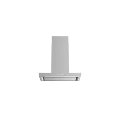
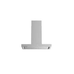
Product Dimensions
Front view
Optional Full-Width Duct Cover Installations
Installation Dimensions
IMPORTANT:
Minimum distance “X”: 30" (76.2 cm)
Suggested maximum distance “X”: 36" (91.4 cm)
Venting Requirements
■ Vent system must terminate to the outdoors.
■ Do not terminate the vent system in an attic or other enclosed area.
■ Do not use 4" (10.2 cm) laundry-type wall caps.
■ Use metal vent only. Rigid metal vent is recommended. Plastic or metal foil vent is not recommended.
■ The length of vent system and number of elbows should be kept to a minimum to provide efficient performance.
For the most efficient and quiet operation:
■ Use no more than three 90° elbows.
■ Make sure there is a minimum of 24" (61.0 cm) of straight vent between the elbows if more than 1 elbow is used.
■ Do not install 2 elbows together.
■ Use clamps to seal all joints in the vent system.
■ The vent system must have a damper. If the roof or wall cap has a damper, do not use the damper supplied with the range hood.
■ Use caulking to seal exterior wall or roof opening around the cap.
■ The size of the vent should be uniform.
Cold weather installations
An additional back draft damper should be installed to minimize backward cold air flow and a thermal break should be installed to minimize conduction of outside temperatures as part of the vent system. The damper should be on the cold air side of the thermal break.
The break should be as close as possible to where the vent system enters the heated portion of the house.
Makeup air
Local building codes may require the use of makeup air systems when using ventilation systems greater than specified CFM of air movement. The specified CFM varies from locale to locale. Consult your HVAC professional for specific requirements in your area.
Venting Methods
A 10" (25.4 cm) round vent system is needed for installation (not included). The hood exhaust opening is 10" (25.4 cm) round. NOTE: Flexible vent is not recommended. Flexible vent creates back pressure and air turbulence that greatly reduce performance.
Vent system can terminate either through the roof or wall.
Calculating Vent System Length
To calculate the length of the system you need, add the equivalent feet (meters) for each vent piece used in the system.
Electrical Requirements
Observe all governing codes and ordinances.
Ensure that the electrical installation is adequate and in conformance with National Electrical Code, ANSI/NFPA 70 (latest edition), or CSA Standards C22.1-94, Canadian Electrical Code, Part 1 and C22.2 No. 0-M91 (latest edition) and all local codes and ordinances.
If codes permit and a separate ground wire is used, it is recommended that a qualified electrician determine that the ground path is adequate.
A copy of the above code standards can be obtained from: National Fire Protection Association 1 Batterymarch Park Quincy, MA 02169-7471
CSA International 8501 East Pleasant Valley Road Cleveland, OH 44131-5575
■ A 120 V, 60 Hz. AC only, 15 A, fused electrical circuit is required.
■ If the house has aluminum wiring, follow the procedure below:
Connect the aluminum wiring using special connectors and/or
tools designed and UL listed for joining copper to aluminum.
Follow the electrical connector manufacturer’s recommended procedure. Aluminum/copper connection must conform with local codes and industry accepted wiring practices.
■ Wire sizes and connections must conform with the rating of the appliance as specified on the model/serial/rating plate. The model/serial/rating plate is located behind the left filter on the rear wall of the range hood.
■ Wire sizes must conform to the requirements of the National Electrical Code, ANSI/NFPA 70 (latest edition), or CSA Standards C22. 1-94, Canadian Electrical Code, Part 1 and C22.2 No. 0-M91 (latest edition) and all local codes and ordinances.
INSTALLATION INSTRUCTIONS
Prepare Location
■ It is recommended that the vent system be installed before hood is installed.
■ If you are installing the optional backsplash with shelves for heat lamps, follow the instructions included with that product.
■ Before making cutouts, make sure there is proper clearance within the ceiling or wall for exhaust vent.
■ Check that all installation parts have been removed from the shipping carton.
1. Disconnect power.
2. Determine which venting method to use: roof or wall exhaust.
3. Select a flat surface for assembling the range hood. Place covering over that surface.
4.Using 2 or more people, lift range hood onto covered surface.
Range Hood Mounting Screws Installation
The hood is attached to the wall with the wood support that is attached to the back of the hood.
1. Determine and mark the centerline on the wall where the canopy range hood will be installed.
2. Select a mounting height between a minimum of 30"
(76.2 cm) and a suggested maximum of 36" (91.4 cm) above the cooking surface and the bottom of the range hood, and mark a horizontal reference line on the wall
3.Remove the wood support from the back of the range hood by loosening the 2 screws from the inside. Locate and level the top of the wood support 153/s" (39.1 cm) above the marked horizontal line and centered on the vertical centerline. Using 2 - 4 of the 6 x 80 mm screws, install wood support so that it is screwed into at least 2 vertical studs.
Optional Duct Cover Installation
1.Attach the full-width duct cover to the top of the range hood with the screws provided with duct covers. The duct cover must be attached to the top of the range hood before mounting the range hood to the wall. For information on ordering the optional duct cover, see the “Accessories” section.
Complete Preparation
1. Determine and make all necessary cuts in the wall for the vent system. Install the vent system before installing the range hood. See the “Venting Requirements” section.
2. Determine the location where the power supply cable will be run through the wall.
3. Drill a 114" (3.2 cm) hole at this location.
4. Pull enough power supply cable through the wall to allow for easy connection to the terminal box.
5. Install the 10" (25.4 cm) square x 10" (25.4 cm) round vent transition with damper to top of the range hood using
4 - 3.5 x 9.5 mm screws.
6. Remove terminal box cover and set aside.
7. Remove knockout from the back of the vent hood and install a UL listed or CSA approved 1/2" strain relief. See “Make Electrical Connection” section.
8. Place the range hood near its mounting position and run the power supply cable through the strain relief into terminal box (enough to make connection).
9. Tighten the strain relief screws.
Install Range Hood
The hood attaches to the wall by the 2 mounting screws in the wood support mounted to the wall in “Range Hood Mounting Screws Installation” in the “Prepare Location” section.
1.Using 2 or more people, hang the range hood on the wall by placing the slotted holes in the range hood back over the 2 screws mounted to the wood support mounted to the wall.
NOTE: If your installation uses the optional duct cover, the vent system needs to be connected to the hood and the duct cover mounted to the top of the range hood before tightening the mounting screws. See steps 5 and 6
2. Push the range hood up into the narrow slots, align the bottom of the hood to the horizontal line, level the hood, and tighten the 2 mounting screws.
3. Mark 2 lower mounting hole locations. Drill 1/8" pilot holes if the holes are located in wood. If holes are not located in wood, remove the hood and drill two 3/8" pilot holes and insert 10 x 50 mm wall anchors. Remount the hood, level, and tighten the upper screws. Install 2 - 6 x 80 mm screws into the lower mounting anchors and tighten.
4. Install 4 - 4.2 x 19 mm screws through the back of the hood into the wood support and tighten.
5. Connect vent system to hood. Seal all joints with clamps.
6. If your installation uses the optional duct cover, mount it to the top of the range hood following the instructions supplied with the duct cover.
Install Range Hood Blower Motor
1.Install the range hood blower motor assembly inside the hood canopy with the wiring to the left.
2.Slide the left mounting plate flange under the bracket.
3.Push the right end of the mounting plate up and snap into spring tab.
NOTE: The spring tab should be outside of the slot in the mounting plate.
4.Align mounting holes and install 5 - 6 x 16 mm screws.
5.Attach power cord connector to connector on wire box on blower motor mounting plate.
Make Electrical Connection
1. Disconnect power.
2. Locate junction box inside of the range hood
3. Use UL listed wire connectors and connect black wires (B) together.
4. Use UL listed wire connectors and connect white wires (A) together.
5. Connect green (or bare) ground wire from home power supply to the green/yellow ground wire (D) in terminal box using UL listed wire connectors.
6. Install terminal box cover.
7. Check that all light bulbs are secure in their sockets.
8. Reconnect power.
Complete Installation and Check Operation
1. Install grease filters. See the “Range Hood Care” section.
2. Install heat lamps into heat lamp sockets.
3. Check operation of the range hood blower and lights. See the “Range Hood Use” section.
4.If range hood does not operate, check to see whether a circuit breaker has tripped or a household fuse has blown. Disconnect power supply and check that the wiring is correct.
RANGE HOOD USE
The range hood is designed to remove smoke, cooking vapors and odors from the cooktop area. For best results, start the hood before cooking and allow it to operate several minutes after the cooking is complete to clear all smoke and odors from the kitchen.
The hood controls are located on the right-hand underside of the range hood.
Range Hood Controls
Operating the lights
1. Turn the light switch to the Night position to use the range hood lights as a night light.
2. Turn the light switch to the High position to turn the range hood lights On.
3. Turn the light switch to the Off position to turn the range hood lights Off.
Operating the blower
Turn the blower switch to the first position to turn the range hood on Low.
Turn the blower switch to the second position to turn the range hood on Medium.
Turn the blower switch to the third position to turn the range hood on Medium - High.
Turn the blower switch to the High position to turn the range hood on High.
Turn the blower switch to the Off position to turn the range hood blower Off.
Operating the heat lamp
1. Turn the heat lamp switch to the High position to turn the heat lamps On.
2. Turn the heat lamp switch to the Off position to turn the heat lamps Off.
RANGE HOOD CARE
Range Hood Lamps
Replacing a Halogen Lamp
Turn off the range hood and allow the halogen lamp to cool.
To avoid damage or decreasing the life of the new bulb, do not touch bulb with bare fingers. Replace bulb, using tissue or wearing cotton gloves to handle bulb.
If new lamps do not operate, make sure the lamps are inserted correctly before calling service.
1. Disconnect power.
2. Push up on the lens and turn it counterclockwise.
3. Remove the bulb and replace it with a 120 V, 50 W maximum halogen bulb with a GU10 base. Turn it clockwise to lock it into place.
4. Repeat steps 2 and 3 for the other bulb if needed.
5. Reconnect power.
Replacing the Infrared Heat Lamps
Turn off the range hood and allow the infrared heat lamp to cool. To avoid damage or decreasing the life of the new lamp, do not touch lamp with bare fingers. Replace lamp, using tissue or wearing cotton gloves to handle lamp.
If new lamps do not operate, make sure the lamps are inserted correctly before calling service.
1. Disconnect power.
2. Twist lamp counterclockwise to remove.
3.Remove the lamp and replace it with a 120 V, 175 W maximum, PAR38 IR lamp made for E-26 base. Twist lamp clockwise to screw it into place.
4. Repeat steps 2 and 3 for the other lamp if needed
5. Reconnect power
Cleaning
Exterior surfaces:
To avoid damage to the exterior surface, do not use steel wool or soap-filled scouring pads. Rub in direction of the grain line to avoid scratching the surface.
Always wipe dry to avoid water marks.
Stainless Steel Cleaner and Polish.
Mild liquid detergent and water.
Wipe with damp soft cloth or nonabrasive sponge, then rinse with clean water and wipe dry.
Metal Filters and Drip Trays:
Use 2 hands to remove filters. Grasp filter handles, pull toward the front of range hood and pull down on the rear handle to remove. Repeat for each filter.
Wash metal filters and grease trays as needed in dishwasher or hot detergent solution to clean.
Replace grease drip tray.
Reinstall filters, grasp filter handles and place front edge of filter into the hood. Push up on the back handle and set rear of filter into the drip tray to secure. Repeat for each filter.
Thermal Protector
The range hood is equipped with a thermal protector to avoid overheating conditions. If the range hood shuts off while in use, move the blower switch to the Off position. Wait approximately 60 minutes, then move the blower switch to the first position to restart the range hood.
Q: My home duct is 7” and cannot be changed out. The installation instructions call for a 10” square to the 10” round home duct connection. Is there a viable work around? Reply