

OOWWNNEERR''SS MMAANNUUAALL
OOppeerraattiioonn
MMaaiinntteennaannccee
S
Sppeecciiffiiccaattiioonnss
All information in this Owner's Manual is current at the time of publica-
tion. However, HYUNDAI reserves the right to make changes at any time
so that our policy of continual product improvement may be carried out.
This manual applies to all models of this vehicle and includes descrip-
tions and explanations of optional as well as standard equipment.
As a result, you may find material in this manual that does not apply to
your specific vehicle.
Please note that some models are equipped with Right-Hand Drive
(RHD). The explanations and illustrations for some operations in RHD
models are opposite of those written in this manual.

F2
Your HYUNDAI should not be modified in any way. Such modifications may adversely affect
the performance, safety or durability of your HYUNDAI and may, in addition, violate condi-
tions of the limited warranties covering the vehicle. Certain modifications may also be in vio-
lation of regulations established by the Department of Transportation and other government
agencies in your country.
Your vehicle is equipped with electronic fuel injection and other electronic components. It is
possible for an improperly installed/adjusted two-way radio or cellular telephone to adversely
affect electronic systems. For this reason, we recommend that you carefully follow the radio
manufacturer's instructions or consult your HYUNDAI dealer for precautionary measures or
special instructions if you choose to install one of these devices.
CAUTION: MODIFICATIONS TO YOUR HYUNDAI
TWO-WAY RADIO OR CELLULAR TELEPHONE INSTALLATION
F3
This manual includes information titled as DANGER, WARNING, CAUTION and NOTICE.
These titles indicate the following:
SAFETY AND VEHICLE DAMAGE WARNING
DANGER indicates a hazardous situa-
tion which, if not avoided, will result
in death or serious injury.
DANGER
WARNING indicates a hazardous situ-
ation which, if not avoided, could
result in death or serious injury.
CAUTION indicates a hazardous situa-
tion which, if not avoided, could result
in minor or moderate injury.
CAUTION
NOTICE indicates a situation which, if not
avoided, could result in vehicle damage.
NOTICE
WARNING

F4
FOREWORD
Congratulations, and thank you for choosing HYUNDAI.We are pleased to welcome you to the growing number of dis-
tinguished people who drive HYUNDAIS.We are very proud of the advanced engineering and high-quality construc-
tion of each HYUNDAI we build.
Your Owner’s Manual will introduce you to the features and operation of your new HYUNDAI. To become familiar with
your new HYUNDAI, so that you can fully enjoy it, read this Owner’s Manual carefully before driving your new vehicle.
This manual contains important safety information and instructions intended to familiarize you with your vehicle’s con-
trols and safety features so you can safely operate your vehicle.
This manual also contains information on maintenance designed to enhance safe operation of the vehicle. It is rec-
ommended that all service and maintenance on your car be performed by an authorized HYUNDAI dealer. HYUNDAI
dealers are prepared to provide high-quality service, maintenance and any other assistance that may be required.
This Owner’s Manual should be considered a permanent part of your vehicle, and should be kept in the vehicle so
you can refer to it at any time. The manual should stay with the vehicle if you sell it to provide the next owner with
important operating, safety and maintenance information.
HYUNDAI MOTOR COMPANY
Copyright 2016 HYUNDAI Motor Company. All rights reserved. No part of this publication may be reproduced, stored
in any retrieval system or transmitted in any form or by any means without the prior written permission of HYUNDAI
Motor Company.
Severe engine and transmission damage may result from the use of poor quality fuels and lubricants that
do not meet HYUNDAI specifications. You must always use high quality fuels and lubricants that meet the
specifications listed on Page 8-7 in the Vehicle Specifications section of the Owner's Manual.
CAUTION
We want to help you get the greatest
possible driving pleasure from your
vehicle. Your Owner’s Manual can
assist you in many ways. We strong-
ly recommend that you read the
entire manual. In order to minimize
the chance of death or injury, you
must read the WARNING and CAU-
TION sections in the manual.
Illustrations complement the words
in this manual to best explain how to
enjoy your vehicle. By reading your
manual, you will learn about fea-
tures, important safety information,
and driving tips under various road
conditions.
The general layout of the manual is
provided in the Table of Contents.
Use the index when looking for a
specific area or subject; it has an
alphabetical listing of all information
in your manual.
Sections: This manual has eight
chapters plus an index. Each chapter
begins with a brief list of contents so
you can tell at a glance if that section
has the information you want.
Your safety, and the safety of others,
is very important. This Owner's
Manual provides you with many safe-
ty precautions and operating proce-
dures. This information alerts you to
potential hazards that may hurt you
or others, as well as damage to your
vehicle.
Safety messages found on vehicle
labels and in this manual describe
these hazards and what to do to
avoid or reduce the risks.
Warnings and instructions contained
in this manual are for your safety.
Failure to follow safety warnings and
instructions can lead to serious injury
or death.
Throughout this manual DANGER,
WARNING, CAUTION, NOTICE and
the SAFETY ALERT SYMBOL will
be used.
This is the safety alert sym-
bol. It is used to alert you to
potential physical injury haz-
ards. Obey all safety mes-
sages that follow this symbol
to avoid possible injury or
death. The safety alert sym-
bol precedes the signal words
DANGER, WARNING and
CAUTION.
HHOOWW TTOO UUSSEE TTHHIISS MMAANNUUAALL
S
SAAFFEETTYY MMEESSSSAAGGEESS
F5
Introduction
DANGER indicates a hazardous
situation which, if not avoided,
will result in death or serious
injury.
DANGER
WARNING indicates a hazardous
situation which, if not avoided,
could result in death or serious
injury.
WARNING
F6
Introduction
NOTICE indicates a situation
which, if not avoided, could result
in vehicle damage.
Gasoline engine
Unleaded
For Europe
For the optimal vehicle performance,
we recommend you use unleaded
gasoline which has an octane rating of
RON (Research Octane Number) 95 /
AKI (Anti Knock Index) 91 or higher.
You may use unleaded gasoline with
an octane rating of RON 91-94 / AKI
87-90 but it may result in slight per-
formance reduction of the vehicle. (Do
not use methanol blended fuels)
Except Europe
Your new vehicle is designed to use
only unleaded fuel having an Octane
Rating of RON (Research Octane
Number) 91 / AKI (Anti-Knock Index)
87 or higher. (Do not use methanol
blended fuels)
Your new vehicle is designed to
obtain maximum performance with
UNLEADED FUEL, as well as mini-
mize exhaust emissions and spark
plug fouling.
NOTICE
• Do not "top off" after the noz-
zle automatically shuts off
when refueling.
• Always check that the fuel cap
is installed securely to pre-
vent fuel spillage in the event
of an accident.
WARNING
NEVER USE LEADED FUEL. The
use of leaded fuel is detrimental
to the catalytic converter and
will damage the engine control
system’s oxygen sensor and
affect emission control.
Never add any fuel system
cleaning agents to the fuel tank
other than what has been speci-
fied (We recommend that you
consult an authorized HYUNDAI
dealer for details.)
CAUTION
CAUTION indicates a hazardous
situation which, if not avoided,
could result in minor or moder-
ate injury.
CAUTION
FFUUEELL RREEQQUUIIRREEMMEENNTTSS
F7
Introduction
Leaded (if equipped)
For some countries, your vehicle is
designed to use leaded gasoline.
When you are going to use leaded
gasoline, we recommend that you
ask an authorized HYUNDAI dealer.
Octane rating of leaded gasoline is
same with unleaded one.
Gasoline containing alcohol and
methanol
Gasohol, a mixture of gasoline and
ethanol (also known as grain alco-
hol), and gasoline or gasohol con-
taining methanol (also known as
wood alcohol) are being marketed
along with or instead of leaded or
unleaded gasoline.
Do not use gasohol containing more
than 10% ethanol, and do not use
gasoline or gasohol containing any
methanol. Either of these fuels may
cause drivability problems and dam-
age to the fuel system, engine control
system and emission control system.
Discontinue using gasohol of any
kind if drivability problems occur.
Vehicle damage or driveability prob-
lems may not be covered by the
manufacturer’s warranty if they result
from the use of:
1. Gasohol containing more than
10% ethanol.
2. Gasoline or gasohol containing
methanol.
3. Leaded fuel or leaded gasohol.
Other fuels
Using fuel additives such as:
- Silicone fuel additive
- MMT (Magnanese, Mn) fuel additive
- Ferrocene (iron-based) fuel additive
- Other metallic-based fuel additives
may result in cylinder misfire, poor
acceleration, engine stalling, dam-
age to the catalyst, or abnormal cor-
rosion, and may cause damage to
the engine resulting in a reduction in
the overall life of the powertrain.
Damage to the fuel system or per-
formance problem caused by the
use of these fuels may not be cov-
ered by your New Vehicle Limited
Warranty.
NOTICE
Never use gasohol which con-
tains methanol. Discontinue
use of any gasohol product
which impairs drivability.
CAUTION

F8
Introduction
Use of MTBE
HYUNDAI recommends avoiding
fuels containing MTBE (Methyl
Tertiary Butyl Ether) over 15.0% vol.
(Oxygen Content 2.7% weight) in
your vehicle.
Fuel containing MTBE over 15.0%
vol. (Oxygen Content 2.7% weight)
may reduce vehicle performance and
produce vapor lock or hard starting.
Do not use methanol
Fuels containing methanol (wood
alcohol) should not be used in your
vehicle. This type of fuel can reduce
vehicle performance and damage
components of the fuel system, engine
control system and emission control
system.
Fuel Additives
HYUNDAI recommends that you use
unleaded gasoline which has an
octane rating of RON (Research
Octane Number) 95 / AKI (Anti Knock
Index) 91 or higher (for Europe) or
Octane Rating of RON (Research
Octane Number) 91 / AKI (Anti-Knock
Index) 87 or higher (except Europe).
For customers who do not use good
quality gasolines including fuel addi-
tives regularly, and have problems
starting or the engine does not run
smoothly, one bottle of additives added
to the fuel tank at every 15,000km (for
Europe) / 10,000km (except Europe).
Additives are available from your
authorized HYUNDAI dealer along
with information on how to use them.
Do not mix other additives.
Operation in foreign countries
If you are going to drive your vehicle
in another country, be sure to:
• Observe all regulations regarding
registration and insurance.
• Determine that acceptable fuel is
available.
Your New Vehicle Limited
Warranty may not cover dam-
age to the fuel system and any
performance problems that are
caused by the use of fuels con-
taining methanol or fuels con-
taining MTBE (Methyl Tertiary
Butyl Ether) over 15.0% vol.
(Oxygen Content 2.7% weight.)
CAUTION
Diesel engine
Diesel fuel
Diesel engine must be operated only
on commercially available diesel fuel
that complies with EN 590 or compa-
rable standard. (EN stands for
"European Norm"). Do not use
marine diesel fuel, heating oils, or
non-approved fuel additives, as this
will increase wear and cause dam-
age to the engine and fuel system.
The use of non-approved fuels and /
or fuel additives will result in a limita-
tion of your warranty rights.
Diesel fuel of above cetane 51 is
used in your vehicle. If two types of
diesel fuel are available, use summer
or winter fuel properly according to
the following temperature conditions.
• Above -5°C (23°F) ... Summer type
diesel fuel.
• Below -5°C (23°F) ... Winter type
diesel fuel.
Watch the fuel level in the tank very
carefully : If the engine stops through
fuel failure, the circuits must be com-
pletely purged to permit restarting.
Biodiesel
Commercially supplied Diesel blends
of no more than 7% biodiesel, com-
monly known as "B7 Diesel" may be
used in your vehicle if Biodiesel meets
EN 14214 or equivalent specifications.
(EN stands for "European Norm"). The
use of biofuels exceeding 7% made
from rapeseed methyl ester (RME),
fatty acid methyl ester (FAME), veg-
etable oil methyl ester (VME) etc. or
mixing diesel exceeding 7% with
biodiesel will cause increased wear or
damage to the engine and fuel sys-
tem. Repair or replacement of worn or
damaged components due to the use
of non approved fuels will not be cov-
ered by the manufactures warranty.
F9
Introduction
Do not let any gasoline or water
enter the tank. This would make
it necessary to drain it out and
to bleed the lines to avoid jam-
ming the injection pump and
damaging the engine.
CAUTION
It is recommended to use the
regulated automotive diesel
fuel for diesel vehicle equipped
with the DPF system.
If you use diesel fuel including
high sulfur (more than 50 ppm
sulfur) and unspecified addi-
tives, it can cause the DPF sys-
tem to be damaged and white
smoke can be emitted.
CAUTION
• Never use any fuel, whether
diesel, B7 biodiesel or other-
wise, that fails to meet the lat-
est petroleum industry speci-
fication.
• Never use any fuel additives
or treatments that are not rec-
ommended or approved by
the vehicle manufacturer.
CAUTION

F10
Introduction
This vehicle should not be modified.
Modification of your vehicle could
affect its performance, safety or
durability and may even violate gov-
ernmental safety and emissions reg-
ulations.
In addition, damage or performance
problems resulting from any modifi-
cation may not be covered under
warranty.
• If you use unauthorized electronic
devices, it may cause the vehicle to
operate abnormally, wire damage,
battery discharge and fire. For your
safety, do not use unauthorized
electronic devices.
By following a few simple precautions
for the first 1,000 km (600 miles) you
may add to the performance, econo-
my and life of your vehicle.
• Do not race the engine.
• While driving, keep your engine
speed (rpm, or revolutions per
minute) between 2,000 rpm and
4,000 rpm.
• Do not maintain a single speed for
long periods of time, either fast or
slow. Varying engine speed is need-
ed to properly break-in the engine.
• Avoid hard stops, except in emer-
gencies, to allow the brakes to seat
properly.
• Don't tow a trailer during the first
2,000 km (1,200 miles) of operation.
HYUNDAI promotes an environmen-
tally sound treatment for end of life
vehicles and offers to take back your
HYUNDAI end of life vehicles in
accordance with the European Union
(EU) End of Life Vehicles Directive.
You can get detailed information
from your national HYUNDAI home-
page.
VVEEHHIICCLLEE BBRREEAAKK--IINN
PPRROOCCEESSSS
V
VEEHHIICCLLEE MMOODDIIFFIICCAATTIIOONNSS RREETTUURRNNIINNGG UUSSEEDD VVEEHHIICCLLEESS
((FFOORR EEUURROOPPEE))

1
2
3
4
5
6
7
8
I
Your vehicle at a glance
Safety system of your vehicle
Convenient features of your vehicle
Multimedia System
Driving your vehicle
What to do in an emergency
Maintenance
Specifications & Consumer information
Index
TABLE OF CONTENTS
F11

Your vehicle at a glance
1
Your vehicle at a glance
1
Exterior overview (I) .............................................1-2
Exterior overview (II) ............................................1-3
Interior overview....................................................1-4
Instrument panel overview (I)..............................1-5
Instrument panel overview (II).............................1-6
Engine compartment .............................................1-7
1-2
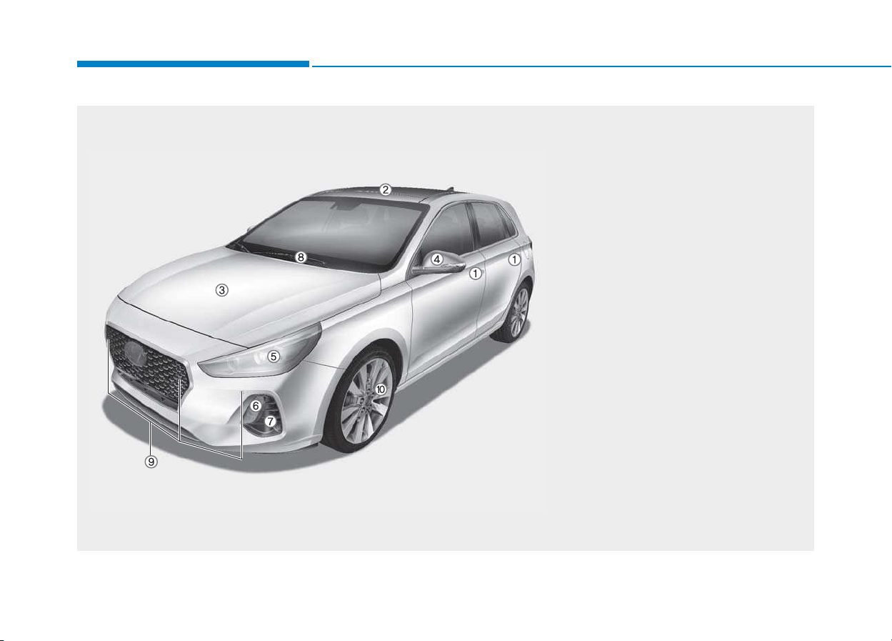
EEXXTTEERRIIOORR OOVVEERRVVIIEEWW ((II))
Your vehicle at a glance
1. Door locks...............................................3-11
2. Panorama sunroof ..................................3-32
3. Hood .......................................................3-37
4. Outside rearview mirror ..........................3-23
5. Head lamp .....................................3-83, 7-86
6. DRL (Daytime Running Light) .......3-91, 7-86
7. Front fog lamp ...............................3-88, 7-91
8. Front windshield wiper blades.......3-97, 7-46
9. Parking assist system...........................3-106
10. Tires and wheels ..................................7-52
OPDE016001
■ Front view
The actual shape may differ from the illustration.
1-3
Your vehicle at a glance
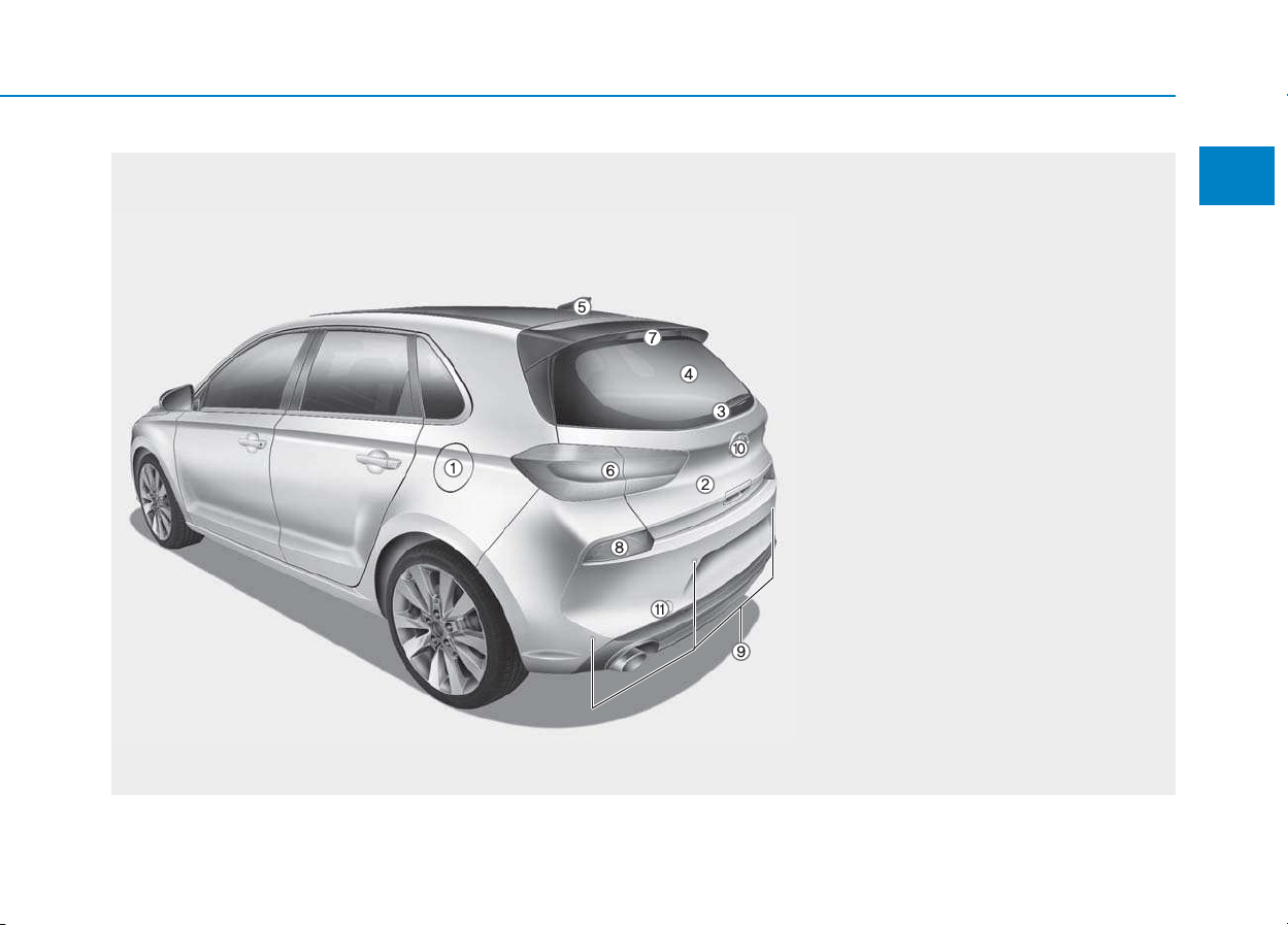
EEXXTTEERRIIOORR OOVVEERRVVIIEEWW ((IIII))
1
1. Fuel filler door.........................................3-40
2. Tailgate ...................................................3-38
3. Rear window wiper blade ..............3-97, 7-47
4. Defroster ...............................................3-109
5. Antenna ....................................................4-3
6. Rear combination lamp ..........................7-98
7. High mounted stop lamp ......................7-103
8. Rear fog lamp..............................3-89, 7-102
9. Rear parking assist system .................3-102
10. Rearview camera................................3-101
11. Towing hook..........................................6-40
OPDE016002
■ Rear view
The actual shape may differ from the illustration.
1-4
Your vehicle at a glance
I
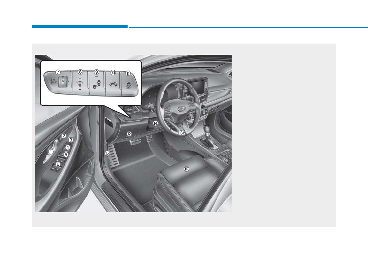
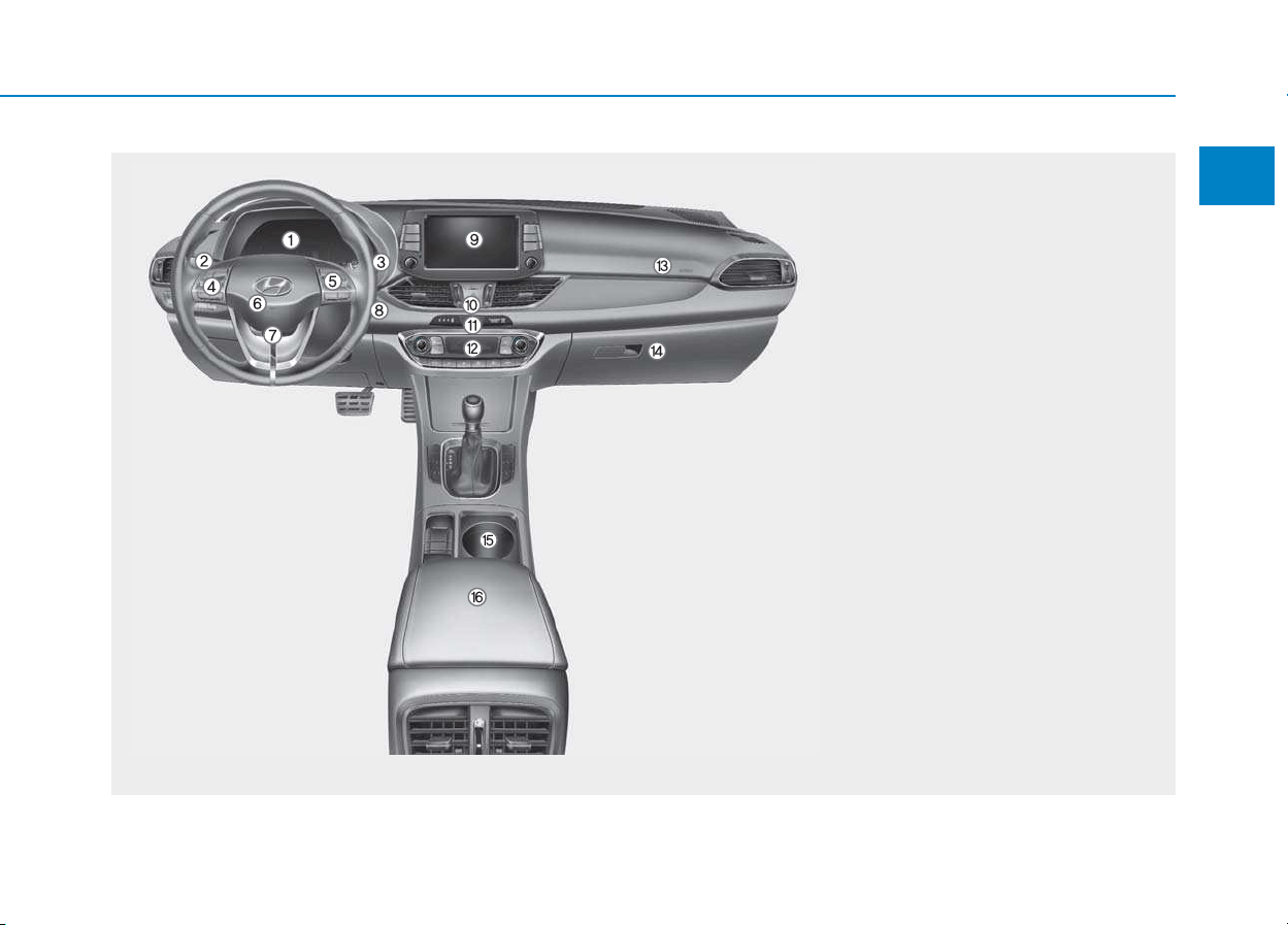
INNTTEERRIIOORR OOVVEERRVVIIEEWW
1. Inside door handle ............................3-12
2. Driver position memory system ........3-17
3. Outside rearview mirror folding ........3-25
4. Outside rearview mirror control ........3-24
5. Power window lock switch ................3-30
6. Power window switches ....................3-27
7. Headlight leveling device ..................3-91
8. Instrument panel illumination
control switch ....................................3-44
9. Blind spot detection system ..............5-70
10. Lane keeping assist system/ ........5-106
Lane departure warning
system (LDWS) ............................5-114
11. ESC OFF button..............................5-55
12. Fuse box..........................................7-63
13. Steering wheel ................................3-19
14. Steering wheel tilt/telescope lever ..3-20
15. Hood release lever ..........................3-37
16. Seat ..................................................2-4
OPDE016003
The actual shape may differ from the illustration.
1-5
Your vehicle at a glance
1
IINNSSTTRRUUMMEENNTT PPAANNEELL OOVVEERRVVIIEEWW ((II))
1. Instrument cluster ..........................3-43
2. Light control/Turn signals ................3-83
3. Wiper/Washer..................................3-97
4. Steering wheel audio controls/ ........4-4
Bluetooth
®
wireless technology
hands-free controls ..........................4-5
5. Speed limiter controls/ ..................5-122
Cruise controls/ ............................5-124
Advanced smart cruise controls ..5-130
6. Horn ................................................3-21
7. Driver’s front air bag........................2-47
8. Key ignition switch/ ..........................5-7
Engine Start/Stop button ................5-11
9. Audio system/ ..................................4-9
Navigation system ..........................4-5
10. Hazard warning flasher switch........6-2
11. Central door lock switch ..............3-13
12. Manual climate control system/ 3- 111
Automatic climate control
system ........................................3-121
13. Passenger’s front air bag ..............2-47
14. Glove box ....................................3-138
15. Cup holder ..................................3-140
16. Console box ................................3-138
OPDE016005
The actual shape may differ from the illustration.
1-6
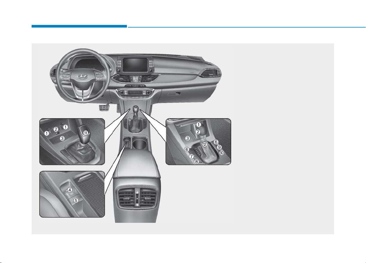
IINNSSTTRRUUMMEENNTT PPAANNEELL OOVVEERRVVIIEEWW ((IIII))
Your vehicle at a glance
1. Power outlet ..................................3-142
2. Aux, USB and iPod
®
........................4-2
3. Wireless cellular phone charging
system ..........................................3-144
4. Electronic parking brake (EPB)
switch ..............................................5-44
5. Auto Hold ........................................5-49
6. Seat warmer/Air ventilation seat ....2-19
7. Heated steering wheel ....................3-21
8. Drive mode button ..........................5-68
9. Parking assist system ON button/ ..3-106
Rear paring assist system
OFF button....................................3-104
10. Idle stop and go (ISG) OFF button 5-62
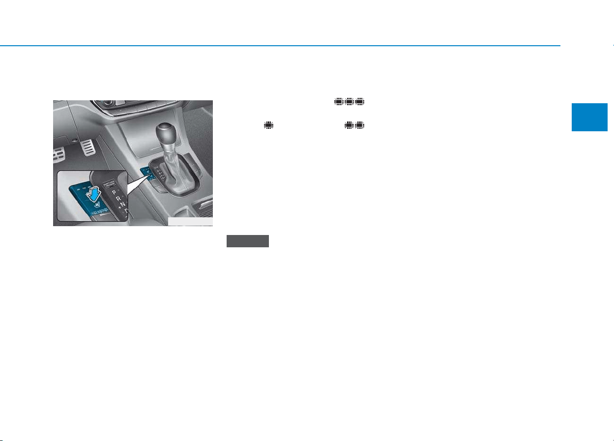
11. Manual transmission shift lever ....5-20
12. Automatic transmission shift lever/ 5-24
Dual clutch transmission
shift lever ......................................5-31
OPDE016004
The actual shape may differ from the illustration.
■■
■■
TT
TT
yy
yy
pp
pp
ee
ee
AA
AA
■■
■■
TT
TT
yy
yy
pp
pp
ee
ee
BB
BB
1-7
Your vehicle at a glance
1
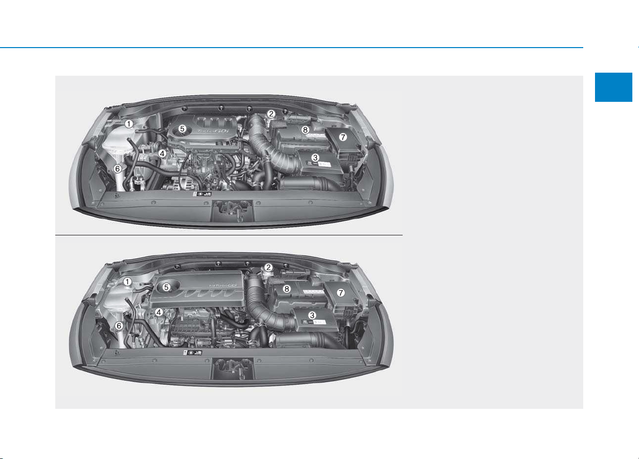
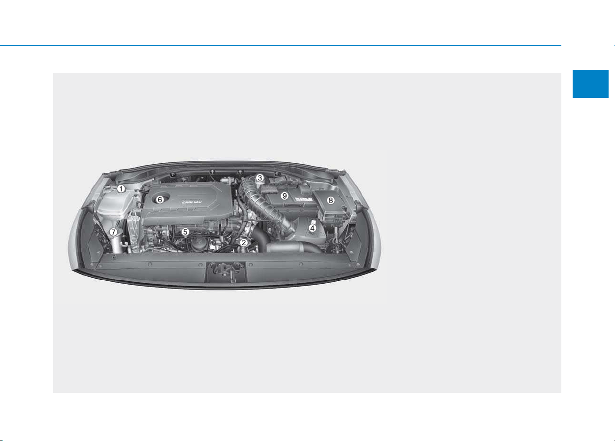
EENNGGIINNEE CCOOMMPPAARRTTMMEENNTT
1. Engine coolant reservoir/
Engine coolant cap ..............................7-37
2. Brake/clutch fluid reservoir ..................7-40
3. Air cleaner............................................7-42
4. Engine oil dipstick ................................7-35
5. Engine oil filler cap ..............................7-35
6. Windshield washer fluid reservoir........7-41
7. Fuse box ..............................................7-64
8. Battery..................................................7-48
OPDE076088/OPD076001
The actual engine room in the vehicle may differ from the illustration.
■■
Gasoline Engine (Kappa 1.0 T-GDI)
■■
Gasoline Engine (Kappa 1.4 T-GDI)
1-8
Your vehicle at a glance
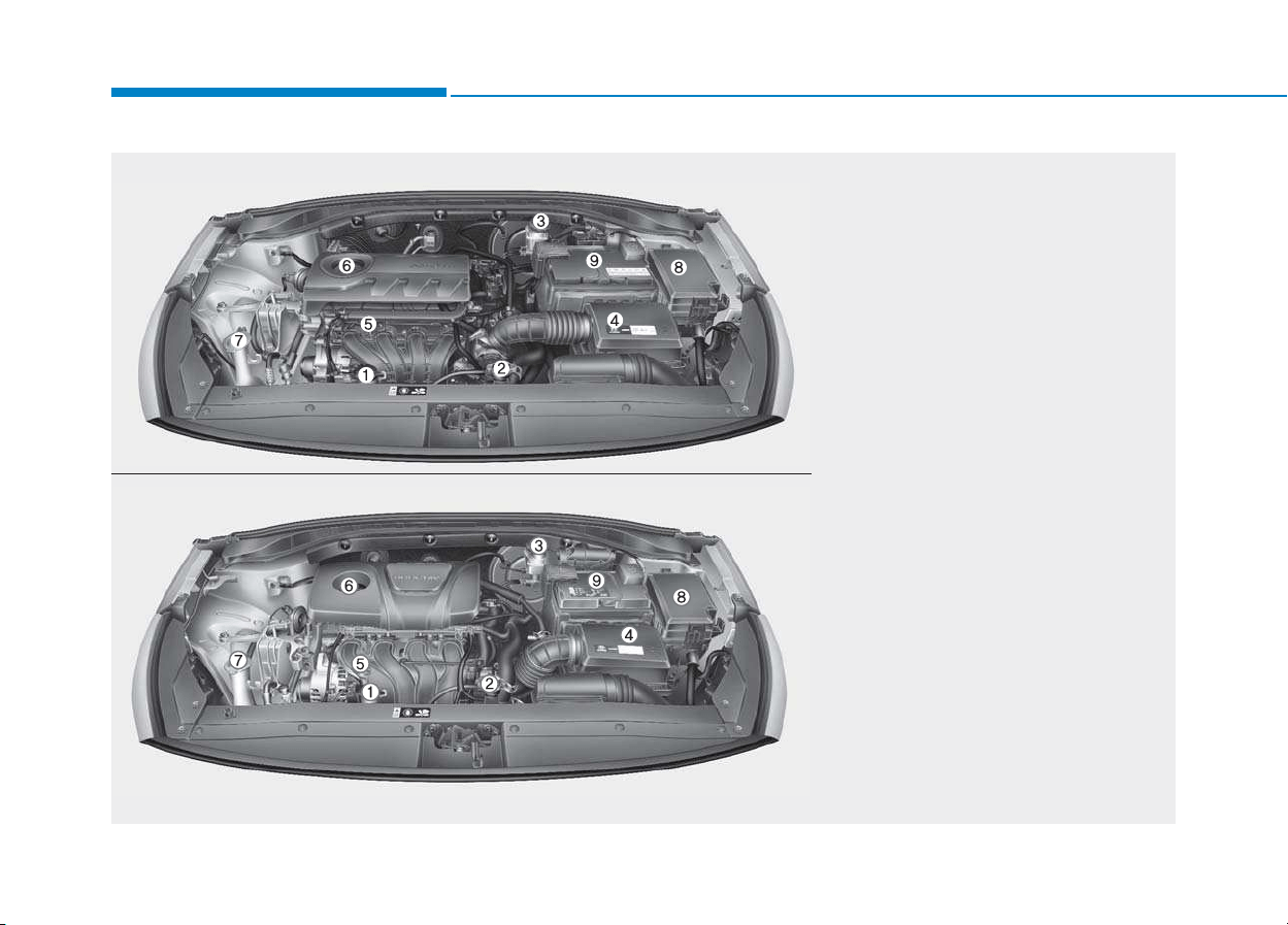
1. Engine coolant reservoir......................7-37
2. Radiator cap.........................................7-38
3. Brake/clutch fluid reservoir ..................7-40
4. Air cleaner............................................7-42
5. Engine oil dipstick ................................7-35
6. Engine oil filler cap ..............................7-35
7. Windshield washer fluid reservoir........7-41
8. Fuse box ..............................................7-64
9. Battery..................................................7-48
OPDE076089/OPDE076093
The actual engine room in the vehicle may differ from the illustration.
■
■
Gasoline Engine (Kappa 1.4 MPI)
■■
Gasoline Engine (Gamma 1.6 MPI)
1-9
Your vehicle at a glance
1
1. Engine coolant reservoir......................7-37
2. Radiator cap.........................................7-38
3. Brake/clutch fluid reservoir ..................7-40
4. Air cleaner............................................7-42
5. Engine oil dipstick ................................7-35
6. Engine oil filler cap ..............................7-35
7. Windshield washer fluid reservoir........7-41
8. Fuse box ..............................................7-64
9. Battery..................................................7-48
OPD076003
The actual engine room in the vehicle may differ from the illustration.
■■
Diesel Engine (U2 1.6 TCI)

Safety system of your vehicle
2
Important safety precautions .............................2-2
Always wear your seat belt ..........................................2-2
Restrain all children .........................................................2-2
Air bag hazards ................................................................2-2
Driver distraction .............................................................2-2
Control your speed ..........................................................2-3
Keep your vehicle in safe condition ............................2-3
Seats ........................................................................2-4
Safety precautions ..........................................................2-5
Front seats..........................................................................2-6
Rear seats .........................................................................2-12
Headrest ...........................................................................2-15
Seat warmers and air ventilation seats.....................2-19
Seat belts .............................................................2-22
Seat belt safety precautions ......................................2-22
Seat belt warning light .................................................2-23
Seat belt restraint system ...........................................2-25
Additional seat belt safety precautions ...................2-31
Care of seat belts ..........................................................2-33
Child restraint system (CRS) .............................2-34
Our recommendation:Children always in the rear 2-34
Selecting a Child Restraint System (CRS) ................2-35
Installing a Child Restraint System (CRS)..................2-37
Air bag - supplemental restraint system ........2-45
Where are the air bags? ..............................................2-47
How does the air bags system operate? .................2-52
What to expect after an air bag inflates ................2-56
Why didn't my air bag go off in a collision? ...........2-57
SRS care ...........................................................................2-62
Additional safety precautions .....................................2-63
Air bag warning labels ..................................................2-63
This chapter provides you with important information about how to protect yourself and your passengers.
It explains how to properly use your seats and seat belts, and how your air bags work.
Additionally, this chapter explains how to properly restrain infants and children in your vehicle.

2-2
You will find many safety precautions
and recommendations throughout
this section, and throughout this man-
ual.The safety precautions in this sec-
tion are among the most important.
Always wear your seat belt
A seat belt is your best protection in
all types of accidents. Air bags are
designed to supplement seat belts,
not replace them. So even though
your vehicle is equipped with air bags,
ALWAYS make sure you and your
passengers wear your seat belts, and
wear them properly.
Restrain all children
All children under age 13 should ride
in your vehicle properly restrained in
a rear seat, not the front seat. Infants
and small children should be
restrained in an appropriate Child
Restraint System. Larger children
should use a booster seat with the
lap/shoulder belt until they can use
the seat belt properly without a
booster seat.
Air bag hazards
While air bags can save lives, they
can also cause serious or fatal
injuries to occupants who sit too
close to them, or who are not prop-
erly restrained. Infants, young chil-
dren, and short adults are at the
greatest risk of being injured by an
inflating air bag. Follow all instruc-
tions and warnings in this manual.
Driver distraction
Driver distraction presents a serious
and potentially deadly danger, espe-
cially for inexperienced drivers. Safety
should be the first concern when
behind the wheel and drivers need to
be aware of the wide array of potential
distractions, such as drowsiness,
reaching for objects, eating, personal
grooming, other passengers, and
using cellular phones.
Drivers can become distracted when
they take their eyes and attention off
the road or their hands off the wheel
to focus on activities other than driv-
ing. To reduce your risk of distraction
and an accident:
• ALWAYS set up your mobile devices
(i.e., MP3 players, phones, naviga-
tion units, etc.) when your vehicle is
parked or safely stopped.
• ONLY use your mobile device when
allowed by laws and conditions per-
mit safe use. NEVER text or email
while driving. Most countries have
laws prohibiting drivers from texting.
Some countries and cities also pro-
hibit drivers from using handheld
phones.
IIMMPPOORRTTAANNTT SSAAFFEETTYY PPRREECCAAUUTTIIOONNSS
Safety system of your vehicle

2-3
Safety system of your vehicle
• NEVER let the use of a mobile device
distract you from driving. You have a
responsibility to your passengers and
others on the road to always drive
safely, with your hands on the wheel
as well as your eyes and attention on
the road.
Control your speed
Excessive speed is a major factor in
crash injuries and deaths. Generally,
the higher the speed, the greater the
risk, but serious injuries can also
occur at lower speeds. Never drive
faster than is safe for current condi-
tions, regardless of the maximum
speed posted.
Keep your vehicle in safe condi-
tion
Having a tire blowout or a mechanical
failure can be extremely hazardous. To
reduce the possibility of such prob-
lems, check your tire pressures and
condition frequently, and perform all
regularly scheduled maintenance.
2
2-4
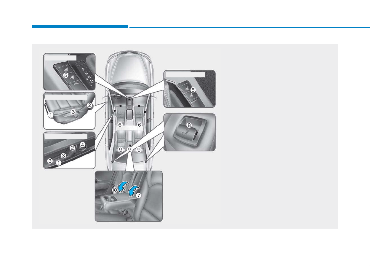
SSEEAATTSS
Safety system of your vehicle
OPDE036001
Front seat
(1) Forward and backward
(2) Seatback angle
(3) Seat cushion height *
(4) Lumbar support (Driver’s seat)*
(5) Seat warmer*/Air ventilation seat*
(6) Headrest
Rear seat
(7) Armrest*
(8) Seatback folding
(9) Headrest
(10) Carrying long/narrow cargo*
* : if equipped
■ Driver’s side
■ Manual adjustment
■ Power adjustment
■ Passenger's side

To reduce the risk of serious
injury or death from an inflating
air bag, take the following pre-
cautions:
• Adjust the driver’s seat as far
to the rear as possible main-
taining the ability to control of
the vehicle.
• Adjust the front passenger seat
as far to the rear as possible.
(Continued)
WARNING
(Continued)
• Hold the steering wheel by the
rim with hands at the 9 o’clock
and 3 o’clock positions to min-
imize the risk of injuries to
your hands and arms.
• NEVER place anything or any-
one between the air bag.
• Do not allow the front passen-
ger to place feet or legs on the
dashboard to minimize the risk
of leg injuries.
2-5
Safety system of your vehicle
2
Safety precautions
Adjusting the seats so that you are sit-
ting in a safe, comfortable position
plays an important role in driver and
passenger safety together with the
seat belts and air bags in an accident.
Air bags
You can take steps to reduce the risk
of being injured by an inflating air
bag. Sitting too close to an air bag
greatly increases the risk of injury in
the event the air bag inflates. Move
your seat as far back as possible
from front air bags, while still main-
taining control of the vehicle.
Do not use a cushion that reduces
friction between the seat and the
passenger.The passenger's hips
may slide under the lap portion
of the seat belt during an acci-
dent or a sudden stop.
Serious or fatal internal injuries
could result because the seat
belt cannot operate properly.
WARNING

2-6
Safety system of your vehicle
Seat belts
Always fasten your seat belt before
starting any trip.
At all times, passengers should sit
upright and be properly restrained.
Infants and small children must be
restrained in appropriate Child Restraint
Systems. Children who have outgrown a
booster seat and adults must be
restrained using the seat belts.
Front seats
The front seat can be adjusted by
using the control lever (or knob) or
switches located on the outside of the
seat cushion. Before driving, adjust
the seat to the proper position so that
you can easily control the steering
wheel, foot pedals and controls on the
instrument panel.
Take the following precautions
when adjusting your seat belt:
• NEVER use one seat belt for
more than one occupant.
• Always position the seatback
upright with the lap portion of
the seat belt snug and low
across the hips.
• NEVER allow children or small
infants to ride in a passenger’s
lap.
(Continued)
(Continued)
• Do not route the seat belt
across your neck, across sharp
edges, or reroute the shoulder
strap away from your body.
• Do not allow the seat belt to
become caught or jammed.
WARNING
Take the following precautions
when adjusting your seat:
• NEVER attempt to adjust the
seat while the vehicle is mov-
ing. The seat could respond
with unexpected movement
and may cause loss of vehicle
control resulting in an acci-
dent.
• Do not place anything under
the front seats. Loose objects
in the driver’s foot area could
interfere with the operation of
the foot pedals, causing an
accident.
(Continued)
WARNING
2-7
Safety system of your vehicle
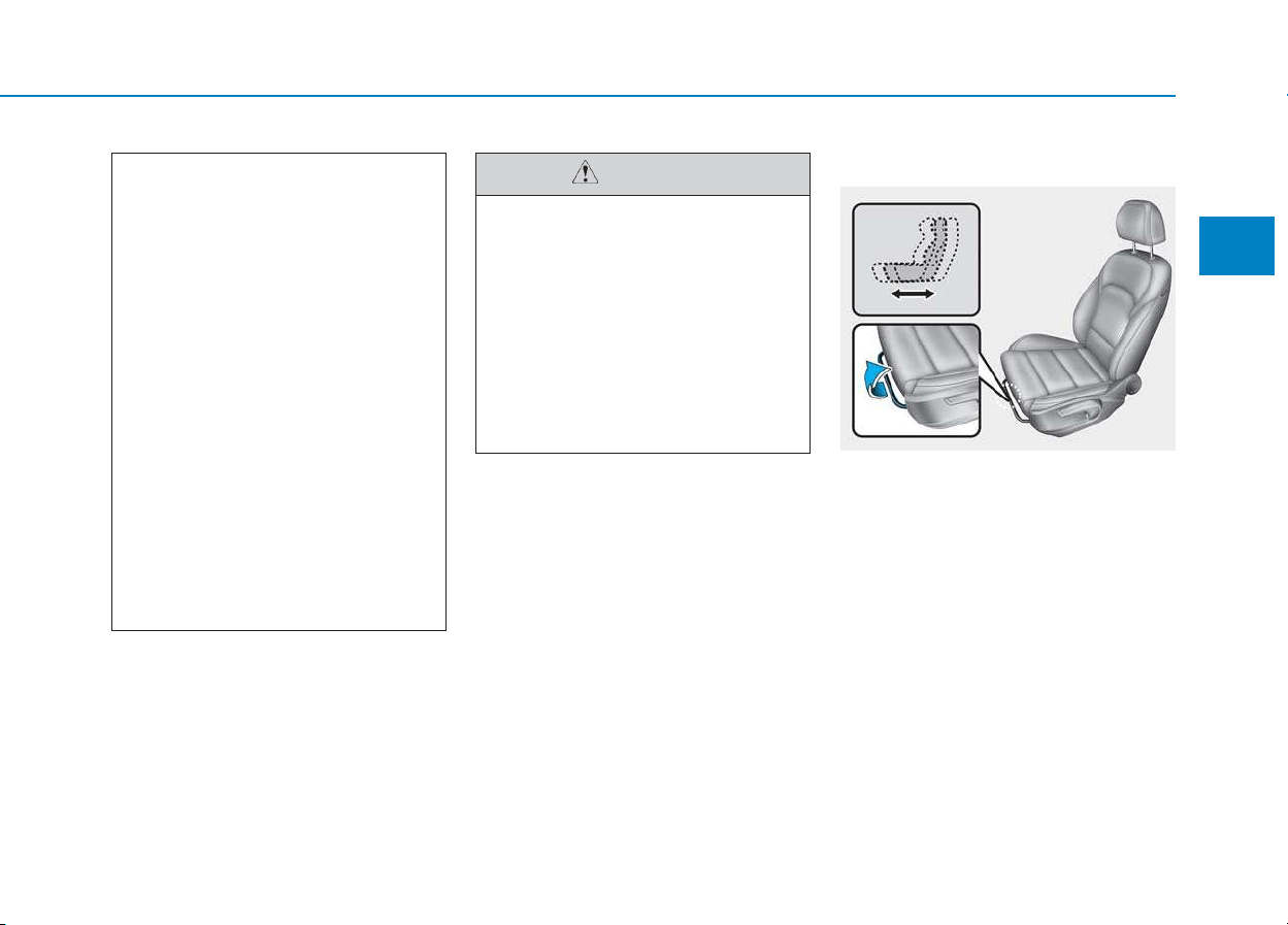
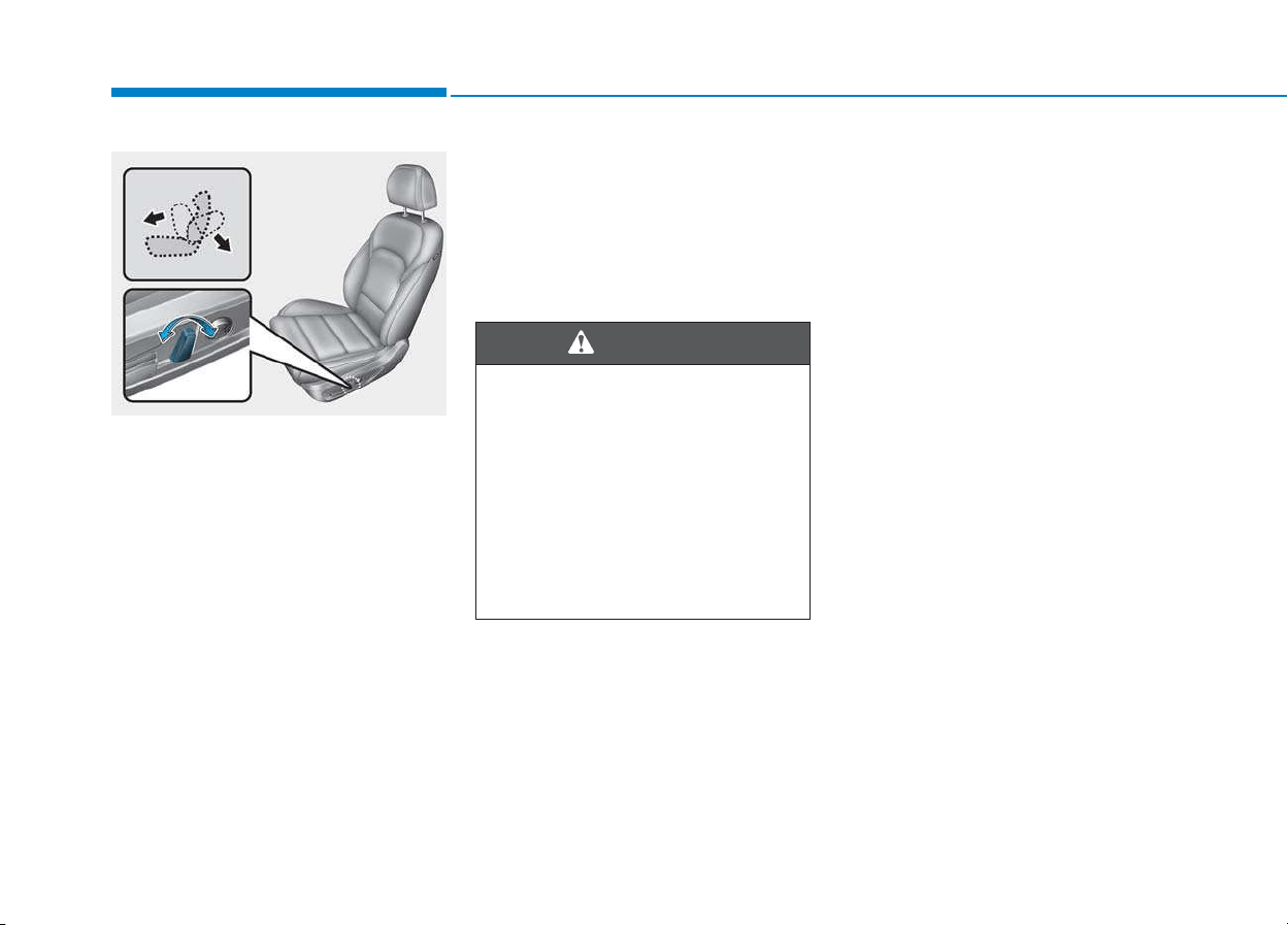
Manual adjustment
Forward and rearward adjustment
To move the seat forward or rearward:
1. Pull up the seat slide adjustment
lever and hold it.
2. Slide the seat to the position you
desire.
3. Release the lever and make sure
the seat is locked in place. Move
forward and rearward without using
the lever. If the seat moves, it is not
locked properly.
2
To prevent injury:
• Do not adjust your seat while
wearing your seat belt.
Moving the seat cushion for-
ward may cause strong pres-
sure on your abdomen.
• Do not allow your hands or
fingers to get caught in the
seat mechanisms while the
seat is moving.
CAUTION
(Continued)
• Do not allow anything to inter-
fere with the normal position
and proper locking of the seat-
back.
• Do not place a cigarette lighter
on the floor or seat. When you
operate the seat, gas may exit
out of the lighter causing a fire.
• Use extreme caution when
picking small objects trapped
under the seats or between
the seat and the center con-
sole. Your hands might be cut
or injured by the sharp edges
of the seat mechanism.
• If there are occupants in the
rear seats, be careful while
adjusting the front seat posi-
tion.
OPDE036002
2-8
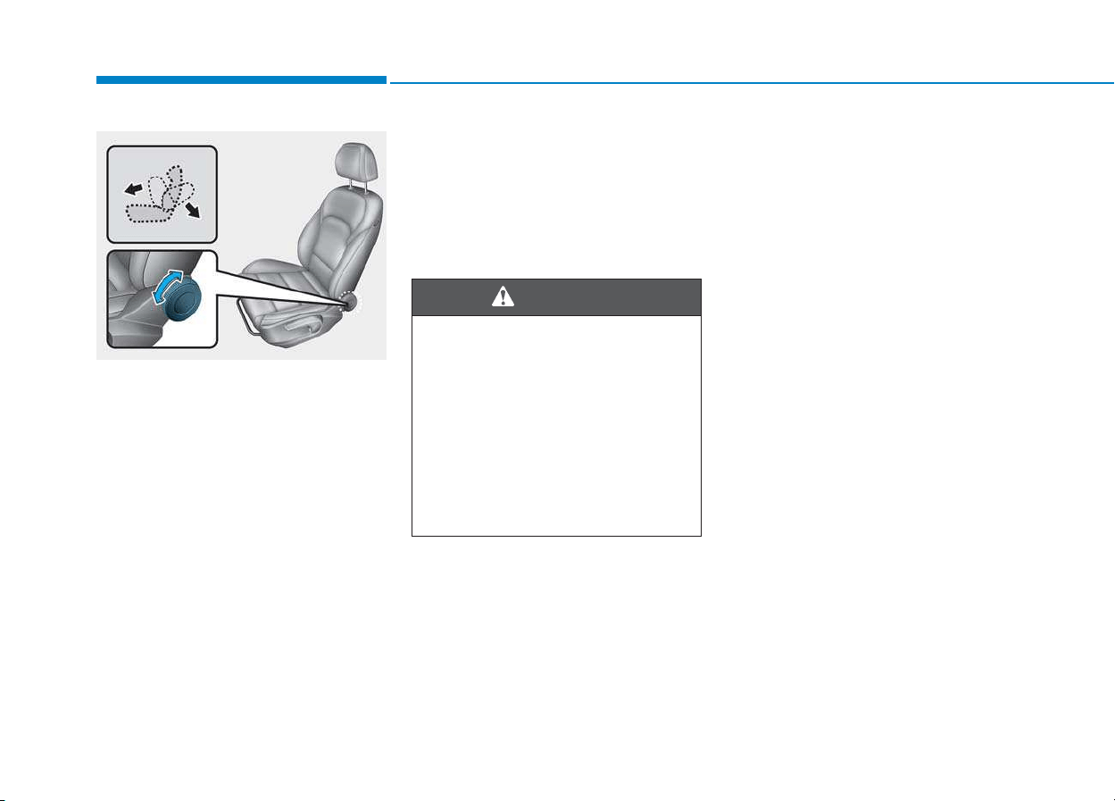
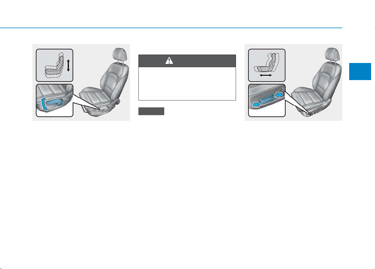
Seatback angle
To recline the seatback:
1.Roll the seatback knob rearward.
2.Adjust the seatback to the position
you desire.
Reclining seatback
Sitting in a reclined position when
the vehicle is in motion can be dan-
gerous. Even when buckled up, the
protections of your restraint system
(seat belts and/or air bags) is greatly
reduced by reclining your seatback.
Seat belts must be snug against your
hips and chest to work properly.
When the seatback is reclined, the
shoulder belt cannot do its job
because it will not be snug against
your chest. Instead, it will be in front
of you. During an accident, you could
be thrown into the seat belt, causing
neck or other injuries.
The more the seatback is reclined,
the greater chance the passenger’s
hips will slide under the lap belt or
the passenger’s neck will strike the
shoulder belt.
Safety system of your vehicle
OPDE036003
NEVER ride with a reclined seat-
back when the vehicle is moving.
Riding with a reclined seatback
increases your chance of seri-
ous or fatal injuries in the event
of a collision or sudden stop.
Drivers and passengers should
ALWAYS sit well back in their
seats, properly belted, and with
the seatbacks upright.
WARNING
2-9
Safety system of your vehicle
Seat cushion height (if equipped)
To change the height of the seat
cushion:
• Push down the lever several times,
to lower the seat cushion.
• Pull up the lever several times, to
raise the seat cushion.
Power adjustment
To prevent damage to the seats:
• Always stop adjusting the seats
when the seat has been adjust-
ed as far forward or rearward as
possible.
• Do not adjust the seats longer
than necessary when the engine
is turned off. This may result in
unnecessary battery drain.
• Do not operate two or more seats
at the same time. This may result
in an electrical malfunction.
Forward and rearward adjustment
To move the seat forward or rearward:
1. Push the control switch forward or
rearward.
2. Release the switch once the seat
reaches the desired position.
NOTICE
2
OPDE036004
NEVER allow children in the
vehicle unattended. The power
seats are operable when the
engine is turned off.
WARNING
OPD036005
2-10
Seatback angle
To recline the seatback:
1. Push the control switch forward or
rearward.
2. Release the switch once the seat-
back reaches the desired position.
Reclining seatback
Sitting in a reclined position when
the vehicle is in motion can be dan-
gerous. Even when buckled up, the
protections of your restraint system
(seat belts and air bags) is greatly
reduced by reclining your seatback.
Seat belts must be snug against your
hips and chest to work properly.
When the seatback is reclined, the
shoulder belt cannot do its job
because it will not be snug against
your chest. Instead, it will be in front
of you. During an accident, you could
be thrown into the seat belt, causing
neck or other injuries.
The more the seatback is reclined,
the greater chance the passenger’s
hips will slide under the lap belt or
the passenger’s neck will strike the
shoulder belt.
Safety system of your vehicle
NEVER ride with a reclined seat-
back when the vehicle is moving.
Riding with a reclined seatback
increases your chance of serious
or fatal injuries in the event of a
collision or sudden stop.
Driver and passengers should
ALWAYS sit well back in their
seats, properly belted, and with
the seatbacks upright.
WARNING
OPD036006
2-11
Safety system of your vehicle
2
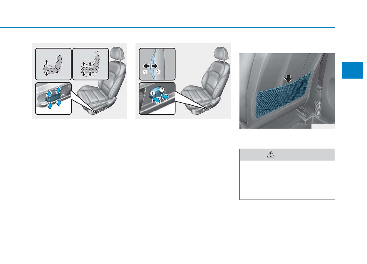
Seat cushion height (if equipped)
To change the height of the seat cush-
ion:
1. • Push the front portion of the con-
trol switch up to raise or down to
lower the front part of the seat
cushion.
• Push the rear portion of the con-
trol switch up to raise or down to
lower the height of the seat cush-
ion.
2. Release the switch once the seat
reaches the desired position.
Lumbar support (for driver’s seat,
if equipped)
• The lumbar support can be adjust-
ed by pressing the lumbar support
switch.
• Press the front portion of the switch
(1) to increase support or the rear
portion of the switch (2) to decrease
support.
Seatback pocket (if equipped)
The seatback pocket is provided on
the back of the front seatbacks.
OPD036007 OPD036008
OAD035017
Do not put heavy or sharp
objects in the seatback pockets.
In an accident they could come
loose from the pocket and
injure occupants.
CAUTION
2-12
Safety system of your vehicle
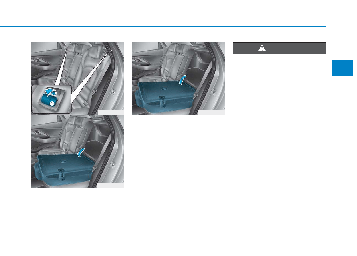
Rear seats
Folding the rear seat
The rear seatbacks can be folded to
facilitate carrying long items or to
increase the luggage capacity of the
vehicle.
To fold down the rear seatback:
1. Set the front seatback to the upright
position and if necessary, slide the
front seat forward.
2. Lower the rear headrests to the
lowest position.
3.Locate the seatbelt toward the out-
board position before folding down
the seatback. If not, the seatbelt
system may be interfered by the
seatback.
• Never allow passengers to sit
on top of the folded down
seatback while the vehicle is
moving. This is not a proper
seating position and no seat
belts are available for use.
This could result in serious
injury or death in case of an
accident or sudden stop.
• Objects carried on the folded
down seatback should not
extend higher than the top of
the front seatbacks. This could
allow cargo to slide forward
and cause injury or damage
during sudden stops.
WARNING
OPD036018 OPDE036019
2-13
Safety system of your vehicle
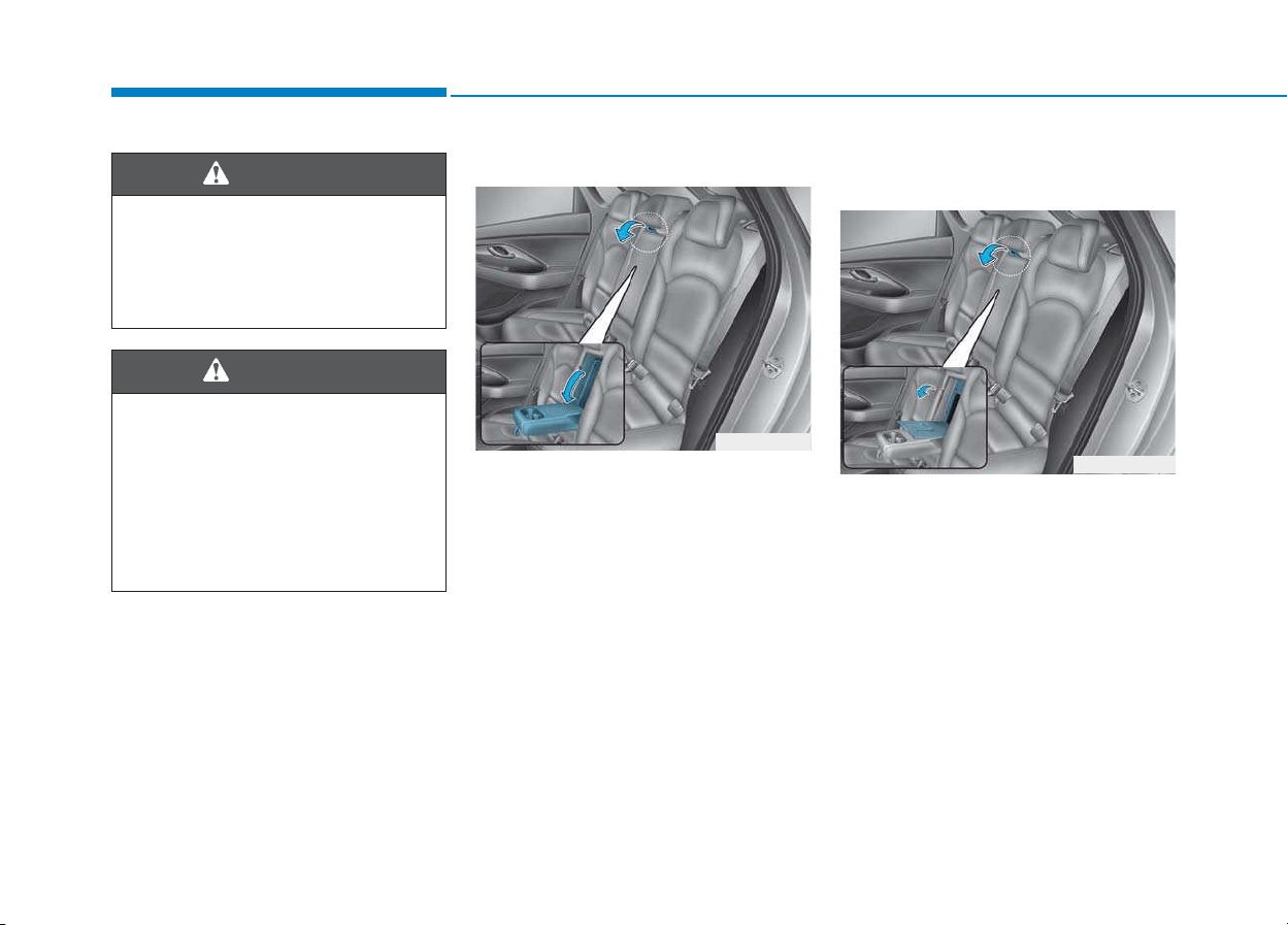
4. Pull up the seatback folding lever
(1), then fold the seat toward the
front of the vehicle.
5.To use the rear seat, lift and push
the seatback rearward.
Push the seatback firmly until it
clicks into place. Make sure the
seatback is locked in place.
2
OPDE036062
OPDE036020
OPDE036021
When returning the rear seat-
back from a folded to an upright
position, hold the seatback and
return it slowly. Ensure that the
seatback is completely locked
into its upright position by
pushing on the top of the seat-
back. In an accident or sudden
stop, the unlocked seatback
could allow cargo to move for-
ward with great force and enter
the passenger compartment,
which could result in serious
injury or death.
WARNING
2-14
Armrest (if equipped)
The armrest is located in the center
of the rear seat. Pull the armrest
down from the seatback to use it.
Carrying long/narrow cargo
(if equipped)
Additional cargo space is provided to
accommodate long/narrow cargo
(skis, poles, etc.) not able to fit prop-
erly in the luggage compartment
when closed.
1.Pull the armrest down.
2.Pull the cover down while pushing
the release lever down.
Safety system of your vehicle
Do not place objects in the rear
seats, since they cannot be
properly secured and may hit
vehicle occupants in a collision
causing serious injury or death.
WARNING
Make sure the engine is off, the
shift lever is in P (Park), and the
parking brake is securely applied
whenever loading or unloading
cargo. Failure to take these steps
may allow the vehicle to move if
the shift lever is inadvertently
moved to another position.
WARNING
OPDE036022
OPDE036072
2-15
Safety system of your vehicle
2
Headrest
The vehicle’s front and rear seats have
adjustable headrests. The headrests
provide comfort for passengers, but
more importantly they are designed to
help protect passengers from whiplash
and other neck and spinal injuries dur-
ing an accident, especially in a rear
impact collision.
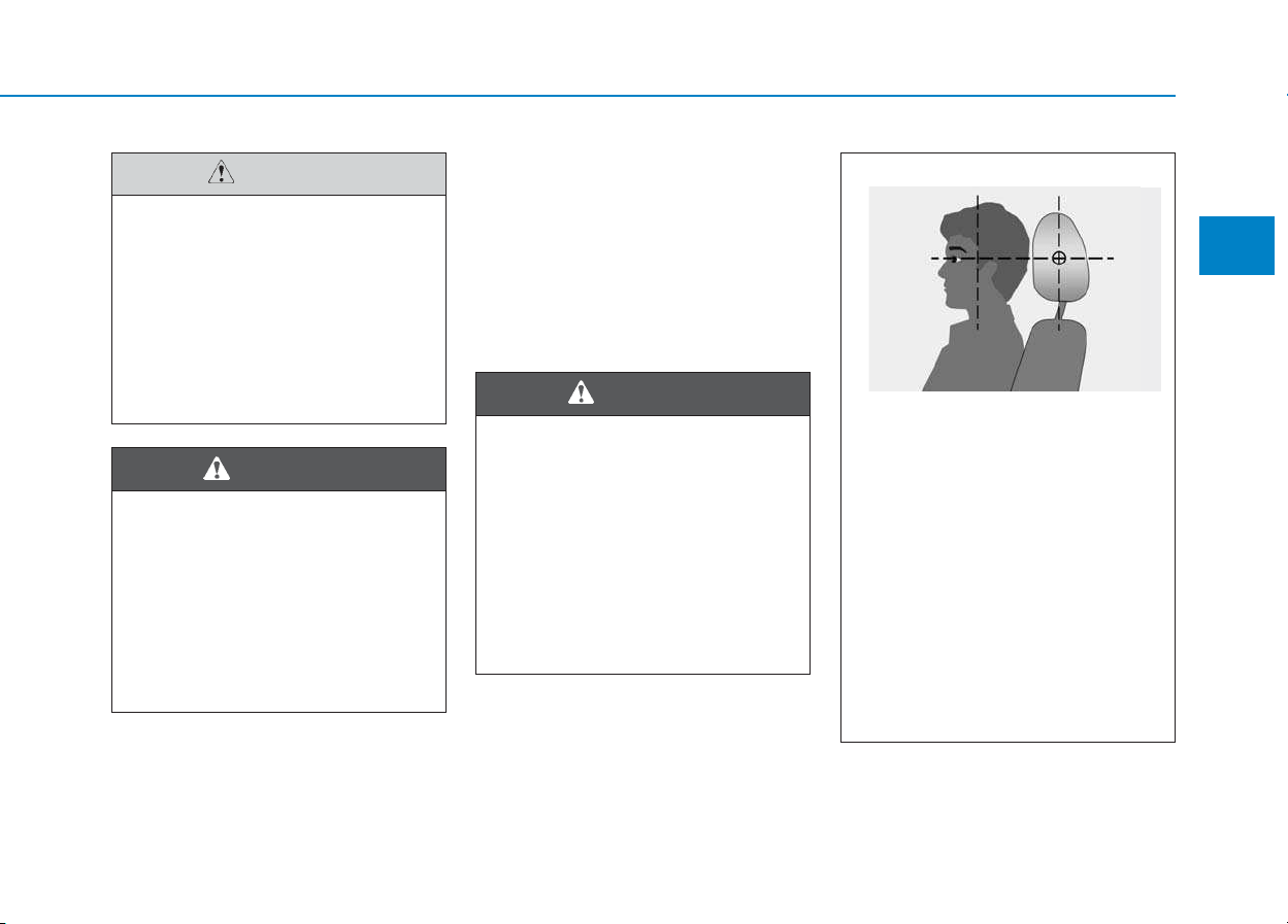
To reduce the risk of serious
injury or death in an accident,
take the following precautions
when adjusting your headrests:
• Always properly adjust the
headrests for all passengers
BEFORE starting the vehicle.
• NEVER let anyone ride in a seat
with the headrest removed.
(Continued)
(Continued)
•
Adjust the headrests so the
middle of the headrests is at
the same height as the height
of the top of the eyes.
• NEVER adjust the headrest
position of the driver’s seat
when the vehicle is in motion.
• Adjust the headrest as close
to the passenger’s head as
possible. Do not use a seat
cushion that holds the body
away from the seatback.
• Make sure the headrest locks
into position after adjusting it.
WARNING
OLF034072N
Cargo should always be secured
to prevent it from being thrown
about the vehicle in a collision
and causing injury to the vehicle
occupants. Do not place objects
in the rear seats, since they can-
not be properly secured and may
hit the front seat occupants in a
collision.
WARNING
• Be careful when loading cargo
through the rear passenger
seats to prevent damage to
the vehicle interior.
• When cargo is loaded through
the rear passenger seats,
ensure the cargo is properly
secured to prevent it from
moving while driving.
CAUTION
2-16
Safety system of your vehicle
To prevent damage, NEVER hit or
pull on the headrests.
Front seat headrests
The driver’s and front passenger’s
seats are equipped with adjustable
headrests for the passengers safety
and comfort.
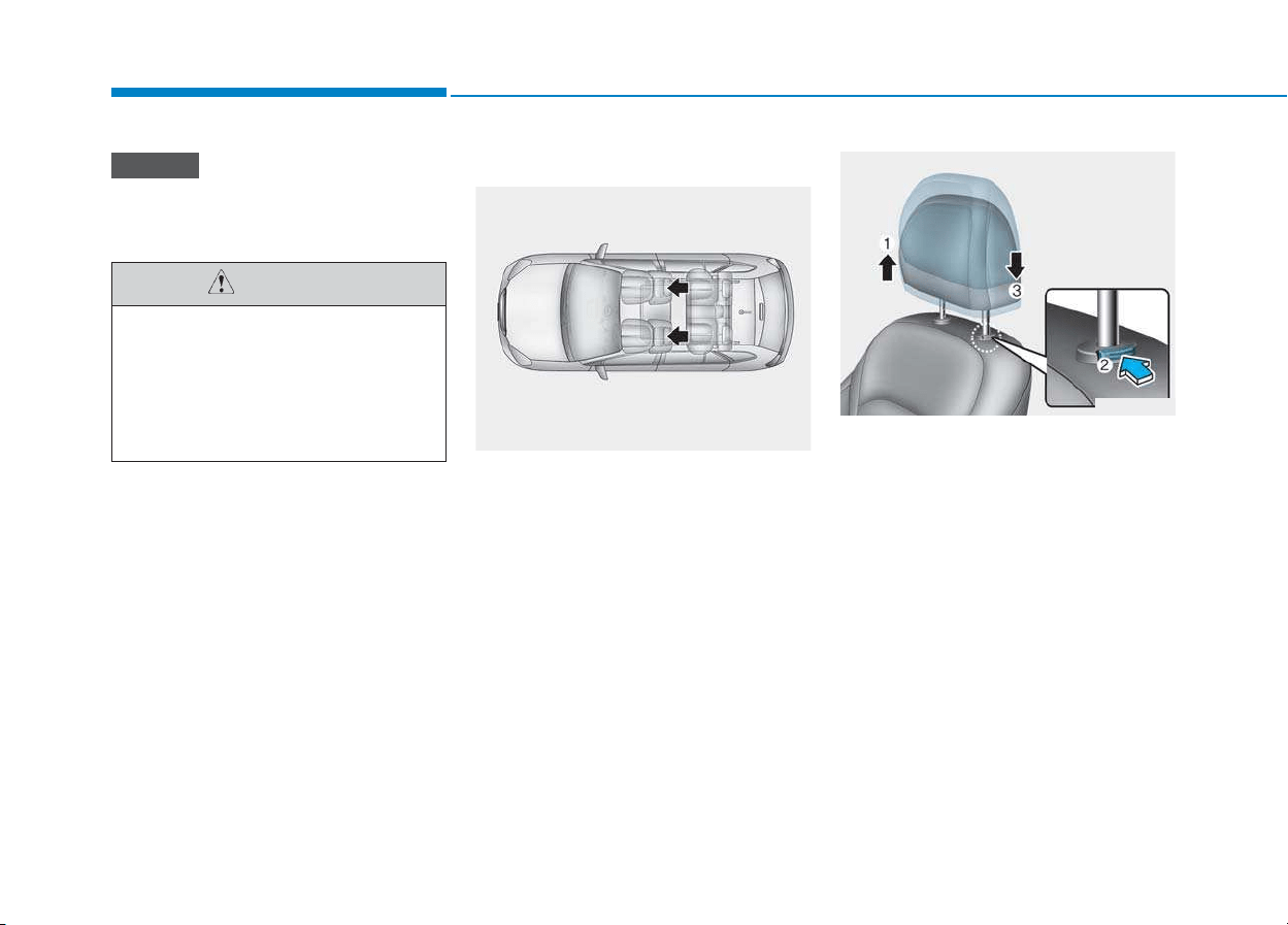
Adjusting the height up and down
To raise the headrest:
1. Pull it up to the desired position
(1).
To lower the headrest:
1. Push and hold the release button
(2) on the headrest support.
2. Lower the headrest to the desired
position (3).
NOTICE
OPDE036068
OPD036010
When there is no occupant in
the rear seats, adjust the height
of the headrest to the lowest
position. The rear seat headrest
can reduce the visibility of the
rear area.
CAUTION
2-17
Safety system of your vehicle
2
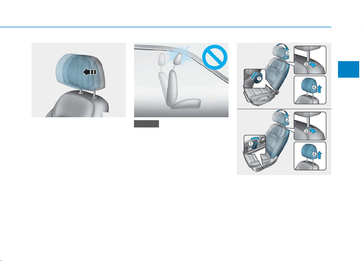
Forward and rearward adjustment
(if equipped)
The headrest may be adjusted for-
ward to 3 different positions by
pulling the headrest forward to the
desired detent. To adjust the head-
rest to it’s furthest rearwards posi-
tion, pull it fully forward to the farthest
position and release it.
If you recline the seatback towards
the front with the headrest and
seat cushion raised, the headrest
may come in contact with the sun-
visor or other parts of the vehicle.
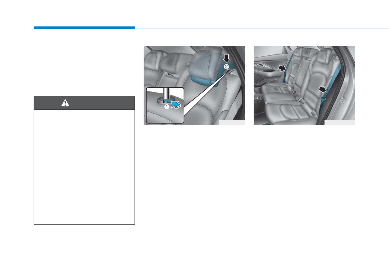
Removal/Reinstall
To remove the headrest:
1. Recline the seatback (2) with using
the seatback angle knob or switch
(1).
2. Raise headrest as far as it can go.
NOTICE
OPDE036011
OPD036013
■ Type A
■ Type B
OLF034015
OPD036009
2-18
Safety system of your vehicle
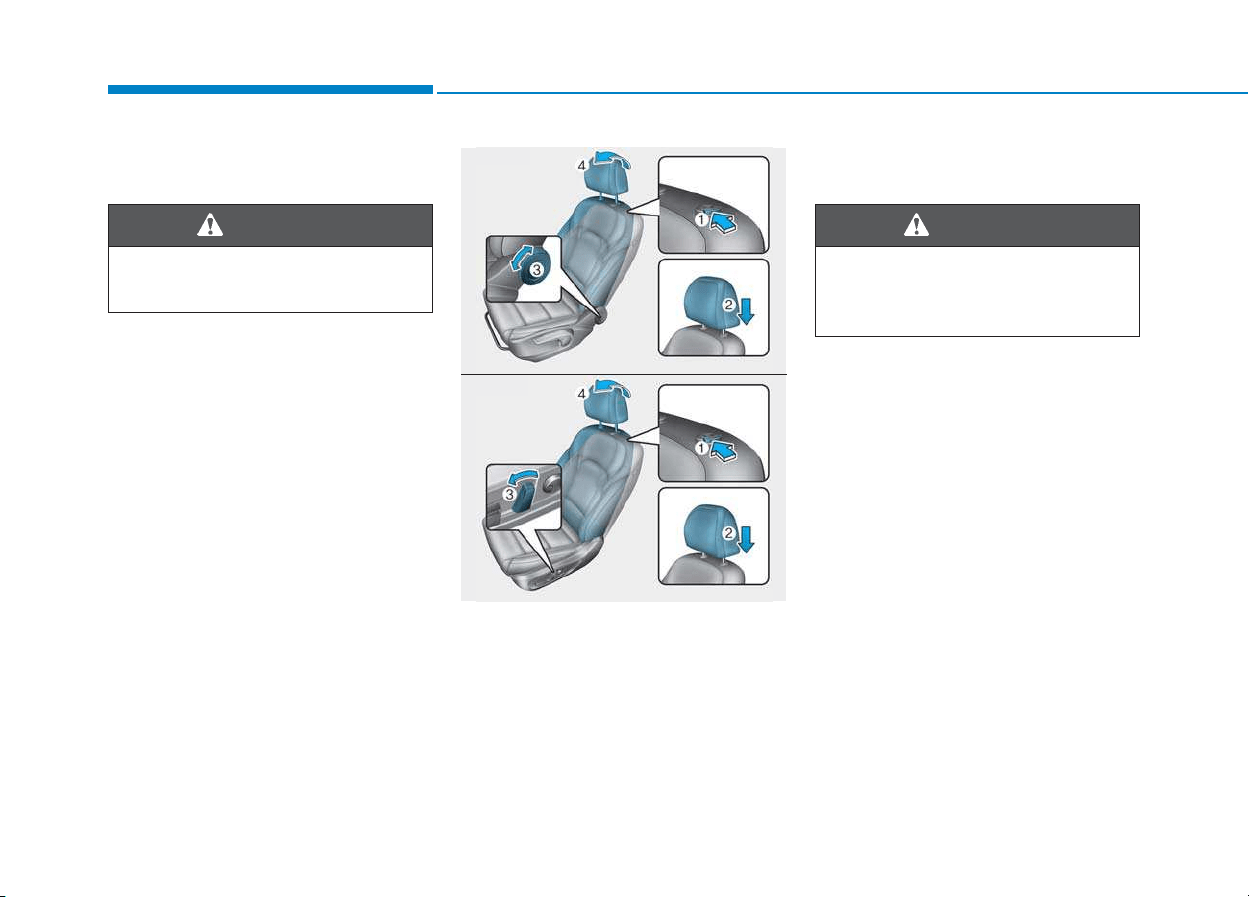
3. Press the headrest release button
(3) while pulling the headrest up (4).
To reinstall the headrest :
1. Recline the seatback.
2. Put the headrest poles (2) into the
holes while pressing the release
button (1).
3. Adjust the headrest to the appropri-
ate height.
4. Recline the seatback (4) with the
seatback angle knob or switch (3).
Always make sure the headrest
locks into position after rein-
stalling and adjusting it properly.
WARNING
OPDE036012
OPD036014
■ Type A
■ Type B
NEVER allow anyone to travel in a
seat with the headrest removed.
WARNING
2-19
Safety system of your vehicle
2
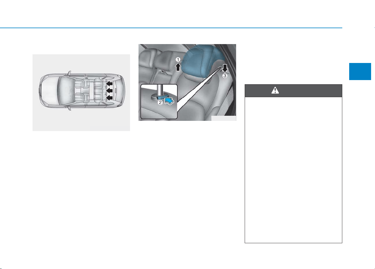
Rear seat headrests
The rear seats are equipped with
headrests in all the seating positions
for the passenger’s safety and com-
fort.
Adjusting the height up and down
To raise the headrest:
1. Pull it up to the desired position (1).
To lower the headrest:
1. Push and hold the release button
(2) on the headrest support.
2. Lower the headrest to the desired
position (3).
Seat warmers and air ventila-
tion seats
Front seat warmers (if equipped)
Seat warmers are provided to warm
the seats during cold weather.
The seat warmers can cause a
SERIOUS BURN, even at low
temperatures and especially if
used for long periods of time.
Passengers must be able to feel
if the seat is becoming too warm
so they can turn it off, if needed.
People who cannot detect tem-
perature change or pain to the
skin should use extreme cau-
tion, especially the following
types of passengers:
• Infants, children, elderly or
disabled persons, or hospital
outpatients.
• People with sensitive skin or
who burn easily.
• Fatigued individuals.
• Intoxicated individuals.
(Continued)
WARNING
OPD036017
OPDE036069
2-20
Safety system of your vehicle
To prevent damage to the seat
warmers and seats:
• Never use a solvent such as
paint thinner, benzene, alcohol
or gasoline to clean the seats.
• Do not place heavy or sharp
objects on seats equipped with
seat warmers.
• Do not change the seat cover. It
may damage the seat warmer.
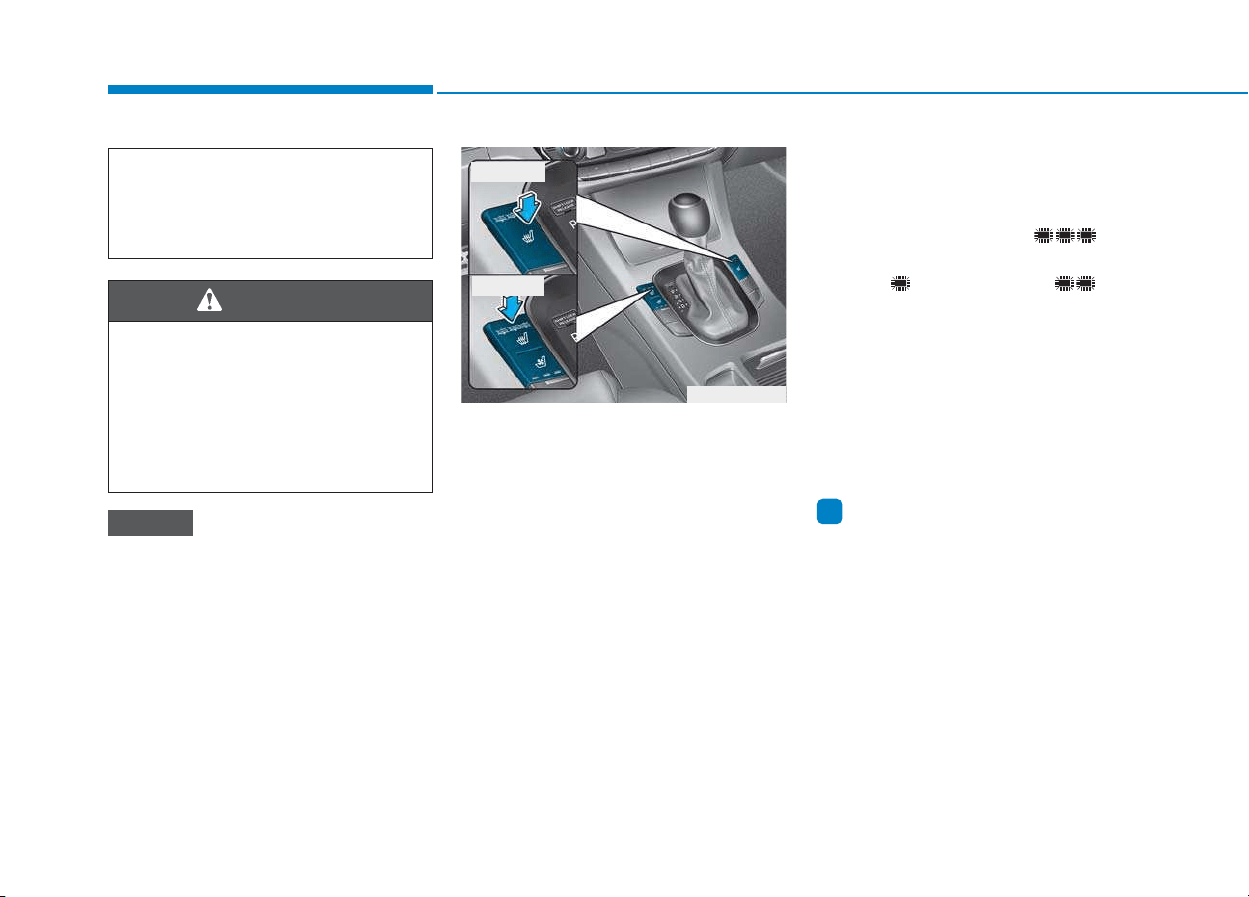
While the engine is running, push
either of the switches to warm the dri-
ver's seat or front passenger's seat.
During mild weather or under condi-
tions where the operation of the seat
warmer is not needed, keep the
switches in the OFF position.
• Each time you push the switch, the
temperature setting of the seat is
changed as follows :
• When pressing the switch for more
than 1.5 seconds with the seat
warmer operating, the seat warmer
will turn OFF.
• The seat warmer defaults to the
OFF position whenever the ignition
switch is placed to the ON position.
Information
With the seat warmer switch in the
ON position, the heating system in the
seat turns off or on automatically
depending on the seat temperature.
i
NOTICE
OPDE036015
■ Type A
■ Type B
OFF HIGH ( )
LOW ( ) MIDDLE ( )
→
→
→
→
(Continued)
• People taking medication that
can cause drowsiness or
sleepiness.
NEVER place anything on the
seat that insulates against heat
when the seat warmer is in oper-
ation, such as a blanket or seat
cushion. This may cause the
seat warmer to overheat, caus-
ing a burn or damage to the seat.
WARNING
2-21
Safety system of your vehicle
2
Front air ventilation seat
(if equipped)
The air ventilation seats are provided
to cool the front seats by blowing air
through small vent holes on the sur-
face of the seat cushions and seat-
backs.
When the operation of the air ventila-
tion seat is not needed, keep the
switches in the OFF position.
While the engine is running, push the
switch to cool the driver's seat or the
front passenger's seat (if equipped).
• Each time you push the switch, the
airflow changes as follows:
• When pressing the switch for more
than 1.5 seconds with the air venti-
lation seat operating, the operation
will turn OFF.
• The air ventilation seats defaults to
the OFF position whenever the
ignition switch is placed to the ON
position.
To prevent damage to the air ven-
tilation seat:
• Use the air ventilation seat ONLY
when the climate control system
is on. Using the air ventilation
seat for prolonged periods of
time with the climate control sys-
tem off could cause the air venti-
lation seat to malfunction.
(Continued)
(Continued)
• Never use a solvent such as paint
thinner, benzene, alcohol or gaso-
line to clean the seats.
• Avoid spilling liquids on the sur-
face of the front seats and seat-
backs; this may cause the air vent
holes to become blocked and not
work properly.
• Do not place materials such as
plastic bags or newspapers under
the seats. They may block the air
intake causing the air vents to not
work properly.
• Do not change the seat covers. It
may damage the air ventilation
seat.
• If the air vents do not operate,
restart the vehicle. If there is no
change, we recommend that you
have your vehicle inspected by
an authorized HYUNDAI dealer.
NOTICE
OFF HIGH ( )
LOW ( ) MIDDLE ( )
→
→
→
→
OPDE036016
2-22
Safety system of your vehicle
This section describes how to use the
seat belts properly. It also describes
some of the things not to do when
using seat belts.
Seat belt safety precautions
Always fasten your seat belt and
make sure all passengers have fas-
tened their seat belts before starting
any trip. Air bags are designed to
supplement the seat belt as an addi-
tional safety device, but they are not a
substitute. Most countries require all
occupants of a vehicle to wear seat
belts.
SSEEAATT BBEELLTTSS
Seat belts must be used by ALL
passengers whenever the vehi-
cle is moving. Take the following
precautions when adjusting and
wearing seat belts:
• Children under the age of 13
should be properly restrained
in the rear seats.
• Never allow children to ride in
the front passenger seat, unless
the air bag is deactivated. If a
child is seated in the front pas-
senger seat, move the seat as
far back as possible and prop-
erly restrain them in the seat.
• NEVER allow an infant or child
to be carried on an occupant’s
lap.
• NEVER ride with the seatback
reclined when the vehicle is
moving.
• Do not allow children to share
a seat or seat belt.
(Continued)
WARNING
(Continued)
• Do not wear the shoulder belt
under your arm or behind your
back.
• Never wear a seat belt over
fragile objects. If there is a sud-
den stop or impact, the seat
belt can damage it.
• Do not use the seat belt if it is
twisted. A twisted seat belt
will not protect you properly
in an accident.
• Do not use a seat belt if the
webbing or hardware is dam-
aged.
• Do not latch the seat belt into
the buckles of other seats.
• NEVER unfasten the seat belt
while driving. This may cause
loss of vehicle control result-
ing in an accident.
• Make sure there is nothing in
the buckle interfering with the
seat belt latch mechanism.
This may prevent the seat belt
from fastening securely.
(Continued)
2-23
Safety system of your vehicle
2
Seat belt warning light
Seat belt warning
Driver’s seat belt warning
As a reminder to the driver, the seat
belt warning light will illuminate for
approximately 6 seconds each time
you turn the ignition switch ON
regardless of belt fastening.
If the seat belt is not fastened when
the ignition switch is turned ON or if
it is disconnected after the ignition
switch is turned ON, the seat belt
warning light will illuminate until the
belt is fastened.
If you start to drive without the seat
belt fastened or you unfasten the
seat belt when you drive under
20km/h, the corresponding warning
light will continue to illuminate until
you fasten the seat belt.
If you continue to drive without the
seat belt fastened or you unfasten
the seat belt when you drive over
20km/h, the seat belt warning chime
will sound for approximately 100 sec-
onds and the corresponding warning
light will blink.
Damaged seat belts and seat
belt assemblies will not operate
properly. Always replace:
• Frayed, contaminated, or dam-
aged webbing.
• Damaged hardware.
• The entire seat belt assembly
after it has been worn in an
accident, even if damage to
webbing or assembly is not
apparent.
WARNING
(Continued)
• No modifications or additions
should be made by the user
which will either prevent the
seat belt adjusting devices
from operating to remove
slack, or prevent the seat belt
assembly from being adjusted
to remove slack.
OAM032161L
■ Instrument cluster
2-24
Safety system of your vehicle
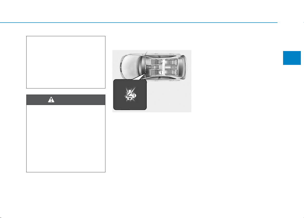
Front passenger’s seat belt warning
As a reminder to the front passenger,
the front passenger’s seat belt warn-
ing lights will illuminate for approxi-
mately 6 seconds each time you turn
the ignition switch ON regardless of
belt fastening.
If the seat belt is not fastened when
the ignition switch is turned ON or if
it is disconnected after the ignition
switch is turned ON, the seat belt
warning light will illuminate until the
belt is fastened.
If you start to drive without the seat
belt fastened or you unfasten the
seat belt when you drive under
20km/h, the corresponding warning
light will continue to illuminate until
you fasten the seat belt.
If you continue to drive without the
seat belt fastened or you unfasten
the seat belt when you drive over
20km/h, the seat belt warning chime
will sound for approximately 100 sec-
onds and the corresponding warning
light will blink.
Information
• You can find the front passenger’s
seat belt warning light on the center
fascia panel.
• Although the front passenger seat is
not occupied, the seat belt warning
light will blink or illuminate for 6
seconds.
• The front passenger's seat belt
warning may operate when luggage
is placed on the front passenger seat.
i
Riding in an improper position
adversely affects the front pas-
senger's seat belt warning sys-
tem. It is important for the driver
to instruct the passenger to
properly be seated as instructed
in this manual.
WARNING
OTLE035082

2-25
Safety system of your vehicle
2
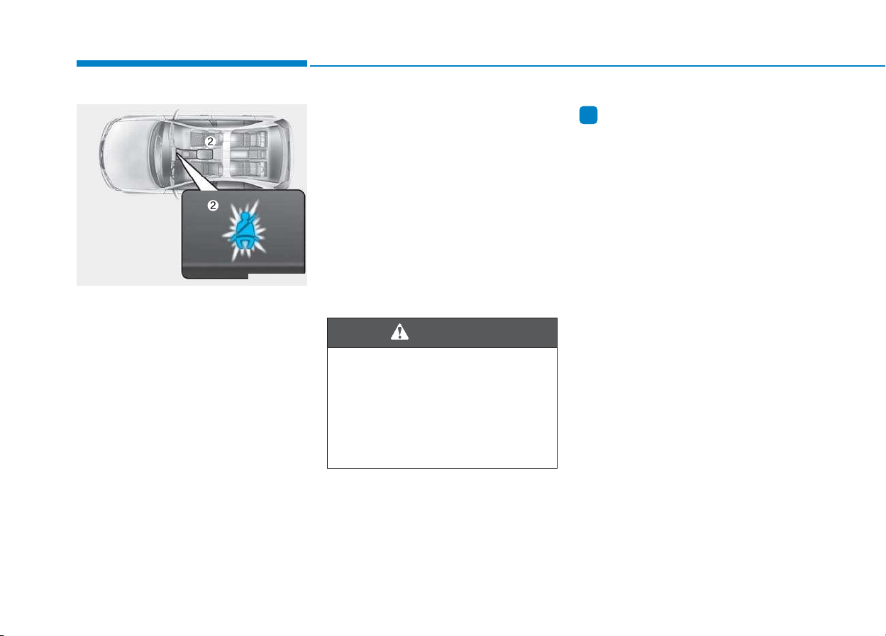
Rear passenger’s seat belt warning
As a reminder to the rear passen-
gers, the rear passenger’s seat belt
warning lights will illuminate for
approximately 6 seconds each time
you turn the ignition switch ON
regardless of belt fastening.
And then, the rear corresponding
seat belt warning light will illuminate
for approximately 35 seconds, if any
of the following occurs:
- You drive over 9km/h when the rear
seat belt is not fastened.
- The rear seat belt is disconnected
when driving under 20km/h.
If the rear seat belt is fastened, the
warning light will turn off immediately.
If the rear seat belt is disconnected
when you drive over the 20km/h, the
corresponding seat belt warning light
will blink and warning chime will
sound for 35 seconds.
But, if the rear passenger's lap/shoul-
der belt is/are connected and discon-
nected twice within 9 seconds after
the belt is fastened, the corresponding
seat belt warning light will not operate.
Seat belt restraint system
Lap/shoulder belt
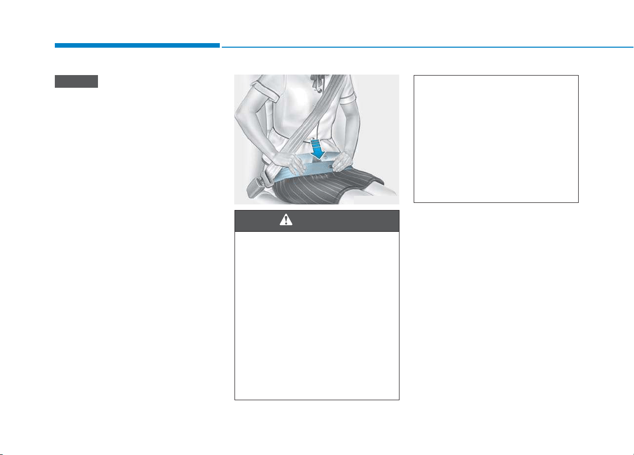
To fasten your seat belt:
Pull it out of the retractor and insert
the metal tab (1) into the buckle (2).
There will be an audible "click" when
the tab locks into the buckle.
The seat belt automatically adjusts to
the proper length after the lap belt
portion is adjusted manually so that it
fits snugly around your hips. If you
lean forward in a slow, easy motion,
the belt will extend and move with
you. If there is a sudden stop or
impact, the belt will lock into position.
It will also lock if you try to lean for-
ward too quickly.
OPD036024
ODH033055
2-26
Safety system of your vehicle
If you are not able to smoothly pull
enough of the seat belt out from
the retractor, firmly pull the seat
belt out and release it. After
release, you will be able to pull the
belt out smoothly.
Height adjustment
You can adjust the height of the
shoulder belt anchor to one of the
four different positions for maximum
comfort and safety.
The shoulder portion should be
adjusted so it lies across your chest
and midway over your shoulder near-
est the door, not over your neck.
NOTICE
ODH033056
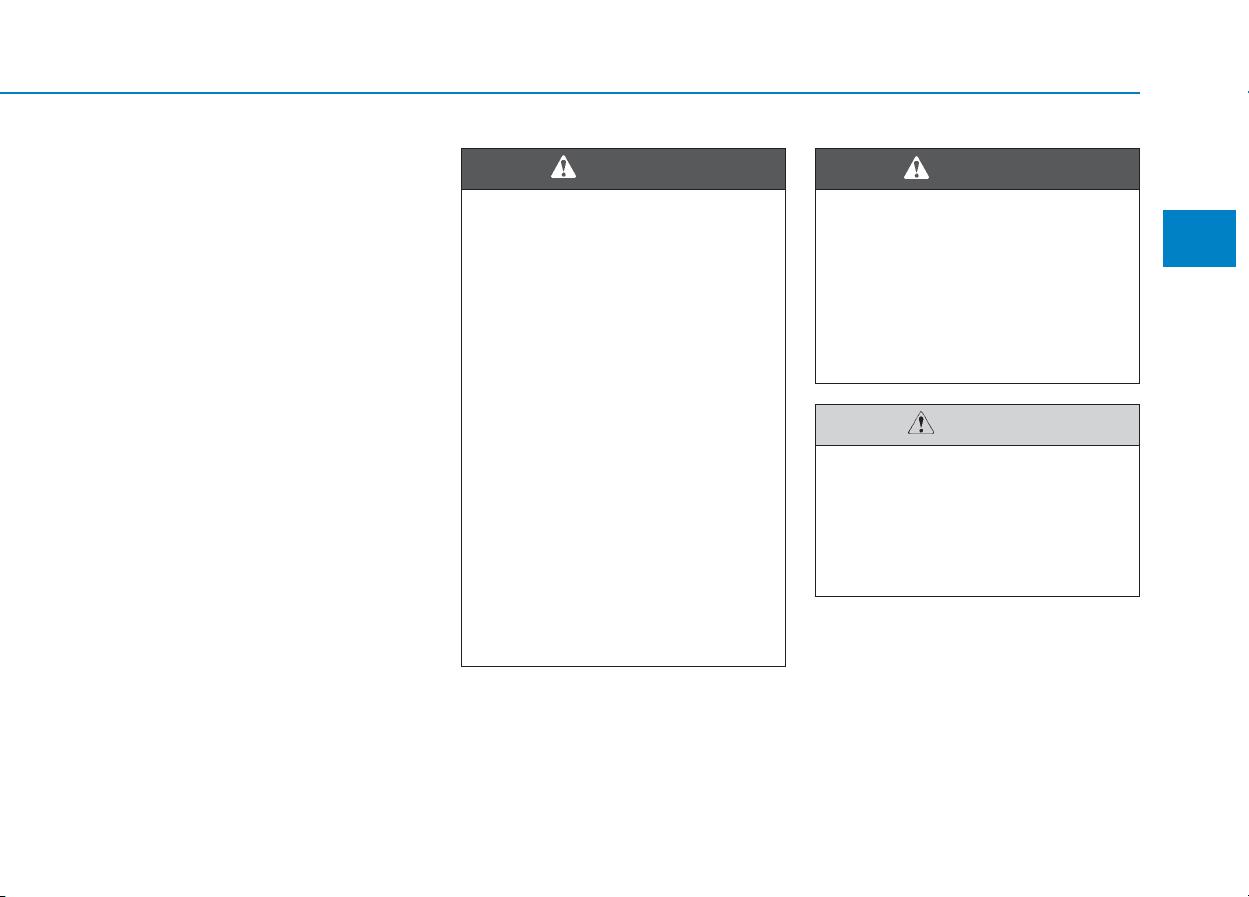
Improperly positioned seat belts
may increase the risk of serious
injury in an accident. Take the fol-
lowing precautions when adjust-
ing the seat belt:
• Position the lap portion of the
seat belt as low as possible
across your hips, not on your
waist, so that it fits snugly. This
allows your strong pelvic bones
to absorb the force of the crash,
reducing the chance of internal
injuries.
(Continued)
WARNING
(Continued)
• Position one arm under the
shoulder belt and the other over
the belt, as shown in the illus-
tration.
• Always position the shoulder
belt anchor into locked posi-
tion at the appropriate height.
• Never position the shoulder
belt across your neck or face.
2-27
Safety system of your vehicle
2
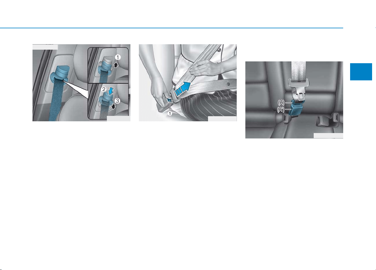
To adjust the height of the seat belt
anchor, lower or raise the height
adjuster into an appropriate position.
To raise the height adjuster, pull it up
(1). To lower it, push it down (3) while
pressing the height adjuster button (2).
Release the button to lock the anchor
into position. Try sliding the height
adjuster to make sure that it has
locked into position.
To release your seat belt:
Press the release button (1) in the
locking buckle.
When it is released, the belt should
automatically draw back into the
retractor. If this does not happen,
check the belt to be sure it is not twist-
ed, then try again.
Rear center seatbelt
(3-point rear center seat belt)
1.Insert the tongue plate (A) into the
buckle (A’) until an audible “click" is
heard, indicating the latch is
locked. Make sure the belt is not
twisted.
OPD036025
■ Front seat
ODH033057
OPDE036070
2-28
Safety system of your vehicle
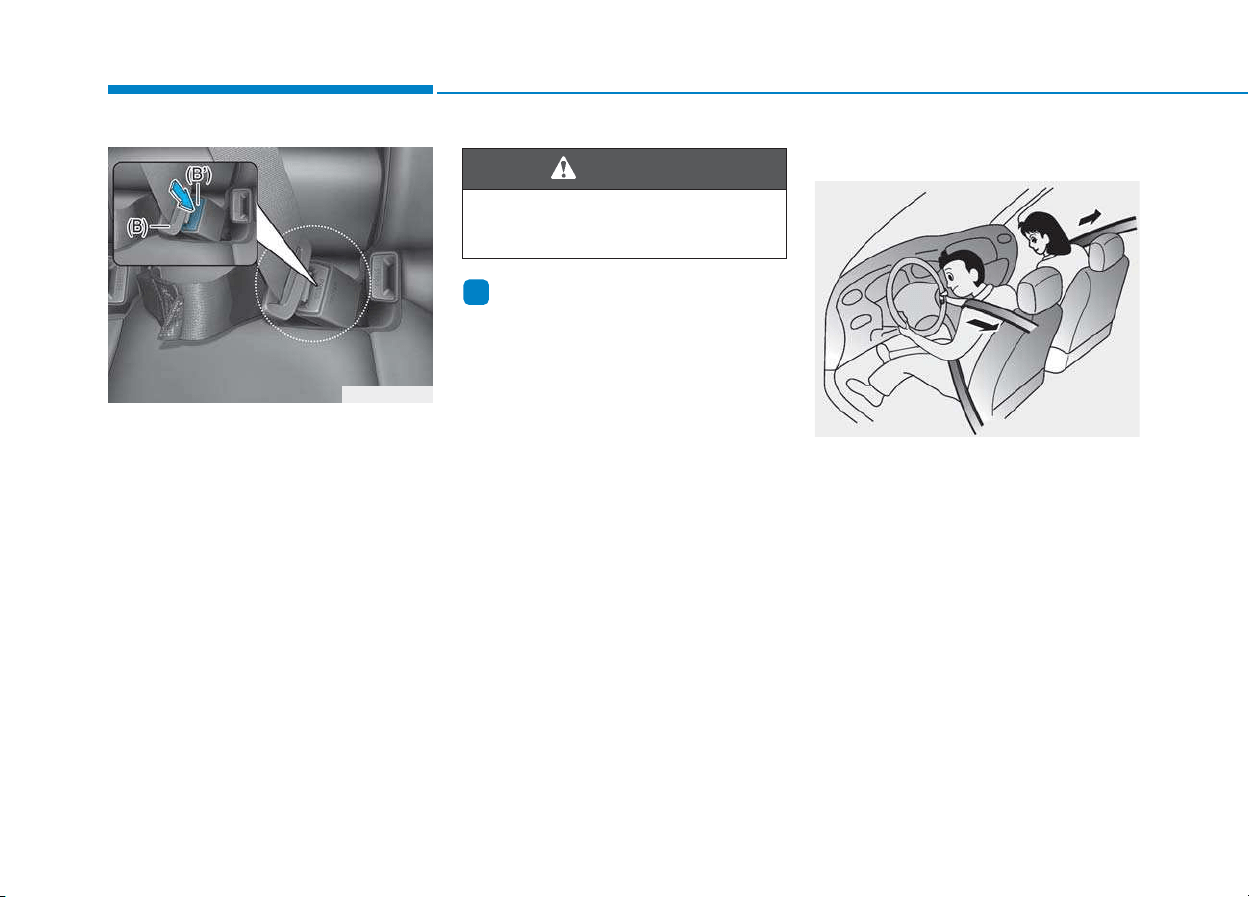
2. Pull the tongue plate (B) and
insert it into the buckle (B’) until an
audible “click” is heard, indicating
the latch is locked. Make sure the
belt is not twisted.
When using the rear center seat belt,
the buckle with the “CENTER” mark
must be used.
Information
If you are not able to pull out the safe-
ty belt from the retractor, firmly pull
the belt out and release it. After
release, you will be able to pull the belt
out smoothly.
Pre-tensioner seat belt
Your vehicle is equipped with driver's
and front passenger's and rear pas-
sengers (if equipped) Pre-tensioner
Seat Belts (Retractor Pretensioner).
The purpose of the pre-tensioner is to
make sure the seat belts fit tightly
against the occupant's body in cer-
tain frontal or side collision(s). The
pre-tensioner seat belts may be acti-
vated in crashes where the frontal or
side collision(s) is severe enough,
together with the air bags.
i
OLMB033039
OPDE036071
Always have the metal tab (A)
inserted into the buckle (A').
WARNING
2-29
Safety system of your vehicle
2
When the vehicle stops suddenly, or
if the occupant tries to lean forward
too quickly, the seat belt retractor will
lock into position. In certain frontal
collisions, the pre-tensioner will acti-
vate and pull the seat belt into tighter
contact against the occupant's body.
If the system senses excessive tension
on the driver or passenger's seat belt
when the pre-tensioner system acti-
vates, the load limiter inside the retrac-
tor pre-tensioner will release some of
the pressure on the affected seat belt.
Do not touch the pre-tensioner
seat belt assemblies for several
minutes after they have been
activated. When the pre-ten-
sioner seat belt mechanism
deploys during a collision, the
pre-tensioner can become hot
and can burn you.
WARNING
Body work on the front area of
the vehicle may damage the
pre-tensioner seat belt system.
Therefore, we recommend the
system to be serviced by an
authorized HYUNDAI dealer.
CAUTION
• Always wear your seat belt and
sit properly in your seat.
• Do not use the seat belt if it is
loose or twisted. A loose or
twisted seat belt will not pro-
tect you properly in an acci-
dent.
• Do not place anything near the
buckle. This may adversely
affect the buckle and cause it
to function improperly.
• Always replace your pre-ten-
sioners after activation or an
accident.
• NEVER inspect, service, repair
or replace the pre-tensioners
yourself. This must be done by
an authorized HYUNDAI dealer.
• Do not hit the seat belt assem-
blies.
WARNING
2-30
Safety system of your vehicle
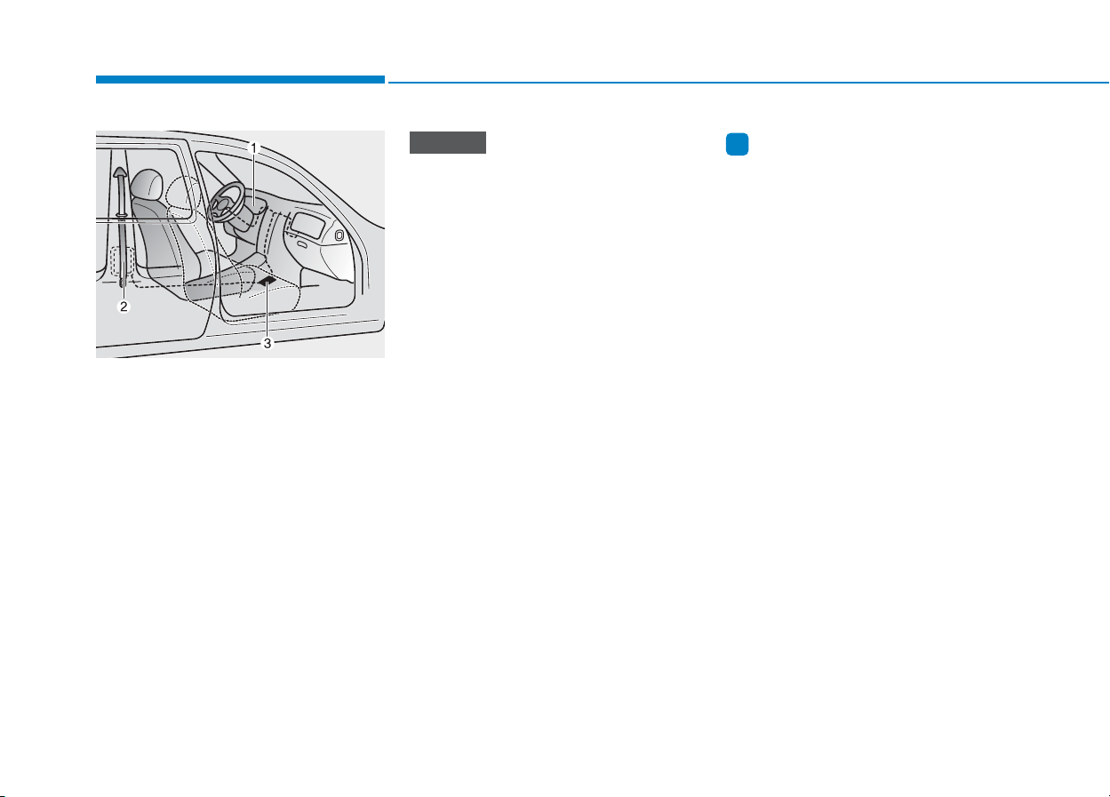
The Pre-Tensioner Seat Belt System
consists mainly of the following com-
ponents. Their locations are shown in
the illustration above:
(1) SRS air bag warning light
(2) Retractor pre-tensioner
(3) SRS control module
The sensor that activates the SRS
control module is connected with
the pre–tensioner seat belts. The
SRS air bag warning light on the
instrument cluster will illuminate
for approximately 6 seconds after
the ignition switch is placed to the
ON position, and then it should
turn off.
If the pre-tensioner is not working
properly, the warning light will illu-
minate even if the SRS air bag is not
malfunctioning. If the warning light
does not illuminate, stays illuminat-
ed or illuminates when the vehicle
is being driven, we recommend the
pre-tensioner seat belts and/or SRS
control module be inspected by an
authorized HYUNDAI dealer as
soon as possible.
Information
• Both the driver's and front passen-
ger's pre-tensioner seat belts may be
activated in certain frontal or side
collisions.
• The pre-tensioners will be activated
even if the seat belts are not worn at
the time of the collision.
• When the pre-tensioner seat belts
are activated, a loud noise may be
heard and fine dust, which may
appear to be smoke, may be visible
in the passenger compartment.
These are normal operating condi-
tions and are not hazardous.
• Although it is non-toxic, the fine dust
may cause skin irritation and should
not be breathed for prolonged peri-
ods. Wash all exposed skin areas
thoroughly after an accident in which
the pre-tensioner seat belts were acti-
vated.
i
NOTICE
OLMB033040/Q

2-31
Safety system of your vehicle
2
Additional seat belt safety pre-
cautions
Seat belt use during pregnancy
The seat belt should always be used
during pregnancy. The best way to
protect your unborn child is to protect
yourself by always wearing the seat
belt.
Pregnant women should always wear
a lap-shoulder seat belt. Place the
shoulder belt across your chest, rout-
ed between your breasts and away
from your neck. Place the lap belt
below your belly so that it fits SNUGLY
across your hips and pelvic bone,
under the rounded part of the belly.
Seat belt use and children
Infant and small children
Most countries have Child Restraint
System laws which require children to
travel in approved Child Restraint
System devices, including booster
seats. The age at which seat belts can
be used instead of Child Restraint
System differs among countries, so
you should be aware of the specific
requirements in your country, and
where you are travelling. Infant and
Child Restraint System must be prop-
erly placed and installed in a rear seat.
For more information refer to the “Child
Restraint Systems” in this chapter.
ALWAYS properly restrain
infants and small children in a
Child Restraint System appropri-
ate for the child’s height and
weight.
To reduce the risk of serious
injury or death to a child and
other passengers, NEVER hold a
child in your lap or arms when
the vehicle is moving. The violent
forces created during an acci-
dent will tear the child from your
arms and throw the child against
the interior of the vehicle.
WARNING
To reduce the risk of serious
injury or death to an unborn
child during an accident, preg-
nant women should NEVER
place the lap portion of the seat
belt above or over the area of
the abdomen where the unborn
child is located.
WARNING

2-32
Safety system of your vehicle
Small children are best protected
from injury in an accident when prop-
erly restrained in the rear seat by a
Child Restraint System that meets
the requirements of the Safety
Standards of your country. Before
buying any Child Restraint System,
make sure that it has a label certify-
ing that it meets Safety Standard of
your country. The Child Restraint
System must be appropriate for your
child's height and weight. Check the
label on the Child Restraint System
for this information. Refer to “Child
Restraint Systems” in this chapter.
Larger children
Children under age 13 and who are
too large for a booster seat should
always occupy the rear seat and use
the available lap/shoulder belts. A
seat belt should lie across the upper
thighs and be snug across the shoul-
der and chest to restrain the child
safely. Check belt fit periodically. A
child's squirming could put the belt
out of position. In the event of an acci-
dent, children are afforded the best
safety restrained by a proper Child
Restraint System in the rear seats.
If a larger child over age 13 must be
seated in the front seat, the child
must be securely restrained by the
available lap/shoulder belt and the
seat should be placed in the rear-
most position.
If the shoulder belt portion slightly
touches the child’s neck or face, try
placing the child closer to the center
of the vehicle. If the shoulder belt still
touches their face or neck, they need
to be returned to an appropriate
booster seat in the rear seat.
• Always make sure larger chil-
dren’s seat belts are worn and
properly adjusted.
• NEVER allow the shoulder
belt to contact the child’s
neck or face.
• Do not allow more than one
child to use a single seat belt.
WARNING

2-33
Safety system of your vehicle
2
Seat belt use and injured people
A seat belt should be used when an
injured person is being transported.
Consult a physician for specific rec-
ommendations.
One person per belt
Two people (including children) should
never attempt to use a single seat belt.
This could increase the severity of
injuries in case of an accident.
Do not lie down
Sitting in a reclined position when
the vehicle is in motion can be dan-
gerous. Even when buckled up, the
protections of your restraint system
(seat belts and/or air bags) is greatly
reduced by reclining your seatback.
Seat belts must be snug against your
hips and chest to work properly.
During an accident, you could be
thrown into the seat belt, causing
neck or other injuries.
The more the seat back is reclined,
the greater the chance for the pas-
senger's hips to slide under the lap
belt or the passenger's neck to strike
the shoulder belt.
Care of seat belts
Seat belt systems should never be
disassembled or modified. In addi-
tion, care should be taken to assure
that seat belts and belt hardware are
not damaged by seat hinges, doors
or other abuse.
Periodic inspection
All seat belts should be inspected
periodically for wear or damage of
any kind. Any damaged parts should
be replaced as soon as possible.
Keep belts clean and dry
Seat belts should be kept clean and
dry. If belts become dirty, they can be
cleaned by using a mild soap solution
and warm water. Bleach, dye, strong
detergents or abrasives should not be
used because they may damage and
weaken the fabric.
• NEVER ride with a reclined
seatback when the vehicle is
moving.
• Riding with a reclined seatback
increases your chance of seri-
ous or fatal injuries in the event
of a collision or sudden stop.
• Driver and passengers should
always sit well back in their
seats, properly belted, and with
the seatbacks upright.
WARNING
2-34
When to replace seat belts
The entire seat belt assembly or
assemblies should be replaced if the
vehicle has been involved in an acci-
dent. This should be done even if no
damage is visible. We recommend that
you consult an authorized HYUNDAI
dealer.
Our recommendation:
Children always in the rear
Children under age 13 should always
ride in the rear seats and must
always be properly restrained to min-
imize the risk of injury in an accident,
sudden stop or sudden maneuver.
According to accident statistics, chil-
dren are safer when properly
restrained in the rear seats than in
the front seat. Children too large for a
Child Restraint System must use the
seat belts provided.
Most countries have regulations
which require children to travel in
approved Child Restraint Systems.
The laws governing the age or
height/weight restrictions at which
seat belts can be used instead of
Child Restraint System differs
among countries, so you should be
aware of the specific requirements in
your country, and where you are trav-
elling.
Child Restraint Systems must be
properly installed in the vehicle seat.
Always use a commercially available
Child Restraint System that meets
the requirements of your country.
Safety system of your vehicle
C
CHHIILLDD RREESSTTRRAAIINNTT SSYYSSTTEEMM
(
(CCRRSS))
Always properly restrain children
in the vehicle. Children of all ages
are safer when riding in the rear
seats. Never place a rearward-
facing Child Restraint System on
the front passenger seat, unless
the air bag is deactivated.
WARNING

2-35
Safety system of your vehicle
2
Child Restraint System (CRS)
Infants and younger children must be
restrained in an appropriate rear-
ward-facing or forward-facing CRS
that has first been properly secured
to the seat of the vehicle. Read and
comply with the instructions for
installation and use provided by the
manufacturer of the Child Restraint
System.
Selecting a Child Restraint
System (CRS)
When selecting a Child Restraint
System for your child, always:
• Make sure the Child Restraint
System has a label certifying that it
meets applicable Safety Standards
of your country.
A Child Restraint System may only
be installed if it was approved in
accordance with the requirements of
ECE-R44 or ECE-R129.
• Select a Child Restraint System
based on your child’s height and
weight. The required label or the
instructions for use typically pro-
vide this information.
• Select a Child Restraint System
that fits the vehicle seating position
where it will be used.
• Read and comply with the warn-
ings and instructions for installation
and use provided with the Child
Restraint System.
Child Restraint System types
There are three main types of Child
Restraint Systems: rearward-facing,
forward-facing and booster Child
Restraint Systems.
They are classified according to the
child’s age, height and weight.
•
Always follow the Child Restraint
System manufacturer’s instruc-
tions for installation and use.
• Always properly restrain your
child in the Child Restraint
System.
• Do not use an infant carrier or
a child safety seat that “hooks”
over a seatback, it may not pro-
vide adequate protection in an
accident.
• After an accident, we recom-
mend a HYUNDAI dealer to
check the Child Restraint
System, seat belts, ISOFIX
anchorages and top-tether
anchorages.
WARNING
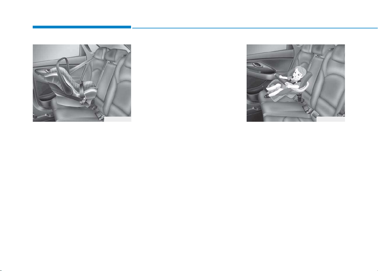
2-36
Safety system of your vehicle
Rearward-facing Child Restraint
System
A rearward-facing Child Restraint
System provides restraint with the
seating surface against the back of
the child. The harness system holds
the child in place, and in an accident,
acts to keep the child positioned in
the Child Restraint Systems and
reduce the stress to the fragile neck
and spinal cord.
All children under the age of one year
must always ride in a rearward-facing
Child Restraint System. There are dif-
ferent types of rearward-facing Child
Restraint Systems: infant-only Child
Restraint Systems can only be used
rearward-facing. Convertible and 3-in-
1 Child Restraint Systems typically
have higher height and weight limits
for the rearward-facing position, allow-
ing you to keep your child rearward-
facing for a longer period of time.
Keep using Child Restraint Systems
in the rearward-facing position as long
as children fit within the height and
weight limits allowed by the Child
Restraint System's manufacturer.
Forward-facing Child Restraint
System
A forward-facing Child Restraint System
provides restraint for the child’s body
with a harness. Keep children in a for-
ward-facing Child Restraint System
with a harness until they reach the
top height or weight limit allowed by
your Child Restraint System’s manu-
facturer.
Once your child outgrows the forward-
facing Child Restraint System, your
child is ready for a booster seat.
OPDE036028OPDE036027
2-37
Safety system of your vehicle
2
Booster seats
A booster seat is a Child Restraint
System designed to improve the fit of
the vehicle’s seat belt system. A boost-
er seat positions the seat belt so that it
fits properly over the stronger parts of
your child’s body. Keep your children in
booster seats until they are big
enough to fit in a seat belt properly.
For a seat belt to fit properly, the lap
belt must lie comfortable across the
upper thighs, not the stomach. The
shoulder belt should lie comfortable
across the shoulder and chest and
not across the neck or face. Children
under age 13 must always be proper-
ly restrained to minimize the risk of
injury in an accident, sudden stop or
sudden maneuver.
Installing a Child Restraint
System (CRS)
After selecting a proper Child Restraint
System for your child and checking
that the Child Restraint System fits
properly on the seating position, there
are three general steps for a proper
installation:
• Properly secure the Child Restraint
System to the vehicle.
All Child
Restraint Systems must be secured
to the vehicle with the lap belt or lap
part of a lap/shoulder belt or with
the ISOFIX top-tether and/or ISOFIX
anchorage and/or with the support
leg.
• Make sure the Child Restraint
System is firmly secured. After
installing a Child Restraint System
to the vehicle, push and pull the
seat forward and from side-to-side
to verify that it is securely attached
to the seat. A Child Restraint
System secured with a seat belt
should be installed as firmly as
possible. However, some side-to-
side movement can be expected.
Before installing your Child
Restraint System always:
Read and follow the instructions
provided by the manufacturer of
the Child Restraint System.
Failure to follow all warnings
and instructions could increase
the risk of the SERIOUS INJURY
or DEATH if an accident occurs.
WARNING
If the vehicle headrest prevents
proper installation of a Child
Restraint System, the headrest
of the respective seating posi-
tion shall be readjusted or
entirely removed.
WARNING
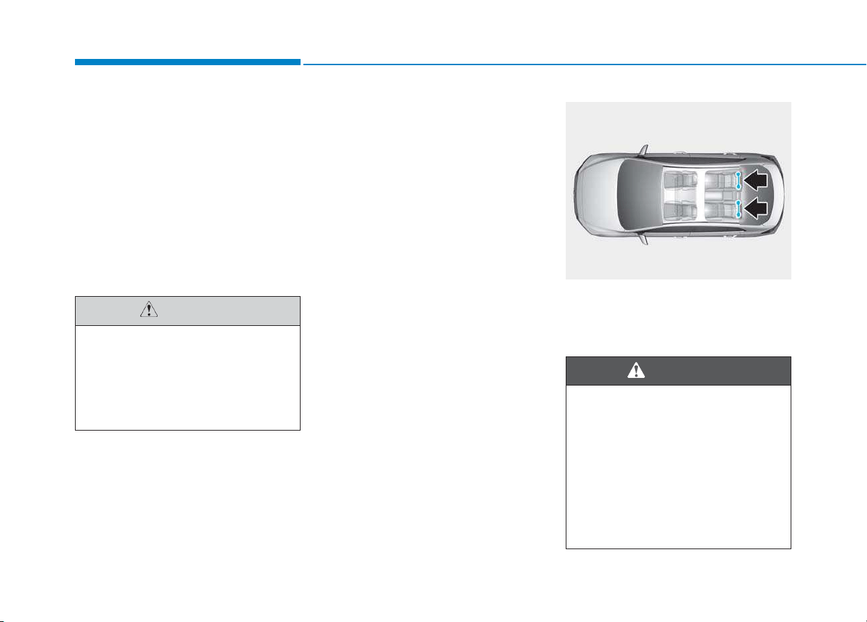
2-38
Safety system of your vehicle
When installing a Child Restraint
System, adjust the vehicle seat and
seatback (up and down, forward and
rearward) so that your child fits in
the Child Restraint System in a con-
fortable manner.
• Secure the child in the Child
Restraint System. Make sure the
child is properly strapped in the
Child Restraint System according
to the Child Restraint System man-
ufacturer’s instructions.
ISOFIX anchorage and top-teth-
er anchorage (ISOFIX anchorage
system) for children
The ISOFIX system holds a Child
Restraint System during driving and in
an accident.This system is designed to
make installation of the Child Restraint
System easier and reduce the possi-
bility of improperly installing your
Child Restraint System. The ISOFIX
system uses anchors in the vehicle
and attachments on the Child
Restraint System. The ISOFIX sys-
tem eliminates the need to use seat
belts to secure the Child Restraint
System to the rear seats.
ISOFIX anchorages are metal bars
built into the vehicle. There are two
lower anchors for each ISOFIX seat-
ing position that will accommodate a
Child Restraint System with lower
attachments.
To use the ISOFIX system in your vehi-
cle, you must have a Child Restraint
System with ISOFIX attachments.
The Child Restraint System manu-
facturer will provide you with instruc-
tions on how to use the Child
Restraint System with its attach-
ments for the ISOFIX anchorages.
ISOFIX anchorages have been pro-
vided in the left and right outboard
rear seating positions. Their locations
are shown in the illustration.
A Child Restraint System in a
closed vehicle can become very
hot. To prevent burns, check the
seating surface and buckles
before placing your child in the
Child Restraint System.
CAUTION
OAE036063
Do not attempt to install a Child
Restraint System using ISOFIX
anchorages in the rear center
seating position. There are no
ISOFIX anchorages provided for
this seat. Using the outboard seat
anchorages, for the CRS installa-
tion on the rear center seating
position, can damage the anchor-
ages.
WARNING
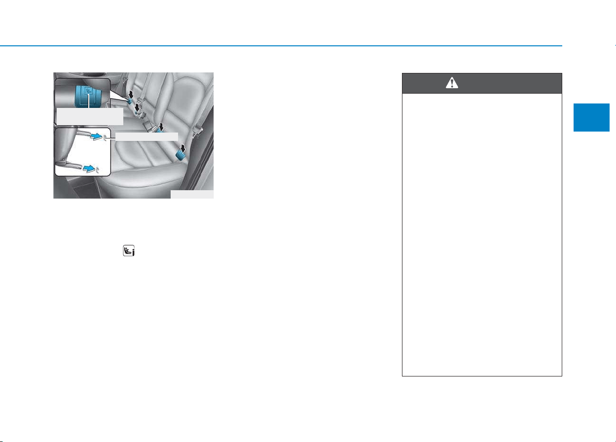
2-39
Safety system of your vehicle
2
ISOFIX anchorages are located
between the seatback and the seat
cushion of the rear seat left and right
outboard seating positions, indicated
by the symbols .
To use the ISOFIX anchorages, push
the upper portion of the ISOFIX
anchorage cover.
Securing a Child Restraint
System with the “ISOFIX
Anchorage System”
To install an i-Size or ISOFIX-compat-
ible Child Restraint System in either of
the rear outboard seating positions:
1. Move the seat belt buckle away
from the ISOFIX anchorages.
2. Move any other objects away from
the anchorages that could prevent
a secure connection between the
Child Restraint System and the
ISOFIX anchorages.
3. Place the Child Restraint System
on the vehicle seat, then attach the
seat to the ISOFIX anchorages
according to the instructions provid-
ed by the Child Restraint System
manufacturer.
4. Follow the instructions of the Child
Restraint System's manufacturer
for proper installation and connec-
tion of the ISOFIX attachments on
the Child Restraint System to the
ISOFIX anchorages.
OPDE036031
ISOFIX Anchorage
Position Indicator
ISOFIX Anchorage
Take the following precautions
when using the ISOFIX system:
• Read and follow all installation
instructions provided with
your Child Restraint System.
• To prevent the child from reach-
ing and taking hold of unre-
tracted seat belts, buckle all
unused rear seat belts and
retract the seat belt webbing
behind the child. Children can
be strangled if a shoulder belt
becomes wrapped around their
neck and the seat belt tightens.
• NEVER attach more than one
Child Restraint System to a
single anchorage. This could
cause the anchor or attach-
ment to come loose or break.
• Always have the ISOFIX sys-
tem inspected by your dealer
after an accident. An accident
can damage the ISOFIX system
and may not properly secure
the Child Restraint System.
WARNING
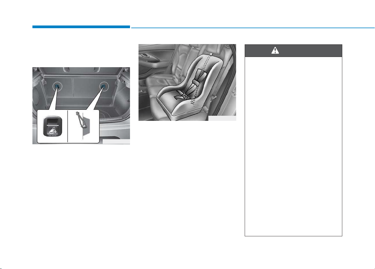
2-40
Safety system of your vehicle
Securing a Child Restraint
System seat with “Top-tether
Anchorage” system
Top-tether anchorages for Child
Restraint Systems are located on the
rear of the seatbacks.
1. Route the Child Restraint System
top-tether strap over the seatback.
Placing the top tether strap, please
follow the instructions of the Child
Restraint System manufacturer.
2. Connect the top-tether strap to the
top-tether anchorage, then tighten
the top-tether strap according to the
instructions of your Child Restraint
System's manufacturer to firmly
attach the Child Restraint System to
the seat.
OPDE036029
OPDE036030
Take the following precautions
when installing the top-tether:
• Read and follow all installation
instructions provided with
your Child Restraint System.
• NEVER attach more than one
Child Restraint System to a
single ISOFIX top-tether
anchorage. This could cause
the anchorage or attachment
to come loose or break.
• Do not attach the top-tether to
anything other than the cor-
rect top-tether anchorage. It
may not work properly if
attached to something else.
• Child Restraint System anchor-
ages are designed to withstand
only those loads imposed by
correctly fitted Child Restraint
System.
Under no circumstances are
they to be used for adult seat
belts or harnesses or for attach-
ing other items or equipment to
the vehicle.
WARNING

2-41
Safety system of your vehicle
2
Suitability of each seating position for ISOFIX Child Restraint Systems according to ECE regulations
IUF = Suitable for ISOFIX Forward-Facing Child Restraint Systems of
universal category approved for use in the mass group.
IL = Suitable for particular ISOFIX Child Restraint Systems given in the
attached list. These ISOFIX CRS are those of the "specific vehicle",
"restricted" or "semi-universal" categories.
X = ISOFIX position not suitable for ISOFIX Child Restraint System in
this mass group and/or this size class.
* Both ISO/R2 and ISO/R3 are able to be set up only at the foremost
position of the passenger seat.
* ISOFIX Child Restraint System size classes and fixtures
A - ISO/F3: Full-Height Forward-Facing toddler Child Restraint System
(height 720mm)
B - ISO/F2: Reduced-Height Forward-Facing toddler Child Restraint
System (height 650mm)
B1 - ISO/F2X: Reduced-Height Second Version Back Surface Shape
Forward-Facing toddler Child Restraint System (height 650mm)
C - ISO/R3: Full-Size Rearward-Facing toddler Child Restraint System
D - ISO/R2: Reduced-Size Rearward-Facing toddler Child Restraint System
E - ISO/R1: Infant-Size Rearward-Facing Child Restraint System
F - ISO/L1: Left Lateral Facing position Child Restraint System (carry-cot)
G - ISO/L2: Right Lateral Facing position Child Restraint System (carry-cot)
Mass Group Size Class Fixture
Vehicle ISOFIX Positions
Front Passenger
Rear Outboard
(Driver side)
Rear Outboard
(Passenger side)
Rear Center
Carrycot
F ISO/L1 - X X -
G ISO/L2 - X X -
0 : UP to 10kg E ISO/R1 - IL IL -
0+ : UP to 13kg
E ISO/R1 - IL IL -
D ISO/R2 - IL IL -
C ISO/R3 - IL IL -
I : 9 to 18kg
D ISO/R2 - IL IL -
C ISO/R3 - IL IL -
B ISO/F2 - IUF + IL IUF + IL -
B1 ISO/F2X - IUF + IL IUF + IL -
A ISO/F3 - IUF + IL IUF + IL -
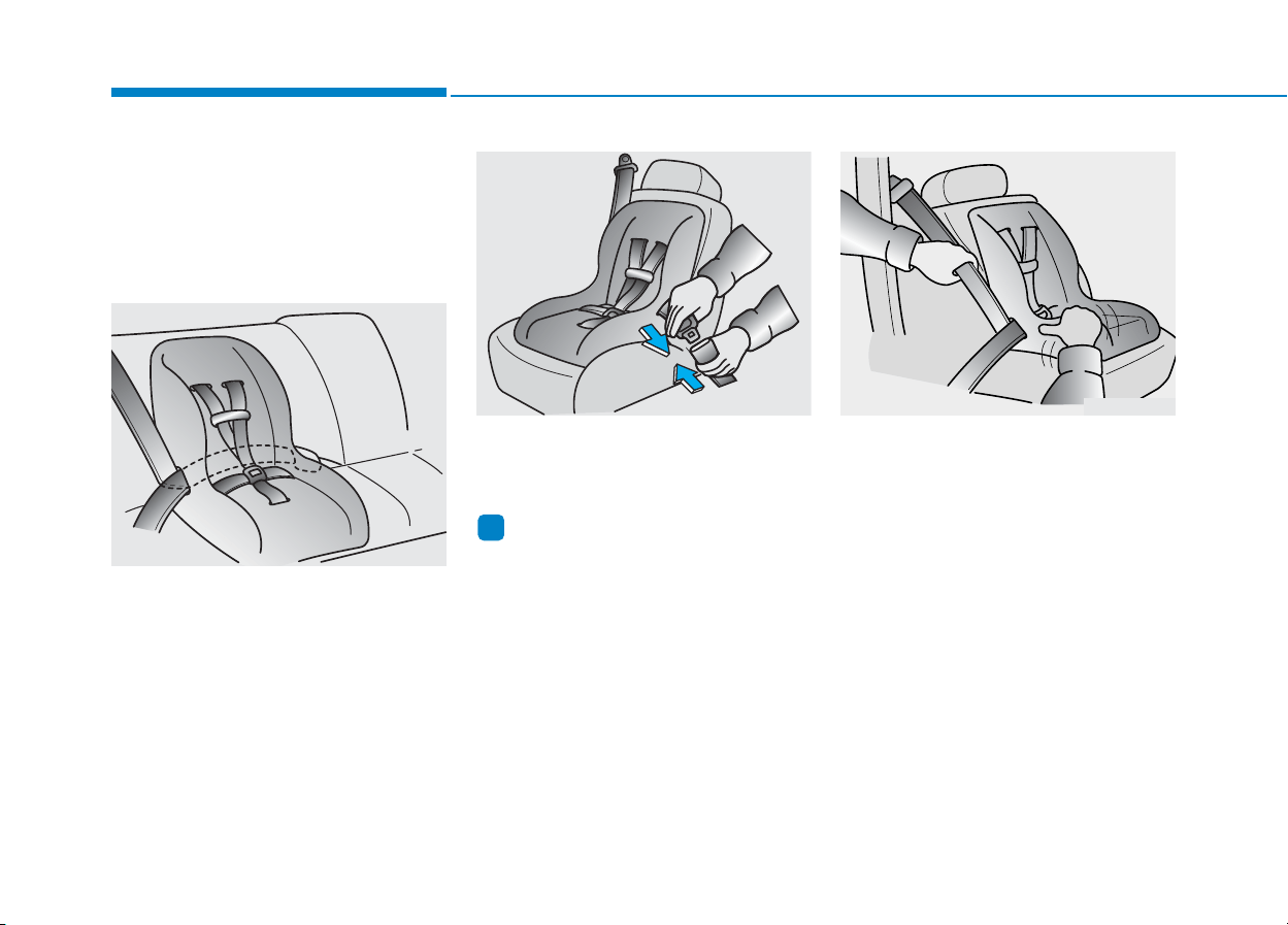
2-42
Safety system of your vehicle
Securing a Child Restraint
System with a lap/shoulder belt
When not using the ISOFIX system,
all Child Restraint Systems must be
secured to a rear seat with the lap
part of a lap/shoulder belt.
Installing a Child Restraint System
with a lap/shoulder belt
To install a Child Restraint System
on the rear seats, do the following:
1. Place the Child Restraint System
on a rear seat and route the lap/
shoulder belt around or through the
Child Restraint System, following
the Child Restraint System manu-
facturer’s instructions. Make sure
the seat belt webbing is not twisted.
2. Fasten the lap/shoulder belt latch
into the buckle. Listen for the dis-
tinct “click” sound.
Information
Position the release button so that it is
easy to access in case of an emergency.
3. Remove as much slack from the
belt as possible by pushing down
on the Child Restraint System while
feeding the shoulder belt back into
the retractor.
4. Push and pull on the Child Restraint
System to confirm that the seat belt
is holding it firmly in place.
If your Child Restraint System manu-
facturer recommends the use of a
top-tether with the lap/shoulder belt,
see page 2-40.
To remove the Child Restraint System,
press the release button on the buckle
and then pull the lap/shoulder belt out
of the Child Restraint System and
allow the seat belt to retract fully.
i
OLMB033044
ODH033063 OLMB033046
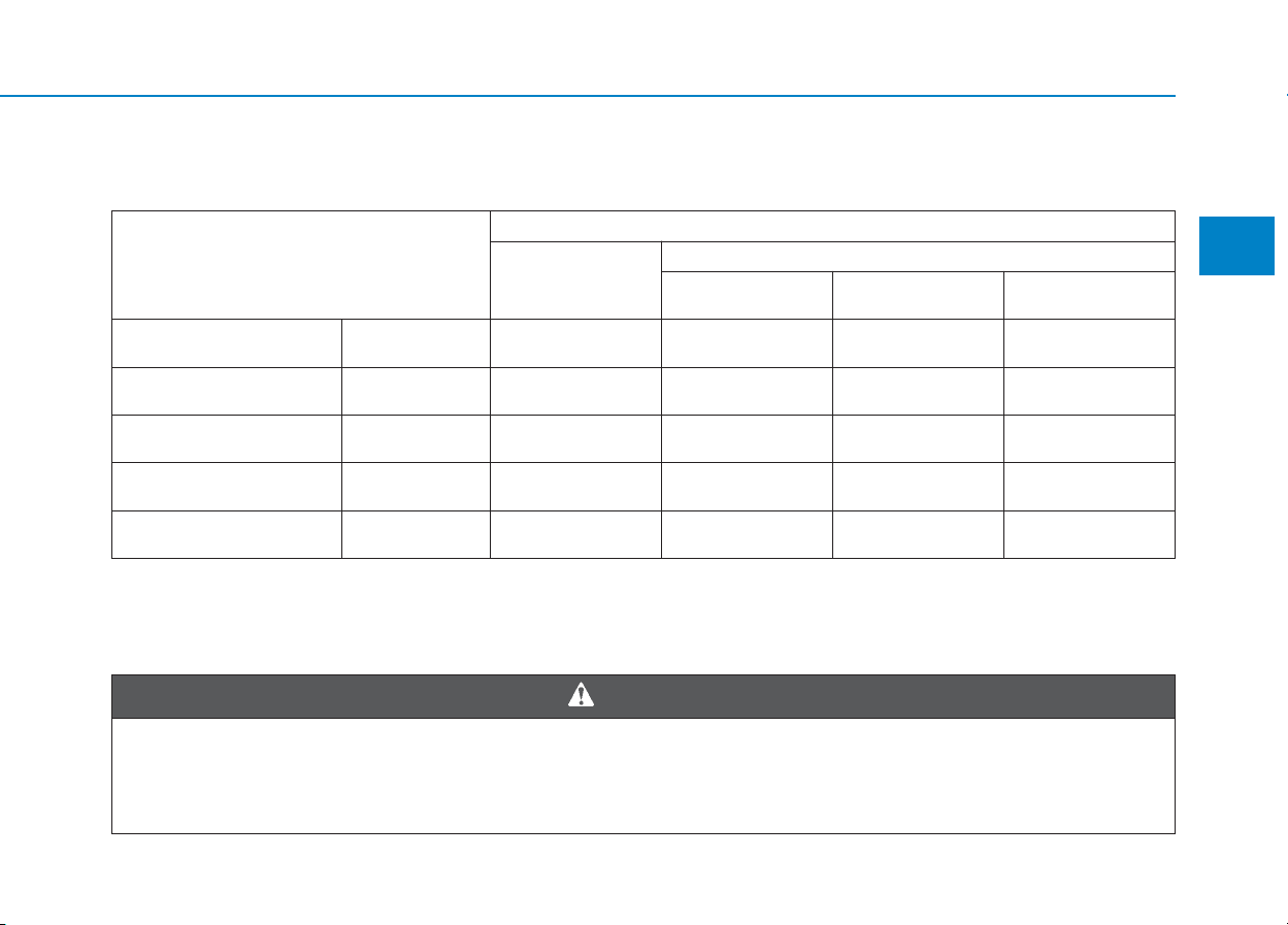
2-43
Safety system of your vehicle
2
Suitability of each seating position for "universal" category belted Child Restraint Systems according to
ECE regulations
U : Suitable for "universal" category Child Restraint Systems approved for use in this mass group
U* : Suitable for "universal" category Child Restraint Systems approved for use in this mass group
(When you install the child seat on the front passenger seat, you should adjust the height to the most upward position (if equipped
with the front passenger seat height adjuster) and adjust the seat back to the upright position to properly restrain the child seat.)
Mass Group
Seating Position
Front passenger
Second Row
Outboard Left 3-point seat belt
Outboard
Right
Group 0
(0-9months)
up to 10kg U* U U U
Group 0 +
(0-2years)
up to 13kg U* U U U
Group I
(9months-4years)
9 to 18kg U* U U U
Group II
(15 to 25kg)
15 to 25kg U* U U U
Group III
(22 to 36kg)
22 to 36kg U* U U U
We recommend that a child restraint seat be installed in the rear seat, even if the front passenger's air bag
ON/OFF switch is set to the OFF position. To ensure the safety of your child, the front passenger's air bag
must be deactivated when it should be necessary to install a child restraint seat on the front passenger
seat in exceptional circumstances.
WARNING

2-44
Safety system of your vehicle
i-Size Child Restraint Systems according to ECE regulations
i-U : Suitable for i-Size "universal" Child Restraint Systems forward and rearward-facing
i-UF : Suitable for forward-facing i-Size "universal" Child Restraint Systems only
X : Seat position not suitable for i-size Child Restraint Systems
Mass Group
Seating Position
Passenger Front
Second Row
Outboard Left Center
Outboard
Right
i-size Child Restraint Systems X i-U X i-U
Recommended child restraint systems (for Europe)
CRS Manufacturer information
Maxi Cosi Cabriofix & Familyfix http://www.maxi-cosi.com
Britax Römmer http://www.britax.com
Graco http//www.gracobaby.com
Mass Group Name Manufacturer Type of Fixation
ECE-R44
Approval No.
Group 0+ Cabriofix & Familyfix Maxi Cosi Rearward-facing with ISOFIX E4 04443907
Group I Duo Plus Britax Römer Forward-facing with ISOFIX and top-tether E1 04301133
Group II KidFix II XP
Britax Römer
Forward-facing with ISOFIX and vehicle Belt E1 04301323
Group III Junior III
Graco
Forward-facing with vehicle Belt
E11 03.44.164
E11 03.44.165
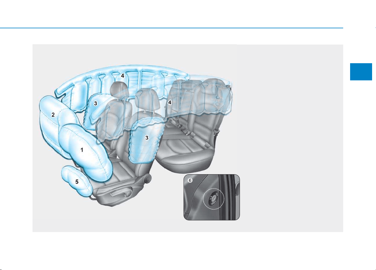
2-45
Safety system of your vehicle
2
AAIIRR BBAAGG -- SSUUPPPPLLEEMMEENNTTAALL RREESSTTRRAAIINNTT SSYYSSTTEEMM
OPDE036032/OPDE036066
The actual air bags in the vehicle may differ from the illustration.
1. Driver’s front air bag
2. Passenger’s front air bag
3. Side air bag*
4. Curtain air bag*
5. Knee air bag*
6. Front passenger air bag ON/OFF
switch*
* : if equipped

2-46
Safety system of your vehicle
The vehicles are equipped with a
Supplemental Air Bag System for the
driver’s seat and front passenger’s
seats.
The front air bags are designed to
supplement the three-point seat
belts. For these air bags to provide
protection, the seat belts must be
worn at all times when driving.
You can be severely injured or killed
in an accident if you are not wearing
a seat belt. Air bags are designed to
supplement seat belts, but do not
replace them. Also, air bags are not
designed to deploy in every collision.
In some accidents, the seat belts are
the only restraint protecting you.
AIR BAG SAFETY PRECAUTIONS
ALWAYS use seat belts Child Restraint Systems - every trip, every
time, everyone! Even with air bags, you can be seriously injured or
killed in a collision if you are improperly belted or not wearing your
seat belt when the air bag inflates.
NEVER place a child in any Child Restraint System or booster seat in
the front passenger seat, unless the air bag is deactivated.
An inflating air bag could forcefully strike the infant or child causing
serious or fatal injuries.
ABC - Always Buckle Children under age 13 in the back seat. It is the
safest place for children of any age to ride. If a child age 13 or older
must be seated in the front seat, he or she must be properly belted
and the seat should be moved as far back as possible.
All occupants should sit upright with the seatback in an upright posi-
tion, centered on the seat cushion with their seat belt on, legs com-
fortably extended and their feet on the floor until the vehicle is parked
and the engine is turned off. If an occupant is out of position during
an accident, the rapidly deploying air bag may forcefully contact the
occupant causing serious or fatal injuries.
You and your passengers should never sit or lean unnecessarily
close to the air bags or lean against the door or center console.
Move your seat as far back as possible from front air bags, while still
maintaining control of the vehicle.
WARNING
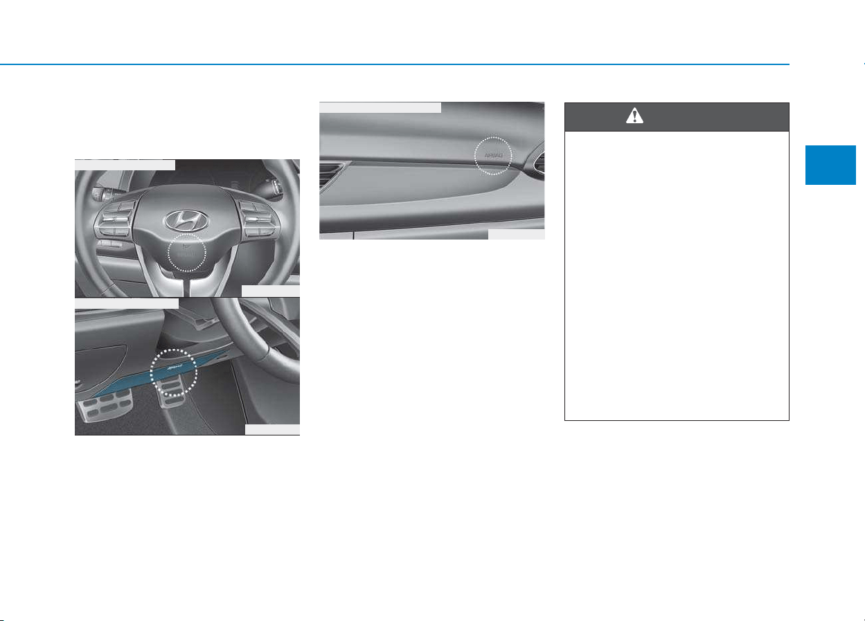
2-47
Safety system of your vehicle
2
Where are the air bags?
Driver’s and passenger’s front
air bags (if equipped)
Your vehicle is equipped with a
Supplemental Restraint System
(SRS) and lap/shoulder belts at both
the driver and passenger seating
positions.
The SRS consists of air bags which
are located in the center of the steer-
ing wheel, in the driver’s side lower
crash pad below the steering wheel,
and the passenger's side front panel
pad above the glove box.
The air bags are labeled with the let-
ters “AIR BAG” embossed on the pad
covers.
The purpose of the SRS is to provide
the vehicle's driver and front passen-
gers with additional protection than
that offered by the seat belt system
alone in case of a frontal impact of
sufficient severity.
To reduce the risk of serious
injury or death from inflating front
air bags, take the following pre-
cautions:
• Seat belts must be worn at all
times to help keep occupants
positioned properly.
• Move your seat as far back as
possible from front air bags,
while still maintaining control
of the vehicle.
• Never lean against the door or
center console.
• Do not allow the front passen-
ger to place their feet or legs on
the dashboard.
(Continued)
WARNING
OPD036033
OPD036034
■ Driver’s knee air bag
OPD036041
■ Passenger’s front air bag
■ Driver’s front air bag
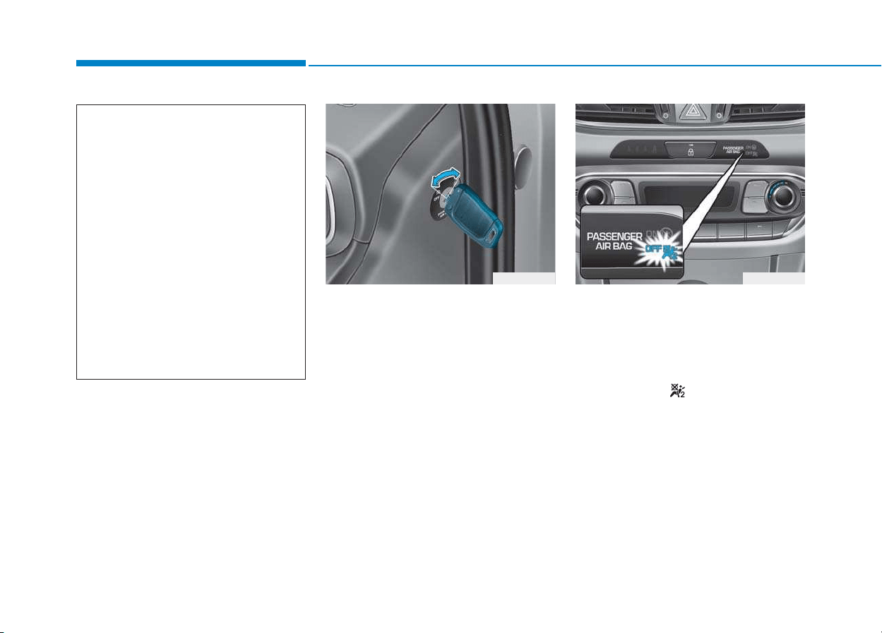
2-48
Safety system of your vehicle
Passenger’s front air bag ON/OFF
switch (if equipped)
The purpose of the switch is to dis-
able the passenger’s front air bag in
order to transport occupants who are
at increased risk for air bag-related
injury due to age, size, or medical
condition.
To deactivate the passenger’s front
air bag:
Insert the key or a similar rigid device
into the passenger’s front air bag
ON/OFF switch and turn it to the
OFF position. The passenger air bag
OFF indicator ( ) will illuminate and
stay on until the passenger’s front air
bag is reactivated.
OPDE036064 OPDE036036
(Continued)
• No objects (such as crash pad
cover, cellular phone holder,
cup holder, perfume or stickers)
should be placed over or near
the air bag modules on the
steering wheel, instrument
panel, windshield glass, and
the front passenger's panel
above the glove box. Such
objects could cause harm if the
vehicle is in a crash severe
enough to cause the air bags to
deploy.
• Do not attach any objects on
front windshield and inside mir-
ror.
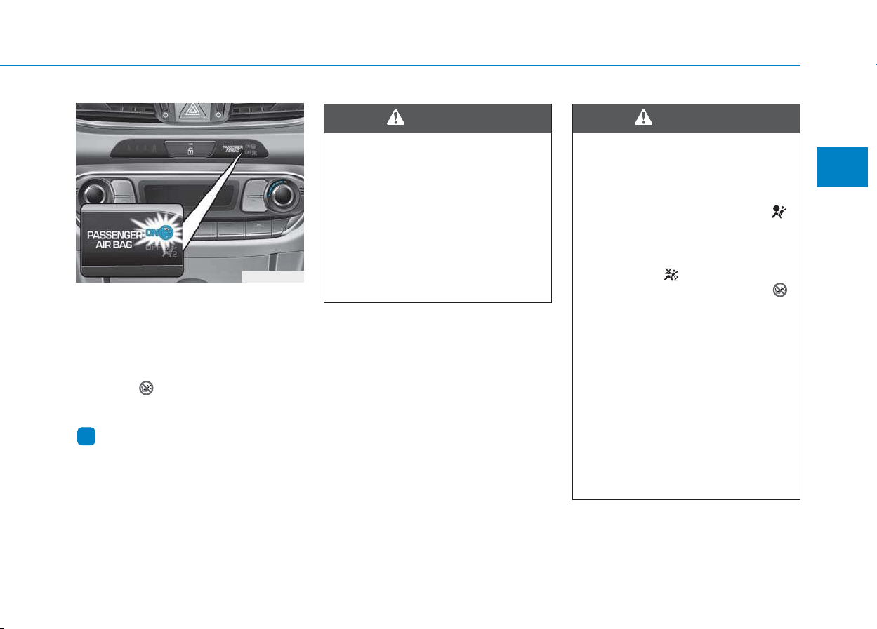
2-49
Safety system of your vehicle
2
To reactivate the passenger’s front
air bag:
Insert the key or a similar rigid device
into the passenger’s front air bag
ON/OFF switch and turn it to the ON
position. The passenger air bag ON
indicator ( ) will illuminate and stay
on for 60 seconds.
Information
The passenger’s front air bag ON/OFF
indicator illuminates for about 4 sec-
onds after the ignition switch is placed
in the ON position.
i
Never allow an adult passenger
to ride in the front passenger
seat when the passenger air
bag OFF indicator is illuminat-
ed. During a collision, the air
bag will not inflate if the indica-
tor is illuminated. Turn on the
passenger’s front air bag or
have your passenger move to
the rear seat.
WARNING
If the passenger’s front air bag
ON/OFF switch malfunctions,
the following conditions may
occur:
• The air bag warning light ( )
on the instrument cluster will
illuminate.
• The passenger air bag OFF
indicator ( ) will not illumi-
nate and the ON indicator ( )
will come on and go off after
approximately 60 seconds.
The passenger’s front air bag
will inflate in a frontal impact
even though the passenger’s
front air bag ON/OFF switch is
set to the OFF position.
• We recommend that an author-
ized HYUNDAI dealer inspect
the passenger’s front air bag
ON/OFF switch and the SRS air
bag system as soon as possi-
ble.
WARNING
OPDE036065
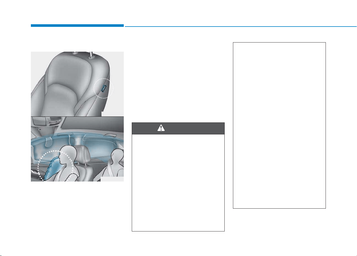
2-50
Safety system of your vehicle
Side air bags (if equipped)
Your vehicle is equipped with a side air
bag in each front seat. The purpose of
the air bag is to provide the vehicle’s
driver and the front passenger with
additional protection than that offered
by the seat belt alone.
The side air bags are designed to
deploy during certain side impact col-
lisions, depending on the crash
severity, angle, speed and point of
impact.
The side air bags on both sides of the
vehicle are designed to deploy when a
rollover is detected by a rollover sen-
sor. (if equipped with rollover sensor)
The side air bags are not designed to
deploy in all side impact or rollover
situations.
(Continued)
• Hold the steering wheel at the 9
o’clock and 3 o’clock positions,
to minimize the risk of injuries
to your hands and arms.
• Do not use any accessory
seat covers.This could reduce
or prevent the effectiveness
of the system.
• Do not place any objects over
the air bag or between the air
bag and yourself.
• Do not hang other objects
except clothes. In an accident
it may cause vehicle damage
or personal injury especially
when air bag is inflated.
• Do not place any objects over
the air bag or between the air
bag and yourself. Also, do not
attach any objects around the
area the air bag inflates such
as the door, side door glass,
front and rear pillar.
(Continued)
To reduce the risk of serious
injury or death from an inflating
side air bag, take the following
precautions:
• Seat belts must be worn at all
times to help keep occupants
positioned properly.
• Do not allow passengers to
lean their heads or bodies onto
doors, put their arms on the
doors, stretch their arms out of
the window, or place objects
between the doors and seats.
(Continued)
WARNING
OPD036042
OPD036043

2-51
Safety system of your vehicle
2
Curtain air bags (if equipped)
Curtain air bags are located along
both sides of the roof rails above the
front and rear doors.
They are designed to help protect the
heads of the front seat occupants
and the rear outboard seat occupants
in certain side impact collisions.
The curtain air bags are designed to
deploy during certain side impact
collisions, depending on the crash
severity, angle, speed and impact.
The curtain air bags on both sides of the
vehicle are designed to deploy when a
rollover is detected by a rollover sensor.
(if equipped with rollover sensor)
The curtain air bags are not designed
to deploy in all side impact or rollover
situations.
OPD036044
OPD036045
(Continued)
• Do not place any objects
between the door and the
seat. They may become dan-
gerous projectiles if the side
air bag inflates.
• Do not install any accessories
on the side or near the side air
bags.
• Do not cause impact to the
doors when the ignition switch
is in the ON position or this
may cause the side air bags to
inflate.
• If the seat or seat cover is
damaged, we recommend that
the system be serviced by an
authorized HYUNDAI dealer.
To reduce the risk of serious
injury or death from an inflating
curtain air bags, take the follow-
ing precautions:
• All seat occupants must wear
seat belts at all times to help
keep occupants positioned
properly.
(Continued)
WARNING
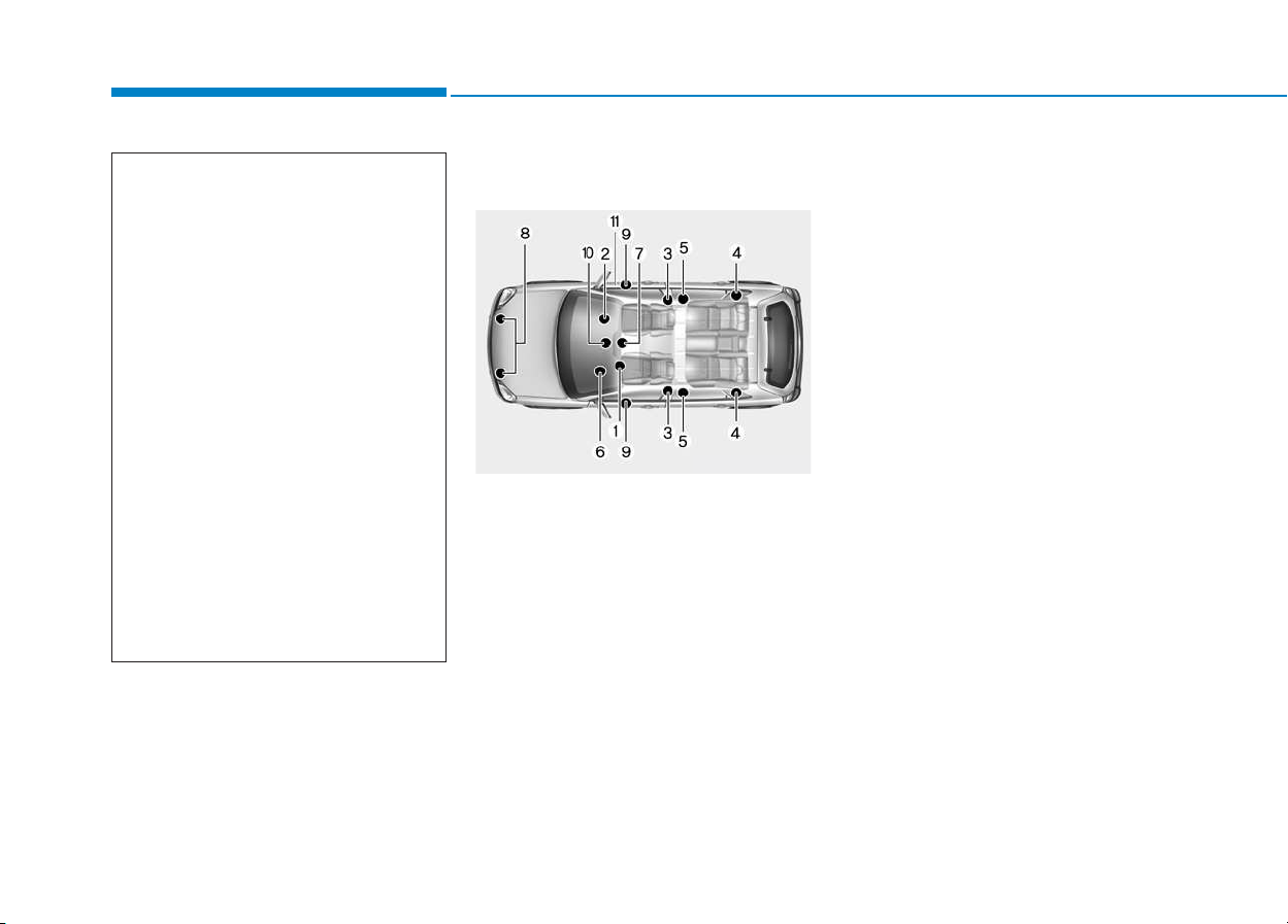
2-52
Safety system of your vehicle
How does the air bags system
operate?
The SRS consists of the following
components:
(1) Driver's front air bag module/
Driver’s knee air bag module
(2) Passenger's front air bag module
(3) Side air bag modules/
Side impact sensors
(4) Curtain air bag modules
(5) Retractor pre-tensioner assem-
blies
(6) Air bag warning light
(7) SRS control module (SRSCM)/
Rollover sensor
(8) Front impact sensors
(9) Side pressure sensors
(10) Passenger’s front air bag
ON/OFF indicator
(front passenger's seat only)
(11) Passenger’s front air bag
ON/OFF switch
The SRSCM continually monitors all
SRS components while the ignition
switch is ON to determine if a crash
impact is severe enough to require
air bag deployment or pre-tensioner
seat belt deployment.
OPDE036063
(Continued)
• Properly secure Child Restraint
System as far away from the
door as possible.
• Do not place any objects over
the air bag. Also, do not attach
any objects around the area the
air bag inflates such as the
door, side door glass, front and
rear pillar, roof side rail.
• Do not hang hard or breakable
objects on the clothes hanger.
• Do not allow passengers to
lean their heads or bodies
onto doors, put their arms on
the doors, stretch their arms
out of the window, or place
objects between the doors
and seats.
• Do not open or repair the side
curtain air bags.
2-53
Safety system of your vehicle
2
SRS warning light
The SRS (Supplement Restraint
System) air bag warning light on the
instrument panel displays the air bag
symbol depicted in the illustration. The
system checks the air bag electrical
system for malfunctions. The light indi-
cates that there is a potential problem
with your air bag system, which could
include your side and/or curtain air
bags used for rollover protection (if
equipped with rollover sensor).
During a moderate to severe frontal
collision, sensors will detect the vehi-
cle’s rapid deceleration. If the rate of
deceleration is high enough, the con-
trol unit will inflate the front air bags,
at the time and with the force needed.
The front air bags help protect the driv-
er and front passenger by responding
to frontal impacts in which seat belts
alone cannot provide adequate
restraint. When needed, the side air
bags help provide protection in the
event of a side impact or rollover by
supporting the side upper body area.
• Air bags are activated (able to inflate
if necessary) only when the ignition
switch is in the ON position.
• Air bags inflate in the event of certain
frontal or side collisions to help pro-
tect the occupants from serious
physical injury.
• There is no single speed at which the
air bags will inflate. Generally, air bags
are designed to inflate based upon
the severity of a collision and its direc-
tion. These two factors determine
whether the sensors produce an elec-
tronic deployment/inflation signal.
If your SRS malfunctions, the
air bag may not inflate properly
during an accident increasing
the risk of serious injury or
death.
If any of the following condi-
tions occur, your SRS is mal-
functioning:
• The light does not turn on for
approximately six seconds
when the ignition switch is in
the ON position.
• The light stays on after illumi-
nating for approximately six
seconds.
• The light comes on while the
vehicle is in motion.
• The light blinks when the
engine is running.
We recommend that an author-
ized HYUNDAI dealer inspect the
SRS as soon as possible if any
of these conditions occur.
WARNING

2-54
Safety system of your vehicle
• Air bag deployment depends on a
number of factors including vehicle
speed, angles of impact and the
density and stiffness of the vehicles
or objects which your vehicle
impacts during a collision. The
determining factors are not limited
to those mentioned above.
• The front air bags will completely
inflate and deflate in an instant. It is
virtually impossible for you to see
the air bags inflate during an acci-
dent. It is much more likely that you
will simply see the deflated air bags
hanging out of their storage com-
partments after the collision.
• In addition to inflating in serious
side collisions, vehicles equipped
with a rollover sensor, side and/or
curtain air bags will inflate if the
sensing system detects a rollover.
When a rollover is detected, curtain
air bags will remain inflated longer
to help provide protection from ejec-
tion, especially when used in con-
junction with the seat belts. (if
equipped with a rollover sensor)
• To help provide protection, the air
bags must inflate rapidly. The speed
of air bag inflation is a consequence
of extremely short time in which to
inflate the air bag between the
occupant and the vehicle structures
before the occupant impacts those
structures. This speed of inflation
reduces the risk of serious or life-
threatening injuries and is thus a
necessary part of air bag design.
However, the rapid air bag inflation
can also cause injuries which can
include facial abrasions, bruises
and broken bones because the
inflation speed also causes the air
bags to expand with a great deal of
force.
• There are even circumstances
under which contact with the air
bag can cause fatal injuries, espe-
cially if the occupant is positioned
excessively close to the air bag.
You can take steps to reduce the risk
of being injured by an inflating air
bag. The greatest risk is sitting too
close to the air bag. An air bag needs
space to inflate. It is recommended
that drivers sit as far as possible
between the center of the steering
wheel and the chest while still main-
taining control of the vehicle.
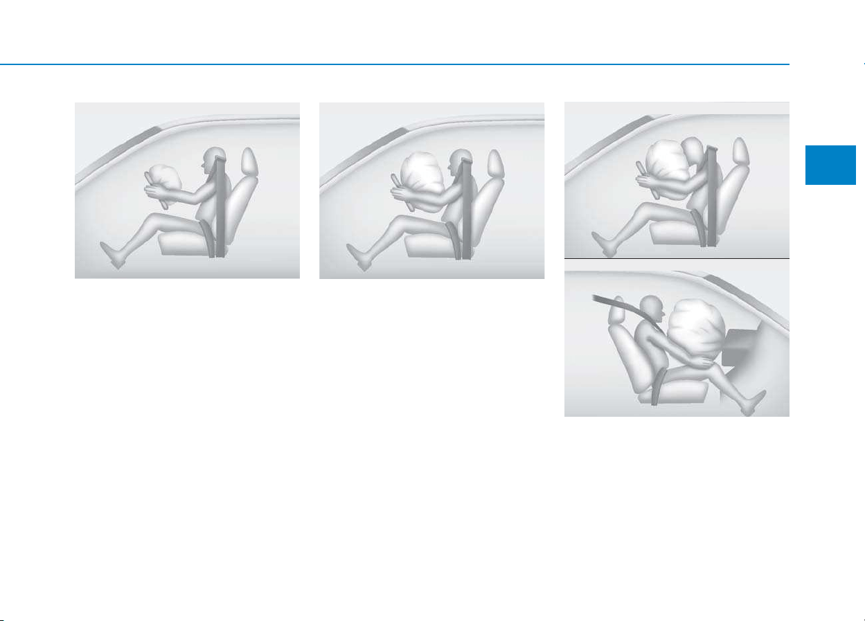
2-55
Safety system of your vehicle
2
When the SRSCM detects a suffi-
ciently severe impact to the front of
the vehicle, it will automatically
deploy the front air bags.
Upon deployment, tear seams mold-
ed directly into the pad covers will
separate under pressure from the
expansion of the air bags. Further
opening of the covers allows full
inflation of the air bags.
A fully inflated air bag, in combina-
tion with a properly worn seat belt,
slows the driver's or the front pas-
senger's forward motion, reducing
the risk of head and chest injury.
After complete inflation, the air bag
immediately starts deflating, enabling
the driver to maintain forward visibili-
ty and the ability to steer or operate
other controls.
OLMB033055
■ Driver’s front air bag (2)
OLMB033056
■ Driver’s front air bag (3)
OLMB033057
■ Passenger’s front air bag
OLMB033054
■ Driver’s front air bag (1)
2-56
Safety system of your vehicle
What to expect after an air bag
inflates
After a frontal or side air bag inflates,
it will deflate very quickly. Air bag
inflation will not prevent the driver
from seeing out of the windshield or
being able to steer. Curtain air bags
may remain partially inflated for
some time after they deploy.
Noise and smoke from inflating
air bag
When the air bags inflate, they make
a loud noise and may produce smoke
and powder in the air inside of the
vehicle. This is normal and is a result
of the ignition of the air bag inflator.
After the air bag inflates, you may feel
substantial discomfort in breathing
because of the contact of your chest
with both the seat belt and the air
bag, as well as from breathing the
smoke and powder. The powder may
aggravate asthma for some people. If
you experience breathing problems
after an air bag deployment, seek
medical attention immediately.
Though the smoke and powder are
nontoxic, they may cause irritation to
the skin, eyes, nose, throat, etc. If this
is the case, wash and rinse with cold
water immediately and seek medical
attention if the symptoms persist.
After an air bag inflates, take
the following precautions:
• Open your windows and doors
as soon as possible after
impact to reduce prolonged
exposure to the smoke and
powder released by the inflat-
ing air bag.
• Do not touch the air bag stor-
age area’s internal compo-
nents immediately after an air
bag has inflated. The parts
that come into contact with an
inflating air bag may be very
hot.
• Always wash exposed skin
areas thoroughly with cold
water and mild soap.
• We recommend that an author-
ized HYUNDAI dealer replace
the air bag immediately after
deployment. Air bags are
designed to be used only once.
WARNING
To prevent objects from becom-
ing dangerous projectiles when
the passenger's air bag inflates:
• Do not install or place any
objects (drink holder, CD hold-
er, stickers, etc.) on the front
passenger's panel above the
glove box where the passen-
ger's air bag is located.
• Do not install a container of
liquid air freshener near the
instrument cluster or on the
instrument panel surface.
WARNING
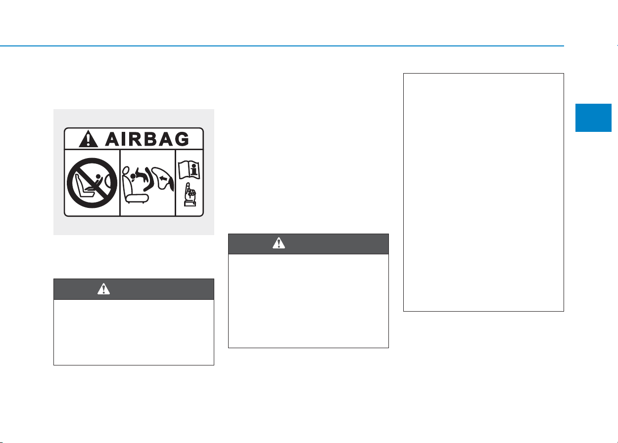
2-57
Safety system of your vehicle
2
Do not install a Child Restraint
System on the front passenger
seat
Never install a Child Restraint System
in the front passenger seat, unless the
air bag is deactivated
Why didn't my air bag go off in
a collision?
There are certain types of accidents
in which the air bag would not be
expected to provide additional protec-
tion. These include rear impacts, sec-
ond or third collisions in multiple
impact accidents, as well as low
speed impacts. Damage to the vehicle
indicates a collision energy absorp-
tion, and is not an indicator of whether
or not an air bag should have inflated.
Air bag collision sensors
OYDESA2042
NEVER use a rearward facing
Child Restraint System on a seat
protected by an ACTIVE AIRBAG
in front of it, DEATH or SERIOUS
INJURY to the CHILD can occur.
WARNING
To reduce the risk of an air bag
deploying unexpectedly and
causing serious injury or death:
•
Do not hit or allow any objects to
impact the locations where air
bags or sensors are installed.
(Continued)
WARNING
(Continued)
• Do not perform maintenance
on or around the air bag sen-
sors. If the location or angle of
the sensors is altered, the air
bags may deploy when they
should not or may not deploy
when they should.
• Do not install bumper guards or
replace the bumper with a non-
genuine part.This may adverse-
ly affect the collision and air
bag deployment performance.
• Place the ignition switch to
the LOCK/OFF or ACC posi-
tion, when the vehicle is being
towed to prevent inadvertent
air bag deployment.
• We recommend that all air bag
repairs are conducted by an
authorized HYUNDAI dealer.
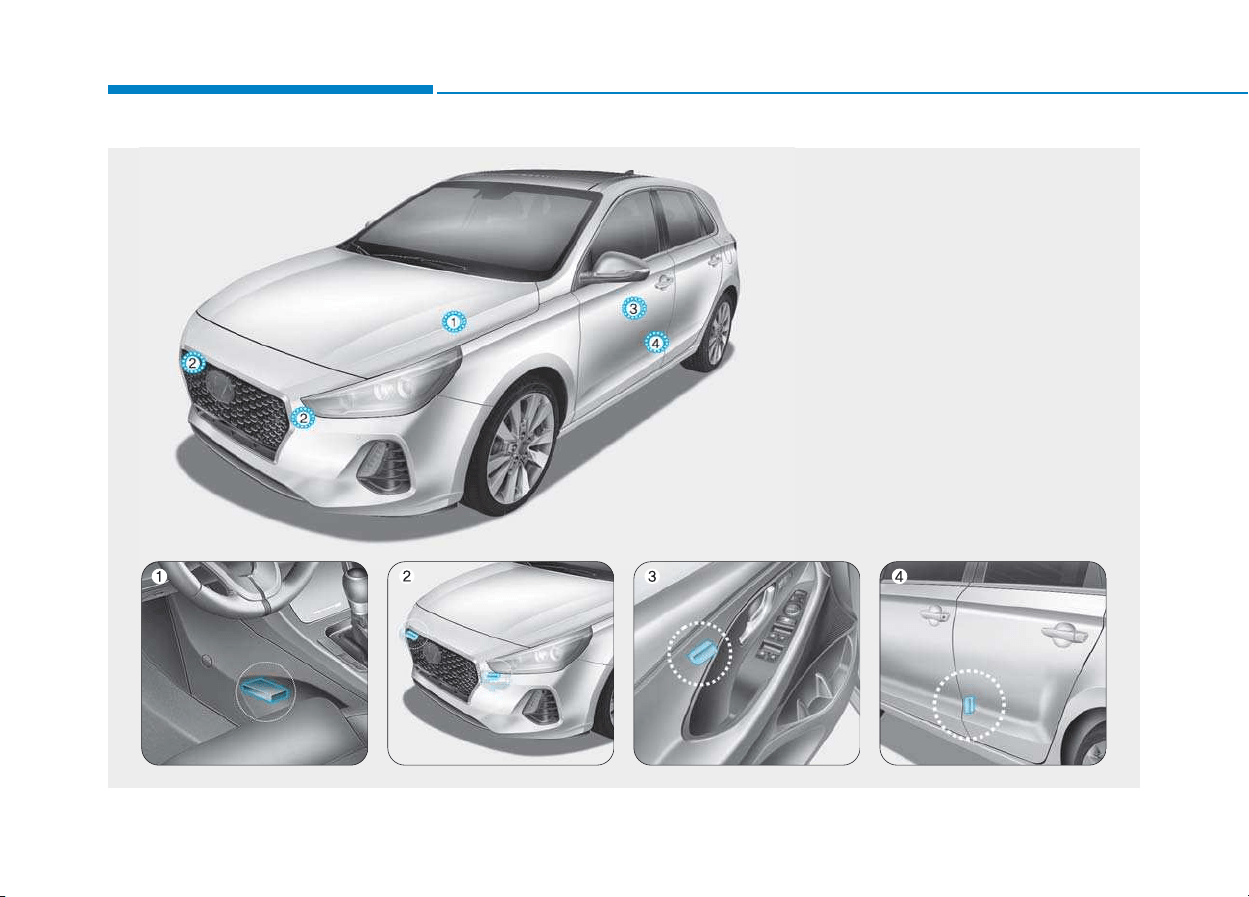
2-58
Safety system of your vehicle
1. SRS control module
2. Front impact sensor
3. Side pressure sensor (front)*
4. Side impact sensor (rear)*
* : if equipped
OPDE036046/OPDE036047/OPDE036048/OPD036049/OPD036050
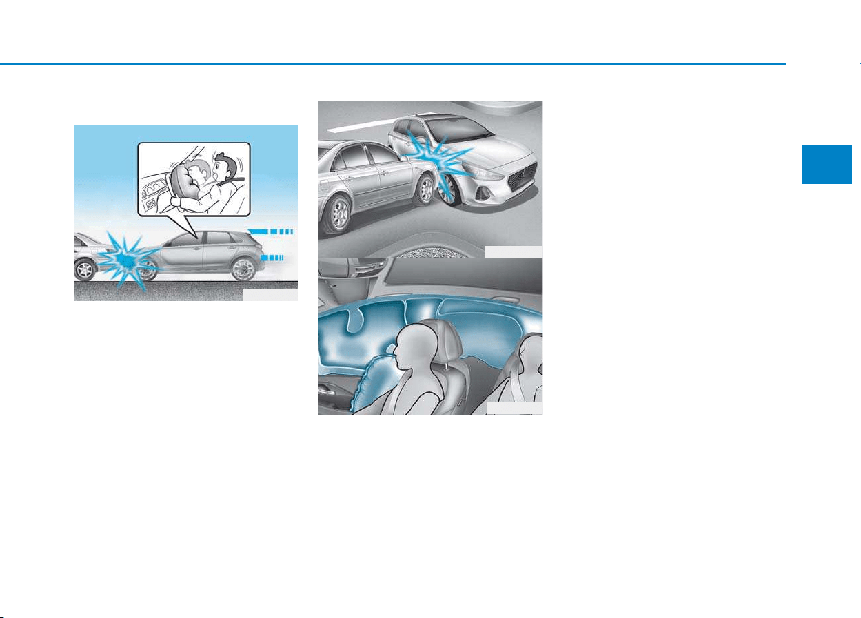
2-59
Safety system of your vehicle
2
Air bag inflation conditions
Front air bags
Front air bags are designed to inflate
in a frontal collision depending on
the severity, speed or angles of
impact of the front collision.
Side and curtain air bags
Side and curtain air bags are
designed to inflate when an impact is
detected by side collision sensors
depending on the severity, speed or
angles of impact resulting from a
side impact collision.
Although the driver’s and front pas-
senger’s air bags are designed to
inflate in frontal collisions, they also
may inflate in other types of colli-
sions if the front impact sensors
detect a sufficient impact. Side and
curtain air bags are designed to
inflate in side impact collisions, but
they may inflate in other collisions if
the side impact sensors detect a suf-
ficient impact.
Also, the side and curtain air bags are
designed to inflate when a rollover is
detected by a rollover sensor. (if
equipped with rollover sensor)
If the vehicle chassis is impacted by
bumps or objects on unimproved
roads, the air bags may deploy. Drive
carefully on unimproved roads or on
surfaces not designed for vehicle
traffic to prevent unintended air bag
deployment.
OPD036052
OPD036053
OPD036051
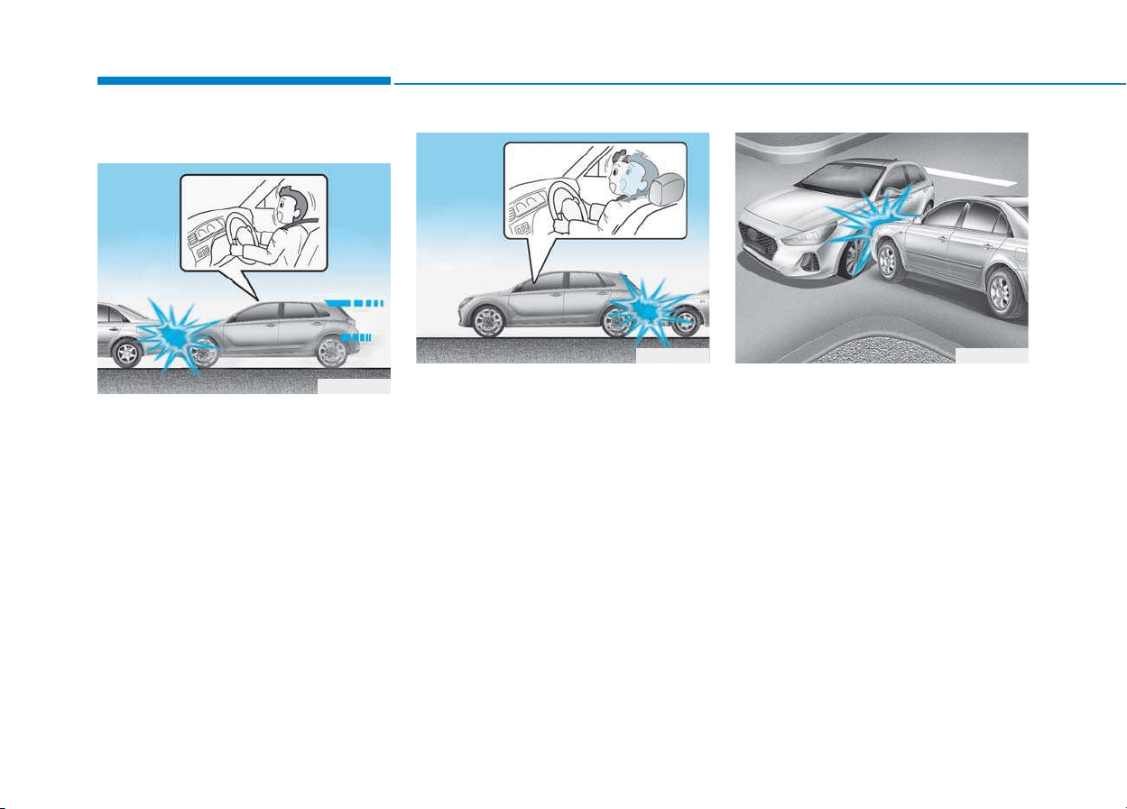
2-60
Safety system of your vehicle
Air bag non-inflation conditions
In certain low-speed collisions the air
bags may not deploy. The air bags
are designed not to deploy in such
cases because they may not provide
benefits beyond the protection of the
seat belts.
Front air bags are not designed to
inflate in rear collisions, because
occupants are moved backward by
the force of the impact. In this case,
inflated air bags would not provide
any additional benefit.
Front air bags may not inflate in side
impact collisions, because occupants
move in the direction of the collision,
and thus in side impacts, front air bag
deployment would not provide addi-
tional occupant protection.
However, side and curtain air bags
may inflate depending on the severity,
vehicle speed and angles of impact.
OPD036055
OPD036054
OPD036056

2-61
Safety system of your vehicle
2
In an angled collision, the force of
impact may direct the occupants in a
direction where the air bags would
not be able to provide any additional
benefit, and thus the sensors may
not deploy any air bags.
Just before impact, drivers often
brake heavily. Such heavy braking
lowers the front portion of the vehicle
causing it to “ride” under a vehicle
with a higher ground clearance. Air
bags may not inflate in this "under-
ride" situation because deceleration
forces that are detected by sensors
may be significantly reduced by such
“underride” collisions.
Front air bags may not inflate in
rollover accidents because front air
bag deployment would not provide
additional occupant protection.
Information
• Vehicles equipped with rollover sensor
The side and curtain air bags may
inflate in a rollover situation, when it is
detected by the rollover sensor.
• Vehicles not equipped with rollover
sensor
The side and/or curtain air bags may
inflate when the vehicle is rolled over
by a side impact collision, if the vehicle
is equipped with side and/or curtain
air bags.
i
OTL035069 OPD036057 OTL035068
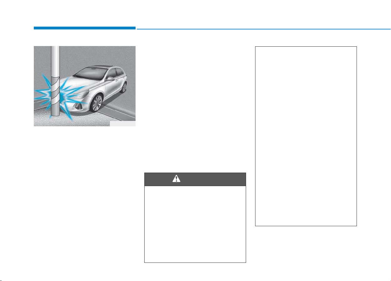
2-62
Safety system of your vehicle
Air bags may not inflate if the vehicle
collides with objects such as utility
poles or trees, where the point of
impact is concentrated and the colli-
sion energy is absorbed by the vehi-
cle structure.
SRS care
The SRS is virtually maintenance-
free and there are no parts you can
safely service by yourself. If the SRS
air bag warning light does not illumi-
nate when the ignition switch is in the
ON position, or continuously remains
on, we recommend that the system
be immediately inspected by an
authorized HYUNDAI dealer.
We recommend any work on the SRS
system, such as removing, installing,
repairing, or any work on the steering
wheel, the front passenger's panel,
front seats and roof rails be performed
by an authorized HYUNDAI dealer.
Improper handling of the SRS system
may result in serious personal injury.
OPD036058
To reduce the risk of serious
injury or death take the follow-
ing precautions:
• Do not attempt to modify or
disconnect the SRS compo-
nents or wiring, including the
addition of any kind of badges
to the pad covers or modifica-
tions to the body structure.
(Continued)
WARNING
(Continued)
• Do not place objects over or
near the air bag modules on the
steering wheel, instrument
panel, and the front passenger's
panel above the glove box.
• Clean the air bag pad covers
with a soft cloth moistened
with plain water. Solvents or
cleaners could adversely affect
the air bag covers and proper
deployment of the system.
• We recommend that inflated
air bags be replaced by an
authorized HYUNDAI dealer.
• If components of the air bag
system must be discarded, or if
the vehicle must be scrapped,
certain safety precautions must
be observed. Consult an author-
ized HYUNDAI dealer for the
necess
ary information. Failure
to follow these precautions
could increase the risk of per-
sonal injury.
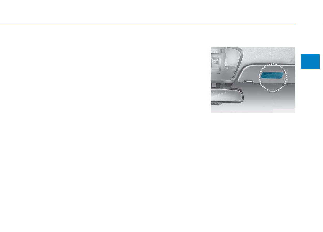
2-63
Safety system of your vehicle
2
Additional safety precautions
Passengers should not move out of
or change seats while the vehicle is
moving. A passenger who is not
wearing a seat belt during a crash or
emergency stop can be thrown
against the inside of the vehicle,
against other occupants, or be ejected
from the vehicle.
Do not use any accessories on seat
belts. Devices claiming to improve
occupant comfort or reposition the
seat belt can reduce the protection
provided by the seat belt and increase
the chance of serious injury in a crash
Do not modify the front seats.
Modification of the front seats could
interfere with the operation of the sup-
plemental restraint system sensing
components or side air bags.
Do not place items under the front
seats. Placing items under the front
seats could interfere with the opera-
tion of the supplemental restraint sys-
tem sensing components and wiring
harnesses.
Do not cause impact to the doors.
Impact to the doors when the ignition
switch is in the ON position may cause
the air bags to inflate.
Adding equipment to or modify-
ing your air bag equipped vehicle
If you modify your vehicle by changing
your vehicle's frame, bumper system,
front end or side sheet metal or ride
height, this may affect the operation of
your vehicle's air bag system.
Air bag warning labels
Air bag warning labels are attached
to alert the passengers of potential
risks of the air bag system.
Be sure to read all of the information
about the air bags that are installed on
your vehicle in this Owner’s Manual.
OAD035053

Convenient features of your vehicle
Accessing your vehicle .........................................3-3
Remote key.........................................................................3-3
Smart key ............................................................................3-6
Immobilizer system .........................................................3-10
DOOR LOCKS ........................................................3-11
Operating door locks from outside the vehicle ......3-11
Operating door locks from inside the vehicle .........3-12
Auto door lock/unlock features..................................3-14
Child-protector rear door locks..................................3-15
Theft-alarm system.............................................3-16
Driver position memory system.........................3-17
Storing memory positions.............................................3-17
Recalling memory positions..........................................3-17
Easy access function .....................................................3-18
Steering wheel......................................................3-19
Electric power steering (EPS)......................................3-19
Tilt steering / Telescope steering...............................3-20
Heated steering wheel...................................................3-21
Horn....................................................................................3-21
Mirrors...................................................................3-22
Inside rearview mirror....................................................3-22
Outside rearview mirror ................................................3-23
Reverse parking aid function.......................................3-26
Windows ................................................................3-27
Power windows................................................................3-27
Manual windows..............................................................3-31
Panorama sunroof ...............................................3-32
Sunshade...........................................................................3-33
Sliding the sunroof .........................................................3-33
Tilting the sunroof..........................................................3-34
Closing the sunroof ........................................................3-34
Resetting the sunroof....................................................3-35
Sunroof open warning...................................................3-36
Exterior features .................................................3-37
Hood ...................................................................................3-37
Tailgate...............................................................................3-38
Fuel filler door.................................................................3-40
Instrument cluster................................................3-43
Instrument cluster control ............................................3-44
Gauges and meters.........................................................3-45
Transmission shift indicator .........................................3-48
Manual transmission shift indicator...........................3-48
Warning and indicator lights ........................................3-51
LCD display messages....................................................3-65
LCD Display...........................................................3-71
LCD display control.........................................................3-71
LCD modes ........................................................................3-72
Trip computer .......................................................3-79
Trip modes ........................................................................3-79
Light .......................................................................3-83
Exterior lights ..................................................................3-83
Static bending light.........................................................3-92
Welcome system..............................................................3-92
3

Interior lights....................................................................3-93
Wipers and washers ............................................3-97
Windshield wipers ..........................................................3-98
Windshield washers .......................................................3-99
Rear window wiper and washer switch ..................3-100
Driver assist system ..........................................3-101
Rear view camera ........................................................3-101
Rear parking assist system ........................................3-102
Parking assist system .................................................3-106
Defroster.............................................................3-109
Rear window defroster ...............................................3-109
Manual climate control system........................3-111
Heating and air conditioning......................................3-112
System operation..........................................................3-116
System maintenance....................................................3-118
Automatic climate control system...................3-121
Automatic heating and air conditioning..................3-122
Manual heating and air conditioning.......................3-123
System operation..........................................................3-128
System maintenance....................................................3-131
Windshield defrosting and defogging ............3-133
Manual climate control system .................................3-133
Automatic climate control system ............................3-134
Defogging logic ............................................................3-135
Auto defogging system
(only for automatic climate control system) .........3-136
Climate control additional features.................3-137
Cluster ionizer ..............................................................3-137
Automatic ventilation ..................................................3-137
To cancel or set the automatic ventilation ............3-137
Sunroof inside air recirculation ...............................3-137
Storage compartment........................................3-138
Center console storage ...............................................3-138
Glove box ........................................................................3-138
Sunglass holder ............................................................3-139
Multi box ........................................................................3-139
Interior features ...............................................3-140
Ashtray ...........................................................................3-140
Cup holder.......................................................................3-140
Sliding armrest .............................................................3-141
Sunvisor...........................................................................3-142
Power outlet .................................................................3-142
Cigarette lighter ...........................................................3-144
Wireless cellular phone charging system ..............3-144
Clock.................................................................................3-146
Clothes hanger .............................................................3-146
Floor mat anchor(s) ....................................................3-147
Luggage net (holder) ...................................................3-147
Cargo area cover .........................................................3-148
Exterior features ...............................................3-149
Mounting bracket for roof carrier ..........................3-149
3
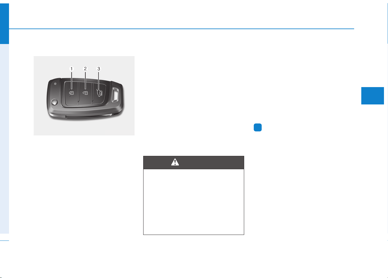
3-3
Convenient features of your vehicle
3
Remote key
Your HYUNDAI uses a remote key,
which you can use to lock or unlock
a door (and tailgate) and even start
the engine.
1. Door Lock
2. Door Unlock
3. Tailgate Unlock
Locking
To lock :
1. Close all doors, engine hood and
tailgate.
2. Press the Door Lock button (1) on
the remote key.
3. The doors will lock. The hazard
warning lights will blink. Also, the
outside rearview mirror will fold, if
the outside rearview mirror folding
switch is in the AUTO position (if
equipped).
4. Make sure the doors are locked by
checking the position of the door
lock button inside the vehicle.
Unlocking
To unlock:
1. Press the Door Unlock button (2)
on the remote key.
2. The doors will unlock. The hazard
warning lights will blink two times.
Also, the outside rearview mirror
will unfold, if the outside rearview
mirror folding switch is in the
AUTO position (if equipped).
Information
After unlocking the doors, the doors
will lock automatically after 30 sec-
onds unless a door is opened.
i
AACCCCEESSSSIINNGG YYOOUURR VVEEHHIICCLLEE
Do not leave the keys in your
vehicle with unsupervised chil-
dren. Unattended children
could place the key in the igni-
tion switch and may operate
power windows or other con-
trols, or even make the vehicle
move, which could result in
serious injury or death.
WARNING
OPDE046001
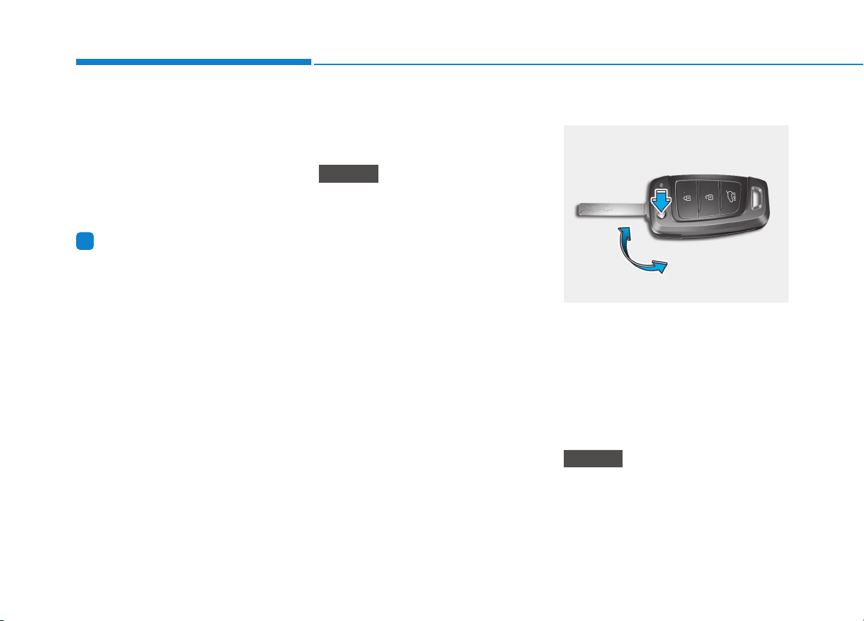
3-4
Convenient features of your vehicle
Tailgate unlocking
To unlock:
1. Press the Tailgate Unlock button
(3) on the remote key for more
than one second.
2. The hazard warning lights will
blink two times.
Information
The word "HOLD" is written on the
button to inform you that you must
press and hold the button for more
than one second.
Start-up
For detailed information refer to “Key
Ignition Switch” in chapter 5.
To prevent damaging the remote
key:
• Keep the remote key away from
water or any liquid and fire. If the
inside of the remote key gets
damp (due to drinks or mois-
ture), or is heated, internal cir-
cuit may malfunction, excluding
the car from the warranty.
• Avoid dropping or throwing the
remote key.
• Protect the remote key from
extreme temperatures.
Mechanical key
If the remote key does not operate
normally, you can lock or unlock the
door by using the mechanical key.
To unfold the key, press the release
button then the key will unfold auto-
matically.
To fold the key, fold the key manually
while pressing the release button.
Do not fold the key without press-
ing the release button. This may
damage the key.
NOTICE
NOTICE
i
OPDE046003
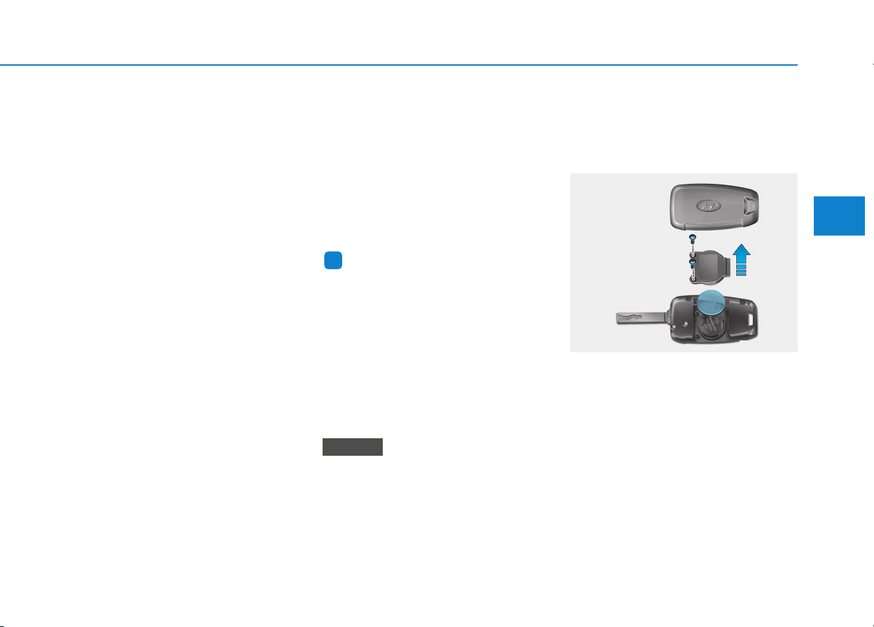
3-5
Convenient features of your vehicle
3
Remote key precautions
The remote key will not work if any of
the following occur:
• The key is in the ignition switch.
• You exceed the operating distance
limit (about 30 m [90 feet]).
• The remote key battery is weak.
• Other vehicles or objects may be
blocking the signal.
• The weather is extremely cold.
• The remote key is close to a radio
transmitter such as a radio station
or an airport which can interfere
with normal operation of the remote
key.
When the remote key does not work
correctly, open and close the door
with the mechanical key. If you have a
problem with the remote key, it is rec-
ommended that you contact an
authorized HYUNDAI dealer.
If the remote key is in close proximity
to your mobile phone, the signal could
be blocked by your mobile phones
normal operational signals.
This is especially important when the
phone is active such as making and
receiving calls, text messaging,
and/or sending/receiving emails.
Avoid placing the remote key and your
mobile phone in the same pants or
jacket pocket and always try to main-
tain an adequate distance between
the two devices.
Information
Changes or modifications not express-
ly approved by the party responsible
for compliance could void the user’s
authority to operate the equipment. If
the keyless entry system is inoperative
due to changes or modifications not
expressly approved by the party
responsible for compliance, it will not
be covered by your manufacturer’s
vehicle warranty.
Keep the remote key away from
electromagnetic materials that
blocks electromagnetic waves to
the key surface.
Battery replacement
If the remote key is not working prop-
erly, try replacing the battery with a
new one.
Battery Type: CR2032
To replace the battery:
1. Insert a slim tool into the slot and
gently pry open the cover.
2. Using a screw driver, remove the
battery cover.
3. Remove the old battery and insert
a new battery. Make sure the bat-
tery position is correct.
4. Reinstall the battery cover and key
cover in the reverse order of
removal.
NOTICE
i
OPD046002
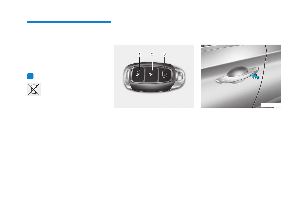
3-6
Convenient features of your vehicle
If you suspect your remote key might
have sustained some damage, or
you feel your remote key is not work-
ing correctly, it is recommended that
you contact an authorized HYUNDAI
dealer.
Information
An inappropriately disposed
battery can be harmful to the
environment and human
health. Dispose the battery
according to your local law(s)
and regulation.
Smart key
Your HYUNDAI uses a Smart Key,
which you can use to lock or unlock
a door (and tailgate) and even start
the engine.
1. Door Lock
2. Door Unlock
3. Tailgate Unlock
Locking
To lock :
1. Close all doors, engine hood and
tailgate.
2. Either press the door handle but-
ton or press the Door Lock button
(1) on the smart key.
3. The hazard warning lights will
blink. Also, the outside rearview
mirror will fold, if the outside
rearview mirror folding switch is in
the AUTO position (if equipped).
4. Make sure the doors are locked by
checking the position of the door
lock button inside the vehicle.
i
OPDE046044 OPD046005
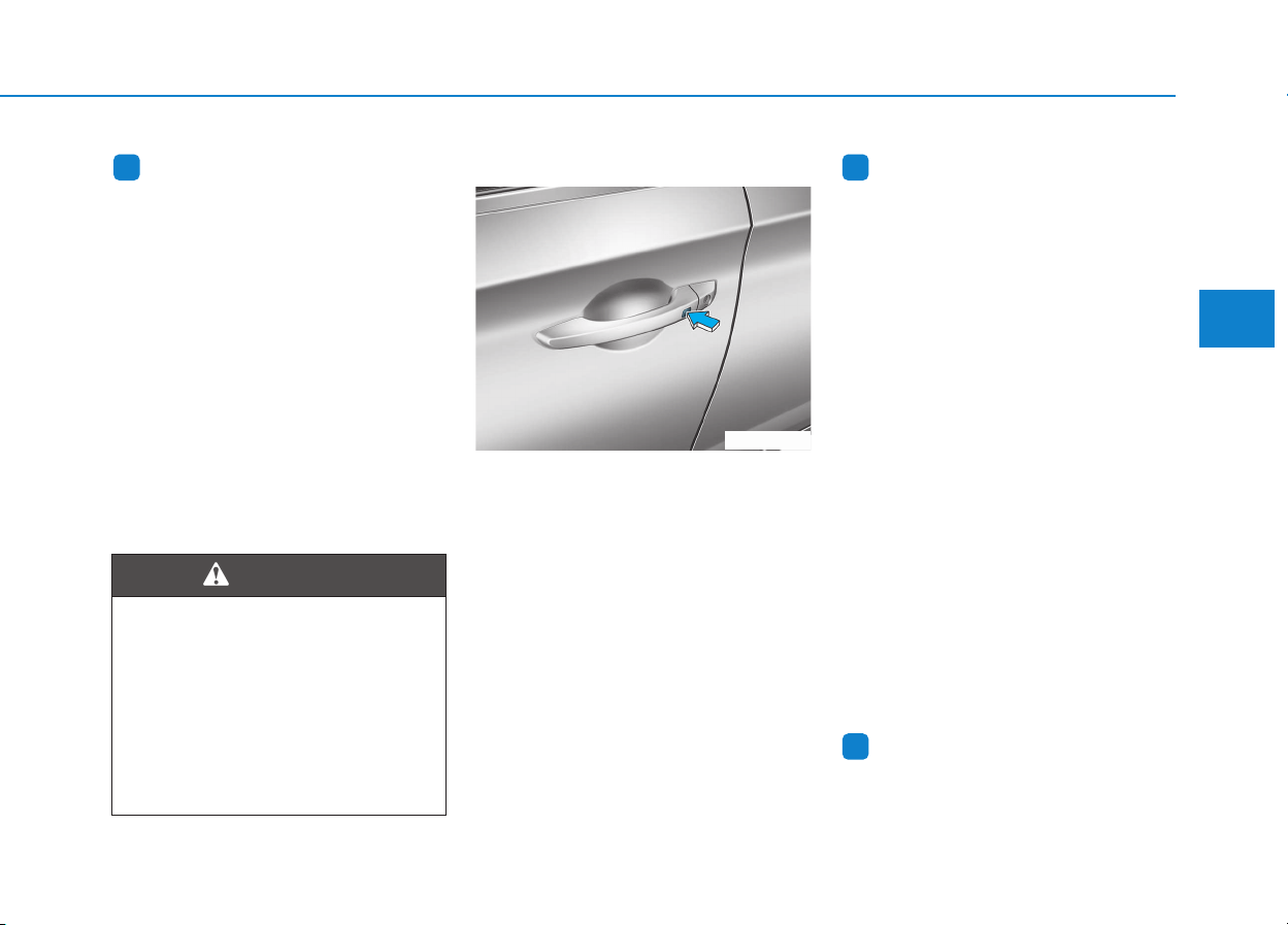
3-7
Convenient features of your vehicle
3
Information
The door handle button will only
operate when the smart key is within
0.7~1 m (28~40 in.) from the outside
door handle.
Even though you press the outside
door handle button, the doors will not
lock and the chime will sound for
three seconds if any of the following
occur:
• The Smart Key is in the vehicle.
• The Engine Start/Stop button is in
ACC or ON position.
• Any door except the tailgate is
open.
Unlocking
To unlock:
1. Carry the Smart Key.
2. Either press the door handle but-
ton or press the Door Unlock but-
ton (2) on the smart key.
3. The doors will unlock. The hazard
warning lights will blink two times.
Also, the outside rearview mirror
will unfold, if the outside rearview
mirror folding switch is in the AUTO
position. (if equipped)
Information
• The door handle button will only
operate when the smart key is with-
in 0.7~1 m (28~40 in.) from the out-
side door handle. Other people can
also open the doors without the
smart key in possession.
• After unlocking the doors, the doors
will lock automatically after 30 sec-
onds unless a door is opened.
Tailgate unlocking
To unlock:
1. Carry the smart key.
2. Either press the tailgate handle
button or press the Tailgate Unlock
button (3) on the smart key for
more than one second.
3. The hazard warning lights will
blink two times.
Once the tailgate is opened and then
closed, the tailgate will lock automat-
ically.
Information
After unlocking the tailgate, the tail-
gate will lock automatically after 30
seconds unless the tailgate is opened.
i
ii
Do not leave the Smart Key in
your vehicle with unsupervised
children. Unattended children
could press the Engine Start/
Stop button and may operate
power windows or other con-
trols, or even make the vehicle
move, which could result in
serious injury or death.
WARNING
OPD046005
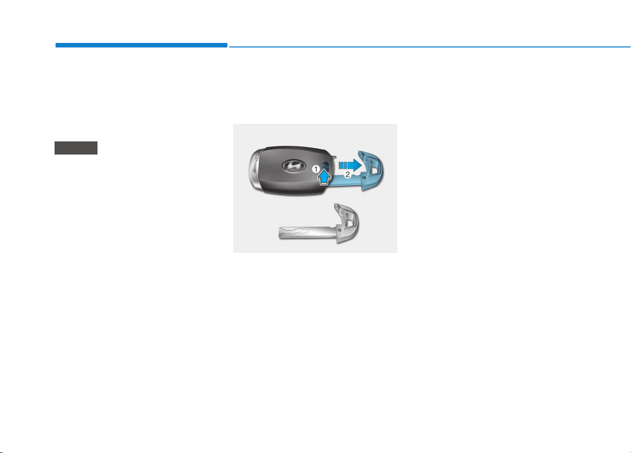
3-8
Convenient features of your vehicle
Start-up
You can start the engine without
inserting the key. For detailed infor-
mation refer to the Engine
Start/Stop button in chapter 5.
To prevent damaging the smart
key:
• Keep the smart key away from
water or any liquid and fire. If the
inside of the smart key gets
damp (due to drinks or moisture),
or is heated, internal circuit may
malfunction, excluding the car
from the warranty.
• Avoid dropping or throwing the
smart key.
• Protect the smart key from
extreme temperatures.
Mechanical key
If the Smart Key does not operate
normally, you can lock or unlock the
door by using the mechanical key.
Move the release lever in the direc-
tion of the arrow (1) and then remove
the mechanical key (2). Insert the
mechanical key into the key hole on
the door.
To reinstall the mechanical key, put
the key into the hole and push it until
a click sound is heard.
Loss of a smart key
A maximum of two smart keys can
be registered to a single vehicle. If
you happen to lose your smart key, it
is recommended that you should
immediately take the vehicle and
remaining key to your authorized
HYUNDAI dealer or tow the vehicle,
if necessary.
NOTICE
OPD046045
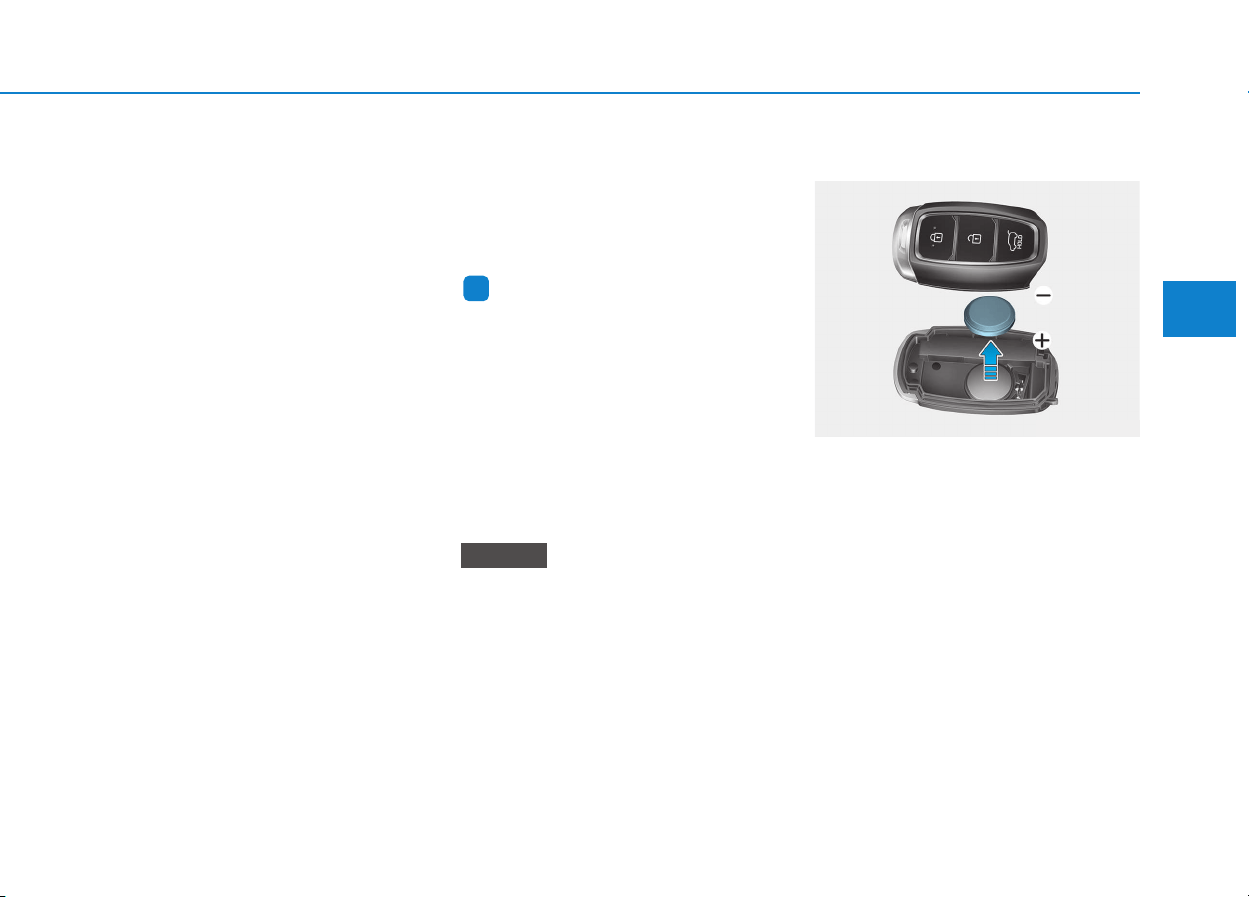
3-9
Convenient features of your vehicle
3
Smart key precautions
The smart key will not work if any of
the following occur:
• The smart key is close to a radio
transmitter such as a radio station
or an airport which can interfere
with normal operation of the trans-
mitter.
• The smart key is near a mobile two
way radio system or a cellular
phone.
• Another vehicle’s smart key is
being operated close to your vehi-
cle.
When the smart key does not work
correctly, open and close the door
with the mechanical key. If you have
a problem with the smart key, it is
recommended that you contact an
authorized HYUNDAI dealer.
If the smart key is in close proximity
to your mobile phone, the signal
could be blocked by your mobile
phones normal operational signals.
This is especially important when the
phone is active such as making and
receiving calls, text messaging,
and/or sending/receiving emails.
Avoid placing the smart key and your
mobile phone in the same pants or
jacket pocket and always try to main-
tain an adequate distance between
the two devices.
Information
Changes or modifications not express-
ly approved by the party responsible
for compliance could void the user’s
authority to operate the equipment. If
the keyless entry system is inoperative
due to changes or modifications not
expressly approved by the party
responsible for compliance, it will not
be covered by your manufacturer’s
vehicle warranty.
Keep the smart key away from
electromagnetic materials that
blocks electromagnetic waves to
the key surface.
Battery replacement
If the Smart Key is not working prop-
erly, try replacing the battery with a
new one.
Battery Type: CR2032
To replace the battery:
1. Pry open the rear cover of the
smart key.
2. Remove the old battery and insert
the new battery. Make sure the
battery position is correct.
3. Reinstall the rear cover of the
smart key.
NOTICE
i
OPDE046046
3-10
Convenient features of your vehicle
If you suspect your smart key might
have sustained some damage, or
you feel your smart key is not work-
ing correctly, it is recommended that
you contact an authorized HYUNDAI
dealer.
Information
An inappropriately disposed
battery can be harmful to the
environment and human health.
Dispose the battery according to
your local law(s) and regulation.
Immobilizer system
(if equipped)
The immobilizer system protects your
vehicle from theft. If an improperly
coded key (or other device) is used,
the engine’s fuel system is disabled.
When the ignition switch is placed in
the ON position, the immobilizer sys-
tem indicator should come on briefly,
then go off. If the indicator starts to
blink, the system does not recognize
the coding of the key.
Place the ignition switch to the
LOCK/OFF position, then place the
ignition switch to the ON position
again.
The system may not recognize your
key’s coding if another immobilizer
key or other metal object (i.e., key
chain) is near the key. The engine
may not start because the metal may
interrupt the transponder signal from
transmitting normally.
If the system repeatedly does not
recognize the coding of the key, it is
recommended that you contact your
HYUNDAI dealer.
Do not attempt to alter this system or
add other devices to it. Electrical
problems could result that may make
your vehicle inoperable.
The transponder in your key is an
important part of the immobilizer
system. It is designed to give
years of trouble-free service, how-
ever you should avoid exposure to
moisture, static electricity and
rough handling. Immobilizer sys-
tem malfunction could occur.
NOTICE
i
In order to prevent theft of your
vehicle, do not leave spare keys
anywhere in your vehicle. Your
immobilizer password is a cus-
tomer unique password and
should be kept confidential.
WARNING
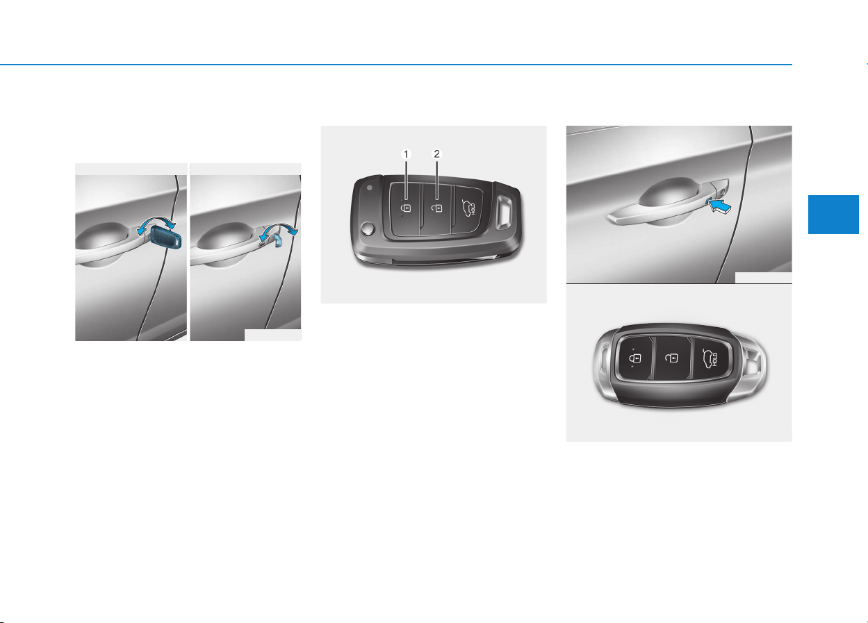
3-11
Convenient features of your vehicle
3
Operating door locks from
outside the vehicle
Mechanical key
Turn the key toward the rear of the
vehicle to unlock and toward the front
of the vehicle to lock.
If you lock/unlock the driver's door
with a key, all vehicle doors will
lock/unlock automatically.
Once the doors are unlocked, they
may be opened by pulling the door
handle.
When closing the door, push the
door by hand. Make sure that doors
are closed securely.
Remote key
To lock the doors, press the Door
Lock button (1) on the remote key.
To unlock the doors, press the Door
Unlock button (2) on the remote key.
Once the doors are unlocked, they
may be opened by pulling the door
handle.
When closing the door, push the
door by hand. Make sure that doors
are closed securely.
Smart key
To lock the doors, press the button on
the outside door handle while carry-
ing the smart key with you or press
the door lock button on the smart key.
DDOOOORR LLOOCCKKSS
OPDE046413
OPD046006
LL
LL
oo
oo
cc
cc
kk
kk
LL
LL
oo
oo
cc
cc
kk
kk
UU
UU
nn
nn
ll
ll
oo
oo
cc
cc
kk
kk
UU
UU
nn
nn
ll
ll
oo
oo
cc
cc
kk
kk
■ Remote key ■ Smart key
OPD046005
OPDE046004
LL
LL
oo
oo
cc
cc
kk
kk
//
//
UU
UU
nn
nn
ll
ll
oo
oo
cc
cc
kk
kk
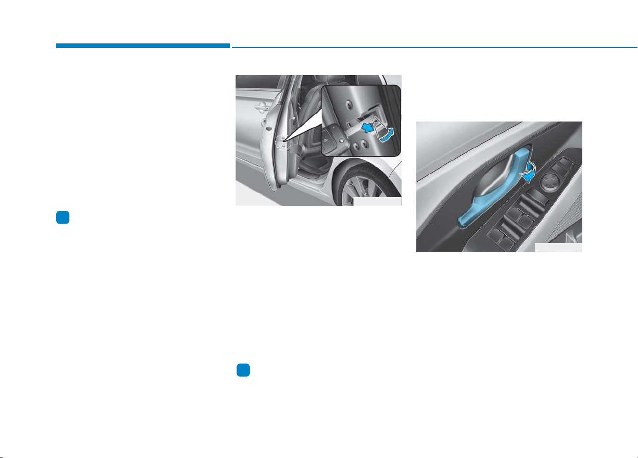
3-12
Convenient features of your vehicle
To unlock the doors, press the button
on the outside door handle while car-
rying the smart key with you or press
the door unlock button on the smart
key.
Once the doors are unlocked, they
may be opened by pulling the door
handle.
When closing the door, push the
door by hand. Make sure that doors
are closed securely.
Information
• In cold and wet climates, door lock
and door mechanisms may not work
properly due to freezing conditions.
• If the door is locked/unlocked multi-
ple times in rapid succession with
either the vehicle key or door lock
switch, the system may stop operat-
ing temporarily in order to protect
the circuit and prevent damage to
system components.
In case of an emergency
If the power door lock does not oper-
ate electrically, the only way to lock
the door(s) is with the mechanical
key from the outside key hole.
Doors without the outside key hole,
you can lock the door as follows:
1. Open the door.
2. Insert the key into the emergency
door lock hole and turn the key
horizontally to lock.
3. Close the door securely.
Information
Once the tailgate is closed when the
power door lock switch does not oper-
ate electrically, you will not be able to
open the tailgate.
Operating door locks from
inside the vehicle
With the door handle
Front door
If the inner door handle is pulled
when the door is locked, the door will
unlock and open.
Rear door
If the inner door handle is pulled
once when the door is locked, the
door will unlock.
If the inner door handle is pulled
once more, the door will open.
i
i
OPDE046007
OPDE046414
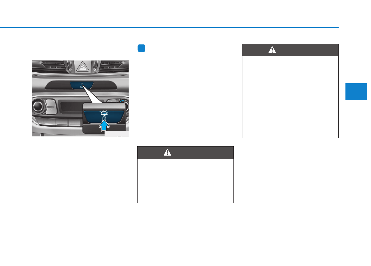
3-13
Convenient features of your vehicle
3
With the central door
lock/unlock switch
• With a door unlocked
- If you press the central door lock
switch, all vehicle doors will lock
and the indicator light on the switch
will illuminate.
- If any door is opened when the
switch is pressed, all doors will not
lock.
• With all doors locked
- If you press the central door unlock
switch, all vehicle doors will unlock.
- If any door is unlocked, the indica-
tor of the central door lock switch
will go off.
Information
If a power door lock ever fails to func-
tion while you are in the vehicle try
one or more of the following tech-
niques to exit:
Operate the door unlock feature
repeatedly (both electronic and manu-
al) while simultaneously pulling on the
door handle.
Operate the other door locks and han-
dles, front and rear.
Lower a front window and use the
mechanical key to unlock the door
from outside.
i
OPD046008
The doors should always be
fully closed and locked while
the vehicle is in motion. If the
doors are unlocked, the risk of
being thrown from the vehicle in
a crash is increased.
WARNING
Do not leave children or animals
unattended in your vehicle. An
enclosed vehicle can become
extremely hot, causing death or
serious injury to unattended
children or animals who cannot
escape the vehicle. Children
might operate features of the
vehicle that could injure them,
or they could encounter other
harm, possibly from someone
gaining entry to the vehicle.
WARNING

3-14
Convenient features of your vehicle
Auto door lock/unlock features
Impact sensing door unlock
system (if equipped)
All doors will be automatically
unlocked when an impact causes the
air bags to deploy.
Speed sensing door lock system
(if equipped)
All doors will be automatically locked
when vehicle speed exceeds 15
km/h (9 mph).
You can activate or deactivate the
Auto Door Lock/Unlock features from
the User Settings mode on the LCD
display. For more details, refer to
"LCD Display" in this chapter.
Leaving your vehicle unlocked
increases the potential risk to
you or others from someone
hiding in your vehicle.
To secure your vehicle, while
depressing the brake, move the
shift lever to the P (Park) posi-
tion (for automatic transmis-
sion/dual clutch transmission)
or first gear or R (Reverse, for
manual transmission), engage
the parking brake, and place the
ignition switch in the LOCK/OFF
position, close all windows,
lock all doors, and always take
the key with you.
WARNING
Opening a door when something
is approaching may cause dam-
age or injury. Be careful when
opening doors and watch for
vehicles, motorcycles, bicycles
or pedestrians approaching the
vehicle in the path of the door.
WARNING
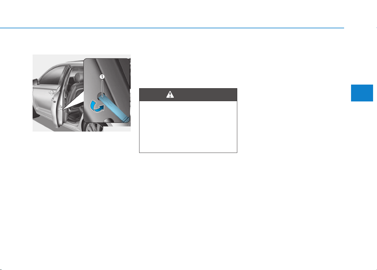
3-15
Convenient features of your vehicle
3
Child-protector rear door locks
The child safety lock is provided to
help prevent children seated in the
rear from accidentally opening the
rear doors.The rear door safety locks
should be used whenever children
are in the vehicle.
The child safety lock is located on
the edge of each rear door. When the
child safety lock is in the lock posi-
tion, the rear door will not open if the
inner door handle is pulled.
To lock the child safety lock, insert a
key (or screwdriver) (1) into the hole
and turn it to the lock position.
To allow a rear door to be opened
from inside the vehicle, unlock the
child safety lock.
OPDE046009
If children accidently open the
rear doors while the vehicle is
in motion, they could fall out of
the vehicle. The rear door safety
locks should always be used
whenever children are in the
vehicle.
WARNING
3-16
Convenient features of your vehicle
This system helps to protect your
vehicle and valuables. The horn will
sound and the hazard warning lights
will blink continuously if any of the
following occurs:
- A door is opened without using the
remote key or smart key.
- The tailgate is opened without
using the remote key or smart key.
- The engine hood is opened.
The alarm continues for 30 seconds,
then the system resets. To turn off
the alarm, unlock the doors with the
remote key or smart key.
The Theft Alarm System automati-
cally sets 30 seconds after you lock
the doors and the tailgate. For the
system to activate, you must lock the
doors and the tailgate from outside
the vehicle with the remote key or
smart key or by pressing the button
on the outside of the door handles
with the smart key in your posses-
sion.
The hazard warning lights will blink
and the chime will sound once to
indicate the system is armed.
Once the security system is set, open-
ing any door, the tailgate, or the hood
without using the remote key or smart
key will cause the alarm to activate.
The Theft Alarm System will not set if
the hood, the tailgate, or any door is
not fully closed. If the system will not
set, check the hood, the tailgate, or
the doors are fully closed.
Do not attempt to alter this system or
add other devices to it.
Information
• Do not lock the doors until all pas-
sengers have left the vehicle. If the
remaining passenger leaves the
vehicle when the system is armed,
the alarm will be activated.
• If the vehicle is not disarmed with
the remote key or smart key, open
the doors by using the mechanical
key and place the ignition switch in
the ON position (for remote key) or
start the engine (for smart key) and
wait for 30 seconds.
• When the system is disarmed but a
door or tailgate is not opened within
30 seconds, the system will be
rearmed.
Information
Vehicles equipped with a theft alarm
system will have a label attached to
the vehicle with the following words:
1. WARNING
2. SECURITY SYSTEM
i
i
TTHHEEFFTT--AALLAARRMM SSYYSSTTEEMM
OJC040170
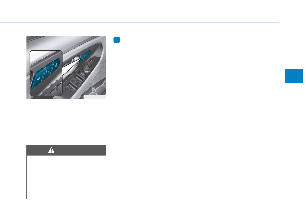
3-17
Convenient features of your vehicle
3
The Driver Position Memory System
is provided to store and recall the fol-
lowing memory settings with a sim-
ple button operation.
- Driver's seat position
- Outside rearview mirror position
- Instrument panel illumination intensity
Information
• If the battery is disconnected, the
memory settings will be erased.
• If the Driver Position Memory
System does not operate normally,
we recommend that you have the
system checked by an authorized
HYUNDAI dealer.
Storing memory positions
1. Move the shift lever into P (Park)
while the ignition switch or the
Engine Start/Stop button is in the
ON position.
2. Adjust the driver's seat position,
outside rearview mirror position
and instrument panel illumination
intensity to the desired position.
3. Press the SET button. The system
will beep once and notify you
"Press button to save settings"on
the LCD display.
4. Press one of the memory buttons
(1 or 2) within 4 seconds. The sys-
tem will beep twice when the mem-
ory has been successfully stored.
5. "Driver 1 (or 2) settings saved" will
appear on the LCD display.
Recalling memory positions
1. Move the shift lever into P (Park)
while the ignition switch or the
Engine Start/Stop button is in the
ON position.
2. Press the desired memory button
(1 or 2). The system will beep
once, then the driver’s seat posi-
tion, outside rearview mirror and
instrument panel illumination will
automatically adjust to the stored
position (if equipped).
3. "Driver 1(or 2) settings is applied"
will appear on the LCD display.
i
DDRRIIVVEERR PPOOSSIITTIIOONN MMEEMMOORRYY SSYYSSTTEEMM ((IIFF EEQQUUIIPPPPEEDD))
OPDE046010
Never attempt to operate the driv-
er position memory system while
the vehicle is moving.
This could result in loss of con-
trol, and an accident causing
death, serious injury, or property
damage.
WARNING

3-18
Convenient features of your vehicle
Information
• While recalling the "1" memory
position, pressing the SET or 1 but-
ton temporarily stops the adjust-
ment of the recalled memory posi-
tion. Pressing the 2 button recalls
the "2" memory position.
• While recalling the "2" memory
position, pressing the SET or 2 but-
ton temporarily stops the adjust-
ment of the recalled memory posi-
tion. Pressing the 1 button recalls
the "1" memory position.
• While recalling the stored positions,
pressing one of the control buttons
for the driver's seat, outside
rearview mirror, or instrument
panel illumination will cause the
movement of that component to stop
and move in the direction that the
control button is pressed.
Easy access function
(if equipped)
The system will move the driver's
seat automatically as follows:
The shift lever is in P (Park)
• Without smart key system
- It will move the driver’s seat rear-
ward when the ignition key is
removed and the driver’s door is
opened.
- It will move the driver’s seat forward
when the ignition key is inserted.
• With smart key system
- It will move the driver’s seat rear-
ward when the Engine Start/Stop
button is in the OFF position and
the driver’s door is opened.
- It will move the driver’s seat for-
ward when the vehicle is turned
ON or the driver’s door is closed
with the smart key with you.
You can activate or deactivate the
Easy Access Function from the User
Settings mode on the LCD display.
For more details, refer to "LCD
Display" in this chapter.
i
Driver should be cautious when
using this function to assure no
injury to passenger or child on
the back seat. In case of emer-
gency the driver has to stop
movement of front seat (when
easy access feature is activat-
ed) by pressing SET button or
any of the driver seat control
switches.
CAUTION

3-19
Convenient features of your vehicle
3
Electric power steering (EPS)
The system assists you with steering
the vehicle. If the engine is off or if
the power steering system becomes
inoperative, the vehicle may still be
steered, but it will require increased
steering effort.
Also, the steering effort becomes
heavier as the vehicle’s speed
increases and becomes lighter as
the vehicle’s speed decreases for
better control of the steering wheel.
Should you notice any change in the
effort required to steer during normal
vehicle operation, we recommend
that the system be checked by an
authorized HYUNDAI dealer.
• If the Electric Power Steering
System does not operate nor-
mally, the warning light ( ) will
illuminate or blink on the instru-
ment cluster. The steering wheel
may become difficult to control
or operate. Take your vehicle to
an authorized HYUNDAI dealer
and have the system checked as
soon as possible.
• When abnormality is detected in
the electric power steering sys-
tem, to prevent a deadly acci-
dent, the steering assist function
will stop. At this time, the warn-
ing light turns on or blinks on
the cluster. The steering wheel
may become difficult to control
or operate. Have your vehicle
checked immediately, after mov-
ing the vehicle to a safe zone.
Information
The following symptoms may occur
during normal vehicle operation:
• The steering effort may be high
immediately after placing the igni-
tion switch button in the ON posi-
tion.
This happens as the system per-
forms the EPS system diagnostics.
When the diagnostics is completed,
the steering wheel will return to its
normal condition.
• A click noise may be heard from the
EPS relay after the ignition switch is
placed to the ON or LOCK/OFF
position.
• Motor noise may be heard when the
vehicle is at a stop or at a low driv-
ing speed.
• When you operate the steering
wheel in low temperature, abnormal
noise may occur. If temperature
rises, the noise will disappear. This
is a normal condition.
(Continued)
i
NOTICE
SSTTEEEERRIINNGG WWHHEEEELL
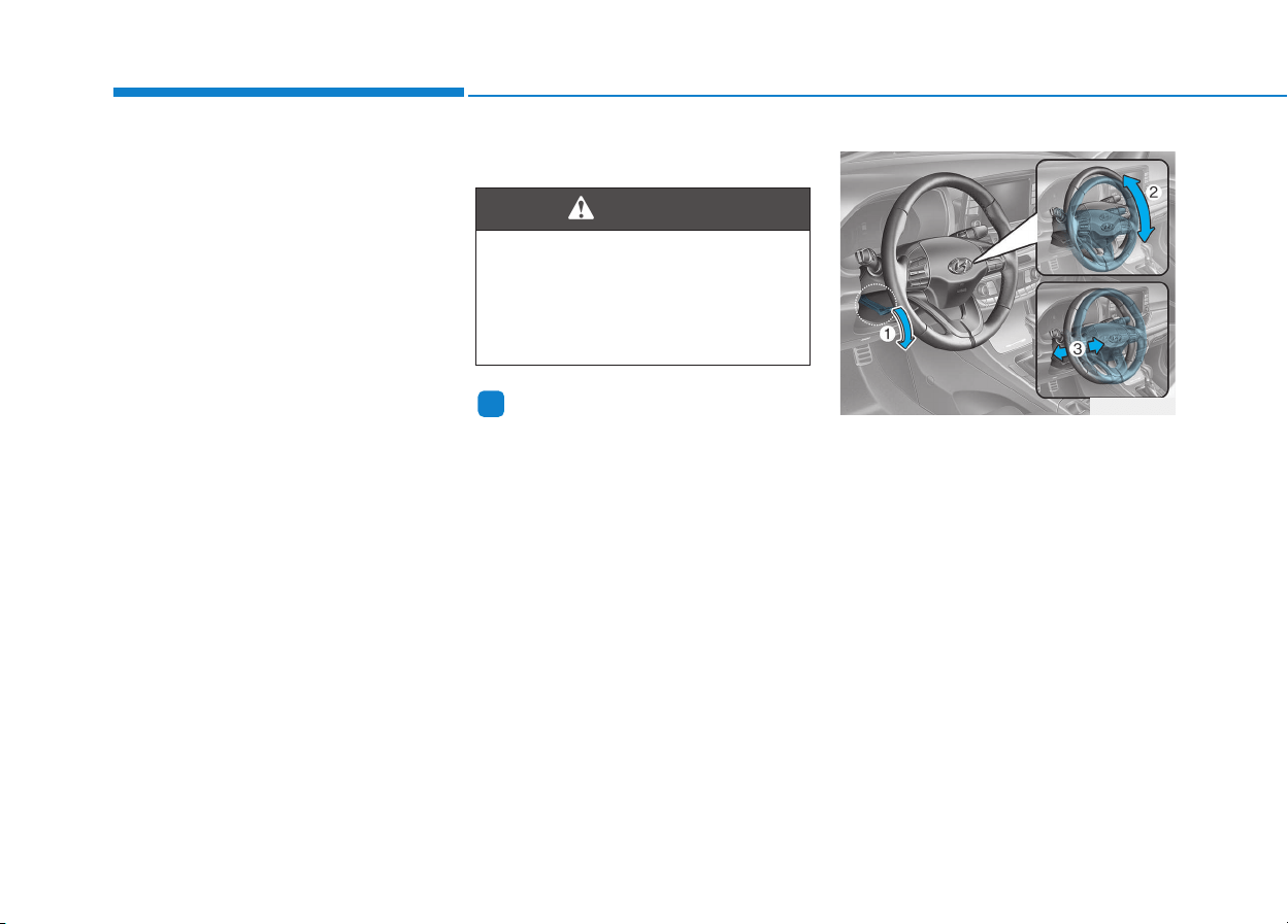
3-20
Convenient features of your vehicle
(Continued)
• When the vehicle is stationary, if
you turn the steering wheel all the
way to the left or right continuously,
the steering wheel effort increases.
This is not a system malfunction. As
time passes, the steering wheel
effort will return to its normal con-
dition.
Tilt steering / Telescope steering
Information
After adjustment, sometimes the lock-
release lever may not lock the steering
wheel.
It is not a malfunction. This occurs
when two gears are not engaged cor-
rectly. In this case, adjust the steering
wheel again and then lock the steering
wheel.
Pull down the lock-release lever (1) on
the steering wheel column and adjust
the steering wheel angle (2) and posi-
tion (3). Move the steering wheel, so it
points toward your chest, not toward
your face.
Make sure you can see the instrument
panel warning lights and gauges.
After adjusting, pull up the lock-
release lever (1) to lock the steering
wheel in place. Push the steering
wheel both up and down to be cer-
tain it is locked in position. Always
adjust the position of the steering
wheel before driving.
i
Never adjust the steering wheel
while driving. You may lose
steering control and cause
severe personal injury, death or
accidents.
WARNING
OPD046012
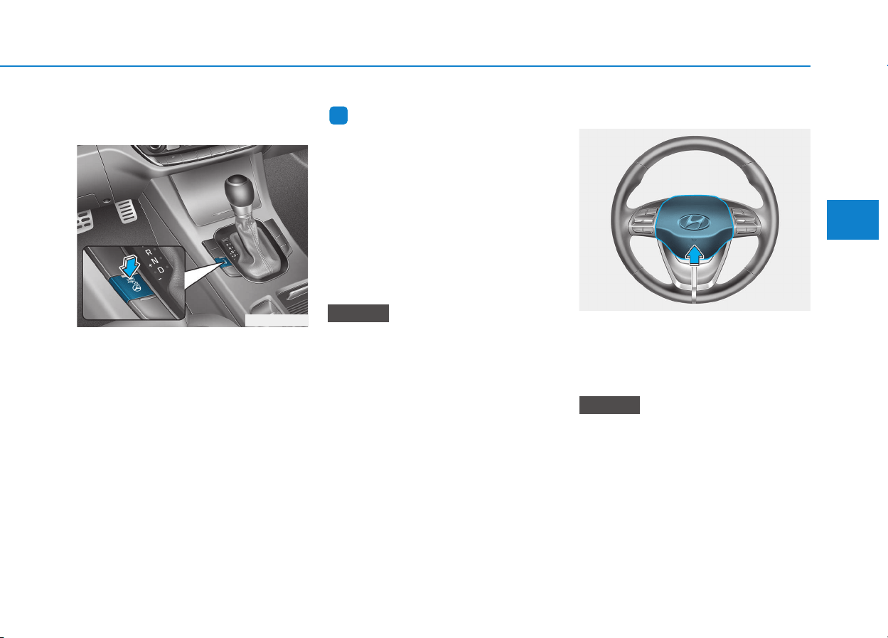
3-21
Convenient features of your vehicle
3
Heated steering wheel
(if equipped)
When the ignition switch is in the ON
position or when the engine is running,
press the heated steering wheel but-
ton to warm the steering wheel. The
indicator on the button will illuminate.
To turn the heated steering wheel off,
press the button again. The indicator
on the button will turn off.
Information
The heated steering wheel will turn off
automatically approximately 30 min-
utes after the heated steering wheel is
turned on.
When the engine is turned off during
the engine and the heated steering
wheel is on, the timer function of heat-
ed steering wheel will be reset.
To reuse heated steering wheel, press
button again.
Do not install any cover or acces-
sory on the steering wheel. This
cover or accessory could cause
damage to the heated steering
wheel system.
Horn
To sound the horn, press the area
indicated by the horn symbol on your
steering wheel. The horn will operate
only when this area is pressed.
Do not strike the horn severely to
operate it, or hit it with your fist.
Do not press on the horn with a
sharp-pointed object.
NOTICE
NOTICE
i
OPD046014
OPDE046013
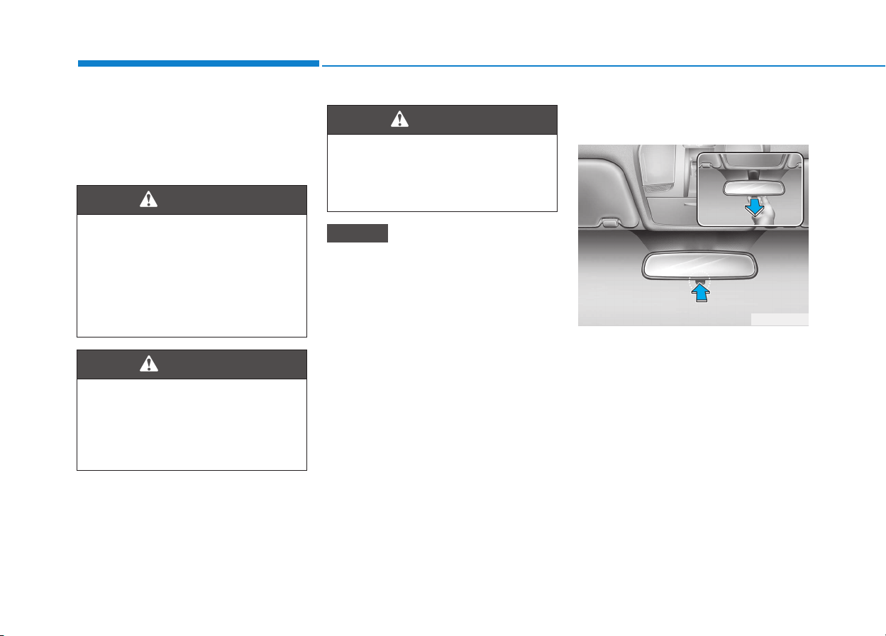
3-22
Convenient features of your vehicle
Inside rearview mirror
Before you start driving, adjust the
rearview mirror to the center on the
view through the rear window.
When cleaning the mirror, use a
paper towel or similar material
dampened with glass cleaner. Do
not spray glass cleaner directly on
the mirror as that may cause the
liquid cleaner to enter the mirror
housing.
Day/night rearview mirror
(if equipped)
Make this adjustment before you
start driving and while the day/night
lever is in the day position.
Pull the day/night lever toward you to
reduce glare from the headlights of
the vehicles behind you during night
driving.
Remember that you lose some
rearview clarity in the night position.
NOTICE
NEVER adjust the mirror while
driving. This may cause loss of
vehicle control resulting in an
accident.
WARNING
OAE046010
Day
Night
MMIIRRRROORRSS
Make sure your line of sight is
not obstructed. Do not place
objects in the rear seat, cargo
area, or behind the rear head-
rests which could interfere with
your vision through the rear
window.
WARNING
To prevent serious injury during
an accident or deployment of
the air bag, do not modify the
rearview mirror and do not
install a wide mirror.
WARNING
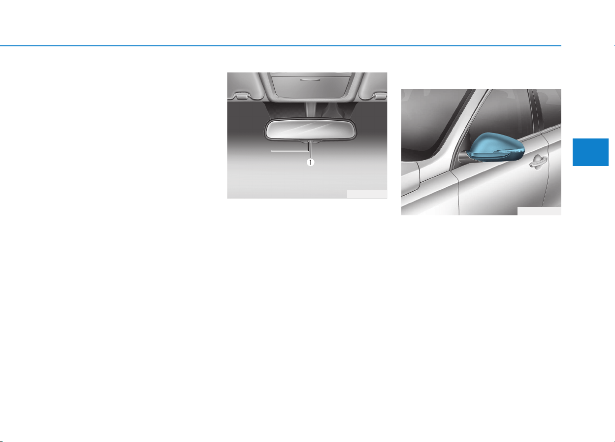
3-23
Convenient features of your vehicle
3
Electric Chromic Mirror (ECM)
(if equipped)
The electric rearview mirror automati-
cally controls the glare from the head-
lamp of the car behind you in night-
time or low light driving conditions.
When the engine is running, the
glare is automatically controlled by
the sensor mounted in the rearview
mirror. The sensor detects the light
level around the vehicle, and auto-
matically adjusts to control the head-
lamp glare from vehicles behind you.
Whenever the shift lever is placed in
R (Reverse), the mirror will automat-
ically go to the brightest setting in
order to improve the drivers view
behind the vehicle.
To operate the electric rearview
mirror:
• Press the ON/OFF button (1) to
turn the automatic dimming func-
tion off. The mirror indicator light
will turn off.
Press the ON/OFF button (1) to
turn the automatic dimming func-
tion on. The mirror indicator light
will illuminate.
• The mirror defaults to the ON posi-
tion whenever the ignition switch is
in the ON position.
Outside rearview mirror
Be sure to adjust mirror angles
before driving.
Your vehicle is equipped with both
left-hand and right-hand outside
rearview mirrors.
The mirror can be adjusted remotely
with the remote switch.
The mirror heads can be folded to
prevent damage during an automatic
car wash or when passing through a
narrow street.
OAD045010
OPD046016
II
II
nn
nn
dd
dd
ii
ii
cc
cc
aa
aa
tt
tt
oo
oo
rr
rr
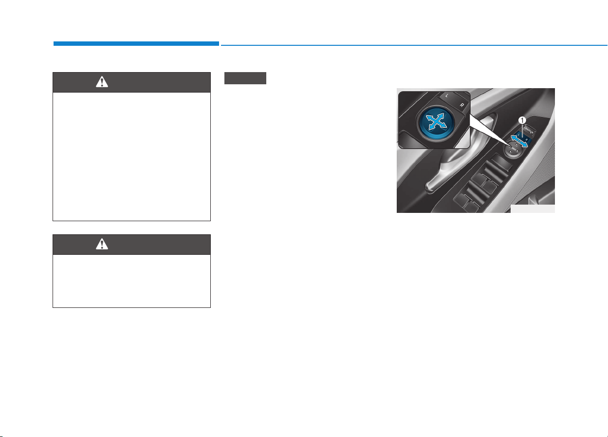
3-24
Convenient features of your vehicle
• Do not scrape ice off the mirror
face; this may damage the sur-
face of the glass.
• If the mirror is jammed with ice,
do not adjust the mirror by
force. Use an approved spray
de-icer (not radiator antifreeze)
spray, or a sponge or soft cloth
with very warm water, or move
the vehicle to a warm place and
allow the ice to melt.
Adjusting the rearview mirrors
1. Press either the L (left side) or R
(right side) button (1) to select the
rearview mirror you would like to
adjust.
2. Use the mirror adjustment control
(2) to position the selected mirror
up, down, left or right.
3. After adjustment, put the button
into neutral (center) position to
prevent inadvertent adjustment.
NOTICE
OPDE046017
• The right outside rearview mir-
ror is convex. In some coun-
tries, the left outside rearview
mirror is also convex. Objects
seen in the mirror are closer
than they appear.
• Use your interior rearview
mirror or turn your head and
look to determine the actual
distance of following vehicles
when changing lanes.
WARNING
Do not adjust or fold the outside
rearview mirrors while driving.
This may cause loss of vehicle
control resulting in an accident.
WARNING
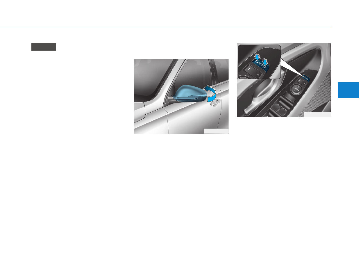
3-25
Convenient features of your vehicle
3
• The mirrors stop moving when
they reach the maximum adjust-
ing angles, but the motor contin-
ues to operate while the switch
is pressed. Do not press the
switch longer than necessary,
the motor may be damaged.
• Do not attempt to adjust the out-
side rearview mirror by hand or
the motor may be damaged.
Folding the outside rearview
mirror
Manual type
To fold the outside rearview mirror,
grasp the housing of the mirror and
then fold it toward the rear of the
vehicle.
Electric type
Left : The mirror will unfold.
Right : The mirror will fold.
Center (AUTO) : The mirror will fold
or unfold automatically as follows:
• Without smart key system
- The mirror will fold or unfold when
the door is locked or unlocked by
the remote key.
• With smart key system
- The mirror will fold or unfold when
the door is locked or unlocked by
the smart key.
- The mirror will fold or unfold when
the door is locked or unlocked by
the button on the outside door
handle.
NOTICE
OPD046018
OPDE046019
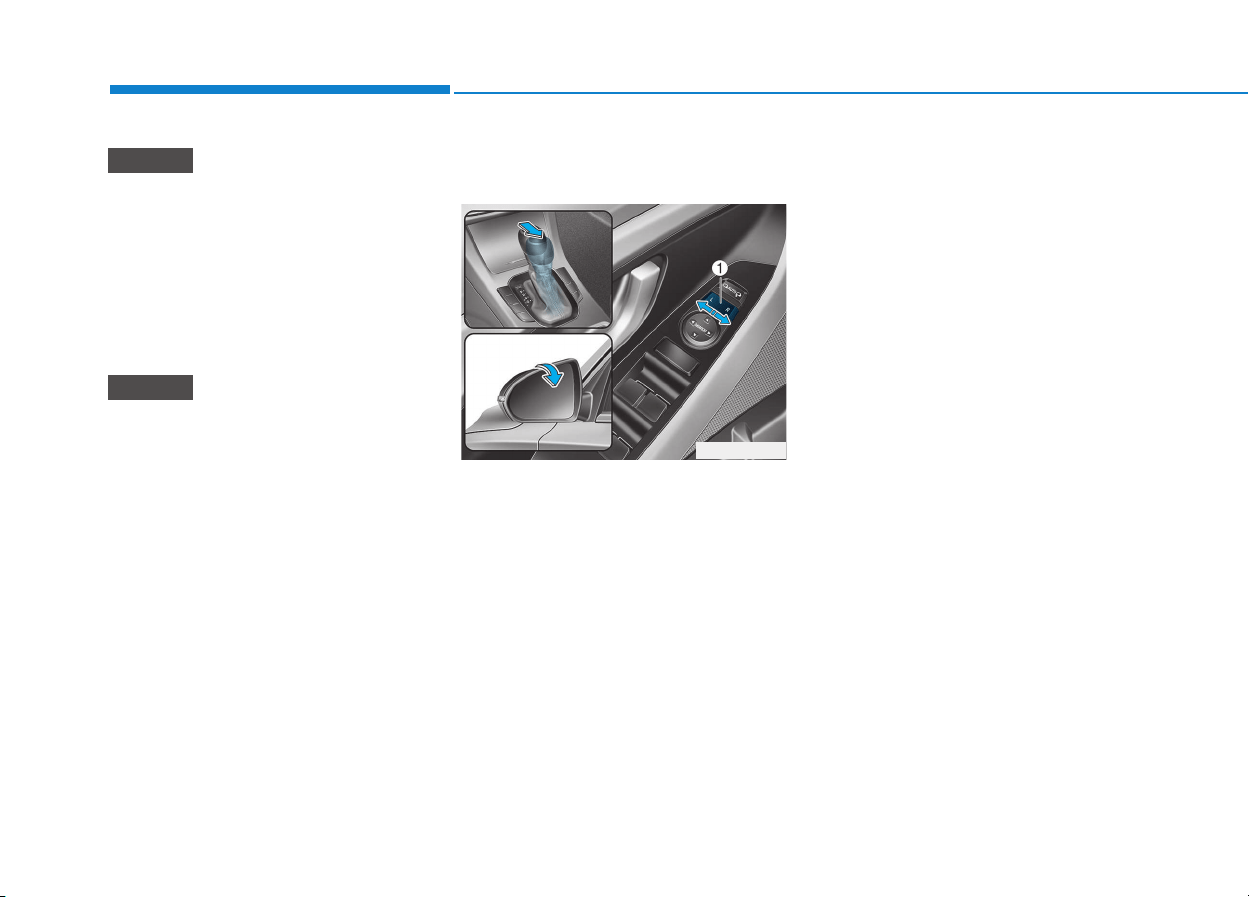
3-26
The electric type outside rearview
mirror operates even though the
ignition switch is in the OFF posi-
tion. However, to prevent unnec-
essary battery discharge, do not
adjust the mirrors longer than
necessary while the engine is not
running.
Do not fold the electric type out-
side rearview mirror by hand. It
could cause motor failure.
Reverse parking aid function
(if equipped)
When you move the shift lever to the
R (Reverse) position, the outside
rearview mirror(s) will rotate down-
wards to aid with driving in reverse.
The position of the outside rearview
mirror switch (1) determines whether
or not the mirrors will move:
Left/Right : When either the L (Left) or
R (Right) switch is select-
ed, both outside rearview
mirrors will move.
Neutral : When neither switch is select-
ed, the outside rearview mir-
rors will not move.
The outside rearview mirrors will
automatically revert to their original
positions if any of the following occur:
• The ignition switch is placed to
either the LOCK/OFF position or
the ACC position.
• The shift lever is moved to any
position except R (Reverse).
• The outside rearview mirror switch
is not selected.
NOTICE
NOTICE
Convenient features of your vehicle
OPDE046423
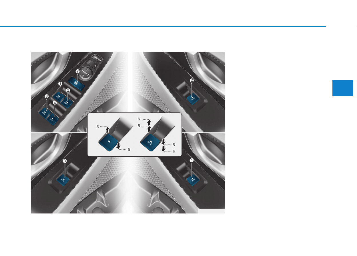
3-27
Convenient features of your vehicle
3
Power windows (if equipped)
(1) Driver’s door power window
switch
(2) Front passenger’s door power
window switch
(3) Rear door (left) power window
switch*
(4) Rear door (right) power window
switch*
(5) Window opening and closing
(6) Automatic power window*
(7) Power window lock switch
* : if equipped
WWIINNDDOOWWSS
OPDE046021
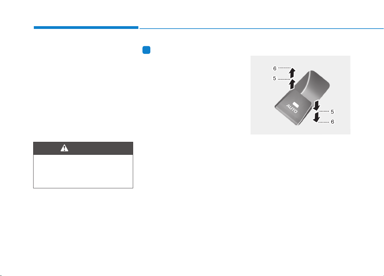
3-28
Convenient features of your vehicle
The ignition switch must be in the ON
position to be able to raise or lower
the windows. Each door has a Power
Window switch to control that door's
window. The driver has a Power
Window Lock switch which can block
the operation of passenger windows.
The power windows will operate for
approximately 30 seconds after the
ignition switch is placed in the ACC
or OFF position. However, if the front
doors are opened, the Power
Windows cannot be operated even
within the 30 second period.
Information
• In cold and wet climates, power win-
dows may not work properly due to
freezing conditions.
• While driving with the rear win-
dows down or with the sunroof (if
equipped) opened (or partially
opened), your vehicle may demon-
strate a wind buffeting or pulsation
noise. This noise is normal and can
be reduced or eliminated by taking
the following actions. If the noise
occurs with one or both of the rear
windows down, partially lower both
front windows approximately one
inch. If you experience the noise
with the sunroof open, slightly close
the sunroof.
Window opening and closing
To open:
Press the window switch down to the
first detent position (5). Release the
switch when you want the window to
stop.
To close:
Pull the window switch up to the first
detent position (5). Release the win-
dow switch when you want the win-
dow to stop.
i
To avoid serious injury or death,
do not extend your head, arms
or body outside the windows
while driving.
WARNING
OAE046020
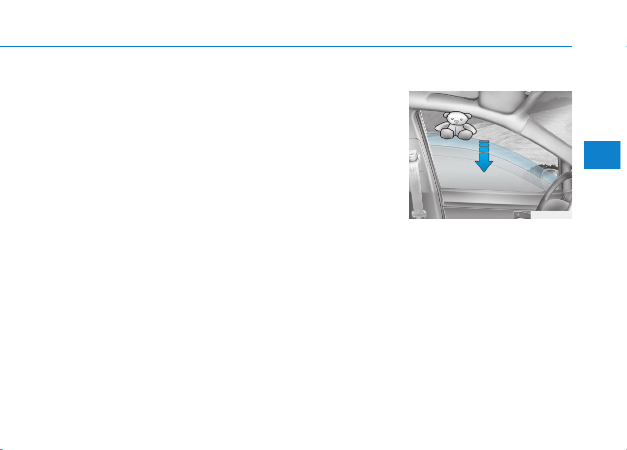
3-29
Convenient features of your vehicle
3
Auto down window (if equipped)
Pressing the power window switch
momentarily to the second detent
position (6) completely lowers the
window even when the switch is
released. To stop the window at the
desired position while the window is
in operation, pull up or press down
and release the switch.
Auto up/down window
(if equipped)
Pressing or pulling up the power win-
dow switch momentarily to the sec-
ond detent position (6) completely
lowers or lifts the window even when
the switch is released. To stop the
window at the desired position while
the window is in operation, pull up or
press down and release the switch.
To reset the power windows
If the power windows do not operate
normally, the automatic power win-
dow system must be reset as follows:
1. Place the ignition switch to the ON
position.
2. Close the window and continue
pulling up on the power window
switch for at least one second.
If the power windows do not operate
properly after resetting, it is recom-
mended that the system be checked
by an authorized HYUNDAI dealer.
Automatic reversal (if equipped)
If a window senses any obstacle
while it is closing automatically, it will
stop and lower approximately 30 cm
(12 inches) to allow the object to be
cleared.
If the window detects the resistance
while the power window switch is
pulled up continuously, the window
will stop upward movement then
lower approximately 2.5 cm (1 inch).
If the power window switch is pulled
up continuously again within 5 sec-
onds after the window is lowered by
the automatic window reversal fea-
ture, the automatic window reversal
will not operate.
OLF044032
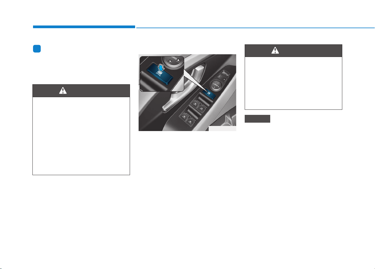
3-30
Convenient features of your vehicle
Information
The automatic reverse feature is only
active when the “Auto Up” feature is
used by fully pulling up the switch to
the second detent.
Power window lock switch
The driver can disable the power
window switches on the rear passen-
gers' doors by pressing the power
window lock switch.
When the power window lock switch
is pressed:
• The driver's master control can
operate all the power windows.
• The front passenger's control can
operate the front passenger's
power window.
• The rear passenger's control can-
not operate the rear passengers'
power window.
• To prevent possible damage to
the power window system, do
not open or close two windows
or more at the same time. This
will also ensure the longevity of
the fuse.
• Never try to operate the main
switch on the driver's door and
the individual door window
switch in opposite directions at
the same time. If this is done, the
window will stop and cannot be
opened or closed.
NOTICE
i
Make sure body parts or other
objects are safely out of the way
before closing the windows to
avoid injuries or vehicle damage.
Objects less than 4 mm (0.16
inch) in diameter caught between
the window glass and the upper
window channel may not be
detected by the automatic reverse
window and the window will not
stop and reverse direction.
WARNING
Do not allow children to play
with the power windows. Keep
the driver’s door power window
lock switch in the LOCK posi-
tion. Serious injury or death can
result from unintentional win-
dow operation by a child.
WARNING
OPDE046023
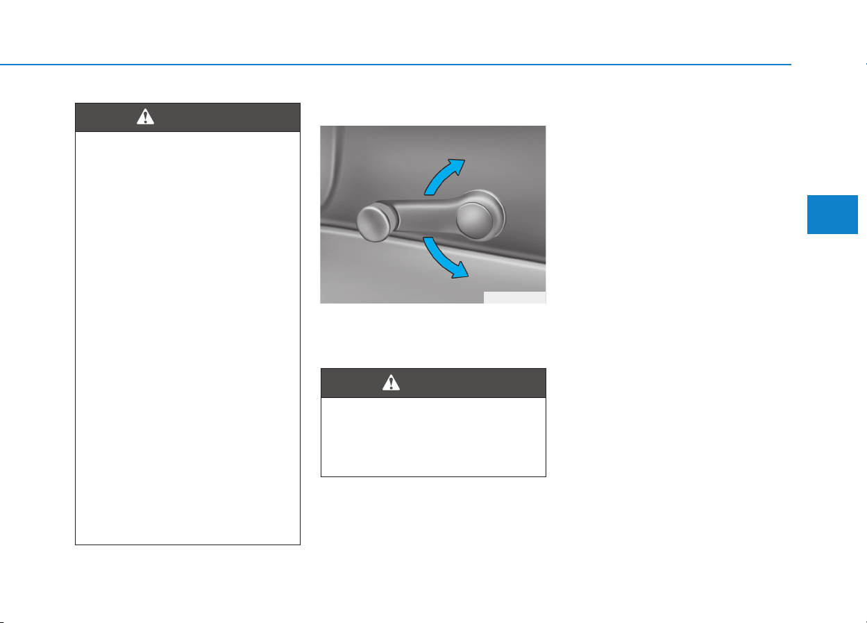
3-31
Convenient features of your vehicle
3
Manual windows (if equipped)
To raise or lower the window, turn the
window regulator handle clockwise
or counterclockwise.
• NEVER leave the keys in your
vehicle with unsupervised
children, when the engine is
running.
• NEVER leave any child unat-
tended in the vehicle. Even
very young children may inad-
vertently cause the vehicle to
move, entangle themselves in
the windows, or otherwise
injure themselves or others.
• Always double check to make
sure all arms, hands, head
and other obstructions are
safely out of the way before
closing a window.
• Do not allow children to play
with the power windows. Keep
the driver’s door power window
lock switch in the LOCK posi-
tion (pressed). Serious injury
can result from unintentional
window operation by the child.
• Do not extend your head,
arms or body outside the win-
dows while driving.
WARNING
When opening or closing the
windows, make sure your pas-
senger's arms, hands and body
are safely out of the way.
WARNING
OPDE036067
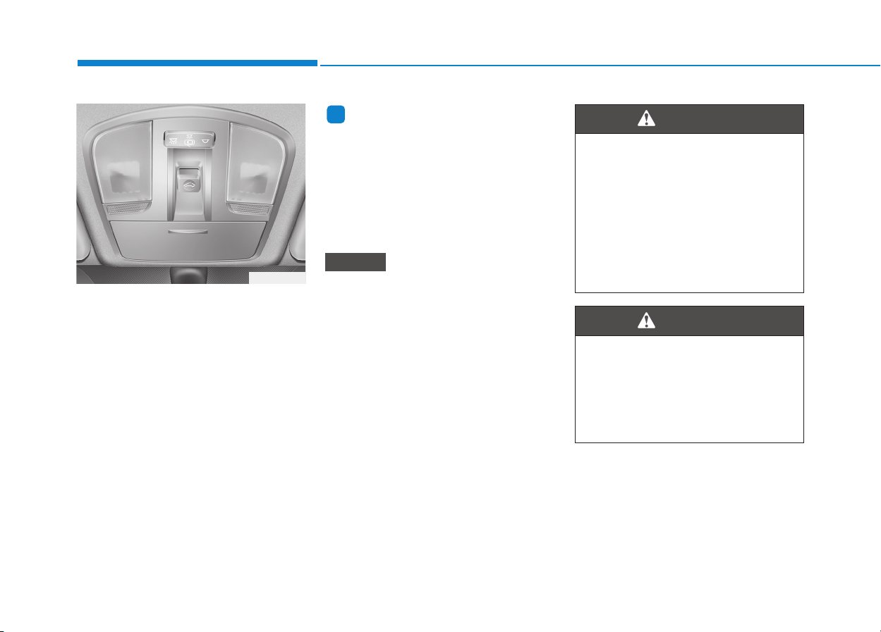
3-32
Convenient features of your vehicle
If your vehicle is equipped with a
sunroof, you can slide or tilt your
sunroof with the sunroof control lever
located on the overhead console.
The ignition switch must be in the ON
position before you can open or
close the sunroof.
The sunroof can be operated for
approximately 30 seconds after the
ignition key is removed or turned to
the ACC or LOCK(or OFF) position.
However, if the front door is opened,
the sunroof cannot be operated even
within 30 seconds.
Information
• In cold and wet climates, the sun-
roof may not work properly due to
freezing conditions.
• After washing the car or after there
is rain, be sure to wipe off any water
that is on the sunroof before operat-
ing it.
• Do not continue to move the sun-
roof control lever after the sun-
roof is fully opened, closed, or
tilted. Damage to the motor or
system components could occur.
• Make sure the sunroof is closed
fully when leaving your vehicle.
If the sunroof is open, rain or
snow may leak through the sun-
roof and wet the interior as well
as cause theft.
NOTICE
i
PPAANNOORRAAMMAA SSUUNNRROOOOFF ((IIFF EEQQUUIIPPPPEEDD))
•
Make sure heads, other body
parts or objects are out of the
way before using the sunroof.
• Do not leave the engine run-
ning and the key in your vehi-
cle with unsupervised children.
Unattended children could
operate the sunroof, which
could result in serious injury.
WARNING
OPD046024
Never adjust the sunroof or
sunshade while driving. This
could result in loss of control
and an accident that may cause
death, serious injury, or proper-
ty damage.
WARNING
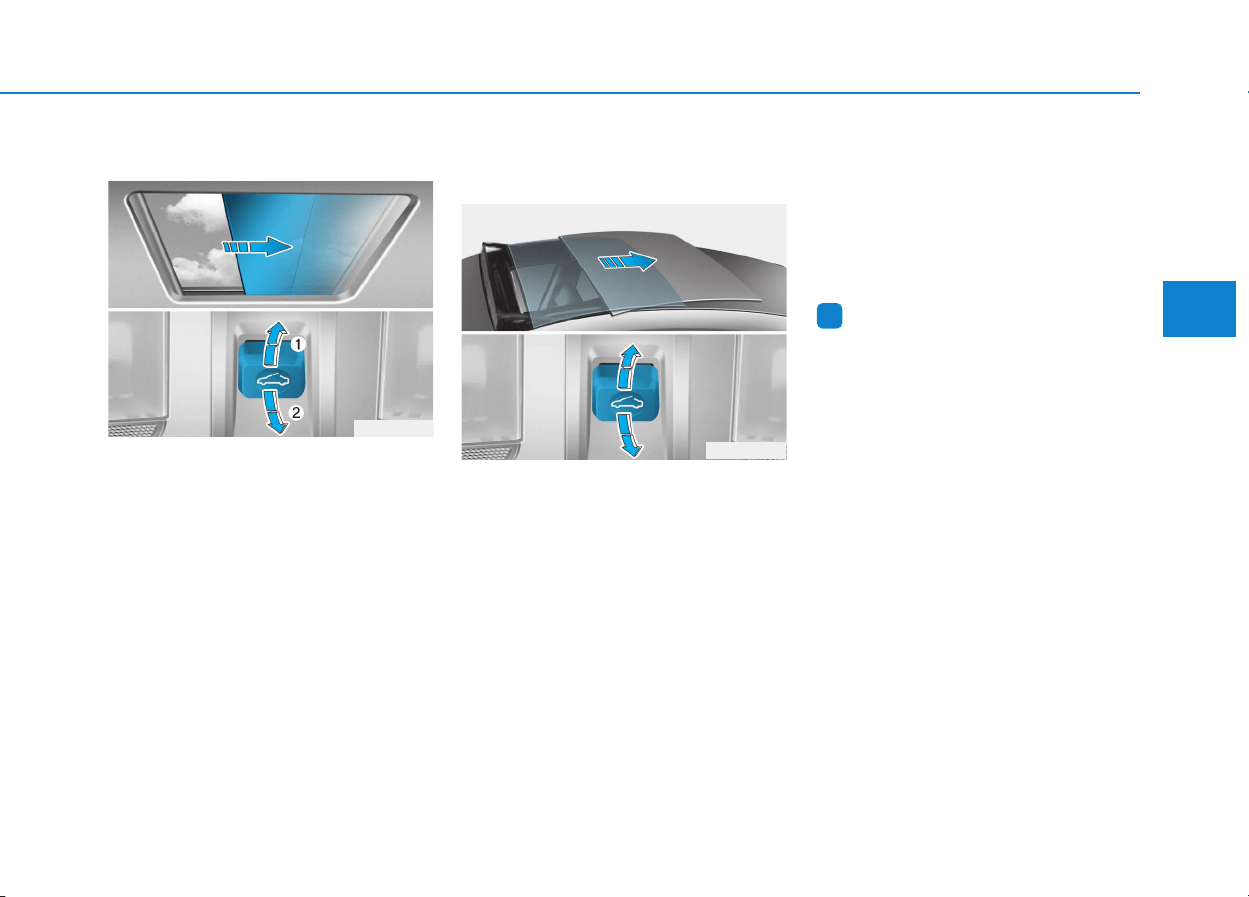
3-33
Convenient features of your vehicle
3
Sunshade
• To open the sunshade, pull the
sunroof control lever backward (1)
to the first detent position.
• To close the sunshade when the
sunroof glass is closed, push the
sunroof control lever forward (2).
To stop the sliding at any point, pull
or push the sunroof control lever
momentarily.
Sliding the sunroof
When the sunshade is closed
If you pull the sunroof control lever
backward to the second detent, the
sunshade will slide all the way open
then the sunroof glass will slide all
the way open. To stop the sunroof
movement at any point, pull or push
the sunroof control lever momentarily.
When the sunshade is opened
If you pull the sunroof control lever
backward, the sunroof glass will slide
all the way open. To stop the sunroof
movement at any point, pull or push
the sunroof control lever momentarily.
Information
Only the front glass of the panorama
sunroof opens and closes.
i
OPD046053
OPD046025
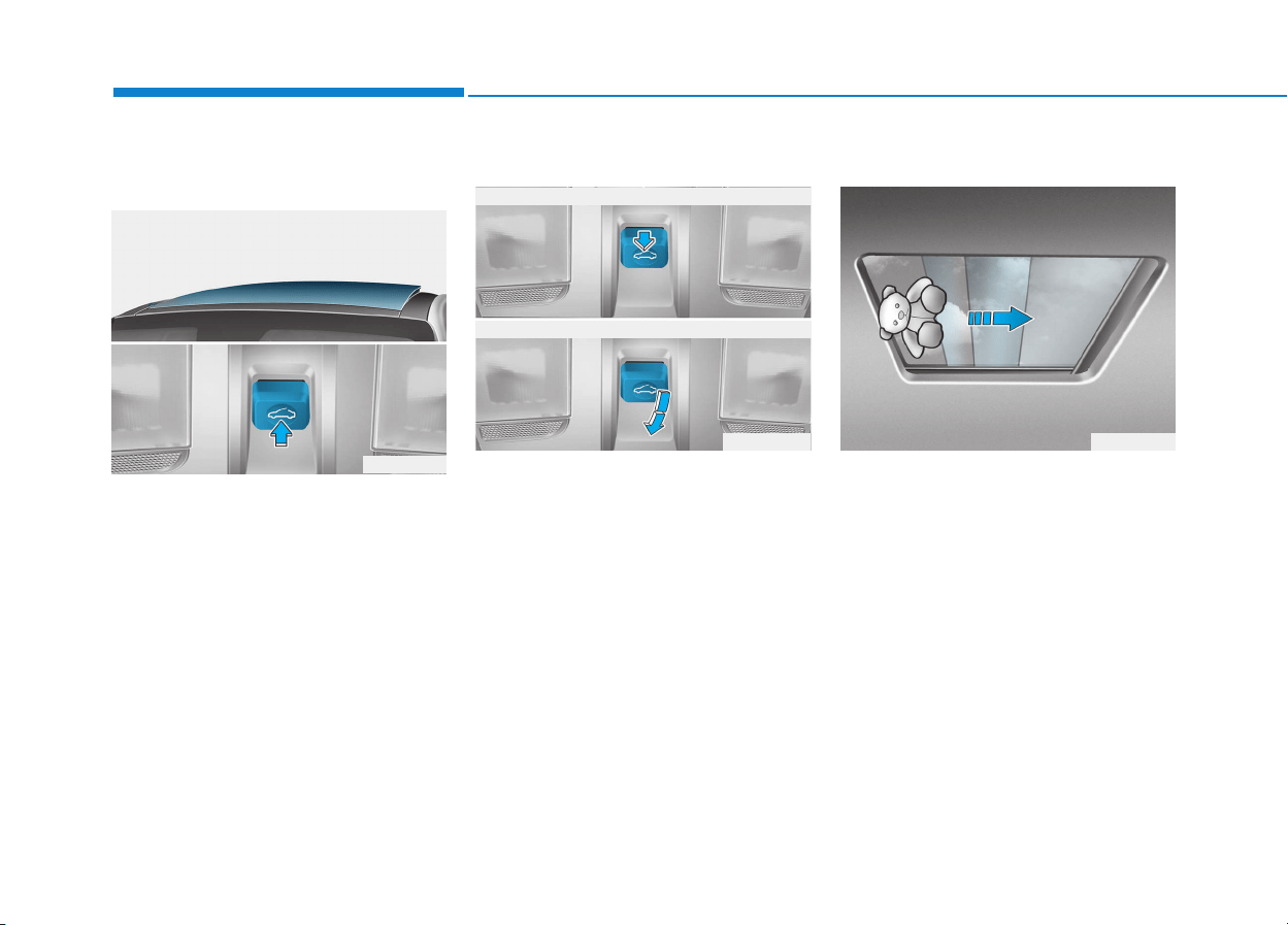
3-34
Convenient features of your vehicle
Tilting the sunroof
When the sunshade is closed
If you push the sunroof control lever
upward, the sunshade will slide open
then the sunroof glass will tilt.
To stop the sunroof movement at any
point, pull or push the sunroof control
lever momentarily.
When the sunshade is opened
If you push the sunroof control lever
upward, the sunroof glass will tilt.
To stop the sunroof movement at any
point, pull or push the sunroof control
lever momentarily.
Closing the sunroof
To close sunroof glass
Push the sunroof control lever for-
ward to the first detent position or
pull the lever downward.
To close sunroof glass with
sunshade
Push the sunroof control lever for-
ward to the second detent position.
The sunroof glass will close then the
sunshade will close automatically.
To stop the sunroof movement at any
point, pull or push the sunroof control
lever momentarily.
Automatic reversal
If an object or part of the body is
detected while the sunroof glass or
sunshade is closing automatically, it
will reverse the direction, and then
stop.
OPD046054
ODH043039OPD046055
■ Sunroof glass
■ Sunroof glass with sunshade
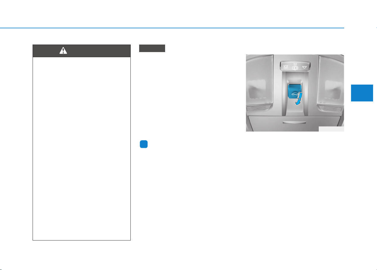
3-35
Convenient features of your vehicle
3
• Periodically remove any dirt that
may accumulate on the sunroof
guide rail or between the sun-
roof and roof panel, which can
make a noise.
• Do not try to open the sunroof
when the temperature is below
freezing or when the sunroof is
covered with snow or ice, the
motor could be damaged. In
cold and wet climates, the sun-
roof may not work properly.
Information
After the vehicle is washed or in a
rainstorm, be sure to wipe off any
water that is on the sunroof before
operating it.
Resetting the sunroof
The sunroof may need to be reset if
the following conditions occur:
- The battery is discharged or dis-
connected or the sunroof fuse has
been replaced or disconnected
- The sunroof control lever is not
operating correctly
To reset the sunroof, perform the fol-
lowing steps:
1. Turn the engine on and close the
sunroof glass and sunshade com-
pletely.
2. Release the control lever.
i
NOTICE
• Make sure heads, other body
parts or other objects are safe-
ly out of the way before closing
the sunroof to avoid injuries or
vehicle damage.
• Small objects that can get
caught between the sunroof
glass and the front glass chan-
nel may not be detected by the
automatic reverse system. In
this case, the sunroof glass will
not detect the object and
reverse direction.
• To avoid serious injury or
death, do not extend your
head, arms or body outside the
sunroof while driving.
• In the event of an accident or
collision, the sunroof glass may
break. Appropriate protection
(ex. seatbelt, child restraint sys-
tem, etc.) must be worn by ALL
passengers whenever the vehi-
cle is moving. ALWAYS proper-
ly restrain children under age
13 in the rear seats.
• Do not sit on the sunroof.
WARNING
OPD046056
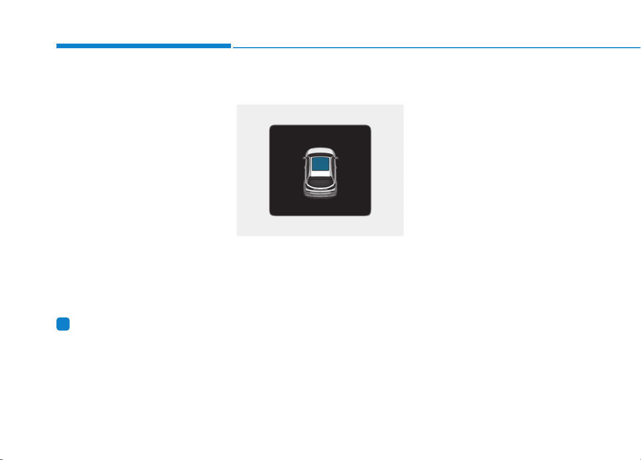
3-36
Convenient features of your vehicle
3. Push and hold the sunroof control
lever forward (to close the sun-
shade) for about 10 seconds until
the sunroof moves slightly, then
release the control lever.
4. Push and hold the sunroof control
lever forward until the sunroof
operates as follows:
Sunshade Open → Glass Tilt Open
→ Glass Slide Open → Glass Slide
Close → Sunshade Close
Then, release the control lever.
When this is complete, the sunroof
system is reset.
For more details, contact an author-
ized HYUNDAI dealer.
Information
If you do not reset the sunroof, it may
not work properly.
Sunroof open warning
(if equipped)
• If the driver turns off the engine when
the sunroof is not fully closed, the
warning chime will sound for approx-
imately 3 seconds and sunroof open
warning will appear on the LCD dis-
play.
• If the driver turns off the engine and
opens the door when the sunroof is
not fully closed, the open sunroof
warning will appear on the LCD dis-
play until the door is closed or the
sunroof is fully closed.
Close the sunroof securely when leav-
ing your vehicle.
i
OPD046116
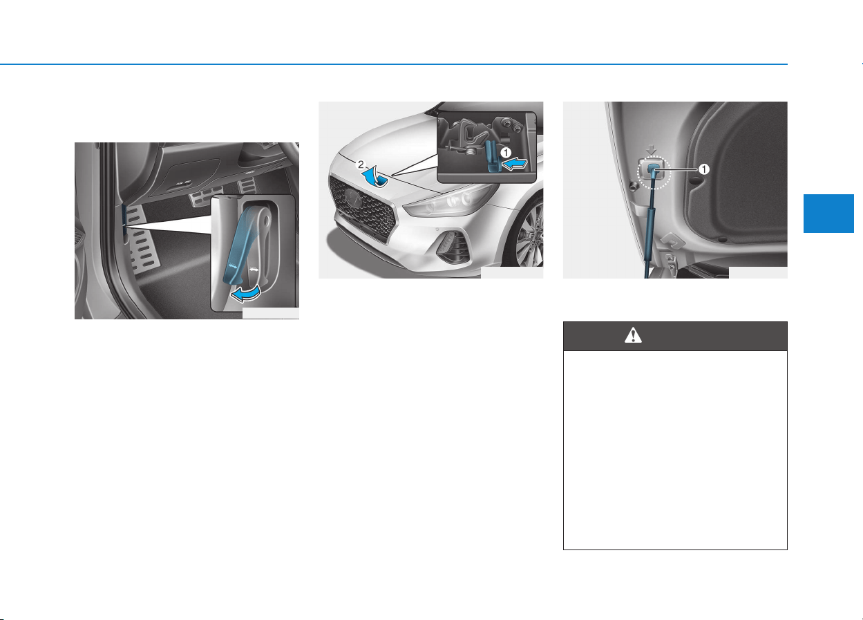
3-37
Convenient features of your vehicle
3
EEXXTTEERRIIOORR FFEEAATTUURREESS
Hood
Opening the hood
1. Park the vehicle and set the park-
ing brake.
2. Pull the release lever to unlatch
the hood. The hood should pop
open slightly.
3. Go to the front of the vehicle, raise
the hood slightly, push the second-
ary latch up (1) inside of the hood
center and lift the hood (2).
4. Pull out the support rod.
5. Hold the hood opened with the
support rod (1).
OPD046027
OPDE046028
• Grasp the support rod in the
area wrapped in rubber. The
rubber will help prevent you
from being burned by hot
metal when the engine is hot.
• The support rod must be
inserted completely into the
hole provided whenever you
inspect the engine compart-
ment. This will prevent the
hood from falling and possi-
bly injuring you.
WARNING
OPD046030
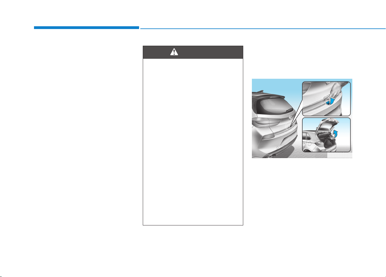
3-38
Convenient features of your vehicle
Closing the hood
1. Before closing the hood, check the
following:
• All filler caps in engine compart-
ment must be correctly installed.
• Gloves, rags or any other com-
bustible material must be removed
from the engine compartment.
2. Return the support rod to its clip to
prevent it from rattling.
3. Lower the hood halfway (lifted
approximately 30cm from the
closed position) and push down to
securely lock in place. Then double
check to be sure the hood is secure.
If the hood can slightly be raised, it
is not securely locked. Open it again
and close it with more force.
Tailgate
Opening the tailgate
1. Make sure the shift lever is in P
(Park) and set the parking brake.
2. Then do one of the following :
- Press the Remote key or Smart
Key Tailgate Unlock button for
more than one second.
- Press the button on the tailgate
itself with the Smart Key in your
possession.
3. Lift the tailgate lid up.
• Before closing the hood,
ensure all obstructions are
removed from around hood
opening.
• Always double check to be
sure that the hood is firmly
latched before driving away.
Check there is no hood open
warning light or message dis-
played on the instrument clus-
ter. If the hood is not latched
while the vehicle is moving, the
chime will sound to warn the
driver the hood is not fully
latched. Driving with the hood
opened may cause a total loss
of visibility, which might result
in an accident.
• Do not move the vehicle with
the hood in the raised posi-
tion, as vision is obstructed,
which might result in an acci-
dent, and the hood could fall
or be damaged.
WARNING
OPD046029
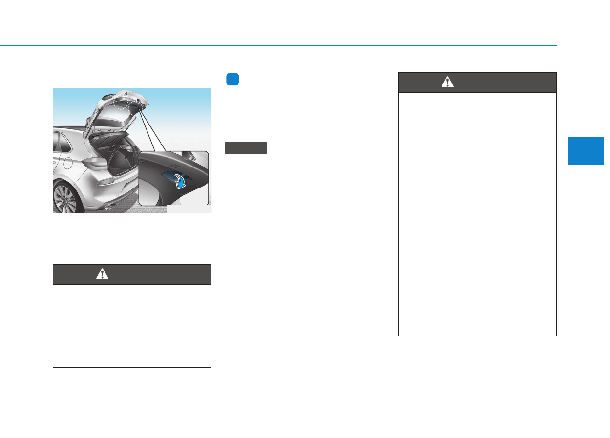
3-39
Convenient features of your vehicle
3
Closing the tailgate
Lower the tailgate lid and press down
until it locks. To be sure the tailgate
lid is securely fastened, always
check by trying to pull it up again.
Information
To prevent damage to the tailgate lift
cylinders and the attached hardware,
always close the tailgate before driv-
ing.
In cold and wet climates, tailgate
lock and tailgate mechanisms may
not work properly due to freezing
conditions.
NOTICE
i
Always keep the tailgate lid com-
pletely closed while the vehicle is
in motion. If it is left open or ajar,
poisonous exhaust gases con-
taining carbon monoxide (CO)
may enter the vehicle and seri-
ous illness or death may result.
WARNING
OPD046031
• NEVER allow anyone to occu-
py the tailgate of the vehicle at
any time. If the tailgate is par-
tially or totally latched and the
person is unable to get out,
serious injury or death could
occur due to lack of ventila-
tion, exhaust fumes and rapid
heat build-up, or because of
exposure to cold weather con-
ditions. The tailgate is also a
highly dangerous location in
the event of a crash because it
is not a protected occupant
space but is a part of the vehi-
cle’s crush zone.
• Your vehicle should be kept
locked and keys should be
kept out of the reach of chil-
dren. Parents should teach
their children about the dan-
gers of playing in tailgates.
WARNING
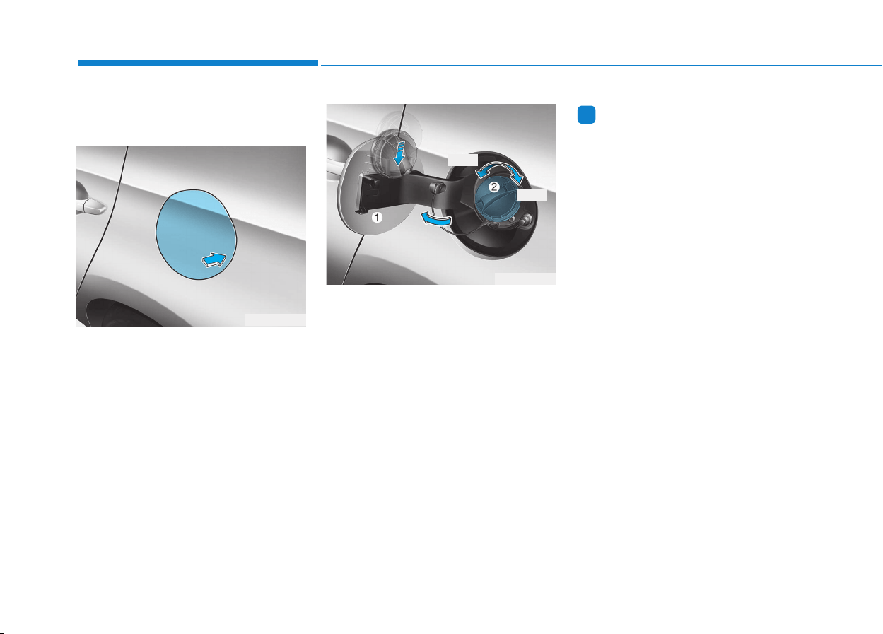
3-40
Convenient features of your vehicle
Fuel filler door
Opening the fuel filler door
1. Turn the engine off.
2. Push the center edge of the fuel
filler door when the driver’s door is
unlocked.
3. Pull the fuel filler door (1) out to
fully open.
4. To remove the fuel tank cap (2),
turn it counterclockwise. You may
hear a hissing noise as the pres-
sure inside the tank equalizes.
5. Place the cap on the fuel filler door.
Information
If the fuel filler door does not open
because ice has formed around it, tap
lightly or push on the door to break
the ice and release the door. Do not
pry on the door. If necessary, spray
around the door with an approved de-
icer fluid (do not use radiator anti-
freeze) or move the vehicle to a warm
place and allow the ice to melt.
i
OPD046034
OPD046033
Open
Close

3-41
Convenient features of your vehicle
3
Closing the fuel filler door
1. To install the fuel tank cap, turn it
clockwise until it “clicks” one time.
2. Close the fuel filler door until it is
latched securely.
Gasoline is highly flammable
and explosive. Failure to follow
these guidelines may result in
SERIOUS INJURY or DEATH:
• Read and follow all warnings
posted at the gas station.
• Before refueling, note the
location of the Emergency
Gasoline Shut-Off, if available,
at the gas station.
• Before touching the fuel noz-
zle, you should eliminate the
potential build-up of static
electricity by touching a metal
part of the vehicle, a safe dis-
tance away from the fuel filler
neck, nozzle, or other gas
source, with your bare hand.
(Continued)
WARNING
(Continued)
•
When refueling, always move
the shift lever to the P (Park)
position (for automatic transmis-
sion/
dual clutch transmission)
or first gear or R (Reverse, for
manual transmission), set the
parking brake, and place the
ignition switch to the LOCK/OFF
position. Sparks produced by
electrical components related to
the engine can ignite fuel vapors
causing a fire.
• When using an approved
portable fuel container, be sure
to place the container on the
ground prior to refueling. Static
electricity discharge from the
container can ignite fuel vapors
causing a fire. Once refueling
has begun, contact between
your bare hand and the vehicle
should be maintained until the
filling is complete.
(Continued)
(Continued)
• Do not use cellular phones
while refueling. Electric cur-
rent and/or electronic interfer-
ence from cellular phones can
potentially ignite fuel vapors
and cause a fire.
• Do not get back into a vehicle
once you have begun refuel-
ing. You can generate a build-
up of static electricity by touch-
ing, rubbing or sliding against
any item or fabric capable of
producing static electricity.
Static electricity discharge can
ignite fuel vapors causing a
fire. If you must re-enter the
vehicle, you should once again
eliminate potentially danger-
ous static electricity discharge
by touching a metal part of the
vehicle, away from the fuel filler
neck, nozzle or other gasoline
source, with your bare hand.
(Continued)

3-42
Convenient features of your vehicle
Information
Make sure to refuel your vehicle
according to the "Fuel Requirements"
suggested in the Introduction chapter.
• Do not spill fuel on the exterior
surfaces of the vehicle. Any type
of fuel spilled on painted sur-
faces may damage the paint.
• If the fuel filler cap requires
replacement, use only a genuine
HYUNDAI cap or the equivalent
specified for your vehicle. An
incorrect fuel filler cap can
result in a serious malfunction
of the fuel system or emission
control system.
NOTICE
i
(Continued)
• Use only approved portable
plastic fuel containers designed
to carry and store gasoline.
• Do not use matches or a
lighter and do not smoke or
leave a lit cigarette in your
vehicle while at a gas station,
especially during refueling.
• Do not over-fill or top-off your
vehicle tank, which can cause
gasoline spillage.
• If a fire breaks out during refu-
eling, leave the vicinity of the
vehicle, and immediately con-
tact the manager of the gas
station and then contact the
local fire department. Follow
any safety instructions they
provide.
(Continued)
(Continued)
• If pressurized fuel sprays out,
it can cover your clothes or
skin and thus subject you to
the risk of fire and burns.
Always remove the fuel cap
carefully and slowly. If the cap
is venting fuel or if you hear a
hissing sound, wait until the
condition stops before com-
pletely removing the cap.
• Always check that the fuel cap
is installed securely to prevent
fuel spillage in the event of an
accident.
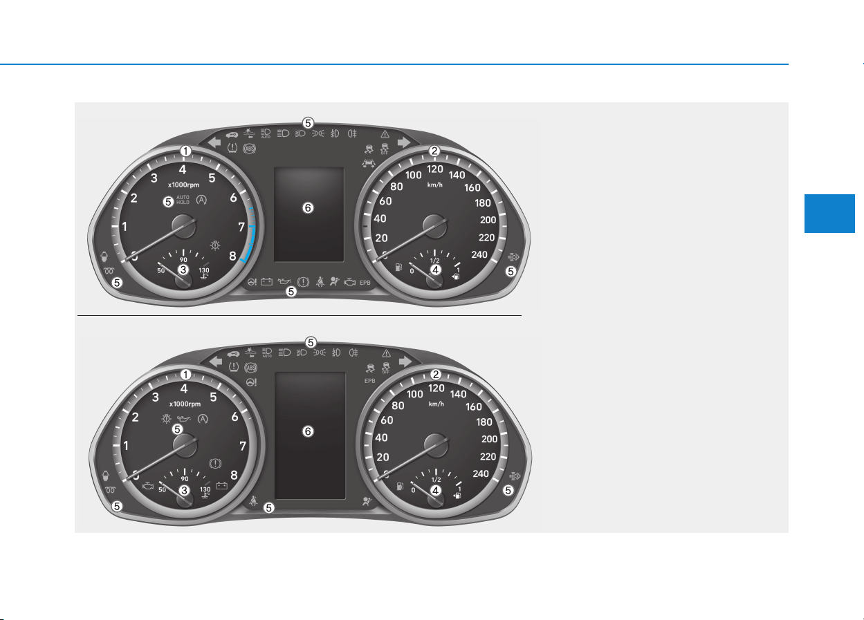
3-43
Convenient features of your vehicle
3
1. Tachometer
2. Speedometer
3. Engine coolant temperature gauge
4. Fuel gauge
5. Warning and indicator lights
6. LCD display (including Trip computer)
OPDE046100/OPDE046101
■■
Type B
■■
Type A
IINNSSTTRRUUMMEENNTT CCLLUUSSTTEERR
The actual cluster in the vehicle may differ
from the illustration.
For more details, refer to the "Gauges and
Meters" in this chapter.
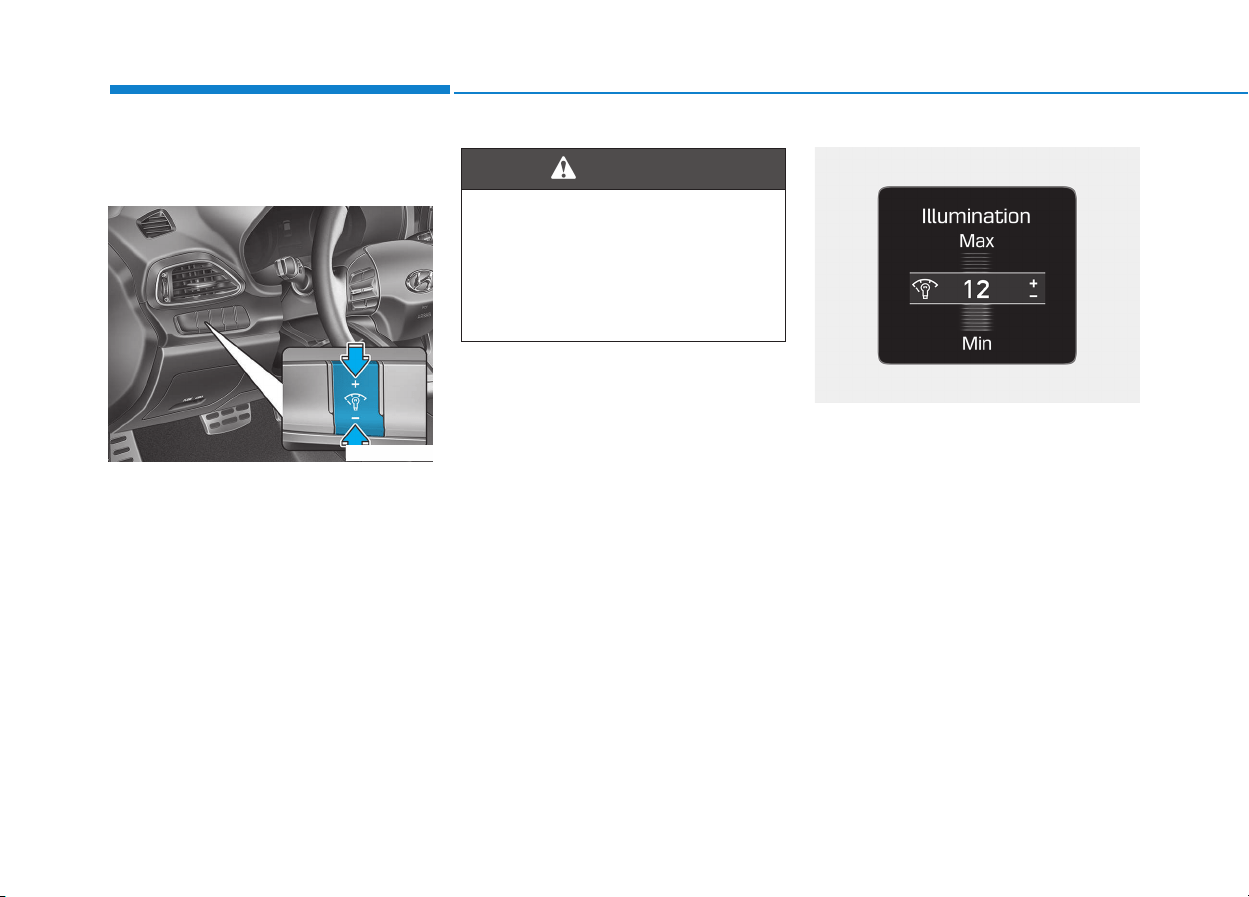
3-44
Convenient features of your vehicle
Instrument cluster control
Instrument panel illumination
When the vehicle's position lights or
headlights are on, press the illumina-
tion control button to adjust the
brightness of the instrument panel
illumination.
When pressing the illumination con-
trol button, the interior switch illumi-
nation intensity is also adjusted.
• The brightness of the instrument
panel illumination is displayed.
• If the brightness reaches to the
maximum or minimum level, an
alarm will sound.
Never adjust the instrument clus-
ter while driving.This could result
in loss of control and lead to an
accident that may cause death,
serious injury, or property dam-
age.
WARNING
OPDE046110
OPD046049
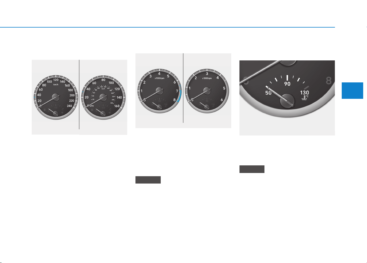
3-45
Convenient features of your vehicle
3
Gauges and meters
Speedometer
The speedometer indicates the
speed of the vehicle and is calibrated
in kilometers per hour (km/h) and/or
miles per hour (MPH).
Tachometer
The tachometer indicates the
approximate number of engine revo-
lutions per minute (rpm).
Use the tachometer to select the cor-
rect shift points and to prevent lug-
ging and/or over-revving the engine.
Do not operate the engine within
the tachometer's RED ZONE. This
may cause severe engine damage.
Engine coolant temperature
gauge
This gauge indicates the tempera-
ture of the engine coolant when the
ignition switch is in the ON position.
If the gauge pointer moves
beyond the normal range area
toward the "130" position, it indi-
cates overheating that may dam-
age the engine.
Do not continue driving with an
overheated engine. If your vehicle
overheats, refer to "If the Engine
Overheats" in chapter 6.
NOTICE
NOTICE
OPDE046102/OPDE046109
■ MPH, km/h
■ km/h
OPDE046104/OPDE046105
■ Diesel engine
■ Gasoline engine
OPDE046106
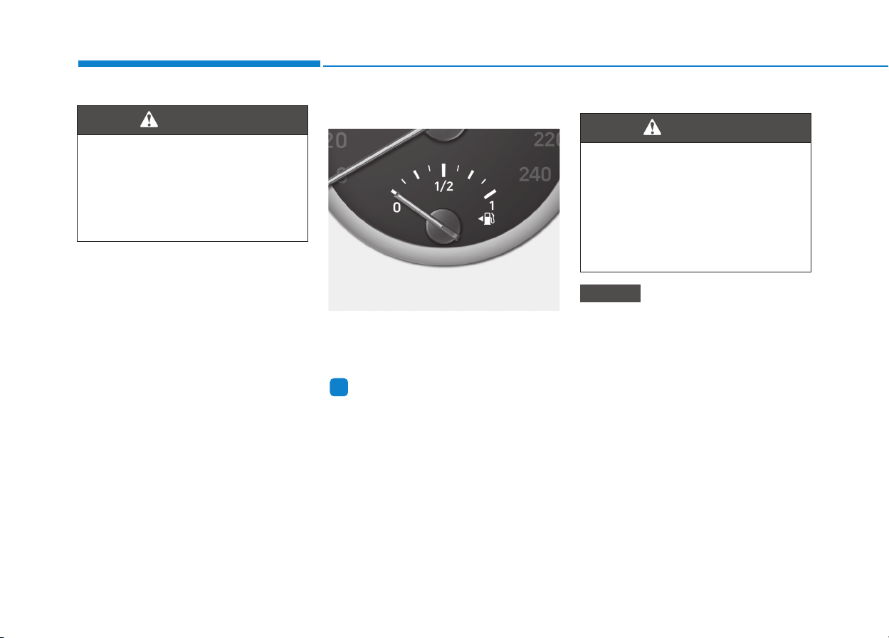
3-46
Convenient features of your vehicle
Fuel gauge
This gauge indicates the approxi-
mate amount of fuel remaining in the
fuel tank.
Information
• The fuel tank capacity is given in
chapter 8.
• The fuel gauge is supplemented by a
low fuel warning light, which will
illuminate when the fuel tank is
nearly empty.
• On inclines or curves, the fuel gauge
pointer may fluctuate or the low fuel
warning light may come on earlier
than usual due to the movement of
fuel in the tank.
Avoid driving with a extremely low
fuel level. Running out of fuel
could cause the engine to misfire
damaging the catalytic converter.
NOTICE
i
Never remove the radiator cap
when the engine is hot. The
engine coolant is under pressure
and could severe burns. Wait
until the engine is cool before
adding coolant to the reservoir.
WARNING
Running out of fuel can expose
vehicle occupants to danger.
You must stop and obtain addi-
tional fuel as soon as possible
after the warning light comes
on or when the gauge indicator
comes close to the "0" level.
WARNING
OPDE046107

3-47
Convenient features of your vehicle
3
Outside temperature gauge
This gauge indicates the current out-
side air temperatures either in
Celsius (°C) or Fahrenheit.
- Temperature range : -40°C ~ 60°C
(-104°F ~ 140°F)
The outside temperature on the dis-
play may not immediately change
like a general thermometer not to
distract the driver.
The temperature unit (from °C to °F
or from °F to °C) can be changed by:
- User Settings mode in the Cluster :
You can change the temperature
unit in the “Other Features -
Temperature unit” .
- Automatic climate control system :
While pressing the OFF button,
press the AUTO button for 3 sec-
onds or more.
The temperature unit of the instrument
cluster and climate control system will
change at once.
Odometer
The odometer indicates the total dis-
tance that the vehicle has been driv-
en and should be used to determine
when periodic maintenance should
be performed.
OPDE046140 OPDE046141

3-48
Convenient features of your vehicle
Distance to empty
• The distance to empty is the esti-
mated distance the vehicle can be
driven with the remaining fuel.
• If the estimated distance is below
1 km (1 mi.), the trip computer will
display “---” as distance to empty.
Information
• If the vehicle is not on level ground
or the battery power has been inter-
rupted, the distance to empty func-
tion may not operate correctly.
• The distance to empty may differ
from the actual driving distance as
it is an estimate of the available
driving distance.
• The trip computer may not register
additional fuel if less than 6 liters
(1.6 gallons) of fuel are added to the
vehicle.
• The distance to empty may vary sig-
nificantly based on driving condi-
tions, driving habits, and condition
of the vehicle.
Transmission shift indicator
Manual transmission shift indi-
cator (if equipped)
This indicator informs which gear is
desired while driving to save fuel.
• Shifting up :
▲
2,
▲
3,
▲
4,
▲
5,
▲
6
• Shifting down :
▼
1,
▼
2,
▼
3,
▼
4,
▼
5
i
OPD046138
OPDE046142
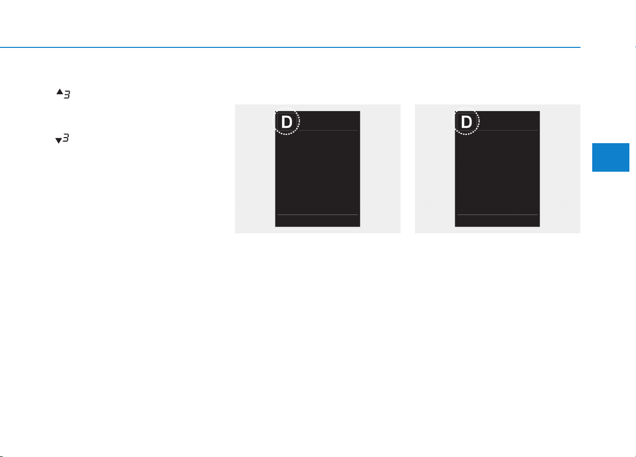
3-49
Convenient features of your vehicle
3
For example
: Indicates that shifting up to the
3rd gear is desired (currently
the shift lever is in the 2nd or
1st gear).
: Indicates that shifting down to
the 3rd gear is desired (current-
ly the shift lever is in the 4th,
5th, or 6th gear).
When the system is not working prop-
erly, the indicator is not displayed.
Automatic transmission shift
indicator (if equipped)
This indicator displays which automat-
ic transmission shift lever is selected.
•Park :P
• Reverse : R
• Neutral : N
•Drive :D
• Manual shift mode : 1, 2, 3, 4, 5, 6
Dual clutch transmission shift
indicator (if equipped)
This indicator displays which shift
lever is selected.
•Park :P
• Reverse : R
• Neutral : N
•Drive :D
• Manual shift mode : D1, D2, D3, D4,
D5, D6, D7
OTL045132OTL045132
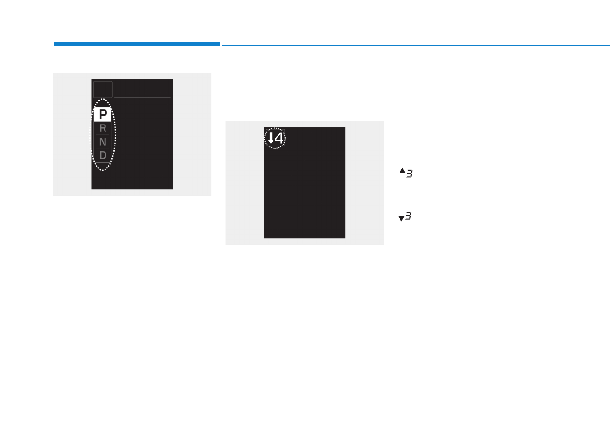
3-50
Convenient features of your vehicle
Shift Indicator Pop-up (if equipped)
The pop-up that indicates the current
gear position is displayed in the clus-
ter for about 2 seconds when shifting
into other positions (P/R/N/D).
Automatic transmission shift indi-
cator / Dual clutch transmission
shift indicator (for Europe,
if equipped)
In the manual shift mode, this indica-
tor informs which gear is desired
while driving to save fuel.
• Automatic transmission shift indi-
cator
- Shifting up :
▲
2,
▲
3,
▲
4,
▲
5,
▲
6
- Shifting down :
▼
1,
▼
2,
▼
3,
▼
4,
▼
5
• Dual clutch transmission shift indi-
cator
- Shifting up :
▲
2,
▲
3,
▲
4,
▲
5,
▲
6
▲
7
- Shifting down :
▼
1,
▼
2,
▼
3,
▼
4,
▼
5,
▼
6
For example
: Indicates that shifting up to the
3rd gear is desired (currently
the shift lever is in the 2nd or
1st gear).
: Indicates that shifting down to
the 3rd gear is desired (current-
ly the shift lever is in the 4th,
5th, or 6th gear).
When the system is not working
properly, the indicator is not dis-
played.
OTL045134
OPDE046142
3-51
Convenient features of your vehicle
3
Warning and indicator lights
Information
Make sure that all warning lights are
OFF after starting the engine. If any
light is still ON, this indicates a situa-
tion that needs attention.
Air Bag Warning Light
This warning light illuminates:
• When you turn the ignition switch
or the Engine Start/Stop button to
the ON position.
- It illuminates for approximately 6
seconds and then goes off.
• When there is a malfunction with
the SRS.
In this case, we recommend that
you have the vehicle inspected by
an authorized HYUNDAI dealer.
Seat Belt Warning Light
This warning light informs the driver
that the seat belt is not fastened.
For more details, refer to the “Seat
Belts” in chapter 2.
Parking Brake & Brake
Fluid Warning Light
This warning light illuminates:
• When you set the ignition switch or
the Engine Start/Stop button to the
ON position.
- It illuminates for approximately 3
seconds
- It remains on if the parking brake
is applied.
• When the parking brake is applied.
• When the brake fluid level in the
reservoir is low.
- If the warning light illuminates
with the parking brake released, it
indicates the brake fluid level in
reservoir is low.
i
3-52
Convenient features of your vehicle
If the brake fluid level in the reser-
voir is low:
1. Drive carefully to the nearest safe
location and stop your vehicle.
2. With the engine stopped, check the
brake fluid level immediately and
add fluid as required (For more
details, refer to “Brake Fluid” in
chapter 7). After adding brake
fluid, check all brake components
for fluid leaks. If a brake fluid leak is
found, or if the warning light
remains on, or if the brakes do not
operate properly, do not drive the
vehicle. We recommend you to
have the vehicle inspected by an
authorized HYUNDAI dealer.
Dual-diagonal braking system
Your vehicle is equipped with dual-
diagonal braking systems. This
means you still have braking on two
wheels even if one of the dual sys-
tems should fail.
With only one of the dual systems
working, more than normal pedal
travel and greater pedal pressure are
required to stop the vehicle.
Also, the vehicle will not stop in as
short a distance with only a portion
of the brake system working.
If the brakes fail while you are driv-
ing, shift to a lower gear for addition-
al engine braking and stop the vehi-
cle as soon as it is safe to do so.
Anti-lock Brake System
(ABS) Warning Light
This warning light illuminates:
• When you set the ignition switch or
the Engine Start/Stop button to the
ON position.
- It illuminates for approximately 3
seconds and then goes off.
• When there is a malfunction with
the ABS (The normal braking sys-
tem will still be operational without
the assistance of the anti-lock
brake system).
In this case, we recommend that
you have the vehicle inspected by
an authorized HYUNDAI dealer.
Parking Brake & Brake Fluid
Warning Light
Driving the vehicle with a warn-
ing light ON is dangerous. If the
Parking Brake & Brake Fluid
Warning Light illuminates with
the parking brake released, it
indicates that the brake fluid
level is low.
In this case, we recommend
that you have the vehicle
inspected by an authorized
HYUNDAI dealer.
WARNING
3-53
Convenient features of your vehicle
3
Electronic Brake Force
Distribution (EBD)
System Warning Light
These two warning lights illuminate
at the same time while driving:
• When the ABS and regular brake
system may not work normally.
In this case, we recommend that
you have the vehicle inspected by
an authorized HYUNDAI dealer.
Information
- Electronic
Brake Force Distribution
(EBD) System Warning Light
When the ABS Warning Light is on or
both ABS and Parking Brake & Brake
Fluid Warning Lights are on, the
speedometer, odometer, or tripmeter
may not work. Also, the EPS Warning
Light may illuminate and the steering
effort may increase or decrease.
In this case, we recommend you have
the vehicle inspected by an authorized
HYUNDAI dealer as soon as possible.
i
Electronic Brake Force
Distribution (EBD) System
Warning Light
When both ABS and Parking
Brake & Brake Fluid Warning
Lights are on, the brake system
will not work normally and you
may experience an unexpected
and dangerous situation during
sudden braking.
In this case, avoid high speed
driving and abrupt braking.
We recommend you have the
vehicle inspected by an author-
ized HYUNDAI dealer as soon
as possible.
WARNING

3-54
Convenient features of your vehicle
Electronic Parking
Brake (EPB) Warning
Light (if equipped)
This warning light illuminates:
• When you set the ignition switch or
the Engine Start/Stop button to the
ON position.
- It illuminates for approximately 3
seconds and then goes off.
• When there is a malfunction with
the EPB.
In this case, we recommend that
you have the vehicle inspected by
an authorized HYUNDAI dealer.
Information
The Electronic Parking Brake (EPB)
Warning Light may illuminate when
the Electronic Stability control (ESC)
Indicator Light comes on to indicates
that the ESC is not working properly
(This does not indicate malfunction of
the EPB).
AUTO HOLD Indicator
Light (if equipped)
This indicator light illuminates:
• [White] When you activate the auto
hold system by pressing the AUTO
HOLD button.
• [Green] When you stop the vehicle
completely by depressing the
brake pedal with the auto hold sys-
tem activated.
• [Yellow] When there is a malfunc-
tion with the auto hold system.
In this case, we recommend that
you have the vehicle inspected by
an authorized HYUNDAI dealer.
For more details, refer to “Auto
Hold” in chapter 5.
Electric Power
Steering (EPS)
Warning Light
This warning light illuminates:
• When you set the ignition switch or
the Engine Start/Stop button to the
ON position.
- It illuminates for approximately 3
seconds and then goes off.
• When there is a malfunction with
the EPS.
In this case, we recommend that
you have the vehicle inspected by
an authorized HYUNDAI dealer.
i
EPB
3-55
Convenient features of your vehicle
3
Malfunction Indicator
Lamp (MIL)
This warning light illuminates:
• When you set the ignition switch or
the Engine Start/Stop button to the
ON position.
- It illuminates for approximately 3
seconds and then goes off.
• When there is a malfunction with
the emission control system.
In this case, we recommend that
you have the vehicle inspected by
an authorized HYUNDAI dealer.
Driving with the Malfunction Indicator
Lamp (MIL) on may cause damage to
the emission control systems which
could affect drivability and/or fuel
economy.
- Gasoline Engine
If the Malfunction Indicator Lamp
(MIL) illuminates, potential catalyt-
ic converter damage is possible
which could result in loss of
engine power.
In this case, we recommend that
you have the vehicle inspected by
an authorized HYUNDAI dealer as
soon as possible.
- Diesel Engine
If the Malfunction Indicator Lamp
(MIL) blinks, error related to the
injection quantity adjustment may
have occurred which could result
in loss of engine power, combus-
tion noise and poor emission.
In this case, we recommend that
you have the engine control sys-
tem inspected by an authorized
HYUNDAI dealer.
Charging System
Warning Light
This warning light illuminates:
• When there is a malfunction with
either the alternator or electrical
charging system.
If there is a malfunction with either
the alternator or electrical charging
system:
1. Drive carefully to the nearest safe
location and stop your vehicle.
2. Turn the engine off and check the
alternator drive belt for looseness
or breakage.
If the belt is adjusted properly,
there may be a problem in the
electrical charging system.
In this case, we recommend that
you have the vehicle inspected by
an authorized HYUNDAI dealer as
soon as possible.
NOTICE
NOTICE
NOTICE
3-56
Convenient features of your vehicle
Engine Oil Pressure
Warning Light
This warning light illuminates:
• When the engine oil pressure is low.
If the engine oil pressure is low:
1. Drive carefully to the nearest safe
location and stop your vehicle.
2. Turn the engine off and check the
engine oil level (For more details,
refer to “Engine Oil” in chapter 7).
If the level is low, add oil as required.
If the warning light remains on
after adding oil or if oil is not avail-
able, we recommend that you
have the vehicle inspected by an
authorized HYUNDAI dealer as
soon as possible.
• If the engine does not stop
immediately after the Engine Oil
Pressure Warning Light is illumi-
nated, severe damage could
result.
• If the warning light stays on
while the engine is running, it
indicates that there may be seri-
ous engine damage or malfunc-
tion. In this case,
1. Stop the vehicle as soon as it
is safe to do so.
2. Turn off the engine and check
the oil level. If the oil level is
low, fill the engine oil to the
proper level.
3. Start the engine again. If the
warning light stays on after the
engine is started, turn the
engine off immediately. In this
case, we recommend that you
have the vehicle inspected by
an authorized HYUNDAI dealer.
Low Fuel Level
Warning Light
This warning light illuminates:
• When the fuel tank is nearly empty.
Add fuel as soon as possible.
Driving with the Low Fuel Level
warning light on or with the fuel
level below “0” can cause the
engine to misfire and damage the
catalytic converter (if equipped).
NOTICE
NOTICE
3-57
Convenient features of your vehicle
3
Master Warning Light
This indicator light illuminates:
• When there is a malfunction in the
below systems.
- Low washer fluid (if equipped)
- Smart high beam malfunction
(if equipped)
- Blind Spot Detection (BSD) mal-
function (if equipped)
- Autonomous Emergency Braking
(AEB) malfunction (if equipped)
- Speed Limit Information Function
(SLIF) malfunction (if equipped)
- Advanced Smart Cruise Control
malfunction (if equipped)
- Tire Pressure Monitoring System
(TPMS, if equipped)
To identify the details of the warn-
ing, look at the LCD display.
Low Tire Pressure
Warning Light
(if equipped)
This warning light illuminates:
• When you set the ignition switch or
Engine Start/Stop button to the ON
position.
- It illuminates for approximately 3
seconds and then goes off.
• When one or more of your tires are
significantly underinflated (The
location of the underinflated tires
are displayed on the LCD display).
For more details, refer to
“Tire Pressure Monitoring System
(TPMS)” in chapter 6.
This warning light remains on after
blinking for approximately 60 sec-
onds or repeats blinking and off at
the intervals of approximately 3
seconds:
• When there is a malfunction with
the TPMS.
In this case, we recommend that
you have the vehicle inspected by
an authorized HYUNDAI dealer as
soon as possible.
For more details, refer to
“Tire Pressure Monitoring System
(TPMS)” in chapter 6.
Safe Stopping
• The TPMS cannot alert you to
severe and sudden tire damage
caused by external factors.
• If you notice any vehicle insta-
bility, immediately take your
foot off the accelerator pedal,
apply the brakes gradually with
light force, and slowly move to
a safe position off the road.
WARNING
3-58
Convenient features of your vehicle
Fuel Filter Warning
Light (Diesel Engine)
This warning light illuminates:
• When water has accumulated
inside the fuel filter.
In this case, remove the water from
the fuel filter.
For more details, refer to "Fuel
Filter" in chapter 7.
• When the Fuel Filter Warning
Light illuminates, engine power
(vehicle speed & idle speed) may
decrease.
• If you keep driving with the warn-
ing light on, engine parts (injec-
tor, common rail, high pressure
fuel pump) may be damaged. If
this occurs, we recommend that
you have the vehicle inspected
by an authorized HYUNDAI deal-
er as soon as possible.
Exhaust System (DPF)
Warning Light (Diesel
Engine)
This warning light illuminates:
• When there is a malfunction with
Diesel Particulate Filter (DPF) sys-
tem.
When this warning light illumi-
nates, it may turn off after driving
the vehicle:
- at more than 60 km/h (37 mph), or
- at more than 2nd gear with 1500
~ 2500 engine rpm for a certain
time (for about 25 minutes).
If this warning light blinks in spite of
the procedure (at this time LCD
warning message will be displayed),
we recommend that you have the
DPF system checked by an author-
ized HYUNDAI dealer.
If you continue to drive with the
DPF warning light blinking for a
long time, the DPF system can be
damaged and fuel consumption
can worsen.
Glow Indicator Light
(Diesel Engine)
This indicator light illuminates:
• When the engine is being preheat-
ed with the ignition switch or
Engine Start/Stop Button in the ON
position.
- The engine can be started after
the glow indicator light goes off.
- The illumination time varies with
the engine coolant temperature,
air temperature, and battery con-
dition.
If the indicator light remains on or
blinks after the engine has warmed
up or while driving, there may a mal-
function with the engine preheating
system.
In this case, we recommend that you
have the vehicle inspected by an
authorized HYUNDAI dealer.
NOTICE
NOTICE

3-59
Convenient features of your vehicle
3
Information
If the engine does not start within 10
seconds after the preheating is com-
pleted, set the ignition switch or
Engine Start/Stop Button to the
LOCK or OFF position for 10 seconds
and then to the ON position in order
to preheat the engine again.
Electronic Stability
Control (ESC) Indicator
Light (if equipped)
This indicator light illuminates:
• When you set the ignition switch or
the Engine Start/Stop button to the
ON position.
- It illuminates for approximately 3
seconds and then goes off.
• When there is a malfunction with
the ESC system.
In this case, we recommend that
you have the vehicle inspected by
an authorized HYUNDAI dealer.
This indicator light blinks:
• While the ESC is operating.
For more details, refer to “Electronic
Stability Control (ESC)”in chapter 5.
Electronic Stability
Control (ESC) OFF
Indicator Light
(if equipped)
This indicator light illuminates:
• When you set the ignition switch or
the Engine Start/Stop button to the
ON position.
- It illuminates for approximately
3 seconds and then goes off.
• When you deactivate the ESC sys-
tem by pressing the ESC OFF but-
ton.
For more details, refer to “Electronic
Stability Control (ESC)”in chapter 5.
i
3-60
Convenient features of your vehicle
AUTO STOP Indicator
Light (if equipped)
This indicator light illuminates:
• When the engine enters the Idle
Stop mode of the ISG (Idle Stop and
Go) system.
This indicator light blinks:
• When the automatic starting occurs,
the AUTO STOP indicator on the
cluster will blink for 5 seconds.
For more details, refer to the “ISG
(Idle Stop and Go) system” in chap-
ter 5.
Information
When the engine automatically starts
by the ISG system, some warning
lights(ABS, ESC, ESC OFF, EPS or
Parking brake warning light) may
turn on for a few seconds.
This happens because of low battery
voltage. It does not mean the system
has malfunctioned.
Immobilizer Indicator
Light (without smart key)
(if equipped)
This indicator light illuminates:
• When the vehicle detects the
immobilizer in the key with the igni-
tion switch in the ON position.
- At this time, you can start the
engine.
- The indicator light goes off after
starting the engine.
This indicator light blinks:
• When there is a malfunction with
the immobilizer system.
In this case, we recommend that
you have the vehicle inspected by
an authorized HYUNDAI dealer.
Immobilizer Indicator
Light (With Smart Key)
(if equipped)
This indicator light illuminates for
up to 30 seconds:
• When the vehicle detects the
smart key in the vehicle with the
Engine Start/Stop button in the
ACC or ON position.
- At this time, you can start the
engine.
- The indicator light goes off after
starting the engine.
This indicator light blinks for a few
seconds:
• When the smart key is not in the
vehicle.
- At this time, you cannot start the
engine.
i

3-61
Convenient features of your vehicle
3
This indicator light illuminates for
2 seconds and goes off:
• If the smart key is in the vehicle
and the Engine Start/Stop button is
ON, but the vehicle cannot detect
the smart key.
In this case, we recommend that
you have the vehicle inspected by
an authorized HYUNDAI dealer.
This indicator light blinks:
• When the battery voltage of the
smart key is low.
- At this time, you cannot start the
engine. However, you can start
the engine if you press the
Engine Start/Stop button with the
smart key. (For more details,
refer to "Starting the Engine"
in chapter 5).
• When there is a malfunction with
the immobilizer system.
In this case, we recommend that
you have the vehicle inspected by
an authorized HYUNDAI dealer.
Turn Signal Indicator
Light
This indicator light blinks:
• When you turn the turn signal light
on.
If any of the following occurs, there
may be a malfunction with the turn
signal system.
- The turn signal indicator light illumi-
nates but does not blink
- The turn signal indicator light blinks
rapidly
- The turn signal indicator light does
not illuminate at all
If either of these conditions occur, we
recommend you to have your vehicle
inspected by an authorized HYUNDAI
dealer.
Low Beam Indicator
Light (if equipped)
This indicator light illuminates:
• When the headlights are on.
High Beam Indicator
Light
This indicator light illuminates:
• When the headlights are on and in
the high beam position
• When the turn signal lever is pulled
into the Flash-to-Pass position.
3-62
Convenient features of your vehicle
Smart High Beam
Indicator Light
(if equipped)
This warning light illuminates:
• When the high-beam is on with the
light switch in the AUTO light posi-
tion.
• If your vehicle detects oncoming or
preceding vehicles, the Smart High
Beam system will switch the high
beam to low beam automatically.
For more details, refer to "Smart
High Beam" in this chapter.
Light ON Indicator
Light
This indicator light illuminates:
• When the tail lights or headlights
are on.
Front Fog Indicator
Light (if equipped)
This indicator light illuminates:
• When the front fog lights are on.
Rear Fog Indicator
Light
This indicator light illuminates:
• When the rear fog lights are on.
LED Headlamp Warning
Light (if equipped)
This warning light illuminates:
• When you turn the ignition switch
or the Engine Start/Stop button to
the ON position.
• When there is a malfunction with
the LED headlamp.
In this case, we recommend that you
have the vehicle inspected by an an
authorized HYUNDAI dealer.
This warning light blinks:
When there is a malfunction with a
LED headlamp related part.
In this case, we recommend that you
have the vehicle inspected by an an
authorized HYUNDAI dealer.
Continuous driving with the LED
Headlamp Warning Light on or
blinking can reduce LED head-
lamp life.
Cruise Indicator Light
(if equipped)
This indicator light illuminates:
• When the cruise control system is
enabled.
For more details, refer to "Cruise
Control System" in chapter 5.
NOTICE
3-63
Convenient features of your vehicle
3
Cruise SET Indicator
Light (if equipped)
This indicator light illuminates:
• When the cruise control speed is
set.
For more details, refer to "Cruise
Control System" in chapter 5.
Speed Limiter Indicator
Light (if equipped)
This indicator light illuminates
when:
• When the speed limiter is enabled.
For more details, refer to "Speed
Limit Control System" in chapter
5.
SPORT Mode Indicator
Light (if equipped)
This indicator light illuminates
• When you select "SPORT" mode
as drive mode.
For more details, refer to "Drive
Mode Integrated Control System"
in chapter 5.
ECO Mode Indicator
Light (if equipped)
This indicator light illuminates
• When you select "ECO" mode as
drive mode.
For more details, refer to "Drive
Mode Integrated Control System"
in chapter 5.
Autonomous
Emergency Braking
(AEB) Warning light
(if equipped)
This indicator light illuminates:
• When you set the ignition switch or
Engine Start/Stop button to the ON
position.
- It illuminates for approximately 3
seconds and then goes off.
• When there is a malfunction with
the AEB.
In this case, we recommend that you
have the vehicle inspected by an
authorized HYUNDAI dealer.
For more information, refer to
"Autonomous Emergency Braking
(AEB)" in chapter 5.
3-64
Convenient features of your vehicle
Lane Departure Warning
System (LDWS)
Indicator Light
(if equipped)
This indicator light illuminates:
• [Green] When you activate the lane
departure warning system.
• [White] When system operating
conditions are not satisfied.
• [Yellow] When there is a malfunc-
tion with the lane departure warn-
ing system.
In this case, we recommend that
you have the vehicle inspected by
an authorized HYUNDAI dealer.
For more details, refer to "Lane
Departure Warning System (LDWS)"
in chapter 5.
Lane Keeping Assist
System (LKAS)
Indicator Light
(if equipped)
This indicator light illuminates:
• [Green] When the system operat-
ing conditions are satisfied.
• [White] The system operating con-
ditions are not satisfied.
• [Yellow] When there is a malfunc-
tion with the lane keeping assist
system.
In this case, we recommend you to
have your vehicle inspected by an
authorized HYUNDAI dealer.
For more details, refer to "Lane
Keeping Assist System (LKAS)" in
chapter 5.
Icy Road Warning Light
(if equipped)
This warning light is to warn the driver
the road may be icy.
When the temperature on the out-
side temperature gauge is approxi-
mately below 4°C (40°F), the Icy
Road Warning Light and Outside
Temperature Gauge blinks and then
illuminates. Also, the warning chime
sounds 1 time.
Information
If the icy road warning light appears
while driving, you should drive more
attentively and safely refraining from
over-speeding, rapid acceleration, sud-
den braking or sharp turning, etc.
i

3-65
Convenient features of your vehicle
3
LCD display messages
Shift to P (for smart key system
and automatic transmission/
dual clutch transmission)
This warning message is displayed if
you try to turn off the engine without
the shift lever in P (Park) position.
At this time, the Engine Start/Stop
button turns to the ACC position (If
you press the Engine Start/Stop but-
ton once more, it will turn to the ON
position).
Low Key Battery
(for smart key system)
This warning message is displayed if
the battery of the smart key is dis-
charged while changing the Engine
Start/Stop button while changing to
the OFF position.
Press START button while turn-
ing wheel (for smart key sys-
tem)
This warning message is displayed if
the steering wheel does not unlock
normally when the Engine Start/Stop
button is pressed.
You should press the Engine Start/Stop
button while turning the steering wheel
right and left.
Steering wheel not locked
(for smart key system)
This warning message is displayed if
the steering wheel is not locked while
the Engine Start/Stop button changes
to the OFF position.
Check Steering Wheel Lock
System (for smart key system)
This warning message is displayed if
the steering wheel does not lock nor-
mally while the Engine Start/Stop but-
ton changes to the OFF position.
Press brake pedal to start engine
(for smart key system and auto-
matic transmission/dual clutch
transmission)
This warning message is displayed if
the Engine Start/Stop button changes
to the ACC position twice by pressing
the button repeatedly without depress-
ing the brake pedal.
You can start the vehicle by depressing
the brake pedal.
Press clutch pedal to start
engine (for smart key system
and manual transmission)
This warning message is displayed if
the Engine Start/Stop button is in the
ACC position twice by pressing the
button repeatedly without depressing
the clutch pedal.
Depress the clutch pedal to start the
engine.

3-66
Convenient features of your vehicle
Key not in vehicle
(for smart key system)
This warning message is displayed if
the smart key is not in the vehicle
when you press the Engine Start/Stop
button.
When attempting to start the vehicle
always have the smart key with you.
Key not detected
(for smart key system)
This warning message is displayed if
the smart key is not detected when you
press the Engine Start/Stop button.
Press START button with key
(for smart key system)
This warning message is displayed if
you press the Engine Start/Stop but-
ton while the warning message “Key
not detected” is displayed.
At this time, the immobilizer indicator
light blinks.
Press START button again
(for smart key system)
This message is displayed if you
were unable to start the vehicle when
the Engine Start/Stop button was
pressed.
If this occurs, attempt to start the
engine by pressing the Engine
Start/Stop button again.
If the warning message appears
each time you press the Engine
Start/Stop button, we recommend
you to have your vehicle inspected
by an authorized HYUNDAI dealer.
Check BRAKE SWITCH fuse (for
smart key system and automatic
transmission/dual clutch trans-
mission)
This warning message is displayed if
the brake switch fuse is disconnected.
You need to replace the fuse with a
new one. If that is not possible, you
can start the engine by pressing the
Engine Start/Stop button for 10 sec-
onds in the ACC position.
Shift to P or N to start engine (for
smart key system and automatic
transmission/dual clutch trans-
mission)
This warning message is displayed if
you try to start the engine with the
shift lever not in the P (Park) or N
(Neutral) position.
Information
You can start the engine with the shift
lever in the N (Neutral) position. But,
for your safety, we recommend that
you start the engine with the shift
lever in the P (Park) position.
i
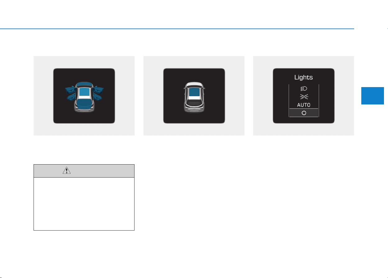
3-67
Convenient features of your vehicle
3
Door, Hood, Tailgate open
This warning is displayed indicating
which door, or hood, or tailgate is
open.
Sunroof open (if equipped)
This warning is displayed if you turn
off the engine when the sunroof is
open.
Close the sunroof securely when
leaving your vehicle.
Lights mode
This indicator displays which exterior
light is selected using the lighting
control.
Before driving the vehicle, you
should confirm that the door/
hood/tailgate is fully closed.
Also, check there is no door/
hood/tailgate open warning
light or message displayed on
the instrument cluster.
CAUTION
OPD046115 OPD046116 OPDE046120
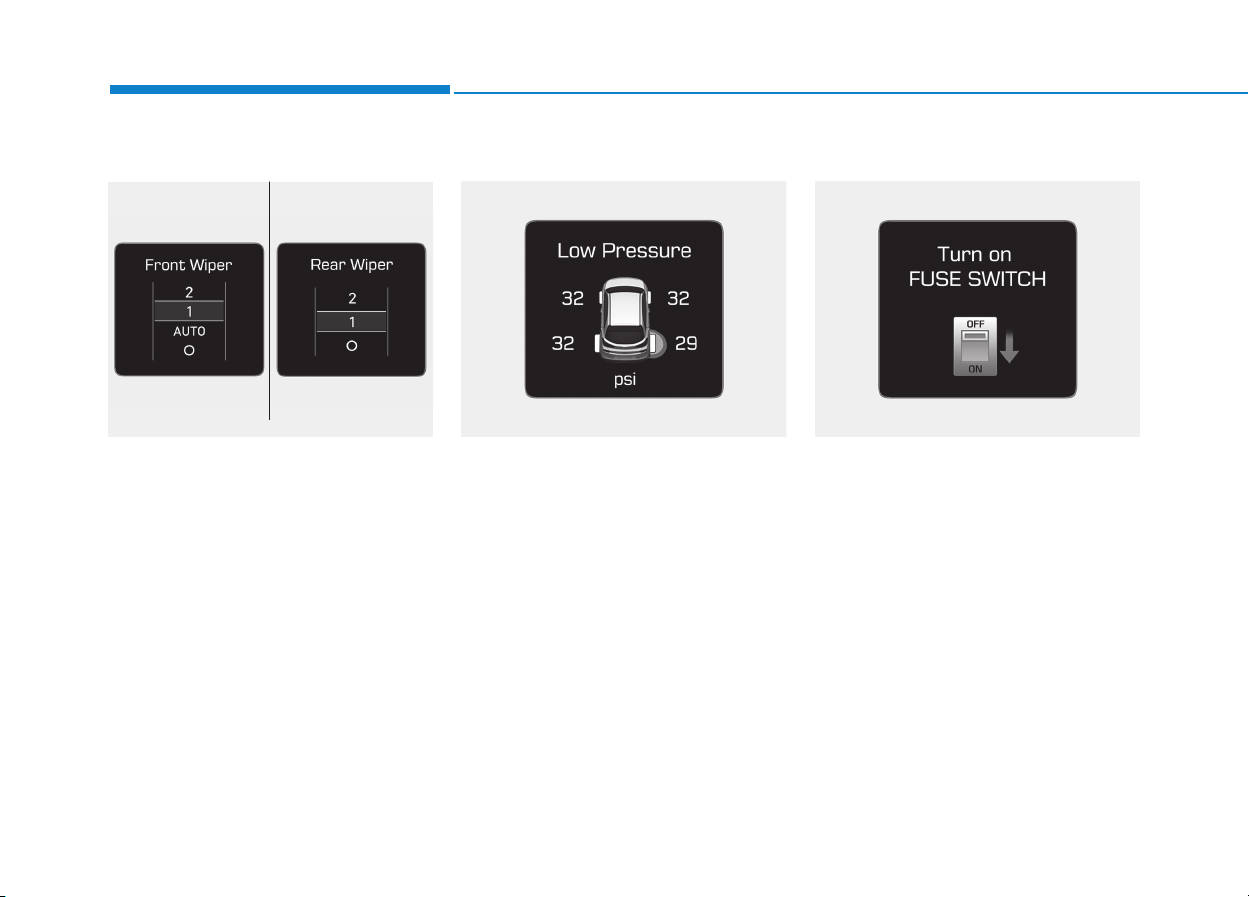
3-68
Convenient features of your vehicle
Wiper mode
This indicator displays which wiper
speed is selected using the wiper
control.
Low Pressure (if equipped)
This warning message is displayed if
the tire pressure is low. The corre-
sponding tire on the vehicle will be
illuminated.
For more details, refer to "Tire
Pressure Monitoring System (TPMS)"
in chapter 6.
Turn on FUSE SWITCH
This warning message is displayed if
the fuse switch located on the fuse
box under the steering wheel is OFF.
You should turn the fuse switch on.
For more details, refer to “Fuses”
in chapter 7.
OPDE046119OPDE066005OPDE046125/OPDE046126
■ Front ■ Rear

3-69
Convenient features of your vehicle
3
Heated Steering Wheel turned
off (if equipped)
This message is displayed if you turn
off the heated steering wheel.
For more details, refer to “Heated
Steering Wheel” in this chapter.
Low washer fluid (if equipped)
This warning message is displayed
if the washer fluid level in the reser-
voir is nearly empty.
Have the washer fluid reservoir
refilled.
Low fuel
This warning message is displayed if
the fuel tank is almost out of fuel.
When this message is displayed, the
low fuel level warning light in the
cluster will come on.
It is recommended to look for the
nearest fueling station and refuel as
soon as possible.
Add fuel as soon as possible.
Engine has overheated
(if equipped)
This warning message is displayed
when the engine coolant tempera-
ture is above 120°C (248°F). This
means that the engine is overheated
and may be damaged.
If your vehicle is overheated, refer
to “Overheating” in chapter 6.
Check exhaust system
(for Diesel engine)
This warning message is displayed if
the DPF system has a malfunction.
At this time, DPF warning light also
blinks.
In this case, we recommend that you
have the DPF system checked by an
authorized HYUNDAI dealer.
For more details, refer to “Warning
Lights” in this chapter.
Check headlight (if equipped)
This warning message is displayed if
the headlamps are not operating
properly. The headlamp bulb may
need to be replaced.
Information
Make sure to replace the burned out
bulb with a new one of the same wattage
rating.
Check headlamp LED
(if equipped)
This warning message is displayed if
there is a problem with the LED
headlamp. We recommend you to
have the vehicle inspected by an
authorized HYUNDAI dealer.
Check headlamp FAN
(if equipped)
This warning message is displayed if
there is a problem with headlamp
fan. We recommend you to have the
vehicle inspected by an authorized
HYUNDAI dealer.
i

3-70
Convenient features of your vehicle
Check smart high beam system
(if equipped)
This warning message is displayed if
there is a problem with the Smart
High Beam System. We recommend
you to have the vehicle inspected by
an authorized HYUNDAI dealer.
For more information, refer to
“Smart High Beam System” in
chapter 3.
Check AEB system (if equipped)
This warning message is displayed if
there is a malfunction with the
Autonomous Emergency Braking (AEB)
system. We recommend that the vehi-
cle be inspected by an authorized
HYUNDAI dealer.
For more details, refer to
"Autonomous Emergency Braking
(AEB) system" in chapter 5.
Check LDWS (if equipped)
This warning message is displayed if
there is a problem with the Lane
Departure Warning System (LDWS).
We recommend you to have the vehi-
cle inspected by an authorized
HYUNDAI dealer.
For more information, refer to
“Lane Departure Warning System
(LDWS)” in chapter 5.
Attention Alert
Check System (if equipped)
This warning message is displayed if
there is a problem with the Driver
Attention Alert System. We recom-
mend you to have the vehicle inspect-
ed by an authorized HYUNDAI dealer.
For more information, refer to
“Driver Attention Alert (DAA)” in
chapter 5.
Check BSD System (if equipped)
This warning message is displayed if
there is a problem with the Blind Spot
Detection (BSD) system. We recom-
mend that the vehicle be inspected
by an authorized HYUNDAI dealer.
For more information, refer to "Blind
Spot Detection (BSD) System" in
chapter 5.
Check LKAS (if equipped)
This warning message is displayed if
there is a problem with the Lane
Keeping Assist System (LKAS). We
recommend you to have the vehicle
inspected by an authorized HYUNDAI
dealer.
For more information, refer to
“Lane Keeping Assist System
(LKAS)” in chapter 5.
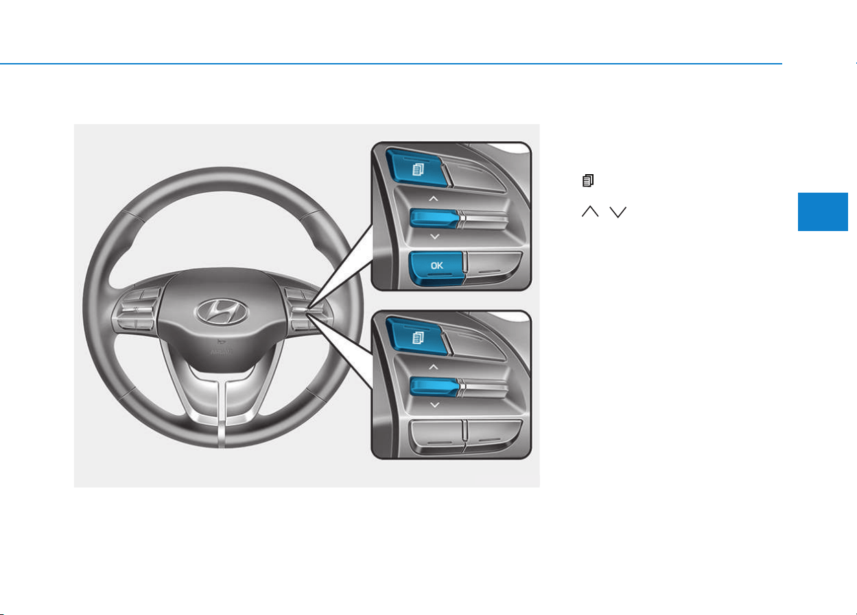
3-71
Convenient features of your vehicle
3
LCD display control
The LCD display modes can be
changed by using the control buttons.
(1) : MODE button for changing
modes
(2) , : MOVE switch for
changing items
(3) OK : SELECT/RESET button for
setting or resetting the
selected item
LLCCDD DDIISSPPLLAAYY
OPDE046404
■
■
■■
TT
TT
yy
yy
pp
pp
ee
ee
AA
AA
■■
■■
TT
TT
yy
yy
pp
pp
ee
ee
BB
BB
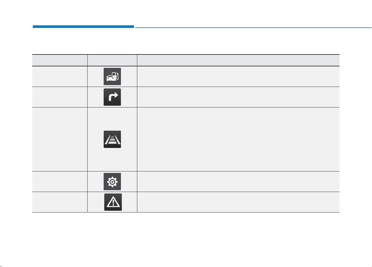
3-72
Convenient features of your vehicle
LCD modes
Modes Symbol Explanation
Trip Computer
This mode displays driving information such as the tripmeter, fuel economy, etc.
For more details, refer to "Trip Computer" in this chapter.
Turn By Turn (TBT) This mode displays the state of the navigation.
Assist
• This mode displays the state of the Smart Cruise Control (SCC) and Lane
Departure Warning System (LDWS)/Lane Keeping Assist System (LKAS).
For more information, refer to "Smart Cruise Control (SCC)" and "Lane
Departure Warning System (LDWS)/Lane Keeping Assist System (LKAS)" in
chapter 5.
• This mode displays information related to Driver Attention Alert and Tire Pressure.
For more information, refer to
"
Driver Attention Alert (DAA)
"
in chapter 5 and
"
Tire Pressure Monitoring System (TPMS)
"
in chapter 6.
User Settings In this mode, you can change settings of the doors, lamps, etc.
Warning
This mode displays warning messages related to the Blind Spot Detection system,
etc.
The information provided differs according to the items applied to your vehicle.
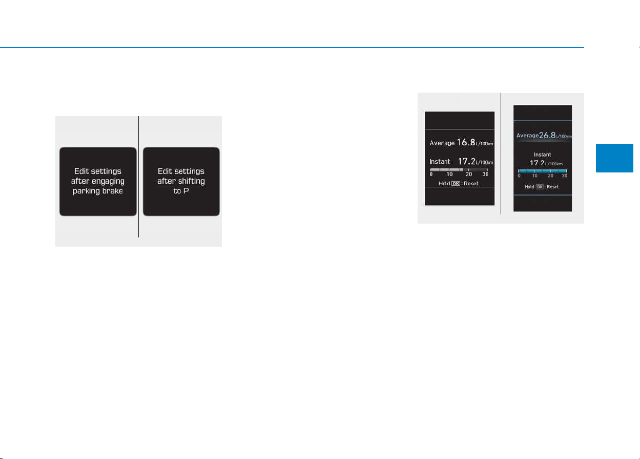
3-73
Convenient features of your vehicle
3
Edit settings after engaging
parking brake / Edit settings
after shifting to P
This warning message illuminates if
you try to select an item from the
User Settings mode while driving.
- Automatic transmission / dual
clutch transmission
For your safety, change the User
Settings after parking the vehicle,
applying the parking brake and mov-
ing the shift lever to P (Park).
- Manual transmission
For your safety, change the User
Settings after engaging the parking
brake.
Quick guide (Help, if equipped)
This mode provides quick guides for
the systems in the User Settings
mode.
Select an item, press and hold the
OK button.
For more details about each sys-
tem, refer to this Owner’s Manual.
Trip computer mode
The trip computer mode displays
information related to vehicle driving
parameters including fuel economy,
trip meter information and vehicle
speed.
For more information, refer to
"Trip Computer" in this chapter.
OPDE046131/OPDE046132
■ Type A ■ Type B
OAD045161L/OAD045162L
■ Type A ■ Type B
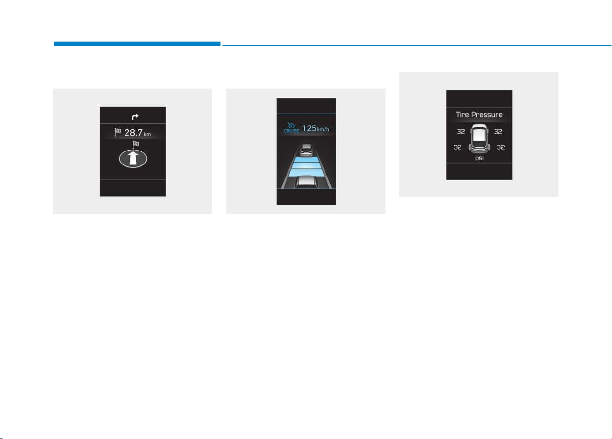
3-74
Convenient features of your vehicle
Turn By Turn (TBT) mode
This mode displays the state of the
navigation.
Assist mode
SCC/LKAS/LDWS/DAA
This mode displays the state of the
Smart Cruise Control (SCC), Lane
Departure Warning System (LDWS)/
Lane Keeping Assist System (LKAS)
and Driver Attention Alert (DAA).
For more information, refer to
each system information in chap-
ter 5.
Tire Pressure
This mode displays information relat-
ed to Tire Pressure.
For more information, refer to
"Tire Pressure Monitoring System
(TPMS)“ in chapter 6.
OPDE046147 OPD046128
OPDE046148

3-75
Convenient features of your vehicle
3
Warning message mode
If one of followings occurs, warning
messages will be displayed in the
information mode for several seconds.
- Low washer fluid (if equipped)
- Smart high beam malfunction
(if equipped)
- Blind Spot Detection (BSD) mal-
function (if equipped)
- Autonomous Emergency Braking
(AEB) malfunction (if equipped)
- Speed Limit Information Function
(SLIF) malfunction (if equipped)
- Advanced Smart Cruise Control
malfunction (if equipped)
- Tire Pressure Monitoring System
(TPMS, if equipped)
User settings mode
In this mode, you can change the
setting of the instrument cluster,
doors, lamps, etc.
1. Driving Assist
2. Door
3. Lights
4. Sound
5. Convenience
6. Service Interval
7. Other Features
8. Reset
The information provided differs
according to the items applied to
your vehicle.
1. Driving Assist
• Lane Keeping Assist System
- Lane Departure Warning/Standard
LKA/Active LKA
To adjust the sensitivity of the Lane
Keeping Assist System.
For more information, refer to the
"Lane Keeping Assist System" in
chapter 5.
• Driver Attention Alert
To adjust the sensitivity of the Driver
Attention Alert (DAA).
- Off/Normal/Early
For more information, refer to the
"Driver Attention Alert (DAA)" in
chapter 5.
• Smart Cruise Control Speed
- Slow/Normal/Fast
To adjust the sensitivity of the
Smart Cruise Control system.
For more information, refer to the
"Smart Cruise Control" in chapter 5.
• Assist Emergency Braking
To activate or deactivate the
Autonomous Emergency Braking
(AEB).
For more information, refer to
"Autonomous Emergency Braking
(AEB)" in chapter 5.

3-76
Convenient features of your vehicle
• Forward Collision Warning
- Late/Normal/Early
To adjust the initial warning alert
time for Autonomous Emergency
Braking system.
For more information, refer to
"Autonomous Emergency Braking
(AEB)" in chapter 5.
• Rear Cross Traffic Alert
To activate or deactivate the Rear
Cross Traffic Alert system.
For more information, refer to
"Blind Spot Detection" in chapter 5.
• Speed Limit Information Function
To activate or deactivate the Speed
Limit Information Function.
For more information, refer to
"Speed Limit Information Function"
in chapter 5.
2. Door
• Automatic Lock
- Disable: The auto door lock opera-
tion will be canceled.
- Enable on Speed: All doors will be
automatically locked when the vehi-
cle speed exceeds 15km/h
(9.3mph).
- Enable on Shift: All doors will be
automatically locked if the automat-
ic transmission/dual clutch trans-
mission shift lever is shifted from
the P (Park) position to the R
(Reverse), N (Neutral), or D (Drive)
position.
• Automatic Unlock
- Disable: The auto door unlock oper-
ation will be canceled.
- Vehicle Off: All doors will be auto-
matically unlocked when the
Engine Star/Stop button is set to
the OFF position. (if equipped with
smart key)
- On Key Out: All doors will be auto-
matically unlocked when the igni-
tion key is removed from the igni-
tion switch. (if equipped with remote
key)
- On Shift to P: All doors will be auto-
matically unlocked if the automatic
transmission/dual clutch transmis-
sion shift lever is shifted to the P
(Park) position.
- Driver Door Unlock: All doors will be
automatically unlocked when the
driver’s door is opened.
• Horn Feedback
To activate or deactivate the horn
feedback.
If the horn feedback is activated,
after locking the door by pressing the
lock button on the remote key, and
pressing it again within 4 seconds,
the horn feedback sound will operate
once to indicate that all doors are
locked. (if equipped with remote key)

3-77
Convenient features of your vehicle
3
3. Lights
• One Touch Turn Signal
- Off: The one touch turn signal func-
tion will be deactivated.
- 3, 5, 7 Flashes: The turn signal indi-
cator will blink 3, 5, or 7 times when
the turn signal lever is moved slightly.
For more information, refer to
"Light" in this chapter.
• Head Lamp Delay
To activate or deactivate the head-
lamp delay function.
For more information, refer to
"Light" in this chapter
• Welcome Light
To activate or deactivate the wel-
come light function.
For more information, refer to
"Light" in this chapter.
4. Sound
• Park Assist System Volume
- Softer/Louder
To adjust the Park Assist System
volume.
• Blind Spot Detection Sound
To activate or deactivate the Blind
Spot Detection sound.
For more information, refer to
"Blind Spot Detection" in chapter 5.
• Welcome Sound
To activate or deactivate the wel-
come sound.
5. Convenience
• Seat Easy Access
- Off: The seat easy access function
is deactivated.
- Normal/Extended: When you turn
off the engine, the driver's seat will
automatically move rearward short
(Normal) or long (Extended) for you
to enter or exit the vehicle more
comfortably.
For more information, refer to
"Driver Position Memory System"
in this chapter.
• Wireless Charging System
To activate or deactivate the wireless
charging system in the front seat.
For more information, refer to
"Wireless Charging System" in
this chapter.
• Wiper/Lights Display
To activate or deactivate the Wiper/
Light mode.
When activated, the LCD display
shows the selected Wiper/Light
mode whenever you changed the
mode.
• Auto Rear Wiper (reverse)
To activate or deactivate the rear
wiper while the vehicle is in reverse
with the front wiper ON.
• Gear Position Pop-up
To activate or deactivate the gear
position pop-up.

3-78
Convenient features of your vehicle
When activated, the gear position
will be displayed on the LCD display.
(if equipped with automatic transmis-
sion/dual clutch transmission)
6. Service Interval
• Service Interval
To activate or deactivate the service
interval function.
• Adjust Interval
If the service interval menu is acti-
vated, you may adjust the time and
distance.
Information
To use the service interval menu, con-
sult an authorized HYUNDAI dealer.
If the service interval is activated and
the time and distance is adjusted,
messages are displayed in the fol-
lowing situations each time the vehi-
cle is turned on.
- Service in
: Displayed to inform the driver the
remaining mileage and days to
service.
- Service required
: Displayed when the mileage and
days to service has been reached
or passed.
Information
If any of the following conditions
occur, the mileage and number of days
to service may be incorrect.
- The battery cable is disconnected.
- The fuse switch is turned off.
- The battery is discharged.
7. Other Features
• Fuel Economy Auto Reset
- Off: The average fuel economy will
not reset automatically whenever
refueling.
- After Ignition: The average fuel
economy will reset automatically
whenever it has passed 4 hours
after turning OFF the engine.
- After Refueling: The average fuel
economy will reset automatically
when refueling.
For more information, refer to
"Trip Computer" in this chapter.
• Fuel Economy Unit
To select the fuel economy unit.
(km/L, L/100, MPG)
• Temperature Unit
To select the temperature unit.
(°C,°F)
• Tire Pressure Unit
To select the tire pressure unit.
(psi, kPa, bar)
8. Reset
You can reset the menus in the User
Settings Mode. All menus in the User
Settings Mode are initialized, except
language and service interval.
i
i
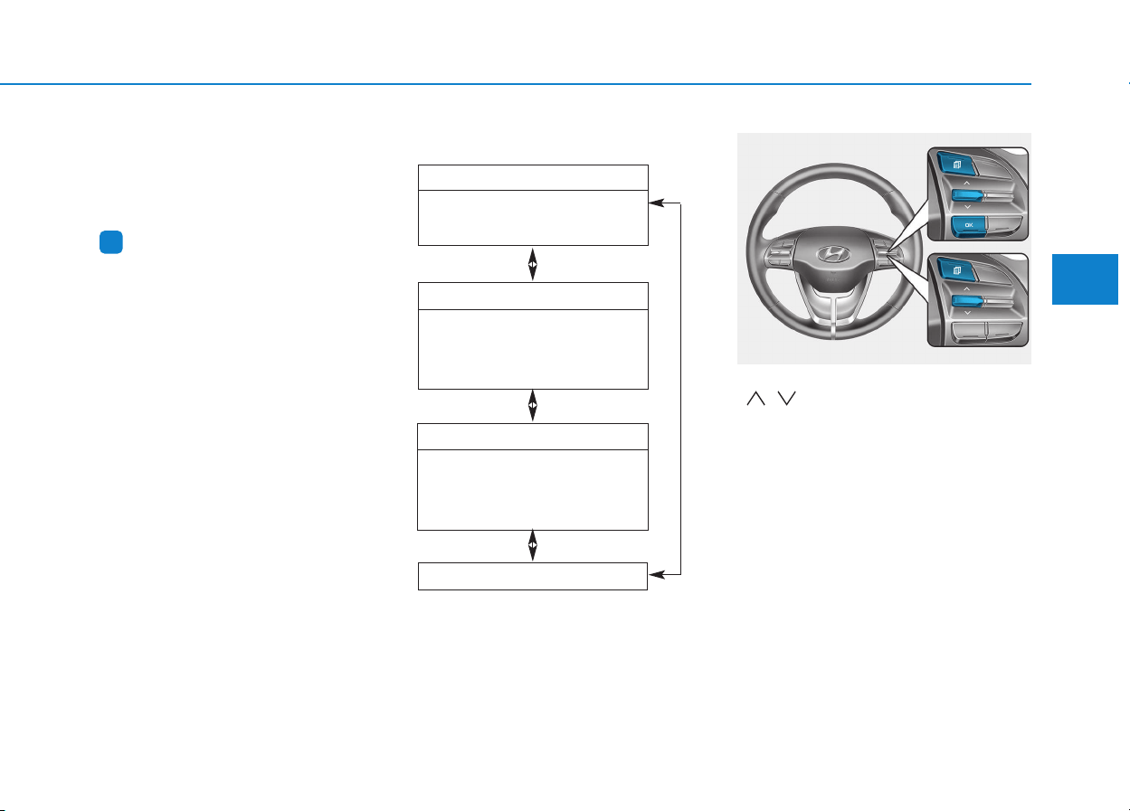
3-79
Convenient features of your vehicle
3
The trip computer is a microcomput-
er-controlled driver information sys-
tem that displays information related
to driving.
Information
Some driving information stored in the
trip computer (for example Average
Vehicle Speed) resets if the battery is
disconnected.
Trip modes
To change the trip mode, toggle the
“ , ” switch on the steering wheel.
i
TTRRIIPP CCOOMMPPUUTTEERR
• Tripmeter
• Average Fuel Economy
• Elapsed Time
Drive Info
• Tripmeter
• Average Fuel Economy
• Elapsed Time
Accumulated Info
• Average Fuel Economy
• Instant Fuel Economy
Fuel Economy
Digital Speedometer
OPDE046404
■■
■■
TT
TT
yy
yy
pp
pp
ee
ee
AA
AA
■■
■■
TT
TT
yy
yy
pp
pp
ee
ee
BB
BB
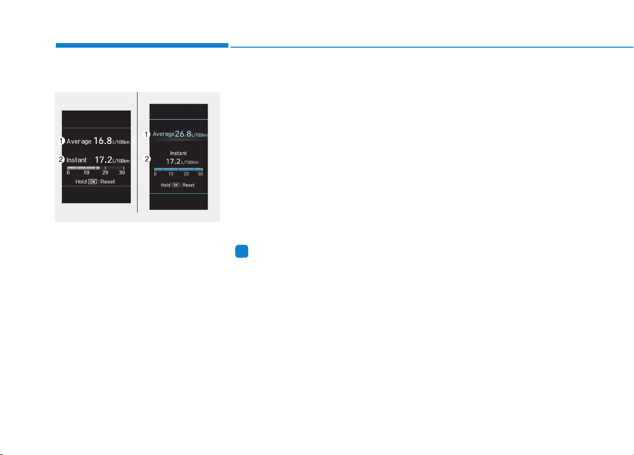
3-80
Convenient features of your vehicle
Fuel economy
Average Fuel Economy (1)
• The average fuel economy is calcu-
lated by the total driving distance
and fuel consumption since the last
average fuel economy reset.
• The average fuel economy can be
reset both manually and automati-
cally.
Manual reset
To clear the average fuel economy
manually, press the [OK] button on
the steering wheel for more than 1
second when the average fuel econo-
my is displayed.
Automatic reset
To automatically reset the average fuel
economy after refueling, select the
"Auto Reset" mode in User Settings
menu on the LCD display.
- After Ignition: The average fuel econ-
omy will reset automatically whenev-
er it has passed 4 hours after turning
OFF the engine.
- After Refueling: The average fuel
economy will reset automatically
when driving speed exceeds 1 km/h,
after adding 6 liters (1.6 gallons) of
fuel or more.
Information
The average fuel economy may be
inaccurate, when the vehicle drives
shorter than 300 meters (0.19 miles)
after turning ON the Engine Start/Stop
button.
Instant Fuel Economy (2)
• This mode displays the instant fuel
economy during the last few sec-
onds when the vehicle speed is
more than 10 km/h (6.2 MPH).
i
OPDE046131/OPDE046132
■ Type A ■ Type B
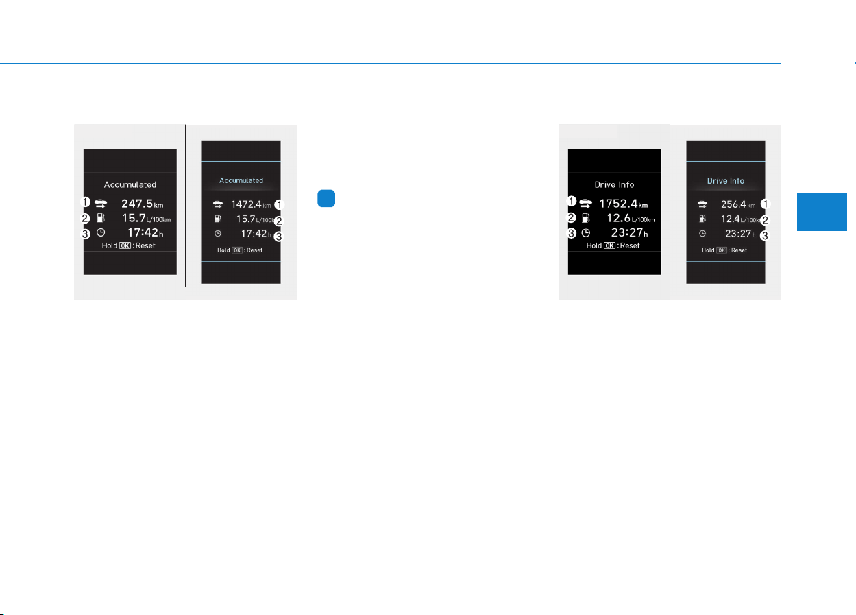
3-81
Convenient features of your vehicle
3
Accumulated Info display
This display shows the accumulated
trip distance (1), the average fuel
economy (2), and the total driving
time (3).
The information is calculated starting
from the last reset.
To manually reset the information,
press and hold the OK button when
viewing the Accumulated driving info.
The trip distance, the average fuel
economy, and total driving time will
reset simultaneously.
The accumulated driving information
will continue to be counted while the
engine is still running (for example,
when the vehicle is in traffic or
stopped at a stop light.)
Information
The vehicle must be driven for a min-
imum of 300 meters (0.19 miles) since
the last ignition key cycle before the
average fuel economy will be recalcu-
lated.
Driving Info display
This display shows the trip distance
(1), the average fuel economy (2),
and the total driving time (3).
The information is calculated for each
ignition cycle. The driving information
data gets initialized, when it has
passed 4 hours after turning OFF the
engine. In other words, the last driv-
ing information is available 4 hours
after you have turned on the engine.
i
OPDE046133/OPDE046134
■ Type A ■ Type B
OPDE046135/OPDE046136
■ Type A ■ Type B
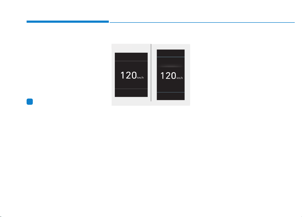
3-82
Convenient features of your vehicle
To manually reset the information,
press and hold the OK button when
viewing the Driving info. The trip dis-
tance, the average fuel economy, and
total driving time will reset simultane-
ously.
The driving information will continue
to be counted while the engine is still
running (for example, when the vehi-
cle is in traffic or stopped at a stop
light.)
Information
The vehicle must be driven for a min-
imum of 300 meters (0.19 miles) since
the last ignition key cycle before the
average fuel economy will be recalcu-
lated.
Digital Speedometer
This message shows the speed of
the vehicle (km/h, MPH).
i
OPDE046145/OPDE046146
■ Type A ■ Type B
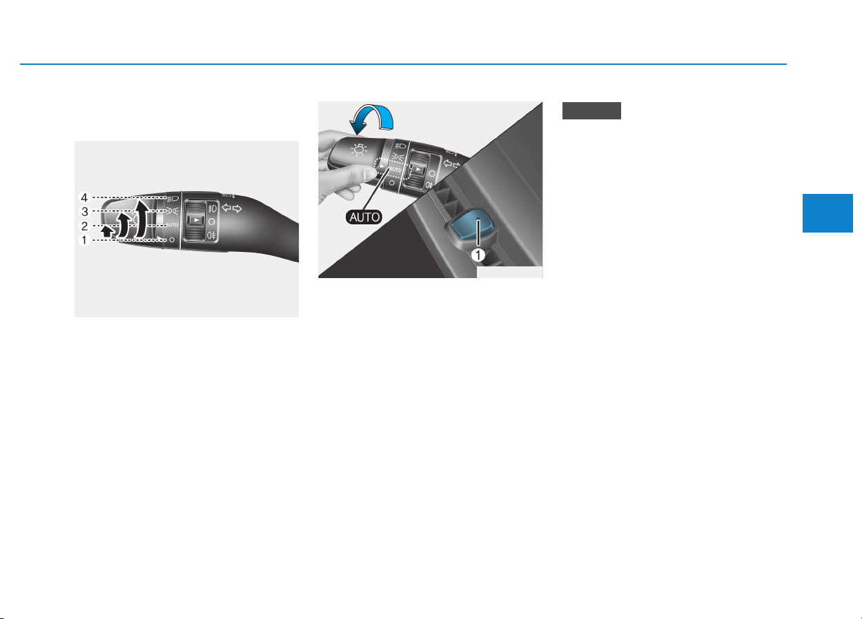
3-83
Convenient features of your vehicle
3
Exterior lights
Lighting control
To operate the lights, turn the knob at
the end of the control lever to one of
the following positions:
(1) O position
(2) AUTO light position (if equipped)
(3) Position lamp position
(4) Headlamp position
AUTO light position (if equipped)
When the light switch is in the AUTO
position, the position lamp and head-
lamp will be turned ON or OFF auto-
matically depending on the amount
of light outside the vehicle.
Even with the AUTO light feature in
operation, it is recommended to
manually turn ON the lamps when
driving at night or in a fog, or when
you enter dark areas, such as tun-
nels and parking facilities.
• Do not cover or spill anything on
the sensor (1) located on the
instrument panel.
• Do not clean the sensor using a
window cleaner, the cleanser
may leave a light film which
could interfere with sensor oper-
ation.
• If your vehicle has window tint
or other types of metallic coat-
ing on the front windshield, the
AUTO light system may not work
properly.
NOTICE
LLIIGGHHTT
OPDE046036
OPDE046065
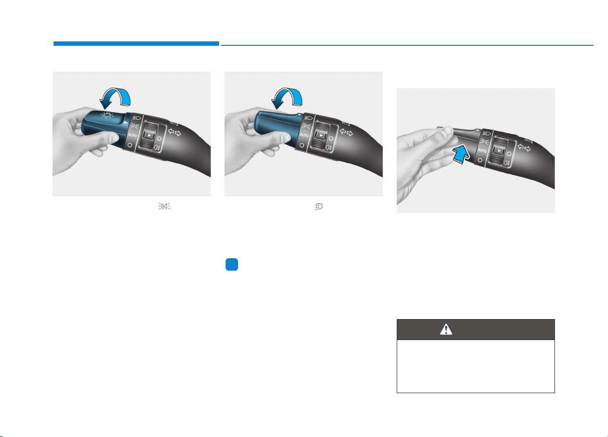
3-84
Convenient features of your vehicle
Position lamp position ( )
The position lamp, license plate lamp
and instrument panel lamp are turned
ON.
Headlamp position ( )
The headlamp, position lamp, license
plate lamp and instrument panel lamp
are turned ON.
Information
The ignition switch must be in the ON
position to turn on the headlamp.
High beam operation
To turn on the high beam headlamp,
push the lever away from you. The
lever will return to its original position.
The high beam indicator will light
when the headlamp high beams are
switched on.
To turn off the high beam headlamp,
pull the lever towards you. The low
beams will turn on.
i
OAE046469L OAE046467L
OAE046453L
Do not use high beam when there
are other vehicles approaching
you. Using high beam could
obstruct the other driver's vision.
WARNING
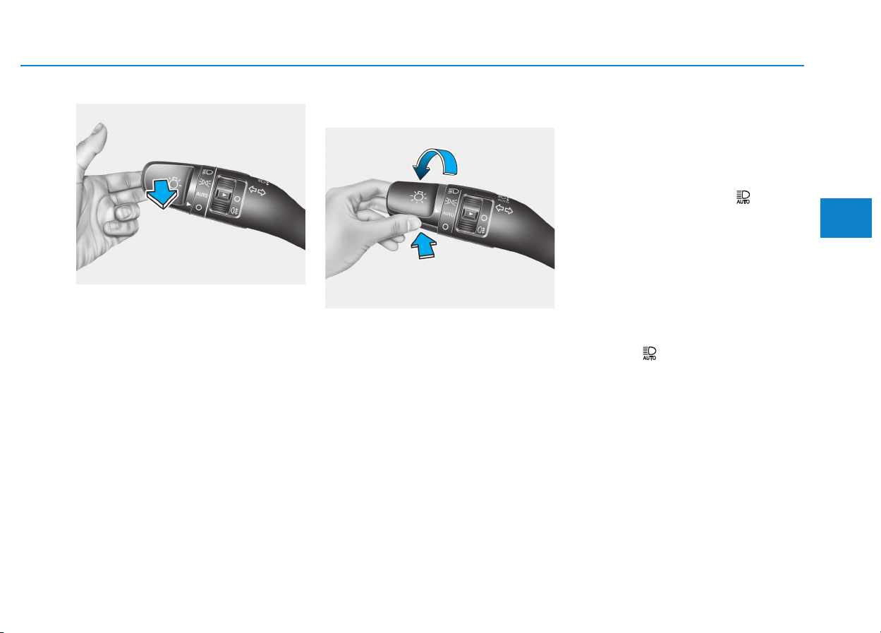
3-85
Convenient features of your vehicle
To flash the high beam headlamp,
pull the lever towards you, then
release the lever. The high beams
will remain ON as long as you hold
the lever towards you.
Smart high beam (if equipped)
The Smart High Beam is a system
that automatically adjusts the head-
lamp range (switches between high
beam and low beam) according to
the brightness of other vehicles and
road conditions.
Operating condition
1.Place the light switch in the AUTO
position.
2.Turn on the high beam by pushing
the lever away from you.
The smart high beam ( ) indica-
tor will illuminate.
3.The Smart High Beam will turn on
when vehicle speed is above
45km/h (25mph).
• If the lever is pushed away when
the Smart High Beam is operat-
ing, the Smart High Beam will
turn off and the high beam will be
on continuously. The smart high
beam ( ) indicator will turn off.
4.If the light switch is placed to the
headlamp position, the Smart High
Beam will turn off and the low
beam will be on continuously.
3
OAE046455L
OPDE046057
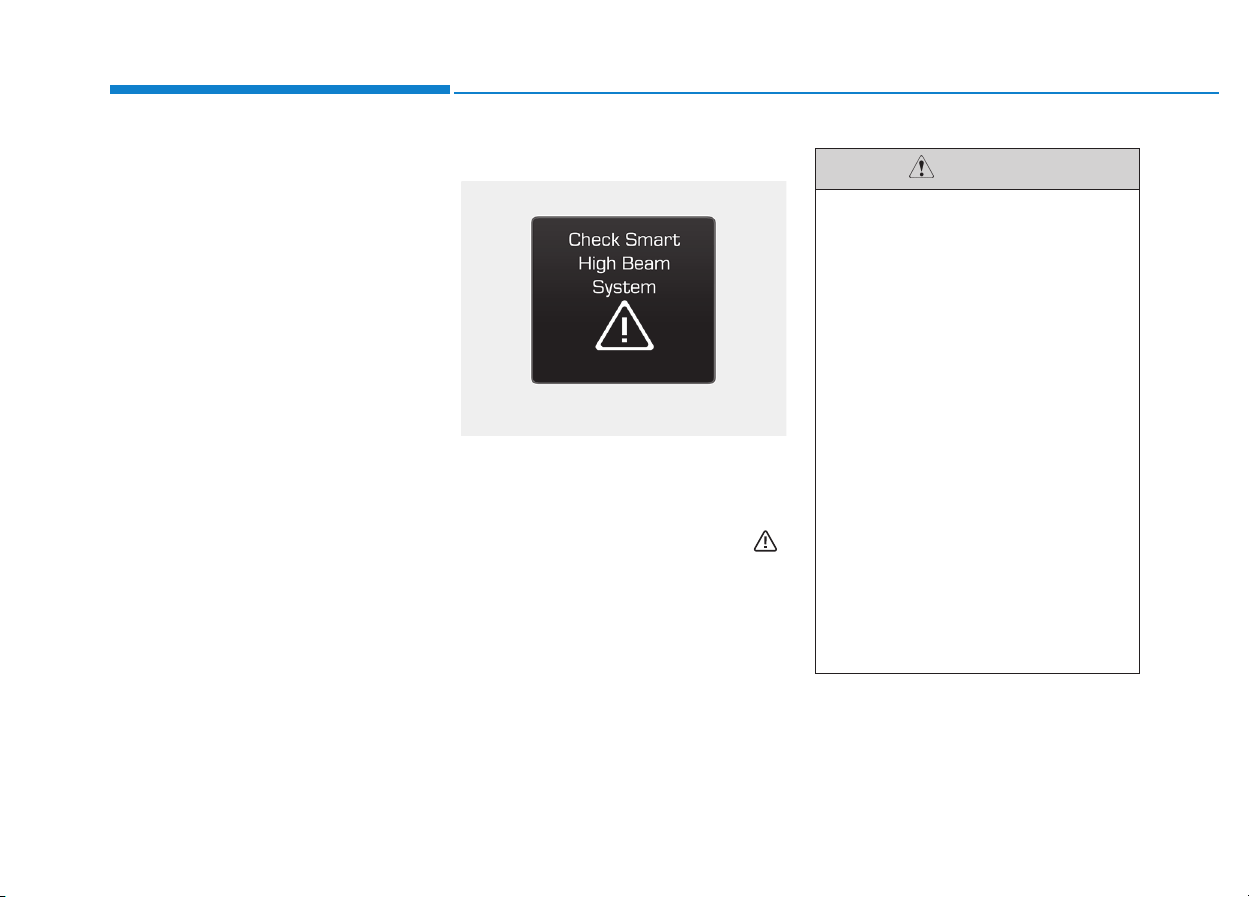
3-86
The high beam switches to low beam
in the below conditions.
- When the Smart High Beam is off.
- When the light switch is not in the
AUTO position.
- When the headlamp is detected
from the on-coming vehicle.
- When the tail lamp is detected
from the front vehicle.
- When the surrounding is bright
enough high beams are not needed.
- When streetlights or other lights
are detected.
- When vehicle speed is below
35km/h (15mph).
Warning light and message
When the Smart High Beam Assist
System is not working properly, the
warning message will come on for a
few second. After the message disap-
pears, the master warning light ( )
will illuminate.
We recommend that you take your
vehicle to an authorized HYUNDAI
dealer and have the system
checked.
Convenient features of your vehicle
ODM046655L
The system may not operate
normally in the below condi-
tions.
• When the light from the on-
coming or front vehicle is not
detected because of lamp
damage, hidden from sight,
etc.
• When the lamp of the on-com-
ing or front vehicle is covered
with dust, snow or water.
• When the light from the on-
coming or front vehicle is not
detected because of exhaust
fumes, smoke, fog, snow, etc.
• When the front window is cov-
ered with foreign matter such
as ice, dust, fog, or is dam-
aged.
(Continued)
CAUTION

3-87
Convenient features of your vehicle
3
(Continued)
• When there is a similar
shaped lamp with the front
vehicle’s lamps.
• When it is hard to see
because of fog, heavy rain or
snow.
• When the headlamp is not
repaired or replaced at an
authorized dealer.
• When headlamp aiming is not
properly adjusted.
• When driving on a narrow
winding road or rough road.
• When driving downhill or
uphill.
• When only part of the vehicle
in front is visible on a cross-
road or on a corner.
• When there is a traffic light,
reflecting sign, flashing sign
or mirror.
• When the road conditions are
bad such as being wet or cov-
ered with snow.
(Continued)
(Continued)
• When the front vehicle’s head-
lamps are off but the fog
lamps on.
• When a vehicle suddenly
appears from a around a cor-
ner.
• When the vehicle is tilted from
a flat tyre or being towed.
•
When the LDWS (Lane Departure
Warning System) or LKAS (Lane
Keeping Assist System) warning
light illuminates. (if equipped)
• Do not place any accessories,
stickers or tint the windshield.
• Have the windshield glass
replaced by an authorised
dealer.
• Do not remove or impact relat-
ed parts of the Smart High
Beam system.
• Be careful that water doesn’t
get into the Smart High Beam
unit.
• Do not place objects on the
instrument panel that reflect
light such as mirrors, white
paper, etc. The system may
malfunction if sunlight is
reflected.
• At times, the Smart High
Beam system may not work
properly, always check the
road conditions for your safe-
ty. When the system does not
operate normally, manually
change between the high
beam and low beam.
WARNING
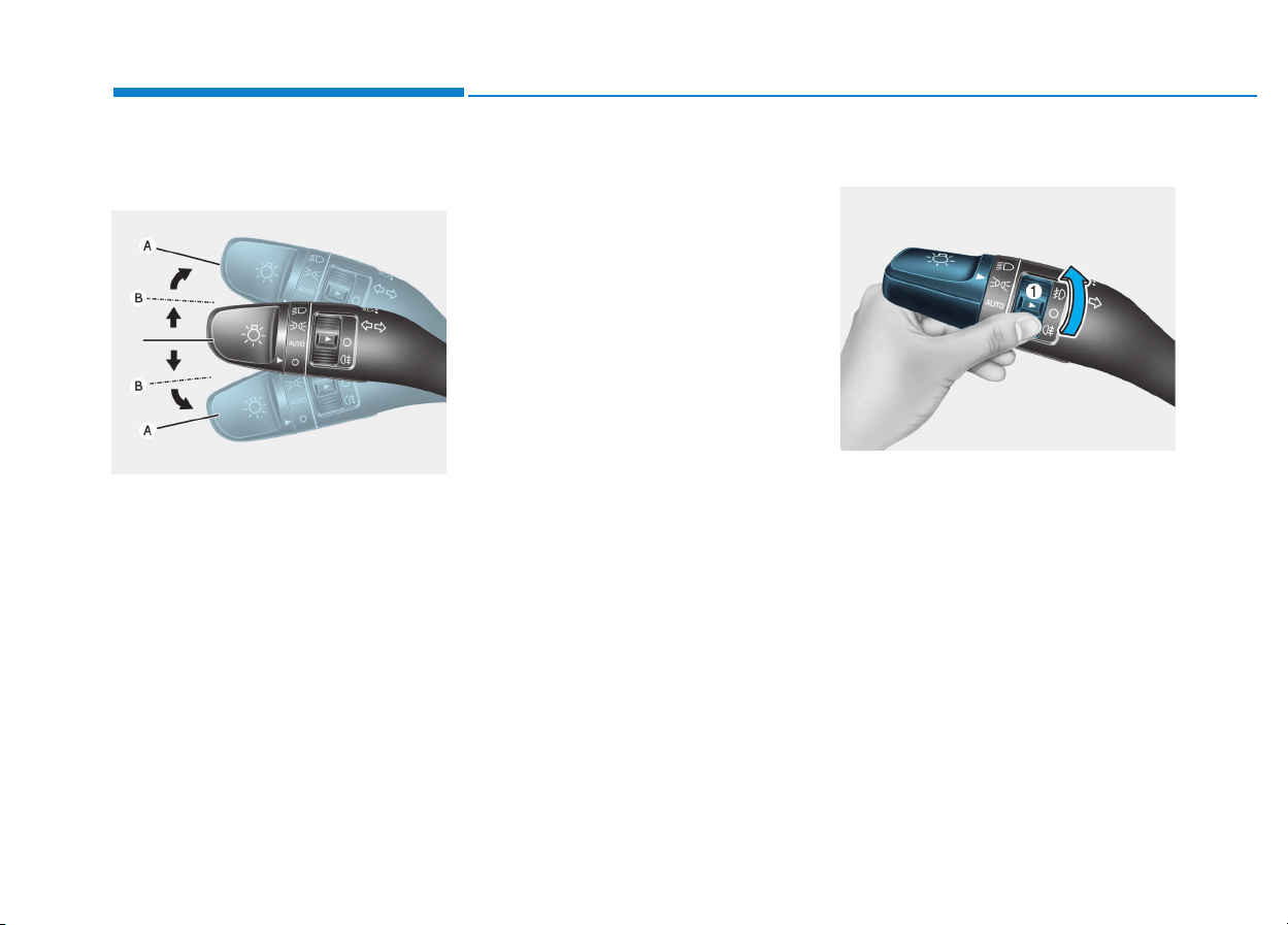
3-88
Convenient features of your vehicle
Turn signals and lane change
signals
To signal a turn, push down on the
lever for a left turn or up for a right
turn in position (A). To signal a lane
change, move the turn signal lever
slightly and hold it in position (B).The
lever will return to the OFF position
when released or when the turn is
completed.
If an indicator stays on and does not
flash or if it flashes abnormally, one of
the turn signal bulbs may be burned
out and will require replacement.
One-touch turn signal function
To activate an one-touch turn signal
function, move the turn signal lever
slightly and then release it. The lane
change signals will blink 3, 5 or 7
times.
You can activate/deactivate the One
Touch Turn Signal function or choose
the number of blinking (3, 5, or 7)
from the User Settings mode on the
LCD display. For more details, refer
to "LCD Display" in this chapter.
Front fog lamp (if equipped)
Fog lamps are used to provide
improved visibility when visibility is
poor due to fog, rain or snow, etc. Use
the switch next to the headlamp switch
to turn the fog lamps ON and OFF.
1. Turn on the position lamp.
2. Turn the light switch (1) to the front
fog lamp position.
OPDE046066
OTLE045284
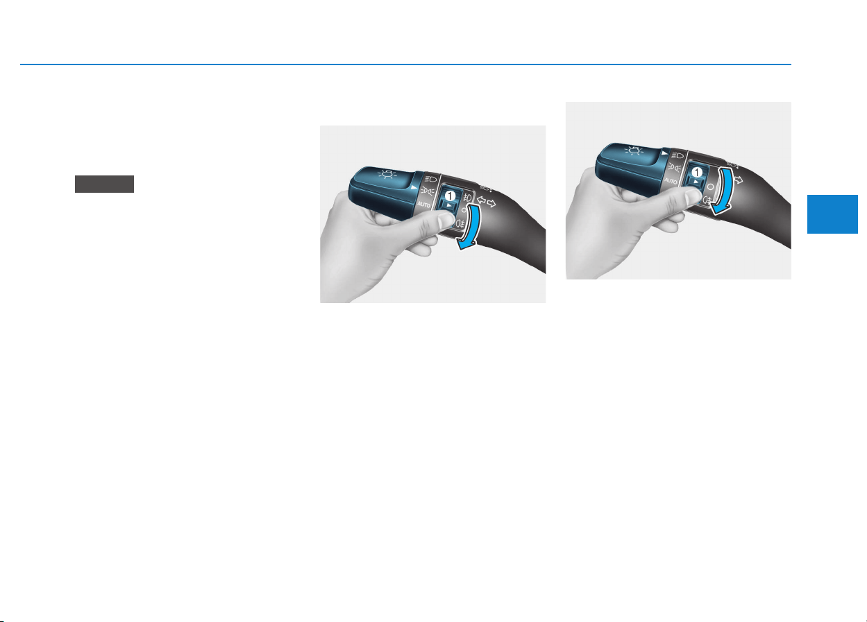
3-89
Convenient features of your vehicle
3
3. To turn off the front fog lamp, turn
the light switch to the front fog
lamp position again or turn off the
position lamp.
When in operation, the fog lamps
consume large amounts of vehicle
electrical power. Only use the fog
lamps when visibility is poor.
Rear fog lamp
Vehicle with front fog lamp
To turn on the rear fog lamp:
Position the light switch in the posi-
tion lamp position, turn the light
switch (1) to the front fog lamp posi-
tion, and then turn the light switch (1)
to the rear fog lamp position.
To turn the rear fog lamps off, do one
of the following:
• Turn off the position light switch.
• Turn the light switch to the rear fog
lamp position again.
• When the light switch is in the posi-
tion lamp position, if you turn off
the front fog lamp, the rear fog
lamp will also turn off.
Vehicle without front fog lamp
To turn on the rear fog lamp:
Position the light switch in the head-
lamp position, and then turn the light
switch (1) to the rear fog lamp position.
To turn the rear fog lamps off, do one
of the following:
• Turn off the headlamp switch.
• Turn the light switch to the rear fog
lamp position again.
NOTICE
OTLE045285
OPDE046064

3-90
Convenient features of your vehicle
Battery saver function
The purpose of this feature is to pre-
vent the battery from being dis-
charged. The system automatically
turns off the position lamp when the
driver turns the engine off and opens
the driver-side door.
With this feature, the position lamps
will turn off automatically if the driver
parks on the side of road at night.
If necessary, to keep the lamps on
when the engine is turned off, perform
the following:
1) Open the driver-side door.
2) Turn the position lamps OFF and
ON again using the light switch on
the steering column.
Headlamp delay function
(if equipped)
If you place the ignition switch to the
ACC or OFF position with the head-
lamps ON, the headlamps (and/or
position lamps) remain on for about 5
minutes. However, with the engine off if
the driver’s door is opened and closed,
the headlamps (and/or position lamps)
are turned off after 15 seconds.
The headlamps (and/or position
lamps) can be turned off by pressing
the lock button on the remote key or
smart key twice or turning the light
switch to the OFF or AUTO position.
However, if you turn the light switch
to the AUTO position when it is dark
outside, the headlamps will not be
turned off.
You can activate or deactivate the
Headlamp Delay function from the
User Settings mode on the LCD dis-
play. For more details, refer to
"LCD Display" in this chapter.
If the driver gets out of the vehicle
through other doors (except dri-
ver's door), the battery saver func-
tion does not operate and the
headlamp delay function does not
turn off automatically. Therefore, It
causes the battery to be dis-
charged. In this case, make sure to
turn off the lamp before getting out
of the vehicle.
NOTICE
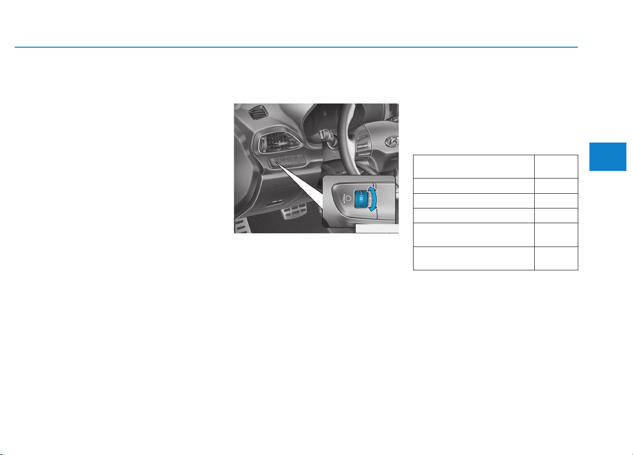
3-91
Convenient features of your vehicle
3
Daytime running light (DRL)
(if equipped)
The Daytime Running Lights (DRL)
can make it easier for others to see
the front of your vehicle during the
day, especially after dawn and before
sunset.
The DRL system will turn the dedi-
cated lamp OFF when:
1. The headlights or front fog lights
are in the ON position.
2. The position light switch is in the
ON position.
3. The engine is turned off.
Headlight leveling device
(if equipped)
Manual type
To adjust the headlight beam level
according to the number of the pas-
sengers and loading weight in the
luggage area, turn the beam leveling
switch.
The higher the number of the switch
position, the lower the headlight
beam level. Always keep the head-
light beam at the proper leveling
position, or headlights may dazzle
other road users.
Listed below are the examples of
proper switch settings. For loading
conditions other than those listed
below, adjust the switch position so
that the beam level may be the near-
est as the condition obtained accord-
ing to the list.
OPD046035
Loading condition
Switch
position
Driver only 0
Driver + Front passenger 0
Full passengers (including driver) 1
Full passengers (including driver)
+ Maximum permissible loading
2
Driver + Maximum permissible
loading
3
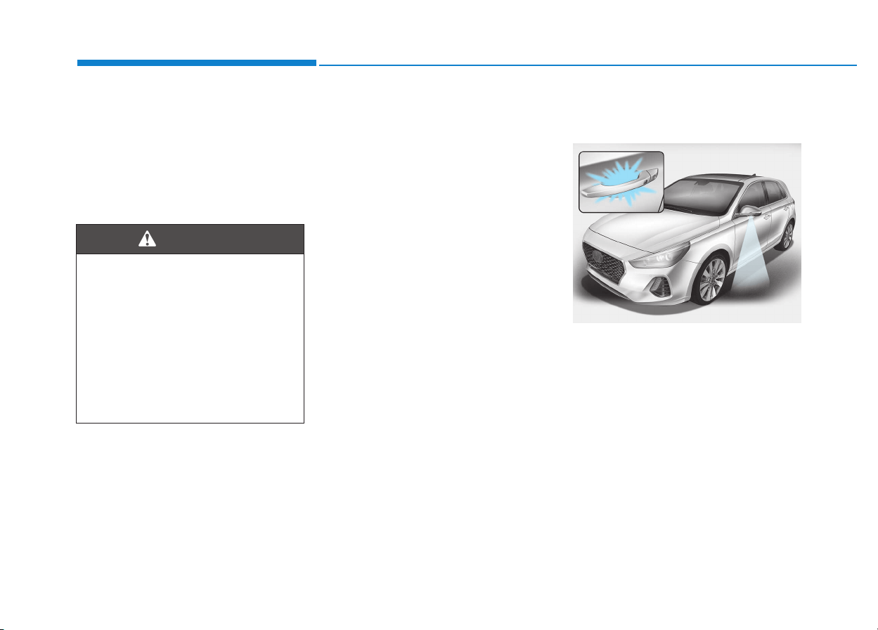
3-92
Automatic type
It automatically adjusts the headlight
beam level according to the number
of passengers and loading weight in
the luggage area.
And it offers proper headlight beam
under various conditions.
Static bending light
(if equipped)
While driving a corner, for greater
visibility and safety, either the left or
right side static bending light will turn
on automatically. The static bending
light will turn on when one of the fol-
lowing conditions occur.
• Vehicle speed is less than 10 km/h
(6 mph) and steering wheel angle
is turned approximately 80 degrees
with the low beam on.
• Vehicle speed is between 10 km/h
(6 mph) to 90 km/h (56 mph) and
steering wheel angle is turned
approximately 35 degrees with the
low beam on.
• When the vehicle is in reverse with
one of the conditions above satis-
fied, the light opposite to the direc-
tion the steering wheel is steered
will turn on.
Welcome system (if equipped)
Welcome light (if equipped)
Puddle lamp (if equipped)
When all the doors (and tailgate) are
closed and locked, the puddle lamp
will come on for about 15 seconds if
any of the below is performed.
• When the door unlock button is
pressed on the remote key or
smart key.
• When the button of the outside
door handle is pressed with the
smart key in possession.
Convenient features of your vehicle
If it does not work properly even
though your car is inclined
backward according to passen-
ger's posture, or the headlight
beam is irradiated to the high or
low position, we recommend
that the system be inspected by
an authorized HYUNDAI dealer.
Do not attempt to inspect or
replace the wiring yourself.
WARNING
OPDE046051

3-93
Convenient features of your vehicle
Door handle lamp (if equipped)
When all the doors (and tailgate) are
closed and locked, the door handle
lamp will come on for about 15 sec-
onds if any of the below is performed.
• When the door unlock button is
pressed on the remote key or
smart key.
• When the button of the outside
door handle is pressed with the
smart key in possession.
Headlamp and position lamp
When the headlamp (lamp switch in
the headlamp or AUTO position) is on
and all doors (and tailgate) are locked
and closed, the position lamp and
headlamp will come on for 15 seconds
if/or any of the below is performed.
• When the door unlock button is
pressed on the remote key or
smart key.
At this time, if you press the door lock
or unlock button, the position lamp and
headlamp will turn off immediately.
You can activate or deactivate the
Welcome Light from the User
Settings mode on the LCD display.
For more details, refer to "LCD
Display" in this chapter.
Interior lamp
When the interior lamp switch is in
the DOOR position and all doors (and
tailgate) are closed and locked, the
room lamp will come on for 30 sec-
onds if any of the below is performed.
• When the door unlock button is
pressed on the remote key or
smart key.
• When the button of the outside
door handle is pressed with the
smart key in possession.
At this time, if you press the door lock
or unlock button, the room lamp will
turn off immediately.
Interior lights
Do not use the interior lights for
extended periods when the engine
is turned off or the battery will dis-
charge.
Interior lamp AUTO cut
The interior lamps will automatically
go off approximately 20 minutes after
the engine is turned off and the
doors closed. If a door is opened, the
lamp will go off 40 minutes after the
engine is turned off. If the doors are
locked and the vehicle enters the
armed stage of the theft alarm sys-
tem, the lamps will go off five sec-
onds later.
NOTICE
3
Do not use the interior lights
when driving in the dark.The inte-
rior lights may obscure your view
and cause an accident.
WARNING
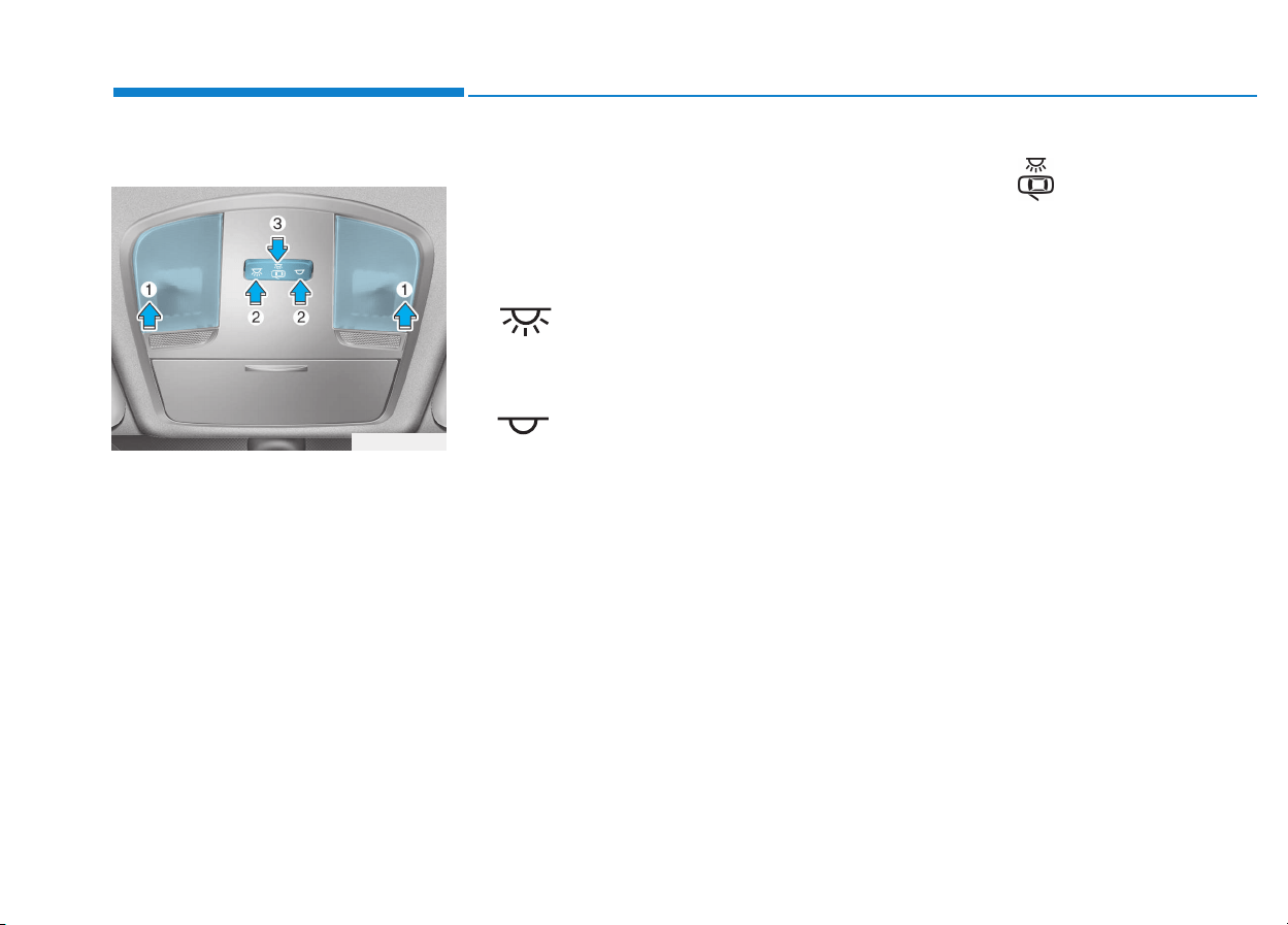
3-94
Convenient features of your vehicle
Front lamps
(1) Front Map Lamp
(2) Front Room Lamp
(3) Front Door Lamp
Front map lamp
Press the map lamp lens (1) to turn
ON the map lamp. Re-press the map
lamp lens to turn OFF the map lamp.
Front room lamp
•:
Press the button to turn ON the
room lamp for the front/rear seats.
•:
Press the button to turn OFF the
room lamp for the front/rear seats.
Front door lamp ( )
The room lamp for the front/rear
seats is automatically turned ON for
approximately 30 seconds, when a
door is opened.
The room lamp for the front/rear
seats is automatically turned ON for
approximately 15 seconds, when the
remote key (smart key) unlocks the
doors. The room lamp fades out,
when the ignition switch is placed to
the ON position in 15 seconds. The
room lamp remains ON up to 20 min-
utes, when a door is opened with the
ignition switch in the either the ACC
or OFF position.
OPDE046041
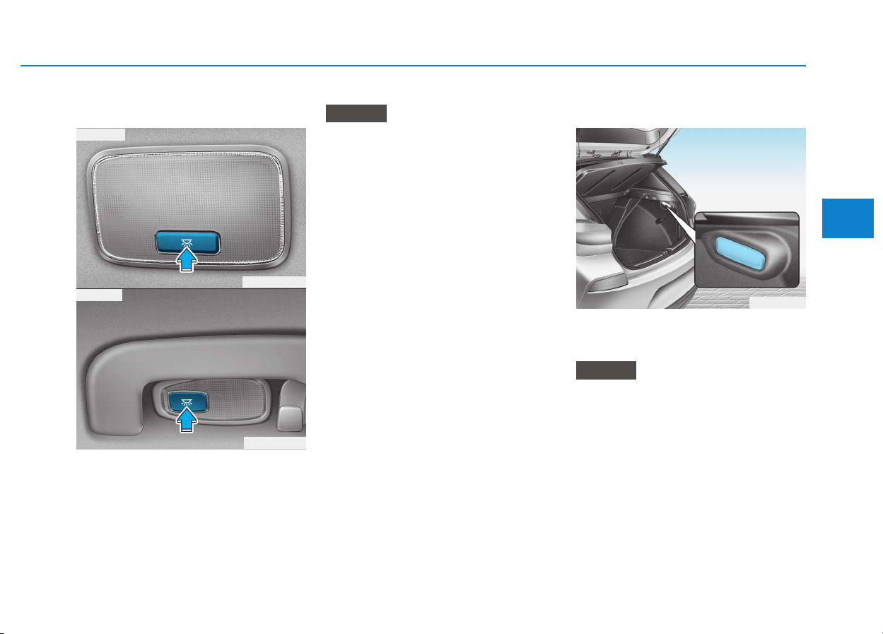
3-95
Convenient features of your vehicle
3
Rear lamps
Do not leave the lamp switches on
for an extended period of time
when the engine is turned off.
Luggage room lamp
The luggage room lamp comes on
when the tailgate is opened.
The luggage room lamp comes on
as long as the tailgate lid is open.
To prevent unnecessary charging
system drain, close the tailgate lid
securely after using the tailgate.
NOTICE
NOTICE
OPD046042
Rear room lamp switch :
Press this button to turn the room
lamp on and off.
OAD045407
OPD046406
■ Type A
■ Type B
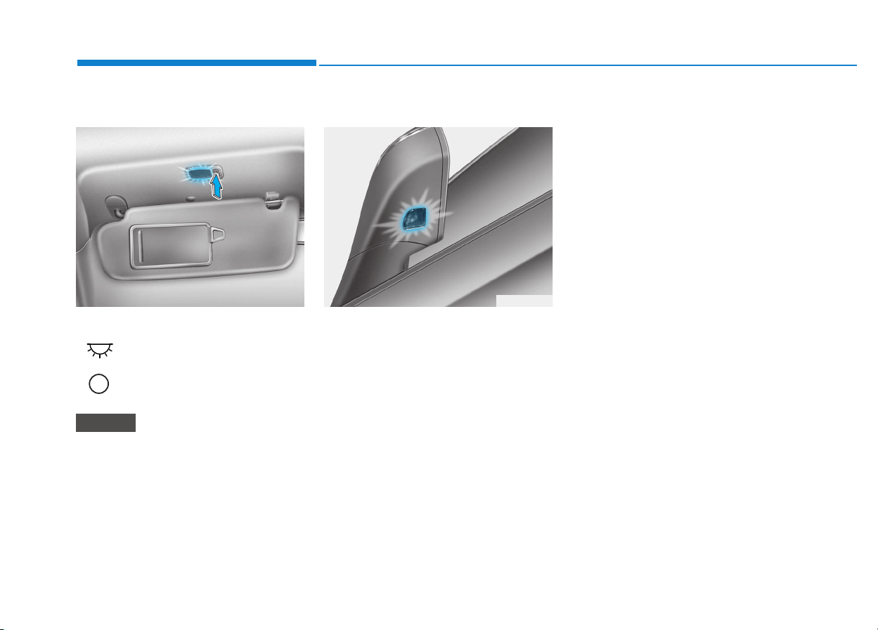
3-96
Convenient features of your vehicle
Vanity mirror lamp (if equipped)
Push the switch to turn the light on or
off.
• : The lamp will turn on if this
button is pressed.
• : The lamp will turn off if this
button is pressed.
Always have the switch in the off
position when the vanity mirror
lamp is not in use. If the sunvisor
is closed without the lamp off, it
may discharge the battery or dam-
age the sunvisor.
Puddle lamp (if equipped)
Welcome light
When all doors (and tailgate) are
closed and locked, the puddle lamp
will come on for 15 seconds if the
door is unlocked by the smart key or
outside door handle button.
For more details, refer to "Welcome
System" in this chapter.
Escort light
When the ignition switch is in the
OFF position and the driver's door is
opened, the puddle lamp will come
on for 30 seconds. If the driver's door
is closed within the 30 seconds, the
puddle lamp will turn off after 15 sec-
onds. If the driver's door is closed
and locked, the puddle lamp will turn
off immediately.
The Puddle Lamp Escort Light will
turn on only the first time the driver's
door is opened after the engine is
turned off.
NOTICE
OPD046043 OLF044259
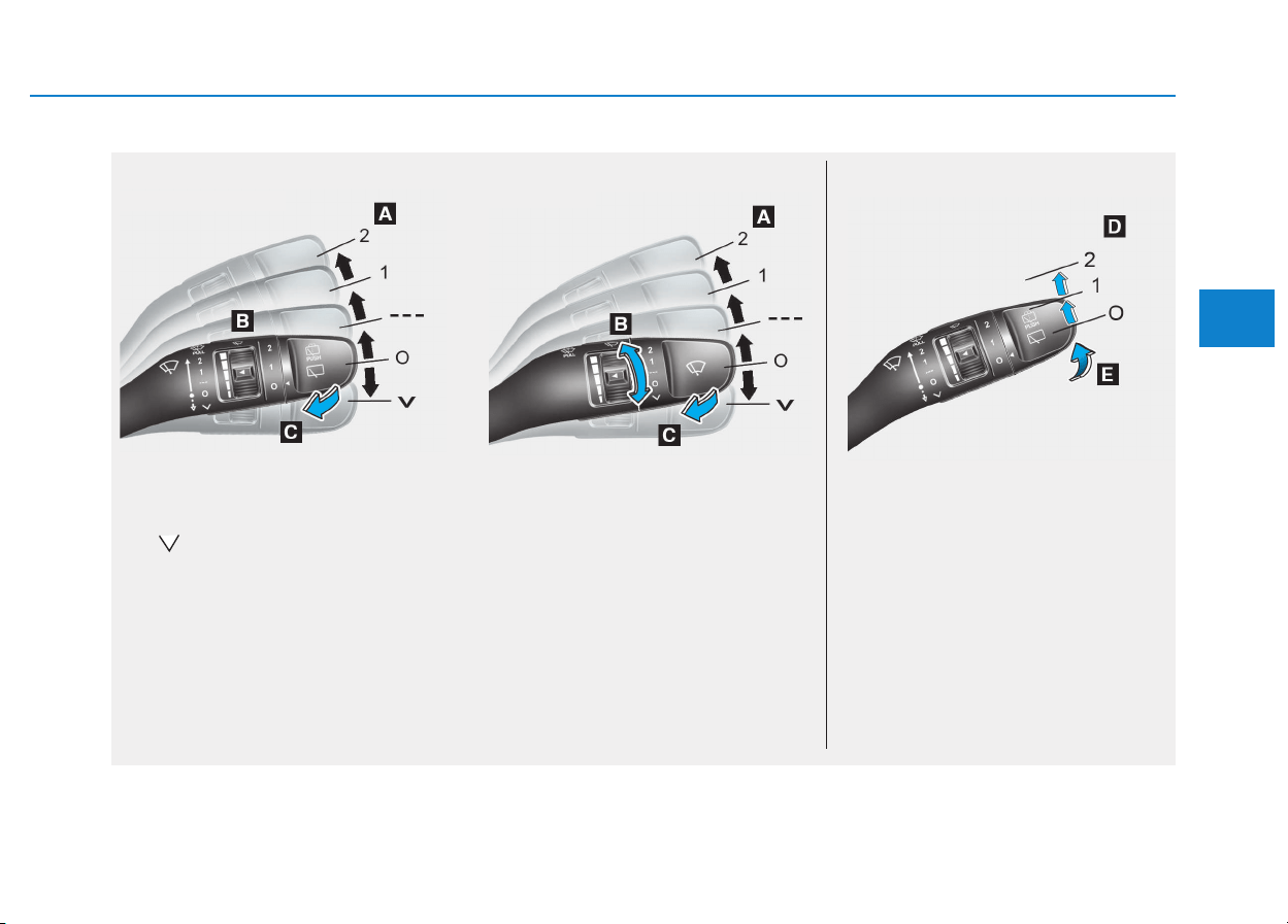
3-97
Convenient features of your vehicle
WWIIPPEERRSS AANNDD WWAASSHHEERRSS
3
■ Front windshield wiper/washer ■ Rear windshield wiper/washer
OPDE046058/OPDE046059/OPDE046060
• Type A
• Type B
A : Wiper speed control (front)
· – Single wipe
· O – Off
· --- – Intermittent wipe
AUTO* – Auto control wipe
· 1 – Low wiper speed
· 2 – High wiper speed
B : Intermittent control wipe time adjust-
ment
C : Wash with brief wipes (front)
D : Rear wiper control*
· 2 – High wiper speed
· 1 – Low wiper speed
· O – Off
E : Wash with brief wipes (rear)
* : if equipped
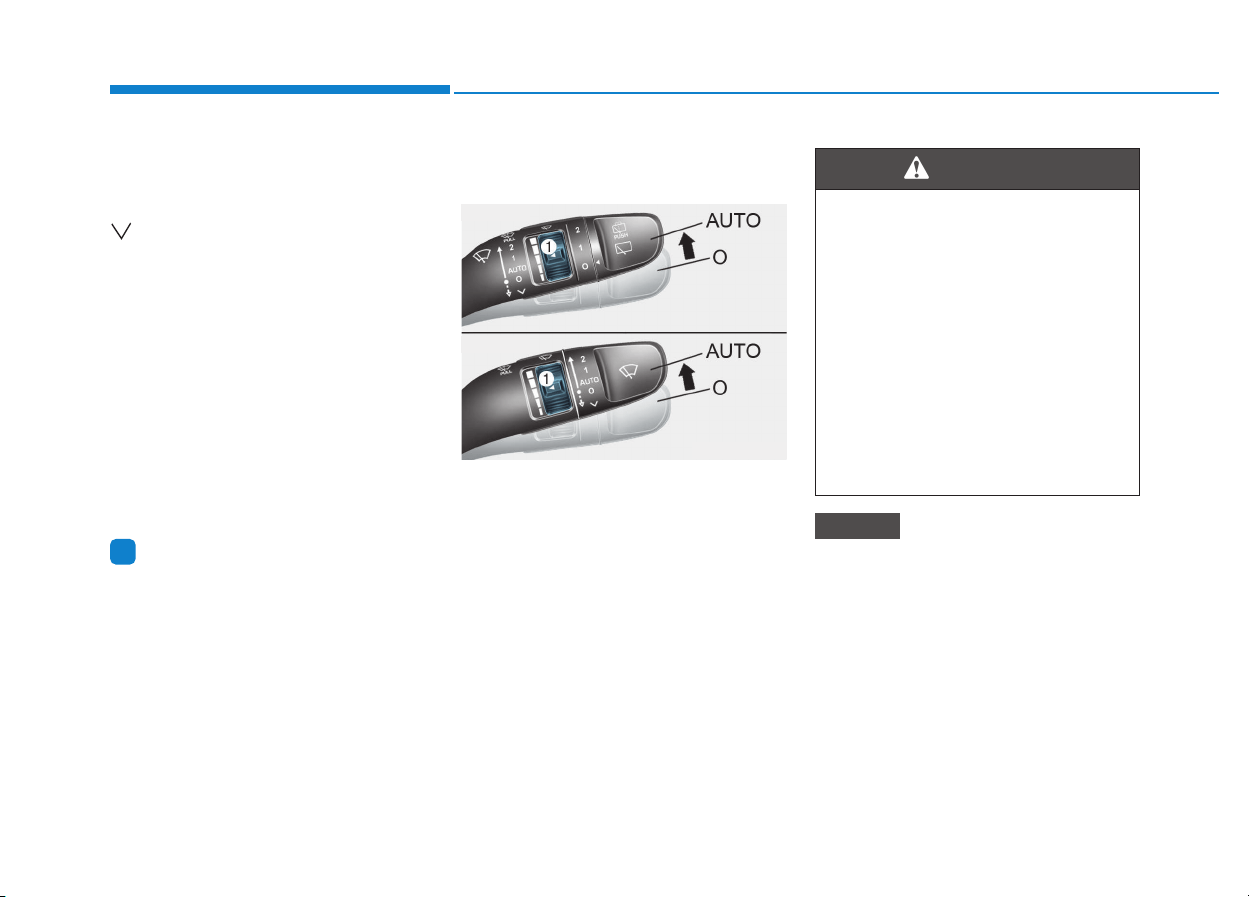
3-98
Convenient features of your vehicle
Windshield wipers
Operates as follows when the igni-
tion switch is turned ON.
: For a single wiping cycle, move
the lever down and release it.
The wipers will operate continu-
ously if the lever is held in this
position.
O : Wiper is not in operation
--- : Wiper operates intermittently at
the same wiping intervals. Use
this mode in light rain or mist. To
vary the speed setting, turn the
speed control knob.
1 : Normal wiper speed
2 : Fast wiper speed
Information
If there is heavy accumulation of snow
or ice on the windshield, defrost the
windshield for about 10 minutes, or until
the snow and/or ice is removed before
using the windshield wipers to ensure
proper operation.
If you do not remove the snow and/or ice
before using the wiper and washer, it may
damage the wiper and washer system.
AUTO (Automatic) control
(if equipped)
The rain sensor located on the upper
end of the windshield glass senses
the amount of rainfall and controls
the wiping cycle for the proper inter-
val. The more it rains, the faster the
wiper operates.
When the rain stops, the wiper stops.
To vary the speed setting, turn the
speed control knob (1).
If the wiper switch is set in AUTO
mode when the ignition switch is in
the ON position, the wiper will oper-
ate once to perform a self-check of
the system. Set the wiper to OFF
position when the wiper is not in use.
• When washing the vehicle, set the
wiper switch in the O position to
stop the auto wiper operation. The
wiper may operate and be damaged
if the switch is set in the AUTO
mode while washing the vehicle.
• Do not remove the sensor cover
located on the upper end of the
passenger side windshield glass.
Damage to system parts could
occur and may not be covered by
your vehicle warranty.
NOTICE
i
OPDE046061
To avoid personal injury from the
windshield wipers, when the
engine is running and the wind-
shield wiper switch is placed in
the AUTO mode:
• Do not touch the upper end of
the windshield glass facing the
rain sensor.
• Do not wipe the upper end of
the windshield glass with a
damp or wet cloth.
• Do not put pressure on the
windshield glass.
WARNING
■ Type A
■ Type B
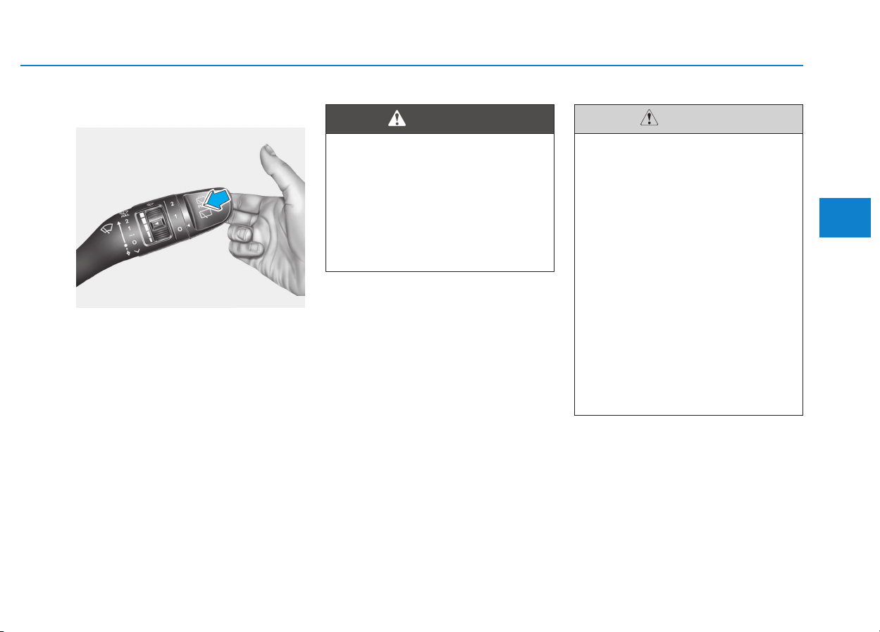
3-99
Convenient features of your vehicle
3
Windshield washers
In the O position, pull the lever gently
toward you to spray washer fluid on
the windshield and to run the wipers
1-3 cycles. The spray and wiper oper-
ation will continue until you release
the lever.
If the washer does not work, you may
need to add washer fluid to the wash-
er fluid reservoir.
When the outside temperature is
below freezing, ALWAYS warm the
windshield using the defroster to
prevent the washer fluid from
freezing on the windshield and
obscuring your vision which
could result in an accident and
serious injury or death.
WARNING
• To prevent possible damage
to the washer pump, do not
operate the washer when the
fluid reservoir is empty.
• To prevent possible damage
to the wipers or windshield,
do not operate the wipers
when the windshield is dry.
• To prevent damage to the
wiper arms and other compo-
nents, do not attempt to move
the wipers manually.
• To prevent possible damage
to the wipers and washer sys-
tem, use anti-freezing washer
fluids in the winter season or
cold weather.
CAUTION
OPDE046062
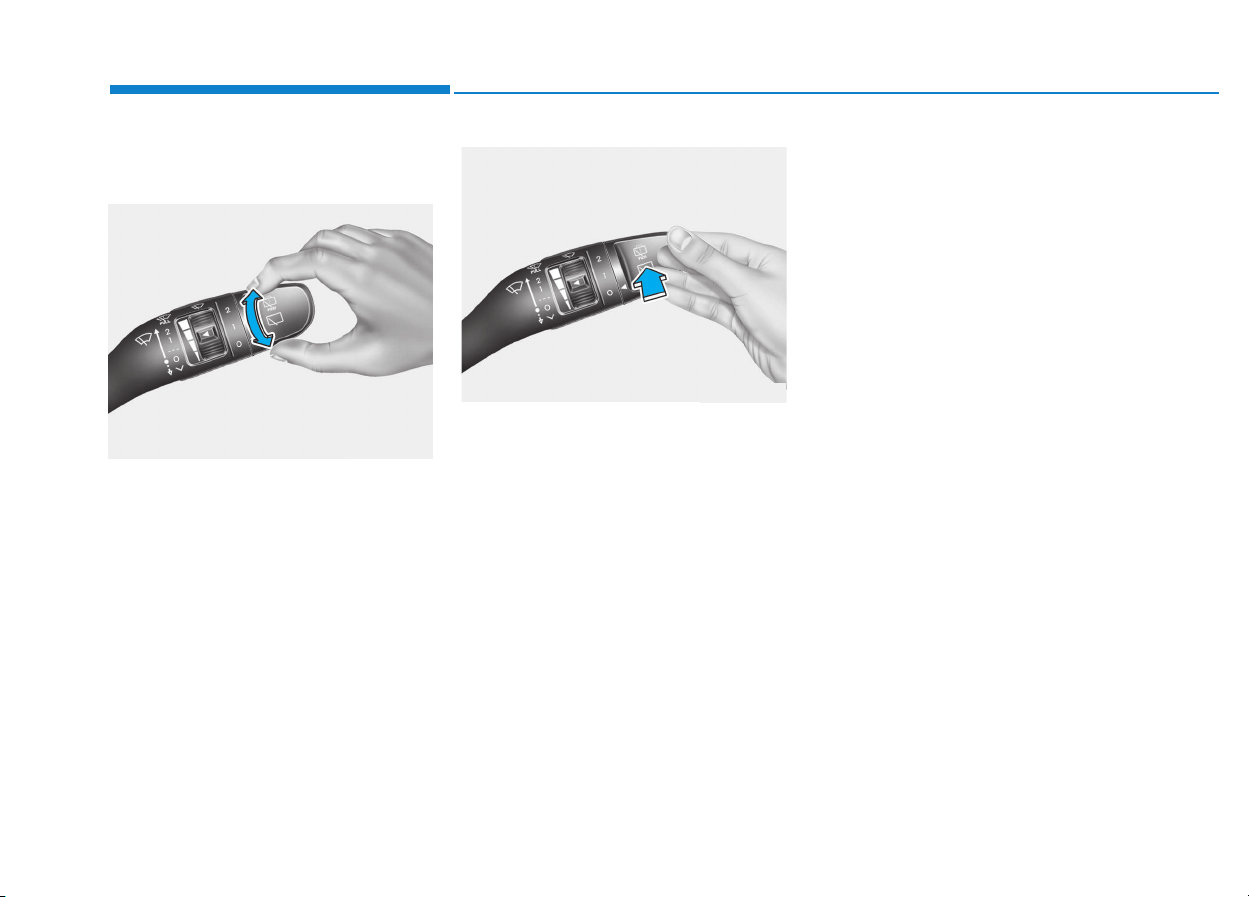
3-100
Convenient features of your vehicle
Rear window wiper and wash-
er switch (if equipped)
The rear window wiper and washer
switch is located at the end of the
wiper and washer switch lever.
Turn the switch to the desired posi-
tion to operate the rear wiper and
washer.
2 – High wiper speed
1 – Low wiper speed
O – Off
Push the lever away from you to
spray rear washer fluid and to run the
rear wipers 1~3 cycles. The spray
and wiper operation will continue until
you release the lever. (if equipped)
Auto rear wiper (if equipped)
The rear wiper will operate while the
vehicle is in reverse with the front
wiper ON by selecting the function on
the LCD display.
Go to ‘User Settings
→
Convenience
→
Auto Rear Wiper (reverse)’.
OTLE045167
OTLE045168
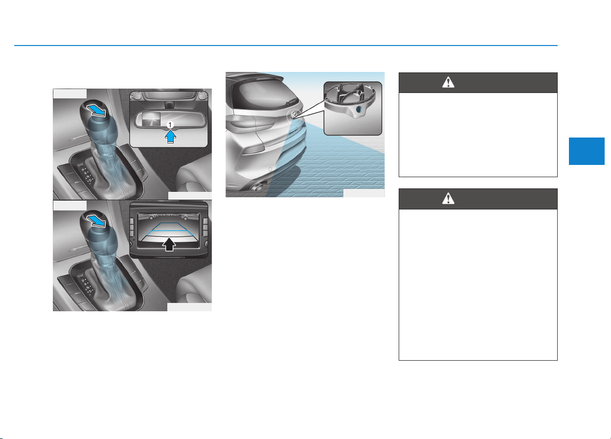
3-101
Convenient features of your vehicle
3
DDRRIIVVEERR AASSSSIISSTT SSYYSSTTEEMM
The Rear View Camera will activate
when the engine is running and the
shift lever is in the R (Reverse) posi-
tion.
This is a supplemental system that
shows behind the vehicle through
the mirror or navigation display while
backing-up.
■
■
Type A
The rear view camera can be turned
off by pressing the ON/OFF button
(1) when the rear view camera is acti-
vated. Press the ON/OFF button (1)
once more to turn on the rear view
camera when the engine is running
and the shift lever is in R (Reverse).
The rear camera display is not a
safety device. It only serves to
assist the driver in identifying
objects directly behind the mid-
dle of the vehicle. The camera
does NOT cover the complete
area behind the vehicle.
WARNING
OPDE046405
OPDE046424
OPD046402
■ Type A
■ Type B
Rear view camera (if equipped)
• Never rely solely on the rear
camera display when backing-
up.
• ALWAYS look around your
vehicle to make sure there are
no objects or obstacles before
moving the vehicle in any
direction to prevent a collision.
• Always pay close attention
when the vehicle is driven
close to objects, particularly
pedestrians, and especially
children.
WARNING
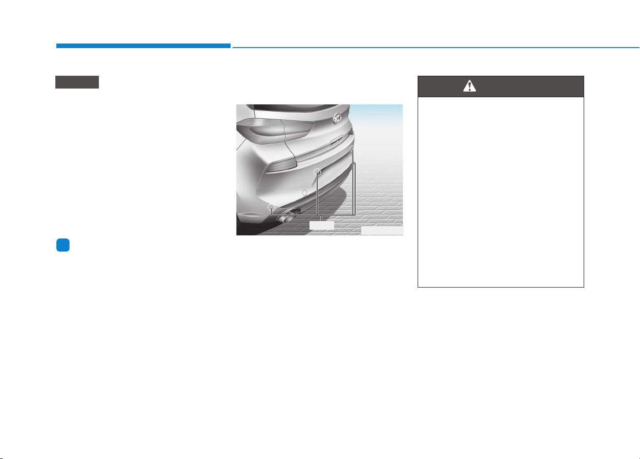
3-102
Convenient features of your vehicle
• Do not spray the camera or its
surrounding area directly with a
high pressure washer. Shock
applied from high pressure
water may cause the device to
not operate normally.
• Do not use any cleanser con-
taining acid or alkaline deter-
gents when cleaning the lens.
Use only a mild soap or neutral
detergent, and rinse thoroughly
with water.
Information
Always keep the camera lens clean. The
camera may not work normally if the
lens is covered with foreign material.
Rear parking assist system
(if equipped)
The Rear Parking Assist System
assists the driver during reverse move-
ment of the vehicle by chiming if any
object is sensed within the distance of
120 cm (50 inches) behind the vehicle.
This system is a supplemental sys-
tem that senses objects within the
range and location of the sensors, it
cannot detect objects in other areas
where sensors are not installed.
i
NOTICE
OPD046400
Sensor
• ALWAYS look around your vehi-
cle to make sure there are not
any objects or obstacles before
moving the vehicle in any direc-
tion to prevent a collision.
• Always pay close attention
when the vehicle is driven close
to objects, particularly pedestri-
ans, and especially children.
• Be aware that some objects
may not be visible on the
screen or be detected by the
sensors, due to the objects
distance, size or material, all of
which can limit the effective-
ness of the sensor.
WARNING

3-103
Convenient features of your vehicle
3
Operation of the Rear Parking
Assist System
Operating condition
• This system will activate when
backing up with the ignition switch
in the ON position. However, if vehi-
cle speed exceeds 5 km/h (3 mph),
the system may not detect objects.
• If vehicle speed exceeds 10 km/h (6
mph), the system will not warn you
even though objects are detected.
• When more than two objects are
sensed at the same time, the clos-
est one will be recognized first.
Types of warning sound and indicator
Types of warning sound Indicator
When an object is 120 cm to 60 cm (47 in. to 24 in.) from the rear
bumper : Buzzer beeps intermittently.
When an object is 60 cm to 30 cm (24 in. to 12 in.) from the rear
bumper : Buzzer beeps more frequently.
When an object is within 30 cm (12 in.) of the rear bumper :
Buzzer beeps continuously.
• The indicator may differ from the illustration as objects or sensors sta-
tus. If the indicator blinks, we recommend that you have your vehicle
checked by an authorized HYUNDAI dealer.
• If the audible warning does not sound or if the buzzer sounds intermit-
tently when shifting into R (Reverse) position, this may indicate a mal-
function with the Parking Assist System. If this occurs, we recommend
that you have your vehicle checked by an authorized HYUNDAI dealer as
soon as possible.
NOTICE
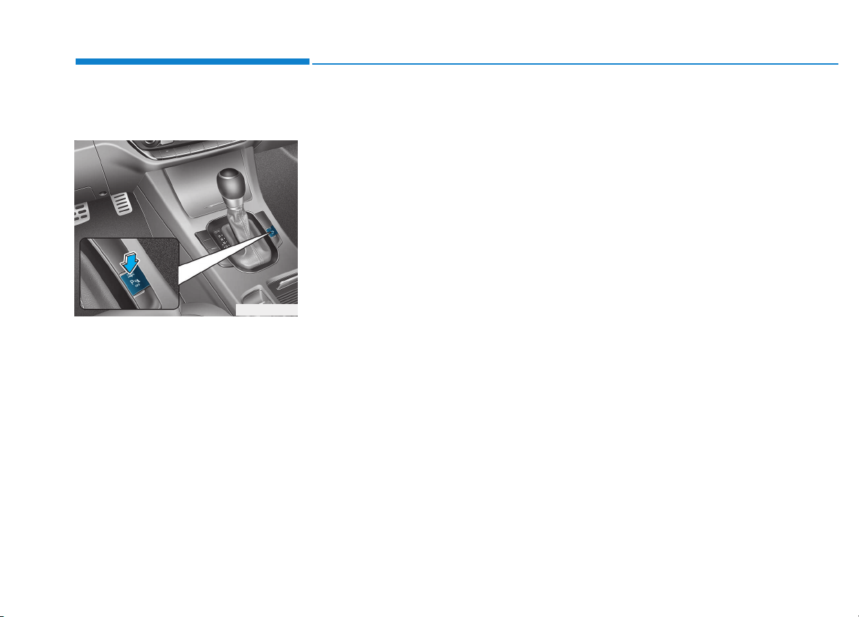
3-104
Convenient features of your vehicle
To turn off the Rear Parking
Assist System (if equipped)
Push the button to turn off the Rear
Parking Assist System. The indicator
light on the button will turn on.
Non-operational conditions of
Parking Assist System
The Rear Parking Assist System
may not operate normally when:
• Moisture is frozen to the sensor.
• Sensor is covered with foreign mat-
ter, such as snow or water, or the
sensor cover is blocked.
There is a possibility of the Rear
Parking Assist System malfunction
when:
• Driving on uneven road surfaces
such as unpaved roads, gravel,
bumps, or gradient.
• Objects generating excessive noise
such as vehicle horns, loud motor-
cycle engines, or truck air brakes
can interfere with the sensor.
• Heavy rain or water spray is present.
• Wireless transmitters or mobile
phones are present near the sensor.
• The sensor is covered with snow.
• Any non-factory equipment or acces-
sories have been installed, or if the
vehicle bumper height or sensor
installation has been modified.
Detecting range may decrease when:
• Outside air temperature is extreme-
ly hot or cold.
• Undetectable objects smaller than
1 m (40 inches) and narrower than
14 cm (6 inches) in diameter.
OPDE046429

3-105
Convenient features of your vehicle
3
The following objects may not be
recognized by the sensor:
• Sharp or slim objects such as
ropes, chains or small poles.
• Objects, which tend to absorb sen-
sor frequency such as clothes,
spongy material or snow.
Rear parking assist system pre-
cautions
• The rear parking assist system may
not sound consistently depending on
the speed and shapes of the objects
detected.
• The rear parking assist system may
malfunction if the vehicle bumper
height or sensor installation has
been modified or damaged. Any
non-factory installed equipment or
accessories may also interfere with
the sensor performance.
• The sensor may not recognize
objects less than 30 cm (11 in.) from
the sensor, or it may sense an incor-
rect distance. Use caution.
• When the sensor is frozen or stained
with snow, dirt, or water, the sensor
may be inoperative until the stains
are removed using a soft cloth.
• Do not push, scratch or strike the
sensor with any hard objects that
could damage the surface of the
sensor. Sensor damage could occur.
• Do not spray the sensors or its sur-
rounding area directly with a high
pressure washer. Shock applied
from high pressure water may cause
the device to not operate normally.
Your new vehicle warranty does
not cover any accidents or dam-
age to the vehicle or injuries to
its occupants related to a Rear
Parking Assist System. Always
drive safely and cautiously.
WARNING
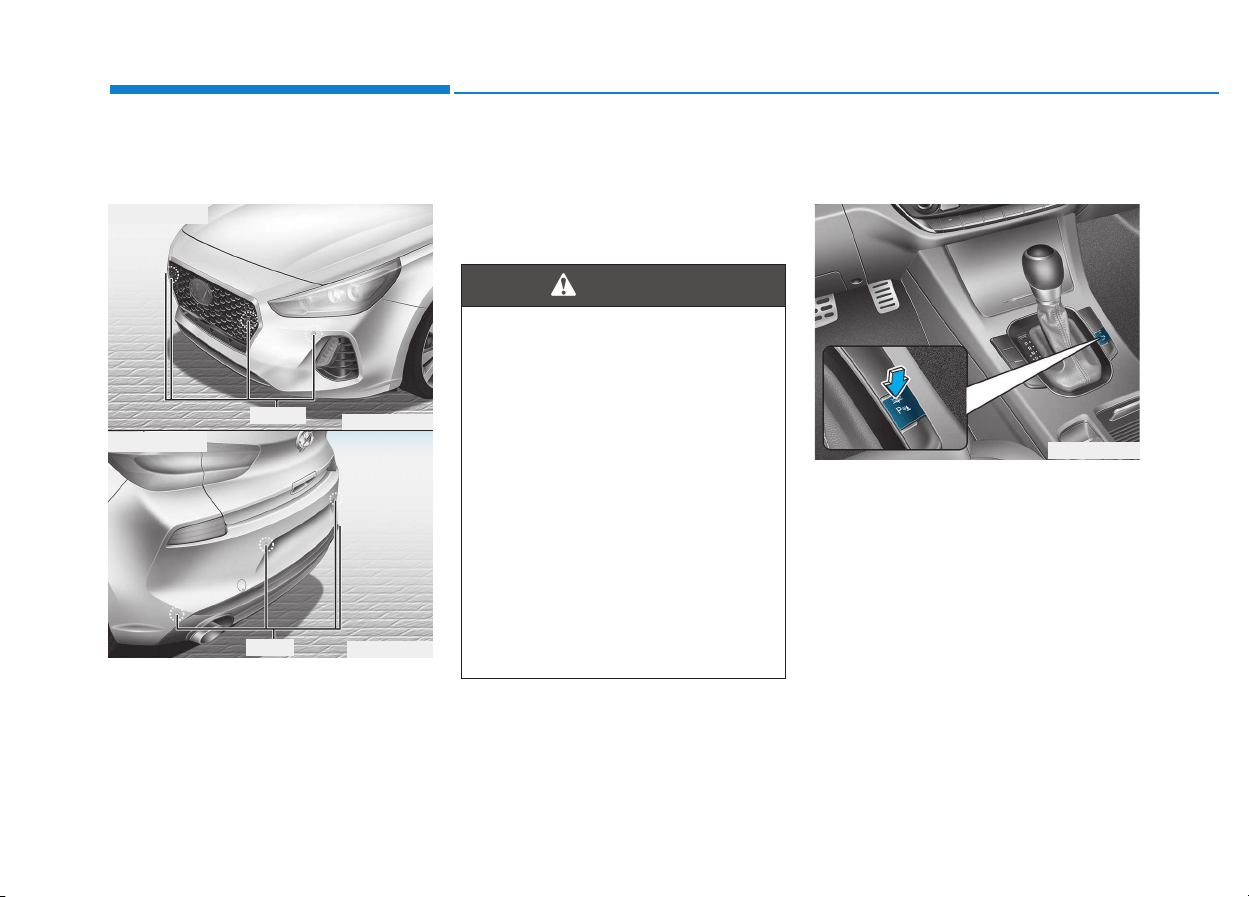
3-106
Convenient features of your vehicle
Parking assist system
(if equipped)
The Parking Assist System assists
the driver during movement of the
vehicle by chiming if any object is
sensed within the distance of 100 cm
(39 inches) in front and 120 cm (47
inches) behind the vehicle.
This system is a supplemental sys-
tem that senses objects within the
range and location of the sensors, it
cannot detect objects in other areas
where sensors are not installed.
Operation of the Parking Assist
System
Operating condition
• This system will activate when the
Parking Assist System button is
pressed with the engine running.
• ALWAYS look around your vehi-
cle to make sure there are not
any objects or obstacles before
moving the vehicle in any direc-
tion to prevent a collision.
• Always pay close attention
when the vehicle is driven close
to objects, particularly pedestri-
ans, and especially children.
• Be aware that some objects
may not be visible on the
screen or be detected by the
sensors, due to the objects
distance, size or material, all of
which can limit the effective-
ness of the sensor.
WARNING
OPDE046401
OPD046400
■ Front sensor
■ Rear sensor
Sensors
Sensor
OPDE046403
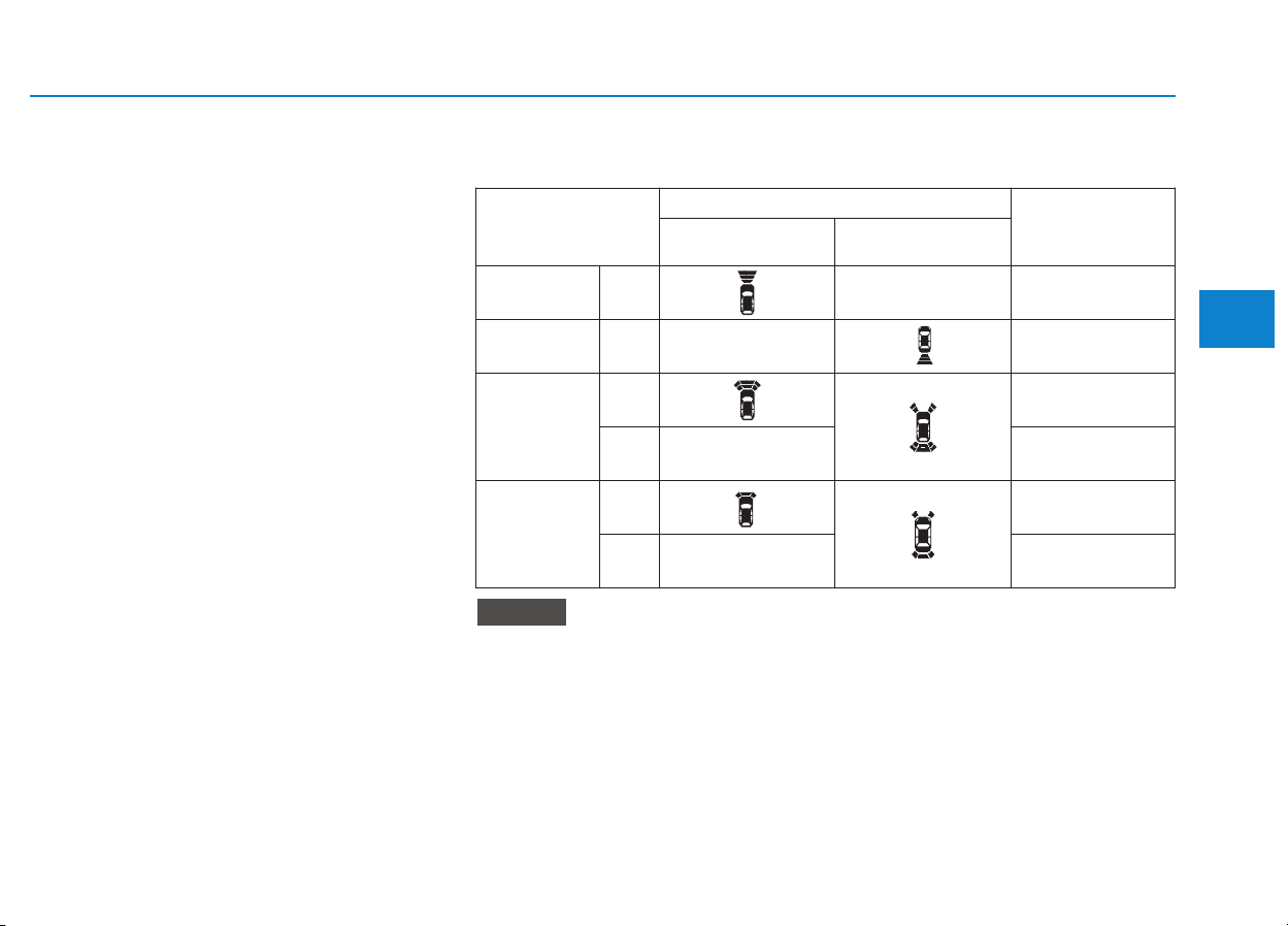
3-107
Convenient features of your vehicle
3
• The Parking Assist System button
turns on automatically and acti-
vates the Parking Assist System
when you move the shift lever to
the R (Reverse) position. However,
if vehicle speed exceeds 10 km/h
(6 mph), the system will not warn
you even though objects are
detected, and if vehicle speed
exceeds 20 km/h (12 mph), the
system will turn off automatically.
To turn on the system, press the
Parking Assist System button.
• When more than two objects are
sensed at the same time, the clos-
est one will be recognized first.
• The indicator may differ from the illustration as objects or sensors
status. If the indicator blinks, we recommend that the system be
checked by an authorized HYUNDAI dealer.
• If the audible warning does not sound or if the buzzer sounds inter-
mittently when shifting into R (Reverse) position, this may indicate a
malfunction with the Parking Assist System. If this occurs, we rec-
ommend that you have your vehicle checked by an authorized
HYUNDAI dealer as soon as possible.
NOTICE
Distance
from object
Warning indicator
Warning sound
When driving
forward
When driving
rearward
61 ~ 100
(24 ~39)
Front -
Buzzer beeps
intermittently
61 ~ 120
(24 ~47)
Rear -
Buzzer beeps
intermittently
31 ~ 60
(12 ~24)
Front
Buzzer beeps
frequently
Rear -
Buzzer beeps
frequently
30
(12)
Front
Buzzer sounds
continuously
Rear -
Buzzer sounds
continuously
Types of warning sound and indicator
cm (in)
3-108
Convenient features of your vehicle
Non-operational conditions of
Parking Assist System
Parking Assist System may not
operate normally when:
• Moisture is frozen to the sensor.
• Sensor is covered with foreign mat-
ter, such as snow or water, or the
sensor cover is blocked.
There is a possibility of Parking
Assist System malfunction when:
• Driving on uneven road surfaces
such as unpaved roads, gravel,
bumps, or gradient.
• Objects generating excessive noise
such as vehicle horns, loud motor-
cycle engines, or truck air brakes
can interfere with the sensor.
• Heavy rain or water spray is present.
• Wireless transmitters or mobile
phones are present near the sensor.
• The sensor is covered with snow.
• Any non-factory equipment or
accessories have been installed, or
if the vehicle bumper height or sen-
sor installation has been modified.
Detecting range may decrease when:
• Outside air temperature is
extremely hot or cold.
• Undetectable objects smaller than
1 m and narrower than 14 cm in
diameter.
The following objects may not be
recognized by the sensor:
• Sharp or slim objects such as
ropes, chains or small poles.
• Objects, which tend to absorb sen-
sor frequency such as clothes,
spongy material or snow.
Parking assist system precau-
tions
• The parking assist system may not
sound consistently depending on the
speed and shapes of the objects
detected.
• The parking assist system may mal-
function if the vehicle bumper height
or sensor installation has been mod-
ified or damaged. Any non-factory
installed equipment or accessories
may also interfere with the sensor
performance.
• The sensor may not recognize
objects less than 30 cm (11 in.) from
the sensor, or it may sense an incor-
rect distance. Use caution.
• When the sensor is frozen or stained
with snow, dirt, or water, the sensor
may be inoperative until the stains
are removed using a soft cloth.
• Do not push, scratch or strike the
sensor. Sensor damage could occur.
• Do not spray the sensors or its sur-
rounding area directly with a high
pressure washer. Shock applied
from high pressure water may cause
the device to not operate normally.
Your new vehicle warranty does
not cover any accidents or dam-
age to the vehicle or injuries to
its occupants related to a
Parking Assist System. Always
drive safely and cautiously.
WARNING
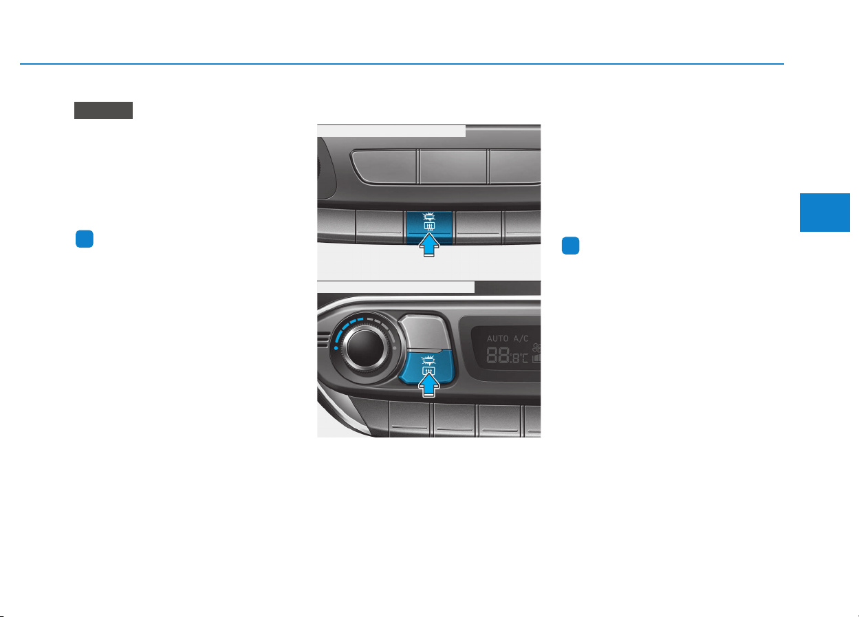
3-109
Convenient features of your vehicle
3
DDEEFFRROOSSTTEERR
To prevent damage to the conduc-
tors bonded to the inside surface
of the rear window, never use
sharp instruments or window
cleaners containing abrasives to
clean the window.
Information
If you want to defrost and defog the
front windshield, refer to “Windshield
Defrosting and Defogging” in this
chapter.
Rear window defroster
The defroster heats the window to
remove frost, fog and thin ice from
the interior and exterior of the rear
window, while engine is running.
• To activate the rear window defroster,
press the rear window defroster but-
ton located in the center facia switch
panel. The indicator on the rear win-
dow defroster button illuminates
when the defroster is ON.
• To turn off the defroster, press the
rear window defroster button again.
Information
• If there is heavy accumulation of
snow on the rear window, brush it off
before operating the rear defroster.
• The rear window defroster automati-
cally turns off after approximately 20
minutes or when the ignition switch is
in the OFF position.
NOTICE
i
i
OPDE046318
OPDE046319
■ Manual climate control system
■ Automatic climate control system

3-110
Convenient features of your vehicle
Outside mirror defroster
(if equipped)
If your vehicle is equipped with the
outside mirror defrosters, they will
operate at the same time you turn on
the rear window defroster.
Front wiper deicer (if equipped)
If your vehicle is equipped with the
wiper deicer, it will operate at the
same time you turn on the rear win-
dow defroster.
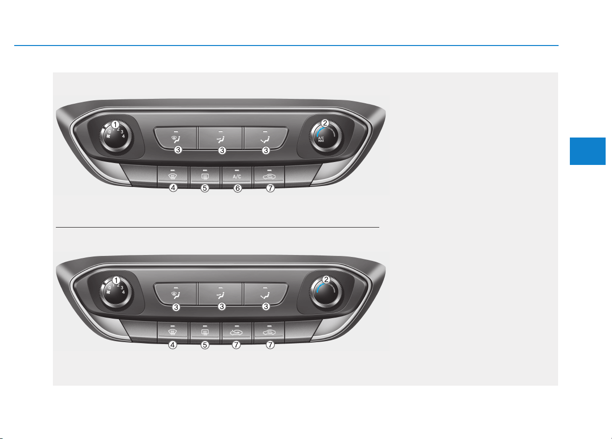
3-111
Convenient features of your vehicle
3
MMAANNUUAALL CCLLIIMMAATTEE CCOONNTTRROOLL SSYYSSTTEEMM ((IIFF EEQQUUIIPPPPEEDD))
OPDE046301/OPDE046300
1. Fan speed control knob
2. Temperature control knob
3. Mode selection buttons
4. Front windshield defroster button
5. Rear window defroster button
6. A/C (Air conditioning) button*
7. Air intake control button
* : if equipped
■■
Type A
■■
Type B
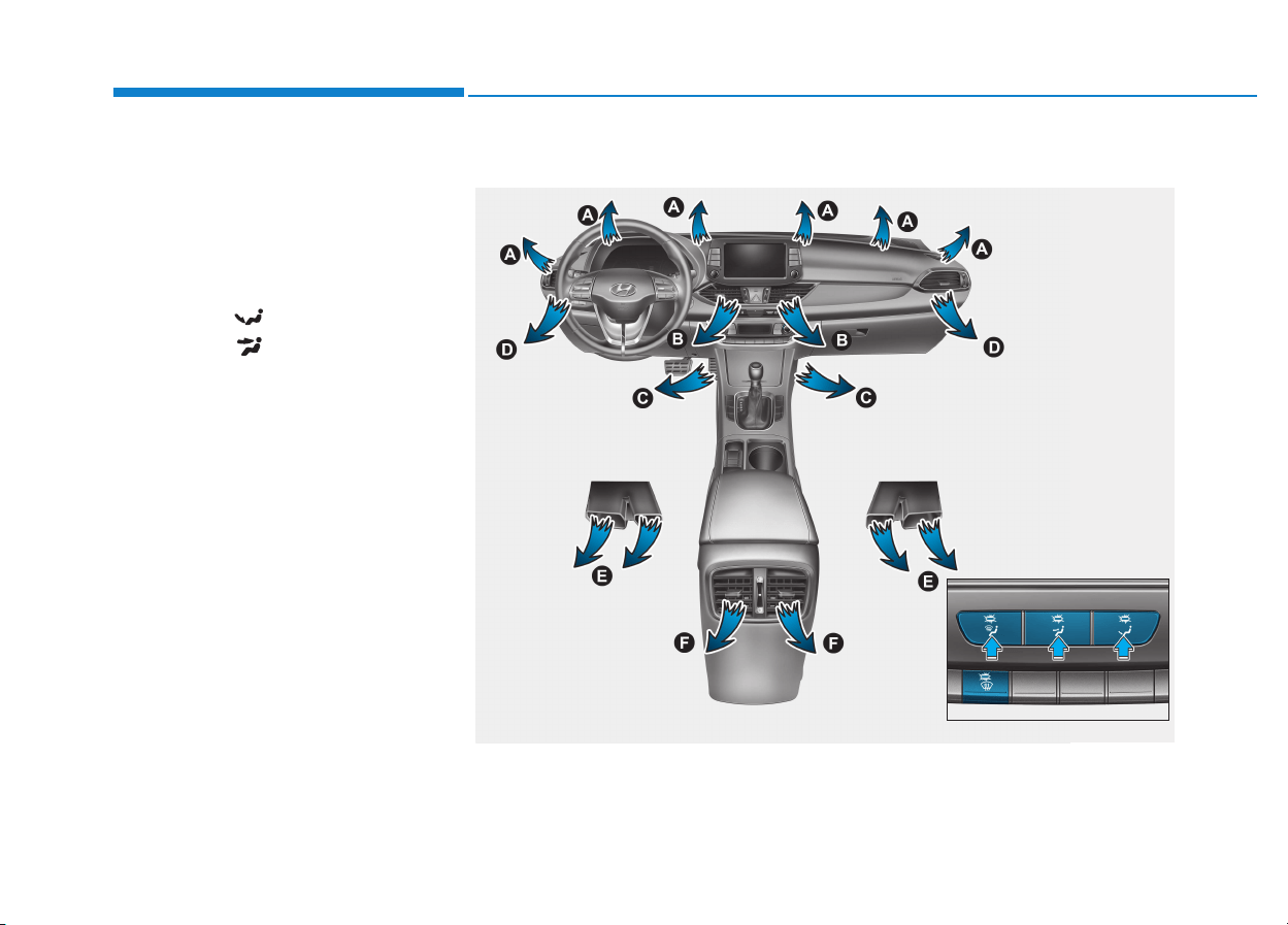
3-112
Convenient features of your vehicle
Heating and air conditioning
1. Start the engine.
2. Set the mode to the desired posi-
tion.
To improve the effectiveness of
heating and cooling :
- Heating:
- Cooling:
3. Set the temperature control to the
desired position.
4. Set the air intake control to the
outside (fresh) air position.
5. Set the fan speed control to the
desired speed.
6. If air conditioning is desired, turn
the air conditioning system on.
Mode selection
(if equipped)
(if equipped)
OPDE046307/OPDE046306
The mode selection button controls the direction of the air flow through the
ventilation system.
Air can be directed to the floor, dashboard outlets, or windshield.
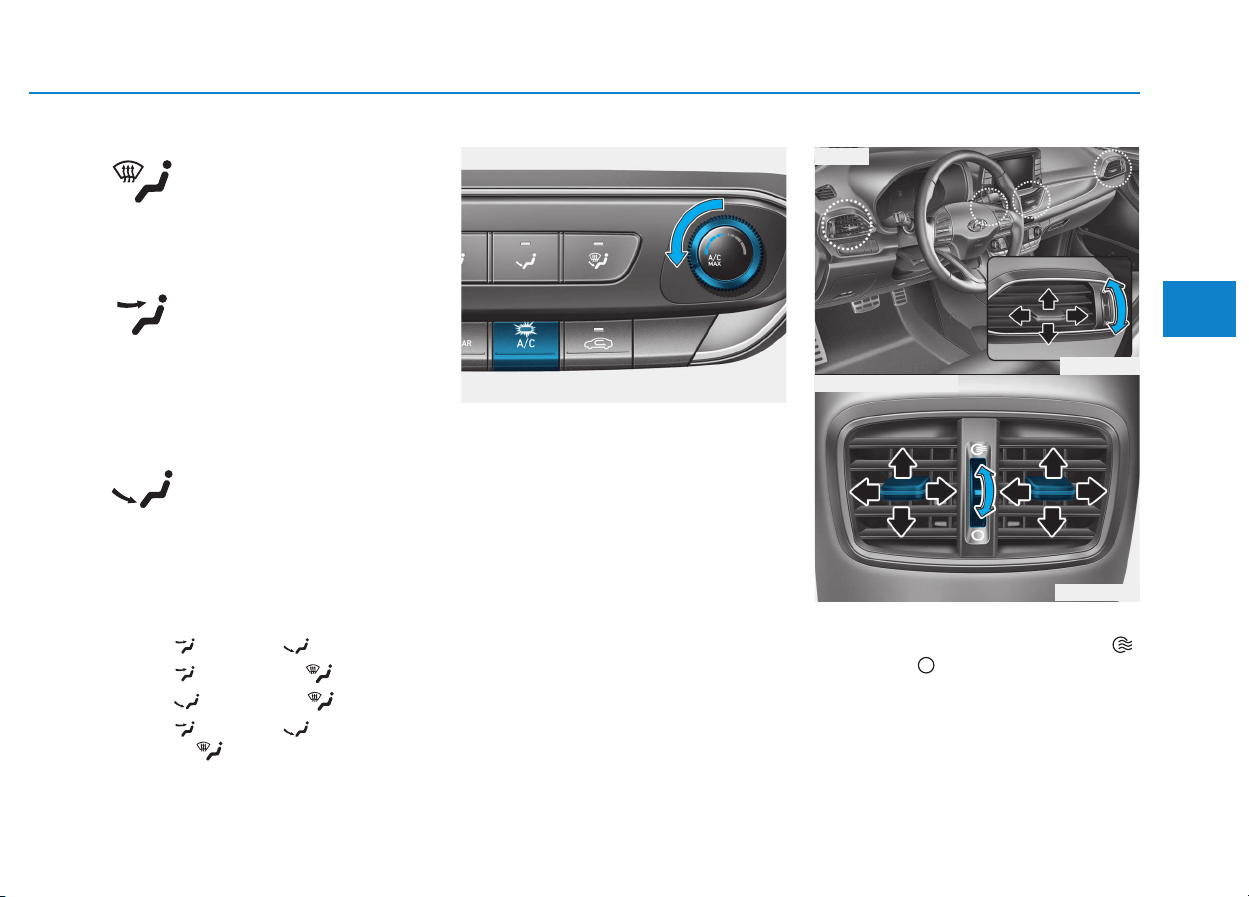
3-113
Convenient features of your vehicle
3
Defrost-Level (A, D)
Most of the air flow is directed to the
windshield.
Face-Level (B, D, F)
Air flow is directed toward the upper
body and face. Additionally, each
outlet can be controlled to direct the
air discharged from the outlet.
Floor-Level (A, C, D, E, F)
Most of the air flow is directed to the
floor.
Also you may select 2~3 modes at
the same time.
- face ( ) + floor ( ) mode
- face ( ) + defrost ( ) mode
- floor ( ) + defrost ( ) mode
- face ( ) + floor ( ) +
defrost ( ) mode
MAX A/C-Level (B, D, F)
(if equipped)
To operate the MAX A/C, turn the
mode selection knob to extreme left.
Air flow is directed toward the upper
body and face.
In this mode, the air conditioning and
the recirculated air position will be
selected automatically.
Instrument panel vents
The outlet vents can be opened ( )
or closed ( ) separately using the
thumbwheel.
Also, you can adjust the direction of
air delivery from these vents using
the vent control lever as shown.
OPD046308
OPD046310
■ Rear (if equpipped)
■ Front
OPD046309
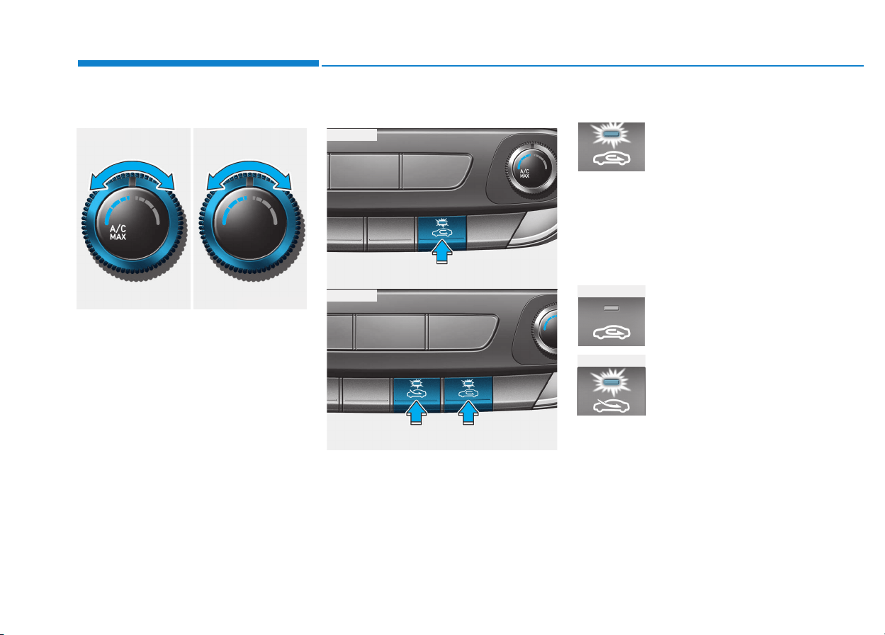
3-114
Convenient features of your vehicle
Temperature control
The temperature will increase by turn-
ing the knob to the right. The tempera-
ture will decrease by turning the knob
to the left.
Air intake control
This is used to select outside (fresh)
air position or recirculated air position.
To change the air intake control posi-
tion, press the control button.
Recirculated air position
With the recirculated air
position selected, air from
the passenger compart-
ment will be drawn
through the heating sys-
tem and heated or cooled
according to the function
selected.
Outside (fresh) air position
With the outside (fresh)
air position selected, air
enters the vehicle from
outside and is heated or
cooled according to the
function selected.
OPD046351
OPDE046312
OPDE046313
■ Type A
■ Type B
■ Type A
■ Type B
■ Type A ■ Type B
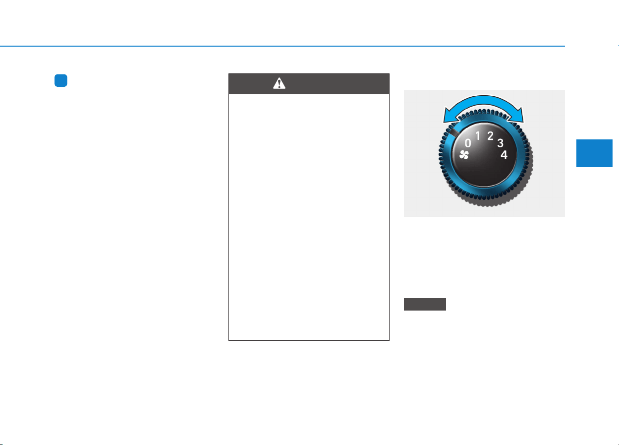
3-115
Convenient features of your vehicle
3
Information
Prolonged use of the air conditioning
with the recirculated air position
selected will result in excessively dry
air in the passenger compartment.
Fan speed control
Turn the knob to the right to increase
the fan speed and airflow. Turn the
knob to the left to decrease fan
speed and airflow.
Setting the fan speed control knob to
the “0” position turns off the fan.
Operating the fan speed when the
ignition switch is in the ON posi-
tion could cause the battery to
discharge. Operate the fan speed
when the engine is running.
NOTICE
i
• Continuous operation of the
climate control system in the
recirculated air position may
allow humidity to increase
inside the vehicle which may
fog the glass and obscure vis-
ibility.
• Do not sleep in a vehicle with
air conditioning or heating
system on. It may cause seri-
ous harm or death due to a
drop in the oxygen level
and/or body temperature.
• Continuous operation of the
climate control system in the
recirculated air position can
cause drowsiness or sleepi-
ness, and loss of vehicle con-
trol. Set the air intake control
to the outside (fresh) air posi-
tion as much as possible
while driving.
WARNING
OPD046311
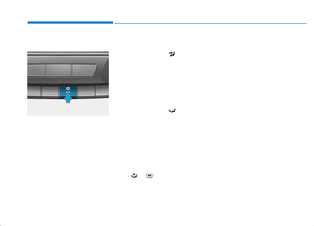
3-116
Convenient features of your vehicle
Air conditioning (A/C)
(if equipped)
Press the A/C button to turn the air
conditioning system on (indicator
light will illuminate). Press the button
again to turn the air conditioning sys-
tem off.
System operation
Ventilation
1. Set the mode to the position.
2. Set the air intake control to the
outside (fresh) air position.
3. Set the temperature control to the
desired position.
4. Set the fan speed control to the
desired speed.
Heating
1. Set the mode to the position.
2. Set the air intake control to the
outside (fresh) air position.
3. Set the temperature control to the
desired position.
4. Set the fan speed control to the
desired speed.
5. If dehumidified heating is desired,
turn the air conditioning system (if
equipped) on.
If the windshield fogs up, set the mode
to the or position.
Operation Tips
• To keep dust or unpleasant fumes
from entering the car through the
ventilation system, temporarily set
the air intake control to the recircu-
lated air position. Be sure to return
the control to the fresh air position
when the irritation has passed to
keep fresh air in the vehicle. This
will help keep the driver alert and
comfortable.
• To prevent interior fog on the wind-
shield, set the air intake control to
the fresh air position and fan speed
to the desired position, turn on the
air conditioning system, and adjust
the temperature control to desired
temperature.
OPDE046314

3-117
Convenient features of your vehicle
3
Air conditioning
HYUNDAI Air Conditioning Systems
are filled with R-134a or R-1234yf
refrigerant.
1. Start the engine. Push the air con-
ditioning button.
2. Set the mode to the position.
3. Set the air intake control to the out-
side air or recirculated air position.
4. Adjust the fan speed control and
temperature control to maintain
maximum comfort.
Information
Your vehicle is filled with R-134a or
R-1234yf according to the regulation
in your country at the time of produc-
tion. You can find out which air condi-
tioning refrigerant is applied to your
vehicle on the label located inside of
the hood. Refer to chapter 8 for the
location of the air conditioning refrig-
erant label.
• The refrigerant system should
only be serviced by trained and
certified technicians to insure
proper and safe operation.
• The refrigerant system should
be serviced in a well-ventilated
place.
• The air conditioning evaporator
(cooling coil) shall never be
repaired or replaced with one
removed from a used or sal-
vaged vehicle and new replace-
ment MAC evaporators shall be
certified (and labeled) as meet-
ing SAE Standard J2842.
• When using the air conditioning
system, monitor the temperature
gauge closely while driving up
hills or in heavy traffic when out-
side temperatures are high. Air
conditioning system operation
may cause engine overheating.
Continue to use the blower fan
but turn the air conditioning sys-
tem off if the temperature gauge
indicates engine overheating.
• When opening the windows in
humid weather air conditioning
may create water droplets inside
the vehicle. Since excessive
water droplets may cause dam-
age to electrical equipment, air
conditioning should only be
used with the windows closed.
NOTICENOTICE
i
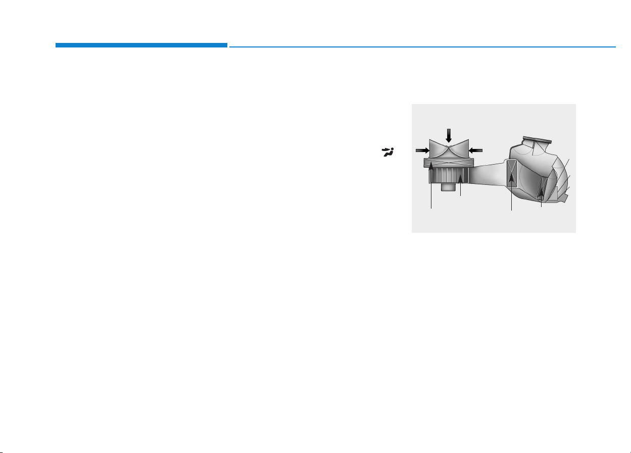
3-118
Convenient features of your vehicle
Air conditioning system operation
tips
• If the vehicle has been parked in
direct sunlight during hot weather,
open the windows for a short time
to let the hot air inside the vehicle
escape.
• After sufficient cooling has been
achieved, switch back from the
recirculated air to the fresh outside
air position.
• To help reduce moisture inside of
the windows on rainy or humid
days, decrease the humidity inside
the vehicle by operating the air
conditioning system with the win-
dows and sunroof closed.
• Use the air conditioning system
every month for a few minutes to
ensure maximum system perform-
ance.
• If you operate the air conditioner
excessively, the difference between
the temperature of the outside air
and that of the windshield could
cause the outer surface of the
windshield to fog up, causing loss
of visibility. In this case, set the
mode selection button to the
position and set the fan speed con-
trol knob to the lowest speed set-
ting.
System maintenance
Climate control air filter
This filter is installed behind the
glove box. It filters the dust or other
pollutants that enter the vehicle
through the heating and air condi-
tioning system.
We recommend that the climate con-
trol air filter replaced by an author-
ized HYUNDAI dealer according to
the maintenance schedule. If the car
is being driven in severe conditions
such as dusty or rough roads, more
frequent climate control filter inspec-
tions and changes are required.
1LDA5047
Outside air
Recirculated
air
Climate control
air filter
Blower
Evaporator
core
Heater core
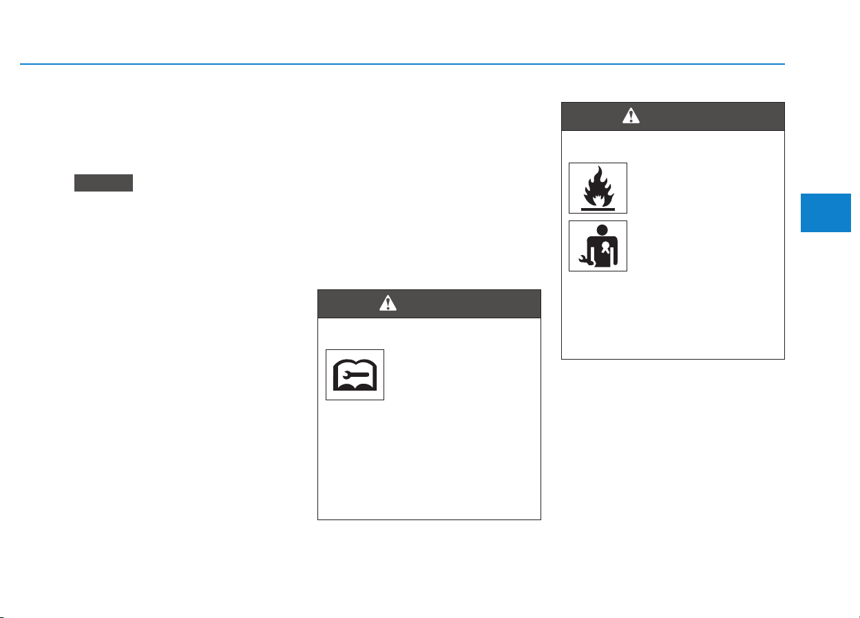
3-119
Convenient features of your vehicle
3
If the air flow rate suddenly decreas-
es, we recommend the system be
checked at an authorized HYUNDAI
dealer.
It is important that the correct
type and amount of oil and refrig-
erant is used. Otherwise, damage
to the compressor and abnormal
system operation may occur.
Checking the amount of air con-
ditioner refrigerant and com-
pressor lubricant
When the amount of refrigerant is
low, the performance of the air con-
ditioning is reduced. Overfilling also
has a bad influence on the air condi-
tioning system.
Therefore, if abnormal operation is
found, we recommend that the sys-
tem be inspected by an authorized
HYUNDAI dealer.
We recommend the air conditioning
system be serviced by an authorized
HYUNDAI dealer.
NOTICE
Vehicles equipped with R-134a
Because the refriger-
ant is at very high
pressure, the air condi-
tioning system should
only be serviced by trained and
certified technicians. It is impor-
tant that the correct type and
amount of oil and refrigerant is
used. Otherwise, it may cause
damage to the vehicle and per-
sonal inju
ry.
WARNING
Vehicles equipped with R-1234yf
Because the refriger-
ant is mildly inflamma-
ble at very high pres-
sure, the air condition-
ing system should only
be serviced by trained
and certified techni-
cians. It is important
that the correct type and amount
of oil and refrigerant is used.
Otherwise, it may cause dam-
age to the vehicle and personal
injury.
WARNING

3-120
Convenient features of your vehicle
Air conditioning refrigerant
label
The actual Air Conditioning refriger-
ant label in the vehicle may differ
from the illustration.
Each symbols and specification on
air conditioning refrigerant label
means as below:
1. Classification of refrigerant
2. Amount of refrigerant
3. Classification of Compressor lubri-
cant
You can find out which air conditioning
refrigerant is applied to your vehicle on
the label located inside of the hood.
Refer to chapter 8 for the location of
the air conditioning refrigerant label.
ODH044365R
ODH043366
■ Example
• Type B
• Type A
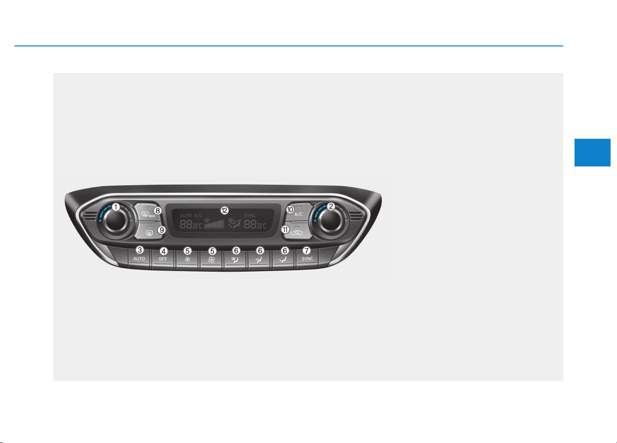
3-121
Convenient features of your vehicle
3
AAUUTTOOMMAATTIICC CCLLIIMMAATTEE CCOONNTTRROOLL SSYYSSTTEEMM ((IIFF EEQQUUIIPPPPEEDD))
OPDE046302
1. Driver’s temperature control knob
2. Passenger’s temperature control knob
3. AUTO (automatic control) button
4. OFF button
5. Fan speed control button
6. Mode selection button
7. SYNC button
8. Front windshield defroster button
9. Rear window defroster button
10. Air conditioning button
11. Air intake control button
12. Climate control information screen
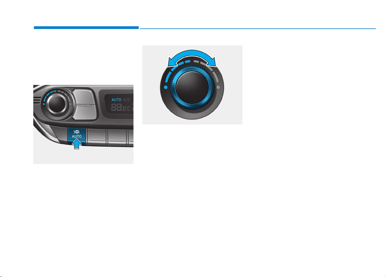
3-122
Convenient features of your vehicle
Automatic heating and air con-
ditioning
The Automatic Climate Control
System is controlled by setting the
desired temperature.
1. Press the AUTO button.
The modes, fan speeds, air intake
and air-conditioning will be controlled
automatically by the temperature set-
ting you select.
2. Turn the temperature control knob
to the desired temperature. If the
temperature is set to the lowest
setting (Lo), the air conditioning
system will operate continuously.
To turn the automatic operation off,
select any button of the following:
- Mode selection button
- Front windshield defroster button
(Press the button one more time to
deselect the front windshield
defroster function. The 'AUTO' sign
will illuminate on the information
display once again.)
- Fan speed control button
The selected function will be con-
trolled manually while other func-
tions operate automatically.
For your convenience and to improve
the effectiveness of the climate con-
trol, use the AUTO button and set the
temperature to 23°C (73°F).
OPDE046350
OPD046315
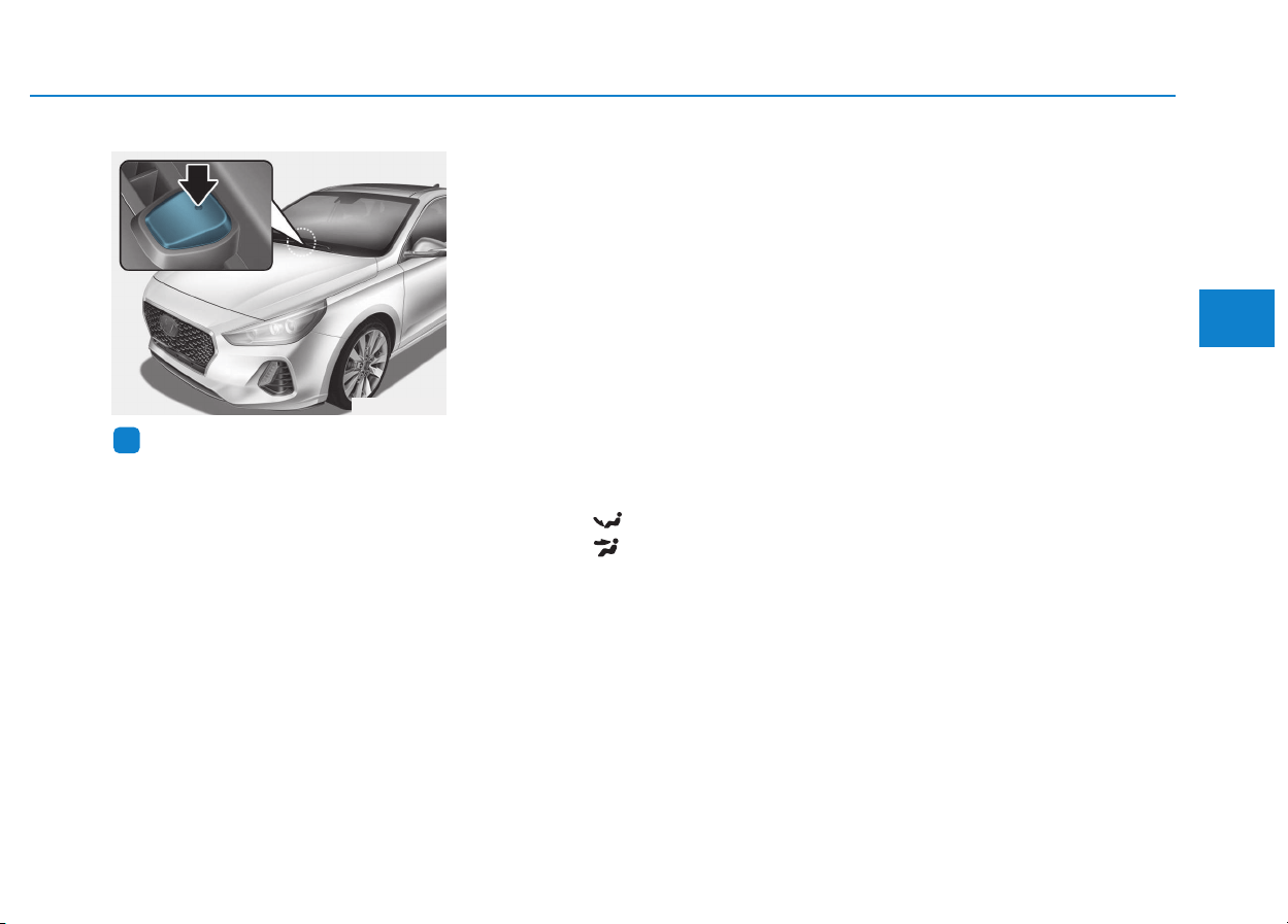
3-123
Convenient features of your vehicle
3
Information
Never place anything near the sensor
to ensure better control of the heating
and cooling system.
Manual heating and air condi-
tioning
The heating and cooling system can be
controlled manually by pushing buttons
other than the AUTO button. In this
case, the system works sequentially
according to the order of buttons select-
ed. When pressing any button except
the AUTO button while using automatic
operation, the functions not selected
will be controlled automatically.
1.Start the engine.
2.Set the mode to the desired position.
For improving the effectiveness of
heating and cooling;
- Heating:
- Cooling:
3.Set the temperature control to the
desired position.
4.Set the air intake control to the out-
side (fresh) air position.
5.Set the fan speed control to the
desired speed.
6.If air conditioning is desired, turn
the air conditioning system on.
7.Press the AUTO button in order to
convert to full automatic control of
the system.
i
OPDE046316
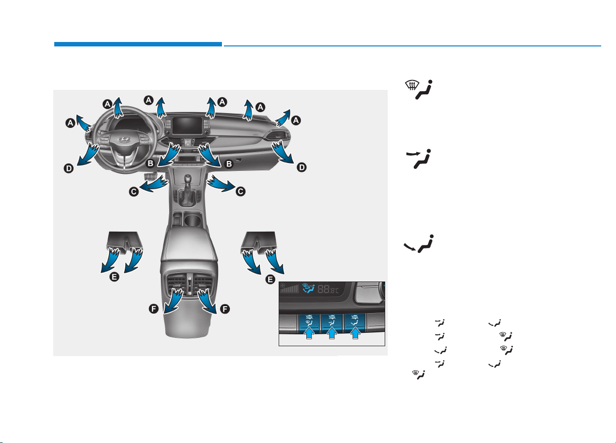
3-124
Convenient features of your vehicle
Mode selection
Defrost-Level (A, D)
Most of the air flow is directed to the
windshield.
Face-Level (B, D, F)
Air flow is directed toward the upper
body and face. Additionally, each
outlet can be controlled to direct the
air discharged from the outlet.
Floor-Level (A, C, D, E, F)
Most of the air flow is directed to the
floor.
Also you may select 2~3 modes at
the same time.
- face ( ) + floor ( ) mode
- face ( ) + defrost ( ) mode
- floor ( ) + defrost ( ) mode
- face ( ) + floor ( ) + defrost
( ) mode
(if equipped)
(if equipped)
OPDE046307/OPDE046317
The mode selection button controls the direction of the air flow through the
ventilation system.
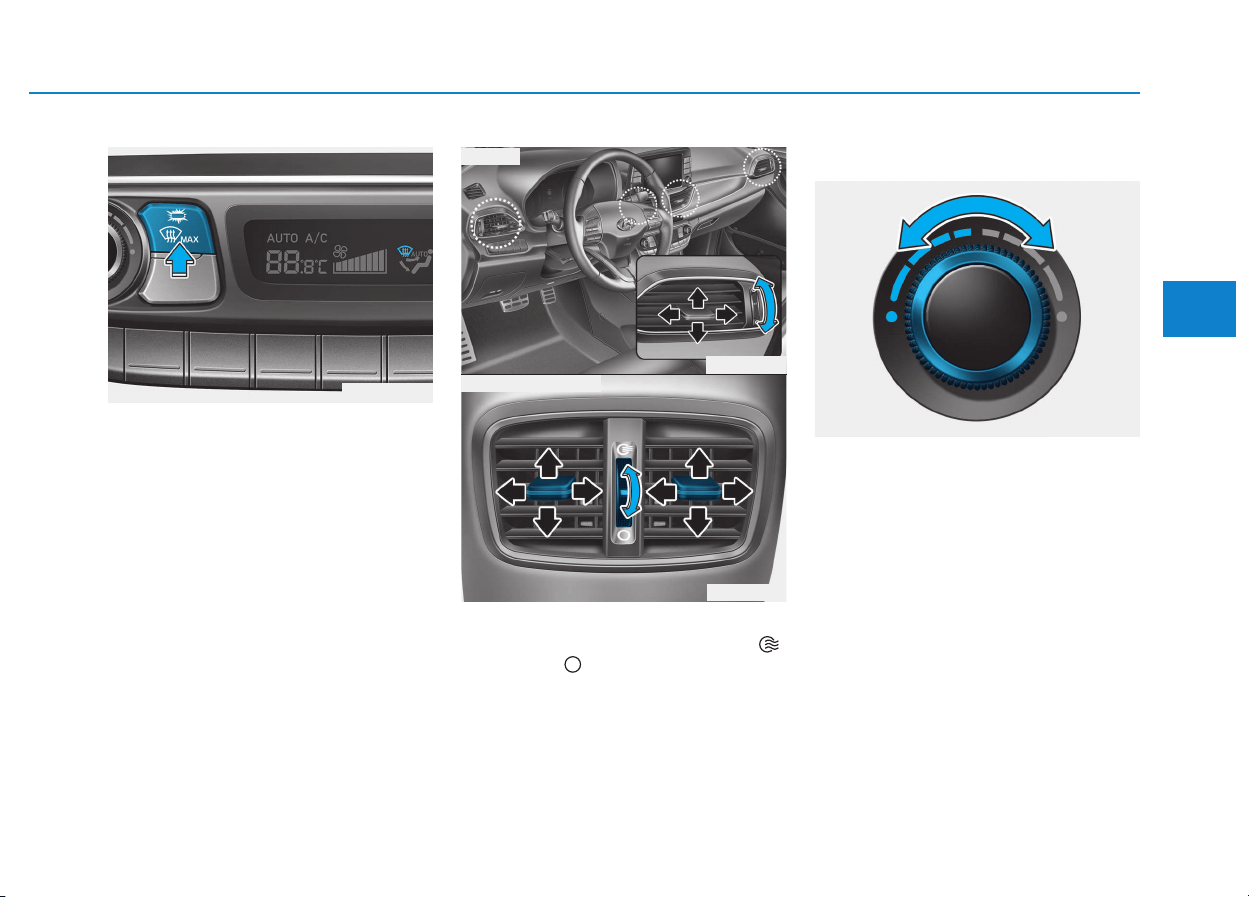
3-125
Convenient features of your vehicle
3
Defrost-Level (A)
Most of the air flow is directed to the
windshield with a small amount of air
directed to the side window defrosters.
Instrument panel vents
The outlet vents can be opened ( )
or closed ( ) separately using the
thumbwheel.
Also, you can adjust the direction of
air delivery from these vents using
the vent control lever as shown.
Temperature control
The temperature will increase by
turning the knob to the right. The
temperature will decrease by turning
the knob to the left.
OPDE046352
OPD046309
OPD046310
■ Front
■ Rear (if equipped)
OPD046315
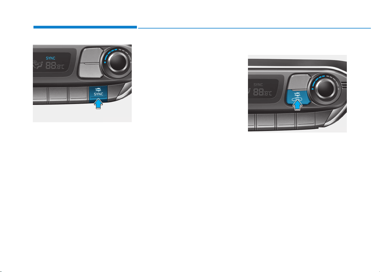
3-126
Convenient features of your vehicle
Adjusting the driver and passenger
side temperature equally
• Press the “SYNC” button to adjust
the driver and passenger side tem-
perature equally.
The passenger side temperature
will be set to the same temperature
as the driver side temperature.
• Turn the driver side temperature
control knob. The driver and pas-
senger side temperature will be
adjusted equally.
Adjusting the driver and passenger
side temperature individually
Press the “SYNC” button again to
adjust the driver and passenger side
temperature individually. The button
indicator will turn off.
Temperature conversion
If the battery has been discharged or
disconnected, the temperature mode
display will reset to Centigrade.
To change the temperature unit from
°C to °F or °F to °C :
- Automatic climate control system
Press the AUTO button for 3 sec-
onds while pressing the OFF button.
- Instrument cluster
Go to User Settings Mode → Other
Features → Temperature Unit.
Air intake control
This is used to select the outside
(fresh) air position or recirculated air
position.
To change the air intake control posi-
tion, push the control button.
OPDE046320
OPDE046321
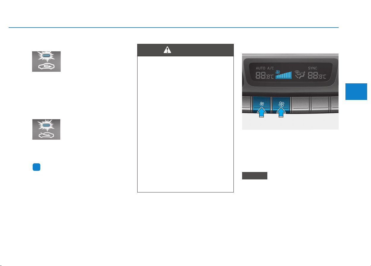
3-127
Convenient features of your vehicle
3
Recirculated air position
With the recirculated air
position selected, air from
the passenger compart-
ment will be drawn through
the heating system and
heated or cooled accord-
ing to the function select-
ed.
Outside (fresh) air position
With the outside (fresh)
air position selected, air
enters the vehicle from
outside and is heated or
cooled according to the
function selected.
Information
Prolonged use of the air conditioning
with the recirculated air position
selected will result in excessively dry
air in the passenger compartment.
Fan speed control
The fan speed can be set to the
desired speed by pushing the fan
speed control button.
Pressing the OFF button turns off the
fan.
Operating the fan speed when the
ignition switch is in the ON posi-
tion could cause the battery to dis-
charge. Operate the fan speed
when the engine is running.
NOTICE
i
• Continued climate control
system operation in the recir-
culated air position may allow
humidity to increase inside
the vehicle which may fog the
glass and obscure visibility.
• Do not sleep in a vehicle with
the air conditioning or heating
system on. It may cause seri-
ous harm or death due to a
drop in the oxygen level
and/or body temperature.
• Continued climate control sys-
tem operation in the recirculat-
ed air position can cause
drowsiness or sleepiness, and
loss of vehicle control. Set the
air intake control to the outside
(fresh) air position as much as
possible while driving.
WARNING
OPDE046323
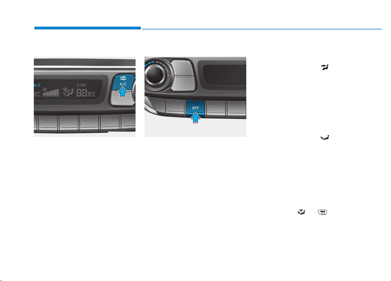
3-128
Convenient features of your vehicle
Air conditioning
Push the A/C button to turn the air
conditioning system on (indicator
light will illuminate).
Push the button again to turn the air
conditioning system off.
OFF mode
Push the OFF button to turn off the
air climate control system. However,
you can still operate the mode and
air intake buttons as long as the igni-
tion switch is in the ON position.
System operation
Ventilation
1. Set the mode to the position.
2. Set the air intake control to the
outside (fresh) air position.
3. Set the temperature control to the
desired position.
4. Set the fan speed control to the
desired speed.
Heating
1. Set the mode to the position.
2. Set the air intake control to the
outside (fresh) air position.
3. Set the temperature control to the
desired position.
4. Set the fan speed control to the
desired speed.
5. If dehumidified heating is desired,
turn the air conditioning system on.
• If the windshield fogs up, set the
mode to the or position.
OPDE046322 OPDE046324

3-129
Convenient features of your vehicle
3
Operation Tips
• To keep dust or unpleasant fumes
from entering the vehicle through
the ventilation system, temporarily
set the air intake control to the
recirculated air position. Be sure to
return the control to the fresh air
position when the irritation has
passed to keep fresh air in the
vehicle. This will help keep the driv-
er alert and comfortable.
• To prevent interior fog on the wind-
shield, set the air intake control to
the fresh air position and fan speed
to the desired position, turn on the
air conditioning system, and adjust
the temperature control to desired
temperature.
Air conditioning
HYUNDAI Air Conditioning Systems
are filled with R-134a or R-1234yf
refrigerant.
1. Start the engine. Push the air con-
ditioning button.
2. Set the mode to the position.
3. Set the air intake control to the out-
side air or recirculated air position.
4. Adjust the fan speed control and
temperature control to maintain
maximum comfort.
Information
Your vehicle is filled with R-134a or
R-1234yf according to the regulation
in your country at the time of produc-
tion. You can find out which air condi-
tioning refrigerant is applied to your
vehicle on the label located inside of
the hood. Refer to chapter 8 for the
location of the air conditioning refrig-
erant label.
• The refrigerant system should
only be serviced by trained and
certified technicians to insure
proper and safe operation.
• The refrigerant system should
be serviced in a well-ventilated
place.
• The air conditioning evaporator
(cooling coil) shall never be
repaired or replaced with one
removed from a used or salvaged
vehicle and new replacement
MAC evaporators shall be certi-
fied (and labeled) as meeting SAE
Standard J2842.
NOTICE
i

3-130
Convenient features of your vehicle
• When using the air conditioning
system, monitor the temperature
gauge closely while driving up
hills or in heavy traffic when out-
side temperatures are high. Air
conditioning system operation
may cause engine overheating.
Continue to use the blower fan
but turn the air conditioning sys-
tem off if the temperature gauge
indicates engine overheating.
• When opening the windows in
humid weather air conditioning
may create water droplets inside
the vehicle. Since excessive
water droplets may cause dam-
age to electrical equipment, air
conditioning should only be
used with the windows closed.
Air conditioning system operation
tips
• If the vehicle has been parked in
direct sunlight during hot weather,
open the windows for a short time
to let the hot air inside the vehicle
escape.
• After sufficient cooling has been
achieved, switch back from the
recirculated air to the fresh outside
air position.
• To help reduce moisture inside of
the windows on rainy or humid
days, decrease the humidity inside
the vehicle by operating the air
conditioning system with the win-
dows and sunroof closed.
• Use the air conditioning system
every month for a few minutes to
ensure maximum system perform-
ance.
• If you operate the air conditioner
excessively, the difference between
the temperature of the outside air
and that of the windshield could
cause the outer surface of the
windshield to fog up, causing loss
of visibility. In this case, set the
mode selection button to the
position and set the fan speed con-
trol knob to the lowest speed set-
ting.
NOTICE
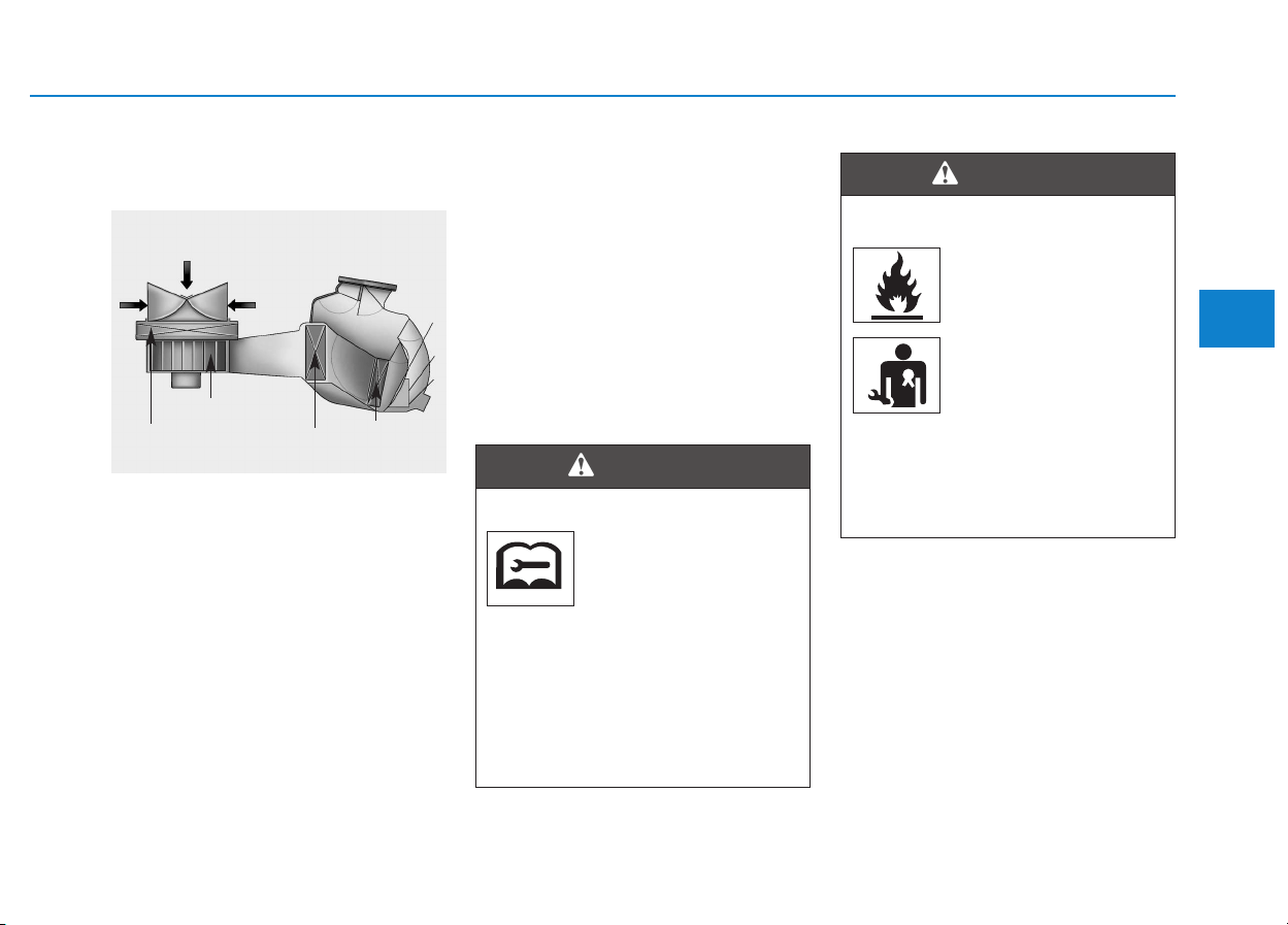
3-131
Convenient features of your vehicle
3
System maintenance
Climate control air filter
This filter is installed behind the
glove box. It filters the dust or other
pollutants that enter the vehicle
through the heating and air condi-
tioning system.
We recommend that the climate con-
trol air filter replaced by an author-
ized HYUNDAI dealer according to
the maintenance schedule. If the car
is being driven in severe conditions
such as dusty or rough roads, more
frequent climate control filter inspec-
tions and changes are required.
If the air flow rate suddenly decreas-
es, we recommend the system be
checked at an authorized HYUNDAI
dealer.
Checking the amount of air con-
ditioner refrigerant and com-
pressor lubricant
When the amount of refrigerant is
low, the performance of the air con-
ditioning is reduced. Overfilling also
has a bad influence on the air condi-
tioning system.
Therefore, if abnormal operation is
found, we recommend that the sys-
tem be inspected by an authorized
HYUNDAI dealer.
We recommend the air conditioning
system be serviced by an authorized
HYUNDAI dealer.
1LDA5047
Outside air
Recirculated
air
Climate control
air filter
Blower
Evaporator
core
Heater core
Vehicles equipped with R-134a
Because the refriger-
ant is at very high
pressure, the air con-
ditioning system
should only be serviced by
trained and certified technicians.
It is important that the correct
type and amount of oil and
refrigerant is used. Otherwise, it
may cause damage to the vehi-
cle and personal injury.
WARNING
Vehicles equipped with R-1234yf
Because the refriger-
ant is mildly inflamma-
ble at very high pres-
sure, the air condition-
ing system should
only be serviced by
trained and certified
technicians. It is
important that the cor-
rect type and amount of oil and
refrigerant is used. Otherwise, it
may cause damage to the vehi-
cle and personal injury.
WARNING
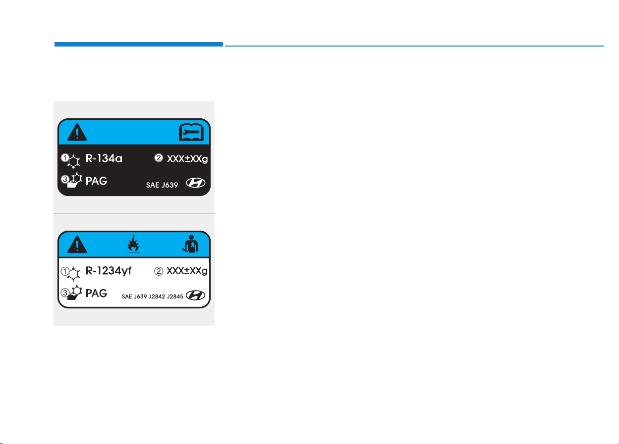
3-132
Convenient features of your vehicle
Air Conditioning refrigerant
label
The actual Air Conditioning refriger-
ant label in the vehicle may differ
from the illustration.
Each symbols and specification on
air conditioning refrigerant label
means as below:
1. Classification of refrigerant
2. Amount of refrigerant
3. Classification of Compressor lubri-
cant
You can find out which air conditioning
refrigerant is applied to your vehicle on
the label located inside of the hood.
Refer to chapter 8 for the location of
the air conditioning refrigerant label.
ODH044365R
ODH043366
■ Example
• Type B
• Type A
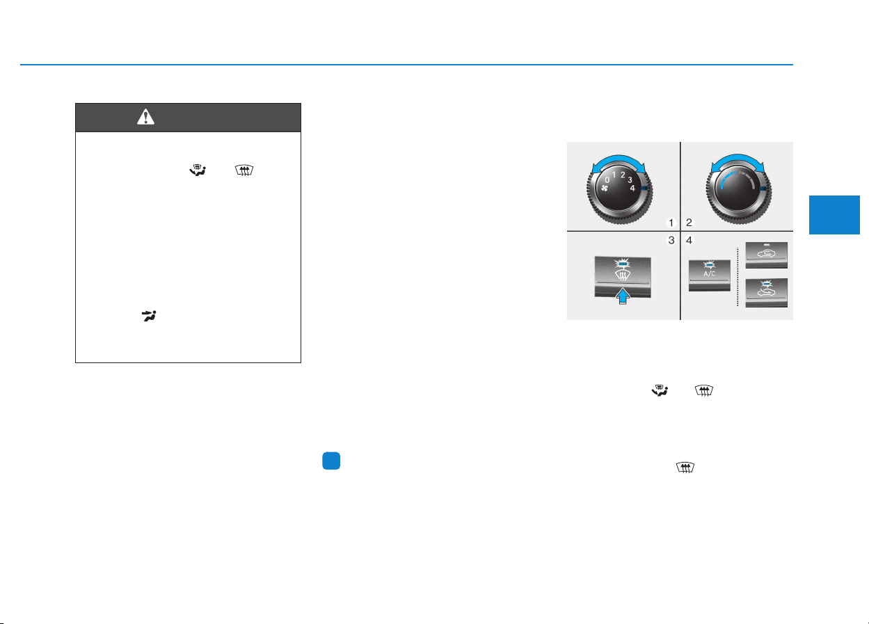
3-133
Convenient features of your vehicle
• For maximum windshield defrost-
ing, set the temperature control
knob to the highest temperature
setting and the fan control knob to
the highest fan speed. Select the
front defrost button on the climate
control display. After the engine
warm-up period, warm air will be
directed to the front windshield.
• If warm air to the floor is desired
while defrosting or defogging, set the
mode to the floor-defrost position.
• Before driving, clear all snow and
ice from the windshield, rear win-
dow, outside rear view mirrors, and
all side windows.
• Clear all snow and ice from the
hood and air inlet in the cowl grill to
improve heater and defroster effi-
ciency and to reduce the probability
of fogging up inside of the wind-
shield.
Information
If the engine temperature is still cold
after starting, then a brief engine
warm up period may be required for
the vented air flow to become warm or
hot.
Manual climate control system
To defog inside windshield
1. Select any fan speed except “0”
position.
2. Select desired temperature.
3. Select the or position.
4. The outside (fresh) air will be select-
ed automatically. Additionally, the air
conditioning (if equipped) will auto-
matically operate if the mode is
selected to the position.
If the air conditioning and outside
(fresh) air position are not selected
automatically, press the correspon-
ding button manually.
i
WWIINNDDSSHHIIEELLDD DDEEFFRROOSSTTIINNGG AANNDD DDEEFFOOGGGGIINNGG
3
Windshield heating
Do not use the or posi-
tion during cooling operation in
extremely humid weather. The
difference between the temper-
ature of the outside air and that
of the windshield could cause
the outer surface of the wind-
shield to fog up, causing loss of
visibility. In this case, set the
mode selection knob or button
to the position and fan
speed control knob or button to
lower speed.
WARNING
■ Type A
■ Type B
OPDE046325
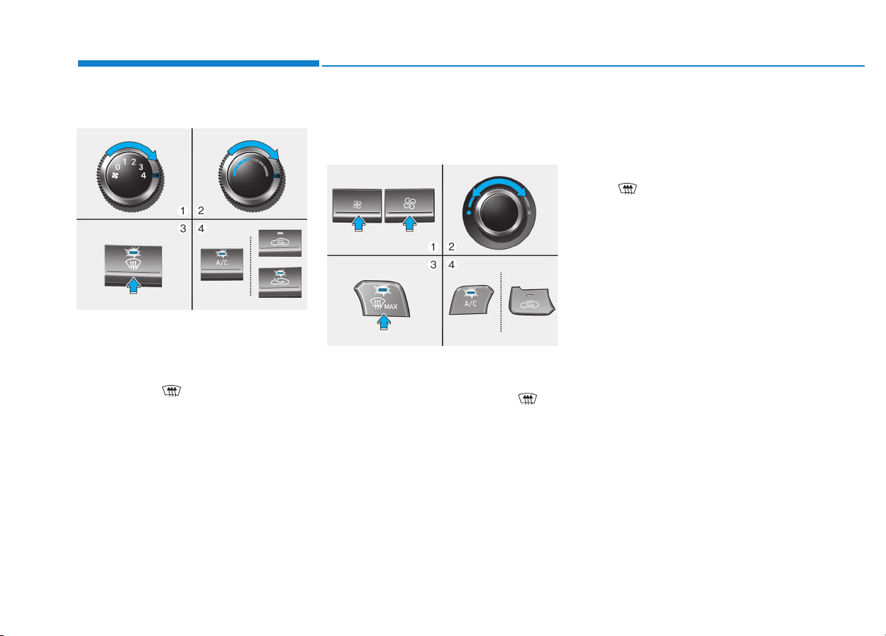
3-134
Convenient features of your vehicle
To defrost outside windshield
1. Set the fan speed to the highest
(extreme right) position.
2. Set the temperature to the
extreme hot position.
3. Select the position.
4. The outside (fresh) air and air con-
ditioning (if equipped) will be
selected automatically.
Automatic climate control
system
To defog inside windshield
1. Select desired fan speed.
2. Select desired temperature.
3. Press the defroster button ( ).
4. The air-conditioning will turn on
according to the detected ambient
temperature, outside (fresh) air
position and higher fan speed will
be selected automatically.
If the air-conditioning, outside (fresh)
air position and higher fan speed are
not selected automatically, adjust the
corresponding button or knob manu-
ally.
If the position is selected, lower
fan speed is controlled to higher fan
speed.
OPDE046326
OPDE046327
■ Type A
■ Type B
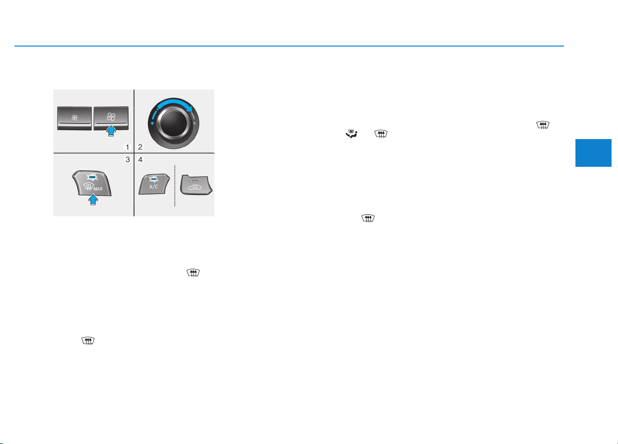
3-135
Convenient features of your vehicle
3
To defrost outside windshield
1. Set fan speed to the highest posi-
tion.
2. Set temperature to the extreme
hot (HI) position.
3. Press the defroster button ( ).
4. The air-conditioning will turn on
according to the detected ambient
temperature and outside (fresh)
air position will be selected auto-
matically.
If the position is selected, lower
fan speed is controlled to higher fan
speed.
Defogging logic (if equipped)
To reduce the probability of fogging
up the inside of the windshield, the
air intake or air conditioning are con-
trolled automatically according to
certain conditions such as or
position. To cancel or return the
defogging logic, do the following.
Manual climate control system
1. Turn the ignition switch to the ON
position.
2. Press the defroster button ( ).
3. Press the air intake control button
at least 5 times within 3 seconds.
The indicator on the air intake button
blinks 3 times with 0.5 seconds of
interval. It indicates that the defog-
ging logic is canceled.
If the battery has been discharged or
disconnected, the defogging logic
will be enabled as the default logic.
Automatic climate control sys-
tem
1. Turn the ignition switch to the ON
position.
2. Press the defroster button ( ).
3. While pressing the air conditioning
button (A/C), press the air intake
control button at least 5 times with-
in 3 seconds.
The climate control information
screen will blink 3 times with 0.5 sec-
onds of interval. It indicates that the
defogging logic is canceled.
If the battery has been discharged or
disconnected, the defogging logic
will be enabled as the default logic.
OPDE046328

3-136
Convenient features of your vehicle
Auto defogging system
(only for automatic climate
control system, if equipped)
Auto defogging reduces the possibil-
ity of fogging up the inside of the
windshield by automatically sensing
the moisture of inside the windshield.
The auto defogging system operates
when the heater or air conditioning is
on.
Information
The auto defogging system may not
operate normally, when the outside
temperature is below -10 °C.
When the Auto Defogging
System operates, the indi-
cator will illuminate.
If higher level of moisture are sensed
in the vehicle, the Auto Defogging
System will operate in the following
order:
Step 1 : Outside air position
Step 2 : Operating the air conditioning
Step 3 : Blowing air toward the wind-
shield
Step 4 : Increasing air flow toward
the windshield
If the air conditioning is off or recircu-
lated air position is manually selected
while Auto Defogging System is ON,
the Auto Defogging System Indicator
will blink 3 times to signal that the
manual operation has been canceled.
To cancel or reset the Auto Defogging
System
Press the front windshield defroster
button for 3 seconds when the igni-
tion switch is in the ON position.
When the Auto Defogging System is
canceled, ADS OFF symbol will blink
3 times and the ADS OFF will be dis-
played on the climate control infor-
mation screen.
When the Auto Defogging System is
reset, ADS OFF symbol will blink 6
times without a signal.
Information
• When the air conditioning is turned
on by Auto defogging system, if you
try to turn off the air conditioning, the
indicator will blink 3 times and the air
conditioning will not turn off.
• For efficiency, do not select recircu-
lated air position while Auto defog-
ging system is operating.
Do not remove the sensor cover
located on the upper end of the
windshield glass.
Damage to system parts could
occur and may not be covered by
your vehicle warranty.
NOTICE
i
i

3-137
Convenient features of your vehicle
CCLLIIMMAATTEE CCOONNTTRROOLL AADDDDIITTIIOONNAALL FFEEAATTUURREESS
3
Cluster ionizer (if equipped)
When the ignition switch is in the ON
position, the clean air function turns
on automatically.
Also, the clean air function turns off
automatically, when the ignition
switch is in the OFF position.
Automatic ventilation
(if equipped)
When the ignition switch is in the ON
position or when the engine is run-
ning and the outside temperature is
low, the automatic ventilation feature
will activate if the recirculated air
intake position is selected for more
than 30 minutes while A/C is on. In
this condition, the air intake position
will automatically switch to the out-
side (fresh) air position.
To cancel or set the Automatic
Ventilation
When the air conditioning system is
on, select Face Level mode and
press the recirculated air position
button for three seconds.
When the automatic ventilation is set,
the air intake control button (recircu-
lated air position) indicator will blink 6
times. When canceled, the air intake
control button (recirculated air posi-
tion) indicator will blink 3 times.
Sunroof inside air recirculation
(if equipped)
When the heater or air conditioning
system is on with the sunroof opened,
the outside (fresh) air position will be
automatically selected. At this time, if
you press the recirculated air position
button, the recirculated air position
will be selected but will change back
to the outside (fresh) air position after
3 minutes.
When the sunroof is closed, the air
intake position will return to the orig-
inal position that was selected.
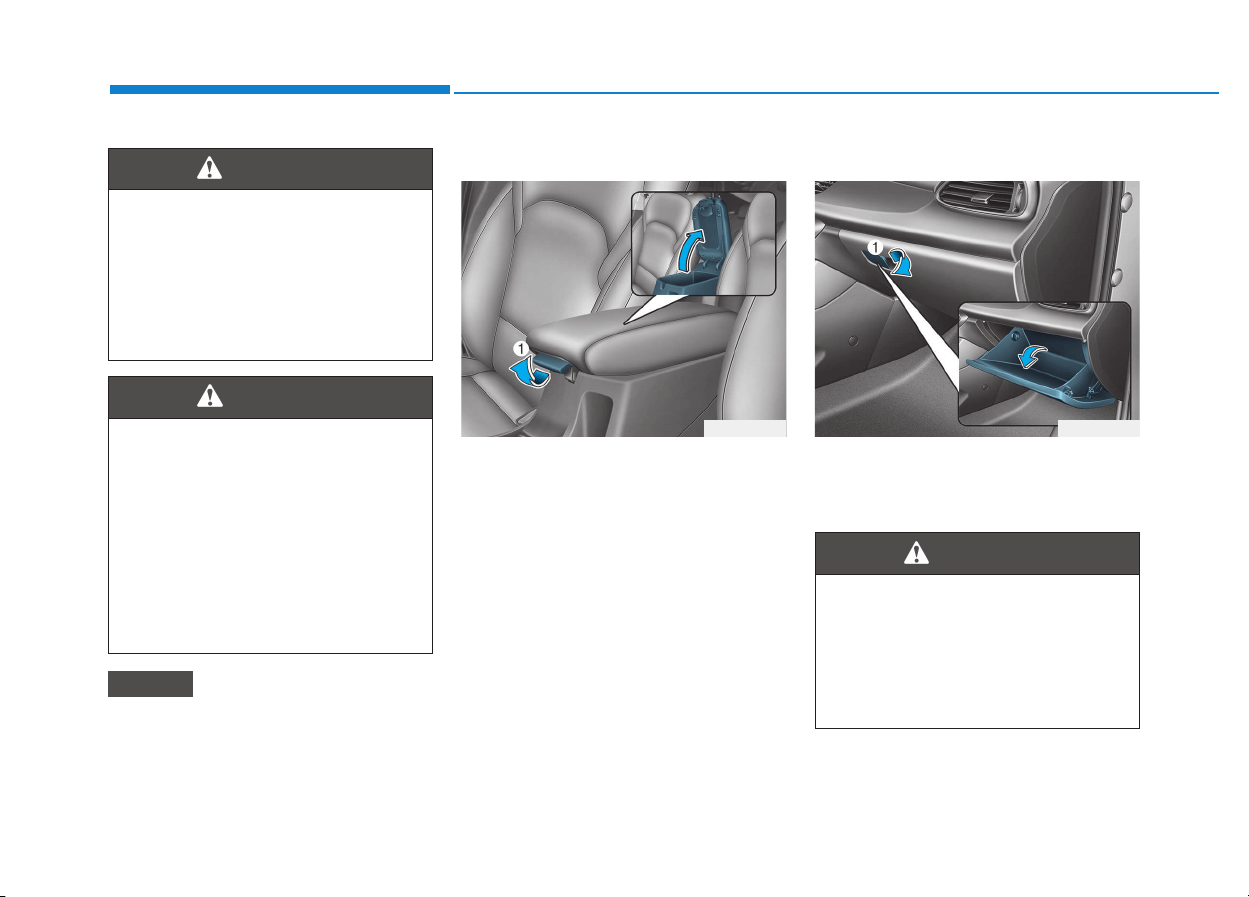
3-138
Convenient features of your vehicle
S
STTOORRAAGGEE CCOOMMPPAARRTTMMEENNTT
To avoid possible theft, do not
leave valuables in the storage
compartments.
Center console storage
To open :
Pull the lever (1).
Glove box
To open the glove box, pull the handle
(1) and the glove box will automatical-
ly open. Close the glove box after use.
NOTICE
Never store cigarette lighters,
propane cylinders, or other
flammable/explosive materials
in the vehicle. These items may
catch fire and/or explode if the
vehicle is exposed to hot tem-
peratures for extended periods.
WARNING
ALWAYS keep the storage com-
partment covers closed secure-
ly while driving. Items inside
your vehicle are moving as fast
as the vehicle. If you have to
stop or turn quickly, or if there
is a crash, the items may fly out
of the compartment and may
cause an injury if they strike the
driver or a passenger.
WARNING
OPD046331
ALWAYS close the glove box
door after use.
An open glove box door can
cause serious injury to the pas-
senger in an accident, even if the
passenger is wearing a seat belt.
WARNING
OPD046333
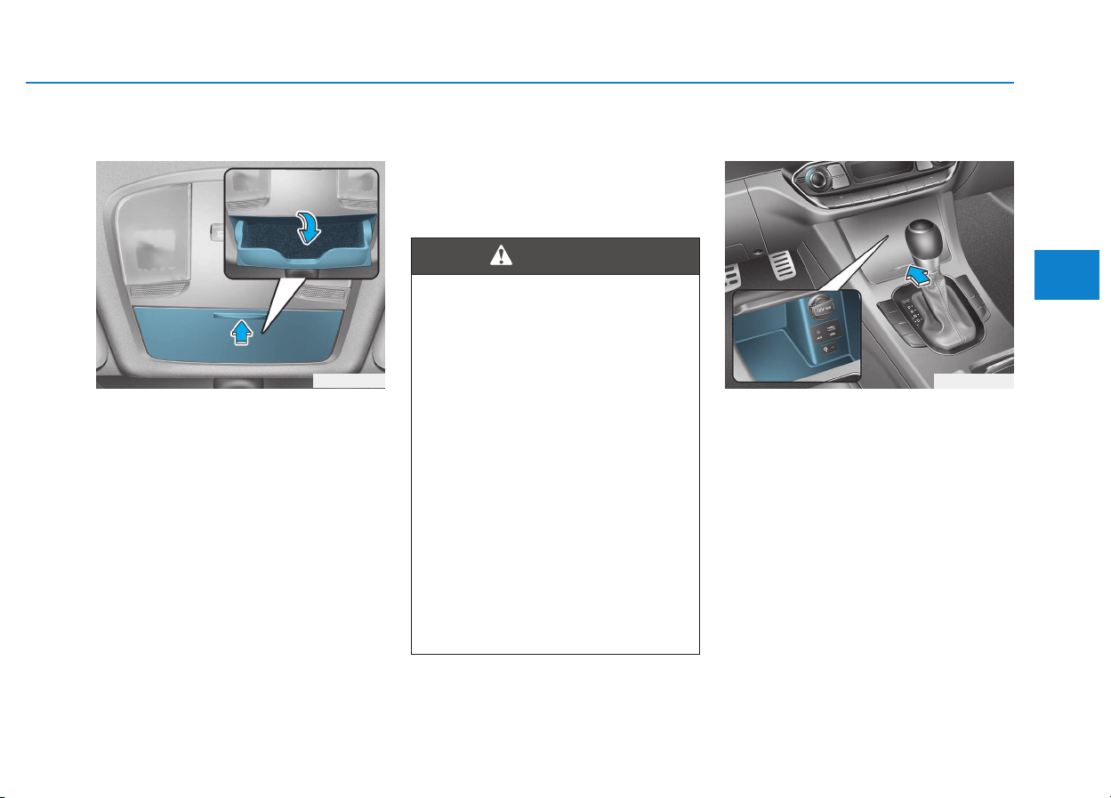
3-139
Convenient features of your vehicle
3
Sunglass holder (if equipped)
To open:
Press the cover and the holder will
slowly open. Place your sunglasses
in the compartment door with the
lenses facing out.
To close:
Push back into position.
Make sure the sunglass holder is
closed while driving.
Multi box (if equipped)
To open the cover, push the lip of the
cover forward and it will slowly open.
To close the cover, push and release
the lip of the cover forward and it will
slowly close.
OPD046334
• Do not keep objects except
sunglasses inside the sun-
glass holder. Such objects can
be thrown from the holder in
the event of a sudden stop or
an accident, possibly injuring
the passengers in the vehicle.
• Do not open the sunglass
holder while the vehicle is
moving. The rear view mirror
of the vehicle can be blocked
by an open sunglass holder.
• Do not attempt to force sun-
glasses into the sunglass
holder. If the sunglasses
become jammed and you try
to open it forcibly, personal
injury may occur.
WARNING
OPDE046338
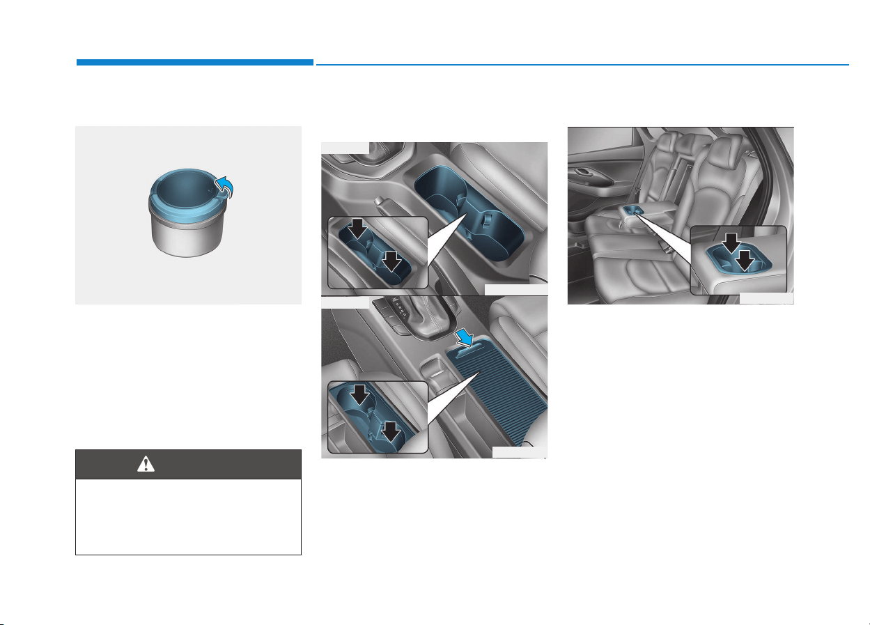
3-140
Convenient features of your vehicle
I
INNTTEERRIIOORR FFEEAATTUURREESS
Ashtray (if equipped)
To use the ashtray, open the cover.
To clean the ashtray:
The plastic receptacle should be
removed by lifting the plastic ashtray
receptacle upward after turning the
cover counterclockwise and pulling it
out.
Cup holder
Front
Cups or small beverages cups may
be placed in the cup holders.
Type B
To use the cup holder, open the
cover.
Rear
Pull the armrest down to use the cup
holders.
OPDE046419
Putting lit cigarettes or matches
in an ashtray with other com-
bustible materials may cause a
fire.
WARNING
OPDE046420
OPD046335
■ Type A
■ Type B
OPD046336
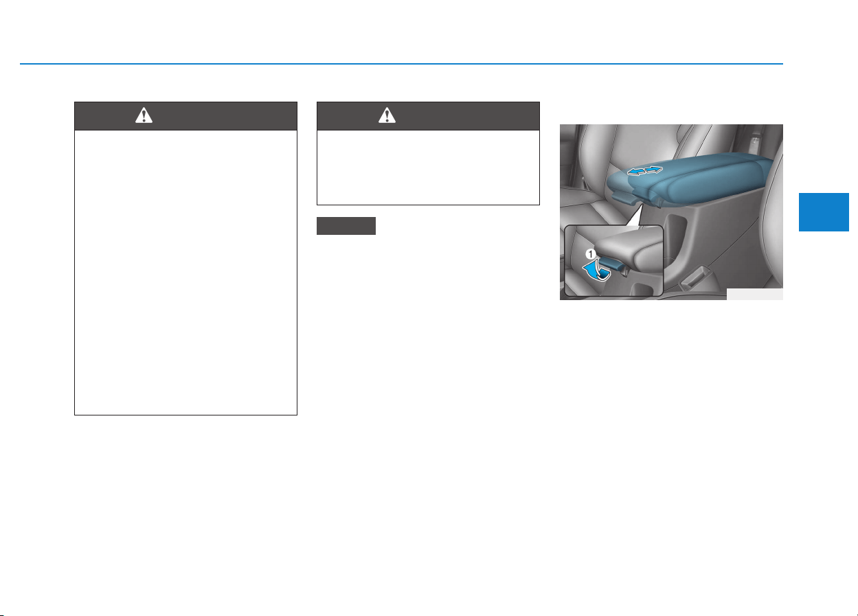
3-141
Convenient features of your vehicle
3
• Keep your drinks sealed while
driving to prevent spilling your
drink. If liquid spills, it may get
into the vehicle's electrical/elec-
tronic system and damage elec-
trical/electronic parts.
• When cleaning spilled liquids, do
not dry the cup holder at high
temperature. This may damage
the cup holder.
Sliding armrest (if equipped)
To move the armrest forward:
Pull up the lever (1) then pull the
armrest forward.
To move the armrest rearward:
Pull up the lever (1) then push the
armrest rearward.
NOTICE
• Avoid abrupt starting and
braking when the cup holder
is in use to prevent spilling
your drink. If hot liquid spills,
you could be burned. Such a
burn to the driver could cause
loss of vehicle control result-
ing in an accident.
• Do not place uncovered or
unsecured cups, bottles,
cans, etc., in the cup holder
containing hot liquid while the
vehicle is in motion. Injuries
may result in the event of sud-
den stop or collision.
• Only use soft cups in the cup
holders. Hard objects can
injure you in an accident.
WARNING
Keep cans or bottles out of
direct sun light and do not put
them in a hot vehicle. It may
explode.
WARNING
OPD046332
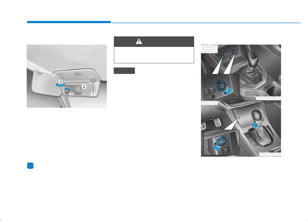
3-142
Convenient features of your vehicle
Sunvisor
To use a sunvisor, pull it downward.
To use a sunvisor for a side window,
pull it downward, unsnap it from the
bracket (1) and swing it to the side (2).
To use the vanity mirror, pull down the
sunvisor and slide the mirror cover (3).
Use the ticket holder (4) to hold tick-
ets.
Information
Close the vanity mirror cover securely
and return the sunvisor to its original
position after use.
Do not put several tickets in the
ticket holder at one time. This
could cause damage to the ticket
holder.
Power outlet (if equipped)
NOTICE
i
For your safety, do not block your
view when using the sunvisor.
WARNING
OPDE046339
■ Front
OPDE046430
OPD046337
• Type A
• Type B
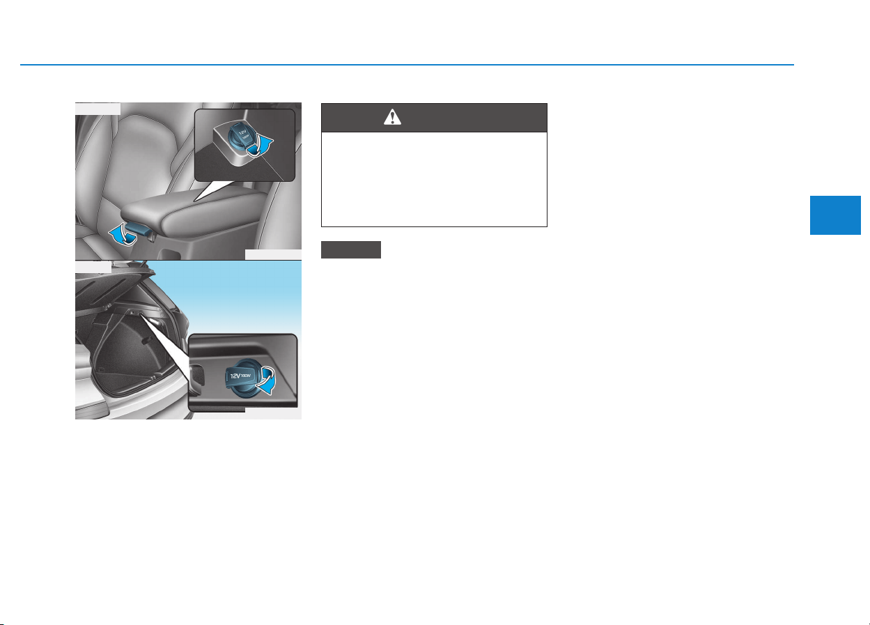
3-143
Convenient features of your vehicle
3
The power outlet is designed to pro-
vide power for mobile telephones or
other devices designed to operate
with vehicle electrical systems. The
devices should draw less than 180
W(Watt) with the engine running.
To prevent damage to the Power
Outlets :
• Use the power outlet only when
the engine is running and remove
the accessory plug after use.
Using the accessory plug for pro-
longed periods of time with the
engine off could cause the battery
to discharge.
• Only use 12V electric accessories
which are less than 180 W(Watt) in
electric capacity.
• Adjust the air-conditioner or
heater to the lowest operating
level when using the power outlet.
• Close the cover when not in use.
(Continued)
(Continued)
• Some electronic devices can
cause electronic interference
when plugged into a vehicle’s
power outlet.These devices may
cause excessive audio static
and malfunctions in other elec-
tronic systems or devices used
in your vehicle.
• Push the plug in as far as it will
go. If good contact is not made,
the plug may overheat and the
fuse may open.
• Plug in battery equipped electrical/
electronic devices with reverse
current protection. The current
from the battery may flow into the
vehicle's electrical/electronic sys-
tem and cause system malfunc-
tion.
NOTICE
Avoid electrical shocks. Do not
place your fingers or foreign
objects (pin, etc.) into a power
outlet or touch the power outlet
with a wet hand.
WARNING
OPD046340
■ Center
OPD046341
■ Rear
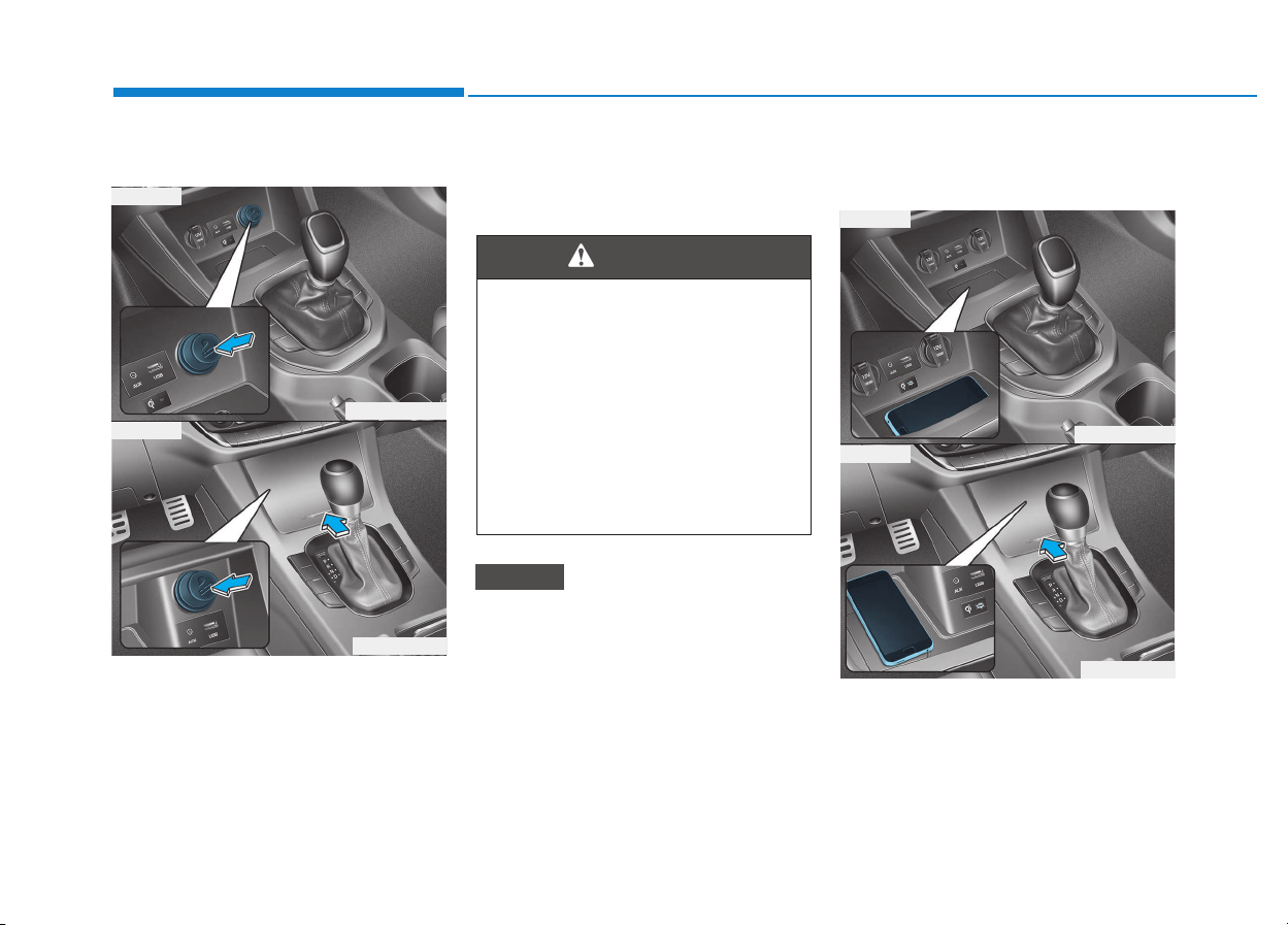
3-144
Convenient features of your vehicle
Cigarette lighter (if equipped)
To use the cigarette lighter, the igni-
tion switch must be in the ACC or ON
position.
Push the cigarette lighter all the way
into its socket. When the element is
heated, the lighter will pop out to the
“ready” position.
We recommend that you use parts
for replacement from an authorized
HYUNDAI dealer.
Only a genuine HYUNDAI lighter
should be used in the cigarette
lighter socket. The use of plug-in
accessories (shavers, hand-held
vacuums, and coffee pots, etc.)
may damage the socket or cause
electrical failure.
Wireless cellular phone charg-
ing system (if equipped)
There is a wireless cellular phone
charging inside the front console.
The system is available when all
doors are closed, and when the igni-
tion switch is in the ACC/ON position.
NOTICE
• Do not hold the lighter in after
it is already heated because it
will overheat.
• If the lighter does not pop out
within 30 seconds, remove it
to prevent overheating.
• Do not insert foreign objects
into the socket of the cigarette
lighter. It may damage the cig-
arette lighter.
WARNING
OPDE046431
OPDE046427
■ Type A
■ Type B
OPDE046432
OPDE046342
■ Type A
■ Type B

3-145
Convenient features of your vehicle
To charge a cellular phone
The wireless cellular phone charging
system charges only the Qi-enabled
cellular phones ( ). Read the label
on the cellular phone accessory
cover or visit your cellular phone
manufacturer’s website to check
whether your cellular phone supports
the Qi technology.
The wireless charging process starts
when you put a Qi-enabled cellular
phone on the wireless charging unit.
1. Remove other items, including the
smart key, from the wireless charg-
ing unit. If not, the wireless charg-
ing process may be interrupted.
2. The indicator illuminates in orange
during the charging process. The
indicator color changes to green,
when the charging process is
completed.
3. You can turn ON or OFF the wire-
less charging function in the User
Settings mode on the instrument
cluster. (For further information,
refer to the “LCD Modes” in this
chapter.)
Slightly change the cellular phone
position, when the cellular phone is
not being charged. Make sure that
the indicator illuminates in orange.
The indicator color may not change
to green in accordance with the cel-
lular phone type, even though the
charging process is completed. The
indicator blinks in orange for 10 sec-
onds when there is a malfunction
with the wireless charging system.
In this case, temporarily stop the
charging process, and re-attempt to
wirelessly charge your cellular phone
again.
The system warns you with a mes-
sage on the LCD display when you do
not take out the cellular phone from
the wireless charging unit with the
front door open and the Engine
Start/Stop button in the OFF position.
• The wireless cellular phone
charging system may not sup-
port certain cellular phones,
which are not verified for the Qi
specification ( ).
(Continued)
(Continued)
• Locate your cell phone well in the
middle of the wireless cellular
phone charging system. Even
when your cell phone locates
slightly to one side, the charging
speed may decrease.
• The wireless charging process
may temporarily stop, when a
smart key function operates (i.e.
starting the engine, opening the
doors, closing the doors).
• For certain cell phones, the indi-
cator color may not change to
green, even when the wireless
charging process is properly
completed.
• The wireless charging process may
temporarily stop, when tempera-
ture abnormally increases inside
the wireless cellular phone charg-
ing system. The wireless charging
process restarts, when tempera-
ture falls to a proper level.
• The wireless charging process
may temporarily stop when there
is any metallic item, such as a
coin, between the wireless cellu-
lar phone charging system and a
cellular phone.
NOTICE
3
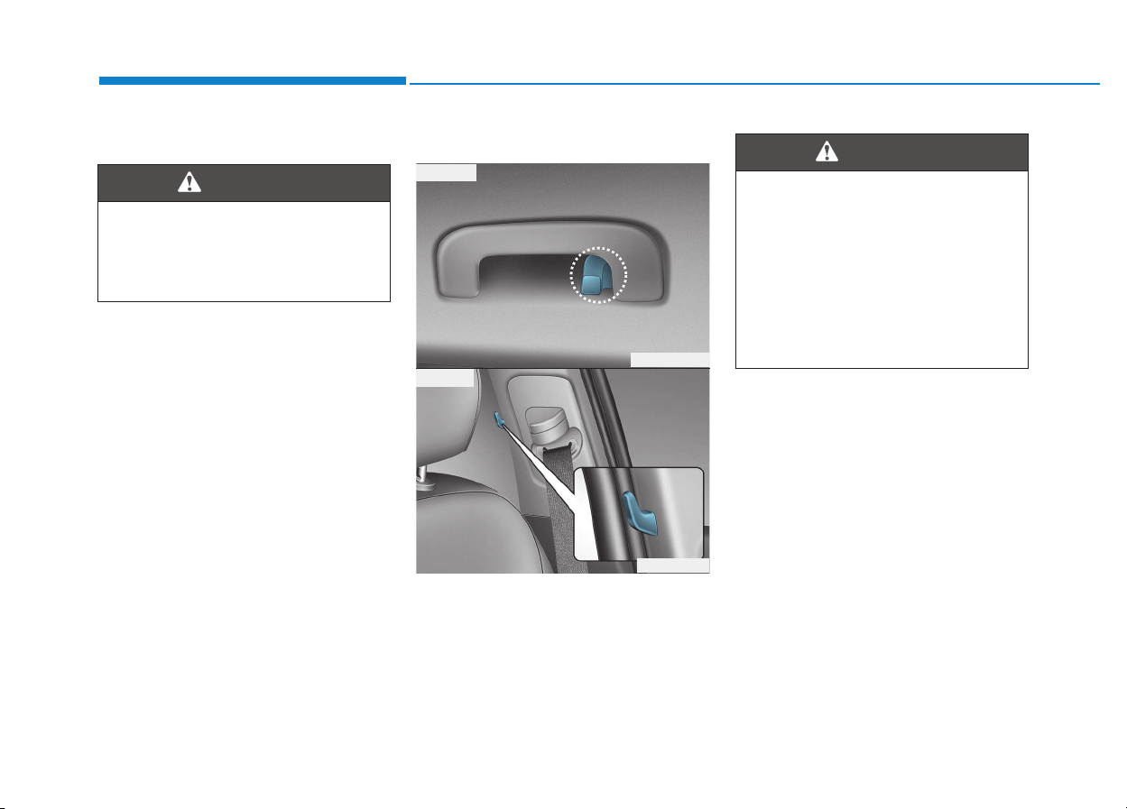
3-146
Clock
Vehicles with Audio system
Select the [SETUP/CLOCK ] button on
the audio system ➟ Select [Date/Time].
• Set time: Set the time displayed on
the audio screen.
• Time format: Choose between 12-
hour and 24-hour time formats.
Vehicles with Navigation system
Select the Settings menu on the
Navigation system ➟ Select
[Date/Time].
• GPS time: Displays time according
to the received GNSS time.
• 24-hour: Switches to 12 hour or 24
hour.
For more details, please refer to
the separate manual that was sup-
plied with your vehicle.
Clothes hanger (if equipped)
These hangers are not designed to
hold large or heavy items.
Convenient features of your vehicle
Do not adjust the clock while
driving.You may lose your steer-
ing control and cause severe
personal injury or accidents.
WARNING
OPD046411
■ Type A
■ Type B
OPDE046050
Do not hang other objects such
as hangers or hard objects
except clothes. Also, do not put
heavy, sharp or breakable
objects in the clothe pockets. In
an accident or when the curtain
air bag is inflated, it may cause
vehicle damage or personal
injury.
WARNING
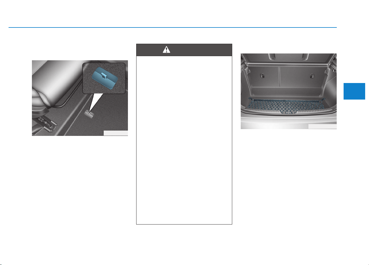
3-147
Convenient features of your vehicle
3
Floor mat anchor(s)
(if equipped)
ALWAYS use the Floor Mat Anchors
to attach the front floor mats to the
vehicle. The anchors on the front
floor carpet keep the floor mats from
sliding forward.
Luggage net (holder)
To keep items from shifting in the
cargo area, you can use the four
holders located in the cargo area to
attach the luggage net.
If necessary, we recommend that you
contact your authorized HYUNDAI
dealer to obtain a luggage net.
OPDE046344
OPD046343
The following must be observed
when installing ANY floor mat
to the vehicle.
• Ensure that the floor mats are
securely attached to the vehi-
cle's floor mat anchor(s) before
driving the vehicle.
• Do not use ANY floor mat that
cannot be firmly attached to
the vehicle's floor mat anchors.
• Do not stack floor mats on top
of one another (e.g. all-weath-
er rubber mat on top of a car-
peted floor mat). Only a single
floor mat should be installed
in each position.
IMPORTANT - Your vehicle was
manufactured with driver's side
floor mat anchors that are
designed to securely hold the
floor mat in place. To avoid any
interference with pedal operation,
HYUNDAI recommends that the
HYUNDAI floor mat designed for
use in your vehicle be installed.
WARNING
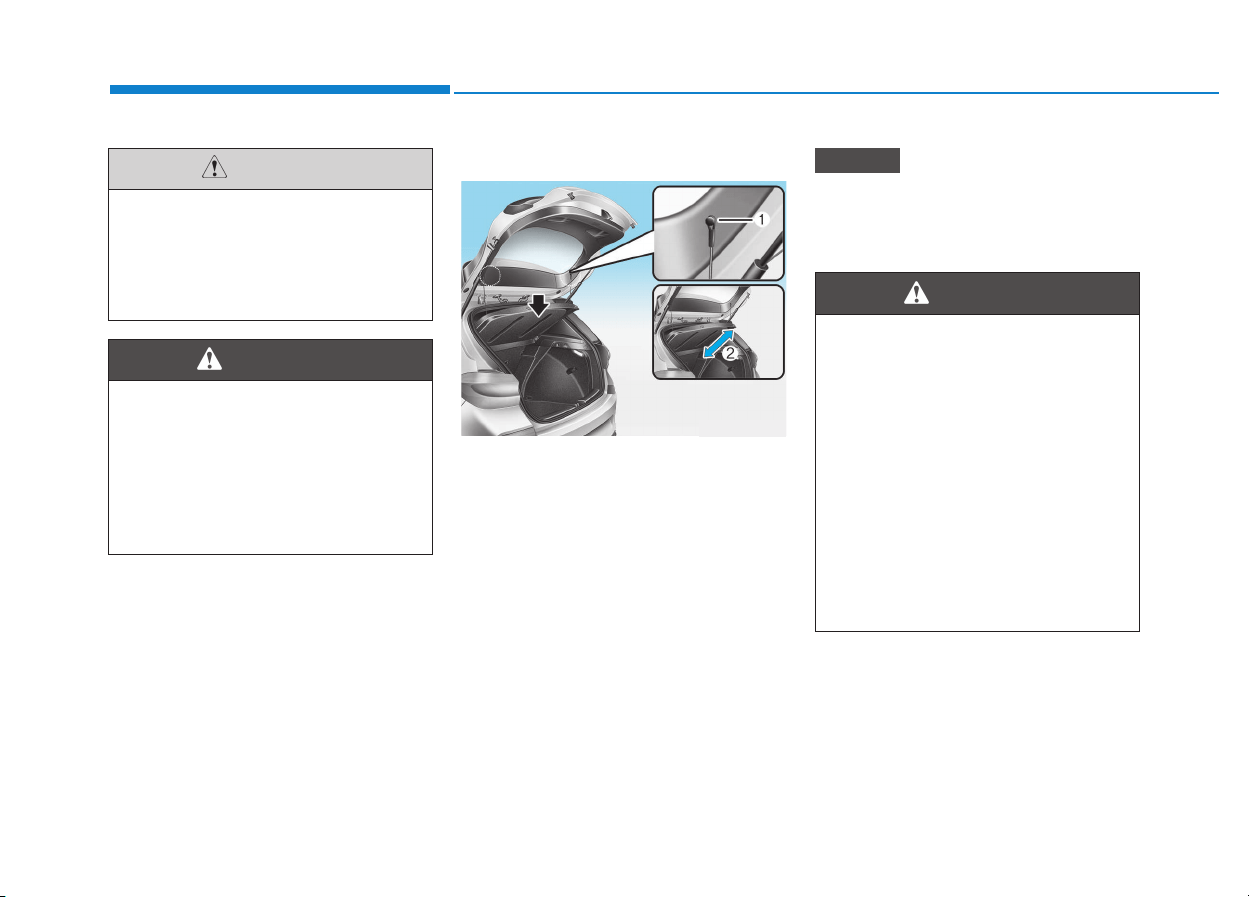
3-148
Convenient features of your vehicle
Cargo area cover (if equipped)
Use the cover to hide items stored in
the cargo area.
The cargo area cover will be lifted
when the tailgate is opened.
Disconnect the strap (1) from the
holder if you want to return the cover
to the original position. To remove the
cargo area cover completely, lift the
cover to a 50-degree angle and pull it
out (2).
Since the cargo area cover may be
damaged or malformed, do not put
luggage on it when it is being used.
NOTICE
To avoid eye injury, DO NOT
overstretch the luggage net.
ALWAYS keep your face and
body out of the luggage net’s
recoil path. DO NOT use the lug-
gage net when the strap has vis-
ible signs of wear or damage.
WARNING
To prevent damage to the goods
or the vehicle, care should be
taken when carrying fragile or
bulky objects in the luggage
compartment.
CAUTION
OPD046346
• Do not place objects on the
cargo area cover while driv-
ing. Such objects may be
thrown about inside the vehi-
cle and possibly injure vehicle
occupants during an accident
or when braking.
• Never allow anyone to ride in
the luggage compartment. It
is designed for luggage only.
• Maintain balance of the vehi-
cle and locate the weight as
far forward as possible.
WARNING
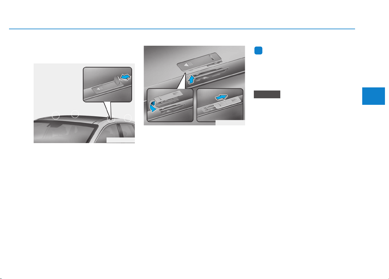
3-149
Convenient features of your vehicle
Mounting bracket for roof car-
rier (if equipped)
To install or remove a roof carrier,
you can use the mounting bracket
and cover on the roof.
When you install a roof carrier, use
the following procedure.
1. Insert a slim tool(coin or flat blade
driver) into the slot and slide the
cover toward the arrow on the
cover.
2. Rotate the cover half way and
insert the cover on the roof hole as
the illustration.
3. After using the roof carrier, install
the cover back on the roof in the
reverse order.
Information
If the vehicle is equipped with a sun-
roof, be sure not to position cargo onto
the roof in such a way that it could
interfere with sunroof operation.
• When carrying cargo on the
roof, take the necessary precau-
tions to make sure the cargo
does not damage the roof of the
vehicle.
• When carrying large objects on
the roof, make sure they do not
exceed the overall roof length or
width.
NOTICE
i
EEXXTTEERRIIOORR FFEEAATTUURREESS
3
OPDE046425
OPDE046426

Multimedia System
Multimedia system.................................................4-2
AUX, USB and iPod
®
®
port ...............................................4-2
Antenna ...............................................................................4-3
Steering wheel audio control .........................................4-4
Bluetooth
®®
Wireless Technology hands-free ..........4-5
Audio / Video / Navigation system (AVN) ..................4-5
How vehicle radio works.................................................4-5
Audio (without touch screen) ..............................4-9
Feature of your audio ...................................................4-10
Radio...................................................................................4-19
Media..................................................................................4-21
Phone .................................................................................4-32
Setup ..................................................................................4-40
Audio (with touch screen)..................................4-42
Feature of your audio ...................................................4-43
Radio .................................................................................4-48
Media..................................................................................4-51
Phone .................................................................................4-62
Setup ..................................................................................4-70
Declaration of conformity ..................................4-72
CE for EU ..........................................................................4-72
4
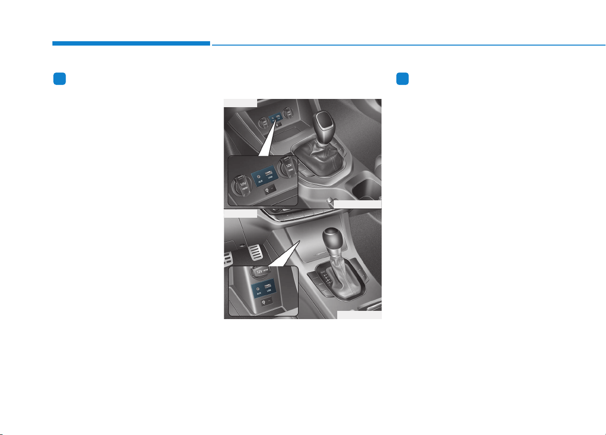
4-2
Multimedia System
Information
• If you install an aftermarket HID
headlamp, your vehicle’s audio and
electronic device may malfunction.
• Prevent chemicals such as perfume,
cosmetic oil, sun cream, hand clean-
er, and air freshener from contacting
the interior parts because they may
cause damage or discoloration.
AUX, USB and iPod
®
port
(if equipped)
You can use an AUX port to connect
audio devices and an USB port to plug
in an USB and also in an iPod
®
port.
Information
When using a portable audio device
connected to the power outlet, noise
may occur during playback. If this
happens, use the power source of the
portable audio device.
❈ iPod
®
is a trademark of Apple Inc.
ii
MMUULLTTIIMMEEDDIIAA SSYYSSTTEEMM
OPDE046428
OPDE046347
■ Type A
■ Type B
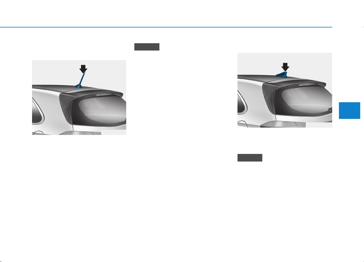
4-3
Multimedia System
4
Antenna
Roof antenna
The roof antenna receives both AM
and FM broadcast signals.
Rotate the roof antenna in a counter-
clockwise direction to remove it.
Rotate it in a clockwise direction to
reinstall it.
• Before entering a place with low
height clearance or a car wash,
remove the antenna by rotating it
counterclockwise. If not, the
antenna may be damaged.
• When reinstalling your antenna,
it is important that it is fully
tightened and adjusted to the
upright position to ensure prop-
er reception.
Shark fin antenna
The shark fin antenna receives
transmitted data. (for example:
AM/FM, DAB, GPS/ GNSS)
• Do not clean the inside of the
rear window glass with a cleaner
or use a scraper to remove for-
eign deposits as this may cause
damage to the antenna elements.
• Avoid adding metallic coatings
such as Ni, Cd, and so on. These
can degrade the receiving AM
and FM broadcast signals.
NOTICE
NOTICE
OPD046412
OPD046345
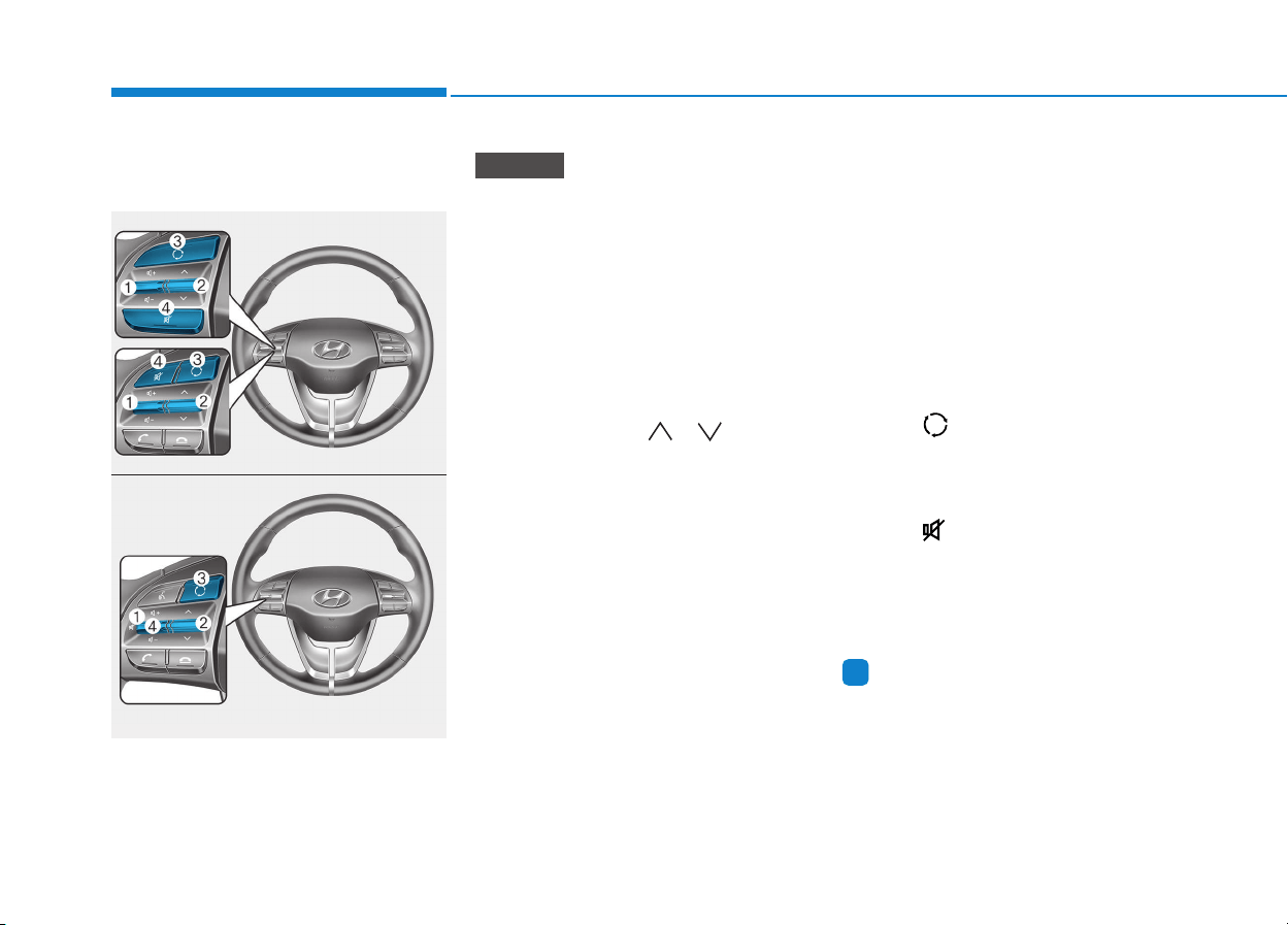
Steering wheel audio control
(if equipped)
The steering wheel audio control
switches are installed for your conven-
ience.
Do not operate audio remote con-
trol buttons simultaneously.
VOLUME (VOL + / - ) (1)
• Move the VOLUME toggle switch
up to increase volume.
• Move the VOLUME toggle switch
down to decrease volume.
SEEK/PRESET ( / ) (2)
If the SEEK/PRESET toggle switch
is moved up or down and held for 0.8
second or more, it will function in the
following modes.
RADIO mode
It will function as the AUTO SEEK
select switch. It will SEEK until you
release the switch.
MEDIA mode
It will function as the FF/REW switch.
If the SEEK/PRESET toggle switch
is moved up or down, it will function
in the following modes.
RADIO mode
It will function as the PRESET STA-
TION UP/DOWN switch.
MEDIA mode
It will function as the TRACK UP/
DOWN switch.
MODE ( ) (3)
Press the MODE button to select
Radio, Disc, or AUX.
MUTE ( ) (4)
• Press the button to mute the
sound.
• Press the button again to activate
the sound.
Information
Detailed information for audio control
buttons are described in the following
pages in this chapter.
i
NOTICE
OPDE046415
OPDE046416
4-4
Multimedia System
■■
■■
TT
TT
yy
yy
pp
pp
ee
ee
AA
AA
■■
■■
TT
TT
yy
yy
pp
pp
ee
ee
CC
CC
■■
■■
TT
TT
yy
yy
pp
pp
ee
ee
BB
BB
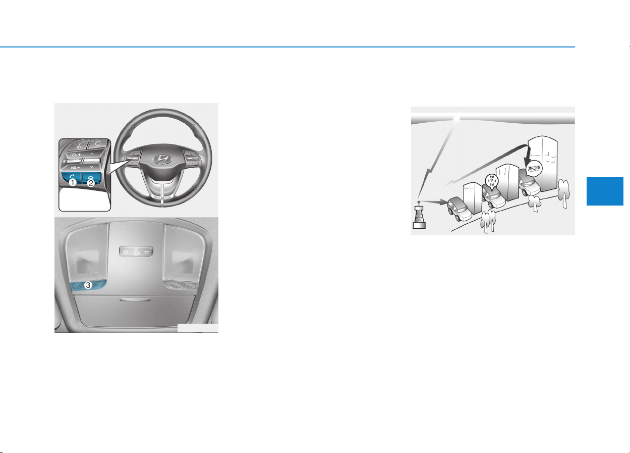
Bluetooth
®
Wireless Technology
hands-free
You can use the phone wirelessly by
using the
Bluetooth
®
Wireless
Technology.
(1) Call / Answer button
(2) Call end button
(3) Microphone
• Audio : For detailed information,
refer to “AUDIO” in this chapter.
• AVN : Detailed information for the
Bluetooth
®
Wireless Technology
hands-free is described in the man-
ual supplied separately.
Audio / Video / Navigation sys-
tem (AVN) (if equipped)
Detailed information for the AVN sys-
tem is described in a separately sup-
plied manual.
How vehicle radio works
FM reception
AM and FM radio signals are broad-
cast from transmitter towers located
around your city. They are intercept-
ed by the radio antenna on your vehi-
cle. This signal is then received by
the radio and sent to your vehicle
speakers.
When a strong radio signal has
reached your vehicle, the precise
engineering of your audio system
ensures the best possible quality
reproduction. However, in some
cases the signal coming to your vehi-
cle may not be strong and clear.
OJF045308L
OPDE046422
OPD046348
4-5
Multimedia System
4
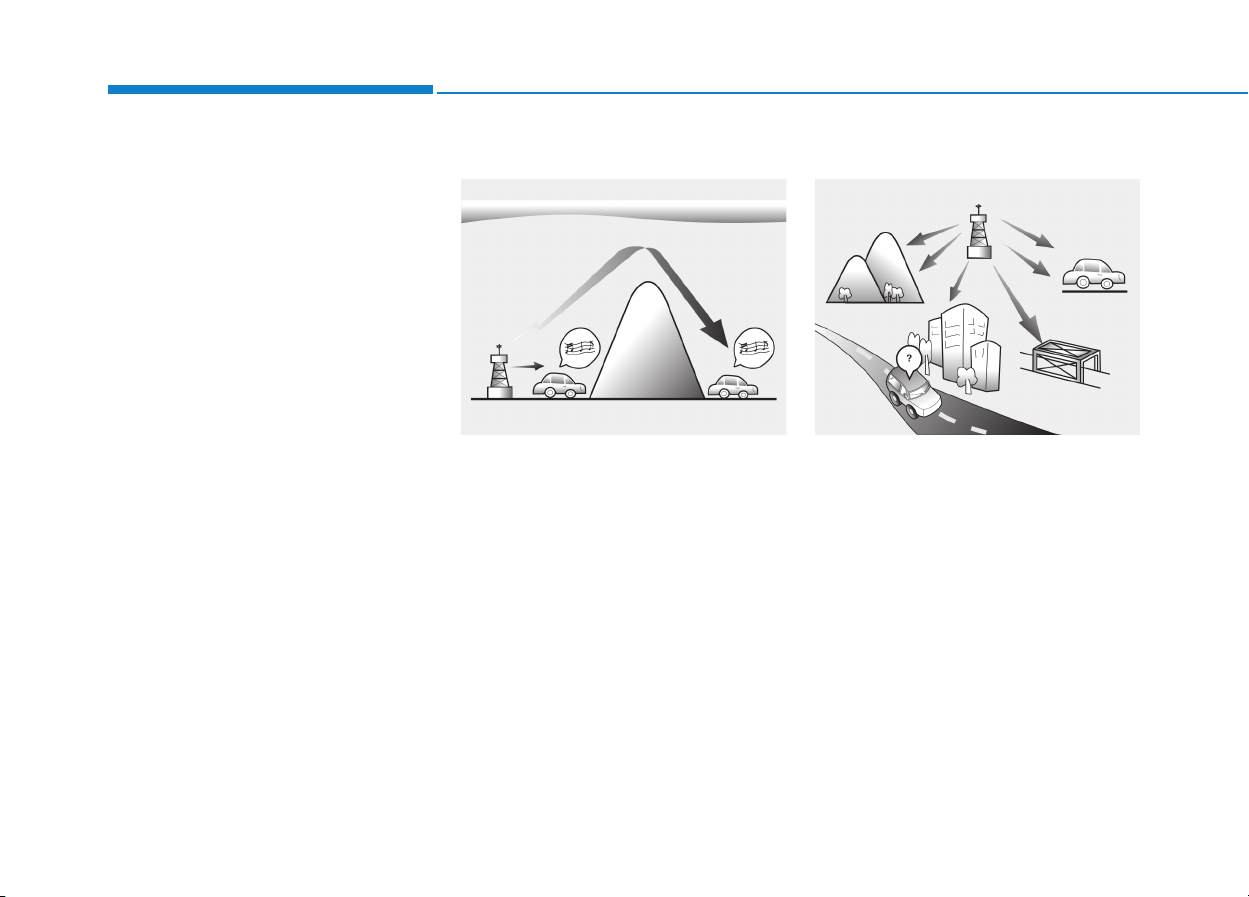
4-6
Multimedia System
This can be due to factors, such as
the distance from the radio station,
closeness of other strong radio sta-
tions or the presence of buildings,
bridges or other large obstructions in
the area.
AM (MW, LW) reception
AM broadcasts can be received at
greater distances than FM broad-
casts. This is because AM radio
waves are transmitted at low fre-
quencies. These long, low frequency
radio waves can follow the curvature
of the earth rather than travelling
straight out into the atmosphere. In
addition, they curve around obstruc-
tions so that they can provide better
signal coverage.
FM radio station
FM broadcasts are transmitted at
high frequencies and do not bend to
follow the earth's surface. Because
of this, FM broadcasts generally
begin to fade at short distances from
the station. Also, FM signals are eas-
ily affected by buildings, mountains,
or other obstructions. These can
result in certain listening conditions
which might lead you to believe a
problem exists with your radio. The
following conditions are normal and
do not indicate radio trouble :
OJF045310LOJF045309L
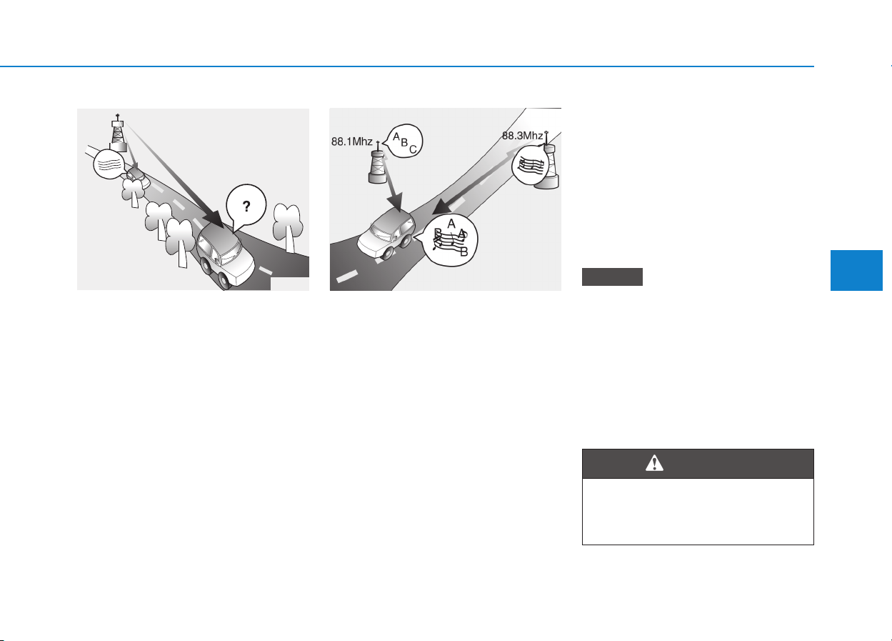
4-7
Multimedia System
4
• Fading - As your vehicle moves
away from the radio station, the
signal will weaken and sound will
begin to fade. When this occurs,
we suggest that you select another
stronger station.
• Flutter/Static - Weak FM signals or
large obstructions between the
transmitter and your radio can dis-
turb the signal causing static or
fluttering noises to occur. Reducing
the treble level may lessen this
effect until the disturbance clears.
• Station Swapping - As a FM signal
weakens, another more powerful
signal near the same frequency
may begin to play. This is because
your radio is designed to lock onto
the clearest signal. If this occurs,
select another station with a
stronger signal.
• Multi-Path Cancellation - Radio
signals being received from sever-
al directions can cause distortion
or fluttering. This can be caused by
a direct and reflected signal from
the same station, or by signals
from two stations with close fre-
quencies. If this occurs, select
another station until the condition
has passed.
Using a cellular phone or a two-
way radio
When a cellular phone is used inside
the vehicle, noise may be produced
from the audio system. This does not
mean that something is wrong with the
audio equipment. In such a case, use
the cellular phone at a place as far as
possible from the audio equipment.
When using a communication
system such as a cellular phone
or a radio set inside the vehicle, a
separate external antenna must be
fitted. When a cellular phone or a
radio set is used with an internal
antenna alone, it may interfere
with the vehicle's electrical sys-
tem and adversely affect safe
operation of the vehicle.
NOTICE
OJF045311L
¢¢¢
JBM004
Do not use a cellular phone
while driving. Stop at a safe
location to use a cellular phone.
WARNING

4-8
Multimedia System
iPod
®
iPod
®
is a registered trademark of Apple Inc.
Bluetooth
®
Wireless Technology
The Bluetooth
®
word mark and logos are registered
trademarks owned by Bluetooth SIG, Inc. and any use of
such marks by HYUNDAI is under license.
Other trademarks and trade names are those of their
respective owners.
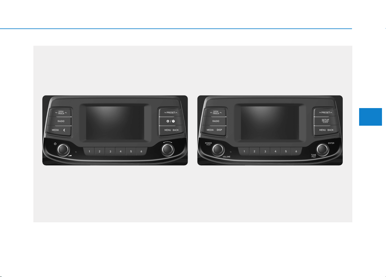
4-9
Multimedia System
4
AAUUDDIIOO ((WWiitthhoouutt TToouucchh SSccrreeeenn))
G4G4G0000EE/G4G4G0001EE
■ Type A-1
■ Type A-2
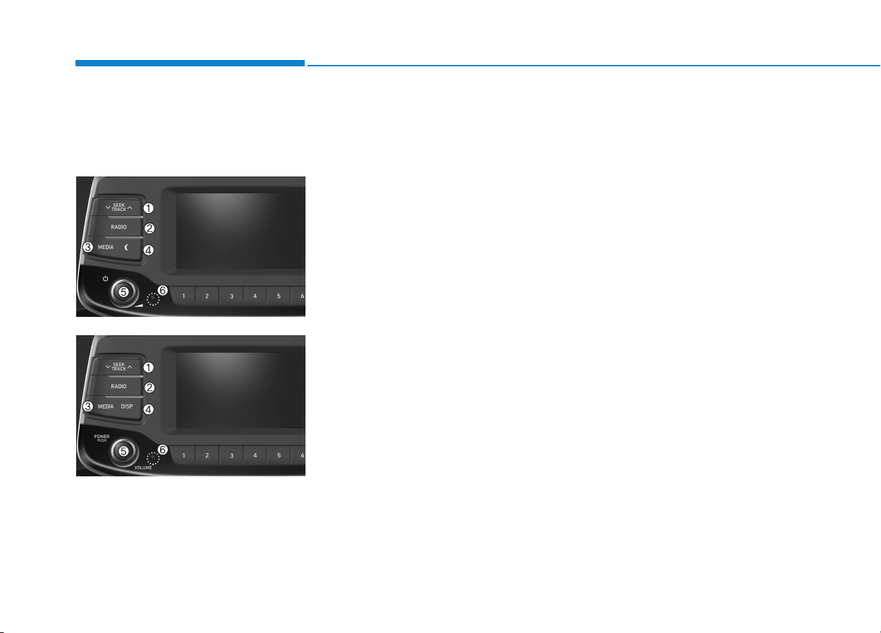
4-10
Multimedia System
Feature of Your Audio
Head unit
❈The actual features in the vehicle
may differ from the illustration.
(1) SEEK/TRACK
• Search for next station in FM and
AM radio mode.
• Change the current song in media
mode.
(2) RADIO
• Start FM and AM radio.
(3) MEDIA
• Select USB(iPod
®
), AUX or My
Music.
• Display the media menu when two
or more media are connected or
when the [MEDIA] button is pressed
in media mode.
(4) DISP
• Turn the display on or off.
(5) POWER/VOLUME knob
• Turn to adjust the volume.
• Press to turn the device on or off.
(6) RESET
• Shutdown and restart the system.
■ Type A-2
■ Type A-1
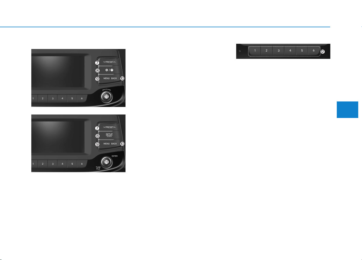
4-11
Multimedia System
4
(7) PRESET
• Move to the previous/next preset
page in radio mode.
(8) SETUP/CLOCK
• Access Display, Sound, Date/Time,
System and Display Off settings.
• Press and hold to set the date/time.
(9) MENU
• Display additional menus available
on the current screen.
(10) BACK
• Return to the previous screen.
(11) TUNE knob
• Turn to navigate through the sta-
tions/songs list.
• Press to select an item.
(12) [1] ~ [6] (Preset)
• Save/play presets in radio mode.
• Select/launch the numeric menus
displayed on the screen.
■ Type A-2
■ Type A-1
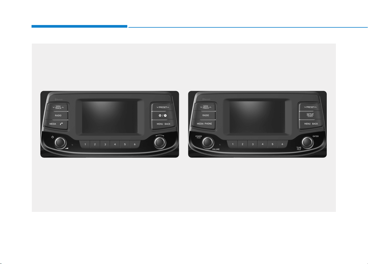
4-12
Multimedia System
G4G4G0002EE/G4G4G0003EE
(With
Bluetooth
®
Wireless Technology)
■ Type A-3
■ Type A-4
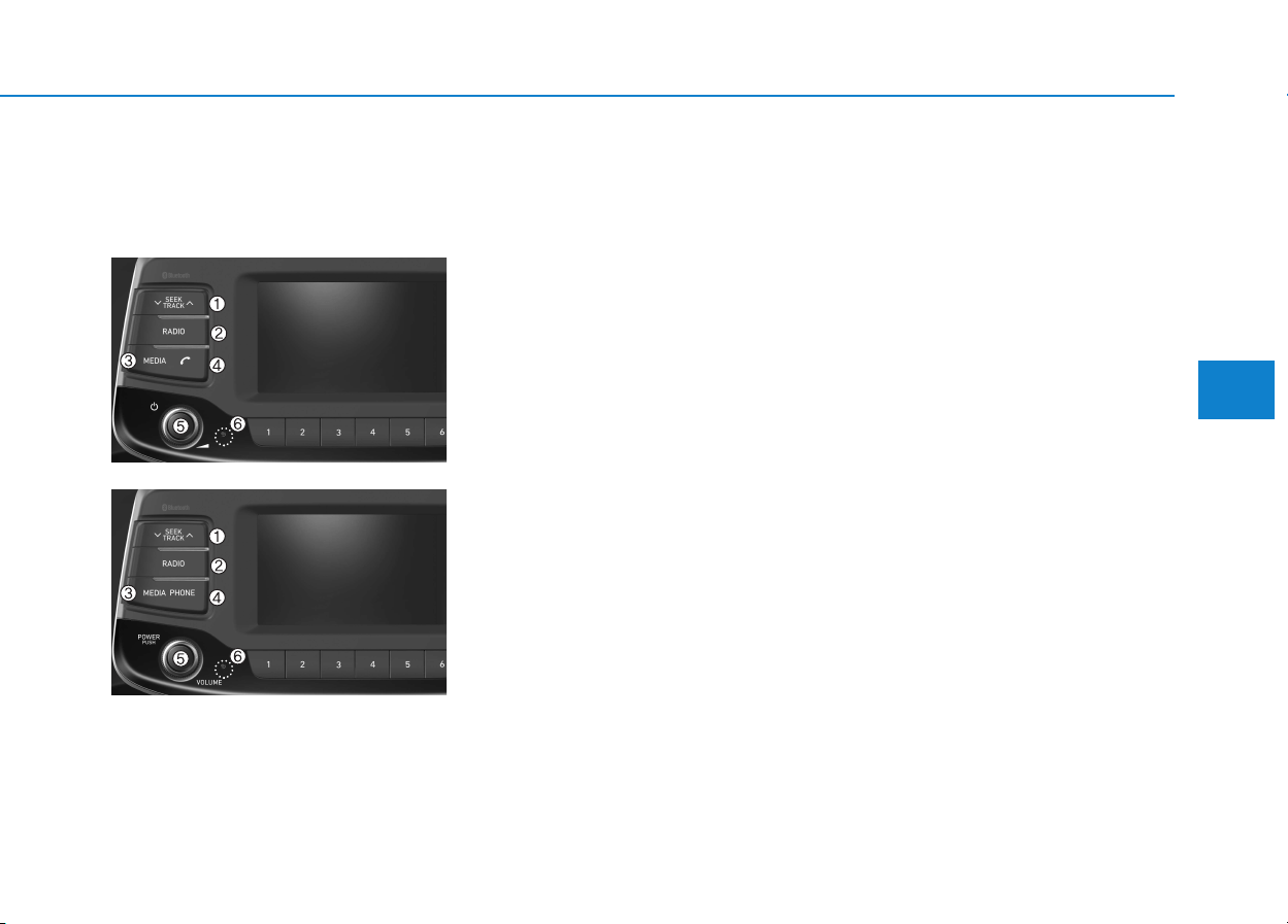
4-13
Multimedia System
4
Feature of Your Audio
Head unit
❈The actual features in the vehicle
may differ from the illustration.
(1) SEEK/TRACK
• Search for next station in DAB/FM*
and AM radio mode.
• Change the current song in media
mode.
* with DAB
(2) RADIO
• Start DAB/FM* and AM radio.
* with DAB
(3) MEDIA
• Select USB(iPod
®
), Bluetooth
®
(BT)
Audio, AUX or My Music.
• Display the media menu when two
or more media are connected or
when the [MEDIA] button is pressed
in media mode.
(4) PHONE
• Start Bluetooth
®
Phone mode.
(5) POWER/VOLUME knob
• Turn to adjust the volume.
• Press to turn the device on or off.
(6) RESET
• Shutdown and restart the system.
■ Type A-4
■ Type A-3
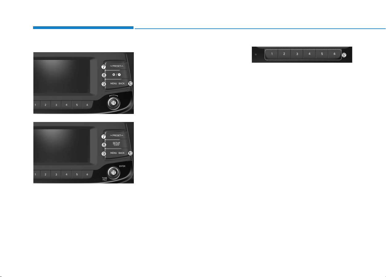
(7) PRESET
• Move to the previous/next preset
page in radio mode.
(8) SETUP/CLOCK
• Access Display, Sound, Date/Time,
Bluetooth, System and Display Off
settings.
• Press and hold to set the date/time.
(9) MENU
• Display additional menus available
on the current screen.
(10) BACK
• Return to the previous screen.
(11) TUNE knob
• Turn to navigate through the sta-
tions/songs list.
• Press to select an item.
(12) [1] ~ [6] (Preset)
• Save/play presets in radio mode.
• Select/launch the numeric menus
displayed on the screen.
■ Type A-4
■ Type A-3
4-14
Multimedia System
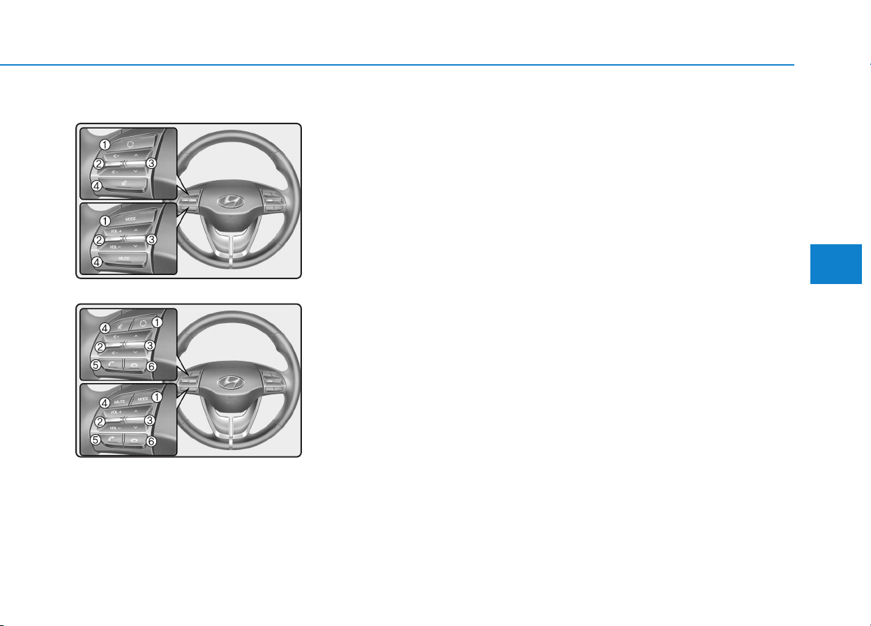
4-15
Multimedia System
4
Steering wheel remote control
(Bluetooth
®
equipped model)
❈ The actual features in the vehicle
may differ from the illustration.
(1) MODE
• Press the button to change the
mode in the following order: Radio
➟ Media.
• Press and hold the button to turn
off. (if equipped)
(2) VOLUME
• Press to adjust the volume.
(3) UP/DOWN
• Press the button in radio mode to
search Presets.
• Press and hold the button in radio
mode to search frequencies.
• Press the button in media mode to
change the current song.
• Press and hold the button in media
mode to quick search through
songs.
(4) MUTE
• Press to mute audio output.

(5) CALL (if equipped)
• Pressing the button
- If not in Bluetooth
®
Handsfree
mode or receiving a phone call.
First press: Display Dial Number
screen.
Second press: Automatically dis-
play the most recently Dialed
Call number.
Third press: Dial the phone num-
ber entered.
- Press in the Incoming Call notifi-
cation screen to accept the
phone call.
- Press in Bluetooth
®
Handsfree
mode to switch to the waiting
call.
• Pressing and holding the button
- If not in Bluetooth
®
Handsfree
mode or receiving a phone call,
the most recently Dialed Call
number is dialed.
- Press in Bluetooth
®
Handsfree
mode to transfer the call to your
cell phone.
- Press in cell phone mode to
switch to Bluetooth
®
Handsfree
mode.
(6) END (if equipped)
• Press in Bluetooth
®
Handsfree
mode to end the phone call.
• Press in the incoming call screen
to reject the call.
4-16
Multimedia System

4-17
Multimedia System
4
• Do not stare at the screen
while driving. Staring at the
screen for prolonged periods
of time could lead to traffic
accidents.
• Do not disassemble, assem-
ble, or modify the audio sys-
tem. Such acts could result in
accidents, fire, or electric
shock.
• Using the phone while driving
may lead to a lack of attention
of traffic conditions and
increase the likelihood of
accidents. Use the phone fea-
ture after parking the vehicle.
• Heed caution not to spill water
or introduce foreign objects
into the device. Such acts
could lead to smoke, fire, or
product malfunction.
(Continued)
WARNING
(Continued)
• Please refrain from use if the
screen is blank or no sound
can be heard as these signs
may indicate product mal-
function. Continued use in
such conditions could lead to
accidents (fires, electric
shock) or product malfunc-
tions.
• Do not touch the antenna dur-
ing thunder or lightening as
such acts may lead to light-
ning induced electric shock.
• Do not stop or park in park-
ing-restricted areas to operate
the product. Such acts could
lead to traffic accidents.
• Use the system with the vehi-
cle ignition turned on.
Prolonged use with the igni-
tion turned off could result in
battery discharge.
Driving while distracted can
result in a loss of vehicle con-
trol that may lead to an acci-
dent, severe personal injury,
and death. The driver’s primary
responsibility is in the safe and
legal operation of a vehicle, and
use of any handheld devices,
other equipment, or vehicle sys-
tems which take the driver’s
eyes, attention and focus away
from the safe operation of a
vehicle or which are not permis-
sible by law should never be
used during operation of the
vehicle.
WARNING

4-18
Multimedia System
• Operating the device while driv-
ing could lead to accidents due
to a lack of attention to external
surroundings. First park the
vehicle before operating the
device.
• Adjust the volume to levels that
allow the driver to hear sounds
from outside of the vehicle.
Driving in a state where external
sounds cannot be heard may
lead to accidents.
• Pay attention to the volume set-
ting when turning the device on.
A sudden output of extreme vol-
ume upon turning the device on
could lead to hearing impair-
ment. (Adjust the volume to a
suitable levels before turning off
the device.)
• If you want to change the position
of device installation, please
inquire with your place of pur-
chase or service maintenance
center. Technical expertise is
required to install or disassem-
ble the device.
(Continued)
(Continued)
• Turn on the car ignition before
using this device. Do not oper-
ate the audio system for long
periods of time with the ignition
turned off as such operations
may lead to battery discharge.
• Do not subject the device to
severe shock or impact. Direct
pressure onto the front side of
the monitor may cause damage
to the LCD or touch screen.
• When cleaning the device, make
sure to turn off the device and
use a dry and smooth cloth.
Never use tough materials,
chemical cloths, or solvents
(alcohol, benzene, thinners,
etc.). As such materials may
damage the device panel or
cause color/quality deteriora-
tion.
• Do not place beverages close to
the audio system. Spilling bever-
ages may lead to system mal-
function.
• In case of product malfunction,
please contact your place of pur-
chase or After Service center.
(Continued)
(Continued)
• Placing the audio system within
an electromagnetic environment
may result in noise interference.
NOTICE
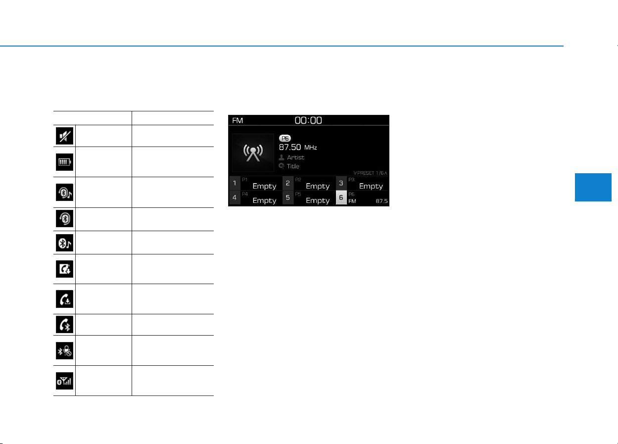
4-19
Multimedia System
4
Information on status icons
Icons showing audio status are shown
in the upper-right corner of the screen.
Radio
FM/AM (with RDS)
Switching between FM and AM
• Press the [RADIO] button on the
audio system to switch between
FM and AM.
Searching stations
Press the [SEEK/TRACK] button to
search stations.
Presets
Save up to 36 frequently used sta-
tions.
1. Press and hold the desired slot
from 1 through 36. This saves the
current station in the selected slot.
If the slot is empty, simply press-
ing saves the station to the slot.
2. To save in slots numbered 7 or
higher, press the [PRESET] but-
ton to move to the previous/next
page and save.
To listen to a preset station, press
the desired station in the list.
Menu
Press the [MENU] button, and select
the desired function.
• List: A list of all available stations in
the current location of the vehicle is
displayed. Press the desired sta-
tion.
• Traffic Announcement (TA): Enable
or disable Traffic Announcements.
• Sound Settings: Audio sound set-
tings can be changed.
• Scan: All available stations are
played for five seconds each.
Icon Description
Mute Mute engaged
Battery
Remaining battery life of
a connected Bluetooth
®
device
Handsfree +
Audio stream-
ing connection
Bluetooth
®
Handsfree
call and audio streaming
available
Handsfree
connection
Bluetooth
®
Handsfree
call available
Bluetaooth
®
audio streaming
Bluetooth
®
audio
streaming available
Downloading
contacts
Downloading contacts
through Bluetooth
®
wire-
less communications
Downloading
call history
Downloading call history
through Bluetooth
®
wire-
less communications
Line busy Phone call in progress
Mute mic
Mic muted during a
call (caller cannot
hear your voice)
Phone signal
strength
Display the phone signal
strength for a cell phone
connected by Bluetooth
®

4-20
Multimedia System
DAB/FM (with DAB)
Switching between DAB/FM and AM
• Press the [RADIO] button on the
audio system to switch between
DAB/FM and AM.
Searching stations
Press the [SEEK/TRACK] button to
search stations.
Presets
Save up to 36 frequently used sta-
tions.
1. Press and hold the desired slot
from 1 through 36. This saves the
current station in the selected slot.
If the slot is empty, simply press-
ing saves the station to the slot.
2. To save in slots numbered 7 or
higher, press the [PRESET] but-
ton to move to the previous/next
page and save.
To listen to a preset station, press
the desired station in the list.
Menu
Press the [MENU] button, and select
the desired function.
• List: A list of all available stations in
the current location of the vehicle is
displayed. Press the desired sta-
tion.
• Traffic Announcement (TA): Enable
or disable Traffic Announcements.
• Region : Enable or disable auto-
matic switching between regional
stations.
• Sound Settings: Audio sound set-
tings can be changed.
• Scan: All available stations are
played for five seconds each.
• Manual tune FM : Search for fre-
quencies manually.
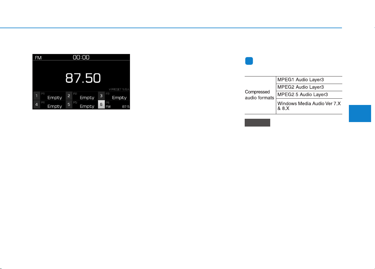
4-21
Multimedia System
4
FM/AM (without RDS)
Switching between FM, AM
• Press the [RADIO] button on the
audio system to switch between
FM and AM.
Searching stations
Press the [SEEK/TRACK] button to
search stations.
Presets
Save up to 36 frequently used sta-
tions.
1. Press and hold the desired slot
from 1 through 36. This saves the
current station in the selected slot.
If the slot is empty, simply press-
ing saves the station to the slot.
2. To save in slots numbered 7 or
higher, press the [PRESET] but-
ton to move to the previous/next
page and save.
To listen to a preset station, press
the desired station in the list.
Menu
Press the [MENU] button, and select
the desired function.
• List: A list of all available stations in
the current location of the vehicle is
displayed. Press the desired sta-
tion. Select [Refresh] to update the
list of available stations.
• Scan: All stations available in the
current location of the vehicle are
played for five seconds each.
• Sound Settings: Audio sound set-
tings can be changed.
Media
Information
- Using MP3
Supported audio formats
File formats other than the for-
mats above may not be recog-
nized or playable. Information
such as filename may not be dis-
played.
NOTICE
i
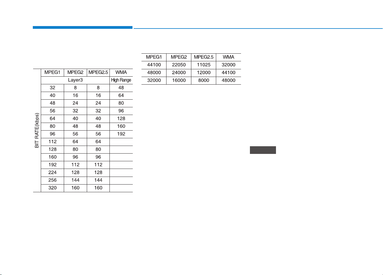
4-22
Multimedia System
Range of supported compressed file
types
1. Bitrate range (Kbps)
2. Sampling frequency (Hz)
• The sound quality of MP3/WMA
compressed files may vary depend-
ing on the bitrate. (A higher bitrate
can have better sound quality.)
• The product only recognizes files
with the MP3 or WMA extension.
Files without one of these exten-
sions are not recognized.
3. Number of recognizable folders
and files
• Folders: 2,000 for USB
• Files: 6,000 for USB
• No recognition limit for folder hier-
archies
4. Character display range (Unicode)
• Filenames: Up to 64 English char-
acters (64 Korean characters)
• Foldernames: Up to 32 English
characters (32 Korean characters)
Languages supported (Unicode sup-
port)
• Korean: 2,604 characters
• English: 94 characters
• Common Chinese characters:
4,888 characters
• Special symbols: 986 characters
Japanese/Simplified Chinese
characters are not supported.
NOTICE

4-23
Multimedia System
4
Information
- Using the USB Devices
• Starting the vehicle while a USB
device is connected can damage the
device. Please disconnect USB
devices before starting the vehicle.
• Starting the vehicle or stopping the
engine while an external USB device
is connected can result in failure of
the external USB device to operate.
• Be cautious of static electricity when
connecting/disconnecting external
USB devices.
• An encrypted MP3 player is not rec-
ognized when connected as an exter-
nal device.
• External USB devices may not be
recognized, depending on the state
of the external USB device.
• Only products with byte/sectors for-
matted at 4 KB or lower are recog-
nized.
• Only USB devices in FAT12/16/32
format are recognized; NTFS and
ExFAT file systems are not recog-
nized.
• Some USB devices are not recog-
nized due to compatibility issues.
(Continued)
(Continued)
• Do not touch the USB connections.
• Connecting and disconnecting USB
devices rapidly over a short period
of time can cause equipment failure.
• Abnormal sounds may be audible
when the USB device is disconnect-
ed.
• Turn the audio off before connecting
or disconnecting external USB
devices.
• Recognition may take longer
depending on the type, capacity or
file format of the external USB
device. This is not a product mal-
function.
• Use of USB devices for purposes
other than playing music files is pro-
hibited.
• Image display and video playback
are not supported.
• Use of USB accessories, including
charge and heat though the USB I/F,
can lead to reduced product per-
formance or malfunctions. Do not
use USB devices or accessories for
these purposes.
(Continued)
(Continued)
• Use of aftermarket USB hubs and
extension cables can result in the
vehicle’s audio system failing to rec-
ognize your USB device. Connect
the USB device directly to the multi-
media port of your vehicle.
• When using high-capacity USB
devices with logical drive divisions,
only files saved on the highest level
logical drive can be played.
If applications are loaded on a USB
drive, file playback may fail.
• Some MP3 players, cell phones, dig-
ital cameras, etc. (USB devices that
are not recognized as mobile stor-
age) may not operate normally
when connected.
• USB charging may not be supported
by some mobile devices.
• Operation is guaranteed only for
standard (Metal Cover Type) USB
Memory drives.
• Operation of HDD, CF, SD and
memory stick devices is not guaran-
teed.
(Continued)
i
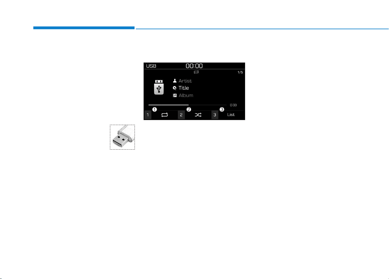
4-24
Multimedia System
(Continued)
• DRM (Digital Rights Management)
files cannot be played.
• SD-type USB memory, CF-type
USB memory, and other USB mem-
ory devices that require adapters
for connection are not supported.
• Proper operation of USB HDDs or
USB drives with connectors that
loosen due to vehicle vibrations is
not guaranteed. (iStick, etc.)
• USB products that are
used as key chains or
cell phone accessories
may damage the USB
jack and affect proper
file playback. Please refrain from
use. Use only products with plug
connectors, as shown in the follow-
ing illustration.
• When MP3 devices or cell phones
are connected simultaneously
through AUX, BT Audio and USB
modes, a popping noise or malfunc-
tion may occur.
USB
(1) Repeat
Enable/disable repeat by pressing
button [1].
(2) Shuffle
Enable/disable shuffle play by press-
ing button [2].
(3) List
View a list of all songs by pressing
button [3].
Playback
Press the [MEDIA] button, and
select [USB].
• Connect a USB drive to the USB
port to automatically play files on
the USB drive.
Changing songs
Press the [SEEK/TRACK] button to
play the previous or next song.
Press and hold the [SEEK/TRACK]
button to rewind or fast forward the
currently playing song.
Search songs by turning TUNE
knob, and press the knob to play.
Selecting songs from a list
Select [List] to see a list of songs
available for play.
Select and play the desired song.
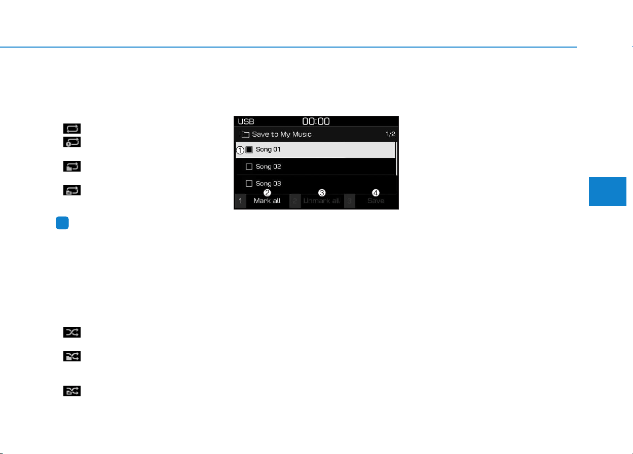
4-25
Multimedia System
4
Repeat play
Select [Repeat] to enable or disable
‘Repeat all’, ‘Repeat current song’,
‘Repeat folder’ or ‘Repeat category’.
• Repeat all: Repeat all songs.
• Repeat current song: The cur-
rently playing song is repeated.
• Repeat folder: All songs in the
current folder are repeated.
• Repeat category: Repeat all
songs in the current category.
Information
The repeat folder function is available
only when songs are playing from the
[File] category under [List].
Shuffle play
Select [Shuffle] to enable/disable
‘Shuffle’, ‘Shuffle folder’ or ‘Shuffle
category’ play.
• Shuffle: Songs are played in
random order.
• Shuffle folder: Songs within
the current folder are played in ran-
dom order.
• Shuffle category: Songs within
the current category are played in
random order.
Menu
Press the [MENU] button, and select
the desired function.
• Save to My Music: Songs on your
USB device can be saved to My
Music.
(1) File: Select a file by using TUNE
knob.
(2) Mark all: Select all files by press-
ing button [1].
(3) Unmark all: Deselect all files by
pressing button [2].
(4) Save: Save the selected files by
pressing button [3].
- Select the files you want to save,
and Select [Save]. This saves the
selected files to My Music.
- Saving is canceled if phone calls
are received or made while sav-
ing.
- Up to 6,000 files can be saved.
• Information: Detailed information
on the song that is currently play-
ing is displayed.
• Sound Settings: Audio sound set-
tings can be changed.
i

4-26
Multimedia System
Information
- Using the iPod
®
Devices
• To use the audio system’s iPod
®
con-
trol function, use the dedicated
cable provided with your iPod
®
.
• Connecting the iPod
®
to the vehicle
during play may result in a loud
noise that lasts about one to two sec-
onds. Connect the iPod
®
to the vehi-
cle after stopping or pausing play.
• Connect the iPod
®
with the vehicle
in the ACC ON state to begin charg-
ing.
• When connecting the iPod
®
cable,
be sure to fully push the cable into
the port.
• When EQ effects are enabled simul-
taneously on external devices, such
as iPod
®
s and the audio system, the
EQ effects may overlap, causing
sound quality deterioration or dis-
tortion. Deactivate the EQ function
for all external devices, if possible.
• Noise may occur when your iPod
®
or the AUX port is connected.
Disconnect and store separately
when not in use.
(Continued)
(Continued)
• There may be noise if the audio sys-
tem is used with an iPod
®
or AUX
external device connected to the
power jack. In these cases, discon-
nect the iPod
®
or external device
from the power jack.
• Play may be interrupted, or device
malfunctions may occur depending
on the characteristics of your
iPod
®
/iPhone
®
.
• Play may fail if your iPhone
®
is con-
nected through both Bluetooth
®
and
USB. In this case, select Dock con-
nector or Bluetooth
®
on your
iPhone
®
to change the sound output
settings.
• If your software version does not
support the communication proto-
col or your iPod
®
is not recognized
due to device failure, anomalies or
defects, iPod
®
mode cannot be used.
• iPod
®
nano (5th generation) devices
may not be recognized if the battery
is low. Charge sufficiently before
use.
(Continued)
(Continued)
• The search and song play order in
the iPod
®
device may be different
from the search order in the audio
system.
• If the iPod
®
has failed due to an
internal defect, please reset the
iPod
®
(consult your iPod
®
manual).
• Depending on the software version,
the iPod
®
may fail to sync with the
system. If the media is removed or
disconnected before recognition, the
previous mode may not be restored
(iPad
®
cannot be charged).
• Cables other than the 1-meter cable
provided with iPod
®
/iPhone
®
prod-
ucts may not be recognized.
• When other music apps are used on
your iPod
®
, the system sync func-
tion may fail due to malfunction of
the iPod
®
application.
i

4-27
Multimedia System
4
iPod
®
(1) Repeat
Enable/disable repeat by pressing
button [1].
(2) Shuffle
Enable/disable shuffle play by press-
ing button [2].
(3) List
View a list of all songs by pressing
button [3].
Playback
Connect your iPod
®
to the audio
USB port, press the [MEDIA] button,
and select [iPod].
Changing songs
Press the [SEEK/TRACK] button to
play the previous or next song.
Press and hold the [SEEK/TRACK]
button to rewind or fast forward the
currently playing song.
Search songs by turning the TUNE
knob, and press the knob to play.
Selecting songs from a list
Select [List] to see a list of songs
available for play.
Select and play the desired song.
Repeat play
Select [Repeat] to enable or disable
‘Repeat category’, ‘Repeat current
song’.
• Repeat category: Repeat all
songs in the current category.
• Repeat current song: The cur-
rently playing song is repeated.
Shuffle play
Select [Shuffle] to enable/disable
‘Shuffle category’ play.
• Shuffle category: Songs within
the current category are played in
random order.
Menu
Press the [MENU] button, and select
the desired function.
• Information: Detailed info on the
currently playing song is displayed.
• Sound Settings: Audio sound set-
tings can be changed.
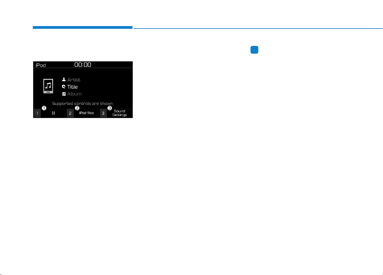
4-28
Multimedia System
When other music programs are
running
When songs saved on your iPod
®
are playing through a separate music
app, the following screen is dis-
played.
(1) Play/Pause: Pause or play music
by pressing button [1].
(2) iPod files: Play music files saved
on your iPod
®
by pressing button
[2].
(3) Sound Settings: Audio sound set-
tings can be changed by pressing
button [3].
Playing iPod files
Select [iPod files] to play songs
saved on your iPod
®
.
If there are no songs saved on your
iPod
®
, the [iPod files] is disabled.
Information
- Using Bluetooth
®
(BT) Audio
(if equipped)
• Bluetooth
®
Audio mode can only be
used if a Bluetooth
®
-enabled phone
is connected. Only devices that sup-
port Bluetooth
®
audio can be used.
• If the Bluetooth
®
-enabled phone is
disconnected during play, the music
stops.
• When the TRACK UP/DOWN but-
tons are used during Bluetooth
®
audio streaming, a popping noise or
sound interruptions may occur,
depending on the cell phone device.
• Depending on the cell phone model,
the audio streaming function may
not be supported.
• If a phone call is made or received
when music is playing in Bluetooth
®
Audio mode, the call may mix with
the music.
• When returning to Bluetooth
®
Audio mode after ending a call, play
might not resume automatically for
some cell phone models.
i
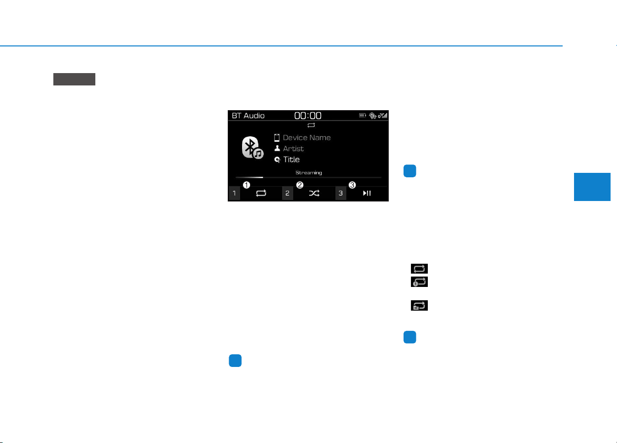
4-29
Multimedia System
4
• Bluetooth
®
Handsfree is a fea-
ture that enables drivers to prac-
tice safe driving. Connecting the
car audio system with a
Bluetooth
®
phone allows the
user to conveniently make calls,
receive calls, and manage the
phone book. Before using the
Bluetooth
®
Wireless Technology,
carefully read the contents of
this user’s manual.
• Excessive use or operations
while driving may lead to negli-
gent driving practices and be
the cause of accidents.
• Do not operate the device exces-
sively while driving.
• Viewing the screen for pro-
longed periods of time is dan-
gerous and may lead to acci-
dents.
• When driving, view the screen
only for short periods of time.
Bluetooth
®
(BT) Audio
(if equipped)
(1) Repeat
Enable/disable repeat by pressing
button [1].
(2) Shuffle
Enable/disable shuffle play by press-
ing button [2].
(3) Play/Pause
Pause or play music by pressing but-
ton [3].
Information
Some cell phones may not support this
function.
Playback
Press the [MEDIA] button, and
select [BT Audio].
Changing songs
Press the [SEEK/TRACK] button to
play the previous or next song.
Information
Some cell phones may not support this
function.
Repeat play
Select [Repeat] to enable or disable
‘Repeat all’, ‘Repeat current song’ or
‘Repeat category’.
• Repeat all: Repeat all songs.
• Repeat current song: The cur-
rently playing song is repeated.
• Repeat category: Repeat all
songs in the current category.
Information
The repeat play function is engaged,
depending on the operation of the con-
nected Bluetooth
®
device.
i
i
i
NOTICE
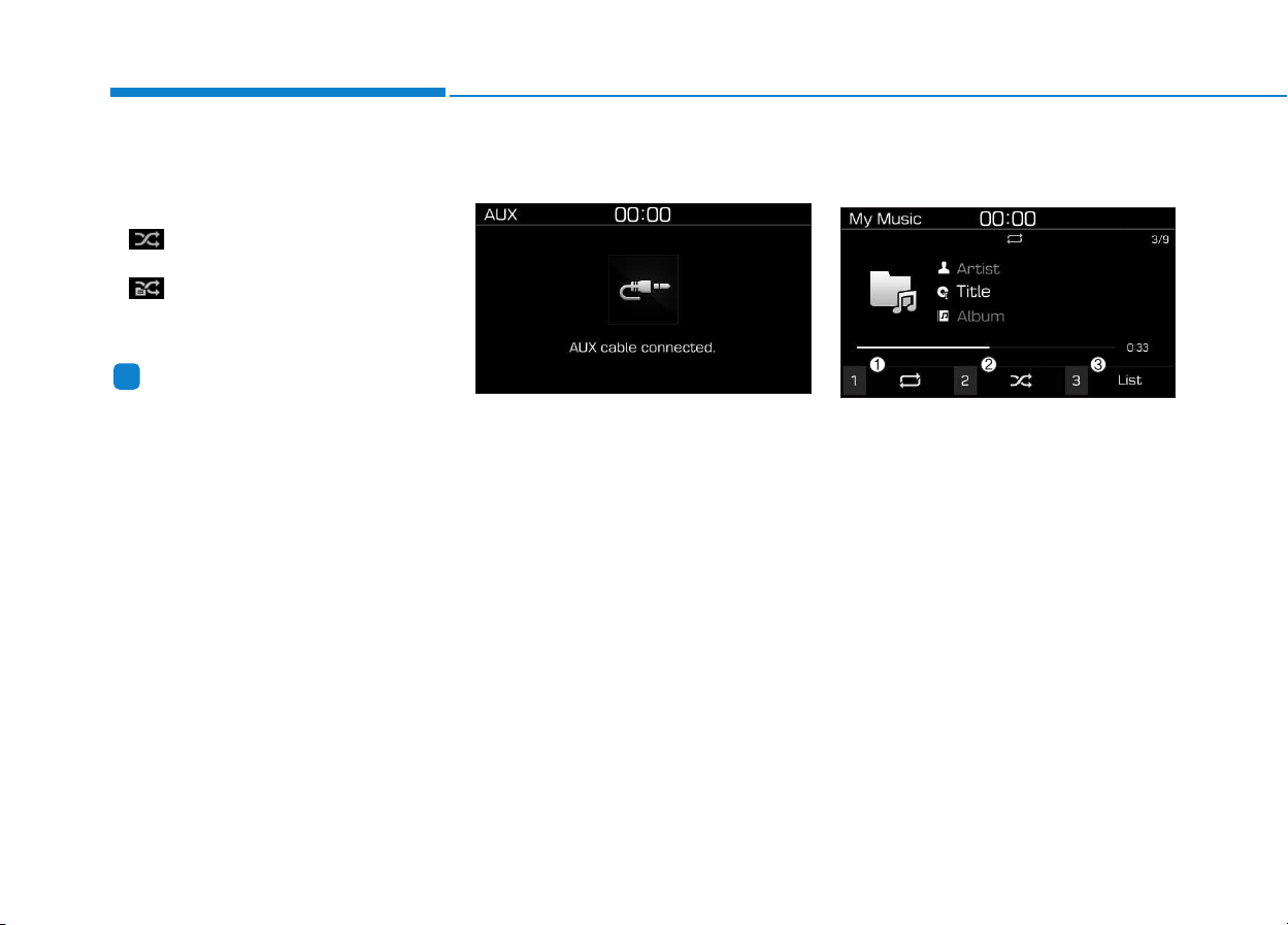
4-30
Multimedia System
Shuffle play
Select [Shuffle] to enable/disable
‘Shuffle’, ‘Shuffle category’ play.
• Shuffle: Songs are played in
random order.
• Shuffle category: Songs within
the current category are played in
random order.
Information
The shuffle function is engaged,
depending on the operation of the con-
nected Bluetooth
®
device.
Menu
Press the [MENU] button, and select
the desired function.
• Connections: The currently con-
nected Bluetooth
®
device can be
changed.
• Sound Settings: Audio sound set-
tings can be changed.
AUX
Running AUX
Press the [MEDIA] button, and
select [AUX].
• Connect the external device con-
nection jack to the AUX terminal to
run AUX.
Menu
Press the [MENU] button and select
the desired function.
• Sound Settings: Audio sound set-
tings can be changed.
My Music
(1) Repeat
Enable/disable repeat by pressing
button [1].
(2) Shuffle
Enable/disable shuffle play by press-
ing button [2].
(3) List
View a list of all songs by pressing
button [3].
i
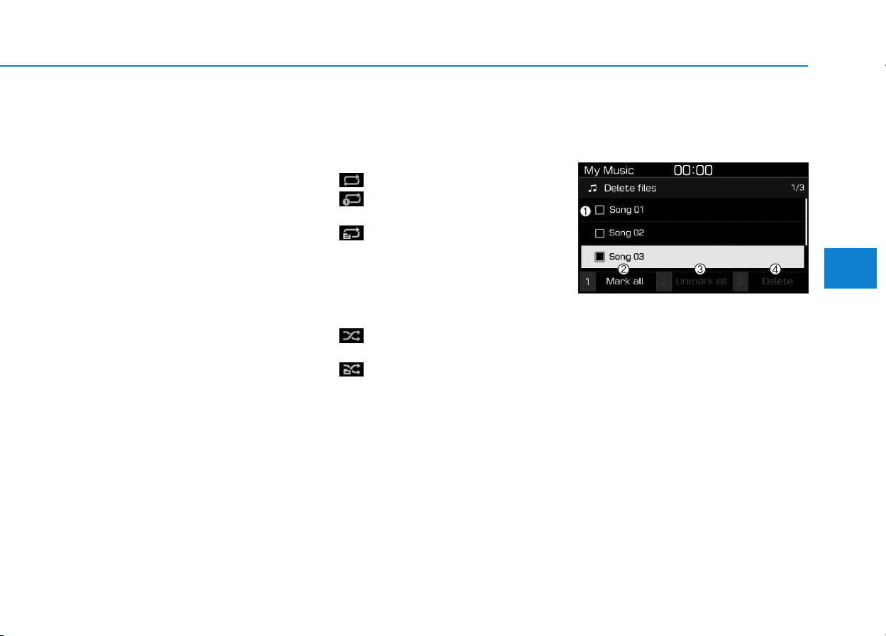
4-31
Multimedia System
4
Playback
Press the [MEDIA] button, and
select [My Music].
• My Music cannot be selected if it
does not contain music.
• Check the content of your USB
drive before saving music to My
Music.
Changing songs
Press the [SEEK/TRACK] button to
play the previous or next song.
• Press and hold the [SEEK/TRACK]
button to rewind or fast forward the
currently playing song.
• Search songs by turning the TUNE
knob and press the knob to play.
Selecting songs from a list
Select [List] to see a list of songs
available for play.
Select and play the desired song.
Repeat play
Select [Repeat] to enable or disable
‘Repeat all’, ‘Repeat current song’ or
‘Repeat category’.
• Repeat all: Repeat all songs.
• Repeat current song: The cur-
rently playing song is repeated.
• Repeat category: Repeat all
songs in the current category.
Shuffle play
Select [Shuffle] to enable/disable
‘Shuffle’, ‘Shuffle category’ play.
• Shuffle: Songs are played in
random order.
• Shuffle category: Songs within
the current category are played in
random order.
Menu
Press the [MENU] button, and select
the desired function.
• Delete files: You can delete files
from My Music.
(1) File: Select saved file by using
TUNE knob.
(2) Mark all: Select all files by press-
ing button [1].
(3) Unmark all: Deselect all files by
pressing button [2].
(4) Delete: Delete the selected file(s)
by pressing button [3].
- Select the file to delete, then
select [Delete] to delete it.
- Delete is canceled if voice recog-
nition is activated or phone calls
are received or made during
delete.

4-32
Multimedia System
• Add to Playlist: Frequently played
songs can be paired in a [Playlist].
- Songs can be played from the
[Playlist].
• Information: Detailed info on the
currently playing song is displayed.
• Sound Settings: Audio sound set-
tings can be changed.
Delete from playlist
When a song in the playlist is play-
ing, press the [MENU] button and
select [Delete from playlist].
Select the song to delete, then select
[Delete].
Phone (if equipped)
Information
- Using Bluetooth
®
(BT) Phone
• Bluetooth
®
is a near-field wireless
networking technology that uses the
2.4 GHz frequency to connect vari-
ous devices within a certain distance
wirelessly.
• The technology is used in PCs,
peripherals, Bluetooth
®
phones,
tablet PCs, household appliances
and automobiles. Devices support-
ing Bluetooth
®
can exchange data at
high speeds without physical cable
connections.
• Bluetooth
®
Handsfree devices
enable convenient access to phone
functions through cell phones
equipped with Bluetooth
®
.
• Some Bluetooth
®
devices may not be
supported by the Bluetooth
®
Handsfree function.
(Continued)
(Continued)
• When Bluetooth
®
is connected and
calls are attempted through a con-
nected cell phone from outside the
vehicle, the call is connected
through the Bluetooth
®
Handsfree
function of the vehicle.
• Please be sure to disconnect the
Bluetooth
®
Handsfree function
through your Bluetooth
®
device or
the audio screen.
• The Bluetooth
®
Handsfree function
helps drivers to drive safely. By con-
necting a Bluetooth
®
-enabled phone
to the vehicle’s audio system, phone
calls can be made and received
through the audio system and con-
tacts can be managed. Consult the
user manual before use.
• Excessive manipulation of controls
while driving, making it difficult to
pay attention to the road ahead, can
lead to accidents. Do not operate the
device excessively while driving.
• Looking at the screen for a pro-
longed time increases the risk of
accidents. Keep time spent looking
at the screen to a minimum.
i

4-33
Multimedia System
4
Precautions when connecting
Bluetooth
®
devices
• The vehicle supports the following
Bluetooth
®
functions. Some
Bluetooth
®
devices may not sup-
port some functions.
1) Bluetooth
®
Handsfree phone
calls
2) Operations during a call
(Private, Switch, Mic Vol. con-
trols)
3) Download call history saved to
the Bluetooth
®
device
4) Download contacts saved to the
Bluetooth
®
device
5) Automatic contacts/call history
download when Bluetooth
®
is
connected
6) Automatic Bluetooth
®
device
connection when the vehicle is
started
7) Bluetooth
®
audio streaming
playback
• Before connecting the audio sys-
tem to your device, make sure your
device supports Bluetooth
®
.
• Even if your device supports
Bluetooth
®
, a Bluetooth
®
connec-
tion cannot be established if the
device’s Bluetooth
®
function is
switched off. Search and connect
with the Bluetooth
®
function
enabled.
• Pair or connect Bluetooth
®
devices
to the audio system with the vehi-
cle at a standstill.
• If a Bluetooth
®
connection is lost
due to abnormal conditions while a
Bluetooth
®
device is connected
(communication range exceeded,
device power OFF, communication
errors, etc.), the disconnected
Bluetooth
®
device is searched for
and automatically reconnected.
• If you want to disable the
Bluetooth
®
device auto-connect
function, turn the Bluetooth
®
func-
tion OFF on your device. Consult
the user manuals for individual
devices to see whether Bluetooth
®
is supported.
• Handsfree call quality and volume
may vary depending on the type of
Bluetooth
®
device.
• Some Bluetooth
®
devices are sub-
ject to intermittent Bluetooth
®
con-
nection failures. In this case, use
the following method.
1) Turn the Bluetooth
®
function off
on your Bluetooth
®
device ➟
Turn it on and try again.
2) Delete the paired device from
both the audio system and
Bluetooth
®
device, then pair
again.
3) Power down your Bluetooth
®
device ➟ Turn it on and try
again.
4) Completely remove the battery
from your Bluetooth
®
device;
reinsert it, reboot, and attempt
connection.
5) Restart the vehicle and reat-
tempt connection.
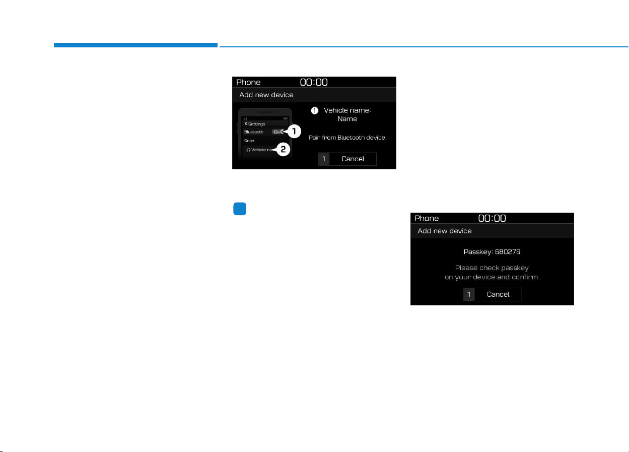
4-34
Multimedia System
Pairing a Bluetooth
®
device
Information on pairing Bluetooth
®
devices
• Pairing refers to the process of
pairing Bluetooth
®
cell phones or
devices with the system prior to
connection. This is a necessary
procedure for Bluetooth
®
connec-
tion and usage.
• Up to five devices can be paired.
• Pairing Bluetooth
®
device is not
allowed while vehicle is moving.
Pairing the first Bluetooth
®
device
Press the [PHONE] button on the
audio system or the [CALL] button
on the steering wheel remote control
➟ Search for the vehicle from the
Bluetooth
®
device, and pair ➟ Enter
the passkey on the Bluetooth
®
device or approve passkey ➟
Bluetooth
®
pairing completed.
1. When the [PHONE] button on the
audio or the [CALL] button on the
steering wheel remote control is
pressed, the following screen is
displayed. Devices can now be
paired.
(1) Vehicle name: Searched name in
Bluetooth
®
device.
Information
The vehicle name in the image above
is an example. Refer to your device for
the actual name of your device.
2. Search for available Bluetooth
®
devices in the Bluetooth
®
menu of
your Bluetooth
®
device (cell
phone, etc.).
3. Confirm that the vehicle name in
your Bluetooth
®
device matches
the vehicle name shown on the
audio screen, then select it.
4-1. For devices that require passkey
entry, a passkey entry screen is
shown on your Bluetooth
®
device.
- Enter the passkey ‘0000’, in your
Bluetooth
®
device.
4-2. For devices that require passkey
confirmation, the following
screen is shown on the audio
system. A 6-digit passkey input
screen is shown in the
Bluetooth
®
device.
- After confirming that the 6-digit
passkey on the audio screen
and the Bluetooth
®
device are
identical, select [OK] in your
Bluetooth
®
device.
i
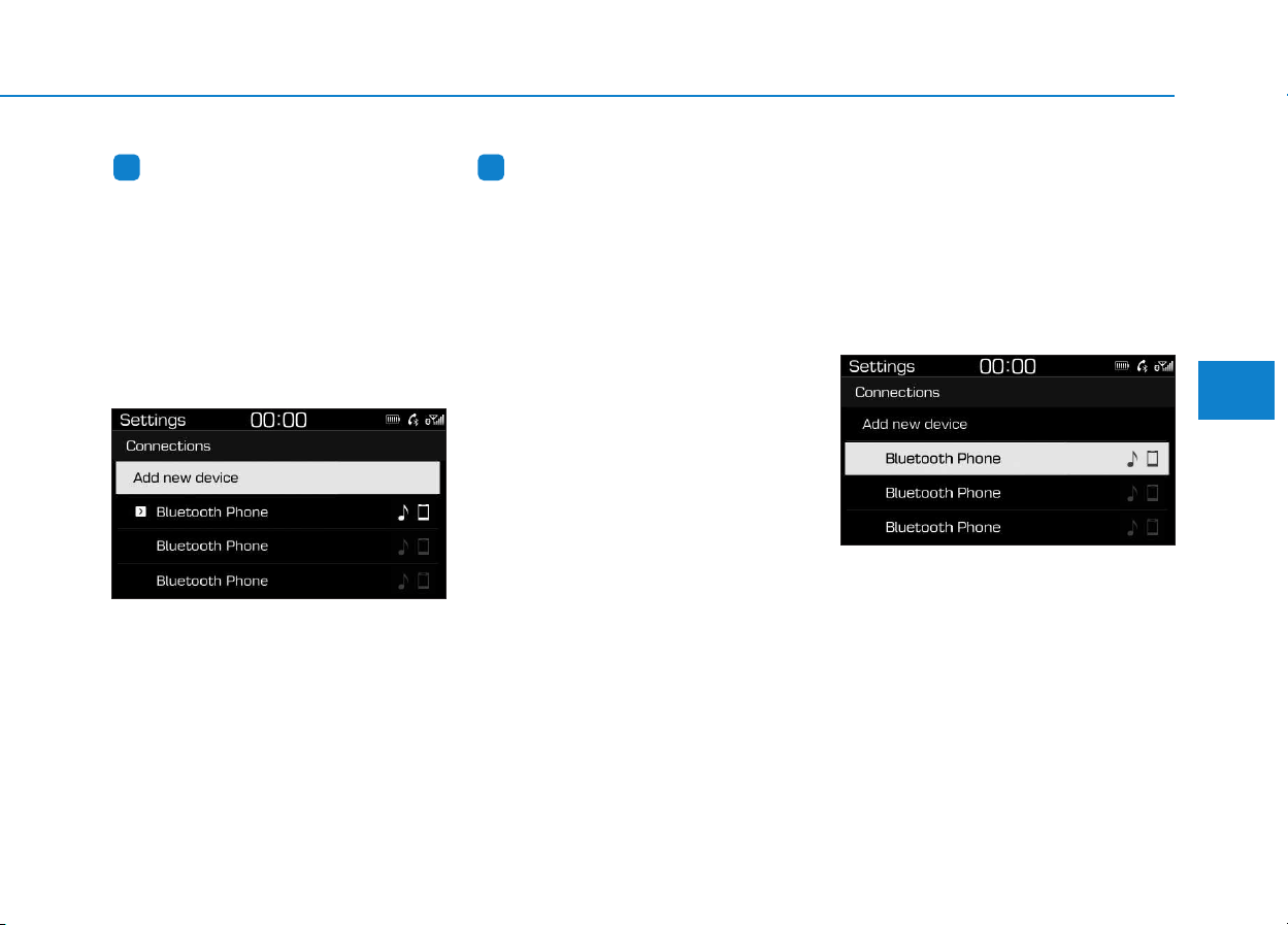
4-35
Multimedia System
4
Information
The 6-digit passkey in the image
above is an example. Refer to your
vehicle for the actual passkey.
Pairing a second Bluetooth
®
device
Press the [SETUP/CLOCK] button
on the audio system ➟ Select
[Bluetooth] ➟ Select [Connections]
➟ Select [Add new device].
- The pairing procedure from this
point is identical to [Pairing the first
Bluetooth device].
Information
• Bluetooth
®
standby mode lasts for
three minutes. If a device is not
paired within three minutes, pairing
is canceled. Start over from the
beginning.
• For most Bluetooth
®
devices, a con-
nection is established automatically
after pairing. Some devices, howev-
er, require separate confirmation
when connecting after pairing. Be
sure to check your Bluetooth
®
device after pairing to confirm that
it has connected.
Connecting Bluetooth
®
devices
If there are no connected devices
Press the [PHONE] button on the
audio system or the [CALL] button in
the steering wheel remote control ➟
List of paired Bluetooth
®
devices ➟
Select the desired Bluetooth
®
device
from the list ➟ Connect Bluetooth
®
.
ii
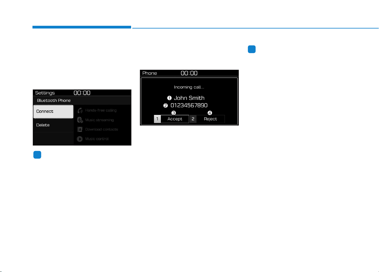
4-36
Multimedia System
If there are connected devices
Press the [PHONE] button on the
audio system ➟ Select [Settings] ➟
Select [Connections] ➟ Select
Bluetooth
®
device to connect ➟ Select
[Connect] ➟ Connect Bluetooth
®
.
Information
• Only one Bluetooth
®
device can be
connected at a time.
• When a Bluetooth
®
device is con-
nected, other devices cannot be
paired.
Accepting/rejecting phone calls
Receiving phone calls with
Bluetooth
®
connected.
(1) Caller name: If the caller number
is in your contacts, the correspon-
ding name is displayed.
(2) Incoming phone number: Incoming
phone number is displayed.
(3) Accept: Accept call.
(4) Reject: Reject call.
Information
• When the incoming call screen is
displayed, audio mode and the set-
tings screen cannot be shown. Only
call volume control is supported.
• Some Bluetooth
®
devices may not
support the call reject function.
• Some Bluetooth
®
devices may not
support the phone number display
function.
i
i
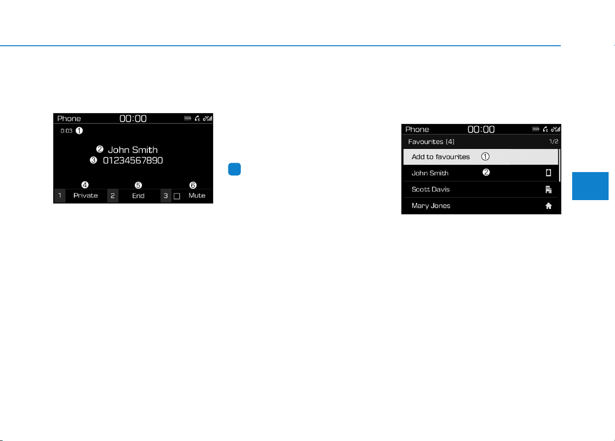
4-37
Multimedia System
4
Operation during calls
Incoming call with Bluetooth
®
con-
nected ➟ Select [Accept].
(1) Call duration: Call duration display.
(2) Caller name: If the caller number is
in your contacts, the corresponding
name is displayed.
(3) Incoming phone number: Incoming
phone number is displayed.
(4) Private: Call is transferred to a cell
phone.
(5) End: End call.
(6) Mute: Block outgoing voice.
Menu
Press the [MENU] button and select
the desired function.
• Switch: Switch between calls if
connected to two or more calls.
• Microphone Volume: Adjust outgo-
ing voice volume.
Information
• Some Bluetooth
®
devices may not
support the Private function.
• The outgoing voice volume may
vary depending on the type of
Bluetooth
®
device. If the outgoing
voice volume is too high or low,
adjust the Microphone Volume.
• The Switch menu will only be dis-
played if connected to two or more
calls.
Favourites
Press the [PHONE] button on the
audio system ➟ Select [Favourites] ➟
Favourites list displayed.
(1) Add to favourites: Add a down-
loaded phone number to
favorites.
(2) Favourites list: A list of paired
favorites is displayed
Connect a call when selected.
Menu
Press the [MENU] button, and select
the desired function.
• Delete: Delete a saved favorites.
i
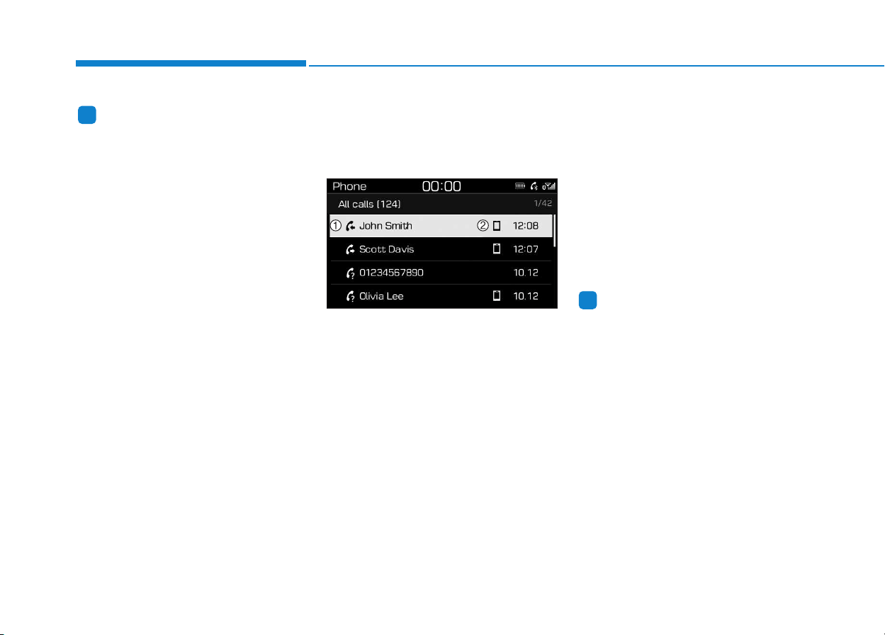
Information
• Up to 20 favourites can be paired
for each paired Bluetooth
®
device.
• Favourites can be accessed when the
Bluetooth
®
device they were paired
from is connected.
• The audio system does not down-
load favourites from Bluetooth
®
devices. Favourites must be newly
saved before use.
• To add to favourites, contacts must
be downloaded first.
• Saved favourites are not updated
even if the contacts of the connected
Bluetooth
®
device are changed. In
this case, favourites need to be delet-
ed and added again.
Call history
Press the [PHONE] button on the
audio system ➟ Select [Call history]
➟ Call history is displayed.
(1) Call history: Display the down-
loaded call history list.
Connect a call when selected.
(2) Call duration: Display the time the
call was connected.
Menu
Press the [MENU] button, and select
the desired function.
• All Calls: Display all call history.
• Missed Calls: Display missed calls.
• Dialed Calls: Display dialed calls.
• Received Calls: Display received
calls.
• Download: Download call history
from connected Bluetooth
®
devices.
Information
• Up to 50 dialed, received and missed
calls are saved.
• When the latest call history is
received, the existing call history is
deleted.
i
i
4-38
Multimedia System
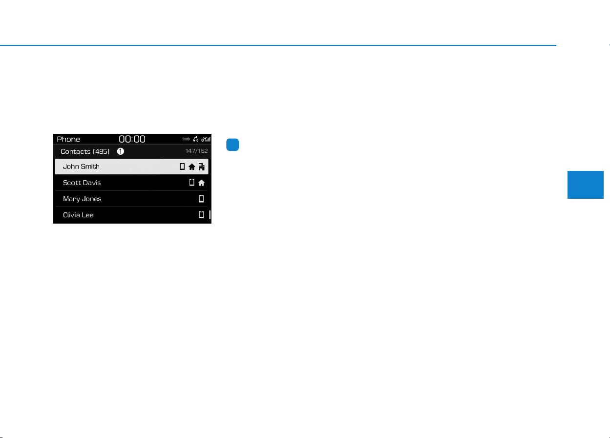
Contacts
Press the [PHONE] button on the
audio system ➟ Select [Contacts] ➟
Select letter (ABC) ➟ Contacts dis-
played.
(1) Contacts: Display downloaded
contacts.
If one phone number is saved, the
number will be dialed when
selected.
If two or more phone numbers are
saved, a list of saved numbers will
be displayed when selected.
Menu
Press the [MENU] button, and select
the desired function.
• Download: Download contacts
from connected Bluetooth
®
devices.
Information
• Up to 2,000 contacts can be saved.
• In some cases, additional confirma-
tion from your Bluetooth
®
device is
necessary when downloading con-
tacts. If downloading of contacts
unsuccessful, consult your
Bluetooth
®
device’s settings or the
audio screen to approve the down-
load.
• Contacts without phone numbers
are not displayed.
Settings
Press the [PHONE] button on the
audio ➟ Select [Settings].
- For phone settings, refer to Setup
page.
i
4-39
Multimedia System
4
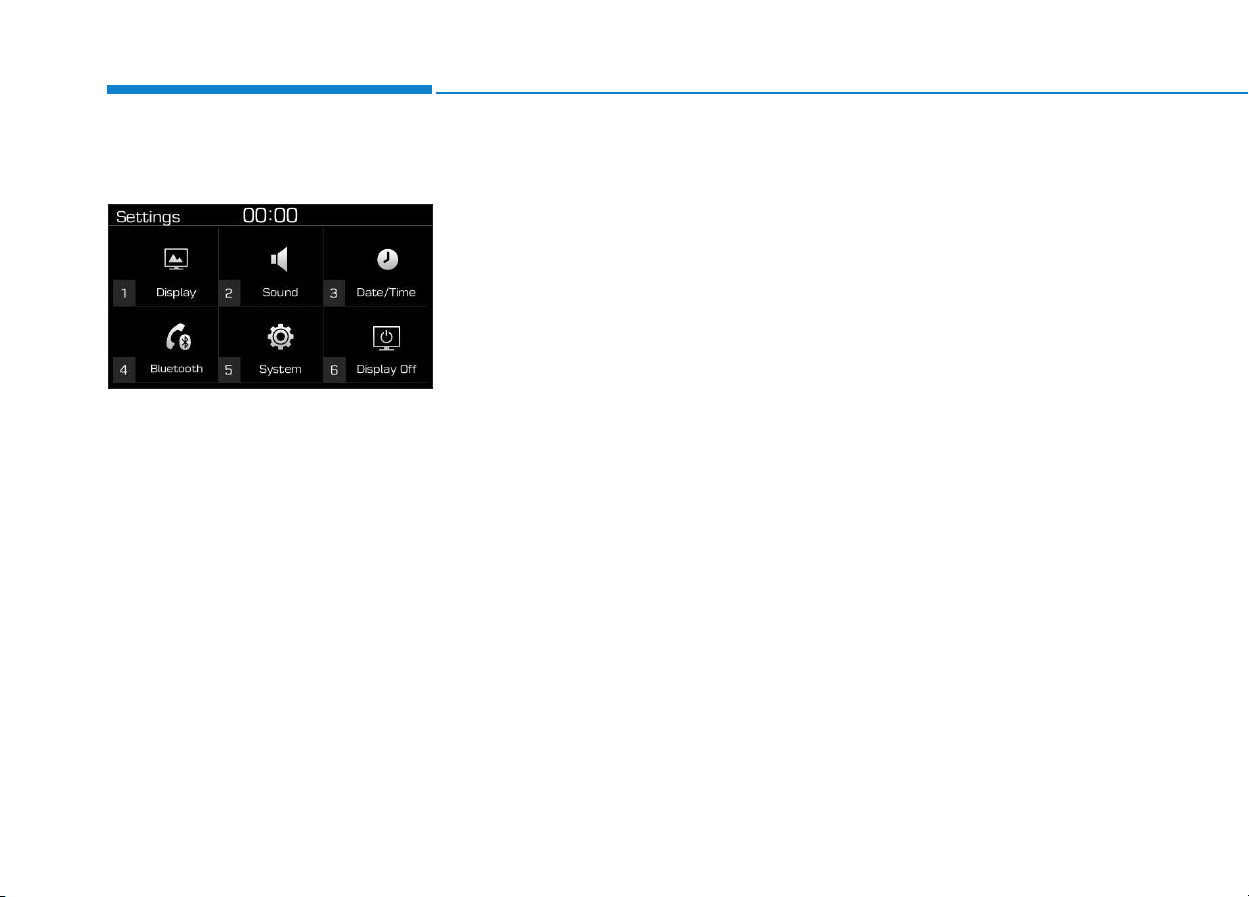
4-40
Multimedia System
Setup
Access Display, Sound, Date/Time,
Bluetooth*, System and Display Off
settings.
Press the [SETUP/CLOCK] button
on the audio system.
* if equipped
Display
Press the [SETUP/CLOCK] button
on the audio system ➟ Select
[Display].
• Dimming mode: Audio screen
brightness can be adjusted to the
time of day.
• Brightness: The brightness of the
audio screen can be changed.
• Screensaver: Set the information
displayed when the audio system
is switched off or the screen is
turned off.
Sound
Press the [SETUP/CLOCK] button
on the audio system ➟ Select
[Sound].
• Position: Sound balance and pan-
ning can be adjusted.
• Equaliser: Sound tone color can be
adjusted.
• Rear parking sensors prioritised:
Automatically lower audio volume
while reversing.
• Speed dependent volume control:
Automatically adjust volume based
on vehicle speed.
Date/Time
Press the [SETUP/CLOCK] button
on the audio system ➟ Select
[Date/Time].
• Set time: Set the time displayed on
the audio screen.
• Time format: Choose between 12-
hour and 24-hour time formats.
• Set date: Set the date displayed on
the audio screen.
Bluetooth (if equipped)
Press the [SETUP/CLOCK] button
➟ Select [Bluetooth].
• Connections: Control pairing, dele-
tion, connection and disconnection
of Bluetooth
®
devices.
• Auto connection priority: Set the
connection priority of Bluetooth
®
devices when the vehicle is started.
• Update contacts: Contacts can be
downloaded from connected
Bluetooth
®
devices.
• Bluetooth voice guidance: Play or
mute voice prompts for Bluetooth
®
device pairing, connection and
errors.

4-41
Multimedia System
4
Information
• When paired devices are deleted,
the call history and contacts of the
device saved to the audio system are
deleted.
• For Bluetooth
®
connections with
low connection priority, some time
may be required for the connection
to be established.
• Contacts can be downloaded only
from the currently connected
Bluetooth
®
device.
• If no Bluetooth
®
device is connected,
the Download Contacts button is
disabled.
• If the language setting is Slovakian,
Hungarian or Korean, Bluetooth
voice guidance is not supported.
System
Press the [SETUP/CLOCK] button
on the audio system ➟ Select
[System].
• Memory information: View My
Music memory usage.
• Language: Change the user lan-
guage.
• Default: Reset the audio system.
Information
The system resets to the default val-
ues, and all saved data and settings
are lost.
Display Off
To prevent glare, the screen can be
turned off with the audio system in
operation.
Press the [SETUP/CLOCK] button
on the audio system ➟ Select
[Display Off].
Information
Use ‘Screensaver’ to set the informa-
tion to be displayed when the screen is
turned off.
i
i
i
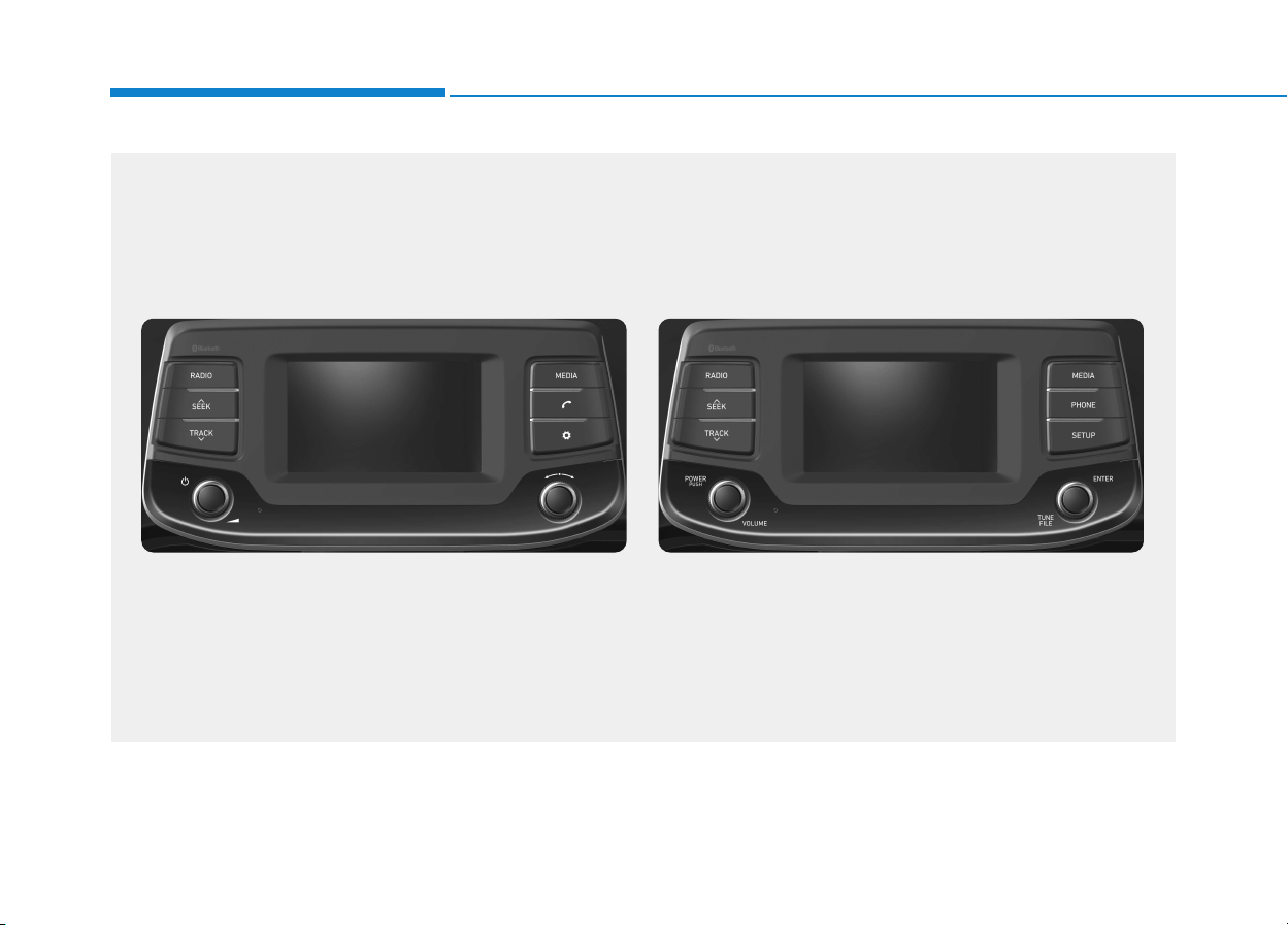
4-42
Multimedia System
■ Type B-1
■ Type B-2
AAUUDDIIOO ((WWiitthh TToouucchh SSccrreeeenn))
G4H4G0000EE/G4H4G0001EE
(With
Bluetooth
®
Wireless Technology)

4-43
Multimedia System
4
Feature of Your Audio
Head unit
❈ The actual features in the vehicle
may differ from the illustration.
(1) LCD screen
• Tap the screen to select a button.
(2) RADIO
• Start DAB/FM* and AM radio.
* with DAB
(3) SEEK/TRACK
• Search for next station in DAB/FM*
and AM radio mode.
• Change the current song in media
mode.
* with DAB
(4) POWER/VOLUME knob
• Turn to adjust the volume.
• Press to turn the device on or off.
(5) RESET
• Shutdown and restart the system.
■ Type B-2
■ Type B-1
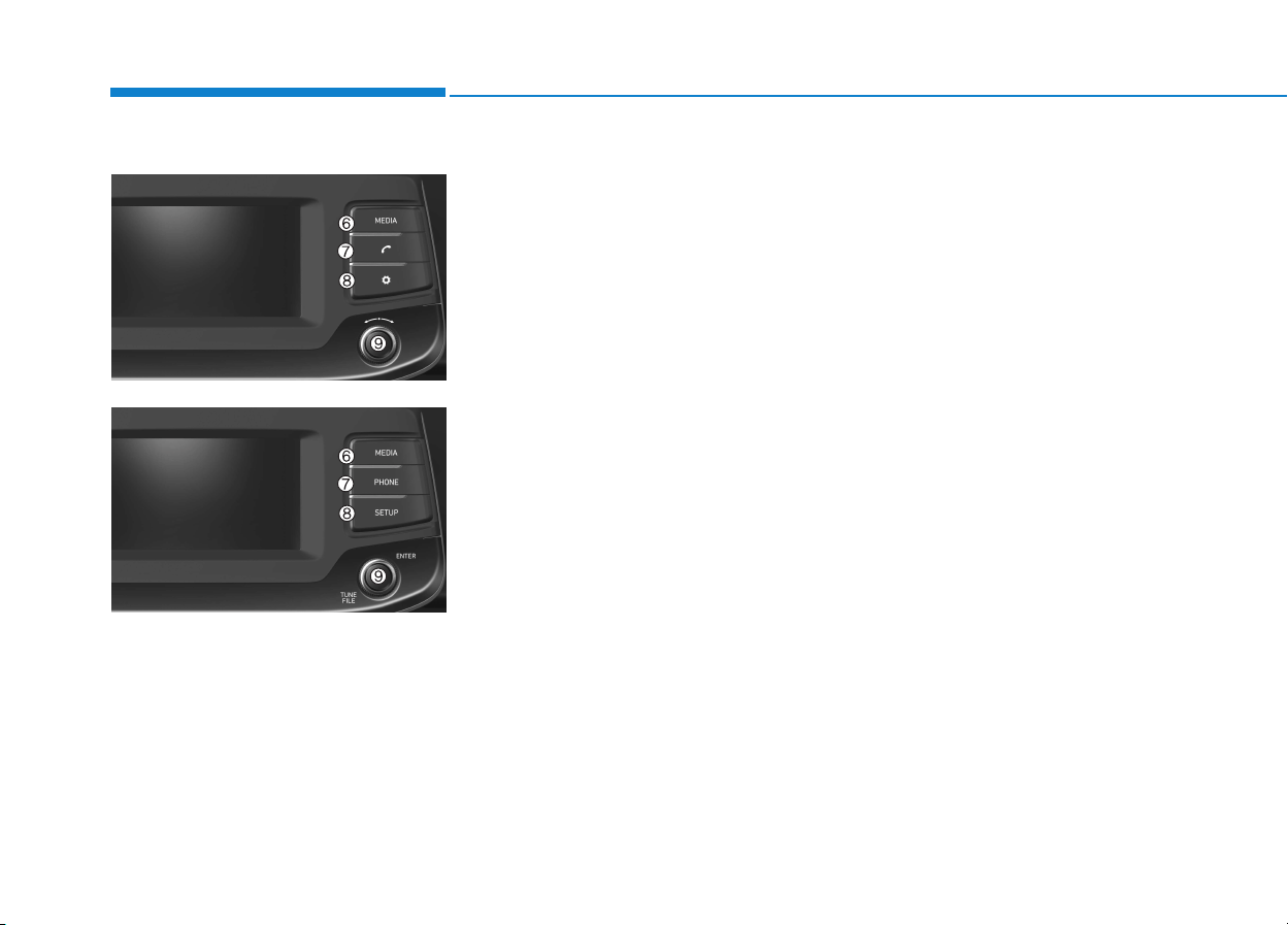
4-44
Multimedia System
(6) MEDIA
• Select USB(iPod
®
), Bluetooth
®
(BT)
Audio, AUX or My Music.
• Display the media menu when two
or more media are connected or
when the [MEDIA] button is
pressed in media mode.
(7) PHONE
• Start Bluetooth
®
Phone mode.
(8) SETUP
• Access Display, Sound, Date/Time,
Bluetooth, System, Screensaver
and Display Off settings.
(9) TUNE knob
• Turn to navigate through the sta-
tions/songs list.
• Press to select an item.
■ Type B-2
■ Type B-1
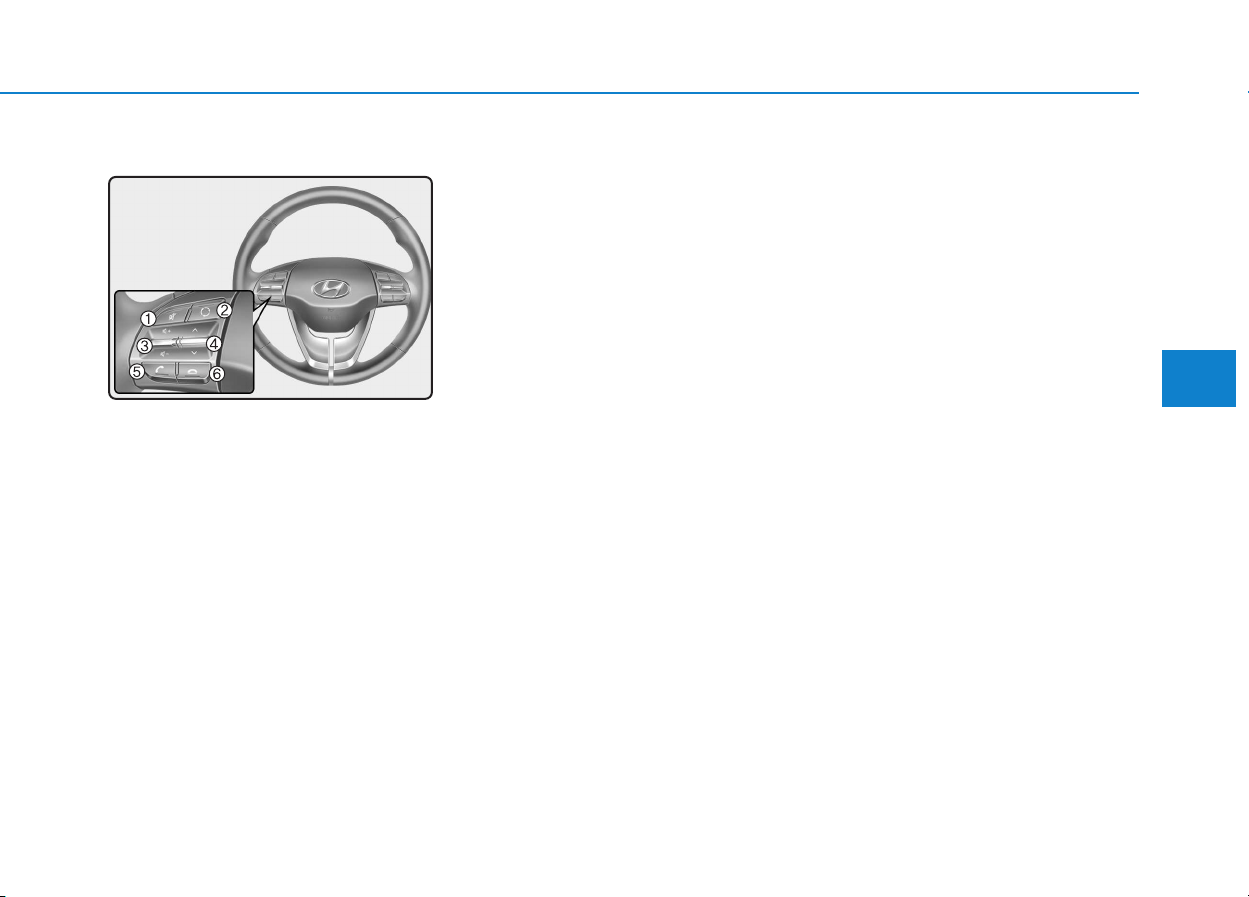
4-45
Multimedia System
4
Steering wheel remote control
❈ The actual features in the may dif-
fer from the illustration.
(1) MUTE
• Press to mute audio output.
(2) MODE
• Press the button to change the
mode in the following order: Radio
➟ Media.
• Press and hold the button to turn
off. (if equipped)
(3) VOLUME
• Press to adjust the volume.
(4) UP/DOWN
• Press the button in radio mode to
search Presets.
• Press and hold the button in radio
mode to search frequencies.
• Press the button in media mode to
change the current song.
• Press and hold the button in media
mode to quick search through
songs.
(5) CALL
• Pressing the button
- If not in Bluetooth
®
Handsfree
mode or receiving a phone call.
First press: Display Dial Number
screen.
Second press: Automatically dis-
play the most recently Dialed
Call number.
Third press: Dial the phone num-
ber entered.
- Press in the Incoming Call notifi-
cation screen to accept the
phone call.
- Press in Bluetooth
®
Handsfree
mode to switch to the waiting call.
• Pressing and holding the button
- If not in Bluetooth
®
Handsfree
mode or receiving a phone call,
the most recently Dialed Call
number is dialed.
- Press in Bluetooth
®
Handsfree
mode to transfer the call to your
cell phone.
- Press in cell phone mode to
switch to Bluetooth
®
Handsfree
mode.
(6) END
• Press in Bluetooth
®
Handsfree
mode to end the phone call.
• Press in the incoming call screen
to reject the call.

4-46
Multimedia System
• Do not stare at the screen
while driving. Staring at the
screen for prolonged periods
of time could lead to traffic
accidents.
• Do not disassemble, assem-
ble, or modify the audio sys-
tem. Such acts could result in
accidents, fire, or electric
shock.
• Using the phone while driving
may lead to a lack of attention
of traffic conditions and
increase the likelihood of
accidents. Use the phone fea-
ture after parking the vehicle.
• Heed caution not to spill water
or introduce foreign objects
into the device. Such acts
could lead to smoke, fire, or
product malfunction.
(Continued)
WARNING
(Continued)
• Please refrain from use if the
screen is blank or no sound
can be heard as these signs
may indicate product malfunc-
tion. Continued use in such
conditions could lead to acci-
dents (fires, electric shock) or
product malfunctions.
• Do not touch the antenna dur-
ing thunder or lightening as
such acts may lead to light-
ning induced electric shock.
• Do not stop or park in park-
ing-restricted areas to operate
the product. Such acts could
lead to traffic accidents.
• Use the system with the vehi-
cle ignition turned on.
Prolonged use with the igni-
tion turned off could result in
battery discharge.
Driving while distracted can
result in a loss of vehicle con-
trol that may lead to an acci-
dent, severe personal injury,
and death. The driver’s primary
responsibility is in the safe and
legal operation of a vehicle, and
use of any handheld devices,
other equipment, or vehicle sys-
tems which take the driver’s
eyes, attention and focus away
from the safe operation of a
vehicle or which are not permis-
sible by law should never be
used during operation of the
vehicle.
WARNING

4-47
Multimedia System
4
• Operating the device while driv-
ing could lead to accidents due
to a lack of attention to external
surroundings. First park the
vehicle before operating the
device.
• Adjust the volume to levels that
allow the driver to hear sounds
from outside of the vehicle.
Driving in a state where external
sounds cannot be heard may
lead to accidents.
• Pay attention to the volume set-
ting when turning the device on.
A sudden output of extreme vol-
ume upon turning the device on
could lead to hearing impair-
ment. (Adjust the volume to a
suitable levels before turning off
the device.)
• If you want to change the posi-
tion of device installation,
please inquire with your place of
purchase or service mainte-
nance center. Technical expert-
ise is required to install or dis-
assemble the device.
(Continued)
(Continued)
• Turn on the car ignition before
using this device. Do not oper-
ate the audio system for long
periods of time with the ignition
turned off as such operations
may lead to battery discharge.
• Do not subject the device to
severe shock or impact. Direct
pressure onto the front side of
the monitor may cause damage
to the LCD or touch screen.
• When cleaning the device, make
sure to turn off the device and
use a dry and smooth cloth.
Never use tough materials,
chemical cloths, or solvents
(alcohol, benzene, thinners,
etc.). As such materials may
damage the device panel or
cause color/quality deterioration
• Do not place beverages close to
the audio system. Spilling bever-
ages may lead to system mal-
function.
(Continued)
(Continued)
• In case of product malfunction,
please contact your place of pur-
chase or After Service center.
• Placing the audio system within
an electromagnetic environment
may result in noise interference.
NOTICE
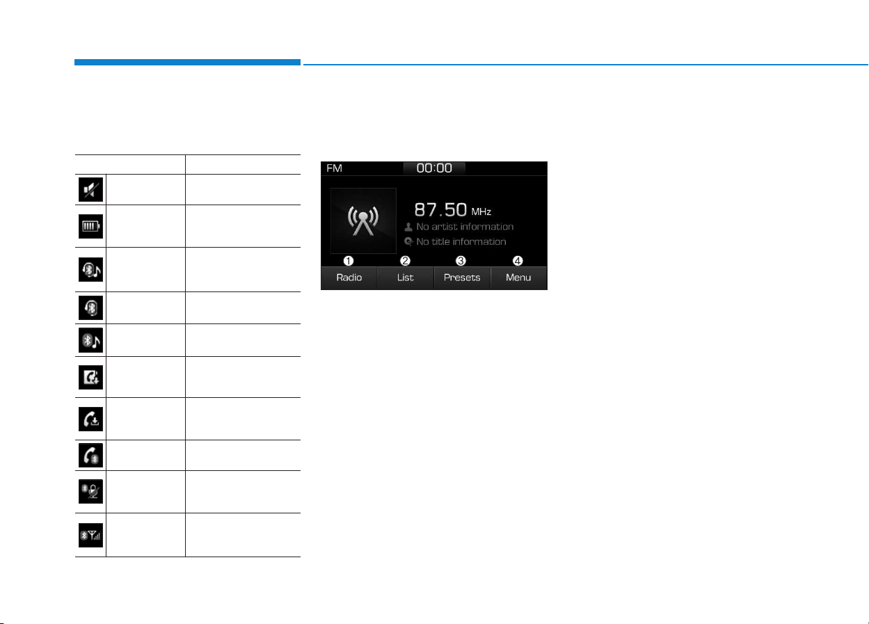
4-48
Multimedia System
Information on status icons
Icons showing audio status are shown
in the upper-right corner of the screen.
Radio
FM/AM (with RDS)
(1) Radio
Switch between FM and AM.
(2) List
View all available stations.
(3) Presets
View all presets.
(4) Menu
Navigate to the menu screen.
Switching between FM and AM
• Press the [RADIO] button on the
audio system to switch between
FM and AM.
• Select [Radio] on the screen to
switch between FM and AM.
Searching stations
Press the [SEEK/TRACK] button to
search stations.
List
A list of all available stations in the
vehicle’s current location is dis-
played. Select the desired station.
Favourite stations can be saved to
[Presets] by selecting [+].
Icon Description
Mute Mute engaged
Battery
Remaining battery life of
a connected Bluetooth
®
device
Handsfree +
Audio stream-
ing connection
Bluetooth
®
Handsfree
call and audio stream-
ing available
Handsfree
connection
Bluetooth
®
Handsfree
call available
Bluetaooth
®
audio streaming
Bluetooth
®
audio
streaming available
Downloading
contacts
Downloading contacts
through Bluetooth
®
wire-
less communications
Downloading
call history
Downloading call history
through Bluetooth
®
wire-
less communications
Line busy Phone call in progress
Mute mic
Mic muted during a
call (caller cannot
hear your voice)
Phone signal
strength
Display the phone signal
strength for a cell phone
connected by Bluetooth
®
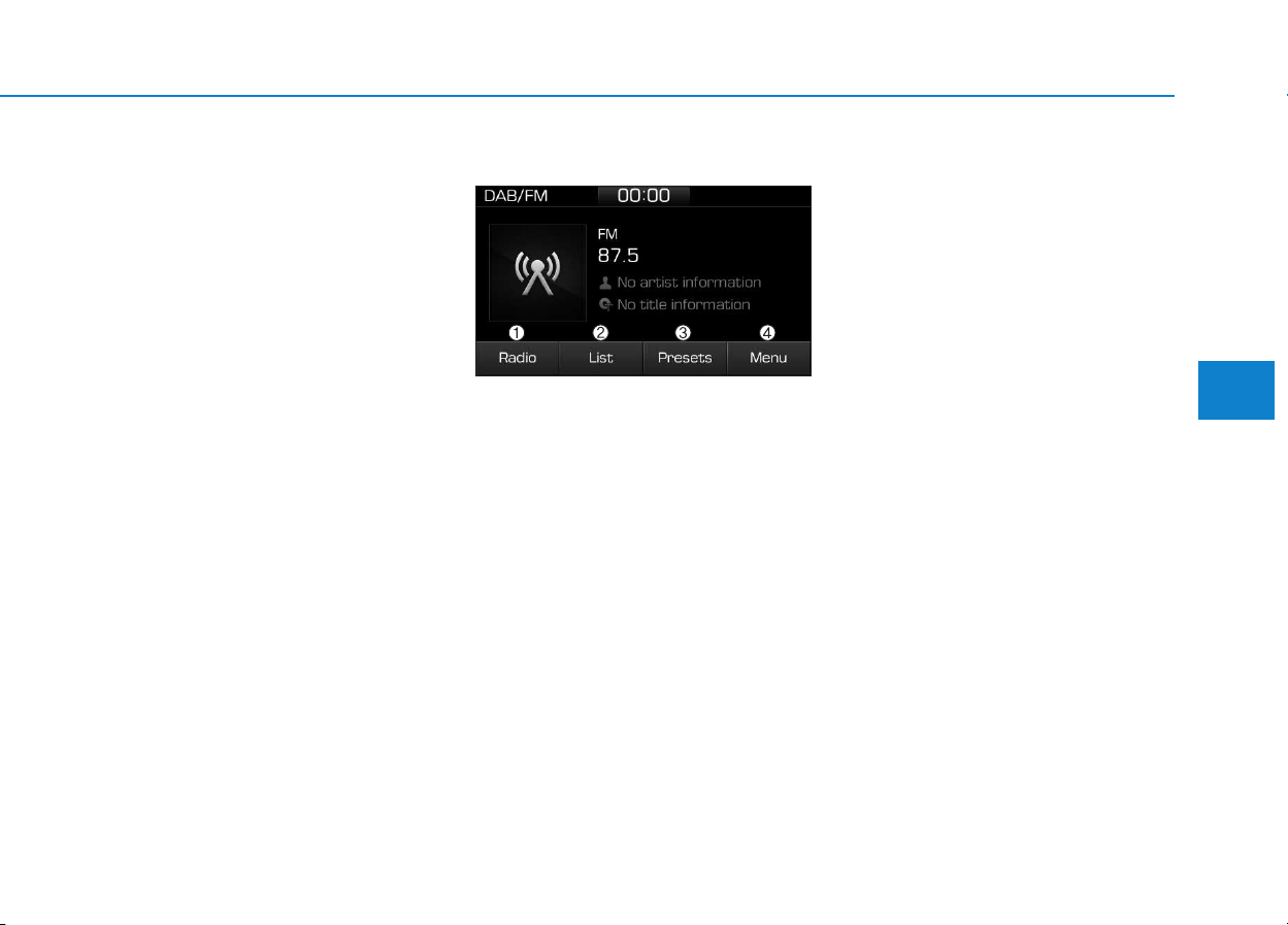
4-49
Multimedia System
4
Presets
Save up to 40 frequently used stations.
To listen to a preset, select the
desired station list.
Press and hold the desired slot from
1 through 40. This saves the current
station in the selected slot.
If the slot is empty, simply selecting
saves the station to the slot.
Menu
Select [Menu], and select the desired
function.
• Traffic Announcement (TA): Enable
or disable Traffic Announcements.
• Scan: All available stations are
played for five seconds each.
• Sound Settings: Audio sound set-
tings can be changed.
DAB/FM (with DAB)
(1) Radio
Switch between DAB/FM and AM.
(2) List
View all available stations.
(3) Presets
View all presets.
(4) Menu
Navigate to the menu screen.
Switching between DAB/FM and AM
• Press the [RADIO] button on the
audio system to switch between
DAB/FM and AM.
• Select [Radio] on the screen to
switch between DAB/FM and AM.
Searching stations
Press the [SEEK/TRACK] button to
search stations.
List
A list of all available stations in the
vehicle’s current location is dis-
played. Select the desired station.
Favourite stations can be saved to
[Presets] by selecting [+].
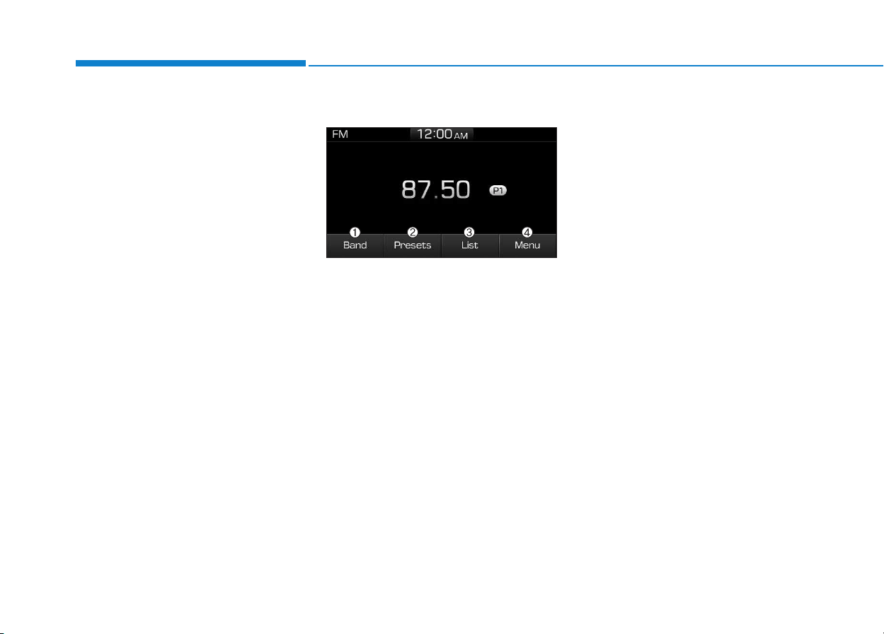
4-50
Multimedia System
Presets
Save up to 40 frequently used stations.
To listen to a preset, select the
desired station list.
Press and hold the desired slot from
1 through 40. This saves the current
station in the selected slot.
If the slot is empty, simply selecting
saves the station to the slot.
Menu
Select [Menu], and select the desired
function.
• Traffic Announcement (TA): Enable
or disable Traffic Announcements.
• Region : Enable or disable auto-
matic switching between regional
stations.
• Scan: All available stations are
played for five seconds each.
• Sound Settings: Audio sound set-
tings can be changed.
• Manual tune FM : Search for fre-
quencies manually.
FM/AM (without RDS)
(1) Band
Switch between FM and AM.
(2) Presets
View all presets.
(3) List
View all available stations.
(4) Menu
Navigate to the menu screen.
Switching between FM and AM
• Press the [RADIO] button on the
audio system to switch between
FM and AM.
• Select [Band] on the screen to
switch between FM and AM.
Searching stations
Press the [SEEK/TRACK] button to
search stations.
List
A list of all available stations in the
vehicle’s current location is dis-
played. Press the desired station.
Favourite stations can be saved to
[Presets] by selecting [save].
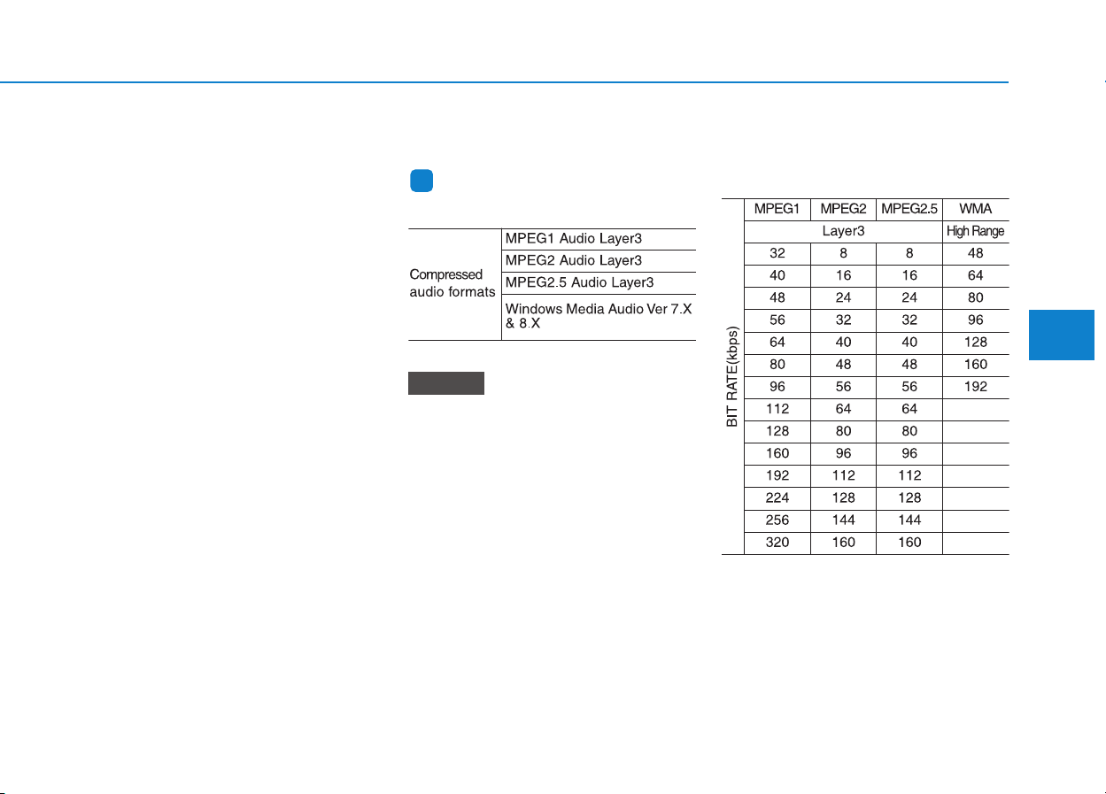
4-51
Multimedia System
4
Presets
Save up to 40 frequently used stations.
To listen to a preset, Select the
desired station list.
Press and hold the desired slot from
1 through 40. This saves the current
station in the selected slot.
If the slot is empty, simply selecting
saves the station to the slot.
Menu
Select [Menu], and select the desired
function.
• Scan: All available stations are
played for five seconds each.
• Sound Settings: Audio sound set-
tings can be changed.
Media
Information
- Using MP3
Supported audio formats
File formats other than the formats
above may not be recognized or
playable. Information such as file-
name may not be displayed.
Range of supported compressed file
types
1. Bitrate range (Kbps)
NOTICE
i
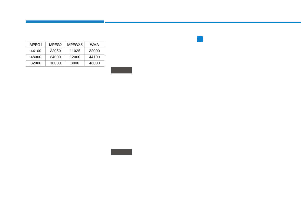
4-52
Multimedia System
2. Sampling frequency (Hz)
• The sound quality of MP3/WMA
compressed files may vary depend-
ing on the bitrate. (A higher bitrate
can have better sound quality.)
• The product only recognizes files
with the MP3 or WMA extension.
Files without one of these exten-
sions are not recognized.
3. Number of recognizable folders
and files
• Folders: 2,000 for USB
• Files: 6,000 for USB
• No recognition limit for folder hier-
archies.
4. Character display range (Unicode)
• Filenames: Up to 64 English char-
acters (64 Korean characters)
• Foldernames: Up to 32 English
characters (32 Korean characters)
The scroll feature can be used to
display file and folder names that
are too long to display on the screen.
(if equipped)
Languages supported (Unicode sup-
port)
• Korean: 2,604 characters
• English: 94 characters
• Common Chinese characters:
4,888 characters
• Special symbols: 986 characters
Japanese/Simplified Chinese char-
acters are not supported.
Information
- Using the USB Devices
• Starting the vehicle while a USB
device is connected can damage the
device. Please disconnect USB
devices before starting the vehicle.
• Starting the vehicle or stopping the
engine while an external USB device
is connected can result in failure of
the external USB device to operate.
• Be cautious of static electricity when
connecting/disconnecting external
USB devices.
• An encrypted MP3 player is not rec-
ognized when connected as an exter-
nal device.
• External USB devices may not be
recognized, depending on the state
of the external USB device.
• Only products with byte/sectors for-
matted at 4 KB or lower are recog-
nized.
• Only USB devices in FAT12/16/32
format are recognized; NTFS and
ExFAT file systems are not recog-
nized.
(Continued)
i
NOTICE
NOTICE

4-53
Multimedia System
4
(Continued)
• Some USB devices are not recog-
nized due to compatibility issues.
• Do not touch the USB connections.
• Connecting and disconnecting USB
devices rapidly over a short period
of time can cause equipment failure.
• Abnormal sounds may be audible
when the USB device is disconnected.
• Turn the audio off before connecting
or disconnecting external USB
devices.
• Recognition may take longer
depending on the type, capacity or
file format of the external USB
device. This is not a product mal-
function.
• Use of USB devices for purposes
other than playing music files is pro-
hibited.
• Image display and video playback
are not supported.
(Continued)
(Continued)
• Use of USB accessories, including
charge and heat though the USB I/F,
can lead to reduced product per-
formance or malfunctions. Do not
use USB devices or accessories for
these purposes.
• Use of aftermarket USB hubs and
extension cables can result in the
vehicle’s audio system failing to rec-
ognize your USB device. Connect
the USB device directly to the multi-
media port of your vehicle.
• When using high-capacity USB
devices with logical drive divisions,
only files saved on the highest level
logical drive can be played.
If applications are loaded on a USB
drive, file playback may fail.
• Some MP3 players, cell phones, dig-
ital cameras, etc. (USB devices that
are not recognized as mobile stor-
age) may not operate normally
when connected.
• USB charging may not be supported
by some mobile devices.
(Continued)
(Continued)
• Operation is guaranteed only for
standard (Metal Cover Type) USB
Memory drives.
• Operation of HDD, CF, SD and mem-
ory stick devices is not guaranteed.
• DRM (Digital Rights Management)
files cannot be played.
• SD-type USB memory, CF-type
USB memory, and other USB mem-
ory devices that require adapters
for connection are not supported.
• Proper operation of USB HDDs or
USB drives with connectors that
loosen due to vehicle vibrations is
not guaranteed. (iStick, etc.)
• USB products that are
used as key chains or
cell phone accessories
may damage the USB
jack and affect proper
file playback. Please refrain from
use. Use only products with plug
connectors, as shown in the follow-
ing illustration.
• When MP3 devices or cell phones are
connected simultaneously through
AUX, BT Audio and USB modes, a
popping noise or malfunction may
occur.
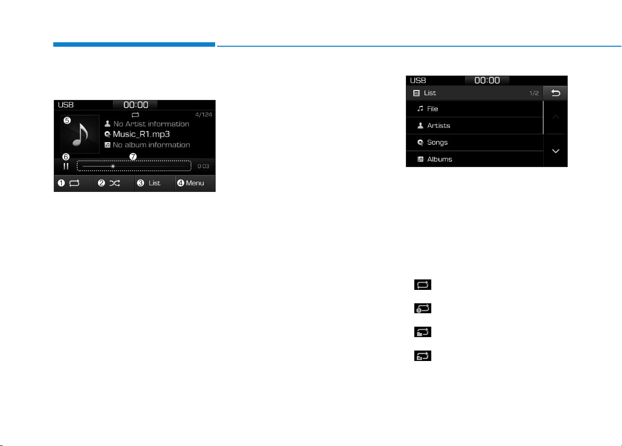
4-54
Multimedia System
USB
(1) Repeat
Enable/disable repeat.
(2) Shuffle
Enable/disable shuffle play.
(3) List
View a list of all songs.
(4) Menu
Navigate to the menu screen.
(5) Album Image
View song info.
(6) Pause
Pause or play music.
(7) Playback progress
Select to skip to the desired location.
Playback
• Press the [MEDIA] button, and
select [USB].
• Connect a USB drive to the USB
port to automatically play files on
the USB drive.
Changing songs
• Press the [SEEK/TRACK] button
to play the previous or next song.
• Press and hold the [SEEK/TRACK]
button to rewind or fast forward the
currently playing song.
• Search songs by turning TUNE
knob, and press the knob to play.
Selecting songs from a list
Select [List] to see a list of songs
available for play.
Select and play the desired song.
Repeat play
Select [Repeat] to enable or disable
‘Repeat all’, ‘Repeat current song’,
‘Repeat folder’ or ‘Repeat category’.
• Repeat all: All songs in the
playlist are repeated.
• Repeat current song: The cur-
rently playing song is repeated.
• Repeat folder: All songs in the
current folder are repeated.
• Repeat category: Repeat all
songs in the current category.
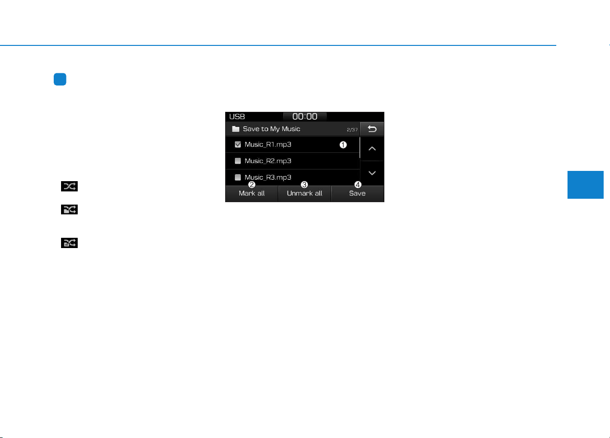
4-55
Multimedia System
4
Information
The repeat folder function is available
only when songs are playing from the
[File] category under [List].
Shuffle play
Select [Shuffle] to enable/disable
‘Shuffle’, ‘Shuffle folder’ or ‘Shuffle
category’ play.
• Shuffle: Songs are played in
random order.
• Shuffle folder: Songs within
the current folder are played in ran-
dom order
• Shuffle category: Songs within
the current category are played in
random order.
Menu
Select [Menu], and select the desired
function.
• Save to My Music: Songs on your
USB device can be saved to My
Music.
(1) File: Select a file to save.
(2) Mark all: Select all files.
(3) Unmark all: Deselect all files.
(4) Save: Save the selected file(s).
- Select the files you want to save,
and select [Save]. This saves the
selected files to My Music.
- Saving is canceled if phone calls
are received or made while saving.
- Up to 6,000 files can be saved.
- The currently playing file on the
USB device cannot be changed
while saving.
- My Music cannot be used while
saving.
- Up to 700 MB can be saved.
• Information: Detailed information
on the currently playing song is dis-
played.
• Sound Settings: Audio sound set-
tings can be changed.
i

4-56
Multimedia System
Information
- Using the iPod
®
Devices
• To use the audio system’s iPod
®
con-
trol function, use the dedicated
cable provided with your iPod
®
.
• Connecting the iPod
®
to the vehicle
during play may result in a loud
noise that lasts about one to two sec-
onds. Connect the iPod
®
to the vehi-
cle after stopping or pausing play.
• Connect the iPod
®
with the vehicle in
the ACC ON state to begin charging.
• When connecting the iPod
®
cable,
be sure to fully push the cable into
the port.
• When EQ effects are enabled simul-
taneously on external devices, such
as iPod
®
s and the audio system, the
EQ effects may overlap, causing
sound quality deterioration or dis-
tortion. Deactivate the EQ function
for all external devices, if possible.
• Noise may occur when your iPod
®
or the AUX port is connected.
Disconnect and store separately
when not in use.
(Continued)
(Continued)
• There may be noise if the audio sys-
tem is used with an iPod
®
or AUX
external device connected to the
power jack. In these cases, discon-
nect the iPod
®
or external device
from the power jack.
• Play may be interrupted, or device
malfunctions may occur depending
on the characteristics of your
iPod
®
/iPhone
®
.
• Play may fail if your iPhone
®
is con-
nected through both Bluetooth
®
and
USB. In this case, select Dock con-
nector or Bluetooth
®
on your
iPhone
®
to change the sound output
settings.
• If your software version does not
support the communication proto-
col or your iPod
®
is not recognized
due to device failure, anomalies or
defects, iPod
®
mode cannot be used.
• iPod
®
nano (5th generation) devices
may not be recognized if the battery
is low. Charge sufficiently before use.
(Continued)
(Continued)
• The search and song play order in
the iPod
®
device may be different
from the search order in the audio
system.
• If the iPod
®
has failed due to an
internal defect, please reset the
iPod
®
(consult your iPod
®
manual).
• Depending on the software version,
the iPod
®
may fail to sync with the
system. If the media is removed or
disconnected before recognition, the
previous mode may not be restored
(iPad
®
cannot be charged).
• Cables other than the 1-meter cable
provided with iPod
®
/iPhone
®
prod-
ucts may not be recognized.
• When other music apps are used on
your iPod
®
, the system sync func-
tion may fail due to malfunction of
the iPod
®
application.
i
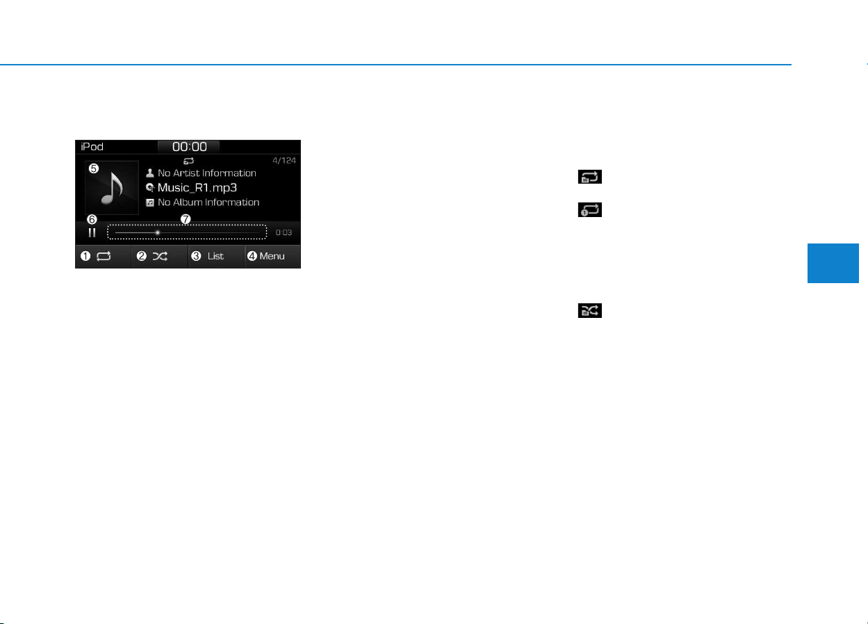
4-57
Multimedia System
4
iPod
®
(1) Repeat
Enable/disable repeat.
(2) Shuffle
Enable/disable shuffle play.
(3) List
View a list of all songs.
(4) Menu
Navigate to the menu screen.
(5) Album Image
View song info.
(6) Pause
Pause or play music.
(7) Playback progress
Select to skip to the desired location.
Playback
• Connect your iPod
®
to the audio
USB port, press the [MEDIA] but-
ton, and select [iPod].
Changing songs
• Press the [SEEK/TRACK] button
to play the previous or next song.
• Press and hold the [SEEK/TRACK]
button to rewind or fast forward the
currently playing song.
• Search songs by turning the TUNE
knob, and press the knob to play.
Selecting songs from a list
Select [List] to see a list of songs
available for play.
Select and play the desired song.
Repeat play
Select [Repeat] to enable or disable
‘Repeat category’, ‘Repeat current
song’.
• Repeat category: Repeat all
songs in the current category.
• Repeat current song: The cur-
rently playing song is repeated.
Shuffle play
Select [Shuffle] to enable/disable
‘Shuffle category’ play.
• Shuffle category: Songs within
the current category are played in
random order.
Menu
Select [Menu], and select the desired
function.
• Information: Detailed info on the
currently playing song is displayed.
• Sound Settings: Audio sound set-
tings can be changed.

4-58
Multimedia System
When other music programs are
running
When songs saved on your iPod
®
are playing through a separate music
app, the following screen is dis-
played.
(1) Play/Pause: Pause or play music.
(2) iPod files: Play music saved on
your iPod
®
.
(3) Sound Settngs: Audio sound set-
tings can be changed.
(4) Album Image: View playback info
.
Information
Operation cannot be carried out cor-
rectly due to iPod
®
application mal-
function.
Playing iPod files
• Select [iPod files] to play songs
saved on your iPod
®
.
If there are no songs saved on your
iPod
®
, the [iPod files] is disabled.
Information
- Using Bluetooth
®
(BT) Audio
• Bluetooth
®
Audio mode can only be
used if a Bluetooth
®
-enabled phone
is connected. Only devices that sup-
port Bluetooth
®
audio can be used.
• If the Bluetooth
®
-enabled phone is
disconnected during play, the music
stops.
• When the TRACK UP/DOWN but-
tons are used during Bluetooth
®
audio streaming, a popping noise or
sound interruptions may occur,
depending on the cell phone device.
• Depending on the cell phone model,
the audio streaming function may
not be supported.
• If a phone call is made or received
when music is playing in Bluetooth
®
Audio mode, the call may mix with
the music.
• When returning to Bluetooth
®
Audio mode after ending a call, play
might not resume automatically for
some cell phone models.
i
i
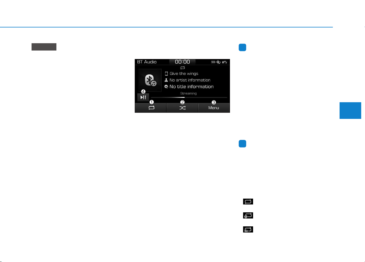
4-59
Multimedia System
4
• Bluetooth
®
Handsfree is a fea-
ture that enables drivers to prac-
tice safe driving. Connecting the
car audio system with a
Bluetooth
®
phone allows the
user to conveniently make calls,
receive calls, and manage the
phone book. Before using the
Bluetooth
®
Wireless Technology,
carefully read the contents of
this user’s manual.
• Excessive use or operations
while driving may lead to negli-
gent driving practices and be
the cause of accidents.
• Do not operate the device exces-
sively while driving.
• Viewing the screen for pro-
longed periods of time is dan-
gerous and may lead to acci-
dents.
• When driving, view the screen
only for short periods of time.
Bluetooth
®
(BT) Audio
(1) Repeat
Enable/disable repeat.
(2) Shuffle
Enable/disable shuffle play.
(3) Menu
Navigate to the menu screen.
(4) Play/Pause
Pause or play music.
Information
• Some cell phone models may not
support particular functions.
• Bluetooth
®
audio volume is synced
with cell phone media volume.
Playback
• Press the [MEDIA] button, and
select [BT Audio].
Changing songs
• Press the [SEEK/TRACK] button
to play the previous or next song.
Information
Some cell phones may not support this
function.
Repeat play
Select [Repeat] to enable or disable
‘Repeat all’, ‘Repeat current song’ or
‘Repeat category’.
• Repeat all: All songs in the
playlist are repeated.
• Repeat current song: The cur-
rently playing song is repeated.
• Repeat category: Repeat all
songs in the current category.
i
i
NOTICE
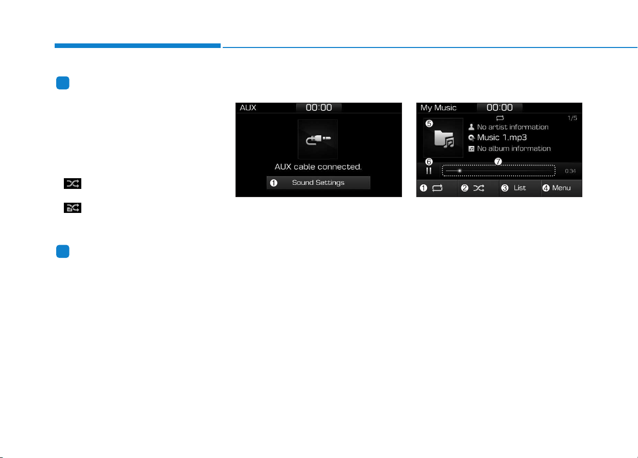
4-60
Multimedia System
Information
The repeat play function is engaged,
depending on the operation of the con-
nected Bluetooth
®
device.
Shuffle play
Select [Shuffle] to enable/disable
‘Shuffle’, ‘Shuffle category’ play.
• Shuffle: Songs are played in
random order.
• Shuffle category: Songs within
the current category are played in
random order.
Information
The shuffle function is engaged,
depending on the operation of the con-
nected Bluetooth
®
device.
Menu
Select [Menu], and select the desired
function.
• Connections: The currently connected
Bluetooth
®
device can be changed.
• Information: Detailed information on
the currently playing song is displayed.
• Sound Settings: Audio sound set-
tings can be changed.
AUX
Running AUX
• Press the [MEDIA] button, and
select [AUX].
• Connect the external device con-
nection jack to the AUX terminal to
run AUX.
(1) Sound Settings: Audio sound set-
tings can be changed.
My Music
(1) Repeat
Enable/disable repeat.
(2) Shuffle
Enable/disable shuffle play.
(3) List
View a list of all songs.
(4) Menu
Navigate to the menu screen.
(5) Album Image
View song info.
i
i
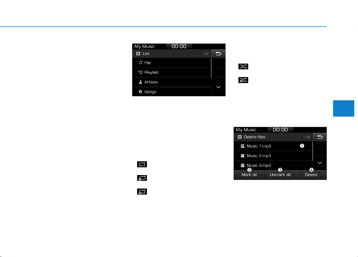
4-61
Multimedia System
4
(6) Pause
Pause or play music.
(7) Playback progress
Select to skip to the desired location.
Playback
Press the [MEDIA] button, and
select [My Music].
• My Music cannot be selected if it
does not contain music.
• Check the content of your USB
drive before saving music to My
Music.
Changing songs
Press the [SEEK/TRACK] button to
play the previous or next song.
• Press and hold the [SEEK/TRACK]
button to rewind or fast forward the
currently playing song.
• Search songs by turning the TUNE
knob and press the knob to play.
Selecting songs from a list
Select [List] to see a list of songs
available for play.
Select and play the desired song.
Repeat play
Select [Repeat] to enable or disable
‘Repeat all’, ‘Repeat current song’ or
‘Repeat category’.
• Repeat all: All songs in the
playlist are repeated.
• Repeat current song: The cur-
rently playing song is repeated.
• Repeat category: Repeat all
songs in the current category.
Shuffle play
Select [Shuffle] to enable/disable
‘Shuffle’, ‘Shuffle category’ play.
• Shuffle: Songs are played in
random order.
• Shuffle category: Songs within
the current category are played in
random order.
Menu
Select [Menu], and select the desired
function.
• Delete files: You can delete files
from My Music.
(1) File: Select saved file.
(2) Mark all: Select all files.
(3) Unmark all: Deselect all files.

4-62
Multimedia System
(4) Delete: Delete the selected file(s).
- Select the file to delete, then
select [Delete] to delete it.
- Delete is canceled if phone calls
are received or made during
delete.
• Add to playlist: Frequently played
songs can be paired in a [Playlist].
- Songs can be played from the
[Playlist].
• Information: Detailed info on the
currently playing song is displayed.
• Sound Settings: Audio sound set-
tings can be changed.
Delete from playlist
When a song in the playlist is play-
ing, select [Menu] and select [Delete
from playlist].
Select the song to delete, then select
[Delete].
Phone
Information
- Using Bluetooth
®
(BT) Phone
• Bluetooth
®
is a near-field wireless
networking technology that uses the
2.4 GHz frequency to connect vari-
ous devices within a certain distance
wirelessly.
• The technology is used in PCs,
peripherals, Bluetooth
®
phones,
tablet PCs, household appliances
and automobiles. Devices support-
ing Bluetooth
®
can exchange data at
high speeds without physical cable
connections.
• Bluetooth
®
Handsfree devices enable
convenient access to phone functions
through cell phones equipped with
Bluetooth
®
.
• Some Bluetooth
®
devices may not
be supported by the Bluetooth
®
Handsfree function.
(Continued)
(Continued)
• When Bluetooth
®
is connected and
calls are attempted through a con-
nected cell phone from outside the
vehicle, the call is connected
through the Bluetooth
®
Handsfree
function of the vehicle.
• Please be sure to disconnect the
Bluetooth
®
Handsfree function through
your Bluetooth
®
device or the audio
screen.
i

4-63
Multimedia System
4
Safety precautions
• The Bluetooth
®
Handsfree function
helps drivers to drive safely. By
connecting a Bluetooth
®
-enabled
phone to the vehicle’s audio sys-
tem, phone calls can be made and
received through the audio system
and contacts can be managed.
Consult the user manual before
use.
• Excessive manipulation of controls
while driving, making it difficult to
pay attention to the road ahead,
can lead to accidents. Do not oper-
ate the device excessively while
driving.
• Looking at the screen for a pro-
longed time increases the risk of
accidents. Keep time spent looking
at the screen to a minimum.
Precautions when connecting
Bluetooth
®
devices
• The vehicle supports the following
Bluetooth
®
functions. Some
Bluetooth
®
devices may not sup-
port some functions.
1) Bluetooth
®
Handsfree phone calls
2) Operations during a call
(Private, Switch, Mic Vol. con-
trols)
3) Download call history saved to
the Bluetooth
®
device
4) Download contacts saved to the
Bluetooth
®
device
5) Automatic contacts/call history
download when Bluetooth
®
is
connected
6) Automatic Bluetooth
®
device
connection when the vehicle is
started
7) Bluetooth
®
audio streaming play-
back
• Before connecting the audio sys-
tem to your device, make sure your
device supports Bluetooth
®
.
• Even if your device supports
Bluetooth
®
, a Bluetooth
®
connec-
tion cannot be established if the
device’s Bluetooth
®
function is
switched off. Search and connect
with the Bluetooth
®
function
enabled.
• Pair or connect Bluetooth
®
devices
to the audio system with the vehi-
cle at a standstill.
• If a Bluetooth
®
connection is lost
due to abnormal conditions while a
Bluetooth
®
device is connected
(communication range exceeded,
device power OFF, communication
errors, etc.), the disconnected
Bluetooth
®
device is searched for
and automatically reconnected.
• If you want to disable the
Bluetooth
®
device auto-connect
function, turn the Bluetooth
®
func-
tion OFF on your device. Consult
the user manuals for individual
devices to see whether Bluetooth
®
is supported.
• Handsfree call quality and volume
may vary depending on the type of
Bluetooth
®
device.
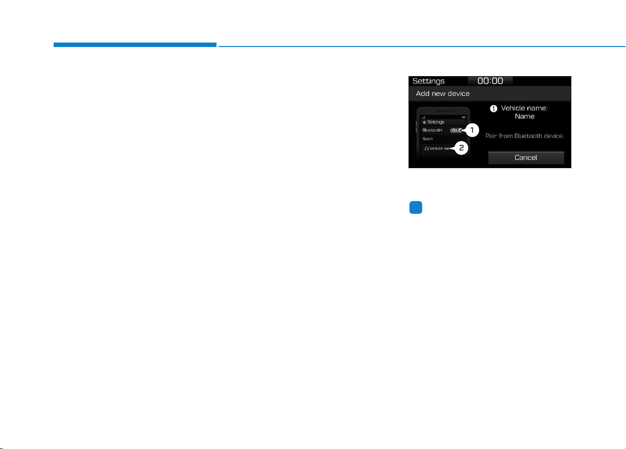
4-64
Multimedia System
• Some Bluetooth
®
devices are sub-
ject to intermittent Bluetooth
®
con-
nection failures. In this case, use
the following method.
1) Turn the Bluetooth
®
function off
on your Bluetooth
®
device ➟
Turn it on and try again.
2) Delete the paired device from
both the audio system and
Bluetooth
®
device, then pair
again.
3) Power down your Bluetooth
®
device ➟ Turn it on and try
again.
4) Completely remove the battery
from your Bluetooth
®
device;
reinsert it, reboot, and attempt
connection.
5) Restart the vehicle and reat-
tempt connection.
Pairing a Bluetooth
®
device
Information on pairing Bluetooth
®
devices
• Pairing refers to the process of
pairing Bluetooth
®
cell phones or
devices with the system prior to
connection. This is a necessary
procedure for Bluetooth
®
connec-
tion and usage.
• Up to five devices can be paired.
• Pairing Bluetooth
®
device is not
allowed while vehicle is moving.
Pairing the first Bluetooth
®
device
Press the [PHONE] button on the
audio system or the [CALL] button
on the steering wheel remote control
➟ Search for the vehicle from the
Bluetooth
®
device, and pair ➟ Enter
the passkey on the Bluetooth
®
device or approve passkey ➟
Bluetooth
®
pairing completed.
1. When the [PHONE] button on the
audio or the [CALL] button on the
steering wheel remote control is
pressed, the following screen is dis-
played. Devices can now be paired.
(1) Vehicle name: Searched name in
Bluetooth
®
device.
Information
The vehicle name in the image above
is an example. Refer to your device for
the actual name of your device.
2. Search for available Bluetooth
®
devices in the Bluetooth
®
menu of
your Bluetooth
®
device (cell
phone, etc.).
3. Confirm that the vehicle name in
your Bluetooth
®
device matches
the vehicle name shown on the
audio screen, then select it.
i
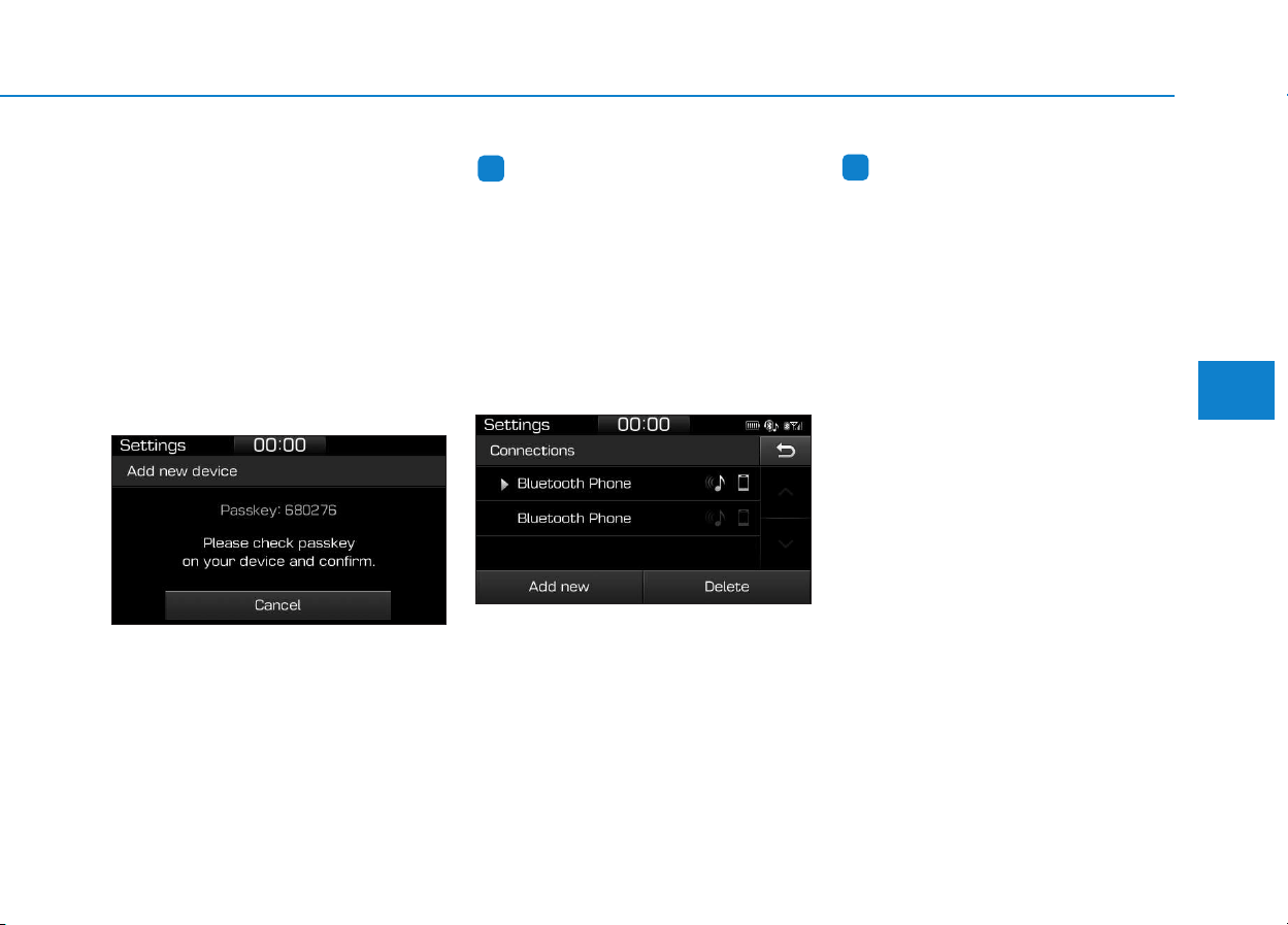
4-65
Multimedia System
4
4-1. For devices that require passkey
entry, a passkey entry screen is
shown on your Bluetooth
®
device.
- Enter the passkey ‘0000’, in your
Bluetooth
®
device.
4-2. For devices that require passkey
confirmation, the following
screen is shown on the audio
system. A 6-digit passkey input
screen is shown in the
Bluetooth
®
device.
- After confirming that the 6-digit
passkey on the audio screen
and the Bluetooth
®
device are
identical, select [OK] in your
Bluetooth
®
device.
Information
The 6-digit passkey in the image
above is an example. Refer to your
vehicle for the actual passkey.
Pairing a second Bluetooth
®
device
Press the [SETUP] button on the
audio system ➟ Select [Bluetooth] ➟
Select [Connections] ➟ Select [Add
new].
- The pairing procedure from this
point is identical to [Pairing the first
Bluetooth device].
Information
• Bluetooth
®
standby mode lasts for
three minutes. If a device is not
paired within three minutes, pairing
is canceled. Start over from the
beginning.
• For most Bluetooth
®
devices, a con-
nection is established automatically
after pairing. Some devices, howev-
er, require separate confirmation
when connecting after pairing. Be
sure to check your Bluetooth
®
device after pairing to confirm that
it has connected.
i
i
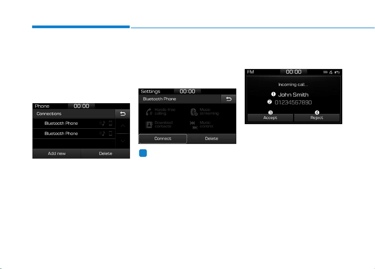
4-66
Multimedia System
Connecting Bluetooth
®
devices
If there are no connected devices
Press the [PHONE] button on the
audio system or the [CALL] button in
the steering wheel remote control ➟
List of paired Bluetooth
®
devices ➟
Select the desired Bluetooth
®
device
from the list ➟ Connect Bluetooth
®
.
If there are connected devices
Press the [PHONE] button on the
audio system ➟ Select [Settings] ➟
Select [Connections] ➟ Select
Bluetooth
®
device to connect ➟ Select
[Connect] ➟ Connect Bluetooth
®
.
Information
• Only one Bluetooth
®
device can be
connected at a time.
• When a Bluetooth
®
device is con-
nected, other devices cannot be
paired.
Accepting/rejecting phone calls
Receiving phone calls with Bluetooth
®
connected.
(1) Caller name: If the caller number
is in your contacts, the correspon-
ding name is displayed.
(2) Incoming phone number: Incoming
phone number is displayed.
(3) Accept: Accept call.
(4) Reject: Reject call.
i
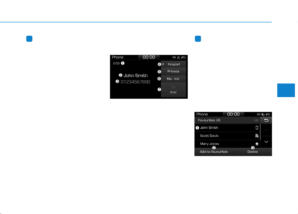
4-67
Multimedia System
4
Information
• When the incoming call screen is
displayed, audio mode and the set-
tings screen cannot be shown. Only
call volume control is supported.
• Some Bluetooth
®
devices may not
support the call reject function.
• Some Bluetooth
®
devices may not
support the phone number display
function.
Operation during calls
Incoming call with Bluetooth
®
con-
nected ➟ Select [Accept].
(1) Call duration: Call duration display.
(2) Caller name: If the caller number is
in your contacts, the corresponding
name is displayed.
(3) Incoming phone number: Incoming
phone number is displayed.
(4) Keypad: Number keypad for
Automatic Response Service input
is displayed.
(5) Private: Call is transferred to a cell
phone.
(6) Microphone Volume: Adjust out-
going voice volume.
(7) End: End call.
Information
• Some Bluetooth
®
devices may not
support the Private function.
• The outgoing voice volume may vary
depending on the type of Bluetooth
®
device. If the outgoing voice volume is
too high or low, adjust the
Microphone Volume.
Favourites
Press the [PHONE] button on the
audio system ➟ Select [Favourites]
➟ Favourites list displayed.
(1) Favourites list: A list of paired
favourites is displayed.
Connect a call when selected.
ii
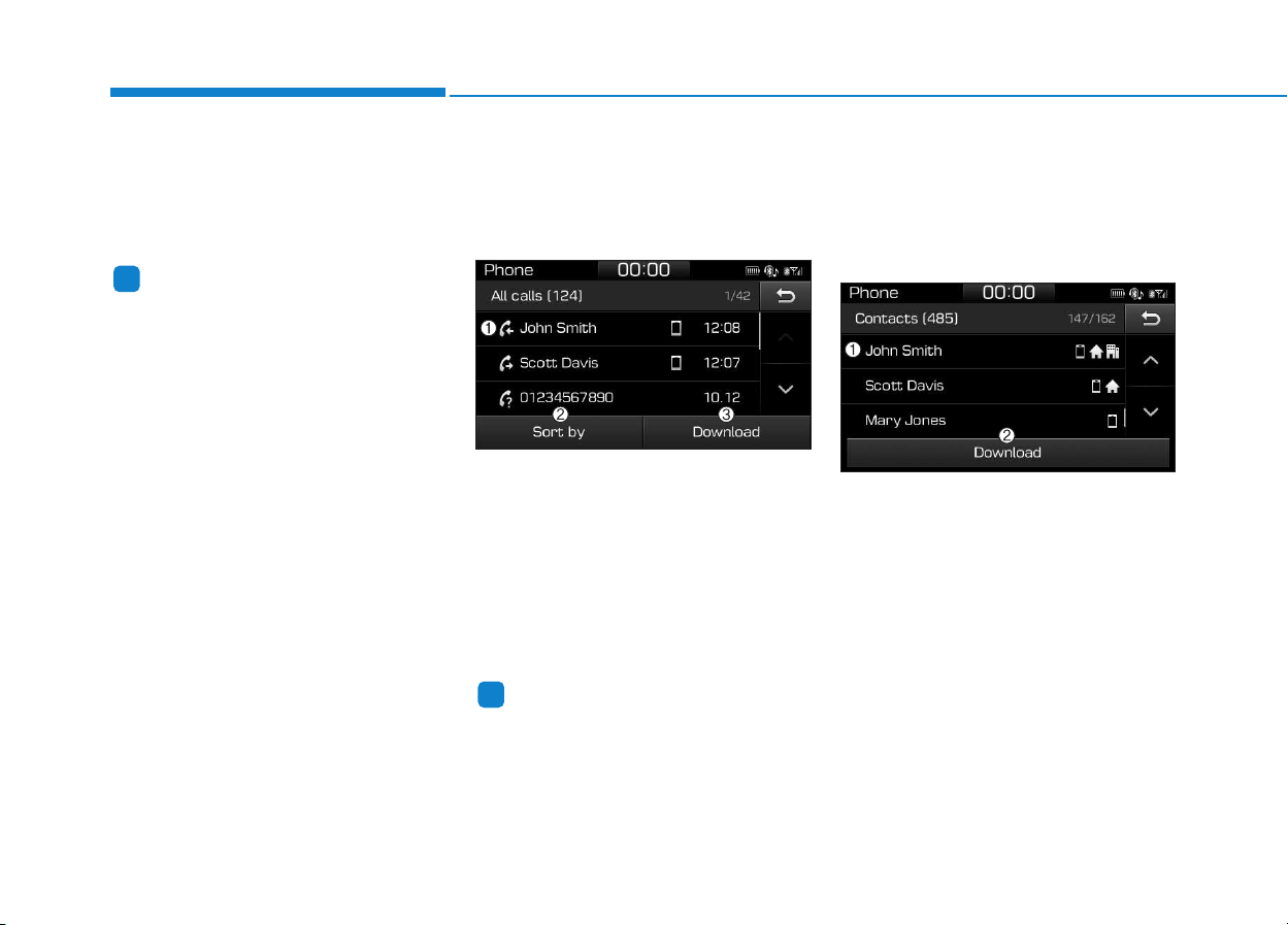
4-68
Multimedia System
(2) Add to favourites: Add a down-
loaded phone number to
favourites.
(3) Delete: Delete a saved Favourites.
Information
• Up to 20 favourites can be paired
for each paired Bluetooth
®
device.
• Favourites can be accessed when the
Bluetooth
®
device they were paired
from is connected.
• The audio system does not down-
load favourites from Bluetooth
®
devices. Favourites must be newly
saved before use.
• To add to favourites, contacts must
be downloaded first.
• Saved favourites are not updated
even if the contacts of the connected
Bluetooth
®
device are changed. In
this case, favourites need to be delet-
ed and added again.
Call history
Press the [PHONE] button on the
audio system ➟ Select [Call history]
➟ Call history is displayed.
(1) Call history: Display the down-
loaded call history list.
Connect a call when selected.
(2) Sort by: Sort by all calls, dialed
calls, received calls or missed
calls.
(3) Download: Download call history
from connected Bluetooth
®
devices.
Information
• Up to 50 dialed, received and missed
calls are saved.
• When the latest call history is
received, the existing call history is
deleted.
Contacts
Press the [PHONE] button on the
audio system ➟ Select [Contacts] ➟
Select letter (ABC) ➟ Contacts dis-
played.
(1) Contacts: Display downloaded
contacts.
Connect a call when selected.
(2) Download: Download contacts from
connected Bluetooth
®
devices.
i
i
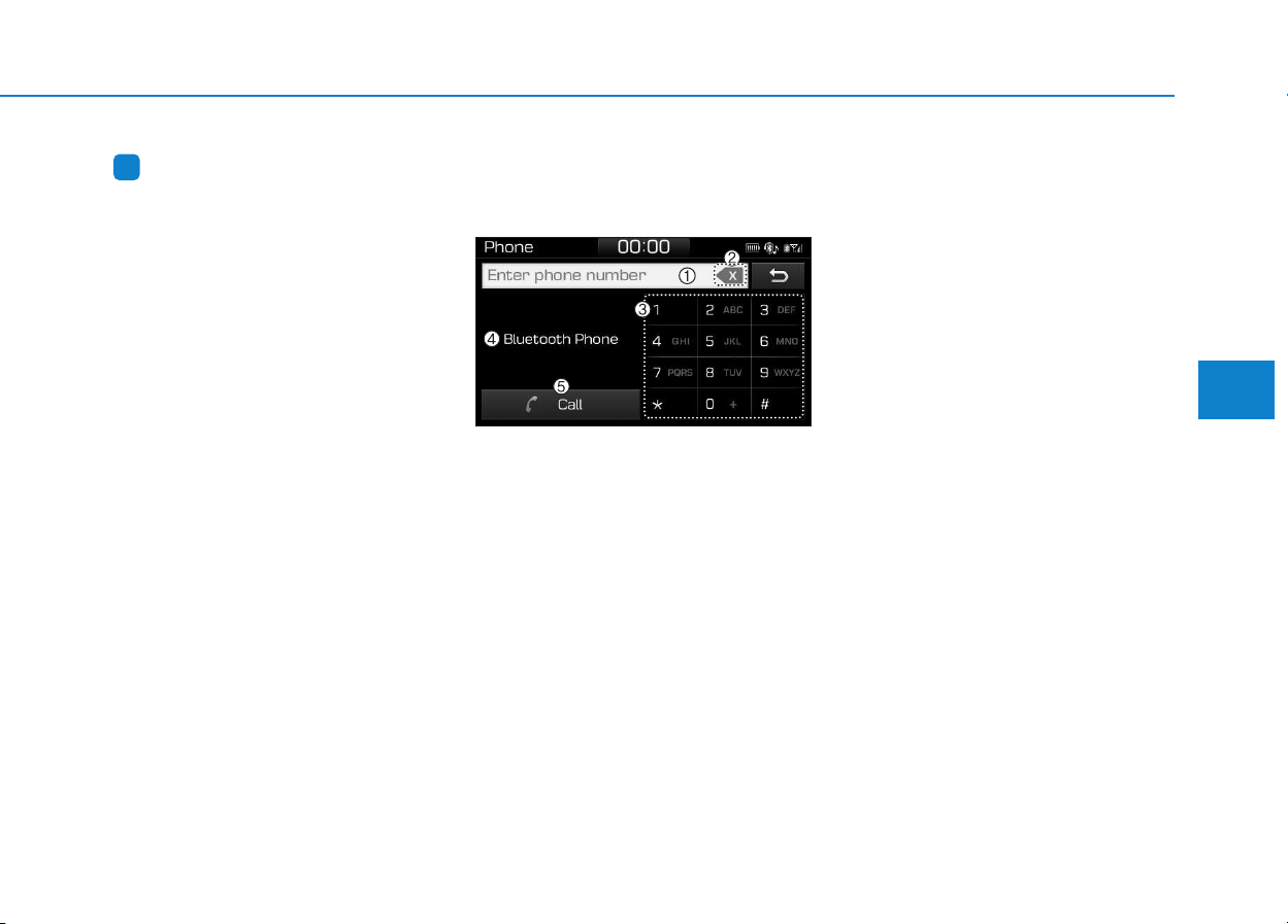
4-69
Multimedia System
4
Information
• Up to 2,000 contacts can be saved.
• In some cases, additional confirmation
from your Bluetooth
®
device is neces-
sary when downloading contacts. If
downloading of contacts unsuccessful,
consult your Bluetooth
®
device’s set-
tings or the audio screen to approve
the download.
• Contacts without phone numbers
are not displayed.
Dial
Press the [PHONE] button on the
audio ➟ Select [Dial].
(1) Phone number entry window: The
phone number entered using the
keypad is displayed.
(2) Clear
- Select to delete individual digits.
- Press and hold to delete the
entire phone number.
(3) Keypad: Enter phone number.
(4) Bluetooth
®
Phone name
- The name of the connected
Bluetooth
®
device is displayed.
- Contacts matching the keypad
number/letter input are displayed.
(5) Call
- Enter and select a phone num-
ber to call.
- Select without entering a phone
number to see the most recent
dialed call.
Settings
Press the [PHONE] button on the
audio ➟ Select [Settings].
- For phone settings, refer to Setup
page.
i

4-70
Multimedia System
Setup
Access Display, Sound, Date/Time,
Bluetooth, System, Screensaver and
Display Off settings.
Press the [SETUP] button on the
audio system.
Display
Press the [SETUP] button on the
audio system ➟ Select [Display].
• Dimming mode: Audio screen bright-
ness can be adjusted to the time of
day.
• Brightness: The brightness of the
audio screen can be changed.
• Text scroll: If text is too long to be
displayed on the screen, enable the
text scroll function. (if equipped)
Sound
Press the [SETUP] button on the
audio system ➟ Select [Sound].
• Position: Sound balance and pan-
ning can be adjusted.
• Equaliser: Sound tone color can be
adjusted.
• Rear parking sensors prioritised:
Automatically lower audio volume
while reversing.
• Speed dependent volume control:
Automatically adjust volume based
on vehicle speed.
• Beep: Select whether to play a beep
sound when the screen is touched.
Date/Time
Press the [SETUP] button on the
audio system ➟ Select [Date/Time].
• Set time: Set the time displayed on
the audio screen.
• Time format: Choose between 12-
hour and 24-hour time formats.
• Set date: Set the date displayed on
the audio screen.
Bluetooth
Press the [SETUP] button on the
audio system ➟ Select [Bluetooth].
• Connections: Control pairing, dele-
tion, connection and disconnection
of Bluetooth
®
devices.
• Auto connection priority: Set the
connection priority of Bluetooth
®
devices when the vehicle is started.
• Update contacts: Contacts can be
downloaded from connected
Bluetooth
®
devices.
• Bluetooth voice guidance: Play or
mute voice prompts for Bluetooth
®
device pairing, connection and
errors.

4-71
Multimedia System
4
Information
• When paired devices are deleted,
the call history and contacts of the
device saved to the audio system are
deleted.
• For Bluetooth
®
connections with
low connection priority, some time
may be required for the connection
to be established.
• Contacts can be downloaded only
from the currently connected
Bluetooth
®
device.
• If no Bluetooth
®
device is connected,
the Download Contacts button is
disabled.
• If the language setting is Slovakian,
Hungarian or Korean, Bluetooth
voice guidance is not supported.
System
Press the [SETUP] button on the
audio system ➟ Select [System].
• Memory information: View My
Music memory usage.
• Language: Change the user lan-
guage.
• Default: Reset the audio system.
Information
The system resets to the default val-
ues, and all saved data and settings
are lost.
Screensaver
Set the information displayed when
the audio system is switched off or
the screen is turned off.
Press the [SETUP] button on the
audio system ➟ Select [Screensaver].
• Analogue: An analog clock is dis-
played.
• Digital: A digital clock is displayed.
• None: No information is displayed.
Display Off
To prevent glare, the screen can be
turned off with the audio system in
operation.
Press the [SETUP] button on the
audio system ➟ Select [Display Off].
Information
Use ‘Screensaver’ to set the informa-
tion to be displayed when the screen is
turned off.
i
i
i
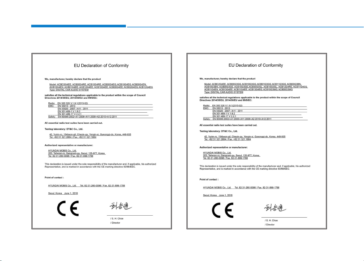
4-72
Multimedia System
D
Deeccllaarraattiioonn ooff CCoonnffoorrmmiittyy
CE for EU

Driving your vehicle
Before driving.........................................................5-5
Before entering the vehicle ...........................................5-5
Before starting...................................................................5-5
Ignition switch ........................................................5-7
Key ignition switch............................................................5-7
Engine Start/Stop button..............................................5-11
Manual transmission............................................5-20
Manual transmission operation ...................................5-20
Good driving practices...................................................5-22
Automatic transmission.......................................5-24
Automatic transmission operation ..............................5-24
Parking...............................................................................5-29
Good driving practices...................................................5-29
Dual clutch transmission.....................................5-31
Dual clutch transmission operation............................5-31
Parking...............................................................................5-39
Good driving practices...................................................5-39
Braking system.....................................................5-41
Power brakes ...................................................................5-41
Disc brakes wear indicator...........................................5-42
Parking brake (Hand type) ...........................................5-42
Electronic Parking Brake (EPB)...................................5-44
AUTO HOLD ......................................................................5-49
Anti-lock Brake System (ABS) ....................................5-53
Electronic Stability Control (ESC)................................5-55
Vehicle Stability Management......................................5-58
Hill-Start Assist Control (HAC) ....................................5-60
Emergency Stop Signal (ESS) ......................................5-60
Good braking practices..................................................5-61
ISG (Idle Stop and Go) system...........................5-62
To activate the ISG system...........................................5-62
To deactivate the ISG system ......................................5-66
ISG system malfunction.................................................5-66
The battery sensor deactivation.................................5-67
Drive mode integrated control system .............5-68
Blind Spot Detection System (BSD) ..................5-70
BSD (Blind Spot Detection) /
LCA (Lane Change Assist).............................................5-71
RCTA (Rear Cross Traffic Alert) ..................................5-74
Limitations of the system .............................................5-77
Autonomous Emergency Braking (AEB)
- Sensor fusion type...........................................5-78
System setting and activation......................................5-78
AEB warning message and system control..............5-80
AEB sensor .......................................................................5-82
System malfunction........................................................5-84
Limitations of the system .............................................5-85
5

5
Autonomous Emergency Braking (AEB)
- Camera type ......................................................5-90
System setting and activation......................................5-90
AEB warning message and system control..............5-92
AEB sensor .......................................................................5-94
System malfunction........................................................5-95
Limitations of the system .............................................5-97
Speed Limit Information Function (SLIF) .......5-101
System setting and activation ...................................5-102
Display .............................................................................5-102
Limitations of the system ...........................................5-104
Lane Keeping Assist System (LKAS)...............5-106
LKAS operation..............................................................5-107
Warning light and message ........................................5-111
LKAS function change.................................................5-112
Limitations of the System...........................................5-113
Lane Departure Warning System (LDWS)......5-114
LDWS operation ............................................................5-115
Warning light and message ........................................5-116
Limitations of the system ...........................................5-116
Driver Attention Alert System (DAA)..............5-118
System setting and activation ...................................5-118
Resetting the system ...................................................5-119
System standby.............................................................5-120
System malfunction......................................................5-120
Speed limit control system ...............................5-122
Speed Limit Control operation...................................5-122
Cruise control .....................................................5-124
Cruise Control operation.............................................5-124
Advanced smart cruise control system ..........5-130
Smart Cruise Control speed........................................5-132
Smart Cruise Control Vehicle-to-Vehicle
Distance...........................................................................5-136
Sensor to detect distance to the vehicle ahead...5-139
To adjust the sensitivity of
Smart Cruise Control....................................................5-141
To convert to Cruise Control mode..........................5-141
Limitations of the system ...........................................5-142

Special driving conditions.................................5-147
Hazardous driving conditions ....................................5-147
Rocking the vehicle ......................................................5-147
Smooth cornering .........................................................5-148
Driving at night..............................................................5-148
Driving in the rain.........................................................5-148
Driving in flooded areas..............................................5-149
Highway driving.............................................................5-149
Reducing the risk of a rollover.................................5-150
Winter driving.....................................................5-151
Snow or icy conditions................................................5-151
Winter Precautions.......................................................5-153
Trailer towing (for europe) ..............................5-156
If you decide to pull a trailer?...................................5-157
Trailer towing equipment ............................................5-160
Driving with a trailer ....................................................5-161
Maintenance when towing a trailer.........................5-165
Vehicle weight ....................................................5-166
Overloading ....................................................................5-166
5

5-4
Driving your vehicle
Carbon monoxide (CO) gas is toxic. Breathing CO can cause unconsciousness and death.
Engine exhaust contains carbon monoxide which cannot be seen or smelled.
Do not inhale engine exhaust.
If at any time you smell engine exhaust inside the vehicle, open the windows immediately. Exposure to CO can cause
unconsciousness and death by asphyxiation.
Be sure the exhaust system does not leak.
The exhaust system should be checked whenever the vehicle is raised to change the oil or for any other purpose. If
you hear a change in the sound of the exhaust or if you drive over something that strikes the underneath side of the
vehicle, we recommend that the exhaust system be checked as soon as possible by an authorized HYUNDAI dealer.
Do not run the engine in an enclosed area.
Letting the engine idle in your garage, even with the garage door open, is a hazardous practice. Run the engine only
long enough to start the engine and to move the vehicle out of the garage.
Avoid idling the engine for prolonged periods with people inside the vehicle.
If it is necessary to idle the engine for a prolonged period with people inside the vehicle, be sure to do so only in an
open area with the air intake set at "Fresh" and fan control set to high so fresh air is drawn into the interior.
Keep the air intakes clear.
To assure proper operation of the ventilation system, keep the ventilation air intakes located in front of the windshield
clear of snow, ice, leaves, or other obstructions.
If you must drive with the tailgate open:
Close all windows.
Open instrument panel air vents.
Set the air intake control at "Fresh", the air flow control at "Floor" or "Face", and the fan control set to high.
WARNING

5-5
Driving your vehicle
5
Before entering the vehicle
• Be sure all windows, outside mir-
ror(s), and outside lights are clean
and unobstructed.
• Remove frost, snow, or ice.
• Visually check the tires for uneven
wear and damage.
• Check under the vehicle for any
sign of leaks.
• Be sure there are no obstacles
behind you if you intend to back up.
Before starting
• Make sure the hood, the tailgate,
and the doors are securely closed
and locked.
• Adjust the position of the seat and
steering wheel.
• Adjust the inside and outside
rearview mirrors.
• Verify all the lights work.
• Fasten your seatbelt. Check that all
passengers have fastened their
seatbelts.
• Check the gauges and indicators in
the instrument panel and the mes-
sages on the instrument display
when the ignition switch is in the
ON position.
• Check that any items you are car-
rying are stored properly or fas-
tened down securely.
BBEEFFOORREE DDRRIIVVIINNGG
To reduce the risk of SERIOUS
INJURY or DEATH, take the fol-
lowing precautions:
• ALWAYS wear your seat belt.
All passengers must be prop-
erly belted whenever the vehi-
cle is moving. For more infor-
mation, refer to "Seat Belts" in
chapter 2.
• Always drive defensively.
Assume other drivers or pedes-
trians may be careless and
make mistakes.
• Stay focused on the task of
driving. Driver distraction can
cause accidents.
• Leave plenty of space between
you and the vehicle in front of
you.
WARNING

5-6
Driving your vehicle
NEVER drink or take drugs and
drive.
Drinking or taking drugs and
driving is dangerous and may
result in an accident and SERI-
OUS INJURY or DEATH.
Drunk driving is the number
one contributor to the highway
death toll each year. Even a
small amount of alcohol will
affect your reflexes, percep-
tions and judgment. Just one
drink can reduce your ability to
respond to changing conditions
and emergencies and your reac-
tion time gets worse with each
additional drink.
Driving while under the influ-
ence of drugs is as dangerous
or more dangerous than driving
under the influence of alcohol.
(Continued)
WARNING
(Continued)
You are much more likely to have
a serious accident if you drink or
take drugs and drive. If you are
drinking or taking drugs, don't
drive. Do not ride with a driver
who has been drinking or taking
drugs. Choose a designated driv-
er or call a taxi.
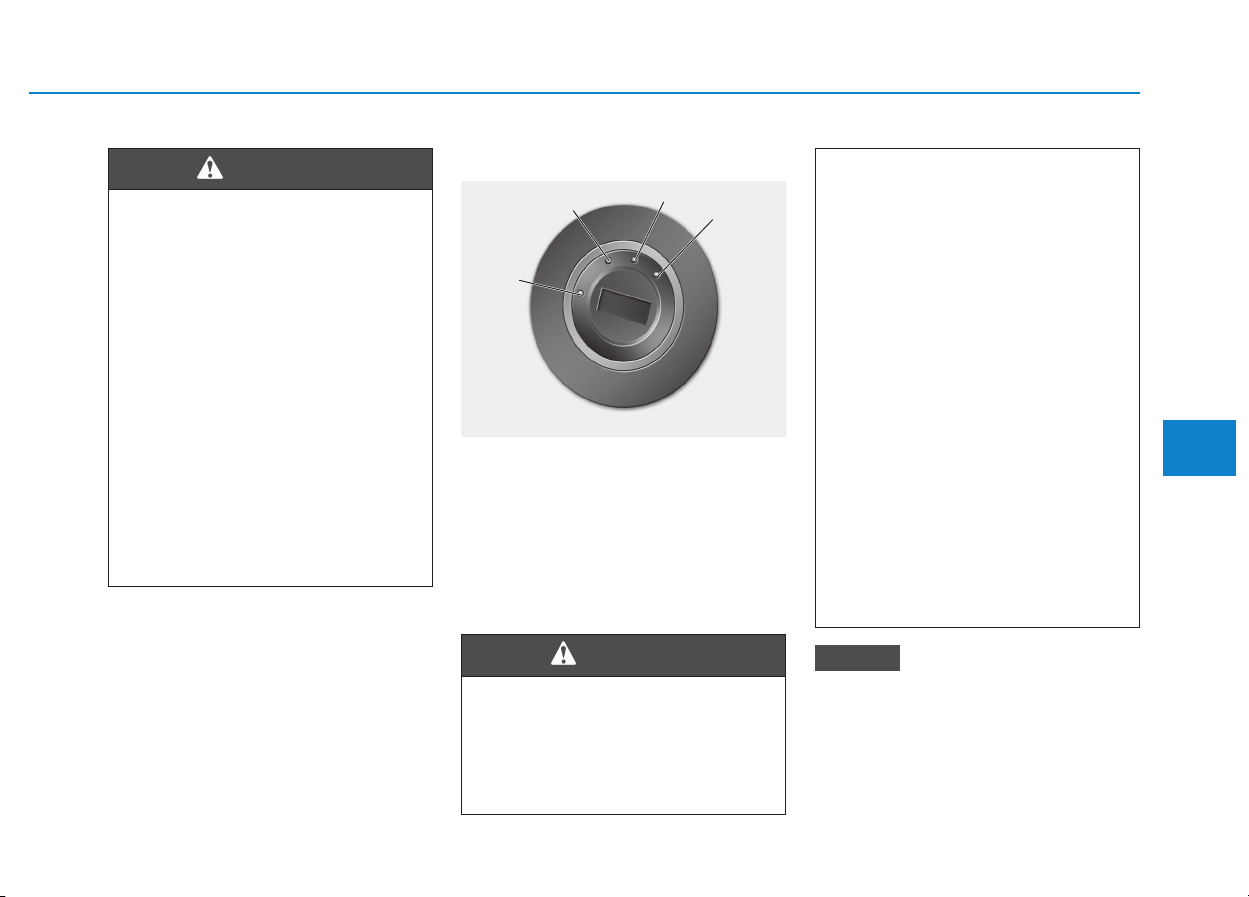
5-7
Driving your vehicle
5
IIGGNNIITTIIOONN SSWWIITTCCHH
Key ignition switch
Whenever the front door is opened,
the ignition switch will illuminate, pro-
vided the ignition switch is not in the
ON position. The light will go off
immediately when the ignition switch
is turned on or go off after about 30
seconds when the door is closed. (if
equipped)
Never use aftermarket key whole
covers.This may generate start-up
failure due to communication fail-
ure.
NOTICE
• NEVER turn the ignition switch
to the LOCK or ACC position
while the vehicle is in motion
except in an emergency.
(Continued)
(Continued)
This will result in the engine
turning off and loss of power
assist for the steering and
brake systems. This may lead
to loss of directional control
and braking function, which
could cause an accident.
• Before leaving the driver's
seat, always make sure the
shift lever is in 1st gear (for
manual transmission vehicle)
or P (Park, for automatic
transmission/dual clutch
transmission vehicle) posi-
tion, apply the parking brake,
and turn ignition switch to the
LOCK position.
Unexpected vehicle move-
ment may occur if these pre-
cautions are not followed.
WARNING
To reduce the risk of SERIOUS
INJURY or DEATH, take the fol-
lowing precautions:
• NEVER allow children or any
person who is unfamiliar with
the vehicle to touch the igni-
tion switch or related parts.
Unexpected and sudden vehi-
cle movement can occur.
• NEVER reach through the
steering wheel for the ignition
switch, or any other control,
while the vehicle is in motion.
The presence of your hand or
arm in this area may cause a
loss of vehicle control result-
ing in an accident.
WARNING
OAE056172L
LOCK
ACC
ON
START

5-8
Driving your vehicle
Key ignition switch positions
Switch
Position
Action Notes
LOCK
To turn the ignition switch to the LOCK position, push the key in
slightly at the ACC position and turn the key towards the LOCK
position.
The ignition key can be removed in the LOCK position.
The steering wheel locks to protect the vehicle from theft.
(if equipped)
ACC
Some electrical accessories are usable.
The steering wheel unlocks.
If difficulty is experienced turning the ignition
switch to the ACC position, turn the key
while turning the steering wheel right and
left to release tension.
ON
This is the normal key position when the engine has started.
All features and accessories are usable.
The warning lights can be checked when you turn the ignition
switch from ACC to ON.
Do not leave the ignition switch in the ON
position when the engine is not running to
prevent the battery from discharging.
START
To start the engine, turn the ignition switch to the START position.
The switch returns to the ON position when you let go of the key.
The engine will crank until you release the
key.

5-9
Driving your vehicle
5
Starting the engine
Starting the gasoline engine
Vehicle with manual transmission:
1. Make sure the parking brake is
applied.
2. Make sure the shift lever is in neu-
tral.
3. Depress the clutch and brake ped-
als.
4. Turn the ignition switch to the
START position. Hold the key
(maximum of 10 seconds) until the
engine starts and release it.
Vehicle with automatic transmis-
sion/dual clutch transmission:
1. Make sure the parking brake is
applied.
2. Make sure the shift lever is in P
(Park).
3. Depress the brake pedal.
4. Turn the ignition switch to the
START position. Hold the key
(maximum of 10 seconds) until the
engine starts and release it.
Information
• Do not wait for the engine to warm
up while the vehicle remains station-
ary.
Start driving at moderate engine
speeds. (Steep accelerating and
decelerating should be avoided.)
• Always start the vehicle with your
foot on the brake pedal. Do not
depress the accelerator while start-
ing the vehicle. Do not race the
engine while warming it up.
i
• Always wear appropriate
shoes when operating your
vehicle. Unsuitable shoes,
such as high heels, ski boots,
sandals, flip-flops, etc., may
interfere with your ability to
use the brake, accelerator and
clutch pedals.
• Do not start the vehicle with the
accelerator pedal depressed.
The vehicle can move and lead
to an accident.
• Wait until the engine rpm is
normal. The vehicle may sud-
denly move if the brake padel
is released when the rpm is
high.
WARNING

5-10
Driving your vehicle
Starting the diesel engine
To start the diesel engine when the
engine is cold, it has to be pre-heat-
ed before starting the engine and
then have to be warmed up before
starting to drive.
Vehicle with manual transmission:
1. Make sure the parking brake is
applied.
2. Make sure the shift lever is in neu-
tral.
3. Depress the clutch and brake ped-
als.
4. Turn the ignition switch to the ON
position to pre-heat the engine.
The glow indicator light ( ) will
illuminate.
5. When the glow indicator light ( )
goes out, turn the key ignition
switch to the START position. Hold
the key (maximum of 10 seconds)
until the engine starts and release
it.
Vehicle with dual clutch transmis-
sion:
1. Make sure the parking brake is
applied.
2. Make sure the shift lever is in P
(Park).
3. Depress the brake pedal.
4. Turn the ignition switch to the ON
position to pre-heat the engine.
The glow indicator light ( ) will
illuminate.
5. When the glow indicator light ( )
goes out, turn the key ignition
switch to the START position. Hold
the key (maximum of 10 seconds)
until the engine starts and release
it.
If the engine does not start within
10 seconds after preheating is
completed, turn the ignition
switch once more to the LOCK
position and wait for 10 seconds.
Then turn the ignition switch to
the ON position in order to pre-
heat the engine again.
Starting and stopping the engine
for turbocharger intercooler
1. Do not race or accelerate the
engine immediately after starting
the engine.
If the engine is cold, idle for sever-
al seconds before sufficient lubri-
cation is ensured in the turbo
charger unit.
2. After high speed or extended driv-
ing that requires heavy engine
load, idle the engine about 1
minute before turning the engine
off.
This idle time will allow the tur-
bocharger to cool prior to shutting
the engine off.
Do not turn off the engine immedi-
ately after it has been subjected to
a heavy load. Doing so may cause
severe damage to the engine or
turbo charger unit.
NOTICE
NOTICE
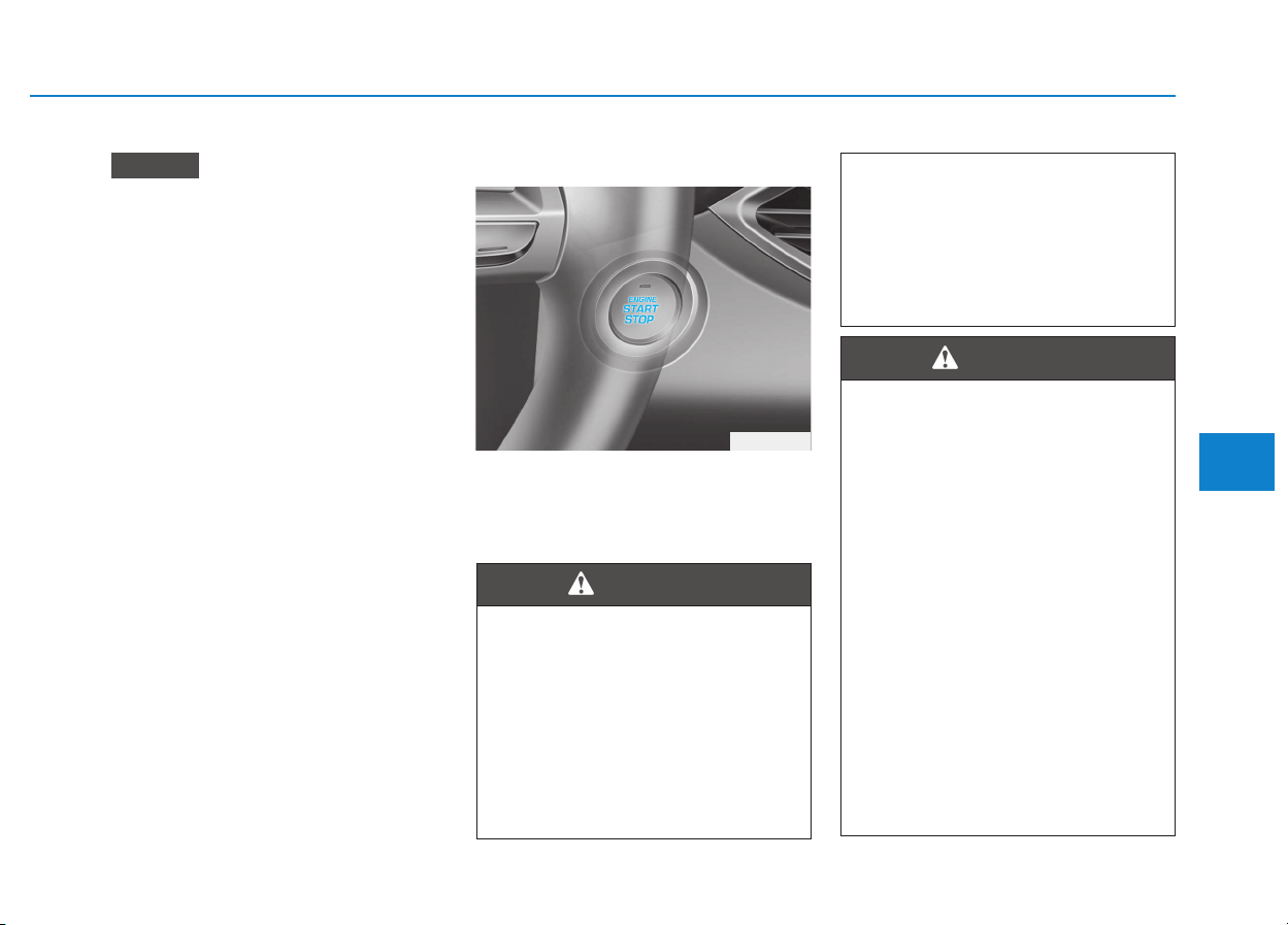
5-11
Driving your vehicle
5
To prevent damage to the vehicle:
• Do not hold the ignition key in
the START position for more
than 10 seconds. Wait 5 to 10
seconds before trying again.
• Do not turn the ignition switch to
the START position with the
engine running. It may damage
the starter.
• If traffic and road conditions
permit, you may put the shift
lever in the N (Neutral) position
while the vehicle is still moving
and turn the ignition switch to
the START position in an
attempt to restart the engine.
• Do not push or tow your vehicle
to start the engine.
Engine Start/Stop button
Whenever the front door is opened,
the Engine Start/Stop button will illu-
minate and will go off 30 seconds
after the door is closed.
NOTICE
OPD056001
To turn the engine off in an
emergency:
Press and hold the Engine Start/
Stop button for more than two
seconds OR Rapidly press and
release the Engine Start/Stop
button three times (within three
seconds).
(Continued)
(Continued)
If the vehicle is still moving, you
can restart the engine without
depressing the brake pedal by
pressing the Engine Start/Stop
button with the shift lever in the
N (Neutral) position.
WARNING
• NEVER press the Engine Start/
Stop button while the vehicle is
in motion except in an emer-
gency. This will result in the
engine turning off and loss of
power assist for the steering
and brake systems. This may
lead to loss of directional con-
trol and braking function,
which could cause an accident.
• Before leaving the driver’s
seat, always make sure the
shift lever is in the P (Park)
position, set the parking
brake, press the Engine Start/
Stop button to the OFF posi-
tion, and take the Smart Key
with you. Unexpected vehicle
movement may occur if these
precautions are not followed.
WARNING

5-12
Driving your vehicle
Engine Stop/Start button positions
- Vehicle with manual transmission
Button Position Action Notes
OFF
To turn off the engine, stop the vehicle and
then press the Engine Start/Stop button.
The steering wheel locks to protect the vehi-
cle from theft. (if equipped)
If the steering wheel is not locked properly
when you open the driver's door, the warning
chime will sound.
ACC
Press the Engine Start/Stop button when
the button is in the OFF position without
depressing the clutch pedal.
Some electrical accessories are usable.
The steering wheel unlocks.
If you leave the Engine Start/Stop button in
the ACC position for more than one hour, the
battery power will turn off automatically to
prevent the battery from discharging.
If the steering wheel doesn't unlock properly,
the Engine Start/Stop button will not work.
Press the Engine Start/Stop button while
turning the steering wheel right and left to
release tension.

5-13
Driving your vehicle
5
- Vehicle with manual transmission
Button Position Action Notes
ON
Press the Engine Start/Stop button while it
is in the ACC position without depressing
the clutch pedal.
The warning lights can be checked before
the engine is started.
Do not leave the Engine Start/Stop button in
the ON position when the engine is not run-
ning to prevent the battery from discharging.
START
To start the engine, depress the clutch and
brake pedals and press the Engine Start/
Stop button with the shift lever in neutral.
If you press the Engine Start/Stop button
without depressing the clutch pedal, the
engine does not start and the Engine
Start/Stop button changes as follows:
OFF
→
→
ACC
→→
ON
→→
OFF or ACC

5-14
Driving your vehicle
Engine Stop/Start button positions
- Vehicle with automatic transmission / dual clutch transmission
Button Position Action Notes
OFF
To turn off the engine, press the Engine
Start/Stop button with shift lever in P (Park).
When you press the Engine Start/Stop but-
ton without the shift lever in P (Park), the
Engine Start/Stop button does not turn to
the OFF position, but turns to the ACC posi-
tion.
The steering wheel locks to protect the vehi-
cle from theft. (if equipped)
If the steering wheel is not locked properly
when you open the driver's door, the warning
chime will sound.
ACC
Press the Engine Start/Stop button when
the button is in the OFF position without
depressing the brake pedal.
Some electrical accessories are usable.
The steering wheel unlocks.
If you leave the Engine Start/Stop button in
the ACC position for more than one hour, the
battery power will turn off automatically to
prevent the battery from discharging.
If the steering wheel doesn't unlock properly,
the Engine Start/Stop button will not work.
Press the Engine Start/Stop button while
turning the steering wheel right and left to
release tension.

5-15
Driving your vehicle
5
- Vehicle with automatic transmission / dual clutch transmission
Button Position Action Notes
ON
Press the Engine Start/Stop button while it
is in the ACC position without depressing
the brake pedal.
The warning lights can be checked before
the engine is started.
Do not leave the Engine Start/Stop button in
the ON position when the engine is not run-
ning to prevent the battery from discharging.
START
To start the engine, depress the brake pedal
and press the Engine Start/Stop button with
the shift lever in the P (Park) or in the N
(Neutral) position.
For your safety, start the engine with the
shift lever in the P (Park) position.
If you press the Engine Start/Stop button
without depressing the brake pedal, the
engine does not start and the Engine
Start/Stop button changes as follows:
OFF
→
→
ACC
→→
ON
→→
OFF or ACC

5-16
Driving your vehicle
Starting the engine
Information
• The engine will start by pressing the
Engine Start/Stop button, only when
the smart key is in the vehicle.
• Even if the smart key is in the vehi-
cle, if it is far away from the driver,
the engine may not start.
• When the Engine Start/Stop button
is in the ACC or ON position, if any
door is open, the system checks for
the smart key. If the smart key is not
in the vehicle, the " " indicator
will blink and the warning "Key not
in vehicle" will come on, and if all
doors are closed, the chime will also
sound for about 5 seconds. Keep the
smart key in the vehicle when using
the ACC position or if the vehicle
engine is ON.
Starting the gasoline engine
Vehicle with manual transmission:
1. Always carry the smart key with
you.
2. Make sure the parking brake is
applied.
3. Make sure the shift lever is in neu-
tral.
4. Depress the clutch and brake ped-
als.
5. Press the Engine Start/Stop but-
ton.
Vehicle with automatic transmission/
dual clutch transmission:
1. Always carry the smart key with
you.
2. Make sure the parking brake is
applied.
3. Make sure the shift lever is in P
(Park).
4. Depress the brake pedal.
5 Press the Engine Start/Stop but-
ton.
i
• Always wear appropriate
shoes when operating your
vehicle. Unsuitable shoes,
such as high heels, ski boots,
sandals, flip-flops, etc., may
interfere with your ability to
use the brake, accelerator and
clutch pedals.
• Do not start the vehicle with the
accelerator pedal depressed.
The vehicle can move and lead
to an accident.
• Wait until the engine rpm is
normal. The vehicle may sud-
denly move if the brake pedal
is released when the rpm is
high.
WARNING

5-17
Driving your vehicle
5
Information
• Do not wait for the engine to warm
up while the vehicle remains station-
ary.
Start driving at moderate engine
speeds. (Steep accelerating and
decelerating should be avoided.)
• Always start the vehicle with your
foot on the brake pedal. Do not
depress the accelerator while start-
ing the vehicle. Do not race the
engine while warming it up.
Starting the diesel engine
To start the diesel engine when the
engine is cold, it has to be pre-heat-
ed before starting the engine and
then have to be warmed up before
starting to drive.
Vehicle with manual transmission:
1. Always carry the smart key with
you.
2. Make sure the parking brake is
applied.
3. Make sure the shift lever is in neu-
tral.
4. Depress the clutch and brake
pedal.
5. Press the Engine Start/Stop but-
ton.
6. Continue depressing the brake
pedal until the glow indicator light
( ) goes out.
7. When the glow indicator light ( )
goes out, the engine will start.
Vehicle with dual clutch transmis-
sion:
1. Always carry the smart key with
you.
2. Make sure the parking brake is
applied.
3. Make sure the shift lever is in P
(Park).
4. Depress the brake pedal.
5. Press the Engine Start/Stop but-
ton.
6. Continue depressing the brake
pedal until the glow indicator light
( ) goes out.
7. When the glow indicator light ( )
goes out, the engine will start.
Information
If the Engine Start/Stop button is
pressed while the engine is pre-heat-
ing, the engine may start.
i
i

5-18
Driving your vehicle
Starting and stopping the engine
for turbocharger intercooler
1. Do not race or accelerate the
engine immediately after starting
the engine.
If the engine is cold, idle for sever-
al seconds before sufficient lubri-
cation is ensured in the turbo
charger unit.
2. After high speed or extended driv-
ing that requires heavy engine
load, idle the engine about 1
minute before turning the engine
off. This idle time will allow the tur-
bocharger to cool prior to shutting
the engine off.
Do not turn off the engine immedi-
ately after it has been subjected to
a heavy load. Doing so may cause
severe damage to the engine or
turbo charger unit.
To prevent damage to the vehicle:
• If the engine stalls while you are
in motion, do not attempt to
move the shift lever to the P
(Park) position.
If traffic and road conditions
permit, you may put the shift
lever in the N (Neutral) position
while the vehicle is still moving
and press the Engine Start/Stop
button in an attempt to restart
the engine.
• Do not push or tow your vehicle
to start the engine.
To prevent damage to the vehicle:
Do not press the Engine Start/
Stop button for more than 10 sec-
onds except when the stop lamp
fuse is blown.
When the stop lamp fuse is blown,
you can't start the engine normal-
ly. Replace the fuse with a new
one. If you are not able to replace
the fuse, you can start the engine
by pressing and holding the
Engine Start/Stop button for 10
seconds with the Engine Start/
Stop button in the ACC position.
For your safety always depress the
brake and/or clutch pedal before
starting the engine.
NOTICENOTICE
NOTICE
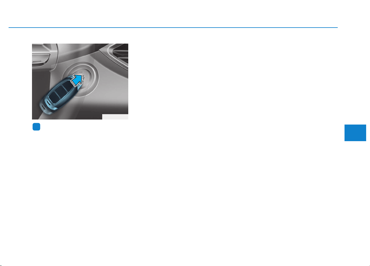
5-19
Driving your vehicle
5
Information
If the smart key battery is weak or the
smart key does not work correctly,
you can start the engine by pressing
the Engine Start/Stop button with the
smart key in the direction of the pic-
ture above.
i
OPDE056005
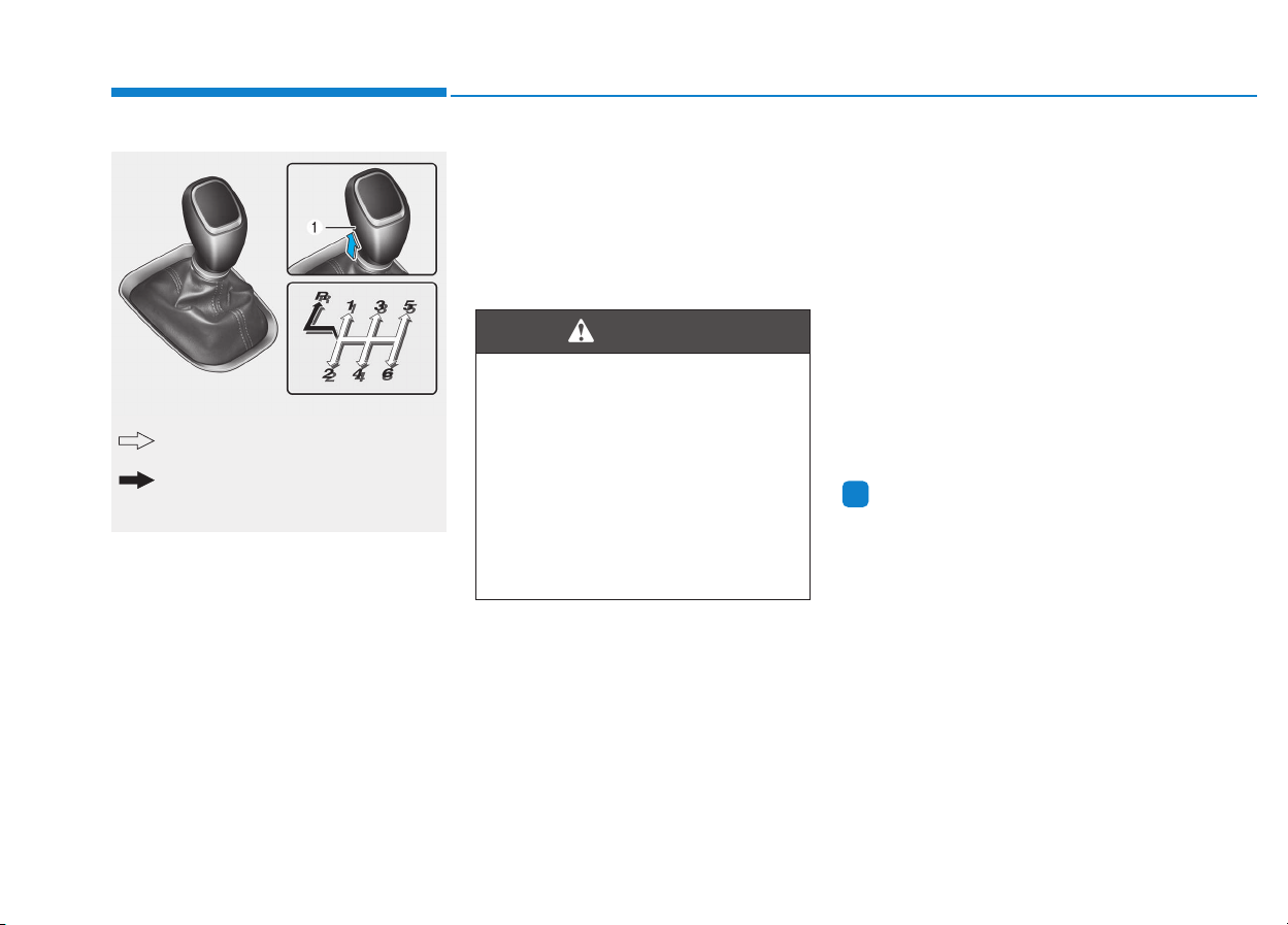
5-20
Driving your vehicle
Manual transmission operation
The manual transmission has 6 for-
ward gears. The transmission is fully
synchronized in all forward gears so
shifting to either a higher or a lower
gear is easily accomplished.
To shift to R (Reverse), make sure
the vehicle has completely stopped,
and then move the shift lever to neu-
tral before moving into R (Reverse).
When you've come to a complete
stop and it's hard to shift into 1st gear
or R (Reverse):
1. Put the shift lever in neutral and
release the clutch pedal.
2. Depress the clutch pedal, and
then shift into first or R (Reverse)
gear.
Information
During cold weather, shifting may be
difficult until the transmission lubri-
cant has warmed up.
i
MMAANNUUAALL TTRRAANNSSMMIISSSSIIOONN ((IIFF EEQQUUIIPPPPEEDD))
Before leaving the driver's seat,
always make sure the shift lever
is in 1st gear when the vehicle
is parked on a uphill and in R
(Reverse) on a downhill, set the
parking brake, and place the
ignition switch in the LOCK/OFF
position. Unexpected vehicle
movement may occur if these
precautions are not followed.
WARNING
OPDE056107
The shift lever can be moved without
pressing the button (1).
The button (1) must be pressed while
moving the shift lever.

5-21
Driving your vehicle
5
Using the clutch
The clutch pedal should be
depressed all the way to the floor
before:
- Starting the engine
The engine will not start without
depressing the clutch pedal.
- Shifting
When releasing the clutch pedal,
release it slowly. The clutch pedal
should always be released while
driving.
To prevent unnecessary wear or
damage to the clutch:
• Do not rest your foot on the
clutch pedal while driving.
• Do not hold the vehicle with the
clutch on an incline, while wait-
ing for the traffic light, etc.
• Always depress the clutch pedal
down fully to prevent noise or
damage.
• Do not start with the 2nd (sec-
ond) gear engaged except when
you start on a slippery road.
Downshifting
Downshift when you must slow down
in heavy traffic or drive up a steep hill
to prevent engine load.
Also, downshifting reduces the
chance of stalling and can accelerate
when you need to increase your
speed again.
When the vehicle is going downhill,
downshifting helps maintain safe
speed by providing brake power from
the engine and enables less wear on
the brakes.
NOTICE

5-22
Driving your vehicle
To prevent damage to the engine,
clutch and transmission:
• When downshifting from 5th
gear to 4th gear, be careful not
to inadvertently push the shift
lever sideways engaging the 2nd
gear. A drastic downshift may
cause the engine speed to
increase to the point the
tachometer will enter the red-
zone.
• Do not downshift more than two
gear at a time or downshift the
gear when the engine is running
at high speed (5,000 RPM or
higher). Such a downshifting
may damage the engine, clutch
and the transmission.
Good driving practices
• Never take the vehicle out of gear
and coast down a hill. This is
extremely dangerous.
• Don't "ride" the brakes. This can
cause the brakes and related parts
to overheat and malfunction.
When you are driving down a long
hill, slow down and shift to a lower
gear. Engine braking will help slow
down the vehicle.
• Slow down before shifting to a
lower gear. This will help avoid
over-revving the engine, which can
cause damage.
• Slow down when you encounter
cross winds. This gives you much
better control of your vehicle.
• Be sure the vehicle is completely
stopped before you shift into R
(Reverse) to prevent damage to
the transmission.
• Exercise extreme caution when
driving on a slippery surface. Be
especially careful when braking,
accelerating or shifting gears. On a
slippery surface, an abrupt change
in vehicle speed can cause the
drive wheels to lose traction and
may cause loss of vehicle control
resulting in an accident
NOTICE
Do not use the engine brake
(shifting from a higher gear to
lower gear) rapidly on slippery
roads. The vehicle may slip
causing an accident.
WARNING

5-23
Driving your vehicle
5
To reduce the risk of SERIOUS
INJURY or DEATH:
• ALWAYS wear your seatbelt.
In a collision, an unbelted
occupant is significantly more
likely to be seriously injured
or killed than a properly belt-
ed occupant.
• Avoid high speeds when cor-
nering or turning.
• Do not make quick steering
wheel movements, such as
sharp lane changes or fast,
sharp turns.
• The risk of rollover is greatly
increased if you lose control
of your vehicle at highway
speeds.
• Loss of control often occurs if
two or more wheels drop off
the roadway and the driver
over steers to reenter the
roadway.
(Continued)
WARNING
(Continued)
• In the event your vehicle
leaves the roadway, do not
steer sharply. Instead, slow
down before pulling back into
the travel lanes.
• HYUNDAI recommends you
follow all posted speed limits.
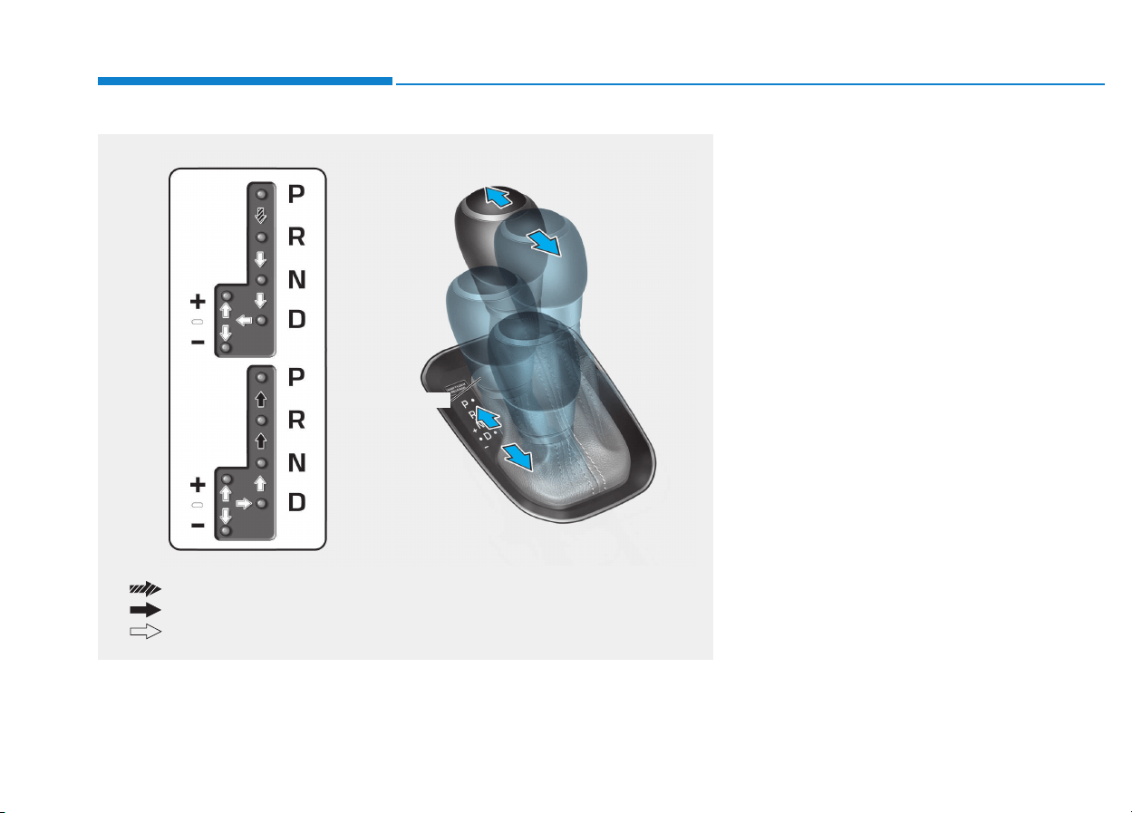
5-24
Driving your vehicle
Automatic transmission opera-
tion
The automatic transmission has six
forward speeds and one reverse
speed.
The individual speeds are selected
automatically in the D (Drive) posi-
tion.
AAUUTTOOMMAATTIICC TTRRAANNSSMMIISSSSIIOONN ((IIFF EEQQUUIIPPPPEEDD))
OPDE056007
The shift lever can freely operate.
Depress the brake pedal and press the shift button while moving the shift lever.
Press the shift button while moving the shift lever.
Manual shift mode
5-25
Driving your vehicle
5
Transmission ranges
The indicator in the instrument clus-
ter displays the shift lever position
when the ignition switch is in the ON
position.
P (Park)
Always come to a complete stop
before shifting into P (Park).
To shift from P (Park), you must
depress firmly on the brake pedal
and make sure your foot is off the
accelerator pedal.
If you have done all of the above
and still cannot shift the lever out of
P (Park), see "Shift-Lock Release"
in this chapter.
The shift lever must be in P (Park)
before turning the engine off.
R (Reverse)
Use this position to drive the vehicle
backward.
Always come to a complete stop
before shifting into or out of R
(Reverse); you may damage the
transmission if you shift into R
(Reverse) while the vehicle is in
motion.
NOTICE
To reduce the risk of serious
injury or death:
• ALWAYS check the surround-
ing areas near your vehicle for
people, especially children,
before shifting a vehicle into
D (Drive) or R (Reverse).
• Before leaving the driver's
seat, always make sure the
shift lever is in the P (Park)
position, then set the parking
brake, and place the ignition
switch in the LOCK/OFF posi-
tion. Unexpected and sudden
vehicle movement can occur
if these precautions are not
followed.
• Do not use the engine brake
(shifting from a high gear to
lower gear) rapidly on slip-
pery roads. The vehicle may
slip causing an accident.
WARNING
• Shifting into P (Park) while the
vehicle is in motion may
cause you to lose control of
the vehicle.
• After the vehicle has stopped,
always make sure the shift
lever is in P (Park), apply the
parking brake, and turn the
engine off.
• When parking on an incline,
block the wheels to prevent
the vehicle from rolling down.
• Do not use the P (Park) posi-
tion in place of the parking
brake.
WARNING
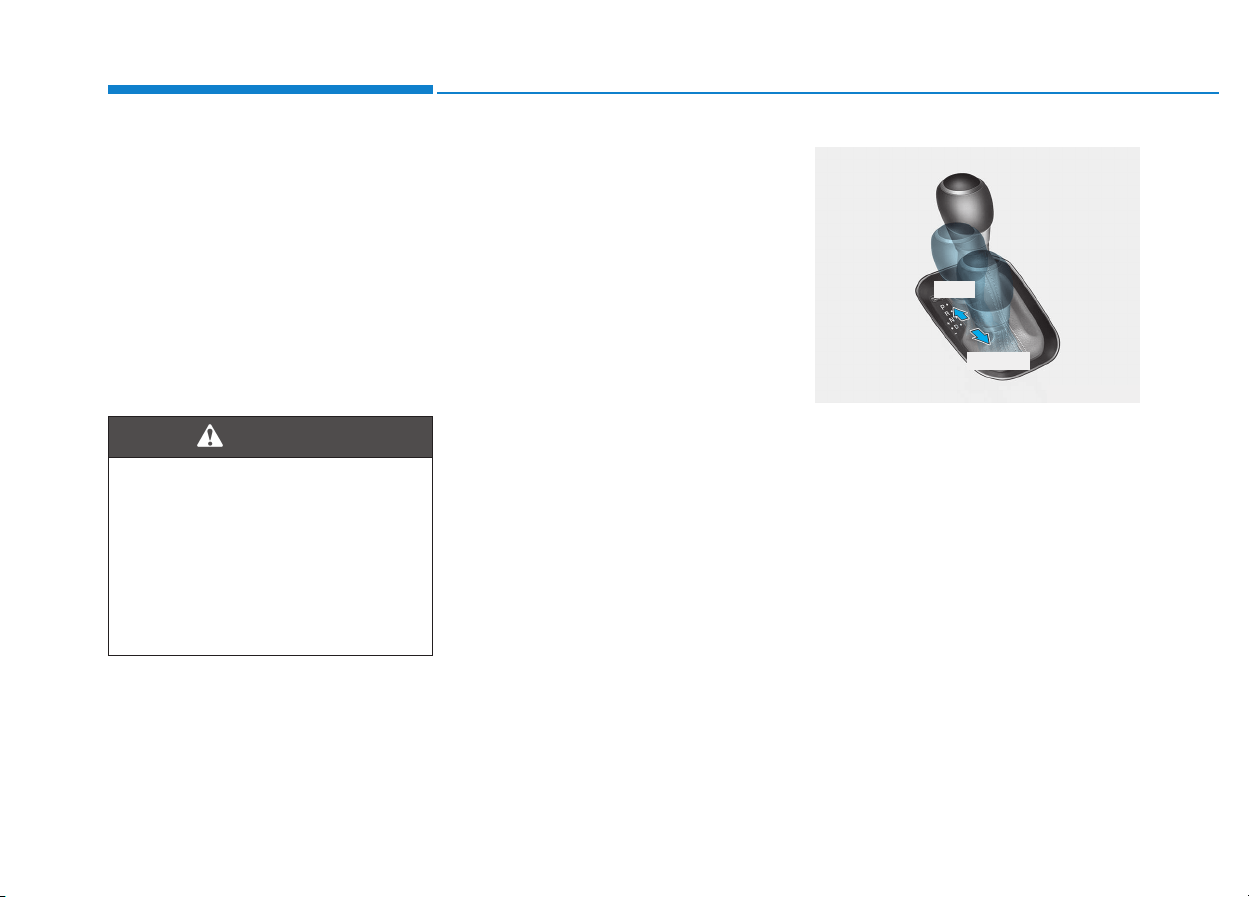
5-26
Driving your vehicle
N (Neutral)
The wheels and transmission are not
engaged.
Use N (Neutral) if you need to restart
a stalled engine, or if it is necessary
to stop with the engine ON. Shift into
P (Park) if you need to leave your
vehicle for any reason.
Always depress the brake pedal
when you are shifting from N
(Neutral) to another gear.
D (Drive)
This is the normal driving position.
The transmission will automatically
shift through a 6-gear sequence, pro-
viding the best fuel economy and
power.
For extra power when passing anoth-
er vehicle or driving uphill, depress
the accelerator fully. The transmis-
sion will automatically downshift to
the next lower gear (or gears, as
appropriate).
Manual shift mode
Whether the vehicle is stationary or
in motion, manual shift mode is
selected by pushing the shift lever
from the D (Drive) position into the
manual gate. To return to D (Drive)
range operation, push the shift lever
back into the main gate.
Do not shift into gear unless
your foot is firmly on the brake
pedal. Shifting into gear when
the engine is running at high
speed can cause the vehicle to
move very rapidly. You could
lose control of the vehicle and
hit people or objects.
WARNING
OPDE056127
+ (UP)
- (DOWN)

5-27
Driving your vehicle
5
In manual shift mode, moving the
shift lever backwards and forwards
will allow you to select the desired
range of gears for the current driving
conditions.
+ (Up) : Push the lever forward once
to shift up one gear.
- (Down) : Pull the lever backwards
once to shift down one
gear.
Information
• Only the six forward gears can be
selected. To reverse or park the
vehicle, move the shift lever to the R
(Reverse) or P (Park) position as
required.
• Downshifts are made automatically
when the vehicle slows down. When
the vehicle stops, 1st gear is auto-
matically selected.
• When the engine rpm approaches
the red zone the transmission will
upshift automatically.
(Continued)
(Continued)
• If the driver presses the lever to
+ (Up) or - (Down) position, the
transmission may not make the
requested gear change if the next
gear is outside of the allowable
engine rpm range. The driver must
execute upshifts in accordance with
road conditions, taking care to keep
the engine rpms below the red zone.
• When driving on a slippery road,
push the shift lever forward into the
+ (Up) position. This causes the
transmission to shift into the 2nd
gear which is better for smooth driv-
ing on a slippery road. Push the shift
lever to the - (Down) side to shift
back to the 1st gear.
i
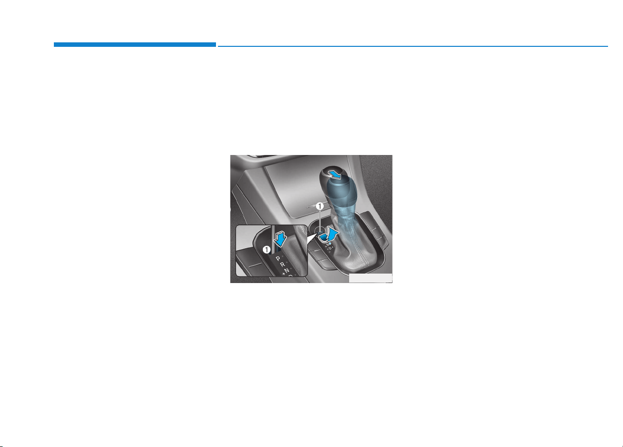
5-28
Driving your vehicle
Shift-lock system
For your safety, the automatic trans-
mission has a shift-lock system
which prevents shifting the transmis-
sion from P (Park) into R (Reverse)
unless the brake pedal is depressed.
To shift the transmission from P
(Park) into R (Reverse):
1. Depress and hold the brake pedal.
2. Start the engine or place the igni-
tion switch in the ON position.
3. Move the shift lever.
Shift-lock release
If the shift lever cannot be moved
from the P (Park) position into R
(Reverse) position with the brake
pedal depressed, continue depress-
ing the brake, and then do the follow-
ing:
1. Place the ignition switch in the
LOCK/OFF position.
2. Apply the parking brake.
3. Carefully remove the cap (1) cov-
ering the shift-lock access hole.
4. Insert a tool (e.g. flathead screw-
driver) into the access hole and
press down on the tool.
5. Move the shift lever while holding
down the screwdriver.
6. Remove the tool from the shiftlock
release access hole then install
the cap.
7. Depress the brake pedal, and then
restart the engine.
If you need to use the shift-lock
release, we recommend that the sys-
tem be inspected by an authorized
HYUNDAI dealer immediately.
Ignition key interlock system
(if equipped)
The ignition key cannot be removed
unless the shift lever is in the P
(Park) position.
OPDE056122

5-29
Driving your vehicle
5
Parking
Always come to a complete stop and
continue to depress the brake pedal.
Move the shift lever into the P (Park)
position, apply the parking brake,
and place the ignition switch in the
LOCK/OFF position. Take the Key
with you when exiting the vehicle.
Good driving practices
• Never move the shift lever from P
(Park) or N (Neutral) to any other
position with the accelerator pedal
depressed.
• Never move the shift lever into P
(Park) when the vehicle is in
motion.
Be sure the vehicle is completely
stopped before you attempt to shift
into R (Reverse) or D (Drive).
• Do not move the shift lever to N
(Neutral) when driving. Doing so
may result in an accident because
of a loss of engine braking and the
transmission could be damaged.
• Do not drive with your foot resting
on the brake pedal. Even light, but
consistent pedal pressure can
result in the brakes overheating,
brake wear and possibly even
brake failure.
• When driving in manual shift mode,
slow down before shifting to a
lower gear. Otherwise, the lower
gear may not be engaged if the
engine rpms are outside of the
allowable range.
• Always apply the parking brake
when leaving the vehicle. Do not
depend on placing the transmis-
sion in P (Park) to keep the vehicle
from moving.
• Exercise extreme caution when
driving on a slippery surface. Be
especially careful when braking,
accelerating or shifting gears. On a
slippery surface, an abrupt change
in vehicle speed can cause the
drive wheels to lose traction and
may cause loss of vehicle control
resulting in an accident
• Optimum vehicle performance and
economy is obtained by smoothly
depressing and releasing the
accelerator.
When you stay in the vehicle
with the engine running, be
careful not to depress the accel-
erator pedal for a long period of
time. The engine or exhaust
system may overheat and start
a fire.
The exhaust gas and the
exhaust system are very hot.
Keep away from the exhaust
system components.
Do not stop or park over flam-
mable materials, such as dry
grass, paper or leaves. They
may ignite and cause a fire.
WARNING

5-30
Driving your vehicle
Information
- Kickdown
Mechanism (if equipped)
Use the kickdown mechanism for
maximum acceleration. Depress the
accelerator pedal beyond the pressure
point. The automatic transmission will
shift to a lower gear depending on the
engine speed.
i
(Continued)
• In the event your vehicle
leaves the roadway, do not
steer sharply. Instead, slow
down before pulling back into
the travel lanes.
• HYUNDAI recommends you
follow all posted speed limits.
To reduce the risk of SERIOUS
INJURY or DEATH:
• ALWAYS wear your seatbelt.
In a collision, an unbelted
occupant is significantly more
likely to be seriously injured
or killed than a properly belt-
ed occupant.
• Avoid high speeds when cor-
nering or turning.
• Do not make quick steering
wheel movements, such as
sharp lane changes or fast,
sharp turns.
• The risk of rollover is greatly
increased if you lose control
of your vehicle at highway
speeds.
• Loss of control often occurs if
two or more wheels drop off
the roadway and the driver
over steers to reenter the
roadway.
(Continued)
WARNING
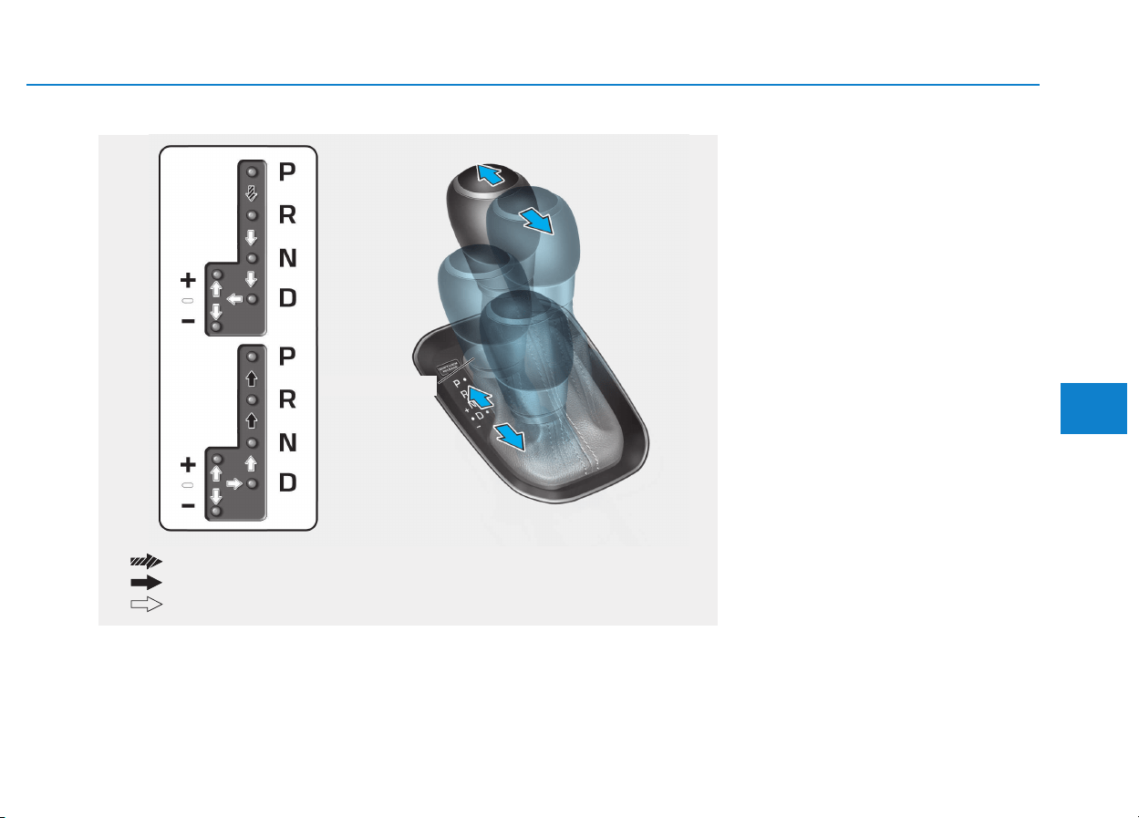
5-31
Driving your vehicle
5
• The dual clutch transmission can
be thought of as an automatically
shifting manual transmission. It
gives the driving feel of a manual
transmission, yet provides the
ease of a fully automatic transmis-
sion.
• When D (Drive) is selected, the
transmission will automatically shift
through the gears similar to a con-
ventional automatic transmission.
Unlike a traditional automatic
transmission, the gear shifting can
sometimes be felt and heard as the
actuators engage the clutches and
the gears are selected.
• The dual clutch transmission incor-
porates a dry-type dual clutch
mechanism, which allows for better
acceleration performance and
increased fuel efficiency while driv-
ing. But it differs from a conven-
tional automatic transmission
because it does not incorporate a
torque converter. Instead, the tran-
sition from one gear to the next is
managed by clutch slip, especially
at lower speeds.
DDUUAALL CCLLUUTTCCHH TTRRAANNSSMMIISSSSIIOONN ((IIFF EEQQUUIIPPPPEEDD))
OPDE056007
The shift lever can freely operate.
Depress the brake pedal and press the shift button while moving the shift lever.
Press the shift button while moving the shift lever.
Manual shift mode
Dual clutch transmission operation
The dual clutch transmission has seven forward speeds and one reverse
speed. The individual speeds are selected automatically when the shift lever
is in the D (Drive) position.

5-32
Driving your vehicle
As a result, shifts are sometimes
more noticeable, and a light vibra-
tion can be felt as the transmission
shaft speed is matched with the
engine shaft speed. This is a nor-
mal condition of the dual clutch
transmission.
• The dry-type clutch transfers
torque more directly and provides
a direct-drive feeling which may
feel different from a conventional
automatic transmission. This may
be more noticeable when launch-
ing the vehicle from a stop or when
traveling at low, stop-and-go vehi-
cle speeds.
• When rapidly accelerating from a
lower vehicle speed, the engine
rpm may increase dramatically as
a result of clutch slip as the dual
clutch transmission selects the cor-
rect gear. This is a normal condi-
tion.
• When accelerating from a stop on
an incline, press the accelerator
smoothly and gradually to avoid
any shudder feeling or jerkiness.
• When traveling at a lower vehicle
speed, if you release the accelera-
tor pedal quickly, you may feel
engine braking before the trans-
mission changes gears. This
engine braking feeling is similar to
operating a manual transmission at
low speed.
• When driving downhill, you may
wish to move the gear shift lever to
Manual Shift mode and downshift
to a lower gear in order to control
your speed without using the brake
pedal excessively.
• When you turn the engine on and
off, you may hear clicking sounds
as the system goes through a self-
test. This is a normal sound for the
dual clutch transmission.
• During the first 1,500 km (1000
miles), you may feel that the vehi-
cle may not be smooth when accel-
erating at low speed. During this
break-in period, the shift quality
and performance of your new vehi-
cle is continuously optimized.
To reduce the risk of serious
injury or death:
• ALWAYS check the surround-
ing areas near your vehicle for
people, especially children,
before shifting a vehicle into
D (Drive) or R (Reverse).
• Before leaving the driver's
seat, always make sure the
shift lever is in the P (Park)
position, then set the parking
brake, and place the ignition
switch in the LOCK/OFF posi-
tion. Unexpected and sudden
vehicle movement can occur
if these precautions are not
followed.
• Do not use aggressive engine
braking (shifting from a high-
er gear to a lower gear) on
slippery roads. This could
cause the tires to slip and may
result in an accident.
WARNING
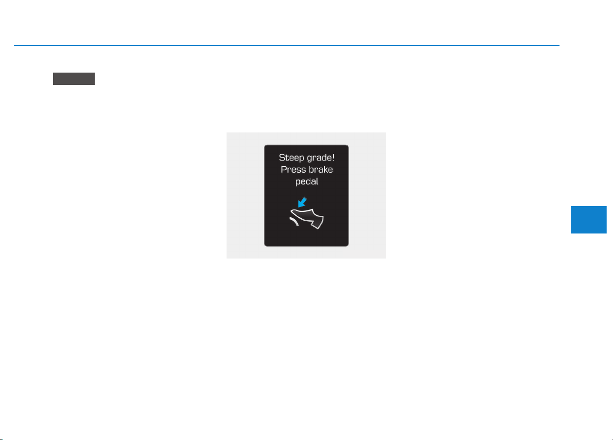
5-33
Driving your vehicle
5
• Always come to a complete stop
before shifting into D (Drive) or
R (Reverse).
• Do not put the shift lever in N
(Neutral) while driving.
DCT warning messages
This warning message is displayed
when vehicle is driven slowly on a
grade and the vehicle detects that
the brake pedal is not applied.
Steep grade
Driving up hills or on steep grades:
• To hold the vehicle on an incline
use the foot brake or the parking
brake.
• When in stop-and-go traffic on an
incline, allow a gap to form ahead
of you before moving the vehicle
forward. Then hold the vehicle on
the incline with the foot brake.
• If the vehicle is held or creeping
forward on an incline by applying
the accelerator pedal, the clutch
and transmission may overheat
which can result in damage. At this
time, a warning message will
appear on the LCD display.
• If the LCD warning is active, the
foot brake must be applied.
• Ignoring the warnings can lead to
damage to the transmission.
NOTICE
OTLE055018

5-34
Driving your vehicle
Transmission high temperature
• Under certain conditions, such as
repeated stop-and-go launches on
steep grades, sudden take off or
acceleration, or other harsh driving
conditions, the transmission clutch
temperatures will increase exces-
sively.
• When the clutch temperatures are
too high, the "Transmission temp is
high! Stop safely" warning mes-
sage will appear on the LCD dis-
play, a chime will sound, and the
transmission shifting may not be
smooth.
• If this occurs, pull over to a safe
location, stop the vehicle with the
engine running, apply the brakes
and shift the vehicle to P (Park),
and allow the transmission to cool.
• If you ignore this warning, the driv-
ing condition may become worse.
You may experience abrupt shifts,
frequent shifts, or jerkiness.
• When the message "Trans cooled.
Resume driving." appears you can
continue to drive your vehicle.
• When possible, drive the vehicle
smoothly.
Transmission overheated
• If the vehicle continues to be driv-
en and the clutch temperatures
reach the maximum temperature
limit, the "Trans Hot! Park with
engine on" warning will be dis-
played. When this occurs the clutch
is disabled until the clutch cools to
normal temperatures.
• The warning will display a time to
wait for the transmission to cool.
• If this occurs, pull over to a safe
location, stop the vehicle with the
engine running, apply the brakes
and shift the vehicle to P (Park),
and allow the transmission to cool.
OTLE055023 OTLA055141/OTLA055142

5-35
Driving your vehicle
5
• When the message "Trans cooled.
Resume driving." appears you can
continue to drive your vehicle
• When possible, drive the vehicle
smoothly.
If any of the warning messages in
the LCD display continue to blink, for
your safety, we recommend you con-
tact an authorized HYUNDAI dealer
and have the system checked.
Transmission ranges
The indicator in the instrument clus-
ter displays the shift lever position
when the ignition switch is in the ON
position.
P (Park)
Always come to a complete stop
before shifting into P (Park).
To shift from P (Park), you must
depress firmly on the brake pedal
and make sure your foot is off the
accelerator pedal.
If you have done all of the above
and still cannot shift the lever out
of P (Park), see "Shift-Lock
Release" in this chapter.
The shift lever must be in P (Park)
before turning the engine off.
• Shifting into P (Park) while the
vehicle is in motion may
cause you to lose control of
the vehicle.
• After the vehicle has stopped,
always make sure the shift
lever is in P (Park), apply the
parking brake, and turn the
engine off.
• Do not use the P (Park) posi-
tion in place of the parking
brake.
WARNING

5-36
Driving your vehicle
R (Reverse)
Use this position to drive the vehicle
backward.
Always come to a complete stop
before shifting into or out of R
(Reverse); you may damage the
transmission if you shift into R
(Reverse) while the vehicle is in
motion.
N (Neutral)
The wheels and transmission are not
engaged.
Use N (Neutral) if you need to restart
a stalled engine, or if it is necessary
to stop with the engine ON. Shift into
P (Park) if you need to leave your
vehicle for any reason.
Always depress the brake pedal
when you are shifting from N
(Neutral) to another gear.
D (Drive)
This is the normal driving position.
The transmission will automatically
shift through a 7-gear sequence, pro-
viding the best fuel economy and
power.
For extra power when passing anoth-
er vehicle or driving uphill, depress
the accelerator fully. The transmis-
sion will automatically downshift to
the next lower gear (or gears, as
appropriate).
Manual shift mode
Whether the vehicle is stationary or
in motion, manual shift mode is
selected by pushing the shift lever
from the D (Drive) position into the
manual gate. To return to D (Drive)
range operation, push the shift lever
back into the main gate.
In manual shift mode, moving the
shift lever backwards and forwards
will allow you to make gearshifts rap-
idly.
Up (+) : Push the lever forward
once to shift up one gear.
Down (-) : Pull the lever backwards
once to shift down one
gear.
NOTICE
OPDE056127
+ (UP)
- (DOWN)
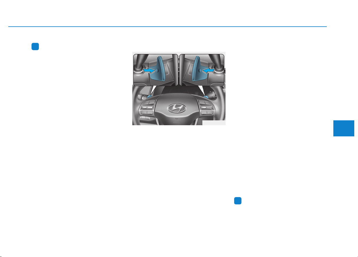
5-37
Driving your vehicle
5
Information
• Only the seven forward gears can be
selected. To reverse or park the
vehicle, move the shift lever to the R
(Reverse) or P (Park) position as
required.
• Downshifts are made automatically
when the vehicle slows down. When
the vehicle stops, 1st gear is auto-
matically selected.
• When the engine rpm approaches
the red zone the transmission will
upshift automatically.
• If the driver presses the lever to
+ (Up) or - (Down) position, the
transmission may not make the
requested gear change if the next
gear is outside of the allowable
engine rpm range. The driver must
execute upshifts in accordance with
road conditions, taking care to keep
the engine rpms below the red zone.
Paddle shifter (if equipped)
The paddle shifter is available when
the shift lever is in the D (Drive) posi-
tion or the manual shift mode.
With the shift lever in the D posi-
tion
The paddle shifter will operate when
the vehicle speed is more than
10km/h.
Pull the [+] or [-] paddle shifter once
to shift up or down one gear and the
system changes from automatic
mode to manual mode.
When the vehicle speed is lower
than 10 km/h, if you depress the
accelerator pedal for more than 5
seconds or if you move the shift lever
from D (Drive) to manual shift mode
and move it from manual shift mode
to D (Drive) again, the system
changes from manual mode to auto-
matic mode.
With the shift lever in the manual
shift mode
Pull the [+] or [-] paddle shifter once
to shift up or down one gear.
Information
If the [+] and [-] paddle shifters are
pulled at the same time, gear shift may
not occur.
i
i
OPD056015
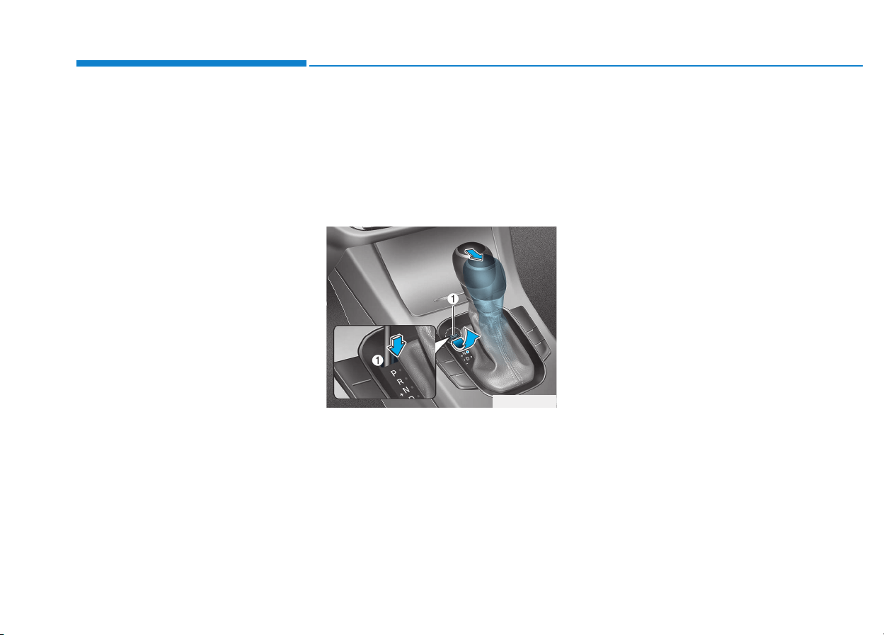
5-38
Driving your vehicle
Shift-lock system
For your safety, the dual clutch trans-
mission has a shift-lock system
which prevents shifting the transmis-
sion from P (Park) into R (Reverse)
unless the brake pedal is depressed.
To shift the transmission from P
(Park) into R (Reverse):
1. Depress and hold the brake pedal.
2. Start the engine or place the igni-
tion switch in the ON position.
3. Move the shift lever.
Shift-lock release
If the shift lever cannot be moved
from the P (Park) position into R
(Reverse) position with the brake
pedal depressed, continue depress-
ing the brake, and then do the follow-
ing:
1. Place the ignition switch in the
LOCK/OFF position.
2. Apply the parking brake.
3. Carefully remove the cap (1) cov-
ering the shift-lock access hole.
4. Insert a tool (e.g. flathead screw-
driver) into the access hole and
press down on the tool.
5. Move the shift lever while holding
down the screwdriver.
6. Remove the tool from the shiftlock
release access hole then install
the cap.
7. Depress the brake pedal, and then
restart the engine.
If you need to use the shift-lock
release, we recommend that the sys-
tem be inspected by an authorized
HYUNDAI dealer immediately.
Ignition key interlock system
(if equipped)
The ignition key cannot be removed
unless the shift lever is in the P
(Park) position.
OPDE056122

5-39
Driving your vehicle
5
Parking
Always come to a complete stop and
continue to depress the brake pedal.
Move the shift lever into the P (Park)
position, apply the parking brake,
and place the ignition switch in the
LOCK/OFF position. Take the Key
with you when exiting the vehicle.
Good driving practices
• Never move the shift lever from P
(Park) or N (Neutral) to any other
position with the accelerator pedal
depressed.
• Never move the shift lever into P
(Park) when the vehicle is in
motion.
Be sure the vehicle is completely
stopped before you attempt to shift
into R (Reverse) or D (Drive).
• Do not move the shift lever to N
(Neutral) when driving. Doing so
may result in an accident because
of a loss of engine braking and the
transmission could be damaged.
• Do not drive with your foot resting
on the brake pedal. Even light, but
consistent pedal pressure can
result in the brakes overheating,
brake wear and possibly even
brake failure.
• When driving in manual shift mode,
slow down before shifting to a
lower gear. Otherwise, the lower
gear may not be engaged if the
engine rpms are outside of the
allowable range.
• Always apply the parking brake
when leaving the vehicle. Do not
depend on placing the transmis-
sion in P (Park) to keep the vehicle
from moving.
• Exercise extreme caution when
driving on a slippery surface. Be
especially careful when braking,
accelerating or shifting gears. On a
slippery surface, an abrupt change
in vehicle speed can cause the
drive wheels to lose traction and
may cause loss of vehicle control
resulting in an accident.
• Optimum vehicle performance and
economy is obtained by smoothly
depressing and releasing the
accelerator.
When you stay in the vehicle
with the engine running, be
careful not to depress the accel-
erator pedal for a long period of
time. The engine or exhaust
system may overheat and start
a fire.
The exhaust gas and the
exhaust system are very hot.
Keep away from the exhaust
system components.
Do not stop or park over flam-
mable materials, such as dry
grass, paper or leaves. They
may ignite and cause a fire.
WARNING

5-40
Driving your vehicle
Information
- Kickdown
Mechanism (if equipped)
Use the kickdown mechanism for
maximum acceleration. Depress the
accelerator pedal beyond the pressure
point. The automatic transmission will
shift to a lower gear depending on the
engine speed.
i
To reduce the risk of SERIOUS
INJURY or DEATH:
• ALWAYS wear your seatbelt.
In a collision, an unbelted
occupant is significantly more
likely to be seriously injured
or killed than a properly belt-
ed occupant.
• Avoid high speeds when cor-
nering or turning.
• Do not make quick steering
wheel movements, such as
sharp lane changes or fast,
sharp turns.
• The risk of rollover is greatly
increased if you lose control
of your vehicle at highway
speeds.
• Loss of control often occurs if
two or more wheels drop off
the roadway and the driver
over steers to reenter the
roadway.
(Continued)
(Continued)
• In the event your vehicle
leaves the roadway, do not
steer sharply. Instead, slow
down before pulling back into
the travel lanes.
• HYUNDAI recommends you
follow all posted speed limits.
WARNING
5-41
Driving your vehicle
5
Power brakes
Your vehicle has power-assisted
brakes that adjust automatically
through normal usage.
If the engine is not running or is
turned off while driving, the power
assist for the brakes will not work.
You can still stop your vehicle by
applying greater force to the brake
pedal than typical. The stopping dis-
tance, however, will be longer than
with power brakes.
When the engine is not running, the
reserve brake power is partially
depleted each time the brake pedal
is applied. Do not pump the brake
pedal when the power assist has
been interrupted.
Pump the brake pedal only when
necessary to maintain steering con-
trol on slippery surfaces.
BBRRAAKKIINNGG SSYYSSTTEEMM
Take the following precautions:
• Do not drive with your foot
resting on the brake pedal.
This will create abnormal high
brake temperatures, exces-
sive brake lining and pad
wear, and increased stopping
distances.
• When descending a long or
steep hill, shift to a lower gear
and avoid continuous applica-
tion of the brakes. Applying
the brakes continuously will
cause the brakes to overheat
and could result in a tempo-
rary loss of braking perform-
ance.
(Continued)
(Continued)
• Wet brakes may impair the
vehicle's ability to safely slow
down; the vehicle may also
pull to one side when the
brakes are applied. Applying
the brakes lightly will indicate
whether they have been
affected in this way. Always
test your brakes in this fash-
ion after driving through deep
water. To dry the brakes, light-
ly tap the brake pedal to heat
up the brakes while maintain-
ing a safe forward speed until
brake performance returns to
normal. Avoid driving at high
speeds until the brakes func-
tion correctly.
WARNING
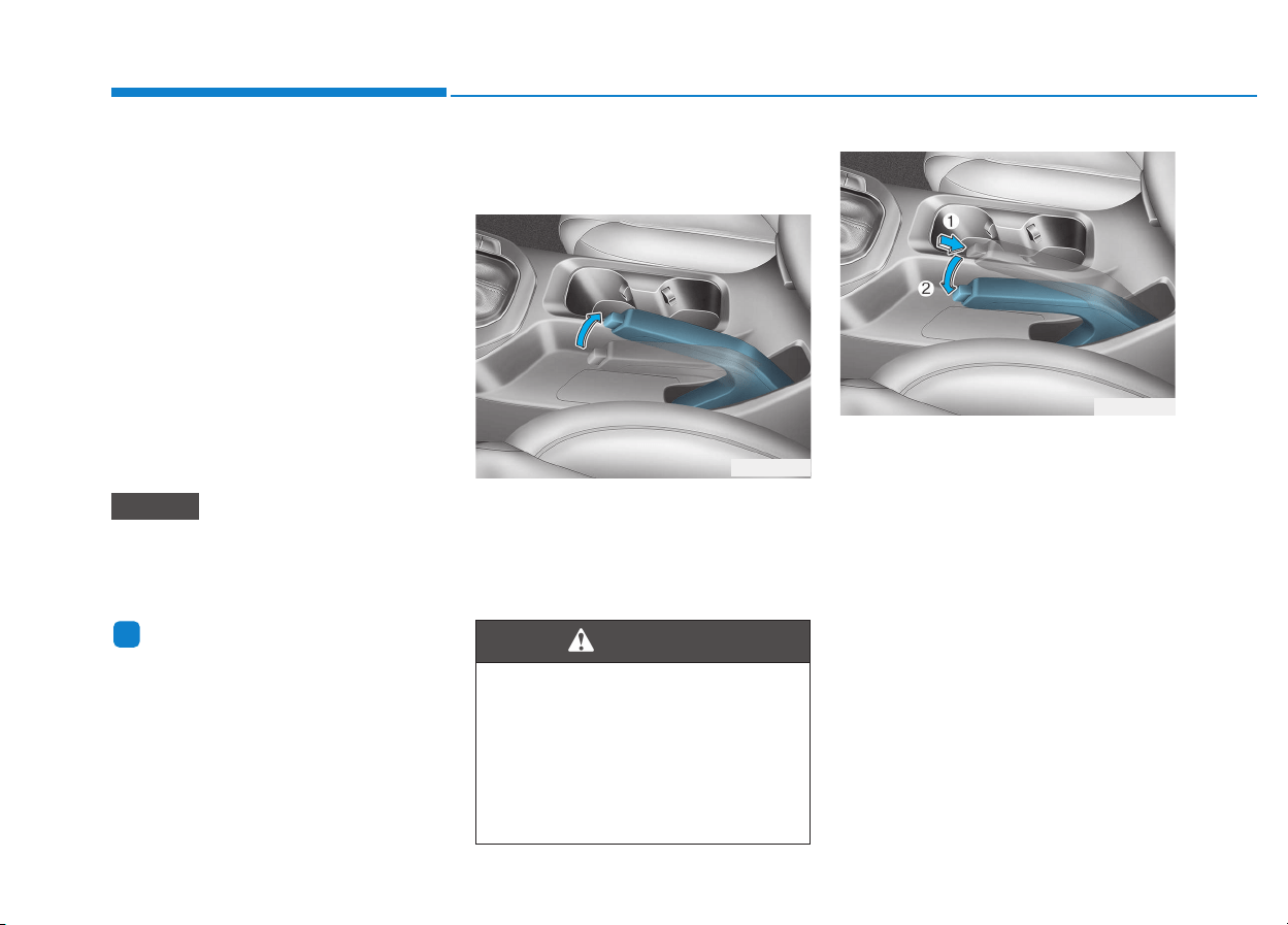
5-42
Driving your vehicle
Disc brakes wear indicator
When your brake pads are worn and
new pads are required, you will hear
a high pitched warning sound from
your front or rear brakes. You may
hear this sound come and go or it
may occur whenever you depress
the brake pedal.
Note that some driving conditions or
climates may cause a brake squeal
when you first apply (or lightly apply)
the brakes. This is normal and does
not indicate a problem with your
brakes.
To avoid costly brake repairs, do
not continue to drive with worn
brake pads.
Information
Always replace brake pads as com-
plete front or rear axle sets.
Parking brake
(hand type, if equipped)
Always set the parking brake before
leaving the vehicle, to apply:
Firmly depress the brake pedal.
Pull up the parking brake lever as far
as possible.
To release:
Firmly depress the brake pedal.
Slightly pull up the parking brake
lever.
While pressing the release button
(1), lower the parking brake (2).
If the parking brake does not release
or does not release all the way, we
recommend that the system be
checked by an authorized HYUNDAI
dealer.
i
NOTICE
To reduce the risk of SERIOUS
INJURY or DEATH, do not oper-
ate the parking brake while the
vehicle is moving except in an
emergency situation. It could
damage the brake system and
lead to an accident.
WARNING
OPD056016
OPD056017
5-43
Driving your vehicle
5
• Do not apply the accelerator
pedal while the parking brake is
engaged. If you depress the
accelerator pedal with the park-
ing brake engaged, warning will
sound. Damage to the parking
brake may occur.
• Driving with the parking brake on
can overheat the braking system
and cause premature wear or
damage to brake parts. Make sure
the parking brake is released and
the Brake Warning Light is off
before driving.
Check the Parking
Brake Warning Light
by placing the ignition
switch to the ON posi-
tion (do not start the
engine).
This light will be illuminated when the
parking brake is applied with the igni-
tion switch in the START or ON posi-
tion.
Before driving, be sure the parking
brake is released and the Brake
Warning Light is OFF.
If the Parking Brake Warning Light
remains on after the parking brake is
released while engine is running,
there may be a malfunction in the
brake system. Immediate attention is
necessary.
If at all possible, cease driving the
vehicle immediately. If that is not pos-
sible, use extreme caution while
operating the vehicle and only con-
tinue to drive the vehicle until you
can reach a safe location.
NOTICE
• Whenever leaving the vehicle
or parking, always come to a
complete stop and continue
to depress the brake pedal.
Move the shift lever into the
1st gear (for manual transmis-
sion vehicle) or P (Park, for
automatic transmission/dual
clutch transmission vehicle)
position, then apply the park-
ing brake, and place the igni-
tion switch in the LOCK/OFF
position.
Vehicles with the parking
brake not fully engaged are at
risk for moving inadvertently
and causing injury to yourself
or others.
• NEVER allow anyone who is
unfamiliar with the vehicle to
touch the parking brake. If the
parking brake is released
unintentionally, serious injury
may occur.
• Only release the parking brake
when you are seated inside the
vehicle with your foot firmly on
the brake pedal.
WARNING
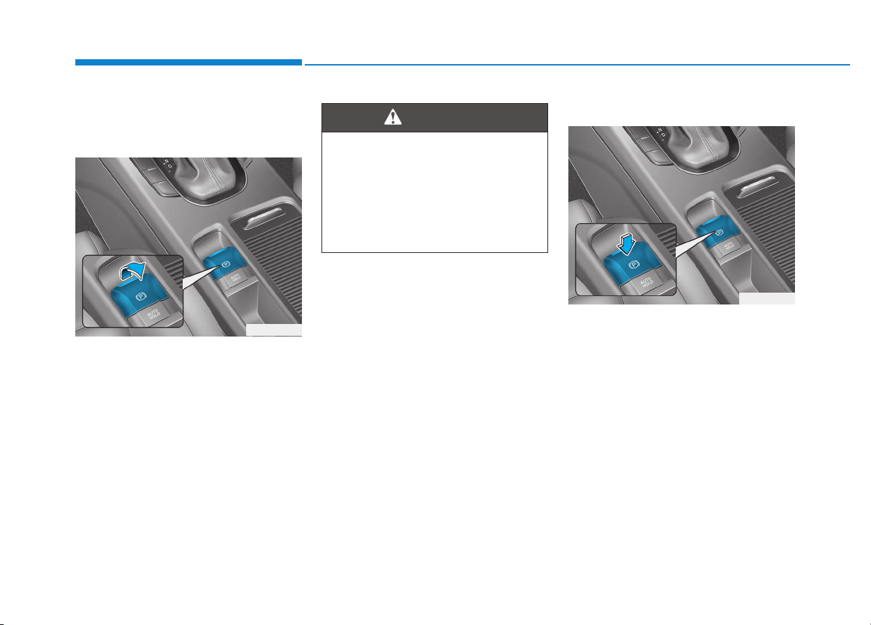
5-44
Driving your vehicle
Electronic Parking Brake (EPB)
(if equipped)
Applying the parking brake
To apply the EPB
(Electronic Parking Brake):
1. Depress the brake pedal.
2. Pull up the EPB switch.
Make sure the Parking Brake
Warning Light comes on.
Releasing the parking brake
To release the EPB (Electronic
Parking Brake), press the EPB
switch in the following condition:
• Place the Engine Start/Stop button
in the ON position.
• Depress the brake pedal.
Make sure the Parking Brake
Warning Light goes off.
OPD056018
To reduce the risk of SERIOUS
INJURY or DEATH, do not oper-
ate the EPB while the vehicle is
moving except in an emergency
situation. It could damage the
brake system and lead to an
accident.
WARNING
OPD056019

5-45
Driving your vehicle
5
To release EPB (Electronic Parking
Brake) automatically:
• Shift lever in P (Park)
With the engine running depress
the brake pedal and shift out of P
(Park) to R (Rear) or D (Drive).
• Shift lever in N (Neutral)
With the engine running depress
the brake pedal and shift out of N
(Neutral) to R (Rear) or D (Drive).
• Manual transmission vehicle
1. Start the engine.
2. Fasten the driver's seat belt.
3. Close the driver's door, engine
hood and tailgate.
4. Depress the clutch pedal with
the gear engaged.
5. Depress the accelerator pedal
while releasing the clutch pedal.
• Automatic transmission/Dual clutch
transmission vehicle
1. Start the engine.
2. Fasten the driver's seat belt.
3. Close the driver's door, engine
hood and tailgate.
4. Depress the accelerator pedal
while the shift lever is in R (Rear),
D (Drive) or manual shift mode.
Make sure the Parking Brake
Warning light goes off.
Information
• For your safety, you can engage the
EPB even though the Engine Stop/
Start button is in the OFF position,
but you cannot release it.
• For your safety, depress the brake
pedal and release the parking brake
manually with the EPB switch when
you drive downhill or when backing
up the vehicle.
Information
- Manual trans-
mission
A vehicle towing a trailer on a hill or
on an incline may slightly roll back-
wards when starting the vehicle. To
prevent the situation follow the below
instructions.
1. Depress the clutch pedal and select
a gear.
2. Keep pulling up the EPB switch.
3. Depress the accelerator pedal and
slowly release the clutch pedal.
4. If the vehicle starts off with enough
driving power release the EPB
switch.
Do not follow the above procedure
when driving on a flat level ground.
The vehicle may suddenly move for-
ward.
i
i
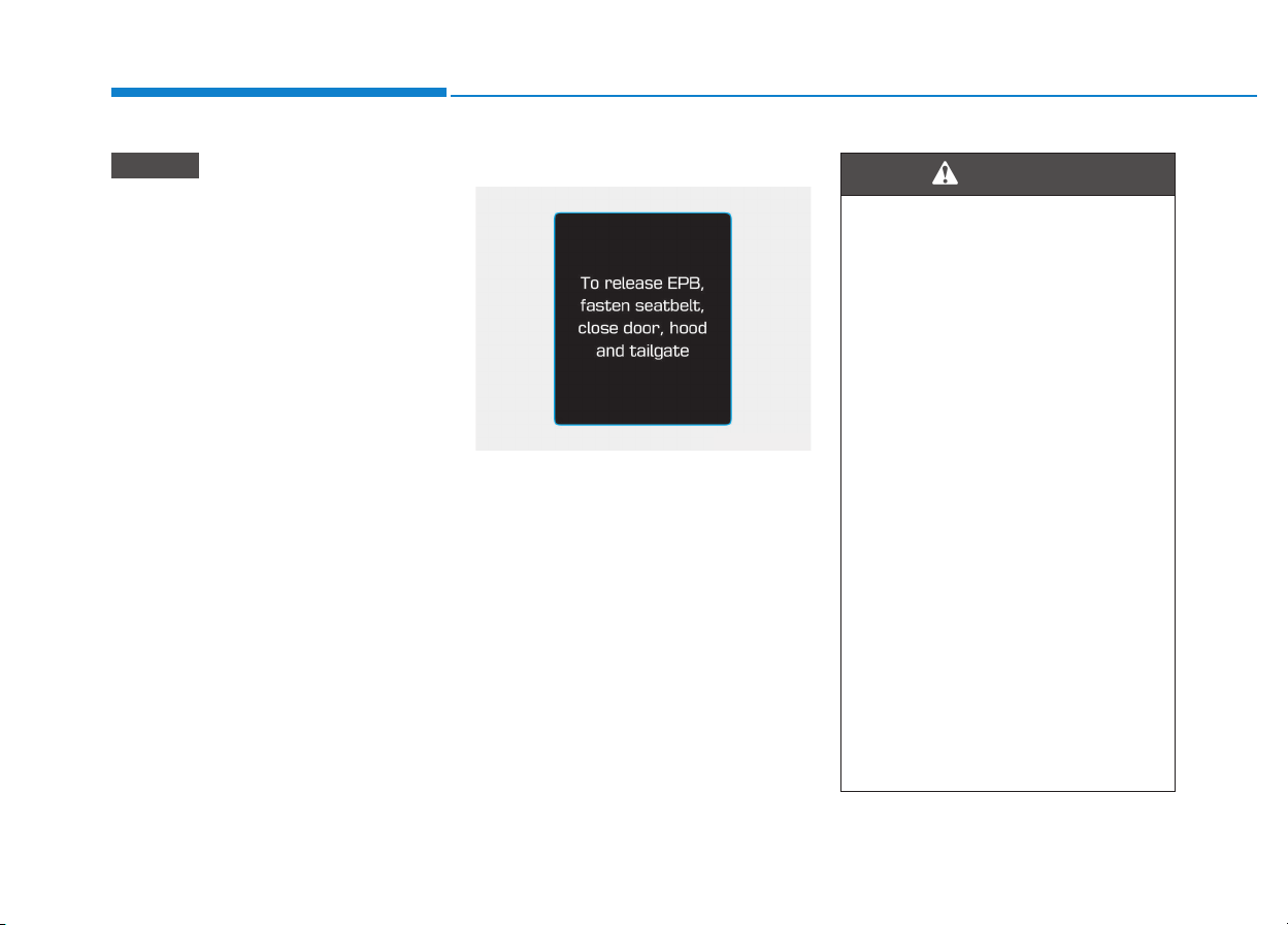
5-46
Driving your vehicle
• If the parking brake warning
light is still on even though the
EPB has been released, we rec-
ommend that the system be
checked by an authorized
HYUNDAI dealer.
• Do not drive your vehicle with
the EPB applied. It may cause
excessive brake pad and brake
rotor wear.
EPB (Electronic Parking Brake)
may be automatically applied
when:
• Requested by other systems
• If the driver turns the engine off
while Auto Hold is operating, EPB
will be automatically applied.
Warning messages
To release EPB, fasten seatbelt,
close door, hood and tailgate
• If you try to drive with the EPB
applied, a warning will sound and a
message will appear.
• If the driver's seat belt is unfas-
tened and the engine hood or tail-
gate is opened, a warning will
sound and a message will appear.
• If there is a problem with the vehi-
cle, a warning may sound and a
message may appear.
If the situation occurs, depress the
brake pedal and release EPB by
pressing the EPB switch.
NOTICE
OPDE056130
• Whenever leaving the vehicle
or parking, always come to a
complete stop and continue
to depress the brake pedal.
Move the shift lever into the P
(Park) position, press the EPB
switch, and press the Engine
Start/Stop button to the OFF
position. Take the Smart Key
with you when exiting the
vehicle.
Vehicles not fully engaged in
P (Park) with the parking
brake set are at risk for mov-
ing inadvertently and causing
injury to yourself or others.
• NEVER allow anyone who is
unfamiliar with the vehicle to
touch the EPB switch. If the
EPB is released unintentional-
ly, serious injury may occur.
• Only release the EPB when
you are seated inside the
vehicle with your foot firmly
on the brake pedal.
WARNING
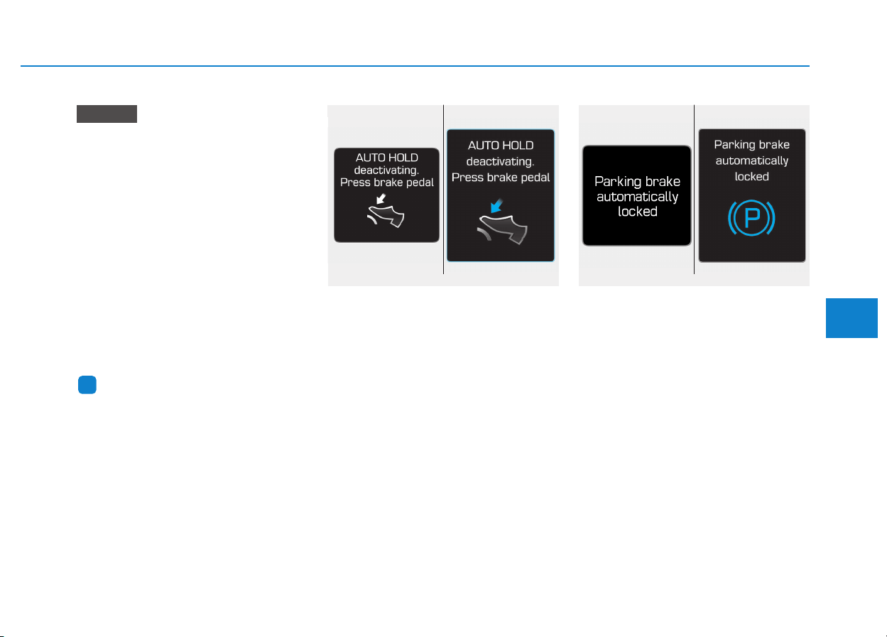
5-47
Driving your vehicle
5
• Do not apply the accelerator
pedal while the parking brake is
engaged. If you depress the
accelerator pedal with the EPB
engaged, a warning will sound
and a message will appear.
Damage to the parking brake
may occur.
• Driving with the parking brake
on can overheat the braking sys-
tem and cause premature wear
or damage to brake parts. Make
sure the EPB is released and the
Parking Brake Warning Light is
off before driving.
Information
• A clicking sound may be heard
while operating or releasing the
EPB. These conditions are normal
and indicate that the EPB is func-
tioning properly.
• When leaving your keys with a
parking attendant or assistant,
make sure to inform him/her how to
operate the EPB.
AUTO HOLD deactivating.
Press brake pedal
When the conversion from Auto Hold
to EPB is not working properly a
warning will sound and a message
will appear.
Parking brake automatically locked
If the EPB is applied while Auto Hold
is activated, a warning will sound and
a message will appear.
i
NOTICE
■ Type A ■ Type B
OTLE055028/OLFH044408L
■ Type A ■ Type B
OLF054131N/OLF044411N
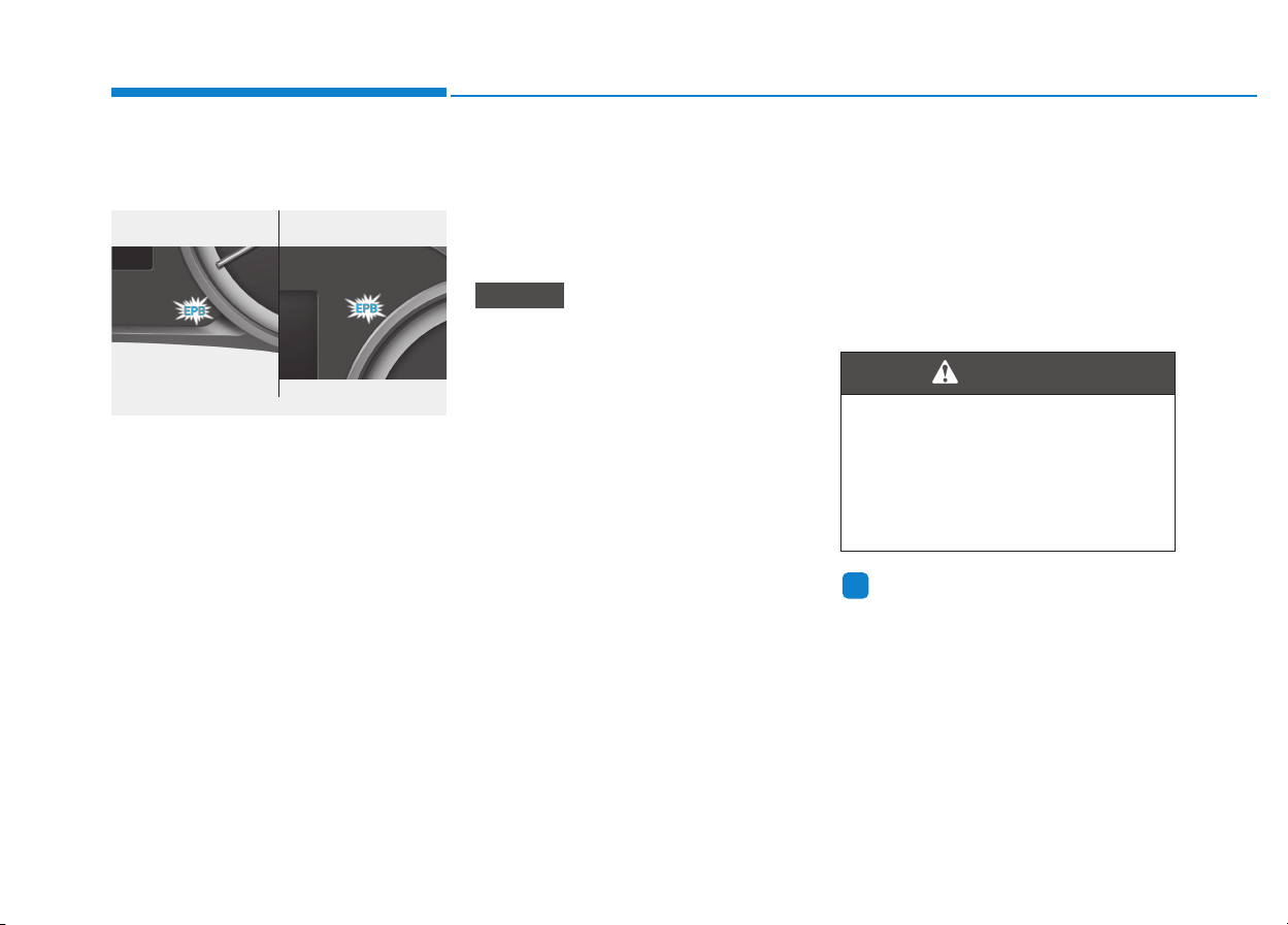
5-48
Driving your vehicle
EPB malfunction indicator
(if equipped)
This warning light illuminates if the
Engine Start/Stop button is changed
to the ON position and goes off in
approximately 3 seconds if the sys-
tem is operating normally.
If the EPB malfunction indicator
remains on, comes on while driving,
or does not come on when the
Engine Start/Stop button is changed
to the ON position, this indicates that
the EPB may have malfunctioned.
If this occurs, we recommend that
the system be checked by an author-
ized HYUNDAI dealer.
The EPB malfunction indicator may
illuminate when the ESC indicator
comes on to indicate that the ESC is
not working properly, but it does not
indicate a malfunction of the EPB.
• If the EPB warning light is still
on, we recommend that the sys-
tem be checked by an author-
ized HYUNDAI dealer.
• If the parking brake warning
light does not illuminate or
blinks even though the EPB
switch was pulled up, the EPB
may not be applied.
• If the parking brake warning light
blinks when the EPB warning
light is on, press the switch, and
then pull it up. Repeat this one
more time. If the EPB warning
does not go off, we recommend
that the system be checked by
an authorized HYUNDAI dealer.
Emergency braking
If there is a problem with the brake
pedal while driving, emergency brak-
ing is possible by pulling up and
holding the EPB switch. Braking is
possible only while you are holding
the EPB switch. However, braking
distance will be longer than normal.
Information
During emergency braking, the park-
ing brake warning light will illumi-
nate to indicate that the system is
operating.
i
NOTICE
■ Type A ■ Type B
OPD056021/OPD056074
Do not operate the parking
brake while the vehicle is mov-
ing except in an emergency sit-
uation. It could damage the
brake system and lead to a
severe accident.
WARNING
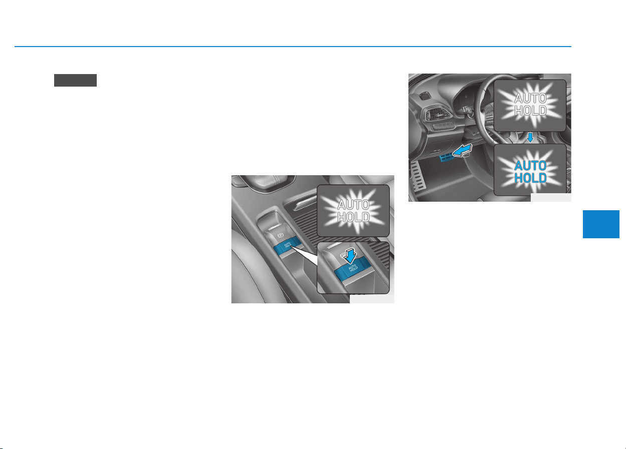
5-49
Driving your vehicle
5
If you continuously notice a noise
or burning smell when the EPB is
used for emergency braking, we
recommend that the system be
checked by an authorized HYUNDAI
dealer.
When the EPB (Electronic Parking
Brake) does not release
If the EPB does not release normal-
ly, we recommend that you contact
an authorized HYUNDAI dealer by
loading the vehicle on a flatbed tow
truck and have the system checked.
AUTO HOLD (if equipped)
The Auto Hold maintains the vehicle
in a standstill even though the brake
pedal is not depressed after the driv-
er brings the vehicle to a complete
stop by depressing the brake pedal.
To apply :
1. With the driver's door, engine
hood and tailgate closed, fasten
the driver's seat belt or depress
the brake pedal and then press
the [AUTO HOLD] switch. The
white AUTO HOLD indicator will
come on and the system will be in
the standby position.
2. When you stop the vehicle com-
pletely by depressing the brake
pedal, the Auto Hold maintains the
brake pressure to hold the vehicle
stationary. The indicator changes
from white to green.
3. The vehicle will remain stationary
even if you release the brake
pedal.
4. If EPB is applied, Auto Hold will be
released.
NOTICE
OPD056022
WW
WW
hh
hh
ii
ii
tt
tt
ee
ee
OPD056023
WW
WW
hh
hh
ii
ii
tt
tt
ee
ee
GG
GG
rr
rr
ee
ee
ee
ee
nn
nn
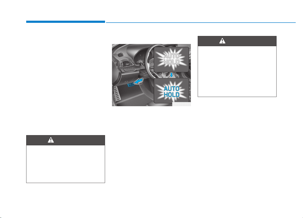
5-50
Driving your vehicle
To release :
• If you press the accelerator pedal
with the shift lever in D (Drive), R
(Reverse) or manual shift mode,
the Auto Hold will be released
automatically and the vehicle will
start to move. The AUTO HOLD
indicator changes from green to
white.
• If the vehicle is restarted using the
cruise control toggle switch (RES+
or SET-) while Auto Hold and cruise
control is operating, the Auto Hold
will be released regardless of
accelerator pedal operation. The
AUTO HOLD indicator changes
from green to white. (if equipped
with cruise control system)
To cancel :
1. Depress the brake pedal.
2. Press the [AUTO HOLD] switch.
The AUTO HOLD indicator will turn
off.
When the AUTO HOLD is auto-
matically released by depress-
ing the accelerator pedal, always
take a look around your vehicle.
Slowly depress the accelerator
pedal for a smooth start.
WARNING
OPD05024
LL
LL
ii
ii
gg
gg
hh
hh
tt
tt
oo
oo
ff
ff
ff
ff
To prevent, unexpected and sud-
den vehicle movement, ALWAYS
press your foot on the brake
pedal to cancel the Auto Hold
before you:
- Drive downhill.
- Drive the vehicle in R (Reverse).
- Park the vehicle.
WARNING

5-51
Driving your vehicle
5
Information
• The Auto Hold does not operate
when:
- The driver's seat belt is unfastened
and driver's door is opened
- The engine hood is opened
- The shift lever is in P (Park) or R
(Reverse)
- The EPB is applied
• For your safety, the Auto Hold auto-
matically switches to EPB when:
- The driver's seat belt is unfastened
and driver's door is opened
- The engine hood is opened with the
shift lever is in D (Drive)
- The vehicle stops for more than 10
minutes
- The vehicle stands on a steep slope
- The vehicle moves several times
(Continued)
(Continued)
In these cases, the parking brake
warning light comes on, the AUTO
HOLD indicator changes from
green to white, and a warning sound
and a message will appear to inform
you that EPB has been automatical-
ly engaged. Before driving off again,
press foot brake pedal, check the
surrounding area near your vehicle
and release parking brake manually
with the EPB switch.
• If the AUTO HOLD indicator changes
to yellow, the Auto Hold is not working
properly. We recommend that you
contact an authorized HYUNDAI
dealer.
• While operating Auto Hold, you may
hear mechanical noise. However, it is
normal operating noise.
If there is a malfunction with the
driver's door or engine hood open
detection system, the Auto Hold
may not work properly.
We recommend that you contact
an authorized HYUNDAI dealer.
NOTICE
i
• Depress the accelerator pedal
slowly when you start the
vehicle.
• For your safety, cancel the
Auto Hold when you drive
downhill, back up the vehicle
or park the vehicle.
WARNING
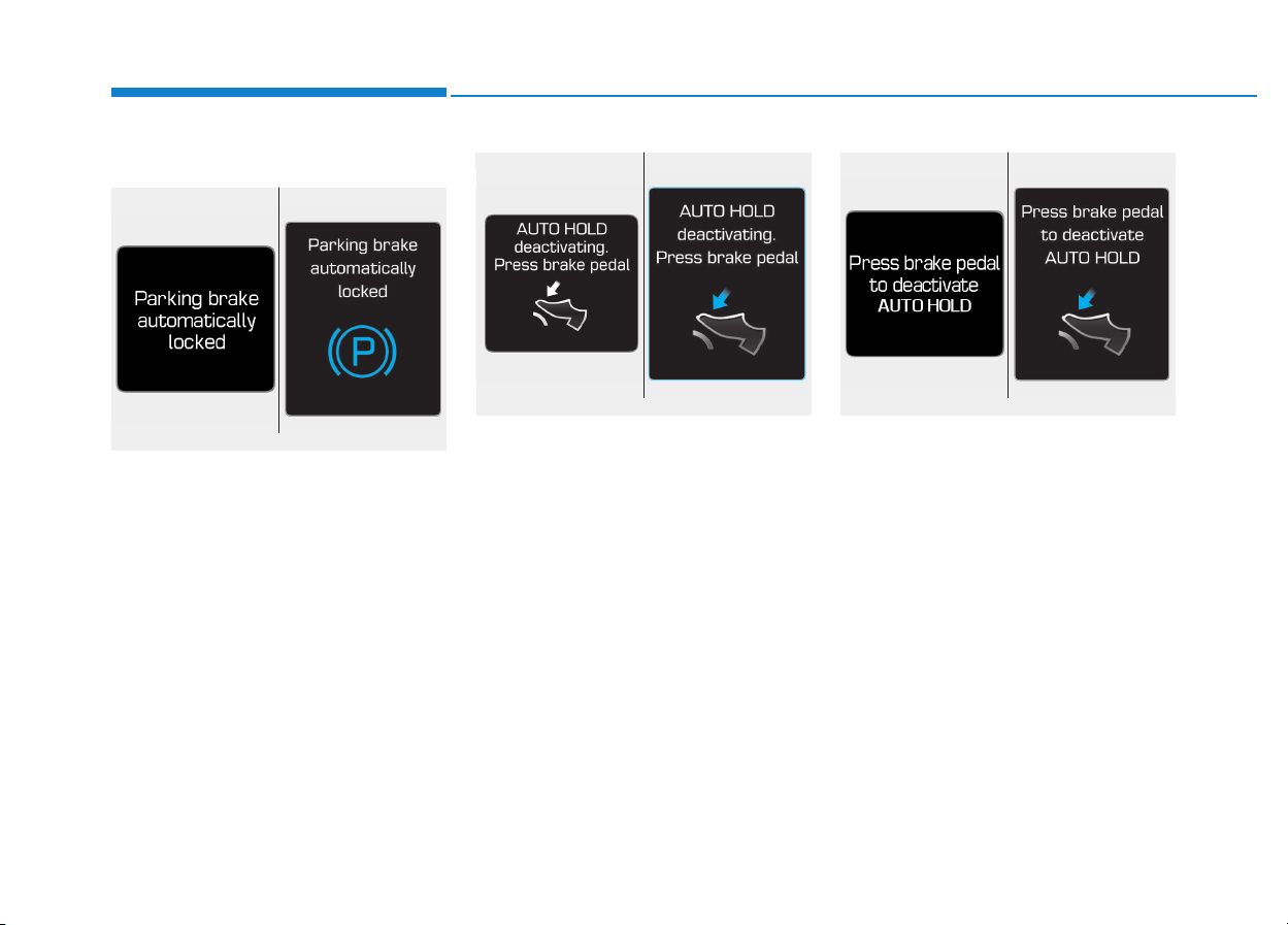
5-52
Driving your vehicle
Warning messages
Parking brake automatically locked
When the EPB is applied from Auto
Hold, a warning will sound and a
message will appear.
AUTO HOLD deactivating.
Press brake pedal
When the conversion from Auto Hold
to EPB is not working properly a
warning will sound and a message
will appear.
When this message is displayed, the
Auto Hold and EPB may not operate.
For your safety, depress the brake
pedal.
Press brake pedal to deactivate
AUTO HOLD
If you did not apply the brake pedal
when you release the Auto Hold by
pressing the [AUTO HOLD] switch, a
warning will sound and a message
will appear.
■ Type A ■ Type B
OLF054131N/OLF044411N
■ Type A ■ Type B
OTLE055028/OLFH044408L
■ Type A ■ Type B
OLF054127N/OLF044407N
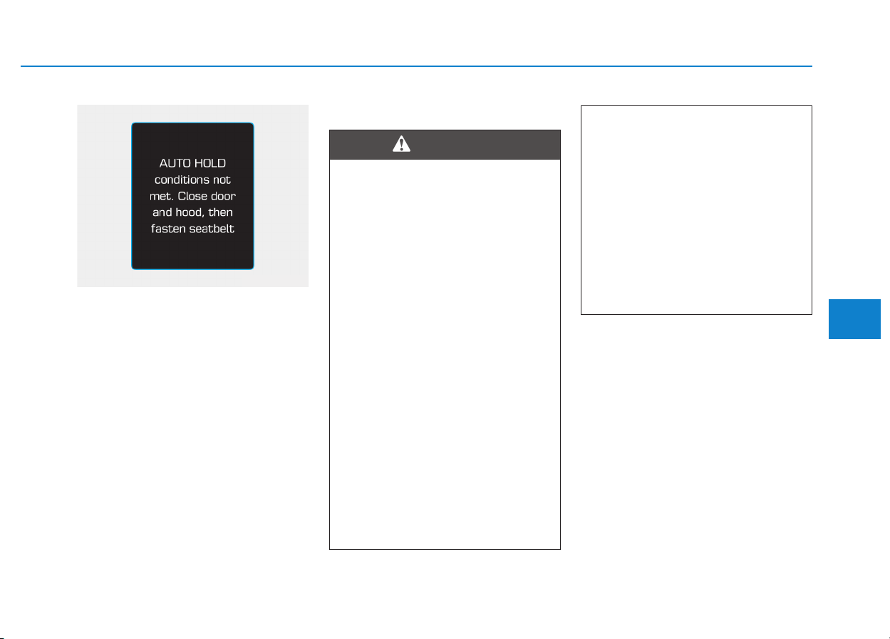
5-53
Driving your vehicle
5
AUTO HOLD conditions not met.
Close door and hood, then fasten
seatbelt
When you press the [AUTO HOLD]
switch, if the driver's door and engine
hood are not closed or the driver's
seat belt is unfastened, a warning
will sound and a message will
appear on the LCD display. At this
moment, press the [AUTO HOLD]
button after closing the driver's door
and engine hood, and fastening the
seat belt.
Anti-lock Brake System (ABS)
ABS is an electronic braking system
that helps prevent a braking skid.
ABS allows the driver to steer and
brake at the same time.
An Anti-Lock Braking System
(ABS) or an Electronic Stability
Control (ESC) system will not
prevent accidents due to
improper or dangerous driving
maneuvers. Even though vehi-
cle control is improved during
emergency braking, always
maintain a safe distance
between you and objects ahead
of you. Vehicle speeds should
always be reduced during
extreme road conditions. The
braking distance for cars
equipped with ABS or ESC may
be longer than for those without
these systems in the following
road conditions.
• Drive your vehicle at reduced
speeds during the following
conditions:
• Rough, gravel or snow-cov-
ered roads.
(Continued)
WARNING
OPDE056108
(Continued)
• On roads where the road sur-
face is pitted or has different
surface height.
• Tire chains are installed on
your vehicle.
The safety features of an ABS
or ESC equipped vehicle should
not be tested by high speed
driving or cornering. This could
endanger the safety of yourself
or others.

5-54
Driving your vehicle
Using ABS
To obtain the maximum benefit from
your ABS in an emergency situation,
do not attempt to modulate your
brake pressure and do not try to
pump your brakes. Depress your
brake pedal as hard as possible.
When you apply your brakes under
conditions which may lock the
wheels, you may hear sounds from
the brakes, or feel a corresponding
sensation in the brake pedal. This is
normal and it means your ABS is
active.
ABS does not reduce the time or dis-
tance it takes to stop the vehicle.
Always maintain a safe distance from
the vehicle in front of you.
ABS will not prevent a skid that
results from sudden changes in
direction, such as trying to take a
corner too fast or making a sudden
lane change. Always drive at a safe
speed for the road and weather con-
ditions.
ABS cannot prevent a loss of stabili-
ty. Always steer moderately when
braking hard. Severe or sharp steer-
ing wheel movement can still cause
your vehicle to veer into oncoming
traffic or off the road.
On loose or uneven road surfaces,
operation of the anti-lock brake sys-
tem may result in a longer stopping
distance than for vehicles equipped
with a conventional brake system.
The ABS warning light ( ) will stay
on for several seconds after the
Engine Start/Stop button is in the ON
position. During that time, the ABS
will go through self-diagnosis and the
light will go off if everything is nor-
mal. If the light stays on, you may
have a problem with your ABS. We
recommend that you contact an
authorized HYUNDAI dealer as soon
as possible.
When you drive on a road having
poor traction, such as an icy road,
and apply your brakes continu-
ously, the ABS will be active con-
tinuously and the ABS warning
light ( ) may illuminate. Pull
your car over to a safe place and
turn the engine off.
Restart the engine. If the ABS
warning light is off, then your ABS
system is normal.
Otherwise, you may have a prob-
lem with your ABS system. We
recommend that you contact an
authorized HYUNDAI dealer as
soon as possible.
NOTICE
If the ABS warning light ( ) is
on and stays on, you may have
a problem with the ABS. Your
power brakes will work normal-
ly. To reduce the risk of serious
injury or death, we recommend
that you contact your HYUNDAI
dealer as soon as possible.
WARNING
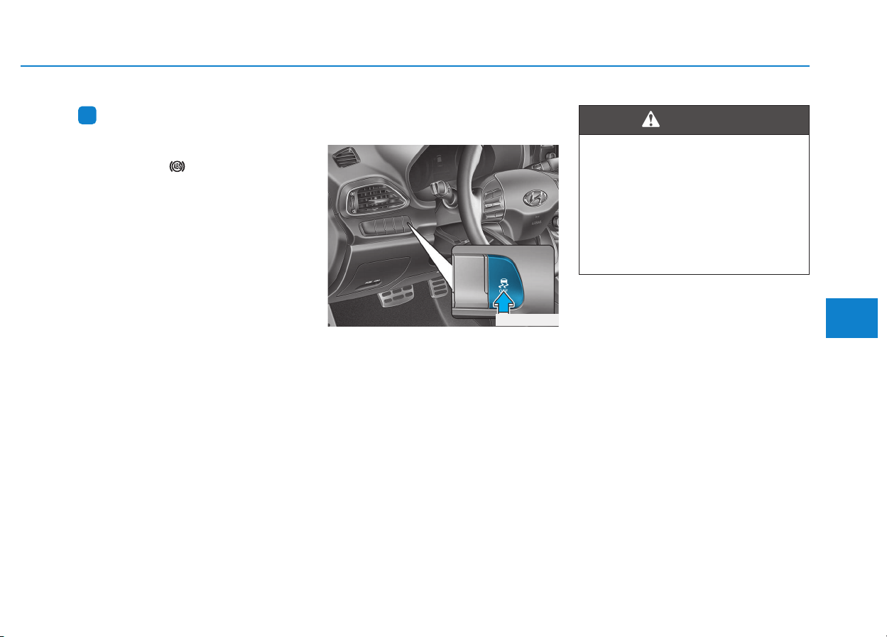
5-55
Driving your vehicle
5
Information
When you jump start your vehicle
because of a drained battery, the ABS
warning light ( ) may turn on at the
same time. This happens because of
the low battery voltage. It does not
mean your ABS is malfunctioning.
Have the battery recharged before
driving the vehicle.
Electronic Stability Control
(ESC) (if equipped)
The Electronic Stability Control
(ESC) system helps to stabilize the
vehicle during cornering maneuvers.
ESC checks where you are steering
and where the vehicle is actually
going. ESC applies braking pressure
to any one of the vehicle's brakes
and intervenes in the engine man-
agement system to assist the driver
with keeping the vehicle on the
intended path. It is not a substitute
for safe driving practices. Always
adjust your speed and driving to the
road conditions.
i
OPD056028
Never drive too fast for the road
conditions or too quickly when
cornering. The ESC system will
not prevent accidents.
Excessive speed in turns, abrupt
maneuvers, and hydroplaning
on wet surfaces can result in
severe accidents.
WARNING

5-56
Driving your vehicle
ESC operation
ESC ON condition
When the ignition switch is in the ON
position, the ESC and the ESC OFF
indicator lights illuminate for approxi-
mately three seconds and goes off,
then the ESC is turned on.
When operating
When the ESC is in opera-
tion, the ESC indicator light
blinks:
• When you apply your brakes under
conditions which may lock the
wheels, you may hear sounds from
the brakes, or feel a corresponding
sensation in the brake pedal. This is
normal and it means your ESC is
active.
• When the ESC activates, the
engine may not respond to the
accelerator as it does under routine
conditions.
• If the Cruise Control was in use
when the ESC activates, the Cruise
Control automatically disengages.
The Cruise Control can be reen-
gaged when the road conditions
allow. See "Cruise Control System"
later in this chapter. (if equipped)
• When moving out of the mud or
driving on a slippery road, the
engine rpm (revolutions per minute)
may not increase even if you press
the accelerator pedal deeply. This is
to maintain the stability and traction
of the vehicle and does not indicate
a problem.
ESC OFF condition
To cancel ESC operation :
• State 1
Press the ESC OFF button briefly.
The ESC OFF indicator light and
message "Traction Control disabled"
will illuminate. In this state, the trac-
tion control function of ESC (engine
management) is disabled, but the
brake control function of ESC (brak-
ing management) still operates.
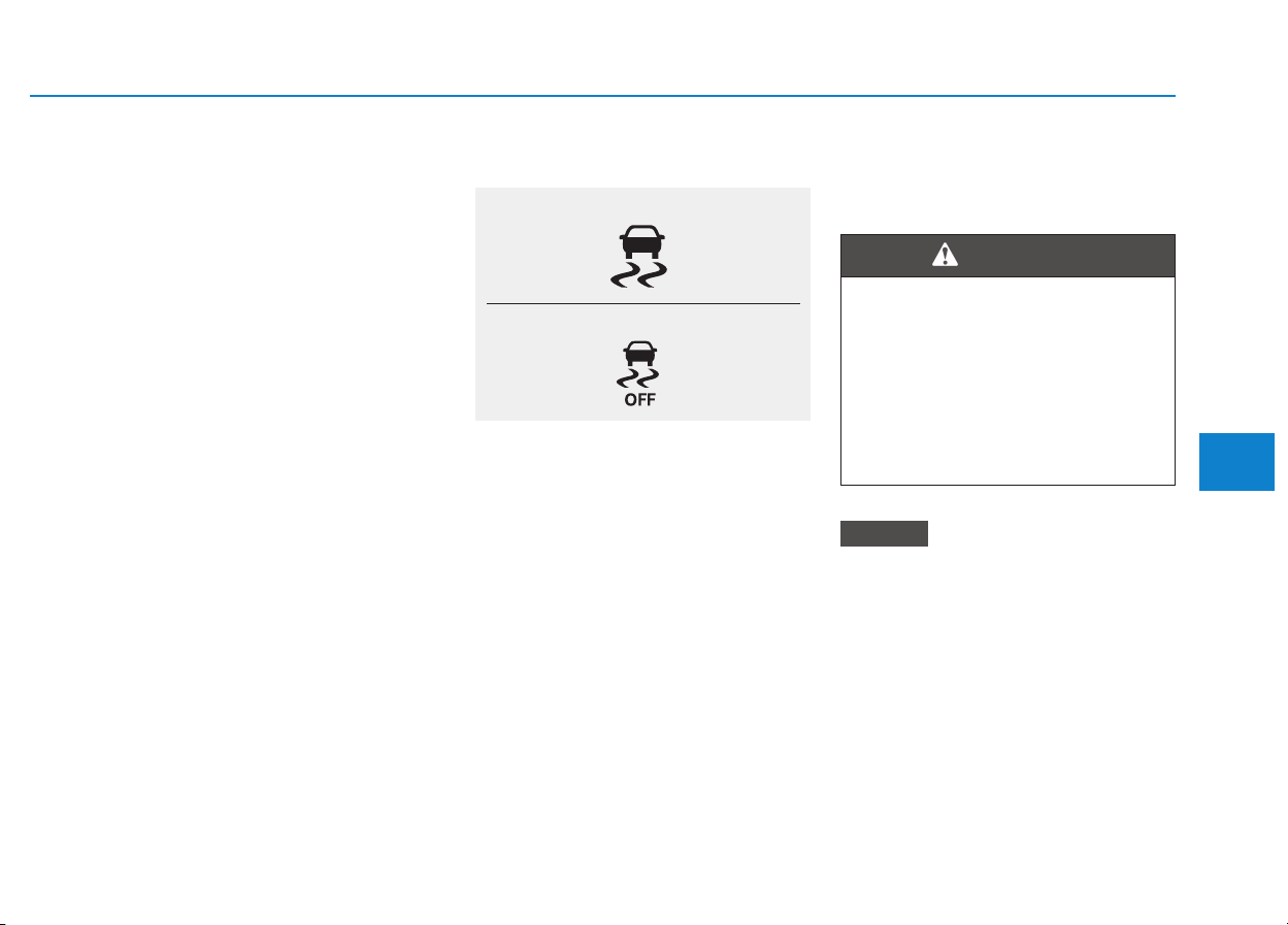
5-57
Driving your vehicle
5
• State 2
Press and hold the ESC OFF button
continuously for more than 3 sec-
onds. The ESC OFF indicator light
and message "Traction & Stability
Control disabled" illuminates and a
warning chime sounds. In this state,
both the traction control function of
ESC (engine management) and the
brake control function of ESC (brak-
ing management) are disabled.
If the ignition switch is placed to the
LOCK/OFF position when ESC is off,
ESC remains off. Upon restarting the
vehicle, the ESC will automatically
turn on again.
Indicator lights
When the ignition switch is in the ON
position, the ESC indicator light illu-
minates, then goes off if the ESC
system is operating normally.
The ESC indicator light blinks when-
ever the ESC is operating.
If ESC indicator light stays on, your
vehicle may have a malfunction with
the ESC system. When this warning
light illuminates we recommend that
the vehicle be checked by an author-
ized HYUNDAI dealer as soon as
possible.
The ESC OFF indicator light comes
on when the ESC is turned off with
the button.
Driving with wheels and tires with
different sizes may cause the ESC
system to malfunction. Before
replacing tires, make sure all four
tires and wheels are the same
size. Never drive the vehicle with
different sized wheels and tires
installed.
NOTICE
■ ESC indicator light (blinks)
■ ESC OFF indicator light (comes on)
When the ESC is blinking, this
indicates the ESC is active:
Drive slowly and NEVER attempt
to accelerate. NEVER turn the
ESC off while the ESC indicator
light is blinking or you may lose
control of the vehicle resulting in
an accident.
WARNING

5-58
Driving your vehicle
ESC OFF usage
When Driving
The ESC OFF mode should only be
used briefly to help free the vehicle if
stuck in snow or mud by temporarily
stopping operation of the ESC to
maintain wheel torque.
To turn ESC off while driving, press
the ESC OFF button while driving on
a flat road surface.
To prevent damage to the trans-
mission:
• Do not allow wheel(s) of one
axle to spin excessively while
the ESC, ABS, and parking brake
warning lights are displayed.
The repairs would not be cov-
ered by the vehicle warranty.
Reduce engine power and do
not spin the wheel(s) excessive-
ly while these lights are dis-
played.
• When operating the vehicle on a
dynamometer, make sure the
ESC is turned off (ESC OFF light
illuminated).
Information
Turning the ESC off does not affect
ABS or standard brake system opera-
tion.
Vehicle Stability Management
(if equipped)
The Vehicle Stability Management
(VSM) is a function of the Electronic
Stability Control (ESC) system. It
helps ensure the vehicle stays stable
when accelerating or braking sud-
denly on wet, slippery and rough
roads where traction over the four
tires can suddenly become uneven.
i
NOTICE
Take the following precautions
when using the Vehicle Stability
Management (VSM):
• ALWAYS check the speed and
the distance to the vehicle
ahead. The VSM is not a sub-
stitute for safe driving prac-
tices.
• Never drive too fast for the
road conditions.The VSM sys-
tem will not prevent acci-
dents. Excessive speed in bad
weather, slippery and uneven
roads can result in severe
accidents.
WARNING
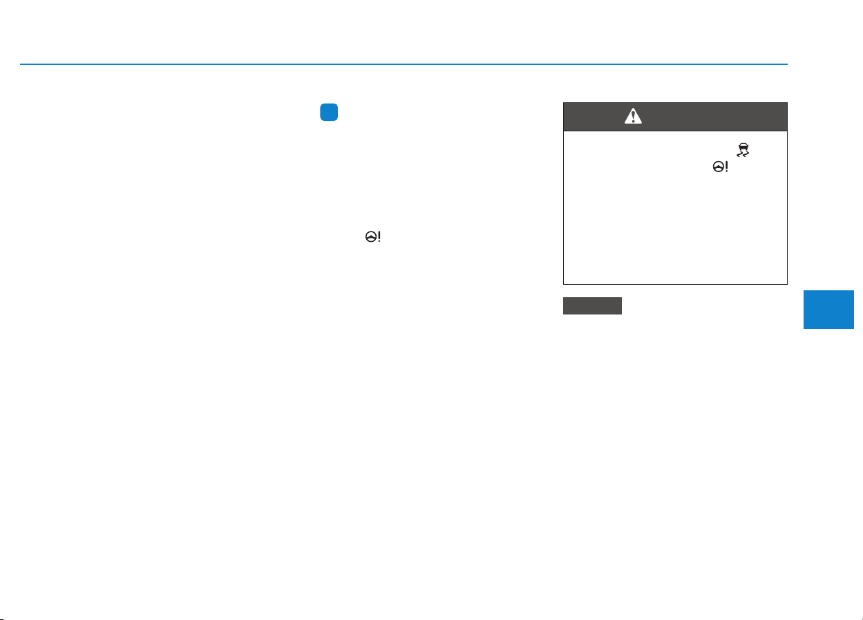
5-59
Driving your vehicle
5
VSM operation
VSM ON condition
The VSM operates when:
• The Electronic Stability Control
(ESC) is on.
• Vehicle speed is approximately
above 15 km/h (9 mph) on curve
roads.
• Vehicle speed is approximately
above 20 km/h (12 mph) when the
vehicle is braking on rough roads.
When operating
When you apply your brakes under
conditions which may activate the
ESC, you may hear sounds from the
brakes, or feel a corresponding sen-
sation in the brake pedal. This is nor-
mal and it means your VSM is active.
Information
The VSM does not operate when:
• Driving on a banked road such as
gradient or incline.
• Driving rearward.
• ESC OFF indicator light is on.
• EPS (Electric power steering) warning
light ( ) is on or blinks.
Driving with wheels and tires with
different sizes may cause the VSM
system to malfunction. Before
replacing tires, make sure all four
tires and wheels are the same
size. Never drive the vehicle with
different sized tires and wheels
installed.
NOTICE
i
If ESC indicator light ( ) or
EPS warning light ( ) stays
or blinks, your vehicle may have
a malfunction with the VSM sys-
tem. When the warning light illu-
minates we recommend that the
vehicle be checked by an
authorized HYUNDAI dealer as
soon as possible.
WARNING

5-60
Driving your vehicle
Hill-Start Assist Control (HAC)
(if equipped)
The Hill-Start Assist Control (HAC)
helps prevent the vehicle from rolling
backwards when starting a vehicle
from a stop on a hill. The system
operates the brakes automatically for
approximately 2 seconds and releas-
es the brake after 2 seconds or when
the accelerator pedal is depressed.
Information
• The HAC does not operate when the
shift lever is in P (Park) or N
(Neutral)
• The HAC activates even when the
ESC (Electronic Stability Control) is
off. However, it does not activate,
when the ESC does not normally
operate.
Emergency Stop Signal (ESS)
(if equipped)
The Emergency Stop Signal system
alerts the driver behind by blinking
the stop lights, while sharply and
severely braking.
The system is activated when:
• The vehicle suddenly stops. (The
deceleration power exceeds 7 m/s
2
,
and the driving speed exceeds 55
km/h (34 mph).)
• The ABS is activated and the driv-
ing speed exceeds 55 km/h (34
mph).
The hazard warning flasher automat-
ically turns ON after blinking the stop
lights, when the driving speeds is
decelerated under 40 km/h (25 mph),
when the ABS is deactivated, and
when the sudden braking situation is
over.
The hazard warning flasher turns
OFF, when the driving speed exceeds
10 km/h (6 mph) after a complete
stop. The hazard warning flasher
turns OFF, when the vehicle drives at
a low speed for a certain period of
time. The driver can manually turn
OFF the hazard warning flasher by
pressing the button.
Information
The Emergency Stop Signal (ESS) sys-
tem will not activate, when the hazard
warning flasher already blinks.
i
i
Always be ready to depress the
accelerator pedal when starting
off on a incline. The HAC acti-
vates only for approximately 2
seconds.
WARNING

5-61
Driving your vehicle
5
Good braking practices
Wet brakes can be dangerous! The
brakes may get wet if the vehicle is
driven through standing water or if it
is washed. Your vehicle will not stop
as quickly if the brakes are wet. Wet
brakes may cause the vehicle to pull
to one side.
To dry the brakes, apply the brakes
lightly until the braking action returns
to normal, taking care to keep the
vehicle under control at all times. If
the braking action does not return to
normal, stop as soon as it is safe to
do so and we recommend that you
call an authorized HYUNDAI dealer
for assistance.
DO NOT drive with your foot resting
on the brake pedal. Even light, but
constant pedal pressure can result in
the brakes overheating, brake wear,
and possibly even brake failure.
If a tire goes flat while you are driv-
ing, apply the brakes gently and
keep the vehicle pointed straight
ahead while you slow down. When
you are moving slowly enough for it
to be safe to do so, pull off the road
and stop in a safe location.
Keep your foot firmly on the brake
pedal when the vehicle is stopped to
prevent the vehicle from rolling for-
ward.
Whenever leaving the vehicle or
parking, always come to a com-
plete stop and continue to
depress the brake pedal. Move
the shift lever into the P (Park)
position, then apply the parking
brake, and place the ignition
switch in the LOCK/OFF posi-
tion.
Vehicles parked with the park-
ing brake not applied or not
fully engaged may roll inadver-
tently and may cause injury to
the driver and others. ALWAYS
apply the parking brake before
exiting the vehicle.
WARNING
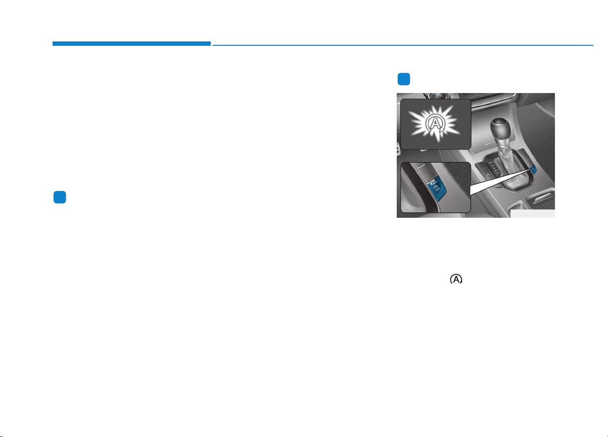
5-62
Driving your vehicle
The ISG system is to reduce the fuel
consumption by automatically shut-
ting down the engine, when the vehi-
cle is at a standstill (i.e. red stop light,
stop sign, and traffic jam).
The engine is automatically started
upon satisfying the starting condi-
tions.
The ISG system is always active,
when the engine is running.
Information
When the engine is automatically
started by the ISG system, some warn-
ing lights (i.e. ABS, ESC, ESC OFF,
EPS, and parking brake warning
light) may illuminate for a few sec-
onds due to the low battery voltage.
However, it does not indicate a mal-
function with the ISG system.
To activate the ISG system
Prerequisite for activation
The ISG system operates in the fol-
lowing situations.
- The driver's seatbelt is fastened.
- The driver's door and the hood are
closed.
- The brake vacuum pressure is
adequate.
- The battery is sufficiently charged.
- The outside temperature is between
-10 °C and 35 °C (14 °F and 95 °F).
- The engine coolant temperature is
not too low.
- The system is not in the diagnostic
mode.
- The steering wheel is not steered
excessively. (for dual clutch trans-
mission vehicle)
- The vehicle is driven on a steep
incline. (for dual clutch transmis-
sion vehicle)
Information
• The ISG system is not activated,
when the prerequisites to activate
the ISG system are unsatisfied. In
this case, the ISG OFF button indi-
cator illuminates, and the auto stop
indicator ( ) illuminates in yellow
on the instrument cluster.
• When the above indicator remains
illuminated on the instrument clus-
ter, we recommend you to have the
IGS system checked by an author-
ized HYUNDAI dealer.
i
i
IISSGG ((IIDDLLEE SSTTOOPP AANNDD GGOO)) SSYYSSTTEEMM ((IIFF EEQQUUIIPPPPEEDD))
OPDE056129
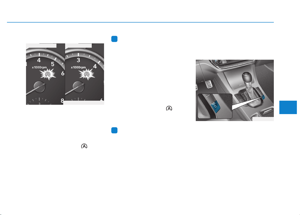
5-63
Driving your vehicle
5
Auto stop
To stop the engine in idle stop mode
Manual transmission vehicle
1. Decrease the vehicle speed to 5
km/h (3 mph).
2. Set the gear in N (Neutral).
3. Release the clutch pedal.
The auto stop indicator ( ) illumi-
nates in green on the instrument
cluster, when the engine stops.
Information
The driving speed must reach at least
10 km/h (6 mph) after an idle stop to
stop the engine in idle stop mode
again.
Dual clutch transmission vehicle
1. Decrease the vehicle speed to 0
km/h.
2. Depress the brake pedal with the
shift lever in D (Drive) or N
(Neutral).
The auto stop indicator ( ) illumi-
nates in green on the instrument
cluster, when the engine stops.
Information
The driving speed must reach at least
8 km/h (5 mph) after an idle stop to
stop the engine in idle stop mode
again.
In auto stop mode, when the driver
opens the hood, the ISG system will
be deactivated.
When the system is deactivated:
The ISG OFF button indicator illumi-
nates.
i
i
OPDE056031
■ Gasoline engine ■ Diesel engine
OPDE056109/OPD056075

5-64
Driving your vehicle
The message, "Auto Stop deactivat-
ed. Start manually", appears on the
LCD display with a beep sound.
At this time, restart the vehicle man-
ually by:
Manual transmission vehicle
Depressing the clutch and brake
pedal with the gear in neutral.
Dual clutch transmission vehicle
Depressing the brake pedal with the
shift lever in P (Park) or N (Neutral).
But for your safety, restart the vehicle
in the P (Park) position.
Auto start
To restart the engine in the auto
stop mode
Manual transmission vehicle
• Depress the clutch pedal with the
gear in N (Neutral).
The auto stop indicator ( ) goes
OFF on the instrument cluster, when
the engine is restarted.
Dual clutch transmission vehicle
• Release the brake pedal.
• When Auto Hold is activated, if you
release the brake pedal, the
engine will be in the auto stop
state. However, if you depress the
accelerator pedal, the engine will
start again.
The auto stop indicator ( ) goes
OFF on the instrument cluster, when
the engine is restarted.
The engine is automatically restart-
ed in the following situations.
- The fan speed of the manual cli-
mate control system is set above
the 3rd position, with the air condi-
tion ON.
- The fan speed of the automatic cli-
mate control system is set above
the 6th position, with the air condi-
tion ON.
- A certain period of time has
elapsed with the air condition ON.
- The defroster is activated.
- The brake vacuum pressure is low.
- The battery is weak.
- The driving speed exceeds 5 km/h
(3 mph). (for manual transmission
vehicle)
- The driving speed exceeds 2 km/h
(1.2 mph). (for dual clutch trans-
mission vehicle)
- The vehicle is shifted to P (Park) or
R (Reverse) when the brake pedal
is depressed or the Auto Hold (if
equipped with EPB) is activated.
OTLE055036
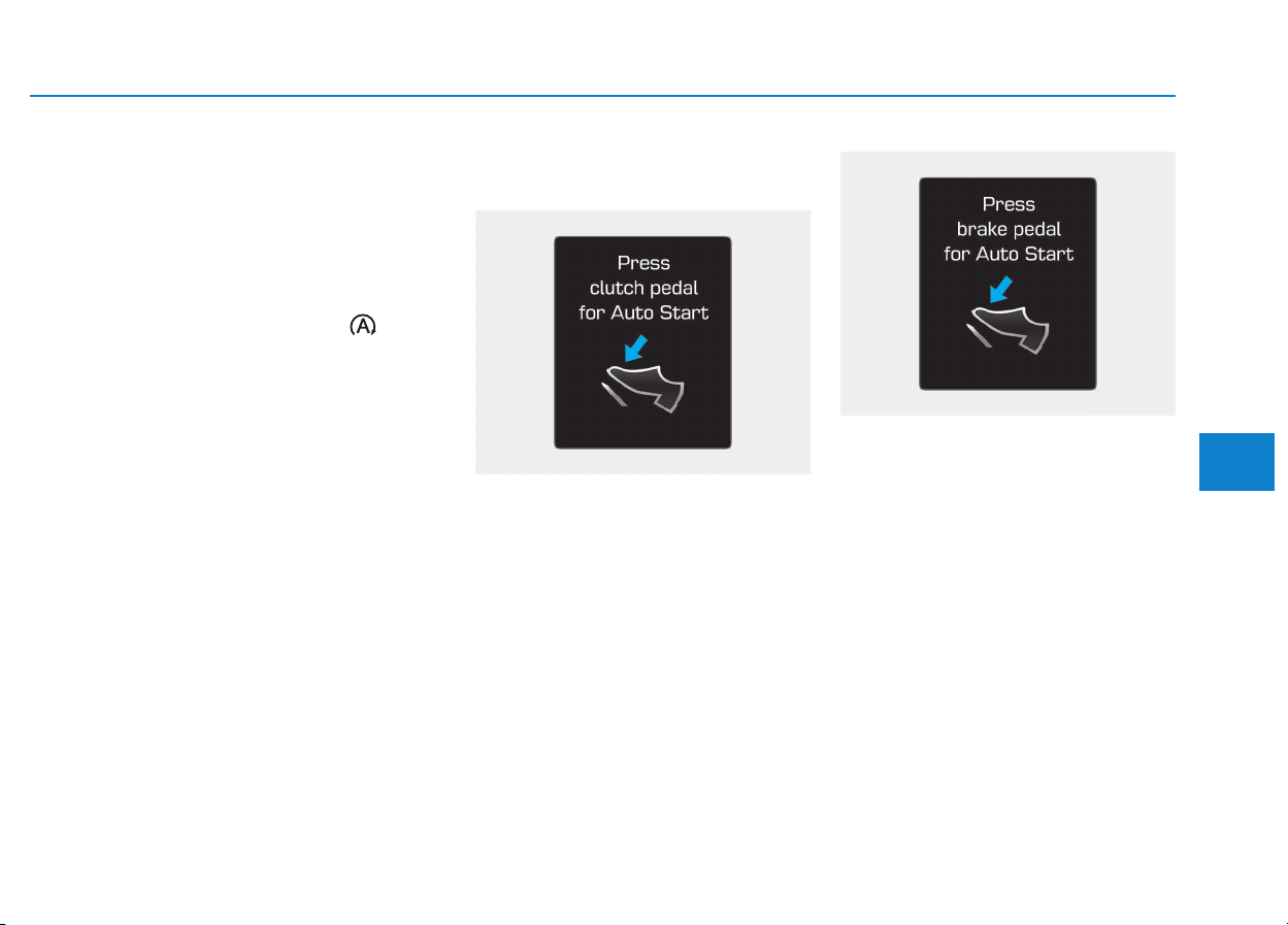
5-65
Driving your vehicle
5
- The door is opened or seat belt is
unfastened when the brake pedal
is depressed or Auto Hold (if
equipped with EPB) is activated.
- The EPB is pressed when the Auto
Hold is activated. (if equipped with
EPB (Electronic Parking Brake))
The auto stop indicator ( ) blinks
in green for 5 seconds on the instru-
ment cluster and a message "Auto
Start" will appear on the LCD display.
The auto start is temporarily deac-
tivated in the following situations.
Manual transmission vehicle
When the gear is shifted without the
clutch pedal depressed. A message
"Press clutch pedal for Auto Start"
will appear on the LCD display. To
activate auto start, shift to neutral
and depress the clutch pedal.
Dual clutch transmission vehicle
When the shift lever is shifted from N
(Neutral) to R (Reverse), D (Drive) or
Manual shift mode without the brake
pedal depressed. A message "Press
brake pedal for Auto Start" will
appear on the LCD display. To acti-
vate auto start, depress the brake
pedal.
OTLE055037
OAD055087L
5-66
To deactivate the ISG system
• Press the ISG OFF button to deac-
tivate the ISG system. Then, the
ISG OFF button indicator illumi-
nates, and the message "Auto
Stop System Off" appears on the
LCD display.
• Press the ISG OFF button again to
reactivate the ISG system. Then,
the ISG OFF button indicator turns
OFF.
ISG system malfunction
The ISG system may not operate:
When there is a malfunction with the
ISG sensors or the ISG system.
The followings occur, when there is
a malfunction with the ISG system:
• The auto stop indicator ( ) will
blink in yellow on the instrument
cluster.
• The light on the ISG OFF button
will illuminate.
Information
• When you cannot turn OFF the ISG
OFF button indicator by pressing the
ISG OFF button, or when the mal-
function with the ISG system per-
sists, we recommend you to contact
an authorized HYUNDAI dealer.
• You can turn off the ISG OFF but-
ton indicator by driving over 80
km/h (50 mph) for up to 2 hours
with the fan speed below the 2nd
position. If the ISG OFF button
indicator remains ON, we recom-
mend you to contact an authorized
HYUNDAI dealer.
i
Driving your vehicle
When the engine is in auto stop
mode, the engine may restart.
Before leaving the vehicle or
checking the engine compart-
ment, stop the engine by plac-
ing the ignition switch to the
LOCK/OFF position or remov-
ing the ignition key.
WARNING
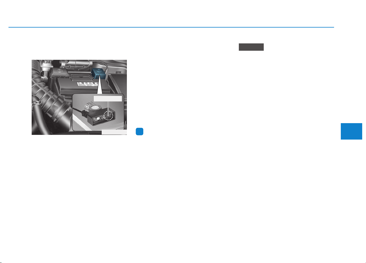
5-67
Driving your vehicle
5
The battery sensor deactiva-
tion
The battery sensor is deactivated,
when the battery is disconnected
from the negative pole for mainte-
nance purpose.
In this case, the ISG system is limit-
edly operated due to the battery sen-
sor deactivation. Thus, the driver
needs to take the following proce-
dures to reactivate the battery sen-
sor after disconnecting the battery.
Prerequisites to reactivate the
battery sensor
Keep the engine in the OFF status
for 4 hours, and attempt to restart the
engine 3 to 4 times for the battery-
sensor reactivation.
Pay extreme caution not to connect
any accessories (i.e. navigation and
black box) to the vehicle with the
engine in the OFF status. If not, the
battery sensor may not be reactivat-
ed.
Information
The ISG system may not operate in
the following situations.
- There is a malfunction with the IGS
system.
- The battery is weak.
- The brake vacuum pressure is low.
In those cases, we recommend you to
have the ISG system checked by an
authorized HYUNDAI dealer.
• Use only the genuine HYUNDAI
ISG battery for replacement. If
not, the ISG system may not nor-
mally operate.
• Do not recharge the ISG battery
with a general battery charger. If
not, it may damage or explode
the ISG battery.
• Do not remove the battery cap. If
not, the battery electrolyte,
which is harmful to the human
body, may leak out.
NOTICE
i
OPD056032
Battery sensor
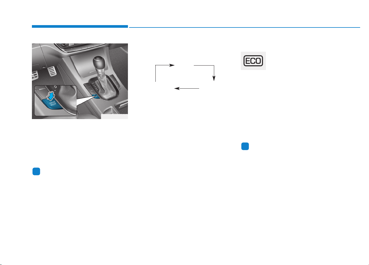
5-68
Driving your vehicle
D
DRRIIVVEE MMOODDEE IINNTTEEGGRRAATTEEDD CCOONNTTRROOLL SSYYSSTTEEMM ((IIFF EEQQUUIIPPPPEEDD))
The drive mode may be selected
according to the driver's preference
or road condition.
The system resets to be in the NOR-
MAL mode (except if it is in ECO
mode), when the engine is restarted.
Information
If there is a problem with the instru-
ment cluster, the drive mode will be in
NORMAL mode and may not change
to SPORT mode.
The mode changes, as below,
whenever the DRIVE MODE button
is pressed.
When NORMAL mode is selected, it
is not displayed on the instrument
cluster.
ECO mode (if equipped)
When the Drive Mode is
set to ECO mode, the
engine and transmission
control logic are changed
to maximize fuel efficiency.
• When the ECO mode is selected
by pressing the DRIVE MODE but-
ton, the ECO indicator will illumi-
nate.
• If the vehicle is set to ECO mode,
when the engine is turned OFF
and restarted the Drive Mode set-
ting will remain in ECO mode.
Information
Fuel efficiency depends on the driver's
driving habit and road condition.
i
i
OPDE056035
ECO
(if equipped)
NORMAL SPORT

5-69
Driving your vehicle
5
When ECO mode is activated:
• The acceleration response may be
slightly reduced as the accelerator
pedal is depressed moderately.
• The air conditioner performance
may be limited.
• The shift pattern of the automatic
transmission may change.
• The engine noise may get louder.
The above situations are normal
conditions when ECO mode is acti-
vated to improve fuel efficiency.
Limitation of ECO mode opera-
tion:
If the following conditions occur while
ECO mode is operating, the system
operation is limited even though
there is no change in ECO indicator.
• When the coolant temperature is
low:
The system will be limited until
engine performance becomes nor-
mal.
• When driving up a hill:
The system will be limited to gain
power when driving uphill because
engine torque is restricted.
• When driving the vehicle with the
automatic transmission or the dual
clutch transmission gear shift lever
in manual shift mode:
The system will be limited accord-
ing to the shift location.
• When the accelerator pedal is
deeply depressed for a few seconds:
The system will be limited, judging
that the driver wants to speed up.
SPORT mode
SPORT mode manages
the driving dynamics by
automatically adjusting the
steering effort, the engine
and transmission control
logic for enhanced driver
performance.
• When SPORT mode is selected by
pressing the DRIVE MODE button,
the SPORT indicator will illuminate.
• Whenever the engine is restarted,
the Drive Mode will revert back to
NORMAL mode. If SPORT mode is
desired, re-select SPORT mode
from the DRIVE MODE button.
• When SPORT mode is activated:
- The engine rpm will tend to remain
raised over a certain length of time
even after releasing the accelerator
- Upshifts are delayed when accel-
erating
Information
In SPORT mode, the fuel efficiency
may decrease.
i
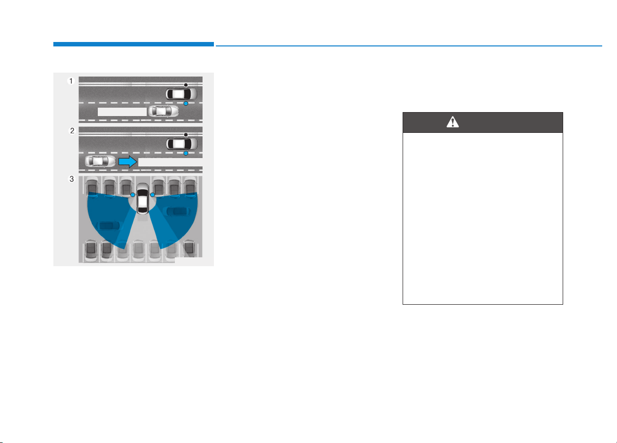
5-70
Driving your vehicle
The Blind Spot Detection System
(BSD) uses radar sensors in the rear
bumper to monitor and warn the driv-
er of an approaching vehicle in the
driver's blind spot area.
The system monitors the rear area of
the vehicle and provides information
to the driver with an audible alert and
a indicator on the outside rearview
mirrors.
(1) BSD (Blind Spot Detection)
The blind spot detection range
varies relative to vehicle speed.
Note that if your vehicle is travel-
ing much faster than the vehicles
around you, the warning will not
occur.
(2) LCA (Lane Change Assist)
The Lane Change Assist feature
will alert you when a vehicle is
approaching in an adjacent lane
at a high rate of speed. If the driv-
er activates the turn signal when
the system detects an oncoming
vehicle, the system sounds an
audible alert. The time of alert
varies according to the speed dif-
ference between you and the
approaching vehicle.
(3) RCTA (Rear Cross Traffic Alert)
The Rear Cross Traffic Alert fea-
ture monitors approaching cross
traffic from the left and right side
of the vehicle when your vehicle is
in reverse. The feature will operate
when the vehicle is moving in
reverse below about 10 km/h (6
mph). If oncoming cross traffic is
detected a warning chime will
sound.
The time of alert varies according
to the speed difference between
you and the approaching vehicle.
BBLLIINNDD SSPPOOTT DDEETTEECCTTIIOONN SSYYSSTTEEMM ((BBSSDD)) ((IIFF EEQQUUIIPPPPEEDD))
OAE056106
Blind spot area
Closing at high speed
• Always be aware of road con-
ditions while driving and be
alert for unexpected situations
even though the Blind Spot
Detection System is operat-
ing.
• The Blind Spot Detection
System (BSD) is not a substi-
tute for proper and safe driving.
Always drive safely and use
caution when changing lanes
or backing up the vehicle. The
Blind Spot Detection System
(BSD) may not detect every
object alongside the vehicle.
WARNING
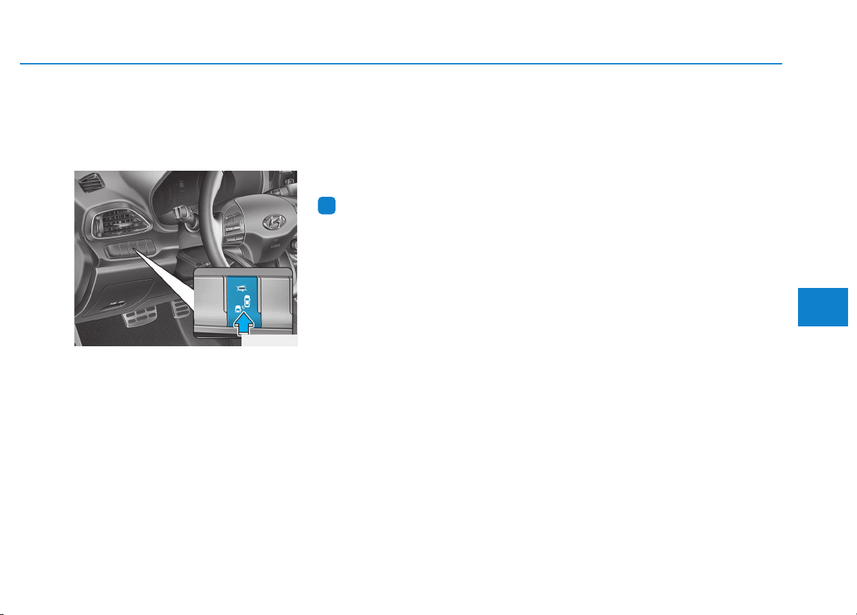
5-71
Driving your vehicle
5
BSD (Blind Spot Detection) /
LCA (Lane Change Assist)
(if equipped)
Operating conditions
To operate:
Press the BSD switch with the
Ignition switch in the ON position.
The indicator on the BSD switch will
illuminate. When the vehicle speed
exceeds 30 km/h (20 mph), the sys-
tem will be activated.
To cancel:
Press the BSD switch again. The
indicator on the switch will go off.
When the system is not used, turn the
system off by turning off the switch.
Information
• If the vehicle is turned off then on
again, the BSD system returns to the
previous state.
• When the system is turned on, the
warning light will illuminate for 3
seconds on the outside rearview
mirror.
The system will activate when:
1. The system is on.
2. The vehicle speed is above about
30 km/h (20 mph).
3. An oncoming vehicle is detected
in the blind spot area.
i
OPD056041
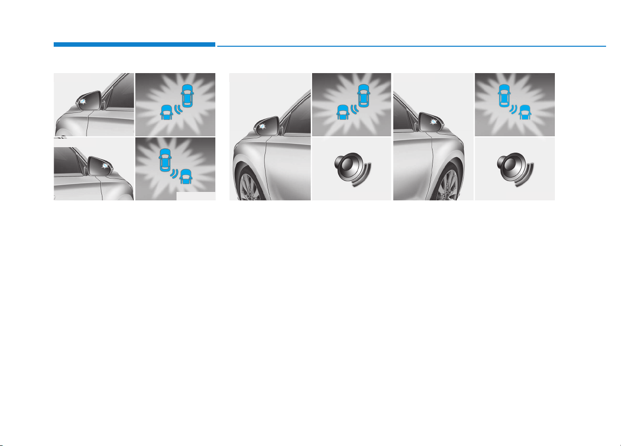
5-72
Driving your vehicle
First stage alert
If a vehicle is detected within the
boundary of the system, a warning
light will illuminate on the outside
rearview mirror.
Once the detected vehicle is no
longer within the blind spot area, the
warning will turn off according to the
driving conditions of the vehicle.
OPD056042
■ Left side
■ Right side
OPD056043
■ Left side
OPD056044
■ Right side
Second stage alert
A warning chime to alert the driver will activate when:
1. A vehicle has been detected in the blind spot area by the radar system
(the warning light will illuminate on the outside rearview mirror) AND
2. The turn signal is applied (same side as where the vehicle is being
detected).
When this alert is activated, the warning light on the outside rearview mir-
ror will also blink.
If you turn off the turn signal indicator, the warning chime will be deacti-
vated.
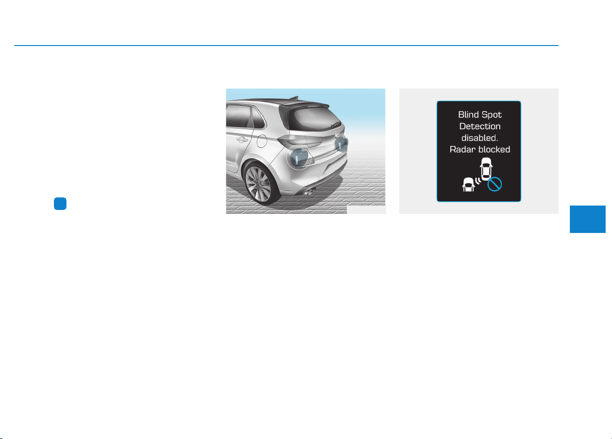
5-73
Driving your vehicle
5
• The second stage alarm may be
deactivated.
- To deactivate the warning chime:
Go to the 'User Settings → Sound
and deselect Blind Spot Detection
Sound' on the LCD display.
- To activate the warning chime:
Go to the 'User Settings → Sound
and select Blind Spot Detection
Sound' on the LCD display.
Information
The warning chime function helps
alert the driver. Deactivate this func-
tion only when it is necessary.
Detecting sensor
The sensors are located inside the
rear bumper.
Always keep the rear bumper clean
for proper operation of the system.
Warning message
Blind Spot Detection disabled.
Radar blocked.
• This warning message may appear
when :
- One or both of the sensors on the
rear bumper is blocked by dirt or
snow or a foreign object.
- Driving in rural areas where the
BSD sensor does not detect
another vehicle for an extended
period of time.
- When there is inclement weather
such as heavy snow or rain.
- A trailer or carrier is installed. (To
use the BSD system, remove the
trailer or carrier from your vehicle.)
i
OPD056045
OAE056040L
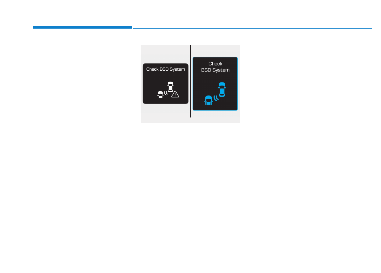
5-74
Driving your vehicle
If any of these conditions occur, the
light on the BSD switch and the sys-
tem will turn off automatically.
When the BSD canceled warning
message is displayed in the cluster,
check to make sure that the rear
bumper is free from any dirt or snow
in the areas where the sensor is
located. Remove any dirt, snow, or
foreign material that could interfere
with the radar sensors.
After any dirt or debris is removed,
the BSD system should operate nor-
mally after about 10 minutes of driv-
ing the vehicle.
If the system still does not operate
normally have your vehicle inspected
by an authorized HYUNDAI dealer.
Check BSD system
If there is a problem with the BSD
system, a warning message will
appear and the light on the switch
will turn off. The system will turn off
automatically. We recommend that
you have your vehicle inspected by
an authorized HYUNDAI dealer.
RCTA (Rear Cross Traffic
Alert) (if equipped)
The Rear Cross Traffic Alert feature
monitors approaching cross traffic
from the left and right side of the
vehicle when your vehicle is in
reverse.
Operating conditions
To operate:
Go to the 'User Settings → Driving
Assist and select Rear Cross Traffic
Alert' on the LCD display.
The system will turn on and standby
to activate. The system will activate
when vehicle speed is below 10 km/h
(6.2 mph) and with the shift lever in R
(Reverse).
■ Type A ■ Type B
OAD055091L/OTLE055040
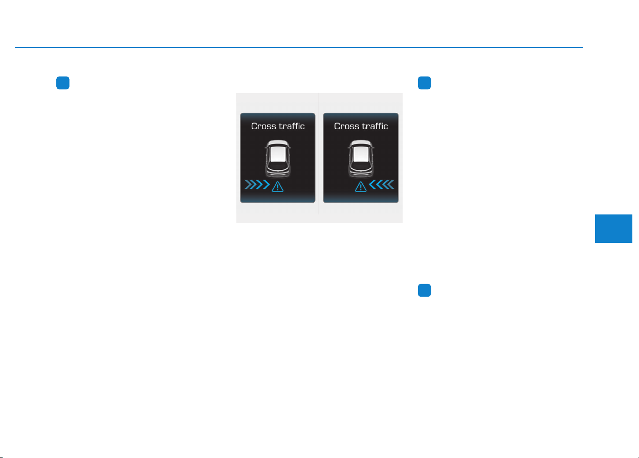
5-75
Driving your vehicle
5
Information
The Rear Cross Traffic Alert (RCTA)
detecting range is approximately
0.5 m ~ 20 m (1 ft ~ 65 ft). An
approaching vehicle will be detected if
their vehicle speed is within 4 km/h ~
36 km/h (2.5 ~ 22.5 mph ).
Note that the detecting range may
vary under certain conditions. As
always, use caution and pay close
attention to your surroundings when
backing up your vehicle.
Warning type
If the vehicle detected by the sensors
approaches your vehicle, the warn-
ing chime will sound, the warning
light on the outside rearview mirror
will blink and a message will appear
on the LCD display.
Information
• The warning chime will turn off
when the detected vehicle moves out
of the sensing area or when the vehi-
cle is right behind your vehicle or
when the vehicle is not approaching
your way or when the speed of the
other vehicle slows down.
• The system may not operate proper-
ly due to other factors or circum-
stances. Always pay attention to
your surrounding.
• If the sensing area near the rear
bumper is blocked by either a wall
or barrier or by a parked vehicle,
the system sensing area may be
reduced.
Information
Turn off the system by pressing the
BSD switch and deselecting Rear
Cross Traffic Alert from the User
Settings mode on the cluster when
using a trailer or carrier behind your
vehicle.
i
ii
■ Left ■ Right
OPDE056046/OPDE056047

5-76
Driving your vehicle
• The system may not work prop-
erly when the bumper has been
damaged, or if the rear bumper
has been replaced or repaired.
• The sensing range differs some-
what according to the width of
the road. When the road is nar-
row, the system may detect
other vehicles in the next lane
Or when the road is wide, the
system may not detect other
vehicles in the next lane.
• The system may turn off due to
strong electromagnetic waves.
Non-operating condition
The BSD indicator on the outer side
view mirror may not illuminate
properly when:
• The outside rearview mirror hous-
ing is damaged.
• The mirror is covered with dirt,
snow, or debris.
• The window is covered with dirt,
snow, or debris.
• The window is tinted.
NOTICE
(Continued)
• The Blind Spot Detection
System (BSD) and Rear Cross
Traffic Alert (RCTA) are not a
substitute for proper and safe
driving practices. Always
drive safely and use caution
when changing lanes or back-
ing up your vehicle. The Blind
Spot Detection System (BSD)
may not detect every object
alongside the vehicle.
• The warning light on the out-
side rearview mirror will illu-
minate whenever a vehicle is
detected at the rear side by
the system.
To avoid accidents, do not
focus only on the warning
light and neglect to see the
surrounding of the vehicle.
• Drive safely even though the
vehicle is equipped with a
Blind Spot Detection System
(BSD) and Rear Cross Traffic
Alert (RCTA). Do not solely
rely on the system but check
your surrounding before
changing lanes or backing the
vehicle up.
The system may not alert the
driver in some conditions so
always check your surround-
ings while driving.
(Continued)
WARNING

5-77
Driving your vehicle
5
Limitations of the system
The driver must be cautious in the
below situations, because the sys-
tem may not detect other vehicles or
objects in certain circumstances.
• The vehicle drives on a curved
road or through a tollgate.
• The vehicle is turning left or right at
a crossroad.
• The sensor is polluted with rain,
snow, mud, etc.
• The rear bumper where the sensor
is located is covered with a foreign
object such as a bumper sticker, a
bumper guard, a bike rack, etc.
• The rear bumper is damaged, or
the sensor is out of the original
default position.
• The vehicle height gets lower or
higher due to heavy loading in the
luggage compartment, abnormal
tire pressure, etc.
• The vehicle drives in inclement
weather such as heavy rain or
snow.
• There is a fixed object near the
vehicle, such as a guardrail, per-
son, animal, etc.
• The vehicle is driven near areas
containing metal substances such
as a construction zone, railroad,
etc.
• A big vehicle is near such as a bus
or truck.
• A motorcycle or bicycle is near.
• A flat trailer is near.
• If the vehicle has started at the
same time as the vehicle next to
you and has accelerated.
• When the other vehicle passes at a
very fast speed.
• While changing lanes.
• While going down or up a steep
road where the height of the lane is
different.
• When the other vehicle approach-
es very close.
• When a trailer or carrier is
installed.
• When the temperature near the
rear bumper area is high or low.
• When the sensors are blocked by
other vehicles, walls or parking-lot
pillars.
• When the detected vehicle also
moves back, as your vehicle drives
back.
• If there are small objects in the
detecting area such as a shopping
cart or a baby stroller.
• If there is a low height vehicle such
as a sports car.
• When other vehicles are close to
your vehicle.
• When the vehicle in the next lane
moves two lanes away from you
OR when the vehicle two lanes
away moves to the next lane from
you.
• When driving through a narrow
road with many trees or bushes.
• When driving through a large area
with few cars or structures around,
such as a desert, rural area, etc.
• When driving on wet surface.
5-78
Driving your vehicle
The Autonomous Emergency
Braking (AEB) system is designed to
detect and monitor the vehicle ahead
or detect a pedestrian (if equipped)
in the roadway through radar signals
and camera recognition to warn the
driver that a collision is imminent,
and if necessary, apply emergency
braking.
System setting and activation
System setting
• The driver can activate the AEB by
placing the ignition switch to the
ON position and by selecting:
'User Settings → Driving Assist →
Assist Emergency Braking'
The AEB deactivates, when the driv-
er cancels the system setting.
The warning light illumi-
nates on the LCD display,
when you cancel the AEB
system. The driver can
monitor the AEB ON/OFF status on
the LCD display. Also, the warning
light illuminates when the ESC
(Electronic Stability Control) is
turned off (Traction & Stability control
disabled.) If the warning light
remains ON when the AEB is acti-
vated, we recommend you to have
the system checked by an authorized
HYUNDAI dealer.
AAUUTTOONNOOMMOOUUSS EEMMEERRGGEENNCCYY BBRRAAKKIINNGG ((AAEEBB))
-
- SSEENNSSOORR FFUUSSIIOONN TTYYPPEE ((FFRROONNTT RRAADDAARR ++ FFRROONNTT CCAAMMEERRAA)) ((IIFF EEQQUUIIPPPPEEDD))
Take the following precautions
when using the Autonomous
Emergency Braking (AEB):
• This system is only a supple-
mental system and it is not
intended to, nor does it
replace the need for extreme
care and attention of the driv-
er. The sensing range and
objects detectable by the sen-
sors are limited. Pay attention
to the road conditions at all
times.
• NEVER drive too fast in accor-
dance with the road condi-
tions or while cornering.
• Always drive cautiously to
prevent unexpected and sud-
den situations from occur-
ring. AEB does not stop the
vehicle completely and is not
a collision avoidance system.
WARNING

5-79
Driving your vehicle
5
• The driver can select the initial warn-
ing activation time on the LCD dis-
play.
Go to the 'User Settings → Driving
Assist → Forward Collision Warning
→ Late/Normal/Early'.
The options for the initial Forward
Collision Warning includes the fol-
lowing:
- Early:
When this condition is selected,
the initial Forward Collision
Warning is activated earlier than
normal. This setting maximizes the
amount of distance between the
vehicle or pedestrian ahead before
the initial warning occurs.
Even though, 'Early' is selected if
the front vehicle suddenly stops
the initial warning activation time
may not seem fast.
- Normal:
When this condition is selected,
the initial Forward Collision
Warning is activated normally. This
setting allows for a nominal
amount of distance between the
vehicle or pedestrian ahead before
the initial warning occurs.
- Late:
When this condition is selected,
the initial Forward Collision
Warning is activated later than nor-
mal. This setting reduces the
amount of distance between the
vehicle or pedestrian ahead before
the initial warning occurs.
Select 'Late' when traffic is light
and when driving speed is slow.
Prerequisite for activation
The AEB gets ready to be activated,
when the AEB is selected on the
LCD display, and when the following
prerequisites are satisfied.
- The ESC (Electronic Stability
Control) is on.
- Vehicle speed is over 10 km/h (6
mph). (The AEB is only activated
within a certain speed range.)
- The system detects a pedestrian
or a vehicle in front, which may col-
lide with your vehicle. (The AEB
may not be activated or may sound
a warning alarm in accordance
with the driving situation or vehicle
condition.)

5-80
Driving your vehicle
AEB warning message and
system control
The AEB produces warning mes-
sages and warning alarms in accor-
dance with the collision risk levels,
such as abrupt stopping of the vehi-
cle in front, insufficient braking dis-
tance, or pedestrian detection. Also,
it controls the brakes in accordance
with the collision risk levels.
The driver can select the initial warn-
ing activation time in the User
Settings in the LCD display. The
options for the initial Forward
Collision Warning include Early,
Normal or Late initial warning time.
Forward Warning (1
st
warning)
This initial warning message appears
on the LCD display with a warning
chime.
• Completely stop the vehicle
on a safe location before
operating the switch on the
steering wheel to activate/
deactivate the AEB system.
• The AEB automatically acti-
vates upon placing the Engine
Start/Stop button to the ON
position. The driver can deac-
tivate the AEB by canceling
the system setting on the LCD
display.
• The AEB automatically deacti-
vates upon canceling the ESC
(Electronic Stability Control).
When the ESC is canceled,
the AEB cannot be activated
on the LCD display.
WARNING
OPDE056036

5-81
Driving your vehicle
5
Collision Warning (2
nd
warning)
This warning message appears on
the LCD display with a warning
chime. Additionally, some vehicle
system intervention occurs by the
engine management system to help
decelerate the vehicle.
- Your vehicle speed may deceler-
ate moderately.
- The AEB system limitedly con-
trols the brakes to preemptively
mitigate impact in a collision.
Emergency braking
(3
rd
warning)
This warning message appears on
the LCD display with a warning
chime.
Additionally, some vehicle system
intervention occurs by the engine
management system to help decel-
erate the vehicle.
- The AEB system limitedly con-
trols the brakes to preemptively
mitigate impact in a collision. The
brake control is maximized just
before a collision.
Brake operation
• In an urgent situation, the braking
system enters into the ready status
for prompt reaction against the dri-
ver's depressing the brake pedal.
• The AEB provides additional brak-
ing power for optimum braking per-
formance, when the driver
depresses the brake pedal.
• The braking control is automatical-
ly deactivated, when the driver
sharply depresses the accelerator
pedal, or when the driver abruptly
operates the steering wheel.
• The AEB brake control is automat-
ically canceled, when risk factors
disappear.
OPDE056038
OPDE056037
The driver should always use
extreme caution while operating
the vehicle, whether or not there
is a warning message or alarm
from the AEB system.
CAUTION
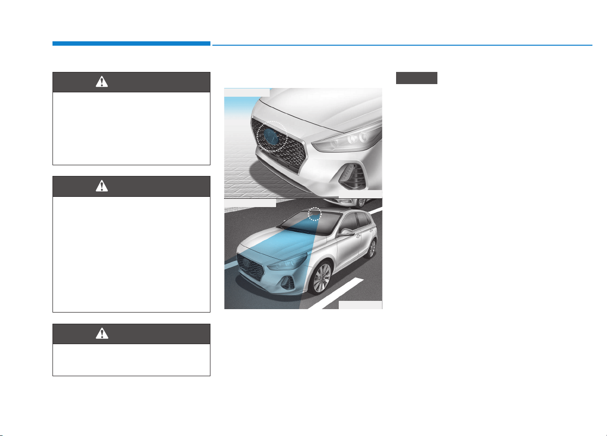
5-82
Driving your vehicle
AEB sensor
In order for the AEB system to oper-
ate properly, always make sure the
radar sensor cover is clean and free
of dirt, snow, and debris. Dirt, snow,
or foreign substances on the lens
may adversely affect the sensing
performance of the sensor.
• Do not apply license plate mold-
ing or foreign objects such as a
bumper sticker or a bumper
guard near the radar sensor.
Doing so may adversely affect
the sensing performance of the
radar.
• Always keep the radar sensor
and cover clean and free of dirt
and debris.
• Use only a soft cloth to wash the
vehicle. Do not spray pressur-
ized water directly on the sensor
or sensor cover.
• Be careful not to apply unneces-
sary force on the radar sensor or
sensor cover. If the sensor is
forcibly moved out of proper
alignment, the AEB system may
not operate correctly. In this
case, a warning message may
not be displayed. Have the vehi-
cle inspected by an authorized
HYUNDAI dealer.
(Continued)
NOTICE
The braking control cannot
completely stop the vehicle nor
avoid all collisions. The driver
should hold the responsibility
to safely drive and control the
vehicle.
WARNING
Never deliberately drive danger-
ously to activate the system.
WARNING
The AEB system logic operates
within certain parameters, such
as the distance from the vehicle
or pedestrian ahead, the speed
of the vehicle ahead, and the
driver's vehicle speed. Certain
conditions such as inclement
weather and road conditions
may affect the operation of the
AEB system.
WARNING
OPDE056039
OPDE056048
■ Front radar
■ Front camera

5-83
Driving your vehicle
5
(Continued)
• If the front bumper becomes
damaged in the area around the
radar sensor, the AEB system
may not operate properly. We
recommend you to have the
vehicle inspected by authorized
HYUNDAI.
• Use only genuine parts to repair
or replace a damaged sensor or
sensor cover. Do not apply paint
to the sensor cover.
• NEVER install any accessories
or stickers on the front wind-
shield, nor tint the front wind-
shield.
• NEVER locate any reflective
objects (i.e. white paper, mirror)
over the dashboard. Any light
reflection may cause a malfunc-
tion of the system.
• Pay extreme caution to keep the
camera out of water.
• NEVER arbitrarily disassemble
the camera assembly, nor apply
any impact on the camera
assembly.
• Playing the vehicle audio sys-
tem at high volume may offset
the system warning sounds.
Information
We recommend you have the system
checked by an authorized HYUNDAI
dealer when:
• The windshield glass is replaced.
• The camera or related parts are
repaired or removed.
Warning message and warning
light
Assist Emergency Braking disabled.
Radar blocked
When the sensor cover is blocked
with dirt, snow, or debris, the AEB
system operation may stop tem-
porarily. If this occurs, a warning
message will appear on the LCD dis-
play.
Remove any dirt, snow, or debris and
clean the radar sensor cover before
operating the AEB system.
The AEB may not properly operate in
an area (e.g. open terrain), where
any substances are not detected
after turning ON the engine.
i
NOTICE
OPDE056131
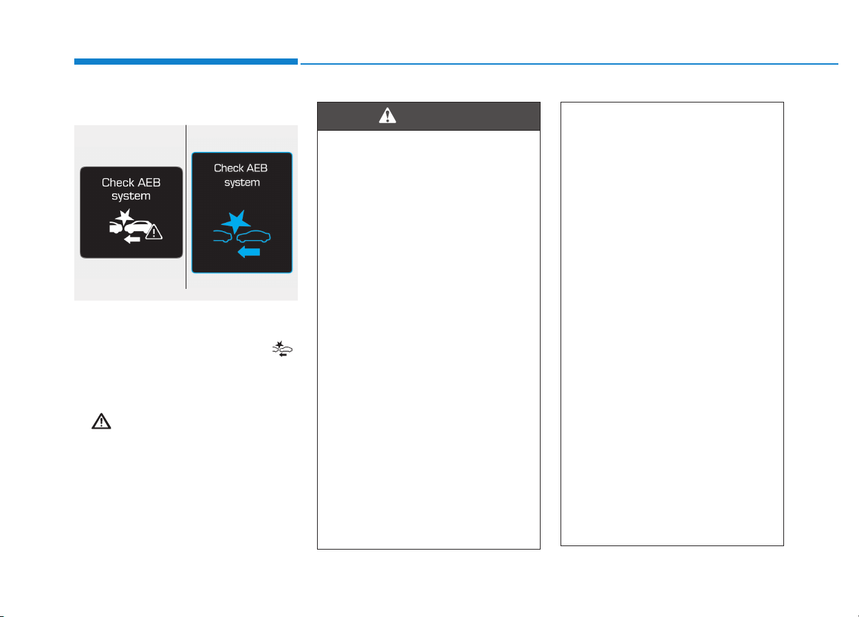
5-84
Driving your vehicle
System malfunction
Check AEB system
• When the AEB is not working prop-
erly, the AEB warning light ( )
will illuminate and the warning
message will appear for a few sec-
onds. After the message disap-
pears, the master warning light
( ) will illuminate. In this case, we
recommend you to have the vehicle
inspected by an authorized
HYUNDAI dealer.
• The AEB warning message may
appear along with the illumination
of the ESC (Electronic Stability
Control) warning light.
• The AEB is only a supplemen-
tal system for the driver's con-
venience. The driver should
hold the responsibility to con-
trol the vehicle operation. Do
not solely depend on the AEB
system. Rather, maintain a
safe braking distance, and, if
necessary, depress the brake
pedal to reduce the driving
speed.
• In certain instances and
under certain driving condi-
tions, the AEB system may
activate prematurely. This ini-
tial warning message appears
on the LCD display with a
warning chime.
Also, in certain instances the
front radar sensor or camera
recognition system may not
detect the vehicle or pedestri-
an ahead. The AEB system
may not activate and the
warning message will not be
displayed.
(Continued)
(Continued)
• If there is a malfunction with the
AEB system, the autonomous
emergency braking is not
applied even though the brak-
ing system is operating normal-
ly.
• If the vehicle in front stops
suddenly, you may have less
control of the brake system.
Therefore, always keep a safe
distance between your vehicle
and the vehicle in front of you.
• The AEB system may activate
during braking and the vehi-
cle may stop suddenly shift-
ing loose objects toward the
passengers. Always keep
loose objects secured.
• The AEB system may not acti-
vate if the driver applies the
brake pedal to avoid a colli-
sion.
• The AEB system operates
only to detect vehicles or
pedestrians in front of the
vehicle.
(Continued)
WARNING
■ Type A ■ Type B
OTLE055071/OAE056038L

5-85
Driving your vehicle
5
Limitations of the system
The Autonomous Emergency Braking
(AEB) system is designed to monitor
the vehicle ahead or a pedestrian in
the roadway through radar signals
and camera recognition to warn the
driver that a collision is imminent, and
if necessary, apply emergency brak-
ing.
In certain situations, the radar sen-
sor or the camera may not be able to
detect the vehicle or pedestrian
ahead. In these cases, the AEB sys-
tem may not operate normally. The
driver must pay careful attention in
the following situations where the
AEB operation may be limited.
Detecting vehicles
The sensor may be limited when:
• The radar sensor or camera is
blocked with a foreign object or
debris
• Inclement weather such as heavy
rain or snow obscures the field of
view of the radar sensor or camera
• There is interference by electro-
magnetic waves
• There is severe irregular reflection
from the radar sensor
• The radar/camera sensor recogni-
tion is limited
• The vehicle in front is too small to
be detected (for example a motor-
cycle or a bicycle, etc.)
• The vehicle in front is an oversize
vehicle or trailer that is too big to
be detected by the camera recog-
nition system (for example a tractor
trailer, etc.)
• The driver's field of view is not well
illuminated (either too dark or too
much reflection or too much back-
light that obscures the field of view)
(Continued)
The AEB system does not
operate when the vehicle is in
reverse.
The AEB system is not
designed to detect other
objects on the road such as
animals.
The AEB system does not
detect vehicles in the oppo-
site lane.
The AEB system does not
detect cross traffic vehicles
that are approaching.
The AEB system cannot
detect the driver approaching
the side view of a parked vehi-
cle (for example on a dead
end street.)
In these cases, you must
maintain a safe braking dis-
tance, and if necessary,
depress the brake pedal to
reduce the driving speed in
order to maintain a safe dis-
tance.
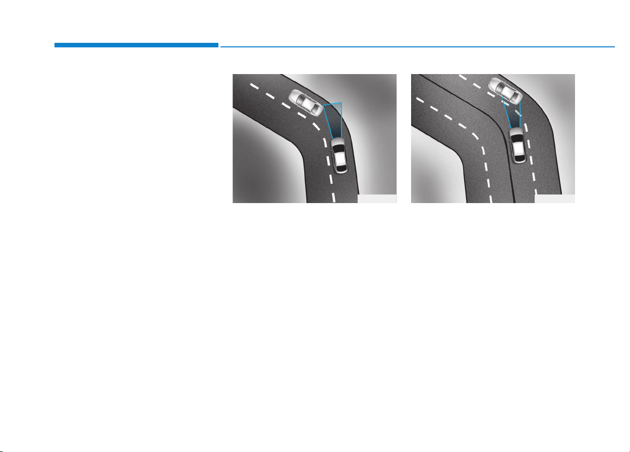
5-86
Driving your vehicle
• The vehicle in front does not have
their rear lights properly turned ON
• The outside brightness changes
suddenly, for example when enter-
ing or exiting a tunnel
• When light coming from a street
light or an oncoming vehicle is
reflected on a wet road surface
such as a puddle in the road
• The field of view in front is
obstructed by sun glare
• The windshield glass is fogged up;
a clear view of the road is obstruct-
ed
• The vehicle in front is driving errat-
ically
• The vehicle drives through a con-
struction area, on an unpaved
road, or above metal materials,
such as a railway
• The vehicle drives inside a build-
ing, such as a basement parking
lot
• The adverse road conditions cause
excessive vehicle vibrations while
driving
- Driving on a curve
The performance of the AEB system
may be limited when driving on a
curved road.
In certain instances on a curved
road, the AEB system may activate
prematurely.
Also, in certain instances the front
radar sensor or camera recognition
system may not detect the vehicle
traveling on a curved road.
In these cases, the driver must main-
tain a safe braking distance, and if
necessary, depress the brake pedal
to reduce your driving speed in order
to maintain a safe distance.
The AEB system may recognize a
vehicle in the next lane when driving
on a curved road.
In this case, the system may unnec-
essarily alarm the driver and apply
the brake.
Always pay attention to road and
driving conditions, while driving. If
necessary, depress the brake pedal
to reduce your driving speed in order
to maintain a safe distance.
Also, when necessary depress the
accelerator pedal to prevent the sys-
tem from unnecessarily decelerating
your vehicle.
OAE056100 OAE056101
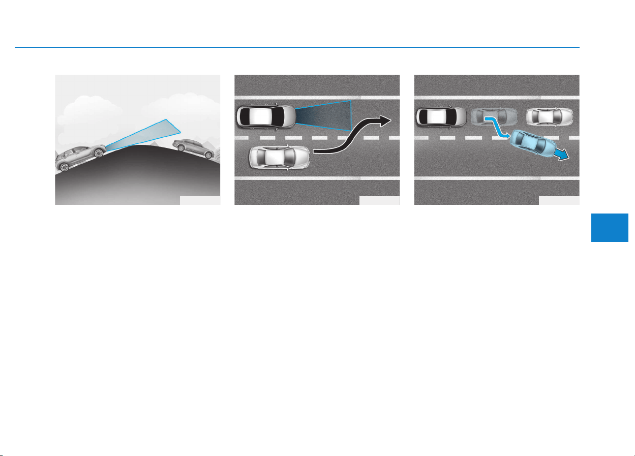
5-87
Driving your vehicle
5
- Driving on a slope
The performance of the AEB decreas-
es while driving upward or downward
on a slope, not recognizing the vehi-
cle in front in the same lane. It may
unnecessarily produce the warning
message and the warning alarm, or it
may not produce the warning mes-
sage and the warning alarm at all.
When the AEB suddenly recognizes
the vehicle in front while passing
over a slope, you may experience
sharp deceleration.
Always keep your eyes forward while
driving upward or downward on a
slope, and, if necessary, depress the
brake pedal to reduce your driving
speed in order to maintain distance.
- Changing lanes
When a vehicle changes lanes in
front of you, the AEB system may not
immediately detect the vehicle, espe-
cially if the vehicle changes lanes
abruptly. In this case, you must main-
tain a safe braking distance, and if
necessary, depress the brake pedal
to reduce your driving speed in order
to maintain a safe distance.
When driving in stop-and-go traffic,
and a stopped vehicle in front of you
merges out of the lane, the AEB sys-
tem may not immediately detect the
new vehicle that is now in front of
you. In this case, you must maintain
a safe braking distance, and if nec-
essary, depress the brake pedal to
reduce your driving speed in order to
maintain a safe distance.
OPD056102 OAE056103 OAE056109
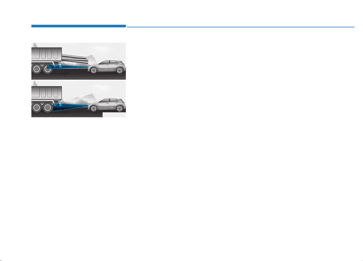
5-88
Driving your vehicle
- Detecting the vehicle in front of you
If the vehicle in front of you has cargo
that extends rearward from the cab,
or when the vehicle in front of you
has higher ground clearance, addi-
tional special attention is required.
The AEB system may not be able to
detect the cargo extending from the
vehicle. In these instances, you must
maintain a safe braking distance
from the rearmost object, and if nec-
essary, depress the brake pedal to
reduce your driving speed in order to
maintain distance.
Detecting pedestrians
The sensor may be limited when:
• The pedestrian is not fully detected
by the camera recognition system,
for example, if the pedestrian is
leaning over or is not fully walking
upright
• The pedestrian is moving very
quickly or appears abruptly in the
camera detection area
• The pedestrian is wearing clothing
that easily blends into the back-
ground, making it difficult to be
detected by the camera recogni-
tion system
• The outside lighting is too bright
(e.g. when driving in bright sunlight
or in sun glare) or too dark (e.g.
when driving on a dark rural road
at night)
• It is difficult to detect and distin-
guish the pedestrian from other
objects in the surroundings, for
example, when there is a group of
pedestrians or a large crowd
• There is an item similar to a per-
son's body structure
• The pedestrian is small
• The pedestrian has impaired
mobility
• The sensor recognition is limited
• The radar sensor or camera is
blocked with a foreign object or
debris
• Inclement weather such as heavy
rain or snow obscures the field of
view of the radar sensor or camera
• When light coming from a street
light or an oncoming vehicle is
reflected on a wet road surface
such as a puddle in the road
• The field of view in front is
obstructed by sun glare
• The windshield glass is fogged up;
a clear view of the road is obstruct-
ed
• The adverse road conditions cause
excessive vehicle vibrations while
driving
OPD056040

5-89
Driving your vehicle
5
Information
In some instances, the AEB system
may be cancelled when subjected to
electromagnetic interference.
i
• Do not use the Autonomous
Emergency Braking system
when towing a vehicle.
Application of the AEB sys-
tem while towing may
adversely affect the safety of
your vehicle or the towing
vehicle.
• Use extreme caution when the
vehicle in front of you has
cargo that extends rearward
from the cab, or when the
vehicle in front of you has
higher ground clearance.
• The AEB system is designed
to detect and monitor the
vehicle ahead or detect a
pedestrian in the roadway
through radar signals and
camera recognition. It is not
designed to detect bicycles,
motorcycles, or smaller
wheeled objects such as lug-
gage bags, shopping carts, or
strollers.
(Continued)
WARNING
(Continued)
• Never try to test the operation
of the AEB system. Doing so
may cause severe injury or
death.
5-90
Driving your vehicle
The Autonomous Emergency
Braking (AEB) system is designed to
detect and monitor the vehicle ahead
in the roadway through camera
recognition to warn the driver that a
collision is imminent, and if neces-
sary, apply emergency braking.
System setting and activation
System setting
• The driver can activate the AEB by
placing the ignition switch to the
ON position and by selecting:
'User Settings → Driving Assist →
Assist Emergency Braking'
The AEB deactivates, when the driv-
er cancels the system setting.
The warning light illumi-
nates on the LCD display,
when you cancel the AEB
system. The driver can
monitor the AEB ON/OFF status on
the LCD display. Also, the warning
light illuminates when the ESC
(Electronic Stability Control) is
turned off (Traction & Stability control
disabled.) If the warning light
remains ON when the AEB is acti-
vated, we recommend you to have
the system checked by an authorized
HYUNDAI dealer.
AAUUTTOONNOOMMOOUUSS EEMMEERRGGEENNCCYY BBRRAAKKIINNGG ((AAEEBB)) -- CCAAMMEERRAA TTYYPPEE ((IIFF EEQQUUIIPPPPEEDD))
Take the following precautions
when using the Autonomous
Emergency Braking (AEB):
• This system is only a supple-
mental system and it is not
intended to, nor does it
replace the need for extreme
care and attention of the driv-
er. The sensing range and
objects detectable by the sen-
sors are limited. Pay attention
to the road conditions at all
times.
• NEVER drive too fast in accor-
dance with the road condi-
tions or while cornering.
• Always drive cautiously to
prevent unexpected and sud-
den situations from occur-
ring. AEB does not stop the
vehicle completely and is not
a collision avoidance system.
WARNING

5-91
Driving your vehicle
5
• The driver can select the initial warn-
ing activation time on the LCD dis-
play.
Go to the 'User Settings → Driving
Assist → Forward Collision Warning
→ Late/Normal/Early'.
The options for the initial Forward
Collision Warning includes the fol-
lowing:
- Early:
When this condition is selected,
the initial Forward Collision
Warning is activated earlier than
normal. This setting maximizes the
amount of distance between the
vehicle ahead before the initial
warning occurs.
Even though, 'Early' is selected if
the front vehicle suddenly stops
the initial warning activation time
may not seem fast.
- Normal:
When this condition is selected,
the initial Forward Collision
Warning is activated normally. This
setting allows for a nominal
amount of distance between the
vehicle ahead before the initial
warning occurs.
- Late:
When this condition is selected,
the initial Forward Collision
Warning is activated later than nor-
mal. This setting reduces the
amount of distance between the
vehicle ahead before the initial
warning occurs.
Select 'Late' when traffic is light
and when driving speed is slow.
Prerequisite for activation
The AEB gets ready to be activated,
when the AEB is selected on the
LCD display, and when the following
prerequisites are satisfied.
- The ESC (Electronic Stability
Control) is on.
- Vehicle speed is over 10 km/h (6
mph). (The AEB is only activated
within a certain speed range.)
- The system detects vehicle in
front, which may collide with your
vehicle. (The AEB may not be acti-
vated or may sound a warning
alarm in accordance with the driv-
ing situation or vehicle condition.)
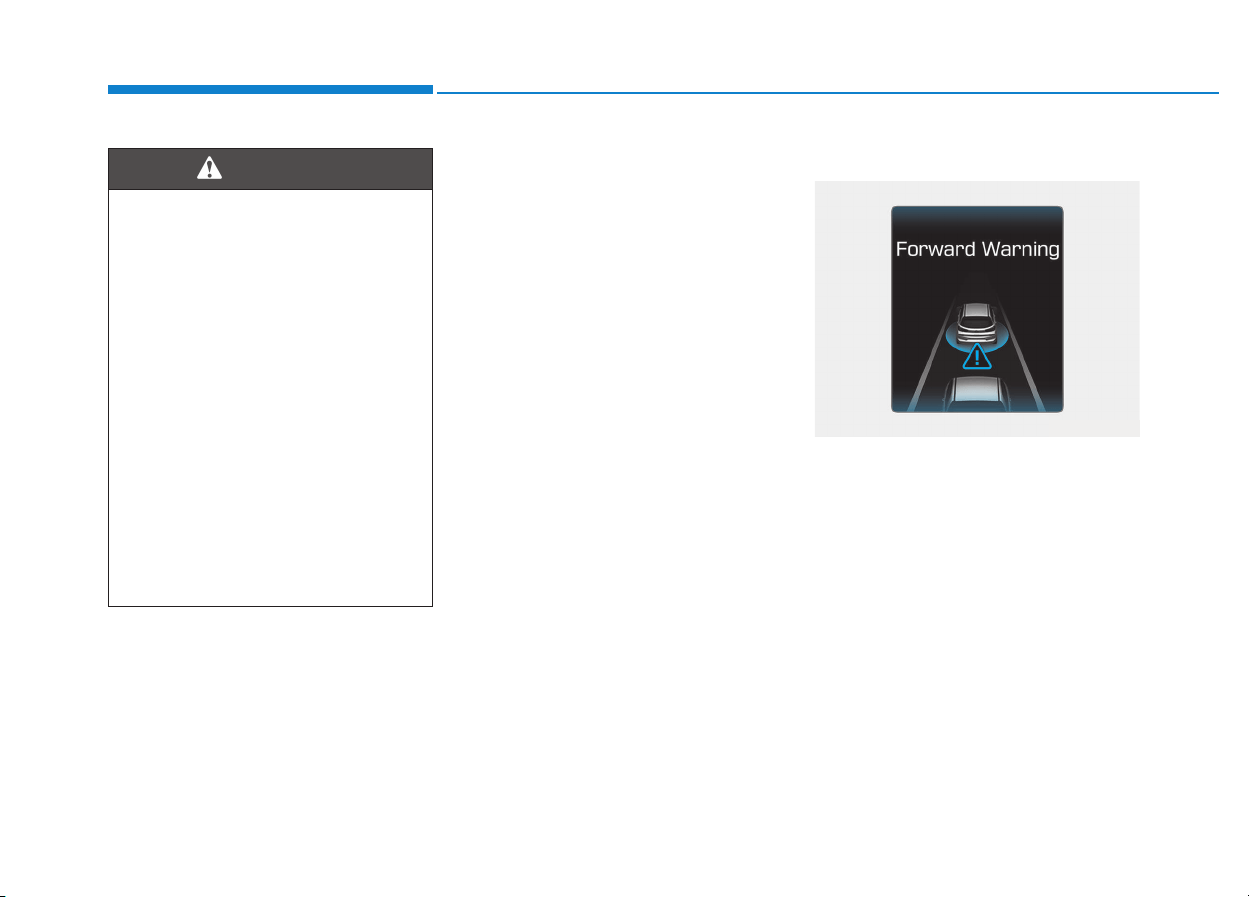
5-92
Driving your vehicle
AEB warning message and
system control
The AEB produces warning mes-
sages and warning alarms in accor-
dance with the collision risk levels,
such as abrupt stopping of the vehi-
cle in front, insufficient braking dis-
tance, or detection. Also, it controls
the brakes in accordance with the
collision risk levels.
The driver can select the initial warn-
ing activation time in the User
Settings in the LCD display. The
options for the initial Forward
Collision Warning include Early,
Normal or Late initial warning time.
Forward Warning (1
st
warning)
This initial warning message appears
on the LCD display with a warning
chime.
• Completely stop the vehicle
on a safe location before
operating the switch on the
steering wheel to activate/
deactivate the AEB system.
• The AEB automatically acti-
vates upon placing the Engine
Start/Stop button to the ON
position. The driver can deac-
tivate the AEB by canceling
the system setting on the LCD
display.
• The AEB automatically deacti-
vates upon canceling the ESC
(Electronic Stability Control).
When the ESC is canceled,
the AEB cannot be activated
on the LCD display.
WARNING
OPDE056036
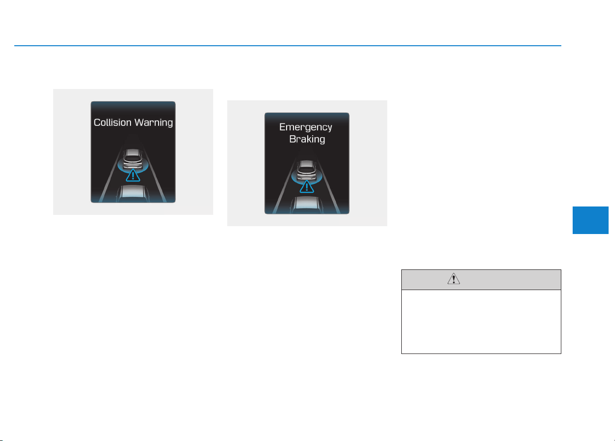
5-93
Driving your vehicle
5
Collision Warning (2
nd
warning)
This warning message appears on
the LCD display with a warning
chime. Additionally, some vehicle
system intervention occurs by the
engine management system to help
decelerate the vehicle.
- Your vehicle speed may deceler-
ate moderately.
- The AEB system limitedly con-
trols the brakes to preemptively
mitigate impact in a collision.
Emergency braking
(3
rd
warning)
This warning message appears on
the LCD display with a warning
chime.
Additionally, some vehicle system
intervention occurs by the engine
management system to help decel-
erate the vehicle.
- The AEB system limitedly con-
trols the brakes to preemptively
mitigate impact in a collision. The
brake control is maximized just
before a collision.
Brake operation
• In an urgent situation, the braking
system enters into the ready status
for prompt reaction against the dri-
ver's depressing the brake pedal.
• The AEB provides additional brak-
ing power for optimum braking per-
formance, when the driver
depresses the brake pedal.
• The braking control is automatical-
ly deactivated, when the driver
sharply depresses the accelerator
pedal, or when the driver abruptly
operates the steering wheel.
• The AEB brake control is automat-
ically canceled, when risk factors
disappear.
OPDE056038
OPDE056037
The driver should always use
extreme caution while operating
the vehicle, whether or not there
is a warning message or alarm
from the AEB system.
CAUTION
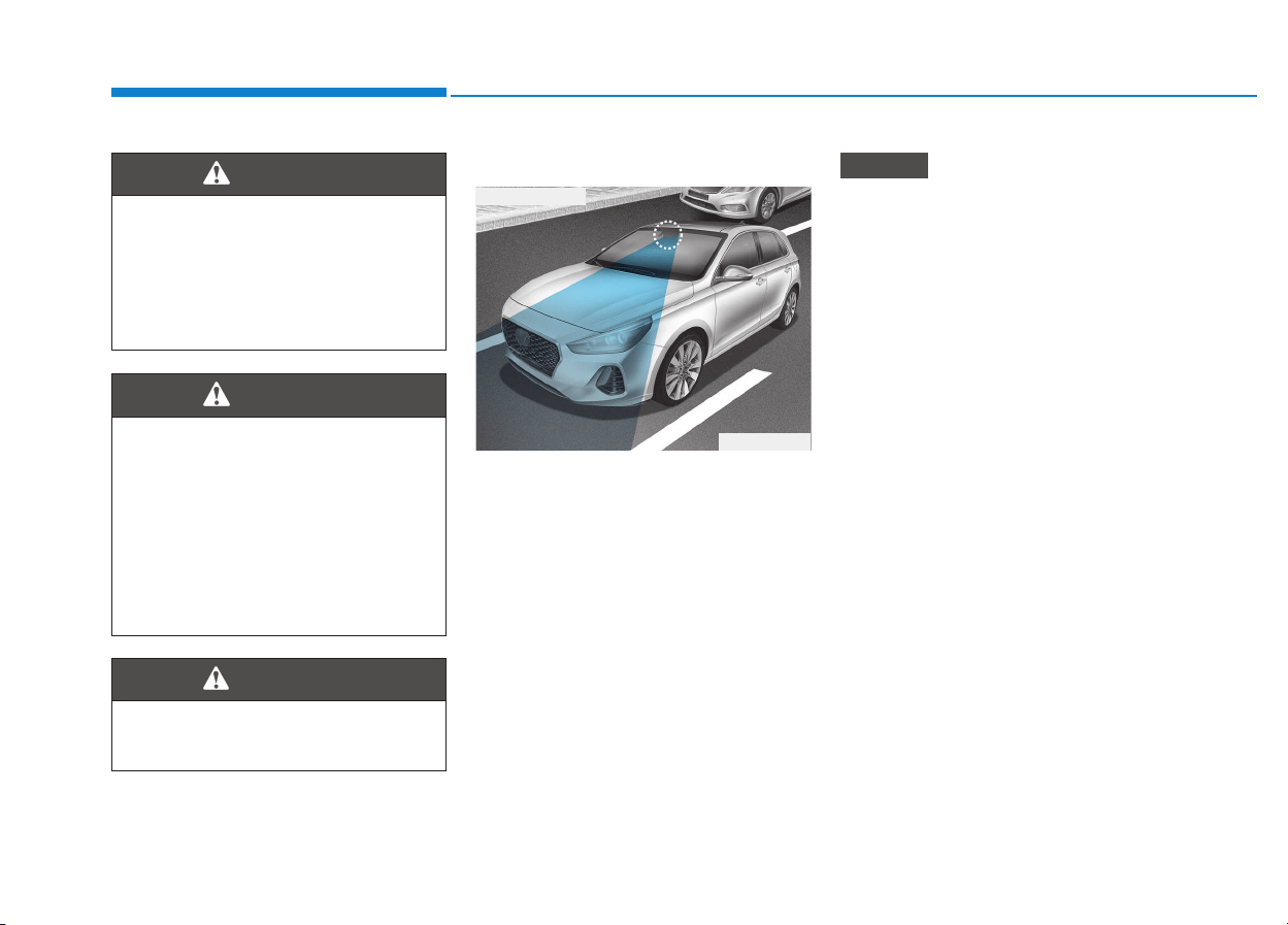
5-94
Driving your vehicle
AEB sensor
In order for the AEB system to oper-
ate properly, always make sure the
camera is clean and free of dirt,
snow, and debris. Dirt, snow, or for-
eign substances on the lens may
adversely affect the sensing perform-
ance of the camera.
• Always keep the camera sensor
clean and free of dirt and debris.
• Be careful not to apply unneces-
sary force on the camera sensor.
If the sensor is forcibly moved
out of proper alignment, the AEB
system may not operate correct-
ly. In this case, a warning mes-
sage may not be displayed. Have
the vehicle inspected by an
authorized HYUNDAI dealer.
• Use only genuine parts to repair
or replace a damaged sensor.
NOTICE
The braking control cannot
completely stop the vehicle nor
avoid all collisions. The driver
should hold the responsibility
to safely drive and control the
vehicle.
WARNING
Never deliberately drive danger-
ously to activate the system.
WARNING
The AEB system logic operates
within certain parameters, such
as the distance from the vehicle
ahead, the speed of the vehicle
ahead, and the driver's vehicle
speed. Certain conditions such
as inclement weather and road
conditions may affect the oper-
ation of the AEB system.
WARNING
OPDE056048
■ Front camera
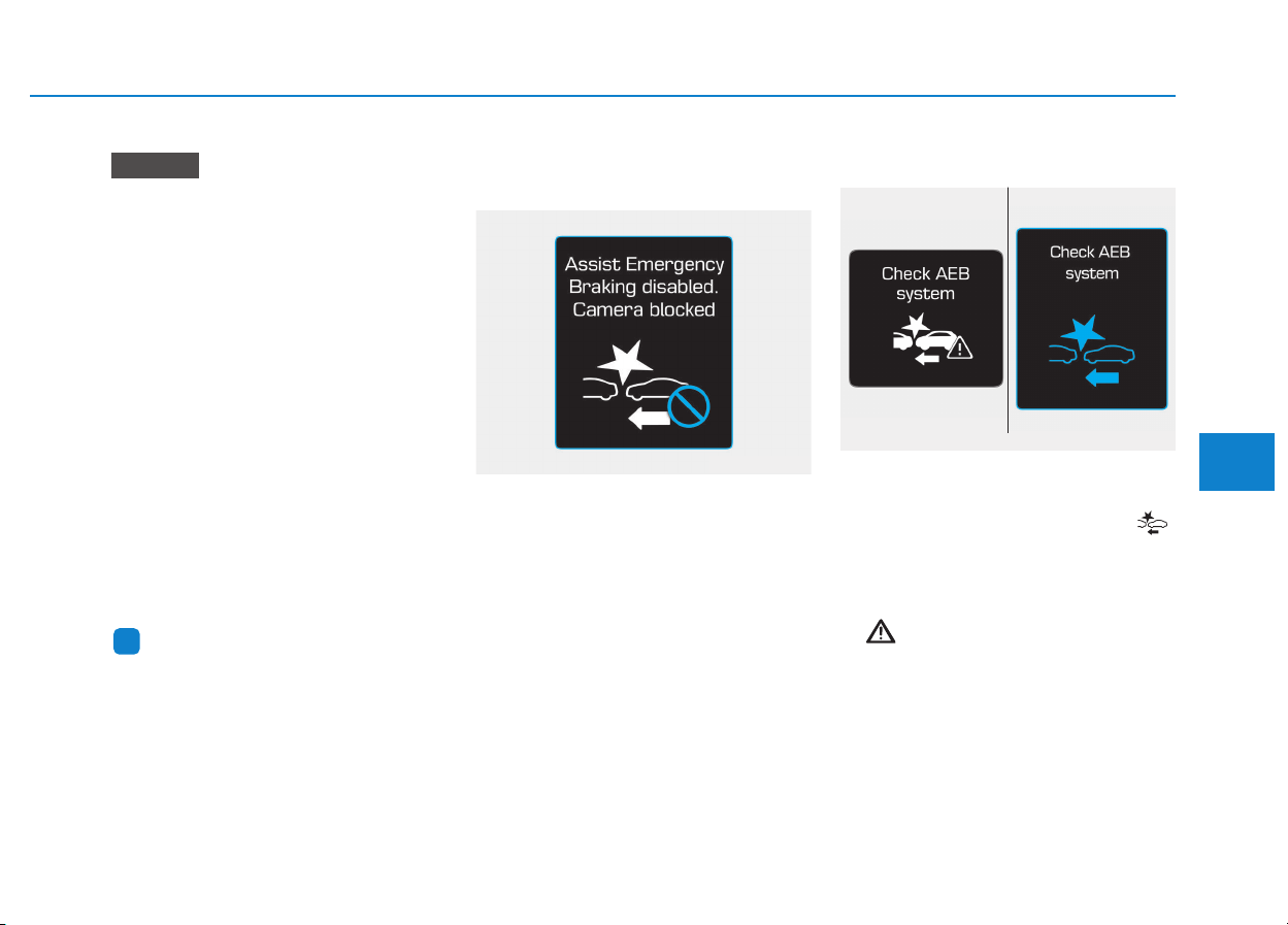
5-95
Driving your vehicle
5
• NEVER install any accessories
or stickers on the front wind-
shield, nor tint the front wind-
shield.
• NEVER locate any reflective
objects (i.e. white paper, mirror)
over the dashboard. Any light
reflection may cause a malfunc-
tion of the system.
• Pay extreme caution to keep the
camera out of water.
• NEVER arbitrarily disassemble
the camera assembly, nor apply
any impact on the camera
assembly.
• Playing the vehicle audio sys-
tem at high volume may offset
the system warning sounds.
Information
We recommend you have the system
checked by an authorized HYUNDAI
dealer when:
• The windshield glass is replaced.
• The camera or related parts are
repaired or removed.
Warning message and warning
light
Assist Emergency Braking disabled.
Camera blocked
When the camera sensor is blocked
with dirt, snow, or debris, the AEB
system operation may stop tem-
porarily. If this occurs, a warning
message will appear on the LCD dis-
play.
Remove any dirt, snow, or debris and
clean the camera sensor cover
before operating the AEB system.
The AEB may not properly operate in
an area (e.g. open terrain), where
any substances are not detected
after turning ON the engine.
System malfunction
Check AEB system
• When the AEB is not working prop-
erly, the AEB warning light ( )
will illuminate and the warning
message will appear for a few sec-
onds. After the message disap-
pears, the master warning light
( ) will illuminate. In this case, we
recommend you to have the vehicle
inspected by an authorized
HYUNDAI dealer.
• The AEB warning message may
appear along with the illumination
of the ESC (Electronic Stability
Control) warning light.
i
NOTICE
■ Type A ■ Type B
OTLE055071/OAE056038L
OPDE056128

5-96
Driving your vehicle
• The AEB is only a supplemen-
tal system for the driver's con-
venience. The driver should
hold the responsibility to con-
trol the vehicle operation. Do
not solely depend on the AEB
system. Rather, maintain a
safe braking distance, and, if
necessary, depress the brake
pedal to reduce the driving
speed.
• In certain instances and
under certain driving condi-
tions, the AEB system may
activate prematurely. This ini-
tial warning message appears
on the LCD display with a
warning chime.
Also, in certain instances the
front radar sensor or camera
recognition system may not
detect the vehicle or pedestri-
an ahead. The AEB system
may not activate and the
warning message will not be
displayed.
(Continued)
(Continued)
• If there is a malfunction with the
AEB system, the autonomous
emergency braking is not
applied even though the brak-
ing system is operating normal-
ly.
• If the vehicle in front stops
suddenly, you may have less
control of the brake system.
Therefore, always keep a safe
distance between your vehicle
and the vehicle in front of you.
• The AEB system may activate
during braking and the vehi-
cle may stop suddenly shift-
ing loose objects toward the
passengers. Always keep
loose objects secured.
• The AEB system may not acti-
vate if the driver applies the
brake pedal to avoid a colli-
sion.
(Continued)
WARNING
(Continued)
• The AEB system operates
only to detect vehicles in front
of the vehicle.
The AEB system does not
operate when the vehicle is in
reverse.
The AEB system is not
designed to detect other
objects on the road such as
animals.
The AEB system does not
detect vehicles in the oppo-
site lane.
The AEB system does not
detect cross traffic vehicles
that are approaching.
The AEB system cannot
detect the driver approaching
the side view of a parked vehi-
cle (for example on a dead
end street.)
In these cases, you must
maintain a safe braking dis-
tance, and if necessary,
depress the brake pedal to
reduce the driving speed in
order to maintain a safe dis-
tance.

5-97
Driving your vehicle
5
Limitations of the system
The Autonomous Emergency Braking
(AEB) system is designed to monitor
the vehicle ahead in the roadway
through camera recognition to warn
the driver that a collision is imminent,
and if necessary, apply emergency
braking.
In certain situations, the camera may
not be able to detect the vehicle
ahead. In these cases, the AEB sys-
tem may not operate normally. The
driver must pay careful attention in
the following situations where the
AEB operation may be limited.
Detecting vehicles
The sensor may be limited when:
• The camera is blocked with a for-
eign object or debris
• Inclement weather such as heavy
rain or snow obscures the field of
view of the radar sensor or camera
• There is interference by electro-
magnetic waves
• The camera sensor recognition is
limited
• The vehicle in front is too small to
be detected (for example a motor-
cycle or a bicycle, etc.)
• The vehicle in front is an oversize
vehicle or trailer that is too big to
be detected by the camera recog-
nition system (for example a tractor
trailer, etc.)
• The driver's field of view is not well
illuminated (either too dark or too
much reflection or too much back-
light that obscures the field of view)
• The vehicle in front does not have
their rear lights properly turned ON
• The outside brightness changes
suddenly, for example when enter-
ing or exiting a tunnel
• When light coming from a street
light or an oncoming vehicle is
reflected on a wet road surface
such as a puddle in the road
• The field of view in front is
obstructed by sun glare
• The windshield glass is fogged up;
a clear view of the road is obstruct-
ed
• The vehicle in front is driving errat-
ically
• The vehicle drives through a con-
struction area, on an unpaved
road, or above metal materials,
such as a railway
• The vehicle drives inside a build-
ing, such as a basement parking
lot
• The adverse road conditions cause
excessive vehicle vibrations while
driving
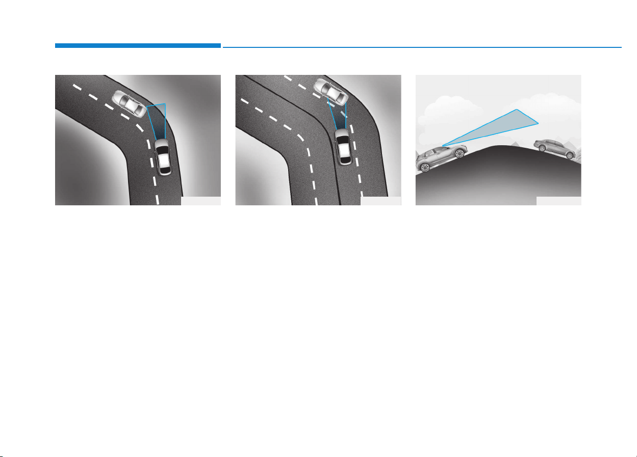
5-98
Driving your vehicle
- Driving on a curve
The performance of the AEB system
may be limited when driving on a
curved road.
In certain instances on a curved
road, the AEB system may activate
prematurely.
Also, in certain instances the front
radar sensor or camera recognition
system may not detect the vehicle
traveling on a curved road.
In these cases, the driver must main-
tain a safe braking distance, and if
necessary, depress the brake pedal
to reduce your driving speed in order
to maintain a safe distance.
The AEB system may recognize a
vehicle in the next lane when driving
on a curved road.
In this case, the system may unnec-
essarily alarm the driver and apply
the brake.
Always pay attention to road and
driving conditions, while driving. If
necessary, depress the brake pedal
to reduce your driving speed in order
to maintain a safe distance.
Also, when necessary depress the
accelerator pedal to prevent the sys-
tem from unnecessarily decelerating
your vehicle.
- Driving on a slope
The performance of the AEB decreas-
es while driving upward or downward
on a slope, not recognizing the vehi-
cle in front in the same lane. It may
unnecessarily produce the warning
message and the warning alarm, or it
may not produce the warning mes-
sage and the warning alarm at all.
When the AEB suddenly recognizes
the vehicle in front while passing
over a slope, you may experience
sharp deceleration.
Always keep your eyes forward while
driving upward or downward on a
slope, and, if necessary, depress the
brake pedal to reduce your driving
speed in order to maintain distance.
OAE056100 OAE056101 OPDE056102
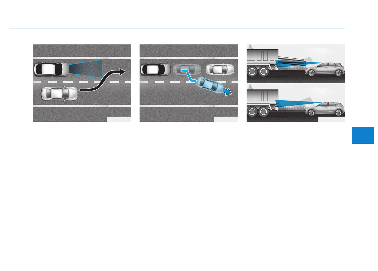
5-99
Driving your vehicle
5
- Changing lanes
When a vehicle changes lanes in
front of you, the AEB system may not
immediately detect the vehicle, espe-
cially if the vehicle changes lanes
abruptly. In this case, you must main-
tain a safe braking distance, and if
necessary, depress the brake pedal
to reduce your driving speed in order
to maintain a safe distance.
When driving in stop-and-go traffic,
and a stopped vehicle in front of you
merges out of the lane, the AEB sys-
tem may not immediately detect the
new vehicle that is now in front of
you. In this case, you must maintain
a safe braking distance, and if nec-
essary, depress the brake pedal to
reduce your driving speed in order to
maintain a safe distance.
- Detecting the vehicle in front of you
If the vehicle in front of you has cargo
that extends rearward from the cab,
or when the vehicle in front of you
has higher ground clearance, addi-
tional special attention is required.
The AEB system may not be able to
detect the cargo extending from the
vehicle. In these instances, you must
maintain a safe braking distance
from the rearmost object, and if nec-
essary, depress the brake pedal to
reduce your driving speed in order to
maintain distance.
OAE056103 OAE056109 OPDE056040

5-100
Driving your vehicle
Information
In some instances, the AEB system
may be cancelled when subjected to
electromagnetic interference.
i
• Do not use the Autonomous
Emergency Braking system
when towing a vehicle.
Application of the AEB sys-
tem while towing may
adversely affect the safety of
your vehicle or the towing
vehicle.
• Use extreme caution when the
vehicle in front of you has
cargo that extends rearward
from the cab, or when the
vehicle in front of you has
higher ground clearance.
• The AEB system is designed
to detect and monitor the
vehicle ahead in the roadway
through camera recognition. It
is not designed to detect bicy-
cles, motorcycles, or smaller
wheeled objects such as lug-
gage bags, shopping carts, or
strollers.
• Never try to test the operation
of the AEB system. Doing so
may cause severe injury or
death.
WARNING
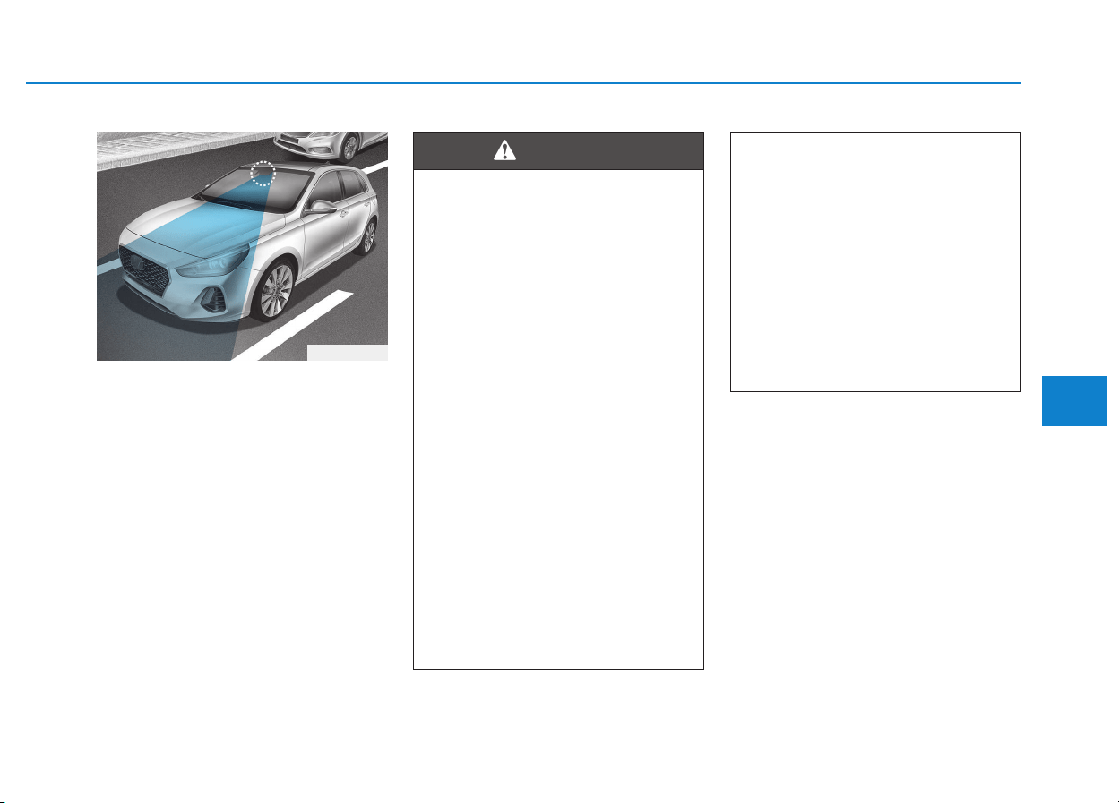
5-101
Driving your vehicle
5
The SLIF displays the speed limit
information and overtaking restric-
tion through the instrument cluster
and the navigation. The SLIF reads
the traffic signs through the camera,
which is attached on the upper part
of the inner front windshield.
The SLIF also utilizes the navigation
information to display the speed limit
information.
SSPPEEEEDD LLIIMMIITT IINNFFOORRMMAATTIIOONN FFUUNNCCTTIIOONN ((SSLLIIFF)) ((IIFF EEQQUUIIPPPPEEDD))
(Continued)
• Do not arbitrarily modify or
manipulate the multi-function
camera. Do not apply strong
impact.
• Do not place objects on the
dashboard that reflects light
such as mirrors, white paper,
etc. The system may malfunc-
tion if the sunlight is reflected.
• The system is not available in
all countries.
OPDE056048
• Speed Limit Information
Function (SLIF) is only a sup-
plemental system and is not
always able to correctly dis-
play speed limits and overtak-
ing restrictions.
• The driver still holds the
responsibility not to exceed
the maximum speed limit.
• Do not install any accessories
and stickers. Do not tint the
front windshield, especially
near the rearview mirror.
• The SLIF detects the traffic
signs through the camera to
display the speed limit infor-
mation.
Therefore, the SLIF may not
properly operate, when it is
hard to detect the traffic signs.
For further details, please
refer to the "Limitations of the
system".
(Continued)
WARNING

5-102
Driving your vehicle
System setting and activation
System setting
• The driver can activate the SLIF by
selecting 'User Settings → Driving
Assist → Speed Limit Information
Function'.
• When the SLIF is activated, the
symbols appear on the instrument
cluster to display the speed limit
information and overtaking restric-
tion.
• When the SLIF is activated in the
navigation setting, the above infor-
mation and the restriction are also
displayed on the navigation.
System activation
• The SLIF displays the speed limit
information and alerts the overtak-
ing restriction, when your vehicle
passes by the relevant traffic signs.
• The SLIF restores the previous
speed limit information, right after
the ignition switch is placed to the
ON position.
• You may find different speed limit
information for the same road. The
information is displayed depending
on the driving situations. Because,
traffic signs with additional sign
(e.g. rainy, arrow, etc.) are also
detected and compared with vehi-
cle internal data (e.g. wiper opera-
tion, turn signal, etc.).
• The SLIF automatically updates
the speed limit information in the
following situations.
- The vehicle changes driving
direction, or makes a U-turn.
- The vehicle enters or exits from a
highway, country road, etc.
- The vehicle enters or exits from a
town, village, etc.
Information
The speed limit information on the
instrument cluster may differ from
the one on the navigation. In this case,
check the speed unit setting on the
navigation.
Display
• The symbol is displayed on the
instrument cluster and the naviga-
tion, when the SLIF does not have
any reliable speed limit informa-
tion.
i
WTL-220
■ No reliable speed limit information
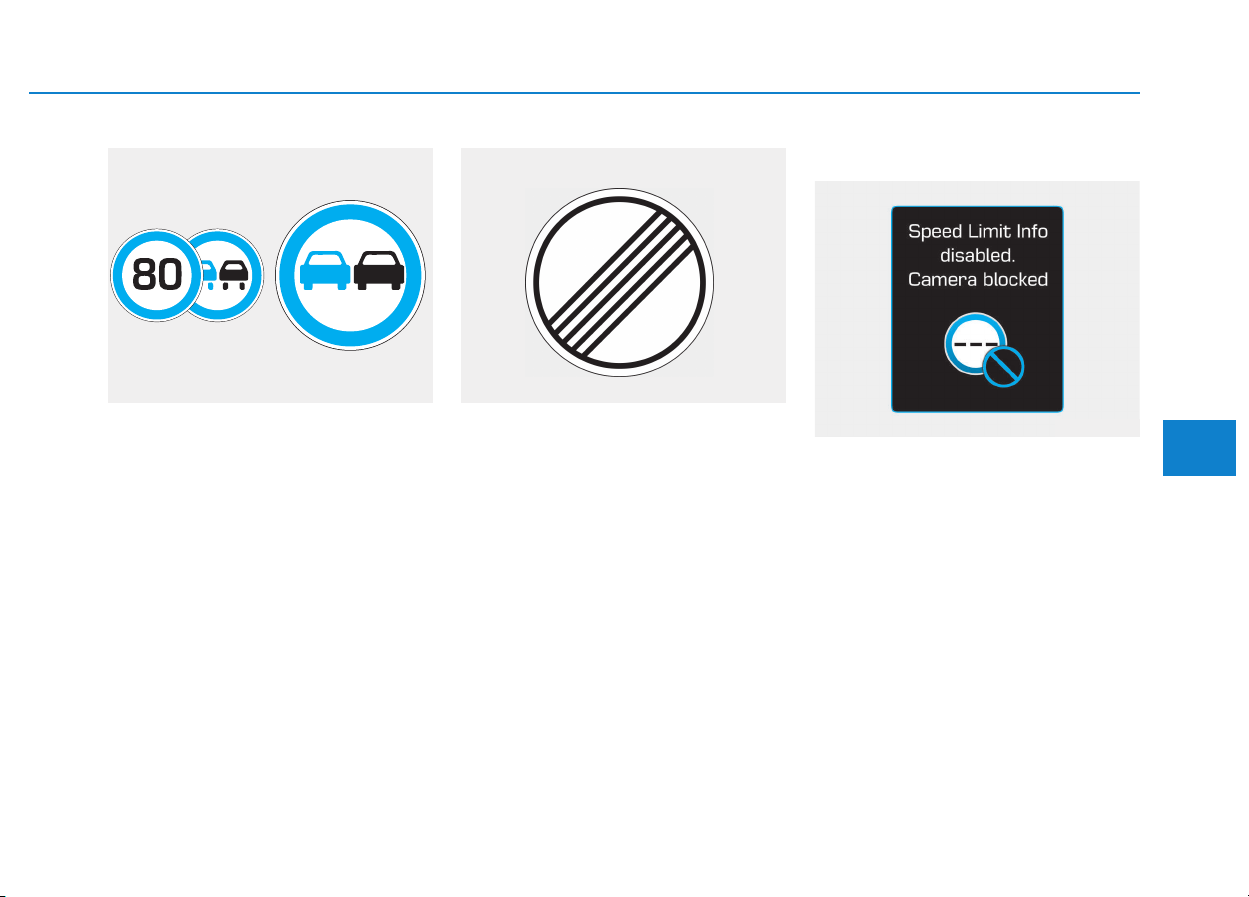
5-103
Driving your vehicle
5
• The symbol is displayed on the
instrument cluster and the naviga-
tion, when the SLIF detects a no-
overtaking sign.
• The symbol, 'end of limitation', is
displayed on the instrument cluster
for the roads in Germany, which
have no speed limit applicable. It is
displayed, until the vehicle passes
by another speed limit sign.
Warning message
Speed Limit Info disabled. Camera
blocked
The warning message appears,
when the camera lens is blocked by
some objects. The SLIF does not
operate, until the objects are
removed. Check the windshield glass
around the camera area. If the prob-
lem persists after removing the
objects, we recommend you to have
the system checked by an authorized
HYUNDAI dealer.
WTL-222/WTL-221
■ No passing information
WUM-205
■ Unlimited speed (only in Germany)
OTLE055082

5-104
Driving your vehicle
Check SLIF
The warning message appears for a
few seconds, when the SLIF does
not properly operate. Then, the mas-
ter warning light ( ) will illuminate.
We recommend you to have the sys-
tem checked by an authorized
HYUNDAI dealer.
Limitations of the system
The SLIF may not operate or may
not provide correct information in the
following situations.
• The traffic sign is located on a
sharp curve.
• The traffic sign is improperly posi-
tioned (i.e. turned over, blocked by
an object, and damaged).
• The traffic sign is uncommon or the
combination between traffic signs
are uncommon.
• The traffic sign is contrary to
Vienna convention.
• Another vehicle blocks the traffic
sign.
• The LED light of the traffic sign is
broken.
• The weather is bad, such as rain-
ing, snowing, and fogging.
• There is sunlight glare around the
traffic sign due to low solar altitude.
• It is dark at night.
• There is bright light around the traf-
fic sign.
• There is dirt, ice or frost on the
front windshield, where the camera
is installed.
• The camera lens is blocked by an
object, such as sticker, paper, or
fallen leaf.
• Your vehicle drives right after
another vehicle.
• There is a malfunction with the
navigation.
• The bus or truck, on which the
speed sticker is attached, passes
by your vehicle.
• Your vehicle drives in an area,
which is uncovered by the naviga-
tion system.
• Your navigation has not been
updated.
OTLE055080

5-105
Driving your vehicle
5
The driver must be cautious in the fol-
lowing situations. The SLIF may not
assist the driver and may not proper-
ly operate.
• Do not attach anything, such as
sticker, on the front windshield,
where the camera is installed. It
may adversely affect the SLIF and
cause a malfunction with the SLIF.
• Do not place any objects, which
have reflective surface, such as a
mirror and white paper, on the
dashboard.
• Do not arbitrarily modify or manipu-
late the camera, such as touching
the lens and unscrewing the cam-
era unit.
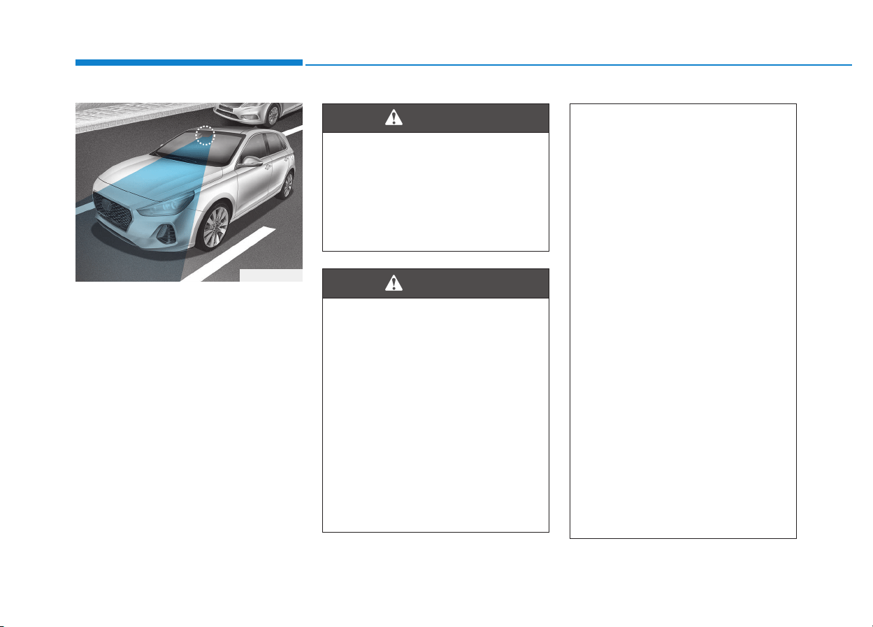
5-106
Driving your vehicle
The Lane Keeping Assist System
detects lane lines on the road, and
assists the driver's steering to help
keep the vehicle between lanes.
When the system detects the vehicle
straying from its lane, it alerts the
driver with a visual and audible warn-
ing, while applying a slight counter-
steering torque, trying to prevent the
vehicle from moving out of its lane.
LLAANNEE KKEEEEPPIINNGG AASSSSIISSTT SSYYSSTTEEMM ((LLKKAASS)) ((IIFF EEQQUUIIPPPPEEDD))
OPDE056048
The Lane Keeping Assist
System is not a substitute for
safe driving practices, but a
convenience function. It is the
responsibility of the driver to
always be aware of the sur-
rounding and steer the vehicle.
WARNING
Take the following precautions
when using the Lane Keeping
Assist System (LKAS):
• The steering wheel is not con-
tinuously controlled so if the
vehicle speed is at a higher
rate when leaving a lane the
vehicle may not be controlled
by the system.
• Do not steer the steering
wheel suddenly when the
steering wheel is being assist-
ed by the system.
(Continued)
WARNING
(Continued)
• LKAS prevents the driver
from moving out of the lane
unintentionally by assisting
the driver's steering. However,
the driver should not solely
rely on the system but always
pay attention on the steering
wheel to stay in the lane.
• Always check the road condi-
tion and surroundings and be
cautious when the system
cancels, does not operate or
malfunctions.
• Do not install any accessories
and stickers. Do not tint the
front windshield, especially
near the rearview mirror.
• The system detects lane lines
and controls the steering
wheel by a camera, therefore,
if the lane lines are hard to
detect, the system may not
work properly.
Please refer to "Limitations of
the system".
(Continued)
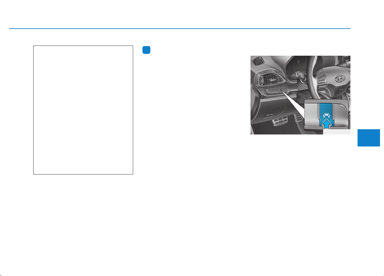
5-107
Driving your vehicle
5
Information
We recommend you have the system
checked by an authorized HYUNDAI
dealer when:
• The windshield glass is replaced.
• The LKAS camera or related parts
are repaired or removed.
LKAS operation
To activate the LKAS:
With the ignition switch in the ON
position, press the LKAS button
located on the instrument panel on
the lower left hand side of the driver.
(Lower right hand side of the driver
for RHD vehicles.)
The indicator in the cluster display
will initially illuminate white. This indi-
cates the LKAS is in the READY but
NOT ENABLED state.
Note that the vehicle speed must be
at least approximately 60 km/h (40
mph) to ENABLE the LKAS.The indi-
cator in the cluster display will illumi-
nate green.
i
(Continued)
• Do not attempt to repair the
LKAS camera and do not
remove any parts.
• Do not place objects that
reflect light on the dashboard
while driving.
• Always have your hands on
the steering wheel while the
LKAS system is activated. If
you continue to drive with
your hands off the steering
wheel after the "Keep hands
on steering wheel" warning
message appears, the system
will turn off automatically.
• Always be cautious when
using the system.
OPD056049
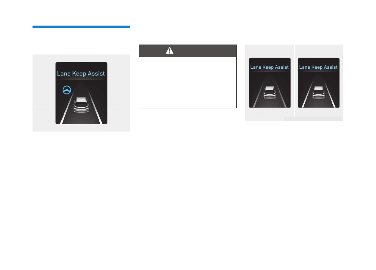
5-108
Driving your vehicle
LKAS activation
• The LKAS screen will appear when
you select the Assist Mode tab on
the LCD display if the system is
activated.
• When both lane lines are detected
and all the conditions to activate
the LKAS are satisfied, a green
steering wheel indicator will illumi-
nate and the LKAS indicator light
will change from white to green.
This indicates that the LKAS sys-
tem is in the ENABLED state and
the steering wheel will be able to
be controlled.
• If the system detects a lane line,
the color changes from gray to
white.
• If the system detects the left lane
line, the left lane line color will
change from gray to white.
• If the system detects the right lane
line, the right lane line color will
change from gray to white.
• Both lane lines must be detected
for the system to fully activate.
OPDE056055
The Lane Keeping Assist
System is a system to prevent
the driver from leaving the lane.
However, the driver should not
solely rely on the system but
always check the road condi-
tions when driving.
WARNING
■ Lane line undetected
■ Lane line detected
OPDE056051/OPDE056052
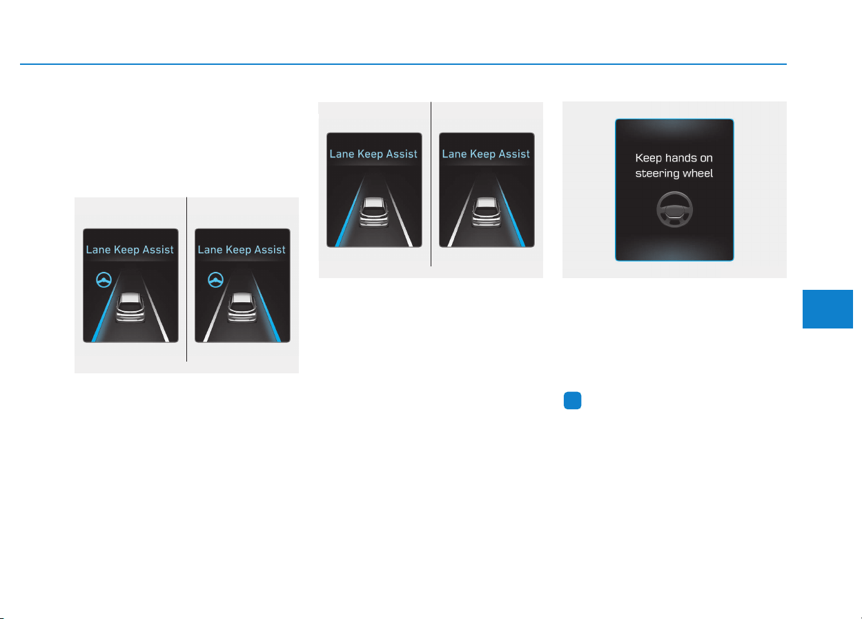
5-109
Driving your vehicle
5
• If your vehicle speed exceeds 60
km/h (40 mph) and the LKAS but-
ton is ON, the system is enabled. If
your vehicle departs from the pro-
jected lane in front of you, the
LKAS operates as follows:
A visual warning appears on the
cluster LCD display. Either the left
lane line or the right lane line in the
cluster LCD display will blink
depending on which direction the
vehicle is veering.
If the steering wheel appears, the
system will control the vehicle’s
steering to prevent the vehicle from
crossing the lane line.
If all the conditions to activate LKAS
is not satisfied, the system will con-
vert to LDWS (Lane Departure
Warning System) and warn the driv-
er only when the driver crosses the
lane lines.
Keep hands on steering wheel
If the driver takes their hands off the
steering wheel for several seconds
while the LKAS is activated, the sys-
tem will warn the driver with a visual
and audible warning.
Information
If the steering wheel is grabbed slight-
ly, the message may appear.
i
OAEE056129L
■ Left lane line ■ Right lane line
OPDE056053/OPDE056054
■ Left lane line ■ Right lane line
OPDE056056/OPDE056057
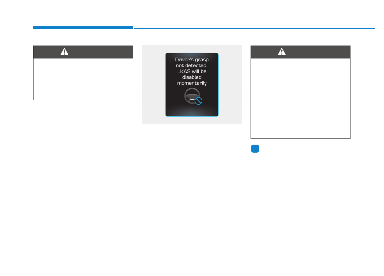
5-110
Driving your vehicle
Driver's grasp not detected.
LKAS will be disabled momentarily
If the driver still does not have their
hands on the steering wheel after the
message "Keep hands on steering
wheel", the system will not control
the steering wheel and warn the driv-
er only when the driver crosses the
lane lines.
However, if the driver has their hands
on the steering wheel again, the sys-
tem will start controlling the steering
wheel.
Information
• Even though the steering is assisted
by the system, the driver may con-
trol the steering wheel.
• The steering wheel may feel heavier
when the steering wheel is assisted
by the system than when it is not.
i
• The driver is responsible for
accurate steering.
• Turn off the system and drive
the vehicle in below situa-
tions.
- In bad weather
- In bad road condition
- When the steering wheel
needs to be controlled by the
driver frequently.
WARNING
The warning message may
appear late according to road
conditions. Therefore, always
have your hands on the steering
wheel while driving.
WARNING
OAEE056130L

5-111
Driving your vehicle
5
The LKAS system will not be in the
ENABLED state and the steering
wheel will not be assisted when:
• Vehicle speed is below 60 km/h (40
mph) and over 200 km/h (125 mph).
• Only one lane line is detected.
• The turn signal is turned on before
changing a lane. If you change
lanes without the turn signal on,
the steering wheel might be con-
trolled.
• The hazard warning flasher is on.
• The width of the lane is below 2.6 m
(8.5 feet) and over 4.5 m (15 feet).
• ESC (Electronic Stability Control) or
VSM (Vehicle Stability Management)
is activated.
• The vehicle is driven on a sharp
curve.
• The vehicle brakes suddenly.
• The vehicle makes sharp lane
changes.
• There are more than two lane lines
on the road. (e.g. construction
area)
• The vehicle is driven on a steep
incline.
Information
When the system is turned on or right
after changing a lane, drive in the
middle of the lane. If not, the system
will not provide steering assist func-
tion.
Warning light and message
Check LKAS
If there is a problem with the system
a message will appear for a few sec-
onds. If the problem continues the
LKAS failure indicator will illuminate.
i
OAEE056131L

5-112
Driving your vehicle
LKAS failure indicator
The LKAS failure indica-
tor (yellow) will illuminate
if the LKAS is not working
properly. We recommend
that the system be
checked by an authorized
HYUNDAI dealer.
When there is a problem with the
system do one of the following:
• Turn the system on after turning
the engine off and on again.
• Check if the ignition switch is in the
ON position.
• Check if the system is affected by
the weather. (ex: fog, heavy rain,
etc.)
• Check if there is foreign matter on
the camera lens.
If the problem is not solved, we rec-
ommend that the system be checked
by an authorized HYUNDAI dealer.
LKAS function change
The driver can change LKAS to Lane
Departure Warning System (LDWS)
or change the LKAS mode between
Standard LKA and Active LKA from
the LCD display. Go to the 'User
Settings → Driving Assist → Lane
Keeping Assist System → Lane
Departure Warning/Standard LKA/
Active LKA'.
The system is automatically set to
Standard LKA if a function is not
selected.
Lane Departure Warning
LDWS alerts the driver with a visual
warning and a warning alarm when
the system detects the vehicle
departing the lane. The steering
wheel will not be controlled.
Standard LKA
The Standard LKA mode guides the
driver to keep the vehicle within the
lanes. It rarely controls the steering
wheel, when the vehicle drives well
inside the lanes. However, it starts to
control the steering wheel, when the
vehicle is about to deviate out of the
lanes.
Active LKA
The Active LKA mode provides more
frequent steering wheel control in
comparison with the Standard LKA
mode. The driver may not feel the
onset of the steering wheel control,
because the Active LKA may be con-
stantly controlling the steering with
lighter corrections.

5-113
Driving your vehicle
5
Limitations of the System
The LKAS may operate prematurely
even if the vehicle does not depart
from the intended lane, OR, the
LKAS may not warn you if the vehicle
leaves the intended lane under the
following circumstances:
• The lanes ahead are not visible
due to rain, snow, water on the
road, damaged or stained road
surface, or other factors.
• The brightness outside changes
suddenly such as when entering or
exiting a tunnel.
• The brightness outside is too low
such as when the headlamps are
not on at night or the vehicle is
going through a tunnel.
• The surrounding of the inside rear
view mirror temperature is high
due to direct sunlight.
• It is difficult to distinguish the lane
marking from the road surface or
the lane marking is faded or not
clearly marked.
• Driving on a steep grade, over a
hill, or when driving on a curved
road.
• When light coming from a street
light or an oncoming vehicle is
reflected on a wet road surface
such as a puddle in the road.
• The windshield or the LKAS cam-
era lens is blocked with dirt or
debris.
• The field of view in front is
obstructed by sun glare.
• The lanes are incomplete or the
area is in a construction zone.
• There are more than two lane lines
on the road in front of you.
• The lane line is merged or divided.
(e.g. tollgate)
• The lane number increases or
decreases or the lane marker are
crossing complicatedly.
• The lane line in a tunnel is stained
with oil.
• The lane markings are not clearly
visible from the road.
• The shadow is on the lane marker
by a median strip, trees, etc.
• The lane width is too wide or too
narrow. See previous page.
• The windshield glass is fogged up;
a clear view of the road is obstruct-
ed.
• There are markings on the road
surface that look like a lane line
that is inadvertently being detected
by the camera.
• There is a boundary structure in
the roadway such as a concrete
barrier, guardrail and reflector post
that is inadvertently being detected
by the camera.
• There is not enough distance
between you and the vehicle in
front to be able to detect the lane
line or the vehicle ahead is driving
on the lane line.
• The adverse road conditions cause
excessive vehicle vibrations while
driving.
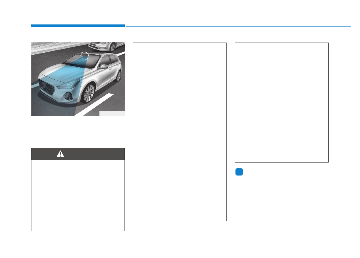
5-114
Driving your vehicle
This Lane Departure Warning System
detects the lane with the sensor at the
front windshield and warns you when
your vehicle leaves the lane.
Information
We recommend you have the system
checked by an authorized HYUNDAI
dealer when:
• The windshield glass is replaced.
• The LDWS camera or related parts
are repaired or removed.
i
LLAANNEE DDEEPPAARRTTUURREE WWAARRNNIINNGG SSYYSSTTEEMM ((LLDDWWSS)) ((IIFF EEQQUUIIPPPPEEDD))
Take the following precautions
when using the Lane Departure
Warning System (LDWS):
• ALWAYS check your sur-
roundings and the road condi-
tions before changing lanes.
The LDWS does not control
the vehicle to change lanes or
to stay in the current lane.
(Continued)
(Continued)
• Do not make abrupt maneu-
vers or turn the steering
wheel suddenly if the LDWS
alerts you that the vehicle is
departing from the lane.
• If the camera recognition sys-
tem does not properly detect
the lane, the LDWS may not
notify you if the vehicle
departs from the lane.
• The LDWS does not operate
until the vehicle speed reach-
es approximately 60 km/h (37
mph).
• The LDWS camera recogni-
tion system is located in front
of the rear view mirror at the
center of the front windshield.
Do not spray water or any
type of liquid near the camera.
The system may become
damaged.
• Do not attempt to repair the
LDWS camera and do not
remove any parts.
(Continued)
(Continued)
• Do not place objects that
reflect light on the dashboard
while driving.
• Do not place any accessories
near the inside rearview mir-
ror.
• The operation of the LDWS
may be affected by several
factors including environmen-
tal conditions that affect the
ability of the camera to detect
the lanes in front of you. It is
the responsibility of the driver
to pay careful attention to the
roadway and to maintain the
vehicle in its intended lane at
all times.
WARNING
OPDE056048
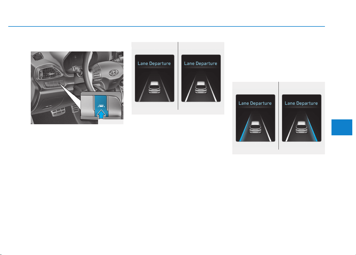
5-115
Driving your vehicle
5
LDWS operation
To activate the LDWS:
With the ignition switch in the ON
position, press the LDWS button
located on the instrument panel on
the lower left hand side of the driver.
The indicator in the cluster display
will initially illuminate white. This indi-
cates the LDWS is in the READY but
NOT ENABLED state.
Note that the vehicle speed must be
at least approximately 60 km/h (40
mph) to ENABLE the LDWS. The
indicator in the cluster display will
illuminate green.
• The LDWS screen will appear
when you select the Assist Mode
tab on the LCD display if the sys-
tem is activated.
• If the system detects a lane line,
the color changes from gray to
white.
• If the system detects the left lane
line, the left lane line color will
change from gray to white.
• If the system detects the right lane
line, the right lane line color will
change from gray to white.
• If your vehicle speed exceeds 60
km/h (40 mph) and the LDWS but-
ton is ON, the system is enabled. If
your vehicle departs from the pro-
jected lane in front of you, the
LDWS operates as follows:
A visual warning appears on the
cluster LCD display. Either the left
lane line or the right lane line in the
cluster LCD display will blink
depending on which direction the
vehicle is veering.
■ Lane line detected■ Lane line undetected
OPDE056110/OPDE056111
OPDE056049
■ Left ■ Right
OPDE056112/OPDE056113
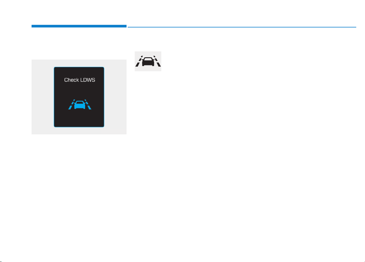
5-116
Driving your vehicle
Warning light and message
Check LDWS
If there is a problem with the system
a message will appear for a few sec-
onds.
If the problem continues the LDWS
failure indicator will illuminate.
LDWS failure indicator
The LDWS failure indica-
tor (yellow) will illuminate
if the LDWS is not work-
ing properly. We recom-
mend you to have your vehicle
checked by an authorized HYUNDAI
dealer.
When there is a problem with the
system, do one of the following:
• Turn the system on after turning
the vehicle off and on again.
• Check if the ignition switch is in the
ON position.
• Check if the system is affected by the
weather. (e.g. fog, heavy rain, etc.)
• Check if there is foreign matter on
the camera lens.
If the problem is not solved, we rec-
ommend you have the system
checked by an authorized HYUNDAI
dealer.
Limitations of the system
The LDWS may operate prematurely
even if the vehicle does not depart
from the intended lane, OR, the
LDWS may not warn you if the vehi-
cle leaves the intended lane under
the following circumstances:
• The lanes ahead are not visible
due to rain, snow, water on the
road, damaged or stained road
surface, or other factors.
• The brightness outside changes
suddenly such as when entering or
exiting a tunnel.
• The brightness outside is too low
such as when the headlamps are
not on at night or the vehicle is
going through a tunnel.
• The surrounding of the inside rear
view mirror temperature is high
due to direct sunlight.
• It is difficult to distinguish the lane
marking from the road surface or
the lane marking is faded or not
clearly marked.
• Driving on a steep grade, over a
hill, or when driving on a curved
road.
OAE056164L

5-117
Driving your vehicle
5
• When light coming from a street
light or an oncoming vehicle is
reflected on a wet road surface
such as a puddle in the road.
• The windshield or the LDWS cam-
era lens is blocked with dirt or
debris.
• The field of view in front is
obstructed by sun glare.
• The lanes are incomplete or the
area is in a construction zone.
• There are more than two lane lines
on the road in front of you.
• The lane line is merged or divided.
(e.g. tollgate)
• The lane number increases or
decreases or the lane marker are
crossing complicatedly.
• The lane line in a tunnel is stained
with oil.
• The lane markings are not clearly
visible from the road.
• The lane width is too wide or too
narrow.
• The shadow is on the lane marker
by a median strip, trees, etc.
• The windshield glass is fogged up;
a clear view of the road is obstruct-
ed.
• There are markings on the road
surface that look like a lane line
that is inadvertently being detected
by the camera.
• There is a boundary structure in
the roadway such as a concrete
barrier, guardrail and reflector post
that is inadvertently being detected
by the camera.
• There is not enough distance
between you and the vehicle in
front to be able to detect the lane
line or the vehicle ahead is driving
on the lane line.
• The adverse road conditions cause
excessive vehicle vibrations while
driving.
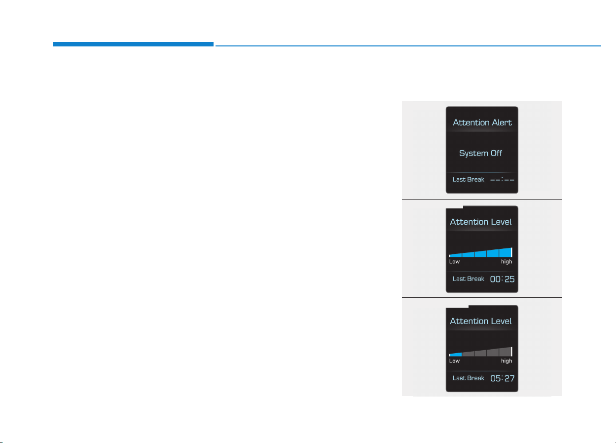
5-118
Driving your vehicle
The Driver Attention Alert (DAA),
system is to warn the driver with any
hazardous driving situations upon
detecting the driver's fatigue level or
inattentive driving practices.
System setting and activation
System setting
• The Driver Attention Alert system
is set to be in the OFF position,
when your vehicle is first delivered
to you from the factory.
• To turn ON the Driver Attention
Alert system, turn on the engine,
and then select 'User Settings →
Driving Assist → Driver Attention
Alert → Normal/Early' on the LCD
display.
• The driver can select the Driver
Attention Alert system mode.
- Off : The Driver Attention Alert
system is deactivated.
- Normal : The Driver Attention
Alert system alerts the driver of
his/her fatigue level or inattentive
driving practices.
- Early : The Driver Attention Alert
system alerts the driver of his/her
fatigue level or inattentive driving
practices faster than Normal
mode.
• The set-up of the Driver Attention
Alert system will be maintained, as
selected, when the engine is re-
started.
Prerequisite for activation
The Driver Attention Alert system is
operable, when driving speed is
between 60 km/h (40 mph) and 200
km/h (125 mph).
Display of the driver's attention
level
DDRRIIVVEERR AATTTTEENNTTIIOONN AALLEERRTT SSYYSSTTEEMM ((DDAAAA)) ((IIFF EEQQUUIIPPPPEEDD))
OPDE056125
■ System off
OPDE056061
■ Attentive driving
OPDE056062
■ Inattentive driving
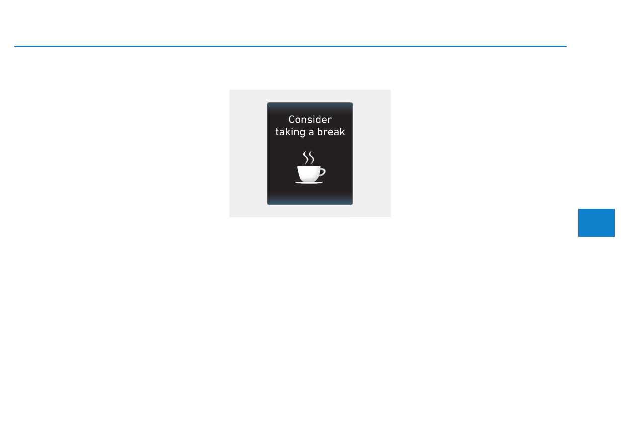
5-119
Driving your vehicle
5
• The driver can monitor their driving
conditions on the LCD display.
The DAA screen will appear when
you select the Assist Mode tab on
the LCD display if the system is
activated. (For more information,
refer to "LCD Modes" in chapter
3.)
• The driver's attention level is dis-
played on the scale of 1 to 5. The
lower the number is, the more inat-
tentive the driver is.
• The number decreases when the
driver does not take a break for a
certain period of time.
• The number increases when the
driver attentively drives for a cer-
tain period of time.
Take a break
• The "Consider taking a break"
message appears on the LCD dis-
play and a warning sounds in order
to suggest the driver to take a
break, when the driver’s attention
level is below 1.
• The Driver Attention Alert system
does not suggest the driver to take
a break, when the total driving time
is shorter than 10 minutes.
Resetting the system
• The last break time is set to 00:00
and the driver's attention level is
set to 5 (very attentive) when the
driver resets the Driver Attention
Alert system.
• The Driver Attention Alert system
resets the last break time to 00:00
and the driver's attention level to 5
in the following situations.
- The engine is turned OFF.
- The driver unfastens the seat belt
and then opens the driver's door.
- The engine has been idled con-
tinuously over 10 minutes.
• The Driver Attention Alert system
operates again, when the driver
restarts driving.
OPDE056063
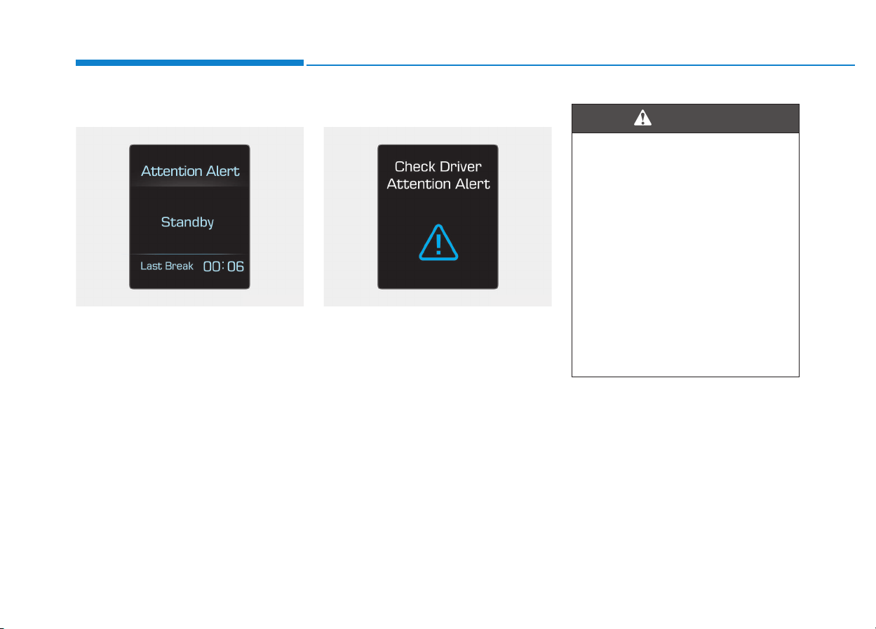
5-120
Driving your vehicle
System standby
The Driver Attention Alert system
enters the ready status and displays
the 'Standby' screen in the following
situations.
- The camera sensor keeps failing to
detect the lanes.
- Driving speed remains under 60
km/h (40 mph) or over 200 km/h
(125 mph).
System malfunction
When the "Check System" warning
message appears, the system is not
working properly. In this case, we rec-
ommend you to have the vehicle
inspected by an authorized HYUNDAI
dealer.
OPDE056126 OPDE056065
• The Driver Attention Alert
system is not a substitute for
safe driving practices, but a
convenience function only. It
is the responsibility of the
driver to always drive cau-
tiously to prevent unexpected
and sudden situations from
occurring. Pay attention to the
road conditions at all times.
• The driver, who feels fatigued,
should take a break, even
though there is no break sug-
gestion by the Driver Attention
Alert system.
WARNING
5-121
Driving your vehicle
5
The Driver Attention Alert system
utilizes the camera sensor on the
front windshield for its operation.
To keep the camera sensor in the
best condition, you should
observe the followings:
• NEVER install any accessories
or stickers on the front wind-
shield, nor tint the front wind-
shield.
• NEVER locate any reflective
objects (i.e. white paper, mirror)
over the dashboard. Any light
reflection may cause a malfunc-
tion of the Driver Attention Alert
(DAA) system.
• Pay extreme caution to keep the
camera sensor out of water.
• NEVER arbitrarily disassemble
the camera assembly, nor apply
any impact on the camera
assembly.
• Playing the vehicle audio sys-
tem at high volume may offset
the Driver Attention Alert sys-
tem warning sounds.
NOTICE
The Driver Attention Alert sys-
tem may not properly operate
with limited alerting in the fol-
lowing situations:
• The lane detection perform-
ance is limited. (For more
information, refer to "Lane
Keeping Assist System
(LKAS)" in this chapter.)
• The vehicle is violently driven
or is abruptly turned for
obstacle avoidance (e.g. con-
struction area, other vehicles,
fallen objects, bumpy road).
• Forward drivability of the
vehicle is severely under-
mined (possibly due to wide
variation in tire pressures,
uneven tire wear-out, toe-
in/toe-out alignment).
• The vehicle drives on a curvy
road.
• The vehicle drives on a
bumpy road.
(Continued)
CAUTION
(Continued)
• The vehicle drives through a
windy area.
• The vehicle is controlled by
the following driving assist
systems:
- Lane Keeping Assist System
(LKAS)
- Autonomous Emergency
Braking (AEB) System
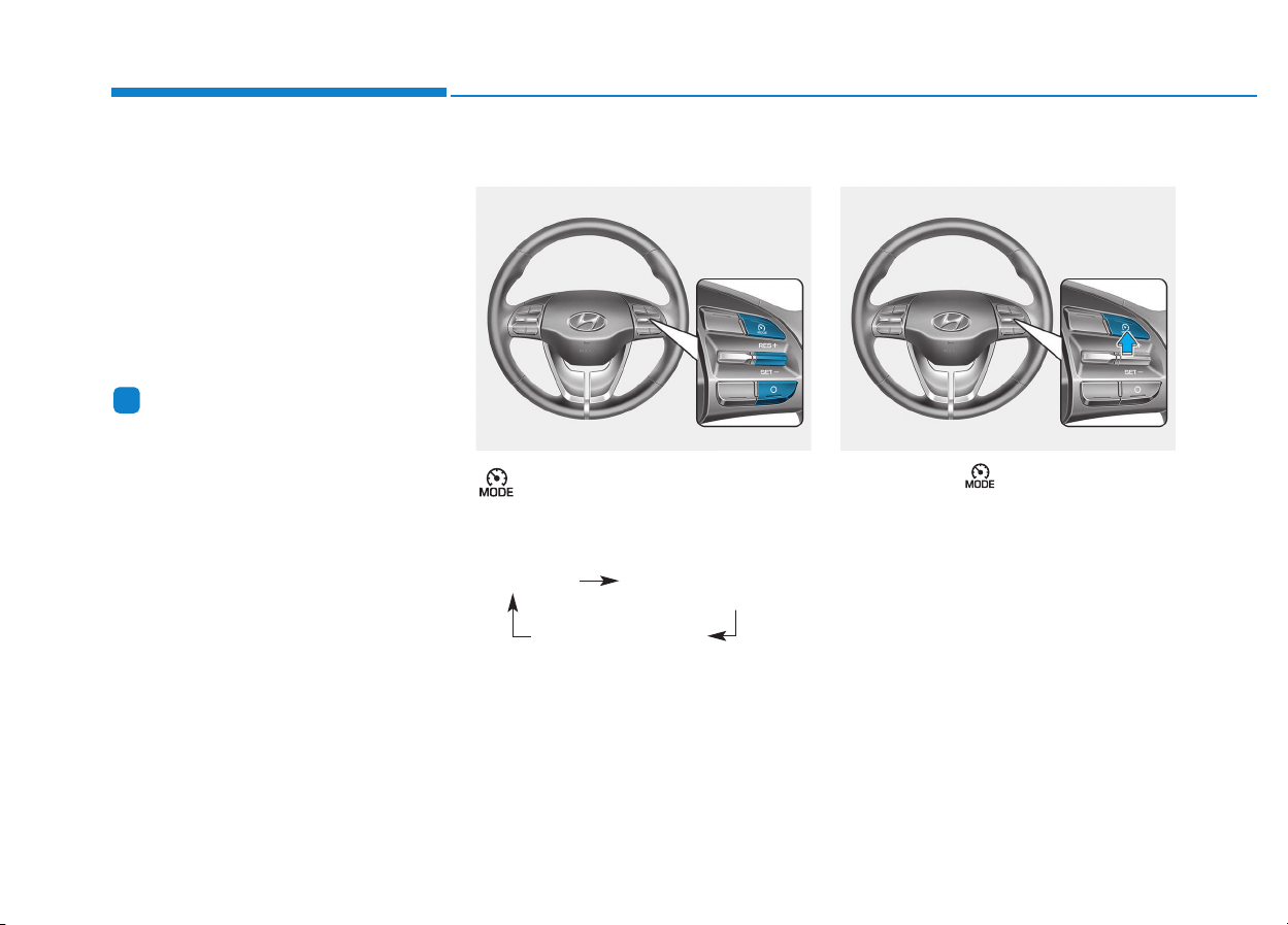
5-122
Driving your vehicle
Speed Limit Control operation
You can set the speed limit when you
do not want to drive over a specific
speed.
If you drive over the preset speed
limit, the warning system operates
(set speed limit will blink and chime
will sound) until the vehicle speed
returns within the speed limit.
Information
While speed limit control is in opera-
tion, the cruise control system cannot
be activated.
Speed limit control switch
: Changes mode between cruise
control/smart cruise control
system and speed limit control
system.
RES+: Resumes or increases speed
limit control speed.
SET-: Sets or decreases speed limit
control speed.
O: Cancels set speed limit.
To set speed limit
1. Press the button to turn the
system on. The speed limit indica-
tor in the instrument cluster will
illuminate.
i
SSPPEEEEDD LLIIMMIITT CCOONNTTRROOLL SSYYSSTTEEMM ((IIFF EEQQUUIIPPPPEEDD))
OPDE056114 OPDE056115
System off
Speed Limit Control
Cruise Control/Smart
Cruise Control
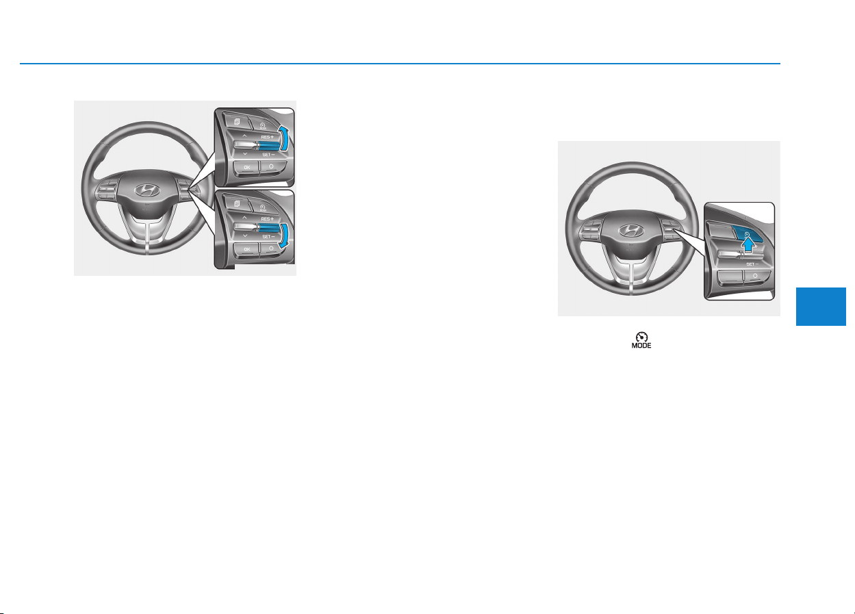
5-123
Driving your vehicle
5
2. Push the toggle switch down
(SET-).
3. • Push the toggle switch up
(RES+) or down (SET-), and
release it at the desired speed.
• Push the toggle switch up
(RES+) or down (SET-) and hold
it. The speed will increase or
decrease by 5 km/h.
The set speed limit will display on the
instrument cluster.
If you would like to drive over the pre-
set speed limit when you depress the
accelerator pedal less than approxi-
mately 50%, the vehicle speed will
maintain within speed limit.
However if you depress the acceler-
ator pedal more than approximately
70%, you can drive over the speed
limit. Then the set speed limit will
blink and chime will sound until you
return the vehicle speed within the
speed limit.
To turn off the speed limit con-
trol, do one of the following:
• Press the button.
• If you press O (cancel) button
once, the set speed limit will can-
cel, but it will not turn the system
off. If you wish to resume the speed
limit, push the +RES or SET- tog-
gle switch on your steering wheel
to your desired speed.
OPDE056116
OPDE056115
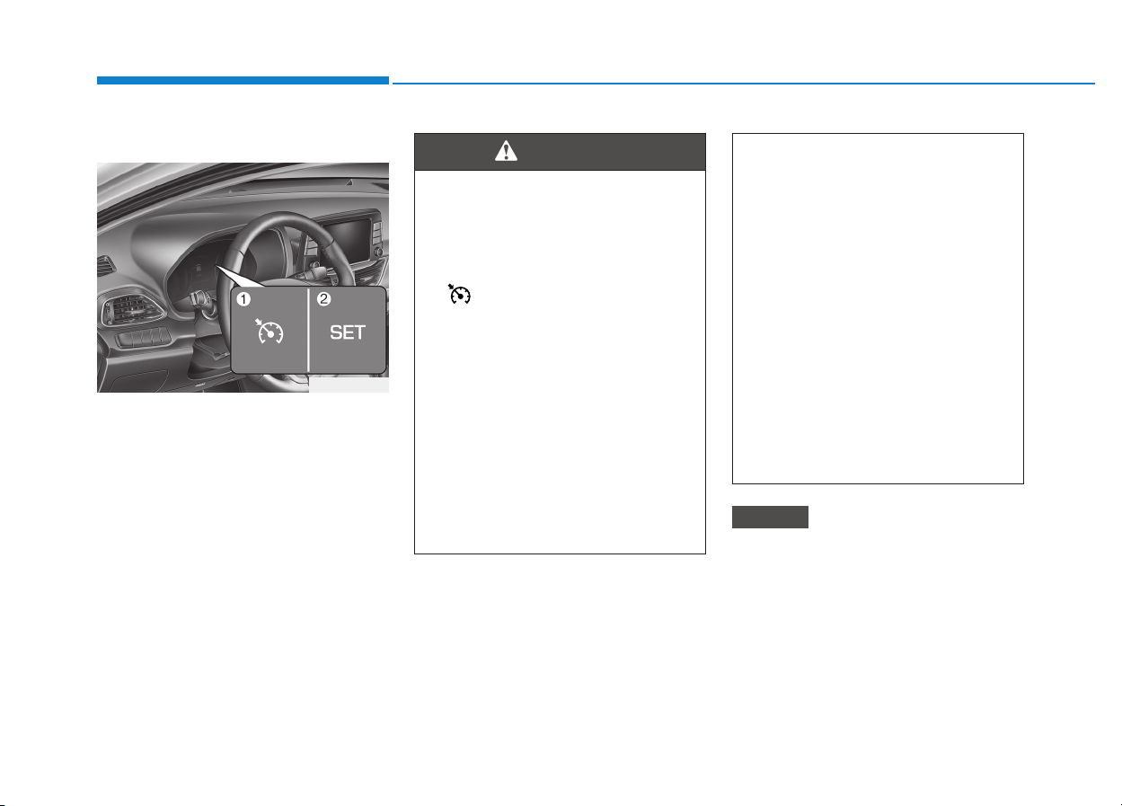
5-124
Driving your vehicle
Cruise Control operation
1. CRUISE indicator
2. SET indicator
The Cruise Control system allows you
to drive at speeds above 30 km/h
(20 mph) without depressing the
accelerator pedal.
During cruise-speed driving of a
manual transmission vehicle, do
not shift into neutral without
depressing the clutch pedal, since
the engine will be overrevved. If
this happens, depress the clutch
pedal or press the cruise control
ON / OFF button.
NOTICE
CCRRUUIISSEE CCOONNTTRROOLL ((IIFF EEQQUUIIPPPPEEDD))
Take the following precautions:
• Always set the vehicle speed
under the speed limit in your
country.
• If the Cruise Control is left on,
( indicator light in the
instrument cluster is illumi-
nated) the Cruise Control can
be activated unintentionally.
Keep the Cruise Control sys-
tem off (CRUISE indicator
light OFF) when the Cruise
Control is not in use, to avoid
inadvertently setting a speed.
• Use the Cruise Control system
only when traveling on open
highways in good weather.
(Continued)
(Continued)
• Do not use the Cruise Control
when it may be unsafe to keep
the vehicle at a constant
speed:
- When driving in heavy traffic
or when traffic conditions
make it difficult to drive at a
constant speed
- When driving on rainy, icy, or
snow-covered roads
- When driving on hilly or
windy roads
- When driving in windy areas
• Do not use cruise control
when towing a trailer.
WARNING
OPDE056066

5-125
Driving your vehicle
5
Information
• During normal cruise control opera-
tion, when the SET switch is activat-
ed or reactivated after applying the
brakes, the cruise control will ener-
gize after approximately 3 seconds.
This delay is normal.
• Before activating the cruise control
function, the system will check to
verify that the brake switch is oper-
ating normally. Depress the brake
pedal at least once after turning ON
the ignition or starting the vehicle.
Cruise control switch
O : Cancels cruise control operation.
: Turns cruise control system on
or off.
RES+: Resumes or increases cruise
control speed.
SET-: Sets or decreases cruise con-
trol speed.
Information
First, switch the mode to Cruise
Control by pressing the button if
equipped with the Speed Limit
Control System.
The mode changes, as below, whenev-
er the button is pressed.
ii
OPDE056115
System off Cruise Control
Speed Limit Control
OPDE056117
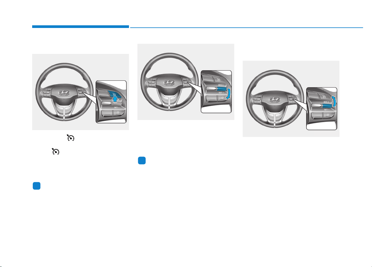
5-126
Driving your vehicle
To set Cruise Control speed
1. Press the button on the steer-
ing wheel to turn the system on.
The indicator will illuminate.
2. Accelerate to the desired speed,
which must be more than 30 km/h
(20 mph).
Information
- Manual trans-
mission
For manual transmission vehicles, you
should depress the brake pedal at
least once to set the cruise control
after starting the engine.
3. Push the toggle switch down
(SET-), and release it. The SET
indicator light will illuminate.
4. Release the accelerator pedal.
Information
On a steep slope, the vehicle may
slightly slow down or speed up, while
driving uphill or downhill.
To increase Cruise Control
speed
• Push the toggle switch up (RES+)
and hold it, while monitoring the
SET speed on the instrument clus-
ter.
Release the toggle switch when the
desired speed is shown and the
vehicle will accelerate to that speed.
i
i
OPDE056118
OPDE056119
OPDE056120
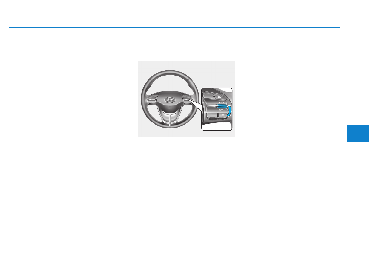
5-127
Driving your vehicle
5
• Push the toggle switch up (RES+)
and release it immediately. The
cruising speed will increase 2.0
km/h (1.2 mph) each time the tog-
gle switch is operated in this man-
ner.
• Depress the accelerator pedal.
When the vehicle attains the
desired speed, push the toggle
switch down (SET-).
To decrease Cruise Control
speed
• Push the toggle switch down (SET-)
and hold it.Your vehicle will gradual-
ly slow down. Release the toggle
switch at the speed you want to
maintain.
• Push the toggle switch down (SET-)
and release it immediately. The
cruising speed will decrease 2.0
km/h (1.2 mph) each time the toggle
switch is operated in this manner.
• Lightly tap the brake pedal. When
the vehicle attains the desired
speed, push the toggle switch
down (SET-).
To temporarily accelerate with
the Cruise Control ON
Depress the accelerator pedal. When
you take your foot off the accelerator,
the vehicle will return to the previ-
ously set speed.
If you push the toggle switch down
(SET-) at the increased speed, the
Cruise Control will maintain the
increased speed.
OPDE056119
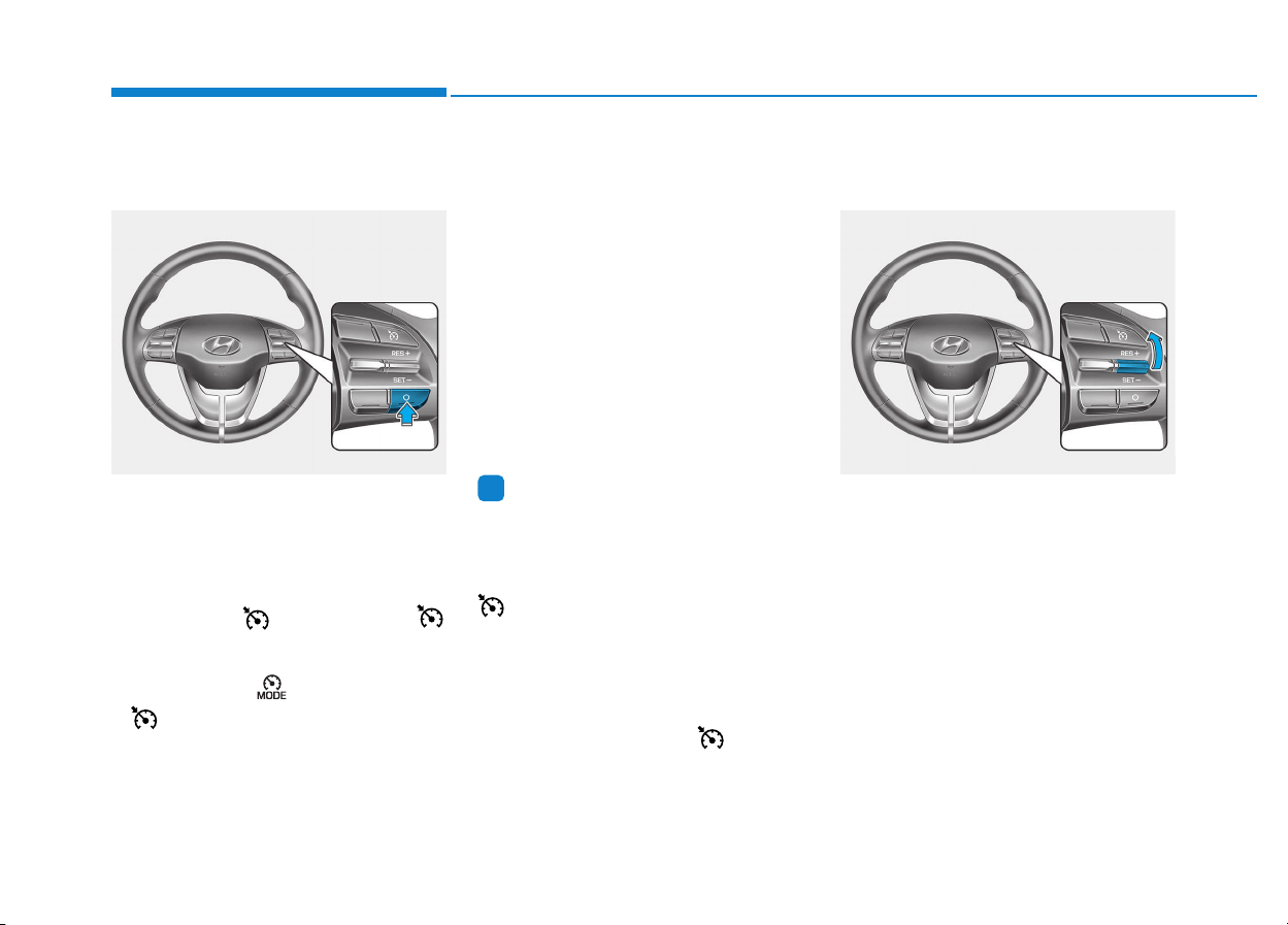
5-128
Driving your vehicle
Cruise Control will be canceled
when:
• Depressing the brake pedal.
• Depressing the clutch pedal.
(for manual transmission vehicle)
• Pressing the O button located on
the steering wheel.
• Pressing the button. Both the
indicator and the SET indicator will
turn OFF.
• Pressing the button. Both the
indicator and the SET indicator
will turn OFF. (if equipped with the
Speed Limit Control)
• Moving the shift lever into N
(Neutral). (for automatic transmis-
sion/dual clutch transmission vehi-
cle)
• Decreasing the vehicle speed to
less than approximately 30 km/h
(20 mph).
• The ESC (Electronic Stability
Control) is operating.
• Downshifting to the 2nd gear in
manual shift mode. (for automatic
transmission/dual clutch transmis-
sion vehicle)
Information
Each of the above actions will cancel
Cruise Control operation (the SET
indicator light in the instrument clus-
ter will go off), but only pressing the
button will turn the system off. If
you wish to resume Cruise Control
operation, push the toggle switch up
(RES+) located on your steering
wheel. You will return to your previ-
ously preset speed, unless the system
was turned off using the button.
To resume preset Cruising
speed
Push the toggle switch up (RES+). If
the vehicle speed is over 30 km/h (20
mph), the vehicle will resume the
preset speed.
i
OPDE056120OPDE056121

5-129
Driving your vehicle
5
To turn Cruise Control off
• Press the button (the indi-
cator light will go off).
• Press the button (The cruise
indicator light will go off.). (if
equipped with Speed Limit Control)
- With the Cruise Control on,
pressing the button once will turn
Off the Cruise Control and turn
on the Speed Limit Control.
- With the Cruise Control off and
Speed Limit Control on, pressing
the button will turn off both sys-
tem.
Information
The mode changes, as below, whenev-
er the button is pressed.
i
System off Cruise Control
Speed Limit Control
OPDE056118
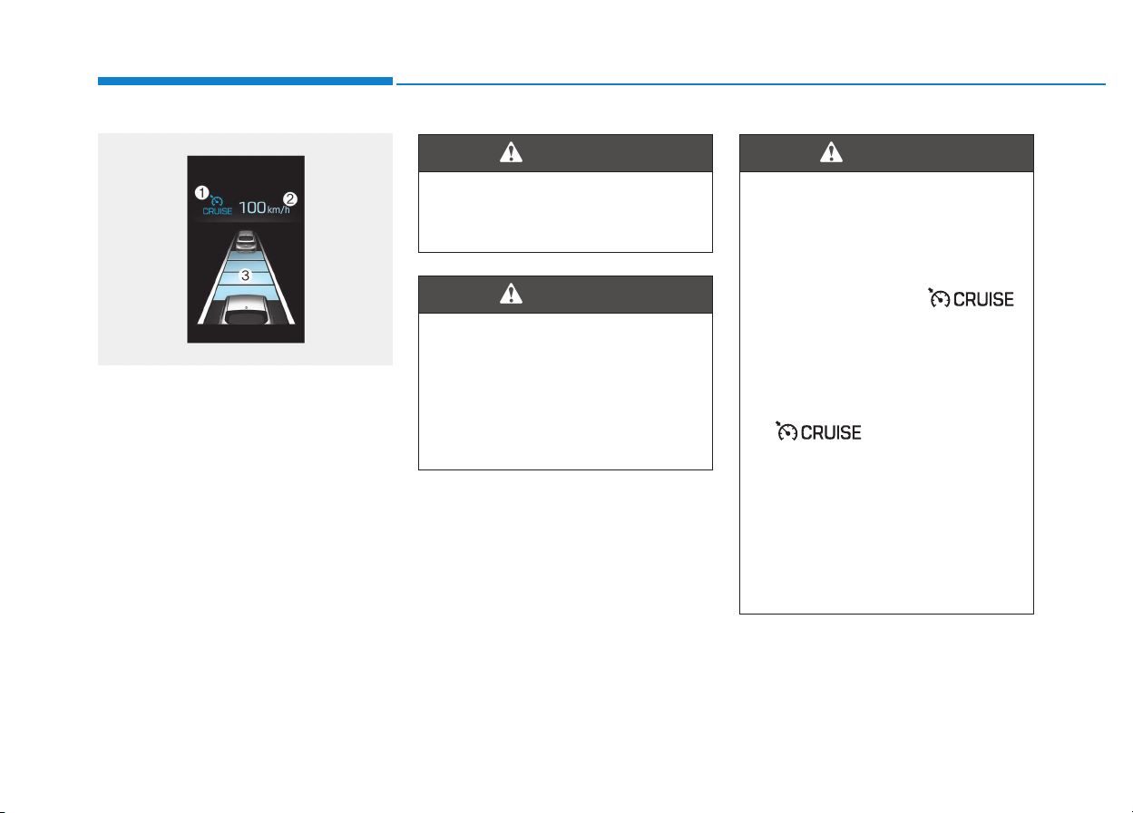
5-130
Driving your vehicle
➀ Cruise indicator
➁ Set speed
➂ Vehicle-to-vehicle distance
The SCC screen will appear when
you select the Assist Mode tab on
the LCD display if the system is acti-
vated.
The Smart Cruise Control System
allows you to program the vehicle to
maintain constant speed and dis-
tance detecting the vehicle ahead
without depressing the accelerator/
brake pedal.
AADDVVAANNCCEEDD SSMMAARRTT CCRRUUIISSEE CCOONNTTRROOLL SSYYSSTTEEMM ((IIFF EEQQUUIIPPPPEEDD))
For your safety, please read the
owner's manual before using the
Smart Cruise Control system.
WARNING
The Smart Cruise Control
System is not a substitute for
safe driving practices, but a
convenience function only. It is
the responsibility of the driver
to always check the speed and
distance to the vehicle ahead.
WARNING
Take the following precautions :
• Always set the vehicle speed
under the speed limit in your
country.
• If the Smart Cruise Control is
left on, (cruise ( )
indicator light in the instru-
ment cluster is illuminated)
the Smart Cruise Control can
be activated unintentionally.
Keep the Smart Cruise
Control System off (cruise
( ) indicator light
OFF) when the Smart Cruise
Control is not in use, to avoid
inadvertently setting a speed.
• Use the Smart Cruise Control
System only when traveling
on open highways in good
weather.
(Continued)
WARNING
OAE056097
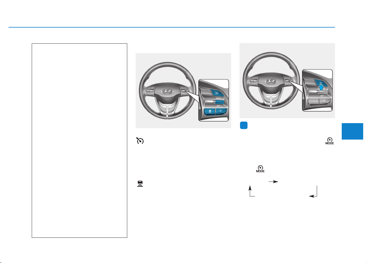
5-131
Driving your vehicle
5
Smart cruise control switch
O : Cancels cruise control operation.
: Turns cruise control system on
or off.
RES+: Resumes or increases cruise
control speed.
SET-: Sets or decreases cruise con-
trol speed.
: Sets vehicle-to-vehicle dis-
tance.
Information
First, switch the mode to Smart
Cruise Control by pressing the
button if equipped with the Speed
Limit Control System.
The mode changes, as below, whenev-
er the button is pressed.
i
(Continued)
• Do not use the Smart Cruise
Control when it may not be
safe to keep the vehicle at a
constant speed:
- When driving in heavy traffic
or when traffic conditions
make it difficult to drive at a
constant speed
- When driving on rainy, icy, or
snow-covered roads
- When driving on a steep
downhill or uphill
- When driving in windy areas
- When driving in parking lots
- When driving near crash
barriers
- When driving on a sharp
curve
- When driving with limited
view (possibly due to bad
weather, such as fog, snow,
rain or sandstorm)
- When the vehicle sensing
ability decreases due to
vehicle modification result-
ing level difference of the
vehicle's front and rear
OPDE056123
OPDE056115
System off Smart Cruise Control
Speed Limit Control
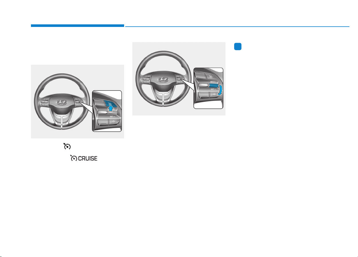
5-132
Driving your vehicle
Smart Cruise Control speed
To set Smart Cruise Control
speed
1. Push the button on the steer-
ing wheel to turn the system on.
The cruise ( ) indicator
will illuminate.
2. Accelerate to the desired speed.
The Smart Cruise Control speed
can be set as follows:
• 30 km/h (20 mph)~180 km/h
(110 mph) : when there is no
vehicle in front
• 0 km/h (0 mph)~180 km/h (110
mph) : when there is a vehicle in
front
3. Push the toggle switch down
(SET-). The Set Speed and
Vehicle-to-Vehicle Distance on the
LCD display will illuminate.
4. Release the accelerator pedal.
The desired speed will automati-
cally be maintained.
If there is a vehicle in front of you, the
speed may decrease to maintain the
distance to the vehicle ahead.
On a steep grade, the vehicle may
slow down or speed up slightly while
going uphill or downhill.
Information
Vehicle speed may decrease on an
upward slope and increase on a down-
ward slope.
i
OPDE056118
OPDE056119
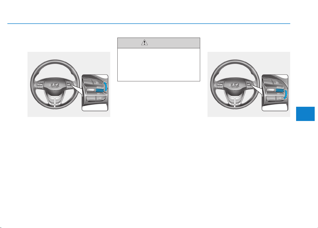
5-133
Driving your vehicle
5
To increase Smart Cruise
Control set speed
Follow either of these procedures:
• Push the toggle switch up (RES+),
and release it immediately. The
cruising speed will increase by 1
km/h (1 mph) each time you move
the toggle switch up in this manner.
• Push the toggle switch up (RES+),
and hold it. Your vehicle set speed
will increase by 10 km/h (5 mph).
Release the toggle switch at the
speed you want.
• You can set the speed to 180 km/h
(110 mph).
To decrease the Smart Cruise
Control set speed
Follow either of these procedures:
• Push the toggle switch down (SET-),
and release it immediately. The
cruising speed will decrease by 1
km/h (1 mph) each time you move
the toggle switch down in this man-
ner.
• Push the toggle switch down (SET-),
and hold it. Your vehicle set speed
will decrease by 10 km/h (5 mph).
Release the toggle switch at the
speed you want.
• You can set the speed to 30 km/h
(20 mph).
OPDE056120
Check the driving condition
before using the toggle switch.
Driving speed sharply increas-
es, when you push up and hold
the toggle switch.
CAUTION
OPDE056119
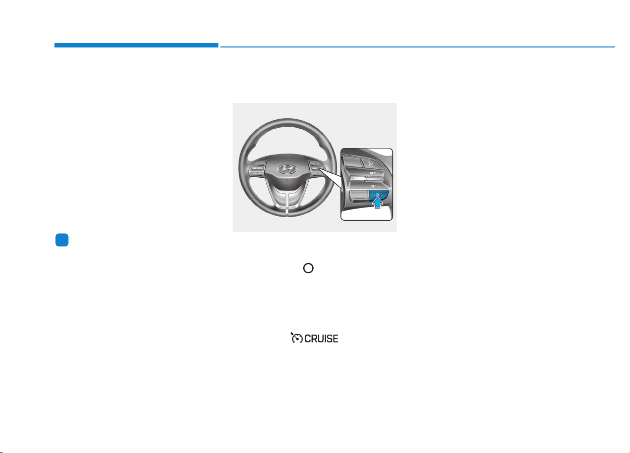
5-134
Driving your vehicle
To temporarily accelerate with
the Smart Cruise Control on
If you want to speed up temporarily
when the Smart Cruise Control is on,
depress the accelerator pedal.
Increased speed will not interfere
with Smart Cruise Control operation
or change the set speed.
To return to the set speed, take your
foot off the accelerator pedal.
If you push the toggle switch down
(SET-) at increased speed, the cruis-
ing speed will be set again pedal.
Information
Be careful when accelerating tem-
porarily, because the speed is not con-
trolled automatically at this time even
if there is a vehicle in front of you.
Smart Cruise Control will be
temporarily canceled when:
Cancelled manually
• Depressing the brake pedal.
• Pressing the button located on
the steering wheel.
The Smart Cruise Control turns off
temporarily when the Set Speed and
Vehicle-to-Vehicle Distance indicator
on the LCD display turns off.
The cruise ( ) indicator is
illuminated continuously.
Cancelled automatically
• The driver's door is opened.
• The shift lever is shifted to N
(Neutral), R (Reverse) or P (Park).
• The parking brake is applied.
• The vehicle speed is over 190
km/h (120 mph).
• The ESC (Electronic Stability
Control), TCS (Traction Control
System) or ABS is operating.
• The ESC is turned off.
• The sensor or the cover is dirty or
blocked with foreign matter.
• The vehicle is stopped for a certain
period of time.
• The vehicle stops and goes repeat-
edly for a long period of time.
• The accelerator pedal is continu-
ously depressed for a long period
of time.
• The engine performance is abnor-
mal.
• The driver starts driving by pushing
the toggle switch up (RES+)/down
(SET-) or depressing the accelera-
tor pedal, approximately 3 minutes
after the vehicle is stopped by the
Smart Cruise Control System with
no other vehicle ahead.
i
OPDE056121
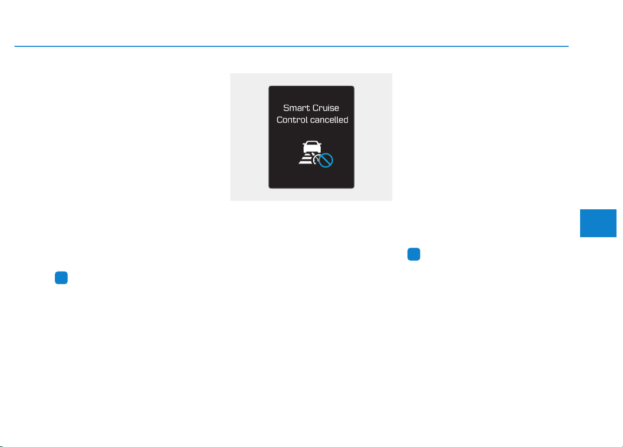
5-135
Driving your vehicle
5
• The driver starts driving by pushing
the toggle switch up (RES+)/down
(SET-) or depressing the accelera-
tor pedal, after stopping the vehicle
with a vehicle stopped far away in
front.
• The AEB is activated.
Each of these actions will cancel the
Smart Cruise Control operation. The
Set Speed and Vehicle-to-Vehicle
Distance on the LCD display will go
off.
In a condition the Smart Cruise
Control is cancelled automatically,
the Smart Cruise Control will not
resume even though the RES+ or
SET- toggle switch is pushed.
Information
If the Smart Cruise Control is can-
celled by other than the reasons men-
tioned, we recommend that the system
be checked by an authorized
HYUNDAI dealer.
Smart Cruise Control cancelled
If the system is cancelled, the warn-
ing chime will sound and a message
will appear for a few seconds.
You must adjust the vehicle speed by
depressing the accelerator or brake
pedal according to the road condition
ahead and driving condition.
Always check the road conditions.
Do not rely on the warning chime.
To resume Smart Cruise Control
set speed
If any method other than the cruise
toggle switch was used to cancel
cruising speed and the system is still
activated, the cruising speed will
automatically resume when you
push the toggle switch up (RES+) or
down (SET-).
If you push the toggle switch up
(RES+), the speed will resume to the
recently set speed. However, if vehi-
cle speed drops below 30 km/h (20
mph), it will resume when there is a
vehicle in front of your vehicle.
Information
Always check the road conditions
when you push the toggle switch up
(RES+) to resume speed.
i
i
OAE056165L
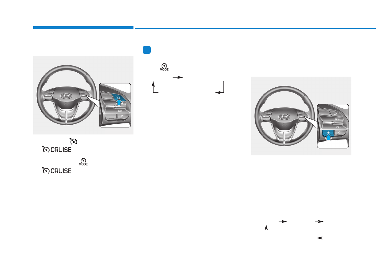
5-136
Driving your vehicle
To turn Cruise Control off
• Press the button (the cruise
( ) indicator light will go
off).
• Press the button (The
( ) indicator light will go
off.). (if equipped with Speed Limit
Control)
- With the Smart Cruise Control
on, pressing the button once will
turn Off the Smart Cruise Control
and turn on the Speed Limit
Control.
- With the Smart Cruise Control off
and Speed Limit Control on,
pressing the button will turn off
both system.
Information
The mode changes, as below, whenev-
er the button is pressed.
Smart Cruise Control Vehicle-
to-Vehicle Distance
To set Vehicle-to-Vehicle
Distance
When the Smart Cruise Control
System is ON, you can set and main-
tain the distance from the vehicle
ahead of you without pressing the
accelerator or brake pedal.
Each time the button is pressed, the
vehicle to vehicle distance changes
as follows:
i
OPDE056118
System off Smart Cruise Control
Speed Limit Control
OPDE056124
Distance 4 Distance 3 Distance 2
Distance 1
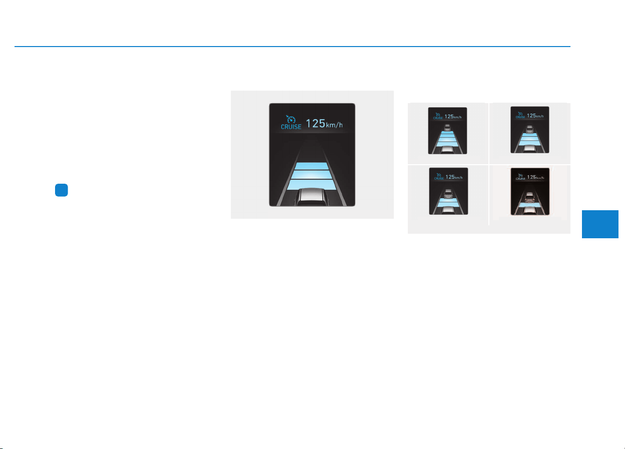
5-137
Driving your vehicle
5
For example, if you drive at 90 km/h
(56 mph), the distance maintain as
follows:
Distance 4 - approximately 52.5 m
Distance 3 - approximately 40 m
Distance 2 - approximately 32.5 m
Distance 1 - approximately 25 m
Information
The distance is set to the last set dis-
tance when the system is used for the
first time after starting the engine.
When the lane ahead is clear:
The vehicle speed will maintain the
set speed.
When there is a vehicle ahead
of you in your lane:
• Your vehicle speed will slow down
or speed up to maintain the select-
ed distance.
• If the vehicle ahead speeds up,
your vehicle will travel at a steady
cruising speed after accelerating to
the set speed.
i
OPD056084
Distance 4 Distance 3
Distance 1
Distance 2
OPD056085/OPD056086/OPD056087/OPD056088
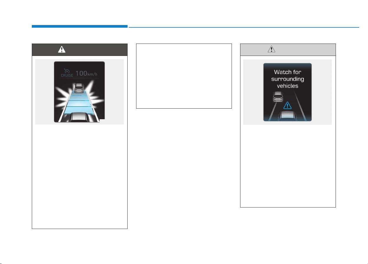
5-138
Driving your vehicle
When using the Smart Cruise
Control System:
• The warning chime sounds
and the Vehicle-to Vehicle
Distance indicator blinks if
the vehicle is unable to main-
tain the selected distance
from the vehicle ahead.
• If the warning chime sounds,
depress the brake pedal or
use the steering wheel toggle
switch to actively adjust the
vehicle speed, and the dis-
tance to the vehicle ahead.
(Continued)
(Continued)
• Even if the warning chime is
not activated, always pay
attention to the driving condi-
tions to prevent dangerous
situations from occurring.
• Playing the vehicle audio sys-
tem at high volume may offset
the system warning sounds.
WARNING
OPD056089
If the vehicle ahead (vehicle
speed: less than 30km/h) disap-
pears to the next lane, the warn-
ing chime will sound and a mes-
sage "Watch for surrounding
vehicles" will appear. Adjust
your vehicle speed for vehicles
or objects that can suddenly
appear in front of you by
depressing the brake pedal.
Always pay attention to the road
condition ahead.
CAUTION
OPDE056090
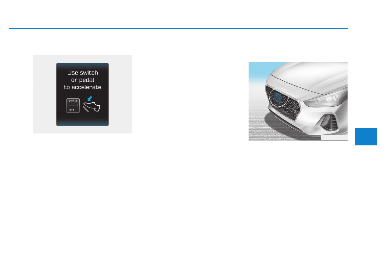
5-139
Driving your vehicle
5
In traffic situation
Use switch or pedal to accelerate
• In traffic, your vehicle will stop if the
vehicle ahead of you stops. Also, if
the vehicle ahead of you starts
moving, your vehicle will start as
well. However, if the vehicle stops
for more than 3 seconds, you must
depress the accelerator pedal or
push up the toggle switch (RES+)
or push down the toggle switch
(SET-) to start driving.
• If you push the advanced smart
cruise control toggle switch (RES+
or SET-) while Auto Hold and
advanced smart cruise control is
operating the Auto Hold will be
released regardless of accelerator
pedal operation and the vehicle will
start to move. The AUTO HOLD
indicator changes from green to
white. (if equipped with EPB
(Electronic Parking Brake))
Sensor to detect distance to
the vehicle ahead
The Smart Cruise Control uses a
sensor to detect distance to the vehi-
cle ahead.
OPDE056039
OPDE056091
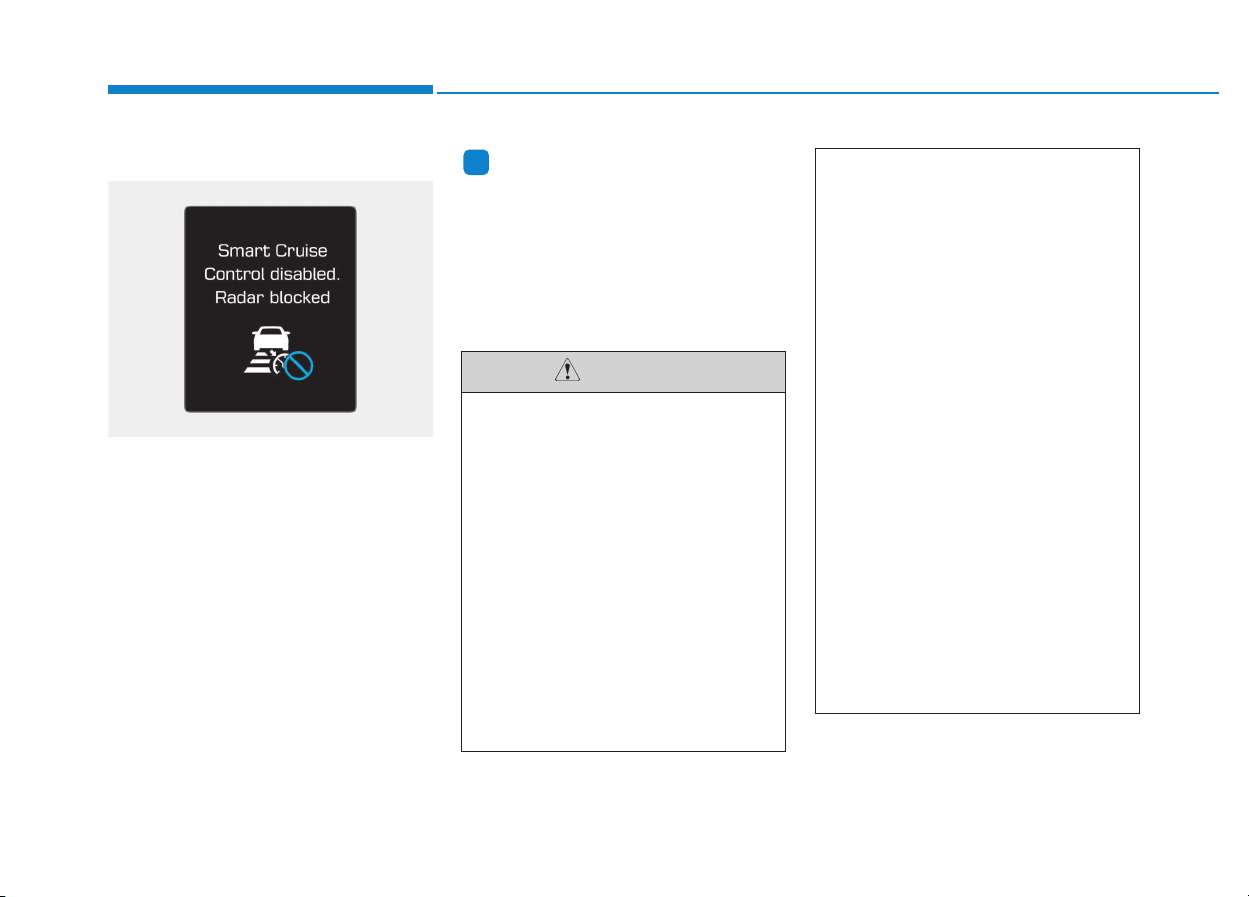
5-140
Driving your vehicle
Warning message
Smart Cruise Control disabled.
Radar blocked
When the sensor lens cover is
blocked with dirt, snow, or debris, the
Smart Cruise Control System opera-
tion may stop temporarily. If this
occurs, a warning message will
appear on the LCD display. Remove
any dirt, snow, or debris and clean
the radar sensor lens cover before
operating the Smart Cruise Control
System. The Smart Cruise Control
system may not properly activate, if
the radar is totally contaminated, or if
any substance is not detected after
turning ON the engine (e.g. in an open
terrain).
Information
For the SCC operation is temporarily
stopped if the radar is blocked, but you
wish to use cruise control mode (speed
control function), you must convert to
the cruise control mode (refer to “To
convert to Cruise Control mode” in
the following page.
i
OAE056166L
(Continued)
• Be careful not to apply unnec-
essary force on the radar sen-
sor or sensor cover. If the sen-
sor is forcibly moved out of
proper alignment, the Smart
Cruise Control System may
not operate correctly. In this
case, a warning message may
not be displayed. Have the
vehicle inspected by an
authorized HYUNDAI dealer.
• If the front bumper becomes
damaged in the area around
the radar sensor, the Smart
Cruise Control System may
not operate properly. We rec-
ommend you to have the vehi-
cle inspected by an author-
ized HYUNDAI dealer.
• Use only genuine HYUNDAI
parts to repair or replace a
damaged sensor or sensor
cover. Do not apply paint to
the sensor cover.
• Do not apply license plate
molding or foreign objects
such as a bumper sticker or a
bumper guard near the radar
sensor. Doing so may adverse-
ly affect the sensing perform-
ance of the radar.
• Always keep the radar sensor
and lens cover clean and free
of dirt and debris.
• Use only a soft cloth to wash
the vehicle. Do not spray pres-
surized water directly on the
sensor or sensor cover.
(Continued)
CAUTION
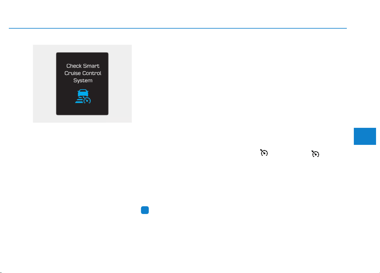
5-141
Driving your vehicle
5
Check Smart Cruise Control System
The message will appear when the
vehicle to vehicle distance control
system is not functioning normally.
We recommend that you take your
vehicle to an authorized HYUNDAI
dealer and have the system checked.
To adjust the sensitivity of
Smart Cruise Control
The sensitivity of vehicle speed
when following the front vehicle to
maintain the set distance can be
adjusted. Go to the 'User Settings →
Driving Assist → Smart Cruise
Control Speed → Slow/Normal/Fast'
on the LCD display. You may select
one of the three stages you prefer.
- Slow:
Vehicle speed following the front
vehicle to maintain the set distance
is slower than normal speed.
- Normal:
Vehicle speed following the front
vehicle to maintain the set distance
is normal.
- Fast:
Vehicle speed following the front
vehicle to maintain the set distance
is faster than normal speed.
Information
The last selected speed sensitivity of
the smart cruise control is remained in
the system.
To convert to Cruise Control
mode
The driver may choose to only use
the Cruise Control mode (speed con-
trol function) by doing as follows:
1. Turn the Smart Cruise Control
System on (the cruise indicator
light will be on but the system will
not be activated).
2. Push and hold the Vehicle-to-
Vehicle Distance button for more
than 2 seconds.
3. Choose between "Smart Cruise
Control" and "Cruise Control".
When the system is canceled using
the button or the button is
used after the engine is turned on,
the Smart Cruise Control mode will
turn on.
i
OAE056167L
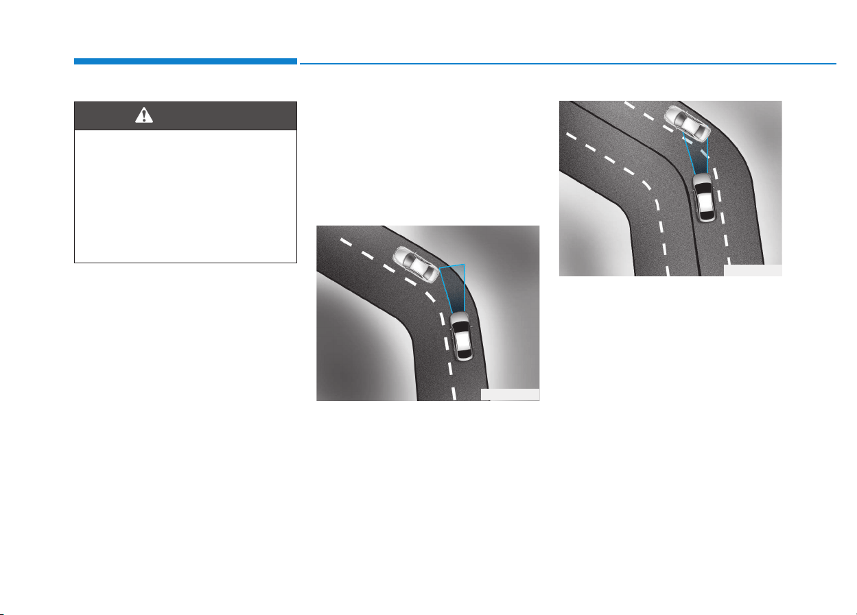
5-142
Driving your vehicle
Limitations of the system
The Smart Cruise Control System
may have limits to its ability to detect
distance to the vehicle ahead due to
road and traffic conditions.
On curves
• The Smart Cruise Control System
may not detect a moving vehicle in
your lane, and then your vehicle
could accelerate to the set speed.
Also, the vehicle speed will
decrease when the vehicle ahead
is recognized suddenly.
• Select the appropriate set speed
on curves and apply the brakes or
accelerator pedal if necessary.
Your vehicle speed can be reduced
due to a vehicle in the adjacent lane.
Apply the accelerator pedal and
select the appropriate set speed.
Check to be sure that the road con-
ditions permit safe operation of the
Smart Cruise Control.
OAE056101
OAE056100
When using the Cruise Control
mode, you must manually
adjust the distance to other
vehicles by depressing the
accelerator or brake pedal. The
system does not automatically
adjust the distance to vehicles
in front of you.
WARNING
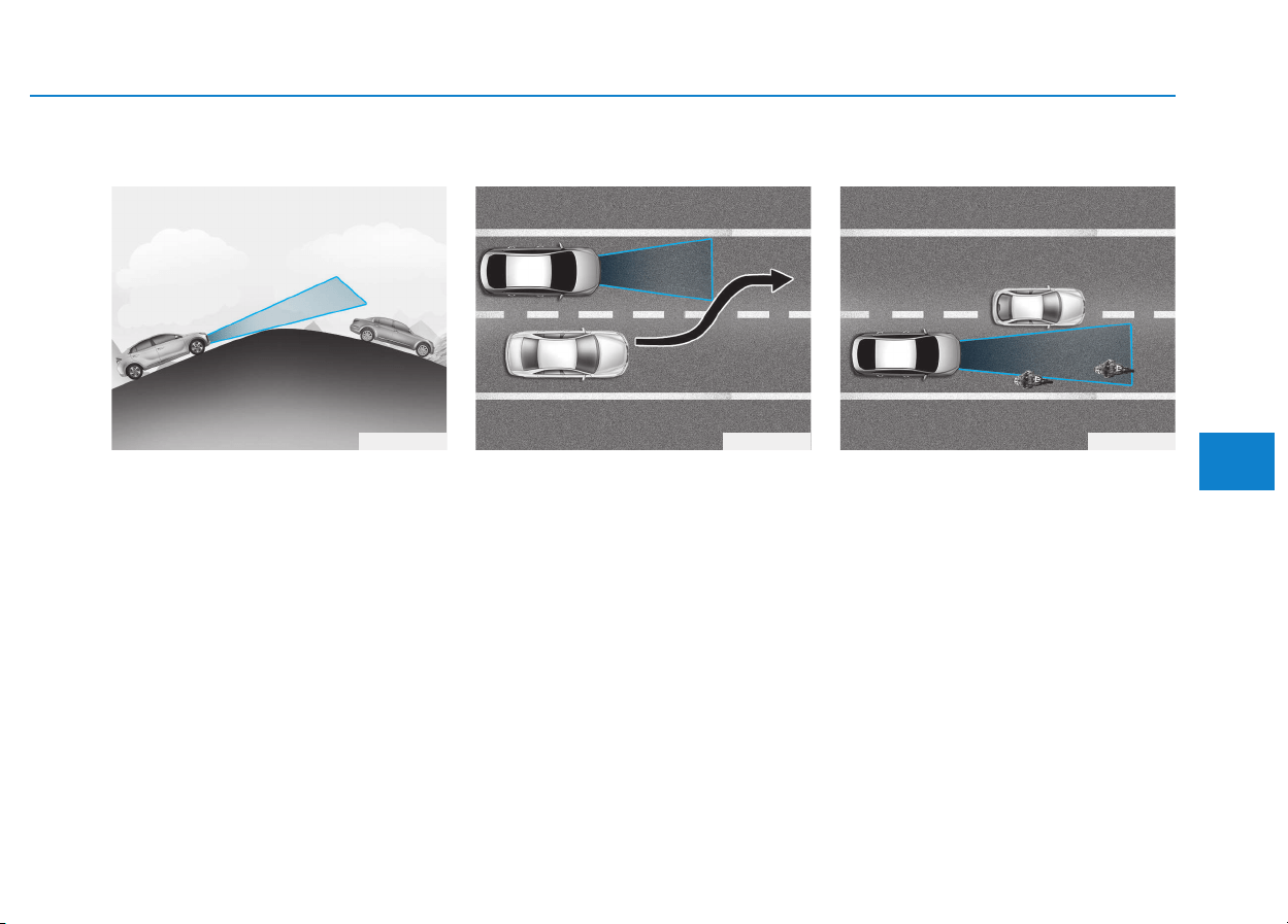
5-143
Driving your vehicle
5
On inclines
• During uphill or downhill driving,
the Smart Cruise Control System
may not detect a moving vehicle in
your lane, and cause your vehicle
to accelerate to the set speed.
Also, the vehicle speed will rapidly
decrease when the vehicle ahead
is recognized suddenly.
• Select the appropriate set speed
on inclines and apply the brake or
accelerator pedal if necessary.
Lane changing
• A vehicle which moves into your
lane from an adjacent lane cannot
be recognized by the sensor until it
is in the sensor's detection range.
• The radar may not detect immedi-
ately when a vehicle cuts in sud-
denly. Always pay attention to the
traffic, road and driving conditions.
• If a slower vehicle moves into your
lane, your speed may decrease to
maintain the distance to the vehicle
ahead.
• If a faster vehicle which moves into
your lane, your vehicle will acceler-
ate to the set speed.
Vehicle recognition
Some vehicles in your lane cannot
be recognized by the sensor:
- Narrow vehicles such as motorcy-
cles or bicycles
- Vehicles offset to one side
- Slow-moving vehicles or sudden-
decelerating vehicles
- Stopped vehicles
- Vehicles with small rear profile
such as trailers with no loads
OAE056104OAE056103OAE056102
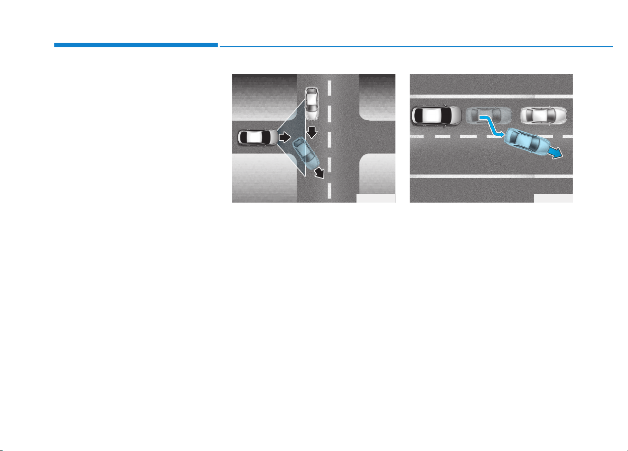
5-144
Driving your vehicle
A vehicle ahead cannot be recog-
nized correctly by the sensor if any of
following occurs:
- When the vehicle is pointing
upwards due to overloading in the
luggage compartment
- While the steering wheel is operat-
ing
- When driving to one side of the
lane
- When driving on narrow lanes or
on curves
Apply the brake or accelerator pedal
if necessary.
• Your vehicle may accelerate when
a vehicle ahead of you disappears.
• When you are warned that the
vehicle ahead of you is not detect-
ed, drive with caution.
• When driving in stop-and-go traffic,
and a stopped vehicle in front of
you merges out of the lane, the
system may not immediately
detect the new vehicle that is now
in front of you. In this case, you
must maintain a safe braking dis-
tance, and if necessary, depress
the brake pedal to reduce your
driving speed in order to maintain a
safe distance.
OAE056109OAE056108
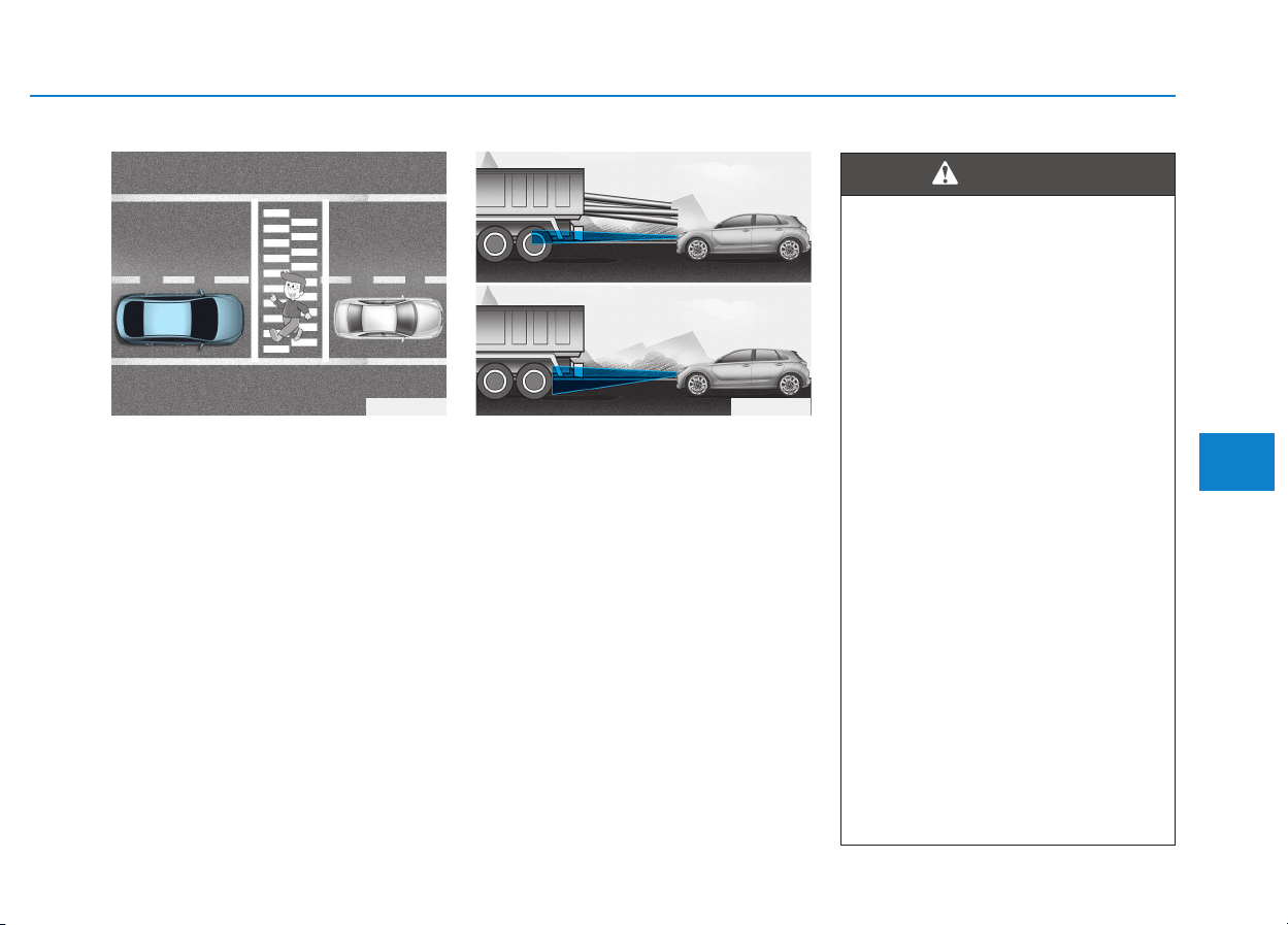
5-145
Driving your vehicle
5
• Always look out for pedestrians
when your vehicle is maintaining a
distance with the vehicle ahead.
• Always be cautious for vehicles
with higher height or vehicles car-
rying loads that sticks out from the
back of the vehicle.
When using the Smart Cruise
Control take the following pre-
cautions:
• If an emergency stop is nec-
essary, you must apply the
brakes. The vehicle cannot be
stopped at every emergency
situation by using the Smart
Cruise Control System.
• Keep a safe distance accord-
ing to road conditions and
vehicle speed. If the vehicle to
vehicle distance is too close
during a high-speed driving, a
serious collision may result.
• Always maintain sufficient
braking distance and deceler-
ate your vehicle by applying
the brakes if necessary.
• The Smart Cruise Control
System cannot recognize a
stopped vehicle, pedestrians
or an oncoming vehicle.
Always look ahead cautiously
to prevent unexpected and
sudden situations from occur-
ring.
(Continued)
WARNING
OPD056040OAE056110

5-146
Driving your vehicle
The Smart Cruise Control System
may not operate temporarily due
to:
• Electrical interference
• Modifying the suspension
• Differences of tire abrasion or
tire pressure
• Installing different type of tires
NOTICE
(Continued)
• Vehicles moving in front of you
with a frequent lane change
may cause a delay in the sys-
tem's reaction or may cause
the system to react to a vehicle
actually in an adjacent lane.
Always drive cautiously to pre-
vent unexpected and sudden
situations from occurring.
• Always be aware of the select-
ed speed and vehicle to vehi-
cle distance. The driver
should not solely rely on the
system but always pay atten-
tion to driving conditions and
control your vehicle speed.
• The Smart Cruise Control
System may not recognize
complex driving situations so
always pay attention to driv-
ing conditions and control
your vehicle speed.

5-147
Driving your vehicle
5
Hazardous driving conditions
When hazardous driving elements
are encountered such as water,
snow, ice, mud and sand, take the
bellow suggestions:
• Drive cautiously and keep a longer
braking distance.
• Avoid abrupt braking or steering.
• When your vehicle is stuck in snow,
mud, or sand, use the second
gear. Accelerate slowly to avoid
unnecessary wheel spinning.
• Put sand, rock salt, tire chains or
other non-slip materials under the
wheels to provide additional trac-
tion while being stuck in ice, snow,
or mud.
Rocking the vehicle
If it is necessary to rock the vehicle
to free it from snow, sand, or mud,
first turn the steering wheel right and
left to clear the area around your
front wheels. Then, shift back and
forth between R (Reverse) and a for-
ward gear.
Try to avoid spinning the wheels, and
do not race the engine.
To prevent transmission wear, wait
until the wheels stop spinning before
shifting gears. Release the accelera-
tor pedal while shifting, and press
lightly on the accelerator pedal while
the transmission is in gear. Slowly
spinning the wheels in forward and
reverse directions causes a rocking
motion that may free the vehicle.
SSPPEECCIIAALL DDRRIIVVIINNGG CCOONNDDIITTIIOONNSS
Downshifting with an automatic
transmission while driving on
slippery surfaces can cause an
accident. The sudden change in
tire speed could cause the tires
to skid. Be careful when down-
shifting on slippery surfaces.
WARNING
If the vehicle is stuck and
excessive wheel spin occurs,
the temperature in the tires can
increase very quickly. If the tires
become damaged, a tire blow
out or tire explosion can occur.
This condition is dangerous -
you and others may be injured.
Do not attempt this procedure if
people or objects are anywhere
near the vehicle.
If you attempt to free the vehi-
cle, the vehicle can overheat
quickly, possibly causing an
engine compartment fire or
other damage. Try to avoid spin-
ning the wheels as much as
possible to prevent overheating
of either the tires or the engine.
DO NOT allow the vehicle to
spin the wheels above 56 km/h
(35 mph).
WARNING

5-148
Driving your vehicle
Information
The ESC system (if equipped) must be
turned OFF before rocking the vehi-
cle.
If you are still stuck after rocking
the vehicle a few times, have the
vehicle pulled out by a tow vehicle
to avoid engine overheating, pos-
sible damage to the transmission,
and tire damage. See "Towing" in
chapter 6.
Smooth cornering
Avoid braking or gear changing in
corners, especially when roads are
wet. Ideally, corners should always
be taken under gentle acceleration.
Driving at night
Night driving presents more hazards
than driving in the daylight. Here are
some important tips to remember:
• Slow down and keep more dis-
tance between you and other vehi-
cles, as it may be more difficult to
see at night, especially in areas
where there may not be any street
lights.
• Adjust your mirrors to reduce the
glare from other driver's head-
lamps.
• Keep your headlamps clean and
properly aimed. Dirty or improperly
aimed headlamps will make it
much more difficult to see at night.
• Avoid staring directly at the head-
lamps of oncoming vehicles. You
could be temporarily blinded, and it
will take several seconds for your
eyes to readjust to the darkness.
Driving in the rain
Rain and wet roads can make driving
dangerous. Here are a few things to
consider when driving in the rain or
on slick pavement:
• Slow down and allow extra follow-
ing distance. A heavy rainfall
makes it harder to see and increas-
es the distance needed to stop
your vehicle.
• Turn OFF your Cruise Control. (if
equipped)
• Replace your windshield wiper
blades when they show signs of
streaking or missing areas on the
windshield.
• Be sure your tires have enough
tread. If your tires do not have
enough tread, making a quick stop
on wet pavement can cause a skid
and possibly lead to an accident.
See "Tire Tread" in chapter 7.
• Turn on your headlamps to make it
easier for others to see you.
• Driving too fast through large pud-
dles can affect your brakes. If you
must go through puddles, try to
drive through them slowly.
NOTICE
i

5-149
Driving your vehicle
5
• If you believe your brakes may be
wet, apply them lightly while driv-
ing until normal braking operation
returns.
Hydroplaning
If the road is wet enough and you are
going fast enough, your vehicle may
have little or no contact with the road
surface and actually ride on the
water. The best advice is SLOW
DOWN when the road is wet.
The risk of hydroplaning increas-
es as the depth of tire tread
decreases, refer to "Tire Tread" in
chapter 7.
Driving in flooded areas
Avoid driving through flooded areas
unless you are sure the water is no
higher than the bottom of the wheel
hub. Drive through any water slowly.
Allow adequate stopping distance
because brake performance may be
reduced.
After driving through water, dry the
brakes by gently applying them sev-
eral times while the vehicle is moving
slowly.
Highway driving
Tires
Adjust the tire inflation, as specified.
Under-inflation may overheat or
damage the tires.
Do not install worn-out or damaged
tires, which may reduce traction or
fail the braking operation.
Information
Never over-inflate your tires above the
maximum inflation pressure, as speci-
fied on your tires.
Fuel, engine coolant and engine
oil
Driving at higher speeds on the high-
way consumes more fuel and is less
efficient than driving at a slower,
more moderate speed. Maintain a
moderate speed in order to conserve
fuel when driving on the highway.
Be sure to check both the engine
coolant level and the engine oil
before driving.
Drive belt
A loose or damaged drive belt may
overheat the engine.
i

5-150
Driving your vehicle
Reducing the risk of a rollover
Your multi-purpose passenger vehi-
cle is defined as a Sports Utility
Vehicle (SUV). SUV’s have higher
ground clearance and a narrower
track to make them capable of per-
forming in a wide variety of off-road
applications. The specific design
characteristics give them a higher
center of gravity than ordinary vehi-
cles making them more likely to roll
over if you make abrupt turns. Utility
vehicles have a significantly higher
rollover rate than other types of vehi-
cles. Due to this risk, driver and pas-
sengers are strongly recommended
to buckle their seat belts. In a rollover
crash, an unbelted person is signifi-
cantly more likely to die than a per-
son wearing a seat belt.
There are steps that a driver can
make to reduce the risk of a rollover.
If at all possible, avoid sharp turns or
abrupt maneuvers, do not load your
vehicle with heavy cargo on the roof,
and never modify your vehicle in any
way.
Utility vehicles have a signifi-
cantly higher rollover rate than
other types of vehicles. To pre-
vent rollovers or loss of control:
• Take corners at slower speeds
than you would with a passen-
ger vehicle.
• Avoid sharp turns and abrupt
maneuvers.
• Do not modify your vehicle in
any way that you would raise
the center of gravity.
• Keep tires properly inflated.
• Do not carry heavy cargo on
the roof.
WARNING
In a rollover crash, an unbelted
person is significantly more
likely to die than a person wear-
ing a seat belt. Make sure all
passengers are wearing their
seat belts.
WARNING

5-151
Driving your vehicle
5
The severe weather conditions of
winter quickly wear out tires and
cause other problems. To minimize
winter driving problems, you should
take the following suggestions:
Information
Information for Snow Tires and Tire
Chains in the national language
(Bulgarian, Hungarian, Icelandic,
Polish) is provided in the Appendix.
Snow or icy conditions
You need to keep sufficient distance
between your vehicle and the vehicle
in front of you.
Apply the brakes gently. Speeding,
rapid acceleration, sudden brake
applications, and sharp turns are
potentially very hazardous practices.
During deceleration, use engine
braking to the fullest extent. Sudden
brake applications on snowy or icy
roads may cause skids to occur.
To drive your vehicle in deep snow, it
may be necessary to use snow tires
or to install tire chains on your tires.
Always carry emergency equipment.
Some of the items you may want to
carry include tire chains, tow straps
or chains, a flashlight, emergency
flares, sand, a shovel, jumper cables,
a window scraper, gloves, ground
cloth, coveralls, a blanket, etc.
Snow tires
If you mount snow tires on your vehi-
cle, make sure to use radial tires of
the same size and load range as the
original tires. Mount snow tires on all
four wheels to balance your vehicle’s
handling in all weather conditions.
The traction provided by snow tires
on dry roads may not be as high as
your vehicle's original equipment
tires. Check with the tire dealer for
maximum speed recommendations.
Information
Do not install studded tires without first
checking local and municipal regula-
tions for possible restrictions against
their use.
i
i
WWIINNTTEERR DDRRIIVVIINNGG
Snow tires should be equivalent
in size and type to the vehicle's
standard tires. Otherwise, the
safety and handling of your vehi-
cle may be adversely affected.
WARNING
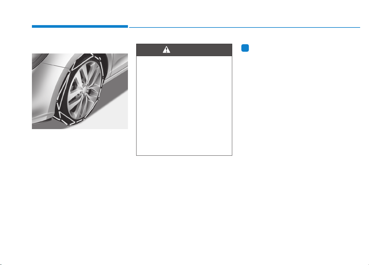
5-152
Driving your vehicle
Tire chains
Since the sidewalls of radial tires are
thinner than other types of tires, they
may be damaged by mounting some
types of tire chains on them.
Therefore, the use of snow tires is
recommended instead of tire chains.
Do not mount tire chains on vehicles
equipped with aluminum wheels; if
unavoidable use a wire type chain. If
tire chains must be used, use gen-
uine HYUNDAI parts and install the
tire chain after reviewing the instruc-
tions provided with the tire chains.
Damage to your vehicle caused by
improper tire chain use is not cov-
ered by your vehicle manufacturer’s
warranty.
Information
• Install tire chains on the front tires.
It should be noted that installing tire
chains on the tires will provide a
greater driving force, but will not
prevent side skids.
• Do not install studded tires without
first checking local and municipal
regulations for possible restrictions
against their use.
i
OPDE056072
The use of tire chains may
adversely affect vehicle han-
dling:
• Drive less than 30 km/h (20
mph) or the chain manufactur-
er’s recommended speed
limit, whichever is lower.
• Drive carefully and avoid
bumps, holes, sharp turns,
and other road hazards, which
may cause the vehicle to
bounce.
• Avoid sharp turns or locked
wheel braking.
WARNING

5-153
Driving your vehicle
5
Chain Installation
When installing tire chains, follow the
manufacturer's instructions and
mount them as tightly possible. Drive
slowly (less than 30 km/h (20 mph))
with chains installed. If you hear the
chains contacting the body or chas-
sis, stop and tighten them. If they still
make contact, slow down until the
noise stops. Remove the tire chains
as soon as you begin driving on
cleared roads.
When mounting snow chains, park
the vehicle on level ground away
from traffic. Turn on the vehicle
Hazard Warning Flasher and place a
triangular emergency warning device
behind the vehicle (if available).
Always place the vehicle in P (Park),
apply the parking brake and turn off
the engine before installing snow
chains.
When using tire chains:
• Wrong size chains or improperly
installed chains can damage
your vehicle's brake lines, sus-
pension, body and wheels.
• Use SAE “S” class or wire chains.
• If you hear noise caused by
chains contacting the body,
retighten the chain to prevent
contact with the vehicle body.
• To prevent body damage, retight-
en the chains after driving 0.5~1.0
km (0.3~0.6 miles).
• Do not use tire chains on vehi-
cles equipped with aluminum
wheels. If unavoidable, use a
wire type chain.
• Use wire chains less than 12 mm
(0.47 in) wide to prevent damage
to the chain’s connection.
Winter Precautions
Use high quality ethylene glycol
coolant
Your vehicle is delivered with high
quality ethylene glycol coolant in the
cooling system. It is the only type of
coolant that should be used because
it helps prevent corrosion in the cool-
ing system, lubricates the water
pump and prevents freezing. Be sure
to replace or replenish your coolant
in accordance with the maintenance
schedule in section 7. Before winter,
have your coolant tested to assure
that its freezing point is sufficient for
the temperatures anticipated during
the winter.
NOTICE

5-154
Driving your vehicle
Check battery and cables
The winter temperature increases
the battery consumption. Inspect
the battery and cables, as speci-
fied in the chapter 7. The battery
charging level can be checked by an
authorized HYUNDAI dealer or in a
service station.
Change to "winter weight" oil if
necessary
In some regions during winter, it is
recommended to use the "winter
weight" oil with lower viscosity. For
further information, refer to the chap-
ter 8. When you are not sure about a
type of winter weight oil, consult an
authorized HYUNDAI dealer.
Check spark plugs and ignition
system
Inspect the spark plugs, as speci-
fied in the chapter 7. If necessary,
replace them. Also check all ignition
wirings and components for any
cracks, wear-out, and damage.
To prevent locks from freezing
To prevent the locks from being
frozen, spray approved de-icing fluid
or glycerin into key holes. When a
lock opening is already covered with
ice, spray approved de-icing fluid
over the ice to remove it. When an
internal part of a lock freezes, try to
thaw it with a heated key. Carefully
use the heated key to avoid an injury.
Use approved window washer
anti-freeze solution in system
To prevent the window washer from
being frozen, add authorized window
washer anti-freeze solution, as spec-
ified on the window washer contain-
er. Window washer anti-freeze solu-
tion is available from an authorized
HYUNDAI dealer, and so are the
most vehicle accessory outlets. Do
not use engine coolant or other types
of anti-freeze solution to prevent any
damage to the vehicle paint.

5-155
Driving your vehicle
5
Do not let your parking brake
freeze
Under some conditions your parking
brake can freeze in the engaged
position. This is most likely to hap-
pen when there is an accumulation
of snow or ice around or near the
rear brakes or if the brakes are wet.
When there is the risk that your park-
ing brake may freeze, temporarily
apply it with the shift lever in P
(Park). Also, block the rear wheels in
advance, so the vehicle may not roll.
Then, release the parking brake.
Do not let ice and snow accumu-
late underneath
Under some conditions, snow and
ice can build up under the fenders
and interfere with the steering. When
driving in such conditions during the
severe winter, you should check
underneath the vehicle on a regular
basis, so that moving the front
wheels and the steering components
is unblocked.
Carry emergency equipment
In accordance with weather condi-
tions, you should carry appropriate
emergency equipment, while driving.
Some of the items you may want to
carry include tire chains, tow straps
or chains, flashlight, emergency
flares, sand, shovel, jumper cables,
window scraper, gloves, ground
cloth, coveralls, blanket, etc.
Do not place objects or materials
in the engine compartment
Putting objects or materials in the
engine compartment may cause an
engine failure or combustion,
because those may block the engine
cooling. Such damage will not be
covered by the manufacturer’s war-
ranty.

5-156
Driving your vehicle
If you are considering to tow with
your vehicle, you should first check
with your country's Department of
Motor Vehicles to determine legal
requirements. Since laws vary the
requirements for towing trailers, cars,
or other types of vehicles or appara-
tus may differ. Ask an authorized
HYUNDAI dealer for further details
before towing.
Remember that trailering is different
than just driving your vehicle by itself.
Trailering means changes in han-
dling, durability, and fuel economy.
Successful, safe trailering requires
correct equipment, and it has to be
used properly. Damage to your vehi-
cle caused by improper trailer towing
is not covered by your vehicle manu-
facturer’s warranty.
This section contains many time-
tested, important trailering tips and
safety rules. Many of these are
important for your safety and that of
your passengers. Please read this
section carefully before you pull a
trailer.
TTRRAAIILLEERR TTOOWWIINNGG ((FFOORR EEUURROOPPEE))
Take the following precautions:
• If you don't use the correct
equipment and/or drive improp-
erly, you can lose control of the
vehicle when you are pulling a
trailer. For example, if the trailer
is too heavy, the braking per-
formance may be reduced. You
and your passengers could be
seriously or fatally injured. Pull
a trailer only if you have fol-
lowed all the steps in this sec-
tion.
• Before towing, make sure the
total trailer weight, GCW
(Gross Combination Weight),
GVW (Gross Vehicle Weight),
GAW (Gross Axle Weight) and
trailer tongue load are all with-
in the limits.
• When you tow a trailer, make
sure to turn off the ISG sys-
tem.
WARNING

5-157
Driving your vehicle
5
Information
- For Europe
• The technically permissible maxi-
mum load on the rear axle(s) may be
exceeded by not more than 15 %
and the technically permissible
maximum laden mass of the vehicle
may be exceeded by not more than
10% or 100 kg (220.4 lbs), whichev-
er value is lower. In this case, do not
exceed 100 km/h (62.1 mph) for
vehicle of category M1 or 80 km/h
(49.7 mph) for vehicle of category
N1.
• When a vehicle of category M1 is
towing a trailer, the additional load
imposed at the trailer coupling
device may cause the tire maximum
load ratings to be exceeded, but not
by more than 15%. In this case, do
not exceed 100 km/h (62.1 mph) and
increase the tire inflation pressure
by at least 0.2 bar.
If you decide to pull a trailer?
Here are some important points if
you decide to pull a trailer:
• Consider using a sway control. You
can ask a trailer hitch dealer about
sway control.
• Do not do any towing with your
vehicle during its first 2,000 km
(1,200 miles) in order to allow the
engine to properly break in. Failure
to heed this caution may result in
serious engine or transmission
damage.
• When towing a trailer, be sure to
consult an authorized HYUNDAI
dealer for further information on
additional requirements such as a
towing kit, etc.
• Always drive your vehicle at a mod-
erate speed (less than 100 km/h
(60 mph)) or posted towing speed
limit.
• On a long uphill grade, do not
exceed 70 km/h (45 mph) or the
posted towing speed limit,
whichever is lower.
• Carefully observe the weight and
load limits provided in the following
pages.
i
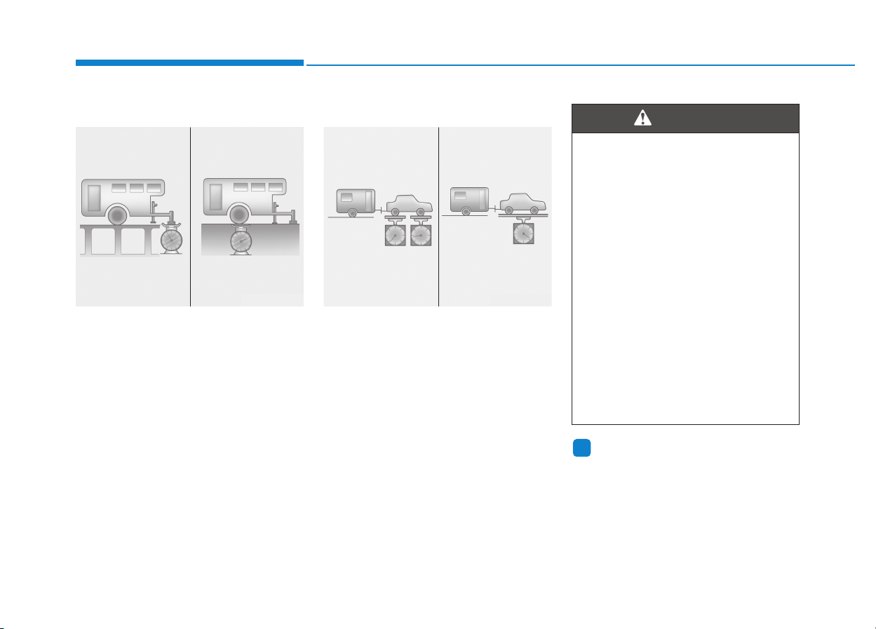
5-158
Driving your vehicle
Trailer weight
What is the maximum safe weight of a
trailer? It should never weigh more
than the maximum trailer weight with
trailer brakes. But even that can be
too heavy. It depends on how you plan
to use your trailer. For example,
speed, altitude, road grades, outside
temperature and how often your vehi-
cle is used to pull a trailer are all
important. The ideal trailer weight can
also depend on any special equip-
ment that you have on your vehicle.
Tongue load
The tongue load is an important
weight to measure because it affects
the total Gross Vehicle Weight
(GVW) of your vehicle. The trailer
tongue should weigh a maximum of
10% of the total loaded trailer weight,
within the limits of the maximum trail-
er tongue load permissible.
After you've loaded your trailer,
weigh the trailer and then the tongue,
separately, to see if the weights are
proper. If they aren’t, you may be
able to correct them simply by mov-
ing some items around in the trailer.
Information
With increasing altitude the engine
performance decreases. From 1,000 m
above sea level and for every 1,000 m
thereafter 10% of vehicle/trailer
weight (trailer weighter + gross vehi-
cle weight) must be deducted.
i
Take the following precautions:
• Never load a trailer with more
weight in the rear than in the
front. The front should be
loaded with approximately
60% of the total trailer load;
the rear should be loaded with
approximately 40% of the total
trailer load.
• Never exceed the maximum
weight limits of the trailer or
trailer towing equipment.
Improper loading can result in
damage to your vehicle and/or
personal injury. Check weights
and loading at a commercial
scale or highway patrol office
equipped with scales.
WARNING
OLMB053048
Gross Axle Weight
Gross Vehicle Weight
OLMB053047
Tongue Load
Total Trailer Weight

5-159
Driving your vehicle
5
M/T : Manual transmission
A/T : Automatic transmission
DCT : Dual clutch transmission
Item
Gasoline Engine
1.0 T-GDI 1.4 T-GDI 1.4 MPI 1.6 MPI
M/T M/T DCT
M/T M/T A/T
Maximum trailer
weight
kg (Ibs.)
Without brake
System
1200 (2645) 1400 (3086) 1200 (2645) 1300 (2866) 1200 (2645)
With brake
System
600 (1322)
Maximum permissible static vertical
load on the coupling device kg (Ibs.)
75 (165)
Recommended distance from rear wheel
center to coupling point mm (inch)
885 (34.8)
Item
Diesel Engine
1.6 TCI
M/T DCT
Maximum trailer
weight
kg (Ibs.)
Without brake
System 1500 (3306)
With brake System 650 (1433)
Maximum permissible static vertical
load on the coupling device kg (Ibs.)
75 (165)
Recommended distance from rear wheel
center to coupling point mm (inch)
885 (34.8)
Reference weight and distance when towing a trailer (for Europe)
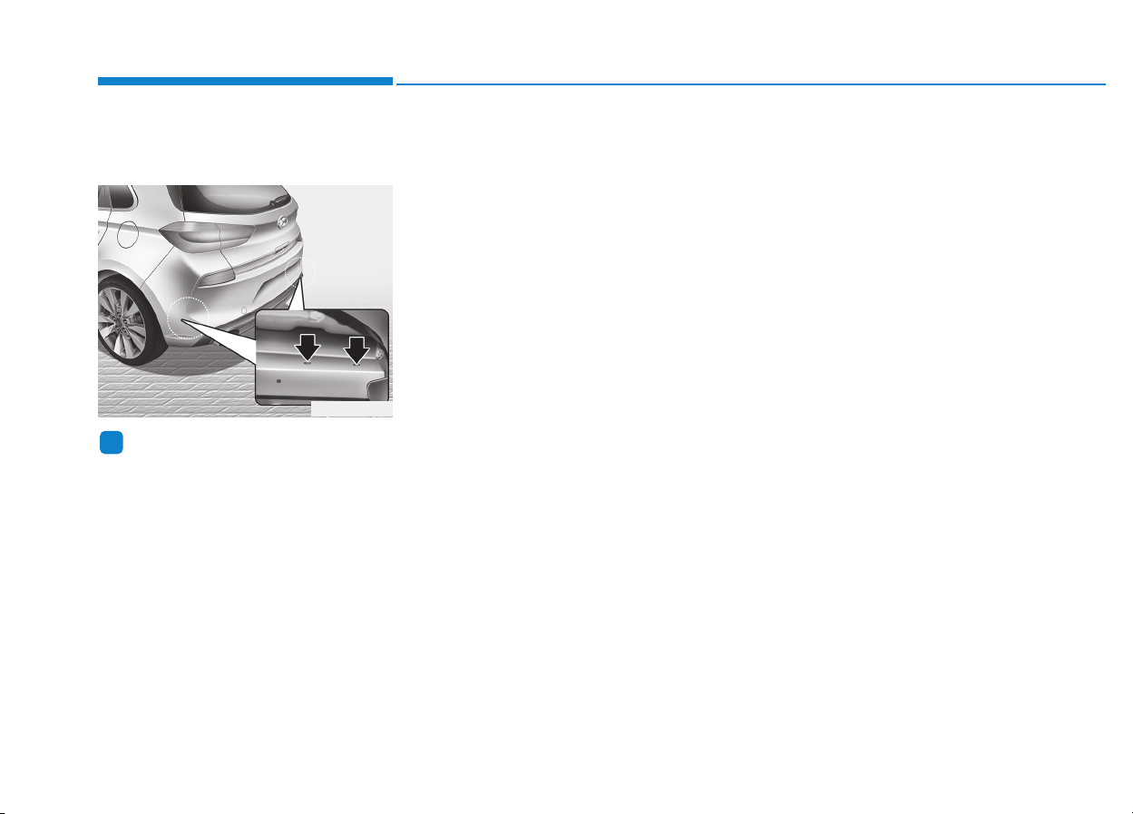
5-160
Driving your vehicle
Trailer towing equipment
Hitches
Information
The mounting hole for hitches are
located on both sides of the underbody
behind the rear tires.
It's important to have the correct
hitch equipment. Crosswinds, large
trucks going by, and rough roads are
a few reasons why you’ll need the
right hitch. Here are some rules to
follow:
• Do you have to make any holes in
the body of your vehicle when you
install a trailer hitch? If you do, then
be sure to seal the holes later
when you remove the hitch. If you
don’t seal them, carbon monoxide
(CO) from your exhaust can get
into your vehicle, as well as dirt
and water.
• The bumpers on your vehicle are
not intended for hitches. Do not
attach rental hitches or other
bumper-type hitches to them. Use
only a frame-mounted hitch that
does not attach to the bumper.
• A HYUNDAI trailer hitch accessory is
available at an authorized HYUNDAI
dealer.
Safety chains
You should always attach chains
between your vehicle and your trail-
er. Cross the safety chains under the
tongue of the trailer so that the
tongue will not drop to the road if it
becomes separated from the hitch.
Instructions about safety chains may
be provided by the hitch manufactur-
er or trailer manufacturer. Follow the
manufacturer’s recommendation for
attaching safety chains. Always leave
just enough slack so you can turn
with your trailer. And, never allow
safety chains to drag on the ground.
i
OPDE066036

5-161
Driving your vehicle
5
Trailer brakes
If your trailer is equipped with a brak-
ing system, make sure it conforms
your country’s regulations and that it
is properly installed and operating
correctly.
If your trailer weighs more than the
maximum trailer weight without trail-
er brakes loaded, then it needs its
own brakes and they must be ade-
quate. Be sure to read and follow the
instructions for the trailer brakes so
you’ll be able to install, adjust and
maintain them properly. Be sure not
to tap into your vehicle's brake sys-
tem.
Driving with a trailer
Towing a trailer requires a certain
amount of experience. Before setting
out for the open road, you must get
to know your trailer. Acquaint your-
self with the feel of handling and
braking with the added weight of the
trailer. And always keep in mind that
the vehicle you are driving is now
longer and not nearly as responsive
as your vehicle is by itself.
Before you start, check the trailer
hitch and platform, safety chains,
electrical connector(s), lights, tires
and brakes.
During your trip, occasionally check
to be sure that the load is secure,
and that the lights and trailer brakes
are still working.
Distance
Stay at least twice as far behind the
vehicle ahead as you would when
driving your vehicle without a trailer.
This can help you avoid situations
that require heavy braking and sud-
den turns.
Passing
You will need more passing distance
up ahead when you’re towing a trail-
er. And, because of the increased
vehicle length, you’ll need to go
much farther beyond the passed
vehicle before you can return to your
lane.
Do not use a trailer with its own
brakes unless you are absolute-
ly certain that you have proper-
ly set up the brake system. This
is not a task for amateurs. Use
an experienced, competent trail-
er shop for this work.
WARNING

5-162
Driving your vehicle
Backing up
Hold the bottom of the steering
wheel with one hand. Then, to move
the trailer to the left, move your hand
to the left. To move the trailer to the
right, move your hand to the right.
Always back up slowly and, if possi-
ble, have someone guide you.
Making turns
When you’re turning with a trailer,
make wider turns than normal. Do this
so your trailer won’t strike soft shoul-
ders, curbs, road signs, trees, or other
objects. Avoid jerky or sudden
maneuvers. Signal well in advance.
Turn signals
When you tow a trailer, your vehicle
has to have a different turn signal
flasher and extra wiring. The green
arrows on your instrument panel will
flash whenever you signal a turn or
lane change. Properly connected,
the trailer lights will also flash to alert
other drivers you’re about to turn,
change lanes, or stop.
When towing a trailer, the green
arrows on your instrument panel will
flash for turns even if the bulbs on
the trailer are burned out. Thus, you
may think drivers behind you are
seeing your signals when, in fact,
they are not. It’s important to check
occasionally to be sure the trailer
bulbs are still working. You must also
check the lights every time you dis-
connect and then reconnect the
wires.
Do not connect a trailer lighting
system directly to your vehi-
cle’s lighting system. Use an
approved trailer wiring harness.
Failure to do so could result in
damage to the vehicle electrical
system and/or personal injury.
Consult an authorized HYUNDAI
dealer for assistance.
WARNING

5-163
Driving your vehicle
5
Driving on hills
Reduce speed and shift to a lower
gear before you start down a long or
steep downgrade. If you don’t shift
down, you might have to use your
brakes so much that they would get
overheated and may not operate effi-
ciently.
On a long uphill grade, shift down
and reduce your speed to around 70
km/h (45 mph) to reduce the possi-
bility of engine and transmission
overheating.
If your trailer weighs more than the
maximum trailer weight without trail-
er brakes and you have an automat-
ic transmission/dual clutch transmis-
sion, you should drive in D (Drive)
when towing a trailer.
Operating your vehicle in D (Drive)
when towing a trailer will minimize
heat build-up and extend the life of
your transmission.
To prevent engine and/or trans-
mission overheating:
• When towing a trailer on steep
grades (in excess of 6%) pay
close attention to the engine
coolant temperature gauge to
ensure the engine does not
overheat. If the needle of the
coolant temperature gauge
moves towards "H" (HOT), pull
over and stop as soon as it is
safe to do so, and allow the
engine to idle until it cools
down.You may proceed once the
engine has cooled sufficiently.
• If you tow a trailer with the max-
imum gross vehicle weight and
maximum trailer weight, it can
cause the engine or transmis-
sion to overheat. When driving
in such conditions, allow the
engine to idle until it cools
down.You may proceed once the
engine or transmission has
cooled sufficiently.
(Continued)
(Continued)
• You must decide your vehicle
speed according to trailer weight
and uphill grade.
• Vehicles equipped with a dual
clutch transmission when tow-
ing a trailer on steep grades, the
clutch in the transmission could
overheat.
When the clutch is overheated,
the safe protection mode
engages. If the safe protection
mode engages, the gear posi-
tion indicator on the cluster
blinks with a chime sound.
At this time, a warning message
will appear on the LCD display
and driving may not be smooth.
If you ignore this warning, the
driving condition may become
worse.
To return to normal driving con-
dition, stop the vehicle on a flat
road and apply the foot brake for
a few minutes before driving off.
NOTICE
5-164
Driving your vehicle
Parking on hills
Generally, if you have a trailer
attached to your vehicle, you should
not park your vehicle on a hill.
However, if you ever have to park
your trailer on a hill, here's how to do
it:
1. Pull the vehicle into the parking
space.
Turn the steering wheel in the
direction of the curb (right if head-
ed down hill, left if headed up hill).
2. Shift the vehicle to P (Park, for
automatic transmission/dual
clutch transmission vehicle) or
neutral (for manual transmission
vehicle).
3. Set the parking brake and shut off
the vehicle.
4. Place wheel chocks under the
trailer wheels on the down hill side
of the wheels.
5. Start the vehicle, hold the brakes,
shift to neutral, release the park-
ing brake and slowly release the
brakes until the trailer chocks
absorb the load.
6. Reapply the brakes and parking
brakes.
7. Move the shift lever to P (Park, for
automatic transmission/dual
clutch transmission vehicle) or 1st
gear when the vehicle is parked
on a uphill grade and in R
(Reverse) on a downhill (for man-
ual transmission vehicle).
8. Shut off the vehicle and release
the vehicle brakes but leave the
parking brake set.
Ready to leave after parking on
a hill
1. With the shift lever to P (Park, for
automatic transmission/dual clutch
transmission vehicle) or neutral (for
manual transmission vehicle),
apply your brakes and hold the
brake pedal down while you:
• Start your engine;
• Shift into gear; and
• Release the parking brake.
2. Slowly remove your foot from the
brake pedal.
3. Drive slowly until the trailer is clear
of the chocks.
4. Stop and have someone pick up
and store the chocks.
To prevent serious or fatal
injury:
• Do not get out of the vehicle
without the parking brake
firmly set. If you have left the
engine running, the vehicle
can move suddenly. You and
others could be seriously or
fatally injured.
• Do not apply the accelerator
pedal to hold the vehicle on
an uphill.
WARNING

5-165
Driving your vehicle
5
Maintenance when towing a
trailer
Your vehicle will need service more
often when you regularly pull a trail-
er. Important items to pay particular
attention to include engine oil, auto-
matic transmission fluid, axle lubri-
cant and cooling system fluid. Brake
condition is another important item to
frequently check. If you’re trailering,
it’s a good idea to review these items
before you start your trip. Don’t forget
to also maintain your trailer and
hitch. Follow the maintenance sched-
ule that accompanied your trailer and
check it periodically. Preferably, con-
duct the check at the start of each
day’s driving. Most importantly, all
hitch nuts and bolts should be tight.
To prevent vehicle damage:
• Due to higher load during trailer
usage, overheating might occur
on hot days or during uphill driv-
ing. If the coolant gauge indi-
cates over-heating, switch off
the air conditioner and stop the
vehicle in a safe area to cool
down the engine.
• Do not switch off the engine
while the coolant gauge indi-
cates over-heating.
(Keep the engine idle to cool
down the engine)
• When towing check automatic
transmission fluid more fre-
quently.
• If your vehicle is not equipped
with an air conditioner, you
should install a condenser fan
to improve engine performance
when towing a trailer.
NOTICE

Two labels on your driver’s door sill
show how much weight your vehicle
was designed to carry: the Tire and
Loading Information Label and the
Certification Label.
Before loading your vehicle, familiar-
ize yourself with the following terms
for determining your vehicle's weight
ratings, from the vehicle's specifica-
tions and the Certification Label:
Base Curb Weight
This is the weight of the vehicle includ-
ing a full tank of fuel and all standard
equipment. It does not include pas-
sengers, cargo, or optional equipment.
Vehicle Curb Weight
This is the weight of your new vehicle
when you picked it up from your deal-
er plus any aftermarket equipment.
Cargo Weight
This figure includes all weight added
to the Base Curb Weight, including
cargo and optional equipment.
GAW (Gross Axle Weight)
This is the total weight placed on
each axle (front and rear) - including
vehicle curb weight and all payload.
GAWR (Gross Axle Weight Rating)
This is the maximum allowable
weight that can be carried by a single
axle (front or rear). These numbers
are shown on the Certification Label.
The total load on each axle must
never exceed its GAWR.
GVW (Gross Vehicle Weight)
This is the Base Curb Weight plus
actual Cargo Weight plus passen-
gers.
GVWR (Gross Vehicle Weight
Rating)
This is the maximum allowable
weight of the fully loaded vehicle
(including all options, equipment,
passengers and cargo). The GVWR
is shown on the Certification Label
located on the driver’s door sill.
Overloading
VVEEHHIICCLLEE WWEEIIGGHHTT
The Gross Axle Weight Rating
(GAWR) and the Gross Vehicle
Weight Rating (GVWR) for your
vehicle are on the Certification
Label attached to the driver's
(or front passenger’s) door.
Exceeding these ratings can
cause an accident or vehicle
damage. You can calculate the
weight of your load by weighing
the items (and people) before
putting them in the vehicle. Be
careful not to overload your
vehicle.
WARNING
Driving your vehicle
5-166

What to do in an emergency
Hazard warning flasher ........................................6-2
In case of an emergency while driving ..............6-2
If the engine stalls while driving...................................6-2
If the engine stalls at a crossroad or crossing .........6-2
If you have a flat tire while driving..............................6-3
If the engine will not start ...................................6-3
If the engine doesn't turn over or
turns over slowly...............................................................6-3
If the engine turns over normally but
doesn't start .......................................................................6-4
Jump starting .........................................................6-4
If the engine overheats ........................................6-7
Tire Pressure Monitoring System (TPMS).........6-8
Check tire pressure...........................................................6-8
Tire pressure monitoring system ..................................6-9
Low tire pressure telltale..............................................6-10
Low tire pressure position telltale and tire
pressure telltale...............................................................6-10
TPMS (Tire Pressure Monitoring System)
malfunction indicator .....................................................6-12
Changing a tire with TPMS...........................................6-12
If you have a flat tire (with spare tire)............6-15
Jack and tools ..................................................................6-15
Changing tires ..................................................................6-16
Jack label...........................................................................6-21
EC Declaration of conformity for Jack......................6-22
If you have a flat tire (with tire mobility kit)..6-23
For 15, 16 inch tire .........................................................6-23
For 17 inch tire................................................................6-30
Towing ...................................................................6-39
Towing service .................................................................6-39
Removable towing hook ................................................6-40
Emergency towing ..........................................................6-41
Emergency commodity........................................6-43
Fire extinguisher .............................................................6-43
First aid kit........................................................................6-43
Triangle reflector ............................................................6-43
Tire pressure gauge .......................................................6-43
6
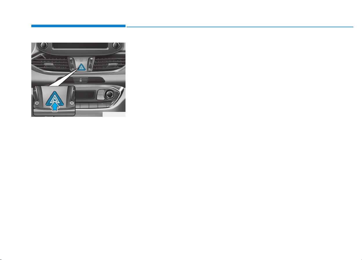
6-2
The hazard warning flasher serves
as a warning to other drivers to exer-
cise extreme caution when approach-
ing, overtaking, or passing your vehi-
cle.
It should be used whenever emer-
gency repairs are being made or
when the vehicle is stopped near the
edge of a roadway.
To turn the hazard warning flasher
on or off, press the hazard warning
flasher button with the ignition switch
in any position. The button is located
in the center fascia panel. All turn
signal lights will flash simultaneously.
• The hazard warning flasher oper-
ates whether your vehicle is run-
ning or not.
• The turn signals do not work when
the hazard flasher is on.
If the engine stalls while driving
• Reduce your speed gradually,
keeping a straight line. Move cau-
tiously off the road to a safe place.
• Turn on your hazard warning flash-
er.
• Try to start the engine again. If your
vehicle will not start, we recom-
mend that you contact an author-
ized HYUNDAI dealer.
If the engine stalls at a cross-
road or crossing
If the engine stalls at a crossroad or
crossing, if safe to do so, move the
shift lever to the N (Neutral) position
and then push the vehicle to a safe
location.
HHAAZZAARRDD WWAARRNNIINNGG FFLLAASSHHEERR
What to do in an emergency
I
INN CCAASSEE OOFF AANN EEMMEERRGGEENNCCYY
W
WHHIILLEE DDRRIIVVIINNGG
OPD066001

6-3
What to do in an emergency
If you have a flat tire while
driving
If a tire goes flat while you are driving:
• Take your foot off the accelerator
pedal and let the vehicle slow
down while driving straight ahead.
Do not apply the brakes immedi-
ately or attempt to pull off the road
as this may cause loss of vehicle
control resulting in an accident.
When the vehicle has slowed to
such a speed that it is safe to do
so, brake carefully and pull off the
road. Drive off the road as far as
possible and park on firm, level
ground. If you are on a divided
highway, do not park in the median
area between the two traffic lanes.
• When the vehicle is stopped, press
the hazard warning flasher button,
move the shift lever into P (Park,
for automatic transmission/dual
clutch transmission vehicle) or neu-
tral (for manual transmission vehi-
cle), apply the parking brake, and
place the ignition switch in the
LOCK/OFF position.
• Have all passengers get out of the
vehicle. Be sure they all get out on
the side of the vehicle that is away
from traffic.
• When changing a flat tire, follow
the instructions provided later in
this chapter.
If the engine doesn't turn over
or turns over slowly
• Be sure the shift lever is in N
(Neutral) or P (Park) if it is an auto-
matic transmission/dual clutch
transmission vehicle. The engine
starts only when the shift lever is in
N (Neutral) or P (Park).
• Check the battery connections to
be sure they are clean and tight.
• Turn on the interior light. If the light
dims or goes out when you operate
the starter, the battery is drained.
Do not push or pull the vehicle to start
it. This could cause damage to your
vehicle. See instructions for "Jump
Starting" provided in this chapter.
6
IIFF TTHHEE EENNGGIINNEE WWIILLLL NNOOTT
S
STTAARRTT
Push or pull starting the vehicle
may cause the catalytic con-
verter to overload which can
lead to damage to the emission
control system.
CAUTION
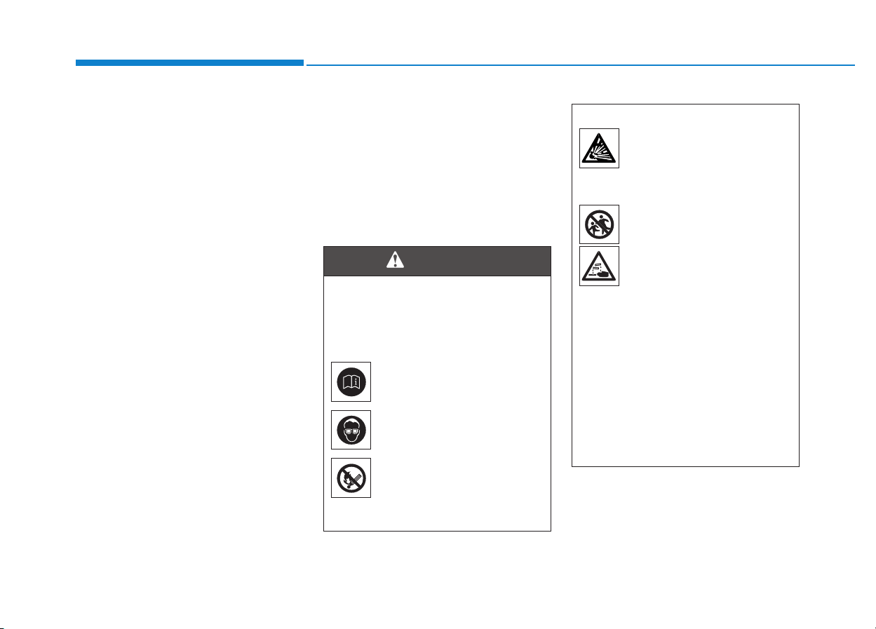
6-4
What to do in an emergency
If the engine turns over nor-
mally but doesn’t start
• Check the fuel level and add fuel if
necessary.
If the engine still does not start, we
recommend that you call an author-
ized HYUNDAI dealer for assistance.
Jump starting can be dangerous if
done incorrectly. Follow the jump
starting procedure in this section to
avoid serious injury or damage to
your vehicle. If in doubt about how to
properly jump start your vehicle, we
strongly recommend that you have a
service technician or towing service
do it for you.
JJUUMMPP SSTTAARRTTIINNGG
To prevent SERIOUS INJURY or
DEATH to you or bystanders,
always follow these precautions
when working near or handling
the battery:
Always read and follow
instructions carefully
when handling a battery.
Wear eye protection
designed to protect the
eyes from acid splashes.
Keep all flames, sparks,
or smoking materials
away from the battery.
(Continued)
WARNING
(Continued)
Hydrogen is always
present in battery cells,
is highly combustible,
and may explode if ignit-
ed.
Keep batteries out of
reach of children.
Batteries contain sulfu-
ric acid which is highly
corrosive. Do not allow
acid to contact your
eyes, skin or clothing.
If acid gets into your eyes, flush
your eyes with clean water for at
least 15 minutes and get imme-
diate medical attention. If acid
gets on your skin, thoroughly
wash the area. If you feel pain or
a burning sensation, get med-
ical attention immediately.
(Continued)
6-5
What to do in an emergency
To prevent damage to your vehi-
cle:
• Only use a 12-volt power supply
(battery or jumper system) to
jump start your vehicle.
• Do not attempt to jump start
your vehicle by push-starting.
Information
An inappropriately disposed
battery can be harmful to the
environment and human
health. Dispose the battery
according to your local law(s)
or regulations.
Jump starting procedure
1. Position the vehicles close enough
that the jumper cables will reach,
but do not allow the vehicles to
touch.
2. Avoid fans or any moving parts in
the engine compartment at all
times, even when the vehicles are
turned off.
3. Turn off all electrical devices such
as radios, lights, air conditioning,
etc. Put the vehicles in P (Park, for
automatic transmission/dual
clutch transmission vehicle) or
neutral (for manual transmission
vehicle), and set the parking
brakes. Turn both vehicles OFF.
i
NOTICE
6
(Continued)
• When lifting a plastic-cased
battery, excessive pressure
on the case may cause battery
acid to leak. Lift with a battery
carrier or with your hands on
opposite corners.
• Do not attempt to jump start
your vehicle if your battery is
frozen.
• NEVER attempt to recharge
the battery when the vehicle’s
battery cables are connected
to the battery.
• The electrical ignition system
works with high voltage.
NEVER touch these compo-
nents with the engine running
or when the ignition switch is
in the ON position.
• Do not allow the (+) and (-)
jumper cables to touch. It may
cause sparks.
• The battery may rupture or
explode when you jump start
with a low or frozen battery.
Pb
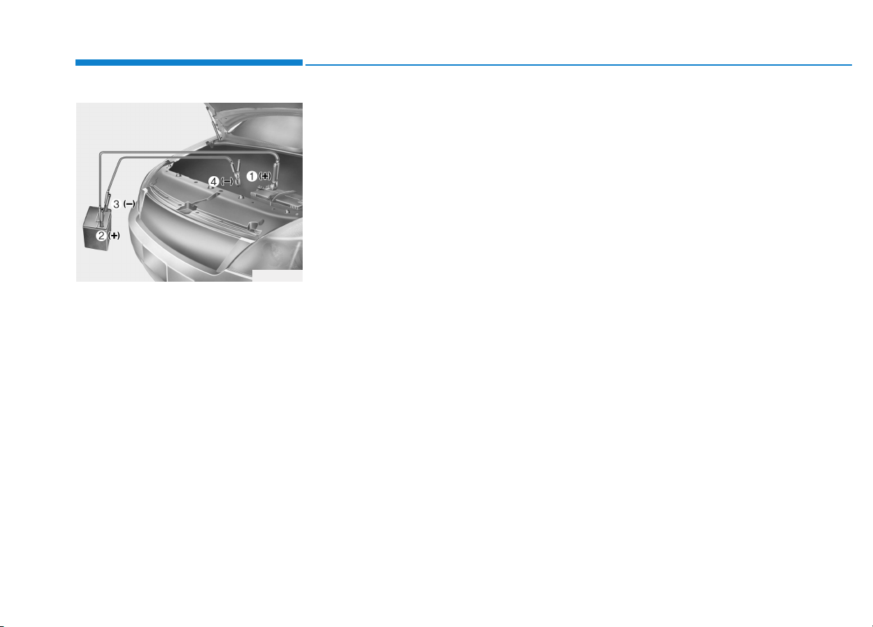
6-6
What to do in an emergency
4. Connect the jumper cables in the
exact sequence shown in the illus-
tration. First connect one jumper
cable to the red, positive (+)
jumper terminal of your vehicle
(1).
5. Connect the other end of the
jumper cable to the red, positive
(+) battery/jumper terminal of the
assisting vehicle (2).
6. Connect the second jumper cable
to the black, negative (-) battery/
chassis ground of the assisting
vehicle (3).
7. Connect the other end of the sec-
ond jumper cable to the black,
negative (-) chassis ground of
your vehicle (4).
Do not allow the jumper cables to
contact anything except the cor-
rect battery or jumper terminals or
the correct ground. Do not lean
over the battery when making
connections.
8. Start the engine of the assisting
vehicle and let it run at approxi-
mately 2,000 rpm for a few min-
utes. Then start your vehicle.
If your vehicle will not start after a
few attempts, it probably requires
servicing. In this event please seek
qualified assistance. If the cause of
your battery discharging is not
apparent, have your vehicle checked
by an authorized HYUNDAI dealer.
Disconnect the jumper cables in the
exact reverse order you connected
them:
1. Disconnect the jumper cable from
the black, negative (-) chassis
ground of your vehicle (4).
2. Disconnect the other end of the
jumper cable from the black, neg-
ative (-) battery/chassis ground of
the assisting vehicle (3).
3. Disconnect the second jumper
cable from the red, positive (+)
battery/jumper terminal of the
assisting vehicle (2).
4. Disconnect the other end of the
jumper cable from the red, positive
(+) jumper terminal of your vehicle
(1).
1VQA4001
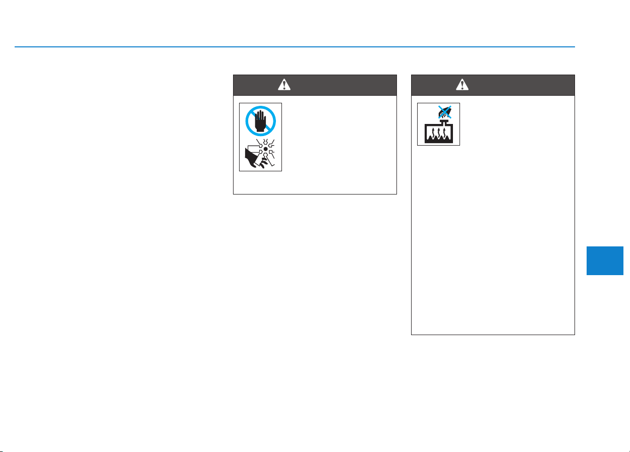
6-7
What to do in an emergency
6
If your temperature gauge indicates
overheating, you experience a loss
of power, or hear loud pinging or
knocking, the engine may be over-
heating. If this happens, you should:
1. Pull off the road and stop as soon
as it is safe to do so.
2. Place the shift lever in P (Park, for
automatic transmission/dual clutch
transmission vehicle) or neutral (for
manual transmission/dual clutch
transmission vehicle) and set the
parking brake. If the air condition-
ing is ON, turn it OFF.
3. If engine coolant is running out
under the vehicle or steam is com-
ing out from the hood, stop the
engine. Do not open the hood until
the coolant has stopped running
or the steaming has stopped. If
there is no visible loss of engine
coolant and no steam, leave the
engine running and check to be
sure the engine cooling fan is
operating. If the fan is not running,
turn the engine off.
4. Check for coolant leaking from the
radiator, hoses or under the vehi-
cle. (If the air conditioning had been
in use, it is normal for cold water to
be draining from it when you stop.)
5. If engine coolant is leaking out, stop
the engine immediately and we rec-
ommend that you call an authorized
HYUNDAI dealer for assistance.
IIFF TTHHEE EENNGGIINNEE OOVVEERRHHEEAATTSS
While the engine is
running, keep hands,
clothing and tools
away from the mov-
ing parts such as the
cooling fan and drive
belt to prevent seri-
ous injury.
WARNING
NEVER remove the
radiator cap or the
drain plug while the
engine and radiator
are hot. Hot coolant
and steam may blow out under
pressure, causing serious injury.
Turn the engine off and wait
until the engine cools down.
Use extreme care when remov-
ing the radiator cap. Wrap a
thick towel around it, and turn it
counterclockwise slowly to the
first stop. Step back while the
pressure is released from the
cooling system. When you are
sure all the pressure has been
released, press down on the
cap, using a thick towel, and
continue turning counterclock-
wise to remove it.
WARNING
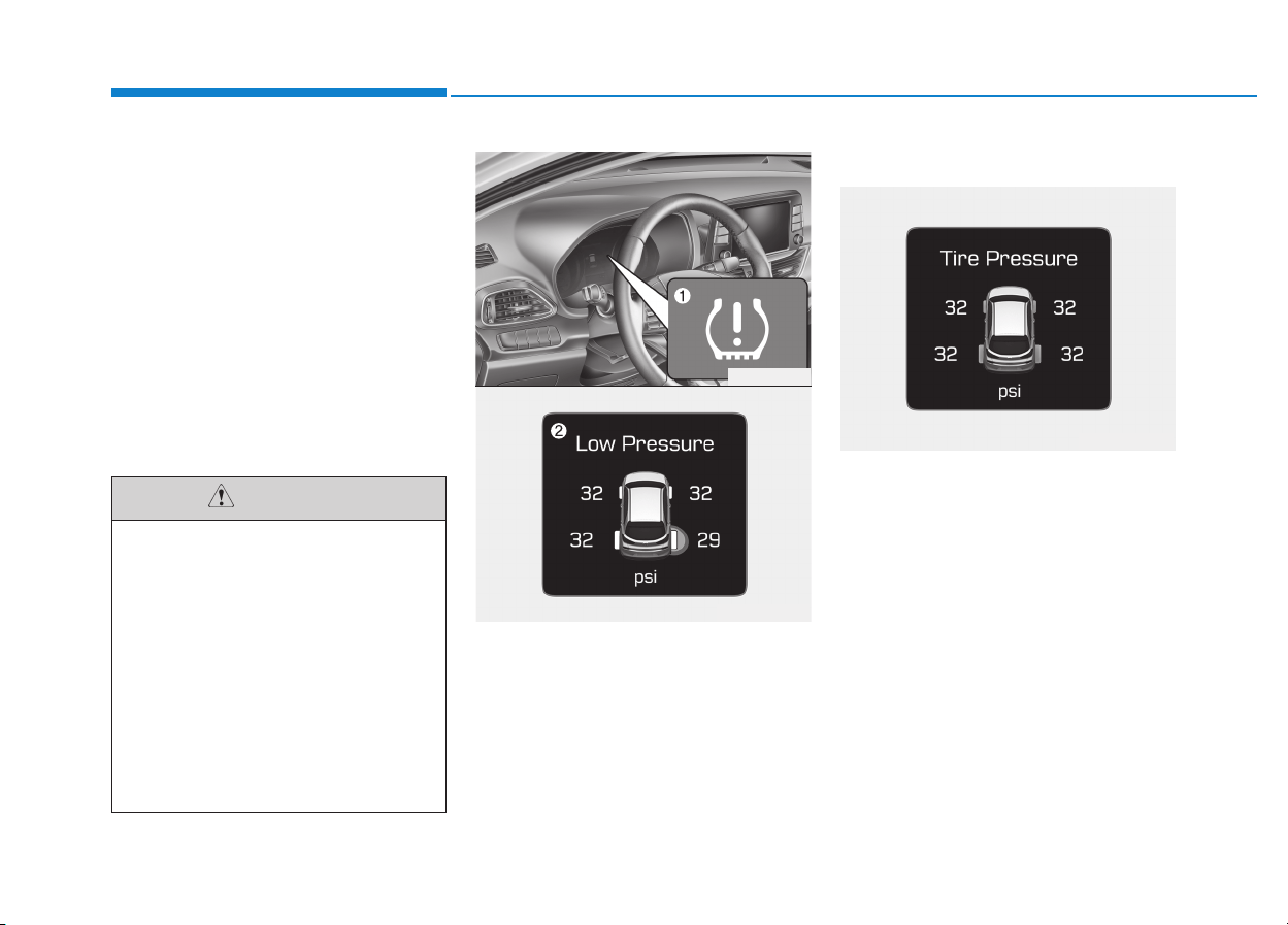
6-8
What to do in an emergency
6. If you cannot find the cause of the
overheating, wait until the engine
temperature has returned to nor-
mal. Then, if coolant has been
lost, carefully add coolant to the
reservoir to bring the fluid level in
the reservoir up to the halfway
mark.
7. Proceed with caution, keeping
alert for further signs of overheat-
ing. If overheating happens again,
we recommend that you call an
authorized HYUNDAI dealer for
assistance.
(1) Low Tire Pressure Telltale/
TPMS Malfunction Indicator
(2) Low tire pressure position telltale
and tire pressure telltale
(Shown on the LCD display)
Check tire pressure
• You can check the tire pressure in
the Assist mode on the cluster.
Refer to the "LCD Modes" in
chapter 3.
• Tire pressure is displayed few min-
utes later after driving.
• If tire pressure is not displayed when
the vehicle is stopped, "Drive to dis-
play" message will appear. After driv-
ing, check the tire pressure.
• Serious loss of coolant indi-
cates a leak in the cooling
system and we recommend
the system be checked by an
authorized HYUNDAI dealer.
• When the engine overheats
from low engine coolant, sud-
denly adding engine coolant
may cause cracks in the
engine. To prevent damage,
add engine coolant slowly in
small quantities.
CAUTION
TTIIRREE PPRREESSSSUURREE MMOONNIITTOORRIINNGG SSYYSSTTEEMM ((TTPPMMSS)) ((IIFF EEQQUUIIPPPPEEDD))
OPD066009
OPDE066005
OPDE066007
6-9
What to do in an emergency
6
• The displayed tire pressure values
may differ from those measured
with a tire pressure gauge.
• You can change the tire pressure
unit in the User Settings mode on
the instrument cluster.
- psi, kpa, bar (Refer to "LCD
Modes" in chapter 3).
Tire pressure monitoring sys-
tem
Each tire, including the spare (if pro-
vided), should be checked monthly
when cold and inflated to the inflation
pressure recommended by the vehi-
cle manufacturer on the vehicle plac-
ard or tire inflation pressure label. (If
your vehicle has tires of a different
size than the size indicated on the
vehicle placard or tire inflation pres-
sure label, you should determine the
proper tire inflation pressure for
those tires.)
As an added safety feature, your
vehicle has been equipped with a tire
pressure monitoring system (TPMS)
that illuminates a low tire pressure
telltale when one or more of your
tires is significantly under-inflated.
Accordingly, when the low tire pres-
sure telltale illuminates, you should
stop and check your tires as soon as
possible, and inflate them to the
proper pressure. Driving on a signifi-
cantly under-inflated tire causes the
tire to overheat and can lead to tire
failure. Under-inflation also reduces
fuel efficiency and tire tread life, and
may affect the vehicle’s handling and
stopping ability.
Please note that the TPMS is not a
substitute for proper tire mainte-
nance, and it is the driver’s responsi-
bility to maintain correct tire pres-
sure, even if under-inflation has not
reached the level to trigger illumina-
tion of the TPMS low tire pressure
telltale.
Over-inflation or under-inflation
can reduce tire life, adversely
affect vehicle handling, and
lead to sudden tire failure that
may cause loss of vehicle con-
trol resulting in an accident.
WARNING
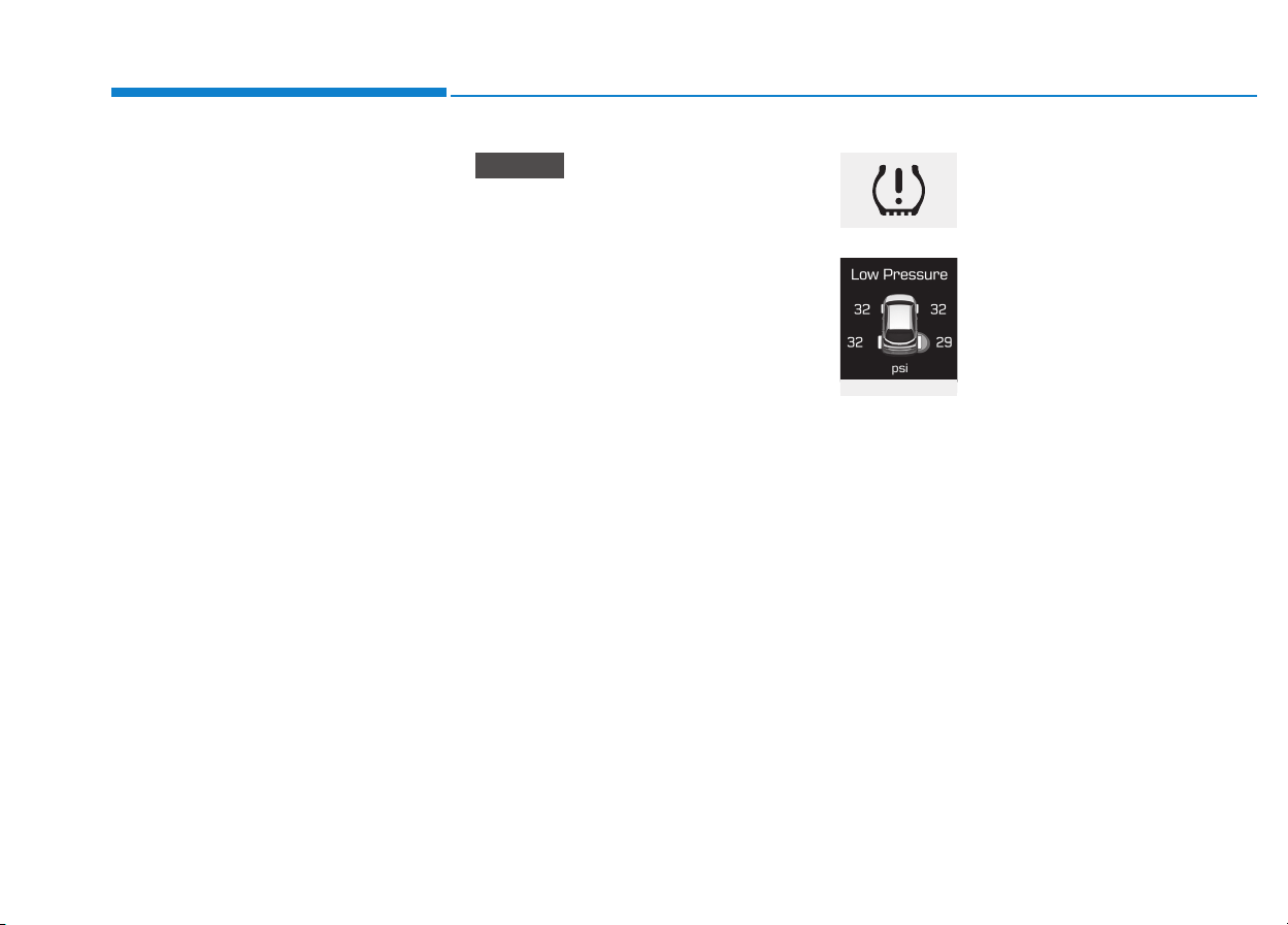
6-10
What to do in an emergency
Your vehicle has also been equipped
with a TPMS malfunction indicator to
indicate when the system is not
operating properly. The TPMS mal-
function indicator is combined with
the low tire pressure telltale. When
the system detects a malfunction,
the telltale will flash for approximate-
ly one minute and then remain con-
tinuously illuminated. This sequence
will continue upon subsequent vehi-
cle start-ups as long as the malfunc-
tion exists. When the malfunction
indicator is illuminated, the system
may not be able to detect or signal
low tire pressure as intended.
TPMS malfunctions may occur for a
variety of reasons, including the
installation of replacement or alter-
nate tires or wheels on the vehicle
that prevent the TPMS from function-
ing properly. Always check the TPMS
malfunction telltale after replacing
one or more tires or wheels on your
vehicle to ensure that the replace-
ment or alternate tires and wheels
allow the TPMS to continue to func-
tion properly.
If any of the below happens, we
recommend that the system be
checked by an authorized HYUNDAI
dealer.
1. The low tire pressure telltale/
TPMS malfunction indicator
does not illuminate for 3 sec-
onds when Engine Start/Stop
button is turned to the ON or
engine is running.
2. The TPMS malfunction indicator
remains illuminated after blink-
ing for approximately 1 minute.
3. The Low tire pressure position
telltale remains illuminated.
Low tire pressure
telltale
Low tire pressure
position telltale
and tire pressure
telltale
When the tire pressure monitoring
system warning indicators are illumi-
nated and warning message dis-
played on the cluster LCD display,
one or more of your tires is signifi-
cantly under-inflated. The low tire
pressure position telltale light will
indicate which tire is significantly
under-inflated by illuminating the cor-
responding position light.
NOTICE
OPDE066005
6-11
What to do in an emergency
6
If either telltale illuminates, immedi-
ately reduce your speed, avoid hard
cornering and anticipate increased
stopping distances. You should stop
and check your tires as soon as pos-
sible. Inflate the tires to the proper
pressure as indicated on the vehi-
cle’s placard or tire inflation pressure
label located on the driver’s side cen-
ter pillar outer panel. If you cannot
reach a service station or if the tire
cannot hold the newly added air,
replace the low pressure tire with a
spare tire.
If you drive the vehicle for about 10
minutes at speeds above 25 km/h
after replacing the low pressure tire
with the spare tire, the below will
happen:
• The TPMS malfunction indicator
may blink for approximately 1 minute
and then remain continuously illumi-
nated because the TPMS sensor is
not mounted on the spare wheel.
The spare tire is not equipped with
a tire pressure sensor.
NOTICE
In winter or cold weather, the low
tire pressure telltale may illumi-
nate if the tire pressure was
adjusted to the recommended
tire inflation pressure in warm
weather. It does not mean your
TPMS is malfunctioning because
the decreased temperature leads
to a lowering of tire pressure.
When you drive your vehicle
from a warm area to a cold area
or from a cold area to a warm
area, or the outside temperature
is higher or lower, you should
check the tire inflation pressure
and adjust the tires to the recom-
mended tire inflation pressure.
CAUTION
Low pressure damage
Significantly low tire pressure
makes the vehicle unstable and
can contribute to loss of vehicle
control and increased braking
distances.
Continued driving on low pres-
sure tires can cause the tires to
overheat and fail.
WARNING
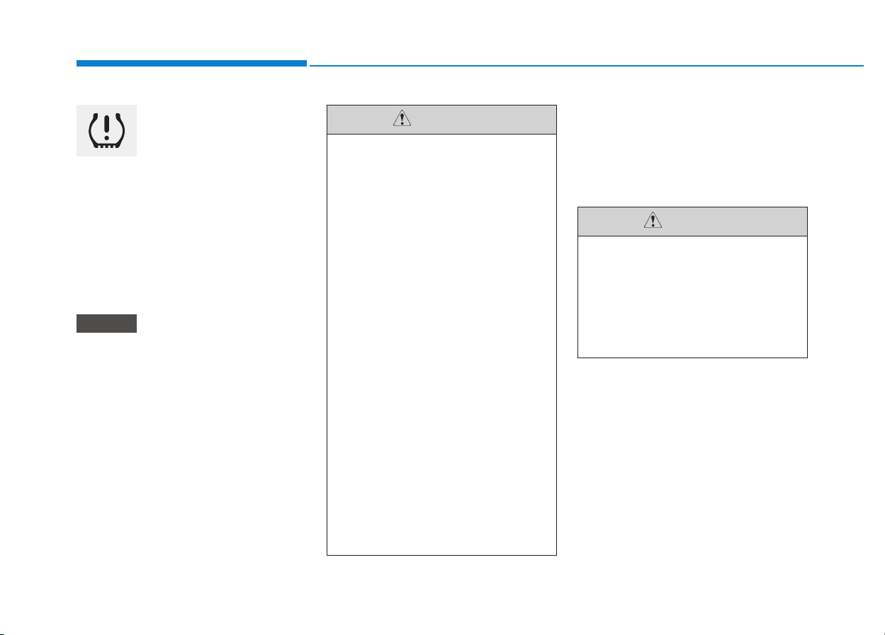
6-12
What to do in an emergency
TPMS (Tire Pressure
Monitoring System)
malfunction indicator
The TPMS malfunction indicator will
illuminate after it blinks for approxi-
mately one minute when there is a
problem with the Tire Pressure
Monitoring System.
We recommend that the system be
checked by an authorized HYUNDAI
dealer.
If there is a malfunction with the
TPMS, the low tire pressure posi-
tion telltale will not be displayed
even though the vehicle has an
under-inflated tire.
Changing a tire with TPMS
If you have a flat tire, the low Tire
Pressure and Position telltales will
come on. We recommend that the
system be checked by an authorized
HYUNDAI dealer.
Each wheel is equipped with a tire
pressure sensor mounted inside the
tire behind the valve stem. You must
use TPMS specific wheels. It is rec-
ommended that you have your tires
serviced by an authorized HYUNDAI
dealer.
NOTICE
• The TPMS malfunction indicator
may blink for approximately 1
minute and then remain contin-
uously illuminated if the vehicle
is moving around electric power
supply cables or radios trans-
mitter such as at police stations,
government and public offices,
broadcasting stations, military
installations, airports, or trans-
mitting towers, etc. This can
interfere with normal operation
of the Tire Pressure Monitoring
System (TPMS).
• The TPMS malfunction indica-
tor may blink for approximate-
ly 1 minute and then remain
continuously illuminated if
snow chains are used or some
separate electronic devices
such as notebook computer,
mobile charger, remote starter
or navigation etc., are used in
the vehicle.
This can interfere with normal
operation of the Tire Pressure
Monitoring System (TPMS).
CAUTION
NEVER use a puncture-repair-
ing agent to repair and/or inflate
a low pressure tire. The tire
sealant can damage the tire
pressure sensor. If used, you
will have to replace the tire
pressure sensor.
CAUTION

6-13
What to do in an emergency
6
If you drive the vehicle for about 10
minutes at speeds above 25 km/h
after replacing the low pressure tire
with the spare tire, the below will
happen:
• The TPMS malfunction indicator
may blink for approximately 1 minute
and then remain continuously illumi-
nated because the TPMS sensor is
not mounted on the spare wheel.
You may not be able identify a low
tire by simply looking at it. Always
use a good quality tire pressure
gauge to measure the tire's inflation
pressure. Please note that a tire that
is hot (from being driven) will have a
higher pressure measurement than a
tire that is cold (from sitting station-
ary for at least 3 hour and driven less
than 1.6 km (1 mile) during that 3
hour period).
Allow the tire to cool before measur-
ing the inflation pressure. Always be
sure the tire is cold before inflating to
the recommended pressure.
A cold tire means the vehicle has
been sitting for 3 hours and driven for
less than 1.6 km (1 mile) in that 3
hour period.
• The TPMS cannot alert you to
severe and sudden tire dam-
age caused by external factors
such as nails or road debris.
• If you feel any vehicle instabil-
ity, immediately take your foot
off the accelerator, apply the
brakes gradually and with
light force, and slowly move to
a safe position off the road.
WARNING

6-14
What to do in an emergency
Tampering with, modifying, or
disabling the Tire Pressure
Monitoring System (TPMS) com-
ponents may interfere with the
system's ability to warn the driv-
er of low tire pressure condi-
tions and/or TPMS malfunctions.
Tampering with, modifying, or
disabling the Tire Pressure
Monitoring System (TPMS) com-
ponents may void the warranty
for that portion of the vehicle.
WARNING
For EUROPE
• Do not modify the vehicle; it
may interfere with the TPMS
function.
• The wheels on the market do
not have a TPMS sensor.
For your safety, we recom-
mend that you use parts for
replacement from an author-
ized HYUNDAI dealer.
• If you use the wheels on the
market, use a TPMS sensor
approved by a HYUNDAI deal-
er. If your vehicle is not
equipped with a TPMS sensor
or TPMS does not work prop-
erly, you may fail the periodic
vehicle inspection conducted
in your country.
(Continued)
(Continued)
❈
❈
All vehicles sold in the
EUROPE market during below
period must be equipped with
TPMS.
- New model vehicle :
Nov. 1, 2012 ~
- Current model vehicle :
Nov. 1, 2014~ (Based on
vehicle registrations)
WARNING
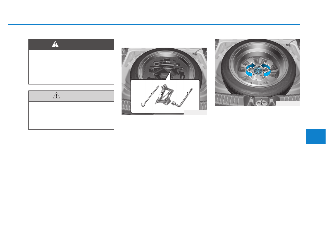
6-15
What to do in an emergency
6
Jack and tools
(1) Jack handle
(2) Jack
(3) Wheel nut wrench
The jack, jack handle, and wheel nut
wrench are stored in the luggage
compartment under the luggage box
cover.
The jack is provided for emergency
tire changing only.
Turn the winged hold down bolt
counterclockwise to remove the
spare tire.
Store the spare tire in the same com-
partment by turning the winged hold
down bolt clockwise.
To prevent the spare tire and tools
from "rattling", store them in their
proper location.
IIFF YYOOUU HHAAVVEE AA FFLLAATT TTIIRREE ((WWIITTHH SSPPAARREE TTIIRREE,, IIFF EEQQUUIIPPPPEEDD))
OPDE066027
OPDE066028
Changing a tire can be danger-
ous. Follow the instructions in
this section when changing a
tire to reduce the risk of serious
injury or death.
WARNING
Be careful as you use the jack
handle to stay clear of the flat
end. The flat end has sharp
edges that could cause cuts.
CAUTION
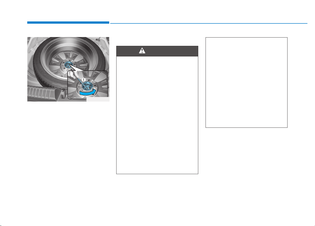
6-16
What to do in an emergency
If it is hard to loosen the tire hold-
down wing bolt by hand, you can
loosen it easily using the jack handle.
1. Put the jack handle (1) inside of
the tire hold-down wing bolt.
2. Turn the tire hold-down wing bolt
counterclockwise with the jack
handle.
Changing tires
A vehicle can slip or roll off of a
jack causing serious injury or
death to you or those nearby.
Take the following safety pre-
cautions:
• Do not get under a vehicle
that is supported by a jack.
• NEVER attempt to change a
tire in the lane of traffic.
ALWAYS move the vehicle
completely off the road on
level, firm ground away from
traffic before trying to change
a tire. If you cannot find a
level, firm place off the road,
call a towing service for assis-
tance.
• Be sure to use the jack pro-
vided with the vehicle.
(Continued)
WARNING
(Continued)
• ALWAYS place the jack on the
designated jacking positions
on the vehicle and NEVER on
the bumpers or any other part
of the vehicle for jacking sup-
port.
• Do not start or run the engine
while the vehicle is on the
jack.
• Do not allow anyone to remain
in the vehicle while it is on the
jack.
• Keep children away from the
road and the vehicle.
OPDE066029
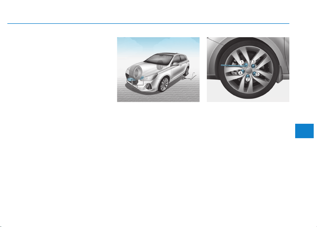
6-17
What to do in an emergency
6
Follow these steps to change your
vehicle’s tire:
1. Park on a level, firm surface.
2. Move the shift lever into P (Park,
for automatic transmission/dual
clutch transmission vehicle) or neu-
tral (for manual transmission vehi-
cle), apply the parking brake, and
place the ignition switch in the
LOCK/OFF position.
3. Press the hazard warning flasher
button.
4. Remove the wheel lug nut wrench,
jack, jack handle, and spare tire
from the vehicle.
5. Block both the front and rear of the
tire diagonally opposite of the tire
you are changing.
6. Loosen the wheel lug nuts coun-
terclockwise one turn each in the
order shown above, but do not
remove any lug nuts until the tire
has been raised off of the ground.
OPDE066030
BB
BB
ll
ll
oo
oo
cc
cc
kk
kk
OPDE066031
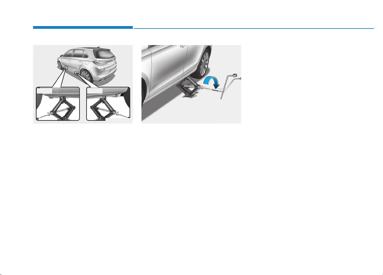
6-18
What to do in an emergency
7. Place the jack at the designated
jacking position under the frame
closest to the tire you are chang-
ing. The jacking positions are
plates welded to the frame with
two notches. Never jack any other
position or part of the vehicle. It
may damage to the side seal
molding.
8. Insert the jack handle into the jack
and turn it clockwise, raising the
vehicle until the tire clears the
ground. Make sure the vehicle is
stable on the jack.
9. Loosen the lug nuts with the wheel
lug nut wrench and remove them
with your fingers. Remove the
wheel from the studs and lay it flat
on the ground out of the way.
Remove any dirt or debris from
the studs, mounting surfaces, and
wheel.
10. Install the spare tire onto the
studs of the hub.
11. Tighten the lug nuts with your fin-
gers onto the studs with the
smaller end of the lug nuts clos-
est to the wheel.
12. Lower the vehicle to the ground
by turning the jack handle coun-
terclockwise.
OPDE066033OPDE066032
■ Front ■ Rear
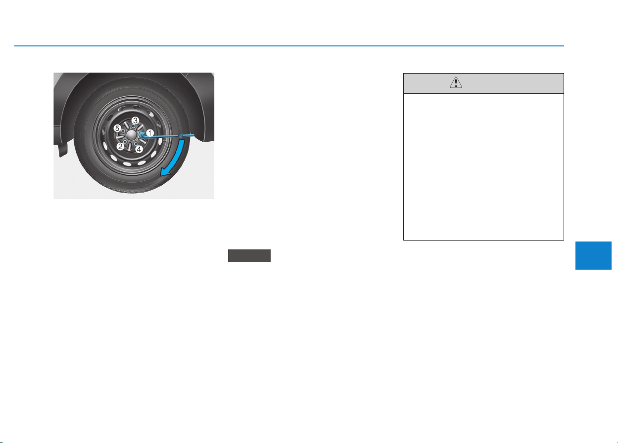
6-19
What to do in an emergency
6
13. Use the wheel lug nut wrench to
tighten the lug nuts in the order
shown. Double-check each lug
nut until they are tight. After
changing tires, we recommend
that an authorized HYUNDAI
dealer tighten the lug nuts to their
proper torque as soon as possi-
ble. The wheel lug nut should
be tightened to 11~13 kgf·m
(79~94 lbf·ft).
If you have a tire gauge, check the
tire pressure (see "Tires and
Wheels" in chapter 8 for tire pressure
instructions.). If the pressure is lower
or higher than recommended, drive
slowly to the nearest service station
and adjust it to the recommended
pressure. Always reinstall the valve
cap after checking or adjusting tire
pressure. If the cap is not replaced,
air may leak from the tire. If you lose
a valve cap, buy another and install it
as soon as possible. After changing
tires, secure the flat tire and return
the jack and tools to their proper stor-
age locations.
• Check the tire pressure as soon
as possible after installing a
spare tire. Adjust it to the rec-
ommended pressure.
• Check and tighten the wheel lug
nuts after driving over 50 km if
tires are replaced. Re-check the
tire wheel lug nuts after driving
over 1,000 km.
If any of the equipment such as the
jack, lug nuts, studs, or other equip-
ment is damaged or in poor condi-
tion, do not attempt to change the
tire and call for assistance.
NOTICE
OTL065007
Your vehicle has metric threads
on the studs and lug nuts. Make
certain during tire changing
that the same nuts that were
removed are reinstalled. If you
have to replace your lug nuts
make sure they have metric
threads to avoid damaging the
studs and ensure the wheel is
properly secured to the hub. We
recommend that you consult an
authorized HYUNDAI dealer for
assistance.
CAUTION

6-20
What to do in an emergency
Use of compact spare tires
(if equipped)
Compact spare tires are designed for
emergency use only. Drive carefully
on the compact spare tire and
always follow the safety precautions.
When driving with the compact spare
tire mounted to your vehicle:
• Check the tire pressure after
installing the compact spare tire.
The compact spare tire should be
inflated to 420 kPa (60 psi).
• Do not take this vehicle through an
automatic car wash while the com-
pact spare tire is installed.
• Do not use the compact spare tire
on any other vehicle because this
tire has been designed especially
for your vehicle.
• The compact spare tire’s tread life is
shorter than a regular tire. Inspect
your compact spare tire regularly
and replace worn compact spare
tires with the same size and design,
mounted on the same wheel.
• Do not use more than one compact
spare tire at a time.
• Do not tow a trailer while the com-
pact spare tire is installed.
When the original tire and wheel
are repaired and reinstalled on the
vehicle, the lug nut torque must be
set correctly. The correct lug nut
tightening torque is 11~13 kgf·m
(79~94 lbf·ft).
NOTICE
To prevent compact spare tire
failure and loss of control pos-
sibly resulting in an accident:
• Use the compact spare tire
only in an emergency.
• NEVER operate your vehicle
over 80 km/h (50 mph).
• Do not exceed the vehicle’s
maximum load rating or the
load carrying capacity shown
on the sidewall of the com-
pact spare tire.
• Do not use the compact spare
tire continuously. Repair or
replace the original tire as
soon as possible to avoid fail-
ure of the compact spare tire.
WARNING

6-21
What to do in an emergency
6
Jack label
To prevent damaging the com-
pact spare tire and your vehicle:
• Drive slowly enough for the
road conditions to avoid all
hazards, such as a potholes
or debris.
• Avoid driving over obstacles.
The compact spare tire diame-
ter is smaller than the diame-
ter of a conventional tire and
reduces the ground clearance
approximately 25 mm (1 inch).
• Do not use tire chains on the
compact spare tire. Because
of the smaller size, a tire chain
will not fit properly.
• Do not use the compact spare
tire on any other wheels, nor
should standard tires, snow
tires, wheel covers or trim
rings be used with the com-
pact spare wheel.
CAUTION
■ Example
OHYK065011
1. Model Name
2. Maximum allowable load
3. When using the jack, set your
parking brake.
4. When using the jack, stop the
engine.
5. Do not get under a vehicle that is
supported by a jack.
6. The designated locations under
the frame
7. When supporting the vehicle, the
base plate of jack must be vertical
under the lifting point.
8. Shift into Reverse gear on vehicles
with manual transmission or move
the shift lever to the P position on
vehicles with automatic transmis-
sion/ dual clutch transmission.
9. The jack should be used on firm
level ground.
10. Jack manufacture
11. Production date
12. Representative company and
address
The actual Jack label in the vehicle may differ from the illustration.
For more detailed specifications, refer to the label attached to the jack.
6-22
What to do in an emergency
JACKDOC14F
EC Declaration of conformity for Jack
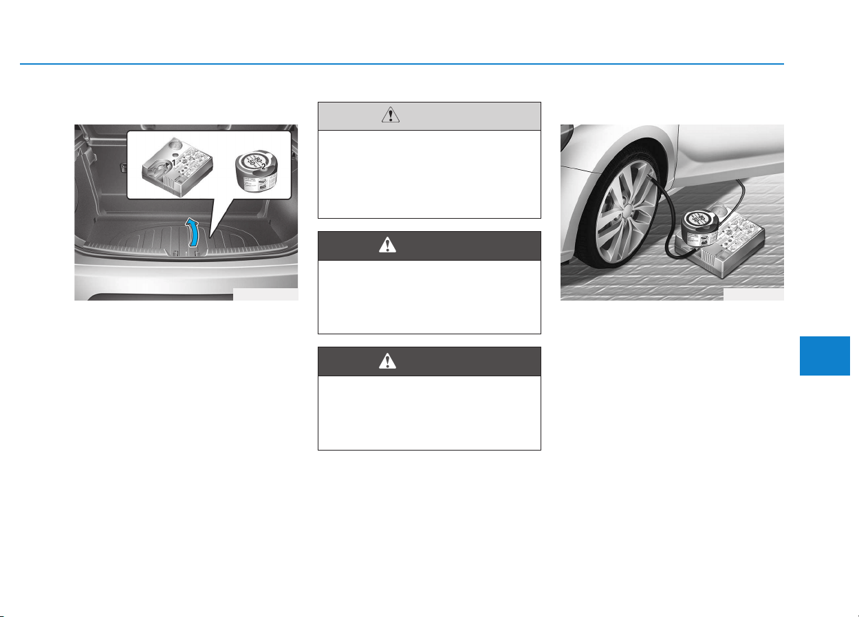
6-23
What to do in an emergency
6
For 15, 16 inch tire
For safe operation, carefully read
and follow the instructions in this
manual before use.
(1) Compressor
(2) Sealant bottle
The Tire Mobility Kit is a temporary
fix to the tire and we recommend that
the system be inspected by an
authorized HYUNDAI dealer.
Introduction
With the Tire Mobility Kit you stay
mobile even after experiencing a tire
puncture.
The system of compressor and seal-
ing compound effectively and com-
fortably seals most punctures in a
passenger car tire caused by nails
or similar objects and reinflates the
tire.
After you ensured that the tire is
properly sealed you can drive cau-
tiously on the tire (distance up to 200
km (120 miles)) at a max. speed of
80 km/h (50 mph) in order to reach a
service station or tire dealer to have
the tire replaced.
IIFF YYOOUU HHAAVVEE AA FFLLAATT TTIIRREE ((WWIITTHH TTIIRREE MMOOBBIILLIITTYY KKIITT,, IIFF EEQQUUIIPPPPEEDD))
OPDE066010 OPDE066012
Do not use the Tire Mobility Kit
to repair punctures in the tire
walls. This can result in an acci-
dent due to tire failure.
WARNING
Have your tire repaired as soon
as possible. The tire may loose
air pressure at any time after
inflating with the Tire Mobility Kit.
WARNING
When two or more tires are flat,
do not use the tire mobility kit
because the supported one
sealant of Tire Mobility Kit is
only used for one flat tire.
CAUTION

6-24
What to do in an emergency
It is possible that some tires, espe-
cially with larger punctures or dam-
age to the sidewall, cannot be sealed
completely.
Air pressure loss in the tire may
adversely affect tire performance.
For this reason, you should avoid
abrupt steering or other driving
maneuvers, especially if the vehicle
is heavily loaded or if a trailer is in
use.
The Tire Mobility Kit is not designed
or intended as a permanent tire
repair method and is to be used for
one tire only. This instruction shows
you step by step how to temporarily
seal the puncture simply and reliably.
Read the section "Notes on the safe
use of the Tire Mobility Kit".
Notes on the safe use of the
Tire Mobility Kit
• Park your car at the side of the
road so that you can work with the
Tire Mobility Kit away from moving
traffic.
• To be sure your vehicle will not
move, even when you're on fairly
level ground, always set your park-
ing brake.
• Only use the Tire Mobility Kit for
sealing/inflation passenger car
tires. Only punctured areas located
within the tread region of the tire
can be sealed using the tire mobil-
ity kit.
• Do not use on motorcycles, bicy-
cles or any other type of tires.
• When the tire and wheel are dam-
aged, do not use Tire Mobility Kit
for your safety.
• Use of the Tire Mobility Kit may not
be effective for tire damage larger
than approximately 6 mm (0.24 in).
If the tire cannot be made roadwor-
thy with the Tire Mobility Kit, we
recommend that you contact an
authorized HYUNDAI dealer.
• Do not use the Tire Mobility Kit if a
tire is severely damaged by driving
run flat or with insufficient air pres-
sure.
• Do not remove any foreign objects
such as nails or screws that have
penetrated the tire.
• Provided the car is outdoors, leave
the engine running. Otherwise
operating the compressor may
eventually drain the car battery.
• Never leave the Tire Mobility Kit
unattended while it is being used.
• Do not leave the compressor run-
ning for more than 10 min. at a time
or it may overheat.
• Do not use the Tire Mobility Kit if
the ambient temperature is below
-30°C (-22°F).
Do not use the TMK if a tire is
severely damaged by driving run
flat or with insufficient air pres-
sure.
Only punctured areas located
within the tread region of the tire
can be sealed using the TMK.
WARNING
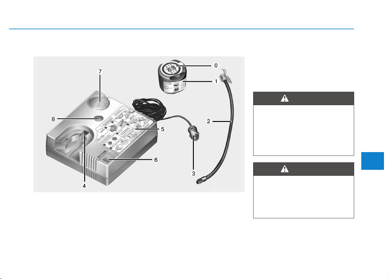
6-25
What to do in an emergency
6
0. Speed- restriction label
1. Sealant bottle and label with
speed restriction
2. Filling hose from sealant bottle to
wheel
3. Connectors and cable for the
power outlet direct connection
4. Holder for the sealant bottle
5. Compressor
6. ON/OFF switch
7. Pressure gauge for displaying the
tire inflation pressure
8. Button for reducing tire inflation
pressure
Connectors, cable and connection
hose are stored in the compressor
housing.
Strictly follow the specified sequence,
otherwise the sealant may escape
under high pressure.
Components of the Tire Mobility Kit
OGDE064102
Expired sealant
Do not use the Tire sealant after
the sealant has expired (i.e.
pasted the expiration date on
the sealant container). This can
increase the risk of tire failure.
WARNING
Sealant
• Keep out of reach of children.
• Avoid contact with eyes.
• Do not swallow.
WARNING
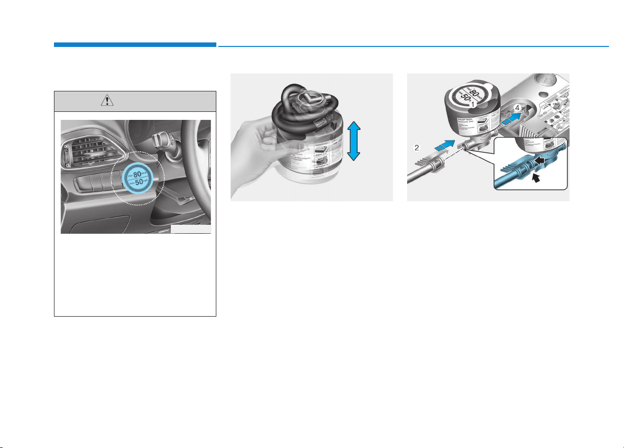
6-26
What to do in an emergency
Using the Tire Mobility Kit
1. Shake the sealant bottle. 2. Screw the filling hose (2) onto the
connector of the sealant bottle (1).
3. Insert the sealant bottle into the
housing of the compressor (4) so
that the bottle is upright.
4. Ensure that the button (8) on the
compressor is not pressed.
Detach the speed restriction
label (0) from the sealant bottle
(1), and place it in a highly visi-
ble place inside the vehicle
such as on the steering wheel
to remind the driver not to drive
too fast.
CAUTION
OLMF064103 OPDE066014
OPD066013
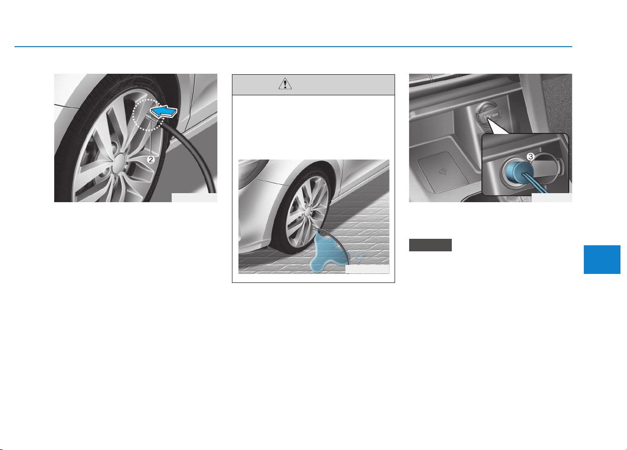
6-27
What to do in an emergency
6
5. Unscrew the valve cap from the
valve of the defective wheel and
screw the filling hose (2) of the
sealant bottle onto the valve.
6. Ensure that the compressor is
switched off, position 0.
7. Plug the compressor power cord
(3) into the vehicle power outlet.
Only use the front passenger side
power outlet when connecting the
power cord.
NOTICE
OPD066017OPDE066015
Securely install the sealant fill-
ing hose to the valve. If not,
sealant may flow backward,
possibly clogging the filling
hose.
CAUTION
OPDE066016
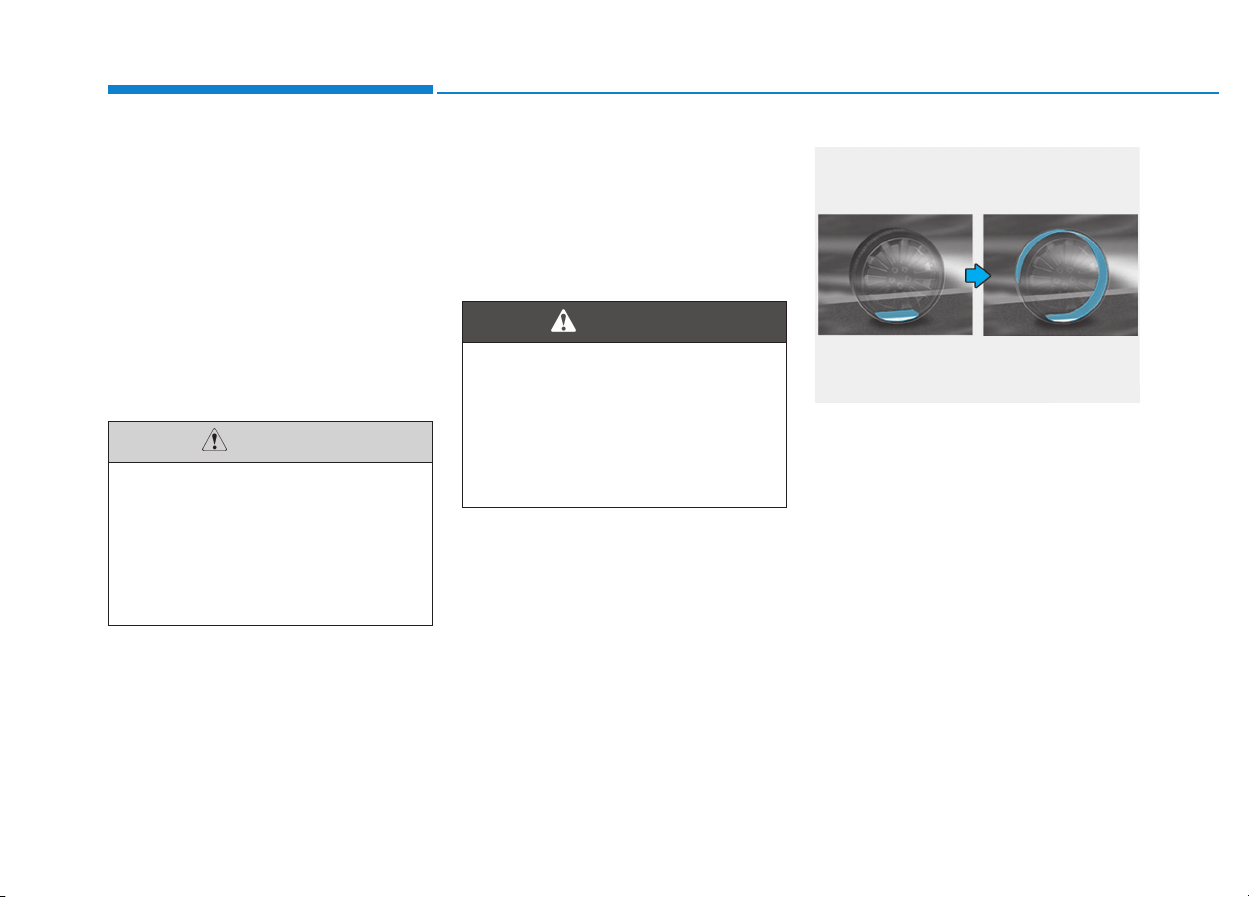
6-28
What to do in an emergency
8. With the ignition switch in the ON
position, switch on the compres-
sor and let it run for approximately
5~7 minutes to fill the sealant up
to proper pressure. (refer to the
Tire and Wheels, chapter 8). The
inflation pressure of the tire after
filling is unimportant and will be
checked/corrected later.
Be careful not to overinflate the
tire and stay away from the tire
when filling it.
9. Switch off the compressor.
10. Detach the hoses from the
sealant bottle connector and
from the tire valve.
Return the Tire Mobility Kit to its stor-
age location in the vehicle.
Distributing the sealant
11. Immediately drive approximately
7~10 km (4~6 miles or, about
10min) to evenly distribute the
sealant in the tire.
Tire pressure
Do not attempt to drive your
vehicle if the tire pressure is
below 200 kPa (29 psi). This
could result in an accident due
to sudden tire failure.
CAUTION
Carbon monoxide
Do not leave your vehicle run-
ning in a poorly ventilated area
for extended periods of time.
Carbon monoxide poisoning
and suffocation can occur.
WARNING
OLMF064106
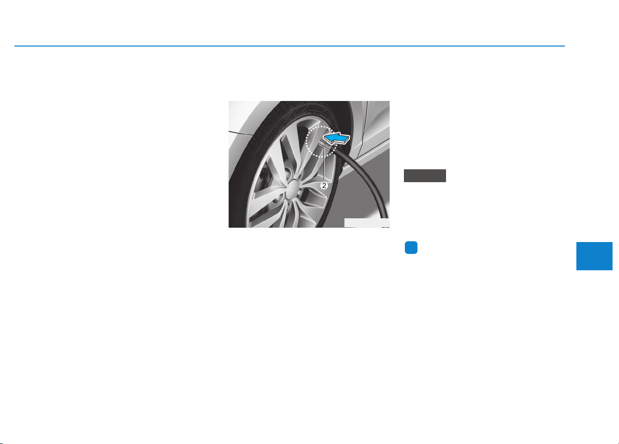
6-29
What to do in an emergency
6
Do not exceed a speed of 80 km/h
(50 mph). If possible, do not fall
below a speed of 20 km/h (12 mph).
While driving, if you experience any
unusual vibration, ride disturbance or
noise, reduce your speed and drive
with caution until you can safely pull
off of the side of the road.
Call for road side service or towing.
When you use the Tire Mobility Kit,
the tire pressure sensors and wheel
may be damaged by sealant, remove
the sealant stained with tire pressure
sensors and wheel and inspect in
authorized dealer.
Checking the tire inflation pres-
sure
1. After driving approximately 7~10
km (4~6 miles or about 10 min),
stop at a safety location.
2. Connect the filling hose (2) of the
compressor directly to the tire
valve.
3. Plug the compressor power cord
into the vehicle power outlet.
4. Adjust the tire inflation pressure to
the recomended tire inflation.
With the ignition swithched on,
proceed as follows.
- To increase the inflation pres-
sure : Switch on the compres-
sor, position I. To check the cur-
rent inflation pressure setting,
briefly switch off the compressor.
- To reduce the inflation pres-
sure: Press the button (8) on the
compressor.
Do not let the compressor run for
more than 10 minutes, otherwise
the device will overheat and may
be damaged.
Information
The pressure gauge may show higher
than actual reading when the com-
pressor is running. To get an accurate
tire reading, the compressor needs to
be turned off.
i
NOTICE
OPDE066015
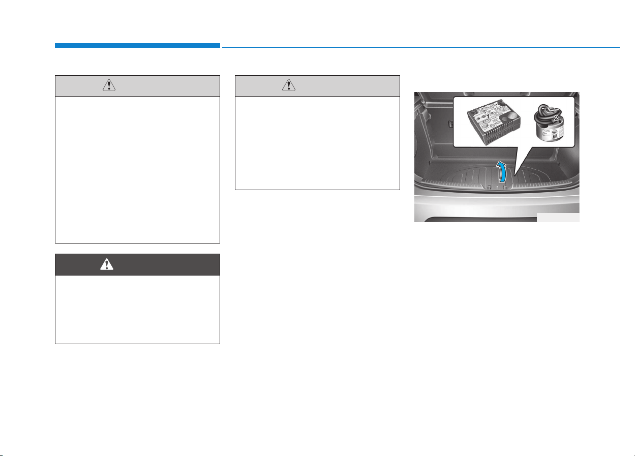
6-30
What to do in an emergency
For 17 inch tire
For safe operation, carefully read
and follow the instructions in this
manual before use.
(1) Compressor
(2) Sealant bottle
The Tire Mobility Kit is a temporary
fix to the tire and we recommend that
the system be inspected by an
authorized HYUNDAI dealer.
The tire inflation pressure must
be at least 220 kPa (32 psi). If it
is not, do not continue driving.
Call for road side service or tow-
ing.
WARNING
If the inflation pressure is not
maintained, drive the vehicle a
second time, refer to Distributing
the sealant. Then repeat steps 1
to 4.
Use of the TMK may be ineffec-
tual for tire damage larger than
approximately 4 mm (0.16 in).
We recommend that you contact
an authorized HYUNDAI dealer if
the tire cannot be made road-
worthy with the Tire Mobility Kit.
CAUTION
Tire pressure sensor
The sealant on the tire pressure
sensor and wheel should be
removed when you replace the
tire with a new one and inspect
the tire pressure sensors at an
authorized dealer.
CAUTION
OPD066010
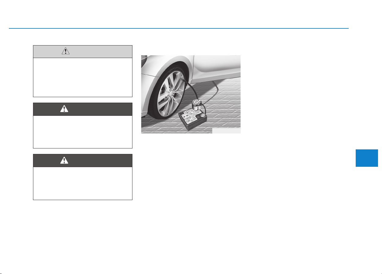
6-31
What to do in an emergency
Introduction
With the Tire Mobility Kit you stay
mobile even after experiencing a tire
puncture.
The system of compressor and seal-
ing compound effectively and com-
fortably seals most punctures in a
passenger car tire caused by nails
or similar objects and reinflates the
tire.
After you ensured that the tire is
properly sealed you can drive cau-
tiously on the tire (distance up to 200
km (120 miles)) at a max. speed of
80 km/h (50 mph) in order to reach a
service station or tire dealer to have
the tire replaced.
It is possible that some tires, espe-
cially with larger punctures or dam-
age to the sidewall, cannot be sealed
completely.
Air pressure loss in the tire may
adversely affect tire performance.
For this reason, you should avoid
abrupt steering or other driving
maneuvers, especially if the vehicle
is heavily loaded or if a trailer is in
use.
The Tire Mobility Kit is not designed
or intended as a permanent tire
repair method and is to be used for
one tire only. This instruction shows
you step by step how to temporarily
seal the puncture simply and reliably.
Read the section "Notes on the safe
use of the Tire Mobility Kit".
6
OPDE066011
Do not use the Tire Mobility Kit
to repair punctures in the tire
walls. This can result in an acci-
dent due to tire failure.
WARNING
Have your tire repaired as soon
as possible. The tire may loose
air pressure at any time after
inflating with the Tire Mobility Kit.
WARNING
When two or more tires are flat,
do not use the tire mobility kit
because the supported one
sealant of Tire Mobility Kit is
only used for one flat tire.
CAUTION

6-32
Notes on the safe use of the
Tire Mobility Kit
• Park your car at the side of the
road so that you can work with the
Tire Mobility Kit away from moving
traffic.
• To be sure your vehicle will not
move, even when you're on fairly
level ground, always set your park-
ing brake.
• Only use the Tire Mobility Kit for
sealing/inflation passenger car
tires. Only punctured areas located
within the tread region of the tire
can be sealed using the tire mobil-
ity kit.
• Do not use on motorcycles, bicy-
cles or any other type of tires.
• When the tire and wheel are dam-
aged, do not use Tire Mobility Kit
for your safety.
• Use of the Tire Mobility Kit may not
be effective for tire damage larger
than approximately 6 mm (0.24 in).
If the tire cannot be made roadwor-
thy with the Tire Mobility Kit, we
recommend that you contact an
authorized HYUNDAI dealer.
• Do not use the Tire Mobility Kit if a
tire is severely damaged by driving
run flat or with insufficient air pres-
sure.
• Do not remove any foreign objects
such as nails or screws that have
penetrated the tire.
• Provided the car is outdoors, leave
the engine running. Otherwise
operating the compressor may
eventually drain the car battery.
• Never leave the Tire Mobility Kit
unattended while it is being used.
• Do not leave the compressor run-
ning for more than 10 min. at a time
or it may overheat.
• Do not use the Tire Mobility Kit if
the ambient temperature is below
-30°C (-22°F).
What to do in an emergency
Do not use the TMK if a tire is
severely damaged by driving
run flat or with insufficient air
pressure.
Only punctured areas located
within the tread region of the
tire can be sealed using the
TMK.
WARNING
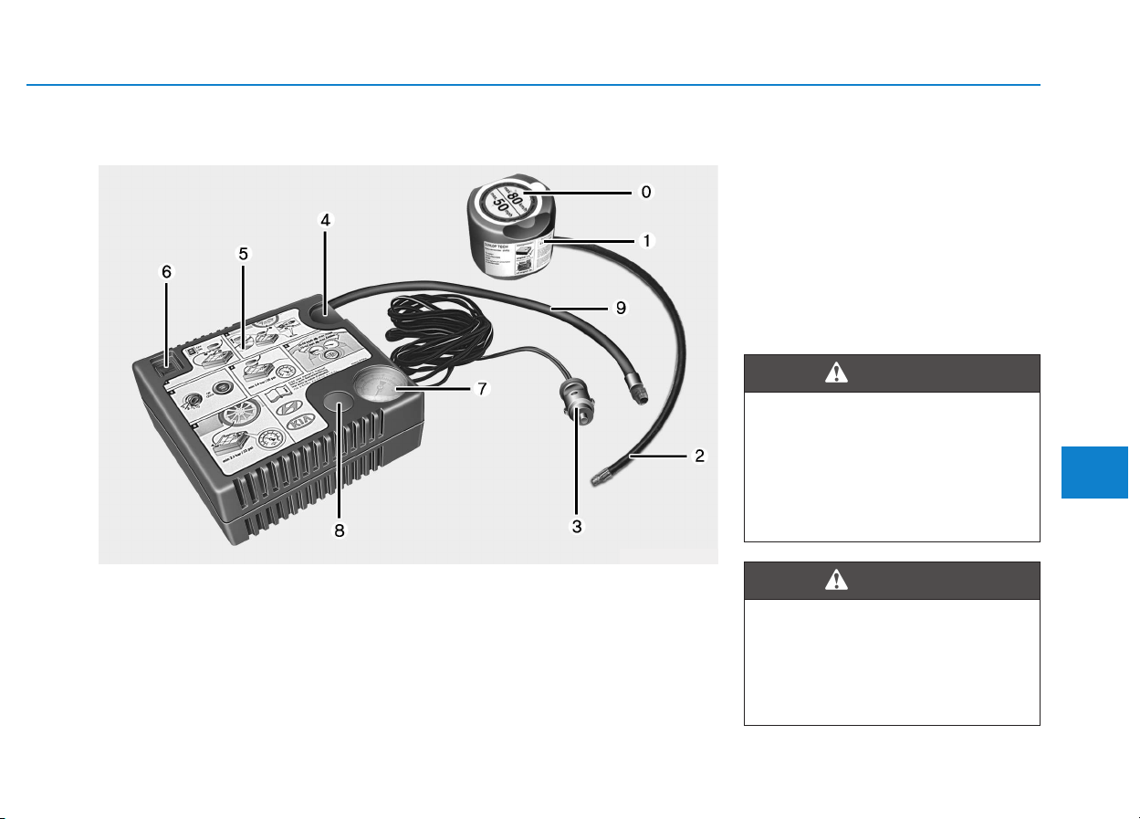
6-33
What to do in an emergency
0. Speed- restriction label
1. Sealant bottle and label with
speed restriction
2. Filling hose from sealant bottle to
wheel
3. Connectors and cable for the
power outlet direct connection
4. Holder for the sealant bottle
5. Compressor
6. ON/OFF switch
7. Pressure gauge for displaying the
tire inflation pressure
8. Button for reducing tire inflation
pressure
9. Hose to connect compressor and
sealant bottle or compressor and
wheel
Connectors, cable and connection
hose are stored in the compressor
housing.
Strictly follow the specified sequence,
otherwise the sealant may escape
under high pressure.
6
Components of the Tire Mobility Kit
OEL069020
Expired sealant
Do not use the Tire sealant after
the sealant has expired (i.e.
pasted the expiration date on
the sealant container). This can
increase the risk of tire failure.
WARNING
Sealant
• Keep out of reach of children.
• Avoid contact with eyes.
• Do not swallow.
WARNING
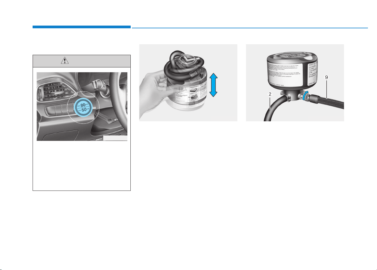
6-34
Using the Tire Mobility Kit
1. Shake the sealant bottle. 2. Screw the connection hose (9)
onto the connector of the sealant
bottle.
3. Ensure that the button (8) on the
compressor is not pressed.
What to do in an emergency
Detach the speed restriction
label (0) from the sealant bottle
(1), and place it in a highly visi-
ble place inside the vehicle
such as on the steering wheel
to remind the driver not to drive
too fast.
CAUTION
OLMF064103 OLMF064104
OPD066013
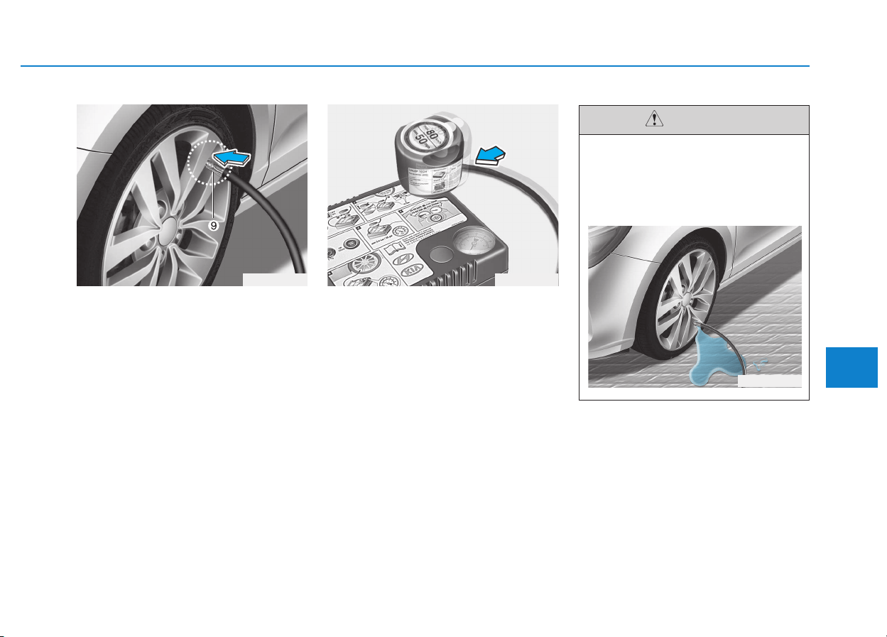
6-35
What to do in an emergency
4. Unscrew the valve cap from the
valve of the defective wheel and
screw the connector hose (9) of
the sealant bottle onto the valve.
5. Insert the sealant bottle into the
housing of the compressor (4) so
that the bottle is upright.
6. Ensure that the compressor is
switched off, position 0.
6
OLMF064105
Securely install the sealant fill-
ing hose to the valve. If not,
sealant may flow backward,
possibly clogging the filling
hose.
CAUTION
OPDE066016
OPDE066015
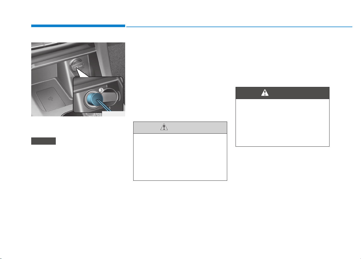
6-36
7. Plug the compressor power cord
(3) into the vehicle power outlet.
Only use the front passenger side
power outlet when connecting the
power cord.
8. With the ignition switch in the ON
position, switch on the compres-
sor and let it run for approximately
5~7 minutes to fill the sealant up
to proper pressure. (refer to the
Tire and Wheels, chapter 8). The
inflation pressure of the tire after
filling is unimportant and will be
checked/corrected later.
Be careful not to overinflate the
tire and stay away from the tire
when filling it.
9. Switch off the compressor.
10. Detach the hoses from the
sealant bottle connector and
from the tire valve.
Return the Tire Mobility Kit to its stor-
age location in the vehicle.
NOTICE
What to do in an emergency
OPD066017
Tire pressure
Do not attempt to drive your
vehicle if the tire pressure is
below 200 kPa (29 psi). This
could result in an accident due
to sudden tire failure.
CAUTION
Carbon monoxide
Do not leave your vehicle run-
ning in a poorly ventilated area
for extended periods of time.
Carbon monoxide poisoning
and suffocation can occur.
WARNING
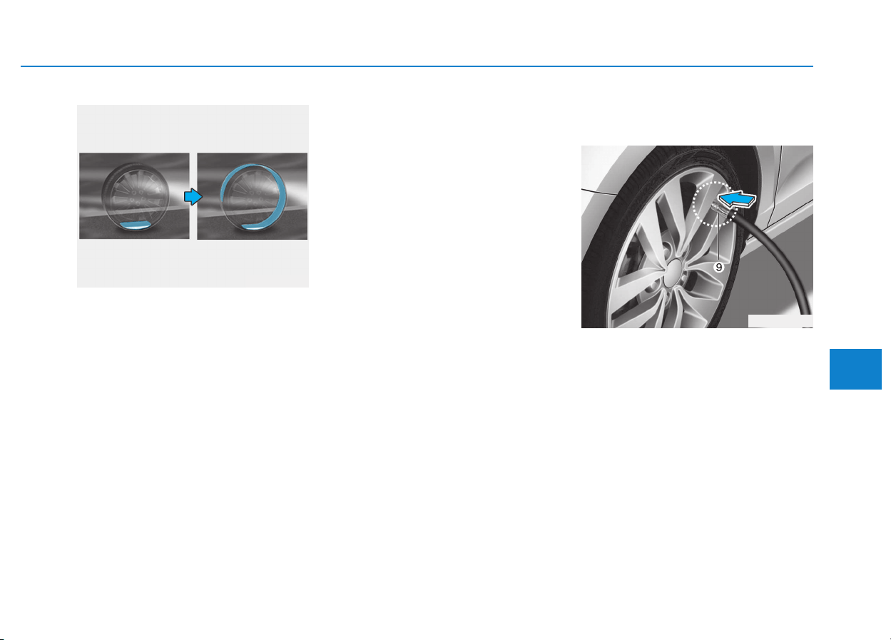
6-37
What to do in an emergency
Distributing the sealant
11. Immediately drive approximately
7~10 km (4~6 miles or, about
10min) to evenly distribute the
sealant in the tire.
Do not exceed a speed of 80 km/h
(50 mph). If possible, do not fall
below a speed of 20 km/h (12 mph).
While driving, if you experience any
unusual vibration, ride disturbance or
noise, reduce your speed and drive
with caution until you can safely pull
off of the side of the road.
Call for road side service or towing.
When you use the Tire Mobility Kit,
the tire pressure sensors and wheel
may be damaged by sealant, remove
the sealant stained with tire pressure
sensors and wheel and inspect in
authorized dealer.
Checking the tire inflation pres-
sure
1. After driving approximately 7~10
km (4~6 miles or about 10 min),
stop at a safety location.
2. Connect the connection hose (9)
of the compressor directly to the
tire valve.
3. Plug the compressor power cord
into the vehicle power outlet.
4. Adjust the tire inflation pressure to
the recomended tire inflation.
With the ignition swithched on,
proceed as follows.
6
OLMF064106
OPDE066015
6-38
- To increase the inflation pres-
sure : Switch on the compres-
sor, position I. To check the cur-
rent inflation pressure setting,
briefly switch off the compressor.
- To reduce the inflation pres-
sure: Press the button (8) on the
compressor.
Do not let the compressor run for
more than 10 minutes, otherwise
the device will overheat and may
be damaged.
Information
The pressure gauge may show higher
than actual reading when the com-
pressor is running. To get an accurate
tire reading, the compressor needs to
be turned off.
i
NOTICE
What to do in an emergency
The tire inflation pressure must
be at least 220 kPa (32 psi). If it
is not, do not continue driving.
Call for road side service or tow-
ing.
WARNING
If the inflation pressure is not
maintained, drive the vehicle a
second time, refer to Distributing
the sealant. Then repeat steps 1
to 4.
Use of the TMK may be ineffec-
tual for tire damage larger than
approximately 4 mm (0.16 in).
We recommend that you contact
an authorized HYUNDAI dealer if
the tire cannot be made road-
worthy with the Tire Mobility Kit.
CAUTION
Tire pressure sensor
The sealant on the tire pressure
sensor and wheel should be
removed when you replace the
tire with a new one and inspect
the tire pressure sensors at an
authorized dealer.
CAUTION
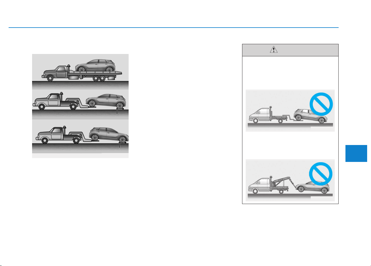
6-39
What to do in an emergency
6
Towing service
If emergency towing is necessary,
we recommend having it done by an
authorized HYUNDAI dealer or a
commercial tow-truck service.
Proper lifting and towing procedures
are necessary to prevent damage to
the vehicle. The use of wheel dollies
or flatbed is recommended.
It is acceptable to tow the vehicle
with the rear wheels on the ground
(without dollies) and the front wheels
off the ground.
If any of the loaded wheels or sus-
pension components are damaged
or the vehicle is being towed with the
front wheels on the ground, use a
towing dolly under the front wheels.
When being towed by a commercial
tow truck and wheel dollies are not
used, the front of the vehicle should
always be lifted, not the rear.
TTOOWWIINNGG
OPD066018
Dollies
Dollies
• Do not tow the vehicle with the
front wheels on the ground as
this may cause damage to the
vehicle.
• Do not tow with sling-type
equipment. Use wheel lift or
flatbed equipment.
CAUTION
OPD066019
OPD066020
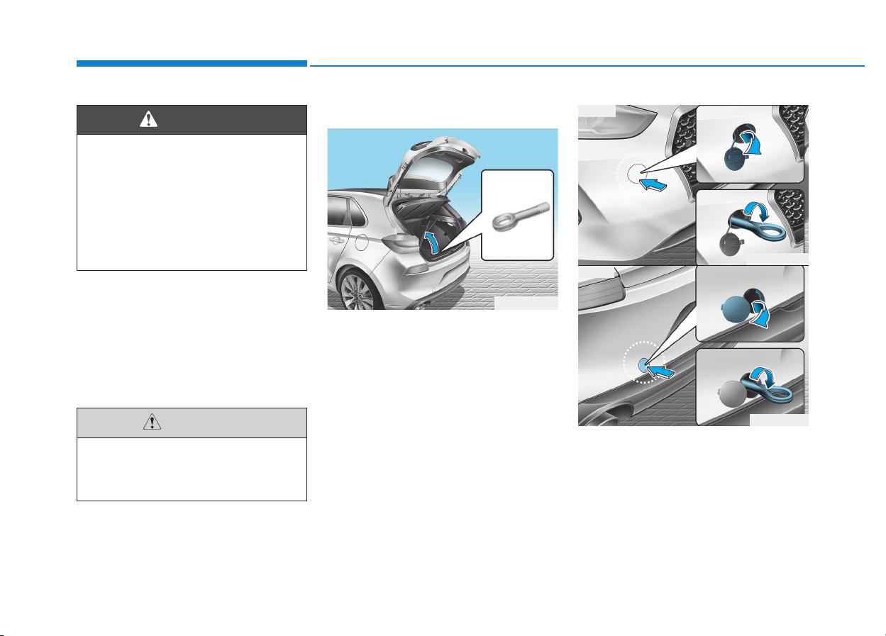
6-40
What to do in an emergency
When towing your vehicle in an
emergency without wheel dollies:
1. Place the ignition switch in the
ACC position.
2. Place the shift lever in N (Neutral).
3. Release the parking brake.
Removable towing hook
1. Open the tailgate, and remove the
towing hook from the tool case.
2. Remove the hole cover pressing
the lower part of the cover on the
bumper.
3. Install the towing hook by turning it
clockwise into the hole until it is
fully secured.
4. Remove the towing hook and
install the cover after use.
Failure to place the shift lever in
N (Neutral) may cause internal
damage to the transmission.
CAUTION
OPDE066035
OPDE066021
OPD066023
■ Front
■ Rear
If your vehicle is equipped with
a rollover sensor, place the igni-
tion switch in the LOCK/OFF or
ACC position when the vehicle
is being towed. The side impact
and curtain air bag may deploy
if the sensor detects the situa-
tion as a rollover.
WARNING
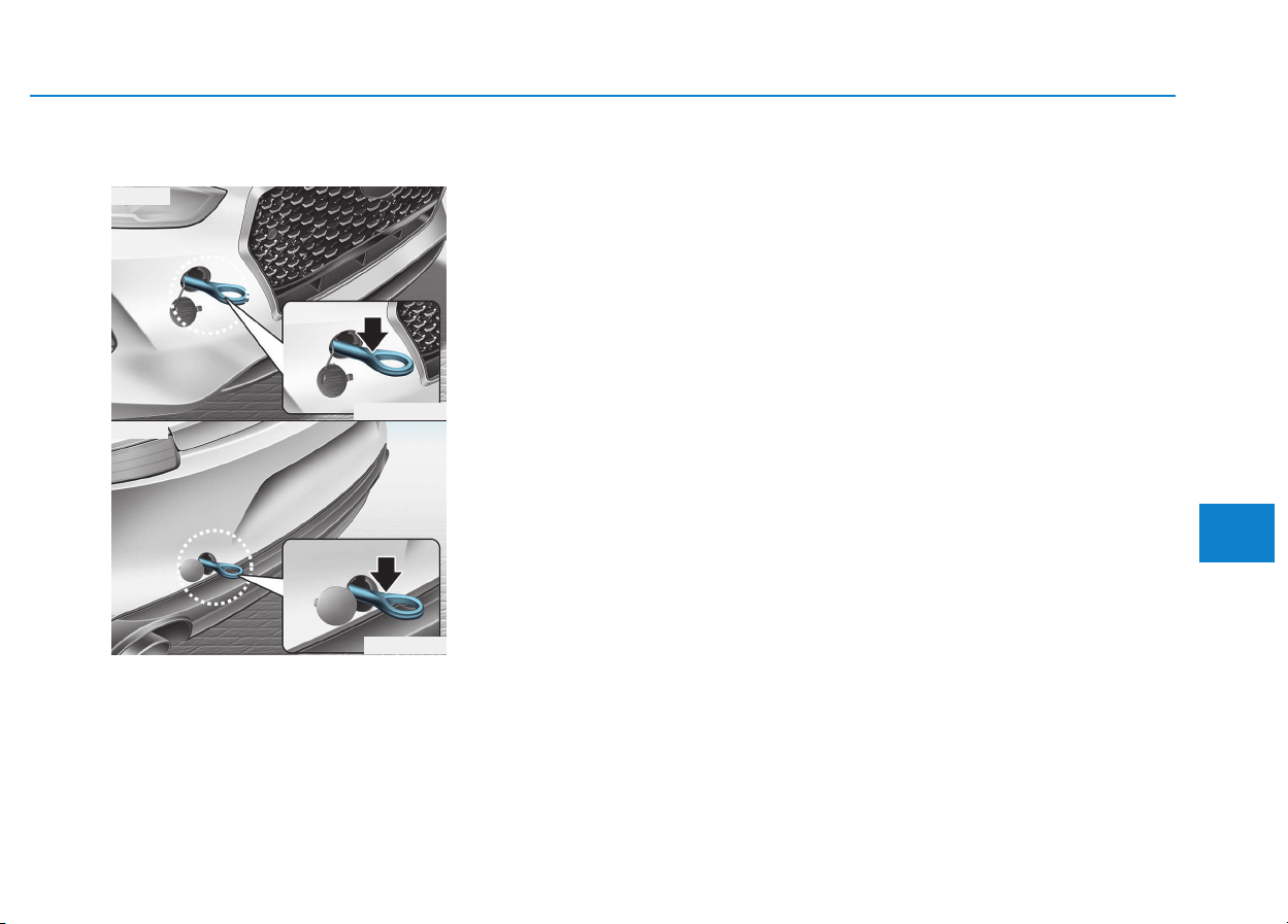
6-41
What to do in an emergency
6
Emergency towing
If towing is necessary, we recommend
you have it done by an authorized
HYUNDAI dealer or a commercial tow
truck service.
If towing service is not available in an
emergency, your vehicle may be
temporarily towed using a cable or
chain secured to the emergency tow-
ing hook at the front (or rear) of the
vehicle.
Use extreme caution when towing
the vehicle with a cable or chain. A
driver must be in the vehicle to steer
it and operate the brakes.
Towing in this manner may be done
only on hard-surfaced roads for a
short distance and at low speeds.
Also, the wheels, axles, power train,
steering and brakes must all be in
good condition.
Always follow these emergency tow-
ing precautions:
• Place the ignition switch in the ACC
position so the steering wheel is not
locked.
• Place the shift lever in N (Neutral).
• Release the parking brake.
• Depress the brake pedal with more
force than normal since you will
have reduced braking perform-
ance.
• More steering effort will be required
because the power steering system
will be disabled.
• Use a vehicle heavier than your
own to tow your vehicle.
• The drivers of both vehicles should
communicate with each other fre-
quently.
• Before emergency towing, check
that the hook is not broken or dam-
aged.
• Fasten the towing cable or chain
securely to the hook.
• Do not jerk the hook. Apply steady
and even force.
OPDE066022
OPD066026
■ Front
■ Rear
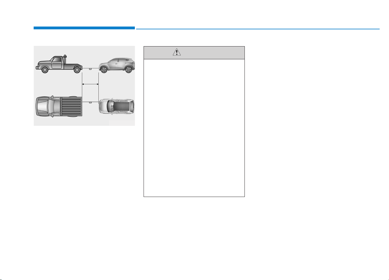
6-42
What to do in an emergency
• Use a towing cable or chain less
than 5 m (16 feet) long. Attach a
white or red cloth (about 30 cm (12
inches) wide) in the middle of the
cable or chain for easy visibility.
• Drive carefully so the towing cable
or chain remains tight during towing.
• Before towing, check the automatic
transmission/dual clutch transmis-
sion for fluid leaks under your vehi-
cle. If the automatic transmission
fluid is leaking, flatbed equipment
or a towing dolly must be used.
To avoid damage to your vehicle
and vehicle components when
towing:
• Always pull straight ahead
when using the towing hooks.
Do not pull from the side or at
a vertical angle.
• Do not use the towing hooks
to pull a vehicle out of mud,
sand or other conditions from
which the vehicle cannot be
driven out under its own
power.
• Limit the vehicle speed to
15 km/h (10 mph) and drive
less than 1.5 km (1 mile) when
towing to avoid serious dam-
age to the automatic transmis-
sion.
CAUTION
OTL065029

6-43
What to do in an emergency
6
Your vehicle is equipped with emer-
gency commodities to help you
respond to emergency situation.
Fire extinguisher
If there is small fire and you know how
to use the fire extinguisher, follow
these steps carefully.
1. Pull out the safety pin at the top of
the extinguisher that keeps the han-
dle from being accidentally pressed.
2. Aim the nozzle towards the base
of the fire.
3. Stand approximately 2.5 m (8 ft)
away from the fire and squeeze
the handle to discharge the extin-
guisher. If you release the handle,
the discharge will stop.
4. Sweep the nozzle back and forth
at the base of the fire. After the fire
appears to be out, watch carefully
since it may re-ignite.
First aid kit
Supplies for use in giving first aid
such as scissors, bandage and
adhesive tape, etc. are provided.
Triangle reflector
Place the triangle reflector on the
road to warn oncoming vehicles dur-
ing emergencies, such as when the
vehicle is parked by the roadside due
to problems.
Tire pressure gauge
(if equipped)
Tires normally lose some air in day-
to-day use, and you may have to add
a air periodically and usually it is not
a sign of a leaking tire, but of normal
wear. Always check tire pressure
when the tires are cold because tire
pressure increases with temperature.
To check the tire pressure, take the
following steps:
1. Unscrew the inflation valve cap
that is located on the rim of the
tire.
2. Press and hold the gauge against
the tire valve. Some air will leak as
you begin and more will leak if you
don't press the gauge in firmly.
3. A firm non-leaking push will acti-
vate the gauge.
4. Read the tire pressure on the gauge
to see whether the tire pressure is
low or high.
5. Adjust the tire pressure to the
specified pressure. Refer to “Tires
and Wheels” in chapter 8.
6. Reinstall the inflation valve cap.
EEMMEERRGGEENNCCYY CCOOMMMMOODDIITTYY ((IIFF EEQQUUIIPPPPEEDD))

7
Maintenance
7
Maintenance
Engine compartment .............................................7-3
Maintenance services ...........................................7-6
Owner's responsibility......................................................7-6
Owner maintenance precautions ..................................7-6
Owner maintenance...............................................7-7
Owner maintenance schedule........................................7-8
Scheduled maintenance services ......................7-10
Normal Maintenance Schedule
(Gasoline Engine, for Europe)......................................7-11
Maintenance Under Severe Usage and
Low Mileage Conditions
(Gasoline Engine, for Europe)......................................7-14
Normal Maintenance Schedule
(Gasoline Engine, except Europe)...............................7-16
Maintenance Under Severe Usage and
Low Mileage Conditions
(Gasoline Engine, except Europe)...............................7-20
Normal Maintenance Schedule
(Diesel Engine, for Europe) ..........................................7-22
Maintenance Under Severe Usage and
Low Mileage Conditions
(Diesel Engine, for Europe) ..........................................7-25
Normal Maintenance Schedule
(Diesel Engine, except Europe)....................................7-27
Maintenance Under Severe Usage and
Low Mileage Conditions
(Diesel Engine, except Europe)....................................7-30
Explanation of scheduled maintenance items.7-32
Engine oil ..............................................................7-35
Checking the engine oil level.......................................7-35
Checking the engine oil and filter ..............................7-36
Engine coolant......................................................7-37
Checking the engine coolant level..............................7-37
Changing the engine coolant .......................................7-39
Brake/clutch fluid................................................7-40
Checking the brake/clutch fluid level........................7-40
Washer fluid .........................................................7-41
Checking the washer fluid level ..................................7-41
Parking brake .......................................................7-41
Checking the parking brake .........................................7-41
Fuel Filter (For Diesel)........................................7-42
Draining water from fuel filter....................................7-42
Fuel filter cartridge replacement................................7-42
Air cleaner ............................................................7-42
Filter replacement...........................................................7-42
Climate control air filter .....................................7-44
Filter inspection...............................................................7-44
Filter replacement...........................................................7-44
Wiper blades.........................................................7-45
Blade inspection ..............................................................7-45
Blade replacement ..........................................................7-46
7

7
Battery...................................................................7-48
For best battery service................................................7-49
Battery capacity label....................................................7-49
Battery recharging .........................................................7-50
Reset items .......................................................................7-51
Tires and wheels..................................................7-52
Tire care............................................................................7-52
Recommended cold tire inflation pressures.............7-53
Check tire inflation pressure........................................7-54
Tire rotation .....................................................................7-54
Wheel alignment and tire balance ..............................7-55
Tire replacement .............................................................7-56
Wheel replacement.........................................................7-57
Tire traction......................................................................7-57
Tire maintenance ............................................................7-57
Tire sidewall labeling......................................................7-57
Low aspect ratio tires....................................................7-61
Fuses......................................................................7-62
Instrument panel fuse replacement ...........................7-63
Engine compartment panel fuse replacement.........7-64
Fuse/Relay panel description ......................................7-66
Light bulbs.............................................................7-85
Headlamp, static bending lamp,
position lamp, turn signal lamp and
daytime running light bulb replacement ...................7-86
Front fog lamp .................................................................7-91
Headlamp and front fog lamp
aiming (for Europe) ........................................................7-91
Side repeater lamp replacement .................................7-97
Rear combination lamp bulb replacement ................7-98
Rear fog lamp ................................................................7-102
High mounted stop lamp replacement.....................7-103
License plate light bulb replacement.......................7-103
Interior light bulb replacement..................................7-103
Appearance care................................................7-105
Exterior care ..................................................................7-105
Interior care ...................................................................7-110
Emission control system ...................................7-111
1. Crankcase emission control system...................7-111
2. Evaporative emission control system ................7-111
3. Exhaust emission control system .......................7-112
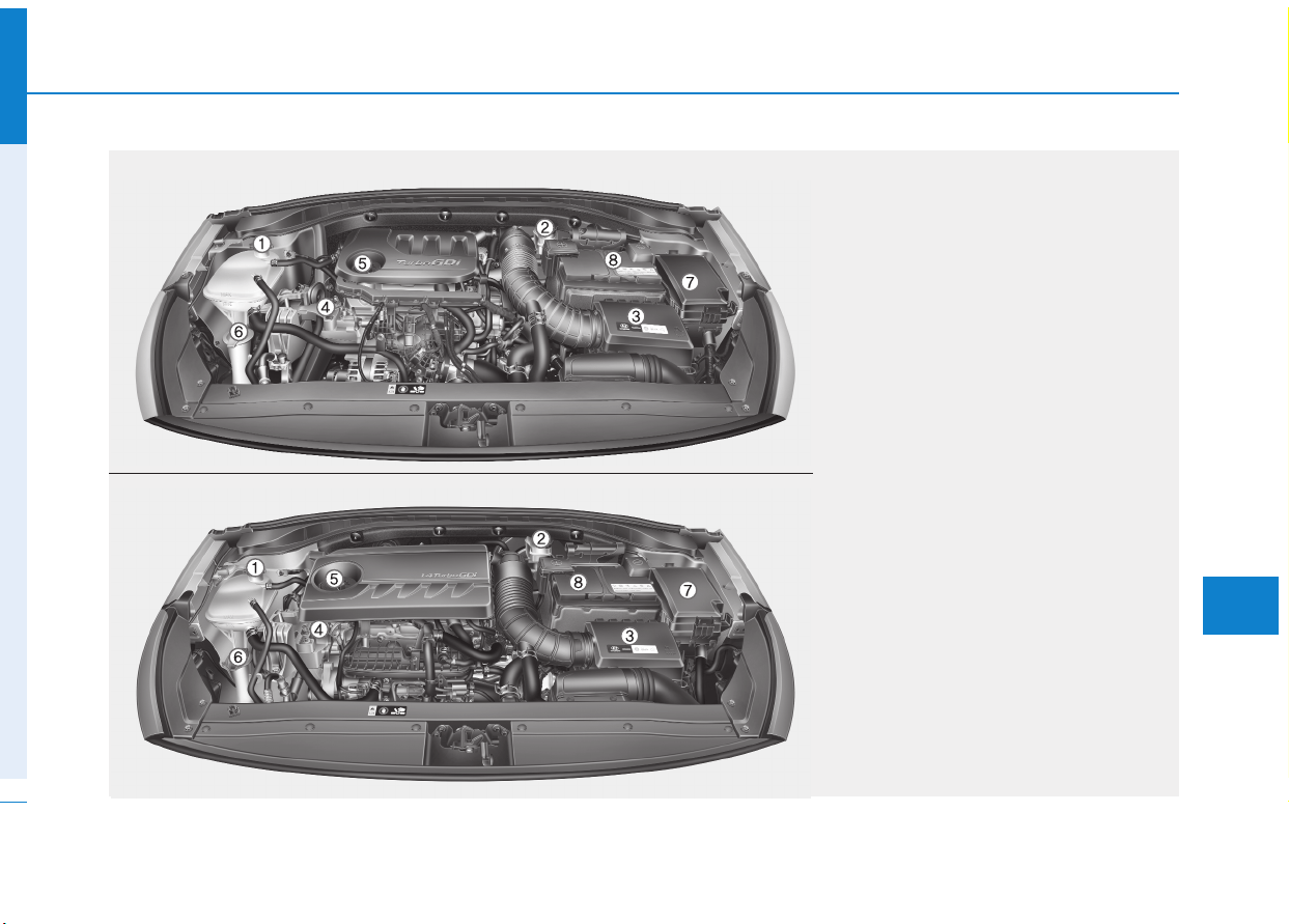
7-3
7
Maintenance
EENNGGIINNEE CCOOMMPPAARRTTMMEENNTT
1. Engine coolant reservoir/
Engine coolant cap
2. Brake/clutch fluid reservoir
3. Air cleaner
4. Engine oil dipstick
5. Engine oil filler cap
6. Windshield washer fluid reservoir
7. Fuse box
8. Battery
The actual engine room in the vehicle
may differ from the illustration.
OPDE076088/OPD076001
■■
Gasoline Engine (Kappa 1.0 T-GDI)
■■
Gasoline Engine (Kappa 1.4 T-GDI)
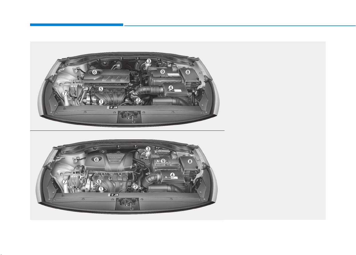
7-4
Maintenance
1. Engine coolant reservoir
2. Radiator cap
3. Brake/clutch fluid reservoir
4. Air cleaner
5. Engine oil dipstick
6. Engine oil filler cap
7. Windshield washer fluid reservoir
8. Fuse box
9. Battery
The actual engine room in the vehicle
may differ from the illustration.
OPDE076089/OPDE076093
■
■
Gasoline Engine (Kappa 1.4 MPI)
■■
Gasoline Engine (Gamma 1.6 MPI)
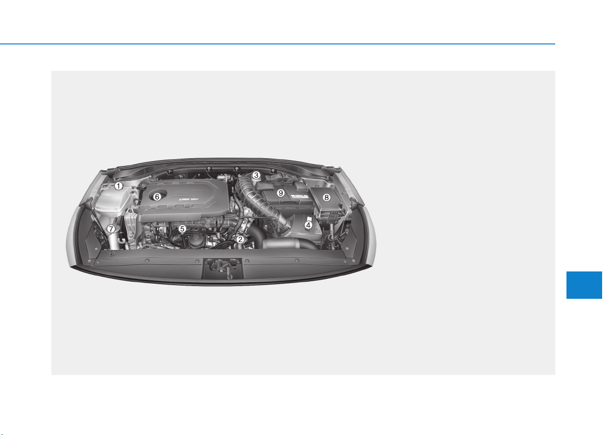
1. Engine coolant reservoir
2. Radiator cap
3. Brake/clutch fluid reservoir
4. Air cleaner
5. Engine oil dipstick
6. Engine oil filler cap
7. Windshield washer fluid reservoir
8. Fuse box
9. Battery
The actual engine room in the vehicle
may differ from the illustration.
OPD076003
■■
Diesel Engine (U2 1.6 TCI)
7-5
7
Maintenance

7-6
Maintenance
M
MAAIINNTTEENNAANNCCEE SSEERRVVIICCEESS
You should exercise the utmost care
to prevent damage to your vehicle
and injury to yourself whenever per-
forming any maintenance or inspec-
tion procedures.
We recommend you have your vehi-
cle maintained and repaired by an
authorized HYUNDAI dealer. An
authorized HYUNDAI dealer meets
HYUNDAI’s high service quality stan-
dards and receives technical support
from HYUNDAI in order to provide
you with a high level of service satis-
faction.
Owner’s responsibility
Maintenance service and record reten-
tion are the owner’s responsibility.
You should retain documents that show
proper maintenance has been per-
formed on your vehicle in accordance
with the scheduled maintenance serv-
ice charts shown on the following
pages. You need this information to
establish your compliance with the
servicing and maintenance require-
ments of your vehicle warranties.
Detailed warranty information is pro-
vided in your Service Passport.
Repairs and adjustments required as
a result of improper maintenance or
a lack of required maintenance are
not covered.
Owner maintenance precautions
Inadequate, incomplete or insufficient
servicing may result in operational
problems with your vehicle that could
lead to vehicle damage, an accident,
or personal injury. This chapter pro-
vides instructions only for the mainte-
nance items that are easy to perform.
Several procedures can be done only
by an authorized HYUNDAI dealer
with special tools.
Your vehicle should not be modified in
any way. Such modifications may
adversely affect the performance,
safety or durability of your vehicle and
may, in addition, violate conditions of
the limited warranties covering the
vehicle.
Improper owner maintenance dur-
ing the warranty period may affect
warranty coverage. For details, read
the separate Service Passport pro-
vided with the vehicle. If you're
unsure about any servicing or main-
tenance procedure, we recommend
that the system be serviced by an
authorized HYUNDAI dealer.
NOTICE

7-7
7
Maintenance
OOWWNNEERR MMAAIINNTTEENNAANNCCEE
The following lists are vehicle checks
and inspections that should be per-
formed by the owner or an authorized
HYUNDAI dealer at the frequencies
indicated to help ensure safe, depend-
able operation of your vehicle.
Any adverse conditions should be
brought to the attention of your dealer
as soon as possible.
These Owner Maintenance vehicle
checks are generally not covered by
warranties and you may be charged
for labor, parts and lubricants used.
Performing maintenance work
on a vehicle can be dangerous.
If you lack sufficient knowledge
and experience or the proper
tools and equipment to do the
work, we recommend that the
system be serviced by an author-
ized HYUNDAI dealer. ALWAYS
follow these precautions for
performing maintenance work:
• Park your vehicle on level
ground, move the shift lever
into the P (Park, for automatic
transmission/dual clutch trans-
mission vehicle) position, apply
the parking brake, place the
ignition switch in the
LOCK/OFF position.
(Continued)
WARNING
(Continued)
• Block the tires (front and back)
to prevent the vehicle from
moving.
Remove loose clothing or jew-
elry that can become entan-
gled in moving parts.
• If you must run the engine
during maintenance, do so
out doors or in an area with
plenty of ventilation.
• Keep flames, sparks, or smok-
ing materials away from the
battery and fuel-related parts.
7-8
Maintenance
Owner maintenance schedule
When you stop for fuel:
• Check the engine oil level.
• Check coolant level in the engine
coolant reservoir.
• Check the windshield washer fluid
level.
• Check for low or under-inflated tires.
While operating your vehicle:
• Note any changes in the sound of
the exhaust or any smell of exhaust
fumes in the vehicle.
• Check for vibrations in the steering
wheel. Notice if there is any
increased steering effort or loose-
ness in the steering wheel, or
change in its straight-ahead position.
• Notice if your vehicle constantly turns
slightly or “pulls” to one side when
traveling on smooth, level road.
• When stopping, listen and check for
unusual sounds, pulling to one side,
increased brake pedal travel or
“hard-to-push” brake pedal.
• If any slipping or changes in the
operation of your transaxle occurs,
check the transaxle fluid level.
• Check the automatic transmission/
dual clutch transmission P (Park)
function.
• Check the parking brake.
• Check for fluid leaks under your
vehicle (water dripping from the air
conditioning system during or after
use is normal).
Be careful when checking your
engine coolant level when the
engine is hot. This may result in
coolant being blown out of the
opening and cause serious
burns and other injuries.
WARNING
Diesel Engine
Never manipulate or modify the
injection system while running
the diesel engine or within 30
seconds after turning OFF the
diesel engine. The high-pressure
pump, high-pressure pipes, rail,
and injectors are still subject to
the high pressure right after
stopping the diesel engine.
When the fuel leakage vents out,
it may cause serious body injury.
Any people, who are implement-
ed with the artificial cardiac
pacemaker, should remain away
from the ECU or the wiring har-
ness by at least 30 cm, while run-
ning the diesel engine. The high
currents of the electric engine
control system produce a con-
siderable amount of magnetic
fields.
WARNING

7-9
7
Maintenance
At least monthly:
• Check coolant level in the engine
coolant reservoir.
• Check the operation of all exterior
lights, including the stoplights, turn
signals and hazard warning flashers.
• Check the inflation pressures of all
tires including the spare for tires
that are worn, show uneven wear,
or are damaged.
• Check for loose wheel lug nuts.
At least twice a year:
(i.e., every Spring and Fall)
• Check radiator, heater and air condi-
tioning hoses for leaks or damage.
• Check windshield washer spray
and wiper operation. Clean wiper
blades with clean cloth dampened
with washer fluid.
• Check headlamp alignment.
• Check muffler, exhaust pipes,
shields and clamps.
• Check the seat belts for wear and
function.
At least once a year:
• Clean body and door drain holes.
• Lubricate door hinges and hood
hinges.
• Lubricate door and hood locks and
latches.
• Lubricate door rubber weather
strips.
• Check the air conditioning system.
• Inspect and lubricate automatic
transaxle linkage and controls.
• Clean the battery and terminals.
• Check the brake fluid level.

7-10
Maintenance
S
SCCHHEEDDUULLEEDD MMAAIINNTTEENNAANNCCEE SSEERRVVIICCEESS
Follow Normal Maintenance Schedule if the vehicle is usually operated where none of the following conditions apply.
If any of the following conditions apply, you must follow the Maintenance Under Severe Usage Conditions.
• Repeated driving short distance of less than 8 km (5 miles) in normal temperature or less than 16 km (10 miles) in
freezing temperature
• Extensive engine idling or low speed driving for long distances
• Driving on rough, dusty, muddy, unpaved, graveled or salt-spread roads
• Driving in areas using salt or other corrosive materials or in very cold weather
• Driving in heavy traffic area
• Driving on uphill, downhill, or mountain road repeatedly
• Towing a trailer or using a camper, or roof rack
• Driving as a patrol car, taxi, other commercial use of vehicle towing
• Driving over 170 km/h (106 mile/h)
• Frequently driving in stop-and-go condition
If your vehicle is operated under the above conditions, you should inspect, replace or refill more frequently than the
following Normal Maintenance Schedule. After the periods or distance shown in the chart, continue to follow the pre-
scribed maintenance intervals.

7-11
7
Maintenance
I : Inspect and if necessary, adjust, correct, clean or replace.
R : Replace or change.
** : The engine oil level should be checked regularly and maintained properly. Operating with an insufficient amount of oil can dam-
age the engine, and such damage is not covered by warranty.
*
1
: Inspect drive belt tensioner, idler and alternator pulley and if necessary correct or replace.
*
2
: Check the engine oil level and leak every 500 km (350 miles) or before starting a long trip.
*
3
: If good quality gasolines meet Europe Fuel standards (EN228) or equivalents including fuel additives is not available, one bot-
tle of additive is recommended. Additives are available from your authorized HYUNDAI dealer along with information on how to
use them. Do not mix other additives.
*
4
: For your convenience, it can be replaced prior to it's interval when you do maintenance of other items.
Normal Maintenance Schedule (Gasoline Engine, for Europe)
Months 24 48 72 96 120 144 168 192
Miles x 1,000 20 40 60 80 100 120 140 160
Km x 1,000 30 60 90 120 150 180 210 240
Drive belts *
1
At first, inspect at 90,000 km (60,000 miles) or 72 months,
after that, every 30,000 km (20,000 miles) or 24 months
Engine oil and
engine oil filter ** *
2
1.0 T-GDI Replace every 15,000 km (10,000 miles) or 12 months
1.4 T-GDI Replace every 15,000 km (10,000 miles) or 12 months
MPI Replace every 30,000 km (20,000 miles) or 12 months
Fuel additives *
3
Add every 15,000 km (10,000 miles) or 12 months
Intercooler, in/out hose,
air intake hose
T-GDI
Inspect every 15,000 km (10,000 miles)
Air cleaner filter I R I R I R I R
Spark plugs
T-GDI
Replace every 75,000 km (50,000 miles) *
4
or 60 months
MPI
Replace every 160,000 km (100,000 miles) *
4
or 120 months
MAINTENANCE
INTERVALS
MAINTENANCE
ITEM

Maintenance
7-12
Normal Maintenance Schedule (Gasoline Engine, for Europe) (Cont.)
Months 24 48 72 96 120 144 168 192
Miles x 1,000 20 40 60 80 100 120 140 160
Km x 1,000 30 60 90 120 150 180 210 240
Vapor hose and fuel filler cap I I I I
Fuel tank air filter I I I I
Fuel filter *
5
I I I I I I I I
Fuel lines, hoses and connections I I I I
Cooling system
Inspect “Coolant level adjustment and leak” every day.
At first, inspect 60,000 km (40,000 miles) or 48 months
after that, inspect every 30,000 km (20,000 miles) or 24 months
Engine coolant *
6
At first, replace at 210,000 km (120,000 miles) or 10 years :
after that, replace every 30,000 km (20,000 miles) or 24 months *
7
Battery condition I I I I I I I I
Brake lines, hoses and connections I I I I I I I I
Parking brake (if equipped) I I I I I I I I
MAINTENANCE
INTERVALS
MAINTENANCE
ITEM
I : Inspect and if necessary, adjust, correct, clean or replace.
R : Replace or change.
*
5
: The fuel filter is considered to be maintenance free but periodic inspection is recommended for this maintenance schedule
depends on fuel quality. If there are some important matters like fuel flow restriction, surging, loss of power, hard starting prob-
lem etc, replace the fuel filter immediately regardless of maintenance schedule and consult an authorized HYUNDAI dealer for
details.
*
6
: When adding coolant, use only deionized water or soft water for your vehicle and never mix hard water in the coolant filled at
the factory. An improper coolant mixture can result in serious malfunction or engine damage.
*
7
: For your convenience, it can be replaced prior to it's interval when you do maintenance of other items.

7-13
7
Maintenance
Normal Maintenance Schedule (Gasoline Engine, for Europe) (Cont.)
I : Inspect and if necessary, adjust, correct, clean or replace.
R : Replace or change.
*
8
: Manual transmission/dual clutch transmission fluid should be changed anytime they have been submerged in water.
*
9
: Inspect for excessive valve noise and/or engine vibration and adjust if necessary.We recommend that the system be checked
by an authorized HYUNDAI dealer.
Months 24 48 72 96 120 144 168 192
Miles x 1,000 20 40 60 80 100 120 140 160
Km x 1,000 30 60 90 120 150 180 210 240
Brake/clutch fluid R R R R R R R R
Disc brakes and pads I I I I I I I I
Steering gear rack, linkage and boots I I I I I I I I
Driveshaft and boots I I I I I I I I
Tire (pressure & tread wear) I I I I I I I I
Front suspension ball joints I I I I I I I I
Air conditioner refrigerant I I I I I I I I
Air conditioner compressor I I I I I I I I
Climate control air filter R R R R R R R R
Manual transmission fluid *
8
I I I I
Dual clutch transmission fluid *
8
I I I I
Automatic transaxle fluid No check, No service required
Valve clearance (1.6 MPI) *
9
I I
Exhaust system I I I I I I I I
MAINTENANCE
INTERVALS
MAINTENANCE
ITEM

Maintenance
7-14
Maintenance Under Severe Usage and Low Mileage Conditions (Gasoline Engine, for Europe)
The following items must be serviced more frequently on cars mainly used under severe and low mileage driving con-
ditions. Refer to the chart below for the appropriate maintenance intervals.
R : Replace I : Inspect and if necessary, adjust, correct, clean or replace
Maintenance item
Maintenance
operation
Maintenance intervals Driving condition
Engine oil and engine oil
filter
T-GDI R
Replace every 7,500 km (4,500 miles)
or 6 months
A, B, C, D, E,
F, G, H, I, J, K
MPI R
Replace every 15,000 km (10,000 miles)
or 6 months
Air cleaner filter R
Replace more frequently
depending on the condition
C, E
Spark plugs R
Replace more frequently
depending on the condition
B, H
Steering gear rack, linkage and boots I
Inspect more frequently
depending on the condition
C, D, E, F, G
Front suspension ball joints I
Inspect more frequently
depending on the condition
C, D, E, F, G
Disc brakes and pads, calipers and rotors I
Inspect more frequently
depending on the condition
C, D, E, G, H
Parking brake (if equipped) I
Inspect more frequently
depending on the condition
C, D, G, H
Driveshaft and boots I
Inspect more frequently
depending on the condition
C, D, E, F, G, H, I

7-15
7
Maintenance
Severe driving conditions
A : Repeatedly driving short distance of less than 5 miles (8 km)
in normal temperature or less than 10 miles (16 km) in freez-
ing temperature
B : Extensive engine idling or low speed driving for long dis-
tances
C : Driving on rough, dusty, muddy, unpaved, graveled or salt
spread roads
D : Driving in areas using salt or other corrosive materials or in
very cold weather
E : Driving in the heavy dust condition
F : Driving in heavy traffic area
G : Driving on uphill, downhill, or mountain roads repeatedly
H : Towing a trailer, or using a camper or roof rack
I : Driving for patrol car, taxi, commercial car or vehicle towing
J : Driving over 170 km/h (106 mile/h)
K : Frequently driving in stop-and-go conditions and under
15,000 km per year.
Maintenance item
Maintenance
operation
Maintenance intervals Driving condition
Climate control air filter R
Replace more frequently
depending on the condition
C, E, G
Manual transmission fluid R Every 120,000 km (80,000 miles)
C, D, E, F, G,
H, I, J
Automatic transmission fluid R Every 100,000 km (62,000 miles)
A, C, D, E, F, G, H,
I, J
Dual clutch transmission fluid R Every 120,000 km (80,000 miles)
C, D, E, G, H,
I, J

Maintenance
7-16
Normal Maintenance Schedule (Gasoline Engine, except Europe)
Months 12 24 36 48 60 72 84 96
Miles x 1,000 10 20 30 40 50 60 70 80
Km x 1,000 15 30 45 60 75 90 105 120
Drive belts *
1
I I I I I I I I
Engine oil and
engine oil filter *
2
*
3
MPI - Except Middle East,
Morocco, Egypt
R R R R R R R R
MPI - For Middle East,
Morocco, Egypt
Replace every 10,000 km (6,500 miles) or 12 months
T-GDI Replace every 10,000 km (6,500 miles) or 12 months
Fuel additives *
4
Add every 10,000 km (6,500 miles) or 12 months
Intercooler, in/out hose,
air intake hose
T-GDI Inspect every 10,000 km (6,500 miles)
Air cleaner filter
Except Middle East I I R I I R I I
For Middle East R R R R R R R R
I : Inspect and if necessary, adjust, correct, clean or replace.
R : Replace or change.
*
1
: Inspect drive belt tensioner, idler and alternator pulley and if necessary correct or replace.
*
2
: Check the engine oil level and leak every 500 km (350 miles) or before starting a long trip.
*
3
: The engine oil level should be checked regularly and maintained properly. Operating with an insufficient amount of oil can dam-
age the engine, and such damage is not covered by warranty.
*
4
: If good quality gasolines meet Europe Fuel standards (EN228) or equivalents including fuel additives is not available, one bot-
tle of additive is recommended. Additives are available from your authorized HYUNDAI dealer along with information on how
to use them. Do not mix other additives.
MAINTENANCE
INTERVALS
MAINTENANCE
ITEM

7-17
7
Maintenance
Months 12 24 36 48 60 72 84 96
Miles x 1,000 10 20 30 40 50 60 70 80
Km x 1,000 15 30 45 60 75 90 105 120
Spark plugs
T-GDI Replace every 75,000 km (50,000 miles) *
5
or 60 months
MPI Replace every 160,000 km (100,000 miles) *
5
or 120 months
Vapor hose and fuel filler cap I I
Fuel tank air filter I R I R
Fuel filter *
6
I R I R
Fuel lines, hoses and connections I I
Normal Maintenance Schedule (Gasoline Engine, except Europe) (Cont.)
MAINTENANCE
INTERVALS
MAINTENANCE
ITEM
I : Inspect and if necessary, adjust, correct, clean or replace.
R : Replace or change.
*
5
: For your convenience, it can be replaced prior to it's interval when you do maintenance of other items.
*
6
: The fuel filter is considered to be maintenance free but periodic inspection is recommended for this maintenance schedule
depends on fuel quality. If there are some important matters like fuel flow restriction, surging, loss of power, hard starting prob-
lem etc, replace the fuel filter immediately regardless of maintenance schedule. We recommend that you consult an authorized
HYUNDAI dealer for details.

Maintenance
7-18
Normal Maintenance Schedule (Gasoline Engine, except Europe) (Cont.)
Months 12 24 36 48 60 72 84 96
Miles x 1,000 10 20 30 40 50 60 70 80
Km x 1,000 15 30 45 60 75 90 105 120
Cooling system
Inspect “Coolant level adjustment and leak” every day.
At first, inspect 60,000 km (40,000 miles) or 48 months
after that, inspect every 30,000 km (20,000 miles) or 24 months
Engine coolant *
7
At first, replace at 200,000 km (120,000 miles) or 120 months :
after that, replace every 40,000 km (25,000 miles) or 24 months *
5
Battery condition I I I I I I I I
Brake lines, hoses and connections I I I I I I I I
Parking brake (if equipped) I I I I I I I I
Brake/clutch fluid I I I I I I I I
Disc brakes and pads I I I I I I I I
Steering gear rack, linkage and boots I I I I I I I I
Driveshaft and boots I I I I
Tire (pressure & tread wear) I I I I I I I I
I : Inspect and if necessary, adjust, correct, clean or replace.
R : Replace or change.
*
5
: For your convenience, it can be replaced prior to it's interval when you do maintenance of other items.
*
7
: When adding coolant, use only deionized water or soft water for your vehicle and never mix hard water in the coolant filled at
the factory. An improper coolant mixture can result in serious malfunction or engine damage. For your convenience, it can be
replaced prior to it's interval when you do maintenance of other items.
MAINTENANCE
INTERVALS
MAINTENANCE
ITEM

7-19
7
Maintenance
Normal Maintenance Schedule (Gasoline Engine, except Europe) (Cont.)
Months 12 24 36 48 60 72 84 96
Miles x 1,000 10 20 30 40 50 60 70 80
Km x 1,000 15 30 45 60 75 90 105 120
Front suspension ball joints I I I I I I I I
Air conditioner refrigerant I I I I I I I I
Air conditioner compressor I I I I I I I I
Climate control air filter R R R R R R R R
Manual transmission fluid *
8
I I
Dual clutch transmission fluid *
8
I I
Automatic transmission fluid No check, No service required
Valve clearance (1.6 MPI) *
9
I
Exhaust system I I I I
I : Inspect and if necessary, adjust, correct, clean or replace.
R : Replace or change.
*
8
: Manual transmission/Dual clutch transmission fluid should be changed anytime they have been submerged in water.
*
9
: Inspect for excessive valve noise and/or engine vibration and adjust if necessary.We recommend that the system be checked
by an authorized HYUNDAI dealer.
MAINTENANCE
INTERVALS
MAINTENANCE
ITEM

Maintenance
7-20
Maintenance Under Severe Usage and Low Mileage Conditions (Gasoline Engine, except Europe)
The following items must be serviced more frequently on cars mainly used under severe driving conditions.
Refer to the chart below for the appropriate maintenance intervals.
R : Replace I : Inspect and if necessary, adjust, correct, clean or replace
Maintenance item
Maintenance
operation
Maintenance intervals
Driving
condition
Engine oil and
engine oil filter
MPI - Except Middle East,
Morocco, Egypt
R
7,500 km (4,500 miles) or 6 months
A, B, C, D, E, F, G,
H, I, J, K
MPI - For Middle East,
Morocco, Egypt
5,000 km (3,000 miles) or 6 months
T-GDI 5,000 km (3,000 miles) or 6 months
Air cleaner filter R
Replace more frequently
depending on the condition
C, E
Spark plugs R
Replace more frequently
depending on the condition
B, H
Steering gear rack, linkage and boots I
Inspect more frequently
depending on the condition
C, D, E, F, G
Front suspension ball joints I
Inspect more frequently
depending on the condition
C, D, E, F, G

7-21
7
Maintenance
Maintenance item
Maintenance
operation
Maintenance intervals
Driving
condition
Disc brakes and pads, calipers and rotors I
Inspect more frequently
depending on the condition
C, D, E, G, H
Parking brake (if equipped) I
Inspect more frequently
depending on the condition
C, D, G, H
Driveshaft and boots I
Inspect more frequently
depending on the condition
C, D, E, F, G, H, I, J
Climate control air filter R
Replace more frequently
depending on the condition
C, E, G
Manual transmission fluid R Every 120,000 km (80,000 miles)
C, D, E, F, G,
H, I, J
Automatic transmission fluid R Every 100,000 km (62,000 miles) A, C, F, G, H, I, J
Dual clutch transmission fluid R Every 120,000 km (80,000 miles) C, D, E, G, H, I, J
Severe driving conditions
A : Repeatedly driving short distance of less than 5 miles (8 km)
in normal temperature or less than 10 miles (16 km) in freez-
ing temperature
B : Extensive engine idling or low speed driving for long distances
C : Driving on rough, dusty, muddy, unpaved, graveled or salt
spread roads
D : Driving in areas using salt or other corrosive materials or in
very cold weather
E : Driving in the heavy dust condition
F : Driving in heavy traffic area
G : Driving on uphill, downhill, or mountain roads repeatedly
H : Towing a trailer, or using a camper or roof rack
I : Driving for patrol car, taxi, commercial car or vehicle towing
J : Driving over 170 km/h (106 mile/h)
K : Frequently driving in stop-and-go conditions

Maintenance
7-22
I : Inspect and if necessary, adjust, correct, clean or replace.
R : Replace or change.
** : The engine oil level should be checked regularly and maintained properly. Operating with an insufficient amount of oil can dam-
age the engine, and such damage is not covered by warranty.
*
1
: Inspect drive belt tensioner, idler and alternator pulley and if necessary correct or replace.
*
2
: Check the engine oil level and leak every 500 km (350 miles) or before starting a long trip.
*
3
: This maintenance schedule depends on fuel quality. It is applicable only when using a qualified fuel <"EN590 or equivalent">.
If the diesel fuel specifications don't meet the EN590, it must be replaced according to the severe maintenance schedule.
*
4
: If the recommended oil is not available, replace engine oil and engine oil filter every 20,000 km or 12 months.
*
5
: This maintenance schedule depends on fuel quality. It is applicable only when using a qualified fuel <"EN590 or equivalent">.
If the diesel fuel specifications don't meet the EN590, it must be replaced more frequently. If there are some important safety
matters like fuel flow restriction, surging, loss of power, hard starting problem etc., replace the fuel filter immediately regardless
of maintenance schedule. We recommend that you consult an authorized HYUNDAI dealer for details.
Normal Maintenance Schedule (Diesel Engine, for Europe)
Months 24 48 72 96 120 144 168 192
Miles x 1,000 20 40 60 80 100 120 140 160
Km x 1,000 30 60 90 120 150 180 210 240
Drive belts *
1
At first, inspect at 90,000 km (60,000 miles) or 48 months,
after that, every 30,000 km (20,000 miles) or 24 months
Engine oil and engine oil filter ** *
2
*
3
*
4
R R R R R R R R
Air cleaner filter I R I R I R I R
Fuel lines, hoses and connections I I I I I I I I
Fuel filter cartridge *
5
I R I R I R I R
Cooling system
Inspect “Coolant level adjustment and leak” every day.
At first, inspect 60,000 km (40,000 miles) or 48 months
after that, inspect every 30,000 km (20,000 miles) or 24 months
MAINTENANCE
INTERVALS
MAINTENANCE
ITEM

7-23
7
Maintenance
Normal Maintenance Schedule (Diesel Engine, for Europe) (Cont.)
I : Inspect and if necessary, adjust, correct, clean or replace.
R : Replace or change.
*
6
: When adding coolant, use only deionized water or soft water for your vehicle and never mix hard water in the coolant filled at
the factory. An improper coolant mixture can result in serious malfunction or engine damage.
*
7
: For your convenience, it can be replaced prior to it's interval when you do maintenance of other items.
Months 24 48 72 96 120 144 168 192
Miles x 1,000 20 40 60 80 100 120 140 160
Km x 1,000 30 60 90 120 150 180 210 240
Engine coolant *
6
At first, replace at 210,000 km (120,000 miles) or 10 years :
after that, replace every 30,000 km (20,000 miles) or 24 months *
7
Battery condition I I I I I I I I
Brake lines, hoses and connections I I I I I I I I
Parking brake (if equipped) I I I I I I I I
Brake/clutch fluid R R R R R R R R
Disc brakes and pads I I I I I I I I
Steering gear rack, linkage and boots I I I I I I I I
Driveshaft and boots I I I I I I I I
Tire (pressure & tread wear) I I I I I I I I
Front suspension ball joints I I I I I I I I
MAINTENANCE
INTERVALS
MAINTENANCE
ITEM

Maintenance
7-24
Normal Maintenance Schedule (Diesel Engine, for Europe) (Cont.)
Months 24 48 72 96 120 144 168 192
Miles x 1,000 20 40 60 80 100 120 140 160
Km x 1,000 30 60 90 120 150 180 210 240
Air conditioner refrigerant I I I I I I I I
Air conditioner compressor I I I I I I I I
Climate control air filter R R R R R R R R
Manual transmission fluid *
8
I I I I
Dual clutch transmission fluid *
8
I I I I
Exhaust system I I I I I I I I
I : Inspect and if necessary, adjust, correct, clean or replace.
R : Replace or change.
*
8
: Manual transmission/dual clutch transmission fluid should be changed anytime they have been submerged in water.
MAINTENANCE
INTERVALS
MAINTENANCE
ITEM

7-25
7
Maintenance
Maintenance Under Severe Usage and Low Mileage Conditions (Diesel Engine, for Europe)
The following items must be serviced more frequently on cars mainly used under severe and low mileage driving con-
ditions. Refer to the chart below for the appropriate maintenance intervals.
R : Replace I : Inspect and if necessary, adjust, correct, clean or replace
Maintenance item
Maintenance
operation
Maintenance intervals Driving condition
Engine oil and engine oil filter R
Replace every 15,000 km (10,000 miles)
or 12 months
A, B, C, D, E, F, G,
H, I, J, K
Air cleaner filter R
Replace more frequently
depending on the condition
C, E
Steering gear rack, linkage and boots I
Inspect more frequently
depending on the condition
C, D, E, F, G
Front suspension ball joints I
Inspect more frequently
depending on the condition
C, D, E, F, G
Disc brakes and pads, calipers and rotors I
Inspect more frequently
depending on the condition
C, D, E, G, H
Parking brake (if equipped) I
Inspect more frequently
depending on the condition
C, D, G, H
Driveshaft and boots I
Inspect more frequently
depending on the condition
C, D, E, F, G, H, I

Maintenance
7-26
Severe driving conditions
A : Repeatedly driving short distance of less than 5 miles (8 km)
in normal temperature or less than 10 miles (16 km) in freez-
ing temperature
B : Extensive engine idling or low speed driving for long dis-
tances
C : Driving on rough, dusty, muddy, unpaved, graveled or salt
spread roads
D : Driving in areas using salt or other corrosive materials or in
very cold weather
E : Driving in heavy dust condition
F : Driving in heavy traffic area
G : Driving on uphill, downhill, or mountain roads repeatedly
H : Towing a trailer, or using a camper or roof rack
I : Driving for patrol car, taxi, commercial car or vehicle towing
J : Driving over 170 km/h (106 mile/h)
K : Frequently driving in stop-and-go conditions and under
15,000 km per year.
Maintenance item
Maintenance
operation
Maintenance intervals Driving condition
Climate control air filter R
Replace more frequently
depending on the condition
C, E, G
Manual transmission fluid R Every 120,000 km (80,000 miles)
C, D, E, F, G,
H, I, K
Dual clutch transmission fluid R Every 120,000 km (80,000 miles)
C, D, E, G, H,
I, K

7-27
7
Maintenance
Normal Maintenance Schedule (Diesel Engine, except Europe)
Months 12 24 36 48 60 72 84 96
Miles x 1,000 10 20 30 40 50 60 70 80
Km x 1,000 15 30 45 60 75 90 105 120
Drive belts *
1
Except Russia
At first, inspect at 80,000 km (50,000 miles) or 48 months,
after that, every 20,000 km (12,500 miles) or 12 months
For Russia
At first, inspect at 90,000 km (60,000 miles) or 48 months
after that, inspect every 30,000 km (20,000 miles) or 24 months
Engine oil and
engine oil filter *
2
*
3
Except Russia Replace every 10,000 km (6,500 miles) or 12 months
For Russia Replace every 15,000 km (10,000 miles) or 12 months
Air cleaner filter
Except Middle East I I R I I R I I
For Middle East R R R R R R R R
Fuel lines, hoses and connections I I I I
Fuel filter cartridge *
4
I R I R
Cooling system
Inspect “Coolant level adjustment and leak” every day.
At first, inspect 60,000 km (40,000 miles) or 48 months
after that, inspect every 30,000 km (20,000 miles) or 24 months
I : Inspect and if necessary, adjust, correct, clean or replace.
R : Replace or change.
*
1
: Inspect drive belt tensioner, idler and alternator pulley and if necessary correct or replace.
*
2
: Check the engine oil level and leak every 500 km (350 miles) or before starting a long trip.
*
3
: The engine oil level should be checked regularly and maintained properly. Operating with an insufficient amount of oil can dam-
age the engine, and such damage is not covered by warranty.
*
4
: This maintenance schedule depends on fuel quality. It is applicable only when using a qualified fuel <"EN590 or equivalent">.
If the diesel fuel specifications don't meet the EN590, it must be replaced more frequently. HYUNDAI recommends "every
7,500km inspection, every 15,000km replacement". If there are some important safety matters like fuel flow restriction, surg-
ing, loss of power, hard starting problem etc., replace the fuel filter immediately regardless of maintenance schedule. We rec-
ommend that you consult an authorized HYUNDAI dealer for details.
MAINTENANCE
INTERVALS
MAINTENANCE
ITEM

Maintenance
7-28
Normal Maintenance Schedule (Diesel Engine, except Europe) (Cont.)
Months 12 24 36 48 60 72 84 96
Miles x 1,000 10 20 30 40 50 60 70 80
Km x 1,000 15 30 45 60 75 90 105 120
Engine coolant *
6
At first, replace at 200,000 km (120,000 miles) or 120 months :
after that, replace every 40,000 km (25,000 miles) or 24 months *
5
Battery condition I I I I I I I I
Brake lines, hoses and connections I I I I I I I I
Parking brake (if equipped) I I I I I I I I
Brake/clutch fluid I I I I I I I I
Disc brakes and pads I I I I I I I I
Steering gear rack, linkage and boots I I I I I I I I
Driveshaft and boots I I I I
Tire (pressure & tread wear) I I I I I I I I
I : Inspect and if necessary, adjust, correct, clean or replace.
R : Replace or change.
*
5
: For your convenience, it can be replaced prior to it's interval when you do maintenance of other items.
*
6
: When adding coolant, use only deionized water or soft water for your vehicle and never mix hard water in the coolant filled at
the factory. An improper coolant mixture can result in serious malfunction or engine damage. For your convenience, it can be
replaced prior to it's interval when you do maintenance of other items.
MAINTENANCE
INTERVALS
MAINTENANCE
ITEM

7-29
7
Maintenance
Normal Maintenance Schedule (Diesel Engine, except Europe) (Cont.)
Months 12 24 36 48 60 72 84 96
Miles x 1,000 10 20 30 40 50 60 70 80
Km x 1,000 15 30 45 60 75 90 105 120
Front suspension ball joints I I I I I I I I
Air conditioner refrigerant I I I I I I I I
Air conditioner compressor I I I I I I I I
Climate control air filter R R R R R R R R
Manual transmission fluid *
7
I I
Dual clutch transmission fluid *
7
I I
Exhaust system I I I I
I : Inspect and if necessary, adjust, correct, clean or replace.
R : Replace or change.
*
7
: Manual transmission/Dual clutch transmission fluid should be changed anytime they have been submerged in water.
MAINTENANCE
INTERVALS
MAINTENANCE
ITEM

Maintenance
7-30
Maintenance Under Severe Usage and Low Mileage Conditions (Diesel Engine, except Europe)
The following items must be serviced more frequently on cars mainly used under severe driving conditions.
Refer to the chart below for the appropriate maintenance intervals.
R : Replace I : Inspect and if necessary, adjust, correct, clean or replace
Maintenance item
Maintenance
operation
Maintenance intervals
Driving
condition
Engine oil and
engine oil filter
Except Russia
R
5,000 km (3,000 miles) or 6 months
A, B, C, D, E, F, G,
H, I, J, K
For Russia 7,500 km (4,500 miles) or 6 months
Air cleaner filter R
Replace more frequently
depending on the condition
C, E
Steering gear rack, linkage and boots I
Inspect more frequently
depending on the condition
C, D, E, F, G
Front suspension ball joints I
Inspect more frequently
depending on the condition
C, D, E, F, G
Disc brakes and pads, calipers and rotors I
Inspect more frequently
depending on the condition
C, D, E, G, H
Parking brake (if equipped) I
Inspect more frequently
depending on the condition
C, D, G, H
Driveshaft and boots I
Inspect more frequently
depending on the condition
C, D, E, F, G, H, I, J

7-31
7
Maintenance
Maintenance item
Maintenance
operation
Maintenance intervals
Driving
condition
Climate control air filter R
Replace more frequently
depending on the condition
C, E, G
Manual transmission fluid R Every 120,000 km (80,000 miles)
C, D, E, F, G,
H, I, J
Dual clutch transmission fluid R Every 120,000 km (80,000 miles) C, D, E, G, H, I, J
Severe driving conditions
A : Repeatedly driving short distance of less than 5 miles (8 km)
in normal temperature or less than 10 miles (16 km) in freez-
ing temperature
B : Extensive engine idling or low speed driving for long distances
C : Driving on rough, dusty, muddy, unpaved, graveled or salt
spread roads
D : Driving in areas using salt or other corrosive materials or in
very cold weather
E : Driving in heavy dust condition
F : Driving in heavy traffic area
G : Driving on uphill, downhill, or mountain roads repeatedly
H : Towing a trailer, or using a camper or roof rack
I : Driving for patrol car, taxi, commercial car or vehicle towing
J : Driving over 170 km/h (106 mile/h)
K : Frequently driving in stop-and-go conditions
7-32
Maintenance
E
EXXPPLLAANNAATTIIOONN OOFF SSCCHHEEDDUULLEEDD MMAAIINNTTEENNAANNCCEE IITTEEMMSS
Engine oil and filter
The engine oil and filter should be
changed at the intervals specified in
the maintenance schedule. If the car
is being driven in severe conditions,
more frequent oil and filter changes
are required.
Drive belts
Inspect all drive belts for evidence of
cuts, cracks, excessive wear or oil
saturation and replace if necessary.
Drive belts should be checked peri-
odically for proper tension and
adjusted as necessary.
Fuel filter (cartridge)
A clogged-up fuel filter may limit the
vehicle driving speed, damage the
emission system, and cause the
hard starting. When a considerable
amount of foreign substances are
accumulated in the fuel tank, the fuel
filter should be replaced.
Upon installing a new fuel filter, oper-
ate the diesel engine for several min-
utes, and check the connections for
any leakages. We recommend you to
have the fuel filter replaced by an
authorized HYUNDAI dealer.
Fuel lines, fuel hoses and con-
nections
Check the fuel lines, fuel hoses and
connections for leakage and dam-
age. We recommend that the fuel
lines, fuel hoses and connections be
replaced by an authorized HYUNDAI
dealer.
Vapor hose and fuel filler cap
The vapor hose and fuel filler cap
should be inspected at those inter-
vals specified in the maintenance
schedule. Make sure that a new
vapor hose or fuel filler cap is cor-
rectly replaced.
Vacuum crankcase ventilation
hoses (if equipped)
Inspect the surface of hoses for evi-
dence of heat and/or mechanical
damage. Hard and brittle rubber,
cracking, tears, cuts, abrasions, and
excessive swelling indicate deterio-
ration. Particular attention should be
paid to examine those hose surfaces
nearest to high heat sources, such
as the exhaust manifold.
Inspect the hose routing to assure
that the hoses do not come in con-
tact with any heat source, sharp
edges or moving component which
might cause heat damage or
mechanical wear. Inspect all hose
connections, such as clamps and
couplings, to make sure they are
secure, and that no leaks are pres-
ent. Hoses should be replaced
immediately if there is any evidence
of deterioration or damage.
When you are inspecting the belt,
place the ignition switch to the
LOCK/OFF or ACC position.
CAUTION

7-33
7
Maintenance
Air cleaner filter
We recommend that the air cleaner
filter be replaced by an authorized
HYUNDAI dealer.
Spark plugs
(for Gasoline Engine)
Make sure to install new spark plugs
of the correct heat range.
Valve clearance
(for Gasoline Engine)
I
nspect excessive valve noise and/or
engine vibration and adjust if neces-
sary. We recommend that the system
be serviced by an authorized HYUNDAI
dealer.
Cooling system
Check the cooling system parts,
such as radiator, coolant reservoir,
hoses and connections for leakage
and damage. Replace any damaged
parts.
Engine coolant
The coolant should be changed at
the intervals specified in the mainte-
nance schedule.
Automatic transmission fluid
(if equipped)
Automatic transmission fluid should
not be checked under normal usage
conditions.
We recommend that the automatic
transmission fluid changed by an
authorized HYUNDAI dealer accord-
ing to the maintenance schedule.
Information
Automatic transmission fluid color is
basically red.
As the vehicle is driven, the automatic
transmission fluid will begin to look
darker.
It is normal condition and you should
not judge the need to replace the fluid
based upon the changed color.
The use of a non-specified fluid
could result in transmission mal-
function and failure.
Use only specified automatic
transmission fluid.
(Refer to “Recommended lubri-
cants and capacities” in chapter 8.)
Manual transmission fluid
(if equipped)
Inspect the manual transmission
fluid according to the maintenance
schedule.
NOTICE
i
Do not disconnect and inspect
spark plugs when the engine is
hot. You may burn yourself.
WARNING

7-34
Maintenance
Dual clutch transmission fluid
(if equipped)
Inspect the dual clutch transmission
fluid according to the maintenance
schedule.
Brake hoses and lines
Visually check for proper installation,
chafing, cracks, deterioration and
any leakage. Replace any deteriorat-
ed or damaged parts immediately.
Brake/Clutch fluid
(if equipped)
Check brake fluid level in the brake
fluid reservoir. The level should be
between “MIN” and “MAX” marks on
the side of the reservoir. Use only
hydraulic brake fluid conforming to
DOT 3 or DOT 4 specification.
Parking brake
Inspect the parking brake system
including the parking brake lever and
cables.
Brake pads, calipers and
rotors
Check the pads for excessive wear,
discs for run out and wear, and
calipers for fluid leakage.
For more information on checking
the pads or lining wear limit, refer to
the HYUNDAI web site.
(http://ser
vice.hyundai-motor.com)
Suspension mounting bolts
Check the suspension connections
for looseness or damage. Retighten
to the specified torque.
Steering gear box, linkage &
boots/lower arm ball joint
With the vehicle stopped and engine
off, check for excessive free-play in
the steering wheel.
Check the linkage for bends or dam-
age. Check the dust boots and ball
joints for deterioration, cracks, or
damage. Replace any damaged
parts.
Drive shafts and boots
Check the drive shafts, boots and
clamps for cracks, deterioration, or
damage. Replace any damaged
parts and, if necessary, repack the
grease.
Air conditioning refrigerant/
compressor
Check the air conditioning lines and
connections for leakage and dam-
age.
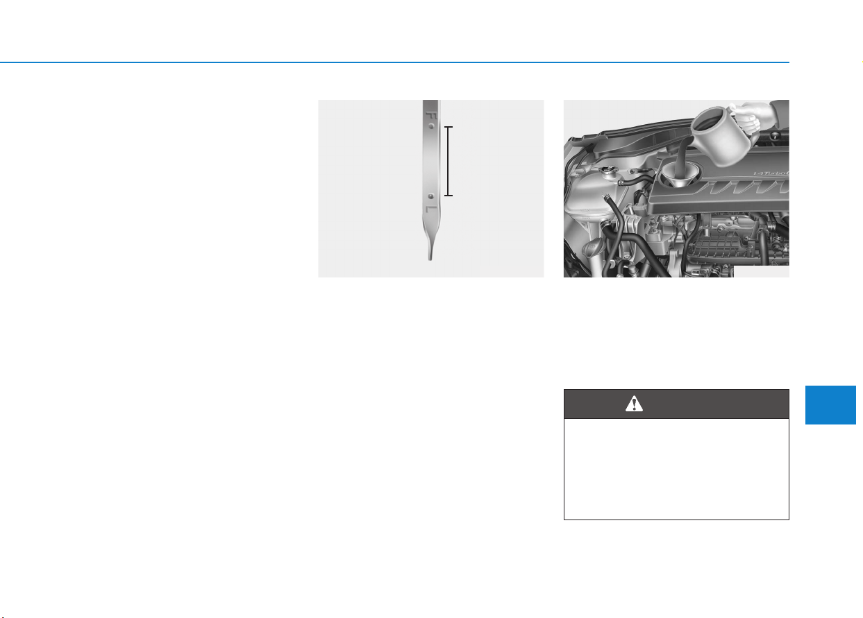
7-35
7
Maintenance
EENNGGIINNEE OOIILL
Checking the engine oil level
1. Follow all of the oil manufacturer’s
precautions.
2. Be sure the vehicle is on level
ground.
3. Start the engine and allow it to reach
normal operating temperature.
4. Turn the engine off and wait for a
few minutes (about 5 minutes) for
the oil to return to the oil pan.
5. Pull the dipstick out, wipe it clean,
and re-insert it fully.
6. Pull the dipstick out again and
check the level. The level should
be between F (Full) and L (Low).
7. If it is near or at L, add enough oil
to bring the level to F.
Use only the specified engine oil.
(Refer to “Recommended lubricants
and capacities” in chapter 8.)
OPDE076067 OPD076007
Radiator hose
Be very careful not to touch the
radiator hose when checking or
adding engine oil as it may be
hot enough to burn you.
WARNING
7-36
Maintenance
To prevent damage to your engine:
• Do not overfill with engine oil.
Add oil in small quantities and
recheck level to ensure engine
is not overfilled.
• Do not spill engine oil when
adding or changing engine oil.
Use a funnel to help prevent oil
from being spilled on engine
components. Wipe off spilled oil
immediately.
Checking the engine oil and filter
We recommend that the engine oil
and filter be replaced by an authorized
HYUNDAI dealer.
NOTICE
Used engine oil may cause irri-
tation or cancer of the skin if
left in contact with the skin for
prolonged periods of time. Used
engine oil contains chemicals
that have caused cancer in lab-
oratory animals. Always protect
your skin by washing your
hands thoroughly with soap
and warm water as soon as pos-
sible after handling used oil.
WARNING
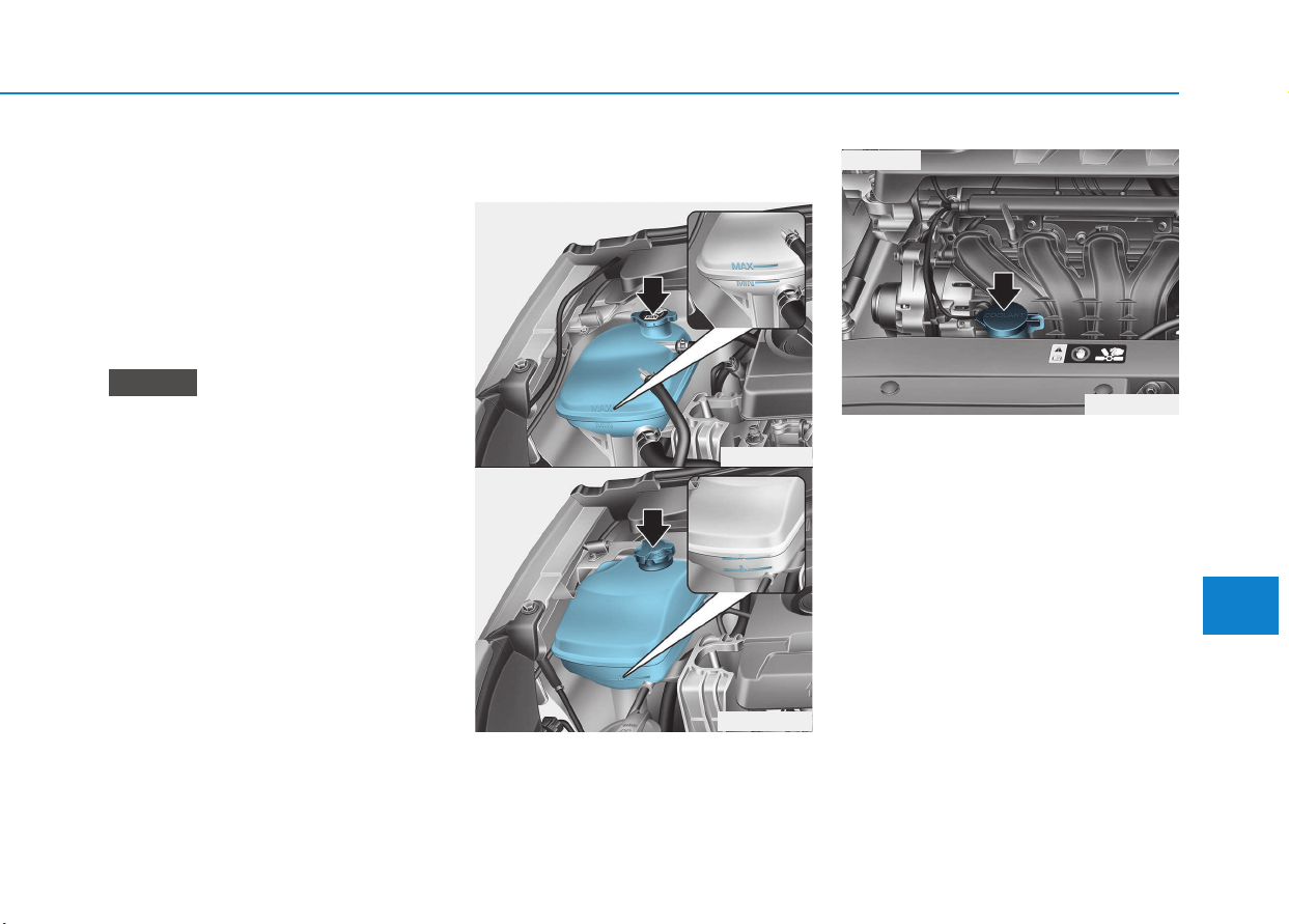
7-37
7
Maintenance
EENNGGIINNEE CCOOOOLLAANNTT
The high-pressure cooling system
has a reservoir filled with year-round
antifreeze coolant. The reservoir is
filled at the factory.
Check the antifreeze protection and
coolant concentration level at least
once a year, at the beginning of the
winter season, and before traveling
to a colder climate.
• When the engine overheats from
low engine coolant, suddenly
adding engine coolant may cause
cracks in the engine. To prevent
damage, add engine coolant
slowly in small quantities.
• Do not drive with no engine
coolant. It may cause water pump
failure and engine seizure, etc.
Checking the engine coolant
level
Check the condition and connections
of all cooling system hoses and
heater hoses. Replace any swollen
or deteriorated hoses.
The coolant level should be filled
between MAX and MIN (or F (Full)
and L (Low)) marks on the side of the
coolant reservoir when the engine is
cool.
If the coolant level is low, add enough
distilled (deionized) water. Bring the
level to MAX, (or F (Full)) but do not
overfill.
If frequent additions are required, we
recommend that the system be
inspected by an authorized HYUNDAI
dealer.
NOTICE
OPDE076068
OPDE076070
■ Type A
■ Type B
OPDE076091
■ Type C
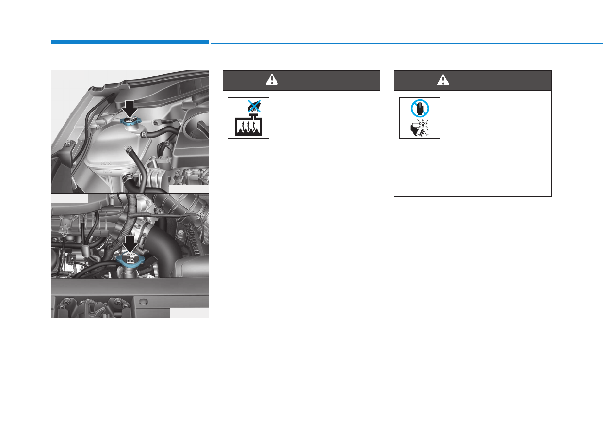
7-38
Maintenance
The electric motor for the cooling fan
is controlled by engine coolant tem-
perature, refrigerant pressure and
vehicle speed. As the engine coolant
temperature decreases, the electric
motor will automatically shut off. This
is a normal condition. If your vehicle
is equipped with GDI, the electric
motor for the cooling fan may begin
to operate at any time and continue
to operate until you disconnect the
negative battery cable.
The electric motor for
the cooling fan may
continue to operate
or start up when the
engine is not running
and can cause serious injury.
Keep hands, clothing and tools
away from the rotating fan blades
of the cooling fan.
WARNING
Never remove the
coolant cap/radiator
cap or the drain plug
while the engine and
radiator are hot. Hot
coolant and steam may blow out
under pressure, causing serious
injury.
Turn the engine off and wait until
the engine cools down. Use
extreme care when removing the
coolant cap/radiator cap. Wrap a
thick towel around it, and turn it
counterclockwise slowly to the
first stop. Step back while the
pressure is released from the
cooling system. When you are
sure all the pressure has been
released, press down on the cap,
using a thick towel, and continue
turning counterclockwise to
remove it.
WARNING
OPD076013
OPD076015
■ Type A
■ Type B

7-39
7
Maintenance
Recommended engine coolant
• When adding coolant, use only dis-
tilled (deionized) water for your
vehicle and never mix hard water in
the coolant filled at the factory. An
improper coolant mixture can
result in serious malfunction or
engine damage.
• The engine in your vehicle has alu-
minum engine parts and must be
protected by an ethylene-glycol
with phosphate based coolant to
prevent corrosion and freezing.
• DO NOT USE alcohol or methanol
coolant or mix them with the spec-
ified coolant.
• Do not use a solution that contains
more than 60% antifreeze or less
than 35% antifreeze, which would
reduce the effectiveness of the solu-
tion.
For mixture percentage, refer to the
following table.
Information
If in doubt about the mix ratio, a 50%
water and 50% antifreeze mix is the
easiest to mix together as it will be the
same quantity of each. It is suitable to
use for most temperature ranges of
-35°C (-31°F) and higher.
Changing the engine coolant
We recommend that coolant be
changed by an authorized HYUNDAI
dealer according to the Maintenance
Schedule at the beginning of this
chapter.
To prevent damage to engine parts,
put a thick towel around the radia-
tor cap and/or radiator cap before
refilling the coolant to prevent the
coolant from overflowing into
engine parts, such as the genera-
tor.
NOTICE
i
Ambient
Temperature
Mixture Percentage
(volume)
Antifreeze Water
-15°C (5°F) 35 65
-25°C (-13°F) 40 60
-35°C (-31°F) 50 50
-45°C (-49°F) 60 40
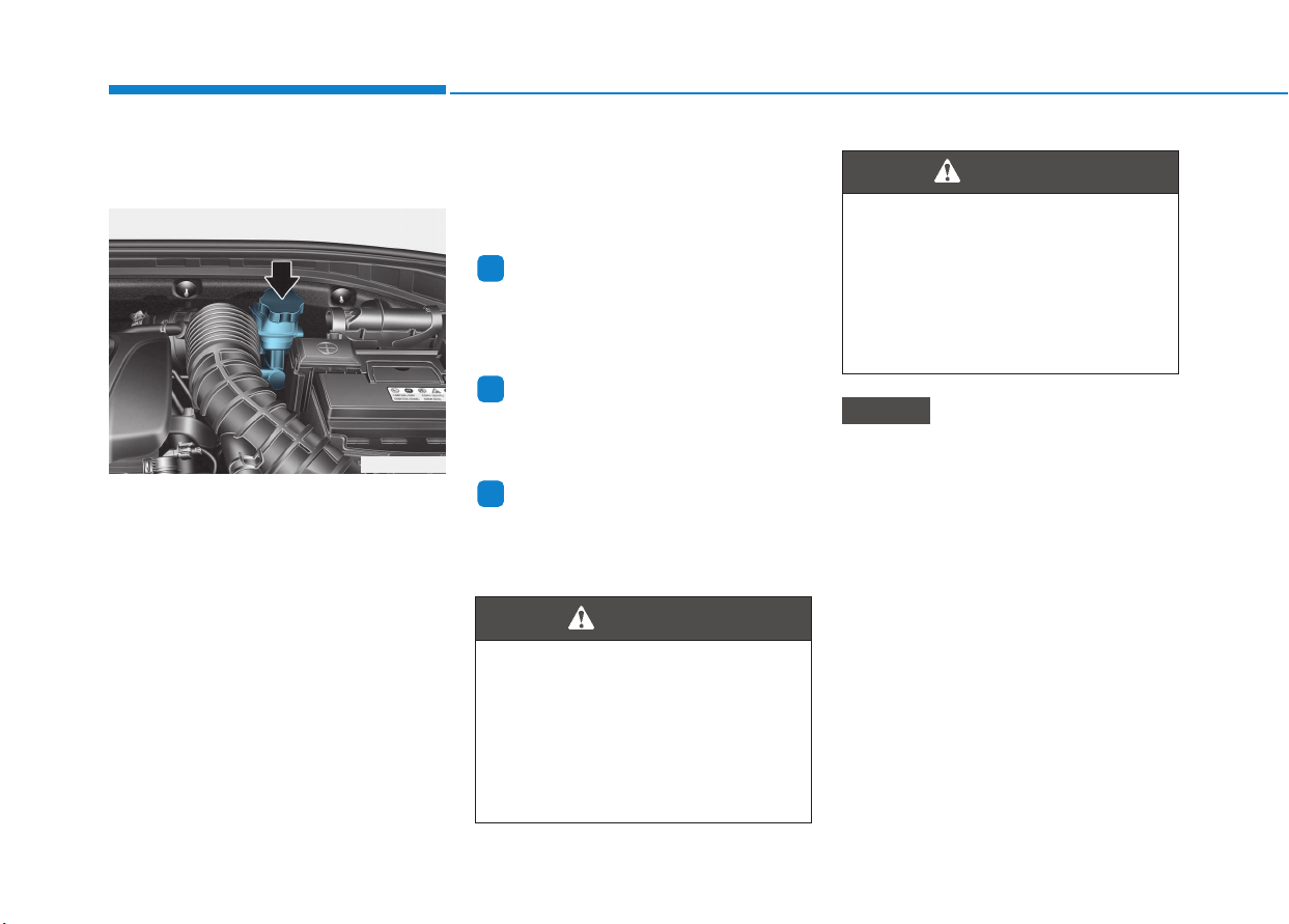
BBRRAAKKEE//CCLLUUTTCCHH FFLLUUIIDD ((IIFF EEQQUUIIPPPPEEDD))
Checking the brake/clutch
fluid level
Check the fluid level in the reservoir
periodically. The fluid level should be
between MAX and MIN marks on the
side of the reservoir.
Before removing the reservoir cap
and adding brake/clutch fluid, clean
the area around the reservoir cap
thoroughly to prevent brake/clutch
fluid contamination.
If the level is low, add fluid to the MAX
level. The level will fall with accumulat-
ed mileage. This is a normal condition
associated with the wear of the brake
linings.
If the fluid level is excessively low,
we recommend that the system be
checked by an authorized HYUNDAI
dealer.
Information
Use only the specified brake/clutch
fluid. (Refer to “Recommended lubri-
cants and capacities” in chapter 8.)
Information
Before removing the brake/clutch filler
cap, read the warning on the cap.
Information
Clean filler cap before removing. Use
only DOT3 or DOT4 brake/clutch fluid
from a sealed container.
• Do not allow brake/clutch fluid
to contact the vehicle's body
paint, as paint damage will
result.
• Brake/clutch fluid, which has
been exposed to open air for an
extended time should never be
used as its quality cannot be
guaranteed. It should be dis-
posed of properly.
• Don't put in the wrong kind of
fluid. A few drops of mineral-
based oil, such as engine oil, in
your brake/ clutch system can
damage brake/ clutch system
parts.
NOTICE
i
i
i
7-40
Maintenance
OPD076016
If the brake/clutch system
requires frequent additions of
fluid this could indicate a leak in
the brake/clutch system. We
recommend that the vehicle be
inspected by an authorized
HYUNDAI dealer.
WARNING
Do not allow brake/clutch fluid
to come in contact with your
eyes. If brake/clutch fluid comes
in contact with your eyes, flush
your eyes with clean water for at
least 15 minutes and get imme-
diate medical attention.
WARNING
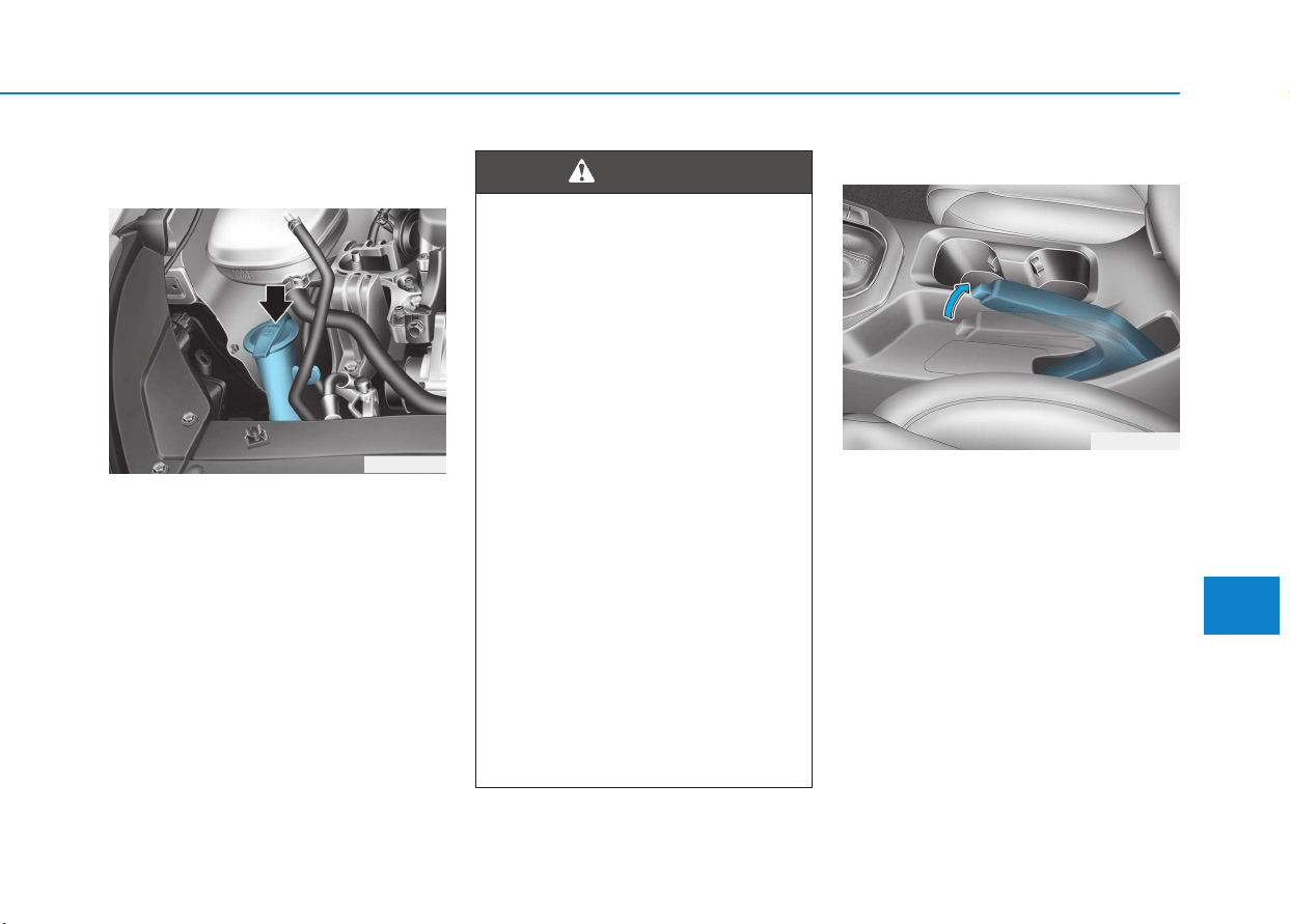
7-41
7
Maintenance
WWAASSHHEERR FFLLUUIIDD
Checking the washer fluid
level
Check the fluid level in the washer
fluid reservoir and add fluid if neces-
sary. Plain water may be used if
washer fluid is not available.
However, use washer solvent with
antifreeze characteristics in cold cli-
mates to prevent freezing.
Checking the parking brake
Check the stroke of the parking
brake by counting the number of
“clicks’’ heard while fully applying it
from the released position. Also, the
parking brake alone should securely
hold the vehicle on a fairly steep
grade. If the stroke is more or less
than specified, we recommend that
the system be serviced by an author-
ized HYUNDAI dealer.
Stroke : 5~6 “clicks’’ at a force of
20 kg (44 lbs, 196 N).
OPD076017
PPAARRKKIINNGG BBRRAAKKEE
OPD056016
To prevent serious injury or
death, take the following safety
precautions when using washer
fluid:
• Do not use engine coolant or
antifreeze in the washer fluid
reservoir. Engine coolant can
severely obscure visibility
when sprayed on the wind-
shield and may cause loss of
vehicle control resulting in an
accident or damage to paint
and body trim.
• Do not allow sparks or flame
to contact the washer fluid or
the washer fluid reservoir.
Washer fluid may contain
alcohol and can be flamma-
ble.
• Do not drink washer fluid and
avoid contact with skin.
Washer fluid is poisonous to
humans and animals.
• Keep washer fluid away from
children and animals.
WARNING
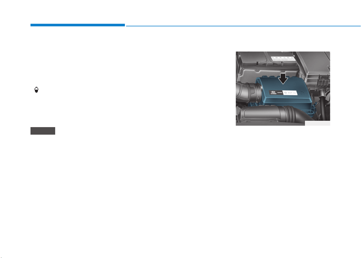
7-42
Maintenance
A
AIIRR CCLLEEAANNEERRFFUUEELL FFIILLTTEERR ((FFOORR DDIIEESSEELL))
Draining water from fuel filter
The fuel filter in the diesel engine
operates the critical function of sepa-
rating water from the fuels and accu-
mulating the water in its bottom.
When enough water is accumulated
inside the fuel filter, the warning light
( ) illuminates with the ignition
switch in the ON position.
In this case, we recommend you to
have the system checked by an
authorized HYUNDAI dealer.
When the accumulated water is not
drained at a proper timing, water
may permeate in the fuel filter,
damaging the major vehicle com-
ponents, such as the fuel system.
Fuel filter cartridge replace-
ment
We recommend the fuel filter car-
tridge be replaced by an authorized
HYUNDAI dealer according to the
Maintenance Schedule at the begin-
ning of this chapter.
Filter replacement
The air cleaner filter can be cleaned
for inspection using compressed air.
Do not attempt to wash or to rinse it,
as water will damage the filter.
If soiled, the air cleaner filter must be
replaced.
NOTICE
OPD076018
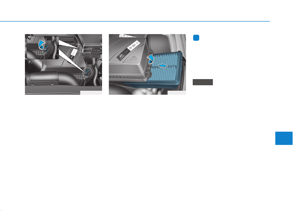
7-43
7
Maintenance
1. Loosen the air cleaner cover
attaching clips and open the cover.
2. Wipe the inside of the air cleaner.
3. Replace the air cleaner filter.
4. Lock the cover with the cover
attaching clips.
5. Check if the cover is firmly installed.
Information
If the vehicle is operated in extremely
dusty or sandy areas, replace the element
more often than the usual recommended
intervals (refer to “Maintenance Under
Severe Usage Conditions” in this chap-
ter).
• Do not drive with the air cleaner
filter removed. This will result in
excessive engine wear.
• When removing the air cleaner
filter, be careful that dust or dirt
does not enter the air intake, or
damage may result.
• Use HYUNDAI genuine parts,
use of non-genuine parts could
damage the air flow sensor.
NOTICE
i
OPDE076021 OPD076022
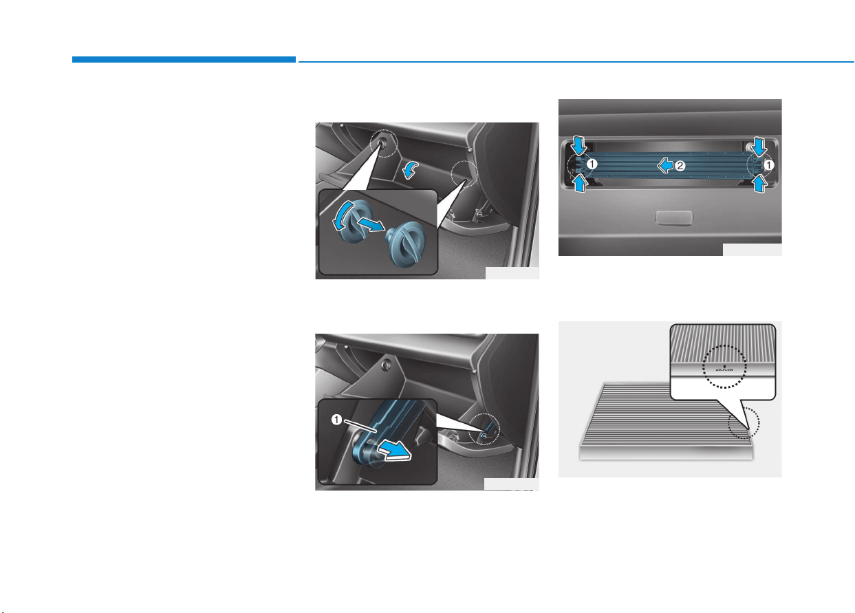
7-44
Maintenance
C
CLLIIMMAATTEE CCOONNTTRROOLL AAIIRR FFIILLTTEERR
Filter inspection
If the vehicle is operated in the
severely air-polluted cities or on
dusty rough roads for a long period,
it should be inspected more fre-
quently and replaced earlier. When
you, the owner, replace the climate
control air filter, replace it performing
the following procedure, and be care-
ful to avoid damaging other compo-
nents.
Replace the filter according to the
Maintenance Schedule.
Filter replacement
1. With the glove box open, remove
the stoppers on both sides.
2. Remove the support strap (1).
3. Press and hold the lock (1) on both
sides of the cover.
4. Pull out the cover (2).
5. Replace the climate control air filter.
6. Reassemble in the reverse order
of disassembly.
OPD076024
OPD076023
OPD076025
OPD076026

7-45
7
Maintenance
Install a new climate control air filter
in the correct direction with the
arrow symbol(
↓
↓
) facing downwards.
Otherwise, the climate control effects
may decrease, possibly with a noise.
Blade inspection
Contamination of either the wind-
shield or the wiper blades with for-
eign matter can reduce the effective-
ness of the windshield wipers.
Common sources of contamination
are insects, tree sap, and hot wax
treatments used by some commer-
cial car washes. If the blades are not
wiping properly, clean both the win-
dow and the blades with a good
cleaner or mild detergent, and rinse
thoroughly with clean water.
To prevent damage to the wiper
blades, arms or other compo-
nents, do not:
• Use gasoline, kerosene, paint
thinner, or other solvents on or
near them.
• Attempt to move the wipers
manually.
• Use non-specified wiper blades.
Information
Commercial hot waxes applied by
automatic car washes have been
known to make the windshield diffi-
cult to clean.
Information
Wiper blades are consumable item and
normal wear of the wipers may not be
covered by your vehicle warranty.
i
i
NOTICENOTICE
WWIIPPEERR BBLLAADDEESS
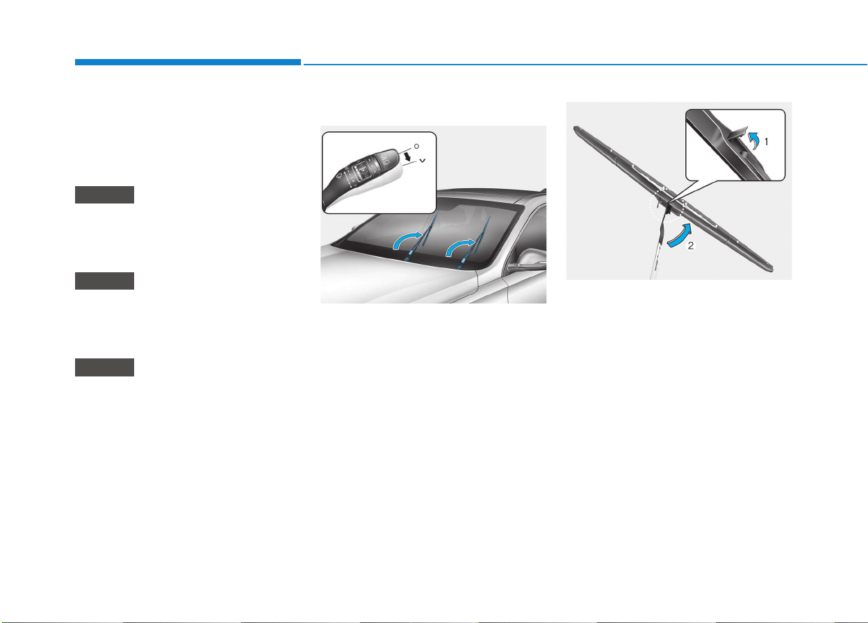
7-46
Maintenance
Blade replacement
When the wipers no longer clean
adequately, the blades may be worn
or cracked, and require replacement.
To prevent damage to the wiper arms
or other components, do not attempt
to move the wipers manually.
The use of a non-specified wiper
blade could result in wiper mal-
function and failure.
• In order to prevent damage to
the hood and the wiper arms, the
wiper arms should only be lifted
when in the fully up position.
• Always return the wiper arms to
the windshield before starting
your journey
Front windshield wiper blade
To replace a wiper blade, follow the
procedure mentioned to raise the
wiper arm.
Turn off the engine, move the wiper
switch to the single wiping (V) posi-
tion within 20 seconds and hold the
switch for more than 2 seconds until
the wiper arm is in the fully up posi-
tion.
1. Lift up the wiper blade clip (1).
Then lift up the wiper blade (2).
NOTICE
NOTICE
NOTICE
OPDE076027
OAD075074L
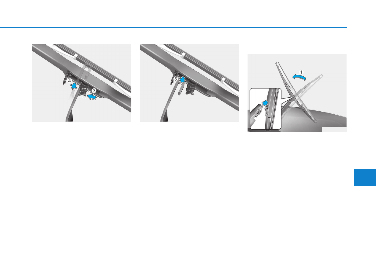
7-47
7
Maintenance
2. While pushing the lock (3), pull
down the wiper blade (4).
3. Remove the wiper blade from the
wiper arm (5).
4. Install a new wiper blade assem-
bly in the reverse order of removal.
5. Return the wiper arm on the wind-
shield.
Rear window wiper blade
1. Raise the wiper arm and pull out
the wiper blade assembly.
OAD075075L OAD075076L
OTL075050
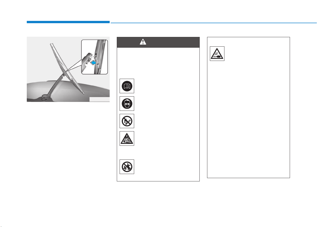
7-48
Maintenance
B
BAATTTTEERRYY
2. Install the new blade assembly by
inserting the center part into the
slot in the wiper arm until it clicks
into place.
3. Make sure the blade assembly is
installed firmly by trying to pull it
slightly.
To prevent damage to the wiper arms
or other components, we recommend
that the wiper blade be replaced by an
authorized HYUNDAI dealer.
OTL075051
To prevent SERIOUS INJURY or
DEATH to you or bystanders,
always follow these precautions
when working near or handling
the battery:
Always read and follow
instructions carefully
when handling a battery.
Wear eye protection
designed to protect the
eyes from acid splashes.
Keep all flames, sparks,
or smoking materials
away from the battery.
Hydrogen is always
present in battery cells,
is highly combustible,
and may explode if ignit-
ed.
Keep batteries out of
reach of children.
(Continued)
WARNING
(Continued)
Batteries contain sulfu-
ric acid which is highly
corrosive. Do not allow
acid to contact your
eyes, skin or clothing.
If acid gets into your eyes, flush
your eyes with clean water for at
least 15 minutes and get imme-
diate medical attention. If acid
gets on your skin, thoroughly
wash the area. If you feel pain or
a burning sensation, get med-
ical attention immediately.
• When lifting a plastic-cased
battery, excessive pressure
on the case may cause battery
acid to leak. Lift with a battery
carrier or with your hands on
opposite corners.
• Do not attempt to jump start
your vehicle if your battery is
frozen.
(Continued)
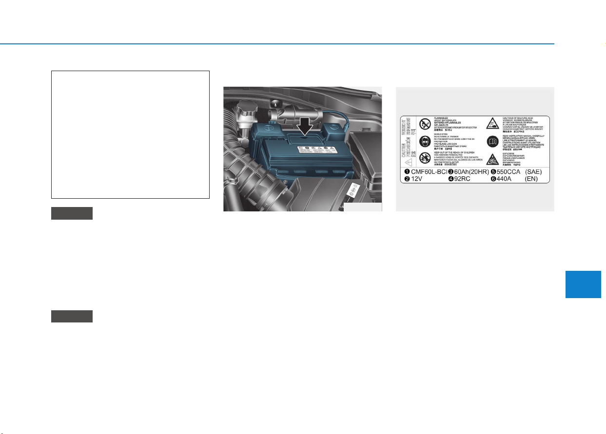
7-49
7
Maintenance
• When you do not use the vehicle
for a long time in a low tempera-
ture area, disconnect the battery
and keep it indoors.
• Always charge the battery fully
to prevent battery case damage
in low temperature areas.
If you connect unauthorized elec-
tronic devices to the battery, the
battery may be discharged. Never
use unauthorized devices.
For best battery service
• Keep the battery securely mounted.
• Keep the battery top clean and dry.
• Keep the terminals and connec-
tions clean, tight, and coated with
petroleum jelly or terminal grease.
• Rinse any spilled electrolyte from
the battery immediately with a
solution of water and baking soda.
• If the vehicle is not going to be
used for an extended time, discon-
nect the battery cables.
Battery capacity label
The actual battery label in the vehicle
may differ from the illustration.
1. CMF60L-BCI : The HYUNDAI
model name of battery
2. 12V : The nominal voltage
3. 60Ah(20HR) : The nominal capacity
(in Ampere hours)
4. 92RC : The nominal reserve capac-
ity (in min.)
5. 550CCA : The cold-test current in
amperes by SAE
6. 440A : The cold-test current in
amperes by EN
NOTICE
NOTICE
OPD076028
(Continued)
• NEVER attempt to recharge
the battery when the vehicle’s
battery cables are connected
to the battery.
• The electrical ignition system
works with high voltage.
NEVER touch these compo-
nents with the engine running
or when the ignition switch is
in the ON position.
OLMB073072
■ Example
7-50
Maintenance
Battery recharging
By battery charger
Your vehicle has a maintenance-free,
calcium-based battery.
• If the battery becomes discharged
in a short time (because, for exam-
ple, the headlights or interior lights
were left on while the vehicle was
not in use), recharge it by slow
charging (trickle) for 10 hours.
• If the battery gradually discharges
because of high electric load while
the vehicle is being used, recharge
it at 20-30A for two hours.
Always follow these instructions
when recharging your vehicle’s
battery to avoid the risk of SERI-
OUS INJURY or DEATH from
explosions or acid burns:
• Before performing mainte-
nance or recharging the bat-
tery, turn off all accessories
and place the Engine Start/
Stop button to the OFF posi-
tion.
• Keep all flames, sparks, or
smoking materials away from
the battery.
• Always work outdoors or in an
area with plenty of ventilation.
• Wear eye protection when
checking the battery during
charging.
• The battery must be removed
from the vehicle and placed in
a well ventilated area.
(Continued)
WARNING
(Continued)
• Watch the battery during
charging, and stop or reduce
the charging rate if the battery
cells begin boiling violently.
• The negative battery cable
must be removed first and
installed last when the battery
is disconnected. Disconnect
the battery charger in the fol-
lowing order:
(1) Turn off the battery charger
main switch.
(2) Unhook the negative
clamp from the negative
battery terminal.
(3) Unhook the positive clamp
from the positive battery
terminal.
•
Always use a genuine HYUNDAI
approved battery when you
replace the battery.
7-51
7
Maintenance
By jump starting
After a jump start from a good bat-
tery, drive the vehicle for 20-30 min-
utes before it is shutoff. The vehicle
may not restart if you shut it off
before the battery had a chance to
adequately recharge. See “Jump
Starting” in chapter 6 for more infor-
mation on jump starting procedures.
Information
An inappropriately disposed
battery can be harmful to
the environment and human
health.
Dispose the battery according to your
local law(s) or regulation.
Reset items
Items should be reset after the bat-
tery has been discharged or the bat-
tery has been disconnected.
• Auto up/down window
• Sunroof
• Trip computer
• Climate control system
• Driver position memory system
• Clock
• Audio system
i
AGM battery (if equipped)
• Absorbent Glass Matt (AGM)
batteries are maintenance-
free and we recommend that
the AGM battery be serviced
by an authorized HYUNDAI
dealer. For charging your
AGM battery, use only fully
automatic battery chargers
that are specially developed
for AGM batteries.
• When replacing the AGM bat-
tery, we recommend that you
use parts for replacement
from an authorized HYUNDAI
dealer.
• Do not open or remove the
cap on top of the battery. This
may cause leaks of internal
electrolyte that could result in
severe injury.
CAUTION
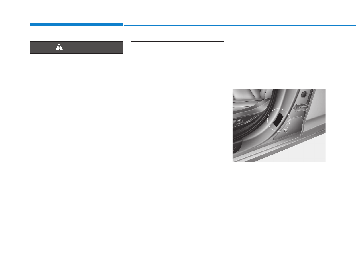
7-52
Maintenance
T
TIIRREESS AANNDD WWHHEEEELLSS
Tire care
For proper maintenance, safety, and
maximum fuel economy, you must
always maintain recommended tire
inflation pressures and stay within the
load limits and weight distribution rec-
ommended for your vehicle.
All specifications (sizes and pressures)
can be found on a label attached to the
driver’s side center pillar.
(Continued)
• Replace tires that are worn,
show uneven wear, or are dam-
aged. Worn tires can cause
loss of braking effectiveness,
steering) control, or traction.
• ALWAYS replace tires with the
same size as each tire that
was originally supplied with
this vehicle. Using tires and
wheels other than the recom-
mended sizes could cause
unusual handling characteris-
tics, poor vehicle control, or
negatively affect your vehi-
cle’s Anti-Lock Brake System
(ABS) resulting in a serious
accident.
Tire failure may cause loss of
vehicle control resulting in an
accident. To reduce risk of
SERIOUS INJURY or DEATH,
take the following precautions:
• Inspect your tires monthly for
proper inflation as well as
wear and damage.
• The recommended cold tire
pressure for your vehicle can
be found in this manual and on
the tire label located on the dri-
ver’s side center pillar. Always
use a tire pressure gauge to
measure tire pressure. Tires
with too much or too little
pressure wear unevenly caus-
ing poor handling.
• Check the pressure of the
spare every time you check
the pressure of the other tires
on your vehicle.
(Continued)
WARNING
OPD086007
7-53
7
Maintenance
Recommended cold tire infla-
tion pressures
All tire pressures (including the
spare) should be checked when the
tires are cold. “Cold tires” means the
vehicle has not been driven for at
least three hours or driven less than
1.6 km (one mile).
Warm tires normally exceed recom-
mended cold tire pressures by 28 to
41 kPa (4 to 6 psi). Do not release air
from warm tires to adjust the pres-
sure or the tires will be under-inflat-
ed. For recommended inflation pres-
sure, refer to “Tire and Wheels” in
chapter 8.
Recommended pressures must
be maintained for the best ride,
vehicle handling, and minimum
tire wear.
Over-inflation or under-inflation
can reduce tire life, adversely
affect vehicle handling, and
lead to sudden tire failure that
could result in loss of vehicle
control resulting in an accident.
Severe under-inflation can lead
to severe heat build-up, causing
blowouts, tread separation and
other tire failures that can result
in the loss of vehicle control
resulting in an accident. This
risk is much higher on hot days
and when driving for long peri-
ods at high speeds.
WARNING
• Under-inflation results in
excessive wear, poor handling
and reduced fuel economy.
Wheel deformation is also
possible. Keep your tire pres-
sures at the proper levels. If a
tire frequently needs refilling,
we recommend it be checked
by an authorized HYUNDAI
dealer.
• Over-inflation produces a
harsh ride, excessive wear at
the center of the tire tread,
and a greater possibility of
damage from road hazards.
CAUTION

7-54
Maintenance
Check tire inflation pressure
Check your tires, including the spare
tire, once a month or more.
How to check
Use a good quality tire pressure
gauge to check tire pressure. You
can not tell if your tires are properly
inflated simply by looking at them.
Radial tires may look properly inflat-
ed when they are under-inflated.
Remove the valve cap from the tire
valve stem. Press the tire gauge firm-
ly onto the valve to get a pressure
measurement. If the cold tire inflation
pressure matches the recommended
pressure on the tire and loading
information label, no further adjust-
ment is necessary. If the pressure is
low, add air until you reach the rec-
ommended pressure. Make sure to
put the valve caps back on the valve
stems. Without the valve cap, dirt or
moisture could get into the valve
core and cause air leakage. If a valve
cap is missing, install a new one as
soon as possible.
If you overfill the tire, release air by
pushing on the metal stem in the
center of the tire valve. Recheck the
tire pressure with the tire gauge. Be
sure to put the valve caps back on
the valve stems. Without the valve
cap, dirt or moisture could get into
the valve core and cause air leakage.
If a valve cap is missing, install a new
one as soon as possible.
Tire rotation
To equalize tread wear, HYUNDAI
recommends that the tires be rotated
every 12,000 km (7,500 miles) or
sooner if irregular wear develops.
During rotation, check the tires for
correct balance.
When rotating tires, check for uneven
wear and damage. Abnormal wear is
usually caused by incorrect tire pres-
sure, improper wheel alignment, out-
of-balance wheels, severe braking or
severe cornering. Look for bumps or
bulges in the tread or side of tire.
Replace the tire if you find either of
these conditions. Replace the tire if
fabric or cord is visible. After rotation,
be sure to bring the front and rear tire
pressures to specification and check
lug nut tightness (proper torque is
11~13 kgf·m [79~94 lbf·ft]).
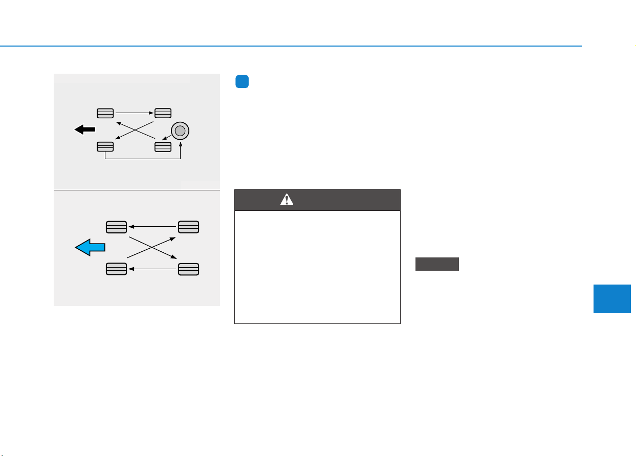
7-55
7
Maintenance
Disc brake pads should be inspected
for wear whenever tires are rotated.
Information
The outside and inside of the unsym-
metrical tire is distinguishable. When
installing an unsymmetrical tire, be
sure to install the side marked "out-
side" face the outside. If the side
marked "inside" is installed on the
outside, it will have a bad effect on
vehicle performance.
Wheel alignment and tire bal-
ance
The wheels on your vehicle were
aligned and balanced carefully at the
factory to give you the longest tire life
and best overall performance.
In most cases, you will not need to
have your wheels aligned again.
However, if you notice unusual tire
wear or your vehicle pulling one way
or the other, the alignment may need
to be reset.
If you notice your vehicle vibrating
when driving on a smooth road, your
wheels may need to be rebalanced.
Improper wheel weights can dam-
age your vehicle’s aluminum
wheels. Use only approved wheel
weights.
NOTICE
i
CBGQ0706
ODH073802
■ With a full-size spare tire (if equipped)
■ Without a spare tire
• Do not use the compact spare
tire for tire rotation.
• Do not mix bias ply and radial
ply tires under any circum-
stances. This may cause
unusual handling characteris-
tics that may cause loss of
vehicle control resulting in an
accident.
WARNING
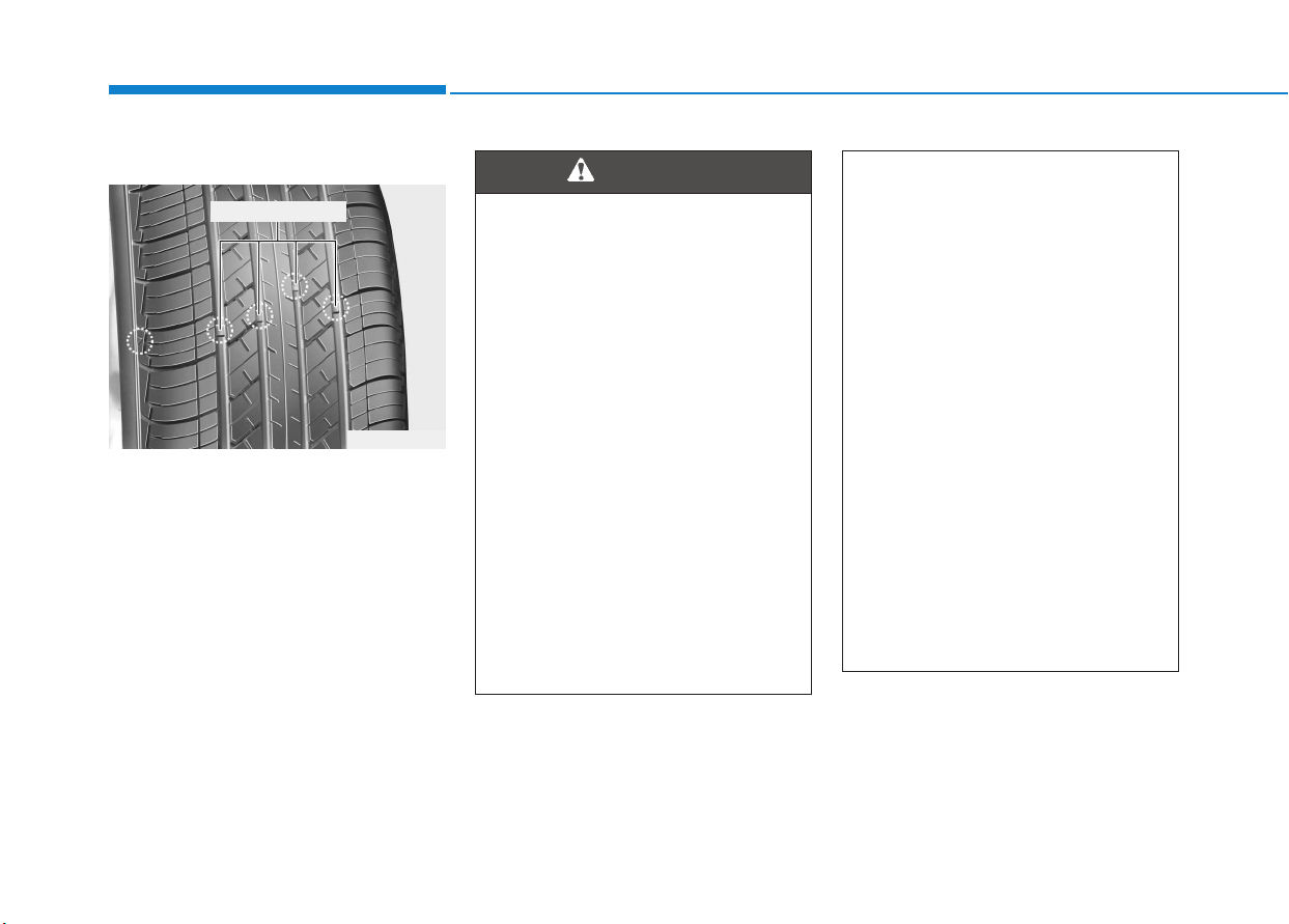
7-56
Maintenance
Tire replacement
If the tire is worn evenly, a tread wear
indicator will appear as a solid band
across the tread. This shows there is
less than 1.6 mm (1/16 in.) of tread
left on the tire. Replace the tire when
this happens.
Do not wait for the band to appear
across the entire tread before replac-
ing the tire.
OLMB073027
Tread wear indicator
To reduce the risk of DEATH or
SERIOUS INJURY:
• Replace tires that are worn,
show uneven wear, or are
damaged. Worn tires can
cause loss of braking effec-
tiveness, steering control, and
traction.
• Always replace tires with the
same size as each tire that
was originally supplied with
this vehicle. Using tires and
wheels other than the recom-
mended sizes could cause
unusual handling characteris-
tics, poor vehicle control, or
negatively affect your vehi-
cle’s Anti-Lock Brake System
(ABS) resulting in a serious
accident.
(Continued)
WARNING
(Continued)
• When replacing tires (or
wheels), it is recommended to
replace the two front or two
rear tires (or wheels) as a pair.
Replacing just one tire can
seriously affect your vehicle’s
handling.
• Tires degrade over time, even
when they are not being used.
Regardless of the remaining
tread, HYUNDAI recommends
that tires be replaced after six
(6) years of normal service.
• Heat caused by hot climates or
frequent high loading condi-
tions can accelerate the aging
process. Failure to follow this
warning may cause sudden
tire failure, which could lead to
a loss of vehicle control result-
ing in an accident.

7-57
7
Maintenance
Compact spare tire replacement
(if equipped)
A compact spare tire has a shorter
tread life than a regular size tire.
Replace it when you can see the
tread wear indicator bars on the tire.
The replacement compact spare tire
should be the same size and design
tire as the one provided with your
new vehicle and should be mounted
on the same compact spare tire
wheel. The compact spare tire is not
designed to be mounted on a regular
size wheel, and the compact spare
tire wheel is not designed for mount-
ing a regular size tire.
Wheel replacement
When replacing the metal wheels for
any reason, make sure the new
wheels are equivalent to the original
factory units in diameter, rim width
and offset.
Tire traction
Tire traction can be reduced if you
drive on worn tires, tires that are
improperly inflated or on slippery
road surfaces. Tires should be
replaced when tread wear indicators
appear. To reduce the possibility of
losing control, slow down whenever
there is rain, snow or ice on the road.
Tire maintenance
In addition to proper inflation, correct
wheel alignment helps to decrease
tire wear. If you find a tire is worn
unevenly, have your dealer check the
wheel alignment.
When you have new tires installed,
make sure they are balanced. This
will increase vehicle ride comfort and
tire life. Additionally, a tire should
always be rebalanced if it is removed
from the wheel.
Tire sidewall labeling
This information identifies and
describes the fundamental charac-
teristics of the tire and also provides
the tire identification number (TIN)
for safety standard certification. The
TIN can be used to identify the tire in
case of a recall.
The original tire should be
repaired or replaced as soon as
possible to avoid failure of the
spare and loss of vehicle control
resulting in an accident.The com-
pact spare tire is for emergency
use only. Do not operate your
vehicle over 80 km/h (50 mph)
when using the compact spare
tire.
WARNING
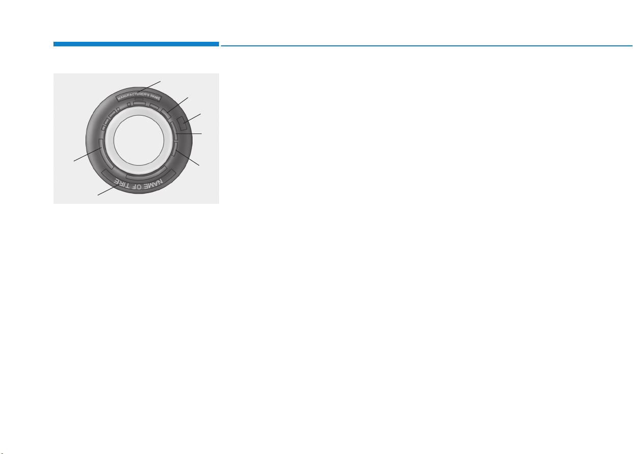
7-58
Maintenance
1. Manufacturer or brand name
Manufacturer or brand name is
shown.
2. Tire size designation
A tire’s sidewall is marked with a tire
size designation. You will need this
information when selecting replace-
ment tires for your car. The following
explains what the letters and num-
bers in the tire size designation
mean.
Example tire size designation:
(These numbers are provided as an
example only; your tire size designa-
tor could vary depending on your
vehicle.)
205/55R16 91H
205 - Tire width in millimeters.
55 - Aspect ratio. The tire’s section
height as a percentage of its
width.
R - Tire construction code (Radial).
16 - Rim diameter in inches.
91 - Load Index, a numerical code
associated with the maximum
load the tire can carry.
H - Speed Rating Symbol. See the
speed rating chart in this section
for additional information.
Wheel size designation
Wheels are also marked with impor-
tant information that you need if you
ever have to replace one. The follow-
ing explains what the letters and
numbers in the wheel size designa-
tion mean.
Example wheel size designation:
6.5JX16
6.5 - Rim width in inches.
J - Rim contour designation.
16 - Rim diameter in inches.
OLMB073028
1
1
2
3
4
5,6
7

7-59
7
Maintenance
Tire speed ratings
The chart below lists many of the dif-
ferent speed ratings currently being
used for passenger car tires. The
speed rating is part of the tire size
designation on the sidewall of the
tire. This symbol corresponds to that
tire’s designed maximum safe oper-
ating speed.
3. Checking tire life (TIN : Tire
Identification Number)
Any tires that are over six years old,
based on the manufacturing date,
(including the spare tire) should be
replaced by new ones. You can find
the manufacturing date on the tire
sidewall (possibly on the inside of the
wheel), displaying the DOT Code.
The DOT Code is a series of num-
bers on a tire consisting of numbers
and English letters. The manufactur-
ing date is designated by the last four
digits (characters) of the DOT code.
DOT : XXXX XXXX OOOO
The front part of the DOT means a
plant code number, tire size and
tread pattern and the last four num-
bers indicate week and year manu-
factured.
For example:
DOT XXXX XXXX 1516 represents
that the tire was produced in the 15th
week of 2016.
4. Tire ply composition and
material
The number of layers or plies of rub-
ber-coated fabric in the tire. Tire
manufacturers also must indicate the
materials in the tire, which include
steel, nylon, polyester, and others.
The letter "R" means radial ply con-
struction; the letter "D“ means diago-
nal or bias ply construction; and the
letter "B" means belted-bias ply con-
struction.
5. Maximum permissible infla-
tion pressure
This number is the greatest amount
of air pressure that should be put in
the tire. Do not exceed the maximum
permissible inflation pressure. Refer
to the Tire and Loading Information
label for recommended inflation
pressure.
Speed
Rating
Symbol
Maximum Speed
S 180 km/h (112 mph)
T 190 km/h (118 mph)
H 210 km/h (130 mph)
V 240 km/h (149 mph)
W 270km/h (168mph)
Y 300km/h (186mph)

7-60
Maintenance
6. Maximum load rating
This number indicates the maximum
load in kilograms and pounds that
can be carried by the tire. When
replacing the tires on the vehicle,
always use a tire that has the same
load rating as the factory installed
tire.
7. Uniform tire quality grading
Quality grades can be found where
applicable on the tire sidewall
between tread shoulder and maxi-
mum section width.
For example:
TREAD wear 200
TRACTION AA
TEMPERATURE A
Tread wear
The tread wear grade is a compara-
tive rating based on the wear rate of
the tire when tested under controlled
conditions on a specified govern-
ment test course. For example, a tire
graded 150 would wear one-and-a-
half times (1½) as well on the gov-
ernment course as a tire graded 100.
The relative performance of tires
depends upon the actual conditions
of their use, however, and may
depart significantly from the norm
due to variations in driving habits,
service practices and differences in
road characteristics and climate.
These grades are molded on the
sidewalls of passenger vehicle tires.
The tires available as standard or
optional equipment on your vehicle
may vary with respect to grade.
Traction - AA, A, B & C
The traction grades, from highest to
lowest, are AA, A, B and C. Those
grades represent the tire’s ability to
stop on wet pavement as measured
under controlled conditions on spec-
ified government test surfaces of
asphalt and concrete. A tire marked
C may have poor traction perform-
ance.
The traction grade assigned to
this tire is based on straight-
ahead braking traction tests,
and does not include accelera-
tion, cornering, hydroplaning,
or peak traction characteristics.
WARNING

7-61
7
Maintenance
Temperature - A, B & C
The temperature grades are A (the
highest), B and C representing the
tire’s resistance to the generation of
heat and its ability to dissipate heat
when tested under controlled condi-
tions on a specified indoor laboratory
test wheel.
Sustained high temperature can
cause the material of the tire to
degenerate and reduce tire life, and
excessive temperature can lead to
sudden tire failure. Grades B and A
represent higher levels of perform-
ance on the laboratory test wheel
than the minimum required by law.
Low aspect ratio tires
A low aspect ratio tire, of which the
aspect ratio is lower than 50, is
designed for a sporty-look vehicle.
The low aspect ratio is to optimize
handling and braking. Thus, it may
be uncomfortable to ride and it may
generate noises, in comparison with
a normal tire.
The temperature grade for this
tire is established for a tire that
is properly inflated and not
overloaded. Excessive speed,
under-inflation, over-inflation,
or excessive loading, either
separately or in combination,
can cause heat build-up and
possible sudden tire failure.
This may cause loss of vehicle
control resulting in an accident.
WARNING
The side wall of a low aspect
ratio tire is shorter than the nor-
mal one. Thus, the low-aspect
wheel and tire are easily dam-
aged. Follow the below instruc-
tions.
• When driving on a rough road
or driving off a road, be care-
ful not to damage the tires
and wheels. After driving,
inspect the tires and wheels.
• When passing over a pothole,
speed bump, manhole, or
curb stone, slowly drive the
vehicle not to damage the
tires and wheels.
(Continued)
CAUTION
(Continued)
• When there is an impact on a
tire, inspect the tire condition.
Or, contact an authorized
HYUNDAI dealer.
• Inspect the tire condition and
pressure every 3,000 km
(1,800 miles) to prevent a tire
damage.
• It is difficult to recognize a tire
damage only with your eyes.
When there is a slight hint of a
tire damage, check and replace
the tire to prevent the damage
caused by air leakage.
• When a tire is damaged while
driving on a rough road, off a
road, or over obstacles, such
as a pothole, manhole, or curb
stone, your warranty does not
cover the damage.
• The tire information is speci-
fied on the tire side wall.
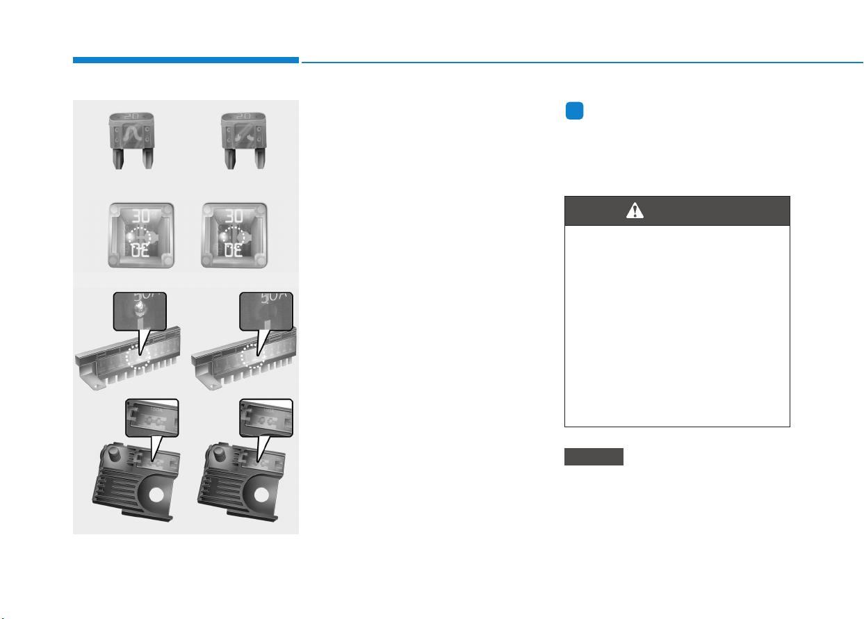
7-62
Maintenance
F
FUUSSEESS
A vehicle’s electrical system is pro-
tected from electrical overload dam-
age by fuses.
This vehicle has 2 (or 3) fuse panels,
one located in the driver’s side panel
bolster, the other in the engine com-
partment.
If any of your vehicle’s lights, acces-
sories, or controls do not work, check
the appropriate circuit fuse. If a fuse
has blown, the element inside the
fuse will be melted or broken.
If the electrical system does not
work, first check the driver’s side
fuse panel. Before replacing a blown
fuse, turn the engine and all switches
off, and then disconnect the negative
battery cable. Always replace a
blown fuse with one of the same rat-
ing.
If the replacement fuse blows, this indi-
cates an electrical problem. Avoid
using the system involved and immedi-
ately consult an authorized HYUNDAI
dealer.
Information
Three kinds of fuses are used: blade
type for lower amperage rating, car-
tridge type, and multi fuse for higher
amperage ratings.
Do not use a screwdriver or any
other metal object to remove
fuses because it may cause a
short circuit and damage the sys-
tem.
NOTICE
i
Normal
■ Blade type
■ Cartridge type
Blown
Normal
Blown
Normal
Blown
OLF074075
NEVER replace a fuse with any-
thing but another fuse of the
same rating.
• A higher capacity fuse could
cause damage and possibly
cause a fire.
• Do not install a wire or alu-
minum foil instead of the
proper fuse - even as a tem-
porary repair. It may cause
extensive wiring damage and
possibly a fire.
WARNING
Normal
Blown
■ Multi fuse
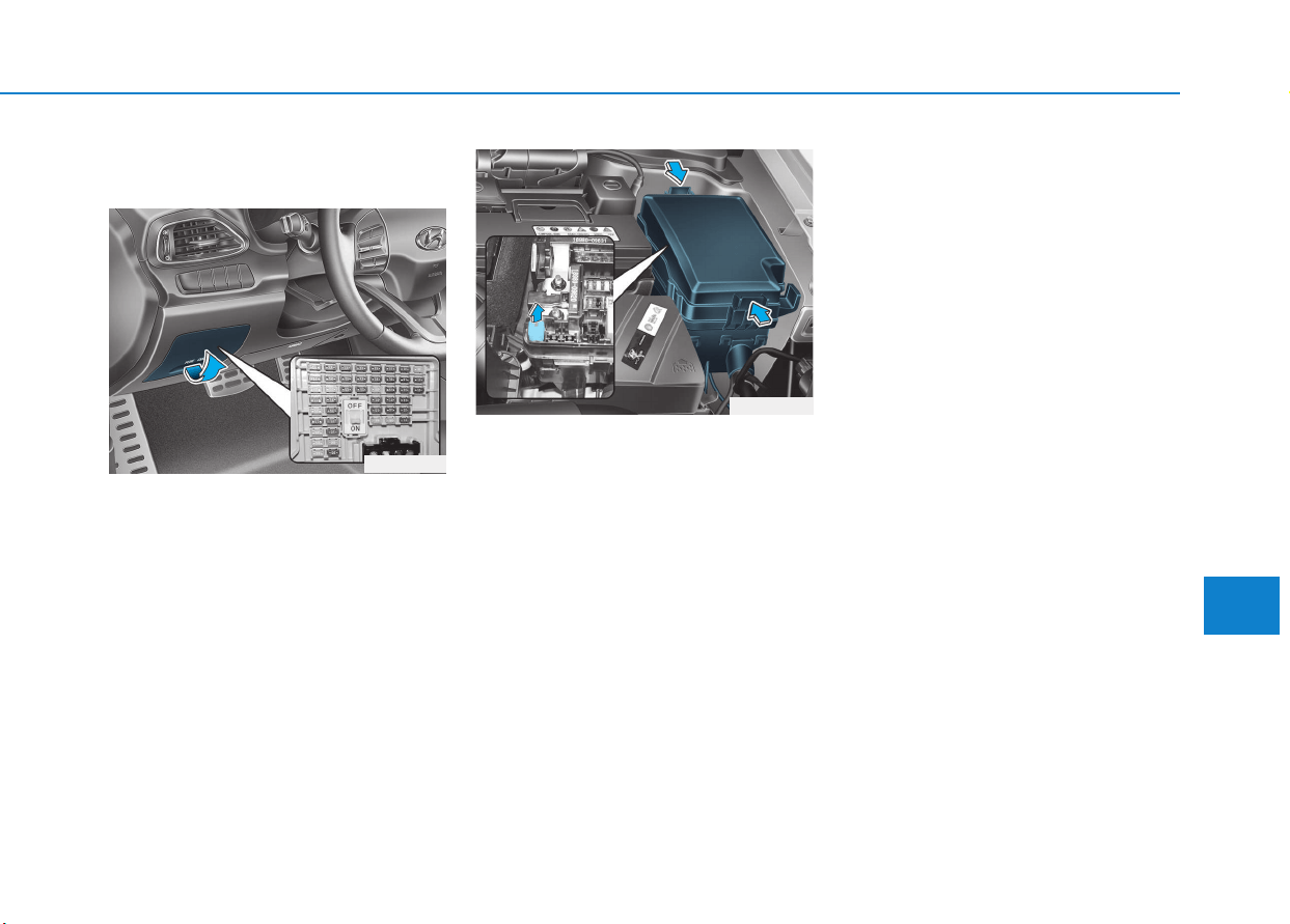
7-63
7
Maintenance
Instrument panel fuse replace-
ment
1. Turn the vehicle off.
2. Turn all other switches OFF.
3. Open the fuse panel cover.
4. Refer to the label on the inside of
the fuse panel cover to locate the
suspected fuse location.
5. Pull the suspected fuse straight
out. Use the removal tool provided
in the engine compartment fuses
panel.
6. Check the removed fuse; replace it
if it is blown. Spare fuses are pro-
vided in the instrument panel fuse
panels (or in the engine compart-
ment fuse panel).
7. Push in a new fuse of the same
rating, and make sure it fits tightly
in the clips. If it fits loosely, consult
an authorized HYUNDAI dealer.
In an emergency, if you do not have
a spare fuse, use a fuse of the same
rating from a circuit you may not
need for operating the vehicle, such
as the cigarette lighter fuse.
If the headlamps or other electrical
components do not work and the
fuses are OK, check the fuse panel
in the engine compartment. If a fuse
is blown, it must be replaced with the
same rating.
OPD076034
OPD076035
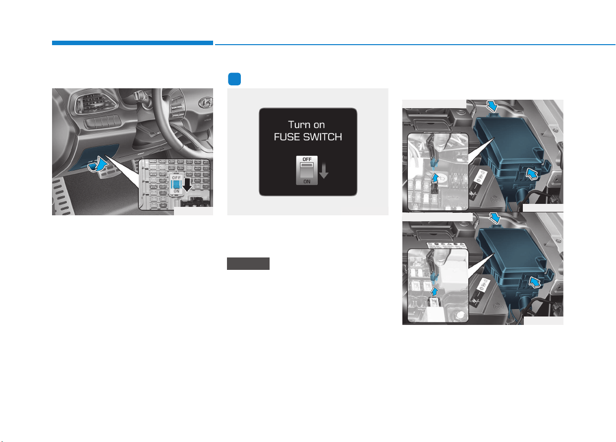
7-64
Maintenance
Fuse switch
Always, place the fuse switch to the
ON position.
If you move the switch to the OFF
position, some items such as the
audio system and digital clock must
be reset and the smart key may not
work properly.
Information
If the fuse switch is OFF, “Turn on
FUSE SWITCH” message will appear.
• Always place the fuse switch in
the ON position while driving the
vehicle.
• Do not move the transportation
fuse switch repeatedly. The fuse
switch may be damaged.
Engine compartment panel
fuse replacement
1. Turn the vehicle off.
2. Turn all other switches OFF.
3. Remove the fuse panel cover by
pressing the tap and pulling up.
NOTICE
i
OPD076036 OPDE046119
OPD076032
OPD076033
■ Blade type fuse
■ Cartridge type fuse
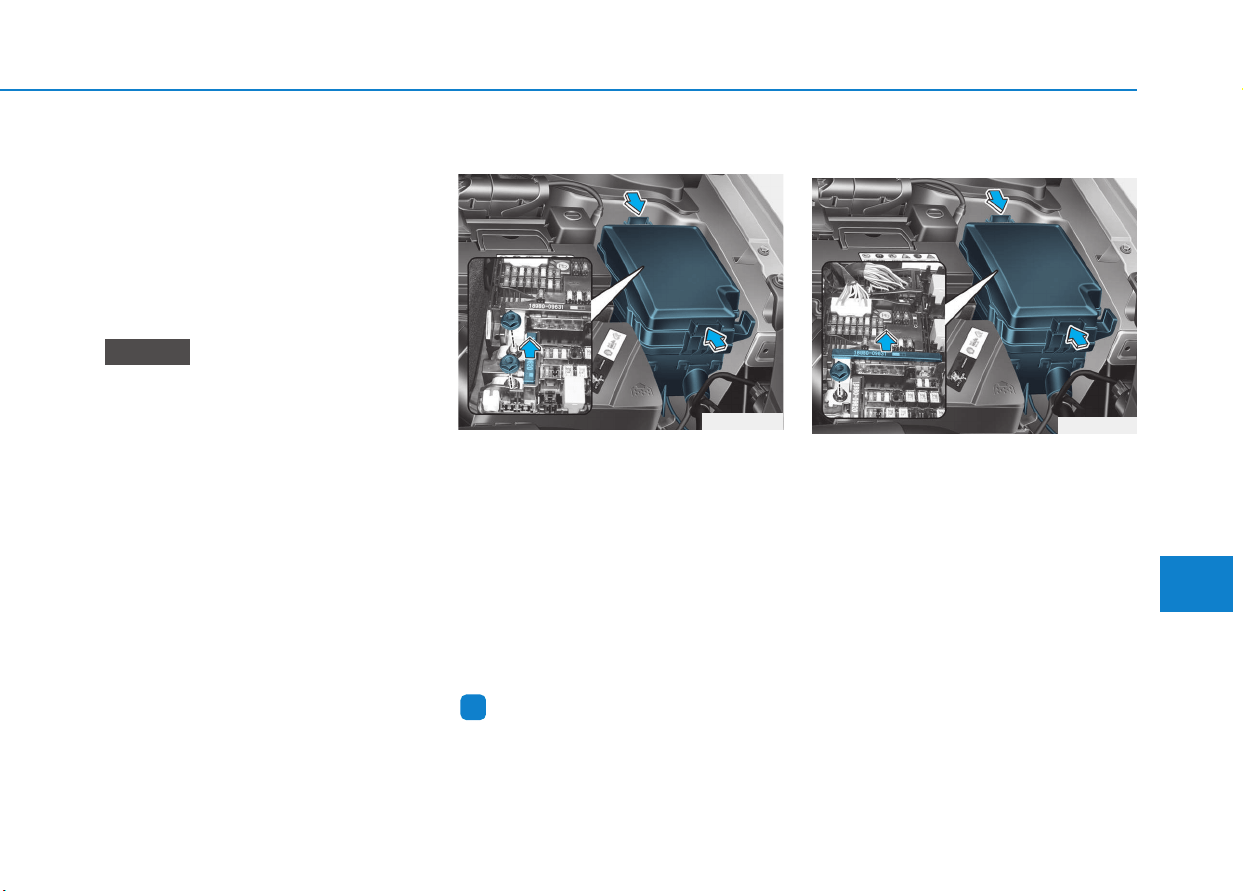
7-65
7
Maintenance
4. Check the removed fuse; replace it
if it is blown. To remove or insert
the fuse, use the fuse puller in the
engine compartment fuse panel.
5. Push in a new fuse of the same
rating, and make sure it fits tightly
in the clips. If it fits loosely, consult
an authorized HYUNDAI dealer.
After checking the fuse panel in
the engine compartment, securely
install the fuse panel cover. You
may hear a clicking sound if the
cover is securely latched. If it is
not securely latched, electrical
failure may occur from water con-
tact.
Main fuse
The electronic system may not func-
tion correctly even when the fuses
located in the engine compartment
and instrument panel are not discon-
nected. In such case, the cause of
the problem may be disconnection of
the main fuse (BFT type), which is
located inside the positive battery
terminal (+) cap. Since the main fuse
is designed more intricately than
other parts, we recommend you visit
the nearest HYUNDAI dealer.
Information
After inspection always securely
install the battery cap. If it is not
securely latched, electrical failure may
occur from water contact.
Multi fuse
If the multi fuse is blown, it must be
removed as follows:
1. Turn the vehicle off.
2. Disconnect the negative battery
cable.
3. Remove the fuse panel cover by
pressing the tab and pulling it up.
4. Remove the nuts shown in the pic-
ture above.
5. Replace the fuse with a new one
of the same rating.
6. Reinstall in the reverse order of
removal.
i
NOTICE
OPD076030
OPD076031
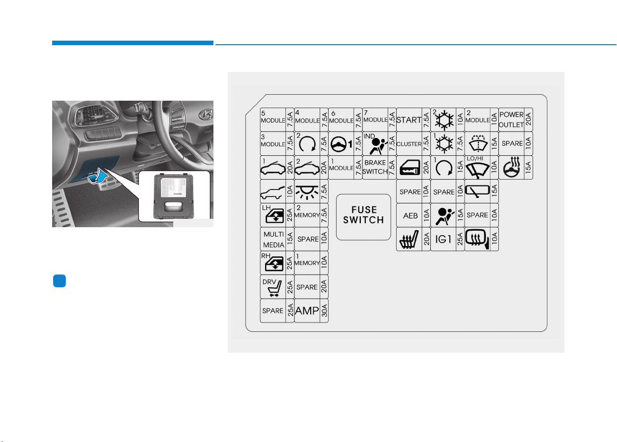
7-66
Maintenance
Fuse/Relay panel description
Driver’s side fuse panel
Inside the fuse/relay box covers, you
can find the fuse/relay label describ-
ing fuse/relay name and capacity.
Information
Not all fuse panel descriptions in this
manual may be applicable to your
vehicle. It is accurate at the time of
printing. When you inspect the fuse
box on your vehicle, refer to the fuse
box label.
i
OPD076039
OPDE076040
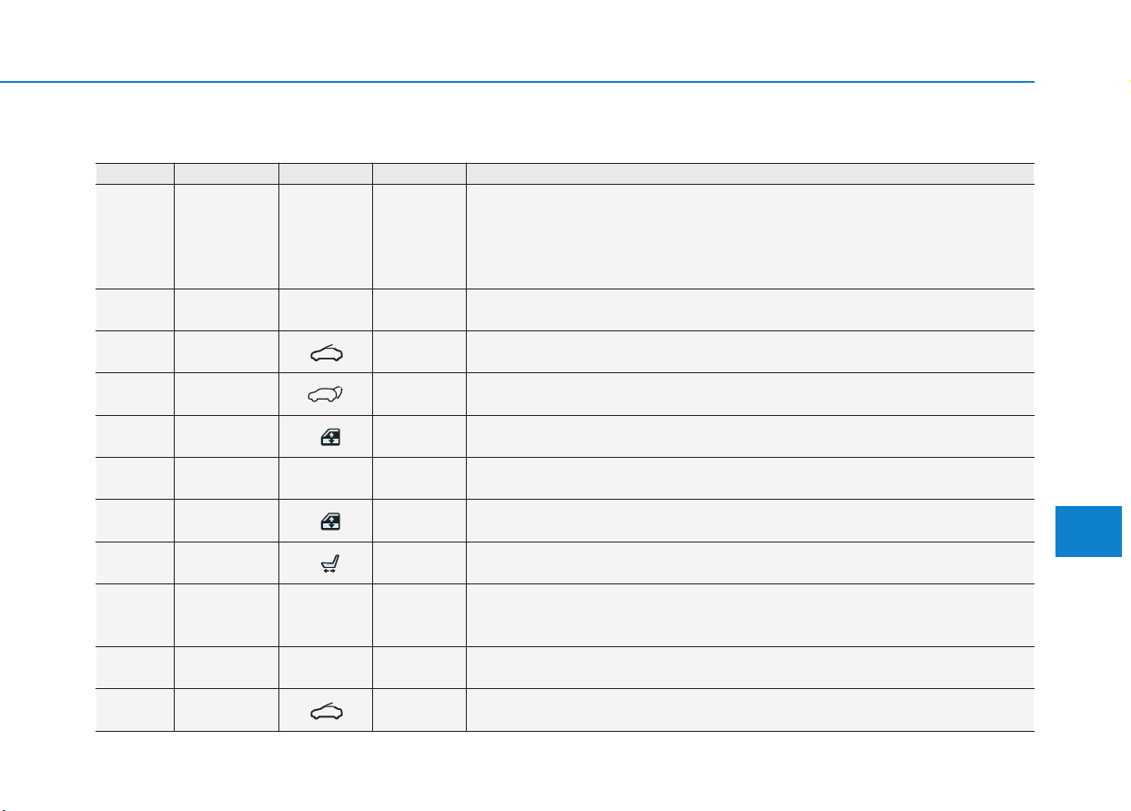
7-67
7
Maintenance
Driver's side fuse Panel
Fuse No. Fuse Name Symbol Fuse Rating Circuit Protected
F1 MODULE 5
MODULE
5
7.5A
Crash Pad Switch, Electro Chromic Mirror, MTS E-Call Module, Audio,
A/V & Navigation Head Unit, A/C Control Module, A/T Shift Lever Indicator,
Console Switch RH, DC-DC Converter, Head Lamp LH/RH, Active Air Flap Unit,
Auto Head Lamp Leveling Device Module, Front Seat Warmer Control Module,
Front Air Ventilation Seat Control Module, Driver IMS Module
F2 MODULE 3
MODULE
3
7.5A Driver/Passenger Door Module, BCM, Sport Mode Switch
F3 SUNROOF 1
1
20A Panorama Sunroof
F4 TAILGATE 10A Tail Gate Relay
F5
POWER
WINDOW LH
LH
25A
Power Window LH Relay, Driver/Passenger Safety Window Module,
Rear Power Window Switch LH, Rear Safety Window Module LH
F6 MULTIMEDIA
MULTI
MEDIA
15A Audio, A/V & Navigation Head Unit, DC-DC Converter
F7
POWER
WINDOW RH
RH
25A
Power Window RH Relay, Driver/Passenger Safety Window Module,
Rear Power Window Switch RH, Rear Safety Window Module RH
F8
POWER
SEAT DRIVER
DRV
25A Driver Seat Manual Switch, Driver IMS Module
F10 MODULE 4
MODULE
4
7.5A
Lane Keeping Assist Module, Rear Parking Assist Buzzer, Stop Lamp Switch,
Blind Spot Detection Radar LH/RH, BCM, Electric Parking Brske Switch,
Autonomous Emergency Braking Module
F11 SMART KEY 2
SMART
KEY
2
7.5A Smart Key Control Module, Immobilizer Module
F12 SUNROOF 2
2
20A Panorama Sunroof
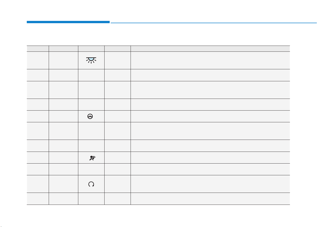
7-68
Maintenance
Driver's side fuse Panel
Fuse No. Fuse Name Symbol Fuse Rating Circuit Protected
F13
INTERIOR
LAMP
7.5A
Wireless Charger, Vanity Lamp LH/RH, Room Lamp, Overhead Console Lamp,
Personal Lamp LH/RH, Rain Sensor, Ignition Key Ill. & Door Warning Switch,
Glove Box Lamp, Luggage Lamp
F14 MEMORY 2
MEMORY
2
7.5A MTS E-Call Module
F16 MEMORY 1
MEMORY
1
10A
Driver/Passenger Door Module, Driver IMS Module, BCM, A/C Control Module,
Instrument Cluster, Auto Light & Photo Sensor,
ICM Relay Box (Outside Mirror Folding/Unfolding Relay)
F19 MODULE 6
MODULE
6
7.5A Smart Key Control Module, BCM
F20 MDPS
1
7.5A MDPS Unit
F21 MODULE 1
MODULE
1
7.5A
Hazard Switch, Center Door Lock Switch, Active Air Flap Unit,
Driver/Passenger Door Module, Driver/Passenger Power Outside Mirror,
Driver/Passenger Smart Key Outside Handle, Data Link Connector
F22 MODULE 7
MODULE
7
7.5A
Front Seat Warmer Control Module, Front Air Ventilation Seat Control Module, Nozzle
Heater
F23
AIRBAG
INDICATOR
IND
7.5A Instrument Cluster, Center Door Lock Switch
F24
BRAKE
SWITCH
BRAKE
SWITCH
7.5A Smart Key Control Module, Stop Lamp Switch
F25 START 7.5A
Without Smart Key : ICM Relay Box (Burglar Alarm Relay),
With Smart Key : Transaxle Range Switch, Smart Key Control Module, ECM/PCM,
Engine Room Junction Block (RLY.4)"
F26 CLUSTER
CLUSTER
7.5A Instrument Cluster
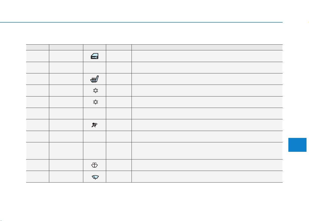
7-69
7
Maintenance
Driver's side fuse Panel
Fuse No. Fuse Name Symbol Fuse Rating Circuit Protected
F27 DOOR LOCK 20A Door Lock/Unlock Relay, ICM Relay Box (T/Turn Unlock Relay)
F29 AEB
AEB
10A Autonomous Emergency Braking Module
F30
SEAT HEATER
FRONT
20A Front Seat Warmer Control Module, Front Air Ventilation Seat Control Module
F31
AIR
CONDITIONER 2
2
10A
A/C Control Module, ECM/PCM, Blower Resistor, Blower Motor,
E/R Junction Block (RLY.10)
F32
AIR
CONDITIONER 1
1
7.5A A/C Control Module, Cluster Ionizer, E/R Junction Block (RLY.1/10/11/13)
F33 SMART KEY 1
SMART
KEY
1
15A Smart Key Control Module, Immobilizer Module
F35 AIRBAG 15A SRS Control Module
F36 IGNITION 1
IG1
25A PCB Block (F45/F46/F47/F48)
F37 MODULE 2
MODULE
2
10A
Wireless Charger, MTS E-Call Module, Smart Key Control Module, BCM, Audio,
A/V & Navigation Head Unit, DC-DC Converter, Power Outside Mirror Switch,
Engine Room Junction Block (RLY.14)
F38 WASHER 15A Multifunction Switch
F39 WIPER
LO/HI
10A ECM/PCM, BCM
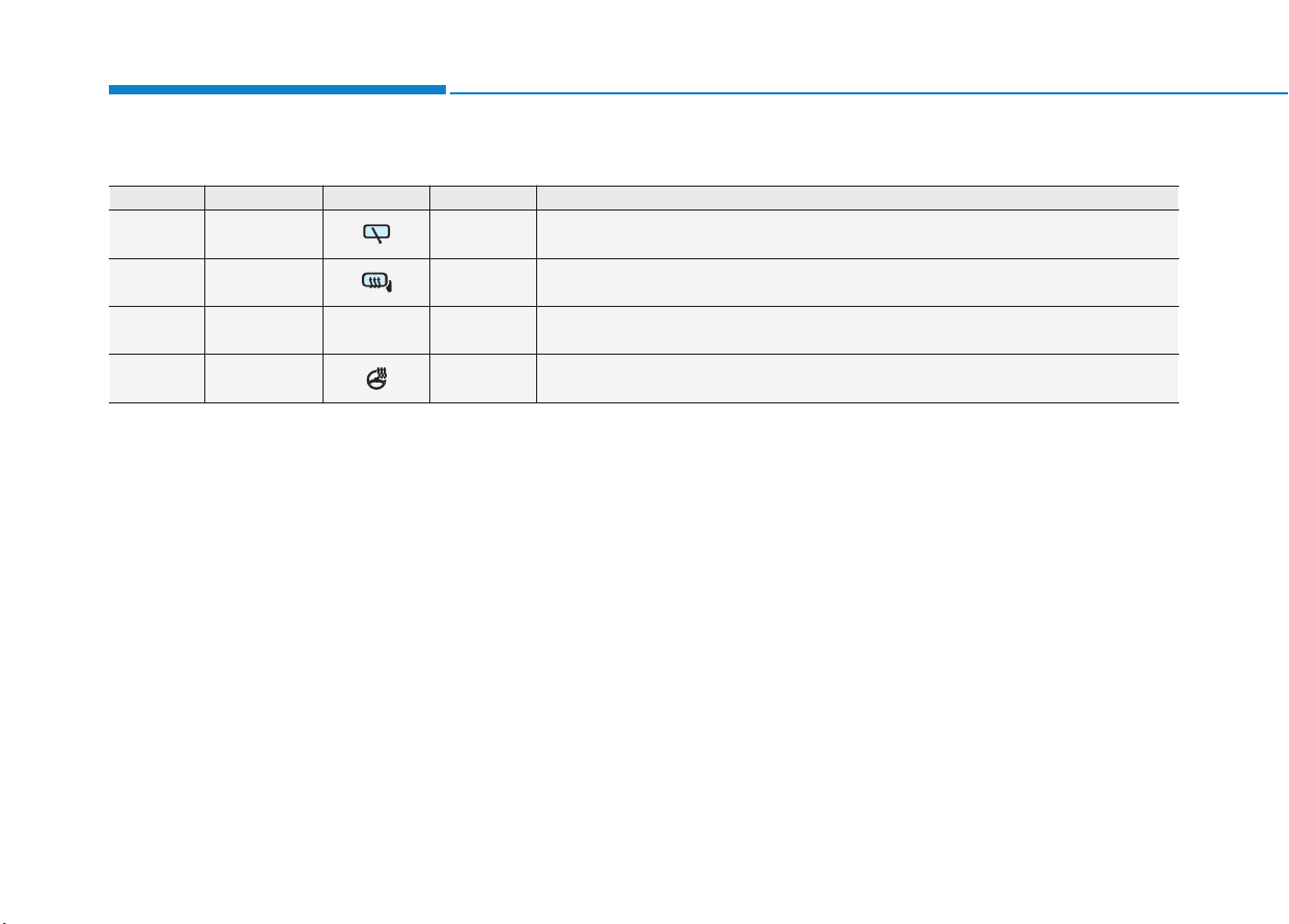
7-70
Maintenance
Driver's side fuse Panel
Fuse No. Fuse Name Symbol Fuse Rating Circuit Protected
F40 REAR WIPER 15A Rear Wiper Relay, Rear Wiper Motor
F42
MIRROR
HEATED
10A Driver/Passenger Power Outside Mirror, A/C Control Module, ECM/PCM
F43
POWER
OUTLET
POWER
OUTLET
20A Rear Power Outlet #2
F45
HEATED
STEERING
15A BCM

7-71
7
Maintenance
Engine compartment fuse panel
Inside the fuse/relay box covers, you
can find the fuse/relay label describ-
ing fuse/relay name and capacity.
Information
Not all fuse panel descriptions in this
manual may be applicable to your
vehicle. It is accurate at the time of
printing. When you inspect the fuse
box on your vehicle, refer to the fuse
box label.
i
OPD076037
OPDE076038
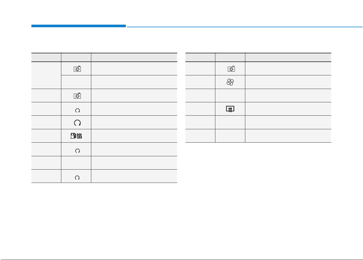
7-72
Maintenance
Engine compartment fuse panel
Relay No. Symbol Relay Name
R LY. 1
3
COOLING FAN 3 Relay (Gasoline)
PTC
HEATER
2
PTC HEATER #2 Relay (Diesel)
R LY. 2
2
COOLING FAN 2 Relay
R LY. 3
(IG1)
3
PDM #3 (IG1) Relay
R LY. 4
1
START Relay
R LY. 5 FUEL HEATER Relay (Diesel)
R LY. 6
(IG2)
4
PDM #4 (IG2) Relay
R LY. 7
FUEL
PUMP
FUEL PUMP Relay
R LY. 8
(ACC)
2
PDM #2 (ACC) Relay
Relay No. Symbol Relay Name
R LY. 9
1
COOLING FAN 1 Relay
R LY. 1 0 BLOWER Relay
R LY. 1 1
PTC
HEATER
1
PTC HEATER #1 Relay
R LY. 1 2 REAR HEATED Relay
R LY. 1 3
PTC
HEATER
3
PTC HEATER #3 Relay (Diesel)
R LY. 1 4
POWER
OUTLET
POWER OUTLET Relay
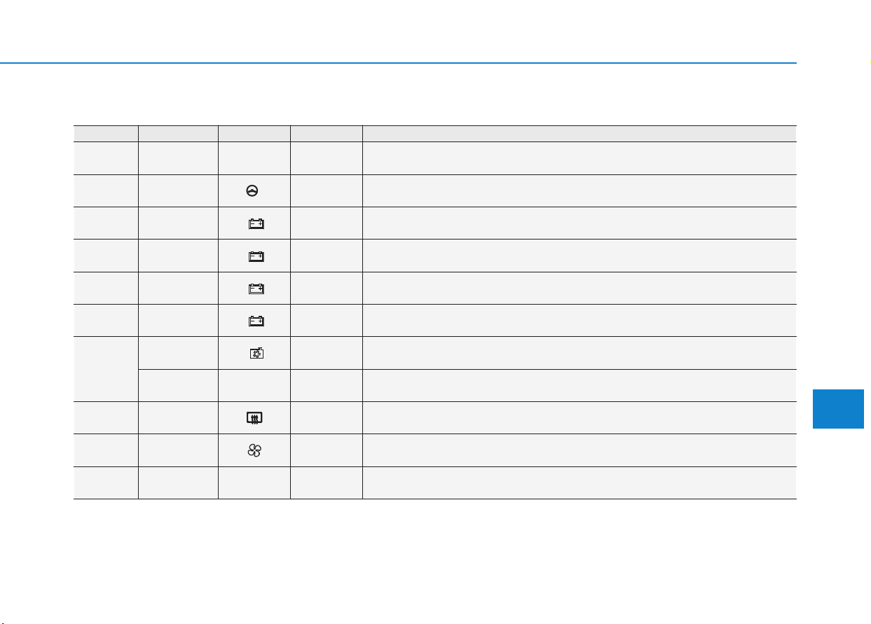
7-73
7
Maintenance
Engine compartment fuse panel
Fuse No. Fuse Name Symbol Fuse Rating Circuit Protected
F1 MAIN
MAIN
150A Fuse : F27, F29, F30, F33
F2 MDPS 1
1
80A MDPS Unit
F3 B+5
5
60A PCB Block (Fuse : F43, F44, F50, F51, F52, Engine Control Relay)
F4 B+2
2
60A IGPM (Fuse : F30, IPS0, IPS1, IPS2)
F5 B+3
3
60A IGPM (IPS3, IPS4, IPS5, IPS6)
F6 B+4
4
60A IGPM (Fuse : F3, F4, F5, F7, F8, F12)
F7
COOLING
FAN 1
1
60A RLY.9 (Gasoline)
PTC
HEATER 1
PTC
HEATER
1
50A RLY.2 (Diesel)
F8
REAR
HEATED
40A REAR HEATED Relay
F9 BLOWER 40A RLY.10
F10 IGNITION 1
IG1
40A Ignition Switch, E/R Junction Block (RLY.3, RLY8)
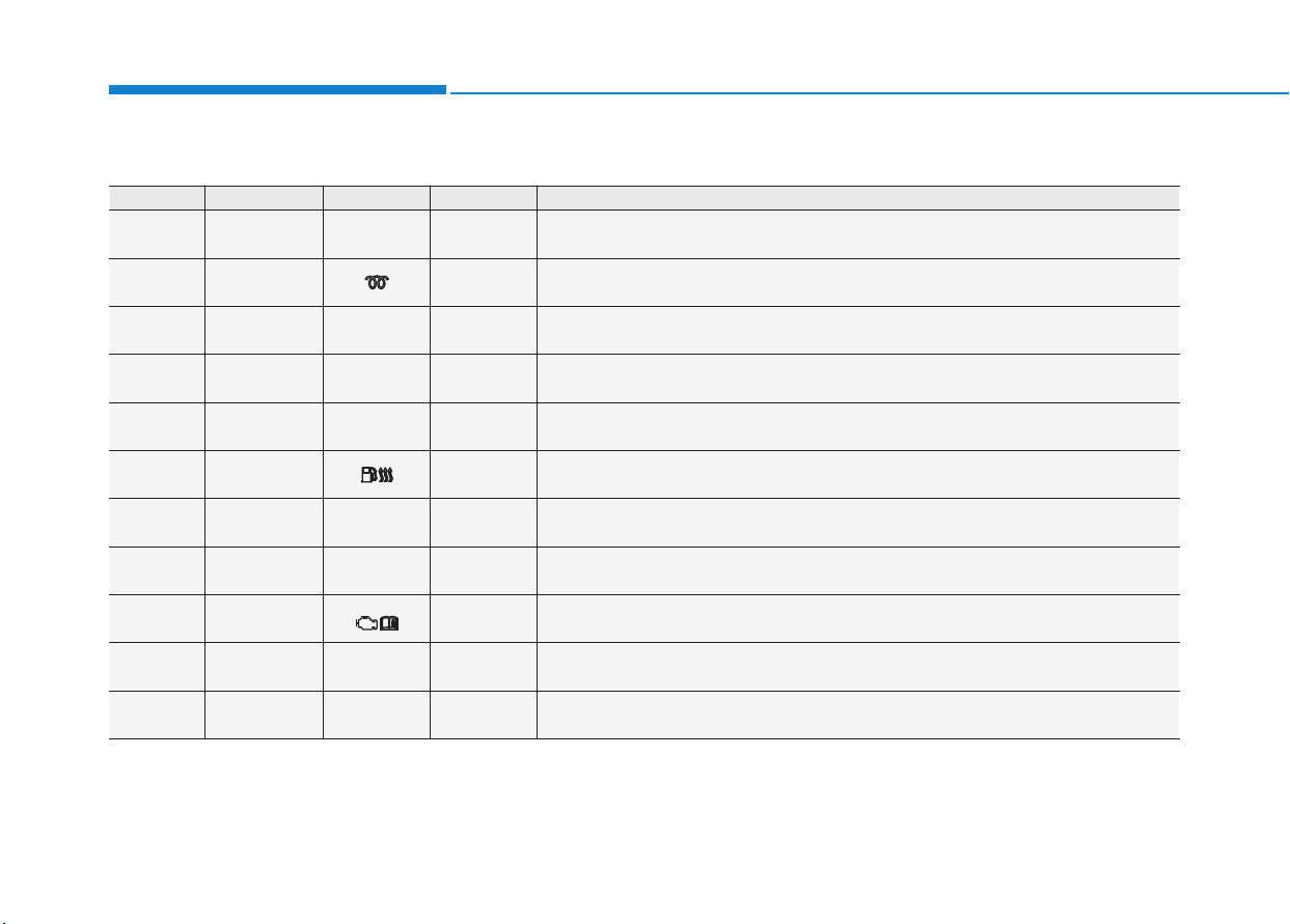
7-74
Maintenance
Engine compartment fuse panel
Fuse No. Fuse Name Symbol Fuse Rating Circuit Protected
F11 IGNITION 2
IG2
40A Ignition Switch, E/R Junction Block (RLY.6)
F12 GLOW 80A Glow Plug Unit
F13
PTC
HEATER 1
PTC
HEATER
1
50A RLY.11
F14
PTC
HEATER 2
PTC
HEATER
2
50A R LY. 1
F15
PTC
HEATER 3
PTC
HEATER
3
50A RLY.13
F16
FUEL
HEATER
30A R LY. 5
F17
POWER
OUTLET 3
POWER
OUTLET
3
20A Rear Power Outlet 1
F18
POWER
OUTLET 2
POWER
OUTLET
2
20A Front Power Outlet
F20 TCU1
T1
15A TCM
F21
VACUUM
PUMP
VACUUM
PUMP
20A Vacuum Pump
F22 FUEL PUMP
FUEL
PUMP
20A R LY. 7
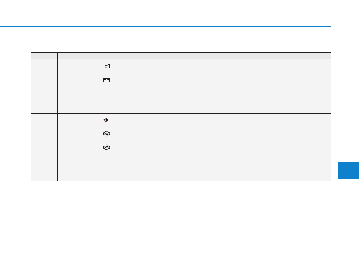
7-75
7
Maintenance
Engine compartment fuse panel
Fuse No. Fuse Name Symbol Fuse Rating Circuit Protected
F23
COOLING
FAN 2
2
40A RLY.9, RLY.2 (Gasoline)
F24 B+1
1
40A IGPM (Leak Current Autocut Device, Fuse : F21, F24, F27, F33)
F25 DCT 1
DCT
1
40A TCM
F26 DCT 2
DCT
2
40A TCM
F27
BURGLAR
ALARM HORN
10A ICM Relay Box (Burglar Alarm Horn Relay)
F29 ABS 1
1
40A ABS Control Module, ESP Control Module, Multipurpose Check Connector
F30 ABS 2
2
30A ABS Control Module, ESP Control Module, Multipurpose Check Connector
F33
POWER OUT-
LET 1
POWER
OUTLET
1
40A RLY.14
F34
BACK UP
LAMP
B/UP
LAMP
10A Back-Up Lamp Switch
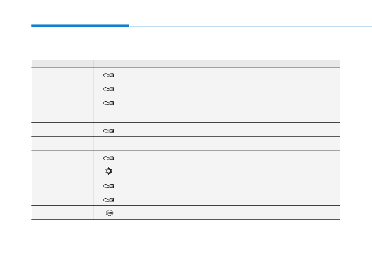
7-76
Maintenance
Fuse No. Fuse Name Symbol Fuse Rating Circuit Protected
F37 SENSOR 2
S2
10A
RCV Control Solenoid Valve , Purge Control Solenoid Valve, Oil Control Valve #1/#2,
A/Con Relay, E/R Junction Block (RLY.9)
F38 ECU 2
E2
10A ECM
F39 ECU 1
E1
20A ECM
F40 INJECTOR
INJECTOR
15A -
F41 SENSOR 1
S1
15A Oxygen Sensor (Up), Oxygen Sensor (Down)
F42
IGNITION
COIL
IGN
COIL
20A Ignition Coil #1/#2/#3
F43 ECU 3
E3
15A ECM
F44 A/CON 10A A/Con Relay
F45 ECU 5
E5
10A ECM
F46 SENSOR 4
S4
15A -
F47 ABS 3
3
10A ABS/ESP Control Module, Multipurpose Check Connector
Engine compartment fuse panel
■ Kappa 1.0 T-GDI

7-77
7
Maintenance
Fuse No. Fuse Name Symbol Fuse Rating Circuit Protected
F48 TCU 2
T2
15A E/R Junction Block (Fuse : F34)
F49 SENSOR 3
S3
10A E/R Junction Block (RLY.7)
F50 ECU 4
E4
15A ECM
F51 WIPER 25A Wiper Relay
F52 HORN 15A Horn Relay
Engine compartment fuse panel
■ Kappa 1.0 T-GDI
Fuse No. Fuse Name Symbol Fuse Rating Circuit Protected
F37 SENSOR 2
S2
10A
RCV Control Solenoid Valve , Purge Control Solenoid Valve, Oil Control Valve #1/#2,
A/Con Relay, E/R Junction Block (RLY.9)
F38 ECU 2
E2
10A ECM
F39 ECU 1
E1
20A ECM
F40 INJECTOR
INJECTOR
15A -
F41 SENSOR 1
S1
15A Oxygen Sensor (Up), Oxygen Sensor (Down)
■ Kappa 1.4 T-GDI
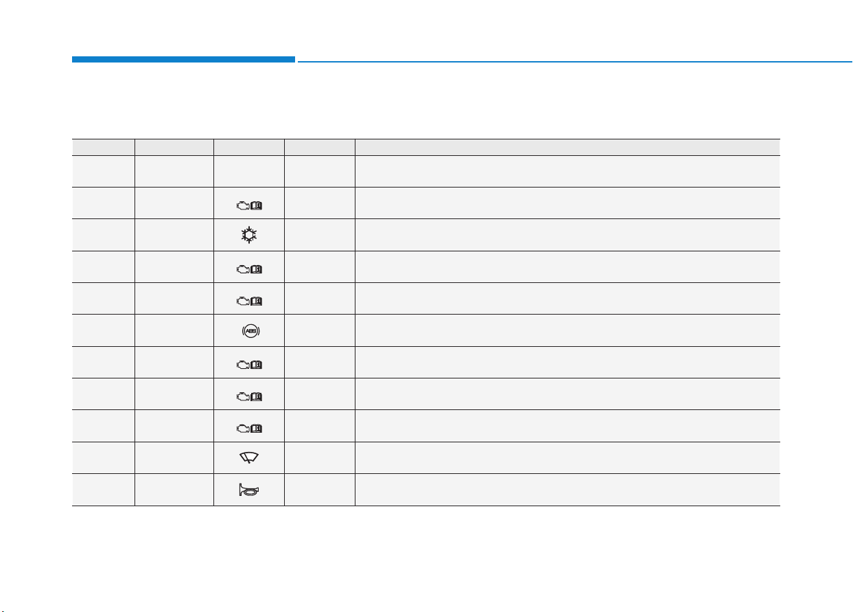
7-78
Maintenance
Fuse No. Fuse Name Symbol Fuse Rating Circuit Protected
F42
IGNITION
COIL
IGN
COIL
20A Ignition Coil #1/#2/#3/#4
F43 ECU 3
E3
15A ECM
F44 A/CON 10A A/Con Relay
F45 ECU 5
E5
10A ECM
F46 SENSOR 4
S4
15A Vacuum Pump
F47 ABS 3
3
10A ABS/ESP Control Module, Multipurpose Check Connector
F48 TCU 2
T2
15A TCM, Transaxle Range Switch, E/R Junction Block (Fuse : F34)
F49 SENSOR 3
S3
10A E/R Junction Block (RLY.7)
F50 ECU 4
E4
15A ECM
F51 WIPER 25A Wiper Relay
F52 HORN 15A Horn Relay
Engine compartment fuse panel
■ Kappa 1.4 T-GDI
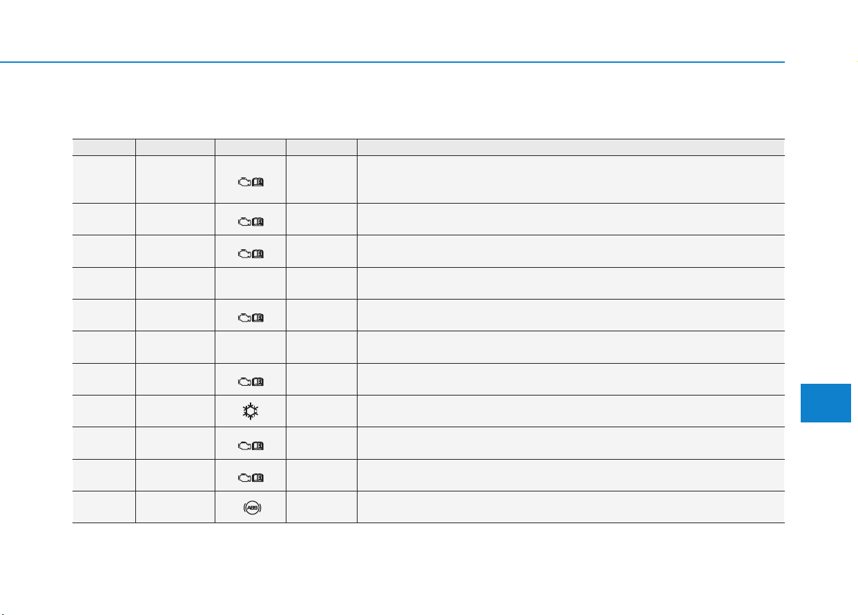
7-79
7
Maintenance
Engine compartment fuse panel
Fuse No. Fuse Name Symbol Fuse Rating Circuit Protected
F37 SENSOR 2
S2
10A
Camshaft Position Sensor #1/#2, Purge Control Solenoid Valve,
Oil Control Valve #1/#2, Variable Intake Solenoid Valve,
E/R Junction Block (RLY.1, RLY.2)
F38 ECU 2
E2
10A ECM
F39 ECU 1
E1
20A ECM
F40 INJECTOR
INJECTOR
15A Injector #1/#2/#3/#4
F41 SENSOR 1
S1
15A Oxygen Sensor (Up), Oxygen Sensor (Down)
F42
IGNITION
COIL
IGN
COIL
20A Ignition Coil #1/#2/#3/#4, Condenser
F43 ECU 3
E3
15A ECM
F44 A/CON 10A -
F45 ECU 5
E5
10A ECM
F46 SENSOR 4
S4
15A -
F47 ABS 3
3
10A ABS/ESP Control Module, Multipurpose Check Connector
■ Kappa 1.4 MPI
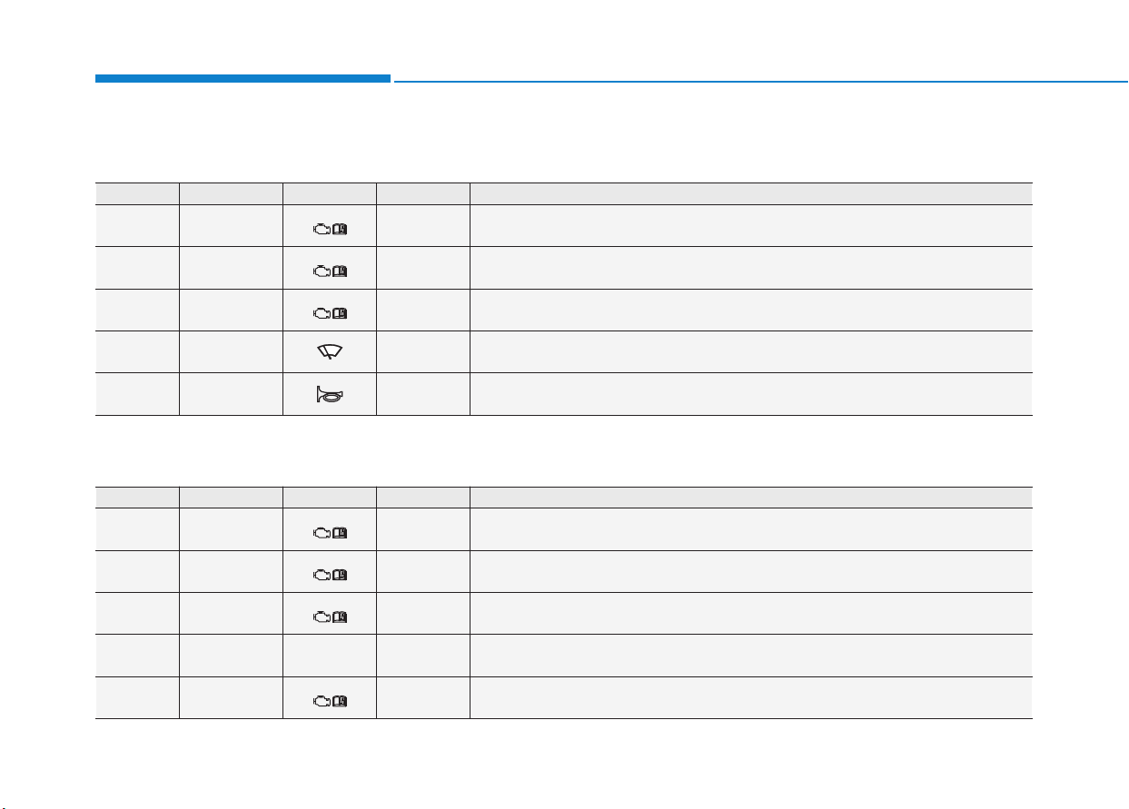
7-80
Maintenance
Engine compartment fuse panel
Fuse No. Fuse Name Symbol Fuse Rating Circuit Protected
F48 TCU 2
T2
15A E/R Junction Block (Fuse : F34)
F49 SENSOR 3
S3
10A E/R Junction Block (RLY.7)
F50 ECU 4
E4
15A -
F51 WIPER 25A Wiper Relay
F52 HORN 15A Horn Relay
■ Kappa 1.4 MPI
■ Gamma 1.6 MPI
Fuse No. Fuse Name Symbol Fuse Rating Circuit Protected
F37 SENSOR 2
S2
10A
Camshaft Position Sensor #1/#2, Purge Control Solenoid Valve, Oil Control Valve
#1/#2, Variable Intake Solenoid Valve, E/R Junction Block (RLY.1, RLY.2)
F38 ECU 2
E2
10A ECM/PCM
F39 ECU 1
E1
20A ECM/PCM
F40 INJECTOR
INJECTOR
15A Injector #1/#2/#3/#4
F41 SENSOR 1
S1
15A Oxygen Sensor (Up), Oxygen Sensor (Down)
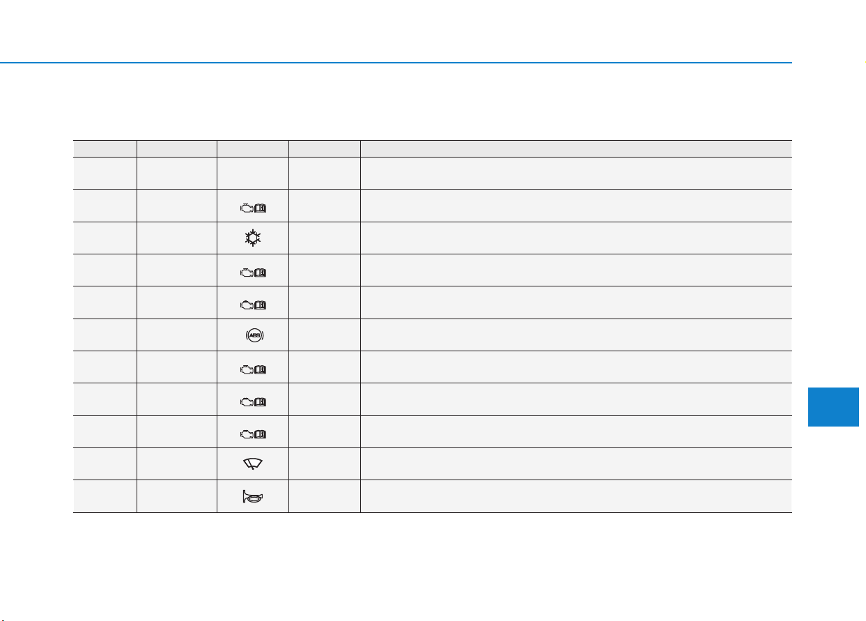
7-81
7
Maintenance
Engine compartment fuse panel
■ Gamma 1.6 MPI
Fuse No. Fuse Name Symbol Fuse Rating Circuit Protected
F42
IGNITION
COIL
IGN
COIL
20A Ignition Coil #1/#2/#3/#4, Condenser
F43 ECU 3
E3
15A ECM/PCM
F44 A/CON 10A -
F45 ECU 5
E5
10A ECM/PCM
F46 SENSOR 4
S4
15A -
F47 ABS 3
3
10A ABS/ESP Control Module, Multipurpose Check Connector
F48 TCU 2
T2
15A Transaxle Range Switch, E/R Junction Block (Fuse : F34)
F49 SENSOR 3
S3
10A E/R Junction Block (RLY.7)
F50 ECU 4
E4
15A ECM/PCM
F51 WIPER 25A Wiper Relay
F52 HORN 15A Horn Relay
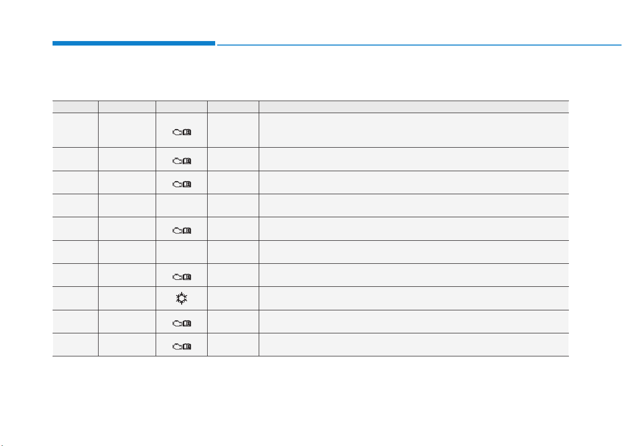
7-82
Maintenance
Fuse No. Fuse Name Symbol Fuse Rating Circuit Protected
F37 SENSOR 2
S2
10A
Oil Level Sensor , Electronic VGT Actuator, EGR Cooling Valve,
Fuel Pressure Regulating Valve, PM Sensor, Stop Lamp Switch, A/Con Relay,
E/R Junction Block (RLY.2/5/11)
F38 ECU 2
E2
10A -
F39 ECU 1
E1
20A ECM
F40 INJECTOR
INJECTOR
15A -
F41 SENSOR 1
S1
15A Lambda Sensor #1/#2
F42
IGNITION
COIL
IGN
COIL
20A Ignition Coil #1/#2/#3/#4
F43 ECU 3
E3
15A ECM
F44 A/CON 10A -
F45 ECU 5
E5
10A ECM
F46 SENSOR 4
S4
15A Fuel Filter Heater & Fuel Filter Warning Sensor, Glow Plug Unit
■ U-II 1.6 TCI
Engine compartment fuse panel
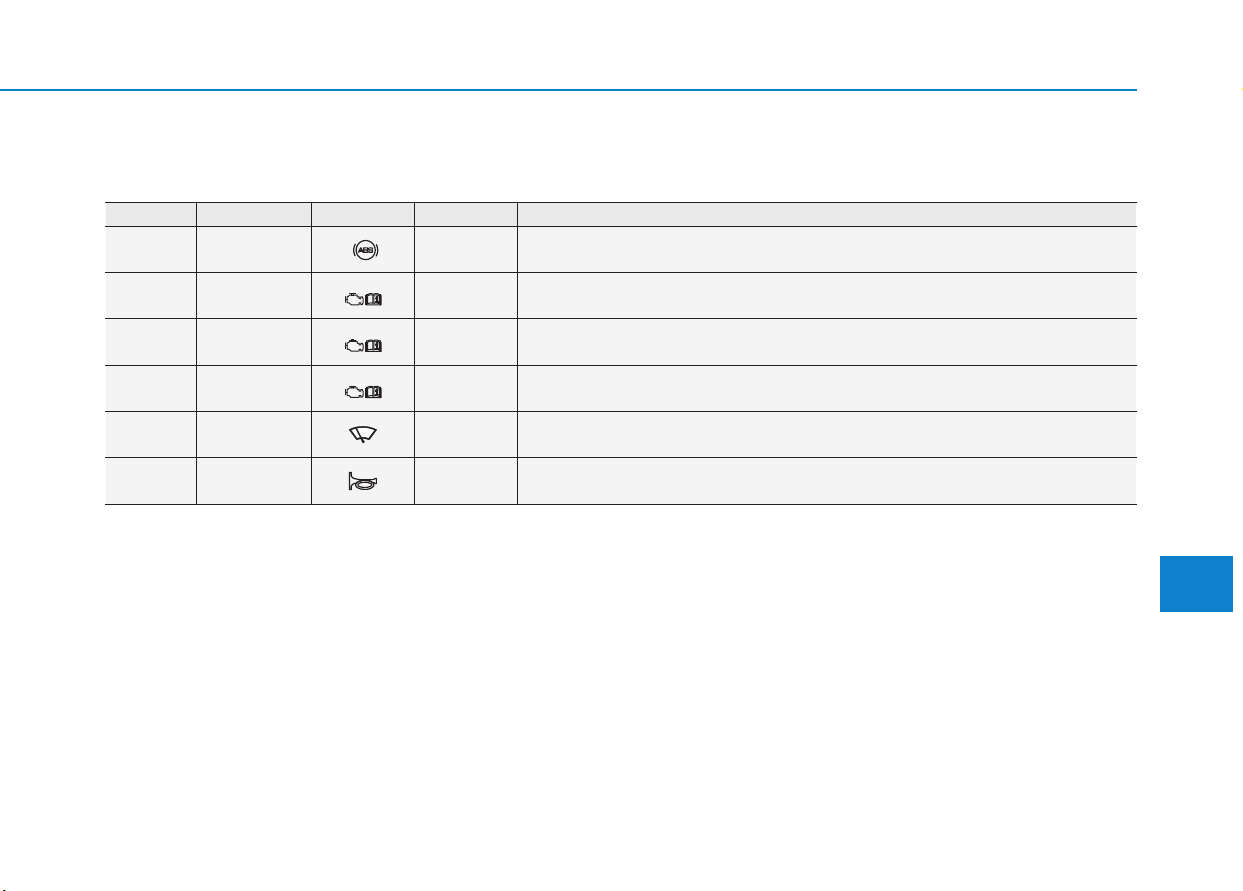
7-83
7
Maintenance
Fuse No. Fuse Name Symbol Fuse Rating Circuit Protected
F47 ABS 3
3
10A ABS/ESP Control Module, Multipurpose Check Connector
F48 TCU 2
T2
15A TCM, Transaxle Range Switch, E/R Junction Block (Fuse : F34)
F49 SENSOR 3
S3
10A
Air Flow Sensor, Rail Pressure Control Valve, Camshaft Position Sensor,
Oil Pressure Valve, E/R Junction Block (RLY.7)
F50 ECU 4
E4
15A -
F51 WIPER 25A Wiper Relay
F52 HORN 15A Horn Relay
Engine compartment fuse panel
■ U-II 1.6 TCI
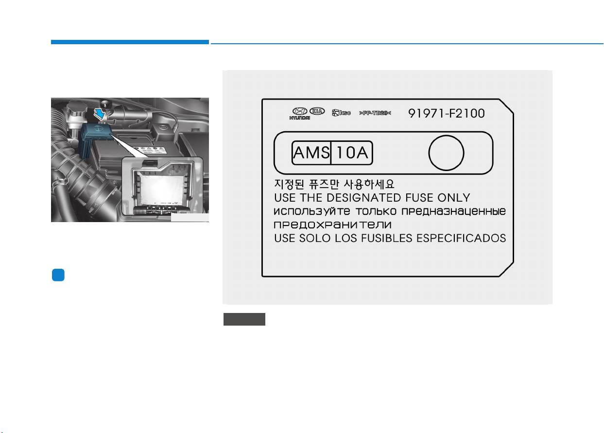
7-84
Maintenance
Engine compartment fuse panel
(Battery terminal cover)
Inside the fuse/relay box cover, you
can find the fuse/relay label describ-
ing fuse/relay name and capacity.
Information
Not all fuse panel descriptions in this
manual may be applicable to your
vehicle; the information is accurate at
the time of printing. When you inspect
the fuse panel in your vehicle, refer to
the fuse panel label.
i
OPD076066
OPD076065
After checking the fuse panel in the engine compartment, securely
install the cover. If it is not securely latched, electrical failure may occur
from water contact.
NOTICE

7-85
7
Maintenance
LLIIGGHHTT BBUULLBBSS
Consult an authorized HYUNDAI
dealer to replace most vehicle light
bulbs. It is difficult to replace vehicle
light bulbs because other parts of the
vehicle must be removed before you
can get to the bulb. This is especially
true for removing the headlamp
assembly to get to the bulb(s).
Removing/installing the headlamp
assembly can result in damage to
the vehicle.
Be sure to replace the burned-out
bulb with one of the same wattage
rating. Otherwise, it may cause
damage to the fuse or electric
wiring system.
Information
After heavy driving, rain or washing,
headlamp and tail lamp lenses could
appear frosty. This condition is caused
by the temperature difference between
the lamp inside and outside. This is
similar to the condensation on your
windows inside your vehicle during the
rain and doesn’t indicate a problem
with your vehicle. If the water leaks
into the lamp bulb circuitry, we rec-
ommend that the system be checked
by an authorized HYUNDAI dealer.
Information
The headlamp aiming should be adjust-
ed after an accident or after the head-
lamp assembly is reinstalled at an
authorized HYUNDAI dealer.
Information
- Traffic Change
(for Europe)
The low beam light distribution is
asymmetric. If you go abroad to a coun-
try with opposite traffic direction, this
asymmetric part will dazzle oncoming
car driver. To prevent dazzle, ECE reg-
ulation demand several technical solu-
tions (ex. automatic change system,
adhesive sheet, down aiming). These
headlamps are designed not to dazzle
opposite drivers. So, you need not
change your headlamps in a country
with opposite traffic direction.
i
i
i
NOTICE
Prior to working on the light,
firmly apply the parking brake,
ensure that the ignition switch is
in the LOCK/OFF position and
turn off the lights to avoid sud-
den movement of the vehicle and
burning your fingers or receiving
an electric shock.
WARNING
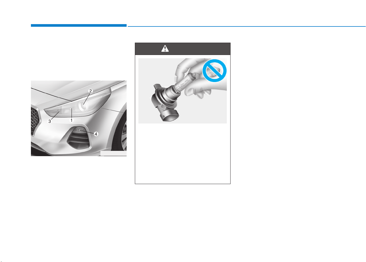
7-86
Maintenance
Headlamp, static bending lamp,
position lamp, turn signal lamp
and daytime running light bulb
replacement
Type A
(1) Headlamp (High)/Position lamp
(2) Headlamp (Low)
(3) Turn signal lamp
(4) Daytime running light
(if equipped)
• Always handle them carefully, and
avoid scratches and abrasions. If
the bulbs are lit, avoid contact with
liquids.
• Never touch the glass with bare
hands. Residual oil may cause the
bulb to overheat and burst when lit.
• A bulb should be operated only
when installed in a headlamp.
• If a bulb becomes damaged or
cracked, replace it immediately
and carefully dispose of it.
OPDE076092
• Handle halogen bulbs with
care. Halogen bulbs contain
pressurized gas that will pro-
duce flying pieces of glass that
could cause injuries if broken.
• Wear eye protection when
changing a bulb. Allow the bulb
to cool down before handling it.
WARNING
OLMB073042L
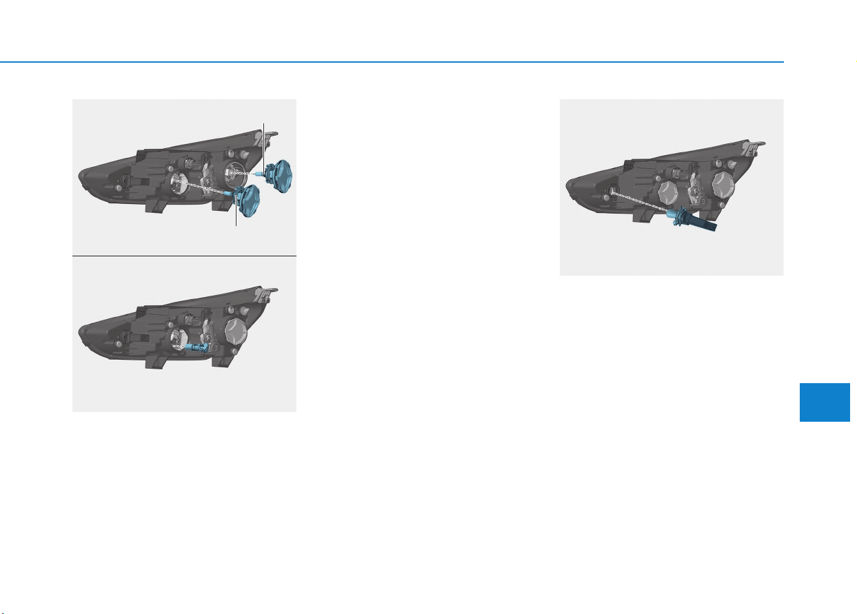
7-87
7
Maintenance
Headlamp and position lamp
1. Open the hood.
2. Disconnect the negative battery
cable.
3. Remove the bulb cover by turning
it counterclockwise.
4. Disconnect the bulb socket-con-
nector. (for low beam and high
beam)
5. Remove the bulb from the head-
lamp assembly.
6. Install a new bulb.
7. Connect the bulb socket-connec-
tor. (for low beam and high beam)
8. Install the bulb cover by turning it
clockwise.
Turn signal lamp
1. Open the hood.
2. Disconnect the negative battery
cable.
3.Remove the socket from the
assembly by turning the socket
counterclockwise until the tabs on
the socket align with the slots on
the assembly.
4.Remove the bulb from the socket
by pressing it in and rotating it
counterclockwise until the tabs on
the bulb align with the slots in the
socket. Pull the bulb out of the
socket.
OPDE076076
OPDE076075
■ Position lamp
■ High/Low beam
High
Low
OPDE076077
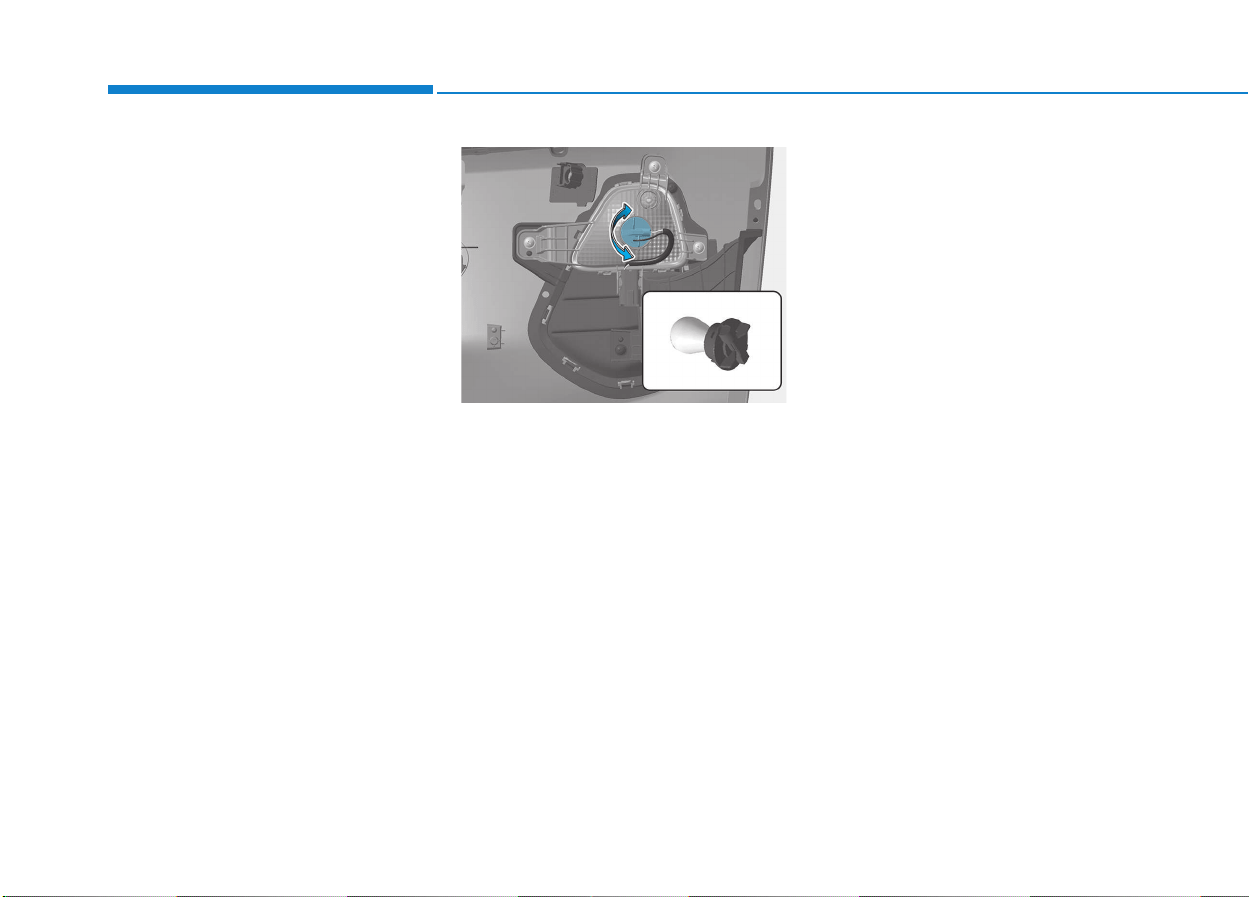
7-88
Maintenance
5.Insert a new bulb by inserting it into
the socket and rotating it until it
locks into place.
6.Install the socket in the assembly
by aligning the tabs on the socket
with the slots in the assembly.
7.Push the socket into the assembly
and turn the socket clockwise.
Daytime running light
1. Loosen the pin-type retainers of the
under cover and then remove the
undercover.
2. Reach your hand into the back of
the front bumper.
3. Remove the socket from the hous-
ing by turning the socket counter-
clockwise until the tabs on the sock-
et align with the slots of the housing.
4. Remove the bulb from the socket by
pressing it in and rotating it counter-
clockwise until the tabs on the bulb
align with the slots in the socket.
Pull the bulb out of the socket.
5. Insert a new bulb by inserting it into
the socket and rotating it until it
locks into place.
6. Install the socket into the housing by
aligning the tabs on the socket with
the slots in the housing. Push the
socket into the housing and turn the
socket clockwise.
OPDE076096
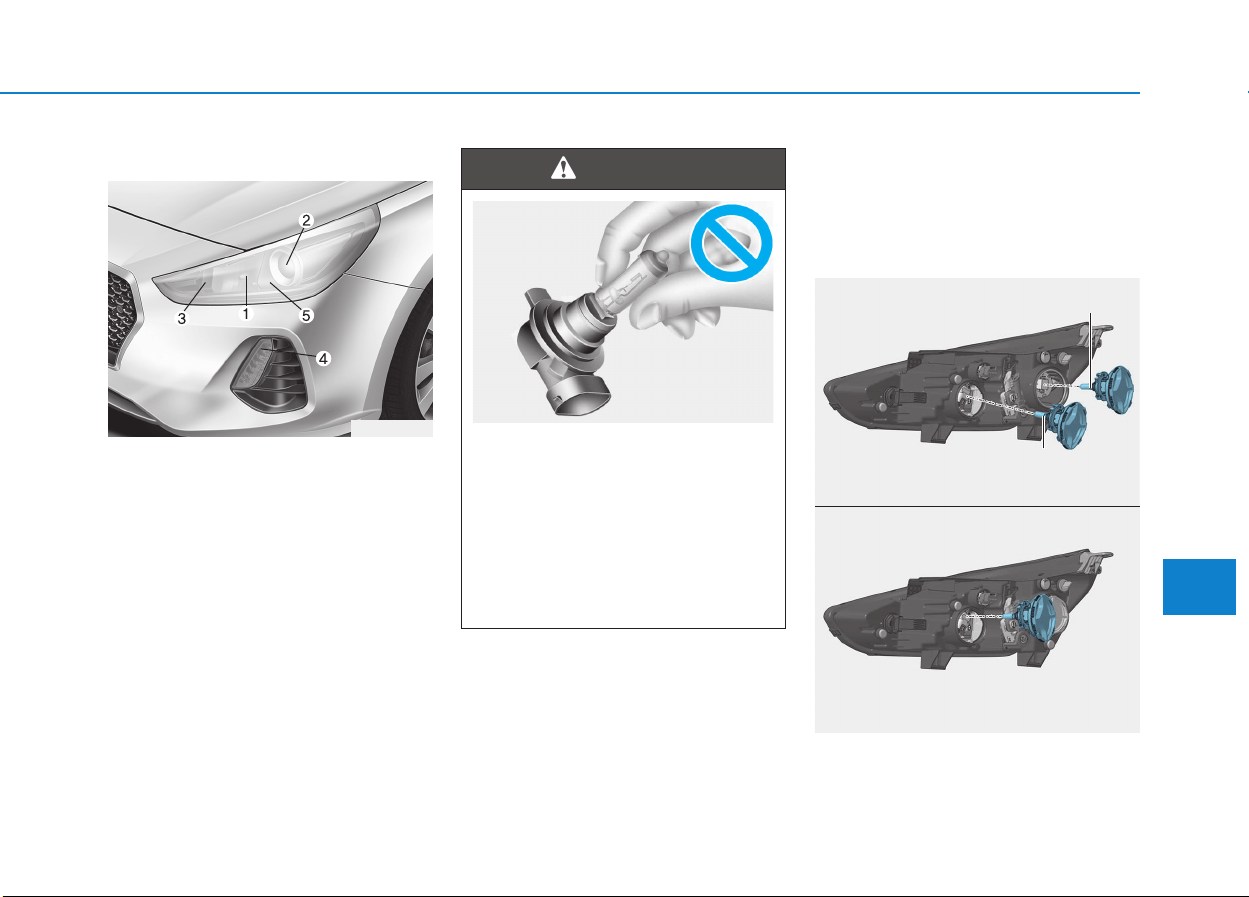
7-89
7
Maintenance
Type B
(1) Headlamp (High)
(2) Headlamp (Low)
(3) Turn signal lamp
(4) Position lamp &
Daytime running light
(5) Static bending light
• Always handle them carefully, and
avoid scratches and abrasions. If
the bulbs are lit, avoid contact with
liquids.
• Never touch the glass with bare
hands. Residual oil may cause the
bulb to overheat and burst when lit.
• A bulb should be operated only
when installed in a headlamp.
• If a bulb becomes damaged or
cracked, replace it immediately
and carefully dispose of it.
Headlamp lamp and static bending
light
1. Open the hood.
OPDE076076
■ High/Low beam
High
Low
OPDE076090
■ Static bending light
OPD076042
• Handle halogen bulbs with
care. Halogen bulbs contain
pressurized gas that will pro-
duce flying pieces of glass that
could cause injuries if broken.
• Wear eye protection when
changing a bulb. Allow the bulb
to cool down before handling it.
WARNING
OLMB073042L
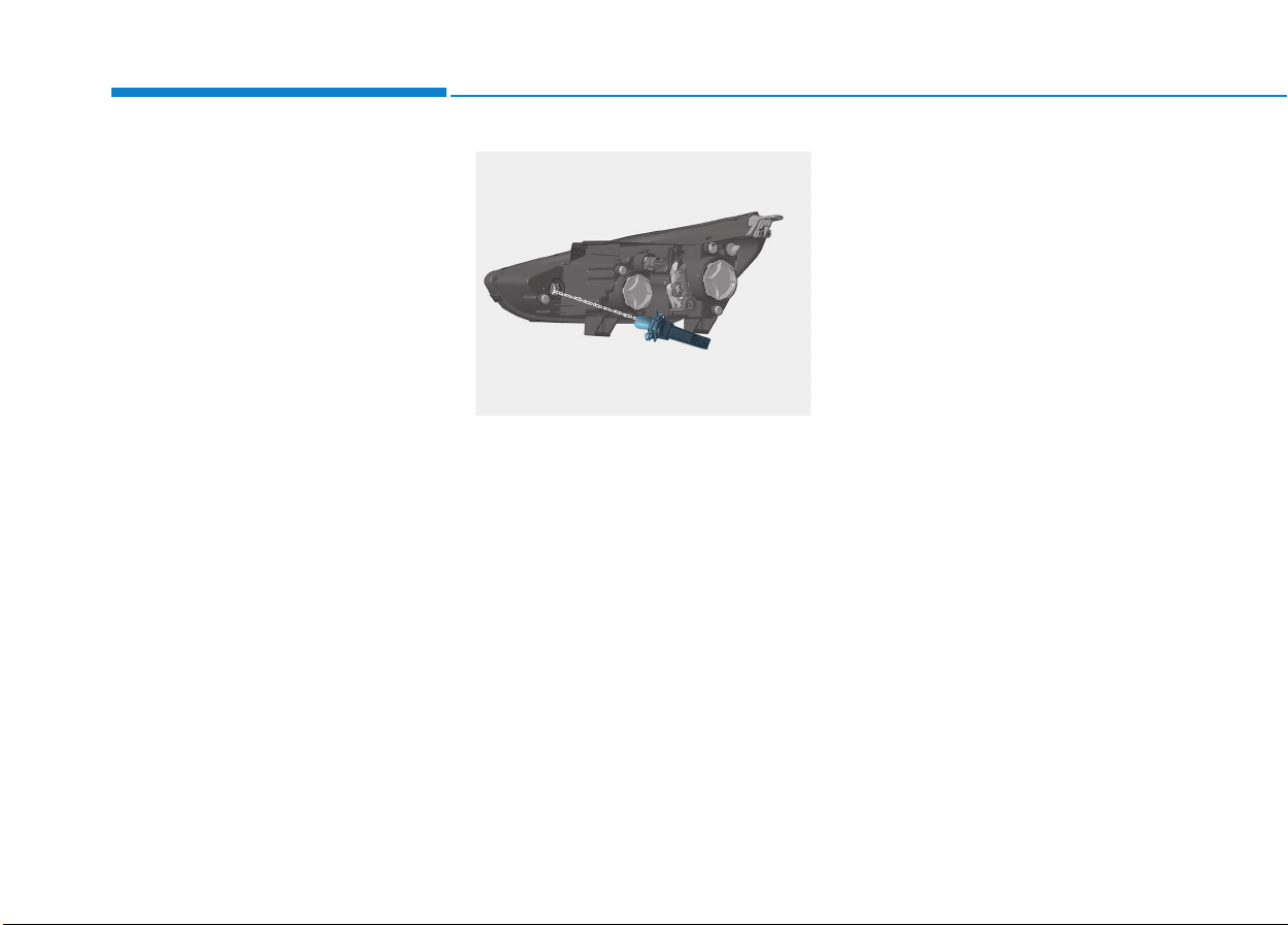
7-90
Maintenance
2. Disconnect the negative battery
cable.
3. Remove the bulb cover by turning
it counterclockwise.
4. Disconnect the bulb socket-con-
nector.
5. Remove the bulb from the head-
lamp assembly.
6. Install a new bulb.
7. Connect the bulb socket-connec-
tor.
8. Install the bulb cover by turning it
clockwise.
Turn signal lamp
1. Open the hood.
2. Disconnect the negative battery
cable.
3.Remove the socket from the
assembly by turning the socket
counterclockwise until the tabs on
the socket align with the slots on
the assembly.
4.Remove the bulb from the socket by
pressing it in and rotating it counter-
clockwise until the tabs on the bulb
align with the slots in the socket.
Pull the bulb out of the socket.
5.Insert a new bulb by inserting it into
the socket and rotating it until it
locks into place.
6.Install the socket in the assembly
by aligning the tabs on the socket
with the slots in the assembly.
7.Push the socket into the assembly
and turn the socket clockwise.
Position lamp and daytime running
light
If the LED lamp does not operate, we
recommend you to have the vehicle
checked by an authorized HYUNDAI
dealer.
OPDE076077
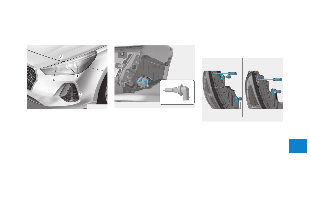
7-91
7
Maintenance
Type C
(1) Headlamp (Low)
(2) Headlamp (High)
(3) Static bending light
(4) Position lamp & Turn signal lamp
& Daytime running light
Headlamp, static bending light,
position lamp, turn signal lamp and
daytime running light
If the light bulb does not operate, we
recommend you to have the vehicle
checked by an authorized HYUNDAI
dealer.
Front fog lamp (if equipped)
1. Loosen the pin-type retainers of the
under cover and then remove the
undercover.
2. Reach your hand into the back of the
front bumper.
3. Disconnect the power connector
from the socket.
4. Remove the bulb-socket from the
housing by turning the socket coun-
terclockwise until the tabs on the
socket align with the slots of the
housing.
5. Install a new bulb-socket into the
housing by aligning the tabs on the
socket with the slots in the housing.
Push the socket into the housing
and turn the socket clockwise.
Headlamp and front fog lamp
aiming (for Europe)
Headlamp aiming
1. Inflate the tires to the specified
pressure and remove any loads
from the vehicle except the driver,
spare tire, and tools.
2. The vehicle should be placed on a
flat floor.
3. Draw vertical lines (Vertical lines
passing through respective head
lamp centers) and a horizontal line
(Horizontal line passing through
center of head lamps) on the
screen.
OPDE076097
■ Halogen type ■ LED type
OPDE076085/OPDE076086
OPD076041
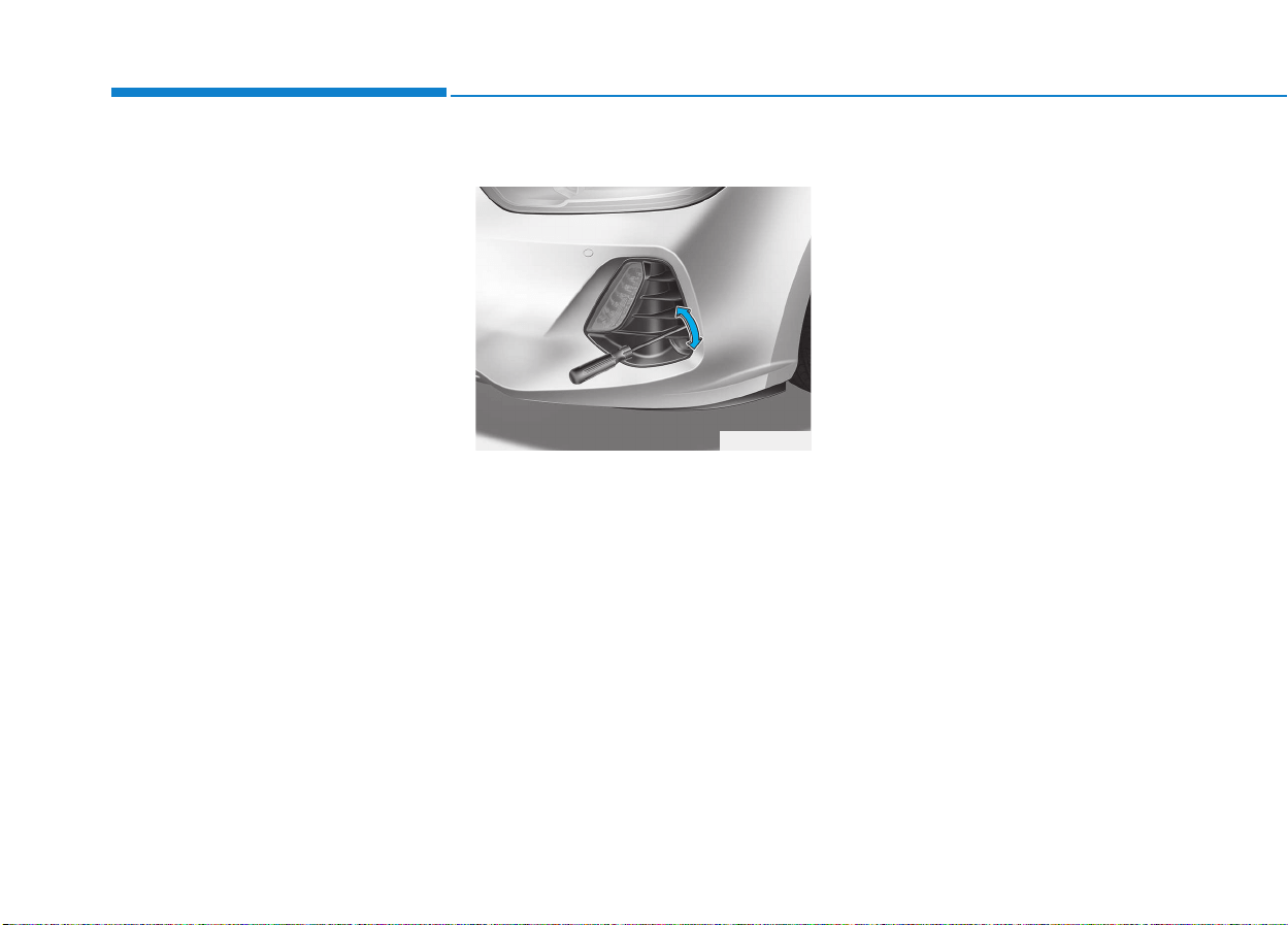
7-92
Maintenance
4. With the headlamp and battery in
normal condition, aim the head-
lamps so the brightest portion falls
on the horizontal and vertical
lines.
5. To aim the low beam left or right,
turn the driver clockwise or coun-
terclockwise. To aim the low beam
up or down, turn the driver clock-
wise or counterclockwise.
To aim the high beam up or down,
turn the driver clockwise or coun-
terclockwise.
Front fog lamp aiming
The front fog lamp can be aimed as
the same manner of the headlamps
aiming. With the front fog lamps and
battery in normal condition, aim the
front fog lamps. To aim the front fog
lamp up or down, turn the driver
clockwise or counterclockwise.
OPDE076087
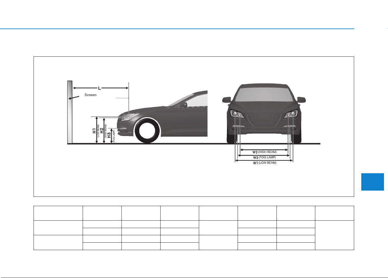
7-93
7
Maintenance
Unit: mm (in)
Aiming point
H1 : Height between the head lamp bulb center and ground (Low beam)
H2 : Height between the head lamp bulb center and ground (High beam)
H3 : Height between the fog lamp bulb center and ground
W1 : Distance between the two head lamp bulbs centers (Low beam)
W2 : Distance between the two head lamp bulbs centers (High beam)
W3 : Distance between the two fog lamp bulbs centers
OPDE076081
Vehicle
condition
Lamp type H1 H2 H3 W1 W2 W3
Without driver
Halogen 681 (26.81) 645 (25.39)
344 (13.54)
1,440 (56.69) 1,218 (47.95)
1,484 (58.42)
LED 677 (26.65) 631 (24.84) 1,385 (54.52) 1,114 (43.85)
With driver
Halogen 676 (26.61) 640 (25.19)
339 (13.34)
1,440 (56.69) 1,218 (47.95)
LED 672 (26.45) 626 (24.64) 1,385 (54.52) 1,114 (43.85)
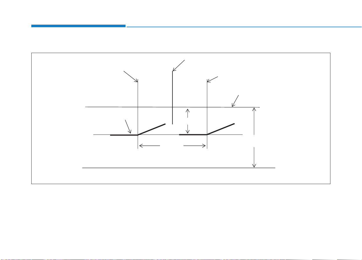
7-94
Maintenance
Headlamp low beam (LHD side)
1. Turn the low beam on without driver aboard.
2. The cut-off line should be projected in the cut-off line shown in the picture.
3. When aiming the low beam, vertical aiming should be adjusted after adjusting the horizontal aiming.
4. If headlamp leveling device is equipped, adjust the head lamp leveling device switch with 0 positions.
:
&DUD[LV
9HUWLFDOOLQHRIOHIW
KHDGODPSEXOEFHQWHU
&XWRIIOLQH
9HUWLFDOOLQHRIULJKW
KHDGODPSEXOEFHQWHU
+RUL]RQWDOOLQHRI
KHDGODPSEXOEFHQWHU
*5281'
+
/RZEHDP
/RZEHDP
OPDE076082
■ Based on 10m screen
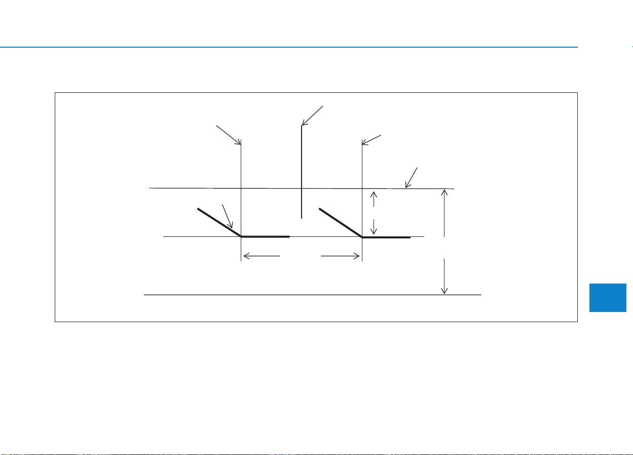
7-95
7
Maintenance
Headlamp low beam (RHD side)
1. Turn the low beam on without driver aboard.
2. The cut-off line should be projected in the cut-off line shown in the picture.
3. When aiming the low beam, vertical aiming should be adjusted after adjusting the horizontal aiming.
4. If headlamp leveling device is equipped, adjust the head lamp leveling device switch with 0 positions.
:
&DUD[LV
9HUWLFDOOLQHRIOHIW
KHDGODPSEXOEFHQWHU
&XWRIIOLQH
9HUWLFDOOLQHRIULJKW
KHDGODPSEXOEFHQWHU
+RUL]RQWDOOLQHRI
KHDGODPSEXOEFHQWHU
*5281'
+
/RZEHDP
/RZEHDP
OPDE076083
■ Based on 10m screen
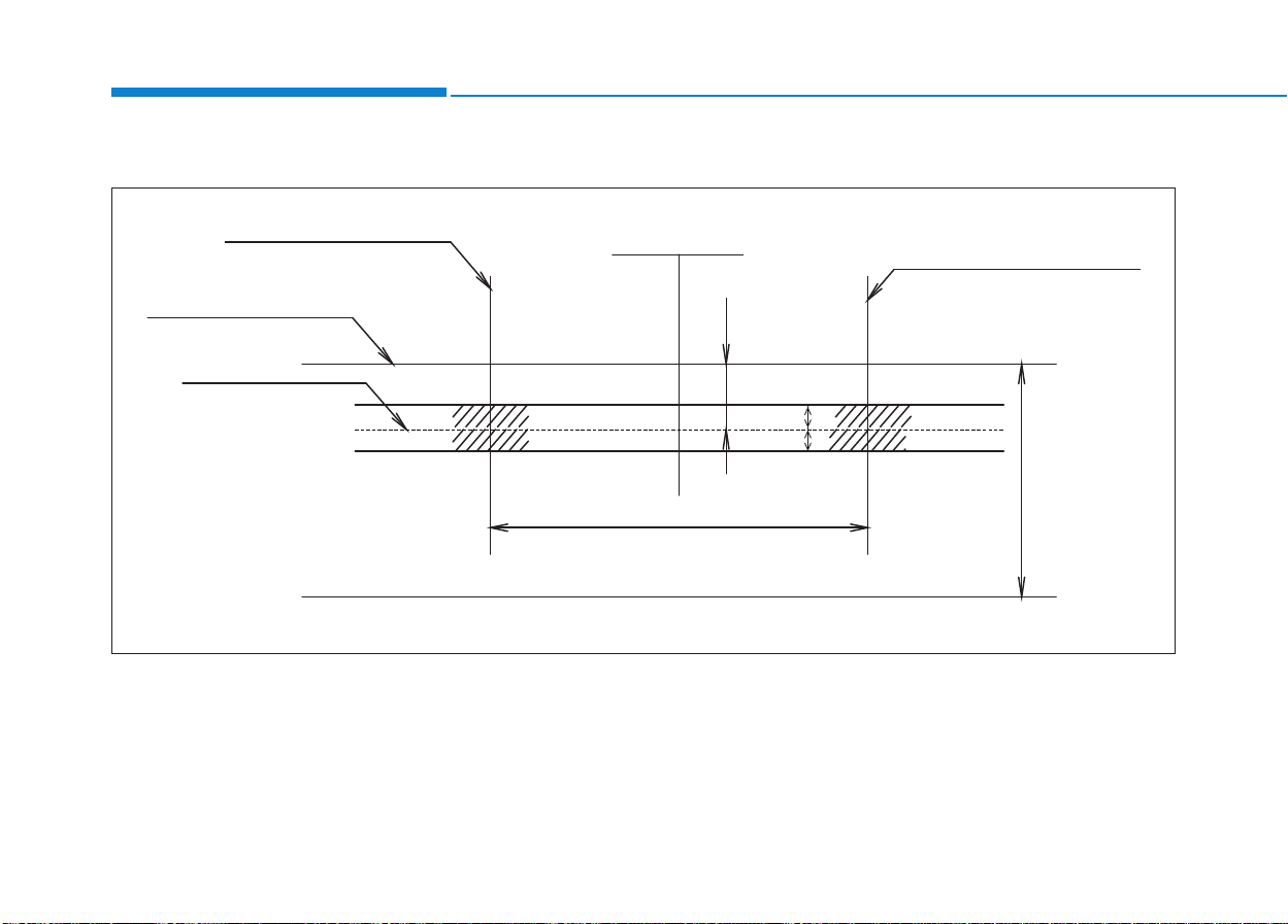
7-96
Maintenance
Front fog lamp
1. Turn the front fog lamp on without the driver aboard.
2. The cut-off line should be projected in the allowable range (shaded region).
Vertical line of the left fog lamp bulb center
Vertical line of the right fog lamp bulb center
H3 (Front fog)
Car axis
200mm
+30
-30
Horizontal line of fog lamp bulb center
Cut-off line
W3 (Front fog)
GROUND
OPDE076084
■ Based on 10m screen
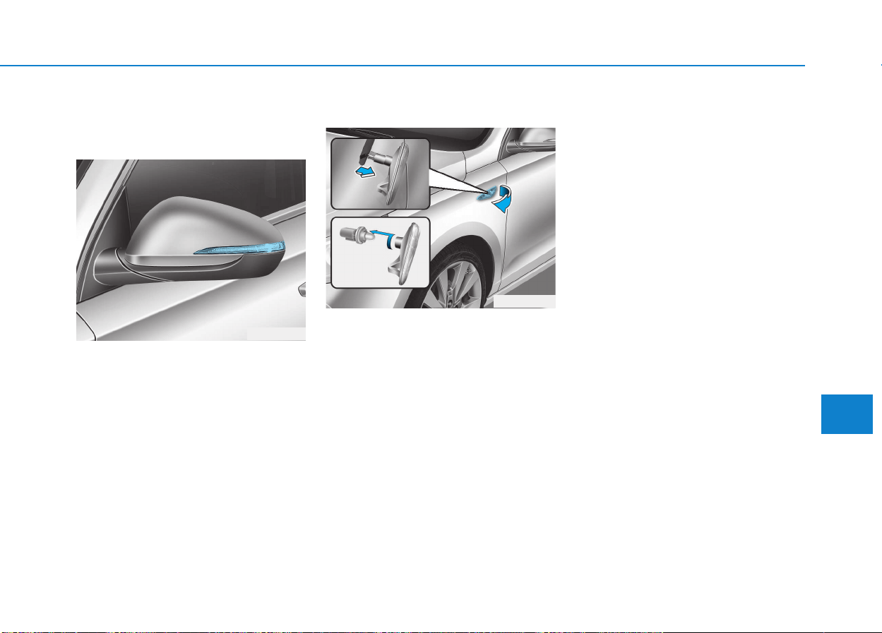
7-97
7
Maintenance
Side repeater lamp replace-
ment
Type A
If the light bulb does not operate, we
recommend you to have the vehicle
checked by an authorized HYUNDAI
dealer.
Type B
1.Remove the lamp assembly from
the vehicle by prying the lens and
pulling the assembly out.
2.Disconnect the bulb electrical con-
nector.
3.Separate the socket and the lens
parts by turning the socket coun-
terclockwise until the tabs on the
socket align with the slots on the
lens part.
4.Remove the bulb by pulling it
straight out.
5.Insert a new bulb in the socket.
6.Reassemble the socket and the
lens part.
7.Connect the bulb electrical con-
nector.
8.Reinstall the lamp assembly to the
body of the vehicle.
OPDE076079
OPD076044
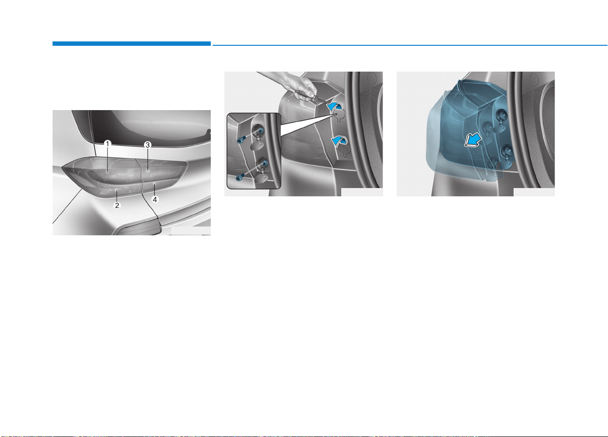
7-98
Maintenance
Rear combination lamp bulb
replacement
Type A
(1) Stop/Tail lamp
(2) Turn signal lamp
(3) Tail lamp
(4) Backup lamp
Stop/Tail lamp and turn signal lamp
1. Turn off the engine.
2. Open the tailgate.
3. Open the lamp assembly retaining
screw covers.
4. Loosen the lamp assembly retain-
ing screws with a cross-tip screw-
driver.
5. Remove the rear combination
lamp assembly from the body of
the vehicle.
OPD076048
OPD076045
OPD076047
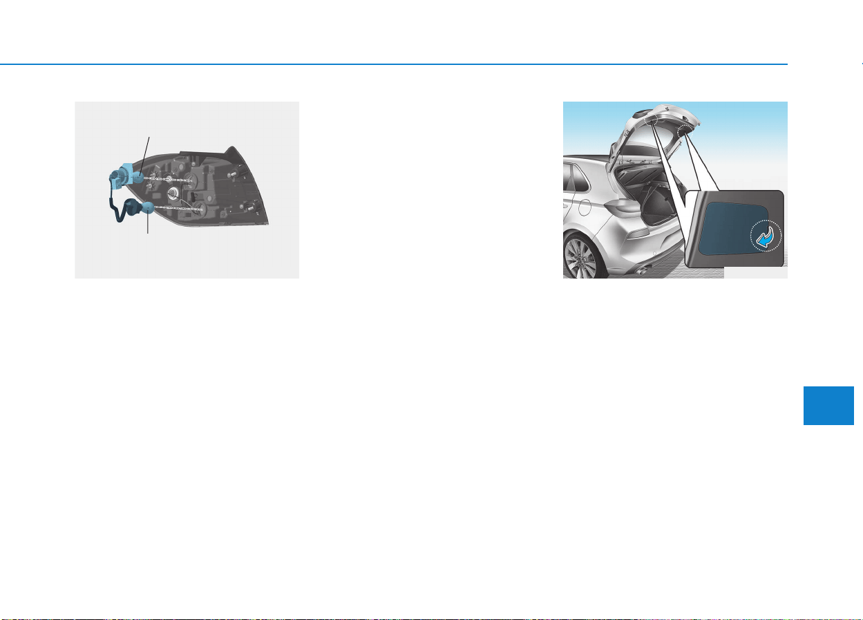
7-99
7
Maintenance
6. Remove the socket from the
assembly by turning the socket
counterclockwise until the tabs on
the socket align with the slots on
the assembly.
7. Remove the bulb from the socket
by pressing it in and rotating it
counterclockwise until the tabs on
the bulb align with the slots in the
socket. Pull the bulb out of the
socket.
8. Insert a new bulb by inserting it
into the socket and rotating it until
it locks into place.
9. Install the socket in the assembly
by aligning the tabs on the socket
with the slots in the assembly.
Push the socket into the assembly
and turn the socket clockwise.
10. Reinstall the lamp assembly to
the body of the vehicle.
Tail lamp and backup lamp
1. Turn off the engine.
2. Open the tailgate.
3. Remove the service cover using a
flat-blade screwdriver.
OPD076049
Stop/tail lamp
Turn signal lamp
OPDE076072
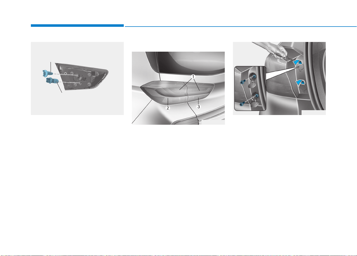
7-100
Maintenance
4. Remove the socket from the
assembly by turning the socket
counterclockwise until the tabs on
the socket align with the slots on
the assembly.
5. Remove the bulb by pulling it
straight out.
6. Insert a new bulb by inserting it
into the socket and rotating it until
it locks into place.
7. Install the socket into the assembly
by aligning the tabs on the socket
with the slots in the assembly.
Push the socket into the assembly
and turn the socket clockwise.
8. Reinstall the service cover.
Type B
(1) Stop/Tail lamp
(2) Turn signal lamp
(3) Backup lamp
Stop/Tail lamp
If the LED lamp does not operate,
have the vehicle checked by an
authorized HYUNDAI dealer.
Turn signal lamp
1. Turn off the engine.
2. Open the tailgate.
3. Open the lamp assembly retaining
screw covers.
4. Loosen the lamp assembly retain-
ing screws with a cross-tip screw-
driver.
OPD076046
OPD076052
Backup lamp
Tail lamp
OPD076047
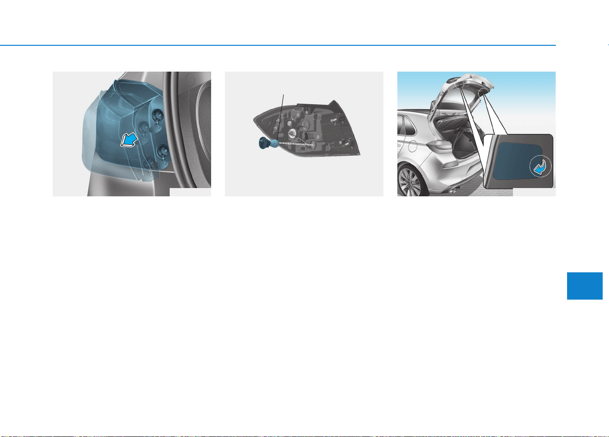
7-101
7
Maintenance
5. Remove the rear combination
lamp assembly from the body of
the vehicle.
6. Remove the socket from the assem-
bly by turning the socket counter-
clockwise until the tabs on the socket
align with the slots on the assembly.
7. Remove the bulb from the socket by
pressing it in and rotating it counter-
clockwise until the tabs on the bulb
align with the slots in the socket. Pull
the bulb out of the socket.
8. Insert a new bulb by inserting it into
the socket and rotating it until it locks
into place.
9. Install the socket in the assembly by
aligning the tabs on the socket with
the slots in the assembly. Push the
socket into the assembly and turn the
socket clockwise.
10. Reinstall the lamp assembly to the
body of the vehicle
Backup lamp
1. Turn off the engine.
2. Open the tailgate.
3. Remove the service cover using a
flat-blade screwdriver.
OPD076048 OPD076064
Turn signal lamp
OPDE076072
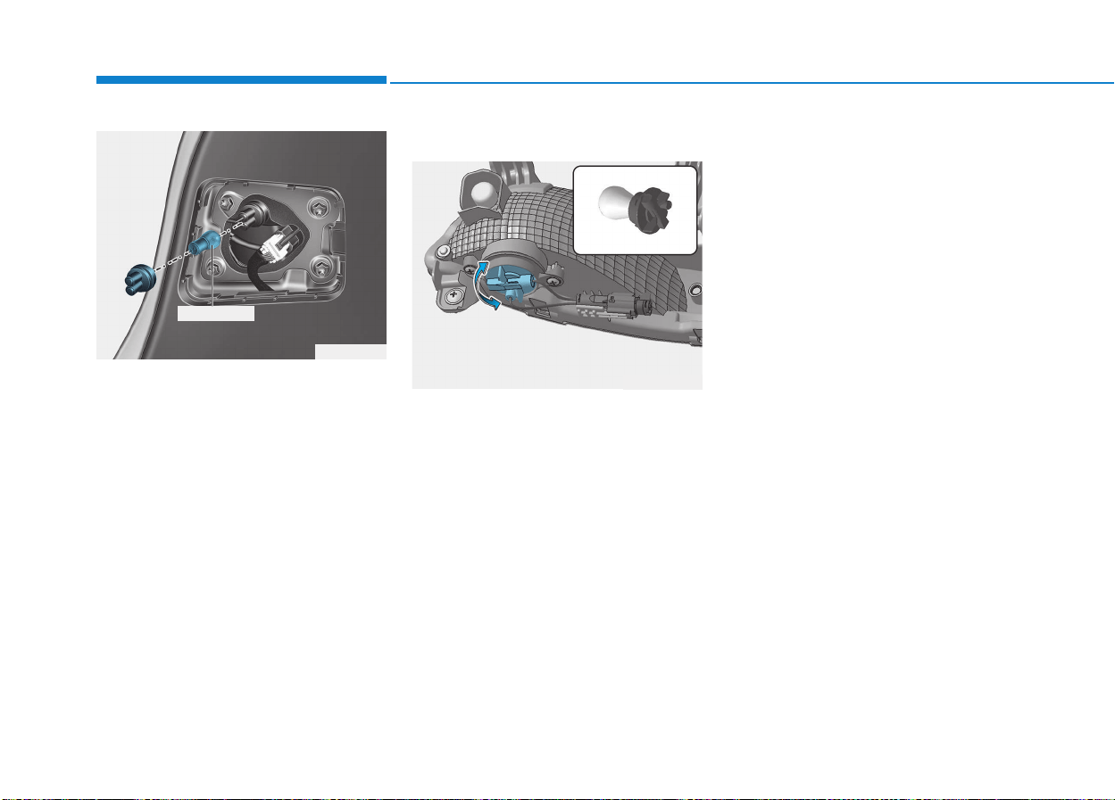
7-102
Maintenance
4. Remove the bulb by pulling it
straight out.
5. Insert a new bulb by inserting it
into the socket and rotating it until
it locks into place.
6. Install the socket into the assembly
by aligning the tabs on the socket
with the slots in the assembly.
Push the socket into the assembly
and turn the socket clockwise.
7. Reinstall the service cover.
Rear fog lamp
1. Loosen the pin-type retainers and
screws of the rear wheel guard and
then detach it from the rear bumper.
2. Reach your hand into the back of
the rear bumper.
3. Remove the socket from the hous-
ing by turning the socket counter-
clockwise until the tabs on the sock-
et align with the slots of the housing.
4. Remove the bulb from the socket by
pressing it in and rotating it counter-
clockwise until the tabs on the bulb
align with the slots in the socket.
Pull the bulb out of the socket.
5. Insert a new bulb by inserting it into
the socket and rotating it until it
locks into place.
6. Install the socket into the housing by
aligning the tabs on the socket with
the slots in the housing. Push the
socket into the housing and turn the
socket clockwise.
OPD076053
Backup lamp
OPDE076095
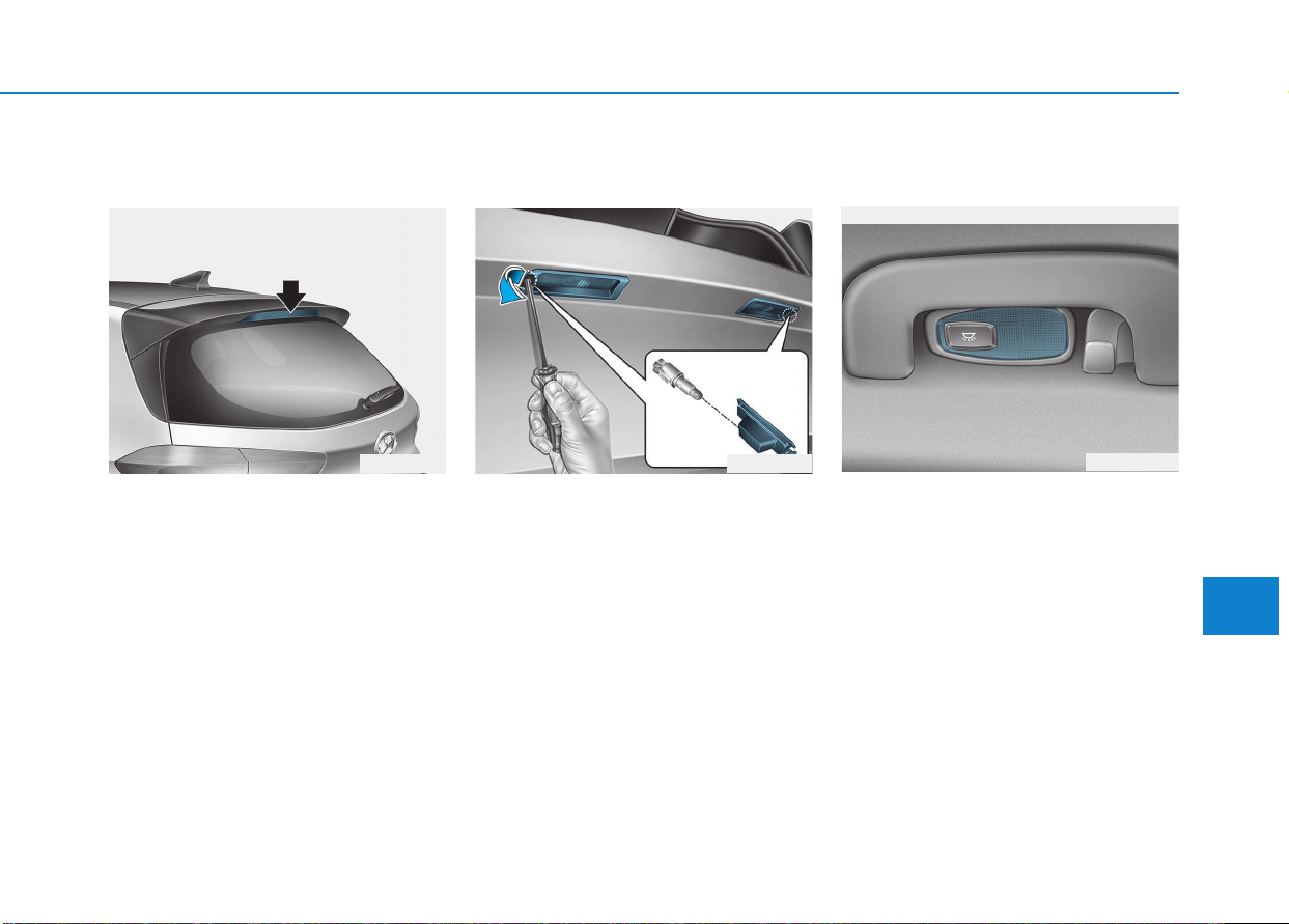
7-103
7
Maintenance
High mounted stop lamp
replacement
If the high mounted stop lamp does not
operate, we recommend that you con-
tact an authorized HYUNDAI dealer.
License plate light bulb
replacement
1. Using a flat-blade screwdriver,
gently pry the lens cover from the
lamp housing.
2. Remove the bulb by pulling it
straight out.
3. Install a new bulb.
4. Reinstall in the reverse order.
Interior light bulb replacement
Room lamp
If the LED lamp does not operate, we
recommend you to have the vehicle
checked by an authorized HYUNDAI
dealer.
OPD076054 OPD076055
OPDE076057
■ Room lamp - with sunroof
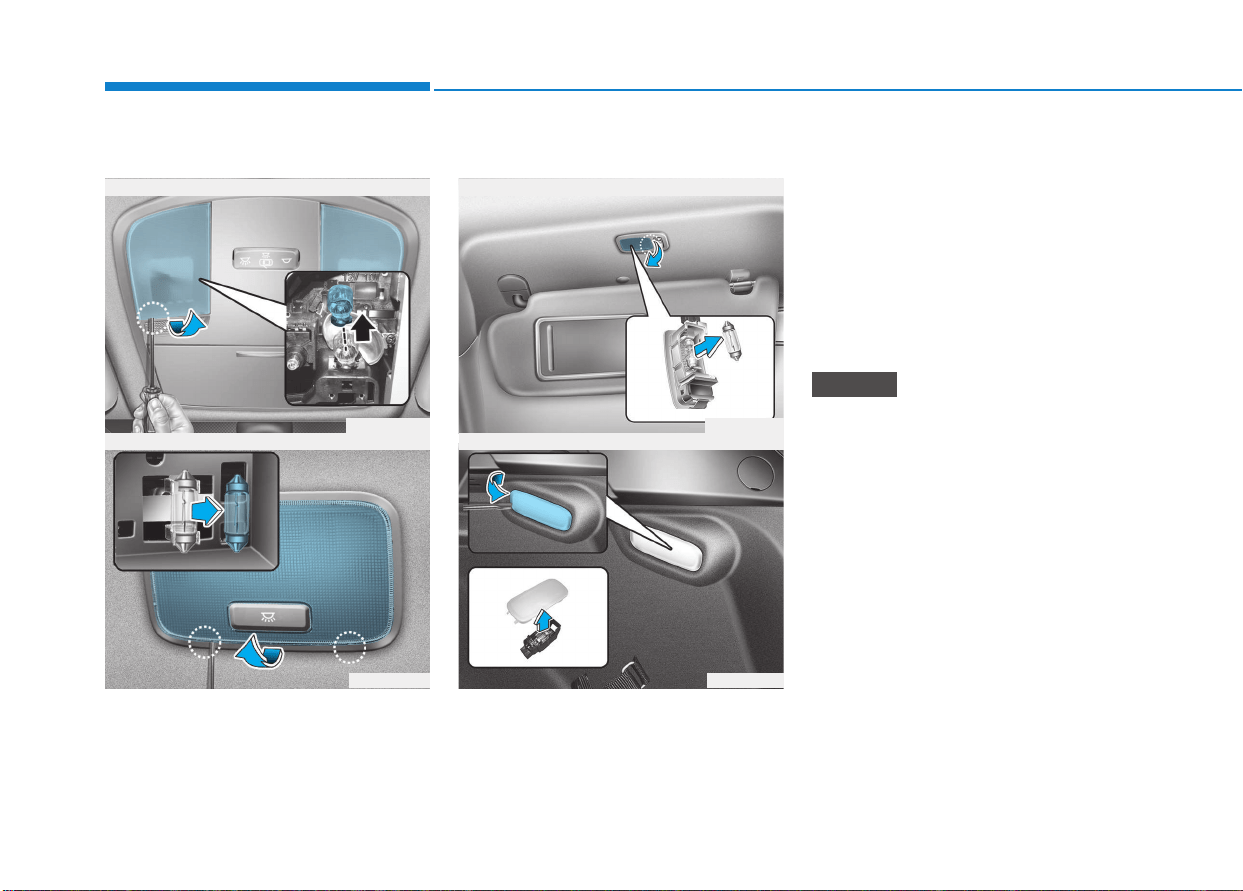
7-104
Maintenance
1. Using a flat-head screwdriver,
gently pry the lens from the interi-
or light housing.
2. Remove the bulb by pulling it
straight out.
3. Install a new bulb in the socket.
4. Align the lens tabs with the interior
light housing notches and snap
the lens into place.
Be careful not to damage the
cover, tab, and plastic housing.
NOTICE
■ Map lamp
OPD076056
OAD075045
■ Vanity mirror lamp
■ Luggage room lamp
OPD076063
OPD076059
■ Room lamp - without sunroof
Map lamp, room lamp, vanity mirror lamp and tailgate room lamp

7-105
7
Maintenance
AAPPPPEEAARRAANNCCEE CCAARREE
Exterior care
Exterior general caution
It is very important to follow the label
directions when using any chemical
cleaner or polish. Read all warning
and caution statements that appear
on the label.
Finish maintenance
Washing
To help protect your vehicle’s finish
from rust and deterioration, wash it
thoroughly and frequently at least
once a month with lukewarm or cold
water.
If you use your vehicle for off-road
driving, you should wash it after each
off-road trip. Pay special attention to
the removal of any accumulation of
salt, dirt, mud, and other foreign
materials. Make sure the drain holes
in the lower edges of the doors and
rocker panels are kept clear and
clean.
Insects, tar, tree sap, bird droppings,
industrial pollution and similar deposits
can damage your vehicle’s finish if not
removed immediately.
Even prompt washing with plain water
may not completely remove all these
deposits.
A mild soap, safe for use on painted
surfaces, may be used.
After washing, rinse the vehicle thor-
oughly with lukewarm or cold water.
Do not allow soap to dry on the finish.
• Do not use strong soap, chemi-
cal detergents or hot water, and
do not wash the vehicle in direct
sunlight or when the body of the
vehicle is warm.
• Be careful when washing the
side windows of your vehicle.
Especially, with high-pressure
water, water may leak through
the windows and wet the interior.
• To prevent damage to the plastic
parts and lamps, do not clean
with chemical solvents or strong
detergents.
High-pressure washing
• When using high-pressure washers,
make sure to maintain sufficient dis-
tance from the vehicle.
Insufficient clearance or excessive
pressure can lead to component
damage or water penetration.
• Do not spray the camera, sensors or
its surrounding area directly with a
high pressure washer. Shock
applied from high pressure water
may cause the device to not operate
normally.
• Do not bring the nozzle tip close to
boots (rubber or plastic covers) or
connectors as they may be dam-
aged if they come into contact with
high pressure water.
NOTICE
Wet brakes
After washing the vehicle, test
the brakes while driving slowly
to see if they have been affected
by water. If braking performance
is impaired, dry the brakes by
applying them lightly while main-
taining a slow forward speed.
WARNING
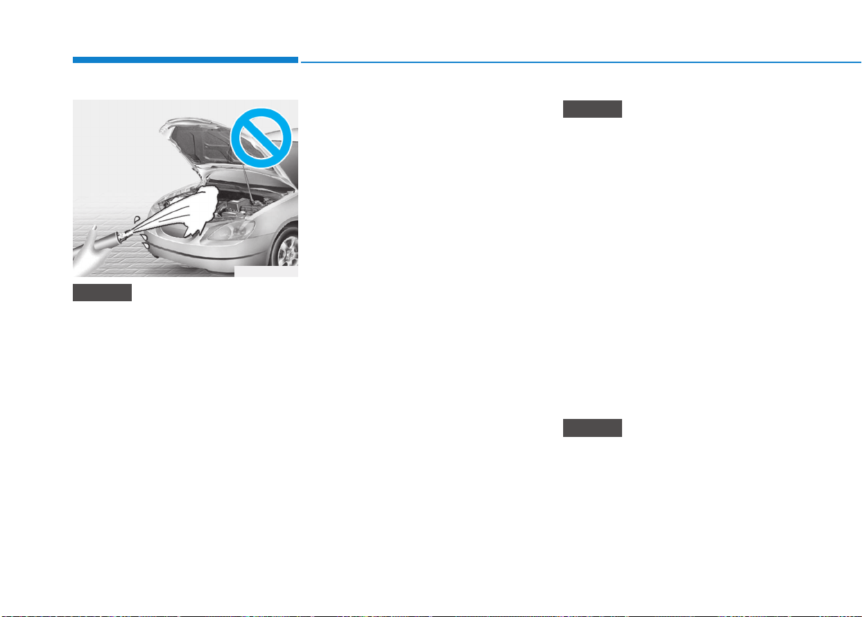
7-106
Maintenance
• Water washing in the engine com-
partment including high pressure
water washing may cause the fail-
ure of electrical circuits located in
the engine compartment.
• Never allow water or other liquids
to come in contact with electri-
cal/electronic components inside
the vehicle as this may damage
them.
Waxing
A good coat of wax is a barrier
between your paint and contaminate.
Keeping a good coat of wax on your
vehicle will help protect it.
Wax the vehicle when water will no
longer bead on the paint.
Always wash and dry the vehicle
before waxing. Use a good quality
liquid or paste wax, and follow the
manufacturer’s instructions. Wax all
metal trim to protect it and to main-
tain its luster.
Removing oil, tar, and similar materi-
als with a spot remover will usually
strip the wax from the finish. Be sure
to re-wax these areas even if the rest
of the vehicle does not yet need wax-
ing.
• Wiping dust or dirt off the body
with a dry cloth will scratch the
finish.
• Do not use steel wool, abrasive
cleaners, or strong detergents
containing highly alkaline or
caustic agents on chrome-plated
or anodized aluminum parts. This
may result in damage to the pro-
tective coating and cause discol-
oration or paint deterioration.
Finish damage repair
Deep scratches or stone chips in the
painted surface must be repaired
promptly. Exposed metal will quickly
rust and may develop into a major
repair expense.
If your vehicle is damaged and
requires any metal repair or
replacement, be sure the body
shop applies anti-corrosion materi-
als to the parts repaired or replaced.
NOTICE
NOTICE
NOTICE
OLMB073082
7-107
7
Maintenance
Bright-metal maintenance
• To remove road tar and insects,
use a tar remover, not a scraper or
other sharp object.
• To protect the surfaces of bright-
metal parts from corrosion, apply a
coating of wax or chrome preser-
vative and rub to a high luster.
• During winter weather or in coastal
areas, cover the bright metal parts
with a heavier coating of wax or
preservative. If necessary, coat the
parts with non-corrosive petroleum
jelly or other protective compound.
Underbody maintenance
Corrosive materials used for ice and
snow removal and dust control may
collect on the underbody. If these
materials are not removed, acceler-
ated rusting can occur on underbody
parts such as the fuel lines, frame,
floor pan and exhaust system, even
though they have been treated with
rust protection.
Thoroughly flush the vehicle under-
body and wheel openings with luke-
warm or cold water once a month,
after off-road driving and at the end of
each winter. Pay special attention to
these areas because it is difficult to
see all the mud and dirt. It will do
more harm than good to wet down the
road grime without removing it. The
lower edges of doors, rocker panels,
and frame members have drain holes
that should not be allowed to clog with
dirt; trapped water in these areas can
cause rusting.
Aluminum wheel maintenance
The aluminum wheels are coated with
a clear protective finish.
• Do not use any abrasive cleaner,
polishing compound, solvent,
or wire brushes on aluminum
wheels.
• Clean the wheel when it has
cooled.
• Use only a mild soap or neutral
detergent, and rinse thoroughly
with water. Also, be sure to clean
the wheels after driving on salted
roads.
• Do not wash the wheels with high-
speed car wash brushes.
• Do not use any cleanser contain-
ing acid or alkaline detergents.
NOTICE
After washing the vehicle, test
the brakes while driving slowly
to see if they have been affected
by water. If braking performance
is impaired, dry the brakes by
applying them lightly while main-
taining a slow forward speed.
WARNING

7-108
Maintenance
Corrosion protection
Protecting your vehicle from corro-
sion
By using the most advanced design
and construction practices to combat
corrosion, we produces cars of the
highest quality. However, this is only
part of the job. To achieve the long-
term corrosion resistance your vehi-
cle can deliver, the owner's coopera-
tion and assistance is also required.
Common causes of corrosion
The most common causes of corro-
sion on your car are:
• Road salt, dirt and moisture that is
allowed to accumulate underneath
the car.
• Removal of paint or protective coat-
ings by stones, gravel, abrasion or
minor scrapes and dents which
leave unprotected metal exposed to
corrosion.
High-corrosion areas
If you live in an area where your car
is regularly exposed to corrosive
materials, corrosion protection is
particularly important. Some of the
common causes of accelerated cor-
rosion are road salts, dust control
chemicals, ocean air and industrial
pollution.
Moisture breeds corrosion
Moisture creates the conditions in
which corrosion is most likely to occur.
For example, corrosion is accelerated
by high humidity, particularly when
temperatures are just above freezing.
In such conditions, the corrosive
material is kept in contact with the car
surfaces by moisture that is slow to
evaporate.
Mud is particularly corrosive because
it is slow to dry and holds moisture in
contact with the vehicle. Although the
mud appears to be dry, it can still
retain the moisture and promote cor-
rosion.
High temperatures can also acceler-
ate corrosion of parts that are not
properly ventilated so the moisture
can be dispersed. For all these rea-
sons, it is particularly important to
keep your car clean and free of mud
or accumulations of other materials.
This applies not only to the visible sur-
faces but particularly to the underside
of the car.
To help prevent corrosion
You can help prevent corrosion from
getting started by observing the fol-
lowing:

7-109
7
Maintenance
Keep your car clean
The best way to prevent corrosion is
to keep your car clean and free of
corrosive materials. Attention to the
underside of the car is particularly
important.
• If you live in a high-corrosion area
— where road salts are used, near
the ocean, areas with industrial
pollution, acid rain, etc.—, you
should take extra care to prevent
corrosion. In winter, hose off the
underside of your car at least once
a month and be sure to clean the
underside thoroughly when winter
is over.
• When cleaning underneath the car,
give particular attention to the
components under the fenders and
other areas that are hidden from
view. Do a thorough job; just damp-
ening the accumulated mud rather
than washing it away will acceler-
ate corrosion rather than prevent
it. Water under high pressure and
steam are particularly effective in
removing accumulated mud and
corrosive materials.
• When cleaning lower door panels,
rocker panels and frame members,
be sure that drain holes are kept
open so that moisture can escape
and not be trapped inside to accel-
erate corrosion.
Keep your garage dry
Don't park your car in a damp, poor-
ly ventilated garage. This creates a
favorable environment for corrosion.
This is particularly true if you wash
your car in the garage or drive it into
the garage when it is still wet or cov-
ered with snow, ice or mud. Even a
heated garage can contribute to cor-
rosion unless it is well ventilated so
moisture is dispersed.
Keep paint and trim in good condition
Scratches or chips in the finish
should be covered with "touch-up"
paint as soon as possible to reduce
the possibility of corrosion. If bare
metal is showing through, the atten-
tion of a qualified body and paint
shop is recommended.
Bird droppings : Bird droppings are
highly corrosive and may damage
painted surfaces in just a few hours.
Always remove bird droppings as
soon as possible.
Don't neglect the interior
Moisture can collect under the floor
mats and carpeting to cause corro-
sion. Check under the mats periodi-
cally to be sure the carpeting is dry.
Use particular care if you carry fertil-
izers, cleaning materials or chemi-
cals in the car.
These should be carried only in
proper containers and any spills or
leaks should be cleaned up, flushed
with clean water and thoroughly
dried.

7-110
Maintenance
Interior care
Interior general precautions
Prevent chemicals such as perfume,
cosmetic oil, sun cream, hand cleaner
and air freshener from contacting the
interior parts because they may
cause damage or discoloration. If they
do contact the interior parts, wipe them
off immediately.
See the instructions that follow for
the proper way to clean vinyl.
Never allow water or other liquids to
come in contact with electrical/elec-
tronic components inside the vehi-
cle as this may damage them.
When cleaning leather products
(steering wheel, seats etc.), use
neutral detergents or low alcohol
content solutions. If you use high
alcohol content solutions or acid/
alkaline detergents, the color of
the leather may fade or the sur-
face may get stripped off.
Cleaning the upholstery and
interior trim
Vinyl
Remove dust and loose dirt from
vinyl with a whisk broom or vacuum
cleaner. Clean vinyl surfaces with a
vinyl cleaner.
Fabric
Remove dust and loose dirt from fabric
with a whisk broom or vacuum cleaner.
Clean with a mild soap solution recom-
mended for upholstery or carpets.
Remove fresh spots immediately with
a fabric spot cleaner. If fresh spots do
not receive immediate attention, the
fabric can be stained and its color can
be affected. Also, its fire-resistant prop-
erties can be reduced if the material is
not properly maintained.
Using anything but recommended
cleaners and procedures may affect
the fabric’s appearance and fire-
resistant properties.
Cleaning the lap/shoulder belt
webbing
Clean the belt webbing with any mild
soap solution recommended for clean-
ing upholstery or carpet. Follow the
instructions provided with the soap. Do
not bleach or re-dye the webbing
because this may weaken it.
Cleaning the interior window
glass
If the interior glass surfaces of the
vehicle become fogged (that is, cov-
ered with an oily, greasy or waxy film),
they should be cleaned with glass
cleaner. Follow the directions on the
glass cleaner container.
Do not scrape or scratch the inside
of the rear window. This may result
in damage to the rear window
defroster grid.
NOTICE
NOTICE
NOTICE
NOTICE

7-111
7
Maintenance
EEMMIISSSSIIOONN CCOONNTTRROOLL SSYYSSTTEEMM
The emission control system of your
vehicle is covered by a written limited
warranty. Please see the warranty
information contained in the Service
Passport in your vehicle.
Your vehicle is equipped with an
emission control system to meet all
emission regulations.
There are three emission control
systems which are as follows.
(1) Crankcase emission control sys-
tem
(2) Evaporative emission control sys-
tem
(3) Exhaust emission control system
In order to assure the proper function
of the emission control systems, it is
recommended that you have your car
inspected and maintained by an
authorized HYUNDAI dealer in accor-
dance with the maintenance schedule
in this manual.
1. Crankcase emission control
system
The positive crankcase ventilation
system is employed to prevent air
pollution caused by blow-by gases
being emitted from the crankcase.
This system supplies fresh filtered air
to the crankcase through the air
intake hose. Inside the crankcase,
the fresh air mixes with blow-by
gases, which then pass through the
PCV valve into the induction system.
2. Evaporative emission con-
trol system
The Evaporative Emission Control
System is designed to prevent fuel
vapors from escaping into the atmos-
phere.
For the Inspection and Maintenance
Test (With Electronic Stability Control
(ESC) system)
• To prevent the vehicle from
misfiring during dynamome-
ter testing, turn the Electronic
Stability Control (ESC) sys-
tem off by pressing the ESC
switch.
• After dynamometer testing is
completed, turn the ESC sys-
tem back on by pressing the
ESC switch again.
CAUTION

7-112
Maintenance
Engine exhaust gases contain
carbon monoxide (CO). Though
colorless and odorless, it is dan-
gerous and could be lethal if
inhaled. Follow the instructions
following to avoid CO poisoning.
WARNING
Canister
Fuel vapors generated inside the fuel
tank are absorbed and stored in the
onboard canister. When the engine is
running, the fuel vapors absorbed in
the canister are drawn into the surge
tank through the purge control sole-
noid valve.
Purge Control Solenoid Valve
(PCSV)
The purge control solenoid valve is
controlled by the Engine Control
Module (ECM); when the engine
coolant temperature is low during
idling, the PCSV closes so that evap-
orated fuel is not taken into the
engine. After the engine warms-up
during ordinary driving, the PCSV
opens to introduce evaporated fuel to
the engine.
3. Exhaust emission control
system
The Exhaust Emission Control System
is a highly effective system which con-
trols exhaust emissions while main-
taining good vehicle performance.
Vehicle modifications
This vehicle should not be modified.
Modification of your vehicle could
affect its performance, safety or
durability and may even violate gov-
ernmental safety and emissions reg-
ulations.
In addition, damage or performance
problems resulting from any modifi-
cation may not be covered under
warranty.
• If you use unauthorized electronic
devices, it may cause the vehicle to
operate abnormally, wire damage,
battery discharge and fire. For your
safety, do not use unauthorized
electronic devices.
Engine exhaust gas precautions
(carbon monoxide)
• Carbon monoxide can be present
with other exhaust fumes.Therefore,
if you smell exhaust fumes of any
kind inside your vehicle, have it
inspected and repaired immediately.
If you ever suspect exhaust fumes
are coming into your vehicle, drive it
only with all the windows fully open.
Have your vehicle checked and
repaired immediately.

7-113
7
Maintenance
• Do not operate the engine in con-
fined or closed areas (such as
garages) any more than what is
necessary to move the vehicle in or
out of the area.
• When the vehicle is stopped in an
open area for more than a short
time with the engine running,
adjust the ventilation system (as
needed) to draw outside air into the
vehicle.
• Never sit in a parked or stopped
vehicle for any extended time with
the engine running.
• When the engine stalls or fails to
start, excessive attempts to restart
the engine may cause damage to
the emission control system.
Operating precautions for cat-
alytic converters (if equipped)
Your vehicle is equipped with a cat-
alytic converter emission control
device.
Therefore, the following precautions
must be observed:
• Use only UNLEADED FUEL for
gasoline engine.
• Do not operate the vehicle when
there are signs of engine malfunc-
tion, such as misfire or a noticeable
loss of performance.
• Do not misuse or abuse the
engine. Examples of misuse are
coasting with the engine off and
descending steep grades in gear
with the engine off.
• Do not operate the engine at high
idle speed for extended periods (5
minutes or more).
• A hot exhaust system can
ignite flammable items under
your vehicle. Do not park, idle,
or drive the vehicle over or
near flammable objects, such
as dry grass, paper, leaves, etc.
• The exhaust system and cat-
alytic system are very hot while
the engine is running or imme-
diately after the engine is
turned off. Keep away from the
exhaust system and catalytic,
you may get burned.
Also, do not remove the heat
sink around the exhaust sys-
tem, do not seal the bottom of
the vehicle or do not coat the
vehicle for corrosion control. It
may present a fire risk under
certain conditions.
WARNING

7-114
Maintenance
• Do not modify or tamper with any
part of the engine or emission con-
trol system. All inspections and
adjustments must be made by an
authorized HYUNDAI dealer.
• Avoid driving with a very low fuel
level. If you run out of gasoline, it
could cause the engine to misfire
and result in excessive loading of
the catalytic converter.
Failure to observe these precautions
could result in damage to the catalytic
converter and to your vehicle.
Additionally, such actions could void
your warranties.
Diesel particulate filter (DPF)
(if equipped)
The Diesel Particulate Filter (DPF)
system removes the soot in the
exhaust gas.
The DPF system automatically burns
(or oxidizes) the accumulated soot in
accordance with the driving situa-
tions, unlike a disposable air filter.
In other words, the accumulated soot
is automatically purged out by the
engine control system and by the high
exhaust-gas temperature at normal/
high driving speeds.
However, when the vehicle is continu-
ally driven at repeated short distance
or driven at low speed for a long time,
the accumulated soot may not be
automatically removed because of low
exhaust gas temperature. In this case,
the accumulated soot is out of the
detection range, the soot oxidization
process does not occur, and the
Malfunction Indicator Lamp ( )
Illuminates.
The Malfunction Indicator Lamp (MIL)
stops illuminating, when the driving
speed exceeds 60 km/h (37mph), or
when the engine rpm is between
1,500 and 2,500 with the gear in the
2nd position or above for approxi-
mately 25 minutes.
When the MIL continuously blinks or
the warning message “Check exhaust
system” illuminates in the above
cases, we recommend you to have the
DPF system checked by an author-
ized HYUNDAI dealer.
When the vehicle is continuously driv-
en with the MIL flashing for an extend-
ed period of time, it may damage the
DPF system and lower the fuel econ-
omy.

7-115
7
Maintenance
Lean NOx Trap (if equipped)
The Lean NOx Trap (LNT) system
removes the nitrogen oxide in the
exhaust gas. The smell can occur in
the exhaust gas depending on the
quality of the fuel and it can degrade
NOx reduction performance, please
use the regulated automotive diesel
fuel.
Diesel Fuel
(if equipped with DPF)
We recommend you to use only
the regulated diesel fuels, when
your vehicle is equipped with
the DPF system.
When you use other diesel fuels,
which is high in sulfurs (above
50 ppm) or contains unspecified
additives, it may damage the
DPF system and cause the white
smoke emission.
CAUTION

8
Specifications & Consumer information
8
Specifications & Consumer information
8
Dimensions..............................................................8-2
Engine......................................................................8-2
Bulb wattage...........................................................8-3
Tires and wheels....................................................8-4
Load and speed capacity tires (for europe)......8-5
Air conditioning system ........................................8-6
Vehicle weight and luggage volume....................8-6
Recommended lubricants and capacities ...........8-7
Recommended engine oil (For Europe).......................8-9
Recommended SAE viscosity number..........................8-9
Vehicle identification number (VIN)..................8-12
Vehicle certification label...................................8-12
Tire specification and pressure label ...............8-13
Engine number .....................................................8-13
Air conditioner compressor label ......................8-14
Refrigerant label..................................................8-14
Declaration of conformity ..................................8-14

8-2
Specifications & Consumer information
D
DIIMMEENNSSIIOONNSS
E
ENNGGIINNEE
Item mm (in)
Overall length 4,340 (170.86)
Overall width 1,795 (70.66)
Overall height 1,455 (57.28)
Front tread
195/65 R15 1,573 (61.92)
205/55 R16 1,565 (61.61)
225/45 R17 1,559 (61.37)
Rear tread
195/65 R15 1,581 (62.24)
205/55 R16 1,573 (61.92)
225/45 R17 1,567 (61.69)
Wheelbase 2,650 (104.33)
Item
Gasoline Engine Diesel Engine
1.0 T-GDI 1.4 T-GDI 1.4 MPI 1.6 MPI 1.6 TCI
Displacement
cc (cu. in)
997
(60.84)
1353
(82.56)
1,368
(83.48)
1591
(97.08)
1582
(96.53)
Bore x Stroke
mm (in.)
71.0 x 84.0
(2.79 x 3.30)
71.6 x 84.0
(2.81 x 3.30)
72.0 X 84.0
(2.83 x 3.30)
77.0 x 85.44
(3.03x3.06)
77.2 x 84.5
(3.03 x 3.32)
Firing order
1-2-3 1-3-4-2 1-3-4-2 1-3-4-2 1-3-4-2
No. of cylinders
In-line 3 cylinder In-line 4 cylinder In-line 4 cylinder In-line 4 cylinder In-line 4 cylinder

8
Specifications & Consumer information
BBUULLBB WWAATTTTAAGGEE
Light Bulb Bulb Type Wattage
Front
Type A
Headlamp
Low H7LL 55
High H7LL 55
Position lamp W5W 5
Turn signal lamp PY21W 21
Daytime running light P21W 21
Type B
Headlamp
Low H7LL 55
High H7LL 55
Position lamp LED LED
Turn signal lamp PY21W 21
Static bending light (SBL) H7LL 55
Daytime running light LED LED
Type C
Headlamp
Low LED LED
High LED LED
Position lamp LED LED
Turn signal lamp LED LED
Static bending light (SBL) LED LED
Daytime running light LED LED
Fog lamp HB4 51
Side repeater lamp
Type A LED LED
Type B W5W 5
Rear
Type A
Stop/Tail lamp P21/5W 21/5
Turn signal lamp PY21W 21
Tail lamp W5W 5
Backup lamp W16W 16
Type B
Stop/Tail lamp LED LED
Turn signal lamp PY21W 21
Backup lamp LED LED
High mounted stop light LED LED
8-3
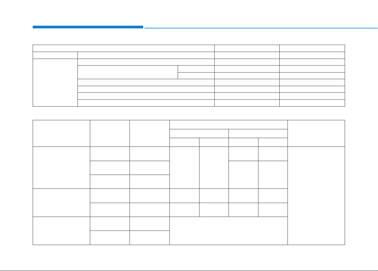
8-4
Specifications & Consumer information
Item Tire Size Wheel Size
Inflation Pressure Bar (kPa, psi)
Wheel Lug Nut
Torque
kgf·m (lbf·ft, N·m)
Normal Load Maximum Load
Front Rear Front Rear
Full size tire
195/65 R15 6.0J X 15
2.2
(220, 32)
2.2
(220, 32)
2.35
(235, 34)
2.5
(250, 36)
11~13
(79~94, 107~127)
205/55 R16 6.5J X 16
2.35
(235, 34)
2.75
(275,40)
225/45 R17 7.0J X 17
Full size tire
(for eco pack)
195/65 R15 6.0J X 15
2.35
(235, 34)
2.35
(235, 34)
2.35
(235, 34)
2.5
(250, 36)
205/55 R16 6.5J X 16
2.2
(220, 32)
2.2
(220, 32)
2.35
(235, 34)
2.75
(275, 40)
Compact spare tire
T125/80D15 4.0T×15
4.2 (420, 60)
T125/80D16 4.0T×16
TTIIRREESS AANNDD WWHHEEEELLSS
Light Bulb Bulb Type Wattage
Rear Fog lamp PY21W 21
Interior
Map lamp W10W 10
Room lamp
Type A FESTOON 8
Type B LED LED
Vanity mirror lamp FESTOON 5
Glove box lamp FESTOON 5
Luggage room lamp FESTOON 10
License plate lamp FESTOON 5
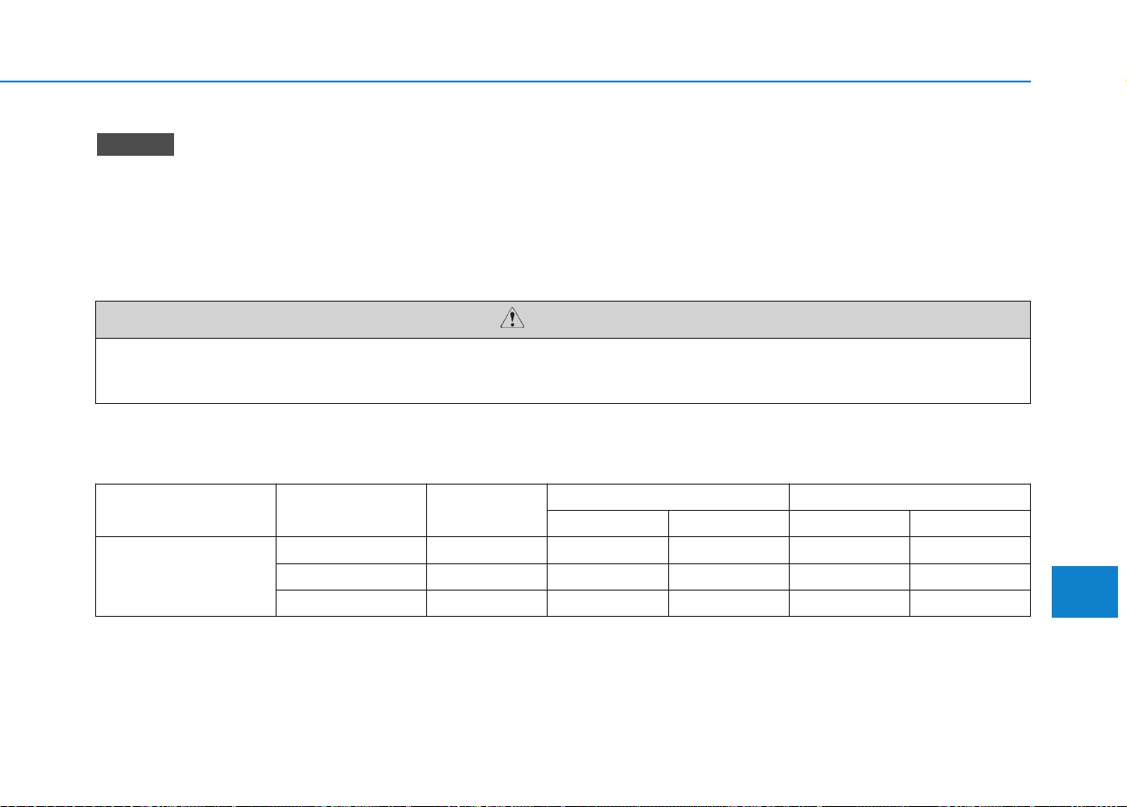
8-5
8
Specifications & Consumer information
When replacing tires, use the same size originally supplied with the vehicle.
Using tires of a different size can damage the related parts or make it work irregularly.
CAUTION
• It is permissible to add 20 kPa (3 psi) to the standard tire pressure specification if colder temperatures are
expected soon. Tires typically lose 7 kPa (1 psi) for every 7°C (12°F) temperature drop. If extreme tempera-
ture variations are expected, recheck your tire pressure as necessary to keep them properly inflated.
• An air pressure generally decreases, as you drive up to a high-altitude area above sea level.Thus, if you plan
to drive a high-altitude area, check the tire pressures in advance. If necessary, inflate them to a proper level
(Air inflation per altitude: +10 kPa/1 km (+2.4 psi/1 mile)).
NOTICE
*
1
LI : LOAD INDEX
*
2
SS : SPEED SYMBOL
Item Tire Size Wheel Size
Load Capacity Speed Capacity
LI *
1
kg SS *
2
km/h
Full size tire
195/65 R15 6.0J X 15 91 615 H 210
205/55 R16 6.5J X 16 91 615 H 210
225/45 R17 7.0J X 17 91 615 W 270
LLOOAADD AANNDD SSPPEEEEDD CCAAPPAACCIITTYY TTIIRREESS ((FFOORR EEUURROOPPEE))

8-6
Specifications & Consumer information
A
AIIRR CCOONNDDIITTIIOONNIINNGG SSYYSSTTEEMM
Item
Gasoline Engine Diesel Engine
1.0 T-GDI 1.4 T-GDI 1.4 MPI 1.6 MPI 1.6 TCI
M/T M/T DCT M/T M/T A/T M/T DCT
Gross vehicle weight
kg (lbs.)
1800
(3968)
1820
(4012)
1850
(4078)
1760
(3880)
1780
(3924)
1800
(3968)
1860
(4100)
1900
(4188)
Luggage volume (VDA)
l (cu ft.)
MIN 395 (13.95)
MAX 1,301 (45.94)
VVEEHHIICCLLEE WWEEIIGGHHTT AANNDD LLUUGGGGAAGGEE VVOOLLUUMMEE
Items Weight of Volume Classification
Refrigerant g (oz.) 500 (17.63)
R-1234yf (For Europe)
R-134a (Except Europe)
Compressor lubricant g (oz.) 110±10 (3.88±0.35) PAG
Contact an authorized HYUNDAI dealer for more details.
M/T : Manual transmission
A/T : Automatic transmission
DCT : Dual clutch transmission
Min : Behind rear seat to upper edge of the seat back.
Max : Behind front seat to roof.
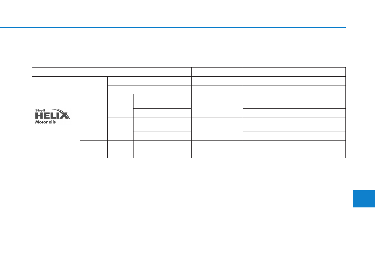
8-7
Specifications & Consumer information
RREECCOOMMMMEENNDDEEDD LLUUBBRRIICCAANNTTSS AANNDD CCAAPPAACCIITTIIEESS
To help achieve proper engine and powertrain performance and durability, use only lubricants of the proper quality.
The correct lubricants also help promote engine efficiency that results in improved fuel economy.
These lubricants and fluids are recommended for use in your vehicle.
Lubricant Volume Classification
Engine oil *
1
*
2
(drain and refill)
Recommends
Gasoline
1.0 T-GDI
3.6 l (3.8 US qt.)
ACEA A5/B5 *
3
1.4 T-GDI
4.2 l (4.4 US qt.)
ACEA A5/B5 *
3
1.4 MPI
Except Europe
3.6 l (3.8 US qt.)
API SM & ILSAC GF-4 (or above),
ACEA A5/B5 *
3
For Europe ACEA A5/B5 *
3
1.6 MPI
Except Middle East *
4
3.6 l (3.8 US qt.)
API SM & ILSAC GF-4 (or above),
ACEA A5/B5 *
3
For Middle East *
4
ACEA A5/B5 *
3
Diesel 1.6 TCI
with DPF *
5
5.3 l (5.6 US qt.)
ACEA C2 or C3
without DPF *
5
ACEA C2 or C3 or A3/B4
8
*
1
: Refer to the recommended SAE viscosity numbers on page 9.
*
2
: Engine oils labeled Energy Conserving Oil are now available. Along with other additional benefits, they contribute to fuel economy by reducing
the amount of fuel necessary to overcome engine friction. Often, these improvements are difficult to measure in everyday driving, but in a year’s
time, they can offer significant cost and energy savings.
*
3
: If the ACEA A5/B5 engine oil is not available in your country, you are able to use ACEA A3/B3, A3/B4.
*
4
: Middle East includes Morocco, Sudan and Egypt.
*
5
: Diesel Particulate Filter

8-8
Specifications & Consumer information
Lubricant Volume Classification
Manual
transmission fluid
1.0 T-GDI
1.6 ~ 1.7 l
(1.7 ~ 1.8 US qt.)
HK SYN MTF 70W (SK)
SPIRAX S6 GHME 70W MTF (H.K.SHELL)
GS MTF HD 70W (GS CALTEX)
API GL-4, SAE 70W, TGO-9
1.4 MPI
1.6 MPI
1.4 T-GDI
1.7 ~ 1.8 l
(1.8 ~ 1.9 US qt.)
1.6 TCI
Automatic transmission fluid
6.7 l (7.1 US qt.)
MICHANG ATF SP-IV, SK ATF SP-IV,
NOCA ATF SP-IV, HYUNDAI genuine ATF SP-IV
Dual clutch transmission
1.9 ~ 2.0 l
(2.0 ~ 2.1 US qt.)
HK SYN DCTF 70W (SK)
SPIRAX S6 GHME 70W DCTF (H.K.SHELL)
GS DCTF HD 70W (GS CALTEX)
API GL-4, SAE 70W
Coolant
1.0 T-GDI
6.0 l (6.3 US qt.)
Mixture of antifreeze and distilled water
(Ethylene-glycol with phosphate based coolant for
aluminum radiator)
1.4 T-GDI
6.1 l (6.4 US qt.)
1.4 MPI
5.8 l (6.1 US qt.)
1.6 MPI
M/T
5.7 l (6.0 US qt.)
A/T
5.6 l (5.9 US qt.)
1.6 TCI
6.7 l (7.1 US qt.)
Brake/clutch fluid
0.7 ~ 0.8 l
(0.7 ~ 0.8 US qt.)
FMVSS116 DOT-3 or DOT-4
Fuel
50 l (13.21 US gal.)
Refer to “Fuel Requirements” in the Introduction chapter.
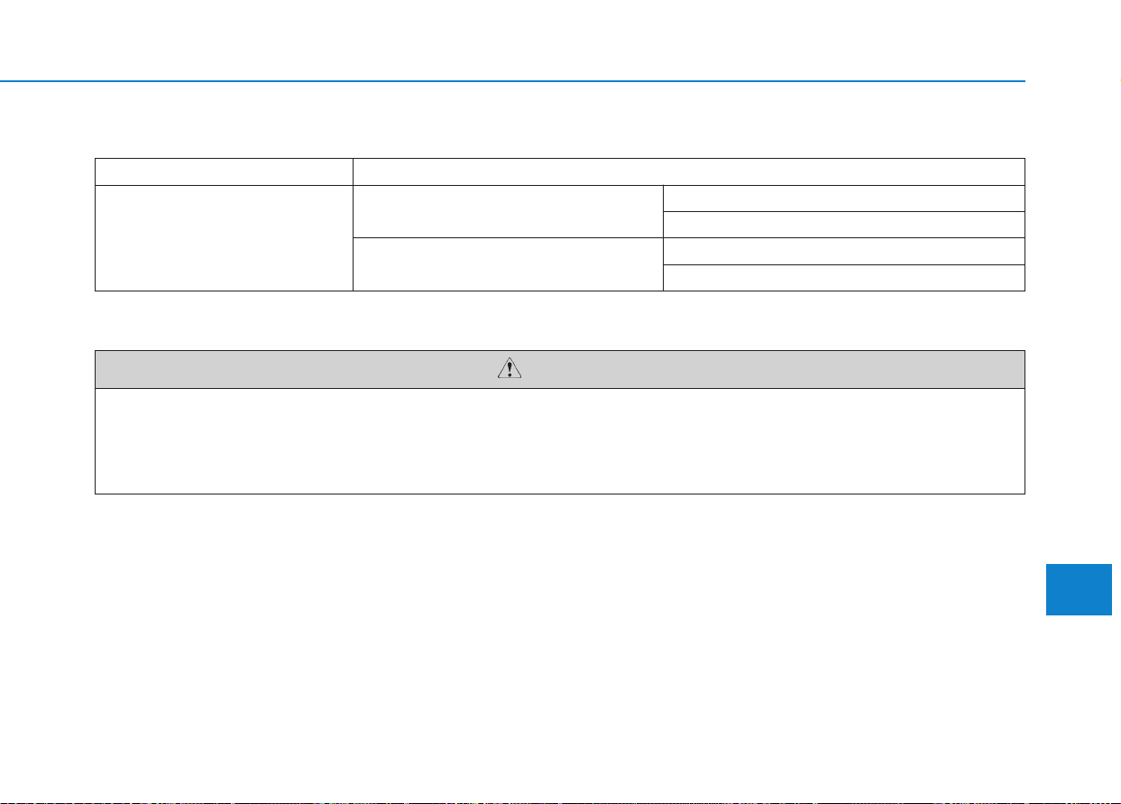
8-9
8
Specifications & Consumer information
Recommended engine oil (For Europe)
Supplier Product
Shell
Gasoline Engine
HELIX ULTRA AH-E 5W-30
HELIX ULTRA 5W-40
Diesel Engine
HELIX ULTRA AP 5W-30
HELIX ULTRA AP-L 5W-30
Always be sure to clean the area around any filler plug, drain plug, or dipstick before checking or draining
any lubricant.This is especially important in dusty or sandy areas and when the vehicle is used on unpaved
roads. Cleaning the plug and dipstick areas will prevent dirt and grit from entering the engine and other
mechanisms that could be damaged.
CAUTION
Recommended SAE viscosity number
Engine oil viscosity (thickness) has an effect on fuel economy and cold weather operating (engine start and engine oil
flowability). Lower viscosity engine oils can provide better fuel economy and cold weather performance, however, high-
er viscosity engine oils are required for satisfactory lubrication in hot weather. Using oils of any viscosity other than
those recommended could result in engine damage.
8-10
Specifications & Consumer information
When choosing an oil, consider the range of temperature your vehicle will be
operated in before the next oil change.
Proceed to select the recommended oil viscosity from the chart.
Temperature Range for SAE Viscosity Numbers
Temperature
°C
(°F)
-30 -20 -10 0 10 20 30 40 50
-10 0 20 40 60 80 100 120
For all countries
5W-30
■ Kappa 1.0/1.4 T-GDI
■ Kappa 1.4 MPI
Temperature Range for SAE Viscosity Numbers
Temperature
°C
(°F)
-30 -20 -10 0 10 20 30 40 50
-10 0 20 40 60 80 100 120
20W-50
10W-30
15W-40
5W-30*
2
, 5W-40
20W-50
15W-40
10W-30
5W-20*
1
, 5W-30
Except Europe,
Middle East *
3
For Europe,
Middle East *
3
*
1
: For better fuel economy, it is recommend-
ed to use the engine oil of a viscosity
grade SAE 5W-20. However, if the engine
oil is not available in your country, select
the proper engine oil using the engine oil
viscosity chart.
*
2
: For better fuel economy, it is recommend-
ed to use the engine oil of a viscosity
grade SAE 5W-30. However, if the engine
oil is not available in your country, select
the proper engine oil using the engine oil
viscosity chart.
*
3
: Middle East includes Morocco, Sudan and
Egypt.
8-11
8
Specifications & Consumer information
Temperature Range for SAE Viscosity Numbers
Temperature
°C
(°F)
-30 -20 -10 0 10 20 30 40 50
-10 0 20 40 60 80 100 120
5W-30
15W-40
10W-30
0W-30
Diesel Engine Oil
■ U2 1.6 TCI
Temperature Range for SAE Viscosity Numbers
Temperature
Gasoline
Engine Oil
°C
(°F)
-30 -20 -10 0 10 20 30 40 50
-10 0 20 40 60 80 100 120
For
Europe
20W-50
10W-30
15W-40
5W-30*
2
, 5W-40
0W-40, 5W-20, 5W-30, 5W-40
20W-50
15W-40
10W-30
0W-20, 5W-20*
1
, 5W-30
Except
Europe
&
Middle
East*
3
For
Middle
East*
3
■ Gamma 1.6 MPI
*
1
: For better fuel economy, it is recommend-
ed to use the engine oil of a viscosity
grade SAE 5W-20. However, if the engine
oil is not available in your country, select
the proper engine oil using the engine oil
viscosity chart.
*
2
: For better fuel economy, it is recommend-
ed to use the engine oil of a viscosity
grade SAE 5W-30. However, if the engine
oil is not available in your country, select
the proper engine oil using the engine oil
viscosity chart.
*
3
: Middle East includes Morocco, Sudan and
Egypt.
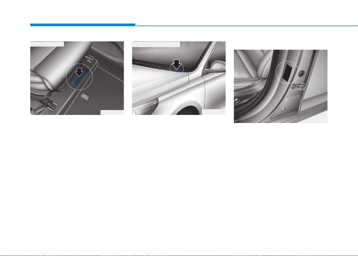
8-12
Specifications & Consumer information
The vehicle identification number
(VIN) is the number used in register-
ing your vehicle and in all legal mat-
ters pertaining to its ownership, etc.
The number is punched on the floor
under the passenger seat. To check
the number, open the cover.
The VIN is also on a plate attached
to the top of the dashboard. The
number on the plate can easily be
seen through the windshield from
outside.
The vehicle certification label attached
on the driver’s (or front passenger’s)
side center pillar gives the vehicle
identification number (VIN).
VVEEHHIICCLLEE IIDDEENNTTIIFFIICCAATTIIOONN NNUUMMBBEERR ((VVIINN)) VVEEHHIICCLLEE CCEERRTTIIFFIICCAATTIIOONN
L
LAABBEELL
OPD086002
■ VIN label (if equipped)
OPDE086007
OPD086001
■ Frame number
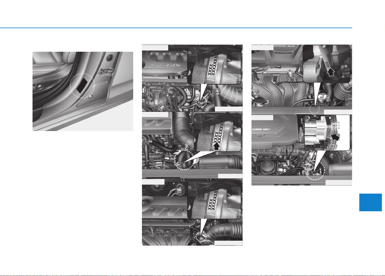
8-13
8
Specifications & Consumer information
The tires supplied on your new vehi-
cle are chosen to provide the best
performance for normal driving.
The tire label located on the driver's
side center pillar gives the tire pres-
sures recommended for your vehicle.
TTIIRREE SSPPEECCIIFFIICCAATTIIOONN AANNDD
P
PRREESSSSUURREE LLAABBEELL
E
ENNGGIINNEE NNUUMMBBEERR
The engine number is stamped on the
engine block as shown in the drawing.
OPD086007
OAD085010L
■ 1.6 MPI
OPD086006
■ 1.6 TCI
OPDE086010
OPD086004
OPDE086011
■ 1.4 T-GDI
■ 1.0 T-GDI
■ 1.4 MPI
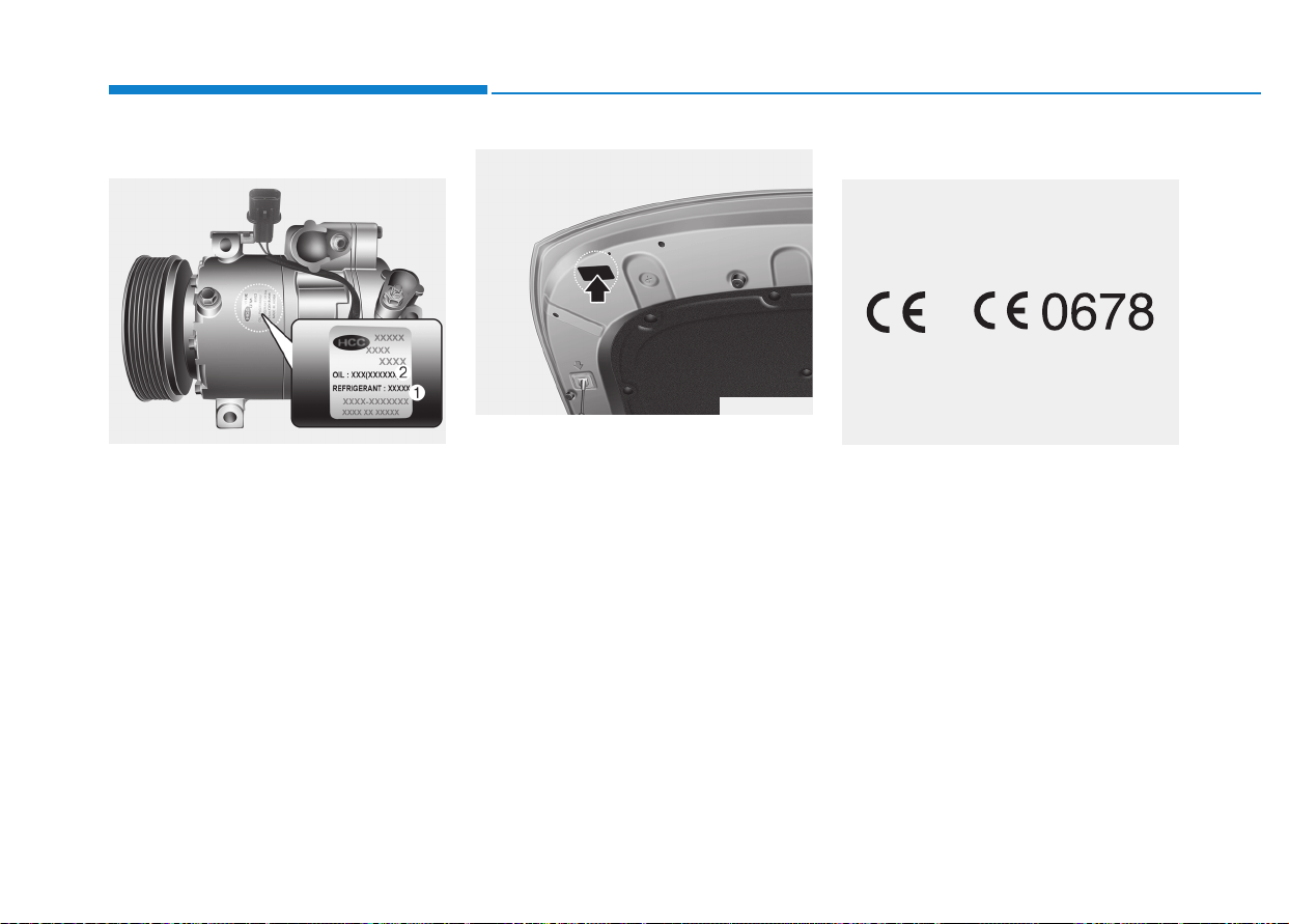
8-14
Specifications & Consumer information
A compressor label informs you the
type of compressor your vehicle is
equipped with such as model, suppli-
er part number, production number,
refrigerant (1) and refrigerant oil (2).
The refrigerant label provides infor-
mation such as refrigerant type and
amount.
The label is located on the underside
of the hood.
The radio frequency components of
the vehicle comply with requirements
and other relevant provisions of
Directive 1995/5/EC.
Further information including the
manufacturer's declaration of con-
formity is available on HYUNDAI
web site as follows;
http://service.hyundai-motor.com
RREEFFRRIIGGEERRAANNTT LLAABBEELLAAIIRR CCOONNDDIITTIIOONNEERR
C
COOMMPPRREESSSSOORR LLAABBEELL
OHC081001
OPDE086008
CE0678
■ Example
DDEECCLLAARRAATTIIOONN OOFF
C
COONNFFOORRMMIITTYY ((IIFF EEQQUUIIPPPPEEDD))

A
Appendix
I
Appendix
A
Шофиране през зимата (Bulgarian)..................9-2
Téli vezetés (Hungarian) .....................................9-6
Vetrarakstur (Icelandic).....................................9-10
Jazda zimą (Polish)...........................................9-14

Тежките зимни атмосферни условия
могат да предизвикат по-голямо
износване и други проблеми. За да
сведете до минимум проблемите,
свързани с шофирането през
зимата, следвайте препоръките по-
долу:
Сняг или поледица
За да карате своето превозно
средство при дълбока снежна
покривка може да се наложи да
използвате зимни гуми или да
поставите вериги върху тях. Ако са
необ ходими зимни гуми, трябва
да изберете гуми със същия
размер и вид като тези на
оригиналните гуми.
В противен случай това може да
се отрази неблагоприятно на
безопасността и експлоатацията
на Вашия автомобил. Освен това
карането с висока скорост,
бързото ускорение, внезапното
натискане на спирачки и резките
завои крият сериозни опасности.
При забавяне на скоростта,
използвайте доколкото е
възможно спирачките на дви
гателя. Внезапното натискане на
спирачки на заснежена или
заледена настилка може да
предизвика занасяне. Трябва да
под държате достатъчна
дистанция между автомобила,
който се движи пред Вас, и Вашия
автомобил.
Освен това натискайте спирачката
леко. Следва да се отбележи че
инсталирането на веригите върху
гума та ще позволи прилагането
на по-голяма движеща сила, но
няма да предотврати занасянето
встрани.
Веригите за гуми не са
позволени във всички държави.
Проверете норма тивната
уредба в своята страна преди
да поставите вериги за гуми.
К СВЕДЕНИЮ
ШОФИРАНЕ ПРЕЗ ЗИМАТА (BULGARIAN)
9-2
Appendix
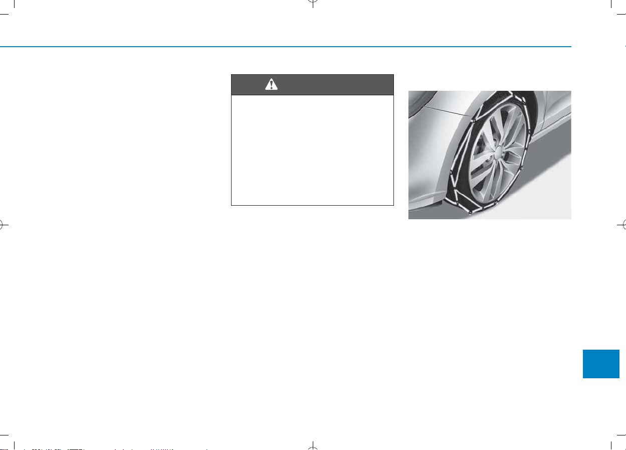
Г уми за сняг
Ако поставите гуми за сняг на своя
авто- мобил се уверете, че това са
радиалнигуми със същия размер и
товарен индекс като тези на
оригиналните гуми. Поставете гуми
за сняг на всичките четири колела,
за да балансирате експлоатацията
на своя автомобил във всякакви
атмос- ферни условия. Имайте
предвид, че тягата на гумите за сняг
върху суха настилка не може да
бъде толкова голяма колкото тази
на оригиналните гуми. Следва да
карате внимателно, дори когато
пътищата са почистени.
Консултирайте се с доставчика на
гуми за максималната
препоръчителна скорост.
Не монтирайте гуми с шипове,
преди да сте проверили
местните, национални и общински
разпоредби за възможни огра-
ничения в тяхната употреба.
Вериги за гуми
Тъй като страниците на
радиалните гуми са по-тънки, те
могат да се повредят, ако върху
тях се монтират някои видове
вери- ги за сняг. Ето защо се
препоръчва изпол- зването на
гуми за сняг, а не на вериги за сняг.
Не поставяйте вериги върху
автомо- били, чиито колела са с
алуминиеви джан- ти; веригите за
сняг могат да повредят колелата.
Ако трябва да се използват вериги
за сняг, използвайте телени вериги
с дебелина от поне 12 мм.
9-3
A
Appendix
Размер на гумите за сняг
Г умите за сняг следва да са
равностойни по размер и тип на
тези на стандартните гуми на
автомобила. В противен случай
това може да се отрази
неблагоприятно на безопасността
и експлоатацията на Вашия
автомобил.
ОСТОРОЖНО
OPDE056072

Повредата на Вашия автомобил
вследствие на непра- вилната
употреба на вериги за сняг не е в
обхвата на гаранцията на
производителя на Вашия
автомобил.
Поставяйте веригите винаги по
две, на предните гуми. Обърнете
внимание, че поставянето на
вериги на гумите на автомобила
осигурява по-добра задвижваща
сила, но не предпазва от
странични поднасяния.
9-4
Appendix
•
Уверете се, че размерът и
видът на веригите са
правилните за Вашите гуми.
Неправилните вериги за сняг
могат да повредят
каросерията и окачването на
автомобила и този тип повреда
може да не е в обхвата на
производствената гаранция за
Вашия автомобил. Също така
куките за свързване на
веригите за сняг могат да се
повредят от намиращите се в
контакт с тях автомобилни
части, като това може да
доведе до разхлабването им.
Уверете се, че веригите за сняг
са от клас S според
класификацията на
Дружеството на автомобилните
инженери (SAE).
(продолжение)
(продолжение)
• Винаги проверявайте дали
вериги- те са били
поставени правилно след
като изминете около 0,5 до 1
км, за да се уверите в
безопасното им поставяне.
Затегнете веригите или ги
поставете отново, ако са се
разхлабили.
ВНИМАНИЕ

Монтиране на вериги
Когато инсталирате веригите,
следвайте инструкциите на
производителя и ги затег- нете
максимално. Карайте бавно с
инста- лирани вериги. Ако чуете, че
веригите са навлезли в контакт с
каросерията или шасито, спрете и
ги затегнете. Ако те все още са в
контакт, намалете скоростта до
преустановяване на контакта.
Свалете веригите веднага, щом
започнете да кара- те по
почистените пътища.
9-5
A
Appendix
Поставяне на вериги
Когато поставите вериги за
сняг , пар- кирайте автомобила
на равно място далеч от
пътното движение. Включете
аварийните светлини и
поставете светлоотразителния
три- ъгълник зад автомобила,
ако разпо- лагате с такъв.
Винаги паркирайте автомобила
в паркинг, дръпнете ръч-ната
спирачка и изключете двигате-
ля преди да поставите веригите
за сняг.
ОСТОРОЖНО
Вериги за гуми
• Използването на вериги може
да се отрази неблагоприятно
на работата на Вашия
автомобил.
• Не надвишавайте пределната
ско- рост, препоръчана от
производителя, или
скоростта от 30 км/ч, което е
по- ниско.
• Карайте внимателно и
избягвайте неравности,
дупки, резки завои и други
опасности на пътя, които
могат да накарат автомобила
да подскача.
• Избягвайте резките завои или
изпол- зването на спирачки,
ако колелата са блокирани.
ОСТОРОЖНО
•
Веригите с грешен размер
или тези, които са
неправилно инсталирани,
могат да повредят
спирачните накладки,
окачването, каросерията и
колелата.
•
Спрете и затегнете веригите
повтор- но винаги, щом ги
чуете да удрят автомобила.
ВНИМАНИЕ

Télen a nehéz időjárási feltételek
nagyobb elhasználódást és más
problémákat eredményezhetnek. A
téli vezetés problémáinak
csökkentése érdekében célszerű
követnie a következő javaslatokat:
Havas vagy jeges útviszonyok
Mély hóban közlekedéshez szükség
lehet téli gumiabroncsok használatára
vagy kerekeire hólánc felszerelésére.
Ha téli gumiabroncsokra van
szüksége, a gyárilag felszerelttel
megegyező méretű és típusú
gumiabroncsot kell választani. Ennek
figyelmen kívül hagyása hátrányosan
befolyásolja gépkocsija biztonságát és
vezethetőségét. Ezen túlmenően a
nagy sebességű haladás, a hirtelen
gyorsítás, a hirtelen fékezés és a
gyors kanyarvétel nagyon veszélyes
gyakorlat.
Lassításkor a lehető legjobban
használja ki motorja fékhatását.
Havas vagy jeges úton a hirtelen
fékezés megcsúszást okozhat.
Elegendően nagy követési
távolságot kell tartania saját
gépkocsija és az Ön előtt haladó
jármű között. Tehát óvatosan
fékezzen. Jegyezze meg, hogy
hólánc használatakor megnő a
hajtóerő, de nem segít az oldalra
kicsúszás elkerülésében.
A hólánc nem legális minden
országban. Ellenőrizze az Ön
országának törvényeit, mielőtt
felszereli a hóláncot.
MEGJEGYZÉS
TTÉÉLLII VVEEZZEETTÉÉSS ((HHUUNNGGAARRIIAANN))
9-6
Appendix
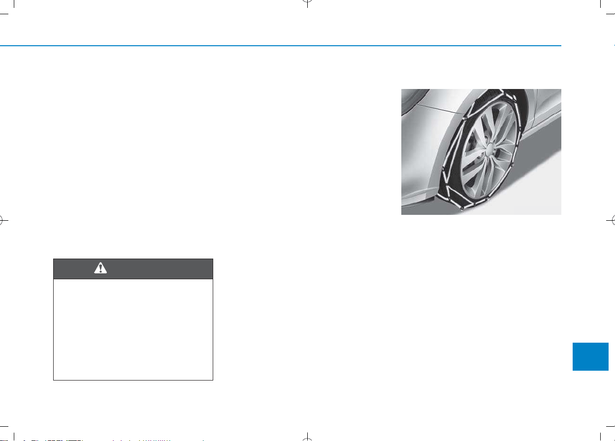
Téli gumiabroncs
Ha téli gumiabroncsot akar használni,
először győződjön meg arról, hogy
ezek megfelelő méretű és
terhelhetőségű radiál abroncsok.
Kifejezetten javasoljuk, hogy mind a
négy kerékre szereltessen téli
gumiabroncsot, hogy biztosítsa
gépkocsija jó vezethetőségét. Ne
feledje, hogy a téli gumiabroncsok
tapadása száraz úton nem olyan jó,
mint a gépkocsira eredetileg felszerelt
gumiabroncsoké. Még tiszta úton is
óvatosan kell vezetnie.Tájékozódjon a
gumiszerelőnél a megengedett
legnagyobb sebességgel
kapcsolatban.
Ne szereltessen fel szöges
gumiabroncsot, mielőtt tájékozódna
a használatukra, illetve esetleges
tiltásukra vonatkozó helyi előírásokról.
Hólánc
Mivel a radiál gumiabroncsok oldalfala
vékonyabb, megsérülhetnek bizonyos
fajtájú hólánc felszerelésétől. Ezért
inkább javasoljuk a téli gumiabroncsok
használatát, mint a hólánc
használatát. Ne szereljen fel hóláncot
alumínium keréktárcsás kerékre, mivel
a hólánc sérüléseket okozhat a
keréktárcsán. Ha mégis hóláncot
kellene használnia, használjon 12
mm-es átmérőnél kisebb, kábeltípusú
hóláncot. Gépkocsijának a hólánc
helytelen használatából eredő káraira
nem vonatkozik a garancia.
9-7
A
Appendix
A téli gumiabroncsok mérete
A téli gumiabroncsnak mind
méretében, mind szerkezetében
meg kell egyeznie az eredeti
nyárival. Ellenkező esetben
gépkocsija biztonsága és
vezethetősége kedvezőtlenül
változhat.
VIGYÁZAT!
OPDE056072
A hóláncot mindig párban szerelje fel
az első kerekekre. Fontos
megjegyezni, hogy a kerekekre
felszerelt hólánc nagyobb tapadóerőt
biztosít, azonban nem akadályozza
meg a kicsúszást oldalra.
A hуlбnc felszerelйse
A hólánc felszerelésekor figyelmesen
kövesse gyártójának utasításait, és a
lehető legfeszesebbre húzza meg a
láncot. A felszerelt hólánccal lassan
közlekedjen. Ha a lánc hozzáverődik
a karosszériához vagy az alvázhoz,
álljon meg és feszítsen rajta. Ha még
mindig hozzáér, lassítson le annyira,
hogy megszűnjön a kontaktus.
Haladéktalanul távolítsa el a
láncokat, amint tiszta útra ér.
9-8
Appendix
• Ügyeljen arra, hogy a hólánc a
gumiabroncsaihoz megfelelő
méretű és típusú legyen. A
nem megfelelő méretű hólánc
megrongálhatja gépkocsija
karosszériáját és
felfüggesztéseit, és erre nem
vonatkozik a gépkocsi
garanciája. Ezenkívül a
hólánc összekötő kapcsai
megsérülhetnek a
karosszériához ütődéstől,
amitől a hólánc meglazulhat,
és leeshet a kerékről.
Kizárólag az SAE szabvány
szerinti „S” osztályú hóláncot
használjon.
• 0,5 - 1km megtétele után
ellenőrizze megfelelő
elhelyezkedésüket a
biztonságos felszerelésük
érdekében. Ha meglazultak,
húzza meg újra, vagy szerelje
fel ismét a hóláncokat.
FIGYELEM!
Hólánc felszerelése
Forgalomtól távol eső sík
felületen álljon félre. Kapcsolja
be a vészvillogót és tegyen ki
elakadásjelző háromszöget a
gépkocsi mögé. A hólánc
felszerelése előtt mindig
kapcsolja P állásba a
sebességváltó választókarját,
működtesse a rögzítőféket, majd
állítsa le a motort.
VIGYÁZAT!
9-9
A
Appendix
Hólánc
• A hólánc használata jelentősen
korlátozza a gépkocsi
kezelhetőségét.
• Ne lépje túl a 30 km/h
sebességet, vagy a hólánc
gyártója által meghatározott
maximális sebességet. Mindig a
kettő közül alacsonyabb értéket
tartsa be.
• Vezessen óvatosan, kerülje a
bukkanókat, lyukakat, éles
kanyarokat és az úton előforduló
egyéb veszélyforrásokat, melyek
a gépkocsi erős berugózását
okozzák.
• Tartózkodjon az éles
kanyarvételtől és a blokkoló
kerekekkel történő fékezéstől.
VIGYÁZAT!
• A nem megfelelő méretű vagy
rosszul felszerelt hólánc
megrongálhatja gépkocsija
féktömlőit, felfüggesztéseit,
karosszériáját és a kerekeit.
• Álljon meg és húzza
feszesebbre a hóláncokat, ha
beleütnek a gépkocsi
valamelyik alkatrészébe.
FIGYELEM!

Akstur í þungri færð og vetrarveðri
leiðir til aukins slits á ökutækinu og
skapar ýmis vandamál. Hægt er að
draga úr erfiðleikum sem fylgja
vetrarakstri ef farið er að þessum
ráðleggingum:
Akstur í snjó eða hálku
Við akstur í djúpum snjó kann að vera
nauðsynlegt að nota vetrarhjólbarða
eða setja keðjur á hjólbarðana.
Reynist nauðsynlegt að nota
vetrarhjólbarða þarf að velja hjólbarða
af sömu stærð og gerð og venjulegu
hjólbarðarnir. Sé það ekki gert getur
það dregið úr öryggi og skert
aksturseiginleika ökutækisins.
Hraðakstur, skyndileg hröðun,
nauðhemlun og krappar beygjur geta
enn fremur falið í sér mikla hættu.
Þegar dregið er úr hraða er ráðlegt
að beita vélarhemlun sem kostur er.
Við nauðhemlun á snævi þöktum
eða hálum vegum getur ökutækið
hæglega runnið til. Nauðsynlegt er
að halda hæfilegri fjarlægð á milli
þíns ökutækis og ökutækisins fyrir
framan. Alltaf ætti að beita hemlinum
mjúklega. Hafa ber í huga að ef
keðjur eru settar á hjólbarða fæst
aukinn drifkraftur en það hindrar þó
ekki að ökutækið renni til hliðanna.
Notkun snjókeðja er ólögleg í
sumum ríkjum. Kynnið ykkur
gildandi landslög áður en keðjur
eru settar upp.
ATHUGIÐ
VVEETTRRAARRAAKKSSTTUURR ((IICCEELLAANNDDIICC))
9-10
Appendix
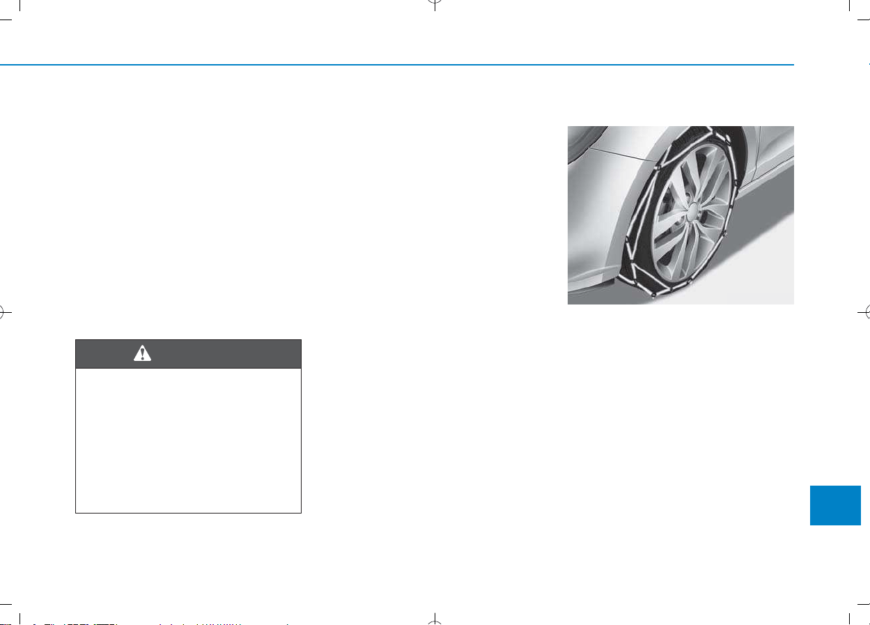
Vetrarhjólbarðar
Ef vetrarhjólbarðar eru settir á
ökutækið þarf að gæta þess að nota
þverofna hjól- barða af sömu stærð og
ásþunga og upprunalegu
hjólbarðarnir. Setjið vetrarhjólbarða á
öll fjögur hjólin til að tryggja örugga
stýringu ökutækisins við öll
veðurskilyrði. Hafið í huga að á auðum
vegi kunna vetrarhjólbarðar að hafa
minna grip en hjólbarðarnir sem fylgdu
ökutækinu. Því þarf að aka af gætni,
jafnvel á auðum vegum. Ráðfærið
ykkur við söluaðila hjólbarðanna um
ráðlagðan hámarkshraða.
Á
ður en negldir hjólbarðar eru settir
upp er rétt að kynna sér reglugerðir um
notkun slíkra hjólbarða í viðkomandi
landi, fylki eða sveitarfélagi.
Keðjur á hjólbarða
Hliðar þverofinna hjólbarða eru þynnri
en á öðrum hjólbörðum og sumar gerðir
snjókeðja geta því valdið skemmdum á
þeim. Því er ráðlegt að nota
vetrarhjólbarða fremur en keðjur, ef
þess er kostur.
Setjið aldrei keðjur á hjólbarða
ökutækja sem búin eru álfelgum þar
sem keðjurnar geta valdið skemmdum
á felgunum. Ef óhjákvæmilegt reynist
að nota keðjur skal nota vírkeðjur sem
eru innan við 12 mm á þykkt.
Ábyrgðartrygging söluaðila ökutækisins
tekur ekki til skemmda sem orsakast af
rangri notkun snjókeðja.
9-11
A
Appendix
Stærðir vetrarhjólbarða
Vetrarhjólbarðar ættu að vera af
sömu stærð og gerð og
hjólbarðarnir sem fylgdu
ökutækinu.
Misræmi á því getur dregið úr
öryggi og skert aksturseiginleika
ökutækisins.
VIÐVÖRUN
OPDE056072

9-12
Appendix
Aðeins skal setja keðjur á í pörum og
aðeins á framhjólbarðana. Hafa ber í
huga að ef keðjur eru settar á
hjólbarða fæst aukinn drifkraftur. Það
hindrar þó ekki að ökutækið renni til
hliðanna.
Uppsetning б keрjum
Þegar keðjur eru settar á skal fylgja
leiðbeiningum framleiðanda og herða
keðjurnar eins mikið og unnt er. Þegar
keðjur hafa verið settar á skal aka
hægt. Ef hljóð heyrist sem bendir til að
keðjurnar séu í snertingu við
yfirbyggingu eða undirvagn er rétt að
nema staðar og herða keðjurnar. Ef
snerting virðist enn eiga sér stað skal
hægja aksturinn þar til hljóðið þagnar.
Takið keðjurnar niður um leið og
komið er á rudda og snjólausa vegi.
• Gætið þess að snjókeðjurnar
séu af þeirri stærð og gerð
sem hæfir hjólbörðunum.
Notkun snjókeðja af rangri
gerð getur valdið skemmdum
á yfirbyggingu og fjöðrun
ökutækisins og kann að falla
utan ábyrgðartryggingar
söluaðila ökutækisins. Þá
geta festikrókar keðjanna
skemmst vegan núnings við
íhluti ökutækisins og
snjókeðjurnar losnað af
hjólbarðanum. Gætið þess að
snjókeðjurnar séu með SAE-
vottun í S-flokki.
• Eftir um það bil 0,5-1 km
akstur skal ævinlega skoða
keðjurnar aftur til að tryggja
að þær hafi verið settar upp á
réttan og öruggan hátt. Herðið
keðjurnar eða setjið þær aftur
á ef þær hafa losnað.
VARÚÐ

9-13
A
Appendix
Uppsetning á keðjum
Þegar snjókeðjur eru settar upp
skal leggja ökutækinu á sléttum
fleti fjarri umferð. Kveikið á
viðvörunarljósum ökutækisins
og setjið þríhyrningslaga
viðvörunarskilti upp fyrir aftan
ökutækið, ef það er tiltækt.
Hafið ökutækið ævinlega í
stöðuhemli og drepið á vélinni
áður en snjókeðjur eru settar
upp.
VIÐVÖRUN
Keðjur á hjólbarða
• Notkun keðja getur skert
aksturs- eiginleika ökutækisins.
• Akið ekki hraðar en 30 km/klst.
eða samkvæmt ráðlögðum
hámarkshraða framleiðanda
keðjanna, hvort sem reynist
lægra.
• Akið gætilega og sneiðið hjá
þústum, holum, kröppum
beygjum og öðrum hættum á
veginum, sem gætu valdið
hristingi ökutækisins.
• Forðist krappar beygjur eða
læsta hemlun.
VIÐVÖRUN
• Séu snjókeðjur af rangri stærð
eða rangt upp settar geta þær
valdið skemmdum á hemlalögn,
fjöðrun, yfirbyggingu og hjólum
ökutækisins.
• Hvenær sem hljóð bendir til
þess að keðjurnar sláist við
ökutækið skal stöðva akstur
og herða keðjurnar.
VARÚÐ

JAZDA ZIMĄ (POLISH)
9-14
Appendix
Surowe warunki pogodowe zimą
powodują większe zużycie pojazdu i
inne problemy. Aby zminimalizować
problemy związane z jazdą w zimie,
postępuj zgodnie z poniższymi
sugestiami:
Jazda w warunkach
śniegowych i przy oblodzeniu
Aby prowadzić pojazd w głębokim
śniegu, może okazać się niezbędne
użycie opon zimowych lub
zainstalowanie łańcuchów
śniegowych. Jeśli potrzebne okażą
się opony zimowe, konieczne jest
wybranie opon o rozmiarze i typie
odpowiadających oponom, w jakie
pojazd był pierwotnie wyposażony.
Jeśli założone zostaną
nieodpowiednie opony, będzie to
miało negatywny wpływ na
bezpieczeństwo i prowadzenie
pojazdu. Ponadto jazda z nadmierną
prędkością, gwałtowne
przyspieszanie, nagłe hamowanie i
ostre skręty będą stanowiły
potencjalnie bardzo duże
niebezpieczeństwo.
Podczas zwalniania należy w pełni
wykorzystać hamowanie silnikiem.
Nagłe hamowanie na zaśnieżonej
lub oblodzonej drodze może
spowodować poślizg pojazdu.
Należy utrzymywać odpowiedni
odstęp od pojazdu jadącego z
przodu. Hamulców należy używać
ostrożnie. Należy pamiętać, że
założenie łańcuchów śniegowych
zapewni większą siłę napędową, ale
nie zapobiegnie ślizganiu się na
boki.
Stosowanie łańcuchów śniegowych
nie jest zgodne z prawem we
wszystkich krajach. Przed założeniem
łańcuchów śniegowych należy
sprawdzić przepisy danego kraju.
UWAGA
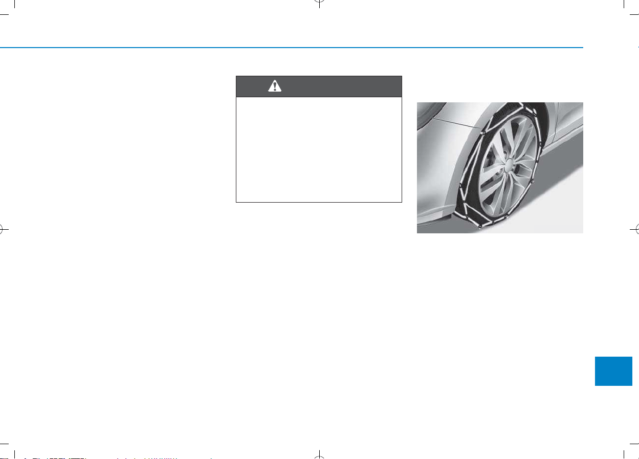
Opony zimowe
Kiedy zakładane są opony zimowe,
należy upewnić się, że są to opony
radialne o takim samym rozmiarze i
zakresie obciążeń co pierwotne
opony pojazdu. Opony zimowe należy
zakładać na wszystkie cztery koła
pojazdu, by we wszystkich
warunkach pogodowych pojazd
pozwalał się prowadzić równomiernie.
Należy pamiętać, że przyczepność
zapewniana przez opony zimowe na
suchej drodze może nie być równie
wysoka jak przyczepność
pierwotnych opon pojazdu. Pojazd
należy prowadzić ostrożnie nawet
wtedy, gdy drogi są oczyszczone. Aby
poznać informacje na temat
zalecanych ograniczeń prędkości dla
danych opon, należy skontaktować
się ze sprzedawcą opon.
Opon okolcowanych nie należy
zakładać bez uprzedniego
sprawdzenia w przepisach lokalnych,
stanowych i miejskich, czy na ich
użycie nie są nałożone ograniczenia.
Łańcuchy śniegowe
(przeciwpoślizgowe)
Ponieważ ścianki boczne opon
radialnych są cieńsze, założenie
niektórych rodzajów łańcuchów
śniegowych może spowodować ich
uszkodzenie. Z tego względu zaleca
się korzystanie z opon zimowych
zamiast łańcuchów śniegowych.
Łańcuchów śniegowych nie należy
zakładać w pojazdach, które są
wyposażone w felgi aluminiowe,
ponieważ mogą one powodować
uszkodzenia felg. Jeśli użycie
łańcuchów śniegowych jest niezbędne,
należy zastosować łańcuchy drutowe o
grubości poniżej 12 mm.
9-15
A
Appendix
Rozmiar opon zimowych
Opony zimowe powinny mieć
rozmiar i typ odpowiadający
standardowym oponom pojazdu.
Jeśli tak nie jest, może to mieć
negatywny wpływ na
bezpieczeństwo i prowadzenie
pojazdu.
OSTRZEŻENIE
OPDE056072

Uszkodzenia pojazdu spowodowane
użyciem niewłaściwych łańcuchów
śniegowych nie jest objęte gwarancją
producenta pojazdu.
Łańcuchy na opony należy zakładać
jedynie parami i na przednich
oponach. Należy pamiętać, że
założenie łańcuchów na oponach
zwiększy siłę napędową, ale nie
zapobiegnie poślizgowi bocznemu.
Zakіadanie іaсcuchуw њniegowych
Zakładając łańcuchy śniegowe należy
postępować zgodnie z instrukcjami
podanymi przez producenta.
Łańcuchy należy założyć tak ciasno,
jak to tylko możliwe. Kiedy łańcuchy są
już założone, pojazd należy prowadzić
powoli. Jeśli dadzą się słyszeć dźwięki
świadczące o tym, że łańcuchy stykają
się z nadwoziem lub podwoziem,
należy zatrzymać samochód i
zacisnąć je. Jeśli łańcuchy wciąż
stykają się z elementami pojazdu,
należy zmniejszać prędkość, aż
łańcuchy przestaną uderzać w
samochód. Łańcuchy należy zdjąć jak
tylko rozpocznie się jazdę po
oczyszczonej drodze.
9-16
Appendix
•
Należy upewnić się, że
łańcuchy śniegowe mają
odpowiedni rozmiar i typ dla
opon pojazdu. Zastosowanie
niewłaściwych łańcuchów
śniegowych może spowodować
uszkodzenie nadwozia oraz
zawieszenia, a zniszczenia
powstałe w ten sposób mogą
nie być objęte gwarancją
producenta pojazdu.
(Ciąg dalszy)
(Ciąg dalszy)
Ponadto, haczyki łączące
łańcuchów śniegowych mogą
zostać zniszczone na skutek
stykania się z elementami
samochodu, co może
spowodować zsunięcie się
łańcuchów z opon. Należy
upewnić się, że łańcuchy
śniegowe są klasy “S” SAE i
posiadają certyfikat.
• Po przejechaniu ok. 0,5 do 1
km (0,3 do 0,6 mil), dla
zachowania bezpieczeństwa,
należy zawsze sprawdzić, czy
łańcuchy śniegowe zostały
poprawnie założone. Jeśli
łańcuchy poluzowały się,
należy je zacisnąć lub założyć
ponownie.
OSTROŻNIE

9-17
A
Appendix
Zakładanie łańcuchów
śniegowych
Aby założyć łańcuchy śniegowe,
należy zatrzymać pojazd na
płaskim podłożu, z dala od ruchu
drogowego. Włączyć światła
awaryjne pojazdu i umieścić za
nim trójkąt ostrzegawczy, jeśli
jest on dostępny. Zanim
rozpocznie się instalowanie
łańcuchów śniegowych dźwignię
zmiany biegów należy zawsze
umieścić w położeniu P (Postój),
zaciągnąć hamulec postojowy i
wyłączyć silnik.
OSTRZEŻENIE
Łańcuchy śniegowe
• Użycie łańcuchów śniegowych
może mieć negatywny wpływ
na prowadzenie pojazdu.
• Pojazdu nie należy prowadzić
szybciej niż 30 km/h (20 mil/h)
lub z prędkością większą, niż
zalecana przez producenta,
którakolwiek z tych wartości
okaże się mniejsza.
• Pojazd należy prowadzić
ostrożnie i unikać wybojów,
dziur, ostrych skrętów i innych
zagrożeń drogowych, które
mogą powodować
podskakiwanie pojazdu.
• Należy unikać ostrych
zakrętów lub hamowania z
zablokowanymi kołami.
OSTRZEŻENIE
• Łańcuchy o niewłaściwym
rozmiarze lub niepoprawnie
założone mogą uszkodzić
linki hamulcowe pojazdu,
zawieszenie, nadwozie oraz
koła.
• Za każdym razem, kiedy da się
usłyszeć, że łańcuchy
uderzają w samochód, należy
zatrzymać się i zacisnąć je.
OSTROŻNIE

I
Index
I

I-2
Advanced smart cruise control system.......................5-130
Air bag warning labels .................................................2-63
Air bags.........................................................................2-45
Additional safety precautions ....................................2-63
Air bag collision sensors ...........................................2-57
Air bag inflation conditions.......................................2-59
Air bag non-inflation conditions ...............................2-60
Air bag warning labels...............................................2-63
Curtain air bags..........................................................2-51
Do not install a child restraint on
the front passenger seat ...........................................2-57
Driver's air bag...........................................................2-47
Driver's knee air bag..................................................2-47
How does the air bags system operate?.....................2-52
Passenger's front air bag ON/OFF switch .................2-48
Passenger's front air bag ............................................2-47
Side air bags...............................................................2-50
SRS Care....................................................................2-62
SRS components and functions .................................2-52
SRS warning light......................................................2-53
What to expect after an air bag inflates.....................2-56
Why didn't my air bag go off in a collision ..............2-57
Air conditioner compressor label .................................8-14
Air conditioning refrigerant label.......................3-120, 132
Air conditioning system specification............................8-6
Air ventilation seats......................................................2-21
Alarm system................................................................3-16
Antenna...........................................................................4-3
Anti-lock brake system (ABS) .....................................5-53
Appearance care .........................................................7-105
Exterior care.............................................................7-105
Interior care..............................................................7-110
Armrest .........................................................................2-14
Ashtray........................................................................3-140
Audio / Video / Navigation system ................................4-5
Auto defogging system...............................................3-136
Auto hold ......................................................................5-49
Auto light position........................................................3-83
Automatic climate control system..............................3-121
Air conditioning.......................................................3-128
Air conditioning refrigerant label............................3-132
Air intake control.....................................................3-126
Automatic heating and air conditioning ..................3-122
Fan speed control.....................................................3-127
Manual heating and air conditioning.......................3-123
Mode selection.........................................................3-124
OFF mode ................................................................3-128
SYNC button ...........................................................3-126
System maintenance ................................................3-131
Temperature control.................................................3-125
Automatic transmission ................................................5-24
Good driving practices...............................................5-29
Ignition key interlock system ....................................5-28
Manual shift mode .....................................................5-26
Parking .......................................................................5-29
Shift lock system .......................................................5-28
Index
A

I-3
Shift-lock release .......................................................5-28
Automatic ventilation .................................................3-115
Autonomous emergency braking (AEB) system
Camera type ...............................................................5-90
Sensor fusion type (front radar + front camera)........5-78
Aux, USB and iPod ........................................................4-2
Battery...........................................................................7-48
Battery recharging......................................................7-50
Battery saver function...................................................3-90
Before driving.................................................................5-5
Blade type fuse .............................................................7-64
Blind spot detection (BSD) system ..............................5-70
Bluetooth
®
Wireless Technology hands-free..................4-5
Bottle holder ...............................................................3-140
Brake system.................................................................5-41
Anti-lock brake system (ABS) ..................................5-53
Auto hold ...................................................................5-49
Disc brakes wear indicator ........................................5-42
Electronic parking brake (EPB).................................5-44
Electronic stability control (ESC) .............................5-55
Emergency Stop Signal (ESS)...................................5-60
Good braking practices..............................................5-61
Hill-start assist control (HAC)...................................5-60
Parking brake (hand type) .........................................5-42
Power brakes..............................................................5-41
Vehicle stability management (VSM) .......................5-58
Brake/clutch fluid .........................................................7-40
Bulb replacement
Daytime running light (DRL)....................................7-86
Front fog lamp ...........................................................7-91
Front position lamp....................................................7-86
Front turn signal lamp ...............................................7-86
Headlamp ...................................................................7-86
Headlamp and front fog lamp aiming........................7-91
High mounted stop lamp .........................................7-103
Interior light bulb.....................................................7-103
License plate light bulb ...........................................7-103
Rear combination light bulb ......................................7-98
Rear fog lamp ..........................................................7-102
Side repeater lamp ....................................................7-97
Static bending lamp ...................................................7-86
Bulb wattage ...................................................................8-3
Button start/stop, see engine start/stop button..............5-11
Camera (Rear view)....................................................3-101
Capacities (Lubricants)...................................................3-7
Care
Exterior care.............................................................7-105
Interior care..............................................................7-110
Tire care .....................................................................7-52
Cargo area cover.........................................................3-148
Cartridge type fuse .......................................................7-64
Cellular phone holder .................................................3-144
I
Index
B
C

I-4
Center console storage................................................3-138
Central door lock switch...............................................3-13
Certification label .........................................................8-12
Chains
Tire chains................................................................5-152
Check tire inflation pressure.........................................7-54
Child restraint system (CRS)........................................2-34
Booster seats ..............................................................2-37
Forward-facing child restraint system .......................2-36
Installing a child restraint system (CRS)...................2-37
ISOFIX anchorage and top-tether anchorage
for children ..............................................................2-38
Rearward-facing child restraint system .....................2-36
Securing a child restraint system seat with
"Top-tether Anchorage" system...............................3-40
Securing a child restraint system with
a lap/shoulder belt....................................................3-42
Securing a child restraint system with
the "ISOFIX Anchorage System"............................2-39
Selecting a child restraint system (CRS)...................2-35
Child-protector rear door lock......................................3-15
Cigarette lighter ..........................................................3-144
Climate control air filter ...............................................7-44
Climate control system
Automatic climate control system ...........................3-121
Manual climate control system ................................3-111
Clock...........................................................................3-146
Clothes hanger ............................................................3-146
Cluster ionizer.............................................................3-115
Combined instrument, see instrument cluster ..............3-43
Compact spare tire replacement ...................................7-57
Coolant..........................................................................7-37
Cooling fluid, see engine coolant.................................7-37
Crankcase emission control system ............................7-111
Cruise control system .................................................5-124
Cup holder ..................................................................3-140
Curtain air bags.............................................................2-51
Dashboard illumination, see instrument panel
illumination.................................................................3-44
Dashboard, see instrument cluster................................3-43
Day/night rearview mirror............................................3-22
Daytime running light (DRL).......................................3-91
Declaration of conformity ............................................8-14
Defogging (Windshield) .............................................3-133
Defroster .....................................................................3-109
Rear window defroster.............................................3-109
Defrosting (Windshield) .............................................3-133
Dimensions .....................................................................8-2
Display illumination, see instrument panel
illumination.................................................................3-44
Displays, see instrument cluster ...................................3-43
Distance to empty ........................................................3-48
Door locks.....................................................................3-11
Auto door lock/unlock features .................................3-14
Central door lock switch............................................3-13
Child-protector rear door lock ...................................3-15
Index
D

I-5
Drinks holders, see cup holders..................................3-140
Drive mode integrated control system ........................5-68
ECO mode .................................................................5-68
SPORT mode .............................................................5-69
Driver attention alert system (DAA) ..........................5-118
Driver position memory system ...................................3-17
Easy access function..................................................3-18
Recalling memory positions ......................................3-17
Storing memory positions..........................................3-17
Driver's air bag .............................................................2-47
Driver's knee airbag......................................................2-47
Driving at night...........................................................5-148
Driving in flooded areas .............................................5-149
Driving in the rain ......................................................5-148
Dual clutch transmission ..............................................5-31
Good driving practices...............................................5-39
Ignition key interlock system ....................................5-38
Manual shift mode .....................................................5-36
Parking .......................................................................5-39
Shift lock system .......................................................5-38
Shift-lock release .......................................................5-38
Easy access function.....................................................3-18
ECO mode ....................................................................5-68
Electric chromic mirror (ECM)....................................3-23
Electric power steering (EPS) ......................................3-19
Electronic parking brake (EPB) ...................................5-44
Electronic stability control (ESC) ................................5-55
Emergency Stop Signal (ESS)......................................5-60
Emergency towing........................................................6-41
Emission control system .............................................7-111
Crankcase emission control system .........................7-111
Evaporative emission control System......................7-111
Exhaust emission control system.............................7-112
Engine compartment.......................................................7-3
Engine compartment panel fuse replacement...............7-64
Engine coolant ..............................................................7-37
Engine coolant temperature gauge ...............................3-45
Engine number..............................................................8-13
Engine oil......................................................................7-35
Engine specification .......................................................8-2
Engine start/stop button ................................................5-11
EPB (Electronic Parking Brake)...................................5-44
Evaporative emission control System.........................7-111
Exhaust emission control system................................7-112
Explanation of scheduled maintenance items ..............7-32
Exterior care ...............................................................7-105
Exterior features
Front view....................................................................1-2
Exterior overview
Mounting bracket for roof carrier............................3-149
Rear view .....................................................................1-3
I
Index
E

I-6
Flat tire
Changing tires............................................................6-15
Tire Mobility Kit (TMK)...........................................6-23
Floor mat anchor(s) ....................................................3-147
Fluid
Brake/clutch fluid ......................................................7-40
Washer fluid...............................................................7-41
Front fog lamp ..............................................................3-88
Front seat adjustment......................................................2-6
Manual adjustment.......................................................2-7
Power adjustment.........................................................2-9
Seatback pocket .........................................................2-11
Front seat headrests
Adjusting the height up and down.............................2-16
Forward and rearward adjustment .............................2-16
Removal/Reinstall......................................................2-17
Fuel filler door..............................................................3-40
Fuel filter
Draining water from fuel filter ..................................7-42
Fuel filter cartridge replacement................................7-42
Fuel gauge.....................................................................3-46
Fuel requirements ...........................................................F-6
Diesel engine ...............................................................F-9
Gasoline engine ...........................................................F-6
Fuses .............................................................................7-62
Blade type fuse ..........................................................7-64
Cartridge type fuse.....................................................7-64
Engine compartment panel fuse replacement............7-64
Fuse switch ................................................................7-64
Fuse/relay panel description ......................................7-66
Instrument panel fuse replacement............................7-63
Main fuse ...................................................................7-65
Multi fuse...................................................................7-65
Gauges and meters........................................................3-45
Glove box ...................................................................3-138
Hazard warning flasher...................................................6-2
Hazardous driving conditions.....................................5-147
Headlamp delay function..............................................3-90
Headlamp leveling device ............................................3-91
Headlamp position........................................................3-84
Headlight bulb replacement..........................................7-85
Headrest ........................................................................2-15
Front seat headrests ...................................................2-16
Rear seat headrests.....................................................2-19
Heated steering wheel...................................................3-21
Height adjustment.........................................................2-26
High beam operation ....................................................3-84
Highway driving .........................................................5-149
Hill-start assist control (HAC) .....................................5-60
Hood .............................................................................3-37
Horn ..............................................................................3-21
Index
F
G
H

I-7
How to use this manual..................................................F-5
If the engine doesn't turn over or turns over slowly ......6-3
If the engine overheats ...................................................6-7
If the engine stalls at a crossroad or crossing ................6-2
If the engine stalls while driving....................................6-2
If the engine turns over normally but doesn't start.........6-4
If the engine will not start ..............................................6-3
If you have a flat tire while driving ...............................6-3
Ignition switch ................................................................5-7
Engine Start/Stop button............................................5-11
Key ignition switch......................................................5-7
Immobilizer system ......................................................3-10
Impact sensing door unlock..........................................3-14
Important safety precautions ..........................................2-2
Air bag hazards............................................................2-2
Always wear your seat belt..........................................2-2
Control your speed.......................................................2-3
Driver distraction .........................................................2-2
Keep your vehicle in safe condition ............................2-3
Restrain all children.....................................................2-2
In case of emergency while driving ...............................6-2
Indicator light ...............................................................3-51
Inside rearview mirror ..................................................3-22
Instrument cluster .........................................................3-43
Assist mode................................................................3-74
Gauges and meters.....................................................3-45
Instrument panel illumination....................................3-44
LCD display control ..................................................3-71
LCD modes................................................................3-72
Shift indicator pop-up................................................3-50
Transmission shift indicator.......................................3-48
Trip computer mode...................................................3-73
User settings mode.....................................................3-75
Warning and indicator lights......................................3-51
Warning messages......................................................3-65
Instrument panel fuse replacement...............................7-63
Instrument panel overview .............................................1-5
Interior care.................................................................7-110
Interior features
Ashtray.....................................................................3-140
Bottle holder ............................................................3-140
Cargo area cover......................................................3-148
Cellular phone holder ..............................................3-144
Cigarette lighter .......................................................3-144
Clock........................................................................3-146
Clothes hanger .........................................................3-146
Cup holder ...............................................................3-140
Floor mat anchor(s) .................................................3-147
Luggage net (holder) ...............................................3-147
Power outlet .............................................................3-142
Sliding armrest.........................................................3-141
Sunvisor ...................................................................3-142
Wireless cellular phone charging system ................3-144
I
Index
I

I-8
Interior lights ................................................................3-93
Front lamps ................................................................3-94
Interior lamp AUTO cut ............................................3-93
Luggage room lamp...................................................3-95
Puddle lamp ...............................................................3-96
Rear lamps .................................................................3-95
Vanity mirror lamp.....................................................3-96
Interior overview ............................................................1-4
ISG (Idle stop and go) system......................................5-62
Jump starting...................................................................6-4
Label
Air conditioner compressor label ..............................8-14
Refrigerant label ........................................................8-14
Tire sidewall labeling.................................................7-57
Tire specification and pressure label .........................8-13
Vehicle certification label ..........................................8-12
Lane change signals......................................................3-88
Lane departure warning system (LDWS)...................5-114
Lane keeping assist system (LKAS) ..........................5-106
Lap/shoulder belt ..........................................................2-25
LCD display
LCD modes................................................................3-72
Assist mode................................................................3-74
Quick guide help........................................................3-73
Trip computer mode...................................................3-73
Turn By Turn (TBT) mode ........................................3-74
User settings mode.....................................................3-75
Warning message mode .............................................3-75
LCD display messages
Attention Alert Check System ...................................3-70
Check AEB system ....................................................3-70
Check BRAKE SWITCH fuse ..................................3-66
Check BSD System ...................................................3-70
Check exhaust system................................................3-69
Check headlamp FAN................................................3-69
Check headlamp LED................................................3-69
Check headlight .........................................................3-69
Check LDWS.............................................................3-70
Check LKAS..............................................................3-70
Check smart high beam system .................................3-70
Check steering wheel lock system.............................3-65
Door, Hood, Tailgate open.........................................3-67
Engine has overheated ...............................................3-69
Heated Steering Wheel turned off .............................3-69
Key not detected ........................................................3-66
Key not in vehicle......................................................3-66
Lights mode ...............................................................3-67
Low fuel.....................................................................3-69
Low Key Battery .......................................................3-65
Low pressure..............................................................3-68
Low washer fluid .......................................................3-69
Press brake pedal to start engine ...............................3-65
Press clutch pedal to start engine ..............................3-65
Index
J
L

I-9
Press START button again.........................................3-66
Press START button while turning wheel .................3-65
Press START button with key ...................................3-66
Shift to P ....................................................................3-65
Shift to P or N to start engine....................................3-66
Steering wheel not locked..........................................3-65
Sunroof open..............................................................3-67
Turn on FUSE SWITCH ...........................................3-68
Wiper mode................................................................3-68
LCD modes...................................................................3-72
Light..............................................................................3-83
Auto light position .....................................................3-83
Battery saver function................................................3-90
Daytime running light (DRL)....................................3-91
Front fog lamp ...........................................................3-88
Headlamp delay function...........................................3-90
Headlamp leveling device .........................................3-91
Headlamp position .....................................................3-84
High beam operation .................................................3-84
Lane change signals...................................................3-88
Position lamp position ...............................................3-84
Rear fog lamp ............................................................3-89
Smart high beam........................................................3-85
Static bending light....................................................3-92
Turn signals................................................................3-88
Light bulbs....................................................................7-85
Lubricants and capacities ...............................................8-7
Luggage net (holder) ..................................................3-147
Luggage room lamp......................................................3-95
Main fuse ......................................................................7-65
Maintenance
Explanation of scheduled maintenance items............7-32
Maintenance services...................................................7-6
Maintenance under severe usage conditions .............7-14
Normal maintenance schedule ..................................7-11
Owner maintenance .....................................................7-7
Scheduled maintenance services ...............................7-10
Tire maintenance........................................................7-57
Maintenance schedule
Diesel engine .............................................................7-22
Gasoline engine..........................................................7-11
Maintenance services......................................................7-6
Manual climate control system...................................3-111
Air conditioning.......................................................3-116
Air conditioning refrigerant label............................3-120
Air intake control .....................................................3-114
Fan speed control .....................................................3-115
Heating and air conditioning ...................................3-112
Mode selection.........................................................3-112
System maintenance.................................................3-118
Temperature control .................................................3-114
Manual transmission.....................................................5-20
Downshifting .............................................................5-19
Good driving practices...............................................5-22
Using the clutch .........................................................5-21
I
Index
M

I-10
Mirrors ..........................................................................3-22
Adjusting the outside rearview mirrors .....................3-24
Day/night rearview mirror .........................................3-22
Electric chromic mirror (ECM) .................................3-23
Folding/Unfolding the outside rearview mirror ........3-25
Inside rearview mirror ...............................................3-22
Outside rearview mirror.............................................3-23
Reverse parking aid function.....................................3-26
Moonroof, see sunroof..................................................3-32
Mounting bracket for roof carrier...............................3-149
Multi box ....................................................................3-139
Multi fuse......................................................................7-65
Multimedia system .........................................................4-2
Antenna........................................................................4-3
Audio / Video / Navigation system .............................4-5
Aux, USB and iPod .....................................................4-2
Bluetooth
®
Wireless Technology hands-free ...............4-5
Steering wheel audio control .......................................4-4
Odometer ......................................................................3-47
Oil (Engine) ..................................................................7-35
Outside rearview mirror ...............................................3-23
Outside temperature gauge ...........................................3-47
Owner maintenance ........................................................7-7
Paddle shifter ................................................................5-37
Panorama sunroof, see sunroof ....................................3-32
Parking assist system..................................................3-106
Passenger's front air bag ON/OFF switch ....................2-48
Passenger's front air bag...............................................2-47
Position lamp position ..................................................3-84
Power brakes.................................................................5-19
Power outlet................................................................3-142
Power steering ..............................................................3-19
Power window lock switch...........................................3-30
Pre-tensioner seat belt...................................................2-28
Puddle lamp ..................................................................3-96
Rear center seat belt .....................................................2-27
Rear fog lamp ...............................................................3-89
Rear parking assist system .........................................3-102
Rear seat adjustment.....................................................2-12
Armrest ......................................................................2-14
Carrying long/narrow cargo.......................................2-14
Folding the rear seat ..................................................2-12
Rear seat headrests .......................................................2-19
Adjusting the height up and down.............................2-19
Rear view camera .......................................................3-101
Rear window wiper and washer switch......................3-100
Recommended cold tire inflation pressures .................7-53
Index
O
P
R

I-11
Recommended lubricants and capacities........................8-7
Reducing the risk of a rollover...................................5-150
Refrigerant label ...........................................................8-14
Remote key .....................................................................3-3
Battery replacement .....................................................3-5
Locking ........................................................................3-3
Mechanical key............................................................3-4
Tailgate unlocking........................................................3-4
Unlocking.....................................................................3-3
Removable towing hook...............................................6-40
Replacement light bulb.................................................7-85
Returning used vehicles ..............................................F-10
Reverse parking aid function........................................3-26
Rocking the vehicle ....................................................5-147
Rotation (Tire) ..............................................................7-54
Safety messages..............................................................F-5
Scheduled maintenance services ..................................7-10
Seat belt warning light
Driver's seat ...............................................................2-23
Front passenger's seat ...............................................2-24
Rear passenger's seat .................................................2-25
Seat belts.......................................................................2-22
Additional seat belt safety precautions......................2-31
Care of seat belts .......................................................2-33
Do not lie down .........................................................2-33
Height adjustment......................................................2-26
Keep belts clean and dry............................................2-33
Lap/shoulder belt .......................................................2-25
One person per belt....................................................2-33
Periodic inspection.....................................................2-33
Pre-tensioner seat belt................................................2-28
Rear center seat belt...................................................2-27
Seat belt restraint system ...........................................2-25
Seat belt safety precautions .......................................2-22
Seat belt use and children..........................................2-31
Seat belt use and injured people ................................2-33
Seat belt use during pregnancy..................................2-31
Seat belt warning light...............................................2-23
When to replace seat belts .........................................2-34
Seat warmers ...............................................................2-19
Seats................................................................................2-4
Air ventilation seats ...................................................2-21
Front seat adjustment...................................................2-6
Front seat warmers.....................................................2-19
Headrest .....................................................................2-15
Rear seat adjustment..................................................2-12
Safety precautions........................................................2-5
Side air bags .................................................................2-50
Sliding armrest............................................................3-141
Smart high beam...........................................................3-85
Smart key........................................................................3-6
Battery replacement .....................................................3-9
Locking ........................................................................3-6
Mechanical key............................................................3-8
Tailgate unlocking........................................................3-7
Unlocking.....................................................................3-7
I
Index
S

I-12
Smooth cornering .......................................................5-148
Snow tires ...................................................................5-151
Spare tire
Compact spare tire replacement ................................7-57
Special driving conditions
Driving at night........................................................5-148
Driving in flooded areas ..........................................5-149
Driving in the rain ...................................................5-148
Hazardous driving conditions..................................5-147
Highway driving ......................................................5-149
Reducing the risk of a rollover ................................5-150
Rocking the vehicle .................................................5-147
Smooth cornering.....................................................5-148
Speed limit control system .........................................5-122
Speed limit information function (SLIF) ...................5-101
Speed sensing door lock ...............................................3-14
Speedometer .................................................................3-45
SPORT mode ................................................................5-69
Starting difficulties, see engine will not start.................6-3
Static bending light.......................................................3-92
Steering wheel
Electric power steering (EPS) ...................................3-19
Heated steering wheel................................................3-21
Horn ...........................................................................3-21
Power steering ...........................................................3-19
Tilt steering / Telescope steering ...............................3-20
Steering wheel audio control..........................................4-4
Storage compartment..................................................3-138
Center console storage.............................................3-138
Glove box.................................................................3-138
Multi box .................................................................3-139
Sunglass holder........................................................3-139
Sunglass holder...........................................................3-139
Sunroof .........................................................................3-32
Automatic reversal.....................................................3-34
Closing the sunroof....................................................3-34
Resetting the sunroof .................................................3-35
Sliding the sunroof.....................................................3-33
Sunroof open warning ...............................................3-36
Sunshade ....................................................................3-33
Tilting the sunroof .....................................................3-34
Sunroof inside air recirculation ..................................3-115
Sunvisor ......................................................................3-142
Tachometer ...................................................................3-45
Tailgate .........................................................................3-38
Theft-alarm system .......................................................3-16
Tilt steering / Telescope steering ..................................3-20
Tire chains ..................................................................5-152
Tire load and speed capacity ..........................................8-5
Tire Mobility Kit (TMK)..............................................6-23
Tire pressure monitoring system (TPMS) ......................6-8
Tire rotation ..................................................................7-54
Tire specification and pressure label ............................8-13
Index
T

I-13
Tires and wheels ...........................................................7-52
Check tire inflation pressure......................................7-54
Compact spare tire replacement ................................7-57
Low aspect ratio tires.................................................7-61
Recommended cold tire inflation pressures ..............7-53
Tire care .....................................................................7-52
Tire maintenance........................................................7-57
Tire replacement ........................................................7-56
Tire rotation ...............................................................7-54
Tire sidewall labeling.................................................7-57
Tire traction................................................................7-57
Wheel alignment and tire balance .............................7-55
Wheel replacement ....................................................7-57
Tires and wheel specification .........................................8-4
Towing ..........................................................................6-39
Trailer towing .............................................................5-153
Trip computer ...............................................................3-79
Accumulated Info display..........................................3-81
Average fuel economy ...............................................3-80
Digital speedometer ...................................................3-82
Driving Info display...................................................3-81
Instant fuel economy .................................................3-80
Turn signals ..................................................................3-88
User settings mode .......................................................3-75
Vanity mirror lamp .......................................................3-96
Vehicle break-in process...............................................F-10
Vehicle certification label .............................................8-12
Vehicle identification number (VIN)............................8-12
Vehicle modification.....................................................F-10
Vehicle stability management (VSM) ..........................5-58
Vehicle weight ............................................................5-166
Overloading .............................................................5-166
Vehicle weight and luggage volume...............................8-6
Warning and indicator lights ........................................3-51
Air bag warning light.................................................3-51
Anti-lock Brake System (ABS) warning light ..........3-52
AUTO HOLD indicator light ....................................3-54
AUTO STOP indicator light ......................................3-60
Autonomous emergency braking (AEB) warning light...3-63
Charging system warning light .................................3-55
Cruise indicator light .................................................3-63
Cruise SET indicator light .........................................3-63
ECO mode indicator light..........................................3-63
Electric power steering (EPS) warning light.............3-54
Electronic brake force warning light .........................3-53
Electronic parking brake (EPB) warning light ..........3-54
Electronic stability control (ESC) indicator light......3-59
Electronic stability control (ESC) OFF indicator light..3-59
I
Index
U
V
W

I-14
Engine oil pressure warning light .............................3-56
Exhaust system (DPF) warning light.........................3-58
Front fog indicator light.............................................3-62
Fuel filter warning light.............................................3-58
Glow indicator light...................................................3-58
High beam indicator light..........................................3-61
Icy road warning light ...............................................3-64
Immobilizer indicator light........................................3-60
Lane departure warning system (LDWS) warning light .3-64
Lane keeping assist system (LKAS) warning light ..3-64
LED headlamp warning light ...................................3-62
Light ON indicator light ............................................3-62
Low beam indicator light...........................................3-61
Low fuel level warning light ....................................3-56
Low tire pressure warning light.................................3-57
Malfunction indicator lamp (MIL) ............................3-55
Master warning light..................................................3-57
Parking brake & brake fluid warning light................3-51
Rear fog indicator light..............................................3-62
Seat belt warning light...............................................3-51
Smart high beam indicator light ................................3-62
Speed limiter indicator light ......................................3-51
SPORT mode indicator light......................................3-63
Turn signal indicator light .........................................3-61
Warning light ................................................................3-51
Washer fluid..................................................................7-41
Welcome system ...........................................................3-92
Door handle lamp ......................................................3-93
Headlamp and position lamp .....................................3-93
Interior lamp ..............................................................3-93
Puddle lamp ..............................................................3-92
Wheel alignment and tire balance ................................7-55
Wheel replacement .......................................................7-57
Windows .......................................................................3-27
Auto down window ...................................................3-29
Auto up/down window ..............................................3-29
Automatic reversal.....................................................3-29
Manual windows........................................................3-31
Power window lock switch........................................3-30
Power windows..........................................................3-27
Resetting the windows...............................................3-29
Windshield defrosting and defogging ........................3-133
Windshield washers .....................................................3-99
Windshield wipers .......................................................3-98
Winter driving.............................................................5-151
Snow tires ................................................................5-151
Tire chains................................................................5-152
Winter Precautions......................................................5-153
Wiper blades replacement ............................................7-45
Wipers and washers ......................................................3-97
Auto rear wiper........................................................3-100
Rear window wiper and washer switch...................3-100
Windshield washers ..................................................3-99
Windshield wipers ....................................................3-98
Wireless cellular phone charging system ...................3-144
Index