
REMOTE CONTROL PANEL
RCP-1500
RCP-1501
RCP-1530
OPERATION MANUAL [English]
1st Edition (Revised 6)

2
Table of Contents
Table of Contents
Precautions................................................................ 3
Overview .................................................................... 4
Features .......................................................................... 4
Examples of System Configurations ............................... 5
Supported devices .......................................................... 7
Operating Cameras ........................................................ 7
Names and Functions of Parts ................................ 8
Operation Panel .............................................................. 8
Connector Panel ........................................................... 26
Installation ............................................................... 27
Connection Precautions ................................................ 27
Setting the Status Screen Display ................................ 27
Setting the Clock ........................................................... 29
Setting the LAN Connection ......................................... 30
Setting LEGACY Mode ................................................. 30
Setting BRIDGE Mode .................................................. 31
Setting Multi-Camera System (MCS) Mode .................. 32
Changing the Output Destination for Previews ............. 33
Settings .................................................................... 34
Setting the User Interface ............................................. 34
To set the sounds .................................................... 34
To set the brightness of the LEDs ........................... 35
To adjust the LCD ................................................... 35
To illuminate character display in dark places ........ 36
To change the sensitivity of the adjustment
knobs ................................................................... 37
To set the screen saver ........................................... 37
To perform RPN correction ..................................... 38
Setting Security Restrictions ......................................... 39
To set the security level .......................................... 39
To protect operations with a security code .............. 40
Operation Settings ........................................................ 42
To set PIX/WF operation ......................................... 42
Customization ............................................................... 43
To assign functions to assignable buttons .............. 43
To assign functions to assignable adjustment
knobs ................................................................... 44
To set the custom paint menu ................................. 45
To assign menus to custom buttons ....................... 46
Saving and Initializing Settings ..................................... 48
To save changed setting values to a “Memory Stick
Duo” ..................................................................... 48
Menus ...................................................................... 50
Menu Operations ...........................................................50
Menu Tree .....................................................................52
Status Screen ................................................................54
Paint Menu ....................................................................54
File Menu ......................................................................64
Maintenance Menu ........................................................65
Config Menu ..................................................................72
To set the return input settings ................................78
To control the CCU menu ........................................78
To control the CAMERA/BPU menu ........................78
To change RCP assignments ..................................79
Multi Menu .....................................................................80
Function Menu ..............................................................80
Scene Menu ..................................................................81
About “Memory Stick Duo” ................................... 82
Inserting a “Memory Stick Duo” .....................................82
Protecting Saved Data ..................................................82
Precautions ...................................................................82
Specifications ......................................................... 83

3
Precautions
Precautions
Note on faulty pixels on the LCD panel
The LCD panel fitted to this unit is manufactured with high
precision technology, giving a functioning pixel ratio of at least
99.99%. Thus a very small proportion of pixels may be “stuck,”
either always off (black), always on (red, green, or blue), or
flashing. In addition, over a long period of use, because of the
physical characteristics of the liquid crystal display, such
“stuck” pixels may appear spontaneously. These problems are
not a malfunction.
Cleaning the touch panel
When cleaning the touch panel display, use a soft cloth and
some ethanol to gently wipe only the area that is dirty. Using
too much ethanol or broad wiping may result in smearing.
You can also use a soft, dry cloth such as that used for
cleaning glasses to gently wipe off the dirt.
• Do not clean the touch panel with water or any chemical
substances other than ethanol.
• When wiping the touch panel, take proper care to prevent
any liquid from entering between the touch panel and the
body of the unit.
• Using excessive force when wiping may result in scratches
on the touch panel.
Note on interference
Do not place mobile phones or similar devices on the control
panel. Doing so may result in malfunction of the unit.
Notes

4
Overview
Overview
Features
The MSU-1000 series and RCP-1000 series are remote
control panels for configuring and controlling Sony’s studio
and broadcast cameras.
This section describes the features that are common between
the MSU-1000 series and RCP-1000 series.
Remote control panels
The RCP-1000 series of remote control panels is designed
mainly for operation. Use a remote control panel with a camera
on a one-to-one basis.
• The RCP-1530 incorporates an LCD display with a touch
panel, and a variety of settings are available to make this
remote control panel compare favorably with the MSU. It is
multifunctional while at the same time having a slim body
that is just 80 mm wide, which allows you to mount up to five
units in a 19-inch EIA rack. The iris and master black
adjustment block employs joystick type control.
• The RCP-1500 incorporates an LCD display with direct
operation switches and a touch panel, which makes it a
remote control panel that offers both ease of operation and
multifunctionality that compares favorably with the MSU.
The iris and master black adjustment block employs joystick
type control. Up to four units can be mounted in a 19-inch
EIA rack.
• The RCP-1501 incorporates an LCD display with direct
operation switches and a touch panel, which makes it a
remote control panel that offers both ease of operation and
multifunctionality that compares favorably with the MSU.
The iris and master black adjustment block employs dial
(knob) type control. Up to four units can be mounted in a 19-
inch EIA rack.
Operability suitable for basic camera
operations
This remote control panel is provided with the control functions
required to perform the basic operations of cameras to enable
the simple and accurate operation of various functions. The
operation buttons, adjustment knobs, and other controls are
arranged on the panel according to function and frequency of
use. Guard frames are provided around buttons that are vital
to the operation and setup of cameras to prevent the buttons
from being unintentionally operated.
Illuminated buttons with high visibility flash and light to notify
you of the operation status to enable operation even in dark
locations. Likewise, an illuminated panel surface is employed
to allow you to confirm function names even when the
surroundings are dark.
Building of a variety of control systems
It is possible to connect by LAN cable in addition to connecting
using CCA-5 cable. Therefore, when setting up a multi-camera
control system, not only can a system be built using the
CNU-700 as previously, but a system can also be built using a
LAN. In a system that uses CNU-700s, two camera command
network units (CNUs) can be used to control a camera system
of up to 24 cameras. In a system that uses a LAN, a camera
system of up to 96 cameras can be controlled.
Support for operating multiple cameras
Various operations are made possible by using multiple
camera systems that support multiple cameras.
The following functions are provided to control the connected
cameras.
• Panel active function
This function always enables one control panel for one
camera to prevent unintentional operation. Even with a
control panel that does not have the panel active
permission, a camera can be operated using the parallel
function, with the exception of iris and master black
operations.
• RCP assignment function
This function changes the combination of an RCP and
camera system.
1)
• Master/subordinate function
This function makes changes in conjunction with the color
temperature of the specified camera system.
1) 2)
Customizable functions
Various settings can be configured according to the operation
configuration and the frequency with which functions are used.
• Menus
You can create a custom paint menu, and change the contents
and order of a menu.
• Function restriction
You can restrict access to items of a certain level or above to
restrict the operators that can configure settings.
•Switches
You can assign any function to a spare switch.
• Adjustment knobs
3)
You can assign any function to a spare adjustment knob.
• Operation and call sounds
You can mute and adjust the volume of the operation and call
sounds if necessary.
• Exporting and importing of settings
You can save the settings to a “Memory Stick Duo”, and then
export them to another remote control panel.
1) If multiple CNUs exist in the system, this only works for cameras
connected to the same CNU.
2) This does not work when connected to a network.
3) Customization of the adjustment knobs is only possible with the
RCP-1500/1501.
Overview
5
Examples of System Configurations
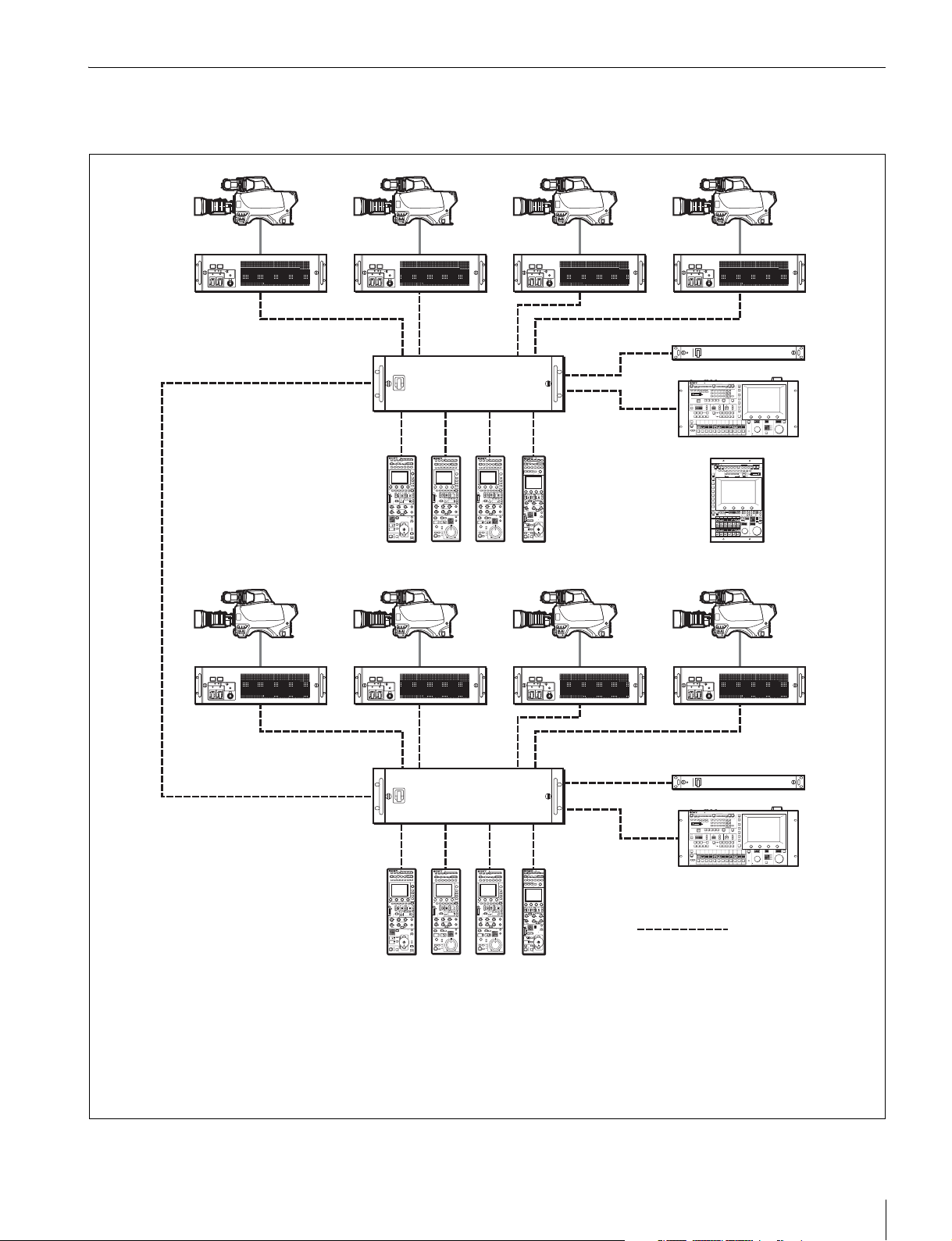
Connection example for LEGACY mode
• The maximum cable length for from a CCU (camera control unit) to an RCP is 200 m.
• Up to six systems can be connected to a CNU-700 as standard. In such a case, connect one MSU and one VCS.
Up to 12 systems can be connected if you install BKP-7930 in the CNU-700. In such a case, connect two MSUs and two
VCSs.
• Up to 24 systems can be connected if you connect a pair of CNU-700s. In such a case, you can connect four MSUs and
four VCSs, but ALL, RCP assignment, and master/subordinate cannot be executed for cameras connected to a different
CNU.
Camera heads
CCU
VCS-700
CCU (1 to 6)
VCS
CNU-700
MSU-1000/1500
CCA-5 cable
RCP (1 to 6)
CCU/CNU
REMOTE
RCP-1500/1501/1530
MSU
6
Overview
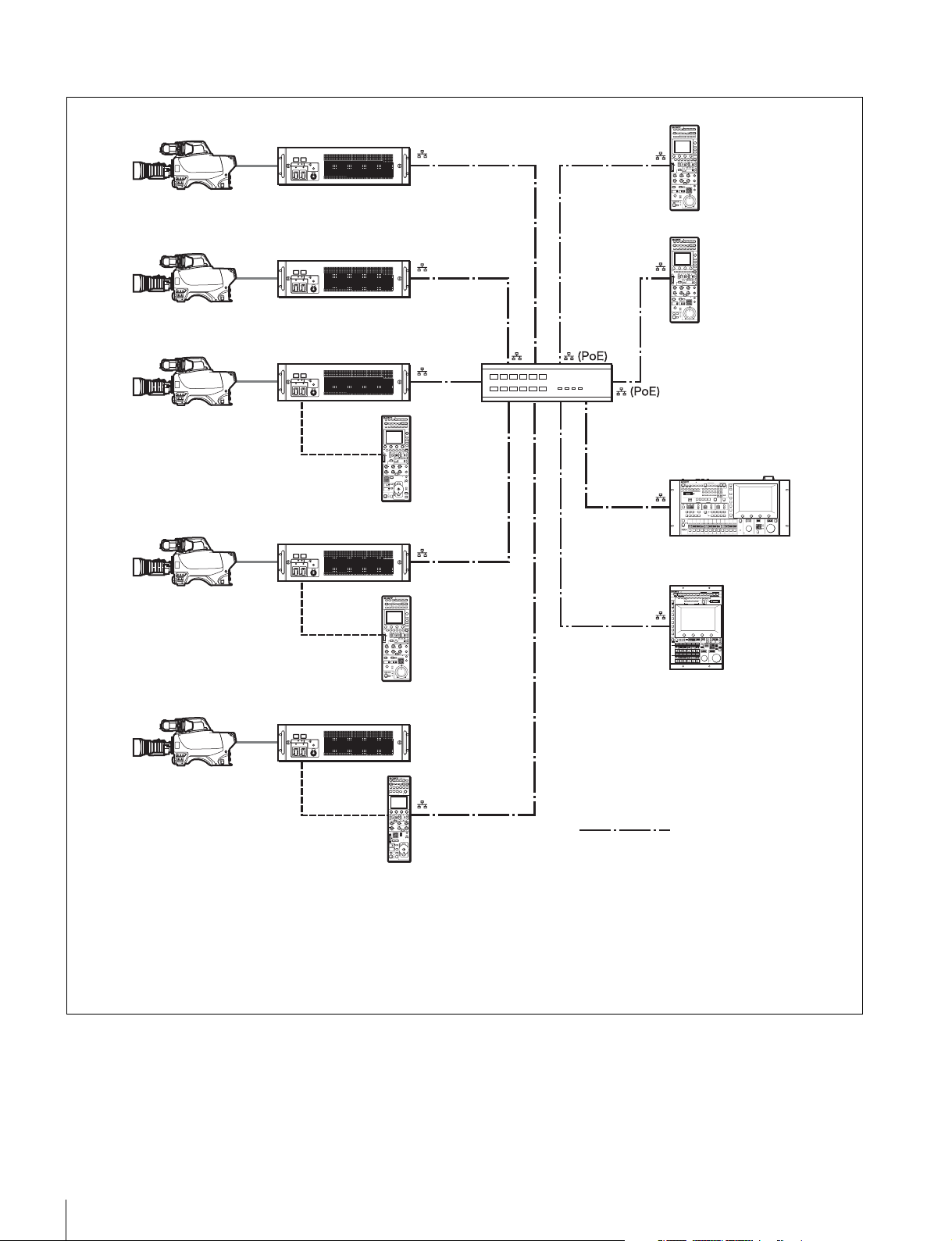
Connection example for MCS mode
Regarding the power supply of a switching hub
The power consumption of the PoE of this control panel is 7 W.
Use a hub capable of supplying enough power for all
connected RCPs.
• In MCS mode, be sure to set one of the multiple MSUs as the master. Not to turn off the power or disconnect the cable of
the master MSU during operation.
• The maximum number of devices that can be directly connected to the network is 96 excluding the master MSU. This
maximum number does not include any RCP connected by CCA cable to a CCU connected to the network or any CCU
connected by CCA cable to a RCP connected to the network. A client MSU is counted as one unit.
• A CNU and VCS cannot be connected to a system that will be used in MCS mode.
Camera heads
CCU
MSU-1000/1500
RCP-1500
PoE compatible switching hub
LAN straight cable
(category 5 or above)
RCP-1501
RCP-1530

Overview
7
Supported devices
This unit supports connection to the following devices.
• BVP-E30 series
• CCU-590/790 series
• HDC1000(R)/1500(R)/3300(R) series
• HDCU1000/1500/3300(R) series
• HDC2000/2500 series
• HDCU2000/2500 series
• HSC-300/HSCU-300 series
• HXC-100/HXCU-100 series
• HXC-D70/HXCU-D70 series
• HDC-P1
• HDFA-200
• F23/F35
• SRW-9000/SRW-9000PL
• PDW-700/740/F800
• HSC300RF/300R/100RF/100R
• HSCU300RF/300R
•CA4000
• BPU8000/4000
For details about the devices other than the above, refer to the
connecting information for each device.
• Proper functioning may not be possible depending on the
firmware version. Be sure to update to the latest version
before use.
• The functions that are available on the control panel may be
limited depending on the connected camera. Some controls
may not function with certain cameras, but this is not a
malfunction.
Operating Cameras
Camera control permissions (panel active,
IRIS/MB active, and PARA)
By combining an MSU and RCP, you can operate one camera
device from multiple control panels, and multiple cameras from
one MSU. This is called a “multi-camera system.” A multi-
camera system can be implemented by introducing a CNU or
by establishing a LAN connection in MCS mode.
To prevent unintentional operation in a multi-camera system,
permission is granted to operate the cameras for only either
the connected MSU or RCP. There are three types of
permission.
• Panel active
Even if multiple control panels are connected to one camera,
only one control panel has the control permission. This
panel is referred to as “active.”
An inactive control panel can only be used to display the
status.
• PARA (parallel control)
By enabling the PARA function on an inactive control panel,
you can control cameras. The PARA function is enabled
from an inactive control panel, but can be disabled from any
control panel.
• IRIS/MB active
To prevent unintentional operation of IRIS and master black,
you can choose the control panels on which to activate
IRIS/MB. The PARA function does not operate.
Operating an inactive control panel on which PARA is
disabled will not change the state of the camera.
White balance link (master/subordinate mode)
The color temperature of light shining on the subject varies
moment by moment when you shoot outdoors. When
correcting for this, you can link the cameras within the system
and then control them. When you do this, set the camera that
is to be controlled directly to “Master,” and the cameras that
are to be linked to “Subordinate.”
When you change the white balance of the control panel to
which the master camera is connected, the subordinate
cameras are corrected by the same correction amount.
However, adjusting a subordinate camera does not affect any
of the other cameras.
The white balance link function is only enabled when there is
a connection to a CNU (LEGACY mode).
The functions that are available on the control panel may be
limited depending on the connected camera. Some controls
may not function with certain cameras, but this is not a
malfunction.
Notes
Note
8
Names and Functions of Parts
Names and Functions of Parts
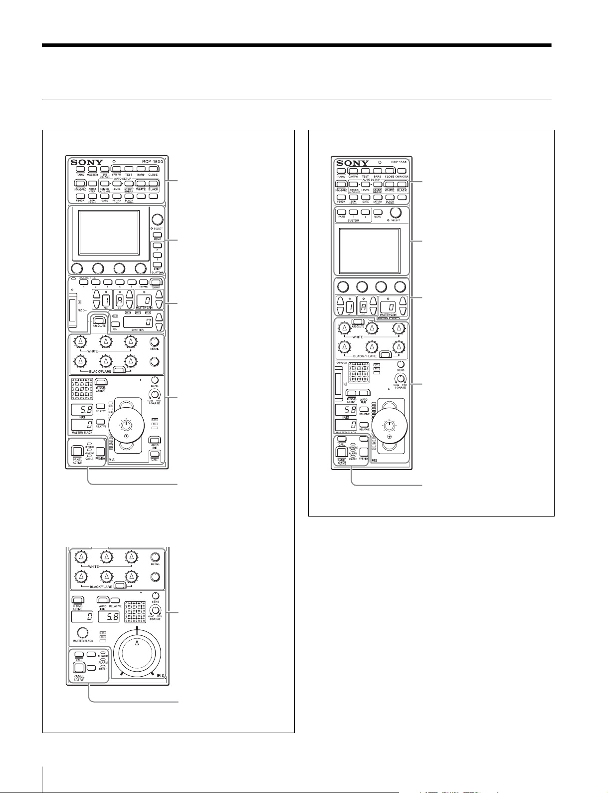
Operation Panel
Camera/panel control block
(RCP-1500/1501) (page 9)
Menu operation block
(page 13)
Function control block
(RCP-1500/1501) (page 14)
Adjustment block (RCP-1500)
(page 17)
Panel control/status display
block (RCP-1500) (page 23)
RCP-1500
RCP-1501
Adjustment block (RCP-1501)
(page 19)
Panel control/status display
block (RCP-1501) (page 24)
Camera/panel control block
(RCP-1530) (page 11)
Menu operation block
(page 13)
Function control block
(RCP-1530) (page 16)
Adjustment block (RCP-1530)
(page 21)
Panel control/status display
block (RCP-1530) (page 25)
RCP-1530
Names and Functions of Parts
9
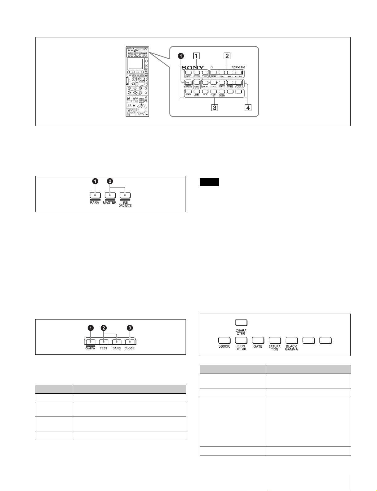
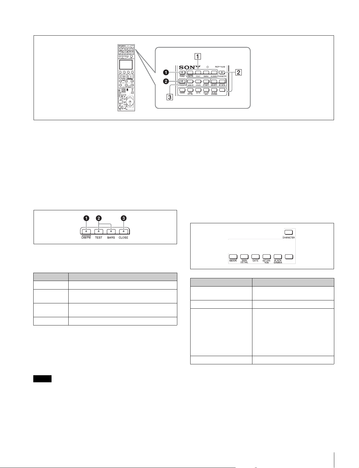
Camera/panel control block (RCP-1500/1501)
a STANDARD button
This button is for accessing the standard state of the camera.
After the standard state is accessed, you can cancel access by
pressing the STANDARD button again while it is lit.
1 Control selection block
a PARA (parallel control) button
This is the PARA function button. It allows you to
simultaneously control the control panels that are active.
However, IRIS and master black are only enabled on control
panels on which IRIS/MB is active, and cannot be controlled
simultaneously.
b MASTER and SUBORDINATE buttons
These are the master/subordinate function buttons. A
subordinate device is linked to the white balance adjustment
of the master device. If both are set to ON, the setting of the
master device takes priority.
These were formerly the master/slave function buttons.
2 Power/output signal selection block
a CAM PW (camera power) button
This button is for supplying power from the CCU to the camera
heads.
b Test signal output selection buttons
These buttons light when pressed and are for operating the
test signal generator of the camera to output the
corresponding signal.
TEST: Camera test signal
BARS (color bars): Color bar signal
When the BARS button is lit, the function of the BARS button
takes priority for CCU output. When you select TEST, press
the BARS button to turn its light off.
c CLOSE (iris close) button
This button is for closing the iris of the lens connected to the
camera. Pressing it when the auto iris is on changes the iris
indication to CLS. Pressing it when the auto iris is off displays
the iris value, and the state of that iris value is restored when
the close mode is cancelled.
3 Camera/CCU function ON/OFF buttons
These buttons are for various functions. A function is enabled
when its button is lit. A function with an OFF indication is off
when the button is lit. Functions can be assigned to the spare
buttons.
For details on assigning functions to spare buttons, see “To
assign functions to assignable buttons” (page 43).
Lighting state Meaning
On The power is being supplied.
Off The power is disconnected. It is not supplied even
if the button is pressed.
Slow flashing The power is disconnected. It is supplied when the
button is pressed.
Fast flashing The camera is starting up.
Note
Button Description
5600K Electric color temperature correction
function
SKIN DETAIL Skin detail function
GATE Gate function
Displays the active area of the
function on the screen (corresponds
to Skin DTL and Multi matrix gate).
For details on for what kind of image
output a gate signal is displayed, refer
to the operation manual of the device
of the connection destination.
SATURATION Saturation function
10
Names and Functions of Parts
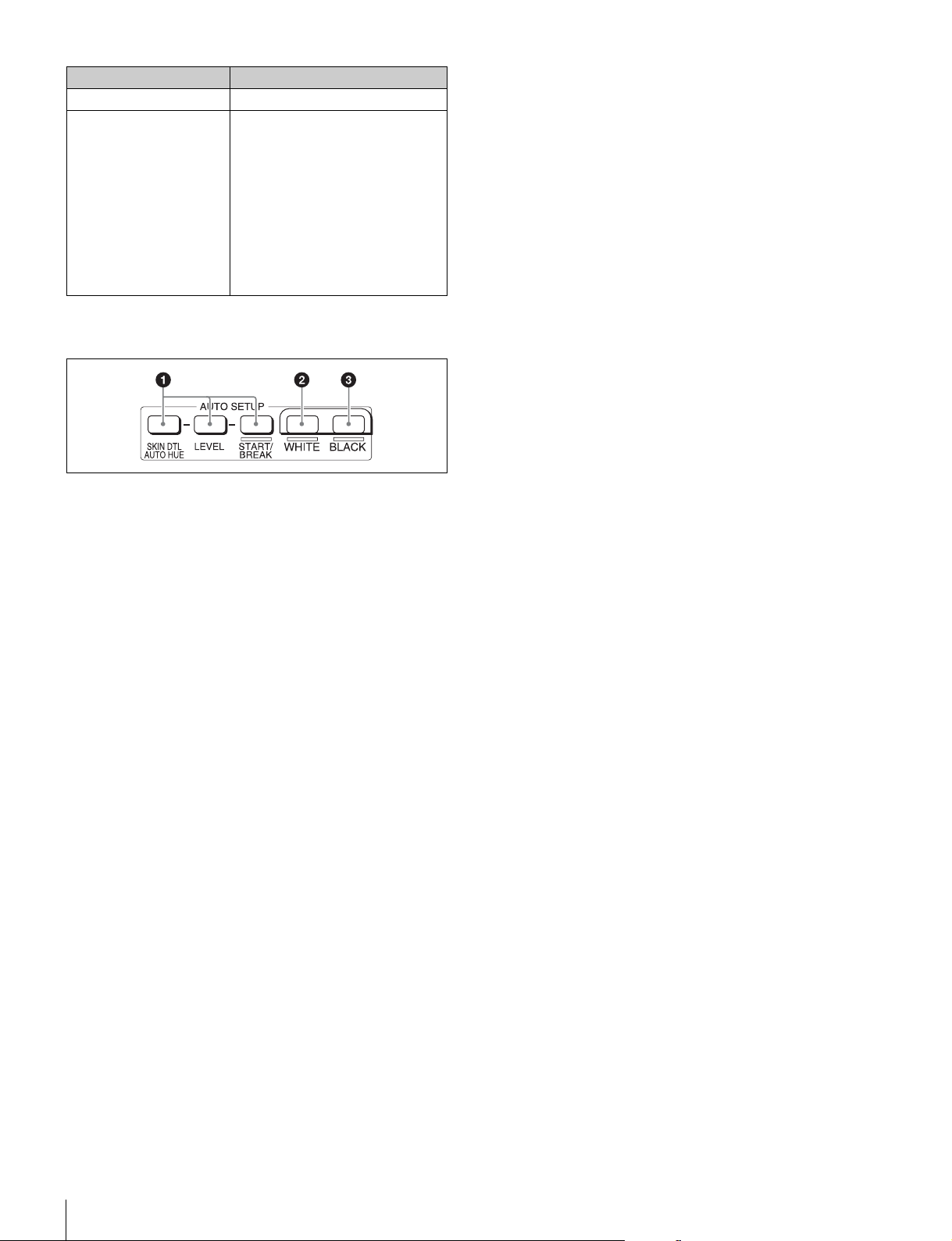
4 AUTO SETUP block
These buttons are for automatically adjusting the camera.
a AUTO SETUP buttons and START/BREAK button
Pressing one of the following buttons and then pressing the
START/BREAK button runs the corresponding automatic
adjustment function.
SKIN DTL AUTO HUE: Automatically sets the skin detail to an
effective hue.
LEVEL: Runs the auto level setup.
Pressing the START/BREAK button while this function is
running stops auto adjustment. The button flashes to indicate
that this function is stopped, and pressing the button again
stops the flashing indication.
b WHITE (auto white balance) button
This button is for starting auto white balance adjustment. The
button is lit while this function is running and goes out when
adjustment is finished. Pressing it again or pressing the
START/BREAK button while this function is running stops
automatic adjustment. The button flashes to indicate that this
function is stopped, and pressing the button again stops the
flashing indication.
c BLACK (auto black balance) button
This button is for starting auto black balance adjustment. The
button is lit while this function is running and goes out when
adjustment is finished. Pressing it again or pressing the
START/BREAK button while this function is running stops
automatic adjustment. The button flashes to indicate that this
function is stopped, and pressing the button again stops the
flashing indication.
BLACK GAMMA Black gamma function
CHARACTER CCU character button
Turns ON/OFF character output of
the CCU and switches to the next
page. When this function is ON, each
press of the button switches to the
next page (holding the button
switches to the last page and stops
the function in the OFF state). For
details on for what kind of image
output characters are displayed, refer
to the operation manual of the device
of the connection destination.
Button Description
Names and Functions of Parts
11
Camera/panel control block (RCP-1530)
a PARA (parallel control) button
This is the PARA function button. It allows you to
simultaneously control the control panels that are active.
However, IRIS and master black are only enabled on control
panels on which IRIS/MB is active, and cannot be controlled
simultaneously.
b STANDARD button
This button is for accessing the standard state of the camera.
After the standard state is accessed, you can cancel access by
pressing the STANDARD button again while it is lit.
1 Power/output signal selection block
a CAM PW (camera power) button
This button is for supplying power from the CCU to the camera
heads.
b Test signal output selection buttons
These buttons light when pressed and are for operating the
test signal generator of the camera to output the
corresponding signal.
TEST: Camera test signal
BARS (color bars): Color bar signal
When the BARS button is lit, the function of the BARS button
takes priority. When you select TEST, press the BARS button
to turn its light off.
c CLOSE (iris close) button
This button is for closing the iris of the lens connected to the
camera. Pressing it when the auto iris is on changes the iris
indication to CLS. Pressing it when the auto iris is off displays
the iris value, and this value is redisplayed when the close
mode is cancelled.
2 Camera/CCU function ON/OFF buttons
These buttons are for various functions. A function is enabled
when its button is lit. A function with an OFF indication is off
when the button is lit. Functions can be assigned to the spare
buttons.
For details on assigning functions to spare buttons, see
page 43.
Lighting state Meaning
On The power is being supplied.
Off The power is disconnected. It is not supplied even
if the button is pressed.
Slow flashing The power is disconnected. It is supplied when the
button is pressed.
Fast flashing The camera is starting up.
Note
Button Description
5600K Electric color temperature correction
function
SKIN DETAIL Skin detail function
GATE Gate function
Displays the active area of the
function on the screen (corresponds
to Skin DTL and Multi matrix gate).
For details on for what kind of image
output a gate signal is displayed, refer
to the operation manual of the device
of the connection destination.
SATURATION Saturation function

12
Names and Functions of Parts
3 AUTO SETUP block
These buttons are for automatically adjusting the camera.
a AUTO SETUP buttons and START/BREAK button
Pressing one of the following buttons and then pressing the
START/BREAK button runs the corresponding automatic
adjustment function.
SKIN DTL AUTO HUE: Automatically sets the skin detail to an
effective hue.
LEVEL: Runs the auto level setup.
Pressing the START/BREAK button while this function is
running stops auto adjustment. The button flashes to indicate
that this function is stopped, and pressing the button again
stops the flashing indication.
b WHITE (auto white balance) button
This button is for starting auto white balance. The button is lit
while this function is running and goes out when adjustment is
finished. Pressing it again or pressing the START/BREAK
button while this function is running stops automatic
adjustment. The button flashes to indicate that this function is
stopped, and pressing the button again stops the flashing
indication.
c BLACK (auto black balance) button
This button is for starting auto black balance. The button is lit
while this function is running and goes out when adjustment is
finished. Pressing it again or pressing the START/BREAK
button while this function is running stops automatic
adjustment. The button flashes to indicate that this function is
stopped, and pressing the button again stops the flashing
indication.
BLACK GAMMA Black gamma function
CHARACTER CCU character button
Turns ON/OFF character output of
the CCU and switches to the next
page. When this function is ON, each
press of the button switches to the
next page (a long press switches to
the last page and stops the function
in the OFF state). For details on for
what kind of image output characters
are displayed, refer to the operation
manual of the device of the
connection destination.
Button Description
Names and Functions of Parts
13
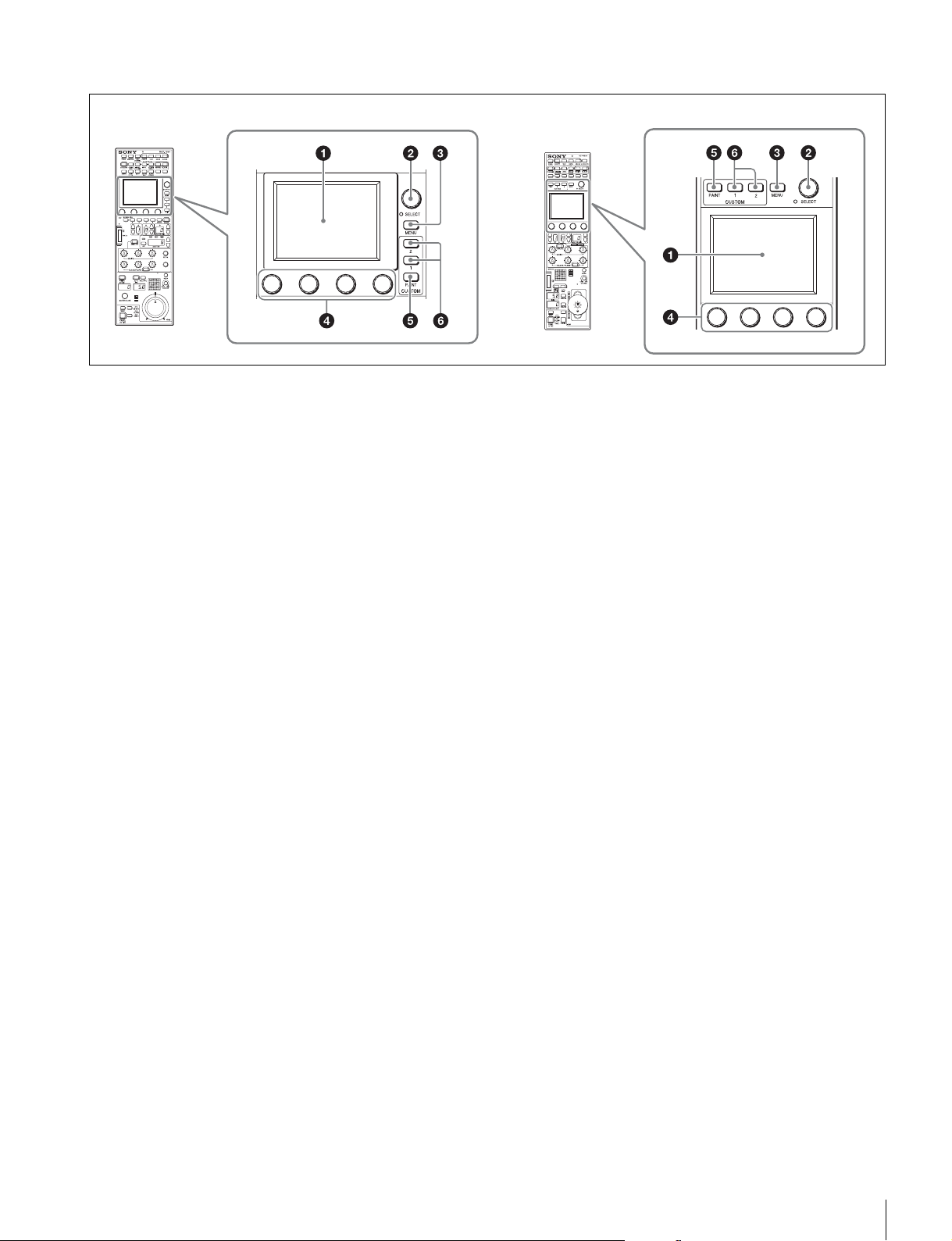
Menu operation block
Menu operation is performed on the LCD.
Operation is performed by touching the buttons and tabs that
are displayed on the LCD. Use the adjustment knobs to
change numbers and select items.
To change menus, press a menu button or custom button and
then use the buttons in the menu to navigate through the
menu. When you reach the lowest level in the menu, the LED
of the SELECT knob lights. You can display the desired page
by turning the SELECT knob to forward through the menus in
order or by pressing the SELECT button and then accessing
the page from the selection screen.
For details on menu operations, see “Menu Tree” (page 52).
a LCD/touch panel
This is for displaying menus and performing operations.
b SELECT knob
Turning the knob while the LED is lit allows you to select
menus. Pressing in the knob while the LED is lit displays the
menu selection screen to also allow you to switch to the
desired menu.
Pressing in the knob with the Status screen displayed allows
you to display the CUSTOM PAINT menu.
c MENU button
This button is for accessing the menu screen.
d Adjustment knobs (rotary encoders)
These knobs are for adjusting or selecting items in menus.
e CUSTOM PAINT button
This button is for accessing the CUSTOM PAINT menu. You
can set the contents and order of the CUSTOM PAINT menu.
f CUSTOM buttons
These buttons are for directly accessing preset menus. The
CUSTOM1 and CUSTOM2 buttons are available.
RCP-1500/1501 RCP-1530
14
Names and Functions of Parts
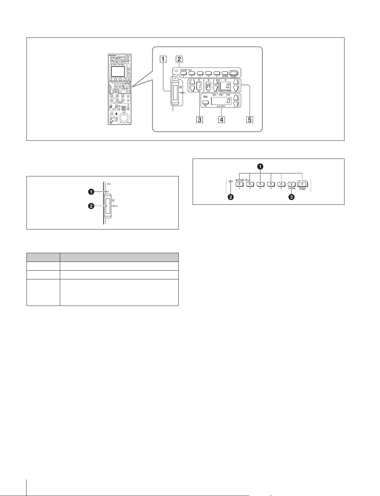
Function control block (RCP-1500/1501)
1 “Memory Stick Duo” insertion block
For details on a “Memory Stick Duo,” see “About “Memory
Stick Duo”” (page 82).
a Access indicator
This indicates the status of a “Memory Stick Duo.”
b “Memory Stick Duo” slot
This slot allows you to use a “Memory Stick Duo.” You can save
or read various files.
2 Scene file control block
a SCENE FILE selection buttons and STORE button
These buttons are for registering and reading scene files.
To register a scene file, press the STORE button to start it
flashing and then press the SCENE FILE button with the
corresponding number. When file registration is finished, the
STORE button goes out. To stop registration part way through,
press the STORE button again before pressing the SCENE
FILE button.
To read a scene file, press the SCENE FILE button with the
corresponding number while the STORE button is not flashing.
The items that can be stored to a scene file differ depending
on the connected camera.
b Scene file indicator
This lights when a scene file is read. While the any of scenes
1 to 5 is being read, the button with the corresponding number
is lit. While any of scenes 6 and above are read, only the LED
of SCENE FILE is lit.
c EXPAND button
This button is for accessing the Scene File menu to perform
various operations. Press this button to use the 32-scene file
function.
Indication Meaning or measure
Off A “Memory Stick Duo” is not inserted.
Lit in green A “Memory Stick Duo” is inserted.
Lit in red Data is being read or written. The data cannot be
guaranteed if you eject the “Memory Stick Duo” in
this state (be careful because all of the data may be
lost).
Names and Functions of Parts
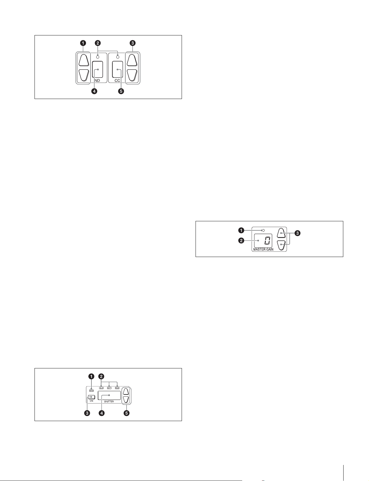
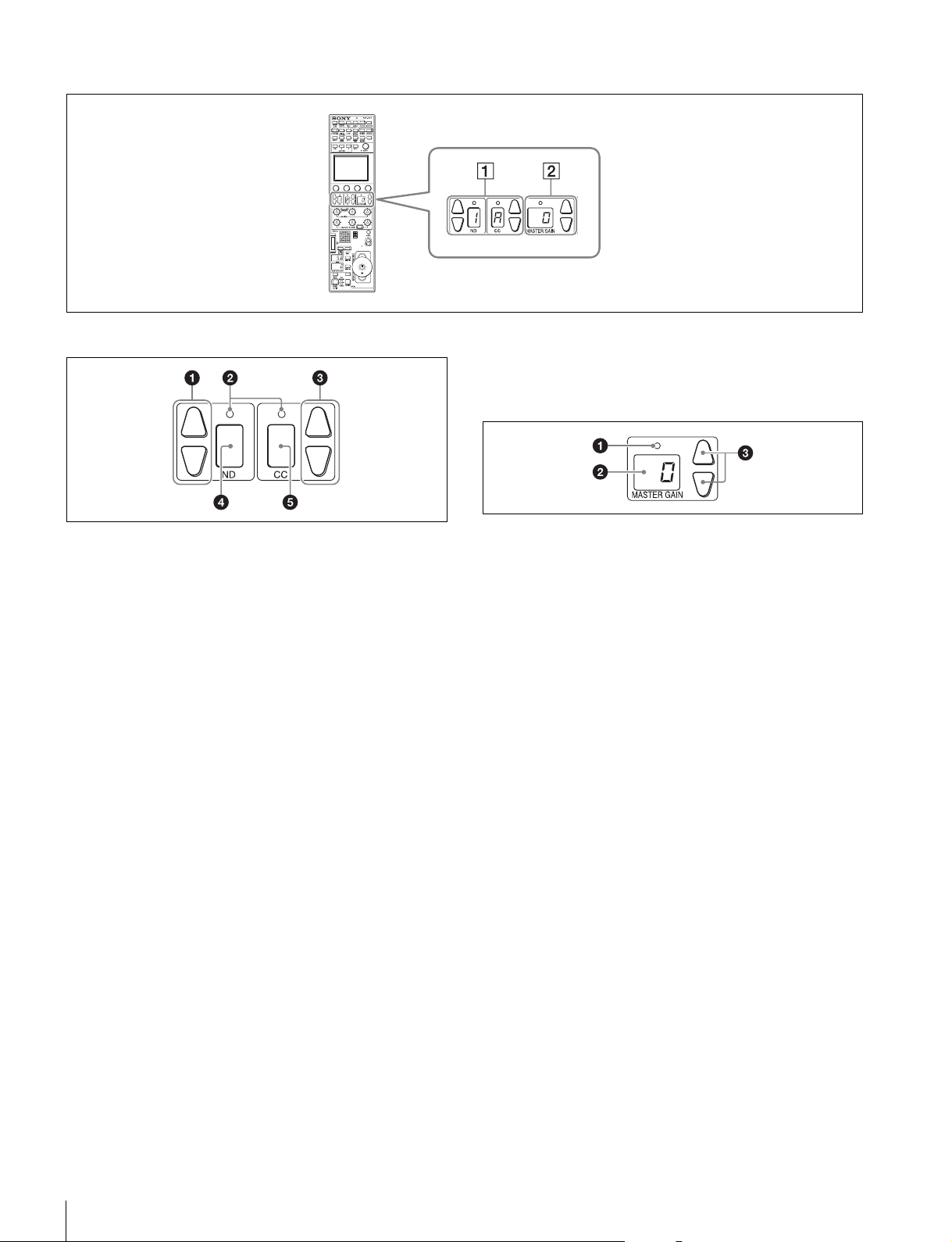
15
3 Filter control block
a ND filter selection buttons
These buttons are lit when the RCP has the filter servo control
permission. When they are not lit, the camera side has the
control permission. Pressing either the top or bottom button
once switches the control permission to the RCP. If there is no
filter servo or the camera does not have a filter, these buttons
do not light and the control permission can also not be
switched.
The v button changes the ND filters in order in the forward
direction. The V button changes them in the opposite
direction. Pressing and holding one of the buttons changes the
ND filters continuously.
b Standard value indicators
These light when standard values are set in the Standard Ind
menu. The indicators light in green when values are in their
standard state, and in amber when values are not in their
standard state.
c CC (color temperature conversion) filter selection
buttons
These buttons are lit when the RCP has the filter servo control
permission. When they are not lit, the camera side has the
control permission. Pressing either the top or bottom button
once switches the control permission to the RCP. If there is no
filter servo or the camera does not have a filter, these buttons
do not light and the control permission can also not be
switched.
The v button changes the CC filters in order in the forward
direction. The V button changes them in the opposite
direction. Pressing and holding one of the buttons changes the
ND filters continuously.
d ND filter display window
This window displays the ND filter that is currently selected.
e CC (color temperature conversion) filter display
window
This window displays the CC filter that is currently selected.
4 Shutter control block
a DEG indicator
This indicator is lit when the shutter display is indicating an
angle value. Configure the setting with the switches in Shutter
of the Paint menu.
b SLS/SHUTTER/ECS indicators
The indicator corresponding to the selected function is lit.
Select a function in the menu.
SLS: Slow shutter mode
SHT: Shutter mode
ECS: ECS (Extended Clear Scan) mode
c ON button
This button is for turning ON/OFF the camera’s SLS, shutter,
or ECS function. Pressing the button causes it to light and
turns ON the function, and pressing it again causes the button
to go out and turns OFF the function.
d Shutter speed display window
This window is for displaying the shutter speed that is currently
set. If the DEG indicator is lit while in shutter mode (the SHT
indicator is also lit), this window displays an angle value. If the
DEG indicator is not lit, the shutter speed is displayed in
seconds.
e Shutter speed selection buttons
These buttons are for setting the shutter speed. Each press of
the v (up) button increases the shutter speed, and each press
of the V (down) button decreases it.
5 Master gain control block
a Standard value indicator
This lights when standard values are set in the Standard Ind
menu. The indicator lights in green when values are in their
standard state, and in amber when values are not in their
standard state.
b Master gain display window
This window displays the master gain that is currently set.
c Master gain selection buttons
This block is for setting the sensitivity of the camera. Each
press of the v (up) button increases the sensitivity, and each
press of the V (down) button decreases it. Pressing and
holding one of the buttons changes the sensitivity
continuously. The setting value (unit: dB) is displayed in the
display window.
12
34 5
16
Names and Functions of Parts
Function control block (RCP-1530)
1 Filter control block
a ND filter selection buttons
These buttons are lit when the RCP has the filter servo control
permission. When they are not lit, the camera side has the
control permission. Pressing either the top or bottom button
once switches the control permission to the RCP. If there is no
filter servo or the camera does not have a filter, these buttons
do not light and the control permission can also not be
switched.
The v button changes the ND filters in order in the forward
direction. The V button changes them in the opposite
direction. Pressing and holding one of the buttons changes the
ND filters continuously.
b Standard value indicators
These light when standard values are set in the Standard Ind
menu. The indicators light in green when values are in their
standard state, and in amber when values are not in their
standard state.
c CC (color temperature conversion) filter selection
buttons
These buttons are lit when the RCP has the filter servo control
permission. When they are not lit, the camera side has the
control permission. Pressing either the top or bottom button
once switches the control permission to the RCP. If there is no
filter servo or the camera does not have a filter, these buttons
do not light and the control permission can also not be
switched.
The v button changes the CC filters in order in the forward
direction. The V button changes them in the opposite
direction. Pressing and holding one of the buttons changes the
ND filters continuously.
d ND filter display window
This window displays the ND filter that is currently selected.
e CC (color temperature conversion) filter display
window
This window displays the CC filter that is currently selected.
2 Master gain control block
a Standard value indicator
This lights when standard values are set in the Standard Ind
menu. The indicator lights in green when values are in their
standard state, and in amber when values are not in their
standard state.
b Master gain display window
This window displays the master gain that is currently set.
c Master gain selection buttons
This block is for setting the sensitivity of the camera. Each
press of the v (up) button increases the sensitivity, and each
press of the V (down) button decreases it. Pressing and
holding one of the buttons changes the sensitivity
continuously. The setting value (unit: dB) is displayed in the
displayed in the display window.
Names and Functions of Parts
17
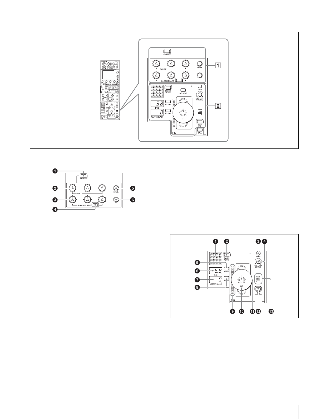
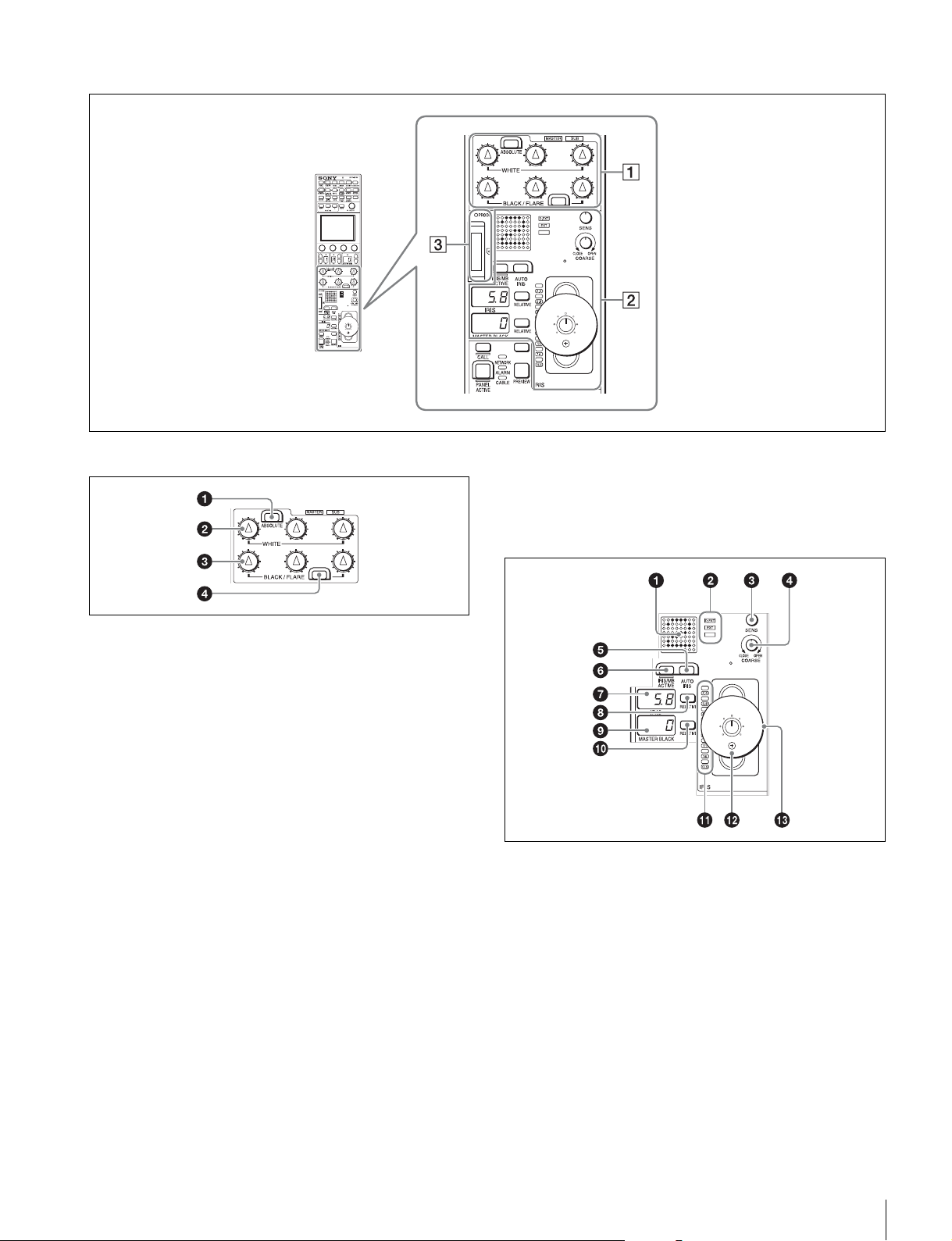
Adjustment block (RCP-1500)
1 White balance/black balance adjustment block
a ABSOLUTE button
This button changes the mode for manual adjustment using
the WHITE, BLACK, FLARE, DETAIL, and assignable knobs
between absolute value mode (lit) and relative value mode
(not lit). In absolute value mode, a knob indication value
becomes that setting value. In relative value mode, a knob
indication angle and the setting value do not match.
The relative value mode is selected automatically in the
following cases.
• During power up
• When the active status of the panel has changed
• When in PARA or master/subordinate mode
• When auto setup (level, white, and black) finishes
• When a scene file is read
• When the adjustment mode is switched between flare
balance and black balance by pressing the FLARE button
• When the controlled CCU/HDCU is changed with the RCP
Assign settings
b WHITE (manual white balance) knobs
These knobs allow you to adjust the R, G, and B signals in
order from left to right.
c BLACK/FLARE (manual black balance/flare balance)
knobs
These knobs adjust the black balance when the FLARE button
is not lit, and the flare balance when the FLARE button is lit.
They adjust the R, G, and B signals in order from left to right.
d FLARE (flare balance mode) button
This button changes the adjustment mode of the BLACK/
FLARE knobs. The knobs adjust the flare balance when the
button is lit, and the black balance when the button is not lit.
e DETAIL knob
This knob adjusts the detail level.
f Assignable adjustment knob
This knob adjusts a preselected item.
For details on selecting the item of the assignable adjustment
knob, see page 44.
2 Iris/master control black adjustment block
a Camera number/tally display window
This window displays an amber number for the camera
controlled by the control panel.
When a red tally signal is sent to the camera, a black number
is displayed and the background of the number lights in red.
When a green tally signal is sent to the camera, a black
number is displayed and the background of the number lights
in green.
When both red and green tally signals are simultaneously
sent, the left half of the background lights in red, and the right
half lights in green.
18
Names and Functions of Parts
b IRIS/MB ACTIVE (iris/master black active) button
This button is for the iris and master black control permission.
The iris and master black can only be adjusted when this
button is lit. Pressing the PANEL ACTIVE button also causes
this button to light.
c SENS (iris adjustment range) knob
This knob is for manually adjusting the iris in absolute value
mode. It does not work in relative value mode.
d COARSE (iris coarse adjustment) knob
This knob is for manually adjusting the iris.
Also see the table “Iris Adjustment Functions”, (page 20).
e IRIS RELATIVE button
This button changes the manual adjustment mode of the IRIS
control lever. Relative value mode is enabled when the button
is lit, and absolute value mode is enabled when the button is
not lit.
f IRIS display window
This window displays the iris setting as an F number. If the lens
is closed, “CLS” is displayed.
g Master black display window
This window displays the master black setting value.
h MASTER BLACK RELATIVE button
This button changes the manual adjustment mode of the
master black control ring. Relative value mode is enabled
when the button is lit, and absolute value mode is enabled
when the button is not lit.
i Iris indicators
The corresponding LED lights according to the iris setting.
When the IRIS RELATIVE button is not lit, the indicators light
dimly to display the upper and lower limits of manual
adjustment.
j IRIS control lever
This lever is for manually adjusting the iris of the lens when the
AUTO IRIS button is not lit. When the AUTO IRIS button is lit,
you can finely adjust the reference value for auto adjustment
of the iris.
Press the switch axially to output preview key signals from the
EXT I/O connector.
Also see the table “Iris Adjustment Functions”, (page 20).
k Master black control ring
This ring is for manually adjusting the master black. The
setting value is displayed in the master black display window.
l AUTO IRIS button
This button is for adjusting the iris automatically.
m EXT (lens extender) indicators
EXT: Lights when the lens extender is used.
D EXT: Lights when the digital extender function is turned ON.
Iris Adjustment Functions
Relative value mode
(IRIS RELATIVE button lit)
Absolute value mode
(IRIS RELATIVE button not lit)
IRIS knob Adjusts the iris in relative values.
A variable amount can be set. (See page 37)
Adjusts the iris within the variable range set by the
SENS and COARSE knobs.
COARSE knob Adjusts the iris in relative values within the full range
from OPEN to CLOSE.
Sets the lower limit for the CLOSE side.
SENS knob Does not function. Sets the upper limit for OPEN, referenced to the
CLOSE value set by the COARSE knob.
Names and Functions of Parts
19
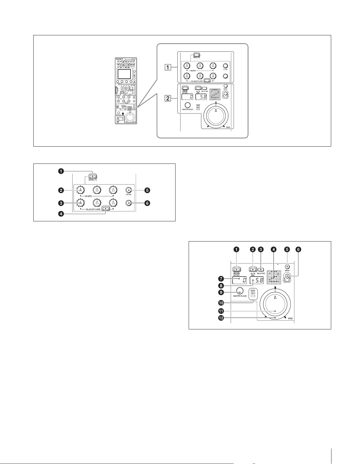
Adjustment block (RCP-1501)
1 White balance/black balance adjustment block
a ABSOLUTE button
This button changes the mode for manual adjustment using
the WHITE, BLACK, FLARE, DETAIL, and assignable knobs
between absolute value mode (lit) and relative value mode
(not lit). In absolute value mode, a knob indication value
becomes that setting value. In relative value mode, a knob
indication angle and the setting value do not match.
The relative value mode is selected automatically in the
following cases.
• During power up
• When the active status of the panel has changed
• When in PARA or master/subordinate mode
• When auto setup (level, white, and black) finishes
• When a scene file is read
• When the adjustment mode is switched between flare
balance and black balance by pressing the FLARE button
• When the controlled CCU/HDCU is changed with the RCP
Assign settings
b WHITE (manual white balance) knobs
These knobs allow you to adjust the R, G, and B signals in
order from left to right.
c BLACK/FLARE (manual black balance/flare balance)
knobs
These knobs adjust the black balance when the FLARE button
is not lit, and the flare balance when the FLARE button is lit.
They adjust the R, G, and B signals in order from left to right.
d FLARE (flare balance mode) button
This button changes the adjustment mode of the BLACK/
FLARE knobs. The knobs adjust the flare balance when the
button is lit, and the black balance when the button is not lit.
e DETAIL knob
This knob adjusts the detail level.
f Assignable adjustment knob
This knob adjusts a preselected item.
For details on selecting the item of the assignable adjustment
knob, see page 44.
2 Iris/master control black adjustment block
a IRIS/MB ACTIVE (iris/master black active) button
This button is for the iris and master black control permission.
The iris and master black can only be adjusted when this
button is lit. Pressing the PANEL ACTIVE button also causes
this button to light.
b AUTO IRIS button
This button is for adjusting the iris automatically.
c IRIS RELATIVE button
This button changes the manual adjustment mode of the IRIS
knob. Relative value mode is enabled when the button is lit,
and absolute value mode is enabled when the button is not lit.
20
Names and Functions of Parts
d Camera number/tally display window
This window displays an amber number for the camera
controlled by the control panel.
When a red tally signal is sent to the camera, a black number
is displayed and the background of the number lights in red.
When a green tally signal is sent to the camera, a black
number is displayed and the background of the number lights
in green.
When both red and green tally signals are simultaneously
sent, the left half of the background lights in red, and the right
half lights in green.
e SENS (iris adjustment range) knob
This knob is for manually adjusting the iris in absolute value
mode. It does not work in relative value mode.
f COARSE (iris coarse adjustment) knob
This knob is for manually adjusting the iris.
Also see the table “Iris Adjustment Functions”, (page 20).
g Master black display window
This window displays the master black setting value.
h IRIS display window
This window displays the iris setting as an F number. If the lens
is closed, “CLS” is displayed.
i MASTER BLACK knob
This knob is for manually adjusting the master black. The
setting value is displayed in the master black display window.
j EXT (lens extender) indicators
EXT: Lights when the lens extender is used.
D EXT: Lights when the digital extender function is turned ON.
k IRIS knob
This knob is for manually adjusting the iris of the lens when the
AUTO button is not lit. When the AUTO IRIS button is lit, you
can finely adjust the reference value for auto adjustment of the
iris.
Also see the table “Iris Adjustment Functions”, (page 20).
l Iris gauge
The white marker line on the gauge provides a click position
for the IRIS knob. If you turn the gauge to align the marker line
with the most frequently used iris position, it can be used as a
setting reference for the IRIS knob.
The gauge rotates 360, so set the marker line so that it is
outside the rotation range of the knob if you do not need a click
position.
Iris Adjustment Functions
Relative value mode
(IRIS RELATIVE button lit)
Absolute value mode
(IRIS RELATIVE button not lit)
IRIS knob Adjusts the iris in relative values.
A variable amount can be set. (See page 37)
Adjusts the iris within the variable range set by the
SENS and COARSE knobs.
COARSE knob Adjusts the iris in relative values within the full range
from OPEN to CLOSE.
Sets the lower limit for the CLOSE side.
SENS knob Does not function. Sets the upper limit for OPEN, referenced to the
CLOSE value set by the COARSE knob.
Names and Functions of Parts
21
Adjustment block (RCP-1530)
1 White balance/black balance adjustment block
a ABSOLUTE button
This button changes the mode for manual adjustment using
the WHITE, BLACK, FLARE, DETAIL, and assignable knobs
between absolute value mode (lit) and relative value mode
(not lit). In absolute value mode, a knob indication value
becomes that setting value. In relative value mode, a knob
indication angle and the setting value do not match.
The relative value mode is selected automatically in the
following cases.
• During power up
• When the active status of the panel has changed
• When in PARA or master/subordinate mode
• When auto setup (level, white, and black) finishes
• When a scene file is read
• When the adjustment mode is switched between flare
balance and black balance by pressing the FLARE button
• When the controlled CCU/HDCU is changed with the RCP
Assign settings
b WHITE (manual white balance) knobs
These knobs allow you to adjust the R, G, and B signals in
order from left to right.
c BLACK/FLARE (manual black balance/flare balance)
knobs
These knobs adjust the black balance when the FLARE button
is not lit, and the flare balance when the FLARE button is lit.
They adjust the R, G, and B signals in order from left to right.
d FLARE (flare balance mode) button
This button changes the adjustment mode of the BLACK/
FLARE knobs. The knobs adjust the flare balance when the
button is lit, and the black balance when the button is not lit.
2 Iris/master control black adjustment block
a Camera number/tally display window
This window displays an amber number for the camera
controlled by the control panel.
When a red tally signal is sent to the camera, a black number
is displayed and the background of the number lights in red.
When a green tally signal is sent to the camera, a black
number is displayed and the background of the number lights
in green.
When both red and green tally signals are simultaneously
sent, the left half of the background lights in red, and the right
half lights in green.
b EXT (lens extender) indicators
EXT: Lights when the lens extender is used.
D EXT: Lights when the digital extender function is turned ON.
22
Names and Functions of Parts
c SENS (iris adjustment range) knob
This knob is for manually adjusting the iris in absolute value
mode. It does not work in relative value mode.
d COARSE (iris coarse adjustment) knob
This knob is for manually adjusting the iris.
Also see the table “Iris Adjustment Functions”, (page 20).
e AUTO IRIS button
This button is for adjusting the iris automatically.
f IRIS/MB ACTIVE (iris/master black active) button
This button is for the iris and master black control permission.
The iris and master black can only be adjusted when this
button is lit. Pressing the PANEL ACTIVE button also causes
this button to light.
g IRIS display window
This window displays the iris setting as an F number. If the lens
is closed, “CLS” is displayed.
h IRIS RELATIVE button
This button changes the manual adjustment mode of the IRIS
control lever. Relative value mode is enabled when the button
is lit, and absolute value mode is enabled when the button is
not lit.
i Master black display window
This window displays the master black setting value.
j MASTER BLACK RELATIVE button
This button changes the manual adjustment mode of the
master black control ring. Relative value mode is enabled
when the button is lit, and absolute value mode is enabled
when the button is not lit.
k Iris indicators
The corresponding LED lights according to the iris setting.
When the IRIS RELATIVE button is not lit, the indicators light
dimly to display the upper and lower limits of manual
adjustment.
l IRIS control lever
This lever is for manually adjusting the iris of the lens when the
AUTO IRIS button is not lit. When the AUTO IRIS button is lit,
you can finely adjust the reference value for auto adjustment
of the iris.
Press the switch axially to output preview key signals from the
EXT I/O connector.
Also see the table “Iris Adjustment Functions”, (page 22).
m Master black control ring
This ring is for manually adjusting the master black. The
setting value is displayed in the master black display window.
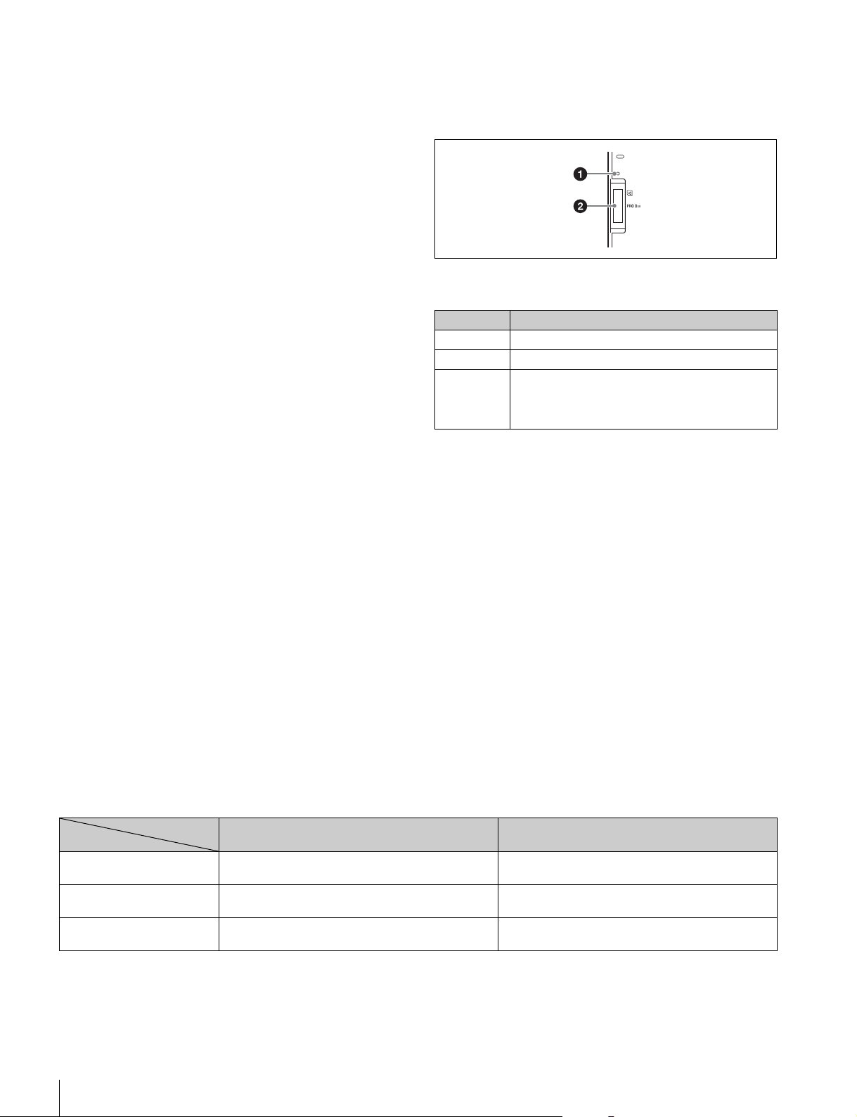
3 “Memory Stick Duo” insertion block
a Access indicator
This indicates the status of a “Memory Stick Duo.”
b “Memory Stick Duo” slot
This slot allows you to use a “Memory Stick Duo.” You can save
or read various files.
For details on handling a “Memory Stick Duo,” see “About
“Memory Stick Duo”” (page 82).
Iris Adjustment Functions
Indication Meaning or measure
Off A “Memory Stick Duo” is not inserted.
Lit in green A “Memory Stick Duo” is inserted.
Lit in red Data is being read or written. The data cannot be
guaranteed if you eject the “Memory Stick Duo” in
this state (be careful because all of the data may be
lost).
Relative value mode
(IRIS RELATIVE button lit)
Absolute value mode
(IRIS RELATIVE button not lit)
IRIS knob Adjusts the iris in relative values.
A variable amount can be set. (See page 37)
Adjusts the iris within the variable range set by the
SENS and COARSE knobs.
COARSE knob Adjusts the iris in relative values within the full range
from OPEN to CLOSE.
Sets the lower limit for the CLOSE side.
SENS knob Does not function. Sets the upper limit for OPEN, referenced to the
CLOSE value set by the COARSE knob.
Names and Functions of Parts
23
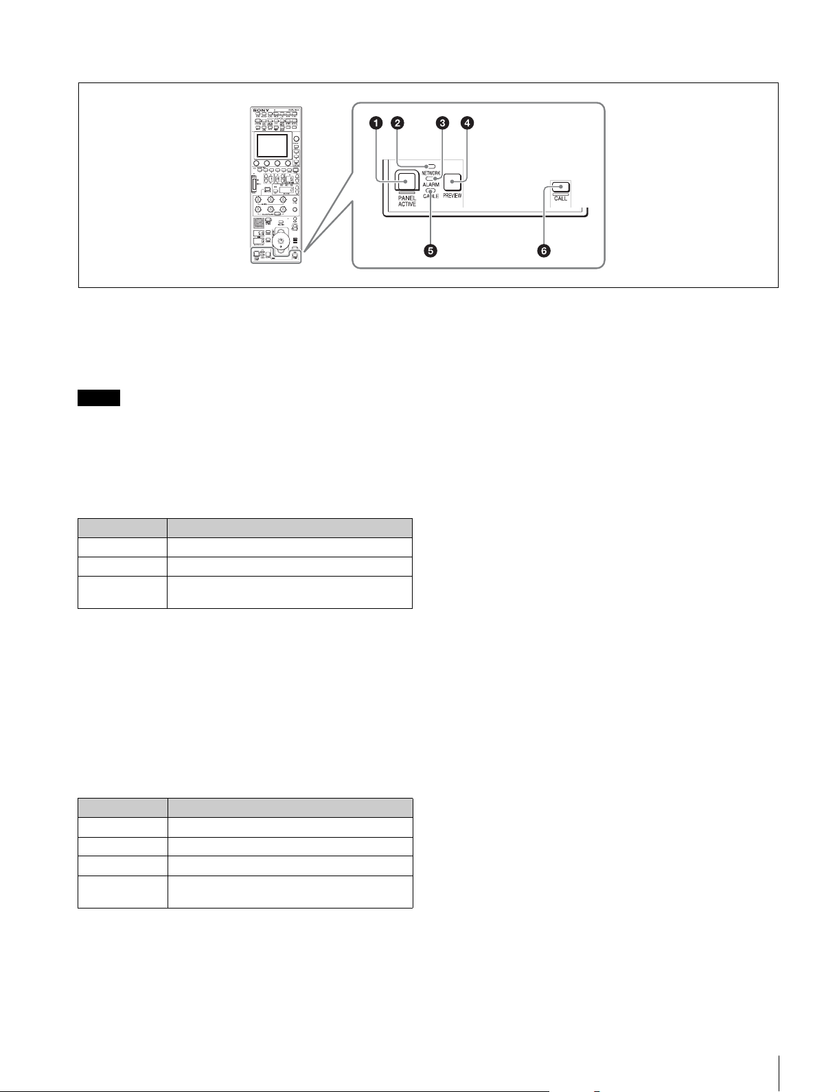
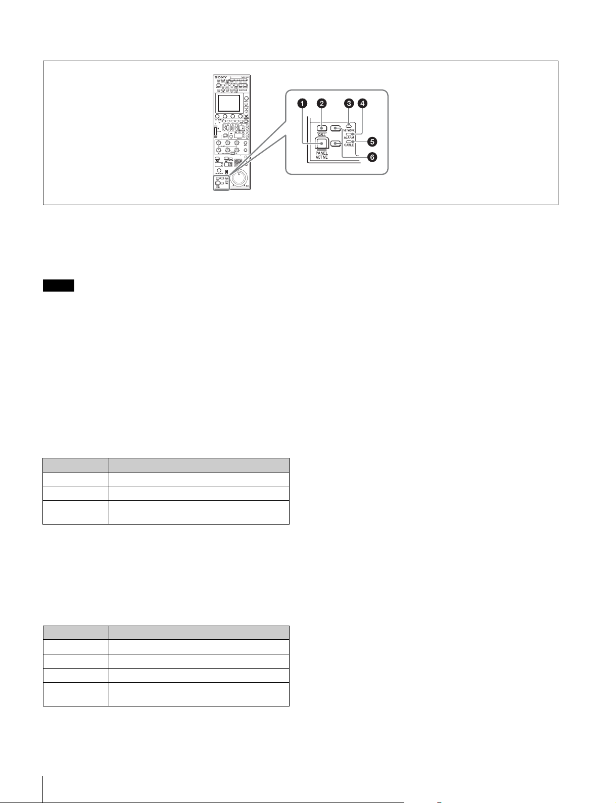
Panel control/status display block (RCP-1500)
a PANEL ACTIVE button
This button is for the control permission. It also serves as a
function for preventing unintentional operation because a
camera cannot be controlled from this control panel when this
button and the PARA button are not lit.
If the connection to the master breaks off in MCS mode
system, panel active operations are not possible.
In this case, a long press of the PANEL ACTIVE button forces
the availability of the panel active.
b NETWORK indicator
This indicates the status of the network connection.
c ALARM indicator
This lights red when a system error occurs and the self-
diagnosis function is operating on the camera head or CCU/
HDCU.
d PREVIEW button
This button is for outputting preview key signals from the EXT
I/O connector.
e CABLE indicator
This indicates the communication state of the camera head
and CCU.
f CALL button
This button is for communication. If it is pressed, the tally state
for the camera or CCU changes, and a call signal is sent.
Likewise, a call signal can be received from another device.
When a call signal is sent (or received), this button lights and
the call sound plays. The call sound can be selected in the
menu.
Note
Lighting state Meaning
On Connected to a control device.
Flashing A control device cannot be found.
Off Cannot connect to the camera network.
Alternatively, the mode is LEGACY.
Lighting state Meaning
On (green) The reception state is good.
On (yellow) The reception level is low.
On (red) The reception level is extremely low.
Off The power of the camera is off. Alternatively, a
communication error occurred.
24
Names and Functions of Parts
Panel control/status display block (RCP-1501)
a PANEL ACTIVE button
This button is for the control permission. It also serves as a
function for preventing unintentional operation because a
camera cannot be controlled from this control panel when this
button and the PARA button are not lit.
If the connection to the master breaks off in MCS mode
system, panel active operations are not possible.
In this case, a long press of the PANEL ACTIVE button forces
the availability of the panel active.
b CALL button
This button is for communication. If it is pressed, the tally state
for the camera or CCU changes, and a call signal is sent. A call
signal can also be received from another device with this
button. When a call signal is sent (or received), this button
lights and the call sound plays. The call sound can be selected
in the menu.
c NETWORK indicator
This indicates the status of the network connection.
d ALARM indicator
This lights red when a system error occurs and the self-
diagnosis function is operating on the camera head or CCU/
HDCU.
e CABLE indicator
This indicates the communication state of the camera head
and CCU.
f Assignable buttons
These button allow any functions to be assigned to them.
For details on assigning functions to assignable buttons, see
page 43.
Note
Lighting state Meaning
On Connected to a control device.
Flashing A control device cannot be found.
Off Cannot connect to the camera network.
Alternatively, the mode is LEGACY.
Lighting state Meaning
On (green) The reception state is good.
On (yellow) The reception level is low.
On (red) The reception level is extremely low.
Off The power of the camera is off. Alternatively, a
communication error occurred.
Names and Functions of Parts
25
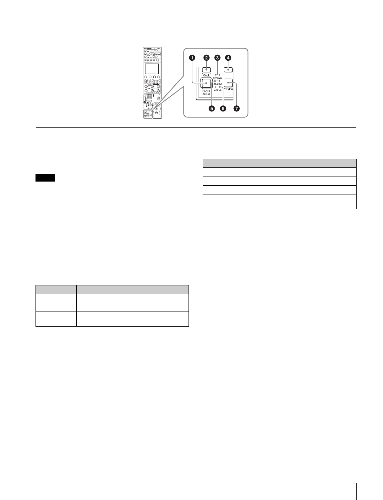
Panel control/status display block (RCP-1530)
a PANEL ACTIVE button
This button is for the control permission. It also serves as a
function for preventing unintentional operation because a
camera cannot be controlled from this control panel when this
button and the PARA button are not lit.
If the connection to the master breaks off in MCS mode
system, panel active operations are not possible.
In this case, a long press of the PANEL ACTIVE button forces
the availability of the panel active.
b CALL button
This button is for communication. If it is pressed, the tally state
for the camera or CCU changes, and a call signal is sent. A call
signal can also be received from another device with this
button. When a call signal is sent (or received), this button
lights and the call sound plays. The call sound can be selected
in the menu.
c NETWORK indicator
This indicates the status of the network connection.
d Assignable buttons
These button allow any functions to be assigned to them.
For details on assigning functions to assignable buttons, see
page 43.
e ALARM indicator
This lights red when a system error occurs and the self-
diagnosis function is operating on the camera head or CCU/
HDCU.
f CABLE indicator
This indicates the communication state of the camera head
and CCU.
g PREVIEW button
This button is for outputting preview key signals from the EXT
I/O connector.
Note
Lighting state Meaning
On Connected to a control device.
Flashing A control device cannot be found.
Off Cannot connect to the camera network.
Alternatively, the mode is LEGACY.
Lighting state Meaning
On (green) The reception state is good.
On (yellow) The reception level is low.
On (red) The reception level is extremely low.
Off The power of the camera is off. Alternatively, a
communication error occurred.
26
Names and Functions of Parts
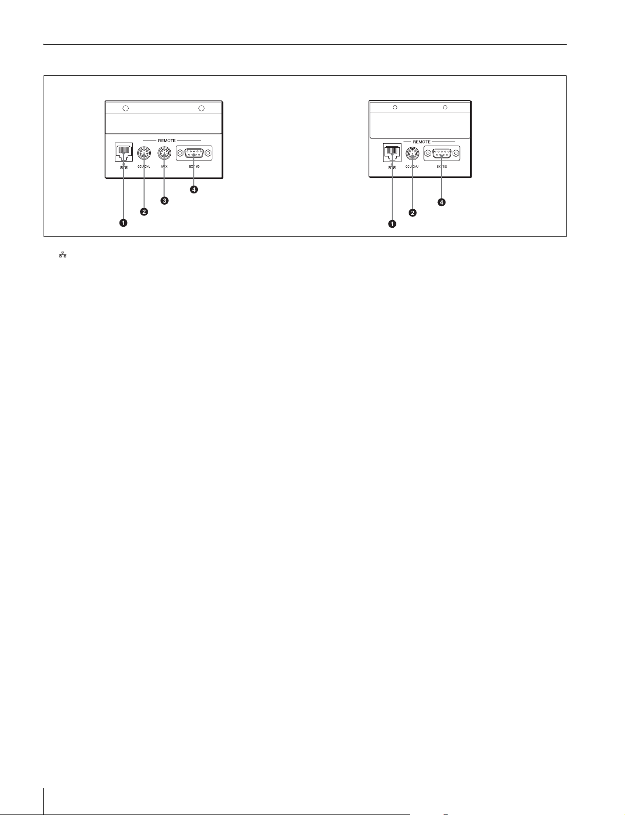
Connector Panel
a (network) connector (8-pin RJ-45)
This is for connecting to the network. Use a LAN cable
(shielded type, category 5 or above) to connect to a 10BASE-
T/100BASE-TX hub. This connector can receive power
supplied from an IEEE802.3af compliant power supply device
(PoE).
b CCU/CNU REMOTE (CCU/CNU remote) connector
(8-pin multi-connector, female)
This is for connecting to the RCP/CNU connector of the CCU
or the RCP connector of the CNU.
c AUX REMOTE (auxiliary remote) connector (8-pin
multi-connector, female) (RCP-1500/1501 only)
This is a spare connector.
d EXT I/O connector (D-sub 9-pin, female)
This is used for external interface connections.
RCP-1500/1501 RCP-1530
Installation
27
Installation
For details on menu operations, see page 52.
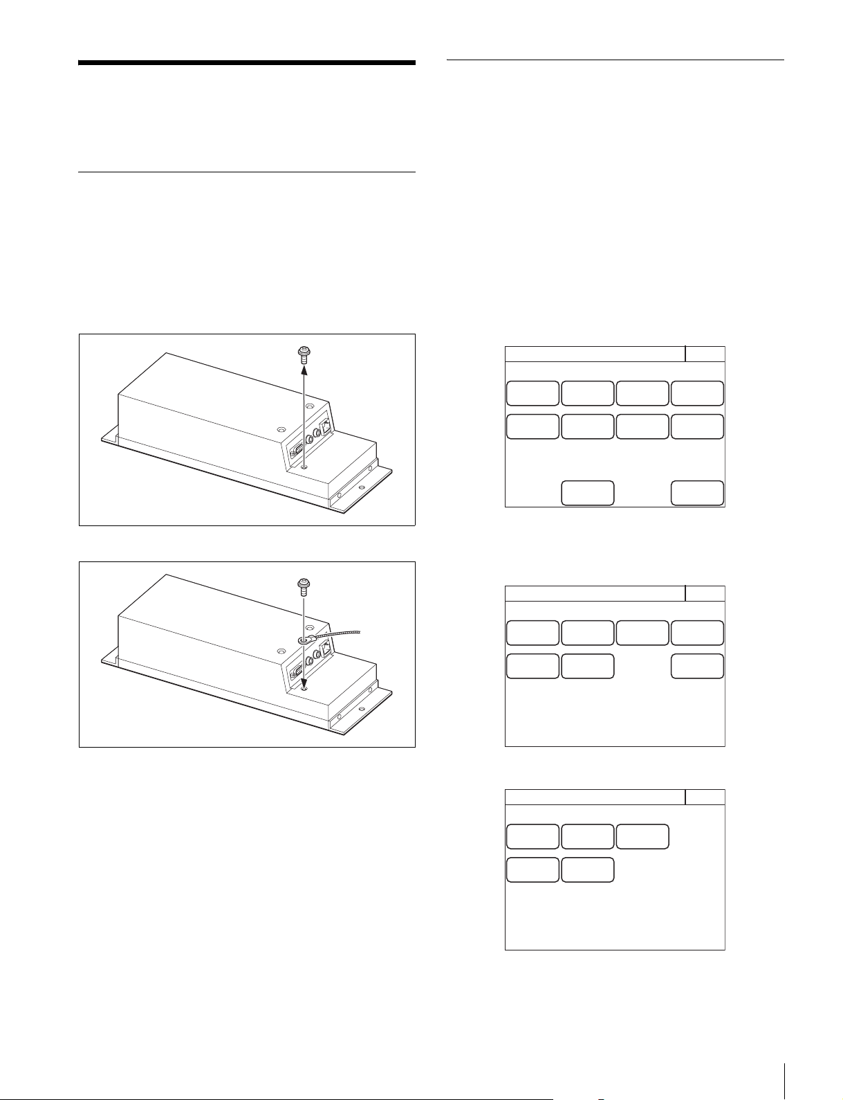
Connection Precautions
Ground the control panel in the following cases.
• When connecting using just a LAN cable
To connect a safety ground wire to the bottom of the
control panel
1 Remove the screw for connecting a safety ground
wire on the bottom of the control panel.
2 Use the removed screw to attach a safety ground wire.
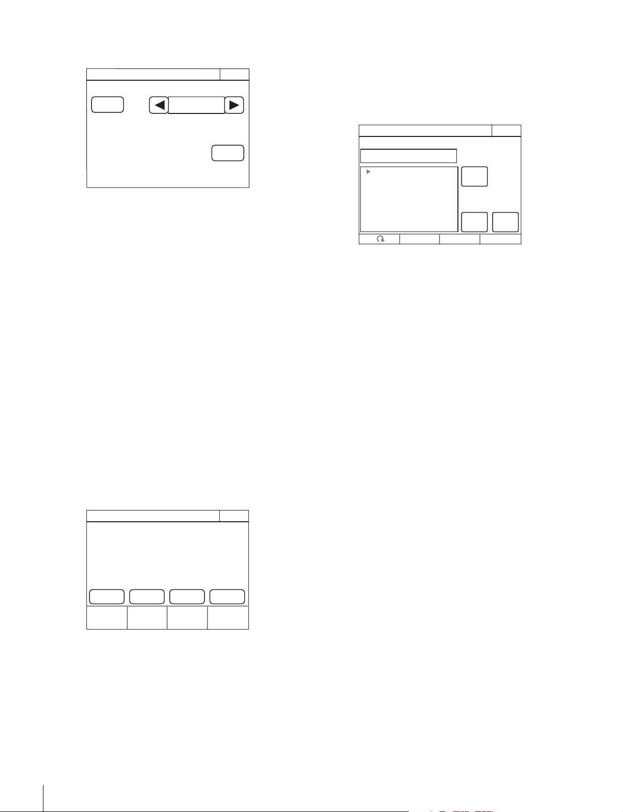
Setting the Status Screen Display
You can set the type of status screen that appears when no
MENU buttons are lit.
• With the status screen display disabled, a blank screen
appears if no MENU buttons are lit.
• You can select from several types of contents displayed on
the status screen. The adjustment functions can also be
assigned to the adjustment knobs of the menu operation
block according to a display type.
1 Enter engineer mode. (page 51)
2 Press the MENU button.
The menu closes and the control panel remains in
engineer mode.
3 Display the RCP Config screen. (page 51)
4 Press [Customize].
The RCP Customize screen appears.
RCP-1500/1501
RCP-1530
RCP Config
Exit
Customize
Display
/Sound
Mode
VR
Setting
Date
/Time
Option
Key
Network
Infor-
mation
Security
Backup
Engineer Mode
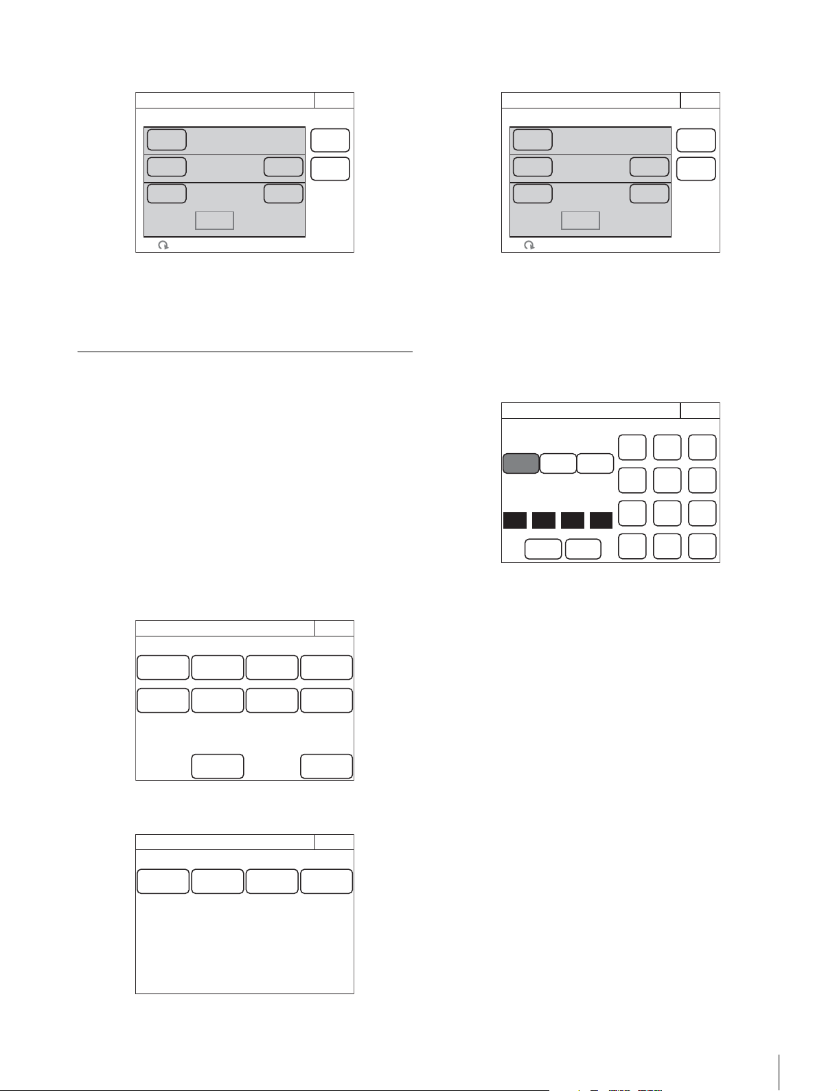
RCP Customize
ExitEngineer Mode
SW
Customize
Status
Customize
Menu
Customize
VR
Customize
Standard
Ind
Custom
Menu SW
Detail
VR
RCP Customize
ExitEngineer Mode
SW
Customize
Status
Customize
Menu
Customize
Standard
Ind
Custom
Menu SW
28
Installation
5 Press [Status Customize].
The Status Customize screen appears.
This screen contains the status display screen ON/OFF
button, the status screen type select button, and the menu
customize button of the adjustment knobs (according to
display type). (The
[Knob Customize] button may not
appear, depending on the selected status screen type.)
[Status Display OFF] : When pressed, the button is lit
and the status display is disabled. A blank screen
appears if no MENU buttons on the operation panel
are lit.
[Menu Type] : Selects the status screen type with the
right and left arrow buttons.
[Knob Customize] : Assigns the adjustment function to
the adjustment knobs, according to the selected status
screen type. Press this button to open the function
assignment menu.
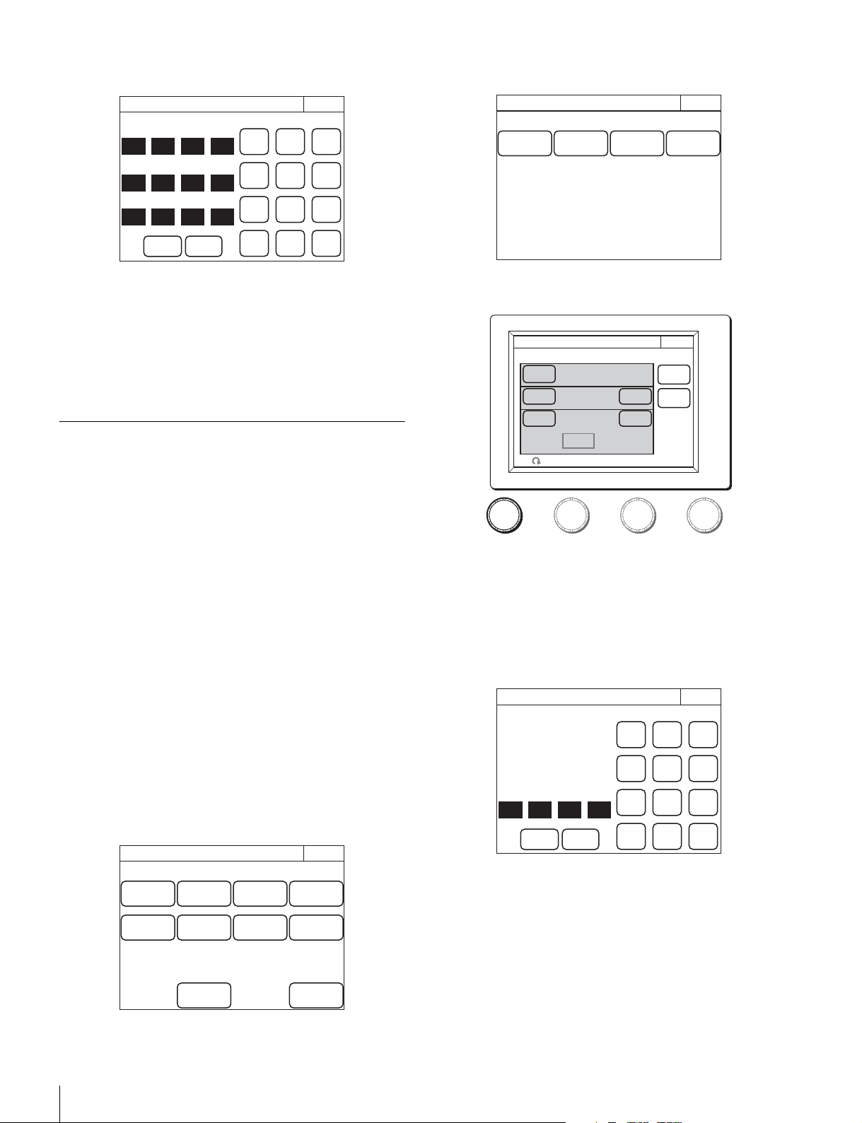
6 Press the [Knob Customize] button when using the
adjustment button.
The Knob Customize screen appears.
The Select Knob buttons that set the usable adjustment
knobs in the selected status screen type, and the
functions currently assigned to the adjustment knobs are
displayed.
[Select Knob $Knob 1 - Knob 4%] : Assigns the
adjustment knob to set, and opens the setting menu.
(The displayed Select Knob buttons change according
to the Menu Type selected in step 5.)
7 Press the Select Knob button to set the adjustment
knob.
The Knob Customize screen for setting the assigned
adjustment knob appears.
The Knob Customize screen displays the function
currently assigned to the selected adjustment knob. A list
of assignable functions is also displayed.
8 Turn the adjustment knob on the far left to select the
function assigned to the adjustment knob.
Turn the adjustment knob on the far left to move the cursor
(B) up and down in the list. If you place a cursor over the
function to assign, the function name is displayed in
amber.
9 Press [Enter].
The function assigned to the adjustment knob in the status
screen changes to the function selected in the previous
step. At this time, “*” appears in front of the function name.
10Press [Save].
The confirmation message screen appears.
11Press [Save].
The function assignment of the adjustment knob is saved
to this unit. If you close the menu before saving, the
function assignment of the adjustment knob will not be
reflected.
12When assigning a function to multiple adjustment
knobs, repeat steps 7 to 11.
13To reset function assignments of the adjustment
knobs to their default settings, perform the following
in the Knob Customize screen of each adjustment
knob.
1 Press
[Default Setting].
The confirmation message screen appears.
2 Press
[OK].
Function assignments of the adjustment knobs are
reset to their default settings.
3 Press
[Save].
Status Customize
Exit
Status Display
OFF
Menu Type
Control Value
Only
Engineer Mode
Knob
Customize
Knob Customize
ExitEngineer Mode
Knob 1
No Assign No Assign No Assign No Assign
Knob 2
Knob 3
Select Knob
Knob 4
Knob1 Customize
ExitEngineer Mode
Save
Default
Setting
Enter
NO ASSIGN
NO ASSIGN
Color Temp
White Balance
Master Flare
Detail
SD Detail
Skin Detail
Master White Gain
Gamma

Installation
29
Setting the Clock
The control panel has an internal clock for recording the date
and time at which reference files and scene files are saved to
a “Memory Stick Duo.”
Use the following procedure to set the clock.
1 Enter engineer mode. (page 51)
2 Press the MENU button.
The menu closes and the control panel remains in
engineer mode.
3 Display the RCP Config screen. (page 50)
4 Press [Date/Time].
The Date/Time screen appears.
5 Set the time zone.
1 Press and highlight
[Time Zone].
2 Set your region with the leftmost adjustment knobs.
Set the hour offset from Greenwich Standard Time.
3 Press
[Set].
6 Set the date.
1 Press and highlight
[Date].
2 Set the Year, Month, and Day with the left three
adjustment knobs.
3 Press
[Set].
7 Set the time.
1 Press and highlight
[Time].
2 Set the Hour, Minute and Second with the left three
adjustment knobs.
3 Press
[Set] in synchronization with a time signal.
RCP Config
Exit
Customize
Display
/Sound
Mode
VR
Setting
Date
/Time
Option
Key
Network
Infor-
mation
Security
Backup
Engineer Mode
2009/08/10
(MON)
15
:
30
:
30 GMT+00
:
00
Set Cancel
Date/Time
Exit
Date Time
Time
Zone
Engineer Mode
2009/08/10
(MON)
15
:
30
:
30 GMT+00
:
00
Set Cancel
Date/Time
Exit
Date Time
Time
Zone
Hour
0
Engineer Mode
2009/08/10
(MON)
15
:
30
:
30 GMT+00
:
00
Set Cancel
Date/Time
Exit
Date Time
Time
Zone
Year
2009
Month
08
Day
10
Engineer Mode
2009/08/10
(MON)
15
:
30
:
30 GMT+00
:
00
Set Cancel
Date/Time
Exit
Date Time
Time
Zone
Hour
15
Minute
30
Second
30
Engineer Mode

30
Installation
Setting the LAN Connection
When connecting using a LAN cable, set the LAN I/F as
follows:
1 Enter engineer mode. (page 51)
2 Press the MENU button.
The menu closes and the control panel remains in
engineer mode.
3 Display the RCP Config screen. (page 50)
4 Press [Network].
The Network screen appears.
5 Press [LAN I/F].
The LAN I/F screen appears.
The Speed and Duplex buttons are not displayed when
Negotiation is set to AUTO, as the Speed/Duplex setting
is made automatically.
This screen allows settings for the equipment for LAN
connection.
Perform the setting according to the connection
requirements for the target.
LAN I/F: Sets LAN I/F to OFF.
Negotiation AUTO: The connection settings for the target
equipment are configured automatically. Use AUTO
only when the target equipment also supports the Auto
Negotiation function.
Speed 10M/100M: Sets the connection speed.
Duplex Half/Full: Sets the communication method: Half
(half duplex) or Full (full duplex).
Setting LEGACY Mode
Set the control panel to LEGACY mode when connecting
without using a LAN cable. When the control panel is
connected, for example, to a multi-camera system with a
CNU-700 or to a LAN system and a LAN cable is not directly
connected to the control panel, always set the control panel to
LEGACY mode. The TCP/IP and RCP number do not need to
be set.
1 Enter engineer mode. (page 51)
2 Press the MENU button.
The menu closes and the control panel remains in
engineer mode.
3 Display the RCP Config screen. (page 50)
4 Press [Network].
The Network screen appears.
RCP Config
Exit
Customize
Display
/Sound
Mode
VR
Setting
Date
/Time
Option
Key
Network
Infor-
mation
Security
Backup
Engineer Mode
Exit
Network
Info
LAN I/F TCP/IPCNS
Network
Engineer Mode
LAN I/F
Exit
Speed
100M10M
Duplex
FullHalf
CancelSet
LAN I/F
OFF
Nego-
tiation
AUTO
Engineer Mode
RCP Config
Exit
Customize
Display
/Sound
Mode
VR
Setting
Date
/Time
Option
Key
Network
Infor-
mation
Security
Backup
Engineer Mode
Exit
LAN I/F TCP/IP
Network
Info
CNS
Network
Engineer Mode
Installation
31
5 Press [CNS].
The CNS screen appears.
6 Press [LEGACY].
7 Press [Set].
The control panel is set to LEGACY mode.
Setting BRIDGE Mode
Set the control panel to BRIDGE mode when connecting the
control panel and a camera device on a LAN on a one-to-one
basis. The TCP/IP needs to be set in BRIDGE mode. The IP
address of the connection target camera device also needs to
be set in the RCP or MSU. The RCP number does not need to
be set. Multi-camera operation is not possible in BRIDGE
mode.
1 Enter engineer mode. (page 51)
2 Press the MENU button.
The menu closes and the control panel remains in
engineer mode.
3 Display the RCP Config screen. (page 50)
4 Press [Network].
The Network screen appears.
5 Press [CNS].
The CNS screen appears.
6 Press [Bridge].
7 Press [Set].
The control panel is set to BRIDGE mode.
8 Set the connection mode.
1 Press
[Edit].
The Bridge Mode Set screen appears.
2 Press a button to set the sub mode of BRIDGE mode.
Set the sub mode in accordance with the connection
state.
[Active] : Performs the process to connect to the
target by itself.
[Passive] : Waits for a connection from the target.
[Semi-auto] : Switches between Active and Passive
depending on the connection environment. Active
is enabled when the RCP stands alone, and
Passive is enabled when the RCP is connected to
a CCU or camera via a CCA-5 cable.
9 Set the IP address of the connection target camera
device.
1 Set the target IP address.
Press the IP address input field, and then use the
numeric keypad on the screen to enter the IP address.
2 Press
[Set].
10Press [Exit].
The CNS screen reappears.
11Press [Exit].
The Network screen reappears.
12Set the TCP/IP.
CNS
Exit
Mode:Semi-Auto
Target:
192.168.0.1
Mode:Master
Master:
192.168.0.1
Set
Cancel
Legacy
Bridge
MCS
RCP No. 96
Edit
Edit
Engineer Mode
RCP Config
Exit
Customize
Display
/Sound
Mode
VR
Setting
Date
/Time
Option
Key
Network
Infor-
mation
Security
Backup
Engineer Mode
Exit
LAN I/F TCP/IP
Network
Info
CNS
Network
Engineer Mode
CNS
Exit
Mode:Semi-Auto
Target:
192.168.0.1
Mode:Master
Master:
192.168.0.1
Set
Cancel
Legacy
Bridge
MCS
RCP No. 96
Edit
Edit
Engineer Mode
Active
192
168
Passive
Semi-
auto
Connection Mode
Bridge Mode Set
Exit
Set Cancel
7
0 1
Enter
Target
89
456
12
0BS
3
Engineer Mode
32
Installation
1 Press [TCP/IP].
The TCP/IP screen appears.
2 Set the IP address, subnet mask, and default gateway.
Press the corresponding input field, and then use the
numeric keypad on the screen to enter the information.
3 Press
[Set].
13Press [Exit].
The Network screen reappears and the control panel is
set to BRIDGE mode.
Setting Multi-Camera System (MCS)
Mode
Set the control panel to MCS mode when using it in a multi-
camera system on a LAN. However, set the control panel to
LEGACY mode when connecting it to a CCU via a CCA cable
and connecting a LAN cable to that CCU. The mode to use
when connecting a LAN cable to the control panel and using a
CCA cable to connect to a CCU is MCS mode.
One device needs to be the master in MCS mode. The MSU
can be set as the master, but if there are multiple MSUs within
the system, set one MSU as the master and set the remaining
MSUs as clients.
To set the control panel to MCS mode, the TCP/IP, IP address
of the master device, and RCP number need to be set. The
RCP number corresponds to the camera selection number of
the MSU. Configure the setting so that there will not be a
duplicate within the system.
1 Enter engineer mode. (page 51)
2 Press the MENU button.
The menu closes and the control panel remains in
engineer mode.
3 Display the RCP Config screen. (page 50)
4 Press [Network].
The Network screen appears.
5 Press [CNS].
The CNS screen appears.
6 Press [MCS].
7 Press [Set].
The control panel is set to MCS mode.
8 Set the IP address of the master device.
1 Press
[Edit].
The MCS Mode Set screen appears.
2 Set the IP address of the master device.
Press the IP address input field, and then use the
numeric keypad on the screen to enter the IP address.
3 Press
[Set].
9 Press [Exit].
The CNS screen reappears.
10Set the RCP number.
0
0
TCP/IP
Exit
Set Cancel
7
0 0
Enter
Default GW
255
255
255 0
Subnet Mask
192
168
0 1
IP Address
89
456
12
0BS
3
Engineer Mode
RCP Config
Exit
Customize
Display
/Sound
Mode
VR
Setting
Date
/Time
Option
Key
Network
Infor-
mation
Security
Backup
Engineer Mode
Exit
LAN I/F TCP/IP
Network
Info
CNS
Network
Engineer Mode
CNS
Exit
Mode:Semi-Auto
Target:
192.168.0.1
Mode:Master
Master:
192.168.0.1
Set
Cancel
Legacy
Bridge
MCS
RCP No. 96
Edit
Edit
Engineer Mode
192
168
MCS Mode Set
Exit
Set Cancel
7
0 1
Enter
89
456
12
0BS
3
Master
Engineer Mode
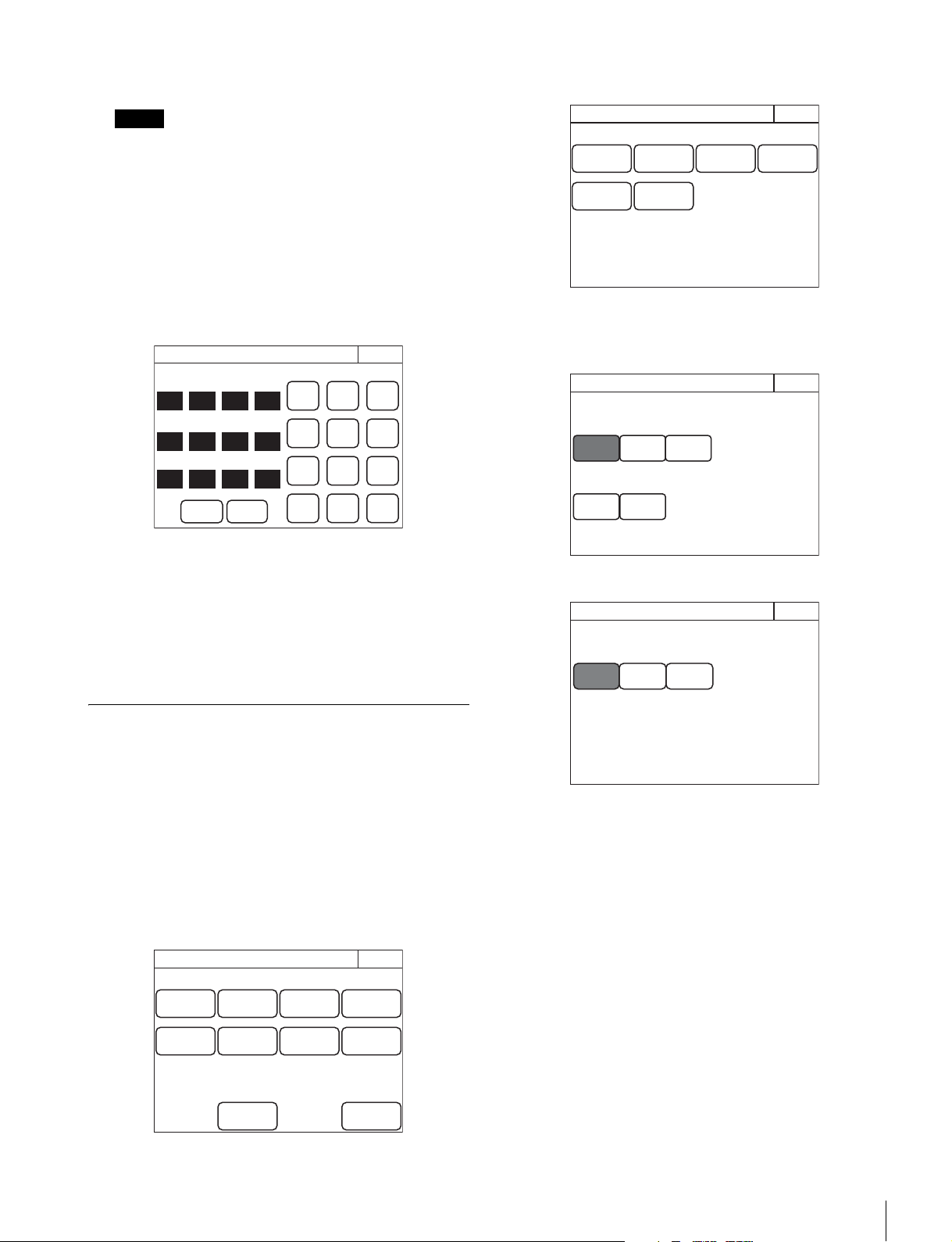
Installation
33
1 Turn the adjustment knob on the far left to change the
RCP number.
If an RCP number is duplicated, the equipment will not
function normally. Be sure to set a number that will not be
a duplicate of that of another MCS.
2 Press
[Set].
11Press [Exit].
The Network screen reappears.
12Set the TCP/IP.
1 Press
[TCP/IP].
The TCP/IP screen appears.
2 Set the IP address, subnet mask, and default gateway.
Press the corresponding input field, and then use the
numeric keypad on the screen to enter the information.
3 Press
[Set].
13Press [Exit].
The Network screen reappears and the control panel is
set to MCS mode.
Changing the Output Destination for
Previews
The output destination of the key signals for previews of the
control panel can be changed.
1 Enter engineer mode. (page 51)
2 Press the MENU button.
The menu closes and the control panel remains in
engineer mode.
3 Display the RCP Config screen. (page 50)
4 Press [Mode].
The RCP Mode screen appears.
5 Press [Preview].
The Preview screen appears.
RCP-1500/1530
RCP-1501
6 Press a button to select the output destination.
[RCP] : EXT I/O connector of the RCP unit
[CCU] : External output connector of the CCU
[CNU S-BUS] : S-BUS system via the CNU
Note
0
0
TCP/IP
Exit
Set Cancel
7
0 0
Enter
Default GW
255
255
255 0
Subnet Mask
192
168
0 1
IP Address
89
456
12
0BS
3
Engineer Mode
RCP Config
Exit
Customize
Display
/Sound
Mode
VR
Setting
Date
/Time
Option
Key
Network
Infor-
mation
Security
Backup
Engineer Mode
Exit
Matrix
Gate
Extend
Call
Screen
Saver
Panel
Active
PIX/WF
RCP Mode
Preview
Engineer Mode
Preview
SW
Preview
CCU
CNU
S-BUS
RCP
Joy
Preview
Exit
Disable
Engineer Mode
RCP
Preview
Preview
Exit
CCU
CNU
S-BUS
Engineer Mode

34
Settings
Settings
For details on menu operations, see page 52.
Setting the User Interface
To set the sounds
The control panel plays a sound when call signals are
received, and when the panel is operated.
Turn ON/OFF the sounds or adjust the volume if necessary.
1 Display the RCP Config screen. (page 50)
2 Press [Display/Sound].
The Display/Sound screen appears.
3 Turn the SELECT knob to select “Sound.”
The Sound screen appears.
The Sound screen can also be displayed after you press
the SELECT knob if you turn the SELECT knob to select
“Sound” and then press the SELECT knob.
RCP-1500/1501
RCP-1530
4 Select the type of sound to set.
Press the tab to display the setting screen of the desired
sound, and then set each of the sound settings.
Call: Sets the sound played when call signals are
received.
Touch: Sets the sound played when the LCD/touch panel
is touched.
SW: Sets the sound played when the buttons are pressed.
RE: Sets the sound played when the adjustment knobs
are turned.
5 Turn the adjustment knobs to set the sound.
The following settings can be configured.
Volume: Adjusts the volume.
Sound: Selects the type of sound.
Master: Adjusts the master volume.
To confirm a sound, press
[Sound Test] to play the
sound.
To turn ON/OFF the sound for each type
One of following buttons is displayed in each of the sound
setting screens to turn ON/OFF the sound. You can press
the button to turn ON/OFF the sound. The sound turns ON
when the button lights.
[Call Sound] : Turns ON/OFF the sound played when call
signals are received.
[Touch Click] : Turns ON/OFF the sound played when the
LCD/touch panel is touched.
[Switch Click] : Turns ON/OFF the sound played when
the buttons are pressed.
RCP Config
Exit
Display
/Sound
Infor-
mation
Security
Sound
Te st
Call
Sound
Clear
Call To uc h S W R E
OFF
Sound
Display/Sound
Volume
50
Sound
1
Master
50
Exit1/5
Sound
Te st
Call
Sound
Clear
Call To uc h S W R E
OFF
Sound
Display/Sound
Volume
50
Sound
1
Master
50
Exit1/5
Sound
Te st
Call
Sound
Clear
Call To uc h S W R E
OFF
Sound
Display/Sound
Volume
50
Sound
1
Master
50
Exit1/5
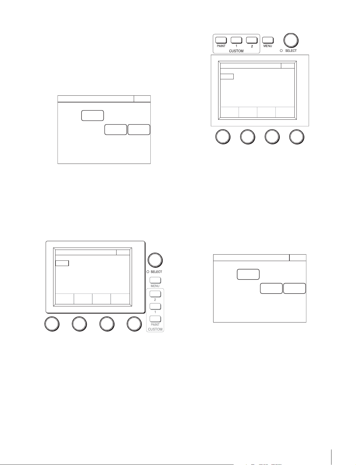
Settings
35
[RE Click] : Turns ON/OFF the sound played when the
adjustment knobs are turned.
To turn off all sounds
Press
[OFF] to light the button.
To set the brightness of the LEDs
You can adjust the brightness of the operation buttons and tally
display window on the control panel.
1 Display the RCP Config screen. (page 50)
2 Press [Display/Sound].
The Display/Sound screen appears.
3 Turn the SELECT knob to select “LED.”
The LED screen appears.
The LED screen can also be displayed after you press the
SELECT knob if you turn the SELECT knob to select
“LED” and then press the SELECT knob.
RCP-1500/1501
RCP-1530
4 Turn the adjustment knobs to set the brightness of
the LEDs.
The following settings can be configured.
Switch: Sets the brightness of the LEDs built into the
operation buttons.
Tally : Sets the brightness of the camera number/tally
display window.
Other: Sets the brightness of the indicators.
Master: Sets the brightness of all LEDs.
To adjust the LCD
You can adjust the brightness of the LCD of the menu
operation block.
1 Display the RCP Config screen. (page 50)
2 Press [Display/Sound].
The Display/Sound screen appears.
3 Turn the SELECT knob to select “LCD.”
The LCD screen appears.
The LCD screen can also be displayed after you press the
SELECT knob if you turn the SELECT knob to select
“LCD” and then press the SELECT knob.
RCP Config
Exit
Display
/Sound
Infor-
mation
Security
Clear
LED
Display/Sound
Switch
50
Tally
50
Master
50
Other
50
Exit2/5
Clear
LED
Display/Sound
Switch
50
Tally
50
Master
50
Other
50
Exit2/5
RCP Config
Exit
Display
/Sound
Infor-
mation
Security
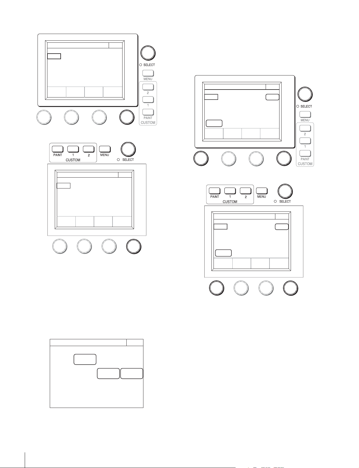
36
Settings
RCP-1500/1501
RCP-1530
4 Turn the adjustment knobs to set the brightness of
the LCD.
The following setting can be configured.
Bright: Sets the brightness of the LCD.
To illuminate character display in dark places
You can set a slight light to be emitted from the characters on
the panel by the EL backlight. This setting makes the
characters easy to see in dark surroundings.
1 Display the RCP Config screen. (page 50)
2 Press [Display/Sound].
The Display/Sound screen appears.
3 Turn the SELECT knob to select “EL.”
The EL screen appears.
The EL screen can also be displayed after you press the
SELECT knob if you turn the SELECT knob to select “EL”
and then press the SELECT knob.
RCP-1500/1501
RCP-1530
4 Turn the adjustment knobs to change the setting.
The following settings can be configured.
Detect: Specifies the surrounding brightness at which to
turn OFF the EL backlight. If you press the
[Light
Detect]
button to light the button, the EL backlight
turns OFF automatically when the brightness of the
value that is specified here is detected.
Bright: Adjusts the brightness of the EL backlight.
To turn OFF the character light setting
Press
[OFF] to light the button.
Clear
LCD
Display/Sound
Bright
50
Exit3/5
Clear
LCD
Display/Sound
Bright
50
Exit3/5
RCP Config
Exit
Display
/Sound
Infor-
mation
Security
Light
Detect
Clear
1000H
OFF
EL
Display/Sound
Detect
50
Bright
2
Exit4/5
Light
Detect
Clear
1000H
OFF
EL
Display/Sound
Detect
50
Exit4/5
Bright
2
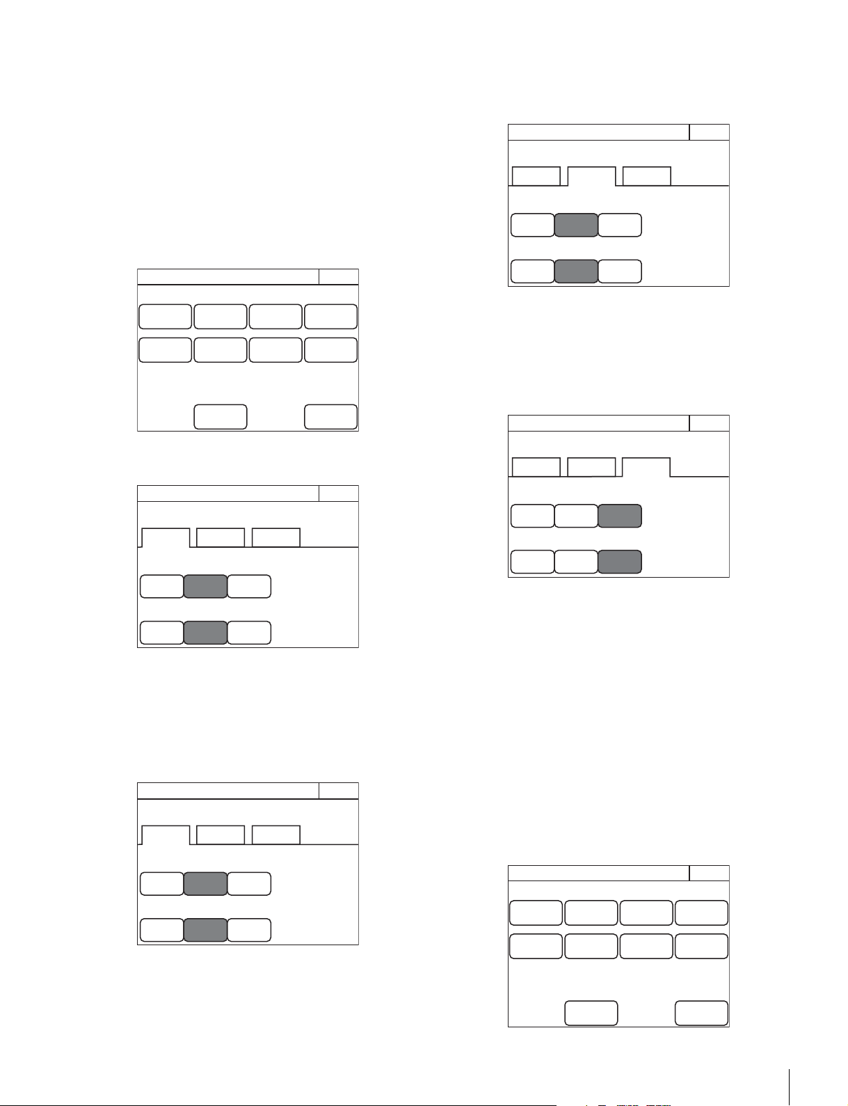
Settings
37
To change the sensitivity of the adjustment
knobs
You can change the sensitivity of the WHITE, BLACK/FLARE,
DETAIL, assignable, IRIS, and MASTER BLACK adjustment
knobs for when they are used in relative value mode.
1 Enter engineer mode. (page 51)
2 Press the MENU button.
The menu closes and the control panel remains in
engineer mode.
3 Display the RCP Config screen. (page 50)
4 Press [VR Setting].
The VR Setting screen appears.
The following steps differ depending on the type of knob
to be adjusted (WHITE or BLACK/FLARE, DETAIL, IRIS,
or MASTER BLACK).
To adjust the sensitivity of the WHITE and BLACK/
FLARE knobs
1 Press the [White/Blk/Flr] tab.
2 Press the sensitivity (number) you want to set for
each of the adjustment knobs.
To adjust the sensitivity of the DETAIL and
assignable knobs (RCP-1500/1501 only)
1 Press the [Detail/Assign] tab.
2 Press the sensitivity (number) you want to set for
each of the adjustment knobs.
To adjust the sensitivity of the IRIS and MASTER
BLACK knobs
1 Press the [Iris/M.Black] tab.
2 Press the sensitivity (number) you want to set for
each of the adjustment knobs.
To set the screen saver
You can set the screen saver to be activated to protect the
display of the menu operation block when the control panel is
not operated for a certain time.
The screen saver can be turned ON/OFF and the time until it
is activated can be set as necessary.
1 Enter engineer mode. (page 51)
2 Press the MENU button.
The menu closes and the control panel remains in
engineer mode.
3 Display the RCP Config screen. (page 50)
RCP Config
Exit
Customize
Display
/Sound
Mode
VR
Setting
Date
/Time
Option
Key
Network
Infor-
mation
Security
Backup
Engineer Mode
White/
Blk/Flr
Detail/
Assign
1/1
White
VR Setting
Exit
1/2 1/4
1/1
Black/Flare
1/2 1/4
Engineer Mode
Iris/
M.Black
White/
Blk/Flr
Detail/
Assign
1/1
White
VR Setting
Exit
1/2 1/4
1/1
Black/Flare
1/2 1/4
Engineer Mode
Iris/
M.Black
White/
Blk/Flr
Detail/
Assign
1/1
Detail
VR Setting
Exit
1/2 1/4
1/1
Assignable
1/2 1/4
Engineer Mode
Iris/
M.Black
White/
Blk/Flr
Detail/
Assign
Iris/
M.Black
1/1
Iris
VR Setting
Exit
1/2 1/4
1/1
Master Black
1/2 1/4
Engineer Mode
RCP Config
Exit
Customize
Display
/Sound
Mode
VR
Setting
Date
/Time
Option
Key
Network
Infor-
mation
Security
Backup
Engineer Mode
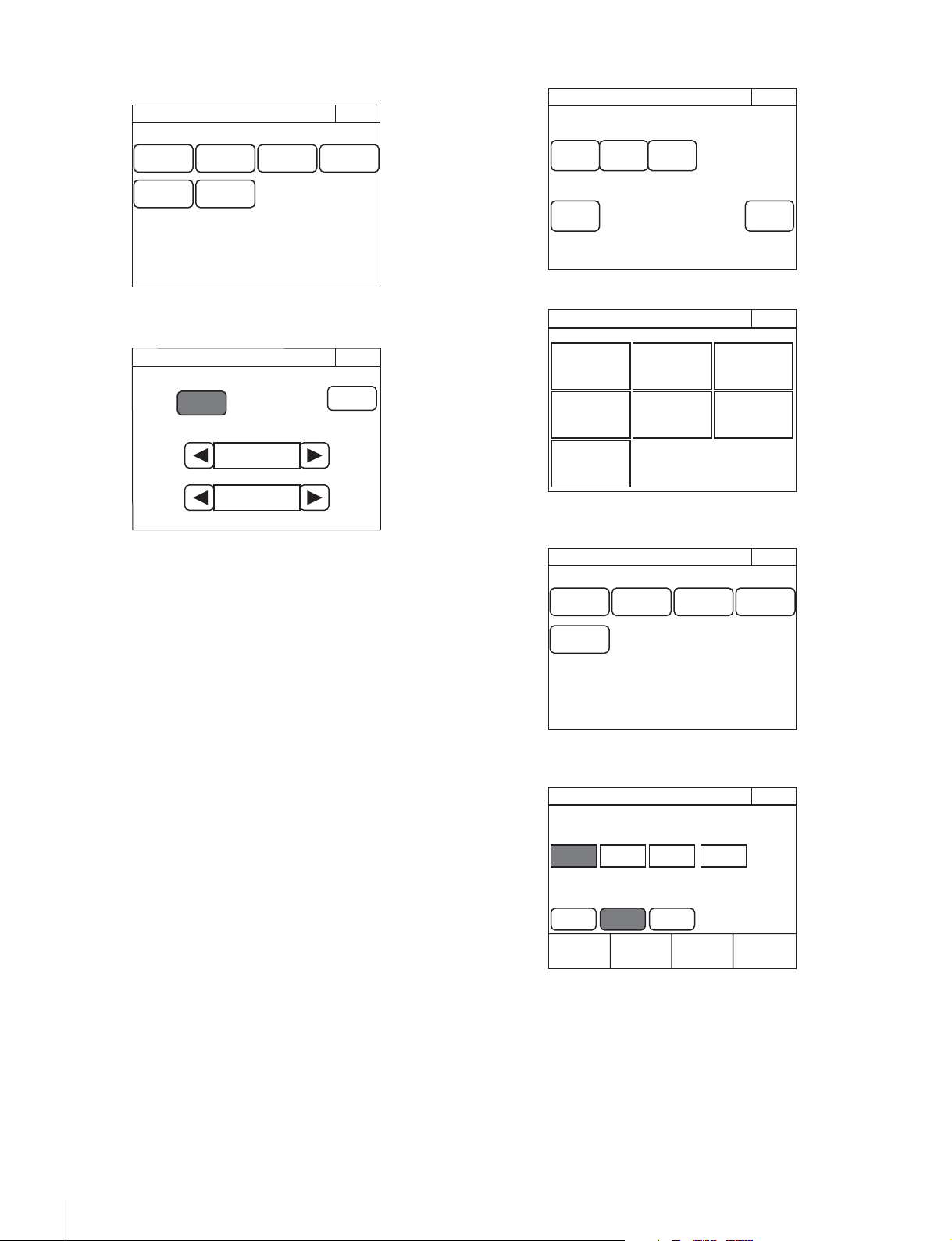
38
Settings
4 Press [Mode].
The Mode screen appears.
5 Press [Screen Saver].
The Screen Saver screen appears.
6 Press [ON] to light the button and turn ON the screen
saver.
7 Set the screen saver.
The following settings can be configured. You can press b
or B to change both of the settings.
Wait Time: Sets the time until the screen saver is
activated in minutes.
Type: Selects the type of screen saver.
Press
[Preview] to display a preview of the selected
screen saver. Press any place on the LCD to cancel the
preview display.
To perform RPN correction
The CCD image sensor is manufactured with high precision
technology. However, cosmic rays and other noise may affect
the pixels of the CCD image sensor, resulting in small white
dots appearing on the display. This is a physical characteristic
of CCD image sensors and is not a malfunction.
Performing auto black balance adjustment activates the
correction function, and may reduce the effects of this
phenomenon.
You can also perform correction manually to reduce the white
dots.
1 Enter engineer mode. (page 51)
2 Press [Exit] to return to the Category Select screen.
3 Press [Maintenance].
The Maintenance screen appears.
4 Press [RPN].
The RPN Correction screen appears.
A cross-shaped cursor appears on the PIX monitor.
Perform the following steps while viewing the PIX monitor.
5 Press the button that corresponds to the channel you
want to correct (
[R], [G], or [B]) to light it.
Exit
Extend
Call
Screen
Saver
PIX/WF
Matrix
Gate
Panel
Active
Preview
RCP Mode
Engineer Mode
Screen Saver
Exit
Screen Saver
ON
Preview
Wait Time
Ty pe
3 min
Vertical Drawing
Page
Permission
Item
Permission
Code
Change
Security
Exit
ALL
Preset
Engeneer
Mode
Engineer Mode
Category Select
Scene
Func-
tion
Multi
Config File
Mainten-
ance
Paint
Exit
Engineer Mode
Maintenance
Exit
Camera Lens CCU
SD
Adjusting
RPN
Engineer Mode
H Cursor
RPN Correction
H Cursor
500
V Cursor
157ev
Exit
V Cursor
H/V
Cursor
R G B Enter
Engineer Mode
Cursor Indication

Settings
39
6 Select the cursor type displayed on the monitor.
[H Cursor] : Press this to light the button and turn the
horizontal cursor ON.
[V Cursor] : Press this to light the button and turn the
vertical cursor ON.
[H/V Cursor] : Press this to light the button and turn the
horizontal and vertical cursors ON.
7 Move the cursors on the monitor to the position you
want to correct.
Turning the adjustment knobs move the cursors on the
monitor. Based on the cursor type selected in step 6, the
horizontal or vertical cursor or both will be assigned to the
adjustment knobs.
8 Press [Enter].
The cursor position is set, and the RPN Correction screen
changes to the following.
9 Turn the adjustment knob on the far right to correct
the defect on the monitor.
Turning the adjustment knob right increases the
brightness level, and turning it left decreases the
brightness level. View the monitor and perform
adjustments until the defects are not visible.
10Press [Save].
The brightness correction value is registered to the control
panel.
To set a different correction value, press
[Delete] to delete
the previous value, and repeat the procedure from step 9.
11Press [Exit].
The brightness correction value is registered to the control
panel.
Setting Security Restrictions
To set the security level
You can restrict the control functions of the control panel if
necessary.
1 Enter engineer mode. (page 51)
2 Set the security level.
The settings for the security level are split into two
screens. Press each of the buttons to display each setting
screen and configure the security level settings.
H Cursor
RPN Correction
H Cursor
500
V Cursor
157ev
Exit
V Cursor
H/V
Cursor
R GBEnter
Engineer Mode
Cursor Indication
H Cursor
RPN Correction
Level
99
Exit
V Cursor
H/V
Cursor
CancelSave
Delete
Engineer Mode
Cursor Indication
H Cursor
RPN Correction
Level
99
Exit
V Cursor
H/V
Cursor
CancelSave
Delete
Engineer Mode
Cursor Indication
Page
Permission
Item
Permission
Code
Change
Security
Exit
ALL
Preset
Engeneer
Mode
Engineer Mode
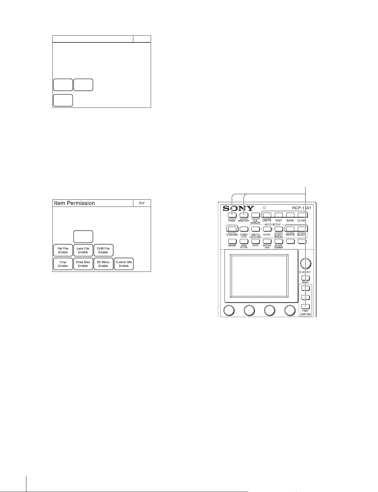
40
Settings
When [Page Permission] is pressed:
The following settings can be configured.
[Full Lock] : Press this to light the button and prohibit
all operations of the control panel.
[View Mode] : Press this to light the button and prohibit
all operations of the control panel except for viewing
data.
[Full Paint] : Under the default settings, all operations
of the control panel are prohibited except for
custom paint menu operations. Press this to light
the button and permit all other operations of the
control panel.
When
[Item Permission] is pressed:
The following settings can be configured.
[Auto Setup Enable] : Press this to light the button and
add the {Auto Setup} button to the Maintenance
menu. The APR function of the control panel is
permitted.
[Ref File Enable] : Press this to light the button and
permit the setting of the reference files of the
control panel.
[Lens File Enable] : Press this to light the button and
permit the setting of the lens files of the control
panel.
[OHB File Enable] : Press this to light the button and
permit the setting of the OHB files of the control
panel.
[Crop Enable] : Press this to light the button and
permit the setting of 16:9 t 4:3 Crop of the control
panel.
[Knee Max Enable] : Press this to light the button and
permit the knee max function.
[3D Menu Enable] : Press this to light the button and
permit 3D System and CCU 3D Monitor
configuration of the control panel. Light [3D Menu
Enable] when using the HDFA-200 and configuring
the 3D system.
[Custom Mtx Enable] : Press this to light the button
and the Custom Matrix menu is added to the FILE
menu. You can save a Custom Preset Matrix file,
and save or readout the file from a Memory Stick.
3 Press [Exit] when the settings are finished.
The Security screen reappears.
4 Press [Engineer Mode] to cancel engineer mode.
To protect operations with a security code
To prevent unwanted operations, you can protect operation of
the control panel with a security code.
To enable security code protection
Under the default settings, the security code is disabled. Use
the following procedure to enable the security code.
1 For RCP-1500/1501, turn on the control panel while
holding down the PARA, MASTER, and CUSTOM
PAINT buttons.
For RCP-1530, turn on the control panel while holding
down the PANEL ACTIVE, IRIS/MB ACTIVE, and PAINT
buttons.
RCP-1500/1501
Page Permission
Exit
Full Lock
View
Mode
Full Paint
Engineer Mode
Engineer ModeEngineer Mode
Auto Setup
Enable
Holding down
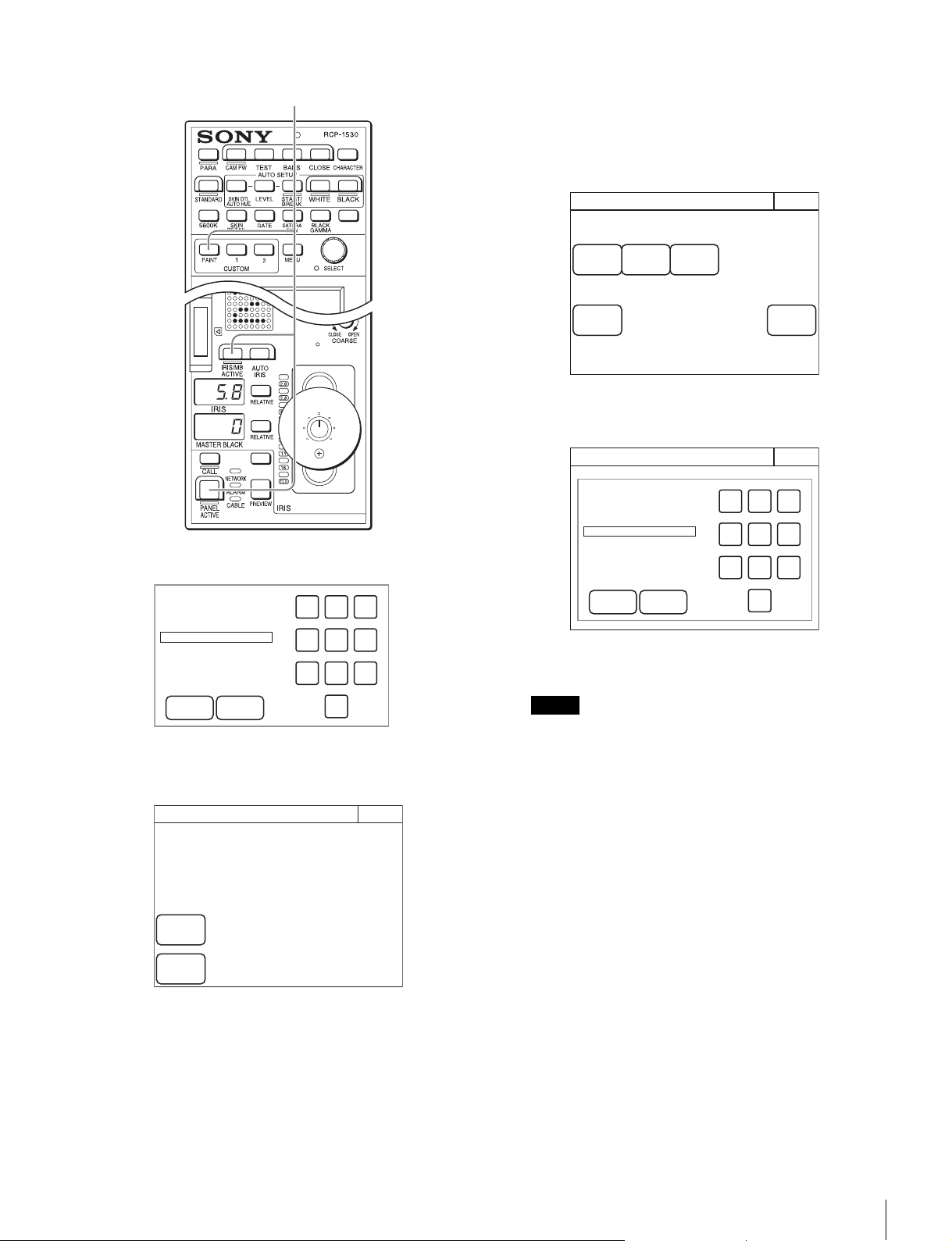
Settings
41
RCP-1530
The numeric keypad appears.
2 Use the numeric keypad to enter “0359,” and then
press
[OK].
The Engineer Protection screen appears.
3 Press [Code Enable] to light the button.
Security code protection is enabled.
If you press [Code Delete] here to light the button, a
confirmation screen for security code deletion appears.
The Engineer Protection screen reappears when you
press
[OK].
4 Press [Exit].
To set the security code
Some of the menus on the control panel are operated in
engineer mode. To limit the use of engineer mode to specific
operators, preset the security code. After you set the security
code, it will need to be entered to switch to engineer mode.
1 Enter engineer mode. (page 51)
2 Press [Code Change].
The numeric keypad and new security code (Code No.)
input field appear.
3 Use the numeric keypad to enter any security code (1
to 8 digits), and then press
[OK].
Each number entered for the security code appears as “*”
on the screen.
A security code reentry screen appears.
4 Confirm the security code entered in step 3 by
reentering it, and press
[OK].
The Security screen reappears.
5 Press [Engineer Mode] to cancel engineer mode.
The security code is set, and the numeric keypad will
appear whenever you press the [Engineer Mode] button
in the Security screen. To enter engineer mode, enter the
security code that was set and press the
[OK] button.
To change the security code
1 Perform steps 1 to 4 of “To enter engineer mode”
(page 51) to display the Security screen.
2 Press [Engineer Mode].
The numeric keypad and security code (Code No.) input
field appear.
Holding down
OK Cancel
789
456
123
0
Code No:
Engineer Protection
Engineer Prot
Exit
Code
Enable
Code
Delete
Protection
Note
Page
Permission
Item
Permission
Code
Change
Security
Exit
ALL
Preset
Engeneer
Mode
Engineer Mode
Security
Exit
OK Cancel
789
456
123
0
Code No:
Engineer Mode
Engineer Mode
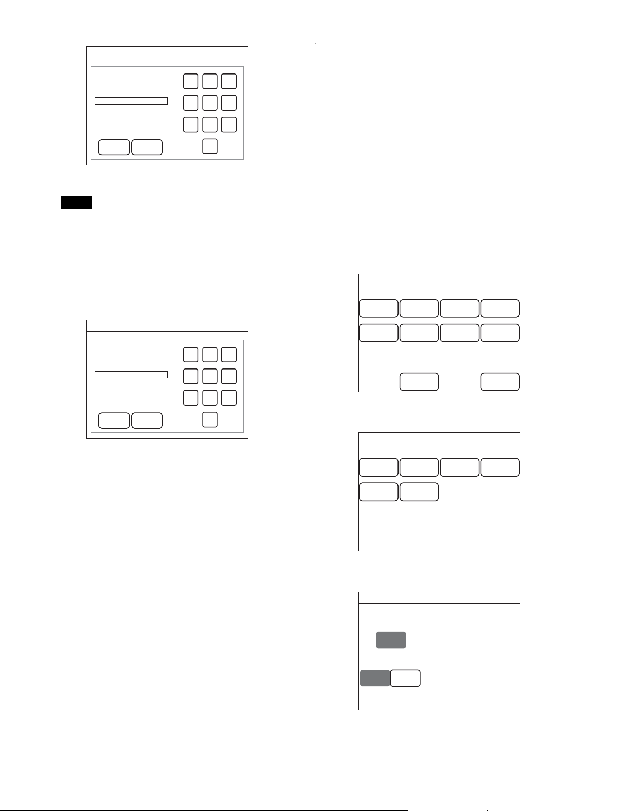
42
Settings
3 Enter the security code, and then press [OK].
Each number entered for the security code appears as “*”
on the screen.
The control panel enters engineer mode, and
[Code
Change]
appears.
4 Press [Code Change].
The current security code (Old Code No.) input field
appears.
5 Enter the security code that you entered in step 3, and
then press
[OK].
The new security code (New Code No.) input field
appears.
6 Perform steps 3 to 5 of “To set the security code” to
set a new security code.
To delete the security code
If you forget the security code or need to disable it to enter
engineer mode in an emergency, perform the procedure for
“To enable security code protection” (page 40), and perform
one of the following in step 3.
• Press
[Code Enable] to turn the button light off (security
code protection is disabled).
• Press [Code Delete] to light the button (the security code is
deleted).
Operation Settings
To set PIX/WF operation
You can set the following operations for PIX/WF output.
• Whether to link output from the PIX1 OUTPUT and WF1
OUTPUT connectors to RGB switching on the adjustment
display (PIX/WF Synchro setting).
• Turn ON/OFF All Mode (PIX/WF/Synchro setting)
• Control mode of the monitor selection buttons (PIX/WF
Control Mode setting)
• PIX/WF channel selection
1 Enter engineer mode. (page 51)
2 Press the MENU button.
The menu closes and the control panel remains in
engineer mode.
3 Display the RCP Config screen. (page 50)
4 Press [Mode].
The Mode screen appears.
5 Press [PIX/WF].
The PIX/WF screen appears.
Note
Security
Exit
OK Cancel
789
456
123
0
Code No:
Engineer Mode
Security
Exit
OK Cancel
789
456
123
0
Old Code No:
Engineer Mode
Engineer Mode
RCP Config
Exit
Customize
Display
/Sound
Mode
VR
Setting
Date
/Time
Option
Key
Network
Infor-
mation
Security
Backup
Engineer Mode
Exit
Matrix
Gate
Extend
Call
Screen
Saver
Panel
Active
PIX/WF
RCP Mode
Preview
Engineer Mode
Alter-
nate
PIX/WF Synchro
ON
Direct
PIX/WF
Exit
PIX/WF Control Mode
Engineer Mode
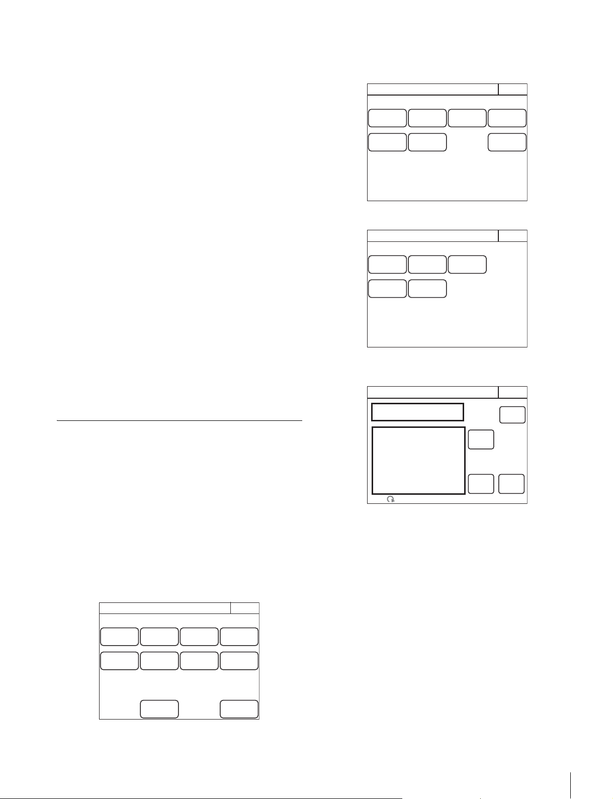
Settings
43
6 Set the PIX/WF operations
The following settings can be configured.
PIX/WF Synchro
Turn ON/OFF linking of output from the PIX2 OUTPUT
and WF2 OUTPUT connectors to RGB switching on the
adjustment display.
•Press
[ON] to light the button and switch to linking of
output from the PIX2 OUTPUT and WF2 OUTPUT
connectors to RGB switching on the adjustment display
when the white shading or black shading is adjusted.
•Set
[OFF] to output the signal selected with the
PICTURE MONITOR or WAVEFORM MONITOR
buttons from the PIX2 OUTPUT and WF2 OUTPUT
connectors regardless of the RGB selection in the
adjustment screen.
PIX/WF Control Mode
Select the control mode of the monitor selection buttons.
•Press
[Direct] to switch to direct mode. When you press
any of the R, G, and B buttons of the PICTURE
MONITOR and WAVEFORM MONITOR to light it, the
button that was pressed previously goes out, and the
signal corresponding to the newly pressed button is
output. To output the R and G signals, press the G
button while holding down the R button.
•Press
[Alternate] to switch to alternate mode. When
you press any of the R, G, and B buttons of the
PICTURE MONITOR and WAVEFORM MONITOR to
light it, the signal is output in combination with that of the
button that is already lit. To output the R and G signals,
press the R button to light it and then press the G button
to light it. When the B button is lit, press it so that it goes
out.
Customization
To assign functions to assignable buttons
Some of the buttons on the control panel are assignable
buttons, and you can assign any function to an assignable
button. Assignable buttons can also be assigned as CUSTOM
buttons.
1 Enter engineer mode. (page 51)
2 Press the MENU button.
The menu closes and the control panel remains in
engineer mode.
3 Display the RCP Config screen. (page 50)
4 Press [Customize].
The RCP Customize screen appears.
RCP-1500/1501
RCP-1530
5 Press [SW Customize].
The SW Customize screen appears.
All of the assignable buttons light immediately after this
screen is displayed.
RCP Config
Exit
Customize
Display
/Sound
Mode
VR
Setting
Date
/Time
Option
Key
Network
Infor-
mation
Security
Backup
Engineer Mode
RCP Customize
ExitEngineer Mode
SW
Customize
Status
Customize
Menu
Customize
VR
Customize
Standard
Ind
Custom
Menu SW
Detail
VR
RCP Customize
ExitEngineer Mode
SW
Customize
Status
Customize
Menu
Customize
Standard
Ind
Custom
Menu SW
Default
All
Enter
Save
SW Customize
Exit
Engineer Mode
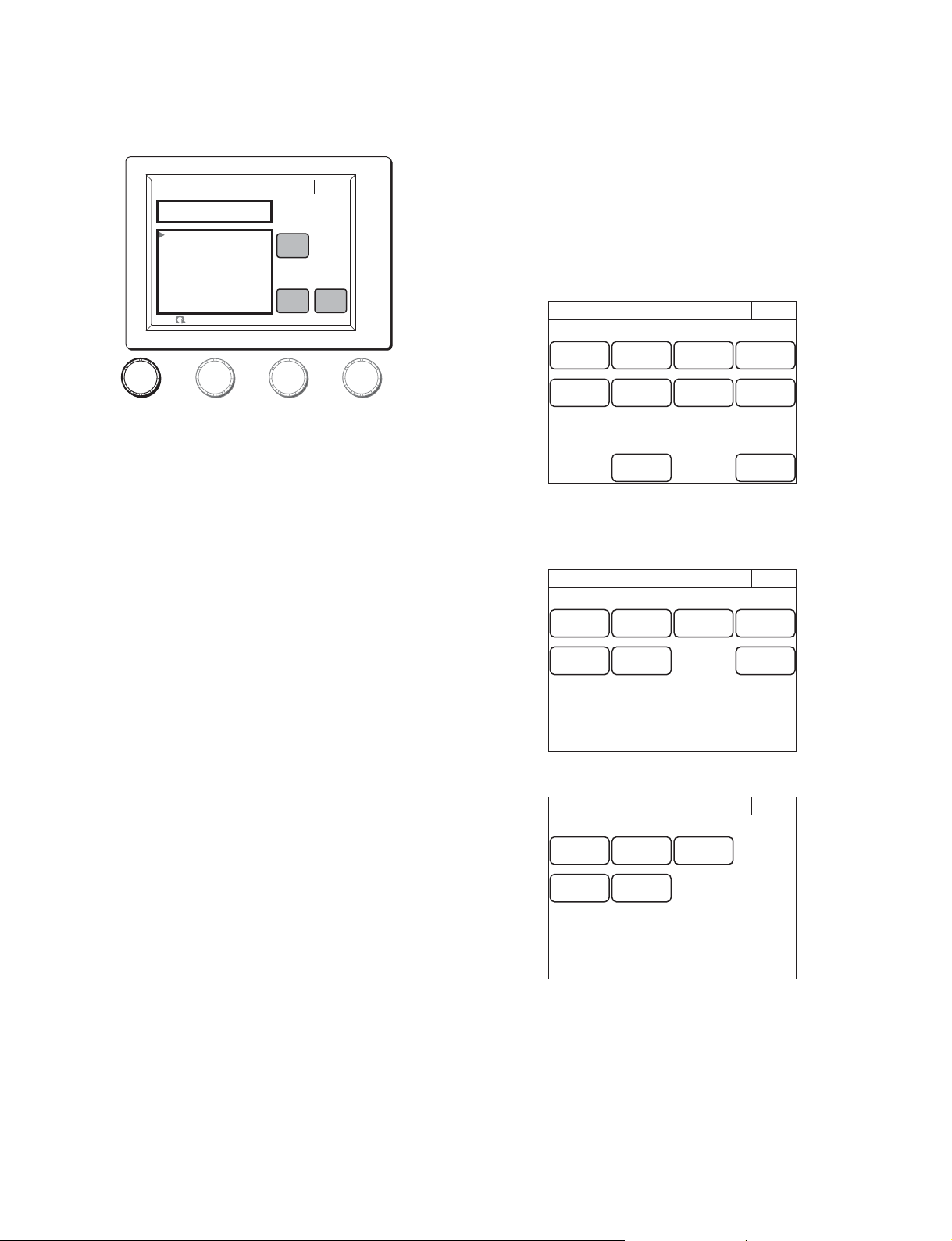
44
Settings
6 Press the button for which to change the assigned
function.
The function that is currently assigned to the pressed
button appears in the SW Customize screen.
A list of assignable functions also appears.
7 Turn the adjustment knob on the far left to select the
function to assign to the button.
Turning the adjustment knob on the far left moves the
cursor (B) in the list up or down. If you align the cursor with
an assignable function, that function name is displayed in
amber.
8 Press [Enter].
The function assigned to the button changes to the
function that was selected in the previous step. At that
time, “*” appears in front of the function name.
9 Repeat steps 6 to 8 if you want to assign functions to
multiple buttons.
10Press [Save].
The confirmation message screen appears.
11Press [Save].
The function assignments of assignable buttons are
saved.
If you exit the menu without saving, the function
assignments will not be reflected.
To reset the function assignments of assignable
buttons to their default settings
1 Press [Default All].
The confirmation message screen appears.
2 Press [OK].
The function assignments of assignable buttons are reset
to their default settings.
3 Press [Save].
The confirmation message screen appears.
4 Press [Save].
The function assignments of assignable buttons are saved
and registered to the control panel.
To assign functions to assignable adjustment
knobs
Some of the adjustment knobs on the control panel are
assignable adjustment knobs, and you can assign any function
to an assignable adjustment knob.
1 Enter engineer mode. (page 51)
2 Press the MENU button.
The menu closes and the control panel remains in
engineer mode.
3 Display the RCP Config screen. (page 50)
4 Press [Customize].
The RCP Customize screen appears.
RCP-1500/1501
RCP-1530
5600K
AUTO KNEE
SKIN DETAIL
GATE
SATURATION
CONTRAST
BLACK GAMMA
CHARACTER
KNEE APERTURE
NO ASSIGN
Exit
Save
Enter
SW Customize
NO ASSIGN
Default
All
Engineer Mode
RCP Config
Exit
Customize
Display
/Sound
Mode
VR
Setting
Date
/Time
Option
Key
Network
Infor-
mation
Security
Backup
Engineer Mode
RCP Customize
ExitEngineer Mode
SW
Customize
Status
Customize
Menu
Customize
VR
Customize
Standard
Ind
Custom
Menu SW
Detail
VR
RCP Customize
ExitEngineer Mode
SW
Customize
Status
Customize
Menu
Customize
Standard
Ind
Custom
Menu SW
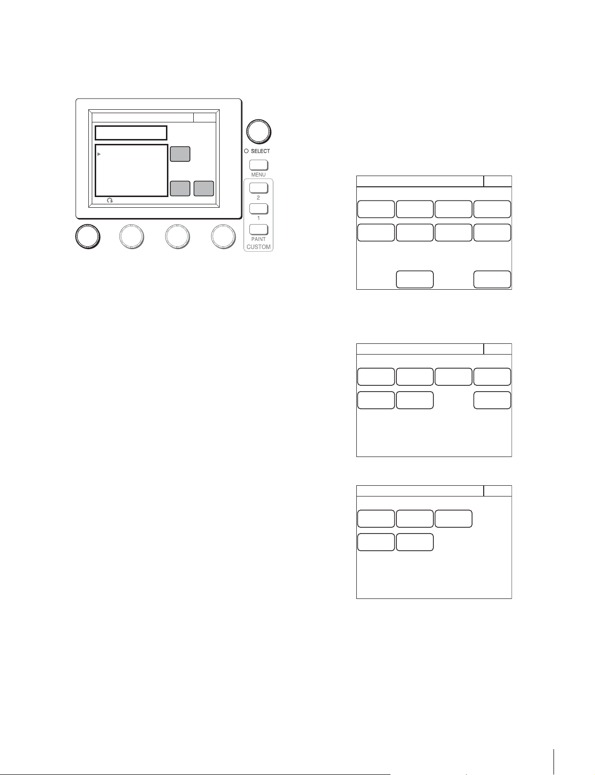
Settings
45
5 Press [VR Customize].
The VR Customize screen appears.
The function that is currently assigned to the pressed
button appears in the VR Customize screen.
A list of assignable functions also appears.
6 Turn the adjustment knob on the far left to select the
function to assign to the assignable adjustment knob.
Turning the adjustment knob on the far left moves the
cursor (B) in the list up or down. If you align the cursor with
an assignable function, that function name is displayed in
amber.
7 Press [Enter].
The function assigned to the button changes to the
function that was selected in the previous step. At that
time, “*” appears in front of the function name.
8 Press [Save].
The confirmation message screen appears.
9 Press [Save].
The function assignments of assignable adjustment
knobs are saved.
If you exit the menu without saving, the function
assignments will not be reflected.
To reset the function assignments of assignable
adjustment knobs to their default settings
1 Press [Default All].
The confirmation message screen appears.
2 Press [OK].
The function assignments of assignable adjustment
knobs are reset to their default settings.
3 Press [Save].
The confirmation message screen appears.
4 Press [Save].
The function assignments of assignable adjustment
knobs are saved.
If you exit the menu without saving, the function
assignments will not be reflected.
To set the custom paint menu
If you register the custom paint menu containing frequently
used paint menu items, you can quickly display the necessary
paint menu items to configure settings.
1 Enter engineer mode. (page 51)
2 Press the MENU button.
The menu closes and the control panel remains in
engineer mode.
3 Display the RCP Config screen. (page 50)
4 Press [Customize].
The RCP Customize screen appears.
RCP-1500/1501
RCP-1530
GAMMA
MASTER FLARE
KNEE POINT
KNEE SLOPE
SATURATION
SKIN DETAIL
BLACK GAMMA
NO ASSIGN
Exit
Save
Enter
VR Customize
BLACK GAMMA
Default
All
Engineer Mode
RCP Config
Exit
Customize
Display
/Sound
Mode
VR
Setting
Date
/Time
Option
Key
Network
Infor-
mation
Security
Backup
Engineer Mode
RCP Customize
ExitEngineer Mode
SW
Customize
Status
Customize
Menu
Customize
VR
Customize
Standard
Ind
Custom
Menu SW
Detail
VR
RCP Customize
ExitEngineer Mode
SW
Customize
Status
Customize
Menu
Customize
Standard
Ind
Custom
Menu SW

46
Settings
5 Press [Menu Customize].
The Menu Customize screen appears.
This screen contains two lists, one at the top and the other
at the bottom. The top list displays the custom paint menu
items. The bottom list displays the paint menu items that
can be added to the custom paint menu. You can edit the
custom paint menu by selecting paint menu items in the
bottom list and adding them to the top list.
To add a paint menu item to the custom paint menu
1 Turn the adjustment knob on the far left to select the
paint menu item to add to the custom paint menu from
the bottom list.
Turning the paint adjustment knob on the far left moves
the cursor (B) in the bottom list up or down. If you align the
cursor with the paint menu item to add to the custom paint
menu, that paint menu item is displayed in amber.
2 Turn the SELECT knob to specify the position to
insert the paint menu item in the top list.
Turning the SELECT knob moves the cursor (B) in the top
list up or down. Align the cursor with the item above the
position to insert the paint menu item. The paint menu
item at the cursor position is displayed in amber.
3 Press [Insert].
The paint menu item selected in the bottom list is added
below the item at the cursor position in the top list.
4 Repeat steps 1 to 3 if you want to add multiple paint
menu items.
5 Press [Line] to insert a separator line between items
in the custom paint menu if necessary.
The separator line is inserted below the item at the cursor
position in the top list.
6 Press [Save].
The confirmation message screen appears.
7 Press [Save].
The contents of the custom paint menu are saved and
registered to the control panel.
To delete a paint menu item from the custom paint
menu
1 Turn the SELECT knob to select the paint menu item
to delete in the top list.
2 Press [Delete].
The selected paint menu item is deleted from the top list.
3 Select the paint menu item above a separator line and
then press
[Line] when you want to delete a separator
line.
4 Press [Save].
The confirmation message screen appears.
5 Press [Save].
The contents of the custom paint menu are saved and
registered to the control panel.
To reset the custom paint menu to the default
settings
1 Press [Default All].
The confirmation message screen appears.
2 Press [OK].
The contents of the custom paint menu are reset to the
default settings.
3 Press [Save].
The confirmation message screen appears.
4 Press [Save].
The contents of the custom paint menu are saved and
registered to the control panel.
To assign menus to custom buttons
You can assign any menu to a custom button on the control
panel. A menu can also be assigned to an assignable button
that has been assigned as a custom button.
1 Enter engineer mode. (page 51)
2 Press the MENU button.
The menu closes and the control panel remains in
engineer mode.
3 Display the RCP Config screen. (page 50)
Default
All
Insert
Save
Menu Customize
Exit
Delete
Paint Item
Custom Paint Menu
1 Detail
2 Skin Detail
3 Gamma
4 Knee
Black
Flare
Detail
Skin Detail
White
Save
TOP
Engineer Mode
RCP Config
Exit
Customize
Display
/Sound
Mode
VR
Setting
Date
/Time
Option
Key
Network
Infor-
mation
Security
Backup
Engineer Mode
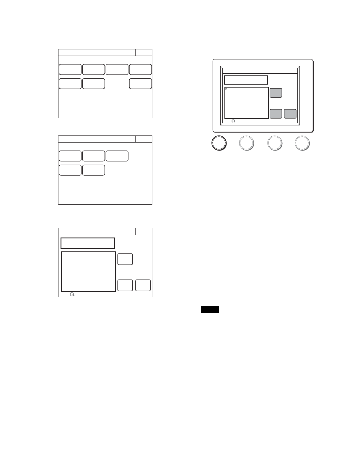
Settings
47
4 Press [Customize].
The RCP Customize screen appears.
RCP-1500/1501
RCP-1530
5 Press [Custom Menu SW].
The Custom Menu SW screen appears.
All of the custom buttons light immediately after this
screen is displayed.
6 Press the button for which to change the assigned
function.
The function that is currently assigned to the pressed
button appears in the Custom Menu SW screen.
A list of assignable functions also appears.
7 Turn the adjustment knob on the far left to select the
function to assign to the button.
Turning the adjustment knob on the far left moves the
cursor (B) in the list up or down. If you align the cursor with
an assignable function, that function name is displayed in
amber.
8 Press [Enter].
The function assigned to the button changes to the
function that was selected in the previous step. At that
time, “*” appears in front of the function name.
9 Repeat steps 6 to 8 if you want to assign functions to
multiple buttons.
10Press [Save].
The confirmation message screen appears.
11Press [Save].
The function assignments of custom buttons are saved.
If you exit the menu without saving, the function
assignments will not be reflected.
When you assign one of the following menus from the
paint menu to a custom button, the same menu must also
be registered in the custom paint menu. If you assign the
menu to a custom button without registering it in the
custom paint menu, pressing the custom button will not
access the assigned menu.
•Skin Detail
•Gain
•Gamma
•Black Gamma
• Knee
• Shutter
• Saturation
• Flicker Reduction
•White
•Black
•Flare
• Detail
RCP Customize
ExitEngineer Mode
SW
Customize
Status
Customize
Menu
Customize
VR
Customize
Standard
Ind
Custom
Menu SW
Detail
VR
RCP Customize
ExitEngineer Mode
SW
Customize
Status
Customize
Menu
Customize
Standard
Ind
Custom
Menu SW
Default
All
Enter
Save
Custom Menu SW
Exit
Engineer Mode
Note
5600K
AUTO KNEE
SKIN DETAIL
GATE
SATURATION
CONTRAST
BLACK GAMMA
CHARACTER
KNEE APERTURE
NO ASSIGN
Exit
Save
Enter
Custom Menu SW
NO ASSIGN
Default
All
Engineer Mode
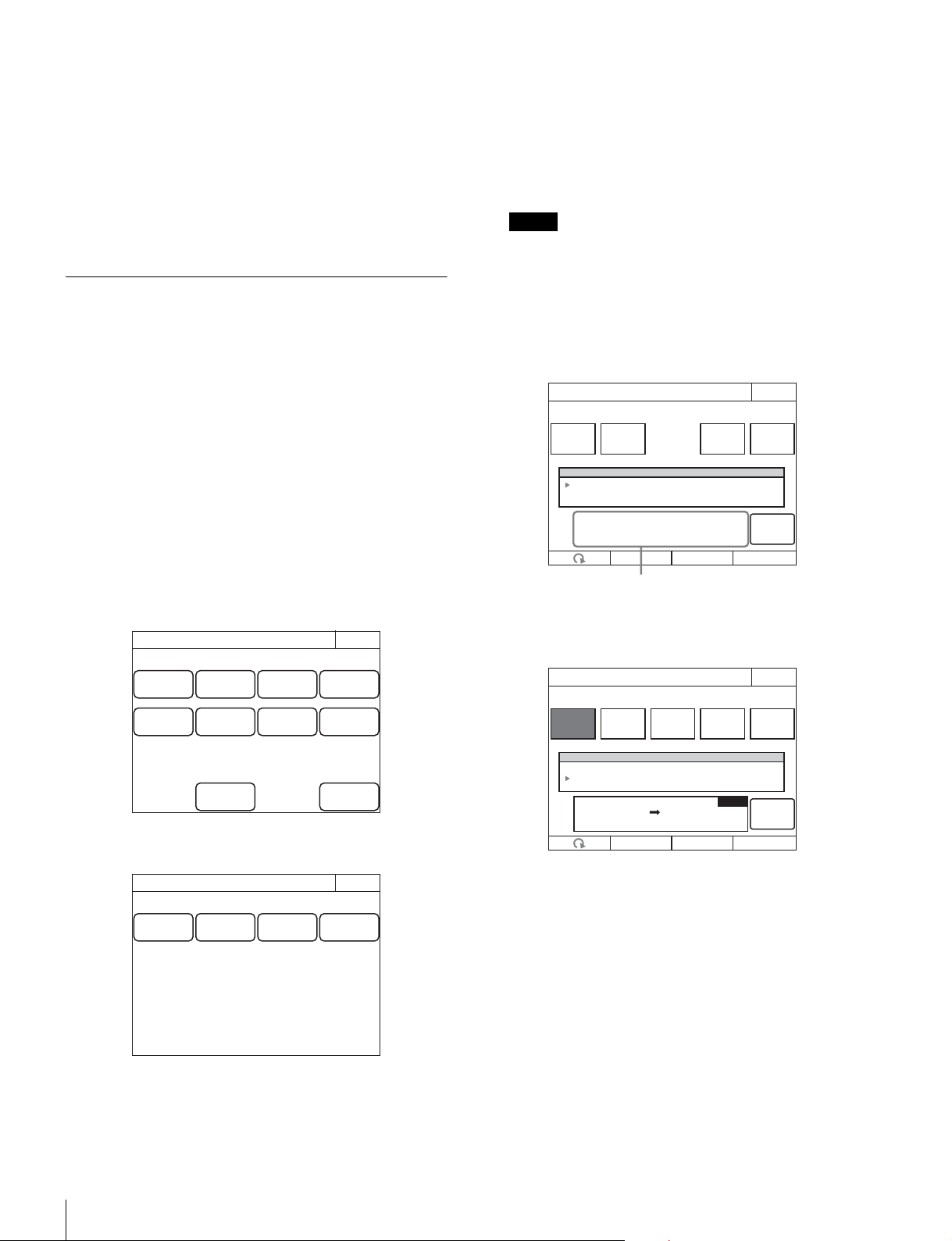
48
Settings
•Matrix
•V Mod Saw
•White Clip
• Auto Iris
• Mono Color
• Noise Suppression
• Gamma/Knee
• Low Key Saturation
• Knee Saturation
• Gamma Table
•3D Monitor
Saving and Initializing Settings
To save changed setting values to a “Memory
Stick Duo”
You can save the changed setting values of reference files and
scene files to a “Memory Stick Duo.” You can use these files
when necessary by reading them from the “Memory Stick
Duo.”
1 Insert a “Memory Stick Duo” into the “Memory Stick
Duo” slot. (page 82)
2 Enter engineer mode. (page 51)
3 Press the MENU button.
The menu closes and the control panel remains in
engineer mode.
4 Display the RCP Config screen.
5 Press [Backup].
The Backup screen appears.
6 Select the settings to save.
[Menu Customize]: Status screen customizing, custom
paint menu settings
[SW/VR Customize]: Assignable button, custom button,
and assignable adjustment knob settings
[Network Config]: Network settings
[Panel Config]: RCP configuration menu settings other
than the above
When selecting a Network Config file saved to the same
model unit but with the different serial number, other than
this unit, the model information on the file displayed on a
message area is shown in red. It is possible to read such
a file, but confirm that the IP address does not conflict with
an IP address of another unit.
Example: When Menu Customize is selected.
7 Press [Store].
The screen changes as follows.
RCP Config
Exit
Customize
Display
/Sound
Mode
VR
Setting
Date
/Time
Option
Key
Network
Infor-
mation
Security
Backup
Engineer Mode
Panel
Config
Network
Config
Menu
Customize
SW
Customize
Backup
Exit
Engineer Mode
Note
Enter
Menu Customize
Exit
DeleteFile IDRecall
1 11/11/11
11/12/24
11:11
12:13
RCP-1500
RCP-15002
Store
Custom r01
No Date Time
Engineer Mode
Message area: Displays file operation
information or File ID.
Enter
Menu Customize
Exit
DeleteFile IDRecall
Engineer Mode
File
Number
Store
Input file no:
RCP MS
3
1 11/11/11
11/12/24
11:11
12:13
RCP-1500
RCP-15002
No Date Time
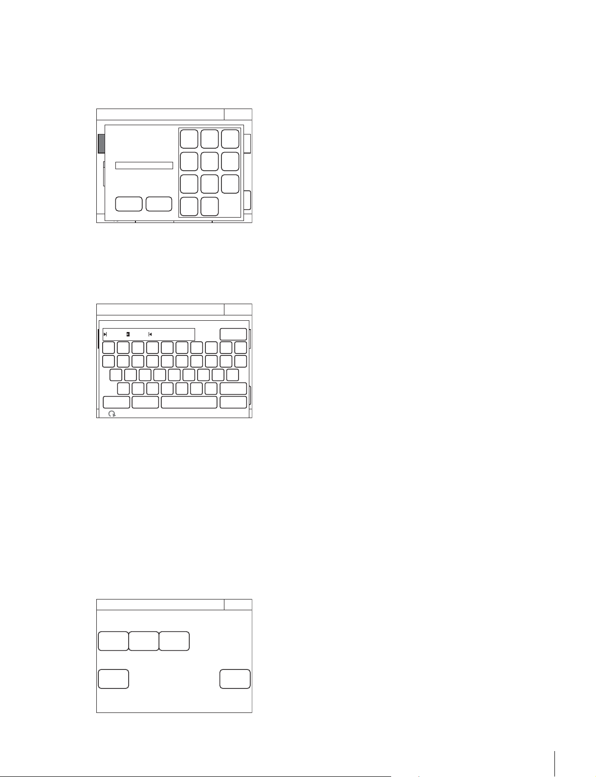
Settings
49
8 Press [File Number] or use the leftmost adjustment
knob to select the file number, and press
[Enter].
When
[File Number] is pressed, the file number entry
screen appears as follows. Enter the file number, and then
press
[OK] to confirm. If you select the same number as
that of a file displayed in the list, the data is overwritten.
9 Confirm the file number, and press [Enter].
The settings are saved to the “Memory Stick Duo.”
10Press [File ID] to set or change the File ID in the file.
When software keyboard is displayed, enter a File ID, and
press
[Enter] to set the File ID.
To read settings saved to a “Memory Stick Duo.”
Perform the procedure of “To save changed setting values to a
“Memory Stick Duo” (page 48)” up to step 5, and then press
[Recall] in step 6. The subsequent operation is the same.
To delete settings saved to a “Memory Stick Duo.”
Perform the procedure of “To save changed setting values to a
“Memory Stick Duo” (page 48)” up to step 5, and then press
[Delete] in step 6. The subsequent operation is the same.
To initialize the settings
You can reset all of the RCP configuration menu settings to
their default settings.
1 Enter engineer mode. (page 51)
2 Press [All Preset].
The confirmation message appears.
3 Press [OK].
The RCP configuration menu settings are all reset to their
default settings.
Enter
Menu Customize
Exit
Delete
File IDRecall
1 11/11/11
11/12/24
11:11
12:13
RCP-1500
RCP-15002
No Date Time
Engineer Mode
File
Number
Store
Input file no :
RCP MS
3
OK Cancel
File number:
3
BS
1
4
7
0
2
5
8
3
6
9
Enter
Menu Customize
Exit
DeleteFile IDRecall
1 11/11/11
11/12/24
11:11
12:13
RCP-1500
RCP-15002
No Date Time
Engineer Mode
File
Number
Store
Input file no :
RCP MS
3
0
BS
Enter
987654321
poiuytrewq
lkjhgfdsa
mnbvcx
Cancel
SpaceCaps!"#
Cursor
z
custom r02
File ID
Page
Permission
Item
Permission
Code
Change
Security
Exit
ALL
Preset
Engeneer
Mode
Engineer Mode
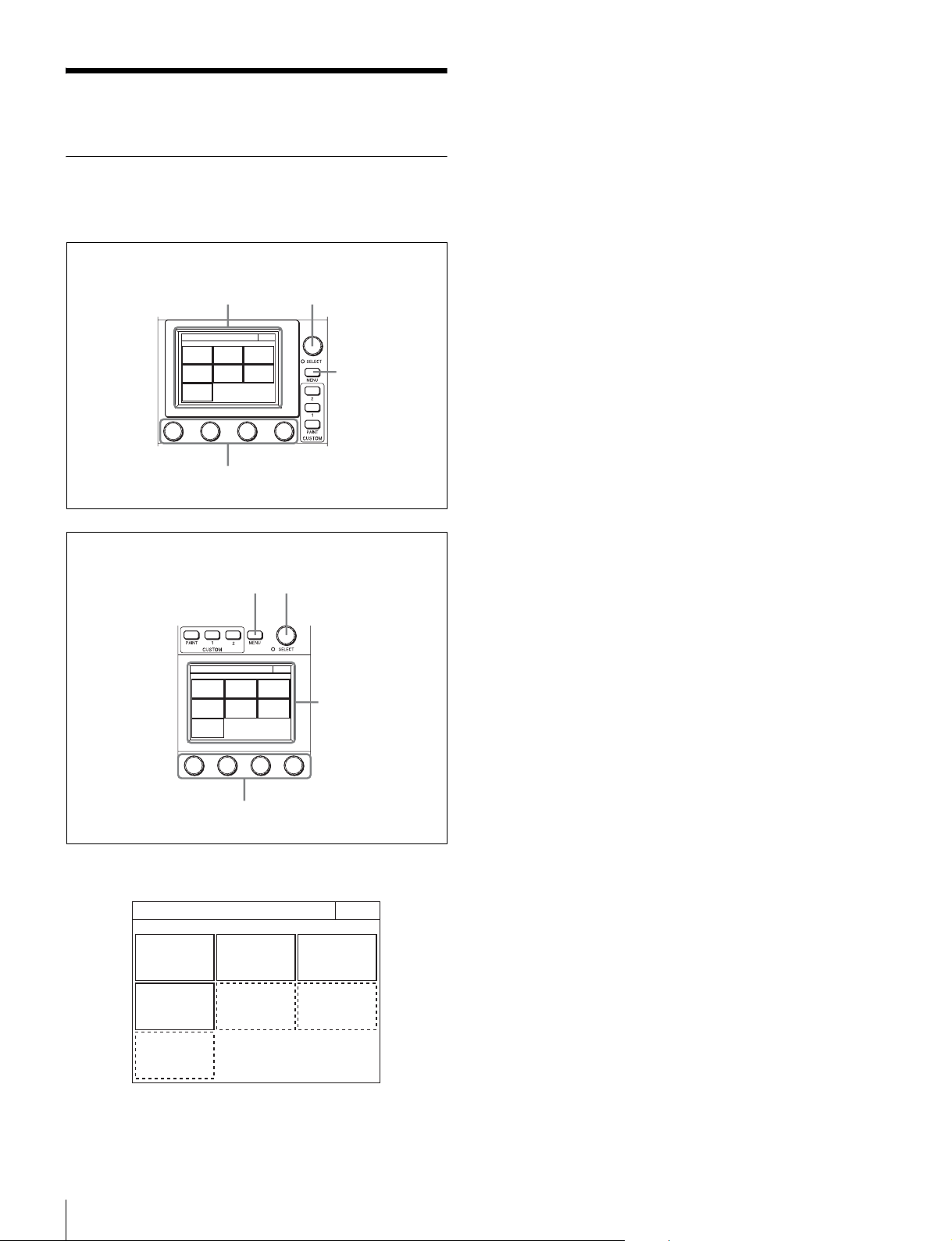
50
Menus
Menus
Menu Operations
You can use various operation menus to adjust system
devices and perform other operations with the control panel.
1 Press the MENU button.
The Category Select screen appears.
2 Press a button on the Category Select screen to
select a menu.
[Scene] : Scene Menu (page 81)
[Function] : Function Menu (page 80)
[Multi] : Multi Menu (page 80)
[Config] : Config Menu (page 72)
The following menu items are added when the control
panel is in engineer mode or Full Paint of Page Permission
is set to ON.
[File] : File Menu (page 64)
[Maintenance] : Maintenance Menu (page 65)
[Paint] : Paint Menu (page 54)
When you select a menu, the corresponding setting and
adjustment screen for the menu appears.
3 Select the item to operate.
• For a menu (Paint menu, etc.) consisting of multiple
pages, turn the SELECT knob to select an item and
then press the SELECT knob to display the setting and
adjustment screen for that item. Turning the SELECT
knob after the setting and adjustment screen is displays
allows you to switch to another item.
• When tabs are displayed in the setting and adjustment
screen, press a tab to switch to the setting item.
4 Set or adjust the item.
• Turn the adjustment knob (or press the button) in
accordance with the setting and adjustment item
(parameter) to adjust the setting value (select a setting).
• When a message screen appears, perform the
operation in accordance with the message, and then
press
[OK].
When the setting or adjustment is finished
• To adjust another item of the same menu, turn the SELECT
knob to switch to the setting and adjustment screen for that
item.
• To adjust a different menu, press
[Exit] to return to the
Category Select screen, and then select another menu.
• To close the menu, press [Exit] in the Category Select
screen.
To display the RCP screen
When setting the control panel, use the following procedure to
display the RCP screen.
Category Select
Scene
Func-
tion
Multi
Config File
Mainten-
ance
Paint
Exit
1
23
4
RCP-1500/1501
Category Select
Scene
Func-
tion
Multi
Config File
Mainten-
ance
Pain t
Exit
1
2
3
4
RCP-1530
Category Select
Scene
Func-
tion
Multi
Config File
Mainten-
ance
Paint
Exit
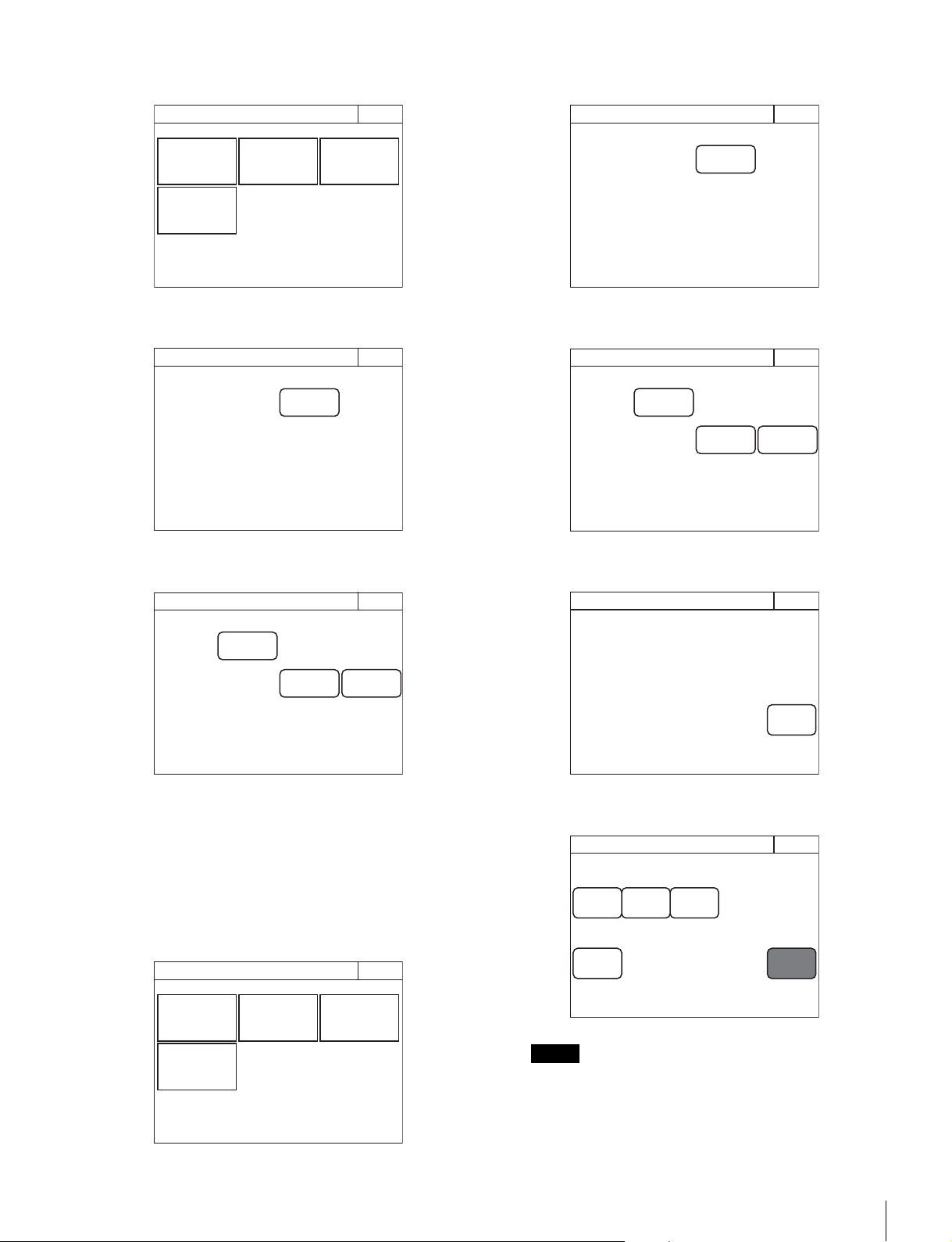
Menus
51
1 Press the MENU button.
The Category Select screen appears.
2 Press [Config].
The Config screen appears.
3 Press [RCP].
The RCP screen appears.
To enter engineer mode
Some settings of the control panel have their functions
restricted and are not displayed to prevent unintentional
operation. When you enter engineer mode, the restrictions are
cancelled.
Use the following procedure to enter engineer mode.
1 Press the MENU button.
The Category Select screen appears.
2 Press [Config].
The Config screen appears.
3 Press [RCP].
The RCP screen appears.
4 Press [Security].
The Security screen appears.
5 Press [Engineer Mode] to light the button.
The items that were hidden appear.
If a security code has been configured (page 41), a
security code entry screen will appear when you press
[Engineer Mode]. Enter the correct security code and
press
[OK] to enter engineer mode.
Category Select
Scene
Func-
tion
Multi
Config
Exit
RCP
Config
Exit
RCP Config
Exit
Display
/Sound
Infor-
mation
Security
Category Select
Scene
Func-
tion
Multi
Config
Exit
Note
RCP
Config
Exit
RCP Config
Exit
Display
/Sound
Infor-
mation
Security
Security
Exit
Engeneer
Mode
Page
Permission
Item
Permission
Code
Change
Security
Exit
ALL
Preset
Engeneer
Mode
Engineer Mode

52
Menus
Menu Tree
HDFX
IF Select
Paint
White
Black
Flare
Detail
Skin DTL
Matrix
Gain
Gamma
Black Gamma
Knee
Shutter
Saturation
V Mod Saw
White Clip
Auto Iris
Mono Color
Noise Suppression
Flicker Reduction
Gamma/Knee
Low Key Saturation
Knee Saturation
Gamma Table
File
Reference
Ref Store
Scene
Store/Recall
Lens
Lens Store
OHB
Memory Stick
Lens Select
Auto White
Adjusting
OHB Store
Auto W Shading
User Gamma
User Gam Transfer
Adjusting
Auto B Shading
Auto White
Auto Black
Adjusting
Format
Custom Matrix
Store
Transfer
Adjusting
Scene Trans
fer
Adjusting
RGB
Color Temp
1/3
2/3
3/3
Skin DTL 1
Skin DTL 2
Gamma
Step
Shutter
FPS
Skin DTL 3
Y Limit
Knee Point
Knee Slope
Auto Knee
User 1/2
User 2/2
Multi
Preset
Ref Transfer
Adjusting
Lens
Auto Iris Settings
Flare
V Mod Saw
ALAC
CCU
Phase
Monitor Output
SD Adj
SD Detail
Config
Camera
CCU
RCP
Customize
Display/Sound
Sound
LED
LCD
EL
To uch Panel
Standard
Hyper
Special
User
Cross Color Suppression
H
SC
1/3
2/3
3/3
3D Monitor
Select
Mode
CAM Ctrl
Maintenance
Camera
Black Shading
White Shading
R
G
B
R
G
Call
To uch
SW
RE
Mode
CAM Menu Control
Mode
Return Setting
Channel ID
CCU Menu Control
Menu Customize
SW Customize
Custom Menu SW
VR Customize
(RCP-1500/1501 only)
Standard Ind
Status Customize
Detail VR
(RCP-1500/1501 only)
Black Set
OHB Matrix
ATW Setting
Microphone Gain
B
White
Black Set
Black
User 1/2
User 2/2
Multi
SD Gamma
SD Matrix
Interporation
Cross Color Reduction
Aspect
RPN
User 1/2
User 2/2
Multi
Preset
Auto Setup

Menus
53
Network
Information
Security
Backup
RCP Assignment
Multi
Function
Optical Level
PIX/WF
Option Key
Multi Format
BPU Multi Format
Time
Time Zone
Network Info
CNS
LAN I/F
TCP/IP
Version
Network Info
Option Info
Page Permission
Item Permission
ALL Preset
Engineer Mode
Menu Customize
SW/VR Customize
Panel Config
Network Config
Screen Saver
PIX/VF
Matrix Gate
Extend Call
Panel Active
Preview
Mode
Date/Time
VR Setting
White/Blk/Flr
Detail/Assign
Iris/M.Black
Date
3D Mode
Channel ID
3D CAM Control
3D System
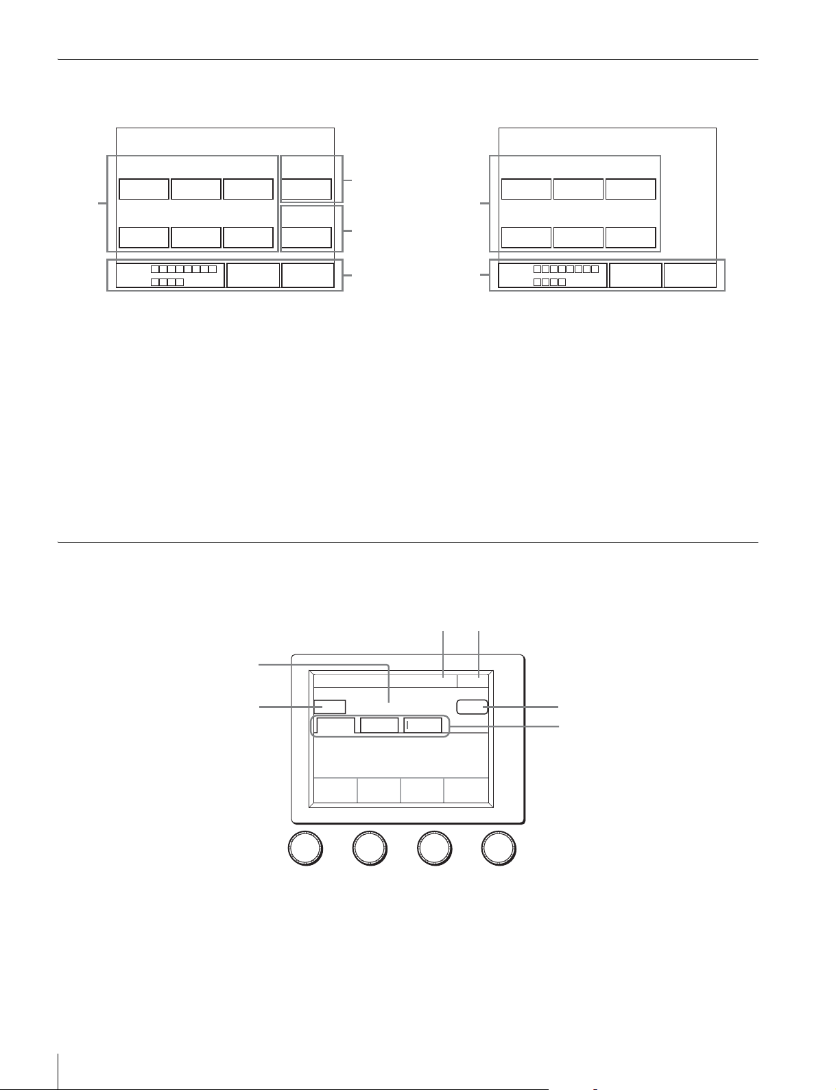
54
Menus
Status Screen
Status screen of RCP-1500/1501
1 Displays the value adjusted with the white balance/black
balance adjustment block of the control panel. When the
FLARE button is lit, the FLARE adjustment value is
displayed.
2 Displays the value adjusted with the DETAIL knob.
3 Displays the adjustment item name and the value adjusted
with the assignable adjustment knob.
4 If you make Customize settings, the value adjusted with the
function assigned to the adjustment knobs and Optical
level will be displayed. They are not displayed under the
default settings.
Status screen of RCP-1530
1 Displays the value adjusted with the white balance/black
balance adjustment block of the control panel. When the
FLARE button is lit, the FLARE adjustment value is
displayed.
2 If you make Customize settings, the value adjusted with the
function assigned to the adjustment knobs and Optical
level will be displayed. They are not displayed under the
default settings.
Paint Menu
Screen display example (when “Knee” is selected in the Paint menu)
a This indicates the page number/total number of pages.
When this indication is displayed, you can turn the SELECT
knob to change the page.
b Press this to return to the previous menu screen.
c Displays the names of functions that are selected.
d Press this to light the button in red and display a red frame
around items that can be cleared.
0
R
0
G
0
B
0
Detail
White
0
R
0
G
0
B
0
Black Gamma
Master
Blk GammaM White
CAM
0.0 0
CCU
1
2
3
4
0
R
0
G
0
B
White
0
R
0
G
0
B
Black
Blk GammaM White
CAM
0.0 0
CCU
1
2
Clear OFF
Knee
Point
Knee
Slope
Auto knee
Knee
Paint
R
-99
G
-99
B
-99
Master
-99
Exit10/23
12
5
4
6
3

Menus
55
You can press items with a red frame around them to clear
their values one by one. If you press c, the values for all
of the items with a red frame around them will be cleared.
To cancel clearing items, press
[Clear] again.
e Press this to turn OFF all of the functions displayed in c.
f Press a tab to switch to the setting items. Indicators are
displayed for the individual setting items of each tab to
indicate whether or not a setting is ON or OFF (an indicator
lights when the setting item is ON).
Clear OFF
Knee
Point
Knee
Slope
Auto knee
Knee
Paint
R
-99
G
-99
B
-99
Master
-99
Exit10/23
Items that can be cleared are indicated by a red frame
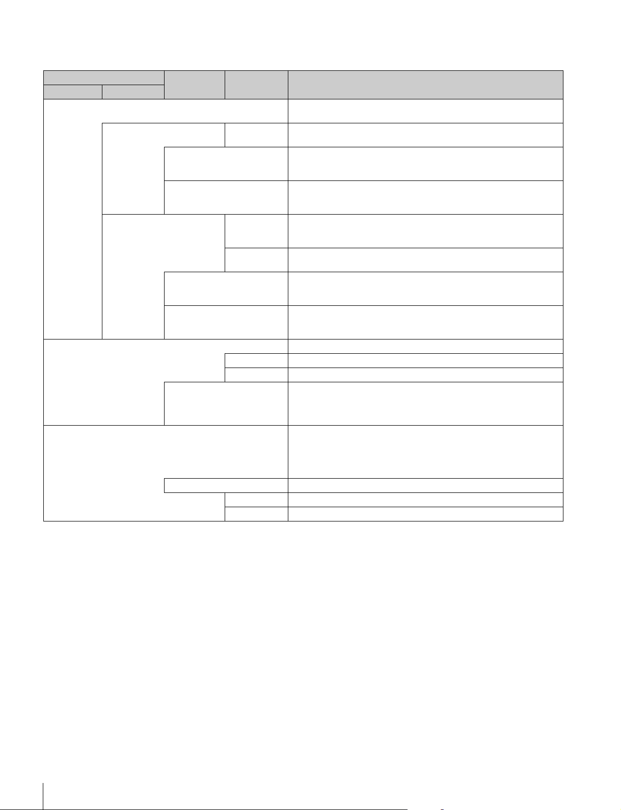
56
Menus
Menu items
The mark in the “Control Item” column indicates an item that is assigned to a paint adjustment knob.
Paint menu
Switch Control item Description
Menu Submenu
White Corrects the color reproduction of the camera to match the color
temperature of the light source shining on the subject.
RGB R/G/B Changes the sensitivity of each primary color (R, G, and B) and corrects
the color temperature.
ATW This is the Auto Tracing White Balance. It continually corrects the white
balance to match the screen during shooting. An error may be generated
depending on the pattern.
AWB This is the Auto White Balance. Pressing this button during the shooting of
a white subject automatically corrects the color temperature so that the
white parts of the subject become white.
Color Temp Color Temp Corrects the color temperature in accordance with the spectrum of black
body radiation of the color space. (R and B are corrected in the opposite
direction.)
Balance Corrects the balance so that it intersects the color temperature in the color
space. (R and B are corrected in the same direction.)
ATW This is the Auto Tracing White Balance. It continually corrects the white
balance to match the screen during shooting. An error may be generated
depending on the pattern.
AWB This is the Auto White Balance. Pressing this button during the shooting of
a white subject automatically corrects the color temperature so that the
white parts of the subject become white.
Black Adjusts the black level of images for when the lens is closed.
R/G/B Adjusts the black level of each of R, G, and B.
Master Links R, G, and B and adjusts them simultaneously.
ABB This is the Auto Black Balance. It automatically adjusts the R black and B
black so that no color is added to black when the lens is closed. Depending
on the model of camera, Black Set is also automatically adjusted at the
same time. When this is executed, the lens is temporarily closed.
Flare Corrects the phenomenon of black in the subject becoming bright and color
being added due to the influence of the optical system. Adjusting this in the
plus direction reduces the black level of the corresponding color in
accordance with the brightness of the subject. Be careful not to overcorrect
this.
OFF Disables the flare correction function.
R/G/B Adjusts the correction level of each of R, G, and B.
Master Links R, G, and B and adjusts them simultaneously.

Menus
57
Detail Corrects the contour.
OFF Disables the detail function.
1/3 This is the first page of detail adjustment.
HD Adjust ON: Performs detail adjustment for HD output (down converted) of BPU.
OFF or not displayed: Performs the conventional detail adjustment.
Level Adjusts the contour correction level. Adjusting this in the plus direction
makes pictures sharp, and adjusting this in the minus direction makes
pictures soft. For cameras with an electronic software focus function, this
enables softer pictures than when in the DTL OFF state.
Limiter Makes adjustments so that contour correction is not greater than a set level
to prevent overcorrection by strong contour correction when shooting
subjects with large luminance differences. Adjusting this in the plus
direction also enables clipping of objects with small luminance differences.
Crisp Makes adjustments so that signals with small luminance differences are
considered to be noise and correction is not applied to them in order to
reduce the emphasizing of also the contours of noise by the contour
correction function. Adjusting this in the plus direction results in luminance
differences for which contour correction is not performed becoming large
and improvements in S/N sensitivity, but resolution sensitivity deteriorates.
Level Dep Contour correction is not applied to the dark parts and S/N sensitivity is
increased in order to reduce the emphasizing of also the contours of noise
by the contour correction function. Adjusting this in the plus direction
results in contour correction not being applied up to a brighter level.
Level Dep Off Disables the Level Dep function.
2/3 This is the second page of detail adjustment.
HD Adjust ON: Performs detail adjustment for HD output (down converted) of BPU.
OFF or not displayed: Performs the conventional detail adjustment.
H/V Ratio Adjusts the horizontal and vertical ratio of contour correction.
Frequency Adjusts the center frequency of contour correction.
Mix Ratio With a type of camera that creates a contour correction signal from
gamma, adjusts the ratio for adding that correction signal before and after
the gamma.
Detail Comb Reduces cross color noise by applying the comb filter to contour correction
signals. Adjusting this in the plus direction reduces cross color noise, but
resolution sensitivity deteriorates. This can only be used when an SD
camera is connected.
3/3 This is the third page of detail adjustment.
HD Adjust ON: Performs detail adjustment for HD output (down converted) of BPU.
OFF or not displayed: Performs the conventional detail adjustment.
W Limiter This is the limiter correction for detail signals added in the white direction.
B Limiter This is the limiter correction for detail signals added in the black direction.
Fine DTL Attenuates the contour correction signal. Adjusting this in the plus direction
attenuates the signal. This can only be used when an SD camera is
connected.
Fine DTL Enables the Fine DTL function. This can only be used when an SD camera
is connected.
Knee Apt Adjusts the resolution sensitivity of high-luminance parts for which knee is
applied.
Knee Apt Enables the Knee Apt function.
Paint menu
Switch Control item Description
Menu Submenu
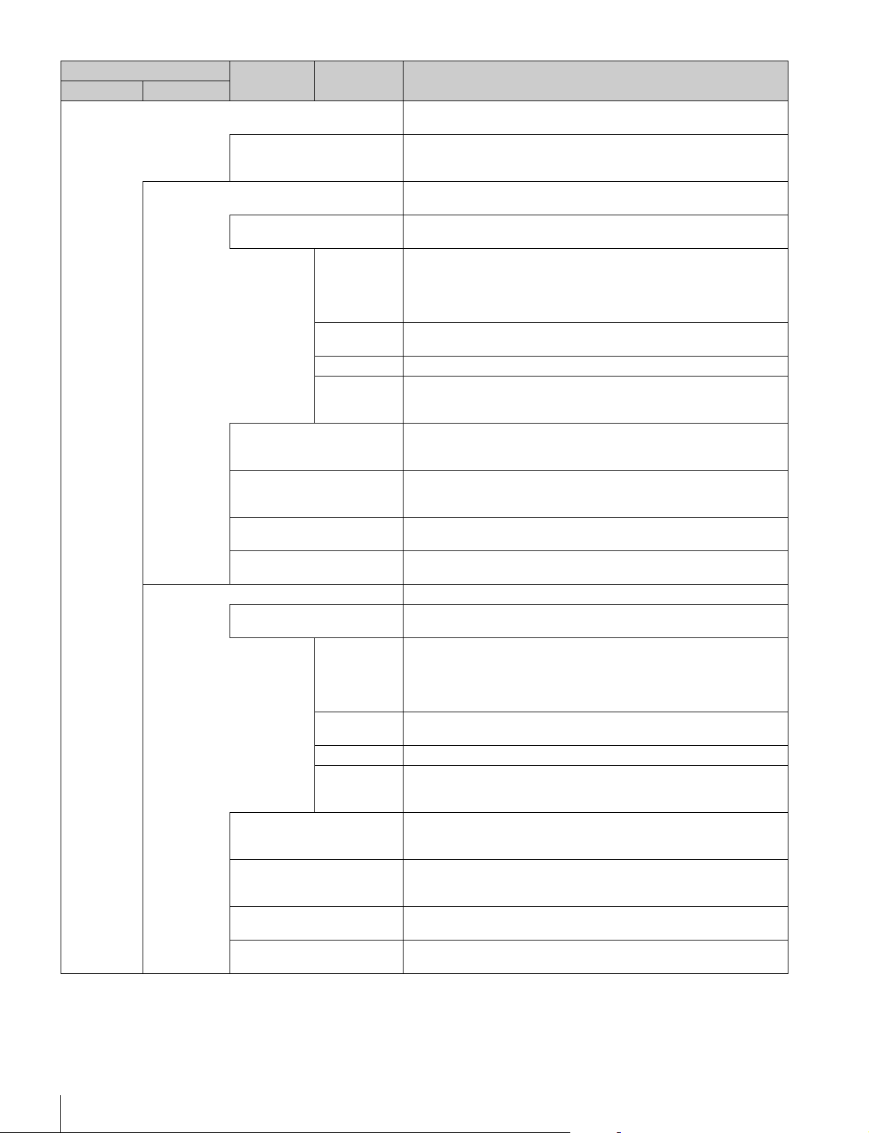
58
Menus
Skin DTL Allows adjustment of the contour correction level of the set color area. For
example, allows you to make the faces of people appear shiny.
ON Enables the Skin DTL function. Allows up to three channels to be adjusted
separately. This switch enables the Skin DTL function to be turned ON/OFF
simultaneously in accordance with the setting of each channel.
Skin DTL 1 Sets the first channel of Skin DTL. When this channel is enabled, the ON
mark appears on the very left of the tab.
Skin DTL 1 Enables Skin DTL of this channel. Skin DTL cannot be disabled for models
with three channels.
Level This is the contour correction value within the color area that is set with
Phase or Width. Adjusting this in the plus direction makes pictures sharp,
and adjusting this in the minus direction makes pictures soft. For cameras
with an electronic software focus function, this enables softer pictures than
when in the DTL OFF state.
Phase Adjusts the center of the hues of the effective color area of Skin DTL. The
value is almost equivalent to the phase on a vector scope.
Width Sets a range centered on the phase. The value indicates an angle.
Saturation Disables Skin DTL for places with a small degree of color saturation.
Adjusting this in the minus direction also allows Skin DTL to be enabled for
places with less saturation.
Auto Hue 1 This is a function for automatically searching for a hue. Capture the subject
you want to measure in the center of the screen and execute the function.
The phase of this channel is adjusted automatically.
Gate 1 Adds a gate signal to the range of this channel for which Skin DTL is
effective. For the output connector for which the signal can be added, refer
to the manual of the corresponding device.
Natural Skin DTL Enables the Natural Skin DTL function. This can be common to control the
three channels.
Zoom Link Enables the function that changes the correction amount for Skin DTL in
response to the zoom value of the camera.
Skin DTL 2 Sets the second channel of Skin DTL.
Skin DTL 2 Enables Skin DTL of this channel. When this channel is enabled, the ON
mark appears on the very left of the tab.
Level This is the contour correction value within the color area that is set with
Phase or Width. Adjusting this in the plus direction makes pictures sharp,
and adjusting this in the minus direction makes pictures soft. For cameras
with an electronic software focus function, this enables softer pictures than
when in the DTL OFF state.
Phase Adjusts the center of the hues of the effective color area of Skin DTL. The
value is almost equivalent to the phase on a vector scope.
Width Sets a range centered on the phase. The value indicates an angle.
Saturation Disables Skin DTL for places with a small degree of color saturation.
Adjusting this in the minus direction also allows Skin DTL to be enabled for
places with less saturation.
Auto Hue 2 This is a function for automatically searching for a hue. Capture the subject
you want to measure in the center of the screen and execute the function.
The phase of this channel is adjusted automatically.
Gate 2 Adds a gate signal to the range of this channel for which Skin DTL is
effective. For the output connector for which the signal can be added, refer
to the manual of the corresponding device.
Natural Skin DTL Enables the Natural Skin DTL function. This can be common to control the
three channels.
Zoom Link Enables the function that changes the correction amount for Skin DTL in
response to the zoom value of the camera.
Paint menu
Switch Control item Description
Menu Submenu
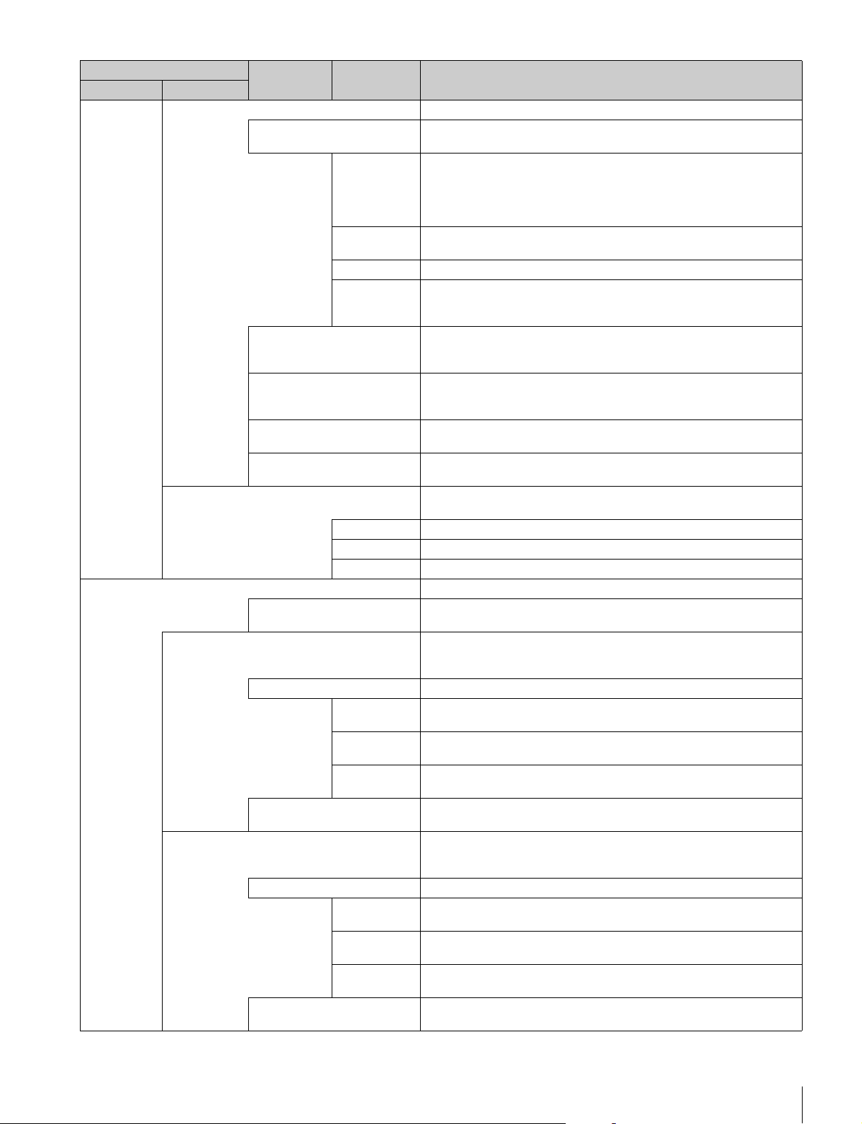
Menus
59
Skin DTL 3 Sets the third channel of Skin DTL.
Skin DTL 3 Enables Skin DTL of this channel. When this channel is enabled, the ON
mark appears on the very left of the tab.
Level This is the contour correction value within the color area that is set with
Phase or Width. Adjusting this in the plus direction makes pictures sharp,
and adjusting this in the minus direction makes pictures soft. For cameras
with an electronic software focus function, this enables softer pictures than
when in the DTL OFF state.
Phase Adjusts the center of the hues of the effective color area of Skin DTL. The
value is almost equivalent to the phase on a vector scope.
Width Sets a range centered on the phase. The value indicates an angle.
Saturation Disables Skin DTL for places with a small degree of color saturation.
Adjusting this in the minus direction also allows Skin DTL to be enabled for
places with less saturation.
Auto Hue 3 This is a function for automatically searching for a hue. Capture the subject
you want to measure in the center of the screen and execute the function.
The phase of this channel is adjusted automatically.
Gate 3 Adds a gate signal to the range of this channel for which Skin DTL is
effective. For the output connector for which the signal can be added, refer
to the manual of the corresponding device.
Natural Skin DTL Enables the Natural Skin DTL function. This can be common to control the
three channels.
Zoom Link Enables the function that changes the correction amount for Skin DTL in
response to the zoom value of the camera.
Y Limit Disables Skin DTL for low-luminance. Sets the maximum for the Y level to
disable.
Y Limit1 Sets the maximum for the Y level in the first channel of Skin DTL.
Y Limit2 Sets the maximum for the Y level in the second channel of Skin DTL.
Y Limit3 Sets the maximum for the Y level in the third channel of Skin DTL.
Matrix Corrects the color reproduction without changing the white balance.
OFF Enables the matrix function. This switch enables the function to be turned
ON/OFF simultaneously in accordance with individual matrix settings.
User 1/2 Sets the matrix correction factor individually. This is the first page of the
settings. When User Matrix is enabled, the ON mark appears on the very
left of the tab.
User Matrix Enables the User Matrix function.
R-G Corrects the signal of the R channel in accordance with the difference
between the signals of the R channel and G channel.
G-B Corrects the signal of the G channel in accordance with the difference
between the signals of the G channel and B channel.
B-R Corrects the signal of the B channel in accordance with the difference
between the signals of the B channel and R channel.
Adaptive Matrix Enables the Adaptive Matrix function. This can be common to control all
the matrix functions.
User 2/2 Sets the matrix correction factor individually. This is the second page of the
settings. When User Matrix is enabled, the ON mark appears on the very
left of the 1/2 tab.
User Matrix Enables the User Matrix function. This is the same switch as 1/2.
R-B Corrects the signal of the R channel in accordance with the difference
between the signals of the R channel and B channel.
G-R Corrects the signal of the G channel in accordance with the difference
between the signals of the G channel and R channel.
B-G Corrects the signal of the B channel in accordance with the difference
between the signals of the B channel and G channel.
Adaptive Matrix Enables the Adaptive Matrix function. This can be common to control all
the matrix functions.
Paint menu
Switch Control item Description
Menu Submenu
60
Menus
Multi Changes color reproduction for each hue divided into 16. When Multi
Matrix is enabled, the ON mark appears on the very left of the tab.
Multi Matrix Enables the Multi Matrix function.
Phase Selects the hue to adjust.
Hue Changes the hue of colors within the hue range selected with Phase.
Saturation Changes the saturation of colors within the hue range selected with Phase.
Adaptive Matrix Enables the Adaptive Matrix function. This can be common to control all
the matrix functions.
Gate Adds a gate signal to an image within the hue range selected with Phase.
For the output connector for which the signal can be added, see the
manual of the corresponding device.
All Clear Returns the factors of all ranges of Multi Matrix to their initial states.
Preset Selects the matrix provided for the camera in advance. When Preset Matrix
is enabled, the ON mark appears on the very left of the tab.
Preset Matrix Enables Preset Matrix.
Preset Selects the matrix provided for the camera in advance.
Adaptive Matrix Enables the Adaptive Matrix function. This can be common to control all
the matrix functions.
Level Adjusts the effective condition of the Adaptive Matrix function.
Gain Sets is the sensitivity of the camera. The sensitivity of the camera is
determined by the sum of the master gain and the master white gain.
Step Changes the sensitivity of the camera in steps.
M White Changes the sensitivity of the camera continuously.
Gamma Corrects the photoelectric conversion characteristic of the image pickup
device to the luminance characteristic of the display.
OFF Disables the gamma correction function.
Gamma R/G/B Adjusts the correction level of each of R, G, and B.
Master Links R, G, and B and adjusts them simultaneously.
Step Step Gamma Changes correction in steps.
Black Gamma Adjusts gamma correction of the screen dark sections.
ON Enables the black gamma function.
Range Selects the range for which black gamma is effective. Select from Low
Range, L.Mid Range, H.Mid Range, and High Range.
R/G/B Adjusts the correction level of each of R, G, and B.
Master Links R, G, and B and adjusts them simultaneously.
Knee Compresses the bright parts of the screen to enable expressions within the
signal standard. This enables you to obtain pictures that have a high
dynamic range.
OFF Disables knee correction. Auto Knee is also disabled.
Knee Point Compresses the bright parts and adjusts the start level.
R/G/B Adjusts the level of each of R, G, and B.
Master Links R, G, and B and adjusts them simultaneously.
Knee Max Applies clipping at the point that knee correction is applied to make
adjusting the knee point easy. This can only be set when in engineer mode
or when Knee Max Enable is enabled.
Knee Slope Adjusts the ratio for compressing images.
R/G/B Adjusts the compression level of each of R, G, and B.
Master Links R, G, and B and adjusts them simultaneously.
Paint menu
Switch Control item Description
Menu Submenu
Menus
61
Auto Knee Automatically adjusts the knee factor in accordance with the captured
image signal.
ON Enables the auto knee function. The settings configured for Knee Point/
Slope are ignored. When auto knee is enabled, the ON mark appears on
the very left of the tab.
Adaptive Divides the area with knee applied in the level direction, and sets the
optimal slope for each part.
Point Limit Sets the lower limit for the knee point automatically adjusted by auto knee.
This results in low level images not being influenced by auto knee.
Auto Slope Sets the knee slope of auto knee.
Shutter Controls the exposure time of the image pickup device.
Shutter Selects and sets the shutter mode.
Slow Shutter Slow Shutter Shoots with the frequency from the frame frequency of the capture image
format (unit: number of frames).
Shutter Shutter Controls the exposure time in steps. Display is 1/x seconds.
Angle Displays the shutter speed as an angle value.
ECS ECS This is the Extended Clear Scan. It finely controls the exposure time (unit:
Hz).
S-EVS S-EVS This is the Super Enhanced Vertical Definition System. It controls the
vertical definition.
FPS This function is for overcrank and undercrank shooting.
Shutter ON Enables the shutter function.
Angle Displays the shutter speed as an angle value.
Select FPS Performs overcrank and undercrank shooting.
Step/
continuous
Sets the shutter speed.
Comp Corrects the change in the image level for when the FPS is changed.
OFF : Disables the correction function.
Angle : Automatically controls the shutter in conjunction with the FPS and
maintains the output level.
Gain : Automatically controls the electronic gain in conjunction with the
FPS and maintains the output level.
FPS Sets the number of frames to capture.
Saturation Adjusts the saturation of images. The luminance is not changed.
ON Enables the saturation function.
Saturation Adjusts the saturation.
V Mod Saw Corrects color shading in the vertical direction caused by the lens or optical
system.
OFF Disables the V Modulation Saw correction function.
R/G/B Adjusts the correction level of each of R, G, and B.
Master Links R, G, and B and adjusts them simultaneously. R, B, and G move in
the opposite direction.
White Clip Sets the maximum value of the image signal. Limits signals over a certain
value by applying a clip to them.
OFF Disables the white clip function.
R/G/B Sets the maximum value of each of R, G, and B.
Master Links R, G, and B and sets them simultaneously.
Auto Iris Controls the iris of the lens in accordance with the brightness of the
subject. Additional adjustments are possible with the iris adjustment knob
even when using the auto focus.
ON Enables the auto iris function.
Pattern Selects the weighted pattern of auto iris in accordance with the screen
position.
Paint menu
Switch Control item Description
Menu Submenu
62
Menus
Mono Color Applies a special affect to make the screen mono color.
ON Enables the mono color function.
Saturation Sets the saturation.
Hue Sets the hue.
Noise Suppression Controls the white noise on the screen. Over control results in deterioration
of fine resolution sensitivity.
ON Enables the Noise Suppression function.
Noise Sup Adjusts the control level.
Flicker Reduction This is a function for Super Motion. It allows you to reduce flickering on the
screen caused by the relationship between temporal fluctuations of the
light source and the frame frequency of the camera.
ON Enables the Flicker Reduction function.
Power Line
Frequency
Sets the power line frequency of the lighting.
Area When there are multiple light sources, the screen is divided into areas and
flickering is reduced in each area. This sets that area division method.
Average Time Sets the time constant of the parameter used for correction.
Gain This is the correction level.
Offset This is image level at which correction starts to be applied.
Gamma/knee This page contains the gamma, black gamma, and knee.
Gamma Off Disables gamma correction.
Gamma This value corresponds to the master of gamma adjustment.
Black Gamma On Enables the black gamma function.
Blk Gamma This value corresponds to the master of black gamma adjustment.
Knee Off Disables knee correction. Auto Knee is also disabled.
Knee Point This value corresponds to the master of knee point adjustment.
Knee Slope This value corresponds to the master of knee slope adjustment.
Auto Knee On Enables the auto knee function.
Low Key Saturation Allows adjustment of the saturation of dark sections.
ON Enables the low key saturation function.
Range Sets the range for which low key saturation is performed.
Low K Sat Sets the saturation level.
Knee Saturation Compensates for the color fading of the parts for which knee is applied and
makes them appear colorful.
ON Enables the knee saturation function.
Knee Sat Sets the correction level.
Gamma Table Allows you to select the curve for gamma correction.
Standard Standard Uses a standard gamma curve.
Standard Allows you to select a type of standard gamma curve.
Gamma OFF Disables gamma correction.
Hyper Hyper Uses gamma to completely reproduce the dynamic range of the camera
including the high-luminance parts.
Hyper Allows you to select a type of hyper gamma curve.
Gamma OFF Disables gamma correction.
Special Special Allows you to select the gamma that emulates film and other gamma.
Special Allows you to select a type of special gamma curve.
Gamma OFF Disables gamma correction.
Paint menu
Switch Control item Description
Menu Submenu

Menus
63
User User Allows you to select gamma created with CVP File Editor and other
gamma.
User Allows you to select a type of user gamma curve.
Gamma OFF Disables gamma correction.
Cross Color Suppression Reduces the cross color of VBS. This can only be used when an SD
camera is connected.
ON Enables the Cross Color Suppression function.
CCS Sets the control level.
Paint menu
Switch Control item Description
Menu Submenu
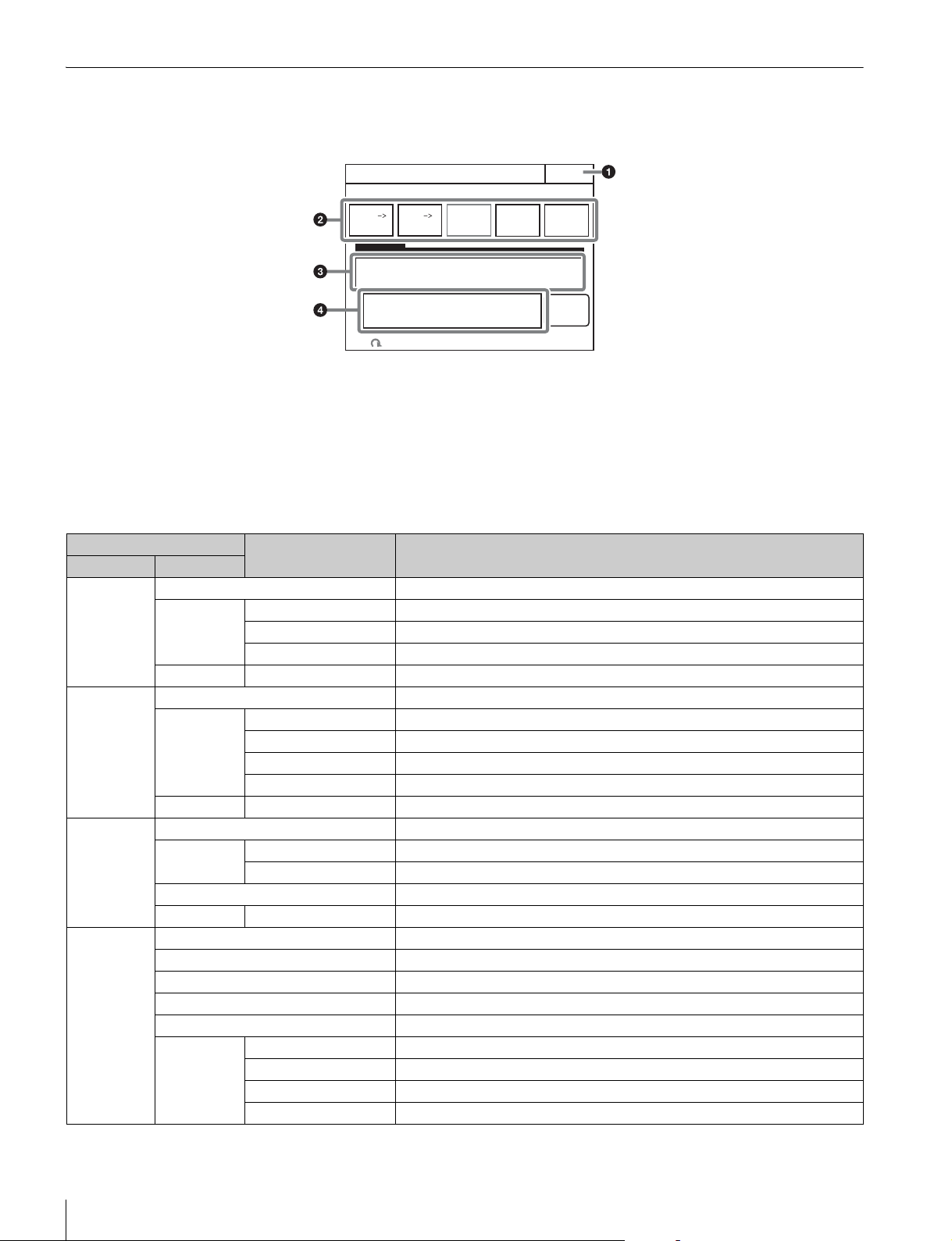
64
Menus
File Menu
Screen display example (when “Scene” is selected in the File menu, and then “Scene Transfer” is selected)
a Press this to return to the previous menu screen.
b Press a button to select the transfer destination and source.
Press the
[File ID] button to enter a File ID, press the
[Delete] button to delete a file.
c This displays a list of scene files that can be transferred.
When there are multiple files, turn the SELECT knob to
select the scene file that will be transferred.
d Message area
This displays files and the operation information.
Menu items
Scene Transfer
Exit
Enter
DeleteFile ID
CAM
MS
MS
CAM
File
Number
HD
No Cam Date Time
File menu
Control item Function
Menu Submenu
Reference Ref Store Registers a reference file.
Ref Transfer CAM t MS Transfers a reference file from a camera to a “Memory Stick Duo.”
MS t CAM Transfers a reference file from a “Memory Stick Duo” to a camera.
File ID Sets a File ID in a reference file of a “Memory Stick Duo.”
Adjusting (Paint menu items) Allows you to adjust the save items.
Scene Store/Recall Registers or reads a scene file.
Scene
Transfer
CAM t MS Transfers a scene file from a camera to a “Memory Stick Duo.”
MS t CAM Transfers a scene file from a “Memory Stick Duo” to a camera.
File ID Sets a File ID in a scene file of a “Memory Stick Duo.”
Delete Deletes a scene file from a “Memory Stick Duo.”
Adjusting (Paint menu items) Allows you to adjust the save items.
Lens Lens Store Registers a lens file.
Lens Select Change Name Changes the lens name.
Select File Selects a lens file.
Auto White Adjusts the auto white balance.
Adjusting (Paint menu items) Allows you to adjust the save items.
OHB OHB Store Registers an OHB file.
Auto W Shading Adjusts the auto white shading.
Auto B Shading Adjusts the auto black shading.
Auto White Adjusts the auto white.
Auto Black Adjusts the auto black.
Adjusting Black Shading Adjusts the black shading.
White Shading Adjusts the white shading.
Black Set Adjusts the black set.
Matrix Adjusts the OHB matrix.
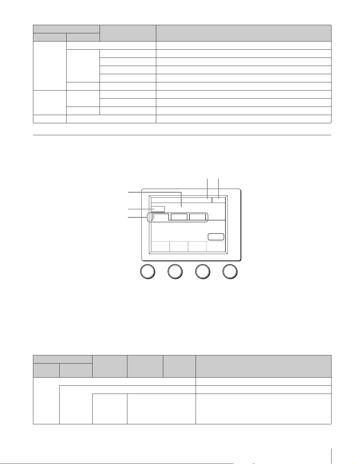
Menus
65
Maintenance Menu
Screen display example (when “Camera” is selected in the Maintenance menu, and then “Black Shading” is
selected)
a This indicates the page number/total number of pages.
When this indication is displayed, you can turn the SELECT
knob to change the page.
b Press this to return to the previous menu screen.
c This displays the current setting item name. After
[Clear] is
pressed to light it, you can clear all of the setting values.
d Press this to clear the setting items.
e Press a tab to switch to the setting items.
Menu items
Custom
Matrix
Store Registers a Custom Preset Matrix file.
Transfer CAM t MS Transfers a Custom Preset Matrix file from a camera to a “Memory Stick Duo.”
MS t CAM Transfers a Custom Preset Matrix file from a “Memory Stick Duo” to a camera.
File ID Sets a File ID in a Custom Preset Matrix file of a “Memory Stick Duo.”
Delete Deletes a Custom Preset Matrix file from a “Memory Stick Duo.”
Adjusting (Paint menu items) Allows you to adjust the save items.
User Gamma User Gam
Transfer
MS t CAM Transfers a user gamma file from a “Memory Stick Duo” to a camera.
Delete Allows you to delete a user gamma file from a “Memory Stick Duo.”
Adjusting (Paint menu items) Selects a Gamma Table.
Memory Stick Format Formats a “Memory Stick Duo.”
File menu
Control item Function
Menu Submenu
Auto B
Shading
Clear
R B
Black Shading
Camera
H Saw
-99
H Para
-99
V Saw
-99
V Para
-99
Exit1/6
G
3
5
4
12
Maintenance menu
Submenu Switch Control item Description
Menu Secondary
menu
Camera These are the maintenance items related to camera heads.
Black Shading Corrects black shading in images.
R Auto B Shading This is the Auto Black Shading. It automatically adjusts each of
the RGB, HV, and SAW/PARA parameters. Auto adjustment may
be additionally performed with 2D Black Shading depending on
the camera. If 2D Black Shading is not saved to the OHB file, it
will not be saved when the power of the camera is turned off.
66
Menus
H SAW Corrects spots in the left and right directions of the R channel in
a linear fashion.
H PARA Corrects spots in the horizontal direction in relation to the center
part of the R channel in a parabolic fashion.
V SAW Corrects spots in the up and down directions of the R channel in
a linear fashion.
V PARA Corrects spots in the vertical direction in relation to the center
part of the R channel in a parabolic fashion.
G Auto B Shading This is the Auto Black Shading. It automatically adjusts each of
the RGB, HV, and SAW/PARA parameters. Auto adjustment may
be additionally performed with 2D Black Shading depending on
the camera. If 2D Black Shading is not saved to the OHB file, it
will not be saved when the power of the camera is turned off.
H SAW Corrects spots in the left and right directions of the G channel in
a linear fashion.
H PARA Corrects spots in the horizontal direction in relation to the center
part of the G channel in a parabolic fashion.
V SAW Corrects spots in the up and down directions of the G channel in
a linear fashion.
V PARA Corrects spots in the vertical direction in relation to the center
part of the G channel in a parabolic fashion.
B Auto B Shading This is the Auto Black Shading. It automatically adjusts each of
the RGB, HV, and SAW/PARA parameters. Auto adjustment may
be additionally performed with 2D Black Shading depending on
the camera. If 2D Black Shading is not saved to the OHB file, it
will not be saved when the power of the camera is turned off.
H SAW Corrects spots in the left and right directions of the B channel in
a linear fashion.
H PARA Corrects spots in the horizontal direction in relation to the center
part of the B channel in a parabolic fashion.
V SAW Corrects spots in the up and down directions of the B channel in
a linear fashion.
V PARA Corrects spots in the vertical direction in relation to the center
part of the B channel in a parabolic fashion.
White
Shading
Corrects sensitivity shading in images.
R Auto W Shading This is the Auto White Shading. It automatically adjusts each of
the RGB, HV, and SAW/PARA parameters. Auto adjustment may
be additionally performed with 3D White Shading depending on
the camera. If 3D White Shading is not saved to the OHB file, it
will not be saved when the power of the camera is turned off.
H SAW Corrects spots in the left and right directions of the R channel in
a linear fashion.
H PARA Corrects spots in the horizontal direction in relation to the center
part of the R channel in a parabolic fashion.
V SAW Corrects spots in the up and down directions of the R channel in
a linear fashion.
V PARA Corrects spots in the vertical direction in relation to the center
part of the R channel in a parabolic fashion.
G Auto W Shading This is the Auto White Shading. It automatically adjusts each of
the RGB, HV, and SAW/PARA parameters. Auto adjustment may
be additionally performed with 3D White Shading depending on
the camera. If 3D White Shading is not saved to the OHB file, it
will not be saved when the power of the camera is turned off.
H SAW Corrects spots in the left and right directions of the G channel in
a linear fashion.
H PARA Corrects spots in the horizontal direction in relation to the center
part of the G channel in a parabolic fashion.
Maintenance menu
Submenu Switch Control item Description
Menu Secondary
menu
Menus
67
V SAW Corrects spots in the up and down directions of the G channel in
a linear fashion.
V PARA Corrects spots in the vertical direction in relation to the center
part of the G channel in a parabolic fashion.
B Auto W Shading This is the Auto White Shading. It automatically adjusts each of
the RGB, HV, and SAW/PARA parameters. Auto adjustment may
be additionally performed with 3D White Shading depending on
the camera. If 3D White Shading is not saved to the OHB file, it
will not be saved when the power of the camera is turned off.
H SAW Corrects spots in the left and right directions of the B channel in
a linear fashion.
H PARA Corrects spots in the horizontal direction in relation to the center
part of the B channel in a parabolic fashion.
V SAW Corrects spots in the up and down directions of the B channel in
a linear fashion.
V PARA Corrects spots in the vertical direction in relation to the center
part of the B channel in a parabolic fashion.
White R/G/B Changes primary color (R, G, and B) sensitivity and corrects
color temperature.
AWB This is the Auto White Balance. Pressing this button while
shooting a white subject automatically corrects the color
temperature so that the white areas of the subject appear
correctly.
Black Set Makes adjustments so that the black level of each color does not
change when the master gain is changed.
Black Set R/G/B Adjusts the correction level of each of R, G, and B.
ABB This is the Auto Black Balance. It automatically adjusts the R
black and B black so that no color is added to black when the
lens is closed. Depending on the model of camera, Black Set is
also automatically adjusted at the same time. When this is
executed, the lens is automatically closed.
Black R/G/B Adjusts the black level of each of R, G, and B.
Master Links R, G, and B and adjusts them simultaneously.
ABB This is the Auto Black Balance. It automatically adjusts the R
black and B black so that no color is added to black when the
lens is closed. Depending on the model of camera, Black Set is
also automatically adjusted at the same time. When this is
executed, the lens is automatically closed.
OHB Matrix Absorbs variations in color reproduction by the optical head
block (optical unit).
ON Enables the OHB matrix function. This switch enables the
function to be turned ON/OFF simultaneously in accordance
with individual matrix settings.
User 1/2 Sets the OHB User Matrix correction factor individually. This is
the first page of the settings.
R-G Corrects the signal of the R channel in accordance with the
difference between the signals of the R channel and G channel.
G-B Corrects the signal of the G channel in accordance with the
difference between the signals of the G channel and B channel.
B-R Corrects the signal of the B channel in accordance with the
difference between the signals of the B channel and R channel.
User 2/2 Sets the matrix correction factor individually. This is the second
page of the settings.
R-B Corrects the signal of the R channel in accordance with the
difference between the signals of the R channel and B channel.
G-R Corrects the signal of the G channel in accordance with the
difference between the signals of the G channel and R channel.
Maintenance menu
Submenu Switch Control item Description
Menu Secondary
menu
68
Menus
B-G Corrects the signal of the B channel in accordance with the
difference between the signals of the B channel and G channel.
Multi Allows you to change color reproduction for each hue divided
into 16.
Phase Selects the hue to adjust.
Hue Changes the hue of colors within the hue range selected with
Phase.
Saturation Changes the saturation of colors within the hue range selected
with Phase.
All Clear Returns the factors of all ranges of Multi Matrix to their initial
states.
ATW Setting Adjusts the Auto Tracing White balance.
ATW Enables the ATW function.
Speed Sets the convergence speed.
Microphone Gain Sets the sensitivity of the microphones mounted on the camera
head.
Ch1 Sets the sensitivity of microphone 1.
Ch2 Sets the sensitivity of microphone 2.
Lens These are the maintenance items related to the lens.
Auto Iris Settings Sets various parameters of the auto iris.
Level Sets the convergence level of the auto iris. The higher the value
the brighter it becomes.
APL Ratio Sets the responsiveness to detailed bright parts of the subject.
The higher the value the nearer it becomes to the average
value, resulting in unresponsiveness to detailed parts.
Iris Gain This is the response speed of the auto iris. The higher the value
the faster the response, but hunting becomes more likely to
occur.
Pattern Sets the detection area of the auto iris.
Auto Iris Enables the auto iris function.
Flare Corrects the phenomenon of black in the subject becoming
bright and color being added due to the influence of the optical
system. Adjusting this in the plus direction reduces the black
level of the corresponding color in accordance with the
brightness of the subject. Be careful not to overcorrect this.
OFF Disables the flare correction function.
R/G/B Adjusts the correction level of each of R, G, and B.
Master Links R, G, and B and adjusts them simultaneously.
V Mod Saw Corrects color shading in the vertical direction caused by the
lens or optical system.
OFF Disables the V Modulation Saw correction function.
R/G/B Adjusts the correction level of each of R, G, and B.
Master Links R, G, and B and adjusts them simultaneously. R, B, and G
move in the opposite direction.
D.shade Comp Automatically corrects V Mod Shading in accordance with the
state of the lens. Operation is only possible for compatible lens.
ALAC This is the Auto Lens Aberration Compensation. It automatically
reduces the chromatic aberration or magnification when using a
compatible lens. When the function is stopped or a compatible
lens is not attached, "Stop" is displayed on the screen.
ON Enables the ALAC function.
Maintenance menu
Submenu Switch Control item Description
Menu Secondary
menu
Menus
69
CCU These are the maintenance items related to the CCU.
Phase When a synchronization signal is input to the CCU, this allows
you to set the phase in relation to that signal.
H Sets the phase of H.
H Step Adjusts the phase of the H direction.
H Course Coarsely adjusts the phase of the H direction.
H Fine Finely adjusts the phase of the H direction. This can only be
used when an SD camera is connected.
SC Adjusts the phase of the subcarrier.
SC Phase Adjusts the phase of the VBS subcarrier.
BF Phase Adjusts the phase of the burst flag. This can only be used when
an SD camera is connected.
Monitor Output Sets the marker for monitor output.
4:3 Marker Places a 4:3 marker on a 16:9 image for monitor output of the
CCU.
Gate Marker Sets the brightness of the gate marker (skin gate, etc.).
4:3 Mod Darkens the outside of a 4:3 area within an 16:9 image for
monitor output of the CCU.
Moduration
Level
This is the level with which to darken with 4:3 Mod.
3D Monitor Sets the 3D Monitor output of the CCU.
Select Select Left Camera, Right Camera or 3D Monitor for the 3D
Monitor output.
Mode Sets the display mode during the 3D Monitor output setting.
Border Line Sets whether to display the border lines when the 3D Monitor
Mode is set to split mode.
CAM Ctrl Sets the camera(s) to be controlled from the control panel: Left
Camera, Right Camera, or both.
SD Adj These are the maintenance items for down converter output.
SD Detail This is the contour correction function for down converter output.
OFF Disables the SD Detail function.
1/3 This is the first page of SD Detail adjustment.
Level This the contour correction level. Adjusting this in the plus
direction makes pictures sharp, and adjusting this in the minus
direction makes pictures soft.
Limiter Makes adjustments so that contour correction is not greater than
a set level to prevent overcorrection by strong contour correction
when shooting subjects with large luminance differences.
Adjusting this in the plus direction also enables clipping of
objects with small luminance differences.
Crisp Makes adjustments so that signals with small luminance
differences are considered to be noise and correction is not
applied to them in order to reduce the emphasizing of also the
contours of noise by the contour correction function. Adjusting
this in the plus direction results in luminance differences for
which contour correction is not performed becoming large and
improvements in S/N sensitivity, but resolution sensitivity
deteriorates.
Level Dep Contour correction is not applied to the dark parts and S/N
sensitivity is increased in order to reduce the emphasizing of
also the contours of noise by the contour correction function.
Adjusting this in the plus direction results in contour correction
not being applied up to a brighter level.
Maintenance menu
Submenu Switch Control item Description
Menu Secondary
menu
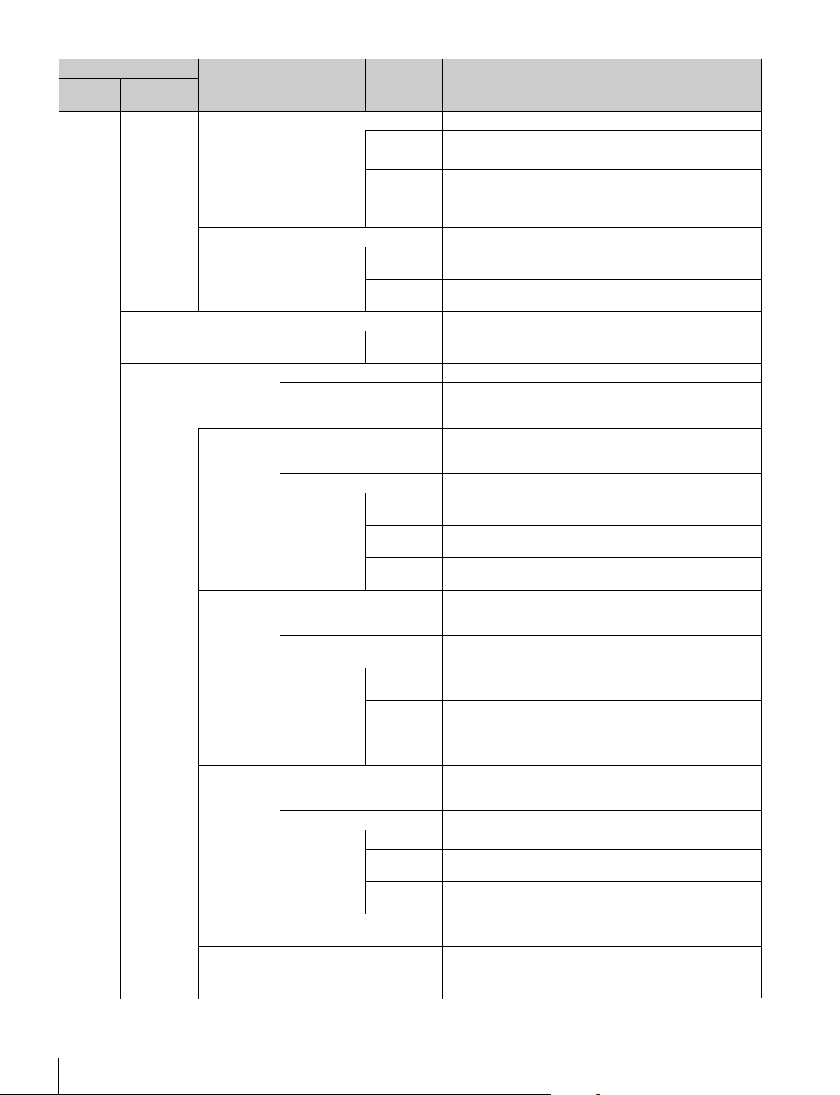
70
Menus
2/3 This is the second page of SD Detail adjustment.
H/V Ratio Adjusts the horizontal and vertical ratio of contour correction.
Frequency Adjusts the center frequency of contour correction.
Detail Comb Reduces cross color noise by applying the comb filter to contour
correction signals. Adjusting this in the plus direction reduces
cross color noise, but resolution sensitivity deteriorates. This
can only be used when an SD camera is connected.
3/3 This is the third page of SD Detail adjustment.
W Limiter This is the limiter correction for detail signals added in the white
direction.
B Limiter This is the limiter correction for detail signals added in the black
direction.
SD Gamma This is the gamma correction for down converter output.
SD M
Gamma
Adjusts SD gamma.
SD Matrix This is the linear matrix correction for down converter output.
OFF Disables the SD matrix function. This switch enables the
function to be turned ON/OFF simultaneously in accordance
with individual matrix settings.
User 1/2 Sets the SD matrix correction factor individually. This is the first
page of User Matrix. When User Matrix is enabled, the ON mark
appears on the very left of the tab.
ON Enables the User Matrix function.
R-G Corrects the signal of the R channel in accordance with the
difference between the signals of the R channel and G channel.
G-B Corrects the signal of the G channel in accordance with the
difference between the signals of the G channel and B channel.
B-R Corrects the signal of the B channel in accordance with the
difference between the signals of the B channel and R channel.
User 2/2 Sets the SD matrix correction factor individually. This is the
second page of User Matrix. When User Matrix is enabled, the
ON mark appears on the very left of the 1/2 tab.
ON Enables the User Matrix function. This is the same switch as
1/2.
R-B Corrects the signal of the R channel in accordance with the
difference between the signals of the R channel and B channel.
G-R Corrects the signal of the G channel in accordance with the
difference between the signals of the G channel and R channel.
B-G Corrects the signal of the B channel in accordance with the
difference between the signals of the B channel and G channel.
Multi If Multi Matrix which allows you to change the color reproduction
for each hue divided into 16 is enabled, the ON mark appears
on the very left of the tab.
ON Enables the SD Multi Matrix function.
Phase Selects the hue to adjust.
Hue Changes the hue of colors within the hue range selected with
Phase.
Saturation Changes the saturation of colors within the hue range selected
with Phase.
All Clear Returns the factors of all ranges of Multi Matrix to their initial
states.
Preset Selects the matrix provided in advance. When Preset Matrix is
enabled, the ON mark appears on the very left of the tab.
ON Enables SD Preset Matrix.
Maintenance menu
Submenu Switch Control item Description
Menu Secondary
menu
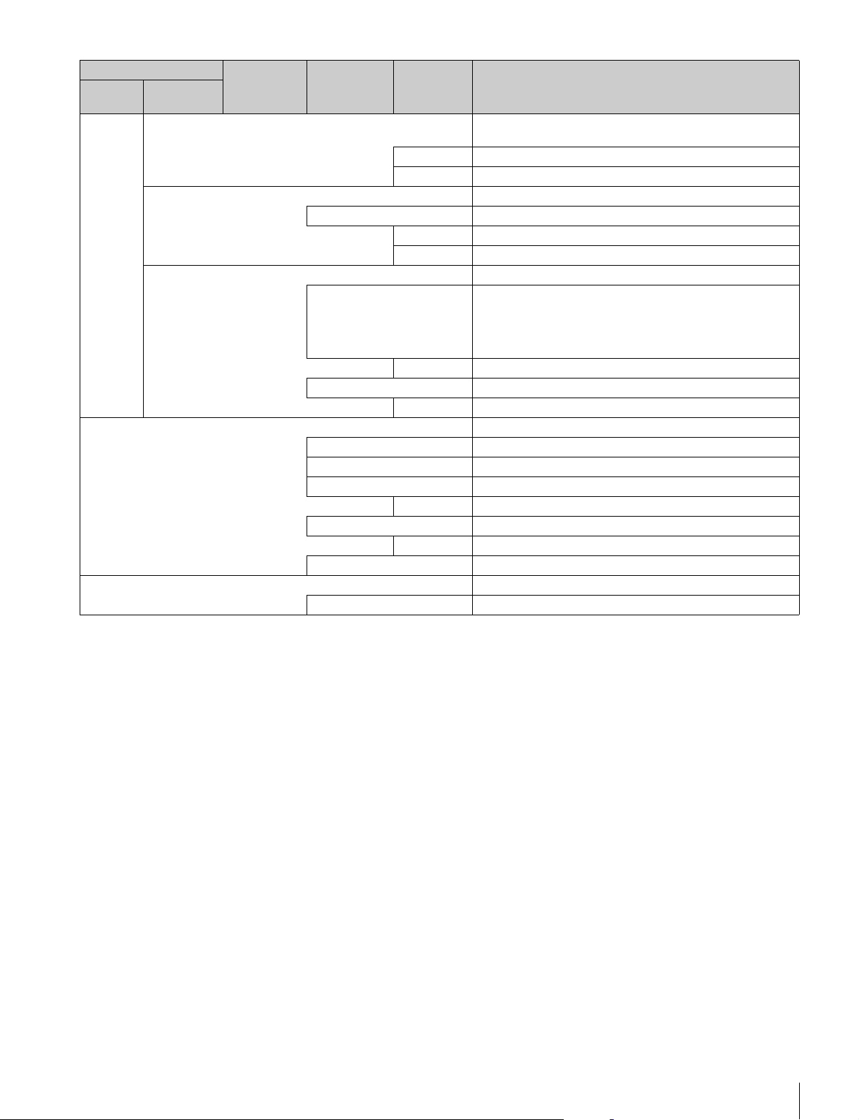
Menus
71
Interpolation Selects the filter for the down converter. Each of the frequency
characteristics differ.
H Selects the filter for the horizontal direction.
V Selects the filter for the vertical direction.
Cross Color Reduction Reduces the cross color of VBS output.
ON Disables the Cross Color Reduction function.
Coring Sets cross color elimination to not work for detail signals.
CC Reduction This is the level for cross color elimination.
Aspect Sets the aspect for the down converter.
SD Aspect Ratio 16:9 Squeeze: Outputs without converting the aspect. This is
for a 16:9 monitor.
Letter Box: Inserts a black band at the top and bottom and then
outputs. This is for a 4:3 monitor.
4:3 Crop: Crops to 4:3. This is for a 4:3 monitor.
Letter Box Sets the aspect of Letter Box.
Center Lock Crops the center part when cropping to 4:3.
Crop Position Sets the position for when cropping to 4:3.
RPN Corrects the RPN. This can only be set when in engineer mode.
R/G/B Select the channel to correct.
Enter Confirms settings.
H Cursor Outputs the H cursor.
H Cursor Confirms the H cursor position.
V Cursor Outputs the V cursor.
V Cursor Confirms the V cursor position.
H/V Cursor Outputs the H and V cursors.
Auto
Setup
This function is available when connecting F65.
APR Starts the APR function of the camera.
Maintenance menu
Submenu Switch Control item Description
Menu Secondary
menu
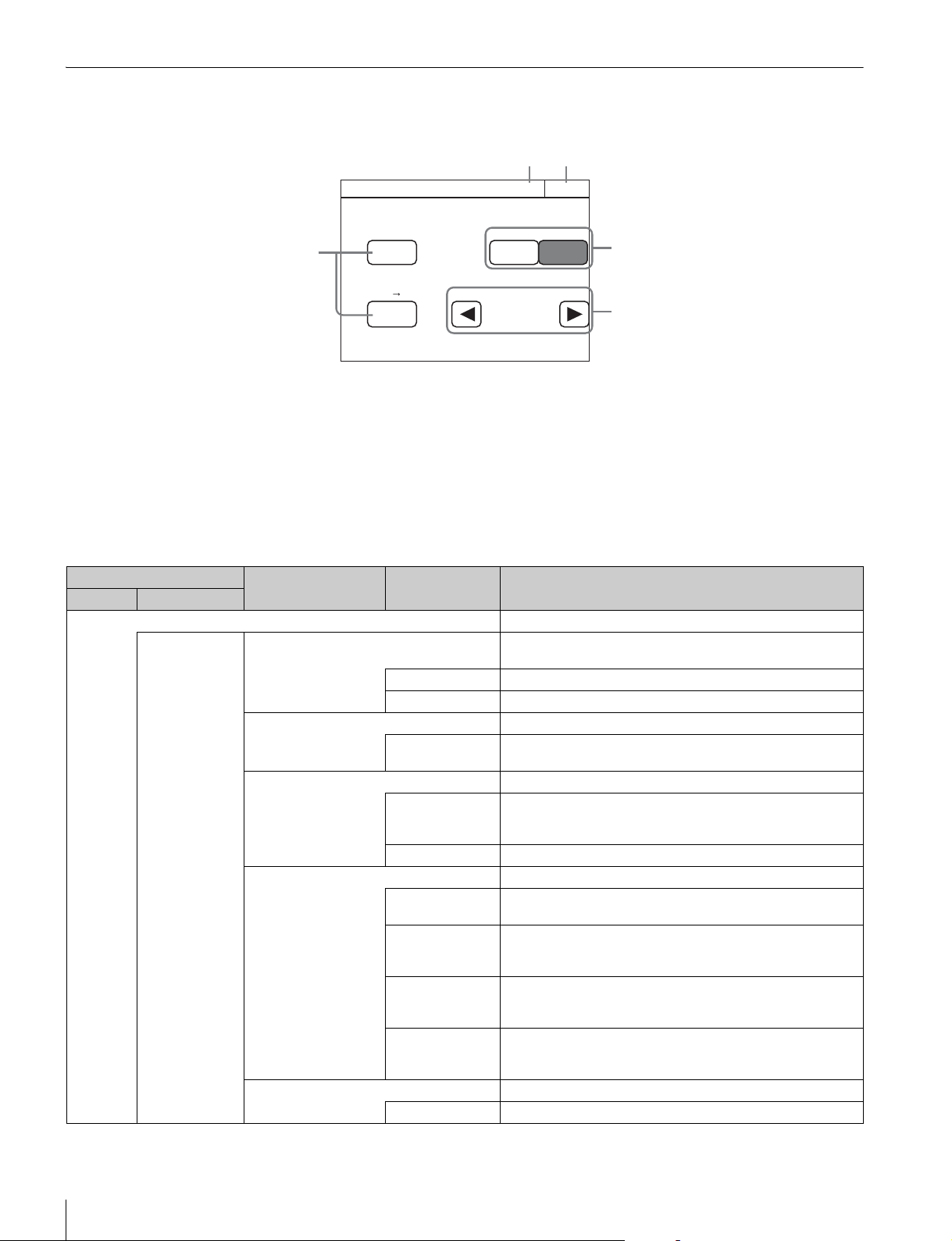
72
Menus
Config Menu
Screen display example (when “Mode” is selected after selecting “Camera” (Camera Config) in the Config menu)
a This indicates the page number/total number of pages.
When this indication is displayed, you can turn the SELECT
knob to change the page.
b Press this to return to the previous menu screen.
c Press this to light the button and turn ON each of the
functions.
d Press either of the buttons to select a mode.
e Press b/B to select a filter.
Menu items
Camera Mode
Exit3/3
White Gamma RGB
ON
16:9 4:3
Chroma Filter
Wide
Crop
Auto White Shading mode
RGB RB Only
4
5
3
1 2
Config Menu
Item Option Function
Menu Submenu
Camera Sets the camera.
Mode White Setup Mode Selects the white value for when an auto setup is performed or
an item is cleared.
AWB Restores the auto white balance value obtained last time.
Auto Level Restores the reference file value.
White Gamma RGB Selects the reference for white and gamma of the auto setup.
ON R, G, and B are independent when this is ON, and all of R, G,
and B use the G channel as the reference when this is OFF.
Auto White Shading Mode Sets the operation mode of auto white shading.
RGB Matches all of the R, G, and B channels so that they become
even. A white subject with uniform luminance and no color
shading must be used in this mode.
RB Only Matches the R and B channels to the G channel.
Camera FAN Mode Sets the operation mode of the camera fan.
Maximum Sets the number of revolutions of the camera fan to the
maximum number.
Auto1 Controls the number of revolutions of the fan in accordance with
the internal temperature of the camera. This is the optimal mode
for reducing any rise in the internal temperature.
Auto2 Controls the number of revolutions of the fan in accordance with
the internal temperature of the camera. This is the optimal mode
for reducing the operation sound of the fan.
Minimum Sets the number of revolutions of the camera fan to the minimum
number. However, if the internal temperature exceeds a
specified value, the number of revolutions are increased.
16:9 t 4:3 Crops a 16:9 picture to 4:3.
Crop Executes cropping when Crop is ON.
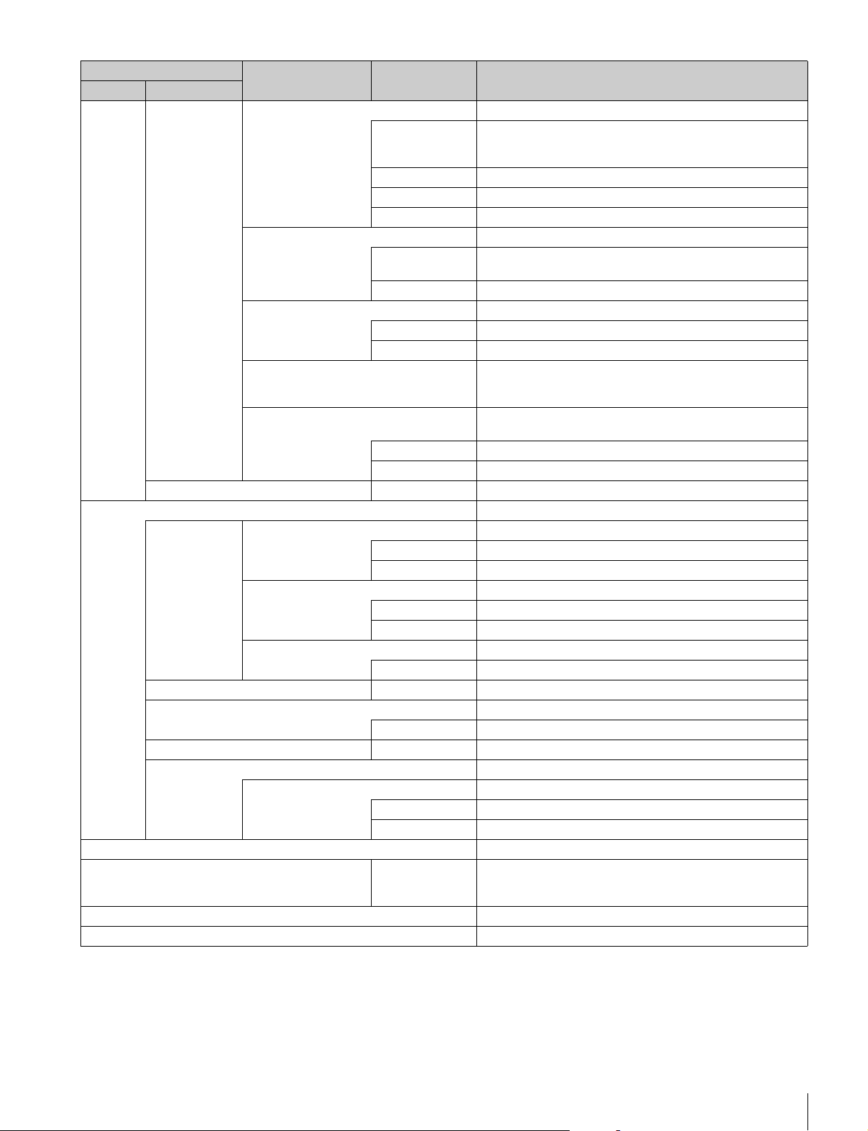
Menus
73
V Detail Creation Mode Select the generation method for V Detail.
RGB Nam Uses the V Detail generated from each of the R, G, and B
channels that has the largest amplitude. This increases
resolution sensitivity, but S/N sensitivity may deteriorate.
G Generates V Detail from the G channel.
R+G Generates V Detail from a signal combining R and G.
Y Generates V Detail from the luminance signal.
V Detail Control Mode Sets control for when the Detail H/V Ratio knob is turned.
H/V Moves H Detail and V Detail in the opposite direction in
response to movement of the knob.
V Only Adjusts V Detail only.
Test2 Mode Selects the signal of Test2.
3step Selects a convex test waveform.
10step Selects a step test waveform.
Chroma Filter Sets the band for the chroma component. Full is the same band
as the signal standard, and the band becomes narrower above
that.
720P Acquisition Selects the 720P generation mode. This can only be set when a
camera with a switching function is connected.
Super Sampling This is 720P using the super sampling system.
V-SOP This is 720P using the V-SOP system.
CAM Menu Control – See “To control the CAMERA/BPU menu” (page 78).
CCU Sets the CCU.
Mode GenLock Mode Selects the type of signal using synchronization.
HD This is the HD3 value SYNC.
SD This is BBS.
Bars Character Sets the characters to add to color bars signals.
On Add characters to color bars signals.
Edit Opens the character edit screen.
Chroma Turns OFF the VBS chroma signal.
Off Adds the chroma component to VBS.
Return Settings – See “To set the return input settings” (page 78).
Channel ID Sets the Channel ID display for direct output.
Channel ID ON Turns ON the Channel ID display for direct output.
CCU Menu Control – See “To control the CCU menu” (page 78).
HDFX Performs the HDFX200 settings.
IF Select Selects the cable connecting method.
Triax Triax cable connection
Fiber Fiber cable connection
RCP See “RCP menu items” below.
RCP Assignment Panel No. Selects the target cameras to be controlled by the control panel.
This can only be set when in MCS mode. In addition, all
connected devices must support the RCP assignment function.
Multi Format Sets the video format for each CCU output.
BPU Multi Format Sets the video format for each BPU output.
Config Menu
Item Option Function
Menu Submenu
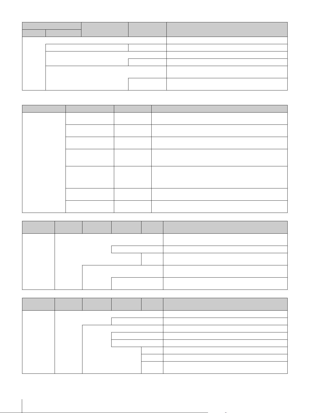
74
Menus
RCP menu items
3D System Sets the 3D System using the HDFA-200.
3D Mode 3D Mode Turns ON/OFF the 3D Mode.
Channel ID Sets the Channel ID display for direct output.
Channel ID ON Turns ON the Channel ID display for direct output.
3D CAM Control Sets the camera to be controlled from the control panel in 3D
System.
CAM Ctrl Sets the camera(s) to be controlled from the control panel: Left
Camera, Right Camera, or both.
Config Menu
Item Option Function
Menu Submenu
Menu Item Option Function
Customize – Menu Customize Changes the custom paint configuration. This can only be set when in
engineer mode.
– SW Customize Assigns functions to spare switches. This can only be set when in
engineer mode.
– Custom Menu SW Assigns functions to custom buttons. This can only be set when in
engineer mode.
– VR Customize
(RCP-1500/1501
only)
Assigns functions to spare adjustment knobs. This can only be set when
in engineer mode.
– Standard Ind Selects the standard state. The LED at the top of the corresponding
indication lights green in the standard state, and amber in the non-
standard state. It remains off when not even one standard state is
selected. This can only be set when in engineer mode.
– Status Customize Changes the status screen configuration. This can only be set when in
engineer mode.
– Detail VR (RCP-
1500/1501 only)
Changes the function assignment of the Detail knob. This can only be
set in engineer mode.
Menu Secondary
menu
Submenu Switch Control
item
Description
Customize Status Customize Changes the status screen configuration. This can only be set in
engineer mode.
Status Display OFF Turns OFF the status screen display.
Menu
Type
Selects the status screen type.
Knob Customize Sets the usable adjustment knob according to the status screen
type.
Knob1 - 4 Opens the menu which sets the function assignments of
adjustment knobs.
Menu Secondary
menu
Submenu Switch Control
item
Description
Display/Sound Sound Sets the volume and type.
OFF Sets no sound to be emitted from the speakers.
Call Sets the call sound.
Sound Test Confirms the set call sound.
CALL Sound Disables the call sound.
Volume Adjusts the volume of the call sound.
Sound Selects the type of the call sound.
Master Simultaneously sets the volume for all sounds emitted from the
speakers.
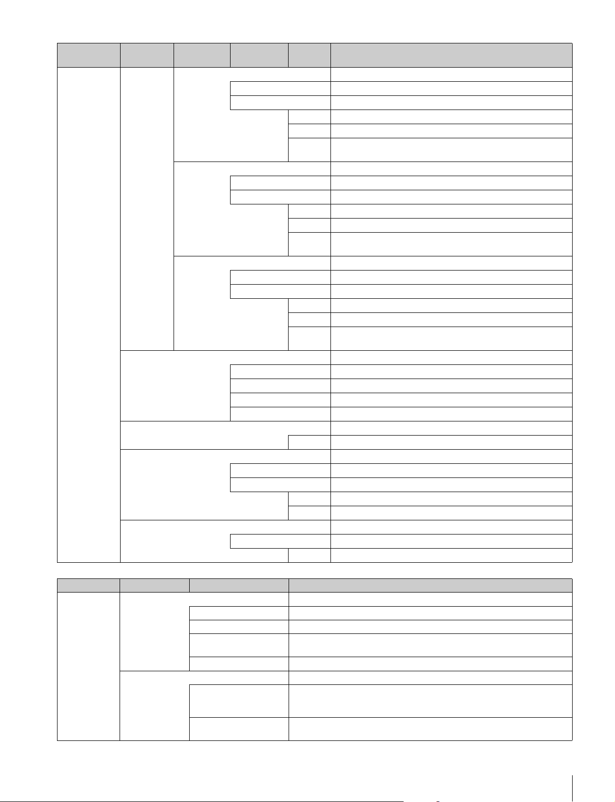
Menus
75
Touch Sets the operation sound for when a switch on the LCD is pressed.
Sound Test Confirms the set operation sound.
Touch Sound Disables the operation sound.
Volume Adjusts the volume of the operation sound.
Sound Selects the type of the operation sound.
Master Simultaneously sets the volume for all sounds emitted from the
speakers.
SW Sets the operation sound for when a switch button is pressed.
Sound Test Confirms the set operation sound.
Switch Sound Disables the operation sound.
Volume Adjusts the volume of the operation sound.
Sound Selects the type of the operation sound.
Master Simultaneously sets the volume for all sounds emitted from the
speakers.
RE Sets the operation sound for when an adjustment knob is turned.
Sound Test Confirms the set operation sound.
RE Sound Disables the operation sound.
Volume This is the volume of the operation sound.
Sound Selects the type of the operation sound.
Master Simultaneously sets the volume for all sounds emitted from the
speakers.
LED Sets the LED brightness.
Switch Sets the switch brightness.
Tally Sets the tally brightness.
Other Sets other LED settings.
Master Simultaneously sets the brightness of all items.
LCD Adjusts the LCD.
Bright Adjusts the brightness of the LCD.
EL Adjusts the backlight for illuminating the function names.
OFF Turns off the backlight.
Light Detect Turns off the backlight in response to the surrounding brightness.
Detect Sets the brightness for turning off the backlight.
Bright Adjusts the brightness of the backlight.
Touch Panel Sets the touch sensor of the LCD.
Touch Test Tests the response of the touch sensor.
Sense Sets the sensitivity of the touch sensor.
Menu Secondary
menu
Submenu Switch Control
item
Description
Menu Item Option Function
Mode Screen Saver Sets the screen saver to display on the LCD.
ON Enables the screen saver function.
Preview Displays a preview of the set screen saver.
Wait Time Sets the time from when the last operation was performed until when the
screen saver is displayed.
Type Selects the screen saver type.
PIX/WF Sets the operation for when PIX/WF output.
PIX/WF Syncro Links RGB selection in the menu and PIX/WF control for when Black Shading
and White Shading are adjusted (linked when ON). This can only be set when
in engineer mode.
PIX/WF Control Mode Sets the control mode of the monitor selection buttons. See “To set PIX/WF
operation” (page 42).
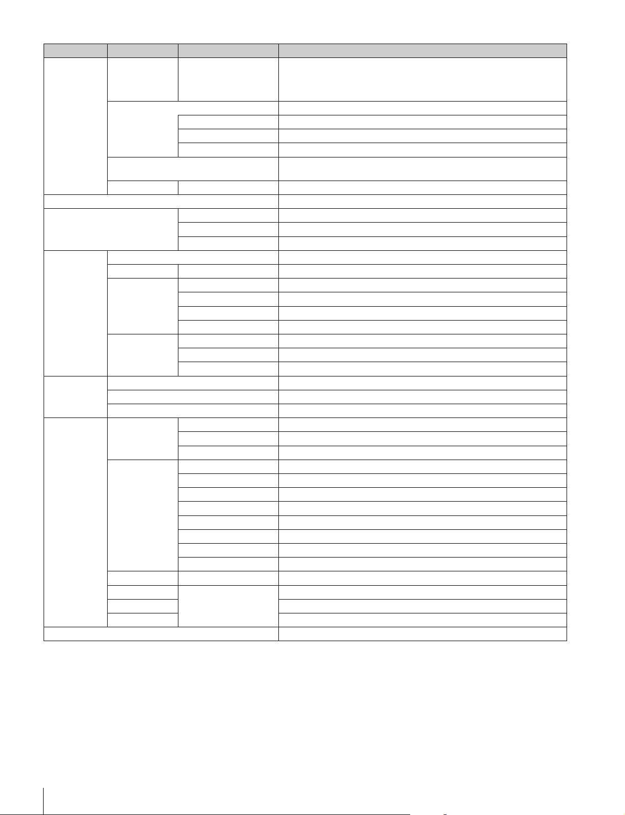
76
Menus
Matrix Gate Gate Interlock When this is turned ON, priority is given to the setting of the control panel for
the selection of Multi Matrix Gate when the control panel disables Panel Active
or PARA, even if another panel has a different channel selected. This can only
be set when in engineer mode.
Extend Call The TALLY indicator continues to flash for a while when a call is received.
ON Enables Extend Call.
Time Sets the flashing duration of the TALLY indicator.
Mode Sets the condition for enabling this function.
Preview Specifies the output destination for previews. This can only be set when in
engineer mode.
Panel Active IRIS/MB Active Mode Sets the IRIS/MB ACTIVE to enable the IRIS only.
VR Setting See “To change the sensitivity of the adjustment knobs” (page 37).
Date/Time Date Sets the date.
Time Sets the time.
Time Zone Sets the time zone.
Network Network Info Displays the network information.
CNS Legacy/Bridge/MCS Sets the CNS.
LAN I/F Negotiation Sets the negotiation operation.
LAN I/F OFF Turns OFF the LAN I/F.
Speed Sets the network line connection speed.
Duplex Sets the network line communication method.
TCP/IP IP Address Sets the IP address.
Subnet Mask Sets the subnet mask.
Default GW Sets the default gateway.
Information Version Displays the version information.
Network Info Displays the network information.
Option Info Shows the Option Software installation status.
Security Page Permission Full Lock Locks all menu screens.
View Mode Locks the menu screens. However, the menus can be viewed.
Full Paint Enables the menus such as Paint, Maintenance, and File.
Item Permission Ref File Enable Enables the operation of reference files.
Lens File Enable Enables the operation of lens files.
OHB File Enable Enables the operation of OHB files.
Crop Enable Enables the operation of crop.
Knee Max Enable Enables the operation of Knee Max.
3D Menu Enable Enables the 3D System settings.
Custom Matrix Enable Enables the operation of a Custom Preset Matrix file.
Auto Setup Enable Enables the operation of the Auto Setup menu.
Code Change Code No. Registers a security code.
Engineer Protect Code Enable Protects switching to engineer mode with a security code.
All Preset Restores all settings to their default states.
Engineer Mode Switches to engineer mode.
Option Key Enables Key code installation of the Option Software.
Menu Item Option Function
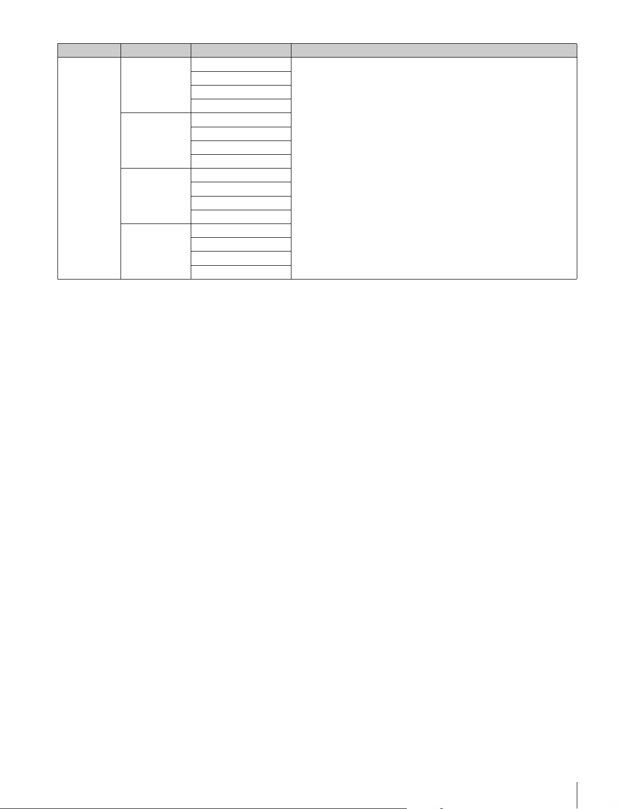
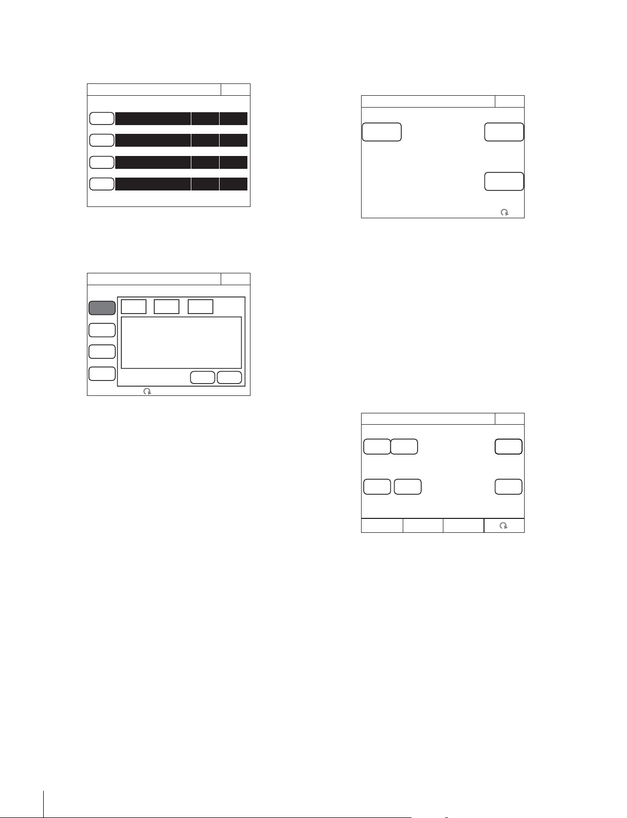
78
Menus
To set the return input settings
Select [Return Settings] in the CONFIG menu to set the
formats of return signals from the CCU.
Use the following procedure to set the settings.
1 Press any one of [Return-1] to [Return-4].
The screen for specifying the format of the return signal
appears.
2 Set the format of the return signal.
[Input]: Specifies the input signal.
[Aspect]: Specifies the aspect ratio. This can only be set
if you specified SD signal for
[Input].
[LB Mode]: Specify the display mode for letter box if you
specified [Letter Box] for
[Aspect].
The setting values that can be selected for each setting
value are displayed in a list. Turn the adjustment knob on
the very left to move the cursor to select a setting value.
3 Press [Enter].
The settings for the format of the return signal are
changed.
4 Repeat steps 1 to 3 if you also want to set the
remaining return signals.
To control the CCU menu
Select [CCU Menu Control] in the CONFIG menu to remotely
control the menu displayed for image output of the CCU from
this control panel.
•Use
[Menu Disp] to display or hide the CCU menu.
The setting menu appears when this button is pressed even
when CHARACTER display is enabled for image output of
the CCU. In such a case, closing the setting menu redisplays
the CHARACTER display.
•Press
[Enter] to switch to the setting mode and confirm
changing of the setting value.
•Press [Cancel] to end the setting mode and cancel
changing of the setting value.
• Turn the adjustment knob on the very right to move the
cursor in the CCU menu and change a setting value.
To control the CAMERA/BPU menu
When you select [CAM Menu Control] in the CONFIG menu,
you can control the menu obtained by the camera head or the
BPU from the unit displaying the image output of the CCU.
•Use
[CAM Menu Overlay] to display the camera/BPU
menu switching the CCU character display.
•Use
[BPU Select] to select whether to display the camera
menu or the BPU menu in the image output of the CCU
when the [CAM Menu Overlay] button is lit. When BPU is
not used, this button is disabled.
•Use [Display] to display or hide the camera/BPU operation
state.
•Use
[Menu] to display or hide the camera/BPU menu.
The
[Display] and [Menu] buttons are equivalent to the toggle
switch for the menu display in the camera head or the front
panel of the BPU.
To operate while displaying the camera/BPU menu
•Press
[Enter] to switch to the setting mode and confirm
changing of the setting value.
•Press [Cancel] to end the setting mode and cancel
changing of the setting value.
• Turn the adjustment knob on the very right to move the
cursor in the camera/BPU menu and change a setting value.
Exit
Return Settings
Input Aspect LB Mode
Return 1
1080/59.94i (PsF)
Return 2
NTSC Squeeze
Return 3
NTSC
Letter
Box
16:8
Return 4
1080/59.94i (PsF)
Exit
Return Settings
Return 1
Return 2
Return 3
Return 4
LB
Mode
CancelEnter
Input Aspect
Exit
EnterMenu Disp
CCU Menu Control
Cancel
CAM Menu Ctrl
Exit
Cancel
EnterMenu
Menu
Overlay
Dsiplay
BPU
Select
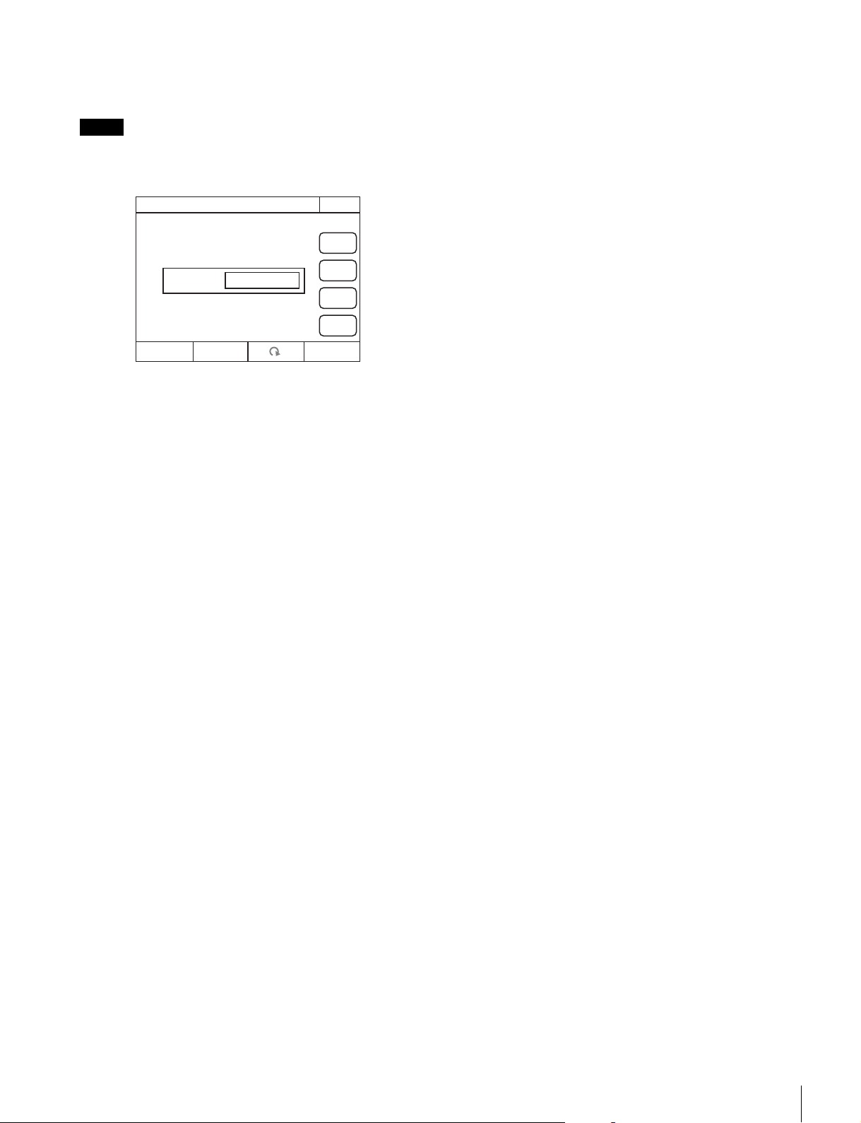
Menus
79
To change RCP assignments
Selecting [RCP Assignment] in the Config menu allows you
to change RCP assignments.
The following RCP assignment function is only available in
MCS mode. In addition, the function is not available when an
MSU-900/950 is set as the master.
1 Use the “Camera” knob (second knob from the right)
to select the camera number for which you want to
control.
If you select
[All Camera], all cameras will be displayed.
(When
[All Camera] is not selected, only devices with
established connections to the Master of the MCS mode
are displayed.)
2 To return all RCP assignments to their standard state,
press
[Reset].
3 Press [Set].
The setting changes are applied.
Note
RCP Assignment
Exit
Set
Reset
Cancel
All
Camera
Camera-01
Panel-01
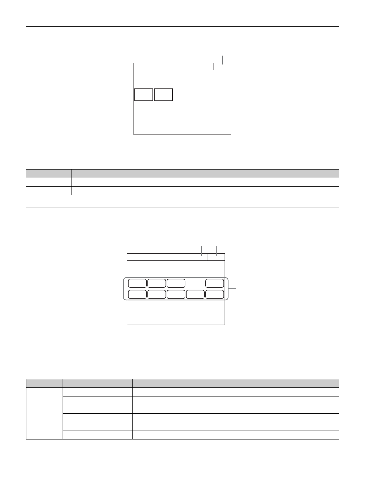
80
Menus
Multi Menu
a Press this to return to the previous menu screen.
Menu items
Function Menu
Screen display example (when PIX/WF is selected)
a This indicates the page number/total number of pages.
When this indication is displayed, you can turn the SELECT
knob to change the page.
b Press this to return to the previous menu screen.
c Press a button to light it and select the output signal or turn
ON the shutter.
Menu items
Multi
Exit
Master
Subordinate
1
Item Function
Master Sets this unit to master mode.
Subordinate Sets this unit to subordinate mode.
PIX
R
PIX
G
PIX
B
PIX/WF
Function
Exit2/2
PIX
ENC
WF
R
WF
G
WF
B
WF
SEQ
WF
ENC
3
12
Menu Item Function
Optical Level CAM Displays the optical communication reception level of the camera.
CCU Displays the optical communication reception level of the CCU.
Optical Level
(when
connecting the
separate
camera)
CCU t BPU Displays the optical communication reception level from CCU to BPU.
BPU t CCU Displays the optical communication reception level from BPU to CCU.
BPU t CAM Displays the optical communication reception level from BPU to the camera.
CAM t BPU Displays the optical communication reception level from the camera to BPU.
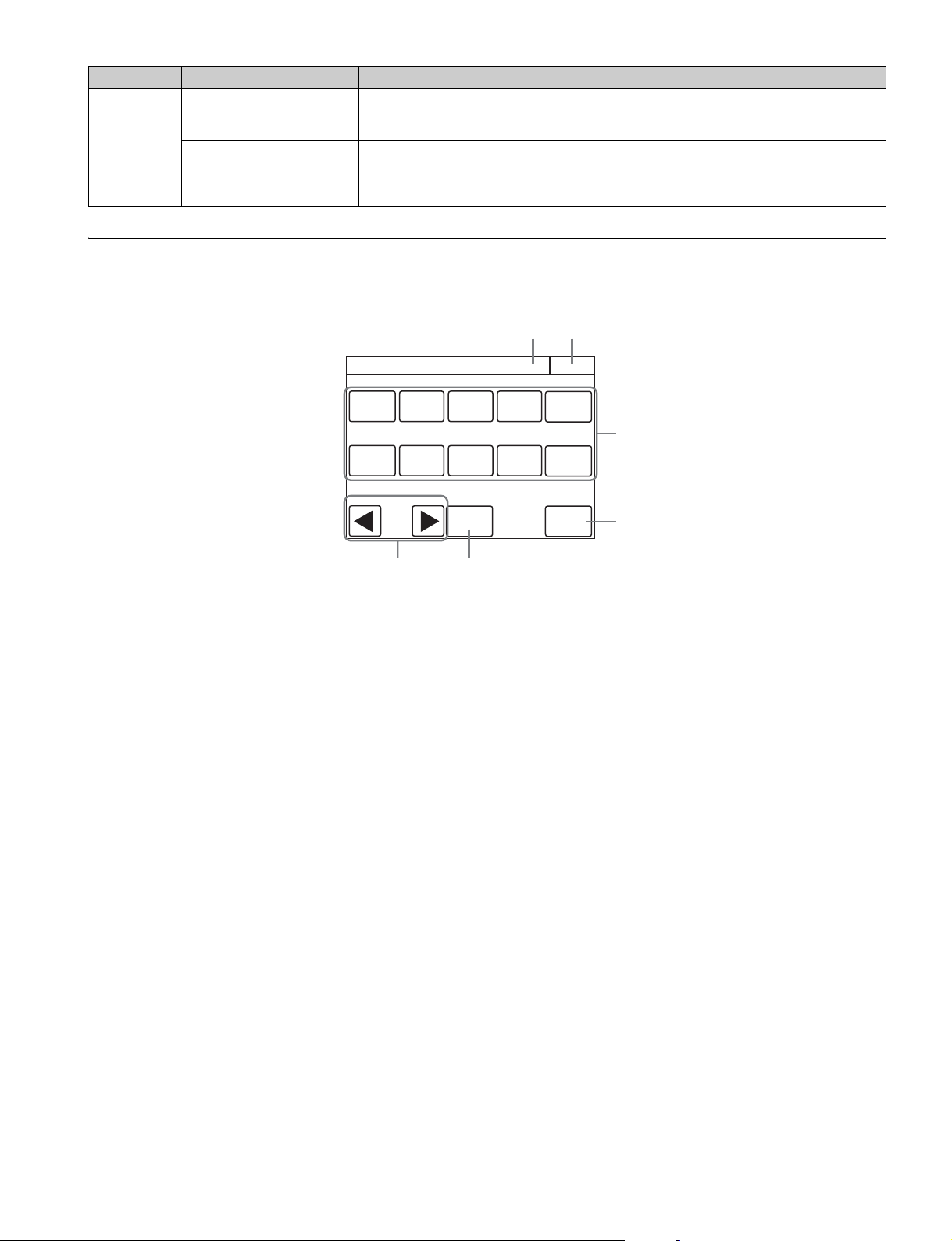
Menus
81
Scene Menu
Screen display example (when connected to the cameras of the 32 scene files)
a This indicates the page number/total number of pages.
When this indication is displayed, you can turn the SELECT
knob to change the page.
b Press this to return to the previous menu screen.
c Select and press the number of a scene file to access the
registered file. When you access a file, the number of the
accessed scene file lights.
If you press the same number, the state returns to that
before you accessed the file.
d Press
[Store] and then press the desired scene file
number to register the file. When file registration is finished,
[Store] turns off.
e When you press [Dissolve] to turn it on, the picture
changes gradually when the scene file is accessed. (When
off, the picture changes instantly.)
f Set the approximate time to change the picture while
[Dissolve] is on. (The larger the number the longer it takes
for the picture to change.)
PIX/WF PIX (R/G/B/ENC) Selects the OUTPUT signal of PIX of CCU.
R/G/B: Outputs one of the R, G, and B signals (or a combination of multiple signals).
ENC: Outputs an encoded signal.
WF (R/G/B/SEQ/ENC) Selects the OUTPUT output signal of WF of CCU.
R/G/B: Outputs one of the R, G, and B signals (or a combination of multiple signals).
SEQ: Monitors the waveforms of the three signals R, G, and B in sequential mode.
ENC: Outputs an encoded signal.
Menu Item Function
1
Scene
Exit1/6
2 3 4 5
6
7 8 9 10
Store
Dissolve
Dissolve Speed
1.0
3
4
12
6 5
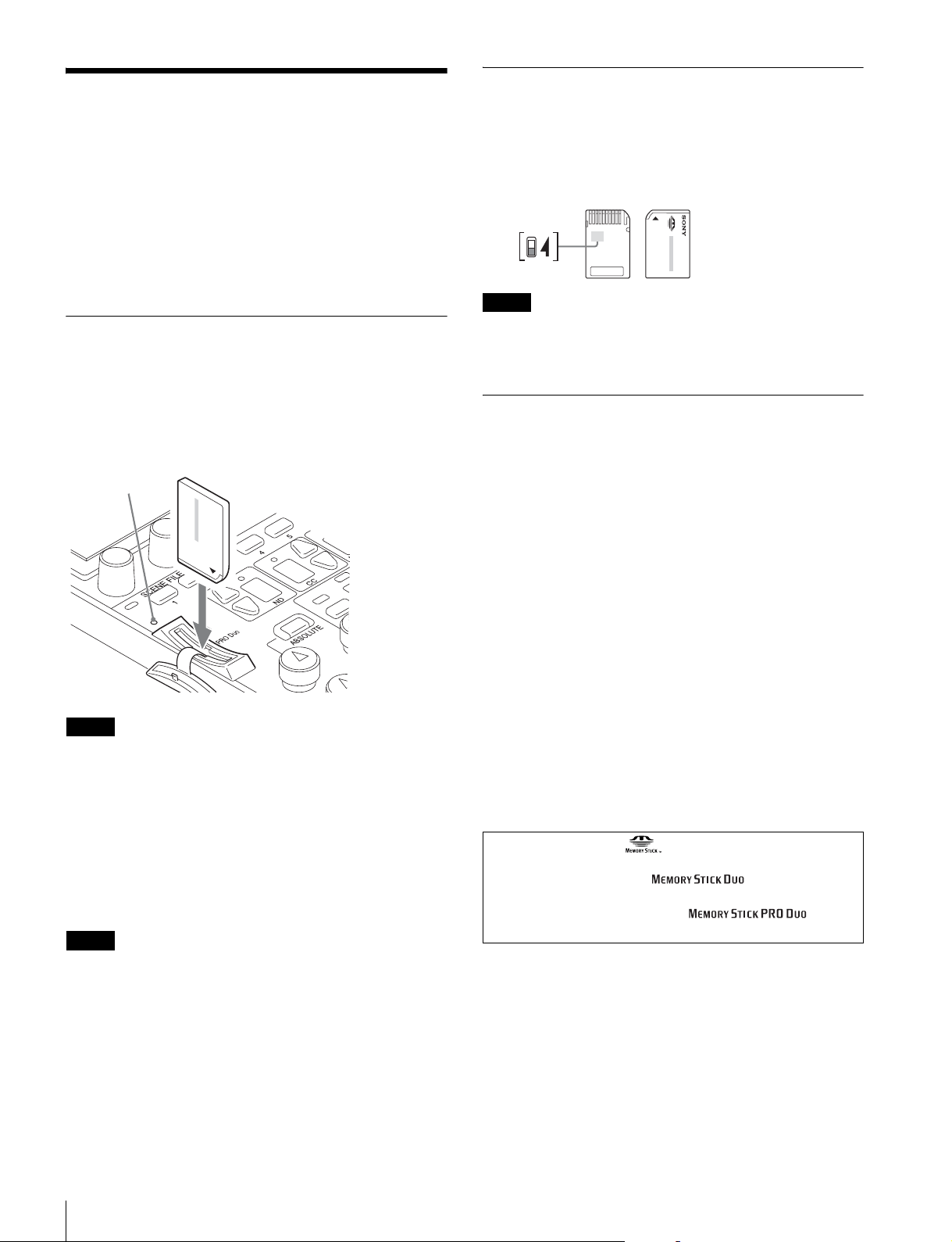
82
About “Memory Stick Duo”
About “Memory Stick
Duo”
You can use “Memory Stick Duo” and “Memory Stick PRO
Duo” media with this unit.
Unit operations have been checked using “Memory Stick Duo”
media up to 8 GB.
This unit is equipped with PrFILE for Memory Stick
manufactured by eSOL Co.,Ltd.
Inserting a “Memory Stick Duo”
Open the “Memory Stick Duo” slot cover, and insert the
“Memory Stick Duo” into the “Memory Stick Duo” slot as
shown, until it clicks into place and the access (status)
indicator lights red.
When the “Memory Stick Duo” is properly inserted, the
indicator changes from red to green.
Confirm the orientation of the “Memory Stick Duo” before
inserting it. If there is some resistance when you insert it or it
does not fit properly, the “Memory Stick Duo” may be turned
around or upside down. Do not force the “Memory Stick Duo”
into the slot. Confirm the sides and ends of the “Memory Stick
Duo” before inserting it again.
To remove a “Memory Stick Duo”
Confirm that the access indicator is not lit red, then lightly push
in the “Memory Stick Duo” to release the lock.
If the access indicator is lit red, data is being read from or
written to the “Memory Stick Duo.” In such cases, do not shake
the unit or subject it to shock. In addition, do not turn off the
power to the unit or remove the “Memory Stick Duo.” Doing so
may damage the data.
Protecting Saved Data
To prevent accidental erasure of important data, use the LOCK
switch on the “Memory Stick Duo.”
Slide the switch upward to the write protect position.
This ensures that you cannot inadvertently overwrite data on
the “Memory Stick Duo.”
If you are using a “Memory Stick Duo” that does not have a
LOCK switch, be careful not to inadvertently overwrite or erase
your data.
Precautions
• Do not attach anything other than the supplied label to the
“Memory Stick Duo” labeling position.
• Attach the label so that it does not stick out beyond the
labeling position.
• Carry and store the “Memory Stick Duo” in its case.
• Do not touch the connector of the “Memory Stick Duo” with
anything, including your finger or metallic objects.
• Do not strike, bend, or drop the “Memory Stick Duo.”
• Do not disassemble or modify the “Memory Stick Duo.”
• Do not allow the “Memory Stick Duo” to get wet.
• Do not use or store the “Memory Stick Duo” in a location that
is:
— Extremely hot, such as in a car parked in the sun
— Under direct sunlight
— Very humid or subject to corrosive substances
• To prevent data loss, make backups of data frequently. In no
event will Sony be liable for any loss of data.
• Unauthorized recording may be contrary to the provisions of
copyright law. When you use a “Memory Stick Duo” that has
been pre-recorded, be sure that the material has been
recorded in accordance with copyright and other applicable
laws.
Note
Note
Access indicator
Note
• “Memory Stick” and are trademarks of Sony
Corporation.
• “Memory Stick Duo” and are trademarks of
Sony Corporation.
• “Memory Stick PRO Duo” and are
trademarks of Sony Corporation.
Lock switch
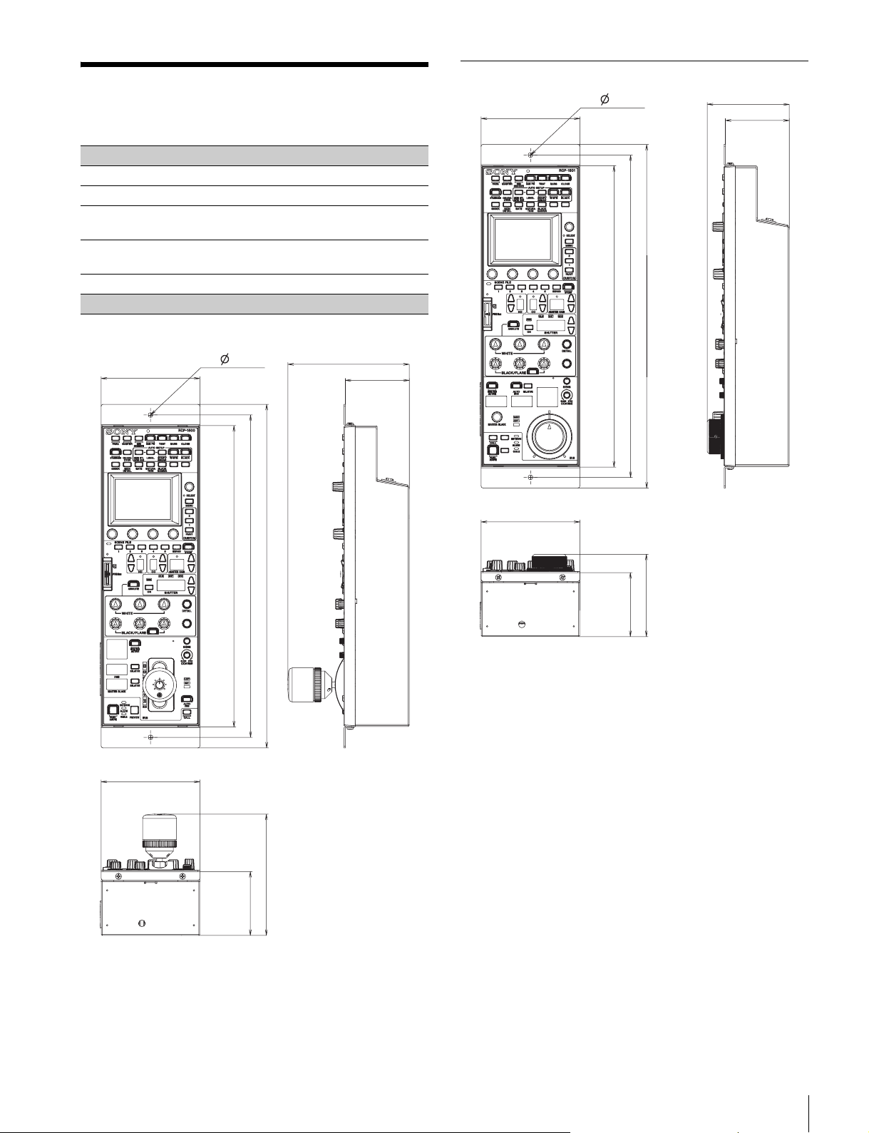
Specifications
83
Specifications
General
Power supply 10.5 V to 30 V DC
Power consumption 4 W
Operating
temperature
5 °C to 40 °C (41 °F to 104 °F)
Weight RCP-1500/1501: 1.8 kg (3 lb. 15 oz.)
RCP-1530: 1.6 kg (3 lb. 8 oz.)
External dimensions
Unit: mm (inches)
RCP-1500
67 (2
3
/
4
)
125 (5)
102 (4
1
/
8
)
355 (14)
67 (2
3
/
4
)
125 (5)
102 (4
1
/
8
)
332.2 (13
1
/
8
)
310 (12
1
/
4
)
2- 5 (
7
/
32
)
RCP-1501
67 (2
3
/4)
85 (3
3
/8)
102 (4
1
/8)
355 (14)
67 (2
3
/4)
85 (3
3
/8)
102 (4
1
/8)
332.2 (13
1
/8)
310 (12
1
/4)
2- 5 (
7
/32)
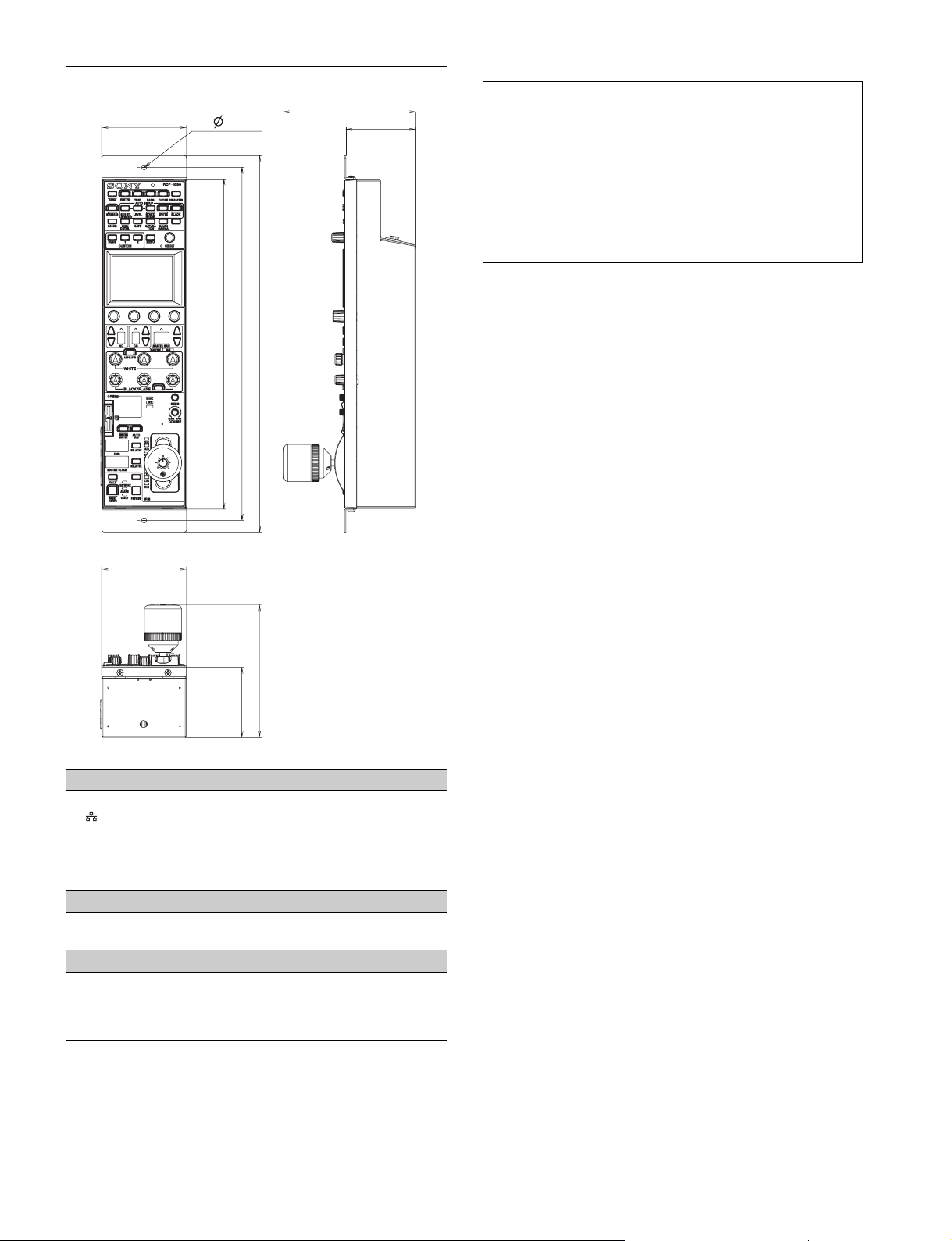
84
Specifications
Design and specifications are subject to change without
notice.
RCP-1530
Inputs/outputs
REMOTE
8-pin RJ-45 (1)
CCU/CNU 8-pin multi-connector, female (1)
AUX (RCP-1500/1501 only)
8-pin multi-connector, female (1)
EXT I/O 9-pin, female (1)
Supplied accessories
Operation guide (1)
Operation manual (CD-ROM) (1)
Optional accessories
External I/O connector JAE DE-9PF-N 1-568-182-11
CCA-5-3 remote cable (3 m)
CCA-5-10 remote cable (10 m)
CCA-5-30 remote cable (30 m)
67 (2
3
/4)
125 (5)
80 (3
1
/4)
355 (14)
67 (2
3
/4)
125 (5)
80 (3
1
/4)
332.2 (13
1
/8)
310 (12
1
/4)
2- 5 (
7
/32)
Note
Always verify that the unit is operating properly before use.
SONY WILL NOT BE LIABLE FOR DAMAGES OF ANY
KIND INCLUDING, BUT NOT LIMITED TO,
COMPENSATION OR REIMBURSEMENT ON ACCOUNT
OF THE LOSS OF PRESENT OR PROSPECTIVE
PROFITS DUE TO FAILURE OF THIS UNIT, EITHER
DURING THE WARRANTY PERIOD OR AFTER
EXPIRATION OF THE WARRANTY, OR FOR ANY OTHER
REASON WHATSOEVER.

The material contained in this manual consists of information
that is the property of Sony Corporation and is intended solely
for use by the purchasers of the equipment described in this
manual.
Sony Corporation expressly prohibits the duplication of any
portion of this manual or the use thereof for any purpose other
than the operation or maintenance of the equipment described
in this manual without the express written permission of Sony
Corporation.

Sony Corporation
RCP-1500 (SY)
RCP-1501 (SY)
RCP-1530 (SY)
4-169-285-07(1)
© 2010