OWNER'S MANUAL
612.7995383-115V
612.7995483-230V
612.7995183-GAS
Model Nos.
612.7995323-115V
612.7995423-230V
612.7995123-GAS
ASSEMBLY, INSTALLATION, AND
OPERATION INSTRUCTIONS
KENMORE
READ THIS BOOK! IT WILL TELL YOU HOW TO SAFELY ASSEMBLE AND INSTALL
YOUR COMPACT KITCHEN. IT WILL ALSO GIVE YOU HINTS ON HOW TO OBTAIN
THE MOST EFFICIENT OPERATION. RECORD IN SPACE PROVIDED BELOW THE
SERIAL NUMBER AND MODEL NUMBER OF THIS APPLIANCE. THEY ARE LOCATED
ON THE SERIAL PLATE ON THE TOE BASE.
SERIAL # MODEL #
FULL ONE YEAR WARRANTY
ON COMPACT KITCHEN
For one year from the date of purchase, we will repair
this COMPACT KITCHEN free of charge,
if defective in material or Workmanship.
FULL FIVE YEAR WARRANTY ON
SEALED REFRIGERATION SYSTEM
For five years from the date of purchase, we will repair the sealed system
(consisting of refrigerant, co.nnecting tubing and compressor motor)
free of charge, if defective in material or workmanship
Service under these warranties is available by simply contacting your nearest
Sears store or Service Center throughout the United States
SEARS, ROEBUCK AND CO.
_art No. 1300000 SEARS, ROEBUCK AND CO., U.S.A.
GENERAL INFORMATION
LOCAL CODES
The installation of the Compact Kitchen Unit must be
in accordance with these instructions and all local
plumbing and electrical codes and Underwriter's
Laboratories Requirements.
SAFETY
This unit is approved for a permanent electrical con-
nection. It is extremely important that the correct wire
size is being used and that the unit is properly ground-
ed. See Wiring Diagrams Fig. 7 and 8 and Note under
Step 1for the total power requirements. Name plate on
right side of base has the maximum power require-
ments also.
INSPECTION
Sears Compact Kitchen Units are carefully inspected
and cartoned to protect against shipping damage. If
there is damage or missing parts, the transportation
company agent should make a notation to that effect
on the bill. Send the bill to Sears, Roebuck and Co.
location from which the Company Kitchen Unit was
purchased with reference to the parts list in the "Repair
Parts Manual" and advise what parts are missing or
damaged. If available, give the invoice number on all
order bills. Following this procedure will enable Sears
to quickly ship the needed parts without further incon-
venience.
WATER PIPING INSTALLATION
The easiest method of connecting a faucet to water
supply pipes is the use of corrugated tubing designed
specifically for this procedure. However, in some areas
local plumbing codes may permit the use of copper
tubing. If so, the dimensions listed in Table 6 would be
appropriate for copper tubing. Compression fittings
and compression nuts would have to be purchased in
addition to the copper tubing. Shut off valves for cor-
rugated tubing are used with copper tubing. In some
areas, iron pipe is the only approved plumbing. Table 5
lists plumbing needed for iron pipe use. Table 6 lists
plumbing needed for corrugated tubing use.
ELECTRICAL INSTALLATION
The easiest method for electrical installation is the
use of armored cable. However, in some areas local
electrical codes do not permit the use of armored
cable. Some local electrical codes permit the use of
rigid conduit only. Table 2A lists the electrical supplies
needed involving armored cable or rigid conduit. Elec-
trical connections should be made by a licensed
electrician.
PREPARATION FOR INSTALLATION
Tools Needed
• 5/16 in. Nut Driver
• Hack Saw
• Screwdriver
• Pliers
• Adjustable Wrench
• Pipe Wrench - 8 in.
• Hammer
Purchased Parts Needed
• Plumbing: Refer to Table 2A and Table 5 or Table6
• Electrical: Refer to Table 2A
Parts Included With Unit
• Sink Faucet
• Basket Strainer
Unit Preparation
Remove side compartment panel by removing the two
hex head screws at the bottom of the panel and pulling
panel straight down. Test run refrigerator before per-
manent installation. An electrical outlet is located on
the left wall of the compartment. A three-wire power
cord is plugged into this outlet. Remove the plug and
attach to an extension cord. Plug the extension cord
into an electrical outlet. The compressor for the re-
frigerator will be turned on. Run the refrigerator for
1/2 hour. Check the freezer section. If the section is
cold, the refrigerator is operating properly.
INSTALLATION INSTRUCTIONS
This Compact Kitchen Unit has limited space on the
back wall for plumbing and electrical service access.
The plumbing (water supply and drain pipe) must
come out of the wall. The electrical junction box must
be located in the area specified in Figure 1 to avoid
interference when the unit is set in place. The proper
sequence of service connections is important to make
installation as trouble free as possible, as follows:
• Water Supply Connections
• Drain Pipe Connection
• Electrical Connection
STEP 1: Pre-lnstallation Procedure--Location Of
Plumbing and Electrical Supply On Wall.
A. Mark locations for the water supply pipes (hot &
cold), drain pipe and electrical junction box on the wall
as per dimensions in Figure 1.
IMPORTANT:
These plumbing and electrical connections must be in
the specified area illustrated in Figure 1 to avoid in-
terference when setting the unit in place.
B. Plumbing Installation: The water supply lines and
drain pipe extend beyond the back wall as per dimen-
sions in Figure 2A.
IMPORTANT:
The plumbing dimensions are critical in assuring
proper alignment with the faucet and sink drain con-
nections when the unit is set in place.
• Connect 3/8 in. angle valves to water supply lines.
The type of valve connections depend upon the type
of plumbing (iron pipe or tubing).
• Connect 90 Degree elbow to the drain pipe. Do not
connect J-Bend or tube tail at this time.
C. Electrical Service: Locate electrical junction box on
wall as per dimensions in Figure 1 in order to clear the
refrigerator coils over the compressor at the rear of the
unit.
• Punch out plug on wall junction box as shown in
Figure 2B.
• Attach electrical supply line as per Figure 2A for
armored cable or Figure 2B fo conduit.
NOTE:
Models 995383/995323 have maximum power input of
1800 watts. 115 volt. 60 Hz, 20 amp. protected branch
circuit is needed.
Models 995483/995423 have maximum power input of
2650 watts. 115/230 volt. 60 Hz, 20 amp. protected
branch circuit is needed.
Use No. 12 AWG insulated wire for both power require-
ments.
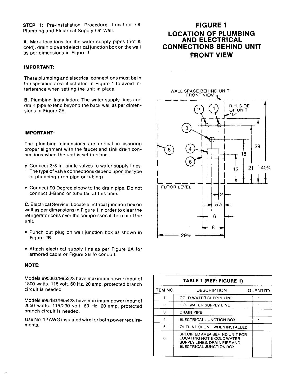
FIGURE 1
LOCATION OF PLUMBING
AND ELECTRICAL
CONNECTIONS BEHIND UNIT
FRONT VIEW
WALL SPACE BEHIND UNIT
FRONT VI
I
I
I
I
I
I
FLOOR LEVEL
•.=_ 291/2
0
I
J
ITEM NO. QUANTITY
1 1
2 1
3 1
4 1
5 1
TABLE 1 (REF: FIGURE 1)
DESCRIPTION
COLD WATER SUPPLY LINE
HOT WATER SUPPLY LINE
DRAIN PIPE
ELECTRICAL JUNCTION BOX
OUTLINE OF UNITWHEN INSTALLED
SPECIFIED AREA BEHIND UNIT FOR
LOCATING HOT & COLD WATER
SUPPLY LINES, DRAIN PIPE AND
ELECTRICAL JUNCTION BOX
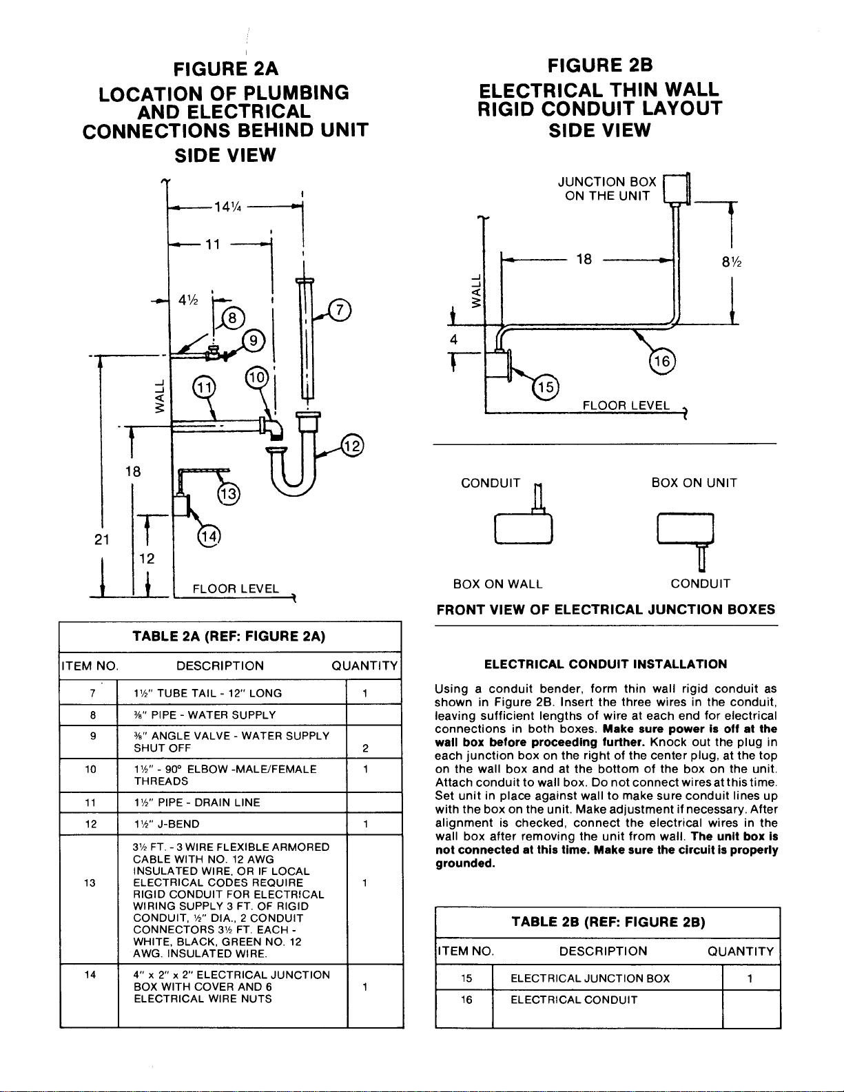
FIGURE 2A
LOCATION OF PLUMBING
AND ELECTRICAL
CONNECTIONS BEHIND UNIT
SIDE VIEW
..j,.
..J
.J
<c
21
._---- 141/4
FLOOR LEVEL
FIGURE 2B
ELECTRICAL THIN WALL
RIGID CONDUIT LAYOUT
SIDE VIEW
<
<
JUNCTION BOX
ON THE UNIT
18
FLOOR LEVEL
CONDUIT N BOX ON UNIT
I ]
BOX ON WALL CONDUIT
FRONT VIEW OF ELECTRICAL JUNCTION BOXES
TABLE 2A (REF: FIGURE 2A)
ITEM NO. DESCRIPTION QUANTITY
7 11/2'' TUBE TAIL - 12" LONG 1
8 %" PIPE - WATER SUPPLY
9 %" ANGLE VALVE - WATER SUPPLY
SHUT OFF 2
10 11/2"- 90° ELBOW -MALE/FEMALE 1
THREADS
11 11/2'' PIPE- DRAIN LINE
12 11/2'' J-BEND 1
13
14
31/2 FT. - 3 WIRE FLEXIBLE ARMORED
CABLE WITH NO. 12 AWG
INSULATED WIRE. OR IF LOCAL
ELECTRICAL CODES REQUIRE
RIGID CONDUIT FOR ELECTRICAL
WIRING SUPPLY 3 FT. OF RIGID
CONDUIT, 1/_,, DIA., 2 CONDUIT
CONNECTORS 31/2 FT. EACH -
WHITE, BLACK, GREEN NO. 12
AWG. INSULATED WIRE.
4" x 2" x 2" ELECTRICAL JUNCTION
BOX WITH COVER AND 6
ELECTRICAL WIRE NUTS
ELECTRICAL CONDUIT INSTALLATION
Using a conduit bender, form thin wall rigid conduit as
shown in Figure 2B. Insert the three wires in the conduit,
leaving sufficient lengths of wire at each end for electrical
connections in both boxes. Make sure power is off at the
wall box before proceeding further. Knock out the plug in
each junction box on the right of the center plug, at the top
on the wall box and at the bottom of the box on the unit.
Attach conduit to wall box. Do not connect wires at this time.
Set unit in place against wall to make sure conduit lines up
with the box on the unit. Make adjustment if necessary. After
alignment is checked, connect the electrical wires in the
wall box after removing the unit from wall. The unit box is
not connected at this time. Make sure the circuit is properly
grounded.
TABLE 2B (REF: FIGURE 2B)
ITEM NO. DESCRIPTION QUANTITY
15 ELECTRICAL JUNCTION BOX 1
16 ELECTRICAL CONDUIT
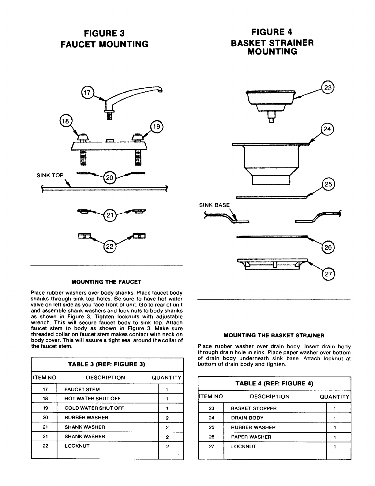
FIGURE 3
FAUCET MOUNTING
FIGURE 4
BASKET STRAINER
MOUNTING
SINK TOP
\ ,,
MOUNTING THE FAUCET
Place rubber washers over body shanks. Place faucet body
shanks through sink top holes. Be sure to have hot water
valve on left side as you face front of unit. Go to rear of unit
and assemble shank washers and lock nuts to body shanks
as shown in Figure 3. Tighten Iocknuts with adjustable
wrench. This will secure faucet body to sink top. Attach
faucet stem to body as shown in Figure 3. Make sure
threaded collar on faucet stem makes contact with neck on
body cover. This will assure a tight seal around the collar of
the faucet stem.
TABLE 3 (REF: FIGURE 3)
ITEM NO. DESCRIPTION QUANTITY
17 FAUCET STEM 1
18 HOT WATER SHUT OFF 1
19 COLD WATER SHUT OFF 1
20 RUBBER WASHER 2
21 SHANK WASHER 2
21 SHANK WASHER 2
22 LOCKNUT 2
i
! i ,
| i
SINK BASE
MOUNTING THE BASKET STRAINER
Place rubber washer over drain body. Insert drain body
through drain hole in sink. Place paper washer over bottom
of drain body underneath sink base. Attach Iocknut at
bottom of drain body and tighten.
TABLE 4 (REF: FIGURE 4)
ITEM NO. DESCRIPTION QUANTITY
23 BASKET STOPPER 1
24 DRAIN BODY 1
25 RUBBER WASHER 1
26 PAPER WASHER 1
27 LOCKNUT 1
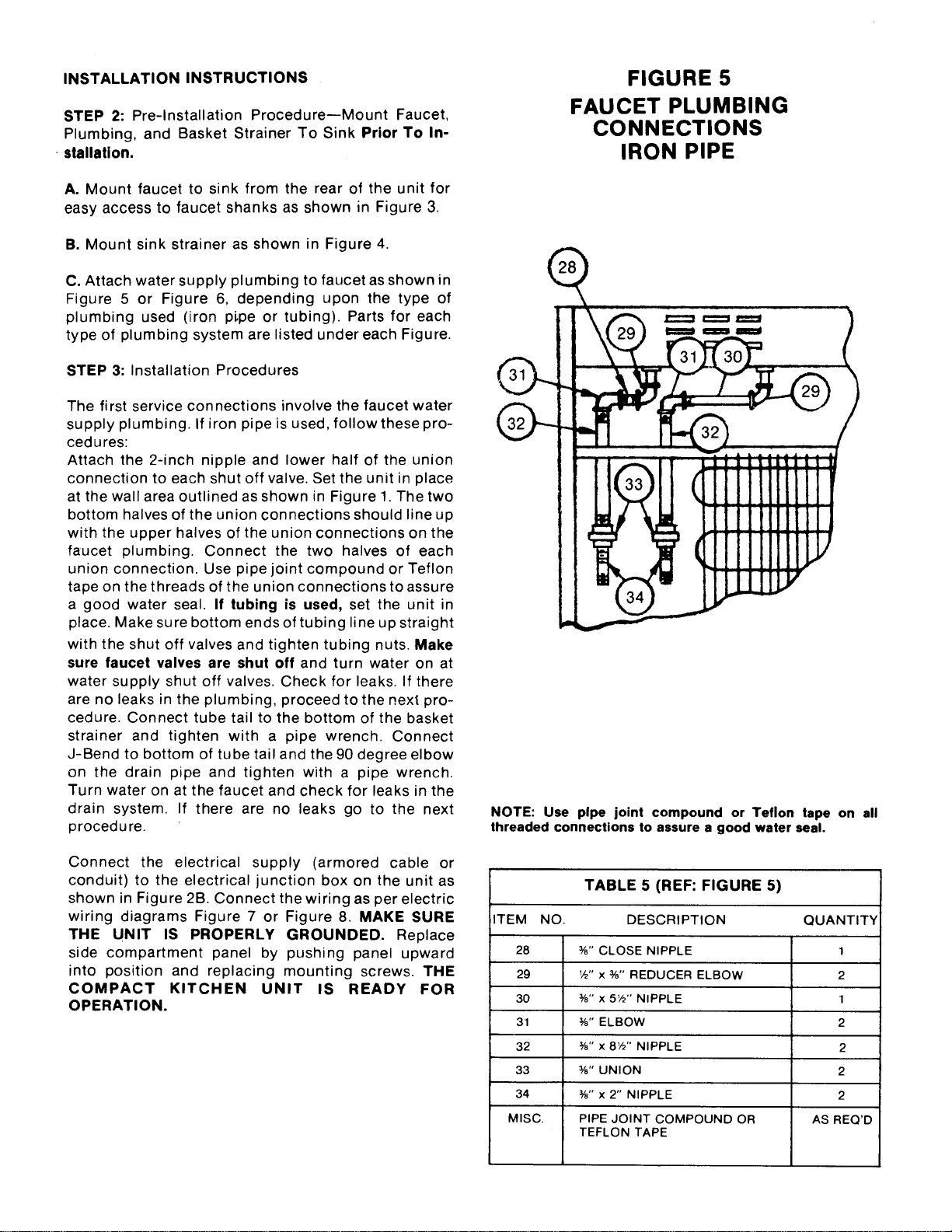
INSTALLATION INSTRUCTIONS
STEP 2: Pre-lnstallation Procedure--Mount Faucet,
Plumbing, and Basket Strainer To Sink Prior To In-
. stallation.
A. Mount faucet to sink from the rear of the unit for
easy access to faucet shanks as shown in Figure 3.
B. Mount sink strainer as shown in Figure 4.
C. Attach water supply plumbing to faucet as shown in
Figure 5 or Figure 6, depending upon the type of
plumbing used (iron pLpe or tubing). Parts for each
type of plumbing system are listed under each Figure.
STEP 3: Installation Procedures
The first service connections involve the faucet water
supply plumbing. If iron pipe is used, follow these pro-
cedures:
Attach the 2-inch nipple and lower half of the union
connection to each shut off valve. Set the unit in place
at the wall area outlined as shown in Figure 1. The two
bottom halves of the union connections should line up
with the upper halves of the union connections on the
faucet plumbing. Connect the two halves of each
union connection. Use pipe joint compound or Teflon
tape on the threads of the union connections to assure
a good water seal. If tubing is used, set the unit in
place. Make sure bottom ends of tubing line up straight
with the shut off valves and tighten tubing nuts. Make
sure faucet valves are shut off and turn water on at
water supply shut off valves. Check for leaks. If there
are no leaks in the plumbing, proceed to the next pro-
cedure. Connect tube tail to the bottom of the basket
strainer and tighten with a pipe wrench. Connect
J-Bend to bottom of tube tail and the 90 degree elbow
on the drain pipe and tighten with a pipe wrench.
Turn water on at the faucet and check for leaks in the
drain system. If there are no leaks go to the next
proced u re.
Connect the electrical supply (armored cable or
conduit) to the electrical junction box on the unit as
shown in Figure 2B. Connect the wiring as per electric
wiring diagrams Figure 7 or Figure 8. MAKE SURE
THE UNIT IS PROPERLY GROUNDED. Replace
side compartment panel by pushing panel upward
into position and replacing mounting screws. THE
COMPACT KITCHEN UNIT IS READY FOR
OPERATION.
FIGURE 5
FAUCET PLUMBING
CONNECTIONS
IRON PIPE
®
G
NOTE: Use pipe joint compound or Teflon tape on all
threaded connections to assure a good water seal.
ITEM
28
29
3O
31
32
33
34
MISC.
NO.
TABLE 5 (REF: FIGURE 5)
DESCRIPTION
¾" CLOSE NIPPLE
W' x ¾" REDUCER ELBOW
¾" x 5W' NIPPLE
¾" ELBOW
¾" x 8W' NIPPLE
%" UNION
¾" x 2" NIPPLE
PIPE JOINT COMPOUND OR
TEFLON TAPE
QUANTITY
1
2
1
2
2
2
2
AS REQ'D
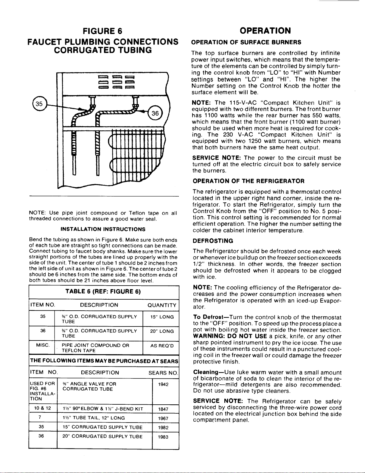
FIGURE 6
FAUCET PLUMBING CONNECTIONS
CORRUGATED TUBING
NOTE: Use pipe joint compound or Teflon tape on all
threaded connections to assure a good water seal.
INSTALLATION INSTRUCTIONS
Bend the tubing as shown in Figure 6: Make sure both ends
of each tube are straight so tight connections can be made.
Connect tubing to faucet body shanks. Make sure the lower
straight portions of the tubes are lined up properly with the
side of the unit. The center of tube I should be2 inches from
the left side of unit as shown in Figure6. Thecenteroftube2
should be 6 inches from the same side. The bottom ends of
both tubes should be 21 inches above floor level.
TABLE 6 (REF: FIGURE 6)
ITEM NO. DESCRIPTION QUANTITY
35
36
MISC.
THE FOLLOWING
ITEM NO.
%" O.D. CORRUGATED SUPPLY
TUBE
¾" O.D. CORRUGATED SUPPLY
TUBE
PIPE JOINT COMPOUND OR
TEFLON TAPE
15" LONG
20" LONG
AS REQ'D
ITEMS MAY BE PURCHASED AT SEARS
DESCRIPTION SEARS NO.
USED FOR %" ANGLE VALVE FOR 1942
FIG. #6 CORRUGATED TUBE
INSTALLA-
TION
10 & 12 11/:_'' 90°ELBOW & 11/2'' J-BEND KIT 1847
7 11/2'' TUBE TAIL, 12" LONG 1967
35 15" CORRUGATED SUPPLY TUBE 1982
36 20" CORRUGATED SUPPLY TUBE 1983
OPERATION
OPERATION OF SURFACE BURNERS
The top surface burners are controlled by infinite
power input switches, which means that the tempera-
ture of the elements can be controlled by simply turn-
ing the control knob from "LO" to "HI" with Number
settings between "LO" and "HI". The higher the
Number setting on the Control Knob the hotter the
surface element will be.
NOTE: The 115-V-AC "Compact Kitchen Unit" is
equipped with two different burners. The front burner
has 1100 watts while the rear burner has 550 watts,
which means that the front burner (1100 wat_ burner)
should be used when more heat is required for cook-
ing. The 230 V-AC "Compact Kitchen Unit" is
equipped with two 1250 watt burners, which means
that both burners have the same heat output.
SERVICE NOTE: The power to the circuit must be
turned off at the electric circuit box to safely service
the burners.
OPERATION OF THE REFRIGERATOR
The refrigerator is equipped with a thermostat control
located in the upper right hand corner, inside the re-
frigerator. To start the Refrigerator, simply turn the
Control Knob from the "OFF" position to No. 5 posi-
tion. This control setting is recommended for normal
efficient operation. The higher the number setting the
colder the cabinet interior temperature.
DEFROSTING
The Refrigerator should be defrosted once each week
or whenever ice buildup on the freezer section exceeds
1/2" thickness. In other words, the freezer section
should be defrosted when it appears to be clogged
with ice.
NOTE: The cooling efficiency of the Refrigerator de-
creases and the power consumption increases when
the Refrigerator is operated with an iced-up Evapor-
ator.
To Defrost--Turn the control knob of the thermostat
to the "OFF" position. To speed up the process place a
pot with boiling hot water inside the freezer section.
WARNING: DO NOT USE a pick, knife, or any other
sharp pointed instrument to pry the ice loose. The use
of these instruments could result in a punctured cool-
ing coil in the freezer wall or could damage the freezer
protective finish.
Cleaning--Use luke warm water with a small amount
of bicarbonate of soda to clean the interior of the re-
frigerator-mild detergents are also recommended.
Do not use abrasive type cleaners.
SERVICE NOTE: The Refrigerator can be safely
serviced by disconnecting the three-wire power cord
located on the electrical junction box behind the side
compartment panel.
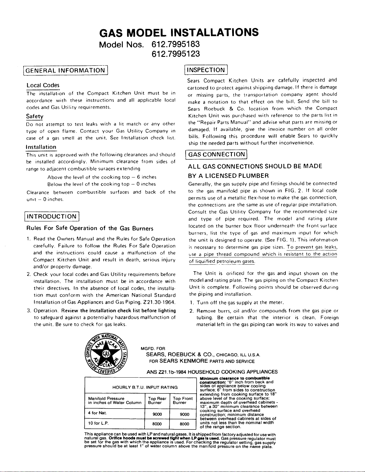
GAS MODEL INSTALLATIONS
Model Nos. 612.7995183
612.7995123
GENERAL INFORMATION ]
Local Codes
The installation of the Compact Kitchen Unit must be in
accordance with these instructions and all applicable Ioca!
codes and Gas Utility requirements.
Safety
Do not attempt to test leaks with a lit match or any other
type of open flame. Contact your Gas Utility Company in
case of a gas smell at the unit. See Installation check list.
Installation
This unit is approved with the following clearances and should
be installed accordingly. Minimum clearance from sides of
range to adjacent combustible suraces extending
Above the level of the cooking top - 6 inches
Below the level of the cooking top - 0 inches
Clearance between combustible surfaces and back of the
un,t - 0 inches.
INTRODUCTION I
Rules For Safe Operation of the Gas Burners
1. Read the Owners Manual and the Rules for Safe Operation
carefully. Failure to follow the Rules For Safe Operation
and the instructions could cause a malfunction of the
Compact Kitchen Unit and result in death, serious injury
and/or property damage.
2. Check your local codes and Gas Utility requirements before
installation. The installation must be in accordance with
their directives. In the absence of local codes, the installa-
tion must conform with the American National Standard
Installation of Gas Appliances and Gas Piping. Z21.30-1964.
3. Operation. Review the installation check list before lighting
to safeguard against a potentially hazardous malfunction of
the unit. Be sure to check for gas leaks.
INSPECTION ]
Sears Compact Kitchen Units are cafefully inspected and
cartoned to protect against shipping damage. If there is damage
or missing parts, the transportation company agent should
make a notation to that effect on the bill. Send the bill to
Sears Roebuck & Co. location from which the Compact
Kitchen Unit was purchased with reference to the parts list in
the "Repair Parts Manual" and advise what parts are missing or
damaged. If available, give the invoice number on all order
bills. Following this procedure will enable Sears to quickly
ship the needed parts without further inconvenience.
co CT.O Ss.ou.o
BY A LICENSED PLUMBER
Generally, the gas supply pipe and fittings should be connected
to the gas manifold pipe as shown in FIG. 2. If local code
permits use of a metallic flex-hose to make the gas connection,
the connections are the same as use of regular pipe installation.
Consult the Gas Utility Company for the recommended size
and type of pipe required. The model and rating plate
located on the burner box floor underneath the front surface
burners, list the type o{ gas and maximum input for which
the unit is designed to operate. (See FIG. 1). This information
is necessary to determine gas pipe sizes. To prevent gas leaks,
bse a pipe thread compound which is resistant to the action
of liquified petroleum gases.
The Unit is orificed for the gas and input shown on the
model and rating plate. The gas piping on the Compact Kitchen
Unit is complete. Following points should be observed during
the I_iping and installation.
1. Turn off the gas supply at the meter.
2. Remove burrs, oil and/or compounds from the gas pipe or
tubing. Be certain that the interior is clean. Foreign
material left in the gas piping can work its way to valves and
HOURLY B.T.U. INPUT RATING
Manifold Pressure Top Rear Top Front
in inches of Water Column Burner Burner
4 for Nat. 9000 9000
10for LP. 8000 8000
MGFD. FOR
SEARS, ROEBUCK & CO., CHICAGO, ILL U.S.A.
FOR SEARS KENMORE PARTS AND SERVICE
ANS Z21 .lb-1984 HOUSEHOLD COOKING APPLIANCES
Minimum clearance to combustible
conatrucUon: "0" inch from back and
sides of appliance below cooling
surface; 6" from sidesto construction
extending from cooking surface to 18"
above level of the cooking surface;
maximum depth of overhead cabinets -
13", a 30" minimumclearance between
cooking surfaceand overhead
construction;minimum distance
between overhead cabinets at sidesof
units not less than the nominal width
of the range section.
This appliance can be used with LP and natural gases. It is shipped from factory adjusted for use with
natural gas. Orifice hoods must be screwed tight when LP gas Is used. Gas pressure regulator must
be set for the gas with which the appliance is used. For checking the regulator setting, gas supply
pressure should be at least 1" of water column above the manifold pressure on the name plate.
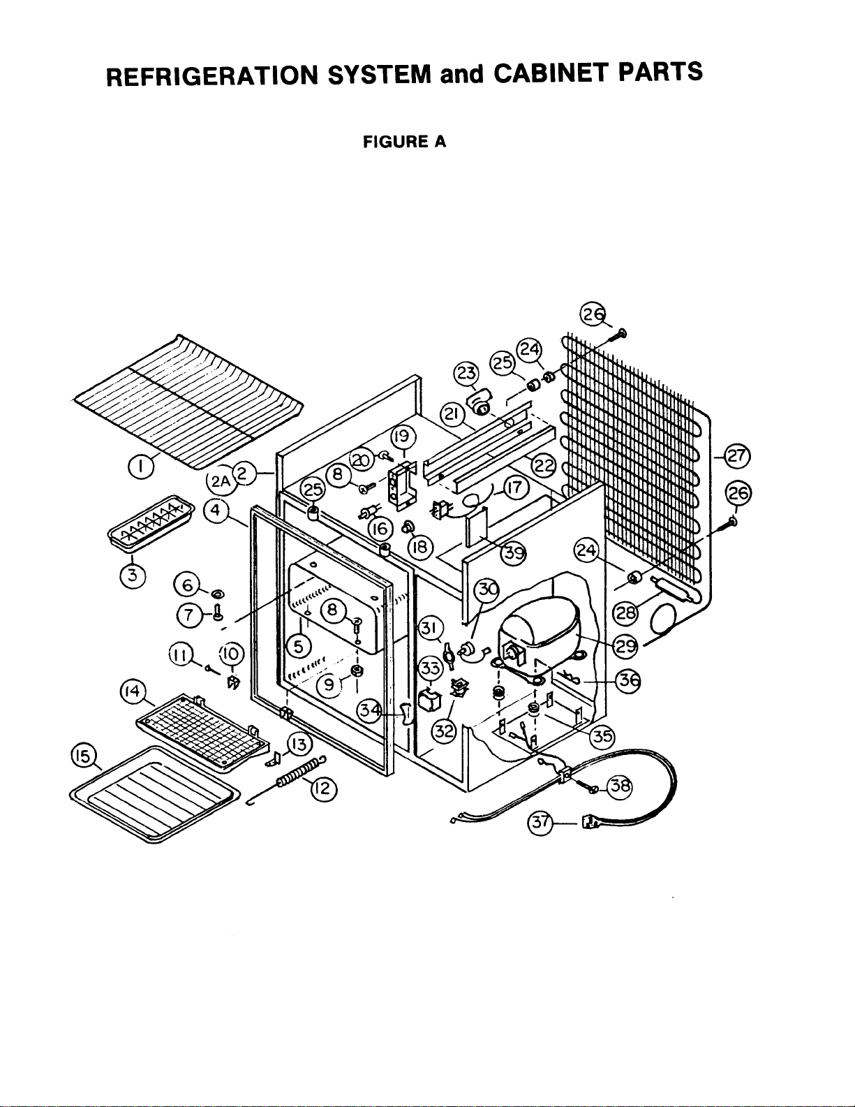
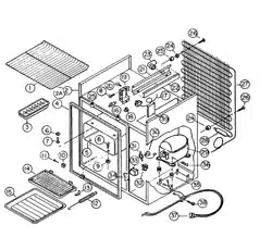
REFRIGERATION SYSTEM and CABINET PARTS
FIGURE A
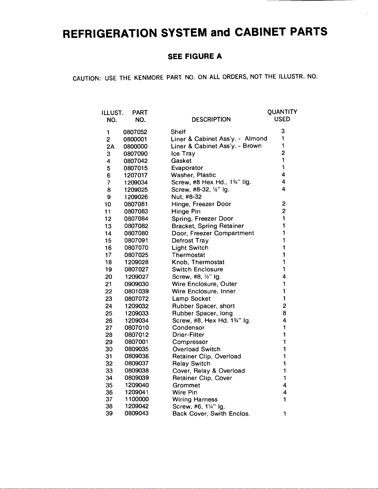
REFRIGERATION SYSTEM and CABINET PARTS
SEE FIGURE A
CAUTION: USE THE KENMORE PART NO. ON ALL ORDERS, NOT THE ILLUSTR. NO.
ILLUST. PART QUANTITY
NO. NO. DESCRIPTION USED
1 0807052 Shelf 3
2 0800001 Liner & Cabinet Ass'y. - Almond 1
2A 0800000 Liner & Cabinet Ass'y. - Brown 1
3 0807090 Ice Tray 2
4 0807042 Gasket 1
5 0807015 Evaporator 1
6 1207017 Washer, Plastic 4
7 1209034 Screw, #8 Hex Hd., 13/_'' IIg. 4
8 1209025 Screw, #8-32, _,_"Ig. 4
9 1209026 Nut, #8-32
10 0807081 Hinge, Freezer Door 2
11 0807083 Hinge Pin 2
12 0807084 Spring, Freezer Door 1
13 0807082 Bracket, Spring Retainer 1
14 0807080 Door, Freezer Compartment 1
15 0807091 Defrost Tray 1
16 0807070 Light Switch 1
17 0807025 Thermostat 1
18 1209028 Knob, Thermostat 1
19 0807027 Switch Enclosure 1
20 1209027 Screw, #8, 1/2"Ig. 4
21 0909030 Wire Enclosure, Outer 1
22 0801039 Wire Enclosure, Inner 1
23 0807072 Lamp Socket 1
24 1209032 Rubber Spacer, short 2
25 1209033 Rubber Spacer, long 8
26 1209034 Screw, #8, Hex Hd. 13/4"Ig. 4
27 0807010 Condensor 1
28 0807012 Drier-Filter 1
29 0807001 Compressor 1
30 0809035 Overload Switch 1
31 0809036 Retainer Clip, Overload 1
32 0809037 Relay Switch 1
33 0809038 Cover, Relay & Overload 1
34 0809039 Retainer Clip, Cover 1
35 1209040 Grommet 4
36 1209041 Wire Pin 4
37 1100000 Wiring Harness 1
38 1209042 Screw, #6, 1W' Ig.
39 0809043 Back Cover, Swith Enclos. 1
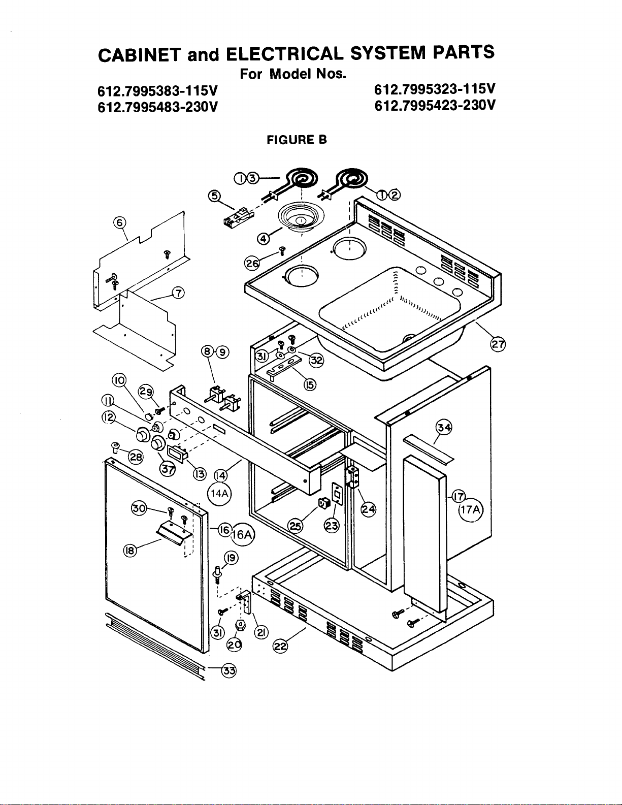
CABINET and ELECTRICAL SYSTEM PARTS
For Model Nos.
612.7995383-115V 612.7995323-115V
612.7995483-230V 612.7995423-230V
FIGURE B
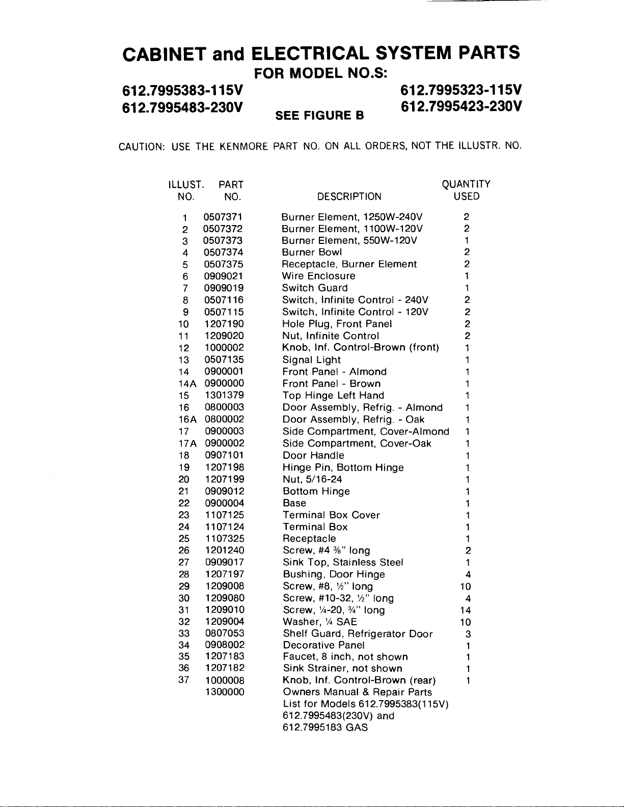
CABINET and ELECTRICAL SYSTEM PARTS
FOR MODEL NO.S:
612.7995383-115V 612.7995323-115V
612.7995483-230V 612.7995423-230V
SEE FIGURE B
CAUTION: USE THE KENMORE PART NO. ON ALL ORDERS, NOT THE ILLUSTR. NO.
ILLUST. PART QUANTITY
NO. NO. DESCRIPTION USED
1 0507371
2 0507372
3 0507373
4 0507374
5 0507375
6 0909021
7 0909019
8 0507116
9 0507115
10 1207190
11 1209020
12 1000002
13 0507135
14 0900001
14A 0900000
15 1301379
16 0800003
16A 0800002
17 0900003
17A 0900002
18 0907101
19 1207198
20 1207199
21 0909012
22 0900004
23 1107125
24 1107124
25 1107325
26 1201240
27 0909017
28 1207197
29 1209008
30 1209080
31 1209010
32 1209004
33 0807053
34 0908002
35 1207183
36 1207182
37 1000008
1300000
Burner Element, 1250W-240V 2
Burner Element, 1100W-120V 2
Burner Element, 550W-120V 1
Burner Bowl 2
Receptacle, Burner Element 2
Wire Enclosure 1
Switch Guard 1
Switch, Infinite Control - 240V 2
Switch, Infinite Control - 120V 2
Hole Plug, Front Panel 2
Nut, Infinite Control 2
Knob, Inf. Control-Brown (front) 1
Signal Light 1
Front Panel - Almond 1
Front Panel- Brown 1
Top Hinge Left Hand 1
Door Assembly, Refrig. - Almond 1
Door Assembly, Refrig - Oak 1
Side Compartment, Cover-Almond 1
Side Compartment, Cover-Oak 1
Door Handle 1
Hinge Pin, Bottom Hinge 1
Nut, 5/16-24 1
Bottom Hinge 1
Base 1
Terminal Box Cover 1
Terminal Box 1
Receptacle 1
Screw, #4 %" long 2
Sink Top, Stainless Steel 1
Bushing, Door Hinge 4
Screw, #8, 1/2"long 10
Screw, #10-32, 1/2"long 4
Screw, 1A-20,3/_,,long 14
Washer, 1/_SAE 10
Shelf Guard, Refrigerator Door 3
Decorative Panel 1
Faucet, 8 inch, not shown 1
Sink Strainer, not shown 1
Knob, Inf. Control-Brown (rear) 1
Owners Manual & Repair Parts
List for Models 612.7995383(115V)
612.7995483(230V) and
612.7995183 GAS
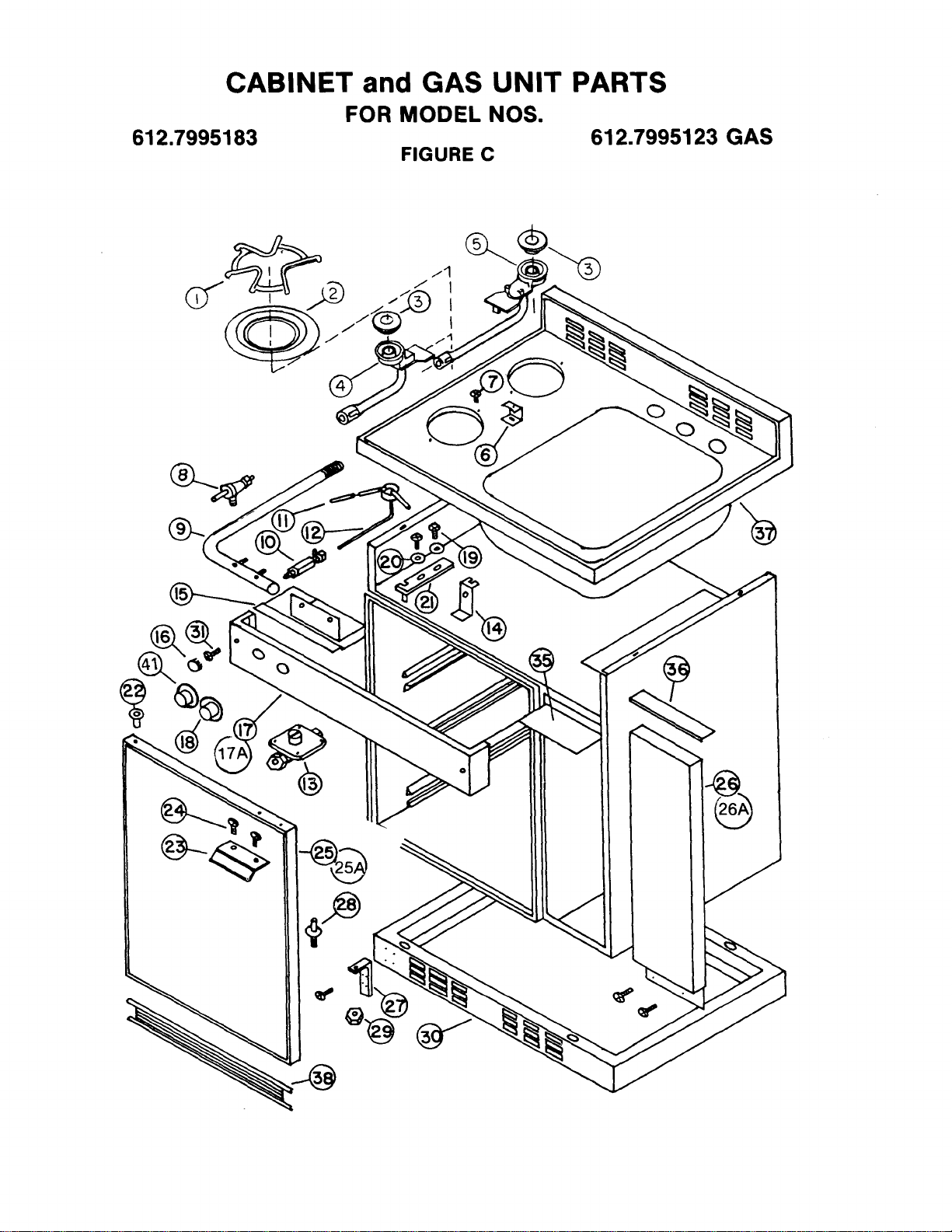
CABINET and GAS UNIT PARTS
FOR MODEL NOS.
612.7995183 612.7995123 GAS
FIGURE C
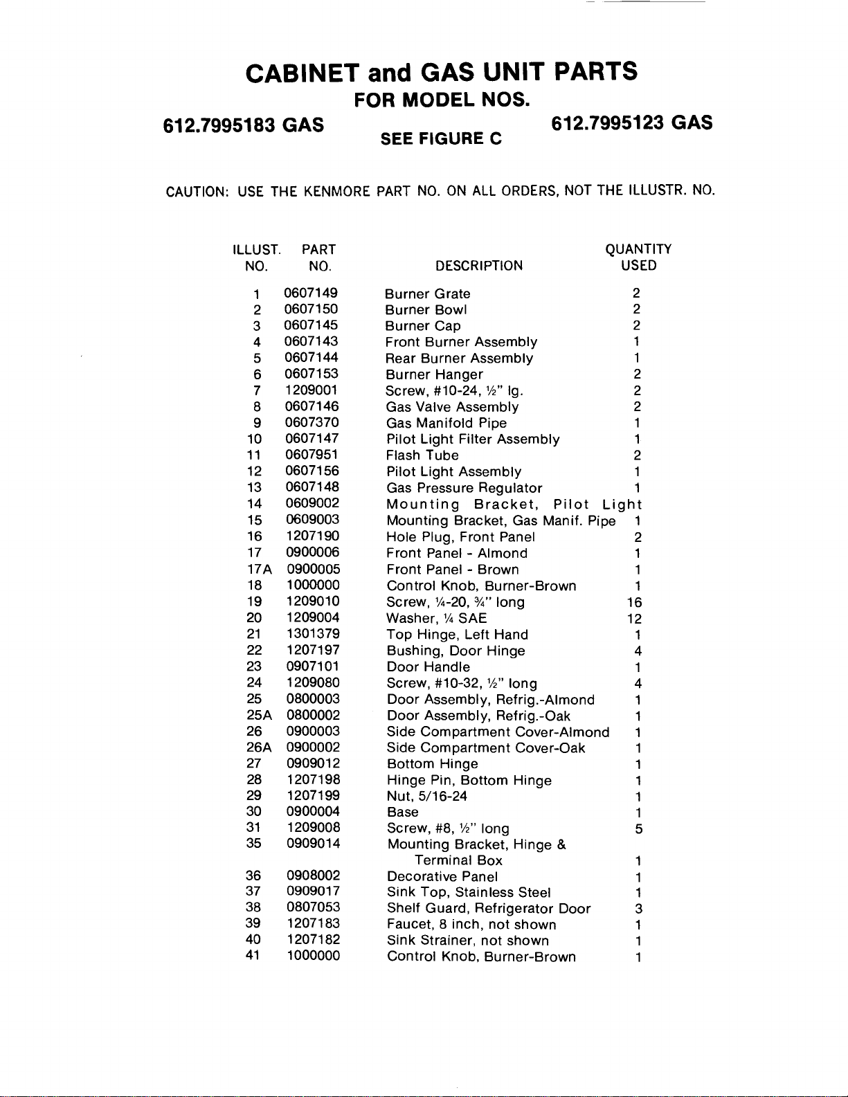
CABINET and GAS UNIT PARTS
FOR MODEL NOS.
612.7995183 GAS 612,7995123 GAS
SEE FIGURE C
CAUTION: USE THE KENMORE PART NO. ON ALL ORDERS, NOT THE ILLUSTR. NO.
ILLUST. PART QUANTITY
NO. NO, DESCRIPTION USED
1 0607149
2 0607150
3 0607145
4 0607143
5 0607144
6 0607153
7 1209001
8 0607146
9 0607370
10 0607147
11 0607951
12 0607156
13 0607148
14 0609002
15 0609003
16 1207190
17 0900006
17A 0900005
18 1000000
19 1209010
20 1209004
21 1301379
22 1207197
23 0907101
24 1209080
25 0800003
25A 0800002
26 0900003
26A 0900002
27 0909012
28 1207198
29 1207199
30 0900004
31 1209008
35 0909014
36 0908002
37 0909017
38 0807053
39 1207183
40 1207182
41 1000000
Burner Grate 2
Burner Bowl 2
Burner Cap 2
Front Burner Assembly 1
Rear Burner Assembly 1
Burner Hanger 2
Screw, #10-24, 1/2"Ig. 2
Gas Valve Assembly 2
Gas Manifold Pipe 1
Pilot Light Filter Assembly 1
Flash Tube 2
Pilot Light Assembly 1
Gas Pressure Regulator 1
Mounting Bracket, Pilot Light
Mounting Bracket, Gas Manif. Pipe 1
Hole Plug, Front Panel 2
Front Panel - Almond 1
Front Panel - Brown 1
Control Knob, Burner-Brown 1
Screw, 1/_-20,3/_,,long 16
Washer, 1/_SAE 12
Top Hinge, Left Hand 1
Bushing, Door Hinge 4
Door Handle 1
Screw, #10-32, _" long 4
Door Assembly, Refrig.-Almond 1
Door Assembly, Refrig.-Oak 1
Side Compartment Cover-Almond 1
Side Compartment Cover-Oak 1
Bottom Hinge 1
Hinge Pin, Bottom Hinge 1
Nut, 5/16-24 1
Base 1
Screw, #8, V2" long 5
Mounting Bracket, Hinge &
Terminal Box 1
Decorative Panel 1
Sink Top, Stainless Steel 1
Shelf Guard, Refrigerator Door 3
Faucet, 8 inch, not shown 1
Sink Strainer, not shown 1
Control Knob, Burner-Brown 1

Service Notes & Reminders