iNSTALLATiON AND SERVICE MUST BE PERFORMED BY A QUALiFiED iNSTALLER.
iMPORTANT: SAVE FOR LOCAL ELECTRICAL iNSPECTOR'S USE.
READ AND SAVE THESE iNSTRUCTiONS FOR FUTURE REFERENCE.
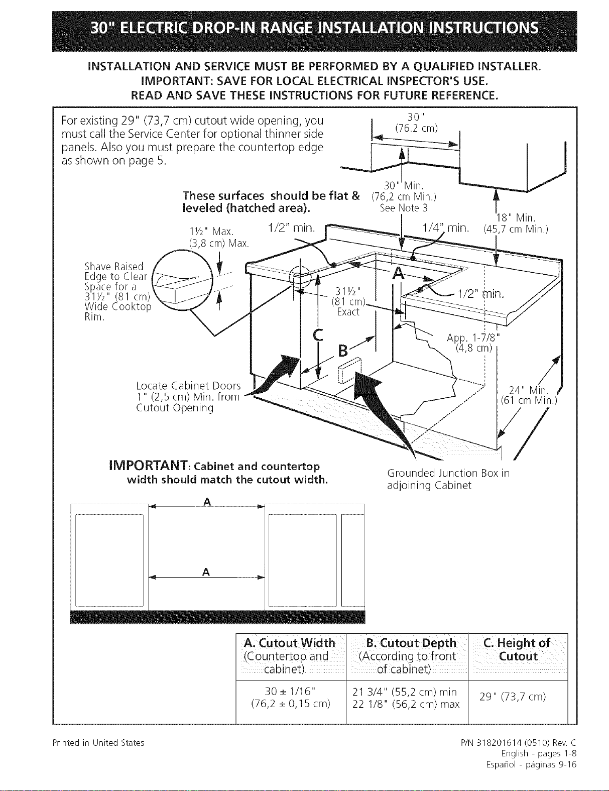
For existing 29" (73,7 cm) cutout wide opening, you 30"
must call the Service Center for optional thinner side _ cm_ I
panels. Also you must prepare the countertop edge [------_-i----_ I I
as shown on page 5.
These surfaces should be flat & (76,2 cm Min.) _
leveled (hatched area). SeeNote 3 118"Min.
11/2'' Max. 1/2" min. 1/4' rain. (45,7 cm Min.)
(3,8 cm) Max.
Shave Raised
Edge to Clear
Space for a
311/2" (81 cm)
Wide Cooktop
Rim.
Locate Cabinet Doors
1 " (2,5 cm) Min. from
Cutout Opening
24" Min.
(61 cm Min.)
IMPORTANT: Cabinet and countertop
width should match the cutout width.
Grounded Junction Box in
adjoining Cabinet
A: Cutout Width Bi Cutout Depth C, Height of
(countertop and (ACcording to front CuIEout
cabinet), of cabinet),
30+1/16" 21 3/4" (55,2 cm) min 29" (73,7 cm)
(76,2 + 0,15 cm) 22 1/8" (56,2 cm) max
Printed in United States P/N 318201614 (0510) Rev. C
English - pages 1-8
Espaflol - p_iginas 9-16
NOTES:
1.Do not pinch the power supply cord between the range and the wall.
2.Do not seal the range to the side cabinets.
3.24" (61 cm) minimum clearance between the cooktop and the bottom of the cabinet when
the bottom of wood or metal cabinet is protected by not lessthan 1/4" (0.64 cm) flame retardant
millboard covered with not less than No. 28 MSG sheet metal, 0.015" (0.4 mm) stainless steel,
0.024" (0.6 mm) aluminum, or 0.020" (0.5 mm) copper. 30" (76.2 cm) minimum clearance
when the cabinet is unprotected.
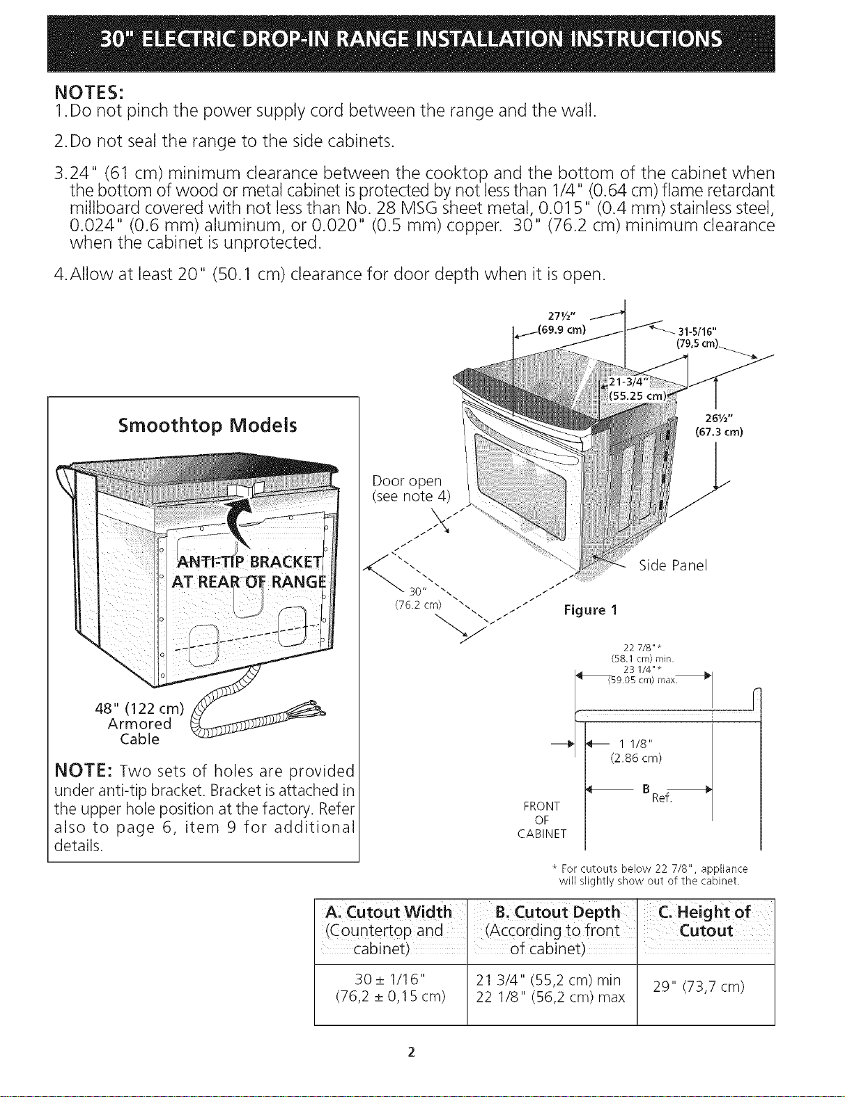
4.Allow at least 20" (50.1 cm) clearance for door depth when it is open.
Smoothtop Models
48" (122 cm)
Armored
Cable
NOTE: Two sets of holes are provided
under anti-tip bracket. Bracket is attached in
the upper hole position at the factory. Refer
also to page 6, item 9 for additional
details.
261/2"
(67.3 cm)
Door open
(see note 4)
Side Panel
/
/
/ /
Figure 1
22 718" *
(58.1 cm) rain.
23 1/4"*
59.05 cm) max_
i
_/ _ 1 1/8"
/ (2.86 cm)
B Ref.
FRONT
OF
CABINET
* For cutouts below 22 7/8", appliance
will slightly show out of tt_e cabinet.
A: CutoutW!dth I B, Cutout Depth' C, Heightof
(Countertop and , (According to front Cutout
Cabinet), of cabinet),
30 _+1/16" 21 3/4" (55,2 cm) rain 29" (73,7 cm)
(76,2 _+0,15 cm) 22 1/8" (56,2 cm) max
Important Notes to the Installer
1. Read all instructions contained in these installation
instructions before installing range.
2. Remove all packing material from the oven before
connecting the electrical supply to the range.
3. Observe all governing codes and ordinances.
4. Be sure to leave these instructions with the consumer.
5. Oven door may be removed to facilitate installation.
6. Do not lift the range by the door handle.
Important Note to the Consumer
Keep these instructions with your owner's guide for future
reference.
RTANT SAFETY
INSTRUCTIONS
• Be sure your range is installed and grounded
properly by a qualified installer or service
technician.
• This range must be electrically grounded in
accordance with local codes or, in their absence,
with the National Electrical Code ANSI/NFPA No.
70--latest edition.
The installation of appliances designed for
manufactured (mobile) home installation must conform
with Manufactured Home Construction and Safety
Standard, title 24CFR, part 3280 [Formerly the Federal
Standard for Mobile Home Construction and Safety,
title 24, HUD (part 280)] or when such standard is not
applicable, the Standard for Manufactured Home
Installation 1982 (Manufactured Home Sites,
Communities and Setups), ANSI Z225.1/NEPA 501A-
latest edition, or with local codes.
• Make sure the wall coverings around the range
can withstand the heat generated by the range.
• All ranges can tip.
• Injury to personscould result.
• Installanti-tip devicepackedwith range.
To reduce the risk of
tipping of the range, the range must be
secured by properly installed anti-tip screws,
for models with coil elements. They are
located in a plastic bag in the oven. For smoothtop models,
the anti-tip bracket located at the rear of the range fits under
the countertop and prevents range from tipping. Failure to
install the anti-tip screws will allow the range to tip over if
excessive weight is placed on an open door or if a child climbs
upon it. Serious injury might result from spilled hot liquids or
from the range itself.
• Before installing the range in an area covered
with linoleum or any other synthetic floor
covering, make sure the floor covering can
withstand heat at least 90°F above room
temperature without shrinking, warping or
discoloring. Do not install the range over carpeting
unless you place an insulating pad or sheet of 1/4"
thick plywood between the range and carpeting.
Never leave children alone or
unattended in the area where an appliance is in use.
As children grow, teach them the proper, safe use of all
appliances. Never leave the oven door open when the
range is unattended.
Stepping, leaning or sitting on the
door of this range can result in serious injuries and
can also cause damage to the range.
• Do not store items of interest to children in the
cabinets above the range. Children could be seriously
burned climbing on the range to reach items.
• To eliminate the risk of burns or fire by reaching
over heated surface units, cabinet storage space
above the surface unit should be avoided. If
cabinet storage isto be provided the risk can be reduce
by installing a range hood that project horizontally a
minimum of 5 inches beyond the bottom of the
cabinet.
• Do not use the oven as a storage space. This
creates a potentially hazardous situation.
• Never use your range for warming or heating the
room. Prolonged use of the range without adequate
ventilation can be dangerous.
• Do not store or use gasoline or other flammable
vapors and liquids near this or any other
appliance. Explosions or fires could result.
• Reset all controls to the "off" position after using
a programmable timing operation.
FOR MODELS WITH SELF-CLEAN FEATURE:
• Remove broiler pan, food and other utensils
before self-cleaning the oven. Wipe up excess
spillage. Follow the precleaning instructions in the Use
and Care Guide.
ElectricaJ Requirements
This appliance must be supplied with the proper voltage
and frequency, and connected to an individual, properly
grounded branch circuit, protected by a circuit breaker or
fuse, having amperage as noted on the rating plate (the
rating plate is located on the oven frame).
If local codes permit, you can use a 3-wire single phase
120/208 or 120/240 Volt, 60Hz AC only electrical
system. If you connect to aluminum wiring, properly
installed connectors approved for use with aluminum
wiring must be use.
NOTE: Wire sizes and connections must conform with
the fuse size and rating of the appliance in accordance
with the National Electrical Code ANSI/NFPA No. 70-
latest edition, and local codes and ordinances.
EJectrical Shock Hazard
• Electrical ground is required on this appliance.
• Do not connect to the electrical supply until
appliance is permanently grounded.
• Disconnect power to the junction box before
making the electrical connection.
• This appliance must be connected to a
grounded, metallic, permanent wiring system,
or a grounding connector should be connected
to the grounding terminal or wire lead on the
appliance.
• Do not use a gas supply line for grounding the
appliance.
Failure to do any of the above could result in a
fire, personal injury or electrical shock.
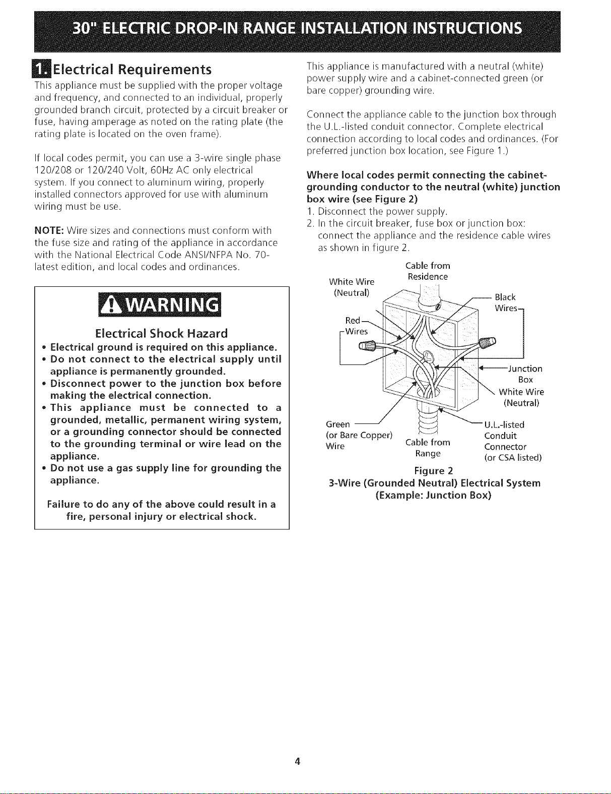
This appliance is manufactured with a neutral (white)
power supply wire and a cabinet-connected green (or
bare copper) grounding wire.
Connect the appliance cable to the junction box through
the U.L-listed conduit connector. Complete electrical
connection according to local codes and ordinances. (For
preferred junction box location, see Figure 1.)
Where local codes permit connecting the cabinet-
grounding conductor to the neutral (white) junction
box wire (see Figure 2)
1. Disconnect the power supply.
2. In the circuit breaker, fuse box or junction box:
connect the appliance and the residence cable wires
as shown in figure 2.
Cable from
Residence
White Wire
(Neutral)
Black
WiresI
Box
Wire
(Neutral)
Green U.L.-listed
(or Bare Copper) Conduit
Wire Cable from Connector
Range (or CSA listed)
Figure 2
3-Wire (Grounded Neutral) Electrical System
(Example: Junction Box)
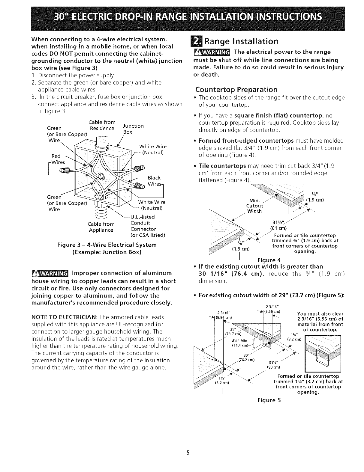
When connecting to a 4-wire eJectricaJ system,
when instaJJing in a mobiJe home, or when JocaJ
codes DO NOT permit connecting the cabinet-
grounding conductor to the neutraJ (white) junction
box wire (see Figure 3)
1. Disconnect the power supply.
2. Separate the green (or bare copper) and white
appliance cable wires.
3. In the circuit breaker, fuse box or junction box:
connect appliance and residence cable wires as shown
in figure 3.
Cable from
Green Residence
(or Bare Copper)
Red_
Wires
Green
(or Bare Copper)
Wire
Junction
Box
White Wire
eutral)
I"S whitewire
Cable from Conduit
Appliance Connector
(or CSA listed)
Figure 3 - 4-Wire Electrical System
(Example: Junction Box)
Improper connection of aluminum
house wiring to copper leads can result in a short
circuit or fire. Use only connectors designed for
joining copper to aluminum, and follow the
manufacturer's recommended procedure closely.
NOTE TO ELECTRICIAN: The armored cable leads
supplied with this appliance are UL-recognized for
connection to larger gauge household wiring. The
insulation of the leads is rated at temperatures much
higher than the temperature rating of household wiring.
The current carrying capacity of the conductor is
governed by the temperature rating of the insulation
around the wire, rather than the wire gauge alone.
Range Installation
The electrical power to the range
must be shut off while line connections are being
made. Failure to do so could result in serious injury
or death.
Countertop Preparation
* The cooktop sides of the range fit over the cutout edge
of your countertop.
* If you have a square finish (flat) countertop, no
countertop preparation is required. Cooktop sides lay
directly on edge of countertop.
, Formed front-edged countertops must have molded
edge shaved flat 3/4" (1.9 cm) from each front corner
of opening (Figure 4).
, Tile countertops may need trim cut back 3/4"(1.9
cm) from each front corner and/or rounded edge
flattened (Fiqure 4).
31,/2,__
(81 cm)
Formed or tile countertop
trimmed %" (1.9 cm) back at
front corners of countertop
(1.9 cm) opening.
I Figure 4
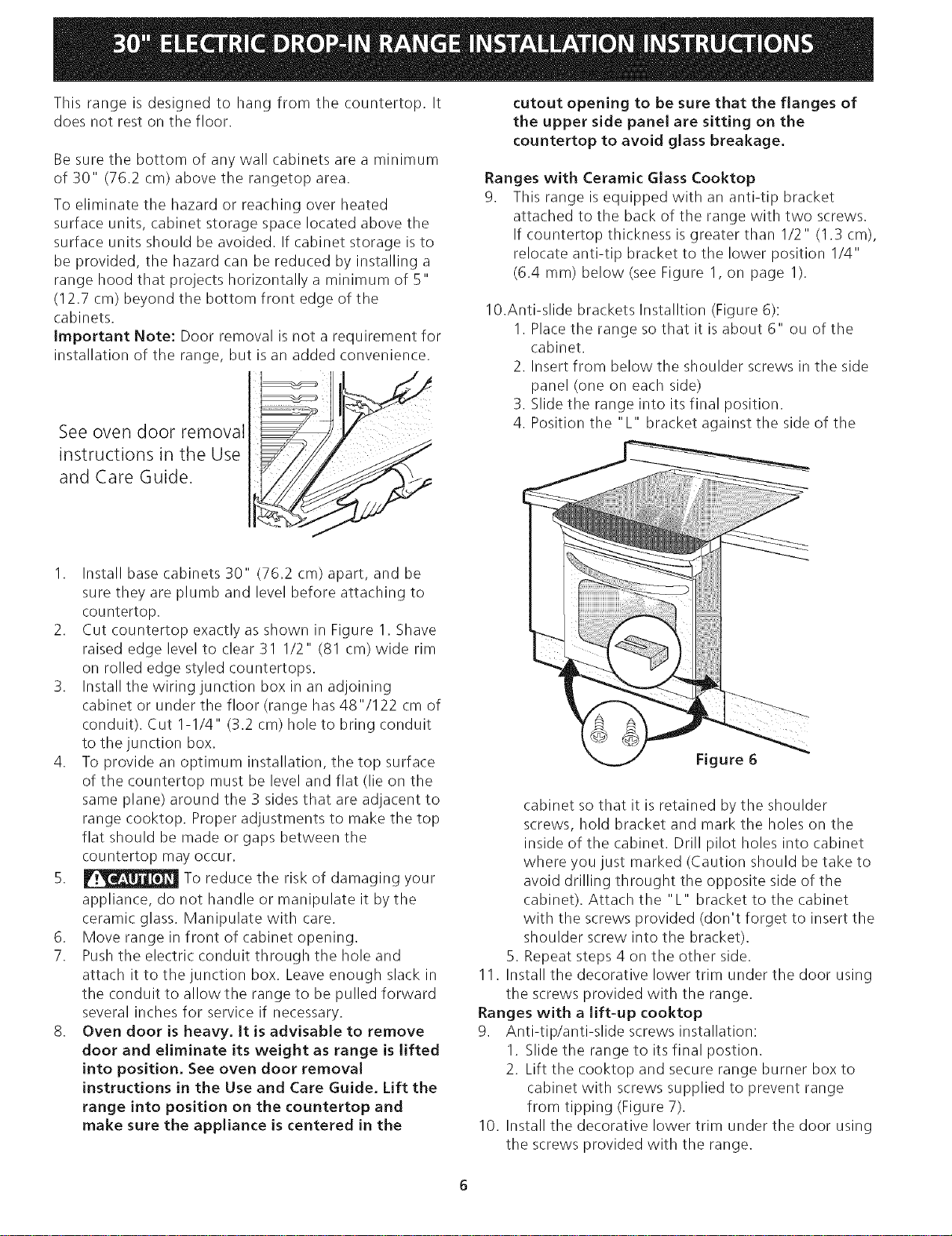
• If the existing cutout width is greater than
30 1116" (76,4 cm), reduce the 3A" (1.9 cm)
dimension.
• For existing cutout width of 29" (73.7 cm) (Figure 5):
2 3/16"
2 3/16" (5.56 cm) YOU must also clear
_l (s's6 crn) 2 3/16" (5.56 cm) of
material from front
of countertop.
1v4"
(3.2 cm)
311/z"
(80 cm)
_ ._ Formed or tile countertop
11/4"
(3.2cm) _ trimmed 11A'' (3.2 cm) back at
front corners of countertop
I opening.
Figure 5
Thisrangeisdesignedto hangfromthecountertop.It
doesnotrestonthefloor.
Besurethebottomofanywallcabinetsareaminimum
of30"(76.2cm)abovetherangetoparea.
Toeliminatethehazardorreachingoverheated
surfaceunits,cabinetstoragespacelocatedabovethe
surfaceunitsshouldbeavoided.Ifcabinetstorageisto
beprovided,thehazardcanbereducedbyinstallinga
rangehoodthatprojectshorizontallyaminimumof5"
(12.7cm)beyondthebottomfrontedgeofthe
cabinets.
ImportantNote:Doorremovalisnotarequirementfor
installationoftherange,butisanaddedconvenience.
See oven door removal
instructions in the Use
and Care Guide.
I. Install base cabinets 30" (76.2 cm) apart, and be
sure they are plumb and level before attaching to
countertop.
2. Cut countertop exactly as shown in Figure 1. Shave
raised edge level to clear 31 I/2" (81 cm) wide rim
on rolled edge styled countertops.
3. Install the wiring junction box in an adjoining
cabinet or under the floor (range has 48"/122 cm of
conduit). Cut 1-1/4" (3.2 cm) hole to bring conduit
to the junction box.
4. To provide an optimum installation, the top surface
of the countertop must be level and flat (lie on the
same plane) around the 3 sides that are adjacent to
range cooktop. Proper adjustments to make the top
flat should be made or gaps between the
countertop may occur.
5. _ To reduce the risk of damaging your
appliance, do not handle or manipulate it by the
ceramic glass. Manipulate with care.
6. Move range in front of cabinet opening.
7. Push the electric conduit through the hole and
attach it to the junction box. Leave enough slack in
the conduit to allow the range to be pulled forward
several inches for service if necessary.
8. Oven door is heavy. It is advisable to remove
door and eliminate its weight as range is lifted
into position. See oven door removal
instructions in the Use and Care Guide. Lift the
range into position on the countertop and
make sure the appliance is centered in the
cutout opening to be sure that the flanges of
the upper side panel are sitting on the
countertop to avoid glass breakage.
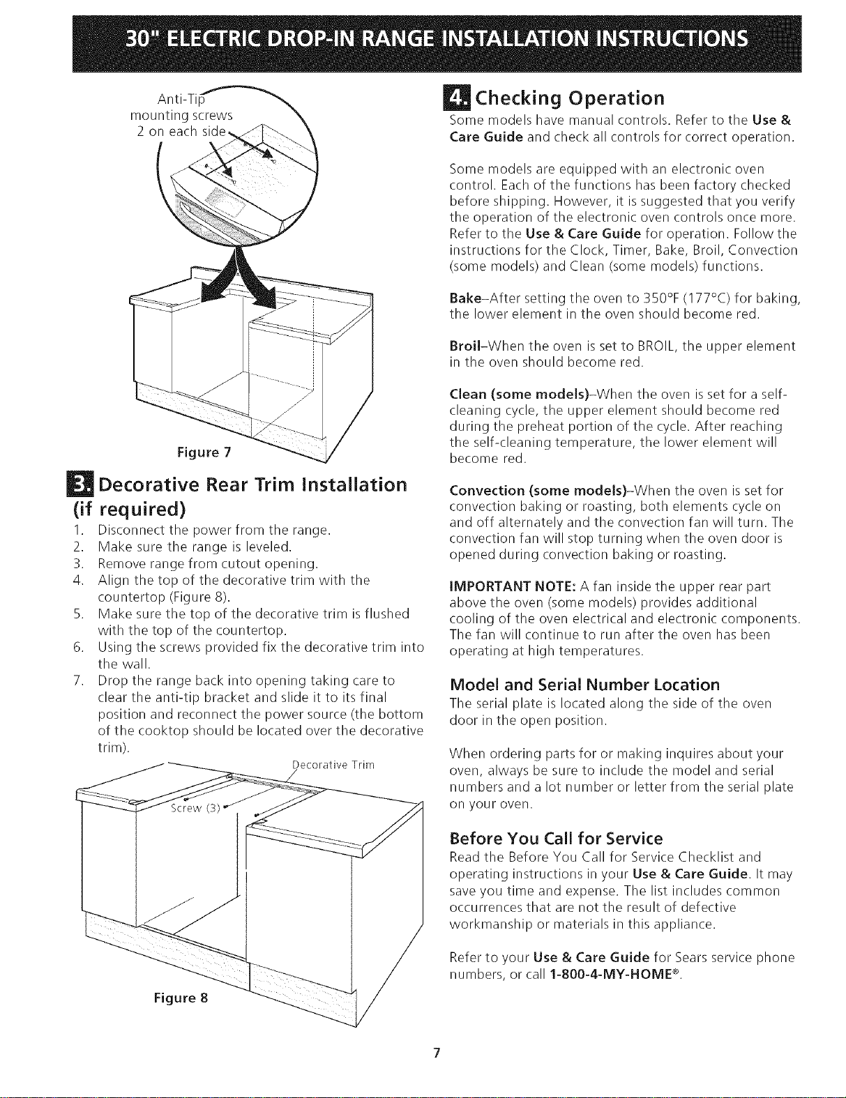
Ranges with Ceramic Glass Cooktop
9. This range is equipped with an anti-tip bracket
attached to the back of the range with two screws.
If countertop thickness is greater than I/2" (1.3 cm),
relocate anti-tip bracket to the lower position 1/4"
(6.4 mm) below (see Figure I, on page I).
10.Anti-slide brackets Installtion (Figure 6):
1. Place the range so that it is about 6" ou of the
cabinet.
2. Insert from below the shoulder screws in the side
panel (one on each side)
3. Slide the range into its final position.
4. Position the "L" bracket against the side of the
Figure 6
cabinet so that it is retained by the shoulder
screws, hold bracket and mark the holes on the
inside of the cabinet. Drill pilot holes into cabinet
where you just marked (Caution should be take to
avoid drilling throught the opposite side of the
cabinet). Attach the "L" bracket to the cabinet
with the screws provided (don't forget to insert the
shoulder screw into the bracket).
5. Repeat steps 4 on the other side.
11. Install the decorative lower trim under the door using
the screws provided with the range.
Ranges with a lift-up cooktop
9. Anti-tip/anti-slide screws installation:
I. Slide the range to its final postion.
2. Lift the cooktop and secure range burner box to
cabinet with screws supplied to prevent range
from tipping (Figure 7).
10. Install the decorative lower trim under the door using
the screws provided with the range.
Anti-Tip
mountingscrews
2oneachside
Decorative Rear Trim Installation
(if required)
1. Disconnect the power from the range.
2. Make sure the range is leveled.
3. Remove range from cutout opening.
4. Align the top of the decorative trim with the
countertop (Figure 8).
5. Make sure the top of the decorative trim is flushed
with the top of the countertop.
6. Using the screws provided fix the decorative trim into
the wall.
7. Drop the range back into opening taking care to
clear the anti-tip bracket and slide it to its final
position and reconnect the power source (the bottom
of the cooktop should be located over the decorative
trim).
Decorative Trim
/
Screw
Figure 8
Checking Operation
Some models have manual controls. Refer to the Use &
Care Guide and check all controls for correct operation.
Some models are equipped with an electronic oven
control. Each of the functions has been factory checked
before shipping. However, it is suggested that you verify
the operation of the electronic oven controls once more.
Refer to the Use & Care Guide for operation. Follow the
instructions for the Clock, Timer, Bake, Broil, Convection
(some models) and Clean (some models) functions.
Bake-After setting the oven to 350% (177°C) for baking,
the lower element in the oven should become red.
Broil-When the oven isset to BROIL, the upper element
in the oven should become red.
Clean (some models)-When the oven is set for a self-
cleaning cycle, the upper element should become red
during the preheat portion of the cycle. After reaching
the self-cleaning temperature, the lower element will
become red.
Convection (some models)-When the oven isset for
convection baking or roasting, both elements cycle on
and off alternately and the convection fan will turn. The
convection fan will stop turning when the oven door is
opened during convection baking or roasting.
iMPORTANT NOTE: A fan inside the upper rear part
above the oven (some models) provides additional
cooling of the oven electrical and electronic components.
The fan will continue to run after the oven has been
operating at high temperatures.
Model and Serial Number Location
The serial plate is located along the side of the oven
door in the open position.
When ordering parts for or making inquires about your
oven, always be sure to include the model and serial
numbers and a lot number or letter from the serial plate
on your oveR.
Before You Call for Service
Read the Before You Call for Service Checklist and
operating instructions in your Use & Care Guide. It may
save you time and expense. The list includes common
occurrences that are not the result of defective
workmanship or materials in this appliance.
Refer to your Use & Care Guide for Sears service phone
numbers, or call 1-800-4-MY-HOME _.

Notes ."
LA INSTALACION Y EL SERVIClO DEBEN SER EFECTUADOS POR UN INSTALADOR CALIFICADO.
IMPORTANTE: GUARDE ESTAS INSTRUCClONES PARA USO DEL
INSPECTOR LOCAL DE ELECTRIClDAD.
LEA Y GUARDE ESTAS INSTRUCClONES PARA REFERENClA FUTURA.
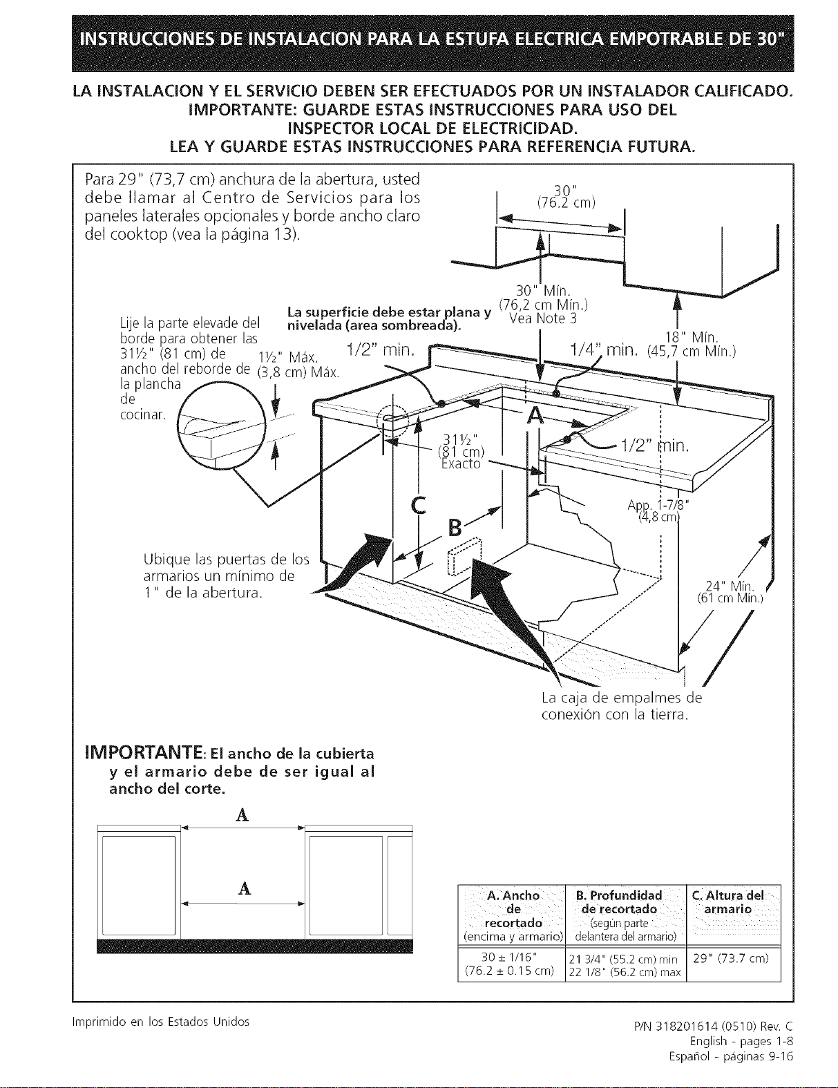
Para 29" (73,7 cm) anchura de la abertura, usted
30"
debe Ilamar al Centro de Servicios para los (76.2 cm)
paneles laterales opcionales y borde ancho claro I_t--___T_____________._II
delcooktop(vealap_gina13). _1 _
30" Min. _x
........ su o," 'eo ,a, -
LlJe la par_e elevade del nivelada (area sombreada), v...... I
18" Min.
1/2" min. 1/4' min. (45,7cm Min.)
horde para obtener las
31V2" (81 cm)de 11/2"M_ix.
ancho del reborde de (3,8 cm) M_ix.
la plancha
de
cocinar.
Ubique las puertas de los
armarios un minimo de
1" de la abertura.
31V2"
(81 cm)
Exacto
1/2" _in.
24" Min.
(61 cm Min.
La caja de empalmes de
conexiOn con la tierra.
IMPORTANTE: El ancho de la cubierta
y el arrnario debe de set igual al
ancho del corte.
A
A
A, Anch0 B. Profundidad C. Altura del
de ' derecQrtado ' armario
recortado ' (segOnparte
(encima y armario) delanteradelarmario)
30 + 1116" 21 314" (55.2 cm) rain 29" (73.7 cm)
(76.2 _+0.15 cm) 22 1/8" (56.2 cm) max
Imprimido en los Estados Unidos
P/N 318201614 (0510) Rev. C
English - pages 1-8
Espahol - p_iginas 9-16
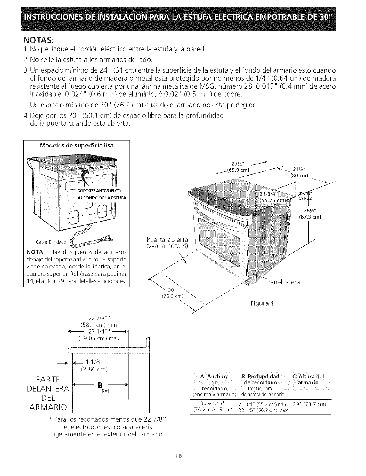
NOTAS:
1.No pellizque el cordon el_ctrico entre la estufa y la pared.
2. No selle la estufa a los armarios de lado.
3. Un espacio minimo de 24" (61 cm) entre la superficie de la estufa y el fondo del armario esto cuando
el fondo del armario de madera o metal est,1 protegido por no menos de 1/4" (0.64 cm) de madera
resistente al fuego cubierta por una I_imina met_ilica de MSG, n0mero 28, 0.015" (0.4 mm) de acero
inoxidable, 0.024" (0.6 mm) de aluminio, 6 0.02" (0.5 mm) de cobre.
Un espacio minimo de 30" (76.2 cm) cuando el armario no est,1 protegido.
4. Deje pot los 20" (50.1 cm) de espacio libre para la profundidad
de la puerta cuando esta abierta.
Modelos de superfide lisa
ALFONDO DE LA ESTUFA
Cable Blindado
NOTA: Hay dosjuegos de agujeros
debajo del soporte antivuelco. Elsoporte
viene colocado, desde la fabrica, en el
agujero superior. Refi_rase para paginar
14,el articulo 9 para detalles adicionales.
Puerta abierta
(vea la nota 4)
/ /
/ /
/
/
/
<i
30" ",.,
(76.2 cm) ",.
22 7/8" *
(58.1 cm) rain.
[_ 23 1/4"*_ I
(59.05 cm) max. r
i
(2.86 cm)
PARTE
DELANTERA _ _Ref,
DEL
ARMARIO
* Para los recortados menos que 22 7/8",
el electrodomestico aparecer[a
ligeramente en el exterior del armario.
i
i
/i
f
/
/
Panel lateral
Figura 1
A, Anchura B: Profundidad Ci Altura del
de ' de recortado armario
recortado (seg0n parte
(encima y armario) delantera del armario)
30 _+1/16" 21 3/4" (55.2 cm) rain 29" (73.7 cm)
(76.2 _+0.15 cm) 22 1/8" (56.2 cm) max
10
Notas importantes para el Mstalador
1. Lea todas lasinstrucciones contenidas en este manual
antes de instalar la estufa.
2. Saque todo el material usado en el embalaje del
compartimiento del homo antes de conectar el
suministro elOctrico a la estufa.
3. Observe todos los c0digos y reglamentos pertinentes.
4. Deje estas instrucciones con el comprador.
5. Para facilitar la instalaciOn puede quitarse la puerta
del horno.
6. No levante la estufa por la manija de la puerta.
Nota importante para el consumidor
Conserve estas instrucciones y el Manual del Usuario para
referencia futura.
Manufactured Home Installation 1982 (Manufactured
Home sites, communities and setups); ANSIZ225.1/
NFPA 501A- 01tima ediciOn o con codigos locales.
• AsegQrese que el tapis de pared alrededor de la
cocina pueda resistir el calor generado por la
estufa.
• Antes de instalar la estufa en una &tea cubierta de
linoleo o cualquier otto revestidor de piso
sint_tico, aseg_rese que _ste pueda resistir al
menos 90°F sobre la temperatura de la pieza sin
encogerse, ladearse o descolorise. No instale la
estufa encima de una alfombra a menos que coloque
una placa de aislamineto o una plancha de I/4" de
madera entre la cocina y el alfombrado.
IMPORTANTES
INSTRUCCIONES DE
EGURIDAD
Nunca deje a los niSos solos o sin
cuidado en el area donde el el&ctrodom&stico est&
en uso. A medida que los nihos crezcan, ensOheles el
uso adecuado de los elOctrodomOsticos.Nunca deje la
puerta del homo abierta cuando la estufa est6 sin
supervision.
• AsegQrese que su cocina est_ instalada y
conectada adecuadamente a tierra por un
instalador calificado o un t_cnico de servicio.
• Esta cocina debe ser conectada a tierra
el_ctricamente de acuerdo con los cOdigos
locales, o de no existir, con la National Electrical
Code ANSI/NFPA No.70- _ltima ediciOm
• LainstalaciOn de el_ctrodom_sticos destinados para
casas (movibles) deben conformarse con la
Manufactured Home Construction and Safety
Standard, titulo 24CFR, parte 3280 [antiguamente la
Federal Standard for Mobile Home Construction and
Safety, titulo 24, HUD (parte 280)] o cuando este
codigo no se aplica, la Standard for
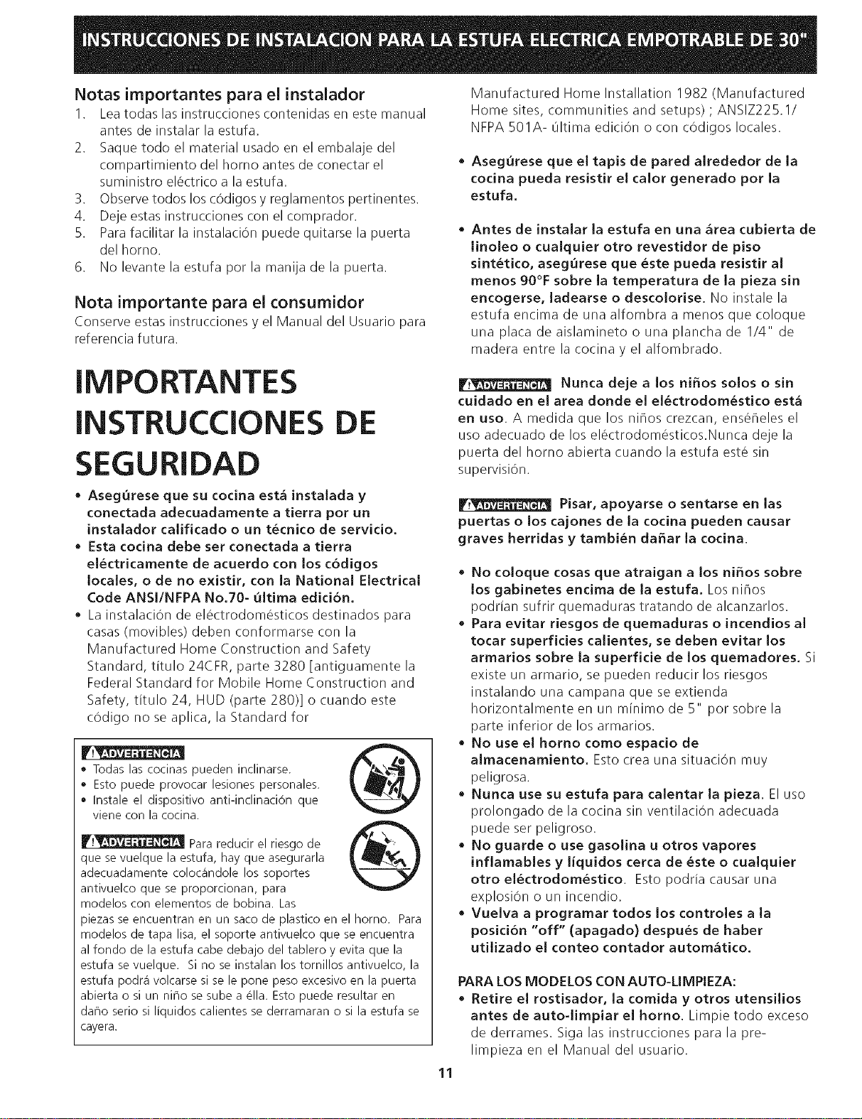
o Todaslascocinaspueden inclinarse.
, Esto puede provocarlesionespersonales.
, Instaleel dispositivo anti-inclinacion que
vienecon lacocina.
V.w_J__ Para reducir el riesgo de
que se vuelque la estufa, hay que asegurarla
adecuadamente coloc_indole los soportes
antivuelco que se proporcionan, para
modelos con elementos de bobina. Las
oiezas se encuentran en un saco de plastico en el homo. Para
modelos de tapa lisa, el soporte antivuelco que se encuentra
al fondo de la estufa cabe debajo del tablero y evita que la
estufa se vuelque. Si no se instalan los tornillos antivuelco, la
estufa podr_i volcarse si se le pone peso excesivo en la puerta
abierta o si un nir3ose sube a ella. Esto puede resultar en
dar3oserio si liquidos calientes se derramaran o si la estufa se
cayera.
Pisar, apoyarse o sentarse en las
puertas o los cajones de la cocina pueden causar
graves herridas y tambi_n daEar la cocina.
• No coloque cosas que atraigan a los niSos sobre
los gabinetes endma de la estufa. Los nihos
podrian sufrir quemaduras tratando de alcanzarlos.
• Para evitar riesgos de quemaduras o incendios al
tocar superficies calientes, se deben evitar los
armarios sobre la superficie de los quemadores. Si
existe un armario, se pueden reducir los riesgos
instalando una campana que se extienda
horizontalmente en un minimo de 5" por sobre la
parte inferior de los armarios.
• No use el horno como espacio de
almacenamiento. Esto crea una situation muy
peligrosa.
• Nunca use su estufa para calentar la pieza. El uso
prolongado de la cocina sin ventilaciOn adecuada
puede ser peligroso.
• No guarde o use gasolina u otros vapores
inflamables y liquidos cerca de _ste o cualquier
otto el_ctrodom_stico. Esto podria causar una
explosion o un incendio.
• Vuelva a programar todos los controles a la
posici6n "off" (apagado) despu_s de haber
utilizado el conteo contador autom&tico.
PARA LOS MODELOS CON AUTO-LIMPIEZA:
• Retire el rostisador, la comida y otros utensilios
antes de auto-limpiar el horno. Limpie todo exceso
de derrames. Siga las instrucciones para la pre-
limpieza en el Manual del usuario.
11
Req uisitos el6ctricos
Este artefacto debe ser suministrado con el voltaje y la
frecuencia adecuados, y conectado a un circuito
individual correctamente puesto a tierra, protegido por
un cortacircuitos o un fusible con el amperio anotado en
la plata de calificaciOn (la plata se encuentra en el
armaz6n del homo).
Si los cOdigos locales Io permiten, se puede usar un
sistema electrico de 3 alambres de fase 0nica de 120/
2086120/240voltios, 60HzACsolamente. Sise
conecta a un alambrado de aluminio, tienen que usarse
conectores bien instalados y aprobados para uso con el
alambrado de aluminio.
NOTA: Los tamahos de alambres y conectores deben
conformarse con el tamaho del fusible y la calificaci6n
del artefacto de acuerdo con el COdigo EI6ctrico
National ANSI/NFPA No. 70-01tima edici6n y los cOdigos
y ordenanzas locales.
Riesgo de choque electrico
o Una puesta a tierra se require en este aparato.
No Io conecte a la corriente el_ctrico hasta que
el aparato haya sido puesto a tierra.
o Desconecte la corriente el_ctrica a la caja de
empalmes antes de hater la conexi6n el_ctrica.
Este aparato debe estar conectado con un
sistema de alambres puesto en tierra, metalico
y permanente o un conector de pueta a tierre
debe conectarse al terminal de puesta a tierra
o el alambre conductor en al aparato.
No utilice el suministro de gas para hater la
puesta a tierra.
La falta de hater cualquier de las cosas arriba
podria resultar en un incendio, choque electrico
o lesiones personales.
Este aparato esta fabricado con un alambre el_ctrico
neutro (blanco) y un alambre verde (o alambre pelado)
de puesta a tierra conectado al gabinete.
Conecte el cable del aparato a la caja de empalmes por
mediodelconductordeuni6nlistado-UL. Completela
conexi6n segOn los c6digos y ordenanzas locales. (Para
la ubicaci6n preferida de la caja de empalmes, v6ase la
Figura 1.)
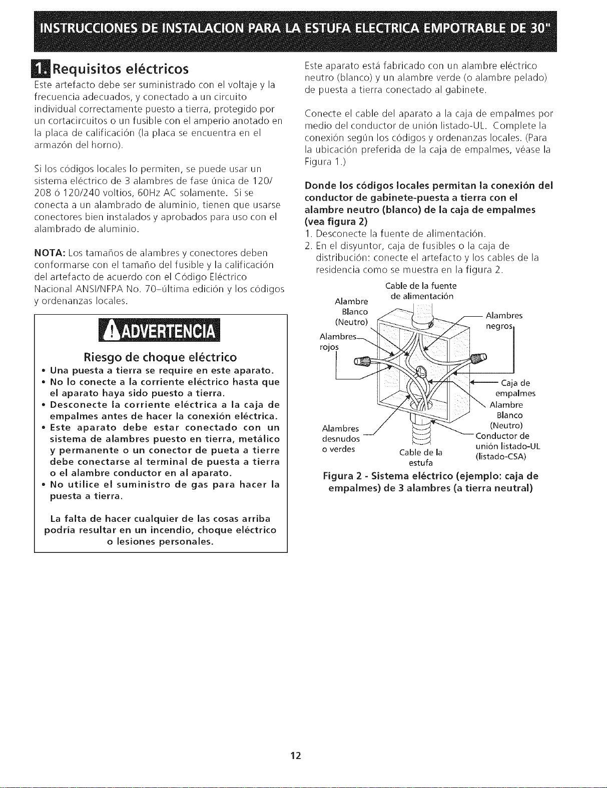
Donde los c6digos locales permitan la conexi6n del
conductor de gabinete-puesta a tierra con el
alambre neutro (bJanco) de Ja caja de empaJmes
(vea figura 2)
I. Desconecte la fuente de alimentaciOn.
2. En el disyuntor, caja de fusibles o la caja de
distribuciOn: conecte el artefacto y los cables de la
residencia como se muestra en la figura 2.
Cable de la fuente
de alimentaci6n
negr°s 1
Caja de
empammes
Alambre
Blanco
Alambres (Neutro)
desnudos Conductor de
uni6n listado-UL
o verdes Cable de la (listado-CSA)
estufa
Figura 2 - Sistema el_ctrico (ejemplo: caja de
empalmes) de 3 alambres (a tierra neutral)
Alambre
Blanco
(Neutro)
Alambres_
tO*
12
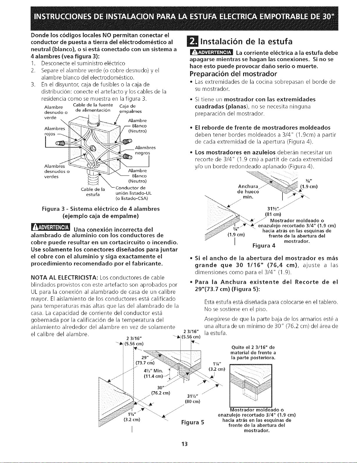
Donde los c6digos locales NO permitan conectar el
conductor de puesta a tierra del el6ctrodom6stico al
neutral (blanco), o si est_ conectado con un sistema a
4 alambres (vea figura 3):
1. Desconecte el suministro el_ctrico
2. Separe el alambre verde (o cobre desnudo) y el
alambre blanco del electrodom6stico.
3. En el disyuntor, caja de fusibles o la caja de
distribuciOn: conecte el artefacto y los cables de la
residencia como se muestra en la figura 3.
Alambre Cable de la fuente Caja de
desnudo o de alimentaci6n empalmes
ver0e A,ambre
Alambres __//_-NBel uatnrCI
ii Aiambres
T
desnudos o _'_1_ _ Alambre
verdes _<x. -- "_ Blanco
_nd _Nto_td °)
estufa uni6n listado-UL
(o listado-CSA)
Figura 3 - Sistema el6ctrico de 4 alambres
(ejemplo caja de empalme)
Una conexi6n incorrecta del
alarnbrado de aluminio con los conductores de
cobre puede resultar en un cortadrcuito o incendio.
Use solamente los conectores dise_ados para juntar
el cobre con el aluminio y siga exactamente el
procedimiento recomendado por el fabricante.
NOTA AL ELECTRIClSTA: Losconductores de cable
blindados provistos con este artefacto son aprobados por
UL para la conexi6n al alambrado de casa de un calibre
mayor. El aislamiento de los conductores esta calificado
para temperaturas mas altas que las del alambrado de la
casa. La capacidad de corriente del conductor esta
gobernada por la calificaci6n de la temperatura del
aislamiento alrededor del alambre en vez de solamente
el calibre del alambre.
2 3/16"
2 3/16"
_! (5.56 cm)
instaladon de la estufa
La corriente el6ctrica a la estufa debe
apagarse mientras se hagan las conexiones. Si no se
hace esto puede provocar da_o serio o muerte.
Preparation del mostrador
• Las extrernidades de la cocina sobrepasan el borde de
su mostrador.
• Si tiene un mostrador con las extremidades
cuadradas (planas), no se necesita ninguna
preparaci6n del mostrador.
• El reborde de frente de mostradores moldeados
deben tener bordes rnoldeados a 3/4" (1.9crn) a partir
de cada extremidad de la apertura (Figura 4).
• Los mostradores en azuleios deberan necesitar un
recorte de 3/4" (1.9 cm) a partit de cada extremidad
y/o un borde redondeado aplanado (Figura 4).
31_/,, _ /
(81 cm)
/ Mostrador moldeado o
recortado 3/4" (1.9 cm)
hada atr,_s en las esquinas de
(1.9 cm) frente de la abertura del
I Figura 4
mostrador.
• Si el ancho de la abertura del mostrador es m&s
grande que 30 1/16" (76,4 cm), ajuste a las
dimensiones corno para el 3/4" (1.9).
• Para la Anchura existente del Recorte de el
29"(73.7 cm) (Figura 5):
Estaestufa esta disehada para colocarse en el tablero.
No sesostiene en el piso.
Aseg0rese de que la parte baja de los armarios est_ a
una altura de un minimo de 30" (76.2 cm) del area de
la estufa.
Quite el 2 3/16" de
material de frente a
la parte posteriora.
(3.2 cm)
I
(76.2 cm)
31"V:/"
(80cm)
Figura 5
Mostrador moldeado o
enazulejo recortado 314" (1.9 cm)
hada atras en las esquinas de
frente de la abertura del
mostrador.
13
Paraeliminarelpeligrodetenerqueextenderelbrazopor
encimadelasuperficiecalientedelaestufa,sedebe
evitarlainstalaciOndegabinetesporencimadeella.Si
hayqueinstalargabinetesporencimadelaestufa,se
puedereducirelriesgoinstalandounventiladordeestufa
queseproyectehorizontalmenteunminimode5"(12.7
cm)masaliadelhordedelanteroinferiordelosgabinetes.
Notaimportante:Noesnecesario,perosies
conveniente,quitarlapuertaparainstalarelhomo.
Consulte las instrucciones
para retirar la puerta en la
Guia de Uso y Cuidado.
f
1. Instale los gabinetes inferiores con una separaciOn de
30" (76.2 cm), y aseg0rese de que est_n a plomo y
nivelados antes de unirlos al tablero.
2. Corte el tablero exactamente como se muestra en la
Figural. Cepille anivelelborde levantado, para
para que libre un filete de 31 I/2" (81 cm) de ancho
en tableros con hordes laminados.
3. Instale la caja de conexiones el_ctricas en un armario
adjunto o debajo del piso (la estufa tiene 48"/122 cm
de alambre). Abra un agujero de 1-I/4" (3.2 cm) para
traer el alambre hasta la caja de conexiones.
4. Para una instalaciOn Optima, la superficie superior de
la mesada debe estar nivelada y ser plana (sobre el
mismo piano) en los 3 lados adyacentes a la cocina.
Se deben hater los ajustes correspondientes para
hacer que la parte superior quede plana, de Io
contrario podran quedar espacios entre la mesada y la
cocina.
5. _ Para reducir el riesgo de dahar su
artefacto, no Io manipule cerca del vidrio ceramico.
Manip01elo con cuidado.
6. Coloque la cocina enfrente de la abertura del armario.
7. Introduzca el alambre el_ctrico por el agujero y fijelo a
la caja. Deje suficiente alambre flojo para permitir
que la estufa sejale hacia delante varias pulgadas si
fuera necesario darle servicio.
8. La puerta del horno es pesada. Se aconseja retirar
la puerta para eliminar su peso mientras se
coloca la cocina en posici6n. Ve a las
instrucciones para retirar la puerta del horno en
la Guia de Uso y Cuidado. Levante la cocina y
col6quela en posici6n sobre la mesada y
asegOrese que el artefacto est& centrado en la
abertura de corte para asegurar que las bridas del
panel superior est_n apoyadas en la mesada para
evitar que el vidrio se rompa.
Cocinas con vidrio cer_mico
9. Esta estufa puede traer soportes antivuelco, fijados al
dorso de la estufa con dos tomillos. Siel grueso del
tablero es mas de 1/2" (1.3 cm), coloque de nuevo el
soporte antivuelco en la posiciOn mas baja, de I/4"
(6.4 ram) (Vea la Figura I en la pagina 7).
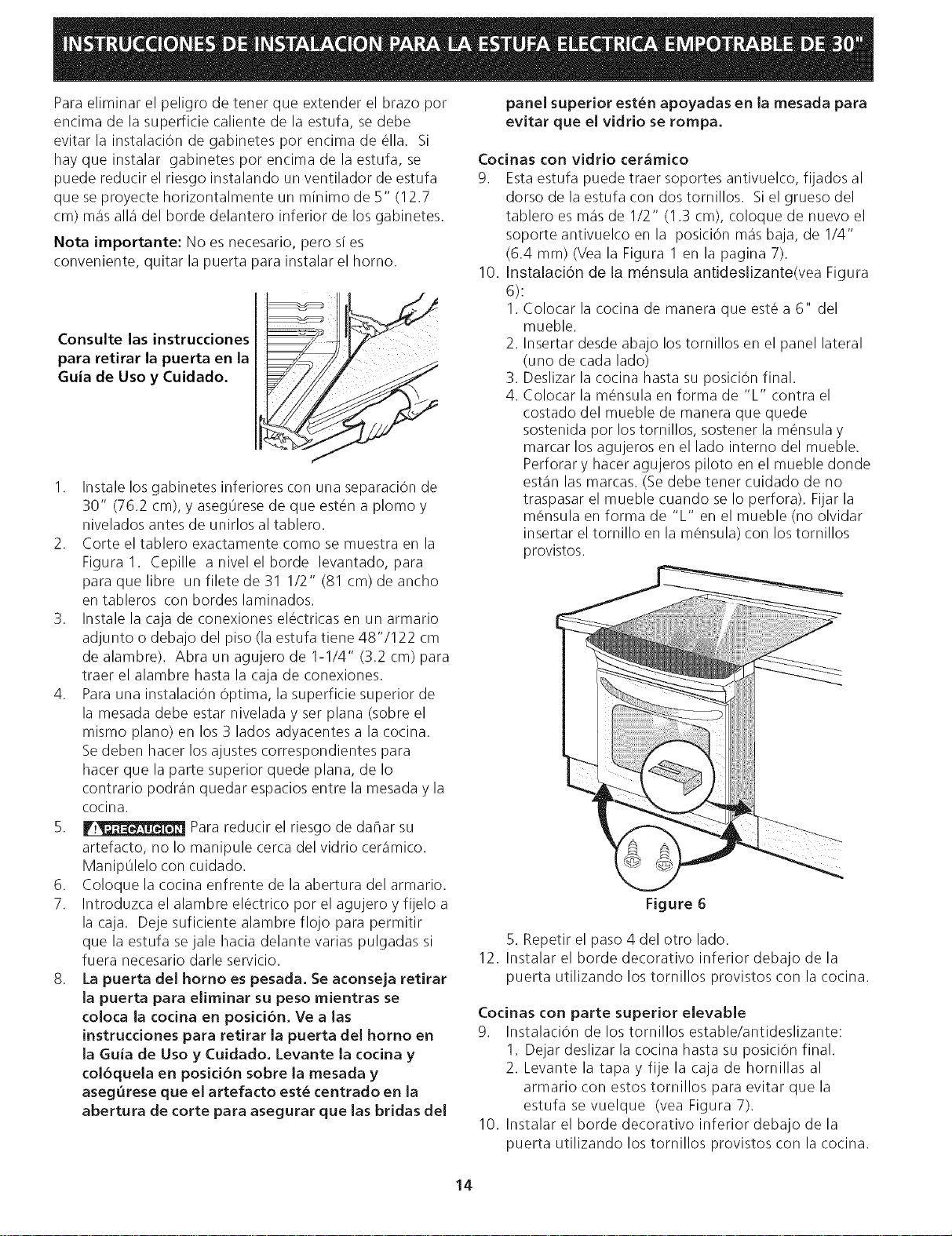
10. Instalaci6n de la mensula antideslizante(vea Figura
6):
I. Colocar la cocina de manera que est_ a 6" del
mueble.
2. Insertar desde abajo los tornillos en el panel lateral
(uno de cada lado)
3. Deslizar la cocina hasta su posiciOn final.
4. Colocar la m_nsula en forma de "L" contra el
costado del mueble de manera que quede
sostenida pot los tornillos, sostener la m_nsula y
marcar los agujeros en el lado interno del mueble.
Perforar y hacer agujeros piloto en el mueble donde
estan las marcas. (Se debe tenet cuidado de no
traspasar el mueble cuando se Io perfora). Fijar la
m_nsula en forma de "L" en el mueble (no olvidar
insertar el tornillo en la m_nsula) con lostornillos
provistos.
Figure 6
5. Repetir el paso 4 del otto lado.
12. Instalar el horde decorativo inferior debajo de la
puerta utilizando los tornillos provistos con la cocina.
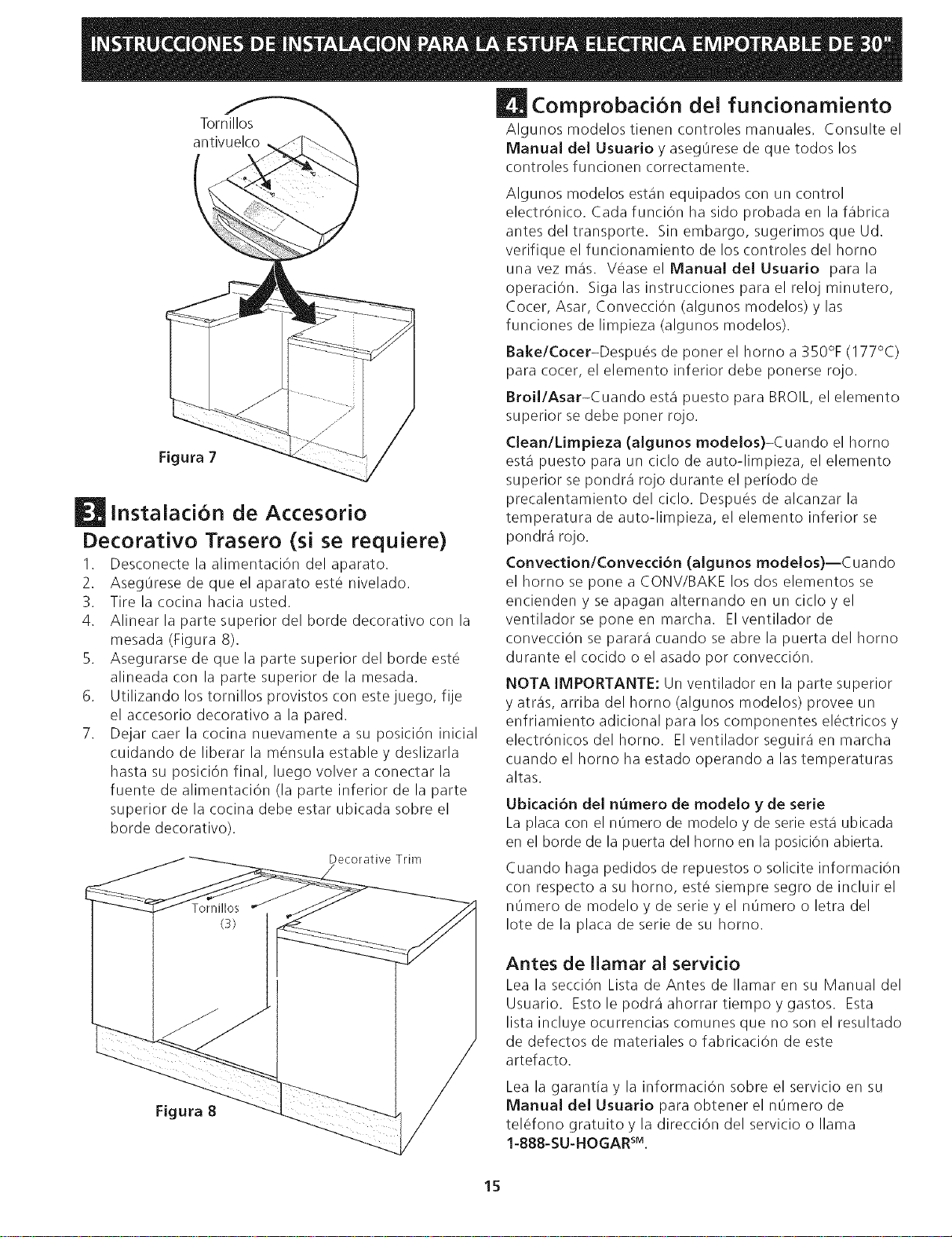
Codnas con parte superior elevable
9. InstalaciOn de los tornillos estable/antideslizante:
1. Dejar deslizar la cocina hasta su posicion final.
2. Levante la tapa y fije la caja de hornillas al
armario con estos tornillos para evitar que la
estufasevuelque (vea Figura7).
10. Instalar el horde decorativo inferior debajo de la
puerta utilizando los tornillos provistos con la cocina.
14
mornillos _ Comprobaci6n dei funcionamiento
Algunosmodelostienencontrolesmanuales. Consulteel
antivuelco Manual del Usuario y aseg@resede que todos los
controles funcionen correctamente.
Figura 7
instalaci6n de Accesorio
Decorativo Trasero (si se requiere)
I. Desconecte la alimentaci6n del aparato.
2. Aseg@resede que el aparato est6 nivelado.
3. Tire la cocina hacia usted.
4. Alinear la parte superior del horde decorativo con la
mesada (Figura 8).
5. Asegurarse de que la parte superior del horde est6
alineada con la parte superior de la mesada.
6. Utilizando los tornillos provistos con estejuego, fije
el accesorio decorativo a la pared.
7. Dejar caer la cocina nuevamente a su posici6n inicial
cuidando de liberar la mensula estable y deslizarla
hasta su posici6n final, luego volver a conectar la
fuente de alimentaciOn (la parte inferior de la parte
superior de la cocina debe estar ubicada sobre el
horde decorativo).
Decorative Trim
/
Tornillos
(3)
Figura 8
Algunos modelos estan equipados con un control
electr6nico. Cada funci6n ha sido probada en la fabrica
antesdeltransporte. Sin embargo, sugerimosqueUd.
verifique el funcionamiento de los controles del horno
unavez mas. V6aseel Manualdel Usuario para la
operaciOn. Sigalasinstruccionesparaelrelojminutero,
Cocer, Asar, ConvecciOn (algunos modelos) y las
funciones de limpieza (algunos modelos).
Bake/Cocer-Despu6s de poner el homo a 350% (177°C)
para cocer, el elemento inferior debe ponerse rojo.
Broil/Asar-Cuando esta puesto para BROIL,el elemento
superior se debe poner rojo.
Clean/Limpieza (algunos modelos)-Cuando el horno
esta puesto para un ciclo de auto-limpieza, el elemento
superior se pondra rojo durante el periodo de
precalentamiento del ciclo. Despu6s de alcanzar la
temperatura de auto-limpieza, el elemento inferior se
pondra rojo.
ConvectionlConvecci6n (algunos modelos)--Cuando
el horno se pone a CONV/BAKE los dos elementos se
encienden y se apagan alternando en un ciclo y el
ventiladorseponeen marcha. EIventiladorde
convecci6n se parara cuando se abre la puerta del homo
durante el cocido o el asado por convecci6n.
NOTA IMPORTANTE: Un ventilador en la parte superior
y atras, arriba del homo (algunos modelos) provee un
enfriamiento adicional para los componentes electricos y
electr6nicosdelhorno. EIventiladorseguiraenmarcha
cuando el homo ha estado operando alas temperaturas
altas.
Ubicad6n del n_mero de modelo y de serie
La placa con el n@merode modelo y de serie esta ubicada
en el horde de la puerta del homo en la posiciOn abierta.
Cuando haga pedidos de repuestos o solicite informaciOn
con respecto a su homo, est6 siempre segro de incluir el
n@mero de modelo y de serie y el n@mero o letra del
Iote de la plata de serie de su homo.
Antes de Ilamar al servicio
Lea la secciOn Lista de Antes de Ilamar en su Manual del
Usuario. Estolepodraahorrartiempoygastos. Esta
lista incluye ocurrencias comunes que no son el resultado
de defectos de materiales o fabricaciOn de este
artefacto.
Lea la garantia y la informaciOn sobre el servicio en su
Manual del Usuario para obtener el n@mero de
tel6fono gratuito y la direcci6n del servicio o llama
1-888-SU-HOGAR sM.
15

NOTA$:
16

