For Questions and Information call us at: 1-800-864-6194
•
Monday - Friday 8:00am - 5:00pm CST
KEEP THIS MANUAL FOR FUTURE REFERENCE
NOT FOR COMMERCIAL USE
OWNER’S MANUAL
Barbour International, Inc.
•
101 Cypress Way
•
Brandon, MS 39042
•
www.thebayou.com
Safety Alerts, Assembly & Operating Instructions
General Maintenance & Storage
This Instruction Manual contains important information necessary for the proper
assembly and safe use of this appliance. Carefully read and follow all war
nings and
instructions before assembling and using this appliance.
WARNING
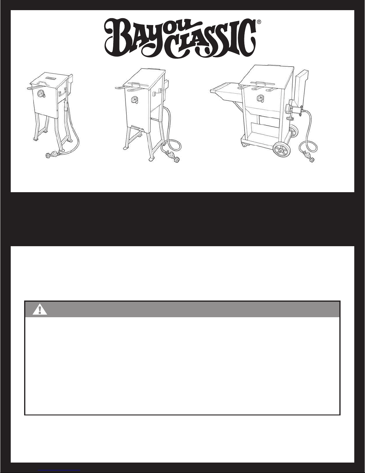
MODEL
#700-701
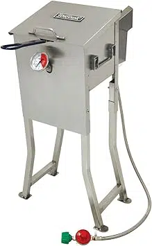
4-Gallon
MODEL
#700-725
2.5-Gallon
STAINLESS BAYOU FRYER
®
MODEL
#700-709
9-Gallon
• This appliance does not have automatic thermostat
controls so must be attended and monitored
at all times during oil heat up and frying.
• Oil heated above 400°F can ignite and cause a fire.
• Monitor the thermometer every 3 minutes to ensure cooking oil does not exceed 400°F.
• Shut off gas if oil exceeds 400°F or begins to smoke.
• Lid must be open during oil heat up and frying.
• In case of fire; close lid, turn off gas and call Fire Department.
• Do not attempt to extinguish an oil/grease fire with water.
• Surface of the appliance is extremely hot.
• This appliance is not to be used to fry whole turkeys.
Downloaded from www.ManualsFile.com manuals search engine
• Sober adult operation ONLY! Only a qualified person shall operate this appliance. The use of
alcohol, prescription or non prescription dr
ugs may impair ability to properly assemble or safely
operate this appliance.
• Do not use this fryer for other than its intended purpose.
•
Never allow oil or grease to exceed 400°F (200°C), it can ignite and cause a fire. Shut off gas if
oil exceeds 400°F or begins to smoke.
•
Regardless of thermometer reading, if the oil/grease starts to smoke, turn OFF fuel supply to the
burner and STOP COOKING IMMEDIATELY. This indicates the thermometer is not working properly.
Discard the thermometer and call 1-800-864-6194 M-F 8am-5pm CST for assistance.
•
Never operate this appliance within 10 feet of any structure or combustible material. Do not operate
it within 25 feet of combustible/flammable liquids such as gasoline or paints.
•
In case of fire, close lid, turn off gas and call Fire Department.
•
Do not attempt to extinguish an oil/grease fire with water.
DANGER
WARNING
• This fryer is a high pressure gas appliance for OUTDOOR USE ONLY (Outside any enclosure).
DO NOT use in a building, home, garage, balcony
, porch, tent or any other enclosed area.
Gas appliances shall not be used on or under apartment/condominium balconies or decks.
DO NOT install or use in or on recreational vehicles, pick-up trucks or boats.
• This appliance does not have automatic thermostat controls and MUST BE ATTENDED and
monitored at all times during oil heat up, frying, and cool down periods.
•
Only use replacement/accessory parts manufactured by Barbour International, Inc.
• Combustion by products from the use of this product can contain chemicals known to the
State of California to cause cancer, birth defects, or other reproductive harm.
•
This product contains a chemical(s) known to the State of California to cause cancer, birth defects
or other reproductive harm.
• THIS APPLIANCE IS NOT TO BE USED TO FRY WHOLE TURKEYS.
Remember: Think Safety and Use Common Sense!
FAILURE TO FOLLOW THESE INSTRUCTIONS COULD RESULT IN FIRE, EXPLOSION OR BURN HAZARD,
WHICH COULD CAUSE PROPERTY DAMAGE, PERSONAL INJUR
Y OR DEATH.
IF YOU SMELL GAS:
1. Shut off gas to the appliance.
2.
Extinguish any open flame.
3. If odor continues, keep away from the appliance and immediately call your fire department.
DANGER
The warnings and safety instructions in this manual MUST be understood and followed to provide reasonable
safety and efficiency
while using your appliance. Read the assembly, operation, and storage instructions
thoroughly before operating or servicing this equipment.
Downloaded from www.ManualsFile.com manuals search engine
1
CONTENTS
Table of Contents/Safety Symbols
Safety Precautions & W
arnings
Note to Consumer & Warranty
Assembly Instructions
#700-725 2.5-Gal.
#700-709 9-Gal.
#700-701 4-Gal.
Thermometer Assembly
Regulator Hose Assembly
Connecting Regulator Hose Assembly
Liquid Propane Gas Information
Gas Leak Testing Instructions
Set-Up and Positioning
Set-Up for 2.5 Gallon T
abletop Fryer
Lighting Instructions
Operating Instructions
Cooking Oil
Cleaning and Storage
Trouble Shooting Tips
FAQs and Helpful Tips
10 - 11
12 - 13
14
15
16
17
18 - 19
20
21
22
If you have a missing or damaged part, please do not return
this item to the store.
Call Barbour International, Inc. for assistance:
1-800-864-6194
Monday-Friday 8:00am - 5:00pm CST
1
2
3
4
5
6 - 7
8
8
9
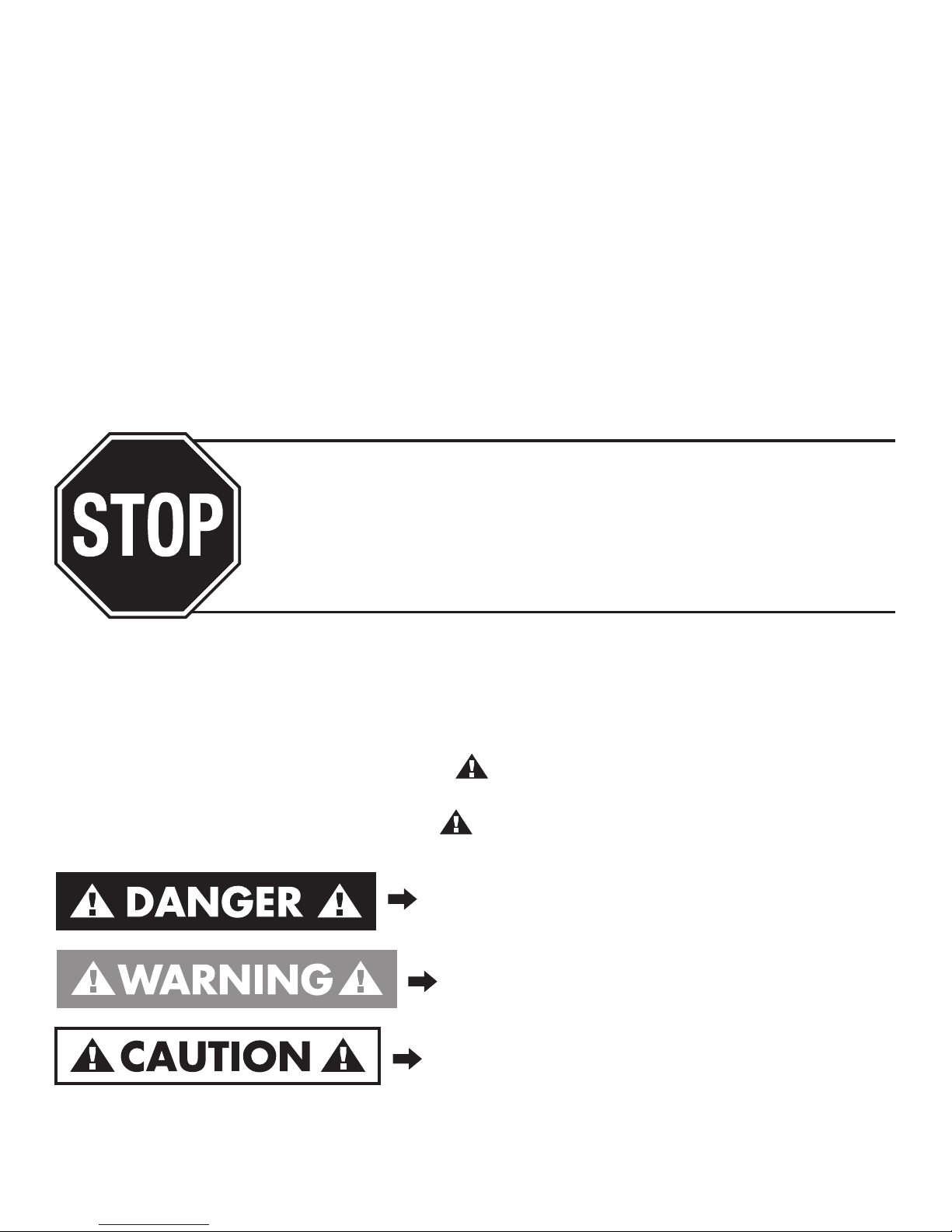
SAFETY SYMBOLS
The symbols and boxes shown below explain what each heading means. Read and follow all
of the safety warnings and instructions contained in this manual and on the cooker.
THE PURPOSE OF THIS SAFETY ALERT SYMBOL IS TO ATTRACT YOUR ATTENTION
TO POSSIBLE HAZARDS AS YOU ASSEMBLE AND USE THIS PRODUCT
.
WHEN YOU SEE THE SAFETY ALER
T SYMBOL
PAY CLOSE ATTENTION TO THE INFORMATION WHICH FOLLOWS!
Indicates an imminently hazardous situation which,
if not avoided, will result in death or serious injury
.
Hazard or unsafe practices which could result in
minor personal injur
y
, product, or property damages.
Hazard or unsafe practices which could result in
severe property damages, personal injur
y, or death.
Carefully read and follow all WARNINGS, SAFETY PRECAUTIONS, ASSEMBLY and OPERATING INSTRUCTIONS
contained in this manual and on the cooker.
DO
NOT skip any of the warnings and instructions! SAVE THIS MANUAL FOR FUTURE REFERENCE.
Downloaded from www.ManualsFile.com manuals search engine
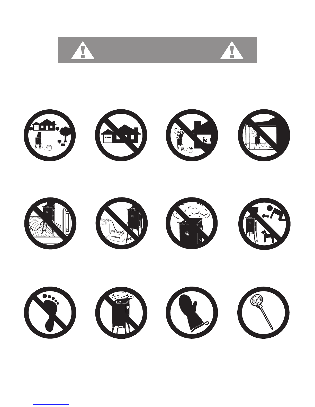
ALWAYS
wear protective mitts, gloves,
and long sleeve clothing
when cooking.
OUTDOOR USE ONLY!
Do not operate inside patios,
garages or carports.
NEVER!
No barefeet or sandals
when cooking.
NEVER
use under any
roof or overhang.
NEVER!
let children or pets near
the cooking area
during and after use.
NEVER
LEAVE APPLIANCE
UNATTENDED!
HOT!
Unit is extremely hot during and
after use. Allow 2 hours for unit
to cool down before touching.
Below 115°F (45°C)
ALWAYS
use an accurate thermometer
to monitor temperature when
preheating oil or frying.
NEVER
use on decks, boats or
any combustible surface!
NEVER
place flammable or
combustible materials
within 25-ft of fryer.
ALWAYS
operate in a clear open
area away from buildings,
trees and shrubs.
NEVER
close lid when
preheating oil or frying.
2
SAFETY PRECAUTIONS AND WARNINGS
Remember: Think Safety and Use Common Sense!
This fryer does not have automatic thermostat controls.
Failure to follow these instructions could result in fire or explosion
which could cause proper
ty damage, personal injury or death!
WARNING
2
Downloaded from www.ManualsFile.com manuals search engine

3
LIMITED WARRANTY
Barbour International, Inc. ("V
endor") warrants to the original retail purchaser of this gas fryer/cooker and no other person, that if this gas fryer/cooker is
assembled and operated in accordance with the printed instructions accompanying it, then for a period of one (1) year from the date of purchase, all parts
in such gas fryer/cooker shall be free from defects in material and workmanship. Vendor may require reasonable proof of your date of purchase from an
authorized retailer or distributor. Therefore, you should retain your sales slip or invoice. This Limited Warranty shall be limited to the repair or replacement
of parts, which prove defective under normal use and service and which Vendor shall determine in its reasonable discretion upon examination to be defective.
Before returning any parts, you should contact Vendor's Customer Service Department using the contact information listed below. If Vendor confirms, after
examination, a defect covered by this Limited Warranty in any returned part, and if Vendor approves the claim, Vendor will replace such defective part without
charge. If you return defective parts, transportation charges must be prepaid by you. Vendor will return replacement parts to the original retail purchaser,
freight or postage prepaid.
This Limited Warranty does not cover any failures or operating difficulties due to accident, abuse, misuse, alteration, misapplication, improper installation
or improper maintenance or service by you or any third party, or failure to perform normal and routine maintenance on the gas fryer/cooker, as set out in
this owner's manual. In addition, the Limited Warranty does not cover damage to the finish, such as scratches, surface chips and cracks, discoloration, rust
or other weather damage, after purchase.
This Limited Warranty is in lieu of all other express warranties. Vendor disclaims all warranties for products that are purchased from sellers other than authorized
retailers or distributors. AFTER THE PERIOD OF THE ONE (1)-YEAR EXPRESS WARRANTY, VENDOR DISCLAIMS ANY AND ALL IMPLIED WARRANTIES,
INCLUDING WITHOUT LIMITATION THE IMPLIED WARRANTIES OF MERCHANTABILITY AND FITNESS FOR A PARTICULAR PURPOSE. FURTHER, VENDOR
SHALL HAVE NO LIABILITY WHATSOEVER TO PURCHASER OR ANY THIRD PARTY FOR ANY SPECIAL, INDIRECT, PUNITIVE, INCIDENTAL, OR CONSEQUENTIAL
DAMAGES. Vendor assumes no responsibility for any defects caused by third parties. This Limited Warranty gives the purchaser specific legal rights; a
purchaser may have other rights depending upon where he or she lives. Some jurisdictions do not allow the exclusion or limitation of special, incidental or
consequential damages, or limitations on how long a warranty lasts, so the above exclusion and limitations may apply to you.
Vendor does not authorize any person or company to assume for it any other obligation or liability in connection with the sale, installation, use, removal,
return, or replacement of its equipment, and no such representations are binding on Vendor.
NOTE TO CONSUMER
Sincerely,
This LP Gas Cooker is a specialized high pressure gas appliance having greater heat output than traditional kitchen stoves.
It operates using an open flame, and you must use extreme caution and attention when operating. It is referred to as "fr
yer"
and "appliance" in this manual and on warning tags. Same as a kitchen stove, this appliance does not have automatic
thermostat controls so must be attended and monitored at all times during use. Owning and operating this appliance includes
accepting responsibility and liability forusing it safely and properly accoridng to all applicable laws, common sense practices,
and all information found within the manual.
This appliance is for OUTDOOR USE ONLY, providing multiple cooking options such as frying fish, chicken, french fries,
hushpuppies, onions and wings. This appliance is not to be used to fry whole turkeys.
Restrict the use of this appliance to sober adults who can read, understand and follow the warnings and instructions in this
manual, and on the fryer. Safety Alerts alone cannot eliminate the hazards that they signal. Strict compliance with these
instructions, plus common sense operation, are primary accident prevention measures.
If you have any doubts or concerns about your ability to use this appliance call 1-800-864-6194. If, after talking with a
Bayou Classic Customer Service Representative, you still have concerns about operating this appliance, DO NOT USE!
Contact your dealer for return and refund.
The assembly and operation of this appliance must conform with local codes or; in the absence of local codes, with the National
Fuel Gas Code, ANSI Z223.1/NFPA 54, Storage and Handling of Liquefied Petroleum Gases, ANSI/NFPA 58, Natural Gas
and Propane Installation Code, CSA B149.1, Propane Storage and Handling, CSA B149.2, or the Standard for Recreational
Vehicles, ANSI A119.2/NFPA 1192 and the Recreational Vehicle Code, CSA z240 RV Series.
Where conflicts exist between instructions and information in this manual and local or national codes or regulations regarding
use and operation of this appliance, the operator shall comply with the codes or laws put in force by the regulatory authority
for the zone in which the equipment is operated. To check your local codes, see your local LP gas dealer or Natural Gas
Company.
Downloaded from www.ManualsFile.com manuals search engine
4
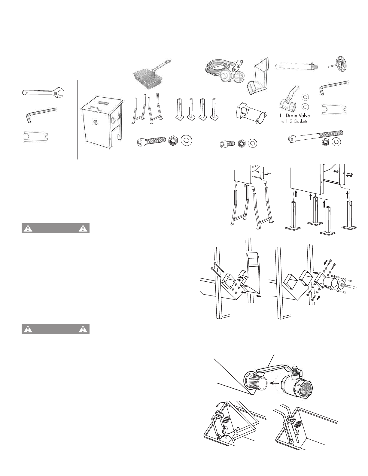
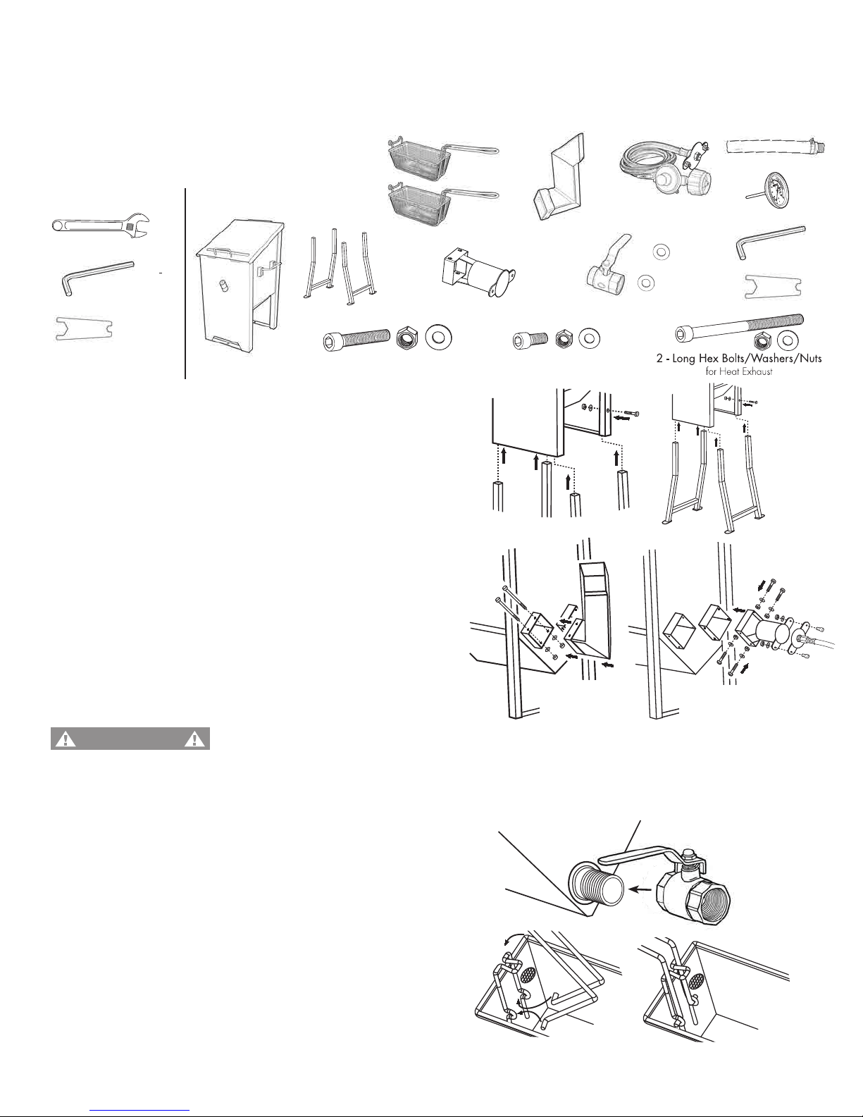
3. Screw Drain Valve onto Fryer Body. Wrench tighten.
NOTE: When Attaching Drain Valve, make sure that
the Locking Tab for Handle is positioned towards
the Fryer Body.
1 - Exhaust Vent
1 - Hex Wrench
4. Lock Basket Handle into place by inserting handle
into loops on Basket. Then with some pressure,
carefully force Basket Handle Bars around the clasp
on the Basket.
ASSEMBLY INSTRUCTIONS
READ ALL SAFETY WARNINGS
& ASSEMBLY INSTRUCTIONS CAREFULLY BEFORE ASSEMBLING OR OPERATING
YOUR FRYER. Inspect contents in the box to ensure all parts are included and undamaged.
FOR MISSING PARTS OR ASSISTANCE, PLEASE CALL 1-800-864-6194 M-F 8am - 5pm CST.
Proof of purchase will be required.
TOOLS REQUIRED:
Adjustable Wrench
PARTS INCLUDED:
Model #700-725
1 - Fryer Body
1 - Stainless Steel
Basket
2 - Extension Legs
1 - Thermometer
Wrench
1 - Thermometer
1 - Drain Hose
Thermometer Wrench,
provided
5. Attach Regulator Hose Assembly to Brass Connector
on Gas Inlet/Jet Burner
. Refer to pages 8 - 9.
Exhaust vent MUST be attached to the LEFT
opening on back panel so that exhaust
flows A
W
AY from burner intake and AWAY
from the person lighting the burner.
WARNING
Hex Wrench, provided
2 - Long Hex Bolts/Washers/Nuts
for Heat Exhaust
4 - Short Hex Bolts/Washers/Nuts
for Gas Inlet
4 - Large Hex Bolts/Washers/Nuts
for either Extension Legs or Short Legs
2. (a) Attach EXHAUST VENT
to LEFT opening on back
of Fryer using 2 Long Hex Bolts/Washers/Nuts.
Check to verify that all connections on the pre-assembled
Gas Inlet/Jet Burner are screwed together tightly.
(b) Attach the GAS INLET to RIGHT opening on back
of Fryer using 4 Short Hex Bolts/Washers/Nuts.
Attach REGULATOR HOSE ASSEMBLY with GAS INLET
COVER to GAS INLET using pre-attached Hex Bolts/Nuts.
(a)
ON LEFT
SIDE
4 - Short Legs
1. Attach LEGS to base of fryer:
(a)
Freestanding application: Slide Extension Legs into holes on
the Fryer. Attach using the 4 Large Hex Bolts/Washers/Nuts.
-OR-
(a) Tabletop application: Slide 4 Short Legs into holes on
the Fryer. Attach using the 4 Large Hex Bolts/Washers/Nuts.
(a)
(b)
This fryer must be operated with
either the shor
t or long legs attached.
WARNING
OR
EXHAUST VENT
2.5-Gal. Fryer
(b)
ON RIGHT
SIDE
GAS INLET/JET BURNER
ASSEMBLY INSTRUCTIONS
READ ALL SAFETY WARNINGS
& ASSEMBLY INSTRUCTIONS CAREFULLY BEFORE ASSEMBLING OR OPERATING
YOUR FRYER. Inspect contents in the box to ensure all parts are included and undamaged.
FOR MISSING PARTS OR ASSISTANCE, PLEASE CALL 1-800-864-6194 M-F 8am - 5pm CST.
Proof of purchase will be required.
1- Regulator
Hose Assembly
with Gas Inlet Cover
1 - Gas Inlet/Jet Burner
Downloaded from www.ManualsFile.com manuals search engine
5
1 - Drain Valve with 2 Gaskets
1 - Hex Wrench
ASSEMBLY INSTRUCTIONS
READ ALL SAFETY WARNINGS
& ASSEMBLY INSTRUCTIONS CAREFULLY BEFORE ASSEMBLING OR OPERATING
YOUR FRYER. Inspect contents in the box to ensure all parts are included and undamaged.
FOR MISSING PARTS OR ASSISTANCE, PLEASE CALL 1-800-864-6194 M-F 8am - 5pm CST.
Proof of purchase will be required.
TOOLS REQUIRED:
Adjustable Wrench
PARTS INCLUDED:
Model #700-701
1 - Fryer Body
2 - Stainless Steel Baskets
2 - Extension Legs
1 - Exhaust Vent
1 - Thermometer Wrench
1 - Thermometer
1 - Drain Hose
Thermometer Wrench,
provided
Hex Wrench, provided
1. Slide Extension Leg into holes on the Fryer
.
Attach using the 4 Large Hex Bolts/Washers/Nuts.
4. Lock Basket Handle into place by inser
ting handle
into loops on Basket. Then with some pressure,
carefully force Basket Handle Bars around the clasp
on the Basket.
2. (a) Attach EXHAUST VENT to LEFT opening on back
of Fryer using 2 Long Hex Bolts/Washers/Nuts.
Check to verify that all connections on the pre-assembled
Gas Inlet/Jet Burner are screwed together tightly.
(b) Attach the GAS INLET to RIGHT opening on back
of Fryer using 4 Short Hex Bolts/Washers/Nuts.
Attach REGULATOR HOSE ASSEMBLY with GAS INLET
COVER to GAS INLET using pre-attached Hex Bolts/Nuts.
3. Screw Drain Valve onto Fr
yer Body. Wrench tighten.
NOTE: When Attaching Drain Valve, make sure that the
Locking Tab for Handle is positioned towards
the Fryer Body.
4 - Short Hex Bolts/Washers/Nuts
for Gas Inlet
4 - Large Hex Bolts/Washers/Nuts
for Extension Legs
(a)
ON LEFT
SIDE
5. Attach Regulator Hose Assembly to Brass Connector
on Gas Inlet/Jet Burner
. Refer to pages 8 - 9.
EXHAUST VENT
Exhaust vent MUST be attached to the LEFT
opening on back panel so that exhaust
flows A
W
AY from burner intake and AWAY
from the person lighting the burner.
WARNING
4-Gal. Fryer
(b)
ON RIGHT
SIDE
GAS INLET/JET BURNER
1- Regulator
Hose Assembly
with Gas Inlet Cover
1 - Gas Inlet/Jet Burner
Downloaded from www.ManualsFile.com manuals search engine
6
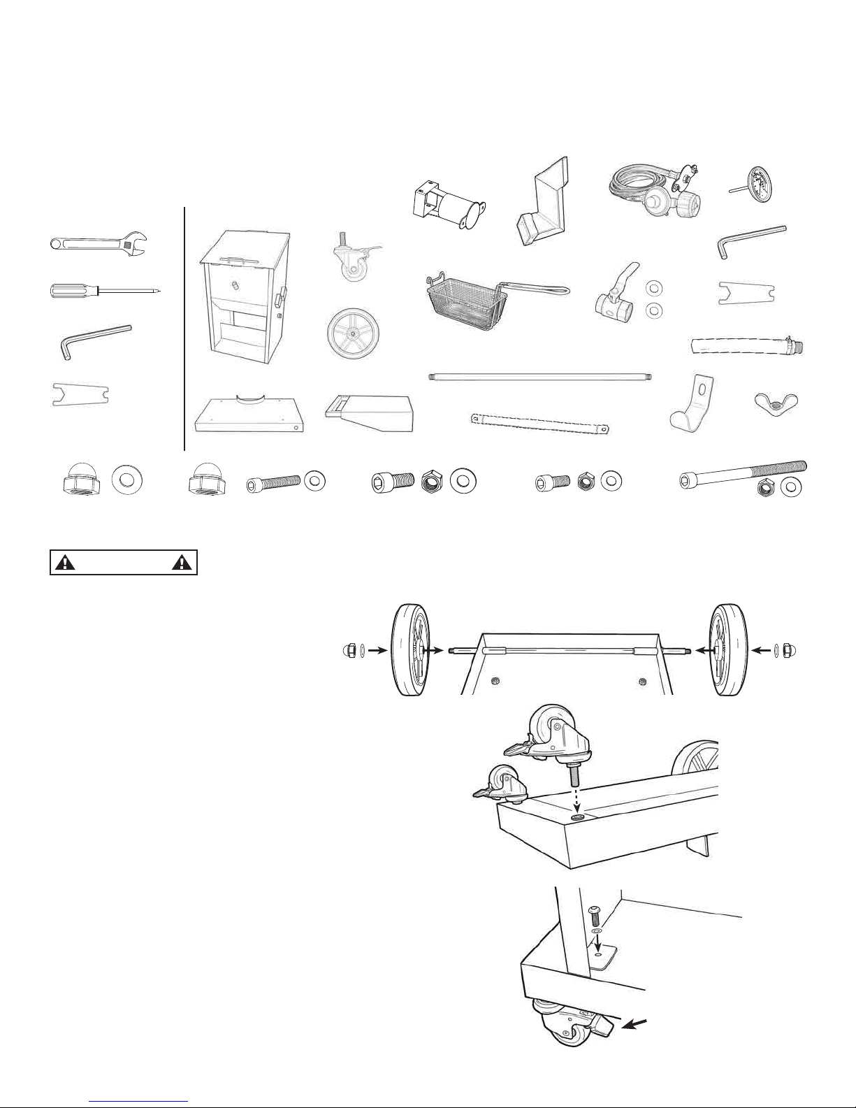
ASSEMBLY INSTRUCTIONS
READ ALL SAFETY WARNINGS & ASSEMBLY INSTRUCTIONS CAREFULLY BEFORE ASSEMBLING OR OPERATING
YOUR FRYER. Inspect contents in the box to ensure all parts are included and undamaged.
FOR MISSING PARTS OR ASSISTANCE, PLEASE CALL 1-800-864-6194 M-F 8am - 5pm CST.
Proof of purchase will be required.
TOOLS REQUIRED:
Adjustable Wrench
PARTS INCLUDED:
Model #700-709
Phillips Head Screwdriver
1 - Fryer Body
3 - Stainless Steel Baskets
1 - Cart Bottom
1 - Gas Inlet/
Jet Bur
ner
1 - Exhaust Vent
1 - Thermometer Wrench
1 - Thermometer
1 - Drain Hose
Thermometer Wrench,
provided
4 - Short Hex Bolts/Washers/Nuts
for Gas Inlet
2 - Acorn Nuts
for Side Shelf
2 - Side Shelf Brackets
1 - Side Shelf
1 - Drain Valve
with 2 Gaskets
1 - Tank Hook
1 - Wingnut
for Tank Hook
4 - Large Hex Bolts/Washers/Nuts
for Cart Bottom
2 - Acorn Nuts/Washers
for Wheels
2 - Long Bolts/Washers/Nuts
for Heat Exhaust
4 - Hex Bolts
for Side Shelf
1. Place Cart Bottom upside down
on floor and slide in Wheel Axle.
Attach both Large Wheels using
Acor
n Nuts and Washers.
2. Screw on Locking Casters in front holes of Cart Bottom.
W
rench Tighten.
Flip over Cart Bottom, right side up.
This Fryer is HEAVY! Moving, unpacking and assembly is a TWO PERSON operation.
Before lifting onto car
t, open lid and remove all components and packaging from inside.
2 - Wheels
2 - Locking Casters
1 - Wheel Axle
1 - Hex Wrench
Hex Wrench, provided
NOTE:
Lock Down Tabs on
Casters before placing
Fr
yer on Cart
CAUTION
3. When placing Fryer Body on Car
t Bottom, make sure
the Tank Hook on Fryer Body will align with the Tank Rest
on Cart Bottom.
Carefully lift Fryer Body and place on top of Cart Bottom.
Align the brackets on Fryer Body to the holes on Cart Bottom.
Attach using 4 Large Hex Bolts/Washers/Nuts.
9-Gal. Fryer
1- Regulator
Hose Assembly
with Gas Inlet Cover
Downloaded from www.ManualsFile.com manuals search engine
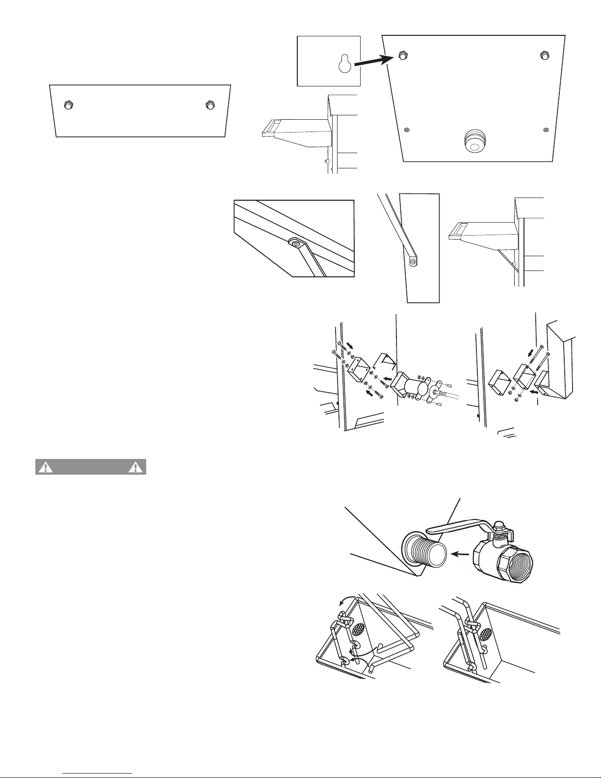
7
8. Lock Basket Handle into place by inserting handle
into loops on Basket. Then with some pressure,
carefully force Basket Handle Bars around the
clasp on the Basket.
5. Attach Shelf Brackets
to Side Shelf and Fryer
using 4 Small Hex Bolts/W
ashers.
Side Shelf
with Brackets
Underneath
Side Shelf
4. Attach 2 Acorn Nuts on Shelf Side of Fr
yer
as shown below. Then Slide Side Shelf onto
Acorn Nuts on side of Fryer Wall.
Side Shelf on
Fryer Wall
Side of Fryer for Shelf
Exhaust vent MUST be attached to the RIGHT opening on back panel so that exhaust flows
AW
AY from burner intake and AWAY from the person lighting the burner.
WARNING
6. (a) Check to verify that all connections on the pre-assembled
Gas Inlet/Jet Burner are screwed together tightly
.
Attach the GAS INLET to the LEFT opening on back
of Fryer using 4 Short Hex Bolts/Washers/Nuts.
(b) Attach EXHAUST VENT to RIGHT opening on back
of Fryer using 2 Long Hex Bolts/Washers/Nuts.
Attach REGULATOR HOSE ASSEMBLY with GAS INLET
COVER to GAS INLET using pre-attached Hex Bolts/Nuts.
(b)
(a)
Acorn Nuts attach to Fryer Wall
7. Screw Drain Valve onto Fr
yer Body. Wrench tighten.
NOTE: When Attaching Drain Valve, make sure that the
Locking Tab for Handle is positioned towards
the Fryer Body.
Side of
Fryer W
all
ON RIGHT
SIDE
ON LEFT
SIDE
EXHAUST VENT
GAS INLET/JET BURNER
9. Attach Regulator Hose Assembly to Brass Connector
on Gas Inlet/Jet Bur
ner
. Refer to pages 8 - 9.
Downloaded from www.ManualsFile.com manuals search engine
8
LP GAS CYLINDER
T
o check your local codes, see your local LP gas dealer or natural gas company. This appliance is not intended to
be connected to a natural gas supply line.
When
purchasing or exchanging a cylinder for your gas cooker, it must be constructed and marked in accordance
with the specifications for LP gas cylinders by the U.S. Department of Transportation (DOT) or the National Standard
of Canada, CAN/CSA-B339, Cylinders, Spheres and Tubes for the Transportation of Dangerous Goods as applicable
with a listed over-filling device (OPD).
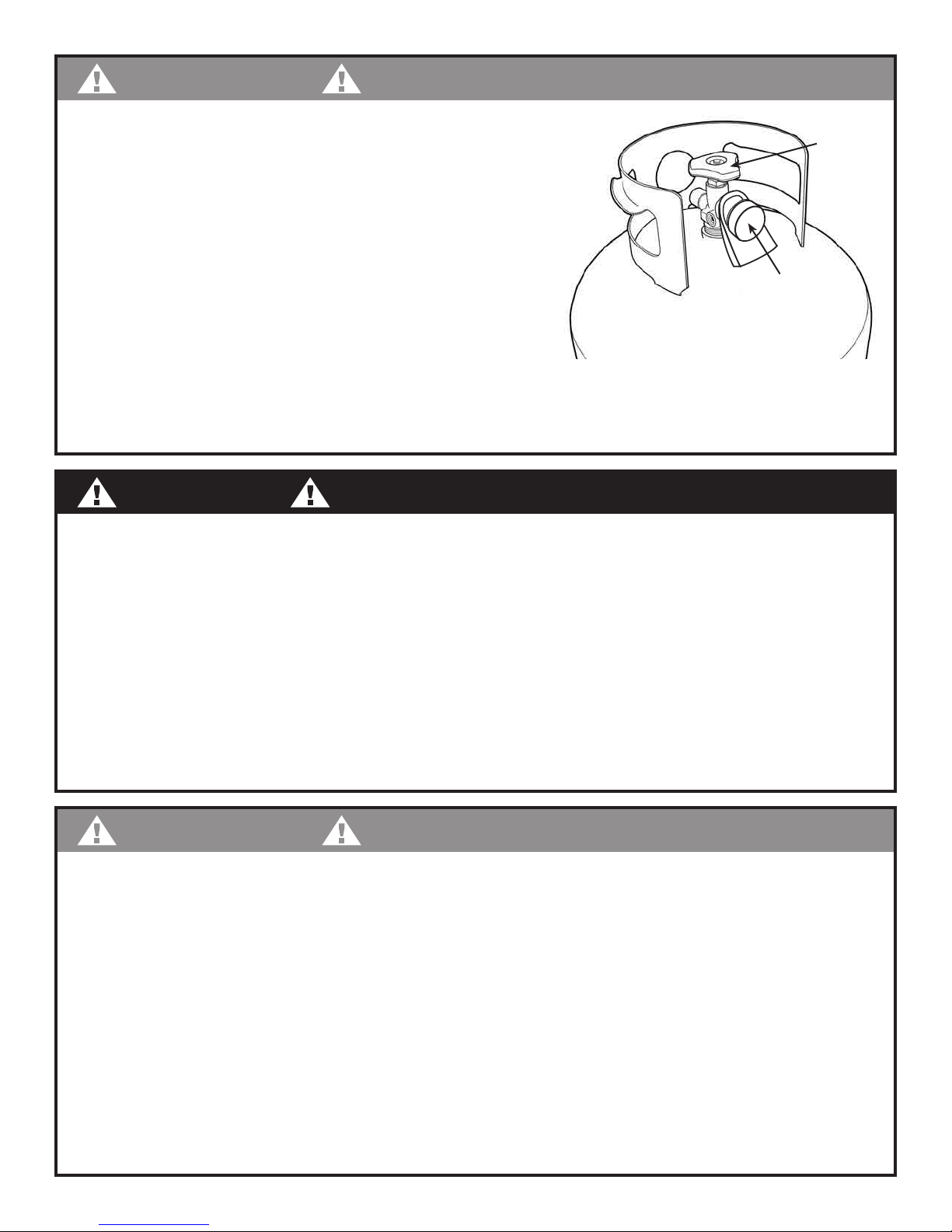
The cylinder must also be equipped with:
• A shut-off valve terminating in a Type-1
gas cylinder valve outlet.
• A Type-1 valve that prevents gas flow
until a positive seal is obtained.
• An arrangement for vapor withdrawal.
• A collar to protect the cylinder shut-off valve.
• A safety relief device having direct communication
with the vapor space of the cylinder.
• A listed Over-filling Prevention Device (OPD).
• A protective cap on cylinder Type-1 Outlet.
DANGER
This appliance can produce carbon monoxide which has
no odor.
Using it in an enclosed space can kill you.
Never
use this appliance in an enclosed space such as a camper,
tent, car or home.
CARBON MONOXIDE HAZARD
WARNING
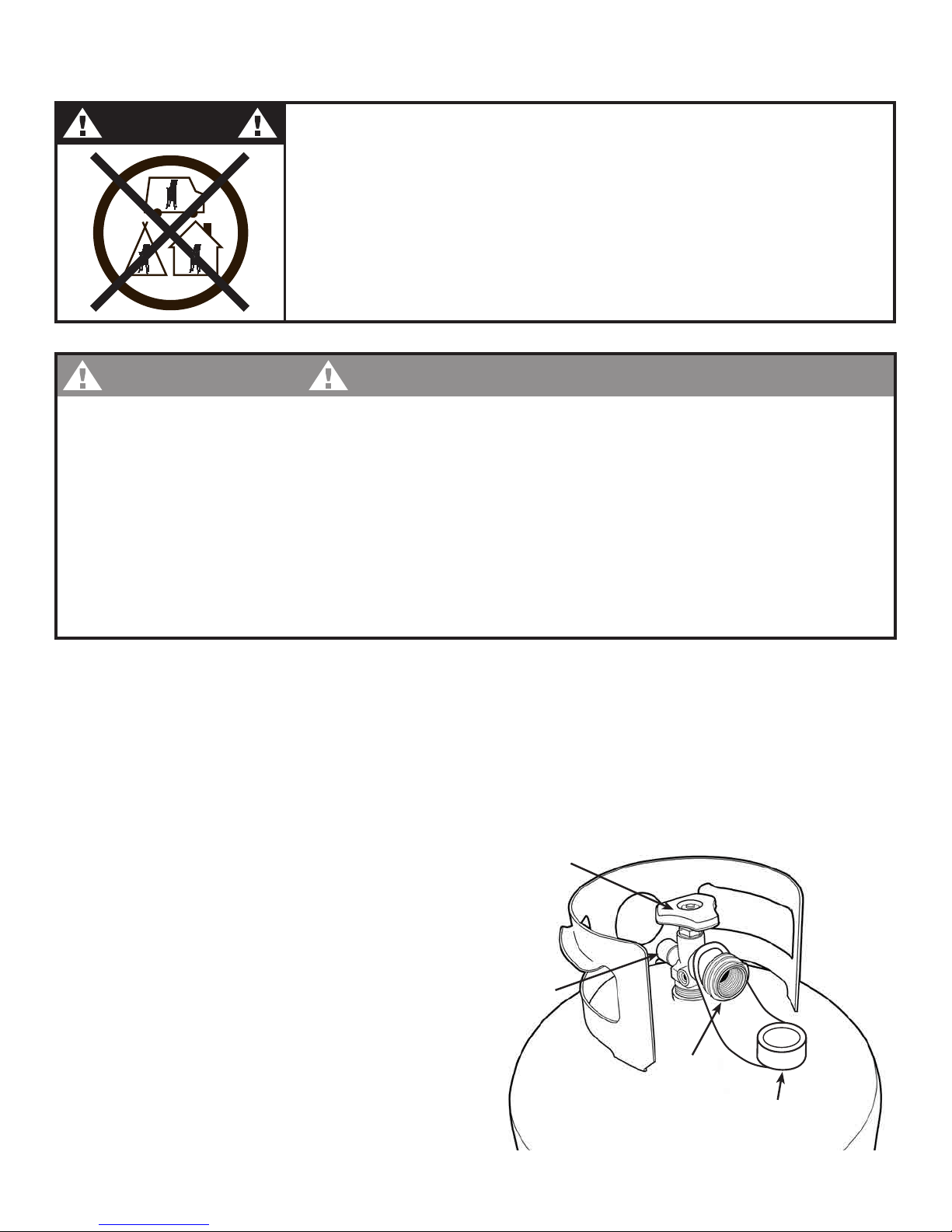
LP GAS CYLINDER (NOT SUPPLIED WITH THIS APPLIANCE)
The LP (Liquid Propane) gas cylinder specifically designed to be used with this fr
yer must have a 20 lb
(9.1 kg) capacity incorporating a Type-1 cylinder valve and an over-filling protection device (OPD).
• DO NOT connect this cooker to an existing #510 POL cylinder valve with Left Hand Threads.
The Type-1 valve can be identified with the large external threads on the valve outlet.
• DO NOT connect to a propane cylinder exceeding this capacity.
• DO NOT connect to a cylinder that uses any other type of valve connection device.
OPD Handwheel
(Cylinder Valve)
Protective Cap
Type1
Outlet
Safety Relief
Valve
LP GAS CYLINDER SPECIFICATIONS
Downloaded from www.ManualsFile.com manuals search engine
WARNING
• Turn off the cylinder valve when your fryer is not in use.
• Handle the LP gas cylinder with care.
• Always secure the LP gas cylinder in an upright position.
• Never connect an unregulated LP gas cylinder to your fryer.
• DO NOT expose LP gas cylinders to excessive heat
or ignition sources.
• DO NOT store a spare LP gas cylinder near your fryer.
• Allow only qualified LP gas dealers to fill or repair your
LP gas cylinder
• DO NOT allow the LP gas cylinder to be filled beyond 80% capacity.
• Read and follow all warnings/instructions that are on the cylinder and that accompany this product.
DANGER
• Never store spare LP gas cylinder near your fryer. This could cause excess pressure to be expelled
through the vapor relief valve resulting in fire, explosion, or severe
personal injury, including death.
NOTE: PROPANE GAS IS HEAVIER THAT AIR AND WILL COLLECT IN LOW AREAS.
PROPER VENTILATION IS EXTREMELY IMPORTANT
• Keep the ventilation opening(s) of the LP gas cylinder enclosure free and clear from obstruction and
debris.
• DO NOT insert any foreign objects into the valve outlet. Damage to the back-check could result.
A damaged back-check can cause a leak, possibly resulting in explosion, fire, severe personal
injury, bodily harm or death.
WARNING
FILLING THE LP GAS CYLINDER:
• Allow only qualified LP gas dealers to properly fill or repair
your LP gas cylinder.
• New tanks should be purged prior to filling; inform LP gas dealer if you are using a new tank.
• DO NOT allow the cylinder to be filled beyond 80% capacity. Over-filled tanks can create a
dangerous condition. Over-filled tanks can build up pressure and cause the relief valve to expel
propane gas vapors. The vapor is combustible and if it comes in contact with a spark source or
flame; an explosion causing severe burns, bodily harm, or death could occur.
• Always use a protective cylinder cap when cooker is not connected to cylinder.
• If you exchange a cylinder with a qualified exchange program, be sure the cylinder has a
Type-1 valve and an over-filling prevention device (OPD).
Store upright with
Protective Cap
CLOSED
Cylinder
Valve
Use and store cylinder
in upright position
9
Downloaded from www.ManualsFile.com manuals search engine

THERMOMETER TEST INSTRUCTIONS
2-STEP METHOD for Thermometer Testing
1. TEMPERATURE ACCURACY
:
While wearing protective gloves, hold the thermometer by the dial and insert stem into boiling water.
The needle should quickly move around the dial and register approximately 212°F (100°C)
(plus or minus 5°F). This indicates whether or not temperature reading is accurate.
NOTE: Due to water evaporation, the max reading possible on a thermometer in hot water is 212°F (100°C).
2. TEMPERATURE RANGE:
Hold thermometer by the dial and place end of the stem above a lit match or lighter. The needle
should quickly move around the dial and register a temperature reading far above 350°F. If the needle
stops at a low temperature reading such as 225°F; then the thermometer is damaged and cannot be
used. Discard the thermometer and order a replacement thermometer (Model #5070).
If you are uncertain about any aspect of testing or operating you fryer:
Call 1-800-864-6194 Monday - Friday, 8am - 5pm CST for assistance.
10
1. Test the thermometer to insure it accurately measures temperature
as shown above.
2.
Before installing thermometer, make sure the rubber gasket
is located on stem of thermometer underneath brass nut.
3. Insert Thermometer into hole on front of fryer.
Make sure the thermometer face is in the
upright position. Gently turn the brass nut
clockwise until thermometer is secure.
4. Using wrench provided, tighten brass nut
of thermometer until it is tightly secured to Fryer Stem.
5. After attaching thermometer
, check to make sure thermometer needle is pointing near actual outside
ambient temperature number.
F
I
R
E
H
A
Z
A
R
D
200
350
150
100
250
50
50
150
400
°C
750
°F
TURN
OFF
GAS
400
10
Upright Position
RUBBER
GASKET
BRASS
NUT
THERMOMETER ATTACHMENT INSTRUCTIONS
CAUTION
DO NOT tighten top nut on stem. Tightening the top nut will also turn the dial
and the temperature calibration will be compromised.
The thermometer supplied with your fryer is Model #5070. It is a sensitive measuring device which may
not work properly if dropped, bent, or twisted.
T
o order a replacement ther
mometer, call 1-800-864-6194, M - F 8am - 5pm CST for assistance.
You should test your thermometer before you install it into your fryer.
Always use a thermometer when frying any food products. DO NOT attempt frying if the thermometer
is not working. Always check to be sure thermometer is working properly BEFORE fr
ying.
DANGER
Downloaded from www.ManualsFile.com manuals search engine
11
REGULATOR HOSE ASSEMBLY
The hose supplied with your fryer is Model #M5HPR-1.
It is designed to work with a LP Gas Cylinder and is a
T
ype-1 connection device with the following features:
1. The system will not allow gas flow from the cylinder
until a positive connection to the cylinder valve has been made.
NOTE: The cylinder valve must be turned off (clockwise)
before any connection is made or removed.
2. A flow limiting device, when activated, restricts the
flow of gas to 10 cubic feet per hour.
NOTE: the flow limiting device can be activated when
attempting to light fryer. If this occurs, refer to Trouble Shooting on page 21.
WARNING
• DO NOT attempt to connect it to any other fuel supply source such as a natural gas line.
• DO NOT use any other pressure regulator/hose assembly than the
one supplied with your fryer.
• DO NOT attempt to adjust or repair the regulator.
• DO NOT attempt to disconnect the regulator hose assembly while fryer is in operation.
For connection to
LP Gas Cylinder
TYPE-1
Connector
Coupling Nut
Brass
Connector
For connection
to Fryer
Regulator Valve
A replacement regulator can be supplied by contracting Barbour International, Inc. at 1-800-864-6194.
Only use replacement regulator hose assembly #M5HPR-1. This regulator is designed to operate at a
maximum out put pressure of 10 psi (pounds per square inch).
CAUTION
The valve on the regulator hose assembly controls flame intensity ONLY. It is not an ON/OFF valve.
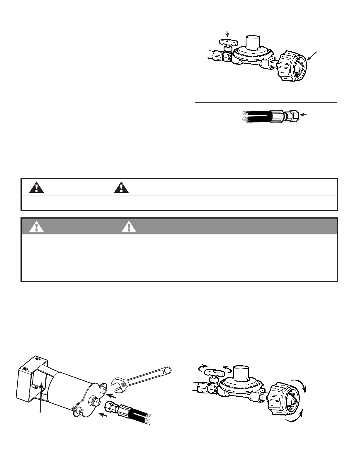
INSPECTING REGULATOR HOSE ASSEMBLY
The Regulator Hose Assembly is a pre-assembled unit. Do not take apar
t. Prior to each use, visually
inspect the regulator hose assembly. If there is evidence of abrasion, wear, cuts or leaks, the hose must
be replaced prior to the appliance being put into operation. To remove, use a wrench to loosen the brass
connector on the hose. To reattach, wrench tighten the brass connector back to the burner assembly.
Call 1-800-864-6194 for replacement Model #M5HPR-1. M-F 8am - 5pm CST.
Connect to Tank
(Clockwise)
Disconnect from Tank
(Counter
-Clockwise)
Decrease
Gas Flow
Increase
Gas Flow
Caution: The Regulator Valve
Controls the "Volume" of Gas
ONLY.
Use the Valve on the Propane Tank to
turn Gas Supply "ON" or "OFF".
PRESET REGULATOR
WITH SIDE VAL
VE
Turn Clockwise
Wrench Tighten
Light
BURNER
HERE
JET BURNER
Turn Counter-Clockwise
to Remove
Downloaded from www.ManualsFile.com manuals search engine
12
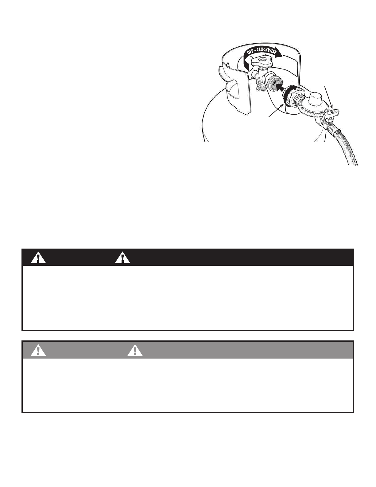
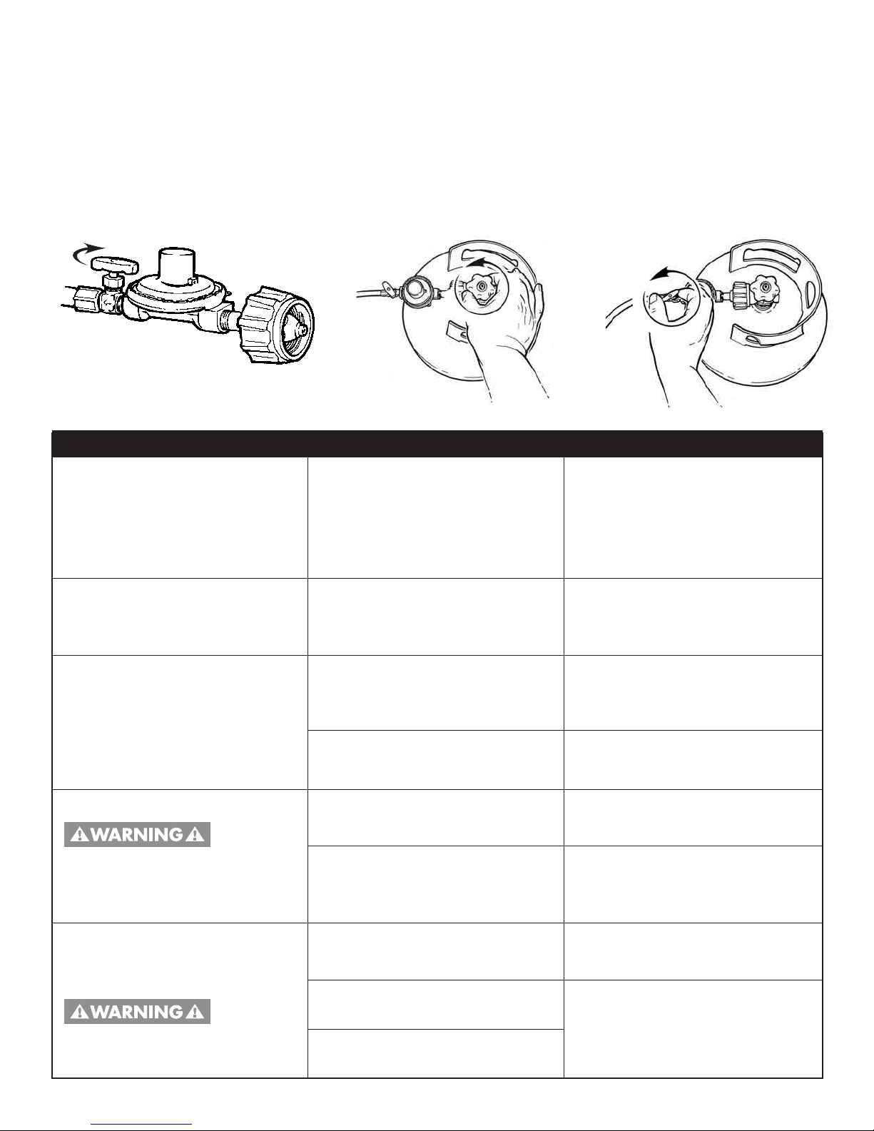
1. Check that cylinder is upright and the valve is closed
by turning the knob clockwise.
2.
Check that the Regulator Control Valve is also closed
by turning the knob clockwise.
3. Remove the protective safety caps from the cylinder valve
and the Type-1 Coupling Nut on the regulator.
4. Insert the nipple of large coupling nut into the
cylinder valve outlet. Insure that the coupling nut
is centered properly.
5. Turn the large coupling nut clockwise by hand and
tighten to a full stop. Take care not to cross thread
the coupling nut onto the cylinder valve.
Do not use tools to tighten connection.
NOTE: If you are unable to make the connection, repeat steps 4 and 5.
6. Check that the hose does not contain kinks, does not come into contact with sharp edges, and does
not contact surfaces that may become hot during use.
7.
Leak check all fittings before lighting fryer. Refer to pages 12 - 13 for Gas Leak Test Instructions.
CONNECTING REGULATOR HOSE ASSEMBLY TO LP GAS CYLINDER
Turn Coupling Nut
CLOCKWISE
to Attach
Hand Tighten!
Turn Regulator Valve
CLOCKWISE
to OFF position
Upright
position
DANGER
To prevent fire or explosion hazard:
• DO NOT smoke or per
mit ignition sources in the area while conducting a leak test.
•
Perform test OUTDOORS only in a well ventilated area at least 10-ft away from any structure or trees.
• Never perform a leak test with a match or open flame.
• Never perform a leak test while the appliance is in use or while fryer is still hot.
WARNING
WHEN TO PERFORM A LEAK TEST
•
After assembling your fryer and before lighting for the first time, even if purchased fully assembled.
• Every time the LP gas cylinder is refilled or if any of the gas components are replaced.
• Every time you use your fryer.
GAS LEAK TESTING
Downloaded from www.ManualsFile.com manuals search engine
13
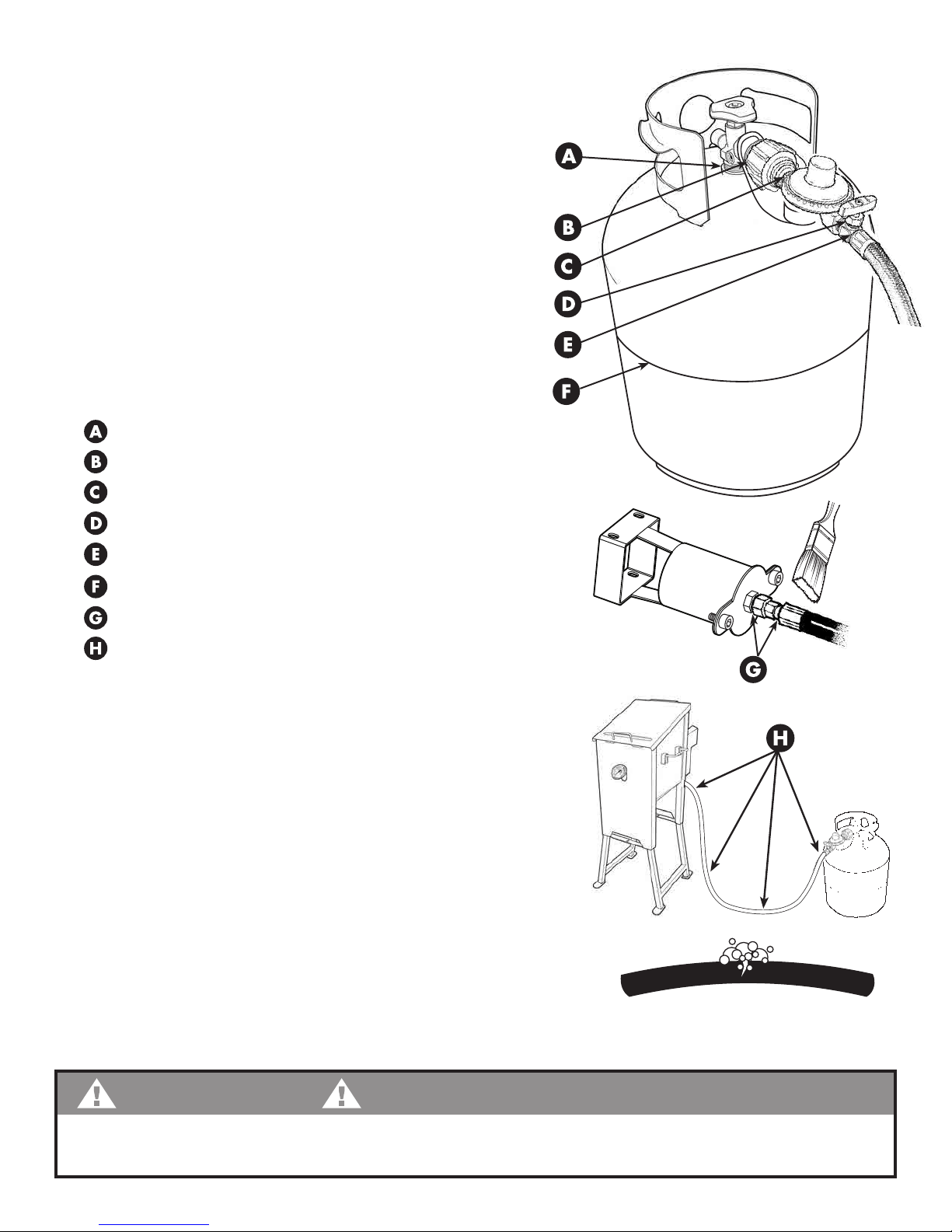
GAS LEAK TEST INSTRUCTIONS
Note: The gas leak test must be per formed in an area that has
adequate lighting in order to see if bubbles are developing.
DO NOT use a flashlight to check for bubbbles.
1. Create a mixture of 50% water and
50% liquid dishwashing soap.
2. Turn the gas cylinder valve to the OFF position (clockwise).
Then turn regulator control valve to OFF position
(clockwise).
3. To turn ON the fuel supply, turn the cylinder valve
knob one turn counter-clockwise. Gas will flow through
and stop at the regulator.
4. Using a clean brush, apply the soap water mixture
to the following:
Cylinder Valve to Cylinder
Connection Nut to Cylinder Valve
Back side of Connection Nut to Brass Nipple
Control Valve next to Regulator
Regulator connection to Gas Supply Hose
LP Cylinder Welds
Gas Supply Hose connection to Burner on Fryer
Full length of Gas Supply Hose
5. Check each place A - F for growing bubbles which indicates a leak.
6. Next, turn ON regulator valve (clockwise) to permit gas
to pass through the hose. Apply soap water mixture to full
length of gas supply hose and connection to burner on fryer.
Check each place for growing bubbles, G & H,
which indicates a leak.
7. Turn OFF gas supply valve (clockwise) on LP Gas Cylinder.
8. Turn regulator control valve to OFF position (clockwise).
9. Tighten any leaking connections.
10. Repeat soap water mixture test until no leaks are detected.
DO NOT use fryer if gas leaks cannot be stopped.
Call 1-800-864-6194 M-F 8am - 5pm CST for assistance, or
contact a qualified appliance repair service.
11. After you are certain there are no leaks, turn tank valve and regulator control valve to OFF position.
Wait 5 minutes for any gas fumes to evacuate before lighting the burner on fryer.
WARNING
If growing soap bubbles persist throughout any portion of the Gas Leak Test, terminate use immediately.
For assistance, contact your propane dealer or Barbour International, Inc. at 1-800-864-6194.
GAS SUPPLY HOSE
Watch for Bubbles
Downloaded from www.ManualsFile.com manuals search engine
14
Wind Direction
10 ft.
Clearance
20 in.
Minimum
10 ft.
Clearance
1. Read and understand everything in this manual.
2.
Insure that the fryer is properly assembled and
connected to propane cylinder.
3. Inspect the gas supply hose for burns, chaffing,
kinks and proper routing before each use.
4. Perform full Gas Leak Test. Refer to pages 12 - 13
for Testing Instructions.
5. Test thermometer to insure it is working properly.
Refer to page 10 for Thermometer Testing.
6. Clean the inside of your fryer with soap and water.
7. Determine proper amount of cooking oil to use.
Refer to page 18 for Proper Amount of Oil.
8. Inspect the heat tube for obstructions. Remove vent
and intake and wash with hose if necessary.
9. Have a BC or ABC type fire extinguisher readily
accessible.
10. Practice using the fryer with water in the vessel to
become familiar with its operation before frying.
Refer to page 16 for Lighting Instructions.
11. Replace any parts that show wear, abrasion, cuts,
have leaks, or that fail during testing.
WARNING
Use only the parts and accessories provided
by Bayou Classic for use with this appliance.
Using any other product is considered
unintended use of the product and voids the
warranty. Call 1-800-864-6194 M - F
8am - 5pm CST for all replacements par
ts.
FRYER SET-UP
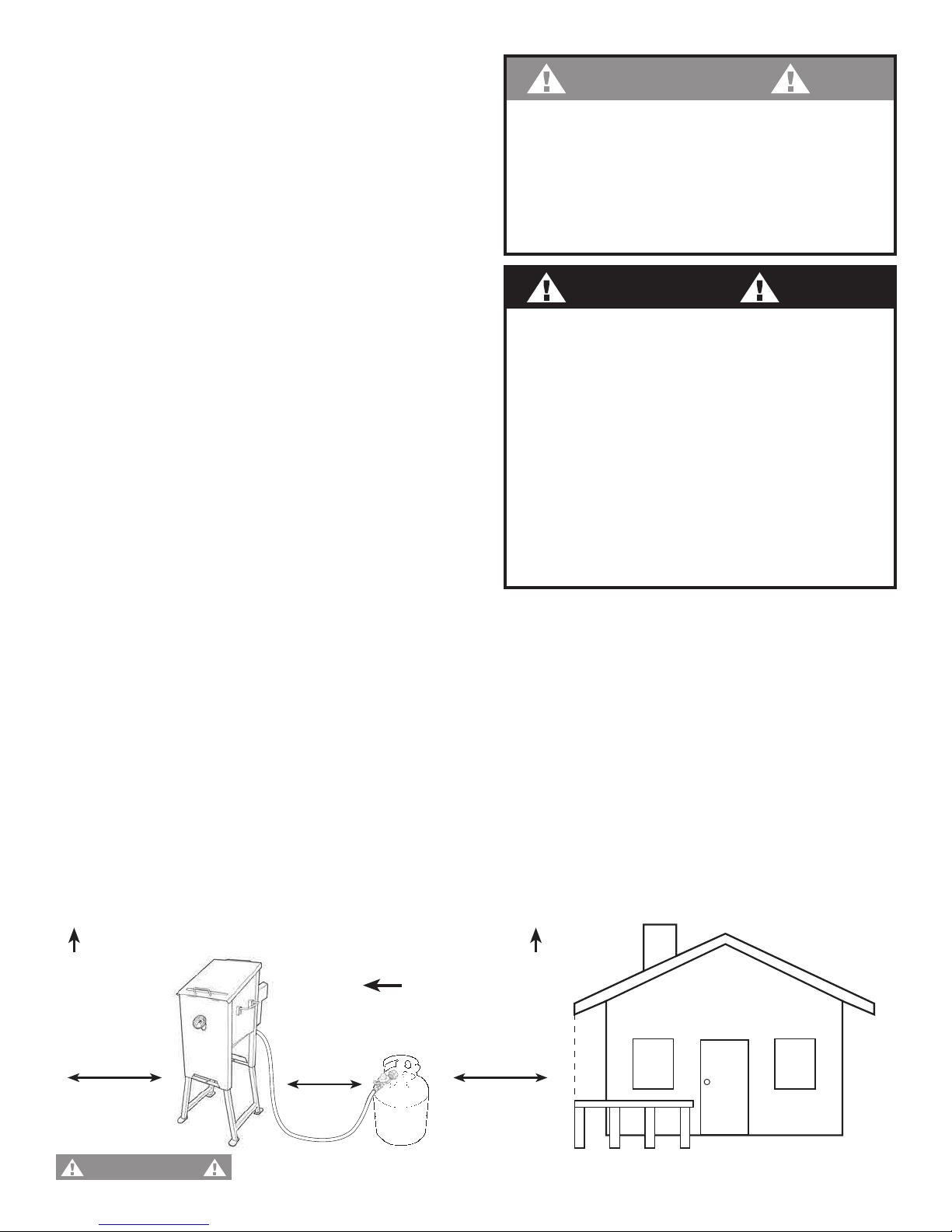
POSITIONING THE FRYER
1. Position the fryer on level ground in a well ventilated location, a safe distance from combustible
materials, buildings and overhangs.
2.
Position the fryer on a non-combustible surface.
3. Position the fryer in an area away from children and pets, and out of normal foot traffic paths.
4. Position fryer DOWNWIND from the nearest structure; no closer than 10-ft from nearest building
or railing, keeping flames from any potential oil/grease fire away from nearest structure.
5. Position fryer DOWNWIND from the LP Gas Cylinder keeping a minimum distance of 20" apart
so the heat of the fryer does not reach cylinder.
6. Gas supply hose should be positioned at least 3 inches away from hot surfaces.
7. Insure that all electrical supply cords are properly grounded and kept away from this appliance.
Make sure overhead is clear of combustible materials!
Hose is a trip hazard. Do not walk between fryer and cylinder.
DANGER
• DO NOT operate this gas appliance closer
than 10 ft (3m) from any combustible
material, including; walls, railings, overhead
construction, tree branches.
• DO NOT store or use gasoline or other
liquid/aerosols
with flammable vapors within
25 ft (7.5m) of this fryer.
• DO NOT position or operate this appliance
on any combustible material, including:
decks, RV’s, boats, or on the tailgate or bed
of a pick-up truck.
WARNING
Downloaded from www.ManualsFile.com manuals search engine
15
Wind Direction
10 ft.
Clearance
10 ft.
Clearance
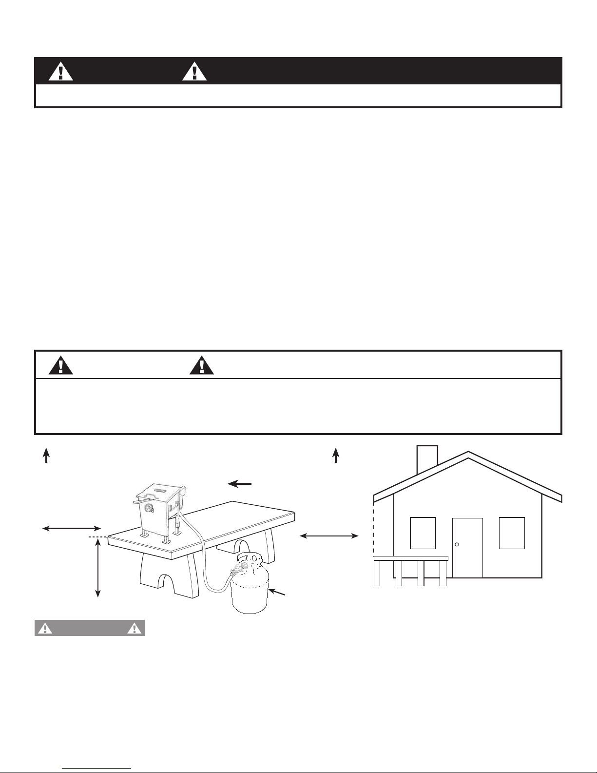
1. Always adhere to all instructions and warnings in this manual. Using the tabletop feature
DOES NOT EXEMPT
any of the instructions or warnings found in this manual.
2. Attach the short legs as outlined in the assembly instructions on page 4, Step 1b.
3. Even in the tabletop application, this fryer shall be used OUTDOORS ONLY.
4. Position the fryer on a stable, flat, non-combustible surface like granite, stone, concrete, or metal.
NOTE: A wood tabletop IS a combustible surface.
5. Position the fryer away from any combustible material, tipping hazards, or other controllable
environment factors.
6. The fryer should be at a comfortable height for the qualified operator to use without risk of
dripping/spilling/splashing hot grease or food on themselves or others.
NOTE: It is NOT recommended that the fryer be placed on a surface greater than 36" from the standing
floor plane. DO NOT Operate the fryer on a pick-up truck bed or tailgate.
7. Locate the fryer in a place where it cannot be pushed off tabletop.
8. DO NOT put the propane tank on a table or countertop.
SET-UP FOR 2.5-GAL. TABLETOP APPLICATION
Make sure overhead is clear of combustible materials!
Hose is a trip hazard. Do not walk between fryer and cylinder.
DANGER
ONLY the 2.5 GALLON Fryer can be adapted for tabletop use.
WARNING
CAUTION
To prevent damage to the tabletop finish, use a non-flammable, heat-resistant coaster or placemat
between the appliance and the tabletop surface.
Never place on carpet, wooden furniture, or other
combustible materials.
36 in.
Maximum
Seccure Upright,
on the Ground
Downloaded from www.ManualsFile.com manuals search engine

16
O
N
-
C
O
U
N
T
E
R
-
C
L
O
C
K
W
I
S
E
O
N
-
C
O
U
N
T
E
R
-
C
L
O
C
K
W
I
S
E
O
N
-
C
O
U
N
T
E
R
-
C
L
O
C
K
W
I
S
E
Place lit Match in Gas Inlet
3
LIGHTING INSTRUCTIONS
Keep head, hair and face away from exhaust vent when lighting. A flash flame can emit from the
exhaust vent during initial burner lighting, igniting hair and clothing.
Make sure LP Cylinder is OFF
clockwise
1
Make sure Regulator Valve is OFF
clockwise
BEFORE LIGHTING
LIGHTING
4
NOTE: The brass valve on
regulator hose assembly
controls flame intensity
only
. It is not an
ON/OFF valve.
S-L-O-W-L-Y Turn
LP Cylinder Valve One Full T
urn
counter-clockwise
2
Gas will flow
to and stop
at closed
regulator
O
F
F
-
C
L
O
C
K
W
I
S
E
5
O
N
-
C
O
U
N
T
E
R
-
C
L
O
C
K
W
I
S
E
S-L-O-W-L-Y
Tur
n Regulator Valve ON
counter-clockwise
O
F
F
-
C
L
O
C
K
W
I
S
E
After lighting Fryer, OPEN
LP Cylinder Valve FULL
Y counter-clockwise
DANGER
WARNING
If the burner does not light within the first
few attempts, there is a problem with the
gas supply.
Turn off the gas at the cylinder
and regulator. DO NOT attempt to operate
fryer until the problem is found and
corrected. Refer to Troubleshooting Tips
on page 21.
• If burner flame does NOT ignite immediately, or is accidentally
extinguished, tur
n off the LP cylinder and regulator.
• Wait 5 minutes for gas to evacuate before re-lighting.
• Follow steps 1 - 5 above to reignite burner.
Always use caution when re-lighting
as appliance frame and oil will be HOT
.
DANGER
TURNING OFF THE FRYER
1. T
urn off LP gas cylinder valve first to prevent gas from being left in the regulator hose system under
pressure. This will allow the propane gas to "bleed" from the r
egulator hose and assembly.
2. Turn regulator valve to the OFF position.
3. Disconnect the regulator hose assembly from the LP cylinder to store the unit.
Light BURNER
HERE
ADJUST Regulator Valve
for Flame Intensity counter-clockwise
Downloaded from www.ManualsFile.com manuals search engine
17
OPERATING INSTRUCTIONS
1. Follow all instructions for Set-Up and Testing as described on pages 12 - 15.
DO NOT skip of the
warnings and instructions contained in the preceding sections of this manual.
2. Add the determined amount of oil/grease into the frying chamber. Refer to page 18.
3. Prepare your food for frying before lighting the fryer. Make sure food is completely thawed and dry.
Properly preparing food ahead of time allows the operator to never have to leave the fryer unattended
and reduces the risk of spillover due to oil boiling over.
4.
Light the burner on the fryer as described and adjust the flame intensity with the regulator control valve
to desired level
.
5. Stay with your fryer. Once Fryer is lit and has begun heating the oil, do not leave the fryer unattended
until cooking is finished and the oil has cooled to 115°F.
6. Keep the lid open. The lid must remain open during heat-up and frying. Closing the lid during heat-
up and frying greatly increases the potential of over-heating the oil to ignition and fire.
7. Wait for the oil to reach optimum frying temperature. It takes only 5 - 10 minutes to reach optimum
frying temperature range of 325°F to 350°F (163°C to 177°C).
8. Once the oil reaches 325°F to 350°F, reduce the burner flame to a low level.
9. Frequently check the thermometer (every 3 minutes), and NEVER allow the oil to reach a temperature
over 400°F. This is labeled "FIRE HAZARD" zone on the thermometer.
10. Use extreme care when S-L-O-W-L-Y lowering food and utensils into and removing from hot oil.
NEVER drop food into hot oil.
11. When cooking is completed, turn off LP cylinder and allow propane gas to "bleed" from the regulator
hose and assembly. Then turn regulator valve to the OFF position.
12. Disconnect regulator hose assembly from the LP cylinder.
13. Follow Cleaning and Storage Instructions on page 20.
• Hot cooking oil is extremely dangerous and must be monitored at all times during use and
cool down period.
• Regardless of thermometer reading, if the oil/grease star
ts to smoke, turn OFF fuel supply to the
burner and STOP COOKING IMMEDIATELY. This indicates the thermometer is not working properly.
Discard the thermometer and call 1-800-864-6194 M-F 8am - 5pm CST for assistance.
• Immersing food into hot cooking oil/grease causes a furious boil while displacing upwards.
Overfilling the fryer vessel with oil/grease, allowing the oil/grease to get too hot, or immersing
frozen or wet food into hot oil can cause a spillover resulting in property damage, personal injury
or death.
• This appliance does not have automatic thermostat controls so it must be monitored at all times
during heat-up, frying and cool down. Use the provided thermometer to monitor frying temperature.
• Oil/grease heated above 400°F (200°C) will ignite and catch fire causing property damage,
personal injury or death.
•
Keep head, hair and face away from exhaust vent when lighting. A flash flame can emit from the
exhaust vent during initial burner lighting, igniting hair and clothing.
• Always keep children and pets away from the cooking area during and after use, until the
cool down period is completed.
DANGER
Downloaded from www.ManualsFile.com manuals search engine
18
COOKING OIL
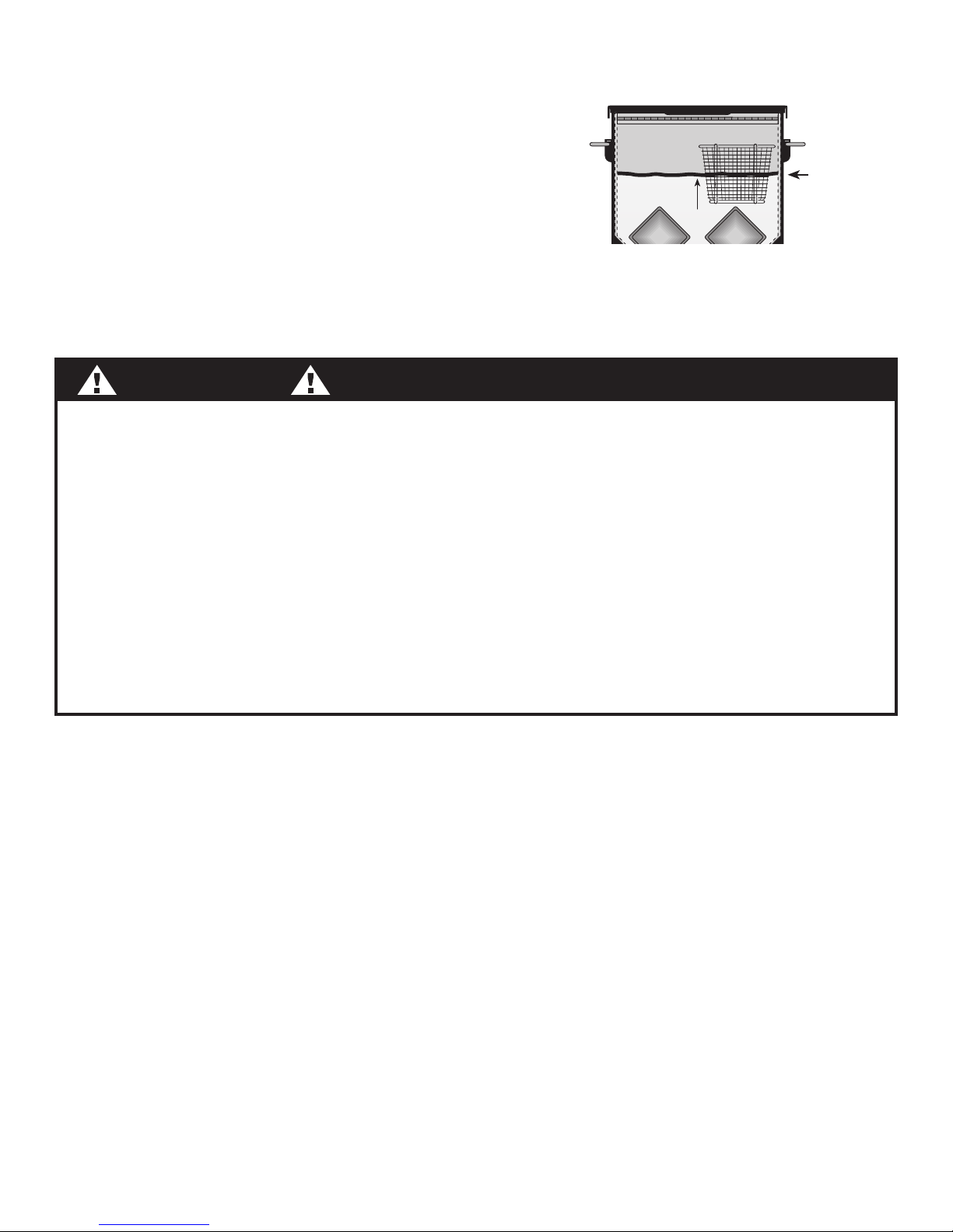
1. Make certain that bottom drain valve is closed
and bur
ner turned off.
2. Set baskets inside the empty fryer. IMPORTANT!
3. Pour cool oil/grease into the fryer vessel.
4. Watch closely as oil rises and reaches the bottom
of the baskets.
5. Continue pouring oil until the bottom of the baskets are submerged between 1.5" to 2" deep.
Pour up to but not above the Maximum Fill Line marked on the back wall of the fryer.
NOTE:
As oil heats up, it will expand and raise level inside the baskets to about 2.5" deep. As food is inserted,
oil level will rise further.
OIL
LEVEL
FRY BASKET
BETWEEN
1.5" to 2"
DEEP
MAXIMUM
OIL FILL LINE
Located on
back wall
FILLING THE FRYER WITH OIL:
TOO LITTLE OIL:
(Less than 1.5" of basket submerged in oil when cool)
• Cooking oil will not cover the food and result
in uneven doneness.
• Thermostat
will not be adequately submerged
and will not give accurate temperature
readings.
• Oil will not fully cover the heating tube resulting
in overheating of the oil and possibly ignition
and fire.
DANGER
TOO MUCH OIL:
(Oil filled above Maximum Fill Line when cool)
• Heat-up and recovery times will be slower
.
• Immersing food will cause a furious boil
displacing upwards, greatly increasing the
possibility of a spillover.
• As oil heats up, it will expand and can result
in a spill over.
IF THESE WARNINGS ARE NOT FOLLOWED EXACTLY; PROPERTY DAMAGE, PERSONAL INJURY,
OR DEATH MA
Y OCCUR.
MANAGING COOKING OIL:
• Monitor the temperature and oil level. You will have to occasionally make minor adjustments to the
regulator
valve until steady frying temperature is achieved. Optimum temperature range is 325°F to 350°F.
• Never drop food or accessories into hot oil/grease. Wear protective gloves and S-L-O-W-L-Y lower
food and accessories into cooking oil in order to prevent splashing or overflow. Be careful when
removing food from oil. It is hot and could cause burns.
• If you need to add cooking oil because the level gets too low as a result of a long-term cooking period
(less than 1.5" of basket submerged in oil when hot).
FOLLOW THESE INSTRUCTIONS:
1. Turn off the fryer and LP Cylinder
2. Let cooking oil cool for 5 minutes
3. S-L-O-W-L-Y pour in new cooking oil - DO NOT EXCEED MAXIMUM FILL LINE
4. Follow instructions to re-light the fryer.
• When frying is finished, do not touch the appliance or handle the oil until it has cooled to
below 115°F. The cool down period varies with the amount of oil used, wind and ambient temperature.
• In the event of rain, snow, hail, sleet or other form of precipitation while cooking with oil,
close the lid and immediately turn off the burner and gas supply. DO NOT MOVE the fryer.
• Properly store or dispose or our oil. Do NOT store cooking oil
Downloaded from www.ManualsFile.com manuals search engine

19
COOKING OIL - continued
1. Y
our fryer is designed to use liquid oil/grease and not solid fats which have to be melted before use.
The most common oils used are vegetable and peanut oil.
2.
Cooking oil typically does not burn when below its flashpoint temperature. The flashpoint (the
temperature at which oil will burn) ranges from 550°F to 700°F, depending on type of oil used, altitude,
variable wind, and ambient temperature. NOTE: the flashpoint temperature is also called the
"smoke point".
3. Cooking oil contained inside the confines of a stockpot, skillet or pan (vessel) is quite stable when
below its flashpoint temperature. For example, if fire or ignition source (lit cigarette, match, spark, etc.)
falls into oil at 350°F, the oil will extinguish the flame similarly to falling into water.
4. As heated cooking oil approaches its flashpoint temperature it becomes unstable and begins to
breakdown. As cooking oil breaks down, vapors are created that when mixed with oxygen will burn.
When heated to very high temperatures, cooking oil vapors will self-ignite.
5. As vegetable oil, contained in a cooking vessel, reaches it flashpoint and self ignites:
• The oil first becomes darker and emits an unpleasant odor.
• At about 440°F, the oil begins emitting a pale vapor smoke.
• At about 500°F, the smoke turns black.
• Soon a heavy, thick black smoke belches out.
• At about 600°F, a small flame flickers out from the oil. At this point the cooking oil has reached
its point of self-ignition.
• If the heat source below the vessel remains engaged, the flame will quickly grow.
• All the while cooking oil burns, thick black smoke continues to belch forth.
• Eventually, the burning cooking oil will self extinguish. The amount of time this takes depends on
vessel and amount of oil (a cooking vessel with gallons of oil will self extinguish in about 20-25
minutes after first flame emits).
6. Cooking oil can be re-used. Most cooking oils recommend using oil 4 - 5 times.
7. Each time you reuse oil, the oil deteriorates and the flash point temperature decreases.
8. 100% Peanut oil is considered a very stable cooking oil having a higher flashpoint temperature than
other vegetable oils.
9. Some cooking oil is sold as a "blend" of vegetable and peanut oil. According to the Food Allergy
Anaphylaxis Network, "Studies shoe that most allergic individuals can safely eat peanut oil )Not cold
pressed, expelled, or extruded peanut oil - sometimes represented as gourmet oils)." Allergic individuals
should consult a physician regarding whether or not to avoid peanut oil.
IMPORTANT FACTS TO KNOW:
Cooking oil that catches fire can omit a huge flame. For example, a small 12" skillet with only 1/2"
deep of oil can create a flame 7 to 9-ft high! A large cooking vessel containing up to 3 gallons of oil
can create a flame up to15-ft high! This will ignite any nearby combustible material and str
uctures.
DANGER
Downloaded from www.ManualsFile.com manuals search engine
20
CLEANING AND STORAGE
DRAINING, STORING & DISPOSING THE OIL
1. Wait for the oil to cool below 115°F (45°C) before touching the appliance or draining the oil.
2.
This fryer comes supplied with a drain hose that attaches to the drain valve.
3. Batter from frying settles down into the V-Bottom at the drain valve. It may be necessary to scoop out
the sediment before draining out the liquid.
4. Put a container directly under where oil will flow out. It is best to pour the oil through a filter or screen
to remove smaller sediment and crumbs that you were not able to scoop out.
NOTE: It is best to store oil back into the original container as purchased.
5. Open the drain S-L-O-W-L-Y until the oil begins to flow.
6. If storing your oil, use an airtight container and store in a cool dark place. DO NOT store oil for more
than 9-12 months, and never use oil that smells rancid.
7. If disposing your oil:
a. DO NOT dump it down the sink or flush it down the toilet because it can clog pipes and
eventually even pollute local waterways.
b. Check with your local solid waste department to see if they have any recommendations or
regulations about disposing of oil.
c. Pour the oil into a container and throw it into the garbage, OR take it to an oil recycling
center (Some cities have drop-off points for used cooking oil to be recycled into biodiesel).
CLEANING THE FRYER
WHAT YOU NEED: garden hose, bucket, dishwashing liquid and a sponge.
1. Move the empty fryer to a clean-up area.
2.
Position bucket under the open drain valve, and using a garden hose rinse out the V-Bottom section.
3. Close the drain valve and add water into the fryer vessel up to the internal heat tubes.
4. Add a dab of dishwashing liquid and clean the interior with the sponge.
5. Drain the soapy water and rinse clean with garden hose.
NOTE: Intense heat at burner and exhaust vent will cause the stainless to turn dull blue. This is normal,
and will not "scrub away".
STORAGE OF FRYER
1. Disconnect the LP cylinder.
2. Store
fryer in a dry place. DO NOT store outside exposed to weather. If storing fryer indoors, detach
and leave LP cylinders outdoors.
3. LP cylinders must be stored outdoors out of reach of children and must NOT be stored in a building,
garage or any other enclosed area. See pages 10 - 11 for Use and Care of LP Gas Cylinders.
4. For long term storage, cover the burner in-take and exhaust vent with a plastic bag to prevent wasps,
spiders and dirt dobbers from building nests inside the heat tubes.
5. Drain the soapy water and rinse clean with garden hose.
NOTE: Intense heat at burner and exhaust vent will cause the stainless to turn dull blue. This is normal,
and will not "scrub away".
WARNING
Storage of a gas appliance indoors is permissible ONLY if the cylinder is disconnected.
Downloaded from www.ManualsFile.com manuals search engine
CLOCKWISE
to closed position
PRESET REGULATOR
WITH VAL
VE
S-L-O-W-L-Y Turn
LP Cylinder Valve ON
One Full T
urn counter-clockwise
O
N
-
C
O
U
N
T
E
R
-
C
L
O
C
K
W
I
S
E
O
N
-
C
O
U
N
T
E
R
-
C
L
O
C
K
W
I
S
E
S-L-O-W-L-Y Turn
Regulator Valve ON
counter
-clockwise to light
burner
21
TROUBLE SHOOTING GUIDE
SYMPTOM
Burner will not light
and burner tube is clean
Not enough gas flow from
propane tank
Open cylinder valve all the way,
then S-L-O-W-L-Y open regulator
valve to light burner
CAUSE POSSIBLE SOLUTION
Low gas level in propane tank,
or tank is empty
Check gas level in propane tank,
re-fill or exchange tank
Burner lights but the flame
remains very small
Rapid gas flow from propane
tank activates EXCESS FLOW
safety device
Repeat lighting instructions and
be certain to S-L-O-W
-L-Y open
cylinder valve one full turn, then
S-L-O-W-L-Y open regulator valve
to light burner
Burner will not light
Blockage in burner tube from
spider webs, insects, dirt
dobbers and debris
Disconnect hose from burner.
Clean and check burner tube for
spiders, insect nests and debris
Hissing or gurgling sounds
coming through regulator hose
assembly from tank to burner
Water in burner tube Check burner tube for moisture,
make sure burner is dr
y
Damaged hose
Perform Gas Leak Test to check hose
and all connections.
See pages 12 - 13 and follow the
instructions.
Gas leak
Flame has gone out
Low gas level in propane tank,
or tank is empty
Check gas level in propane tank
Too much wind Check wind direction and set
Fryer away from windy areas
NEVER move or adjust your fryer
while it is operating. T
ur
n it off
and let it cool first!
Do not use this appliance
if Gas Leak Test fails.
Problems with lighting the fryer:
LP Hose Regulator assemblies and propane tanks are equipped with a safety device
to reduce 90% of
gas flow should the hose be cut or severed. Sometimes this safety device may be activated when lighting
the fryer by opening the cylinder too fast. To prevent this, follow these steps:
TROUBLE SHOOTING TIPS
Prior to lighting, turn
regulator valve to the
CLOSED position.
1. 2. 3.
Downloaded from www.ManualsFile.com manuals search engine
FREQUENTLY ASKED QUESTIONS & SOME HELPFUL TIPS:
1. Batter and food are sticking to the basket.
Ver
y often the first batch results in some food particles sticking to the basket. To reduce this from
occuring, leave the baskets submerged in the oil during the heat up period. Once oil temperature
reaches 300°F, remove the baskets from the oil and set them on the drain bar.
2. How do I keep my cooking temperature steady?
You must constantly monitor the thermometer and make minor adjustments to the regulator valve until
a steady frying temperature is achieved. That is usually attained during the second batch. As the
cooking process continues, a steady frying temperature can be maintained with the burner flame
reduced to a lower setting.
3. What kind of filter do I use when I drain my used cooking oil?
A coffee filter or several layers of cheesecloth will help to remove any particles and crumbs, or you
can use a screen sieve.
4. Is it safe to store my used cooking oil?
During the storage period bacteria will form on poultry, fish or animal fats remaining in the oil. This
bacteria is quickly killed when the oil is re-heated. However, prior to using again, we recommend
that you smell the cooking oil. If it smells unpleasant or rancid, discard properly and use new
cooking oil.
HAVE ANY QUESTIONS/COMMENTS/CONCERNS?
We would love to hear from you. Please contact us at:
1-800-864-6194
• Monday - Friday • 8am to 5pm CST.
Barbour International, Inc. • 101 Cypress Way • Brandon, MS 39042
www.thebayou.com
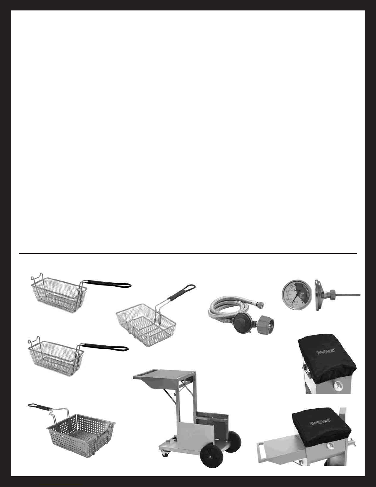
Basket Dimensions:
12" x 11" x 4.5"
700-188
Bayou
®
Fryer Accessory Basket
700-186
4-Gal. Bayou
®
Fryer Basket
5070
Bayou
®
Fryer Thermometer
M5HPR-1
10 PSI Preset Regulator
700-187
9-Gal. Bayou
®
Fryer Basket
Basket Dimensions:
13" x 5.75" x 5.55"
5004
2.5 & 4-Galllon
Bayou
®
Fryer
Cover
Basket Dimensions:
11" x 5.5" x 4.25"
5009
9-Galllon
Bayou
®
Fryer
Cover
Stainless
Braided Hose
Stainless Steel
Basket
BAYOU
®
FRYER ACCESSORIES
700-185
Bayou
®
Fryer
Accessory Cart
Fits 4-Gallon Fryer
Stainless Steel
700-182
2.5-Gal. Bayou
®
Fryer Basket
Stainless Steel
Basket
Stainless Steel
Basket
Stainless Steel
Basket
Basket Dimensions:
7.5" x 11" x 3.5"
Fits 4-Gal.
& 9-Gal. Fryer
Downloaded from www.ManualsFile.com manuals search engine