P/No. 3828EL3003S
Before beginning installation, read these
instructions carefully. This wll simplify installation
and ensure that the dryer is installed correctly and
safely. Leave these instructions near the dryer
after installation for future reference.
To contact LG Electronics, 24 hours a day,
7 days a week:
1-800-243-0000
Or visit us on the Web at: us.lge.com
Pour contacter LG Electronics, 24 heures
par jour, 7 jours par semaine :
1-800-243-0000
ou visitez notre site Web à l’adresse :
us.lge.com
Antes de comenzar la instalación, lea atentamente
estas instrucciones. Esto simplificará la instalación
y asegurará que la secadora está instalada
en forma correcta y segura. Conserve estas
instrucciones cerca de la secadora luego de la
instalación para futuras consultas.
DLE5955W
DLE5955G
DLG5966W
DLG5966G

READ ALL INSTRUCTIONS BEFORE USE
wWARNING For your safety, the information in this manual must be
followed to minimize the risk of fi re or explosion, electric shock, or to prevent
property damage, personal injury, or loss of life.
• Do not install a clothes dryer with
fl exible plastic venting materials. If
fl exible metal (foil type) duct is in-
stalled, it must be of a specifi c type
identifi ed by the appliance manufac-
turer as suitable for use with clothes
dryers. Flexible venting materials are
known to collapse, be easily crushed,
and trap lint. These conditions will
obstruct clothes dryer airfl ow and
increase the risk of fi re.
• Do not store or use gasoline or other
fl ammable vapors and liquids in the
vicinity of this appliance or any other
appliances.
• Installation and service must be
performed by a qualifi ed installer,
service agency, or the gas supplier.
• Install the clothes dryer according to
the manufacturer's instructions and
local codes.
• Save these instructions.
1. Do not try to light a match or cigarette,
or turn on any gas or electrical
appliance.
2. Do not touch any electrical switches.
Do not use any phone in your building.
3. Clear the room, building, or area of all
occupants.
4. Immediately call your gas supplier from
a neighbor’s phone. Follow the gas
supplier’s instructions carefully.
5. If you cannot reach your gas
supplier, call the fi re department.
WHAT TO DO IF YOU SMELL GAS:
CALIFORNIA SAFE DRINKING WATER AND TOXIC ENFORCEMENT ACT
This act requires the governor of California to publish a list of substances known to the state to cause
cancer, birth defects, or other reproductive harm and requires businesses to warn customers of potential
exposure to such substances.
Gas appliances can cause minor exposure to four of these substances, namely benzene, carbon monoxide,
formaldehyde, and soot, caused primarily by the incomplete combustion of natural gas or LP fuels.
Properly adjusted dryers will minimize incomplete combustion. Exposure to these substances can be
minimized further by properly venting the dryer to the outdoors.
2
3
Your Safety and the safety of others is very important.
We have provided many important safety messages in this manual and on your appliance. Always read
and obey all safety messages.
This is the safety alert symbol.
This symbol alerts you to potential hazards that can kill or hurt you and others.
All safety messages will follow the safety alert symbol and either the word DANGER or WARNING.
These words mean:
wDANGER: You can be killed or seriously injured if you don’t immediately follow instructions.
wWARNING: You can be killed or seriously injured if you don’t follow instructions.
All safety messages will tell you what the potential hazard is, tell you how the reduce the chance of
injury, and tell you what can happen if the instructions are not followed.
BASIC SAFETY PRECAUTIONS
wWARNING: To reduce the risk of fire, electric shock, or injury to persons when using this
appliance, follow basic precautions, including the following:
• Read all instructions before using the dryer.
• Before use, the dryer must be properly installed
as described in this manual.
• Do not place items exposed to cooking oils in
your dryer. Items contaminated with cooking
oils may contribute to a chemical reaction that
could cause a load to catch fire.
• Do not dry articles that have been previously
cleaned in, washed in, soaked in, or spotted
with gasoline, dry-cleaning solvents, other
flammable or explosive substances as they give
off vapors that could ignite or explode.
• Do not reach into the dryer if the drum or any
other part is moving.
• Do not repair or replace any part of the dryer
or attempt any servicing unless specifically
recommended in this Use and Care Guide or
in published user-repair instructions that you
understand and have the skills to carry out.
• Do not tamper with controls.
• Before the dryer is removed from service or
discarded, remove the door to the drying
compartment.
• Do not allow children to play on or in the dryer.
Close supervision of children is necessary when
the dryer is used near children.
• Do not use fabric softeners or products to
eliminate static unless recommended by the
manufacturer of the fabric softener or product.
• Do not use heat to dry articles containing
foam rubber or similarly textured rubber-like
materials.
• Keep area around the exhaust opening and
adjacent surrounding areas free from the
accumulation of lint, dust, and dirt.
• The interior of the dryer and exhaust vent
should be cleaned periodically by qualified
service personnel.
• Do not install or store the dryer where it will be
exposed to the weather.
• Always check the inside of the dryer for foreign
objects
• Clean lint screen before or after each load.
• The dryer must not be installed or stored in an
area where it will be exposed to water.
READ ALL INSTRUCTIONS BEFORE USE
wWARNING For your safety, the information in this manual must be
followed to minimize the risk of fire or explosion, electric shock, or to prevent
property damage, personal injury, or loss of life.
4
GROUNDING INSTRUCTIONS
This appliance must be grounded. In the event
of malfunction or breakdown, grounding will
reduce the risk of electric shock by providing
a path of least resistance for electric current.
This appliance must be equipped with a cord
having an equipment-grounding conductor and
a grounding plug. The plug must be plugged into
an appropriate outlet that is properly installed and
grounded in accordance with all local codes and
ordinances.
wWARNING — Improper
connection of the equipment-grounding
conductor can result in a risk of electric shock.
Check with a qualifi ed electrician or service
person if you are in doubt as to whether the
appliance is properly grounded.
Do not modify the plug provided with the
appliance. If it will not fi t the outlet, have a proper
outlet installed by a qualifi ed electrician.
This appliance must be connected to a grounded
metal, permanent wiring system or an equipment-
grounding conductor must be run with the circuit
conductors and connected to the equipment-
grounding terminal or lead on the appliance.
Electrical shock can result if the dryer is not
properly grounded.
READ ALL INSTRUCTIONS BEFORE USE
SAFETY INSTRUCTIONS FOR INSTALLATION
• Properly ground dryer to conform with all
governing codes and ordinances. Follow
details in the installation instructions. Electrical
shock can result if the dryer is not properly
grounded.
• Before use, the dryer must be properly
installed as described in this manual.
Electrical shock can result if the dryer is not
properly grounded.
• Install and store the dryer where it will not be
exposed to temperatures below freezing or
exposed to the weather.
• All repairs and servicing must be performed
by an authorized servicer unless specifi cally
recommended in this Owner's Guide. Use
only authorized factory parts. Failure to follow
this warning can cause serious injury, fi re,
electrical shock or death.
wWARNING For your safety, the information in this manual must be
followed to minimize the risk of fi re or explosion, electric shock, or to prevent
property damage, personal injury, or loss of life.
wWARNING: To reduce the risk of fire, electric shock, or injury to persons when using this
appliance, follow basic precautions, including the following:
• To reduce the risk of electric shock, do not
install the dryer in humid spaces. Failure to
follow this warning can cause serious injury, fi re,
electrical shock or death.
• Connect to a properly rated, protected,
and sized power circuit to avoid electrical
overload. Improper power circuit can melt,
creating electrical shock and/or fi re hazard.
• Remove all packing items and dispose of all
shipping materials properly. Failure to do so
can result in death, explosion, fi re or burns.
• Place dryer at least 18 in. above the fl oor
for a garage installation. Failure to do so can
result in death, explosion, fi re or burns.
• Keep all packaging from children. Packaging
material can be dangerous for children. There is
a risk of suffocation.
5
READ ALL INSTRUCTIONS BEFORE USE
SAFETY INSTRUCTIONS FOR INSTALLATION
wWARNING For your safety, the information in this manual must be
followed to minimize the risk of fire or explosion, electric shock, or to prevent
property damage, personal injury, or loss of life.
Exhaust/Ducting:
• Gas dryers MUST be exhausted to the
outside. Failure to follow these instructions
can result in fire or death.
• The dryer exhaust system must be exhausted
to the outside of the dwelling. If the dryer is
not exhausted outdoors, some fine lint and
large amounts of moisture will be expelled
into the laundry area. An accumulation of
lint in any area of the home can create a health
and fire hazard.
• Use only rigid metal or flexible metal 4-in.
diameter ductwork inside the dryer cabinet
or for exhausting to the outside. Use of
plastic or other combustible ductwork can
cause a fire. Punctured ductwork can cause
a fire if it collapses or becomes otherwise
restricted in use or during installation.
• Ductwork is not provided with the dryer, and
you should obtain the necessary ductwork
locally. The end cap should have hinged
dampers to prevent backdraft when the dryer
is not in use. Failure to follow these instructions
can result in fire or death.
•
The exhaust duct must be 4 in. (10.2 cm) in
diameter with no obstructions. The exhaust
duct should be kept as short as possible.
Make sure to clean any old ducts before
installing your new dryer. Failure to follow
these instructions can result in fire or death.
•
Rigid or semi rigid metal ducting is
recommended for use between the
dryer and the wall. In special installations
when it is impossible to make a connection
with the above recommendations, a UL-
listed flexible metal transition duct may be
used between the dryer and wall connection
only. The use of this ducting will affect drying
time. Failure to follow these instructions can
result in fire or death.
• DO NOT use sheet metal screws or other
fasteners which extend into the duct that
could catch lint and reduce the efficiency
of the exhaust system. Secure all joints with
duct tape. For complete details, follow the
Installation Instructions. Failure to follow these
instructions can result in fire or death.

6
SAFETY INSTRUCTIONS FOR CONNECTING ELECTRICITY
• Do not, under any circumstances, cut or
remove the ground prong from the power
cord. To prevent personal injury or damage to
the dryer, the electrical power cord must be
plugged into a properly grounded outlet.
• For personal safety, this dryer must be
properly grounded. Failure to do so can result
in electrical shock or injury.
• Refer to the installation instructions in this
manual for specifi c electrical requirements
for your model. Failure to follow these
instructions can create an electrical shock
hazard and/or a fi re hazard.
• This dryer must be plugged into a properly
grounded outlet. Electrical shock can result if
the dryer is not properly grounded. Have the
wall outlet and circuit checked by a qualifi ed
electrician to make sure the outlet is properly
grounded. Failure to follow these instructions
can create an electrical shock hazard and/or a
fi re hazard.
• The dryer should always be plugged into
its own individual electrical outlet which
has a voltage rating that matches the rating
plate. This provides the best performance
and also prevents overloading house wiring
circuits which could cause a fi re hazard from
overheated wires.
• Never unplug your dryer by pulling on the
power cord. Always grip plug fi rmly and pull
straight out from the outlet. The power cord
can be damaged, resulting in a risk of fi re and
electrical shock.
• Repair or replace immediately all power
cords that have become frayed or otherwise
damaged. Do not use a cord that shows
cracks or abrasion damage along its length
or at either end. These power cord can melt,
creating electrical shock and/or fi re hazard.
• When installing or moving the dryer, be
careful not to pinch, crush, or damage
the power cord. This will prevent injury and
prevent damage to the dryer from fi re and
electrical shock.
SAVE THESE INSTRUCTIONS
wWARNING: To reduce the risk of fire, electric shock, or injury to persons when using this
appliance, follow basic precautions, including the following:
READ ALL INSTRUCTIONS BEFORE USE
wWARNING For your safety, the information in this manual must be
followed to minimize the risk of fi re or explosion, electric shock, or to prevent
property damage, personal injury, or loss of life.
INSTALLATION INSTRUCTIONS
Choose the Proper Location ................................ 10
Clearances ........................................................... 10
Installation With Optional
Pedestal Base or Stacking Kit .............................. 11
Leveling the Dryer ................................................ 12
Reversing the Door Swing .................................... 12
Changing the Dryer Vent Location ....................... 13
Venting the Dryer ............................................ 14, 15
Connecting Gas Dryers .................................. 16, 17
Connecting Electric Dryers ..............................18-22
Special Requirements for Manufactured
or Mobile Homes .................................................. 23
Final Installation Check ....................................... 23
Duct Condition Testing ......................................... 24
Congratulations on your purchase
and welcome to the LG family. Your
new LG Dryer combines the most
advanced drying sensor technology
with simple operation and high
efficiency. By following the
operating and care instructions
in this manual, your dryer will
provide you with many years of
reliable service.
THANK YOU!
HOW TO USE
Sorting Loads ....................................................... 25
Loading the Dryer ................................................. 25
Check the Lint Filter Before Every Load ............... 25
Control Panel Features ......................................... 26
Cycle Guide .......................................................... 27
The Time and Status Display ............................... 28
Operating the Dryer .............................................. 29
Cycle Setting Buttons .......................................... 30
Cycle Option Buttons .......................................... 31
Special Functions ................................................. 32
Custom Program .................................................. 32
TROUBLESHOOTING
Before Calling for Service ............................... 34–36
CARE AND CLEANING
Regular Cleaning .................................................. 33
SPECIFICATIONS/OPTIONAL
ACCESSORIES
Optional Accessories ........................................... 36
Pedestal Installation ....................................... 37, 38
Stacking Kit Installation .................................. 39, 40
Key Dimensions and Specifications ..................... 40
IMPORTANT SAFETY INSTRUCTIONS
What to Do if You Smell Gas .................................. 2
Basic Safety Precautions ....................................... 3
Grounding Instructions .......................................... 4
Safety Instructions for Installation ...................... 4, 5
Safety Instructions for Connecting Electricity ....... 6
PARTS AND FEATURES
Special Features ..................................................... 8
Key Parts and Components ................................... 9
WARRANTY
Product Information Registration ......................... 41
7
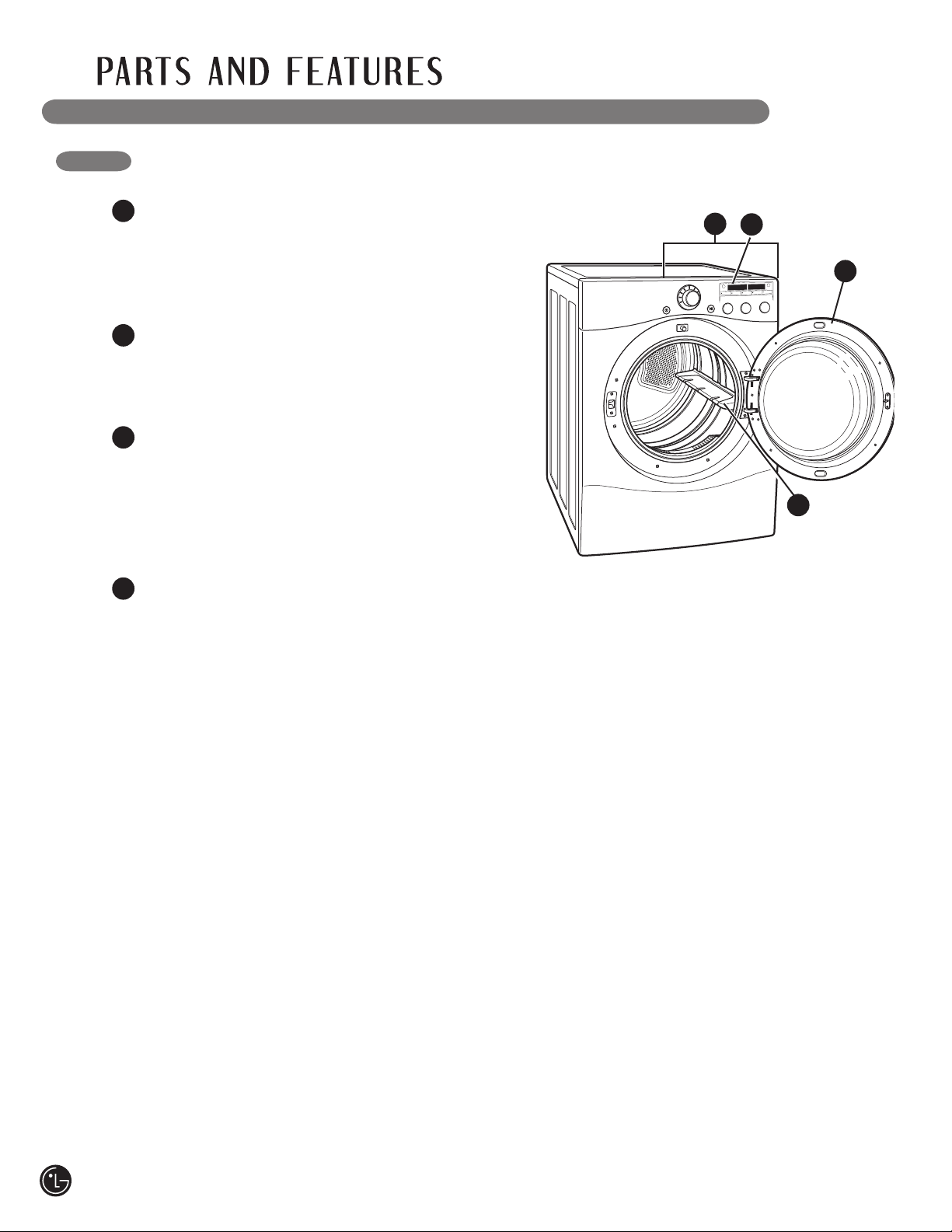
SPECIAL FEATURES
1
2
1
EASY-TO-USE CONTROL PANEL
Rotate the Cycle Selector Knob to select the
desired dry cycle. Adjust settings and add cycle
options with the touch of a button.
2
EASY-ACCESS REVERSIBLE DOOR
Wide-opening door provides easy access for
loading and unloading. Door swing can be
reversed to adjust for installation location.
3
ULTRA-CAPACITY STAINLESS STEEL DRUM
WITH DRUM LIGHT
The ultra-large stainless steel drum offers
superior durability. The drum is equipped with a
yellow light that illuminates when the dryer door
is open and turns off when the door is closed.
4
FLOWSENSE
™
DUCT/FILTER BLOCKAGE
SENSING SYSTEM
The FlowSense
™
duct/filter blockage sensing
system detects and alerts you to blockages in the
filter and ductwork that reduce exhaust flow from
the dryer. This not only helps prevent fires and
help minimize service calls, saving you money.
4
3
8
1
2
LEvELING FEET
Four leveling feet (two in the front, and two in
the back) adjust to improve dryer stability on
uneven floors.
Included Accessories
Drying Rack
2
1
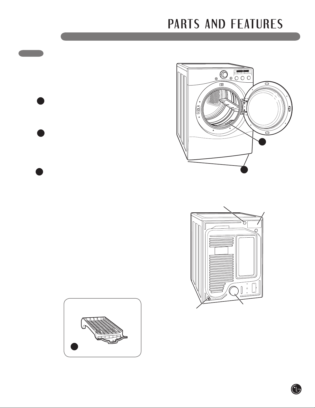
FRONT-MOUNT LINT FILTER
Front-mounted lint filter allows for easy access
and cleaning after every load.
Terminal Block
Access Panel
(Electric Models)
Rear of Dryer
Power Cord Location
(Gas Models)
Gas
Connection
Location
(Gas Models)
Exhaust Duct
Outlet
KEY PARTS AND COMPONENTS
In addition to the special features and
components outlined in the Special Features
section, there are several other important
components that are referenced in this manual.
DRYING RACK
Use the drying rack with the RACK DRY cycle
option. The drying rack allows items, such as
sweaters, delicates, and gym shoes, to be placed
in a flat position for drying.
3
3
9
CHOOSE THE PROPER LOCATION
• Store and install the dryer where it will not be
exposed to temperatures below freezing or
exposed to outdoor weather conditions.
• Choose a location with a solid, level fl oor.
• If the dryer is being installed in a garage,
place the dryer at least 18 in. (46 cm) above
the fl oor.
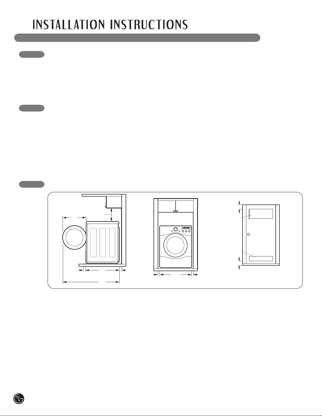
CLEARANCES
30"
(76.1 cm)
50"
(127 cm)
20"
(50.8 cm)
4"
(10 cm)
18"
(45.72 cm)
4"
(10 cm)
• Most installations require a minimum 5½ in.
(14 cm) clearance behind the dryer for the
exhaust ducting.
• Allow minimum clearances of at least 1 in.
(2.5 cm) on the sides and back to minimize
vibration and noise.
• Allowing additional clearance for installation and
servicing is recommended.
• Be sure to allow for wall, door, or fl oor moldings
that may increase the required clearances.
• Allow at least 24 in. (61 cm) in front of the dryer
to open the door.
IMPORTANT: Read all installation instructions completely before
installing and operating your dryer!
It is important that you review this entire manual before installing and using your dryer. Detailed instructions
concerning electrical connections, gas connections, and exhaust requirements are provided on the
following pages.
• Properly ground dryer to conform with all
governing codes and ordinances.
• To reduce the risk of electric shock, do not
install the dryer in damp or wet locations.
• If you are installing your dryer in a manufactured
or mobile home, please refer to the section
Special Requirements for Manufactured or
Mobile Homes.
Additional Instructions for closet installations:
• The closet door must allow for suffi cient airfl ow.
Refer to the diagram above for minimum vent
opening requirements. A louvered door is also
acceptable.
• Make sure that there is at least 18 in. (46 cm) of
clearance above the dryer.
27"
(68.6 cm)
1"
(2.54 cm)
1"
(2.54 cm)
24 in.
2
(155 cm
2
)
3"
(7.6 cm)
3"
(7.6 cm)
48 in.
2
(310 cm
2
)
Closet Door Vent
Requirements
10
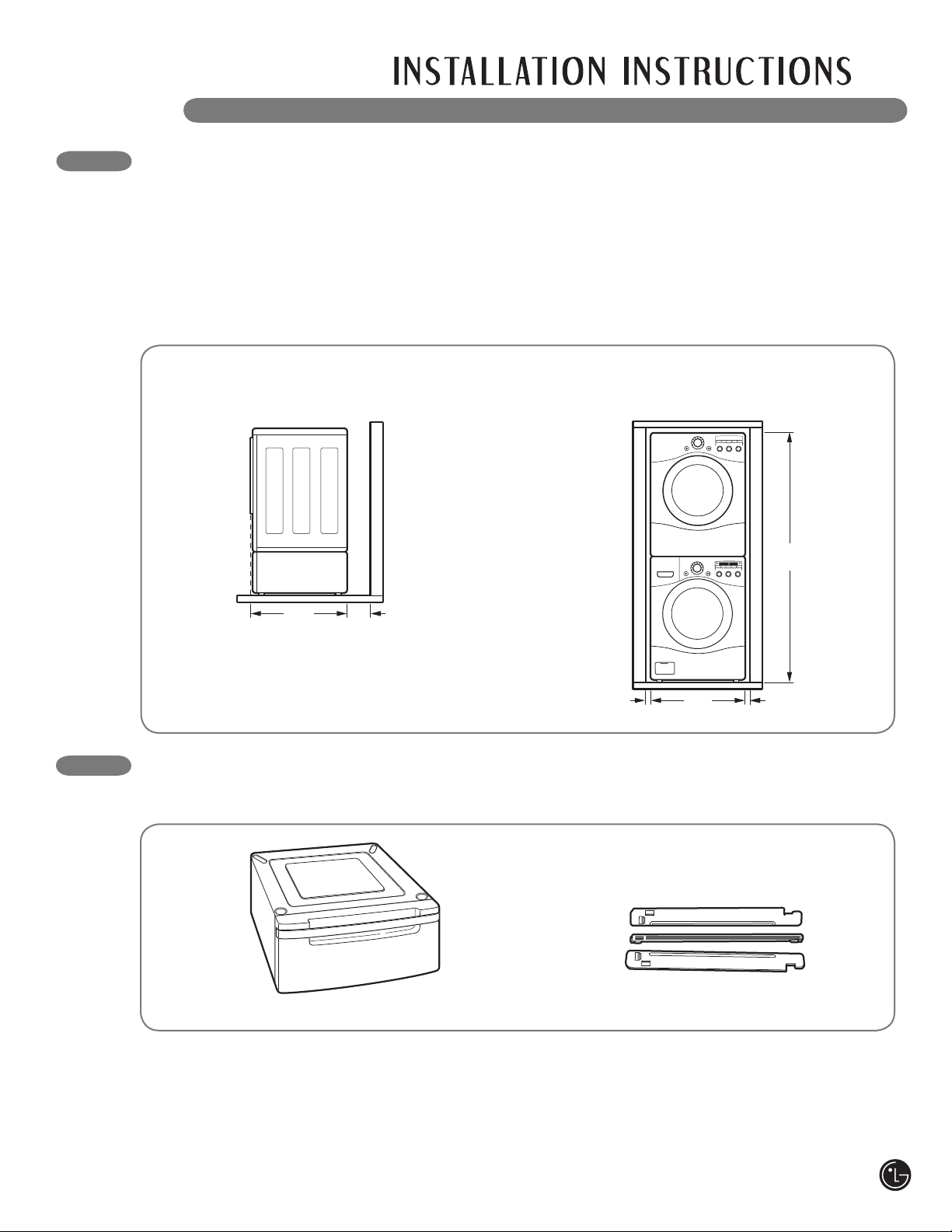
INSTALLATIONS WITH OPTIONAL
PEDESTAL BASE OR STACKING KIT
IMPORTANT: If you are installing your dryer
using an optional pedestal base or stacking
kit, please refer to Optional Accessories in this
manual or to the instructions for your pedestal
or stacking kit before proceeding with the
installation.
30"
(76.1 cm)
4"
(10 cm)
27"
(68.6 cm)
1"
(2.54 cm)
1"
(2.54 cm)
77
1
/2"
(190.5 cm)
Required Dimensions for Installation
With Pedestal
Required Dimensions for Installation
With Stacking Kit
OPTIONAL ACCESSORIES
For these and other LG products, contact your local LG dealer, or visit our Web site at us.lge.com.
Pedestal (sold separately)
Stacking Kit (sold separately)
11
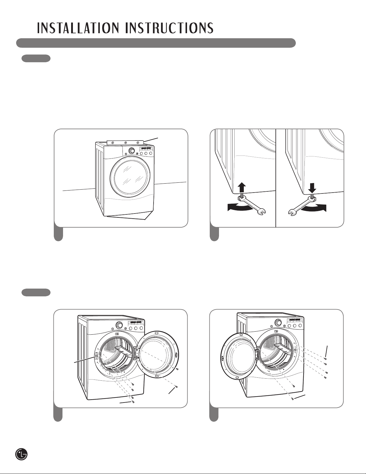
LEvELING THE DRYER
To ensure that the dryer provides optimal drying
performance, it must be level. To minimize
vibration, noise, and unwanted movement, the
floor must be a perfectly level, solid surface.
NOTE: Adjust the leveling feet only as far as
necessary to level the dryer. Extending the
leveling feet more than necessary can cause
the dryer to vibrate.
Position the dryer in the final location. Place
a level across the top of the dryer.
1
Level
Leveling Feet
Use an adjustable wrench to turn the leveling
feet. Turn clockwise to raise the dryer or
counterclockwise to lower it. Raise or lower
the leveling feet until dryer is level from
side to side and front to back.
Make sure that all 4 leveling feet are in firm
contact with the floor.
REvERSING THE DOOR SWING
The swing of the dryer door can be reversed to fit your installation location.
Open the dryer door. Using a Phillips screw-
driver, remove the 2 screws that secure
the door hinge to the dryer door opening.
Remove the 4 screws from the latch side of the
dryer door opening, and remove the door latch.
1
Turn the door around so the hinge is
reversed, and reattach the door using the
2 screws previously removed. Reinstall the
door latch and the 4 screws.
Test the door swing to make sure the door
moves freely and latches securely.
2
Hinge
Screws
Door
Latch
Latch Screws
Hinge
Screws
Latch
Screws
2
• All four leveling feet must rest solidly on the
fl oor. Gently push on the top corners of the
dryer to make sure that the dryer does not
rock from corner to corner.
If you are installing the dryer on the optional
pedestal, you must use the leveling feet on the
pedestal to level the dryer. The dryer leveling feet
should be fully retracted.
12
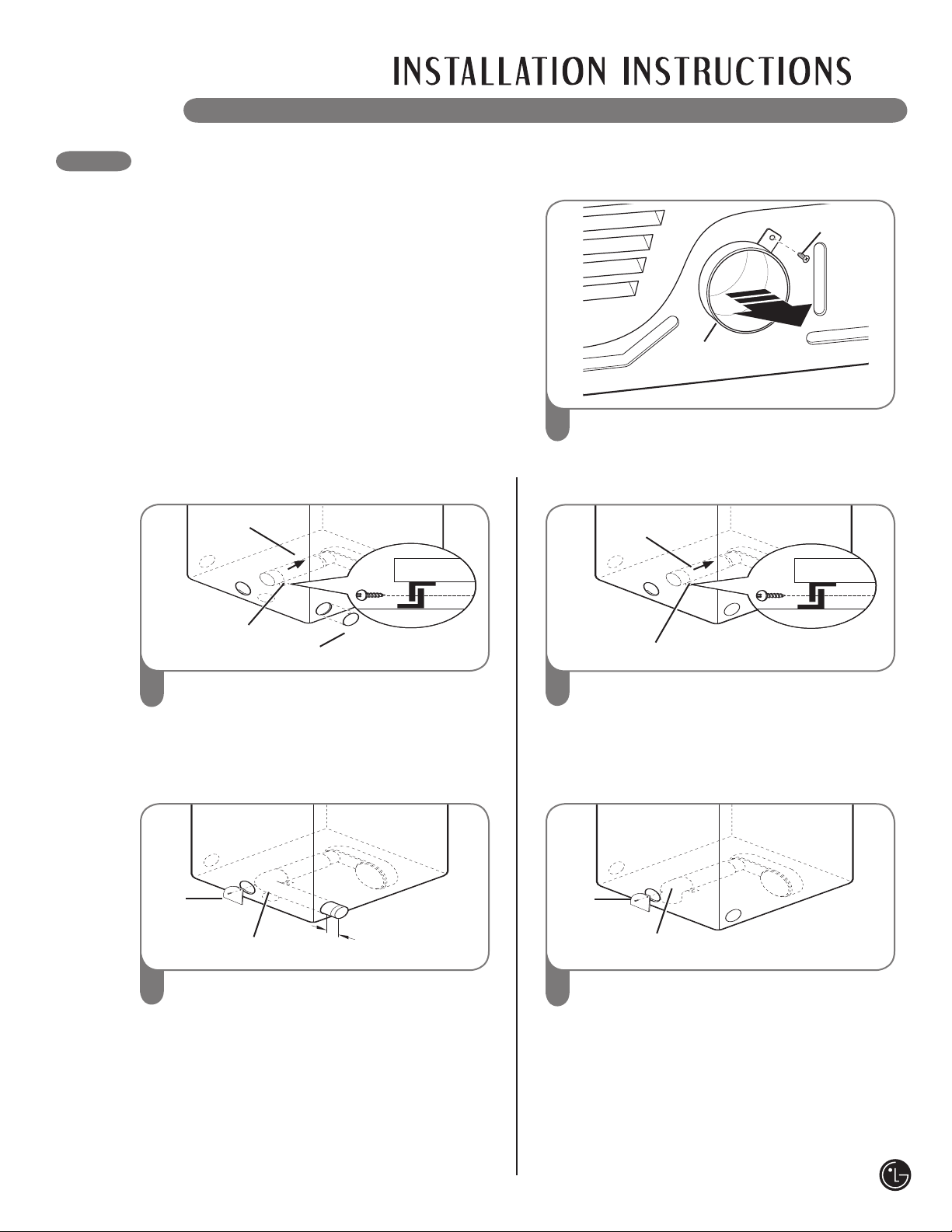
CHANGING THE DRYER vENT LOCATION
Your new dryer is shipped to vent to the rear.
It can also be configured to vent to the bottom
or side (right-side venting is not available on
gas models).
An adapter kit, part number 383EEL9001B,
may be purchased from your LG retailer. This
kit contains the necessary duct components to
change the dryer vent location.
Remove the rear exhaust duct retaining
screw. Pull out the exhaust duct.
1
Press the tabs on the knockout and carefully
remove the knockout for the desired vent
opening (right-side venting is not available on
gas models). Press the adapter duct onto the
blower housing and secure to the base of the
dryer as shown.
2
Knockout
Bracket
Adapter
duct
Preassemble a 4-in. (10.2 cm) elbow to the
next 4-in. (10.2 cm) duct section, and secure all
joints with duct tape. Be sure that the male end
of the elbow faces AWAY from the dryer.
Insert the elbow/duct assembly through the
side opening and press it onto the adapter
duct. Secure in place with duct tape.
Be sure that the male end of the duct
protrudes 1½ in. (3.8 cm) to connect the
remaining ductwork.
Attach cover plate to the back of the dryer with
included screw.
1
1
/
2
"
(3.8 cm)
3
Elbow
Cover
Plate
1
Rear
Exhaust Duct
Retaining
Screw
OPTION 1: Side venting
Press the adapter duct onto the blower
housing and secure to the base of the dryer
as shown.
2
Bracket
Adapter
Duct
Insert the 4-in. (10.2 cm) elbow through the
rear opening and press it onto the adapter
duct. Be sure that the male end of the elbow
faces down through hole in the bottom of the
dryer. Secure in place with duct tape.
Attach the cover plate to the back of the
dryer with included screw.
3
Elbow
Cover
Plate
13
OPTION 2: Bottom venting

vENTING THE DRYER
• Do not crush or collapse ductwork. Failure
to follow these instructions can result in fi re or
death.
• Do not allow ductwork to rest on or
contact sharp objects. Failure to follow these
instructions can result in fi re or death.
• If connecting to existing ductwork, make
sure it is suitable and clean before installing
the dryer. Failure to follow these instructions
can result in fi re or death.
• Venting must conform to local building
codes. Failure to follow these instructions can
result in fi re or death.
• Gas dryers MUST exhaust to the outdoors.
Failure to follow these instructions can result in
fi re or death.
• Use only 4-in. (10.2 cm) rigid or fl exible
metal ductwork inside the dryer cabinet and
for venting outside. Failure to follow these
instructions can result in fi re or death.
• To reduce the risk of fi re, combustion, or
accumulation of combustible gases, DO
NOT exhaust dryer air into an enclosed and
unventilated area, such as an attic, wall,
ceiling, crawl space, chimney, gas vent, or
concealed space of a building. Failure to
follow these instructions can result in fi re
or death.
• To reduce the risk of fi re, DO NOT exhaust
the dryer with plastic or thin foil ducting.
Failure to follow these instructions can result in
fi re or death.
• In Canada, that the exhaust duct shall be
4in.(10.2 cm) in diameter with no obstructions.
In the United States, the required exhaust duct
diameter; The exhaust duct should be kept
as short as possible. Make sure to clean any
old ducts before installing your new dryer.
Failure to follow these instructions can result in
fi re or death.
• Rigid or semirigid metal ducting is
recommended for use between the dryer
and the wall. In special installations when
it is impossible to make a connection with
the above recommendations, a UL-listed
fl exible metal transition duct may be used
between the dryer and wall connection only.
The use of this ducting will affect drying
time. Failure to follow these instructions can
result in fi re or death.
• In Canada, that only those foil-type fl exible
ducts, if any, specifi cally identifi ed for use with
the appliance by the manufacturer shall be
used. In the United States, that only those foil-
type fl exible ducts, if any, specifi cally identifi ed
for use with the appliance by the manufacturer
and that comply with the Outline for Clothes
Dryer Transition Duct, Subject 2158A, shall be
used
• DO NOT use sheet metal screws or other
fasteners which extend into the duct that
could catch lint and reduce the effi ciency of
the exhaust system. Secure all joints with
duct tape. Failure to follow these instructions
can result in fi re or death.
• To maximize operating results, please
observe the duct length limitations noted
in the chart above. Failure to follow these
instructions can result in fi re or death.
• Ductwork is not provided with the dryer.
You should obtain the necessary ductwork
locally. The end cap should have hinged
dampers to prevent backdraft when the
dryer is not in use. Failure to follow these
instructions can result in fi re or death.
• The Total length of fl exible metal duct shall not
exceed 8 ft.(2.4m)
wWARNING: To reduce the risk of fire, electric shock, or injury to persons when using this
appliance, follow basic precautions, including the following:
14
Routing and Connecting Ductwork
Follow the guidelines below to maximize drying
performance and reduce lint buildup and
condensation in the ductwork.
NOTE: Ductwork and fittings are NOT included
and must be purchased separately.
• Use 4-in. (10.2 cm) diameter rigid or semirigid
metal ductwork.
• The exhaust duct run should be as short as
possible.
• Use as few elbow joints as possible.
• The male end of each section of exhaust duct
must point away from the dryer.
• Use duct tape on all duct joints.
• Insulate ductwork that runs through unheated
areas in order to reduce condensation and lint
buildup on duct surfaces.
IMPORTANT: Failure to exhaust the dryer
correctly will void the dryer's warranty.
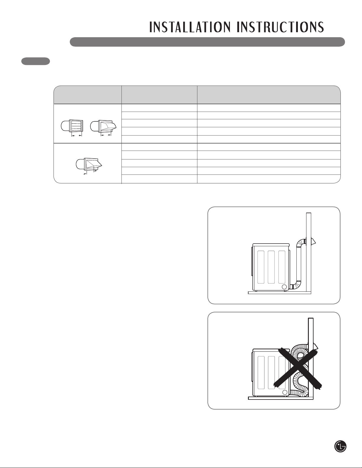
vENTING THE DRYER (cont.)
Correct Venting
Incorrect Venting
Number of Max. Length of 4-In. Dia.
Wall Cap Type 90° Elbows Rigid Metal Duct
0 65 ft. (19.8 m)
1 55 ft. (16.8 m)
2 47 ft. (13.7 m)
3 36 ft. (11.0 m)
4 28 ft. (8.5 m)
0 55 ft. (16.8 m)
1 47 ft. (13.7 m)
2 41 ft. (12.5 m)
3 30 ft. (9.1 m)
4 22 ft. (6.7 m)
NOTE: Deduct 6 ft. (1.8 m) for each additional elbow. It is not recommended to use more than four 90° elbows.
4"
(10.2 cm)
2
1
/2"
(6.35 cm)
4"
(10.2 cm)
Recommended
Use Only for Short
Run Installations
Ductwork
15
Electrical Requirements for Gas Models Only
• Do not, under any circumstances, cut or
remove the third (ground) prong from the
power cord. Failure to follow this warning can
result in fi re, explosion, or death.
• For personal safety, this dryer must be
properly grounded. Failure to follow this warning
can result in fi re, explosion, or death.
• The power cord of this dryer is equipped with
a 3-prong (grounding) plug which mates with
a standard 3-prong (grounding) wall outlet
to minimize the possibility of electric shock
hazard from this appliance. Failure to follow
this warning can result in fi re, explosion,
or death.
• This dryer must be plugged into a
120-VAC, 60-Hz. grounded outlet protected by
a 15-ampere fuse or circuit breaker. Failure to
follow this warning can result in fi re, explosion, or
death.
• Where a standard 2-prong wall outlet is
encountered, it is your personal responsibility
and obligation to have it replaced with a
properly grounded 3-prong wall outlet. Failure
to follow this warning can result in fi re, explosion,
or death.
16
CONNECTING GAS DRYERS
• Gas supply requirements:
As shipped from the factory, this dryer
is confi gured for use with natural gas.
It can be converted for use with LP (Liquefi ed
Propane) gas. Gas pressure
must not exceed 13 in. water column.
• A qualifi ed service or gas company technician
must connect the dryer to the gas service.
Failure to do so can result in fi re, explosion, or
death.
• Isolate the dryer from the gas supply system
by closing its individual manual shutoff valve
during any pressure testing of the gas supply.
Failure to do so can result in fi re, explosion, or
death.
• Supply line requirements:
Your laundry room must have a rigid gas
supply line to your dryer. In the United States,
an individual manual shutoff valve MUST be
installed within at least 6 ft. (1.8 m) of the
dryer, in accordance with the National Fuel
Gas Code ANSI Z223.1. A 1/8-in. NPT pipe
plug must be installed. Failure to do so can
result in fi re, explosion, or death.
• If using a rigid pipe, the rigid pipe should be
1/2-in. IPS. If acceptable under local codes
and ordinances and when acceptable to your
gas supplier, 3/8-in. approved tubing may be
used where lengths are less than 20 ft. (6.1
m). Larger tubing should be used for lengths
in excess of 20 ft. (6.1 m). Failure to do so can
result in fi re, explosion, or death.
• Connect the dryer to the type of gas shown
on the nameplate. Failure to do so can result in
fi re, explosion, or death.
• To prevent contamination of the gas valve,
purge the gas supply of air and sediment
before connecting the gas supply to the dryer.
Before tightening the connection between the
gas supply and the dryer, purge remaining air
until the odor of gas is detected. Failure to do
so can result in fi re, explosion, or death.
• DO NOT use an open fl ame to inspect for
gas leaks. Use a noncorrosive leak-detection
fl uid. Failure to do so can result in fi re, explosion,
or death.
• Use only a new AGA- or CSA-certifi ed gas
supply line with fl exible stainless steel
connectors. Failure to do so can result in fi re,
explosion, or death.
• Securely tighten all gas connections. Failure to
do so can result in fi re, explosion, or death.
• Use Tefl on
®
tape or a pipe-joint compound
that is insoluble in Liquefi ed Petroleum (LP)
gas on all pipe threads. Failure to do so can
result in fi re, explosion, or death.
• DO NOT attempt any disassembly of the
dryer; any disassembly requires the attention
and tools of an authorized and qualifi ed
service person or company. Failure to do so
can result in fi re, explosion, or death.
wWARNING: To reduce the risk of fire, electric shock, or injury to persons when using this
appliance, follow basic precautions, including the following:
• Installation and service must be performed
by a qualified installer, service agency, or the
gas supplier. Failure to do so can result in fire,
explosion, or death.
• Use only a new stainless steel flexible
connector and a new AGA-certified
connector. Failure to do so can result in fire,
explosion, or death.
• A gas shutoff valve must be installed within
6 ft. (1.8 m) of the dryer. Failure to do so can
result in fire, explosion, or death.
• The dryer is configured for Natural Gas when
shipped from the factory. Make sure that the
dryer is equipped with the correct burner
nozzle for the type of gas being used (Natural
Gas or Liquefied Petroleum). Failure to do so
can result in fire, explosion, or death.
• If necessary, the correct nozzle (for the LP
nozzle kit order part number 4948EL4002B)
should be installed by a qualified technician
and the change should be noted on the dryer.
Failure to do so can result in fire, explosion,
or death.
• All connections must be in accordance with
local codes and regulations. Failure to do so
can result in fire, explosion, or death.
• Gas dryers MUST exhaust to the outdoors.
Failure to do so can result in fire, explosion, or
death.
3/8" NPT Gas
Connection
Gas Supply
Shutoff Valve
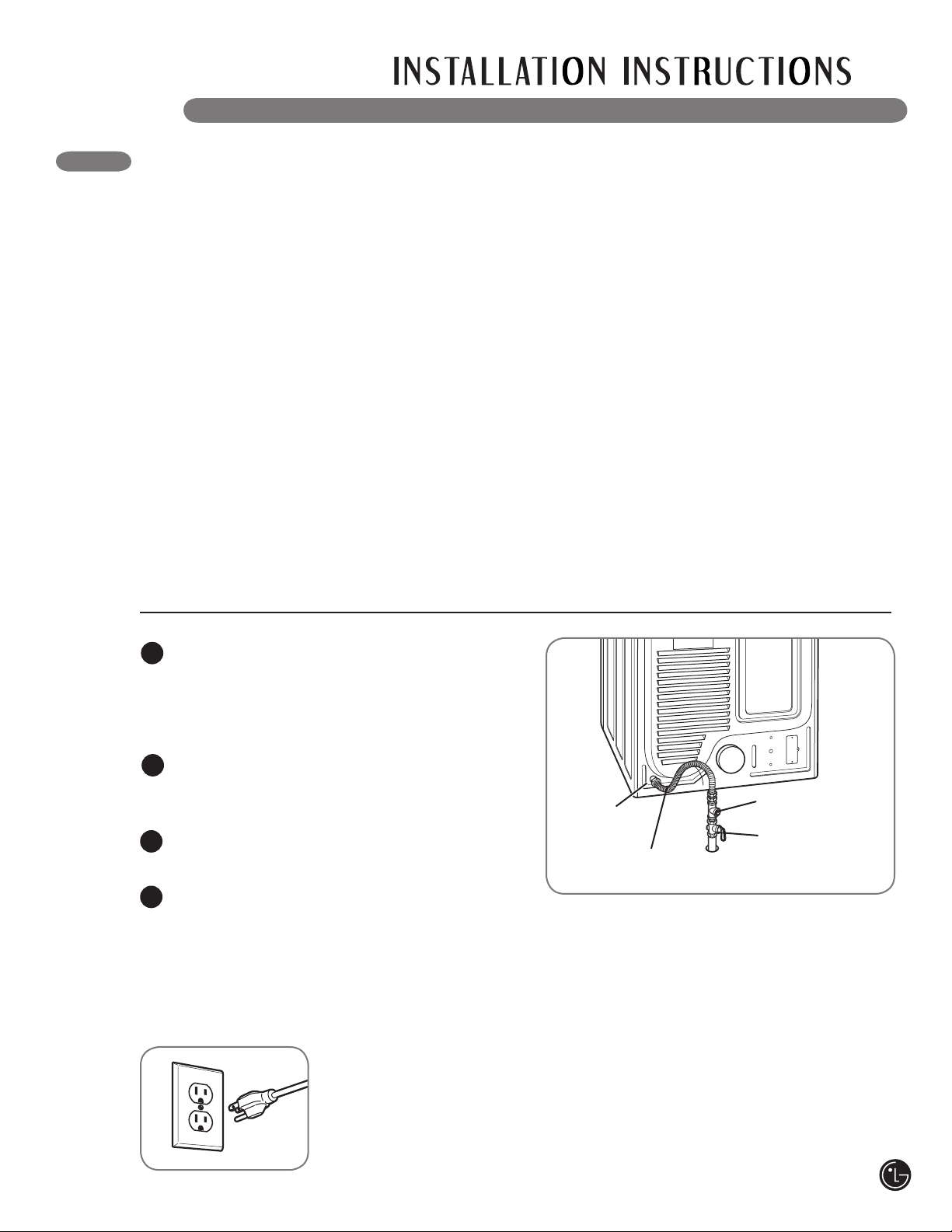
Connecting the Gas Supply
Make sure that the gas supply to the laundry
room is turned OFF. Confirm that the type
of gas available in your laundry room is
appropriate for the dryer. The dryer is
prepared for Natural Gas with a 3/8-in. NPT
gas connection.
Remove the shipping cap from the gas
connection at the back of the dryer. Be
careful not to damage the threads of the gas
connector when removing the shipping cap.
Connect the dryer to your laundry room’s gas
supply using a new flexible stainless steel
connector with a 3/8-in. NPT fitting.
Securely tighten all connections between the
dryer and your laundry room’s gas supply.
Turn on your laundry room’s gas supply and
check all pipe connections (both internal and
external) for gas leaks with a noncorrosive
leak-detection fluid.
1
2
3
4
High-Altitude Installations
The BTU rating of this dryer is AGA-certified for
elevations below 10,000 feet.
If your gas dryer is being installed at an elevation
above 10,000 feet, it must be derated by a
qualified technician or gas supplier.
Electrical Connection
Plug dryer into a
120-VAC, 60-Hz.
grounded 3-prong
outlet.
CONNECTING GAS DRYERS (cont.)
1/8" NPT Pipe
Plug
AGA/CSA-Certified
Stainless Steel
Flexible Connector
wWARNING: To reduce the risk of fire, electric shock, or injury to persons when using this
appliance, follow basic precautions, including the following:
17

18
Electrical Requirements for Electric Models Only
• This dryer must be connected to a grounded
metal, permanent wiring system, or an
equipment- rounding conductor must be run
with the circuit conductors and connected
to the equipment-grounding terminal or lead
on the dryer. Failure to do so can result in fire,
explosion, or death.
• The dryer has its own terminal block that
must be connected to a separate 240 VAC,
60-Hertz, single-phase circuit, fused at 30
amperes (the circuit must be fused on both
sides of the line). ELECTRICAL SERVICE
FOR THE DRYER SHOULD BE OF THE
MAXIMUM RATE VOLTAGE LISTED ON THE
NAMEPLATE. DO NOT CONNECT DRYER TO
110-, 115-, OR 120-VOLT CIRCUIT. Heating
elements are available for field installation
in dryers which are to be connected to an
electrical service of a different voltage than
that listed on the rating plate. Failure to follow
these instructions can result in fire, explosion,
or death.
• If branch circuit to dryer is 15 ft. (4.5 m)
or less in length, use UL (Underwriters
Laboratories) listed No.-10 AWG wire
(copper wire only), or as required by local
codes. If over 15 ft. (4.50 m), use UL-listed
No.-8 AWG wire (copper wire only), or as
required by local codes. Allow sufficient
slack in wiring so dryer can be moved from
its normal location when necessary. Failure
to do so can result in fire, explosion, or death.
• The power cord (pigtail) connection between
wall receptacle and dryer terminal block
IS NOT supplied with dryer. Type of pigtail
and gauge of wire must conform to local
codes and with instructions on the following
pages. Failure to follow these instructions can
result in fire, explosion, or death.
• A 4-wire connection is required for all mobile
and manufactured home installations, as
well as all new construction after January
1, 1996. A 4-wire connection must be used
where local codes do not permit grounding
through the neutral wire. Failure to do so can
result in fire, explosion, or death.
Special Electrical Requirements for Mobile or Manufactured Homes
• Any installation in a manufactured or mobile
home must comply with the Manufactured
Home Construction and Safety Standards
Title 24 CFR, Part 32-80 or Standard CAN/
CSA0Z240 MH and local codes and ordinances.
• A 4-wire connection is required for all mobile
and manufactured home installations, as well
as all new construction after January 1, 1996.
Failure to do so can result in fire, explosion, or
death.
CONNECTING ELECTRIC DRYERS
wWARNING: To reduce the risk of fire, electric shock, or injury to persons when using this
appliance, follow basic precautions, including the following:
wWARNING: To help prevent fire, electric shock, serious injury or death, the wiring and
grounding must conform to the latest edition of the National Electrical Code, ANSI/NFPA 70 and all
applicable local regulations. Please contact a qualified electrician to check your home’s wiring and
fuses to ensure that your home has adequate electrical power to operate the dryer.
wWARNING: To reduce the risk of fire, electric shock, or injury to persons when using this
appliance, follow basic precautions, including the following:
19
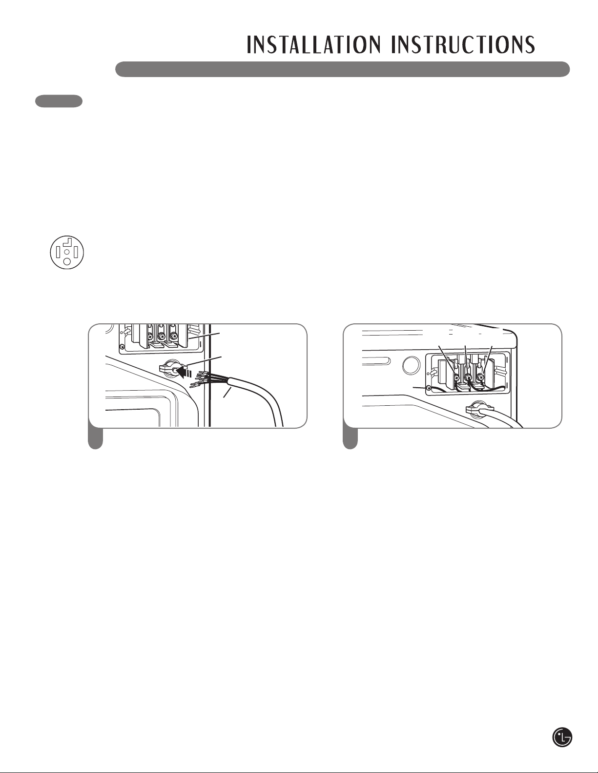
Remove the terminal block access cover
on the upper back of the dryer. Install a
UL-listed strain relief into the power cord
through-hole; then thread a UL-listed, 30A,
240V, 4-wire, #10 AWG-minimum copper
conductor power cord through the
strain relief.
1
Transfer the dryer’s ground wire from behind
the green ground screw to the center screw
of the terminal block. Attach the two hot
leads of the power cord to the outer terminal
block screws. Attach the white neutral wire
to the center terminal block screw. Attach the
power cord ground wire to the green ground
screw. TIGHTEN ALL SCREWS SECURELY.
Reinstall the terminal block access cover.
2
UL-Listed
Strain Relief
UL-Listed
4-Wire
Power Cord
Terminal
Block
Ground Screw
Neutral
(White)
Hot
(Black)
Power Cord
Ground Wire
Hot
(Red)
CONNECTING ELECTRIC DRYERS
Four-Wire Connection for Electric Dryers: Power Cord
• A 4-wire connection is required for all mobile
and manufactured home installations, as well
as all new construction after January 1, 1996.
• A UL-listed strain relief is required.
• Use a 30-amp, 240V, UL-listed power cord
with #10 AWG-minimum copper conductor
and closed loop or forked terminals with
upturned ends.
wWARNING:
• Connect the power cord to the terminal block. Each colored wire should be connected to
same color screw. Wire color indicated on manual is connected to the same color screw
in block. Failure to follow these instructions may result in a short or overload.
• Grounding through the neutral conductor is prohibited for: (1) new branch-circuit
installations, (2) mobile homes, (3) recreational vehicles, and (4) areas where local
codes prohibit grounding through the neutral conductor.
20
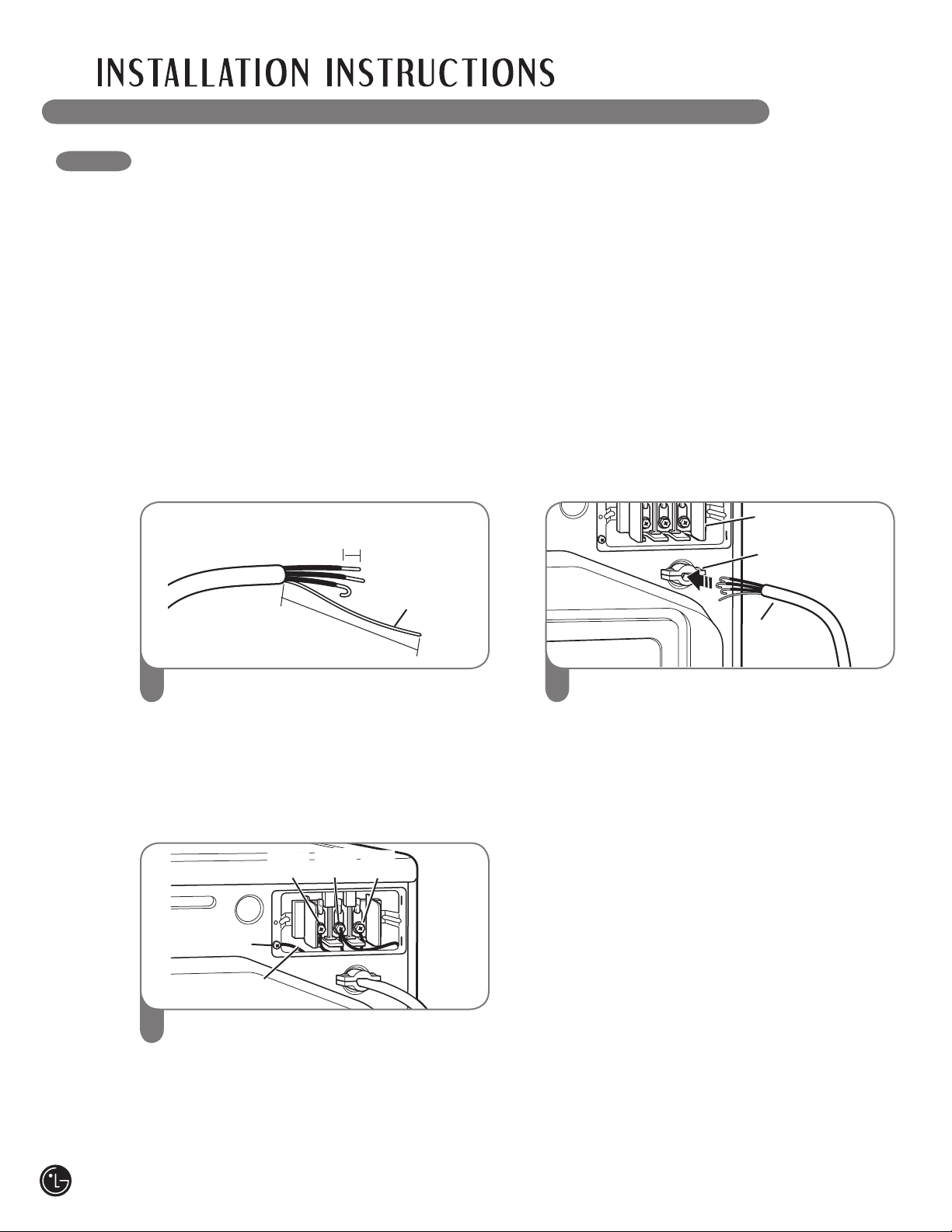
CONNECTING ELECTRIC DRYERS (cont.)
Remove 5 inches (12.7 cm) of the outer
covering from the wire. Remove 5 inches
of insulation from the ground wire. Cut off
approximately 1
1
⁄
2
inches (3.8 cm) from the
the other three wires and strip 1 inch (2.5
cm) insulation from each wire. Bend
the ends of the three shorter wires into
a hook shape.
1
Transfer the dryer’s ground wire from behind
the green ground screw to the center screw
of the terminal block. Attach the two hot
leads of the power cable to the outer terminal
block screws. Attach the white neutral wire
to the center terminal block screw. Attach the
power cable ground wire to the green ground
screw. TIGHTEN ALL SCREWS SECURELY.
Reinstall the terminal block access cover.
3
Ground Wire
Ground Screw
Neutral
(White)
Hot
(Black)
Ground Wire
Hot
(Red)
Remove the terminal block access cover
on the upper back of the dryer. Install a
UL-listed strain relief into the power cord
through-hole; then thread the power cable
prepared in Step 1 through the strain relief.
2
UL-Listed
Strain Relief
UL-Listed
4-Wire
Power Cord
Terminal
Block
5"
(12.7 cm)
1" (2.5 cm)
Four-Wire Connection for Electric Dryers: Direct Wire
• A 4-wire connection is required for all mobile
and manufactured home installations, as well
as all new construction after January 1, 1996.
• A UL-listed strain relief is required.
• Use UL-listed 4-wire #10 AWG-minimum copper
conductor cable.
• Allow at least 5 ft (1.5 m) length to allow for
removal and reinstallation of the dryer.
wWARNING:
• Connect the power cord to the terminal block. Each colored wire should be connected to
same color screw. Wire color indicated on manual is connected to the same color screw
in block. Failure to follow these instructions may result in a short or overload.
• Grounding through the neutral conductor is prohibited for: (1) new branch-circuit
installations, (2) mobile homes, (3) recreational vehicles, and (4) areas where local
codes prohibit grounding through the neutral conductor.
21
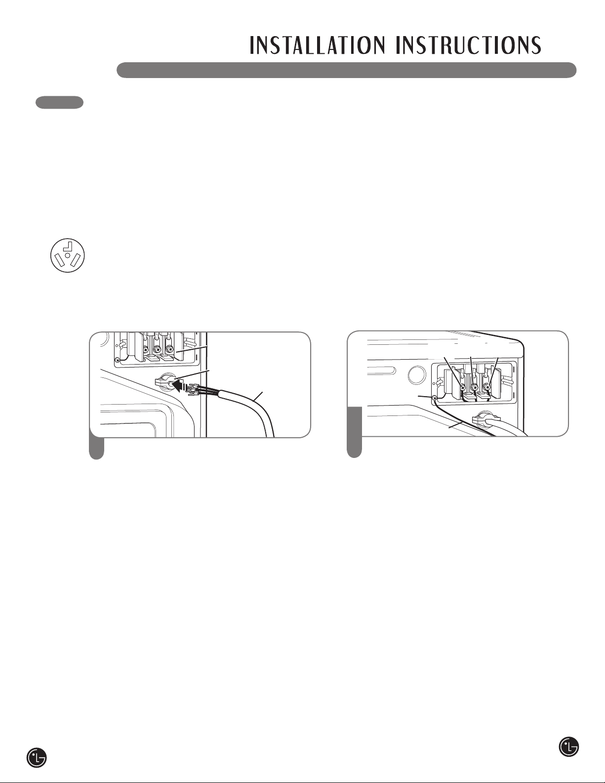
Remove the terminal block access cover
on the upper back of the dryer. Install a
UL-listed strain relief into the power cord
through-hole; then thread a UL-listed, 30A,
240V, 3-wire, #10 AWG-minimum copper
conductor power cord through the strain
relief.
1
Attach the two hot leads of the power cord
to the outer terminal block screws. Attach
the neutral wire to the center terminal block
screw. Connect the external ground (if
required by local codes) to the green ground
screw. TIGHTEN ALL SCREWS SECURELY.
Reinstall the terminal block access cover.
Three-Wire Connection for Electric Dryers: Power Cord
• A 3-wire connection is NOT permitted on new
construction after January 1, 1996.
• A UL-listed strain relief is required.
• Use a 30-amp, 240V, UL-listed power cord
with #10 AWG-minimum copper conductor
and closed loop or forked terminals with
upturned ends.
CONNECTING ELECTRIC DRYERS (cont.)
Ground Screw
UL-Listed
Strain Relief
UL-Listed
3-Wire
Power Cord
Terminal
Block
Ground Wire
Hot
(Black)
Hot
(Red)
Neutral
(White)
wWARNING:
• Connect the power cord to the terminal block. Each colored wire should be connected to
same color screw. Wire color indicated on manual is connected to the same color screw
in block. Failure to follow these instructions may result in a short or overload.
• Grounding through the neutral conductor is prohibited for: (1) new branch-circuit
installations, (2) mobile homes, (3) recreational vehicles, and (4) areas where local
codes prohibit grounding through the neutral conductor.
2
22
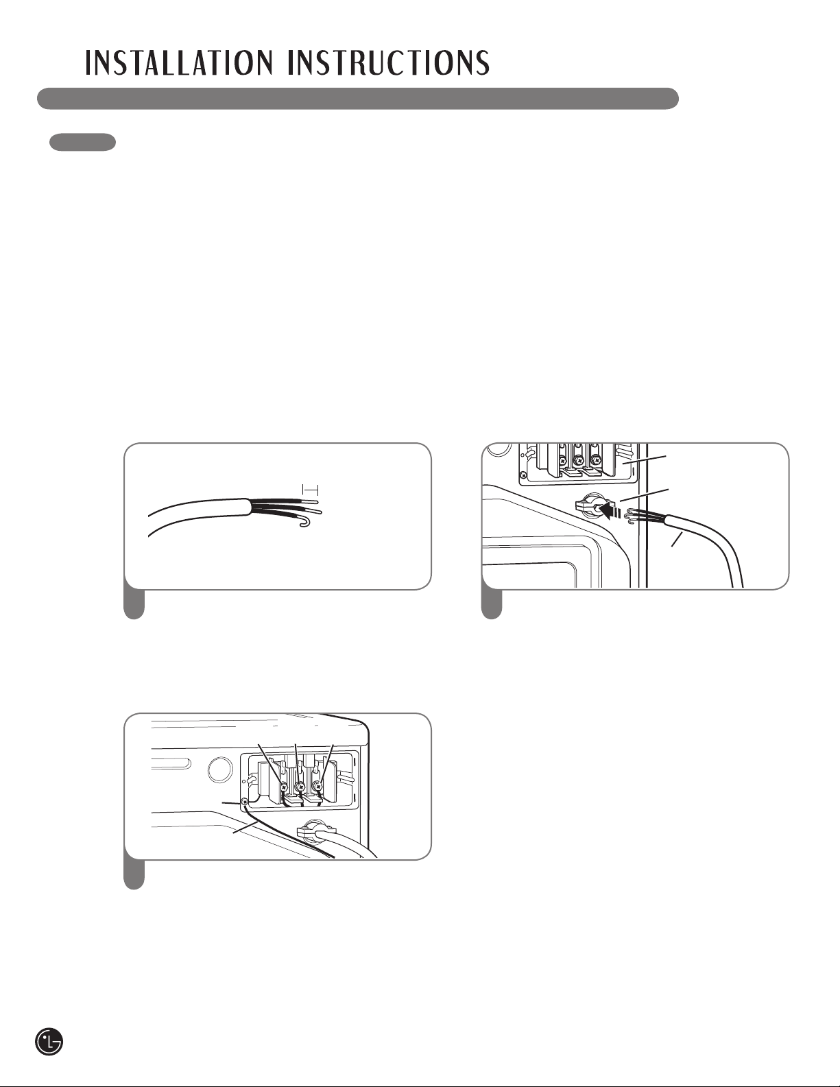
CONNECTING ELECTRIC DRYERS (cont.)
Remove 3
1
⁄
2
inches (8.9 cm) of the outer
covering from the wire. Strip 1 inch (2.5 cm)
insulation from each wire. Bend the ends of
the three wires into a hook shape.
1
Attach the two hot leads of the power cord
to the outer terminal block screws. Attach
the neutral wire to the center terminal block
screw. Connect the external ground (if
required by local codes) to the green ground
screw. TIGHTEN ALL SCREWS SECURELY.
Reinstall the terminal block access cover.
3
Ground Screw
Neutral
(White)
Hot
(Black)
Ground Wire
Hot
(Red)
Remove the terminal block access cover
on the upper back of the dryer. Install a
UL-listed strain relief into the power cord
through-hole; then thread the power cable
prepared in Step 1 through the strain relief.
2
UL-Listed
Strain Relief
UL-Listed
3-Wire
Power Cord
Terminal
Block
1" (2.5 cm)
Three-Wire Connection for Electric Dryers: Direct Wire
• A 3-wire connection is NOT permitted on new
construction after January 1, 1996.
• A UL-listed strain relief is required.
• Use UL-listed 3-wire #10 AWG-minimum copper
conductor cable.
• Allow at least 5 ft (1.5 m) length to allow for
removal and reinstallation of the dryer.
wWARNING:
• Connect the power cord to the terminal block. Each colored wire should be connected to
same color screw. Wire color indicated on manual is connected to the same color screw
in block. Failure to follow these instructions may result in a short or overload.
• Grounding through the neutral conductor is prohibited for: (1) new branch-circuit
installations, (2) mobile homes, (3) recreational vehicles, and (4) areas where local
codes prohibit grounding through the neutral conductor.
23
Testing Dryer Heating
GAS MODELS
Close the dryer door, press the ON/OFF switch
to turn the dryer on, and start the dryer on a heat
setting. When the dryer starts, the igniter should
ignite the main burner.
NOTE: If all air is not purged from the gas line,
the gas igniter may turn off before the main
burner ignites. If this happens, the igniter will
reattempt gas ignition after approximately
two minutes.
Checking Airflow
Effective dryer operation requires proper airflow.
The adequacy of the airflow can be measured
by evaluating the static pressure. Static pressure
in the exhaust duct can be measured with
a manometer, placed on the exhaust duct
approximately 2 ft. (60.9 cm) from the dryer.
Static pressure in the exhaust duct should not
exceed 0.6 in. (1.5 cm). The dryer should be
checked while the dryer is running with no load.
Checking Levelness
Once the dryer is in its final location, recheck
the dryer to be sure it is level. Make sure it is
level front to back and side to side, and that
all 4 leveling feet are firmly on the floor.
FINAL INSTALLATION CHECK
Once you have completed the installation of the dryer and it is in its final location, confirm proper
operation with the following tests and Duct Condition Testing on the following page.
Any installation in a manufactured or mobile
home must comply with the Manufactured Home
Construction and Safety Standards Title 24 CFR,
Part 32-80 or Standard CAN/CSA0Z240 MH and
local codes and ordinances. If you are uncertain
whether your proposed installation will comply
with these standards, please contact a service
and installation professional for assistance.
• A gas dryer must be permanently attached to
the floor.
• The electrical connection for an electric dryer
must be a 4-wire connection. More detailed
information concerning the electrical connection
is provided in the section Connecting Electric
Dryers.
• To reduce the risk of combustion and fire, the
dryer must be vented to the outside.
• DO NOT vent the dryer under a manufactured
home or mobile home.
• Electric dryers may be vented to the outside
using the back, left, right, or bottom panel.
• Gas dryers may be vented to the outside using
the back, left, or bottom panel. Gas dryers may
not be vented to the outside using the right side
panel because of the burner housing.
• The dryer exhaust duct must be affixed securely
to the manufactured or mobile home structure,
and the exhaust duct must be made of a
material that will resist fire and combustion.
It is recommended that you use a rigid or
flexible metal duct.
• DO NOT connect the dryer exhaust duct
to any other duct, vent, chimney, or other
exhaust duct.
• Make sure the dryer has adequate access to
outside fresh air to ensure proper operation.
The opening for outside fresh air must be at
least 25 in
2
(163 cm
2
).
• It is important that the clearance of the duct
from any combustible construction be at least
2 in. (5 cm), and when venting the dryer to
the outdoors, the dryer can be installed with a
clearance of 1 in. (2.5 cm) at the sides and back
of the dryer.
• Please be aware that venting materials are
not supplied with the dryer. You should obtain
the venting materials necessary for proper
installation.
SPECIAL REQUIREMENTS FOR MANUFACTURED OR MOBILE HOMES
24
Your dryer features FlowSense
™
, an innovative
sensor system that automatically detects
blockages and restrictions in dryer ductwork.
Keeping ductwork clean of lint build-up and free
of restrictions allows clothes to dry faster and
reduces energy use.
NOTE: When the dryer is first installed, this test
should be performed to alert you to any existing
problems with the exhaust duct in your home.
However, since the test performed during normal
operation provides more accurate information on
the condition of the exhaust duct than does the
installation test, the number of bars displayed
during the two tests may not be the same.
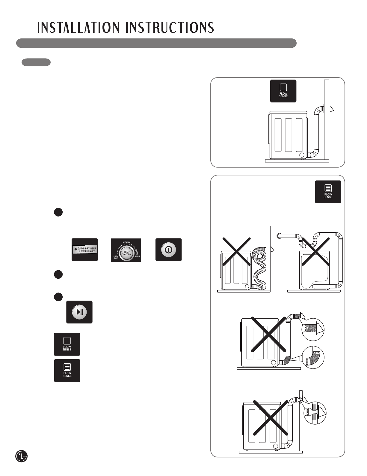
To activate the duct condition test cycle:
NOTE: Dryer heating test must be performed
before proceeding. (Gas dryer only)
Then perform the duct condition test below.
Press and hold the DAMP DRY BEEP and
TEMP CONTROL buttons at the same time.
While holding these buttons, press POWER
ON/OFF.
The dryer will show lnS in the number display
to indicate that it is in duct condition testing
mode.
Press START/PAUSE. The dryer will run for
approximately 2 minutes to test
for blockages or restrictions to air
flow in the ductwork.
DUCT CONDITION TESTING
If no bars are shown in the display,
the ductwork is free from blockages
or restrictions.
If all bars are lit, the dryer ductwork
has a blockage that needs to be
removed immediately.
IMPORTANT: Do NOT interrrupt the test cycle!
Correct Venting
1
2
3
Restricted or Blocked Airflow
Avoid long runs or runs with multiple elbows
or bends.
Check for blockages and lint buildup.
Make sure the ductwork is not crushed
or restricted.
25
• Check all pockets to make sure that they are
empty. Items such as clips, pens, coins, and
keys can damage both your dryer and your
clothes. Flammable objects such as lighters
or matches could ignite, causing a fire.
Failure to do so can result in fire, explosion, or
death.
• Never dry clothes that have been exposed to
oil, gasoline, or other flammable substances.
washing clothes will not completely remove
oil residues. Failure to obey this warning can
result in fire, explosion, or death.
• Combine large and small items in a load.
• Damp clothes will expand as they dry. Do not
overload the dryer; clothes require room to
tumble to dry properly.
• Close zippers, hooks, and drawstrings to
prevent these items from snagging or tangling
on other clothes.
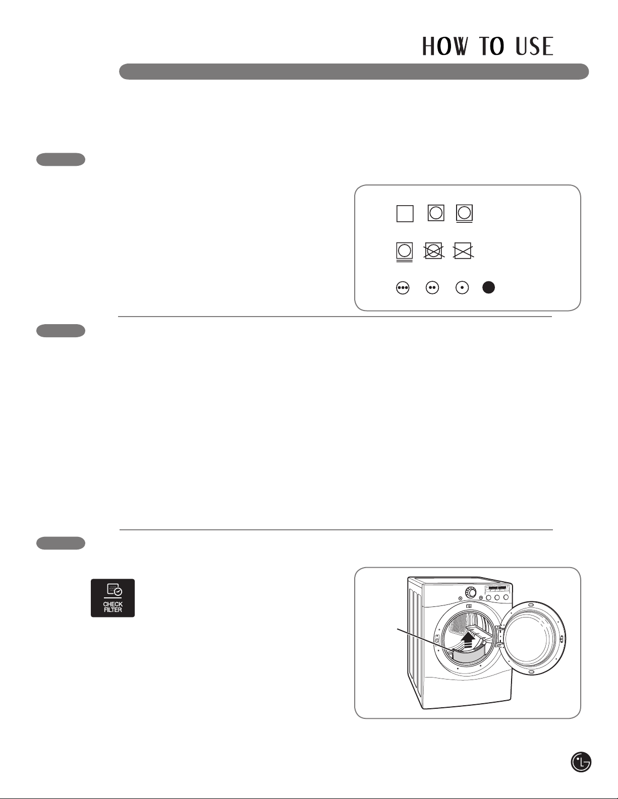
Tumble
dry
Dry
Normal
Permanent Press
/
wrinkle resistant
Gentle/
delicate
Do not tumble dry
Do not dry
(used with
do not wash)
SORTING LOADS
Fabric Care Labels
Most articles of clothing feature fabric care labels
that include instructions for proper care.
Grouping Similar Items
For best results, sort clothes into loads that can
be dried with the same drying cycle.
Different fabrics have different care requirements,
and some fabrics will dry
more quickly than others.
Fabric Care Labels
Heat
setting
High
Medium
Low
No heat/air
CHECK THE LINT FILTER BEFORE EVERY LOAD
The CHECK FILTER indicator will light before
each load to remind you to make sure
the lint filter is clean before starting a
new load. It will also come on during
a load if the lint filter is clogged to let
you know that the lint filter needs to be cleaned;
a clogged lint filter will increase drying times.
To clean, pull the lint filter straight up and roll any
lint off the filter with your fingers. Do not rinse or
wash the filter to remove lint. Push the lint filter
firmly back into place. See “Care and Cleaning”
for more information.
Always ensure the lint filter is properly installed
before running the dryer. Running the dryer with
a loose or missing lint filter may damage the
dryer and articles in the dryer.
Lint Filter
LOADING THE DRYER
Following are instructions for starting and using your new dryer. Please refer to specific sections of this
manual for more detailed information. Important Warning: To reduce the risk of fire, electric shock,
or injury to persons, read this entire manual, including the Important Safety Instructions, before
operating this dryer.
wWARNING: To reduce the risk of fire, electric shock, or injury to persons when using this
appliance, follow basic precautions, including the following:

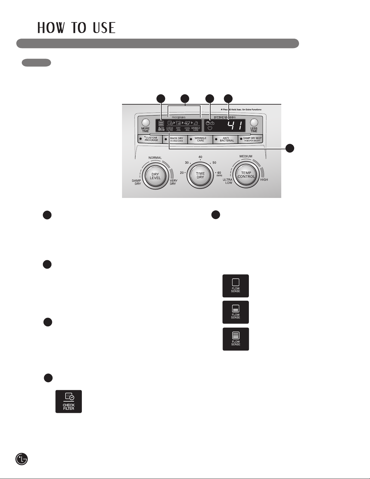
CONTROL PANEL FEATURES
2
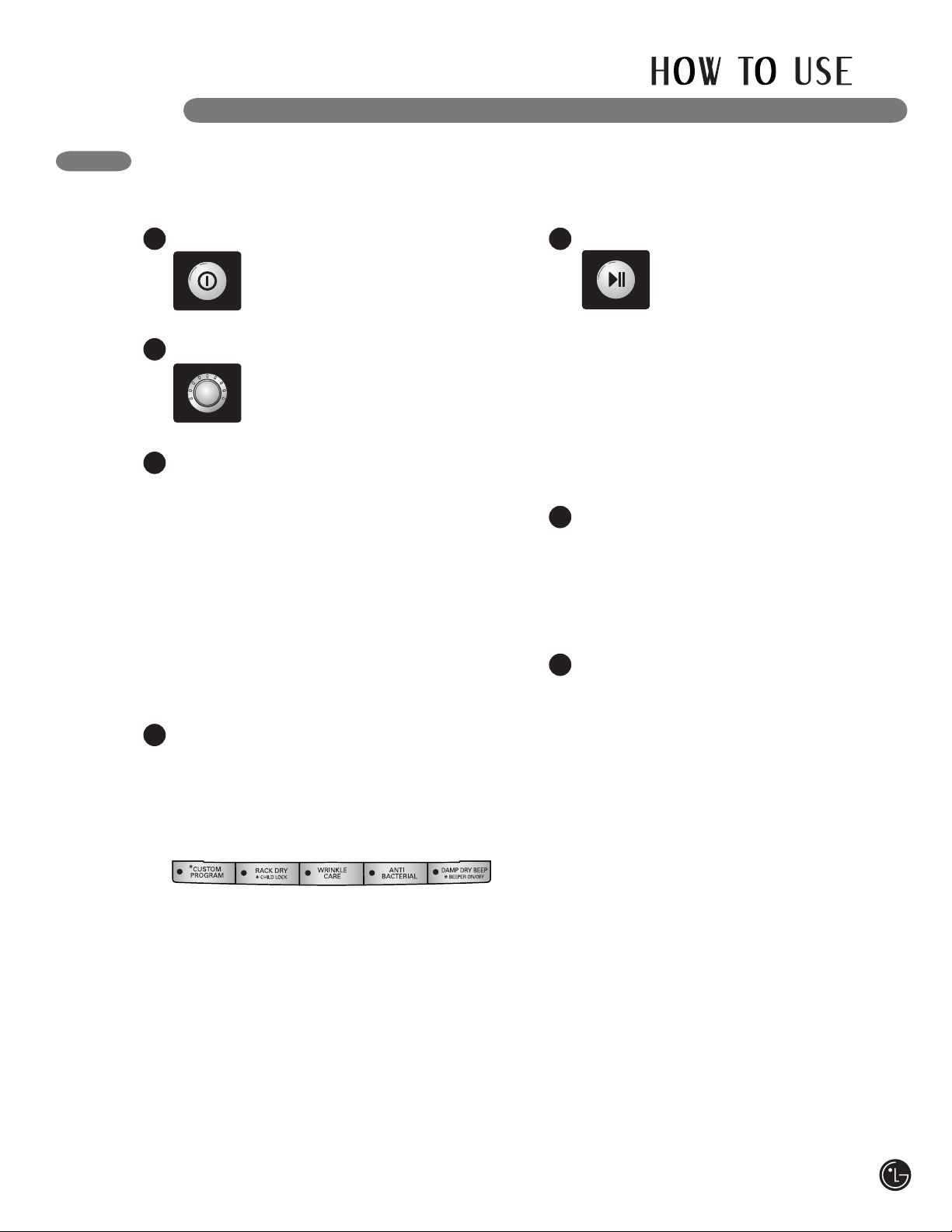
POWER ON/OFF BUTTON
Press to turn the dryer ON. Press again to
turn the dryer OFF.
NOTE: Pressing the ON/OFF button during
a cycle will cancel that cycle and any load
settings will be lost.
CYCLE SELECTOR KNOB
Turn this knob to select the desired cycle.
Once the desired cycle has been selected,
the standard presets will be shown in the
display. On MANUAL DRY cycles, these
settings can be adjusted using the cycle
settings buttons anytime before starting
the cycle.
1
2
CYCLE SETTING BUTTONS
Use these buttons to adjust the desired cycle
settings for the selected cycle.
4
5
START/PAUSE BUTTON
Press this button to START the selected
cycle. If the dryer is running, use this button
to PAUSE the cycle without losing the
current settings.
NOTE: If you do not press the START/PAUSE
button to resume a cycle within 4 minutes,
the dryer automatically turns off.
3
TIME AND STATUS DISPLAY
The display shows the settings, estimated
time remaining, options, and status messages
for your dryer.
6
OPTION BUTTONS
The option buttons allow you to select
additional cycle options. Certain buttons
also allow you to activate special functions
by pressing and holding the button for
3 seconds.
For detailed information about the individual
options, please see the following pages.
1
3
4
6
Following are instructions for starting and using your new dryer. Please refer to specific sections
of this manual for more detailed information. Important Warning: To reduce the risk of fire,
electric shock, or injury to persons, read this entire manual, including the Important Safety
Instructions, before operating this dryer.
MORE TIME/LESS TIME BUTTONS
Use these buttons with MANUAL DRY and
TIME DRY cycles to adjust the drying time.
Press the MORE TIME button to increase
the selected manual cycle time by a minute;
press LESS TIME to decrease the cycle time
by a minute.
7
7
5
7
26
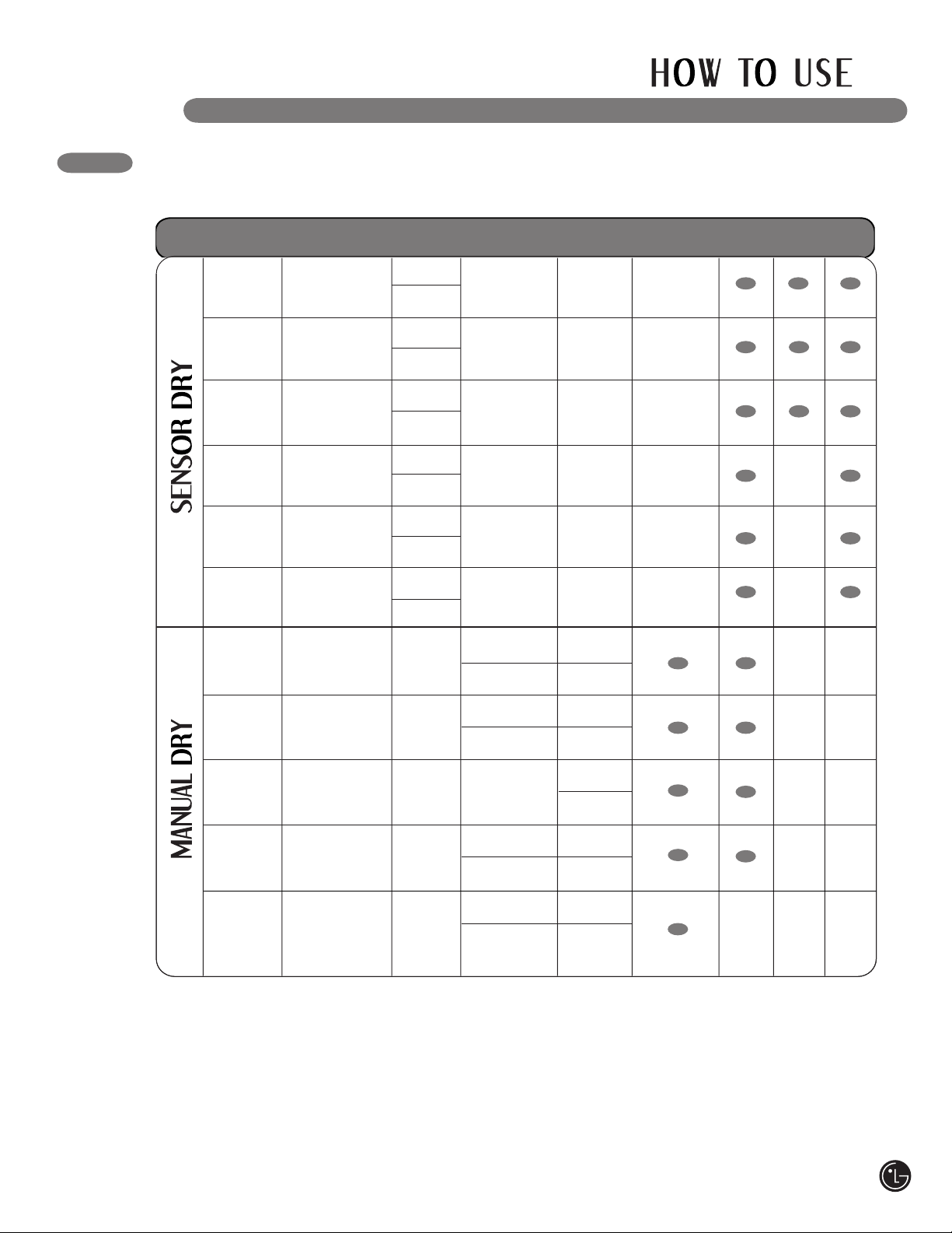
CYCLE GUIDE
The cycle guide below shows the options and recommended fabric types for each cycle.
NOTE: To protect your garments, not every dry level, temperature, or option is available
with every cycle.
Sensor Dry Cycles
Sensor Dry cycles utilize LG’s unique dual sensor
system to detect and compare the moisture level
in clothes and in the air and adjust the drying
time as needed to ensure superior results. The
dryer automatically sets the dryness level and
temperature at the recommended setting for
each cycle. The estimated time remaining will
be shown in the display.
Manual Dry Cycles
Use Manual Dry cycles to select a specific
amount of drying time and a drying temperature.
When a Manual Dry cycle is selected, the
ESTIMATED TIME REMAINING display shows
the actual time remaining in your cycle. You can
change the actual time in the cycle by pressing
MORE TIME or LESS TIME.
Type
Cycle
Fabric Type
Dry
Level
Temperature
Time
in Min.
More Time/
Less Time
Wrinkle
Care
Damp
Dry
Cotton/
Towels
Normal
Perm. Press
Delicates
Denims, towels,
heavy cottons
Work clothes,
corduroys, etc.
Permanent press,
synthetic items
Lingerie, sheets,
blouses
Normal
Adjustable
Normal
Low
Medium
Adjustable
Normal
Adjustable
Normal
Adjustable
Low
Ultra Low
54
55
41
36
Speed Dry
Freshen Up
Air Dry
Time Dry
For small loads
with short
drying times
For removing
light wrinkles
from clothing
For irems that
require heat-free
drying such as
plastics or rubber
For general drying;
time, temperature,
and options can be
set manually
Off
Off
Off
Off
High
Adjustable
Med. High
Adjustable
No Heat
High
Adjustable
25
Adjustable
20
Adjustable
30
Adjustable
40
Adjustable
Rack Dry
Wool sweaters,
silk, lingerie
Off
Off
50
Ultra Low
Low
Adjustable
Heavy Duty
Adjustable
Normal
Adjustable
Normal
Anti-
Bacterial
Med. High
High
32
34
Jeansm
heavyweight items
Ultra
Delicate
Workout wear,
sheer or lacy
garments
27
THE TIME AND STATUS DISPLAY
The display shows the settings, estimated time remaining, options, and status messages for
your dryer.
ESTIMATED TIME REMAINING
When the START/PAUSE button is pressed,
the display will indicate the estimated time
remaining for the selected drying cycle.
1
2
5
CYCLE COMPLETION INDICATOR WITH
CHECK FILTER REMINDER
This portion of the display shows which
stage of the drying cycle is currently
underway (CHECK FILTER, DRYING,
COOLING, or WRINKLE CARE).
FLOW SENSE™ DUCT BLOCKAGE
SENSING SYSTEM INDICATOR
The FLOW SENSE™ duct blockage sensing
system detects and alerts you to blockages
in the ductwork that reduce exhaust flow
from the dryer. This improve operating
efficiency and help minimize service calls,
saving you money.
If no bars are shown in the
display, the ductwork is free from
blockages.
The more bars displayed, the
greater the blockage.
If all bars are lit, the dryer
ductwork has a blockage that
needs to be removed immediately.
15 2 3
3
CHILD LOCK INDICATOR
When CHILD LOCK is set, the Child Lock
indicator will appear and all buttons are
disabled. This prevents children from
changing settings while the dryer
is operating.
4
4
LINT FILTER INDICATOR
The dryer automatically detects reduced air
flow caused by a full lint filter. The
CHECK FILTER indicator will light
before each load as a reminder to
check the lint filter before starting
each load. If the lint filter becomes clogged
during a load, the indicator will come on to
let you know that the filter should be cleaned
immediately for maximum efficiency.
Always clean the lint filter before every cycle.
28
OPERATING THE DRYER
Press the ON/OFF button to turn on the
dryer. The lights around the cycle
selector knob will illuminate.
Turn the cycle selector knob to the desired
cycle. The display will show
the preset Dry Level,
Temperature, Time, and
Option settings for that cycle.
If you would like to change the settings
for that cycle, such as the dry level or
temperature, press the appropriate cycle
settings button(s) until the indicator light for
the desired setting is lit.
NOTE: To protect your garments, not every
dry level, temperature, or option is available
with every cycle.
1
2
3
Select any additional cycle options, such
as WRINKLE CARE, ANTI BACTERIAL, or
DAMP DRY BEEP, by pressing the button
for that option. The indicator light on the
button will light to show that option has been
selected. To deselect an option, press the
button again.
NOTE: To protect your garments, not every
dry level, temperature, or option is available
with every cycle.
4
Press the START/PAUSE button to begin the
cycle. The display will change,
and the dryer will display the
estimated (SENSOR DRY) or set
time (MANUAL DRY) remaining
and start tumbling. To pause the cycle at any
time, for example to clean the lint filter or to
remove a garment, open the dryer door or
press PAUSE. To resume the cycle where it
was stopped, press START/PAUSE again.
NOTE: If the dryer has been stopped for
more than 8 minutes, the dryer will turn
off automatically.
5
Once you have loaded the dryer:
When the load is finished, the beeper (if
set) will sound. If you have set the Wrinkle
Care option, the dryer will tumble the load
periodically for up to 3 hours.
To prevent wrinkling, remove items from the
dryer immediately after the end of the cycle.
6
Always clean the lint filter after every cycle.
To clean, pull the lint filter straight up and
roll any lint off the filter with your fingers.
Do not rinse or wash the filter to remove lint.
Push the lint filter firmly back into place.
7
29
30
CYCLE OPTION BUTTONS
Your dryer features several additional cycle
options to customize cycles to meet your
individual needs. Certain option buttons also
feature a special function (see the following page
for details) that can be activated by pressing and
holding that option button for 3 seconds.
WRINKLE CARE
Selecting this option will tumble the
load periodically for up to 3 hours after
the selected cycle, or until the door is
opened. This is helpful in preventing
wrinkles when you are unable to immediately
remove items from the dryer.
ANTI BACTERIAL
This option will add a high heat setting
to reduce bacteria. It can only be used
with the HEAVY DUTY, COTTON/
TOWELS, and NORMAL cycles.
NOTE: Do not use this cycle with
delicate fabrics.
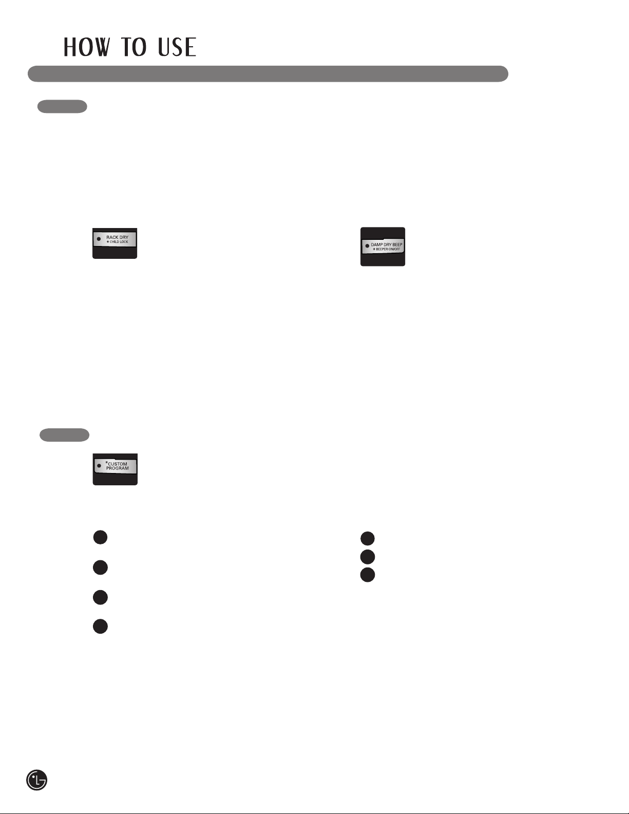
DAMP DRY BEEP
With this option, the dryer will beep
when the load is approximately 80%
dry. This allows you to remove
faster- drying lightweight items or
items that you would like to iron or hang while still
slightly damp.
To Add Cycle Options to a Cycle:
Turn on the dryer and turn the cycle selector
knob to select the desired cycle.
Use the cycle settings buttons to adjust the
settings for that cycle.
Press the cycle option button(s) for the
option you would like to add. A confirmation
message will be shown in the display.
Press the START/PAUSE button to start the
cycle. The dryer will start automatically.
1
2
3
4
CYCLE SETTING BUTTONS
Sensor Dry cycles have preset settings that are
selected automatically and cannot be changed.
Manual Dry cycles have default settings, but you
may also customize the settings using the cycle
setting buttons. Press the button for that setting
until the indicator light for the desired value is lit.
NOTE: To protect your garments, not every
dryness level, temperature, or option is available
with every cycle. See the Cycle Guide for details.
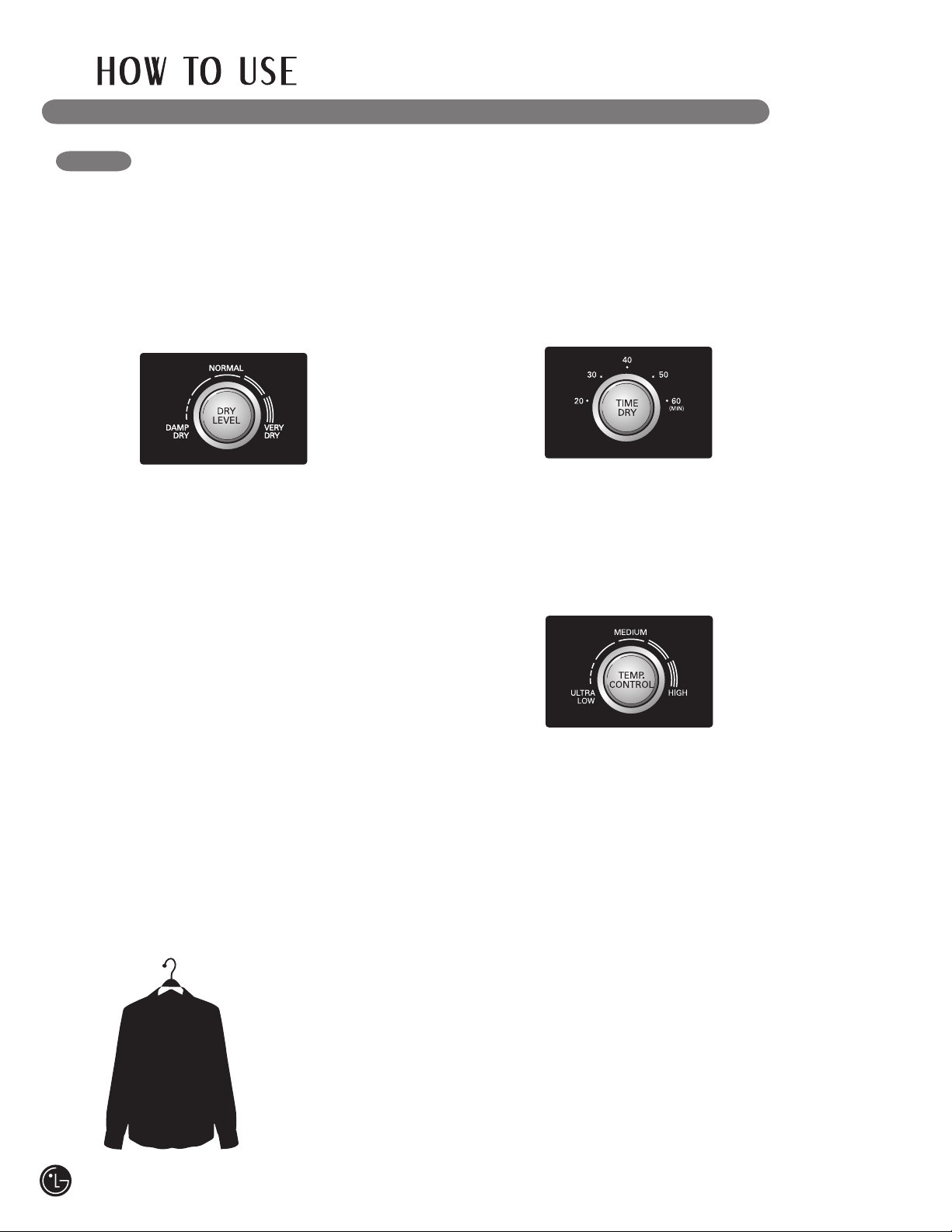
DRY LEVEL
Selects the level of
dryness for the cycle.
Press the DRY LEVEL
button until the indicator
light for the desired
setting is lit.
• This option is only available with SENSOR DRY
cycles.
• The dryer will automatically adjust the cycle
time. Selecting VERY DRY or MORE DRY will
increase the cycle time, while LESS DRY or
DAMP DRY will decrease the cycle time.
• Use a LESS DRY or DAMP DRY setting for
items that you wish to iron.
TIME DRY
Allows you to manually
select the drying time,
from 20 to 60 minutes, in
10- minute increments.
Use this for small loads
or to remove wrinkles.
Press the TIME DRY
button until the indicator light for the desired
drying time is lit. Use the MORE TIME/
LESS TIME buttons to add or reduce the
drying time in 1-minute increments.
TEMP. CONTROL
Adjusts the temperature
setting from ULTRA LOW
to HIGH. This allows
precise care of your
fabrics and garments.
Press the TEMP
CONTROL button until
the indicator light for the desired setting is lit.
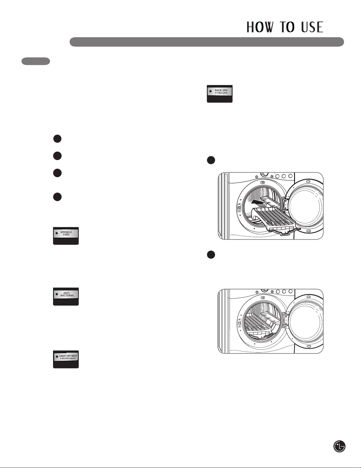
RACK DRY
Use RACK DRY with items, such as
wool sweaters, silk, and lingerie, that
should dry flat. RACK DRY can also
be used with items that should not be
tumbled dry, such as gym shoes or
stuffed animals.
NOTE: NEVER use the rack with a tumble
dry cycle.
To Install the Drying Rack
With the dryer door open, slide the rack into
the dryer drum.
1
Make sure it is seated evenly on the edge
of the inner door rim and resting flat on the
inside of the dryer.
NOTE: Be sure to remove the drying rack
after using the RACK DRY cycle.
2
31
CYCLE OPTION BUTTONS
Your dryer features several additional cycle
options to customize cycles to meet your
individual needs. Certain option buttons also
feature a special function (see the following page
for details) that can be activated by pressing and
holding that option button for 3 seconds.
WRINKLE CARE
Selecting this option will tumble the
load periodically for up to 3 hours after
the selected cycle, or until the door is
opened. This is helpful in preventing
wrinkles when you are unable to immediately
remove items from the dryer.
ANTI BACTERIAL
This option will add a high heat setting
to reduce bacteria. It can only be used
with the HEAVY DUTY, COTTON/
TOWELS, and NORMAL cycles.
NOTE: Do not use this cycle with
delicate fabrics.
DAMP DRY BEEP
With this option, the dryer will beep
when the load is approximately 80%
dry. This allows you to remove
faster- drying lightweight items or
items that you would like to iron or hang while still
slightly damp.
To Add Cycle Options to a Cycle:
Turn on the dryer and turn the cycle selector
knob to select the desired cycle.
Use the cycle settings buttons to adjust the
settings for that cycle.
Press the cycle option button(s) for the
option you would like to add. A confirmation
message will be shown in the display.
Press the START/PAUSE button to start the
cycle. The dryer will start automatically.
1
2
3
4
CYCLE SETTING BUTTONS
Sensor Dry cycles have preset settings that are
selected automatically and cannot be changed.
Manual Dry cycles have default settings, but you
may also customize the settings using the cycle
setting buttons. Press the button for that setting
until the indicator light for the desired value is lit.
NOTE: To protect your garments, not every
dryness level, temperature, or option is available
with every cycle. See the Cycle Guide for details.
DRY LEVEL
Selects the level of
dryness for the cycle.
Press the DRY LEVEL
button until the indicator
light for the desired
setting is lit.
• This option is only available with SENSOR DRY
cycles.
• The dryer will automatically adjust the cycle
time. Selecting VERY DRY or MORE DRY will
increase the cycle time, while LESS DRY or
DAMP DRY will decrease the cycle time.
• Use a LESS DRY or DAMP DRY setting for
items that you wish to iron.
TIME DRY
Allows you to manually
select the drying time,
from 20 to 60 minutes, in
10- minute increments.
Use this for small loads
or to remove wrinkles.
Press the TIME DRY
button until the indicator light for the desired
drying time is lit. Use the MORE TIME/
LESS TIME buttons to add or reduce the
drying time in 1-minute increments.
TEMP. CONTROL
Adjusts the temperature
setting from ULTRA LOW
to HIGH. This allows
precise care of your
fabrics and garments.
Press the TEMP
CONTROL button until
the indicator light for the desired setting is lit.
RACK DRY
Use RACK DRY with items, such as
wool sweaters, silk, and lingerie, that
should dry flat. RACK DRY can also
be used with items that should not be
tumbled dry, such as gym shoes or
stuffed animals.
NOTE: NEVER use the rack with a tumble
dry cycle.
To Install the Drying Rack
With the dryer door open, slide the rack into
the dryer drum.
1
Make sure it is seated evenly on the edge
of the inner door rim and resting flat on the
inside of the dryer.
NOTE: Be sure to remove the drying rack
after using the RACK DRY cycle.
2
Cleaning the Exterior
Proper care of your dryer can extend its life.
The outside of the machine can be cleaned with
warm water and a mild, nonabrasive household
detergent.
Immediately wipe off any spills with a soft,
damp cloth.
IMPORTANT: Do not use methylated spirits,
solvents, or similar products.
Never use steel wool or abrasive cleansers; they
can damage the surface.
REGULAR CLEANING
Cleaning the Interior
Wipe around the door opening and seal with a
soft, damp cloth to prevent lint and dust buildup
that could damage the door seal.
Clean the window with a soft cloth dampened
with warm water and a mild, nonabrasive
household detergent; then wipe dry.
The stainless steel drum can be cleaned with
a conventional stainless steel cleaner, used
according to the manufacturer’s specifications.
Never use steel wool or abrasive cleansers; they
can scratch or damage the surface.
Cleaning the Lint Filter
Cleaning Around and Under the Dryer
Vacuum lint and dust from around the dryer and
underneath it regularly. Vent ductwork should be
checked for lint buildup and cleaned at least once
per year. If any noticeable reduction in airflow or
drying performance occurs, immediately check
ductwork for obstructions and blockages.
Maintaining Ductwork
Vent ductwork should be checked for lint
buildup and cleaned at least once per year. If
any noticeable reduction in airflow or drying
performance occurs, immediately check ductwork
for obstructions and blockages. Contact a
qualified technician or service provider.
wWARNING: To reduce the risk of fire, electric shock, or injury to persons when using this
appliance, follow basic precautions, including the following:
• Unplug the dryer before cleaning to avoid the risk of electric shock. Failure to follow this warning can
cause serious injury, fire, electrical shock or death.
• Never use harsh chemicals, abrasive cleaners, or solvents to clean the washer.
They will damage the finish.
Lint Filter
Always clean the lint filter before every cycle or
when the CHECK FILTER indicator
lights during a cycle.
To clean, open the dryer door and
pull the lint filter straight up.
Then:
Roll any lint off the filter with
your fingers, or
Vacuum the lint filter, or
Wash the lint filter in warm, soapy water and
allow to dry thoroughly before reinstalling.
NOTE: NEVER operate the dryer without the lint
filter in place.
1
2
3
SPECIAL FUNCTIONS
The option buttons also activate special
functions, including CHILD LOCK and
BEEPER ON/OFF. Press and hold the option
button marked with the special function
for 3 seconds to activate.
*
CHILD LOCK
Use this option to prevent unwanted
use of the dryer or to keep cycle
settings from being changed while the
dryer is operating. Press and hold the
RACK DRY button for 3 seconds to activate or
deactivate CHILD LOCK.
The lock icon will be shown in the display, and all
controls are disabled.
*
BEEPER ON/OFF
To turn the beeper off, press and hold
DAMP DRY BEEP for 3 seconds. Press
and hold again for 3 seconds to turn
the beeper back on.
*
CUSTOM PROGRAM
If you have a special combination of
settings that you use frequently, you
can save these settings as a CUSTOM
PROGRAM.
*
To Save a Custom Program:
Turn on the dryer and turn the cycle selector
knob to select the desired cycle.
Use the cycle setting knobs to adjust the
settings for that cycle.
Press the cycle option button(s) for the
option(s) you would like to add.
Press and hold the CUSTOM PROGRAM
button for 3 seconds.
NOTE: You may only save one custom
program at a time. Pressing and holding the
CUSTOM PROGRAM button will overwrite
any previously saved custom program.
1
2
3
4
To Recall a Custom Program:
Turn on the dryer.
Press the CUSTOM PROGRAM button.
Press the START/PAUSE button to start
the cycle.
1
2
3
32
Cleaning the Exterior
Proper care of your dryer can extend its life.
The outside of the machine can be cleaned with
warm water and a mild, nonabrasive household
detergent.
Immediately wipe off any spills with a soft,
damp cloth.
IMPORTANT: Do not use methylated spirits,
solvents, or similar products.
Never use steel wool or abrasive cleansers; they
can damage the surface.
REGULAR CLEANING
Cleaning the Interior
Wipe around the door opening and seal with a
soft, damp cloth to prevent lint and dust buildup
that could damage the door seal.
Clean the window with a soft cloth dampened
with warm water and a mild, nonabrasive
household detergent; then wipe dry.
The stainless steel drum can be cleaned with
a conventional stainless steel cleaner, used
according to the manufacturer’s specifications.
Never use steel wool or abrasive cleansers; they
can scratch or damage the surface.
Cleaning the Lint Filter
Cleaning Around and Under the Dryer
Vacuum lint and dust from around the dryer and
underneath it regularly. Vent ductwork should be
checked for lint buildup and cleaned at least once
per year. If any noticeable reduction in airflow or
drying performance occurs, immediately check
ductwork for obstructions and blockages.
Maintaining Ductwork
Vent ductwork should be checked for lint
buildup and cleaned at least once per year. If
any noticeable reduction in airflow or drying
performance occurs, immediately check ductwork
for obstructions and blockages. Contact a
qualified technician or service provider.
wWARNING: To reduce the risk of fire, electric shock, or injury to persons when using this
appliance, follow basic precautions, including the following:
• Unplug the dryer before cleaning to avoid the risk of electric shock. Failure to follow this warning can
cause serious injury, fire, electrical shock or death.
• Never use harsh chemicals, abrasive cleaners, or solvents to clean the washer.
They will damage the finish.
Lint Filter
Always clean the lint filter before every cycle or
when the CHECK FILTER indicator
lights during a cycle.
To clean, open the dryer door and
pull the lint filter straight up.
Then:
Roll any lint off the filter with
your fingers, or
Vacuum the lint filter, or
Wash the lint filter in warm, soapy water and
allow to dry thoroughly before reinstalling.
NOTE: NEVER operate the dryer without the lint
filter in place.
1
2
3
SPECIAL FUNCTIONS
The option buttons also activate special
functions, including CHILD LOCK and
BEEPER ON/OFF. Press and hold the option
button marked with the special function
for 3 seconds to activate.
*
CHILD LOCK
Use this option to prevent unwanted
use of the dryer or to keep cycle
settings from being changed while the
dryer is operating. Press and hold the
RACK DRY button for 3 seconds to activate or
deactivate CHILD LOCK.
The lock icon will be shown in the display, and all
controls are disabled.
*
BEEPER ON/OFF
To turn the beeper off, press and hold
DAMP DRY BEEP for 3 seconds. Press
and hold again for 3 seconds to turn
the beeper back on.
*
CUSTOM PROGRAM
If you have a special combination of
settings that you use frequently, you
can save these settings as a CUSTOM
PROGRAM.
*
To Save a Custom Program:
Turn on the dryer and turn the cycle selector
knob to select the desired cycle.
Use the cycle setting knobs to adjust the
settings for that cycle.
Press the cycle option button(s) for the
option(s) you would like to add.
Press and hold the CUSTOM PROGRAM
button for 3 seconds.
NOTE: You may only save one custom
program at a time. Pressing and holding the
CUSTOM PROGRAM button will overwrite
any previously saved custom program.
1
2
3
4
To Recall a Custom Program:
Turn on the dryer.
Press the CUSTOM PROGRAM button.
Press the START/PAUSE button to start
the cycle.
1
2
3
33
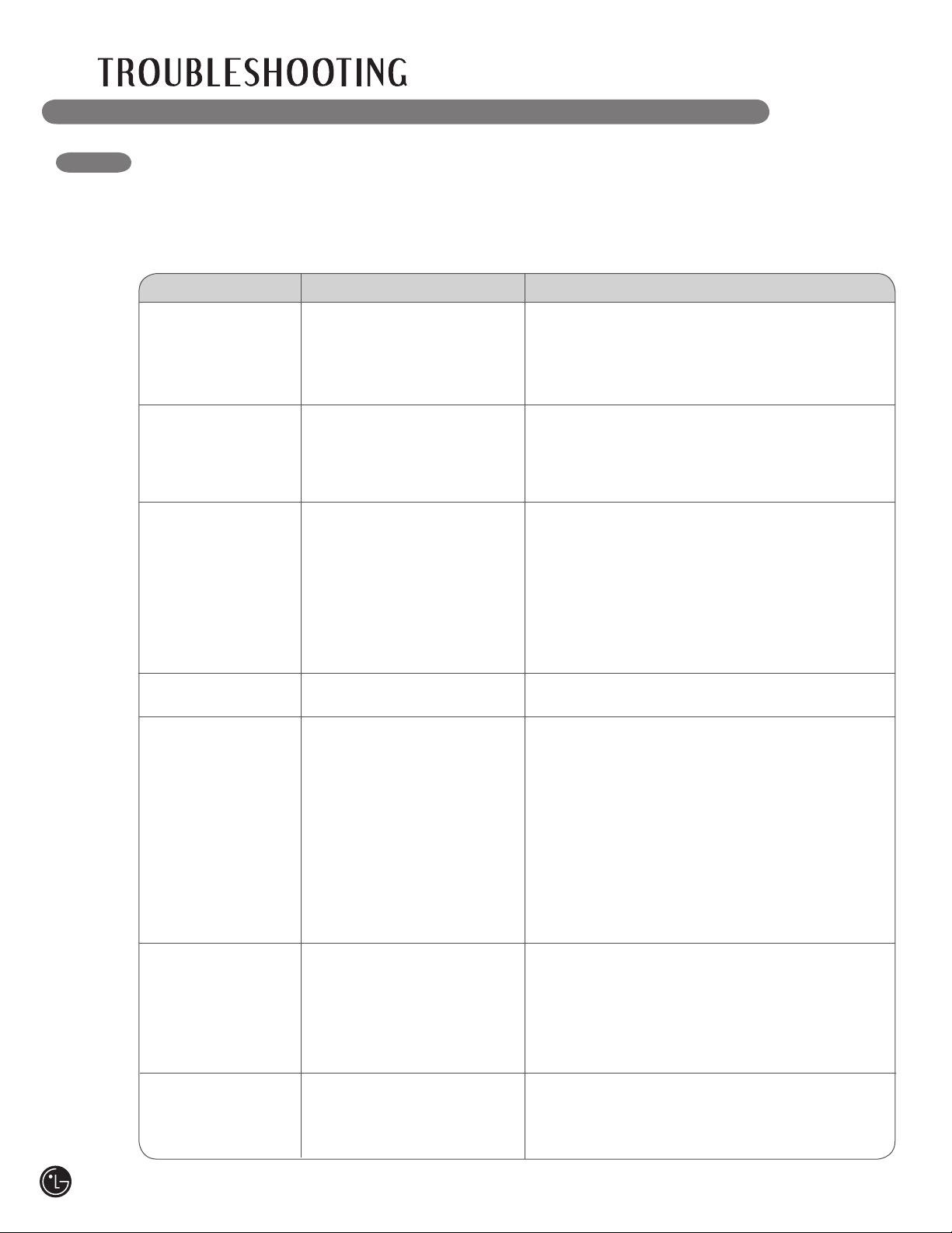
BEFORE CALLING FOR SERVICE (cont.)
Problem Possible Causes Solutions
Clothes take too
long to dry
• Load is not properly sorted.
• Large load of heavy fabrics.
• Dryer controls are not set
properly.
• Lint filter needs to be
cleaned.
• Exhaust ducts blocked, dirty,
or duct run is too long.
• House fuse is blown, circuit
breaker has tripped, or
power outage has occurred.
• Dryer is overloaded.
• Dryer is underloaded.
• Separate heavy items from lightweight items. Larger
and heavier items take longer to dry.
• Heavy fabrics take longer to dry because they tend
to retain more moisture. To help reduce and maintain
more consistent drying times for large and heavy
fabrics, separate these items into smaller loads of
a consistent size.
• Use the appropriate control settings for the type of
load you are drying.
• Make sure the lint filter is cleaned before every load.
With some loads that produce high amounts of lint, it
may be necessary to clean the filter during the cycle.
• Confirm that the exhaust ductwork is properly
configured and free of debris, lint, and obstructions.
Make sure that outside wall dampers can open
properly and are not blocked, jammed, or damaged.
• Reset circuit breaker or replace fuse. Do not
increase fuse capacity. If the problem is a circuit
overload, have it corrected by a qualified electrician.
• Divide larger loads into smaller loads for drying.
• If you are drying a very small load, add a few extra
items to ensure proper tumbling action.
Clothes are wrinkled
• Clothes dried too long
(overdried).
• Clothes left in dryer too long
after cycle ends.
• Overdrying a load of laundry can lead to wrinkled
clothes. Try a shorter drying time, and remove items
while they still retain a slight amount of moisture.
• Remove items from the dryer immediately at the
end of the cycle. Use the WRINKLE CARE option to
continue tumbling clothes at the end of the cycle, for
up to 3 hours.
Clothes are shrinking
• Garment care instructions
are not being followed.
• To avoid shrinkage, please carefully follow the fabric
care instructions for your garment, because some
fabrics will naturally shrink when washed. Other
fabrics can be washed but will shrink when dried
in a dryer. Use a low or no heat setting and/or the
RACK DRY option.
Problem Possible Causes Solutions
Dryer does not heat
• House fuse is blown, circuit
breaker has tripped, or
power outage has occurred.
• Gas supply or service turned
off (gas models only).
• Reset circuit breaker or replace fuse. Do not
increase fuse capacity. If the problem is a circuit
overload, have it corrected by a qualified electrician.
• Confirm that the house gas shutoff and the dryer
gas shutoff are both fully open.
BEFORE CALLING FOR SERVICE
Your dryer is equipped with an automatic error-monitoring system to detect and diagnose problems at an
early stage. If your dryer does not function properly or does not function at all, check the following before
you call for service.
Dryer will not
turn on
• Power cord is not properly
plugged in.
• House fuse is blown, circuit
breaker has tripped, or
power outage has occurred.
• Make sure that the plug is plugged securely into a
grounded outlet matching the dryer’s rating plate.
• Reset circuit breaker or replace fuse. Do not increase
fuse capacity. If the problem is a circuit overload,
have it corrected by a qualified electrician.
Greasy or dirty spots
on clothes
• Fabric softener used
incorrectly.
• Clean and dirty clothes being
dried together.
• Clean and dirty clothes being
dried together.
• Confirm and follow the instructions provided with
your fabric softener.
• Make sure to use your dryer to dry only clean
items, because dirty items can soil clean clothes
placed in the same or subsequent loads.
• Stains on dried clothes are actually stains that
weren’t removed during the washing process.
Make sure that clothes are being completely
cleaned according to the instructions for your
washer and detergent.
Display shows error
code tE1 or tE2
• Thermistor is malfunctioning.
• Turn off the dryer and call for service.
Lint on clothes
• Lint filter not cleaned
properly.
• Laundry not sorted properly.
• Excess static in clothes.
• Dryer is overloaded.
• Tissue, paper, etc., left
in pockets.
• Make sure the lint filter is cleaned before every
load. With some loads that produce high amounts
of lint, it may be necessary to clean the filter
during the cycle.
• Some fabrics are lint producers (i.e., a fuzzy white
cotton towel) and should be dried separately from
clothes that are lint trappers (i.e., a pair of black
linen pants).
• See the Excess static in clothes after drying
section below.
• Divide larger loads into smaller loads for drying.
• Check pockets thoroughly before washing and
drying clothes.
Excess static in
clothes after drying
• Fabric softener not used or
used incorrectly.
• Clothes dried too long
(overdried).
• Drying synthetics, permanent
press, or synthetic blends.
• Use a fabric softener to reduce static electricity.
Be sure to follow the manufacturer’s instructions.
• Overdrying a load of laundry can cause a buildup
of static electricity. Adjust settings and use a
shorter drying time, or use SENSOR DRY cycles.
• These materials can cause static buildup. Try
using a fabric softener.
Drying time is not
consistent
• Heat settings, load size, or
dampness of clothing is not
consistent.
• The drying time for a load will vary depending on the
heat setting, the type of heat used (electric, natural,
or LP gas), the size of the load, the type of fabrics,
the wetness of the clothes, and the condition of the
exhaust ducts and lint filter.
CHECK FILTER light
is on during the
drying cycle
• Lint filter is almost clogged
or full.
• Pause the drying cycle and clean the lint filter.
2 bars are displayed
in FLOW SENSE
indicator
• Ductwork is slightly too long
or has too many turns/
restrictions.
• Partial blockage of the
ductwork due to lint buildup.
• Install a shorter or straighter duct run. See the
Installation Instructions.
• Ductwork should be checked/cleaned soon.
Dryer can be used in this condition, but drying
times may be longer.
4 bars are displayed
in FLOW SENSE
indicator
• Ductwork is too long or has
too many turns/restrictions.
• Significant blockage of the
ductwork due to lint buildup
or debris.
• Install a shorter or straighter duct run. See the
Installation Instructions.
• Ductwork should be checked/cleaned immediately
to remove lint build up and other blockages. Dryer
can be used, but performance and efficiency will be
greatly reduced.
34
BEFORE CALLING FOR SERVICE (cont.)
Problem Possible Causes Solutions
Clothes take too
long to dry
• Load is not properly sorted.
• Large load of heavy fabrics.
• Dryer controls are not set
properly.
• Lint filter needs to be
cleaned.
• Exhaust ducts blocked, dirty,
or duct run is too long.
• House fuse is blown, circuit
breaker has tripped, or
power outage has occurred.
• Dryer is overloaded.
• Dryer is underloaded.
• Separate heavy items from lightweight items. Larger
and heavier items take longer to dry.
• Heavy fabrics take longer to dry because they tend
to retain more moisture. To help reduce and maintain
more consistent drying times for large and heavy
fabrics, separate these items into smaller loads of
a consistent size.
• Use the appropriate control settings for the type of
load you are drying.
• Make sure the lint filter is cleaned before every load.
With some loads that produce high amounts of lint, it
may be necessary to clean the filter during the cycle.
• Confirm that the exhaust ductwork is properly
configured and free of debris, lint, and obstructions.
Make sure that outside wall dampers can open
properly and are not blocked, jammed, or damaged.
• Reset circuit breaker or replace fuse. Do not
increase fuse capacity. If the problem is a circuit
overload, have it corrected by a qualified electrician.
• Divide larger loads into smaller loads for drying.
• If you are drying a very small load, add a few extra
items to ensure proper tumbling action.
Clothes are wrinkled
• Clothes dried too long
(overdried).
• Clothes left in dryer too long
after cycle ends.
• Overdrying a load of laundry can lead to wrinkled
clothes. Try a shorter drying time, and remove items
while they still retain a slight amount of moisture.
• Remove items from the dryer immediately at the
end of the cycle. Use the WRINKLE CARE option to
continue tumbling clothes at the end of the cycle, for
up to 3 hours.
Clothes are shrinking
• Garment care instructions
are not being followed.
• To avoid shrinkage, please carefully follow the fabric
care instructions for your garment, because some
fabrics will naturally shrink when washed. Other
fabrics can be washed but will shrink when dried
in a dryer. Use a low or no heat setting and/or the
RACK DRY option.
Problem Possible Causes Solutions
Dryer does not heat
• House fuse is blown, circuit
breaker has tripped, or
power outage has occurred.
• Gas supply or service turned
off (gas models only).
• Reset circuit breaker or replace fuse. Do not
increase fuse capacity. If the problem is a circuit
overload, have it corrected by a qualified electrician.
• Confirm that the house gas shutoff and the dryer
gas shutoff are both fully open.
BEFORE CALLING FOR SERVICE
Your dryer is equipped with an automatic error-monitoring system to detect and diagnose problems at an
early stage. If your dryer does not function properly or does not function at all, check the following before
you call for service.
Dryer will not
turn on
• Power cord is not properly
plugged in.
• House fuse is blown, circuit
breaker has tripped, or
power outage has occurred.
• Make sure that the plug is plugged securely into a
grounded outlet matching the dryer’s rating plate.
• Reset circuit breaker or replace fuse. Do not increase
fuse capacity. If the problem is a circuit overload,
have it corrected by a qualified electrician.
Greasy or dirty spots
on clothes
• Fabric softener used
incorrectly.
• Clean and dirty clothes being
dried together.
• Clean and dirty clothes being
dried together.
• Confirm and follow the instructions provided with
your fabric softener.
• Make sure to use your dryer to dry only clean
items, because dirty items can soil clean clothes
placed in the same or subsequent loads.
• Stains on dried clothes are actually stains that
weren’t removed during the washing process.
Make sure that clothes are being completely
cleaned according to the instructions for your
washer and detergent.
Display shows error
code tE1 or tE2
• Thermistor is malfunctioning.
• Turn off the dryer and call for service.
Lint on clothes
• Lint filter not cleaned
properly.
• Laundry not sorted properly.
• Excess static in clothes.
• Dryer is overloaded.
• Tissue, paper, etc., left
in pockets.
• Make sure the lint filter is cleaned before every
load. With some loads that produce high amounts
of lint, it may be necessary to clean the filter
during the cycle.
• Some fabrics are lint producers (i.e., a fuzzy white
cotton towel) and should be dried separately from
clothes that are lint trappers (i.e., a pair of black
linen pants).
• See the Excess static in clothes after drying
section below.
• Divide larger loads into smaller loads for drying.
• Check pockets thoroughly before washing and
drying clothes.
Excess static in
clothes after drying
• Fabric softener not used or
used incorrectly.
• Clothes dried too long
(overdried).
• Drying synthetics, permanent
press, or synthetic blends.
• Use a fabric softener to reduce static electricity.
Be sure to follow the manufacturer’s instructions.
• Overdrying a load of laundry can cause a buildup
of static electricity. Adjust settings and use a
shorter drying time, or use SENSOR DRY cycles.
• These materials can cause static buildup. Try
using a fabric softener.
Drying time is not
consistent
• Heat settings, load size, or
dampness of clothing is not
consistent.
• The drying time for a load will vary depending on the
heat setting, the type of heat used (electric, natural,
or LP gas), the size of the load, the type of fabrics,
the wetness of the clothes, and the condition of the
exhaust ducts and lint filter.
CHECK FILTER light
is on during the
drying cycle
• Lint filter is almost clogged
or full.
• Pause the drying cycle and clean the lint filter.
2 bars are displayed
in FLOW SENSE
indicator
• Ductwork is slightly too long
or has too many turns/
restrictions.
• Partial blockage of the
ductwork due to lint buildup.
• Install a shorter or straighter duct run. See the
Installation Instructions.
• Ductwork should be checked/cleaned soon.
Dryer can be used in this condition, but drying
times may be longer.
4 bars are displayed
in FLOW SENSE
indicator
• Ductwork is too long or has
too many turns/restrictions.
• Significant blockage of the
ductwork due to lint buildup
or debris.
• Install a shorter or straighter duct run. See the
Installation Instructions.
• Ductwork should be checked/cleaned immediately
to remove lint build up and other blockages. Dryer
can be used, but performance and efficiency will be
greatly reduced.
35
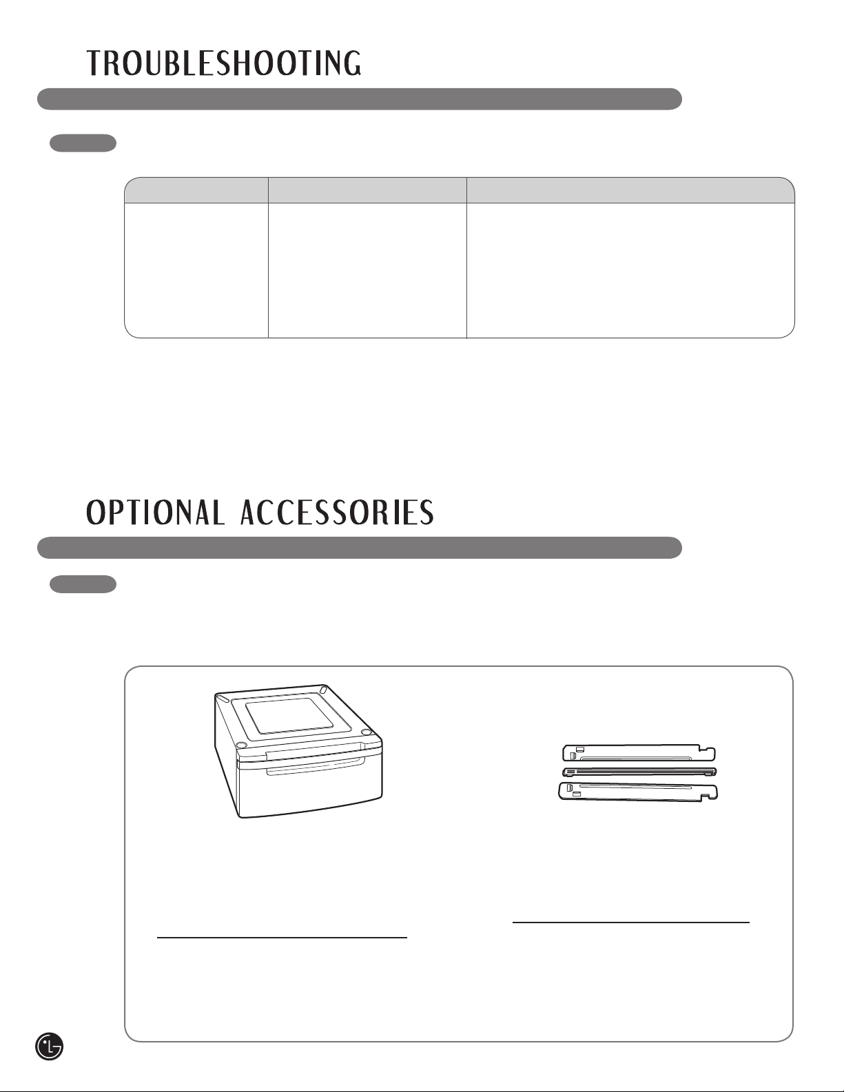
OPTIONAL ACCESSORIES
For these and other LG products, contact your local LG dealer,
or visit our Web site at us.lge.com.
Pedestal
Give your LG washer and dryer a boost
with matching 14-inch high pedestals.
They feature a storage drawer for
added convenience.
14" Pedestal Color
WDP3W White
WDP3B Black
WDP3S Titanium
WDP3N Navy Blue
WDP3R Wild Cherry Red
WDP3G Pearl Gray
Stacking Kit
If space is at a premium, use this kit to
securely stack your LG front-load
washer and dryer.
Bracket Kit Color
WSTK1 White
BSTK1 Black
SSTK1 Titanium
NSTK1 Navy Blue
RSTK1 Wild Cherry Red
GSTK1 Pearl Gray
BEFORE CALLING FOR SERVICE (cont.)
Problem Possible Causes Solutions
Ductwork is clean
and properly installed
as described in
the installation
instructions, but the
FLOW SENSE display
shows 4 bars.
• Dryer is being used for
the first time, or after an
extended power outage.
• This is normal. After the first cycle, the bars in the
FLOW SENSE display will disappear.
36
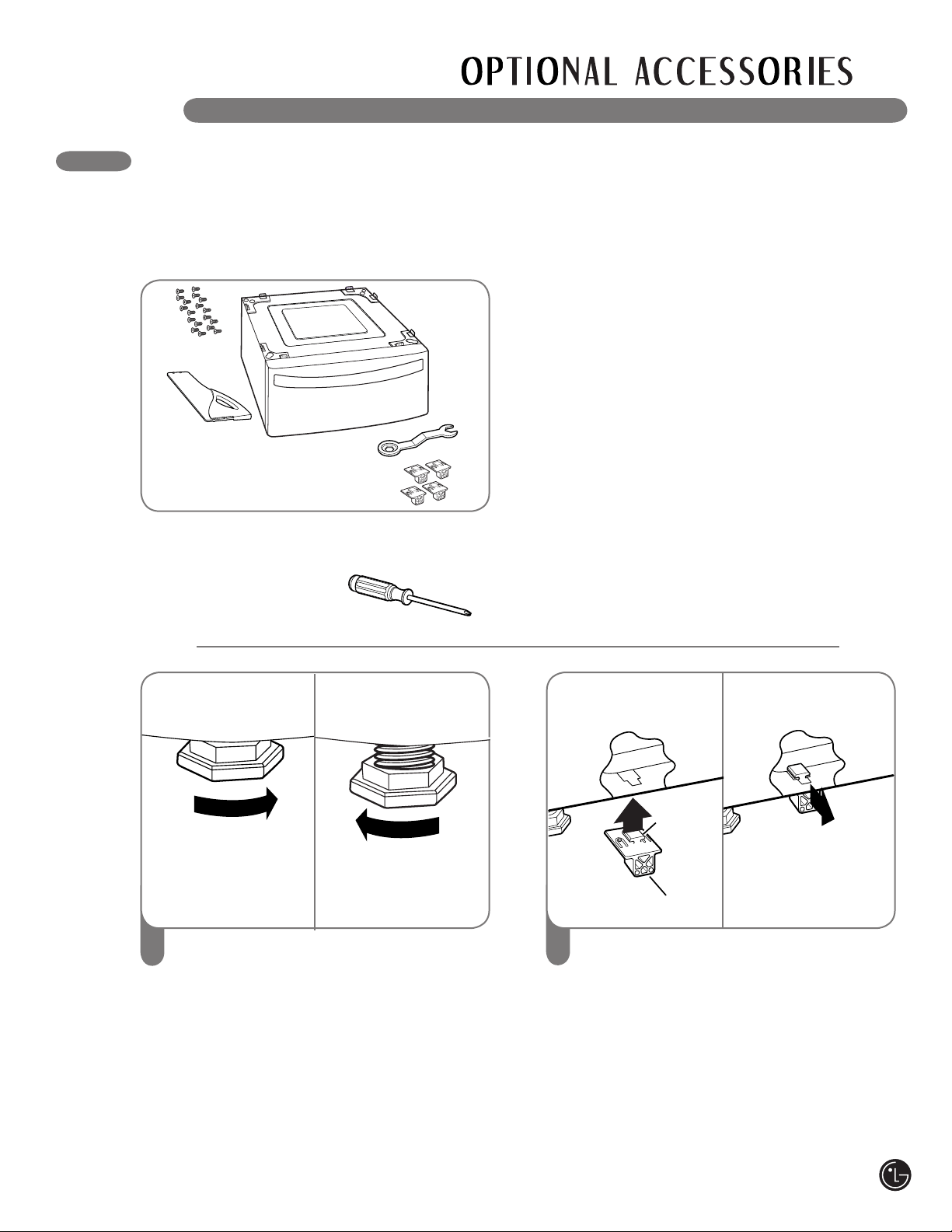
PEDESTAL INSTALLATION
3737
2
1
To set the dryer to the same height as the
washer, fully retract the leveling feet of the
dryer by turning them counterclockwise, then
turn them clockwise 1-1/2 turns.
NOTE: The appliance and pedestal assembly
must be placed on a solid, sturdy, level floor
for proper operation.
Insert the T-clip of the 4 retainers into the
dryer base as shown. Press up on the
back of the clip and pull outward to lock
into place.
The pedestal accessory includes:
• Drawer divider (1) • Wrench (1)
• Screws (18) † • Retainers (4) ††
wWARNING
• Incorrect installation can cause serious
accidents.
• The appliances are heavy. Two or more
people are required when installing the
pedestal. There is a risk of serious back injury
or other injuries.
• Do not allow children to play in or on the
drawer. There is a risk of suffocation or injury.
• Do not step on the handle. There is a risk of
serious injury.
• If appliances are already installed,
disconnect them from all power, water, or
gas lines and from draining or venting
connections. Failure to do so can result in
electrical shock, fire, explosion, or death.
• When installing, gloves must be put on.
To ensure safe and secure installation, please
thoroughly follow the instructions below.
Tools Needed for Installation:
• Phillips-head screwdriver
• Wrench (supplied)
† Dryer installation only uses 8 screws
†† For dryer only
Then loosen
1-1/2 turns
Retract fully
T-clip
Retainer
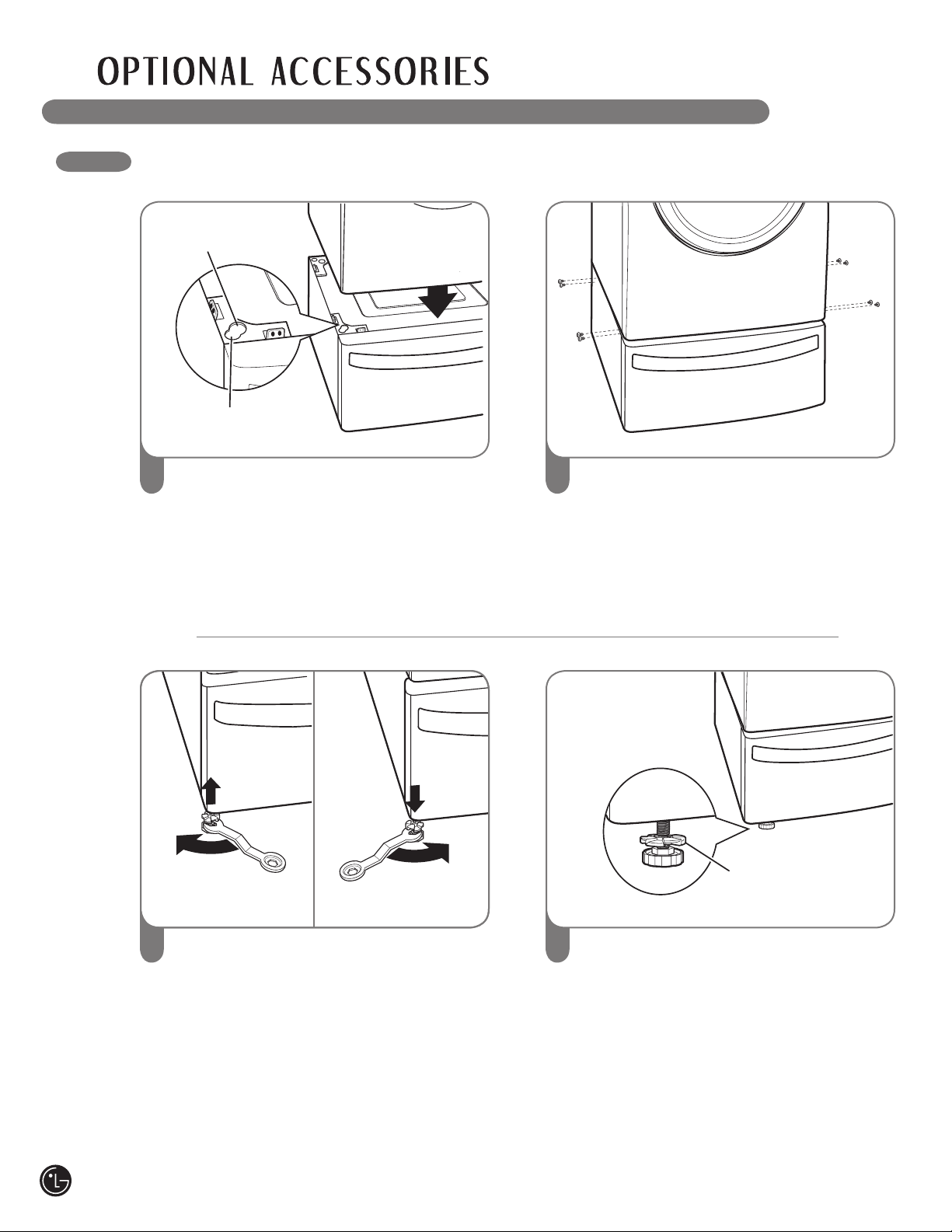
PEDESTAL INSTALLATION (cont.)
38
65
Raise
Lower
Loosen the locknuts on all 4 leveling feet
of the pedestal until you can turn them
with the wrench. Turn clockwise to raise or
counterclockwise to lower until the pedestal
is level and all 4 feet are solidly against the
floor.
3
Place the dryer on the pedestal. Make sure
the front and back feet are in the correct
positions. The dryer feet will fi t into the
innermost positions as shown.
4
Make sure the screws on the pedestal align
with the holes in the retainers, then install 4
screws at each corner to securely attach the
appliance to the pedestal.
NOTE: If the screws are not installed
properly, noise and vibration may result.
Move the appliance to the desired location.
Securely tighten all locknuts by hand.
NOTE: Noise and vibration may result if
locknuts are not tightened.
Be sure to connect the appliances to all
water, power, or gas lines and draining or
venting connections before operation.
If there is excessive vibration during the
first operation after installation, slightly
adjust the leveling feet.
For dryer
For washer/combo
Locknut
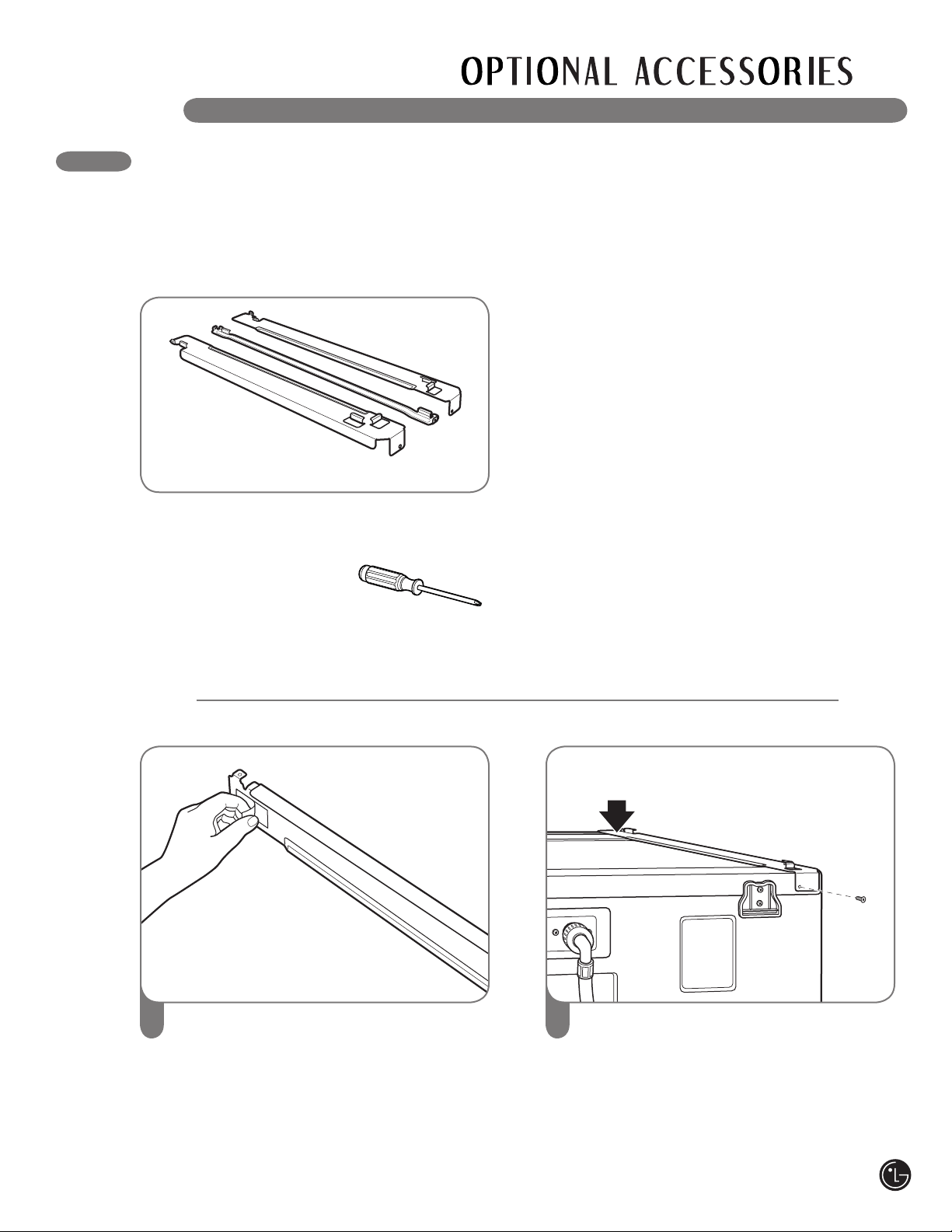
1
Make sure the surface of the washer is clean
and dry. Remove paper backing from the
tape on one of the stacking kit side brackets.
2
Fit the side bracket to the side of the washer
top as shown in the above illustration. Firmly
press the adhesive area of the bracket to the
washer surface. Secure the side bracket to
the washer with a screw on the back side of
the bracket. Repeat steps 1 and 2 to attach
the other side bracket.
This stacking kit includes:
• Two (2) side rails
• One (1) front rail
• Four (4) screws
To ensure safe and secure installation, please
observe the following instructions.
Tools Needed for Installation:
• Phillips-head screwdriver
wWARNING
• Incorrect installation can cause serious
accidents.
• The weight of the dryer and the height of
installation make this stacking procedure too
risky for one person. Two or more people are
required when installing the stacking kit.
There is a risk of serious back injury or other
injuries.
• Do not use the stacking kit with a gas dryer
in potentially unstable conditions such as a
mobile home. Failure to follow this warning can
result in serious injury.
• Place the washer on a solid, stable, level
floor capable of supporting the weight of
both appliances. Failure to follow this warning
can result in serious injury.
• If appliances are already installed,
disconnect them from all power, water, or
gas lines and from draining or venting
connections. Failure to do so can result in
electrical shock, fire, explosion, or death.
STACKING KIT INSTALLATION
39
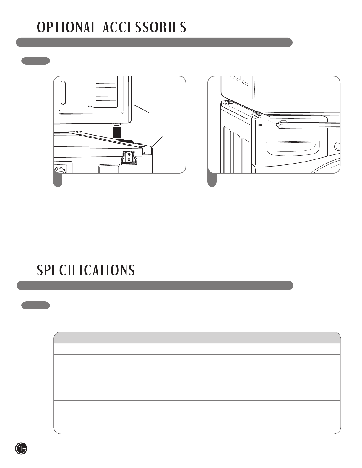
40
STACKING KIT INSTALLATION (cont.)
3
Place the dryer on top of the washer by
fitting the dryer feet into the side brackets as
illustrated. Avoid finger injuries; do not allow
fingers to be pinched between the washer
and dryer. Slowly slide the dryer toward the
back of the washer until the side bracket
stoppers catch the dryer feet.
4
Insert the front rail between the bottom of
the dryer and the top of the washer. Push the
front rail toward the back of the washer until it
comes in contact with the side rail stoppers.
Install the two remaining screws to secure the
front rail to the side rails.
KEY DIMENSIONS AND SPECIFICATIONS
Dryer Models DLE5955W, DLE5955G, DLG5966W, DLG5966G
Description Dryer
Electrical Requirements* Please refer to the rating label regarding detailed information.
Gas Requirements* NG: 10–13 in. WC/LP: 10–13 in. WC (Gas Models only)
Dimensions 27"(W) X 30"(D) X 38
11
/16"(H), 50
"
(D with door open)
68.6 cm (W) X 76.1 cm (D) X 98.3 cm (H), 127 cm (D with door open)
Net Weight 126 lb. (57.2 kg)
Drying Capacity IEC 7.3 cu. ft. (22.5 lbs./10.2 kg)
The appearance and specifications listed in this guide may vary due to constant product improvements.
*Refer to the rating plate on your dryer.
Washer
Dryer
41
Your LG Dryer will be will repaired or replaced, at LG’s option, if it proves to be defective in material or workmanship under
normal use, during the warranty period (“Warranty Period”) set forth below, effective from the date (“Date of Purchase”) of
original consumer purchase of the product. This warranty is good only to the original purchaser of the product and
effective only when used in the United States, including Alaska, Hawaii, and U.S. Territories.
THIS WARRANTY IS IN LIEU OF ANY OTHER WARRANTY, EXPRESS OR IMPLIED, INCLUDING WITHOUT LIMITATION,
ANY WARRANTY OF MERCHANTABILITY OR FITNESS FOR A PARTICULAR PURPOSE. TO THE EXTENT ANY IMPLIED
WARRANTY IS REQUIRED BY LAW, IT IS LIMITED IN DURATION TO THE EXPRESS WARRANTY PERIOD ABOVE.
NEITHER THE MANUFACTURER NOR ITS U.S. DISTRIBUTOR SHALL BE LIABLE FOR ANY INCIDENTAL, CONSEQUENTIAL,
INDIRECT, SPECIAL, OR PUNITIVE DAMAGES OF ANY NATURE, INCLUDING WITHOUT LIMITATION, LOST REVENUES OR
PROFITS, OR ANY OTHER DAMAGE WHETHER BASED IN CONTRACT, TORT, OR OTHERWISE. Some states do not allow
the exclusion or limitation of incidental or consequential damages or limitations on how long an implied warranty lasts, so the above
exclusion or limitation may not apply to you. This warranty gives you specific legal rights and you may also have other rights that vary
from state to state.
THIS LIMITED WARRANTY DOES NOT APPLY TO:
• Service trips to your home to deliver, pick up, and/or install the product, instruct, or replace house fuses or correct wiring, or
correction of unauthorized repairs.
• Damages or operating problems that result from misuse, abuse, operation outside environmental specications or contrary to the
requirements of precautions in the Operating Guide, accident, vermin, fire, flood, improper installation, acts of God, unauthorized
modification or alteration, incorrect electrical current or voltage, or commercial use, or use for other than intended purpose.
The cost of repair or replacement under these excluded circumstances shall be borne by the consumer.
CUSTOMER INTERACTIVE CENTER NUMBERS
TO CONTACT LG ELECTRONICS
BY MAIL:
LG Customer Interactive Center
P. O. Box 240007
201 James Record Road
Huntsville, Alabama 35824
ATTN: CIC
WARRANTY PERIOD:
LABOR: One Year from the Date of Purchase.
PARTS: One Year from the Date of Purchase.
Replacement Units and Repair Parts may be new or
remanufactured.
Replacement Units and Repair Parts are warranted for the
remaining portion of the original unit’s warranty period.
Dryer drum 10 years limited warranty
Parts only. Customer will be responsible for any labor or
in-home service to replace defective parts.
LG ELECTRONICS, INC.
LG DRYER LIMITED WARRANTY - USA
HOW SERVICE IS HANDLED:
In-Home Service:
Please retain dealer’s dated bill of sale or delivery
ticket as evidence of the Date of Purchase for proof of
warranty, and submit a copy of the bill of sale to the
service person at the time warranty service is provided.
Please call 1-800-243-0000 and choose the
appropriate option to locate your nearest LG
Authorized Service Center.
Or visit our Web site at: http://www.lgservice.com.
Call 1-800-243-0000 (24 hours a day, 365 days per
year), and select the appropriate option from the menu.
Or visit our Web site at: http://www.lgservice.com.
To obtain Customer Assistance, Product
Information, or Dealer or Authorized Service
Center location:
Product Registration Information
Model:
Serial Number:
Date of Purchase:
The model and serial number be located on the rating
plate inside the front door.
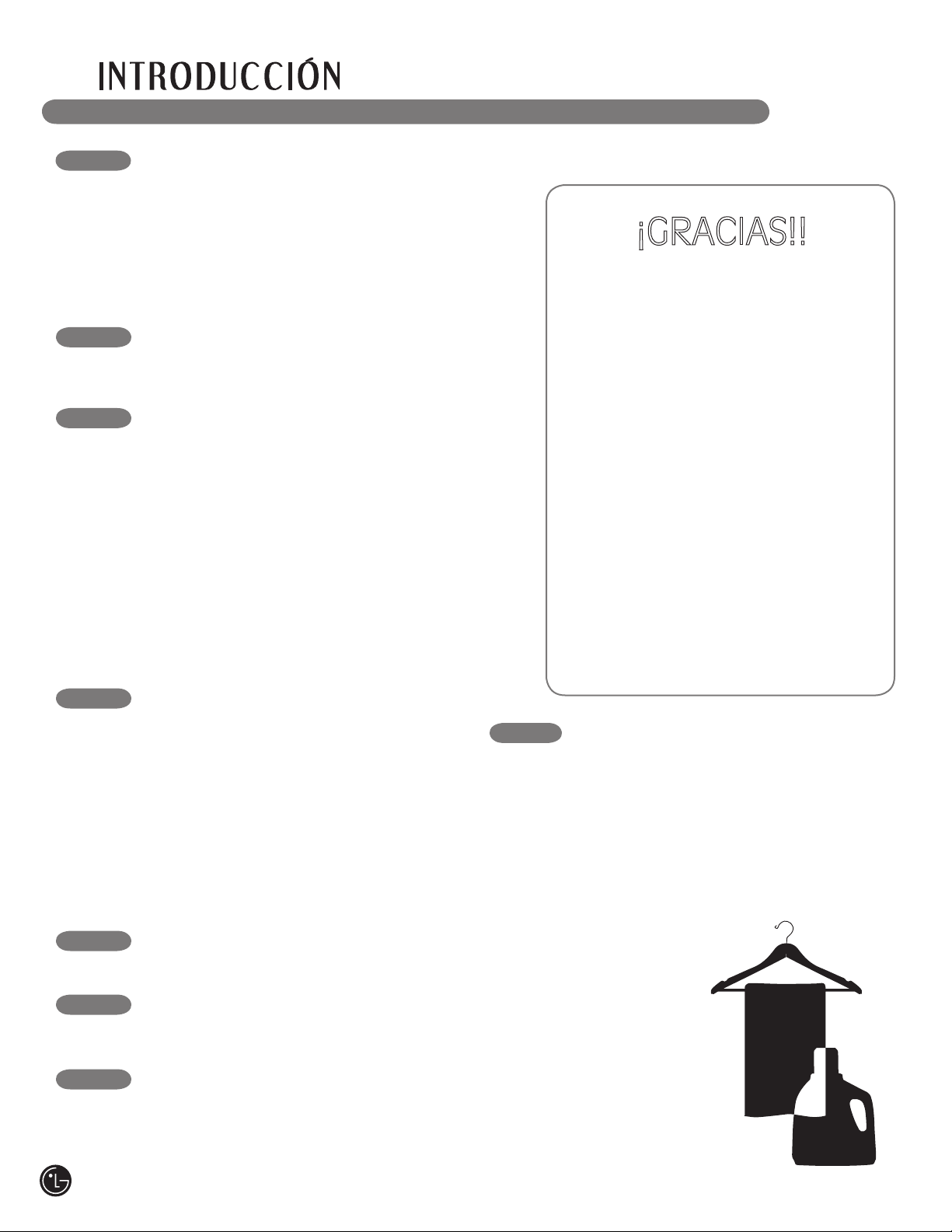
INSTRUCCIONES PARA LA INSTALACIÓN
Escoja el lugar adecuado ..................................... 50
Espacios de instalación ........................................ 50
Instalaciones con la base pedestal
o kit de apilado opcionales .................................. 51
Nivelación de la secadora .................................... 52
Cómo invertir el sentido de la puerta ................... 52
Cómo cambiar la ubicación del conducto
de ventilación de la secadora ............................... 53
Conexión del conducto de ventilación de la secadora
... 54, 55
Conexión de secadoras a gas ........................ 56, 57
Cómo conectar las secadoras eléctricas ....... 58–62
Requisitos especiales para viviendas
móviles o prefabricadas ....................................... 63
Revisión de instalación final ................................. 63
Sistema de evaluación del estado del conducto . 64
Felicitaciones por su compra y
bienvenido a la familia LG. Su
nueva Secadora LG combina la
tecnología de sensor de secado más
avanzada con un funcionamiento
sencillo y muy eficiente. Al seguir las
instrucciones de funcionamiento y
mantenimiento de este manual, su
secadora le brindará muchos años
de servicio fiable.
¡GRACIAS!!
CÓMO USAR
Clasificación de cargas ........................................ 65
Cómo cargar la secadora ..................................... 65
Revise el filtro de pelusa antes
de cada carga ....................................................... 65
Características del panel de control ..................... 66
Guía de ciclos ....................................................... 67
La pantalla de hora y estado ................................ 68
Funcionamiento de la secadora ........................... 69
Botones de ajuste de ciclo ................................... 70
Botones de opción de ciclo ................................. 71
Funciones especiales ........................................... 72
Programa personalizado ...................................... 72
RESOLUCIÓN DE PROBLEMAS
Antes de llamar a
mantenimiento ................................................ 74–76
MANTENIMIENTO Y LIMPIEZA
Limpieza regular ................................................... 73
ESPECIFICACIONES/ACCESORIOS
OPCIONALES
Accesorios opcionales ......................................... 76
Instalación del pedestal .................................. 77, 78
Instalación del kit de apilado .......................... 79, 80
Dimensiones y especificaciones clave ................. 80
INFORMACIÓN IMPORTANTE DE
SEGURIDAD
Precauciones básicas de seguridad ....................43
Qué hacer si huele gas .........................................44
Instrucciones de conexión a tierra .......................45
Instrucciones importante para la instalación..45, 46
Instrucciones importante para conectar
la electricidad .......................................................47
PIEZAS Y CARACTERÍSTICAS
Características especiales.................................... 48
Piezas y componentes clave ................................ 49
GARANTÍA
Información de registro del producto ................... 81
42
Su Seguridad y la de los demás son de suma importancia.
En este manual y en su electrodoméstico figuran muchos mensajes importantes de seguridad. Lea y
cumpla siempre con todos los mensajes de seguridad.
Éste es el símbolo de alerta de seguridad.
El mismo alerta sobre potenciales riesgos de muerte o heridas tanto para usted como para
otras personas.
Todos los mensajes de seguridad estarán a continuación del símbolo de alerta de seguridad y con la
palabra PELIGRO o ADVERTENCIA. Estas palabras significan:
wPELIGRO: Corre riesgo de muerte o de sufrir heridas serias si no sigue las instrucciones
inmediatamente.
wADVERTENCIA: Corre riesgo de muerte o de sufrir heridas serias si no sigue las
instrucciones.
Todos los mensajes de seguridad le indicarán cuál es el riesgo potencial, le dirán cómo reducir las
posibilidades de sufrir heridas y qué puede suceder si no se siguen las instrucciones.
wADVERTENCIA Por su seguridad, debe seguir la información indicada
en este manual para minimizar el riesgo de incendio o explosión, descarga eléctrica,
o para prevenir daños a la propiedad, lesiones personales o muerte.
LEA TODAS LA INSTRUCCIONES ANTES DE USAR
PRECAUCIONES BÁSICAS DE SEGURIDAD
• Lea todas las instrucciones antes de usar la
secadora.
• Antes de usar, la secadora debe estar correctamente
instalada como se describe en este manual.
• No seque artículos que hayan sido limpiados,
lavados, remojados o salpicados previamente con
gasolina, disolventes de limpieza en seco u otras
substancias inflamables o explosivas, ya que emanan
vapores que podrían encenderse o explotar, incluso
después del lavado.
• No coloque artículos que hayan sido expuestos
a aceites, incluyendo aceites comestibles, en su
secadora. Los artículos contaminados con aceites
comestibles podrían contribuir a la generación de
una reacción química que podría ocasionar que una
carga se incendie.
• No introduzca las manos en la secadora cuando el
tambor o las otras partes estén en movimiento.
• No deje que los niños jueguen en la secadora ni
dentro de ella. Cuando se usa la secadora cerca de
los niños, se necesita una supervisión estricta.
• No repare o reemplace ninguna parte de la secadora
ni intente reparar la misma a menos que esto se
recomiende en forma específica en esta Guía de
Uso y Cuidado o en instrucciones de reparación
publicadas las cuales comprende y sabe aplicar.
• No altere los controles.
• Antes de poner la secadora fuera de servicio o de
tirarla, quite la puerta para prevenir que los niños se
metan dentro.
• No use calor para secar artículos que contienen
caucho espumoso, plásticos o materiales de textura
similar al caucho. Estos deben secarse en un ciclo
sin calor.
• Use suavizadores de tela o productos para eliminar
estática únicamente del modo recomendado por el
fabricante.
• Evite la acumulación de pelusa, polvo o tierra
alrededor del área de la apertura de ventilación y
áreas adyacentes.
• La parte interior de la secadora y el conducto de
ventilación se deberán limpiar periódicamente, y la
misma deberá ser realizada por personal calificado
del servicio.
• No instale ni coloque esta secadora en lugares donde
pueda estar expuesta a variables climáticas.
• Antes de cargar la secadora, siempre revise que no
haya objetos extraños en su interior. Mantenga la
puerta cerrada cuando no se use.
• Retire la pelusa del filtro antes de cada carga.
• No instale ni coloque esta secadora en lugares donde
pueda estar expuesta a agua.
wADVERTENCIA Para minimizar el riesgo de incendio o explosión, descarga eléctrica,
o para prevenir lesiones personales cuando use electrodomésticos, se deben seguir precauciones
básicas de seguridad, incluyendo las siguientes:
43
1. No intente encender un cigarrillo o
fósforo, ni encender ningún
electrodoméstico a gas o eléctrico.
2. No toque ningún interruptor eléctrico.
No use ningún teléfono en su edificio.
3. No permita que ninguna persona
se encuentre en la habitación,
edificio o área.
4. Llame a su compañía de gas
inmediatamente desde el teléfono de
un vecino. Siga las instrucciones de su
compañía de gas al pie de la letra.
5. Si no puede comunicarse con su
compañía de gas, llame al
departamento de bomberos.
• No almacene o use gasolina ni
ningún otro tipo de vapores o
líquidos inflamables cerca de este
electrodoméstico ni de ningún otro
electrodoméstico.
• Únicamente un técnico calificado
de mantenimiento, agencia de
mantenimiento o compañía de gas
deberán realizar el mantenimiento
y la instalación.
QUÉ HACER SI HUELE GAS:
LEY EJECUTIVA PARA LA SEGURIDAD DEL AGUA POTABLE Y LOS
TÓXICOS DE CALIFORNIA (CALIFORNIA SAFE DRINKING WATER AND
TOXIC ENFORCEMENT ACT)
Esta ley requiere que el gobernador de California publique un listado de sustancias conocidas en el estado
que causan cáncer, defectos congénitos u otras lesiones reproductivas, y obliga a los negocios a alertar a
los clientes sobre la posible exposición a tales sustancias.
Los electrodomésticos a gas pueden causar exposición leve a cuatro de estas sustancias, principalmente
benceno, monóxido de carbono, formaldehído y hollín, generado principalmente por la combustión parcial
del gas natural o los combustibles LP (petróleo líquido).
Las secadoras calibradas adecuadamente minimizarán la combustión parcial. Para minimizar incluso más la
exposición a estas sustancias, se puede dotar a la secadora de la ventilación adecuada al exterior.
LEA TODAS LA INSTRUCCIONES ANTES DE USAR
wADVERTENCIA Por su seguridad, se debe seguir la información
indicada en este manual para minimizar el riesgo de incendio o explosión, descarga
eléctrica, o para prevenir daños a la propiedad, lesiones personales o muerte.
44
INSTRUCCIONES DE CONEXIÓN A TIERRA
Este electrodoméstico deberá estar conectado a
tierra. En caso de avería o mal funcionamiento,
la conexión a tierra reducirá el riesgo de
descargas eléctricas al brindar un camino con una
resistencia menor para la corriente eléctrica. Este
electrodoméstico debe estar equipado con un
cable con un conductor para la conexión a tierra
del equipo y un enchufe con conexión a tierra.
El enchufe deberá estar conectado a una toma
de corriente instalada en forma adecuada y con
conexión a tierra de acuerdo con todos los códigos
y ordenanzas locales.
wADVERTENCIA — Una
conexión inapropiada del conductor de conexión
a tierra del equipo puede provocar riesgos de
descargas eléctricas. Consulte a un electricista
calificado o personal del servicio si tiene dudas de
que el electrodoméstico se encuentre conectado a
tierra apropiadamente.
No modifique el enchufe que se entrega con el
electrodoméstico. Si no coincide con la toma
de corriente, contrate a un electricista calificado
para que instale una toma de corriente en forma
adecuada.
Este electrodoméstico debe estar conectado a un
sistema de cableado de metal permanente con
conexión a tierra o se debe tender un conducto
para la conexión a tierra del equipo con los
conductores del circuito y conectado al terminal de
tierra del equipo o al conductor de suministro del
electrodoméstico.
Si la secadora no se encuentra adecuadamente
conectada a tierra se pueden producir descargas
eléctricas.
INSTRUCCIONES IMPORTANTE PARA LA INSTALACIÓN
• Conecte la secadora adecuadamente a tierra
según todos los códigos y las regulaciones
vigentes. Siga los detalles en las instrucciones
de instalación. Si la secadora no se encuentra
adecuadamente conectada a tierra se pueden
producir descargas eléctricas.
• Antes de usar, la secadora debe estar
correctamente instalada como se describe
en este manual. Si la secadora no se encuentra
adecuadamente conectada a tierra se pueden
producir descargas eléctricas.
• Todas las reparaciones y controles deberán ser
realizados por un centro de servicio autorizado
a menos que se den otras recomendaciones
específicas en el Manual del Usuario. Utilice
sólo piezas de fábrica autorizadas. Si no se
cumple con esta advertencia se podrán producir
heridas graves, incendios, descargas eléctricas o
muerte.
• Instale y almacene la secadora en un lugar no
expuesto a temperaturas inferiores al punto
de congelación ni expuesto a la intemperie.
Si no se cumple con esta advertencia se podrán
producir heridas graves, incendios, descargas
eléctricas o muerte.
• Con el fin de reducir el riesgo de descargas
eléctricas no instale la secadora en espacios
húmedos. Si no se cumple con esta advertencia
se podrán producir heridas graves, incendios,
descargas eléctricas o muerte.
• Conecte un circuito eléctrico clasificado,
protegido y adecuado para evitar sobrecarga
eléctrica. Un circuito eléctrico inadecuado se
puede fundir, creando descargas eléctricas y/o
riesgo de incendio.
• Quite todos los elementos de embalaje y
deseche adecuadamente todos los materiales
de envío. Si no se cumple con esto se podrá
producir una explosión, incendio, quemaduras o
muerte.
• Coloque la secadora a un altura mínima de 18
pulgadas encima del piso para una instalación
en el garaje. Si no se cumple con esto se podrá
producir una explosión, incendio, quemaduras o
muerte.
• Mantenga todos los envoltorios alejados de los
niños. Los materiales de los envoltorios pueden
resultar peligrosos para los niños. Existe riesgo
de asfixia.
LEA TODAS LA INSTRUCCIONES ANTES DE USAR
wADVERTENCIA Por su seguridad, se debe seguir la información
indicada en este manual para minimizar el riesgo de incendio o explosión, descarga
eléctrica, o para prevenir daños a la propiedad, lesiones personales o muerte.
45
wADVERTENCIA Para reducir el riesgo de incendio, descargas eléctricas o
heridas al usar su electrodoméstico, siga las precauciones básicas, incluyendo lo siguiente:
Conducto de escape/Tubería:
• Las secadoras a gas DEBEN tener un
conducto de ventilación al exterior. Si no se
siguen estas instrucciones se podrá producir
incendio o muerte.
• Para prevenir el ingreso de grandes
cantidades de humedad y pelusa a la
habitación, se recomienda enfáticamente
dotar las secadoras eléctricas de un
conducto de ventilación al exterior. La
acumulación de pelusa en cualquier parte de la
casa puede crear riesgos de salud e incendio.
• Use únicamente sistemas de ventilación
de metal rígido o flexible de 4 pulgadas de
diámetro dentro del gabinete de la secadora
o para ventilación al exterior. Los sistemas de
ventilación de plástico u otro material pueden
causar incendios. Los sistemas de ventilación
agujereados pueden causar incendios si
se colapsan o bloquean durante el uso o la
instalación.
• No se provee el sistema de ventilación con
la secadora; el mismo deberá obtenerse
localmente. La tapa terminal deberá tener
reguladores de tiro con bisagras para
prevenir el retorno de descarga cuando no
se usa la secadora. Si no se siguen estas
instrucciones se podrá producir incendio
o muerte.
• El conducto de escape deberá tener 10 cm
(4 pulg.) de diámetro sin obstrucciones. El
conducto de escape deberá mantenerse
lo más corto posible. Asegúrese de limpiar
cualquier tipo de conducto antiguo antes de
instalar su secadora nueva. Si no se siguen
estas instrucciones se podrá producir incendio
o muerte.
• Se recomiendan conductos rígidos o
semirígidos para usar entre la secadora
y la pared. En instalaciones particulares
cuando es imposible realizar una conexión
siguiendo las recomendaciones antes
indicadas, únicamente se puede utilizar un
conducto metálico de transición aprobado
por UL entre la secadora y la conexión de
pared. Usar este tipo de conducto afectará
el tiempo de secado. Si no se siguen estas
instrucciones se podrá producir incendio
o muerte.
• NO utilice tornillos de lámina de metal ni
otro tipo de aseguradores que extiendan
dentro del conducto y puedan atrapar
pelusa y reducir la eficiencia del sistema de
escape. Asegure todas las uniones con cinta
adhesiva impermeable. Para más detalles,
siga las Instrucciones de Instalación. Si no se
siguen estas instrucciones se podrá producir
incendio o muerte.
46
LEA TODAS LA INSTRUCCIONES ANTES DE USAR
wADVERTENCIA Por su seguridad, se debe seguir la información
indicada en este manual para minimizar el riesgo de incendio o explosión, descarga
eléctrica, o para prevenir daños a la propiedad, lesiones personales o muerte.
INSTRUCCIONES IMPORTANTE PARA LA INSTALACIÓN
wADVERTENCIA Para reducir el riesgo de incendio, descargas eléctricas o
heridas al usar su electrodoméstico, siga las precauciones básicas, incluyendo lo siguiente:

GUARDE ESTAS INSTRUCCIONES
• Bajo ninguna circunstancia, corte o quite
la tercera pata (puesta a tierra) del cable
eléctrico. Para evitar heridas a nivel personal o
daños sobre la secadora, el cable de corriente
eléctrica debe estar conectado en una conexión
a tierra en condiciones adecuadas.
• Por motivos de seguridad personal, este
electrodoméstico debe estar conectado a
tierra adecuadamente. Si esto no se cumple
se podrán producir descargas eléctricas o
heridas.
• Consulte las instrucciones de instalación
de este manual para obtener los requisitos
eléctricos específicos de su modelo. Si estas
instrucciones no se cumplen se podrán producir
descargas eléctricas y/o riesgo de incendio.
• Esta secadora debe estar enchufada
a un tomacorriente conectado a tierra
adecuadamente. Si la secadora no se
encuentra adecuadamente conectada
a tierra se pueden producir descargas
eléctricas. Contrate a un electricista
calificado para que controle el tomacorriente
y el circuito eléctrico para asegurarse que
el enchufe está correctamente conectado
a tierra. Esto evitará riesgos de descargas
y asegurará la estabilidad durante el
funcionamiento.
• La secadora siempre debe estar enchufada
a su tomacorriente individual, con la
clasificación de tensión correspondiente
a la placa de datos de servicio. Esto
proporciona el mejor desempeño y previene a
la vez sobrecarga de los circuitos de cableado
del hogar, lo que podría producir un incendio
debido a los cables sobrecalentados.
• Nunca desenchufe su secadora empujando
el cable de corriente. Siempre tome su
enchufe firmemente y empuje el mismo
hacia fuera para retirarlo. El cable de corriente
se puede cortar debido a cualquier movimiento
de su parte central, resultando en una descarga
eléctrica.
• Repare o reemplace de inmediato todos
los cables de corriente pelados o con
cualquier tipo de daño. No use un cable con
cortaduras o abrasión sobre su extensión
o extremos. Este cable de corriente se puede
fundir, creando descargas eléctricas y/o riesgo
de incendio.
• Al instalar o cambiar de lugar la secadora,
evite todo tipo de cortes u otros daños en
el cable de corriente. Esto evitará heridas
o daños debido a incendios o descargas
eléctricas sobre la secadora.
wADVERTENCIA Para reducir el riesgo de incendio, descargas eléctricas o
heridas al usar su electrodoméstico, siga las precauciones básicas, incluyendo lo siguiente:
47
LEA TODAS LA INSTRUCCIONES ANTES DE USAR
wADVERTENCIA Por su seguridad, se debe seguir la información
indicada en este manual para minimizar el riesgo de incendio o explosión, descarga
eléctrica, o para prevenir daños a la propiedad, lesiones personales o muerte.
INSTRUCCIONES IMPORTANTE PARA CONECTAR LA ELECTRICIDAD
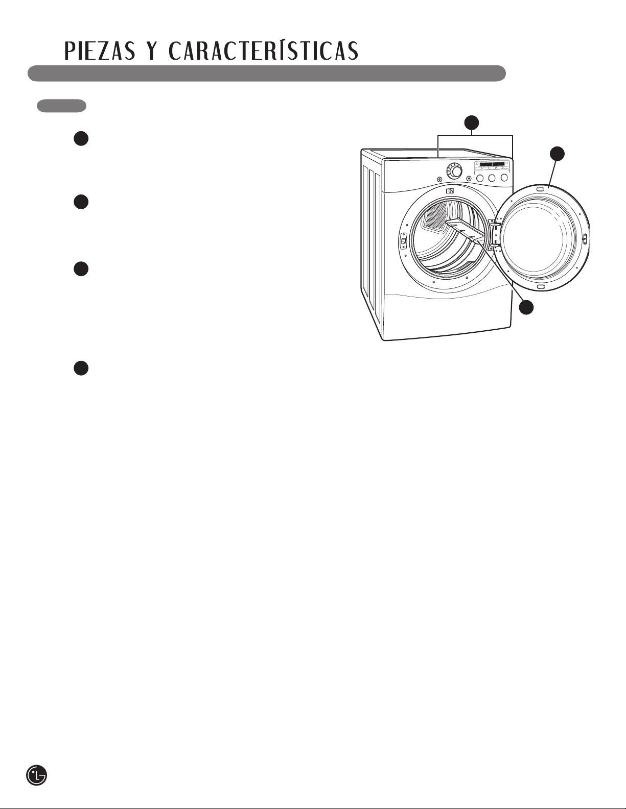
CARACTERÍSTICAS ESPECIALES
1
PANEL DE CONTROL FÁCIL PARA USAR
Gire la perilla selectora de ciclos al ciclo de
secado deseado. Añada los ajustes de ciclo o
programe las opciones con el toque de un botón.
1
2
2
PUERTA REVERSIBLE DE FÁCIL ACCESO
La amplia puerta provee acceso para carga
y descarga. Se puede invertir el sentido de la
puerta para adaptarlo al lugar de la instalación.
3
TAMBOR DE ACERO INOXIDABLE DE
CAPACIDAD SUPERIOR ILUMINADO
El tambor de acero inoxidable de gran capacidad
ofrece durabilidad superior. El tambor está
equipado con una luz amarilla que se ilumina al
abrir la puerta de la secadora y se apaga cuando
se cierra.
4
SISTEMA DE SENSOR DE BLOQUEO DE
CONDUCTO/FILTRO FLOWSENSE
™
El sistema de sensor de bloqueo de conducto/
filtro FlowSense
™
detecta y lo alerta sobre
bloqueos en el filtro y la tubería, lo cual reduce
el flujo de escape de la secadora. Esto puede
mejorar el funcionamiento y ayudar a minimizar
el número de llamadas al servicio técnico,
ahorrándole dinero.
3
48
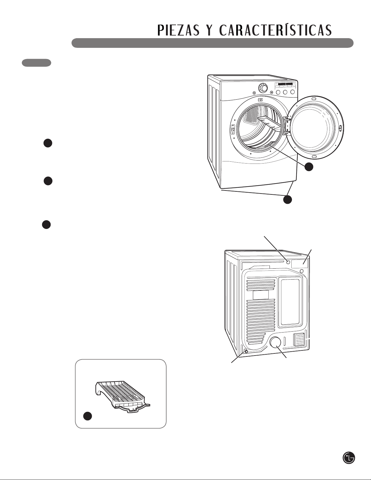
1
2
PATAS NIVELADORAS
Cuatro patas niveladoras (dos en la parte frontal
y dos en la trasera) ajustables para mejorar la
estabilidad de la secadora en pisos desnivelados.
Accesorios incluidos
Estante de
secado
2
1
FILTRO DE PELUSA MONTADO AL FRENTE
El filtro de pelusa montado al frente permite un
fácil acceso y limpieza después de cada carga.
Panel de
acceso del
bloque terminal
(Modelos
eléctricos)
Parte trasera de
la secadora
Ubicación del cable
eléctrico (Modelos a gas)
Ubicación de
la toma de
gas (Modelos
a gas)
Salida del
conducto de
escape
PIEZAS Y COMPONENTES CLAVE
Además de las características y componentes
descritos en la sección de Características
especiales, hay varios componentes importantes
adicionales a los cuales se hace referencia en
este manual.
3
ESTANTE DE SECADO
Use el estante de secado con la opción de ciclo
RACK DRY (estante de secado). El estante de
secado permite colocar los artículos como sacos,
prendas delicadas, calzado deportivo, en una
posición horizontal para secarlos.
3
49
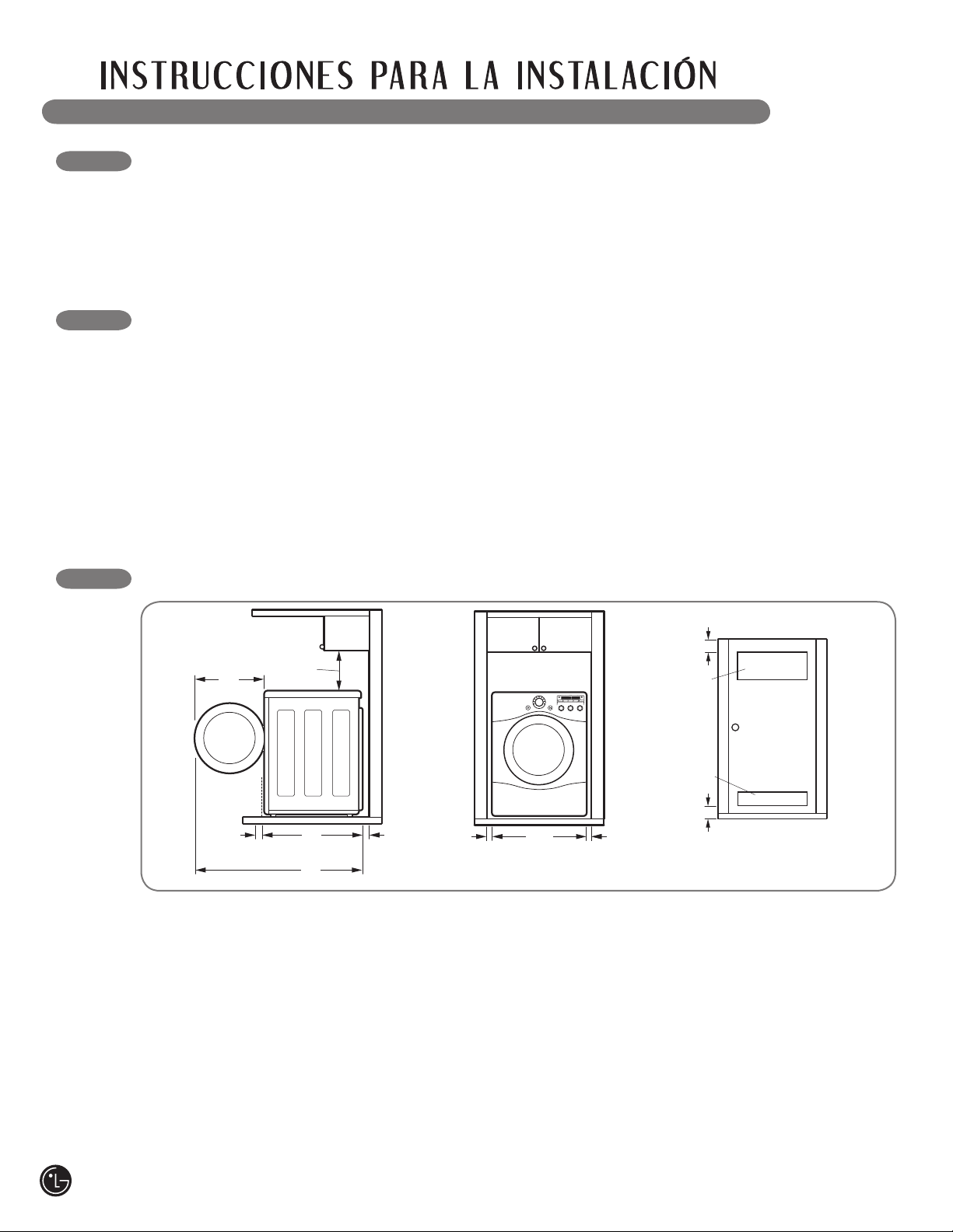
ESCOJA EL LUGAR ADECUADO
• Almacene e instale la secadora en un lugar no
expuesto a temperaturas inferiores a las de
congelación ni a la intemperie.
• Escoja una ubicación con un piso rígido y
nivelado.
• Si va a instalar la secadora en el garaje,
colóquela a una altura mínima de 18 pulgadas
(46 cm) por encima del piso.
ESPACIOS DE INSTALACIÓN
30"
(76,1 cm)
50"
(127 cm)
20"
(50,8 cm)
4"
(10 cm)
18"
(45,7 cm)
4"
(10 cm)
• La mayoría de instalaciones requieren un
espacio mínimo de 5 1⁄2 pulgadas (14 cm)
detrás de la secadora para la instalación del
conducto de escape.
• Deje espacios mínimos de por lo menos
1 pulgada (2,5 cm) a los lados y parte trasera
para minimizar la vibración y el ruido.
• Se recomienda disponer de espacio adicional
para la instalación y el mantenimiento.
• No olvidar prever espacio para las molduras de
pared, puerta o piso que podrían aumentar los
espacios de instalación requeridos.
• Deje por lo menos 24 pulgadas (61,2 cm) al
frente de la secadora para abrir la puerta.
IMPORTANTE: ¡Lea todas las instrucciones de instalación
completamente antes de instalar y hacer funcionar su secadora!
Es importante que revise todo este manual antes de instalar y usar su secadora. Se proporcionan
instrucciones detalladas pertinentes a las conexiones eléctricas, de gas y los requisitos de escape en las
siguientes páginas.
• Conecte la secadora adecuadamente a tierra
según todos los códigos y las regulaciones
vigentes.
• Para reducir el riesgo de descarga eléctrica,
no instale la secadora en sitios húmedos ni
mojados.
• Si instala la secadora en una vivienda móvil o
prefabricada, por favor consulte la sección de
Requisitos especiales para viviendas móviles o
prefabricadas.
Instrucciones adicionales para las instalaciones
en armarios:
• La puerta del armario debe disponer de flujo de
aire suficiente. Consulte el diagrama indicado
más arriba para obtener los requisitos mínimos
de abertura para ventilación. También es
aceptable una puerta tipo persiana.
• Asegúrese que se dispone de por lo menos
18 pulgadas (46 cm) de espacio de instalación
sobre la secadora.
27"
(68.6 cm)
1"
(2.54 cm)
1"
(2.54 cm)
24 in.
2
(155 cm
2
)
3"
(7,6 cm)
3"
(7,6 cm)
48 in.
2
(310 cm
2
)
Requisitos de ventilación
de la puerta del armario
50
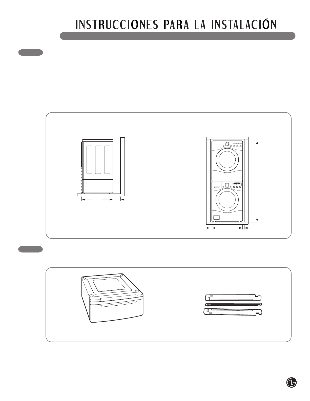
INSTALACIONES CON LA BASE PEDESTAL
O KIT DE APILADO OPCIONALES
IMPORTANTE: Si está instalando su secadora
con una base de pedestal o un kit de apilado
opcionales, consulte la sección de Accesorios
opcionales incluida en este manual o las
instrucciones de su pedestal o kit de apilado
antes de continuar con la instalación.
30"
(76,1 cm)
4"
(10 cm)
27"
(68.6 cm)
1"
(2.54 cm)
1"
(2.54 cm)
77
1
/
2
"
(190.5 cm)
Dimensiones requeridas para
la instalación con pedestal
Dimensiones requeridas para
la instalación con el kit de apilado
ACCESORIOS OPCIONALES
Para estos y otros productos LG, llame a su distribuidor LG local, o visite nuestro sitio Web en us.lge.com.
Kit de apilado
(
Adquirido por separado)
Pedestal
(
Adquirido por separado)
51
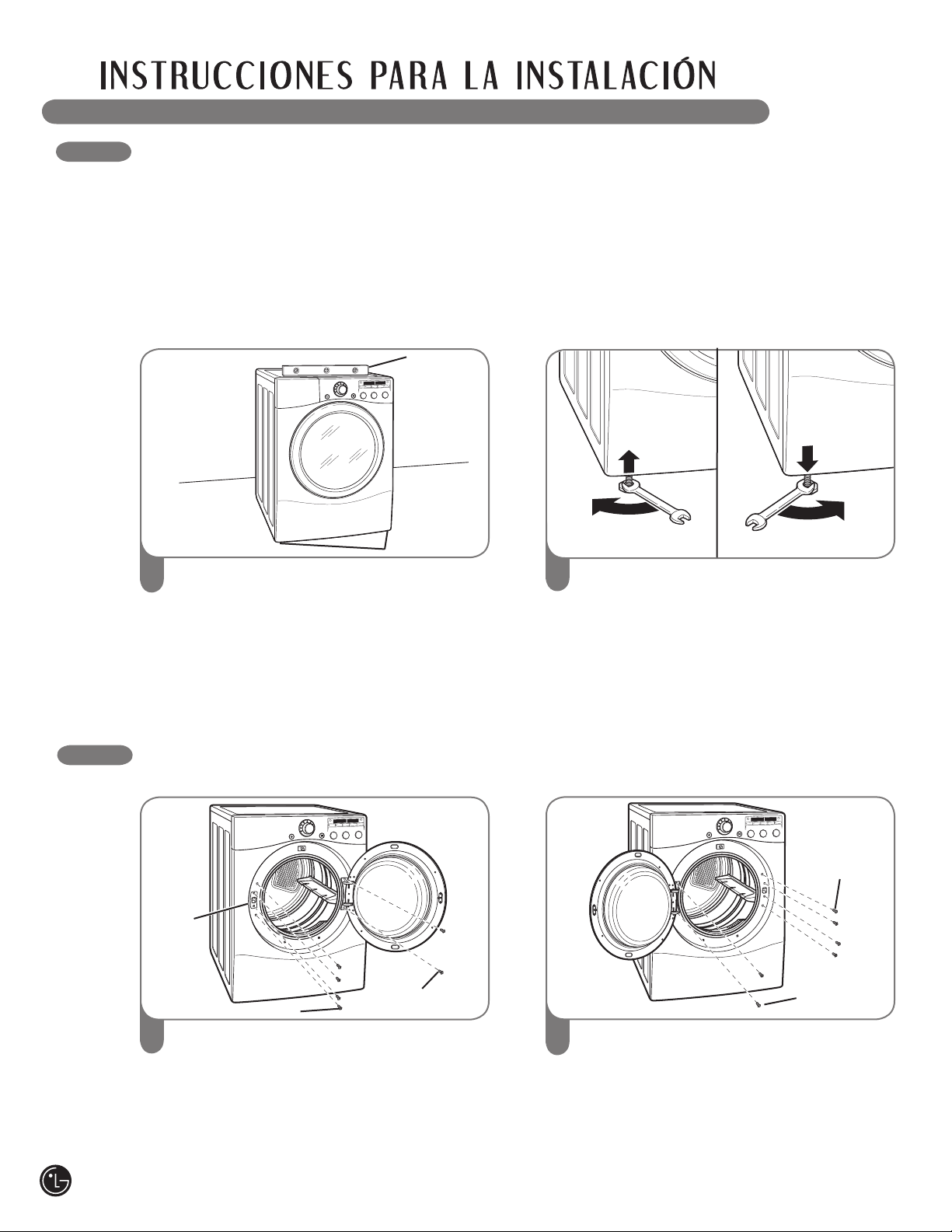
NIVELACIÓN DE LA SECADORA
Para asegurar que la secadora brinde un
desempeño óptimo de secado, debe estar
nivelada. Para minimizar la vibración, el ruido y
movimiento no deseados, el piso deberá ser una
superficie perfectamente nivelada y sólida.
NOTA: Fije las patas niveladoras solo en la
medida necesaria para nivelar la secadora. La
extensión de las patas niveladoras más de lo
necesario puede causar vibración de la secadora.
Coloque la secadora en la posición final.
Coloque un nivelador sobre la secadora.
1
Nivelador
Patas niveladoras
Use una llave de tuercas ajustable para girar
las patas niveladoras. Gire en la dirección
de las manecillas del reloj para levantar
la secadora o en dirección contraria para
bajarla. Suba o baje las patas niveladoras
hasta que la secadora esté nivelada de lado
a lado y de adelante hacia atrás.
Asegúrese de que las 4 patas niveladoras
se encuentran haciendo contacto firme
con el piso.
CÓMO INVERTIR EL SENTIDO DE LA PUERTA
Se puede invertir el sentido de la puerta para que se adapte a su lugar de instalación.
Abra la puerta de la secadora. Utilizando un
destornillador Phillips, quite los 2 tornillos que
aseguran la bisagra de la puerta a la abertura
de la puerta de la secadora. Quite los 4 tornillos
del lado del pasador de la abertura de la puerta
de la secadora, y quite el pasador.
1
Dé vuelta a la puerta de modo que se invierta
la bisagra, y vuelva a colocar la puerta usando
los dos tornillos que quitó anteriormente.
Reinstale el pasador de la puerta y los cuatro
tornillos.
Pruebe el movimiento de la puerta
asegurándose de que se mueve libremente
y se asegura correctamente.
2
Tornillos de
la bisagra
Pasador
de la
puerta
Tornillos del pasador
Tornillos de
la bisagra
Tornillos
del
pasador
2
• Las 4 patas niveladoras deberán apoyarse
firmemente en el piso. Empuje suavemente
las esquinas superiores de la secadora para
asegurarse de que su secadora no se mece de
esquina a esquina.
Si está instalando la secadora sobre el accesorio
de pedestal opcional, deberá usar las patas
niveladoras del pedestal para nivelarla. Las
patas niveladoras de la secadora deberán estar
completamente retraídas.
52

CÓMO CAMBIAR LA UBICACIÓN DEL CONDUCTO
DE VENTILACIÓN DE LA SECADORA
Su secadora está equipada de fábrica para
ventilar en la parte trasera. También puede
configurarse para ventilar en la parte inferior o
lateralmente (no está disponible la ventilación del
lado derecho en los modelos a gas).
Puede adquirirse el kit adaptador, número de
pieza 383EEL9001B, de su distribuidor LG.
Este kit contiene los componentes de conducto
necesarios para cambiar la ubicación de la
ventilación de la secadora.
Quite el tornillo de seguridad del conducto
de ventilación trasero. Tire del conducto de
ventilación hacia afuera.
1
Apriete las lengüetas en el dispositivo de
expulsión y retírelo cuidadosamente para
obtener la ventilación adecuada (no está
disponible ventilación lateral en los modelos
a gas). Apriete el conducto adaptador en la
carcasa del ventilador y asegure la base de la
secadora como se indica.
2
Dispositivo de
expulsión
Abrazadera
Conducto
adaptador
Conecte un codo de 4 pulgadas (10 cm) a la siguiente
sección de conducto de 4 pulgadas (10 cm), y
asegure todas las conexiones con cinta adhesiva
impermeable. Asegúrese de que el extremo macho
del codo apunte hacia AFUERA de la secadora.
Inserte el montaje de codo/conducto a través de
la abertura lateral y presiónelo en el conducto
adaptador. Asegúrelo en su lugar con cinta adhesiva
impermeable.
Asegúrese de que el extremo macho del conducto
sobresalga 1 1⁄2 pulgadas (3,8 cm) para conectar el
resto del sistema de ventilación.
Conecte la placa de cubierta a la parte trasera de la
secadora con el tornillo provisto.
1
1
/
2
"
(3.8 cm)
3
Codo
Placa
de cubierta
1
Parte trasera
Conducto de escape
Tornillo de
seguridad
OPCIÓN 1: Ventilación lateral
Apriete las lengüetas en el dispositivo de
expulsión y retírelo cuidadosamente para
obtener la ventilación adecuada (no está
disponible ventilación lateral en los modelos
a gas). Apriete el conducto adaptador en la
carcasa del ventilador y asegure la base de la
secadora como se indica.
2
Inserte el codo de 4 pulgadas (10 cm) a
través de la abertura trasera y apriételo en
el conducto adaptador. Asegúrese de que el
extremo macho y el codo apunten hacia abajo
por el orificio ubicado en la parte inferior de
la secadora. Asegúrelo en su lugar con cinta
adhesiva impermeable.
Conecte la placa de cubierta a la parte trasera
de la secadora con el tornillo provisto.
3
Codo
Placa
de cubierta
OPCIÓN 2: Ventilación inferior
Abrazadera
Conducto
adaptador
53

CONEXIÓN DEL CONDUCTO DE VENTILACIÓN DE LA SECADORA
• No aplaste ni doble el sistema de conducto.
Si no se siguen estas instrucciones se podrá
producir incendio o muerte.
• No permita que el sistema de conducto se
asiente sobre objetos puntiagudos ni entre
en contacto con los mismos. Si no se siguen
estas instrucciones se podrá producir incendio
o muerte.
• Si conecta a un sistema de conducto
existente, asegúrese de que sea adecuado
y de que esté limpio antes de instalar la
secadora. Si no se siguen estas instrucciones
se podrá producir incendio o muerte.
• El sistema de ventilación debe seguir los
códigos de construcción. Si no se siguen
estas instrucciones se podrá producir incendio
o muerte.
• Las secadoras de gas DEBEN ventilar hacia
el exterior. Si no se siguen estas instrucciones
se podrá producir incendio o muerte.
• Únicamente use un sistema de conducto
rígido y de metal flexible de 10 cm (4 pulg.)
dentro del gabinete de la secadora y para
ventilación al exterior. Si no se siguen estas
instrucciones se podrá producir incendio
o muerte.
• Para reducir el riesgo de incendio,
combustión o acumulación de gases
combustibles, NO descargue el escape
de la secadora en un área cerrada o no
ventilada, tal como un desván, pared, cielo
raso, espacio entre el cimiento y la tierra,
chimenea, conducto de gas o espacios
ocultos de un edificio. Si no se siguen estas
instrucciones se podrá producir incendio
o muerte.
• Para reducir el riesgo de incendio, NO
descargue el escape de la secadora usando
conductos de plástico ni de lámina metálica.
Si no se siguen estas instrucciones se podrá
producir incendio o muerte.
• El conducto de escape deberá tener 10 cm
(4 pulg.) de diámetro sin obstrucciones. El
conducto de escape deberá mantenerse
lo más corto posible. Asegúrese de limpiar
cualquier tipo de conducto antiguo antes de
instalar su secadora nueva. Si no se siguen
estas instrucciones se podrá producir incendio
o muerte.
• Se recomiendan conductos rígidos o
semirígidos para usar entre la secadora
y la pared. En instalaciones particulares
cuando es imposible realizar una conexión
siguiendo las recomendaciones antes
indicadas, únicamente se puede utilizar un
conducto metálico de transición aprobado
por UL entre la secadora y la conexión de
pared. Usar este tipo de conducto afectará
el tiempo de secado. Si no se siguen estas
instrucciones se podrá producir incendio
o muerte.
• NO utilice tornillos de lámina de metal ni
otro tipo de aseguradores que extiendan
dentro del conducto y puedan atrapar
pelusa y reducir la eficiencia del sistema de
escape. Asegure todas las uniones con cinta
adhesiva impermeable. Si no se siguen estas
instrucciones se podrá producir incendio
o muerte.
• Para maximizar los resultados de
funcionamiento, siga las limitaciones de
longitud del conducto indicadas en el cuadro
de arriba. Si no se siguen estas instrucciones
se podrá producir incendio o muerte.
• No se provee el sistema de ventilación con
la secadora; el mismo deberá obtenerse
localmente. La tapa terminal deberá tener
reguladores de tiro con bisagras para
prevenir el retorno de descarga cuando no
se usa la secadora. Si no se siguen estas
instrucciones se podrá producir incendio o
muerte.
wADVERTENCIA Para reducir el riesgo de incendio, descargas eléctricas o
heridas al usar su electrodoméstico, siga las precauciones básicas, incluyendo lo siguiente:
54
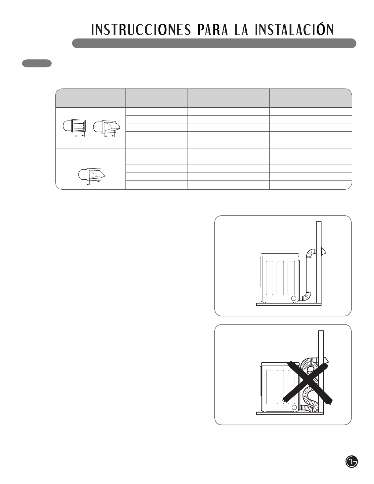
Direccionamiento y conexión del
sistema de conducto de escape
Siga las pautas indicadas más abajo para
maximizar el desempeño de secado y reducir
la acumulación de pelusa en el sistema de
conducto.
NOTA: El sistema de conducto y las conexiones
NO están incluidas y deben adquirirse por
separado.
• Use un sistema de conducto metálico rígido o
semirígido de 10 cm (4 pulg.).
• El conducto de escape deberá tenderse lo más
corto posible.
• Use la menor cantidad de conexiones de codo
que sea posible.
• El extremo macho de cada sección del
conducto de escape deberá apuntar hacia
afuera de la secadora.
• Use cinta adhesiva impermeable en todas las
conexiones de conducto.
• Aísle el sistema de conducto que se tiende a
través de áreas sin calefacción para reducir la
condensación y acumulación de pelusa en las
superficies del conducto.
IMPORTANTE: Si no se instala correctamente
la ventilación de escape de la secadora, se
anulará la garantía.
CONEXIÓN DEL CONDUCTO DE VENTILACIÓN DE LA SECADORA (cont.)
Ventilación de escape
correcta
Ventilación de escape
incorrecta
Número de Long. máx. de conducto metálico Long. máx. de conducto
Tipo de tapa de pared Codos de 90° flexible de diám. 4" metálico flexible de diám. 4"
0 65 pies (19,8 m) 45 pies (13,7 m)
1 55 pies (16,8 m) 35 pies (10,7 m)
2 47 pies (13,7 m) 30 pies (9,1 m)
3 36 pies (11,0 m) 25 pies (7,6 m)
4 28 pies (8,5 m) 20 pies (6,1 m)
0 55 pies (16,8 m) 35 pies (10,7 m)
1 47 pies (13,7 m) 27 pies (8,1 m)
2 41 pies (12,5 m) 21 pies (6,4 m)
3 30 pies (9,1 m) 17 pies (5,2 m)
4 22 pies (6,7 m) 15 pies (4,5 m)
NOTA: Reste 6 pies (1,8 m) por cada codo adicional. No se recomienda usar más de cuatro codos de 90°.
4"
(10.2 cm)
2
1
/2"
(6.35 cm)
4"
(10.2 cm)
Recomendado
Solamente por el uso en
los instalaciones de
conducto cortos
Sistema de conducto
55

56
CONEXIÓN DE SECADORAS A GAS
Requisitos eléctricos para modelos a gas únicamente
• Bajo ninguna circunstancia, corte o quite
la tercera pata (puesta a tierra) del cable
eléctrico. Si no se cumple con esto se podrá
producir una explosión, incendio o muerte.
• Por motivos de seguridad personal, la
secadora debe estar conectada a tierra
adecuadamente. Si no se cumple con esto
se podrá producir una explosión, incendio
o muerte.
• El cable eléctrico de esta secadora está
equipado con un enchufe de 3 patas
(conexión a tierra) que se conecta a un
tomacorriente de pared de tres patas
(con conexión a tierra) para minimizar la
posibilidad de peligro de descarga eléctrica
de este electrodoméstico. Si no se cumple con
esto se podrá producir una explosión, incendio o
muerte.
• Se debe enchufar esta secadora a un
tomacorriente conectado a tierra de 120
V CA, 60 Hz protegido por un fusible o
cortacircuitos de 15 amperios. Si no se
cumple con esto se podrá producir una
explosión, incendio o muerte.
• En caso de disponer de un tomacorriente de
pared estándar de 2 patas, debe cambiarlo
por uno de 3 patas conectado a tierra
adecuadamente. Si no se cumple con esto
se podrá producir una explosión, incendio o
muerte.
• Requisitos de suministro de gas:
Como enviado de fábrica, si configura la secadora
para uso con gas natural. Puede convertirse para
usar con gas LP (propano líquido). La presión de
gas no debe sobrepasar la columna de agua
de 13 pulgadas.
• Un técnico calificado de mantenimiento o de la
compañía de gas debe conectar la secadora al
suministro de gas. Si no se cumple con esto se
podrá producir una explosión, incendio o muerte.
• Aísle la secadora del sistema de suministro
de gas cerrando su válvula de corte individual
manual durante cualquier tipo de prueba de
presión del suministro de gas. Si no se cumple
con esto se podrá producir una explosión, incendio
o muerte.
• Requisitos de la línea de suministro: Su cuarto
de lavado debe tener una línea rígida de
suministro de gas para la secadora. En los
EE. UU., se debe instalar una válvula de corte
manual individual a una distancia de por lo
menos 6 pies (1,8 m) de la secadora, de acuerdo
con el Código Nacional de Gas Combustible
ANSI Z223.1. Se debe instalar un tapón de
tubería de 1/8 pulgadas NPT. Si no se cumple
con esto se podrá producir una explosión, incendio
o muerte.
• Si se usa tubería rígida, la tubería rígida deberá
ser de 1/2 pulgadas IPS. Si es aceptable según
los códigos y las regulaciones locales, y cuando
sea aceptable según su compañía proveedora
de gas, se puede usar tubería de 3/8 pulgadas
aprobada, cuando las longitudes sean menores
de 20 pies (6,1 m). Se debe usar tubería más
larga en caso de longitudes que exceden los 20
pies (6,1 m). Si no se cumple con esto se podrá
producir una explosión, incendio o muerte.
• Conecte la secadora al tipo de gas indicado en
la placa del nombre. Si no se cumple con esto se
podrá producir una explosión, incendio o muerte.
• Para prevenir la contaminación de la válvula de
gas, elimine el aire sedimento del suministro de
gas antes de conectar el suministro de gas a la
secadora. Antes de ajustar la conexión entre el
suministro de gas y la secadora, purgue el aire
hasta que se detecte olor a gas. Si no se cumple
con esto se podrá producir una explosión, incendio
o muerte.
• NO use una llama abierta para inspeccionar las
fugas de gas. Use un fluido anticorrosivo para
detección de fugas. Si no se cumple con esto se
podrá producir una explosión, incendio o muerte.
• Utilice únicamente una línea de suministro de
gas nueva certificada por AGA o CSA, con
conectores flexibles de acero inoxidable. Si
no se cumple con esto se podrá producir una
explosión, incendio o muerte.
• Ajuste bien todas las conexiones de gas.
Si no se cumple con esto se podrá producir una
explosión, incendio o muerte.
• Use cinta de Teflón
®
o un compuesto para
conexiones de tubería insoluble en gas de
petróleo líquido (LP) en todas las roscas de
tubería. Si no se cumple con esto se podrá
producir una explosión, incendio o muerte.
• NO intente desmontar ningún componente de
la secadora; cualquier desmontaje requiere
de la atención y herramientas de un técnico
o compañía de mantenimiento autorizado y
calificado. Si no se cumple con esto se podrá
producir una explosión, incendio o muerte.
wADVERTENCIA Para reducir el riesgo de incendio, descargas eléctricas o
heridas al usar su electrodoméstico, siga las precauciones básicas, incluyendo lo siguiente:
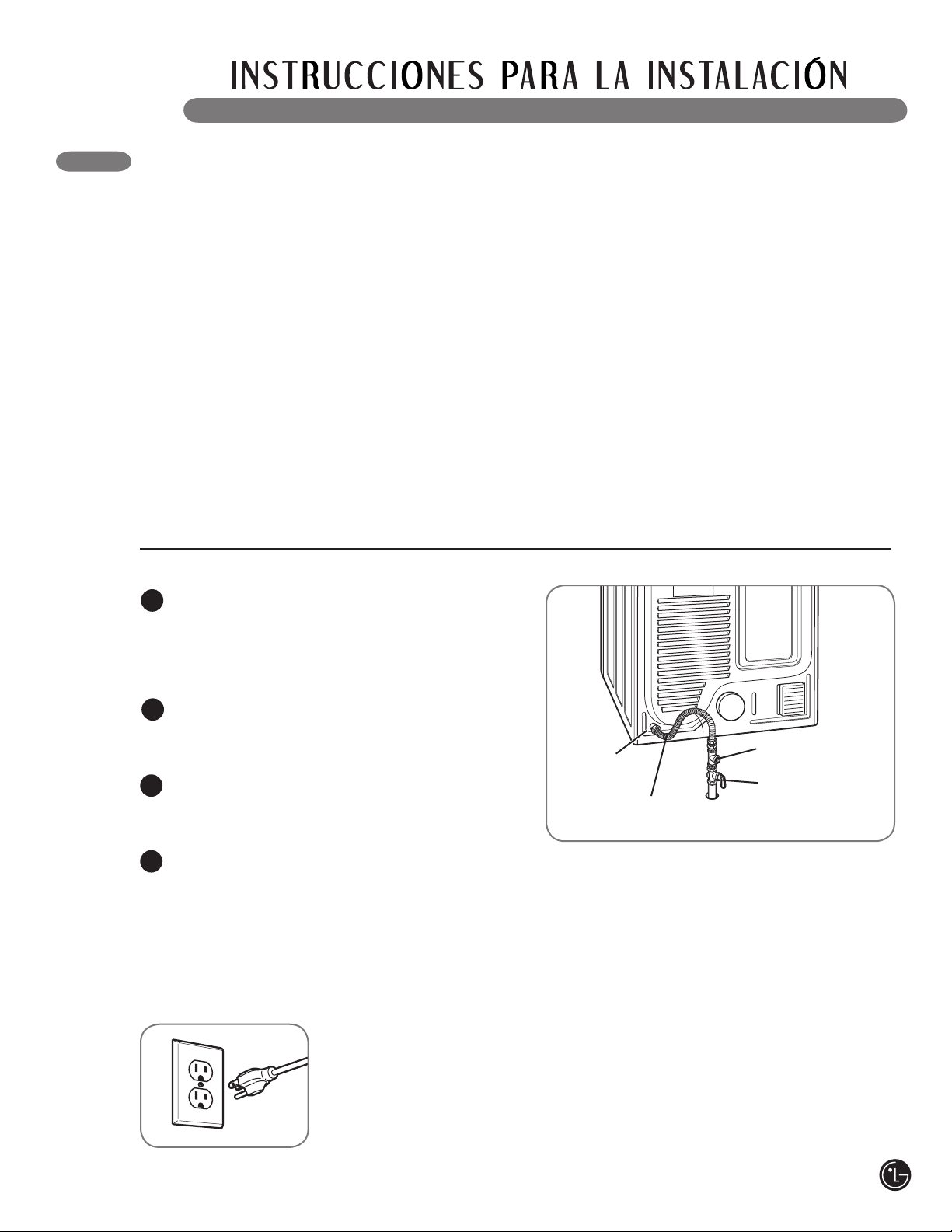
• La instalación y el mantenimiento deben
proveerse por un instalador calificado, agencia
de mantenimiento o compañía de gas. Si no se
cumple con esto se podrá producir una explosión,
incendio o muerte.
• Use únicamente un conector de acero
inoxidable nuevo y un conector certificado por
AGA nuevo. Si no se cumple con esto se podrá
producir una explosión, incendio o muerte.
• Se debe instalar una válvula de corte de gas
a una distancia mínima de 6 pies (1,8 m) de la
secadora. Si no se cumple con esto se podrá
producir una explosión, incendio o muerte.
• La secadora está configurada para gas natural
cuando se envía de fábrica. Asegúrese de que
la secadora está equipara con la boquilla de
quemador correcta para el tipo de gas que
se usará (gas natural o petróleo líquido, LP).
Si no se cumple con esto se podrá producir una
explosión, incendio o muerte.
• De ser necesario, un técnico calificado debe
instalar la boquilla correcta (para el kit de
boquilla LP, ordene la pieza de pedido Núm.
4948EL4002B) y se debe anotar el cambio en
la secadora. Si no se cumple con esto se podrá
producir una explosión, incendio o muerte.
• Se deben realizar todas las conexiones según
los códigos y las regulaciones locales. Si no se
cumple con esto se podrá producir una explosión,
incendio o muerte.
• Las secadoras de gas DEBEN ventilar hacia
el exterior. Si no se cumple con esto se podrá
producir una explosión, incendio o muerte.
wADVERTENCIA
Conexión de
gas 3/8" NPT
Válvula de corte de
suministro de gas
Conexión del suministro de gas
Asegúrese de que el suministro de gas al
cuarto de lavado se encuentre APAGADO.
Confirme que el tipo de gas disponible en
su cuarto de lavado sea el adecuado para
la secadora. La secadora está lista para la
conexión de gas natural de 3/8 pulgadas NPT.
Quite la tapa de envío de la conexión de gas
localizada de la parte trasera de la secadora.
Asegúrese de no dañar la rosca del conector
de gas al quitar la tapa de envío.
Conecte la secadora al suministro de gas
de su cuarto de lavado usando un conector
de acero inoxidable flexible nuevo con una
conexión de 3/8 pulgadas NPT.
Ajuste bien todas las conexiones entre la
secadora y el suministro de gas de su cuarto
de lavado. Abra el suministro de gas de su
cuarto de lavado y verifique que no haya
fugas en todas las conexiones de tubería
(tanto interiores como exteriores) usando un
fluido anticorrosivo para detección de fugas.
1
2
3
4
Instalaciones en lugares de gran altitud
La clasificación BTU para esta secadora es
certificación AGA para elevaciones por debajo de
los 10.000 pies.
Si va a instalar su secadora a más de 10.000
pies, debe ser desclasificada por un técnico
calificado o compañía de gas.
Conexión eléctrica
Enchufe la secadora
en un tomacorriente
de 120 V CA, 60 Hz
de tres patas
conectado a tierra.
CONEXIÓN DE SECADORAS A GAS (cont.)
Tapón de tubería
de 1/8" NPT
Conector flexible de acero
inoxidable certificado por
AGA/CSA
57

58
Requisitos eléctricos únicamente para modelos eléctricos
• Cualquier instalación en una vivienda móvil o
prefabricada debe realizarse de conformidad
con los Estándares de seguridad y
construcción de viviendas prefabricadas,
Título 24 CFR, Parte 32-80 o estándar
CAN/CSA0Z240 MH y con los códigos y
regulaciones locales.
• Se requiere una conexión de 4 hilos en
todas las instalaciones de viviendas móviles
y prefabricadas, así como en todas las
construcciones nuevas posteriores al
1 de enero de 1996. Si no se cumple con
esto se podrá producir una explosión,
incendio o muerte.
CÓMO CONECTAR LAS SECADORAS ELÉCTRICAS
• Esta secadora debe estar conectada a un
sistema de cableado metálico permanente
conectado a tierra, o se debe tender un
conductor de conexión a tierra de equipo con
los conductores de circuito y conectado a
la terminal de conexión a tierra del equipo o
conductor de la secadora. Si no se cumple con
esto se podrá producir una explosión, incendio o
muerte.
• La secadora tiene su propio bloque terminal,
el cual debe conectarse a un circuito de una
sola fase de 240 V CA, de 60 Hz, protegido con
fusible de 30 amperios (el circuito debe tener
protección de fusible a ambos terminales de
la línea). EL SUMINISTRO ELÉCTRICO DE LA
SECADORA DEBERÁ SER DE LA MÁXIMA
CLASIFICACIÓN DE VOLTAJE LISTADA EN LA
PLACA DE CARACTERÍSTICAS. NO CONECTE
LA SECADORA A UN CIRCUITO DE 110, 115
Ó 120 VOLTIOS. Se dispone de elementos
de calentamiento para instalación de campo
en secadoras que deben conectarse a un
suministro eléctrico de voltaje diferente al
listado en la placa de datos de servicio. Si
no se cumple con esto se podrá producir una
explosión, incendio o muerte.
• Si un circuito de ramal a la secadora es de 15
pies (4,5 m) o menos de longitud, use alambre
listado por UL (Underwriters Laboratories)
Núm.-10 AWG (únicamente alambre de cobre),
o según lo requieran las leyes locales. Si es
más largo de 15 pies (4,50 m), use alambre
listado por UL (Underwriters Laboratories)
Núm.-8 AWG (únicamente alambre de cobre), o
según lo requieran las leyes locales. Disponga
de suficiente dotación de cableado, de manera
de poder mover la secadora de su ubicación
normal cuando sea necesario. Si no se cumple
con esto se podrá producir una explosión,
incendio o muerte.
• NO se provee la conexión en espiral del cable
eléctrico entre la caja de pared y el bloque
terminal de la secadora con la misma. El
tipo de conexión en espiral y el calibre del
alambre deben seguir los códigos locales y
las instrucciones indicadas en las siguientes
páginas. Si no se cumple con esto se podrá
producir una explosión, incendio o muerte.
• Se requiere una conexión de 4 hilos en
todas las instalaciones de viviendas móviles
y prefabricadas, así como en todas las
construcciones nuevas posteriores al 1 de
enero de 1996. Se debe usar una conexión de
4 hilos si los códigos locales no permitan la
conexión a tierra utilizando el alambre neutro.
Si no se cumple con esto se podrá producir
una explosión, incendio o muerte.
Requisitos eléctricos especiales para viviendas móviles o prefabricadas
wADVERTENCIA: Para ayudar a evitar incendios, descargas eléctricas, heridas
graves o muerte, el cableado e instalación a tierra deben cumplir con la última edición del Código
Eléctrico Nacional, ANSI/NFPA 70 y todas las regulaciones locales aplicables. Por favor comuníquese
con un electricista calificado para que controle el cableado y los fusibles y así asegurar que su casa
posee energía eléctrica adecuada para operar la secadora.
wADVERTENCIA – Para reducir el riesgo de incendio, descargas eléctricas o
heridas al usar su electrodoméstico, siga las precauciones básicas, incluyendo lo siguiente:
wADVERTENCIA – Para reducir el riesgo de incendio, descargas eléctricas o
heridas al usar su electrodoméstico, siga las precauciones básicas, incluyendo lo siguiente:
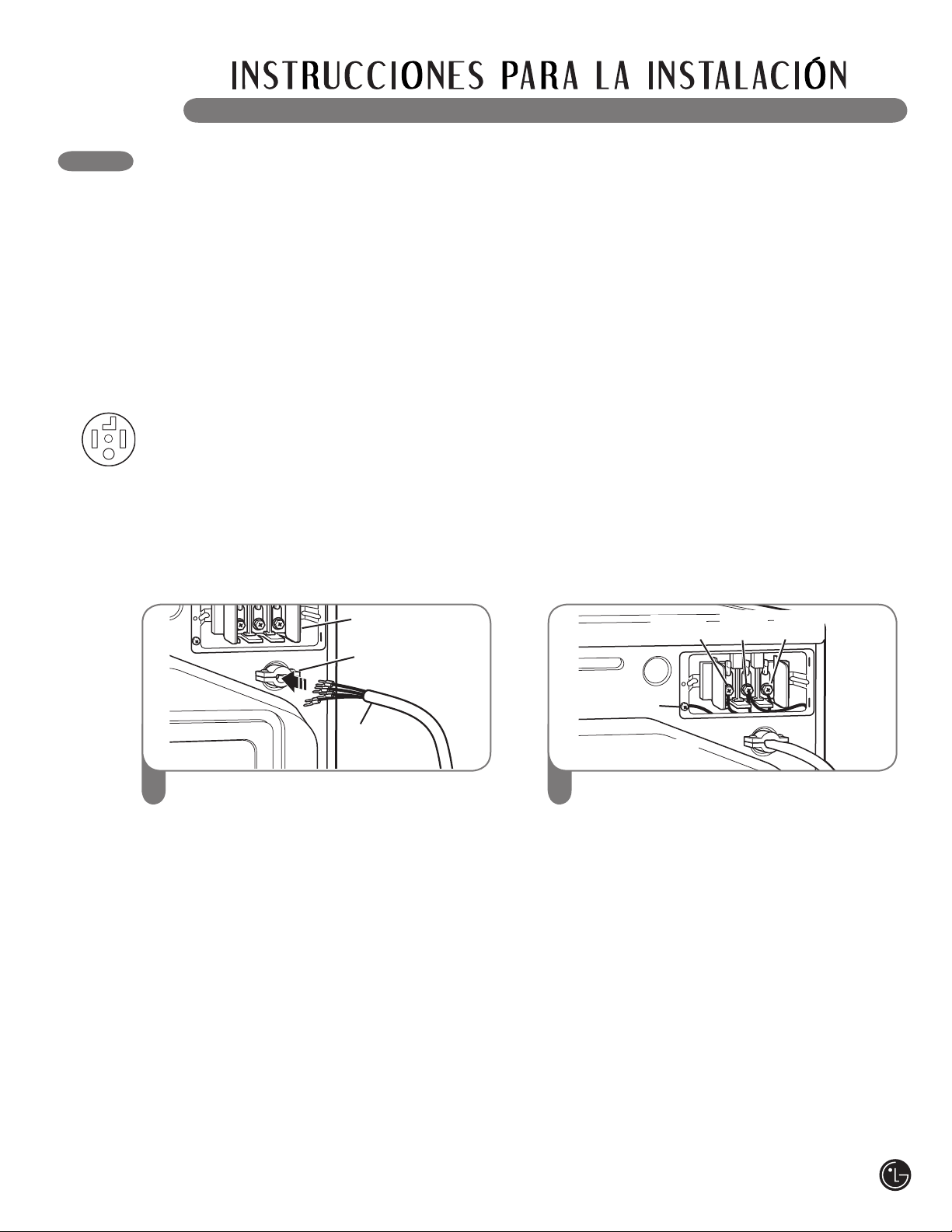
59
Quite la cubierta de acceso al bloque
terminal localizado en la parte superior
trasera de la secadora. Instale un protector
de tensión listado por UL en el orificio de
pase del cable eléctrico; luego pase un
cable eléctrico conductor de cobre Núm. 10
AWG de por lo menos 4 hilos, 30 A listado
por UL por el protector de tensión.
1
Protector de tensión
listado por UL
Cable eléctrico
de cuatro hilos
listado por UL
Bloque
terminal
Transfiera el alambre de conexión a tierra de
la secadora detrás del tornillo de conexión
a tierra de color verde al tornillo central del
bloque terminal. Conecte los dos conductores
calientes del cable eléctrico a los tornillos
del bloque terminal exterior. Conecte el cable
neutro de color blanco al tornillo del bloque
terminal central. Conecte el alambre de
conexión a tierra del cable eléctrico al tornillo
de conexión a tierra de color verde. AJUSTE
BIEN TODOS LOS TORNILLOS. Reinstale la
cubierta de acceso del bloque terminal.
2
Tornillo de
conexión a tierra
Neutro
(blanco)
Caliente
(negro)
Caliente
(rojo)
Alambre de conexión a
tierra del cable eléctrico
Conexión de cuatro hilos para secadoras eléctricas: Cable eléctrico con enchufe
• Se requiere una conexión de 4 hilos en
todas las instalaciones de viviendas móviles
y prefabricadas, así como en todas las
construcciones nuevas posteriores al
1 de enero de 1996.
• Se requiere un protector de tensión listado por UL.
• Instale un cable eléctrico de 30 amp, 240 V,
listado por UL con un conductor de cobre
Núm.-10 AWG como mínimo y terminales de
bucle cerrado o de horquilla con extremos
doblados hacia arriba.
CÓMO CONECTAR LAS SECADORAS ELÉCTRICAS (cont.)
wADVERTENCIA:
• Conecte el cable de suministro de corriente al bloque terminal. Cada cable se debe
conectar al tornillo del mismo color. El color del cable que figura en el manual se conecta
el tornillo del mismo color en el bloque. De otro modo se podrá producir un flujo de
corriente corto o excesivo.
• Contacto por conductor meutro esta prohibido por: (1) nuevas instalaciones de branch-
circuito, (2) las casas mobiles, (3) vehiculos recreacionales, y (4) areas donde los codigos
prohibe una conexión a tierra por el conductor neutro.
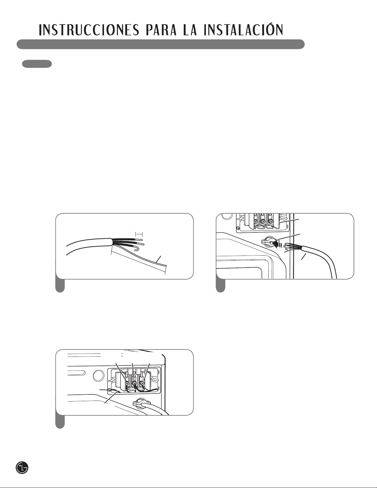
Despegue pulg. (12.7 cm) de la cubierta
del cable del final. Descubra 5 pulg. del
cable de tierra. Corte 1
1
⁄
2
pulg. (3.8 cm) de
los otros 3 cables y despuega 1 pulg. (2.5
cm) del aislamiento del cado uno. Haga los
finales del 3 cables en forma de gancho.
1
Transfiera el alambre de conexión a tierra de
la secadora detrás del tornillo de conexión
a tierra de color verde al tornillo central del
bloque terminal. Conecte los dos conductores
calientes del cable eléctrico a los tornillos del
bloque terminal exterior. Conecte el cable neutro
de color blanco al tornillo del bloque terminal
central. Conecte el alambre de conexión a tierra
del cable eléctrico al tornillo de conexión a tierra
de color verde. AJUSTE BIEN TODOS LOS
TORNILLOS. Reinstale la cubierta de acceso
del bloque terminal.
3
Alambre de
conexión a
tierra
Quite la cubierta de acceso al bloque
terminal localizado en la parte superior
trasera de la secadora. Instale un protector
de tensión listado por UL en el orificio de
pase del cable eléctrico; luego pase el cable
eléctrico fabricado en el Paso 1 por
el protector de tensión.
2
5"
(12.7 cm)
1" (2.5 cm)
• Se requiere una conexión de 4 hilos en
todas las instalaciones de viviendas móviles
y prefabricadas, así como en todas las
construcciones nuevas posteriores al
1 de enero de 1996.
• Se requiere un protector de tensión listado por UL.
• Instale un cable eléctrico listado por UL con
4 conductores de cobre Núm.-10 AWG como
mínimo.
• Prepare un mínimo de 5 pies (1.5 m) de longitud
para poder quitar y reemplazar la secadora.
Conexión de cuatro hilos para secadoras eléctricas: Conexión directa
Tornillo de
conexión a tierra
Neutro
(blanco)
Caliente
(negro)
Caliente
(rojo)
Alambre de conexión a
tierra del cable eléctrico
Protector de tensión
listado por UL
Cable eléctrico
de cuatro hilos
listado por UL
Bloque
terminal
60
CÓMO CONECTAR LAS SECADORAS ELÉCTRICAS (cont.)
wADVERTENCIA:
• Conecte el cable de suministro de corriente al bloque terminal. Cada cable se debe
conectar al tornillo del mismo color. El color del cable que figura en el manual se conecta
el tornillo del mismo color en el bloque. De otro modo se podrá producir un flujo de
corriente corto o excesivo.
• Contacto por conductor meutro esta prohibido por: (1) nuevas instalaciones de branch-
circuito, (2) las casas mobiles, (3) vehiculos recreacionales, y (4) areas donde los codigos
prohibe una conexión a tierra por el conductor neutro.
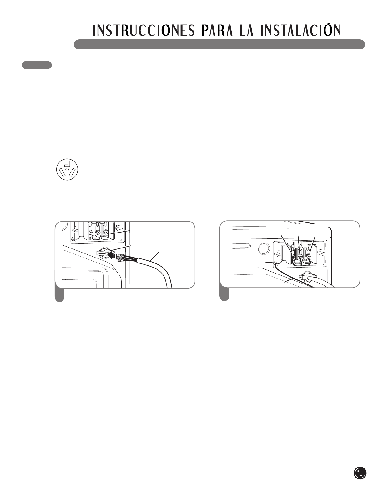
Quite la cubierta de acceso al bloque
terminal localizado en la parte superior
trasera de la secadora. Instale un protector
de tensión listado por UL en el orificio de
pase del cable eléctrico; luego pase un cable
eléctrico conductor de cobre Núm. 10 AWG
de por lo menos 3 hilos, 30 A , 240 V, listado
por UL por el protector de tensión.
1
Conexión de tres hilos para secadoras eléctricas: Cable eléctrico con enchufe
• NO se permite una conexión de 3 hilos en
construcciones nuevas después del 1 de
enero de 1996.
• Se requiere un protector de tensión listado
por UL.
• Instale un cable eléctrico de 30 amp, 240 V,
listado por UL con un conductor de cobre
Núm. 10 AWG como mínimo y terminales
de bucle cerrado o de horquilla con
extremos doblados hacia arriba.
CÓMO CONECTAR LAS SECADORAS ELÉCTRICAS (cont.)
Protector de tensión
listado por UL
Cable eléctrico
de tres hilos
listado por UL
Bloque
terminal
Conecte los dos conductores calientes del
cable eléctrico a los tornillos del bloque
terminal exterior. Conecte el cable neutro
al tornillo del bloque terminal central.
Conecte la conexión a tierra exterior (de ser
requerido por los códigos locales) al tornillo
de color verde. AJUSTE BIEN TODOS LOS
TORNILLOS. Reinstale la cubierta de
acceso del bloque terminal.
2
Tornillo de
conexión a tierra
Alambre de
conexión a tierra
wADVERTENCIA:
• Conecte el cable de suministro de corriente al bloque terminal. Cada cable se debe
conectar al tornillo del mismo color. El color del cable que figura en el manual se conecta
el tornillo del mismo color en el bloque. De otro modo se podrá producir un flujo de
corriente corto o excesivo.
• Contacto por conductor meutro esta prohibido por: (1) nuevas instalaciones de branch-
circuito, (2) las casas mobiles, (3) vehiculos recreacionales, y (4) areas donde los codigos
prohibe una conexión a tierra por el conductor neutro.
Neutro
(blanco)
Caliente
(negro)
Caliente
(rojo)
61
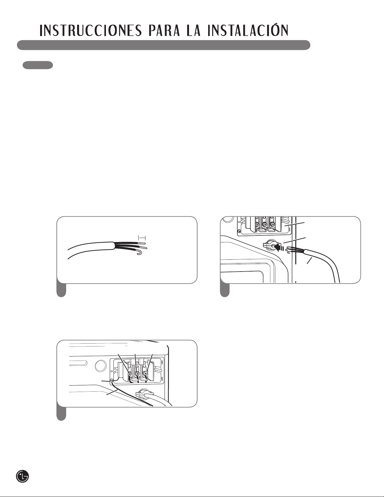
Despegue 3
1
⁄
2
pulg. (8.9 cm) de la cubierta
del cable del final. Despuega 1 pulg. (2.5
cm) del aislamiento de los tres alambres.
Haga los finales del 3 cables en forma de
gancho.
1
Conecte los dos conductores calientes del
cable eléctrico a los tornillos del bloque
terminal exterior. Conecte el cable neutro
al tornillo del bloque terminal central.
Conecte la conexión a tierra exterior (de ser
requerido por los códigos locales) al tornillo
de color verde. AJUSTE BIEN TODOS LOS
TORNILLOS. Reinstale la cubierta de
acceso del bloque terminal.
3
Quite la cubierta de acceso al bloque
terminal localizado en la parte superior
trasera de la secadora. Instale un protector
de tensión listado por UL en el orificio de
pase del cable eléctrico; luego pase el cable
eléctrico fabricado en el Paso 1 por
el protector de tensión.
2
1" (2.5 cm)
CÓMO CONECTAR LAS SECADORAS ELÉCTRICAS (cont.)
Conexión de tres hilos para secadoras eléctricas: Conexión directa
• NO se permite una conexión de 3 hilos en
construcciones nuevas después del 1 de enero
de 1996.
• Se requiere un protector de tensión listado por UL.
• Instale un cable eléctrico listado por UL con
4 conductores de cobre Núm.-10 AWG como
mínimo.
• Prepare un mínimo de 5 pies (1.5 m) de longitud
para poder quitar y reemplazar la secadora.
wADVERTENCIA:
• Conecte el cable de suministro de corriente al bloque terminal. Cada cable se debe
conectar al tornillo del mismo color. El color del cable que figura en el manual se conecta
el tornillo del mismo color en el bloque. De otro modo se podrá producir un flujo de
corriente corto o excesivo.
• Contacto por conductor meutro esta prohibido por: (1) nuevas instalaciones de branch-
circuito, (2) las casas mobiles, (3) vehiculos recreacionales, y (4) areas donde los codigos
prohibe una conexión a tierra por el conductor neutro.
Neutro
(blanco)
Caliente
(negro)
Caliente
(rojo)
Tornillo de
conexión a tierra
Alambre de
conexión a tierra
Protector de tensión
listado por UL
Cable eléctrico
de tres hilos
listado por UL
Bloque
terminal
62
Comprobación del calentamiento
de la secadora
MODELOS A GAS
Cierre la puerta de la secadora, apriete el
interruptor ON/OFF para encender la secadora,
e iniciar la secadora en un ajuste de calor.
Cuando inicia la secadora, el encendedor deberá
encender el quemador principal.
NOTA: Si no se purga todo el aire de la línea de
gas, el encendedor de gas podría apagarse antes
de que se encienda el quemador. Si esto sucede,
el encendedor volverá a intentar encender el gas
después de aproximadamente dos minutos.
Revisión del flujo de aire
El funcionamiento efectivo de la secadora
requiere de un flujo de aire adecuado. La
corrección del flujo de aire puede medirse
evaluando la presión estática. La presión estática
del conducto del escape se puede medir con un
manómetro, colocado en el conducto de escape
aproximadamente a 2 pies (60,9 cm) de distancia
de la secadora. La presión estática del conducto
de escape no debería exceder las 0,6 pulgadas
(1,5 cm). Se debe revisar la secadora mientras
está funcionando sin carga.
Revisión del nivelado
Una vez que la secadora se encuentra en su
ubicación final, vuelva a revisar que la misma
se encuentre nivelada. Asegúrese de que esté
nivelada de adelante hacia atrás y de lado a
lado, y de que las cuatro patas niveladoras se
encuentren asentadas en el piso firmemente.
REVISIÓN DE INSTALACIÓN FINAL
Una vez que haya completado la instalación de la secadora y la misma se encuentre en su ubicación final,
confirme que funcione correctamente realizando las siguientes pruebas.
Cualquier instalación en una vivienda móvil o
prefabricada debe realizarse de conformidad con
los Estándares de seguridad y construcción de
viviendas prefabricadas, Título 24 CFR, Parte
32-80 o estándar CAN/CSA0Z240 MH y con los
códigos y regulaciones locales. Si no está seguro
de si la instalación que ha propuesto cumple
con estos estándares, llame a un técnico de
mantenimiento e instalación para obtener ayuda.
• Una secadora de gas debería fijarse
permanentemente sobre el piso.
• La conexión eléctrica de una secadora eléctrica
debe ser una conexión de 4 hilos. Se provee
información más detallada pertinente a la
conexión eléctrica en la sección Cómo conectar
las secadoras eléctricas.
• Para reducir el riesgo de combustión e incendio,
se debe ventilar la secadora hacia el exterior.
• NO ventile la secadora debajo de una vivienda
móvil o prefabricada.
• Las secadoras eléctricas deben ventilarse hacia
el exterior usando el panel trasero, izquierdo,
derecho o inferior.
• Las secadoras a gas deben ventilarse al exterior
usando el panel trasero, izquierdo o inferior. Las
secadoras a gas no deben ventilarse hacia el
exterior usando el panel derecho debido a la
carcasa del quemador.
• El conducto de escape de la secadora debe
estar bien fijado a la estructura de la vivienda
móvil o prefabricada, y el conducto de escape
debe estar fabricado de un material resistente al
fuego y la combustión. Se recomienda el uso de
un conducto de metal rígido o flexible.
• NO conecte el conducto de escape de la
secadora a ningún otro conducto, respiradero,
chimenea ni a ningún otro tipo de conducto
de escape.
• Asegúrese de que la secadora disponga de
acceso adecuado al aire fresco del exterior
para garantizar un funcionamiento adecuado.
La abertura para la toma de aire fresco
exterior debe ser de por lo menos
25 pulgadas
2
(163 cm
2
).
• Es importante que el espacio libre del conducto
con respecto a cualquier material combustible
de construcción sea de por lo menos 2
pulgadas (5 cm) y que, cuando se ventile
la secadora al exterior, se pueda instalar la
secadora dejando un espacio libre de
1 pulgadas (2,5 cm) a los lados y la parte
trasera de la secadora.
• Tenga en cuenta que los materiales de
ventilación no se proveen con la secadora.
Debe obtener los materiales de ventilación
necesarios para una instalación adecuada.
REQUISITOS ESPECIALES PARA VIVIENDAS MÓVILES O PREFABRICADAS
63
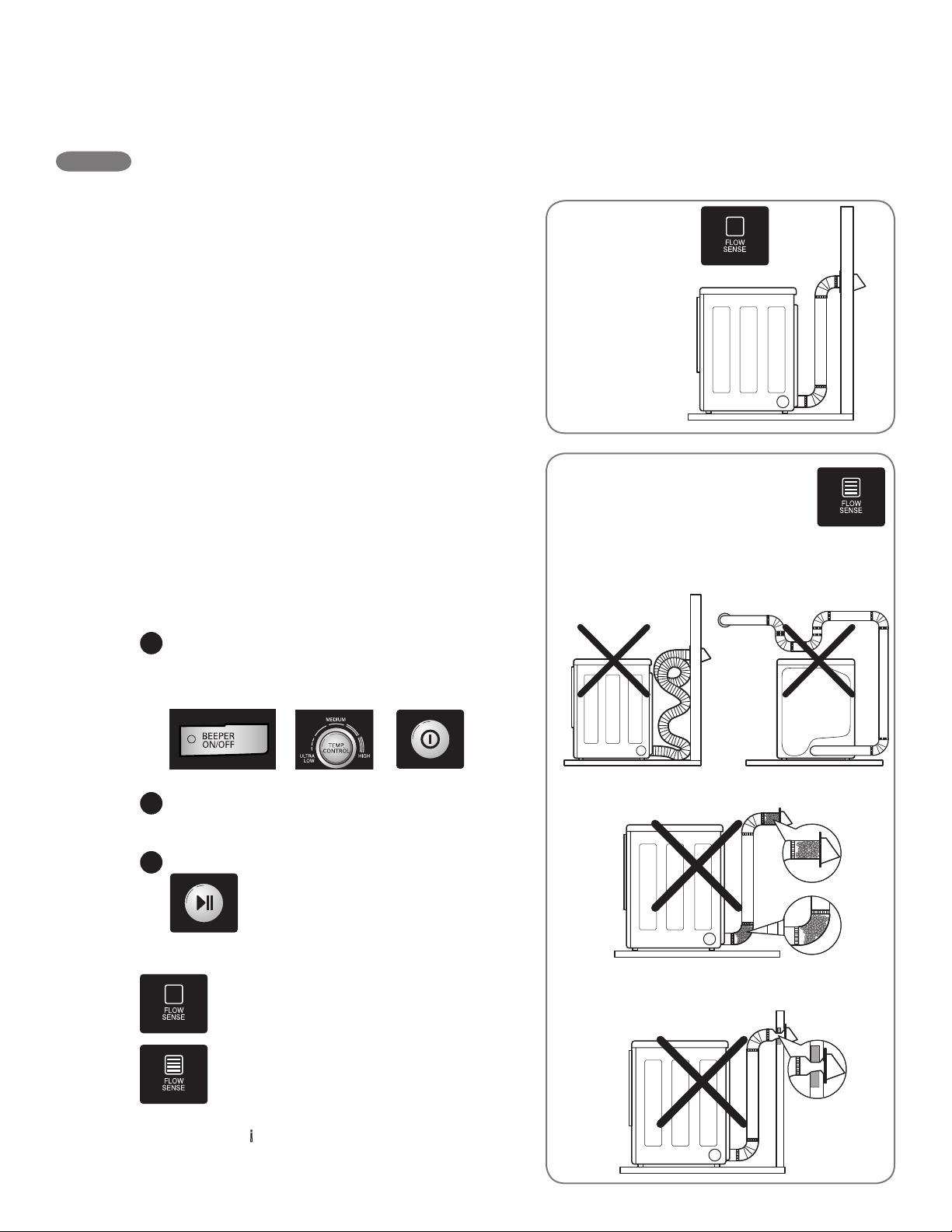
La secadora incluye FlowSense
™
, un sistema
de sensor innovador que detecta en forma
automática bloqueos y restricciones en la
tubería de su secadora. Mantener la tubería sin
acumulación de pelusa y libre de restricciones
hace posible que la ropa se seque más rápido,
reduce el uso de corriente.
NOTA: Cuando recién se instala la secadora,
debe realizarse esta prueba para alertarlo sobre
cualquier clase de problems con el conducto de
extracción de su hogar. Sin embargo, puesto que
la prueba realizada durante un funcionamiento
normal ofrece una información más precisa
sobre el estado del conducto de extracción que
la prueba de instalación, la cantidad de barras
visualizadas durante las dos pruebas puede no
ser la misma.
Para activar el ciclo de evaluación del
estado del conducto:
NOTA: La comprobación del calentamiento
de la secadora debe estan ejucatado antes
de continuar. (Secadora a Gas solamente) Luego,
complete la siguiente evaluación del estado del
Presione y sostenga los botones DAMP DRY
BEEP y TEMP CONTROL al mismo tiempo.
Al sostener estos botones, presione el botón
ENCENDIDO/APAGADO.
La secadora le mostrará InS en la pantalla
numérica para indicar que se encuentra en el
modo de evaluación del estado del conducto.
Presione START/PAUSE. La
secadora evaluará durante
aproximadamente 2 minutos.
bloqueos o restricciones haciendo
circular aire por la tubería.
SISTEMA DE EVALUACIÓN DEL ESTADO DEL CONDUCTO
Si no aparecen barras en la pantalla,
significa que la tubería está libre de
bloqueos o restricciones.
Si todas las barras están encendidas,
la tubería de la secadora posee un
bloqueo que deberá ser eliminado
de inmediato.
IMPORTANTE: ¡No interrumpa el ciclo de
evaluación!
Ventilación
Correcta
1
2
3
Flujo de Aire Restringido
o Bloqueado
Evite funcionamientos prolongados o
funcionamientos con múltiples formaciones
de torceduras o codos.
Controle los bloqueos y la acumulación
de pelusa.
Asegúrese que la tubería no posea cortes
ni restricciones.
conducto.
64
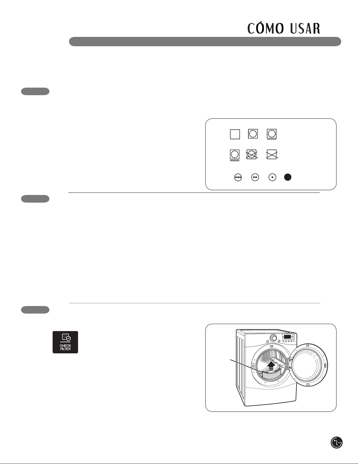
COMO CARGAR LA SECADORA
wADVERTENCIA
Revise todos los bolsillos para asegurarse
de que estén vacíos. Los artículos como clips,
fósforos, plumas, monedas y llaves pueden
dañar su secadora o sus prendas. Los objetos
inflamables tales como encendedores o
fósforos podrían encenderse y provocar
un incendio. Si no se cumple con esto se podrá
producir una explosión, incendio o muerte.
Nunca seque prendas que hayan sido
expuestas a aceite, gasolina u otras
substancias inflamables. Lavar las prendas no
eliminará completamente los residuos
de aceite. Si no se cumple con esto se podrá
producir una explosión, incendio o muerte.
• Combine prendas grandes y pequeñas en una
carga.
• Las prendas húmedas se extenderán mientras
se secan. No sobrecargue la secadora; las
prendas necesitan de espacio para girar y secar
adecuadamente.
• Cierre las cremalleras, ganchos y cordones para
prevenir que estos artículos se enganchen o
enreden en otras prendas.
Secado a
máquina
Seco
Planchado permanente
/
antiarrugas
Suave/
delicado
No secar
a máquina
No secar
(utilizado junto
a “no lavar”)
Normal
CLASIFICACIÓN DE CARGAS
Etiquetas de mantenimiento de las telas
La mayoría de las prendas de vestir tienen etiquetas
de mantenimiento de las telas para lograr un
mantenimiento adecuado.
Agrupamiento de prendas similares
Para obtener los mejores resultados, clasifique
las prendas en cargas que puedan secarse con
el mismo ciclo de secado.
Los diferentes tipos de telas tienen diferentes
requisitos de cuidado, y algunas telas se
secarán más rápido que otras.
Etiquetas de cuidado de las telas
Ajuste
de calor
Alto
Mediano
Bajo
Sin calor/aire
REVISE EL FILTRO DE PELUSA ANTES DE CADA CARGA
El Indicador del CHECK FILTER (control del filtro)
se encenderá antes de cada carga,
recordándole que se debe asegurar
que el filtro de pelusa esté limpio
antes de comenzar una nueva carga.
También se encenderá durante una carga si el
filtro de pelusa está obstruido a fin de indicarle
que el mismo se debe limpiar; un filtro de pelusa
bloqueado incrementará los tiempos de secado.
Para limpiarlo, tire del filtro de pelusa
verticalmente y, con los dedos, enrolle cualquier
pelusa para retirarla del filtro. No enjuague ni lave
el filtro para eliminar la pelusa. Empuje el filtro de
pelusa firmemente en su lugar. Para informacaión
adicional, vea la sección “Cuidado y Limpieza”.
Asegúrese siempre de que el filtro de pelusa
esté instalado adecuadamente antes de poner
en funcionamiento la secadora. Hacer funcionar
Filtro de
pelusa
la secadora sin o con un filtro de pelusa suelto
podría dañar la secadora y los artículos en el
interior de la misma.
A continuación encontrará instrucciones para comenzar a usar su secadora nueva. Para más información
por favor consulte las secciones específicas de este manual. Advertencia importante: Para reducir el
riesgo de incendios, descargas eléctricas o heridas, lea este manual en su totalidad, incluyendo las
Instrucciones Importantes de Seguridad, antes de operar la secadora.
65
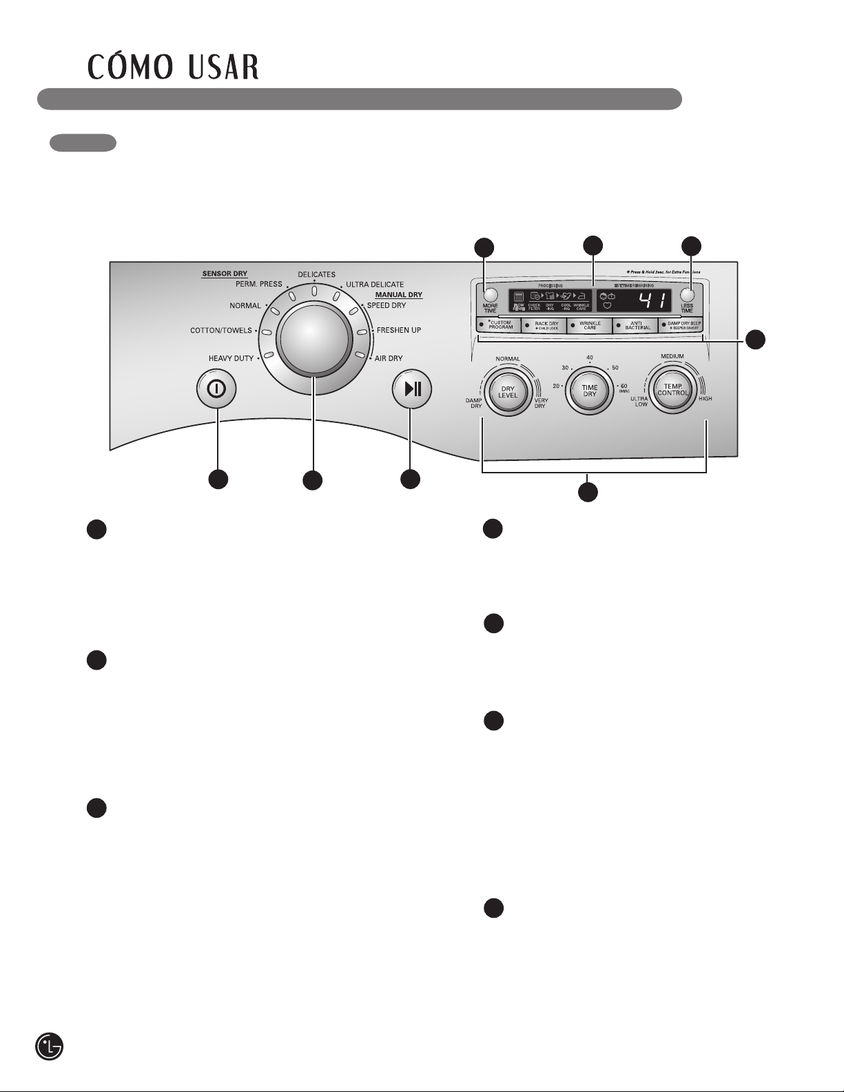
CARACTERÍSTICAS DEL PANEL DE CONTROL
BOTÓN DE ENCENDIDO/APAGADO
(ON/OFF)
Apriete el botón para encender la secadora.
Apriete nuevamente para apagar la secadora.
NOTA: Apretar el botón de ENCENDIDO/
APAGADO durante un ciclo cancelará ese ciclo y
borrará cualquier ajuste de carga.
PERILLA SELECTORA DE CICLOS
Gire esta perilla para seleccionar el ciclo deseado.
Una vez que se haya seleccionado el ciclo
deseado, los preajustes estándar se mostrarán
en la pantalla. En los ciclos de secado manual
(MANUAL DRY) se pueden programar estos
ajustes usando los botones de ajuste de ciclos en
cualquier momento antes de iniciar el ciclo.
BOTÓN DE INICIO/PAUSA (START/PAUSE)
Apriete este botón para iniciar el ciclo
seleccionado. Si la secadora está funcionando,
utilice este botón para hacer una PAUSA en el
ciclo, sin perder los ajustes actuales.
NOTA: Si no aprieta el botón INICIO/PAUSA
para detener un ciclo en 8 minutos, la secadora se
apagará automáticamente.
BOTONES DE MÁS TIEMPO/MENOS
TIEMPO (MORE TIME/LESS TIME)
Use estos botones con los ciclos de secado
manual (MANUAL DRY) y de secado
cronometrado (TIME DRY) para programar el
tiempo de secado. Apriete el botón MORE
TIME para aumentar el tiempo del ciclo
manual seleccionado en intervalos de un
minuto; apriete LESS TIME para disminuir el
tiempo del ciclo en intervalos de un minuto.
A continuación encontrará instrucciones para comenzar a usar su secadora nueva. Para más información
por favor consulte las secciones específicas de este manual. Advertencia importante: Para reducir el
riesgo de incendios, descargas eléctricas o heridas, lea este manual en su totalidad, incluyendo las
Instrucciones Importantes de Seguridad, antes de operar la secadora.
2
1
2
BOTONES DE AJUSTE DE CICLOS
Utilice estos botones para seleccionar los
ajustes de ciclo deseados para el ciclo
seleccionado.
4
5
3
LA PANTALLA DE HORA Y ESTADO
La pantalla de hora y estado muestra el
progreso del ciclo y el tiempo restante
estimado, opciones de ciclos y otros
mensajes del estado actual de su secadora.
6
BOTONES DE OPCIONES
Los botones de opciones le permiten
seleccionar opciones de ciclo adicionales.
Determinados botones también le permitirán
activar funciones especiales al apretar
y mantener apretado el botón durante 3
segundos.
Para obtener información detallada sobre las
opciones individuales, consulte las siguientes
páginas.
1
3
4
6
7
7
5
7
66
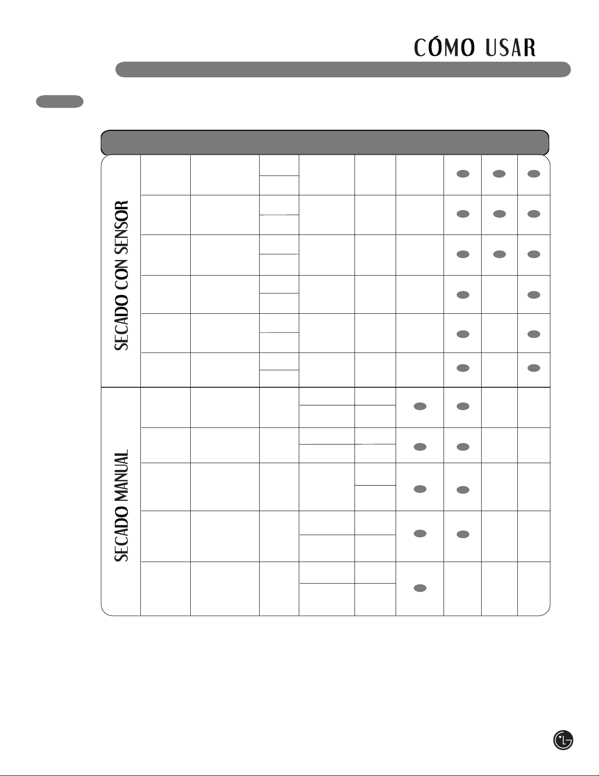
GUÍA DE CICLOS
La guía de ciclos indicada más abajo muestra las opciones y tipos de telas recomendadas para cada ciclo.
NOTA: Para proteger sus prendas, no todos los niveles, temperatura u opciones están
disponible con cada ciclo.
Ciclos de secado con sensor (sensor dry)
Los ciclos de secado por sensor utilizan el sistema
exclusivo de sensor doble de LG para detectar y
comparar el nivel de humedad en las prendas y en
el aire, y programar el tiempo de secado del modo
necesario para asegurar resultados superiores.
La secadora ajusta automáticamente el nivel de
sequedad y temperatura del ajuste recomendado
para cada ciclo. El tiempo restante estimado se
mostrará en la pantalla.
Ciclos de secado manual (manual dry)
Use los ciclos de secado manual para
seleccionar una cantidad específica de tiempo y
temperatura de secado. Cuando se selecciona
el ciclo de secado manual, la pantalla de
tiempo restante estimado (ESTIMATED TIME
REMAINING) muestra el tiempo restante real en
su ciclo. Puede cambiar el tiempo real en el ciclo
apretando MORE TIME (más tiempo) o LESS
TIME (menos tiempo).
Tipo
Ciclo
Tipo
de tela
Nivel de
secado
Temperatura
Tiempo
en min.
Más tiempo/
Menos tiempo
Cuidado
antiarrugas
Secado
húmedo
Algodón/
Toallas
Vaquera, toallas,
algodones pesados
Normal
Ropa de trabajo,
pana, etc.
Planchado
permanente
Planchado
permanente,
prendas de tela
sintética
Delicado
Lencería,
sábanas, blusas
Normal
Ajustable
Normal
Ajustable
Normal
Ajustable
Normal
Ajustable
Media alta
54
Media
55
Baja
41
Baja
Secado
veloz
36
Para cargas
pequeñas con
tiempos cortos
de secado
Refrescado
Para quitar
arrugas menores
de la ropa
Secado
con aire
Para artículos que
requieren secado
sin calor tales como
plásticos o cauchos
Secado
cronometrado
Para secado general;
se pueden programar
manualmente las
operaciones de
tiempo y temperatura
Apagado
Apagado
Apagado
Apagado
Alta
Ajustable
25
Media Alta
Ajustable
Ajustable
20
Sin calor
Ajustable
Alta
30
Ajustable
40
Ajustable
Ajustable
Secado
en
estante
Su
éteres de lana,
sedas, lencería
Apagado
Apagado
Ultra baja
Baja
50
Ajustable
Anti-
bacteriano
Ultra baja
32
34
Normal
Ajustable
Normal
Ajustable
Pesado
Vaquera, art iculos
pesados
Lencería,
sábanas, blusas
Ultra
delicado
Alta
67
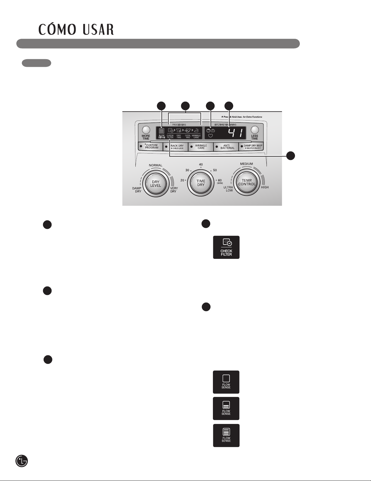
LA PANTALLA DE HORA Y ESTADO
La pantalla muestra los ajustes, el tiempo restante estimado, las opciones y los mensajes de
estado correspondientes a su secadora.
TIEMPO RESTANTE ESTIMADO
(ESTIMATED TIME REMAINING)
Cuando se apriete el botón inicio/pausa
(START/PAUSE), la secadora mostrará
el secado con sensor (SENSOR DRY)
estimado o el tiempo programado de sacado
cronometrado (TIME DRY) restante, y
comenzará a girar.
1
2
INDICADOR DE FINALIZACIÓN DE
CICLO CON RECORDATORIO DE
CONTROL DE FILTRO
Esta opción de la pantalla muestra qué
etapa del ciclo de secado se está llevando
a cabo: CHECK FILTER (control del filtro),
DRYING (secado), COOLING (enfriamiento),
o WRINKLE CARE (cuidado antiarrugas).
15 2 3
3
INDICADOR DE SEGURO INFANTIL
(CHILD LOCK)
Cuando se ha fijado el seguro infantil,
aparecerá el indicador de seguro infantil y se
desactivarán todos los botons.
Esto previene que los niños cambien los
ajustes mientras la secadora se encuentra
en funcionamiento.
4
4
INDICADOR DEL FILTRO DE PELUSA
La secadora detecta en forma automática la
reducción del flujo de aire producida
por un filtro de pelusa completo. El
indicador de CHECK FILTER (control
del fltro) se encenderá, permitiéndole
saber que el filtro se debe limpiar de inmediato
para una máxima eficiencia.
Siempre limpie el filtro de pelusa antes de cada
ciclo.
5
INDICADOR DEL SISTEMA DE SENSOR DE
BLOQUEO DE CONDUCTO FLOW SENSE
™
El sistema de sensor de bloqueo de conducto/
filtro FlowSense
™
detecta y lo alerta sobre
bloqueos en el filtro y la tubería, lo cual reduce
el flujo de escape de la secadora. Esto puede
mejorar el funcionamiento y ayudar a minimizar
el número de llamadas al servicio técnico,
ahorrándole dinero.
Si no aparecen barras en la pantalla,
significa que la tubería está libre de
bloqueos.
Cuantas más barras aparezcan, mayor
será el bloqueo.
Si todas las barras están encendidas,
la tubería de la secadora posee un
bloqueo que deberá ser eliminado de
inmediato.
68
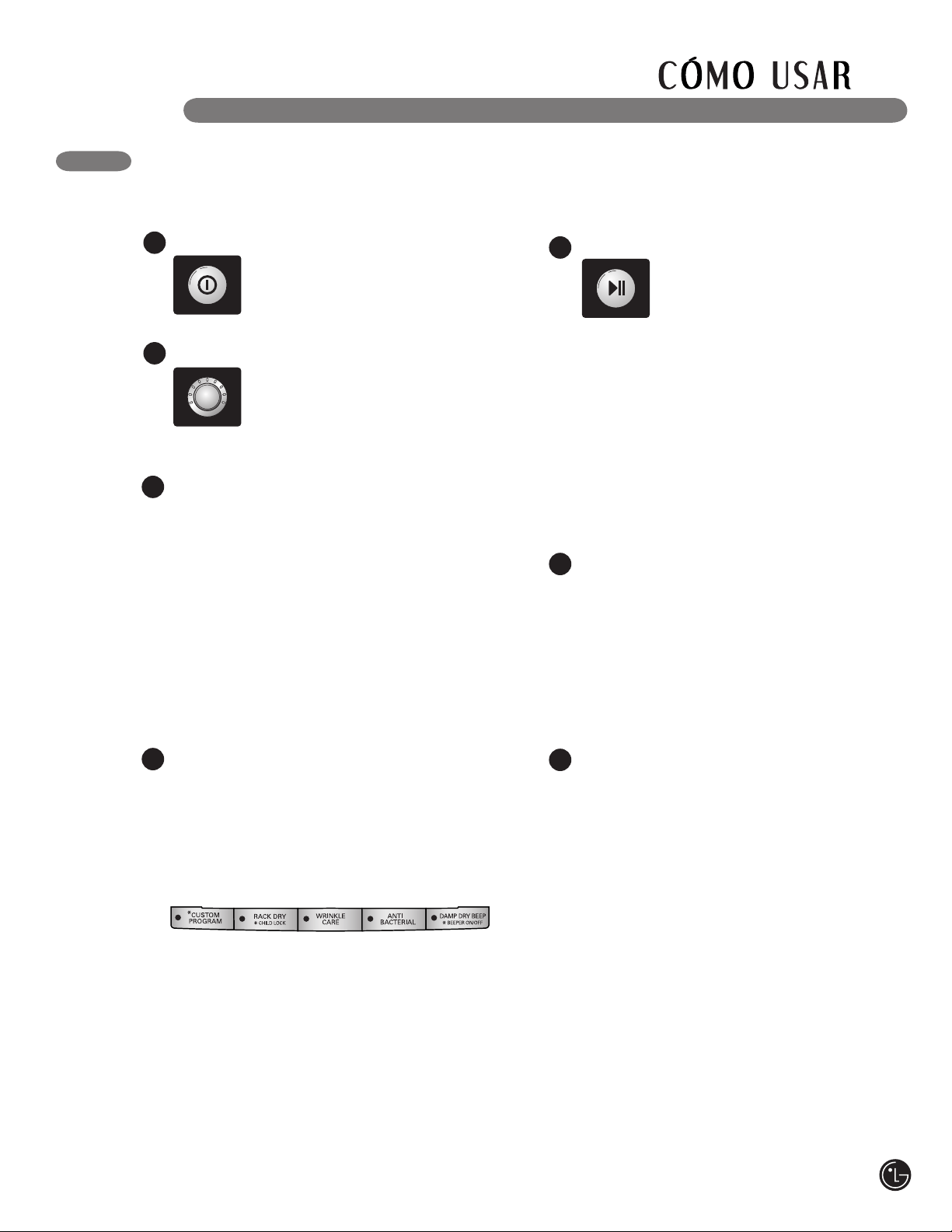
FUNCIONAMIENTO DE LA SECADORA
Apriete el botón de inicio/pausa (START/
PAUSE) para iniciar el ciclo. La
pantalla cambiará, y la secadora
mostrará el secado con sensor
(SENSOR DRY) estimado o el
tiempo programado de secado manual
(MANUAL DRY) restante e iniciará el giro.
Para detener el ciclo en cualquier momento,
abra la puerta de la secadora o apriete
pausa (PAUSE). Para continuar con el ciclo,
desde el punto en que se detuvo, apriete
START/PAUSE nuevamente.
NOTA: Si se ha detenido la secadora por
más de 8 minutos, la secadora se apagará
automáticamente.
5
Una vez que ha cargado la secadora:
Cuando se ha terminado la carga, sonará
la alarma (de haberse programado). Si ha
programado la opción de cuidado de arrugas
(WRINKLE CARE), la secadora girará la carga
de manera periódica por un plazo de hasta 3
horas.
Para prevenir las arrugas, retire los artículos
de la secadora inmediatamente después del
término de un ciclo.
6
Limpie siempre el filtro de pelusa después
de cada ciclo.
Para limpiarlo, tire del filtro de pelusa
verticalmente y, con los dedos, enrolle
cualquier pelusa para retirarla del filtro.
No enjuague ni lave el filtro para eliminar
la pelusa. Empuje el filtro de pelusa
firmemente en su lugar.
7
Si desea modificar los ajustes para ese ciclo,
ya sea sobre el nivel de secado o la tempera-
tura, presione el botón(es) de ajustes de ciclo
adecuado hasta que la luz indicadora para el
ajuste adecuado se encienda.
NOTA: Para proteger sus prendas, no todos
los niveles de secado, temperatura u opción
están disponibles en todos los ciclos.
3
Seleccione cualquier opción de ciclo
adicional, tal como cuidado de arrugas
(WRINKLE CARE), antibacterial, o pitido de
secado húmedo bip (DAMP DRY BEEP),
presione el botón para esa opción. La luz
indicadora en el botón se encienda. Para
deseleccione esa opción, presione
nuevamente el botón.
NOTA: Para proteger sus prendas, no todos
los niveles de secado, temperatura u opción
están disponibles en todos los ciclos.
4
Apriete el botón encendido/apagado (ON/
OFF) para encender la secadora.
Las luces alrededor de la perilla
selectora de ciclos se iluminarán.
Gire la perilla selectora al ciclo deseado.
La pantalla mostrará los ajustes
preseleccionados de nivel de
secado (DRY LEVEL), Temperatura
(TEMPERATURE), Tiempo (TIME),
y Opción (OPTION) para ese ciclo.
1
2
69
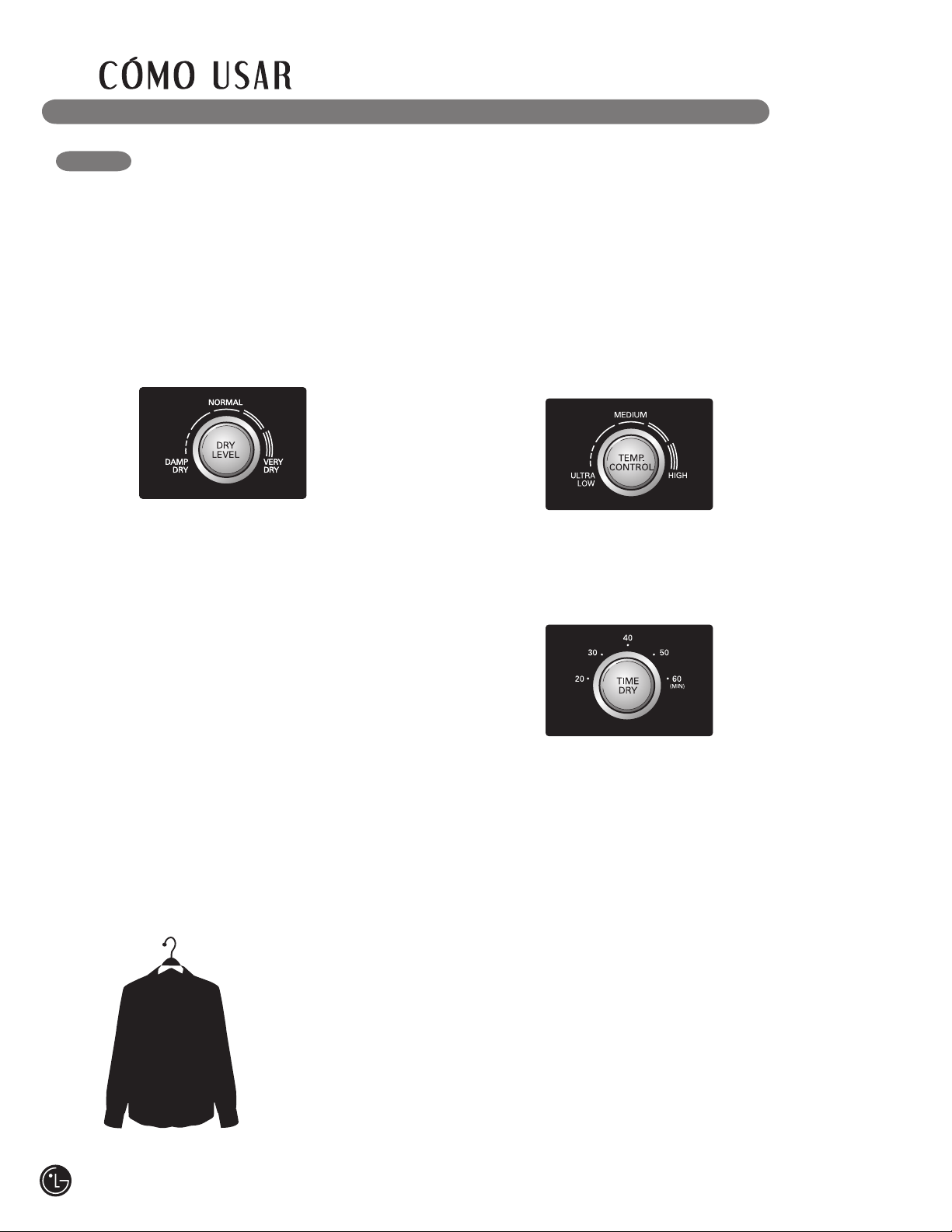
BOTONES DE AJUSTE DE CICLOS
Los ciclos de secado por sensor tienen
ajustes preprogramados que se seleccionan
automáticamente y no pueden cambiarse.
Los ciclos de secado manual tienen ajustes
predeterminados, pero pueden personalizarse
usando los botones de ajustes de ciclos.
Presione el botón para ese ajuste hasta que la
luz indicadora del valor deseado se encienda.
NOTA: Para proteger las prendas, no todos los
niveles de secado, temperatura u opción están
disponibles en todos los ciclos. Vea la Guía de
ciclos para obtener más detalles.
CONTROL DEL TEMPERATURA
(TEMP. CONTROL)
Regula el ajuste de
temperatura desde ultra
bajo (ULTRA LOW) a
calor alto (HIGH HEAT).
Esto permite el cuidado
preciso de sus telas
y prendas. Presione
el botón control de termperaturea (TEMP
CONTROL) hasta que la luz indicadora del tiempo
de secado deseado se encienda.
TIEMPO DE SECADO
(TIME DRY)
Le permite seleccionar
el tiempo de secado
manualmente, de
20 a 60 minutos, en
incrementos de 10
minutos.Use esta opción
en cargas pequeñas o para eliminar arrugas.
Presione el botón tiempo de secado (TIME DRY)
hasta que la luz indicadora del ajuste deseado se
encienda. Use los botones de mas tiempo/menos
tiempo (MORE TIME/LESS TIME) para añadir o
reducir el tiempo de secado en incrementos de 1
minuto.
NIVEL DE SECADO (DRY LEVEL)
Selecciona el nivel
de sequedad para el
ciclo. Presione el botón
nivel de secado (DRY
LEVEL) hasta que la luz
indicadora del ajuste
deseado se encienda.
• Esta opción está disponible únicamente en
los ciclos de secado con sensor
(SENSOR DRY).
• La secadora ajustará el tiempo de ciclo
automáticamente. Al seleccionar muy seco
(VERY DRY) o más seco (MORE DRY) se
incrementará el tiempo del ciclo, mientras que
menos seco (LESS DRY) o húmedo seco (DAMP
DRY) disminuirá el tiempo del ciclo.
• Use un ajuste menos seco (LESS DRY) o
húmedo seco (DAMP DRY) en los artículos que
desee planchar
70
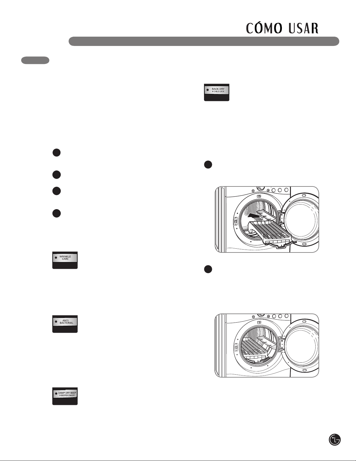
BOTONES DE OPCIÓN DE CICLO
Su secadora dispone de varias opciones de ciclo
adicionales, las cuales personalizan los ciclos
para satisfacer sus necesidades individuales.
Ciertos botones de opción también incorporan
una función especial (vea la siguiente página para
obtener mayor información) que puede activarse
apretando y manteniendo apretado ese botón de
opción por 3 segundos.
CUIDADO DE ARRUGAS (WRINKLE CARE)
Al seleccionar esta opción, hará girar
la carga periódicamente por un plazo
de hasta 3 horas después del ciclo
seleccionado, o hasta que se abra
la puerta. Esto es de ayuda para prevenir la
formación de arrugas cuando no le sea posible
retirar las prendas de la secadora inmediatamente.
ANTI BACTERIAL
Esta opción añadirá un ajuste de calor
alto para eliminar bacterias. Puede
utilizarse con los ciclos de uso industrial
(HEAVY DUTY), algodón/toallas
(COTTON/TOWELS) y NORMAL.
NOTA: No use este ciclo con telas
delicadas.
BIP DE SECADO HÚMEDO
(DAMP DRY BEEP)
Con esta opción, la secadora hará
sonar la alarma cuando la carga está
80% seca. Esta función le permite
retirar el(los) artículo(s) liviano(s) que
seca(n) rápidamente o que desea planchar o
colgar mientras aún se encuentran húmedos.
Para añadir opciones de ciclo al ciclo:
Encienda la secadora y gire la perilla
selectora de ciclos para seleccionar el ciclo
deseado.
Use los botones de programación de ciclo
para fijar los ajustes para ese ciclo.
Apriete el(los) botón(es) de opción de ciclo
para la opción que desea añadir. Aparecerá
en la pantalla un mensaje de confirmación.
Apriete el botón inicio/pausa (START/PAUSE)
para iniciar el ciclo. La secadora iniciará
automáticamente.
1
2
3
4
71
ESTANTE DE SECADO (RACK DRY)
Use el ciclo RACK DRY con artículos
tales como suéteres de lana, sedas
y lencería, que se deberían secar en
posición horizontal. También se puede
usar RACK DRY con artículos que no deben
secarse girando, tales como calzado deportivo o
animales de peluche.
NOTA: NUNCA use el este ciclo en combinación
con un ciclo de secado giratorio.
Para instalar el estante de secado
Manteniendo abierta la puerta de la
secadora, deslice el estante en el
tambor de la secadora.
1
Asegúrese de que esté asentado
uniformemente sobre el borde interior de la
puerta y descanse horizontalmente sobre el
interior de la secadora.
NOTA: Asegúrese de quitar el estante de
secado después de usar el ciclo RACK DRY.
2
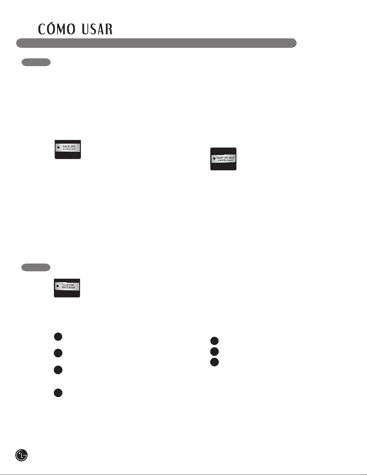
*
SEGURO INFANTIL (CHILD LOCK)
Use esta función para prevenir el uso
no deseado de la secadora o para que
se cambien los ajustes de un ciclo
mientras la secadora se encuentra en
funcionamiento. Apriete y mantenga apretado
el botón de estante de secado (RACK DRY) por
3 segundos para activar o desactivar el seguro
infantil (CHILD LOCK).
Se mostrará seguro infantil (CHILD LOCK) en
la pantalla, y todos los controles permanecerán
desactivados.
Se puede bloquear a la secadora durante un ciclo.
FUNCIONES ESPECIALES
Los botones de opciones también activan
funciones especiales, incluyendo el seguro infantil
(CHILD LOCK) y el pitido encendido/apagado
(BEEP ON/OFF (LANGUAGE). Apriete y mantenga
apretado el botón de opción marcado con la
función especial por 3 segundos para activar.
*
PROGRAMA PERSONALIZADO
Si tiene una combinación especial de
ajustes que usa con frecuencia, puede
guardar estos ajustes a manera de
programa personalizado (CUSTOM
PROGRAM).
*
Para guardar un programa
personalizado:
Encienda la secadora y gire la perilla selectora
de ciclos para seleccionar el ciclo deseado.
Use los botones de programación de ciclo para
fijar los ajustes para ese ciclo.
Apriete el(los) botón(es) de opción de ciclo
para la opción que desea añadir. Aparecerá en
la pantalla un mensaje de confirmación.
Apriete y mantenga apretado el botón
CUSTOM PROGRAM durante 3 segundos.
NOTA: Puede guardar solo un programa
personalizado a la vez. Al apretar y mantener
apretado el botón CUSTOM PROGRAM,
reemplazará cualquier programa personalizado
que haya guardado anteriormente.
1
2
3
4
Para recuperar un programa
personalizado
Encienda la secadora.
Apriete el botón CUSTOM PROGRAM.
Apriete el botón inicio/pausa (START/PAUSE)
para iniciar el ciclo.
1
2
3
*
PITIDO ENCENDIDO/APAGADO (BEEPER
ON/OFF)
Para apagar el pitido, presione y
sostenga el botón pitido húmedo seco
(DAMP DRY BEEP) for 3 seconds.
por 3 segundos. Presione y sostenga
nuevamente durante 3 segundos para volver a
encender el pitido.
72
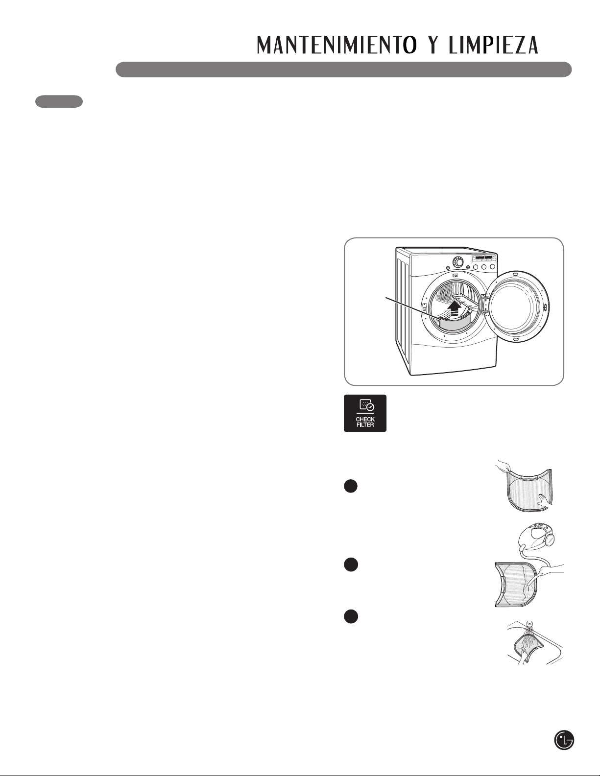
Limpieza del exterior
El mantenimiento adecuado de su secadora
podría prolongar su vida útil. El exterior de la
unidad puede limpiarse con agua tibia y un
detergente de jabón medio, no abrasivo.
Limpie inmediatamente cualquier clase de fuga,
con un trapo suave y húmedo.
IMPORTANTE: No use alcohol desnaturalizado,
disolventes o productos similares.
Nunca use limpiadores abrasivos o de lana
metálica; pueden dañar la superficie.
LIMPIEZA REGULAR
Limpieza del interior
Limpie con un paño alrededor de la abertura y el
sello de la puerta con un paño suave húmedo para
prevenir la acumulación de pelusa y polvo que
podrían dañar el sello de la puerta.
Limpie la ventanilla con un paño suave humedecido
con agua caliente y un detergente suave no
abrasivo para el hogar; luego seque con un paño.
Se puede limpiar el tambor de acero inoxidable
con un limpiador de acero inoxidable convencional,
usado según las especificaciones del fabricante.
Nunca use limpiadores abrasivos ni de lana
metálica; pueden raspar o dañar la superficie.
Limpieza alrededor y debajo de la
secadora
Aspire la pelusa y polvo alrededor de la secadora
y debajo de ella con regularidad. Se debe revisar
que el sistema de conductos de ventilación no
tenga acumulación de pelusa y se debe limpiar
una vez por año. Si se percibe una reducción del
flujo de aire o desempeño del secado notorios,
revise que el sistema de conductos no esté
bloqueado ni tenga obstrucciones.
Mantenimiento del sistema de conductos
Se debe revisar que el sistema de conductos de
ventilación no tenga acumulación de pelusa y se
debe limpiar una vez por año. Si se percibe una
reducción del flujo de aire o desempeño del secado
notorios, revise que el sistema de conductos no
esté bloqueado ni tenga obstrucciones. Llame a un
técnico o proveedor de mantenimiento calificados.
wADVERTENCIA – Para reducir el riesgo de incendio, descargas eléctricas o
heridas al usar su electrodoméstico, siga las precauciones básicas, incluyendo lo siguiente:
• Desenchufe la secadora antes de limpiar la misma para evitar el riesgo de descargas eléctricas.
Si no se cumple con esta advertencia se podrán producir heridas graves, incendios, descargas
eléctricas o muerte.
• Al limpiar la secadora nunca utilice químicos de corte, limpiadores abrasivos o solventes.
Los mismos dañarán su aspecto.
Limpieza del filtro de pelusa
Filtro de
pelusa
Limpie siempre el filtro de pelusa antes
de cada ciclo o cuando el indicador
CHECK FILTER se encenderá durante
una carga.
Para limpiarlo, tire del filtro de pelusa
verticalmente. Luego:
Con los dedos, enrolle
cualquier pelusa para retirarla
del filtro, o
Limpie el filtro de pelusa con
un aspirador, o
Lave el filtro de pelusa en una
solución de agua caliente y
jabonosa y luego deje que se
seque profundamente antes
de reinstalar.
NOTA: NUNCA opere la secadora sin haber
colocado antes el filtro de pelusa.
1
2
3
73
Problema Causas posibles Soluciones
La secadora no
calienta
• El fusible del hogar está
quemado, el cortacircuitos se
ha accionado, o ha ocurrido
una interrupción eléctrica.
• Se ha apagado el suministro o
servicio de gas (solo modelos
a gas).
• Reactive el disyuntor o cambie el fusible. No aumente
la capacidad del fusible. Si el problema se debe a una
sobrecarga de circuito, pida a un electricista calificado
que solucione el problema.
• Confirme que la válvula de corte de gas de la vivienda
y la válvula de corte de gas de la secadora estén
completamente abiertas.
ANTES DE LLAMAR A MANTENIMIENTO
Su secadora está equipada con un sistema de monitoreo de errores automático para la detección y el
diagnóstico de problemas en una etapa temprana. Si su secadora no funciona adecuadamente o no
funciona en lo absoluto, revise lo siguiente antes de llamar a mantenimiento.
La secadora no se
enciende
• El cable eléctrico no está
enchufado adecuadamente.
• El fusible del hogar está
quemado, el cortacircuitos se
ha accionado, o ha ocurrido
una interrupción eléctrica.
• Asegúrese de que el enchufe esté conectado de manera
segura en un tomacorriente con conexión a tierra, que se
corresponda con la placa de clasificación.
• Reactive el disyuntor o cambie el fusible. No aumente
la capacidad del fusible. Si el problema se debe a una
sobrecarga de circuito, pida a un electricista calificado
que solucione el problema.
Manchas de grasa
o suciedad en las
prendas
• Suavizador de telas usado
incorrectamente.
• Prendas limpias y sucias
secadas juntas.
• Prendas limpias y sucias
secadas juntas.
• Confirme y siga las instrucciones provistas con su
suavizador de telas.
• Asegúrese de usar su secadora solo para secar artículos
limpios, ya que los artículos sucios pueden ensuciar las
prendas limpias en la misma carga o en las subsiguientes.
• Las manchas en ropas secas son en realidad manchas
que no se eliminaron durante los procesos de lavado.
Asegúrese de que las ropas queden completamente
limpias de acuerdo con las instrucciones de su lavadora
y detergente.
La pantalla muestra
los errores tE1 o tE2
• No está funcionando el
calefactor.
• Apague la secadora y llame a mantenimiento.
Pelusa en las
prendas
• No se ha limpiado
correctamente el filtro de
pelusa.
• Prendas de lavado no
clasificadas adecuadamente.
• Exceso de estática en las
prendas.
• La secadora está
sobrecargada.
• Pañuelos de papel, papeles,
etc. dejados en los bolsillos.
• Asegúrese de limpiar el filtro de pelusa antes de
cada carga. Con algunas cargas que producen altas
cantidades de pelusa, puede ser necesario limpiar el
filtro durante el ciclo.
• Algunas telas producen pelusas (por ejemplo: una
toalla de algodón peluda blanca) y deben secarse
aparte de las prendas que atrapan pelusa (por ejemplo:
un par de pantalones de lino).
• Observe el exceso de estática en las prendas después
del secadora indicado de la sección más abajo.
• Divida las cargas grandes en cargas más pequeñas
para realizar el secado.
• Revise los bolsillos minuciosamente antes de lavar y
secar prendas.
Exceso de estática
en las prendas
después del secado
• No se usa suavizador de tela
o se usa incorrectamente.
• Las prendas se secaron
por demasiado tiempo
(excesivamente secas).
• Secado de telas sintéticas,
planchado permanente o
combinación de materiales
sintéticos.
• Use un suavizador de telas para reducir la
electricidad estática. Asegúrese de seguir las
instrucciones del fabricante.
• Sobrecargar una carga de lavado puede causar la
acumulación de electricidad estática. Programe
los ajustes y use un tiempo de secado menos
prolongado; o use los ciclos secado con sensor
(SENSOR DRY).
• Estos materiales pueden causar acumulación de
estática. Intente usar un suavizador de telas.
El tiempo de
secado no es
constante
• Los ajustes de calor, el
tamaño de la carga o la
humedad de las prendas
no son constantes.
• El tiempo de secado para una carga variará dependiendo
del ajuste de calor, tipo de calor utilizado (eléctrico,
natural, o gas LP), el tamaño de la carga, el tipo de tela,
el nivel de humedad de las prendas y la condición de los
conductos de escape y el filtro de pelusa.
74
ANTES DE LLAMAR A MANTENIMIENTO (cont.)
Problema Causas posibles Soluciones
Las prendas
tardan demasiado
tiempo en
secarse
• La carga no está
correctamente
clasificada.
• Carga grande de telas
pesadas.
• No se han programado
adecuadamente los
controles de la secadora.
• Se necesita limpiar el
filtro de pelusa.
• Los conductos de escape
están bloqueados, sucios
o el tendido de los conductos
es demasiado largo.
• El fusible del hogar está
quemado, el cortacircuitos se
ha accionado, o ha ocurrido
una interrupción eléctrica.
• La secadora está
sobrecargada.
• Hay muy poca carga en
la secadora.
• Separe los artículos pesados de los livianos. Los artículos
más grandes y pesados requieren de mayor tiempo de
secado.
• Las telas pesadas requieren de mayor tiempo de secado
ya que tienden a retener mayor humedad. Para ayudar a
reducir y mantener tiempos de secado más constantes para
telas pesadas y de mayor tamaño, separe estos artículos en
cargas más pequeñas de un tamaño sistemático.
• Use los ajustes de control adecuados para el tipo de carga
que esté secando.
• Asegúrese de limpiar el filtro de pelusa antes de cada carga.
Con algunas cargas que producen altas cantidades de
pelusa, puede ser necesario limpiar el filtro durante el ciclo.
• Confirme que el sistema de conducto de escape se
encuentre configurado correctamente y no tenga desechos,
pelusa ni obstrucciones. Asegúrese de que los reguladores
de tiro exteriores abran adecuadamente y no estén
bloqueados, atascados ni dañados.
• Reactive el disyuntor o cambie el fusible. No aumente
la capacidad del fusible. Si el problema se debe a una
sobrecarga de circuito, pida a un electricista calificado que
solucione el problema.
• Divida las cargas grandes en cargas más pequeñas para
realizar el secado.
• Si está secando una carga muy pequeña, añada algunos
artículos adicionales para asegurar una acción de giro
apropiada.
Las prendas
están arrugadas
• Las prendas se secaron
por demasiado tiempo
(excesivamente secas).
• Se han dejado las
prendas en la secadora
por demasiado tiempo
una vez finalizado el ciclo.
• Secar excesivamente una carga de lavandería puede
provocar arrugas en las prendas. Intente secar por un
período menos prolongado y retire los artículos mientras
aún retienen una cantidad leve de humedad.
• Retire inmediatamente todos los artículos de la secadora
al final del ciclo. Use la opción cuidado de arrugas
(WRINKLE CARE) para continuar girando las prendas al
final de un ciclo, por un plazo máximo de 3 horas.
Las prendas
encogen
• No se siguen las
instrucciones de la
etiqueta de la prenda.
• Para evitar que las prendas encojan, siga cuidadosamente
las instrucciones de cuidado de telas correspondiente a
su prenda, ya que algunas telas encogen naturalmente
cuando se lavan. Otras telas se pueden lavar, pero
encogen cuando se secan en una secadora. Use un
ajuste de calor bajo o sin calor y/o la opción estante de
secado (RACK DRY).
La luz de CHECK
FILTER está
encendida durante
el ciclo de secado
• El filtro de pelusa está casi
atascado o lleno.
• Pause el ciclo de secado y limpie el filtro de pelusa.
2 barras aparecen
en el indicador del
FLOW SENSE
• La tubería es un poco larga
y posee muchos giros/
restricciones.
• Bloqueo parcial de la tubería
por acumulación de pelusa.
• Instale un conducto más corto o más derecho. Lea
las Instrucciones de Instalación.
• La tubería se deberá controlar/limpiar lo antes
posible. La secadora se puede usar en estas
condiciones, pero es posible que los tiempos de
secado sean más prolongados.
75
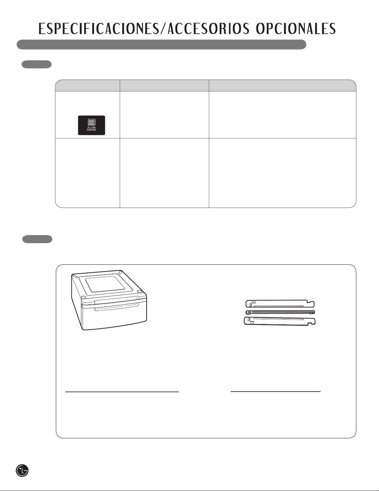
ACCESORIOS OPCIONALES
Para estos y otros productos LG, llame a su distribuidor LG
local, o visite nuestro sitio Web en us.lge.com.
Pedestal
Incremente el desempeño de su lavadora
LG con los pedestales de 35,5 centímetros
(14 pulgadas) de alto correspondientes.
Proveen un cajón de almacenamiento para
brindar mayor comodidad.
Pedestal 14" Color
WDP3W Blanco
WDP3B Negro
WDP3S Titanio
WDP3N Azul Marino
WDP3R Rojo Cereza
WDP3G Gris Perla
Kit de apilado
Si no se dispone de espacio,
utilice este kit para apilar de
manera segura su lavadora de
carga frontal y secadora LG.
Kit de
abrazadera Color
WSTK1 Blanco
BSTK1 Negro
SSTK1 Titanio
NSTK1 Azul Marino
RSTK1 Rojo Cereza
GSTK1 Gris Perla
ANTES DE LLAMAR A MANTENIMIENTO (cont.)
Problema Causas posibles Soluciones
La tubería
está limpia y
adecuadamente
instalada como
se describe en
las instrucciones
de instalación,
pero la pantalla
del FLOWSENSE
muestra 4 barras.
• La secadora se está usando
por primera vez o luego de
estar fuera de uso por un
período prolongado.
• Esto es normal. Luego del primer ciclo, las barras
desaparecerán de la pantalla del FLOWSENSE.
4 barras aparecen
en el indicador del
FLOWSENSE
• La tubería es demasiado
larga o posee muchos giros/
restricciones.
• Bloqueo significativo de la
tubería por acumulación de
pelusa o escombros.
• Instale un conducto más corto o más derecho. Lea
las Instrucciones de Instalación.
• La tubería se deberá controlar/limpiar de inmediato
para eliminar la pelusa acumulada y otros bloqueos.
La secadora se puede usar, pero su funcionamiento
y eficacia se verán reducidos de forma importante.
76
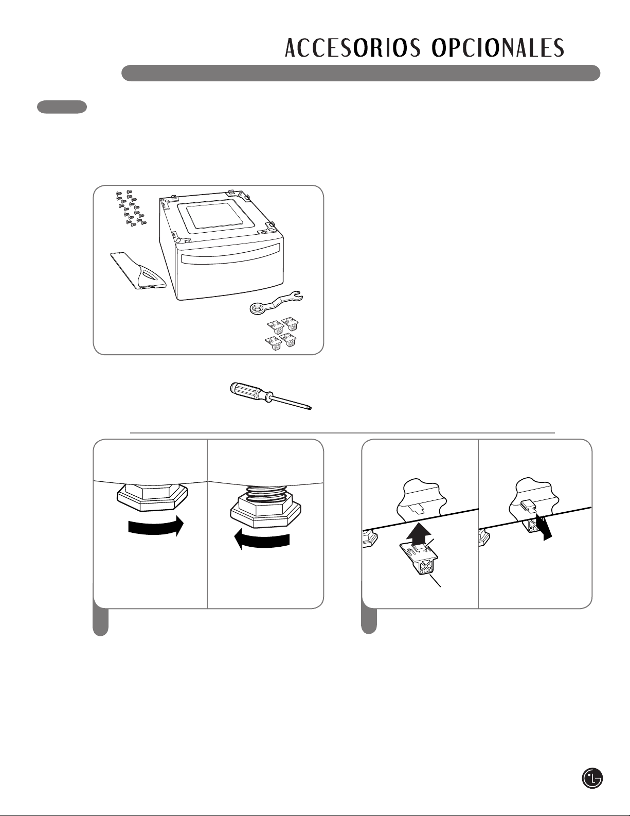
INSTALACIÓN DEL PEDESTAL
El accesorio de pedestal incluye:
• Divisor de cajón (1) • Llave (1)
• Tornillos (18) † • Sujetadores (4) ††
Para asegurar la instalación segura, siga
cuidadosamente las siguientes instrucciones.
1
Para ajustar la secadora a la misma altura
como la lavadora, asegúrese de que las
patas niveladoras de la secadora están
replegadas completamente girándolas
en sentido de las agujas del reloj, luego
girándolas en sentido contrario de las agujas
del reloj 1-1/2 revoluciones.
NOTA: El conjunto del electrodoméstico y el
pedestal deben estar colocados en un piso
sólido, resistente y nivelado para obtener el
funcionamiento adecuado.
Inserte el extremo en T de los 4 sujetadores
dentro de la base de la secadora como se
muestra. Presione el extremo trasera hacia
arriba y tire hacia el exterior para asegurar en
su lugar.
wADVERTENCIA
• La instalación incorrecta puede causar
accidentes graves.
• Los electrodomésticos son muy pesados.
Se requiere de dos o más personas para
instalar del pedestal. Si esto no se cumple
se podrán sufrir daños en la espalda u
otras heridas.
• No permita que los niños jueguen en el
cajón. Existe riesgo de asfixia y heridas.
• Nunca se debe parar sobre la manija. Si lo
hace se podrán producir heridas graves.
•
Si los electrodomésticos ya se encuentran
instalados, desconéctelos de cualquier fuente
de alimentación, tuberías de gas o agua, y de
las conexiones de drenaje o ventilación. Si no
se cumple con esta advertencia se podrán
producir incendios, explosión, descargas
eléctricas, o muerte.
•
Use guantes durante la instalación.
2
† Se necesita 8 tornillos para la secadora
†† Para secadora solamente
Herramientas necesarias para
la instalación:
• Destornillador Phillips
• Llave (provista)
Sujetador
Extremo
en T
Replagade
completmente
Luego afloje
1-1/2 revoluciones
77
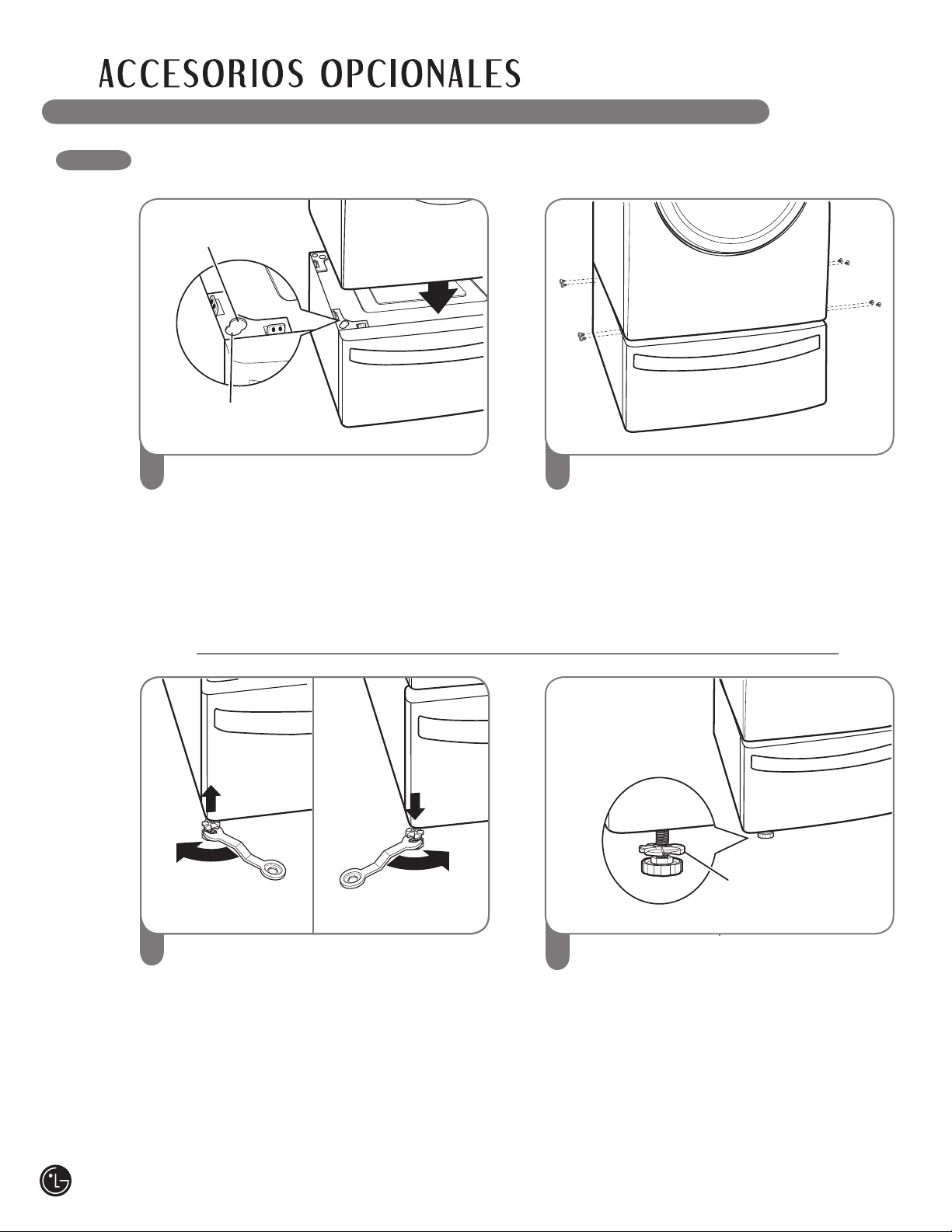
INSTALACIÓN DEL PEDESTAL (cont.)
3
Coloque el electrodoméstico encima del
pedestal. Asegúrese que los pies frentes y
traseros se encuentren en las posiciones
correctas. Las patas de la secadora
coincidirán con las posiciones extremas
interiores como indicado.
4
Asegúrese de que los orifi cios del
pedestal se alinean con los orifi icios de los
sujetadores, luego instale 2 tornillos en cada
esquina para ajustar en forma segura el ele-
ctrodoméstico al pedestal.
NOTA: Si los tornillos no se instalan de
manera adecuada, es posible que se
produzcan ruidos y vibraciones.
Mueva el electrodoméstico hacia
la ubicación deseada.
5
Afloje las tuercas en las 4 patas niveladoras
del pedestal hasta que pueda girarlos con la
llave. Gire en el sentido de las manecillas del
reloj o al contrario para bajar hasta vez que
el pedestal esté nivelado y todas las 4 patas
estén apoyadas firmemente en el piso.
Cómo Usar las Almohadillas
para Piso
Si instalará el pedestal en un piso de
madera, coloque las almohadillas para
piso debajo de las patas del pedestal. Esto
ayudará a reducir la vibración cuando la
lavadora esté en funcionamiento.
6
Asegure de manera segura las tuercas
manualmente.
NOTA: Puede haber ruido y vibración si las
tuercas no están aseguradas.
Asegúrese de conectar los electrodomésticos
a todas las tuberías de agua o gas o a la
fuente de poder o conexiones de ventilación
antes de poner en funcionamiento.
Si hay vibración excesiva durante el primer
ciclo de funcionamiento después de la
instalación, ajuste levemente las patas
niveladoras.
Para la secadora
Para la lavadora/combinación
Raise
Bajar
Tuerca
78
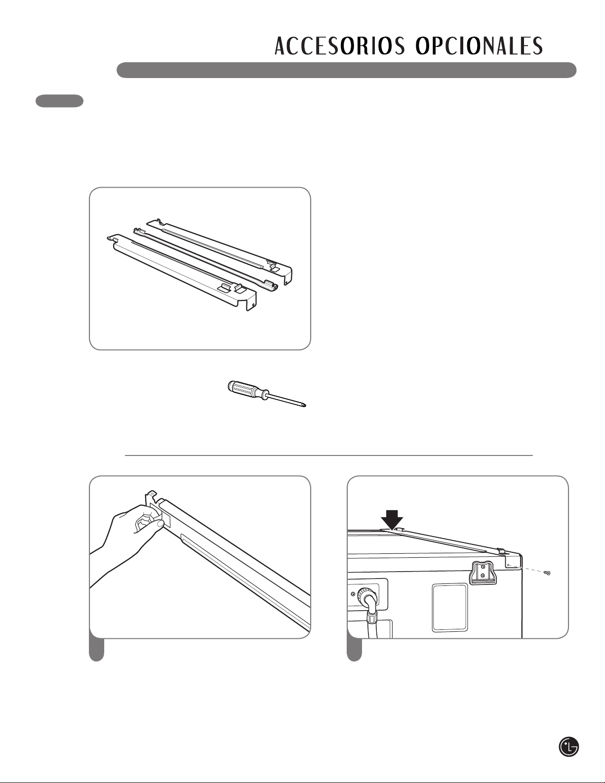
INSTALACIÓN DEL KIT DE APILADO
Este kit de apilado incluye:
• Dos (2) rieles laterales.
• Un (1) riel frontal.
• Cuatro (4) tornillos.
Para asegurar la instalación segura, siga las
siguientes instrucciones.
1
Asegúrese de que la superficie de la
lavadora esté limpia y seca. Quite el papel
de respaldo de la cinta ubicado en una de
las abrazaderas laterales del kit de apilado.
2
Haga coincidir la abrazadera lateral del
lado de la parte superior de la lavadora
como se indica en la ilustración anterior.
Apriete firmemente el área adhesiva de la
abrazadera a la superficie de la lavadora.
Asegure la abrazadera lateral a la lavadora
con un tornillo en su lado trasero. Repita los
pasos 1 y 2 para conectar la abrazadera del
otro lado.
Herramientas necesarias para la
instalación:
• Destornillador Phillips
wADVERTENCIA
• La instalación incorrecta puede causar
accidentes graves.
• El peso de la secadora y la altura de la
instalación hacen que el procedimiento de
apilado sea demasiado riesgoso para que lo
realice una sola persona. Si esto no se cumple
se podrán sufrir daños en la espalda u otras
heridas.
• No utilizar el kit de apilado con un secadora
a gas en condiciones potencialmente
inestables tales como una casa rodante. Si lo
hace se podrán producir heridas graves.
• Nunca coloque una lavadora sobre la
secadora. Si no se cumple con esta
advertencia se podrán producir heridas graves
• Coloque la lavadora sobre un piso sólido,
estable y nivelado para soportar el peso de
ambos electrodomésticos. Si lo hace se
podrán producir heridas graves.
• Si los electrodomésticos ya se encuentran
instalados, desconéctelos de cualquier
fuente de alimentación, tuberías de gas o
agua y de las conexiones de drenaje o
ventilación. Si no se cumple con esta
advertencia se podrán producir incendios,
explosión, descargas eléctricas o muerte.
79
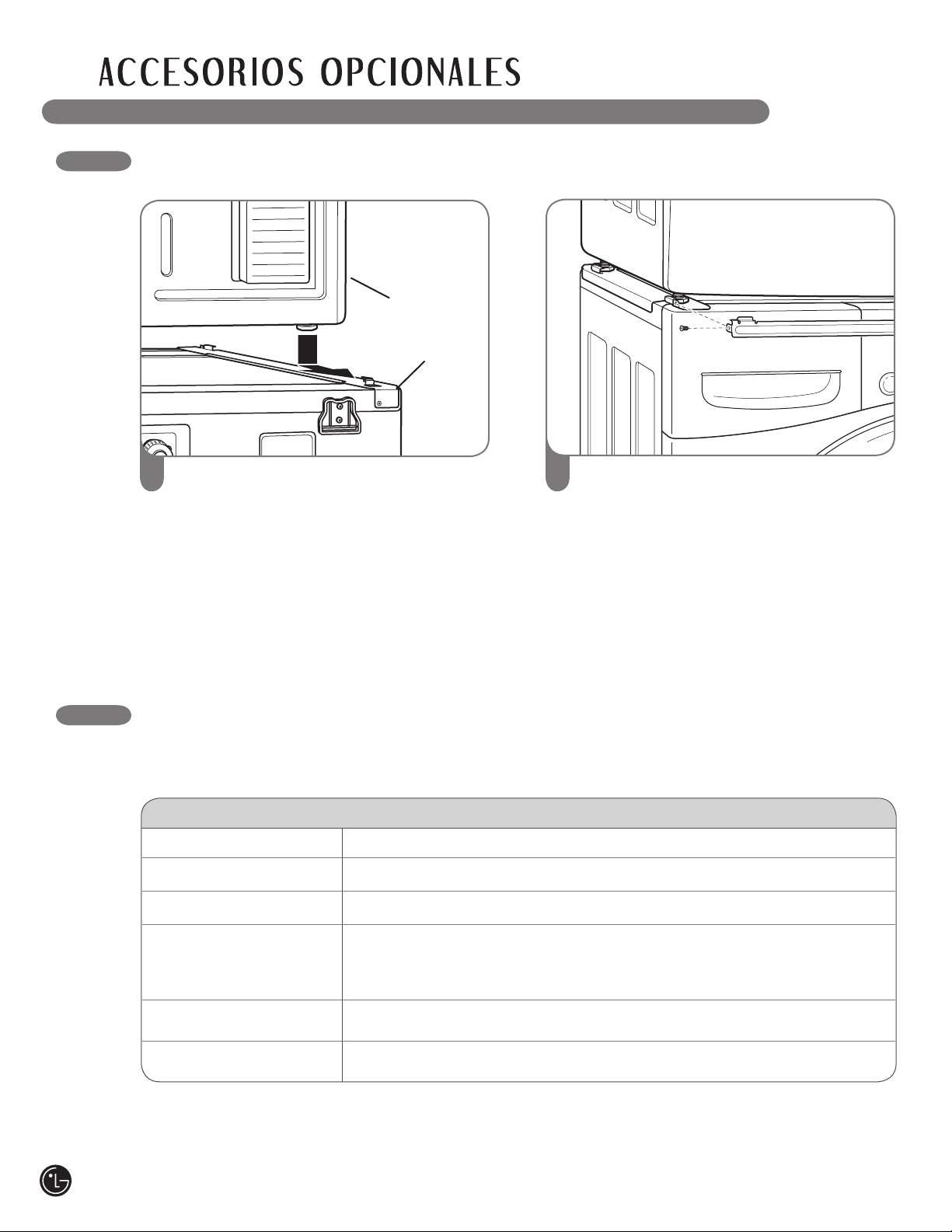
INSTALACIÓN DEL KIT DE APILADO
3
Coloque la secadora sobre la lavadora
haciendo coincidir las patas en las
abrazaderas laterales como se indica.
Evite lesionarse los dedos; no deje que los
dedos queden atrapados entre la lavadora
y la secadora. Deslice despacio la secadora
hacia la parte trasera de la lavadora hasta
que los topes de la abrazadera lateral
coincidan con las patas de la secadora.
4
Insterte el riel frontal entre la parte inferior
de la secadora y la parte superior de la
lavadora. Empuje el riel frontal hacia la parte
trasera de la lavadora hasta que entre en
contacto con los topes del riel lateral. Instale
los dos tornillos restantes para asegurar el
riel frontal a los laterales.
Lavadora
Secadora
DIMENSIONES Y ESPECIFICACIONES CLAVE
Secadora Modelos DLE5955W, DLE5955G, DLG5966W, y DLG5966G
Descripción Secadora
Requisitos eléctricos* Consulte la placa de clasificación para información en detalles.
Requisitos de gas* NG: 10 a 13 pulgadas WC/LP: 10 a 13 pulgadas WC (Solo modelos a gas)
Dimensiones 27"(ancho) X 30"(profundidad) X 38
11
/16"(alto), 50" (D con la puerta abierta)
68,6 cm (ancho) X 76,1 cm (profundidad) X 98,3 cm (alto), 127 cm (con
la puerta abierta)
Peso neto 126 libra (57,2 kg)
Capacidad de secado IEC 7,3 pies cúbicos (22,5 lb/10,2 kg)
El aspecto y las especificaciones enumeradas en esta guía podrían variar debido a mejoras constantes
del producto.
*Consulte la placa de clasificación colocada en su secadora.
80
Su secadora LG será reparada o reemplazada, a discreción de LG, si se comprueba que existe un defecto en el material
o la mano de obra bajo condiciones de uso normales, durante el período de garantía (“Período de garantía”) establecido
más abajo, vigente desde la fecha (“Fecha de compra”) de la compra del cliente original de producto. Esta garantía es
válida únicamente para el comprador original del producto y cuando se usa en EE. UU., incluyendo Alaska, Hawaii, y los
territorios de los EE. UU., exclusivamente.
ESTA GARANTÍA REEMPLAZA CUALQUIER OTRA, EXPRESA O IMPLÍCITA, INCLUYENDO SIN LIMITACIÓN, CUALQUIER
GARANTÍA DE COMERCIALIZACIÓN O ADECUACIÓN PARA UN PROPÓSITO DETERMINADO. EN LA MEDIDA REQUERIDA
POR LA LEY, CUALQUIER GARANTÍA IMPLÍCITA SE LIMITA EN SU VIGENCIA AL PERÍODO DE GARANTÍA EXPRESA INDICADO
MÁS ARRIBA. NI EL FABRICANTE NI EL DISTRIBUIDOR DE LOS EE. UU. SERÁN RESPONSABLES POR DAÑOS INCIDENTALES,
CONSECUENCIALES, INDIRECTOS, ESPECIALES O PUNITIVOS DE CUALQUIER NATURALEZA INCLUYENDO SIN LIMITACIÓN,
PÉRDIDA DE GANACIAS O INGRESOS, O CUALQUIER OTRA CLASE DE DAÑOS, CONTRACTUALES, EXTRACONTRACTUALES,
O DE CUALQUIER TIPO. Algunos estados no permiten la exclusión o limitación de daños incidentales o consecuenciales o limitación
en la duración de una garantía implícita, de modo que la exclusión o limitación indicada anteriormente podría no aplicar en su caso. Esta
garantía le brinda derechos legales específicos y podría también tener otros derechos que varían según el estado.
ESTA GARANTÍA LIMITADA NO APLICA A:
• Viajes de mantenimiento desde su hogar para entrega, recepción y/o instalación del producto, instrucción o reemplazo de fusibles
del hogar o cableado adecuado o corrección de reparaciones no autorizadas.
• Los daños o problemas operativos que resulten de la negligencia en el uso, el abuso, el funcionamiento fuera de las especicacio-
nes medioambientales o inconsistentes con los requisitos de precauciones establecidos en la Guía de funcionamiento, accidente,
insectos, incendio, inundación, instalación inadecuada, casos de fuerza mayor, modificación o alteración no autorizada, corriente o
voltaje incorrectos, o uso comercial, o uso diferente al indicado.
El costo de reparación o reemplazo bajo estas circunstancias excluidas será responsabilidad del cliente.
NÚMEROS DE CENTROS INTERACTIVOS DE CLIENTE
PERÍODO DE GARANTÍA:
MANO DE OBRA: Un año desde la Fecha de compra.
PIEZAS: Un año desde la Fecha de compra.
Las unidades de reemplazo y piezas de reparación
podrían ser nuevas o refabricadas.
Las unidades de reemplazo o piezas de reparación
están garantizadas por la porción restante del período
de garantía de la unidad original.
Garantía limitada del tambor de la secadora por 10 años.
Solo las piezas. El cliente sera responsable de cualquier
trabajo o servicio realizado en su casa para reemplazar las
piezas defectuosas.
LG ELECTRONICS, INC.
GARANTÍA LIMITADA DE LA SECADORA LG – EE. UU.
CÓMO SE ADMINISTRA EL MANTENIMIENTO:
Mantenimiento en el hogar “In-Home”:
Guarde la factura fechada del distribuidor o la boleta de
entrega como evidencia de la Fecha de compra como
prueba para la garantía, y entregue una copia de la
factura al técnico de mantenimiento al momento que se
presta el mantenimiento.
Llame al 1-800-243-0000 y escoja la opción adecuada
para ubicar a su Centro de Mantenimiento Autorizado
LG más cercano.
O visite nuestro sitio Web en: http://www.lgservice.com.
PARA CONTACTAR A LG ELECTRONICS
POR CORREO:
LG Customer Interactive Center
P. O. Box 240007
201 James Record Road
Huntsville, Alabama 35824
ATTN: CIC
Llame al 1-800-243-0000 (24 horas al día, 365 días al año),
y seleccione la opción adecuada a partir del menú.
O visite nuestro sitio Web en: http://www.lgservice.com.
Para obtener Asistencia para el cliente,
información del producto o mantenimiento o
distribuidor autorizado:
Información de registro del producto
Modelo:
Número de serie:
Fecha de compra:
El modelo y número de serie figuran en la placa de
clasificación en la parte interna de la puerta del frente.
81

82

83

P/No. 3828EL3003S