

Owner's ManOwner's Man
Owner's ManOwner's Man
Owner's Man
ualual
ualual
ual

RESPONSIBILITY FOR MAINTENANCERESPONSIBILITY FOR MAINTENANCE
RESPONSIBILITY FOR MAINTENANCERESPONSIBILITY FOR MAINTENANCE
RESPONSIBILITY FOR MAINTENANCE
The maintenance requirements for your new Hyundai are found in Section 5. As the owner,
it is your responsibility to see that all maintenance operations specified by the manufacturer
are carried out at the appropriate intervals. When the vehicle is used in severe driving
conditions, more frequent maintenance is required for some operations. Maintenance
requirements for severe operating conditions are also included in Section 5.
A020A01A-AAT
OWNER'S MANUALOWNER'S MANUAL
OWNER'S MANUALOWNER'S MANUAL
OWNER'S MANUAL
A030A01X-GAT
OperationOperation
OperationOperation
Operation
MaintenanceMaintenance
MaintenanceMaintenance
Maintenance
SpecificationsSpecifications
SpecificationsSpecifications
Specifications
All information in this Owner's Manual is current at the time of publication. However, Hyundai reserves the right to make changes
at any time so that our policy of continual product improvement may be carried out.
This manual applies to all current Hyundai models and includes descriptions and explanations of optional as well as standard
equipment. As a result, you may find material in this manual that does not apply to your specific vehicle.
Please note that some ATOS models are equipped with Right-Hand Drive (RHD). The explanations and illustrations for some
operations in RHD models are opposite of those written in this manual.
A030A02X

A040A01A-AAT
FOREWORDFOREWORD
FOREWORDFOREWORD
FOREWORD
Thank you for choosing Hyundai. We are pleased to welcome you to the growing number of discriminating
people who drive Hyundais. The advanced engineering and high-quality construction of each Hyundai we
build is something of which we're very proud.
Your Owner's Manual will introduce you to the features and operation of your new Hyundai. It is suggested
that you read it carefully since the information it contains can contribute greatly to the satisfaction you receive
from your new car.
The manufacturer also recommends that all service and maintenance on your car be performed by an
authorized Hyundai dealer. Hyundai dealers are prepared to provide high-quality service, maintenance and
any other assistance that may be required.
A050A06A-AAT
HYUNDAI MOTOR COMPANYHYUNDAI MOTOR COMPANY
HYUNDAI MOTOR COMPANYHYUNDAI MOTOR COMPANY
HYUNDAI MOTOR COMPANY
Note: Note:
Note: Note:
Note: Because future owners will also need the information included in this manual, if you sell this Hyundai,
please leave the manual in the vehicle for their use. Thank you.
CAUTION: Severe engine and transaxle damage may result from the use of poor quality fuels andCAUTION: Severe engine and transaxle damage may result from the use of poor quality fuels and
CAUTION: Severe engine and transaxle damage may result from the use of poor quality fuels andCAUTION: Severe engine and transaxle damage may result from the use of poor quality fuels and
CAUTION: Severe engine and transaxle damage may result from the use of poor quality fuels and
lubricants that do not meet Hyundai specifications. You must always use high quality fuels andlubricants that do not meet Hyundai specifications. You must always use high quality fuels and
lubricants that do not meet Hyundai specifications. You must always use high quality fuels andlubricants that do not meet Hyundai specifications. You must always use high quality fuels and
lubricants that do not meet Hyundai specifications. You must always use high quality fuels and
lubricants that meet the specifications listed on Page 9-3 in the Vehicle Specifications section oflubricants that meet the specifications listed on Page 9-3 in the Vehicle Specifications section of
lubricants that meet the specifications listed on Page 9-3 in the Vehicle Specifications section oflubricants that meet the specifications listed on Page 9-3 in the Vehicle Specifications section of
lubricants that meet the specifications listed on Page 9-3 in the Vehicle Specifications section of
the Owner's Manual.the Owner's Manual.
the Owner's Manual.the Owner's Manual.
the Owner's Manual.
Copyright 2002 Hyundai Motor Company. All rights reserved. No part of this publication may be
reproduced, stored in any retrieval system or transmitted in any form or by any means without the prior
written permission of Hyundai Motor Company.

CAUTION: MODIFICATIONS TO YOUR HYUNDAICAUTION: MODIFICATIONS TO YOUR HYUNDAI
CAUTION: MODIFICATIONS TO YOUR HYUNDAICAUTION: MODIFICATIONS TO YOUR HYUNDAI
CAUTION: MODIFICATIONS TO YOUR HYUNDAI
Modification of components may void the manufacturer's warrantyModification of components may void the manufacturer's warranty
Modification of components may void the manufacturer's warrantyModification of components may void the manufacturer's warranty
Modification of components may void the manufacturer's warranty
Your Hyundai should not be modified in any way. Modifications may adversely affect the safety, durability
and performance of your Hyundai. Components which are subjected to modification or are added to the
vehicle resulting in consequential damage are not covered by the vehicle manufacturer's warranty.
A070A01A-GAT

A090A01A-AAT
SAFETY AND VEHICLE DAMAGE WARNINGSAFETY AND VEHICLE DAMAGE WARNING
SAFETY AND VEHICLE DAMAGE WARNINGSAFETY AND VEHICLE DAMAGE WARNING
SAFETY AND VEHICLE DAMAGE WARNING
This manual includes information titled as WARNING, CAUTION and NOTE.
These titles indicate the following:
WARNING:WARNING:
WARNING:WARNING:
WARNING:
This indicates that a condition may result in harm, serious injury or death to you or otherThis indicates that a condition may result in harm, serious injury or death to you or other
This indicates that a condition may result in harm, serious injury or death to you or otherThis indicates that a condition may result in harm, serious injury or death to you or other
This indicates that a condition may result in harm, serious injury or death to you or other
persons if the warning is not heeded. Follow the advice provided with the warning.persons if the warning is not heeded. Follow the advice provided with the warning.
persons if the warning is not heeded. Follow the advice provided with the warning.persons if the warning is not heeded. Follow the advice provided with the warning.
persons if the warning is not heeded. Follow the advice provided with the warning.
CAUTION:CAUTION:
CAUTION:CAUTION:
CAUTION:
This indicates that a condition may result in damage to your vehicle or its equipment ifThis indicates that a condition may result in damage to your vehicle or its equipment if
This indicates that a condition may result in damage to your vehicle or its equipment ifThis indicates that a condition may result in damage to your vehicle or its equipment if
This indicates that a condition may result in damage to your vehicle or its equipment if
the caution is not heeded. Follow the advice provided with the caution.the caution is not heeded. Follow the advice provided with the caution.
the caution is not heeded. Follow the advice provided with the caution.the caution is not heeded. Follow the advice provided with the caution.
the caution is not heeded. Follow the advice provided with the caution.
NOTE:NOTE:
NOTE:NOTE:
NOTE:
This indicates that interesting or helpful information is being provided.This indicates that interesting or helpful information is being provided.
This indicates that interesting or helpful information is being provided.This indicates that interesting or helpful information is being provided.
This indicates that interesting or helpful information is being provided.

OWNER'S I.D.
ORIGINAL:
ADDRESS:
DATE OF SALE:
SUBSEQUENT:
ADDRESS:
TRANSFER DATE:
NAME:
STREET:
TOWN:
COUNTRY:
P.CODE:
NAME:
STREET:
TOWN:
COUNTRY:
P.CODE:
A000A01A-GAT
This Owner's Manual should be considered a part of the car and remain with it when it is sold for the use of
the next owner.

TABLE OF CONTENTSTABLE OF CONTENTS
TABLE OF CONTENTSTABLE OF CONTENTS
TABLE OF CONTENTS
SECTION PAGESECTION PAGE
SECTION PAGESECTION PAGE
SECTION PAGE
1.1.
1.1.
1.
FEATURES OF YOUR HYUNDAI ...................................................................... 1-1FEATURES OF YOUR HYUNDAI ...................................................................... 1-1
FEATURES OF YOUR HYUNDAI ...................................................................... 1-1FEATURES OF YOUR HYUNDAI ...................................................................... 1-1
FEATURES OF YOUR HYUNDAI ...................................................................... 1-1
2.2.
2.2.
2.
DRIVING YOUR HYUNDAI ................................................................................ 2-1DRIVING YOUR HYUNDAI ................................................................................ 2-1
DRIVING YOUR HYUNDAI ................................................................................ 2-1DRIVING YOUR HYUNDAI ................................................................................ 2-1
DRIVING YOUR HYUNDAI ................................................................................ 2-1
3.3.
3.3.
3.
WHAT TO DO IN AN EMERGENCY .................................................................. 3-1WHAT TO DO IN AN EMERGENCY .................................................................. 3-1
WHAT TO DO IN AN EMERGENCY .................................................................. 3-1WHAT TO DO IN AN EMERGENCY .................................................................. 3-1
WHAT TO DO IN AN EMERGENCY .................................................................. 3-1
4.4.
4.4.
4.
CORROSION PREVENTION & APPEARANCE CARE ...................................... 4-1CORROSION PREVENTION & APPEARANCE CARE ...................................... 4-1
CORROSION PREVENTION & APPEARANCE CARE ...................................... 4-1CORROSION PREVENTION & APPEARANCE CARE ...................................... 4-1
CORROSION PREVENTION & APPEARANCE CARE ...................................... 4-1
5.5.
5.5.
5.
VEHICLE MAINTENANCE REQUIREMENTS .................................................... 5-1VEHICLE MAINTENANCE REQUIREMENTS .................................................... 5-1
VEHICLE MAINTENANCE REQUIREMENTS .................................................... 5-1VEHICLE MAINTENANCE REQUIREMENTS .................................................... 5-1
VEHICLE MAINTENANCE REQUIREMENTS .................................................... 5-1
6.6.
6.6.
6.
DO-IT-YOURSELF MAINTENANCE .................................................................. 6-1DO-IT-YOURSELF MAINTENANCE .................................................................. 6-1
DO-IT-YOURSELF MAINTENANCE .................................................................. 6-1DO-IT-YOURSELF MAINTENANCE .................................................................. 6-1
DO-IT-YOURSELF MAINTENANCE .................................................................. 6-1
7.7.
7.7.
7.
EMISSION CONTROL SYSTEMS ...................................................................... 7-1EMISSION CONTROL SYSTEMS ...................................................................... 7-1
EMISSION CONTROL SYSTEMS ...................................................................... 7-1EMISSION CONTROL SYSTEMS ...................................................................... 7-1
EMISSION CONTROL SYSTEMS ...................................................................... 7-1
8.8.
8.8.
8.
CONSUMER INFORMATION ............................................................................ 8-1CONSUMER INFORMATION ............................................................................ 8-1
CONSUMER INFORMATION ............................................................................ 8-1CONSUMER INFORMATION ............................................................................ 8-1
CONSUMER INFORMATION ............................................................................ 8-1
9.9.
9.9.
9.
VEHICLE SPECIFICATIONS ............................................................................. 9-1VEHICLE SPECIFICATIONS ............................................................................. 9-1
VEHICLE SPECIFICATIONS ............................................................................. 9-1VEHICLE SPECIFICATIONS ............................................................................. 9-1
VEHICLE SPECIFICATIONS ............................................................................. 9-1
10.10.
10.10.
10.
INDEX ............................................................................................................. 10-1INDEX ............................................................................................................. 10-1
INDEX ............................................................................................................. 10-1INDEX ............................................................................................................. 10-1
INDEX ............................................................................................................. 10-1
11
11
1
22
22
2
33
33
3
44
44
4
55
55
5
66
66
6
77
77
7
88
88
8
99
99
9
1010
1010
10

A100A01L-GAT
GUIDE TO HYUNDAI GENUINEGUIDE TO HYUNDAI GENUINE
GUIDE TO HYUNDAI GENUINEGUIDE TO HYUNDAI GENUINE
GUIDE TO HYUNDAI GENUINE
PARTSPARTS
PARTSPARTS
PARTS
1. What are Hyundai Genuine Parts?
Hyundai Genuine Parts are the same
parts used by Hyundai Motor Compa-
ny to manufacture vehicles. They are
designed and tested for the optimum
safety, performance, and reliability to
our customers.
2. Why should you use genuine parts?
Hyundai Genuine Parts are engineered
and built to meet rigid original manu-
facturing requirements. Using imita-
tion, counterfeit or used salvage parts
is not covered under the Hyundai
New Vehicle Limited Warranty or any
other Hyundai warranty. In addition,
any damage to or failure of Genuine
Hyundai Parts caused by the installa-
tion or failure of an imitation, counter-
feit or used salvage part is not cov-
ered by Hyundai Motor Company.
3. How can you tell if you are pur-
chasing Hyundai Genuine Parts?
Look for the Hyundai Genuine Parts
Logo on the package (see below).
The export specifications are written
in English only.
Hyundai Genuine Parts are only sold
through authorized Hyundai
Dealerships.
A100A01L
A100A02L A100A04L
A100A03L
FEATURES OF YOUR HYUNDAIFEATURES OF YOUR HYUNDAI
FEATURES OF YOUR HYUNDAIFEATURES OF YOUR HYUNDAI
FEATURES OF YOUR HYUNDAI
1- 1
1. FEATURES OF
YOUR HYUNDAI
B010A01A-GAT
FUEL RECOMMENDATIONS
Use Unleaded Gasoline
Unleaded gasoline with a Pump Octane Rating
of 87 (Research Octane Number 91) or higher
must be used in Hyundai vehicle. If leaded gaso-
line is used, it will cause the catalytic converter to
become ineffective and the emission control
system to malfunction.
This can also result in increased maintenance
expense. To avoid accidental use of leaded fuel,
the larger nozzle used with leaded gasoline at
service stations can not be inserted into fuel tank
opening of Hyundai vehicle.
NOTE:
o For some countries, Hyundai vehicles are
designed to use leaded gasoline. When
you are going to use leaded gasoline, ask
to Hyundai dealer whether leaded gaso-
line in your vehicle is available or not.
o Octane Rating of leaded gasoline is same
with unleaded one.
B010B01A-AAT
What About Gasohol?
Gasohol (a mixture of 90% unleaded gasoline
and 10% ethanol or grain alcohol) may be used
in your Hyundai. However, if your engine devel-
ops drive ability problems, the use of 100%
unleaded gasoline is recommended. Fuels with
unspecified quantities of alcohol, or alcohols
other than ethanol, should not be used.
B010D01S-AAT
Do not Use Methanol
Fuels containing methanol (wood alcohol) should
not be used in your Hyundai. This type of fuel can
reduce vehicle performance and damage com-
ponents of the fuel system.
CAUTION:
Your Hyundai's New Vehicle Limited War-
ranty may not cover damage to the fuel sys-
tem and performance problems that are
caused by the use of methanol or fuels con-
taining methanol.
B010E01A-AAT
Gasolines for Cleaner Air
To help contribute to cleaner air, Hyundai recom-
mends that you use gasolines treated with deter-
gent additives, which help prevent deposit for-
mation in the engine. These gasolines will help
the engine run cleaner and the Emission Control
System performance.
B010F01A-AAT
Operation in Foreign Countries
If you are going to drive your Hyundai in another
country, be sure to:
o Observe all regulations regarding registra-
tion and insurance.
o Determine that acceptable fuel is available.
B020A01X-GAT
BREAKING IN YOUR NEW HYUNDAI
During the First 2,000 km (1,200 Miles)
No formal "break-in" procedure is required with
your new Hyundai. However, you can contribute
to the economical operation and durability of your
Hyundai by observing the following recommen-
dations during the first 2,000 km (1,200 miles).
o Don't drive faster than 88 km/h (55 mph).
o While driving, keep your engine speed (rpm,
or revolutions per minute) between 2000 and
4000 rpm.
o Use moderate acceleration. Don't start quickly
or depress the accelerator pedal fully.
B010A01X
1
FEATURES OF YOUR HYUNDAIFEATURES OF YOUR HYUNDAI
FEATURES OF YOUR HYUNDAIFEATURES OF YOUR HYUNDAI
FEATURES OF YOUR HYUNDAI
1- 2
B880A01A-GAT
IMMOBILIZER SYSTEM
(If Installed)
The immobilizer system is an anti-theft device,
designed to deter automobile theft.
B030B01A-AAT
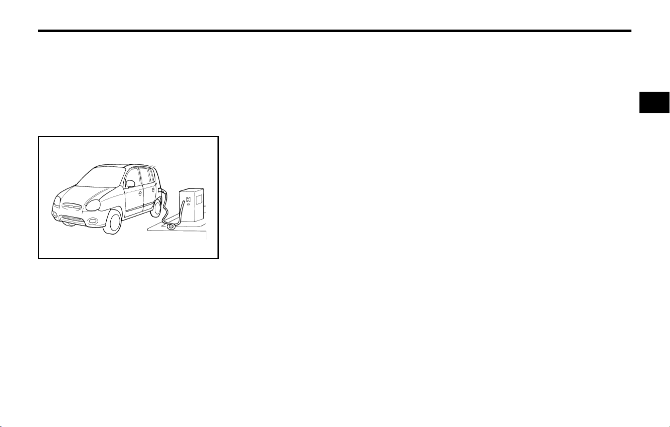
Record Your Key Number
AS10040A
A code number is stamped on the number plate
that came with the keys to your Hyundai. This
key number plate should not be left with the keys
but kept in a safe place, not in the vehicle. The
key number should also be recorded in a place
where it can be found in an emergency.
If you need additional keys, or if you should lose
your keys, your authorized Hyundai dealer can
make new keys if you can supply the key num-
ber.
o For the first 300 km (200 miles), try to avoid
hard stops.
o Don't lug the engine (in other words, don't
drive so slowly in too high a gear that the
engine "bucks" shift to a lower gear).
o Whether going fast or slow, vary your speed
from time to time.
o Don't let the engine idle longer than 3 minutes
for a catalytic converter-equipped engine.
B030A01A-AAT
KEYS
For greater convenience, the same key operates
all the locks in your Hyundai. However, because
the doors can be locked without a key, carrying
a spare key is recommended in case you acci-
dentally lock one key inside the car.
AS10030A
B880B03A-GAT
Keys
All of the locks fitted to the vehicle are operated
by the same key. However, since it is possible to
lock the doors without the use of the key, care
should be exercised to ensure that the key does
not become locked inside the vehicle by mistake.
NOTE:
If you make your own duplicate key, you will
not be able to cancel the system or start the
engine.
AX10020A-1
FEATURES OF YOUR HYUNDAIFEATURES OF YOUR HYUNDAI
FEATURES OF YOUR HYUNDAIFEATURES OF YOUR HYUNDAI
FEATURES OF YOUR HYUNDAI
1- 3
B880C02A-GAT
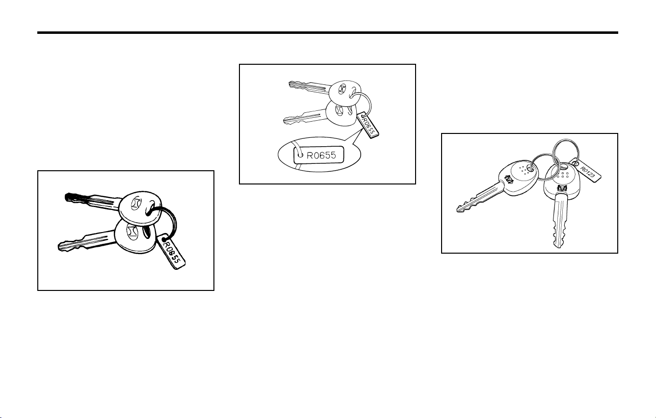
Key Numbers
AX10030A-1
The vehicle key number is recorded upon a
metal tag attached to the keys when the vehicle
is first delivered to you.
The key number should be recorded and kept in
a safe place in case the need to order further
keys arises. New keys are available from any
Hyundai dealer by quoting the relevant key num-
ber.
In the interest of security, the metal tag attached
to the keys which bears the key number should
be removed from the key ring after you receive
your new vehicle. In addition, key numbers can-
not be provided by Hyundai for security reasons.
If you need additional keys or if you should lose
your keys, your authorized Hyundai dealer can
make new keys.
B880D02A-GAT
Limp home procedures
B880D01X
In case the immobilizer warning indicator blinks
for five seconds when the ignition key is turned to
"ON" position, this indicates that the immobilizer
system is out of order. And you cannot start the
engine without the limp home procedures with
ignition key.
The following procedure is how to start the en-
gine with the function of the limp home. (0, 1, 2,
3 as a sample password).
NOTE:
You can get the limp home password when
the vehicle is first delivered to you. If you do
not have the password, consult your autho-
rized Hyundai dealer.
1. To set the password you may turn the ignition
key "ON" and then turn it "OFF" according to
the digit numbers, then the immobilizer indi-
cator will blink along with the operation of the
ignition key. For example, turn the ignition key
once for digit number "1", and twice for "2",
and so on. However, for the digit number "0",
you must turn the ignition key for 10 times.
2. Wait for 3~10 seconds.
3. You may set the remaining number of digits
by following the same procedures 1 and 2.
4. If all of four digits have been tried success-
fully, turn the ignition key "ON" and check that
the immobilizer indicator illuminates. From
this time, you have to start your engine within
30 seconds. If you start your engine after 30
seconds, your engine will not start.
NOTE:
If the engine dies while driving after limp
home procedure, you can start your engine
within 8 seconds without limp home proce-
dure again.
5. If the immobilizer indicator blinks for five
seconds, you have to try the limp home
procedure again from the beginning.
After doing the limp home procedure, you have to
consult with your authorized Hyundai dealer as
soon as possible.
FEATURES OF YOUR HYUNDAIFEATURES OF YOUR HYUNDAI
FEATURES OF YOUR HYUNDAIFEATURES OF YOUR HYUNDAI
FEATURES OF YOUR HYUNDAI
1- 4
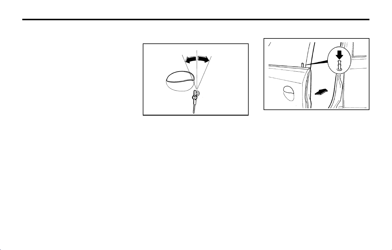
B040B01A-AAT
Locking, Unlocking Front Doors With a
Key
LOCK
UNLOCK
o The door can be locked or unlocked with a
key.
o Lock the door by turning the key toward the
front of the vehicle and unlock it by turning the
key toward the rear.
B040B01A
CAUTION:
o If you fail to try the limp home procedure
with the sequence of three times, you
have to wait for about one hour to do the
limp home procedure again.
o If you cannot start your engine in spite of
limp home procedure, have your vehicle
towed by an authorized Hyundai dealer.
B040A01A-AAT
DOOR LOCKS
WARNING:
o Unlocked doors can be dangerous. Be-
fore you drive away (especially if there are
children in the car), be sure that all the
doors are securely closed and locked so
that the doors cannot be inadvertently
opened from the inside. This helps ensure
that doors will not be opened accidentally.
Also, when combined with the proper use
of seat belts, locking the doors helps keep
occupants from being ejected from the
car in case of an accident.
o Before opening the door, always look for
and avoid oncoming traffic.
The doors can be locked without a key. First
depress the lock button, then close the door.
NOTE:
o When locking the door this way, be careful
not to lock the door with the ignition key
left in the vehicle.
o To prevent theft, always remove the igni-
tion key, close all windows, and lock all
doors when leaving your vehicle unat-
tended.
B040C01X-GAT
Locking from Outside
B040C01X
FEATURES OF YOUR HYUNDAIFEATURES OF YOUR HYUNDAI
FEATURES OF YOUR HYUNDAIFEATURES OF YOUR HYUNDAI
FEATURES OF YOUR HYUNDAI
1- 5
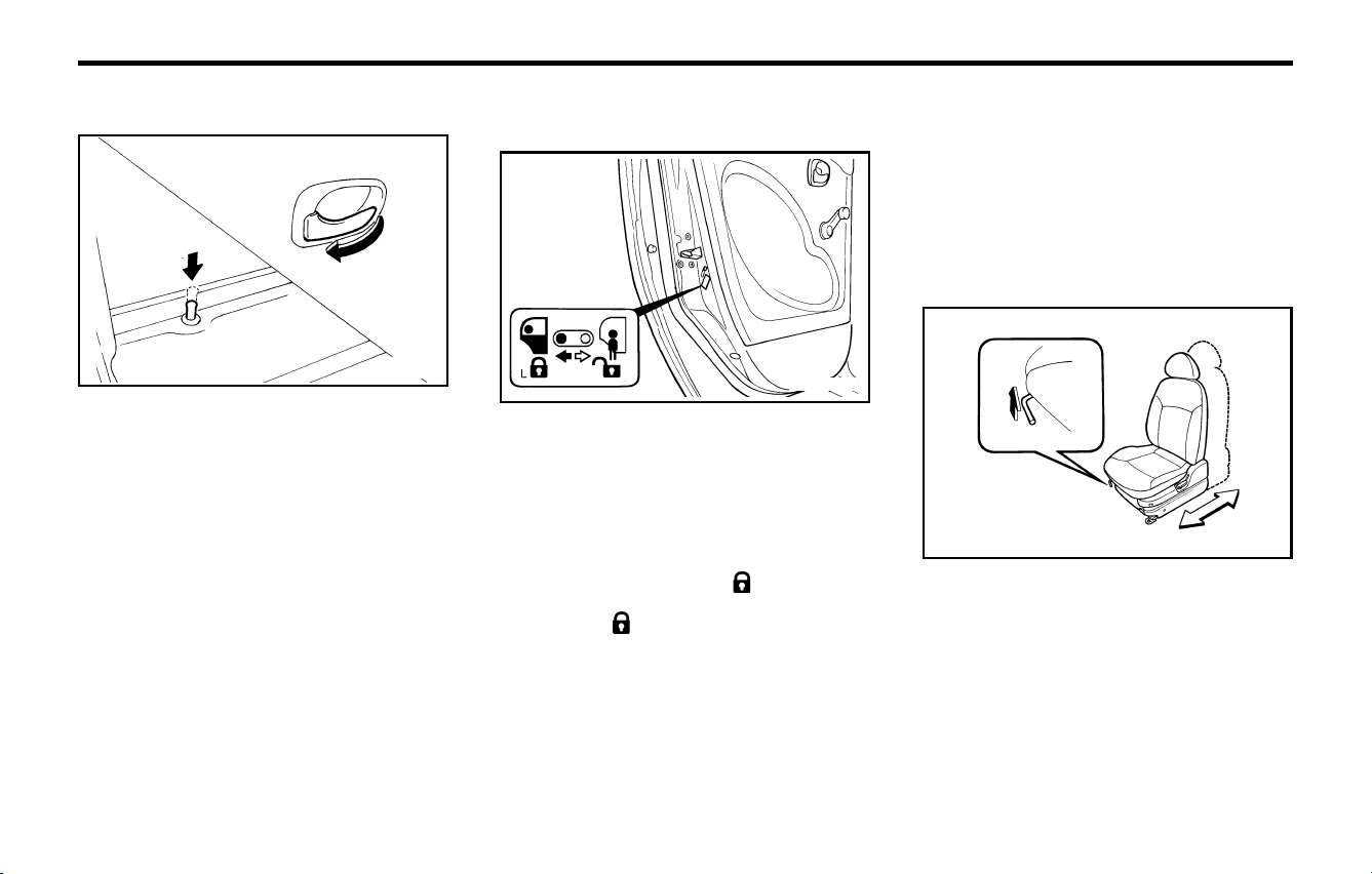
B040E03A-AAT
CHILD-PROTECTOR REAR DOOR
LOCK
Your Hyundai is equipped with a "child-protec-
tor" rear door lock assembly. When the lock
mechanism is engaged, the rear door cannot be
opened from the inside. It's use is recommended
whenever there are small children in the rear
seat.
To engage the child-protector feature so that the
door cannot be opened from the inside, move the
child-protector lever to the " " position and
close the door. Move the lever to the opposite
direction of " " position when normal door
operation is desired.
If you wish to be able to open the door from the
outside, the outside door handle will function
normally.
B040E02A-1
B040D01X-AAT
Locking from the Inside
To lock your Hyundai from the inside, simply
close the door and push the lock button down.
When this is done, the door cannot be opened
using either the inside or the outside door handle.
To unlock the car from the inside, pull up the lock
button and then pull the inside door handle.
AS10070A
B080A01A-AAT
ADJUSTABLE FRONT SEATS
WARNING:
Never attempt to adjust the seat while the
vehicle is moving. This could result in loss of
control, or an accident which may cause
death, serious injury, or property damage.
B080B01A-AAT
Adjusting Seat Forward and RearwardAdjusting Seat Forward and Rearward
Adjusting Seat Forward and RearwardAdjusting Seat Forward and Rearward
Adjusting Seat Forward and Rearward
To move the seat toward the front or rear, pull
the lock release lever upward. This releases the
seat on its track so you can move it forward or
rearward to the desired position. When you find
the position you want, release the lever and
slide the seat forward or rearward on its track
until it locks into the desired position and cannot
be moved further.
B080B01A
FEATURES OF YOUR HYUNDAIFEATURES OF YOUR HYUNDAI
FEATURES OF YOUR HYUNDAIFEATURES OF YOUR HYUNDAI
FEATURES OF YOUR HYUNDAI
1- 6
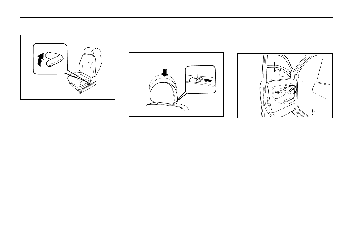
To raise or lower the window, turn the window
regulator handle clockwise or counterclockwise.
WARNING:
When opening or closing the windows, make
sure your passenger's arms, hands and body
are safely out of the way.
B050A01A-AAT
WINDOW GLASS
B050A01A
B080D02A-AAT
Adjustable Headrests (If installed)
Headrests are designed to help reduce the risk of
neck injuries.
To raise the headrest, pull it up. To lower it, push
it down while pressing the lock knob.
WARNING:
o For maximum effectiveness in case of an
accident the headrest should be adjusted
so the top of the headrest is at the same
height as the top of the occupant's ears.
For this reason, the use of a cushion that
holds the body away from the seatback is
not recommended.
o Do not operate vehicle with the headrests
removed as severe injury to an occupant
may occur in the event of an accident.
B080D01A
Lock knob
The seat belt cannot provide full pretection to
an occupant if the seat back is reclined.
Headrests may provide protection against
neck injuries when properly adjusted.
B080C01A-AAT
Adjusting Seatback Angle
To recline the seatback, lean forward to take your
weight off it, then pull up on the recliner control
lever at the outside edge of the seat. Now lean
back until the desired seatback angle is achieved.
To lock the seatback into position, release the
recliner control lever.
WARNING:
To minimize risk of severe injury in the event
of a collision or a sudden stop, both the driver
and passenger seatbacks should always be
in an upright position while the vehicle is in
motion. The protection provided by the seat
belts and airbags may be reduced signifi-
cantly when the seatbacks are reclined. There
is greater risk that the driver and passenger
will slide under the belt which may result in
serious injury if a crash occurs when the
seatbacks are reclined.
B080C01A
FEATURES OF YOUR HYUNDAIFEATURES OF YOUR HYUNDAI
FEATURES OF YOUR HYUNDAIFEATURES OF YOUR HYUNDAI
FEATURES OF YOUR HYUNDAI
1- 7
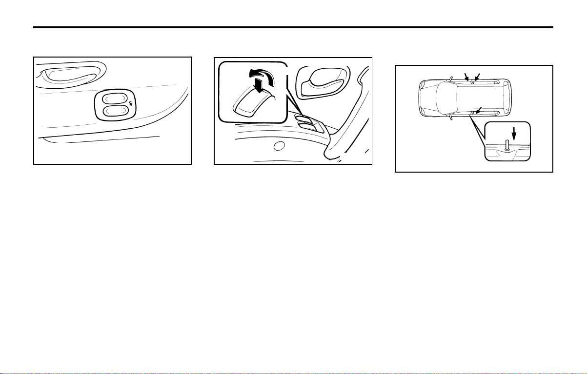
B060A01V-GAT
POWER WINDOWS (If installed)
B060A01V
Open
Close
The power windows operate only when the igni-
tion key is in the "ON" position. The main switches
are located on the driver's armrest and control
the front windows.
The windows may be opened by depressing the
appropriate window switch and closed by pulling
up the switch.
WARNING:
o Be careful that head, hands and body are
not trapped by a closing window.
o If passengers remain in the car when you
leave, especially if a child remains alone,
always remove the ignition key for safety.
B060A02X-GAT
POWER WINDOWS (If installed)
The power windows operate only when the igni-
tion key is in the "ON" position. The main switches
are located on the driver's armrest and control
the front windows. The windows may be oper-
ated by depressing the desired switch.
WARNING:
o Be careful that head, hands and body are
not trapped by a closing window.
o If passengers remain in the car when you
leave, especially if a child remains alone,
always remove the ignition key for safety.
B060A01A
B040G01A-GAT
CENTRAL DOOR LOCKING SYSTEM
(If Installed)
B040G01A
This system is controlled by the driver's door lock
and operates the passenger door locks. When
the driver's door is locked, the passenger doors
are locked automatically.
If a rear door is open when the latch in depressed,
it will remain locked when closed. If the front
passenger door is open when the latch is locked,
the outside door handle must be held in the raised
position. When the door is closed, the door will
remain locked. All doors will be unlocked auto-
matically whenever the driver's door is unlocked
whether by key or latch.
B150A01X-GAT
SEAT BELT PRECAUTIONS
All occupants of the vehicle should wear their
seat belts at all times. Indeed, your local's laws
may require that some or all occupants of the
vehicle use seat belts.

FEATURES OF YOUR HYUNDAIFEATURES OF YOUR HYUNDAI
FEATURES OF YOUR HYUNDAIFEATURES OF YOUR HYUNDAI
FEATURES OF YOUR HYUNDAI
1- 8
WARNING:
Sitting in a reclined position or lying down
when your vehicle is in motion can be dan-
gerous. Even if you buckle up, your seat belts
can't do their job when you're reclined.
The shoulder belt can't do its job because it
won't be against your body. Instead, it will be
in front of you. In a crash you could go into it
with great force, receiving serious neck or
other injuries.
The lap belt can't do its job either. In a crash
the belt could go up over your abdomen. The
belt forces would be applied there, not at your
pelvic bones.
This could cause serious internal injuries.
For proper protection when the vehicle is in
motion, have the seatback upright. Then sit
well back in the seat and wear your seat belt
properly.
B160B01A-AAT
Periodic Inspection
It is recommended that all seat belts be inspected
periodically for wear or damage of any kind.
Parts of the system that are damaged should be
replaced as soon as possible.
B160A01S-GAT
CARE OF SEAT BELTS
Seat belt systems should never be disassembled
or modified. In addition, care should be taken to
assure that seat belts and belt hardware are not
damaged by seat hinges, doors or other abuse.
B150E01A-AAT
Injured Person
A seat belt should be used when an injured
person is being transported. When this is neces-
sary, you should consult a physician for recom-
mendations.
B150F01A-AAT
One Person Per Belt
Two people (including children) should never
attempt to use a single seat belt. This could
increase the severity of injuries in case of an
accident.
B150G01A-AAT
Do Not Lie Down
To reduce the chance of injuries in the event of an
accident, and to achieve maximum effective-
ness of the restraint system, all passengers
should be sitting up and the front seats should be
in an upright position when the car is moving. A
seat belt cannot operate properly if the person is
lying down in the rear seat or if the front seat is in
a reclined position.
B150D01A-AAT
Pregnant Women
The use of a seat belt is recommended for
pregnant women to lessen the chance of injury in
an accident. When a seat belt is used, the lap belt
portion should be placed as low and snugly as
possible on the hips, not across the abdomen.
For specific recommendations, consult a physi-
cian.
The possibility of injury or the severity of injury in
an accident will be decreased if this elementary
safety precaution is observed. In addition, the
following recommendations are made:
B150B01A-GAT
Infant or Small Child
Some countries require the use of child restraint
systems for infants and small children. Whether
this is required by law or not, it is strongly
recommended that a child restraint seat or infant
restraint system be used for infants or small
children weighing less than 18 kilograms (40
pounds).
B150C01A-AAT
Larger Children
Children who are too large for child restraint
systems should occupy the rear seat and use
the available lap/shoulder belts. The lap portion
should be fastened snug on the hips and as low
as possible. Check belt fit periodically. A child's
squirming could move the belt out of position.
If the larger child (over age 13) is in the front seat,
the child should be securely restrained by the
seat belt. Under no circumstances should the
child be allowed to stand or kneel on the seat.
Children are afforded the most safety in the event
of an accident when they are restrained by a
proper restraint system in the rear seat. Never
allow children to ride in the front passenger seat.
FEATURES OF YOUR HYUNDAIFEATURES OF YOUR HYUNDAI
FEATURES OF YOUR HYUNDAIFEATURES OF YOUR HYUNDAI
FEATURES OF YOUR HYUNDAI
1- 9
YR10301B
B180A01A-GAT
SEAT BELTS-Driver's 3-Point System
with Emergency Locking Retractor
To Fasten Your Belt
B160D01A-AAT
When to Replace Seat Belts
The entire seat belt assembly or assemblies
should be replaced if the vehicle has been in-
volved in an accident. This should be done even
if no damage is visible. Additional questions
concerning seat belt operation should be direct-
ed to your Hyundai Dealer.
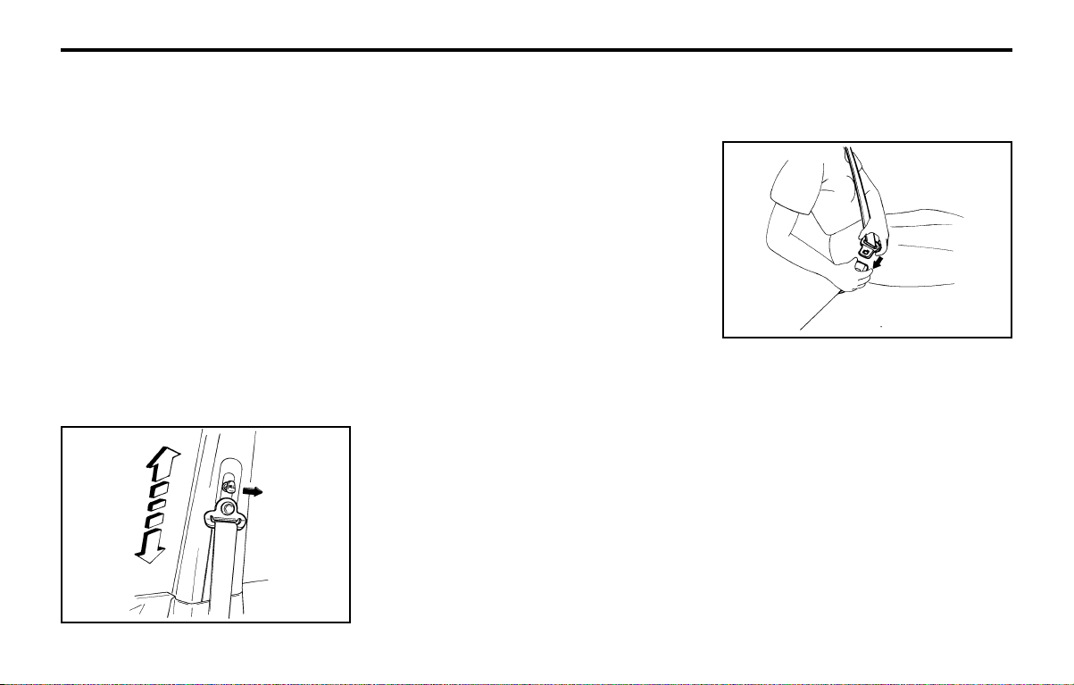
B170A03X-GAT
HEIGHT ADJUSTABLE FRONT SEAT
SHOULDER BELT (If installed)
B170A01X
You can adjust the height of the front seat shoul-
der belt anchor to one of 4 positions. The shoul-
der belt should be adjusted so that it fits midway
over the shoulder, and NEVER across the neck.
To adjust the height of the shoulder belt anchor,
pull on the height adjuster knob and then lower or
raise the height adjuster into an appropriate. To
raise the height adjuster, pull it up. To lower it,
push it down while pressing the height adjuster
button. Release the knob to lock the anchor into
position. Try to slide the anchor upward and
downward after releasing the knob to make sure
that it has locked into position.
WARNING:
o The height adjuster must be in the locked
position whenever the vehicle is moving.
o The misadjustment of height of the shoul-
der belt could reduce the effectiveness of
the seat belt in a crash.
B160C01A-AAT
Keep Belts Clean and Dry
Seat belts should be kept clean and dry. If belts
become dirty, they can be cleaned by using a
mild soap solution and warm water. Bleach, dye,
strong detergents or abrasives should not be
used because they may damage and weaken
the fabric.
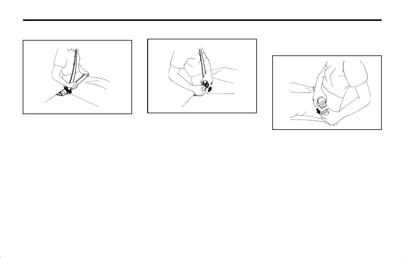
To fasten your seat belt, pull it out of the retractor
and insert the metal tab into the buckle. There will
be an audible "click" when the tab locks into the
buckle.
The seat belt automatically adjusts to the proper
length only after the lap belt is adjusted manually
so that it fits snugly around your hips.
If you lean forward in a slow, easy motion, the belt
will extend and let you move around. If there is a
sudden stop or impact, however, the belt will lock
into position. It will also lock if you try to lean
forward too quickly. Check to make sure that the
belt is properly locked and that the belt is not
twisted.
FEATURES OF YOUR HYUNDAIFEATURES OF YOUR HYUNDAI
FEATURES OF YOUR HYUNDAIFEATURES OF YOUR HYUNDAI
FEATURES OF YOUR HYUNDAI
1- 10
SSA1090S
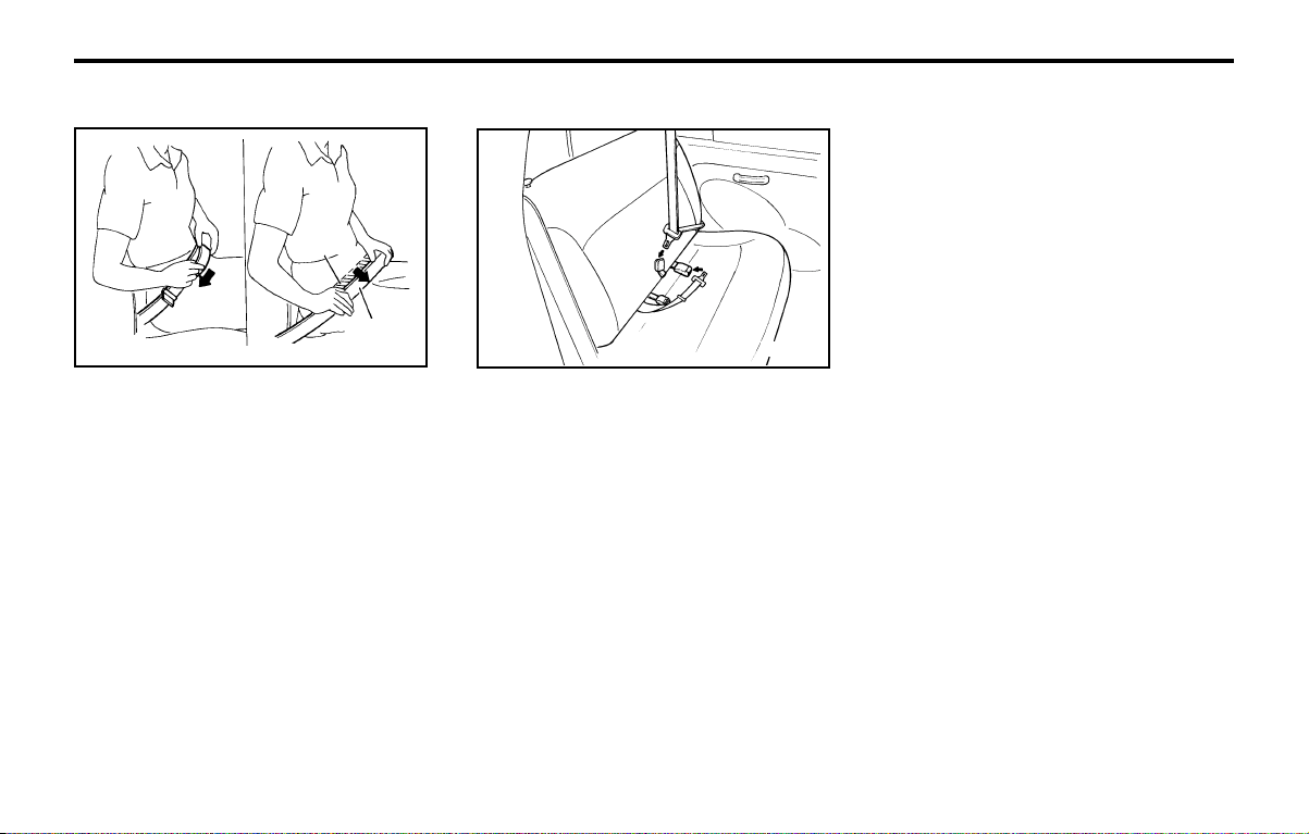
B220A01A-AAT
SEAT BELTS (2-Point Static Type)
(Rear Seat Center)
To Fasten Your Seat Belt
To fasten a 2-point static type belt, insert the
metal tab into the locking buckle. There will be an
audible "click" when the tab locks into the buckle.
Check to make sure the belt is properly locked
and that the belt is not twisted.
B200A01A-GAT
Adjusting Your Seat Belt
YR10311B
You should place the belt as low as possible on
your hips, not on your waist. If located too high on
your body, the chances of sliding out from under
it and suffering serious injury or death are in-
creased. Both arms should not be under or over
the belt. Rather, one should be over and the other
under, as shown in the illustration.
B210A01A-AAT
To Release the Seat Belt
YR10321B
The seat belt is released by pressing the release
button in the locking buckle. When it is released,
the belt should automatically draw back into the
retractor.
If this does not happen, check the belt to be sure
it is not twisted, then try again.
FEATURES OF YOUR HYUNDAIFEATURES OF YOUR HYUNDAI
FEATURES OF YOUR HYUNDAIFEATURES OF YOUR HYUNDAI
FEATURES OF YOUR HYUNDAI
1- 11
B230A02P-GAT
CHILD RESTRAINT SYSTEM
(If installed)
Children riding in the car should sit in the rear
seat and must always be restrained to minimize
the risk of injury in an accident, sudden stop or
sudden maneuver. According to accident statis-
tics, children are safer when properly restrained
in the rear seats than in the front seat. Larger
children should use one of the seat belts pro-
vided.
You are required by law to use safety restraints
for children. If small children ride in your vehicle
you must put them in a child restraint system
(safety seat).
Children could be injured in a crash if their
restraints are not properly secured. For small
children and babies, a child seat or infant seat
must be used. Before buying a particular child
restraint system, make sure it fits your car seat
and seat belts, and fits your child. Follow all the
instructions provided by the manufacturer when
installing the child restraint system.
WARNING:
o A child restraint system must be placed in
the rear seat. Never install a child or infant
seat on the front passenger's seat.
Should an accident occur and cause the
passenger side airbag to deploy, it could
severely injure or kill an infant or child
seated in an infant or child seat. Thus, only
use a child restraint in the rear seat of your
vehicle.
B220C01A-AAT
To Release the Seat Belt
When you want to release the seat belt, press the
button in the locking buckle.
WARNING:
The center lap belt latching mechanism is
different from those for the rear seat shoul-
der belts. When fastening the rear seat shoul-
der belts or the center lap belt, make sure
they are inserted into the correct buckle to
obtain maximum protection from the seat
belt system and assure proper operation.
B220B01A-AAT
Adjusting Your Seat Belt
SSA1090T
With a 2-point static type seat belt, the length
must be adjusted manually so it fits snugly around
your body. Fasten the belt and pull on the loose
end to tighten. The belt should be placed as low
as possible on your hips, not on your waist. If the
belt is too high, it could increase the possibility of
your being injured in an accident.
Correct
Shorten
Too high
B220C01A
FEATURES OF YOUR HYUNDAIFEATURES OF YOUR HYUNDAI
FEATURES OF YOUR HYUNDAIFEATURES OF YOUR HYUNDAI
FEATURES OF YOUR HYUNDAI
1- 12
After installation of the child restraint system, try
to move it in all directions to be sure the child
restraint system is securely installed.
If you need to tighten the belt, pull more webbing
toward the retractor. When you unbuckle the
seat belt and allow it to retract, the retractor will
automatically revert back to its normal seated
passenger emergency locking usage condition.
NOTE:
o Before installing the child restraint sys-
tem, read the instructions supplied by the
child restraint system manufacturer.
o If the seat belt does not operate as de-
scribed, have the system checked imme-
diately by your authorized Hyundai dealer.
WARNING:
Do not install any child restraint system in the
front passenger seat. Should an accident
occur and cause the passenger side airbag
to deploy, it could severely injure or kill an
infant or child seated in an infant or child
seat. Therefore, only use a child restraint
system in the rear seat of your vehicle.
o Since a safety belt or child restraint sys-
tem can become very hot if it is left in a
closed vehicle, be sure to check the seat
cover and buckles before placing a child
there.
o When the child restraint system is not in
use, fasten it with a safety belt so that it
will not be thrown forward in the case of a
sudden stop or an accident.
o Children who are too large to be in a child
restraint should sit in the rear seat and be
restrained with the available lap/shoulder
belts. Never allow children to ride in the
front passenger seat.
o Always make sure that the shoulder belt
portion of the outboard lap/shoulder belt
is positioned midway over the shoulder,
never across the neck. Moving the child
closer to the center of the vehicle may help
provide a good shoulder belt fit. The lap
belt portion of the lap/shoulder belt or the
center seat lap belt must always be posi-
tioned as low as possible on the child's
hips and as snug as possible.
o If the seat belt will not properly fit the
child, we recommend the use of an ap-
proved booster seat in the rear seat in
order to raise the child's seating height so
that the seat belt will properly fit the child.
o Never allow a child to stand up or kneel on
the seat.
o Never use an infant carrier or child safety
seat that "hooks" over a seatback; it may
not provide adequate security in an acci-
dent.
o Never allow a child to be held in a person's
arms while they are in a moving vehicle, as
this could result in serious injury to the
child in the event of an accident or a
sudden stop. Holding a child in a moving
vehicle does not provide the child with
any means of protection during an acci-
dent, even if the person holding the child
is wearing a seat belt.
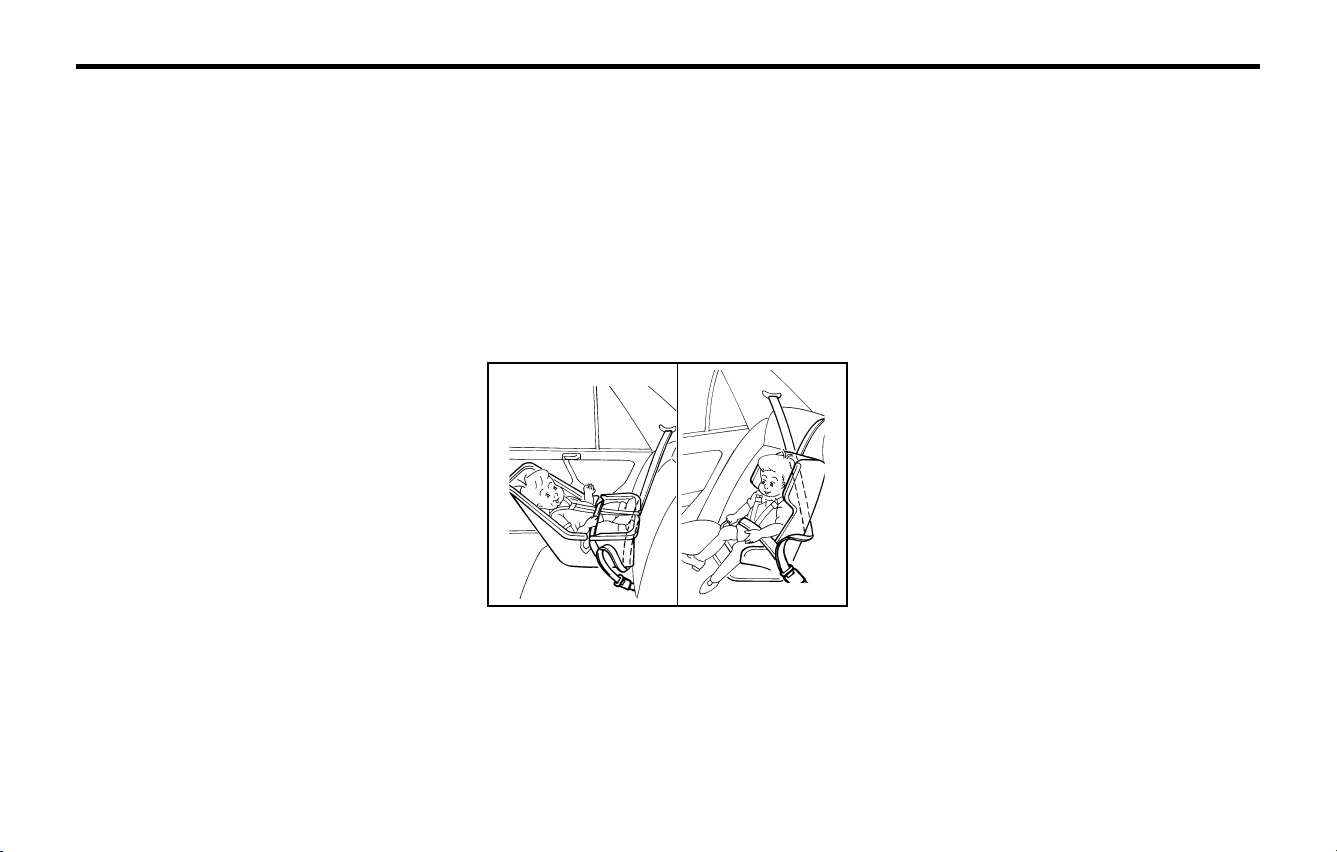
B230G01A-GAT
Installation on Outboard Rear Seats
YR10400B
To install a child restraint system in the outboard
rear seats, extend the shoulder/lap belt from its
retractor. Install the child restraint system, buckle
the seat belt and allow the seat belt to take up any
slack. Make sure that the lap portion of the belt is
tight around the child restraint system and the
shoulder portion of the belt is positioned so that
it cannot interfere with the child's head or neck.
On outboard rear seats
FEATURES OF YOUR HYUNDAIFEATURES OF YOUR HYUNDAI
FEATURES OF YOUR HYUNDAIFEATURES OF YOUR HYUNDAI
FEATURES OF YOUR HYUNDAI
1- 13
B240A03F-AAT
SUPPLEMENTAL RESTRAINT
(AIRBAG) SYSTEM (If installed)
AS10356A
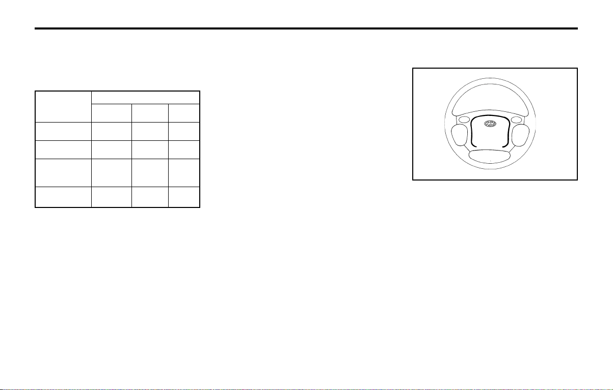
Your Hyundai is equipped with a Supplemental
Restraint (Airbag) System. The indications of the
system's presence are the letters "SRS AIRBAG"
embossed on the airbag pad cover in the steering
wheel and the passenger's side front panel pad
above the glove box.
The Hyundai SRS consists of airbags installed
under the pad covers in the center of the steering
wheel and the passenger's side front panel above
the glove box. The purpose of the SRS is to
provide the vehicle's driver and the front passen-
ger with additional protection when used to-
gether with the seat belt, in case of a frontal
impact.
NOTE:
Be sure to read information about the SRS on
the labels provided on the backside of the
sun visor and in the glove box.
B180B01X-GAT
Pre-tensioner Seat Belt (If installed)
Ordinarily the pre-tensioner seat belt operates in
the same way as E.L.R (Emergency Locking
Retractor) type (When vehicles stop suddenly,
the belt will lock into the position. It will also
lock if you try to lean forward too quickly.).
However, when vehicles crash, the retractor
rewinds the belt webbing. This will restrain the
passenger movement quickly and also reduce
the slack between passenger and belt webbing.
NOTE:
o When the pre-tensioner seat belt is acti-
vated, there may be an explosion noise.
This noise is normal and is not hazardous.
o Pre-tensioner seat belt is designed to op-
erate only when a sufficiently severe im-
pact occurs and it will be only operated
once.
WARNING:
If the pre-tensioner seat belt was activated,
never attempt to replace it by yourself. It must
be replaced by an authorized Hyundai Dealer.
Age Group
Seating Position
Front
Passenger
Rear
Outboard
Rear
Center
0 : Up to 10 kg
(0 ~ 9 months)
0+ : Up to 13 kg
(0 ~ 2 years)
I : 9kg to 18kg
(9 months ~
4 years)
II & III : 15kg to 36kg
(4 ~ 12 years)
XUX
XUX
UF U UF
UF UF UF
U : Suitable for "universal" category restraints
approved for use in this mass group
UF : Suitable for forward-facing "universal" cat-
egory restraints approved for use in this
mass group
X : Seat position not suitable for children in this
mass group
B230H01X-GAT
Child Seat Restraint Suitability For Seat Po-
sition
Use child safety seats that have been officially
approved and are appropriate for your children.
FEATURES OF YOUR HYUNDAIFEATURES OF YOUR HYUNDAI
FEATURES OF YOUR HYUNDAIFEATURES OF YOUR HYUNDAI
FEATURES OF YOUR HYUNDAI
1- 14
B240B03A-AAT
SRS Components and Functions
o For maximum safety protection in all types
of crashes, all occupants including the
driver should always wear their seat belts
whether or not an airbag is also provided
at their seating position to minimize the
risk of severe injury or death in the event
of a crash. Do not sit or lean unnecessarily
close to the airbag while the vehicle is in
motion.
o The SRS airbag system must deploy very
rapidly to provide protection in a crash. If
an occupant is out of position because of
not wearing a seat belt, the airbag may
forcefully contact the occupant causing
serious or fatal injuries.
B240C01X
WARNING:
o As its name implies, the SRS is designed
to work with, and be supplemental to, the
driver's and the passenger's three point
seat belt systems and is not a substitute
for them. Therefore, your seat belts must
be worn at all times while the vehicle is in
motion. The airbags deploy only in certain
frontal impact conditions severe enough
to likely cause significant injury to the
vehicle occupants.
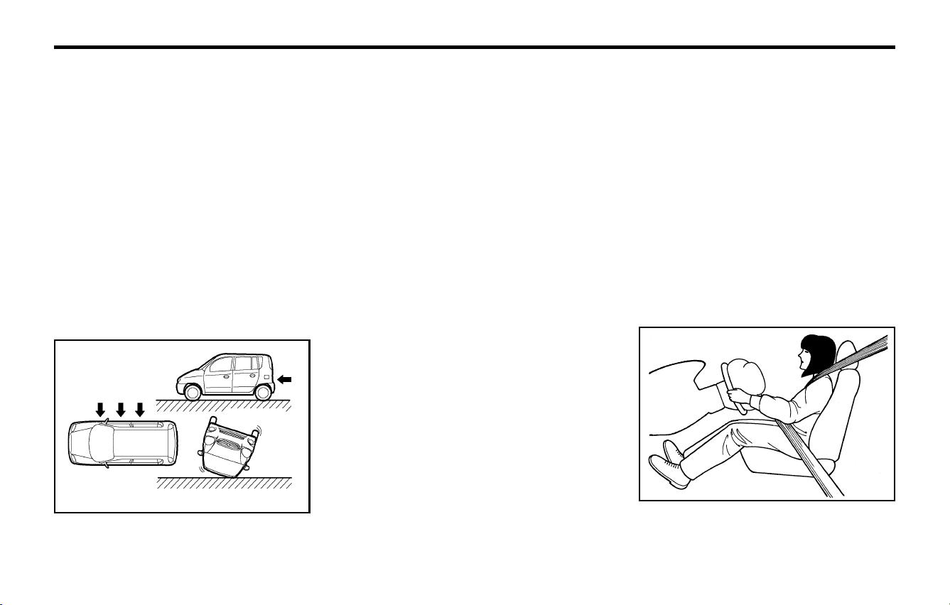
o The SRS is designed to deploy the airbags
only when an impact is sufficiently severe
and when the impact angle is less than 30°
from the forward longitudinal axis of the
vehicle and will not deploy in side, rear or
rollover impacts. Additionally, the airbags
will only deploy once. Thus, seat belts
must be worn at all times.
Rear impact
Side impact
Rollover
o Front airbags are not intended to deploy
in side-impact, rear-impact or rollover
crashes. In addition, airbags will not de-
ploy in frontal crashes below the deploy-
ment threshold speed.
o The driver should sit back as far as possi-
ble while still maintaining control of the
vehicle. If you are sitting too close to the
airbag, it can cause death or serious injury
when it inflates.
o No objects should be placed over or near
the airbag modules on the steering wheel,
instrument panel, and the front passen-
ger's panel above the glove box, because
any such object could cause harm if the
vehicle is in a crash severe enough to
cause the airbags to deploy.
o If the airbags deploy, they must be re-
placed by an authorized Hyundai dealer.
o Do not tamper with or disconnect SRS
wiring, or other components of the SRS
system. Doing so could result in injury,
due to accidental firing of the airbags or
by rendering the SRS inoperative.
o Do not install a child restraint system in
the front passenger seat position. A child
restraint system must never be placed in
the front seat. The infant or child could be
severely injured or killed by an airbag
deployment in case of an accident.
Do not allow children to ride in the front
passenger seat. If also children(teenagers
and older) must ride in the front seat,
make sure they are always properly belted
and that the seat is moved back as far as
possible.
FUA1111B
FEATURES OF YOUR HYUNDAIFEATURES OF YOUR HYUNDAI
FEATURES OF YOUR HYUNDAIFEATURES OF YOUR HYUNDAI
FEATURES OF YOUR HYUNDAI
1- 15
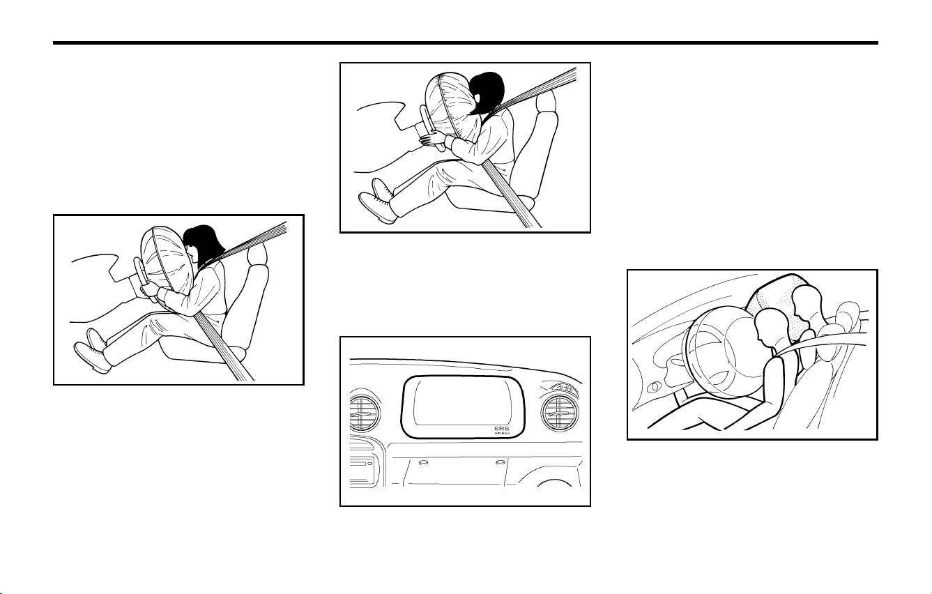
The SRS service reminder indicator (SRI) on the
instrument panel will blink for about 6 seconds
after the ignition key is turned to the "ON"
position or after the engine is started, after which
the SRI should go out.
The airbag modules are located both in the
center of the steering wheel and in the front
passenger's panel above the glove box. When
the SRSCM detects a considerable impact to the
front of the vehicle, it will automatically deploy the
airbags.
The SRS consists of the following components:
- Driver's Airbag Module
- Passenger's Airbag Module
- SRS Service Reminder Indicator (SRI)
- SRS Control Module (SRSCM)
The SRSCM continually monitors all elements
while the ignition is "ON" to determine if a frontal
or near-frontal impact is severe enough to re-
quire airbag deployment.
Upon deployment, tear seams molded directly
into the pad covers will separate under pressure
from the expansion of the airbags. Further open-
ing of the covers then allows full inflation of the
airbags.
A fully inflated airbag in combination with a prop-
erly worn seat belt slows the driver's or the
passenger's forward motion, thus reducing the
risk of head or chest injury.
After complete inflation, the airbag immediately
starts deflating, enabling the driver to maintain
forward visibility.
CAUTION:
When installing a container of liquid air fresh-
ener inside a vehicle, do not place it near the
instrument cluster nor on the instrument panel
pad surface. If there is any leakage from the
air freshener onto these areas (Instrument
FUA1112A
FUA1113A
B240B04X
FUA1115A
FEATURES OF YOUR HYUNDAIFEATURES OF YOUR HYUNDAI
FEATURES OF YOUR HYUNDAIFEATURES OF YOUR HYUNDAI
FEATURES OF YOUR HYUNDAI
1- 16
to the body structure, can adversely affect
SRS performance and lead to possible
injury.
o For cleaning the airbag pad covers, use
only a soft, dry cloth or one which has
been moistened with plain water. Solvents
or cleaners could adversely affect the
airbag covers and proper deployment of
the system.
o No objects should be placed over or near
the airbag modules on the steering wheel,
instrument panel, and the front passen-
ger's panel above the glove box, because
any such object could cause harm if the
vehicle is in a crash severe enough to
cause the airbags to inflate.
o If the airbags inflate, they must be re-
placed by an authorized Hyundai dealer.
o Do not tamper with or disconnect SRS
wiring, or other components of the SRS
system. Doing so could result in injury,
due to accidental firing of the airbags or
by rendering the SRS inoperative.
o Do not install a child restraint system in
the front passenger seat position.
A child restraint system must never be
placed in the front seat. The infant or child
could be severely injured by an airbag
deployment in case of an accident.
o If components of the airbag system must
be discarded, or if the vehicle must be
scrapped, certain safety precautions must
be observed. Your Hyundai dealer knows
these precautions and can give you the
YT10355A
cluster, instrument panel pad or air ventila-
tor), it may damage these parts. If the liquid
from the air freshener does leak onto these
areas, wash them with water immediately.
WARNING:
o When the SRS is activated, there may be a
loud noise and fine dust will be released
through out the vehicle. These conditions
are normal and are not hazardous. How-
ever, the fine dust generated during airbag
deployment may cause skin irritation. Be
sure to wash your hands and face thor-
oughly with lukewarm water and a mild
soap after an accident in which the airbags
were deployed.
o The SRS can function only when the igni-
tion key is in the "ON" position. If the SRS
SRI does not come on, or continuously
remains on, after flashing for about 6 sec-
onds when the ignition key is turned to
the "ON" position, or after the engine is
started, or comes on while driving, the
SRS is not working properly. If this oc-
curs, have your vehicle immediately in-
spected by your Hyundai dealer.
o Before you replace a fuse or disconnect a
battery terminal, turn the ignition key to
the "LOCK" position or remove the igni-
tion key. Never remove or replace the air
bag related fuse(s) when the ignition key
is in the "ON" position. Failure to heed this
warning will cause the SRS SRI to illumi-
nate.
B240C01Y-GAT
SRS Care
The SRS is virtually maintenance-free and so
there are no parts you can safely service by
yourself. The entire SRS system must be in-
spected by an authorized Hyundai dealer in 10
years after the date that the vehicle was manu-
factured.
Any work on the SRS system, such as removing,
installing, repairing, or any work on the steering
wheel must be performed by a qualified Hyundai
technician. Improper handling of the SRS sys-
tem may result in serious personal injury.
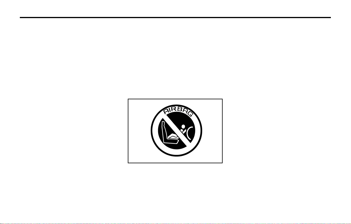
WARNING:
o Extreme Hazard! Do not use a rearward
facing child restraint on a seat protected
by an airbag in front of it!
o Modification to SRS components or wir-
ing, including the addition of any kind of
badges to the pad covers or modifications

FEATURES OF YOUR HYUNDAIFEATURES OF YOUR HYUNDAI
FEATURES OF YOUR HYUNDAIFEATURES OF YOUR HYUNDAI
FEATURES OF YOUR HYUNDAI
1- 17
necessary information. Failure to follow
these precautions and procedures could
increase the risk of personal injury.
o If you sell your vehicle, be sure to inform
the new owner of these important points
and make certain that this manual is trans-
ferred to the new owner.
o If your car was flooded and has soaked
carpeting or water on flooring, you
shouldn't try to start engine; have the car
towed to authorized Hyundai dealer.

FEATURES OF YOUR HYUNDAIFEATURES OF YOUR HYUNDAI
FEATURES OF YOUR HYUNDAIFEATURES OF YOUR HYUNDAI
FEATURES OF YOUR HYUNDAI
1- 18
B250A02X-GAT
INSTRUMENTS AND CONTROLS
1. Multi-Function Light Switch
2. Headlight Leveling Device (If installed)
3. Horn Button
4. Driver's Airbag (If installed)
5. Windshield Wiper/Washer Switch
6. Rear Wiper Switch/Rear Washer Switch
(If installed)
7. Rear Defroster Switch
8. Center Air Vent Louver
9. Digital Clock (If installed)
10. Hazard Warning Switch
11. Defroster Ventilation Outlet
12. Front Fog Light Switch (If installed)
13. Rear Fog Light Switch (If installed)
14. Passenger's Airbag (If installed)
15. Side Air Vent Louver
16. Hood Release Lever
17. Ignition Switch and Keys
18. Air Conditioning Switch
19. Cigarette Light
20. Ashtray
21. Heating/Air Conditioning Control Panel
22. Audio System
CAUTION:
When installing a container of liquid air fresh-
ener inside a vehicle, do not place it near the
instrument cluster nor on the instrument panel
pad surface. If there is any leakage from the
air freshener onto these areas (Instrument
cluster, instrument panel pad or air ventila-
tor), it may damage these parts. If the liquid
from the air freshener does leak onto these
areas, wash them with water immediately.
151 3 4 5,6 11 12 13 14
16 17 18 19 20 21 22
2 738
9
810
B250A02X
FEATURES OF YOUR HYUNDAIFEATURES OF YOUR HYUNDAI
FEATURES OF YOUR HYUNDAIFEATURES OF YOUR HYUNDAI
FEATURES OF YOUR HYUNDAI
1- 19
B260B01X-GAT
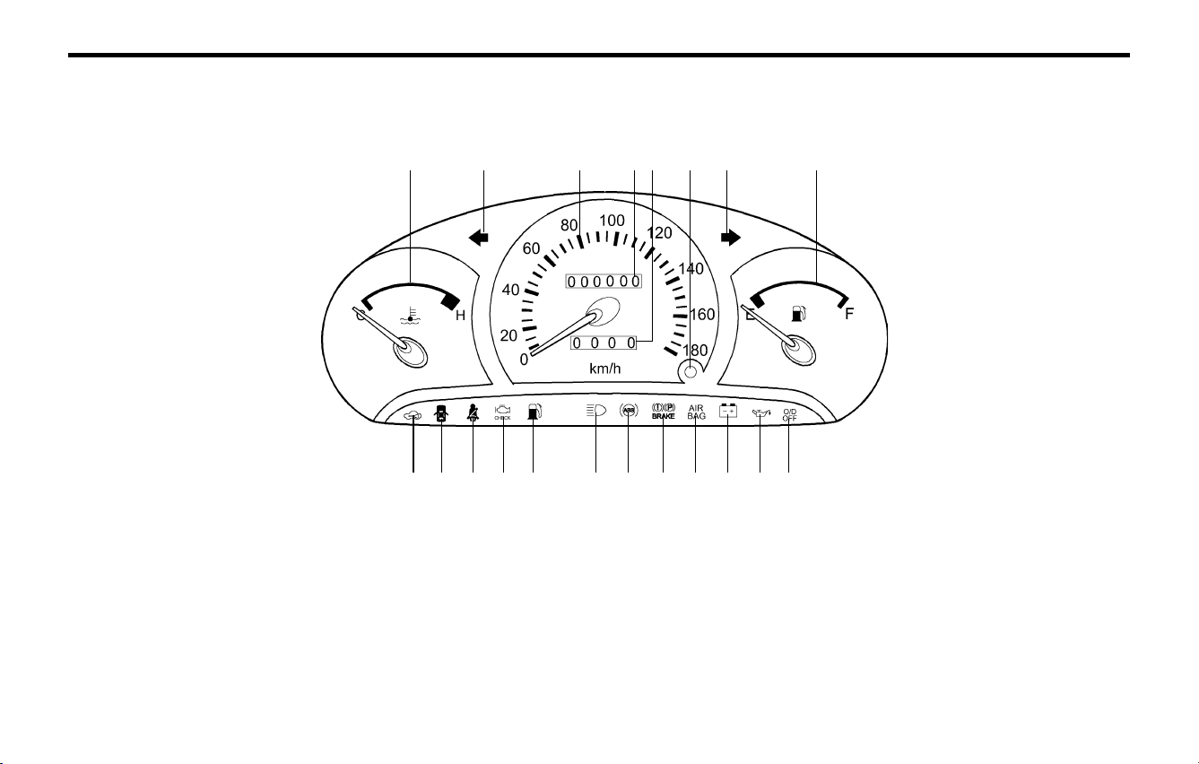
INSTRUMENT CLUSTER AND INDICATORINSTRUMENT CLUSTER AND INDICATOR
INSTRUMENT CLUSTER AND INDICATORINSTRUMENT CLUSTER AND INDICATOR
INSTRUMENT CLUSTER AND INDICATOR
1. Temperature Gauge
2. Turn Signal Indicator Light
3. Speedometer
4. Odometer
5. Trip Odometer
6. Trip Odometer Reset button
7. Fuel Gauge
8. Immobilizer Warning Indicator Light
9. Door Ajar Warning Light
10. Seat Belt Warning Light
11. Malfunction Indicator Lamp (MIL) (If installed)
12. Low Fuel Warning Light
13. High Beam Indicator Light
14. ABS Service Reminder Indicator (If installed)
15. Parking Brake/Brake Fluid Level Warning
Light
16. SRS Service Reminder Indicator (If installed)
17. Charging System Warning Light
18. Oil Pressure Warning Light
19. Overdrive Off Indicator Light (Auto T/A only)
1356
98 10 11 12 13
B260A03X
2 4 2 7
14 15 16 17 18 19
FEATURES OF YOUR HYUNDAIFEATURES OF YOUR HYUNDAI
FEATURES OF YOUR HYUNDAIFEATURES OF YOUR HYUNDAI
FEATURES OF YOUR HYUNDAI
1- 20
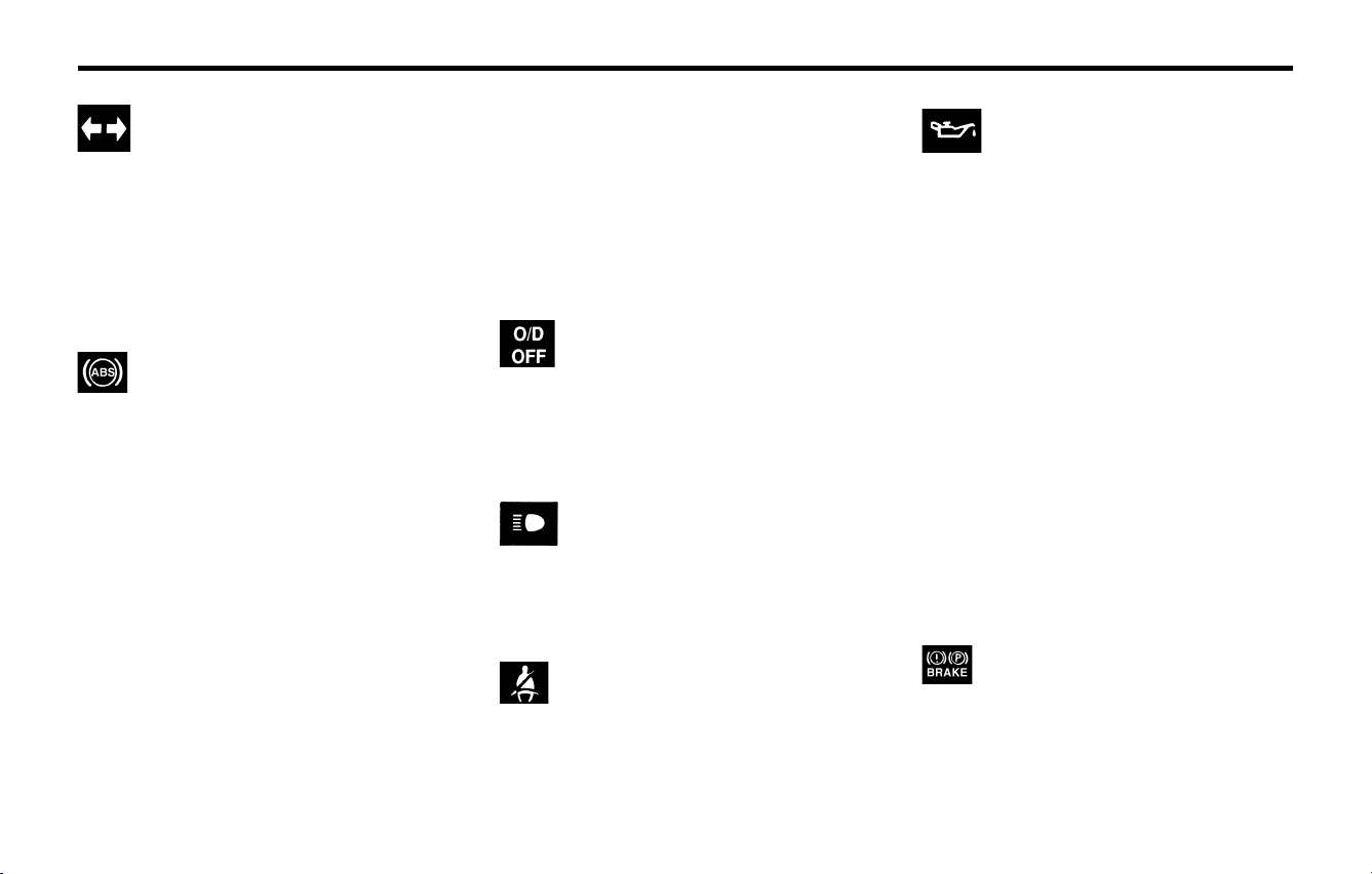
B260P02Y-AAT
ABS Service Reminder Indica-
tor (SRI) (If installed)
When the key is turned to the "ON" position, the
ABS SRI will come on and then go off in a few
seconds. If the ABS SRI remains on, comes on
while driving, or does not come on when the key
is turned to the "ON" position, this indicates that
there may be a problem with the ABS.
If this occurs, have your vehicle checked by your
Hyundai dealer as soon as possible. The normal
braking system will still be operational, but with-
out the assistance of the anti-lock brake system.
B260D01A-AAT
Turn Signal Indicator Lights
The blinking green arrows on the instrument
panel show the direction indicated by the turn
signals. If the arrow comes on but does not
illuminate, blinks more rapidly than normal, or
does not illuminate at all, a malfunction in the turn
signal system is indicated. Your dealer should be
consulted for repairs.
B260G01A-AAT
Oil Pressure Warning Light
CAUTION:
If the oil pressure warning light stays on
while the engine is running, serious engine
damage may result. The oil pressure warning
light comes on whenever there is insufficient
oil pressure. In normal operation, it should
come on when the ignition switch is turned
on, then go out when the engine is started. If
the oil pressure warning light stays on while
the engine is running, there is a serious
malfunction.
If this happens, stop the car as soon as it is
safe to do so, turn off the engine and check
the oil level. If the oil level is low, fill the engine
oil to the proper level and start the engine
again. If the light stays on with the engine
running, turn the engine off immediately. In
any instance where the oil light stays on
when the engine is running, the engine should
be checked by an Hyundai dealer before the
car is driven again.
B260E02A-GAT
Seat Belt Reminder Light
The seat belt reminder light comes on until your
seat belt is fastened when the ignition key is
turned from the "OFF" position to "ON" or
"START".
B260H03A-AAT
Parking Brake/Brake Fluid Level
Warning Light
WARNING:
If you suspect brake trouble, have your brakes
checked by a Hyundai dealer as soon as
possible. Driving your car with a problem in
either the brake electrical system or brake
B260F01A-AAT
High Beam Indicator Light
The high beam indicator light comes on when-
ever the headlights are switched to the high
beam or flash position.
B260C01A-AAT
O/D OFF IndicatorO/D OFF Indicator
O/D OFF IndicatorO/D OFF Indicator
O/D OFF Indicator
(If installed)
When the overdrive switch is turned on, the
overdrive off indicator will go out. This amber
indicator will be illuminated when the overdrive
switch is turned off. (Auto T/A only)
CAUTION:
If the both ABS SRI and Parking Brake/Brake
fluid level warning lights remain "ON" or
come on while driving, there may be a prob-
lem with E.B.D (Electronic Brake Force Dis-
tribution).
If this occurs, avoid sudden stops and have
your vehicle checked by your Hyundai dealer
as soon as possible.
FEATURES OF YOUR HYUNDAIFEATURES OF YOUR HYUNDAI
FEATURES OF YOUR HYUNDAIFEATURES OF YOUR HYUNDAI
FEATURES OF YOUR HYUNDAI
1- 21
B270A01A-AAT
BRAKE PAD WEAR WARNING SOUND
The front disc brake pads have wear indicators
that should make a high-pitched squealing or
scraping noise when new pads are needed. The
sound may come and go or be heard all the time
when the vehicle is moving. It may also be heard
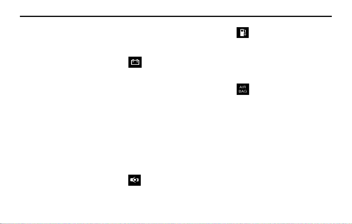
B260M01A-AAT
Low Fuel Level Warning Light
The low fuel level warning light comes on when the
fuel tank is approaching empty. When it comes on,
you should add fuel as soon as possible. Driving
with the fuel level warning light on or with the fuel
level below "E" can cause the engine to misfire
and damage the catalytic converter.
hydraulic system is dangerous, and could
result in serious injury or death.
Warning Light Operation
The parking brake/brake fluid level warning light
should come on when the parking brake is ap-
plied and the ignition switch is turned to "ON" or
"START". After the engine is started, the light
should go out when the parking brake is re-
leased.
If the parking brake is not applied, the warning
light should come on when the ignition switch is
turned to "ON" or "START", then go out when the
engine starts. If the light comes on at any other
time, you should slow the vehicle and bring it to
a complete stop in a safe location off the road-
way.
The brake warning light indicates that the brake
fluid level in the brake master cylinder is low and
hydraulic brake fluid conforming to DOT 3 or
DOT 4 specifications should be added. After
adding fluid, if no other trouble is found, the car
should be immediately and carefully driven
to a Hyundai dealer for inspection. If further
trouble is experienced, the vehicle should not be
driven at all but taken to a dealer by a profes-
sional towing service or some other safe method.
Your Hyundai is equipped with dual-diagonal
braking systems. This means you still have brak-
ing on two wheels even if one of the dual systems
should fail. With only one of the dual systems
working, more than normal pedal travel and
greater pedal pressure are required to stop the
car. Also, the car will not stop in as short a
B260J01S-GAT
Charging System Warning Light
The charging system warning light should come
on when the ignition is turned on, then go out
when the engine is running. If the light stays on
while the engine is running, there is a malfunction
in the electrical charging system. If the light
comes on while you are driving, stop, turn off the
engine and check under the hood. First, make
certain the generator drive belt is in place. If it is,
check the tension of the belt.
And then, have the system checked by your
Hyundai dealer.
CAUTION:
If the drive belt (generator belt) is loosen,
broken, or mission while the vehicle is driv-
ing, there may be a serious malfunction, en-
gine could overheat because this belt also
drives the water pump.
B260L01A-GAT
Door Ajar Warning Light
The door ajar warning light warns you that a door
is not completely closed.
B260B01S-GAT
SRS (Airbag) Service Reminder
Indicator (SRI) (If installed)
The SRS service reminder indicator (SRI) comes
on and flashes for about 6 seconds after the
ignition key is turned to the "ON" position or after
the engine is started, after which it will go out.
This light also comes on when the SRS is not
working properly. If the SRI does not come on, or
continuously remains on after flashing for about
6 seconds when you turned the ignition key to the
"ON" position or started the engine, or if it comes
on while driving, have the SRS inspected by an
authorized Hyundai Dealer.
distance with only half of the brake system work-
ing. If the brakes fail while you are driving, shift to
a lower gear for additional engine braking and
stop the car as soon as it is safe to do so.
FEATURES OF YOUR HYUNDAIFEATURES OF YOUR HYUNDAI
FEATURES OF YOUR HYUNDAIFEATURES OF YOUR HYUNDAI
FEATURES OF YOUR HYUNDAI
1- 22
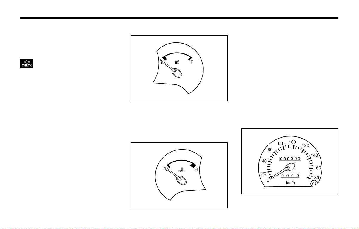
B300A01A-GAT
SPEEDOMETER
Your Hyundai's speedometer is calibrated in
kilometers per hour or miles per hour.
B280A01A-AAT
FUEL GAUGE
The needle on the gauge indicates the approxi-
mate fuel level in the fuel tank. The fuel capacity
is given in Section 9.
B900A01A-GAT
ACOUSTIC WARNING SOUND
(If installed)
The acoustic warning chime sounds when the
tail lights are on and the door in driver side is
open. This prevents the battery from discharging
when the car is left with the tail lights on. The
chime sounds until the tail lights are turned off.
B260N02A-AAT
Malfunction Indicator Light
(If installed)
This light illuminates when there is a malfunction
of an exhaust gas related component, and the
system is not functioning properly so that the
exhaust gas regulation values are not satisfied.
This light will also illuminate when the ignition key
is turned to the "ON" position, and will go out in a
few seconds. If it illuminates while driving, or
does not illuminate when the ignition key is
turned to the "ON" position, take your car to your
nearest authorized Hyundai dealer and have the
system checked.
when the brake pedal is pushed down firmly.
Excessive rotor damage will result if the worn
pads are not replaced. See your Hyundai dealer
immediately.
B280A01X
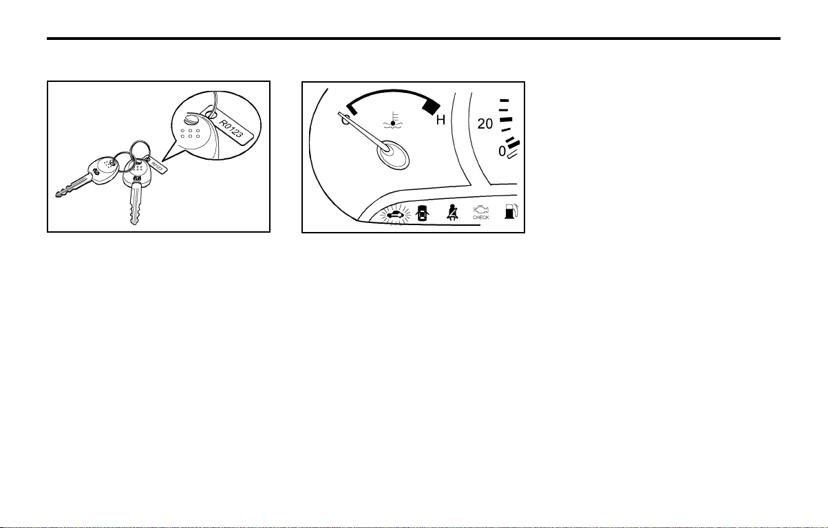
B290A02A-AAT
ENGINE COOLANT TEMPERATURE
GAUGE
WARNING:
Never remove the radiator cap when the en-
gine is hot. The engine coolant is under pres-
sure and could erupt and cause severe burns.
Wait until the engine is cool before removing
the radiator cap.
The needle on the engine coolant temperature
gauge should stay in the normal range. If it
moves across the dial to "H" (Hot), pull over and
stop as soon as possible and turn off the engine.
Then open the hood and check the coolant level
and the water pump drive belt. If you suspect
cooling system trouble, have your cooling sys-
tem checked by Hyundai dealer as soon as
possible.
B290A01X
B300A01X
FEATURES OF YOUR HYUNDAIFEATURES OF YOUR HYUNDAI
FEATURES OF YOUR HYUNDAIFEATURES OF YOUR HYUNDAI
FEATURES OF YOUR HYUNDAI
1- 23
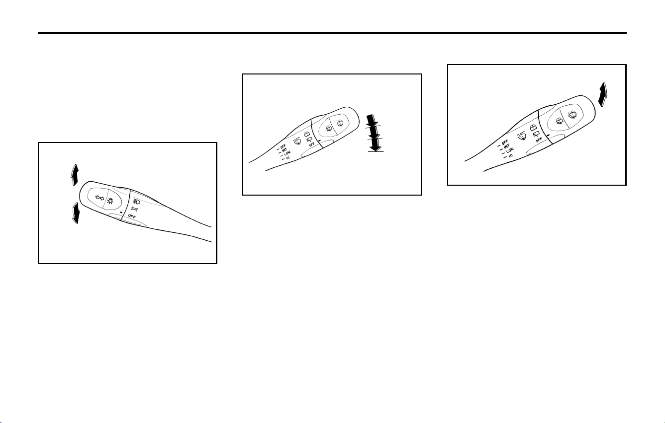
B340B01A-AAT
Lane Change Signal
To indicate a lane change, move the lever up or
down to a point where it begins flashing.
The lever will automatically return to the center
position when released.
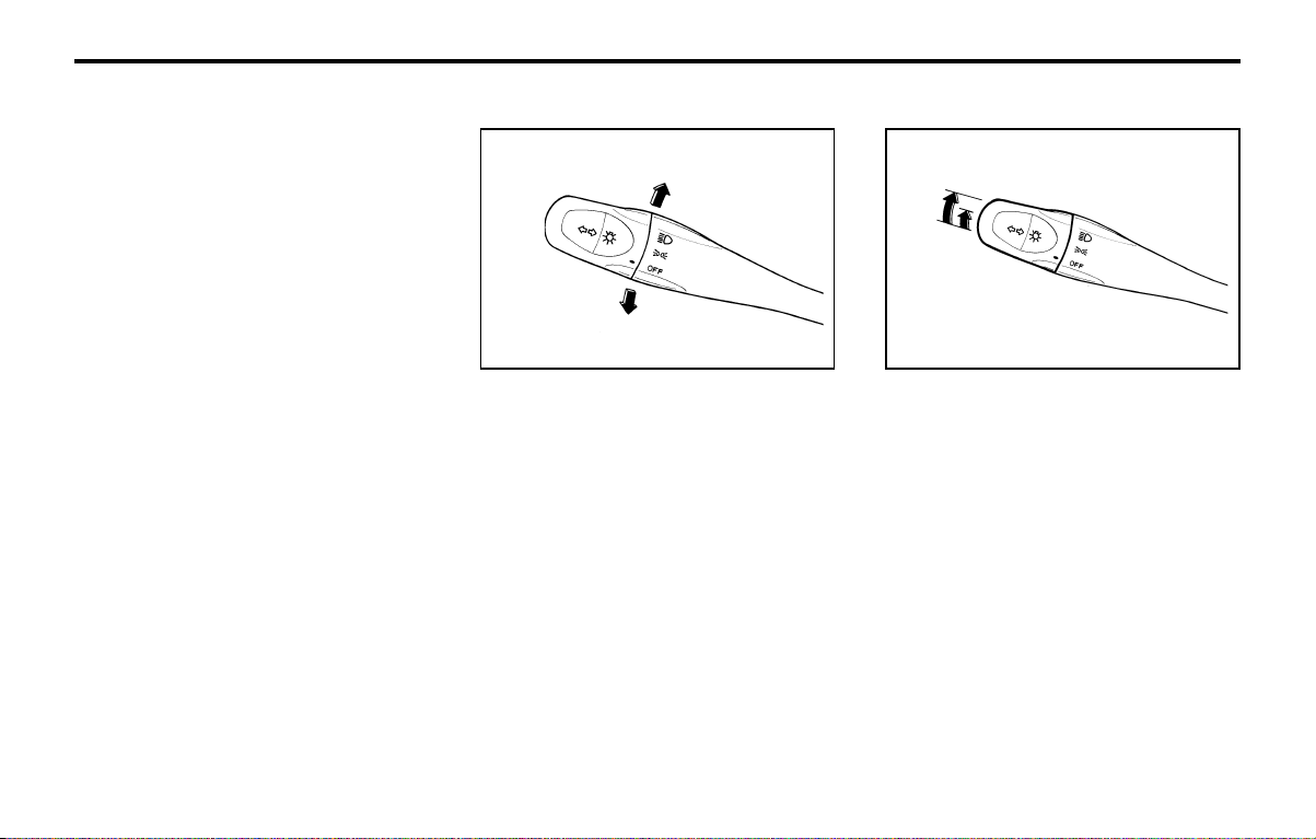
B340A01A-AAT
COMBINATION TURN SIGNAL,
HEADLIGHT AND HIGH-BEAM SWITCH
Turn Signal Operation
Pulling down on the lever causes the turn signals
on the left side of the car to blink. Pushing upward
on the lever causes the turn signals on the right
side of the car to blink. As the turn is completed,
the lever will automatically return to the center
position and turn off the turn signals at the same
time. If either turn signal indicator light blinks
more rapidly than usual, goes on but does not
blink, or does not go on at all, there is a malfunc-
tion in the system. Check for a burned-out fuse or
bulb or see your Hyundai dealer.
B340B01X
B310A01A-GAT
ODOMETER
The odometer records the total driving distance
in kilometers or miles, and is useful for keeping a
record for maintenance intervals.
NOTE:
Any alteration of the odometer may void your
warranty coverage.
B320A01A-GAT
TRIP ODOMETER
The trip odometer may be used to conveniently
record trip distances. Push the reset knob to set
the counter to zero.
B340C01A-AAT
Headlight Switch
To operate the headlights, turn the barrel on the
end of the multi-function switch. The first position
turns on the parking lights, sidelights, tail lights
and instrument panel lights. The second position
turns on the headlights.
B340C01X
B340F01A-GAT
Daytime Running Lights (If Installed)
Your Hyundai is equipped with daytime running
lights. The daytime running lights are used to
improve visibility for oncoming traffic. Your vehi-
cle daytime running lights are designed to remain
on continuously when the engine is operating
even though the headlight switch is in the "OFF"
position. However, the daytime running lights will
be off while the parking brake is applied.
FEATURES OF YOUR HYUNDAIFEATURES OF YOUR HYUNDAI
FEATURES OF YOUR HYUNDAIFEATURES OF YOUR HYUNDAI
FEATURES OF YOUR HYUNDAI
1- 24
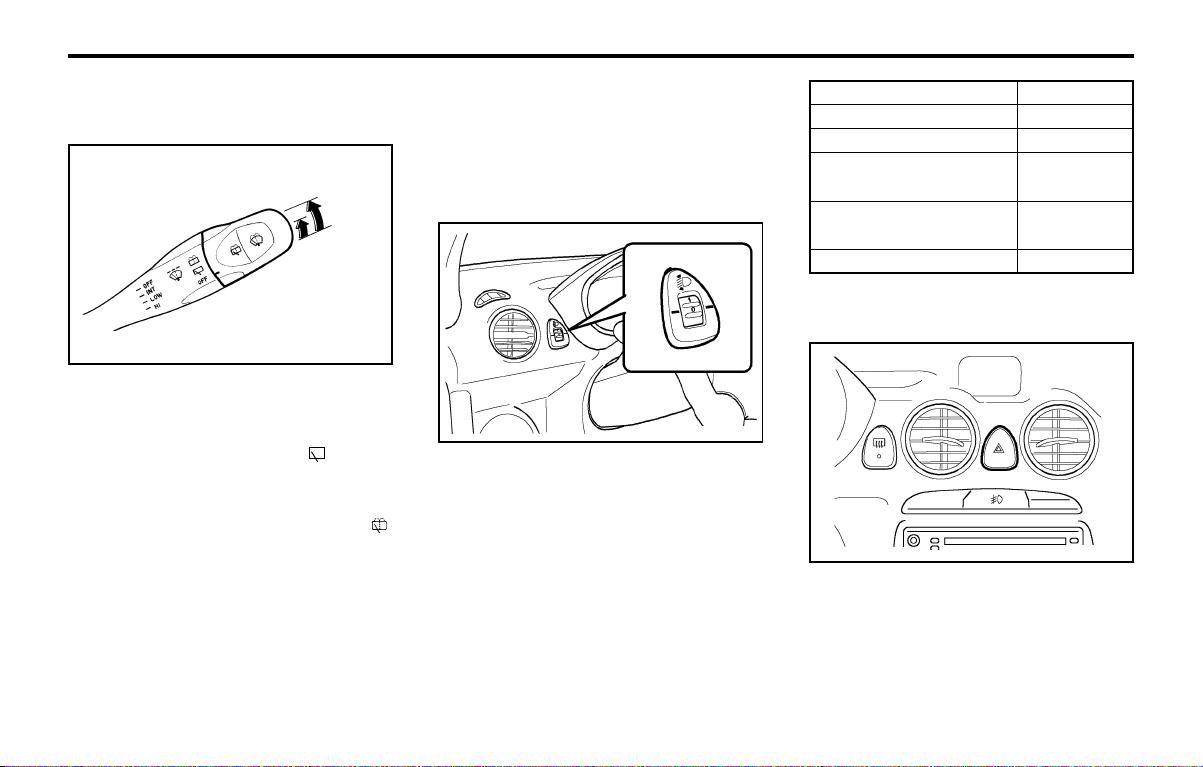
B350B01A-AAT
Windshield Washer Operation
B350B01X
To use the windshield washer, pull the wiper/
washer lever toward the steering wheel. When
the washer lever is operated, the wipers auto-
matically make two passes across the wind-
shield. The washer continues to operate until the
lever is released.
NOTE:
o Do not operate the washer more than 15
seconds at a time or when the fluid reser-
voir is empty.
o In icy or freezing weather, be sure the
wiper blades are not frozen to the glass
prior to operating the wipers.
o In areas where water freezes in winter, use
windshield washer antifreeze.
B340E01A-AAT
Headlight Flasher
To flash the headlights, pull the switch lever
toward you, then release it. The headlights can
be flashed even though the headlight switch is in
the "OFF" position.
B340E01X
B350A01A-AAT
WINDSHIELD WIPER AND WASHER
SWITCH
B350A01X
OFF
1
2
3
The windshield wiper switch has three positions:
1. Intermittent wiper operation
2. Low-speed operation
3. High-speed operation
NOTE:
To prevent damage to the wiper system, do
not attempt to wipe away heavy accumula-
tions of snow or ice. Accumulated snow and
ice should be removed manually. If there is
only a light layer of snow or ice, operate the
heater in the defrost mode to melt the snow or
ice before using the wiper.
B340D01A-AAT
High-Beam Switch
To turn on the headlight high beams, push the
lever forward (away from you). The high beam
indicator light will come on at the same time. For
low beams, pull the lever back toward you.
FEATURES OF YOUR HYUNDAIFEATURES OF YOUR HYUNDAI
FEATURES OF YOUR HYUNDAIFEATURES OF YOUR HYUNDAI
FEATURES OF YOUR HYUNDAI
1- 25
wiper blade wear. For the same reason, do not
operate the washer when the washer fluid reser-
voir is empty.
B340G02X-GAT
HEADLIGHT LEVELING DEVICE SYS-
TEM (If installed)
To adjust the headlight beam level according to
the number of the passengers and the loading
weight in the luggage area, turn the beam level-
ing switch.
The higher the number of the switch position, the
lower the headlight beam level. Always keep the
headlight beam at the proper leveling position, or
headlights may dazzle other road users.
Listed below are the examples of proper switch
settings. For loading conditions other than those
listed below, adjust the switch position so that the
beam level may be the nearest as the condition
obtained according to the list.
B390A01X-GAT
REAR WINDOW WIPER AND WASHER
(If installed)
B390A01X
3
2
1
To operate the rear wiper and washer, turn the
barrel on the end of the multifunction switch.
1. OFF
2. When the point indicates the , the rear
windshield wiper starts to operate continu-
ously.
3. The washer fluid will be spray onto the rear
winshield by indicating the point onto the .
The wiper operates continuously after the
washer fluid is sprayed.
Do not operate the washer continuously for more
than 15 seconds or when the fluid reservoir is
empty; this could damage the system.
Do not operate the wiper when the window is dry;
this can result in scratching as well as premature
B370A01A-AAT
HAZARD WARNING SYSTEM
The hazard warning system should be used
whenever you find it necessary to stop the car in
a hazardous location. When you must make
such an emergency stop, always pull off the road
as far as possible.
The hazard warning lights are turned on by
pushing in on the hazard switch. This causes all
Loading condition
Driver only
Driver + front passenger
Full passengers
(including driver)
Full passengers (including
driver) + Permissible load
Driver + Permissible load
Switch position
0
0
1
1
2
B340G01X
HMX404D
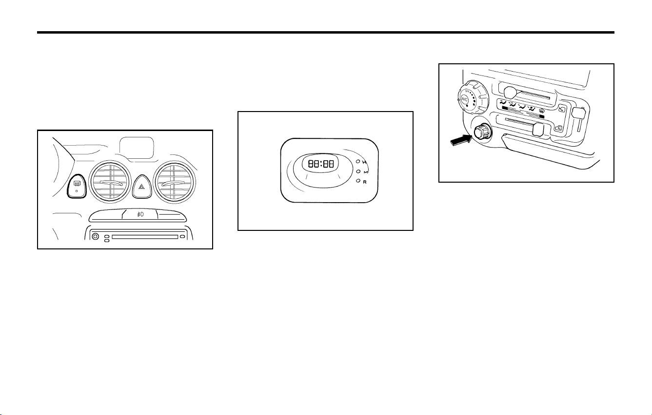
FEATURES OF YOUR HYUNDAIFEATURES OF YOUR HYUNDAI
FEATURES OF YOUR HYUNDAIFEATURES OF YOUR HYUNDAI
FEATURES OF YOUR HYUNDAI
1- 26
B420A02A-AAT
CIGARETTE LIGHTER
For the cigarette lighter to work, the key must be
in the "ACC" position or the "ON" position.
To use the cigarette lighter, push it all the way into
its socket. When the element has heated, the
lighter will pop out to the "ready" position.
Do not hold the cigarette lighter pressed in. This
can damage the heating element and create a
fire hazard.
If it is necessary to replace the cigarette lighter,
use only a genuine Hyundai replacement or its
approved equivalent.
CAUTION:
Do not use electric accessories or equipment
other than the Hyundai genuine parts in the
socket.
B420A01A-1
B400A01A-AAT
DIGITAL CLOCK (If Installed)
There are three control buttons for the digital
clock. Their functions are:
HOUR - Push "H" to advance the hour indicated.
MIN - Push "M" to advance the minute indicated.
RESET - Push "R" to reset minutes to ":00" to
facilitate resetting the clock to the correct time.
When this is done:
Pressing "R" between 10 : 30 and 11 : 29 changes
the readout to 11 : 00.
Pressing "R" between 11 : 30 and 12 : 29 changes
the readout to 12 : 00.
NOTE:
The engine must be running for the rear
window defroster to operate.
B400A01A
turn signal lights to blink. The hazard warning
lights will operate even though the key is not in
the ignition.
To turn the hazard warning lights off, push in on
the switch a second time.
B380A01A-AAT
REAR WINDOW DEFROSTER
SWITCH
The rear window defroster is turned on by push-
ing in on the switch. To turn the defroster off, push
in on the switch a second time. The rear window
defroster automatically turns itself off after about
15 minutes. To restart the defroster cycle, push
in on the switch again after it has turned itself off.
CAUTION:
Do not clean the inner side of the rear window
glass with an abrasive type of glass cleaner
or use a scraper to remove the foreign depos-
its from the inner surface of the glass as this
may cause damage to the defroster elements.
HMX404C
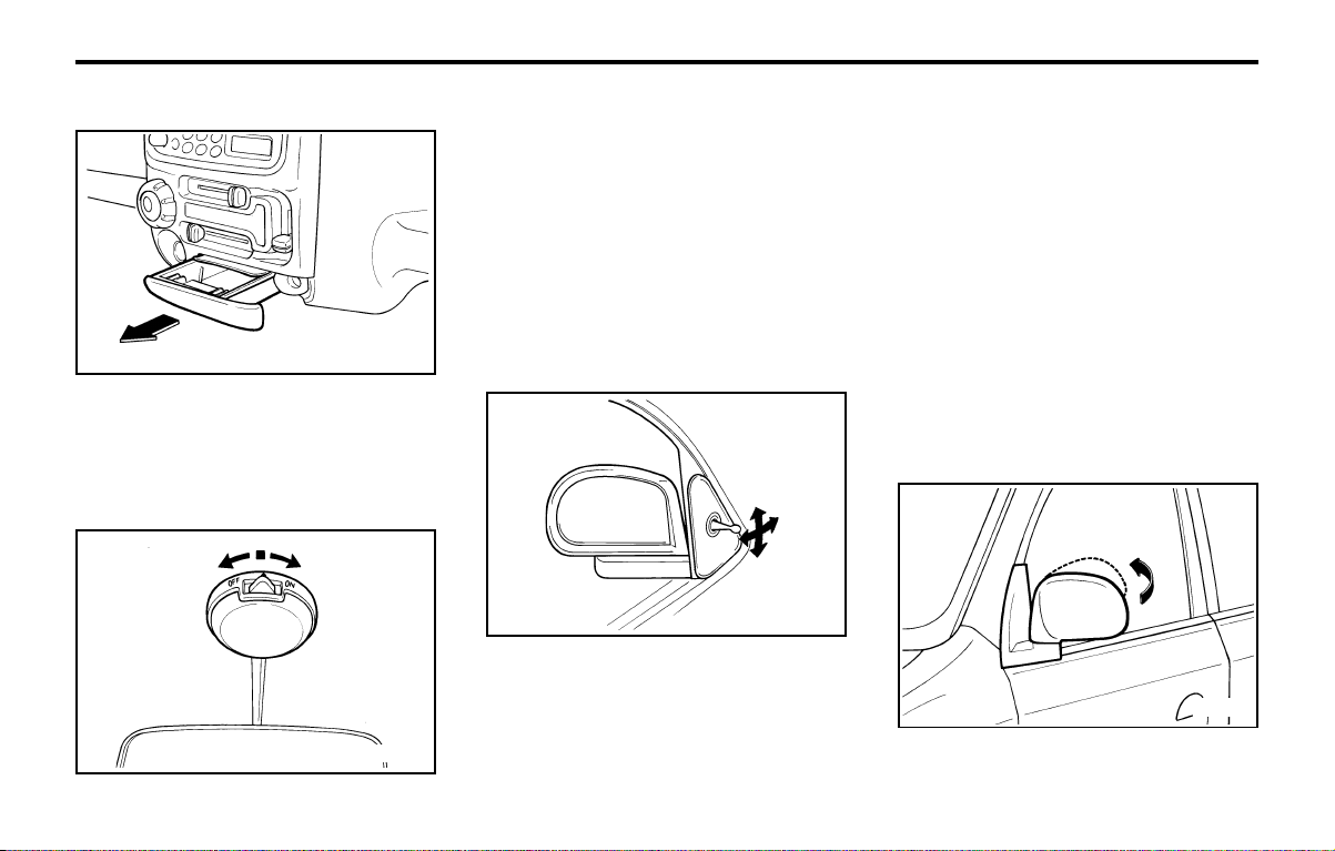
FEATURES OF YOUR HYUNDAIFEATURES OF YOUR HYUNDAI
FEATURES OF YOUR HYUNDAIFEATURES OF YOUR HYUNDAI
FEATURES OF YOUR HYUNDAI
1- 27
B510A01A-AAT
OUTSIDE REARVIEW MIRROR
Manual Type
The outside rearview mirrors are equipped with
a remote control for your convenience. It is
operated by the control lever in the bottom front
corner of the window.
Before driving away, always check that your
mirrors are positioned so you can see behind
The interior courtesy light has a 3-position switch.
The three positions are:
o " • " In the "MIDDLE" position, the interior
courtesy light comes on when any door is
opened, then goes out when it is closed.
o "OFF" In the "LEFT" position, the light stays
off even though a door is open.
o "ON" In the "RIGHT" position, the light stays
on at all times.
B510A01A
B430A01X-GAT
FRONT ASHTRAY
B430A01X
The front ashtray may be opened by pulling it out
by its grip. To remove the ashtray to empty or
clean it, press down on the spring-loaded tab
inside the ashtray and pull it all the way out.
B490A01X-GAT
INTERIOR LIGHT
B490A01X
B510C01A-AAT
FOLDING THE OUTSIDE REARVIEW
MIRRORS
To fold the outside rear view mirrors, push them
towards the rear.
you, both to the left and right sides, as well as
directly behind your vehicle. When using the
mirror, always exercise caution when attempting
to judge the distance of vehicles behind or along
side of you.
CAUTION:CAUTION:
CAUTION:CAUTION:
CAUTION:
If the mirror control is jammed with ice, do not
attempt to break it free using the control
handle or by manipulating the face of the
mirror. Use an approved spray deicer (not
radiator antifreeze) to release the frozen
mechanism or move the vehicle to a warm
place and allow the ice to melt.
B510C01A
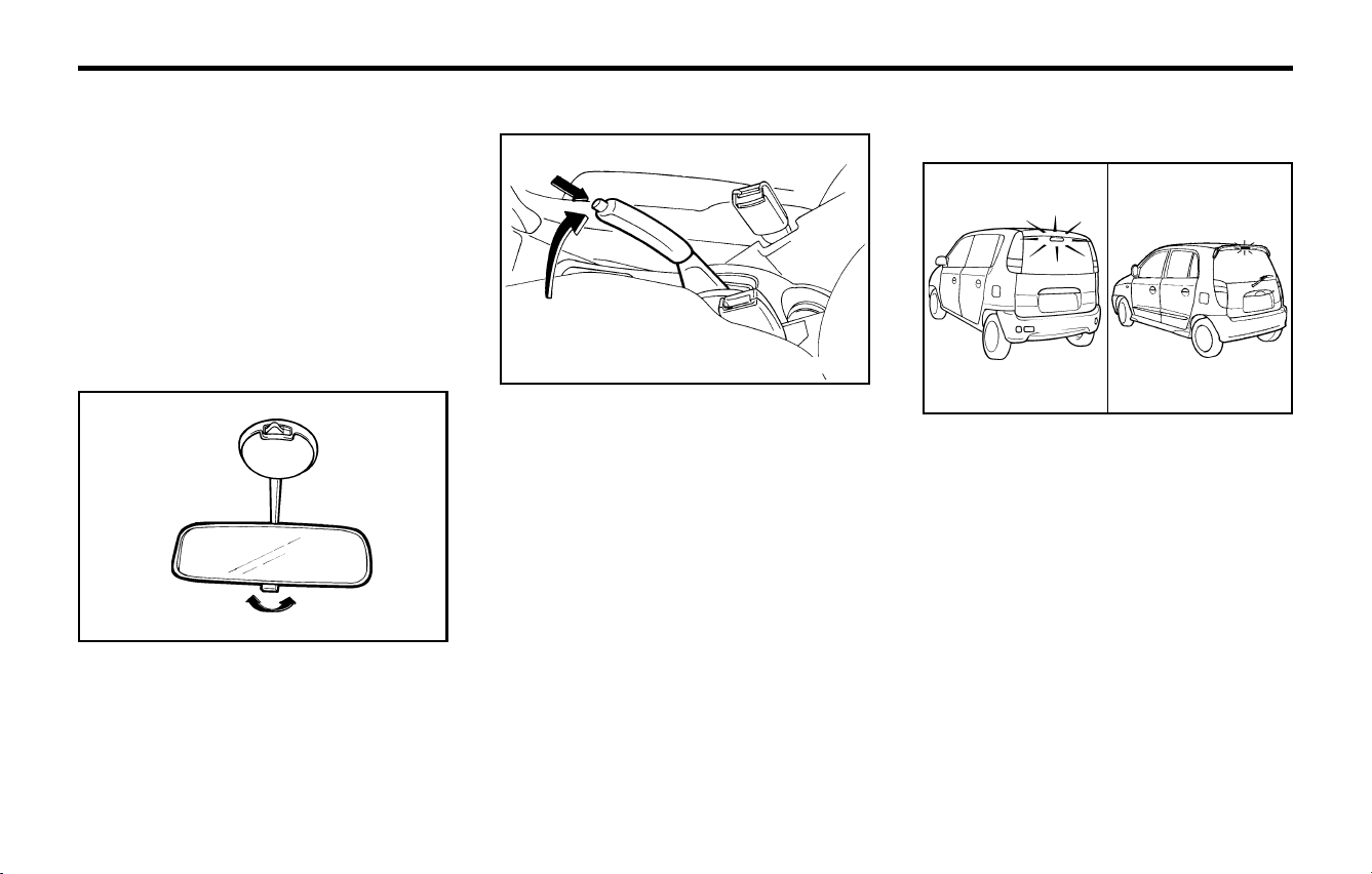
FEATURES OF YOUR HYUNDAIFEATURES OF YOUR HYUNDAI
FEATURES OF YOUR HYUNDAIFEATURES OF YOUR HYUNDAI
FEATURES OF YOUR HYUNDAI
1- 28
B550A01F B550A01V
<PRIME>
B550A01S-GAT
HIGH-MOUNTED REAR STOP LIGHT
(If Installed)
In addition to the lower-mounted rear stoplights
on either side of the car, the high mounted rear
stoplight in the center of the rear window or
installed in the rear spoiler also lights when the
brakes are applied.
Always engage the parking brake before leaving
the car. This also turns on the parking brake
indicator light when the key is in the "ON" or
"START" position. Before driving away, be sure
that the parking brake is fully released and the
indicator light is off.
o To engage the parking brake, pull the lever up
as far as possible.
o To release the parking brake, pull up the lever
and press the thumb button. Then, while
holding the button in, lower the brake lever.
B530A01A-AAT
PARKING BRAKE
B530A01A
B520A01A-AAT
DAY/NIGHT INSIDE REARVIEW MIR-
ROR
Your Hyundai is equipped with a day/night inside
rearview mirror. The "night" position is selected
by flipping the tab at the bottom of the mirror
toward you. In the "night" position, the glare of
headlights of cars behind you is reduced.
The outside rear view mirrors can be folded
rearward for parking in narrow areas.
WARNING:
Do not adjust or fold the outside rearview
mirrors while the vehicle is moving. This
could result in loss of control, and an acci-
dent which could cause death, serious inju-
ry or property damage.
B520A01A
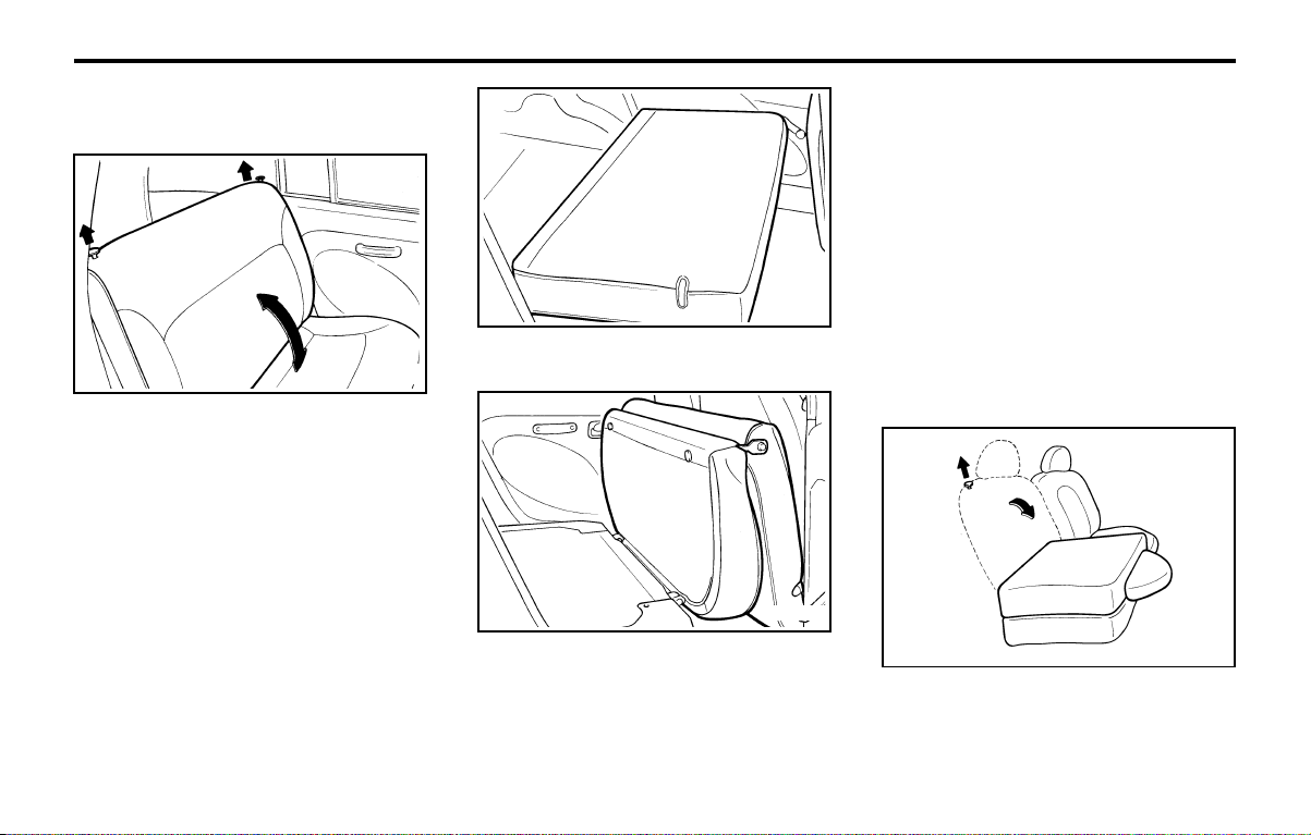
FEATURES OF YOUR HYUNDAIFEATURES OF YOUR HYUNDAI
FEATURES OF YOUR HYUNDAIFEATURES OF YOUR HYUNDAI
FEATURES OF YOUR HYUNDAI
1- 29
For greater convenience, the entire seatback
and seat cushion may be folded down and up.
B110A02X
B110A03X
o To unlock the seatback, pull up on the
seatback locking knob, then pull forward on
the seatback.
o After being folded down rear seat back, fold-
up the seat cushion.
B110A01X-GAT
FOLDING REAR SEATBACK AND
SEAT CUSHION
B110A01X
WARNING:
The purpose of the fold-down rear seat back
and the fold-up rear seat cushion is to allow
you to carry more objects than could other-
wise be accommodated. Do not allow pas-
sengers to sit on the cargo area while the car
is moving as this is not a proper seating
position and no seat belts are available for
use when the seat back is folded down. This
could result in serious injury or death in case
of an accident or a sudden stop. Objects
should not extend higher than the top of the
front seats. This could allow cargo to slide
forward and cause injury or damage during
sudden stops.
o When you return the rear seat to its upright
position, always be sure it has locked into
position by pulling and pushing on the top of
the seatback.
WARNING:
When you return the rear seat to its upright
position after being folded down and folded
up, be careful not to damage the seat belt
webbing or buckle. In addition, do not allow
the seat belt webbing or buckle to get caught
or pinched in the rear seat.
B110B01X-GAT
Folding rear seatback and seat
cushion individually (If installed)
B110B01X
The entire seatback and seat cushion may be
folded down and up individually.
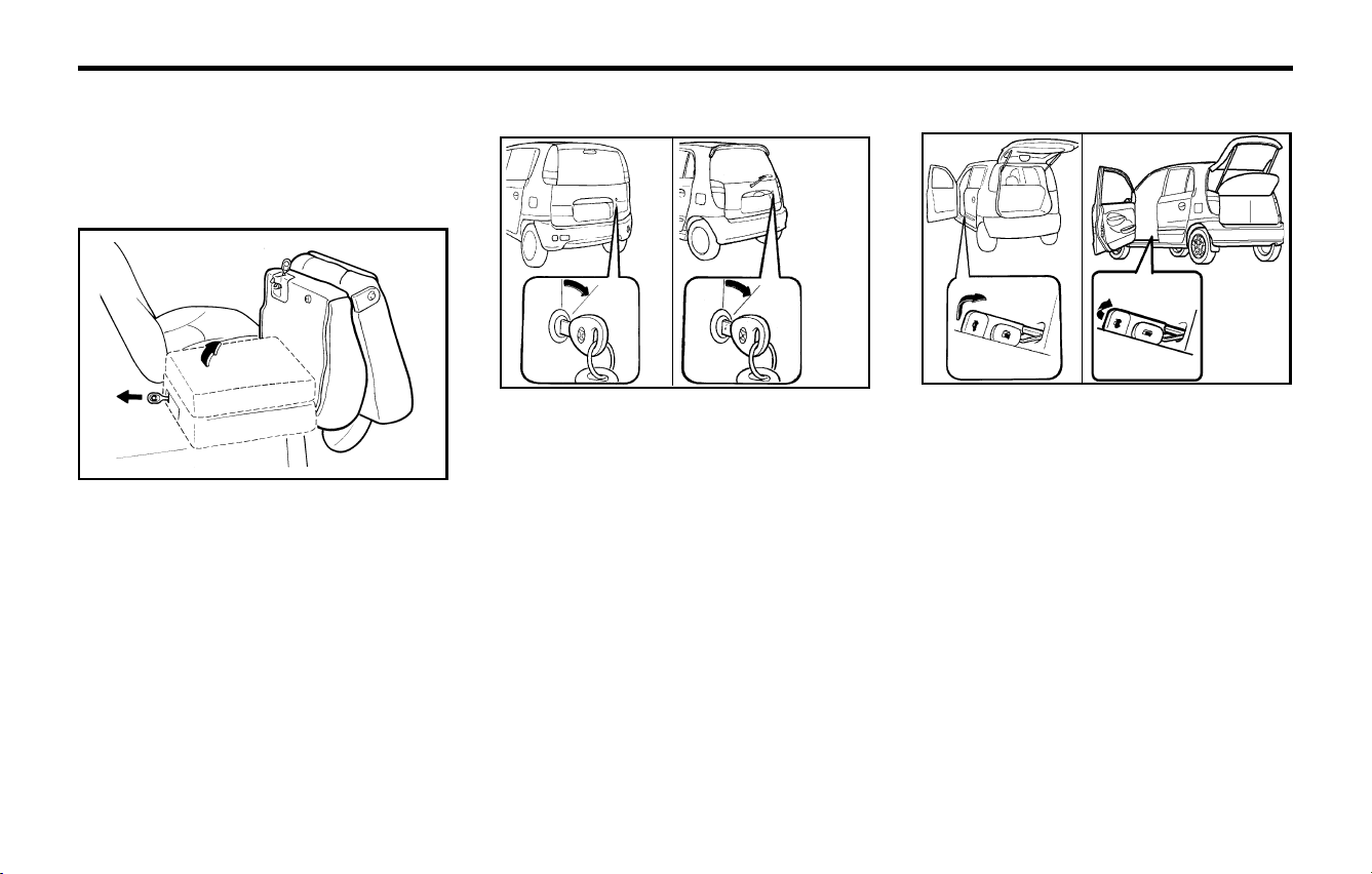
FEATURES OF YOUR HYUNDAIFEATURES OF YOUR HYUNDAI
FEATURES OF YOUR HYUNDAIFEATURES OF YOUR HYUNDAI
FEATURES OF YOUR HYUNDAI
1- 30
B540D01X-GAT
Remote Tail Gate Release (If installed)
The tail gate is opened by pulling the lever to
release the lock, then raising the tail gate manu-
ally.
To close, lower the tail gate, then press down on
it until it locks. To be sure the tail gate is securely
fastened, always try to pull it up again.
WARNING:
The tail gate should always be kept com-
pletely closed while the vehicle is in motion.
If it is left open or ajar, exhaust gases may
enter the car and serious illness may result.
B540D01V
B540D02X/
<PRIME>
B540A01X-GAT
TAIL GATE
B540A01V
B540A02X/
<PRIME>
WARNING:
The tail gate should always be kept com-
pletely closed while the vehicle is in motion.
If it is left open or ajar, poisonous exhaust
gases may enter the car resulting in serious
injury or death to the occupants. See addi-
tional warnings concerning exhaust gases
on page 2-1.
o The tail gate is opened by first turning the key
clockwise to release the lock, then raising the
door manually.
o To close, lower the tail gate, then press down
on it until it locks. To be sure the tail gate is
securely fastened, always try to pull it up
again.
o To unlock the seatback, pull up on the
seatback locking knob, then pull forward on
the seatback.
o After being folded down rear seat, pull the
lever on the rear side of the seat cushion to
fold-up the seat cushion.
B110B02X
WARNING:
o When you return the rear seat to its up-
right position, always be sure it has locked
into position by pulling and pushing on
the top of the seatback.
o When you return the rear seat to its up
right position after being folded down and
folded up, be careful not to damage the
seat belt webbing or buckle. In addition,
do not allow the seat belt webbing or
buckle to get caught or pinched in the rear
seat.
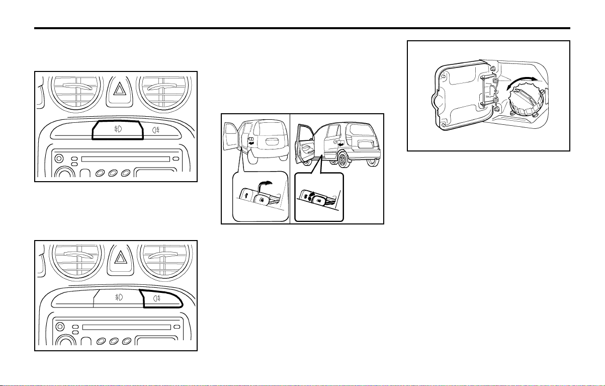
FEATURES OF YOUR HYUNDAIFEATURES OF YOUR HYUNDAI
FEATURES OF YOUR HYUNDAIFEATURES OF YOUR HYUNDAI
FEATURES OF YOUR HYUNDAI
1- 31
B560A01X-AAT
REMOTE FUEL-FILLER LID RELEASE
(If installed)
The fuel-filler lid may be opened from inside the
vehicle by pulling up on the fuel-filler lid opener
located on the front floor area on the left side of
the car.
NOTE:
If the fuel-filler lid will not open because ice
has formed around it, tap lightly or push on
the lid to break the ice and release the lid. Do
not pry on the lid. If necessary, spray around
the lid with an approved de-icer fluid (do not
use radiator anti-freeze) or move the vehicle
to a warm place and allow the ice to melt.
To turn on the rear fog lights, push the switch.
They will come on when the headlights are
turned on.
B560A01V
<PRIME>
B560A01X/
B360A01A-GAT
FRONT FOG LIGHT SWITCH
(If Installed)
To turn on the front fog lights, push the switch.
They will light when the headlight switch is in the
first or second position.
B360B01A-GAT
Rear Fog Light Switch (If installed)
B360A01X
B360B01X
WARNING:
Gasoline vapors are dangerous. Before refu-
eling, always stop the engine and never allow
sparks or open flames near the filler area. If
you need to replace the filler cap, use a
genuine Hyundai replacement part.
If you open the fuel filler cap during high
ambient temperatures, a slight "pressure
sound" may be heard. This is normal and not
a cause for concern.
Whenever you open the fuel filler cap, turn it
slowly.
B560A02A
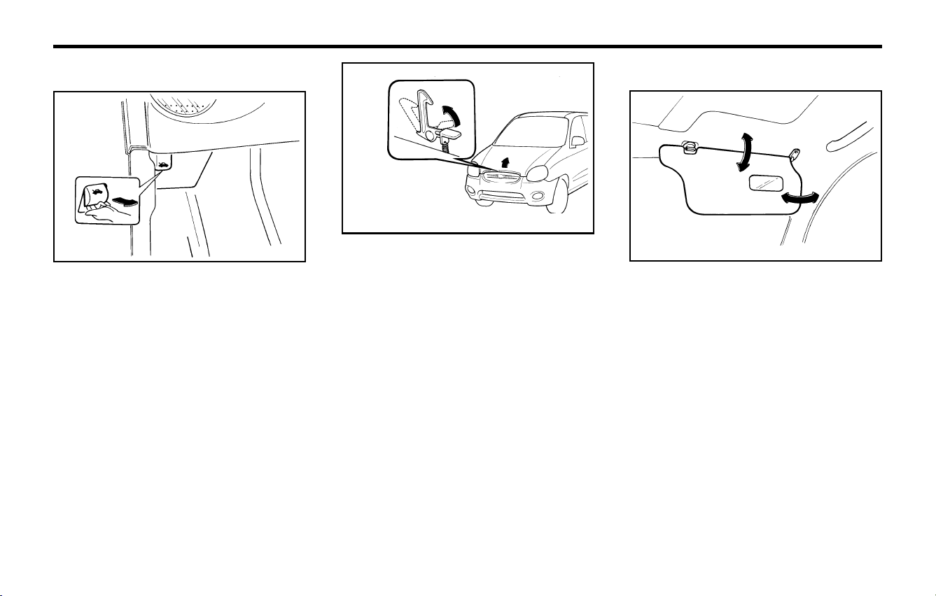
FEATURES OF YOUR HYUNDAIFEATURES OF YOUR HYUNDAI
FEATURES OF YOUR HYUNDAIFEATURES OF YOUR HYUNDAI
FEATURES OF YOUR HYUNDAI
1- 32
B580A01A-AAT
SUNVISOR
Your Hyundai is equipped with sun visors to give
the driver and front passenger either frontal or
sideward shade. The sun visors are fitted on both
sides on all models. To reduce glare or to shut out
direct rays of the sun, turn the sun visor down to
block the annoyance.
A vanity mirror is provided on the back of the sun
visor for the front passenger.
NOTE:
The Supplemental Restraint System (SRS)
label containing useful information can be
found on the back of each sun visor.
WARNING:
Do not place the sun visor in such a manner
that it obscures visibility of the roadway,
traffic or other objects.
B580A01A
WARNING:
Make sure that the support rod has been
released prior to closing the hood. Always
double check to be sure that the hood is
firmly latched before driving away. If it is not
latched, the hood could fly open while the
vehicle is being driven, causing a total loss of
visibility, which might result in an accident.
The support rod must be inserted completely
into the hole provided in the hood whenever
you inspect the engine compartment. This
will prevent the hood from falling and possi-
bly injuring you. Do not move the vehicle with
the hood in the raised position, as vision is
obstructed and the hood could fall or be
damaged.
B570A02A
B570A01A-GAT
HOOD RELEASE
1. Pull the release knob to unlatch the hood.
2. Press the safety catch lever up and lift the
hood.
3. Hold the hood open with the support rod.
Before closing the hood, return the support rod to
its clip to prevent it from rattling. Lower the hood
until it is about 30 cm (1 ft.) above the closed
position and let it drop. Make sure that it locks into
place.
B570A01A
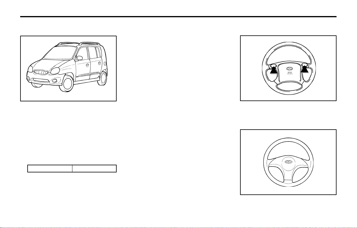
FEATURES OF YOUR HYUNDAIFEATURES OF YOUR HYUNDAI
FEATURES OF YOUR HYUNDAIFEATURES OF YOUR HYUNDAI
FEATURES OF YOUR HYUNDAI
1- 33
o Always drive your vehicle at a moderate
speed.
o To use the roof rails as a roof rack, you
must fit the roof rails with two or more
crossrails or equivalent.
WARNING:
o In case of hectical steering movements or
bad fixation the luggage can fall from the
vehicle and injure persons or property.
Make sure that the luggage is properly
fixed and avoid sudden movement
(e.g.dashing start, fast turning
manoeuvres, hard cornering, sudden brak-
ing) Check frequently whether the roof
rack is properly fastened.
o Voluminous, large, long or flat objects can
change the aerodynamic drag of vehicle
or can suddenly been lifted by the wind.
The driver could lose control of the car
and provoke an accident and injuries. For
this reason, drive at reduced speed when
you transport such objects.
o The maximum load limit of the roof rack
including luggage load is 30 kg.
B630A02X-GAT
ROOF RACK (If installed)
ROOF RACK
If your Hyundai has a roof rack, you can load
things on top of your vehicle. Crossrails and
fixing components to adapt the roof rack on your
vehicle may be obtained from an authorized
Hyundai dealer.
Hyundai dealers are prepared to provide high
quality service that may be required.
CAUTION:
o The following specifications are recom-
mended when loading cargo or luggage.
30 kg (66 lb)
B630A01X
o Loading cargo or luggage above 30 kg (66
lb) on the roof rack may damage your
vehicle.
o When you carry large objects, never let
them hang over the rear or the sides of
your vehicle.
B610B01A-GAT
HORN (Without Airbag)
Press the center hub of the steering wheel to
sound the horn.
B610B01A
B610A01A-GAT
HORN (With Airbag) (If installed)
Press either of the side buttons on the steering
wheel to sound the horn.
HNV.OM057
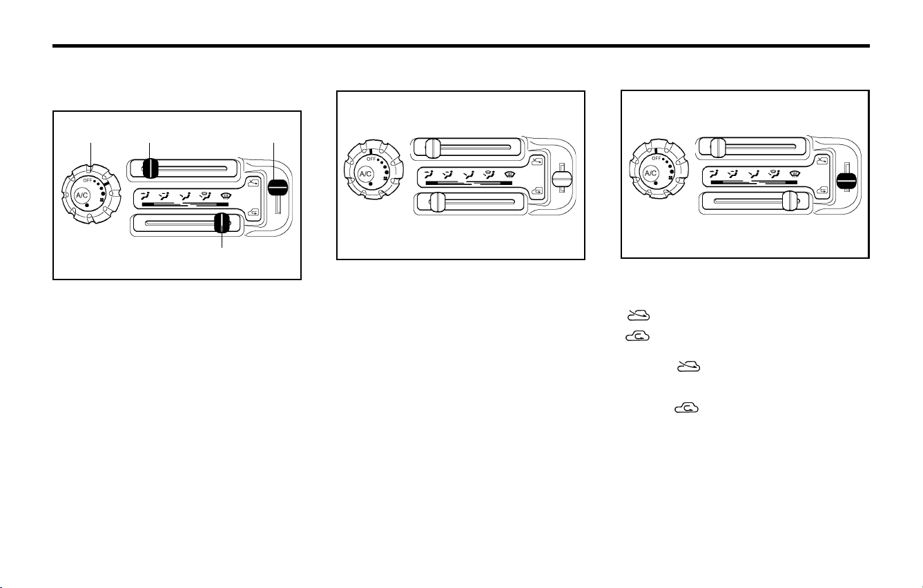
FEATURES OF YOUR HYUNDAIFEATURES OF YOUR HYUNDAI
FEATURES OF YOUR HYUNDAIFEATURES OF YOUR HYUNDAI
FEATURES OF YOUR HYUNDAI
1- 34
This is used to select fresh outside air or recircu-
lation of inside air.
Fresh
Recirculation
With the " " mode selected, air enters the
vehicle from outside and is heated or cooled
according to the other functions selected.
With the " " mode selected, air from within
the passenger compartment is drawn through
the heating system and heated or cooled accord-
ing to the other functions selected.
B670C02A-AAT
Air Intake Control
B670C02A-1
B670B02X-GAT
Fan Speed Control (Blower Control)
This is used to turn the blower fan on and off and
to select the fan speed.
The blower fan speed, and therefore the volume
of air delivered from the system, may be con-
trolled manually by setting the blower control
between the "1" and "4" position.
B670B01X-1
B680A01X-GAT
HEATING AND VENTILATION
(If installed)
There are four controls for the heating and cool-
ing system. They are:
1. Fan Speed Control.
This is used to turn the fan on and select the
fan speed.
2. Air Flow Control.
This is used to direct the flow of air. Air can be
directed to the floor, dashboard outlets, or
windshield. Five symbols are used to repre-
sent Face, Bi-Level, Floor, Floor-Defrost and
Defrost air positions.
3. Air Intake Control.
This allows you to select fresh outside air or
to circulate inside air.
4. Temperature Control.
This is used to turn the heating system on and
off and to select the degree of heating de-
sired.
B680A01X-1
12
4
3
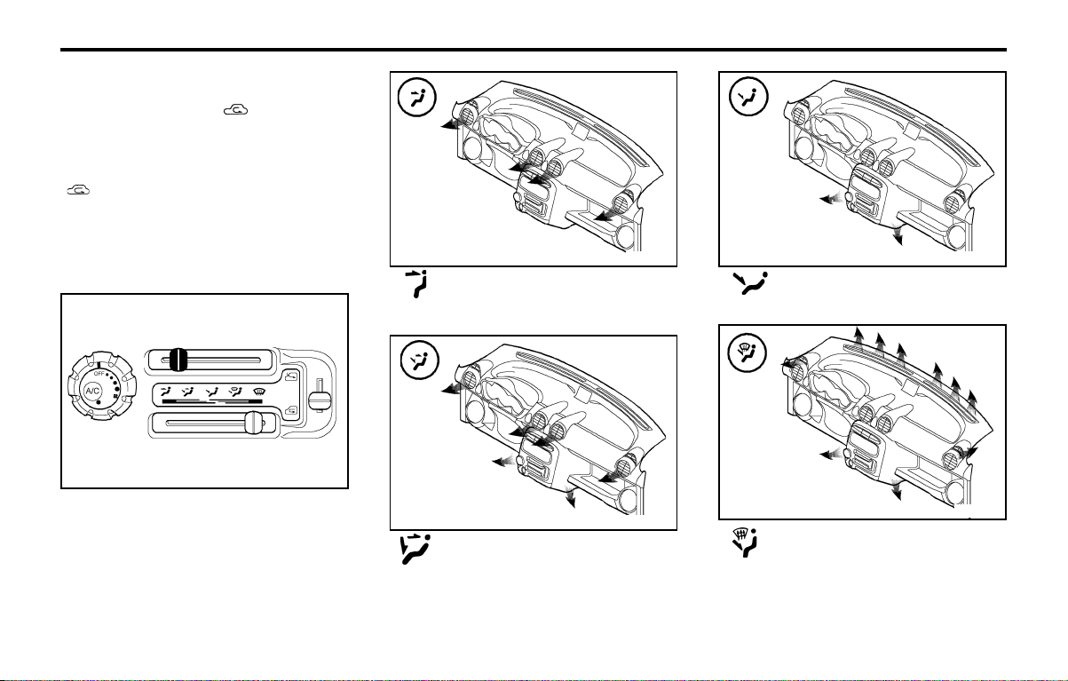
FEATURES OF YOUR HYUNDAIFEATURES OF YOUR HYUNDAI
FEATURES OF YOUR HYUNDAIFEATURES OF YOUR HYUNDAI
FEATURES OF YOUR HYUNDAI
1- 35
B670D02A-AAT
Air Flow Control
NOTE:
It should be noted that prolonged operation
of the heating system in " " mode will give
rise to misting of the windshield and side
windows and the air within the passenger
compartment will become stale. In addition
prolonged use of the air conditioning with the
" " mode selected may result in the air
within the passenger compartment becom-
ing excessively dry.
This is used to direct the flow of air. Air can be
directed to the floor, dashboard outlets, or wind-
shield. Five symbols are used to represent Face,
Bi-Level, Floor, Floor-Defrost and Defrost air
position.
B670D02A-1
Face-Level
Selecting the "Face" mode will cause air to be
discharged through the face level vents.
Bi-Level
Air is discharged through the face vents and the
floor vents. This makes it possible to have cooler
air from the dashboard vents and warmer air
from the floor outlets at the same time.
B670D01X
B670D02X
Floor-Level
Air is discharged through the floor vents.
Floor-Defrost Level
Air is discharged through the windshield defrost
vents and the floor vents.
B670D03X
B670D04X
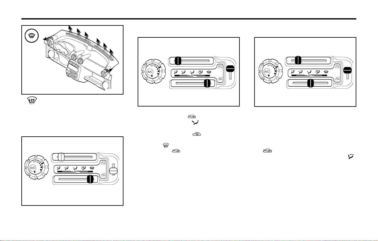
FEATURES OF YOUR HYUNDAIFEATURES OF YOUR HYUNDAI
FEATURES OF YOUR HYUNDAIFEATURES OF YOUR HYUNDAI
FEATURES OF YOUR HYUNDAI
1- 36
B700A01A-AAT
BI-LEVEL HEATING
Your Hyundai is equipped with bi-level heating
controls. This makes it possible to have cooler air
from the dashboard vents and warmer air from
the floor outlets at the same time. To use this
feature:
o Set the air intake control to the fresh air
( ) position.
o Set the air flow control at the bi-level ( )
position.
o Set the temperature control between "Cool"
and "Warm".
B700A01A-1
For normal heating operation, set the air intake
control to the fresh air ( ) position and the air
flow control to the floor ( ) position.
For faster heating, the air intake control should
be set in the recirculate ( ) position.
If the windows fog up, set the air flow control to
the defrost ( ) position and the air intake control
to the fresh air ( ) position.
For maximum heat, move the temperature con-
trol to "Warm".
B690A01A-AAT
HEATING CONTROLS
B680A01X-1
B670E02A-AAT
Temperature Control
This is used to turn the heating system on and off
and to select the degree of heating desired.
B670E02A-1
Defrost-Level
Air is discharged through the windshield defrost
vents.
B670D05X
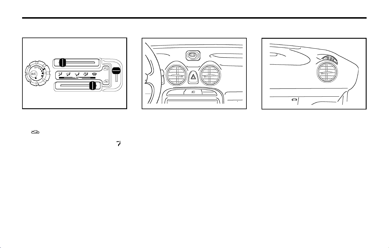
FEATURES OF YOUR HYUNDAIFEATURES OF YOUR HYUNDAI
FEATURES OF YOUR HYUNDAIFEATURES OF YOUR HYUNDAI
FEATURES OF YOUR HYUNDAI
1- 37
B710B01S-AAT
Center Ventilator
The center ventilators are located in the middle of
the dashboard. The direction of air flow from the
vents in the center of dashboard is adjustable. To
control the direction of the air flow, move the knob
in the center of vent up-and-down and side-to-
side.
B710B01X
B710A01A-AAT
VENTILATION
To operate the ventilation system:
o Set the air intake control at the fresh air
( ) position.
o To direct all intake air to the dashboard vents,
set the airflow control to the face ( )
position.
o Adjust the fan speed control to the desired
speed.
o Set the temperature control between "Cool"
and "Warm".
B680A01X-1
The side ventilators are located on each side of
the dashboard.
To change the direction of the air flow, move the
knob in the center of vent up-and-down and side-
to-side.
B710C01X-GAT
Side Ventilator
B710C02X
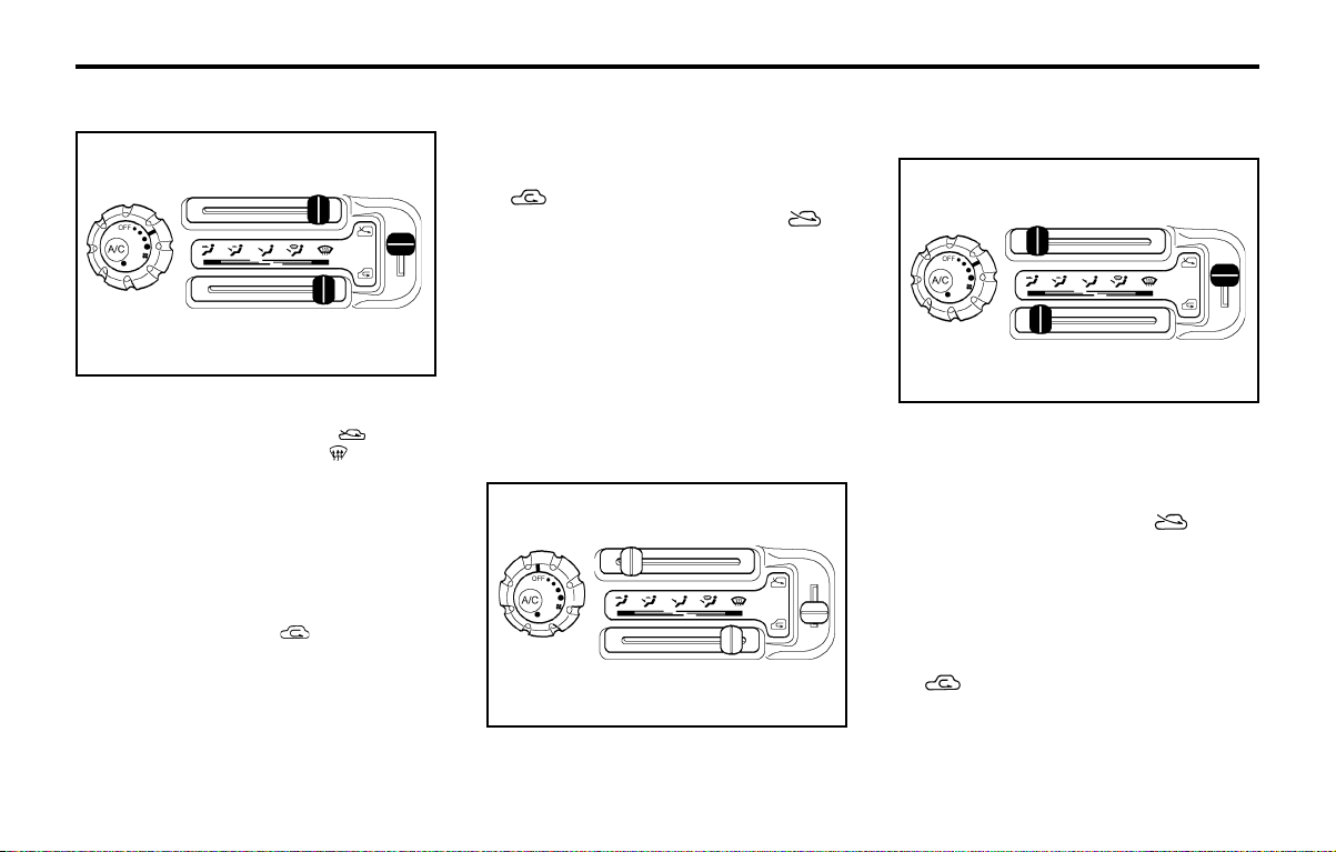
FEATURES OF YOUR HYUNDAIFEATURES OF YOUR HYUNDAI
FEATURES OF YOUR HYUNDAIFEATURES OF YOUR HYUNDAI
FEATURES OF YOUR HYUNDAI
1- 38
B740B01X-GAT
Air Conditioning Operation (If installed)
Cooling
To use the air conditioning to cool interior:
o Turn on the fan control switch.
o Turn on the air conditioning switch by pushing
in on the switch.
o Set the air intake control to the position.
o Set the temperature control to "Cool". ("Cool"
provides maximum cooling. The temperature
may be moderated by moving the control
toward "Warm".)
o Adjust the fan control to the desired speed.
For greater cooling, turn the fan control to one
of the higher speeds or temporarily select the
position on the air intake control.
B740B01X-1
B730A01A-AAT
OPERATION TIPS
o To keep dust or unpleasant fumes from enter-
ing the car through the ventilation system,
temporarily set the air intake control at the
position.
Be sure to return the control to the
position when the irritation has passed to
keep fresh air in the vehicle. This will help
keep the driver alert and comfortable.
o Air for the heating/cooling system is drawn in
through the grilles just ahead of the wind-
shield. Care should be taken that these are
not blocked by leaves, snow, ice or other
obstructions.
B740A01X-GAT
AIR CONDITIONING SWITCH
(If installed)
The air conditioning is turned on by pushing the
A/C button in the fan control rotary switch.
B740A01X-1
B720A02X-GAT
DEFROSTING/DEFOGGING
To use the heating/ventilation system to defrost
or defog the windshield:
o Set the air intake control to the position.
o Set the air flow control to the position.
o Set the temperature control to a comfortably
warm position.
o Set the fan speed control to position 3 or 4.
o If vehicle is so equipped, push on the A/C for
increased defogging action.
NOTE:
In high humidity areas the A/C can be used
with the air intake in the position
for increased defogging action.
B720A01X-1
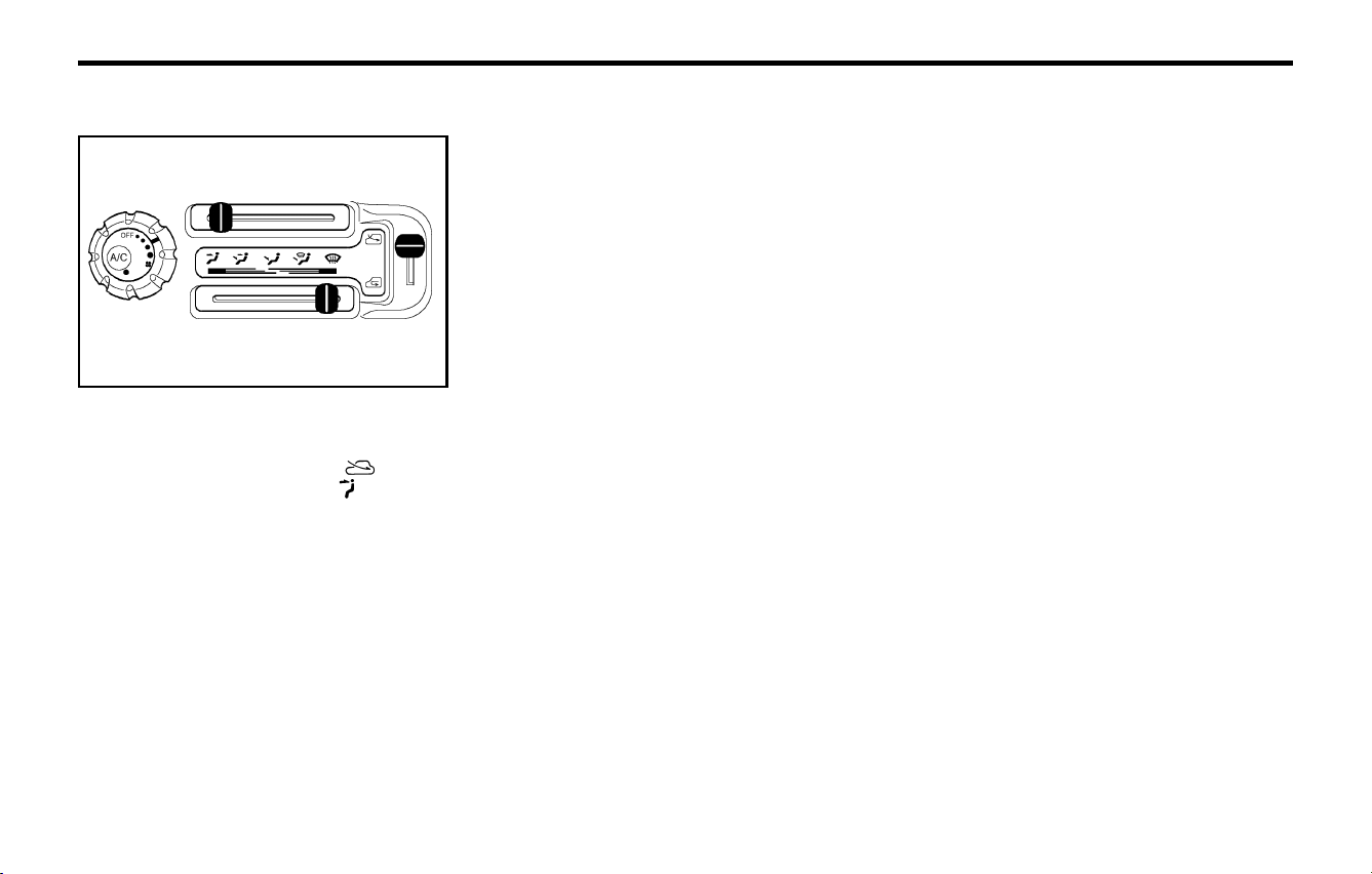
FEATURES OF YOUR HYUNDAIFEATURES OF YOUR HYUNDAI
FEATURES OF YOUR HYUNDAIFEATURES OF YOUR HYUNDAI
FEATURES OF YOUR HYUNDAI
1- 39
B740D01A-AAT
Operation Tips
o If the interior of the car is hot when you first
get in, open the windows for a few minutes to
expel the hot air.
o When you are using the air conditioning sys-
tem, keep all windows closed to keep hot air
out.
o When moving slowly, as in heavy traffic, shift
to a lower gear. This increases engine speed,
which in turn increases the speed of the air
conditioning compressor.
o On steep grades, turn the air conditioner off
to avoid the possibility of the engine over-
heating.
o During winter months or in periods when the
air conditioning is not used regularly, run the
air conditioning once every month for a few
minutes. This will help circulate the lubricants
and keep your system in peak operating
condition.
For dehumidified heating:
o Turn on the fan control switch.
o Turn on the air conditioning switch.
o Set the air intake control to the position.
o Set the air flow control to the position.
o Adjust the fan control to the desired speed.
o For more rapid action, set the fan at one of the
higher speeds.
o Adjust the temperature control to provide the
desired amount of warmth.
B740C01X-GAT
De-Humidified Heating
B680A01X-1
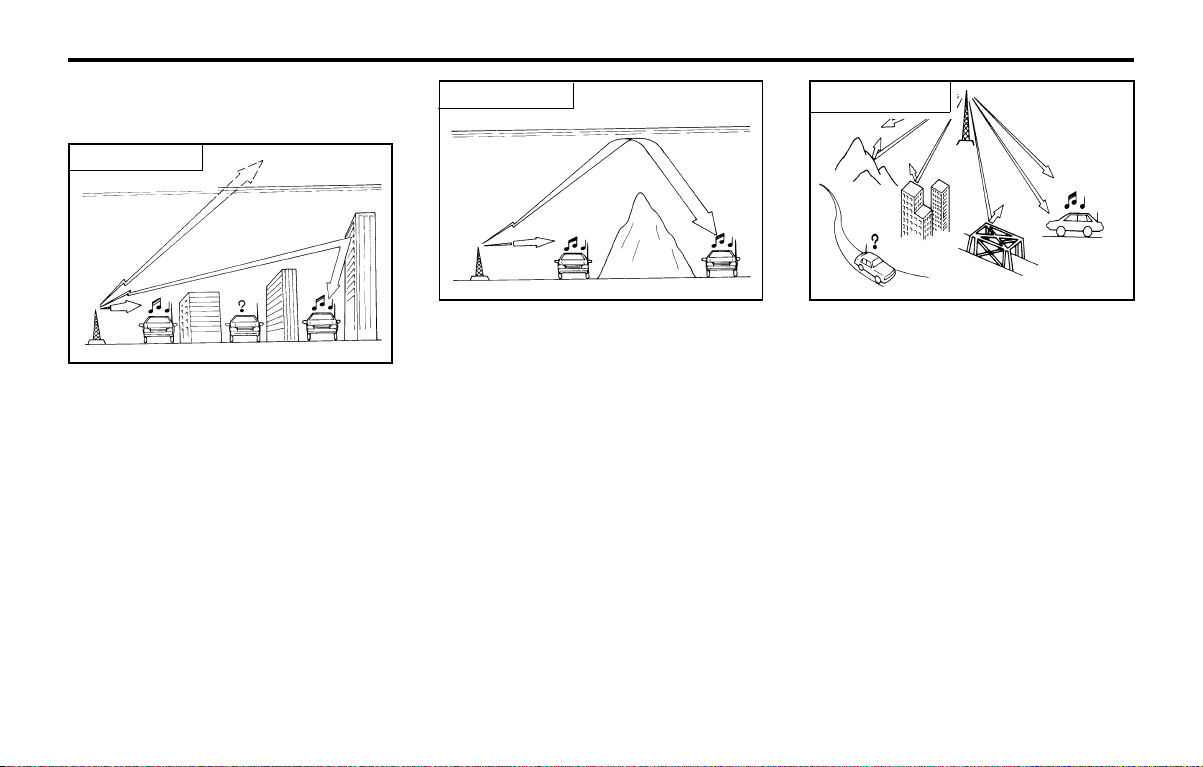
FEATURES OF YOUR HYUNDAIFEATURES OF YOUR HYUNDAI
FEATURES OF YOUR HYUNDAIFEATURES OF YOUR HYUNDAI
FEATURES OF YOUR HYUNDAI
1- 40
Ionosphere
SSAR011A
AM reception
AM broadcasts can be received at greater dis-
tances than FM broadcasts. This is because AM
radio waves are transmitted at low frequency.
These long, low frequency radio waves can
follow the curvature of the earth rather than
travelling straight out into the ionosphere. In
addition, they curve around obstructions so that
they can provide better signal coverage.
B750A02A-AAT
STEREO SOUND SYSTEM
How Car Audio Works
Ionosphere
FM reception
SSAR010A
AM and FM radio signals are broadcast from
transmitter towers located around your city. They
are intercepted by the radio antenna on your car.
This signal is then received by the radio and sent
to your car speakers.
When a strong radio signal has reached your
vehicle, the precise engineering of your audio
system ensures high quality reproduction. How-
ever, in some cases the signal coming to your
vehicle is not strong and clear. This can be due
to factors such as the distance from the radio
station, closeness of other strong radio stations
or the presence of buildings, bridges or other
large obstructions in the area.
FM broadcasts are transmitted at high frequency
and do not bend to follow the earth's surface.
Because of this, FM broadcasts generally begin
to fade at short distances from the station. Also,
FM signals are easily affected by buildings, moun-
tains, or other obstructions. These can result in
certain listening conditions which might lead you
to believe a problem exists with your radio. The
following conditions are normal and do not indi-
cate radio trouble:
Mountains
Buildings
Obstructed area
Iron bridges
Unobstructed
area
FM radio station
SSAR012A
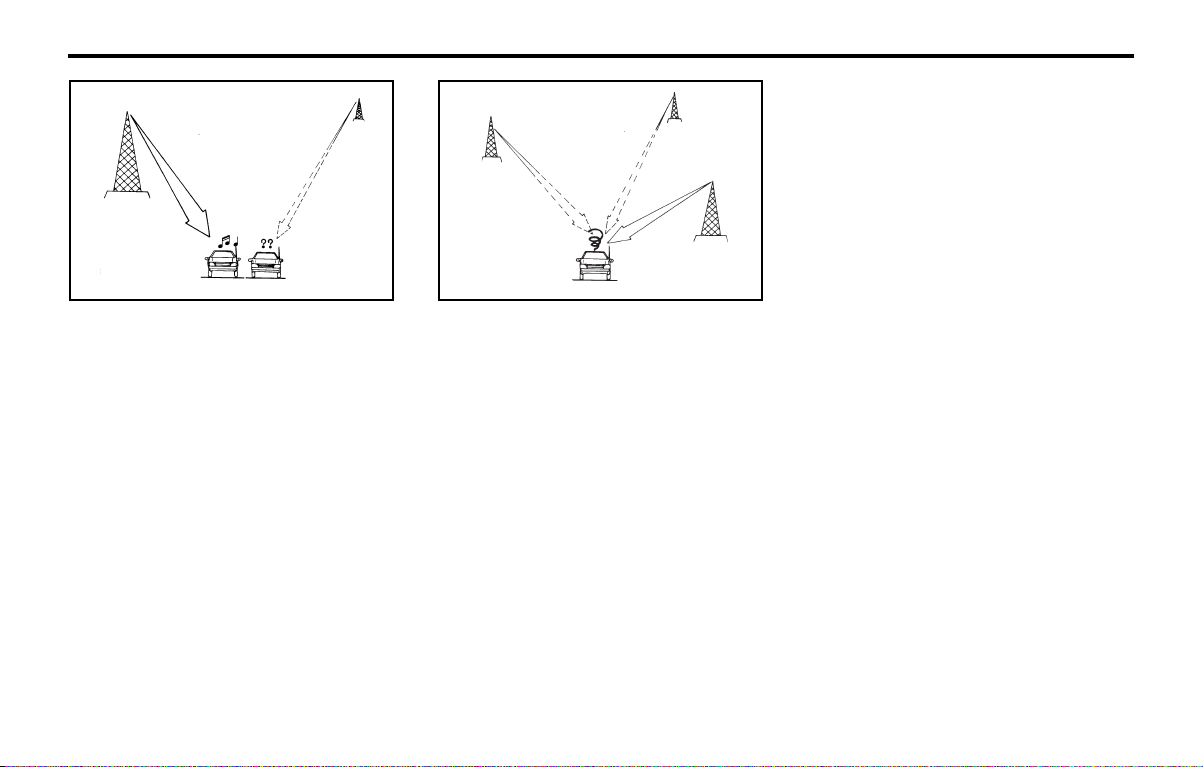
FEATURES OF YOUR HYUNDAIFEATURES OF YOUR HYUNDAI
FEATURES OF YOUR HYUNDAIFEATURES OF YOUR HYUNDAI
FEATURES OF YOUR HYUNDAI
1- 41
B750B02Y-AAT
Using a cellular phone or a two-way
radio
When a cellular phone is used inside the vehicle,
noise may be produced from the audio equip-
ment. This does not mean that something is
wrong with the audio equipment. In such a case,
use the cellular phone at a place as far as
possible from the audio equipment.
CAUTION:
When using a communication system such
as a cellular phone or a radio inside the
vehicle, a separate external antenna must be
fitted. When a cellular phone or a radio set is
used with an internal antenna alone, it may
interfere with the vehicle's electrical system
and adversely affect safe operation of the
vehicle.
WARNING:
Don't use a cellular phone when you are
driving, you must stop at a safe place to use
a cellular phone.
SSAR013A
o Fading - As your car moves away from the
radio station, the signal will weaken and sound
will begin to fade. When this occurs, we
suggest that you select another stronger sta-
tion.
o Flutter/Static - Weak FM signals or large
obstructions between the transmitter and your
radio can disturb the signal causing static or
fluttering noises to occur. Reducing the treble
level may lessen this effect until the distur-
bance clears.
SSAR014A
o Station Swapping - As a FM signal weakens,
another more powerful signal near the same
frequency may begin to play. This is because
your radio is designed to lock onto the clearest
signal. If this occurs, select another station
with a stronger signal.
o Multi-Path Cancellation - Radio signals being
received from several directions can cause
distortion or fluttering. This can be caused by
a direct and a reflected signal from the same
station, or by signals from two stations with
close frequencies. If this occurs, select anoth-
er station until the condition has passed.
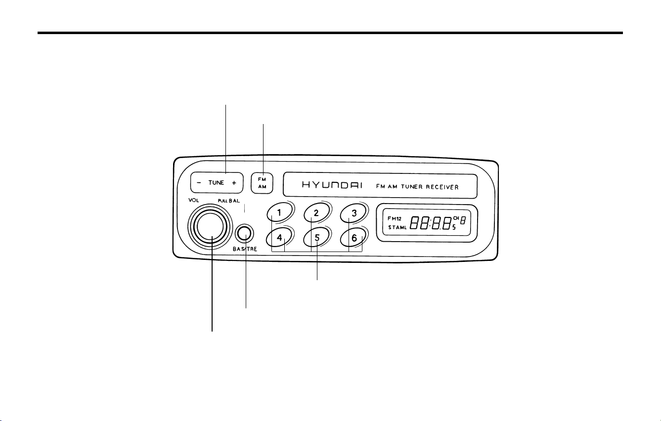
FEATURES OF YOUR HYUNDAIFEATURES OF YOUR HYUNDAI
FEATURES OF YOUR HYUNDAIFEATURES OF YOUR HYUNDAI
FEATURES OF YOUR HYUNDAI
1- 42
B901A01X
B901A02X-GAT
STEREO RADIO OPERATION (HMR 90) (If installed)
1. POWER ON-OFF/VOLUME/BALANCE Control Knob
2. BASS/TREBLE Control Knob
5. PRESET Buttons
4. TUNE/SEEK Select Button
3. BAND Selector

FEATURES OF YOUR HYUNDAIFEATURES OF YOUR HYUNDAI
FEATURES OF YOUR HYUNDAIFEATURES OF YOUR HYUNDAI
FEATURES OF YOUR HYUNDAI
1- 43
B901B02X-GAT
1. POWER ON-OFF/VOLUME CON-
TROL KNOB
The radio unit may be operated when the ignition
key is in the "ACC" or "ON" position. Rotate
the knob clockwise to switch the radio unit on,
and to increase the volume.
The LCD shows the radio frequency in the radio
mode. Turn the knob counterclockwise to reduce
the volume, and to switch the radio unit off.
BAL (Balance Control) Knob
Pull and turn the control knob clockwise to em-
phasize right speaker sound. (Left speaker sound
will be attenuated). When the control knob is
turned counterclockwise, left speaker sound will
be emphasized. (Right speaker sound will be
attenuated).
2. BASS Control Knob
Press to pop the knob out and turn to the left or
right for the desired bass tone.
TREBLE Control Knob
Further pull-lock position of popped-up knob.
Turn to the left or right for the desired treble tone.
3. BAND Selector
Pressing the button changes the AM, FM1
and FM2 bands. The mode selected is displayed
on LCD.
4. TUNE (manual) Select Button
Press the (+) side or (-) side to increase or to
decrease the frequency. With the button held
down for 0.5 sec. or more, the stop signal (broad-
casting radio wave) is ignored and channel se-
lection continues.
SEEK Operation (Automatic Channel
Selection)
Press the TUNE select button 1 sec. or more.
When the (+) side is pressed, the unit will auto-
matically tune to the next higher frequency and
when the (-) side is pressed, it will automatically
tune to the next lower frequency.
5. PRESET STATION SELECT
Six (6) stations for AM, FM and FM2 respectively
can be preset in the electronic memory circuit on
this unit.
FM
AM
HOW TO PRESET STATIONS
Six AM and twelve FM stations may be pro-
grammed into the memory of the radio. Then, by
simply pressing the band select button and/or
one of the six station select buttons, you may
recall any of these stations instantly. To program
the stations, follow these steps:
o Press band selector to set the band for AM,
FM and FM2.
o Select the desired station to be stored by
seek, scan or manual tuning.
o Determine the preset station select button
you wish to use to access that station.
o Press the station select button for more than
two seconds. A select button indicator will
show in the display indicating which select
button you have depressed. The frequency
display will flash after it has been stored into
the memory. You should then release the
button, and proceed to program the next
desired station. A total of 18 stations can be
programmed by selecting one AM and two
FM stations per button.
o When completed, any preset station may be
recalled by selecting AM, FM or FM2 band
and the appropriate station button.
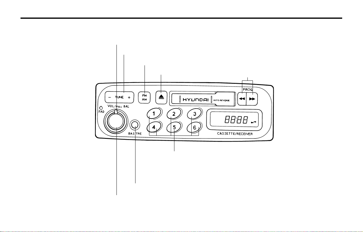
FEATURES OF YOUR HYUNDAIFEATURES OF YOUR HYUNDAI
FEATURES OF YOUR HYUNDAIFEATURES OF YOUR HYUNDAI
FEATURES OF YOUR HYUNDAI
1- 44
B900A01X
B900A02X-GAT
STEREO RADIO AND CASSETTE TAPE PLAYER OPERATION (H900A) (If installed)
1. POWER ON-OFF/VOLUME/BALANCE Control Knob
2. BASS/TREBLE Control Knob
5. PRESET Buttons
8. FADER Control Knob
4. TUNE/SEEK Select Button
3. BAND Selector
6. TAPE EJECT Button
7. TAPE PROGRAM Button

FEATURES OF YOUR HYUNDAIFEATURES OF YOUR HYUNDAI
FEATURES OF YOUR HYUNDAIFEATURES OF YOUR HYUNDAI
FEATURES OF YOUR HYUNDAI
1- 45
B900B02X-GAT
1. POWER ON-OFF/VOLUME CON-
TROL KNOB
The radio unit may be operated when the ignition
key is in the "ACC" or "ON" position. Rotate
the knob clockwise to switch the radio unit on and
to increase the volume.
The LCD shows the radio frequency in the radio
mode, or the tape direction indicator in the tape
mode. Turn the knob counterclockwise to reduce
the volume and to switch the radio unit off.
BAL (Balance Control) Knob
Pull and turn the control knob clockwise to em-
phasize right speaker sound. (Left speaker sound
will be attenuated) When the control knob is
turned counterclockwise, left speaker sound will
be emphasized. (Right speaker sound will be
attenuated)
2. BASS Control Knob
Press to pop the knob out and turn to the left or
right for the desired bass tone.
TREBLE Control Knob
Further pull-lock position of popped-up knob.
Turn to the left or right for the desired treble tone.
3. BAND Selector
Pressing the button changes the AM, FM1
and FM2 bands. The mode selected is displayed
on LCD.
4. TUNE (manual) Select Button
Press the (+) side or (-) side to increase or to
decrease the frequency. With the button held
down for 0.5 sec. or more, the stop signal (broad-
casting radio wave) is ignored and channel se-
lection continues.
SEEK Operation (Automatic Channel
Selection)
Press the TUNE select button 1 sec. or more.
When the (+) side is pressed, the unit will auto-
matically tune to the next higher frequency and
when the (-) side is pressed, it will automatically
tune to the next lower frequency.
5. PRESET STATION SELECT Button
Six (6) stations for AM, FM and FM2 respectively
can be preset in the electronic memory circuit on
this unit.
FM
AM
HOW TO PRESET STATIONS
Six AM and twelve FM stations may be pro-
grammed into the memory of the radio. Then, by
simply pressing the band select button and/or
one of the six station select buttons, you may
recall any of these stations instantly. To program
the stations, follow these steps:
o Press band selector to set the band for AM,
FM, and FM2.
o Select the desired station to be stored by
seek, scan or manual tuning.
o Determine the preset station select button
you wish to use to access that station.
o Press the station select button for more than
two seconds. A select button indicator will
show in the display indicating which select
button you have depressed. The frequency
display will flash after it has been stored into
the memory. You should then release the
button, and proceed to program the next
desired station. A total of 18 stations can be
programmed by selecting one AM and one
FM station per button.
o When completed, any preset station may be
recalled by selecting AM, FM or FM2 band
and the appropriate station button.

FEATURES OF YOUR HYUNDAIFEATURES OF YOUR HYUNDAI
FEATURES OF YOUR HYUNDAIFEATURES OF YOUR HYUNDAI
FEATURES OF YOUR HYUNDAI
1- 46
6. TAPE EJECT Button
To elect the tape, press the button.
7. TAPE PROGRAM
When you press the button whose arrow is in the
same direction as the tape play arrow in the
display the tape will advance at high speed.
When you press the button whose arrow is in the
opposite direction to the tape play arrow in the
display the tape will rewind at high speed.
To stop FF or REW action, press the opposite
button. When you press two buttons simulta-
neously you play the reverse side of the tape and
an arrow will appear in the display to show tape
direction.
8. FAD (Fader Control) Knob
Turn the control knob clockwise to emphasize
front speaker sound (Rear speaker sound will be
attenuated). When the control knob is turned
counterclockwise, rear speaker sound will be
emphasized (Front speaker sound will be atten-
uated).
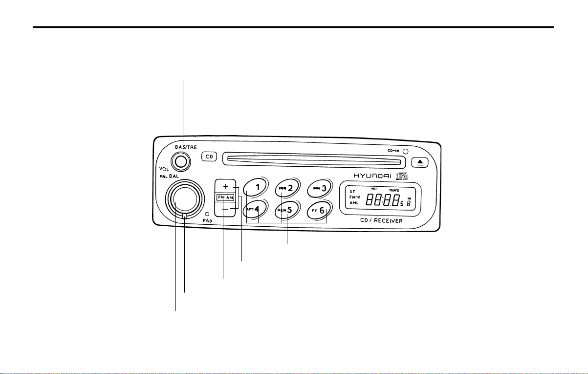
FEATURES OF YOUR HYUNDAIFEATURES OF YOUR HYUNDAI
FEATURES OF YOUR HYUNDAIFEATURES OF YOUR HYUNDAI
FEATURES OF YOUR HYUNDAI
1- 47
B922A01X
B922A02X-GAT
STEREO RADIO OPERATION (H922M) (If installed)
3. BASS/TREBLE Control Knob
1. POWER ON-OFF/VOLUME/BALANCE Control Knob
2. FADER Control Knob
6. PRESET Buttons
5. TUNE/SEEK Select Button
4. BAND Selector

FEATURES OF YOUR HYUNDAIFEATURES OF YOUR HYUNDAI
FEATURES OF YOUR HYUNDAIFEATURES OF YOUR HYUNDAI
FEATURES OF YOUR HYUNDAI
1- 48
B922B03X-GAT
1. POWER ON-OFF/VOLUME
CONTROL KNOB
The radio unit may be operated when the ignition
key is in the "ACC" or "ON" position. The clock
will be displayed automatically, although the ra-
dio unit has gone out. Press the button to switch
the power on. The LCD shows the radio fre-
quency in the radio mode or the CD track indica-
tor in the CD mode. To switch the power off,
press the button again.
VOLUME Control
Rotate the knob clockwise to increase the vol-
ume and turn the knob counterclockwise to re-
duce the volume.
BALANCE Control
Pull and turn the control knob clockwise to em-
phasize right speaker sound. (Left speaker sound
will be attenuated) When the control knob is
turned counterclockwise, left speaker sound will
be emphasized. (Right speaker sound will be
attenuated)
2. FAD (Fader Control) Knob
Turn the control knob counterclockwise to em-
phasize front speaker sound. (Rear speaker
sound will be attenuated) When the control knob
is turned clockwise, rear speaker sound will be
emphasized. (Front speaker sound will be atten-
uated)
FM/AM
6. PRESET STATION SELECT Button
Six (6) stations for AM, FM and FM2 respectively
can be preset in the electronic memory circuit on
this unit.
HOW TO PRESET STATIONS
Six AM and twelve FM stations may be pro-
grammed into the memory of the radio. Then, by
simply pressing the band select button and/or
one of the six station select buttons, you may
recall any of these stations instantly. To program
the stations, follow these steps:
o Press band selector to set the band for AM,
FM, and FM2.
o Select the desired station to be stored by
seek, scan or manual tuning.
o Determine the preset station select button
you wish to use to access that station.
o Press the station select button for more than
two seconds. A select button indicator will
show in the display indicating which select
button you have depressed. The frequency
display will flash after it has been stored into
the memory. You should then release the
button, and proceed to program the next
desired station. A total of 18 stations can be
programmed by selecting one AM and one
FM station per button.
o When completed, any preset station may be
recalled by selecting AM, FM or FM2 band
and the appropriate station button.
3. BASS/TREBLE Control Knob
BASS Control Knob
Press to pop the knob out and turn to the left or
right for the desired bass tone.
TREBLE Control Knob
Further pull-lock position of popped-up knob.
Turn to the left or right for the desired treble tone.
4. BAND Selector
Pressing the button changes the AM, FM1
and FM2 bands. The mode selected is displayed
on LCD.
5. TUNE (Manual) Select Button
Press the (+) side or (-) side to increase or to
decrease the frequency. With the button held
down for 0.5 sec. or more, the stop signal (broad-
casting radio wave) is ignored and channel se-
lection continues.
SEEK Operation (Automatic Channel
Selection)
Press the TUNE select button 1 sec. or more,
and releasing will automatically tune the next
available station. When the (+) side is pressed
longer than 1 second and releasing will automat-
ically tune the next higher frequency and when
the (-) side is pressed longer than 1 second and
releasing will automatically tune the next lower
frequency.

FEATURES OF YOUR HYUNDAIFEATURES OF YOUR HYUNDAI
FEATURES OF YOUR HYUNDAIFEATURES OF YOUR HYUNDAI
FEATURES OF YOUR HYUNDAI
1- 49
B922A01X
B922E02X-GAT
COMPACT DISK PLAYER OPERATION (H922M) (If installed)
4. REPEAT
3. TRACK UP/DOWN
5. EJECT Button
2. FF/REW
1. STOP

FEATURES OF YOUR HYUNDAIFEATURES OF YOUR HYUNDAI
FEATURES OF YOUR HYUNDAIFEATURES OF YOUR HYUNDAI
FEATURES OF YOUR HYUNDAI
1- 50
B922F01X-GAT
1. STOP
o Insert the CD to start CD playback, during the
radio operation.
o Press the button to stop CD playback
and to change the source to the radio.
2. FF/REW
While the disc is playing, press and hold FF
button to quickly move forward until you reach
the desired section of the track and vice versa.
3. TRACK UP/DOWN
o The desired track on the disc currently being
played can be selected using the track num-
ber.
o Pressing the button once increases the
track number by one and pressing the
button decreases it.
4. REPEAT
o To repeat the music you are listening to,
press the RPT button and to cancel music
repeat, press again.
FM/AM
5. EJECT Button
When the EJECT button is pressed with the CD
loaded, the CD is ejected.
NOTE:
o To ensure proper operation of the unit,
keep the vehicle interior temperature with-
in a normal range by using the vehicle's air
conditioning or heating system.
o When replacing the fuse, replace it with a
fuse having the correct capacity.
o The preset station frequencies are all
erased when the car battery is discon-
nected. Therefore, all data will have to be
set again if this should occur.
o Do not add any oil to the rotating parts.
o This equipment is designed to be used
only in a 12 volt DC battery system with
negative ground.
o This unit is made of precision parts. Do
not attempt to disassemble or adjust any
parts.
o When driving your vehicle, be sure to keep
the volume of the unit set low enough to
allow you to hear sounds coming from the
outside.
o Do not expose this equipment (including
the speakers and tape) to water or exces-
sive moisture.

FEATURES OF YOUR HYUNDAIFEATURES OF YOUR HYUNDAI
FEATURES OF YOUR HYUNDAIFEATURES OF YOUR HYUNDAI
FEATURES OF YOUR HYUNDAI
1- 51
B922G01A-GAT
AUDIO FAULT CODE
If you see any error indication in the display while using the CD or Tape mode, find the cause in the chart below. If you cannot clear the error indication, take
the car to your Hyundai dealer.
INDICATION
CAUSE SOLUTION
Er2
Er3
Er6
CDP DECK MECHANICAL ERROR
(EJECT ERROR, LOADING ERROR)
FOCUS ERROR
DATA READ ERROR
DISC ERROR
AFTER RESETTING THE AUDIO, PUSH THE EJECT BUTTON.
IF DISC IS NOT EJECTED, CONSULT YOUR HYUNDAI DEALER.
MAKE SURE THE DISC IS NOT SCRATCHED OR DAMAGED.
PRESS THE EJECT BUTTON AND PULL OUT THE DISC. THEN
INSERT A NORMAL CD DISC.
CHECK IF THE DISC IS INSERTED CORRECTLY IN THE CD PLAYER.
MAKE SURE THE DISC IS NOT SCRATCHED OR DAMAGED.
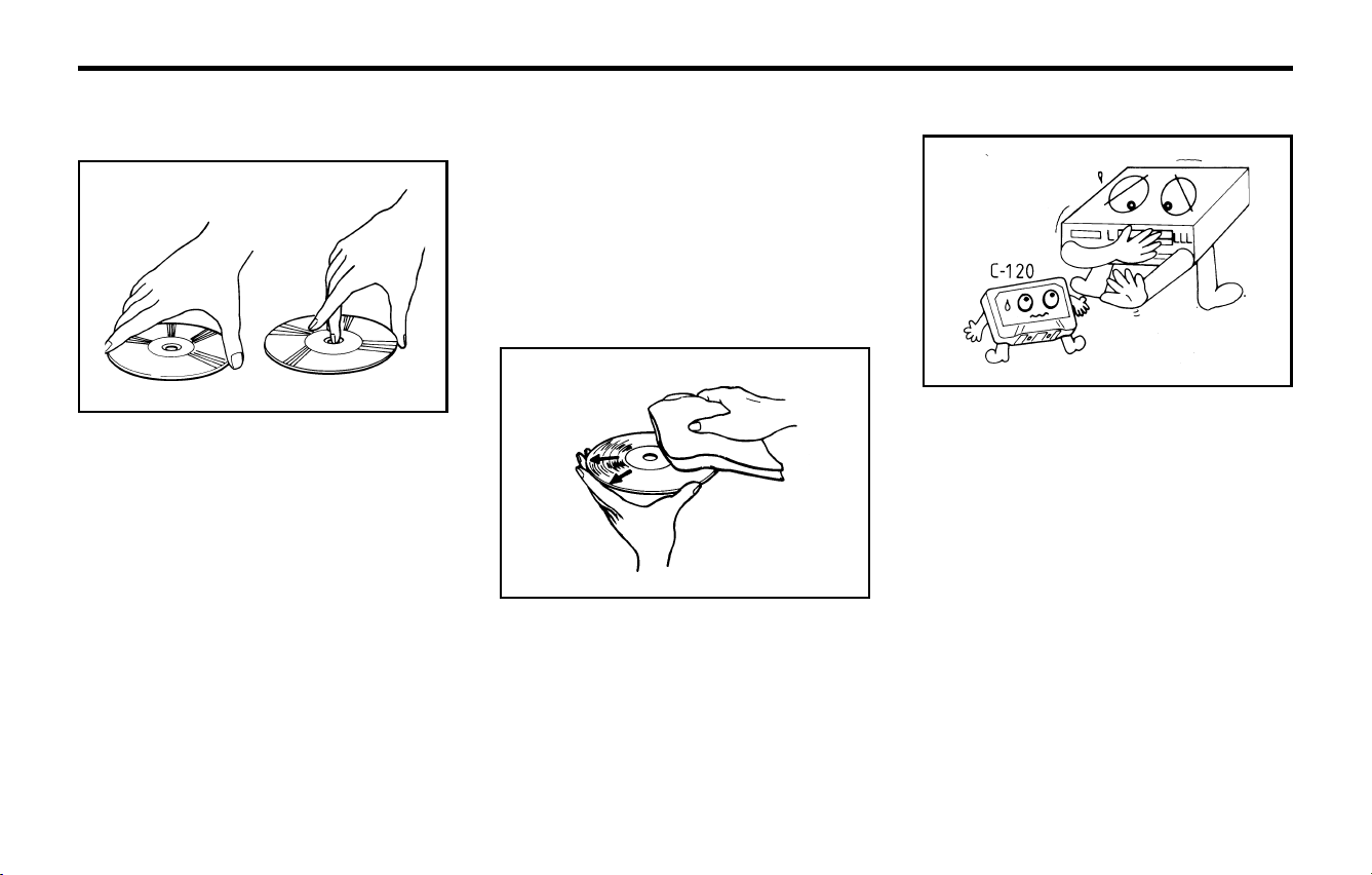
FEATURES OF YOUR HYUNDAIFEATURES OF YOUR HYUNDAI
FEATURES OF YOUR HYUNDAIFEATURES OF YOUR HYUNDAI
FEATURES OF YOUR HYUNDAI
1- 52
B850A01F-AAT
CARE OF DISC
Proper Handling
YL11240B
YL11250B
Handle your disc as shown. Do not drop the disc.
Hold the disc so you will not leave fingerprints on
the surface. If the surface is scratched,
it may cause the pickup to skip signal tracks. Do
not affix tape, paper, or gummed labels on the
disc. Do not write on the disc.
Damaged Disc
Do not attempt to play damaged, warped or
cracked discs. These could severely damage
the playback mechanism.
Storage
When not in use, place your discs in their indi-
vidual case and store them in a cool place away
from the sun, heat, and dust.
Do not grip or pull out the disc with your hand
while the disc is being pulled into the unit by the
self loading mechanism.
Do not pull the unit from the dash immediately
after a disc is inserted or the eject switch has
been pressed. If the unit is pulled out before an
operation is completed, the disc will be unstable
in the unit and may be damaged. Do not attempt
to insert a disc into the unit when the unit is out of
the dash or the power is off.
Keep Your Discs Clean
Fingerprints, dust, or soil on the surface of a disc
could cause the pickup to skip signal tracks.
Wipe the surface clean with a clean soft cloth. If
the surface is heavily soiled, dampen a clean soft
cloth in a solution of mild neutral detergent to wipe
it clean. See drawing.
B860A01A-AAT
CARE OF CASSETTE TAPES
SSAR040B
Proper care of your cassette tapes will extend
the tape life and increase your listening enjoy-
ment. Always protect your tapes and cassette
cases from direct sunlight, severely cold and
dusty conditions. When not in use, cassettes
should always be stored in the original protective
cassette case. When the vehicle is very hot or
cold, allow the interior temperature to become
more comfortable before listening to your cas-
settes.
o Never leave a cassette inserted in the player
when not being played. This could damage
the tape player unit and the cassette tape.
o We strongly recommend against the use of
tapes longer than C-60 (60 minutes total).
Tapes such as C-120 or C-180 are very thin
and do not perform as well in the automotive
environment.
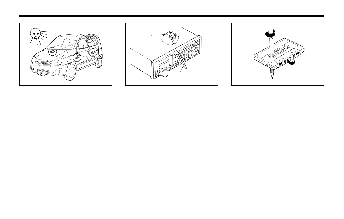
FEATURES OF YOUR HYUNDAIFEATURES OF YOUR HYUNDAI
FEATURES OF YOUR HYUNDAIFEATURES OF YOUR HYUNDAI
FEATURES OF YOUR HYUNDAI
1- 53
B860A02X
o Be sure that the cassette label is not loose or
peeling off or tape ejection may be difficult.
o Never touch or soil the actual audio tape
surfaces.
o Keep all magnetized objects, such as electric
motors, speakers or transformers away from
your cassette tapes and tape player unit.
o Store cassettes in a cool, dry place with the
open side facing down to prevent dust from
settling in the cassette body.
o Avoid repeated fast reverse usage to replay
one given tune or tape section. This can
cause poor tape winding to occur, and even-
tually cause excessive internal drag and poor
audio quality in the cassette. If this occurs, it
can sometimes be corrected by fast winding
the tape from end to end several times. If this
does not correct the problem, do not continue
to use the tape in your vehicle.
SSAR042B
Head
Cotton applicator
o The playback head, capstan and pinch rollers
will develop a coating of tape residue that can
result in deterioration of sound quality, such
as a wavering sound. They should be cleaned
monthly using a commercially available head
cleaning tape or special solution available
from audio specialty shops. Follow the suppli-
er's directions carefully and never oil any part
of the tape player unit.
o Always be sure that the tape is tightly wound
on its reel before inserting in the player.
Rotate a pencil in the drive sprockets to wind
up any slack.
SSAR053B
NOTE:
Look at a tape before you insert it. If the tape
is loose, tighten it by turning one of the hubs
with a pencil or your finger. If the label is
peeling off, do not put it in the drive mecha-
nism.
Do not leave tapes sitting where they are
exposed to hot, warm, or high humidity, such
as on top of the dashboard or in the player. If
a tape is exposed to extreme heat or cold, let
it reach a moderate temperature before put-
ting it in the player.
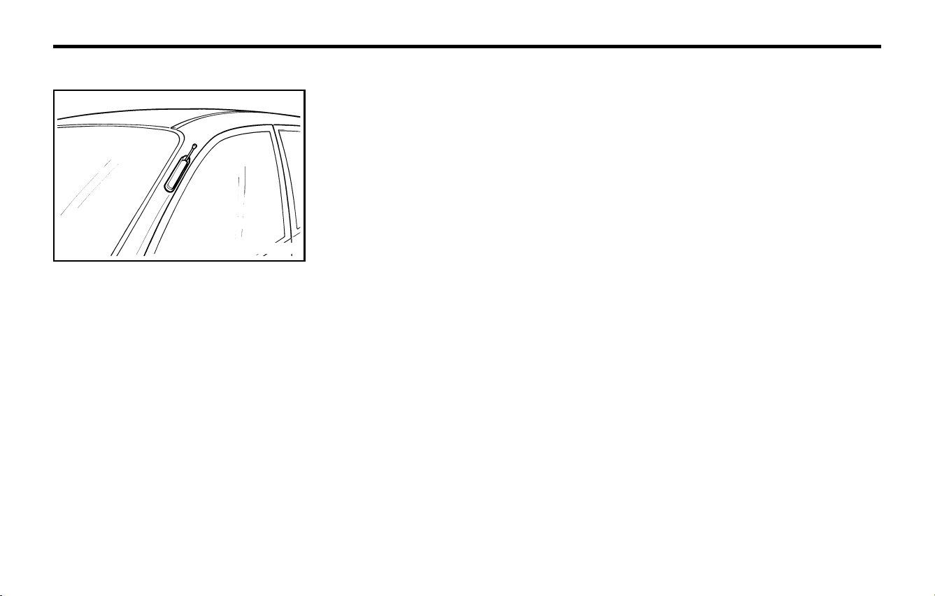
FEATURES OF YOUR HYUNDAIFEATURES OF YOUR HYUNDAI
FEATURES OF YOUR HYUNDAIFEATURES OF YOUR HYUNDAI
FEATURES OF YOUR HYUNDAI
1- 54
B870C01X-GAT
ANTENNA
Your car uses a manual stainless steel antenna
to receive both AM and FM broadcast signals.
Pull up the antenna using your fingers, as shown
in the drawing.
NOTE:
Before entering an automatic car wash or a
place with a low height clearance, turn off the
radio and be sure that the antenna is fully
retracted.
B870C02X

DRIVING YOUR HYUNDAIDRIVING YOUR HYUNDAI
DRIVING YOUR HYUNDAIDRIVING YOUR HYUNDAI
DRIVING YOUR HYUNDAI
2- 1
2. DRIVING YOUR HYUNDAI
C010A01A-AAT
WARNING: ENGINE EXHAUST CAN BE DANGEROUS!WARNING: ENGINE EXHAUST CAN BE DANGEROUS!
WARNING: ENGINE EXHAUST CAN BE DANGEROUS!WARNING: ENGINE EXHAUST CAN BE DANGEROUS!
WARNING: ENGINE EXHAUST CAN BE DANGEROUS!
Engine exhaust fumes can be extremely dangerous. If, at any time, you smell exhaust fumes inside the vehicle, open the
windows immediately.
o Do not inhale exhaust fumes.o Do not inhale exhaust fumes.
o Do not inhale exhaust fumes.o Do not inhale exhaust fumes.
o Do not inhale exhaust fumes.
Exhaust fumes contain carbon monoxide, a colorless, odorless gas that can cause unconsciousness and death by
asphyxiation.
o Be sure the exhaust system does not leak.o Be sure the exhaust system does not leak.
o Be sure the exhaust system does not leak.o Be sure the exhaust system does not leak.
o Be sure the exhaust system does not leak.
The exhaust system should be checked whenever the vehicle is raised to change the oil or for any other purpose. If you hear
a change in the sound of the exhaust or if you drive over something that strikes the underneath side of the car, have the
exhaust system checked as soon as possible by your Hyundai dealer.
o Do not run the engine in an enclosed area.o Do not run the engine in an enclosed area.
o Do not run the engine in an enclosed area.o Do not run the engine in an enclosed area.
o Do not run the engine in an enclosed area.
Letting the engine idle in your garage, even with the garage door open, is a hazardous practice. Never run the engine in your
garage any longer than it takes to start the engine and back the car out.
o Avoid idling the engine for prolonged periods with people inside the car.o Avoid idling the engine for prolonged periods with people inside the car.
o Avoid idling the engine for prolonged periods with people inside the car.o Avoid idling the engine for prolonged periods with people inside the car.
o Avoid idling the engine for prolonged periods with people inside the car.
If it is necessary to idle the engine for a prolonged period with people inside the car, be sure to do so only in an open area
with the air intake set at "Fresh" and the fan operating at one of the higher speeds so fresh air is drawn into the interior.
If you must drive with the tail gate open because you are carrying objects that make this necessary:
1. Close all windows.
2. Open side vents.
3. Set the air intake control at "Fresh", the air flow control at "Floor" or "Face" and the fan at one of the higher speeds.
To assure proper operation of the ventilation system, be sure the ventilation air intakes located just in front of the windshield
are kept clear of snow, ice, leaves or other obstructions.
22
22
2
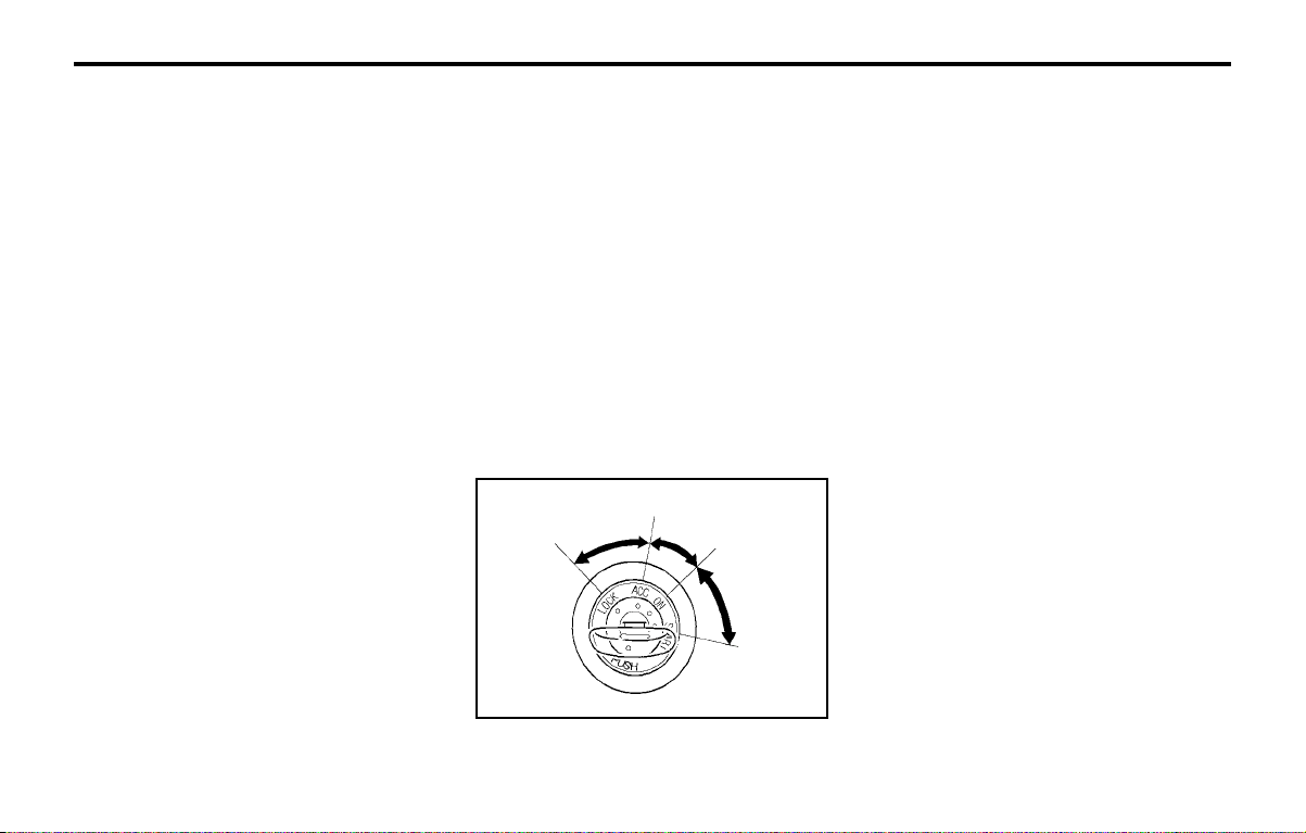
DRIVING YOUR HYUNDAIDRIVING YOUR HYUNDAI
DRIVING YOUR HYUNDAIDRIVING YOUR HYUNDAI
DRIVING YOUR HYUNDAI
2- 2
C020A01A-AAT
BEFORE STARTING THE ENGINEBEFORE STARTING THE ENGINE
BEFORE STARTING THE ENGINEBEFORE STARTING THE ENGINE
BEFORE STARTING THE ENGINE
Before you start the engine, you should always:
1. Look around the vehicle to be sure there are
no flat tires, puddles of oil, water or other
indications of possible trouble.
2. After entering the car, check to be sure the
parking brake is engaged.
3. Check that all windows, and lights are clean.
4. Check that the interior and exterior mirrors
are clean and in position.
5. Check your seat, seatback and headrest to
be sure they are in their proper positions.
6. Lock all the doors.
7. Fasten your seat belt and be sure that all
other occupants have fastened theirs.
8. Turn off all lights and accessories that are
not needed.
9. When you turn the ignition switch to "ON",
check that all appropriate warning lights are
operating and that you have sufficient fuel.
10.Check the operation of warning lights and all
bulbs when key is in the "ON" position.
o To start the engine, insert the ignition key
and turn it to the "START" position. Release
it as soon as the engine starts. Do not hold
the key in the "START" position for more
than 15 seconds.
NOTE:NOTE:
NOTE:NOTE:
NOTE:
For safety, the engine will not start if theFor safety, the engine will not start if the
For safety, the engine will not start if theFor safety, the engine will not start if the
For safety, the engine will not start if the
shift lever is not shift lever is not
shift lever is not shift lever is not
shift lever is not
in "P" or "N" Positionin "P" or "N" Position
in "P" or "N" Positionin "P" or "N" Position
in "P" or "N" Position
(Automatic Transaxle).(Automatic Transaxle).
(Automatic Transaxle).(Automatic Transaxle).
(Automatic Transaxle).
C040A01A-AAT
KEY POSITIONSKEY POSITIONS
KEY POSITIONSKEY POSITIONS
KEY POSITIONS
WARNING:WARNING:
WARNING:WARNING:
WARNING:
The engine should not be turned off or theThe engine should not be turned off or the
The engine should not be turned off or theThe engine should not be turned off or the
The engine should not be turned off or the
key removed from key removed from
key removed from key removed from
key removed from
the ignition key cylinderthe ignition key cylinder
the ignition key cylinderthe ignition key cylinder
the ignition key cylinder
while the vehicle is in motion. The steeringwhile the vehicle is in motion. The steering
while the vehicle is in motion. The steeringwhile the vehicle is in motion. The steering
while the vehicle is in motion. The steering
wheel wheel
wheel wheel
wheel
is locked by removing the key.is locked by removing the key.
is locked by removing the key.is locked by removing the key.
is locked by removing the key.
oo
oo
o
"START""START"
"START""START"
"START"
The engine is started in this position. It will
crank until you release the key.
NOTE:NOTE:
NOTE:NOTE:
NOTE:
Do not hold the key in the "START" positionDo not hold the key in the "START" position
Do not hold the key in the "START" positionDo not hold the key in the "START" position
Do not hold the key in the "START" position
for more than 15 seconds.for more than 15 seconds.
for more than 15 seconds.for more than 15 seconds.
for more than 15 seconds.
oo
oo
o
"ON""ON"
"ON""ON"
"ON"
When the key is in the "ON" position, the
ignition is on and all accessories may be turned
on. If the engine is not running, the key should
not be left in the "ON" position. This will dis-
charge the battery and may also damage the
ignition system.
oo
oo
o
"ACC""ACC"
"ACC""ACC"
"ACC"
With the key in the "ACC" position, the some
electrical accessories (radio etc.) may be oper-
ated.
oo
oo
o
"LOCK""LOCK"
"LOCK""LOCK"
"LOCK"
The key can be removed or inserted in this
position. To protect against theft, the steering
wheel locks by removing the key.
NOTE:NOTE:
NOTE:NOTE:
NOTE:
To unlock the steering wheel, insert the key,To unlock the steering wheel, insert the key,
To unlock the steering wheel, insert the key,To unlock the steering wheel, insert the key,
To unlock the steering wheel, insert the key,
and then turn the and then turn the
and then turn the and then turn the
and then turn the
steering wheel and keysteering wheel and key
steering wheel and keysteering wheel and key
steering wheel and key
simultaneously.simultaneously.
simultaneously.simultaneously.
simultaneously.
C030A02X-GAT
COMBINATION IGNITION SWITCHCOMBINATION IGNITION SWITCH
COMBINATION IGNITION SWITCHCOMBINATION IGNITION SWITCH
COMBINATION IGNITION SWITCH
To Start the EngineTo Start the Engine
To Start the EngineTo Start the Engine
To Start the Engine
o If your Hyundai is equipped with a manual
transaxle, place the shift lever in neutral and
depress the clutch pedal fully.
o If your Hyundai has an automatic transaxle,
place the shift lever in "P" (park).
C040A01E
LOCKLOCK
LOCKLOCK
LOCK
ACCACC
ACCACC
ACC
ONON
ONON
ON
STARTSTART
STARTSTART
START
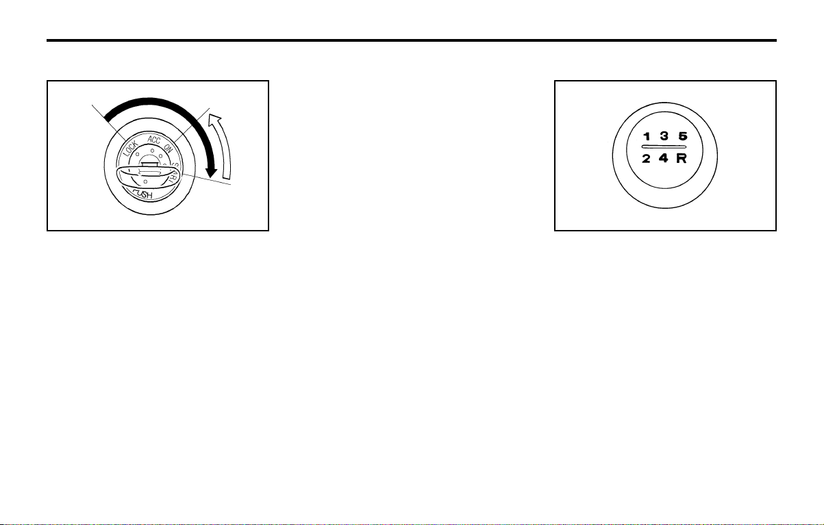
DRIVING YOUR HYUNDAIDRIVING YOUR HYUNDAI
DRIVING YOUR HYUNDAIDRIVING YOUR HYUNDAI
DRIVING YOUR HYUNDAI
2- 3
C050A01X-GAT
STARTINGSTARTING
STARTINGSTARTING
STARTING
Normal starting with either a cold or warm
engine is obtained without pumping or depress-
ing the accelerator pedal. Simply turn the key to
the "START" position and release when the
engine starts. After the engine has started,
allow the engine to run for 10 to 20 seconds
prior to placing the vehicle in gear.
The starter should not be operated for more
than 15 seconds at a time. Wait 15-30 seconds
between starting attempts to protect the starter
from overheating.
WARNING:WARNING:
WARNING:WARNING:
WARNING:
Never run the engine in a closed or poorlyNever run the engine in a closed or poorly
Never run the engine in a closed or poorlyNever run the engine in a closed or poorly
Never run the engine in a closed or poorly
ventilated area ventilated area
ventilated area ventilated area
ventilated area
any longer than is needed toany longer than is needed to
any longer than is needed toany longer than is needed to
any longer than is needed to
move your car in or out of the area. Themove your car in or out of the area. The
move your car in or out of the area. Themove your car in or out of the area. The
move your car in or out of the area. The
carbon carbon
carbon carbon
carbon
monoxide gas emitted is odorlessmonoxide gas emitted is odorless
monoxide gas emitted is odorlessmonoxide gas emitted is odorless
monoxide gas emitted is odorless
and can cause serious injury or death.and can cause serious injury or death.
and can cause serious injury or death.and can cause serious injury or death.
and can cause serious injury or death.
C050B02X-GAT
Normal Conditions:Normal Conditions:
Normal Conditions:Normal Conditions:
Normal Conditions:
The Starting Procedure:
1. Insert key, and fasten the seat belt.
2. Depress the clutch pedal fully (manual
transaxle) and place the gearshift lever in
neutral (manual transaxle) or the selector
lever (automatic transaxle) in "P" (park)
position.
3. After turning the ignition key to the "ON"
position, make certain all warning lights and
gauges are functioning properly before start-
ing the engine.
WARNING:WARNING:
WARNING:WARNING:
WARNING:
Be sure that the clutch is fully depressedBe sure that the clutch is fully depressed
Be sure that the clutch is fully depressedBe sure that the clutch is fully depressed
Be sure that the clutch is fully depressed
when starting a when starting a
when starting a when starting a
when starting a
manual transaxle vehicle.manual transaxle vehicle.
manual transaxle vehicle.manual transaxle vehicle.
manual transaxle vehicle.
Otherwise, there is the potential to causeOtherwise, there is the potential to cause
Otherwise, there is the potential to causeOtherwise, there is the potential to cause
Otherwise, there is the potential to cause
damage damage
damage damage
damage
to the vehicle or injury to someoneto the vehicle or injury to someone
to the vehicle or injury to someoneto the vehicle or injury to someone
to the vehicle or injury to someone
inside or outside the vehicle as a result inside or outside the vehicle as a result
inside or outside the vehicle as a result inside or outside the vehicle as a result
inside or outside the vehicle as a result
ofof
ofof
of
the forward or backward movement of thethe forward or backward movement of the
the forward or backward movement of thethe forward or backward movement of the
the forward or backward movement of the
vehicle that will occur if the vehicle that will occur if the
vehicle that will occur if the vehicle that will occur if the
vehicle that will occur if the
clutch is notclutch is not
clutch is notclutch is not
clutch is not
depressed when the vehicle is started.depressed when the vehicle is started.
depressed when the vehicle is started.depressed when the vehicle is started.
depressed when the vehicle is started.
4. Turn the ignition key to the "Start" position
and release it when the engine starts.
C070A04X-GAT
OPERATING THE MANUAL TRANSAXLEOPERATING THE MANUAL TRANSAXLE
OPERATING THE MANUAL TRANSAXLEOPERATING THE MANUAL TRANSAXLE
OPERATING THE MANUAL TRANSAXLE
C070A01X
Your Hyundai's manual transaxle has a con-
ventional shift pattern. This shift pattern is also
imprinted on the shift knob. The transaxle is
fully synchronized in all forward gears so shift-
ing to either a higher or a lower gear is easily
accomplished.
CAUTION:CAUTION:
CAUTION:CAUTION:
CAUTION:
oo
oo
o
Do not attempt to engage reverse gearDo not attempt to engage reverse gear
Do not attempt to engage reverse gearDo not attempt to engage reverse gear
Do not attempt to engage reverse gear
when the when the
when the when the
when the
car is moving.car is moving.
car is moving.car is moving.
car is moving.
oo
oo
o
To avoid damaging the selector mecha-To avoid damaging the selector mecha-
To avoid damaging the selector mecha-To avoid damaging the selector mecha-
To avoid damaging the selector mecha-
nism, do not use the gear nism, do not use the gear
nism, do not use the gear nism, do not use the gear
nism, do not use the gear
shift lever as ashift lever as a
shift lever as ashift lever as a
shift lever as a
hand rest. Release the lever immediatelyhand rest. Release the lever immediately
hand rest. Release the lever immediatelyhand rest. Release the lever immediately
hand rest. Release the lever immediately
the shift is completed.the shift is completed.
the shift is completed.the shift is completed.
the shift is completed.
oo
oo
o
To avoid premature clutch wear, do notTo avoid premature clutch wear, do not
To avoid premature clutch wear, do notTo avoid premature clutch wear, do not
To avoid premature clutch wear, do not
use the clutch pedal as use the clutch pedal as
use the clutch pedal as use the clutch pedal as
use the clutch pedal as
a foot rest, anda foot rest, and
a foot rest, anda foot rest, and
a foot rest, and
do not hold the vehicle on a gradientdo not hold the vehicle on a gradient
do not hold the vehicle on a gradientdo not hold the vehicle on a gradient
do not hold the vehicle on a gradient
using the clutch.using the clutch.
using the clutch.using the clutch.
using the clutch.
C050A01E

DRIVING YOUR HYUNDAIDRIVING YOUR HYUNDAI
DRIVING YOUR HYUNDAIDRIVING YOUR HYUNDAI
DRIVING YOUR HYUNDAI
2- 4
C070B01X-GAT
Using the Clutch of Manual transaxleUsing the Clutch of Manual transaxle
Using the Clutch of Manual transaxleUsing the Clutch of Manual transaxle
Using the Clutch of Manual transaxle
The clutch should be pressed all the way to the
floor before shifting, then released slowly. The
clutch pedal should be always used after fully
returning to the original position. Do not rest
your foot on the clutch pedal while driving. This
can cause unnecessary wear. Do not partially
engage the clutch to hold the car on an incline.
This causes unnecessary wear. Use the park-
ing brake to hold the car on an incline. Do not
operate the clutch pedal rapidly and repeatedly.
o Slow down when you encounter cross winds.
This gives you much better control of your
car.
o Be sure the car is completely stopped be-
fore you attempt to shift into reverse. The
transaxle can be damaged if you do not. To
shift into reverse, depress the clutch (manual
transaxle), move the shift lever to neutral,
wait three seconds, then shift to the reverse
position.
o Exercise extreme caution when driving on a
slippery surface. Be especially careful when
braking, accelerating or shifting gears. On a
slippery surface, an abrupt change in ve-
hicle speed can cause the drive wheels to
lose traction and the vehicle to go out of
control.
CAUTION:CAUTION:
CAUTION:CAUTION:
CAUTION:
oo
oo
o
The risk of rollover is greatly increased ifThe risk of rollover is greatly increased if
The risk of rollover is greatly increased ifThe risk of rollover is greatly increased if
The risk of rollover is greatly increased if
you you
you you
you
lose control of your vehicle at high-lose control of your vehicle at high-
lose control of your vehicle at high-lose control of your vehicle at high-
lose control of your vehicle at high-
way speeds.way speeds.
way speeds.way speeds.
way speeds.
oo
oo
o
Loss of control often occurs if two orLoss of control often occurs if two or
Loss of control often occurs if two orLoss of control often occurs if two or
Loss of control often occurs if two or
more wheels drop off the more wheels drop off the
more wheels drop off the more wheels drop off the
more wheels drop off the
roadway androadway and
roadway androadway and
roadway and
the driver oversteers to reenter the road-the driver oversteers to reenter the road-
the driver oversteers to reenter the road-the driver oversteers to reenter the road-
the driver oversteers to reenter the road-
way.way.
way.way.
way.
oo
oo
o
In the event your vehicle leaves the road-In the event your vehicle leaves the road-
In the event your vehicle leaves the road-In the event your vehicle leaves the road-
In the event your vehicle leaves the road-
way, do not steer sharply. way, do not steer sharply.
way, do not steer sharply. way, do not steer sharply.
way, do not steer sharply.
Instead, slowInstead, slow
Instead, slowInstead, slow
Instead, slow
down before pulling back into the traveldown before pulling back into the travel
down before pulling back into the traveldown before pulling back into the travel
down before pulling back into the travel
lanes.lanes.
lanes.lanes.
lanes.
oo
oo
o
In a collision crash, on unbelted personIn a collision crash, on unbelted person
In a collision crash, on unbelted personIn a collision crash, on unbelted person
In a collision crash, on unbelted person
is significantly more likely to die than ais significantly more likely to die than a
is significantly more likely to die than ais significantly more likely to die than a
is significantly more likely to die than a
person wearing a seatbelt.person wearing a seatbelt.
person wearing a seatbelt.person wearing a seatbelt.
person wearing a seatbelt.
oo
oo
o
Ensure that the engine is not over-revvedEnsure that the engine is not over-revved
Ensure that the engine is not over-revvedEnsure that the engine is not over-revved
Ensure that the engine is not over-revved
by upshifting.by upshifting.
by upshifting.by upshifting.
by upshifting.
oo
oo
o
Do not coast with the shift lever at theDo not coast with the shift lever at the
Do not coast with the shift lever at theDo not coast with the shift lever at the
Do not coast with the shift lever at the
neutral position.neutral position.
neutral position.neutral position.
neutral position.
oo
oo
o
When descending long gradients, makeWhen descending long gradients, make
When descending long gradients, makeWhen descending long gradients, make
When descending long gradients, make
use of the engine braking use of the engine braking
use of the engine braking use of the engine braking
use of the engine braking
to assist theto assist the
to assist theto assist the
to assist the
footbrake to avoid brake fade or over-footbrake to avoid brake fade or over-
footbrake to avoid brake fade or over-footbrake to avoid brake fade or over-
footbrake to avoid brake fade or over-
heating.heating.
heating.heating.
heating.
oo
oo
o
When slippery conditions are encoun-When slippery conditions are encoun-
When slippery conditions are encoun-When slippery conditions are encoun-
When slippery conditions are encoun-
tered, increased caution should tered, increased caution should
tered, increased caution should tered, increased caution should
tered, increased caution should
be ex-be ex-
be ex-be ex-
be ex-
ecuted when gear changing, braking orecuted when gear changing, braking or
ecuted when gear changing, braking orecuted when gear changing, braking or
ecuted when gear changing, braking or
accelerating. Abrupt changes in accelerating. Abrupt changes in
accelerating. Abrupt changes in accelerating. Abrupt changes in
accelerating. Abrupt changes in
speedspeed
speedspeed
speed
may cause a loss of traction.may cause a loss of traction.
may cause a loss of traction.may cause a loss of traction.
may cause a loss of traction.
oo
oo
o
To shift into reverse, rest the lever inTo shift into reverse, rest the lever in
To shift into reverse, rest the lever inTo shift into reverse, rest the lever in
To shift into reverse, rest the lever in
neutral for at least neutral for at least
neutral for at least neutral for at least
neutral for at least
3 seconds after your3 seconds after your
3 seconds after your3 seconds after your
3 seconds after your
car is completely stopped. Then movecar is completely stopped. Then move
car is completely stopped. Then movecar is completely stopped. Then move
car is completely stopped. Then move
the lever into the reverse position.the lever into the reverse position.
the lever into the reverse position.the lever into the reverse position.
the lever into the reverse position.
oo
oo
o
During cold weather, shifting may be dif-During cold weather, shifting may be dif-
During cold weather, shifting may be dif-During cold weather, shifting may be dif-
During cold weather, shifting may be dif-
ficult until the transaxle lubricant hasficult until the transaxle lubricant has
ficult until the transaxle lubricant hasficult until the transaxle lubricant has
ficult until the transaxle lubricant has
warmed up. This is normal and not harm-warmed up. This is normal and not harm-
warmed up. This is normal and not harm-warmed up. This is normal and not harm-
warmed up. This is normal and not harm-
ful to the transaxle.ful to the transaxle.
ful to the transaxle.ful to the transaxle.
ful to the transaxle.
oo
oo
o
If you 've come to a complete stop andIf you 've come to a complete stop and
If you 've come to a complete stop andIf you 've come to a complete stop and
If you 've come to a complete stop and
it's hard to shift into 1it's hard to shift into 1
it's hard to shift into 1it's hard to shift into 1
it's hard to shift into 1
stst
stst
st
or R(Reverse), or R(Reverse),
or R(Reverse), or R(Reverse),
or R(Reverse),
put the shift lever in N(Neutral) positionput the shift lever in N(Neutral) position
put the shift lever in N(Neutral) positionput the shift lever in N(Neutral) position
put the shift lever in N(Neutral) position
and let up on the clutch. Press the clutchand let up on the clutch. Press the clutch
and let up on the clutch. Press the clutchand let up on the clutch. Press the clutch
and let up on the clutch. Press the clutch
pedal back down, and then shift into 1pedal back down, and then shift into 1
pedal back down, and then shift into 1pedal back down, and then shift into 1
pedal back down, and then shift into 1
stst
stst
st
or R(Reverse) gear position.or R(Reverse) gear position.
or R(Reverse) gear position.or R(Reverse) gear position.
or R(Reverse) gear position.
oo
oo
o
Do not use the shift lever as a handrestDo not use the shift lever as a handrest
Do not use the shift lever as a handrestDo not use the shift lever as a handrest
Do not use the shift lever as a handrest
during driving, as this can result in pre-during driving, as this can result in pre-
during driving, as this can result in pre-during driving, as this can result in pre-
during driving, as this can result in pre-
mature wear of the transaxle shift forks.mature wear of the transaxle shift forks.
mature wear of the transaxle shift forks.mature wear of the transaxle shift forks.
mature wear of the transaxle shift forks.
C070D01X-GAT
Good Driving PracticesGood Driving Practices
Good Driving PracticesGood Driving Practices
Good Driving Practices
o Never take the car out of gear and coast
down a hill. This is extremely hazardous.
Always leave the car in gear.
o Don't "ride" the brakes. This can cause
them to overheat and malfunction. Instead,
when you are driving down a long hill, slow
down and shift to a lower gear. When you do
this, engine braking will help slow the car.
o Slow down before shifting to a lower gear.
This will help avoid over-revving the engine,
which can cause damage.
WARNING:WARNING:
WARNING:WARNING:
WARNING:
When downshifting from fifth gear to fourthWhen downshifting from fifth gear to fourth
When downshifting from fifth gear to fourthWhen downshifting from fifth gear to fourth
When downshifting from fifth gear to fourth
gear, caution should gear, caution should
gear, caution should gear, caution should
gear, caution should
be taken not to inad-be taken not to inad-
be taken not to inad-be taken not to inad-
be taken not to inad-
vertently press the gear shift lever sidewaysvertently press the gear shift lever sideways
vertently press the gear shift lever sidewaysvertently press the gear shift lever sideways
vertently press the gear shift lever sideways
in such in such
in such in such
in such
a manner that second gear is en-a manner that second gear is en-
a manner that second gear is en-a manner that second gear is en-
a manner that second gear is en-
gaged. Such over revving of the engine maygaged. Such over revving of the engine may
gaged. Such over revving of the engine maygaged. Such over revving of the engine may
gaged. Such over revving of the engine may
possibly cause engine damage.possibly cause engine damage.
possibly cause engine damage.possibly cause engine damage.
possibly cause engine damage.

DRIVING YOUR HYUNDAIDRIVING YOUR HYUNDAI
DRIVING YOUR HYUNDAIDRIVING YOUR HYUNDAI
DRIVING YOUR HYUNDAI
2- 5
Shift
from-to
Recommended
1-2
2-3
3-4
4-5
20 km/h (15 mph)
40 km/h (25 mph)
55 km/h (35 mph)
75 km/h (45 mph)
NOTE:NOTE:
NOTE:NOTE:
NOTE:
Depress the brake pedal and push theDepress the brake pedal and push the
Depress the brake pedal and push theDepress the brake pedal and push the
Depress the brake pedal and push the
button when shifting.button when shifting.
button when shifting.button when shifting.
button when shifting.
Push the button when shifting.Push the button when shifting.
Push the button when shifting.Push the button when shifting.
Push the button when shifting.
The selector lever can be shifted free-The selector lever can be shifted free-
The selector lever can be shifted free-The selector lever can be shifted free-
The selector lever can be shifted free-
ly.ly.
ly.ly.
ly.
For optimum fuel economy, accelerate gradual-
ly. The transaxle will automatically shift to the
second, third and overdrive gears.
C090B01A-AAT
The function of each position is asThe function of each position is as
The function of each position is asThe function of each position is as
The function of each position is as
follows:follows:
follows:follows:
follows:
o P (Park):o P (Park):
o P (Park):o P (Park):
o P (Park):
Use to hold the vehicle in place when parking or
while starting the engine; shift the selector lever
to the "P" (Park) position. Whenever parking
the car, apply the parking brake and shift the
selector lever to the "P" (Park) position.
CAUTION:CAUTION:
CAUTION:CAUTION:
CAUTION:
Never place the selector lever in the "P"Never place the selector lever in the "P"
Never place the selector lever in the "P"Never place the selector lever in the "P"
Never place the selector lever in the "P"
(Park) position unless the vehicle is fully(Park) position unless the vehicle is fully
(Park) position unless the vehicle is fully(Park) position unless the vehicle is fully
(Park) position unless the vehicle is fully
stopped. Failure to observe this caution willstopped. Failure to observe this caution will
stopped. Failure to observe this caution willstopped. Failure to observe this caution will
stopped. Failure to observe this caution will
cause severe damage to the transaxle.cause severe damage to the transaxle.
cause severe damage to the transaxle.cause severe damage to the transaxle.
cause severe damage to the transaxle.
C090A01A-GAT
AUTOMATIC TRANSAXLEAUTOMATIC TRANSAXLE
AUTOMATIC TRANSAXLEAUTOMATIC TRANSAXLE
AUTOMATIC TRANSAXLE
The highly efficient Hyundai automatic transaxle
has four forward speeds and one reverse speed.
It has a conventional shift pattern as shown in
the illustration. At night, with the first position of
the multi-function switch, the appropriate sym-
bol on the shift pattern indicator will be illuminat-
ed according to the range selected.
CAUTION:CAUTION:
CAUTION:CAUTION:
CAUTION:
Never shift into "R" or "P" position whileNever shift into "R" or "P" position while
Never shift into "R" or "P" position whileNever shift into "R" or "P" position while
Never shift into "R" or "P" position while
the vehicle is moving.the vehicle is moving.
the vehicle is moving.the vehicle is moving.
the vehicle is moving.
C090B01X
C070C01A-AAT
To Remove the Ignition KeyTo Remove the Ignition Key
To Remove the Ignition KeyTo Remove the Ignition Key
To Remove the Ignition Key
1. Turn the ignition key to the "ACC" position.
2. Simultaneously push and turn the ignition
key counterclockwise from the "ACC" posi-
tion to the "LOCK" position.
3. The key can be removed in the "LOCK"
position.
C070E02A-GAT
Recommended Shift PointsRecommended Shift Points
Recommended Shift PointsRecommended Shift Points
Recommended Shift Points
C070C01E
LOCKLOCK
LOCKLOCK
LOCK
ACCACC
ACCACC
ACC
ONON
ONON
ON
STARTSTART
STARTSTART
START
The shift points as shown are recommended for
optimum fuel economy and performance.
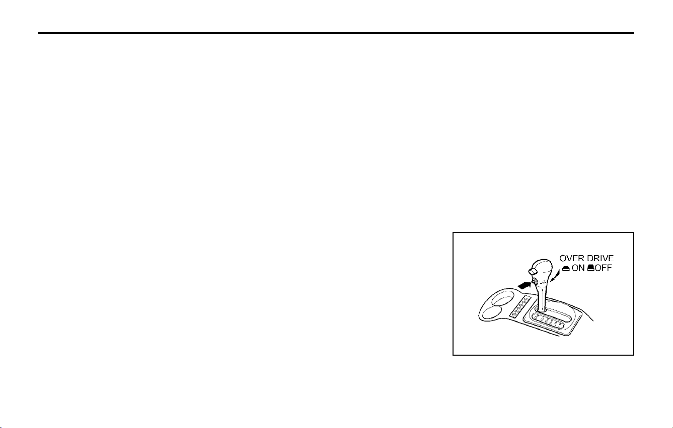
DRIVING YOUR HYUNDAIDRIVING YOUR HYUNDAI
DRIVING YOUR HYUNDAIDRIVING YOUR HYUNDAI
DRIVING YOUR HYUNDAI
2- 6
C090G01S-GAT
o L (Low gear):o L (Low gear):
o L (Low gear):o L (Low gear):
o L (Low gear):
Use for driving up a very steep grade or for
engine braking when descending steep hills.
When downshifting to "L", the transaxle will
temporarily remain in second gear until the
vehicle has slowed enough for low gear to
engage. Do not exceed 50 km/h (30 mph) in low
gear.
"L" shifts to 1st gear only. However, shift up to
2nd is performed when the car exceeds a
certain speed and, as speed increases, the
transaxle will shift up to 3rd gear to prevent
over-revving the engine.
C090H01E-GAT
NOTE:NOTE:
NOTE:NOTE:
NOTE:
oo
oo
o
For smooth and safe operation, depressFor smooth and safe operation, depress
For smooth and safe operation, depressFor smooth and safe operation, depress
For smooth and safe operation, depress
the brake pedal when shifting from "Neu-the brake pedal when shifting from "Neu-
the brake pedal when shifting from "Neu-the brake pedal when shifting from "Neu-
the brake pedal when shifting from "Neu-
tral" position or "Park" position to a for-tral" position or "Park" position to a for-
tral" position or "Park" position to a for-tral" position or "Park" position to a for-
tral" position or "Park" position to a for-
ward or reverse gear.ward or reverse gear.
ward or reverse gear.ward or reverse gear.
ward or reverse gear.
oo
oo
o
The brake pedal fully depressed in orderThe brake pedal fully depressed in order
The brake pedal fully depressed in orderThe brake pedal fully depressed in order
The brake pedal fully depressed in order
to move the shift lever from the "P"to move the shift lever from the "P"
to move the shift lever from the "P"to move the shift lever from the "P"
to move the shift lever from the "P"
(Park) position to any of the other posi-(Park) position to any of the other posi-
(Park) position to any of the other posi-(Park) position to any of the other posi-
(Park) position to any of the other posi-
tions.tions.
tions.tions.
tions.
oo
oo
o
It is always possible to shift from "R",It is always possible to shift from "R",
It is always possible to shift from "R",It is always possible to shift from "R",
It is always possible to shift from "R",
"N", "D", "2", "L" position to "P" posi-"N", "D", "2", "L" position to "P" posi-
"N", "D", "2", "L" position to "P" posi-"N", "D", "2", "L" position to "P" posi-
"N", "D", "2", "L" position to "P" posi-
tion. The vehicle must be fully stopped totion. The vehicle must be fully stopped to
tion. The vehicle must be fully stopped totion. The vehicle must be fully stopped to
tion. The vehicle must be fully stopped to
avoid transaxle damage.avoid transaxle damage.
avoid transaxle damage.avoid transaxle damage.
avoid transaxle damage.
C090I01E-AAT
CAUTION:CAUTION:
CAUTION:CAUTION:
CAUTION:
oo
oo
o
Shift into "R" and "P" position only whenShift into "R" and "P" position only when
Shift into "R" and "P" position only whenShift into "R" and "P" position only when
Shift into "R" and "P" position only when
the vehicle has completely stopped.the vehicle has completely stopped.
the vehicle has completely stopped.the vehicle has completely stopped.
the vehicle has completely stopped.
When the overdrive switch is turned on, the
transaxle will automatically upshift to the sec-
ond, third and overdrive gears. When the over-
C090P01A-GAT
Overdrive SwitchOverdrive Switch
Overdrive SwitchOverdrive Switch
Overdrive Switch
C090P01X
oo
oo
o
Do not accelerate the engine in reverseDo not accelerate the engine in reverse
Do not accelerate the engine in reverseDo not accelerate the engine in reverse
Do not accelerate the engine in reverse
or any of the forward positions with theor any of the forward positions with the
or any of the forward positions with theor any of the forward positions with the
or any of the forward positions with the
brakes applied.brakes applied.
brakes applied.brakes applied.
brakes applied.
oo
oo
o
Always apply the footbrake when shift-Always apply the footbrake when shift-
Always apply the footbrake when shift-Always apply the footbrake when shift-
Always apply the footbrake when shift-
ing from "P" or "N", to "R", "D", "2" oring from "P" or "N", to "R", "D", "2" or
ing from "P" or "N", to "R", "D", "2" oring from "P" or "N", to "R", "D", "2" or
ing from "P" or "N", to "R", "D", "2" or
"L" position."L" position.
"L" position."L" position.
"L" position.
oo
oo
o
Do not use the "P" (Park) position inDo not use the "P" (Park) position in
Do not use the "P" (Park) position inDo not use the "P" (Park) position in
Do not use the "P" (Park) position in
place of the parking brake. Always setplace of the parking brake. Always set
place of the parking brake. Always setplace of the parking brake. Always set
place of the parking brake. Always set
the parking brake, shift the transaxle intothe parking brake, shift the transaxle into
the parking brake, shift the transaxle intothe parking brake, shift the transaxle into
the parking brake, shift the transaxle into
"P" (Park) position and turn off the igni-"P" (Park) position and turn off the igni-
"P" (Park) position and turn off the igni-"P" (Park) position and turn off the igni-
"P" (Park) position and turn off the igni-
tion when you leave the vehicle, evention when you leave the vehicle, even
tion when you leave the vehicle, evention when you leave the vehicle, even
tion when you leave the vehicle, even
momentarily. Never leave the vehiclemomentarily. Never leave the vehicle
momentarily. Never leave the vehiclemomentarily. Never leave the vehicle
momentarily. Never leave the vehicle
unattended while the engine is running.unattended while the engine is running.
unattended while the engine is running.unattended while the engine is running.
unattended while the engine is running.
oo
oo
o
Check the automatic transaxle fluid levelCheck the automatic transaxle fluid level
Check the automatic transaxle fluid levelCheck the automatic transaxle fluid level
Check the automatic transaxle fluid level
regularly, and add fluid as necessary.regularly, and add fluid as necessary.
regularly, and add fluid as necessary.regularly, and add fluid as necessary.
regularly, and add fluid as necessary.
C090C01A-AAT
o R(Reverse):o R(Reverse):
o R(Reverse):o R(Reverse):
o R(Reverse):
Use for backing up the vehicle. Bring the car to
a complete stop before shifting the selector
lever to "R" position.
C090E01A-GAT
o D (Drive):o D (Drive):
o D (Drive):o D (Drive):
o D (Drive):
Use for normal driving. The transaxle will auto-
matically shift through a four-gear sequence,
giving best economy and power. Never down-
shift manually to "2" position or "L" position
when vehicle speed is more than 95 km/h (60
mph).
C090D02A-AAT
o N (Neutral):o N (Neutral):
o N (Neutral):o N (Neutral):
o N (Neutral):
In the "N" position, the transaxle is in neutral
position, which means that no gears are en-
gaged. The engine can be started with the shift
lever in "N" position, although this is not recom-
mended except if the engine stalls while the car
is moving.
C090F01A-AAT
o 2 (Second gear):o 2 (Second gear):
o 2 (Second gear):o 2 (Second gear):
o 2 (Second gear):
Use for driving on a slippery road, hill climbing
or engine braking downhill. "2" automatically
shifts between first and second gears.
This means that no shift-up to 3rd gear is
performed. However, the shift-up to third gear is
done when the car speed exceeds a certain
value to prevent the engine from over-revving.
Manually move the selector to "D" returning to
normal driving condition.

DRIVING YOUR HYUNDAIDRIVING YOUR HYUNDAI
DRIVING YOUR HYUNDAIDRIVING YOUR HYUNDAI
DRIVING YOUR HYUNDAI
2- 7
C130A01A-AAT
GOOD BRAKING PRACTICESGOOD BRAKING PRACTICES
GOOD BRAKING PRACTICESGOOD BRAKING PRACTICES
GOOD BRAKING PRACTICES
WARNING:WARNING:
WARNING:WARNING:
WARNING:
Do not allow passengers to sit on the cargoDo not allow passengers to sit on the cargo
Do not allow passengers to sit on the cargoDo not allow passengers to sit on the cargo
Do not allow passengers to sit on the cargo
area while the area while the
area while the area while the
area while the
car is moving as this is not acar is moving as this is not a
car is moving as this is not acar is moving as this is not a
car is moving as this is not a
proper seating position and no seat beltsproper seating position and no seat belts
proper seating position and no seat beltsproper seating position and no seat belts
proper seating position and no seat belts
are are
are are
are
available for use when the seat back isavailable for use when the seat back is
available for use when the seat back isavailable for use when the seat back is
available for use when the seat back is
folded down. This could result in folded down. This could result in
folded down. This could result in folded down. This could result in
folded down. This could result in
seriousserious
seriousserious
serious
injury or death in case of an accident or ainjury or death in case of an accident or a
injury or death in case of an accident or ainjury or death in case of an accident or a
injury or death in case of an accident or a
sudden stop. Objects should sudden stop. Objects should
sudden stop. Objects should sudden stop. Objects should
sudden stop. Objects should
not extendnot extend
not extendnot extend
not extend
higher than the top of the front seats. Thishigher than the top of the front seats. This
higher than the top of the front seats. Thishigher than the top of the front seats. This
higher than the top of the front seats. This
could allow cargo could allow cargo
could allow cargo could allow cargo
could allow cargo
to slide forward and causeto slide forward and cause
to slide forward and causeto slide forward and cause
to slide forward and cause
injury or damage during sudden stops.injury or damage during sudden stops.
injury or damage during sudden stops.injury or damage during sudden stops.
injury or damage during sudden stops.
o After being parked, check to be sure the
parking brake is not engaged and that the
parking brake indicator light is out before
driving away.
o Driving through water may get the brakes
wet. They can also get wet when the car is
washed. Wet brakes can be dangerous!
Your car will not stop as quickly if the brakes
are wet and it may also pull to one side. To
dry the brakes, apply the brakes lightly until
the braking action returns to normal, taking
care to keep the car under control at all
times. If the braking action does not return to
normal, stop as soon as it is safe to do so
and call your Hyundai dealer for assistance.
o Don't coast down hills with the car out of
gear. This is extremely hazardous. Keep the
car in gear at all times, use the brakes to
slow down, then shift to a lower gear so that
engine braking will help you maintain a safe
speed.
o Exercise extreme caution when driving on a
slippery surface. Be especially careful when
braking, accelerating or shifting gears. On a
slippery surface, an abrupt change in ve-
hicle speed can cause the drive wheels to
lose traction and the vehicle to go out of
control.
o Turn the overdrive switch on for good fuel
economy and smooth driving. If engine brak-
ing is needed in the "D" range or if repeated
upshifting and downshifting between 3rd and
4th gear is needed when climbing a gentle
slope, it is recommended that the overdrive
switch be turned off. Turn the overdrive
switch back on immediately afterward.
CAUTION:CAUTION:
CAUTION:CAUTION:
CAUTION:
oo
oo
o
The risk of rollover is greatly increased ifThe risk of rollover is greatly increased if
The risk of rollover is greatly increased ifThe risk of rollover is greatly increased if
The risk of rollover is greatly increased if
you lose control of your vehicle at high-you lose control of your vehicle at high-
you lose control of your vehicle at high-you lose control of your vehicle at high-
you lose control of your vehicle at high-
way speeds.way speeds.
way speeds.way speeds.
way speeds.
oo
oo
o
Loss of control often occurs if two orLoss of control often occurs if two or
Loss of control often occurs if two orLoss of control often occurs if two or
Loss of control often occurs if two or
more wheels drop off the roadway andmore wheels drop off the roadway and
more wheels drop off the roadway andmore wheels drop off the roadway and
more wheels drop off the roadway and
the driver oversteers to reenter the road-the driver oversteers to reenter the road-
the driver oversteers to reenter the road-the driver oversteers to reenter the road-
the driver oversteers to reenter the road-
way.way.
way.way.
way.
oo
oo
o
In the event your vehicle leaves the road-In the event your vehicle leaves the road-
In the event your vehicle leaves the road-In the event your vehicle leaves the road-
In the event your vehicle leaves the road-
way, do not steer sharply. Instead, slowway, do not steer sharply. Instead, slow
way, do not steer sharply. Instead, slowway, do not steer sharply. Instead, slow
way, do not steer sharply. Instead, slow
down before pulling back into the traveldown before pulling back into the travel
down before pulling back into the traveldown before pulling back into the travel
down before pulling back into the travel
lanes.lanes.
lanes.lanes.
lanes.
oo
oo
o
In a collision crash, on unbelted personIn a collision crash, on unbelted person
In a collision crash, on unbelted personIn a collision crash, on unbelted person
In a collision crash, on unbelted person
is significantly more likely to die than ais significantly more likely to die than a
is significantly more likely to die than ais significantly more likely to die than a
is significantly more likely to die than a
person wearing a seatbelt.person wearing a seatbelt.
person wearing a seatbelt.person wearing a seatbelt.
person wearing a seatbelt.
C090N02A-AAT
Good Driving PracticesGood Driving Practices
Good Driving PracticesGood Driving Practices
Good Driving Practices
o Never move the gear selector lever from "P"
or "N" to any other position with the acceler-
ator pedal depressed.
o Never move the gear selector lever into "P"
when the vehicle is in motion.
o Be sure the car is completely stopped be-
fore you attempt to shift into "R".
o Never take the car out of gear and coast
down a hill. This may be extremely hazard-
ous. Always leave the car in gear when
moving.
o Do not "ride" the brakes. This can cause
them to overheat and malfunction. Instead,
when you are driving down a long hill, slow
down and shift to a lower gear. When you do
this, engine braking will help slow the car.
o Slow down before shifting to a lower gear.
Otherwise, the lower gear may not be en-
gaged.
o Always use the parking brake. Do not de-
pend on placing the transaxle in "P" to keep
the car from moving.
drive switch is turned off, the transaxle will not
upshift to the overdrive gear. For normal driv-
ing, the selector lever should be left in the "D"
position and the overdrive switch turned on.
If you need to accelerate rapidly, press the
accelerator pedal all the way to the floor. The
transaxle will automatically shift to a lower gear,
depending on the vehicle speed and load.

DRIVING YOUR HYUNDAIDRIVING YOUR HYUNDAI
DRIVING YOUR HYUNDAIDRIVING YOUR HYUNDAI
DRIVING YOUR HYUNDAI
2- 8
WARNING:WARNING:
WARNING:WARNING:
WARNING:
Your ABS will not prevent accidents due toYour ABS will not prevent accidents due to
Your ABS will not prevent accidents due toYour ABS will not prevent accidents due to
Your ABS will not prevent accidents due to
improper or dangerous improper or dangerous
improper or dangerous improper or dangerous
improper or dangerous
driving maneuvers.driving maneuvers.
driving maneuvers.driving maneuvers.
driving maneuvers.
Even though vehicle control is improvedEven though vehicle control is improved
Even though vehicle control is improvedEven though vehicle control is improved
Even though vehicle control is improved
during emergency during emergency
during emergency during emergency
during emergency
braking, always maintainbraking, always maintain
braking, always maintainbraking, always maintain
braking, always maintain
a safe distance between you and objectsa safe distance between you and objects
a safe distance between you and objectsa safe distance between you and objects
a safe distance between you and objects
ahead. Vehicle ahead. Vehicle
ahead. Vehicle ahead. Vehicle
ahead. Vehicle
speeds should always bespeeds should always be
speeds should always bespeeds should always be
speeds should always be
reduced during extreme road conditions.reduced during extreme road conditions.
reduced during extreme road conditions.reduced during extreme road conditions.
reduced during extreme road conditions.
The braking distance for cars equipped withThe braking distance for cars equipped with
The braking distance for cars equipped withThe braking distance for cars equipped with
The braking distance for cars equipped with
an anti-lock braking system an anti-lock braking system
an anti-lock braking system an anti-lock braking system
an anti-lock braking system
may be longermay be longer
may be longermay be longer
may be longer
than for those without it in the followingthan for those without it in the following
than for those without it in the followingthan for those without it in the following
than for those without it in the following
road conditions.road conditions.
road conditions.road conditions.
road conditions.
oo
oo
o
Driving on rough, gravel or snow-cov-Driving on rough, gravel or snow-cov-
Driving on rough, gravel or snow-cov-Driving on rough, gravel or snow-cov-
Driving on rough, gravel or snow-cov-
ered roads.ered roads.
ered roads.ered roads.
ered roads.
oo
oo
o
Driving with tire chains installed.Driving with tire chains installed.
Driving with tire chains installed.Driving with tire chains installed.
Driving with tire chains installed.
oo
oo
o
Driving on roads where the road surfaceDriving on roads where the road surface
Driving on roads where the road surfaceDriving on roads where the road surface
Driving on roads where the road surface
is pitted or has different is pitted or has different
is pitted or has different is pitted or has different
is pitted or has different
surface height.surface height.
surface height.surface height.
surface height.
During these conditions the vehicleDuring these conditions the vehicle
During these conditions the vehicleDuring these conditions the vehicle
During these conditions the vehicle
should should
should should
should
be driven at reduced speeds. The safetybe driven at reduced speeds. The safety
be driven at reduced speeds. The safetybe driven at reduced speeds. The safety
be driven at reduced speeds. The safety
features features
features features
features
of an ABS equipped vehicle shouldof an ABS equipped vehicle should
of an ABS equipped vehicle shouldof an ABS equipped vehicle should
of an ABS equipped vehicle should
not be tested by high speed driving or cor-not be tested by high speed driving or cor-
not be tested by high speed driving or cor-not be tested by high speed driving or cor-
not be tested by high speed driving or cor-
nering. nering.
nering. nering.
nering.
This could endanger the safety ofThis could endanger the safety of
This could endanger the safety ofThis could endanger the safety of
This could endanger the safety of
yourself or others.yourself or others.
yourself or others.yourself or others.
yourself or others.
C120A02A-AAT
ANTI-LOCK BRAKE SYSTEMANTI-LOCK BRAKE SYSTEM
ANTI-LOCK BRAKE SYSTEMANTI-LOCK BRAKE SYSTEM
ANTI-LOCK BRAKE SYSTEM
(If installed)(If installed)
(If installed)(If installed)
(If installed)
The Anti-Lock Brake System (ABS) is designed
to prevent wheel lock-up during sudden braking
or on hazardous road surfaces. The ABS con-
trol module monitors the wheel speed and con-
trols the pressure applied to each brake. Thus,
in emergency situations or on slick roads, ABS
will increase vehicle control during braking.
NOTE:NOTE:
NOTE:NOTE:
NOTE:
During ABS operation, a slight pulsationDuring ABS operation, a slight pulsation
During ABS operation, a slight pulsationDuring ABS operation, a slight pulsation
During ABS operation, a slight pulsation
may be felt in the brake may be felt in the brake
may be felt in the brake may be felt in the brake
may be felt in the brake
pedal when thepedal when the
pedal when thepedal when the
pedal when the
brakes are applied. Also, a noise may bebrakes are applied. Also, a noise may be
brakes are applied. Also, a noise may bebrakes are applied. Also, a noise may be
brakes are applied. Also, a noise may be
heard in the engine heard in the engine
heard in the engine heard in the engine
heard in the engine
compartment while brak-compartment while brak-
compartment while brak-compartment while brak-
compartment while brak-
ing. These conditions are normal and indi-ing. These conditions are normal and indi-
ing. These conditions are normal and indi-ing. These conditions are normal and indi-
ing. These conditions are normal and indi-
cate that the cate that the
cate that the cate that the
cate that the
anti-lock brake system is func-anti-lock brake system is func-
anti-lock brake system is func-anti-lock brake system is func-
anti-lock brake system is func-
tioning properly.tioning properly.
tioning properly.tioning properly.
tioning properly.
put the gear selector lever in "P" (automatic)
or in first or reverse gear (manual transaxle)
and block the rear wheels so the car cannot
roll. Then release the parking brake.
o Do not hold the vehicle on the upgrade with
the accelerator pedal. This can cause the
transaxle to overheat. Always use the brake
pedal or parking brake.
o Don't "ride" the brake pedal. Resting your
foot on the brake pedal while driving can be
dangerous because it can result in the brakes
overheating and losing their effectiveness. It
also increases the wear of the brake compo-
nents.
o If a tire goes flat while you are driving, apply
the brakes gently and keep the car pointed
straight ahead while you slow down. When
you are moving slowly enough for it to be
safe to do so, pull off the road and stop in a
safe place.
o If your car is equipped with an automatic
transaxle, don't let your car creep forward.
To avoid creeping forward, keep your foot
on the brake pedal when the car is stopped.
o Use caution when parking on a hill. Engage
the parking brake and place the gear selec-
tor lever in "P" (automatic transaxle) or in
first or reverse gear (manual transaxle). If
your car is facing downhill, turn the front
wheels into the curb to help keep the car
from rolling. If your car is facing uphill, turn
the front wheels away from the curb to help
keep the car from rolling. If there is no curb
or if it is required by other conditions to keep
the car from rolling, block the wheels.
o Under some conditions your parking brake
can freeze in the engaged position. This is
most likely to happen when there is an
accumulation of snow or ice around or near
the rear brakes or if the brakes are wet. If
there is a risk that the parking brake may
freeze, apply it only temporarily while you

DRIVING YOUR HYUNDAIDRIVING YOUR HYUNDAI
DRIVING YOUR HYUNDAIDRIVING YOUR HYUNDAI
DRIVING YOUR HYUNDAI
2- 9
resulting in the engine bucking. If this hap-
pens, shift to a lower gear. Over-revving is
racing the engine beyond its safe limit. This
can be avoided by shifting at the recom-
mended speeds.
o Use your air conditioning sparingly. The air
conditioning system is operated by engine
power so your fuel economy is reduced
when you use it.
C150A01A-AAT
SMOOTH CORNERINGSMOOTH CORNERING
SMOOTH CORNERINGSMOOTH CORNERING
SMOOTH CORNERING
Avoid braking or gear changing in corners,
especially when roads are wet. Ideally, corners
should always be taken under gentle accelera-
tion. If you follow these suggestions, tire wear
will be held to a minimum.
C160A01A-AAT
WINTER DRIVINGWINTER DRIVING
WINTER DRIVINGWINTER DRIVING
WINTER DRIVING
The more severe weather conditions of winter
result in greater wear and other problems. To
minimize the problems of winter driving, you
should follow these suggestions:
C160B01A-GAT
Snowy or Icy ConditionsSnowy or Icy Conditions
Snowy or Icy ConditionsSnowy or Icy Conditions
Snowy or Icy Conditions
To drive your vehicle in deep snow, it may be
necessary to use snow tires or to install tire
chains on your tires. If snow tires are needed,
it is necessary to select tires equivalent in size
and type to the original equipment tires.
o Be sure that the wheels are aligned correct-
ly. Improper alignment can result from hitting
curbs or driving too fast over irregular sur-
faces. Poor alignment causes faster tire
wear and may also result in other problems
as well as greater fuel consumption.
o Keep your car in good condition. For better
fuel economy and reduced maintenance
costs, maintain your car in accordance with
the maintenance schedule in Section 5. If
you drive your car in severe conditions,
more frequent maintenance is required (see
Section 5 for details).
o Keep your car clean. For maximum service,
your Hyundai should be kept clean and free
of corrosive materials. It is especially impor-
tant that mud, dirt, ice, etc. not be allowed to
accumulate on the underside of the car. This
extra weight can result in increased fuel
consumption and also contribute to corro-
sion.
o Travel lightly. Don't carry unnecessary weight
in your car. Weight reduces fuel economy.
o Don't let the engine idle longer than neces-
sary. If you are waiting (and not in traffic),
turn off your engine and restart only when
you're ready to go.
o Remember, your Hyundai does not require
extended warm-up. As soon as the engine is
running smoothly, you can drive away. In
very cold weather, however, give your en-
gine a slightly longer warm-up period.
o Don't "lug" or "over-rev" the engine. Lugging
is driving too slowly in too high a gear
C140A01A-AAT
DRIVING FOR ECONOMYDRIVING FOR ECONOMY
DRIVING FOR ECONOMYDRIVING FOR ECONOMY
DRIVING FOR ECONOMY
You can save fuel and get more kilometers from
your car if you follow these suggestions:
o Drive smoothly. Accelerate at a moderate
rate. Don't make "jack-rabbit" starts or full-
throttle shifts and maintain a steady cruising
speed. Don't race between stoplights. Try to
adjust your speed to that of the other traffic
so you don't have to change speeds unnec-
essarily. Avoid heavy traffic whenever pos-
sible. Always maintain a safe distance from
other vehicles so you can avoid unneces-
sary braking. This also reduces brake wear.
o Drive at a moderate speed. The faster you
drive, the more fuel your car uses. Driving at
a moderate speed, especially on the high-
way, is one of the most effective ways to
reduce fuel consumption.
o Don't "ride" the brake or clutch pedal. This
can increase fuel consumption and also
increase wear on these components. In ad-
dition, driving with your foot resting on the
brake pedal may cause the brakes to over-
heat, which reduces their effectiveness and
may lead to more serious consequences.
o Take care of your tires. Keep them inflated
to the recommended pressure. Incorrect in-
flation, either too much or too little, results in
unnecessary tire wear. Check the tire pres-
sures at least once a month.

DRIVING YOUR HYUNDAIDRIVING YOUR HYUNDAI
DRIVING YOUR HYUNDAIDRIVING YOUR HYUNDAI
DRIVING YOUR HYUNDAI
2- 10
ice. If the lock is frozen internally, you may be
able to thaw it out by using a heated key.
Handle the heated key with care to avoid burn-
ing your fingers.
NOTE:NOTE:
NOTE:NOTE:
NOTE:
The proper temperature for using the immo-The proper temperature for using the immo-
The proper temperature for using the immo-The proper temperature for using the immo-
The proper temperature for using the immo-
bilizer key is from -40°C to 80°C. If you heatbilizer key is from -40°C to 80°C. If you heat
bilizer key is from -40°C to 80°C. If you heatbilizer key is from -40°C to 80°C. If you heat
bilizer key is from -40°C to 80°C. If you heat
the immobilizer key over 80°C to open thethe immobilizer key over 80°C to open the
the immobilizer key over 80°C to open thethe immobilizer key over 80°C to open the
the immobilizer key over 80°C to open the
frozen lock, frozen lock,
frozen lock, frozen lock,
frozen lock,
it may cause damage to theit may cause damage to the
it may cause damage to theit may cause damage to the
it may cause damage to the
transponder in its head.transponder in its head.
transponder in its head.transponder in its head.
transponder in its head.
C160H01A-AAT
Use Approved Anti-Freeze in WindowUse Approved Anti-Freeze in Window
Use Approved Anti-Freeze in WindowUse Approved Anti-Freeze in Window
Use Approved Anti-Freeze in Window
Washer SystemWasher System
Washer SystemWasher System
Washer System
To keep the water in the window washer sys-
tem from freezing, add an approved anti-freeze
solution in accordance with instructions on the
container. Window washer anti-freeze is avail-
able from Hyundai dealers and most auto parts
outlets. Do not use engine coolant or other
types of anti-freeze as these may damage the
finish.
C160I01X-GAT
Don't Let Your Parking Brake FreezeDon't Let Your Parking Brake Freeze
Don't Let Your Parking Brake FreezeDon't Let Your Parking Brake Freeze
Don't Let Your Parking Brake Freeze
Under some conditions your parking brake can
freeze in the engaged position. This is most
likely to happen when there is an accumulation
of snow or ice around or near the rear brakes or
if the brakes are wet. If there is a risk the
parking brake may freeze, apply it only tempo-
C160F01A-AAT
Check Spark Plugs and IgnitionCheck Spark Plugs and Ignition
Check Spark Plugs and IgnitionCheck Spark Plugs and Ignition
Check Spark Plugs and Ignition
SystemSystem
SystemSystem
System
Inspect your spark plugs as described in Sec-
tion 6 and replace them if necessary. Also
check all ignition wiring and components to be
sure they are not cracked, worn or damaged in
any way.
C160D01A-AAT
Check Battery and CablesCheck Battery and Cables
Check Battery and CablesCheck Battery and Cables
Check Battery and Cables
Winter puts additional burdens on the battery
system. Visually inspect the battery and cables
as described in Section 6. The level of charge
in your battery can be checked by your Hyundai
dealer or a service station.
C160E01A-AAT
Change to "Winter Weight" Oil ifChange to "Winter Weight" Oil if
Change to "Winter Weight" Oil ifChange to "Winter Weight" Oil if
Change to "Winter Weight" Oil if
NecessaryNecessary
NecessaryNecessary
Necessary
In some climates it is recommended that a
lower viscosity "winter weight" oil be used dur-
ing cold weather. See Section 9 for recommen-
dations. If you aren't sure what weight oil you
should use, consult your Hyundai dealer.
C160G01A-GAT
To Keep Locks from FreezingTo Keep Locks from Freezing
To Keep Locks from FreezingTo Keep Locks from Freezing
To Keep Locks from Freezing
To keep the locks from freezing, squirt an
approved de-icer fluid or glycerine into the key
opening. If a lock is covered with ice, squirt it
with an approved de-icing fluid to remove the
Failure to do so may adversely affect the safety
and handling of your car. Speeding, rapid accel-
eration, sudden brake applications, and sharp
turns are potentially very hazardous practices.
During deceleration, use engine braking to the
fullest extent. Sudden brake applications on
snowy or icy roads may cause skids to occur.
You need to keep sufficient distance between
the vehicle in front and your vehicle. Also, apply
the brake gently.
It should be noted that installing tire chains on
the tire will provide a greater driving force, but
will not prevent side skids.
NOTE:NOTE:
NOTE:NOTE:
NOTE:
Tire chains are not legal in all provinces.Tire chains are not legal in all provinces.
Tire chains are not legal in all provinces.Tire chains are not legal in all provinces.
Tire chains are not legal in all provinces.
Check Check
Check Check
Check
province laws before fitting tireprovince laws before fitting tire
province laws before fitting tireprovince laws before fitting tire
province laws before fitting tire
chains.chains.
chains.chains.
chains.
C160C01A-AAT
Use High Quality Ethylene GlycolUse High Quality Ethylene Glycol
Use High Quality Ethylene GlycolUse High Quality Ethylene Glycol
Use High Quality Ethylene Glycol
CoolantCoolant
CoolantCoolant
Coolant
Your Hyundai is delivered with high quality
ethylene glycol coolant in the cooling system. It
is the only type of coolant that should be used
because it helps prevent corrosion in the cool-
ing system, lubricates the water pump and
prevents freezing. Be sure to replace or replen-
ish your coolant in accordance with the main-
tenance schedule in Section 5. Before winter,
have your coolant tested to assure that its
freezing point is sufficient for the temperatures
anticipated during the winter.

DRIVING YOUR HYUNDAIDRIVING YOUR HYUNDAI
DRIVING YOUR HYUNDAIDRIVING YOUR HYUNDAI
DRIVING YOUR HYUNDAI
2- 11
C190A01A-GAT
TRAILER OR VEHICLE TOWINGTRAILER OR VEHICLE TOWING
TRAILER OR VEHICLE TOWINGTRAILER OR VEHICLE TOWING
TRAILER OR VEHICLE TOWING
If you are considering towing with your car, you
should first check with your Province Depart-
ment of Motor Vehicles to determine their legal
requirements.
Since laws vary from province to province the
requirements for towing trailers, cars, or other
types of vehicles or apparatus may differ. Ask
your Hyundai dealer for further details before
towing.
CAUTION:CAUTION:
CAUTION:CAUTION:
CAUTION:
Do not do any towing with your car duringDo not do any towing with your car during
Do not do any towing with your car duringDo not do any towing with your car during
Do not do any towing with your car during
its first 2,000 km (1,200 miles) in order toits first 2,000 km (1,200 miles) in order to
its first 2,000 km (1,200 miles) in order toits first 2,000 km (1,200 miles) in order to
its first 2,000 km (1,200 miles) in order to
allow the engine to properly break in. Fail-allow the engine to properly break in. Fail-
allow the engine to properly break in. Fail-allow the engine to properly break in. Fail-
allow the engine to properly break in. Fail-
ure to heed this caution may result in seri-ure to heed this caution may result in seri-
ure to heed this caution may result in seri-ure to heed this caution may result in seri-
ure to heed this caution may result in seri-
ous engine or transaxle damage.ous engine or transaxle damage.
ous engine or transaxle damage.ous engine or transaxle damage.
ous engine or transaxle damage.
C190B01S-AAT
Trailer HitchesTrailer Hitches
Trailer HitchesTrailer Hitches
Trailer Hitches
Select the proper hitch and ball combination,
making sure that it's location is compatible with
that of the trailer or vehicle being towed.
Use a quality non-equalizing hitch which distrib-
utes the tongue load uniformly throughout the
chassis.
The hitch should be bolted securely to the car
and installed by a qualified technician. DO NOT
USE A HITCH DESIGNED FOR TEMPORARY
INSTALLATION AND NEVER USE ONE THAT
ATTACHES ONLY TO THE BUMPER.
C170A01A-AAT
HIGHER SPEED MOTORINGHIGHER SPEED MOTORING
HIGHER SPEED MOTORINGHIGHER SPEED MOTORING
HIGHER SPEED MOTORING
Pre-Trip InspectionsPre-Trip Inspections
Pre-Trip InspectionsPre-Trip Inspections
Pre-Trip Inspections
1. Tires:
Adjust the tire inflation pressures to specifica-
tion driving. Low tire inflation pressures will
result in overheating and possible failure of the
tires.
Avoid using worn or damaged tires which may
result in reduced traction or tire failure.
NOTE:NOTE:
NOTE:NOTE:
NOTE:
Never exceed the maximum tire inflationNever exceed the maximum tire inflation
Never exceed the maximum tire inflationNever exceed the maximum tire inflation
Never exceed the maximum tire inflation
pressure shown on the tires.pressure shown on the tires.
pressure shown on the tires.pressure shown on the tires.
pressure shown on the tires.
2. Fuel, engine coolant and engine oil:
High speed travel consumes 1.5 times more
fuel than urban motoring. Do not forget to check
both engine coolant and engine oil.
3. Drive belt:
A loose or damaged drive belt may result in
overheating of the engine.
C180A01A-AAT
USE OF LIGHTSUSE OF LIGHTS
USE OF LIGHTSUSE OF LIGHTS
USE OF LIGHTS
Check your lights regularly for correct operation
and always keep them clean. When driving
during the day in conditions of poor visibility, it
is helpful to drive with headlights on low beam.
This enables you to be seen as well as to see.
rarily while you put the gear selector lever in
"P" (automatic transaxle) or in first or reverse
gear (manual transaxle) and block the rear
wheels so the car cannot roll. Then release the
parking brake.
C160J01A-AAT
Don't Let Ice and Snow AccumulateDon't Let Ice and Snow Accumulate
Don't Let Ice and Snow AccumulateDon't Let Ice and Snow Accumulate
Don't Let Ice and Snow Accumulate
UnderneathUnderneath
UnderneathUnderneath
Underneath
Under some conditions, snow and ice can build
up under the fenders and interfere with the
steering. When driving in severe winter condi-
tions where this may happen, you should peri-
odically check underneath the car to be sure
the movement of the front wheels and the
steering components are not obstructed.
C160K01A-AAT
Carry Emergency EquipmentCarry Emergency Equipment
Carry Emergency EquipmentCarry Emergency Equipment
Carry Emergency Equipment
Depending on the severity of the weather where
you drive your car, you should carry appropri-
ate emergency equipment. Some of the items
you may want to carry include tire chains, tow
straps or chains, flashlight, emergency flares,
sand, a shovel, jumper cables, a window
scraper, gloves, ground cloth, coveralls, a blan-
ket, etc.
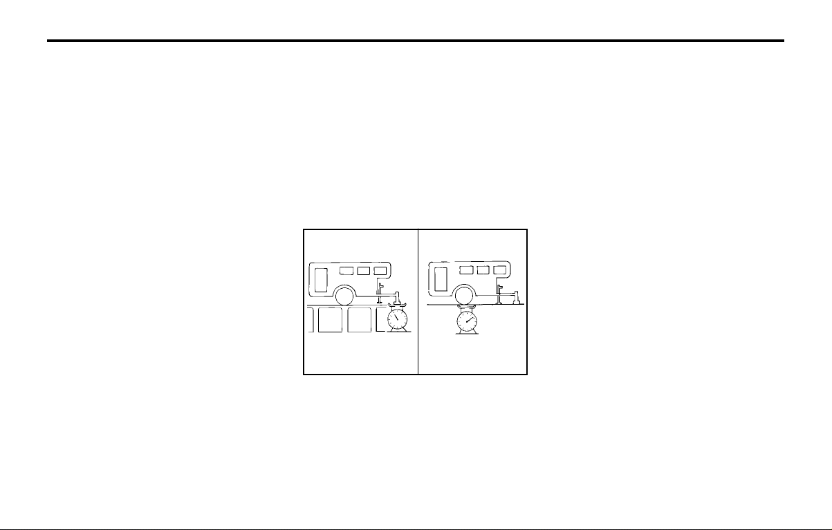
DRIVING YOUR HYUNDAIDRIVING YOUR HYUNDAI
DRIVING YOUR HYUNDAIDRIVING YOUR HYUNDAI
DRIVING YOUR HYUNDAI
2- 12
NOTE:NOTE:
NOTE:NOTE:
NOTE:
1.1.
1.1.
1.
Never load the trailer with more weight inNever load the trailer with more weight in
Never load the trailer with more weight inNever load the trailer with more weight in
Never load the trailer with more weight in
the back the back
the back the back
the back
than in the front. About 60% ofthan in the front. About 60% of
than in the front. About 60% ofthan in the front. About 60% of
than in the front. About 60% of
the trailer load should be in the front halfthe trailer load should be in the front half
the trailer load should be in the front halfthe trailer load should be in the front half
the trailer load should be in the front half
on the trailer and the remaining 40% inon the trailer and the remaining 40% in
on the trailer and the remaining 40% inon the trailer and the remaining 40% in
on the trailer and the remaining 40% in
the rear.the rear.
the rear.the rear.
the rear.
2.2.
2.2.
2.
The total gross vehicle weight with trailerThe total gross vehicle weight with trailer
The total gross vehicle weight with trailerThe total gross vehicle weight with trailer
The total gross vehicle weight with trailer
must not exceed the must not exceed the
must not exceed the must not exceed the
must not exceed the
Gross Vehicle WeightGross Vehicle Weight
Gross Vehicle WeightGross Vehicle Weight
Gross Vehicle Weight
Rating (GVWR) shown on the vehicle iden-Rating (GVWR) shown on the vehicle iden-
Rating (GVWR) shown on the vehicle iden-Rating (GVWR) shown on the vehicle iden-
Rating (GVWR) shown on the vehicle iden-
tification plate tification plate
tification plate tification plate
tification plate
(see page 8-1). The total(see page 8-1). The total
(see page 8-1). The total(see page 8-1). The total
(see page 8-1). The total
gross vehicle weight gross vehicle weight
gross vehicle weight gross vehicle weight
gross vehicle weight
is the combinedis the combined
is the combinedis the combined
is the combined
weight of the vehicle, driver, all passen-weight of the vehicle, driver, all passen-
weight of the vehicle, driver, all passen-weight of the vehicle, driver, all passen-
weight of the vehicle, driver, all passen-
gers and their luggage, gers and their luggage,
gers and their luggage, gers and their luggage,
gers and their luggage,
cargo, hitch, trailercargo, hitch, trailer
cargo, hitch, trailercargo, hitch, trailer
cargo, hitch, trailer
tongue load and other optional equip-tongue load and other optional equip-
tongue load and other optional equip-tongue load and other optional equip-
tongue load and other optional equip-
ment.ment.
ment.ment.
ment.
3.3.
3.3.
3.
The front or rear axle weight must notThe front or rear axle weight must not
The front or rear axle weight must notThe front or rear axle weight must not
The front or rear axle weight must not
exceed the Gross Axle Weight exceed the Gross Axle Weight
exceed the Gross Axle Weight exceed the Gross Axle Weight
exceed the Gross Axle Weight
RatingRating
RatingRating
Rating
(GAWR) shown on the vehicle identifica-(GAWR) shown on the vehicle identifica-
(GAWR) shown on the vehicle identifica-(GAWR) shown on the vehicle identifica-
(GAWR) shown on the vehicle identifica-
tion plate (see page 8-1). It is possibletion plate (see page 8-1). It is possible
tion plate (see page 8-1). It is possibletion plate (see page 8-1). It is possible
tion plate (see page 8-1). It is possible
that your towing package does not ex-that your towing package does not ex-
that your towing package does not ex-that your towing package does not ex-
that your towing package does not ex-
ceed ceed
ceed ceed
ceed
the GVWR but exceeds the GAWR.the GVWR but exceeds the GAWR.
the GVWR but exceeds the GAWR.the GVWR but exceeds the GAWR.
the GVWR but exceeds the GAWR.
Improper trailer loading and/or too muchImproper trailer loading and/or too much
Improper trailer loading and/or too muchImproper trailer loading and/or too much
Improper trailer loading and/or too much
luggage in the trunk can overload luggage in the trunk can overload
luggage in the trunk can overload luggage in the trunk can overload
luggage in the trunk can overload
thethe
thethe
the
rear axle. Redistribute the load and checkrear axle. Redistribute the load and check
rear axle. Redistribute the load and checkrear axle. Redistribute the load and check
rear axle. Redistribute the load and check
the axle weight again.the axle weight again.
the axle weight again.the axle weight again.
the axle weight again.
4.4.
4.4.
4.
The maximum permissible overhang ofThe maximum permissible overhang of
The maximum permissible overhang ofThe maximum permissible overhang of
The maximum permissible overhang of
the coupling point is 570 mm.the coupling point is 570 mm.
the coupling point is 570 mm.the coupling point is 570 mm.
the coupling point is 570 mm.
(ATOS VAN : 568mm)(ATOS VAN : 568mm)
(ATOS VAN : 568mm)(ATOS VAN : 568mm)
(ATOS VAN : 568mm)
C190D01A-GAT
Safety ChainsSafety Chains
Safety ChainsSafety Chains
Safety Chains
Should the hitch connection between your car
and the trailer or vehicle you are towing fail, the
trailer or vehicle could wander dangerously
across other lanes of traffic and ultimately col-
lide with another vehicle. To eliminate this po-
tentially dangerous situation, safety chains, at-
tached between your car and the trailer or
towed vehicle, are required in most provinces.
C190E04X-GAT
Trailer Weight LimitTrailer Weight Limit
Trailer Weight LimitTrailer Weight Limit
Trailer Weight Limit
Tongue load Total trailer weight
SSA2200B
Tongue loads can be increased or decreased
by redistributing the load in the trailer. This can
be verified by checking the total weight of the
loaded trailer and then checking the load on the
tongue.
C190C01X-GAT
Trailer BrakesTrailer Brakes
Trailer BrakesTrailer Brakes
Trailer Brakes
If your trailer is equipped with a braking system,
make sure it conforms to federal and/or local
regulations and that it is properly installed and
operating correctly.
NOTE:NOTE:
NOTE:NOTE:
NOTE:
If you tow a trailer or vehicle, your car willIf you tow a trailer or vehicle, your car will
If you tow a trailer or vehicle, your car willIf you tow a trailer or vehicle, your car will
If you tow a trailer or vehicle, your car will
require more frequent require more frequent
require more frequent require more frequent
require more frequent
maintenance due tomaintenance due to
maintenance due tomaintenance due to
maintenance due to
the additional load. See "Maintenance Un-the additional load. See "Maintenance Un-
the additional load. See "Maintenance Un-the additional load. See "Maintenance Un-
the additional load. See "Maintenance Un-
der Severe der Severe
der Severe der Severe
der Severe
Usage Conditions" on page 5-4.Usage Conditions" on page 5-4.
Usage Conditions" on page 5-4.Usage Conditions" on page 5-4.
Usage Conditions" on page 5-4.
CAUTION:CAUTION:
CAUTION:CAUTION:
CAUTION:
oo
oo
o
Never connect a trailer brake system di-Never connect a trailer brake system di-
Never connect a trailer brake system di-Never connect a trailer brake system di-
Never connect a trailer brake system di-
rectly rectly
rectly rectly
rectly
to the vehicle brake system.to the vehicle brake system.
to the vehicle brake system.to the vehicle brake system.
to the vehicle brake system.
oo
oo
o
When towing a trailer on steep grades (inWhen towing a trailer on steep grades (in
When towing a trailer on steep grades (inWhen towing a trailer on steep grades (in
When towing a trailer on steep grades (in
excess of 12%) pay close excess of 12%) pay close
excess of 12%) pay close excess of 12%) pay close
excess of 12%) pay close
attention to theattention to the
attention to theattention to the
attention to the
engine coolant temperature gauge toengine coolant temperature gauge to
engine coolant temperature gauge toengine coolant temperature gauge to
engine coolant temperature gauge to
ensure the engine does ensure the engine does
ensure the engine does ensure the engine does
ensure the engine does
not overheat. Ifnot overheat. If
not overheat. Ifnot overheat. If
not overheat. If
the needle of the coolant temperaturethe needle of the coolant temperature
the needle of the coolant temperaturethe needle of the coolant temperature
the needle of the coolant temperature
gauge moves across gauge moves across
gauge moves across gauge moves across
gauge moves across
the dial towardsthe dial towards
the dial towardsthe dial towards
the dial towards
"H" (HOT), pull over and stop as soon as"H" (HOT), pull over and stop as soon as
"H" (HOT), pull over and stop as soon as"H" (HOT), pull over and stop as soon as
"H" (HOT), pull over and stop as soon as
it is safe to do it is safe to do
it is safe to do it is safe to do
it is safe to do
so, and allow the engine toso, and allow the engine to
so, and allow the engine toso, and allow the engine to
so, and allow the engine to
idle until it cools down. You may proceedidle until it cools down. You may proceed
idle until it cools down. You may proceedidle until it cools down. You may proceed
idle until it cools down. You may proceed
once once
once once
once
the engine has cooled sufficiently.the engine has cooled sufficiently.
the engine has cooled sufficiently.the engine has cooled sufficiently.
the engine has cooled sufficiently.
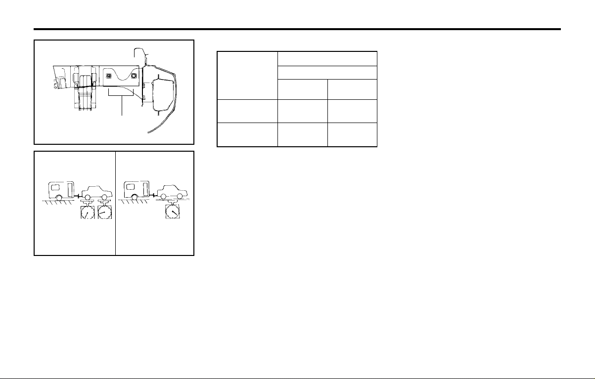
DRIVING YOUR HYUNDAIDRIVING YOUR HYUNDAI
DRIVING YOUR HYUNDAIDRIVING YOUR HYUNDAI
DRIVING YOUR HYUNDAI
2- 13
4. To maintain engine braking efficiency and
electrical charging performance, do not use
fifth gear (manual transaxle) or overdrive
(automatic transaxle).
5. Always secure items in the trailer to prevent
load shift while driving.
6. Check the condition and air pressure of all
tires on the trailer and your car. Low tire
pressure can seriously affect the handling.
Also check the spare tire.
7. The vehicle/trailer combination is more af-
fected by crosswind and buffeting.
When being passed by a large vehicle, keep
a constant speed and steer straight ahead.
If there is too much wind buffeting slow
down to get out of the other vehicle's air
turbulence.
8. When parking your car and trailer, especial-
ly on a hill, be sure to follow all the normal
precautions. Turn your front wheel into the
curb, set the parking brake firmly, and put
the transaxle in 1st or Reverse (manual) or
Park (automatic). In addition, place wheel
chocks at each of the trailer's tires.
9. If the trailer has electric brakes, start your
vehicle and trailer moving, and then apply
the trailer brake controller by hand to be
sure the brakes are working. This lets you
check your electrical connection at the same
time.
10.During your trip, check occasionally to be
sure that the load is secure, and that the
lights and any trailer brakes are still working.
WARNING:WARNING:
WARNING:WARNING:
WARNING:
oo
oo
o
The tongue load should never exceed;The tongue load should never exceed;
The tongue load should never exceed;The tongue load should never exceed;
The tongue load should never exceed;
Auto: 25kgAuto: 25kg
Auto: 25kgAuto: 25kg
Auto: 25kg
Manual : 28kgManual : 28kg
Manual : 28kgManual : 28kg
Manual : 28kg
oo
oo
o
Maximun permissible mass of the cou-Maximun permissible mass of the cou-
Maximun permissible mass of the cou-Maximun permissible mass of the cou-
Maximun permissible mass of the cou-
pling device (ATOS VAN only) : 20kgpling device (ATOS VAN only) : 20kg
pling device (ATOS VAN only) : 20kgpling device (ATOS VAN only) : 20kg
pling device (ATOS VAN only) : 20kg
oo
oo
o
Improperly loading your car and trailerImproperly loading your car and trailer
Improperly loading your car and trailerImproperly loading your car and trailer
Improperly loading your car and trailer
can seriously affect its steering and brak-can seriously affect its steering and brak-
can seriously affect its steering and brak-can seriously affect its steering and brak-
can seriously affect its steering and brak-
ing performance causing a crash whiching performance causing a crash which
ing performance causing a crash whiching performance causing a crash which
ing performance causing a crash which
could cause serious injury or death.could cause serious injury or death.
could cause serious injury or death.could cause serious injury or death.
could cause serious injury or death.
kg.
Maximum Towable Weight
Trailer
Manual
Transaxle
Auto
Transaxle
With
Brake Type
Without
Brake Type
400
400
C190F01A-GAT
Trailer or Vehicle Towing TipsTrailer or Vehicle Towing Tips
Trailer or Vehicle Towing TipsTrailer or Vehicle Towing Tips
Trailer or Vehicle Towing Tips
1. Before towing, check hitch and safety chain
connections as well as proper operation of
the trailer running lights, brake lights, and
turn signals.
2. Always drive your vehicle at a moderate
speed (Less than 100 km/h)
3. Trailer towing requires more fuel than nor-
mal conditions.
Gross axle weight Gross vehicle weight
SSA2200D
CAUTION:CAUTION:
CAUTION:CAUTION:
CAUTION:
The following specifications are recommend-The following specifications are recommend-
The following specifications are recommend-The following specifications are recommend-
The following specifications are recommend-
ed when towing a ed when towing a
ed when towing a ed when towing a
ed when towing a
trailer. The loaded trailertrailer. The loaded trailer
trailer. The loaded trailertrailer. The loaded trailer
trailer. The loaded trailer
weight cannot safely exceed the values inweight cannot safely exceed the values in
weight cannot safely exceed the values inweight cannot safely exceed the values in
weight cannot safely exceed the values in
the the
the the
the
chart.chart.
chart.chart.
chart.
Coupling point
C190E03X
é
é
700
400

DRIVING YOUR HYUNDAIDRIVING YOUR HYUNDAI
DRIVING YOUR HYUNDAIDRIVING YOUR HYUNDAI
DRIVING YOUR HYUNDAI
2- 14
11.Avoid jerky starts, sudden acceleration or
sudden stops.
12.Avoid sharp turns and rapid lane changes.
13.Avoid holding the brake pedal down too long
or too frequently. This could cause the brakes
to overheat, resulting in reduced braking
efficiency.
14.When going down a hill, shift into a lower
gear and use the engine braking effect.
When ascending a long grade, downshift the
transaxle to a lower gear and reduce speed
to reduce chances of engine overloading
and/or overheating.
15.If you have to stop while going uphill, do not
hold the vehicle in place by pressing on the
accelerator. This can cause the automatic
transaxle to overheat. Use the parking brake
or footbrake.
NOTE:NOTE:
NOTE:NOTE:
NOTE:
When towing check transaxle fluid moreWhen towing check transaxle fluid more
When towing check transaxle fluid moreWhen towing check transaxle fluid more
When towing check transaxle fluid more
frequently.frequently.
frequently.frequently.
frequently.
CAUTION:CAUTION:
CAUTION:CAUTION:
CAUTION:
If overheating should occur when towing,If overheating should occur when towing,
If overheating should occur when towing,If overheating should occur when towing,
If overheating should occur when towing,
(temperature gauge reads near red zone),(temperature gauge reads near red zone),
(temperature gauge reads near red zone),(temperature gauge reads near red zone),
(temperature gauge reads near red zone),
taking the following action may reduce ortaking the following action may reduce or
taking the following action may reduce ortaking the following action may reduce or
taking the following action may reduce or
eliminate the problem.eliminate the problem.
eliminate the problem.eliminate the problem.
eliminate the problem.
1. Turn off the air conditioner.
2. Reduce highway speed.
3. Select a lower gear when going uphill.
4. While in stop and go traffic, place the gear
selector in park or neutral and idle the en-
gine at a higher speed.
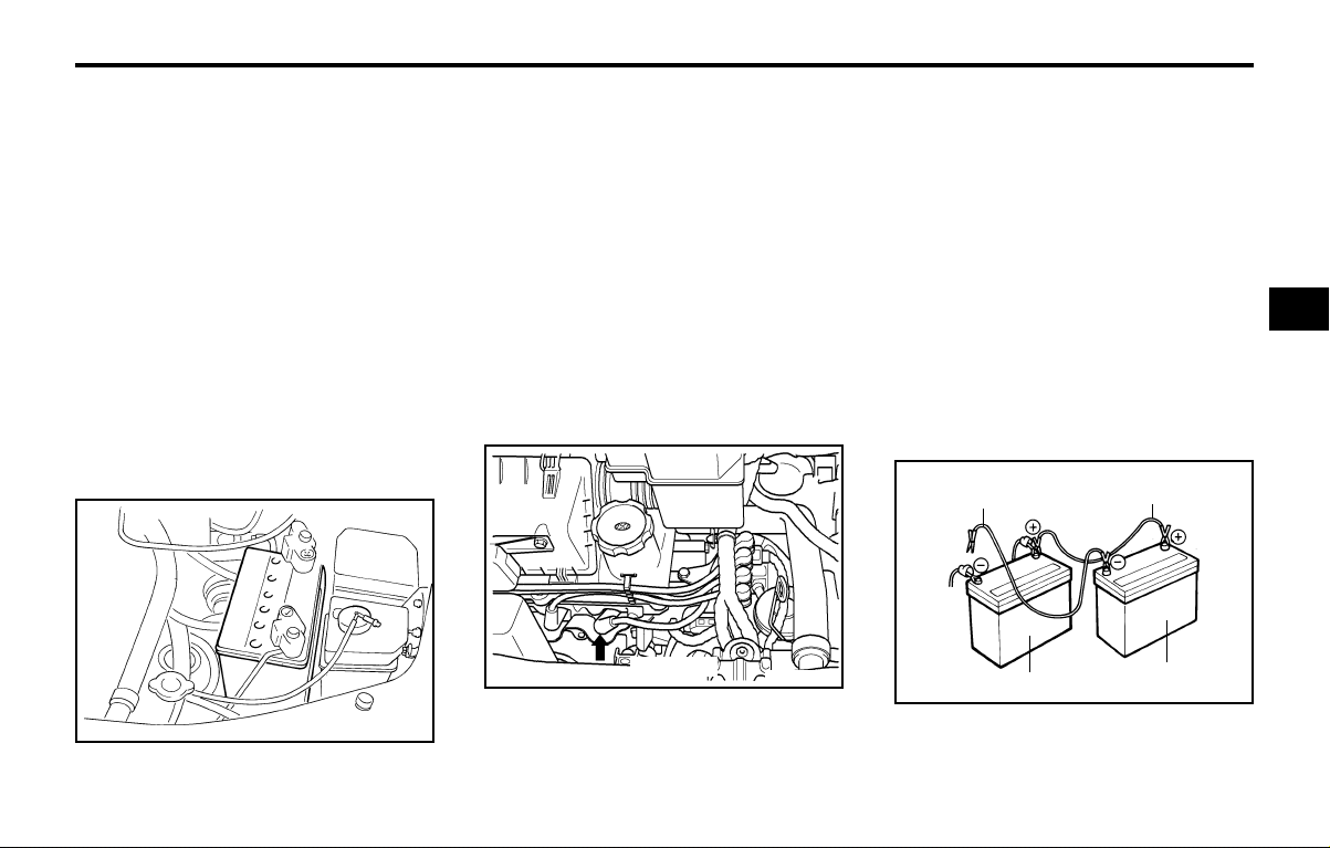
WHAT TO DO IN AN EMERGENCYWHAT TO DO IN AN EMERGENCY
WHAT TO DO IN AN EMERGENCYWHAT TO DO IN AN EMERGENCY
WHAT TO DO IN AN EMERGENCY
3-1
D010B01A-AAT
If Engine Doesn't Turn Over or TurnsIf Engine Doesn't Turn Over or Turns
If Engine Doesn't Turn Over or TurnsIf Engine Doesn't Turn Over or Turns
If Engine Doesn't Turn Over or Turns
Over SlowlyOver Slowly
Over SlowlyOver Slowly
Over Slowly
3.3.
3.3.
3.
WHAWHA
WHAWHA
WHA
T T
T T
T
TT
TT
T
O DO IN ANO DO IN AN
O DO IN ANO DO IN AN
O DO IN AN
EMERGENCYEMERGENCY
EMERGENCYEMERGENCY
EMERGENCY
D010A01A-AAT
IF THE ENGINE WILL NOT STARTIF THE ENGINE WILL NOT START
IF THE ENGINE WILL NOT STARTIF THE ENGINE WILL NOT START
IF THE ENGINE WILL NOT START
CAUTION:CAUTION:
CAUTION:CAUTION:
CAUTION:
If the engine will not start, do not push orIf the engine will not start, do not push or
If the engine will not start, do not push orIf the engine will not start, do not push or
If the engine will not start, do not push or
pull the car to pull the car to
pull the car to pull the car to
pull the car to
start it. This could result in astart it. This could result in a
start it. This could result in astart it. This could result in a
start it. This could result in a
collision or cause other damage. In addi-collision or cause other damage. In addi-
collision or cause other damage. In addi-collision or cause other damage. In addi-
collision or cause other damage. In addi-
tion, tion,
tion, tion,
tion,
push or pull starting may cause thepush or pull starting may cause the
push or pull starting may cause thepush or pull starting may cause the
push or pull starting may cause the
catalytic converter to be overloaded andcatalytic converter to be overloaded and
catalytic converter to be overloaded andcatalytic converter to be overloaded and
catalytic converter to be overloaded and
create a fire hazard.create a fire hazard.
create a fire hazard.create a fire hazard.
create a fire hazard.
1. If your car has an automatic transaxle, be
sure the gear selector lever is in "N" or "P"
and the emergency brake is set.
2. Check the battery connections to be sure
they are clean and tight.
3. Turn on the interior light. If the light dims or
goes out when you operate the starter, the
battery is discharged.
4. Check the starter connections to be sure
they are securely tightened.
5. Do not push or pull the vehicle to start it. See
instructions for "Jump Starting" on the fol-
lowing pages.
D010C01A-AAT
If Engine Turns Over Normally but DoesIf Engine Turns Over Normally but Does
If Engine Turns Over Normally but DoesIf Engine Turns Over Normally but Does
If Engine Turns Over Normally but Does
Not StartNot Start
Not StartNot Start
Not Start
1. Check fuel level.
2. Check all connectors at ignition, coil and
spark plugs. Reconnect any that may be
disconnected or loose.
D010D01A-AAT
If the Engine Stalls While DrivingIf the Engine Stalls While Driving
If the Engine Stalls While DrivingIf the Engine Stalls While Driving
If the Engine Stalls While Driving
1. Reduce your speed gradually, keeping a
straight line. Move cautiously off the road to
a safe place.
2. Turn on your emergency flashers.
3. Try to start the engine again. If your vehicle
will not start, contact a Hyundai dealer or
seek other qualified assistance.
D010B01A
3. Check the fuel line in the engine room.
4. If the engine still refuses to start, call a
Hyundai dealer or seek other qualified as-
sistance.
D020A02A-AAT
JUMP STARTINGJUMP STARTING
JUMP STARTINGJUMP STARTING
JUMP STARTING
AX30030A
Negative to the engine
not to the battery
Booster battery
Positive to positive
Dead battery
D010C01X-1
Spark Plug
33
33
3

WHAT TO DO IN AN EMERGENCYWHAT TO DO IN AN EMERGENCY
WHAT TO DO IN AN EMERGENCYWHAT TO DO IN AN EMERGENCY
WHAT TO DO IN AN EMERGENCY
3-2
2. Turn off all unnecessary lights and acces-
sories in both vehicles.
3. Attach the clamps of the jumper cable in the
exact order shown in the illustration. That is,
first, attach one clamp of the jumper cable to
the positive (+) post or cable of the dis-
charged battery. Then attach the other end
of the same cable to the positive (+) post or
cable of the booster battery. Next, using the
other cable, attach one clamp to the nega-
tive (-) post or cable of the booster battery.
Then attach the other end of that cable to a
solid metal part of the engine away from the
battery. Do not connect the cable to any
moving part.
4. Start the engine in the car with the booster
battery and let it run for a few minutes. This
will help to assure that the booster battery is
fully charged. During the jumping operation,
run the engine in this vehicle at about 2,000
rpm.
5. Start your engine using the normal starting
procedure. After the engine starts, leave the
jumper cables connected and let the engine
run at fast idle or about 2,000 rpm for sev-
eral minutes.
6. Carefully remove the jumper cables in the
reverse order of attachment.
If you do not know why your battery became
discharged (because the lights were left on,
etc.), have the charging system checked by
your Hyundai dealer.
WARNING:WARNING:
WARNING:WARNING:
WARNING:
The gas produced by the battery during theThe gas produced by the battery during the
The gas produced by the battery during theThe gas produced by the battery during the
The gas produced by the battery during the
jump start operation is highly explosive. Ifjump start operation is highly explosive. If
jump start operation is highly explosive. Ifjump start operation is highly explosive. If
jump start operation is highly explosive. If
these instructions are not followed exactly,these instructions are not followed exactly,
these instructions are not followed exactly,these instructions are not followed exactly,
these instructions are not followed exactly,
serious personal injury and damage to theserious personal injury and damage to the
serious personal injury and damage to theserious personal injury and damage to the
serious personal injury and damage to the
vehicle may occur! If you are not sure howvehicle may occur! If you are not sure how
vehicle may occur! If you are not sure howvehicle may occur! If you are not sure how
vehicle may occur! If you are not sure how
to follow this procedure, seek qualified as-to follow this procedure, seek qualified as-
to follow this procedure, seek qualified as-to follow this procedure, seek qualified as-
to follow this procedure, seek qualified as-
sistance. Automobile batteries contain sul-sistance. Automobile batteries contain sul-
sistance. Automobile batteries contain sul-sistance. Automobile batteries contain sul-
sistance. Automobile batteries contain sul-
furic acid. This is poisonous and highlyfuric acid. This is poisonous and highly
furic acid. This is poisonous and highlyfuric acid. This is poisonous and highly
furic acid. This is poisonous and highly
corrosive. When jump starting, wear protec-corrosive. When jump starting, wear protec-
corrosive. When jump starting, wear protec-corrosive. When jump starting, wear protec-
corrosive. When jump starting, wear protec-
tive glasses and be careful not to get acid ontive glasses and be careful not to get acid on
tive glasses and be careful not to get acid ontive glasses and be careful not to get acid on
tive glasses and be careful not to get acid on
yourself, your clothing or on the car.yourself, your clothing or on the car.
yourself, your clothing or on the car.yourself, your clothing or on the car.
yourself, your clothing or on the car.
o If you should accidentally get acid on your
skin or in your eyes, immediately remove
any contaminated clothing and flush the
area with clear water for at least 15 minutes.
Then promptly obtain medical attention. If
you must be transported to an emergency
facility, continue to apply water to the affect-
ed area with a sponge or cloth.
o The gas produced by the battery during the
jump start operation is highly explosive. Do
not smoke or allow a spark or an open flame
in the vicinity.
o The battery being used to provide the jump
start must be 12-volt. If you cannot deter-
mine that it is a 12-volt battery, do not
attempt to use it for the jump start.
o To jump start a car with a discharged bat-
tery, follow this procedure exactly:
1. If the booster battery is installed in another
vehicle, be sure the two vehicles are not
touching.
D030A01A-AAT
IF THE ENGINE OVERHEATSIF THE ENGINE OVERHEATS
IF THE ENGINE OVERHEATSIF THE ENGINE OVERHEATS
IF THE ENGINE OVERHEATS
If your temperature gauge indicates overheat-
ing, you experience a loss of power, or hear
loud pinging or knocking, the engine is probably
too hot. If this happens to you, you should:
1. Pull off the road and stop as soon as it is
safe to do so.
2. Place the gear selector lever in "P" (auto-
matic transaxle), or neutral (manual
transaxle) and set the parking brake. If the
air conditioning is on, turn it off.
3. If engine coolant is running out under the car
or steam is coming out from the hood, stop
the engine. Do not open the hood until the
engine coolant has stopped running or the
steaming has stopped. If there is no visible
loss of engine coolant and no steam, leave
the engine running and check to be sure the
engine cooling fan is operating. If the fan is
not running, turn the engine off.
4. Check to see if the water pump drive belt is
missing. If it is not missing, check to see that
it is tight. If the drive belt seems to be
satisfactory, check for engine coolant leak-
ing from the radiator, hoses or under the car.
(If the air conditioning had been in use, it is
normal for cold water to be draining from it
when you stop).
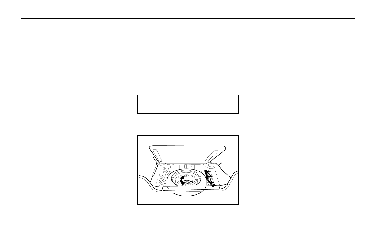
WHAT TO DO IN AN EMERGENCYWHAT TO DO IN AN EMERGENCY
WHAT TO DO IN AN EMERGENCYWHAT TO DO IN AN EMERGENCY
WHAT TO DO IN AN EMERGENCY
3-3
WARNING:WARNING:
WARNING:WARNING:
WARNING:
While the engine is running, keep hands,While the engine is running, keep hands,
While the engine is running, keep hands,While the engine is running, keep hands,
While the engine is running, keep hands,
long hair long hair
long hair long hair
long hair
and clothing away from movingand clothing away from moving
and clothing away from movingand clothing away from moving
and clothing away from moving
parts such as the fan and drive belts toparts such as the fan and drive belts to
parts such as the fan and drive belts toparts such as the fan and drive belts to
parts such as the fan and drive belts to
prevent prevent
prevent prevent
prevent
injury.injury.
injury.injury.
injury.
5. If the water pump drive belt is broken or
engine coolant is leaking out, stop the en-
gine immediately and call the nearest
Hyundai dealer for assistance.
WARNING:WARNING:
WARNING:WARNING:
WARNING:
Do not remove the radiator cap when theDo not remove the radiator cap when the
Do not remove the radiator cap when theDo not remove the radiator cap when the
Do not remove the radiator cap when the
engine is hot. This may allowengine is hot. This may allow
engine is hot. This may allowengine is hot. This may allow
engine is hot. This may allow
coolant to be coolant to be
coolant to be coolant to be
coolant to be
blown out of the opening and cause seriousblown out of the opening and cause serious
blown out of the opening and cause seriousblown out of the opening and cause serious
blown out of the opening and cause serious
burns.burns.
burns.burns.
burns.
6. If you cannot find the cause of the overheat-
ing, wait until the engine temperature has
returned to normal. Then, if engine coolant
has been lost, carefully remove the radiator
cap and add engine coolant to bring the fluid
level in the reservoir up to the halfway mark.
7. Proceed with caution, keeping alert for fur-
ther signs of overheating. If overheating hap-
pens again, call a Hyundai dealer for assis-
tance.
CAUTION:CAUTION:
CAUTION:CAUTION:
CAUTION:
Serious loss of engine coolant indicatesSerious loss of engine coolant indicates
Serious loss of engine coolant indicatesSerious loss of engine coolant indicates
Serious loss of engine coolant indicates
there is a leak in there is a leak in
there is a leak in there is a leak in
there is a leak in
the cooling system and thisthe cooling system and this
the cooling system and thisthe cooling system and this
the cooling system and this
should be checked as soon as possible by ashould be checked as soon as possible by a
should be checked as soon as possible by ashould be checked as soon as possible by a
should be checked as soon as possible by a
Hyundai Hyundai
Hyundai Hyundai
Hyundai
dealer.dealer.
dealer.dealer.
dealer.
D040A01A-GAT
SPARE TIRESPARE TIRE
SPARE TIRESPARE TIRE
SPARE TIRE
The following instructions for the FULL SIZE
spare tire should be observed:
Check inflation pressure as soon as practical
after installing the spare tire, and adjust to the
specified pressure. The tire pressure should be
periodically checked and maintained at the
specified pressure while the tire is stored.
Tire Size
Inflation Pressure
Full Size
210 kPa (30 psi)
Spare Tire Pressure
D040B01A-AAT
Handling the Spare TireHandling the Spare Tire
Handling the Spare TireHandling the Spare Tire
Handling the Spare Tire
Remove the installation bolt to remove the spare
tire. To replace the spare tire in its storage
D050A01A-AAT
IF YOU HAVE A FLAT TIREIF YOU HAVE A FLAT TIRE
IF YOU HAVE A FLAT TIREIF YOU HAVE A FLAT TIRE
IF YOU HAVE A FLAT TIRE
If a tire goes flat while you are driving:
1. Take your foot off the accelerator pedal and
let the car slow down while driving straight
ahead. Do not apply the brakes immediately
or attempt to pull off the road as this may
cause a loss of control. When the car has
slowed to such a speed that it is safe to do
so, brake carefully and pull off the road.
Drive off the road as far as possible and
park on firm, level ground. If you are on a
divided highway, do not park in the median
area between the two traffic lanes.
2. When the car is stopped, turn on your emer-
gency hazard flashers, set the parking brake
and put the transaxle in "P" (automatic
transaxle) or reverse (manual transaxle)
3. Have all passengers get out of the car. Be
sure they all get out on the side of the car
that is away from traffic.
4. Change the tire according to the instructions
provided as following.
compartment, tighten the bolt firmly with your
fingers until there is no more play in the spare
tire.
D040B01X

WHAT TO DO IN AN EMERGENCYWHAT TO DO IN AN EMERGENCY
WHAT TO DO IN AN EMERGENCYWHAT TO DO IN AN EMERGENCY
WHAT TO DO IN AN EMERGENCY
3-4
D060A01A-AAT
CHANGING A FLAT TIRECHANGING A FLAT TIRE
CHANGING A FLAT TIRECHANGING A FLAT TIRE
CHANGING A FLAT TIRE
The procedure described on the following pages
can be used to rotate tires as well as to change
a flat tire. When preparing to change a flat tire,
check to be sure the gear selector lever is in "P"
(automatic transaxle) or reverse gear (manual
transaxle) and that the parking brake is set,
then:
D060B01FC-GAT
1. Obtain Spare Tire and Tool1. Obtain Spare Tire and Tool
1. Obtain Spare Tire and Tool1. Obtain Spare Tire and Tool
1. Obtain Spare Tire and Tool
Remove the spare tire and take out the jack and
tool bag from the luggage room.
NOTE:NOTE:
NOTE:NOTE:
NOTE:
The jack is located beneath the luggage matThe jack is located beneath the luggage mat
The jack is located beneath the luggage matThe jack is located beneath the luggage mat
The jack is located beneath the luggage mat
in the vehicle.in the vehicle.
in the vehicle.in the vehicle.
in the vehicle.
Block the wheel that is diagonally opposite from
the flat to keep the vehicle from rolling when the
car is raised on the jack.
D060C01A-AAT
2. Block the Wheel2. Block the Wheel
2. Block the Wheel2. Block the Wheel
2. Block the Wheel
SSA3050D
Flat tire
D060D01A-AAT
3. Loosen Wheel Nuts3. Loosen Wheel Nuts
3. Loosen Wheel Nuts3. Loosen Wheel Nuts
3. Loosen Wheel Nuts
D060A01X
HNVOM096
D040B01X
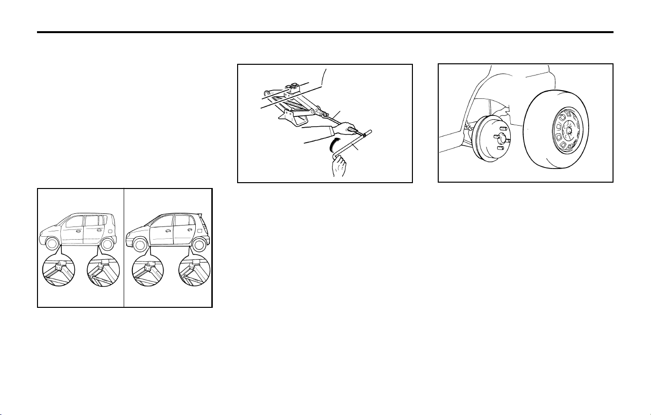
WHAT TO DO IN AN EMERGENCYWHAT TO DO IN AN EMERGENCY
WHAT TO DO IN AN EMERGENCYWHAT TO DO IN AN EMERGENCY
WHAT TO DO IN AN EMERGENCY
3-5
Wheel nut
Wrench
The wheel nuts should be loosened slightly
before raising the car. To loosen the nuts, turn
the wrench handle counterclockwise. When
doing this, be sure that the socket is seated
completely over the nut so it cannot slip off. For
maximum leverage position the wrench so the
handle is to the right as shown in the drawing.
Then, while holding the wrench near the end of
the handle, pull up on it with steady pressure.
Do not remove the nuts at this time. Just loosen
them about one-half turn.
D060E01A-AAT
4. Put the Jack in Place4. Put the Jack in Place
4. Put the Jack in Place4. Put the Jack in Place
4. Put the Jack in Place
The base of the jack should be placed on firm,
level ground. The jack should be positioned as
shown in the drawing.
D060F02E-AAT
5. Raising the Car5. Raising the Car
5. Raising the Car5. Raising the Car
5. Raising the Car
D060G01A-AAT
6. Changing Wheels6. Changing Wheels
6. Changing Wheels6. Changing Wheels
6. Changing Wheels
AS30120A
After inserting a wrench bar into the wheel nut
wrench, install the wrench bar into the jack as
shown in the drawing. To raise the vehicle, turn
the wheel nut wrench clockwise. As the jack
begins to raise the vehicle, double check that it
is properly positioned and will not slip. If the
jack is on soft ground or sand, you may find it
necessary to place a board, brick, flat stone or
other object under the base of the jack to keep
it from sinking.
Raise the car high enough so that the fully
inflated spare tire can be installed. To do this,
you will need more ground clearance than is
required to remove the flat tire.
WARNING:WARNING:
WARNING:WARNING:
WARNING:
Do not get under the car when it is sup-Do not get under the car when it is sup-
Do not get under the car when it is sup-Do not get under the car when it is sup-
Do not get under the car when it is sup-
ported by the jack. This is very dangerousported by the jack. This is very dangerous
ported by the jack. This is very dangerousported by the jack. This is very dangerous
ported by the jack. This is very dangerous
as the vehicle could fall and cause seriousas the vehicle could fall and cause serious
as the vehicle could fall and cause seriousas the vehicle could fall and cause serious
as the vehicle could fall and cause serious
injury or death. No one should stay in theinjury or death. No one should stay in the
injury or death. No one should stay in theinjury or death. No one should stay in the
injury or death. No one should stay in the
car while the jack is being used.car while the jack is being used.
car while the jack is being used.car while the jack is being used.
car while the jack is being used.
Use the wrench to loosen the wheel nuts, then
remove them with your fingers. Remove the
wheel cover (if installed) from the wheel and
slide the wheel off the studs and lay it flat so it
cannot roll away. To put the wheel on the hub,
pick up the spare tire, line up the holes with the
studs and slide the wheel onto them. If this is
difficult, tip the wheel slightly and get the top
hole in the wheel lined up with the top stud.
Then jiggle the wheel back and forth until the
wheel can be slid over the other studs.
D060E01A
<PRIME>
D060E01V
HFC4022
Wrench bar
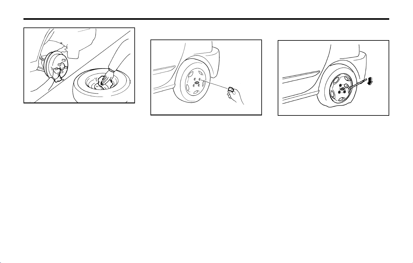
WHAT TO DO IN AN EMERGENCYWHAT TO DO IN AN EMERGENCY
WHAT TO DO IN AN EMERGENCYWHAT TO DO IN AN EMERGENCY
WHAT TO DO IN AN EMERGENCY
3-6
AS30130A
WARNING:WARNING:
WARNING:WARNING:
WARNING:
Wheel covers may have sharp edges. Han-Wheel covers may have sharp edges. Han-
Wheel covers may have sharp edges. Han-Wheel covers may have sharp edges. Han-
Wheel covers may have sharp edges. Han-
dle them carefully to avoid possible severedle them carefully to avoid possible severe
dle them carefully to avoid possible severedle them carefully to avoid possible severe
dle them carefully to avoid possible severe
injury.injury.
injury.injury.
injury.
Before putting the wheel into place, be sureBefore putting the wheel into place, be sure
Before putting the wheel into place, be sureBefore putting the wheel into place, be sure
Before putting the wheel into place, be sure
that there is nothing on the hub or wheelthat there is nothing on the hub or wheel
that there is nothing on the hub or wheelthat there is nothing on the hub or wheel
that there is nothing on the hub or wheel
(such as mud, tar, gravel, etc.) that inter-(such as mud, tar, gravel, etc.) that inter-
(such as mud, tar, gravel, etc.) that inter-(such as mud, tar, gravel, etc.) that inter-
(such as mud, tar, gravel, etc.) that inter-
feres with the wheel fitting solidly againstferes with the wheel fitting solidly against
feres with the wheel fitting solidly againstferes with the wheel fitting solidly against
feres with the wheel fitting solidly against
the hub. If there is, remove it. If there is notthe hub. If there is, remove it. If there is not
the hub. If there is, remove it. If there is notthe hub. If there is, remove it. If there is not
the hub. If there is, remove it. If there is not
good contact on the mounting surface be-good contact on the mounting surface be-
good contact on the mounting surface be-good contact on the mounting surface be-
good contact on the mounting surface be-
tween the wheel and hub, the wheel nutstween the wheel and hub, the wheel nuts
tween the wheel and hub, the wheel nutstween the wheel and hub, the wheel nuts
tween the wheel and hub, the wheel nuts
could come loose and cause the loss of acould come loose and cause the loss of a
could come loose and cause the loss of acould come loose and cause the loss of a
could come loose and cause the loss of a
wheel. Loss of a wheel may result in loss ofwheel. Loss of a wheel may result in loss of
wheel. Loss of a wheel may result in loss ofwheel. Loss of a wheel may result in loss of
wheel. Loss of a wheel may result in loss of
control of the vehicle. This may cause seri-control of the vehicle. This may cause seri-
control of the vehicle. This may cause seri-control of the vehicle. This may cause seri-
control of the vehicle. This may cause seri-
ous injury or death.ous injury or death.
ous injury or death.ous injury or death.
ous injury or death.
D060I01E-GAT
8. Lower Vehicle and Tighten Nuts8. Lower Vehicle and Tighten Nuts
8. Lower Vehicle and Tighten Nuts8. Lower Vehicle and Tighten Nuts
8. Lower Vehicle and Tighten Nuts
D060H01A-AAT
7. Re-install Wheel Nuts7. Re-install Wheel Nuts
7. Re-install Wheel Nuts7. Re-install Wheel Nuts
7. Re-install Wheel Nuts
To reinstall the wheel cover, hold it on the wheel
and put the wheel nuts on the studs and tighten
them finger tight. The nuts should be installed
with their small diameter ends directed inward.
Jiggle the tire to be sure it is completely seated,
then tighten the nuts with your fingers again.
Lower the car to the ground by turning the
wheel nut wrench counterclockwise. Then posi-
tion the wrench as shown in the drawing and
tighten the wheel nuts. Be sure the socket is
seated completely over the nut. Do not stand on
the wrench handle or use an extension pipe
over the wrench handle.
Go around the wheel tightening every other unt
until they are all tight. Then double-check each
nut for tightness. After changing wheels, have a
technician tighten the wheel nuts to their proper
torque as soon as possible.
Wheel nut tightening torque:Wheel nut tightening torque:
Wheel nut tightening torque:Wheel nut tightening torque:
Wheel nut tightening torque:
Steel wheel & aluminium alloy wheel:
900-1,100 kg.cm (65-80 lb.ft)
D060H01A
HNVOM098

WHAT TO DO IN AN EMERGENCYWHAT TO DO IN AN EMERGENCY
WHAT TO DO IN AN EMERGENCYWHAT TO DO IN AN EMERGENCY
WHAT TO DO IN AN EMERGENCY
3-7
D060J01FC-GAT
After Changing WheelsAfter Changing Wheels
After Changing WheelsAfter Changing Wheels
After Changing Wheels
If you have a tire gauge, remove the valve cap
and check the air pressure. If the pressure is
lower than recommended, drive slowly to the
nearest service station and inflate to the correct
pressure. If it is too high, adjust it until it is
correct. Always reinstall the valve cap after
checking or adjusting tire pressure. If the cap is
not replaced, air may leak from the tire. If you
lose a valve cap, buy another and install it as
soon as possible.
After you have changed wheels, always secure
the flat tire in its place in the luggage room and
return the jack and tools to their proper storage
locations.
D080A01A-GAT
IF YOUR CAR MUST BE TOWEDIF YOUR CAR MUST BE TOWED
IF YOUR CAR MUST BE TOWEDIF YOUR CAR MUST BE TOWED
IF YOUR CAR MUST BE TOWED
D080B01A-AAT
Towing a Car With a Manual TransaxleTowing a Car With a Manual Transaxle
Towing a Car With a Manual TransaxleTowing a Car With a Manual Transaxle
Towing a Car With a Manual Transaxle
o OK FOR AUTOMATIC OR MANUAL
TRANSAXLE EQUIPPED VEHICLE
WITH NO DAMAGE
o OK FOR AUTOMATIC OR MANUAL
TRANSAXLE EQUIPPED VEHICLE
CAUTION:CAUTION:
CAUTION:CAUTION:
CAUTION:
Your car can be damaged if towed incor-Your car can be damaged if towed incor-
Your car can be damaged if towed incor-Your car can be damaged if towed incor-
Your car can be damaged if towed incor-
rectly!rectly!
rectly!rectly!
rectly!
If your car has to be towed, it should be done by
your Hyundai dealer or a commercial tow truck
service. This will help assure that your car is
not damaged in towing. Also, professionals are
generally aware of state and local laws govern-
ing towing. In any case, rather than risk dam-
age to your car, it is suggested that you show
this information to the tow truck operator. Be
sure that a safety chain system is used and that
local laws are observed.
o If the car is being towed with the rear wheels
on the ground, be sure the parking brake is
released.
o If the car is being towed with the front
wheels on the ground, be sure that the
transaxle is in neutral. Also, be sure that the
ignition key is in the "ACC" position. This is
necessary to prevent damage to the steer-
ing lock mechanism, which is not designed
to hold the front wheels straight while the car
is being towed.
o If any of the loaded wheels or suspension
components are damaged, a towing dolly
must be used.
D080A01A
D080B01A
D060J01X
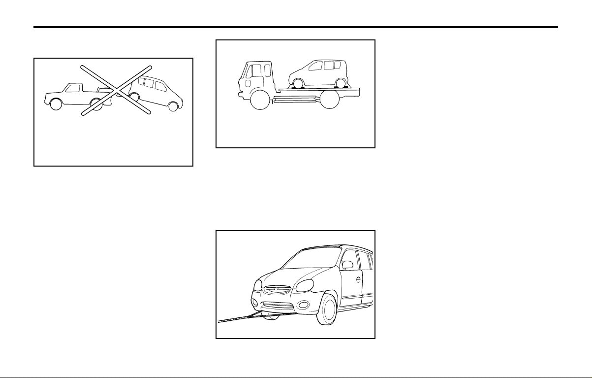
WHAT TO DO IN AN EMERGENCYWHAT TO DO IN AN EMERGENCY
WHAT TO DO IN AN EMERGENCYWHAT TO DO IN AN EMERGENCY
WHAT TO DO IN AN EMERGENCY
3-8
D080C02A-GAT
Towing a Car With Automatic TransaxleTowing a Car With Automatic Transaxle
Towing a Car With Automatic TransaxleTowing a Car With Automatic Transaxle
Towing a Car With Automatic Transaxle
o NOT OK FOR AUTOMATIC
TRANSAXLE EQUIPPED VEHICLE
o OK FOR MANUAL TRANSAXLE
CAUTION:CAUTION:
CAUTION:CAUTION:
CAUTION:
A car with an automatic transaxle shouldA car with an automatic transaxle should
A car with an automatic transaxle shouldA car with an automatic transaxle should
A car with an automatic transaxle should
never be towed from the rear with the frontnever be towed from the rear with the front
never be towed from the rear with the frontnever be towed from the rear with the front
never be towed from the rear with the front
wheels on the ground. This can cause seri-wheels on the ground. This can cause seri-
wheels on the ground. This can cause seri-wheels on the ground. This can cause seri-
wheels on the ground. This can cause seri-
ous damage to the transaxle. If the car mustous damage to the transaxle. If the car must
ous damage to the transaxle. If the car mustous damage to the transaxle. If the car must
ous damage to the transaxle. If the car must
be towed from the rear, a towing dolly mustbe towed from the rear, a towing dolly must
be towed from the rear, a towing dolly mustbe towed from the rear, a towing dolly must
be towed from the rear, a towing dolly must
be used under the front wheels.be used under the front wheels.
be used under the front wheels.be used under the front wheels.
be used under the front wheels.
If the car is being towed with the rear wheels on
the ground, be sure the parking brake is re-
leased.
D080D02X-GAT
Emergency TowingEmergency Towing
Emergency TowingEmergency Towing
Emergency Towing
For emergency towing when no commercial
tow vehicle is available, attach a tow cable,
chain or strap to the two hooks under the front
of your car. Do not attempt to tow your vehicle
in this manner on any unpaved surface. This
could result in serious damage to your car.
Nor should it be attempted if the wheels, drive
train, axles, steering or brakes are damaged.
Before towing, be sure the transaxle is in neu-
tral and the key is in "ACC" (with the engine off)
or in the "ON" position (with the engine run-
ning). A driver must be in the towed car to steer
it and operate the brakes.
CAUTION:CAUTION:
CAUTION:CAUTION:
CAUTION:
If the car is being towed with all four wheelsIf the car is being towed with all four wheels
If the car is being towed with all four wheelsIf the car is being towed with all four wheels
If the car is being towed with all four wheels
on the ground, it can be towed only from theon the ground, it can be towed only from the
on the ground, it can be towed only from theon the ground, it can be towed only from the
on the ground, it can be towed only from the
front. Be sure that the transaxle is in neutral.front. Be sure that the transaxle is in neutral.
front. Be sure that the transaxle is in neutral.front. Be sure that the transaxle is in neutral.
front. Be sure that the transaxle is in neutral.
Do not tow at speeds greater than 50 km/hDo not tow at speeds greater than 50 km/h
Do not tow at speeds greater than 50 km/hDo not tow at speeds greater than 50 km/h
Do not tow at speeds greater than 50 km/h
(30 mph) and for more than 25 km (15 miles).(30 mph) and for more than 25 km (15 miles).
(30 mph) and for more than 25 km (15 miles).(30 mph) and for more than 25 km (15 miles).
(30 mph) and for more than 25 km (15 miles).
Be sure the steering is unlocked by placingBe sure the steering is unlocked by placing
Be sure the steering is unlocked by placingBe sure the steering is unlocked by placing
Be sure the steering is unlocked by placing
the key in the "ACC" position. A driver mustthe key in the "ACC" position. A driver must
the key in the "ACC" position. A driver mustthe key in the "ACC" position. A driver must
the key in the "ACC" position. A driver must
be in the towed vehicle to operate the steer-be in the towed vehicle to operate the steer-
be in the towed vehicle to operate the steer-be in the towed vehicle to operate the steer-
be in the towed vehicle to operate the steer-
ing and brakes.ing and brakes.
ing and brakes.ing and brakes.
ing and brakes.
o OK FOR AUTOMATIC OR MANUAL
TRANSAXLE EQUIPPED VEHICLE
D080C01A
D080C02A
D080D01X
D120A01A-GAT
IF YOU LOSE YOUR KEYSIF YOU LOSE YOUR KEYS
IF YOU LOSE YOUR KEYSIF YOU LOSE YOUR KEYS
IF YOU LOSE YOUR KEYS
If you lose your keys, many Hyundai dealers
can make you a new key if you have your key
number. If you lock the keys inside your car and
you cannot obtain a new key, many Hyundai
dealers can use special tools to open the door
for you.
Information about the key of immobilizer sys-
tem (If installed) will be found on page 1-2.
NOTE:NOTE:
NOTE:NOTE:
NOTE:
Before towing, check the level of theBefore towing, check the level of the
Before towing, check the level of theBefore towing, check the level of the
Before towing, check the level of the
transaxle fluid. If it is below the "HOT" rangetransaxle fluid. If it is below the "HOT" range
transaxle fluid. If it is below the "HOT" rangetransaxle fluid. If it is below the "HOT" range
transaxle fluid. If it is below the "HOT" range
on the dipstick, add fluid. If you cannot addon the dipstick, add fluid. If you cannot add
on the dipstick, add fluid. If you cannot addon the dipstick, add fluid. If you cannot add
on the dipstick, add fluid. If you cannot add
fluid, a towing dolly must be used.fluid, a towing dolly must be used.
fluid, a towing dolly must be used.fluid, a towing dolly must be used.
fluid, a towing dolly must be used.

CORROSION PREVENTION AND APPEARANCE CARECORROSION PREVENTION AND APPEARANCE CARE
CORROSION PREVENTION AND APPEARANCE CARECORROSION PREVENTION AND APPEARANCE CARE
CORROSION PREVENTION AND APPEARANCE CARE
4-1
4.4.
4.4.
4.
CORRCORR
CORRCORR
CORR
OSION PRE-OSION PRE-
OSION PRE-OSION PRE-
OSION PRE-
VENTION & AP-VENTION & AP-
VENTION & AP-VENTION & AP-
VENTION & AP-
PEARANCE CAREPEARANCE CARE
PEARANCE CAREPEARANCE CARE
PEARANCE CARE
E020A01A-AAT
TO HELP PREVENT CORROSIONTO HELP PREVENT CORROSION
TO HELP PREVENT CORROSIONTO HELP PREVENT CORROSION
TO HELP PREVENT CORROSION
You can help prevent corrosion from getting
started by observing the following:
E020B01A-AAT
Keep Your Car CleanKeep Your Car Clean
Keep Your Car CleanKeep Your Car Clean
Keep Your Car Clean
The best way to prevent corrosion is to keep
your car clean and free of corrosive materials.
Attention to the underside of the car is particu-
larly important.
o If you live in a high-corrosion area — where
road salts are used, near the ocean, areas
with industrial pollution, acid rain, etc.— you
should take extra care to prevent corrosion.
In winter, hose off the underside of your car
at least once a month and be sure to clean
the underside thoroughly when winter is
over.
o When cleaning underneath the car, give
particular attention to the components under
the fenders and other areas that are hidden
from view. Do a thorough job; just dampen-
ing the accumulated mud rather than wash-
ing it away will accelerate corrosion rather
than prevent it. Water under high pressure
and steam are particularly effective in re-
moving accumulated mud and corrosive
materials.
o When cleaning lower door panels, rocker
panels and frame members, be sure that
drain holes are kept open so that moisture
can escape and not be trapped inside to ac-
celerate corrosion.
E010B01A-AAT
Common Causes of CorrosionCommon Causes of Corrosion
Common Causes of CorrosionCommon Causes of Corrosion
Common Causes of Corrosion
The most common causes of corrosion on your
car are:
o Road salt, dirt and moisture that is allowed
to accumulate underneath the car.
o Removal of paint or protective coatings by
stones, gravel, abrasion or minor scrapes
and dents which leave unprotected metal
exposed to corrosion.
E010A01A-AAT
CORROSION PROTECTIONCORROSION PROTECTION
CORROSION PROTECTIONCORROSION PROTECTION
CORROSION PROTECTION
Protecting Your Hyundai from Corro-Protecting Your Hyundai from Corro-
Protecting Your Hyundai from Corro-Protecting Your Hyundai from Corro-
Protecting Your Hyundai from Corro-
sionsion
sionsion
sion
By using the most advanced design and con-
struction practices to combat corrosion, Hyundai
produces cars of the highest quality. However,
this is only part of the job. To achieve the long
term corrosion resistance your Hyundai can
deliver, the owner's cooperation and assistance
is also required.
E010C01A-AAT
High-Corrosion AreasHigh-Corrosion Areas
High-Corrosion AreasHigh-Corrosion Areas
High-Corrosion Areas
If you live in an area where your car is regularly
exposed to corrosive materials, corrosion pro-
tection is particularly important. Some of the
common causes of accelerated corrosion are
road salts, dust control chemicals, ocean air
and industrial pollution.
E010D01A-AAT
Moisture Breeds CorrosionMoisture Breeds Corrosion
Moisture Breeds CorrosionMoisture Breeds Corrosion
Moisture Breeds Corrosion
Moisture creates the conditions in which corro-
sion is most likely to occur. For example, cor-
rosion is accelerated by high humidity, particu-
larly when temperatures are just above freez-
ing. In such conditions, the corrosive material is
kept in contact with the car surfaces by mois-
ture that is slow to evaporate.
Mud is particularly corrosive because it is slow
to dry and holds moisture in contact with the
vehicle. Although the mud appears to be dry, it
can still retain the moisture and promote corro-
sion.
High temperatures can also accelerate corro-
sion of parts that are not properly ventilated so
the moisture can be dispersed. For all these
reasons, it is particularly important to keep your
car clean and free of mud or accumulations of
other materials. This applies not only to the
visible surfaces but particularly to the underside
of the car.
44
44
4

CORROSION PREVENTION AND APPEARANCE CARECORROSION PREVENTION AND APPEARANCE CARE
CORROSION PREVENTION AND APPEARANCE CARECORROSION PREVENTION AND APPEARANCE CARE
CORROSION PREVENTION AND APPEARANCE CARE
4-2
E020C01A-AAT
Keep Your Garage DryKeep Your Garage Dry
Keep Your Garage DryKeep Your Garage Dry
Keep Your Garage Dry
Don't park your car in a damp, poorly ventilated
garage. This creates a favorable environment
for corrosion. This is particularly true if you
wash your car in the garage or drive it into the
garage when it is still wet or covered with snow,
ice or mud. Even a heated garage can contrib-
ute to corrosion unless it is well ventilated so
moisture is dispersed.
E020D01A-AAT
Keep Paint and Trim in Good ConditionKeep Paint and Trim in Good Condition
Keep Paint and Trim in Good ConditionKeep Paint and Trim in Good Condition
Keep Paint and Trim in Good Condition
Scratches or chips in the finish should be cov-
ered with "touch-up" paint as soon as possible
to reduce the possibility of corrosion. If bare
metal is showing through, the attention of a
qualified body and paint shop is recommended.
E020E01A-AAT
Don't Neglect the InteriorDon't Neglect the Interior
Don't Neglect the InteriorDon't Neglect the Interior
Don't Neglect the Interior
Moisture can collect under the floor mats and
carpeting to cause corrosion. Check under the
mats periodically to be sure the carpeting is dry.
Use particular care if you carry fertilizers, clean-
ing materials or chemicals in the car.
These should be carried only in proper contain-
ers and any spills or leaks should be cleaned
up, flushed with clear water and thoroughly
dried.
E030A01A-AAT
WASHING AND WAXINGWASHING AND WAXING
WASHING AND WAXINGWASHING AND WAXING
WASHING AND WAXING
Washing Your HyundaiWashing Your Hyundai
Washing Your HyundaiWashing Your Hyundai
Washing Your Hyundai
Never wash your car when the surface is hot
from being in the sun. Always wash your car in
the shade.
Wash your car frequently. Dirt is abrasive and
can scratch the paint if it is not removed. Air
pollution or acid rain may damage the paint and
trim through chemical action if pollutants are
allowed to remain in contact with the surface. If
you live near the ocean or in an area where
road salts or dust control chemicals are used,
you should pay particular attention to the under-
side of the car. Start by rinsing the car to
remove dust and loose dirt. In winter, or if you
have driven through mud or muddy water, be
sure to thoroughly clean the underside as well.
Use a hard direct stream of water to remove
accumulations of mud or corrosive materials.
Use a good quality car-washing solution and
follow the manufacturer's directions on the pack-
age. These are available at your Hyundai deal-
er or auto parts outlet. Don't use strong house-
hold detergents, gasoline, strong solvents or
abrasive cleaning powders as these may dam-
age the finish.
Use a clean sponge or cloth, rinse it frequently
and don't damage the finish by rubbing too
hard. For stubborn spots, dampen them fre-
quently and remove them a little at a time.
To clean whitewall tires, use a stiff brush or
soapy steel-wool scouring pad.
To clean plastic wheel covers, use a clean
sponge or soft cloth and water.
To clean cast aluminum alloy wheels, use a
mild soap or neutral detergent. Do not use
abrasive cleaners. Protect the bare-metal sur-
faces by cleaning, polishing and waxing. Be-
cause aluminum is subject to corrosion, be sure
to give aluminum alloy wheels special attention
in winter. If you drive on salted roads, clean the
wheels thoroughly afterwards.
After washing, be sure to rinse thoroughly. If
soapy water dries on the finish, streaking will
result.
When the weather is warm and the humidity
low, you may find it necessary to rinse each
section immediately after washing to avoid
streaking.
After rinsing, dry the car using a damp chamois
or soft, absorbent cloth. The reason for drying
the car is to remove water from the car so it will
dry without water spots. Don't rub, this can
damage the finish.
If you find any nicks or scratches in the paint,
use touch-up paint to cover them to prevent
corrosion. To protect the paintwork of the car
against corrosion, you must clean your Hyundai

CORROSION PREVENTION AND APPEARANCE CARECORROSION PREVENTION AND APPEARANCE CARE
CORROSION PREVENTION AND APPEARANCE CARECORROSION PREVENTION AND APPEARANCE CARE
CORROSION PREVENTION AND APPEARANCE CARE
4-3
(at least once a month). Give special attention
to the removal of salt, mud and other substanc-
es on the underside of the splashboards of the
car. Make sure that the outlets and the under-
side of the doors are open. Paint damage can
be caused by small accumulation of tar, indus-
trial precipitation, tree resin, insects and bird
droppings, when not removed immediately.
If water alone is not strong enough to remove
the accumulated dirt, use a mild car washing
solution. Be sure to rinse the surface after
washing to remove the solution. Never allow
the solution to dry on the painted surfaces.
E030C01A-AAT
Polishing and WaxingPolishing and Waxing
Polishing and WaxingPolishing and Waxing
Polishing and Waxing
Always wash and dry the car before polishing
or waxing or using a combination cleaner and
wax. Use a good quality commercial product
and follow the manufacturer's directions on the
container. Polish and wax the bright trim pieces
as well as the paint.
E030B01A-AAT
Spot CleaningSpot Cleaning
Spot CleaningSpot Cleaning
Spot Cleaning
Don't use gasoline, strong solvents or corrosive
cleaning agents. These can damage the finish
of the car. To remove road tar, use turpentine
on a clean, soft cloth or commercially available
bug and tar remover. Be gentle.
To remove dead insects or tree sap, use warm
water and mild soap or car-washing solution.
Soak the spot and rub gently. If the paint has
lost its luster, use a commercial car-cleaning
polish.
E030D01A-AAT
When to Wax AgainWhen to Wax Again
When to Wax AgainWhen to Wax Again
When to Wax Again
You should polish and wax the car again when
water no longer beads on a clean surface but
spreads out over a larger area.
E030E01A-AAT
Maintaining BumpersMaintaining Bumpers
Maintaining BumpersMaintaining Bumpers
Maintaining Bumpers
Special precautions must be observed to pre-
serve the appearance of the bumpers on your
Hyundai. They are:
o Be careful not to spill battery electrolyte or
hydraulic brake fluid on the bumpers. If you
do, wash it off immediately with clean water.
o Be gentle when cleaning the bumper sur-
faces. They are made of soft plastic and the
surface can be damaged if mistreated. Do
not use abrasive cleaners. Use warm water
and mild soap or car-washing solution.
o Do not expose the bumpers to high tem-
peratures. For example, if you have your
car repainted, do not leave the bumpers on
the car if the car is going to be placed in a
high temperature paint booth.
E040A01A-AAT
CLEANING THE INTERIORCLEANING THE INTERIOR
CLEANING THE INTERIORCLEANING THE INTERIOR
CLEANING THE INTERIOR
To Clean the Vinyl UpholsteryTo Clean the Vinyl Upholstery
To Clean the Vinyl UpholsteryTo Clean the Vinyl Upholstery
To Clean the Vinyl Upholstery
To clean the vinyl upholstery, first remove loose
dirt and dust with a vacuum cleaner. Then apply
a solution of mild soap or detergent and water
using a clean sponge or soft cloth. Allow this to
stay on the surface to loosen the dirt, then wipe
with a clean damp sponge or cloth. If all the dirt
stains are not removed, repeat this procedure
until the upholstery is clean. Do not use gaso-
line, solvent, paint thinner or other strong clean-
ers.
E040B01A-AAT
To Clean the Leather UpholsteryTo Clean the Leather Upholstery
To Clean the Leather UpholsteryTo Clean the Leather Upholstery
To Clean the Leather Upholstery
(If Installed)(If Installed)
(If Installed)(If Installed)
(If Installed)
In the normal course of use, leather upholstered
surfaces will, like any material, pick-up dust and
dirt. This dust and dirt must be cleaned off or it
may work into the surface of the leather, caus-
ing damage.
Fine leather needs care, and should be cleaned
when necessary. Washing leather thoroughly
with soap and water will keep your leather
lustrous, beautiful and ensure you have many
years of wear.

CORROSION PREVENTION AND APPEARANCE CARECORROSION PREVENTION AND APPEARANCE CARE
CORROSION PREVENTION AND APPEARANCE CARECORROSION PREVENTION AND APPEARANCE CARE
CORROSION PREVENTION AND APPEARANCE CARE
4-4
Take a piece of cheese cloth and using any
mild soap and lukewarm water, work up a good
lather. Thoroughly wash the leather. Wipe clean
with a slightly damp cloth and dry with soft
cloth. Do this as often as the leather becomes
soiled.
During tanning operations, sufficient oils are
incorporated through processing that none need
be applied during the life of the leather. Oil
applied to the finished surface will in no way
help the leather and may do more harm than
good. Varnishes and furniture polishes should
never be used under any conditions.
E040C01A-AAT
Cleaning the CarpetsCleaning the Carpets
Cleaning the CarpetsCleaning the Carpets
Cleaning the Carpets
Use a foam-type carpet cleaner. Cleaners of
this type are available in aerosol cans in liquid
form or powder. Read the instructions and fol-
low them exactly. Using a vacuum cleaner with
the appropriate attachment, remove as much
dirt from the carpets as possible. Apply the
foam following the manufacturer's directions,
then rub in overlapping circles. Do not add
water. These cleaners work best when the
carpet is kept as dry as possible.
E050A01A-AAT
ANY QUESTIONS?ANY QUESTIONS?
ANY QUESTIONS?ANY QUESTIONS?
ANY QUESTIONS?
If you have any questions about the care of
your car, consult your Hyundai dealer.
E040D01A-AAT
Cleaning the Seat BeltsCleaning the Seat Belts
Cleaning the Seat BeltsCleaning the Seat Belts
Cleaning the Seat Belts
To clean the seat belts, use a cloth or sponge
with mild soap or detergent and warm water. Do
not use strong detergents, dye, bleach or abra-
sive materials on the seat belts as this may
weaken the fabric.
While cleaning the belts, inspect them for ex-
cessive wear, cuts, fraying or other signs of
damage and replace them if necessary.
E040E01A-AAT
Cleaning the WindowsCleaning the Windows
Cleaning the WindowsCleaning the Windows
Cleaning the Windows
You may use any household window cleaner on
the windows. However, when cleaning the in-
side of the rear window be careful not to dam-
age the rear window defroster wiring.

VEHICLE MAINTENANCE REQUIREMENTSVEHICLE MAINTENANCE REQUIREMENTS
VEHICLE MAINTENANCE REQUIREMENTSVEHICLE MAINTENANCE REQUIREMENTS
VEHICLE MAINTENANCE REQUIREMENTS
5-1
5.5.
5.5.
5.
VEHICLE MAINTE-VEHICLE MAINTE-
VEHICLE MAINTE-VEHICLE MAINTE-
VEHICLE MAINTE-
NANCE REQNANCE REQ
NANCE REQNANCE REQ
NANCE REQ
UIRE-UIRE-
UIRE-UIRE-
UIRE-
MENTSMENTS
MENTSMENTS
MENTS
F010A01A-GAT
MAINTENANCE INTERVALSMAINTENANCE INTERVALS
MAINTENANCE INTERVALSMAINTENANCE INTERVALS
MAINTENANCE INTERVALS
Service requirementsService requirements
Service requirementsService requirements
Service requirements
To assure that you receive the greatest number
of kilometers of satisfying operation from your
Hyundai, certain maintenance procedures must
be performed. Although careful design and en-
gineering have reduced these to a minimum,
those that are required are of the utmost impor-
tance.
It is your responsibility to have these mainte-
nance procedures performed to comply with the
terms of the warranties covering your new
Hyundai. The Service Passport supplied with
your new vehicle provides further information
about these warranties.
F010B01A-AAT
Maintenance RequirementsMaintenance Requirements
Maintenance RequirementsMaintenance Requirements
Maintenance Requirements
The maintenance required for your Hyundai
can be divided into three main areas:
o Specified scheduled procedures
o General everyday checks
o Do-it-yourself maintenance
F010C01A-GAT
Specified Scheduled ProceduresSpecified Scheduled Procedures
Specified Scheduled ProceduresSpecified Scheduled Procedures
Specified Scheduled Procedures
These are the procedures such as inspections,
adjustments and replacements that are listed in
the maintenance charts starting on page 5-2.
These procedures must be performed at the
intervals shown in the maintenance schedule to
assure that your warranty remains in effect.
Although it is strongly recommended that they
be performed by the factory-trained or distribu-
tor-trained technicians at your Hyundai dealer,
these procedures may be performed at any
qualified service facility.
It is suggested that genuine Hyundai service
parts be used for any required repairs or re-
placements. Other parts of equivalent quality
such as engine oil, engine coolant, manual or
auto transaxle oil, brake fluid and so on which
are not supplied by Hyundai Motor Company or
its distributor may be used without affecting
your warranty coverage but you should always
be sure these are equivalent to the quality of the
original Hyundai parts. Your Service Passport
provides further information about your warran-
ty coverage.
F010E01A-AAT
Do-It-Yourself MaintenanceDo-It-Yourself Maintenance
Do-It-Yourself MaintenanceDo-It-Yourself Maintenance
Do-It-Yourself Maintenance
If you are mechanically inclined, own a few
tools that are required and want to take the time
to do so, you can inspect and service a number
of items. For more information about doing it
yourself, see Section 6.
F010F01A-AAT
A Few TipsA Few Tips
A Few TipsA Few Tips
A Few Tips
o Whenever you have your Hyundai serviced,
keep copies of the service records in your
glovebox. This will help ensure that you can
document that the required procedures have
been performed to keep your warranties in
effect. This is especially important when
service is not performed by an authorized
Hyundai dealer.
o If you choose to do your own maintenance
and repairs, you may find it helpful to have
an official Hyundai Shop Manual. A copy of
this publication may be purchased at your
Hyundai dealer's parts department.
F020A02X-GAT
SCHEDULED MAINTENANCE RE-SCHEDULED MAINTENANCE RE-
SCHEDULED MAINTENANCE RE-SCHEDULED MAINTENANCE RE-
SCHEDULED MAINTENANCE RE-
QUIREMENTSQUIREMENTS
QUIREMENTSQUIREMENTS
QUIREMENTS
Inspection should be performed any time a
malfunction is experienced or suspected. Re-
ceipts for all emission control system services
should be retained to demonstrate compliance
with conditions of the emissions system war-
ranty. For severe usage maintenance require-
ments, see page 5-4 of this section.
F010D01A-AAT
General ChecksGeneral Checks
General ChecksGeneral Checks
General Checks
These are the regular checks you should per-
form when you drive your Hyundai or you fill the
fuel tank. A list of these items will be found on
page 6-2.
55
55
5

VEHICLE MAINTENANCE REQUIREMENTSVEHICLE MAINTENANCE REQUIREMENTS
VEHICLE MAINTENANCE REQUIREMENTSVEHICLE MAINTENANCE REQUIREMENTS
VEHICLE MAINTENANCE REQUIREMENTS
5- 2
ENGINE CONTROL SYSTEM MAINTENANCE
1 ENGINE OIL & FILTER (SG OR ABOVE) See Note (1)
2 DRIVE BELT (WATER PUMP & GENERATOR)
3 FUEL FILTER (MFI)
4 FUEL LINES, FUEL HOSES & CONNECTIONS
5 TIMING BELT
6 VAPOR HOSE & FUEL FILLER CAP
7 VACUUM CRANKCASE VENTILATION HOSES
8 AIR CLEANER FILTER
9 SPARK PLUGS
10 VALVE CLEARANCE
F030A01A-GAT
SCHEDULED MAINTENANCESCHEDULED MAINTENANCE
SCHEDULED MAINTENANCESCHEDULED MAINTENANCE
SCHEDULED MAINTENANCE
The following maintenance services must be performed to assure good
vehicle control and performance. Keep receipts for all vehicle services to
protect your warranty.
Where both mileage and time are shown, the frequency of service is
determined by whichever occurs first.
No. DESCRIPTION
105
84
R
I
I
120
96
R
R
R
I
I
I
R
I
I
90
72
R
I
I
R
I
I
R
R
I
75
60
R
I
I
I
60
48
R
R
R
I
I
I
I
R
I
45
36
R
I
I
R
30
24
R
I
I
I
I
R
I
I
15
12
R
I
I
KILOMETERS X 1000
MONTHS
F030B01X-GAT
R : Replace I : Inspect and, after inspection, clean, adjust, repair or replace if necessary
Note : (1) SF OR LOWER : EVERY 10,000 KM OR 6 MONTHS : "R"

VEHICLE MAINTENANCE REQUIREMENTSVEHICLE MAINTENANCE REQUIREMENTS
VEHICLE MAINTENANCE REQUIREMENTSVEHICLE MAINTENANCE REQUIREMENTS
VEHICLE MAINTENANCE REQUIREMENTS
5-3
GENERAL MAINTENANCE
COOLING SYSTEM
ENGINE COOLANT
MANUAL TRANSAXLE OIL
AUTOMATIC TRANSAXLE
FLUID
BRAKE HOSES AND LINES
BRAKE FLUID
REAR BRAKE DRUMS/LININGS, PARKING BRAKE
BRAKE PADS, CALIPERS AND ROTORS
EXHAUST PIPE AND MUFFLER
SUSPENSION MOUNTING BOLTS
STEERING GEAR BOX, LINKAGE & BOOTS/LOWER ARM BALL JOINT
POWER STEERING PUMP, BELT AND HOSES
DRIVESHAFTS AND BOOTS
AIR CONDITIONING REFRIGERANT
REAR WHEEL BEARING GREASE
F030C06X-GAT
R : Replace I : Inspect and, after inspection, clean, adjust, repair or replace if necessary
120
96
I
I
I
I
I
I
I
I
I
I
I
I
I
I
I
105
84
I
I
I
I
I
I
I
I
I
I
I
90
72
I
I
R
I
I
I
I
I
I
I
I
I
I
I
I
75
60
I
I
I
I
I
I
I
I
I
I
I
60
48
I
I
I
I
I
I
I
I
I
I
I
I
I
I
I
45
36
I
I
I
I
I
I
I
I
I
I
I
30
24
I
I
I
I
I
I
I
I
I
I
I
I
I
I
I
15
12
I
I
I
I
I
I
I
I
I
I
I
KILOMETERS X 1000
MONTHS
NO. DESCRIPTION
1
2
3
4
5
6
7
8
9
10
11
12
13
14
15
See Note (2)
Note : (2) FOR EVERY 24 MONTHS OR 45,000 KM, WHICHEVER OCCURS FIRST : "R"
European Community Only
Except European Community

VEHICLE MAINTENANCE REQUIREMENTSVEHICLE MAINTENANCE REQUIREMENTS
VEHICLE MAINTENANCE REQUIREMENTSVEHICLE MAINTENANCE REQUIREMENTS
VEHICLE MAINTENANCE REQUIREMENTS
5- 4
ENGINE OIL AND FILTER
AIR CLEANER FILTER
SPARK PLUGS
TIMING BELT
BRAKE PADS, CALIPERS AND ROTORS
REAR BRAKE DRUMS/LININGS,
PARKING BRAKE
STEERING GEAR BOX, LINKAGE
& BOOTS/LOWER ARM BALL JOINT
DRIVESHAFTS AND BOOTS
MANUAL TRANSAXLE OIL
AUTOMATIC TRANSAXLE
FLUID
European community Only
Except European community
MAINTENANCE UNDER SEVERE USAGE CONDITIONSMAINTENANCE UNDER SEVERE USAGE CONDITIONS
MAINTENANCE UNDER SEVERE USAGE CONDITIONSMAINTENANCE UNDER SEVERE USAGE CONDITIONS
MAINTENANCE UNDER SEVERE USAGE CONDITIONS
The following items must be serviced more frequently on cars normally used under severe driving conditions. Refer to the chart below for the appropriate
maintenance intervals.
R : Replace I : Inspect and, after inspection, clean, adjust, repair or replace if necessary
F040A05X-GAT
DRIVING
CONDITION
MAINTENANCE
INTERVALS
MAINTENANCE
OPERATION
R
R
R
R
I
I
I
I
R
R
EVERY 7,500 KM OR 6 MONTHS
MORE FREQUENTLY
MORE FREQUENTLY
EVERY 60,000 KM OR 48 MONTHS
MORE FREQUENTLY
MORE FREQUENTLY
MORE FREQUENTLY
EVERY 15,000 KM OR 12 MONTHS
EVERY 100,000 KM
EVERY 45,000 KM
EVERY 40,000 KM
MAINTENANCE ITEM
A, B, C, F, H
C, E
B, H
D, E, F, G
C, D, G, H
C, D, G, H
C, D, E, F
C, D, E, F
A, C, D, E, F, G, H, I, J
A, C, E, F, G, H, I
SEVERE DRIVING CONDITIONSSEVERE DRIVING CONDITIONS
SEVERE DRIVING CONDITIONSSEVERE DRIVING CONDITIONS
SEVERE DRIVING CONDITIONS
A - Repeated short distance driving
B - Extensive idling
C - Driving in dusty, rough roads
D - Driving in areas using salt or other corrosive materials or in very
cold weather
E - Driving in sandy areas
F - More than 50% driving in heavy city traffic during hot weather
above 32°C (90°F)
G - Driving in mountainous areas
H - Towing a trailer
I - Driving for patrol car, taxi, commercial car or vehicle towing
J - Driving over 170 km/h

VEHICLE MAINTENANCE REQUIREMENTSVEHICLE MAINTENANCE REQUIREMENTS
VEHICLE MAINTENANCE REQUIREMENTSVEHICLE MAINTENANCE REQUIREMENTS
VEHICLE MAINTENANCE REQUIREMENTS
5-5
F060A01A-AAT
EXPLANATION OF SCHEDULED MAIN-EXPLANATION OF SCHEDULED MAIN-
EXPLANATION OF SCHEDULED MAIN-EXPLANATION OF SCHEDULED MAIN-
EXPLANATION OF SCHEDULED MAIN-
TENANCE ITEMSTENANCE ITEMS
TENANCE ITEMSTENANCE ITEMS
TENANCE ITEMS
F060M01A-AAT
oo
oo
o
Engine oil and filterEngine oil and filter
Engine oil and filterEngine oil and filter
Engine oil and filter
The engine oil and filter should be changed at
the intervals specified in the maintenance sched-
ule. If the car is being driven in severe condi-
tions, more frequent oil and filter changes are
required.
F060B01A-AAT
oo
oo
o
Drive beltsDrive belts
Drive beltsDrive belts
Drive belts
Inspect all drive belts for evidence of cuts,
cracks, excessive wear or oil and replace if
necessary. Drive belts should be checked pe-
riodically for proper tension and adjusted as
necessary.
F060C01A-GAT
oo
oo
o
Fuel filterFuel filter
Fuel filterFuel filter
Fuel filter
A clogged filter can limit the speed at which the
vehicle may be driven, damage the emission
system and cause hard starting. If an exces-
sive amount of foreign matter accumulates in
the fuel tank, the filter may require replacement
more frequently.
After installing a new filter, run the engine for
several minutes, and check for leaks at the
connections.
F060D01A-GAT
oo
oo
o
Fuel lines, fuel hoses and connec-Fuel lines, fuel hoses and connec-
Fuel lines, fuel hoses and connec-Fuel lines, fuel hoses and connec-
Fuel lines, fuel hoses and connec-
tionstions
tionstions
tions
Check the fuel lines, fuel hoses and connec-
tions for leakage and damage. Replace any
damaged or leaking parts immediately.
Inspect the hose routing to assure that the
hoses do not come in contact with any heat
source, sharp edges or moving component
which might cause heat damage or mechanical
wear. Inspect all hose connections, such as
clamps and couplings, to make sure they are
secure, and that no leaks are present. Hoses
should be replaced immediately if there is any
evidence of deterioration or damage.
F060H01A-AAT
oo
oo
o
Air cleaner filterAir cleaner filter
Air cleaner filterAir cleaner filter
Air cleaner filter
A Genuine Hyundai air cleaner filter is recom-
mended when filter is replaced.
F060J01A-AAT
oo
oo
o
Spark plugsSpark plugs
Spark plugsSpark plugs
Spark plugs
Make sure to install new spark plugs of the
correct heat range.
F060E01A-AAT
oo
oo
o
Timing beltTiming belt
Timing beltTiming belt
Timing belt
Inspect all parts related to the timing belt for
damage and deformation. Replace any dam-
aged parts immediately.
F060G01A-AAT
oo
oo
o
Vapor hose and fuel filler capVapor hose and fuel filler cap
Vapor hose and fuel filler capVapor hose and fuel filler cap
Vapor hose and fuel filler cap
The vapor hose and fuel filler cap should be
inspected at those intervals specified in the
maintenance schedule. Make sure that a new
vapor hose or fuel filler cap is correctly re-
placed.
F060F01A-AAT
o Vacuum, crankcase ventilation hos-o Vacuum, crankcase ventilation hos-
o Vacuum, crankcase ventilation hos-o Vacuum, crankcase ventilation hos-
o Vacuum, crankcase ventilation hos-
eses
eses
es
Inspect the surface of hoses for evidence of
heat and/or mechanical damage. Hard and brit-
tle rubber, cracking, tears, cuts, abrasions, and
excessive swelling indicate deterioration. Par-
ticular attention should be paid to examine
those hose surfaces nearest to high heat sourc-
es, such as the exhaust manifold.
F060N01X-GAT
oo
oo
o
Valve clearancesValve clearances
Valve clearancesValve clearances
Valve clearances
Incorrect valve clearance will not only result in
unsteady engine operation, but will also cause
excessive noise and reduced engine perfor-
mance. Inspect valve clearance and adjust as
required while the engine is hot.
Valve-to-rocker arm clearance
Intake valves ..... 0.2 mm (0.008 in.)
Exhaust valves .... 0.25 mm (0.010 in.)

VEHICLE MAINTENANCE REQUIREMENTSVEHICLE MAINTENANCE REQUIREMENTS
VEHICLE MAINTENANCE REQUIREMENTSVEHICLE MAINTENANCE REQUIREMENTS
VEHICLE MAINTENANCE REQUIREMENTS
5- 6
F070B01A-GAT
oo
oo
o
Cooling SystemCooling System
Cooling SystemCooling System
Cooling System
Check the cooling system part, such as radia-
tor, coolant reservoir, hoses and connections
for leakage and damage. Replace any dam-
aged parts.
F070C01A-AAT
oo
oo
o
Engine coolantEngine coolant
Engine coolantEngine coolant
Engine coolant
The coolant should be changed at the
intervals specified in the maintenance sched-
ule.
F070D02X-GAT
oo
oo
o
Manual transaxle oilManual transaxle oil
Manual transaxle oilManual transaxle oil
Manual transaxle oil
Inspect the manual transaxle oil according to
the maintenance schedule.
NOTE:NOTE:
NOTE:NOTE:
NOTE:
If the oil level is low, check for possibleIf the oil level is low, check for possible
If the oil level is low, check for possibleIf the oil level is low, check for possible
If the oil level is low, check for possible
leaks before adding oil. Do not overfill.leaks before adding oil. Do not overfill.
leaks before adding oil. Do not overfill.leaks before adding oil. Do not overfill.
leaks before adding oil. Do not overfill.
F070E01X-GAT
oo
oo
o
Automatic transaxle fluidAutomatic transaxle fluid
Automatic transaxle fluidAutomatic transaxle fluid
Automatic transaxle fluid
The fluid level should be in the "HOT" range of
the dipstick, after the engine and transaxle are
at normal operating temperature. Check the
Automatic Transaxle Fluid level with the engine
running and the transaxle in neutral, with the
parking brake properly applied. Use ESSO JWS-
3314 when adding or changing fluid.
F070F01A-AAT
oo
oo
o
Brake hoses and linesBrake hoses and lines
Brake hoses and linesBrake hoses and lines
Brake hoses and lines
Visually check for proper installation, chafing,
cracks, deterioration and any leakage. Replace
any deteriorated or damaged parts immediate-
ly.
F070G01A-AAT
oo
oo
o
Brake fluidBrake fluid
Brake fluidBrake fluid
Brake fluid
Check brake fluid level in the brake fluid reser-
voir. The level should be between "MIN" and
"MAX" marks on the side of the reservoir. Use
only hydraulic brake fluid conforming to DOT 3
or DOT 4.
F070H01A-AAT
oo
oo
o
Rear brake drums/linings, parkingRear brake drums/linings, parking
Rear brake drums/linings, parkingRear brake drums/linings, parking
Rear brake drums/linings, parking
brakebrake
brakebrake
brake
Check the rear brake drums and linings for
scoring, burning, leaking fluid, broken parts,
and excessive wear. Inspect the parking brake
system including the parking brake lever and
cables. For detailed service procedures, refer
to the Shop Manual.
F070J01A-AAT
oo
oo
o
Brake pads, calipers and rotorsBrake pads, calipers and rotors
Brake pads, calipers and rotorsBrake pads, calipers and rotors
Brake pads, calipers and rotors
Check the pads for excessive wear, discs for
run out and wear, and calipers for fluid leakage.
F070L01A-AAT
oo
oo
o
Suspension mounting boltsSuspension mounting bolts
Suspension mounting boltsSuspension mounting bolts
Suspension mounting bolts
Check the suspension connections for loose-
ness or damage. Retighten to the specified
torque.
F070K01A-AAT
oo
oo
o
Exhaust pipe and mufflerExhaust pipe and muffler
Exhaust pipe and mufflerExhaust pipe and muffler
Exhaust pipe and muffler
Visually inspect the exhaust pipes, muffler and
hangers for cracks, deterioration, or damage.
Start the engine and listen carefully for any
exhaust gas leakage. Tighten connections or
replace parts as necessary.
F070M01A-AAT
oo
oo
o
Steering gear box, linkage & boots/Steering gear box, linkage & boots/
Steering gear box, linkage & boots/Steering gear box, linkage & boots/
Steering gear box, linkage & boots/
lower lower
lower lower
lower
arm ball jointarm ball joint
arm ball jointarm ball joint
arm ball joint
With the vehicle stopped and engine off, check
for excessive free-play in the steering wheel.
Check the linkage for bends or damage. Check
the dust boots and ball joints for deterioration,
cracks, or damage. Replace any damaged parts.
F070N01A-AAT
oo
oo
o
Power steering pump, belt andPower steering pump, belt and
Power steering pump, belt andPower steering pump, belt and
Power steering pump, belt and
hoseshoses
hoseshoses
hoses
Check the power steering pump and hoses for
leakage and damage. Replace any damaged or
leaking parts immediately. Inspect the power
steering belt for evidence of cuts, cracks, ex-
cessive wear, oiliness and proper tension. Re-
place or adjust it if necessary.

VEHICLE MAINTENANCE REQUIREMENTSVEHICLE MAINTENANCE REQUIREMENTS
VEHICLE MAINTENANCE REQUIREMENTSVEHICLE MAINTENANCE REQUIREMENTS
VEHICLE MAINTENANCE REQUIREMENTS
5-7
F070P01A-AAT
oo
oo
o
Driveshafts and bootsDriveshafts and boots
Driveshafts and bootsDriveshafts and boots
Driveshafts and boots
Check the drive shafts, boots and clamps for
cracks, deterioration, or damage. Replace any
damaged parts and, if necessary, repack the
grease.
F070Q01A-AAT
oo
oo
o
Air conditioning refrigerantAir conditioning refrigerant
Air conditioning refrigerantAir conditioning refrigerant
Air conditioning refrigerant
Check the air conditioning lines and connec-
tions for leakage and damage. Check air condi-
tioning performance according to the relevant
shop manual if necessary.
F070R02X-GAT
oo
oo
o
Rear wheel bearing greaseRear wheel bearing grease
Rear wheel bearing greaseRear wheel bearing grease
Rear wheel bearing grease
Check rear wheel bearing grease whenever the
brake drums are removed to inspect the rear
brake system.
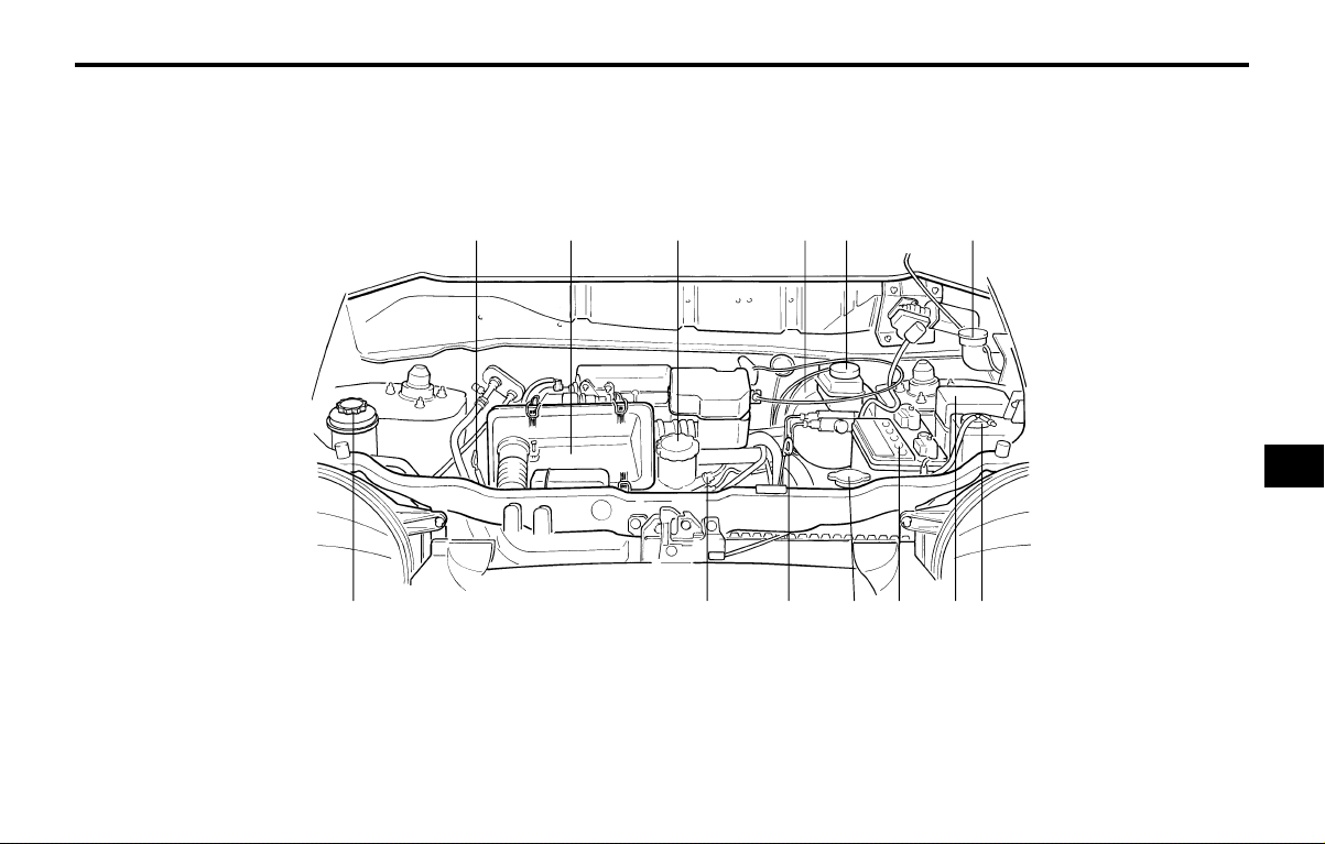
DO-IT-YOURSELF MAINTENANCEDO-IT-YOURSELF MAINTENANCE
DO-IT-YOURSELF MAINTENANCEDO-IT-YOURSELF MAINTENANCE
DO-IT-YOURSELF MAINTENANCE
6-1
G010A02X-GAT
ENGINE COMPARTMENT (For Multiport Fuel Injection)ENGINE COMPARTMENT (For Multiport Fuel Injection)
ENGINE COMPARTMENT (For Multiport Fuel Injection)ENGINE COMPARTMENT (For Multiport Fuel Injection)
ENGINE COMPARTMENT (For Multiport Fuel Injection)
1. Engine oil level dipstick
2. Air cleaner
3. Engine oil filler cap
4. Brake booster
5. Brake fluid reservoir
6. Windshield washer fluid reservoir cap
7. Power steering fluid reservoir
8. Spark plug
9. Automatic transaxle fluid level dipstick
(Automatic T/A only)
10. Radiator cap
11. Battery
12. Relay box
13. Engine coolant reservoir
6.6.
6.6.
6.
DO-ITDO-IT
DO-ITDO-IT
DO-IT
-Y-Y
-Y-Y
-Y
OURSELF MAINTENANCEOURSELF MAINTENANCE
OURSELF MAINTENANCEOURSELF MAINTENANCE
OURSELF MAINTENANCE
12 45 6
HNVOM113
81011131279
3
66
66
6
DO-IT-YOURSELF MAINTENANCEDO-IT-YOURSELF MAINTENANCE
DO-IT-YOURSELF MAINTENANCEDO-IT-YOURSELF MAINTENANCE
DO-IT-YOURSELF MAINTENANCE
6-2
G020A01A-AAT
GENERAL CHECKSGENERAL CHECKS
GENERAL CHECKSGENERAL CHECKS
GENERAL CHECKS
Engine CompartmentEngine Compartment
Engine CompartmentEngine Compartment
Engine Compartment
The following should be checked regularly:
o Engine oil level and condition
o Transaxle fluid level and condition
o Brake fluid level
o Clutch fluid level
o Engine coolant level
o Windshield washer fluid level
o Accessory drive belt condition
o Engine coolant hose condition
o Fluid leaks (on or below components)
o Power steering fluid level
o Battery Condition
G020C01X-GAT
Vehicle InteriorVehicle Interior
Vehicle InteriorVehicle Interior
Vehicle Interior
The following should be checked each time
when the vehicle is driven:
o Lights operation
o Windshield wipers operation
o Horn operation
o Defroster, heating system operation (and air
conditioning, if installed)
o Steering operation and condition
o Mirror condition and operation
o Turn signal operation
o Accelerator pedal operation
o Brake operation, including parking brake
o Manual transaxle operation, including clutch
operation
o Automatic transaxle operation, including
"Park" mechanism operation
o Seat control condition and operation
o Seat belt condition and operation
o Sunvisor operation
If you notice anything that does not operate
correctly or appears to be functioning in cor-
rectly, inspect it carefully and seek assistance
from your Hyundai dealer if service is needed.
G030A01A-AAT
CHECKING THE ENGINE OILCHECKING THE ENGINE OIL
CHECKING THE ENGINE OILCHECKING THE ENGINE OIL
CHECKING THE ENGINE OIL
Engine oil is essential to the performance and
service of the engine. It is suggested that you
check the oil level at least once a week in
normal use and more often if you are on a trip
or driving in severe conditions.
G030B01A-GAT
Recommended OilRecommended Oil
Recommended OilRecommended Oil
Recommended Oil
SSA6030B
°C
°F
-25
-13
20W-40 20W-50
15W-40 15W-50
10W-30
10W-40 10W-50
5W-40
5W-30
5W-20
40
104
20
68
10
50
0
32
-15
5
-10
-14
SH, SG or SG/CD (API) multi-grade and fuel
efficient oil is recommended.
NOTE:NOTE:
NOTE:NOTE:
NOTE:
SAE 5W-20 is not recommended for sus-SAE 5W-20 is not recommended for sus-
SAE 5W-20 is not recommended for sus-SAE 5W-20 is not recommended for sus-
SAE 5W-20 is not recommended for sus-
tained high speed vehicle operation.tained high speed vehicle operation.
tained high speed vehicle operation.tained high speed vehicle operation.
tained high speed vehicle operation.
G020B01A-AAT
Vehicle ExteriorVehicle Exterior
Vehicle ExteriorVehicle Exterior
Vehicle Exterior
The following should be checked monthly:
o Overall appearance and condition
o Wheel condition and wheel nut torque
o Exhaust system condition
o Light condition and operation
o Windshield glass condition
o Wiper blade condition
o Paint condition and body corrosion
o Fluid leaks
o Door and hood lock condition
o Tire pressure and condition
(including spare tire)
o Air filter condition
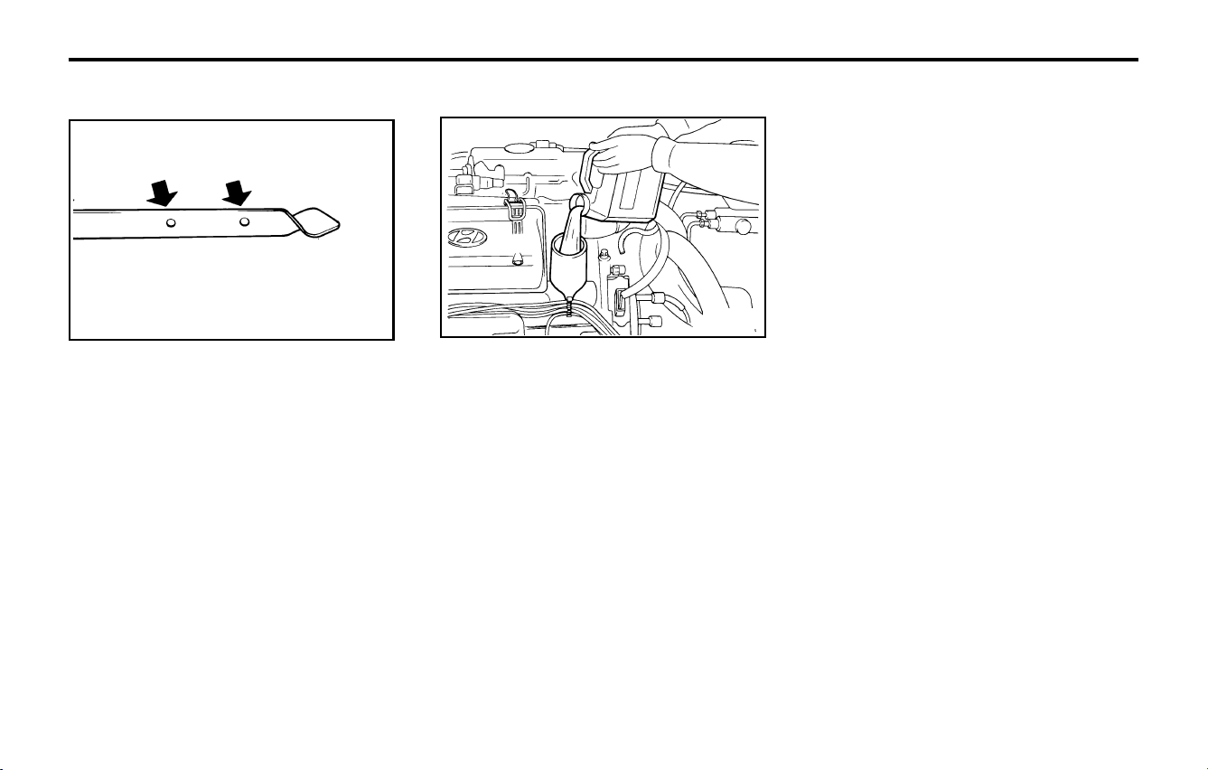
DO-IT-YOURSELF MAINTENANCEDO-IT-YOURSELF MAINTENANCE
DO-IT-YOURSELF MAINTENANCEDO-IT-YOURSELF MAINTENANCE
DO-IT-YOURSELF MAINTENANCE
6-3
G030C01A-AAT
To Check the Oil LevelTo Check the Oil Level
To Check the Oil LevelTo Check the Oil Level
To Check the Oil Level
G030D01A-GAT
Adding OilAdding Oil
Adding OilAdding Oil
Adding Oil
AS60050A
LF
Before checking the oil, warm up the engine to
the normal operating temperature and be sure
your car is parked on level ground. Turn the
engine off.
Wait a minute, then remove the dipstick, wipe it
off, fully reinsert the dipstick and withdraw it
again. Then note the highest level the oil has
reached on the dipstick. It should be between
the upper ("FULL") and lower ("LOW") range.
If the oil level is close to or below the "L" mark,
add oil until it reaches the "F" mark. To add oil:
1. Remove the oil filler cap by turning it counter-
clockwise.
2. Add oil, then check the level again. Do not
overfill.
3. Replace the cap by turning it clockwise.
The distance between the "F" and "L" marks is
equal to about 1 liter of oil.
G350A01A-GAT
ENGINE OIL CONSUMPTIONENGINE OIL CONSUMPTION
ENGINE OIL CONSUMPTIONENGINE OIL CONSUMPTION
ENGINE OIL CONSUMPTION
Function of Engine OilFunction of Engine Oil
Function of Engine OilFunction of Engine Oil
Function of Engine Oil
Engine oil has the primary function of lubricat-
ing and cooling the inside of the engine.
Engine oil consumptionEngine oil consumption
Engine oil consumptionEngine oil consumption
Engine oil consumption
It is normal that an engine should consume
some engine oil while normal driving. The cause
of oil consumption in a normal engine are as
follows;
o Engine oil is used to lubricate pistons, piston
rings and cylinders.
A thin film of oil is left on the cylinder wall
when a piston moves downwards in the
cylinder. High negative pressure generated
during engine operation sucks some of the
oil into the combustion chamber.
This oil with some oil of the cylinder wall is
burned by the high temperature combustion
gases during the combustion process.
o The engine oil consumption is strongly ef-
fected by the viscosity and quality of oil,
engine rpm and driving condition etc. The
engine oil is more consumed under severe
driving conditions such as high speeds and
frequent acceleration and deceleration than
normal driving condition.
G030D01A
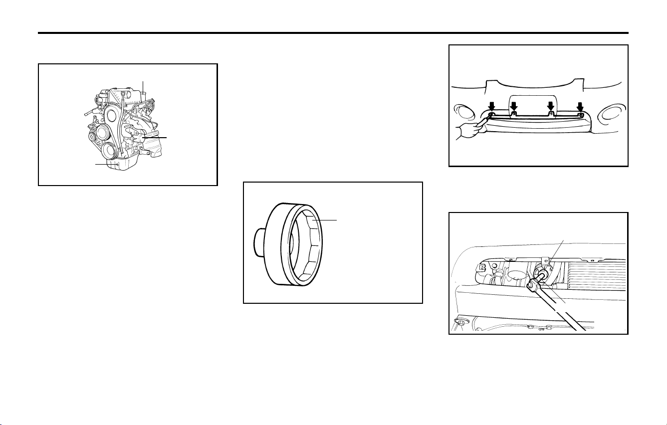
DO-IT-YOURSELF MAINTENANCEDO-IT-YOURSELF MAINTENANCE
DO-IT-YOURSELF MAINTENANCEDO-IT-YOURSELF MAINTENANCE
DO-IT-YOURSELF MAINTENANCE
6-4
G040A03X-GAT
CHANGING THE OIL AND FILTERCHANGING THE OIL AND FILTER
CHANGING THE OIL AND FILTERCHANGING THE OIL AND FILTER
CHANGING THE OIL AND FILTER
3. Slide underneath the car and loosen the
drain plug by turning it counterclockwise
with a wrench of the proper size. Be sure
that a drain pan is in position to catch the oil
as it drains out, then remove the drain plug.
WARNING:WARNING:
WARNING:WARNING:
WARNING:
Be very careful when draining the engine oilBe very careful when draining the engine oil
Be very careful when draining the engine oilBe very careful when draining the engine oil
Be very careful when draining the engine oil
as it may be hot as it may be hot
as it may be hot as it may be hot
as it may be hot
enough to burn you!enough to burn you!
enough to burn you!enough to burn you!
enough to burn you!
4. When the oil has stopped draining, replace
the drain plug using a new washer and
retighten by turning it clockwise.
6. First, remove the vehicle number plate. Un-
screw the tapping screws (4EA) and re-
move the front bumper grille.
Oil filler cap
Oil filter
Drain plug
The engine oil and filter should be changed at
those intervals specified in the maintenance
schedule in Section 5. If the car is being driven
in severe conditions, more frequent oil and filter
changes are required.
The procedure for changing the oil and filter is
as follows:
1. Park the car on level ground and set the
parking brake. Start the engine and let it
warm up until the needle on the coolant
temperature gauge moves above the lowest
mark. Turn the engine off and place the gear
selector lever in "P" (automatic transaxle) or
reverse gear (manual transaxle).
2. Open the hood and remove the engine oil
filler cap.
G040A01X
G040A02X
SST (09263-02000)
5. Before removing the oil filter, prepare the
special tool (oil filter wrench), extension bar
and ratchet handle.
G040A03X
SST (09263-02000)
G040A04X
Extension bar
7. Using the special tool (09263-02000), re-
move the oil filter through the bumper hole.
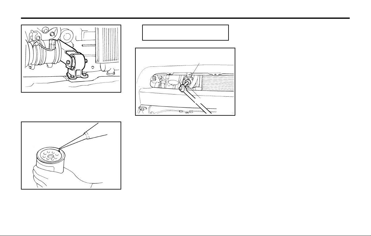
DO-IT-YOURSELF MAINTENANCEDO-IT-YOURSELF MAINTENANCE
DO-IT-YOURSELF MAINTENANCEDO-IT-YOURSELF MAINTENANCE
DO-IT-YOURSELF MAINTENANCE
6-5
G050A01A-AAT
CHECKING AND CHANGING THE EN-CHECKING AND CHANGING THE EN-
CHECKING AND CHANGING THE EN-CHECKING AND CHANGING THE EN-
CHECKING AND CHANGING THE EN-
GINE COOLANTGINE COOLANT
GINE COOLANTGINE COOLANT
GINE COOLANT
WARNING:WARNING:
WARNING:WARNING:
WARNING:
Do not remove the radiator cap when theDo not remove the radiator cap when the
Do not remove the radiator cap when theDo not remove the radiator cap when the
Do not remove the radiator cap when the
engine is hot. When the engine is hot, theengine is hot. When the engine is hot, the
engine is hot. When the engine is hot, theengine is hot. When the engine is hot, the
engine is hot. When the engine is hot, the
engine coolant is under pressure and mayengine coolant is under pressure and may
engine coolant is under pressure and mayengine coolant is under pressure and may
engine coolant is under pressure and may
erupt through the opening if the cap iserupt through the opening if the cap is
erupt through the opening if the cap iserupt through the opening if the cap is
erupt through the opening if the cap is
removed. You could be seriously burned ifremoved. You could be seriously burned if
removed. You could be seriously burned ifremoved. You could be seriously burned if
removed. You could be seriously burned if
you do not observe this precaution. Do notyou do not observe this precaution. Do not
you do not observe this precaution. Do notyou do not observe this precaution. Do not
you do not observe this precaution. Do not
remove the radiator cap until the radiator isremove the radiator cap until the radiator is
remove the radiator cap until the radiator isremove the radiator cap until the radiator is
remove the radiator cap until the radiator is
cool to the touch.cool to the touch.
cool to the touch.cool to the touch.
cool to the touch.
8. Before installing the new oil filter on the
engine, apply clean engine oil to the surface
of the rubber gasket.
Temporarily tighten the oil filter by hand.
G040A05X
G040A06X
9. Using the special tool (09263-02000) and
torque wrench, tighten the oil filter to the
specified torque.
Tightening torque .............. 12-16 Nm
(120-160 kg.cm, 9-12 lb.ft)
SST (09263-02000)
G040A04X
Extension bar
NOTE:NOTE:
NOTE:NOTE:
NOTE:
oo
oo
o
Be careful not to drop the engine oil onBe careful not to drop the engine oil on
Be careful not to drop the engine oil onBe careful not to drop the engine oil on
Be careful not to drop the engine oil on
the rubber the rubber
the rubber the rubber
the rubber
parts of the engine mountingparts of the engine mounting
parts of the engine mountingparts of the engine mounting
parts of the engine mounting
insulator.insulator.
insulator.insulator.
insulator.
oo
oo
o
You can purchase the SST from yourYou can purchase the SST from your
You can purchase the SST from yourYou can purchase the SST from your
You can purchase the SST from your
Hyundai dealer.Hyundai dealer.
Hyundai dealer.Hyundai dealer.
Hyundai dealer.
oo
oo
o
If you aren't sure how to use, consultIf you aren't sure how to use, consult
If you aren't sure how to use, consultIf you aren't sure how to use, consult
If you aren't sure how to use, consult
your Hyundai dealer.your Hyundai dealer.
your Hyundai dealer.your Hyundai dealer.
your Hyundai dealer.
10.Refill the crankcase with the recommended
engine oil. Refer to the specification in chap-
ter 9 for engine oil capacity.
11.Start the engine and check to be sure no oil
is leaking from the drain plug or oil filter.
12.Shut off the engine and recheck the oil level.
NOTE:NOTE:
NOTE:NOTE:
NOTE:
Always dispose of used engine oil in anAlways dispose of used engine oil in an
Always dispose of used engine oil in anAlways dispose of used engine oil in an
Always dispose of used engine oil in an
environmentally acceptable environmentally acceptable
environmentally acceptable environmentally acceptable
environmentally acceptable
manner. It is sug-manner. It is sug-
manner. It is sug-manner. It is sug-
manner. It is sug-
gested that it be placed in a sealed containergested that it be placed in a sealed container
gested that it be placed in a sealed containergested that it be placed in a sealed container
gested that it be placed in a sealed container
and taken and taken
and taken and taken
and taken
to a service station for reclama-to a service station for reclama-
to a service station for reclama-to a service station for reclama-
to a service station for reclama-
tion. Do not pour the oil on the ground ortion. Do not pour the oil on the ground or
tion. Do not pour the oil on the ground ortion. Do not pour the oil on the ground or
tion. Do not pour the oil on the ground or
put it into the household trash.put it into the household trash.
put it into the household trash.put it into the household trash.
put it into the household trash.
WARNING:WARNING:
WARNING:WARNING:
WARNING:
Used motor oil may cause irritation or can-Used motor oil may cause irritation or can-
Used motor oil may cause irritation or can-Used motor oil may cause irritation or can-
Used motor oil may cause irritation or can-
cer of the skin if cer of the skin if
cer of the skin if cer of the skin if
cer of the skin if
left in contact with the skinleft in contact with the skin
left in contact with the skinleft in contact with the skin
left in contact with the skin
for prolonged periods of time. Wash yourfor prolonged periods of time. Wash your
for prolonged periods of time. Wash yourfor prolonged periods of time. Wash your
for prolonged periods of time. Wash your
hands hands
hands hands
hands
thoroughly with soap and warm wa-thoroughly with soap and warm wa-
thoroughly with soap and warm wa-thoroughly with soap and warm wa-
thoroughly with soap and warm wa-
ter as soon as possible after handling usedter as soon as possible after handling used
ter as soon as possible after handling usedter as soon as possible after handling used
ter as soon as possible after handling used
oil.oil.
oil.oil.
oil.
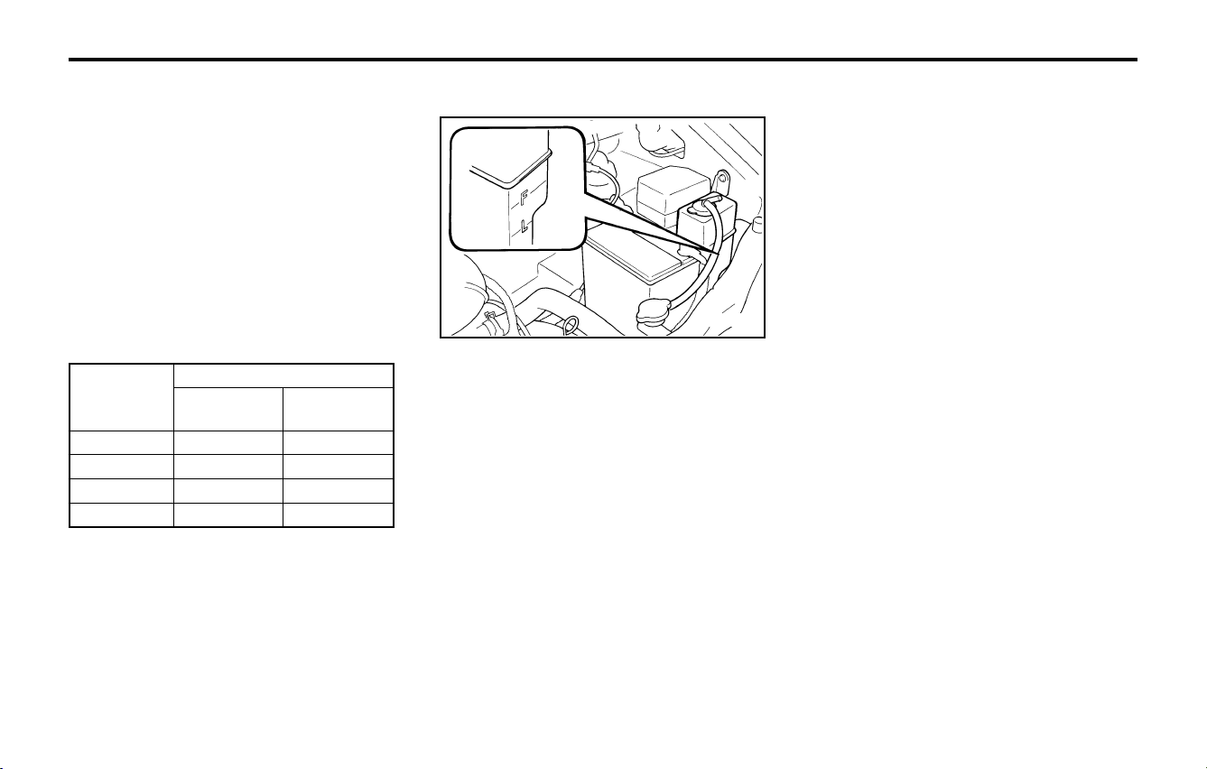
DO-IT-YOURSELF MAINTENANCEDO-IT-YOURSELF MAINTENANCE
DO-IT-YOURSELF MAINTENANCEDO-IT-YOURSELF MAINTENANCE
DO-IT-YOURSELF MAINTENANCE
6-6
-15 (5)
-25 (-13)
-35 (-31)
-45 (-49)
G050B01A-AAT
Recommended Engine CoolantRecommended Engine Coolant
Recommended Engine CoolantRecommended Engine Coolant
Recommended Engine Coolant
Use a high quality ethylene-glycol coolant in a
50/50 mix with water. The engine coolant should
be compatible with aluminum engine parts. Ad-
ditional corrosion inhibitors or additives should
not be used. The cooling system must be main-
tained with the correct concentration and type
of engine coolant to prevent freezing and corro-
sion.
Never allow the concentration of antifreeze to
exceed the 60% level or go below the 35% level
or damage to the coolant system may result. For
proper concentration when adding or replacing
the coolant, refer to the following table.
35%
40%
50%
60%
G050C01A-AAT
To Check the Coolant LevelTo Check the Coolant Level
To Check the Coolant LevelTo Check the Coolant Level
To Check the Coolant Level
The coolant level can be seen on the side of the
plastic coolant reservoir. The level of the cool-
ant should be between the "LOW" and "FULL"
lines on the reservoir when the engine is cold.
If the level is below the "LOW" mark, add
engine coolant to bring it up between "LOW"
and "FULL". If the level is low, inspect for
coolant leaks and recheck the fluid level fre-
quently. If the level drops again, visit your
Hyundai dealer for an inspection and diagnosis
of the reason.
G050D02A-AAT
To Change the Engine CoolantTo Change the Engine Coolant
To Change the Engine CoolantTo Change the Engine Coolant
To Change the Engine Coolant
The engine coolant should be changed at those
intervals specified in the vehicle maintenance
schedule in Section 5.
CAUTION:CAUTION:
CAUTION:CAUTION:
CAUTION:
Engine coolant can damage the finish ofEngine coolant can damage the finish of
Engine coolant can damage the finish ofEngine coolant can damage the finish of
Engine coolant can damage the finish of
your car. If you spill engine coolant on theyour car. If you spill engine coolant on the
your car. If you spill engine coolant on theyour car. If you spill engine coolant on the
your car. If you spill engine coolant on the
car, wash it off thoroughly with clean water.car, wash it off thoroughly with clean water.
car, wash it off thoroughly with clean water.car, wash it off thoroughly with clean water.
car, wash it off thoroughly with clean water.
1. Park the car on level ground, set the parking
brake and remove the radiator cap when
cool.
2. Be sure your drain receptacle is in place.
Open the drain cock on the radiator. Allow
all the engine coolant to drain from the
cooling system, then securely close the drain
cock.
3. Check Section 9 for the capacity of the
cooling system in your car. Then, following
the manufacturer's directions on the engine
coolant container, add the appropriate quan-
tity of engine coolant to the radiator.
G050C01A
65%
60%
50%
40%
Water
Antifreeze
solution
Ambient
temperature
°C ( °F)
Engine coolant concentration
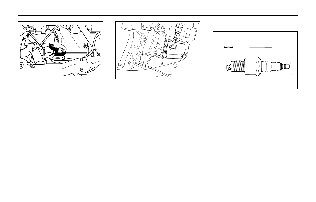
DO-IT-YOURSELF MAINTENANCEDO-IT-YOURSELF MAINTENANCE
DO-IT-YOURSELF MAINTENANCEDO-IT-YOURSELF MAINTENANCE
DO-IT-YOURSELF MAINTENANCE
6-7
4. Turn the radiator cap counterclockwise with-
out pressing down on it, until it stops. This
relieves any pressure remaining in the cool-
ing system. And remove the radiator cap by
pushing down and turning counterclockwise.
Now fill the radiator with clean demineral-
ized or distilled water. Continue to add clean
demineralized or distilled water in small quan-
tities until the fluid level stays up in the
radiator neck.
SSA6060A
Unleaded: 1.0 ~ 1.1 mm (0.039 ~ 0.043 in.)
Leaded: 0.8 ~ 0.9 mm (0.031 ~ 0.035 in.)
G060B02A-GAT
REPLACING THE SPARK PLUGSREPLACING THE SPARK PLUGS
REPLACING THE SPARK PLUGSREPLACING THE SPARK PLUGS
REPLACING THE SPARK PLUGS
The spark plugs should be changed at the
intervals specified in the vehicle maintenance
schedule in Section 5 or whenever engine per-
formance indicates they should be changed.
Symptoms that suggest poor spark plug perfor-
mance include engine misfiring under load, loss
of fuel economy, poor acceleration, etc. When
spark plugs are replaced, always use spark
plugs recommended by Hyundai. The use of
other spark plugs can result in loss of perfor-
mance, radio interference or engine damage.
NOTE:NOTE:
NOTE:NOTE:
NOTE:
When replacing the spark plug, always useWhen replacing the spark plug, always use
When replacing the spark plug, always useWhen replacing the spark plug, always use
When replacing the spark plug, always use
the genuine parts recommended.the genuine parts recommended.
the genuine parts recommended.the genuine parts recommended.
the genuine parts recommended.
G050D02X
5. Start the engine, top off the radiator with
water and then add engine coolant to the
reservoir until the level is between "LOW"
and "FULL".
6. Replace the radiator and reservoir caps and
check to be sure the drain cocks are fully
closed and not leaking.
WARNING:WARNING:
WARNING:WARNING:
WARNING:
The cooling fan is controlled by engine cool-The cooling fan is controlled by engine cool-
The cooling fan is controlled by engine cool-The cooling fan is controlled by engine cool-
The cooling fan is controlled by engine cool-
ant temperature and may sometimes oper-ant temperature and may sometimes oper-
ant temperature and may sometimes oper-ant temperature and may sometimes oper-
ant temperature and may sometimes oper-
ate even when the engine is not running.ate even when the engine is not running.
ate even when the engine is not running.ate even when the engine is not running.
ate even when the engine is not running.
Use extreme caution when working near theUse extreme caution when working near the
Use extreme caution when working near theUse extreme caution when working near the
Use extreme caution when working near the
blades of the cooling fan so that you are notblades of the cooling fan so that you are not
blades of the cooling fan so that you are notblades of the cooling fan so that you are not
blades of the cooling fan so that you are not
injured by a rotating fan blade. As the en-injured by a rotating fan blade. As the en-
injured by a rotating fan blade. As the en-injured by a rotating fan blade. As the en-
injured by a rotating fan blade. As the en-
gine coolant temperature decreases, the fangine coolant temperature decreases, the fan
gine coolant temperature decreases, the fangine coolant temperature decreases, the fan
gine coolant temperature decreases, the fan
will automatically shut off. This is a normalwill automatically shut off. This is a normal
will automatically shut off. This is a normalwill automatically shut off. This is a normal
will automatically shut off. This is a normal
condition.condition.
condition.condition.
condition.
G050B01A
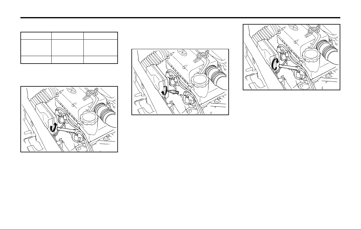
DO-IT-YOURSELF MAINTENANCEDO-IT-YOURSELF MAINTENANCE
DO-IT-YOURSELF MAINTENANCEDO-IT-YOURSELF MAINTENANCE
DO-IT-YOURSELF MAINTENANCE
6-8
NOTE:NOTE:
NOTE:NOTE:
NOTE:
Spark plugs should be tightened firmly. Over-Spark plugs should be tightened firmly. Over-
Spark plugs should be tightened firmly. Over-Spark plugs should be tightened firmly. Over-
Spark plugs should be tightened firmly. Over-
tightening can damage tightening can damage
tightening can damage tightening can damage
tightening can damage
the threads in thethe threads in the
the threads in thethe threads in the
the threads in the
aluminum cylinder head. Also, leaving themaluminum cylinder head. Also, leaving them
aluminum cylinder head. Also, leaving themaluminum cylinder head. Also, leaving them
aluminum cylinder head. Also, leaving them
too loose can too loose can
too loose can too loose can
too loose can
cause the spark plug to getcause the spark plug to get
cause the spark plug to getcause the spark plug to get
cause the spark plug to get
very hot and possibly result in damage tovery hot and possibly result in damage to
very hot and possibly result in damage tovery hot and possibly result in damage to
very hot and possibly result in damage to
the the
the the
the
engine.engine.
engine.engine.
engine.
6. Replace the cable by pushing the insulated
connector directly down onto the electrode.
Check to be sure it has snapped into place
and can't fall off.
G060C03A
G060C02A-AAT
Changing the Spark PlugsChanging the Spark Plugs
Changing the Spark PlugsChanging the Spark Plugs
Changing the Spark Plugs
Unleaded
RC9YC4
RC10YC4
BKR5ES-11
NGK
Leaded
RC9YC
RC10YC
BKR5ES
CHAMPION
G060C01A
You will find it easier to change spark plugs if
the engine is cold. Always change one spark
plug at a time. This helps avoid getting the wires
mixed up.
1. Using a clean cloth, remove any dirt that has
accumulated around the base of the spark
plug so it cannot fall into the cylinder when
the spark plug is removed.
WARNING:WARNING:
WARNING:WARNING:
WARNING:
It is recommended that the engine be coolIt is recommended that the engine be cool
It is recommended that the engine be coolIt is recommended that the engine be cool
It is recommended that the engine be cool
or cold when changing or cold when changing
or cold when changing or cold when changing
or cold when changing
the spark plugs. Ifthe spark plugs. If
the spark plugs. Ifthe spark plugs. If
the spark plugs. If
the engine is hot, you could burn yourselfthe engine is hot, you could burn yourself
the engine is hot, you could burn yourselfthe engine is hot, you could burn yourself
the engine is hot, you could burn yourself
on the insulated on the insulated
on the insulated on the insulated
on the insulated
connector, the spark plugconnector, the spark plug
connector, the spark plugconnector, the spark plug
connector, the spark plug
or the engine itself.or the engine itself.
or the engine itself.or the engine itself.
or the engine itself.
3. When preparing to remove the old spark
plug, guide the socket down over the spark
plug, being careful not to damage the ce-
ramic insulator.
4. To remove the old spark plug, turn the
wrench handle in a counterclockwise direc-
tion.
5. To install the new spark plug, guide the
socket down over the spark plug, being
careful not to damage the ceramic insulator.
G060C02A
Recommended Spark Plugs:Recommended Spark Plugs:
Recommended Spark Plugs:Recommended Spark Plugs:
Recommended Spark Plugs: 2. To remove the spark plug cable, pull straight
up on the insulated connector, not the cable.
Pulling on the cable may damage the carbon
core conductor.
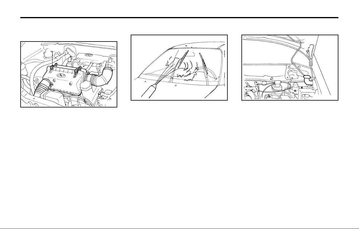
DO-IT-YOURSELF MAINTENANCEDO-IT-YOURSELF MAINTENANCE
DO-IT-YOURSELF MAINTENANCEDO-IT-YOURSELF MAINTENANCE
DO-IT-YOURSELF MAINTENANCE
6-9
G090A01X-GAT
FILLING THE WASHER RESERVOIRFILLING THE WASHER RESERVOIR
FILLING THE WASHER RESERVOIRFILLING THE WASHER RESERVOIR
FILLING THE WASHER RESERVOIR
The washer fluid reservoir supplies fluid to the
windshield washer system.
A good quality washer fluid should be used to fill
the washer reservoir. The fluid level should be
checked more frequently during bad weather or
whenever the washer system is in more fre-
quent use.
The capacity of the washer reservoir is 2.5
liters (2.63 U.S. quarts).
CAUTION:CAUTION:
CAUTION:CAUTION:
CAUTION:
oo
oo
o
Radiator antifreeze (engine coolant)Radiator antifreeze (engine coolant)
Radiator antifreeze (engine coolant)Radiator antifreeze (engine coolant)
Radiator antifreeze (engine coolant)
should not be used in the washer systemshould not be used in the washer system
should not be used in the washer systemshould not be used in the washer system
should not be used in the washer system
because it will damage the car's finish.because it will damage the car's finish.
because it will damage the car's finish.because it will damage the car's finish.
because it will damage the car's finish.
oo
oo
o
The washer lever should not be pulledThe washer lever should not be pulled
The washer lever should not be pulledThe washer lever should not be pulled
The washer lever should not be pulled
and the washer should not be operated ifand the washer should not be operated if
and the washer should not be operated ifand the washer should not be operated if
and the washer should not be operated if
the washer reservoir is empty. This canthe washer reservoir is empty. This can
the washer reservoir is empty. This canthe washer reservoir is empty. This can
the washer reservoir is empty. This can
damage the washer fluid pump.damage the washer fluid pump.
damage the washer fluid pump.damage the washer fluid pump.
damage the washer fluid pump.
G070A01X-GAT
CHANGING THE AIR CLEANER FIL-CHANGING THE AIR CLEANER FIL-
CHANGING THE AIR CLEANER FIL-CHANGING THE AIR CLEANER FIL-
CHANGING THE AIR CLEANER FIL-
TERTER
TERTER
TER
G080A02A-AAT
WINDSHIELD WIPER BLADESWINDSHIELD WIPER BLADES
WINDSHIELD WIPER BLADESWINDSHIELD WIPER BLADES
WINDSHIELD WIPER BLADES
The wiper blades should be carefully inspected
from time to time and cleaned to remove accu-
mulations of road film or other debris. To clean
the wiper blades and arms, use a clean sponge
or cloth with a mild soap or detergent and water.
If the wipers continue to streak or smear the
glass, replace them with Genuine Hyundai
Replacement Parts or their equivalent.
CAUTION:CAUTION:
CAUTION:CAUTION:
CAUTION:
oo
oo
o
Do not operate the wipers on dry glass.Do not operate the wipers on dry glass.
Do not operate the wipers on dry glass.Do not operate the wipers on dry glass.
Do not operate the wipers on dry glass.
This can result in more rapid wear of theThis can result in more rapid wear of the
This can result in more rapid wear of theThis can result in more rapid wear of the
This can result in more rapid wear of the
wiper blades and may scratch the glass.wiper blades and may scratch the glass.
wiper blades and may scratch the glass.wiper blades and may scratch the glass.
wiper blades and may scratch the glass.
oo
oo
o
Keep the blade rubber out of contactKeep the blade rubber out of contact
Keep the blade rubber out of contactKeep the blade rubber out of contact
Keep the blade rubber out of contact
with petroleum products such as enginewith petroleum products such as engine
with petroleum products such as enginewith petroleum products such as engine
with petroleum products such as engine
oil, gasoline etc.oil, gasoline etc.
oil, gasoline etc.oil, gasoline etc.
oil, gasoline etc.
To change the filter, loosen the clamps (1) on
the cover. When this is done, the cover can be
lifted off, the old filter removed and the new filter
put in its place. Genuine Hyundai replacement
parts are recommended.
CAUTION:CAUTION:
CAUTION:CAUTION:
CAUTION:
Operating your vehicle without a proper airOperating your vehicle without a proper air
Operating your vehicle without a proper airOperating your vehicle without a proper air
Operating your vehicle without a proper air
filter in place filter in place
filter in place filter in place
filter in place
can result in excessive enginecan result in excessive engine
can result in excessive enginecan result in excessive engine
can result in excessive engine
wear.wear.
wear.wear.
wear.
G070A01X
(1)
AS60160A
G090A01X
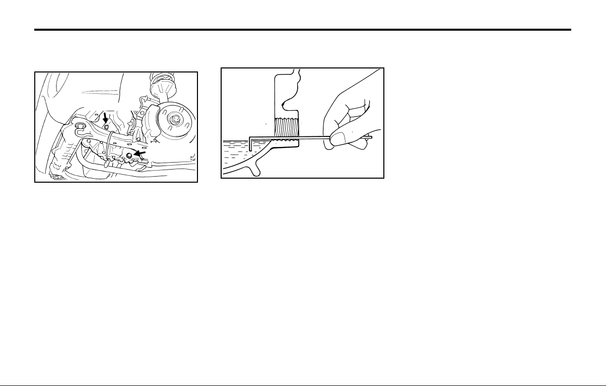
DO-IT-YOURSELF MAINTENANCEDO-IT-YOURSELF MAINTENANCE
DO-IT-YOURSELF MAINTENANCEDO-IT-YOURSELF MAINTENANCE
DO-IT-YOURSELF MAINTENANCE
6-10
G110A01A-AAT
CHECKING THE TRANSAXLE FLUIDCHECKING THE TRANSAXLE FLUID
CHECKING THE TRANSAXLE FLUIDCHECKING THE TRANSAXLE FLUID
CHECKING THE TRANSAXLE FLUID
(AUTOMATIC)(AUTOMATIC)
(AUTOMATIC)(AUTOMATIC)
(AUTOMATIC)
Transaxle fluid in the automatic transaxle should
be checked at those intervals specified in the
vehicle maintenance schedule in Section 5.
G110B01X-AAT
Recommended FluidRecommended Fluid
Recommended FluidRecommended Fluid
Recommended Fluid
Your Hyundai automatic transaxle is specially
designed to operate with ESSO JWS3314. Dam-
age caused by a nonspecified fluid is not cov-
ered by your new vehicle limited warranty.
G110C01X-GAT
Transaxle Fluid CapacityTransaxle Fluid Capacity
Transaxle Fluid CapacityTransaxle Fluid Capacity
Transaxle Fluid Capacity
The fluid capacity of the automatic transaxle is
5.2 liters (5.48 U.S. quarts).
WARNING:WARNING:
WARNING:WARNING:
WARNING:
The transaxle fluid level should be checkedThe transaxle fluid level should be checked
The transaxle fluid level should be checkedThe transaxle fluid level should be checked
The transaxle fluid level should be checked
when the engine when the engine
when the engine when the engine
when the engine
is at normal operating tem-is at normal operating tem-
is at normal operating tem-is at normal operating tem-
is at normal operating tem-
perature. This means that the engine, radia-perature. This means that the engine, radia-
perature. This means that the engine, radia-perature. This means that the engine, radia-
perature. This means that the engine, radia-
tor, tor,
tor, tor,
tor,
exhaust system etc., are very hot. Exer-exhaust system etc., are very hot. Exer-
exhaust system etc., are very hot. Exer-exhaust system etc., are very hot. Exer-
exhaust system etc., are very hot. Exer-
cise great care not to burn yourself cise great care not to burn yourself
cise great care not to burn yourself cise great care not to burn yourself
cise great care not to burn yourself
duringduring
duringduring
during
this procedure.this procedure.
this procedure.this procedure.
this procedure.
G100A04X-GAT
CHECKING THE TRANSAXLE OILCHECKING THE TRANSAXLE OIL
CHECKING THE TRANSAXLE OILCHECKING THE TRANSAXLE OIL
CHECKING THE TRANSAXLE OIL
(MANUAL)(MANUAL)
(MANUAL)(MANUAL)
(MANUAL)
Transaxle lubricant in the manual and transaxle
should be checked at those intervals specified
in the vehicle maintenance schedule in Section
5.
Recommended OilRecommended Oil
Recommended OilRecommended Oil
Recommended Oil
Use only HYUNDAI GENUINE PARTS MTF
75W/90 (API GL-4) in the manual transaxle.
Manual Transaxle Oil CapacityManual Transaxle Oil Capacity
Manual Transaxle Oil CapacityManual Transaxle Oil Capacity
Manual Transaxle Oil Capacity
The oil capacity of the manual transaxle is 2.45
liters (2.58 U.S. quarts).
WARNING:WARNING:
WARNING:WARNING:
WARNING:
It is always better to check the transaxle oilIt is always better to check the transaxle oil
It is always better to check the transaxle oilIt is always better to check the transaxle oil
It is always better to check the transaxle oil
level when the level when the
level when the level when the
level when the
engine is cool or cold. If theengine is cool or cold. If the
engine is cool or cold. If theengine is cool or cold. If the
engine is cool or cold. If the
engine is hot, you should exercise greatengine is hot, you should exercise great
engine is hot, you should exercise greatengine is hot, you should exercise great
engine is hot, you should exercise great
caution caution
caution caution
caution
to avoid burning yourself on hotto avoid burning yourself on hot
to avoid burning yourself on hotto avoid burning yourself on hot
to avoid burning yourself on hot
engine or exhaust parts.engine or exhaust parts.
engine or exhaust parts.engine or exhaust parts.
engine or exhaust parts.
G100B01A-AAT
To check the Manual Transaxle FluidTo check the Manual Transaxle Fluid
To check the Manual Transaxle FluidTo check the Manual Transaxle Fluid
To check the Manual Transaxle Fluid
LevelLevel
LevelLevel
Level
SSA6100B
Park the car on level ground with the engine off.
1. Using a wrench of the correct size, loosen
the oil filler plug by turning it counterclock-
wise and remove it with your fingers.
2. Use your finger or suitable tool to feel inside
the hole. The oil level should be at its bottom
edge. If it is not, check for leaks before
adding oil. To refill the transaxle or bring the
oil level up, add oil slowly until it reaches the
proper level. Do not overfill.
3. Replace the plug and washer, screw it in
with your fingers and then tighten securely
with the wrench.
G100A01X
Filler plug
Drain plug
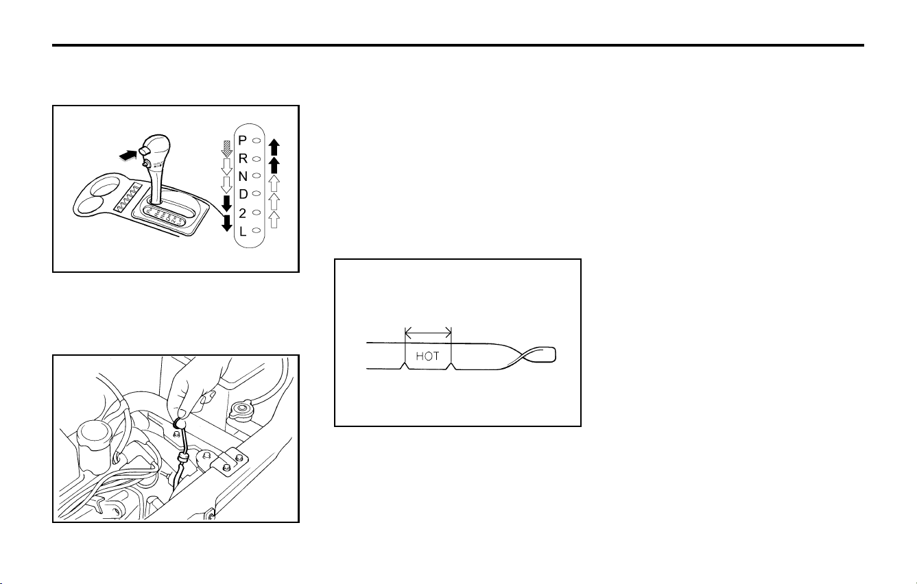
DO-IT-YOURSELF MAINTENANCEDO-IT-YOURSELF MAINTENANCE
DO-IT-YOURSELF MAINTENANCEDO-IT-YOURSELF MAINTENANCE
DO-IT-YOURSELF MAINTENANCE
6-11
WARNING:WARNING:
WARNING:WARNING:
WARNING:
The cooling fan is controlled by engine cool-The cooling fan is controlled by engine cool-
The cooling fan is controlled by engine cool-The cooling fan is controlled by engine cool-
The cooling fan is controlled by engine cool-
ant temperature and may sometimes oper-ant temperature and may sometimes oper-
ant temperature and may sometimes oper-ant temperature and may sometimes oper-
ant temperature and may sometimes oper-
ate even when the engine is not running.ate even when the engine is not running.
ate even when the engine is not running.ate even when the engine is not running.
ate even when the engine is not running.
Use extreme caution when working near theUse extreme caution when working near the
Use extreme caution when working near theUse extreme caution when working near the
Use extreme caution when working near the
blades of the cooling fan, so that you are notblades of the cooling fan, so that you are not
blades of the cooling fan, so that you are notblades of the cooling fan, so that you are not
blades of the cooling fan, so that you are not
injured by a rotating fan blade. As the en-injured by a rotating fan blade. As the en-
injured by a rotating fan blade. As the en-injured by a rotating fan blade. As the en-
injured by a rotating fan blade. As the en-
gine coolant temperature decreases, the fangine coolant temperature decreases, the fan
gine coolant temperature decreases, the fangine coolant temperature decreases, the fan
gine coolant temperature decreases, the fan
will automatically shut off. This is a normalwill automatically shut off. This is a normal
will automatically shut off. This is a normalwill automatically shut off. This is a normal
will automatically shut off. This is a normal
condition.condition.
condition.condition.
condition.
G120C02A-AAT
Recommended Brake FluidRecommended Brake Fluid
Recommended Brake FluidRecommended Brake Fluid
Recommended Brake Fluid
Use only hydraulic brake fluid conforming to
DOT 3 or DOT 4 specifications in your braking
G120A01A-AAT
CHECKING THE BRAKESCHECKING THE BRAKES
CHECKING THE BRAKESCHECKING THE BRAKES
CHECKING THE BRAKES
CAUTION:CAUTION:
CAUTION:CAUTION:
CAUTION:
Because brakes are essential to the safeBecause brakes are essential to the safe
Because brakes are essential to the safeBecause brakes are essential to the safe
Because brakes are essential to the safe
operation of the car, it is suggested thatoperation of the car, it is suggested that
operation of the car, it is suggested thatoperation of the car, it is suggested that
operation of the car, it is suggested that
they be checked and inspected by yourthey be checked and inspected by your
they be checked and inspected by yourthey be checked and inspected by your
they be checked and inspected by your
Hyundai dealer. The brakes should beHyundai dealer. The brakes should be
Hyundai dealer. The brakes should beHyundai dealer. The brakes should be
Hyundai dealer. The brakes should be
checked and inspected for wear at thosechecked and inspected for wear at those
checked and inspected for wear at thosechecked and inspected for wear at those
checked and inspected for wear at those
intervals specified in the vehicle mainte-intervals specified in the vehicle mainte-
intervals specified in the vehicle mainte-intervals specified in the vehicle mainte-
intervals specified in the vehicle mainte-
nance schedule in Section 5.nance schedule in Section 5.
nance schedule in Section 5.nance schedule in Section 5.
nance schedule in Section 5.
G120B01A-AAT
Checking the Brake Fluid LevelChecking the Brake Fluid Level
Checking the Brake Fluid LevelChecking the Brake Fluid Level
Checking the Brake Fluid Level
WARNING:WARNING:
WARNING:WARNING:
WARNING:
Use caution when handling brake fluid. ItUse caution when handling brake fluid. It
Use caution when handling brake fluid. ItUse caution when handling brake fluid. It
Use caution when handling brake fluid. It
can damage your vision if it gets into yourcan damage your vision if it gets into your
can damage your vision if it gets into yourcan damage your vision if it gets into your
can damage your vision if it gets into your
eyes. It will also damage your vehicle's painteyes. It will also damage your vehicle's paint
eyes. It will also damage your vehicle's painteyes. It will also damage your vehicle's paint
eyes. It will also damage your vehicle's paint
if spilled on it and not removed immediately.if spilled on it and not removed immediately.
if spilled on it and not removed immediately.if spilled on it and not removed immediately.
if spilled on it and not removed immediately.
G110D02A-GAT
To Check the Automatic Transaxle FluidTo Check the Automatic Transaxle Fluid
To Check the Automatic Transaxle FluidTo Check the Automatic Transaxle Fluid
To Check the Automatic Transaxle Fluid
LevelLevel
LevelLevel
Level
Park the car on level ground with the parking
brake engaged. When the transaxle fluid level
is checked, the transaxle fluid should be at
normal operating temperature and the engine
idling.
While the engine is idling, apply the brakes and
move the gear selector lever from "P" to each
of its other positions — "R", "N", "D", "2", "L" —
and then return to "N" or "P" with the engine still
idling:
1. Open the hood, being careful to keep hands,
long hair and clothing clear of any moving
parts.
2. Remove the transaxle dipstick, wipe it clean,
reinsert the dipstick as far as it will go, then
remove it again. Now check the fluid level on
the dipstick. It should be in the "HOT" range
on the dipstick.
Fluid level should be within this range
3. If the transaxle fluid level is low, use a funnel
to add transaxle fluid through the dipstick
tube until the level reaches the "HOT" range.
Do not overfill.
C090B01X
G110D02A
G110D03A
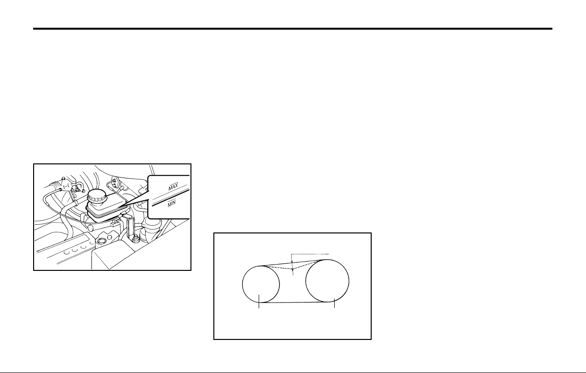
DO-IT-YOURSELF MAINTENANCEDO-IT-YOURSELF MAINTENANCE
DO-IT-YOURSELF MAINTENANCEDO-IT-YOURSELF MAINTENANCE
DO-IT-YOURSELF MAINTENANCE
6-12
G140B01A-AAT
Checking the Air Conditioning Opera-Checking the Air Conditioning Opera-
Checking the Air Conditioning Opera-Checking the Air Conditioning Opera-
Checking the Air Conditioning Opera-
tiontion
tiontion
tion
1. Start the engine and let it run at a fast idle for
several minutes with the air conditioning set
at the maximum cold setting.
2. If the air coming out of the in-dash vents is
not cold, have the air conditioning system
inspected by your Hyundai dealer.
CAUTION:CAUTION:
CAUTION:CAUTION:
CAUTION:
Running the air conditioning system for ex-Running the air conditioning system for ex-
Running the air conditioning system for ex-Running the air conditioning system for ex-
Running the air conditioning system for ex-
tended periods of time with a low refrigeranttended periods of time with a low refrigerant
tended periods of time with a low refrigeranttended periods of time with a low refrigerant
tended periods of time with a low refrigerant
level may damage the compressor.level may damage the compressor.
level may damage the compressor.level may damage the compressor.
level may damage the compressor.
When the air conditioning is being used regu-
larly, the compressor drive belt tension should
be checked at least once a month.
To check the drive belt tension, press down on
the belt halfway between the engine crankshaft
and compressor pulleys. Pressing with your
finger, you should not be able to deflect this belt
anymore than 5 - 5.5 mm. If you have the
instruments to check it with a force of 98N (22
lb.), the deflection should be approx. 5 - 5.5
(0.197 - 0.217 inches). If the belt is too loose,
have it adjusted by your Hyundai dealer.
G120D01A-AAT
To Check the Fluid LevelTo Check the Fluid Level
To Check the Fluid LevelTo Check the Fluid Level
To Check the Fluid Level
The fluid level in the brake fluid reservoir should
be checked periodically. The level should be
between the "MIN" and "MAX" marks on the
side of the reservoir. If the level is at or below
the "MIN" mark, carefully add fluid to bring it up
to "MAX". Do not overfill.
G120E02A-AAT
Adding Brake FluidAdding Brake Fluid
Adding Brake FluidAdding Brake Fluid
Adding Brake Fluid
WARNING:WARNING:
WARNING:WARNING:
WARNING:
Handle brake fluid carefully. It can damageHandle brake fluid carefully. It can damage
Handle brake fluid carefully. It can damageHandle brake fluid carefully. It can damage
Handle brake fluid carefully. It can damage
your vision if it gets into your eyes. Use onlyyour vision if it gets into your eyes. Use only
your vision if it gets into your eyes. Use onlyyour vision if it gets into your eyes. Use only
your vision if it gets into your eyes. Use only
DOT 3 or DOT 4 specification fluid from aDOT 3 or DOT 4 specification fluid from a
DOT 3 or DOT 4 specification fluid from aDOT 3 or DOT 4 specification fluid from a
DOT 3 or DOT 4 specification fluid from a
sealed container. Do not allow the fluid cansealed container. Do not allow the fluid can
sealed container. Do not allow the fluid cansealed container. Do not allow the fluid can
sealed container. Do not allow the fluid can
or reservoir to remain open any longer thanor reservoir to remain open any longer than
or reservoir to remain open any longer thanor reservoir to remain open any longer than
or reservoir to remain open any longer than
required. This will prevent entry of dirt andrequired. This will prevent entry of dirt and
required. This will prevent entry of dirt andrequired. This will prevent entry of dirt and
required. This will prevent entry of dirt and
moisture which can damage the brake sys-moisture which can damage the brake sys-
moisture which can damage the brake sys-moisture which can damage the brake sys-
moisture which can damage the brake sys-
tem and cause improper operation.tem and cause improper operation.
tem and cause improper operation.tem and cause improper operation.
tem and cause improper operation.
To add brake fluid, first wipe away any dirt then
unscrew the fluid reservoir cap. Slowly pour the
recommended fluid into the reservoir. Do not
overfill. Carefully replace the cap on the reser-
voir and tighten.
G120E01A
G140A01A-AAT
AIR CONDITIONER CAREAIR CONDITIONER CARE
AIR CONDITIONER CAREAIR CONDITIONER CARE
AIR CONDITIONER CARE
Keeping the Condenser CleanKeeping the Condenser Clean
Keeping the Condenser CleanKeeping the Condenser Clean
Keeping the Condenser Clean
The air conditioner condenser (and engine ra-
diator) should be checked periodically for accu-
mulation of dirt, dead insects, leaves, etc. These
can interfere with maximum cooling efficiency.
When removing such accumulations, brush or
hose them away carefully to avoid bending the
cooling fans.
G140D01X-GAT
Checking the Compressor Drive BeltChecking the Compressor Drive Belt
Checking the Compressor Drive BeltChecking the Compressor Drive Belt
Checking the Compressor Drive Belt
A/C pulley
Crank pulley
G140D01X
5 ~ 5.5 mm
system. Follow the instructions printed on the
container.
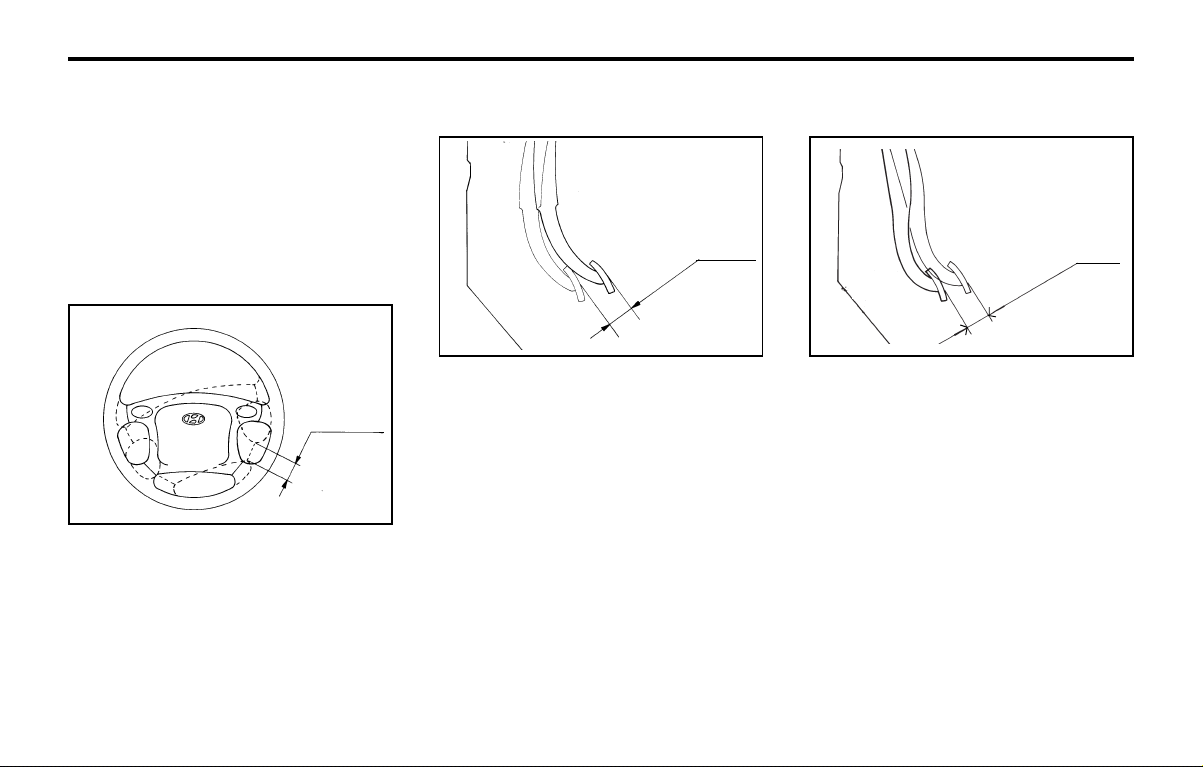
DO-IT-YOURSELF MAINTENANCEDO-IT-YOURSELF MAINTENANCE
DO-IT-YOURSELF MAINTENANCEDO-IT-YOURSELF MAINTENANCE
DO-IT-YOURSELF MAINTENANCE
6-13
G170A01A-GAT
CHECKING BRAKE PEDALCHECKING BRAKE PEDAL
CHECKING BRAKE PEDALCHECKING BRAKE PEDAL
CHECKING BRAKE PEDAL
FREEPLAYFREEPLAY
FREEPLAYFREEPLAY
FREEPLAY
To check the steering wheel freeplay, stop the
car with the wheels pointed straight ahead and
gently move the steering wheel back and forth.
Use very light finger pressure and be sensitive
to changes in resistance that mark the limits of
the freeplay. If the freeplay is greater than
specified, have it inspected by your Hyundai
dealer and adjusted or repaired if necessary.
G160A01A-GAT
CHECKING CLUTCH PEDALCHECKING CLUTCH PEDAL
CHECKING CLUTCH PEDALCHECKING CLUTCH PEDAL
CHECKING CLUTCH PEDAL
FREEPLAYFREEPLAY
FREEPLAYFREEPLAY
FREEPLAY
SSA6160A
6 ~ 13 mm
(0.24 ~ 0.51 in.)
With the engine off, press lightly on the clutch
pedal until you feel a change in resistance. This
is the clutch pedal freeplay. The freeplay should
be within the limits specified in the illustration. If
it is not, have it inspected by your Hyundai
dealer and adjusted or repaired if necessary.
SSA6170A
3 ~ 8 mm
(0.12 ~ 0.31 in.)
With the engine off, press down on the brake
pedal several times to reduce the vacuum in the
brake booster.
Then, using your hand, press down slowly on
the brake pedal until you feel a change in
resistance. This is the brake pedal freeplay.
The freeplay should be within the limits speci-
fied in the illustration. If it is not, have it in-
spected by your Hyundai dealer and adjusted
or repaired if necessary.
G140C01A-AAT
LubricationLubrication
LubricationLubrication
Lubrication
To lubricate the compressor and the seals in
the system, the air conditioning should be run
for at least 10 minutes each week. This is
particularly important during cool weather when
the air conditioning system is not otherwise in
use.
G150A01A-GAT
CHECKING STEERING WHEELCHECKING STEERING WHEEL
CHECKING STEERING WHEELCHECKING STEERING WHEEL
CHECKING STEERING WHEEL
FREEPLAYFREEPLAY
FREEPLAYFREEPLAY
FREEPLAY
AS60260A
30 mm
(1.18 in.)
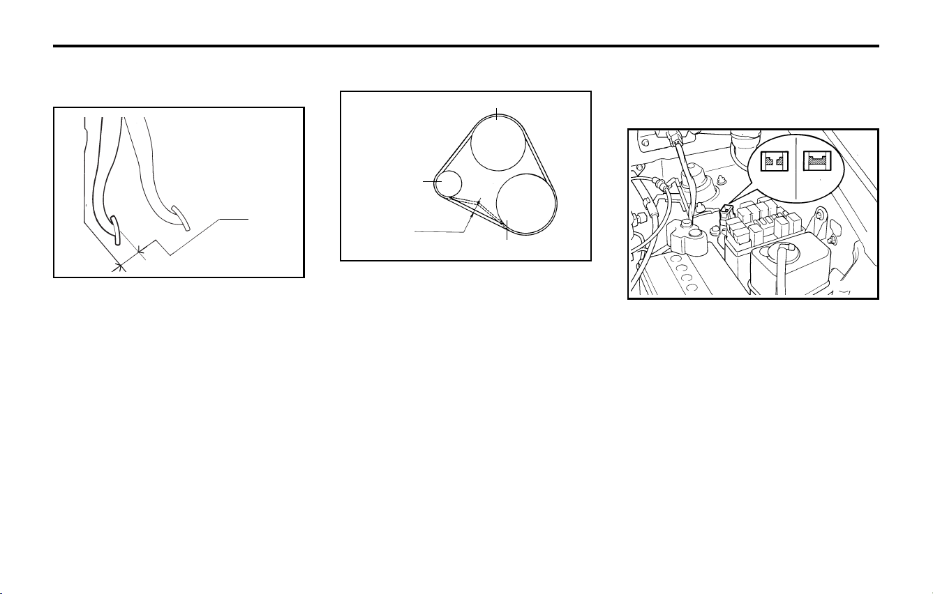
DO-IT-YOURSELF MAINTENANCEDO-IT-YOURSELF MAINTENANCE
DO-IT-YOURSELF MAINTENANCEDO-IT-YOURSELF MAINTENANCE
DO-IT-YOURSELF MAINTENANCE
6-14
G200A01A-AAT
CHECKING AND REPLACINGCHECKING AND REPLACING
CHECKING AND REPLACINGCHECKING AND REPLACING
CHECKING AND REPLACING
FUSESFUSES
FUSESFUSES
FUSES
Replacing a Fusible LinkReplacing a Fusible Link
Replacing a Fusible LinkReplacing a Fusible Link
Replacing a Fusible Link
A fusible link will melt if the electrical circuits
from the battery are ever overloaded, thus pre-
venting damage to the entire wiring harness.
(This could be caused by a short in the system
drawing too much current.) If this ever happens,
have a Hyundai dealer determine the cause,
repair the system and replace the fusible link.
The fusible links are located in a relay box for
easy inspection.
CAUTION:CAUTION:
CAUTION:CAUTION:
CAUTION:
When replacing a fusible link, never useWhen replacing a fusible link, never use
When replacing a fusible link, never useWhen replacing a fusible link, never use
When replacing a fusible link, never use
anything but a new fusible link with theanything but a new fusible link with the
anything but a new fusible link with theanything but a new fusible link with the
anything but a new fusible link with the
same or lower amperage rating. Never use asame or lower amperage rating. Never use a
same or lower amperage rating. Never use asame or lower amperage rating. Never use a
same or lower amperage rating. Never use a
piece of wire or a higher-rated fusible link.piece of wire or a higher-rated fusible link.
piece of wire or a higher-rated fusible link.piece of wire or a higher-rated fusible link.
piece of wire or a higher-rated fusible link.
This could result in serious damage andThis could result in serious damage and
This could result in serious damage andThis could result in serious damage and
This could result in serious damage and
create a fire hazard.create a fire hazard.
create a fire hazard.create a fire hazard.
create a fire hazard.
G200A01A
Bad
Good
G180A01A-GAT
CHECKING BRAKE PEDALCHECKING BRAKE PEDAL
CHECKING BRAKE PEDALCHECKING BRAKE PEDAL
CHECKING BRAKE PEDAL
CLEARANCECLEARANCE
CLEARANCECLEARANCE
CLEARANCE
SSA6180A
36 mm (1.42 in.)
You need a helper to check the brake pedal
clearance. With the engine running, have your
helper press down on the brake pedal several
times and then hold it down with a force of about
490N (50kg, 110lbs). The brake pedal clear-
ance is the distance from the top surface of the
brake pedal to the asphalt sheeting under the
floor mat.
If the brake pedal clearance is not within the
limits specified in the illustration, have it in-
spected by your Hyundai dealer and adjusted
or repaired if necessary.
G190A01A-GAT
CHECKING DRIVE BELTSCHECKING DRIVE BELTS
CHECKING DRIVE BELTSCHECKING DRIVE BELTS
CHECKING DRIVE BELTS
Water pump pulley
Crankshaft pulley
Drive belts should be checked periodically for
proper tension and adjusted if necessary. At the
same time, belts should be examined for cracks,
wear, fraying or other evidence of deterioration
and replaced if necessary.
Belt routing should also be checked to be sure
there is no interference between the belts and
other parts of the engine. After a belt is re-
placed, the new belt should be adjusted again
after two or three weeks to eliminate slack
resulting from initial stretching after use.
G190A01A
9.5~11.0 mm
(0.37 ~ 0.43 in.)
Generator
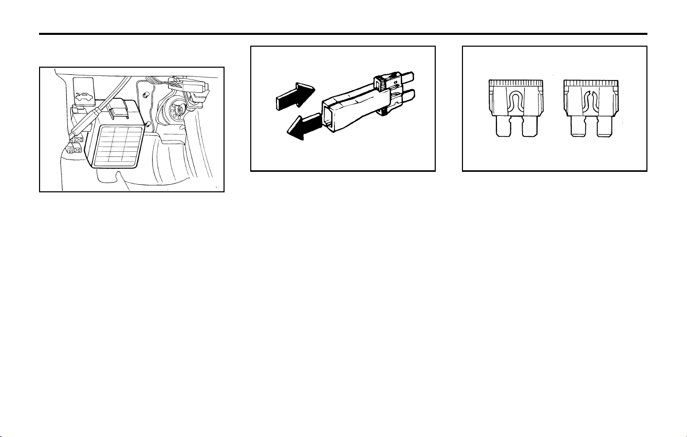
DO-IT-YOURSELF MAINTENANCEDO-IT-YOURSELF MAINTENANCE
DO-IT-YOURSELF MAINTENANCEDO-IT-YOURSELF MAINTENANCE
DO-IT-YOURSELF MAINTENANCE
6-15
CAUTION:CAUTION:
CAUTION:CAUTION:
CAUTION:
A burned-out fuse indicates that there is aA burned-out fuse indicates that there is a
A burned-out fuse indicates that there is aA burned-out fuse indicates that there is a
A burned-out fuse indicates that there is a
problem in the electrical circuit. If you re-problem in the electrical circuit. If you re-
problem in the electrical circuit. If you re-problem in the electrical circuit. If you re-
problem in the electrical circuit. If you re-
place a fuse and it blows as soon as theplace a fuse and it blows as soon as the
place a fuse and it blows as soon as theplace a fuse and it blows as soon as the
place a fuse and it blows as soon as the
accessory is turned on, the problem is seri-accessory is turned on, the problem is seri-
accessory is turned on, the problem is seri-accessory is turned on, the problem is seri-
accessory is turned on, the problem is seri-
ous and should be referred to a Hyundaious and should be referred to a Hyundai
ous and should be referred to a Hyundaious and should be referred to a Hyundai
ous and should be referred to a Hyundai
dealer for diagnosis and repair. Never re-dealer for diagnosis and repair. Never re-
dealer for diagnosis and repair. Never re-dealer for diagnosis and repair. Never re-
dealer for diagnosis and repair. Never re-
place a fuse with anything except a fuseplace a fuse with anything except a fuse
place a fuse with anything except a fuseplace a fuse with anything except a fuse
place a fuse with anything except a fuse
with the same or a lower amperage rating. Awith the same or a lower amperage rating. A
with the same or a lower amperage rating. Awith the same or a lower amperage rating. A
with the same or a lower amperage rating. A
higher capacity fuse could cause damagehigher capacity fuse could cause damage
higher capacity fuse could cause damagehigher capacity fuse could cause damage
higher capacity fuse could cause damage
and create a fire hazard.and create a fire hazard.
and create a fire hazard.and create a fire hazard.
and create a fire hazard.
Good Burned out
4. Replace the blown fuse by pressing a new
fuse of the same rating into place. The fuse
should be a snug fit. If it is not, have the fuse
clip repaired or replaced by a Hyundai deal-
er. If you do not have a spare fuse, you may
be able to borrow a fuse of the same or
lower rating from an accessory you can
temporarily get along without (the radio or
cigarette lighter, for example). Always re-
member to replace the borrowed fuse.
G200B01A-AAT
Replacing Accessory FuseReplacing Accessory Fuse
Replacing Accessory FuseReplacing Accessory Fuse
Replacing Accessory Fuse
The fuse box for the lights and other electrical
accessories will be found low on the dashboard
on the driver's side. Inside the box you will find
a list showing the circuits protected by each
fuse.
If any of your car's lights or other electrical
accessories stop working, a blown fuse could
be the reason. If the fuse has burned out, you
will see that the metal strip inside the fuse has
burned through. If you suspect a blown fuse,
follow this procedure:
1. Turn off the ignition and all other switches.
2. Open the fuse box and examine each fuse.
Remove each fuse by pulling it toward you
(a small "fuse puller" tool is contained in the
fuse box to simplify this operation).
3. Be sure to check all other fuses even if you
find one that appears to have burned out.
G200B01A
SSA6201B
SSA6202B
Fuse Puller
G210A01A-AAT
CHECKING THE BATTERYCHECKING THE BATTERY
CHECKING THE BATTERYCHECKING THE BATTERY
CHECKING THE BATTERY
WARNING:WARNING:
WARNING:WARNING:
WARNING:
Batteries can be dangerous!.Batteries can be dangerous!.
Batteries can be dangerous!.Batteries can be dangerous!.
Batteries can be dangerous!.
When working with batteries, carefully ob-When working with batteries, carefully ob-
When working with batteries, carefully ob-When working with batteries, carefully ob-
When working with batteries, carefully ob-
serve the following precautions to avoidserve the following precautions to avoid
serve the following precautions to avoidserve the following precautions to avoid
serve the following precautions to avoid
serious injuries.serious injuries.
serious injuries.serious injuries.
serious injuries.
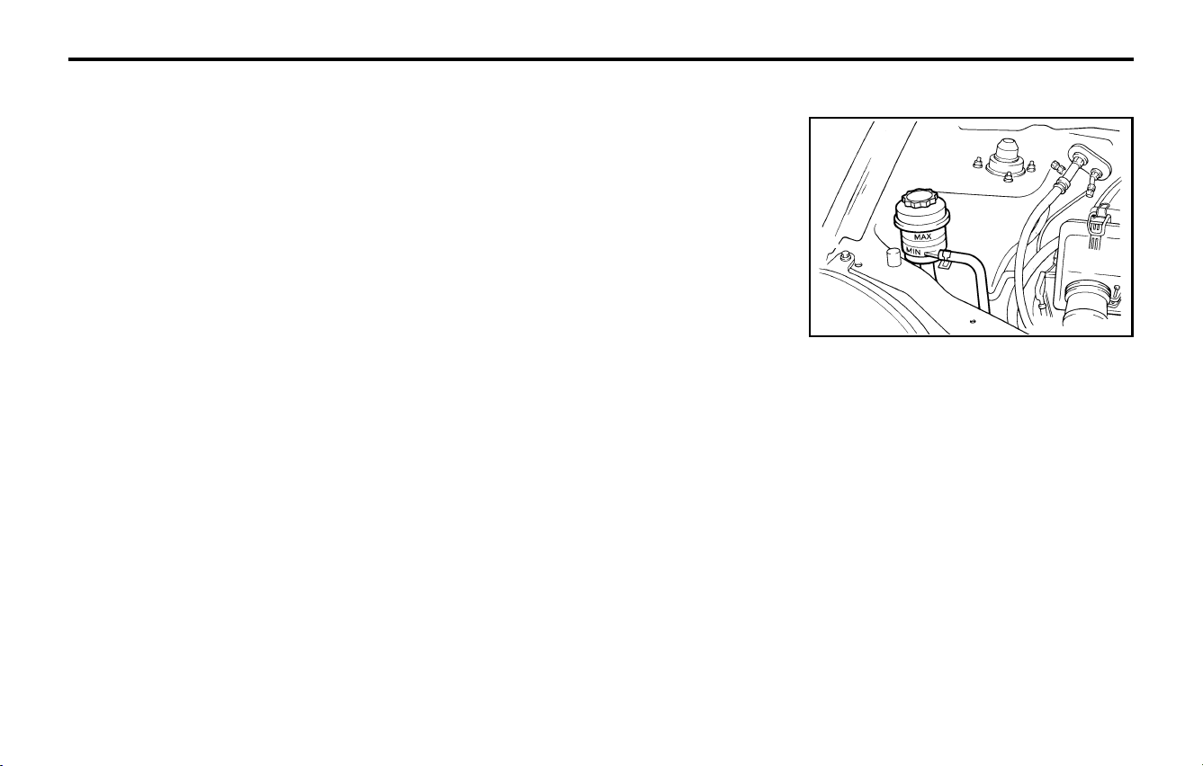
DO-IT-YOURSELF MAINTENANCEDO-IT-YOURSELF MAINTENANCE
DO-IT-YOURSELF MAINTENANCEDO-IT-YOURSELF MAINTENANCE
DO-IT-YOURSELF MAINTENANCE
6-16
G230A03A-GAT
POWER STEERING FLUID LEVELPOWER STEERING FLUID LEVEL
POWER STEERING FLUID LEVELPOWER STEERING FLUID LEVEL
POWER STEERING FLUID LEVEL
The power steering fluid level should be checked
regularly.
To check the power steering fluid level, be sure
the ignition is "OFF", then check to make cer-
tain that the power steering fluid level is be-
tween the "MAX" and "MIN" level markings on
the fluid reservoir.
NOTE:NOTE:
NOTE:NOTE:
NOTE:
Grinding noise from the power steeringGrinding noise from the power steering
Grinding noise from the power steeringGrinding noise from the power steering
Grinding noise from the power steering
pump may be heard immediately after thepump may be heard immediately after the
pump may be heard immediately after thepump may be heard immediately after the
pump may be heard immediately after the
engine is started in extremely cold condi-engine is started in extremely cold condi-
engine is started in extremely cold condi-engine is started in extremely cold condi-
engine is started in extremely cold condi-
tions (below tions (below
tions (below tions (below
tions (below
-20°C). If the noise stops dur--20°C). If the noise stops dur-
-20°C). If the noise stops dur--20°C). If the noise stops dur-
-20°C). If the noise stops dur-
ing warm up, there is no abnormal functioning warm up, there is no abnormal function
ing warm up, there is no abnormal functioning warm up, there is no abnormal function
ing warm up, there is no abnormal function
in the system. This is due to a power steer-in the system. This is due to a power steer-
in the system. This is due to a power steer-in the system. This is due to a power steer-
in the system. This is due to a power steer-
ing fluid characteristic in extremely colding fluid characteristic in extremely cold
ing fluid characteristic in extremely colding fluid characteristic in extremely cold
ing fluid characteristic in extremely cold
conditions.conditions.
conditions.conditions.
conditions.
G230A01X
The fluid in the battery contains a strong solu-
tion of sulfuric acid, which is poisonous and
highly corrosive. Be careful not to spill it on
yourself or the car. If you do spill battery fluid on
yourself, immediately do the following:
o If battery fluid is on your skin, flush the
affected areas with water for at least 15
minutes and then seek medical assistance.
o If battery fluid is in your eyes, rinse out your
eyes with water and get medical assistance
as soon as possible. While you are being
driven to get medical assistance, continue
to rinse your eyes by using a sponge or soft
cloth saturated with water.
o If you swallow battery fluid, drink a large
quantity of water or milk followed by milk of
magnesia, eat a raw egg or drink vegetable
oil. Get medical assistance as soon as
possible.
While batteries are being charged (either by a
battery charger or by the vehicle's alternator),
they produce explosive gases. Always observe
these warnings to prevent injuries from occur-
ring:
o Charge batteries only in a well ventilated
area.
o Do not permit flames, sparks or smoking in
the area.
o Keep children away from the area.
G210B01A-AAT
Checking the BatteryChecking the Battery
Checking the BatteryChecking the Battery
Checking the Battery
Keep the battery clean. Any evidence of corro-
sion around the battery posts or terminals should
be removed using a solution of household bak-
ing soda and warm water. After the battery
terminals are dry, cover them with a light coat-
ing of grease.
G220A01A-AAT
CHECKING ELECTRIC COOLINGCHECKING ELECTRIC COOLING
CHECKING ELECTRIC COOLINGCHECKING ELECTRIC COOLING
CHECKING ELECTRIC COOLING
FANSFANS
FANSFANS
FANS
WARNING:WARNING:
WARNING:WARNING:
WARNING:
The radiator fan is controlled by engine cool-The radiator fan is controlled by engine cool-
The radiator fan is controlled by engine cool-The radiator fan is controlled by engine cool-
The radiator fan is controlled by engine cool-
ant temperature and may sometimes operateant temperature and may sometimes operate
ant temperature and may sometimes operateant temperature and may sometimes operate
ant temperature and may sometimes operate
even when the engine is not running. Useeven when the engine is not running. Use
even when the engine is not running. Useeven when the engine is not running. Use
even when the engine is not running. Use
extreme caution when working near the bladesextreme caution when working near the blades
extreme caution when working near the bladesextreme caution when working near the blades
extreme caution when working near the blades
of the cooling fan, so that you are not injuredof the cooling fan, so that you are not injured
of the cooling fan, so that you are not injuredof the cooling fan, so that you are not injured
of the cooling fan, so that you are not injured
by a rotating fan blade. As the coolant tem-by a rotating fan blade. As the coolant tem-
by a rotating fan blade. As the coolant tem-by a rotating fan blade. As the coolant tem-
by a rotating fan blade. As the coolant tem-
perature decreases the fan will automaticallyperature decreases the fan will automatically
perature decreases the fan will automaticallyperature decreases the fan will automatically
perature decreases the fan will automatically
shut off. This is a normal condition.shut off. This is a normal condition.
shut off. This is a normal condition.shut off. This is a normal condition.
shut off. This is a normal condition.
G220B01A-AAT
Checking Engine Cooling FanChecking Engine Cooling Fan
Checking Engine Cooling FanChecking Engine Cooling Fan
Checking Engine Cooling Fan
The engine cooling fan should come on auto-
matically if the engine coolant temperature is
high.
G220C01A-AAT
Checking Condenser Cooling FanChecking Condenser Cooling Fan
Checking Condenser Cooling FanChecking Condenser Cooling Fan
Checking Condenser Cooling Fan
The condenser cooling fan should come on
automatically whenever the air conditioning is
in operation.
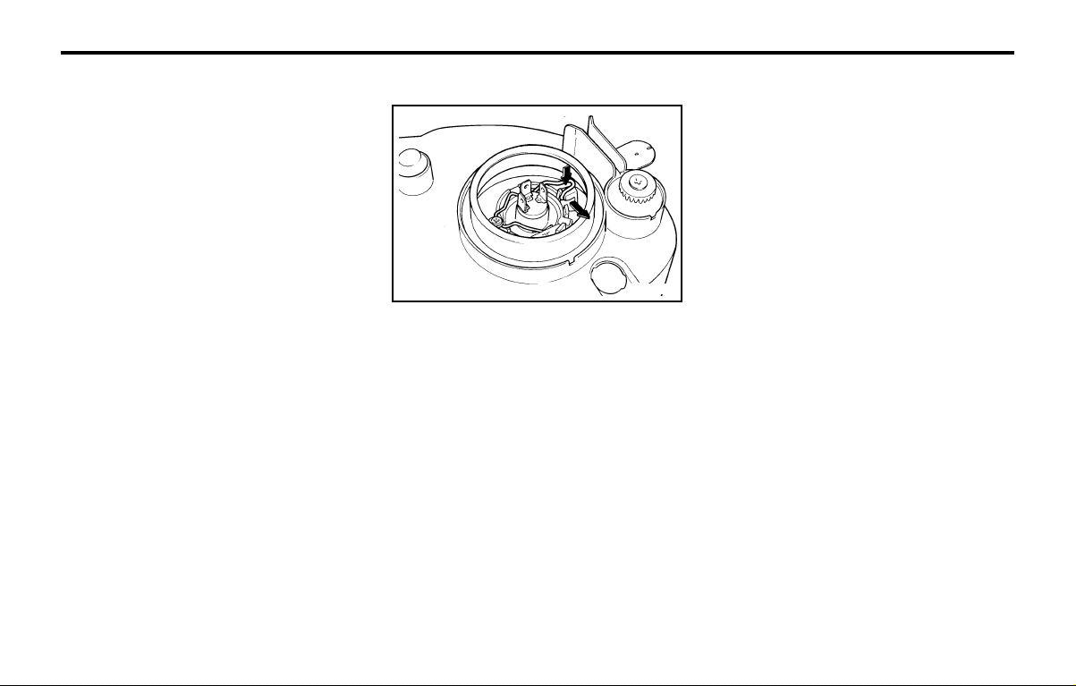
DO-IT-YOURSELF MAINTENANCEDO-IT-YOURSELF MAINTENANCE
DO-IT-YOURSELF MAINTENANCEDO-IT-YOURSELF MAINTENANCE
DO-IT-YOURSELF MAINTENANCE
6-17
G270A02X-GAT
HEADLIGHT BULBHEADLIGHT BULB
HEADLIGHT BULBHEADLIGHT BULB
HEADLIGHT BULB
Replacement instructions:
1. Allow the bulb to cool. Wear eye protection.
2. Always grasp the bulb by its base, avoid
touching the glass.
3. Disconnect the connector, then remove the
dust cover.
4. Push the bulb spring for removing the head-
light bulb.
5. Remove the headlight bulb. If the bulb is
burned out, replace it with the same watt-
age.
6. Installation is the reverse order of the re-
moval.
7. Use the protective cap and carton to promptly
dispose of the old bulb.
8. Check for proper headlight aim.
WARNING:WARNING:
WARNING:WARNING:
WARNING:
The halogen bulb contains gas under pres-The halogen bulb contains gas under pres-
The halogen bulb contains gas under pres-The halogen bulb contains gas under pres-
The halogen bulb contains gas under pres-
sure and if impacted sure and if impacted
sure and if impacted sure and if impacted
sure and if impacted
could shatter, and re-could shatter, and re-
could shatter, and re-could shatter, and re-
could shatter, and re-
sulting in flying fragments. Always wear eyesulting in flying fragments. Always wear eye
sulting in flying fragments. Always wear eyesulting in flying fragments. Always wear eye
sulting in flying fragments. Always wear eye
protection protection
protection protection
protection
when servicing the bulb. Protectwhen servicing the bulb. Protect
when servicing the bulb. Protectwhen servicing the bulb. Protect
when servicing the bulb. Protect
the bulb against abrasions or scratches andthe bulb against abrasions or scratches and
the bulb against abrasions or scratches andthe bulb against abrasions or scratches and
the bulb against abrasions or scratches and
against liquids when lighted. Turn the bulbagainst liquids when lighted. Turn the bulb
against liquids when lighted. Turn the bulbagainst liquids when lighted. Turn the bulb
against liquids when lighted. Turn the bulb
on only when installed in a headlight. Re-on only when installed in a headlight. Re-
on only when installed in a headlight. Re-on only when installed in a headlight. Re-
on only when installed in a headlight. Re-
place the headlight if damaged or cracked.place the headlight if damaged or cracked.
place the headlight if damaged or cracked.place the headlight if damaged or cracked.
place the headlight if damaged or cracked.
Keep the bulb out of the reach Keep the bulb out of the reach
Keep the bulb out of the reach Keep the bulb out of the reach
Keep the bulb out of the reach
of childrenof children
of childrenof children
of children
and dispose of the used bulb with care.and dispose of the used bulb with care.
and dispose of the used bulb with care.and dispose of the used bulb with care.
and dispose of the used bulb with care.
G290A02X-GAT
HEADLIGHT AIMING ADJUSTMENTHEADLIGHT AIMING ADJUSTMENT
HEADLIGHT AIMING ADJUSTMENTHEADLIGHT AIMING ADJUSTMENT
HEADLIGHT AIMING ADJUSTMENT
Before performing aiming adjustment, make sure
of the following.
1. Keep all tires inflated to the correct pres-
sure.
2. Place the vehicle on level ground and press
the front bumper & rear bumper down sev-
eral times. Place the vehicle at a distance of
3,000 mm (118 in.) from the test wall.
3. See that the vehicle is unloaded (except for
full levels of coolant, engine oil and fuel, and
spare tire, jack, and tools). Have the driver
or equivalent weight placed in driver's seat.
Recommended FluidRecommended Fluid
Recommended FluidRecommended Fluid
Recommended Fluid
Use PSF-3 type fluid.
NOTE:NOTE:
NOTE:NOTE:
NOTE:
Do not start the engine when the powerDo not start the engine when the power
Do not start the engine when the powerDo not start the engine when the power
Do not start the engine when the power
steering oil reservoir is empty.steering oil reservoir is empty.
steering oil reservoir is empty.steering oil reservoir is empty.
steering oil reservoir is empty.
G240A01A-AAT
POWER STEERING HOSESPOWER STEERING HOSES
POWER STEERING HOSESPOWER STEERING HOSES
POWER STEERING HOSES
It is suggested that you check the power steer-
ing hose connections for fluid leakage at those
intervals specified in the vehicle maintenance
schedule in Section 5.
The power steering hoses should be replaced if
there is severe surface cracking, pulling, scuff-
ing or worn spots. Deterioration of the hose
could cause premature failure.
G260A03A-AAT
REPLACING HEADLIGHT BULBSREPLACING HEADLIGHT BULBS
REPLACING HEADLIGHT BULBSREPLACING HEADLIGHT BULBS
REPLACING HEADLIGHT BULBS
Before attempting to replace a headlight bulb,
be sure the switch is turned to the "OFF"
position.
The next paragraph shows how to reach head-
light bulbs so they may be changed. Be sure to
replace the burned-out bulb with one of the
same number and wattage rating.
CAUTION:CAUTION:
CAUTION:CAUTION:
CAUTION:
Keep the lamps out of contact with petro-Keep the lamps out of contact with petro-
Keep the lamps out of contact with petro-Keep the lamps out of contact with petro-
Keep the lamps out of contact with petro-
leum product, such as oil, gasoline, etc.leum product, such as oil, gasoline, etc.
leum product, such as oil, gasoline, etc.leum product, such as oil, gasoline, etc.
leum product, such as oil, gasoline, etc.
G270A01X
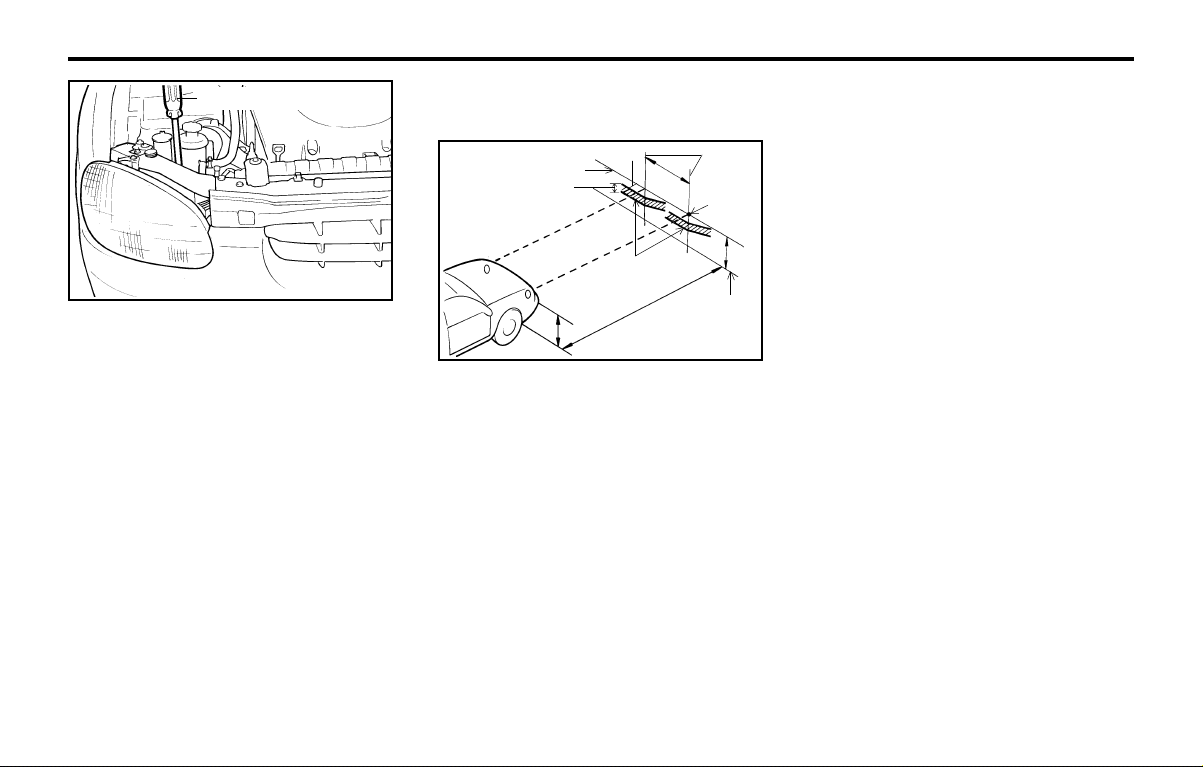
DO-IT-YOURSELF MAINTENANCEDO-IT-YOURSELF MAINTENANCE
DO-IT-YOURSELF MAINTENANCEDO-IT-YOURSELF MAINTENANCE
DO-IT-YOURSELF MAINTENANCE
6-18
SPECIFICATIONS:SPECIFICATIONS:
SPECIFICATIONS:SPECIFICATIONS:
SPECIFICATIONS:
"H"
Horizontal center line of headlights from
ground : 646 mm (25.43 in.)
"W"
Distance between each headlight center:
988 mm (38.89 in.)
"L"
Distance between the headlights and the
wall that the lights are tested against:
3,000 mm (118 in.).
4. Clean the head light lenses and turn on the
headlights (Low beam).
5. Open the hood.
6. Draw the vertical line (through the center of
each headlight beam pattern) and the hori-
zontal line (through the center of each head-
light beam pattern) on the aiming screen.
And then, draw the horizontal parallel line at
30 mm (1.18 in.) under the horizontal line.
7. Adjust each cut-off line of the low beam to
the parallel line with a phillips screwdriver -
VERTICAL AIMING.
8. Adjust each cut-off line of the low beam to
the each vertical line with a phillips screw-
driver - HORIZONTAL AIMING.
G290A02Y
Vertical aiming
G290B02X-GAT
Adjustment After Headlight AssemblyAdjustment After Headlight Assembly
Adjustment After Headlight AssemblyAdjustment After Headlight Assembly
Adjustment After Headlight Assembly
ReplacementReplacement
ReplacementReplacement
Replacement
G290B01Y
Vertical
line
Cut-off line
Ground line
Horizontal line
L
W
H
H
"P"
15mm (0.59in.)
30mm(1.18in.)
If the vehicle has had front body repair and the
headlight assembly has been replaced, the
headlight aiming should be checked using the
aiming screen as shown in the illustration. Turn
on the headlight switch. (Low Beam Position)
1. Adjust headlights so that main axis of light is
parallel to center line of the body and is
aligned with point "P" shown in the illustra-
tion.
2. Dotted lines in the illustration show the cen-
ter of headlights.
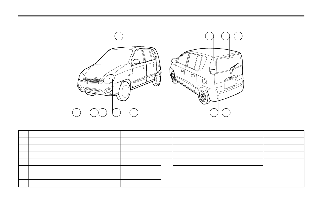
DO-IT-YOURSELF MAINTENANCEDO-IT-YOURSELF MAINTENANCE
DO-IT-YOURSELF MAINTENANCEDO-IT-YOURSELF MAINTENANCE
DO-IT-YOURSELF MAINTENANCE
6-19
G280A01X-GAT
(ATOS)(ATOS)
(ATOS)(ATOS)
(ATOS)
G280A02X
6
11 7 9
1 432 5 10 8
Part Name
Front Fog Light
Headlight
Front Position Light
Front Turn Signal Light
Side-Repeater Light (If installed)
Interior Light
High Mounted Rear Stop Light (If Installed)
No.
1
2
3
4
5
6
7
Wattage
55
60/55
5
21
5
8
21
No.
8
9
10
11
Wattage
5
5
21
21
21/5
21
Part Name
Luggage Compartment Light
License Plate Light
Rear Fog Light
Rear Combination Light
Turn Signal Light
Stop/Tail Light
Back-up Light
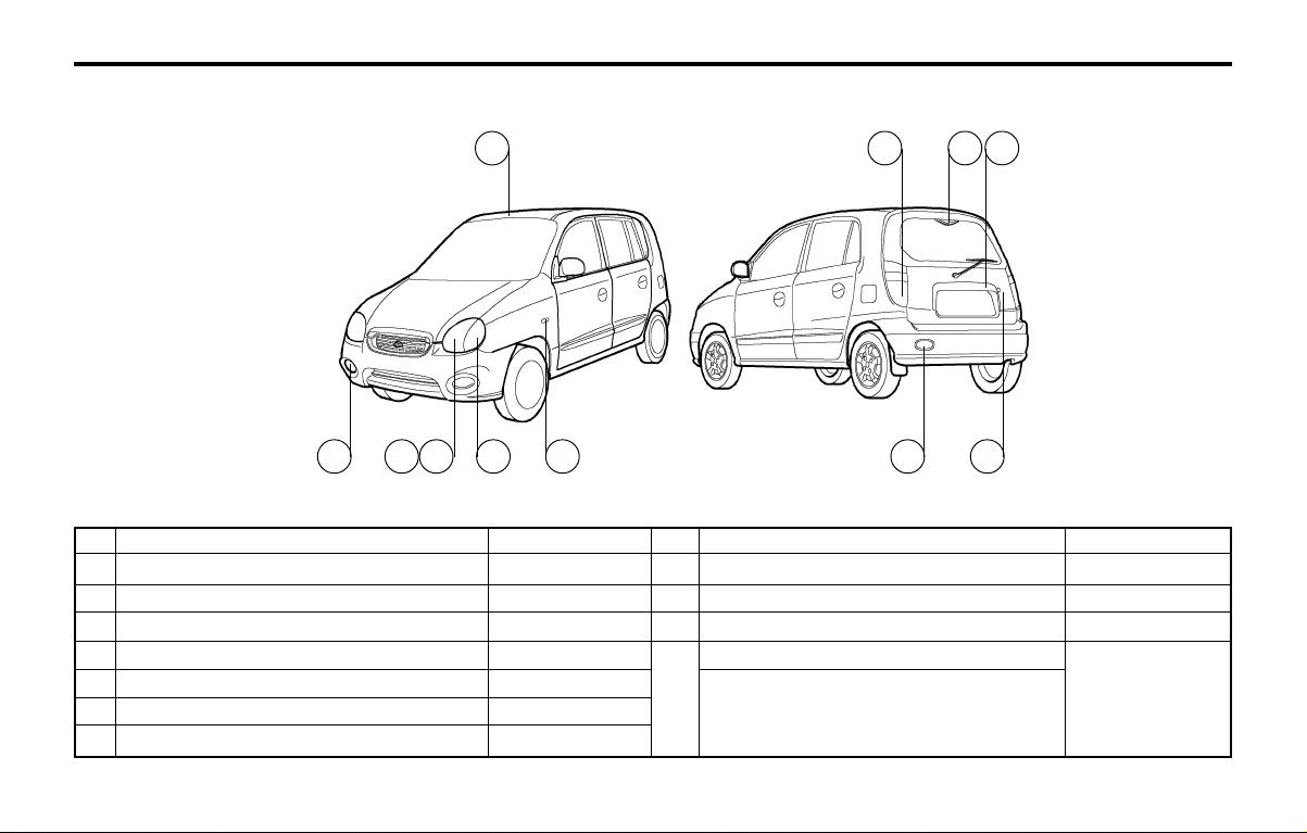
DO-IT-YOURSELF MAINTENANCEDO-IT-YOURSELF MAINTENANCE
DO-IT-YOURSELF MAINTENANCEDO-IT-YOURSELF MAINTENANCE
DO-IT-YOURSELF MAINTENANCE
6-20
G280A02V-GAT
(ATOS PRIME)(ATOS PRIME)
(ATOS PRIME)(ATOS PRIME)
(ATOS PRIME)
Part Name
Front Fog Light
Headlight
Front Position Light
Front Turn Signal Light
Side-Repeater Light (If installed)
Interior Light
High Mounted Rear Stop Light (If Installed)
No.
1
2
3
4
5
6
7
Wattage
55
60/55
5
21
5
8
2.6
No.
8
9
10
11
Wattage
5
5
21
21
21/5
21
Part Name
Luggage Compartment Light
License Plate Light
Rear Fog Light
Rear Combination Light
Turn Signal Light
Stop/Tail Light
Back-up Light
G280A03V
6
11 9
1 432 5 10 8
7
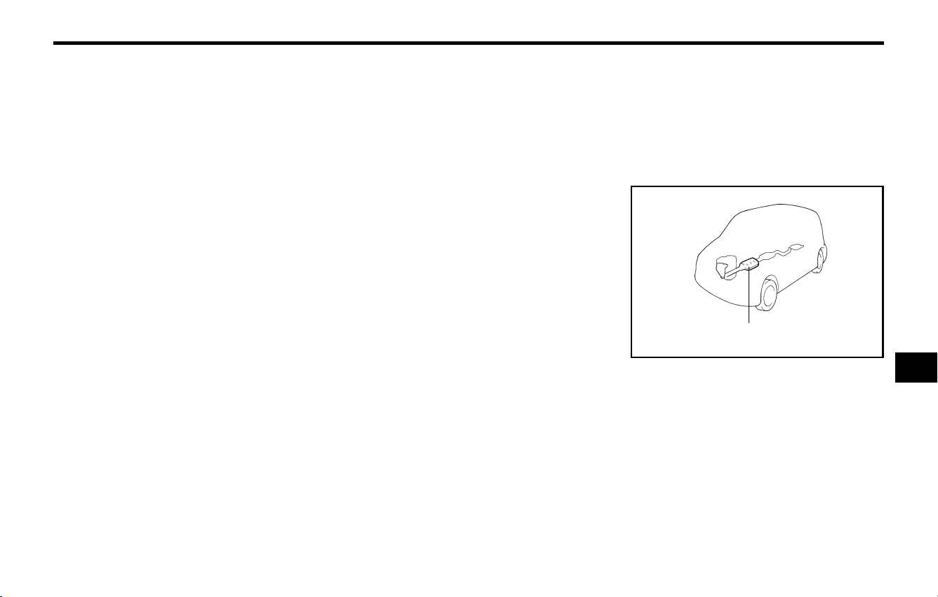
EMISSION CONTROL SYSTEMSEMISSION CONTROL SYSTEMS
EMISSION CONTROL SYSTEMSEMISSION CONTROL SYSTEMS
EMISSION CONTROL SYSTEMS
7-1
7.7.
7.7.
7.
EMISSION CON-EMISSION CON-
EMISSION CON-EMISSION CON-
EMISSION CON-
TRTR
TRTR
TR
OL SYSTEMSOL SYSTEMS
OL SYSTEMSOL SYSTEMS
OL SYSTEMS
H010A01A-GAT
EMISSION CONTROL SYSTEMEMISSION CONTROL SYSTEM
EMISSION CONTROL SYSTEMEMISSION CONTROL SYSTEM
EMISSION CONTROL SYSTEM
(If Installed)(If Installed)
(If Installed)(If Installed)
(If Installed)
Your Hyundai is equipped with an emission
control system to meet all requirements of the
Emission prohibition rules of your province.
There are three emission control systems which
are as follows.
1) Crankcase emission control system
2) Evaporative emission control system
3) Exhaust emission control system
In order to assure the proper function of the
emission control systems, it is recommended
that you have your car inspected and main-
tained by an authorized Hyundai dealer in ac-
cordance with the maintenance schedule in this
manual.
the crankcase through the air intake hose.
Inside the crankcase, the fresh air mixes with
blow-by gases, which then pass through the
PCV valve and into the induction system.
H010C02A-GAT
2.2.
2.2.
2.
Evaporative Emission ControlEvaporative Emission Control
Evaporative Emission ControlEvaporative Emission Control
Evaporative Emission Control
System (If installed)System (If installed)
System (If installed)System (If installed)
System (If installed)
The Evaporative Emission Control System is
designed to prevent fuel vapors from escaping
into the atmosphere.
CanisterCanister
CanisterCanister
Canister
While the engine is inoperative, fuel vapors
generated inside the fuel tank are absorbed and
stored in the onboard canister. When the en-
gine is running, the fuel vapors absorbed in the
canister are drawn into the induction system
through
the purge control solenoid valve.
Purge Control Solenoid ValvePurge Control Solenoid Valve
Purge Control Solenoid ValvePurge Control Solenoid Valve
Purge Control Solenoid Valve
The purge control solenoid valve is controlled
by the ECM; when the engine coolant temper-
ature is low, and during idling, it closes, so that
evaporated fuel is not taken into the engine.
After engine warm-up, during ordinary driving, it
opens so as to introduce evaporated fuel to the
engine.
H010B01A-AAT
1.1.
1.1.
1.
Crankcase Emission Control Sys-Crankcase Emission Control Sys-
Crankcase Emission Control Sys-Crankcase Emission Control Sys-
Crankcase Emission Control Sys-
temtem
temtem
tem
The Positive Crankcase Ventilation System is
employed to prevent air pollution caused by
blow-by gases being emitted from the crank-
case. This system supplies fresh filtered air to
H010D01A-AAT
3. Exhaust Emission Control System3. Exhaust Emission Control System
3. Exhaust Emission Control System3. Exhaust Emission Control System
3. Exhaust Emission Control System
The exhaust emission control system is a high-
ly effective system which controls exhaust emis-
sion while maintaining good vehicle perfor-
mance.
H020A01A-GAT
CATALYTIC CONVERTER CATALYTIC CONVERTER
CATALYTIC CONVERTER CATALYTIC CONVERTER
CATALYTIC CONVERTER
(If Installed)(If Installed)
(If Installed)(If Installed)
(If Installed)
The catalytic converter is part of the exhaust
emission control system. It's purpose is to re-
move certain engine emission products from
the engine's exhaust. It looks something like a
muffler and is located underneath the car in the
exhaust system.
Catalytic Converter
H020A01A
77
77
7

EMISSION CONTROL SYSTEMSEMISSION CONTROL SYSTEMS
EMISSION CONTROL SYSTEMSEMISSION CONTROL SYSTEMS
EMISSION CONTROL SYSTEMS
7-2
o Do not touch the catalytic converter or any
other part of the exhaust system while the
engine is running as it is very hot and could
result in burns.
o Remember that your Hyundai dealer is your
best source of assistance.
H020B01A-GAT
About the Catalytic ConverterAbout the Catalytic Converter
About the Catalytic ConverterAbout the Catalytic Converter
About the Catalytic Converter
Exhaust gases passing through the catalytic
converter cause it to operate at very high tem-
peratures. As a result, the introduction of large
amounts of unburned gasoline may cause it to
overheat and create a fire hazard.
This can be avoided by observing the following:
o Use unleaded fuel only.
o Maintain your engine in good condition. Ex-
tremely high converter temperatures can
result from improper operation of the electri-
cal, ignition or fuel injection systems.
o If your engine stalls, pings, knocks, or is
hard to start, take your car to your Hyundai
dealer as soon as possible and have the
difficulty corrected.
o Avoid driving with a very low fuel level. If you
run out of gasoline, it could cause the engine
to misfire and result in excessive loading of
the catalytic converter.
o Avoid idling the engine for periods longer
than 10 minutes.
o Your Hyundai should not be either pushed
or pulled to get it started.
This can cause the catalytic converter to
overload.
o Take care not to stop your Hyundai over any
combustible material such as grass, paper,
leaves or rags. As these materials could
come in contact with the catalytic converter
and could cause a fire.
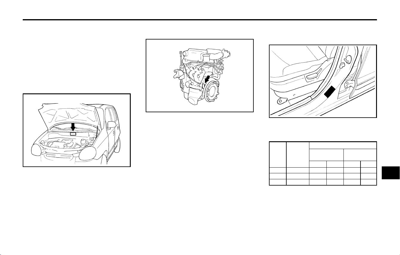
CONSUMER INFORMATIONCONSUMER INFORMATION
CONSUMER INFORMATIONCONSUMER INFORMATION
CONSUMER INFORMATION
8-1
I010B01A-AAT
Engine NumberEngine Number
Engine NumberEngine Number
Engine Number
8.8.
8.8.
8.
CONSUMER IN-CONSUMER IN-
CONSUMER IN-CONSUMER IN-
CONSUMER IN-
FORMAFORMA
FORMAFORMA
FORMA
TIONTION
TIONTION
TION
I010A01A-GAT
VEHICLE IDENTIFICATION NUMBERVEHICLE IDENTIFICATION NUMBER
VEHICLE IDENTIFICATION NUMBERVEHICLE IDENTIFICATION NUMBER
VEHICLE IDENTIFICATION NUMBER
(VIN)(VIN)
(VIN)(VIN)
(VIN)
The vehicle identification number (VIN) is the
number used in registering your car and in all
legal matters pertaining to its ownership, etc.
It can be found on the identification plate at-
tached to the engine side of the firewall be-
tween the engine and passenger compartment.
The engine number is stamped on the engine
block as shown in the drawing.
I020A01A-AAT
TIRE INFORMATIONTIRE INFORMATION
TIRE INFORMATIONTIRE INFORMATION
TIRE INFORMATION
The tires supplied on your new Hyundai are
chosen to provide the best performance for
normal driving.
I030A01X-GAT
RECOMMENDED INFLATION PRES-RECOMMENDED INFLATION PRES-
RECOMMENDED INFLATION PRES-RECOMMENDED INFLATION PRES-
RECOMMENDED INFLATION PRES-
SURESSURES
SURESSURES
SURES
The tire label located on the driver side center
pillar outer panel gives the tire pressures rec-
ommended for your vehicle.
I010A01A
I010B01A
I030A01S
88
88
8
4.0BX13
4.5JX13
5.0JX13
TIRE
SIZE
PRESSURE. kPa (PSI)
155/70R13
155/70R13
175/60R13
REAR
207(30)
207(30)
207(30)
FRONT
221(32)
221(32)
221(32)
UP TO 2
PERSONS
UP TO MAX.
LOAD
REAR
221(32)
221(32)
221(32)
FRONT
207(30)
207(30)
207(30)
RIM
SIZE
These pressures were chosen to provide the
most satisfactory combination of ride comfort,
tire wear and stability under normal conditions.
Tire pressures should be checked at least
monthly. Proper tire inflation pressures should
be maintained for these reasons:
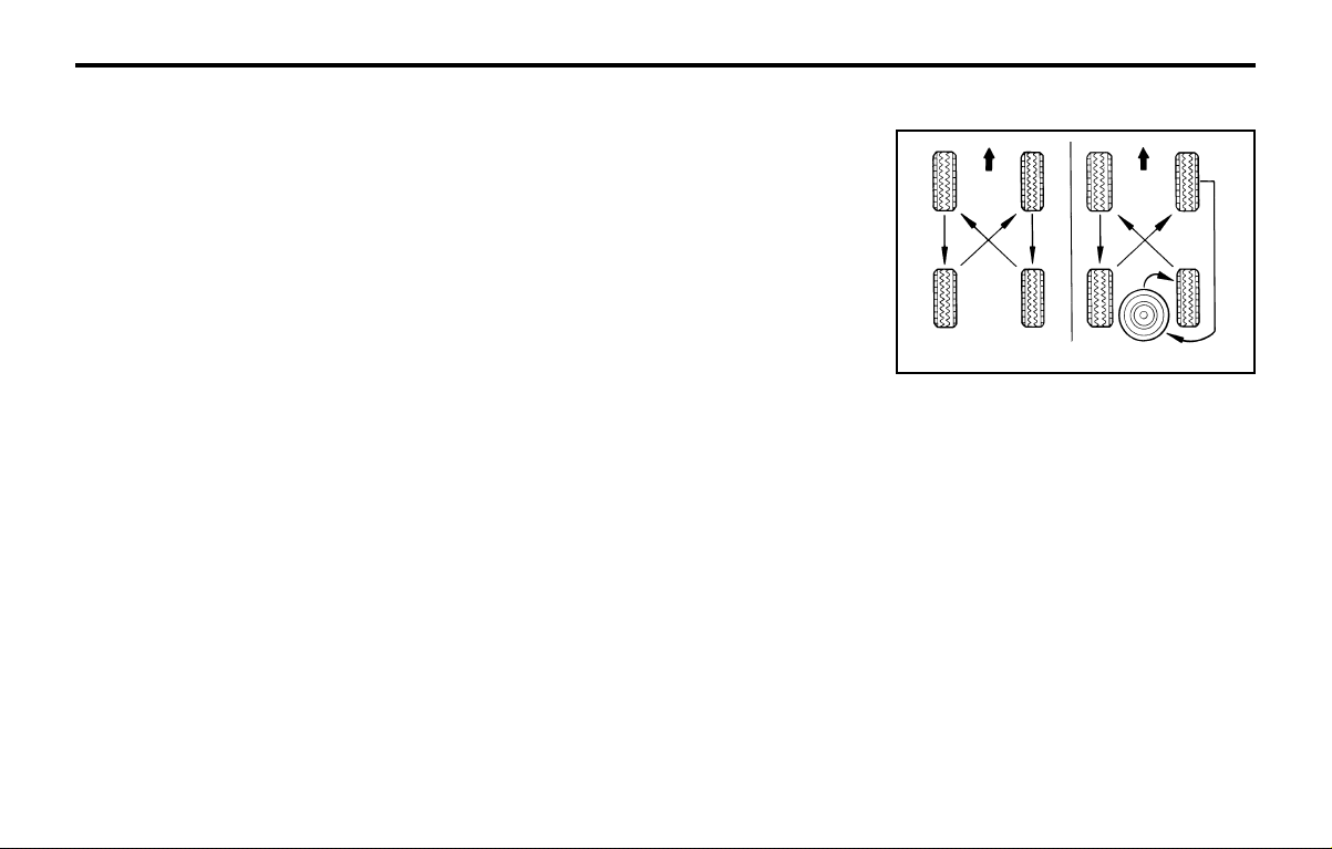
CONSUMER INFORMATIONCONSUMER INFORMATION
CONSUMER INFORMATIONCONSUMER INFORMATION
CONSUMER INFORMATION
8-2
o Lower-than-recommended tire pressures
cause uneven tread wear and poor han-
dling.
o Higher-than-recommended tire pressures
increase the chance of damage from im-
pacts and cause uneven tread wear.
CAUTION:CAUTION:
CAUTION:CAUTION:
CAUTION:
Always observe the following:Always observe the following:
Always observe the following:Always observe the following:
Always observe the following:
oo
oo
o
Check pressures when the tires are cold.Check pressures when the tires are cold.
Check pressures when the tires are cold.Check pressures when the tires are cold.
Check pressures when the tires are cold.
That is, after the car has been parked forThat is, after the car has been parked for
That is, after the car has been parked forThat is, after the car has been parked for
That is, after the car has been parked for
at least three hours and hasn't been driv-at least three hours and hasn't been driv-
at least three hours and hasn't been driv-at least three hours and hasn't been driv-
at least three hours and hasn't been driv-
en more than 1.6 km or one mile sinceen more than 1.6 km or one mile since
en more than 1.6 km or one mile sinceen more than 1.6 km or one mile since
en more than 1.6 km or one mile since
starting up.starting up.
starting up.starting up.
starting up.
oo
oo
o
Check the pressure of your spare tireCheck the pressure of your spare tire
Check the pressure of your spare tireCheck the pressure of your spare tire
Check the pressure of your spare tire
each time you check the pressure ofeach time you check the pressure of
each time you check the pressure ofeach time you check the pressure of
each time you check the pressure of
other tires.other tires.
other tires.other tires.
other tires.
oo
oo
o
Never overload your car. Be especiallyNever overload your car. Be especially
Never overload your car. Be especiallyNever overload your car. Be especially
Never overload your car. Be especially
careful about overloading if you equipcareful about overloading if you equip
careful about overloading if you equipcareful about overloading if you equip
careful about overloading if you equip
your car with a luggage rack or car topyour car with a luggage rack or car top
your car with a luggage rack or car topyour car with a luggage rack or car top
your car with a luggage rack or car top
carrier.carrier.
carrier.carrier.
carrier.
I040A01A-GAT
SNOW TIRESSNOW TIRES
SNOW TIRESSNOW TIRES
SNOW TIRES
If you equip your car with snow tires, they
should be the same size and have the same
load capacity as the original tires. Snow tires
should be installed on all four wheels; other-
wise, poor handling may result.
Snow tires should carry 28 kPa (4 psi) more air
pressure than the pressure recommended for
the standard tires on the tire label on the driver
side center pillar outer panel, or up to the
maximum pressure shown on the tire sidewall
whichever is less.
Do not drive faster than the speed limit when
your car is equipped with snow tires.
I050A01X-GAT
TIRE CHAINSTIRE CHAINS
TIRE CHAINSTIRE CHAINS
TIRE CHAINS
Tire chains, if necessary, should be installed on
the front wheels. Be sure that the chains are the
proper size and that they are installed in accor-
dance with the manufacturer's instructions.
To minimize tire and chain wear, do not con-
tinue to use tire chains when they are no longer
needed.
WARNING:WARNING:
WARNING:WARNING:
WARNING:
When driving on roads covered with snowWhen driving on roads covered with snow
When driving on roads covered with snowWhen driving on roads covered with snow
When driving on roads covered with snow
or ice, drive at less or ice, drive at less
or ice, drive at less or ice, drive at less
or ice, drive at less
than 30 km/h (20 mph).than 30 km/h (20 mph).
than 30 km/h (20 mph).than 30 km/h (20 mph).
than 30 km/h (20 mph).
I060A01A-GAT
TIRE ROTATIONTIRE ROTATION
TIRE ROTATIONTIRE ROTATION
TIRE ROTATION
SSA8050A
Tires should be rotated every 10,000 km (6,000
miles). If you notice that tires are wearing un-
evenly between rotations, have the car checked
by a Hyundai dealer so the cause may be
corrected.
After rotating, adjust the tire pressures and be
sure to check wheel nut tightness.
WARNING:WARNING:
WARNING:WARNING:
WARNING:
Do not mix bias-ply and radial-ply tires un-Do not mix bias-ply and radial-ply tires un-
Do not mix bias-ply and radial-ply tires un-Do not mix bias-ply and radial-ply tires un-
Do not mix bias-ply and radial-ply tires un-
der any circumstances.der any circumstances.
der any circumstances.der any circumstances.
der any circumstances.
This may cause dangerous handling char-This may cause dangerous handling char-
This may cause dangerous handling char-This may cause dangerous handling char-
This may cause dangerous handling char-
acteristics.acteristics.
acteristics.acteristics.
acteristics.
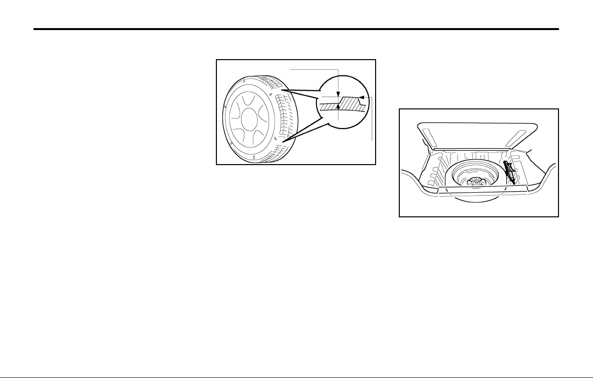
CONSUMER INFORMATIONCONSUMER INFORMATION
CONSUMER INFORMATIONCONSUMER INFORMATION
CONSUMER INFORMATION
8-3
tread. Always replace your tires with those of
the recommended size. If you change wheels,
the new wheel's rim width and offset must meet
Hyundai specification.
I070A01A-AAT
TIRE BALANCINGTIRE BALANCING
TIRE BALANCINGTIRE BALANCING
TIRE BALANCING
A tire that is out of balance may affect handling
and tire wear. The tires on your Hyundai were
balanced before the car was delivered but may
need balancing again during the years you own
the car.
Whenever a tire is dismounted for repair, it
should be rebalanced before being reinstalled
on the car.
I080A01A-AAT
TIRE TRACTIONTIRE TRACTION
TIRE TRACTIONTIRE TRACTION
TIRE TRACTION
Tire traction can be reduced if you drive on
worn tires, tires that are improperly inflated or
on slippery road surfaces. Tires should be re-
placed when tread wear indicators appear. To
reduce the possibility of losing control, slow
down whenever there is rain, snow or ice on the
road.
Wear indicator
I090A01S-GAT
WHEN TO REPLACE TIRESWHEN TO REPLACE TIRES
WHEN TO REPLACE TIRESWHEN TO REPLACE TIRES
WHEN TO REPLACE TIRES
I100A01FC-GAT
SPARE TIRE AND TOOLSSPARE TIRE AND TOOLS
SPARE TIRE AND TOOLSSPARE TIRE AND TOOLS
SPARE TIRE AND TOOLS
Your Hyundai is delivered with the following:
Spare tire and wheel
Wheel nut wrench, Wrench bar, Spanner,
Screwdriver
Jack
WARNINGWARNING
WARNINGWARNING
WARNING
::
::
:
oo
oo
o
Driving on worn-out tires is dangerous!Driving on worn-out tires is dangerous!
Driving on worn-out tires is dangerous!Driving on worn-out tires is dangerous!
Driving on worn-out tires is dangerous!
Worn-out tires can cause loss of brakingWorn-out tires can cause loss of braking
Worn-out tires can cause loss of brakingWorn-out tires can cause loss of braking
Worn-out tires can cause loss of braking
effectiveness, steering control and trac-effectiveness, steering control and trac-
effectiveness, steering control and trac-effectiveness, steering control and trac-
effectiveness, steering control and trac-
tion. When replacing tires, never mix ra-tion. When replacing tires, never mix ra-
tion. When replacing tires, never mix ra-tion. When replacing tires, never mix ra-
tion. When replacing tires, never mix ra-
dial and bias-ply tires on the same car. Ifdial and bias-ply tires on the same car. If
dial and bias-ply tires on the same car. Ifdial and bias-ply tires on the same car. If
dial and bias-ply tires on the same car. If
you replace radial tires with bias-ply tires,you replace radial tires with bias-ply tires,
you replace radial tires with bias-ply tires,you replace radial tires with bias-ply tires,
you replace radial tires with bias-ply tires,
they must be installed in sets of four.they must be installed in sets of four.
they must be installed in sets of four.they must be installed in sets of four.
they must be installed in sets of four.
oo
oo
o
Using tires and wheels of other than theUsing tires and wheels of other than the
Using tires and wheels of other than theUsing tires and wheels of other than the
Using tires and wheels of other than the
recommended sizes may cause unusualrecommended sizes may cause unusual
recommended sizes may cause unusualrecommended sizes may cause unusual
recommended sizes may cause unusual
handling characteristics that may causehandling characteristics that may cause
handling characteristics that may causehandling characteristics that may cause
handling characteristics that may cause
death, serious injury or property death, serious injury or property
death, serious injury or property death, serious injury or property
death, serious injury or property
dam-dam-
dam-dam-
dam-
age.age.
age.age.
age.
The original tires on your car have tread wear
indicators. The tread wear indicators appear
when the tread depth is 1.6 mm (0.06 in.). The
tire should be replaced when these appear as a
solid bar across two or more grooves of the
D060J01X
1.6 mm (0.06 in.)
HGK248
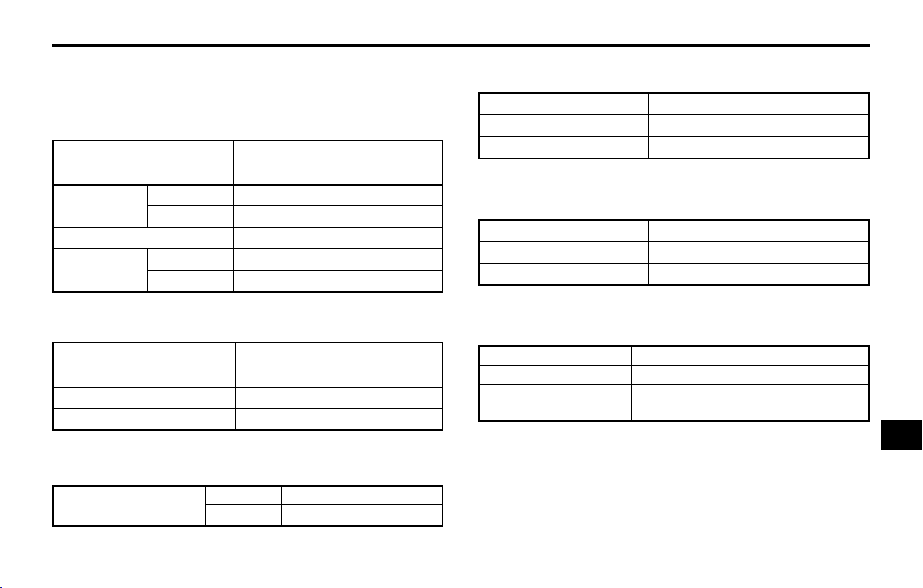
VEHICLE SPECIFICATIONSVEHICLE SPECIFICATIONS
VEHICLE SPECIFICATIONSVEHICLE SPECIFICATIONS
VEHICLE SPECIFICATIONS
9-1
9.9.
9.9.
9.
VEHICLE SPECIFICAVEHICLE SPECIFICA
VEHICLE SPECIFICAVEHICLE SPECIFICA
VEHICLE SPECIFICA
TIONSTIONS
TIONSTIONS
TIONS
J010A02X-GAT
MEASUREMENTMEASUREMENT
MEASUREMENTMEASUREMENT
MEASUREMENT
mm (in.)
J020A01X-GAT
POWER STEERINGPOWER STEERING
POWER STEERINGPOWER STEERING
POWER STEERING
Imp.gal
7.7
Liter
35
US.gal
9.3
J060A01X-GAT
FUEL SYSTEMFUEL SYSTEM
FUEL SYSTEMFUEL SYSTEM
FUEL SYSTEM
J040A02X-GAT
ELECTRICALELECTRICAL
ELECTRICALELECTRICAL
ELECTRICAL
J050A02X-GAT
BRAKEBRAKE
BRAKEBRAKE
BRAKE
Dual hydraulic with brake booster
Ventilated disc type
Drum type
Cable operated on rear wheel
J030A03X-GAT
TIRETIRE
TIRETIRE
TIRE
3495 (137.6)
1495 (58.9)
1615 (63.6)
1580 (62.2)
2380 (93.7)
1315 (51.8)
1300 (51.2)
Overall length
Overall width
Overall height
(unladen)
Wheel base
Wheel tread
Front
Rear
ATOS
ATOS PRIME
Type
Wheel free play
Rack stroke
Oil pump type
Rack and pinion
0 ~ 30 mm (0 ~ 1.18 in.)
136 mm
Vane type
Standard
Option
Spare
155 / 70 R13
175 / 60 R13
Full Size
Battery
Generator
Starting motor
MF 12V 40AH
13.5V 70A
0.8 KW
Fuel tank capacity
Type
Front brake type
Rear brake type
Parking brake
99
99
9

VEHICLE SPECIFICATIONSVEHICLE SPECIFICATIONS
VEHICLE SPECIFICATIONSVEHICLE SPECIFICATIONS
VEHICLE SPECIFICATIONS
9-2
J090A01X-GAT
SPARK PLUGSPARK PLUG
SPARK PLUGSPARK PLUG
SPARK PLUG
ITEMS
Spark plug
Spark plug gap
UNLEADED
NGK : BKR5ES-11
CHAMPION : RC9YC4, RC10YC4
1.0 - 1.1 mm (0.039 - 0.043 in.)
LEADED
NGK : BKR5ES
CHAMPION : RC9YC, RC10YC
0.8 - 0.9 mm (0.031 - 0.035 in.)
J070A01X-GAT
ENGINEENGINE
ENGINEENGINE
ENGINE
ITEMS
Engine type
Idle Speed (RPM)
Ignition Timing (Base)
Firing order
Specifications
1.0 MFI
4-Cylinder in-line SOHC
900 ± 100
BTDC 5° ± 2°
1 - 3 - 4 - 2

VEHICLE SPECIFICATIONSVEHICLE SPECIFICATIONS
VEHICLE SPECIFICATIONSVEHICLE SPECIFICATIONS
VEHICLE SPECIFICATIONS
9-3
Oil & Coolant Standard
API SG SAE 20W-40, 20W-50 (ABOVE -10°C)
OR ABOVE SAE 15W-40, 15W-50 (ABOVE -15°C)
SAE 10W-30 (-25°C ~ 40°C)
SAE 10W-40, 10W-50 (ABOVE -25°C)
SAE 5W-20 *1, *2 (BELOW -10°C)
SAE 5W-30 *1 (BELOW 10°C)
SAE 5W-40 *1 (BELOW 20°C)
*1. Restricted by driving condition and dealing area
*2. Not recommended for sustained high speed vehicle operation
Normal driving condition
Severe driving condition
HYUNDAI GENUINE PARTS MTF 75W/90 (API GL-4)
ESSO JWS3314
PSF-3
DOT 3, DOT 4 or equivalent
Ethylene glycol base for aluminum radiator
Item
Engine Oil
Engine oil consumption
Transaxle
Power steering
Brake fluid
Engine coolant
Q'ty (liter)
3.1 (3.26 US-qts, 2.72 lmp-qts)
MAX. 1L / 1500 Km
MAX. 1L / 1000 Km
2.45 (2.58 us-qts, 2.15 lmp-qts)
5.2 (5.48 us-qts, 4.56 lmp-qts)
As required
As required
4.5 (4.74 us-qts, 3.95 lmp-qts)
J080A03X-GAT
LUBRICATION CHARTLUBRICATION CHART
LUBRICATION CHARTLUBRICATION CHART
LUBRICATION CHART
Manual
Auto

INDEXINDEX
INDEXINDEX
INDEX
10-1
Catalytic Converter .................................................................... 7-1 ~ 7-2
Child-Protector Rear Door Lock ......................................................... 1-5
Cigarette Lighter ................................................................................ 1-26
Clock ................................................................................................ 1-26
Clutch Pedal freeplay ........................................................................ 6-13
Combination Light
Daytime running lights ................................................................. 1-23
Headlight flasher .......................................................................... 1-24
Headlight switch ........................................................................... 1-23
High-beam switch ........................................................................ 1-24
Lane change signal ...................................................................... 1-23
Turn signal operation ................................................................... 1-23
Compact Disk Player Operation (H922M) ........................................ 1-49
Cooling Fans ..................................................................................... 6-16
Corrosion Protection
Cleaning the interior ....................................................................... 4-3
Protecting your Hyundai from corrosion ........................................ 4-1
Washing and waxing ...................................................................... 4-2
DD
DD
D
Defroster ........................................................................................... 1-38
Door
Central door locking system .......................................................... 1-7
Door locks ...................................................................................... 1-4
Locking, unlocking front doors with a key ..................................... 1-4
Drive Belts ............................................................................... 6-12, 6-14
Driving
Economical driving ......................................................................... 2-9
Smooth cornering ........................................................................... 2-9
Winter driving ................................................................................. 2-9
ZK000A1-G
10. INDEX10. INDEX
10. INDEX10. INDEX
10. INDEX
AA
AA
A
Air bag .................................................................................... 1-13 ~ 1-17
Air Cleaner Filter ................................................................................. 6-9
Air Conditioning
Care ............................................................................................. 6-12
Operation ..................................................................................... 1-38
Antenna ............................................................................................. 1-54
Ashtray .............................................................................................. 1-27
Audio Fault Code .............................................................................. 1-51
BB
BB
B
Battery ...................................................................................... 2-10, 6-16
Bi-Level Heating ................................................................................ 1-36
Brake
Anti-lock system ............................................................................ 2-8
Checking the brakes .................................................................... 6-11
Fluid .................................................................................. 6-11 ~ 6-12
Pedal clearance ........................................................................... 6-14
Pedal freeplay .............................................................................. 6-13
Practices ...............................................................................2-7 ~ 2-8
Breaking-In your New Hyundai ........................................................... 1-1
CC
CC
C
Care of Cassette Tapes ................................................................... 1-52
Cassette Tape Player Operation (H900A) ............................. 1-44 ~ 1-46
1010
1010
10

INDEXINDEX
INDEXINDEX
INDEX
10-2
EE
EE
E
Emission Control System ................................................................... 7-1
Engine
Before starting the engine .............................................................. 2-2
Compartment (For MFI) ................................................................. 6-1
Coolant ........................................................................................... 6-5
Coolant temperature gauge ......................................................... 1-22
If the engine overheats .................................................................. 3-2
Number .......................................................................................... 8-1
Oil .................................................................................................. 6-2
Oil consumption ............................................................................. 6-3
Starting ........................................................................................... 2-3
Engine Exhaust Can Be Dangerous ................................................... 2-1
FF
FF
F
Fan Speed Control ............................................................................ 1-34
Fog Light
Front ............................................................................................. 1-31
Rear ............................................................................................. 1-31
Front Seats
Adjustable front seats .................................................................... 1-5
Adjustable headrests ..................................................................... 1-6
Adjusting seat forward and rearward ............................................. 1-5
Adjusting seatback angle ............................................................... 1-6
Fuel
Capacity ......................................................................................... 9-1
Gauge .......................................................................................... 1-22
Recommendations ......................................................................... 1-1
Fuel Filler Lid
Remote release ............................................................................ 1-31
Fuses ................................................................................................ 6-15
GG
GG
G
General Everyday Checks .................................................................. 6-2
HH
HH
H
Hazard Warning System ................................................................... 1-27
Headlight ........................................................................................... 6-17
Headlight Bulb Replacement ............................................................. 6-17
Headlight Leveling Device System ................................................... 1-25
Heating and Ventilation
High-mounted Rear Stoplight ............................................................ 1-28
Hood Release ................................................................................... 1-32
Horn ................................................................................................ 1-33
II
II
I
Ignition Switch ..................................................................................... 2-2
Immobilizer System ............................................................................. 1-2
Instrument Cluster and Indicator ....................................................... 1-19
Instruments and Controls .................................................................. 1-18
Interior Light ...................................................................................... 1-27
JJ
JJ
J
Jump Starting ...................................................................................... 3-1
KK
KK
K
Keys .................................................................................................. 1-2
If you lose your keys ..................................................................... 3-8
Positions ........................................................................................ 2-2

INDEXINDEX
INDEXINDEX
INDEX
10-3
Adjustable height ........................................................................... 1-9
Adjusting your seat belt ............................................................... 1-10
Care of seat belts .......................................................................... 1-8
Precautions .................................................................................... 1-7
Spark Plugs ............................................................................... 6-7 ~ 6-8
Speedometer ..................................................................................... 1-22
Starting Procedure .............................................................................. 2-3
Steering Wheel Free play ................................................................. 6-13
Stereo Radio Operation (H922M) .......................................... 1-47 ~ 1-48
Stereo Radio Operation (HMR90) ......................................... 1-42 ~ 1-43
Stereo Sound System ............................................................ 1-40 ~ 1-41
Sun Visor .......................................................................................... 1-32
TT
TT
T
Tail Gate
Open ............................................................................................ 1-30
Remote release ............................................................................ 1-30
Tires
Balancing ....................................................................................... 8-3
Chains ............................................................................................ 8-2
Changing a flat tire ........................................................................ 3-4
If you have a flat tire ...................................................................... 3-3
Information ..................................................................................... 8-1
Pressure ........................................................................................ 8-1
Replacement .................................................................................. 8-3
Rotation .......................................................................................... 8-2
Snow tires ...................................................................................... 8-2
Spare tire ....................................................................................... 3-3
Traction .......................................................................................... 8-3
MM
MM
M
Maintenance Intervals
Explanation of scheduled maintenance items ...................... 5-5 ~ 5-7
Maintenance under severe usage conditions ................................ 5-4
Scheduled maintenance ................................................................. 5-2
Service requirements ..................................................................... 5-1
Mirrors
Day-night inside rearview ............................................................ 1-28
Outside rear view ........................................................................ 1-27
OO
OO
O
Odometer .......................................................................................... 1-23
PP
PP
P
Parking Brake ................................................................................... 1-28
Power Steering Fluid Level .................................................... 6-16 ~ 6-17
Pretensioner Seat Belt ...................................................................... 1-13
RR
RR
R
Rear Seat
Fold down .................................................................................... 1-29
Rear Window Defroster Switch ......................................................... 1-26
Rear Window Wiper and Washer ..................................................... 1-25
Roof Rack ......................................................................................... 1-33
SS
SS
S
Seat Belts
2-Point static type ............................................................. 1-10 ~ 1-11
3-Point type ......................................................................... 1-9 ~ 1-10

INDEXINDEX
INDEXINDEX
INDEX
10-4
Towing
Emergency ..................................................................................... 3-8
If your car must be towed ............................................................. 3-7
Trailer or vehicle towing .............................................................. 2-11
Transaxle
Automatic ....................................................................................... 2-5
Automatic transaxle fluid checking ................................... 6-10 ~ 6-11
Manual transaxle oil checking ....................................................... 6-9
VV
VV
V
Vehicle Identification Number (VIN) .................................................... 8-1
Ventilation
Center ventilator ........................................................................... 1-37
Side ventilator .............................................................................. 1-37
WW
WW
W
Warning Lights ....................................................................... 1-20 ~ 1-22
Windows
Manual ........................................................................................... 1-6
Power ............................................................................................. 1-7
Windshield Wiper and Washer ......................................................... 1-24
Windshield Wiper Blades .................................................................... 6-9

Printing : AUG. 08, 2002
Publication No.: A02O-EG28E
Printed in Korea
Seoul Korea

A000A01A-GAT
This Owners Manual should be considered as a part of the car and remain with it when it is sold for the
use of the next owner.
OWNER I.D.
ORIGINAL:
ADDRESS:
DATE OF SALE:
SUBSEQUENT:
ADDRESS:
TRANSFER DATE:
NAME:
STREET:
TOWN:
COUNTRY:
P.CODE:
NAME:
STREET:
TOWN:
COUNTRY:
P.CODE:
XV020A1-E
OWNER’S MANUAL
Operation
Maintenance
Specifications
The information in this Owner’s Manual is current at the time of publication. However, the right to amend specifications without notice
or obligation to incorporate such amendments into vehicles already produced is reserved.
This manual applies to all markets and includes descriptions and explanations of optional as well as standard equipment. As a result,
some of the equipment operating descriptions referred to may not apply to the particular vehicle with which this manual is supplied.
Please refer to the nearest franchised Hyundai dealer for information regarding current standard and optional equipment levels.
A030A02X

A020A01A-EAT
Responsibilty For Maintenance
It is the responsibility of the vehicle owner/driver to ensure that all routine
maintenance services are undertaken in line with the recommendations specified
in Section 5 of this manual. In addition, in order to ensure continued validity of
the new vehicle warranty and safe operation of the vehicle, non scheduled
maintenance/running repairs should be undertaken at the earliest available
opportunity. Under severe operating conditions, more frequent maintenance is
required. Details of the maintenance schedule for such conditions are also given
in section 5.
It is recommended that all maintenance operations and repairs are entrusted to
a franchised Hyundai dealer to ensure that the latest repair methods, specialized
tooling and genuine Hyundai parts are used to ensure the continued reliability
and safety of the vehicle.

A040A01A-EAT
FOREWORD
Hyundai Motor Company wish to take this opportunity to thank you for purchasing a Hyundai product and to welcome
you to the ever increasing number of discriminating motorists who drive Hyundai vehicles. The advanced engineering
and construction methods employed during both design and production of the Hyundai marque are something of
which we are proud, and this commitment to providing a high quality product is supported by a comprehensive after
sales and warranty service of which we are equally proud.
This owners manual will introduce the operating and maintenance requirements for the vehicle and it is recommended
that it is carefully read to ensure that the maximum performance and durability along with safe and satisfactory
operation are obtained. The recommended routine maintenance servicing along with any running repairs that may
be required should be entrusted to a franchised Hyundai dealer to ensure that only the latest methods and genuine
Hyundai replacement parts are used for the continued reliability, safety and performance of the vehicle.
Should any question or query exist regarding any aspect of your Hyundai please contact the nearest Hyundai dealer
who will be only too pleased to assist wherever possible.
Note: This owners manual should be considered as part of the vehicle and should be kept in the vehicle at all times
for ease of reference.
In the event of the vehicle being sold please ensure that this manual is left in the vehicle for the reference of the
new owner.
CAUTION: Severe engine and transaxle damage may result from the use of poor quality fuels and lubricants
that do not meet Hyundai specifications. You must always use high quality fuels and lubricants that meet
the specifications listed on Page 9-3 in the Vehicle Specifications section of the Owner's Manual.
Copyright 2002 Hyundai Motor Company. All rights reserved. The material in this manual may not be reproduced
in any form without written permission from Hyundai Motor Company.

A070A01A-EAT
CAUTION: MODIFICATIONS TO YOUR HYUNDAI
Modification of components may void the manufacturer’s warranty
Your Hyundai should not be modified in any way. Modifications may adversely
affect the safety, durability and performance of your Hyundai. Components
which are subjected to modification or are added to the vehicle resulting in
consequential damage are not covered by the vehicle manufacturers war-
ranty.
A080A01A-EAT
TWO WAY RADIO INSTALLATION
This vehicle is fitted with electronically controlled fuel injection or other micro
processor controlled equipment.
It is possible for incorrectly installed two way radio equipment including mobile
telephones to adversely affect these systems.
Before radio equipment of this kind is installed, please contact your Hyundai
dealer for recommendation regarding the suitability of the particular radio
equipment concerned and the recommended method of installation and
equipment location. Incorrectly installed or unsuitable equipment which gives
rise to incorrect functioning of or damage to electronic vehicle components will
not fall within the scope of the vehicle manufacturers warranty.

A090A01A-AAT
SAFETY AND VEHICLE DAMAGE WARNING
This manual includes information titled as WARNING, CAUTION and NOTE.
These titles indicate the following:
WARNING:
This indicates that a condition may result in harm or injury to you or other persons
if the warning is not heeded. Follow the advice provided with the warning.
CAUTION:
This indicates that a condition may result in damage to your vehicle or its equipment
if the caution is not heeded. Follow the advice provided with the caution.
NOTE:
This indicates that interesting or helpful information is being provided.

ZA050A1-E
TABLE OF CONTENTS
SECTION PAGE
1. FEATURES OF YOUR HYUNDAI ........................................................................... 1-1
2. DRIVING YOUR HYUNDAI ..................................................................................... 2-1
3. WHAT TO DO IN AN EMERGENCY ....................................................................... 3-1
4. CORROSION PREVENTION & APPEARANCE CARE .......................................... 4-1
5. VEHICLE MAINTENANCE REQUIREMENTS ........................................................ 5-1
6. DO-IT-YOURSELF MAINTENANCE ....................................................................... 6-1
7. EMISSION CONTROL SYSTEM ........................................................................... 7-1
8. CONSUMER INFORMATION ................................................................................. 8-1
9. VEHICLE SPECIFICATIONS .................................................................................. 9-1
10. INDEX .................................................................................................................. 10-1
1
3
2
4
5
6
7
8
9
10
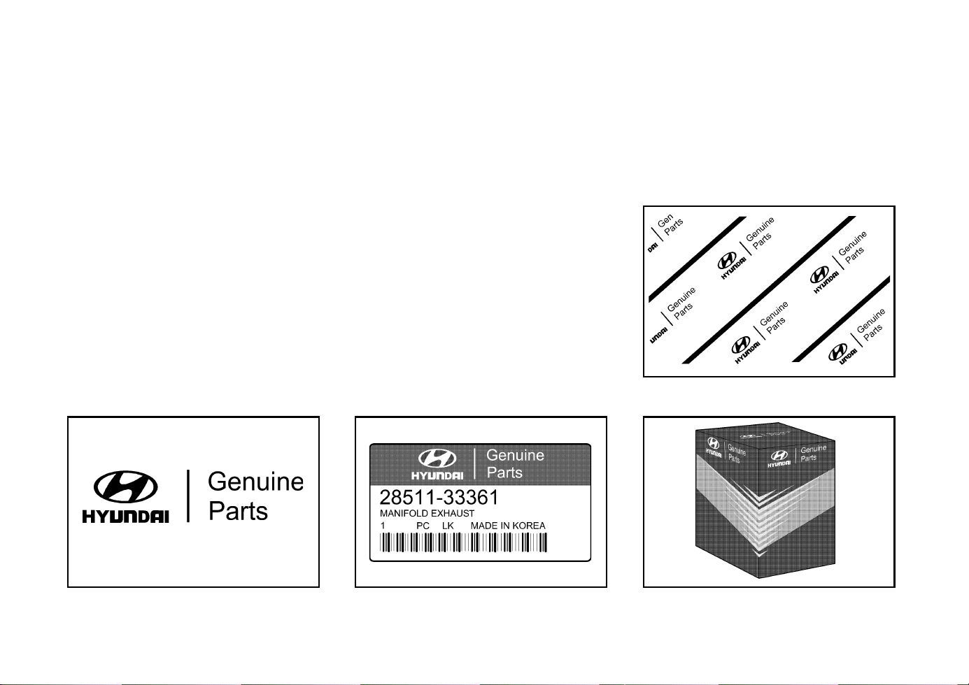
A100A01L-EAT
Guide to Hyundai Genuine
Parts
1. What are Hyundai Genuine Parts?
Hyundai Genuine Parts are the same parts
used by Hyundai Motor Company to manu-
facture vehicles. They are designed and
tested for the optimum safety, performance,
and reliability to our customers.
2. Why should you use genuine parts?
Hyundai Genuine Parts are engineered and
built to meet rigid original manufacturing re-
quirements. Using imitation, counterfeit or
used salvage parts is not covered under the
Hyundai New Vehicle Limited Warranty or
any other Hyundai warranty. In addition,
any damage to or failure of Genuine Hyundai
Parts caused by the installation or failure of
an imitation, counterfeit or used salvage
part is not covered by Hyundai Motor Com-
pany.
3. How can you tell if you are purchasing
Hyundai Genuine Parts?
Look for the Hyundai Genuine Parts Logo
on the package (see below).
The export specifications are written in En-
glish only.
Hyundai Genuine Parts are only sold through
authorized Hyundai Dealerships.
A100A01L
A100A02L A100A04L
A100A03L
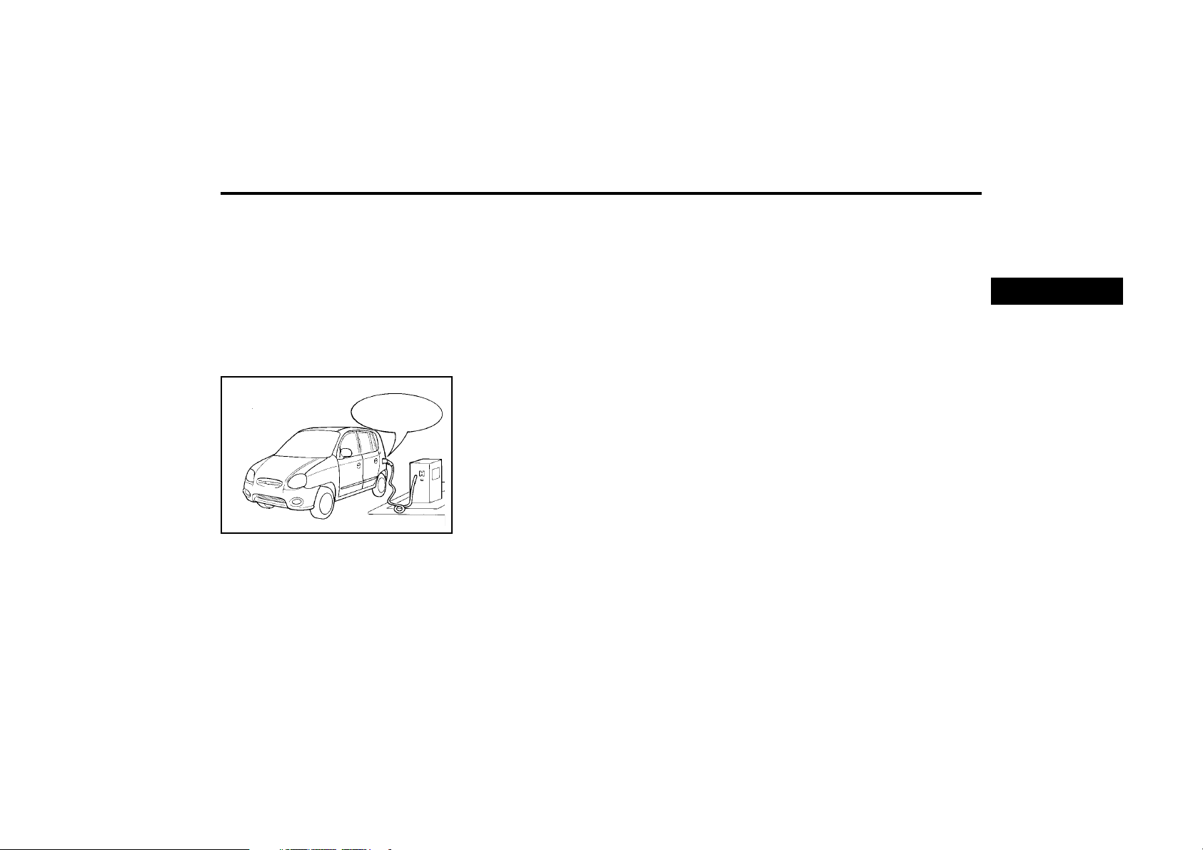
FEATURES OF YOUR HYUNDAI
1-1
ZB000A1-A
1. FEATURES OF
YOUR HYUNDAI
cised when charging the vehicle tank from jerry
cans or by means of a funnel that the fuel being
used is unleaded.
The use of leaded fuel in this vehicle will result
in irreversible pollution of the catalyst element.
Such pollution will prevent correct operation of
the catalyst and give rise to increased operat-
ing temperatures leading to the catalyst ele-
ment melting and restricting the exhaust flow
along with an increase in exhaust emission
levels.
CAUTION:
The vehicle warranty will not extend to dam-
age arising from the use of incorrect fuels.
Unleaded fuel with a Research Octane Number
(RON) of 91 or higher must be used in this
vehicle.
To prevent accidental charging of the fuel tank
with leaded fuel, a small diameter filler neck
along with a restrictor flap are fitted to ensure
that only unleaded fuel pump nozzles may enter
the filler neck. However, care must be exer-
B010A01X
UNLEADED
FUEL ONLY
B010A01X-EAT
FUEL RECOMMENDATIONS
THIS VEHICLE MUST ONLY BE OPERATED
WITH UNLEADED FUEL.
SERIOUS DAMAGE WILL RESULT FROM
THE USE OF LEADED FUEL.
B020A01X-EAT
RUNNING IN
The longevity and performance of the vehicle
are greatly affected by the care exercised dur-
ing the first 1000 miles of motoring. Because of
modern manufacturing techniques, rigid guide-
lines regarding maximum road speeds have
become unnecessary. However, certain pre-
cautions should be observed in order to obtain
the best possible performance and useful life
from the vehicle.
1) Do not race the engine without a load (i.e
revving the engine in neutral).
2) During the first 500 miles the maximum
engine speed should be restricted to 3000
rpm and gradually increased thereafter.
3) Avoid prolonged constant speed operation.
The internal components of the engine will
become more quickly run in if the operation
speed is varied during the running in period.
4) Never allow the engine to labour. Use the
gearbox freely and avoid large throttle open-
ings when the engine speed is below 1500
rpm.
5) Avoid rapid acceleration and maximum
throttle openings.
6) Avoid harsh braking during the first 100
miles of urban motoring or 1000 miles of
motorway driving to allow the friction facings
of the brake pads and shoes to bed against
the discs and drums properly.
B010D01S-EAT
"Alternative fuels"
Fuels which contain methanol or ethanol must
not be used.
B010F01A-EAT
Operation in Foreign Countries
Drivers of vehicles which are to be operated in
foreign countries must satisfy themselves that:
o The vehicle meets all local regulations with
respect to insurance, specifications etc.,
o The correct types and grades of fuel are
available for satisfactory operation of the
vehicle.
1
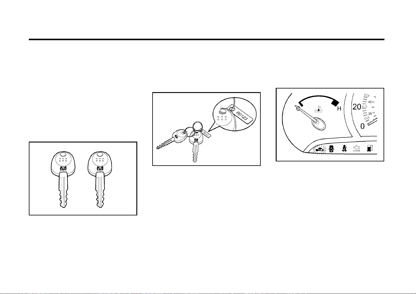
FEATURES OF YOUR HYUNDAI
1-2
B010E01A-AAT
GASOLINES FOR CLEANER AIR
To help contribute to cleaner air, Hyundai rec-
ommends that you use gasolines treated with
detergent additives, which help to prevent de-
posit formation in the engine. These gasolines
will help the engines run cleaner and the Emis-
sion Control System performance.
B880A01A-EAT
IMMOBILIZER SYSTEM
The immobilizer system is an anti-theft device,
designed to prevent and deter automobile theft.
B880B03A-GAT
Keys
B880B01O
All of the locks fitted to the vehicle are operated
by the same key. However, since it is possible
to lock the doors without the use of the key,
care should be exercised to ensure that the key
does not become locked inside the vehicle by
mistake.
B880C02A-GAT
Key Numbers
AX10030A-1
The vehicle key number is recorded upon a
metal tag attached to the keys when the vehicle
is first delivered to you.
The key number should be recorded and kept
in a safe place in case the need to order further
keys arises. New keys are available from any
Hyundai dealer by quoting the relevant key
number.
In the interest of security, the metal tag at-
tached to the keys which bears the key number
should be removed from the key ring after you
receive your new vehicle. In addition, key num-
bers cannot be provided by Hyundai for secu-
rity reasons.
NOTE:
If you make your own duplicate key, you will
not be able to cancel the system or start the
engine.
If you need additional keys or if you should lose
your keys, your authorized Hyundai dealer can
make new keys.
B880D02A-GAT
Limp home procedures
B880D01X-DAG
In case the immobilizer warning indicator blinks
for five seconds when the ignition key is turned
to "ON" position, this indicates that the immobi-
lizer system is out of order. And you cannot
start the engine without the limp home proce-
dures with ignition key.
The following procedure is how to start the
engine with the function of the limp home. (0, 1,
2, 3 as a sample password).
NOTE:
You can get the limp home password when
the vehicle is first delivered to you. If you do
not have the password, consult your autho-
rized Hyundai dealer.
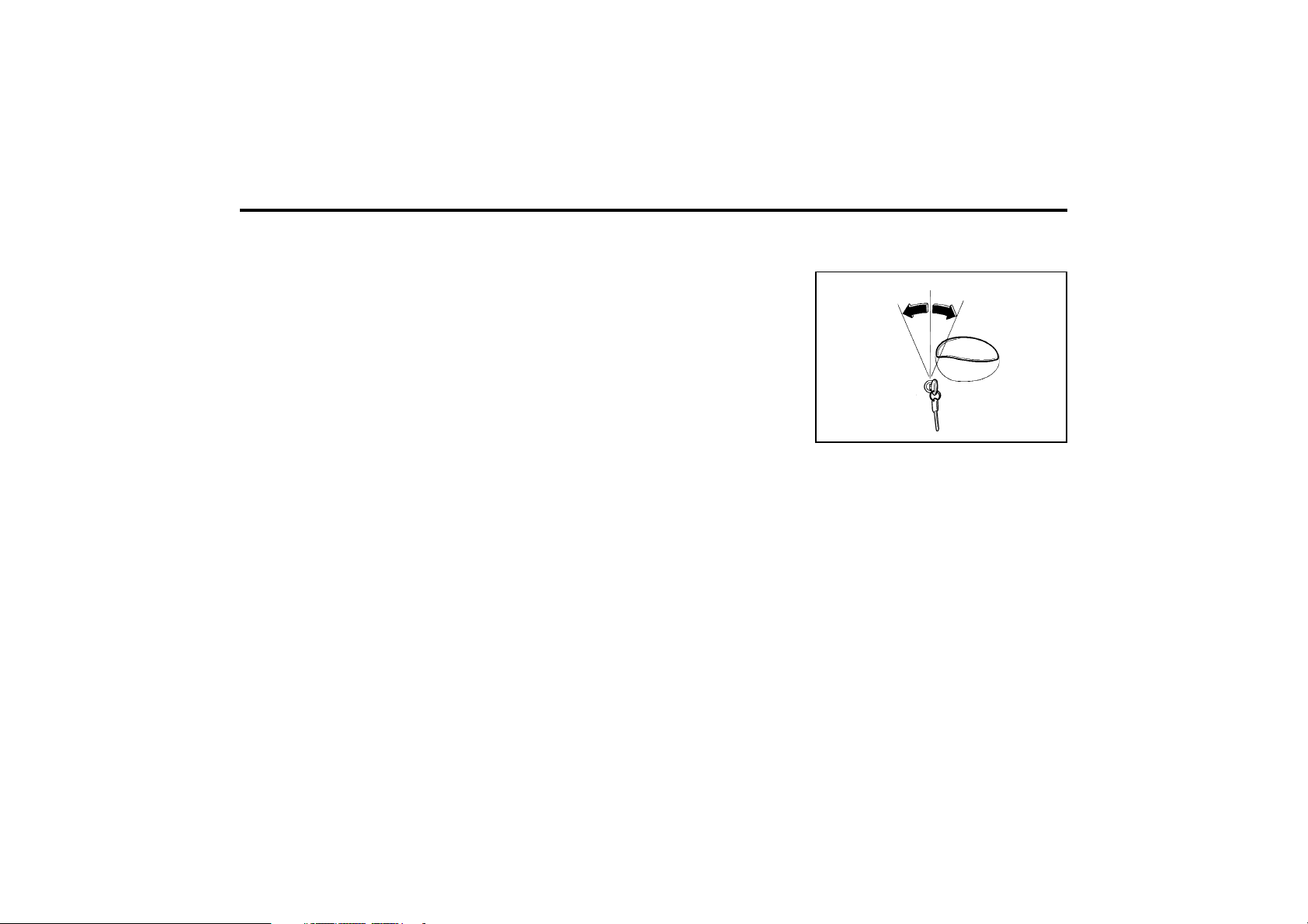
FEATURES OF YOUR HYUNDAI
1-3
CAUTION:
o If you fail to try the limp home procedure
with the sequence of three times, you
have to wait for about one hour to do the
limp home procedure again.
o If you cannot start your engine in spite of
limp home procedure, have your vehicle
towed by an authorized Hyundai dealer.
1. To set the password you may turn the igni-
tion key "ON" and then turn it "OFF" accord-
ing to the digit numbers, then the immobi-
lizer indicator will blink along with the opera-
tion of the ignition key. For example, turn the
ignition key once for digit number "1", and
twice for "2", and so on. However, for the
digit number "0", you must turn the ignition
key for 10 times.
2. Wait for 3~10 seconds.
3. You may set the remaining number of digits
by following the same procedures 1 and 2.
4. If all of four digits have been tried success-
fully, turn the ignition key "ON" and check
that the immobilizer indicator illuminates.
From this time, you have to start your engine
within 30 seconds. If you start your engine
after 30 seconds, your engine will not start.
NOTE:
If the engine dies while driving after limp
home procedure, you can start your engine
within 8 seconds without limp home proce-
dure again.
5. If the immobilizer indicator blinks for five
seconds, you have to try the limp home
procedure again from the beginning.
After doing the limp home procedure, you have
to consult with your authorized Hyundai dealer
as soon as possible.
SB040A1-F
DOOR LOCKS
WARNING:
o Unlocked doors can be dangerous.
Before you drive away-especially if there
are children in the car-be sure that all the
doors are securely closed and locked,
the doors cannot be opened from inside.
This helps assure that doors will not be
opened accidentally. Also, when com-
bined with the proper use of seat belts,
locking the doors helps keep occupants
from being ejected from the car in case
of an accident.
o Before opening the door, always look for
and avoid oncoming traffic.
XV10050E
Unlock
Lock
SB040B1-F
Locking, unlocking front doors with
key
o The door can be locked or unlocked with a
key.
o Lock the door by turning the key toward the
front of the vehicle and unlock it by turning
the key toward the rear.
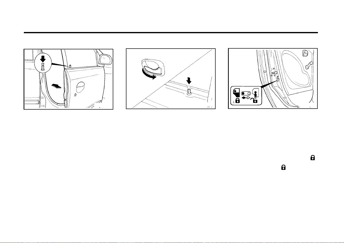
FEATURES OF YOUR HYUNDAI
1-4
B040E02A-AAT
Child-Protector Rear Door Lock
Your Hyundai is equipped with a "child-protec-
tor" rear door lock assembly. When the lock
mechanism is engaged, the rear door cannot be
opened from the inside. Its use is recommend-
ed whenever there are small children
in the rear seat.
To engage the child-protector feature so that
the door cannot be opened from the inside,
move the child-protector lever to the " "
position and close the door. Move the lever to
the opposite direction of " " position when
normal door operation is desired.
If you wish to be able to open the door from the
outside, pull the outside door handle to its up
position.
B040E02A-1
To lock your Hyundai from inside, simply close
the door and push the lock button down.
When this is done, the door cannot be opened
using either the inside or the outside door handle.
To unlock your Hyundai from inside, pull up the
lock button and then pull the inside door handle.
Before opening the door, always look for and
avoid on coming traffic.
B040P01X-EAT
Locking from Inside
AS10070D
B040C01A-EAT
Locking from the Outside
XV10060E
The doors can be locked without a key.
First push the lock button down, then close the
door.
NOTE:
o When locking the door this way, be care-
ful not to lock the door with the ignition
key left in the vehicle.
o For protects against theft, always remove
the ignition key, close all windows, and
lock all doors when leaving your vehicle
unattended.
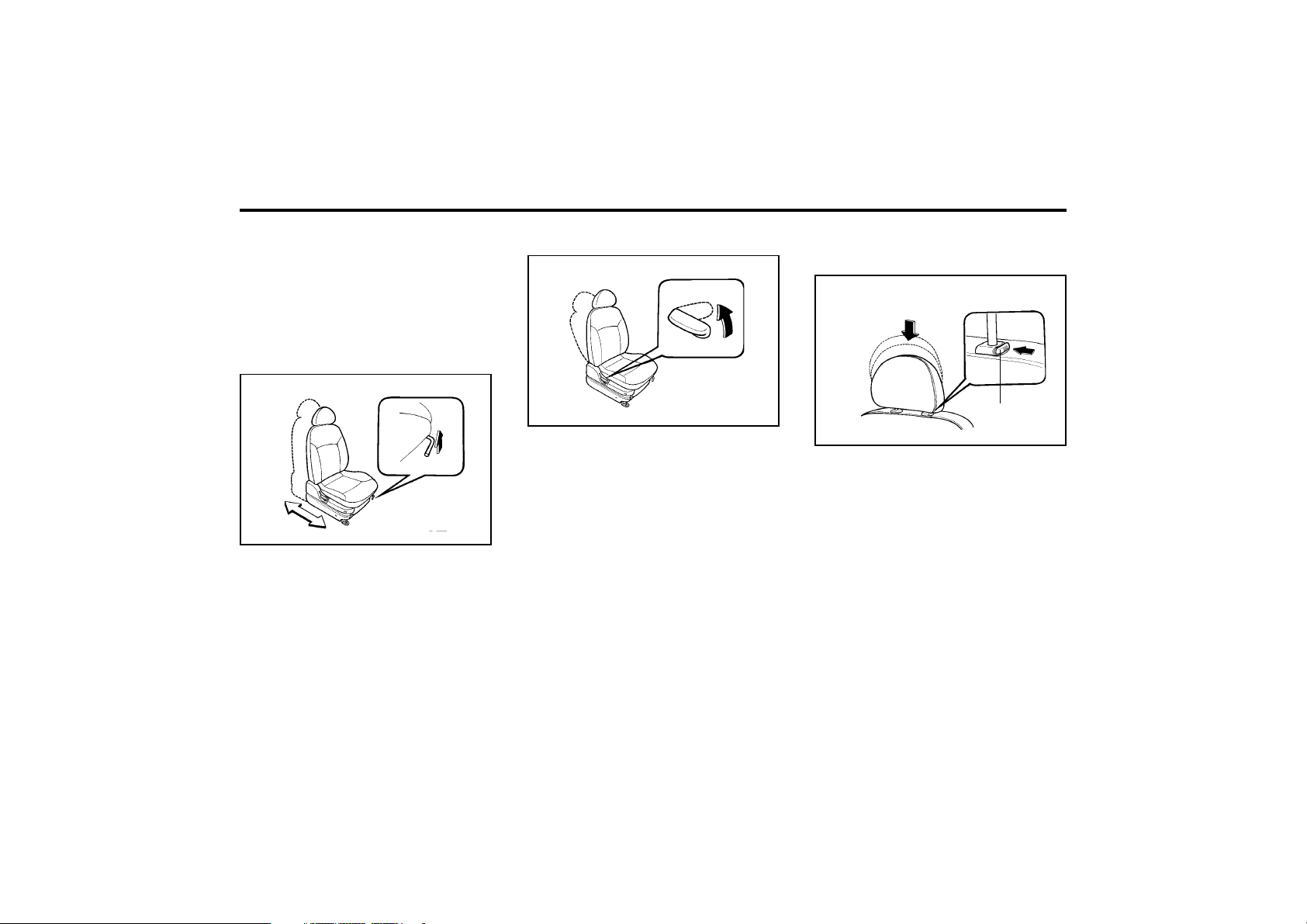
FEATURES OF YOUR HYUNDAI
1-5
B080A01A-AAT
ADJUSTABLE FRONT SEATS
WARNING:
Never attempt to adjust the seat while the
vehicle is moving. This could result in loss
of control, and an accident causing death,
serious injury, or property damage.
B080B01A-AAT
Adjusting Seat Forward and Rearward
B080C01A-AAT
Adjusting Seatback Angle
XV10110E
To move the seat toward the front or rear, pull
the lock release lever upward. This releases
the seat on its track so you can move it forward
or rearward to the desired position. When you
find the position you want, release the lever and
slide the seat forward or rearward on its track
until it locks into position and cannot be moved
further.
XV10120E
To recline the seatback, lean forward to take
your weight off it, then pull up on the recliner
control lever at the outside edge of the seat.
Now lean back until the desired seatback angle
is achieved. To lock the seatback into position,
release the recliner control lever.
WARNING:
To minimize risk of personal injury in the
event of a collision or sudden stop, both the
driver and passenger seatbacks should al-
ways be in a nearly upright position while
the vehicle is in motion. The protection pro-
vided by the seat belts and airbags may be
reduced significantly when the seatback is
reclined. There is greater risk that the driver
and passenger will slide under the seat belt
resulting in serious injury when the seatback
is reclined.
B080D01A
Lock Knob
B080D02A-AAT
Adjustable Headrestraint
(Not all models)
Headrestraint are designed to help reduce the
risk of neck injuries.
To raise the headrest, pull it up. To lower it,
push it down while pressing the lock knob.
WARNING:
o For maximum effectiveness in case of an
accident the headrestraint should be ad-
justed so the top of the headrestraint is
at the same height as the top of the
occupant's ears. For this reason, the use
of a cushion that holds the body away
from the seatback is not recommended.
o Do not operate vehicle with the
headrestraint removed as severe injury
to an occupant may occur in the event of
an accident. Headrests may provide pro-
tection against neck injuries when prop-
erly adjusted.
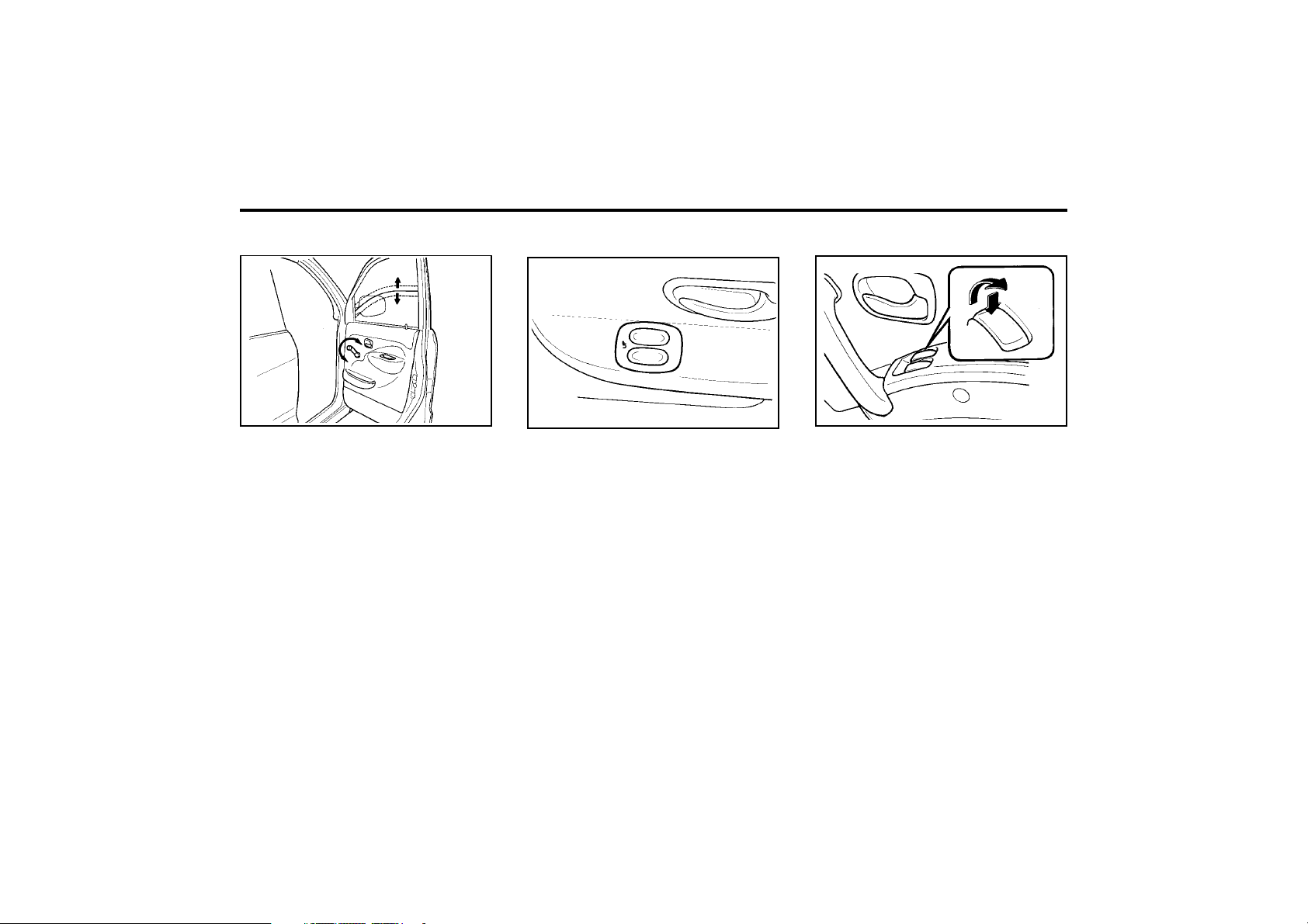
FEATURES OF YOUR HYUNDAI
1-6
B060A01V-GAT
POWER WINDOWS (Not all models)
B060A01V.DAG
The power windows operate only when the
ignition key is in the "ON" position. The main
switches are located on the driver's arm rest
and control the front windows.
The windows may be opened by depressing the
appropriate window switch and closed by pull-
ing up the switch.
WARNING:
o Be careful that head, hands and body are
not trapped by a closing window.
o If passengers remain in the car when you
leave, especially if a child remains alone,
always remove the ignition key for safety.
Close
Open
The power windows operate only when the
ignition key is in the "ON" position. The main
switches are located on the driver’s arm rest
and control the front windows. The windows
may be operated by depressing the desired
switch.
WARNING:
o Be careful that head, hands and body are
not trapped by a closing window.
o If passengers remain in the car when you
leave, especially if a child remains alone,
always remove the ignition key for safe-
ty.
B060A02X-GAT
POWER WINDOWS (Not all models)
XV10180E
B050A01A-AAT
WINDOW GLASS
XV10170E
To raise or lower the window, turn the window
regulator handle clockwise or counterclockwise.
WARNING:
When opening or closing the windows, make
sure your passenger’s arms and hands are
safely out of the way.

FEATURES OF YOUR HYUNDAI
1-7
B040G01A-GAT
CENTRAL DOOR LOCKING SYSTEM
(Not all models)
XV10210E
This system is controlled by the driver’s door
lock and operates the passenger door lock.
When the driver’s door is locked, the passenger
doors are locked automatically.
If a rear door is open when the latch in de-
pressed, it will remain locked when closed. If
the front passenger door is open when the latch
is locked, the outside door handle must be held
in the raised position. When the door is closed,
the door will remain locked. All doors will be
unlocked automatically whenever the driver’s
door is unlocked whether by key or latch.
ZB090A1-E
SEAT BELT PRECAUTIONS
All vehicle occupants should wear seat belts at
all times. The possibility of injury or the severity
of injury in an accident be decreased if this
elementary safety precaution is observed. In
addition, we would like to make the following
recommendations.
ZB090C1-E
Children
It is recommended that children occupy the rear
seat and wear their seat belts. If the child is in
the front seat, it should be securely restrained
by the seat belt. Under no circumstances should
the child be allowed to stand or kneel on the
seat.
ZB090D1-E
Pregnant Women
The use of a seat belt is recommended for
pregnant women. The seat belt should be worn
as low and snugly as possible across the hips,
not across the abdomen. A qualified Medical
Practioner should be consulted for further infor-
mation.
ZB090E1-A
Injured Person
A seat belt should be used when an injured
person is being transported. When this is nec-
essary, you should consult a physician for rec-
ommendations.
ZB090F1-A
One Person Per Belt
Two people (including children) should never
attempt to use a single seat belt. This could
increase the severity of injuries in case of an
accident.
ZB090G1-B
Do Not Lie Down
For maximum effectiveness, all passengers
should be sitting up and the front seats should
be in an upright position. A seat belt cannot
operate properly if the person is lying down in
the rear seat or if the front seat is at or near the
fully reclined position.
B160A01S-GAT
CARE OF SEAT BELTS
Seat belt systems should never be disassem-
bled or modified. In addition, care should be
taken to assure that seat belts and belt hard-
ware are not damaged by seat hinges, doors or
other abuse.
ZB090I1-A
Periodic Inspection
It is recommended that all seat belts be inspect-
ed periodically for wear or damage of any kind.
Parts of the system that are damaged should
be replaced as soon as possible.
ZB090J1-A
Keep Belts Clean and Dry
Seat belts should be kept clean and dry. If belts
become dirty, they can be cleaned using a mild
soap solution and warm water. Bleach, dye,
strong detergents or abrasives should not be
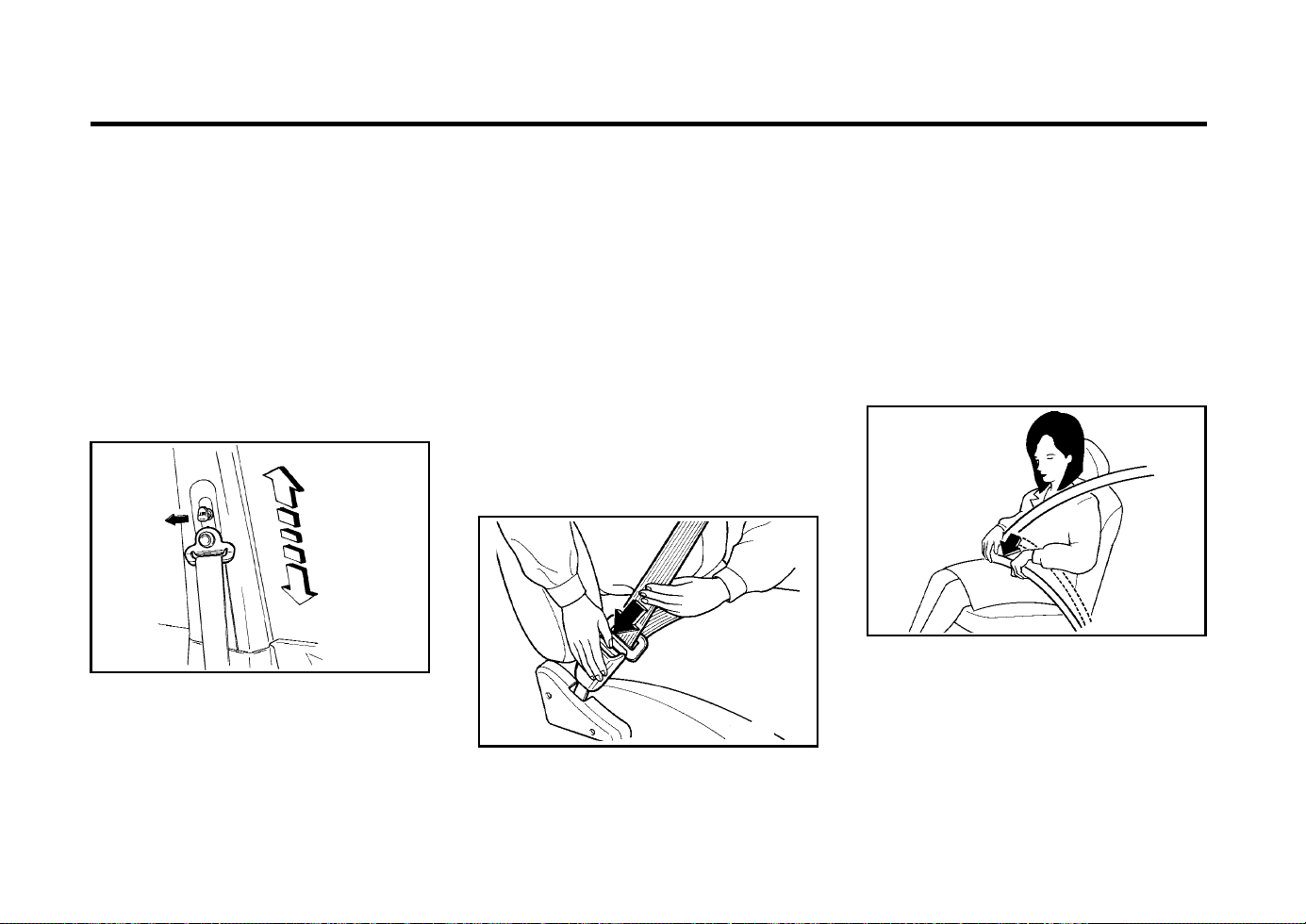
FEATURES OF YOUR HYUNDAI
1-8
ZB090U1-A
Adjusting Your Seat Belt
You should place the belt as low as possible on
your hips, not on your waist. If located too high
on your body, the chances of sliding out from
under it and suffering serious injury or death are
increased. Both arms should not be under or
over the belt. Rather, one should be over and
the other under, as shown in the illustration.
There will be an audible "click" when the tab
locks into the buckle.
The seat belt automatically adjusts to the proper
length only after the lap belt is adjusted manu-
ally so that it fits snugly around your hips. If you
lean forward in a slow, easy motion, the belt will
extend and let you move around. If there is a
sudden stop or impact, however, the belt will
lock into position. It will also lock if you try to
lean forward too quickly.
To fasten your seat belt, pull it out of the
retractor and insert the metal tab into the buckle.
pull on the height adjuster knob and then lower
or raise the height adjuster into an appropriate.
To raise the height adjuster, pull it up. To lower
it, push it down while pressing the height ad-
juster button. Release the knob to lock the
anchor into position. Try to slide the anchor
upward and downward after releasing the knob
to make sure that it has locked into position.
WARNING:
o The height adjuster must be in the locked
position whenever the vehicle is moving.
o The misadjustment of height of the shoul-
der belt could reduce the effectiveness
of the seat belt in a crash.
ZB090T1-H
SEAT BELTS (3-Point Type)
To Fasten Your Belt
used because they may damage and weaken
the fabric.
B170A03X-GAT
HEIGHT ADJUSTABLE FRONT SEAT
SHOULDER BELT (Not all models)
XV10191E
You can adjust the height of the front seat
shoulder belt anchor to one of 4 positions. The
shoulder belt should be adjusted so that it fits
midway over the shoulder, and NEVER across
the neck.
To adjust the height of the shoulder belt anchor,
ZB090K1-A
When to Replace Seat Belts
The entire seat belt assembly or assemblies
should be replaced if the vehicle has been
involved in an accident. This should be done
even if no damage is visible. Additional ques-
tions concerning seat belt operation should be
directed to your Hyundai Dealer.
FUA1090P
FUA1090Q
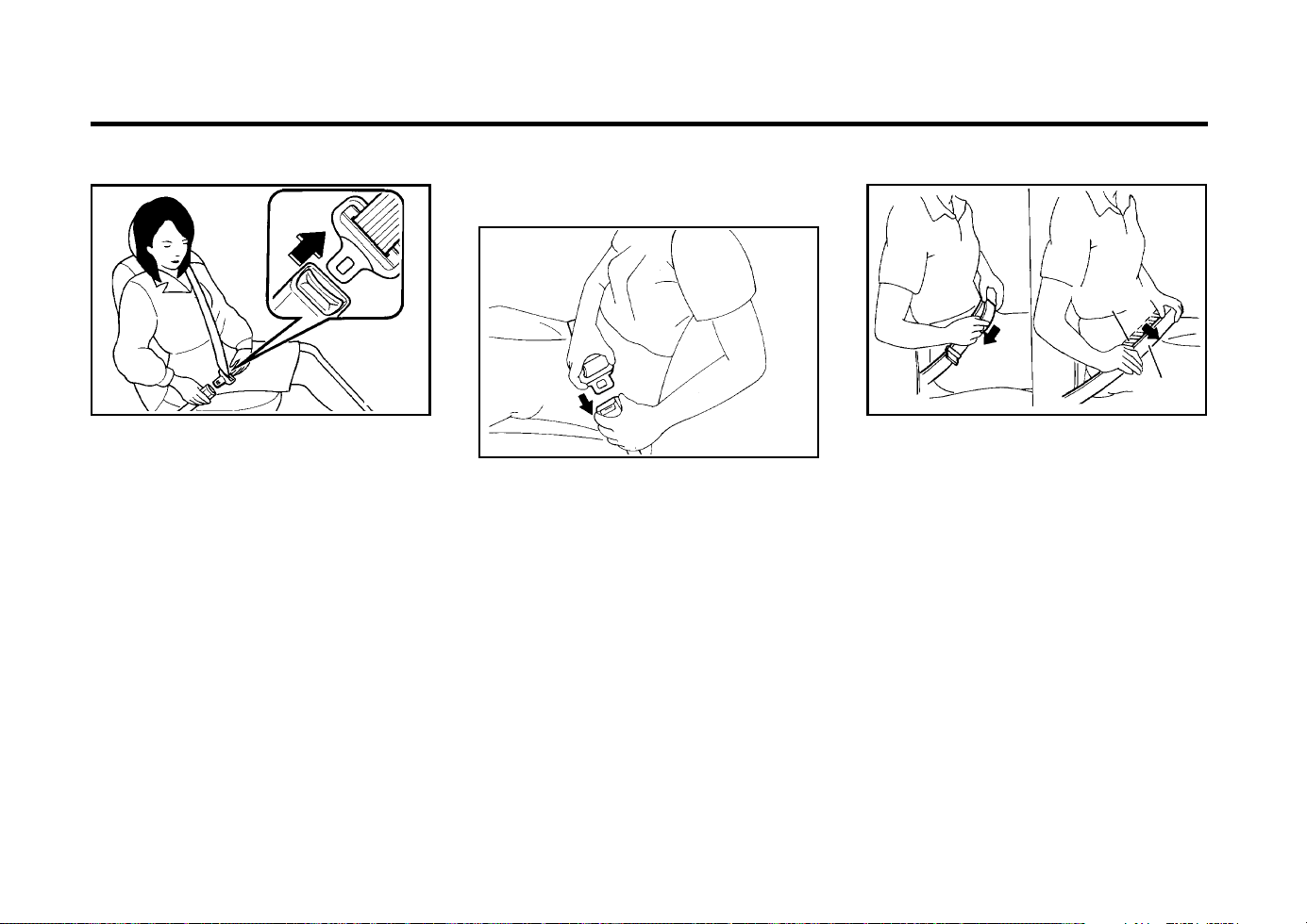
FEATURES OF YOUR HYUNDAI
1-9
ZB090W2-A
SEAT BELTS (2-Point Static Type)
(Rear Seat Centre)
To Fasten Your Seat Belt
ZB090V1-A
To Release the Seat Belt
The seat belt is released by pressing the re-
lease button in the locking buckle. When it is
released, the belt should automatically draw
back into the retractor.
If this does not happen, check the belt to be
sure it is not twisted, then try again.
SSD1090S
To fasten a 2-point static type seat belt, insert
the metal tab into the locking buckle. There will
be an audible “click” when the tab locks into the
buckle. Check to make sure the belt is properly
locked and that the belt is not twisted.
FUA1090R
ZB090X2-A
Adjusting Your Seat Belt
SSA1090T
Shorten
Correct
Too high
With a 2-point static type seat belt, the length
must be adjusted manually so it fits snugly
around your body. Fasten the belt and pull on
the loose end to tighten. The belt should be
placed as low as possible on your hips, not on
your waist. If the belt is too high, it could
increase the possibility of your being injured in
an accident because you could slide under it.
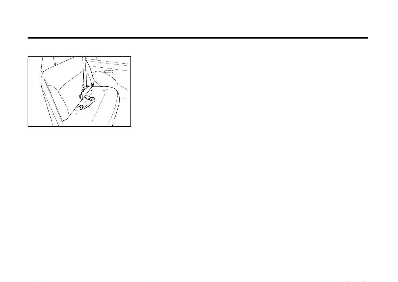
FEATURES OF YOUR HYUNDAI
1-10
ZB090Y1-A
To Release the Seat Belt
B220C01A
When you want to release the seat belt, press
the button in the locking buckle.
WARNING:
The centre lap belt latching mechanism is
different from those for the rear seat shoul-
der belts. When fastening the rear seat shoul-
der belts or the centre lap belt, make sure
they are inserted into the correct buckle to
obtain maximum protection from the seat
belt system and assure proper operation.
B230A02P-GAT
CHILD RESTRAINT SYSTEM
(Not all models)
Children riding in the car should sit in the rear
seat and must always be properly restrained to
minimize the risk of injury in an accident, sud-
den stop or sudden maneuver. According to
accident statistics, children are safer when prop-
erly restrained in the rear seats than in the front
seat. Larger children should use one of the seat
belts provided.
You are required by law to use safety restraints
for children. If small children ride in your vehicle
you must put them in a child restraint system
(safety seat).
Children could be injured or killed in a crash if
their restraints are not properly secured. For
small children and babies, a child seat or infant
seat must be used. Before buying a particular
child restraint system, make sure it fits your car
seat and seat belts, and fits your child. Follow
all the instructions provided by the manufac-
turer when installing the child restraint system.
WARNING:
o A child restraint system must be placed
in the rear seat. Never install a child or
infant seat on the front passenger's seat.
Should an accident occur and cause the
passenger side airbag to deploy, it could
severely injure or kill an infant or child
seated in an infant or child seat. Thus,
only use a child restraint in the rear seat
of your vehicle.
o Since a safety belt or child restraint sys-
tem can become very hot if it is left in a
closed vehicle, be sure to check the seat
cover and buckles before placing a child
there.
o When the child restraint system is not in
use, fasten it with a safety belt so that it
will not be thrown forward in the case of
a sudden stop or an accident.
o Children who are too large to be in a
child restraint should sit in the rear seat
and be restrained with the available lap/
shoulder belts. Never allow children to
ride in the front passanger seat.
o Always make sure that the shoulder belt
portion of the outboard lap/shoulder belt
is positioned midway over the shoulder,
never across the neck or behind the back.
Moving the child closer to the center of
the vehicle may help provide a good
shoulder belt fit. The lap belt portion of
the lap/shoulder belt or the center seat
lap belt must always be positioned as
low as possible on the child's hips and
as snug as possible.
o If the seat belt will not properly fit the
child, we recommend the use of an ap-
proved booster seat in the rear seat in
order to raise the child's seating height
so that the seat belt will properly fit the
child.
o Never allow a child to stand up or kneel
on the seat.
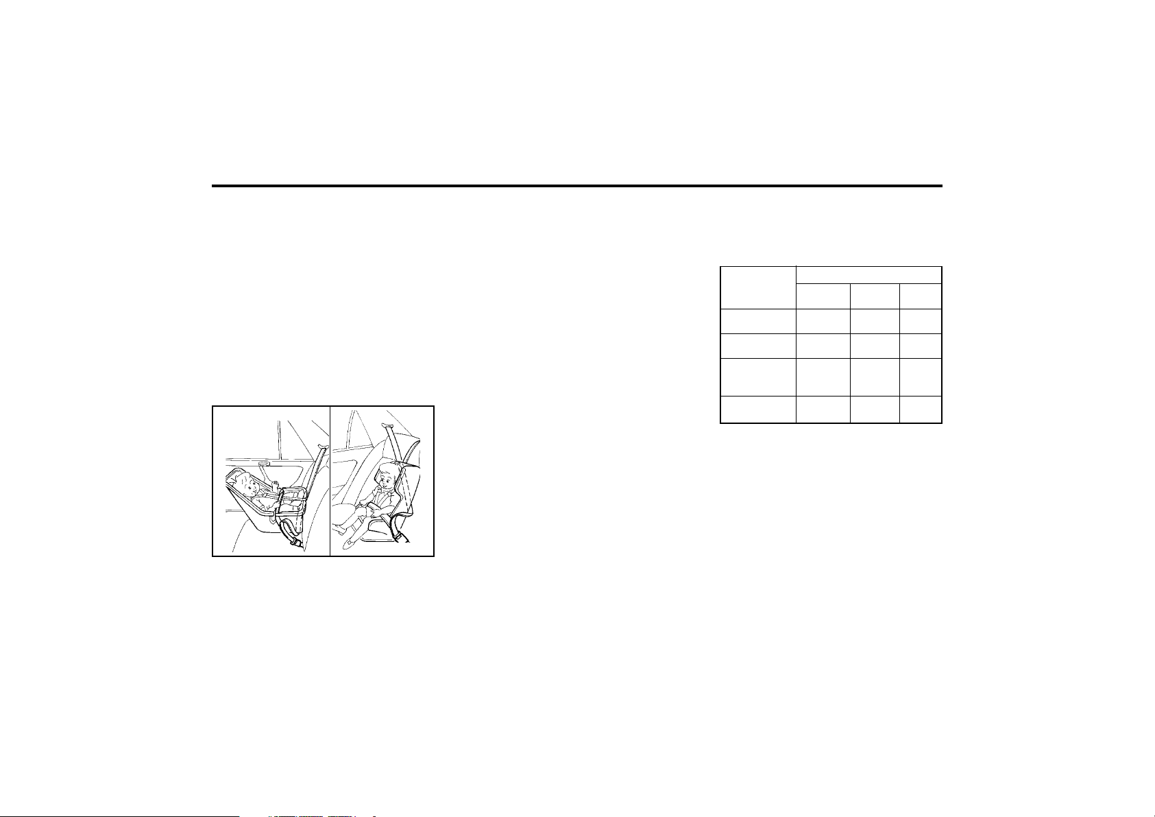
FEATURES OF YOUR HYUNDAI
1-11
B230G01A-GAT
Installation on Outboard Rear Seats
YR10400B
To install a child restraint system in the out-
board rear seats, extend the shoulder/lap belt
from its retractor. Install the child restraint sys-
tem, buckle the seat belt and allow the seat belt
to take up any slack. Make sure that the lap
On outboard rear seats
o Never use an infant carrier or child safety
seat that "hooks" over a seatback; it may
not provide adequate security in an acci-
dent.
o Never allow a child to be held in a person's
arms while they are in a moving vehicle,
as this could result in serious injury to
the child in the event of an accident or a
sudden stop. Holding a child in a moving
vehicle does not provide the child with
any means of protection during an acci-
dent, even if the person holding the child
is wearing a seat belt.
portion of the belt is tight around the child
restraint system and the shoulder portion of the
belt is positioned so that it cannot interfere with
the child's head or neck. After installation of the
child restraint system, try to move it in all
directions to be sure the child restraint system
is securely installed.
If you need to tighten the belt, pull more web-
bing toward the retractor. When you unbuckle
the seat belt and allow it to retract, the retractor
will automatically revert back to its normal seated
passenger emergency locking usage condition.
NOTE:
o Before installing the child restraint sys-
tem, read the instructions supplied by
the child restraint system manufacturer.
o If the seat belt does not operate as de-
scribed, have the system checked imme-
diately by your authorized Hyundai dealer.
WARNING:
Do not install any child restraint system in
the front passenger seat. Should an acci-
dent occur and cause the passenger side
airbag to deploy, it could severely injure or
kill an infant or child seated in an infant or
child seat. Therefore, only use a child re-
straint system in the rear seat of your ve-
hicle.
Age Group
Seating Position
Front
Passenger
Rear
Outboard
Rear
Center
0 : Up to 10 kg
(0 ~ 9 months)
0+ : Up to 13 kg
(0 ~ 2 years)
I : 9kg to 18kg
(9 months ~
4 years)
II & III : 15kg to
36kg (4 ~ 12 years)
XUX
XUX
UF U UF
UF UF UF
B230H01X-GAT
Child Seat Restraint Suitability For Seat Po-
sition
Use child safety seats that have been officially
approved and are appropriate for your children.
U : Suitable for "universal" category restraints
approved for use in this mass group
UF : Suitable for forward-facing "universal" cat-
egory restraints approved for use in this
mass group
X : Seat position not suitable for children in
this mass group
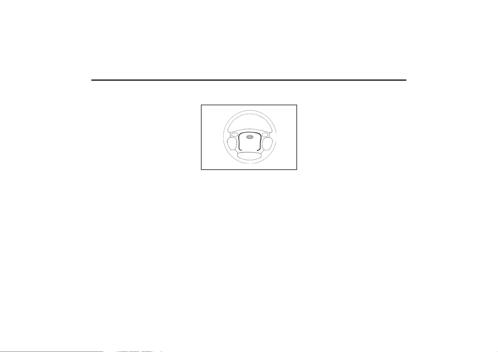
FEATURES OF YOUR HYUNDAI
1-12
NOTE:
Be sure to read information about the SRS
on the labels provided on the backside of
the sun visor and in the glove box.
WARNING:
o As its name implies, the SRS is designed
to work with, and be supplemental to, the
driver's and the passenger's three point
seat belt systems and is not a substitute
for them. Therefore your seat belts must
be worn at all times while the vehicle is in
motion. In addition, the airbags deploy
only in certain frontal impact conditions
severe enough to likely cause significant
injury to the vehicle occupants.
o The SRS is designed to deploy the airbags
only when an impact is sufficiently se-
vere and when the impact angle is less
than 30° from the forward longitudinal
axis of the vehicle and will not deploy in
side, rear or rollover impacts. Additional-
ly, the airbags will only deploy once.
Thus, seat belts must be worn at all
times.
B240A02F-EAT
SUPPLEMENTAL RESTRAINT
(AIRBAG) SYSTEM (Not all models)
Your Hyundai is equipped with a Supplemental
Restraint (Airbag) System. The indications of
the system's presence are the letters "SRS AIR
BAG" embossed on the airbag pad cover in the
steering wheel and the passenger's side front
panel pad above the glove box.
The Hyundai SRS consists of airbags installed
under the pad covers in the centre of the
steering wheel and the passenger's side front
panel above the glove box. The purpose of the
SRS is to provide the vehicle's driver and/or the
front passenger with additional protection than
that offered by the seat-belt system alone, in
case of a frontal impact of sufficient severity.
AS10356A
B180B01X-GAT
Pre-tensioner Seat Belt
(Not all models)
Ordinarily the pre-tensioner seat belt operates
in the same way as E.L.R (Emergency Locking
Retractor) type (When vehicles stop suddenly,
the belt will lock into the position. It will also
lock if you try to lean forward too quickly.).
However, when vehicles crash, the retractor
rewinds the belt webbing. This will restrain the
passenger movement quickly and also reduce
the slack between passenger and belt webbing.
NOTE:
o When the pre-tensioner seat belt is acti-
vated, there may be an explosion noise.
This noise is normal and is not hazard-
ous.
o Pre-tensioner seat belt is designed to
operate only when a sufficiently severe
impact occurs and it will be only operat-
ed once.
WARNING:
If the pre-tensioner seat belt was activated,
never attempt to replace it by yourself. It
must be replaced by an authorized Hyundai
Dealer.
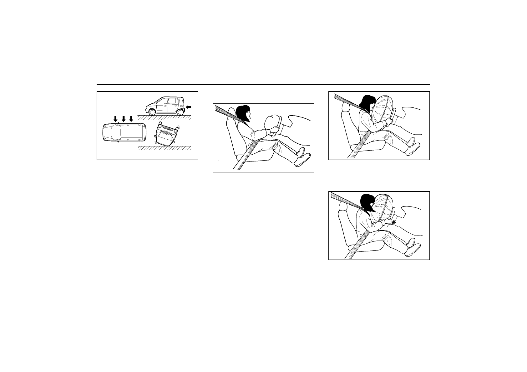
FEATURES OF YOUR HYUNDAI
1-13
B240C01X
Rear impact
Side impact
Rollover
o Front airbags are not intended to deploy
in side-impact, rear-impact or rollover
crashes. In addition, airbags will not de-
ploy in frontal crashes below the deploy-
ment threshold speed.
o For maximum safety protection in all
types of crashes, all occupants including
the driver should always wear their seat
belts whether or not an airbag is also
provided at their seating position to min-
imize the risk of severe injury or death in
the event of a crash. Do not sit or lean
unnecessarily close to the airbag while
the vehicle is in motion.
o The SRS airbag system must deploy very
rapidly to provide protection in a crash. If
an occupant is out of position because of
not wearing a seat belt, the airbag may
forcefully contact the occupant causing
serious or fatal injuries.
B240B01X-EAT
SRS Components and Functions
The SRS consists of the following components:
- Driver's Side Airbag Module
- SRS Service Reminder Indicator (SRI)
- SRS Control Module (SRSCM)
The SRSCM continually monitors all elements
while the ignition is "ON" to determine if a
frontal or near-frontal impact is severe enough
to require airbag deployment.
FUA1111B
The SRS service reminder indicator (SRI) on
the instrument panel will blink for about 6 sec-
onds after the ignition key is turned to the "ON"
position or after the engine is started, after
which the SRI should go out.
The airbag modules are located both in the
centre of the steering wheel. When the SRSCM
detects a considerable impact to the front of the
vehicle, it will automatically deploy the airbags.
FUA1113A
FUA1112A

FEATURES OF YOUR HYUNDAI
1-14
B240C01X-EAT
SRS Care
The SRS is virtually maintenance-free and so
there are no parts you can safely service by
yourself. The entire SRS system must be in-
spected by an authorized Hyundai dealer in 10
years after the date that the car was manufac-
ture.
Any work on the airbag system, such as remov-
ing, installing, repairing, or any work on the
steering wheel must be performed by a quali-
fied Hyundai technician.
Improper handling of the airbag system may
result in serious personal injury.
WARNING:
o Modification to SRS components or wir-
ing, including the addition of any kind of
badges to the pad cover or modifica-
tions to the body structure, can adverse-
ly affect SRS performance and lead to
possible injury.
o For cleaning the horn pad, use only a
soft, dry cloth or one which has been
moistened with plain water. Solvents or
cleaners could adversely affect the airbag
cover and proper deployment of the sys-
tem.
o No objects should be placed over or near
the label identifying the airbag on the
steering wheel and instrument panel,
because any such object could cause
harm if the vehicle is in a crash severe
enough to cause the airbag to inflate.
WARNING:
o When the SRS is activated, there may be
a loud noise and fine dust will be re-
leased through out the vehicle. These
conditions are normal and are not haz-
ardous. However, the fine dust generat-
ed during airbag deployment may cause
skin irritation. Be sure to wash your hands
and face thoroughly with lukewarm wa-
ter and a mild soap after an accident in
which the airbags were deployed.
o The SRS can function only when the
ignition key is in the "ON" position. If the
SRS SRI does not come on, or continu-
ously remains on, after flashing for about
6 seconds when the ignition key is turned
to the "ON" position, or after the engine
is started, or comes on while driving, the
SRS is not working properly. If this oc-
curs, have your vehicle immediately in-
spected by your Hyundai dealer.
o Before you replace a fuse or disconnect
a battery terminal, turn the ignition key to
the "LOCK" position or remove the igni-
tion key. Never remove or replace the air
bag related fuse(s) when the ignition key
is in the "ON" position. Failure to heed
this warning will cause the SRS SRI to
illuminate.
Upon deployment, tear seams molded directly
into the pad covers will separate under pres-
sure from the expansion of the airbags. Further
opening of the covers then allows full inflation of
the airbags.
A fully inflated airbag in combination with a
properly worn seat belt slows the driver's for-
ward motion, thus reducing the
risk of head and chest injury.
After complete inflation, the airbag immediately
starts deflating, enabling the driver to maintain
forward visibility.
CAUTION:
When installing a container of liquid air
fresherer inside a vehicle, do not place it
near the instrument cluster nor on the in-
strument panel pad surface. If there is any
leakage from the air fresherer onto these
areas (instrument cluster, instrument panel
pad or air ventilator), it may damage these
parts. If the liquid from the air fresherer
does leak onto these areas, wash them with
water immediately.

FEATURES OF YOUR HYUNDAI
1-15
o If the airbag inflate, it must be replaced
by an authorized Hyundai dealer.
o Do not tamper with or disconnect SRS
wiring, or other components of the SRS
system. Doing so could result in injury,
due to accidental firing of the airbag or
by rendering the SRS inoperative.
o If components of the airbag system must
be discarded, or if the vehicle must be
scrapped, certain safety precautions
must be observed. Your Hyundai dealer
knows these precautions and can give
you the necessary information. Failure to
follow these precautions and procedures
could increase the risk of personal inju-
ry.
o If you sell your vehicle, be sure to inform
the new owner of these important points
and make certain that this manual is
transferred to the new owner together
with the vehicle.
o If your vehicle was flooded and has
soaked carpeting or water on flooring,
you shouldn't try to start engine; have
the car towed to authorized Hyundai
dealer.
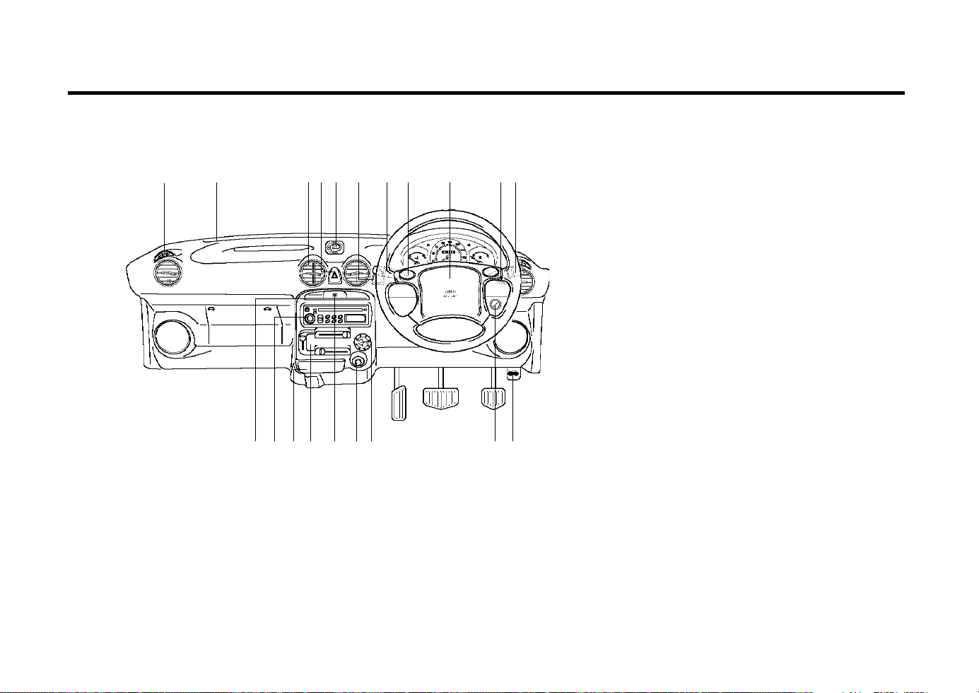
FEATURES OF YOUR HYUNDAI
1-16
B250A02X-EAT
INSTRUMENTS AND CONTROLS
1. Side Air Vent Louver
2. Defroster Ventilation Outlet
3. Center Air Vent Louver
4. Hazard Warning Switch
5. Digital Clock (Not all models)
6. Rear Defroster Switch
7. Windshield Wiper/Washer Switch
8. Rear Wiper Switch/Rear Washer Switch
9. Horn Button
10. SRS Air Bag (Driver Side)
11. Head light Leveling Device
12. Multi-Function Light Switch
13. Rear Fog Light Switch
14. Audio System (Not all models)
15. Ashtray
16. Heating/Air Conditioning Control Panel
17. Front Fog Light Switch
18. Cigarette Light
19. Air Conditioning Switch
20. Ignition Switch
21. Hood Release Lever
B250A02X-DAG
CAUTION:
When installing a container of liquid air
fresherer inside a vehicle, do not place it
near the instrument cluster nor on the crash
pad surface. If there is any leakage from the
air fresherer onto these areas (Instrument
cluster, instrument panel or air ventilator), it
may damage these parts. If the liquid from
an air fresherer does leak onto these areas,
wash them with water immediaterly.
1
2
34
5
9
7,8
6
10
1112
14 15 16 17 1918 2120
13
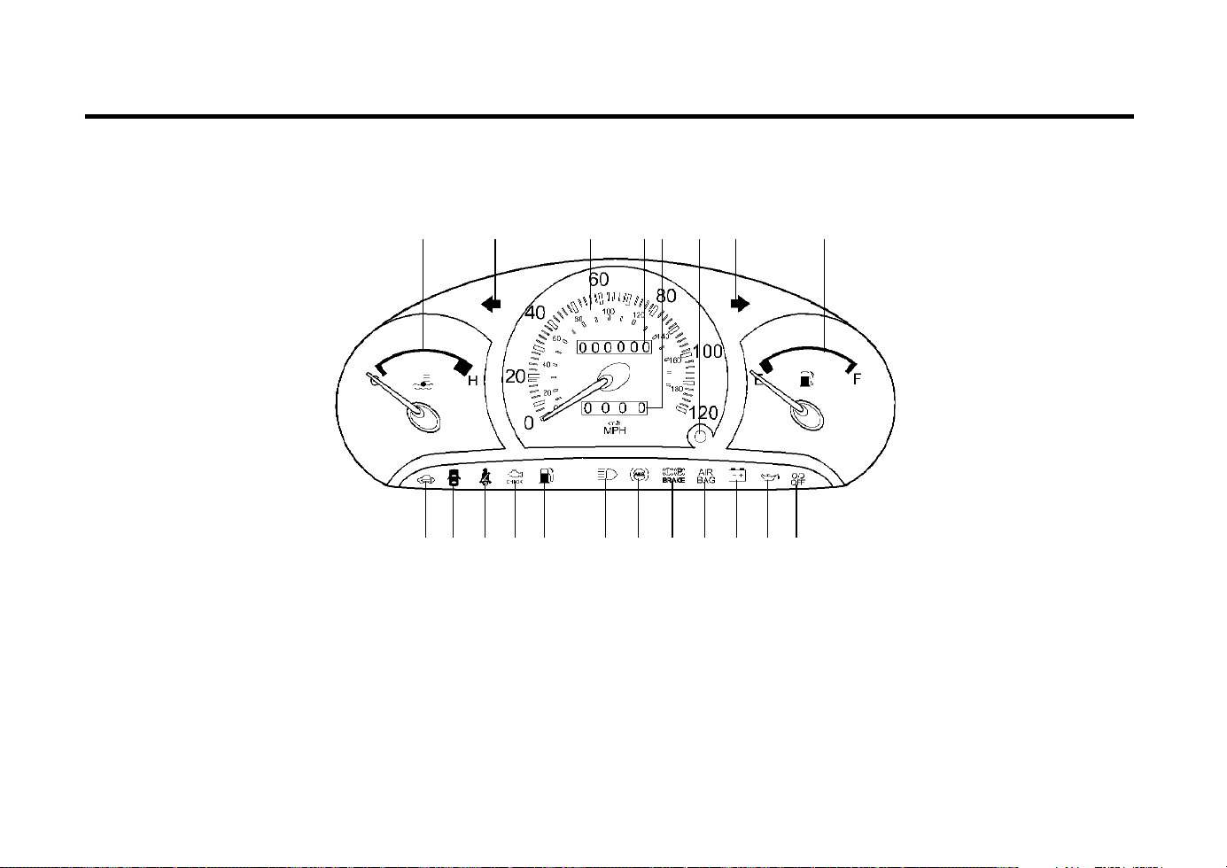
FEATURES OF YOUR HYUNDAI
1-17
B260A04X-EAT
INSTRUMENT CLUSTER AND INDICATOR
1. Temperature Gauge
2. Turn Signal Indicator Light
3. Speedometer
4. Odometer
5. Trip Odometer
6. Trip Odometer Reset Button
7. Fuel Gauge
8. Immobilizer Warning Indicator Light
9. Door Ajar Warning Light
10. Seat Belt Warning Light
11. Malfunction Indicator Lamp (MIL)
12. Low Fuel Warning Light
13. High Beam Indicator Light
14. ABS Service Reminder Indicator
(Not all models)
15. Parking Brake/Brake Fluid Level Warning
Light
16. SRS Service Reminder Indicator
(Not all models)
17. Charging System Warning Light
18. Oil Pressure Warning Light
19. Overdrive Off Indicator Light (Auto T/A only)
1
356
98 10 11 12 13
B260A03X-DAG
2
4 2 7
14 15 16 17 18 19
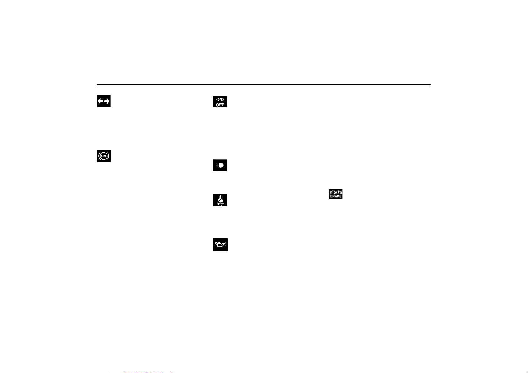
FEATURES OF YOUR HYUNDAI
1-18
ZB110G2-E
TURN SIGNAL INDICATOR
LIGHT
The blinking green arrow on the instrument
panel shows the direction indicated by the turn
signals. If the arrow comes on but does not
blink, blinks more rapidly than normal or does
not blink at all, a malfunction in the turn signal
system is indicated.
B260P02Y-AAT
ABS SERVICE REMINDER
INDICATOR (SRI) (Not all models)
When the key is turned to the “ON” position, the
ABS light will come on and then go off in a few
seconds.
If the ABS light remains on, comes on while
driving, or does not come on when the key is
turned to the “ON” position, this indicates that
there may be a problem with the ABS.
If this occurs, have your vehicle checked by
your Hyundai dealer as soon as possible. The
normal braking system will still be operational,
but without the assistance of the anti-lock brake
system.
CAUTION:
If the both ABS SRI and Parking Brake/
Brake fluid level warning lights remain "ON"
or come on while driving, there may be a
problem with E.B.D (Electronic brake force
distribution).
If this occurs, avoid sudden stops and have
your vehicle checked by your Hyundai dealer
as soon as possible.
SB210E1-E
OVERDRIVE OFF INDICATOR
LIGHT (Not all models)
When the overdrive (4th gear) switch is turned
off and the operation of overdrive (4th gear) is
cancelled, the overdrive warning light (O/D OFF)
will be illuminated. When the switch is at the on
position, the gearbox will operate in the normal
fully automatic mode and the warning light will
be extinguished.
ZB110J2-E
HIGH BEAM INDICATOR
LIGHT
This light is coloured blue and should illuminate
only when the headlight upper beam is on.
B260E02A-GAT
SEAT BELT REMINDER LIGHT
The seat belt reminder light comes on until your
seat belt is fastened when the ignition key is
turned from the "OFF" position to "ON" or
"START".
ZB110K2-E
OIL PRESSURE WARNING
LIGHT
The oil pressure warning light will illuminate
when insufficient oil pressure exists for safe
engine operation.
The light should illuminate when the ignition is
turned on and should be extinguished as soon
as the engine is started.
ZB110L3-E
PARKING BRAKE, BRAKE
CIRCUIT FAILURE
WARNING LIGHT
This light will be illuminated when the hand
brake is applied and the ignition on, and should
go out when the hand brake is released. The
vehicle should not be driven until the hand
brake has been released and the light go out. It
also will be illuminated if the brake fluid level in
the reservoir falls to the MIN. mark. If the light
illuminates while driving pull off the road if
possible and stop immediately. Contact your
nearest authorized dealer and have the system
checked.
CAUTION:
Operation of the engine with low oil pres-
sure may result in serious damage to the
engine.
Should the oil pressure light fail to extinguish
after starting or illuminate when the engine is
running, the engine must be stopped immedi-
ately. If the engine oil level is low, add a suffi-
cient quantity of oil to raise the level to the full
marking on the dip stick. Restart the engine and
check that the warning light is extinguished.
Should the light still be illuminated, stop the
engine immediately and seek assistance from
the nearest Hyundai dealer.
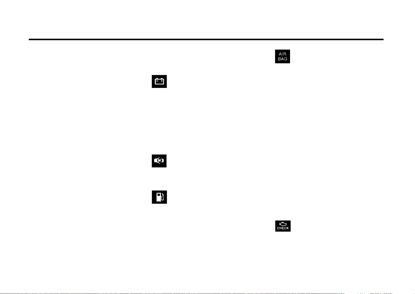
FEATURES OF YOUR HYUNDAI
1-19
YB110C1-A
SRS (Airbag) SERVICE
REMINDER INDICATOR
(Not all models)
The SRS service reminder indicator (SRI) comes
on and flashes for about 6 seconds after the
ignition key is turned to the “ON” position or
after the engine is started, after which it will go
out.
This light also comes on when the SRS is not
working properly.
If the SRI does not come on, or continuously
remains on after flashing for about 6 seconds
when you turned the ignition key to the “ON”
position or started the engine, or if it comes on
while driving, have the SRS inspected by an
authorized Hyundai Dealer.
ZB110P2-E
LOW FUEL LEVEL WARNING
LIGHT
The low fuel level warning light comes on when
the fuel tank is approaching empty. When it
comes on, you should add fuel as soon as
possible. Driving with the fuel level warning light
on or with the fuel level below "E" can cause the
engine to misfire.
ZB110R1-E
BRAKE PAD WEAR WARNING SOUND
When the brake pads of the front brakes be-
come worn to almost the limit of use, a
metalfriction squealing sound will be heard as a
warning to the driver that the brakes should be
checked. When this sound is heard, replace the
brake pads with new ones.
ZB110Q2-A
MALFUNCTION INDICATOR
LIGHT
This light illuminates when there is a malfunc-
tion of an exhaust gas related component, and
the system is not functioning properly so that
B260L01A-GAT
DOOR AJAR WARNING LIGHT
The door ajar warning light warns you that a
door is not completely closed.
ZB110M2-E
CHARGING WARNING LIGHT
This red warning light indicates malfunctioning
of the alternator and electrical charging system.
If this warning light glows when the ignition
switch is in the "ON" position (engine off), the
bulb and electrical wiring are satisfactory. The
light should go out when the engine is started.
If the light glows when the engine is running, the
alternator and electrical system should be
checked as soon as possible.
Warning Light Operation
The parking brake/brake fluid level warning
light should come on when the parking brake is
applied and the ignition switch is turned to "ON"
or "START". After the engine is started, the light
should go out when the parking brake is re-
leased.
If the parking brake is not applied, the warning
light should come on when the ignition switch is
turned to "ON" or "START", then go out when
the engine starts. If the light comes on at any
other time, you should slow the vehicle and
bring it to a complete stop in a safe location off
the roadway.
The brake warning light indicates that the brake
fluid level in the brake master cylinder is low
and hydraulic brake fluid conforming to DOT 3
or DOT 4 specifications should be added. After
adding fluid, if no other trouble is found, the car
should be immediately and carefully driven
to a Hyundai dealer for inspection. If further
trouble is experienced, the vehicle should not
be driven at all but taken to a dealer by a
professional towing service or some other safe
method.
Your Hyundai is equipped with dual-diagonal
braking systems. This means you still have
braking on two wheels even if one of the dual
systems should fail. With only one of the dual
systems working, more than normal pedal trav-
el and greater pedal pressure are required to
stop the car. Also, the car will not stop in as
short a distance with only half of the brake
system working. If the brakes fail while you are
driving, shift to a lower gear for additional en-
gine braking and stop the car as soon as it is
safe to do so.
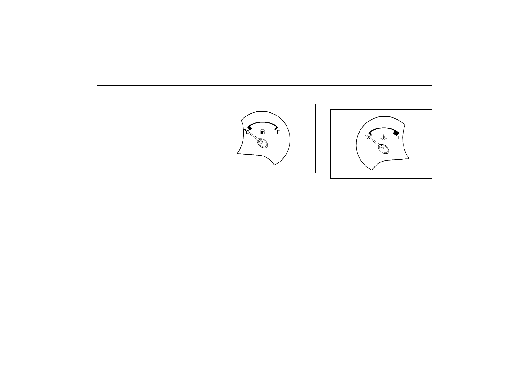
FEATURES OF YOUR HYUNDAI
1-20
WARNING:
Never remove the radiator cap when the
engine is hot. The engine coolant is under
pressure and could erupt and cause severe
burns. Wait until the engine is cool before
removing the radiator cap.
The needle on the engine coolant temperature
gauge should stay in the normal range. If it
moves across the dial to “H” (Hot), pull over and
stop as soon as possible and turn off the
engine. Then open the hood and check the
coolant level and the water pump drive belt. If
you suspect cooling system trouble, have your
cooling system checked by Hyundai dealer as
soon as possible.
The needle on the gauge indicates the fuel level
in the fuel tank. The fuel capacity is given in
section 9.
NOTE:
The engine should not be operated below
the “E” mark of the fuel gauge and with the
low fuel level warning lamp on, or serious
engine damage or misfire may result.
B290A02A-AAT
ENGINE COOLANT TEMPERATURE
GAUGE
ZB110S1-E
FUEL GAUGE
B900A01A-GAT
ACOUSTIC WARNING SOUND
(Not all models)
The acoustic warning chime sounds when the
tail lights are on and the door in driver side is
open. This prevents the battery from discharg-
ing when the car is left with the tail lights on.
The chime sounds until the tail lights are turned
off.
the exhaust gas regulation values are not sat-
isfied. This light will also illuminate when the
ignition key is turned to the “ON” position, and
then it will go out in a few seconds. If it illumi-
nates while driving, or does not illuminate when
the ignition key is turned to the “ON” position,
take your car to your nearest authorized Hyundai
dealer and have the system checked.
B280A01X
B290A01X
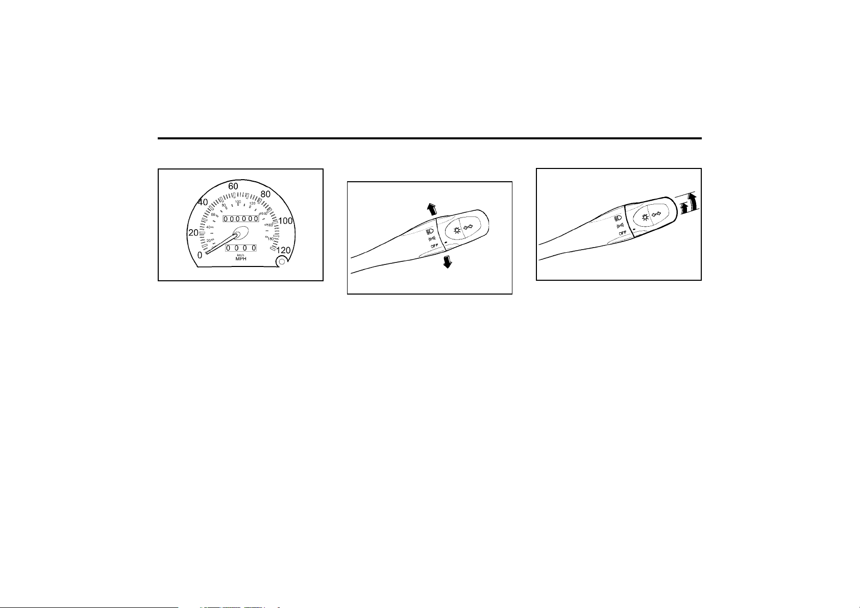
FEATURES OF YOUR HYUNDAI
1-21
B340B01X-DAG
ZB120A1-E
MULTI FUNCTION SWITCH
Turn Signal Operation
To signal an intention to turn right, the switch
lever should be pulled down. To signal an
intention to turn left, the switch lever should be
pushed upwards. In both instances, the turn
signal lamps on one side of the car will flash
and the warning lamp located in the instrument
cluster will flash in sympathy. Upon completion
of the manoeuvre, the lever will, under normal
circumstances, return to the "Off" position.
However, if the manoeuvre involved only a
small movement of the steering wheel, the
signal may need to be cancelled manually. If
either turn signal indicator flashes more rapidly
than normal or refuses to flash at all, a malfunc-
tion of the turn signal system may exist.
ZB110U1-A
SPEEDOMETER
Your Hyundai’s speedometer is calibrated in
miles per hour (on the outer scale) and kilome-
ters per hour (on the inner scale).
B300A01X-DAG
ZB110W1-E
TRIP ODOMETER
The trip odometer may be used to more accu-
rately record trip distances. Push the reset
knob to set the counter to zero.
ZB110V1-E
ODOMETER
The odometer records the total driving distance
in miles, and is useful for keeping a record for
maintenance intervals.
ZB120C1-A
HEADLIGHT SWITCH
B340C01X-DAG
ZB120D1-E
HIGH AND LOW BEAM
To turn on the headlight high beams, push the
lever forward (away from you). For low beams,
pull the lever back (toward you). The appropri-
ate headlight beam indicator light will come on
at the same time.
To operate the headlights, turn the barrel on the
end of the multi-function switch. The first posi-
tion turns on the parking lights, sidelights, tail
lights and instrument panel lights. The second
position turns on the headlights.
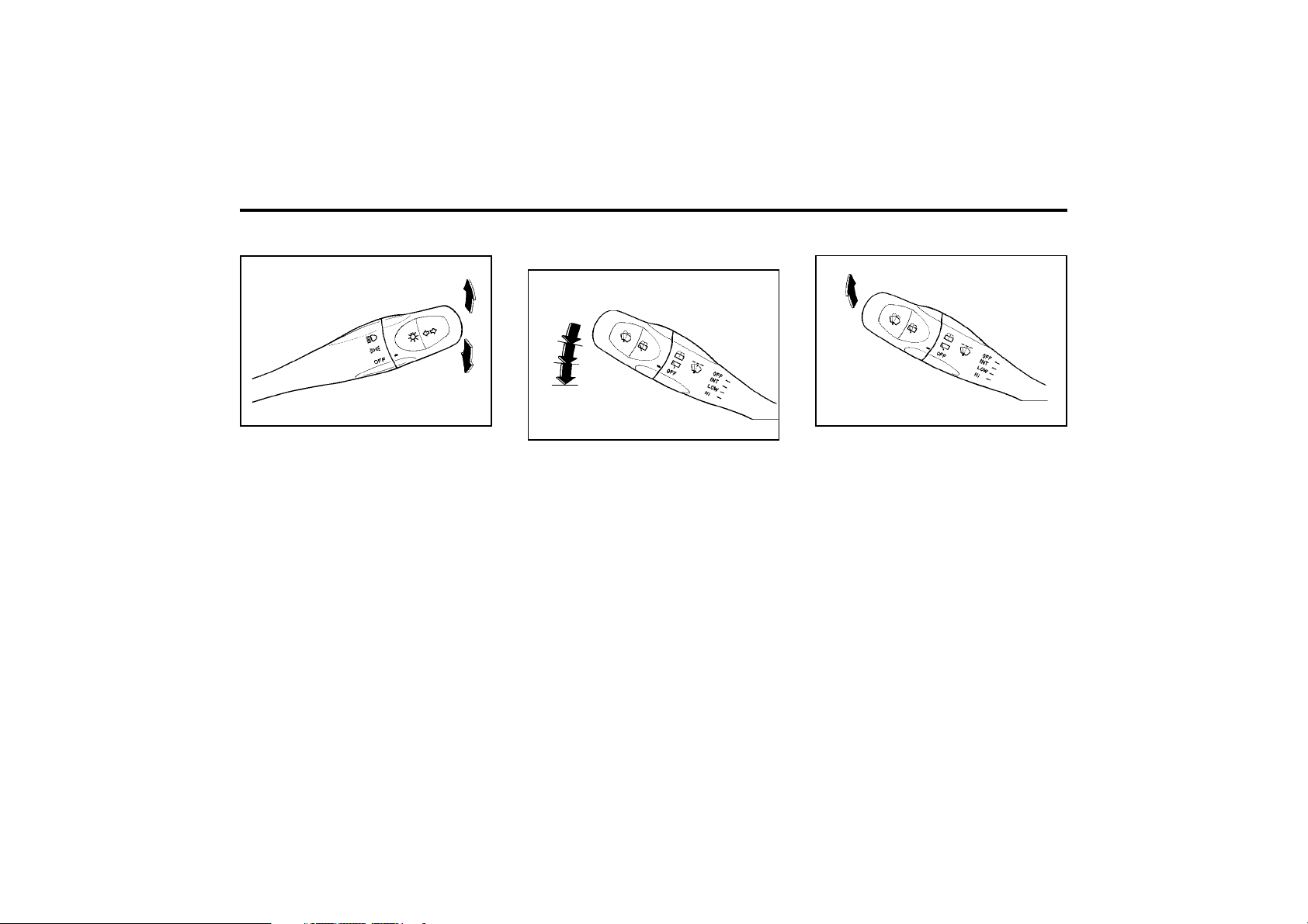
FEATURES OF YOUR HYUNDAI
1-22
YB130B1-B
WINDSHIELD WASHER OPERATION
B350B01X-DAG
To use the windshield washer, pull the wiper/
washer lever toward the steering wheel. When
the washer lever is operated, the wipers auto-
matically make two passes across the wind-
shield. The washer continues to operate until
the lever is released.
NOTE:
o Do not operate the washer more than 15
seconds at a time or when the fluid res-
ervoir is empty.
o In icy or freezing weather, be sure the
wiper blades are not frozen to the glass
prior to operating the wipers.
o In areas where water freezes in winter,
use windshield washer antifreeze.
ZB130A1-E
WINDSCREEN WIPER AND
WASHER SWITCH
B350A01X-DAG
The windscreen wiper switch has three posi-
tions.
1. Intermittent operation
2. Low speed operation
3. High speed operation
NOTE:
To prevent damage to the wiper system, do
not attempt to wipe away heavy accumula-
tions of snow or ice.
Accumulated snow and ice should be re-
moved manually. If there is only a light layer
of snow or ice, operate the heater in the
defrost mode to melt the snow or ice before
using the wiper.
OFF
1
2
3
B340E01A-AAT
HEADLIGHT FLASHER
B340E01X-DAG
To flash the headlights, pull the switch lever
toward you, then release it. The headlights can
be flashed even though the headlight switch is
in the "OFF" position.
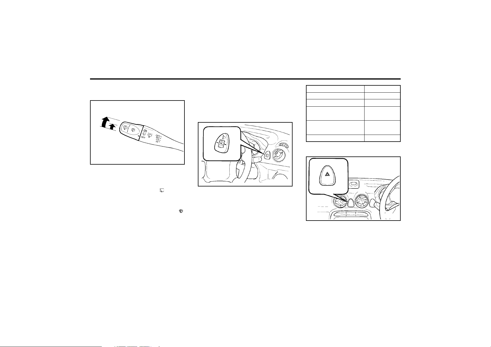
FEATURES OF YOUR HYUNDAI
1-23
reason, do not operate the washer when the
washer fluid reservoir is empty.
B340G02X-GAT
HEADLIGHT LEVELING DEVICE SYS-
TEM
To adjust the headlight beam level according to
the number of the passengers and the loading
weight in the luggage area, turn the beam
leveling switch. The higher the number of the
switch position, the lower the headlight beam
level. Always keep the headlight beam at the
proper leveling position, or headlights may daz-
zle other road users. Listed below are the
examples of recommanded switch settings. For
loading conditions other than those listed be-
low, adjust the switch position so that the beam
level may be the nearest as the condition ob-
tained according to the list.
B340G01A-DAG
B390A01X-GAT
REAR WINDOW WIPER AND WASHER
(Not all models)
B390A01X-DAG
To operate the rear wiper and washer, turn the
barrel on the end of the multifunction switch.
1. OFF
2. When the point indicates the , the rear
windshield wiper starts to operate continu-
ously.
3. The washer fluid will be spray onto the rear
winshield by indicating the point onto the .
The wiper operates continuously after the
washer fluid is sprayed.
Do not operate the washer continuously for
more than 15 seconds or when the fluid reser-
voir is empty; this could damage the system.
Do not operate the wiper when the window is
dry; this can result in scratching as well as
premature wiper blade wear. For the same
1
2
3
The hazard warning system should be used
whenever you find it necessary to stop the car
in a hazardous location. When you must make
such an emergency stop, always pull off the
roadway as far as possible.
To turn on the hazard warning lights, push the
hazard switch. This causes all turn signal lights
to blink. The hazard warning lights will operate
AB160A1-A
HAZARD WARNING SYSTEM
XV10590E
Loading condition
Driver only
Driver + front passenger
Full passengers
(including driver)
Full passengers (including
driver) + Permissible load
Driver + Permissible load
Switch position
0
0
1
1
2
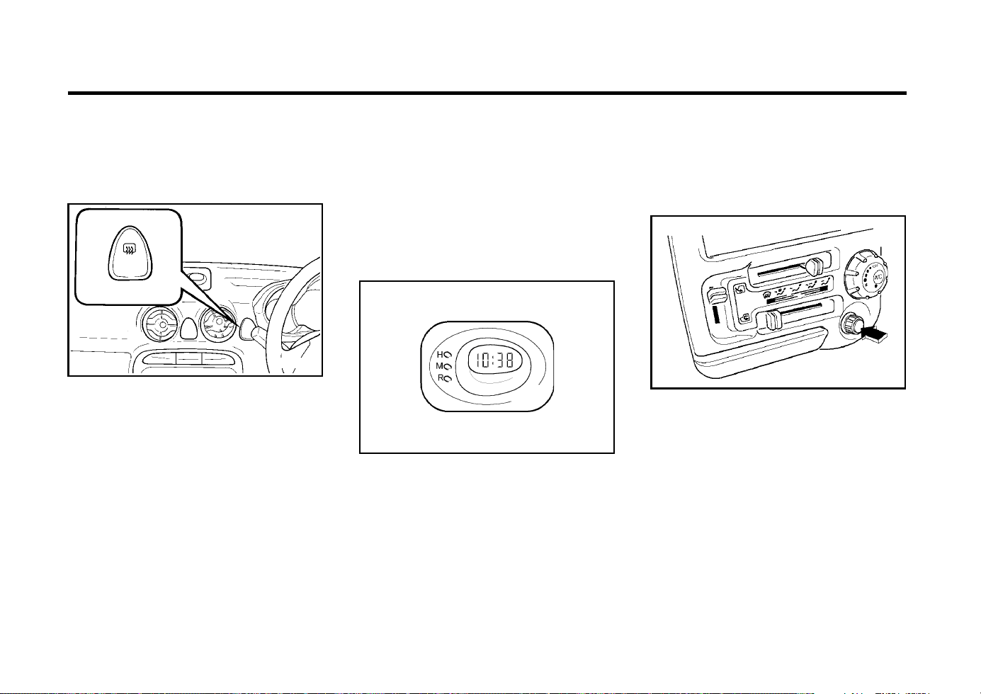
FEATURES OF YOUR HYUNDAI
1-24
ZB210A1-A
CIGAR LIGHTER
B420A01X.DAG
For the cigarette lighter to work, the key must
be in the "ACC" position or the "ON" position.
To use the cigarette lighter, push it all the way
into its socket. When the element has heated,
the lighter will pop out to the "ready" position.
Do not hold the cigarette lighter pressed in. This
can damage the heating element and create a
fire hazard.
If it is necessary to replace the cigarette lighter,
use only a genuine Hyundai replacement or its
approved equivalent.
Pressing "R" between 10 : 30 and 11 : 29
changes the readout to 11 : 00 Pressing "R"
between 11 : 30 and 12 : 29 changes the
readout to 12 : 00
ZB190A1-A
DIGITAL CLOCK (Not all models)
B400A01A-DAG
There are three control buttons for the digital
clock. Their functions are:
HOUR - Push "H" to advance the hour indicat-
ed.
MIN - Push "M" to advance the minute indi-
cated.
RESET - Push "R" to reset minutes to ":00" to
facilitate resetting the clock to the
correct time. When this is done:
zontal movement of the cloth should be
made when cleaning the glass and care
should be exercised to ensure that the heat-
ing elements are not damaged by rings or
jewellery whilst the glass is being cleaned.
NOTE:
The engine must be running for the heated
rear window to operate.
SB250A1-E
HEATED REAR WINDOW
XV10600E-DAG
To operate the heated rear window depress the
switch shown. The heated rear window will
automatically turn off after 15 minutes or when
the ignition is turned off.
The system may be turned off manually by
depressing the switch again.
CAUTION:
The inside of the rear windscreen should
never be cleaned with a hard or sharp imple-
ment since damage to the heating element
may occur. The glass should only be cleaned
with a soft cloth or chamois leather with the
use only of a mild detergent or proprietary
glass cleaner where necessary. Only hori-
even though the key is not in the ignition. To
turn off the hazard warning lights, push the
hazard switch.
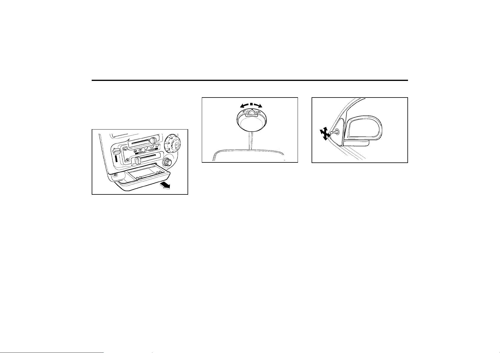
FEATURES OF YOUR HYUNDAI
1-25
The interior courtesy light has a 3-position
switch. The three positions are:
o" z " In the "MIDDLE" position, the interior
courtesy light comes on when any door is
opened, then goes out when it is closed.
o "OFF" In the "LEFT" position, the light stays
off even though a door is open.
o "ON" In the "RIGHT" position, the light stays
on at all times.
ZB270A1-A
OUTSIDE REAR VIEW MIRROR
The outside rear view mirror lever type is
equipped with remote control for your conve-
nience. It is operated by the control lever in the
bottom front corner of the window.
Before driving away, always check that your
mirror is positioned so you can see directly
behind you. When using the mirror, always
exercise caution when attempting to judge the
distance of vehicles behind you.
CAUTION:
If the mirror control is jammed with ice, do
not attempt to break it free using the control
handle or by manipulating the face of the
mirror. Use an approved spray de-icer (not
radiator antifreeze) to release the frozen
mechanism or move the vehicle to a warm
place and allow the ice to melt.
B510A01A-DAG
B430A01X-GAT
FRONT ASHTRAY
The front ashtray may be opened by pulling it
out by its grip. To remove the ashtray to empty
or clean it, press down on the spring-loaded tab
inside the ashtray and pull it all the way out.
B490A01X-GAT
INTERIOR LIGHT
B490A01X
B430A02X.DAG
CAUTION:
Do not use electric accessories or equip-
ment other than the Hyundai genuine parts
in the socket.
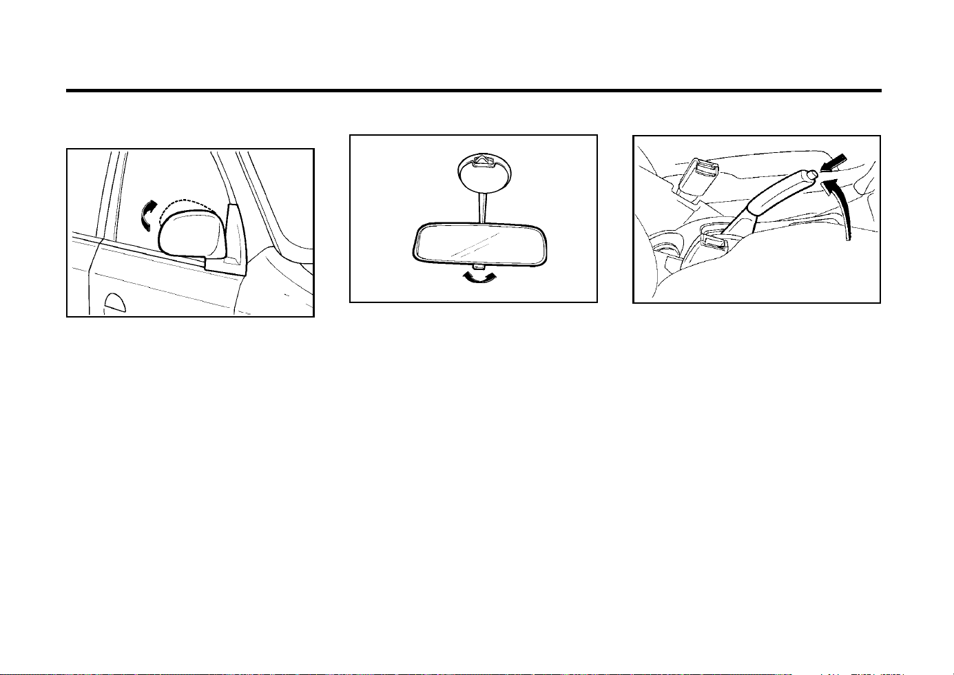
FEATURES OF YOUR HYUNDAI
1-26
ZB290A1-E
PARKING BRAKE
XV10740E
The hand brake must always be set when the
vehicle is to be left unattended. When the hand
brake is applied, and the ignition key is at the
"ON" position, the hand brake warning lamp will
be illuminated. Before driving the vehicle, the
hand brake must be fully released and the
warning lamp extinguished.
o To set the hand brake, apply the foot brake
and pull the hand brake lever up with the
button depressed. Release the button when
the brake is fully applied.
o To release the hand brake, apply the foot
brake and pull up the hand brake lever
slightly. Depress the button and lower the
lever.
ZB280A1-A
DAY/NIGHT REAR VIEW MIRROR
B520A01A
Your Hyundai is equipped with a day/night
inside rear view mirror.
The "night" position is selected by flipping the
tab at the bottom of the mirror toward you. In the
"night" position, the glare of headlights of cars
behind you is reduced.
AB270D1-A
FOLDING THE OUTSIDE REAR VIEW
MIRRORS
To fold the outside rear view mirrors, push them
towards the rear.
The outside rear view mirrors can be folded
rearward for parking in restricted areas.
WARNING:
Do not adjust or fold it while the vehicle
moving.
This could result in loss of control, and an
accident causing death, serious injury, or
property damage.
B510C01A-DAG
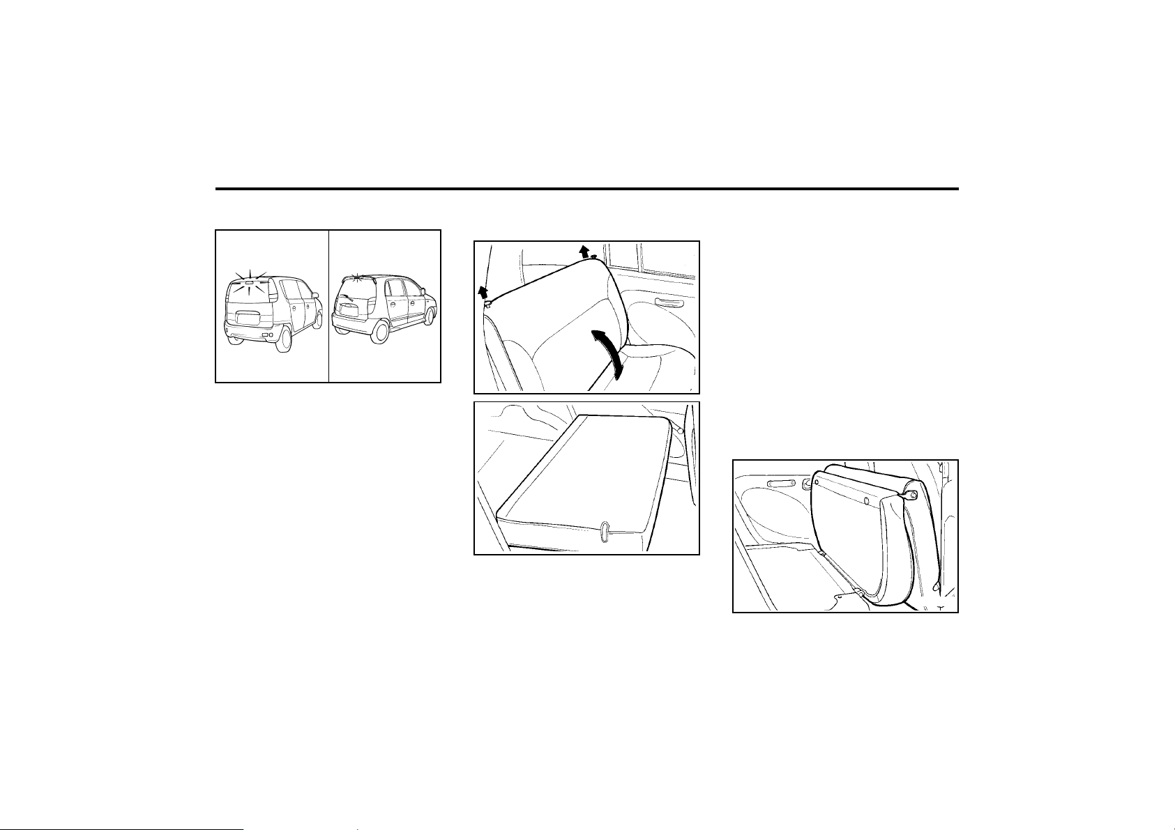
FEATURES OF YOUR HYUNDAI
1-27
sengers to sit on the cargo area while the
car is moving as this is not a proper seating
position and no seat belts are available for
use when the seat back is folded down. This
could result in serious injury or death in
case of an accident or a sudden stop. Ob-
jects should not extend higher than the top
of the front seats. This could allow cargo to
slide forward and cause injury or damage
during sudden stops.
For greater convenience, the entire seatback
and seat cushion may be folded down and up.
o To unlock the seatback, pull up on the
seatback locking knob, then pull forward on
the seatback.
o After being folded down rear seat back, fold-
up the seat cushion.
B110A03X
B110A01X-GAT
FOLDING REAR SEATBACK AND SEAT
CUSHION
B110A01X
WARNING:
The purpose of the fold-down rear seat back
and the fold-up rear seat cushion is to allow
you to carry more objects than could other-
wise be accommodated. Do not allow pas-
B110A02X
B550A01S-DAT
HIGH-MOUNTED REAR STOPLIGHT
In addition to the lower-mounted rear stoplights
on either side of the car, the high mounted rear
stoplight in the centre of the rear window or
installed in the rear spoiler also comes on when
the brakes are applied.
B550A01V.DAG
<AMICA>
B550A01X.DAG
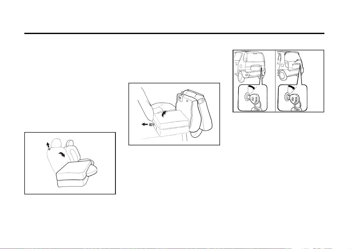
FEATURES OF YOUR HYUNDAI
1-28
B540A01X-GAT
TAIL GATE (Not all models)
WARNING:
The tail gate should always be kept com-
pletely closed while the vehicle is in motion.
If it is left open or ajar, poisonous exhaust
gases may enter the car resulting in serious
injury or death to the occupants. See addi-
tional warnings concerning exhaust gases
on page 2-1.
o The tail gate is opened by first turning the
key clockwise to release the lock, then rais-
ing the door manually.
o To close, lower the tail gate, then press
down on it until it locks. To be sure the tail
gate is securely fastened, always try to pull
it up again.
B540A01V
B540A02X/
<AMICA>
B110B02X
The entire seatback and seat cushion may be
folded down and up individually.
o To unlock the seatback, pull up on the
seatback locking knob, then pull forward on
the seatback.
o After being folded down rear seat, pull the
lever on the rear side of the seat cushion to
fold-up the seat cushion.
WARNING:
o When you return the rear seat to its
upright position, always be sure it has
locked into position by pulling and push-
ing on the top of the seatback.
o When you return the rear seat to its
upright position after being folded down
and folded up, be careful not to damage
the seat belt webbing or buckle. In addi-
tion, do not allow the seat belt webbing
or buckle to get caught or pinched in the
rear seat.
B110B01X-GAT
Folding rear seatback and seat
cushion individually (Not all models)
B110B01X
WARNING:
o When you return the rear seat to its
upright position, always be sure it has
locked into position by pulling and push-
ing on the top of the seatback.
o When you return the rear seat to its
upright position after being folded down
and folded up, be careful not to damage
the seat belt webbing or buckle. In addi-
tion, do not allow the seat belt webbing
or buckle to get caught or pinched in the
rear seat.
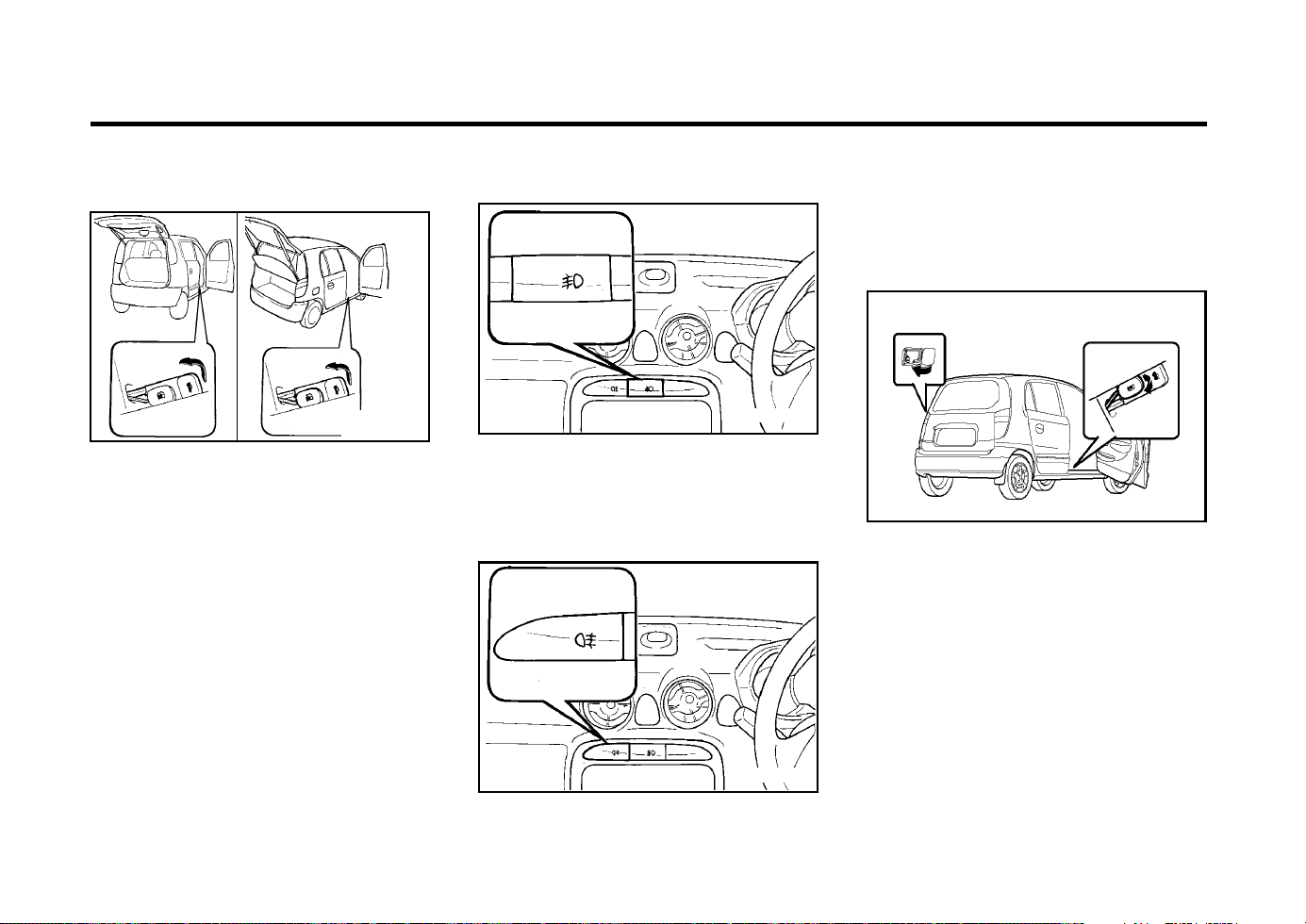
FEATURES OF YOUR HYUNDAI
1-29
To turn on the rear fog lights, push the switch.
They will come on when the headlights are
turned on.
JB360A1-A
REMOTE FUEL-FILLER LID
RELEASE (Not all models)
The fuel-filler lid may be opened from inside the
vehicle by pulling up on the fuel-filler lid opener
located on the front floor area on the left side of
the car.
NOTE:
If the fuel-filler lid will not open because ice
has formed around it, tap lightly or push on
the lid to break the ice and release the lid.
Do not pry on the lid. If necessary, spray
around the lid with an approved de-icer fluid
(do not use radiator anti-freeze) or move the
vehicle to a warm place and allow the ice to
melt.
B560A01V.DAG
To turn on the front fog lights, push the switch.
They will come on when the headlight switch is
in the first or second position.
XV10729E
B360B01A-GAT
REAR FOG LIGHT SWITCH
B540D01X-GAT
Remote Tail Gate Release
(Not all models)
The tail gate is opened by pulling the lever to
release the lock, then raising the tail gate man-
ually.
To close, lower the tail gate, then press down
on it until it locks. To be sure the tail gate is
securely fastened, always try to pull it up again.
WARNING:
The tail gate should always be kept com-
pletely closed while the vehicle is in motion.
If it is left open or ajar, exhaust gases may
enter the car and serious illness may result.
B360A01A-GAT
FRONT FOG LIGHT SWITCH
(Not all models)
XVA1150E
<AMICA>
B540D02X.DAG
B540D01V.DAG
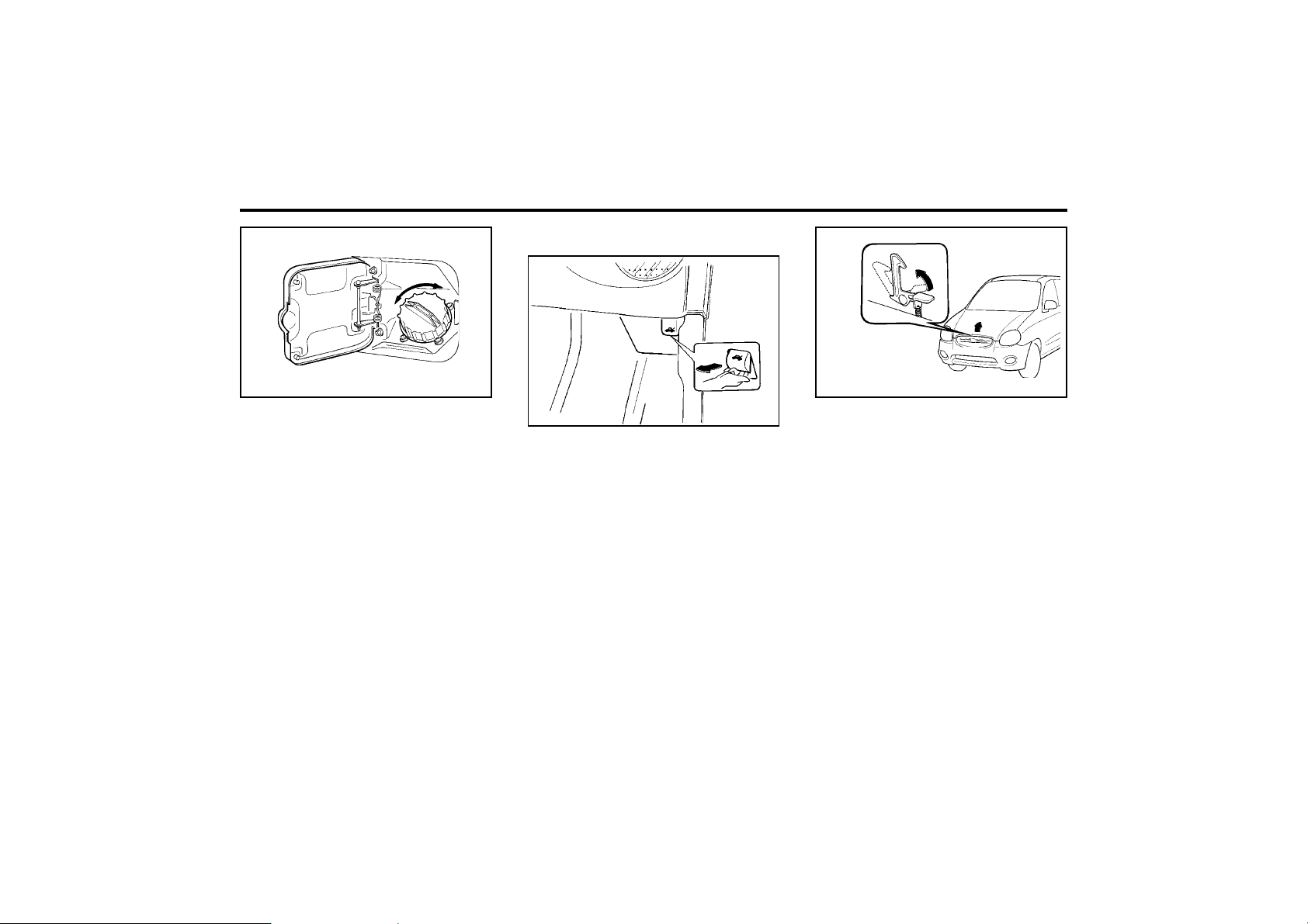
FEATURES OF YOUR HYUNDAI
1-30
B570A02A
WARNING:
Make sure that the support rod has been
released prior to closing the bonnet. Always
double check to be sure that the bonnet is
firmly latched before driving away. If it is not
latched, the bonnet could fly open while the
vehicle is being driven, causing a total loss
of visibility, which might result in an acci-
dent. The support rod must be inserted
completely into the hole provided in the
bonnet whenever you inspect the engine
compartment. This will prevent the bonnet
from falling and possibly injuring you. Do
not move the vehicle with the bonnet in the
raised position, as vision is obstructed and
the bonnet could fall or be damaged.
B570A01A-EAT
BONNET RELEASE
B560A02A
WARNING:
Gasoline vapors are dangerous. Before re-
fueling, always stop the engine and never
allow sparks or open flames near the filler
area. If you need to replace the filler cap, use
a genuine Hyundai replacement part.
If you open the fuel filler cap during high
ambient temperatures, a slight “pressure
sound” may be heard. This is normal and
not a cause for concern.
Whenever you open the fuel filler cap, turn
it slowly.
XV10860E
1. Pull the release knob to unlatch the bonnet.
2. Press the safety catch lever up and lift the
bonnet.
3. Hold the bonnet open with the support rod.
Before closing the bonnet, return the support
rod to its clip to prevent it from rattling. Lower
the bonnet until it is about 1 ft. (30 cm) above
the closed position and let it drop. Make sure
that it locks into place.

FEATURES OF YOUR HYUNDAI
1-31
o Always drive your vehicle at a moderate
speed.
o To use the roof rails as a roof rack, you
must fit the roof rails with two or more
crossrails or equivalent.
WARNING:
o In case of hectical steering movements
or bad fixation the luggage can fall from
the vehicle and injure persons or prop-
erty. Make sure that the luggage is prop-
erly fixed and avoid sudden movement
(e.g.dashing start, fast turning
manoeuvres, hard cornering, sudden
braking) Check frequently whether the
roof rack is properly fastened.
o Voluminous, large, long or flat objects
can change the aerodynamic drag of ve-
hicle or can suddenly been lifted by the
wind. The driver could lose control of the
car and provoke an accident and injuries.
For this reason, drive at reduced speed
when you transport such objects.
o The maximum load limit of the roof rack
including luggage load is 66 lb.
ZB380A2-A
SUN-VISOR
XV10880E
Your Hyundai is equipped with a sun visor to
give the driver and front passenger either fron-
tal or side ward shade. The sun visors are fitted
on both sides on standard models. To reduce
glare or to shut out direct rays of the sun, turn
the sun visor down to block the annoyance.
A vanity mirror is provided on the back of the
sun visor for the front passenger.
NOTE:
The Supplemental Restraint System (SRS)
label containing useful information can be
found on the back of each sun visor.
WARNING:
Do not place the sun visor in such a manner
that it obscures visibility of the roadway,
traffic or other objects.
B630A02X-EAT
ROOF RACK (Not all models)
ROOF RACK
If your Hyundai has a roof rack, you can load
things on top of your vehicle. Crossrails and
fixing components to adapt the roof rack on
your vehicle may be obtained from an autho-
rized Hyundai dealer.
Hyundai dealers are prepared to provide high
quality service that may be required.
CAUTION:
o The following specifications are recom-
mended when loading cargo or luggage.
66 lb (30 kg)
B630A01X
o Loading cargo or luggage above 66 lb (30
kg) on the roof rack may damage your
vehicle.
o When you carry large objects, never let
them hang over the rear or the sides of
your vehicle.

FEATURES OF YOUR HYUNDAI
1-32
B670B02X-DAG
B670B02X-GAT
Fan Speed Control (Blower Control)
This is used to turn the blower fan on and off
and to select the fan speed.
The blower fan speed, and therefore the vol-
ume of air delivered from the system, may be
controlled manually by setting the blower con-
trol between the "1" and "4" position.
B680A01X-GAT
HEATING AND VENTILATION
(Not all models)
B680A02X-DAG
1
2
3
4
There are four controls for the heating and
cooling system. They are:
1. Fan Speed Control.
This is used to turn the fan on and select the
fan speed.
2. Air Flow Control.
This is used to direct the flow of air. Air can
be directed to the floor, dashboard outlets,
or windshield. Five symbols are used to
represent Face, Bi-Level, Floor, Floor-De-
frost and Defrost air positions.
3. Air Intake Control.
This allows you to select fresh outside air or
to circulate inside air.
4. Temperature Control.
This is used to turn the heating system on
and off and to select the degree of heating
desired.
AB420A1-F
HORN (With Airbag)
HNV.OM057
Press either of the side buttons on the steering
wheel to sound the horn.
ZB420A1-E
HORN
B610B01A
Press the centre hub of the steering wheel to
sound the horn.
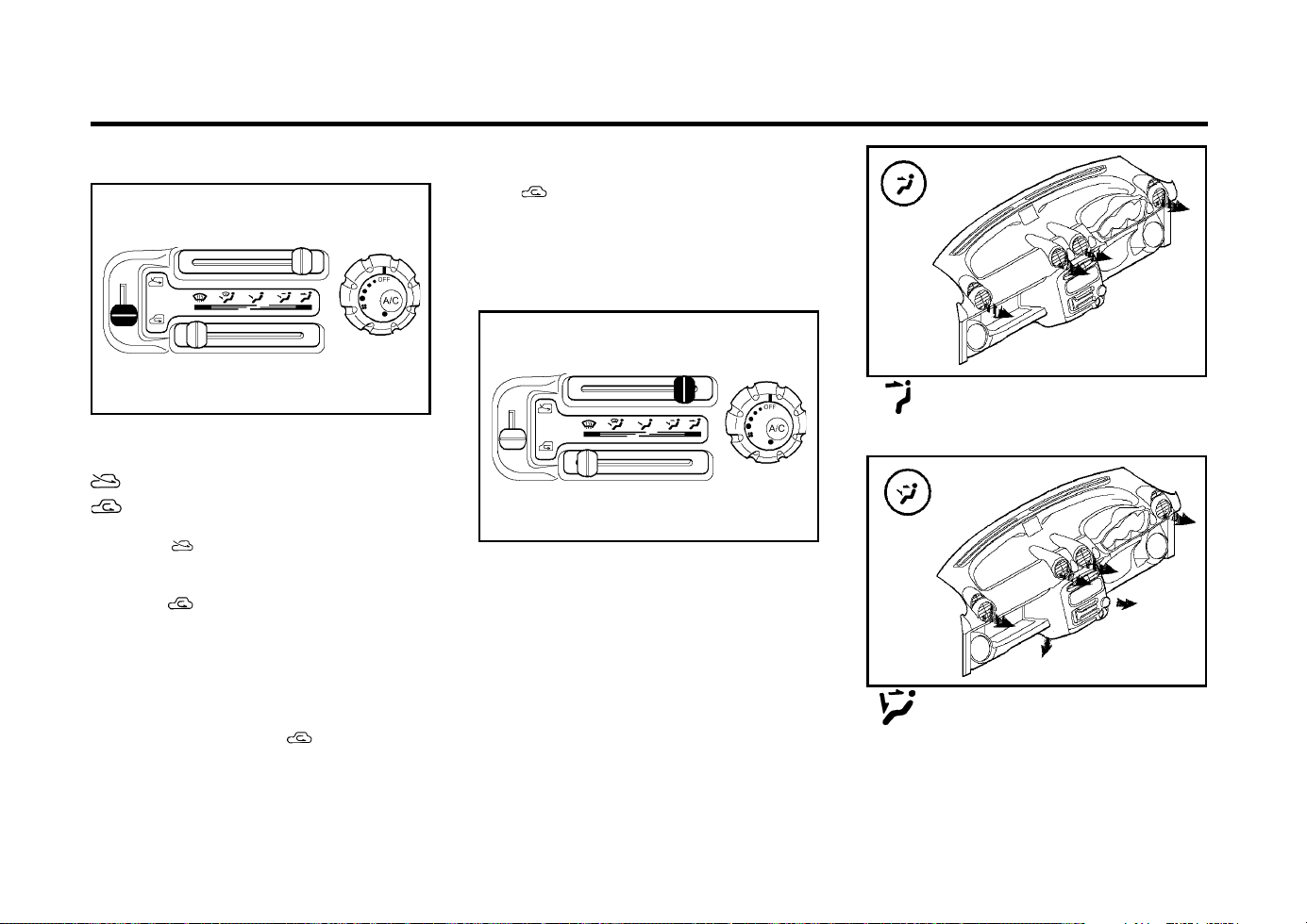
FEATURES OF YOUR HYUNDAI
1-33
B670C02A-AAT
Air Intake Control
B670C03A-DAG
This is used to select fresh outside air or
recirculation inside air.
Fresh
Recirculation
With the " " mode selected, air enters the
vehicle from outside and is heated or cooled
according to the other functions selected.
With the " " mode selected, air from within
the passenger compartment is drawn through
the heating system and heated or cooled ac-
cording to the other functions selected.
NOTE:
It should be noted that prolonged operation
of the heating system in " " mode will give
rise to misting of the windshield and side
windows and the air within the passenger
compartment becoming stale. In addition
prolonged use of the air conditioning with
the " " mode selected may result in the
air within the passenger compartment be-
coming excessively dry.
B670D02A-AAT
Air Flow Control
B670D03A-DAG
This is used to direct the flow of air. Air can be
directed to the floor, dashboard outlets, or wind-
shield. Five symbols are used to represent
Face, Bi-Level, Floor, Floor-Defrost and De-
frost air position.
B670D01X-DAG
B670D02X-DAG
Face-Level
Selecting the “Face” mode will cause air to be
discharged through the face level vents.
Bi-Level
Air is discharged through the face vents and the
floor vents. This makes it possible to have
cooler air from the dashboard vents and warm-
er air from the floor outlets at the same time.
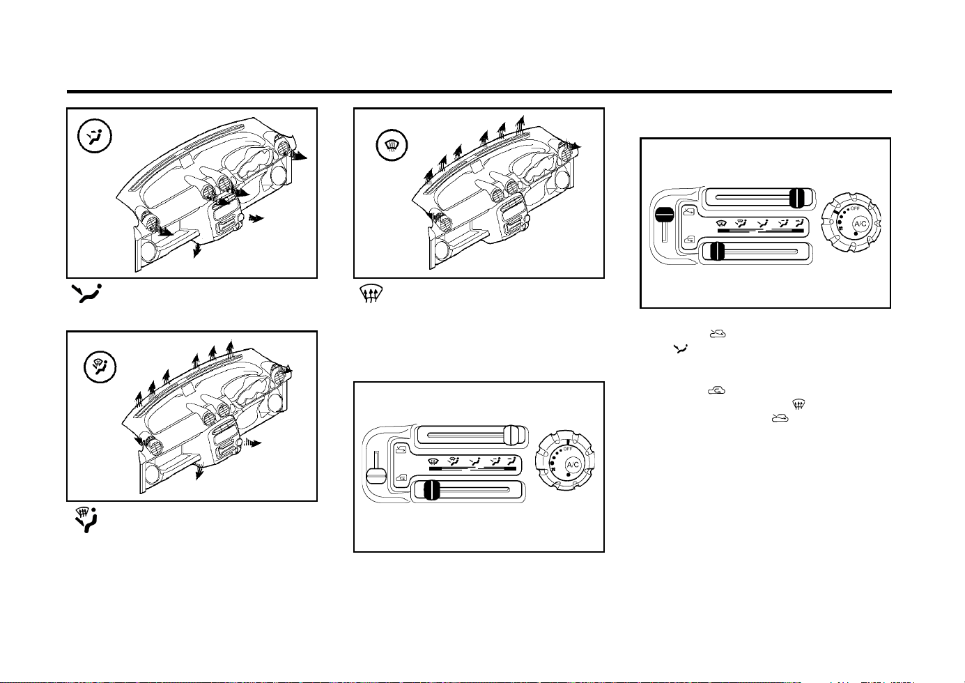
FEATURES OF YOUR HYUNDAI
1-34
B670D03X-DAG
B670D05X-DAG
B670D04X-DAG
Floor-Level
Air is discharged through the floor vents.
Floor-Defrost Level
Air is discharged through the windshield defrost
vents and the floor vents.
Defrost-Level
Air is discharged through the windshield defrost
vents.
B680A02X-DAG
B690A01A-AAT
HEATING CONTROLS
For normal heating operation, set the air intake
control to the position and the air flow control
to the position.
For faster heating, the air intake control should
be set in the position. If the windows fog up,
set the air flow control to the position and the
air intake control to the position.
For maximum heat, move the temperature con-
trol to “Warm”.
B670E02A-AAT
Temperature Control
B670E03A-DAG
This is used to turn the heating system on and
off and to select the degree of heating desired.
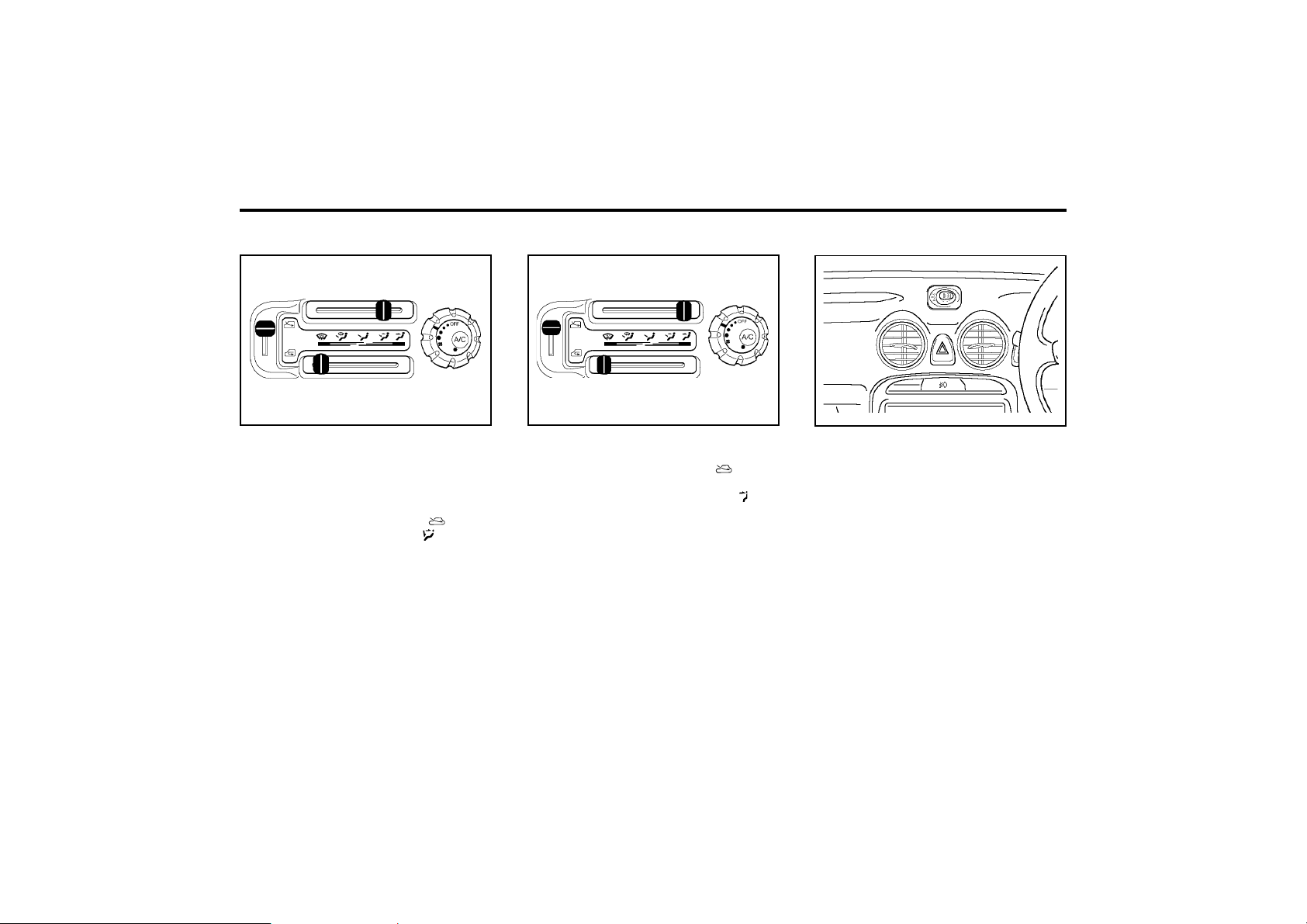
FEATURES OF YOUR HYUNDAI
1-35
B680A02X-DAG
B710A01A-AAT
VENTILATION
To operate the ventilation system:
o Set the air intake control at the position.
o To direct all intake air to the dashboard
vents, set the airflow control to the posi-
tion.
o Adjust the fan speed control to the desired
speed.
o Set the temperature control between "Cool"
and "Warm".
B710B01S-EAT
Centre Ventilator
B710B01X-DAG
The centre ventilators are located in the middle
of the dashboard. The direction of air flow from
the vents in the centre of dashboard is adjust-
able. To control the direction of the air flow,
move the knob in the centre of vent up-and-
down and side-to-side.
B700A02A-DAG
B700A01A-AAT
BI-LEVEL HEATING
Your Hyundai is equipped with bi-level heating
controls. This makes it possible to have cooler
air from the dashboard vents and warmer air
from the floor outlets at the same time. To use
this feature:
o Set the air intake control to the position.
o Set the air flow control at the position.
o Set the temperature control between "Cool"
and "Warm"
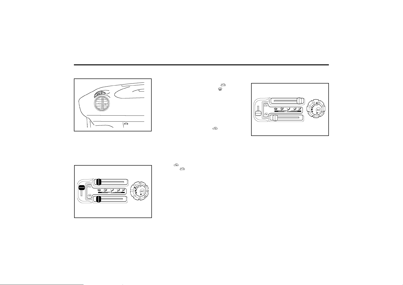
FEATURES OF YOUR HYUNDAI
1-36
To use the heating/ventilation system to defrost
or defog the windshield:
o Set the air intake control to the position.
o Set the air flow control to the position.
o Set the temperature control to a comfortably
warm position.
o Set the fan speed control to position 3 or 4.
o If vehicle is so equipped, push on the A/C for
increased defogging action.
NOTE:
In high humidity areas the A/C can be used
with the air intake in the position for
increased defogging action.
B730A01A-AAT
OPERATION TIPS
o To keep dust or unpleasant fumes from
entering the car through the ventilation sys-
tem, temporarily set the air intake control at
the position. Be sure to return the control
to the position when the irritation has
passed to keep fresh air in the vehicle. This
will help keep the driver alert and comfort-
able.
o Air for the heating/cooling system is drawn
in through the grilles just ahead of the wind-
shield. Care should be taken that these are
not blocked by leaves, snow, ice or other
obstructions.
B740A01X-GAT
AIR CONDITIONING SWITCH
(Not all models)
B740A02X-DAG
The air conditioning is turned on by pushing the
A/C button in the fan control rotary switch.
B710C02X-DAG
B710C01X-EAT
Side Ventilator
B720A02X-DAG
B720A02X-GAT
DEFROSTING/DEFOGGING
The side ventilators are located on each side of
the dashboard.
To change the direction of the air flow, move the
knob in the centre of vent up-and-down and
side-to-side.
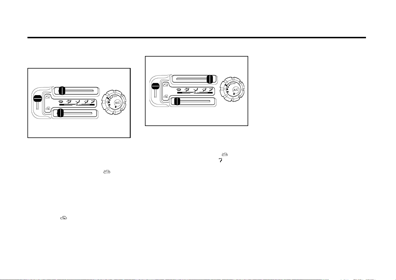
FEATURES OF YOUR HYUNDAI
1-37
B740D01A-AAT
OPERATION TIPS
o If the interior of the car is hot when you first
get in, open the windows for a few minutes
to expel the hot air.
o When you are using the air conditioning
system, keep all windows closed to keep
hot air out.
o When moving slowly, as in heavy traffic,
shift to a lower gear. This increases engine
speed, which in turn increases the speed of
the air conditioning compressor.
o On steep grades, turn the air conditioning off
to avoid the possibility of the engine over-
heating.
o During winter months or in periods when the
air conditioning is not used regularly, run the
air conditioning once every month for a few
minutes. This will help circulate the lubri-
cants and keep your system in peak operat-
ing condition.
B680A02X-DAG
B740C01X-GAT
De-Humidified Heating
For dehumidified heating:
o Turn on the fan control switch.
o Turn on the air conditioning switch.
o Set the air intake control to the
position.
o Set the air flow control to the
position.
o Adjust the fan control to the desired speed.
o For more rapid action, set the fan at one of
the higher speeds.
o Adjust the temperature control to provide the
desired amount of warmth.
B740B02X-DAG
B740B01X-GAT
AIR CONDITIONING OPERATION
(Not all models)
Cooling
To use the air conditioning to cool interior:
o Turn on the fan control switch.
o Turn on the air conditioning switch by push-
ing in on the switch.
o Set the air intake control to the
position.
o Set the temperature control to "Cool". ("Cool"
provides maximum cooling. The tempera-
ture may be moderated by moving the con-
trol toward "Warm".)
o Adjust the fan control to the desired speed.
For greater cooling, turn the fan control to
one of the higher speeds or temporarily
select the
position on the air intake
control.
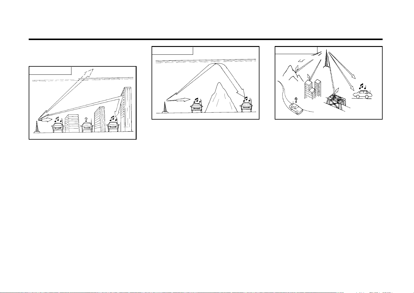
FEATURES OF YOUR HYUNDAI
1-38
SSAR012A
Unobstructed
area
Mountains
Buildings
Obstructed area
Iron bridges
FM broadcasts are transmitted at high frequency
and do not bend to follow the earth’s surface.
Because of this, FM broadcasts generally begin
to fade at short distances from the station. Also,
FM signals are easily affected by buildings,
mountains, or other obstructions. These can
result in certain listening conditions which might
lead you to believe a problem exists with your
radio. The following conditions are normal and
do not indicate radio trouble:
FM radio station
ZB500A1-A
STEREO SOUND SYSTEM
How Car Audio Works
SSAR010A
Ionosphere
FM reception
AM and FM radio signals are broadcast from
transmitter towers located around your city.
They are intercepted by the radio antenna on
your car. This signal is then received by the
radio and sent to your car speakers.
When a strong radio signal has reached your
vehicle, the precise engineering of your audio
system ensures high quality reproduction. How-
ever, in some cases the signal coming to your
vehicle is not strong and clear. This can be due
to factors such as the distance from the radio
station, closeness of other strong radio stations
or the presence of buildings, bridges or other
large obstructions in the area.
Ionosphere
SSAR011A
AM reception
AM broadcasts can be received at greater dis-
tances than FM broadcasts. This is because
AM radio waves are transmitted at low fre-
quency. These long, low frequency radio waves
can follow the curvature of the earth rather than
travelling straight out into the inosphere. In
addition, they curve around obstructions so that
they can provide better signal coverage.
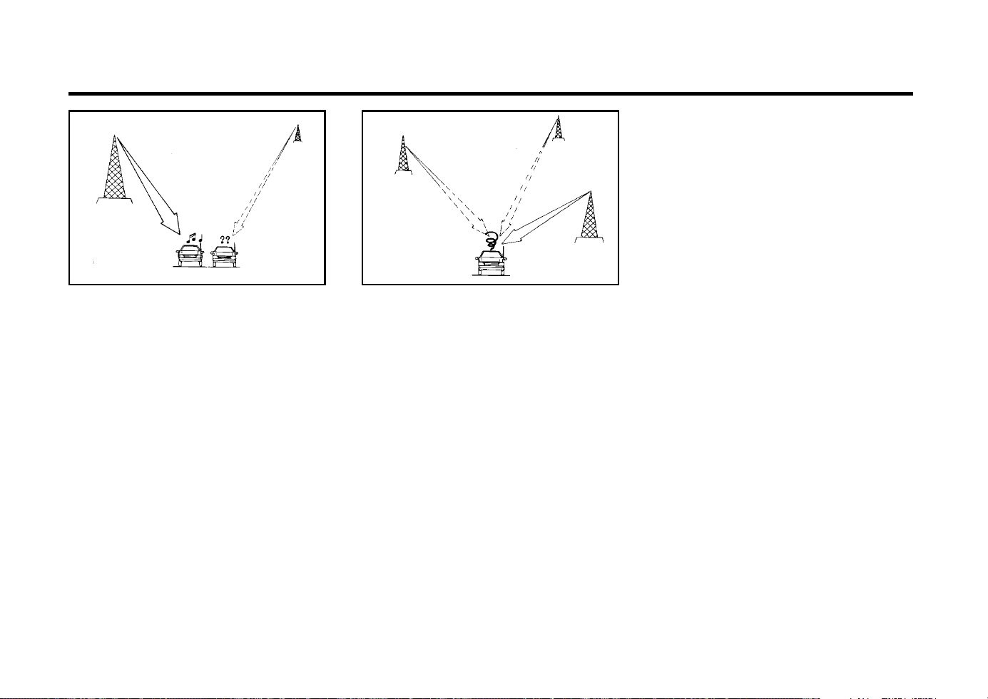
FEATURES OF YOUR HYUNDAI
1-39
B750B02Y-AAT
Using a cellular phone or a two-way
radio
When a cellular phone is used inside the vehi-
cle, noise may be produced from the audio
equipment. This does not mean that something
is wrong with the audio equipment. In such a
case, use the cellular phone at a place as far as
possible from the audio equipment.
CAUTION:
When using a communication system such
a cellular phone or a radio set inside the
vehicle, a separate external antenna must
be fitted. When a cellular phone or a radio
set is used by using an internal antenna
alone, it may interfere with the vehicle's
electrical system and adversely affect safe
operation of the vehicle.
WARNING:
Don't use a cellular phone when you are
driving, you must stop the car at the safe
place to use a cellular phone.
SSAR013A
o Fading - As your car moves away from the
radio station, the signal will weaken and
sound will begin to fade. When this occurs,
we suggest that you select another stronger
station.
o Flutter/Static - Weak FM signals or large
obstructions between the transmitter and
your radio can disturb the signal causing
static or fluttering noises to occur. Reducing
the treble level may lessen this effect until
the disturbance clears.
SSAR014A
o Station Swapping - As a FM signal weak-
ens, another more powerful signal near the
same frequency may begin to play. This is
because your radio is designed to lock onto
the clearest signal. If this occurs, select
another station with a stronger signal.
o Multi-Path Cancellation - Radio signals be-
ing received from several directions can
cause distortion or fluttering. This can be
caused by a direct and a reflected signal
from the same station, or by signals from
two stations with close frequencies. If this
occurs, select another station until the con-
dition has passed.
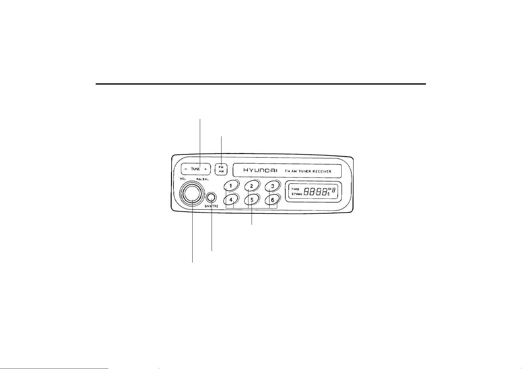
FEATURES OF YOUR HYUNDAI
1-40
B901A02X-GAT
STEREO RADIO OPERATION (HMR 90) (Not all models)
B901A01X
5. PRESET Buttons
3. BAND Selector
4. TUNE/SEEK Select Button
2. BASS/TREBLE Control Knob
1. POWER ON-OFF/VOLUME/BALANCE Control Knob

FEATURES OF YOUR HYUNDAI
1-41
3. BAND Selector
Pressing the button changes the AM, FM1
and FM2 bands. The mode selected is dis-
played on LCD.
4. TUNE (Manual) Select Button
Press the (+) side or (-) side to increase or to
decrease the frequency. With the button held
down for 0.5 sec. or more, the stop signal
(broadcasting radio wave) is ignored and chan-
nel selection continues.
SEEK Operation (Automatic Channel
Selection)
Press the TUNE select button 1 sec. or more.
When the (+) side is pressed, the unit will
automatically tune to the next higher frequency
and when the (-) side is pressed, it will automat-
ically tune to the next lower frequency.
5. PRESET STATION SELECT
Six (6) stations for AM, FM and FM2 respec-
tively can be preset in the electronic memory
circuit on this unit.
HOW TO PRESET STATIONS
Six AM and twelve FM stations may be pro-
grammed into the memory of the radio. Then,
by simply pressing the band select button and/
or one of the six station select buttons, you may
recall any of these stations instantly. To pro-
gram the stations, follow these steps:
B901B02X-GAT
1. POWER ON-OFF/VOLUME CON-
TROL KNOB
The radio unit may be operated when the igni-
tion key is in the "ACC" or "ON" position. Rotate
the knob clockwise to switch the radio unit on,
and to increase the volume.
The LCD shows the radio frequency in the radio
mode. Turn the knob counterclockwise to re-
duce the volume, and to switch the radio unit
off.
BAL (Balance Control) Knob
Pull and turn the control knob clockwise to
emphasize right speaker sound (Left speaker
sound will be attenuated). When the control
knob is turned counterclockwise, left speaker
sound will be emphasized (Right speaker sound
will be attenuated).
2. BASS Control Knob
Press to pop the knob out and turn to the left or
right for the desired bass tone.
TREBLE Control Knob
Further pull-lock position of popped-up knob.
Turn to the left or right for the desired treble
tone.
FM
AM
o Press band selector to set the band for AM,
FM and FM2.
o Select the desired station to be stored by
seek, scan or manual tuning.
o Determine the preset station select button
you wish to use to access that station.
o Press the station select button for more than
two seconds. A select button indicator will
show in the display indicating which select
button you have depressed. The frequency
display will flash after it has been stored into
the memory. You should then release the
button, and proceed to program the next
desired station. A total of 18 stations can be
programmed by selecting one AM and two
FM stations per button.
o When completed, any preset station may be
recalled by selecting AM, FM or FM2 band
and the appropriate station button.
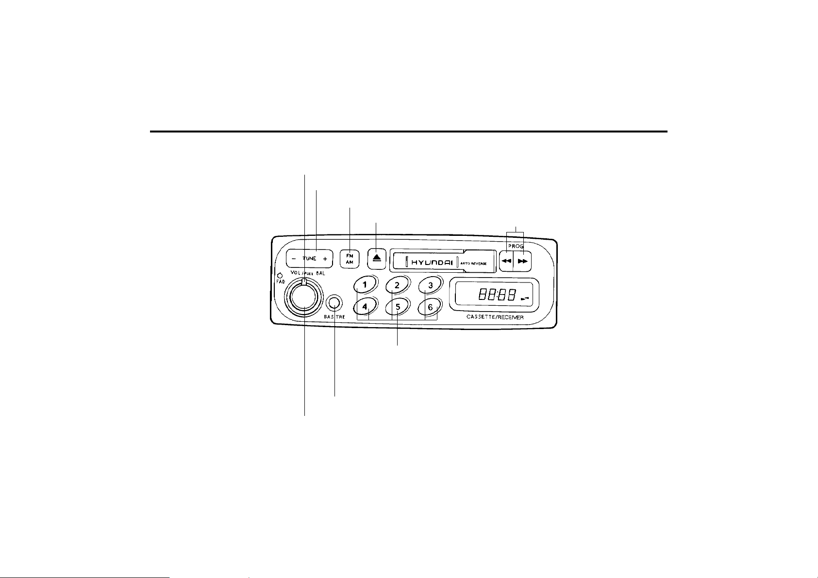
FEATURES OF YOUR HYUNDAI
1-42
B900A01X
B900A02X-GAT
STEREO RADIO AND CASSETTE TAPE PLAYER OPERATION (H900) (Not all models)
1. POWER ON-OFF/VOLUME/BALANCE Control Knob
2. BASS/TREBLE Control Knob
5. PRESET Buttons
8. FADER Control Knob
4. TUNE/SEEK Select Button
3. BAND Selector
6. TAPE EJECT Button
7. TAPE PROGRAM Button

FEATURES OF YOUR HYUNDAI
1-43
B900B02X-GAT
1. POWER ON-OFF/VOLUME CON-
TROL KNOB
The radio unit may be operated when the igni-
tion key is in the "ACC" or "ON" position. Rotate
the knob clockwise to switch the radio unit on
and to increase the volume.
The LCD shows the radio frequency in the radio
mode, or the tape direction indicator in the tape
mode. Turn the knob counterclockwise to re-
duce the volume and to switch the radio unit off.
BAL (Balance Control) Knob
Pull and turn the control knob clockwise to
emphasize right speaker sound. (Left speaker
sound will be attenuated) When the control
knob is turned counterclockwise, left speaker
sound will be emphasized. (Right speaker sound
will be attenuated)
2. BASS Control Knob
Press to pop the knob out and turn to the left or
right for the desired bass tone.
TREBLE Control Knob
Further pull-lock position of popped-up knob.
Turn to the left or right for the desired treble
tone.
3. BAND Selector
Pressing the button changes the AM, FM1
and FM2 bands. The mode selected is dis-
played on LCD.
4. TUNE (manual) Select Button
Press the (+) side or (-) side to increase or to
decrease the frequency. With the button held
down for 0.5 sec. or more, the stop signal
(broadcasting radio wave) is ignored and chan-
nel selection continues.
SEEK Operation (Automatic Channel
Selection)
Press the TUNE select button 1 sec. or more.
When the (+) side is pressed, the unit will
automatically tune to the next higher frequency
and when the (-) side is pressed, it will automat-
ically tune to the next lower frequency.
5. PRESET STATION SELECT Button
Six (6) stations for AM, FM and FM2 respec-
tively can be preset in the electronic memory
circuit on this unit.
HOW TO PRESET STATIONS
Six AM and twelve FM stations may be pro-
grammed into the memory of the radio. Then,
by simply pressing the band select button and/
or one of the six station select buttons, you may
recall any of these stations instantly. To pro-
gram the stations, follow these steps:
FM
AM
o Press band selector to set the band for AM,
FM, and FM2.
o Select the desired station to be stored by
seek, scan or manual tuning.
o Determine the preset station select button
you wish to use to access that station.
o Press the station select button for more than
two seconds. A select button indicator will
show in the display indicating which select
button you have depressed. The frequency
display will flash after it has been stored into
the memory. You should then release the
button, and proceed to program the next
desired station. A total of 18 stations can be
programmed by selecting one AM and one
FM station per button.
o When completed, any preset station may be
recalled by selecting AM, FM or FM2 band
and the appropriate station button.
6. TAPE EJECT Button
To elect the tape, press the button.
7. TAPE PROGRAM
When you press the button whose arrow is in
the same direction as the tape play arrow in the
display the tape will advance at high speed.
When you press the button whose arrow is in
the opposite direction to the tape play arrow in
the display the tape will rewind at high speed.
To stop FF or REW action, press the opposite
button. When you press two buttons simulta-
neously you play the reverse side of the tape

FEATURES OF YOUR HYUNDAI
1-44
and an arrow will appear in the display to show
tape direction.
8. FAD (Fader Control) Knob
Turn the control knob clockwise to emphasize
front speaker sound (Rear speaker sound will
be attenuated). When the control knob is turned
counterclockwise, rear speaker sound will be
emphasized (Front speaker sound will be atten-
uated).
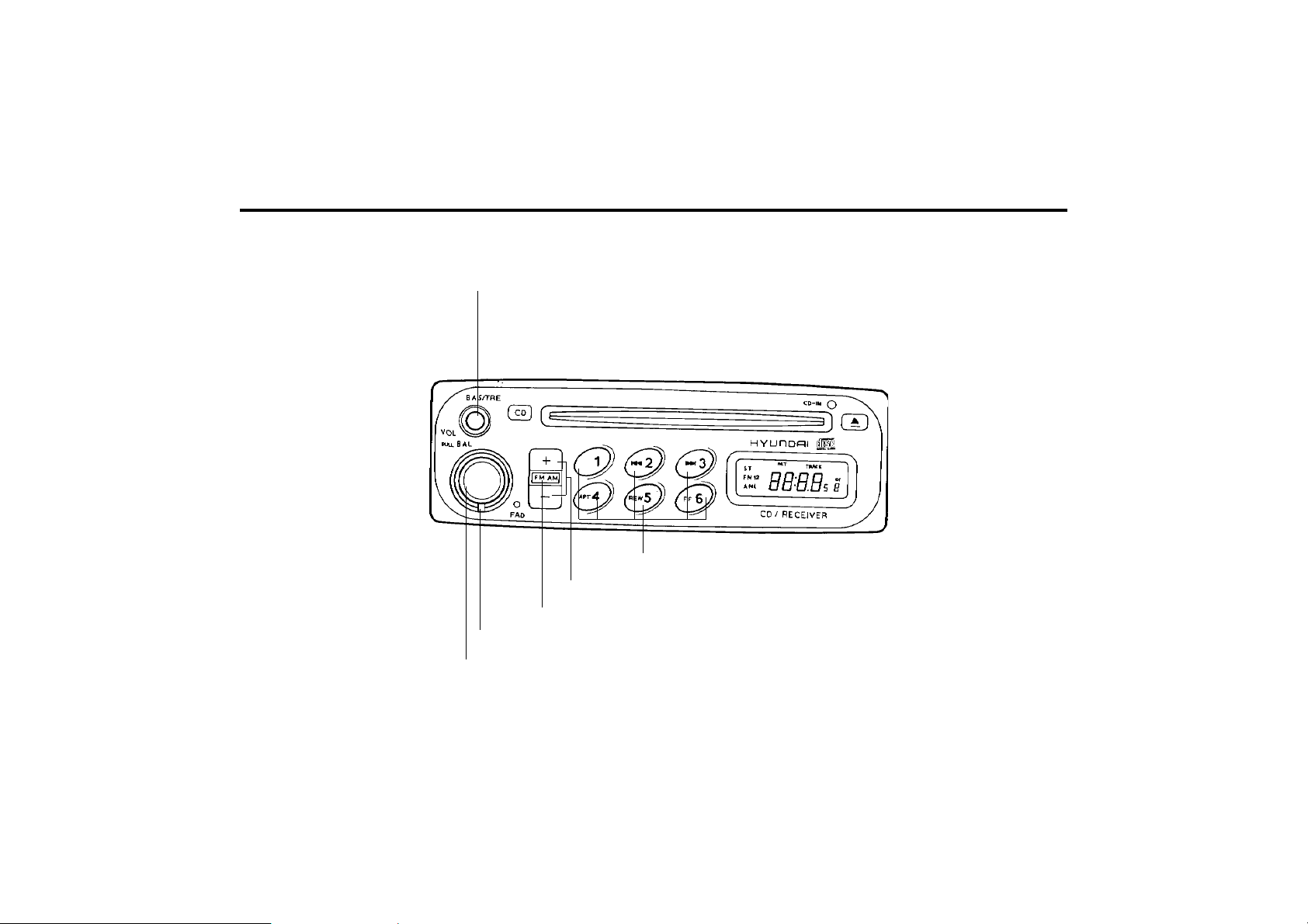
FEATURES OF YOUR HYUNDAI
1-45
B922A01X
B922A02X-GAT
STEREO RADIO OPERATION (H922M) (Not all models)
3. BASS/TREBLE Control Knob
1. POWER ON-OFF/VOLUME/BALANCE Control Knob
2. FADER Control Knob
6. PRESET Buttons
5. TUNE/SEEK Select Button
4. BAND Selector

FEATURES OF YOUR HYUNDAI
1-46
B922B02X-GAT
1. POWER ON-OFF/VOLUME CON-
TROL KNOB
The radio unit may be operated when the igni-
tion key is in the "ACC" or "ON" position. The
clock will be displayed automatically, although
the radio unit has gone out. Press the button to
switch the power on. The LCD shows the radio
frequency in the radio mode or the CD track
indicator in the CD mode. To switch the power
off, press the button again.
VOLUME Control
Rotate the knob clockwise to increase the vol-
ume and turn the knob counterclockwise to
reduce the volume.
BALANCE Control
Pull and turn the control knob clockwise to
emphasize right speaker sound. (Left speaker
sound will be attenuated) When the control
knob is turned counterclockwise, left speaker
sound will be emphasized. (Right speaker sound
will be attenuated)
2. FAD (Fader Control) Knob
Turn the control knob counterclockwise to em-
phasize front speaker sound. (Rear speaker
sound will be attenuated) When the control
knob is turned clockwise, rear speaker sound
will be emphasized. (Front speaker sound will
be attenuated)
FM/AM
6. PRESET STATION SELECT Button
Six (6) stations for AM, FM and FM2 respec-
tively can be preset in the electronic memory
circuit on this unit.
HOW TO PRESET STATIONS
Six AM and twelve FM stations may be pro-
grammed into the memory of the radio. Then,
by simply pressing the band select button and/
or one of the six station select buttons, you may
recall any of these stations instantly. To pro-
gram the stations, follow these steps:
o Press band selector to set the band for AM,
FM, and FM2.
o Select the desired station to be stored by
seek, scan or manual tuning.
o Determine the preset station select button
you wish to use to access that station.
o Press the station select button for more than
two seconds. A select button indicator will
show in the display indicating which select
button you have depressed. The frequency
display will flash after it has been stored into
the memory. You should then release the
button, and proceed to program the next
desired station. A total of 18 stations can be
programmed by selecting one AM and one
FM station per button.
o When completed, any preset station may be
recalled by selecting AM, FM or FM2 band
and the appropriate station button.
3. BASS/TREBLE Control Knob
BASS Control Knob
Press to pop the knob out and turn to the left or
right for the desired bass tone.
TREBLE Control Knob
Further pull-lock position of popped-up knob.
Turn to the left or right for the desired treble
tone.
4. BAND Selector
Pressing the button changes the AM,
FM1 and FM2 bands. The mode selected is
displayed on LCD.
5. TUNE (Manual) Select Button
Press the (+) side or (-) side to increase or to
decrease the frequency. With the button held
down for 0.5 sec. or more, the stop signal
(broadcasting radio wave) is ignored and chan-
nel selection continues.
SEEK Operation (Automatic Channel
Selection)
Press the TUNE select button 1 sec. or more,
and releasing will automatically tune the next
available station. When the (+) side is pressed
longer than 1 second and releasing will auto-
matically tune the next higher frequency and
when the (-) side is pressed longer than 1
second and releasing will automatically tune
the next lower frequency.
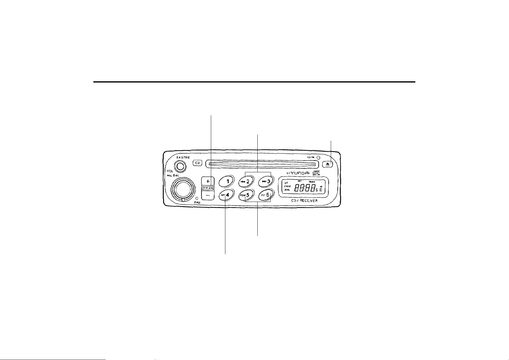
FEATURES OF YOUR HYUNDAI
1-47
B922A01X
B922E02X-GAT
COMPACT DISK PLAYER OPERATION (H922M) (Not all models)
4. REPEAT
3. TRACK UP/DOWN
5. EJECT Button
2. FF/REW
1. STOP

FEATURES OF YOUR HYUNDAI
1-48
B922F01X-GAT
1. STOP
o Insert the CD to start CD playback, during
the radio operation.
o Press the button to stop CD playback
and to change the source to Radio.
2. FF/REW
While the disc is playing, press and hold FF
button to quickly move forward until you reach
the desired section of the track and vice versa.
3. TRACK UP/DOWN
o The desired track on the disc currently being
played can be selected using the track num-
ber.
o Pressing the button once increases the
track number by one and pressing the
button decreases it.
4. REPEAT
o To repeat the music you are listening to,
press the RPT button and to cancel music
repeat, press again.
FM/AM
5. EJECT Button
When the EJECT button is pressed with the CD
loaded, the CD is ejected.
NOTE:
o To assure proper operation of the unit,
keep the vehicle interior temperature with-
in a normal range by using the vehicle’s
air conditioning or heating system.
o When replacing the fuse, replace it with a
fuse having the correct capacity.
o The preset station frequencies are all
erased when the car battery is discon-
nected. Therefore, all data will have to be
set again if this should occur.
o Do not add any oil to the rotating parts.
o This equipment is designed to be used
only in a 12 volt DC battery system with
negative ground.
o This unit is made of precision parts. Do
not attempt to disassemble or adjust any
parts.
o When driving your vehicle, be sure to
keep the volume of the unit set low
enough to allow you to hear sounds com-
ing from the outside.
o Do not expose this equipment (including
the speakers and tape) to water or exces-
sive moisture.

FEATURES OF YOUR HYUNDAI
1-49
B922G01A-GAT
AUDIO FAULT CODE
If you see any error indication in the display while using the CD or Tape mode, find the cause in the chart below. If you cannot clear the error indication,
take the car to your Hyundai dealer.
INDICATION
CAUSE SOLUTION
Er2
Er3
Er6
CDP DECK MECHANICAL ERROR
(EJECT ERROR, LOADING ERROR)
FOCUS ERROR
DATA READ ERROR
DISC ERROR
AFTER RESETTING THE AUDIO, PUSH THE EJECT BUTTON.
IF DISC IS NOT EJECTED, CONSULT YOUR HYUNDAI DEALER.
MAKE SURE THE DISC IS NOT SCRATCHED OR DAMAGED.
PRESS THE EJECT BUTTON AND PULL OUT THE DISC. THEN
INSERT A NORMAL CD DISC.
CHECK IF THE DISC IS INSERTED CORRECTLY IN THE CD PLAYER.
MAKE SURE THE DISC IS NOT SCRATCHED OR DAMAGED.

FEATURES OF YOUR HYUNDAI
1-50
SR040B1-E
Care of Cassette Tape
SSAR040B
In order to ensure maximum life from cassette
tapes, the following points should be observed.
o Always return cassettes to the storage box
after use.
o Never leave cassettes exposed to sunlight,
dampness or extreme temperatures.
o Never leave cassettes in the tape player
when not in use.
o Ensure that the cassette label is not loose or
peeling.
YL11250B
while the disc is being pulled into the unit by the
Self Loading mechanism.
Do not pull the unit from the dash immediately
after a disc is inserted or the Eject Switch has
been pressed. If the unit is pulled out before an
operation is completed, the disc will be unstable
in the unit and may be damaged. Do not attempt
to insert a disc into the unit when the unit is out
of the dash or the power is off.
Keep Your Discs Clean
Fingerprints, dust, or soil on the surface could
cause the pickup to skip signal tracks. Wipe the
surface clean with a clean soft cloth. If the
surface is heavily soiled, dampen a clean soft
cloth in a solution of mild neutral detergent to
wipe it clean. See drawing.
B850A01F-AAT
CARE OF DISC
Proper Handling
YL11240B
Handle your disc as shown. Do not drop the
disc. Hold the disc so you will not leave finger-
prints on the surface. If the surface is scratched,
it may cause the pickup to skip signal tracks.
Do not affix tape, paper, or gummed labels on
the disc. Do not write on the disc.
Damaged Disc
Do not attempt to play damaged, warped or
cracked discs. It could severely damage the
playback mechanism.
Storage
When not in use, place your discs in their
individual case and store them in a cool place
away from the sun, heat, and dust.
Do not grip or pull out the disc with your hand
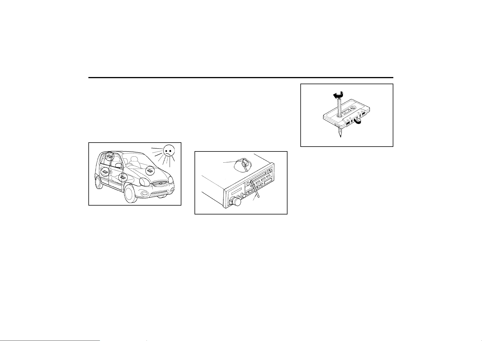
FEATURES OF YOUR HYUNDAI
1-51
o To avoid a build up of tape residue on the
playback head, pinch roller and capstan,
clean these monthly using a proprietary head
clean-ing tape or a purpose made head
cleaning solution applied with a cotton bud.
o Always remove slack from cassettes before
playing, by rotating a pencil inserted into the
drive socket to facilitate this.
o Do not use the cassette unit if the vehicle
has been parked in extremely hot or cold
ambient temperatures until the temperature
inside the passenger compartment reaches
normal levels.
SSAR042B
Cotton applicator
Head
FUAR053B
NOTE:
Look at a tape before you insert it. If the tape
is loose, tighten it by turning one of the
hubs with a pencil or your finger. If the label
is peeling off, do not put it in the player. It
may cause the tape to jam in the drive
mechanism when you try to eject it.
Do not leave tapes sitting where they are
exposed to high temperatures or, high hu-
midity, such as on top of the dashboard or
in the player. If a tape is extreme heat or
cold, let it reach a moderate temperature
before putting it in the player.
o Avoid the use of C120 cassettes since the
tape is very thin and may give rise to
operational difficulty.
o Do not store cassettes in the vicinity of
sources of magnetism such as loudspeak-
ers, electric motors, etc.
o Avoid repeatedly playing one section of a
given tape, since poor tape winding may
result. (Fast winding the tape from end to
end several times may relieve this situation
should it occur).
B860A02X-DAG
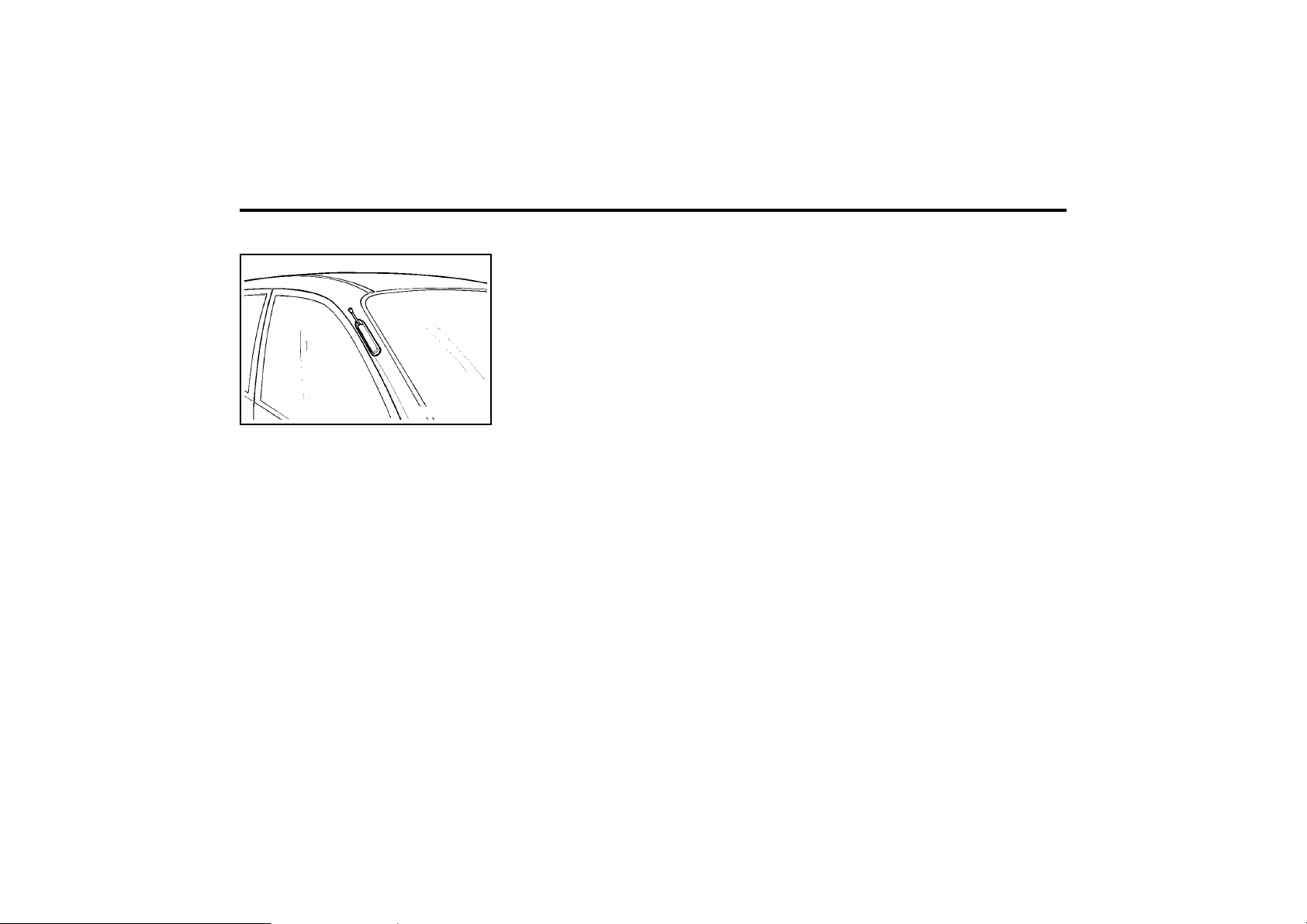
FEATURES OF YOUR HYUNDAI
1-52
B870C01X-GAT
ANTENNA
Your car uses a manual stainless steel antenna
to receive both AM and FM broadcast signals.
Pull up the antenna using your fingers, as
shown in the drawing.
NOTE:
Before entering an automatic car wash or a
place with a low height clearance, be sure
that the antenna is fully retracted.
HTJOM013.DAG

DRIVING YOUR HYUNDAI
2- 1
C010A01A-AAT
WARNING : ENGINE EXHAUST CAN BE DANGEROUS!
Engine exhaust fumes can be extremely dangerous. If, at any time, you smell exhaust fumes inside the vehicle, open the
windows immediately.
o Do not inhale exhaust fumes.
Exhaust fumes contain carbon monoxide, a colorless, odorless gas that can cause unconsciousness and death by
asphyxiation.
o Be sure the exhaust system does not leak.
The exhaust system should be checked whenever the vehicle is raised to change the oil or for any other purpose. If you
hear a change in the sound of the exhaust or if you drive over something that strikes the underneath side of the car, have
the exhaust system checked as soon as possible by your Hyundai dealer.
o Do not run the engine in an enclosed area.
Letting the engine idle in your garage, even with the garage door open, is a hazardous practice. Never run the engine in
your garage any longer than it takes to start the engine and back the car out.
o Avoid idling the engine for prolonged periods with people inside the car.
If it is necessary to idle the engine for a prolonged period with people inside the car, be sure to do so only in an open area
with the air intake set at “Fresh” and fan operating at one of the higher speeds so fresh air is drawn into the interior.
If you must drive with the tail gate open because you are carrying objects that make this necessary:
1. Close all windows.
2. Open side vents.
3. Set the air intake control at “Fresh”, the air flow control at “Floor” or “Face” and the fan at one of the higher speeds.
To assure proper operation of the ventilation system, be sure the ventilation air intakes located just in front of the windshield
are kept clear of snow, ice, leaves or other obstructions.
ZC000A1-E
2. DRIVING YOUR HYUNDAI
2
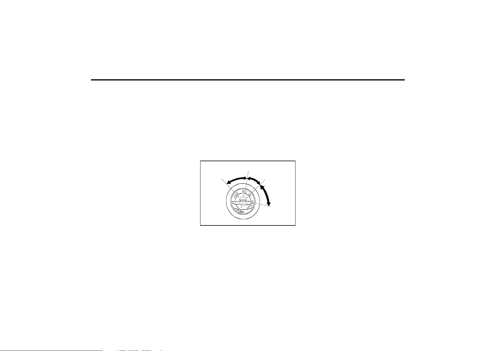
DRIVING YOUR HYUNDAI
2- 2
C020A01A-EAT
BEFORE STARTING THE ENGINE
Before you start the engine, you should always:
o Look around the vehicle to be sure there are
no flat tyres, puddles of oil or water or other
indications of possible trouble.
o After entering the car, check to be sure the
parking brake is engaged.
o Check that all windows, and lights are clean.
o Check that the interior and exterior mirrors
are clean and in position.
o Check your seat, seatback and headrestraint
to be sure they are in their proper positions.
o Lock all the doors.
o Fasten your seat belt and be sure that all
other occupants have fastened theirs.
o Turn off all lights and accessories that are
not needed.
o When you turn the ignition switch to "ON",
check that all appropriate warning lights are
operating and that you have sufficient fuel.
o Check the operation of warning lights and all
bulbs when key is in the "ON" position.
o To start the engine, insert the ignition key
and turn it to the "START" position. Release
it as soon as the engine starts. Do not hold
the key in the "START" position for more
than 15 seconds.
NOTE:
For safety, the engine will not start if the
shift lever is not in "P" or "N" Position (Auto
T/A).
ZC050A2-E
KEY POSITIONS
"START"
The engine is started in this position. It will
crank untill you release the key.
NOTE:
Do not hold the key in the "START" position
for more than 15 seconds.
"ON"
When the key is in the "ON" position, the ignition
is on and all accessories may be turned on. If the
engine is not running, the key should not be left
in the "ON" position. This will discharge the
battery and may also damage the ignition sys-
tem.
"ACC"
With the key in the "ACC" position, the radio and
other accessories may be operated.
"LOCK"
The key can be removed or inserted in this
position. Steering is locked by removing the key.
When unlocking the steering, insert the key, and
then turn the steering wheel and key simulta-
neously.
C040A01E
LOCK
ACC
ON
START
C030A02X-GAT
COMBINATION IGNITION SWITCH
To Start the Engine
o If your Hyundai is equipped with a manual
transaxle, place the shift lever in neutral and
depress the clutch pedal fully.
o If your Hyundai has an automatic transaxle,
place the shift lever in "P" (park).
WARNING:
The engine should not be turned off or the
key removed from the ignition key cylinder
while the car is in motion.
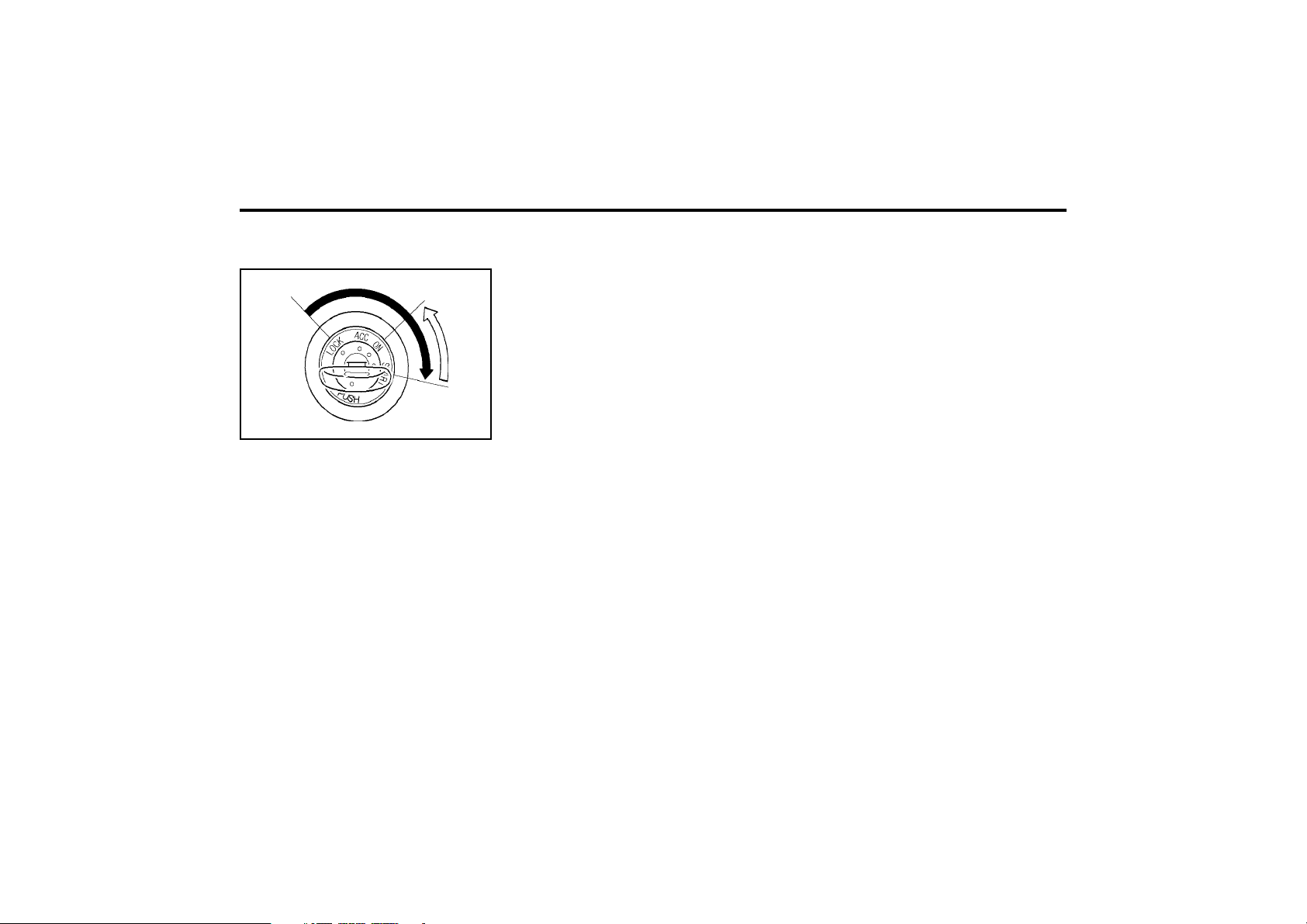
DRIVING YOUR HYUNDAI
2- 3
C050A01A-AAT
STARTING
(For Multiport Fuel Injection)
Normal starting with either a cold or warm
engine is obtained without pumping or depress-
ing the accelerator pedal. Simply turn the key to
the "START" position and release when the
engine starts.
After the engine has started, allow the engine to
run for 10 to 20 seconds prior to placing the
vehicle in gear.
The starter should not be operated for more
than 15 seconds at a time. Wait 15-30 seconds
between starting attempts to protect the starter
from overheating.
WARNING:
Never run the engine in a closed or poorly
ventilated area any longer than is needed to
move your car in or out of the area. The
carbon monoxide gas emitted is odorless
and can cause serious injury or death.
C050B02X-GAT
Normal Conditions:
The Starting Procedure:
1. Insert key, and fasten the seat belt.
2. Depress the clutch pedal fully (manual
transaxle) and place the gearshift lever in
neutral (manual transaxle) or the selector
lever (automatic transaxle) in "P" (park)
position.
3. After turning the ignition key to the "ON"
position, make certain all warning lights and
gauges are functioning properly before start-
ing the engine.
WARNING:
Be sure that the clutch is fully depressed
when starting a manual transaxle vehicle.
Otherwise, there is the potential to cause
damage to the vehicle or injury to someone
inside or outside the vehicle as a result of
the forward or backward movement of the
vehicle that will occur if the clutch is not
depressed when the vehicle is started.
4. Turn the ignition key to the "Start" position
and release it when the engine starts.
DC090C1-E
FUEL ECONOMY
The following suggestions are made to assist in
achieving the greatest degree of fuel economy.
o Maintaining a constant check on fuel con-
sumption will enable the most economical
use pattern and driving style to be adopted.
o Avoid using the vehicle for very short jour-
neys if possible, particularly when a cold
start isinvolved.
o Ensure that tyre pressures are maintained
at the correct level.
o Use only the recommended grade of fuel.
o Avoid carrying unnecessary weight, and if a
roof rack is in use, remove it as soon as
possible after use.
o Anticipate the road and conditions ahead to
enable adjustments in speed to be made
smoothly. Avoid heavy acceleration and
sharp braking.
o Avoid cruising at unnecessary high speeds.
o Always ensure that the periodic maintenance
services are performed by a Hyundai dealer
at the time and/or mileage intervals speci-
fied.
o Use the air conditioner only when neces-
sary.
C050A01E
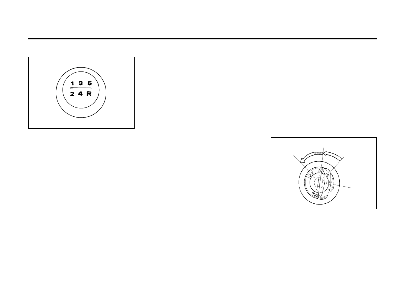
DRIVING YOUR HYUNDAI
2- 4
1. Turn the ignition key to the "ACC" position.
2. Simultaneously push and turn the ignition
key counterclockwise from the "ACC" posi-
tion to the "LOCK" position.
3. The key can be removed in the "LOCK"
position.
C070B01X-GAT
Using the Clutch of Manual transaxle
The clutch should be pressed all the way to the
floor before shifting, then released slowly. The
clutch pedal should be always used after fully
returning to the original position. Do not rest
your foot on the clutch pedal while driving. This
can cause unnecessary wear. Do not partially
engage the clutch to hold the car on an incline.
This causes unnecessary wear. Use the park-
ing brake to hold the car on an incline. Do not
operate the clutch pedal rapidly and repeatedly.
ZC090D2-A
To Remove the Ignition Key
C070A03X-EAT
MANUAL TRANSAXLE
C070A01X
The 5 speed fully synchronized manual transaxle
is controlled by a floor mounted shift lever upon
which the shift pattern is indicated. Ensure that
when changing gear, the clutch pedal is fully
depressed before moving the shift lever.
CAUTION:
o Do not attempt to engage reverse gear
when the car is moving.
o To avoid damaging the selector mecha-
nism, do not use the gear shift lever as a
hand rest. Release the lever immediately
the shift is completed.
o To avoid premature clutch wear, do not
use the clutch pedal as a foot rest, and
do not hold the vehicle on a gradient
using the clutch.
o Ensure that the engine is not over-revved
by upshifting.
o Do not coast with the shift lever at the
neutral position.
o When descending long gradients, make
use of the engine braking to assist the
footbrake to avoid brake fade or over-
heating.
o When slippery conditions are encoun-
tered, increased caution should be exe-
cuted when gear changing, braking or
accelerating. Abrupt changes in speed
may cause a loss of traction.
o To shift into reverse, rest the lever in
neutral for at least 3 seconds after your
car is completely stopped. Then move
the lever into the reverse position.
WARNING:
When downshifting from fifth gear to fourth
gear, caution should be taken not to inad-
vertently press the gear shift lever sideways
in such a manner that second gear is en-
gaged. Such over revving of the engine may
possibly cause engine damage.
C070C01E
LOCK
ACC
ON
START
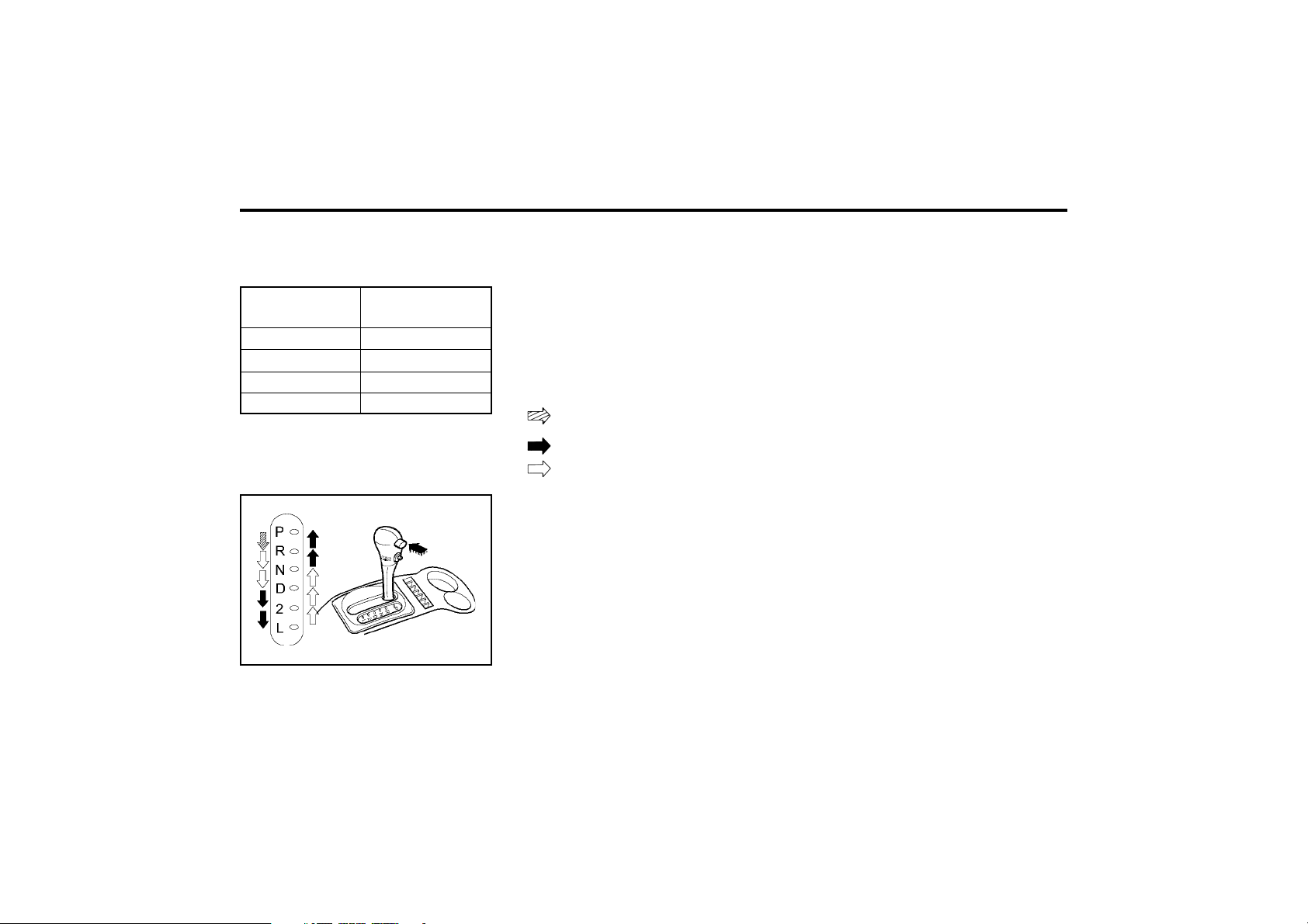
DRIVING YOUR HYUNDAI
2- 5
1-2
2-3
3-4
4-5
Recommended
mph (km/h)
C070E02-GAT
RECOMMENDED SHIFT POINTS
The following shift speeds are recommended
for optimum fuel economy.
C090A01A-GAT
AUTOMATIC TRANSAXLE
(Not all models)
C090B01X-DAG
Condition
15 (20)
25 (40)
35 (55)
45 (75)
The highly efficient Hyundai automatic transaxle
has four forward speeds and one reverse speed.
It has a conventional shift pattern as shown in
the illustration. At night, with the first position of
the multi-function switch, the appropriate sym-
bol on the shift pattern indicator will be illuminat-
ed according to the range selected.
CAUTION:
Never shift into "R" or "P" position while
the vehicle is moving.
NOTE:
Depress the brake pedal and push the
button when shifting.
Push the button when shifting.
The selector lever can be shifted free-
ly.
For optimum fuel economy, accelerate gradual-
ly. The transaxle will automatically shift to the
second, third and overdrive gears.
CAUTION:
The selector must NEVER be shifted to the
"P" position whilst the vehicle is in motion,
otherwise serious transaxle damage will re-
sult.
NOTE:
o The ignition key can be removed with the
selector in only this position. (Not all
models)
o The brake pedal fully depressed in order
to move the shift lever from the "P"
(Park) position to any of the other posi-
tions. (Not all models)
ZC110B1-E
SELECTOR POSITIONS
o P (Park):
With the selector in this position, no drive is
transmitted from the engine and the transaxle
output (and therefore the front wheels) are
locked. The engine may be started with the
selector in this position.
ZC110C1-A
o R (Reverse):
Use for backing up the vehicle. Bring the car to
a complete stop before shifting the selector
lever to "R" position.
C090D02A-AAT
o N (Neutral)
In the "N" position, the transaxle is in neutral,
which means that no gears are engaged. The
engine can be started with the shift lever in "N"
position, although this is not recommended
except if the engine stalls while the car is
moving.
CAUTION:
Do not coast with the selector at the "N"
position
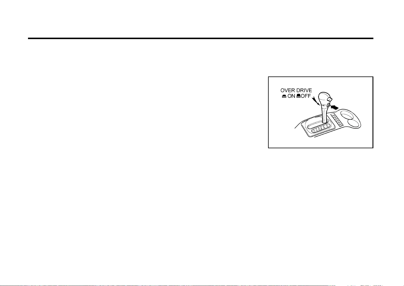
DRIVING YOUR HYUNDAI
2- 6
C090I01E-EAT
CAUTION:
o Shift into "R" and "P" only when the
vehicle has completely stopped.
o Do not accelerate the engine in the re-
verse or any of the forward positions
with the brakes applied.
o Always apply the footbrake when shift-
ing from "P" or "N", to "R", "D", "2" or
"L".
o Do not use the "P" (Park) position in
place of the parking brake. Always set
the park-ing brake, shift the transaxle
into "P" (Park) and turn off the ignition
when you leave the vehicle, even mo-
mentarily. Never leave the vehicle unat-
tended whilst the engine is running.
C090H01E-EAT
NOTE:
o The brake pedal should be depressed
when shifting from NEUTRAL to a for-
ward or reverse gear.
o The brake pedal fully depressed in order
to move the shift lever from the "P"
(Park) position to any of the other posi-
tions.
o It is always possible to shift from "R",
"N", "D", "2", "L" position.
C090P01X-DAG
SC130A1-E
OVERDRIVE SWITCH
SC110E1-E
o D (Drive):
With the selector in this position, first gear will
be engaged from rest and the transaxle will
automatically upshift to second, third and fourth
depending upon the vehicle speed, throttle po-
sition and the position of the Overdrive switch.
The engine may not be started with the selector
in this position.
SC110G1-E
o L (Low Gear):
With the selector in this position, first gear will
be engaged from rest. No upshift will occur
regardless of vehicle speed and throttle open-
ing. The engine may not be started with the
selector in this position.
SC110F1-E
o 2 (Second Gear):
With the selector in this position, first gear will
be engaged from rest. The transaxle will upshift
to second gear depending upon the vehicle
speed and throttle position. No upshift to third or
fourth will occur. The engine may not be started
with the selector in this position.
CAUTION:
Do not move the selector to the 2 position
when the vehicle speed is in excess of 50
m.p.h.
CAUTION:
Do not move the selector to the L position
when the vehicle speed is in excess of 60
m.p.h.
o Check the automatic transaxle fluid level
regularly, and add fluid as necessary.
The overdrive switch prevents the transaxle
upshifting higher than third gear when the switch
is turned "OFF". The transaxle will start from
rest in first gear and upshift to second and third
gear depending upon the roadspeed and throttle
opening but will not upshift to fourth gear. When
the overdrive switch is turned "ON", the transaxle
will start from rest in first gear and will upshift,
depending upon roadspeed and throttle open-
ing to second, third and fourth gear. Therefore,
when the overdrive switch is turned "OFF", the
transaxle performs as a three speed unit and
the overdrive warning light located in the instru-
ment cluster will be illuminated. When the over-
drive switch is turned "ON", the transaxle func-
tions as a fully automatic four speed unit with

DRIVING YOUR HYUNDAI
2- 7
o Ensure that the overdrive switch is at the
"ON" position for maximum economy.
o If rapid acceleration is required, fully de-
press the accelerator pedal. In this condi-
tion, the kickdown mechanism will be oper-
ated and the transaxle will automatically
downshift according to the vehicle speed.
o Do not depress the accelerator pedal with
the brakes applied and the selector at the
"R" "D" "2" or "L" position.
o Turn the overdrive switch on for good fuel
economy and smooth driving. But if engine
braking is needed in the "D" range or if
repeated upshifting and downshifting be-
tween the 3rd and 4th gear is needed when
climbing a gentle slope, it is recommended
that the overdrive switch be turned off. Turn
the overdrive switch back on immediately
afterward.
the maximum fuel economy potential of the
vehicle being realized.
SC140A1-E
EFFECTIVE BRAKING
Braking system performance and friction mate-
rial life are greatly affected by the driving style
adopted. The following suggestions are made
to assist in achieving the best results from the
braking system.
o Anticipate the road and conditions ahead in
order that heavy braking may be avoided.
o When descending long gradients, use the
engine to assist in retarding the vehicle to
minimize the possibility of brake fade occur-
ring.
ZC120D1-E
General Operating Instructions
o The button in the selector handle must be
depressed before the selector can be moved.
o The engine may only be started when the
selector is at position "P" or "N".
o Ensure that the footbrake is firmly applied
when shifting from "P" or "N" to "D", "2" or
"L" and vice versa.
o Always engage the parking brake when the
vehicle is unattended, never use the "P"
position in place of the parking brake.
o Under normal circumstances, the selector
should be placed in the "D" position and the
transaxle allowed to select the most ideal
ratio for the circumstances. In this position
maximum fuel economy will be achieved.
o When descending steep gradients where
engine braking is required, the selector
should be placed at the "2" or "L" position
depending upon the vehicle speed.
o When ascending steep gradients and using
large throttle openings, the transaxle may
repeatedly change between two adjacent
ratios. This is a normal characteristic and
may be prevented by selecting "2" or "L"
depending upon the vehicle speed.
o Never move the selector to or from the "P"
or "N" position with the accelerator de-
pressed.
o When trailer towing, ensure that the trailer
brakes function correctly and use engine
brak-ing to assist the vehicle braking system.
o Use only genuine Hyundai replacement
brake pads and shoes to ensure consistent
friction characteristics and wear rates.
o After driving through deep water (e.g.
fording), the brakes may become wet and
performance reduced. Always check brake
efficiency after emerging from the water and
dry the brakes by lightly depressing the
brake pedal several times whilst driving slow-
ly.
o Apply the parking brake only when the vehi-
cle is at rest.
o Since the power assistance provided by the
brake servo is derived from the engine,
coast-ing with the engine turned off or tow-
ing of the vehicle with the engine turned off
will result in greatly increased pedal pres-
sures being re-quired to stop the vehicle.
o Do not hold the vehicle on the upgrade with
the accelerator pedal. This can cause the
transmission to overheat. Always use the
brake pedal or parking brake.
YC250A1-A
ANTI-LOCK BRAKE SYSTEM
(Not all models)
The Anti-Lock Brake System (ABS) is designed
to prevent wheel lock-up during sudden braking
or on hazardous road surfaces. The ABS con-
trol module monitors the wheel speed and con-
trols the pressure applied to each brake. Thus,

DRIVING YOUR HYUNDAI
2- 8
in emergency situations or on slick roads, ABS
will increase vehicle control during braking.
NOTE:
During ABS operation, a slight pulsation
may be felt in the brake pedal when the
brakes are applied. Also, a noise may be
heard in the engine compartment while brak-
ing. These conditions are normal and indi-
cate that the anti-lock brake system is func-
tioning properly.
WARNING:
Your ABS will not prevent accidents due to
improper or dangerous driving maneuvers.
Even though vehicle control is improved
during emergency braking, always maintain
a safe distance between you and objects
ahead. Vehicle speeds should always be
reduced during extreme road conditions.
The braking distance for cars equipped with
an anti-lock braking system may be longer
than for those without it in the following
road conditions.
o Driving on rough, gravel or snow-cov-
ered roads.
o Driving with tire chains installed.
o Driving on roads where the road surface
is pitted or has different surface height.
These roads should be driven at reduced
speeds. The safety features of an ABS
equipped vehicle should not be tested by
high speed driving or cornering. This could
endanger the safety of yourself or others.
unnecessary tire wear. Check the tire pres-
sures at least once a month.
o Be sure that the wheels are aligned cor-
rectly. Improper alignment can result from
hitting curbs or driving too fast over irregular
surfaces. Poor alignment causes faster tire
wear and may also result in other problems
as well as greater fuel consumption.
o Keep your car in good condition. For better
fuel economy and reduced maintenance
costs, maintain your car in accordance with
the maintenance schedule in Section 5. If
you drive your car in severe conditions,
more frequent maintenance is required (see
Section 5 for details).
o Keep your car clean. For maximum service,
your car should be kept clean and free of
corrosive materials. It is especially impor-
tant that mud, dirt, ice, etc. not be allowed to
accumulate on the underside of the car. This
extra weight can result in increased fuel
consumption and also contribute to corro-
sion.
o Travel lightly. Don’t carry unnecessary weight
in your car. Weight is an enemy of good fuel
economy.
o Don’t let the engine idle longer than neces-
sary. If you are waiting (and not in traffic),
turn off your engine and restart only when
you’re ready to go.
o Remember, your car does not require ex-
tended warm-up. As soon as the engine is
running smoothly, you can drive away. In
very cold weather, however, give your en-
gine a slightly longer warm-up period.
SC150A1-F
DRIVING FOR ECONOMY
You can save fuel and get more miles from your
car if you follow these suggestions:
o Drive smoothly. Accelerate at a moderate
rate. Don’t make "jack-rabbit" starts or full-
throttle shifts and maintain a steady cruising
speed. Don’t race between stoplights. Try to
adjust your speed to that of the other traffic
so you don’t have to change speeds unnec-
essarily.
Avoid heavy traffic whenever possible. Al-
ways maintain a safe distance from other
vehicles so you can avoid unnecessary brak-
ing. This also reduces brake wear.
o Drive at a moderate speed. The faster you
drive, the more fuel your car uses. Driving at
a moderate speed, especially on the high-
way, is one of the most effective ways to
reduce fuel consumption.
o Don’t "ride" the brake or clutch pedal. This
can increase fuel consumption and also
increase wear on these components. In ad-
dition, driving with your foot resting on the
brake pedal may cause the brakes to over-
heat, which reduces their effectiveness and
may lead to more serious consequences.
o Take care of your tires. Keep them inflated
to the recommended pressure. Incorrect infla-
tion, either too much or too little, results in

DRIVING YOUR HYUNDAI
2- 9
ZC170C1-E
Anti-freeze/Corrosion inhibitor
The cooling system must always contain an
Ethylene-Glycol based anti-freeze solution. The
system is filled during manufacture with solu-
tion of the correct strength which should be
checked before the onset of winter and adjust-
ed or changed as required.
NOTE:
The anti-freeze solution contains a corro-
sion inhibitor to prevent degradation of the
aluminum castings contained within the
engine. Therefore, never, drain the system
and refill with water only.
In addition, anti-freeze solution must ALWAYS
be used in vehicles fitted with air conditioning,
to prevent the heater matrix from freezing and
subsequently bursting with the refrigeration sys-
tem in use.
ZC170B1-E
Electrical System
Winter conditions impose severe demands upon
vehicle electrical systems, particularly the charg-
ing circuit. The battery condition and perfor-
mance along with the alternator performance
and drive belt condition should be checked prior
to the onset of winter.
o Don’t "lug" or "over-rev" the engine. Lugging
is driving too slowly in too high a gear
resulting in the engine bucking. If this hap-
pens to you, shift to a lower gear.
Over-revving is racing the engine beyond its
safe limit. This can be avoided by shifting at
the recommended speeds.
o Use your air conditioning sparingly. The air
conditioning system is operated by the en-
gine power so your fuel economy is reduced
when you use it.
SC160A1-F
SMOOTH CORNERING
Avoid braking or gear changing in corners,
especially when roads are wet. Ideally, corners
should always be taken under gentle accelera-
tion. If you follow these suggestions, tire wear
will be held to a minimum.
SC170A1-E
WINTER MOTORING
The onset of winter conditions subject motor
vehicles to greater operating demands. There-
fore, the following suggestions will assist in
maintaining peak performance and reliability
during these periods:
ZC170D1-E
Door Locks
Should the door lock mechanism become fro-
zen, a proprietary lock de-icer should be used.
Alternatively, warming the door key may thaw
the door lock. However, the key should be
handled carefully to avoid burning the fingers.
Never attempt to thaw a frozen door lock using
hot water, since the water will eventually freeze
and compound the problem.
NOTE:
The proper temperature for using the immo-
bilizer key is from -40°F to 176°F(from -40°C
to 80°C). If you heat the immobilizer key
over 176°F(80°C) to open the frozen lock, it
may cause damage to the transponder in its
head.
ZC170E1-E
Windscreen Washers & Wipers
The windscreen washer bottle should be filled
with a solution of water and a proprietary winter
screen wash additive. The windscreen wipers
should not be used it the blades are frozen to
the windscreen or if they are covered with
snow, before this is removed.
NOTE:
Never allow undiluted screen washer fluid
additive to spill upon the paintwork or use
engine coolant anti-freeze since damage to
the paintwork may result.

DRIVING YOUR HYUNDAI
2- 10
CAUTION:
o Never connect a trailer brake system di-
rectly to the vehicle brake system.
o When towing a trailer on steep grades (in
excess of 12%) pay close attention to the
engine coolant temperature gauge to
ensure the engine does not overheat. If
the needle of the coolant temperature
gauge moves across the dial towards
"H" (HOT), pull over and stop as soon as
it is safe to do so, and allow the engine to
idle until it cools down. You may proceed
once the engine has cooled sufficiently.
C190D01A-GAT
Safety Chains
Should the hitch connection between your car
and the trailer or vehicle you are towing fail, the
trailer or vehicle could wander dangerously
across other lanes of traffic and ultimately col-
lide with another vehicle. To eliminate this po-
tentially dangerous situation, safety chains, at
tached between your car and the trailer or
towed vehicle, are required in most provinces.
o When driving in extreme conditions, the
windscreen wiper blades may fail to clear
the screen properly due to the formation of
ice upon the blade edge. It will therefore be
necessary to periodically remove such ice
to restore their efficiency.
o If the power operated door mirrors become
frozen, attempts to adjust these may dam-
age the mechanism.
o The formation of snow or ice build up inside
the wheel arches may interfere with the
roadwheels or steering mechanism. In such
instances, unusual noises or an increase in
steering effort may result. Therefore, ensure
that the wheelarches are checked periodi-
cally and any accumulated snow or ice
removed.
o It is advisable to carry emergency equip-
ment including, torch, shovel, tow rope, blan-
kets etc., if a journey is to be undertaken into
areas of severe road conditions.
CAUTION:
Do not do any towing with your car during
its first 1,200 miles in order to allow the
engine to properly break in. Failure to heed
this caution may result in serious engine or
transaxle damage.
C190B01S-AAT
Trailer Hitches
Select the proper hitch and ball combination,
making sure that it's location is compatible with
that of the trailer or vehicle being towed. Use a
quality non-equalizing hitch which distributes
the tongue load uniformly throughout the chas-
sis.
The hitch should be bolted securely to the car
and installed by a qualified technician. DO NOT
USE A HITCH DESIGNED FOR TEMPORARY
INSTALLATION AND NEVER USE ONE THAT
ATTACHES ONLY TO THE BUMPER.
C190A01A-EAT
TRAILER OR VEHICLE TOWING
If you are considering towing with your car, you
should first check with your Province Depart-
ment of Motor Vehicles to determine their legal
requirements.
Since laws vary from province to province the
requirements for towing trailers, cars, or other
types of vehicles or apparatus may differ. Ask
your Hyundai dealer for further details before
towing.
C190C01X-GAT
Trailer Brakes
If your trailer is equipped with a braking system,
make sure it conforms to federal and/or local
regulations and that it is properly installed and
operating correctly.
NOTE:
If you tow a trailer or vehicle, your car will
require more frequent maintenance due to
the additional load. See Maintenance Under
Severe Usage Conditions" on page 5-4.
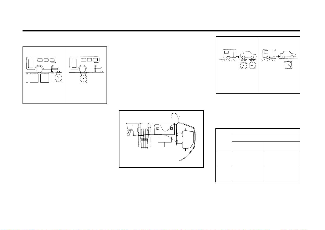
DRIVING YOUR HYUNDAI
2- 11
hitch, trailer tongue load and other op-
tional equipment.
3. The front or rear axle weight must not
exceed the Gross Axle Weight Rating
(GAWR) shown on the vehicle identifica-
tion plate (see page 8-1). It is possible
that your towing package does not ex-
ceed the GVWR but exceeds the GAWR.
Improper trailer loading and/or too much
luggage in the trunk can overload the
rear axle. Redistribute the load and check
the axle weight again.
4. The maximum permissible overhang of
the coupling point : 22.44 in.
(ATOS VAN : 22.36 in.)
C190E04X-GAT
Trailer Weight Limit
SSA2200B
Tongue load
Total trailer weight
Tongue loads can be increased or decreased
by redistributing the load in the trailer. This can
be verified by checking the total weight of the
loaded trailer and then checking the load on the
tongue.
NOTE:
1. Never load the trailer with more weight in
the back than in the front. About 60% of
the trailer load should be in the front half
on the trailer and the remaining 40% in
the rear.
2. The total gross vehicle weight with trailer
must not exceed the Gross Vehicle
Weight Rating (GVWR) shown on the
vehicle identification plate (see page 8-
1). The total gross vehicle weight is the
combined weight of the vehicle, driver,
all passengers and their luggage, cargo,
C190E03X
Ï
Ï
Towing Bracket
Attachment Location
CAUTION:
The following specifications are recommend-
ed when towing a trailer. The loaded trailer
weigh cannot safely exceed the values in
the chart below.
SSA2200D
Gross axle weight
Gross vehicle weight
lb
Trailer
Maximum Towable Weight
Auto Transaxle Manual Transaxle
With
Trailer
Brake
881.8
1543.2
Without
Trailer
Brake
881.8
881.8

DRIVING YOUR HYUNDAI
2- 12
15.If you have to stop while going uphill, do not
hold the vehicle in place by pressing on the
accelerator. This can cause the automatic
transaxle to overheat. Use the parking brake
or footbrake.
NOTE:
When towing, check transaxle fluid more
frequently.
CAUTION:
If overheating should occur when towing,
(temperature gauge reads near red zone),
taking the following action may reduce or
eliminate the problem.
1. Turn off the air conditioner.
2. Reduce highway speed.
3. Select a lower gear when going uphill.
4. While in stop and go traffic, place the gear
selection in park or neutral and idle the
engine at a higher speed.
being passed by a large vehicle, keep a
constant speed and steer straight ahead.
If there is too much wind buffeting, slow
down to get out of the other vehicle's air
turbulence.
8. When parking your car and trailer, especial-
ly on a hill, be sure to follow all the normal
precautions. Turn your front wheel into the
curb, set the parking brake firmly, and put
the transaxle in 1st or Reverse (manual) or
Park (automatic). In addition, place wheel
chocks at each of the trailer's tyres.
9. If the trailer has electric brakes, start your
vehicle and trailer moving, and then apply
the trailer brake controller by hand to be
sure the brakes are working. This lets you
check your electrical connection at the same
time.
10.During your trip, check occasionally to be
sure that the load is secure, and that the
lights and any trailer brakes are still working.
11.Avoid jerky starts, sudden acceleration or
sudden stops.
12.Avoid sharp turns and rapid lane changes.
13.Avoid holding the brake pedal down too long
or too frequently. This could cause the brakes
to overheat, resulting in reduced braking
efficiency.
14.When going down a hill, shift into a lower
gear and use the engine braking effect.
When ascending a long grade, downshift the
transaxle to a lower gear and reduce speed
to reduce chances of engine overloading
and or overheating.
WARNING:
o The tongue load should never exceed;
Auto Transaxle : 55.1 lb
Manual Transaxle 9: 61.7 lb
o Maximun permissible mass of the cou-
pling device (ATOS VAN only) : 44 lb
o Improperly loading your car and trailer
can serious affect its steering and brak-
ing performance causing a crash in which
you may be seriously injured or killed.
YC200E1-A
Trailer or Vehicle Towing Tips
1. Before towing, check hitch and safety chain
connections as well as proper operation of
the trailer running lights, brake lights, and
turn signals.
2. Always drive your vehicle at a moderate
speed (Less than 62 MPH).
3. Trailer towing requires more fuel than nor-
mal conditions.
4. To maintain engine braking efficiency and
electrical charging performance, do not use
fifth gear (manual transaxle) or overdrive
(automatic transaxle).
5. Always secure items in the trailer to prevent
load shift while driving.
6. Check the condition and air pressure of all
tires on the trailer and your car. Low tyre
pressure can seriously affect the handling.
Also check the spare tyre.
7. The vehicle/trailer combination is more af-
fected by crosswind and buffeting. When
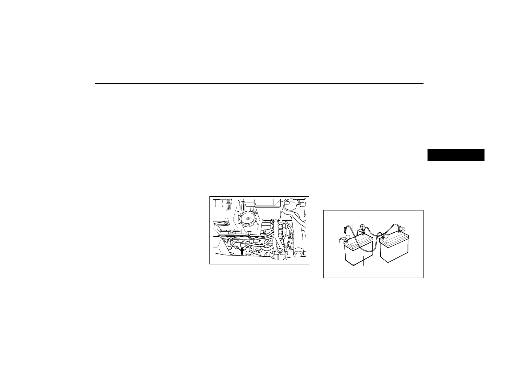
3-1
WHAT TO DO IN AN EMERGENCY
fitted with automatic transaxle ensure that
the transaxle selector is at the "P" or"N"
position.
2. Check the battery terminals and connec-
tions to ensure that these are clean and also
tight.
3. If the ignition warning lamps dim when the
engine is cranked and the battery terminals
have been checked, a discharged battery is
indicated.
4. Do not attempt to push or tow start the
vehicle, refer to "Jump Starting" for informa-
tion regarding engine starting when the bat-
tery is discharged.
DD020A1-E
IF THE ENGINE WILL NOT START
Seek assistance from the nearest Hyundai
dealer with regard to the method of ignition and
fuel system diagnosis.
CAUTION:
If the engine refuses to start, no attempt
should be made to push or tow start the
vehicle. Vehicles with automatic transaxle
or fuel injection will not be able to be started
in this manner since no drive is transmitted
through the automatic transaxle whilst the
engine is not running, and in the case of fuel
injected derivatives, the fuel pump will not
operate under tow start conditions. In addi-
tion, if the vehicle is equipped with an ex-
haust catalyst, damage to the catalyst may
result if the vehicle is tow started.
ZD000A1-E
3. WHAT TO DO IN AN
EMERGENCY
DD020B1-E
IF THE ENGINE CANNOT BE
CRANKED
1. If the vehicle is fitted with manual transaxle
ensure that the clutch pedal is depressed
whilst cranking the engine. If the vehicle is
ZD020C2-D
If Engine Turns Over Normally but Does
Not Start
AD020D1-A
If Engine Stalls While Driving
1. Reduce your speed gradually, keeping a
straight line. Move cautiously off the road to
a safe place.
2. Turn on your emergency flashers.
3. Try starting the engine again. If your vehicle
will not start, see “IF THE ENGINE WILL
NOT START”
DD030A1-E
JUMP STARTING
1. Check fuel level.
2. Check all connectors at coil and spark plugs.
Re-connect any that may be disconnected
or loose.
3. Check fuel line in the engine room.
4. If engine still refuses to start, call a Hyundai
dealer or seek other qualified assistance.
AX30030A
Negative to the engine
not to the battery
Positive to positive
Dead battery
Booster battery
D010C01X-1
Spark plug
3

WHAT TO DO IN AN EMERGENCY
3-2
3. If coolant is running out under the car or
steam is coming out from under the bonnet
stop the engine. Do not open the bonnet
until the coolant has stopped running or the
steaming has stopped. If there is no visible
loss of coolant and no steam, leave the
engine running and check to be sure the
engine cooling fan is operating. If the fan is
not running, turn the engine off.
4. Check to see if the water pump drive belt is
missing. If it is not missing, check to see that
it is tight. If the drive belt seems to be
satisfactory, check for coolant leaking from
the radiator, hoses or under the car. (If the
air conditioner had been in use, it is normal
for cold water to be draining from it).
WARNING:
While the engine is running, keep hands and
clothing away from moving parts such as
the fan and drive belts to prevent injury.
5. If the water pump drive belt is broken or
coolant is leaking out, stop the engine imme-
diately and call the nearest Hyundai dealer
for assistance.
WARNING:
Do not remove the radiator cap when the
engine is hot since steam and boiling water
may be ejected from the radiator resulting in
burns or scalding.
CAUTION:
Personal injury and damage to the vehicle
may occur if jump starting is not performed
correctly. If any doubt exists as to how this
operation should be performed, seek assis-
tance from qualified personnel.
WARNING:
Motor vehicle batteries contain sulphuric
acid and emit hydrogen gas. Protective cloth-
ing should be worn and care exercised to
prevent the acid from coming into contact
with skin or clothing and the vehicle. Naked
lights should not be permitted in the vicinity
of the battery. Care should be exercised to
preventsparks occurring during connection.
If acid accidentally comes into contact with
skin or eyes, the affected area should imme-
diately be flushed with copious amounts of
water and medical assistance sought.
1. Ensure that the booster battery is 12 volt
type. If the booster battery is installed in
another vehicle, ensure that the two vehi-
cles are not touching.
2. Turn off all unnecessary electrical equip-
ment in both vehicles.
3. Ensure that the engine of the vehicle provid-
ing the jump start is running prior to connec-
tion of the jump cables.
4. Connect the red jump cable to the positive
(+) terminal of the booster battery and the
other end to the positive (+) terminal of the
discharged battery.
5. Attach the black jump cable to the negative
(-) terminal of the booster battery, and the
other end to a ground point within the engine
compartment of the vehicle with the flat bat-
tery. Do not connect to the negative battery
terminal of the flat battery since sparks may
be generated with the subsequent risk of
explosion.
6. Raise the booster vehicle engine speed to
2,000 r.p.m. and start the engine of the
vehicle with the flat battery.
7. Remove jump cables in the reverse order of
installation (black cable first).
NOTE:
If the jump cable is incorrectly installed,
damage to the vehicle electrical system may
occur, in particular the electronic compo-
nents such as the Fuel Injection system
computer and the Automatic Transaxle com-
puter. The battery must never be discon-
nected whilst the engine is running.
XD040A1-E
IF THE ENGINE OVERHEATS
If the temperature gauge indicates overheating:
1. Pull off the road and stop as soon as it is
safe to do so.
2. Place the gear selector lever in "P" (auto-
matic), or neutral (manual transaxle, semi-
automatic transalxe) and set the parking
brake. If the air conditioner is on, turn it off.
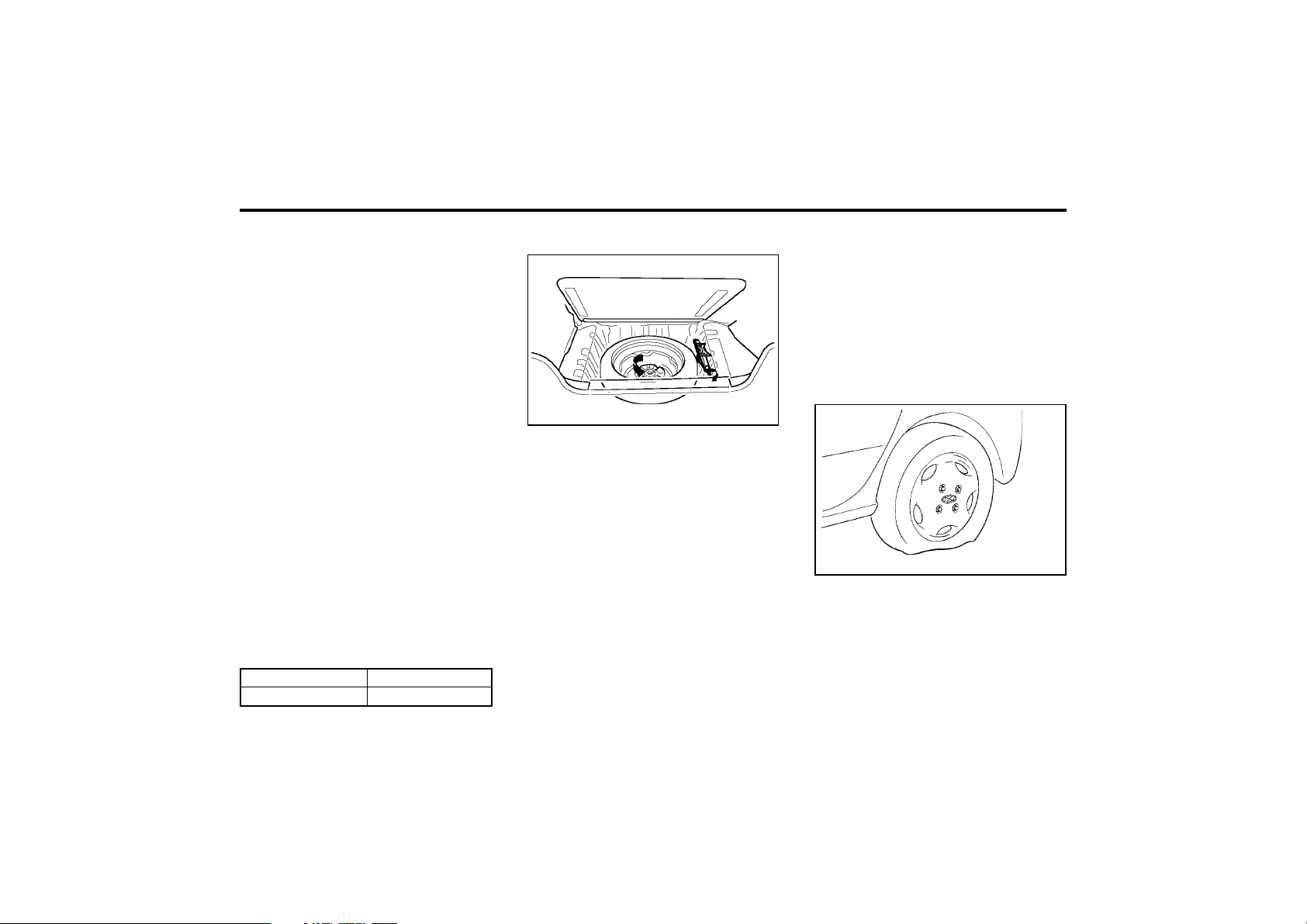
3-3
WHAT TO DO IN AN EMERGENCY
ZD050B1-E
Handling Spare Tyre
6. If the cause of the overheating cannot be
found, wait until the engine temperature has
returned to normal. Then, if coolant has
been lost, carefully remove the radiator cap
and add water to bring the fluid level in the
reservoir up to the base of the radiator fill
opening. Fill the coolant expansion tank to
the halfway mark.
7. Proceed with caution until it is established
that the engine is operating normally. If the
engine overheats repeatedly, the advice of a
Hyundai dealer should be sought.
CAUTION:
Serious loss of coolant indicates there is a
leak in the cooling system and this should
be checked as soon as possible by a Hyundai
dealer.
3. Passengers must not be allowed to remain
inside the vehicle during wheel changing. If
a puncture occurs whilst the vehicle is on a
motorway, the passengers should take ref-
uge on the motorway embankment to avoid
the possibility of injury occurring should the
vehicle be struck by other motorway traffic.
4. Wheel changing should be performed ac-
cording to the following instructions.
ZD050A1-E
FULL-SIZED SPARE TYRE
For customer convenience and satisfaction,
Hyundai has included a full-sized spare tyre
and wheel.
The following instructions should be observed.
1. Check inflation pressure as soon as possi-
ble after installing the spare tyre, and adjust
to the specified pressure.
2. The spare tyre pressure should be checked
once a month while the tyre is stored.
Spare Tyre Pressure (cold)
D040B01X
Remove the installation bolt to remove the spare
tyre. To install the spare tyre, tighten the bolt
firmly with your fingers until the spare tyre has
no more play.
SD060A1-E
IN THE EVENT OF A PUNCTURE
If a puncture occurs whilst driving the vehicle:
1. Bring the car to rest as soon as it is safe to
do so and with the minimum amount of
braking required which will assist in main-
taining the maximum amount of control. The
vehicle should be parked wherever possible
upon firm level ground to facilitate wheel
changing.
2. If the vehicle is creating a hazard and the
road conditions do not permit the wheel to
be changed safely, assistance should be
sought.
SD070A1-E
CHANGING A FLAT TYRE
D060A01X
It is of the utmost importance that care is
exercised when changing road wheels. Ensure
that the parking brake is set and that the gear
shift lever is in reverse (P, if the vehicle has
automatic transaxle).
Tyre Size
Inflation Pressure
155/70 R13
30 psi (210 kPa)
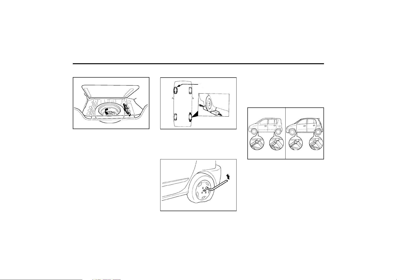
WHAT TO DO IN AN EMERGENCY
3-4
SD070B1-E
1. Obtain Spare Tyre and Tool
Remove the spare wheel, jack, jack handle and
tool bag from the boot.
NOTE:
The jack handle is equipped on the under-
side of the boot luggage mat.
SSA3050D
Flat tyre
SD070D1-E
2. Block the Wheel
Block the wheel that is diagonally opposite from
the flat tyre to prevent the vehicle from rolling
when the car is raised on the jack.
D060D01A
SD070E1-E
3. Loosen Wheel Nuts
The wheel nuts should be loosened slightly
before raising the car. To loosen the nuts, turn
the wheel brace counterclockwise. Ensure that
the wheel brace socket is seated properly on
the nut and that it cannot slip. Do not remove
the nuts at this stage.
SD070F1-F
4. Put the Jack in Place
The base of the jack should be placed on firm,
level ground. The jack should be positioned as
shown in the drawing.
D060E01A
<AMICA>
D060E01V
D040B01X
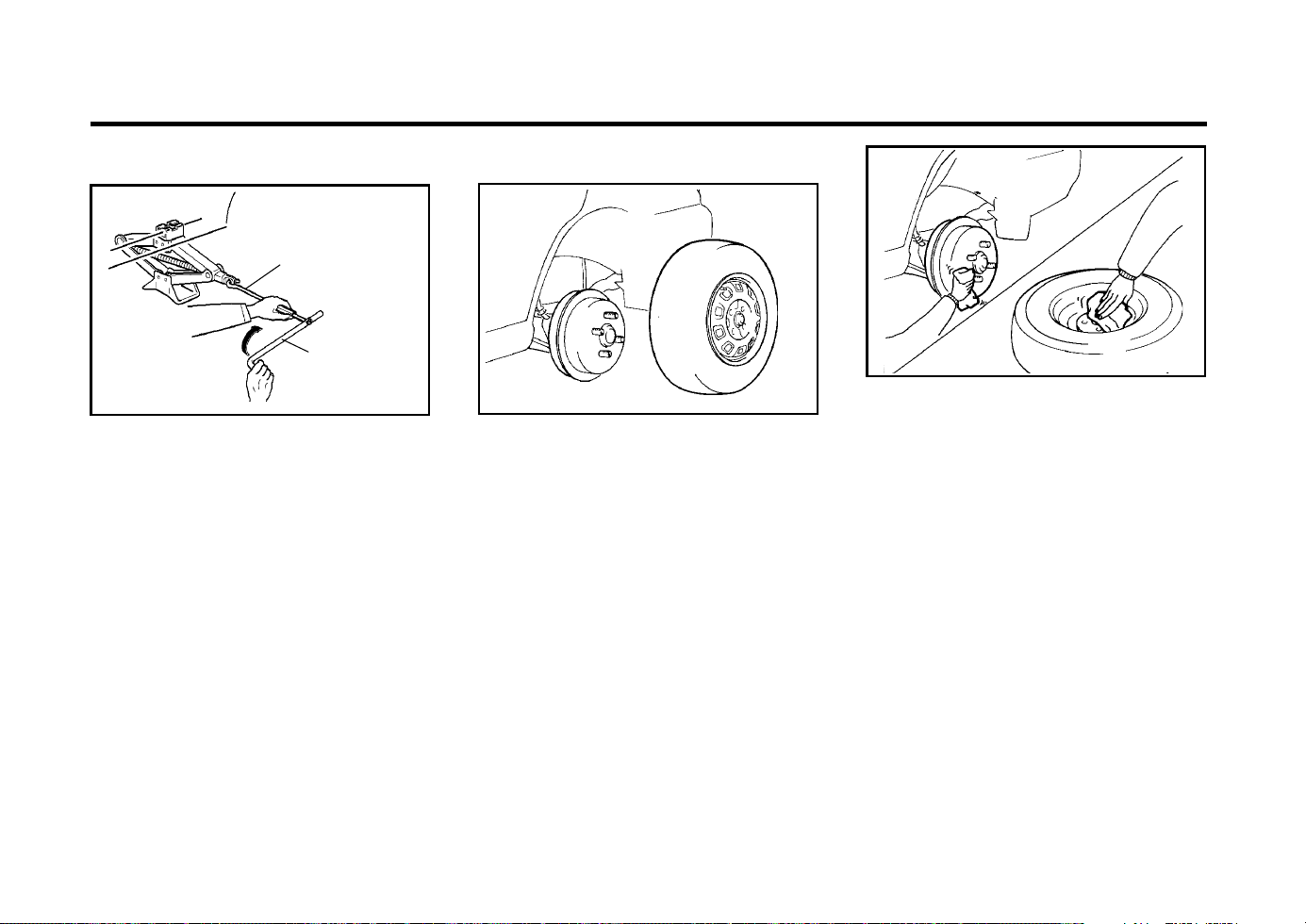
3-5
WHAT TO DO IN AN EMERGENCY
SD070G1-E
5. Raising the Car
AS30120A
SD070H1-E
6. Changing Wheels
Using the wheel brace, remove the nuts and
slide the wheel off the hub and wheel studs. Lie
the wheel flat to prevent it from rolling. Ensure
that the faces of the wheel and hub are clean.
Position the spare wheel over the studs and
slide it up to the hub.
Install the jack handle into the jack as shown in
the drawing. To raise the vehicle, turn the jack
handle clockwise. As the jack begins to raise
the vehicle, double check that it is properly
positioned and will not slip. If the jack is on soft
ground or sand, it may be necessary to place a
stout piece of timber under the base of the jack
to prevent it from sinking.
Raise the car high enough so that the fully
inflated spare wheel can be installed.
WARNING:
Do not get under the car when it is support-
ed by the jack! The jack is solely designed
for wheel changing and is not intended to
support the vehicle for other purposes. The
use of purpose designed supports is neces-
sary whilst the vehicle is raised and the
operator is required to get underneath.
WARNING:
It is important that the faces of the wheel
and hub are clean prior to installing the
wheel. The prescence of dirt or other matter
in the wheel or hub faces could result in the
wheel nuts becoming loose whilst the vehi-
cle is being driven.
AS30130A
HFC4022
Wrench bar
Wheel nut
Wrench
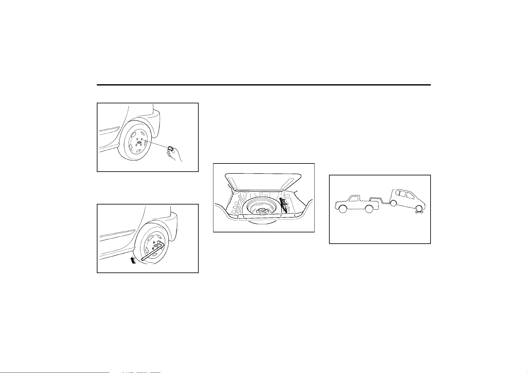
WHAT TO DO IN AN EMERGENCY
3-6
SD070I1-E
7. Re-install Wheel Nuts
D060H01A
Fit the wheel nuts onto the studs and tighten
with the wheel brace.
D060I01A
XD070J1-E
8. Lower Vehicle and Tighten Nuts
Lower the car to the ground turning the jack
handle counterclockwise. When the vehicle is
firmly on the ground, remove the jack and
tighten the wheel nuts securely. At the first
available opportunity, the wheel nut torque
should be checked with a suitable torque
wrench.
Wheel nut tightening torque
Steel wheel & aluminium alloy wheel:
65-80 lb.ft (900-1,100 kg.cm)
SD070K1-E
AFTER CHANGING WHEELS
The pressure of the spare tyre should be
checked at the first available opportunity. If any
doubt exists as to the tyre pressure, the vehicle
should be driven slowly to the nearest service
station and the tyre pressure checked and
adjusted as required.
If the valve cap is lost from any of the valves,
a replacement should be obtained and fitted at
the first available opportunity. The valve cap
prevents the ingress of dirt which may cause
the valve to stick and therefore leak and is part
of the valve sealing function.
Ensure that the spare wheel, jack and jack
handle as well tools are correctly located in the
boot of the vehicle to prevent damage and
noise.
D080A01A
o OK FOR AUTOMATIC OR MANUAL
TRANSAXLE EQUIPPED VEHICLE
SD080A1-E
VEHICLE TOWING OR RECOVERY
CAUTION:
An incorrect tow or recovery could result in
serious damage to the vehicle. If any dam-
age to the suspension, steering or transaxle
is apparent or suspected, a towing ambu-
lance must be used.
D060J01X
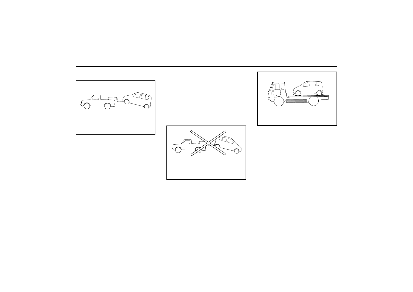
3-7
WHAT TO DO IN AN EMERGENCY
SD090A1-E
Manual Transaxle Vehicle
o If a suspended tow is being given to the
rear, the ignition key must be at the "ACC"
position since the steering lock is not
designed to withstand the force required
to hold the front wheels straight during
the tow.
o The vehicle must not be towed with the
front wheels on the ground for more than
thirty miles.
D080B01A
o OK FOR AUTOMATIC OR MANUAL
TRANSAXLE EQUIPPED VEHICLE
WITH NO DAMAGE
The vehicle may be towed by the conventional
method using the towing eye at the front of the
vehicle as an attachment point. In addition, a
suspended tow with or without an ambulance
may be used with either the front or the rear
wheels being suspended, provided the above
caution is observed.
In addition, the following points must
be noted:
o If towing by conventional means, the ig-
nition key must be at the "ACC" position,
otherwise the steering lock will be acti-
vated.
o Because the brake system and steering
sys-tem power assistance is derived from
the engine, the amount of effort required
to stop or steer the vehicle will be greater
than normal.
SD100A2-E
Automatic Transaxle Vehicle
D080C01A
o NOT OK FOR AUTOMATIC TRANSAXLE
EQUIPPED VEHICLE
o OK FOR MANUAL TRANSAXLE
The vehicle may be towed by the conventional
method using the towing eye at the front of the
vehicle as an attachment point.
In addition, a suspended tow may be given to
the front of the vehicle without an ambulance. In
the event of a suspended tow being given to the
rear of the vehicle, the use of an ambulance is
imperative.
D080C02A
o OK FOR AUTOMATIC OR MANUAL
TRANSAXLE EQUIPPED VEHICLE
CAUTION:
The following restriction must be observed
in order to avoid serious damage to the
transaxle.
The vehicle must never be towed from the
rear with the front wheels on the ground.
The vehicle must not be towed until transaxle
fluid has been added to bring the level up to
the "HOT" marking on the dipstick. (The
level will need to be reduced again after
towing).
The vehicle must not be towed at speeds
faster than 25 mph. or distances greater
than fifty miles. The general points regard-
ing the steering lock etc. described in the
preceding section (Manual transaxle vehicle)
should be observed.
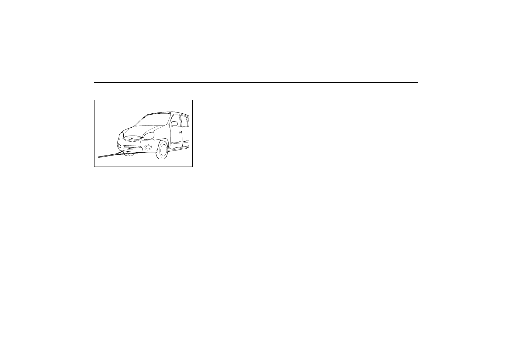
WHAT TO DO IN AN EMERGENCY
3-8
D080D01X-GAT
Emergency Towing
D080D01X
For emergency towing when no commercial
tow vehicle is available, attach a tow cable,
chain or strap to the two hooks under the front
of your car. Do not attempt to tow your vehicle
in this manner on any unpaved surface. This
could result in serious damage to your car.
Nor should it be attempted if the wheels, drive
train, axles, steering or brakes are damaged.
Before towing, be sure the transaxle is in neu-
tral and the key is in "ACC" (with the engine off)
or in the "ON" position (with the engine run-
ning). A driver must be in the towed car to steer
it and operate the brakes.
D120A02A-GAT
IF YOU LOSE YOUR KEYS
Information about the key of immobilizer sys-
tem will be found on page 1-2.

CORROSION PREVENTION & APPEARANCE CARE
4-1
moved. Should any damage to or deterioration
of the underbody coating be apparent, the ad-
vice of a Hyundai dealer regarding the use of a
compatible repair material should be sought.
NOTE:
The underbody should never be steam
cleaned since the underbody coating may
be removed by this process.
During the interim period between power wash-
ing the underbody, the more vulnerable areas
such as wheelarches should be hosed off,
particularly during the winter season to prevent
prolonged contact of road salt with the body.
Ensure that the various drain points located at
bottom of the door panels are kept clear, to
prevent water becoming trapped within the cavi-
ties. Wherever possible, the parking of the
vehicle in a confined, poorly ventilated location
(e.g.) garage should be avoided when the vehi-
cle is wet or covered with snow or ice. Under
these conditions, the internal cavities of the
vehicle will remain damp for long periods of
time which encourage corrosion. Parking the
vehicle where good ventilation exists is prefer-
able.
ZE020B1-E
Underbody Coatings
Every Hyundai passenger car receives a full
underbody and cavity injection treatment during
production. In order that this treatment may
retain maximum effectiveness, it is recommend-
ed that the underbody receives a power wash
and a thorough inspection after each winter
season. In so doing any accumulations of mud,
which act as moisture traps and combine with
road salts to accelerate corrosion, will be re-
ZE000A1-E
4. CORROSION PRE-
VENTION & AP-
PEARANCE CARE
ZE020A1-E
APPEARANCE CARE
In using the most advanced design and con-
struction practices, every Hyundai is built to
retain its original factory finish for many years.
However, long term durability is also greatly
dependant upon maintaining the various pro-
tection systems and coatings used in manufac-
ture since constant exposure to the elements
will eventually result in their breakdown and
loss of effectiveness. The following sugges-
tions are made to assist in the maintenance of
the vehicle bodywork.
ZE020C1-E
Interior
During the winter period, it is possible that the
carpet within the passenger compartment may
become wet. The carpet should not be allowed
to remain in this condition for prolonged periods
JE050A1-E
VALETING
Regular cleaning of the exterior paintwork serves
two important functios. Firstly, the removal of
abrasive dirt and contaminants will maintain the
lustre of the paintwork and will prevent
discolouration and dulling due to prolonged con-
tact.
Secondly, the presence of damage through
impact or abrasion will be apparent allowing
early rectification to be made thus preventing
corrosion from becoming established and
spreading beneath the paint film. To avoid "wa-
ter spotting" the vehicle should not be washed
in direct sunlight particularly in the case of
vehicles having dark body colours. The heat
from the sun rays is absorbed by the paint film
increasing the surface temperature. This action
causes water used for washing to evaporate
quickly leaving behind the deposits from the
water and the shampoo used.
Use only a shampoo intended for the purpose
and ensure that the body work is thoroughly
wetted to soften the dirt film prior to attempting
to remove this.
After removing the dirt film with a soft sponge,
the body work should be thoroughly rinsed and
then dried with a good quality ch mois leather to
prevent streaking or spotting of the paint work.
since the carpet may begin to create musty
smells and promote internal corrosion of the
floorpan.
4

CORROSION PREVENTION & APPEARANCE CARE
4-2
Household detergents, solvents and abrasive
cleaning materials should not be used in order
ot avoid damaging the paint film.
Plastic wheel covers should be cleaned using a
sponge and water. Cast alloy wheels should be
cleaned using a mild soap or neutral detergent.
Abrasive compounds must not be used since in
the event of these damaging the lacquer coat-
ing, oxidisation of the aluminium wheel will
occur, spoiling the appearance.
The use of an a toothbrush will facilitate clean-
ing between the wheel "spokes".
JE080A1-E
BUMPER MAINTENANCE
The special material from which the bumpers
are manufactured warrants special attention to
preserve the appearance of thebumpers. Avoid
contact with battery electrolyte or brake fluid
and ensure that accidental spillages are imme-
diately flushed with water.
Do not use abrasive cleaning materials which
may damage the bumpers.
Avoid subjecting the bumpers to high tempera-
tures such as may be encountered in high bake
paing ovens.
JE060A1-E
STAIN/SPOT REMOVAL
Should tree sap, dead insects or tar prove to be
difficult to remove from the paint film, turpentine
or a proprietary paint cutting compound may be
used. Ensure that the area to be cleaned is not
rubbed intensively to prevent breaking through
the colour coat and exposing the under coat.
JE070A1-E
POLISHING
The exterior paint work should be polished with
a proprietary wax polish when water no longer
collects in bead form on the paint work. The
instructions of the product manufacturer should
be adhered to.
JE090A1-E
ACCIDENT REPAIRS
In the event of the body work sustaining dam-
age, the following points should be noted prior
to repairs being undertaken.
If body panels are replaced or repaired, anti
corrosion treatment must be applied to the
repair area. The product used must be compat-
ible with those used in manufacture. It is recom-
mended that repairs are entrusted to a Hyundai
dealer to ensure that replacement parts used
are of the same high quality as those used in
manufacture of the vehicle and that the correct
repair methods and materials will ensure ade-
quate levels of corrosion protection and the
continued validity of the Anti Perforation War-
ranty.
JE100A1-E
SEAT BELTS
Seat belts should be cleaned only with a mild
soap solution. Strong detergents, solvens or
bleaches may damage the belt webbing and
therefore reduce the effectiveness of the belt.
Belts which display signs of fraying, wear of cut
should be replaced.
JE110A1-E
INTERIOR VALETING
The soft trim and carpets should be maintained
with the regular use of a vacuum cleaner. Heavy
soiling should be removed with a dry cleaning
agent recommended for this purpose following
the instructions of the product manufacturer.
Paint thinner, solvents or other such cleaning
materials should not be used since damage to
the upholstery may result.
JE120A1-E
WINDOWS
A proprietary glass cleaner should be used to
clean the inside of the windows. However, the
rear heated windscreen must only be cleaned
using a light horizontal cleaning action. Care
should be exercised to avoid the use of abra-
sive cleaners or contact with items of jewellery
which may damage the heating elements.

VEHICLE MAINTENANCE REQUIREMENTS
5-1
NOTE:
The inspection and testing of certain elec-
tronic fuel injection/engine management and
automatic transmission control systems re-
quire specialised electronic equipment spe-
cifically designed for Hyundai vehicles. The
use of general purpose electrical test equip-
ment may result in damage to the control
unit microprocessors.
be sure these are equivalent to the quality of
the original Hyundai parts. Your Service Pass-
port provides further information about your
warranty coverage.
DF020F1-E
SERVICE HISTORY
It is important that all scheduled maintenance
services are recorded in the warranty and ser-
vice passport to ensure that proof of mainte-
nance is available when warranty service is
required.
DF020A1-E
MAINTENANCE AND SERVICING
REQUIREMENTS
To ensure the continued reliability and safety of
the vehicle, certain routine maintenance opera-
tions are required at specific mileage or time
intervals.
It is the responsibility of the vehicle owner to
ensure that the maintenance schedules shown
in both this Owners Manual and the Warranty
and Service Passport are adhered to.
The new vehicle warranty may be invalidated if
the routine maintenance operations are not
performed in line with the recommendations
outlined and the safety and durability of the
vehicle adversely affected.
It is recommended that all maintenance opera-
tions with the exception of the daily operating
checks are entrusted to a Hyundai dealer to
ensure that the latest repair and maintenance
procedures and specialized servicing tools are
employed. In addition, the use of genuine
Hyundai replacement parts will ensure that the
vehicle safety and performance will not be
compromised.
ZF010A1-A
5. VEHICLE MAINTE-
NANCE REQUIRE-
MENTS
SF020C1-B
Specified Scheduled Procedures
These are the procedures such as inspections,
adjustments and replacements that are listed in
the maintenance charts starting on page 5-2.
These procedures must be performed at the
intervals shown in the maintenance schedule
to assure that your warranty remains in effect.
Although it is strongly recommended that they
be performed by the factory-trained or distribu-
tor-trained technicians at your Hyundai dealer,
these procedures may be performed at any
qualified service facility.
It is suggested that genuine Hyundai service
parts be used for any required repairs or re-
placements. Other parts of equivalent quality
such as engine oil, engine coolant, manual or
auto transaxle oil, brake fluid and so on which
are not supplied by Hyundai Motor Company or
its distributor may be used without affecting
your warranty coverage but you should always
5
VEHICLE MAINTENANCE REQUIREMENTS
5-2
XF040C1-E
SCHEDULED MAINTENANCE
In order to ensure the continued safety, reliability and longevity of the
vehicle, the following maintenance service operations should be per-
formed at the time or mileage intervals specified.
It is recommended that all routine maintenance services are entrusted to
a Hyundai dealer to ensure that the manufacturers recommended proce-
dures are employed and that only genuine Hyundai replacement parts are
used. Incorrect maintenance techniques or the use of non genuine
replacement parts may invalidate the vehicle warranty.
F030B02X-EAT
R : Replace I : Inspect and, after inspection, clean, adjust, repair or replace if necessary
ENGINE CONTROL SYSTEM MAINTENANCE
1 ENGINE OIL & FILTER (SG OR ABOVE)
2 DRIVE BELT (WATER PUMP & GENERATOR)
3 FUEL FILTER (MFI)
4 FUEL LINES, FUEL HOSES & CONNECTIONS
5 TIMING BELT
6 VAPOR HOSE & FUEL FILLER CAP
7 VACUUM CRANKCASE VENTILATION HOSES
8 AIR CLEANER FILTER
9 SPARK PLUGS
10 VALVE CLEARANCE
No. DESCRIPTION
60
72
R
I
R
R
R
I
50
60
R
R
I
R
I
I
40
48
R
R
I
R
R
I
10
12
R
I
I
MILES X 1000
MONTHS
30
36
R
I
I
I
20
24
R
I
R
R
I

VEHICLE MAINTENANCE REQUIREMENTS
5-3
F030C02X-EAT
R : Replace I : Inspect and, after inspection, clean, adjust, repair or replace if necessary
DESCRIPTION
GENERAL MAINTENANCE
COOLING SYSTEM
ENGINE COOLANT
ENGINE COOLANT SPECIFIC GRAVITY
MANUAL TRANSAXLE OIL
AUTOMATIC TRANSAXLE FLUID AND FILTER
BRAKE PIPES, HOSES, AND CONNECTIONS
BRAKE FLUID
CLUTCH FLUID
REAR BRAKE LININGS AND CYLINDERS
BRAKE PADS
SUSPENSION AND STEERING SYSTEM
FRONT SUSPENSION BALL JOINTS
POLLEN FILTER
TRANSFER CASE OIL
REAR AXLE OIL
CLEAN PROPELLAR SHAFT/RETIGHTEN BOLTS
REAR WHEEL BEARINGS
TYRE CONDITION AND PRESSURE (including Spare)
LUBRICATE LOCKS AND HINGES
CHECK ALL ELECTRICAL SYSTEMS
ROAD TEST
CHECK ALL SYSTEMS WITH HI-SCAN
60
72
I
I
I
R
I
R
R
I
I
I
I
R
I
I
I
I
I
I
I
I
I
50
60
I
I
I
I
I
I
I
I
I
I
R
R
R
I
I
I
I
I
I
I
40
48
I
I
I
I
I
R
R
I
I
I
I
R
I
I
I
I
I
I
I
I
I
30
36
I
R
I
I
I
I
I
I
I
I
I
R
I
I
I
I
I
I
I
I
I
20
24
I
I
I
I
I
R
R
I
I
I
I
R
I
I
I
I
I
I
I
I
I
10
12
I
I
I
I
I
I
I
I
I
I
R
I
I
I
I
I
I
I
I
I
MILES X 1000
MONTHS
NO.
1
2
3
4
5
6
7
8
9
10
11
12
13
14
15
16
17
18
19
20
21
22

VEHICLE MAINTENANCE REQUIREMENTS
5-4
F040A02X-EAT
MAINTENANCE UNDER SEVERE USAGE CONDITIONS
The following items must be serviced more frequently on cars normally used under severe driving conditions. Refer to the chart below for the appropriate
maintenance intervals.
R : Replace I : Inspect and, after inspection, clean, adjust, repair or replace if necessary
SEVERE DRIVING CONDITIONS
A - Repeated short distance driving
B - Extensive idling
C - Driving in dusty, rough roads
D - Driving in areas using salt or other corrosive materials or in
very cold weather
E - Driving in sandy areas
F - More than 50% driving in heavy city traffic during hot weather above
90°F (32°C)
G - Driving in mountainous areas
H - Towing a trailer
I - Driving for rental car, taxi, commercial car or vehicle towing
J - Driving over 100 MPH
ENGINE OIL AND FILTER
AIR CLEANER FILTER
SPARK PLUGS
TIMING BELT
BRAKE PADS, CALIPERS AND ROTORS
REAR BRAKE DRUMS/LININGS,
PARKING BRAKE
STEERING GEAR BOX, LINKAGE
& BOOTS/LOWER ARM BALL JOINT
DRIVESHAFTS AND BOOTS
MANUAL TRANSAXLE OIL TRANSAXLE OIL
AUTOMATIC TRANSAXLE FLUID
DRIVING
CONDITION
MAINTENANCE
INTERVALS
MAINTENANCE
OPERATION
R
R
R
R
I
I
I
I
R
R
EVERY 4,500 MILE OR 6 MONTHS
MORE FREQUENTLY
MORE FREQUENTLY
EVERY 37,000 MILE OR 48 MONTHS
MORE FREQUENTLY
MORE FREQUENTLY
MORE FREQUENTLY
EVERY 9,000 MILE OR 12 MONTHS
EVERY 60,000 MILE
EVERY 27,000 MILE
MAINTENANCE ITEM
A, B, C, F, H
C, E
B, H
D, E, F, G
C, D, G, H
C, D, G, H
C, D, E, F
C, D, E, F
A, C, D, E, F, G, H, I, J
A, C, E, F, G, H, I

VEHICLE MAINTENANCE REQUIREMENTS
5-5
F060A01A-AAT
EXPLANATION OF SCHEDULED MAIN-
TENANCE ITEMS
F060M01A-AAT
o Engine oil and filter
The engine oil and filter should be changed at
the intervals specified in the maintenance sched-
ule. If the car is being driven in severe condi-
tions, more frequent oil and filter changes are
required.
F060B01A-AAT
o Drive belts
Inspect all drive belts for evidence of cuts,
cracks, excessive wear or oil saturation and
replace if necessary. Drive belts should be
checked periodically for proper tension and
adjusted as necessary.
F060C01A-AAT
o Fuel filter
A clogged filter can limit the speed at which the
vehicle may be driven, damage the emission
system and cause hard starting. If an exces-
sive amount of foreign matter accumulates in
the fuel tank, the filter may require replacement
more frequently.
After installing a new filter, run the engine for
several minutes, and check for leaks at the
connections.
F060D01A-AAT
o Fuel lines, fuel hoses and connec-
tions
Check the fuel lines, fuel hoses and connec-
tions for leakage and damage. Replace any
damaged or leaking parts immediately.
F060E01A-AAT
o Timing belt
Inspect all parts related to the timing belt for
damage and deformation. Replace any dam-
aged parts immediately.
F060G01A-AAT
o Vapour hose and fuel filler cap
The vapor hose and fuel filler cap should be
inspected at those intervals specified in the
maintenance schedule. Make sure that a new
vapour hose or fuel filler cap is correctly re-
placed.
F060F01A-AAT
o Vacuum, crankcase
ventilation hoses
Inspect the surface of hoses for evidence of
heat and/or mechanical damage. Hard and
brittle rubber, cracking, tears, cuts, abrasions,
and excessive swelling indicate deterioration.
Particular attention should be paid to examine
those hose surfaces nearest to high heat sourc-
es, such as the exhaust manifold.
Inspect the hose routing to assure that the
hoses do not come in contact with any heat
source, sharp edges or moving component
which might cause heat damage or mechanical
wear. Inspect all hose connections, such as
clamps and couplings, to make sure they are
secure, and that no leaks are present. Hoses
should be replaced immediately if there is any
evidence of deterioration or damage.
F060H01A-AAT
o Air cleaner filter
A Genuine Hyundai air cleaner filter is recom-
mended when filter is replaced.
F060J01A-AAT
o Spark plugs
Make sure to install new spark plugs of the
correct heat range.
F060N01X-GAT
o Valve clearances
Incorrect valve clearance will not only result in
unsteady engine operation, but will also cause
excessive noise and reduced engine perfor-
mance. Inspect valve clearance and adjust as
required while the engine is hot.
Valve-to-rocker arm clearance
Intake valves ..... 0.008 in. (0.2 mm)
Exhaust valves .... 0.010 in. (0.25 mm)

VEHICLE MAINTENANCE REQUIREMENTS
5-6
F070B01A-GAT
o Cooling System
Check the cooling system part, such as radia-
tor, coolant reservoir, hoses and connections
for leakage and damage. Replace any dam-
aged parts.
F070C01A-AAT
o Engine coolant
The coolant should be changed at the intervals
specified in the maintenance schedule.
F070D01X-GAT
o Manual or semi-automatic transaxle
oil
Inspect the manual or semi-automatic transaxle
oil according to the maintenance schedule.
NOTE:
If the oil level is low, check for possible
leaks before adding oil. Do not overfill.
F070E01X-AAT
o Automatic transaxle fluid
The fluid level should be in the “HOT” range of
the dipstick, after engine and transaxle are at
normal operating temperature. Check the Auto-
matic Transaxle Fluid level with the engine
running and the transaxle in neutral, with the
parking brake properly applied. Use ESSO
JWS3314 when adding or changing fluid.
F070F01A-AAT
o Brake hoses and lines
Visually check for proper installation, chafing,
cracks, deterioration and any leakage. Replace
any deteriorated or damaged parts immediate-
ly.
F070G02A-AAT
o Brake fluid
Check brake fluid level in the brake fluid reser-
voir. The level should be between "MIN" and
"MAX" marks on the side of the reservoir. Use
only hydraulic brake fluid conforming to DOT 3
or DOT 4.
F070H01A-AAT
o Rear brake drums/linings, parking
brake
Check the rear brake drums and linings for
scoring, burning, leaking fluid, broken parts,
and excessive wear. Inspect the parking brake
system including the parking brake lever and
cables. For detailed service procedures, refer
to the Shop Manual.
F070J01A-AAT
o Brake pads, calipers and rotors
Check the pads for excessive wear, discs for
run out and wear, and calipers for fluid leakage.
F070K01A-AAT
o Exhaust pipe and muffler
Visually inspect the exhaust pipes, muffler and
hangers for cracks, deterioration, or damage.
Start the engine and listen carefully for any
exhaust gas leakage. Tighten connections or
replace parts as necessary.
F070L01A-AAT
o Suspension mounting bolts
Check the suspension connections for loose-
ness or damage. Retighten to the specified
torque.
F070M01A-AAT
o Steering gear box, linkage & boots/
lower arm ball joint
With the vehicle stopped and engine off, check
for excessive free-play in the steering wheel.
Check the linkage for bends or damage. Check
the dust boots and ball joints for deterioration,
cracks, or damage. Replace any damaged
parts.
F070N01A-AAT
o Power steering pump, belt and hos-
es
Check the power steering pump and hoses for
leakage and damage. Replace any damaged
or leaking parts immediately. Inspect the power
steering belt for evidence of cuts, cracks, ex-
cessive wear, oiliness and proper tension.
Replace or adjust it if necessary.

VEHICLE MAINTENANCE REQUIREMENTS
5-7
F070P01A-AAT
o Driveshafts and boots
Check the drive shafts, boots and clamps for
cracks, deterioration, or damage. Replace any
damaged parts and, if necessary, repack the
grease.
F070Q01A-AAT
o Air conditioning refrigerant
Check the air conditioning lines and connec-
tions for leakage and damage. Check air con-
ditioning performance according to the relevant
shop manual if necessary.
F070R02X-GAT
o Rear wheel bearing grease
Check rear wheel bearing grease whenever
the brake drums are removed to inspect the
rear brake system.
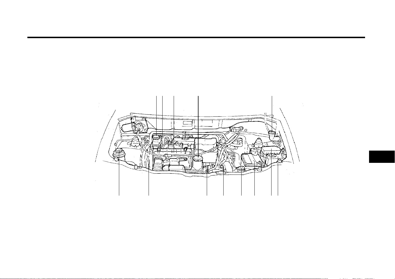
DO-IT-YOURSELF MAINTENANCE
6-1
ZG000A1-E
6. DO-IT-YOURSELF MAINTENANCE
1. Brake fluid reservoir
2. Brake booster
3. Air cleaner
4. Engine oil filler cap
5. Windscreen washer fluid reservoir cap
6. Power steering fluid reservoir
7. Engine oil level dipstick
8. Spark plug
9. Automatic transaxle fluid level dipstick
(Automatic T/A only)
10. Radiator cap
11. Battery
12. Relay box
13. Engine coolant reservoir
G010A01X-EAT
ENGINE COMPARTMENT (For Multiport Fuel Injection)
5
1312
9
1 4
10 118
6
G010A03X
2 3
7
6
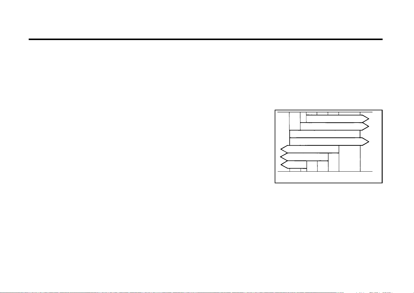
DO-IT-YOURSELF MAINTENANCE
6-2
ZG020B1-E
GENERAL CHECKS
Engine Compartment
The following should be checked regularly:
o Engine oil level and condition
o Transaxle fluid level and condition
o Brake reservoir fluid level
o Engine coolant level
o Windscreen washer fluid level
o Accessory drive belt condition
o Coolant hose condition
o Fluid leaks (on or below components)
o Power steering fluid level
o Tyre pressure and condition (including spare)
o Battery condition
ZG020C1-A
Vehicle Exterior
The following should be checked monthly:
o Overall appearance and condition
o Wheel condition and wheel nut tightness
o Exhaust system condition
o Light condition and operation
o Windscreen glass condition
o Wiper blade condition
o Paint condition and corrosion
o Fluid leaks
o Door and hood lock condition
o Air filter element condition
G020C02X-GAT
Vehicle Interior
The following should be checked each time
when the vehicle is driven:
o Lights operation
o Windscreen wipers operation
o Horn operation
o Defroster, heating system operation (and air
conditioning, if installed)
o Steering operation and condition
o Mirror condition and operation
o Turn signal operation
o Accelerator pedal operation
o Brake operation, including parking brake
o Manual transaxle operation, including clutch
operation
o Automatic transaxle operation, including
"Park" mechanism operation
o Seat control condition and operation
o Seat belt condition and operation
o Sunvisor operation
If you notice anything that does not operate
correctly or appear to be functioning correctly,
inspect it carefully and seek assistance from
your Hyundai dealer if service is needed.
ZG030A1-A
CHECKING THE ENGINE OIL
Engine oil is essential to the performance and
service of the engine. It is suggested that you
check the oil level at least once a week in
normal use and more often if you are on a trip
or driving in severe conditions.
ZG030B1-E
Recommended Oil
SSA6030B
°C
°F
-25
-13
20W-40 20W-50
15W-40 15W-50
10W-30
10W-40 10W-50
5W-40
5W-30
5W-20
40
104
20
68
10
50
0
32
-15
5
-10
-14
SH, SG or SG/CD (API) multi-grade and fuel
efficient oil is recommended.
NOTE:
SAE 5W-20 is not recommended for sus-
tained high speed vehicle operation.
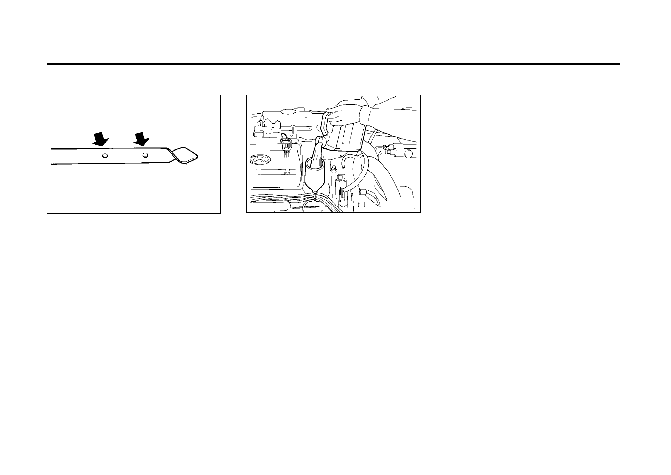
DO-IT-YOURSELF MAINTENANCE
6-3
AS60050A
FL
ZG030C1-A
To Check the Oil Level
Before checking the oil, warm up the engine to
normal operating temperature and be sure it is
parked on level ground. Turn the engine off.
Wait a minute, then remove the dipstick, wipe it
off, fully reinsert the dipstick and withdraw it
again. Then note the highest level the oil has
reached on the dipstick. It should be between
the upper ("F") and lower ("L") range.
ZG030D1-A
Adding Oil
G030D01A
If the oil level is close to or below the "L" mark,
add oil until it reaches the "F" mark. To add oil:
1. Remove the oil filler cap by turning it coun-
terclockwise.
2. Add oil, then check the level again. Do not
overfill.
3. Replace the cap by turning it clockwise.
The distance between the "F" and "L" marks is
equal to about 1 quart of oil.
G350A01A-GAT
ENGINE OIL CONSUMPTION
Function of Engine Oil
Engine oil has the primary function of lubricat-
ing and cooling the inside of the engine.
Engine oil consumption
If is normal that an engine should consume
some engine oil while normal driving. The cause
of oil consumption in a normal engine are as
follows;
o Engine oil is used to lubricate pistons, piston
rings and cylinders.
o A thin film of oil is left on the cylinder wall
when a piston moves downwards in the
cylinder. High negative pressure generated
during engine operation sucks some of the
oil into the combustion chamber.
This oil with some oil of the cylinder wall is
burned by the high temperature combustion
gases during the combustion process.
o The engine oil consumption is strongly ef-
fected by the viscosity and quality of oil,
engine rpm and driving condition etc. The
engine oil is more consumed under severe
driving conditions such as high speeds and
frequent acceleration and deceleration than
normal driving condition.
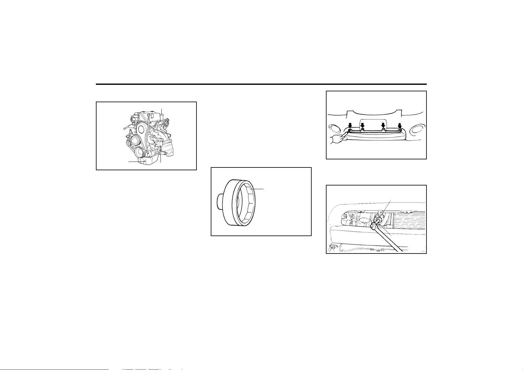
DO-IT-YOURSELF MAINTENANCE
6-4
G040A01X-GAT
CHANGING THE OIL AND FILTER
Oil filler cap
Oil filter
G040A01X
Drain plug
The engine oil and filter should be changed at
those intervals specified in the maintenance
schedule in Section 5. If the car is being driven
in severe conditions, more frequent oil and filter
changes are required.
The procedure for changing the oil and filter is
as follows:
1. Park the car on level ground and set the
parking brake. Start the engine and let it
warm up until the needle on the coolant
temperature gauge moves above the lowest
mark. Turn the engine off and place the gear
selector lever in "P" (automatic transaxle) or
reverse gear (manual transaxle, semi-auto-
matic transaxle).
2. Open the hood and remove the engine oil
filler cap.
3. Slide underneath the car and loosen the
drain plug by turning it counterclockwise
with a wrench of the proper size. Be sure
that a drain pan is in position to catch the oil
as it drains out, then remove the drain plug.
WARNING:
Be very careful when draining the engine oil
as it may be hot enough to burn you!
4. When the oil has stopped draining, replace
the drain plug using a new washer and
retighten by turning it clockwise.
G040A03X
6. First, remove the vehicle number plate. Un-
screw the tapping screws (4EA) and re-
move the front bumper grille.
G040A04X
SST (09263-02000)
Extension bar
7. Using the special tool (09263-02000), re-
move the oil filter through the bumper hole.
G040A02X
SST (09263-02000)
5. Before removing the oil filter, prepare the
special tool (oil filter wrench), extension bar
and ratchet handle.
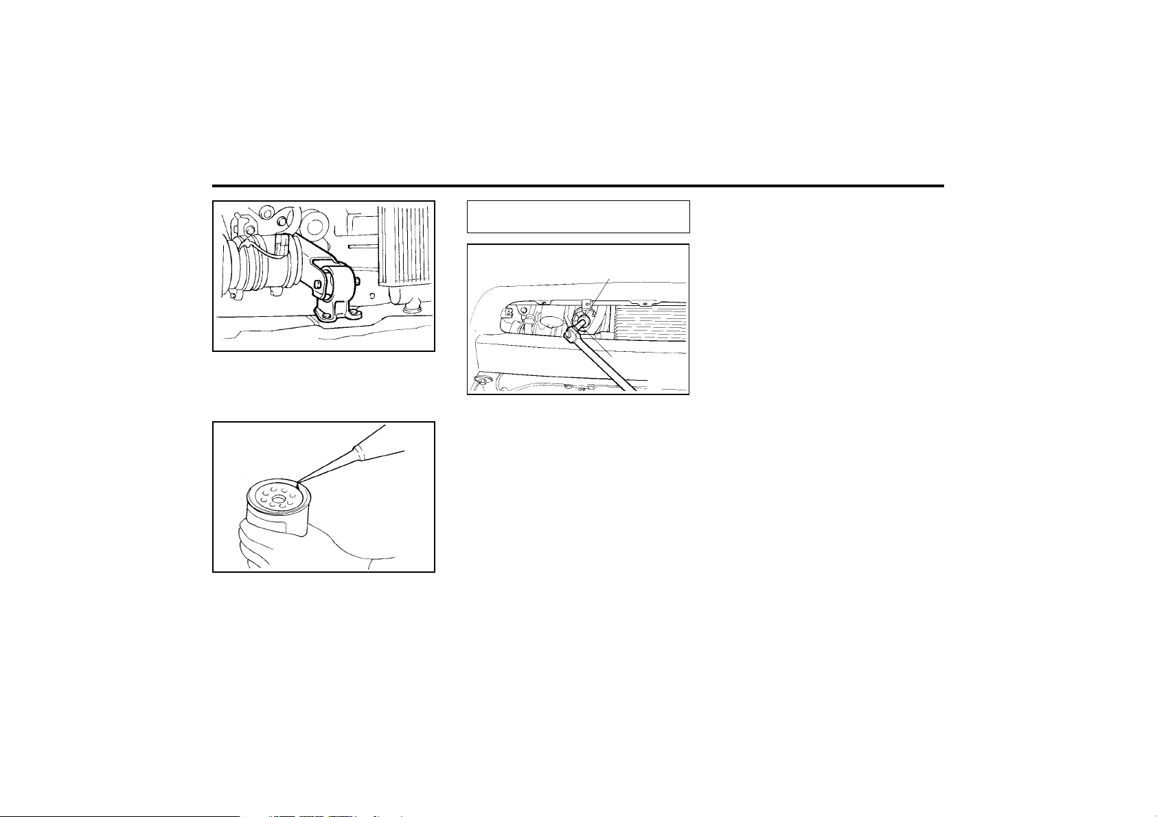
DO-IT-YOURSELF MAINTENANCE
6-5
G040A05X
NOTE:
Always dispose of used engine oil in an
environmentally acceptable manner. It is
suggested that it be placed in a sealed con-
tainer and taken to a service station for
reclamation. Do not pour the oil on the
ground or put it into the household trash.
WARNING:
Used motor oil may cause irritation or can-
cer of the skin if left in contact with the skin
for prolonged periods of time. Wash your
hands thoroughly with soap and warm wa-
ter as soon as possible after handling used
oil.
8. Before installing the new oil filter on the
engine, apply clean engine oil to the surface
of the rubber gasket.
Temporarily tighten the oil filter by hand.
G040A06X
9. Using the special tool (09263-02000) and
torque wrench, tighten the oil filter to the
specified torque.
Tightening torque ................... 12-16 Nm
(120-160 kg.cm, 9-12 lb.ft)
G040A04X
SST (09263-02000)
Extension bar
NOTE:
o Be careful not to drop the engine oil on
the rubber parts of the engine mounting
insulator.
o You can purchase the SST from your
Hyundai dealer.
o If you aren’t sure how to use, consult
your Hyundai dealer.
10.Refill the crankcase with the recommended
engine oil. Refer to the specification in chap-
ter 9 for engine oil capacity.
11.Start the engine and check to be sure no oil
is leaking from the drain plug or oil filter.
12.Shut off the engine and recheck the oil level.
ZG040B1-E
Protect the Environment:
It is illegal to pollute drains, water courses or
soil. Use authorized facilities for disposal. If in
doubt, contact your Local Authority for advice.
ZG050A1-A
CHECKING AND CHANGING THE EN-
GINE COOLANT
WARNING:
Do not remove the radiator cap when the en-
gine is hot. When the engine is hot, the coolant
is under pressure and may erupt through the
opening if the cap is removed. You could be
seriously burned if you do not observe this
precaution. Do not remove the cap until the
radiator is cool to the touch.
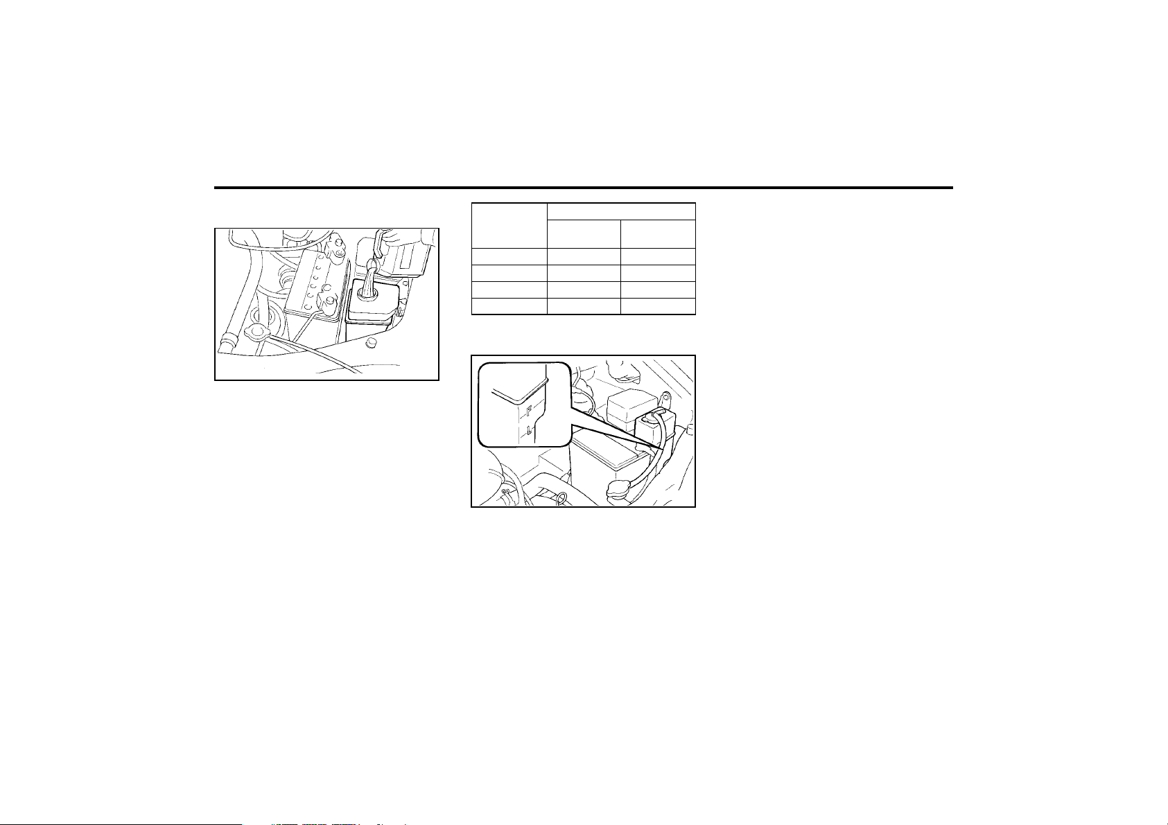
DO-IT-YOURSELF MAINTENANCE
6-6
ZG050B1-A
Recommended Coolant
G050B01A
Use a high quality ethylene-glycol coolant in a
50/50 mix with water. The coolant should be
compatible with aluminum engine parts. Addi-
tional corrosion inhibitors or additives should
not be used. The cooling system must be main-
tained with the correct concentration and type
of coolant to prevent freezing and corrosion.
NEVER allow the concentration of antifreeze to
exceed the 60% level or go below the 35% level
or damage to the coolant system may result.
For proper concentration when adding or re-
placing the coolant, refer to the following table.
Coolant concentration
ZG050C1-A
To Check the Coolant Level
G050C01A
The coolant level can be seen on the side of the
plastic coolant reservoir. The level of the cool-
ant should be between the "LOW" and "FULL"
lines on the reservoir. If the level is below the
"LOW" mark, add coolant to bring it up between
"LOW" and "FULL". If the level is low, inspect
for coolant leaks and recheck the fluid level
frequently. If the level drops again, visit your
Hyundai dealer for an inspection and diagnosis
of the reason.
ZG050D2-A
To Change the Coolant
The coolant should be changed at those inter-
vals specified in the vehicle maintenance sched-
ule in Section 5.
NOTE:
Coolant can damage the finish of your car.
If you spill coolant on the car, wash it off
thoroughly with clear water.
1. Park the car on level ground, set the parking
brake and remove the radiator cap when
cool.
2. Be sure your drain receptacle is in place.
Open the drain cock on the radiator. Allow
all the coolant to drain from the cooling
system, then securely close the drain cock.
3. Check Section 9 for the capacity of the
cooling system in your car. Then, following
the manufacturer’s directions on the coolant
container, add the appropriate quantity of
coolant to the radiator.
Water
Antifreeze
solution
35%
40%
50%
60%
Ambient
temperature
°F (°C)
5 (-15)
-13 (-25)
-31 (-35)
-49 (-45)
65%
60%
50%
40%
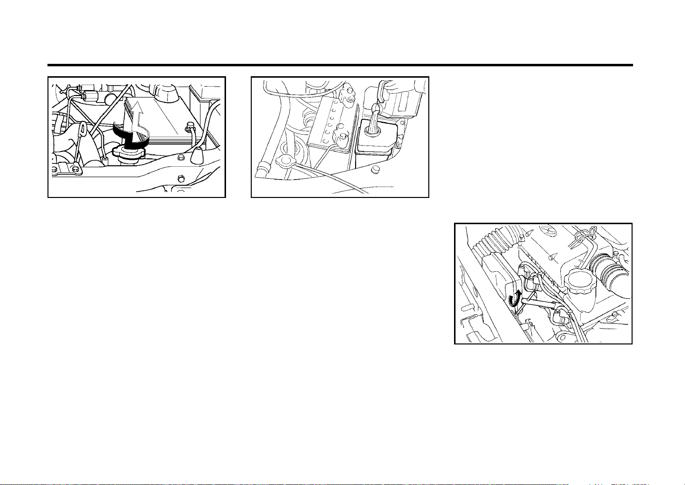
DO-IT-YOURSELF MAINTENANCE
6-7
G050D02X G050B01A
4. Turn the radiator cap counterclockwise with-
out pressing down on it, until it stops. This
relieves any pressure remaining in the cool-
ing system. And remove the radiator cap by
pushing down and turning counterclockwise.
Now fill the radiator with clean demineral-
ized or distilled water. Continue to add clean
demineralized or distilled water in small quan-
tities until the fluid level stays up in the
radiator neck.
5. Start the engine, top off the radiator with
water and then add engine coolant to the
reservoir until the level is between "LOW"
and "FULL".
6. Replace the radiator and reservoir caps and
check to be sure the drain cocks are fully
closed and not leaking.
WARNING:
The cooling fan is controlled by engine cool-
ant temperature and may sometimes oper-
ate even when the engine is not running.
Use extreme caution when working near the
blades of the cooling fan so that you are not
injured by a rotating fan blade. As the en-
gine coolant temperature decreases, the fan
will automatically shut off. This is a normal
condition.
AG060B1-E
SPARK PLUG REPLACEMENT
This operation should only be performed when
the engine is cold.
1. Remove plug lead from the spark plug to be
replaced, pulling the lead by the rubber cap.
(Pulling the lead may damage the carbon
conductor).
2. Clean around the base of the plug to be
removed, and install the plug socket ensur-
ing that the ceramic insulator does not be-
come damaged. Turn the socket anti-clock-
wise to remove the plug.
G060C01A
NOTE:
Spark plugs must only be cleaned using
purpose designed equipment. Wire brush-
ing may damage the centre electrode insula-
tor causing mis-firing to occur.
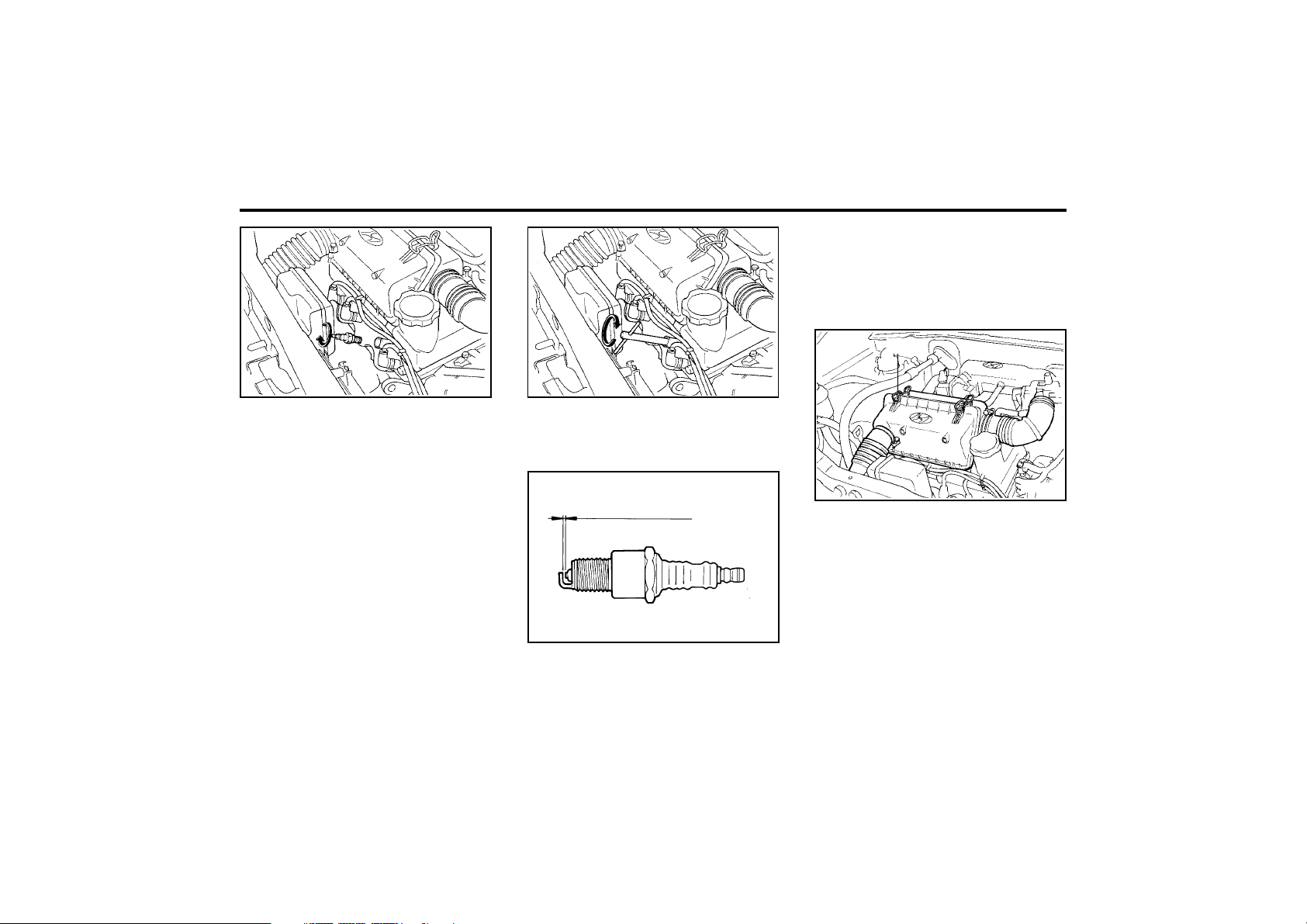
DO-IT-YOURSELF MAINTENANCE
6-8
G070A01X
(1)
SSA6060A
0.039 ~ 0.043 in. (1.0 ~ 1.1 mm)
ZG060A2-E
Recommended Spark Plugs
(Unleaded)
NOTE:
When replacing the spark plug, always use
the genuine parts recommended.
G070A01X-GAT
CHANGING THE AIR CLEANER FIL-
TER
To change the filter, loosen the clamps (1) on
the cover. When this is done, the cover can be
lifted off, the old filter removed and the new filter
put in its place. Genuine Hyundai replacement
parts are recommended.
CAUTION:
Operating your vehicle without a proper air
filter in place can result in excessive engine
wear.
G060C02A
Only the correct grade of spark plug should
be used. Use of an incorrect grade may
result in serious engine damage.
Prior to installing a spark plug, the gap
between the centre and outer electrodes
must be checked and adjusted as neces-
sary.
Adjustment is facilitated by bending the outer
electrode towards or away from the centre
electrode. Under no circumstances should
attempts be made to adjust the position of
the centre electrode.
3. Insert the spark plug into the cylinder head
and screw by and until the plug contacts the
seating area. Tighten the plug with the sock-
et by a further 1/2 to 3/4 of a turn only.
4. Replace the plug lead ensuring that the cap
is pushed firmly into place. Confirm that the
cap is correctly seated by lightly pulling
upon it.
G060C03A
CHAMPION : RC9YC4
RC10YC4
NGK : BKR5ES-11
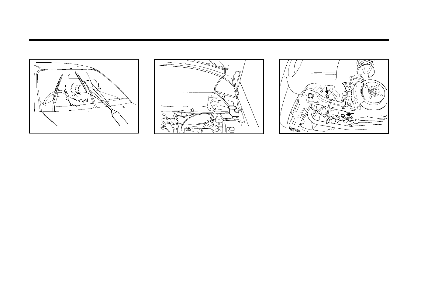
DO-IT-YOURSELF MAINTENANCE
6-9
AS60160A
ZG080A1-A
WINDSHIELD WIPER BLADES
The wiper blades should be carefully inspected
from time to time and cleaned to remove accu-
mulations of road film or other debris.
To clean the wiper blades and arms, use a
clean sponge or cloth with a mild soap or
detergent and water.
If the wipers continue to streak or smear the
glass, replace them with genuine Hyundai re-
placement parts or their equivalent.
NOTE:
o Do not operate the wipers on dry glass.
This can result in more rapid wear of the
wiper blades and may scratch the glass.
o Keep the blade rubber out of contact
with petroleum products such as engine
oil, gasoline etc.
G090A01X-EAT
FILLING THE WASHER RESERVOIR
The washer fluid reservoir supplies fluid to the
windshield washer system.
A good quality washer fluid should be used to fill
the washer reservoir. The fluid level should be
checked more frequently during bad weather or
whenever the washer system is in more fre-
quent use.
The capacity of the washer reservoir is 2.19
lmp.qts (2.5 Litres).
CAUTION:
o Radiator antifreeze (engine coolant)
should not be used in the washer system
because it will damage the car’s finish.
o The washer lever should not be pulled
and the washer should not be operated if
the washer reservoir is empty. This can
damage the washer fluid pump.
XG100A2-E
MANUAL TRANSAXLE LUBRICANT
G100A01X
Filler plug
Drain plug
The transaxle lubricant should be checked and/
or changed at intervals specified in the mainte-
nance schedule.
Recommended Lubricant
Use only HYUNDAI GENUINE PARTS MTF
75W/90 (API GL-4) in the manual transaxle.
CAUTION:
The transaxle lubricant level should only be
checked when the engine is cold to prelude
the possibility of personal injury by contact
with hot components.
1. To check the transaxle lubricant level, the
vehicle should be placed on level ground
and the level plug removed with a suitable
spanner.
G090A01X-DAG
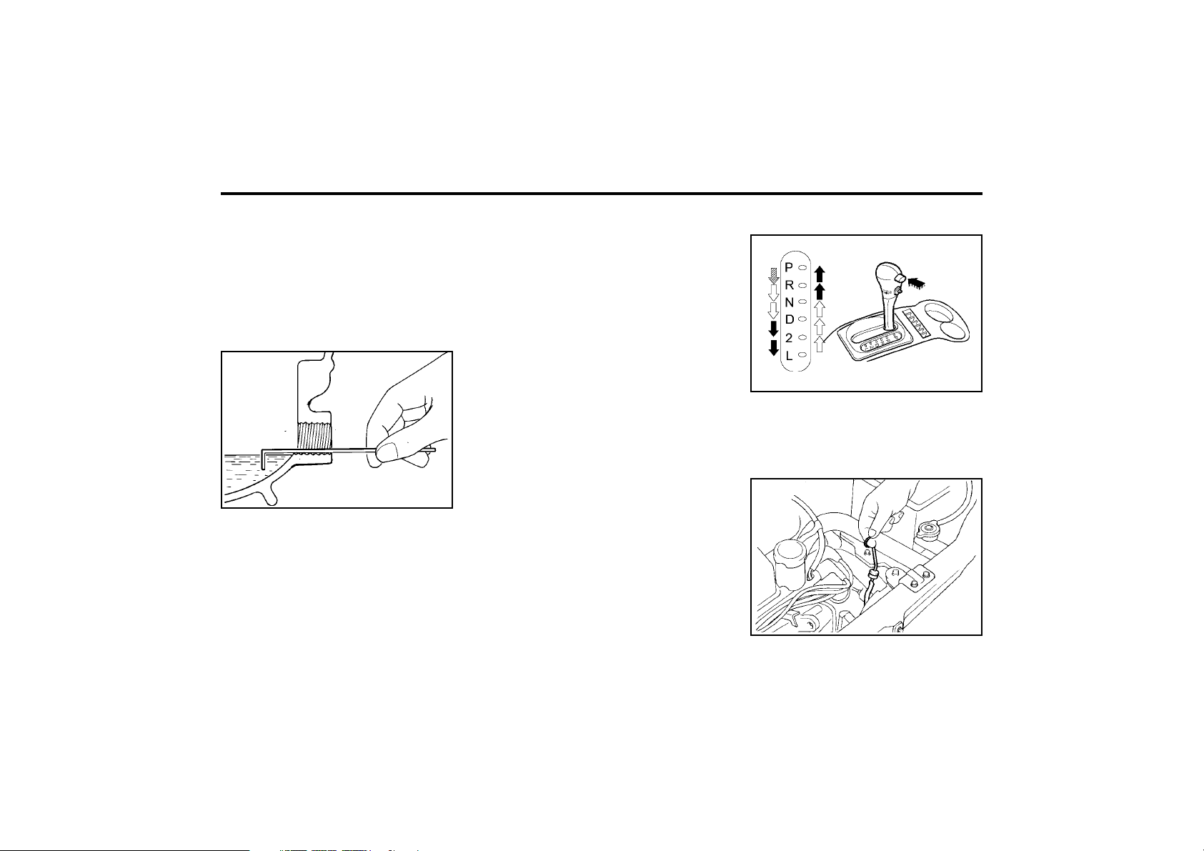
DO-IT-YOURSELF MAINTENANCE
6-10
C090B01X-DAG
G110D01A-GAT
To Check the Transaxle Fluid Level
G110D02A
Park the car on level ground with the parking
brake engaged. When the transaxle fluid level
is checked, the transaxle fluid should be at
normal operating temperature and the engine
idling.
G110A01A-AAT
CHECKING THE TRANSAXLE FLUID
(AUTOMATIC)
Transaxle fluid in the automatic transaxle should
be changed at those intervals specified in the
vehicle maintenance schedule in Section 5.
3. Replace the bolt, screw it in with your fin-
gers and then tighten securely with the
wrench.
G110C01X-EAT
Transaxle Fluid Capacity
The fluid capacity of the automatic transaxle is
4.56 lmp.qts (5.2 Litres).
WARNING:
The transaxle fluid level should be checked
when the engine is at normal operating tem-
perature. This means that the engine, radia-
tor, exhaust system etc., are very hot so you
should exercise great care not to burn your-
self during this procedure.
G110B01X-AAT
Recommended Fluid
Your Hyundai automatic transaxle is specially
designed to operate with ESSO JWS3314.
Damage caused by a nonspecified fluid is not
covered by your new vehicle limited warranty.
ZG100B1-A
To Check the Manual Transaxle
Oil Level
SSA6100B
Park the car on level ground with the engine off.
1. Using a wrench of the correct size, loosen
the oil filler bolt turning it counterclockwise
and remove it with your fingers.
2. Use your finger to feel inside the hole. The
oil level should be at its bottom edge. If it is
not, check for leaks before adding oil. To
refill the transaxle or bring the oil level up,
add oil slowly until it reaches the proper
level. Do not overfill.
2. If the level is correct, lubricant should begin
to drip from the plug orifice. In this case the
plug should be replaced. If the level is incor-
rect, lubricant should be added until it begins
to drip from the plug orifice at which time the
plug should be replaced.
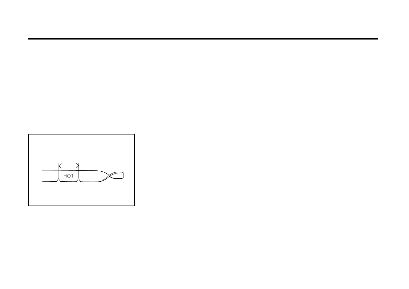
DO-IT-YOURSELF MAINTENANCE
6-11
While the engine is idling, apply the brakes and
move the gear selector lever from "P" to each
of its other positions — "R", "N", "D", "2", "L" —
and then return to "N". With the engine still
idling:
1. Open the hood, being careful to keep hands,
long hair and clothing clear of any moving
parts.
2. Remove the transaxle dipstick, wipe it clean,
reinsert the dipstick as far as it will go, then
remove it again. Now check the fluid level on
the dipstick. It should be in the "HOT" range
on the dipstick.
Fluid level must be within this range
3. If the transaxle fluid level is low, use a funnel
to add transaxle fluid through the dipstick
tube until the level reaches the "HOT" range.
Do not overfill.
G110D03A
G120A01A-AAT
CHECKING THE BRAKES
CAUTION:
Because brakes are essential to the safe oper-
ation of the car, it is suggested that they be
checked and inspected by your Hyundai dealer.
The brakes should be checked and inspected
for wear at those intervals specified in the
vehicle maintenance schedule in Section 5.
G120B01A-AAT
Checking the Brake Fluid Level
WARNING:
Use caution when handling brake fluid. It
can damage your vision if it gets into your
eyes. It will also damage your vehicle’s paint
if spilled on it and not removed immediately.
G120C02A-AAT
Recommended Brake Fluid
Use only hydraulic brake fluid conforming to
DOT 3 or DOT 4 specifications in your braking
system. Follow the instructions printed on the
container.
G120D01A-AAT
To Check the Fluid Level
The fluid level in the brake fluid reservoir should
be checked periodically. The level should be
between the "MIN" and "MAX" marks on the
side of the reservoir. If the level is at or below
the "MIN" mark, carefully add fluid to bring it up
to "MAX". Do not overfill.
WARNING:
The cooling fan is controlled by engine cool-
ant temperature and may sometimes oper-
ate even when the engine is not running.
Use extreme caution when working near the
blades of the cooling fan, so that you are not
injured by a rotating fan blade. As the en-
gine coolant temperature decreases, the fan
will automatically shut off. This is a normal
condition.
NOTE:
Only lint free cloth should be used for wip-
ing the dipstick. The presence of lint within
the transaxle may cause problems with the
normal function of the transaxle.
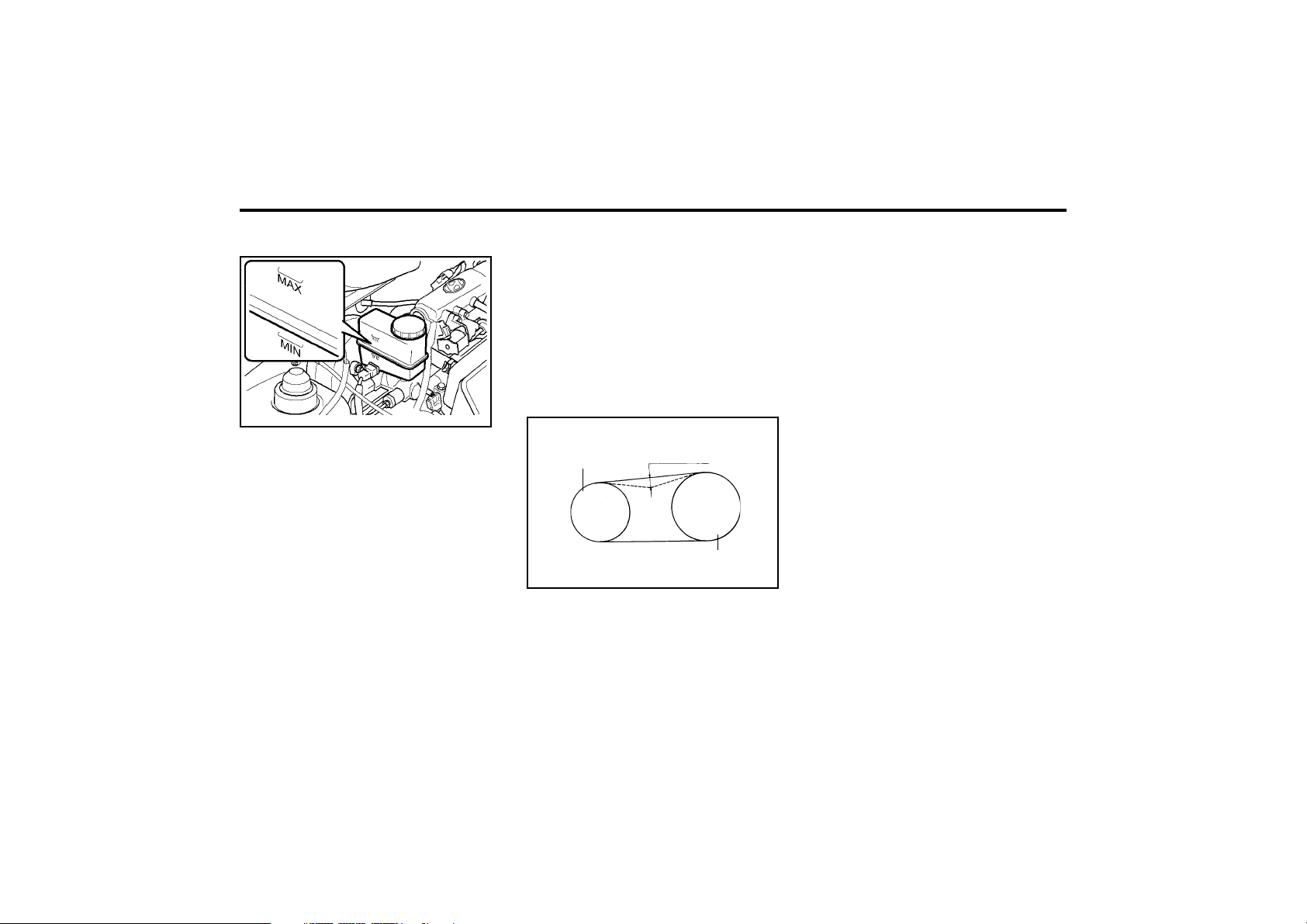
DO-IT-YOURSELF MAINTENANCE
6-12
the instruments to check it with a force of 22 lb.
(98N), the deflection should be approx. 0.197 ~
0.217 inches (5 ~ 5.5 mm). If the belt is too
loose, have it adjusted by your Hyundai dealer.
ZG140C1-E
Checking the Refrigerant
1. Start the engine and let it run at fast idle for
several minutes with the air conditioner set
at one of its colder settings.
2. Open the hood and check two hoses by
touching with your fingers. One line is the
evaporator inlet, the other is the outlet. If
there is a temperature difference between
the two hoses, the refrigerant is low and the
system should be recharged by your Hyundai
dealer.
CAUTION:
Running the air conditioning system for ex-
tended periods of time with a low refrigerant
level may damage the compressor.
ZG140D1-A
Lubrication
To lubricate the compressor and the seals in
the system, the air conditioner should be run for
at least 10 minutes each week. This is particu-
larly important during cool weather when the air
conditioning system is not otherwise in use.
G140A01A-AAT
AIR CONDITIONING CARE
Keeping the Condenser Clean
The air conditioning condenser (and engine
radiator) should be checked periodically for
accumulation of dirt, dead insects, leaves, etc.
These can interfere with maximum cooling effi-
ciency. When removing such accumulations,
brush or hose them away carefully to avoid
bending the cooling fans.
G140D01X-EAT
Checking the Compressor Drive Belt
G140D01X
A/C pulley
0.197 ~ 0.217 in. (5 ~ 5.5 mm)
Crank pulley
When the air conditioning is being used regular-
ly, the compressor drive belt tension should be
checked at least once a month.
To check the drive belt tension, press down on
the belt halfway between the engine crankshaft
and compressor pulleys. Pressing with your
finger, you should not be able to deflect this belt
anymore than 0.197 ~ 0.217 inches. If you have
G120E01X-DAG
G120E02A-AAT
Adding Brake Fluid
WARNING:
Handle brake fluid carefully. It can damage
your vision if it gets into your eyes. Use only
DOT 3 or DOT 4 specification fluid from a
sealed container. Do not allow the fluid can
or reservoir to remain open any longer than
required. This will avoid entry of dirt and
moisture which can damage the brake sys-
tem and cause improper operation.
To add brake fluid, first wipe away any dirt then
unscrew the fluid reservoir cap. Slowly pour the
recommended fluid into the reservoir. Do not
overfill. Carefully replace the cap on the reser-
voir and tighten.
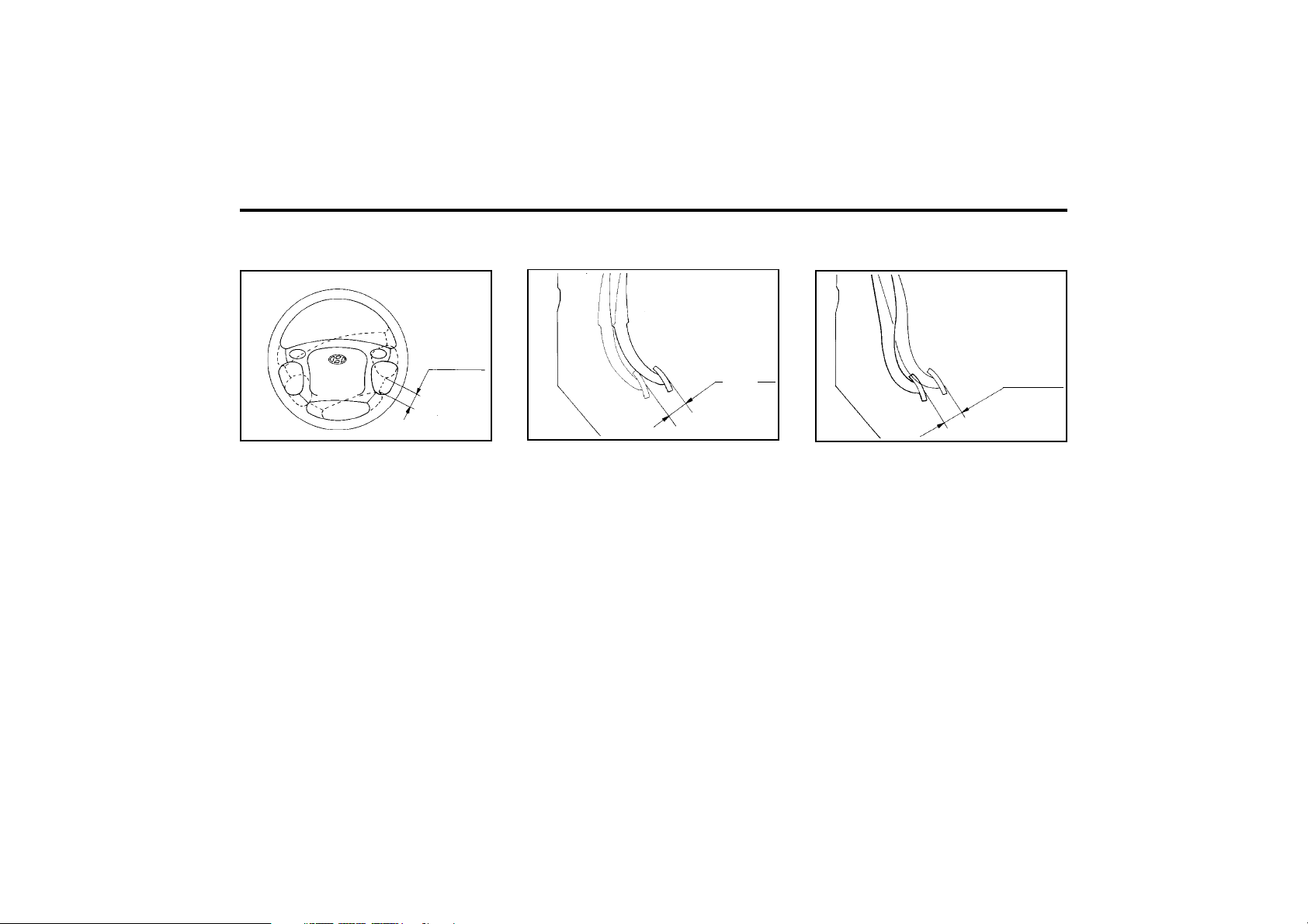
DO-IT-YOURSELF MAINTENANCE
6-13
ZG150A1-A
CHECKING STEERING WHEEL
FREEPLAY
AS60260A
1.18 in.
(30 mm)
To check the steering wheel freeplay, stop the
car with the wheels pointed straight ahead and
gently move the steering wheel back and forth.
Use very light finger pressure and be sensitive
to changes in resistance that mark the limits of
the freeplay. If the freeplay is greater than
specified, have it inspected by your Hyundai
dealer and adjusted or repaired if necessary.
ZG160A1-A
CHECKING CLUTCH PEDAL
FREEPLAY
SSA6160A
0.24~0.51 in.
(6 ~ 13 mm)
With the engine off, press lightly on the clutch
pedal until you feel a change in resistance. This
is the clutch pedal freeplay. The freeplay should
be within the limits specified in the illustration
below. If it is not, have it inspected by your
Hyundai dealer and adjusted or repaired if nec-
essary.
SSA6170A
0.12 ~ 0.31 in.
(3 ~ 8 mm)
ZG170A1-A
CHECKING BRAKE PEDAL
FREEPLAY
With the engine off, press down on the brake
pedal several times to reduce the vacuum in the
brake booster.
Then, using your hand, press down slowly on
the brake pedal until you feel a change in
resistance. This is the brake pedal freeplay.
The freeplay should be within the limits speci-
fied in the illustration below. If it is not, have it
inspected by your Hyundai dealer and adjusted
or repaired if necessary.
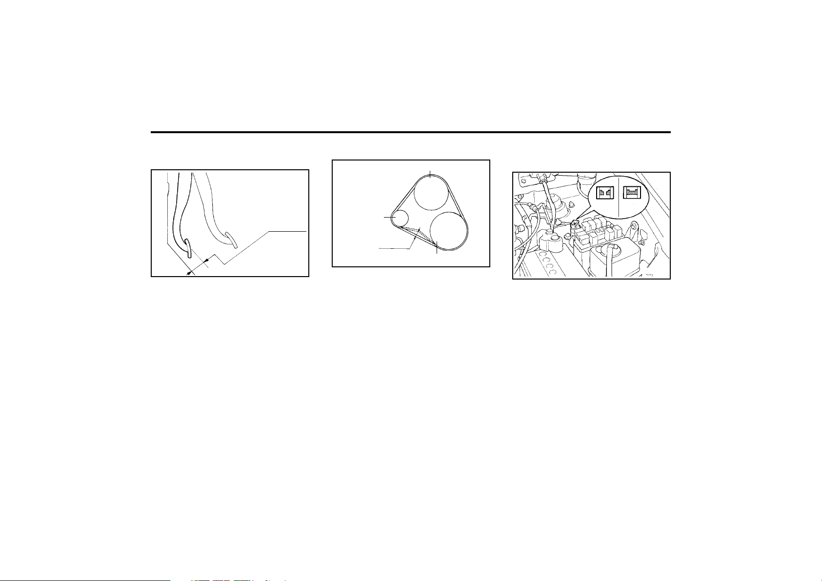
DO-IT-YOURSELF MAINTENANCE
6-14
AG200A1-A
CHECKING AND REPLACING FUSES
Replacing a Fusible Link
G200A01A
Bad
Good
A fusible link will melt if the electrical circuits
from the battery are ever overloaded, thus pre-
venting damage to the entire wiring harness.
(This could be caused by a short in the system
drawing too much current.) If this ever happens,
have a Hyundai dealer determine the cause,
repair the system and replace the fusible link.
The fusible links are located in a relay box for
easy inspection.
CAUTION:
When replacing a fusible link, never use
anything but a new fusible link with the
same or lower amperage rating. Never use a
piece of wire or a higher-rated fusible link.
This could result in serious damage and
create a fire hazard.
ZG190A1-A
CHECKING DRIVE BELTS
G190A01A
Water pump pulley
Generator
0.37 ~ 0.43 in.
(9.5~11.0 mm)
Crankshaft pulley
Drive belts should be checked periodically for
proper tension and adjusted if necessary. At the
same time, belts should be examined for cracks,
wear, fraying or other evidence of deterioration
and replaced if necessary.
Belt routing should also be checked to be sure
there is no interference between the belts and
other parts of the engine. After a belt is re-
placed, the new belt should be adjusted again
after two or three weeks to eliminate slack
resulting from initial stretching after use.
ZG180A1-A
CHECKING BRAKE PEDAL
CLEARANCE
SSA6180A
1.42 in.
(36 mm)
You need a helper to check the brake pedal
clearance. With the engine running, have your
helper press down on the brake pedal several
times and then hold it down with a force of about
110 lbs (50 kg, 490 N). The brake pedal clear-
ance is the distance from the top surface of the
brake pedal to the asphalt sheeting under the
floor mat.
If the brake pedal clearance is not within the
limits specified in the illustration, have it in-
spected by your Hyundai dealer and adjusted
or repaired if necessary.

DO-IT-YOURSELF MAINTENANCE
6-15
DG200B2-E
INDIVIDUAL CIRCUIT FUSES
XV60320E
The fuse box containing the individual circuit
fuses is located on the lower portion of the
dashboard adjacent to the bonnet release. The
fuse box cover is opened by sliding the knob on
the cover to the right. A fuse rating grid will be
found on the reverse side of the cover. In the
event of fuse failure, the fuse should be re-
placed with one of equivalent rating. A fuse
removal tool is provided within the fuse box to
facilitate replacement.
In the event of a replacement fuse failing shortly
after installation a malfunction within the circuit
protected by that fuse is indicated. The circuit
should be checked by a Hyundai dealer at the
first available opportunity.
SSA6201B
WARNING:
The use of replacement fuses having a high-
er rating than specified or other means of
connecting the circuit will create a potential
fire hazard.
DG210A2-E
BATTERY MAINTENANCE
WARNING:
Motor vehicle batteries contain sulphuric
acid which is corrosive and poisonous. Hy-
drogen gas is emitted from the battery which
is explosive when combined with oxygen.
The following precautions must be strictly
observed to avoid personal injury or dam-
age to the vehicle.
o If battery electrolyte is spilled onto skin or
into eyes, the effected area must be flushed
with copious amounts of water and medical
assistance sought.
o If battery electrolyte is ingested, copious
amounts of water or milk followed by an
antacid (raw egg or milk of magnesia) must
be drunk. Vomiting should not be induced
and medical assistance must be sought.
o Batteries must only be charged in well ven-
tilated areas from which naked lights or
sources of sparks are excluded.
o Ensure that children, pets or other unautho-
rized persons are kept away from batteries.
o Do not allow anything to bridge the positive
(+)and negative (-) terminals of the battery.
o Never invert the battery.
The battery fitted during production is of the
“Maintenance Free” type.
G220A01A-AAT
CHECKING ELECTRIC COOLING FANS
WARNING:
The cooling fan is controlled by engine cool-
ant temperature and may sometimes oper-
ate even when the engine is not running.
Use extreme caution when working near the
blades of the cooling fan, so that you are not
injured by a rotating fan blade. As the en-
gine coolant temperature decreases the fan
will automatically shut off. This is a normal
condition.
G220B01A-AAT
Checking Engine Cooling Fan
The engine cooling fan should come on auto-
matically if the engine coolant temperature is
high.
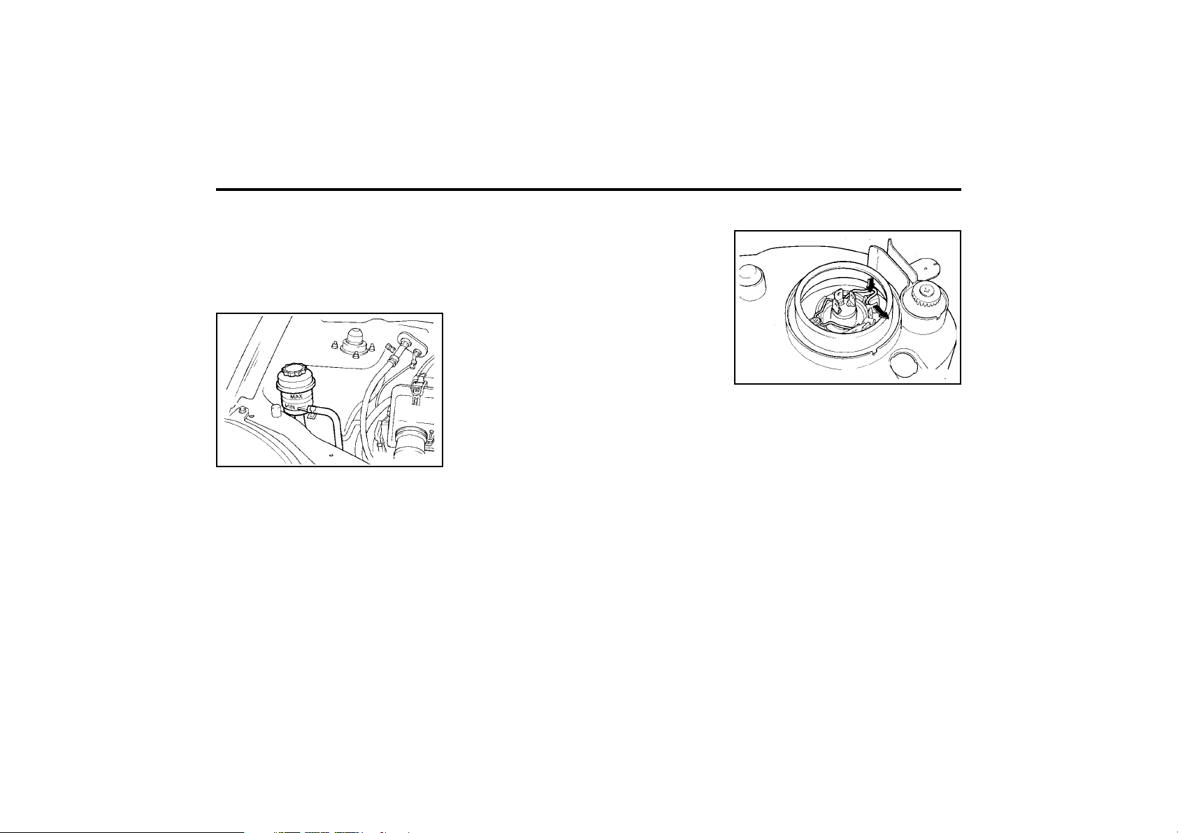
DO-IT-YOURSELF MAINTENANCE
6-16
G270A01X-GAT
HEADLIGHT BULB
G270A01X
Replacement instructions:
1. Allow the bulb to cool. Wear eye protection.
2. Always grasp the bulb by its base, avoid
touching the glass.
3. Disconnect the connector, then remove the
dust cover.
4. Push the bulb spring for removing the head-
light bulb.
5. Remove the headlight bulb. If the bulb is
burned out, replace it with the same watt-
age.
6. Installation is the reverse order of the re-
moval.
7. Use the protective cap and carton to promptly
dispose of the old bulb.
8. Check for proper headlight aim.
noise stops during warm up, there is no
abnormal function in the system. This is due
to a power steering fluid characteristic in
extremely cold conditions.
Recommended Fluid
Use PSF-3 type fluid.
NOTE:
Do not start the engine when the power
steering oil reservoir is empty.
ZG230B1-E
POWER STEERING HOSES
It is suggested that you check the power steering
hose connections for fluid leakage at those inter-
vals specified in the vehicle maintenance sched-
ule in Section 5.
The power steering hoses should be replaced if
there is severe surface cracking, pulling, scuff-
ing or worn spots. Deterioration of the hose could
cause premature failure.
G260A01A-AAT
REPLACING LIGHT BULBS
Before attempting to replace a light bulb, be
sure the switch is turned to the "OFF" position.
The drawings show how to reach light bulbs so
they may be changed. Be sure to replace the
burned-out bulb with one of the same number
and wattage rating.
G220C01A-AAT
Checking Condenser Cooling Fan
The condenser cooling fan should come on
automatically whenever the air conditioning is
in operation.
G230A03A-GAT
POWER STEERING FLUID LEVEL
G230A01X
The power steering fluid level should be checked
regularly.
To check the power steering fluid level, be sure
the ignition is "OFF", then check to make cer-
tain that the power steering fluid level is be-
tween the "MAX" and "MIN" level markings on
the fluid reservoir.
NOTE:
Grinding noise from the power steering
pump may be heard immediately after the
engine is started in extremely cold condi-
tions (below -4°F(-20°C)). In this case, if the
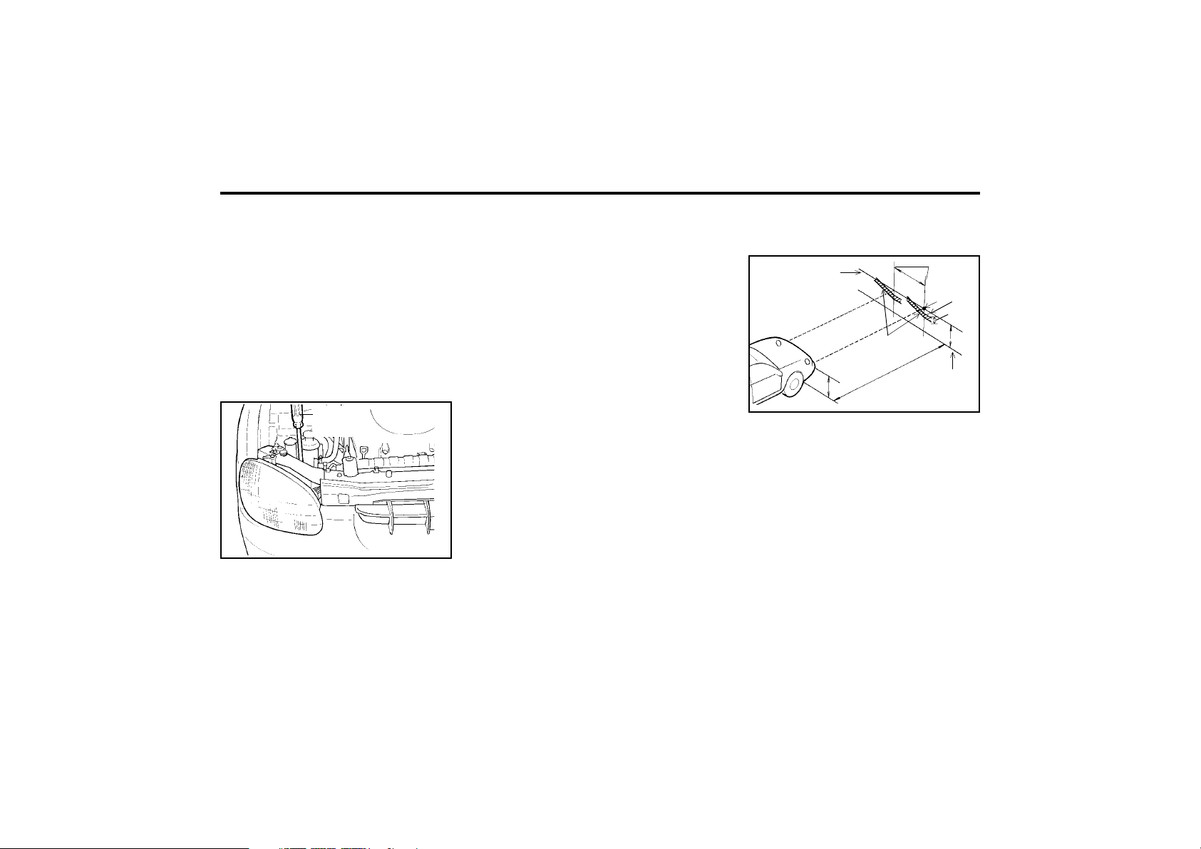
DO-IT-YOURSELF MAINTENANCE
6-17
WARNING:
The halogen bulb contains gas under pres-
sure and if impacted could shatter, and re-
sulting in flying fragments. Always wear eye
protection when servicing the bulb. Protect
the bulb against abrasions or scratches and
against liquids when lighted. Turn on the
bulb only when installing in a headlight.
Replace the headlight if damaged or cracked.
Keep the bulb out of the reach of children
and dispose of the used bulb with care.
G290A01X-EAT
HEADLIGHT AIMING ADJUSTMENT
G290A01V
Before performing aiming adjustment, make sure
of the following.
Vertical
aiming
1. Keep all tires inflated to the correct pres-
sure.
2. Place the vehicle on level ground and press
the front bumper & rear bumper down sev-
eral times.
3. See that the vehicle is unloaded (except for
full levels of coolant, engine oil and fuel, and
spare tire, jack, and tools). Have the driver
or equivalent weight placed in driver's seat.
4. Clean the head lights lens and turn on the
headlight (Low beam).
5. Open the bonnet.
6. Draw the vertical line (through the center of
each headlight) and the horizontal line
(through the centre of each headlight) on the
aiming screen.
1) Horizontal line dimension from ground:
25.43 in. (646 mm)
2) Distance between each vertical line:
38.89 in. (988 mm)
And then, draw the parallel line at 1.18 in.
(30 mm) place under the horizontal line.
7. Adjust each cut-off line of the low beam to
the parallel line with a phillips screwdriver -
VERTICAL AIMING
8. Adjust each cut-off line of the low beam to
the each vertical line with a phillips screw-
driver - HORIZONTAL AIMING.
G290B01X-EAT
Adjustment After Headlight Assembly
Replacement
If the vehicle has had front body repair and the
headlight assembly has been replaced, the
headlight aiming should be checked using the
aiming screen as shown in the illustration. Turn
on the headlight switch. (Low Beam Position)
1. Adjust headlights so that main axis of light is
parallel to centre line of the body and is
aligned with point "P" shown in the illustra-
tion.
2. Dotted lines in the illustration show centre of
headlights.
G290B01S-DAG
Horizontal line
Vertical
line
W
0.59 in.
"P"
1.18 in.
Cut-off line
Ground line
H
H
L

DO-IT-YOURSELF MAINTENANCE
6-18
"H";
Horizontal centre line of headlights from
ground: 25.43 in. (646 mm)
"W";
Distance between each headlight centre:
38.89 in. (988 mm)
"L";
Distance between the headlights and the
wall that the lights are tested against:
118.11 in. (3,000 mm).
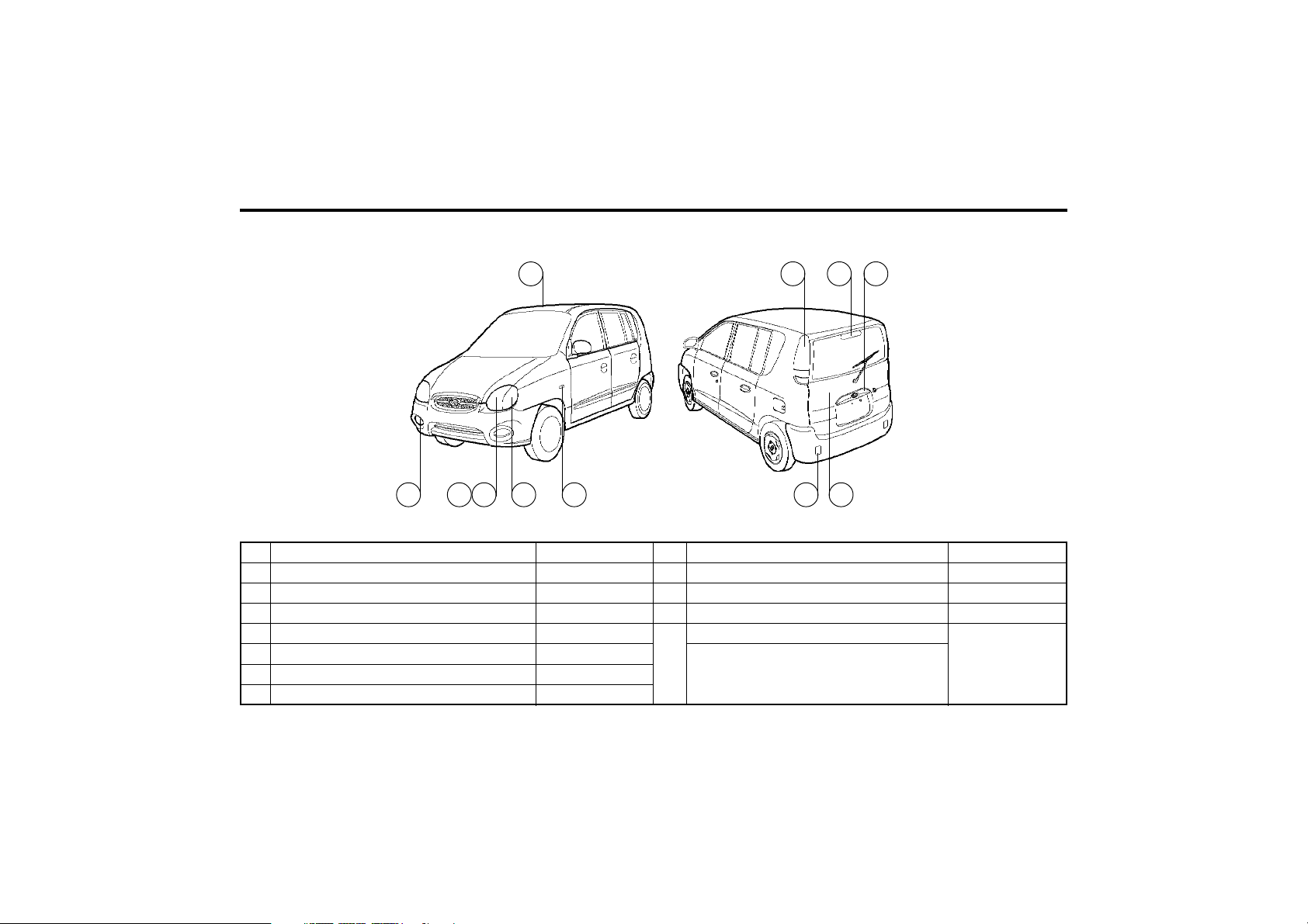
DO-IT-YOURSELF MAINTENANCE
6-19
No.
1
2
3
4
5
6
7
G280A01X-GAT
(ATOZ)
Part Name
Front Fog Light (Not all models)
Headlight
Front Position Light
Front Turn Signal Light
Side Repeater Light (Not all models)
Interior Light
HIgh Mounted Rear Stop Light
Wattage
55
60/55
5
21
5
8
21
No.
8
9
10
11
Wattage
5
5
21
21
21/5
21
Part Name
Luggage Compartment Light
License Plate Light
Rear Fog Light
Rear Combination Light
Turn Signal Light
Stop/Tail Light
Back-up Light
G280A02X
6
11 7 9
1 432 5 10 8
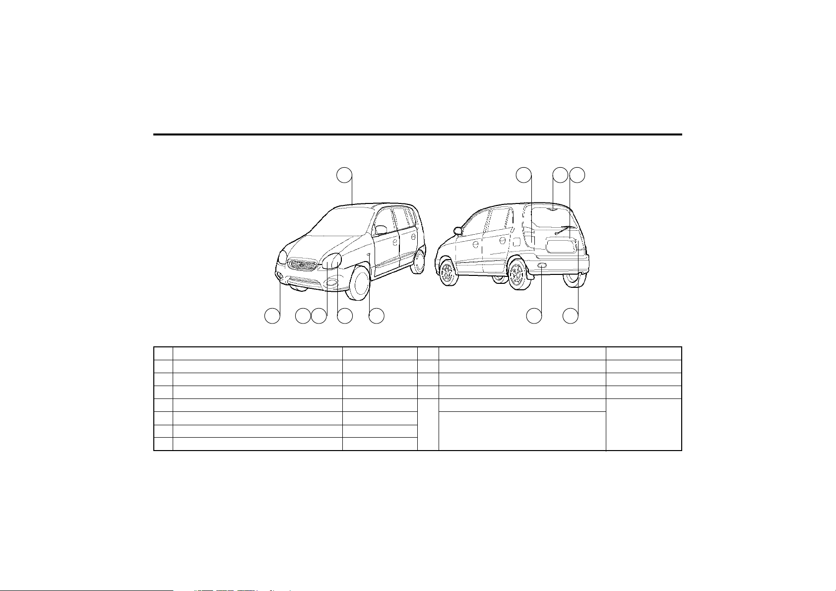
DO-IT-YOURSELF MAINTENANCE
6-20
No.
1
2
3
4
5
6
7
G280A01V-GAT
(AMICA)
Part Name
Front Fog Light (Not all models)
Headlight
Front Position Light
Front Turn Signal Light
Side Repeater Light (Not all models)
Interior Light
HIgh Mounted Rear Stop Light
Wattage
55
60/55
5
21
5
8
2.6
No.
8
9
10
11
Wattage
5
5
21
21
21/5
21
Part Name
Luggage Compartment Light
License Plate Light
Rear Fog Light
Rear Combination Light
Turn Signal Light
Stop/Tail Light
Back-up Light
G280A03V
6
11 9
1 432 5 10 8
7
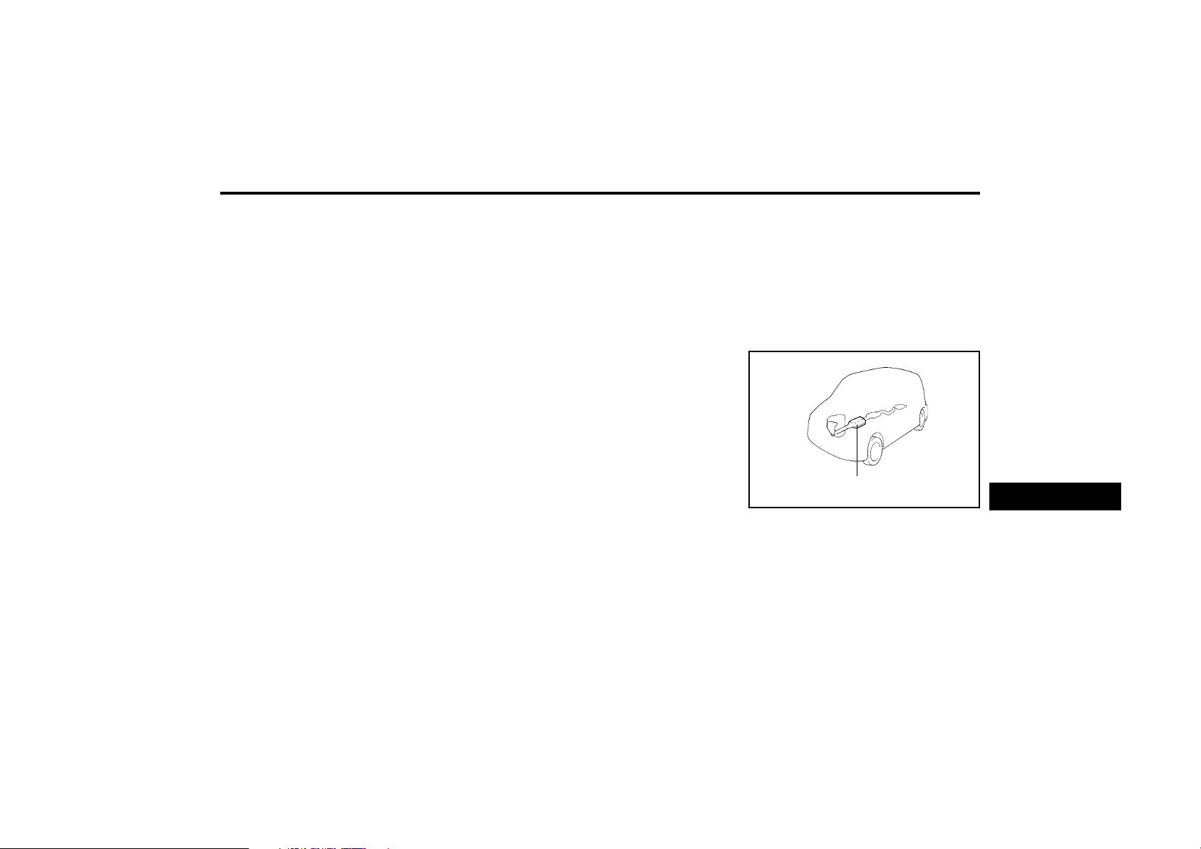
EMISSION CONTROL SYSTEMS
7-1
H010A01A-GAT
EMISSION CONTROL SYSTEM
(Not all models)
Your Hyundai is equipped with an emission
control system to meet all requirements of the
Emission prohibition rules of your province.
There are three emission control systems which
are as follows.
1) Crankcase emission control system
2) Evaporative emission control system
3) Exhaust emission control system
In order to assure the proper function of the
emission control systems, it is recommended
that you have your car inspected and main-
tained by an authorized Hyundai dealer in ac-
cordance with the maintenance schedule in this
manual.
ZH000A1-A
7. EMISSION
CONTROL
SYSTEMS
H010B01A-AAT
1. Crankcase Emission Control Sys-
tem
The Positive Crankcase Ventilation System is
employed to prevent air pollution caused by
blow-by gases being emitted from the crank-
case. This system supplies fresh filtered air to
the crankcase through the air intake hose.
Inside the crankcase, the fresh air mixes with
blow-by gases, which then pass through the
PCV valve and into the induction system.
H010D01A-AAT
3. Exhaust Emission Control System
The Exhaust Emission Control System is a
highly effective system which controls exhaust
emission while maintaining good vehicle perfor-
mance.
H010C02A-GAT
2. Evaporative Emission
Control System (Not all models)
The Evaporative Emission Control System is
designed to prevent fuel vapors from escaping
into the atmosphere.
Canister
While the engine is inoperative, fuel vapours
generated inside the fuel tank are absorbed and
stored in the onboard canister. When the en-
gine is running, the fuel vapors absorbed in the
canister are drawn into the induction system
through the purge control solenoid valve.
Purge Control Solenoid Valve
The purge control solenoid valve is controlled
by the ECM; when the engine coolant temper-
ature is low, and during idling, it closes, so that
evaporated fuel is not taken into the engine.
After engine warm-up, during ordinary driving, it
opens so as to introduce evaporated fuel to the
engine.
H020A01A
Catalytic Converter
H020A01A-GAT
CATALYTIC CONVERTER
(Not all models)
The catalytic converter is part of the exhaust
emission control system. Its purpose is to re-
move certain engine emission products from
the engine’s exhaust. It looks something like a
muffler and is located underneath the car in the
exhaust system.
7

7-2
EMISSION CONTROL SYSTEMS
H020B01A-GAT
About the Catalytic Converter
Exhaust gases passing through the catalytic
converter cause it to operate at very high tem-
peratures. As a result, the introduction of large
amounts of unburned gasoline may cause it to
overheat and create a fire hazard. This can be
avoided by observing the following:
o Use unleaded fuel only.
o Maintain your engine in good condition. Ex-
tremely high converter temperatures can
result from improper operation of the electri-
cal, ignition or fuel injection systems.
o If your engine stalls, pings, knocks, or is
hard to start, take your car to your Hyundai
dealer as soon as possible and have the
difficulty corrected.
o Avoid driving with a very low fuel level. If
your run out of gasoline, it could cause the
engine to misfire and result in excessive
loading of the catalytic converter.
o Avoid idling the engine for periods longer
than 10 minutes.
o Your Hyundai should not be either pushed
or pulled to get it started. This can cause the
catalytic converter to overload.
o Take care not to stop your Hyundai over any
combustible material such as grass, paper,
leaves or rags. As these materials could
come in contact with the catalytic converter
and could cause a fire.
o Do not touch the catalytic converter or any
other part of the exhaust system while the
engine is running as it is very hot and could
result in burns.
o Remember that your Hyundai dealer is your
best source of assistance.
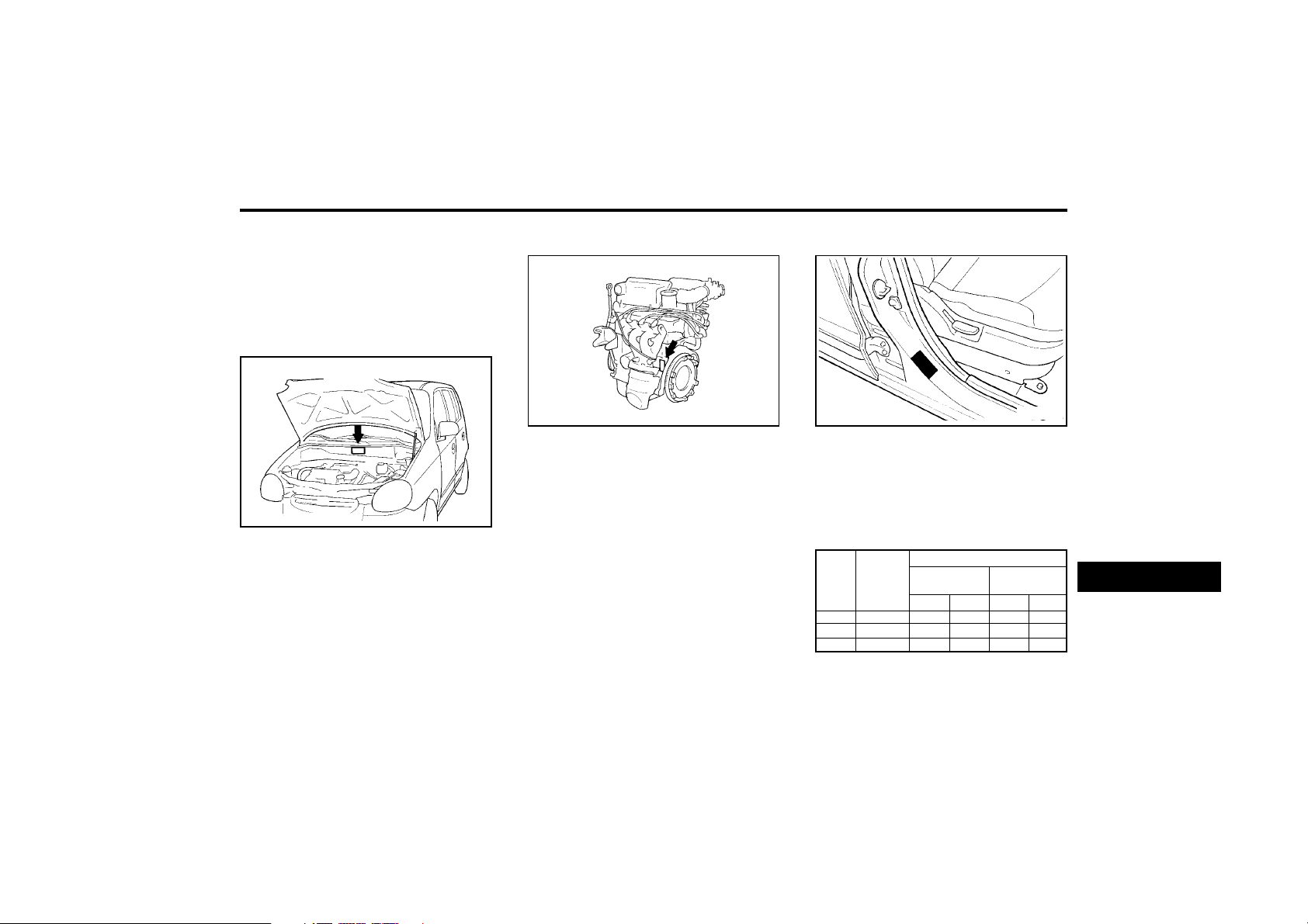
CONSUMER INFORMATION
8-1
ZI010B1-A
Engine Number
ZI010A1-E
VEHICLE IDENTIFICATION
NUMBER (VIN)
ZI000A1-E
8. CONSUMER IN
FORMATION
I010A01A
The vehicle identification number (VIN) is the
number used in registering your car and in all
legal matters pertaining to its ownership, etc.
o On the identification plate attached to the
engine side of the firewall between the en-
gine and passenger compartments.
I010B01A
The engine number is stamped on the engine
block as shown in the drawing.
ZI010C1-E
TYRE INFORMATION
The tires supplied on your new Hyundai are
chosen to provide the best performance for
normal driving.
XI020A1-E
TYRE PRESSURES
XV80030E
In modern high-speed motoring, correct tyre
pressures are vitally important.
Incorrect pressures can reduce adhesion, af-
fect the steering, and cause excessive tyre
wear. Check the pressures before you start a
trip, when tyres are cold. If the pressures are
measured when the tyres are warm, a higher
reading will be obtained.
8
4.0BX13
4.5JX13
5.0JX13
TIRE
SIZE
PRESSURE. kPa (PSI)
155/70R13
155/70R13
175/60R13
REAR
207(30)
207(30)
207(30)
FRONT
221(32)
221(32)
221(32)
UP TO 2
PERSONS
UP TO MAX.
LOAD
REAR
221(32)
221(32)
221(32)
FRONT
207(30)
207(30)
207(30)
RIM
SIZE
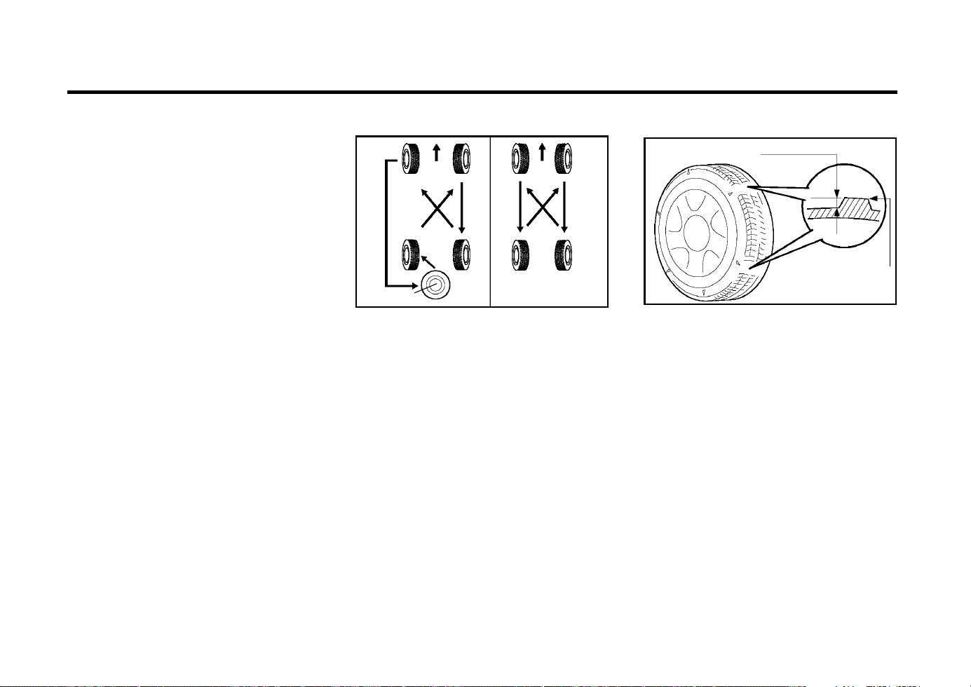
CONSUMER INFORMATION
8-2
SI040A1-E
TYRE CHAINS
Tyre chains, if necessary, should be installed
on the front wheels. Be sure that the chains are
the proper size and that they are installed in
accordance with the manufacturer’s instruc-
tions.
To minimize tyre and chain wear, do not contin-
ue to use tyre chains when they are no longer
needed.
CAUTION:
When driving on roads covered with snow
or ice, drive at less than 20 mph (30 km/h).
XI050A1-E
TYRE ROTATION
Tyre wear will vary for each wheel. In order to
increase the life of each tyre and keep wear
uniform, tyre rotation should be performed ev-
ery 6,000 miles (10,000 km) as shown in figure.
NOTE:
Do not mix bias-ply and radial-ply tyres
under any circumstances. This may cause
dan-gerous handling characteristics.
ZI060A1-E
TYRE BALANCING
A tyre that is out of balance may affect handling
and tyre wear. The tyres on your Hyundai were
balanced before the car was delivered but may
need balancing again during the years you own
the car. Whenever a tyre is dismounted for
repair, it should be rebalanced.
Wear indicator
DI060B1-E
TYRE REPLACEMENT
Tyres must be replaced when the wear indica-
tors appear as a solid bar across the tyre tread.
At this point, the remaining tread depth will be
approximately 0.06 in. (1.6 mm). In addition to
this, the tyre must be replaced if any portion of
the tread has become bald or if there are any
lumps, bulges or deep cuts in the sidewalls or
tread.
Replacement tyres must be of the recommend-
ed size and rating and should be of the same
manufacture and tread pattern on each axle.
ZI030A1-E
SNOW TYRES
If you equip your car with snow tyres, they
should be the same size and have the same
load capacity as the original tyres. Do not drive
faster than 60 mph when your car is equipped
with snow tyres.
HA1409
Spare tyre
1.6 mm (0.06 in.)
HGK248
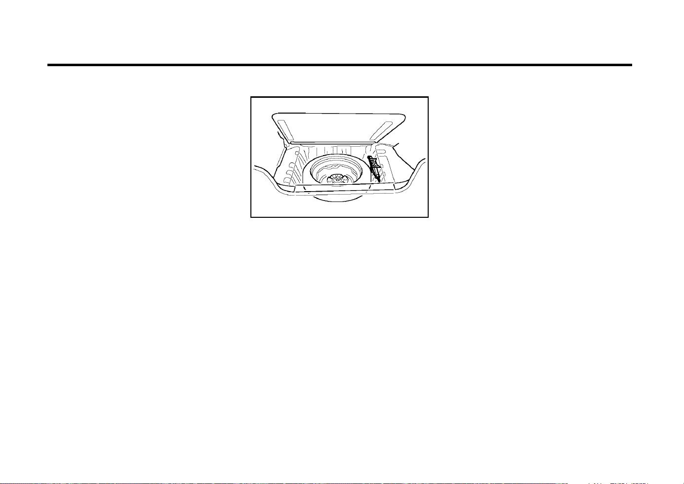
CONSUMER INFORMATION
8-3
DI060C1-E
WHEEL REPLACEMENT
The original wheels may only be replaced with
Hyundai Approved wheels.
CAUTION:
Driving on worn or defective tyres is dan-
gerous. Worn tyres may cause loss of steer-
ing control and a serious deterioration of
braking efficiency. Defective tyres may cause
vibration and loss of control through blow
outs.
Tyres of different size, construction or tread
pattern should not be intermixed on the same
axle. Radial and cross ply tyres should not be
used on the same vehicle.
The use of tyres and wheels of non approved
sizes can be dangerous.
I100A02A-EAT
SPARE TYRE AND TOOLS
Your Hyundai is delivered with the following:
Spare tyre and wheel
Wheel nut wrench, Wrench bar, Spanner,
Screwdriver
Jack
D060J01X
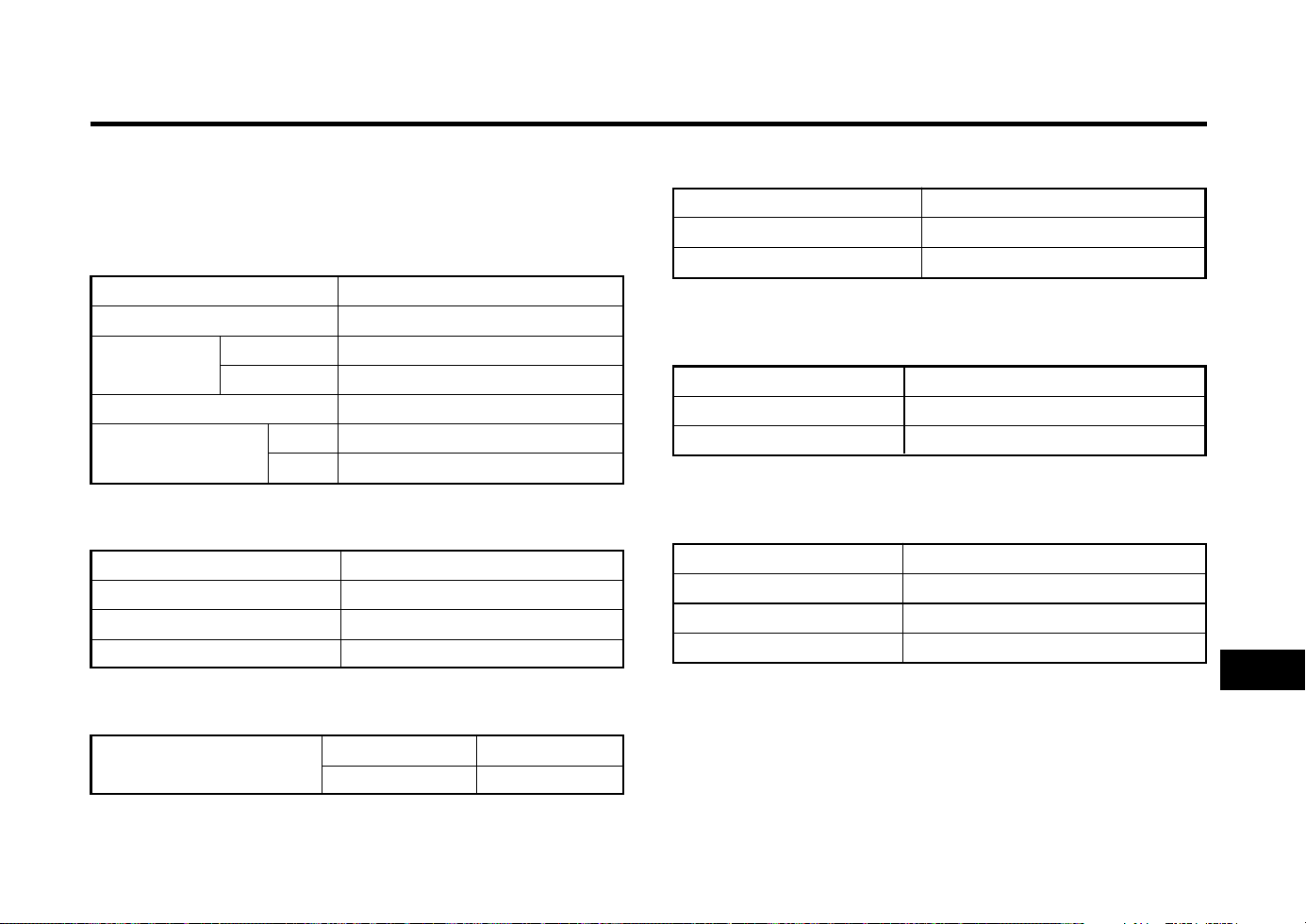
VEHICLE SPECIFICATIONS
9-1
Litres
35
J040A01X-GAT
ELECTRICAL
Battery
Alternator
Starting motor
MF 12V 40AH
13.5V 60A
0.8 KW
J050A02X-GAT
BRAKE
Dual hydraulic with brake booster
Ventilated disc
Drum
Cable operated on rear wheel
J060A01X-EAT
FUEL SYSTEM
lmp.gal
7.7
J020A01X-EAT
POWER STEERING
Type
Wheel free play
Rack stroke
Oil pump type
Rack and pinion
0 ~ 1.181 in. (0 ~ 30 mm)
5.354 in. (136 mm)
Vane type
ZJ000A1-A
9. VEHICLE SPECIFICATIONS
J030A02X-EAT
TYRE
155/70 R 13
175/60 R 13
Full size spare
Standard
Option
Spare
J010A02X-EAT
MEASUREMENT
137.6 (3495)
58.9 (1495)
63.6 (1615)
62.2 (1580)
93.7 (2380)
51.8 (1315)
51.2 (1300)
Overall length
Overall width
Overall height
(unladen)
Wheel base
Wheel tread
in. (mm)
ATOZ
AMICA
Front
Rear
Fuel tank Capacity
Type
Front brake type
Rear brake type
Parking brake
9

VEHICLE SPECIFICATIONS
9-2
J070A01X-GAT
ENGINE
ITEMS
Engine type
Idle Speed (RPM)
Ignition Timing (Base)
Firing order
Specifications
1.0 MFI
4-Cylinder in-line SOHC
900 ± 100
BTDC 5° ± 2°
1 - 3 - 4 - 2
J090A02A-EAT
SPARK PLUG
ITEM
Spark plug
Spark plug gap
UNLEADED
NGK : BKR5ES-11
CHAMPION : RC9YC4, RC10YC4
0.039 ~ 0.043 in. (1.0 ~ 1.1 mm)
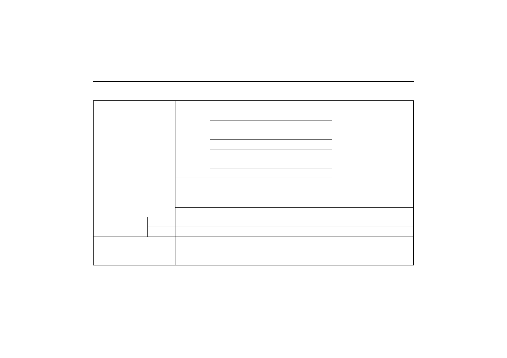
VEHICLE SPECIFICATIONS
9-3
Oil & Coolant Standard
SAE 20W-40, 20W-50 (ABOVE -14°F)
API SG SAE 15W-40, 15W-50 (ABOVE 5°F)
OR SAE 10W-30 (-13°F ~ 104°F)
ABOVE SAE 10W-40, 10W-50 (ABOVE -13°F)
SAE 5W-20 *1, *2 (BELOW 14°F)
SAE 5W-30 *1 (BELOW 50°F)
SAE 5W-40 *1 (BELOW 68°F)
*1. Restricted by driving condition and dealing area
*2. Not recommended for sustained high speed vehicle operation
Normal driving condition
Severe driving condition
HYUNDAI GENUINE PARTS MTF 75W/90 (API GL-4)
ESSO JWS3314
PSF-3
DOT 3, DOT 4 or equivalent
Ethylene glycol base for aluminum radiator
Item
Engine Oil
Engine oil consumption
Transaxle
Power steering
Brake fluid
Engine coolant
Q'ty
2.72 lmp.qts (3.26 us-qts, 3.1 litres)
MAX. 1L / 1500 Km
MAX. 1L / 1000 Km
2.15 lmp.qts (2.58 us-qts, 2.45 litres)
4.56 lmp.qts (5.48 us-qts, 5.2 litres)
As required
As required
3.95 lmp.qts (4.74 us-qts, 4.5 litres)
J080A06X-EAT
LUBRICATION CHART
Manual
Auto

INDEX
10-1
A
ABS SYSTEM ..................................................................................... 2-7
ADJUSTABLE FRONT SEATS .......................................................... 1-5
AIR CLEANER FILTER ...................................................................... 6-8
AIR CONDITIONER CARE .............................................................. 6-12
AIR CONDITIONING SWITCH ......................................................... 1-36
AIR CONDITIONING OPERATION ................................................. 1-37
ANTENNA ......................................................................................... 1-52
APPEARANCE CARE ............................................................... 4-1 ~ 4-2
ASHTRAY ......................................................................................... 1-25
AUDIO FAULT CODE ...................................................................... 1-49
AUTOMATIC TRANSAXLE ....................................................... 2-5 ~ 2-6
B
BATTERY MAINTENANCE .............................................................. 6-15
BEFORE STARTING THE ENGINE .................................................. 2-2
BONNET RELEASE ......................................................................... 1-30
BRAKE CIRCUIT FAILURE WARNING LAMP ................................ 1-18
BRAKE PEDAL CLEARANCE ......................................................... 6-14
BRAKE PEDAL FREEPLAY ............................................................. 6-13
BRAKES ........................................................................................... 6-11
C
CARE OF SEAT BELTS .................................................................... 1-7
CARE OF CASSETTE TAPE ................................................ 1-50 ~ 1-51
CARE OF DISC ................................................................................ 1-50
CATALYTIC CONVERTER (For MFI) ................................................ 7-1
CENTRAL DOOR LOCKING SYSTEM ............................................. 1-7
CHANGING THE OIL AND FILTER ......................................... 6-4 ~ 6-5
CHARGING WARNING LIGHT ........................................................ 1-19
CHILD PROTECTOR REAR DOOR LOCKS .................................... 1-4
CHILD RESTRAINT SYSTEM ............................................... 1-10 ~ 1-11
CIGAR LIGHTER .............................................................................. 1-24
CLOCK .............................................................................................. 1-24
CLUTCH PEDAL FREEPLAY .......................................................... 6-13
COMPACT DISK PLAYER OPERATION (H922M) .............. 1-47 ~ 1-48
COMPRESSOR DRIVE BELT ......................................................... 6-12
COOLING FANS .............................................................................. 6-15
D
DAY-NIGHT REAR VIEW MIRROR................................................. 1-26
DOOR LOCKS .................................................................................... 1-3
DRIVE BELTS .................................................................................. 6-14
DRIVING FOR ECONOMY ................................................................ 2-8
E
EFFECTIVE BRAKING ....................................................................... 2-7
EMERGENCY TOWING ..................................................................... 3-8
EMISSION CONTROL SYSTEM ....................................................... 7-1
ENGINE COMPARTMENT (For MFI Engine) .................................... 6-1
ENGINE COOLANT ........................................................................... 6-5
ENGINE COOLANT TEMPERATURE GAUGE ............................... 1-20
ENGINE OIL CONSUMPTION ........................................................... 6-3
F
FILLING THE WASHER RESERVOIR .............................................. 6-9
FOLDING REAR SEAT BACK AND SEAT CUSHION ................... 1-27
FOLDING THE OUTSIDE REAR VIEW MIRRORS ........................ 1-26
ZK000A1-E
10. INDEX
10

INDEX
10-2
FRONT FOG LIGHT SWITCH ......................................................... 1-29
FUEL ECONOMY ............................................................................... 2-3
FUEL GAUGE .................................................................................. 1-20
FUEL RECOMMENDATIONS ............................................................ 1-1
FUSIBLE LINKS ............................................................................... 6-14
G
GENERAL CHECKS .......................................................................... 6-2
H
HAZARD WARNING SYSTEM ........................................................ 1-24
HEADLIGHT BULB ........................................................................... 6-16
HEADLIGHT LEVELING DEVICE SYSTEM .................................... 1-23
HEADRESTRAINT .............................................................................. 1-5
HEADLIGHT FLASHER .................................................................... 1-22
HEADLIGHT SWITCH ...................................................................... 1-21
HEATED REAR WINDOW ............................................................... 1-24
HEATING AND VENTILATION ........................................................ 1-32
HIGH AND LOW BEAM ................................................................... 1-21
HIGH-MOUNTED REAR STOPLIGHT ............................................. 1-27
HORN ............................................................................................... 1-32
I
IF THE ENGINE CANNOT BE CRANKED ........................................ 3-1
IF THE ENGINE OVERHEATS .......................................................... 3-2
IF THE ENGINE WILL NOT START .................................................. 3-1
IGNITION SWITCH ............................................................................. 2-2
IMMOBILIZER SYSTEM ..................................................................... 1-2
INDIVIDUAL CIRCUIT FUSES ......................................................... 6-15
INSTRUMENT CLUSTER AND INDICATOR .................................. 1-17
INSTRUMENTS AND CONTROLS .................................................. 1-16
INTERIOR LIGHT ............................................................................. 1-25
J
JUMP STARTING ........................................................................ 3-1~3-2
K
KEY POSITIONS ................................................................................ 2-2
KEYS .................................................................................................. 1-2
L
LIGHT BULBS .................................................................................. 6-16
LIMP HOME PROCEDURES ............................................................. 1-2
LOW FUEL LEVEL WARNING LAMP ............................................. 1-19
M
MAINTENANCE AND SERVICING REQUIREMENTS ..................... 5-1
MAINTENANCE UNDER SEVERE USAGE CONDITIONS .............. 5-4
MANUAL TRANSAXLE LUBRICANT ................................................. 6-9
MANUAL TRANSAXLE ...................................................................... 2-4
MULTI FUNCTION SWITCH ............................................................ 1-21
O
ODOMETER ..................................................................................... 1-21
OIL PRESSURE WARNING LIGHT ................................................. 1-18
OUTSIDE REAR VIEW MIRROR .................................................... 1-25
P
PARKING BRAKE ............................................................................ 1-26
POWER STEERING FLUID LEVEL ................................................. 6-16

INDEX
10-3
POWER STEERING HOSES ........................................................... 6-16
POWER WINDOWS ........................................................................... 1-6
R
REAR FOG LIGHT SWITCH ............................................................ 1-29
REAR WINDOW WIPER AND WASHER ........................................ 1-23
REMOTE FUEL FILLER LID RELEASE .......................................... 1-29
REMOTE TAIL GATE RELEASE ..................................................... 1-29
RUNNING IN ...................................................................................... 1-1
S
SCHEDULED MAINTENANCE ................................................. 5-2 ~ 5-3
SEAT BELT PRECAUTIONS ............................................................. 1-7
SEAT BELTS ........................................................................... 1-8 ~ 1-10
SNOW TYRES ................................................................................... 8-1
SPARE TYRE .............................................................................. 3-3, 8-3
SPARK PLUG REPLACEMENT ........................................................ 6-7
SPECIFIATIONS .......................................................................... 9-1, 9-3
SPEEDOMETER .............................................................................. 1-21
SRS AIRBAG SYSTEM ......................................................... 1-12 ~ 1-15
STARTING .......................................................................................... 2-3
STEERING WHEEL FREEPLAY ..................................................... 6-13
STEREO RADIO AND CASSETTE TAPE PLAYER
OPERATION (H900) ........................................................ 1-42 ~ 1-44
STEREO RADIO OPERATION (H922M) .............................. 1-45 ~ 1-46
STEREO RADIO OPERATION (HMR90) ............................. 1-40 ~ 1-41
STEREO SOUND SYSTEM .................................................. 1-38 ~ 1-39
SUN-VISOR ...................................................................................... 1-31
T
TAIL GATE ....................................................................................... 1-28
TRAILER OR VEHICLE TOWING ........................................ 2-10 ~ 2-12
TRANSAXLE FLUID (AUTOMATIC) ..................................... 6-10 ~ 6-11
TYRE BALANCING ............................................................................ 8-2
TYRE INFORMATION ........................................................................ 8-1
TYRE PRESSURES ........................................................................... 8-1
TYRE REPLACEMENT ...................................................................... 8-2
TYRE ROTATION .............................................................................. 8-2
V
VEHICLE IDENTIFICATION NUMBER (VIN) .................................... 8-1
VEHICLE TOWING OR RECOVERY ......................................... 3-6~3-8
W
WHEEL AND TYRE CHANGING ............................................... 3-3 ~3-6
WHEEL REPLACEMENT ................................................................... 8-2
WINDOW GLASS ............................................................................... 1-6
WINDSCREEN WIPER AND WASHER SWITCH ........................... 1-22
WINDSHIELD WASHER OPERATION ............................................ 1-22
WINDSHIELD WIPER BLADES ......................................................... 6-9
WINTER MOTORING ......................................................................... 2-9