Loading ...
Loading ...
Loading ...
7
The extractor hood may be connected to
correctly installed earthed sockets only.
Preferably attach the earthed sockets
directly behind the flue duct.
NOTE:
An additional earthed socket is required for
connecting the screen to the power supply.
K
The earthed socket should be
connected via its own circuit.
K
If the earthed socket is no longer
accessible following installation of the
extractor hood, ensure that there is a
permanently installed disconnector.
If it is necessary to wire the extractor
hood directly into the mains:
The extractor hood should only be
connected to the electricity supply by a
properly qualified electrician.
A separator must be installed in the
household circuit. A suitable separator is a
switch that has a contact gap of more than
1
/
8
” and interrupts all poles. Such devices
include circuit breakers and contactors.
몇CAUTION:
If the connecting cable for this appliance is
damaged, the cable must be replaced by
the manufacturer or his customer service
or a similarly qualified person in order to
prevent serious injury to the user.
Electrical data:
Rating: 120 V Z 60 Hz, 5,5 A (610 W).
Are to be found on the name plate inside
the appliance after removal of the filter
frame.
몇WARNING: Before undertaking any
repairs, always disconnect the extractor
hood from the electricity supply.
Length of the connecting cable: 51
1
/
8
”.
This extractor hood corresponds to EC
regulations concerning RF interference
suppression.
Electrical connection
몇 WARNING: THIS APPLIANCE MUST
BE EARTHED
IMPORTANT: Fitting a Different Plug:
The wires in the mains lead are coloured in
accordance with the following code:
Green and Yellow – Earth
Blue – Neutral
Brown – Live
If you fit your own plug, the colours of these
wires may not correspond with the identify-
ing marks on the plug terminals.
This is what you have to do:
1. Connect the green and yellow (Earth)
wire to the terminal in the plug marked
‘E’ or with the symbol ( ), or coloured
green or green and
yellow.
2. Connect the blue (Neutral) wire to the
terminal in the plug marked ‘N’ or
coloured white.
3. Connect the brown (Live) wire to the
terminal marked ‘L’, or coloured black.
16
7
/
8
”-27
3
/
16
”
13
1
/
2
”
min. 30”
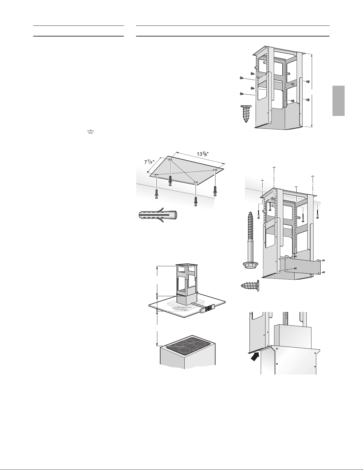
Installation
4. Determine the overall height of the
support frame.
– This is the height of the ceiling, the
height of the base and the distance
between the hob and extractor hood.
The extractor hood is designed to be
fitted to the kitchen ceiling or a rigid
suspended ceiling.
몇CAUTION:
Ensure that the minimum distance
between hotplate and extractor hood is
30” for electric hotplates and 30” for gas
hotplates.
1. Mark the centre point of the extractor
hood on the ceiling.
2. Using the template, mark screw
positions on the ceiling.
3. Drill 2x
1
/
4
” ø holes and insert wall plugs
flush with the ceiling.
Note: At least one screw for the
mounting must be installed through a
stud.
5. Screw together the upper and lower
sections of the support frame at the
specified overall height with 8 screws.
16
7
/
8
”-27
3
/
16
”
6. Screw the support frame to the ceiling
with 4 screws.
7. Remove the panel.
08. Insert the extractor hood over the
installation aids on the support frame.
Loading ...
Loading ...
Loading ...