Loading ...
Loading ...
Loading ...
9INSTALLATION
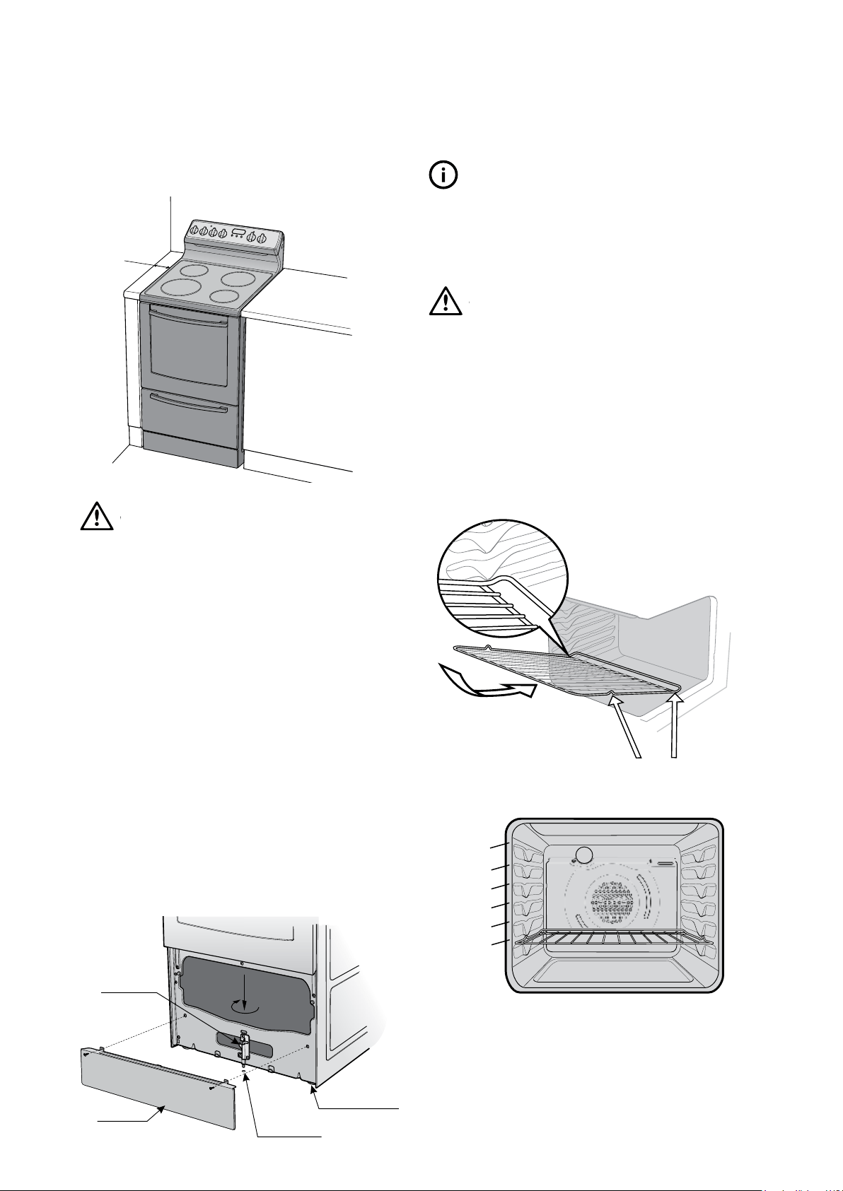
The appliance must not be installed in a corner. It
must be installed at least 100mm from the side wall.
Minimum
100mm
WARNING
WARNING
Step 3: Stability bolt
1. Remove oven door – to be done by qualified
personnel only. For separate grill models only.
(Refer to procedure).
2. Remove screws from kick panel. To remove kick panel
lift kick panel upwards to release the two Location
Tabs from the holes in the bottom of the panel.
3. Position the cooker into the anti-tilt bracket.
4. Remove the tape from the stability bolt.
5. Rotate the stability bolt 180˚ clockwise until it is
pointing to the left like the picture below.
6. The stability bolt should now be able to drop to
the floor.
7. Mark the position for the stability bolt on the floor.
8. Pull the cooker out and drill the bolt hole, using a
6.5mm masonry or wood drill. Minimum 30mm deep
for concrete.
9. Reposition the cooker back into place, then fit the
stability bolt into the drilled hole.
Stability
bolt
Kick panel
ø6.5mm drilled
location hole
Front
adjustable feet
TIPS & INFORMATION
IMPORTANT
Setting the time
If you have purchased a model fitted with an electronic
or programmable clock, you MUST set the time of day
before you can operate your appliance.
WARNING
WARNING
Fitting oven shelves
1. Ensure shelf orientation is correct (refer to
diagram below).
2. Slide oven shelves onto oven supports (side runners)
at an angle until raised back of shelf is past the stop
on oven supports (side runners).
3. Lower front of shelf and push in until stop is reached.
4. To remove oven shelves, withdraw to the stop and
raise the front of shelf to clear the stop.
Note the orientation of the
side and rear features
Not a shelf
position
5 shelf positions
1
2
3
4
5
NOTE: The top ledge is not a shelf position. There are no
stops for shelf withdrawal.
Loading ...
Loading ...
Loading ...