
www.lg.com
OWNER’S MANUAL
LED TV*
Please read this manual carefully before operating your set and
retain it for future reference.
* LG LED TVs are LCD TVs with LED backlighting.
MT35*
MT55*
MT75*
MT30*
MT31*
ENGLISH
2
TABLE OF CONTENTS
TABLE OF CONTENTS
3 LICENSES
3 OPEN SOURCE SOFTWARE
NOTICE
4 ASSEMBLING AND PREPARING
4 Unpacking
7 Separate purchase
8 Parts and buttons
10 Lifting and moving the TV
11 Setting up the TV
11 - Attaching the Stand
13 Mounting on a table
14 Mounting on a wall
16 Tidying cables
16 MAKING CONNECTIONS
17 Antenna Connection
17 Satellite dish Connection
17 Euro Scart Connection
18 Other Connections
21 REMOTE CONTROL
22 USING THE USER GUIDE
23 MAINTENANCE
23 Cleaning Your TV
23 - Screen, frame, cabinet and stand
23 - Power cord
23 Preventing “Image burn” or “Burn-in” on your
TV screen
24 TROUBLESHOOTING
25 SPECIFICATIONS
WARNING
y
If you ignore the warning message, you may
be seriously injured or there is a possibility of
accident or death.
CAUTION
y
If you ignore the caution message, you may be
slightly injured or the product may be damaged.
NOTE
y
The note helps you understand and use the
product safely. Please read the note carefully
before using the product.

ENGLISH
3
LICENSES / OPEN SOURCE SOFTWARE NOTICE
LICENSES
Supported licenses may differ by model. For more information of the licenses, visit
www.lg.com
.
Manufactured under license from Dolby Laboratories. Dolby and the double-D symbol are
trademarks of Dolby Laboratories.
The terms HDMI and HDMI High-Definition Multimedia Interface, and the HDMI logo are
trademarks or registered trademarks of HDMI Licensing LLC in the United States and
other countries.
ABOUT DIVX VIDEO: DivX
®
is a digital video format created by DivX, LLC, a subsidiary
of Rovi Corporation. This is an ofcial DivX Certied
®
device that has passed rigorous
testing to verify that it plays DivX video. Visit divx.com for more information and software
tools to convert your les into DivX videos.
ABOUT DIVX VIDEO-ON-DEMAND: This DivX Certified
®
device must be registered
in order to play purchased DivX Video-on-Demand (VOD) movies. To obtain your
registration code, locate the DivX VOD section in your device setup menu. Go to vod.
divx.com for more information on how to complete your registration.
“DivX Certied
®
to play DivX
®
video up to HD 1080p, including premium content.”
“DivX
®
, DivX Certied
®
and associated logos are trademarks of Rovi Corporation or its
subsidiaries and are used under license.”
“Covered by one or more of the following U.S. patents :
7,295,673; 7,460,668; 7,515,710; 7,519,274”
For DTS patents, see http://patents.dts.com. Manufactured under license from DTS
Licensing Limited. DTS, the Symbol, & DTS and the Symbol together are registered
trademarks, and DTS 2.0 Channel is a trademark of DTS, Inc. © DTS, Inc. All Rights
Reserved.
OPEN SOURCE SOFTWARE NOTICE
To obtain the source code under GPL, LGPL, MPL and other open source licenses, that is contained in this product,
please visit
http://opensource.lge.com
.
In addition to the source code, all referred license terms, warranty disclaimers and copyright notices are available for
download.
LG Electronics will also provide open source code to you on CD-ROM for a charge covering the cost of performing
such distribution (such as the cost of media, shipping and handling) upon email request to [email protected].
This offer is valid for three (3) years from the date on which you purchased the product.
ENGLISH
4
ASSEMBLING AND PREPARING
NOTE
y
Image shown may differ from your TV.
y
Your TV’s OSD (On Screen Display) may differ slightly from that shown in this manual.
y
The available menus and options may differ from the input source or product model that you are using.
y
New features may be added to this TV in the future.
y
The TV can be placed in standby mode in order to reduce the power consumption. And the TV should be
turned off if it will not be watched for some time, as this will reduce energy consumption.
y
The energy consumed during use can be significantly reduced if the level of brightness of the picture is
reduced, and this will reduce the overall running cost.
ASSEMBLING AND PREPARING
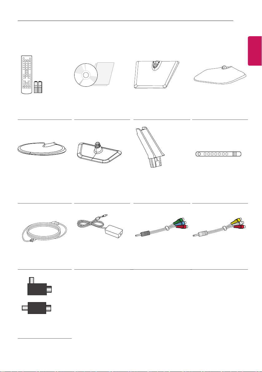
Unpacking
Check your product box for the following items. If there are any missing accessories, contact the local dealer where
you purchased your product. The illustrations in this manual may differ from the actual product and item.
CAUTION
y
Do not use any pirated items to ensure the safety and product life span.
y
Any damages or injuries by using pirated items are not covered by the warranty.
y
Some models have a thin film attached on to the screen and this must not be removed.
NOTE
y
The items supplied with your product may vary depending on the model.
y
Product specifications or contents of this manual may be changed without prior notice due to upgrade of
product functions.
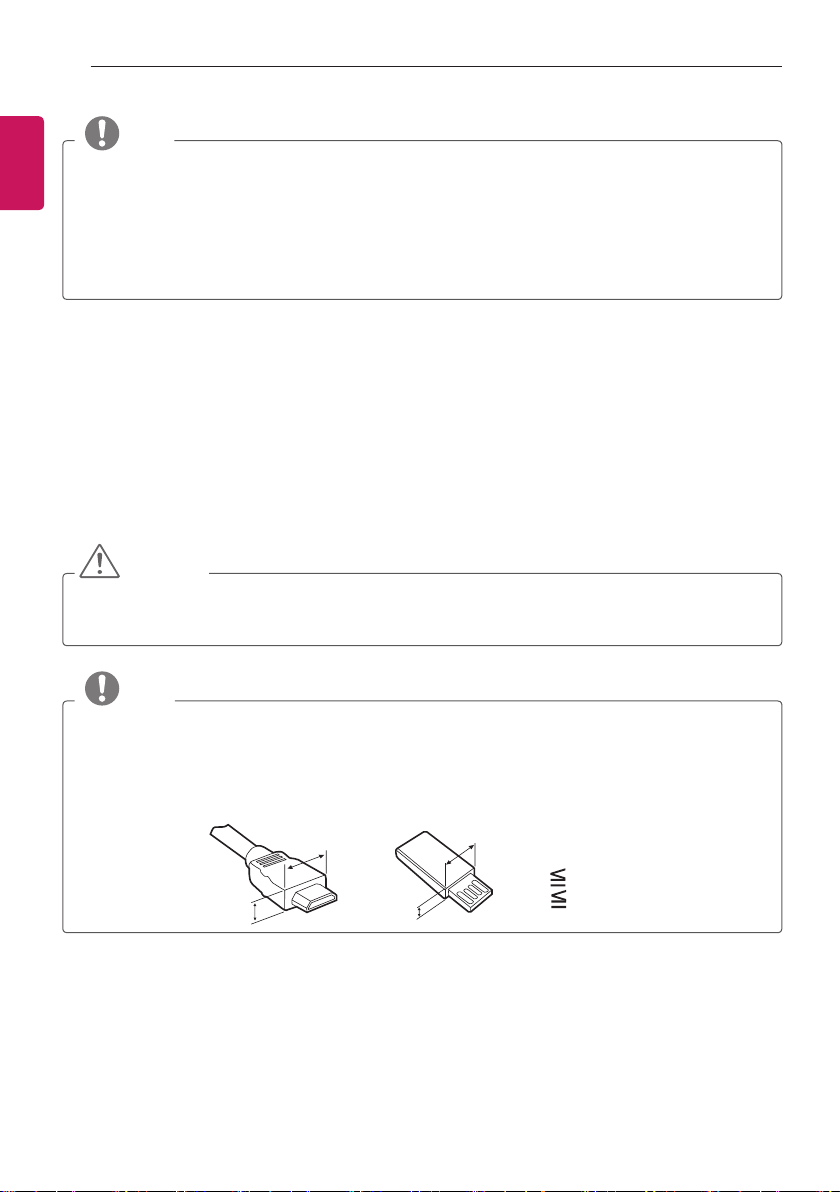
y
For an optimal connection, HDMI cables and USB devices should have bezels less than 10 mm thick and 18
mm width. Use an extension cable that supports USB 2.0 if the USB cable or USB memory stick does not fit
into your TV’s USB port.
*A 10 mm
*B
18 mm
A
B
A
B
ENGLISH
5
ASSEMBLING AND PREPARING
Remote control,
Batteries (AAA)
(See p.21)
CD (Owner’s Manual),
Cards
Stand Base
(Only MT35*)
(See p.11)
Stand Base
(Only MT55*, MT75*)
(See p.11)
Stand Base
(Only MT30*)
(See p.11)
Stand Base
(Only MT31*)
(See p.11)
Stand Body
(Only MT35*, MT30*,
MT55*, MT75*)
(See p.11)
Cable Tie
(See p.16)
Power Cord
(See p.13)
AC-DC Adapter
(See p.13)
Component gender
cable
(See p.18, 19, 20)
Composite gender
cable
(See p.18, 19, 20)
or
Isolator
(Depending on model)
(See p.6)
ENGLISH
6
ASSEMBLING AND PREPARING
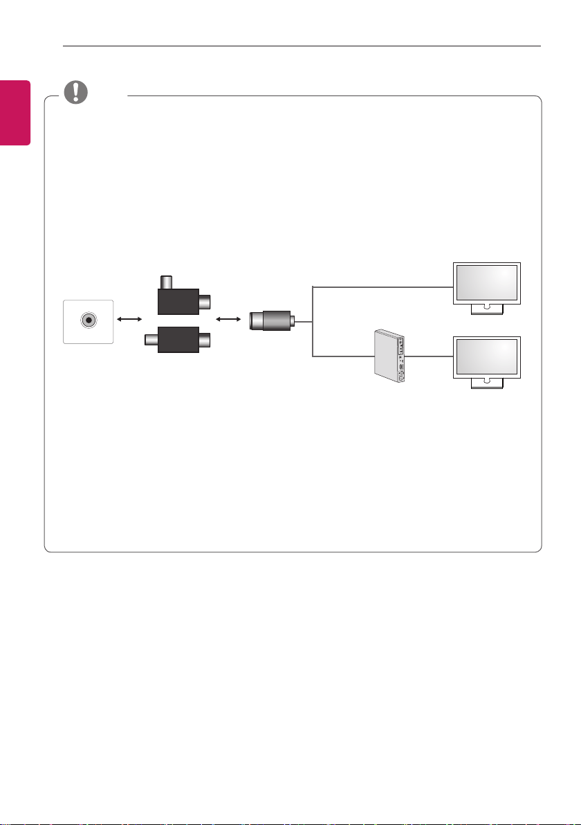
y Antenna Isolator Installation Guide
- Use this to install TV in a place where there is a voltage difference between TV Set and GND of antenna
signal.
» If there is a voltage difference between TV Set and GND of antenna signal, the antenna contact might
be heated and excessive heat might cause an accident.
- You can improve the safety when watching TV by efficiently removing power voltage from TV antenna. It
is recommended to mount the isolator to the wall. If it cannot be mounted to the wall, mount it on the TV.
Avoid disconnecting the antenna Isolator after installation.
- Before starting, be sure that the TV antenna is connected.
ANTENNA/
CABLE IN
Cable / Antenna
Wall
Isolator
1. Connect to TV.
2. Connect to Set-Top box.
Connect one end of the isolator to cable/antenna jack and the other to TV set or set-top box.
“Equipment connected to the protective earthing of the building installation through the mains connection or
through other equipment with a connection to protective earthing - and to a cable distribution system using
coaxial cable, may in some circumstances create a re hazard. Connection to a cable distribution system has
therefore to be provided through a device providing electrical isolation below a certain frequency range (galvanic
isolator, see EN 60728-11)”
When applying the RF Isolator, a slight loss of signal sensitivity can occur.
NOTE
or
ENGLISH
7
ASSEMBLING AND PREPARING
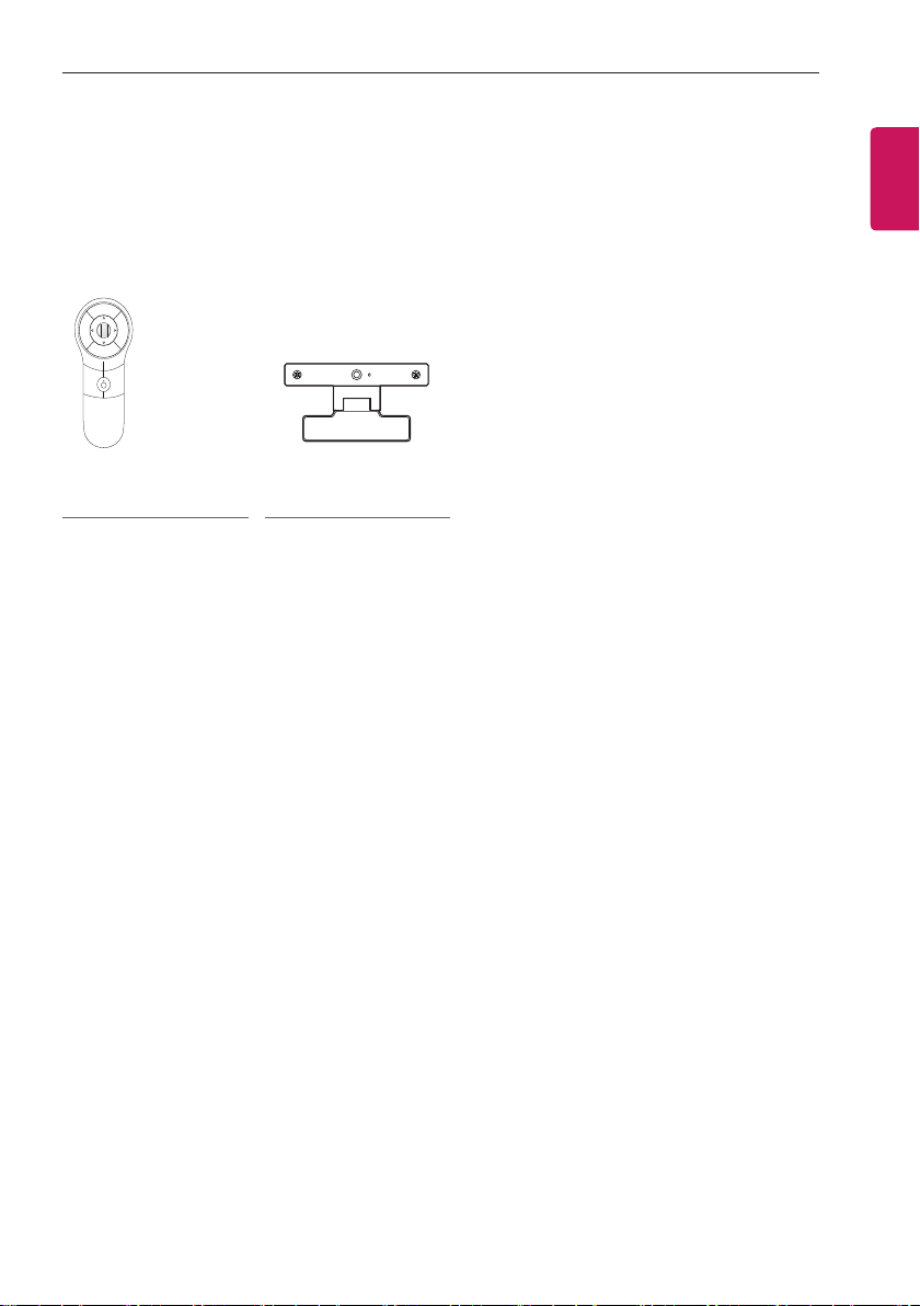
Separate purchase
Separate purchase items can be changed or modied for quality improvement without any notication.
Contact your dealer to buy these items.
These devices only work with certain models.
The model name or design may be changed depending on the upgrade of product functions, manufacturer’s circum-
stances or policies.
AN-MR400
Magic Remote
AN-VC4**
Video call camera
ENGLISH
8
ASSEMBLING AND PREPARING
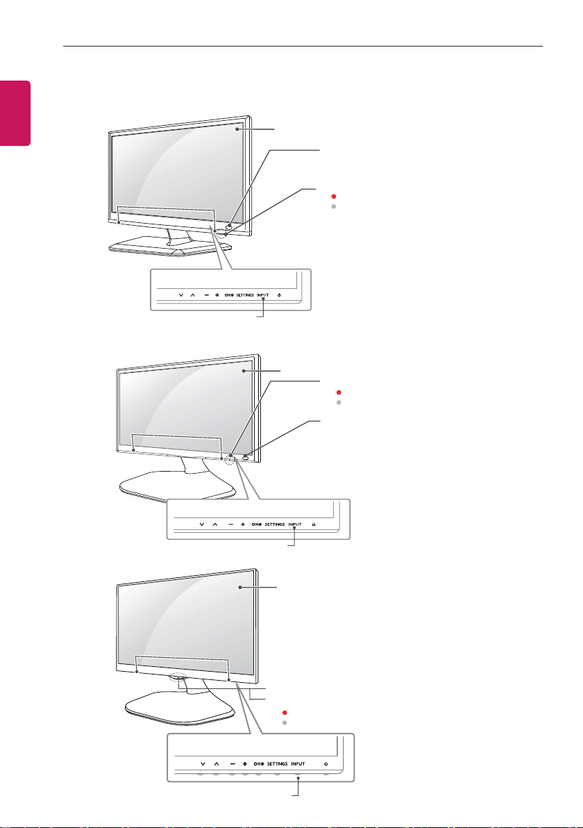
Parts and buttons
MT35*
Remote Control Sensor
Power Indicator
y
Red
:
When the power is turned off
y
Off
:
When the power is turned on
Speakers
Touch Buttons
Screen
MT55*
Remote Control Sensor
Power Indicator
y
Red
:
When the power is turned off
y
Off
:
When the power is turned on
Speakers
Touch Buttons
Screen
MT75*
Touch Buttons
Speakers
Remote Control Sensor
Power Indicator
y
Red
:
When the power is turned off
y
Off
:
When the power is turned on
Screen
ENGLISH
9
ASSEMBLING AND PREPARING
NOTE
y
All of the buttons are touch sensitive and can be operated through simple touch with your finger.
y
Power and control touch button are located on the bottom. (Only MT75*)
y
You can set the power indicator light to on or off by selecting
OPTION
in the main menus.
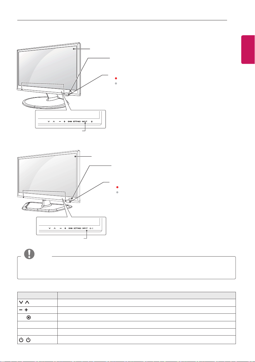
Touch button Description
Scrolls through the saved programmes.
Adjusts the volume level.
OK
Selects the highlighted menu option or confirms an input.
SETTINGS
Accesses the main menus, or saves your input and exits the menus.
INPUT
Changes the input source.
(
/
I)
Turns the power on or off.
Remote Control Sensor
Power Indicator
y
Red :
When the power is turned off
y
Off :
When the power is turned on
Speakers
Touch Buttons
Screen
Remote Control Sensor
Speakers
Touch Buttons
Screen
MT30*
MT31*
Power Indicator
y
Red :
When the power is turned off
y
Off :
When the power is turned on
ENGLISH
10
ASSEMBLING AND PREPARING
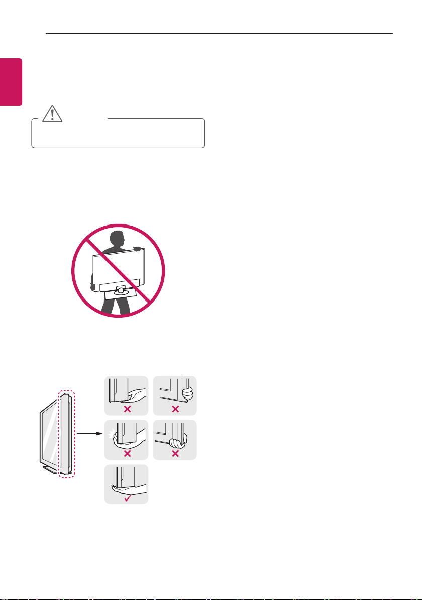
Lifting and moving the TV
Please note the following advice to prevent the
TV from being scratched or damaged and for safe
transportation regardless of its type and size.
CAUTION
y
Avoid touching the screen at all times, as this
may result in damage to the screen.
y
It is recommended to move the TV in the box or
packing material that the TV originally came in.
y
Before moving or lifting the TV, disconnect the
power cord and all cables.
y
When holding the TV, the screen should face
away from you to prevent the screen from
scratches.
y
Hold the top and bottom of the TV frame firmly.
Make sure not to hold the transparent part,
speaker, or speaker grill area.
y
When transporting the TV, do not expose the
TV to jolts or excessive vibration.
y
When transporting the TV, keep the TV upright,
never turn the TV on its side or tilt towards the
left or right.
y
Do not apply excessive pressure to cause
flexing /bending of frame chassis as it may
damage screen.
ENGLISH
11
ASSEMBLING AND PREPARING
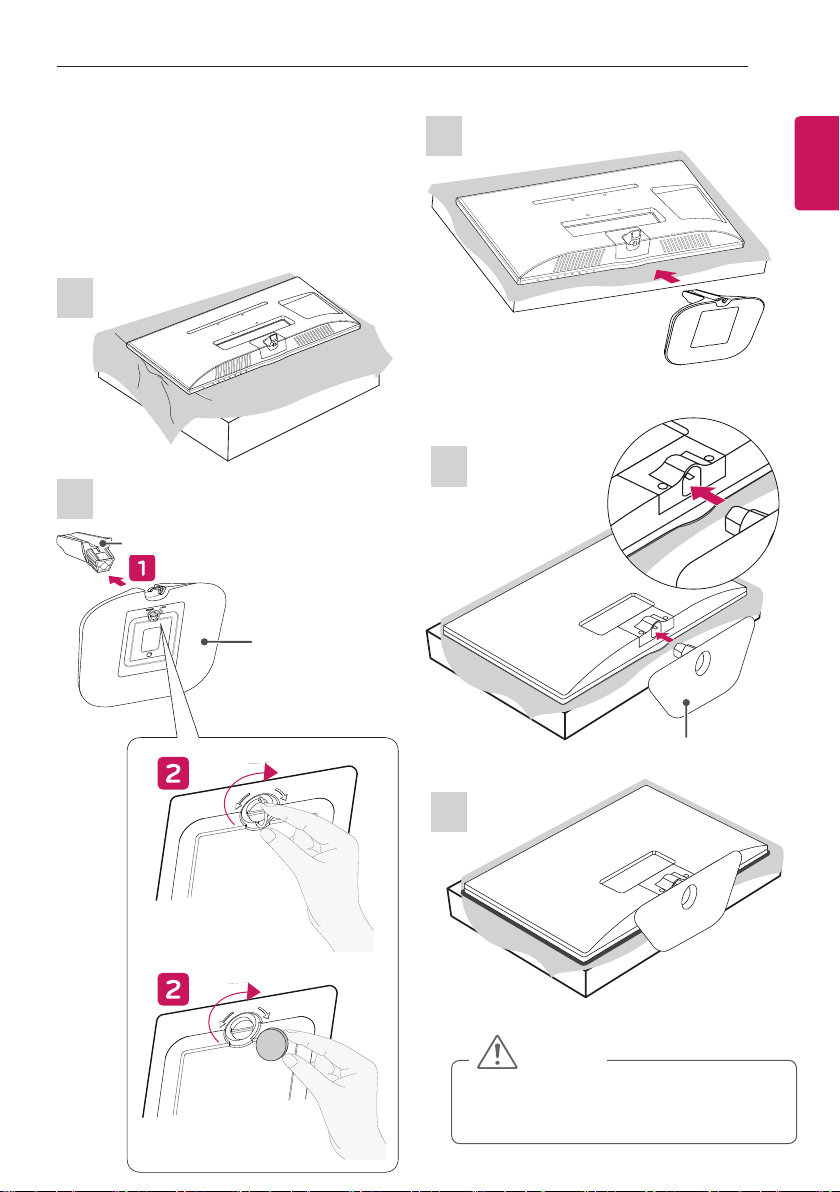
MT35*, MT55*, MT75*, MT30*
1
2
Stand Body
Stand Base
or
Setting up the TV
Image shown may differ from your TV.
Attaching the Stand
3
1
Stand Base
2
MT31*
CAUTION
y
When attaching the stand to the TV set, place the
screen facing down on a cushioned table or flat
surface to protect the screen from scratches.

ENGLISH
12
ASSEMBLING AND PREPARING
y
Do not carry the monitor upside-down by holding
the stand body (or stand base) as this may cause
it to fall off, resulting in damage or injury.
y
The illustration shows a general example of
installation and may look different from the actual
product.
CAUTION
OK
NG
NG
OK
NG
NG
CAUTION
OK
NG
NG
OK
NG
NG
y
Remove the stand before installing the TV on a
wall mount by performing the stand attachment in
reverse.
NOTE
ENGLISH
13
ASSEMBLING AND PREPARING
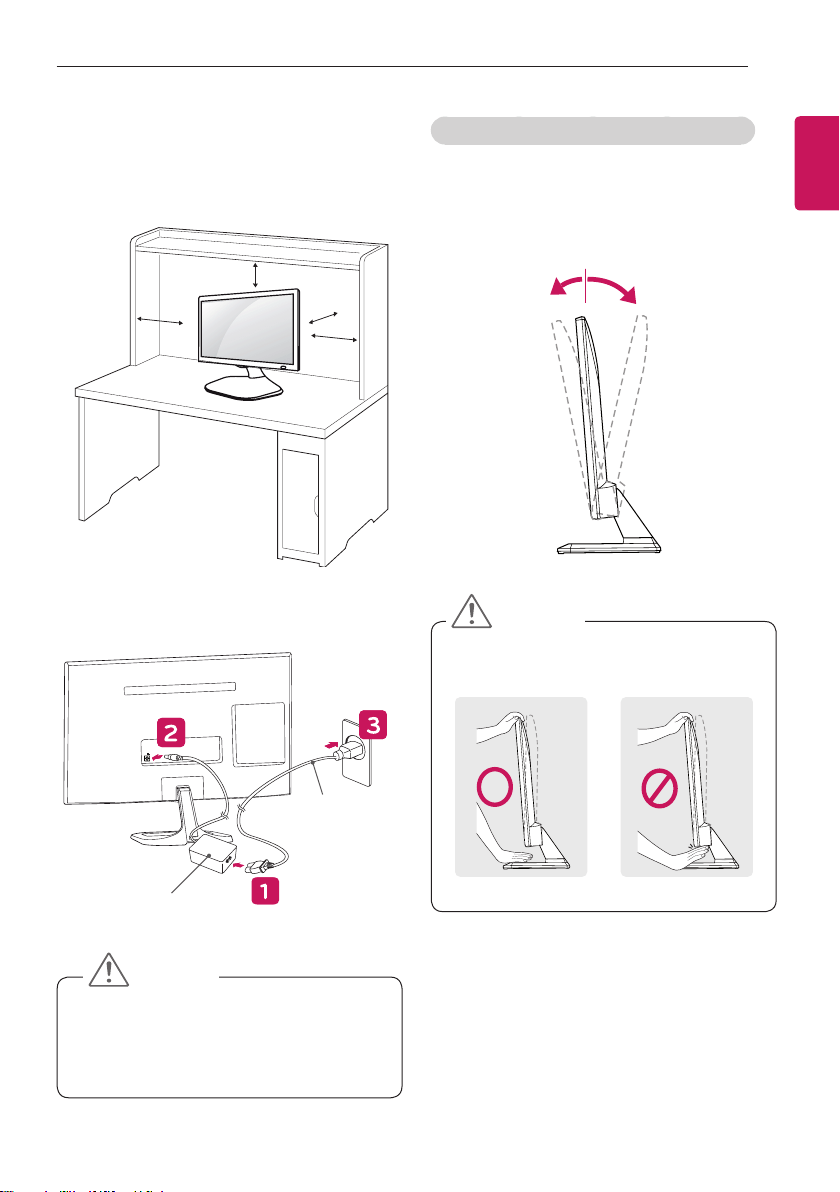
Mounting on a table
1
Lift and tilt the TV into its upright position on a table.
Leave a 10 cm (minimum) space from the wall for
proper ventilation.
10 cm
10 cm
10 cm
10 cm
2
Connect the
AC-DC Adapter
and
Power Cord
to a
wall outlet.
DC-IN
(19V )
DC-IN
(19V )
AC-DC Adapter
Power Cord
y
Do not place the TV near or on sources of heat,
as this may result in fire or other damage.
y
Please be sure to connect the TV to the AC/DC
power adapter before connecting the TV’s power
plug to a wall power outlet.
CAUTION
Adjusting the angle of the TV to suit view
y
Image shown may differ from your TV.
Tilt from +20 to -5 degrees up or down to adjust the
angle of the TV to suit your view.
(Only MT35*, MT55*, MT75*, MT30*)
Front Rear
+20-5
y
When you adjust the angle, do not hold the
buttom of the TV frame as shown on the following
illustration, as may injure your fingers.
CAUTION
ENGLISH
14
ASSEMBLING AND PREPARING
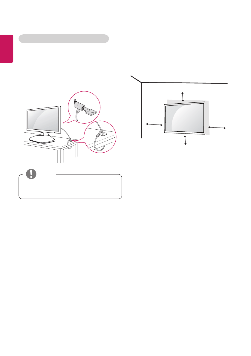
Using the Kensington security system
y
Image shown may differ from your TV.
The Kensington security system connector is located at
the back of the TV. For more information of installation
and using, refer to the manual supplied with the Ken-
sington security system or visit http://www.kensington.
com.
Connect the Kensington security system cable between
the TV and a table.
y
The Kensington security system is optional. You
can obtain additional accessories from most
electronics stores.
NOTE
Mounting on a wall
For proper ventilation, allow a clearance of 10 cm
on each side and from the wall. Detailed installation
instructions are available from your dealer, see the
optional Tilt Wall Mounting Bracket Installation and
Setup Guide.
10 cm
10 cm
10 cm
10 cm
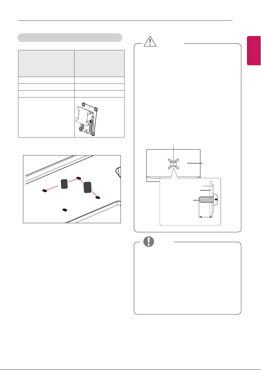
If you intend to mount the TV to a wall, attach Wall
mounting interface (optional parts) to the back of the
TV.
When you install the TV using the wall mounting
interface (optional parts), attach it carefully so it will not
drop.
1
If you use screw longer than standard, the TV might
be damaged internally.
2
If you use improper screw, the product might be
damaged and drop from mounted position. In this
case, LG Electronics is not responsible for it.
ENGLISH
15
ASSEMBLING AND PREPARING
Separate purchase(Wall Mounting Bracket)
Model 24MT35*
27MT55*
27MT75*
24MT30*
29MT31*
Wall Mount (A x B) 100 x 100
Standard screw M4 x L10
Number of screws 4
Wall mount bracket
(optional)
RW120
y
Wall Mount (A x B)
A
B
y
Disconnect the power first, and then move or
install the TV. Otherwise electric shock may
occur.
y
If you install the TV on a ceiling or slanted wall,
it may fall and result in severe injury. Use an
authorized LG wall mount and contact the local
dealer or qualified personnel.
y
Do not over tighten the screws as this may cause
damage to the TV and void your warranty.
y
Use the screws and wall mounts that meet the
VESA standard. Any damages or injuries by
misuse or using an improper accessory are not
covered by the warranty.
y
Screw length from outer surface of back cover
should be under 8mm.
Standard screw
: M4 X L10
Max. 8mm
Back Cover
Wall mount Pad
Wall mount Pad
Back Cover
CAUTION
y
Use the screws that are listed on the VESA
standard screw specifications.
y
The wall mount kit includes an installation manual
and necessary parts.
y
The wall mount bracket is optional. You can
obtain additional accessories from your local
dealer.
y
The length of screws may differ depending on the
wall mount. Be sure to use the proper length.
y
For more information, refer to the instructions
supplied with the wall mount.
NOTE
ENGLISH
16
ASSEMBLING AND PREPARING / MAKING CONNECTIONS
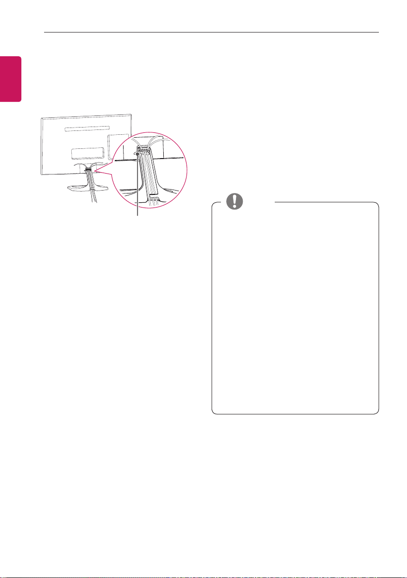
Tidying cables
1
Gather and bind the cables with the Cable Tie.
2
Place the cable on the hook located on the stand
base.
Cable Tie
MAKING CONNECTIONS
This section on MAKING CONNECTIONS
mainly uses diagrams for the 27MT55S models.
Connect various external devices to the TV and switch
input modes to select an external device. For more
information about an external device’s connection, refer
to the manual supplied with each device.
Available external devices are: HD receivers, DVD play-
ers, VCRs, audio systems, USB storage devices, PC,
camcorders or cameras, gaming devices, and other
external devices.
y
The external device connection may differ from
the model.
y
Connect external devices to the TV regardless of
the order of the TV port.
y
If you record a TV programme on a DVD recorder
or VCR, make sure to connect the TV signal input
cable to the TV through a DVD recorder or VCR.
For more information of recording, refer to the
manual provided with the connected device.
y
Refer to the external equipment’s manual for
operating instructions.
y
If you connect a gaming device to the TV, use the
cable supplied with the gaming device.
y
In PC mode, there may be noise associated
with the resolution, vertical pattern, contrast or
brightness. If noise is present, change the PC
output to another resolution, change the refresh
rate to another rate or adjust the brightness and
contrast on the PICTURE menu until the picture is
clear.
y
In PC mode, some resolution settings may not
work properly depending on the graphics card.
NOTE
ENGLISH
17
MAKING CONNECTIONS
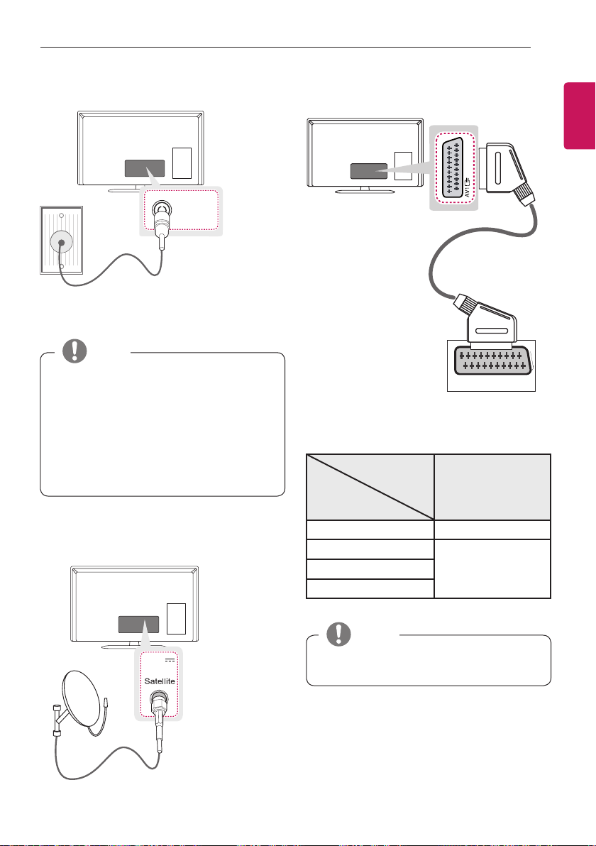
Antenna Connection
ANTENNA
/ CABLE IN
(*Not Provided)
Connect the TV to a wall antenna socket with an RF
cable (75 Ω).
y
Use a signal splitter to use more than 2 TVs.
y
If the image quality is poor, install a signal
amplifier properly to improve the image quality.
y
If the image quality is poor with an antenna
connected, try to realign the antenna in the
correct direction.
y
An antenna cable and converter are not supplied.
y
Supported DTV Audio: MPEG, Dolby Digital,
Dolby Digital Plus, HE-AAC.
NOTE
Satellite dish Connection
(Only satellite models)
(*Not Provided)
13/18 V
700mA Max
LNB IN
Connect the TV to a satellite dish to a satellite socket
with a satellite RF cable (75 Ω).
Euro Scart Connection
AUDIO / VIDEO
(*Not Provided)
Transmits the video and audio signals from an external
device to the TV set. Connect the external device and
the TV set with the euro scart cable as shown.
Output
Type
Current
input mode
AV1
(TV Out
1
)
Digital TV
Digital TV
Analogue TV, AV
Analogue TV
Component
HDMI
1 TV Out : Outputs Analogue TV or Digital TV signals.
y
Any Euro scart cable used must be signal
shielded.
NOTE
ENGLISH
18
MAKING CONNECTIONS
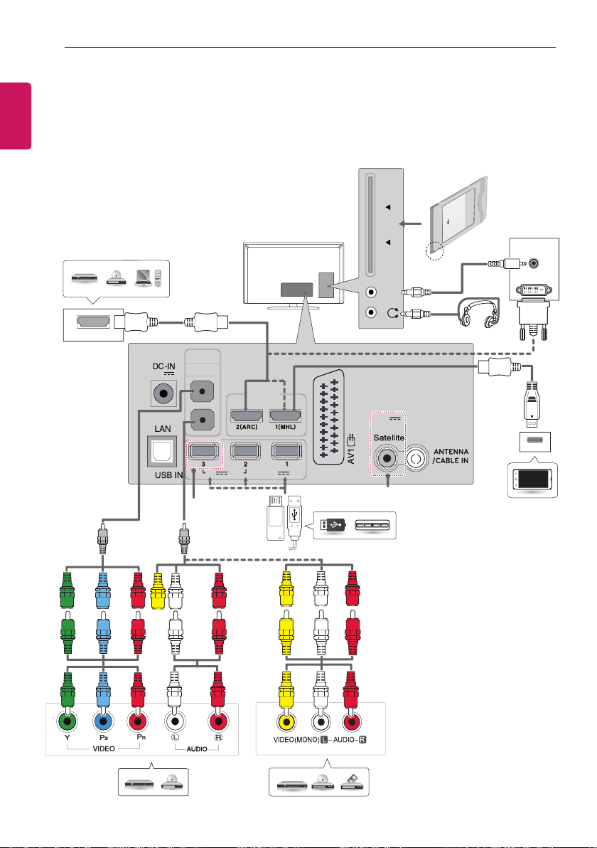
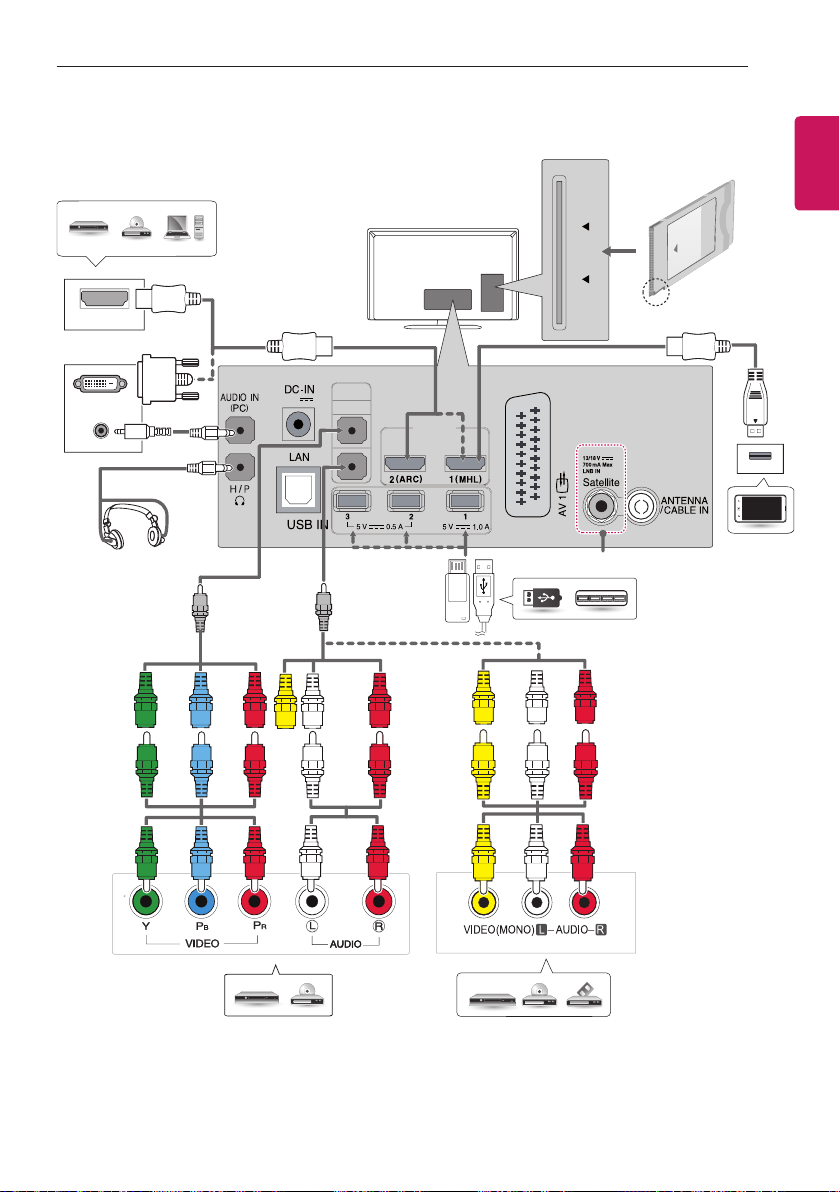
Other Connections
Connect your TV to external devices. For the best picture and audio quality, connect the external device and the TV
with the HDMI cable as shown. Some separate cable is not provided.
MT35*, MT55*, MT30*
HDMI IN
(19 V )
COMPO-
NENT IN
AV2 IN /
AUDIO L R
5 V 1.0 A
5 V 0.5 A
13/18 V
700mA Max
LNB IN
AUDIO
IN
(PC)
PCMCIA
CARD SLOT
H / P
HDMI OUT
DVI OUT
AUDIO OUT
DVD / Blu-Ray / PC /
HD Cable Box / HD STB
USB / HUB
Mobile Phone
GREEN
BLUE
RED
WHITE
RED
DVD / Blu-Ray / HD Cable Box
VCR / DVD / Blu-Ray / HD Cable Box
YELLOW
WHITE
RED
(Only MT55*)
Headphone
(Only satellite models)
Component
gender cable
Composite
gender cable
ENGLISH
19
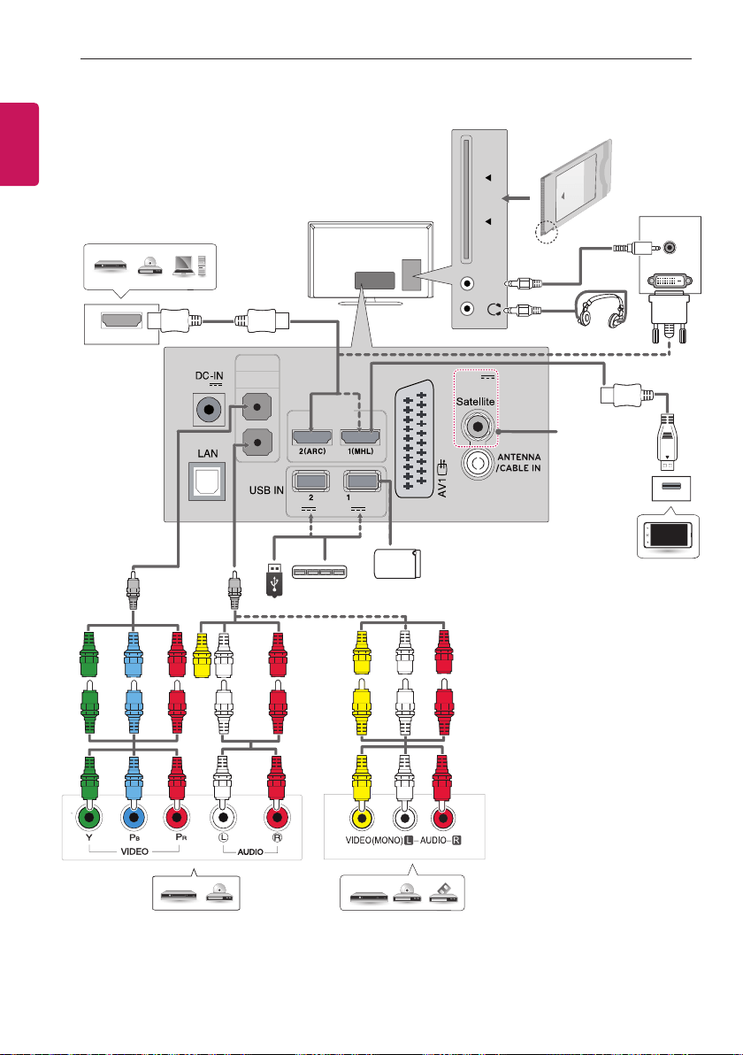
MAKING CONNECTIONS
MT75*
COMPO-
NENT IN
AV2 IN /
AUDIO L R
HDMI IN
PCMCIA
CARD SLOT
HDMI OUT
AUDIO OUT
DVI OUT
(19 V )
GREEN
BLUE
RED
WHITE
RED
USB / HUB
Mobile Phone
DVD / Blu-Ray / PC /
HD Cable Box / HD STB
DVD / Blu-Ray / HD Cable Box
VCR / DVD / Blu-Ray / HD Cable Box
YELLOW
WHITE
RED
Headphone
Component
gender cable
Composite
gender cable
(Only satellite models)
ENGLISH
20
MAKING CONNECTIONS
MT31*
HDMI IN
(19 V )
COMPO-
NENT IN
AV2 IN /
AUDIO L R
5 V 1.0 A
5 V 0.5 A
700mA Max
LNB IN
+KGG#LQ,
13/18 V
AUDIO
IN
(PC)
PCMCIA
CARD SLOT
H / P
HDMI OUT
DVI OUT
AUDIO OUT
DVD / Blu-Ray / PC /
HD Cable Box / HD STB
USB / HUB
Mobile Phone
GREEN
BLUE
RED
WHITE
RED
DVD / Blu-Ray / HD Cable Box VCR / DVD / Blu-Ray / HD Cable Box
YELLOW
WHITE
RED
Headphone
(Only satellite
models)
Component
gender cable
Composite
gender cable
HDD
ENGLISH
21
REMOTE CONTROL
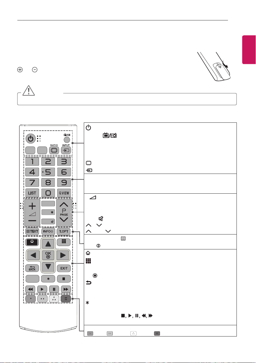
REMOTE CONTROL
The descriptions in this manual are based on the buttons on the remote control.
Please read this manual carefully and use the TV correctly.
To replace batteries, open the battery cover, replace batteries (1.5 V AAA) matching the
and ends to the label inside the compartment, and close the battery cover.
To remove the batteries, perform the installation actions in reverse.
CAUTION
y
Do not mix old and new batteries, as this may damage the remote control.
Make sure to point the remote control toward the remote control sensor on the TV.
APP/
MUTE
FAV
TV/
RAD
SUBTITLE
Q.MENU
GUIDE
SMART
MY APPS
SETTINGS
LIVE TV
(POWER) Turns the TV on or off.
TV/RAD Selects Radio, TV and DTV programme.
Q.MENU Accesses the Quick menus.
SUBTITLE
Recalls your preferred subtitle in digital mode.
GUIDE Shows programme guide.
RATIO
Resizes an image.
INPUT Changes the input source.
Number buttons Enters numbers.
LIST Accesses the saved programme list.
Q.VIEW Returns to the previously viewed programme.
+ -
Adjusts the volume level.
FAV Accesses your favorite programme list.
APP/*
Select the MHP TV menu source. (Only Italy) (Depending on model)
MUTE Mutes all sounds.
P Scrolls through the saved programmes.
PAGE Moves to the previous or next screen.
Teletext buttons ( TEXT / T.OPT)
These buttons are used for teletext.
INFO
Views the information of the current programme and screen.
SMART
Accesses the Home menus.
MY APPS
Shows the list of Apps.
Navigation buttons (up/down/left/right) Scrolls through menus or options.
OK
Selects menus or options and conrms your input.
BACK Returns to the previous level.
EXIT Clears on-screen displays and returns to TV viewing.
SETTINGS Accesses the main menus.
Not functional.
LIVE TV
Returns to LIVE TV.
Control buttons
( )
Controls the Preminum contents,
SmartShare menus or the SIMPLINK compatible devices (USB or SIMPLINK).
Colour buttons These access special functions in some menus.
( : Red, : Green, : Yellow, : Blue)
ENGLISH
22
USING THE USER GUIDE
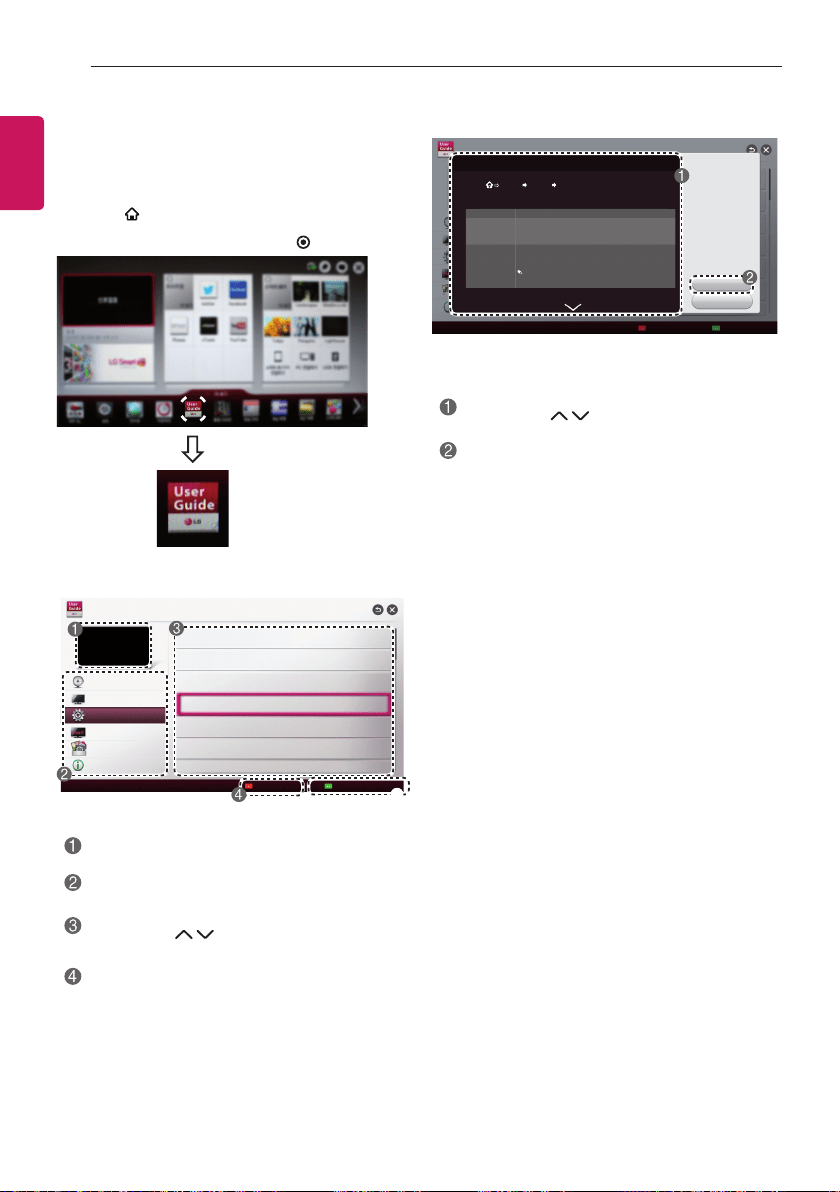
USING THE USER GUIDE
y
Image shown may differ from your TV.
1 Press
SMART
button to access the Home menu.
2 Select
User Guide
and press
OK
.
To use input device
User Guide
To set TV lock options
To set language
To set country
Disabled Assisstance
To set Magic remote control
To set time options
OPTION
Index
Online User Guide
PROGRAMME Setting
PICTURE, SOUND Setting
LG SMART Function
Advanced Function
Information
5
Shows the current watching programme or input
source screen.
Allows to select the category you want.
Allows to select the item you want.
You can use to move between pages.
Allows to browse the description of the
function you want from the index.
5
Provides the detailed information on the
functions of LG Smart TV when the Internet
is connected.
(It may not be available depending on the
country/language.)
Try Now
Close
OPTION > To set language
SMART Settings OPTION Language(Language)
Selects Menu Language and Audio Language displayed on the screen.
Menu Language
Audio Language
Subtitle
Language
Selects a language for the display text.
[In Digital Mode Only]
When watching a digital broadcast containing several
audio languages, you can select the language you want.
[In Digital Mode Only]
Use the Subtitle function when two or more subtitle
languages are broadcast.
If subtitle data in a selected language is not broadcast,
the default language subtitle will be displayed.
Shows the description of the selected menu.
You can use
to move between pages.
Moves to the selected menu directly from the
User Guide.
User Guide
ENGLISH
23
MAINTENANCE
MAINTENANCE
Cleaning Your TV
Clean your TV regularly to keep the best performance and to extend the product lifespan.
CAUTION
y
Make sure to turn the power off and disconnect the power cord and all other cables first.
y
When the TV is left unattended and unused for a long time, disconnect the power cord from the wall outlet
to prevent possible damage from lightning or power surges.
Screen, frame, cabinet and stand
y
To remove dust, wipe the surface with a dry and soft cloth.
y
To remove major dirt, wipe the surface with a soft cloth dampened in clean water or a diluted mild detergent.
Then wipe immediately with a clean and dry cloth.
CAUTION
y
Avoid touching the screen at all times, as this may result in damage to the screen.
y
Do not push, rub, or hit the screen surface with your fingernail or a sharp object, as this may result in
scratches and image distortions.
y
Do not use any chemicals as this may damage the product.
y
Do not spray liquid onto the surface. If water enters the TV, it may result in fire, electric shock, or
malfunction.
Power cord
Remove the accumulated dust or dirt on the power cord regularly.
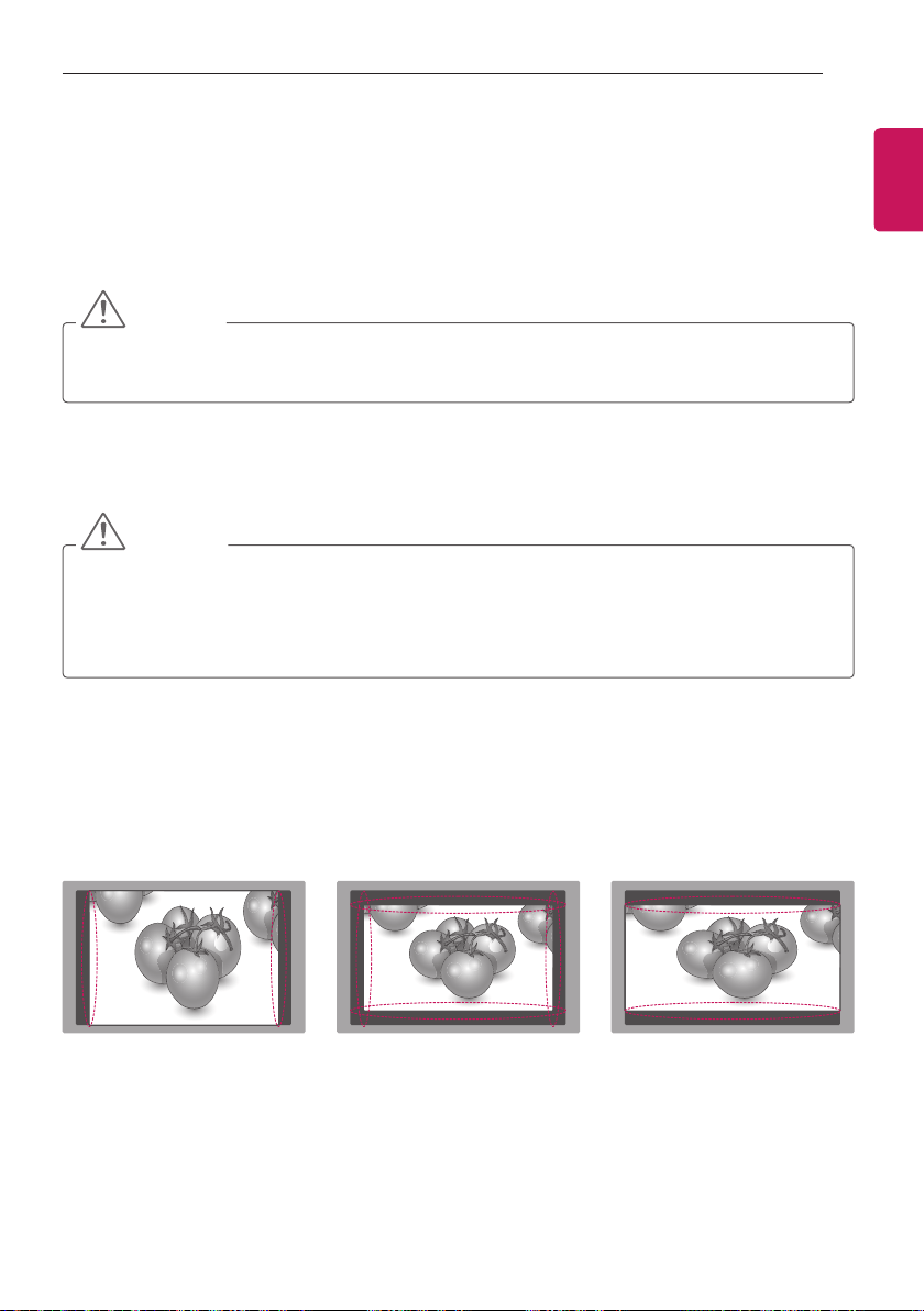
Preventing “Image burn” or “Burn-in” on your TV screen
y
If a fixed image displays on the TV screen for a long period of time, it will be imprinted and become a
permanent disfigurement on the screen. This is “image burn” or “burn-in” and not covered by the warranty.
y
If the aspect ratio of the TV is set to 4:3 for a long period of time, image burn may occur on the letterboxed
area of the screen.
y
Avoid displaying a fixed image on the TV screen for a long period of time (2 or more hours for LCD) to
prevent image burn.
ENGLISH
24
TROUBLESHOOTING
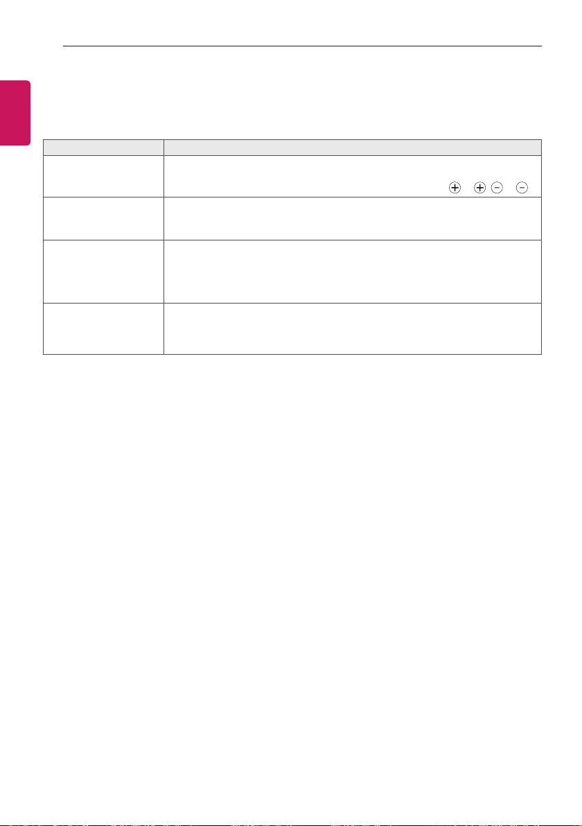
TROUBLESHOOTING
Problem Solution
Cannot control the TV
with the remote control.
y
Check the remote control sensor on the product and try again.
y
Check if there is any obstacle between the product and the remote control.
y
Check if the batteries are still working and properly installed ( to , to ).
No image display and no
sound is produced.
y
Check if the product is turned on.
y
Check if the power cord is connected to a wall outlet.
y
Check if there is a problem in the wall outlet by connecting other products.
The TV turns off suddenly.
y
Check the power control settings. The power supply may be interrupted.
y
Check if the
Automatic Standby
(Depending on model)
/ Sleep Timer
/
Off Time
feature is activated in the
TIME
settings.
y
If there is no signal while the TV is on, the TV will turn off automatically after 15
minutes of inactivity.
When connecting to the
PC (HDMI/DVI), ‘No
signal’ or ‘Invalid Format’
is displayed.
y
Turn the TV off/on using the remote control.
y
Reconnect the HDMI cable.
y
Restart the PC with the TV on.
ENGLISH
25
SPECIFICATIONS
SPECIFICATIONS
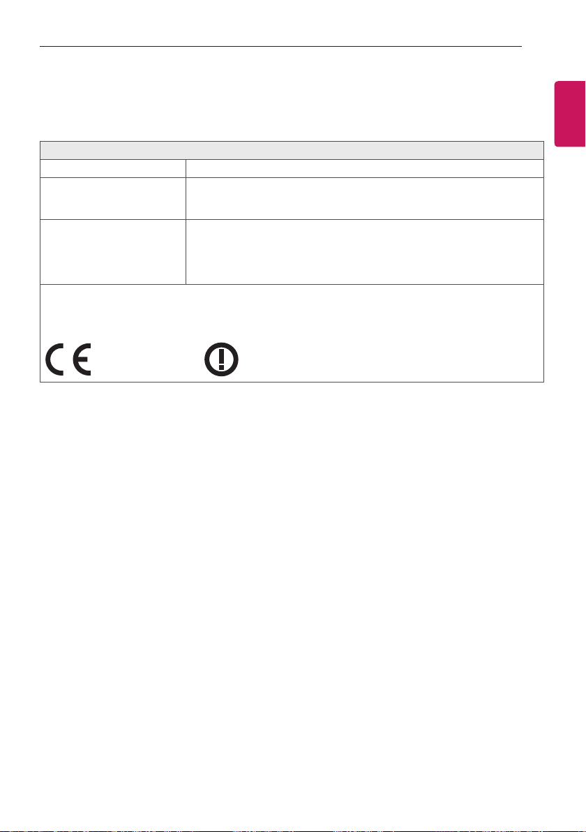
Wireless LAN module (TWFM-B006D) specication
Standard IEEE 802.11a/b/g/n
Frequency Range
2400 to 2483.5 MHz
5150 to 5250 MHz
5725 to 5850 MHz (for Non EU)
Output Power
(Max.)
802.11a: 11 dBm
802.11b: 14 dBm
802.11g: 10.5 dBm
802.11n - 2.4GHz: 11 dBm
802.11n - 5GHz: 12.5 dBm
y
Because band channel used by the country could be different, the user can not change or adjust the operating
frequency and this product is set for the regional frequency table.
y
This device should be installed and operated with minimum distance 20 cm between the device and your body.
And this phrase is for the general statement for consideration of user environment.
0197
0197
ENGLISH
26
SPECIFICATIONS
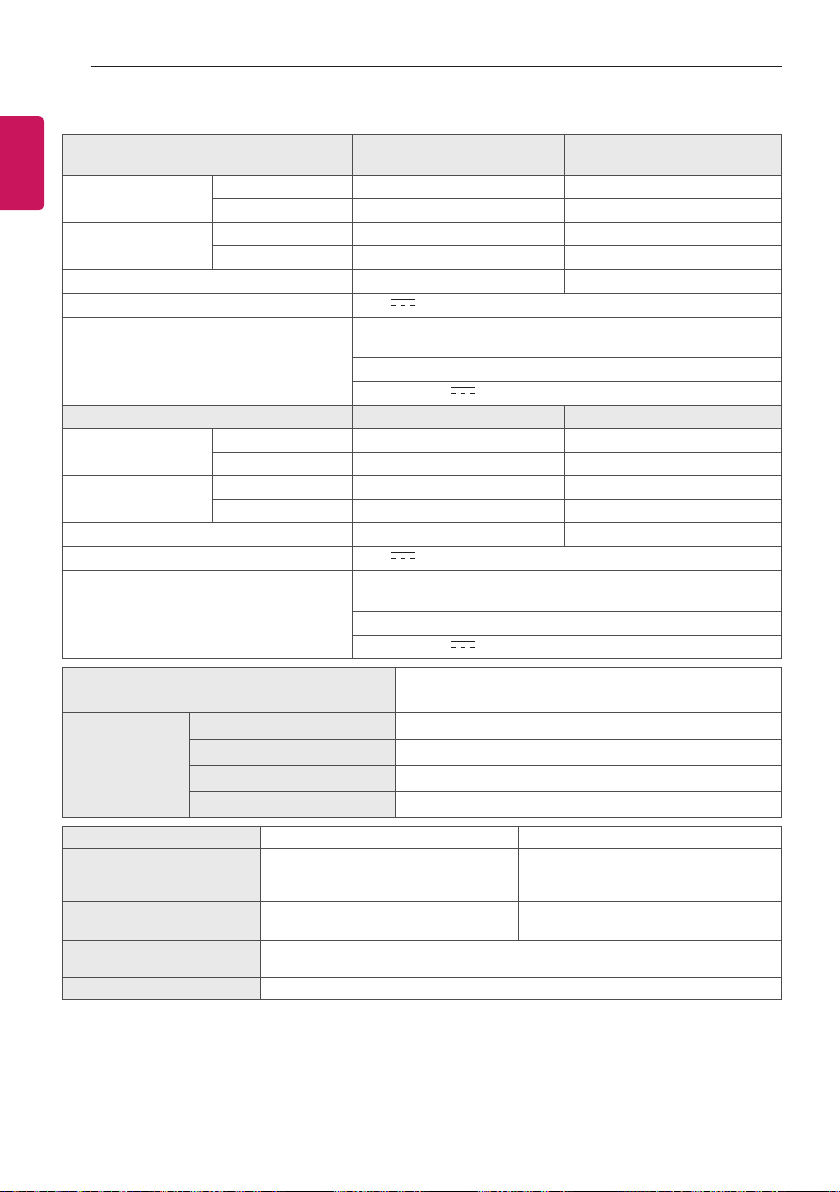
Product specications may be changed without prior notice due to upgrade of product functions.
MODELS
24MT35S
24MT30S
27MT55S
Dimensions
(W x H x D)
With stand (mm) 556.5 x 414.7 x 180.9 641.2 x 489.1 x 213.2
Without stand (mm) 556.5 x 343.1 x 62.9 641.2 x 391.3 x 77.6
Weight
With stand (kg) 4.0 5.3
Without stand (kg) 3.7 4.7
Power consumption 29 W 35 W
Power requirement
19 V 3.2 A
AC/DC Adapter Manufacturer : APD
Model : DA-65G19
IN: AC 100 – 240 V ~ 50/60 Hz
OUT: DC 19 V 3.42 A
MODELS 27MT75S 29MT31S
Dimensions
(W x H x D)
With stand (mm) 622.7 x 476.2 x 213.2
669.0 x 456.0 x 182.0
Without stand (mm) 622.7 x 377.9 x 79.5
669.0 x 411.0 x 82.0
Weight
With stand (kg) 4.9
6.0
Without stand (kg) 4.5
5.6
Power consumption 34 W
40 W
Power requirement
19 V 3.2 A
AC/DC Adapter Manufacturer : APD
Model : DA-65G19
IN: AC 100 – 240 V ~ 50/60 Hz
OUT: DC 19 V 3.42 A
CI Module Size
(W x H x D)
100.0 mm x 55.0 mm x 5.0 mm
Environment
condition
Operating Temperature 10 °C to 35 °C
Operating Humidity 20 % to 80 %
Storage Temperature -10 °C to 60 °C
Storage Humidity 5 % to 90 %
Digital TV Analogue TV
Television system DVB-T(*DVB-T/T2)
DVB-C
DVB-S/S2
PAL/SECAM B/G/I/D/K,
SECAM L/L’
Programme coverage VHF, UHF
C-Band, Ku-Band
VHF: E2 to E12, UHF : E21 to E69,
CATV: S1 to S20, HYPER: S21 to S47
Maximum number of
storable programmes
DVB-S/S2 : 6,000
DVB-T/T2/C & Analogue TV : 1,500
External antenna impedance 75 Ω
* : Only DVB-T2 support model
ENGLISH
27
SPECIFICATIONS
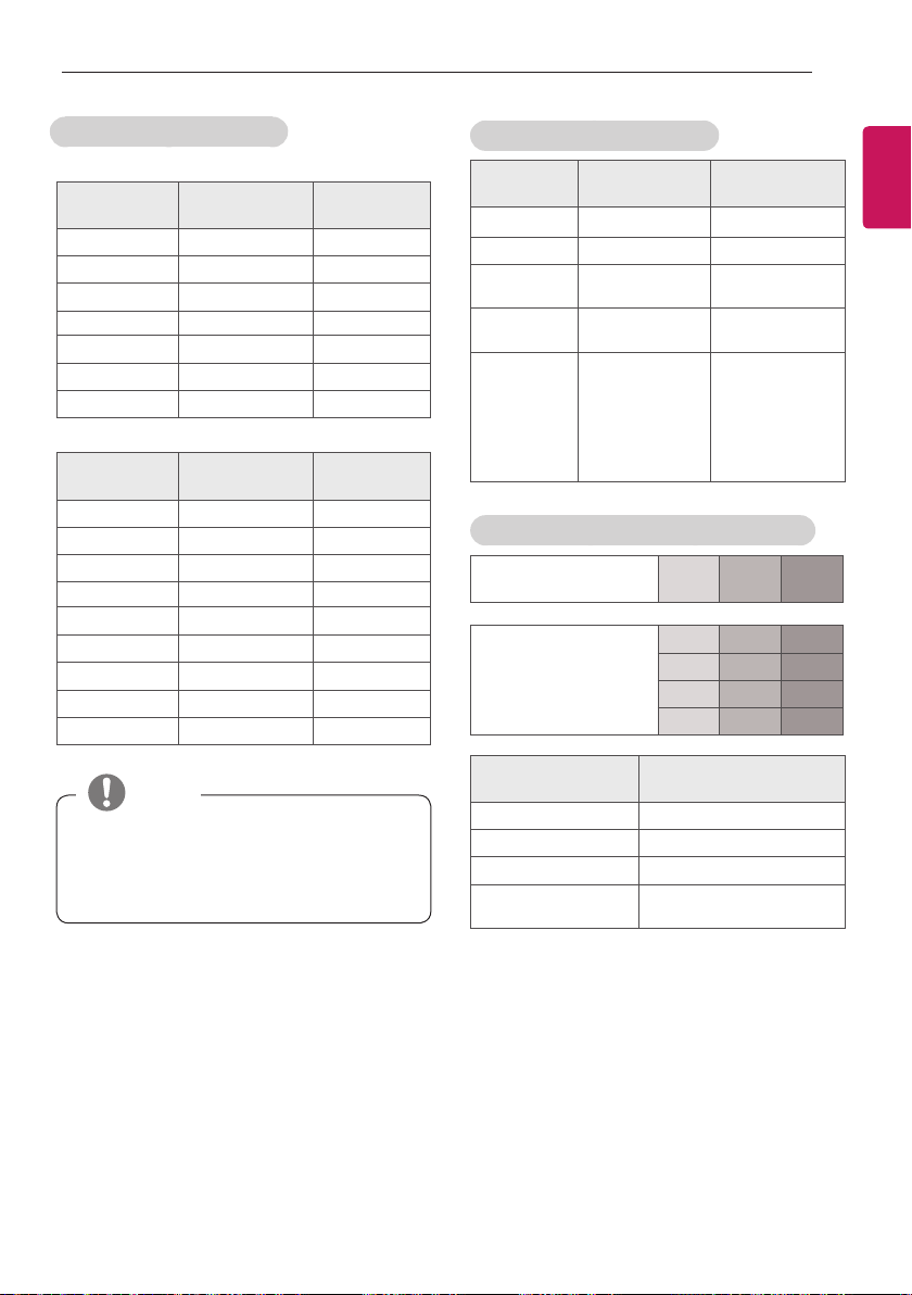
HDMI (PC) supported mode
(Only MT35*, MT30*, MT31*)
Resolution
Horizontal
Frequency(kHz)
Vertical
Frequency(Hz)
640 x 350 31.468 70.09
720 x 400 31.469 70.08
640 x 480 31.469 59.94
800 x 600 37.879 60.317
1024 x 768 48.363 60.004
1152 x 864 54.348 60.053
1360 x 768 47.712 60.015
(Only MT55*, MT75*)
Resolution
Horizontal
Frequency(kHz)
Vertical
Frequency(Hz)
640 x 350 31.468 70.09
720 x 400 31.469 70.08
640 x 480 31.469 59.94
800 x 600 37.879 60.317
1024 x 768 48.363 60.004
1152 x 864 54.348 60.053
1360 x 768 47.712 60.015
1280 x 1024 63.981 60.02
1920 x 1080 67.50 60.00
y
The optimal display resolution is
1360 X 768 @ 60 Hz (MT35*, MT30*, MT31*),
1920 X 1080 @ 60 Hz (MT75*, MT55*).
y
The optimal timing in each mode is vertical
frequency 60 Hz.
NOTE
HDMI (DTV) supported mode
Resolution
Horizontal
Frequency(kHz)
Vertical
Frequency(Hz)
640 x 480 31.469 / 31.50 59.94 / 60.00
720 x 480 31.469 / 31.50 59.94 / 60.00
720 x 576 31.25
15.625
50.00
50.00
1280 x 720 37.50
44.96 / 45.00
50.00
59.94 / 60.00
1920 x 1080
33.72 / 33.75
28.125
26.97 / 27.00
33.716 / 33.75
56.25
67.43 / 67.50
59.94 / 60.00
25.00 / 50.00
23.97 / 24.00
29.976 / 30.00
50.00
59.94 / 60.00
Component port connecting information
Component ports on
the TV
Y P
B
P
R
Video output ports
on DVD player
Y P
B
P
R
Y B-Y R-Y
Y Cb Cr
Y Pb Pr
Signal Component
480i / 576i O
480p / 576p O
720p / 1080i O
1080p
O
(50 Hz / 60 Hz only)
ENGLISH
28
SPECIFICATIONS
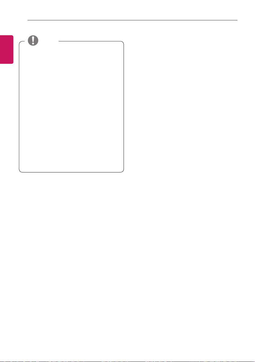
y
Avoid keeping a fixed image on the set’s
screen for prolonged periods of time. The fixed
image may become permanently imprinted on
the screen. Use a screen saver when possible.
y
There may be interference relating to
resolution, vertical pattern, contrast or
brightness in PC mode. Change the PC mode
to another resolution or change the refresh
rate to another rate or adjust the brightness
and contrast on the menu until the picture is
clear. If the refresh rate of the PC graphic card
can not be changed, change the PC graphic
card or consult the manufacturer of the PC
graphic card.
y
The synchronization input waveform for
Horizontal and Vertical frequencies are
separate.
y
Connect the audio cable from the PC to the
Audio input on the TV. (Audio cables are not
included with the TV).
y
If using a sound card, adjust PC sound as
required.
y
DOS mode may not work depending on the
video card if you use an HDMI to DVI cable.
NOTE

Make sure to read the Safety Precautions
before using the product.
Keep the Owner’s Manual (CD) in an
accessible place for future reference.
The model and serial number of the TV
is located on the back and one side of
the TV. Record it below should you ever
need service.
MODEL
SERIAL