

Online Edition for Part no. 01402896703 - X/18

WELCOME TO BMW.
Owner's Manual.
BMW X3.
Thank you for choosing a BMW.
The more familiar you are with your vehicle, the better control you will have on
the road. We therefore strongly suggest:
Read this Owner's Manual before starting off in your new BMW. Also use the
Integrated Owner's Manual in your vehicle. It contains important information
on vehicle operation that will help you make full use of the technical features
available in your BMW. The manual also contains information designed to en‐
hance operating reliability and road safety, and to contribute to maintaining
the value of your BMW.
Any updates made after the editorial deadline can be found in the appendix of
the printed Owner's Manual for the vehicle.
You can find supplementary information in the additional brochures in the on‐
board literature.
We wish you a safe and enjoyable ride.
3
Online Edition for Part no. 01402896703 - X/18

TABLE OF CONTENTS
NOTES
Information ......................................................................................................................... 8
QUICK REFERENCE
Your BMW at a glance .................................................................................................. 18
AT A GLANCE
Cockpit .............................................................................................................................. 36
Idle state, standby state, and drive-ready state ..................................................... 41
iDrive .................................................................................................................................. 44
BMW Gesture Control .................................................................................................. 53
Voice activation system ............................................................................................... 56
General settings ............................................................................................................. 59
Owner's Manual media ................................................................................................ 72
CONTROLS
Opening and closing ..................................................................................................... 76
Seats, mirrors, and steering wheel ......................................................................... 102
Transporting children safely ..................................................................................... 115
Driving ............................................................................................................................. 120
Displays .......................................................................................................................... 140
Lights .............................................................................................................................. 157
Safety .............................................................................................................................. 164
Driving stability control systems .............................................................................. 192
Driver assistance systems ........................................................................................ 197
Driving comfort ............................................................................................................. 233
Climate control ............................................................................................................. 234
Interior equipment ....................................................................................................... 249
Storage compartments .............................................................................................. 256
Cargo area ..................................................................................................................... 260
4
Online Edition for Part no. 01402896703 - X/18

DRIVING TIPS
Things to remember when driving ......................................................................... 270
Trailer towing ................................................................................................................ 275
Saving fuel ..................................................................................................................... 279
MOBILITY
Refueling ........................................................................................................................ 288
Fuel .................................................................................................................................. 290
Wheels and tires .......................................................................................................... 296
Engine compartment ................................................................................................. 325
Engine oil ....................................................................................................................... 328
Coolant ........................................................................................................................... 332
Maintenance ................................................................................................................. 334
Replacing components .............................................................................................. 336
Breakdown assistance ............................................................................................... 344
Care ................................................................................................................................. 351
REFERENCE
Technical data .............................................................................................................. 358
Appendix ........................................................................................................................ 361
Everything from A to Z ............................................................................................... 362
© 2018 Bayerische Motoren Werke
Aktiengesellschaft
Munich, Germany
Reprinting, including excerpts, only with the written consent of BMW AG, Munich.
US English ID5 X/18, 11 18 490
Printed on environmentally friendly paper, bleached without chlorine, suitable for recycling.
Navigation, Entertainment and Communication can be called up via
the Integrated Owner's Manual in the vehicle.
5
Online Edition for Part no. 01402896703 - X/18

6
Online Edition for Part no. 01402896703 - X/18

NOTES
Information .................................................................................................... 8
7
Online Edition for Part no. 01402896703 - X/18

Information
Using this Owner's Manual
Orientation
The fastest way to find information on a particu‐
lar topic is by using the index.
An initial overview of the vehicle is provided in
the first chapter.
Updates made after the editorial
deadline
Due to updates after the editorial deadline, differ‐
ences may exist between the printed Owner's
Manual and the Integrated Owner's Manual in
the vehicle.
Notes on updates can be found in the appendix
of the printed Owner's Manual for the vehicle.
Owner's Manual for Navigation,
Entertainment, Communication
The Owner's Manual for Navigation, Entertain‐
ment, and Communication can be obtained as
printed book from the service center.
The topics are also discussed in the Integrated
Owner's Manual in the vehicle.
Additional sources of
information
Dealer’s service center
A dealer’s service center will be glad to answer
questions at any time.
Internet
The Owner's Manual and general information on
BMW, for example on technology, are available
on the Internet: www.bmwusa.com.
Integrated Owner's Manual in the
vehicle
The Integrated Owner's Manual specifically de‐
scribes features and functions found in the vehi‐
cle. The Integrated Owner's Manual can be dis‐
played on the Control Display. Additional
information, refer to page 72.
BMW Driver’s Guide App
The BMW Driver's Guide app specifically de‐
scribes features and functions found in the vehi‐
cle. The app can be displayed on smartphones
and tablets.
BMW Driver’s Guide Web
Driver’s Guide Web shows the most suitable in‐
formation for the selected vehicle. If possible,
only equipment and functions that are actually in‐
stalled in the vehicle will be explained. Driver’s
Guide Web can be displayed in any current
browser.
Symbols and displays
Symbols in the Owner's Manual
Symbol Meaning
Precautions that must be followed in
order to avoid the possibility of injury
to yourself and to others as well as
serious damage to the vehicle.
Measures that can be taken to help
protect the environment.
"..." Texts in vehicle used to select
individual functions.
Seite 8
NOTES
Information
8
Online Edition for Part no. 01402896703 - X/18

Symbol Meaning
›...‹ Verbal instructions to use with the
voice activation system.
››...‹‹ Responses generated by the voice
activation system.
Action steps
Action steps to be carried out are presented as
numbered list. The steps must be carried out in
the defined order.
1. First action step.
2. Second action step.
Enumerations
Enumerations without mandatory order or alter‐
native possibilities are presented as list with bul‐
let points.
▷ First possibility.
▷ Second possibility.
Symbols on vehicle components
This symbol on a vehicle component
indicates that further information on the
component is available in the Owner's Manual.
Vehicle features and
options
This Owner's Manual describes all models and
all standard, country-specific and optional equip‐
ment that is offered in the model series. There‐
fore, this Owner's Manual also describes and il‐
lustrates features and functions that are not
available in a vehicle, for example because of the
selected optional features or the country-specific
version.
This also applies to safety-related functions and
systems.
When using these functions and systems, the
applicable laws and regulations must be ob‐
served.
For any options and equipment not described in
this Owner's Manual, refer to the Supplementary
Owner's Manuals.
Your BMW dealer’s service center is happy to
answer any questions that you may have about
the features and options applicable to your vehi‐
cle.
Status of the Owner's
Manual
Basic information
The manufacturer of your vehicle pursues a pol‐
icy of constant development that is conceived to
ensure that our vehicles continue to embody the
highest quality and safety standards. In rare
cases, therefore, the features described in this
Owner's Manual may differ from those in your
vehicle.
Updates made after the editorial
deadline
Due to updates after the editorial deadline, differ‐
ences may exist between the printed Owner's
Manual and the Integrated Owner's Manual in
the vehicle.
Notes on updates can be found in the appendix
of the printed Owner's Manual for the vehicle.
For Your Own Safety
Intended use
Follow the following when using the vehicle:
▷ Owner's Manual.
▷ Information on the vehicle. Do not remove
stickers.
▷ Technical vehicle data.
Seite 9
Information
NOTES
9
Online Edition for Part no. 01402896703 - X/18

▷ The traffic, speed, and safety laws where the
vehicle is driven.
▷ Vehicle documents and statutory documents.
Warranty
Your vehicle is technically configured for the op‐
erating conditions and registration requirements
applying in the country of first delivery, also
known as homologation. If your vehicle is to be
operated in a different country it might be neces‐
sary to adapt your vehicle to potentially differing
operating conditions and registration require‐
ments. If your vehicle does not comply with the
homologation requirements in a certain country
you may not be able to lodge warranty claims for
your vehicle there. Further information on war‐
ranty is available from a dealer’s service center.
Maintenance and repairs
WARNING
Improperly performed work on the vehicle paint
can lead to a failure or malfunction of the radar
sensors and thereby result in a safety risk.
There is a risk of accidents or risk of damage to
property. Have paintwork or paintwork repairs
on bumpers of vehicles with radar sensors per‐
formed by a dealer’s service center or another
qualified service center or repair shop only.
Advanced technology, e. g. the use of modern
materials and high-performance electronics, re‐
quires suitable maintenance and repair work.
The manufacturer of the vehicle recommends
that you entrust corresponding procedures to a
BMW dealer’s service center. If you choose to
use another service facility, BMW recommends
use of a facility that performs work, for instance
maintenance and repair, according to BMW
specifications with properly trained personnel, re‐
ferred to in this Owner's Manual as "another
qualified service center or repair shop".
If work is performed improperly, for instance
maintenance and repair, there is a risk of subse‐
quent damage and related safety risks.
Parts and accessories
BMW recommends the use of parts and acces‐
sory products approved by BMW.
Approved parts and accessories, and advice on
their use and installation are available from a
BMW dealer's service center.
BMW parts and accessories have been tested by
BMW for their safety and suitability in BMW vehi‐
cles.
BMW warrants genuine BMW parts and acces‐
sories.
BMW does not evaluate whether each individual
product from another manufacturer can be used
with BMW vehicles without presenting a safety
hazard, even if a country-specific official approval
was issued. BMW does not evaluate whether
these products are suitable for BMW vehicles
under all usage conditions.
California Proposition 65
Warning
California law requires vehicle manufacturers
provide the following warning:
WARNING
Engine exhaust and a wide variety of Automo‐
bile components and parts, including compo‐
nents found in the interior furnishings in a vehi‐
cle, contain or emit chemicals known to the
State of California to cause cancer and birth
defects and reproductive harm. In addition, cer‐
tain fluids contained in vehicles and certain
products of component wear contain or emit
chemicals known to the State of California to
cause cancer and birth defects or other repro‐
ductive harm. Battery posts, terminals and re‐
lated accessories contain lead and lead com‐
pounds. Batteries also contain other chemicals
known to the State of California to cause can‐
Seite 10
NOTES
Information
10
Online Edition for Part no. 01402896703 - X/18

cer. Wash your hands after handling. Used en‐
gine oil contains chemicals that have caused
cancer in laboratory animals. Always protect
your skin by washing thoroughly with soap and
water. For more information go to
www.P65Warnings.ca.gov/passenger-vehicle.
WARNING
Operating, servicing and maintaining a passen‐
ger vehicle or off-highway motor vehicle can
expose you to chemicals including engine ex‐
haust, carbon monoxide, phthalates, and lead,
which are known to the State of California to
cause cancer and birth defects or other repro‐
ductive harm. To minimize exposure, avoid
breathing exhaust, do not idle the engine ex‐
cept as necessary, service your vehicle in a
well-ventilated area and wear gloves or wash
your hands frequently when servicing your ve‐
hicle. For more information go to
www.P65Warnings.ca.gov/passenger-vehicle.
WARNING
Breathing Diesel Engine exhaust exposes you
to chemicals known to the State of California to
cause cancer and birth defects or other repro‐
ductive harm. For more information go to
www.P65Warnings.ca.gov/diesel.
Service and warranty
We recommend that you read this publication
thoroughly. Your vehicle is covered by the follow‐
ing warranties:
▷ New Vehicle Limited Warranty.
▷ Rust Perforation Limited Warranty.
▷ Federal Emissions System Defect Warranty.
▷ Federal Emissions Performance Warranty.
▷ California Emission Control System Limited
Warranty.
Detailed information about these warranties is
listed in the Service and Warranty Information
Booklet for US models or in the Warranty and
Service Guide Booklet for Canadian models.
Your vehicle has been specifically adapted and
designed to meet the particular operating condi‐
tions and homologation requirements in your
country and continental region in order to deliver
the full driving pleasure while the vehicle is oper‐
ated under those conditions. If you wish to oper‐
ate your vehicle in another country or region, you
may be required to adapt your vehicle to meet
different prevailing operating conditions and ho‐
mologation requirements. You should also be
aware of any applicable warranty limitations or
exclusions for such country or region. In such
case, please contact Customer Relations for fur‐
ther information.
Maintenance
Maintain the vehicle regularly to sustain the road
safety, operational reliability and the New Vehicle
Limited Warranty.
Specifications for required maintenance meas‐
ures:
▷ BMW Maintenance system.
▷ Service and Warranty Information Booklet for
US models.
▷ Warranty and Service Guide Booklet for
Canadian models.
If the vehicle is not maintained according to
these specifications, this could result in serious
damage to the vehicle. Such damage is not cov‐
ered by the BMW New Vehicle Limited Warranty.
Data memory
General information
Electronic control devices are installed in the ve‐
hicle. Electronic control units process data they
receive from vehicle sensors, self-generate or
exchange with each other. Some control units
are necessary for the vehicle to function safely or
Seite 11
Information
NOTES
11
Online Edition for Part no. 01402896703 - X/18

provide assistance during driving, for instance
driver assistance systems. Furthermore, control
devices facilitate comfort or infotainment func‐
tions.
Information about stored or exchanged data can
be requested from the manufacturer of the vehi‐
cle, in a separate booklet, for example.
Personal reference
Each vehicle is marked with a unique vehicle
identification number. Depending on the country,
the vehicle owner can be identified with the vehi‐
cle identification number, license plate and corre‐
sponding authorities. In addition, there are other
options to track data collected in the vehicle to
the driver or vehicle owner, e.g. via the Connec‐
tedDrive account that is used.
Operating data in the vehicle
Control units process data to operate the vehicle.
For example, this includes:
▷ Status messages for the vehicle and its indi‐
vidual components, e.g., wheel rotational
speed, wheel speed, deceleration, transverse
acceleration, engaged safety belt indicator.
▷ Ambient conditions, e.g., temperature, rain
sensor signals.
The processed data is only processed in the ve‐
hicle itself and generally volatile. The data is not
stored beyond the operating period.
Electronic components, e.g. control units and ig‐
nition keys, contain components for storing tech‐
nical information. Information about the vehicle
condition, component usage, maintenance re‐
quirements or faults can be stored temporarily or
permanently.
This information generally records the state of a
component, a module, a system, or the environ‐
ment, for instance:
▷ Operating states of system components,
e.g., fill levels, tire inflation pressure, battery
status.
▷ Malfunctions and faults in important system
components, for instance lights and brakes.
▷ Responses by the vehicle to special situa‐
tions such as airbag deployment or engage‐
ment of the driving stability control systems.
▷ Information on vehicle-damaging events.
The data is required to perform the control de‐
vice functions. Furthermore, it also serves to rec‐
ognize and correct malfunctions, and helps the
vehicle manufacturer to optimize vehicle func‐
tions.
The majority of this data is transient and is only
processed within the vehicle itself. Only a small
share of the data is stored event-related in event
or fault memories.
When servicing, for instance during repairs, serv‐
ice processes, warranty cases, and quality assur‐
ance measures, this technical information can be
read out from the vehicle together with the vehi‐
cle identification number.
A dealer’s service center or another qualified
service center or repair shop can read out the in‐
formation. The socket for OBD Onboard Diagno‐
sis required by law in the vehicle is used to read
out the data.
The data is collected, processed, and used by
the relevant organizations in the service network.
The data documents technical conditions of the
vehicle, helps with the identification of the fault,
compliance with warranty obligations and quality
improvement.
Furthermore, the manufacturer has product
monitoring duties to meet in line with product lia‐
bility law. To fulfill these duties, the vehicle man‐
ufacturer needs technical data from the vehicle.
The data from the vehicle can also be used to
check customer claims for warranty and guar‐
anty.
Fault and event memories in the vehicle can be
reset when a dealer’s service center or another
qualified service center or repair shop performs
repair or servicing work.
Seite 12
NOTES
Information
12
Online Edition for Part no. 01402896703 - X/18

Data entry and data transfer into
the vehicle
General information
Depending on the vehicle equipment, comfort
and individual settings can be stored in the vehi‐
cle and modified or reset at any time.
For example, this includes:
▷ Settings for the seat and steering wheel posi‐
tions.
▷ Suspension and climate control settings.
If necessary, data can be transferred to the en‐
tertainment and communication system of the
vehicle, e.g. via smartphone.
This includes the following depending on the re‐
spective equipment:
▷ Multimedia data such as music, films or pho‐
tos for playback in an integrated multimedia
system.
▷ Address book data for use in conjunction with
an integrated hands-free system or an
integrated navigation system.
▷ Entered navigation destinations.
▷ Data on the use of Internet services.
This data can be stored locally in the vehicle or is
found on a device that has been connected to
the vehicle, e.g., a smartphone, USB stick or
MP3 player. If this data is stored in the vehicle, it
can be deleted at any time.
This data is only transmitted to third parties upon
personal request as part of the use of online
services. The transmission depends on the se‐
lected settings for the use of the services.
Incorporation of mobile end devices
Depending on the vehicle equipment, mobile de‐
vices connected to the vehicle, for instance
smartphones, can be controlled via the vehicle
control elements.
The sound and picture from the mobile device
can be played back and displayed through the
multimedia system. Certain information is trans‐
ferred to the mobile device at the same time. De‐
pending on the type of incorporation, this in‐
cludes, for instance position data and other
general vehicle information. This optimizes the
way in which selected apps, for instance naviga‐
tion or music playback, work.
There is no further interaction between the mo‐
bile device and the vehicle, for instance active
access to vehicle data.
How the data will be processed further is deter‐
mined by the provider of the particular app being
used. The extent of the possible settings de‐
pends on the respective app and the operating
system of the mobile device.
Services
General information
If the vehicle has a wireless network connection,
this enables data to be exchanged between the
vehicle and other systems. The wireless network
connection is realized via an in-vehicle transmit‐
ter and receiver unit or via personal mobile devi‐
ces brought into the vehicle, for instance smart‐
phones. This wireless network connection
enables 'online functions' to be used. These in‐
clude online services and apps supplied by the
vehicle manufacturer or by other providers.
Services from the vehicle
manufacturer
Where online services from the vehicle manufac‐
turer are concerned, the corresponding functions
are described in the appropriate place, for in‐
stance the Owner's Manual or manufacturer's
website. The relevant legal information pertaining
to data protection is provided there too. Personal
data may be used to perform online services.
Data is exchanged over a secure connection,
for instance with the IT systems of the vehicle
manufacturer intended for this purpose.
Any collection, processing, and use of personal
data above and beyond that needed to provide
the services must always be based on a legal
permission, contractual arrangement or consent.
Seite 13
Information
NOTES
13
Online Edition for Part no. 01402896703 - X/18
It is also possible to activate or deactivate the
data connection as a whole. That is, with the ex‐
ception of functions and services required by law
such as Assist systems.
Services from other providers
When using online services from other providers,
these services are the responsibility of the rele‐
vant provider and subject to their data privacy
conditions and terms of use. The vehicle manu‐
facturer has no influence on the content ex‐
changed during this process. Information on the
way in which personal data is collected and used
in relation to services from third parties, the
scope of such data, and its purpose, can be ob‐
tained from the relevant service provider.
Event Data Recorder EDR
This vehicle is equipped with an event data re‐
corder EDR. The main purpose of an EDR is to
record, in certain crash or near crash-like situa‐
tions, such as an air bag deployment or hitting a
road obstacle, data that will assist in understand‐
ing how a vehicle’s systems performed. The
EDR is designed to record data related to vehicle
dynamics and safety systems for a short period
of time, typically 30 seconds or less.
The EDR in this vehicle is designed to record
such data as:
▷ How various systems in your vehicle were op‐
erating.
▷ Whether or not the driver and passenger
safety belts were fastened.
▷ How far, if at all, the driver was depressing the
accelerator and/or brake pedal.
▷ How fast the vehicle was traveling.
This data can help provide a better understand‐
ing of the circumstances in which crashes and
injuries occur.
EDR data is recorded by your vehicle only if a
nontrivial crash situation occurs; no data is re‐
corded by the EDR under normal driving condi‐
tions and no personal data, for instance name,
gender, age, and crash location, are recorded.
However, other parties, such as law enforce‐
ment, could combine the EDR data with the type
of personally identifying data routinely acquired
during a crash investigation.
To read data recorded by an EDR, special equip‐
ment is required, and access to the vehicle or the
EDR is needed. In addition to the vehicle manu‐
facturer, other parties, such as law enforcement,
that have the special equipment, can read the in‐
formation if they have access to the vehicle or
the EDR.
Vehicle identification
number
Engine compartment
The vehicle identification number can be found
in the engine compartment, on the right-hand
side of the vehicle.
Seite 14
NOTES
Information
14
Online Edition for Part no. 01402896703 - X/18

Windshield
The vehicle identification number can also be
found behind the windshield.
iDrive
It is also possible to display the vehicle identifica‐
tion number via iDrive, refer to page 64.
Reporting safety defects
For US customers
The following only applies to vehicles owned and
operated in the US.
If you believe that your vehicle has a defect
which could cause a crash or could cause injury
or death, you should immediately inform the Na‐
tional Highway Traffic Safety Administration
NHTSA, in addition to notifying BMW of North
America, LLC, P.O. Box 1227, Westwood, New
Jersey 07675-1227, Telephone
1-800-831-1117.
If NHTSA receives similar complaints, it may
open an investigation, and if it finds that a safety
defect exists in a group of vehicles, it may order a
recall and remedy campaign.
However, NHTSA cannot become involved in in‐
dividual problems between you, your dealer, or
BMW of North America, LLC.
To contact NHTSA, you may call the Vehicle
Safety Hotline toll-free at 1-888-327-4236 (TTY:
1-800-424-9153); go to http://www.safercar.gov;
or write to: Administrator, NHTSA, 400 Seventh
Street, SW., Washington, DC 20590. You can
also obtain other information about motor vehicle
safety from http://www.safercar.gov.
For Canadian customers
Canadian customers who wish to report a safety-
related defect to Transport Canada, Defect In‐
vestigations and Recalls, may call the toll-free
hotline 1-800-333-0510. You can also obtain
other information about motor vehicle safety
from http://www.tc.gc.ca/roadsafety.
Seite 15
Information
NOTES
15
Online Edition for Part no. 01402896703 - X/18

16
Online Edition for Part no. 01402896703 - X/18

QUICK REFERENCE
Your BMW at a glance ............................................................................... 18
17
Online Edition for Part no. 01402896703 - X/18
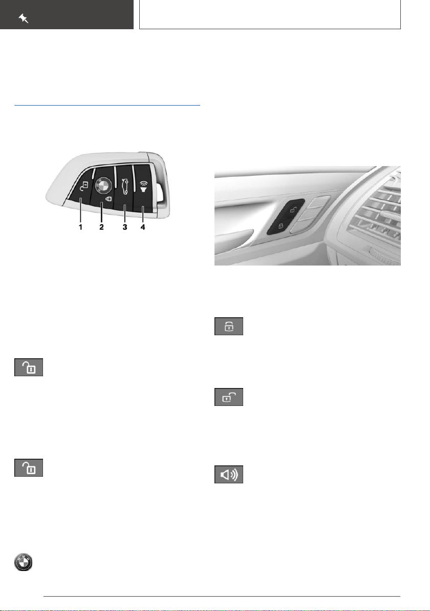
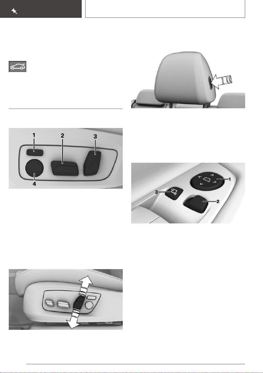
Your BMW at a glance
Opening and closing
Buttons on the remote control
1 Unlocking
2 Locking
3 Opening the tailgate
4 Press and hold or press three times in quick
succession: panic mode
Press briefly: headlight courtesy delay feature
Unlocking the vehicle
Press the button on the remote control.
Depending on the settings, either only the driv‐
er's door or all vehicle access points are un‐
locked.
If only the driver's door is unlocked, press the
button on the remote control again to unlock the
other vehicle access points.
Press and hold the button on the re‐
mote control after unlocking.
The windows and the glass sunroof are opened,
as long as the button on the remote control is
pressed.
Locking the vehicle
Press the button on the remote control.
All vehicle access points are locked.
Buttons for the central locking
system
Overview
Buttons for the central locking system.
Locking
Pressing the button locks the vehicle if
the front doors are closed.
The fuel filler flap remains unlocked.
Unlocking
Pressing the button unlocks the vehicle.
Panic mode
You can trigger the alarm system if you find your‐
self in a dangerous situation.
▷ Press the button on the remote con‐
trol and hold for at least 3 seconds.
▷ Briefly press the button on the remote control
three times in succession.
To switch off the alarm: press any button.
Seite 18
QUICK REFERENCE
Your BMW at a glance
18
Online Edition for Part no. 01402896703 - X/18
Comfort Access
Concept
The vehicle can be accessed without activating
the remote control.
All you need to do is to have the remote control
with you, such as in your pants pocket.
The vehicle automatically detects the remote
control when it is in close proximity or in the car's
interior.
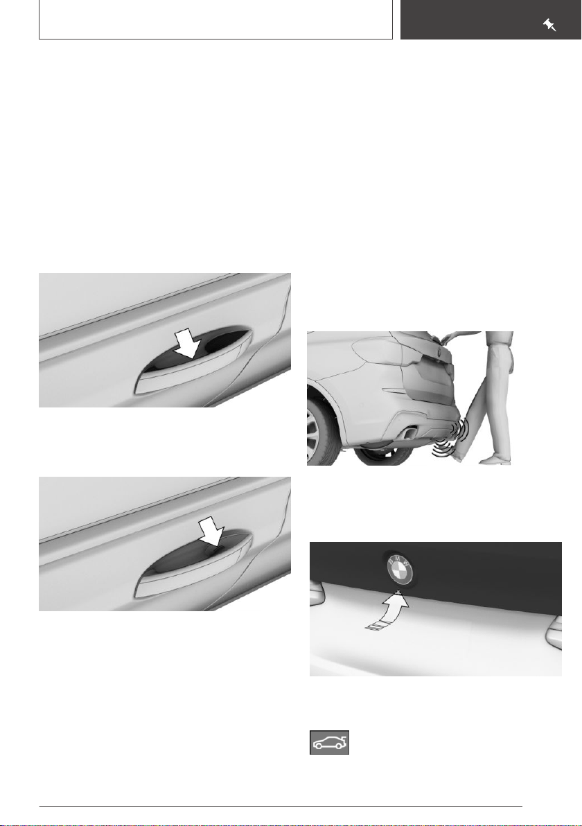
Unlocking the vehicle
Grasp the handle of a vehicle door completely.
Locking the vehicle
Touch the grooved surface on the handle of a
closed vehicle door with your finger for approx.
1 second without grasping the door handle.
Opening and closing the tailgate
with no-touch activation
Concept
The tailgate can be opened and closed with no-
touch activation using the remote control you are
carrying.
Performing the foot movement
1. Stand in the middle behind the vehicle at ap‐
prox. one arm's length away from the rear of
the vehicle.
2. Wave a foot under the vehicle in the direction
of travel and immediately pull it back. With
this movement, the leg must pass through
the ranges of both sensors.
Tailgate
Opening
▷ Unlock the vehicle and then press the button
on the outside of the tailgate.
Press the button on the remote control
for approx. 1 second.
Seite 19
Your BMW at a glance
QUICK REFERENCE
19
Online Edition for Part no. 01402896703 - X/18
Depending on the setting, the doors may be un‐
locked.
Closing
Press the button on the inside of the
tailgate.
Seats, mirrors, and steering
wheel
Electrically adjustable seats
1 Backrest width
2 Forward/backward, height, seat tilt
3 Backrest tilt
4 Lumbar support
Adjusting the head restraint
Adjusting the height: power head
restraints
Push switch up or down.
Adjusting the distance: manual head
restraints
▷ Back: press the button and push the head re‐
straint toward the rear.
▷ Forward: pull the head restraint toward the
front.
Adjusting the exterior mirrors
1 Settings
2 Selecting a mirror, Automatic Curb Monitor
3 Folding in and out
Seite 20
QUICK REFERENCE
Your BMW at a glance
20
Online Edition for Part no. 01402896703 - X/18
Adjusting the steering wheel
Manual steering wheel adjustment
1. Fold the lever down.
2. Move the steering wheel to the preferred
height and angle to suit your seating position.
3. Fold the lever back up.
Memory function
Concept
The following settings can be stored and, if nec‐
essary, retrieved using the memory function:
▷ Seat position.
▷ Exterior mirror position.
▷ Height of the Head-up Display.
Storing
1.
Set the desired position.
2.
Press button on the door. The writ‐
ing on the button lights up.
3. Press selected button 1 or 2 at the door while
the writing is lit. A signal sounds.
Calling up settings
Press selected button 1 or 2.
Displays and control
elements
In the vicinity of the steering
wheel
1 Light switch element
2 Turn signal indicator, high beams
3 Instrument cluster
4 Wipers
5 Start/Stop button
Indicator/warning lights
Instrument cluster
The indicator/warning lights can light up in a vari‐
ety of combinations and colors.
Several lights indicate function checks and light
up only temporarily when standby state or
standby state are activated.
Seite 21
Your BMW at a glance
QUICK REFERENCE
21
Online Edition for Part no. 01402896703 - X/18
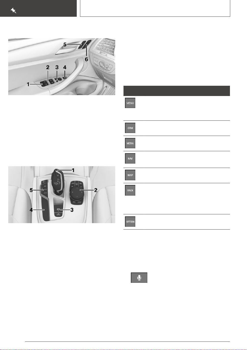
Driver's door
1 Safety switch
2 Power windows
3 Exterior mirrors
4 Opening/closing the tailgate
5 Central locking system
6 Memory function
Switch console
1 Selector lever
2 Controller
3 Parking brake, Automatic Hold
4 Parking assistance systems
5 Driving Dynamics Control
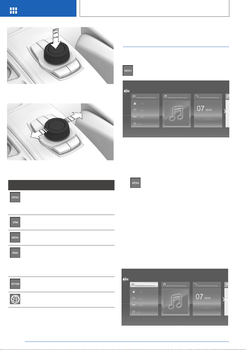
iDrive
Concept
The iDrive combines the functions of many
switches. These functions can be operated via
the Controller and, depending on the equipment
version, the touchscreen.
Controller
General information
The buttons can be used to open the menus di‐
rectly. The Controller can be used to select
menu items and enter the settings.
Buttons on the Controller
Button Function
Press once: call up main menu.
Press twice: display all menu items of
the main menu.
Open the Communication menu.
Open the Media/Radio menu.
Open destination input menu for navi‐
gation.
Open navigation map.
Press once: open the previous dis‐
play.
Press and hold: open the menus used
last.
Open the Options menu.
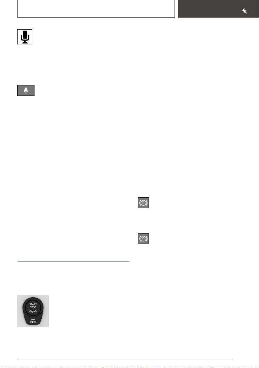
Voice activation
Using the voice activation system
Activating the voice activation system
1. Press the button on the steering
wheel.
2. Wait for the signal.
3. Say the command.
Seite 22
QUICK REFERENCE
Your BMW at a glance
22
Online Edition for Part no. 01402896703 - X/18
The symbol on the Control Display indi‐
cates that voice activation system is ac‐
tive.
If no other commands are possible, operate the
function via iDrive.
Terminating the voice activation system
Press the button on the steering wheel
or ›Cancel‹.
Help on the voice activation system
▷ To have the available spoken instructions
read out loud: ›Voice commands‹.
▷ To have information on the operating princi‐
ple of the voice activation system read out
loud: ›General information on voice control‹.
▷ To have help for the current menu read out
loud: ›Help‹.
Information for Emergency
Requests
Do not use the voice activation system to initiate
an Emergency Request. In stressful situations,
the voice and vocal pitch can change. This can
unnecessarily delay the establishment of a
phone connection.
Instead, use the SOS button close to the interior
mirror.
Driving
Drive-ready state
Switching on drive-ready state
▷ Depress the brake pedal.
▷ Press the Start/Stop button.
Switching off drive-ready state
Steptronic transmission:
1. Engage selector lever position P with the ve‐
hicle stopped.
2. Press the Start/Stop button.
The engine is switched off.
3. Set the parking brake.
Auto Start/Stop function
The Auto Start/Stop function switches the en‐
gine off automatically while stationary to save
fuel. The engine starts automatically under the
following preconditions:
Steptronic transmission:
▷ By releasing the brake pedal.
▷ When Automatic Hold is activated: press the
accelerator pedal.
Parking brake
Setting
Pull the switch.
The LED and indicator light light up.
Releasing
With drive-ready state switched on:
Steptronic transmission: press the switch
while the brake is pressed or selector lever posi‐
tion P is set.
The LED and indicator light go out.
The parking brake is released.
Parking
The parking brake is automatically set if the vehi‐
cle is being held by Automatic Hold and the
drive-ready state is switched off or the vehicle is
exited.
Seite 23
Your BMW at a glance
QUICK REFERENCE
23
Online Edition for Part no. 01402896703 - X/18
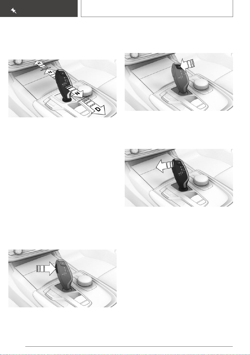
Steptronic transmission
Engaging selector lever position D,
N, R
▷ Drive mode D.
▷ Neutral N.
▷ Reverse R.
With the driver's safety belt fastened, briefly push
the selector lever in the desired direction, past a
resistance point, if needed. The selector lever re‐
turns to the center position in each case.
To prevent the vehicle from creeping after you
select a drive mode or reverse, maintain pressure
on the brake pedal until you are ready to start.
A selector lever lock prevents the inadvertent
shifting to selector lever position R or the inad‐
vertent shifting from selector lever position P.
Engage selector lever position R only when the
vehicle is stationary.
Releasing the selector lever lock
Press the button.
Engaging P
Engage selector lever position P only when the
vehicle is stationary.
Press button P.
Steptronic transmission, Sport
program and manual mode
Activate the sport program/manual mode:
Press the selector lever to the left out of selector
lever position D.
Manual mode:
▷ To shift down: press the selector lever for‐
ward.
▷ To shift up: pull the selector lever rearwards.
End the sport program/manual mode:
Push the selector lever to the right.
Seite 24
QUICK REFERENCE
Your BMW at a glance
24
Online Edition for Part no. 01402896703 - X/18
High beams, headlight flasher,
turn signal
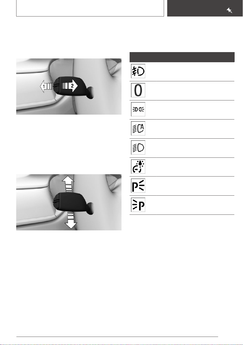
High beams, headlight flasher
Push the lever forward or pull it backward.
▷ High beams on, arrow 1.
The high beams light up when the low beams
are switched on.
▷ High beams off/headlight flasher, arrow 2.
Turn signal
▷ On: press the lever past the resistance point.
▷ Off: press the lever past the resistance point
in the opposite direction.
▷ Triple turn signal activation: lightly tap the
lever up or down.
▷ Brief signaling: press the lever to the resist‐
ance point and hold it there for as long as you
want the turn signal to flash.
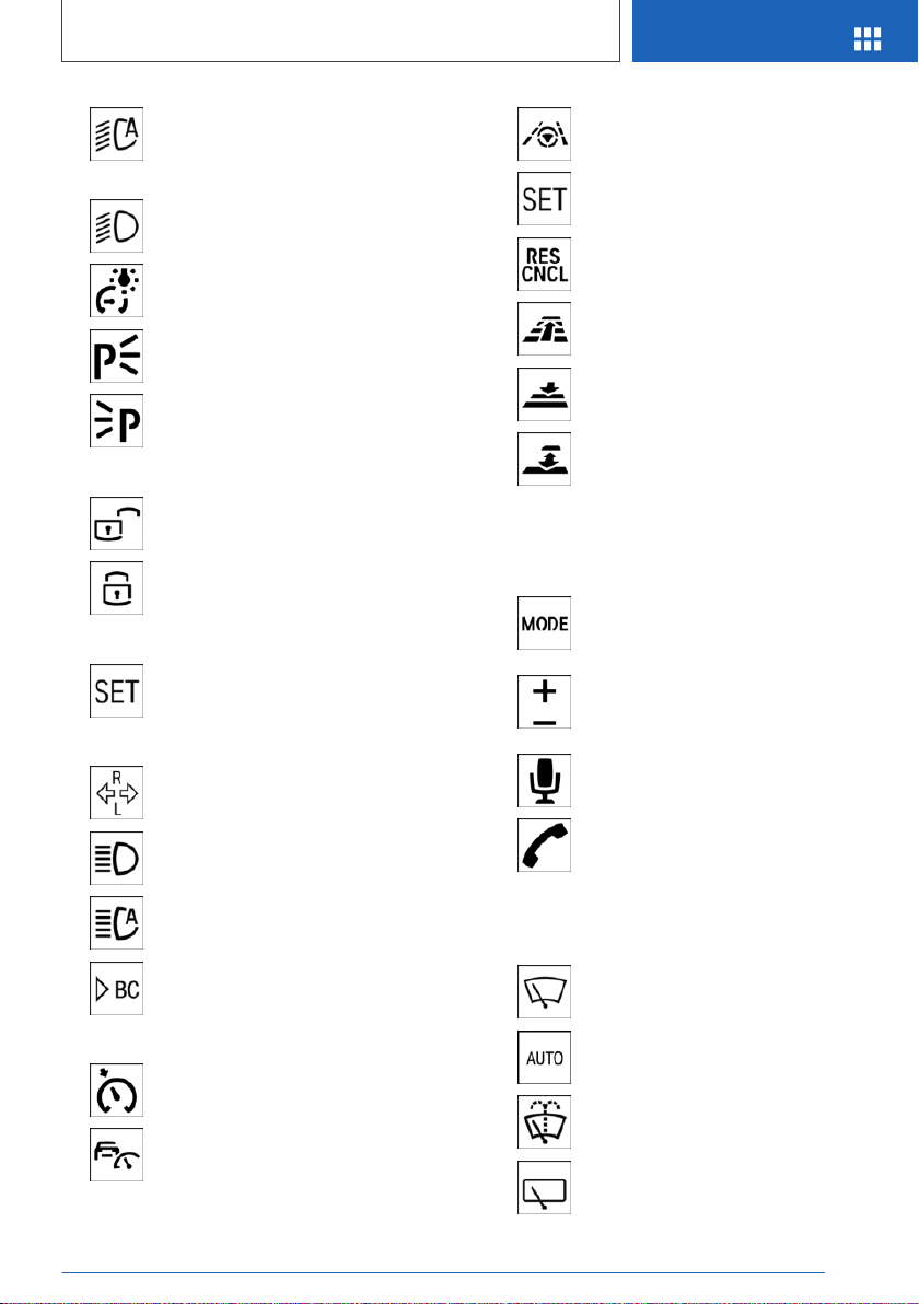
Lights and lighting
Light functions
Symbol Function
Front fog lights.
Lights off.
Daytime running lights.
Parking lights.
Automatic headlight control.
Adaptive light functions.
Low beams.
Instrument lighting.
Right roadside parking light.
Left roadside parking light.
Seite 25
Your BMW at a glance
QUICK REFERENCE
25
Online Edition for Part no. 01402896703 - X/18
Washer/wiper system
Switching the wipers on/off and
brief wipe
Switching on
Press the lever up until the desired position is
reached.
▷ Resting position of the wipers: position 0.
▷ Rain sensor: position 1.
▷ Normal wiper speed: position 2.
▷ Fast wiper speed: position 3.
Brief wipe and switching off
Press the lever down.
▷ Switching off: press the lever down until it
reaches its standard position.
▷ Brief wipe: press the lever down from the
standard position.
Rain sensor
Activating/deactivating
To activate: press the lever up once from its
standard position, arrow 1.
To deactivate: press the lever back into the
standard position.
Adjusting the sensitivity
Turn the thumbwheel on the wiper lever.
Cleaning the windshield
Pull the wiper lever towards you.
Seite 26
QUICK REFERENCE
Your BMW at a glance
26
Online Edition for Part no. 01402896703 - X/18
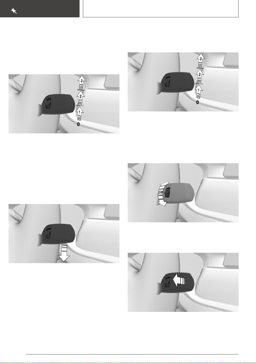
Rear window wiper
Switching on
Turn the outer switch upward.
▷ Resting position of the wiper, position 0.
▷ Intermittent mode, arrow 1. When reverse
gear is engaged, the system switches to con‐
tinuous operation.
Clean the rear window
Turn the outer switch in the desired direction.
▷ In resting position: turn the switch downward,
arrow 3. The switch automatically returns to
its idle position when released.
▷ In intermittent mode: turn the switch further,
arrow 2. The switch automatically returns to
its interval position when released.
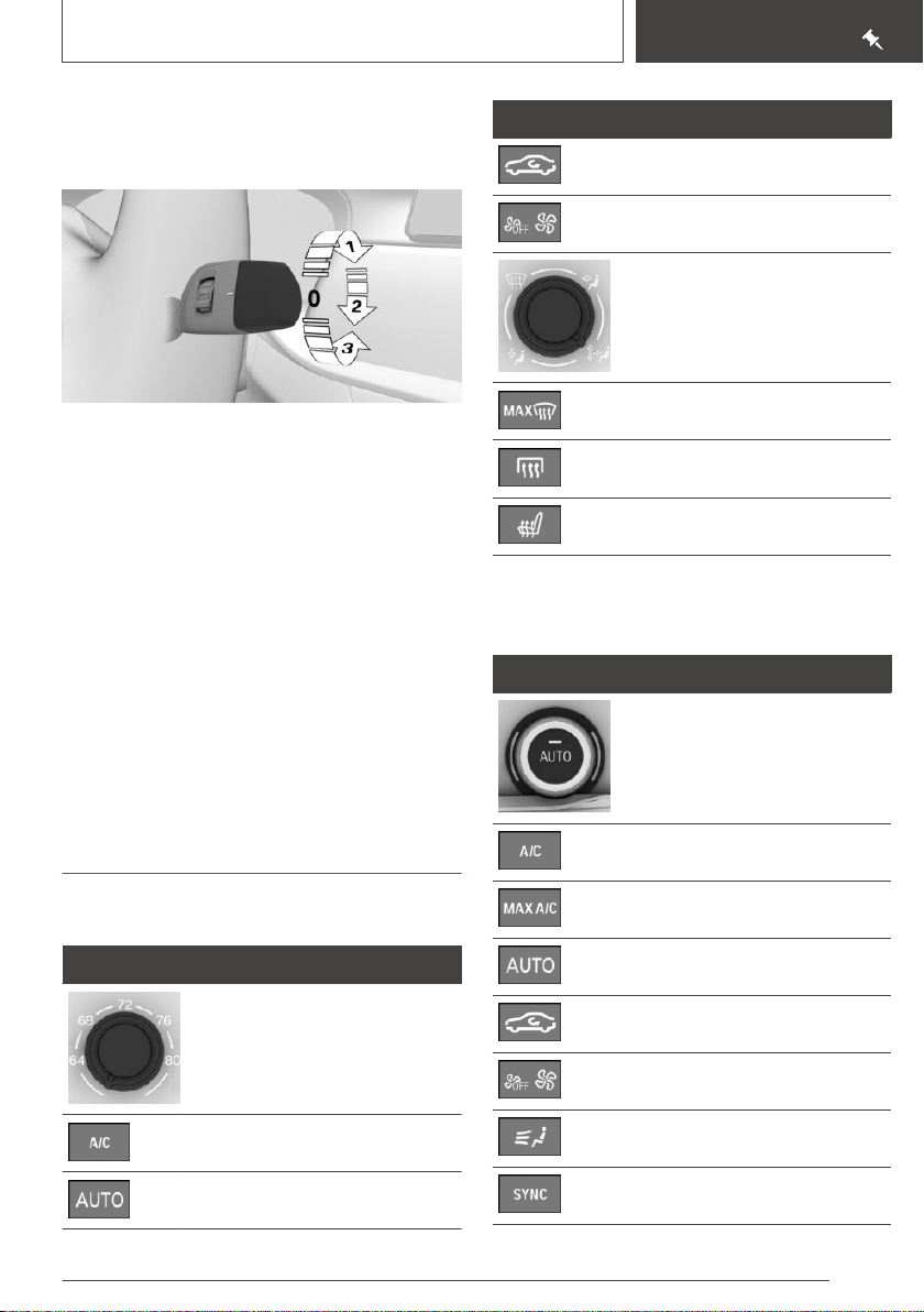
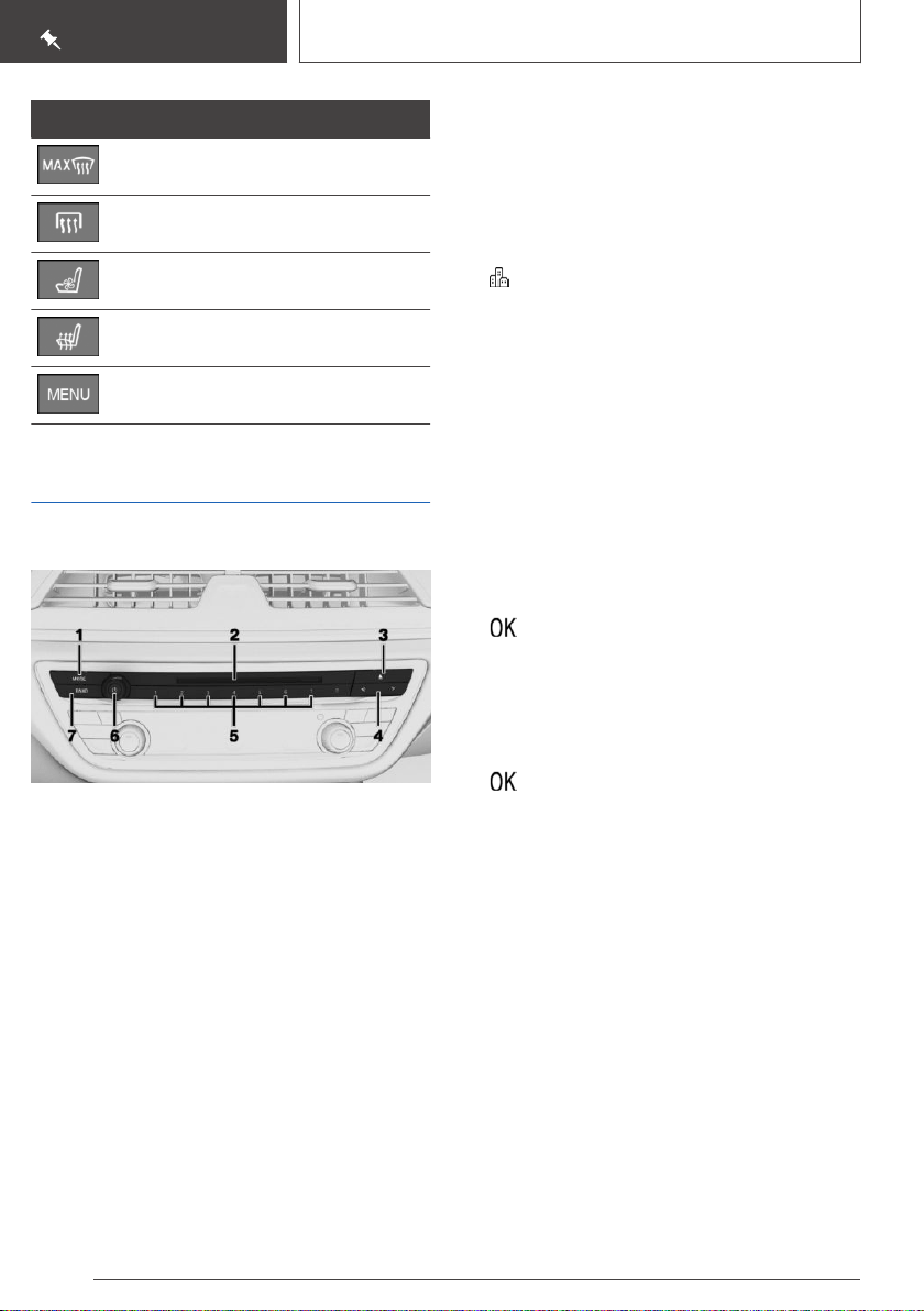
Climate control
Automatic climate control
Button Function
Temperature.
Climate control operation.
AUTO program.
Button Function
Recirculated-air mode.
Air flow, manual.
Air distribution, manual.
Defrost and defog window.
Rear window defroster.
Seat heating.
Automatic climate control with
enhanced features
Button Function
Temperature.
Climate control operation.
Maximum cooling.
AUTO program.
Recirculated-air mode.
Air flow, manual.
Air distribution, manual.
SYNC program.
Seite 27
Your BMW at a glance
QUICK REFERENCE
27
Online Edition for Part no. 01402896703 - X/18
Button Function
Defrost and defog window.
Rear window defroster.
Active seat ventilation.
Seat heating.
Open the Climate menu.
Infotainment
Radio
1 Changing the entertainment source
2 CD/DVD drive
3 Eject CD/DVD
4 Change station/track
5 Programmable memory buttons
6 Sound output on/off, volume
7 Waveband/satellite radio
Changing the waveband
Navigation destination entry
Entering a destination via address
State/province
1. "Navigation"
2. "Enter address"
3. "State/Province?"
4. Move the Controller to the right to select the
state from the list.
Entering the address
The address can be entered in any order.
Example: entering the address via the town/city
1.
"City/Postal code?"
2. Enter the town/city.
The list is narrowed down further with each
entry.
3. Select the symbol.
4. Select a town/city from the list.
5. If necessary, enter the street.
6. Select the street as you would the town/city.
7. If necessary, enter a house number.
8. Select the symbol.
9. Select a house number or range of house
numbers from the list.
Starting destination guidance
"Start guidance"
If only the town/city was entered: destination
guidance is started to the town/city center.
Connecting a mobile phone
General information
After the mobile phone is connected once to the
vehicle, the mobile phone can be operated using
iDrive, the steering wheel buttons, voice activa‐
tion, and gestures.
Seite 28
QUICK REFERENCE
Your BMW at a glance
28
Online Edition for Part no. 01402896703 - X/18

Connecting the mobile phone via passkey
entry
Via iDrive:
1. "My Vehicle"
2. "iDrive settings"
3. "Mobile devices"
4. "Connect new device"
5. Select the functions for which the mobile
phone is to be used.
The Bluetooth name of the vehicle is dis‐
played on the Control Display.
6. To perform additional steps on the mobile
phone, refer to the mobile phone owner's
manual: e.g., search for or connect the Blue‐
tooth device or a new device.
The Bluetooth name of the vehicle appears
on the mobile phone display. Select the Blue‐
tooth name of the vehicle.
7. Depending on the mobile device, a control
number is displayed or the control number
must be entered.
▷ Compare the control number displayed
on the Control Display with the control
number on the display of the device.
Confirm the control number on the device
and on the Control Display.
▷ Enter and confirm the same control num‐
ber on the device and via iDrive.
The device is connected and displayed in the
device list.
Using the phone
Accepting a call
Incoming calls can be answered in several ways.
▷ Via iDrive:
"Accept"
▷ Press the button on the steering
wheel.
▷ Via the selection list in the instrument cluster:
Use the thumbwheel on the steering wheel to
select: "Accept"
▷ Via gestures: point the index finger into the
direction of the Control Display.
Dialing a number
1. "Communication"
2. "Dial number"
3. Enter the numbers.
4. Select the symbol. The connection is es‐
tablished via the mobile phone to which this
function has been assigned.
Establish the connection via the additional
phone:
1. Press button.
2. "Call via"
Apple CarPlay preparation
Concept
CarPlay allows certain functions of a compatible
Apple iPhone to be used via Siri voice operation
and iDrive.
Functional requirements
▷ Compatible iPhone.
iPhone 5 or later with iOS 7.1 or later.
▷ Corresponding mobile wireless contract.
▷ Bluetooth, WiFi, and Siri voice operation are
switched on on the iPhone.
Switching on Bluetooth and CarPlay
Via iDrive:
1.
"My Vehicle"
2. "iDrive settings"
3. "Mobile devices"
4. "Settings"
5. Select the following settings:
▷ "Bluetooth®"
Seite 29
Your BMW at a glance
QUICK REFERENCE
29
Online Edition for Part no. 01402896703 - X/18
▷ "Apple CarPlay"
Pairing iPhone with CarPlay
Pair iPhone via Bluetooth with the vehicle.
Select CarPlay as the function:
"Apple CarPlay"
The iPhone is connected to the vehicle and dis‐
played in the device list.
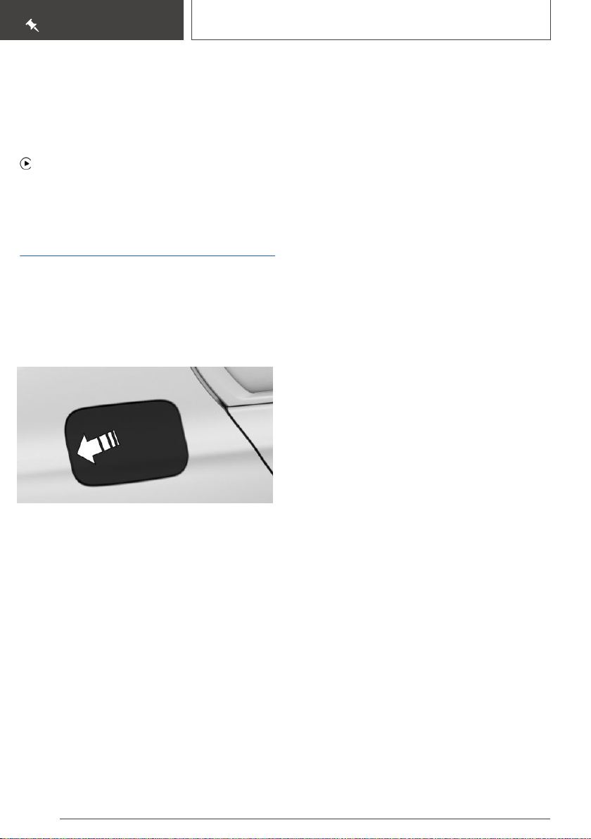
Refueling
Refueling
Fuel cap
1.
Press the rear edge of the fuel filler flap to
open it.
2. Turn the fuel cap counterclockwise.
3. Place the fuel cap in the bracket attached to
the fuel filler flap.
Gasoline
For the best fuel efficiency, the gasoline should
be sulfur-free or very low in sulfur content.
Refuel only with unleaded gasoline without met‐
allic additives.
Information on the recommended fuel grade can
be found in the Owner's Manual.
Diesel
The engine of your BMW is designed for diesel
with low sulfur content:
Ultra-Low Sulfur Diesel ASTM D 975-xx.
xx: comply with the current standard in each
case.
Wheels and tires
Tire inflation pressure specifications
The tire inflation pressure specifications can be
found in the tire inflation pressure table in the
printed Owner's Manual.
After correcting the tire inflation
pressure
With runflat tires:
Reinitialize the Flat Tire Monitor.
With Tire Pressure Monitor TPM:
With tires that cannot be found in the tire pres‐
sure values on the Control Display, reset the Tire
Pressure Monitor TPM.
Checking the tire inflation pressure
Regularly check the tire inflation pressure and
correct it as needed:
▷ At least twice a month.
▷ Before embarking on an extended trip.
Cleaning the wheels
The friction during hard braking may produce
brake dust and make the rims dirty. Brake dust
can be removed by cleaning the rims. BMW rec‐
ommends using vehicle care and cleaning prod‐
ucts from BMW.
Electronic oil measurement
Requirements
Depending on the previous displays, the status
display appears when the engine is running or af‐
ter the vehicle has been driven for at least 30 mi‐
nutes.
Seite 30
QUICK REFERENCE
Your BMW at a glance
30
Online Edition for Part no. 01402896703 - X/18
Displaying the engine oil level
Via iDrive:
1. "My Vehicle"
2. "Vehicle status"
3. "Engine oil level"
Different messages appear on the Control Dis‐
play depending on the engine oil level. Pay atten‐
tion to these messages.
Adding engine oil
General information
Safely park the vehicle and switch off drive-ready
state before adding engine oil.
Adding
Only add engine oil when the message is dis‐
played in the instrument cluster.
Observe the quantity to be added in the mes‐
sage.
Take care not to add too much engine oil.
Observe recommended engine oil types.
Providing assistance
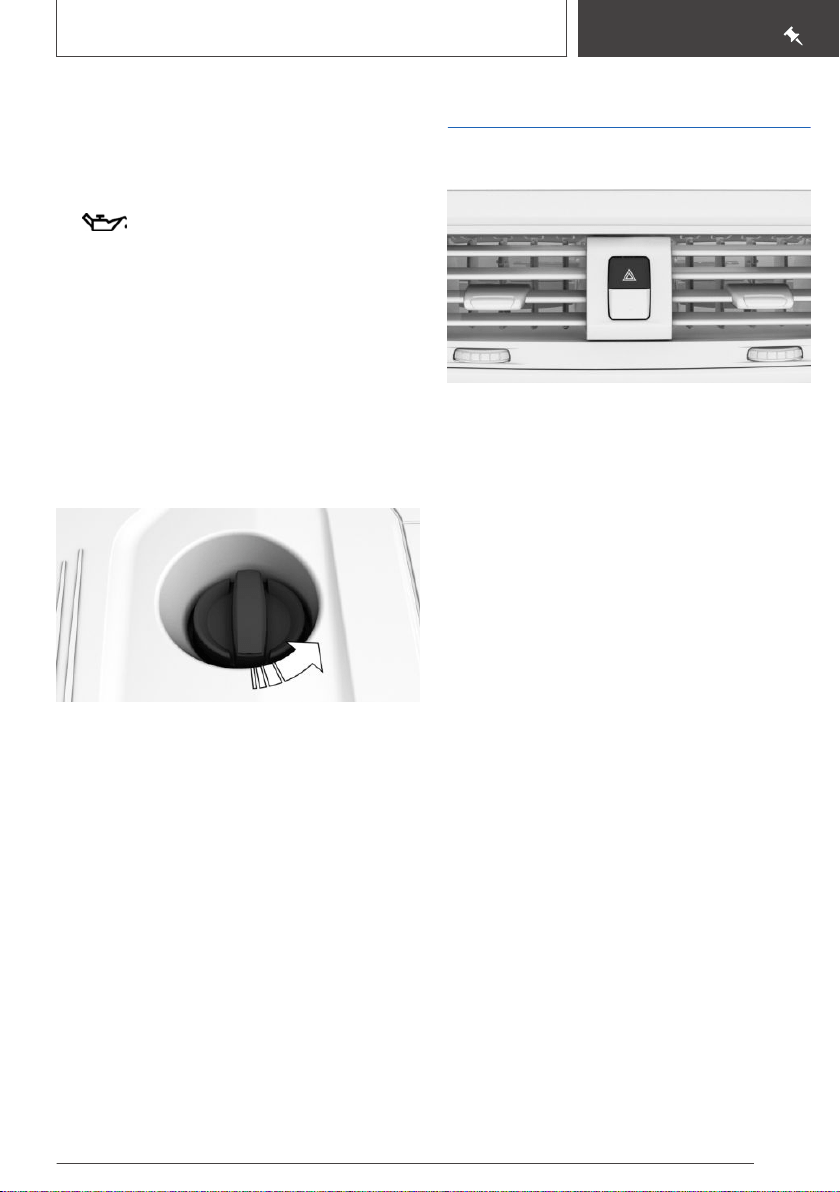
Hazard warning flashers
The button is located in the center console.
Breakdown assistance
BMW Roadside Assistance
Via iDrive:
1.
"ConnectedDrive"
2. "BMW Assist"
3. "BMW Roadside Assistance"
A voice connection is established to BMW
Roadside Assistance.
ConnectedDrive
Concierge service
The BMW Assist Concierge service offers infor‐
mation on events, gas stations or hotels, and
provides phone numbers and addresses. Many
hotels can be booked directly by the BMW Con‐
cierge service. The Concierge service is part of
the optional BMW Assist Response Center.
Via iDrive:
1.
"ConnectedDrive"
2. "Concierge"
A voice connection to the Concierge service is
established.
Seite 31
Your BMW at a glance
QUICK REFERENCE
31
Online Edition for Part no. 01402896703 - X/18

Teleservices
Teleservices are services that help to maintain
vehicle mobility.
Depending on the equipment version, Teleservi‐
ces comprise the following services:
▷ Roadside Assistance.
▷ Service Request.
▷ Automatic Service Request.
▷ Teleservice Report.
▷ Teleservice Battery Guard.
▷ Your dealer’s service center.
Seite 32
QUICK REFERENCE
Your BMW at a glance
32
Online Edition for Part no. 01402896703 - X/18

Seite 33
Your BMW at a glance
QUICK REFERENCE
33
Online Edition for Part no. 01402896703 - X/18

34
Online Edition for Part no. 01402896703 - X/18

AT A GLANCE
Cockpit ........................................................................................................ 36
Idle state, standby state, and drive-ready state .................................... 41
iDrive ............................................................................................................ 44
BMW Gesture Control ............................................................................... 53
Voice activation system ............................................................................ 56
General settings ......................................................................................... 59
Owner's Manual media ............................................................................. 72
35
Online Edition for Part no. 01402896703 - X/18
Cockpit
Vehicle features and
options
This chapter describes all standard, country-spe‐
cific and optional features offered with the series.
It also describes features that are not necessarily
available in your vehicle, e. g., due to the selected
options or country versions. This also applies to
safety-related functions and systems. When us‐
ing these functions and systems, the applicable
laws and regulations must be observed.
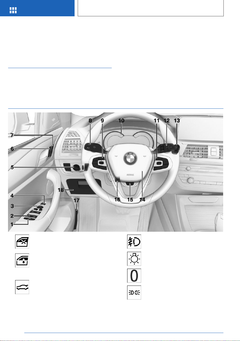
In the vicinity of the steering wheel
1 Safety switch 99
2 Power windows 98
3 Exterior mirror operation 109
4 Opening/closing the tailgate 89
5 Lights
Front fog lights 161
Light switch 157
Lights off
Daytime running lights 159
Parking lights 157
Seite 36
AT A GLANCE
Cockpit
36
Online Edition for Part no. 01402896703 - X/18
Automatic headlight control 158
Adaptive light functions 159
High-beam Assistant 160
Low beams 157
Instrument lighting 161
Right roadside parking light 158
Left roadside parking light 158
6 Central locking system
Unlock 86
Locking 86
7 Seating comfort features
Memory function 111
8 Steering column stalk, left
Turn signal 127
High beams, head‐
light flasher 127
High-beam Assistant 160
Onboard Computer 150
9 Steering wheel buttons, left
Cruise control on/off 197
Active Cruise Control on/off 199
Steering and lane control assistant
on/off 206
Cruise control: store speed
Pause or continue cruise control
Active Cruise Control: increase dis‐
tance
Active Cruise Control: reduce dis‐
tance
With steering and lane control as‐
sistant: adjust distance
Cruise control rocker switch
10 Instrument cluster 140
11 Steering wheel buttons, right
Entertainment source, see Owner's
Manual for Navigation, Entertain‐
ment and Communication 8
Volume, see Owner's Manual for
Navigation, Entertainment and
Communication 8
Voice activation system 56
Telephone, see Owner's Manual
for Navigation, Entertainment and
Communication 8
Thumbwheel for selection lists 149
12 Steering column stalk, right
Wipers 128
Rain sensor 128
Clean the windshield and head‐
lights 129
Rear window wiper in Canadian
models 130
Seite 37
Cockpit
AT A GLANCE
37
Online Edition for Part no. 01402896703 - X/18
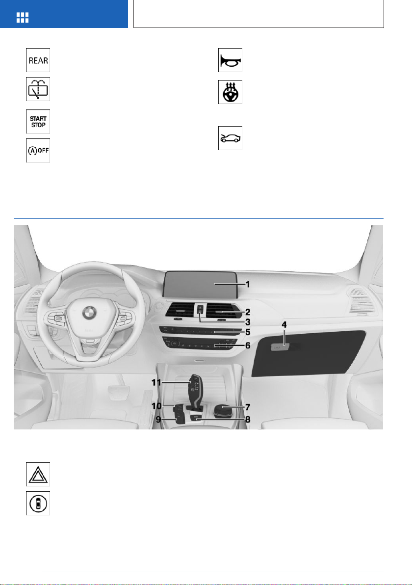
Rear window wiper 130
Clean the rear window 130
13 Switch drive-ready state on/
off 120
Auto Start/Stop function 121
14 Horn, entire surface
15 Heated steering wheel 111
16 Adjust the steering wheel 111
17 Unlock hood 326
18 Glove compartment 257
In the vicinity of the center console
1 Control Display 46
2 Ventilation 241
3 Hazard warning system 344
Intelligent Safety 168
4 Glove compartment 256
5 Radio/multimedia, see Owner's Manual for
Navigation, Entertainment, and Communica‐
tion 8
6 Automatic climate control 234
7 Controller with buttons 46
Seite 38
AT A GLANCE
Cockpit
38
Online Edition for Part no. 01402896703 - X/18
8 Parking brake 124
Automatic Hold 125
9 PDC Park Distance Control 211
Without Surround View: rearview
camera 215
Surround View 218
Crossing traffic warning 230
Parking assistant 225
Surround View: Panorama
View 218
HDC Hill Descent Control 195
10 Driving Dynamics Control 137
SPORT driving mode
COMFORT driving mode
ECO PRO driving mode
ADAPTIVE driving mode
DSC Dynamic Stability Con‐
trol 192
11 Steptronic transmission selector lever 132
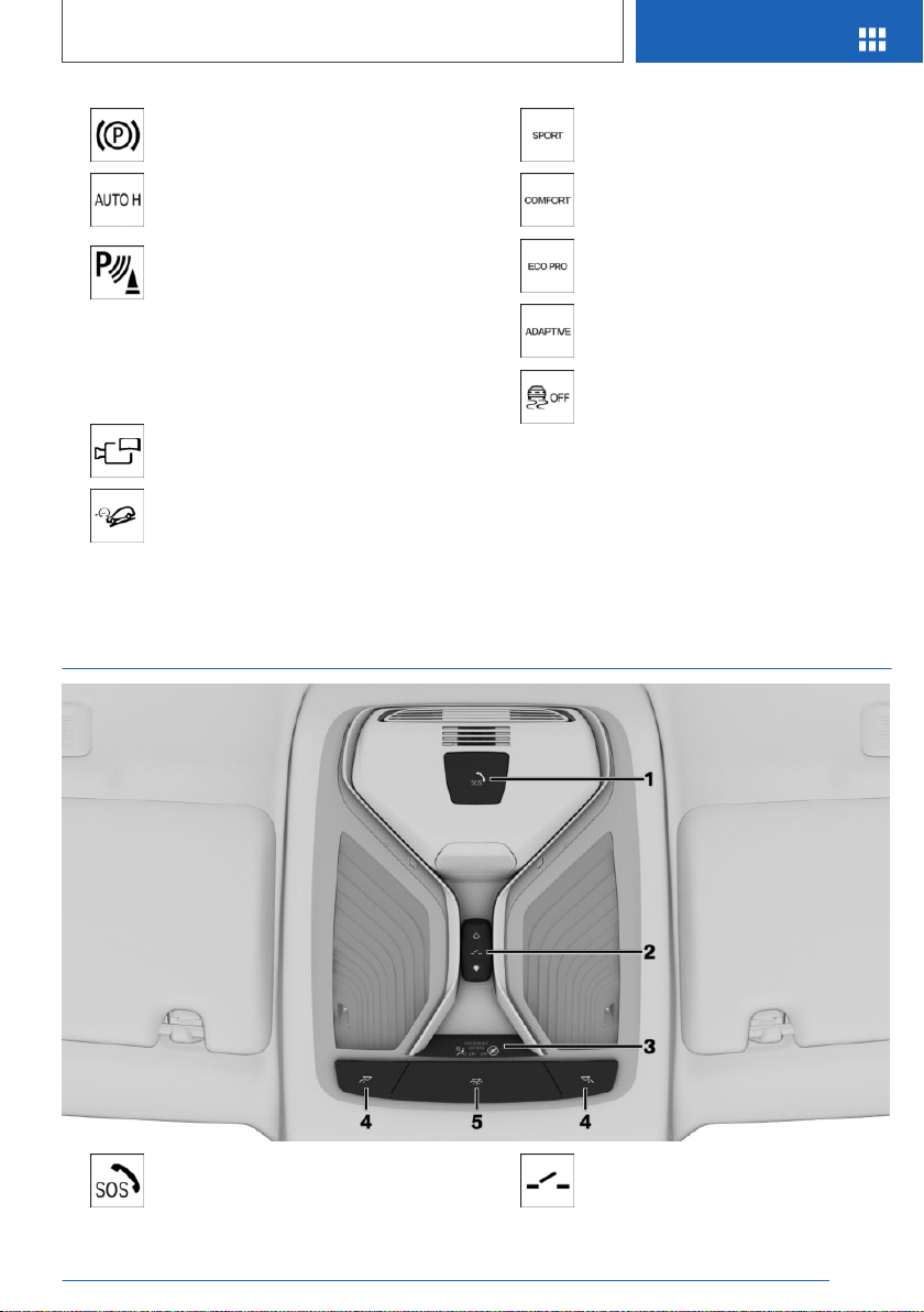
In the vicinity of the roofliner
1 Emergency Request, SOS 346 2 Glass sunroof 99
Seite 39
Cockpit
AT A GLANCE
39
Online Edition for Part no. 01402896703 - X/18


Idle state, standby state, and drive-ready
state
Vehicle features and
options
This chapter describes all standard, country-spe‐
cific and optional features offered with the series.
It also describes features that are not necessarily
available in your vehicle, e. g., due to the selected
options or country versions. This also applies to
safety-related functions and systems. When us‐
ing these functions and systems, the applicable
laws and regulations must be observed.
General information
Depending on the situation, the vehicle is in one
of the three states:
▷ Idle state.
▷ Standby state.
▷ Drive-ready state.
Idle state
Concept
If the vehicle is in idle state, it is switched off. All
power consumers are deactivated.
General information
The vehicle is in idle state prior to opening from
the outside and after exiting and locking.
Safety information
WARNING
An unsecured vehicle can begin to move and
possibly roll away. There is a risk of an accident.
Before exiting, secure the vehicle against roll‐
ing.
In order to ensure that the vehicle is secured
against rolling away, follow the following:
▷ Set the parking brake.
▷ On uphill grades or on a downhill slope,
turn the front wheels in the direction of the
curb.
▷ On uphill grades or on a downhill slope,
also secure the vehicle, for instance with a
wheel chock.
WARNING
Unattended children or animals can cause the
vehicle to move and endanger themselves and
traffic, for instance due to the following actions:
▷ Pressing the Start/Stop button.
▷ Releasing the parking brake.
▷ Opening and closing the doors or win‐
dows.
▷ Engaging selector lever position N.
▷ Using vehicle equipment.
There is a risk of accidents or injuries. Do not
leave children or animals unattended in the ve‐
hicle. Take the remote control with you when
exiting and lock the vehicle.
Automatic idle state
The idle state is automatically established under
the following conditions:
Seite 41
Idle state, standby state, and drive-ready state
AT A GLANCE
41
Online Edition for Part no. 01402896703 - X/18
▷ After several minutes, if no operation takes
place on the vehicle.
▷ If the charge state of the vehicle battery is
low.
▷ Depending on the setting via iDrive, if one of
the front doors is opened when exiting the
vehicle.
The idle state is not automatically established
while a phone call is active.
Establishing idle state when
opening the front doors
Via iDrive:
1.
"My Vehicle"
2. "Vehicle settings"
3. "Doors/Key"
4. "Turn off after door opening"
Manual idle state
To establish idle state in the vehicle after end of
trip:
Press and hold the button until
the OFF indicator on the instru‐
ment cluster goes out.
Standby state
Concept
When standby state is switched on, most func‐
tions can be used while the vehicle is stationary.
Desired settings can be adjusted.
General information
The vehicle is in the standby state after the front
doors are opened from the outside.
Display in the instrument cluster
OFF is displayed in the instru‐
ment cluster. The drivetrain is
switched off and standby state
switched on.
Drive-ready state
Concept
Switching on drive-ready state corresponds to
starting the engine.
General information
Some functions, such as DSC Dynamic Stability
Control, can only be used with drive-ready state
switched on.
Follow further information on the drive-ready
state, refer to page 120.
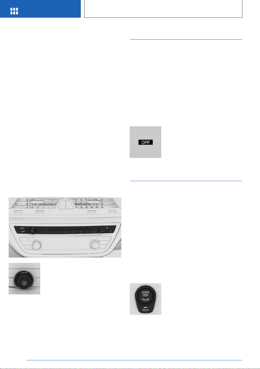
Switching on drive-ready state
Drive-ready state is switched on
via the Start/Stop button:
1.
Depress the brake pedal.
2. Press the Start/Stop button.
Seite 42
AT A GLANCE
Idle state, standby state, and drive-ready state
42
Online Edition for Part no. 01402896703 - X/18

Display in the instrument cluster
When drive-ready state is switched on, the tach‐
ometer shows the current engine speed.
Switching off drive-ready state
Press the Start/Stop button to switch off drive-
ready state. The vehicle switches into standby
state.
Seite 43
Idle state, standby state, and drive-ready state
AT A GLANCE
43
Online Edition for Part no. 01402896703 - X/18
iDrive
Vehicle features and
options
This chapter describes all standard, country-spe‐
cific and optional features offered with the series.
It also describes features that are not necessarily
available in your vehicle, e. g., due to the selected
options or country versions. This also applies to
safety-related functions and systems. When us‐
ing these functions and systems, the applicable
laws and regulations must be observed.
Concept
The iDrive combines the functions of many
switches. These functions can be operated via
the Controller and, depending on the equipment
version, the touchscreen.
Safety information
WARNING
Operating the integrated information systems
and communication devices while driving can
distract from traffic. It is possible to lose control
of the vehicle. There is a risk of an accident.
Only use the systems or devices when the traf‐
fic situation allows. As warranted, stop and use
the systems and devices while the vehicle is
stationary.
Input and display
Letters and numbers
Letters and numbers can be entered using the
Controller or the touchscreen. The keyboard's
display changes automatically.
Symbol Function
or
Change between capital and
lower-case letters.
Insert blank space.
Use voice activation.
Confirm entry.
Entry comparison
When entering names and addresses, the choice
is narrowed down with every letter entered and
letters may be added automatically.
Entries are continuously compared with data
stored in the vehicle.
▷ Only those letters are offered during entry for
which data is available.
▷ Destination search: place names can be en‐
tered in all languages that are available in
iDrive.
Activating/deactivating the
functions
Several menu items are preceded by a check‐
box. The checkbox indicates whether the func‐
tion is activated or deactivated. Selecting the
menu item activates or deactivates the function.
Function is activated.
Function is deactivated.
Seite 44
AT A GLANCE
iDrive
44
Online Edition for Part no. 01402896703 - X/18
Status information
General information
The status field can be found in the upper area of
the Control Display. Status information is dis‐
played in the form of symbols.
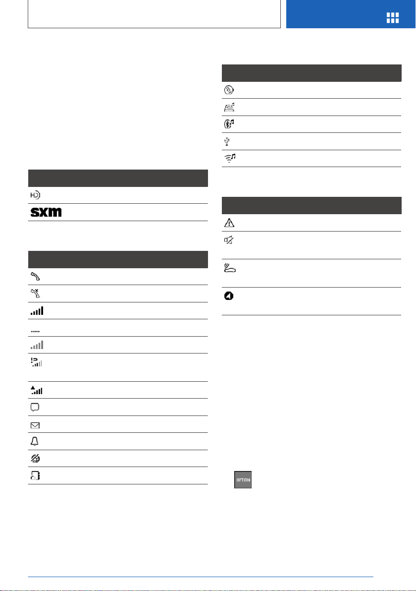
Status field symbols
Radio
Symbol Meaning
HD Radio station is being received.
Satellite radio is switched on.
Telephone
Symbol Meaning
Incoming or outgoing call.
Missed call.
Signal strength of cellular network.
Network search.
Cellular network is not available.
The critical charge state of the mo‐
bile phone has been reached.
Roaming is active.
SMS text message received.
Message received.
Reminder.
Sending not possible.
Contacts are loaded.
Entertainment
Symbol Meaning
CD/DVD player.
Music hard disk.
Bluetooth audio.
USB audio interface.
WiFi.
Additional symbols
Symbol Meaning
Check Control message.
The sound output has been
switched off.
Request for the current vehicle posi‐
tion.
Checking the current vehicle posi‐
tion.
Split screen, split screen display
General information
Additional information can be displayed in several
menus on the right side of the split screen dis‐
play, the so-called split screen, for instance infor‐
mation from the Onboard Computer.
The additional information remains visible even
when switching to another menu on the split
screen.
Switching on/off
1. Press the button.
2. "Split screen"
Seite 45
iDrive
AT A GLANCE
45
Online Edition for Part no. 01402896703 - X/18
Selecting the display
The display can be selected in menus, where the
split screen is supported.
1. Move the Controller to the right until the split
screen is selected.
2. Press the Controller.
3. Select the desired setting.
Specifying the number of displays
It is possible to specify the number of displays.
1. Move the Controller to the right until the split
screen is selected.
2. Press the Controller.
3. "Personalize menu"
4. Select the desired setting.
5. Move the Controller to the left.
Control elements
Overview
1 Control Display, with touchscreen depending
on the equipment version
2 Controller with buttons and, depending on
the equipment version, with touchpad
Control Display
General information
To clean the Control Display, follow the care in‐
structions, refer to page 355.
In the case of very high temperatures on the
Control Display, for instance due to intense solar
radiation, the brightness may be reduced down
to complete deactivation. Once the temperature
is reduced, for instance through shade or air con‐
ditioning, the normal functions are restored.
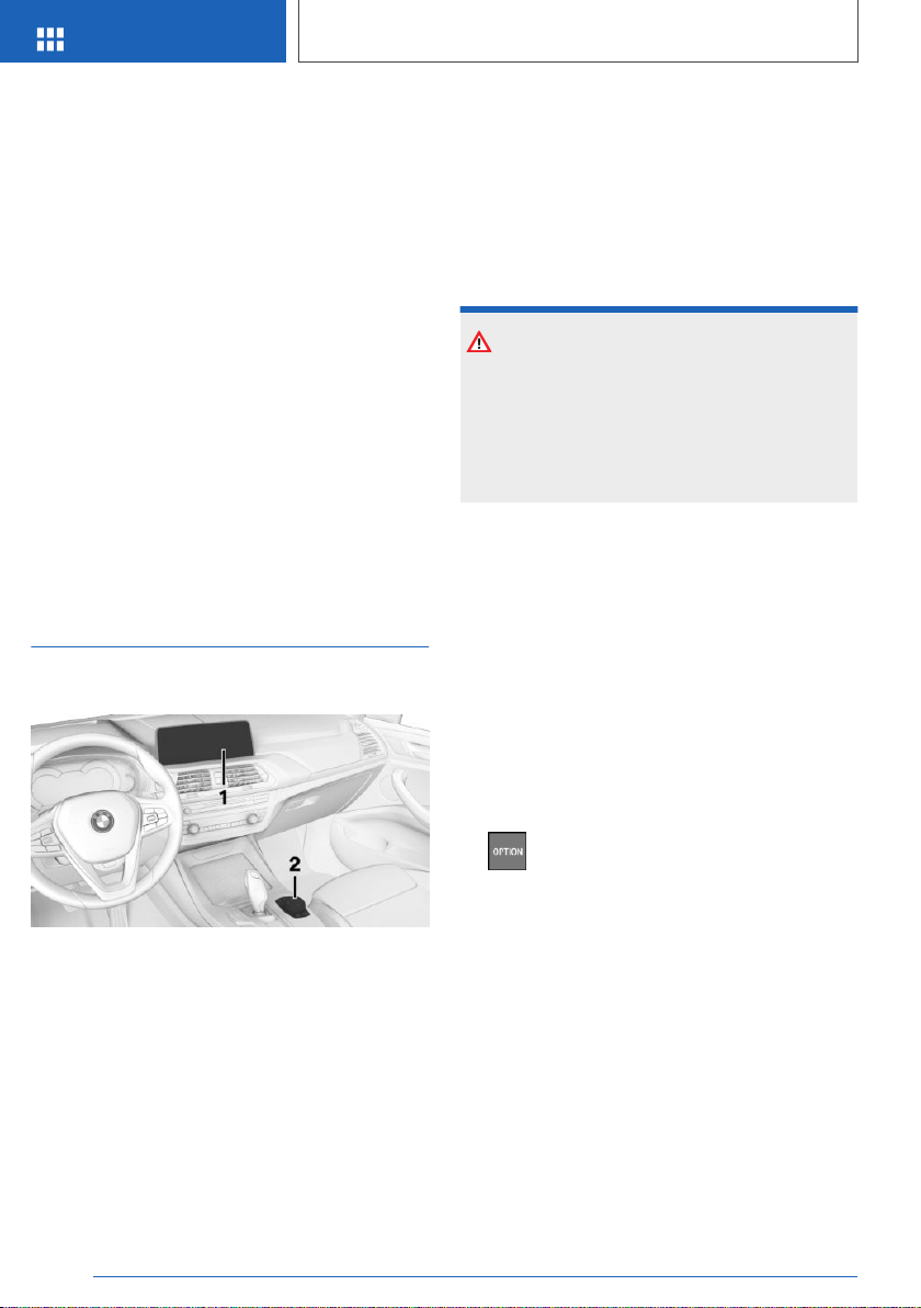
Safety information
NOTICE
Objects in the area in the front of the Control
Display can shift and damage the Control Dis‐
play. There is a risk of damage to property. Do
not place objects in the area in front of the
Control Display.
Switching on/off automatically
The Control Display is switched on automatically
after unlocking.
In certain situations, the Control Display is
switched off automatically, for instance if no op‐
eration is performed on the vehicle for several
minutes.
Switching on/off manually
The Control Display can also be switched off
manually.
1. Press button.
2. "Turn off control display"
Press the Controller or any button on the Con‐
troller to switch it back on again.
Controller with navigation
system
General information
The buttons can be used to open the menus di‐
rectly. The Controller can be used to select
menu items and enter the settings.
Some iDrive functions can be operated using the
touchpad on the Controller, refer to page 51.
Seite 46
AT A GLANCE
iDrive
46
Online Edition for Part no. 01402896703 - X/18
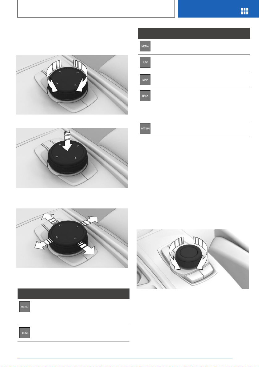
Operation
▷ Turn to switch between menu items, for ex‐
ample.
▷ Press to select a menu item, for example.
▷ Tilt in four directions to switch between dis‐
plays, for example.
Buttons on the Controller
Button Function
Press once: call up main menu.
Press twice: display all menu items of
the main menu.
Open the Communication menu.
Button Function
Open the Media/Radio menu.
Open destination input menu for navi‐
gation.
Open navigation map.
Press once: open the previous dis‐
play.
Press and hold: open the menus used
last.
Open the Options menu.
Controller without navigation
system
General information
The buttons can be used to open the menus di‐
rectly. The Controller can be used to select
menu items and enter the settings.
Operation
▷ Turn to switch between menu items, for ex‐
ample.
▷ Press to select a menu item, for example.
Seite 47
iDrive
AT A GLANCE
47
Online Edition for Part no. 01402896703 - X/18
▷ Tilt in two directions to switch between dis‐
plays, for example.
Buttons on the Controller
Button Function
Press once: call up main menu.
Press twice: display all menu items of
the main menu.
Open the Communication menu.
Open the Media/Radio menu.
Press once: open the previous dis‐
play.
Press and hold: open the menus used
last.
Open the Options menu.
Opening the ConnectedDrive menu.
Operating with the
Controller
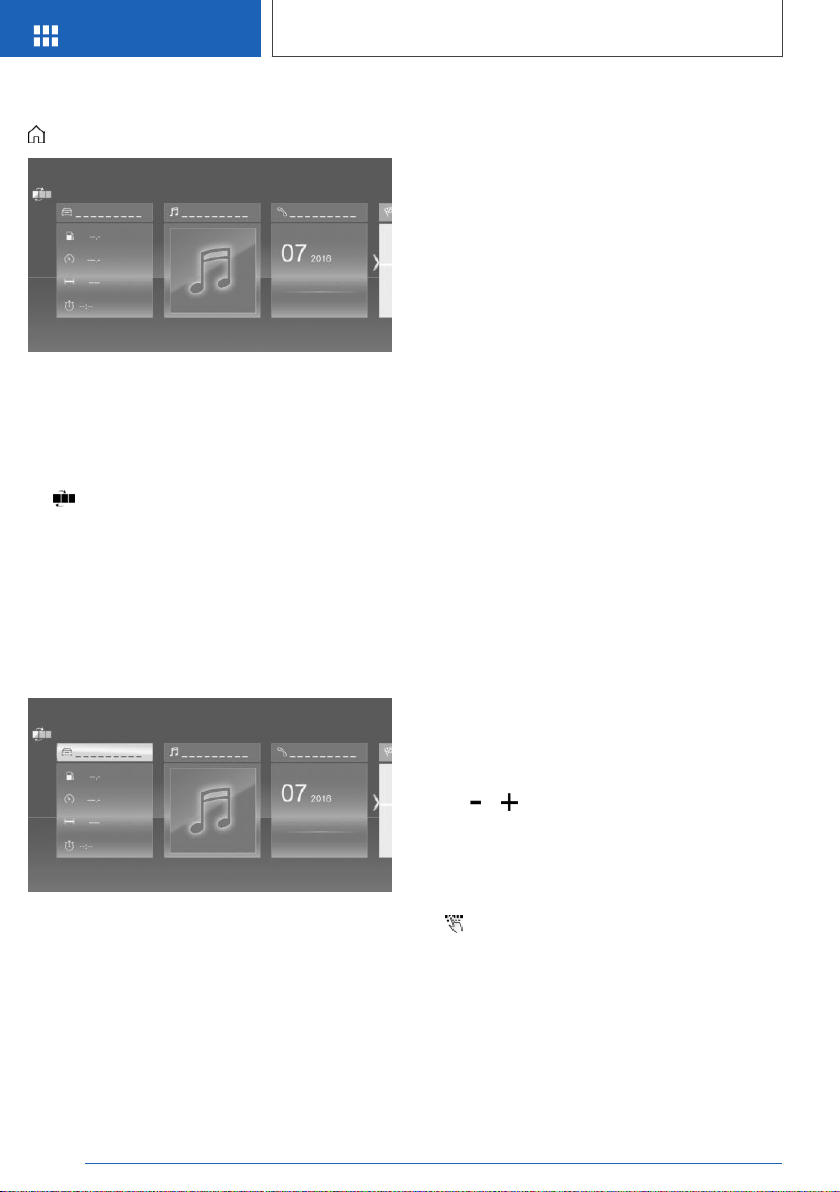
Opening the main menu
Press the button.
The main menu is displayed.
All iDrive functions can be called up via the main
menu.
Adapting the main menu
1. Press the button twice.
All menu items of the main menu are dis‐
played.
2. Select a menu item.
3. To move the menu item to the desired posi‐
tion, tilt the Controller to the right or left.
Selecting menu items
Highlighted menu items can be selected.
1.
Turn the Controller until the desired menu
item is highlighted.
Seite 48
AT A GLANCE
iDrive
48
Online Edition for Part no. 01402896703 - X/18
2. Press the Controller.
Changing between displays
After a menu item is selected, for instance
"iDrive settings", a new display appears.
▷ Move the Controller to the left.
Closes the current display and shows the
previous display.
▷
Press the button.
The previous display opens.
▷ Move the Controller to the right.
New display is opened.
An arrow indicates that additional displays can be
opened.
Opening recently used menus
Press and hold this button.
The recently used menus are displayed.
Opening the Options menu
Press the button.
The "Options" menu is displayed.
The menu consists of various areas:
▷ Screen settings, for instance "Split screen".
▷ Control options for the selected main menu,
for instance for "Media/Radio".
▷ If applicable, further operating options for the
selected menu, for instance "Save station".
Changing settings
Settings, such as brightness, can be entered.
Via iDrive:
1.
"My Vehicle"
2. "iDrive settings"
3. "Displays"
4. "Control display"
5. "Brightness"
6. Turn the Controller until the desired setting is
displayed.
7. Press the Controller.
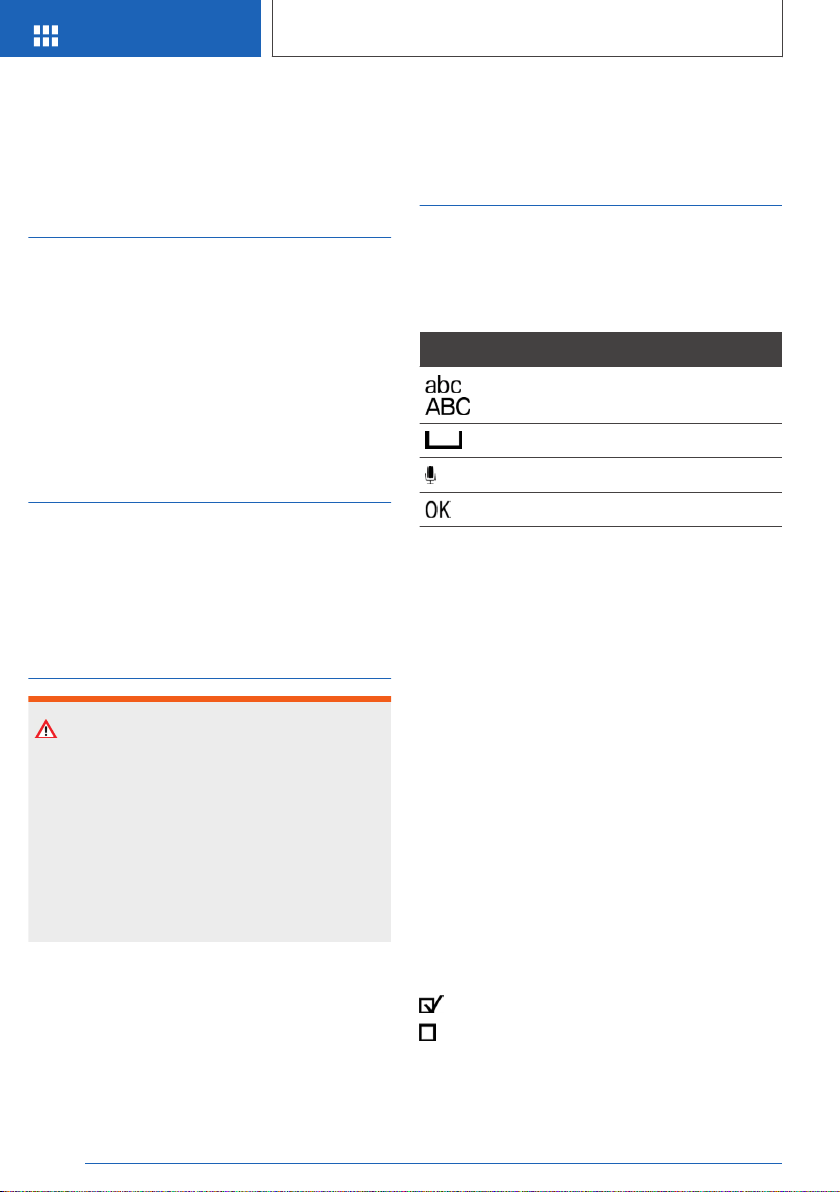
Entering letters and numbers
Input
1. Turn the Controller: select letters or numbers.
2. : confirm entry.
Deleting
Symbol Function
Press the Controller: delete letters or
number.
Hold the Controller down: delete all
letters or numbers.
Using alphabetical lists
For alphabetical lists with more than 30 entries,
the letters for which there is an entry are dis‐
played at the left edge.
1.
Turn the Controller to the left or right quickly.
All letters for which there are entries are dis‐
played on the left edge.
2. Select the first letter of the desired entry.
The first entry of the selected letter is dis‐
played.
Operating via touchscreen
General information
The Control Display is equipped with a touch‐
screen.
Touch screen with your fingers. Do not use any
objects.
Seite 49
iDrive
AT A GLANCE
49
Online Edition for Part no. 01402896703 - X/18
Opening the main menu
Tap on symbol.
The main menu is displayed.
All iDrive functions can be called up via the main
menu.
Adapting the main menu
1.
Tap on symbol.
All menu items of the main menu are dis‐
played.
2. Drag the menu item to the desired position
on the right or left.
Selecting menu items
Tap desired menu item.
Dynamic contents
You can display dynamic contents within the
menu items. The contents of the menu items
update automatically, e.g., the active destination
guidance in the navigation. To access the dy‐
namic content directly, tap on the lower section
of the menu item.
Via iDrive:
1. "My Vehicle"
2. "iDrive settings"
3. "Contents of main menu"
Changing between displays
After a menu item is selected, a new display
opens.
An arrow indicates that additional displays can be
opened.
▷ Swipe to the left.
▷ Tap arrow.
New display is opened.
Changing settings
Settings such as brightness can be changed via
the touchscreen.
Via iDrive:
1.
"My Vehicle"
2. "iDrive settings"
3. "Displays"
4. "Control display"
5. "Brightness"
6. To create the desired setting:
▷ Slide in the selected field to the right or
left, until the desired setting is displayed.
▷ , Tap on symbol.
Entering letters and numbers
Input
1.
Touch the symbol on the touchscreen.
A keyboard is displayed in the Control Dis‐
play.
2. Enter letters and numbers.
Seite 50
AT A GLANCE
iDrive
50
Online Edition for Part no. 01402896703 - X/18
Deleting
Symbol Function
Tapping the symbol: delete the letter
or number.
Tapping and holding the symbol for
an extended period: delete all letters
or numbers.
Operating navigation map
The navigation map can be moved with the
touchscreen.
Function Operation
Enlarge/shrink
map.
Drag in or out with the fin‐
gers.
Touchpad
General information
Some iDrive functions can be operated using the
touchpad on the Controller.
Selecting functions
Via iDrive:
1.
"My Vehicle"
2. "iDrive settings"
3. "Touchpad"
4. Select desired setting:
▷ "Speller": enter letters and numbers.
▷ "Map": using the map.
▷ "Search fields": write letters without se‐
lecting the list field.
▷ "Audio feedback": pronounces entered
letters and numbers.
Entering letters and numbers
Entering letters requires some practice at the be‐
ginning. When entering, pay attention to the fol‐
lowing:
▷ The system distinguishes between upper
and lower-case letters and numbers. To
make entries, it may be necessary to change
between upper and lower-case letters, num‐
bers and characters, refer to page 49.
▷ Enter characters as they are displayed on the
Control Display.
▷ Always enter associated characters, such as
accents or periods so that the letter can be
clearly recognized. The set language deter‐
mines what input is possible. Where neces‐
sary, enter special characters via the Control‐
ler.
Entering special characters
Input Operation
Delete a charac‐
ter.
Swipe to the left on the
touchpad.
Enter a blank
space.
Swipe to the right in the
center of the touchpad.
Enter a hyphen. Swipe to the right in the up‐
per area of the touchpad.
Enter an under‐
score.
Swipe to the right in the
lower area of the touchpad.
Using the map
The map in the navigation system can be moved
via the touchpad.
Function Operation
Move map. Swipe in the appropriate di‐
rection.
Enlarge/shrink
map.
Drag in or out on the touch‐
pad with fingers.
Display menu. Tap once.
Seite 51
iDrive
AT A GLANCE
51
Online Edition for Part no. 01402896703 - X/18

Programmable memory
buttons
General information
The iDrive functions can be stored on the pro‐
grammable memory buttons and called up di‐
rectly, for instance radio stations, navigation des‐
tinations, phone numbers and menu entries or
pages in the Integrated Owner's Manual.
Settings are stored for the driver profile currently
used.
Storing a function
1.
Select function via iDrive.
2.
Press and hold the desired button
until a signal sounds.
Running a function
Press the button.
The function will work immediately. This means,
for instance that the number is dialed when a
phone number is selected.
Displaying the key assignment
Touch buttons with finger. Do not wear gloves or
use objects.
The button assignment is displayed at the top
edge of screen.
Deleting the button assignments
1.
Press and hold buttons 1 and simultane‐
ously for approx. 5 seconds.
2. "OK"
Seite 52
AT A GLANCE
iDrive
52
Online Edition for Part no. 01402896703 - X/18
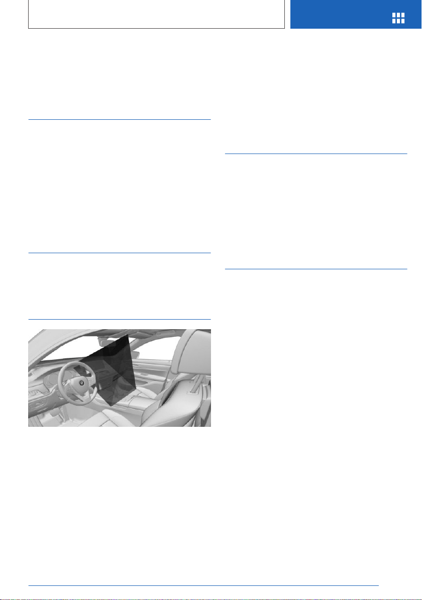
BMW Gesture Control
Vehicle features and
options
This chapter describes all standard, country-spe‐
cific and optional features offered with the series.
It also describes features that are not necessarily
available in your vehicle, e. g., due to the selected
options or country versions. This also applies to
safety-related functions and systems. When us‐
ing these functions and systems, the applicable
laws and regulations must be observed.
Concept
Several iDrive functions can be operated by hand
motion only using BMW Gesture Control.
Overview
The gestures that are performed underneath the
interior mirror are captured by a camera in the
roofliner.
Activating/deactivating
Via iDrive:
1. "My Vehicle"
2. "iDrive settings"
3. "Gestures"
4. "Gesture control"
Settings
Via iDrive:
1.
"My Vehicle"
2. "iDrive settings"
3. "Gestures"
4. Select desired setting:
▷ "Display tips": the possible gesture is
shown on the Control Display.
▷ "Audio feedback": an acoustic signal is
emitted once the gesture is recognized.
Seite 53
BMW Gesture Control
AT A GLANCE
53
Online Edition for Part no. 01402896703 - X/18
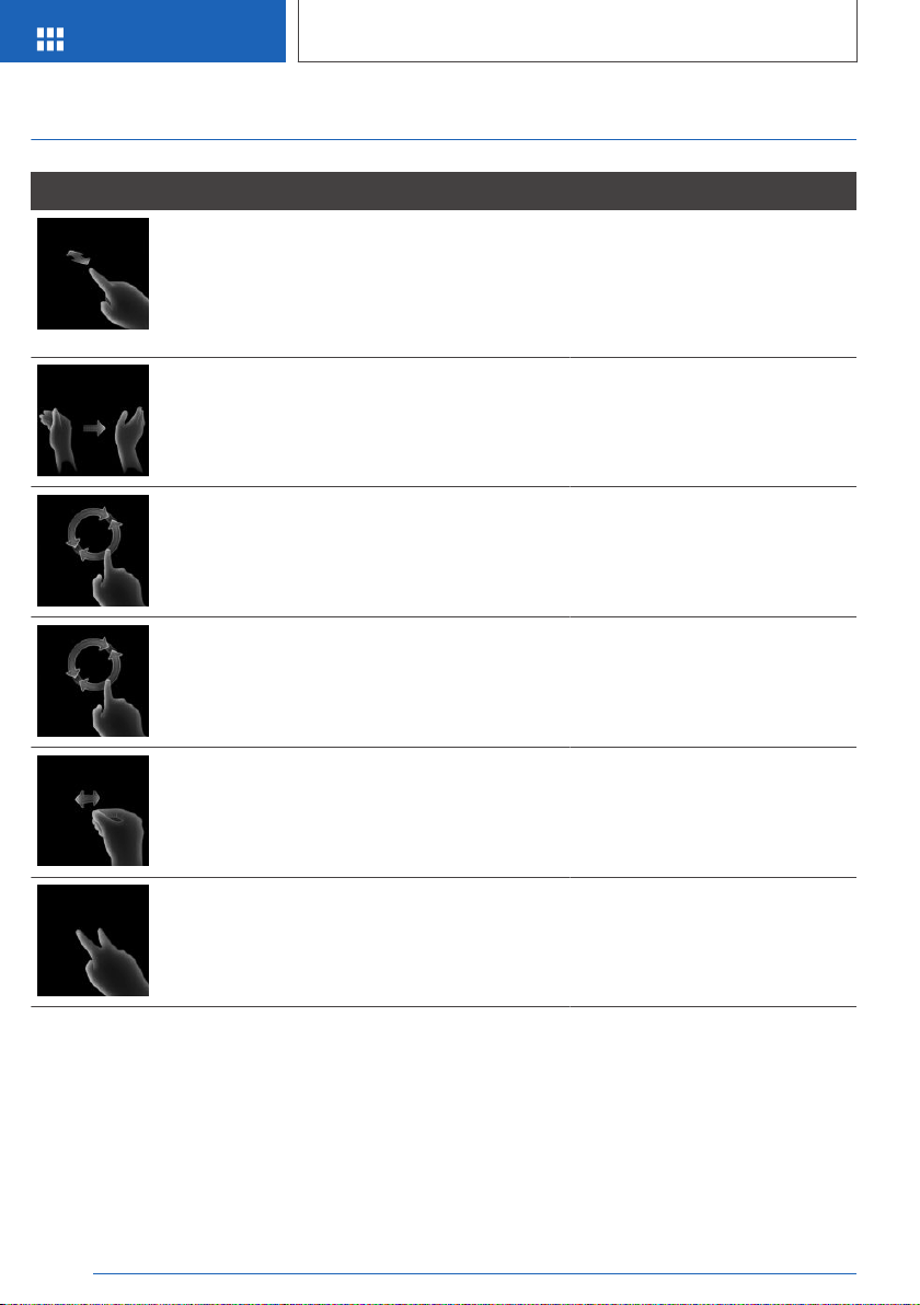
Possible gestures
Gesture Operation Function
Move index finger forward and backward in the
direction of the screen.
Accept call.
Select a highlighted entry in a list
during voice activation.
Confirm the "Resume guidance"
pop-up.
Swipe with the hand across the width of the Con‐
trol Display in the direction of the front-passenger
side.
Reject call.
Close the pop-up.
Terminate voice activation.
Slowly move forearm clockwise in a circular pat‐
tern with the index finger stretched out forward.
Gesture is detected after one circular motion.
Increase the volume.
Slowly move forearm counterclockwise in a circu‐
lar pattern with the index finger stretched out for‐
ward.
Gesture is detected after one circular motion.
Reduce the volume.
Pinch with thumb and index finger and move
hand horizontally to the right or left.
Surround View: turn camera view.
This gesture can only be exe‐
cuted while the vehicle is station‐
ary.
Move stretched out index and middle finger for‐
ward.
Individually assignable gesture.
Perform gestures underneath the interior mirror
and next to the steering wheel.
Execute gestures clearly.
The gestures can also be executed from the
front-passenger side.
Assigning gesture individually
Via iDrive:
1. "My Vehicle"
2. "iDrive settings"
3. "Gestures"
Seite 54
AT A GLANCE
BMW Gesture Control
54
Online Edition for Part no. 01402896703 - X/18

4. "Function assignment"
5. Select the desired setting.
System limits
Gesture recognition by the camera can be distur‐
bed by the following circumstances:
▷ The camera lens is covered.
▷ Objects are located on the interior mirror.
▷ The camera lens is dirty. Clean the camera
lenses, refer to page 354.
▷ The gesture is executed outside of the de‐
tection range.
▷ Wearing of gloves or jewelry.
▷ Smoking in the car's interior.
Seite 55
BMW Gesture Control
AT A GLANCE
55
Online Edition for Part no. 01402896703 - X/18
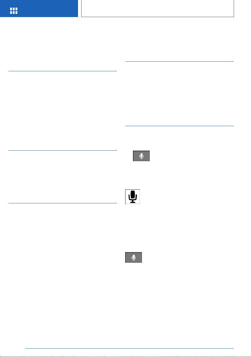
Voice activation system
Vehicle features and
options
This chapter describes all standard, country-spe‐
cific and optional features offered with the series.
It also describes features that are not necessarily
available in your vehicle, e. g., due to the selected
options or country versions. This also applies to
safety-related functions and systems. When us‐
ing these functions and systems, the applicable
laws and regulations must be observed.
Concept
Most functions displayed on the Control Display
can be operated by voice commands via the
voice activation system. The system supports
you with announcements during input.
General information
▷ Functions that can only be used when the ve‐
hicle is stationary can only be operated via
the voice activation system to a limited ex‐
tent.
▷ The system uses a special microphone on
the driver's side.
▷ ›...‹ in the Owner's Manual denotes verbal in‐
structions to use with the voice activation
system.
▷ Say the commands, numbers, and letters
smoothly and with normal volume, emphasis,
and speed.
▷ Always say commands in the language of the
voice activation system.
Functional requirements
To enable voice command recognition, a lan‐
guage must be set via iDrive that is supported by
the voice activation system.
To set the language, refer to page 59.
Using the voice activation
system
Activating the voice activation
system
1. Press the button on the steering
wheel.
2. Wait for the signal.
3. Say the command.
The symbol on the Control Display indi‐
cates that voice activation system is ac‐
tive.
No other commands may be available. In this
case, operate the function via iDrive.
Terminating the voice activation
system
Press the button on the steering wheel
or ›Cancel‹.
Using a smartphone via voice
activation
A smartphone connected to the vehicle can be
used via voice activation.
Seite 56
AT A GLANCE
Voice activation system
56
Online Edition for Part no. 01402896703 - X/18

Activate voice command response on the smart‐
phone for this purpose.
1.
Press and hold the button on the
steering wheel for approx. 3 seconds.
Voice command response is activated on the
smartphone.
2.
Release the button.
If activation is successful, a confirmation ap‐
pears on the Control Display.
If it was not possible to activate voice command
response, the list of Bluetooth devices appears
on the Control Display.
Possible commands
General information
Most menu items on the Control Display can be
voiced as commands.
Commands from other menus can also be spo‐
ken.
You may select list entries such as phone list en‐
tries via voice activation. Read these list entries
out loud exactly as they are shown in the respec‐
tive list.
Displaying possible commands
The following is displayed in the top area of the
Control Display:
▷ Some possible commands for the current
menu.
▷ Some possible commands from other me‐
nus.
▷ Status of the voice recognition.
▷ Encrypted connection is not available.
Help on the voice activation
system
▷ To have the available spoken instructions
read out loud: ›Voice commands‹.
▷ To have information on the operating princi‐
ple of the voice activation system read out
loud: ›General information on voice control‹.
▷ To have help for the current menu read out
loud: ›Help‹.
Example: opening the tone
settings
The commands of the menu items are spoken
just as they are selected via the Controller.
1.
Switch on the Entertainment sound output, if
needed.
2.
Press button on the steering wheel.
3. ›Media and radio‹
4. ›Tone‹
Settings
Setting the voice dialog
You can set the system to use standard dialog or
a short version.
The short version of the voice dialog plays back
short messages in abbreviated form.
Via iDrive:
1.
"My Vehicle"
2. "iDrive settings"
3. "Language"
4. "Speech mode:"
5. Select the desired setting.
Activating voice recognition via
the server
The voice recognition feature via the server pro‐
vides a dictation function and a natural method of
entering destinations while improving the quality
of voice recognition. To use the functions, data is
Seite 57
Voice activation system
AT A GLANCE
57
Online Edition for Part no. 01402896703 - X/18

transmitted to a service provider via an encrypted
connection and stored locally there.
Via iDrive:
1. "My Vehicle"
2. "iDrive settings"
3. "Language"
4. "Server speech recognition"
Speaking during voice output
It is possible to answer during inquiries of the
voice activation system. The function can be de‐
activated if inquiries are often undesirably inter‐
rupted, for instance due to background noise or
talking.
Via iDrive:
1.
"My Vehicle"
2. "iDrive settings"
3. "Language"
4. "Speaking during voice output"
Setting the language
The language to be used for voice activation and
system announcements can be set.
Via iDrive:
1.
"My Vehicle"
2. "iDrive settings"
3. If necessary, "Language"
4. "Language:"
5. Select the desired language.
Adjusting the volume
Turn the volume button during the spoken in‐
structions until the desired volume is set.
▷ The volume remains constant even if the vol‐
ume of other audio sources is changed.
▷ The volume is stored for the driver profile
currently used.
Information for Emergency
Requests
Do not use the voice activation system to initiate
an Emergency Request. In stressful situations,
the voice and vocal pitch can change. This can
unnecessarily delay the establishment of a
phone connection.
Instead, use the SOS button, refer to page 346,
close to the interior mirror.
Environmental conditions
▷ Keep the doors, windows, and glass sunroof
closed to prevent noise interference.
▷ Avoid making other noise in the vehicle while
speaking.
Seite 58
AT A GLANCE
Voice activation system
58
Online Edition for Part no. 01402896703 - X/18

General settings
Vehicle features and
options
This chapter describes all standard, country-spe‐
cific and optional features offered with the series.
It also describes features that are not necessarily
available in your vehicle, e. g., due to the selected
options or country versions. This also applies to
safety-related functions and systems. When us‐
ing these functions and systems, the applicable
laws and regulations must be observed.
Language
Setting the language
Via iDrive:
1.
"My Vehicle"
2. "iDrive settings"
3. If necessary, "Language"
4. "Language:"
5. Select the desired setting.
The setting is stored for the driver profile cur‐
rently used.
Setting the voice dialog
Voice dialog for the voice activation system, refer
to page 57.
Time
Setting the time zone
Via iDrive:
1.
"My Vehicle"
2. "iDrive settings"
3. "Date and time"
4. "Time zone:"
5. Select the desired setting.
The setting is stored for the driver profile cur‐
rently used.
Setting the time
Via iDrive:
1. "My Vehicle"
2. "iDrive settings"
3. "Date and time"
4. "Time:"
5. Turn the Controller until the desired hours are
displayed.
6. Press the Controller.
7. Turn the Controller until the desired minutes
are displayed.
8. Press the Controller.
Setting the time format
Via iDrive:
1.
"My Vehicle"
2. "iDrive settings"
3. "Date and time"
4. "Time format:"
5. Select the desired setting.
The setting is stored for the driver profile cur‐
rently used.
Instrument cluster with
enhanced features: setting the
clock time display
The clock time can be displayed in analog or dig‐
ital form.
Seite 59
General settings
AT A GLANCE
59
Online Edition for Part no. 01402896703 - X/18

Via iDrive:
1. "My Vehicle"
2. "iDrive settings"
3. "Displays"
4. "Instrument panel"
5. "Time"
6. Select the desired setting.
The setting is stored for the driver profile cur‐
rently used.
Automatic time setting
Depending on your vehicle's optional features,
the time, date and, if needed, the time zone are
updated automatically.
Via iDrive:
1.
"My Vehicle"
2. "iDrive settings"
3. "Date and time"
4. "Automatic time setting"
The setting is stored for the driver profile cur‐
rently used.
Date
Setting the date
Via iDrive:
1.
"My Vehicle"
2. "iDrive settings"
3. "Date and time"
4. "Date:"
5. Turn the Controller until the desired day is
displayed.
6. Press the Controller.
7. Make the settings for the month and year.
Setting the date format
Via iDrive:
1. "My Vehicle"
2. "iDrive settings"
3. "Date and time"
4. "Date format:"
5. Select the desired setting.
The setting is stored for the driver profile cur‐
rently used.
Setting the units of
measurement
Depending on the country version, you can set
the units of measurement for some values, for in‐
stance consumption, distances, and tempera‐
ture.
Via iDrive:
1.
"My Vehicle"
2. "iDrive settings"
3. "Units"
4. Select the desired menu item.
5. Select the desired setting.
The setting is stored for the driver profile cur‐
rently used.
Activating/deactivating the
display of the current
vehicle position
Concept
If vehicle location has been activated, the current
vehicle position can be displayed in the BMW
Connected app or in the ConnectedDrive cus‐
tomer portal.
Seite 60
AT A GLANCE
General settings
60
Online Edition for Part no. 01402896703 - X/18

Activating/deactivating
Via iDrive:
1. "My Vehicle"
2. "Vehicle settings"
3. "Vehicle tracking"
4. "Vehicle tracking"
Activating/deactivating
popup windows
For some functions, popup windows are dis‐
played automatically on the Control Display.
Some of these popup windows can be activated
or deactivated.
Via iDrive:
1.
"My Vehicle"
2. "iDrive settings"
3. "Pop-ups"
4. Select the desired setting.
The setting is stored for the driver profile cur‐
rently used.
Control Display
Brightness
Via iDrive:
1.
"My Vehicle"
2. "iDrive settings"
3. "Displays"
4. "Control display"
5. "Brightness at night"
6. Turn the Controller until the desired bright‐
ness is set.
7. Press the Controller.
The setting is stored for the driver profile cur‐
rently used.
Depending on the light conditions, the bright‐
ness settings may not be clearly visible.
Selecting the contents of the
main menu
For some menu items of the main menu, the dis‐
played contents can be selected.
1.
Press button.
2. "Contents of main menu"
3. Select the desired menu and the desired
content.
The setting is stored for the driver profile cur‐
rently used.
Messages
Concept
The menu centrally displays all messages arriv‐
ing in the vehicle in list form.
General information
The following messages can be displayed:
▷ Traffic messages.
▷ Check Control messages.
▷ Communication messages, for example e-
mails, SMS text messages or reminders.
▷ Service requirements messages.
Messages are additionally displayed in the status
field.
Retrieving messages
Via iDrive:
1.
"Notifications"
2. Select the desired message.
The respective menu is opened, where the mes‐
sage is displayed.
Seite 61
General settings
AT A GLANCE
61
Online Edition for Part no. 01402896703 - X/18

Deleting messages
All messages, except Check Control messages,
can be deleted from the list. Check Control mes‐
sages are displayed as long as they are relevant.
Via iDrive:
1. "Notifications"
2. Select the desired message.
3.
Press button.
4. "Delete this notification" or "Delete all
notifications"
Settings
The following settings can be adjusted:
▷ Select the applications, from which mes‐
sages will be permitted.
▷ Sort the messages according to date or prior‐
ity.
Via iDrive:
1.
"My Vehicle"
2. "iDrive settings"
3. "Notifications"
4. Select the desired setting.
Data protection
Data transfer
Concept
The vehicle offers different functions, whose use
requires a data transfer to BMW or a service pro‐
vider. The data transfer can be deactivated for
some functions.
General information
With data transfer deactivated, the respective
function cannot be used.
Only make these settings while stationary.
Activating/deactivating
Follow the instructions on the Control Display.
Via iDrive:
1. "My Vehicle"
2. "iDrive settings"
3. "Data privacy"
4. Select the desired setting.
Deleting personal data in the
vehicle
Concept
Depending on the usage, the vehicle stores per‐
sonal data, such as stored radio stations. This
personal data can be permanently deleted using
iDrive.
General information
Depending on the equipment package, the fol‐
lowing data can be deleted:
▷ Driver profile settings.
▷ Stored radio stations.
▷ Stored programmable memory buttons.
▷ Travel and Onboard Computer information.
▷ Music hard disk.
▷ Navigation, for instance stored destinations.
▷ Phone book.
▷ Online data, for instance Favorites, cookies.
▷ Office data, for instance voice notes.
▷ Login accounts.
Altogether, the deletion of the data can take up
to 15 minutes.
Functional requirement
Data can only be deleted while stationary.
Deleting data
Heed and follow the instructions on the Control
Display.
Seite 62
AT A GLANCE
General settings
62
Online Edition for Part no. 01402896703 - X/18
Via iDrive:
1. "My Vehicle"
2. "iDrive settings"
3. "Data privacy"
4. "Delete personal data"
5. "Delete personal data"
6. "OK"
7. Exit and lock the vehicle.
After 15 minutes, the deletion process is com‐
pleted.
If not all of the data was deleted, repeat the dele‐
tion.
Canceling deletion
Switch on the drive-ready state to cancel dele‐
tion of the data.
Connections
Concept
Various connection types are available for using
mobile devices in the vehicle. The connection
type to select depends on the mobile device and
the desired function.
General information
The following overview shows possible functions
and the suitable connection types for them. The
scope of functions depends on the mobile de‐
vice.
Function Connec‐
tion type
Making calls via the hands-free
system.
Using phone functions via iDrive.
Using the smartphone Office
functions.
Bluetooth.
Playing music from the smart‐
phone or the audio player.
Bluetooth or
USB.
Function Connec‐
tion type
Using compatible apps via
iDrive.
Bluetooth or
USB.
USB storage device:
Exporting and importing driver
profiles.
Performing software updates.
Exporting and importing stored
trips.
Playing music.
USB.
Playing videos from the smart‐
phone or the USB storage de‐
vice.
USB.
Using the vehicle Internet ac‐
cess.
WiFi hot‐
spot.
Use Apple CarPlay apps via
iDrive and voice operation.
Bluetooth
and WiFi.
Screen Mirroring:
Showing the smartphone display
on the Control Display.
WiFi
The following connection types require one-time
pairing with the vehicle:
▷ Bluetooth.
▷ WiFi hotspot.
▷ Apple CarPlay.
▷ Screen Mirroring.
Paired devices are automatically recognized later
on and connected to the vehicle.
Safety information
WARNING
Operating the integrated information systems
and communication devices while driving can
distract from traffic. It is possible to lose control
of the vehicle. There is a risk of an accident.
Only use the systems or devices when the traf‐
Seite 63
General settings
AT A GLANCE
63
Online Edition for Part no. 01402896703 - X/18

fic situation allows. As warranted, stop and use
the systems and devices while the vehicle is
stationary.
Compatible devices
General information
Information on mobile devices compatible with
the vehicle can be found at www.bmwusa.com/
bluetooth.
Malfunctions may occur with devices not listed
or deviating software versions.
Displaying the vehicle identification
number and software part number
When looking for compatible devices, you may
have to state the vehicle identification number
and the software part number. These numbers
can be displayed in the vehicle.
Via iDrive:
1.
"My Vehicle"
2. "iDrive settings"
3. "Mobile devices"
4. "Settings"
5. "Bluetooth® info"
6. "System information"
A software update, refer to page 70, can be
performed, if needed.
Bluetooth connection
Functional requirements
▷ Compatible device, refer to page 64, with
Bluetooth interface.
▷ The remote control or BMW display key is in
the vehicle.
▷ The device is ready for operation.
▷ Bluetooth is switched on in the vehicle, refer
to page 64, and on the device.
▷ Bluetooth presettings, such as visibility, may
be required on the device; refer to the own‐
er's manual of the device.
Switching on Bluetooth
Via iDrive:
1. "My Vehicle"
2. "iDrive settings"
3. "Mobile devices"
4. "Settings"
5. "Bluetooth®"
Activating/deactivating telephone
functions
To use all supported functions of a mobile
phone, the following functions must be activated
prior to pairing the mobile phone with the vehicle.
Via iDrive:
1.
"My Vehicle"
2. "iDrive settings"
3. "Mobile devices"
4. "Settings"
5. Select desired setting:
▷ "Office"
Activate function to transmit short mes‐
sages, e-mails, calendars, tasks, notes,
and reminders to the vehicle. Costs can
be incurred by transmitting all data to the
vehicle.
▷ "Contact images"
Activate function to show the contact pic‐
tures.
6. Move the Controller to the left.
Pairing the mobile device with the
vehicle
Via iDrive:
1.
"My Vehicle"
2. "iDrive settings"
Seite 64
AT A GLANCE
General settings
64
Online Edition for Part no. 01402896703 - X/18

3. "Mobile devices"
4. "Connect new device"
5. Select functions:
▷ "Telephone"
▷ "Bluetooth® audio"
▷ "Apps"
▷ "Apple CarPlay"
▷ "Screen Mirroring"
The Bluetooth name of the vehicle is dis‐
played on the Control Display.
6. Search for Bluetooth devices in the vicinity of
the mobile device.
The Bluetooth name of the vehicle appears
on the mobile device display.
Select the Bluetooth name of the vehicle.
7. Depending on the mobile device, a control
number is displayed or the control number
must be entered.
▷ Compare the control number displayed
on the Control Display with the control
number on the display of the device.
Confirm the control number on the device
and on the Control Display.
▷ Enter and confirm the same control num‐
ber on the device and via iDrive.
The device is connected and displayed in the
device list, refer to page 69.
Frequently asked questions
All requirements are met and all required steps
were completed in the specified order. Despite
that, the mobile device does not function as ex‐
pected.
In this case, the following explanations can help:
Why could the mobile phone not be paired or
connected?
▷ There are too many Bluetooth devices con‐
nected to the mobile phone or vehicle.
In the vehicle, delete Bluetooth connections
with other devices.
Delete all known Bluetooth connections from
the device list on the mobile phone and start
a new device search.
▷ The mobile phone is in power-save mode or
has only a limited remaining battery life.
Charge mobile phone.
Why does the mobile phone no longer react?
▷ The applications on the mobile phone do not
function anymore.
Switch the mobile phone off and on again.
▷ Too high or too low ambient temperature for
mobile phone operation.
Do not subject the mobile phone to extreme
ambient temperatures.
Why can phone functions not be used via iDrive?
▷ The mobile phone may not be properly con‐
figured, for instance as Bluetooth audio de‐
vice.
Connect the mobile phone with the tele‐
phone or additional phone function.
Why are no or not all phone book entries dis‐
played or why are they incomplete?
▷ Transmission of the phone book entries is
not yet complete.
▷ It is possible that only the phone book entries
of the mobile phone or the SIM card are
transmitted.
▷ It may not be possible to display phone book
entries with special characters.
▷ It may not be possible to transmit contacts
from social networks.
▷ The number of phone book entries to be
stored is too high.
▷ Data volume of the contact too large, for in‐
stance due to stored information such as
notes.
Reduce the data volume of the contact.
▷ A mobile phone can only be connected as
audio source or as telephone.
Seite 65
General settings
AT A GLANCE
65
Online Edition for Part no. 01402896703 - X/18

Configure the mobile phone and connect it
with the telephone or additional phone func‐
tion.
How can the phone connection quality be im‐
proved?
▷ Adjust the strength of the Bluetooth signal on
the mobile phone, depending on the mobile
phone.
▷ Insert mobile phone into the wireless charg‐
ing tray.
▷ Adjust the volume of the microphone and
loudspeakers separately in the sound set‐
tings.
If all points in this list have been checked and the
required function is still not available, contact the
hotline, a dealer’s service center or another quali‐
fied service center or repair shop.
USB connection
General information
Mobile devices with a USB port are connected to
the USB interface.
▷ Mobile phones.
▷ Audio devices such as MP3 players.
▷ USB storage devices.
Common file systems are supported. FAT32
and exFAT are the recommended formats.
A connected USB storage device will be sup‐
plied with charging current via the USB interface
if the device supports this. Observe the maxi‐
mum charge current of the USB interface.
The following uses are possible on USB interfa‐
ces with data transfer:
▷ Exporting and importing driver profiles, refer
to page 92.
▷ Playing music files via USB audio.
▷ Playing videos via USB video.
▷ Loading of software updates, refer to
page 70.
Follow the following when connecting:
▷ Do not use force when plugging the connec‐
tor into the USB interface.
▷ Use a flexible adapter cable.
▷ Protect the USB storage device against me‐
chanical damage.
▷ Due to the large number of USB media avail‐
able on the market, it cannot be guaranteed
that every device is operable on the vehicle.
▷ Do not expose USB media to extreme envi‐
ronmental conditions, such as very high tem‐
peratures; refer to the owner's manual of the
device.
▷ Due to the many different compression tech‐
niques, proper playback of the media stored
on the USB storage device cannot be guar‐
anteed in all cases.
▷ To ensure proper transmission of the stored
data, do not charge a USB storage device via
the onboard socket, when it is connected to
the USB interface.
▷ Depending on how the USB storage device is
being used, settings may be required on the
USB storage device, refer to the owner's
manual of the device.
Not compatible USB media:
▷ USB hard drives.
▷ USB hubs.
▷ USB memory card readers with multiple in‐
serts.
▷ HFS-formatted USB media.
▷ Devices such as fans or lamps.
Functional requirement
Compatible device, refer to page 64, with USB
interface.
Connecting the device
Connect the USB storage device using a suitable
adapter cable to a USB interface, refer to
page 254.
The USB storage device is displayed in the de‐
vice list, refer to page 69.
Seite 66
AT A GLANCE
General settings
66
Online Edition for Part no. 01402896703 - X/18
WiFi hotspot
General information
Up to 8 devices can be connected with the hot‐
spot of the vehicle at the same time.
Functional requirements
▷ Compatible device, refer to page 64, with
WiFi interface.
▷ WiFi activated on the device.
▷ Registration and data contract with a service
provider where required.
▷ Internet use is activated for the vehicle.
▷ Standby state switched on.
Activating the WiFi hotspot
Via iDrive:
1.
"My Vehicle"
2. "iDrive settings"
3. "Mobile devices"
4. "Settings"
5. "Internet hotspot"
Connecting device to WiFi hotspot
Via iDrive:
1.
"My Vehicle"
2. "iDrive settings"
3. "Mobile devices"
4. "Connect new device"
5. "Internet hotspot"
Hotspot name and hotspot code are dis‐
played on the Control Display.
6. Search for WiFi networks on the device. Se‐
lect network name on the device.
7. Enter hotspot code on the device and con‐
nect.
The device is displayed in the device list, refer to
page 69.
The initial Internet use via the hotspot requires a
registration and possibly a data volume purchase
from a service provider.
Depending on the country version, data volume
can be purchased via the connected mobile de‐
vice or from the ConnectedDrive Store.
All devices connected via the hotspot use this
data volume.
Settings
The network name and hotspot code can be
changed. In addition, the network name can be
hidden so that it cannot be found by other devi‐
ces.
Via iDrive:
1.
"My Vehicle"
2. "iDrive settings"
3. "Mobile devices"
4.
Press button.
5.
▷ "Change hotspot key"
Enter the desired hotspot code.
▷ "Change hotspot name"
Enter the desired network name.
▷ "Hide hotspot"
Activate or deactivate the function.
6. Confirm the entry of the hotspot code or net‐
work name:
Select the symbol.
Apple CarPlay preparation
Concept
CarPlay allows certain functions of a compatible
Apple iPhone to be used via Siri voice operation
and iDrive.
Functional requirements
▷ Compatible iPhone, refer to page 64.
iPhone 5 or later with iOS 7.1 or later.
Seite 67
General settings
AT A GLANCE
67
Online Edition for Part no. 01402896703 - X/18

▷ Corresponding mobile wireless contract.
▷ Bluetooth, WiFi, and Siri voice operation are
activated on the iPhone.
▷ Booking the ConnectedDrive service: Apple
CarPlay preparation.
Switching on Bluetooth and CarPlay
Via iDrive:
1. "My Vehicle"
2. "iDrive settings"
3. "Mobile devices"
4. "Settings"
5. Select the following settings:
▷ "Bluetooth®"
▷ "Apple CarPlay"
Pairing iPhone with CarPlay
Pair iPhone via Bluetooth with the vehicle, refer
to page 64.
Select CarPlay as the function:
"Apple CarPlay"
The iPhone is connected to the vehicle and dis‐
played in the device list, refer to page 69.
Operation
For more information, refer to the Integrated
Owner's Manual or the Owner's Manual for navi‐
gation, entertainment, communication.
Frequently asked questions
All requirements are met and all required steps
were completed in the specified order. Despite
that, the mobile device does not function as ex‐
pected.
In this case, the following explanations can help:
The iPhone has already been paired with Apple
CarPlay. When a new connection is established,
CarPlay can no longer be selected.
▷ Delete the iPhone concerned from the device
list.
▷ On the iPhone, delete the vehicle concerned
from the list of stored vehicles under Blue‐
tooth and under WiFi.
▷ Pair the iPhone as a new device.
If the steps listed have been carried out and the
required function is still not available: contact the
hotline, a dealer’s service center or another quali‐
fied service center or repair shop.
Screen Mirroring
General information
Screen Mirroring enables mirroring (outputting)
of the smartphone display on the Control Dis‐
play.
Functional requirements
▷ Compatible smartphone, refer to page 64,
with Screen Mirroring interface.
▷ Screen Mirroring is switched on on the
smartphone.
▷ WiFi is switched on in the vehicle.
Activating WiFi
Via iDrive:
1.
"My Vehicle"
2. "iDrive settings"
3. "Mobile devices"
4. "Settings"
5. "Vehicle Wi-Fi®"
Pairing a smartphone with Screen
Mirroring
Via iDrive:
1.
"My Vehicle"
2. "iDrive settings"
3. "Mobile devices"
4. "Connect new device"
5. "Screen Mirroring"
Seite 68
AT A GLANCE
General settings
68
Online Edition for Part no. 01402896703 - X/18
The WiFi name of the vehicle is displayed on
the Control Display.
6. Search for WiFi devices in the surroundings
of the smartphone.
The WiFi name of the vehicle appears on the
device display. Select the WiFi name of the
vehicle.
7. Confirm the connection via iDrive.
The device is connected and displayed in the
device list, refer to page 69.
Managing mobile devices
General information
▷ After one-time pairing, the devices are auto‐
matically recognized and reconnected when
standby state is switched on.
▷ The data stored on the SIM card or in the
mobile phone are transferred to the vehicle
after recognition.
▷ For some devices, certain settings are neces‐
sary, for instance authorization; see the own‐
er's manual of the device.
Displaying the device list
All devices paired with or connected to the vehi‐
cle are displayed in the device list.
Via iDrive:
1.
"My Vehicle"
2. "iDrive settings"
3. "Mobile devices"
A symbol indicates, for which function a device is
used.
Symbol Function
"Telephone"
"Additional telephone"
"Bluetooth® audio"
"Apps"
Symbol Function
"Internet hotspot"
"Apple CarPlay"
"Screen Mirroring"
Configuring the device
Functions can be activated or deactivated for
paired and connected devices.
Via iDrive:
1. "My Vehicle"
2. "iDrive settings"
3. "Mobile devices"
4. Select the desired device.
5. Select the desired setting.
If a function is assigned to a device, the function
will be deactivated where appropriate for a de‐
vice that is already connected and the device will
be disconnected.
Disconnecting the device
Via iDrive:
1.
"My Vehicle"
2. "iDrive settings"
3. "Mobile devices"
4. Select device.
5. "Disconnect device"
The device remains paired and can be con‐
nected again, refer to page 69.
Connecting the device
A disconnected device can be reconnected.
Via iDrive:
1.
"My Vehicle"
2. "iDrive settings"
3. "Mobile devices"
4. Select device.
5. "Connect device"
Seite 69
General settings
AT A GLANCE
69
Online Edition for Part no. 01402896703 - X/18

The functions that were assigned to the device
before disconnecting are assigned to the device
when it is reconnected. If the device is already
connected, these functions are deactivated.
Deleting the device
Via iDrive:
1. "My Vehicle"
2. "iDrive settings"
3. "Mobile devices"
4. Select device.
5. "Delete device"
The device is disconnected and removed from
the device list.
Swapping the telephone and
additional phone
If two mobile phones are connected to the vehi‐
cle, the functions of the phone and additional
phone can be switched.
Via iDrive:
1.
"My Vehicle"
2. "iDrive settings"
3. "Mobile devices"
4. "Settings"
5. "Swap telephone/additional tel."
Software update
General information
The vehicle supports a large number of mobile
devices, for instance mobile phones and MP3
players. Software updates are available for many
of the supported devices. The vehicle is main‐
tained up-to-date via regular vehicle software up‐
dates.
Updates and current information is available at
www.bmw.com/update.
Displaying the installed software
version
The software version installed in the vehicle is
displayed.
Via iDrive:
1. "My Vehicle"
2. "iDrive settings"
3. "Software update"
4. "Show current version"
If an update has been carried out before, select
the desired version to display additional informa‐
tion.
Updating software via USB
The software may only be updated when the ve‐
hicle is stationary.
Via iDrive:
1.
Store the file for the software update in the
main directory of a USB flash drive.
2. Connect the USB storage device to a USB
interface, refer to page 254.
3. "My Vehicle"
4. "iDrive settings"
5. "Software update"
6. "Update software"
7. "USB"
8. "Install software"
9. "OK"
10.Wait for the update to complete.
11."Shut down system"
If necessary, switch off the engine first.
Restoring the software version
The software version before the last software
update and the version before the first software
update can be restored.
The software may only be restored when the ve‐
hicle is stationary.
Seite 70
AT A GLANCE
General settings
70
Online Edition for Part no. 01402896703 - X/18

Via iDrive:
1. "My Vehicle"
2. "iDrive settings"
3. "Software update"
4. "Restore software"
5.
▷ "Previous version"
The previous software version is restored.
▷ "Default software settings"
The first software version is restored.
6. "Remove software"
7. "OK"
8. Wait for restore.
9. "Shut down system"
If necessary, switch off the engine first.
Seite 71
General settings
AT A GLANCE
71
Online Edition for Part no. 01402896703 - X/18

Owner's Manual media
Vehicle features and
options
This chapter describes all standard, country-spe‐
cific and optional features offered with the series.
It also describes features that are not necessarily
available in your vehicle, e. g., due to the selected
options or country versions. This also applies to
safety-related functions and systems. When us‐
ing these functions and systems, the applicable
laws and regulations must be observed.
General information
You can use the following media formats to call
up the content in the Owner's Manual:
▷ Printed Owner's Manual, refer to page 72.
▷ Integrated Owner's Manual in the vehicle, re‐
fer to page 72.
Printed Owner's Manual
Concept
The printed Owner's Manual describes all stand‐
ard, country-specific, and optional features of‐
fered with the series.
General information
The Owner's Manual for Navigation, Entertain‐
ment, and Communication can be obtained as
printed book from the service center.
Supplementary Owner's Manuals
Also follow the instructions of the Supplementary
Owner's Manuals, which are included in addition
to the onboard literature.
Integrated Owner's Manual
in the vehicle
Concept
The Integrated Owner's Manual specifically de‐
scribes features and functions found in the vehi‐
cle.
The Integrated Owner's Manual can be displayed
on the Control Display.
Selecting the Owner's Manual
1. Press button.
2. "My Vehicle"
3. "Owner's Manual"
4. Select the required method of accessing the
contents.
Scrolling through the owner's
manual
Turn the Controller, until the next or previous
contents are displayed.
Context help
General information
The section of the Owner's Manual relating to
the function that is currently selected can be dis‐
played directly.
Opening via iDrive
Change directly to the Options menu from the
function on the Control Display:
1. Press button.
2. "Owner's Manual"
Seite 72
AT A GLANCE
Owner's Manual media
72
Online Edition for Part no. 01402896703 - X/18

Opening when a Check Control
message is displayed
Directly from the Check Control message on the
Control Display:
"Owner's Manual"
Changing between a function and
the Owner's Manual
To switch from a function, for instance radio, to
the Owner's Manual on the Control Display and
to alternate between the two displays:
1.
Press the button.
2. "Owner's Manual"
3. Select the desired page in the Owner's
Manual.
4.
Press the button again to return to last
displayed function.
5.
Press the button to return to the page
of the Owner's Manual displayed last.
To alternate continuously between the last dis‐
played function and the last displayed page of
the Owner's Manual, repeat steps 4 & 5. Opens
a new display every time.
Programmable memory buttons
General information
The jumps into the Owner's Manual can be
stored on the programmable memory buttons,
refer to page 52, and called up directly.
Storing
1.
Select the desired entry point via iDrive:
▷ "Quick reference"
▷ "Search by pictures"
▷ "Keyword search"
▷ "Animations"
2.
Press desired programmable mem‐
ory button and hold for more than 2 seconds.
Executing
Press the corresponding button.
The owner's manual is directly dis‐
played at the selected entry point.
Seite 73
Owner's Manual media
AT A GLANCE
73
Online Edition for Part no. 01402896703 - X/18

74
Online Edition for Part no. 01402896703 - X/18
CONTROLS
Opening and closing ................................................................................. 76
Seats, mirrors, and steering wheel ....................................................... 102
Transporting children safely .................................................................. 115
Driving ....................................................................................................... 120
Displays ..................................................................................................... 140
Lights ......................................................................................................... 157
Safety ........................................................................................................ 164
Driving stability control systems ........................................................... 192
Driver assistance systems ..................................................................... 197
Driving comfort ........................................................................................ 233
Climate control ......................................................................................... 234
Interior equipment ................................................................................... 249
Storage compartments .......................................................................... 256
Cargo area ................................................................................................ 260
75
Online Edition for Part no. 01402896703 - X/18

Opening and closing
Vehicle features and
options
This chapter describes all standard, country-spe‐
cific and optional features offered with the series.
It also describes features that are not necessarily
available in your vehicle, e. g., due to the selected
options or country versions. This also applies to
safety-related functions and systems. When us‐
ing these functions and systems, the applicable
laws and regulations must be observed.
Remote control
General information
Depending on the equipment version, the vehicle
is delivered with two remote controls or one re‐
mote control and the BMW display key, refer to
page 81.
Each remote control contains a replaceable bat‐
tery. Replacing the battery, refer to page 79.
You may set the button functions, depending on
the vehicle equipment and country version. Set‐
tings, refer to page 94.
The vehicle stores personal settings for every re‐
mote control. Driver profile, refer to page 92.
The remote controls hold information about re‐
quired maintenance. Service data in the remote
control, refer to page 334.
To prevent possible locking in of the remote
control, take the remote control with you when
exiting the vehicle.
Safety information
WARNING
People or animals in the vehicle can lock the
doors from the inside and lock themselves in. In
this case, the vehicle cannot be opened from
the outside. There is a risk of injury. Take the
remote control with you so that the vehicle can
be opened from the outside.
WARNING
For some country versions, unlocking from the
inside is only possible with special knowledge.
Persons who spend a lengthy time in the vehi‐
cle while being exposed to extreme tempera‐
tures are at risk of injury or death. Do not lock
the vehicle from the outside when there are
people in it.
WARNING
Unattended children or animals can cause the
vehicle to move and endanger themselves and
traffic, for instance due to the following actions:
▷ Pressing the Start/Stop button.
▷ Releasing the parking brake.
▷ Opening and closing the doors or win‐
dows.
▷ Engaging selector lever position N.
▷ Using vehicle equipment.
There is a risk of accidents or injuries. Do not
leave children or animals unattended in the ve‐
hicle. Take the remote control with you when
exiting and lock the vehicle.
Seite 76
CONTROLS
Opening and closing
76
Online Edition for Part no. 01402896703 - X/18
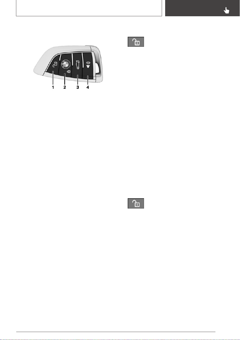
Overview
1 Unlocking
2 Locking
3 Opening/closing the tailgate
4 Press and hold or press three times in quick
succession: panic mode
Press briefly: headlight courtesy delay feature
Unlocking
General information
The behavior of the vehicle when unlocking with
the remote control depends on the following set‐
tings, refer to page 94, for unlocking and lock‐
ing:
▷ If only the driver's door and the fuel filler flap
or all access to the vehicle will be unlocked.
▷ If the unlocking of vehicle is confirmed with a
light signal or a sound signal.
▷ If the welcome light, refer to page 158, is
switched on when the vehicle is being un‐
locked.
▷ If the exterior mirrors are automatically folded
out and in when the vehicle is unlocked and
locked.
Exterior mirrors folded in through convenient
closing must be folded open through conven‐
ient opening.
▷ If the driver's seat is set to the last position
saved in the driver's profile.
▷ If the window is lowered further to make it
easier to enter.
Unlocking the vehicle
Press the button on the remote control.
If, due to the settings, only the driver's door and
fuel filler flap were unlocked, press the button on
the remote control again to unlock the other ve‐
hicle access points.
In addition, the following functions are executed:
▷ The settings stored in the driver profile, refer
to page 92, are applied.
▷ The interior lights are switched on, unless
they were manually switched off. Switch the
interior lights on/off manually, refer to
page 162.
▷ With anti-theft protection: Anti-theft protec‐
tion is switched off.
▷ With alarm system: The alarm system, refer
to page 96, will be switched off.
After opening one of the front doors, the vehicle
is ready for operation, refer to page 42.
The light functions may depend on the ambient
brightness.
Convenient opening
Press and hold the button on the re‐
mote control after unlocking.
The windows and the glass sunroof are opened,
as long as the button on the remote control is
pressed.
Locking
General information
The behavior of the vehicle during locking with
the remote control depends on the following set‐
tings, refer to page 94:
▷ If the locking of the vehicle is confirmed with
a light signal or a sound signal.
▷ If the exterior mirrors are automatically folded
in and out when the vehicle is locked and un‐
locked.
Seite 77
Opening and closing
CONTROLS
77
Online Edition for Part no. 01402896703 - X/18
▷ If the headlight courtesy delay feature, refer
to page 158, is activated during locking.
Locking the vehicle
1. Close the driver's door.
2.
Press the button on the remote control.
The following functions are executed:
▷ All doors, the tailgate, and the fuel filler flap
are locked.
▷ With anti-theft protection: Anti-theft protec‐
tion is switched on. This prevents the doors
from being unlocked using the lock buttons
or the door openers.
▷ With alarm system: The alarm system, refer
to page 96, will be switched on.
If the drive-ready state is still switched on when
you lock the vehicle, the vehicle horn honks
twice. In this case, the drive-ready state must be
switched off by means of the Start/Stop button.
With Comfort Access:
convenient closing
Safety information
WARNING
With convenient closing, body parts can be
jammed. There is a risk of injury. Make sure
that the area of movement of the doors is clear
during convenient closing.
Closing
Press and hold the button on the remote
control in the area close to the vehicle after
locking.
The windows and the glass sunroof are closed,
as long as the button on the remote control is
pressed.
Switching on the interior and
exterior lights
Press the button on the remote control
with the vehicle locked.
The function is not available for the first 10 sec‐
onds after locking.
▷ The interior lights are switched on, unless
they were manually switched off. Switch the
interior lights on/off manually, refer to
page 162.
▷ Depending on the settings, the exterior light‐
ing, refer to page 158, will be switched on.
The light functions may depend on the ambient
brightness.
Tailgate
General information
To avoid locking it in the vehicle, do not place the
remote control in the cargo area.
Depending on the vehicle equipment and coun‐
try version, it is also possible to have the doors
unlocked. Adjusting the settings, refer to
page 94.
Safety information
WARNING
Body parts can be jammed when operating the
tailgate. There is a risk of injury. Make sure that
the area of movement of the tailgate is clear
during opening and closing.
WARNING
The tailgate pivots out when it opens. There is
a risk of injury or risk of damage to property.
Make sure that the area of movement of the
tailgate is clear during opening and closing.
Seite 78
CONTROLS
Opening and closing
78
Online Edition for Part no. 01402896703 - X/18
NOTICE
Sharp-edged or pointed objects can hit the
windows and heat conductors while driving.
There is a risk of damage to property. Cover
the edges and ensure that pointed objects do
not hit the windows.
Opening
Press and hold the button on the re‐
mote control for approx. 1 second.
Panic mode
You can trigger the alarm system if you find your‐
self in a dangerous situation.
▷ Press the button on the remote con‐
trol and hold for at least 3 seconds.
▷ Briefly press the button on the remote control
three times in succession.
To switch off the alarm: press any button.
Switching on the headlight
courtesy delay feature
Press and hold the button on the re‐
mote control for approx. 1 second.
Set the duration, refer to page 158.
Replacing the battery
1.
Remove the integrated key from the remote
control, refer to page 85.
2. Place the integrated key underneath the bat‐
tery compartment cover, arrow 1, and lift the
cover with a lever movement of the
integrated key, arrow 2.
3. Push battery in the direction of the arrow us‐
ing a pointed object and lift it out.
4. Insert a type CR 2032 battery with the posi‐
tive side facing up.
5. Press the cover closed.
Have old batteries disposed of by a deal‐
er’s service center or another qualified
service center or repair shop or take
them to a collection point.
Additional remote controls
Additional remote controls are available from a
dealer’s service center or another qualified serv‐
ice center or repair shop.
Loss of the remote controls
A lost remote control can be blocked and re‐
placed by a dealer’s service center or another
qualified service center or repair shop.
Seite 79
Opening and closing
CONTROLS
79
Online Edition for Part no. 01402896703 - X/18

Malfunction
General information
A Check Control message, refer to page 141, is
displayed.
Remote control detection by the vehicle may
malfunction under the following circumstances:
▷ The battery of the remote control is dis‐
charged. Replacing the battery, refer to
page 79.
▷ Interference of the radio connection from
transmission towers or other equipment with
high transmitting power.
▷ Shielding of the remote control due to metal
objects.
Do not transport the remote control together
with metal objects.
▷ Interference of the radio connection from mo‐
bile phones or other electronic devices in di‐
rect proximity to the remote control.
Do not transport the remote control together
with electronic devices.
▷ Interference of radio transmission by a charg‐
ing process of mobile devices, for instance
charging of a mobile phone.
▷ The remote control is in direct proximity of
the wireless charging tray.
Place the remote control down at a different
location.
In the case of interference, the vehicle can be
unlocked and locked from the outside with the
integrated key, refer to page 84.
Switching the drive-ready state on
via emergency detection of the
remote control
It is not possible to switch on the drive-ready
state if the remote control has not been de‐
tected.
Proceed as follows in this case:
1.
Hold the remote control with its back against
the marked area on the steering column. Pay
attention to the display in the instrument
cluster.
2. If the remote control is detected:
Switch on drive-ready state within 10 sec‐
onds.
If the remote control is not detected, slightly
change the position of the remote control and re‐
peat the procedure.
Frequently asked questions
What precautions can be taken to be able to
open a vehicle with an accidentally locked in re‐
mote control?
▷ The options provided by the Remote Serv‐
ices of the BMW Connected app include the
ability to lock and unlock a vehicle.
This requires an active BMW Connected‐
Drive contract and the BMW Connected app
must be installed on a smartphone.
▷ Unlocking the vehicle can be requested via
the BMW ConnectedDrive Call Center.
An active BMW ConnectedDrive contract is
required.
Seite 80
CONTROLS
Opening and closing
80
Online Edition for Part no. 01402896703 - X/18
BMW display key
General information
The BMW display key is supplied with an addi‐
tional mechanical key. If the display key is used,
the mechanical key should be carried with you,
for instance in the wallet. The mechanical key is
used like the integrated key, refer to page 84.
The display key supports all functions of the
standard remote control.
In addition, the following functions are also avail‐
able:
▷ Display status of doors and windows.
▷ Display status of the anti-theft warning sys‐
tem.
▷ Display service information.
▷ Call up range with available fuel.
Safety information
WARNING
People or animals in the vehicle can lock the
doors from the inside and lock themselves in. In
this case, the vehicle cannot be opened from
the outside. There is a risk of injury. Take the
remote control with you so that the vehicle can
be opened from the outside.
WARNING
For some country versions, unlocking from the
inside is only possible with special knowledge.
Persons who spend a lengthy time in the vehi‐
cle while being exposed to extreme tempera‐
tures are at risk of injury or death. Do not lock
the vehicle from the outside when there are
people in it.
WARNING
Unattended children or animals can cause the
vehicle to move and endanger themselves and
traffic, for instance due to the following actions:
▷ Pressing the Start/Stop button.
▷ Releasing the parking brake.
▷ Opening and closing the doors or win‐
dows.
▷ Engaging selector lever position N.
▷ Using vehicle equipment.
There is a risk of accidents or injuries. Do not
leave children or animals unattended in the ve‐
hicle. Take the remote control with you when
exiting and lock the vehicle.
Overview
1 Opening/closing the tailgate
2 Unlocking
3 Press and hold or press three times in quick
succession: panic mode
Press briefly: headlight courtesy delay feature
4 Locking
5 Display
6 Back
7 Switch the display on/off
8 Micro-USB charging socket
Reception range
The number of available display key functions
depends on the distance from the vehicle.
Seite 81
Opening and closing
CONTROLS
81
Online Edition for Part no. 01402896703 - X/18
▷ When you are in close proximity to the vehi‐
cle, all functions of the display key are availa‐
ble.
▷ The status information can be called up in the
extended reception range.
With parked-car heating: the parked-car heat‐
ing can be operated.
Without parked-car heating: the parked-car
ventilation can be operated.
▷ Outside of the reception range of the vehicle,
you can display the last transmitted status in‐
formation from the vehicle.
The symbol is shown on the display if one of
the buttons is pressed outside of the reception
range.
Display
General information
The display is divided into the upper status line,
the information area, and the lower status line.
Upper status line
The upper status line displays the following infor‐
mation:
▷ Vehicle secured.
Vehicle not secured.
▷ Set time in the vehicle.
▷ Charge state of the display key battery.
Information area
The information area can be used to access in‐
formation and perform additional functions.
If the information area contains more than one
page, then page indicators are shown beneath
the information.
The indicator for the current page has
been filled in.
Swipe to the right or left with a finger to change
between the pages.
If further information is available on a page, tap
the appropriate symbol.
To return to the original page: tap on the
symbol beneath the display.
Lower status line
The lower status line indicates whether or not
the display key is within reception range, refer to
page 81.
▷ "Connected": the display key is within recep‐
tion range.
▷ "Updated": the display key is not within re‐
ception range. It indicates when the last data
transfer from the vehicle took place.
Switching on/off
The display will go out automatically after a brief
period to conserve battery power.
To hide the display manually:
Press the button on the left side of the display
key. Overview, refer to page 81.
To show the display:
1.
Press the button on the left side of the dis‐
play key.
2. Then, swipe with your finger from bottom to
top to unlock the screen lock.
To switch off the display to increase the usable
battery life:
1.
If necessary, cancel the screen lock.
2. Press and hold the button on the left side of
the display key for longer than 4 seconds.
3. "OK"
To switch the display on:
Press the button on the left side of the display
key.
Operating concept
The following information shows how to access
the information and functions using the main
menus.
Seite 82
CONTROLS
Opening and closing
82
Online Edition for Part no. 01402896703 - X/18
Main menu Information/Function
"Security
information"
/
Door status.
Alarm system status.
After alarm triggering: date,
time, and reason for triggering
the alarm.
Window status.
Glass sunroof status.
"Vehicle
information"
Maintenance indicators of Con‐
dition Based Service CBS, refer
to page 334.
Status of the roadside parking
lights.
"Mobility info" Range with available fuel.
"Precondit.
setting"
With parked-car heating: oper‐
ate parked-car heating, refer to
page 243.
Without parked-car heating:
operate parked-car ventilation,
refer to page 243.
Display key battery
General information
Follow the following information:
▷ If the charge state of the display key battery
declines, the display is switched off automati‐
cally. The battery must be recharged so that
the display can be switched back on. The op‐
erability of the standard buttons is retained
until the battery is completely discharged.
▷ Charge the battery for at least three hours
before using the display key for the first time
or if the key has not been used for an ex‐
tended period.
▷ The display key can be used during charging
via the USB port. If the battery is fully dis‐
charged, it may take some time before the
display key can be used again.
▷ Due to the large number of USB chargers
available on the market, it cannot be guaran‐
teed that every charger will function properly.
The charging duration depends on the
charger used.
▷ Charging via the USB port may heat up the
charger and the display key.
Charging in the wireless charging tray may
heat up the tray and the display key.
At higher temperatures, the display key may
cause a reduction in the charging current,
and in isolated cases the charging process
may be interrupted temporarily.
▷ When inserting the display key into the wire‐
less charging tray, make sure there are no
objects between it and the wireless charging
tray.
Safety information
WARNING
When charging a device that meets the Qi
standard in the wireless charging tray, any
metal objects located between the device and
the tray can become very hot. If smart cards,
memory cards or cards with magnetic strips are
placed between the device and the tray, this
may impair card function. There is a risk of in‐
jury and risk of damage to property. When
charging mobile devices, make sure there are
no objects between the device and the tray.
Charging
Via USB
Connect the display key via the micro-USB
charging socket to a USB port.
Seite 83
Opening and closing
CONTROLS
83
Online Edition for Part no. 01402896703 - X/18
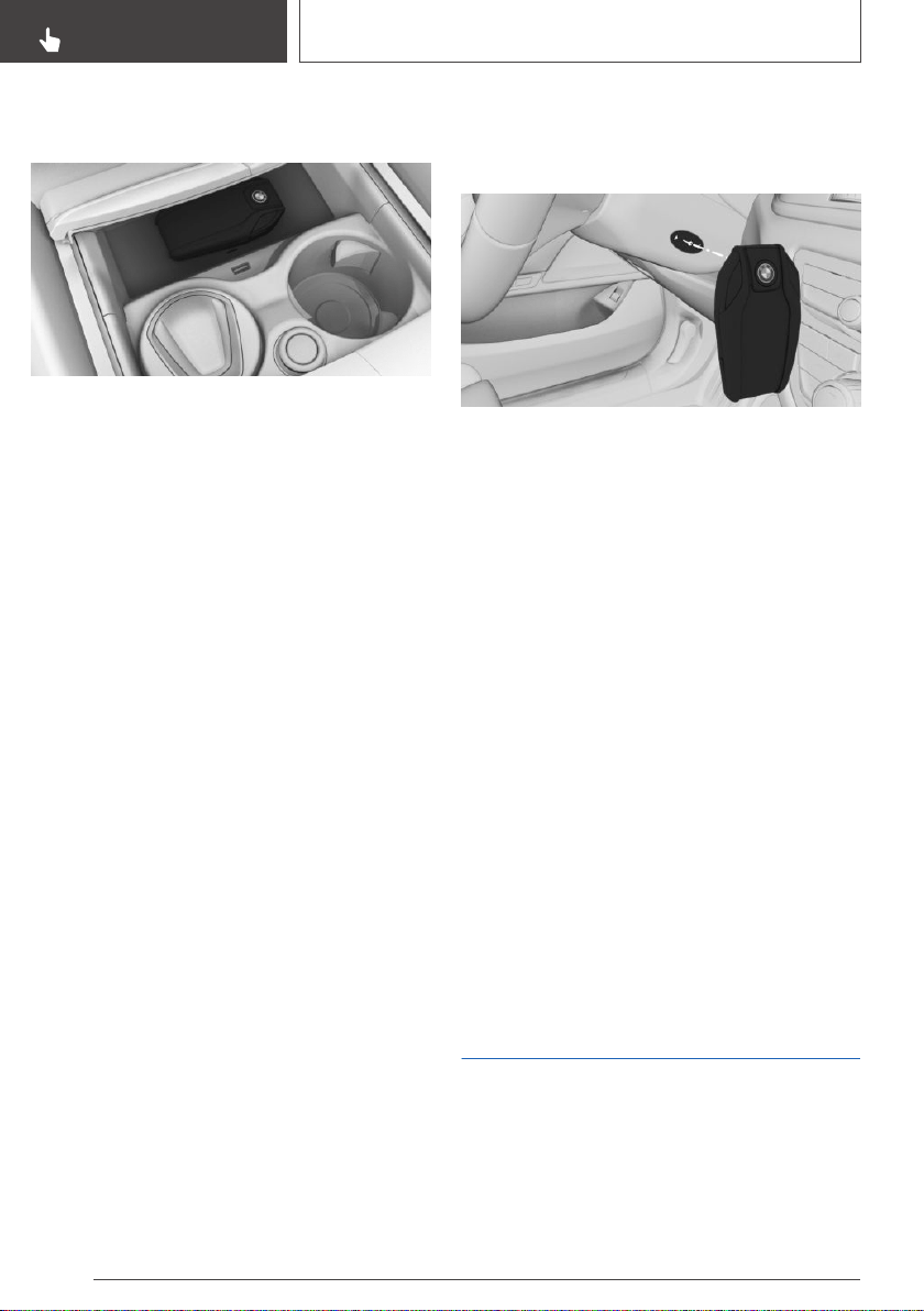
With Steptronic transmission: in the
wireless charging tray
1. Open the tray cover.
2. Place the display key into the middle of the
wireless charging tray in front of the cup hold‐
ers.
Ensure that the display is facing up.
3. Close the tray cover.
Malfunction
General information
A Check Control message is displayed.
BMW display key detection by the vehicle may
malfunction under the following circumstances:
▷ The battery of the display key is discharged.
Charge the battery, refer to page 83.
▷ Interference of the radio connection from
transmission towers or other equipment with
high transmitting power.
▷ Shielding of the display key due to metal ob‐
jects.
▷ Interference of the radio connection from mo‐
bile phones or other electronic devices in di‐
rect proximity.
▷ Interference of radio transmission by a charg‐
ing process of mobile devices, for instance
charging of a mobile phone.
Do not transport the display key together with
metal objects or electronic devices.
In the case of interference, the vehicle can also
be unlocked and locked from the outside with
the mechanical key.
Switching on drive-ready state via
emergency detection of the BMW
display key
It is not possible to switch on the drive-ready
state if the display key has not been detected.
Proceed as follows in this case:
1.
Hold the display key with its back against the
marked area on the steering column. Pay at‐
tention to the display in the instrument clus‐
ter.
2. If the display key is detected:
Switch on drive-ready state within 10 sec‐
onds.
If the display key is not detected, slightly change
the position of the display key and repeat the
procedure.
Resetting the BMW display key
If the charged display key cannot be switched on
anymore or if the display does not respond to
entries anymore, the display key can be reset.
Press and hold the button on the left side of the
display key for at least 20 seconds, until some‐
thing appears on the display.
Integrated key
General information
The driver's door can be locked and unlocked
without remote control using the integrated key.
The integrated key also fits the glove compart‐
ment.
Seite 84
CONTROLS
Opening and closing
84
Online Edition for Part no. 01402896703 - X/18
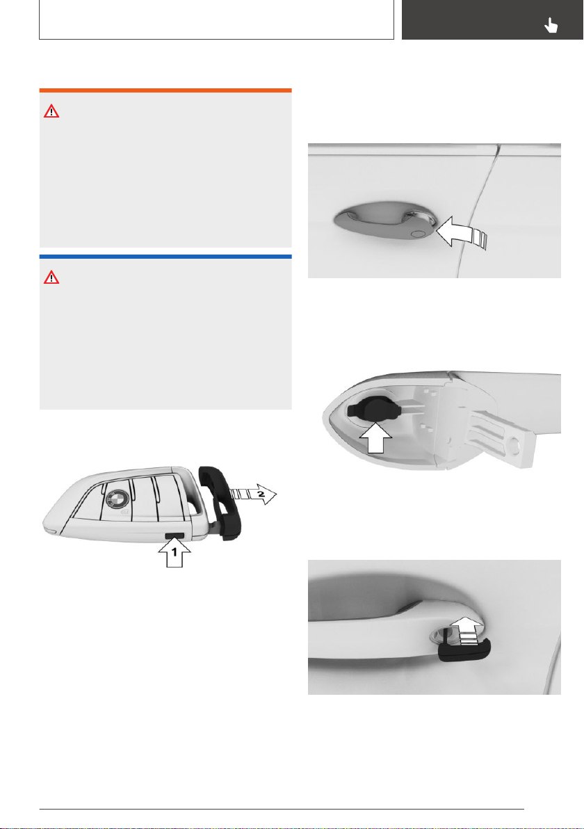
Safety information
WARNING
For some country versions, unlocking from the
inside is only possible with special knowledge.
Persons who spend a lengthy time in the vehi‐
cle while being exposed to extreme tempera‐
tures are at risk of injury or death. Do not lock
the vehicle from the outside when there are
people in it.
NOTICE
The door lock is permanently joined with the
door. The door handle can be moved. When
pulling the door handle with the integrated key
inserted, paint or the integrated key can be
damaged. There is a risk of damage to prop‐
erty. Remove the integrated key before pulling
the outside door handle.
Removing
Press the button, arrow 1, and pull out the
integrated key, arrow 2.
Locking/unlocking via the door
lock
1. Pull and hold the door handle outward with
one hand.
2. Guide one finger of your other hand from the
back under the cover and push the cover out.
Use the thumb for counter support to prevent
the cover from falling out of the door handle.
3. Remove the cover.
4. Unlock or lock the door lock using the
integrated key.
The other doors must be unlocked or locked
from the inside.
Seite 85
Opening and closing
CONTROLS
85
Online Edition for Part no. 01402896703 - X/18
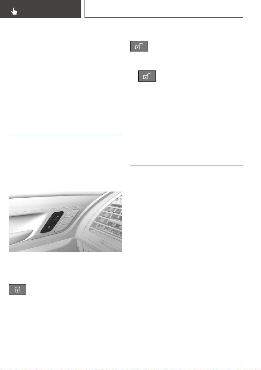
Alarm system
The alarm system is not switched on if the vehi‐
cle is locked with the integrated key.
The alarm system is triggered when the door is
opened, if the vehicle has been unlocked via the
door lock.
In order to stop the alarm, unlock the vehicle with
the remote control, if necessary through emer‐
gency detection of the remote control, refer to
page 80.
Buttons for the central
locking system
General information
In the event of a severe accident, the vehicle is
automatically unlocked. The hazard warning sys‐
tem and interior lights come on.
Overview
Buttons for the central locking system.
Locking
Press the button with the front doors
closed.
▷ The fuel filler flap remains unlocked.
▷ The vehicle is not secured against theft when
locking.
Unlocking
Press the button.
Opening
▷ Press the button to unlock all the
doors.
Pull the door opener above the armrest.
▷ Front doors: pull the door handle on the door
to open the door. The other doors remain
locked.
▷ Back doors: pull twice on the door handle on
the door to be opened; the first time unlocks
the door, the second time opens it. The other
doors remain locked.
Comfort Access
Concept
The vehicle can be accessed without activating
the remote control.
All you need to do is to have the remote control
with you, such as in your pants pocket.
The vehicle automatically detects the remote
control when it is in close proximity or in the car's
interior.
General information
Comfort Access supports the following func‐
tions:
▷ Unlocking and locking the vehicle from the
door handle.
▷ Convenient closing.
▷ Open the tailgate.
▷ Open and close the tailgate with no-touch
activation.
Seite 86
CONTROLS
Opening and closing
86
Online Edition for Part no. 01402896703 - X/18
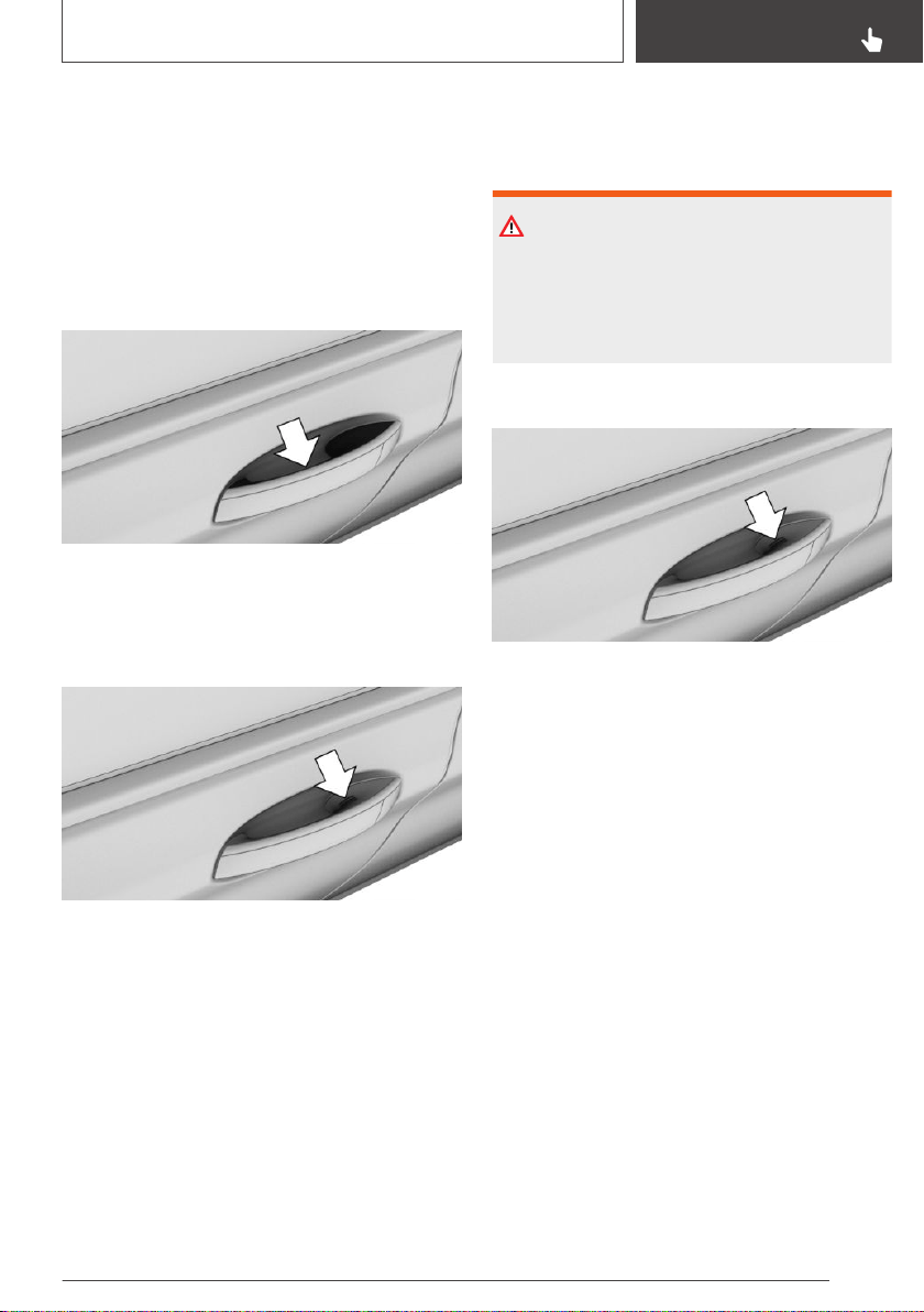
Functional requirements
▷ To lock the vehicle, the remote control must
be located outside of the vehicle near the
doors.
▷ The next unlocking and locking cycle is not
possible until after approx. 2 seconds.
Unlocking
Grasp the handle of a vehicle door completely.
Locking
Close the driver's door.
Touch the grooved surface on the handle of a
closed vehicle door with your finger for approx.
1 second without grasping the door handle.
Convenient closing
Safety information
WARNING
With convenient closing, body parts can be
jammed. There is a risk of injury. Make sure
that the area of movement of the doors is clear
during convenient closing.
Closing
Touch the grooved surface on the handle of a
closed vehicle door with your finger and hold it
there without grasping the door handle.
In addition to locking, the windows and glass
sunroof will be closed.
Opening the tailgate
General information
If the tailgate is opened via Comfort Access,
locked doors are not unlocked.
To avoid locking it in the vehicle, do not place the
remote control in the cargo area.
Seite 87
Opening and closing
CONTROLS
87
Online Edition for Part no. 01402896703 - X/18
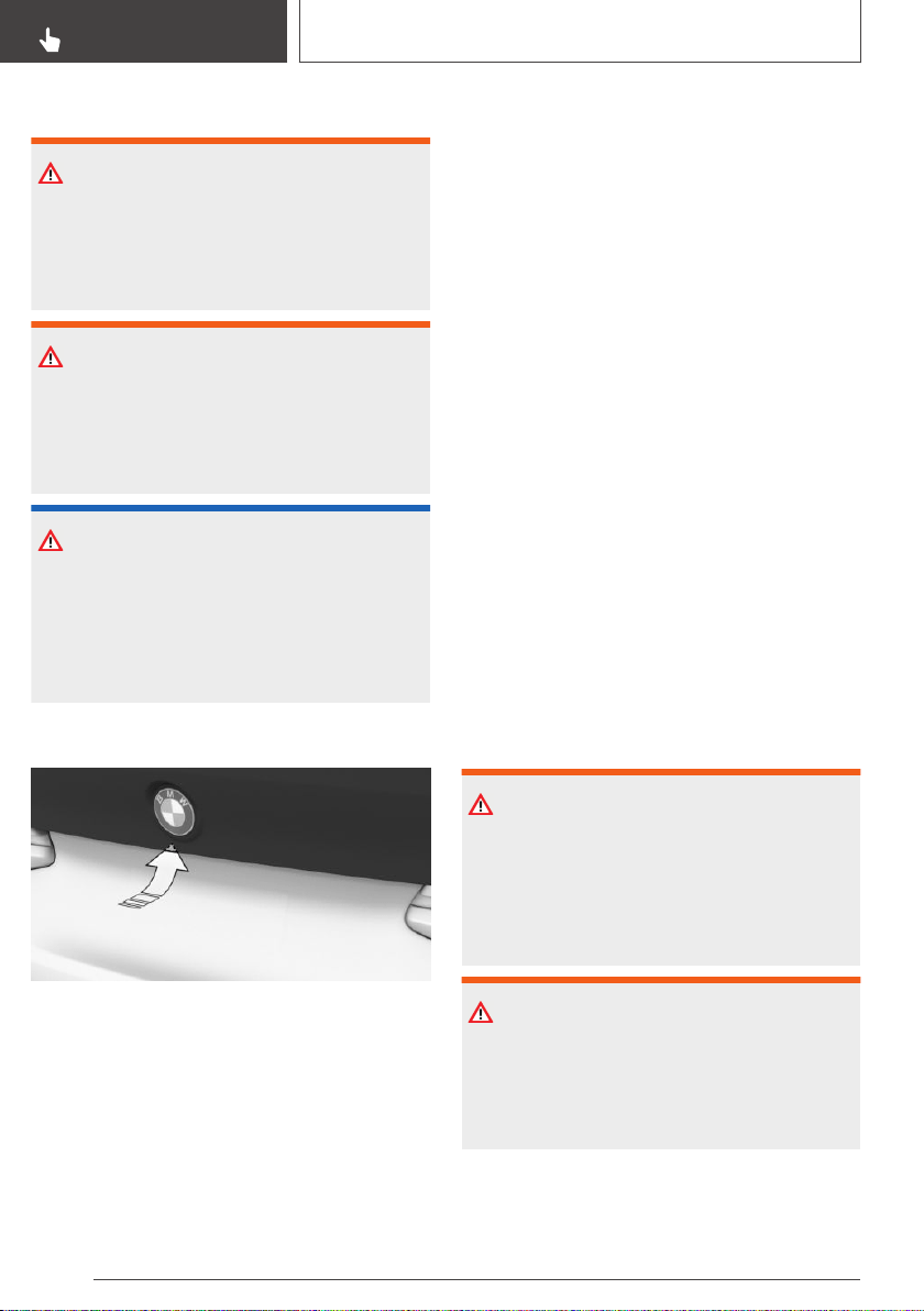
Safety information
WARNING
Body parts can be jammed when operating the
tailgate. There is a risk of injury. Make sure that
the area of movement of the tailgate is clear
during opening and closing.
WARNING
The tailgate pivots out when it opens. There is
a risk of injury or risk of damage to property.
Make sure that the area of movement of the
tailgate is clear during opening and closing.
NOTICE
Sharp-edged or pointed objects can hit the
windows and heat conductors while driving.
There is a risk of damage to property. Cover
the edges and ensure that pointed objects do
not hit the windows.
Opening
Press the button on tailgate's exterior.
Without trailer hitch: touchless
opening and closing of the
tailgate
Concept
The tailgate can be opened and closed with no-
touch activation using the remote control you are
carrying. Two sensors detect a forward-directed
foot motion in the central rear area and the tail‐
gate is opened and closed.
General information
To avoid locking it in the vehicle, do not place the
remote control in the cargo area.
If the remote control is in the sensor area, the
tailgate can be opened or closed inadvertently by
an unconscious or alleged recognized foot
movement.
The sensor has an approximate range of
5 ft/1.50 m extending from the rear of the vehi‐
cle.
If the tailgate is opened with no-touch activation,
locked doors are not unlocked.
Safety information
WARNING
During no-touch activation, vehicle parts may
be touched, such as the hot exhaust gas sys‐
tem. There is a risk of injury. When moving your
foot, make sure you have a firm stance and do
not touch the vehicle.
WARNING
Body parts can be jammed when operating the
tailgate. There is a risk of injury. Make sure that
the area of movement of the tailgate is clear
during opening and closing.
Seite 88
CONTROLS
Opening and closing
88
Online Edition for Part no. 01402896703 - X/18
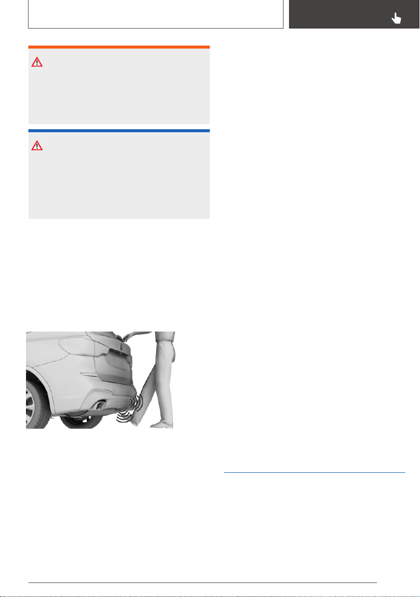
WARNING
The tailgate pivots out when it opens. There is
a risk of injury or risk of damage to property.
Make sure that the area of movement of the
tailgate is clear during opening and closing.
NOTICE
Sharp-edged or pointed objects can hit the
windows and heat conductors while driving.
There is a risk of damage to property. Cover
the edges and ensure that pointed objects do
not hit the windows.
Performing the foot movement
1.
Stand in the middle behind the vehicle at ap‐
prox. one arm's length away from the rear of
the vehicle.
2. Wave a foot under the vehicle in the direction
of travel and immediately pull it back. With
this movement, the leg must pass through
the ranges of both sensors.
Opening
Perform the foot movement described earlier.
Before the tailgate opens, the hazard warning
system flashes.
Moving your foot again will stop the opening mo‐
tion, and moving it one more time after that will
close the tailgate.
Closing
Perform the foot movement described earlier.
The hazard warning system flashes and an
acoustic signal sounds.
Moving your foot again will stop the closing mo‐
tion, and moving it one more time after that will
re-open the tailgate.
Malfunction
Remote control detection by the vehicle may
malfunction under the following circumstances:
▷ The battery of the remote control is dis‐
charged. Replacing the battery, refer to
page 79.
▷ Interference of the radio connection from
transmission towers or other equipment with
high transmitting power.
▷ Shielding of the remote control due to metal
objects.
Do not transport the remote control together
with metal objects.
▷ Interference of the radio connection from mo‐
bile phones or other electronic devices in di‐
rect proximity to the remote control.
Do not transport the remote control together
with electronic devices.
Wet or snowy conditions may disrupt the locking
request recognition function on the door han‐
dles.
In the case of a malfunction, unlock and lock the
vehicle using the buttons of the remote control
or using the integrated key, refer to page 84.
Tailgate
General information
To avoid locking it in the vehicle, do not place the
remote control in the cargo area.
Depending on the vehicle equipment and coun‐
try version, it is also possible to have the doors
Seite 89
Opening and closing
CONTROLS
89
Online Edition for Part no. 01402896703 - X/18
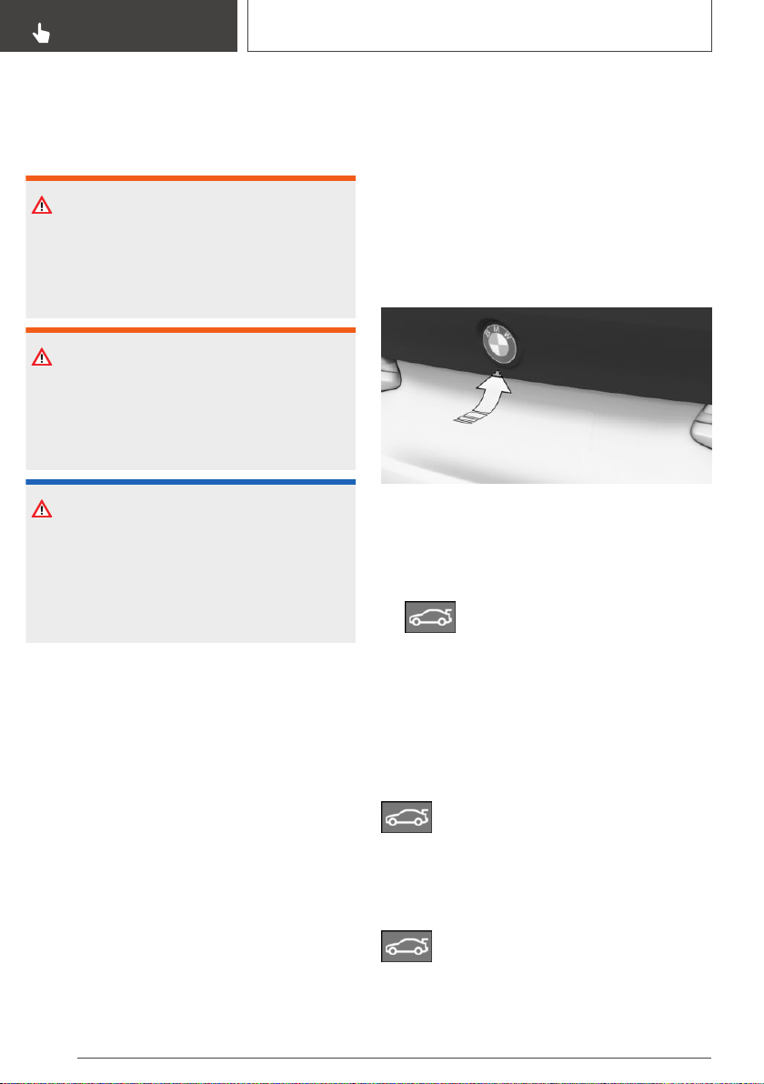
unlocked. Adjusting the settings, refer to
page 94.
Safety information
WARNING
Body parts can be jammed when operating the
tailgate. There is a risk of injury. Make sure that
the area of movement of the tailgate is clear
during opening and closing.
WARNING
The tailgate pivots out when it opens. There is
a risk of injury or risk of damage to property.
Make sure that the area of movement of the
tailgate is clear during opening and closing.
NOTICE
Sharp-edged or pointed objects can hit the
windows and heat conductors while driving.
There is a risk of damage to property. Cover
the edges and ensure that pointed objects do
not hit the windows.
Tailgate
General information
When the trailer socket is in use, the tailgate can‐
not be opened with the remote control or with
the button in the car's interior.
Opening
Adjusting the opening height
You can set how far the tailgate should open.
When adjusting the opening height, ensure that
there is a clearance of at least 4 in/10 cm above
the tailgate.
Via iDrive:
1. "My Vehicle"
2. "Vehicle settings"
3. "Doors/Key"
4. "Tailgate"
5. Monitor the tailgate and set the desired
opening height.
From the outside
▷ Without Comfort Access: unlock vehicle.
With Comfort Access: unlock the vehicle or
have the remote control with you.
Press the button on tailgate's exterior.
▷ Press the button on the remote con‐
trol for approx. 1 second.
Depending on the setting, the doors may also be
unlocked. Opening with the remote control, refer
to page 78.
If the vehicle is stationary, the tailgate opens au‐
tomatically to the adjusted opening height.
From the inside
With Steptronic transmission:
Press the button in the driver's door
downward.
If the vehicle is locked, selector lever position P
must be engaged first.
With manual transmission:
Seite 90
CONTROLS
Opening and closing
90
Online Edition for Part no. 01402896703 - X/18
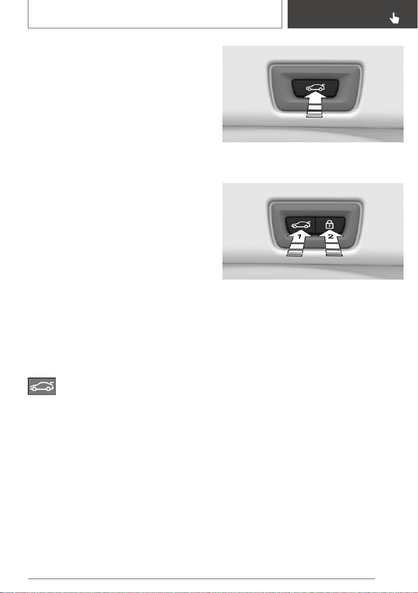
With the vehicle stationary, push the button in
the storage compartment of the driver's door
downwards twice in quick succession.
The tailgate will be opened to the configured
opening height.
Interruption of the opening procedure
The opening procedure is interrupted in the fol‐
lowing situations:
▷ When the vehicle starts moving.
▷ By pressing the button on the outside of the
tailgate. Pressing again closes the tailgate.
▷ By pressing the button on the inside of the
tailgate. Pressing again closes the tailgate.
▷ By pressing the button on the remote control.
Pressing again continues the opening mo‐
tion.
▷ By pressing or pulling the button in the driv‐
er's door. Pressing again continues the open‐
ing motion.
Closing
From the outside
Press the button on tailgate's exterior.
From the inside
Pull and hold the button in the driver
door.
The remote control must be located in the car's
interior for this function.
An acoustic signal sounds before the tailgate is
closed.
From inside the tailgate
Without Comfort Access:
Press the button on the inside of the tailgate.
With Comfort Access:
▷ Press the button, arrow 1, on the inside of the
tailgate.
▷ Press button, arrow 2.
The vehicle will be locked after closing the
tailgate. The driver's door must be closed for
this purpose and the remote control must be
outside of the vehicle in the area of the tail‐
gate.
Interruption of the closing procedure
The closing procedure is interrupted in the fol‐
lowing situations:
▷ If the vehicle starts off with a jerky movement.
▷ By pressing the button on the outside of the
tailgate. Pressing again re-opens the tailgate.
▷ By pressing the button on the inside of the
tailgate. Pressing again re-opens the tailgate.
▷ By releasing the button in the driver's door.
Pulling again and holding continues the clos‐
ing motion.
Seite 91
Opening and closing
CONTROLS
91
Online Edition for Part no. 01402896703 - X/18

Malfunction
Safety information
WARNING
With manual operation of a blocked tailgate, it
can release itself unexpectedly from the block‐
age. There is a risk of injury or risk of damage
to property. Do not operate the tailgate man‐
ually if it is blocked. Have it checked by a deal‐
er’s service center or another qualified service
center or repair shop.
Manual operation
Operate the unlocked tailgate manually with a
slow and smooth motion.
To close the tailgate fully, press down lightly
only. Closing occurs automatically.
Driver profile
Concept
In the driver profiles, individual settings for sev‐
eral drivers can be stored and called up again
when required.
General information
There are three driver profiles with which per‐
sonal vehicle settings can be stored. Every re‐
mote control has one of these driver profiles as‐
signed.
If the vehicle is unlocked using a remote control,
the assigned personal driver profile will be acti‐
vated. All settings stored in the driver profile are
automatically applied.
If several drivers use their own remote control,
the vehicle will adjust the personal settings dur‐
ing unlocking. These settings are also restored, if
the vehicle has been used in the meantime by a
person with a different remote control.
Changes to the settings are automatically stored
in the driver profile currently activated.
If another driver profile is selected via iDrive, the
settings stored in it will be applied automatically.
The new driver profile is assigned to the remote
control currently used.
There is an additional guest profile available that
is not assigned to any remote control. It can be
used to apply settings in the vehicle without
changing the personal driver profiles.
Functional requirements
For the system to be able to identify the driver
profile associated to a particular driver, the de‐
tected remote control must be clearly allocated
to the driver.
This is the case when:
▷ The driver is only carrying his or her own re‐
mote control.
▷ The driver unlocks the vehicle.
▷ The driver gets into the vehicle through the
driver's door.
Active driver profile
After switching on the Control Display, the name
of the active driver profile is displayed.
Select driver profile, refer to page 93.
As soon as the engine is started or any key is
pressed, the last selected display is shown on
the Control Display.
To exit the welcome screen via iDrive:
"OK"
Settings
The settings for the following systems and func‐
tions are stored in the active driver profile. The
scope of storable settings depends on country
and equipment.
▷ Unlocking and locking.
▷ Lights.
▷ Climate control.
Seite 92
CONTROLS
Opening and closing
92
Online Edition for Part no. 01402896703 - X/18

▷ Radio.
▷ Instrument cluster.
▷ Programmable memory buttons.
▷ Volumes, tone.
▷ Control Display.
▷ Navigation.
▷ PDC Park Distance Control.
▷ Rearview camera.
▷ Panorama View.
▷ Head-up Display.
▷ Driving Dynamics Control.
▷ Seat position, exterior mirror position.
Both the positions saved via the seat memory
and the last position set are saved.
▷ Intelligent Safety.
Profile management
Selecting a driver profile
Regardless of the remote control in use, a differ‐
ent driver profile may be activated. This allows
you to call up personal vehicle settings, even if
you did not unlock the vehicle with your own re‐
mote control.
Via iDrive:
1.
"My Vehicle"
2. "Driver profiles"
3. Select driver profile.
4. "OK"
▷ All settings stored in the called-up driver pro‐
file are automatically applied.
▷ The called-up driver profile is assigned to the
remote control being used at the time.
▷ If the driver profile is already assigned to a dif‐
ferent remote control, this driver profile will
apply to both remote controls.
Guest profile
The guest profile is for individual settings that are
stored in none of the three personal driver pro‐
files.
Via iDrive:
1. "My Vehicle"
2. "Driver profiles"
3. "Drive off (guest)"
4. "OK"
The guest profile cannot be renamed. It is not
assigned to the current remote control.
Renaming a driver profile
A personal name can be assigned to the active
driver profile to avoid confusion between the
driver profiles.
Via iDrive:
1.
"My Vehicle"
2. "Driver profiles"
3. Select driver profile.
The driver profile marked with this symbol
can be renamed.
4. "Change driver profile name"
5. Enter profile name.
6. Select the symbol.
Resetting a driver profile
The settings of the active driver profile are reset
to their factory settings.
Via iDrive:
1.
"My Vehicle"
2. "Driver profiles"
3. Select driver profile.
The driver profile marked with this symbol
can be reset.
4. "Reset driver profile"
5. "OK"
Seite 93
Opening and closing
CONTROLS
93
Online Edition for Part no. 01402896703 - X/18

Exporting driver profiles
Most settings of the active driver profile can be
exported.
Exporting is helpful when storing and retrieving
personal settings, for instance before delivering
the vehicle to a workshop. The stored driver pro‐
files can be taken into another vehicle.
Via iDrive:
1. "My Vehicle"
2. "Driver profiles"
3. Select driver profile.
The driver profile marked with this symbol
can be exported.
4. "Export driver profile"
5. Select a storage device for exporting the
driver profile.
▷ "USB device"
Select USB storage device, as needed,
refer to page 66.
▷ Online
Via the BMW ConnectedDrive customer
portal.
Importing driver profiles
The existing settings of the active driver profile
are overwritten with the settings of the imported
driver profile.
Via iDrive:
1.
"My Vehicle"
2. "Driver profiles"
3. Select the driver profile to be overwritten.
The driver profile marked with this symbol
can be overwritten.
4. "Import driver profile"
5. Select a storage device for importing the
driver profile.
▷ USB storage device: "USB device"
Select USB storage device as needed.
▷ Online.
6. Select the driver profile to be imported.
System limits
A clear assignment between the remote control
and driver may not be possible in the following
cases, for example.
▷ The passenger unlocks the vehicle with his or
her own remote control, but another person
is driving.
▷ The driver unlocks the vehicle via Comfort
Access and has multiple remote controls with
him or her.
▷ The driver changes, but the vehicle is not
locked and unlocked.
▷ Multiple remote controls are located outside
of the vehicle.
Settings
General information
Depending on the package and country version,
various settings are available for the remote con‐
trol functions.
These settings are stored for the driver profile
currently used.
Unlocking
Doors
Via iDrive:
1.
"My Vehicle"
2. "Vehicle settings"
3. "Doors/Key"
4. "Driver's door" or "All doors"
5. Select desired setting:
▷ "Driver's door only"
Only the driver's door and the fuel filler
flap are unlocked. Pressing again unlocks
the entire vehicle.
Seite 94
CONTROLS
Opening and closing
94
Online Edition for Part no. 01402896703 - X/18

▷ "All doors"
The entire vehicle is unlocked.
Tailgate
Depending on the vehicle equipment and coun‐
try version, this setting may not be offered.
Via iDrive:
1. "My Vehicle"
2. "Vehicle settings"
3. "Doors/Key"
4. Select the symbol.
5. Select desired setting:
▷ "Tailgate"
The tailgate is opened.
▷ "Tailgate and door(s)"
The tailgate is opened and the doors un‐
locked.
Adjusting the last seat and mirror
position
Via iDrive:
1.
"My Vehicle"
2. "Driver profiles"
3. Select driver profile.
The setting can be made for the driver
profile marked with this symbol.
4. "Last seat position automatic"
When the vehicle is unlocked, the driver's seat
and exterior mirrors resume their last set posi‐
tions.
The most recent position is independent of the
positions saved via the seat memory.
Confirmation signals from the
vehicle
Via iDrive:
1.
"My Vehicle"
2. "Vehicle settings"
3. "Doors/Key"
4. Deactivate or activate the desired confirma‐
tion signals:
▷ "Flash for lock/unlock"
Unlocking is signaled by two flashes, lock‐
ing by one.
▷ With alarm system:
"Acoustic signal for lock/unlock"
Unlocking is signaled by two honks of the
horn, locking by one.
Automatic locking
Via iDrive:
1.
"My Vehicle"
2. "Vehicle settings"
3. "Doors/Key"
4. Select desired setting:
▷ "Lock automatically"
The vehicle locks automatically after a
short period of time if no door is opened
after unlocking.
▷ "Lock after starting to drive"
The vehicle locks automatically after you
drive off.
Automatic unlocking
Via iDrive:
1.
"My Vehicle"
2. "Vehicle settings"
3. "Doors/Key"
4. "Unlock at end of trip"
After drive-ready state is switched off by
pressing the Start/Stop button, the locked ve‐
hicle is automatically unlocked.
Seite 95
Opening and closing
CONTROLS
95
Online Edition for Part no. 01402896703 - X/18

Folding mirrors automatically
Via iDrive:
1. "My Vehicle"
2. "Vehicle settings"
3. "Doors/Key"
4. "Fold mirrors in when locked"
Locking the vehicle folds in the exterior mir‐
rors automatically. Unlocking the vehicle au‐
tomatically folds out the exterior mirrors.
Establishing idle state after
opening the front doors
Via iDrive:
1.
"My Vehicle"
2. "Vehicle settings"
3. "Doors/Key"
4. "Turn off after door opening"
Opening the front doors establishes the idle
state, refer to page 41.
Alarm system
General information
When the vehicle is locked, the vehicle alarm
system reacts to the following changes:
▷ Opening a door, the hood, or the tailgate.
▷ Movements in the car's interior.
▷ Changes in the vehicle tilt, e. g., during at‐
tempts at stealing a wheel or when towing
the vehicle.
▷ Disconnected battery voltage.
▷ Improper use of the socket for OBD Onboard
Diagnosis.
▷ Locking the vehicle while a device is con‐
nected to the socket for the OBD Onboard-
Diagnosis. Socket for the OBD Onboard Di‐
agnosis, refer to page 335.
The alarm system signals the following changes
visually and acoustically:
▷ Acoustic alarm:
Depending on local regulations, the acoustic
alarm may be suppressed.
▷ Visual alarm:
By flashing the exterior lighting.
Switching on/off
When you unlock and lock the vehicle, either
with the remote control or with Comfort Access,
the alarm system is switched off and on at the
same time.
Opening the doors with the alarm
system switched on
The alarm system is triggered when a door is
opened if the door was unlocked using the
integrated key in the door lock.
Switching off the alarm, refer to page 97.
Opening the tailgate with the
alarm system switched on
The tailgate can be opened even when the alarm
system is switched on.
After the tailgate is closed, it is locked and moni‐
tored again provided the doors are locked. The
hazard warning system flashes once.
Panic mode
You can trigger the alarm system if you find your‐
self in a dangerous situation.
▷ Press the button on the remote con‐
trol and hold for at least 3 seconds.
▷ Briefly press the button on the remote control
three times in succession.
To switch off the alarm: press any button.
Seite 96
CONTROLS
Opening and closing
96
Online Edition for Part no. 01402896703 - X/18

Indicator light on the interior
mirror
▷ The indicator light flashes briefly every 2 sec‐
onds:
The alarm system is switched on.
▷ Indicator light flashes for approx. 10 seconds,
then it flashes briefly every 2 seconds:
Interior motion sensor and tilt alarm sensor
are not active, as doors, hood, or tailgate are
not correctly closed. Correctly closed access
points are secured.
When the still open access points are closed,
interior motion sensor and tilt alarm sensor
will be switched on.
▷ The indicator light goes out after unlocking:
The vehicle has not been tampered with.
▷ The indicator light flashes after unlocking un‐
til drive-ready state is switched on, but no
longer than approx. 5 minutes:
An alarm has been triggered.
Tilt alarm sensor
The tilt of the vehicle is monitored.
The alarm system responds in situations such as
attempts to steal a wheel or when the vehicle is
towed.
Interior motion sensor
The windows and the glass sunroof must be
closed for the system to function properly.
Avoiding unintentional alarms
General information
The tilt alarm sensor and interior motion sensor
can trigger an alarm, although no unauthorized
action occurred.
Possible situations for an unwanted alarm:
▷ In automatic vehicle washes.
▷ In duplex garages.
▷ During transport on trains carrying vehicles, at
sea or on a trailer.
▷ With animals in the vehicle.
▷ When the vehicle is locked after start of fuel‐
ing.
The tilt alarm sensor and the interior motion sen‐
sor can be switched off in such situations.
Switching off the tilt alarm sensor
and interior motion sensor
Press the button on the remote control
within 10 seconds as soon as the vehicle is
locked.
The indicator light lights up for approx. 2 sec‐
onds and then continues to flash.
The tilt alarm sensor and interior motion sensor
are switched off until the vehicle is locked again.
Switching off the alarm
▷ Unlock the vehicle using the remote control,
if needed, through emergency detection of
the remote control, refer to page 80.
▷ With Comfort Access: if you are carrying the
remote control on your person, grasp the
driver side or front passenger side door han‐
dle completely.
Seite 97
Opening and closing
CONTROLS
97
Online Edition for Part no. 01402896703 - X/18
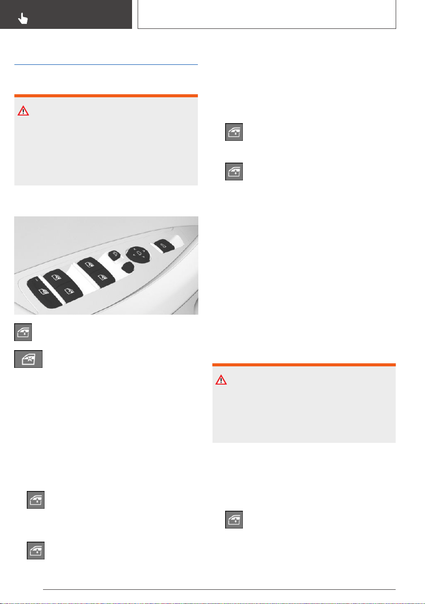
Power windows
Safety information
WARNING
When operating the windows, body parts and
objects can be jammed. There is a risk of injury
or risk of damage to property. Make sure that
the area of movement of the windows is clear
during opening and closing.
Overview
Power windows
Safety switch
Functional requirements
The windows can be operated under the follow‐
ing conditions.
▷ Standby state is established.
▷ Drive-ready state is established.
▷ The remote control is in the car's interior.
Opening
▷ Press the switch to the resistance
point.
The window opens while the switch is being
held.
▷ Press the switch beyond the resistance
point.
The window opens automatically. Pressing
the switch again stops the motion.
Convenient opening via the remote control, refer
to page 77.
Closing
▷ Pull the switch to the resistance point.
The window closes while the switch is
being held.
▷ Pull the switch beyond the resistance
point.
The window closes automatically if the door
is closed. Pulling again stops the motion.
Convenient closing via the remote control, refer
to page 78.
Closing via Comfort Access, refer to page 86.
Jam protection system
General information
If closing force exceeds a specific threshold as a
window closes, closing is interrupted.
The window opens slightly.
Safety information
WARNING
Accessories on the windows such as antennas
can impact jam protection. There is a risk of in‐
jury. Do not install accessories in the area of
movement of the windows.
Closing without the jam protection
system
In case of danger from the outside or if ice might
prevent normal closing, proceed as follows:
1. Pull the switch past the resistance point
and hold it there.
Seite 98
CONTROLS
Opening and closing
98
Online Edition for Part no. 01402896703 - X/18
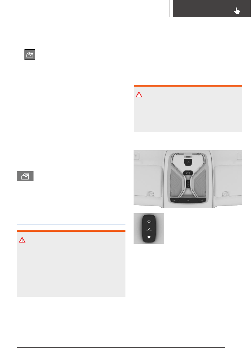
The window closes with limited jam protec‐
tion. If the closing force exceeds a specific
threshold, closing is interrupted.
2.
Pull the switch past the resistance point
again within approx. 4 seconds and hold it
there.
The window closes without jam protection.
Safety switch
Concept
The safety switch in the driver's door can be
used to prevent children, for instance from open‐
ing and closing the rear windows using the
switches in the rear.
If an accident of a certain severity occurs, the
safety function is switched off automatically.
Switching on/off
Press the button.
The LED lights up if the safety function
is switched on.
Roller sunblinds, rear side
windows
WARNING
With closed roller sunblinds and open windows,
the roller sunblinds may be strained while driv‐
ing due to the wind. The roller sunblinds may
be damaged and vehicle occupants may be
harmed. There is a risk of injury. Do not open
the windows while driving if the roller sunblinds
are closed.
Pull out the roller sunblind at the strap and hook
it onto the bracket.
Glass sunroof
General information
The glass sunroof and the sun protection are op‐
erated using the same switch.
Safety information
WARNING
Body parts can be jammed when operating the
glass sunroof. There is a risk of injury. Make
sure that the area of movement of the glass
sunroof is clear during opening and closing.
Overview
Opening/closing the glass sun‐
roof.
Functional requirements
The glass sunroof and the sun protection can be
operated under the following conditions.
▷ Standby state is established.
▷ Drive-ready state is established.
▷ The remote control is in the car's interior.
Seite 99
Opening and closing
CONTROLS
99
Online Edition for Part no. 01402896703 - X/18
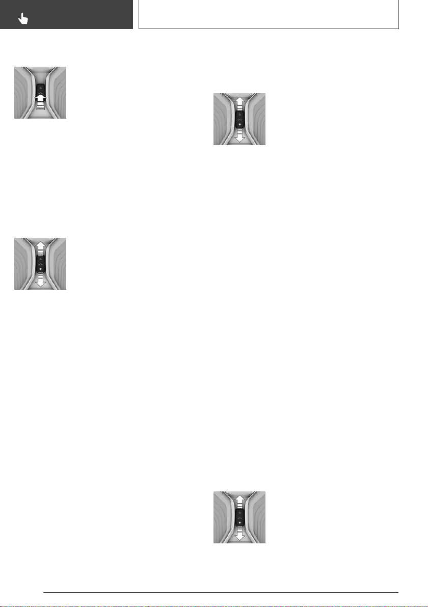
Lifting/closing glass sunroof
Push switch briefly upward.
▷ The closed glass sunroof tilts
and the sun protection opens
slightly.
▷ The opened glass sunroof
closes until it is in the tilted
position. The sun protection
does not move.
▷ The tilted glass sunroof closes.
Opening/closing the glass
sunroof and sun protection
separately
▷ Press the switch in the desired
direction to the resistance
point and hold it there.
Holding down the switch
opens the sun protection. If
the sun protection is already
fully open, the glass sunroof
opens.
The glass sunroof closes
while the switch is being held.
If the glass sunroof is already
closed or in the tilted position,
the sun protection closes.
▷ Press the switch in the desired direction past
the resistance point.
The sun protection opens automatically. If the
sun protection is already fully open, the glass
sunroof opens automatically.
The glass sunroof closes automatically. If the
glass sunroof is already closed or in the tilted
position, the sun protection closes automati‐
cally.
Pressing the switch upward stops the motion.
Opening/closing the glass
sunroof and sun protection
together
Briefly press the switch twice in
succession in the desired direc‐
tion past the resistance point.
The glass sunroof and sun pro‐
tection move together. Pressing
the switch upward stops the motion.
Convenient opening via the remote control, refer
to page 77.
Closing via Comfort Access, refer to page 86.
Comfort position
In some models, the wind noises in the car's in‐
terior are lowest when the glass sunroof is not
fully open. In these models, the automatic func‐
tion initially only opens the glass sunroof up to
this comfort position.
Pressing the switch again opens the glass sun‐
roof fully.
Jam protection system
General information
If the closing force exceeds a certain value when
closing the glass sunroof, the closing operation is
interrupted once the roof reaches the half-open
position, or it is stopped when closing from the
tilted position.
The glass sunroof opens slightly.
Closing from the open position
without jam protection
If there is an external danger, proceed as follows:
1.
Close all doors.
Seite 100
CONTROLS
Opening and closing
100
Online Edition for Part no. 01402896703 - X/18
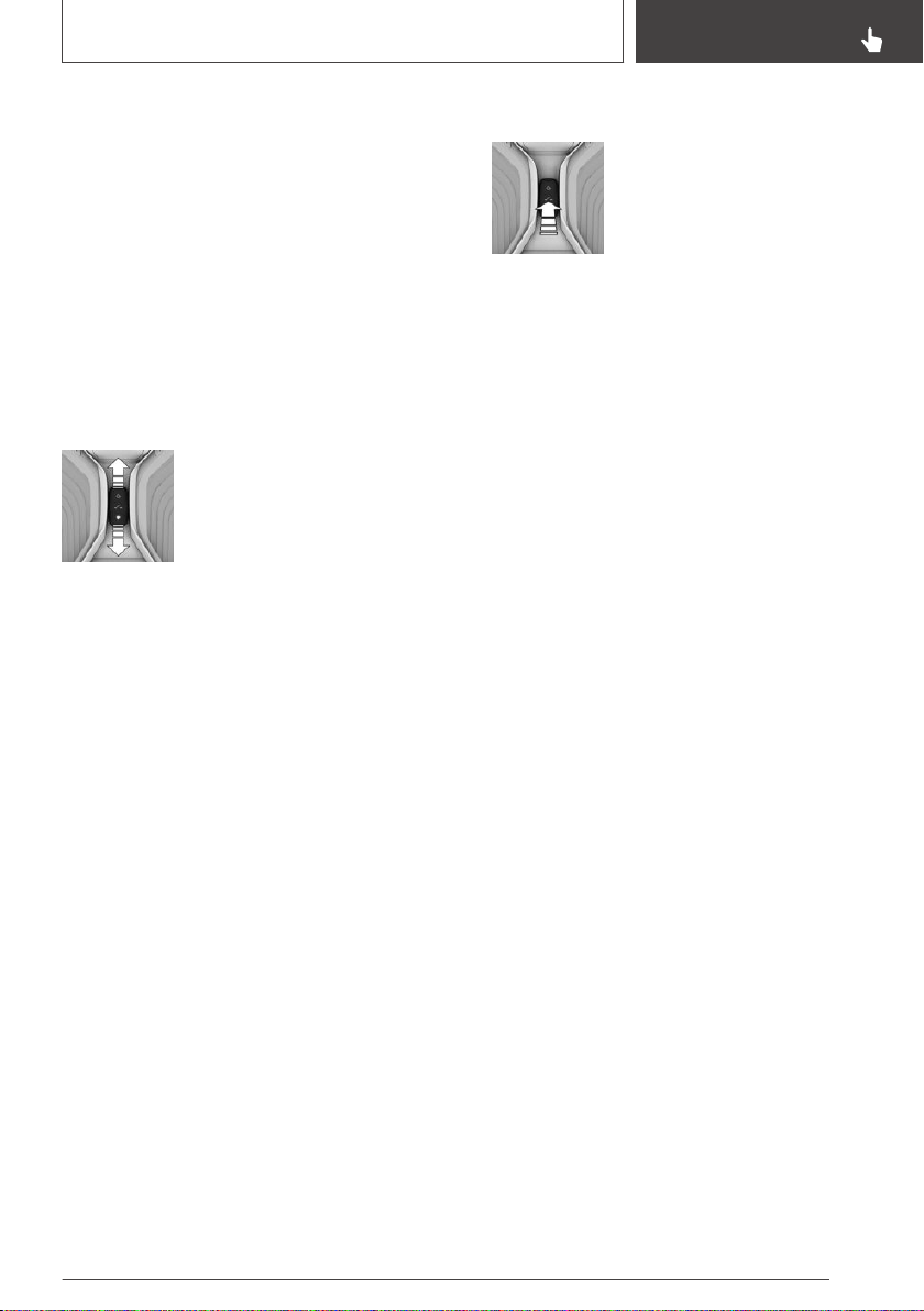
2. Push the switch forward past the resistance
point and hold.
The glass sunroof closes with limited jam
protection. If the closing force exceeds a spe‐
cific threshold, closing is interrupted.
3. Push the switch forward again past the resist‐
ance point and hold until the glass sunroof
closes without jam protection. Make sure that
the closing area is clear.
Closing from the raised position
without jam protection
If there is an external danger, proceed as follows:
1.
Close all doors.
2. Push the switch forward past the resistance
point and hold.
Initializing after a power
interruption
General information
After a power failure during the opening or clos‐
ing process, the glass sunroof can only be oper‐
ated to a limited extent.
The system can be initialized under the following
conditions.
▷ The vehicle is parked in a horizontal position.
▷ The drive-ready state is established.
▷ The external temperature is above
41 ℉/5 ℃.
During initialization, the glass sunroof closes
without jam protection.
Make sure that the closing area is clear.
Initializing the system
Press the switch up and hold it
until initialization is complete.
Initialization begins within 15 seconds.
▷ If the glass sunroof is closed, it opens then
closes again.
▷ If the glass sunroof is open, it first closes,
then opens and closes again.
Initialization is complete once the glass sunroof
and sun protection have opened then closed
again.
Seite 101
Opening and closing
CONTROLS
101
Online Edition for Part no. 01402896703 - X/18

Seats, mirrors, and steering wheel
Vehicle features and
options
This chapter describes all standard, country-spe‐
cific and optional features offered with the series.
It also describes features that are not necessarily
available in your vehicle, e. g., due to the selected
options or country versions. This also applies to
safety-related functions and systems. When us‐
ing these functions and systems, the applicable
laws and regulations must be observed.
Sitting safely
An ideal seating position that meets the needs of
the occupants can make a vital contribution to
relaxed, fatigue-free driving.
In the event of an accident, the correct seating
position plays an important role. Follow the infor‐
mation in the following chapters:
▷ Seats, refer to page 102.
▷ Safety belts, refer to page 104.
▷ Head restraints, refer to page 106.
▷ Airbags, refer to page 164.
Seats, front
Safety information
WARNING
Seat adjustments while driving can lead to un‐
expected movements of the seat. Vehicle con‐
trol could be lost. There is a risk of an accident.
Only adjust the seat on the driver's side when
the vehicle is stationary.
WARNING
With a backrest inclined too far to the rear, the
efficacy of the safety belt can no longer be en‐
sured. There is a risk of sliding under the safety
belt in an accident. There is a risk of injuries or
danger to life. Adjust the seat prior to starting
the trip. Adjust the backrest so that it is in the
most upright position as possible and do not
adjust again while driving.
WARNING
There is a risk of jamming when moving the
seats. There is a risk of injury or risk of damage
to property. Make sure that the area of move‐
ment of the seat is clear prior to any adjust‐
ment.
Electrically adjustable seats
General information
The seat adjustment for the driver's seat is
stored for the driver profile currently used. When
the vehicle is unlocked via the remote control,
the position is automatically retrieved if the func‐
tion, refer to page 95, is activated for this pur‐
pose.
The current seat position can be stored using
the memory function, refer to page 111.
Seite 102
CONTROLS
Seats, mirrors, and steering wheel
102
Online Edition for Part no. 01402896703 - X/18
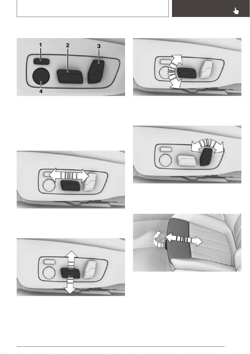
Overview
1 Backrest width
2 Forward/backward, height, seat tilt
3 Backrest tilt
4 Lumbar support
Forward/backward
Push switch forward or backward.
Height
Push switch up or down.
Seat tilt
Move switch up or down.
Backrest tilt
Move switch forward or backward.
Thigh support
Pull the lever at the front of the seat and push
the thigh support forward or back.
Lumbar support
Concept
The curvature of the seat backrest can be ad‐
justed in a way that it supports the lumbar region
Seite 103
Seats, mirrors, and steering wheel
CONTROLS
103
Online Edition for Part no. 01402896703 - X/18
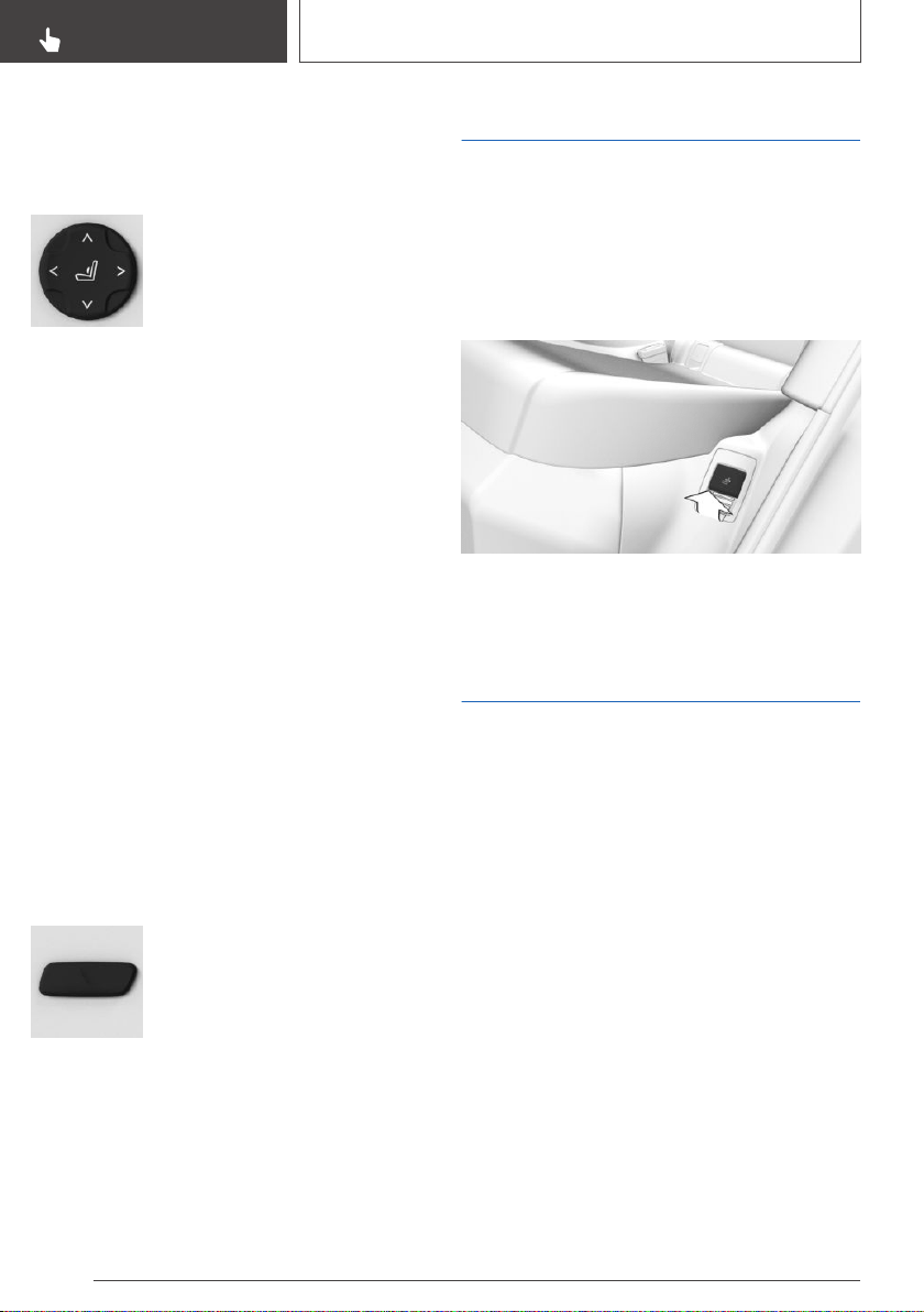
of the spine. The lower back and the spine are
supported for upright posture.
Settings
▷ Press the front/rear section of
the button:
The curvature is increased/
decreased.
▷ Press the upper/lower section
of the button:
The curvature is shifted up/
down.
Functional limitations
It may not be possible to adjust the lumbar sup‐
port at very high and very low temperatures.
Backrest width
Concept
Adjusting the backrest width may improve lateral
support when taking corners.
General information
You can change the backrest width by adjusting
the side wings of the backrest.
To make it easier to enter and exit the vehicle,
the backrest width temporarily opens fully.
Settings
▷ Press the front section of the
button:
The backrest width de‐
creases.
▷ Press the rear section of the
button:
The backrest width increases.
Functional limitations
It may not be possible to adjust the backrest
width at very high and very low temperatures.
Rear seats
General information
The backrest tilt can be adjusted for the rear
seats. The backrest tilt for the center section is
adjusted together with the left backrest.
Backrest tilt
Pull the lever and apply your weight to the back‐
rest or lift it off, as necessary.
Safety belts
Number of safety belts and
safety belt buckles
The vehicle is fitted with five safety belts to en‐
sure occupant safety. However, they can only of‐
fer protection when adjusted correctly.
The two outer safety belt buckles of the rear
seats are intended for the persons sitting on the
left and right.
The center safety belt buckle of the rear seats is
intended for the person sitting in the middle.
General information
Always make sure that safety belts are being
worn by the occupants before driving off. The
airbags supplement the safety belts as an addi‐
tional safety device. The airbags are not a substi‐
tute for safety belts.
Seite 104
CONTROLS
Seats, mirrors, and steering wheel
104
Online Edition for Part no. 01402896703 - X/18
The upper shoulder strap's anchorage point will
be correct for adult seat occupants of every build
if the seat is correctly adjusted.
Safety information
WARNING
Use of a safety belt to buckle more than one
person will potentially defeat the ability of the
safety belt to serve its protective function.
There is a risk of injuries or danger to life. Do
not allow more than one person to wear a sin‐
gle safety belt. Infants and children are not al‐
lowed on an occupant's lap, but must be trans‐
ported and secured in designated child
restraint systems.
WARNING
The efficacy of safety gear, including safety
belts, can be limited or lost when safety belts
are fastened incorrectly. An incorrectly fastened
safety belt can cause additional injuries, for in‐
stance in the event of an accident or during
braking and evasive maneuvers. There is a risk
of injuries or danger to life. Make sure that all
occupants are wearing safety belts correctly.
WARNING
The efficacy of safety gear, including safety
belts, may not be fully functional or fail in the
following situations:
▷ The safety belts or safety belt buckles are
damaged, soiled, or changed in any other
way.
▷ Belt tensioners or belt retractors were
modified.
Safety belts can be imperceptibly damaged in
the event of an accident. There is a risk of inju‐
ries or danger to life. Do not modify safety belts,
safety belt buckles, belt tensioners, belt retrac‐
tors or belt anchors and keep them clean. Have
the safety belts checked after an accident at
the dealer’s service center or another qualified
service center or repair shop.
Correct use of safety belts
▷ Wear the safety belt twist-free and tight to
your body over your lap and shoulders.
▷ Wear the safety belt deep on your hips over
your lap. The safety belt may not press on
your stomach.
▷ Do not rub the safety belt against sharp
edges, or guide it or jam it in across hard or
fragile objects.
▷ Avoid thick clothing.
▷ Re-tighten the safety belt frequently upward
around your upper body.
Buckling the safety belt
1.
Guide the safety belt slowly over shoulder
and hip to put it on.
2. Insert the tongue plate into the safety belt
buckle. The safety belt buckle must engage
audibly.
To ease accessibility to the safety belt buckle, an
adjustable slider is available on the belt to help
position the buckle when not in use.
When the safety belt is fastened, the driver's and
passenger's belt straps are automatically tight‐
ened once after driving away.
Unbuckling the safety belt
1.
Hold the safety belt firmly.
Seite 105
Seats, mirrors, and steering wheel
CONTROLS
105
Online Edition for Part no. 01402896703 - X/18
2. Press the red button in the safety belt buckle.
3. Guide the safety belt back into its roll-up
mechanism.
Safety belt reminder for driver's
seat and front passenger seat
Display in the instrument cluster
The indicator light lights up and a signal
sounds. Make sure that the safety belts
are positioned correctly. The safety belt
reminder can also be activated if objects are
placed on the front passenger seat.
Safety belt reminder for rear
seats
General information
The safety belt reminder is automatically acti‐
vated each time the engine starts.
The safety belt reminder is also activated when a
passenger unbuckles a rear seat safety belt dur‐
ing the trip.
Display in the instrument cluster
The indicator light in the instrument cluster illu‐
minates after the engine is started.
Symbol Description
Green: the safety belt is buckled on
the corresponding rear seat.
Red: the safety belt is not buckled on
the corresponding rear seat.
Safety mode
In critical situations, for instance during an emer‐
gency stop, the front safety belts tighten auto‐
matically.
If the situation passes without an accident occur‐
ring, the belt tension relaxes.
If the belt tension does not loosen automatically,
stop the vehicle and unbuckle the safety belt us‐
ing the red button in the safety belt buckle. Fas‐
ten the safety belt before continuing on your trip.
Front head restraints
Safety information
WARNING
A missing protective effect due to removed or
not correctly adjusted head restraints can
cause injuries in the head and neck area. There
is a risk of injury.
▷ Before driving, install the removed head
restraints on the occupied seats.
▷ Adjust the head restraint so its center sup‐
ports the back of the head at as close to
eye level as possible.
▷ Adjust the distance so that the head re‐
straint is as close as possible to the back
of the head. Adjust the distance via the
backrest tilt as needed.
WARNING
Body parts can be jammed when moving the
head restraint. There is a risk of injury. Make
sure that the area of movement is clear when
moving the head restraint.
WARNING
Objects on the head restraint reduce the pro‐
tective effect in the head and neck area. There
is a risk of injury.
▷ Do not use seat or head restraint covers.
▷ Do not hang objects, for instance clothes
hangers, directly on the head restraint.
Seite 106
CONTROLS
Seats, mirrors, and steering wheel
106
Online Edition for Part no. 01402896703 - X/18
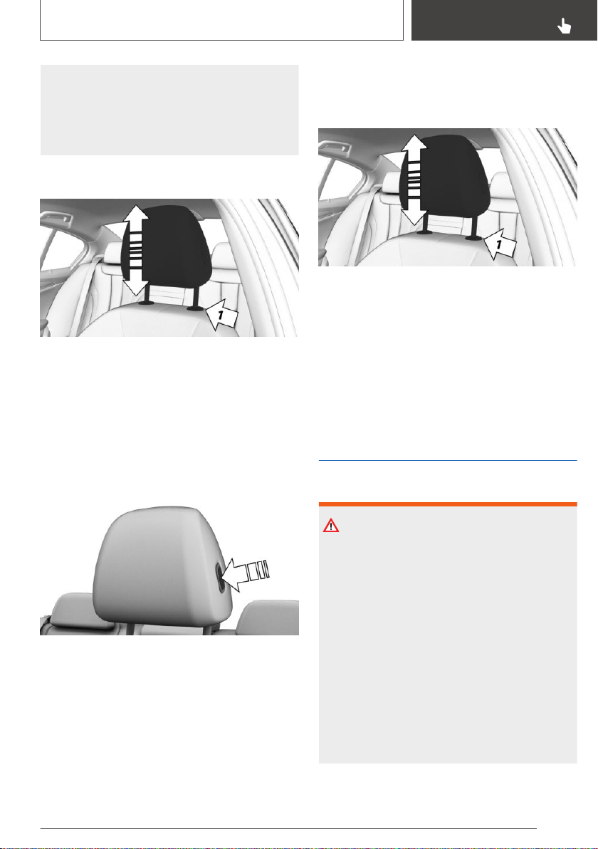
▷ Only use accessories that have been de‐
termined to be safe for attachment to a
head restraint.
▷ Do not use any accessories, for instance
pillows, while driving.
Adjusting the height
▷ To lower: press the button, arrow 1, and push
the head restraint down.
▷ To raise: push the head restraint up.
After setting the height, move the head restraint
up or down slightly, making sure it engages
properly.
Adjusting the distance
▷ Back: press the button and push the head re‐
straint toward the rear.
▷ Forward: pull the head restraint toward the
front.
After setting the distance, move the head re‐
straint forward or backward slightly, making sure
it engages properly.
Removing
Only remove the head restraint if no one will be
sitting in the seat in question.
1. Raise the head restraint up against the resist‐
ance.
2. Press the button, arrow 1, and pull the head
restraint out completely.
Installing
Proceed in the reverse order to install the head
restraint.
Rear head restraints
Safety information
WARNING
A missing protective effect due to removed or
not correctly adjusted head restraints can
cause injuries in the head and neck area. There
is a risk of injury.
▷ Before driving, install the removed head
restraints on the occupied seats.
▷ Adjust the head restraint so its center sup‐
ports the back of the head at as close to
eye level as possible.
▷ Adjust the distance so that the head re‐
straint is as close as possible to the back
of the head. Adjust the distance via the
backrest tilt as needed.
Seite 107
Seats, mirrors, and steering wheel
CONTROLS
107
Online Edition for Part no. 01402896703 - X/18
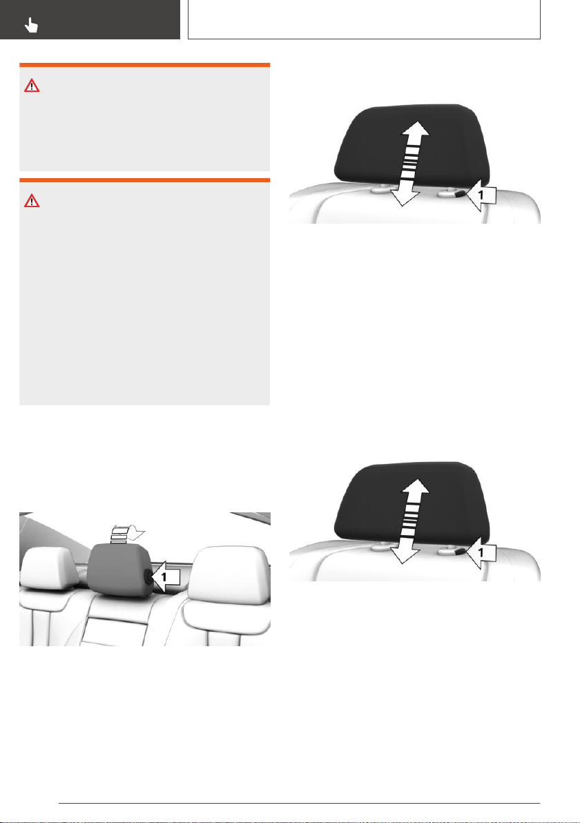
WARNING
Body parts can be jammed when moving the
head restraint. There is a risk of injury. Make
sure that the area of movement is clear when
moving the head restraint.
WARNING
Objects on the head restraint reduce the pro‐
tective effect in the head and neck area. There
is a risk of injury.
▷ Do not use seat or head restraint covers.
▷ Do not hang objects, for instance clothes
hangers, directly on the head restraint.
▷ Only use accessories that have been de‐
termined to be safe for attachment to a
head restraint.
▷ Do not use any accessories, for instance
pillows, while driving.
Folding down the head restraint
To improve the view to the rear, the head re‐
straints can be folded back. Only fold the head
restraint back if no one will be sitting in the corre‐
sponding seat.
▷ To the rear: press the button, arrow 1, and
fold the head restraint backward.
▷ Forward: fold the head restraint toward the
front as far as it will go. Make sure that the
head restraint engages correctly.
Adjusting the height
The height of the outer head restraints can be
adjusted.
▷ To lower: press the button, arrow 1, and push
the head restraint down.
▷ To raise: push the head restraint up.
After setting the height, move the head restraint
up or down slightly, making sure it engages
properly.
Removing
Only remove the head restraint if no one will be
sitting in the seat in question.
1.
Fold down the rear seat backrest, refer to
page 264, in question.
2. Raise the head restraint up against the resist‐
ance.
3. Press the button, arrow 1, and pull the head
restraint out completely.
Installing
Proceed in the reverse order to install the head
restraint.
Seite 108
CONTROLS
Seats, mirrors, and steering wheel
108
Online Edition for Part no. 01402896703 - X/18
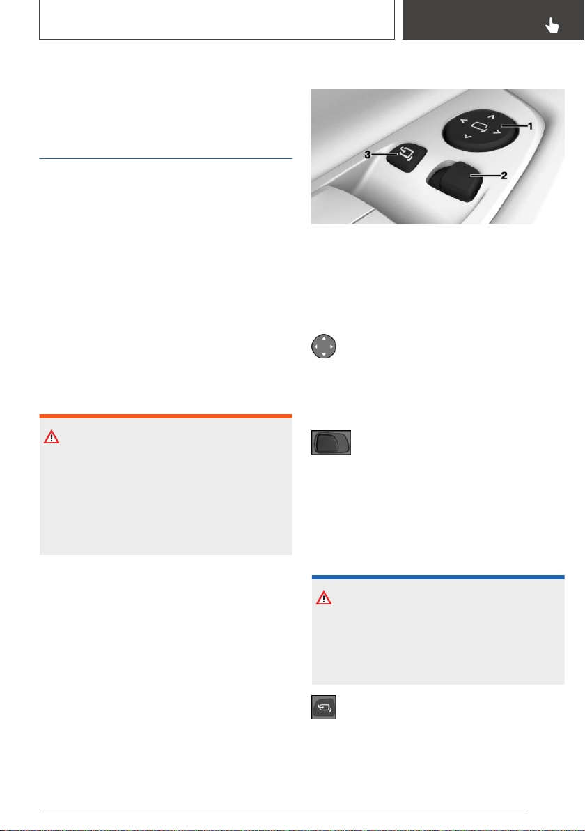
After mounting, slide the head restraint up or
down slightly, making sure the head restraint en‐
gages properly.
Mirrors
Exterior mirrors
General information
The mirror on the front passenger side is more
curved than the driver's side mirror.
The mirror setting is stored for the driver profile
currently in use. When the vehicle is unlocked via
the remote control, the position is automatically
retrieved if the function, refer to page 95, is acti‐
vated for this purpose.
The current exterior mirror position can be stored
using the memory function, refer to page 111.
Safety information
WARNING
Objects reflected in the mirror are closer than
they appear. The distance to the traffic behind
could be incorrectly estimated, for instance
while changing lanes. There is a risk of an acci‐
dent. Estimate the distance to the traffic behind
by looking over your shoulder.
Overview
1 Settings
2 Selecting a mirror, Automatic Curb Monitor
3 Folding in and out
Adjusting electrically
Press the button.
The selected mirror moves along with the
button movement.
Selecting a mirror
To change over to the other mirror:
Slide the switch.
Malfunction
In case of an electrical malfunction, adjust the
mirror by pressing the edges of the mirror glass.
Folding in and out
NOTICE
Depending on the vehicle width, the vehicle
can be damaged in vehicle washes. There is a
risk of damage to property. Before washing,
fold in the mirrors by hand or with the button.
Press the button.
Folding is only possible up to a speed of approx.
15 mph/20 km/h.
Seite 109
Seats, mirrors, and steering wheel
CONTROLS
109
Online Edition for Part no. 01402896703 - X/18
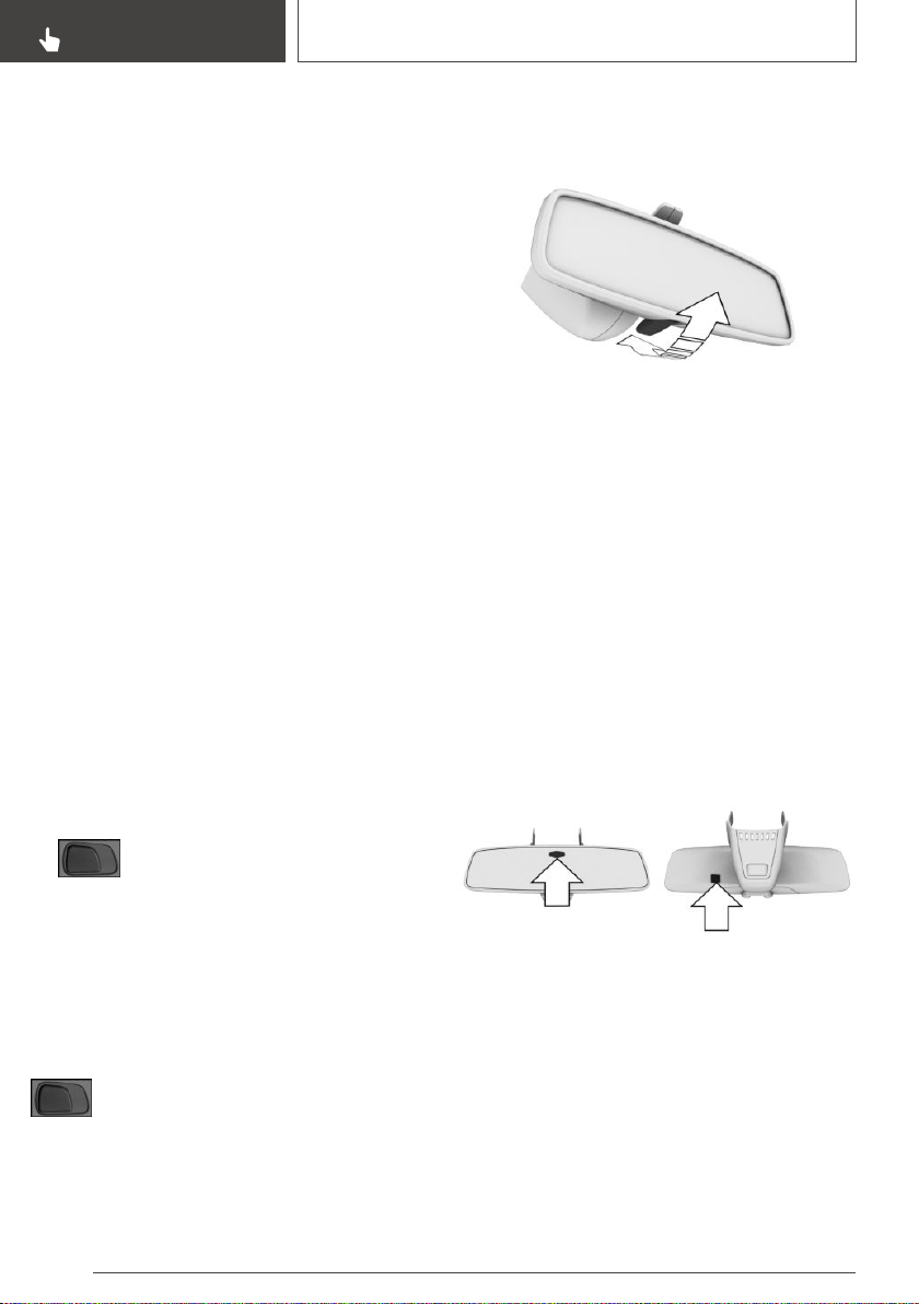
Folding the mirrors in and out is helpful in the fol‐
lowing situations:
▷ In vehicle washes.
▷ On narrow roads.
Mirrors that were folded in are folded out auto‐
matically at a speed of approx. 25 mph/40 km/h.
Automatic heating
Both exterior mirrors are automatically heated as
needed and when the drive-ready state is
switched on.
Automatic dimming feature
The exterior mirror on the driver's side is auto‐
matically dimmed. Photocells in the car's interior
mirror, refer to page 110, are used to control
this.
Automatic Curb Monitor, exterior
mirror
Concept
If reverse gear is engaged, the mirror glass on
the front passenger side is tilted downward. This
improves your view of the curb and other low-ly‐
ing obstacles when parking, for instance.
Activating
1. Slide the switch to the driver's side
mirror position.
2. Engage selector lever position R.
When the trailer socket is in use or trailer towing
is activated, the Automatic Curb Monitor is deac‐
tivated.
Deactivating
Slide the switch to the passenger's side
mirror position.
Interior mirror, manually
dimmable
To reduce the blinding effect of the interior mir‐
ror, flip the lever forward.
Interior mirror, automatic
dimming feature
General information
The interior mirror is dimmed automatically.
Photocells are used for control:
▷ In the mirror glass.
▷ On the back of the mirror.
Overview
Functional requirements
▷ Keep the photocells clean.
▷ Do not cover the area between the interior
mirror and the windshield.
Seite 110
CONTROLS
Seats, mirrors, and steering wheel
110
Online Edition for Part no. 01402896703 - X/18
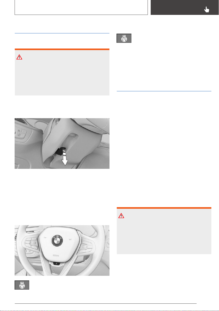
Steering wheel
Safety information
WARNING
Steering wheel adjustments while driving can
lead to unexpected steering wheel movements.
Vehicle control could be lost. There is a risk of
an accident. Adjust the steering wheel while
the vehicle is stationary only.
Manual steering wheel
adjustment
1.
Fold the lever down.
2. Move the steering wheel to the preferred
height and angle to suit your seating position.
3. Fold the lever back up.
Heated steering wheel
Overview
Heated steering wheel
Switching on/off
Press the button.
A Check Control message is displayed.
If the trip is resumed within approx. 15 minutes
after an intermediate stop, the heated steering
wheel activates automatically if the function was
switched on at the end of the last trip.
Memory function
Concept
The following settings can be stored and, if nec‐
essary, retrieved using the memory function:
▷ Seat position.
▷ Exterior mirror position.
▷ Height of the Head-up Display.
General information
Two memory locations with different settings
can be set for each driver profile, refer to
page 92.
The following settings are not stored:
▷ Backrest width.
▷ Lumbar support.
Safety information
WARNING
Using the memory function while driving can
lead to unexpected seat or steering wheel
movements. Vehicle control could be lost.
There is a risk of an accident. Only retrieve the
memory function when the vehicle is stationary.
Seite 111
Seats, mirrors, and steering wheel
CONTROLS
111
Online Edition for Part no. 01402896703 - X/18
WARNING
There is a risk of jamming when moving the
seats. There is a risk of injury or risk of damage
to property. Make sure that the area of move‐
ment of the seat is clear prior to any adjust‐
ment.
Overview
The memory buttons are located on the front
doors.
Storing
1.
Set the desired position.
2.
Press button. The writing on the but‐
ton lights up.
3. Press desired button 1 or 2 while the LED is
lit. A signal sounds.
Calling up settings
The stored position is called up automatically.
Press selected button 1 or 2.
The procedure stops when a switch for setting
the seat is pressed or one of the memory but‐
tons is pressed again.
While driving, the seat position adjustment on
the driver's side is interrupted after a short time.
Seat heating
Overview
Front
Seat heating
Rear
Seat heating
Switching on
Press the button once for each temper‐
ature level.
The maximum temperature is reached when
three LEDs are lit.
When ECO PRO is activated, refer to page 280,
the heater output is reduced.
Seite 112
CONTROLS
Seats, mirrors, and steering wheel
112
Online Edition for Part no. 01402896703 - X/18
Switching off
Press and hold the button until the bar
display on the climate control display
goes out.
Seat heating distribution
The heating action in the seat cushion and the
seat backrest can be distributed in different
ways.
Via iDrive:
1. "My Vehicle"
2. "Vehicle settings"
3. "Climate functions"
4. Select a menu item:
▷ "Seat heating"
▷ "Seat and steering wheel heating"
▷ "Seat climate control"
▷ "Seat climate / steer. wheel heating"
5. Select the desired seat, if needed.
6. Press the Controller and turn it to set the seat
heating distribution.
Active seat ventilation
Concept
Integrated fans in the seat and armrest areas
provide a comfortable seat temperature.
Overview
Active seat ventilation
Switching on
Press the button once for each ventila‐
tion level.
The highest level is active when three LEDs are
lit.
The ventilation switches back by one level after a
short time.
Switching off
Press and hold the button until the bar
display on the climate control display
goes out.
Individual activation
Concept
A number of heating and cooling functions can
be automatically activated depending on the ex‐
ternal temperature.
General information
The external temperature at which the functions
are to be automatically activated can be set via
iDrive.
Activation is performed if the external tempera‐
ture exceeds or falls below the set temperature
in the first 2 minutes after drive-ready state has
been switched on. A new alignment is carried out
after the settings have been changed.
Depending on the equipment package, the fol‐
lowing functions can be automatically activated:
▷ Seat heating.
▷ Heated steering wheel.
▷ Seat ventilation.
If the trip is continued within approx. 15 minutes
after a stop, the functions are activated automati‐
cally with the levels that were last selected.
Seite 113
Seats, mirrors, and steering wheel
CONTROLS
113
Online Edition for Part no. 01402896703 - X/18

Functional requirement
The safety belt of the corresponding seat is
buckled.
Activating/deactivating
Via iDrive:
1. "My Vehicle"
2. "Vehicle settings"
3. "Climate functions"
4. Select a menu item:
▷ "Steering wheel heating"
▷ "Seat heating"
▷ "Seat and steering wheel heating"
▷ "Seat climate control"
▷ "Seat climate / steer. wheel heating"
5. Select desired seat.
6. Select the menu item of the desired function.
7. Set the external temperature at which the
function is to be activated.
8. Set the desired level.
Seite 114
CONTROLS
Seats, mirrors, and steering wheel
114
Online Edition for Part no. 01402896703 - X/18

Transporting children safely
Vehicle features and
options
This chapter describes all standard, country-spe‐
cific and optional features offered with the series.
It also describes features that are not necessarily
available in your vehicle, e. g., due to the selected
options or country versions. This also applies to
safety-related functions and systems. When us‐
ing these functions and systems, the applicable
laws and regulations must be observed.
The right place for children
Safety information
WARNING
Unattended children or animals can cause the
vehicle to move and endanger themselves and
traffic, for instance due to the following actions:
▷ Pressing the Start/Stop button.
▷ Releasing the parking brake.
▷ Opening and closing the doors or win‐
dows.
▷ Engaging selector lever position N.
▷ Using vehicle equipment.
There is a risk of accidents or injuries. Do not
leave children or animals unattended in the ve‐
hicle. Take the remote control with you when
exiting and lock the vehicle.
Always transport children in the
rear seat
General information
Accident research shows that the safest place
for children is in the rear seat.
Transport children younger than 13 years of age
or shorter than 5 ft/150 cm only in the rear seat
in suitable child restraint systems designed for
the age, weight and size of the child. Children
13 years of age or older must wear a safety belt
as soon as a suitable child restraint system can
no longer be used due to their age, weight and
size.
Safety information
WARNING
The safety belt cannot be fastened correctly on
children shorter than 5 ft, 150 cm without suita‐
ble additional child restraint systems. The effi‐
cacy of safety gear, including safety belts, can
be limited or lost when safety belts are fas‐
tened incorrectly. An incorrectly fastened safety
belt can cause additional injuries, for instance in
the event of an accident or during braking and
evasive maneuvers. There is a risk of injuries or
danger to life. Secure children shorter than 5 ft,
150 cm using suitable child restraint systems.
Children on the front passenger
seat
General information
Before using a child restraint system on the front
passenger seat, ensure that the front, knee, and
side airbags on the front passenger side are de‐
activated. Automatic deactivation of front-seat
passenger airbags, refer to page 166.
Seite 115
Transporting children safely
CONTROLS
115
Online Edition for Part no. 01402896703 - X/18

Safety information
WARNING
Active front-seat passenger airbags can injure a
child in a child restraint system when the air‐
bags are activated. There is a risk of injury.
Make sure that the front-seat passenger air‐
bags are deactivated and that the PASSEN‐
GER AIRBAG OFF indicator light lights up.
Installing child restraint
systems
General information
Pay attention to the specifications and the oper‐
ating and safety information of the child restraint
system manufacturer when selecting, installing,
and using child restraint systems.
Safety information
WARNING
The protective effect of damaged child restraint
systems or of child restraint systems exposed
to an accident and their fastening systems can
be limited or lost. A child can e.g.,not suffi‐
ciently restrained, for instance in the event of
an accident or braking and evasive maneuvers.
There is a risk of injuries or danger to life. Have
damaged child restraint systems or of child re‐
straint systems exposed to an accident and
their fastening systems checked and possibly
replaced by the dealer’s service center or an‐
other qualified service center or repair shop.
WARNING
The stability of the child restraint system is lim‐
ited or compromised with incorrect seat adjust‐
ment or improper installation of the child seat.
There is a risk of injuries or danger to life. Make
sure that the child restraint system fits securely
against the backrest. If possible, adjust the
backrest tilt for all affected backrests and cor‐
rectly adjust the seats. Make sure that seats
and backrests are securely engaged or locked.
If possible, adjust the height of the head re‐
straints or remove them.
On the front passenger seat
Deactivating airbags
WARNING
Active front-seat passenger airbags can injure a
child in a child restraint system when the air‐
bags are activated. There is a risk of injury.
Make sure that the front-seat passenger air‐
bags are deactivated and that the PASSEN‐
GER AIRBAG OFF indicator light lights up.
After installing a child restraint system in the
front passenger seat, make sure that the front,
knee and side airbags on the front passenger
side are deactivated.
Deactivate the front-seat passenger airbags au‐
tomatically, refer to page 166.
Seat position and height
Before installing a child restraint system, move
the front passenger seat as far back as it will go
and, if possible, bring it up to medium height.
This seat position and height ensures the best
possible position for the belt and offers optimal
protection in the event of an accident.
If the upper anchor of the safety belt is located in
front of the belt guide of the child seat, move the
front passenger seat carefully forward until the
best possible belt guide position is reached.
Backrest width
Adjustable backrest width: before installing a
child restraint system in the front passenger seat,
open the backrest width completely. Do not
Seite 116
CONTROLS
Transporting children safely
116
Online Edition for Part no. 01402896703 - X/18
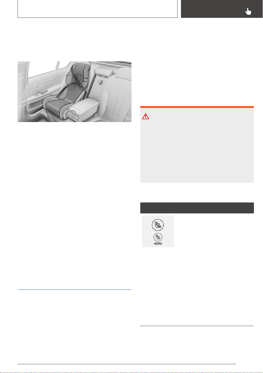
change the backrest width again and do not call
up a memory position.
Child seat security
The safety belts in the rear and the front passen‐
ger safety belt can be permanently locked to fas‐
ten child restraint systems.
Locking the safety belt
1.
Pull out the belt strap completely.
2. Secure the child restraint system with the
safety belt.
3. Allow the belt strap to be pulled in and pull it
tight against the child restraint system. The
safety belt is locked.
Unlocking the safety belt
1.
Unbuckle the safety belt buckle.
2. Remove the child restraint system.
3. Allow the belt strap to be pulled in com‐
pletely.
LATCH child restraint fixing
system
General information
LATCH: Lower Anchors and Tether for Children.
Pay attention to the specifications and the oper‐
ating and safety information of the LATCH child
restraint fixing system manufacturer when se‐
lecting, installing, and using child restraint sys‐
tems.
Mounts for the lower LATCH
anchors
General information
The lower anchors may be used to attach the
CRS to the vehicle seat up to a combined child
and CRS weight of 65 lbs/30 kg when the child is
restrained by the internal harnesses.
Safety information
WARNING
If the LATCH child restraint fixing systems are
not correctly engaged, the protective effect of
the LATCH child restraint fixing system can be
limited. There is a risk of injuries or danger to
life. Make sure that the lower anchors are se‐
curely engaged and that the LATCH child re‐
straint fixing system fits securely against the
backrest.
Position
Symbol Meaning
The corresponding symbol
shows the mounts for the lower
LATCH anchors.
Seats equipped with lower an‐
chors are marked with a pair, 2,
of LATCH symbols.
For vehicles equipped with a
middle seat:
It is not recommended to use
the inner lower anchors of
standard outer LATCH positions
to fasten a child restraint system
on the middle seat. Use the ve‐
hicle safety belt instead for the
middle seat.
Seite 117
Transporting children safely
CONTROLS
117
Online Edition for Part no. 01402896703 - X/18

Before installing LATCH child
restraint fixing systems
Pull the safety belt away from the area of the
child restraint system.
Assembly of LATCH child
restraint fixing systems
1. Install child restraint system, see manufactur‐
er's information.
2. Ensure that both LATCH anchors are prop‐
erly connected.
Child restraint systems with
tether strap
Safety information
WARNING
If the upper retaining strap is incorrectly used
for the child restraint system, the protective ef‐
fect can be reduced. There is a risk of injury.
Make sure that the upper retaining strap is not
guided across sharp edges and without twist‐
ing to the upper retaining strap.
WARNING
If the rear backrest is not locked, the protective
effect of the child restraint system is limited or
there is none. In particular situations, for in‐
stance braking maneuvers or in case of an acci‐
dent, the rear backrest can fold forward. There
is a risk of injuries or danger to life. Make sure
that the rear backrests are locked.
NOTICE
The anchors for the upper retaining straps of
child restraint systems are only provided for
these retaining straps. When other objects are
mounted, the anchors can be damaged. There
is a risk of damage to property. Only mount
child restraint systems to the upper retaining
straps.
Anchors
The respective symbol shows the
anchor for the upper retaining
strap. Seats with an upper top
tether are marked with this sym‐
bol. It can be found on the rear
seat backrest or the rear window shelf.
Routing the retaining strap
1 Direction of travel
2 Head restraint
3 Hook for upper retaining strap
4 Anchor
5 Seat backrest
6 Upper retaining strap
Attaching the upper retaining strap
to the anchor
1.
Raise the head restraint, if needed.
2. Guide the upper retaining strap between the
supports or along both sides of the head re‐
straint to the anchor.
3. If there is a retaining strap, run it between the
backrest and the cargo cover.
4. Attach the hook of the retaining strap to the
anchor.
5. Tighten the retaining strap by pulling it down.
6. Lower and lock head restraints as needed.
Seite 118
CONTROLS
Transporting children safely
118
Online Edition for Part no. 01402896703 - X/18
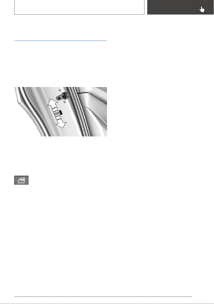
Locking the doors and
windows in the rear
General information
In certain situations it may be advisable to secure
the rear doors and windows, for instance when
transporting children.
Doors
Push the locking lever on the rear doors up.
The door can now be opened from the outside
only.
Safety switch for the rear
Press the button on the driver's door.
This locks various functions so that they cannot
be operated from the rear. Safety switch, refer to
page 99.
Seite 119
Transporting children safely
CONTROLS
119
Online Edition for Part no. 01402896703 - X/18
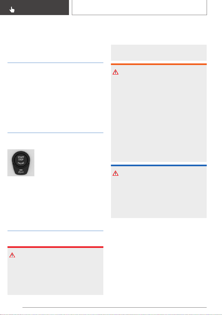
Driving
Vehicle features and
options
This chapter describes all standard, country-spe‐
cific and optional features offered with the series.
It also describes features that are not necessarily
available in your vehicle, e. g., due to the selected
options or country versions. This also applies to
safety-related functions and systems. When us‐
ing these functions and systems, the applicable
laws and regulations must be observed.
Start/Stop button
Concept
Pressing the Start/Stop button
switches drive-ready state on or
off, refer to page 41.
Steptronic transmission: the
drive-ready state is switched on
when you depress the brake pedal while press‐
ing the Start/Stop button.
Pressing the Start/Stop button again switches
drive-ready state back off and standby state, re‐
fer to page 41, is switched back on.
Drive-ready state
Safety information
DANGER
If the exhaust pipe is blocked or ventilation is in‐
sufficient, harmful exhaust gases can enter into
the vehicle. The exhaust gases contain pollu‐
tants which are colorless and odorless. In en‐
closed areas, exhaust gases can also accumu‐
late outside of the vehicle. There is danger to
life. Keep the exhaust pipe free and ensure suf‐
ficient ventilation.
WARNING
An unsecured vehicle can begin to move and
possibly roll away. There is a risk of an accident.
Before exiting, secure the vehicle against roll‐
ing.
In order to ensure that the vehicle is secured
against rolling away, follow the following:
▷ Set the parking brake.
▷ On uphill grades or on a downhill slope,
turn the front wheels in the direction of the
curb.
▷ On uphill grades or on a downhill slope,
also secure the vehicle, for instance with a
wheel chock.
NOTICE
In the case of repeated starting attempts or re‐
peated starting in quick succession, the fuel is
not burned or is inadequately burned. The cata‐
lytic converter can overheat. There is a risk of
damage to property. Avoid repeated starting in
quick succession.
Switching on drive-ready state
Steptronic transmission
1.
Depress the brake pedal.
2. Press the Start/Stop button.
The ignition is activated automatically for a brief
time and is stopped as soon as the engine starts.
Most of the indicator/warning lights in the instru‐
ment cluster light up for a varied length of time.
Seite 120
CONTROLS
Driving
120
Online Edition for Part no. 01402896703 - X/18

Diesel engine
If the engine is cold and temperatures are below
approx. 32 ℉/0 ℃, the start process may be de‐
layed somewhat due to automatic preheating.
A Check Control message with yellow in‐
dicator light is displayed.
Gasoline engine
Depending on the motorization, the full drive
power may not be available for approximately
30 seconds after starting the engine. In this case,
the vehicle will not accelerate as usual.
Display in the instrument cluster
When drive-ready state is switched on, the tach‐
ometer shows the current engine speed.
Switching off drive-ready state
Steptronic transmission
1.
Engage selector lever position P with the ve‐
hicle stopped.
2. Press the Start/Stop button.
The engine is switched off.
3. Set the parking brake.
Auto Start/Stop function
Concept
The Auto Start/Stop function helps save fuel.
The system switches off the engine during a
stop, for instance in traffic congestion or at traffic
lights. Drive-ready state remains switched on.
The engine starts automatically for driving off.
General information
After each engine start using the Start/Stop but‐
ton, the Auto Start/Stop function is ready. The
function is activated from speeds of approx.
3 mph/5 km/h.
Depending on the selected driving mode, refer to
page 137, the system is automatically activated
or deactivated.
Engine stop
Functional requirements
Steptronic transmission
The engine is switched off automatically during a
stop under the following conditions:
▷ The selector lever is in selector lever position
D.
▷ The brake pedal remains pressed while the
vehicle is stationary or the vehicle is held by
Automatic Hold.
▷ The driver's safety belt is buckled or the driv‐
er's door is closed.
Steptronic transmission: manual
engine stop
If the engine was not switched off automatically
when the vehicle stopped, the engine can be
switched off manually:
▷ Press the brake pedal forcefully again from
the current pedal position.
▷ Engage selector lever position P.
If all functional preconditions are fulfilled, the en‐
gine switches off.
Air conditioner when the engine is
switched off
The air flow from the air conditioner is reduced
when the engine is switched off.
Displays in the instrument cluster
General information
The display in the tachometer in‐
dicates that the Auto Start/Stop
function is ready for an Automatic
engine start.
Seite 121
Driving
CONTROLS
121
Online Edition for Part no. 01402896703 - X/18

The display indicates that the
conditions for an automatic en‐
gine stop have not been met.
Total time with switched-off engine
ECO PRO, refer to page 280,
driving mode: depending on the
vehicle equipment, the total time
that the engine has been
switched off using the Auto Start/
Stop function is displayed on an automatic en‐
gine stop.
The total time is automatically reset every time
the vehicle is refueled.
Functional limitations
The engine is not switched off automatically in
the following situations:
▷ In case of a steep downhill grade.
▷ Brake not engaged strongly enough.
▷ The external temperature is high and auto‐
matic climate control is running.
▷ The car's interior has not yet been heated or
cooled to the required level.
▷ Where there is a risk of window condensation
when the automatic climate control is
switched on.
▷ Engine or other parts not at operating tem‐
perature.
▷ Engine cooling is required.
▷ The wheels are at a sharp angle or the steer‐
ing wheel is being turned.
▷ Vehicle battery is heavily discharged.
▷ At higher elevations.
▷ The hood is unlocked.
▷ HDC Hill Descent Control is activated.
▷ The parking assistant is activated.
▷ Stop-and-go traffic.
▷ Steptronic transmission: selector lever posi‐
tion in N or R.
▷ After driving in reverse.
▷ Use of fuel with high ethanol content.
Starting the engine
Functional requirements
Steptronic transmission
The engine starts automatically under the follow‐
ing preconditions:
▷ By releasing the brake pedal.
▷ When Automatic Hold is activated: press the
accelerator pedal.
Driving off
After the engine starts, accelerate as usual.
Safety mode
After the engine switches off automatically, it will
not start again automatically if any one of the fol‐
lowing conditions are met:
▷ The driver's safety belt is unbuckled and the
driver's door is open.
▷ The hood was unlocked.
Some indicator lights light up for a varied length
of time.
The engine can only be started via the Start/Stop
button.
System limits
Even if driving off was not intended, the deacti‐
vated engine starts up automatically in the fol‐
lowing situations:
▷ Excessive warming of the car's interior when
the air conditioning is switched on.
▷ Excessive cooling of the car's interior when
the heating is switched on.
Seite 122
CONTROLS
Driving
122
Online Edition for Part no. 01402896703 - X/18

▷ Where there is a risk of window condensation
when the automatic climate control is
switched on.
▷ The steering wheel is turned.
▷ Steptronic transmission:
Change from selector lever position D to N or
R.
▷ Steptronic transmission:
Change from selector lever position P to N,
D, or R.
▷ Vehicle battery is heavily discharged.
▷ Start of an oil level measurement.
Intelligent Auto Start/Stop
function
Depending on the vehicle equipment and coun‐
try-specific version, the vehicle features a variety
of sensors for assessing the traffic situation. The
Intelligent Auto Start/Stop function uses this in‐
formation to adapt to various traffic situations in a
proactive manner.
For instance, this applies to the following situa‐
tions:
▷ If a situation is detected in which the stopping
time is expected to be very short, the engine
is not switched off automatically. A message
appears on the Control Display, depending
on the situation.
▷ If a situation is detected in which the vehicle
needs to drive off immediately, the engine is
started automatically.
The function may be restricted if the navigation
data is invalid, outdated or not available, for ex‐
ample.
Activating/deactivating the
system manually
Concept
The engine is not automatically switched off.
The engine is started during an automatic engine
stop.
Using the button
Press the button.
Steptronic transmission: via
selector lever position
The Auto Start/Stop function is also deactivated
in selector lever position M/S.
Via the Driving Dynamics Control
The Auto Start/Stop function is also deactivated
in SPORT driving mode of the Driving Dynamics
Control.
Display
▷ LED comes on: auto Start/Stop function is
deactivated.
▷ LED goes out: auto Start/Stop function is ac‐
tivated.
Switching off the vehicle during an
automatic engine stop
General information
During an automatic engine stop, the vehicle can
be switched off permanently, for instance when
leaving it.
Steptronic transmission
1.
Press the Start/Stop button.
▷ Drive-ready state is switched off.
▷ Standby state is switched on.
Seite 123
Driving
CONTROLS
123
Online Edition for Part no. 01402896703 - X/18
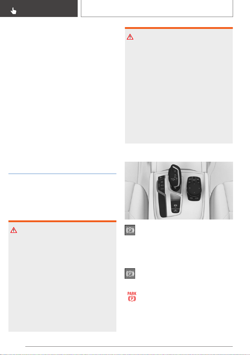
▷ Selector lever position P is engaged auto‐
matically.
2. Set the parking brake.
Automatic deactivation
General information
In certain situations, the Auto Start/Stop function
is deactivated automatically for safety reasons,
for instance if no driver is detected.
Malfunction
The Auto Start/Stop function no longer switches
off the engine automatically. A Check Control
message is displayed. It is possible to continue
driving. Have the system checked by a dealer’s
service center or another qualified service center
or repair shop.
Parking brake
Concept
The parking brake is used to prevent the vehicle
from rolling when it is parked.
Safety information
WARNING
An unsecured vehicle can begin to move and
possibly roll away. There is a risk of an accident.
Before exiting, secure the vehicle against roll‐
ing.
In order to ensure that the vehicle is secured
against rolling away, follow the following:
▷ Set the parking brake.
▷ On uphill grades or on a downhill slope,
turn the front wheels in the direction of the
curb.
▷ On uphill grades or on a downhill slope,
also secure the vehicle, for instance with a
wheel chock.
WARNING
Unattended children or animals can cause the
vehicle to move and endanger themselves and
traffic, for instance due to the following actions:
▷ Pressing the Start/Stop button.
▷ Releasing the parking brake.
▷ Opening and closing the doors or win‐
dows.
▷ Engaging selector lever position N.
▷ Using vehicle equipment.
There is a risk of accidents or injuries. Do not
leave children or animals unattended in the ve‐
hicle. Take the remote control with you when
exiting and lock the vehicle.
Overview
Parking brake
Setting
With a stationary vehicle
Pull the switch.
The LED lights up.
The indicator light in the instrument clus‐
ter illuminates red. The parking brake is
set.
While driving
To use as emergency brake while driving:
Seite 124
CONTROLS
Driving
124
Online Edition for Part no. 01402896703 - X/18
Pull the switch and hold it. The vehicle brakes
hard while the switch is being pulled.
The indicator light in the instrument clus‐
ter illuminates red, a signal sounds, and
the brake lights illuminate.
A Check Control message is displayed.
If the vehicle is slowed down to a speed of ap‐
prox. 2 mph/3 km/h the parking brake is set.
Releasing
Releasing manually
1.
Switch on drive-ready state.
2.
Steptronic transmission: press the
switch while the brake is pressed or selector
lever position P is set.
The LED and indicator light go out.
The parking brake is released.
Automatic release
The parking brake is released automatically
when you drive away.
The LED and indicator light go out.
Automatic Hold
Concept
This system assists the driver by automatically
setting and releasing the brake, such as when
moving in stop-and-go traffic.
The vehicle is automatically held in place when it
is stationary.
On uphill grades the system prevents the vehicle
from rolling backward when driving off.
General information
Under the following conditions, the parking brake
is automatically engaged:
▷ Drive-ready state is switched off.
▷ The driver's door is opened while the vehicle
is stationary.
▷ The moving vehicle is brought to a standstill
using the parking brake.
Display
The indicator light changes from green
to red.
Safety information
WARNING
An unsecured vehicle can begin to move and
possibly roll away. There is a risk of an accident.
Before exiting, secure the vehicle against roll‐
ing.
In order to ensure that the vehicle is secured
against rolling away, follow the following:
▷ Set the parking brake.
▷ On uphill grades or on a downhill slope,
turn the front wheels in the direction of the
curb.
▷ On uphill grades or on a downhill slope,
also secure the vehicle, for instance with a
wheel chock.
WARNING
Unattended children or animals can cause the
vehicle to move and endanger themselves and
traffic, for instance due to the following actions:
▷ Pressing the Start/Stop button.
▷ Releasing the parking brake.
▷ Opening and closing the doors or win‐
dows.
▷ Engaging selector lever position N.
▷ Using vehicle equipment.
Seite 125
Driving
CONTROLS
125
Online Edition for Part no. 01402896703 - X/18
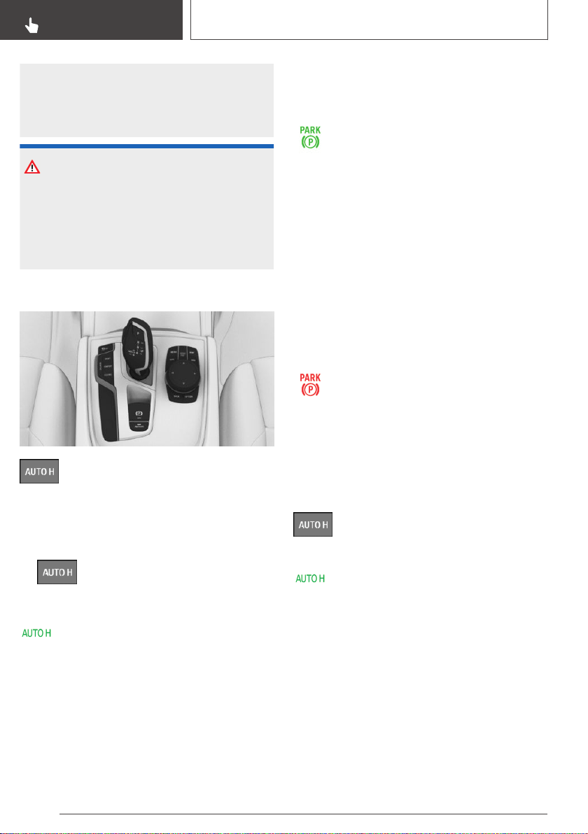
There is a risk of accidents or injuries. Do not
leave children or animals unattended in the ve‐
hicle. Take the remote control with you when
exiting and lock the vehicle.
NOTICE
If the vehicle is stationary, Automatic Hold en‐
gages the parking brake and prevents the vehi‐
cle from rolling in a vehicle wash. There is a risk
of damage to property. Deactivate Automatic
Hold prior to entering the vehicle wash.
Overview
Automatic Hold
Establishing function readiness of
Automatic Hold
1.
Switch on drive-ready state.
2.
Press button.
The LED lights up.
The indicator light lights up green.
Automatic Hold is functional.
After every new vehicle start, the last se‐
lected setting is active.
Automatic Hold holding the vehicle
Function readiness is established and the driv‐
er's door is closed.
After stepping on the brake pedal, for instance
when stopping at a traffic light, the vehicle is au‐
tomatically secured against rolling.
The indicator light lights up green.
Driving off
Step on the accelerator pedal to drive off.
The brake is released automatically and the indi‐
cator light is no longer illuminated.
Activating the parking brake
automatically
The parking brake is automatically set if drive-
ready state is switched off while the vehicle is
being held by Automatic Hold or if the vehicle is
exited.
The indicator light changes from green
to red.
The parking brake is not set automatically, if the
drive-ready state is switched off, while the vehi‐
cle is coasting to a halt. Automatic Hold is deacti‐
vated.
Switching function readiness off
Press the button.
The LED goes out.
The indicator light goes out.
Automatic Hold is switched off.
If the vehicle is being held by Automatic Hold,
press additionally on the brake pedal, when
switching off.
Malfunction
In the event of a failure or malfunction of the
parking brake:
Seite 126
CONTROLS
Driving
126
Online Edition for Part no. 01402896703 - X/18
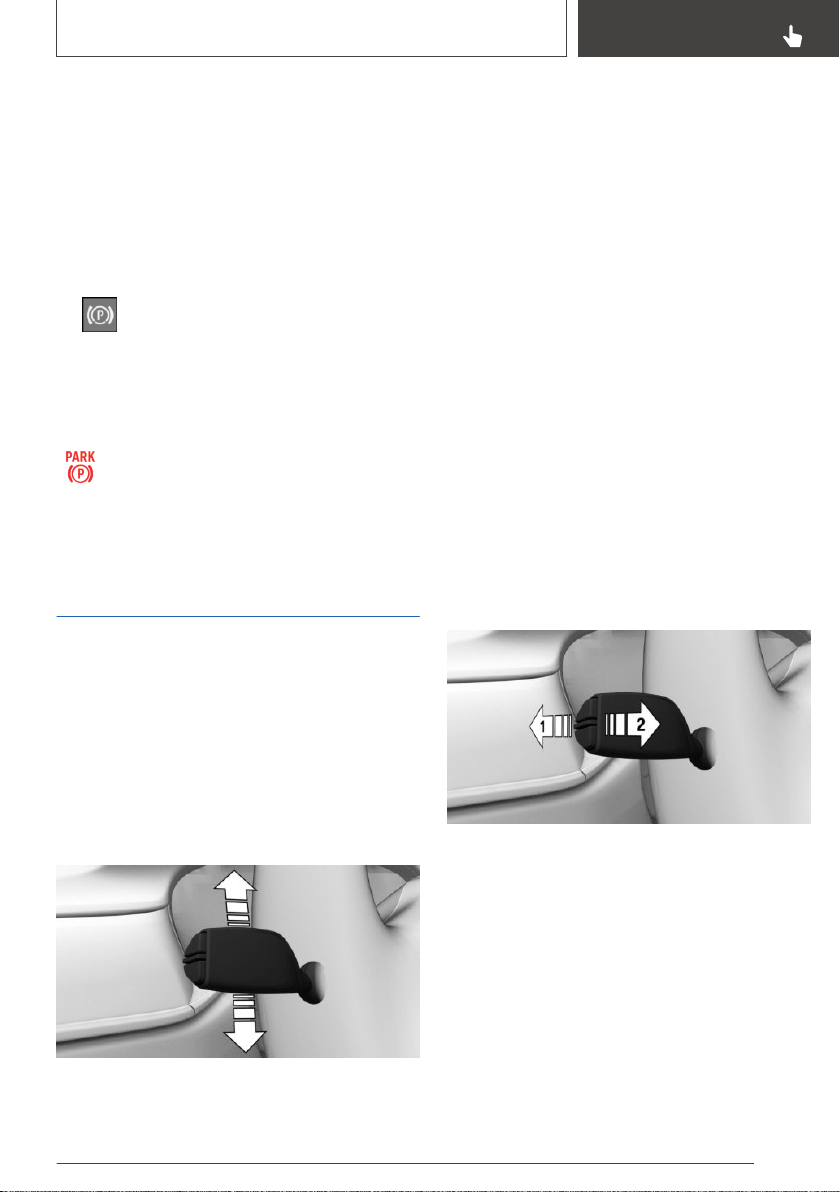
Secure the vehicle against rolling away, for in‐
stance with a wheel chock, after existing the ve‐
hicle.
After a power failure
To reestablish parking brake functionality after a
power failure:
1. Switch on standby state.
2.
Pull the switch while stepping on the
brake pedal or selector lever position P is set
and then push.
This process may take a few seconds. Any
sounds associated with this are normal.
The indicator light is no longer illumi‐
nated as soon as the parking brake is
ready for operation again.
Turn signal, high beams,
headlight flasher
Turn signal
Turn signal in exterior mirror
When driving and during operation of the turn
signals or hazard warning system, do not fold in
the exterior mirrors, so that the signal lights on
the exterior mirror are easy to see.
Using turn signals
Press the lever past the resistance point.
Triple turn signal activation
Lightly tap the lever up or down.
The triple turn signal duration can be adjusted.
Via iDrive:
1. "My Vehicle"
2. "Vehicle settings"
3. "Lighting"
4. "Exterior lighting"
5. "One-touch turn signal"
6. Select the desired setting.
The setting is stored for the driver profile cur‐
rently used.
Signaling briefly
Press the lever to the resistance point and hold it
there for as long as you want the turn signal to
flash.
High beams, headlight flasher
Push the lever forward or pull it backward.
▷ High beams on, arrow 1.
The high beams light up when the low beams
are switched on.
▷ High beams off/headlight flasher, arrow 2.
Seite 127
Driving
CONTROLS
127
Online Edition for Part no. 01402896703 - X/18
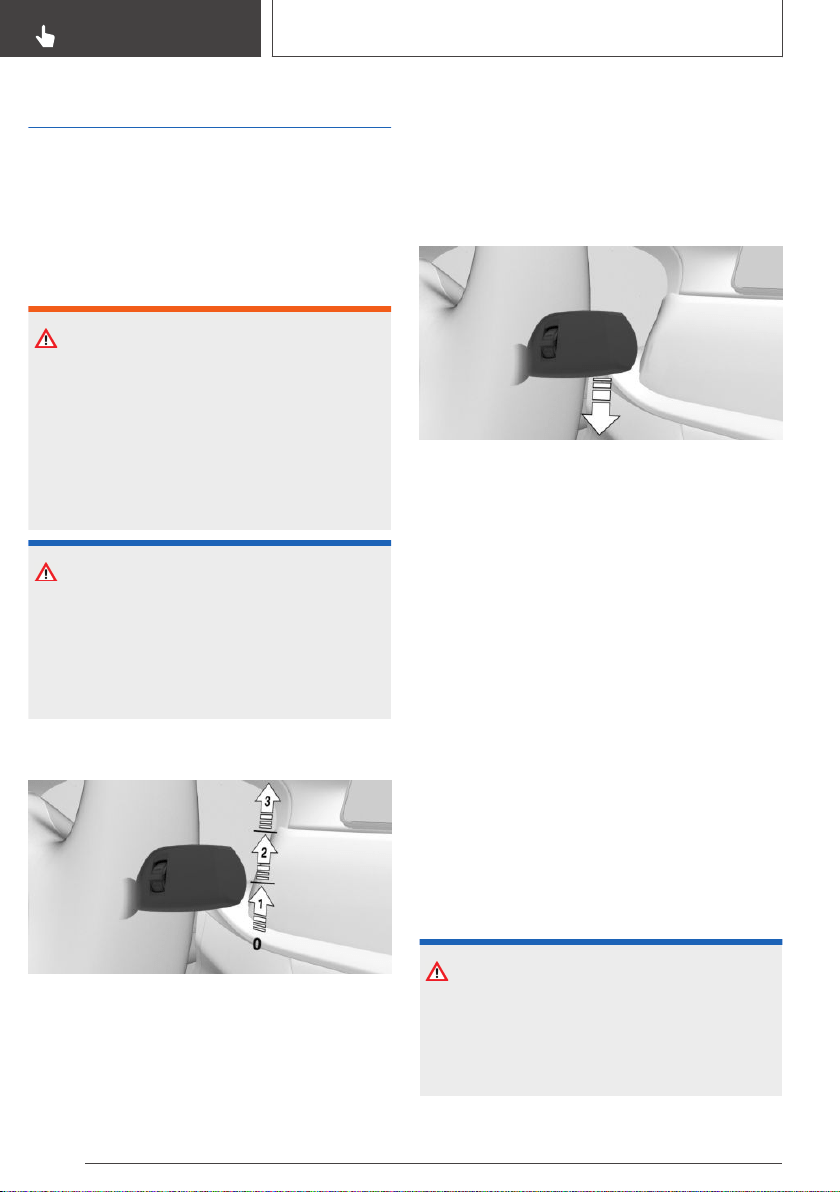
Washer/wiper system
General information
Do not use the wipers if the windshield is dry, as
this may damage the wiper blades or cause them
to become worn more quickly.
Safety information
WARNING
If the wipers start moving in the folded away
state, body parts can be jammed or damage
may occur to parts of the vehicle. There is a risk
of injury or risk of damage to property. Make
sure that the vehicle is switched off when the
wipers are in the folded away state and the wip‐
ers are folded in when switching on.
NOTICE
If the wipers are frozen to the windshield, the
wiper blades can be torn off and the wiper mo‐
tor can overheat when switching on. There is a
risk of damage to property. Defrost the wind‐
shield prior to switching the wipers on.
Switching on
Press the lever up until the desired position is
reached.
▷ Resting position of the wipers, position 0.
▷ Rain sensor, position 1.
▷ Normal wiper speed, position 2.
▷ Fast wiper speed, position 3.
When travel is interrupted with the wiper system
switched on: when travel continues, the wipers
resume at their previous speed.
Switching off and brief wipe
Press the lever down.
▷ Switching off: press the lever down until it
reaches its standard position.
▷ Brief wipe: press the lever down from the
standard position.
The lever automatically returns to its initial
position when released.
Rain sensor
Concept
The rain sensor automatically controls the time
between wipes depending on the intensity of the
rainfall.
General information
The sensor is located on the windshield, directly
in front of the interior mirror.
Safety information
NOTICE
If the rain sensor is activated, the wipers can
accidentally start moving in vehicle washes.
There is a risk of damage to property. Deacti‐
vate the rain sensor in vehicle washes.
Seite 128
CONTROLS
Driving
128
Online Edition for Part no. 01402896703 - X/18
Activating
Press the lever up once from its standard posi‐
tion, arrow 1.
Wiping is started.
The LED in the wiper lever is illuminated.
If wipers are frozen to windshield, wiper opera‐
tion is deactivated.
Deactivating
Press the lever back into the standard position.
Adjusting the rain sensor sensitivity
Turn the thumbwheel to adjust the sensitivity of
the rain sensor.
Upward: high rain sensor sensitivity.
Downward: low rains sensor sensitivity.
Windshield washer system
Safety information
WARNING
The washer fluid can freeze onto the window at
low temperatures and obstruct the view. There
is a risk of an accident. Only use the washer
systems, if the washer fluid cannot freeze. Use
washer fluid with antifreeze, if needed.
NOTICE
When the washer fluid reservoir is empty, the
wash pump cannot work as intended. There is
a risk of damage to property. Do not use the
washer system when the washer fluid reservoir
is empty.
Cleaning the windshield
Pull the lever.
The system sprays washer fluid on the wind‐
shield and activates the wipers briefly.
Windshield washer nozzles
The windshield washer nozzles are automatically
heated while standby state is switched on.
Seite 129
Driving
CONTROLS
129
Online Edition for Part no. 01402896703 - X/18
Rear window wiper
Overview
Switching on
Turn the outer switch upward.
▷ Resting position of the wiper, position 0.
▷ Intermittent mode, arrow 1. When reverse
gear is engaged, the system switches to con‐
tinuous operation.
Clean the rear window
Turn the outer switch in the desired direction.
▷ In resting position: turn the switch downward,
arrow 3. The switch automatically returns to
its idle position when released.
▷ In intermittent mode: turn the switch further,
arrow 2. The switch automatically returns to
its interval position when released.
Fold-away position of the wipers
Concept
The fold-out position enables the wipers to be
folded away from the windshield.
General information
Important, for instance when changing the wiper
blades or when folding out under frosty condi‐
tions.
Safety information
WARNING
If the wipers start moving in the folded away
state, body parts can be jammed or damage
may occur to parts of the vehicle. There is a risk
of injury or risk of damage to property. Make
sure that the vehicle is switched off when the
wipers are in the folded away state and the wip‐
ers are folded in when switching on.
NOTICE
If the wipers are frozen to the windshield, the
wiper blades can be torn off and the wiper mo‐
tor can overheat when switching on. There is a
risk of damage to property. Defrost the wind‐
shield prior to switching the wipers on.
Folding away the wipers
1.
Switch on standby state.
2. Press and hold the wiper level down, until the
wipers stop in a close to vertical position.
Seite 130
CONTROLS
Driving
130
Online Edition for Part no. 01402896703 - X/18
3. Fold the wipers all the way away from the
windshield.
Folding down the wipers
After the wipers are folded back down, the wiper
system must be reactivated.
1.
Fold the wipers back down onto the wind‐
shield.
2. Switch on standby state and press and hold
the wiper lever down again.
3. Wipers return to their resting position and are
ready again for operation.
Washer fluid
General information
All washer nozzles are supplied from one reser‐
voir.
Use a mixture of tap water and windshield
washer concentrate. If desired, a windshield
washer concentrate containing antifreeze can be
used.
Recommended minimum fill quantity:
0.2 US gal/1 liter.
Safety information
WARNING
Some antifreeze agents can contain harmful
substances and are flammable. There is a risk
of fire and a risk of injury. Follow the instruc‐
tions on the containers. Keep antifreeze away
from ignition sources. Do not refill operating
materials into different bottles. Store operating
materials out of reach of children.
United States: the washer fluid mixture ratio is
regulated by the U.S. EPA and many individual
states; do not exceed the allowable washer fluid
dilution ratio limits that apply. Follow the usage
instructions on the washer fluid container.
Use of BMW’s Windshield Washer Concentrate
or the equivalent is recommended.
WARNING
Washer fluid can ignite and catch fire on con‐
tact with hot engine parts. There is a risk of in‐
jury or risk of damage to property. Only add
washer fluid when the engine is cooled down.
Next, fully close the lid of the washer fluid res‐
ervoir.
NOTICE
Silicon-containing additives in the washer fluid
for the water-repelling effect on the windows
can lead to damage to the washing system.
There is a risk of damage to property. Do not
add silicon-containing additives to the washer
fluid.
NOTICE
Mixing different windshield washer concen‐
trates or antifreeze can damage the washing
system. There is a risk of damage to property.
Do not mix different windshield washer concen‐
trates or antifreeze. Follow the information and
mixing ratios provided on the containers.
Seite 131
Driving
CONTROLS
131
Online Edition for Part no. 01402896703 - X/18
Overview
The washer fluid reservoir is located in the en‐
gine compartment.
Malfunction
The use of undiluted windshield washer concen‐
trate or alcohol-based antifreeze can lead to in‐
correct readings at temperatures below
+5 ℉/-15 ℃.
Steptronic transmission
Concept
The Steptronic transmission combines the func‐
tions of an automatic transmission with the pos‐
sibility of manual shifting, if needed.
Safety information
WARNING
An unsecured vehicle can begin to move and
possibly roll away. There is a risk of an accident.
Before exiting, secure the vehicle against roll‐
ing.
In order to ensure that the vehicle is secured
against rolling away, follow the following:
▷ Set the parking brake.
▷ On uphill grades or on a downhill slope,
turn the front wheels in the direction of the
curb.
▷ On uphill grades or on a downhill slope,
also secure the vehicle, for instance with a
wheel chock.
Selector lever positions
Drive mode D
Selector lever position for normal vehicle opera‐
tion. All gears for forward travel are activated au‐
tomatically.
Reverse R
Engage selector lever position R only when the
vehicle is stationary.
Neutral N
The vehicle may be pushed or roll without power,
for instance in vehicle washes, refer to
page 133, in selector lever position N.
Parking position P
Selector lever position, for instance for parking
the vehicle. The transmission blocks the drive
wheels in selector lever position P.
Engage selector lever position P only when the
vehicle is stationary.
Selector lever position P is engaged automati‐
cally in situations such as the following:
▷ After the drive-ready state is switched off and
selector lever position R, D or M/S is en‐
gaged.
▷ If the driver's safety belt is unbuckled, the
driver's door is opened, and the brake pedal
is not pressed while the vehicle is stationary
and selector lever position D, M/S or R is en‐
gaged.
▷ After the standby state has been switched off
when selector lever position N is engaged.
Seite 132
CONTROLS
Driving
132
Online Edition for Part no. 01402896703 - X/18
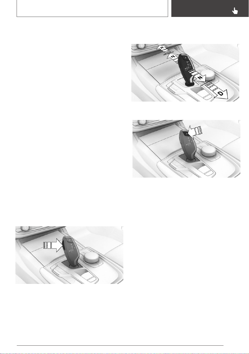
Engaging selector lever
positions
General information
To prevent the vehicle from creeping after you
select a drive mode, maintain pressure on the
brake pedal until you are ready to start.
Functional requirements
Only when the drive-ready state is switched on
and the brake pedal is depressed is it possible to
change from selector lever position P to another
selector lever position.
The selection lever position P cannot be
changed until all technical requirements are met.
Engaging selector lever position D,
N, R
A selector lever lock prevents the following faulty
operation:
▷ Unintentional shifting into selector lever posi‐
tion R.
▷ Unintentional shifting from selector lever po‐
sition P into another selector lever position.
1. Fasten driver's safety belt.
2. Press and hold the button to release the se‐
lector lever lock.
3. Push the selector lever in the desired direc‐
tion, past a resistance point, if needed. The
selector lever automatically returns to the
center position when released.
Engaging selector lever position P
Press button P.
Rolling or pushing the vehicle
General information
In some situations, the vehicle is to roll without
its own power for a short distance, for instance in
a vehicle wash, or be pushed.
Engaging selector lever position N
1.
Switch on drive-ready state while pressing on
the brake pedal.
2. If necessary, release the parking brake.
3. If necessary, switch off Automatic Hold, refer
to page 125.
4. Depress the brake pedal.
5. Touch the selector lever lock and engage se‐
lector lever position N.
6. Switch off drive-ready state.
Seite 133
Driving
CONTROLS
133
Online Edition for Part no. 01402896703 - X/18
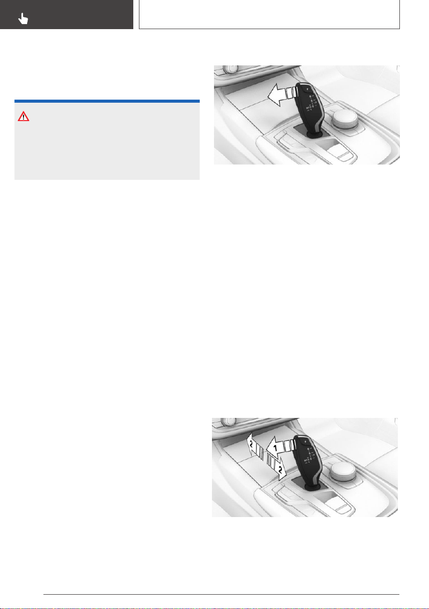
In this way, standby state remains switched
on, and a Check Control message is dis‐
played.
The vehicle may roll.
NOTICE
Selector lever position P is automatically en‐
gaged when standby state is switched off.
There is a risk of damage to property. Do not
switch standby state off in vehicle washes.
Irrespective of standby state, the selector lever
position P is automatically engaged after approx.
35 minutes.
If there is a malfunction, you may not be able to
change the selector lever position.
Electronically unlock the transmission lock, if
needed, refer to page 136.
Kickdown
Kickdown is used to achieve maximum driving
performance.
Step on the accelerator pedal beyond the resist‐
ance point at the full throttle position.
Sport program M/S
Concept
The shifting points and shifting times in the
Sport program are designed for a sportier driving
style. The transmission, for instance shifts up
later and the shifting times are shorter.
Activating the sport program
Press the selector lever to the left out of selector
lever position D.
The engaged gear is displayed in the instrument
cluster, for instance S1.
The sport program of the transmission is acti‐
vated.
Ending the Sport program
Push the selector lever to the right.
D is displayed in the instrument cluster.
Manual mode M/S
Concept
Manual gear-shifting is possible in manual mode.
Activating manual mode
1.
Press the selector lever to the left out of se‐
lector lever position D, arrow 1.
2. Push the selector lever forward or pull it
backward, arrows 2.
Manual mode becomes active and the gear is
changed.
Seite 134
CONTROLS
Driving
134
Online Edition for Part no. 01402896703 - X/18
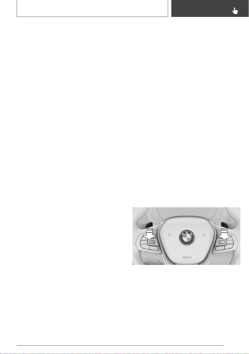
The engaged gear is displayed in the instrument
cluster, for instance M1.
Shifting
▷ To shift down: press the selector lever for‐
ward.
▷ To shift up: pull the selector lever rearwards.
The transmission continues shifting automati‐
cally in certain situations, for instance when
speed limits are reached.
Steptronic Sport transmission:
prevent automatic upshifting in M/S
manual mode
If driving mode SPORT, refer to page 138, is se‐
lected, the Steptronic Sport transmission does
not automatically upshift in M/S manual mode
once the maximum speed is reached.
Depending on the BMW M drive configuration,
this function is active independently of the driv‐
ing mode.
In addition, there is no downshifting for kick‐
down.
Ending the manual mode
Push the selector lever to the right.
D is displayed in the instrument cluster.
Shift paddles
Concept
The shift paddles on the steering wheel allow
you to shift gears quickly while keeping both
hands on the steering wheel.
General information
Shifting
The vehicle only shifts at suitable engine and
road speeds.
Short-term manual mode
In selector lever position D, actuating a shift pad‐
dle switches into manual mode temporarily.
After conservative driving in manual mode with‐
out acceleration or shifting via the shift paddles
for a certain amount of time, the transmission
switches back to automatic mode.
It is possible to switch into automatic mode as
follows:
▷ Pull and hold right shift paddle.
▷ In addition to the briefly pulled right shift pad‐
dle, briefly pull the left shift paddle.
Continuous manual mode
In selector lever position S, actuating a shift pad‐
dle switches into manual mode permanently.
Steptronic Sport transmission
With the appropriate transmission version, the
lowest possible gear can be selected by simulta‐
neously activating kickdown and operating the
left shift paddles. This is not possible in short-
term manual mode.
Shifting
▷ To shift up: briefly pull right shift paddle.
▷ To shift down: briefly pull left shift paddle.
▷ The lowest possible gear can be selected by
pulling and holding the left shift paddle.
The selected gear is briefly displayed in the in‐
strument cluster, followed by the current gear.
Seite 135
Driving
CONTROLS
135
Online Edition for Part no. 01402896703 - X/18
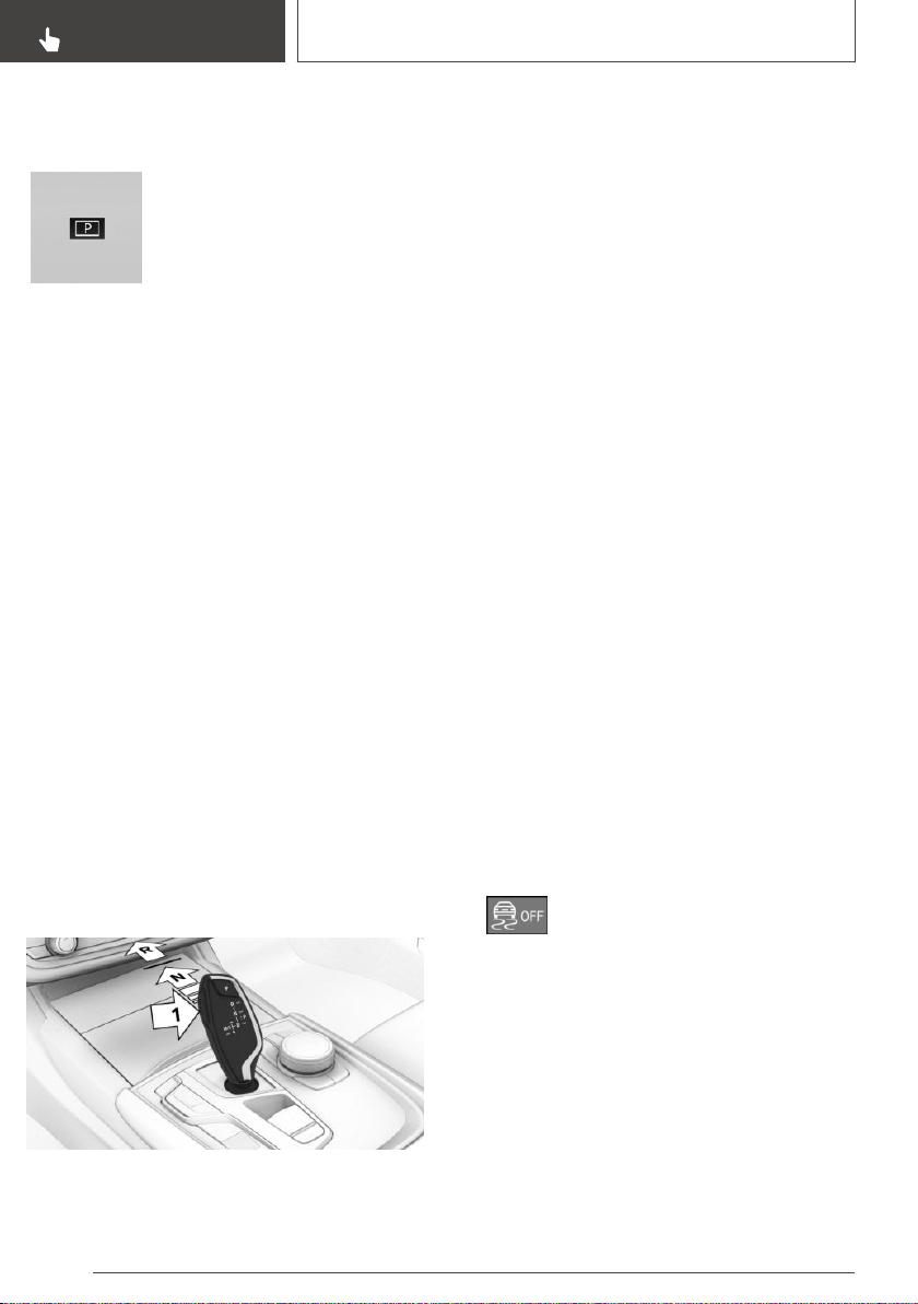
Displays in the instrument
cluster
The selector lever position is dis‐
played, for example P.
Electronic unlocking of the
transmission lock
General information
Electronically unlock the transmission lock to
maneuver vehicle from a danger area.
Unlocking is possible, if the starter can spin the
engine.
Before unlocking the transmission lock, set the
parking brake to prevent the vehicle from rolling
away.
Engaging selector lever position N
1.
Press and hold down brake pedal.
2. Press the Start/Stop button. The starter must
audibly start. Hold the Start/Stop button
pressed.
3. With your free hand, press the button on the
selector lever, arrow 1, and press the selector
lever into selector lever position N and hold,
arrow N, until selector lever position N is dis‐
played in the instrument cluster.
A Check Control message is displayed.
4. Release Start/Stop button and selector lever.
5. Release brake, as soon as the starter stops.
6. Maneuver the vehicle from the danger area
and secure it against moving on its own.
For additional information, see the chapter on
tow-starting and towing, refer to page 348.
Launch Control
Concept
Launch Control enables optimum acceleration
on surfaces with good traction under dry sur‐
rounding conditions.
General information
The use of Launch Control causes premature
component wear since this function represents a
very heavy load for the vehicle.
Do not use Launch Control during the break-in,
refer to page 270, period.
Do not steer the steering wheel when driving off
with Launch Control.
Functional requirements
Launch Control is available when the engine is at
operating temperature. The engine is at operat‐
ing temperature after an uninterrupted trip of at
least 6 miles/10 km.
Start with launch control
1.
Switch on drive-ready state.
2.
Press button.
TRACTION is displayed in the instrument
cluster and the indicator light for DSC OFF
lights up.
3. Engage selector lever position S.
4. With the left foot, forcefully press down on
the brake.
5. Press and hold down the accelerator pedal
beyond the resistance point at the full throttle
position, kickdown.
Seite 136
CONTROLS
Driving
136
Online Edition for Part no. 01402896703 - X/18
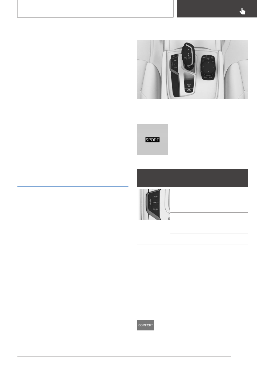
A flag symbol is displayed in the instrument
cluster.
6. The starting engine speed adjusts. Within
3 seconds, release the brake.
Repeated use during a trip
After Launch Control has been used, the trans‐
mission must cool down for approx. 5 minutes
before Launch Control can be used again.
Launch Control adjusts to the surrounding con‐
ditions, when used again.
After using Launch Control
To increase vehicle stability, activate DSC Dy‐
namic Stability Control again as soon as possible.
System limits
An experienced driver may be able to achieve
better acceleration values in DSC OFF mode.
Driving Dynamics Control
Concept
The Driving Dynamics Control influences the
driving dynamics properties of the vehicle. The
vehicle can be adjusted depending on the situa‐
tion using various driving modes.
General information
The following systems are affected, for instance:
▷ Engine characteristics.
▷ Steptronic transmission.
▷ Adaptive chassis.
▷ Steering.
▷ Adaptive M chassis.
▷ Display in the instrument cluster.
▷ Cruise control.
When drive-ready state is switched on, the
COMFORT driving mode is selected automati‐
cally.
Overview
Displays in the instrument
cluster
The selected driving mode is dis‐
played in the instrument cluster.
Driving modes
Button Driving
mode
Configuration
SPORT
SPORT
PLUS
INDIVIDUAL
COMFORT
ECO PRO INDIVIDUAL
ADAPTIVE
Driving modes in detail
COMFORT
Concept
Balanced tuning between dynamic and efficient
driving.
Switching on
Press the button repeatedly until COM‐
FORT is displayed in the instrument
cluster.
Seite 137
Driving
CONTROLS
137
Online Edition for Part no. 01402896703 - X/18

SPORT
Concept
Dynamic tuning for higher agility with an opti‐
mized chassis and suspension.
Switching on
Press the button repeatedly until
SPORT is displayed in the instrument
cluster.
SPORT INDIVIDUAL
Concept
Individual settings can be adjusted in the SPORT
INDIVIDUAL driving mode.
Configuration
Via iDrive:
1.
"My Vehicle"
2. "Vehicle settings"
3. If necessary, "Driving Experience Control"
4. "Configure SPORT INDIVIDUAL"
5. Select the desired setting.
The setting is stored for the driver profile cur‐
rently used.
Reset SPORT INDIVIDUAL to the standard set‐
tings:
"Reset to SPORT STANDARD".
SPORT PLUS
Concept
Dynamic tuning for maximum agility with an ad‐
justed drive.
Switching on
Press the button repeatedly until
SPORT PLUS is displayed in the instru‐
ment cluster.
ECO PRO
Concept
Efficient driving setting.
Switching on
Press the button repeatedly until ECO
PRO is displayed in the instrument clus‐
ter.
ECO PRO INDIVIDUAL
Concept
Individual settings can be adjusted in the ECO
PRO INDIVIDUAL driving mode.
Configuration
Via iDrive:
1.
"My Vehicle"
2. "Vehicle settings"
3. If necessary, "Driving Experience Control"
4. "Configure ECO PRO INDIVIDUAL"
5. Select the desired setting.
The setting is stored for the driver profile cur‐
rently used.
Reset ECO PRO INDIVIDUAL to the standard
settings:
"Reset to ECO PRO STANDARD".
ADAPTIVE
Concept
Comfort-oriented driving mode, whose tuning is
automatically modified to the driving situation
and driving style.
If the navigation system is active, upcoming road
sections are considered.
The function may be restricted if the navigation
data is invalid, outdated or not available, for ex‐
ample.
Seite 138
CONTROLS
Driving
138
Online Edition for Part no. 01402896703 - X/18

Switching on
Press the button. ADAPTIVE is dis‐
played in the instrument cluster.
INDIVIDUAL configuration
General information
The individual configuration of the driving mode
is stored for the active driver profile. The last set
configuration is activated directly when the driv‐
ing mode is called up again.
Activating configuration of the
driving mode
Press the button for the desired driving mode
several times.
Seite 139
Driving
CONTROLS
139
Online Edition for Part no. 01402896703 - X/18
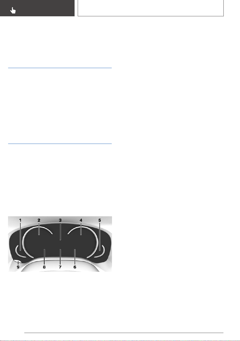
Displays
Vehicle features and
options
This chapter describes all standard, country-spe‐
cific and optional features offered with the series.
It also describes features that are not necessarily
available in your vehicle, e. g., due to the selected
options or country versions. This also applies to
safety-related functions and systems. When us‐
ing these functions and systems, the applicable
laws and regulations must be observed.
Instrument cluster
General information
Depending on the vehicle equipment, it may be
possible to deactivate the display change in the
instrument cluster via iDrive.
Some of the displays in the instrument cluster
may differ from the illustrations in this Owner's
Manual.
Overview
1 Fuel gage 145
Instrument cluster with enhanced features:
range 146
2 Speedometer
3 Time 146
External temperature 146
Variable displays
Service requirements 146
4 Instrument cluster with enhanced features:
tachometer 145
Instrument cluster with enhanced features:
ECO PRO displays 280
5 Engine temperature 145
6 Navigation display
Transmission display
Status, Driving Dynamics Control 137
7 Check Control 141
Onboard Computer 150
8 Variable displays
Speed Limit Info 148
Instrument cluster without enhanced fea‐
tures:
Range 146
9 Reset miles 151
Instrument cluster with
enhanced features: setting the
operating mode
Concept
Depending on the equipment, the instrument
cluster can be set to three different operating
modes in addition to the driving mode.
Settings
Via iDrive:
1.
"My Vehicle"
2. "iDrive settings"
3. "Displays"
4. "Instrument panel"
5. Select desired setting:
Seite 140
CONTROLS
Displays
140
Online Edition for Part no. 01402896703 - X/18

▷ "STANDARD": all displays on the instru‐
ment cluster are active.
▷ "REDUCED" all displays on the instru‐
ment cluster are reduced to the essential.
▷ "INDIVIDUAL": all displays on the instru‐
ment cluster are active. Individual displays
can be individually selected.
Configuring INDIVIDUAL
▷ "Driving mode display": when the driving
mode is switched into ECO PRO or SPORT,
the instrument cluster automatically switches
into the respective view.
▷ "Speed limit exceeded": if the speed recog‐
nized by Speed Limit Info is exceeded, the
exceeded range is marked red in the speed‐
ometer.
▷ Instrument cluster with enhanced features:
"Magnifier function": the current speed is
shown enlarged in the speedometer.
Instrument cluster without
enhanced features: selecting
displays in the instrument
cluster
Via iDrive:
1.
"My Vehicle"
2. "iDrive settings"
3. "Displays"
4. "Instrument panel"
5. Select desired setting:
▷ "Road signs": display Speed Limit Info.
Check Control
Concept
The Check Control system monitors functions in
the vehicle and notifies you of malfunctions in
the monitored systems.
General information
A Check Control message is displayed as a com‐
bination of indicator or warning lights and SMS
text messages in the instrument cluster and, if
applicable, in the Head-up Display.
In addition, an acoustic signal may sound and an
SMS text message may appear on the Control
Display.
Indicator/warning lights
Concept
Indicator/warning lights in the instrument cluster
display the status of some functions in the vehi‐
cle and indicate when a malfunction is present in
the monitored systems.
General information
The indicator/warning lights can light up in a vari‐
ety of combinations and colors.
Several of the lights are checked for proper func‐
tioning and light up temporarily when drive-ready
state is switched on.
Red lights
Safety belt reminder
Indicator light flashes or is illuminated:
safety belt on the driver or passenger
side is not buckled. The safety belt re‐
minder can also be activated if objects are placed
on the front passenger seat.
Make sure that the safety belts are positioned
correctly.
Safety belt reminder for rear seats
The safety belt is not buckled on the cor‐
responding rear seat.
Seite 141
Displays
CONTROLS
141
Online Edition for Part no. 01402896703 - X/18
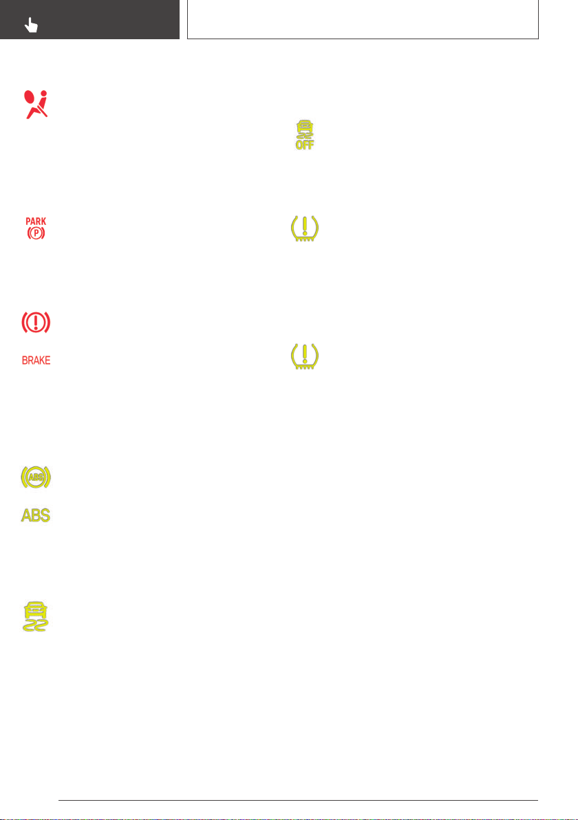
Airbag system
Airbag system and belt tensioner are not
working.
Have the vehicle checked immediately
by a dealer’s service center or another qualified
service center or repair shop.
Parking brake
The parking brake is set.
Release the parking brake, refer to
page 125.
Brake system
Braking system impaired. Continue to
drive moderately.
Have the vehicle checked immediately
by a dealer’s service center or another
qualified service center or repair shop.
Yellow lights
Anti-lock Braking System ABS
Braking force boost may not be working.
Avoid abrupt braking. Take the longer
braking distance into account.
Have the system immediately checked
by a dealer’s service center or another
qualified service center or repair shop.
DSC Dynamic Stability Control
The indicator light flashes: DSC controls
the drive and braking forces. The vehicle
is stabilized. Reduce speed and modify
your driving style to the driving circumstances.
The indicator light lights up: DSC has malfunc‐
tioned.
Have the system immediately checked by a deal‐
er’s service center or another qualified service
center or repair shop.
DSC, refer to page 192.
DSC Dynamic Stability Control is
deactivated or DTC Dynamic Traction
Control is activated
DSC is deactivated or DTC is activated.
DSC, refer to page 192, and DTC, refer
to page 194.
Flat Tire Monitor FTM
The Flat Tire Monitor signals a loss of
tire inflation pressure in a tire.
Reduce your speed and stop cautiously.
Avoid sudden braking and steering maneuvers.
Flat Tire Monitor, refer to page 317.
Tire Pressure Monitor TPM
The indicator light lights up: the Tire
Pressure Monitor reports a low tire infla‐
tion pressure or a flat tire. Follow the in‐
formation in the Check Control message.
The indicator light flashes and then continuously
lights up: no flat tire or loss of tire inflation pres‐
sure can be detected.
▷ Interference caused by systems or devices
with the same radio frequency: after leaving
the area of the interference, the system auto‐
matically becomes active again.
▷ In the case of tires with special approval:
TPM was unable to complete the reset. Re‐
set the system again.
▷ A wheel without TPM wheel electronics is
mounted: have it checked by a dealer’s serv‐
ice center or another qualified service center
or repair shop as needed.
▷ Malfunction: have the system checked by a
dealer’s service center or another qualified
service center or repair shop.
Tire Pressure Monitor, refer to page 310.
Seite 142
CONTROLS
Displays
142
Online Edition for Part no. 01402896703 - X/18
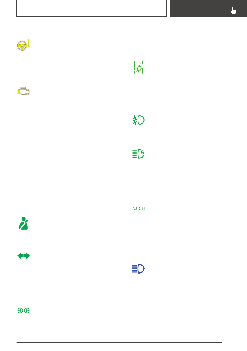
Steering system
Steering system may not be working.
Have the system checked by a dealer’s
service center or another qualified serv‐
ice center or repair shop.
Emissions
▷ The warning light lights up:
Emissions are deteriorating. Have the
vehicle checked as soon as possible.
▷ The warning light flashes under certain cir‐
cumstances:
This indicates that there is excessive misfiring
in the engine.
Reduce the vehicle speed and have the sys‐
tem checked immediately; otherwise, serious
engine misfiring within a brief period can seri‐
ously damage emission control components,
in particular the catalytic converter.
Socket for Onboard Diagnosis, refer to
page 335.
Green lights
Safety belt reminder for rear seats
The safety belt is buckled on the corre‐
sponding rear seat.
Turn signal
Turn signal switched on.
Unusually rapid flashing of the indicator
light indicates that a turn signal bulb has
failed.
Turn signal, refer to page 127.
Parking lights, headlight
Parking lights or headlights are switched
on.
Parking light/low beams, automatic headlight
control, refer to page 157.
Lane departure warning
The indicator light lights up: the system
is activated. At least one lane marking
was detected and warnings can be is‐
sued.
Lane departure warning, refer to page 178.
Front fog lights
Front fog lights are switched on.
Front fog lights, refer to page 161.
High-beam Assistant
High-beam Assistant is switched on.
High beams are switched on and off au‐
tomatically depending on the traffic sit‐
uation.
High-beam Assistant, refer to page 160.
Automatic Hold
Automatic Hold is activated. The vehicle
is automatically held in place when it is
stationary.
Automatic Hold, refer to page 125.
Blue lights
High beams
High beams are switched on.
High beams, refer to page 127.
Seite 143
Displays
CONTROLS
143
Online Edition for Part no. 01402896703 - X/18
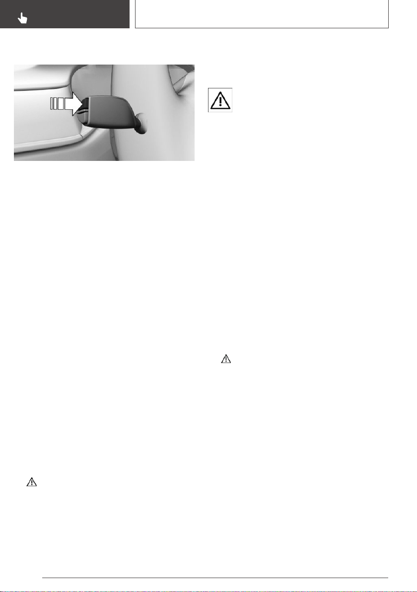
Hiding Check Control messages
Press and hold the button on the turn signal
lever.
Continuous display
Some Check Control messages are displayed
continuously and are not cleared until the mal‐
function is eliminated. If several malfunctions oc‐
cur at once, the messages are displayed consec‐
utively.
The messages can be hidden for approx. 8 sec‐
onds. After this time, they are displayed again
automatically.
Temporary display
Some Check Control messages are hidden auto‐
matically after approx. 20 seconds. The Check
Control messages are stored and can be dis‐
played again later.
Displaying stored Check Control
messages
Via iDrive:
1.
"My Vehicle"
2. "Vehicle status"
3. Move the Controller to the left.
4. "Check Control"
5. Select the SMS text message.
Display
Check Control
At least one Check Control message is
displayed or is stored.
SMS text messages
SMS text messages in combination with a sym‐
bol in the instrument cluster explain a Check
Control message and the meaning of the indica‐
tor/warning lights.
Supplementary SMS text messages
Additional information, such as the reason for an
error or malfunction or the required action, can
be called up via Check Control.
With urgent messages the added text will be au‐
tomatically displayed on the Control Display.
Depending on the Check Control message, fur‐
ther help can be selected.
Via iDrive:
1.
"My Vehicle"
2. "Vehicle status"
3. Move the Controller to the left.
4. "Check Control"
5. Select the desired text message.
6. Select desired setting:
▷ "Call BMW Accident Assistance"
Contact BMW Group Accident Assis‐
tance.
▷ "Service request"
Contact a dealer’s service center or an‐
other qualified service center or repair
shop.
▷ "BMW Roadside Assistance"
Contact Roadside Assistance.
▷ "Owner's Manual"
Seite 144
CONTROLS
Displays
144
Online Edition for Part no. 01402896703 - X/18
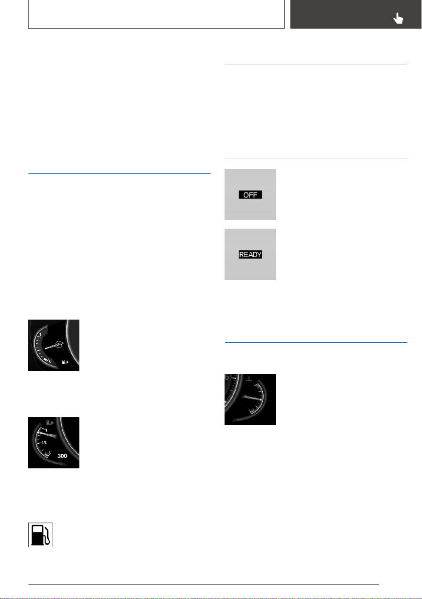
Display additional information about the
Check Control message in the Integrated
Owner's Manual.
Messages after trip completion
Special messages displayed while driving are
displayed again after drive-ready state is
switched off.
Fuel gage
Concept
The current fill level of the fuel tank is displayed.
General information
Vehicle tilt position may cause the display to
vary.
Information on refueling, refer to page 288.
Instrument cluster without
enhanced features: display
An arrow beside the fuel pump
symbol shows which side of the
vehicle the fuel filler flap is on.
Instrument cluster with
enhanced features: display
An arrow beside the fuel pump
symbol shows which side of the
vehicle the fuel filler flap is on.
The current range is displayed as
numerical value.
Indicator light In the instrument
cluster
The yellow indicator light illuminates,
once the fuel reserve is reached.
Tachometer
Always avoid engine speeds in the red warning
field. In this range, the fuel supply is reduced to
protect the engine.
Standby state and drive-
ready state
The letters OFF in the tachome‐
ter indicate that drive-ready state
is switched off and standby state
is switched on.
The letters READY in the tach‐
ometer indicate that the Auto
Start/Stop function is ready to
start the engine automatically.
For further information, see Idle state, standby
state, and drive-ready state, refer to page 41.
Engine temperature
Display
▷ Cold engine: the pointer is at
the low temperature end.
Drive at moderate engine and
vehicle speeds.
▷ Normal operating tempera‐
ture: the pointer is in the mid‐
dle or in the lower half of the
temperature display.
▷ Hot engine: the pointer is at the high end of
the temperature range. In addition, a Check
Control message is displayed.
Check the coolant level, refer to page 332.
Seite 145
Displays
CONTROLS
145
Online Edition for Part no. 01402896703 - X/18
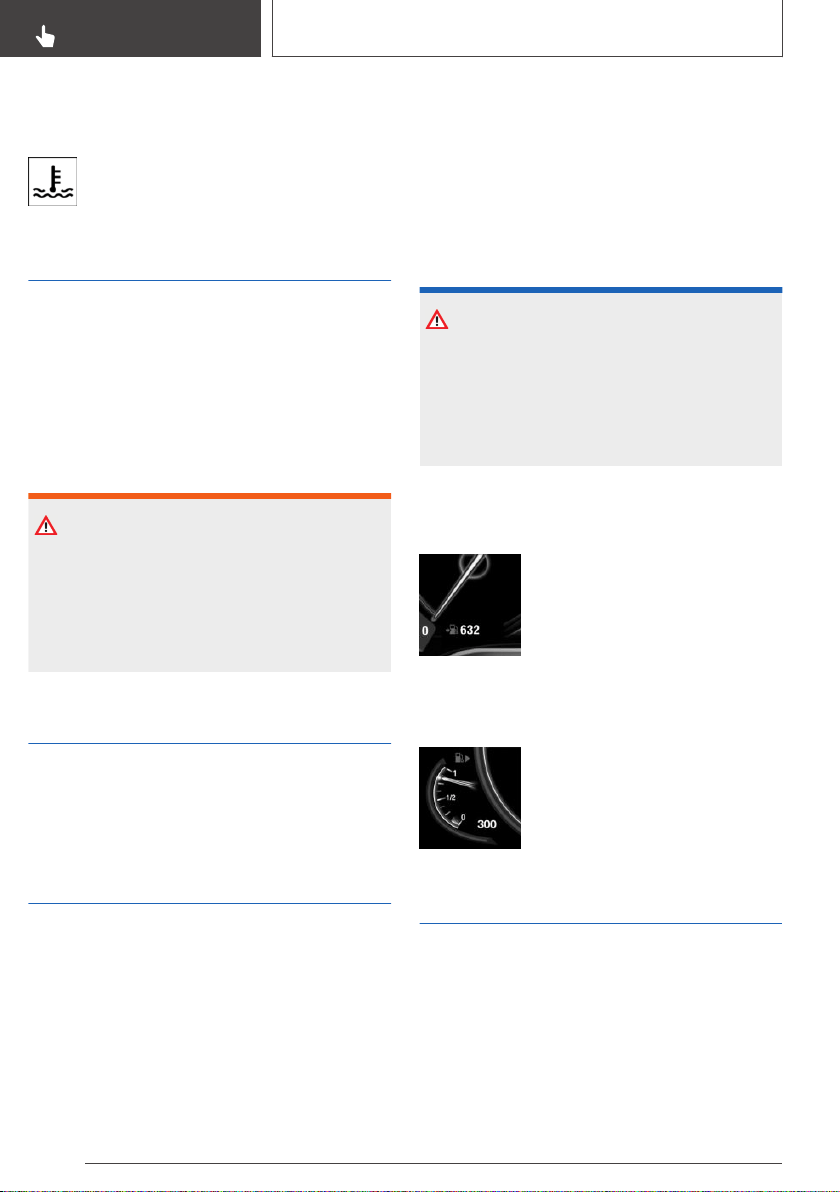
Indicator light In the instrument
cluster
A red indicator light is displayed.
External temperature
General information
If the indicator drops to +37 ℉/+3 ℃ or lower, a
signal sounds.
A Check Control message is displayed.
There is an increased risk of ice on roads.
Safety information
WARNING
Even at temperatures above +37 ℉/+3 ℃
there can be a risk of icy roads, for instance on
bridges or shady sections of road. There is a
risk of an accident. Modify your driving style to
the weather conditions at low temperatures.
Time
The time is displayed in the instrument cluster.
Setting the time and time format, refer to
page 59.
Range
Concept
The range indicates the distance that can still be
covered with the current fuel level.
General information
The estimated range available with the remaining
fuel is permanently displayed in the instrument
cluster.
With a low remaining range, a Check Control
message is briefly displayed. With a dynamic
driving style, for instance taking curves aggres‐
sively, the engine function is not always ensured.
The Check Control message appears continu‐
ously below a range of approx. 30 miles/50 km.
Safety information
NOTICE
With a driving range of less than
30 miles/50 km the engine may no longer have
sufficient fuel. Engine functions are not en‐
sured anymore. There is a risk of damage to
property. Refuel promptly.
Instrument cluster without
enhanced features: display
The current range is displayed as
numerical value at the bottom of
the speedometer.
Instrument cluster with
enhanced features: display
The current range is displayed as
numerical value next to the fuel
gage.
Service requirements
Concept
The function displays the service requirements
and the corresponding maintenance scopes.
General information
After switching on drive-ready state, the instru‐
ment cluster briefly displays available driving dis‐
Seite 146
CONTROLS
Displays
146
Online Edition for Part no. 01402896703 - X/18
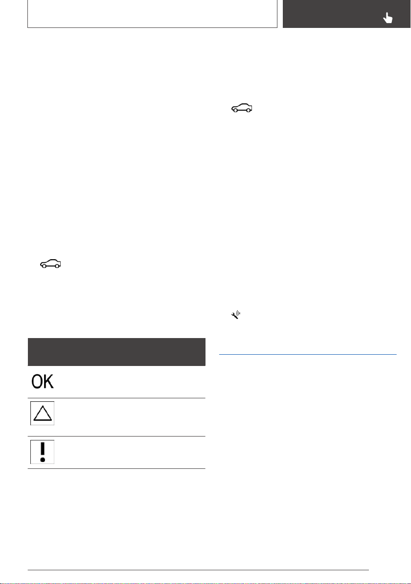
tance or time to the next scheduled mainte‐
nance.
A service advisor can read out the current serv‐
ice requirements from your remote control.
Some information on service requirements can
also be shown on the BMW display key.
Display
Detailed information on service
requirements
More information on the type of service required
may be displayed on the Control Display.
Via iDrive:
1.
"My Vehicle"
2. "Vehicle status"
3. Move the Controller to the left.
4. "Service required"
Required maintenance procedures and le‐
gally mandated inspections are displayed.
5. Select an entry to call up detailed information.
Symbols
Sym‐
bols
Description
No service is currently required.
The deadline for scheduled mainte‐
nance or a legally mandated inspec‐
tion is approaching.
The service deadline has already
passed.
Entering appointment dates
Enter the dates for the mandatory vehicle in‐
spections.
Make sure that the vehicle's date and time are
set correctly.
Via iDrive:
1. "My Vehicle"
2. "Vehicle status"
3. Move the Controller to the left.
4. "Service required"
5. "Vehicle inspection"
6. "Date:"
7. Select the desired setting.
Automatic Service Request
Data regarding the service status or legally man‐
dated vehicle inspections is automatically trans‐
mitted to your dealer’s service center before your
vehicle is due for service.
You can check when your dealer’s service center
was notified.
Via iDrive:
1.
"My Vehicle"
2. "Vehicle status"
3. Move the Controller to the left.
4. "Teleservice Call"
Gear shift indicator
Concept
The system recommends the most efficient gear
for the current driving situation.
General information
Depending on the vehicle equipment and coun‐
try version, the gear shift indicator is active in the
manual mode of the Steptronic transmission and
with manual transmission.
Steptronic transmission:
displaying
Suggestions to shift gear up or down are dis‐
played in the instrument cluster.
Seite 147
Displays
CONTROLS
147
Online Edition for Part no. 01402896703 - X/18
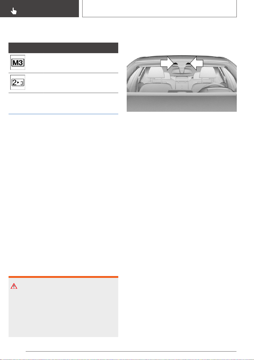
On vehicles without a gear shift indicator, the en‐
gaged gear is displayed.
Example Description
Efficient gear is set.
Shift into efficient gear.
Speed Limit Info
Speed Limit Info
Concept
Speed Limit Info shows the current valid maxi‐
mum speed in the instrument cluster.
General information
The camera in the area of the interior mirror de‐
tects traffic signs at the edge of the road as well
as variable overhead sign posts.
Traffic signs with extra symbols are considered
and compared with the vehicle's onboard data.
The traffic sign will then be either displayed or ig‐
nored depending on the situation in the instru‐
ment cluster and the Head-up Display.
The system takes into account the information
stored in the navigation system and also displays
speed limits present on routes without signs.
Speed limits when towing a trailer are not shown.
Safety information
WARNING
The system cannot serve as a substitute for the
driver’s personal judgment in assessing visibility
and traffic situation. There is a risk of an acci‐
dent. Adjust driving style to traffic conditions.
Watch traffic closely and actively intervene
where appropriate.
Overview
Camera
The camera is installed near the interior mirror.
Keep the windshield in front of the interior mirror
clean and clear.
Displaying Speed Limit Info
General information
Depending on the vehicle equipment, Speed
Limit Info is displayed via the operating mode of
the instrument cluster or via iDrive.
Display via operating mode of the
instrument cluster
The Speed Limit Info displays are shown or hid‐
den via the operating mode of the instrument
cluster.
The Speed Limit Info is displayed in the following
operating modes: "STANDARD" or
"INDIVIDUAL"
Speed Limit Info is not displayed in the following
operating mode: "REDUCED"
Adjusting the operating mode of the instrument
cluster, refer to page 140.
Display via iDrive
1.
"My Vehicle"
2. "iDrive settings"
3. "Displays"
Seite 148
CONTROLS
Displays
148
Online Edition for Part no. 01402896703 - X/18
4. "Instrument panel"
5. "Road signs"
Display
General information
Speed Limit Info is displayed in the instrument
cluster and, if applicable, in the Head-up Display.
Speed Limit Info
Current speed limit.
Speed Limit Info not available.
System limits
The system may not be fully functional and may
provide incorrect information in the following sit‐
uations:
▷ In heavy fog, wet conditions, or snowfall.
▷ When signs are fully or partially concealed by
objects, stickers or paint.
▷ When driving very close to the vehicle in front
of you.
▷ When driving toward bright lights or strong
reflections.
▷ When the windshield in front of the interior
mirror is fogged over, dirty or covered by a
sticker, etc.
▷ If the camera has overheated and been tem‐
porarily switched off due to excessively high
temperatures.
▷ In the event of incorrect detection by the
camera.
▷ If the speed limits or road data stored in the
navigation system are incorrect.
▷ If the speed limits vary with the time of day
and the day of the week.
▷ In areas not covered by the navigation sys‐
tem.
▷ When roads differ from the navigation, such
as due to changes in road routing.
▷ In case of electronic traffic signs.
▷ When passing buses or trucks with traffic
signs applied to them.
▷ If the traffic signs are non-conforming.
▷ When signs that are valid for a parallel road
are detected.
▷ In the presence of country-specific signs and
road configurations.
▷ During calibration of the camera immediately
after vehicle delivery.
Selection lists
General information
Depending on your vehicle's equipment, the fol‐
lowing can be displayed or operated using the
buttons and the thumbwheel on the steering
wheel as well as the displays in the instrument
cluster and the Head-up Display:
▷ Current audio source.
▷ Redial phone feature.
Seite 149
Displays
CONTROLS
149
Online Edition for Part no. 01402896703 - X/18
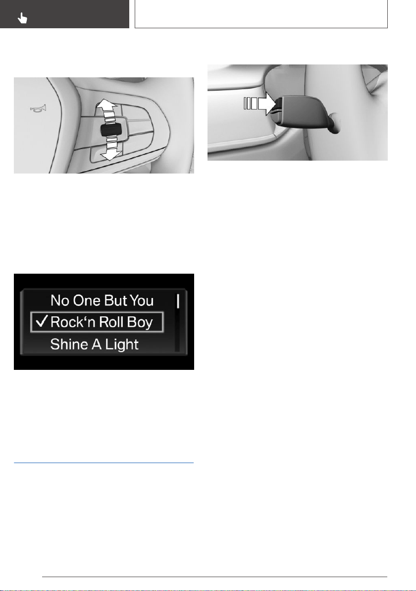
Activating a list and adjusting
the setting
On the right side of the steering wheel, turn the
thumbwheel to activate the corresponding list.
1.
Turn the thumbwheel and select the desired
setting.
2. Press the thumbwheel.
Display
Depending on the equipment version, the list in
the instrument cluster may differ from the illus‐
tration.
Onboard Computer in the
instrument cluster
Concept
The Onboard Computer displays different vehi‐
cle data in the instrument cluster, such as aver‐
age values.
Calling up information
Press and hold the button on the turn signal
lever.
Information is displayed in the instrument cluster.
Pressing the button repeatedly displays addi‐
tional information.
Information at a glance
The following information can be displayed on
the Onboard Computer:
▷ Miles and trip miles.
▷ Navigation data.
When destination guidance is activated in the
navigation system.
▷ Consumption display.
▷ Average consumption and average speed.
▷ Compass display for the driving direction.
Adjusting information for
Onboard Computer
For some information of the Onboard Computer,
it is possible to set whether it can be called up in
the instrument cluster.
Via iDrive:
1.
"My Vehicle"
2. "iDrive settings"
3. "Displays"
4. "Instrument panel"
5. "Onboard info"
6. Select the desired setting.
Seite 150
CONTROLS
Displays
150
Online Edition for Part no. 01402896703 - X/18
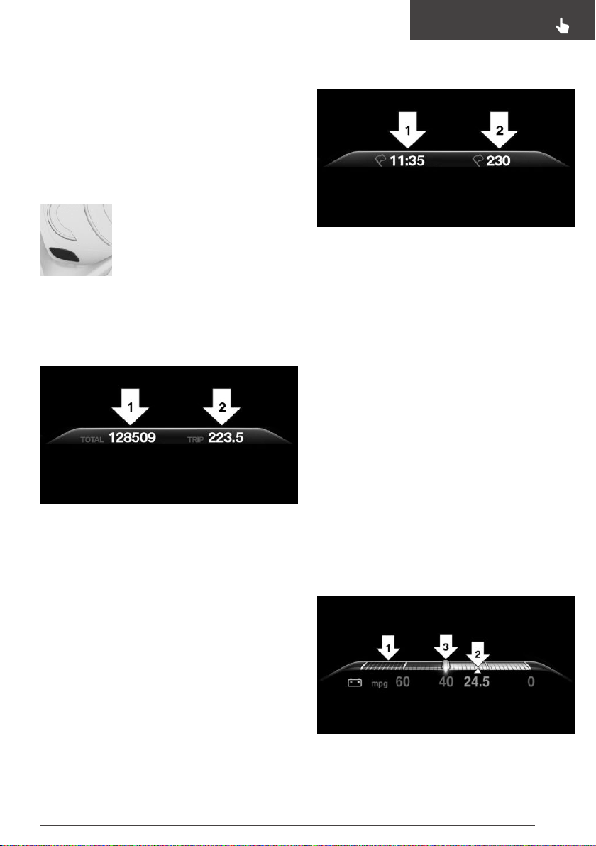
The setting is stored for the driver profile cur‐
rently used.
Information in detail
Odometer and trip odometer
Displaying/resetting miles
▷ Press the knob to display the
trip miles.
When the drive-ready state is
switched off, miles and trip
miles are displayed.
▷ Keep the knob pressed down to reset the trip
miles.
Display
▷ Odometer, arrow 1.
▷ Trip odometer, arrow 2.
Navigation data
General information
The estimated time of arrival and the distance re‐
maining to the destination are displayed if a des‐
tination is entered in the navigation system be‐
fore the trip is started.
Display
▷ Time of arrival, arrow 1.
▷ Distance to destination, arrow 2.
Consumption display
Concept
During energy recovery, the kinetic energy of the
vehicle is converted into electric energy during
coasting. The vehicle battery is partially charged
and fuel consumption can be reduced.
The current consumption displays the current
consumption of fuel. Check whether you are cur‐
rently driving in an efficient and environmentally-
friendly manner.
General information
Energy recovery and current consumption can
be displayed as bar displays in the Onboard
Computer.
Display
▷ Energy recovery, arrow 1.
▷ Average consumption, arrow 2.
Seite 151
Displays
CONTROLS
151
Online Edition for Part no. 01402896703 - X/18

▷ Current consumption, arrow 3.
Average speed and average
consumption
General information
Average speed and average consumption are
calculated for the distance traveled since the last
reset in the Onboard Computer.
Periods in which the vehicle is parked with the
engine manually stopped are not included in the
calculation of the average speed.
Resetting average values
Press and hold the button on the turn signal
lever.
Display
▷ Average speed, arrow 1.
▷ Average consumption, arrow 2.
Onboard Computer on the
Control Display
Concept
The Onboard Computer displays different vehi‐
cle data on the Control Display, such as average
values.
General information
Two types of Onboard Computers are available
on the Control Display:
▷ "Onboard info": average values, such as the
consumption, are displayed. The values can
be reset individually.
▷ "Trip computer": the values deliver an over‐
view of a certain distance and can be reset as
often as necessary.
Calling up the Onboard
Computer or trip computer
Via iDrive:
1.
"My Vehicle"
2. "Driving information"
3. "Onboard info" or "Trip computer"
Resetting the Onboard
Computer
Via iDrive:
1.
"My Vehicle"
2. "Driving information"
3. "Onboard info"
4. "Consumption" or "Speed"
5. "OK"
Resetting the trip computer
Via iDrive:
1.
"My Vehicle"
2. "Driving information"
Seite 152
CONTROLS
Displays
152
Online Edition for Part no. 01402896703 - X/18

3. "Trip computer"
4. Move the Controller to the left, if needed.
▷ "Reset": all values are reset.
▷ "Automatic reset": all values are reset
approx. 4 hours after the vehicle has
come to a standstill.
5. If necessary, "OK"
Sport displays
General information
Depending on the vehicle equipment, the current
values for performance and torque can be dis‐
played on the Control Display.
Displays
Via iDrive:
1.
"My Vehicle"
2. "Technology in action"
3. "Sport displays"
Speed warning
Concept
A speed limit can be set that when reached will
cause a warning to be issued.
General information
The warning is repeated if the vehicle speed ex‐
ceeds the set speed limit again, after it has drop‐
ped below it by 3 mph/5 km/h.
Configuring the speed limit
warning
Via iDrive:
1.
"My Vehicle"
2. "Vehicle settings"
3. "Speed warning"
4. "Warning at:"
5. Turn the Controller until the desired speed is
displayed.
6. Press the Controller.
Activating/deactivating the
speed warning
Via iDrive:
1. "My Vehicle"
2. "Vehicle settings"
3. "Speed warning"
4. "Speed warning"
Setting your current speed as
the speed warning
Via iDrive:
1.
"My Vehicle"
2. "Vehicle settings"
3. "Speed warning"
4. "Select current speed"
Vehicle status
General information
The status can be displayed and actions per‐
formed for several systems.
Opening the vehicle status
Via iDrive:
1.
"My Vehicle"
2. "Vehicle status"
Information at a glance
▷ "Flat Tire Monitor": Status of the Flat Tire
Monitor, refer to page 317.
▷ "Tire Pressure Monitor": Status of the
Tire Pressure Monitor, refer to page 310.
Seite 153
Displays
CONTROLS
153
Online Edition for Part no. 01402896703 - X/18
▷ "Engine oil level": Electronic engine oil
level check, refer to page 328.
▷ "Diesel exhaust fluid": BMW Advanced
Diesel, refer to page 292.
▷ "Check Control": Check Control mes‐
sages are stored in the background and can
be displayed on the Control Display. Display‐
ing stored Check Control messages, refer to
page 144.
▷ "Service required": Displaying service
requirements, refer to page 146.
▷ "Teleservice Call": service request.
Head-up Display
Concept
This system projects important information into
the driver's field of vision, for instance the speed.
The driver can get information without averting
his or her eyes from the road.
General information
Read the information for cleaning the Head-up
Display, refer to page 355.
Overview
Switching on/off
Via iDrive:
1.
"My Vehicle"
2. "iDrive settings"
3. "Displays"
4. "Head-Up Display"
5. "Head-Up Display"
Display
Overview
The following information is displayed on the
Head-up Display:
▷ Speed.
▷ Navigation instructions.
▷ Check Control messages.
▷ Selection list in the instrument cluster.
▷ Driver assistance systems.
Some of this information is only displayed briefly
as needed.
Selecting the view
Various views are available for the Head-up Dis‐
play.
Via iDrive:
1.
"My Vehicle"
2. "iDrive settings"
3. "Displays"
4. "Head-Up Display"
5. Select desired setting:
▷ "STANDARD": all displays in the Head-up
Display are active.
▷ "REDUCED": the displays in the Head-up
Display are reduced to the minimum.
▷ "INDIVIDUAL": all displays in the Head-up
Display are active. Individual displays
such as Check Control messages can be
selected individually.
The setting is stored for the driver profile cur‐
rently used.
Seite 154
CONTROLS
Displays
154
Online Edition for Part no. 01402896703 - X/18

Selecting displays in the Head-up
Display
Via iDrive:
1. "My Vehicle"
2. "iDrive settings"
3. "Displays"
4. "Head-Up Display"
5. "INDIVIDUAL"
6. Select the desired setting.
The setting is stored for the driver profile cur‐
rently used.
Setting the brightness
The brightness is automatically adjusted to the
ambient brightness.
The basic setting can be adjusted manually.
Via iDrive:
1.
"My Vehicle"
2. "iDrive settings"
3. "Displays"
4. "Head-Up Display"
5. "Brightness"
6. Turn the Controller until the desired bright‐
ness is set.
7. Press the Controller.
When the low beams are switched on, the
brightness of the Head-up Display can be addi‐
tionally influenced using the instrument lighting.
Adjusting the height
Via iDrive:
1.
"My Vehicle"
2. "iDrive settings"
3. "Displays"
4. "Head-Up Display"
5. "Height"
6. Turn the Controller until the desired height is
reached.
7. Press the Controller.
The setting is stored for the driver profile cur‐
rently used.
The height of the Head-up Display can also be
stored using the memory function, refer to
page 111.
Setting the rotation
The Head-up Display view can be rotated.
Via iDrive:
1.
"My Vehicle"
2. "iDrive settings"
3. "Displays"
4. "Head-Up Display"
5. "Rotation"
6. Turn the Controller until the desired setting is
selected.
7. Press the Controller.
Visibility of the display
The visibility of the displays in the Head-up Dis‐
play is influenced by the following factors:
▷ Seat position.
▷ Objects on the cover of the Head-up Display.
▷ Sunglasses with certain polarization filters.
▷ Wet roads.
▷ Unfavorable light conditions.
If the image is distorted, have the basic settings
checked by a dealer’s service center or another
qualified service center or repair shop.
Special windshield
The windshield is part of the system.
The shape of the windshield makes it possible to
display a precise image.
A film in the windshield prevents double images
from being generated.
Seite 155
Displays
CONTROLS
155
Online Edition for Part no. 01402896703 - X/18

For this reason, it is strongly suggested to have
the special windshield replaced by a dealer’s
service center or another qualified service center
or repair shop, if necessary.
Seite 156
CONTROLS
Displays
156
Online Edition for Part no. 01402896703 - X/18
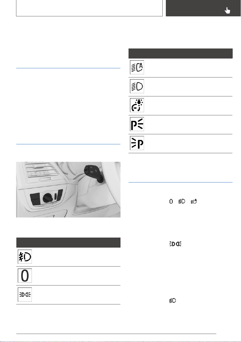
Lights
Vehicle features and
options
This chapter describes all standard, country-spe‐
cific and optional features offered with the series.
It also describes features that are not necessarily
available in your vehicle, e. g., due to the selected
options or country versions. This also applies to
safety-related functions and systems. When us‐
ing these functions and systems, the applicable
laws and regulations must be observed.
Overview
Switches in the vehicle
The light switch element is located next to the
steering wheel.
Symbol Function
Front fog lights.
Lights off.
Daytime running lights.
Parking lights.
Symbol Function
Automatic headlight control.
Adaptive light functions.
Low beams.
Instrument lighting.
Right roadside parking light.
Left roadside parking light.
Parking lights, low beams
and roadside parking lights
General information
Position of switch: , ,
If the driver's door is opened when the drive-
ready state is switched off, the exterior lighting is
automatically switched off.
Parking lights
Position of switch:
The vehicle is illuminated on all sides.
Do not use the parking lights for extended peri‐
ods; otherwise, they might drain the battery and
it would then be impossible to switch on drive-
ready state.
Low beams
Position of switch:
The low beams illuminate when drive-ready state
is switched on.
Seite 157
Lights
CONTROLS
157
Online Edition for Part no. 01402896703 - X/18
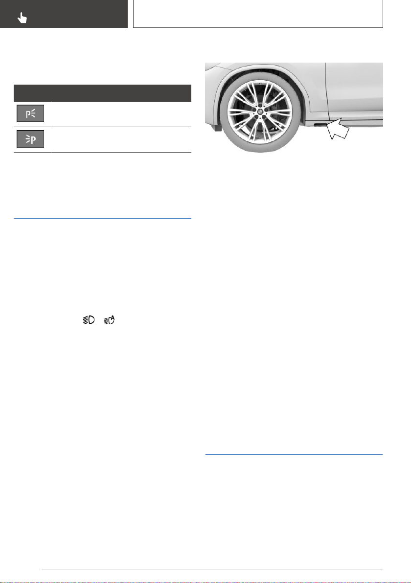
Roadside parking lights
When the vehicle is parked, a one-sided roadside
parking light can be switched on.
Button Function
Right roadside parking light on/off.
Left roadside parking light on/off.
Welcome lights and
headlight courtesy delay
feature
Welcome lights
General information
Depending on the equipment, the exterior light‐
ing of the vehicle can be set individually.
Activating/deactivating
Position of switch:
,
Via iDrive:
1.
"My Vehicle"
2. "Vehicle settings"
3. "Lighting"
4. "Exterior lighting"
5. Select desired setting:
▷ "Welcome lights"
Individual light functions are switched on
for a limited time.
▷ "LED light carpet"
The area next to the vehicle is illuminated
for a limited time.
LED light carpet
The light source is located in the position indi‐
cated.
Keep the light source clean and unobstructed.
Headlight courtesy delay feature
General information
The low beams stay lit for a particular time if the
high beams are switched on after standby state
is switched on.
Setting the duration
Via iDrive:
1.
"My Vehicle"
2. "Vehicle settings"
3. "Lighting"
4. "Exterior lighting"
5. "Pathway lighting"
6. Select the desired setting.
Automatic headlight
control
Concept
The low beams are switched on and off automat‐
ically depending on the ambient brightness, for
instance in tunnels, in twilight or if there is pre‐
cipitation.
Seite 158
CONTROLS
Lights
158
Online Edition for Part no. 01402896703 - X/18
General information
A blue sky with the sun low on the horizon can
cause the lights to be switched on.
Activating
Position of switch:
The indicator light in the instrument cluster is il‐
luminated when the low beams are switched on.
System limits
The automatic headlight control cannot serve as
a substitute for your personal judgment of light‐
ing conditions.
For example, the sensors are unable to detect
fog or hazy weather. In these situations, switch
the light on manually.
Daytime running lights
General information
Position of switch: , ,
The daytime running lights light up when drive-
ready state is switched on. After drive-ready
state is switched off, the parking lights light up in
position .
Activating/deactivating
In some countries, daytime running lights are
mandatory, so it may not be possible to deacti‐
vate the daytime running lights.
Via iDrive:
1.
"My Vehicle"
2. "Vehicle settings"
3. "Lighting"
4. "Exterior lighting"
5. "Daytime running lamps"
The setting is stored for the driver profile cur‐
rently used.
Adaptive light functions
Concept
Adaptive light functions enable dynamic illumina‐
tion of the roadway.
General information
The adaptive light functions may consist of one
system or multiple systems, depending on the
equipment version:
▷ Adaptive Light Control, refer to page 159.
▷ Cornering light, refer to page 159.
Activating
Position of switch:
The adaptive light functions are active when the
drive-ready state is switched on.
Adaptive Light Control
Depending on the steering angle and other pa‐
rameters, the light from the headlight follows the
course of the road.
To avoid blinding oncoming traffic, the Adaptive
Light Control does not swivel to the opposite
lane when the vehicle is at a standstill.
Cornering light
In tight curves, for instance on mountainous
roads or when turning, an additional, cornering
light is switched on that lights up the inside of
the curve when the vehicle is moving below a
certain speed.
The cornering light is automatically switched on
depending on the steering angle or the use of
turn signals.
When driving in reverse, the cornering lights may
be automatically switched on regardless of the
steering angle.
Seite 159
Lights
CONTROLS
159
Online Edition for Part no. 01402896703 - X/18
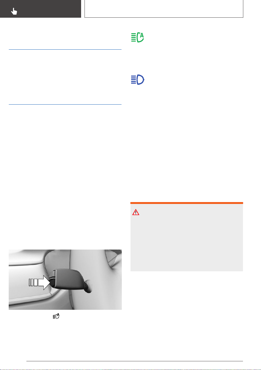
Adaptive headlight range
control
The adaptive headlight range control compen‐
sates for acceleration and braking operations in
order not to blind the oncoming traffic and to
achieve optimum illumination of the roadway.
High-beam Assistant
Concept
The high-beam Assistant detects other traffic
participants early on and automatically switches
the high beams on or off depending on the traffic
situation.
General information
The high-beam Assistant ensures that the high
beams are switched on, whenever the traffic sit‐
uation allows. In the low speed range, the high
beams are not switched on by the system.
The system responds to light from oncoming
traffic and traffic driving ahead of you, and to am‐
bient lighting, for instance in towns and cities.
The high beams can be switched on and off
manually at any time.
Activating/deactivating
Position of switch:
Press and hold the button on the turn signal
lever.
The indicator light in the instrument clus‐
ter is illuminated when the low beams are
switched on.
The headlights are automatically switched be‐
tween low beams and high beams.
The blue indicator light in the instrument
cluster lights up when the system
switches on the high beams.
The high-beam Assistant is deactivated when
manually switching the high beams on and off,
refer to page 127.
To reactivate the high-beam Assistant, press the
button on the turn signal lever.
Sensitivity of the high-beam
Assistant
General information
The sensitivity of the high-beam Assistant can
be adjusted.
Safety information
WARNING
If adjustments have been made or the sensitiv‐
ity has been modified, oncoming traffic may be
momentarily blinded. There is a risk of an acci‐
dent. If adjustments have been made and the
sensitivity has been modified, make sure that
oncoming traffic is not momentarily blinded.
Switch off the high beams manually if required.
Adjusting the sensitivity
Pull the turn signal lever for approxi‐
mately 10 seconds. The system responds more
sensitively.
A Check Control message is displayed.
Seite 160
CONTROLS
Lights
160
Online Edition for Part no. 01402896703 - X/18
Resetting the sensitivity
Pull the turn signal lever again for approx. 10 sec‐
onds. The sensitivity of the high-beam Assistant
is reset to the factory settings.
System limits
The high-beam Assistant cannot serve as a sub‐
stitute for the driver's personal judgment of when
to use the high beams. In situation that require
this, therefore switch off manually.
The system is not fully functional in the following
situations, and driver intervention may be neces‐
sary:
▷ In very unfavorable weather conditions, such
as fog or heavy precipitation.
▷ When detecting poorly-lit road users such as
pedestrians, cyclists, horseback riders and
wagons; when driving close to train or ship
traffic; or at animal crossings.
▷ In tight curves, on hilltops or in depressions,
in cross traffic or half-obscured oncoming
traffic on highways.
▷ In poorly-lit towns and cities or in the pres‐
ence of highly reflective signs.
▷ When the windshield in front of the interior
mirror is fogged over, dirty or covered with
stickers, etc.
Fog lights
Front fog lights
Concept
The front fog lights work alongside the low
beams to illuminate a wider area of the roadway.
Functional requirement
The low beams must be switched on before
switching on the front fog lights.
Switching on/off
Press the button.
The green indicator light lights up if the
front fog lights are switched on.
If the automatic headlight control is activated, the
low beams will come on automatically when you
switch on the front fog lights.
When the high beams or headlight flasher are
activated, the front fog lights are not switched
on.
Instrument lighting
Functional requirement
The parking lights or low beams must be
switched on to adjust the brightness.
Settings
Adjust the brightness with the
thumbwheel.
Interior lights
General information
Depending on the equipment version, interior
lights, footwell lights, entry lights, ambient light‐
ing, and speaker lighting are automatically con‐
trolled.
Seite 161
Lights
CONTROLS
161
Online Edition for Part no. 01402896703 - X/18
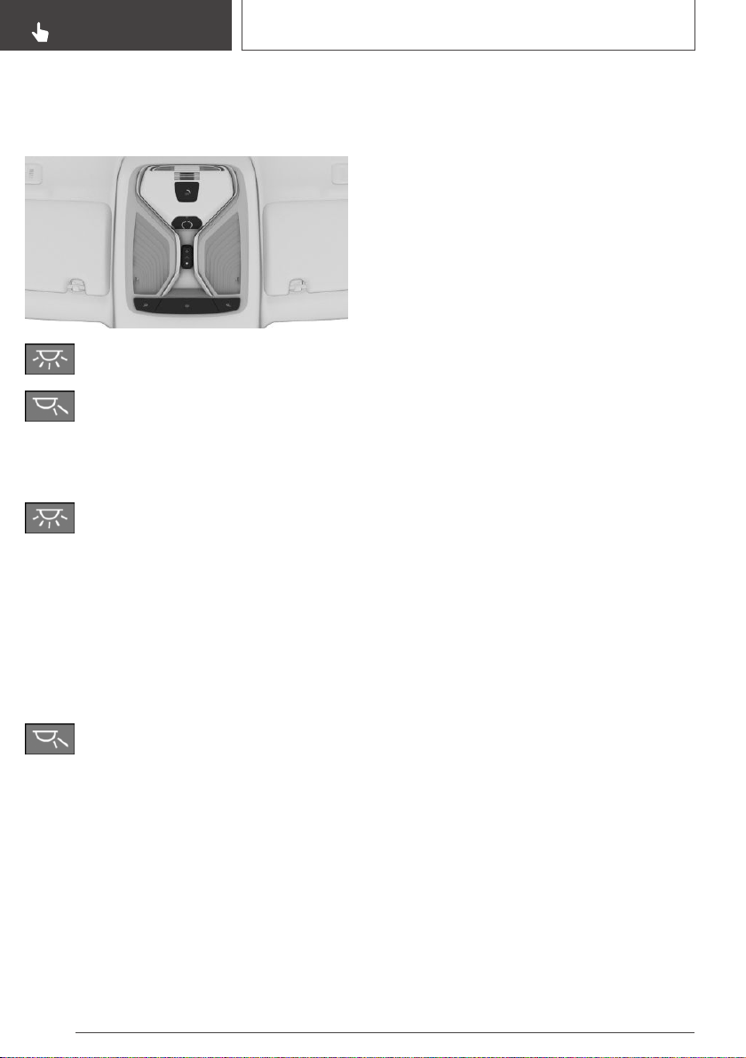
Overview
Buttons in the vehicle
Interior lights
Reading lights
Switching the interior lights
on/off
Press the button.
To switch off permanently: press the button and
hold for approx. 3 seconds.
The interior lights in the rear of the vehicle can
be switched on and off independently. The but‐
ton is located in the rear roofliner.
Switching the reading lights
on/off
Press the button.
Depending on the vehicle equipment, the read‐
ing lights are located next to the interior lights in
the front and rear.
Ambient light
General information
Depending on the equipment version, lighting
can be adjusted for some lights in the car's inte‐
rior.
Switching on/off
The ambient light is switched on when the vehi‐
cle is unlocked, and switched off when the vehi‐
cle is locked.
If the ambient light was deactivated via iDrive, it
will not be switched on when the vehicle is un‐
locked.
Via iDrive:
1. "My Vehicle"
2. "Vehicle settings"
3. "Lighting"
4. "Interior lighting"
5. "Ambient lighting"
The selected setting is stored for the driver pro‐
file currently used.
Selecting color scheme
Via iDrive:
1.
"My Vehicle"
2. "Vehicle settings"
3. "Lighting"
4. "Interior lighting"
5. "Color"
6. Select the desired setting.
Setting the brightness
Via iDrive:
1.
"My Vehicle"
2. "Vehicle settings"
3. "Lighting"
4. "Interior lighting"
5. "Brightness"
6. Select the desired setting.
Dimmed while driving
Via iDrive:
1.
"My Vehicle"
2. "Vehicle settings"
Seite 162
CONTROLS
Lights
162
Online Edition for Part no. 01402896703 - X/18

3. "Lighting"
4. "Interior lighting"
5. "Dimmed for night driving"
Some lights of the interior lighting are dimmed
when the vehicle is driven in the dark.
The selected setting is stored for the driver pro‐
file currently used.
Seite 163
Lights
CONTROLS
163
Online Edition for Part no. 01402896703 - X/18
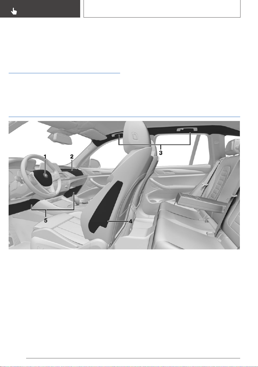
Safety
Vehicle features and
options
This chapter describes all standard, country-spe‐
cific and optional features offered with the series.
It also describes features that are not necessarily
available in your vehicle, e. g., due to the selected
options or country versions. This also applies to
safety-related functions and systems. When us‐
ing these functions and systems, the applicable
laws and regulations must be observed.
Airbags
1 Front airbag, driver
2 Front airbag, front passenger
3 Head airbag
4 Side airbag
5 Knee airbag
Front airbags
Front airbags help protect the driver and the
front passenger by responding to frontal impacts
in which safety belts alone would not provide ad‐
equate protection.
Side airbag
In a lateral impact, the side airbag supports the
side of the body in the chest and lap area.
Head airbag
In a lateral impact, the head airbag supports the
head.
Seite 164
CONTROLS
Safety
164
Online Edition for Part no. 01402896703 - X/18

Ejection Mitigation
The head airbag system is designed as an ejec‐
tion mitigation countermeasure to reduce the
likelihood of ejections of vehicle occupants
through side windows during rollovers or side im‐
pact events.
Knee airbag
The knee airbag supports the legs in a frontal im‐
pact.
Protective effect
General information
Airbags are not triggered in every impact situa‐
tion, for instance in less severe accidents or rear-
end collisions.
Information on optimum effect of the
airbags
WARNING
If the seat position is incorrect or the deploy‐
ment area of the airbags is impaired, the airbag
system cannot provide protection as intended
and may cause additional injuries due to trig‐
gering. There is a risk of injuries or danger to
life. Follow the information on achieving the op‐
timum protective effect of the airbag system.
▷ Keep a distance from the airbags.
▷ Always grasp the steering wheel on the
steering wheel rim. Hold your hands at the
3 o'clock and 9 o'clock positions, to keep the
risk of injury to your hands or arms as low as
possible when the airbag is triggered.
▷ Make sure that the front passenger is sitting
correctly, i.e., keeps his or her feet and legs in
the floor area and does not support them on
the dashboard.
▷ Make sure that occupants keep their heads
away from the side airbag.
▷ There should be no additional persons, ani‐
mals or objects between an airbag and a per‐
son.
▷ Dashboard and windshield on the front pas‐
senger side must stay clear - do not attach
adhesive labels or coverings and do not at‐
tach brackets or cables, for instance for GPS
devices or mobile phones.
▷ Do not apply adhesive materials to the airbag
cover panels, do not cover them or modify
them in any way.
▷ Do not use the cover of the front airbag on
the front passenger side as a storage area.
▷ Do not attach slip covers, seat cushions or
other objects to the front passenger seat that
are not specifically suited for seats with
integrated side airbags.
▷ Do not hang pieces of clothing, such as jack‐
ets, over the backrests.
▷ Never modify either the individual compo‐
nents or the wiring in the airbag system. This
also applies to steering wheel covers, the
dashboard, and the seats.
▷ Do not remove the airbag system.
Even when you follow all instructions very
closely, injury from contact with the airbags can‐
not be fully ruled out in certain situations.
The ignition and inflation noise may lead to
short-term and, in most cases, temporary hear‐
ing impairment in sensitive occupants.
Vehicle modifications for a person with disabili‐
ties may affect the air bag system; contact BMW
Customer Relations for further information.
Warnings and information on the airbags are also
found on the sun visors.
Seite 165
Safety
CONTROLS
165
Online Edition for Part no. 01402896703 - X/18
Functional readiness of the
airbag system
Safety information
WARNING
Individual components can be hot after trigger‐
ing of the airbag system. There is a risk of in‐
jury. Do not touch individual components.
WARNING
Improperly executed work can lead to failure,
malfunction or unintentional triggering of the
airbag system. In the case of a malfunction, the
airbag system might not trigger as intended de‐
spite the accident severity. There is a risk of in‐
juries or danger to life. Have the airbag system
checked, repaired, dismantled and scrapped by
a dealer’s service center or another qualified
service center or repair shop.
Display in the instrument cluster
When drive-ready state is switched on,
the warning light in the instrument clus‐
ter lights up briefly and thereby indicates
the function readiness of the entire airbag sys‐
tem and the belt tensioners.
Malfunction
▷ Warning light does not come on
when drive-ready state is switched
on.
▷ The warning light lights up continuously.
Have the system checked.
Automatic deactivation of the
front-seat passenger airbags
Concept
The system reads if the front passenger seat is
occupied by measuring the human body's resist‐
ance.
Front, knee, and side airbag on the front pas‐
senger's side are activated or deactivated.
General information
Before transporting a child on the front passen‐
ger seat, refer to the safety information and in‐
structions for children on the front passenger
seat, see Children.
Safety information
WARNING
To ensure the front-seat passenger airbag
function, the system must be able to detect
whether a person is sitting in the front passen‐
ger seat. The entire seat cushion area must be
used for this purpose. There is a risk of injuries
or danger to life. Make sure that the front pas‐
senger keeps his or her feet in the floor area.
Malfunction of the automatic
deactivation system
When transporting older children and adults, the
front-seat passenger airbags may be deactivated
in certain sitting positions. In this case, the indi‐
cator light for the front-seat passenger airbags
lights up.
In this case, change the sitting position so that
the front-seat passenger airbags are activated
and the indicator light goes out.
If it is not possible to activate the airbags, have
the person sit in the rear.
To enable correct recognition of the occupied
seat cushion.
Seite 166
CONTROLS
Safety
166
Online Edition for Part no. 01402896703 - X/18
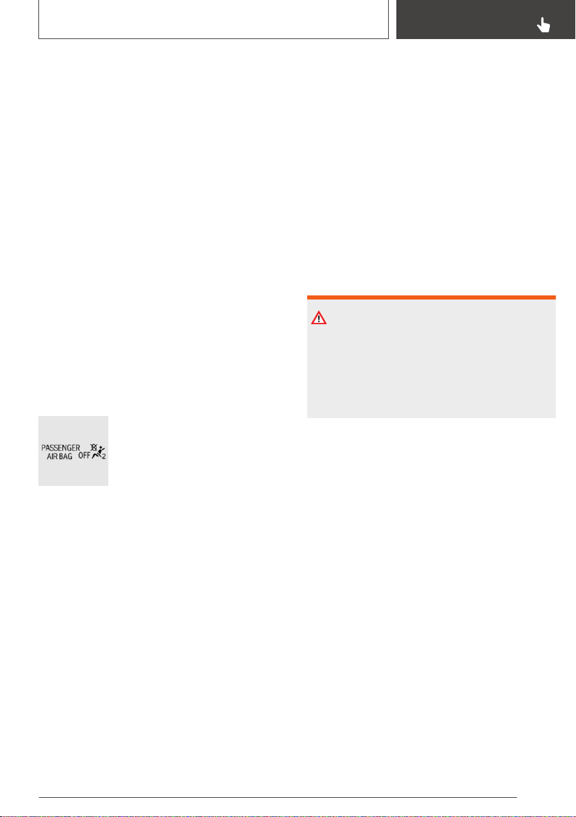
▷ Do not attach covers, cushions, ball mats or
other items to the front passenger seat un‐
less they are specifically determined to be
safe for use on the front passenger seat.
▷ Do not place any electronic devices on the
front passenger seat if a child restraint sys‐
tem is to be installed on it.
▷ Do not place objects under the seat that
could press against the seat from below.
▷ No moisture in or on the seat.
Indicator light for the front-seat
passenger airbags
The indicator light for the front-seat passenger
airbag in the roofliner indicates the operating
state of the front-seat passenger airbag.
The light indicates whether the airbags are either
activated or deactivated.
After drive-ready state is switched on, the light
briefly lights up and then indicates whether the
airbags are either activated or deactivated.
▷ The indicator light lights up
when a child is properly
seated in a child restraint sys‐
tem or when the seat is
empty. The airbags on the
front passenger side are not
activated.
▷ The indicator light does not light up when, for
instance a correctly seated person of suffi‐
cient size is detected on the seat. The air‐
bags on the front passenger side are acti‐
vated.
Detected child restraint systems
The system generally detects children seated in
a child restraint system, particularly in child re‐
straint systems required by NHTSA at the point
in time when the vehicle was manufactured. Af‐
ter installing a child restraint system, make sure
that the indicator light for the front-seat passen‐
ger airbags lights up. This indicates that the child
restraint system has been detected and the
front-seat passenger airbags are not activated.
Strength of the driver's and
front-seat passenger airbag
The explosive power that activates driver's/front-
seat passenger airbags very much depends on
the positions of the driver's/front passenger seat.
To maintain the accuracy of this function over
the long term, calibrate the front seats as soon as
a respective message appears on the Control
Display.
Calibrating the front seats
WARNING
There is a risk of jamming when moving the
seats. There is a risk of injury or risk of damage
to property. Make sure that the area of move‐
ment of the seat is clear prior to any adjust‐
ment.
A corresponding message appears on the Con‐
trol Display.
1.
Press the switch and move the respective
seat all the way forward, until it stops.
2. Press the switch forward again. The seat still
moves forward slightly.
3. Readjust the seat to the desired position.
The calibration procedure is completed when the
message on the Control Display disappears.
If the message continues to be displayed, repeat
the calibration.
If the message does not disappear after a repeat
calibration, have the system checked as soon as
possible.
Seite 167
Safety
CONTROLS
167
Online Edition for Part no. 01402896703 - X/18
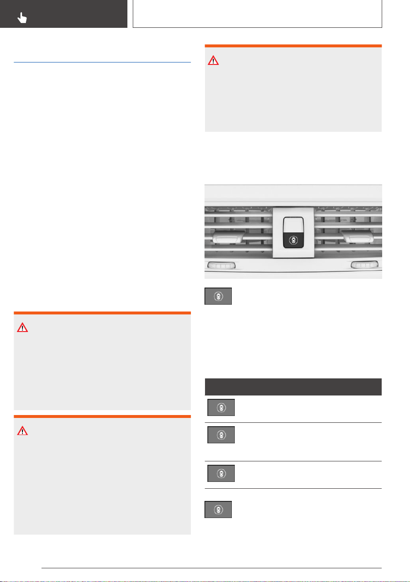
Intelligent Safety
Concept
Intelligent Safety enables central operation of the
driver assistance system.
General information
Depending on how the vehicle is equipped, Intel‐
ligent Safety consists of one or more systems
that can help prevent an imminent collision.
▷ Approach control warning with light braking
function, refer to page 169.
▷ Evasion assistance, refer to page 173.
▷ Person warning with City light braking func‐
tion, refer to page 175.
▷ Lane departure warning, refer to page 178.
▷ Active Blind Spot Detection, refer to
page 181.
▷ Side collision warning, refer to page 185.
Safety information
WARNING
The system cannot serve as a substitute for the
driver’s personal judgment in assessing visibility
and traffic situation. There is a risk of an acci‐
dent. Adjust driving style to traffic conditions.
Watch traffic closely and actively intervene
where appropriate.
WARNING
Indicators and warnings cannot serve as a sub‐
stitute for the driver’s personal judgment. Due
to its limits, the system might not output warn‐
ings or reactions or these might be output late,
incorrectly, or without justification. There is a
risk of an accident. Adjust driving style to traffic
conditions. Watch traffic closely and actively in‐
tervene where appropriate.
WARNING
Due to system limits, individual functions can
malfunction during tow-starting/towing with the
Intelligent Safety systems activated. There is a
risk of an accident. Switch all Intelligent Safety
systems off prior to tow-starting/towing.
Overview
Button in the vehicle
Intelligent Safety
Switching on/off
Some Intelligent Safety systems are automati‐
cally active after every departure. Some Intelli‐
gent Safety systems activate according to the
last setting.
Button Status
Button lights up green: all Intelligent
Safety systems are switched on.
Button lights up orange: some Intelli‐
gent Safety systems are switched off
or currently unavailable.
Button does not light up: all Intelligent
Safety systems are switched off.
Press the button:
The menu for the intelligent safety sys‐
tem is displayed.
Seite 168
CONTROLS
Safety
168
Online Edition for Part no. 01402896703 - X/18
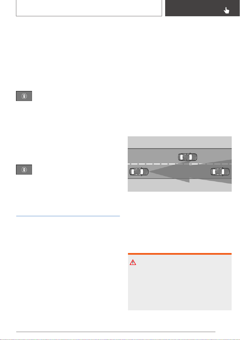
If all Intelligent Safety systems were switched off,
all systems are now switched on.
"Configure INDIVIDUAL": depending on the
equipment version, the Intelligent Safety sys‐
tems can be individually configured. The individ‐
ual settings are activated and stored for the
driver profile currently used. As soon as a setting
is changed on the menu, all settings of the menu
are activated.
Press the button repeatedly. The follow‐
ing settings are switched between:
"ALL ON": all Intelligent Safety systems are
switched on. Basic settings are activated for the
sub-functions, for instance setting for warning
time.
"INDIVIDUAL": the Intelligent Safety systems are
switched on according to the individual settings.
Some Intelligent Safety systems cannot be indi‐
vidually switched off.
Press and hold this button:
All Intelligent Safety systems are
switched off.
Approach control warning
with light braking function
Concept
The system can help prevent accidents. If an ac‐
cident cannot be prevented, the system will help
reduce the impact speed.
The system sounds a warning before an immi‐
nent collision and activates brakes independ‐
ently, if needed.
General information
Depending on the equipment version, the sys‐
tem is controlled by the following sensors:
▷ Camera in the area of the interior mirror.
▷ Radar sensor in the front bumper.
Intersection warning when equipped with a radar
sensor: in addition, a warning is issued at inter‐
sections and junctions if a risk of collision with
crossing traffic is detected.
The approach control warning is available even if
cruise control has been deactivated.
With the vehicle approaching another vehicle in‐
tentionally, the approach control warning and
braking are delayed in order to avoid false sys‐
tem reactions.
The system issues a two-phase warning of a
possible risk of collision with vehicles at speeds
above approx. 3 mph/5 km/h. Time of warnings
may vary with the current driving situation.
Detection range
Objects that the system can detect are taken
into account.
Intersection warning: the system is also able to
detect vehicles crossing your direction of travel
when these vehicles enter into the detection
range of the system.
Safety information
WARNING
The system cannot serve as a substitute for the
driver’s personal judgment in assessing visibility
and traffic situation. There is a risk of an acci‐
dent. Adjust driving style to traffic conditions.
Watch traffic closely and actively intervene
where appropriate.
Seite 169
Safety
CONTROLS
169
Online Edition for Part no. 01402896703 - X/18
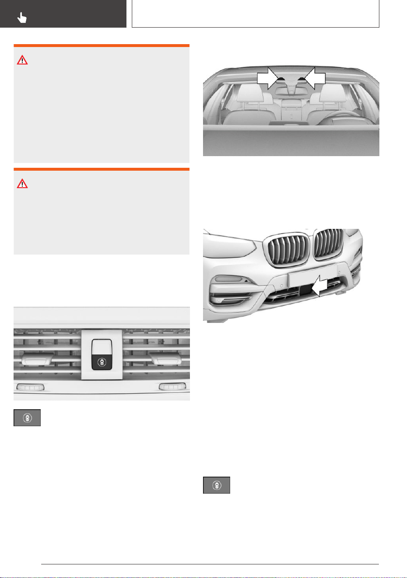
WARNING
Indicators and warnings cannot serve as a sub‐
stitute for the driver’s personal judgment. Due
to its limits, the system might not output warn‐
ings or reactions or these might be output late,
incorrectly, or without justification. There is a
risk of an accident. Adjust driving style to traffic
conditions. Watch traffic closely and actively in‐
tervene where appropriate.
WARNING
Due to system limits, individual functions can
malfunction during tow-starting/towing with the
Intelligent Safety systems activated. There is a
risk of an accident. Switch all Intelligent Safety
systems off prior to tow-starting/towing.
Overview
Button in the vehicle
Intelligent Safety
Camera
The camera is installed near the interior mirror.
Keep the windshield in front of the interior mirror
clean and clear.
With radar sensor
The radar sensor is located in the lower area of
the front bumper.
Always keep radar sensor clean and unob‐
structed.
Switching on/off
Switching on automatically
The system is automatically active after every
driving off.
Switching on/off manually
Press the button.
The menu for the intelligent safety sys‐
tem is displayed.
If all Intelligent Safety systems were switched off,
all systems are now switched on.
Seite 170
CONTROLS
Safety
170
Online Edition for Part no. 01402896703 - X/18
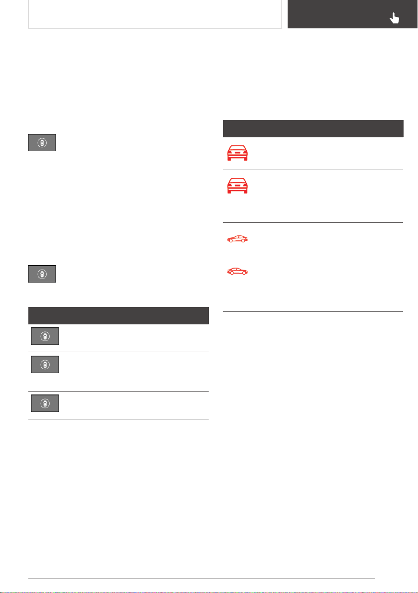
"Configure INDIVIDUAL": depending on the
equipment version, the Intelligent Safety sys‐
tems can be individually configured. The individ‐
ual settings are activated and stored for the
driver profile currently used. As soon as a setting
is changed on the menu, all settings of the menu
are activated.
Press the button repeatedly.
The following settings are switched be‐
tween:
"ALL ON": all Intelligent Safety systems are
switched on. Basic settings are activated for the
subfunctions.
"INDIVIDUAL": the Intelligent Safety systems are
switched on according to the individual settings.
Some Intelligent Safety systems cannot be indi‐
vidually switched off.
Press and hold this button.
All Intelligent Safety systems are
switched off.
Button Status
Button lights up green: all Intelligent
Safety systems are switched on.
Button lights up orange: some Intelli‐
gent Safety systems are switched off
or currently unavailable.
Button does not light up: all Intelligent
Safety systems are switched off.
Setting the warning time
Via iDrive:
1.
"My Vehicle"
2. "Vehicle settings"
3. "Intelligent Safety"
4. "Frontal Collision Warn."
5. Select the desired setting.
The selected time is stored for the driver profile
currently used.
Warning with braking function
Display
A warning symbol appears in the instrument
cluster and in the Head-up Display if a collision
with a detected vehicle is imminent.
Symbol Measure
Symbol lights up red: prewarning.
Brake and increase distance.
Symbol flashes red and an acoustic
signal sounds: acute warning.
Brake and make an evasive maneu‐
ver, if necessary.
Crossing traffic warning:
Symbol flashes red and an acoustic
signal sounds: acute warning when
vehicles cross your direction of
travel.
Brake and make an evasive maneu‐
ver, if necessary.
Prewarning
This warning is provided, for instance when there
is impending danger of a collision or the distance
to the vehicle ahead is too small.
If a prewarning is provided, respond by braking
as warranted.
Acute warning with braking function
Acute warning is displayed in case of the immi‐
nent danger of a collision when the vehicle ap‐
proaches another object at a high differential
speed.
If an acute warning is issued, intervene in the sit‐
uation yourself. If necessary, the system provides
assistance, such as with an automatic braking in‐
tervention, in a possible risk of collision.
Acute warnings can also be triggered without
previous forewarning.
Seite 171
Safety
CONTROLS
171
Online Edition for Part no. 01402896703 - X/18

Brake intervention, City light
braking function
The warning prompts the driver to react. During
a warning, the maximum braking force is used
when the brake is actuated. Prerequisite is suffi‐
ciently quick and hard stepping on the brake
pedal.
The system can additionally assist possibly with
automatic braking intervention if there is a risk of
a collision.
When the vehicle is traveling at a low speed, the
vehicle may come to a complete stop.
The braking intervention takes place up to ap‐
prox. 50 mph/80 km/h.
The braking intervention occurs only if vehicle
stability has not been restricted, for instance by
deactivating the DSC Dynamic Stability Control.
The driver may cancel the braking intervention
by stepping on the accelerator pedal or by ac‐
tively moving the steering wheel.
Object detection can be restricted. Follow the
limitations of the detection range and functional
limitations.
With radar sensor: brake
intervention
The warning prompts the driver to react. During
a warning, the maximum braking force is used
when the brake is actuated. Prerequisite is suffi‐
ciently quick and hard stepping on the brake
pedal.
The system can assist with automatic braking in‐
tervention if there is a risk of a collision.
The braking intervention can bring the vehicle to
a complete stop.
The braking intervention occurs only if vehicle
stability has not been restricted, for instance by
deactivating the DSC Dynamic Stability Control.
At speeds above approx. 130 mph/210 km/h, the
braking intervention occurs as a brief braking
pressure. No automatic delay occurs.
The driver may cancel the braking intervention
by stepping on the accelerator pedal or by ac‐
tively moving the steering wheel.
Cross-traffic warning: brake intervention is not
performed in the event of cross traffic.
Object detection can be restricted. Follow the
limitations of the detection range and functional
limitations.
System limits
Safety information
WARNING
The system can react not at all, too late, incor‐
rectly, or without justification due to the system
limits. There is a risk of accidents or risk of
damage to property. Follow the information re‐
garding the system limits and actively intervene
if needed.
Upper speed limit
If the vehicle speed exceeds approx.
155 mph/250 km/h, the system is deactivated
temporarily. When the vehicle slows down to be‐
low this speed, the system is reactivated.
Intersection warning: the vehicle responds to
crossing traffic if its own speed is below approx.
40 mph/65 km/h.
Detection range
The system's detection potential is limited.
Thus, a system reaction might not come or
might come late.
The following situations may not be detected, for
instance:
▷ Slow moving vehicles when you approach
them at high speed.
▷ Vehicles that suddenly swerve in front of you,
or sharply decelerating vehicles.
▷ Vehicles with an unusual rear appearance.
Seite 172
CONTROLS
Safety
172
Online Edition for Part no. 01402896703 - X/18
▷ Two-wheeled vehicles ahead of you.
▷ Intersection warning: crossing vehicles if their
speed is higher than your own speed.
Functional limitations
The system may not be fully functional in the fol‐
lowing situations:
▷ In heavy fog, wet conditions, or snowfall.
▷ In tight curves.
▷ If the driving stability control systems are lim‐
ited or deactivated, for instance DSC OFF.
▷ If the field of view of the camera or the wind‐
shield is dirty or covered in the area of the in‐
terior mirror.
▷ If the camera has overheated and been tem‐
porarily switched off due to excessively high
temperatures.
▷ Depending on the equipment: if the radar
sensors are dirty or covered.
▷ Up to 10 seconds after the start of the engine
via the Start/Stop button.
▷ During calibration of the camera immediately
after vehicle delivery.
▷ If there are constant blinding effects because
of oncoming light, for instance from the sun
low in the sky.
Warning sensitivity
The more sensitive the warning settings are, for
example the warning time, the more warnings are
displayed. Therefore, there may also be an ex‐
cess of premature or unjustified warnings and re‐
actions.
Evasion assistance
Concept
The system supports the driver in making eva‐
sive maneuvers in certain situations, such as
when obstacles suddenly appear.
General information
The system issues a warning and intervenes to
support the driver if a lateral evasive maneuver is
possible. Sensors monitor and detect the clear‐
ance around the vehicle. If the system identifies
space alongside the vehicle, it supports an eva‐
sive maneuver begun by the driver by safely pro‐
viding targeted steering support.
Detection range
Objects that the system can detect are taken
into account.
Safety information
WARNING
The system cannot serve as a substitute for the
driver’s personal judgment in assessing visibility
and traffic situation. There is a risk of an acci‐
dent. Adjust driving style to traffic conditions.
Watch traffic closely and actively intervene
where appropriate.
WARNING
Indicators and warnings cannot serve as a sub‐
stitute for the driver’s personal judgment. Due
to its limits, the system might not output warn‐
ings or reactions or these might be output late,
incorrectly, or without justification. There is a
risk of an accident. Adjust driving style to traffic
conditions. Watch traffic closely and actively in‐
tervene where appropriate.
Seite 173
Safety
CONTROLS
173
Online Edition for Part no. 01402896703 - X/18
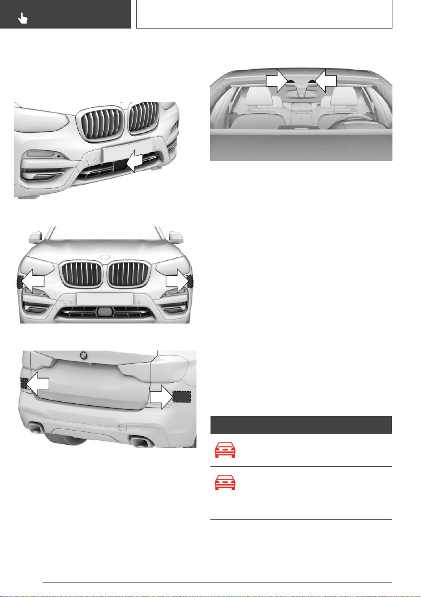
Overview
Radar sensors
The radar sensors are located in the bumpers.
Front center bumper.
Front side bumper.
Rear bumper.
Always keep the bumper in the area of the radar
sensors clean and unobstructed.
Camera
The camera is installed near the interior mirror.
Keep the windshield in front of the interior mirror
clean and clear.
Functional requirements
▷ Approach control warning with light braking
function, refer to page 169, is switched on.
▷ Sensors detect sufficient clearance around
the vehicle.
Switching on/off
The system is automatically active after every
driving off.
Warning with evasion support
Display in the instrument cluster
A warning symbol appears in the instrument
cluster and in the Head-up Display if a collision
with a detected vehicle is imminent.
Symbol Measure
Symbol lights up red: prewarning.
Brake and increase distance.
Symbol flashes red and an acoustic
signal sounds: acute warning.
Brake and make an evasive maneu‐
ver, if necessary.
Seite 174
CONTROLS
Safety
174
Online Edition for Part no. 01402896703 - X/18
Acute warning with evasion support
Acute warning is displayed in case of the immi‐
nent danger of a collision when the vehicle ap‐
proaches another object at a high differential
speed.
If an acute warning is issued, intervene in the sit‐
uation yourself. If there is a risk of collision, the
driver's evasive maneuvers are supported by the
system.
Acute warnings can also be triggered without
previous forewarning.
System limits
Safety information
WARNING
The system can react not at all, too late, incor‐
rectly, or without justification due to the system
limits. There is a risk of accidents or risk of
damage to property. Follow the information re‐
garding the system limits and actively intervene
if needed.
Detection range
The system's detection potential is limited.
Thus, a system reaction might not come or
might come late.
E.g., the following situations may not be de‐
tected:
▷ Slow moving vehicles when you approach
them at high speed.
▷ Vehicles that suddenly swerve in front of you,
or sharply decelerating vehicles.
▷ Vehicles with an unusual rear appearance.
▷ Two-wheeled vehicles ahead of you.
Functional limitations
The system may not be fully functional in the fol‐
lowing situations:
▷ In heavy fog, wet conditions, or snowfall.
▷ In tight curves.
▷ If the driving stability control systems are lim‐
ited or deactivated, for instance DSC OFF.
▷ If the field of view of the camera or the wind‐
shield is dirty or covered in the area of the in‐
terior mirror.
▷ If the camera has overheated and been tem‐
porarily switched off due to excessively high
temperatures.
▷ Depending on the equipment: if the radar
sensors are dirty or covered.
▷ Up to 10 seconds after the start of the engine
via the Start/Stop button.
▷ During calibration of the camera immediately
after vehicle delivery.
▷ If there are constant blinding effects because
of oncoming light, for instance from the sun
low in the sky.
Person warning with City
light braking function
Concept
The system can help prevent accidents with pe‐
destrians. When driving at city speeds, the sys‐
tem will issue a warning if there is imminent risk
of a collision with pedestrians, and support with a
braking function.
General information
The system is active at speeds of approx.
3 mph/5 km/h up to approx. 40 mph/65 km/h.
The system reacts to people who are within the
detection range of the system.
The camera in the area of the interior mirror con‐
trols the system.
Seite 175
Safety
CONTROLS
175
Online Edition for Part no. 01402896703 - X/18

Detection range
The detection area in front of the vehicle is div‐
ided into two areas:
▷ Central area, arrow 1, directly in front of the
vehicle.
▷ Expanded area, arrow 2, to the right and left
of the central area.
A collision is imminent if pedestrians are located
within the central area. A warning is issued about
pedestrians who are located within the extended
area only if they are moving in the direction of the
central area.
Safety information
WARNING
The system cannot serve as a substitute for the
driver’s personal judgment in assessing visibility
and traffic situation. There is a risk of an acci‐
dent. Adjust driving style to traffic conditions.
Watch traffic closely and actively intervene
where appropriate.
WARNING
Indicators and warnings cannot serve as a sub‐
stitute for the driver’s personal judgment. Due
to its limits, the system might not output warn‐
ings or reactions or these might be output late,
incorrectly, or without justification. There is a
risk of an accident. Adjust driving style to traffic
conditions. Watch traffic closely and actively in‐
tervene where appropriate.
WARNING
Due to system limits, individual functions can
malfunction during tow-starting/towing with the
Intelligent Safety systems activated. There is a
risk of an accident. Switch all Intelligent Safety
systems off prior to tow-starting/towing.
Overview
Button in the vehicle
Intelligent Safety
Camera
The camera is installed near the interior mirror.
Keep the windshield in front of the interior mirror
clean and clear.
Switching on/off
Switching on automatically
The system is automatically active after every
driving off.
Seite 176
CONTROLS
Safety
176
Online Edition for Part no. 01402896703 - X/18
Switching on/off manually
Press the button.
The menu for the intelligent safety sys‐
tem is displayed.
If all Intelligent Safety systems were switched off,
all systems are now switched on.
"Configure INDIVIDUAL": depending on the
equipment version, the Intelligent Safety sys‐
tems can be individually configured. The individ‐
ual settings are activated and stored for the
driver profile currently used. As soon as a setting
is changed on the menu, all settings of the menu
are activated.
Press the button repeatedly.
The following settings are switched be‐
tween:
"ALL ON": all Intelligent Safety systems are
switched on. Basic settings are activated for the
subfunctions.
"INDIVIDUAL": the Intelligent Safety systems are
switched on according to the individual settings.
Some Intelligent Safety systems cannot be indi‐
vidually switched off.
Press and hold this button.
All Intelligent Safety systems are
switched off.
Button Status
Button lights up green: all Intelligent
Safety systems are switched on.
Button lights up orange: some Intelli‐
gent Safety systems are switched off
or currently unavailable.
Button does not light up: all Intelligent
Safety systems are switched off.
Warning with braking function
Display
If a collision with a person detected in this way is
imminent, a warning symbol appears on the in‐
strument cluster and in the Head-up Display.
The red symbol is displayed and a signal
sounds.
Alternatively, depending on the vehicle
equipment, a red warning triangle lights
up in the instrument cluster.
Intervene immediately by braking or make an
evasive maneuver.
Braking intervention
The warning prompts the driver to react. During
a warning, the maximum braking force is used
when the brake is actuated. Prerequisite for the
brake booster is sufficiently quick and hard step‐
ping on the brake pedal.
If there is a risk of collision, the system may also
assist with braking.
When the vehicle is traveling at a low speed, the
vehicle may come to a complete stop.
The braking intervention occurs only if vehicle
stability has not been restricted, for instance by
deactivating the DSC Dynamic Stability Control.
The driver may cancel the braking intervention
by stepping on the accelerator pedal or by ac‐
tively moving the steering wheel.
Object detection can be restricted. Follow the
limitations of the detection range and functional
limitations.
Seite 177
Safety
CONTROLS
177
Online Edition for Part no. 01402896703 - X/18
System limits
Safety information
WARNING
The system can react not at all, too late, incor‐
rectly, or without justification due to the system
limits. There is a risk of accidents or risk of
damage to property. Follow the information re‐
garding the system limits and actively intervene
if needed.
Detection range
The detection potential of the camera is limited.
Thus, a warning might not be issued or be is‐
sued late.
The following situations may not be detected, for
instance:
▷ Partially covered pedestrians.
▷ Pedestrians that are not detected as such be‐
cause of the viewing angle or contour.
▷ Pedestrians outside of the detection range.
▷ Pedestrians having a body size less than
32 in/80 cm.
Functional limitations
The system may not be fully functional or may
not be available in the following situations:
▷ In heavy fog, wet conditions, or snowfall.
▷ In tight curves.
▷ If the driving stability control systems are de‐
activated, for instance DSC OFF.
▷ If the field of view of the camera or the wind‐
shield is dirty or covered in the area of the in‐
terior mirror.
▷ If the camera has overheated and been tem‐
porarily switched off due to excessively high
temperatures.
▷ Up to 10 seconds after the start of the engine
via the Start/Stop button.
▷ During calibration of the camera immediately
after vehicle delivery.
▷ If there are constant blinding effects because
of oncoming light, for instance from the sun
low in the sky.
▷ When it is dark outside.
Lane departure warning
Concept
The lane departure warning alerts when the vehi‐
cle on roads with lane markings is about to leave
the lane.
General information
This camera-based system warns starting at a
minimum speed.
The minimum speed is country-specific and is
displayed in the menu for the Intelligent Safety
systems.
Warnings are issued by means of a steering
wheel vibration. The severity of the steering
wheel vibration can be adjusted.
The time of the warning may vary depending on
the current driving situation.
The system does not provide a warning if the
turn signal is set before leaving the lane.
Vehicles with side collision warning: if in the
speed range up to 130 mph/210 km/h a lane
marking is crossed, the system intervenes with a
brief active steering intervention in addition to vi‐
brating. The system thus helps keep the vehicle
in the lane.
Safety information
WARNING
The system cannot serve as a substitute for the
driver’s personal judgment in assessing road
and traffic safety. There is a risk of an accident.
Adjust driving style to traffic conditions. Watch
Seite 178
CONTROLS
Safety
178
Online Edition for Part no. 01402896703 - X/18
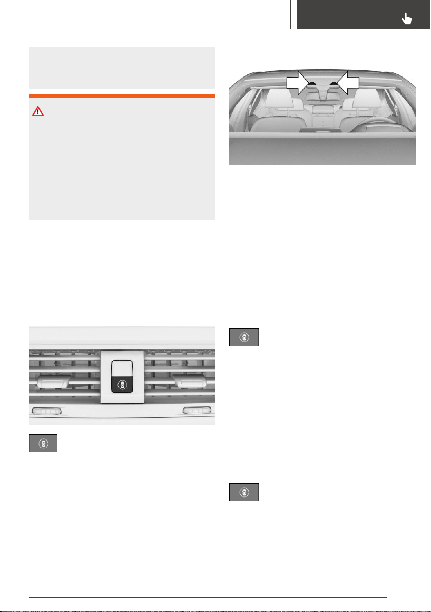
traffic closely and actively intervene where ap‐
propriate. Do not jerk the steering wheel in re‐
sponse to a warning.
WARNING
Indicators and warnings cannot serve as a sub‐
stitute for the driver’s personal judgment. Due
to its limits, the system might not output warn‐
ings or reactions or these might be output late,
incorrectly, or without justification. There is a
risk of an accident. Adjust driving style to traffic
conditions. Watch traffic closely and actively in‐
tervene where appropriate.
Functional requirements
The camera must detect the lane markings for
the lane departure warning to be active.
Overview
Button in the vehicle
Intelligent Safety
Camera
The camera is installed near the interior mirror.
Keep the windshield in front of the interior mirror
clean and clear.
Switching on/off
Switching on automatically
The lane departure warning activates automati‐
cally after departure if the function was switched
on at the end of the last trip.
Switching on/off manually
Press the button.
The menu for the intelligent safety sys‐
tem is displayed.
If all Intelligent Safety systems were switched off,
all systems are now switched on.
"Configure INDIVIDUAL": depending on the
equipment version, the Intelligent Safety sys‐
tems can be individually configured. The individ‐
ual settings are activated and stored for the
driver profile currently used. As soon as a setting
is changed on the menu, all settings of the menu
are activated.
Press the button repeatedly.
The following settings are switched be‐
tween:
"ALL ON": all Intelligent Safety systems are
switched on. Basic settings are activated for the
subfunctions.
Seite 179
Safety
CONTROLS
179
Online Edition for Part no. 01402896703 - X/18
"INDIVIDUAL": the Intelligent Safety systems are
switched on according to the individual settings.
Some Intelligent Safety systems cannot be indi‐
vidually switched off.
Press and hold this button.
All Intelligent Safety systems are
switched off.
Button Status
Button lights up green: all Intelligent
Safety systems are switched on.
Button lights up orange: some Intelli‐
gent Safety systems are switched off
or currently unavailable.
Button does not light up: all Intelligent
Safety systems are switched off.
Setting the warning frequency
Via iDrive:
1.
"My Vehicle"
2. "Vehicle settings"
3. "Intelligent Safety"
4. "Lane Departure Warn."
5. Select the desired setting.
▷ "Always": the system issues a warning
whenever a hazardous situation is de‐
tected.
▷ "Reduced": some warnings are sup‐
pressed depending on the situation,
for instance during passing without a turn
signal or when purposely driving over lane
markings in curves.
▷ "Off": no warnings are issued.
The selected setting is stored for the driver pro‐
file currently used.
Setting the force of the steering
wheel vibration
Via iDrive:
1. "My Vehicle"
2. "Vehicle settings"
3. "Steering wheel vibration"
4. Select the desired setting.
The setting is applied to all Intelligent Safety sys‐
tems and stored for the driver profile currently
used.
Vehicles with side collision warning:
turn steering intervention on/off
The steering intervention can be switched on
and off separately for Active Blind Spot Detec‐
tion and lane departure warning.
Via iDrive:
1.
"My Vehicle"
2. "Vehicle settings"
3. "Intelligent Safety"
4. "Steering intervention"
The selected setting is stored for the driver pro‐
file currently used.
Display in the instrument cluster
The system illuminates green: at least
one lane marking was detected and
warnings can be issued.
Warning function
If you leave the lane
If you leave the lane and if a lane marking has
been detected, the steering wheel vibrates in ac‐
cordance with the steering wheel vibration set‐
ting.
If the turn signal is switched on before a lane
change, a warning is not issued.
Seite 180
CONTROLS
Safety
180
Online Edition for Part no. 01402896703 - X/18

With side collision warning
If in the speed range up to 130 mph/210 km/h a
lane marking is crossed, the system intervenes
with a brief active steering intervention in addi‐
tion to vibrating. The steering intervention helps
keep the vehicle in the lane. The steering inter‐
vention can be noticed on the steering wheel
and can be manually overridden at any time. Dur‐
ing an active steering intervention, the display in
the instrument cluster will blink.
With trailer towing
If the trailer power socket is in use or trailer tow‐
ing is activated, for instance during operation
with trailer or bicycle rack, no steering interven‐
tion takes place.
End of warning
The warning is canceled in the following situa‐
tions:
▷ Automatically after approx. 3 seconds.
▷ When returning to your own lane.
▷ When braking hard.
▷ When using the turn signal.
▷ If DSC Dynamic Stability Control intervenes.
System limits
Safety information
WARNING
The system can react not at all, too late, incor‐
rectly, or without justification due to the system
limits. There is a risk of accidents or risk of
damage to property. Follow the information re‐
garding the system limits and actively intervene
if needed.
Functional limitations
The system may not be fully functional in the fol‐
lowing situations:
▷ In heavy fog, wet conditions, or snowfall.
▷ In the event of missing, worn, poorly visible,
merging, diverging, or multiple lane markings
such as in construction areas.
▷ When lane markings are covered in snow, ice,
dirt or water.
▷ In tight curves or on narrow lanes.
▷ When lane markings are covered by objects.
▷ When driving very close to the vehicle in front
of you.
▷ If there are constant blinding effects because
of oncoming light, for instance from the sun
low in the sky.
▷ If the field of view of the camera or the wind‐
shield is dirty or covered in the area of the in‐
terior mirror.
▷ If the camera has overheated and been tem‐
porarily switched off due to excessively high
temperatures.
▷ Up to 10 seconds after the start of the engine
via the Start/Stop button.
▷ During calibration of the camera immediately
after vehicle delivery.
A Check Control message is displayed when the
system is not fully functional.
Active Blind Spot
Detection
Concept
Active Blind Spot Detection detects vehicles in
the blind spot or vehicles approaching from be‐
hind in the adjacent lane. A warning is issued in
various gradations in these situations.
Seite 181
Safety
CONTROLS
181
Online Edition for Part no. 01402896703 - X/18
General information
Two radar sensors in the rear bumper monitor
the area behind and next to the vehicle when
traveling faster than a minimum speed.
The minimum speed is shown in the menu for
the Intelligent Safety systems.
The system indicates whether there are vehicles
in the blind spot, arrow 1, or approaching from
behind in the adjacent lane, arrow 2.
The light in the exterior mirror lights up dimmed.
Before you change lanes after setting the turn
signal, the system issues a warning in the situa‐
tions described above.
The light in the exterior mirror flashes and the
steering wheel vibrates.
Vehicles with side collision warning: at speeds
between 45 mph/70 km/h and
130 mph/210 km/h, the system can intervene
with a brief active steering intervention and help
to return the vehicle into the lane.
Safety information
WARNING
The system cannot serve as a substitute for the
driver’s personal judgment in assessing visibility
and traffic situation. There is a risk of an acci‐
dent. Adjust driving style to traffic conditions.
Watch traffic closely and actively intervene
where appropriate.
WARNING
Indicators and warnings cannot serve as a sub‐
stitute for the driver’s personal judgment. Due
to its limits, the system might not output warn‐
ings or reactions or these might be output late,
incorrectly, or without justification. There is a
risk of an accident. Adjust driving style to traffic
conditions. Watch traffic closely and actively in‐
tervene where appropriate.
Overview
Button in the vehicle
Intelligent Safety
Radar sensors
The radar sensors are located in the rear
bumper.
Always keep the bumper in the area of the radar
sensors clean and unobstructed.
Seite 182
CONTROLS
Safety
182
Online Edition for Part no. 01402896703 - X/18

Switching on/off
Switching on automatically
The Active Blind Spot Detection is automatically
activated after departure if the function was
switched on at the end of the last trip.
Switching on/off manually
Press the button.
The menu for the intelligent safety sys‐
tem is displayed.
If all Intelligent Safety systems were switched off,
all systems are now switched on.
"Configure INDIVIDUAL": depending on the
equipment version, the Intelligent Safety sys‐
tems can be individually configured. The individ‐
ual settings are activated and stored for the
driver profile currently used. As soon as a setting
is changed on the menu, all settings of the menu
are activated.
Press the button repeatedly.
The following settings are switched be‐
tween:
"ALL ON": all Intelligent Safety systems are
switched on. Basic settings are activated for the
subfunctions.
"INDIVIDUAL": the Intelligent Safety systems are
switched on according to the individual settings.
Some Intelligent Safety systems cannot be indi‐
vidually switched off.
Press and hold this button.
All Intelligent Safety systems are
switched off.
Button Status
Button lights up green: all Intelligent
Safety systems are switched on.
Button lights up orange: some Intelli‐
gent Safety systems are switched off
or currently unavailable.
Button does not light up: all Intelligent
Safety systems are switched off.
Setting the warning time
Via iDrive:
1.
"My Vehicle"
2. "Vehicle settings"
3. "Intelligent Safety"
4. "Blind Spot Detection"
5. Select the desired setting.
"Off": with this setting, no warning is output.
The setting is stored for the driver profile cur‐
rently used.
Setting the force of the steering
wheel vibration
Via iDrive:
1.
"My Vehicle"
2. "Vehicle settings"
3. "Steering wheel vibration"
4. Select the desired setting.
The setting is applied to all Intelligent Safety sys‐
tems and stored for the driver profile currently
used.
Vehicles with side collision warning:
switching steering intervention
on/off
The steering intervention can be switched on
and off separately for Active Blind Spot Detec‐
tion and lane departure warning.
Seite 183
Safety
CONTROLS
183
Online Edition for Part no. 01402896703 - X/18
Via iDrive:
1. "My Vehicle"
2. "Vehicle settings"
3. "Intelligent Safety"
4. "Steering intervention"
The setting is stored for the driver profile cur‐
rently used.
Warning function
Light in the exterior mirror
Prewarning
The dimmed light in the exterior mirror indicates
when there are vehicles in the blind spot or ap‐
proaching from behind.
Acute warning
If the turn signal is switched on while a vehicle is
in the critical zone, the steering wheel vibrates
briefly and the light in the exterior mirror flashes
brightly.
The warning stops when the turn signal is
switched off, or the other vehicle leaves the criti‐
cal zone.
With side collision warning
If at speeds between 45 mph/70 km/h and
130 mph/210 km/h the vibrating steering wheel
is ignored and the lane marking crossed, the sys‐
tem intervenes with a brief active steering inter‐
vention. The steering intervention helps return
the vehicle into the lane. The steering interven‐
tion can be noticed on the steering wheel and
can be manually overridden at any time.
Flashing of the light
A flashing of the light during vehicle unlocking
serves as system self-test.
System limits
Safety information
WARNING
The system can react not at all, too late, incor‐
rectly, or without justification due to the system
limits. There is a risk of accidents or risk of
damage to property. Follow the information re‐
garding the system limits and actively intervene
if needed.
Upper speed limit
If the vehicle speed exceeds approx.
155 mph/250 km/h, the system is deactivated
temporarily.
If the vehicle speed falls below approx.
155 mph/250 km/h, the system once again re‐
sponds according to the setting.
Functional limitations
The system may not be fully functional in the fol‐
lowing situations:
▷ When a vehicle is approaching at a speed
much faster than your own.
▷ In heavy fog, wet conditions, or snowfall.
▷ In tight curves or on narrow lanes.
▷ If the bumper is dirty, iced up, or covered,
for instance by stickers.
▷ If cargo protrudes.
For vehicles with side collision warning, the
steering intervention can be limited, for instance
in the following situation:
Seite 184
CONTROLS
Safety
184
Online Edition for Part no. 01402896703 - X/18
▷ In the event of missing, worn, poorly visible,
merging, diverging, or multiple lane markings
such as in construction areas.
▷ When lane markings are covered in snow, ice,
dirt or water.
▷ When lane markings are not white.
▷ When lane markings are covered by objects.
▷ When driving very close to the vehicle in front
of you.
▷ If there are constant blinding effects because
of oncoming light, for instance from the sun
low in the sky.
▷ If the field of view of the camera or the wind‐
shield is dirty or covered in the area of the in‐
terior mirror.
▷ If the camera has overheated and been tem‐
porarily switched off due to excessively high
temperatures.
▷ Up to 10 seconds after the start of the engine
via the Start/Stop button.
▷ During calibration of the camera immediately
after vehicle delivery.
A Check Control message is displayed when the
system is not fully functional.
If the trailer power socket is in use or trailer tow‐
ing is activated, for instance during operation
with trailer or bicycle rack, the system cannot be
switched on. A Check Control message is dis‐
played.
Displaying warnings
Depending on the selected warning settings, for
instance warning time, more warnings can be
displayed. However, there may also be an excess
of premature warnings of critical situations.
Side collision warning
Concept
The system helps to avoid imminent side colli‐
sions.
General information
Four radar sensors in the bumpers monitor the
area next to the vehicle in the speed range from
approx. 45 mph/70 km/h to ap‐
prox. 130 mph/210 km/h.
The front camera determines the lane marking
positions.
If, for instance another vehicle is detected next to
the vehicle and if there is a risk of collision with
this vehicle, the system helps avoid the collision
via steering intervention.
Safety information
WARNING
The system cannot serve as a substitute for the
driver’s personal judgment in assessing visibility
and traffic situation. There is a risk of an acci‐
dent. Adjust driving style to traffic conditions.
Watch traffic closely and actively intervene
where appropriate.
WARNING
Indicators and warnings cannot serve as a sub‐
stitute for the driver’s personal judgment. Due
to its limits, the system might not output warn‐
ings or reactions or these might be output late,
incorrectly, or without justification. There is a
risk of an accident. Adjust driving style to traffic
conditions. Watch traffic closely and actively in‐
tervene where appropriate.
Seite 185
Safety
CONTROLS
185
Online Edition for Part no. 01402896703 - X/18
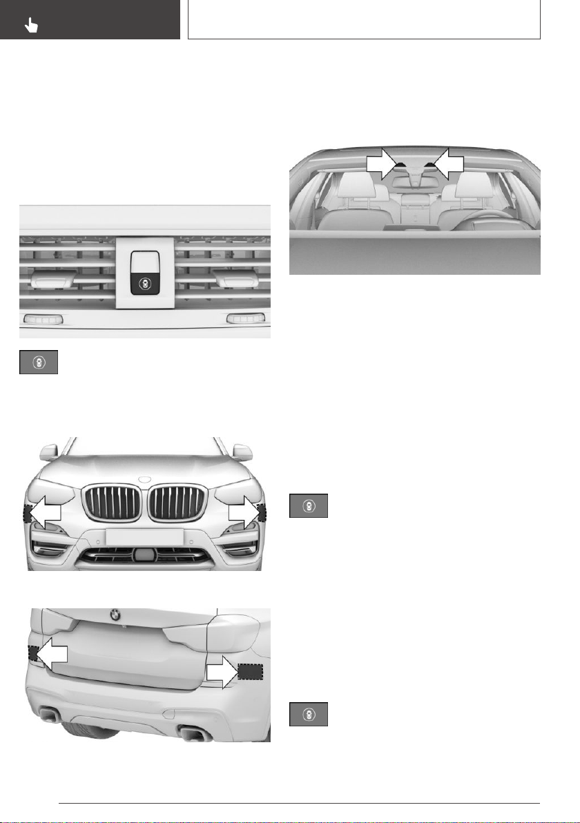
Functional requirements
The camera must detect the lane markings for
the side collision warning with steering interven‐
tion to be active.
Overview
Button in the vehicle
Intelligent Safety
Radar sensors
The radar sensors are located in the bumpers.
Front bumper.
Rear bumper.
Always keep the bumper in the area of the radar
sensors clean and unobstructed.
Camera
The camera is installed near the interior mirror.
Keep the windshield in front of the interior mirror
clean and clear.
Switching on/off
Switching on automatically
The side collision warning activates automatically
after departure if the function was switched on at
the end of the last trip.
Switching on/off manually
Press the button.
The menu for the intelligent safety sys‐
tem is displayed.
If all Intelligent Safety systems were switched off,
all systems are now switched on.
"Configure INDIVIDUAL": depending on the
equipment version, the Intelligent Safety sys‐
tems can be individually configured. The individ‐
ual settings are activated and stored for the
driver profile currently used. As soon as a setting
is changed on the menu, all settings of the menu
are activated.
Press the button repeatedly.
The following settings are switched be‐
tween:
Seite 186
CONTROLS
Safety
186
Online Edition for Part no. 01402896703 - X/18
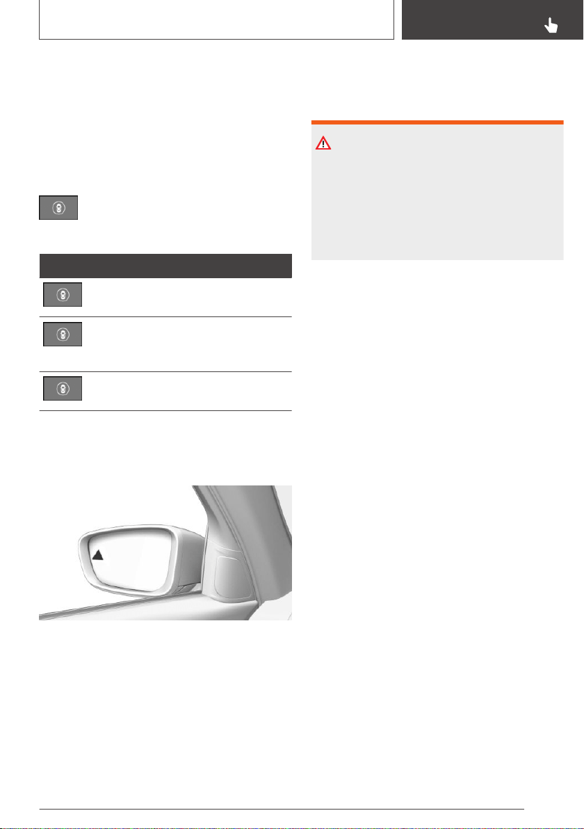
"ALL ON": all Intelligent Safety systems are
switched on. Basic settings are activated for the
subfunctions.
"INDIVIDUAL": the Intelligent Safety systems are
switched on according to the individual settings.
Some Intelligent Safety systems cannot be indi‐
vidually switched off.
Press and hold this button.
All Intelligent Safety systems are
switched off.
Button Status
Button lights up green: all Intelligent
Safety systems are switched on.
Button lights up orange: some Intelli‐
gent Safety systems are switched off
or currently unavailable.
Button does not light up: all Intelligent
Safety systems are switched off.
Warning function
Light in the exterior mirror
If there is a risk of collision
If there is a risk of collision, the light in the exte‐
rior mirror flashes and the steering wheel vi‐
brates. An active steering intervention takes
place to prevent collisions and maintain the vehi‐
cle within its own lane. The steering intervention
can be noticed on the steering wheel and can be
manually overridden at any time.
System limits
Safety information
WARNING
The system can react not at all, too late, incor‐
rectly, or without justification due to the system
limits. There is a risk of accidents or risk of
damage to property. Follow the information re‐
garding the system limits and actively intervene
if needed.
Functional limitations
The system may not be fully functional in the fol‐
lowing situations:
▷ When a vehicle is approaching at a speed
much faster than your own.
▷ In heavy fog, wet conditions, or snowfall.
▷ In tight curves or on narrow lanes.
▷ If the bumper is dirty, iced up, or covered,
for instance by stickers.
▷ If cargo protrudes.
▷ In the event of missing, worn, poorly visible,
merging, diverging, or multiple lane markings
such as in construction areas.
▷ When lane markings are covered in snow, ice,
dirt or water.
▷ When lane markings are covered by objects.
▷ When driving very close to the vehicle in front
of you.
▷ If there are constant blinding effects because
of oncoming light, for instance from the sun
low in the sky.
▷ If the field of view of the camera or the wind‐
shield is dirty or covered in the area of the in‐
terior mirror.
▷ If the camera has overheated and been tem‐
porarily switched off due to excessively high
temperatures.
Seite 187
Safety
CONTROLS
187
Online Edition for Part no. 01402896703 - X/18
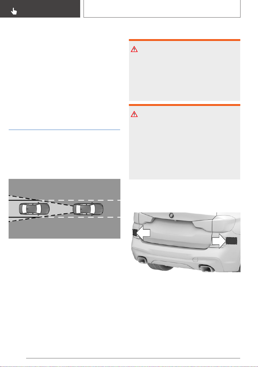
▷ Up to 10 seconds after the start of the engine
via the Start/Stop button.
▷ During calibration of the camera immediately
after vehicle delivery.
A Check Control message is displayed when the
system is not fully functional.
If the trailer power socket is in use or trailer tow‐
ing is activated, for instance during operation
with trailer or bicycle rack, the system cannot be
switched on. A Check Control message is dis‐
played.
Rear collision prevention
Concept
The system reacts to vehicles approaching from
behind.
General information
Two radar sensors in the rear bumper monitor
the area behind the vehicle.
If a vehicle approaches from the rear at a certain
speed, the system responds as follows:
▷ Active Protection, refer to page 189: if a colli‐
sion seems to be unavoidable, PreCrash
functions are triggered.
Safety information
WARNING
The system cannot serve as a substitute for the
driver’s personal judgment in assessing visibility
and traffic situation. There is a risk of an acci‐
dent. Adjust driving style to traffic conditions.
Watch traffic closely and actively intervene
where appropriate.
WARNING
Indicators and warnings cannot serve as a sub‐
stitute for the driver’s personal judgment. Due
to its limits, the system might not output warn‐
ings or reactions or these might be output late,
incorrectly, or without justification. There is a
risk of an accident. Adjust driving style to traffic
conditions. Watch traffic closely and actively in‐
tervene where appropriate.
Overview
Radar sensors
The radar sensors are located in the rear
bumper.
Always keep the bumper in the area of the radar
sensors clean and unobstructed.
Switching on/off
The system is automatically active after every
driving off.
Seite 188
CONTROLS
Safety
188
Online Edition for Part no. 01402896703 - X/18
The system is deactivated in the following situa‐
tions:
▷ When driving in reverse.
▷ If the trailer power socket is in use or trailer
towing is activated, for instance during opera‐
tion with trailer or bicycle rack.
System limits
The system may not be fully functional in the fol‐
lowing situations:
▷ When a vehicle is approaching at a speed
much faster than your own.
▷ When the approaching vehicle approaches
slowly.
▷ In heavy fog, wet conditions, or snowfall.
▷ In tight curves or on narrow lanes.
▷ If the bumper is dirty, iced up, or covered,
for instance by stickers.
▷ If cargo protrudes.
Brake force display
Concept
Additional brake lights indicate emergency brak‐
ing to the traffic behind. This can reduce the risk
of a rear-end collision.
General information
▷ During normal brake application, the outer
brake lights light up.
▷ During heavy brake application, the inner
brake lights additionally light up.
Active Protection
Concept
Active Protection prepares occupants and the
vehicle for a possible accident in critical driving or
collision situations.
General information
Active Protection consists of various PreCrash
functions, which can vary depending on the
equipment.
The system is used to detect certain critical driv‐
ing situations that might lead to an accident. This
includes the following critical driving situations:
▷ Emergency stop.
▷ Severe understeering.
▷ Severe oversteering.
Certain functions of several systems can, within
the system limits, lead to Active Protection trig‐
gering:
▷ Approach control warning with braking func‐
tion: automatic brake intervention.
▷ Approach control warning with braking func‐
tion: brake booster.
▷ Rear collision prevention: detection of immi‐
nent rear collisions.
Safety information
WARNING
The system cannot serve as a substitute for the
driver’s personal judgment. Due to the system
limits, critical situation could not be detected
reliably or in time. There is a risk of an accident.
Adjust driving style to traffic conditions. Watch
traffic closely and actively intervene where ap‐
propriate.
Seite 189
Safety
CONTROLS
189
Online Edition for Part no. 01402896703 - X/18

Function
When the safety belt is fastened, the driver's and
passenger's belt straps are automatically tight‐
ened once after driving away.
In accident-critical situations, the following indi‐
vidual functions become active as needed:
▷ Automatic pretensioning of the front safety
belts.
▷ Automatic window closing up to a narrow
gap.
▷ Automatic closing of the panoramic glass
sunroof, including sun protection.
▷ For vehicles equipped with comfort seats in
the front: automatic positioning of the back‐
rest for the front passenger seat.
After a critical driving situation without an acci‐
dent, the front safety belts are loosened again.
If the belt tension does not loosen automatically,
stop the vehicle and unbuckle the safety belt us‐
ing the red button in the buckle. Fasten the
safety belt before continuing on your trip.
All other systems can be restored to the desired
setting.
PostCrash – iBrake
Concept
In the event of an accident, the system can bring
the vehicle to a halt automatically without inter‐
vention by the driver in certain situations. This
can reduce the risk of a further collision and the
consequences thereof.
At standstill
After coming to a halt, the brake is released auto‐
matically.
Harder vehicle braking
It can be necessary to bring the vehicle in certain
situations to a halt quicker.
To do this, for a short time the braking pressure
applied when stepping on the brake pedal must
be higher than the braking pressure achieved by
the automatic braking function. This interrupts
automatic braking.
Interrupting automatic braking
It can be necessary to interrupt automatic brak‐
ing in certain situations, for instance for an eva‐
sive maneuver.
Interrupt automatic braking:
▷ By pressing the brake pedal.
▷ By pressing the accelerator pedal.
Alertness assistant
Concept
The system can detect decreasing alertness or
fatigue of the driver during long, monotonous
trips, for instance on highways. In this situation, it
is recommended that the driver takes a break.
Safety information
WARNING
The system cannot serve as a substitute for the
driver’s personal judgment in assessing one's
physical state. An increasing lack of alertness or
fatigue may not be detected or not be detected
in time. There is a risk of an accident. Make
sure that the driver is rested and alert. Adjust
driving style to traffic conditions.
Function
The system is switched on each time drive-ready
state is switched on.
After travel has begun, the system monitors cer‐
tain aspects of the driver's behavior, so that de‐
creasing alertness or fatigue can be detected.
This procedure takes the following criteria into
account:
Seite 190
CONTROLS
Safety
190
Online Edition for Part no. 01402896703 - X/18

▷ Personal driving style, for instance steering
behavior.
▷ Driving conditions, for instance length of trip.
Starting at approx. 43 mph/70 km/h, the system
is active and can also display a recommendation
to take a break.
Break recommendation
Switching on/off, adjusting
The alertness assistant is active automatically
with each switching on of drive-ready state and
can thus display a break recommendation.
The break recommendation can also be
switched on or off and adjusted via iDrive.
Via iDrive:
1.
"My Vehicle"
2. "Vehicle settings"
3. "Driver attention control"
4. Select desired setting:
▷ "Off": no break recommendation is made.
▷ "Standard": the break recommendation is
made with a defined value.
▷ "Sensitive": the break recommendation is
issued earlier.
Display
If the driver becomes less alert or fatigued, a
message is displayed in the Control Display with
the recommendation to take a break.
During the display, the following settings can be
selected:
▷ "Do not ask again"
▷ "Places to stop"
▷ "Remind me later"
The break recommendation is repeated after
20 minutes.
After a break, another recommendation to take a
break cannot be displayed until after approxi‐
mately 45 minutes.
System limits
The function may be limited in the following sit‐
uations, for instance and will either output an in‐
correct warning or no warning at all:
▷ When the clock is set incorrectly.
▷ When the vehicle speed is mainly below
about 43 mph/70 km/h.
▷ With a sporty driving style, such as during
rapid acceleration or when cornering fast.
▷ In active driving situations, such as when
changing lanes frequently.
▷ When the road surface is poor.
▷ In the event of strong side winds.
The system is reset approx. 45 minutes after
parking the vehicle, for instance in the case of a
break during longer trips on highways.
Seite 191
Safety
CONTROLS
191
Online Edition for Part no. 01402896703 - X/18

Driving stability control systems
Vehicle features and
options
This chapter describes all standard, country-spe‐
cific and optional features offered with the series.
It also describes features that are not necessarily
available in your vehicle, e. g., due to the selected
options or country versions. This also applies to
safety-related functions and systems. When us‐
ing these functions and systems, the applicable
laws and regulations must be observed.
Anti-lock Braking System
ABS
ABS prevents locking of the wheels during brak‐
ing.
The vehicle maintains its steering power even
during full brake applications, thus increasing ac‐
tive safety.
ABS is operational every time you start the en‐
gine.
Brake assistant
When you apply the brakes rapidly, the system
automatically produces the greatest possible
braking force boost. It reduces the braking dis‐
tance to a minimum during emergency stop.
This system utilizes all of the capabilities pro‐
vided by the Antilock Brake System ABS.
Do not reduce the pressure on the brake pedal
for the duration of the emergency stop.
Adaptive brake assistant
In combination with Active Cruise Control, this
system ensures that the brakes respond even
more rapidly when braking in critical situations.
Drive-off assistant
Concept
This system supports driving off on uphill grades.
Driving off
1.
Hold the vehicle in place with the foot brake.
2. Release the foot brake and drive off without
delay.
After the foot brake is released, the vehicle is
held in place for approx. 2 seconds.
Depending on the vehicle loading or when a
trailer is used, the vehicle may roll back slightly.
DSC Dynamic Stability
Control
Concept
Within the physical limits, the system helps to
keep the vehicle on a steady course by reducing
engine speed and by braking the individual
wheels.
General information
DSC detects the following unstable driving con‐
ditions, for instance:
▷ Fishtailing, which can lead to oversteering.
▷ Loss of traction of the front wheels, which
can lead to understeering.
Seite 192
CONTROLS
Driving stability control systems
192
Online Edition for Part no. 01402896703 - X/18
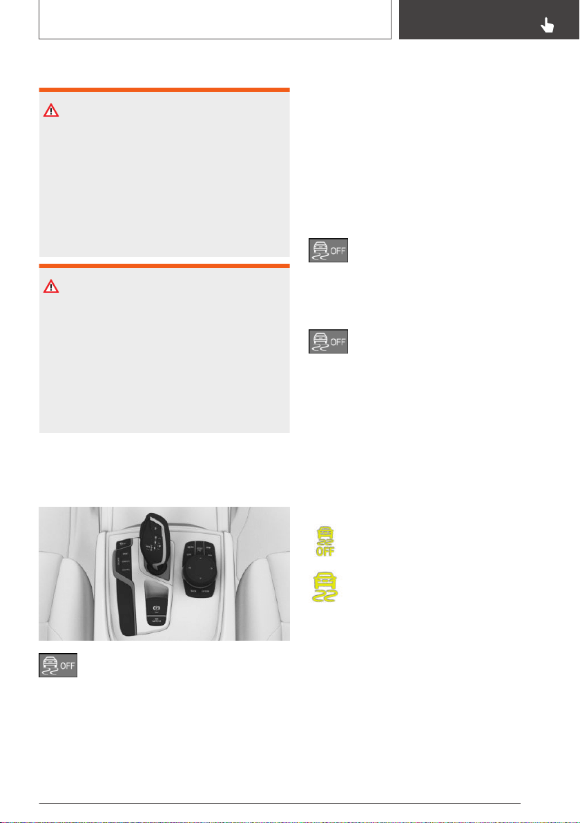
Safety information
WARNING
The system cannot serve as a substitute for the
driver’s personal judgment in assessing the
traffic situation. Based on the limits of the sys‐
tem, it cannot independently react to all traffic
situations. There is a risk of an accident. Adjust
driving style to traffic conditions. Watch traffic
closely and actively intervene where appropri‐
ate.
WARNING
When driving with a roof load, for instance with
roof-mounted luggage rack, the vehicle's cen‐
ter of gravity is higher, which increases the risk
of the vehicle tipping in critical driving situa‐
tions. There is a risk of accidents or risk of
damage to property. Do not deactivate DSC
Dynamic Stability Control when driving with
roof load.
Overview
Button in the vehicle
DSC OFF
Deactivating/activating DSC
General information
When DSC is deactivated, driving stability is re‐
duced during acceleration and when driving in
curves.
To increase vehicle stability, activate DSC again
as soon as possible.
Deactivating DSC
Hold the button down until DSC OFF is
displayed in the instrument cluster and
the DSC OFF indicator light is illuminated.
Activating DSC
Press the button.
DSC OFF and the DSC OFF indicator
light go out.
Display
In the instrument cluster
When DSC is deactivated, DSC OFF is displayed
in the instrument cluster.
Indicator/warning lights
The indicator light lights up: DSC is de‐
activated.
The indicator light flashes: DSC controls
the drive and braking forces.
The indicator light lights up: DSC has
malfunctioned.
Seite 193
Driving stability control systems
CONTROLS
193
Online Edition for Part no. 01402896703 - X/18
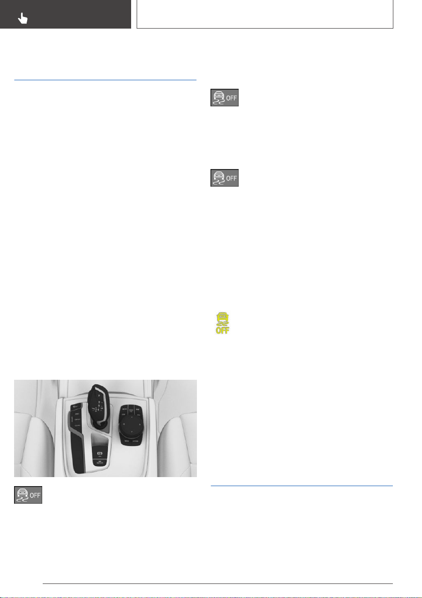
DTC Dynamic Traction
Control
Concept
DTC is a version of the DSC Dynamic Stability
Control where forward momentum is optimized.
The system ensures maximum headway on spe‐
cial road conditions or loose road surfaces, for in‐
stance unplowed snowy roads, but with some‐
what limited driving stability.
General information
When DTC is activated, the vehicle has maxi‐
mum traction. Driving stability is limited during
acceleration and when driving in curves.
You may find it useful to briefly activate DTC in
the following situations:
▷ When driving in slush or on uncleared, snow-
covered roads.
▷ When driving off from deep snow or loose
ground.
▷ When driving with snow chains.
Overview
Button in the vehicle
DSC OFF
Activating/deactivating DTC
Activating DTC
Press the button.
TRACTION is displayed in the instru‐
ment cluster and the indicator light for DSC OFF
lights up.
Deactivating DTC
Press the button again.
TRACTION and the DSC OFF indicator
light go out.
Display
Display in the instrument cluster
If DTC is activated, TRACTION is displayed in
the instrument cluster.
Indicator/warning lights
The indicator light lights up: DTC is acti‐
vated.
Automatic program change
The system automatically switches to "DSC ON"
in the following situations:
▷ If Active Cruise Control with Stop&Go func‐
tion ACC is activated.
▷ On a braking intervention by the Intelligent
Safety systems.
▷ The vehicle has a flat tire.
xDrive
Concept
xDrive is the all-wheel-drive system of the vehi‐
cle. The interaction of xDrive and DSC Dynamic
Stability Control further optimizes traction and
driving dynamics. xDrive variably distributes the
Seite 194
CONTROLS
Driving stability control systems
194
Online Edition for Part no. 01402896703 - X/18
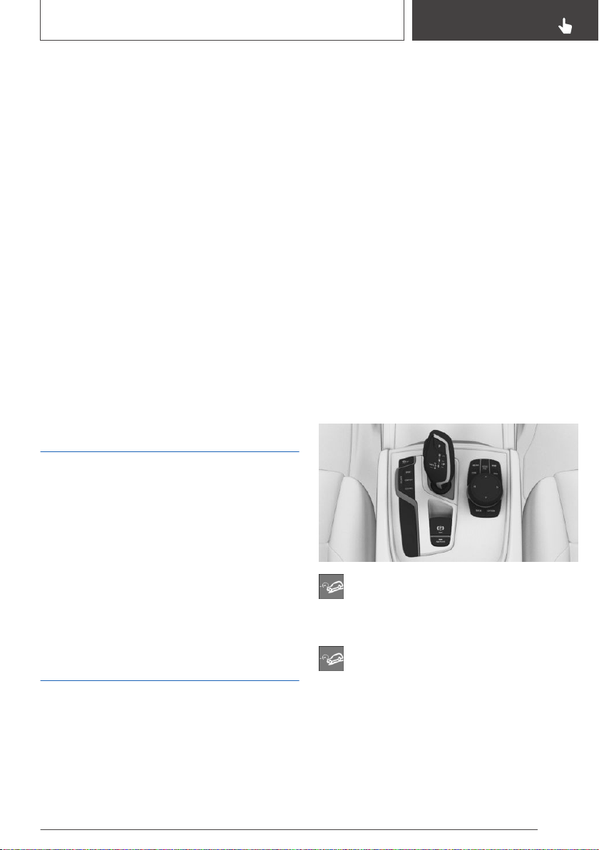
driving forces to the front and rear axles as de‐
manded by the driving situation and road surface.
Display on the Control Display
Displaying xDrive view
Via iDrive:
1. "My Vehicle"
2. "Technology in action"
3. "xDrive status"
The following information is displayed:
▷ With a navigation system: compass display
for the driving direction.
▷ Pitch attitude with degree indication and per‐
centage.
▷ Transverse gradient with degree indication.
▷ Graphic display for the steering angle.
Automatic Differential
Brake
The system controls the driving force by auto‐
matic braking intervention on individual wheels.
The function corresponds to a differential lock:
the system detects if a wheel begins to spin, be‐
cause of loose road surface, for instance and au‐
tomatically brakes it.
The driving force is diverted to the wheel with
better traction.
As a result, the engine force is transferred more
efficiently to the wheels during accelerations.
HDC Hill Descent Control
Concept
Hill Descent Control, HDC, is a downhill control
feature that controls the vehicle speed on steep
downhill grades, for instance when driving on un‐
paved roads.
When the system is active, the vehicle moves at
the speed set by the driver, without the driver
having to depress the brake pedal.
While HTC is controlling the speed, the system
automatically distributes the braking force to the
individual wheels. This improves vehicle drivabil‐
ity and stability. If necessary, the Antilock Brake
System prevents the wheels from locking.
General information
Hill Descent Control can be activated at speeds
below approx. 25 mph/40 km/h.
Speeds can be set between approx.
2 mph/3 km/h and approx. 20 mph/30 km/h.
When the vehicle is moving downhill, the system
reduces the speed to the set value, within the
physical limits.
Overview
Button in the vehicle
HDC
Activating HDC
Press the button. The LED above the but‐
ton lights up.
Speeds between approx. 2 mph/3 km/h and ap‐
prox. 20 mph/30 km/h are adopted as the de‐
sired speed.
Emergency braking function, Active PDC: the
emergency braking function, refer to page 213,
is deactivated.
Seite 195
Driving stability control systems
CONTROLS
195
Online Edition for Part no. 01402896703 - X/18
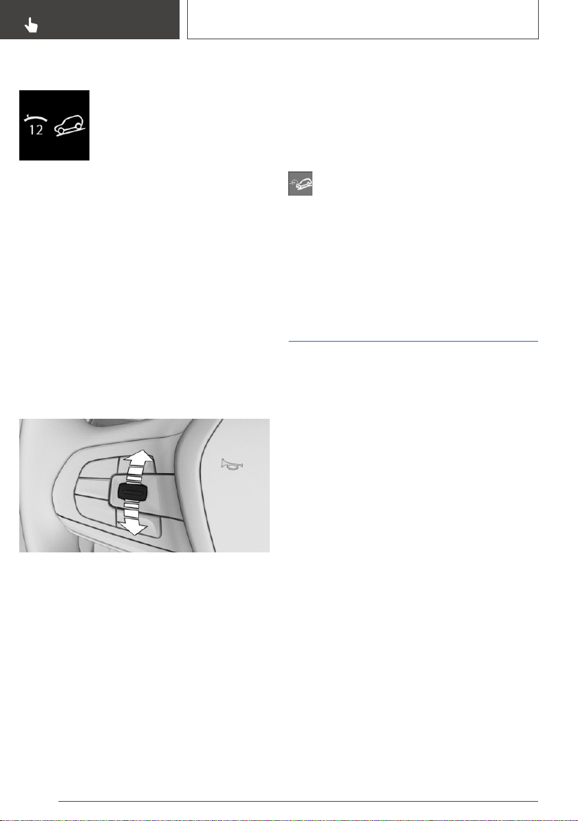
Display in the instrument cluster
A symbol and the selected de‐
sired speed are displayed.
▷ Green display: HDC is active,
the system is reducing the ve‐
hicle speed.
▷ Gray display: HDC is on standby.
Display in the Head-up Display
The HDC status can also be displayed in the
Head-up Display.
Increasing or decreasing vehicle
speed
Using the cruise control rocker
switch
The desired speed can be changed using the
cruise control rocker switch on the steering
wheel.
▷ Press the rocker switch up: the speed in‐
creases gradually.
▷ Press the rocker switch up and hold: the
speed increases while the rocker switch is
pressed.
▷ Press the rocker switch down: the speed de‐
creases gradually.
▷ Press the rocker switch down and hold: the
speed decreases while the rocker switch is
pressed.
Using the brake pedal
While HDC is controlling the speed, the set de‐
sired speed can be reduced by depressing the
brake pedal.
Deactivating HDC
Press the button again. The LED goes out.
HDC is automatically deactivated above
approx. 25 mph/40 km/h.
Malfunction
If a malfunction occurs, a message is displayed in
the instrument cluster.
Variable sport steering
The variable sport steering facilitates a direct and
agile driving style with little steering effort. The
variable sports steering works independently of
the current speed, varying the steering ratio in
line with the steering angle.
Seite 196
CONTROLS
Driving stability control systems
196
Online Edition for Part no. 01402896703 - X/18
Driver assistance systems
Vehicle features and
options
This chapter describes all standard, country-spe‐
cific and optional features offered with the series.
It also describes features that are not necessarily
available in your vehicle, e. g., due to the selected
options or country versions. This also applies to
safety-related functions and systems. When us‐
ing these functions and systems, the applicable
laws and regulations must be observed.
Cruise control
Concept
Using this system, a desired speed can be ad‐
justed using the buttons on the steering wheel.
The system maintains the desired speed. The
system accelerates and brakes automatically as
needed.
General information
Depending on the vehicle setting, the cruise
control characteristic can change in certain
ranges. For instance, the acceleration in ECO
PRO driving mode is more gentle.
Safety information
WARNING
The system cannot serve as a substitute for the
driver’s personal judgment in assessing the
traffic situation. Based on the limits of the sys‐
tem, it cannot independently react to all traffic
situations. There is a risk of an accident. Adjust
driving style to traffic conditions. Watch traffic
closely and actively intervene where appropri‐
ate.
WARNING
The use of the system can lead to an increased
risk of accidents in the following situations,
for instance:
▷ On winding roads.
▷ In heavy traffic.
▷ On slippery roads, in fog, snow, or wet
conditions, or on a loose road surface.
There is a risk of accidents or risk of damage to
property. Only use the system if driving at con‐
stant speed is possible.
WARNING
The desired speed can be incorrectly adjusted
or called up by mistake. There is a risk of an ac‐
cident. Adjust the desired speed to the traffic
conditions. Watch traffic closely and actively in‐
tervene where appropriate.
Overview
Buttons on the steering wheel
Button Function
Cruise control on/off, refer to
page 198.
Pause cruise control, refer to
page 198.
Continue cruise control with the last
setting, refer to page 199.
Store speed, refer to page 198.
Rocker switch:
Set speed, refer to page 198.
Seite 197
Driver assistance systems
CONTROLS
197
Online Edition for Part no. 01402896703 - X/18
Switching cruise control on/off
Switching on
Press the button on the steering wheel.
The indicator lights in the instrument cluster light
up and the mark in the speedometer is set to the
current speed.
Cruise control is active. The current speed is
maintained and stored as desired speed.
DSC Dynamic Stability Control is switched on, if
necessary.
Switching off
Press the button on the steering wheel.
The displays go out. The stored desired speed is
deleted.
Pausing cruise control
Interrupting manually
When active, press the button.
Interrupting automatically
The system is automatically interrupted in the
following situations, for example:
▷ When the driver applies the brakes.
▷ Steptronic transmission: when selector lever
position D is disengaged.
▷ Dynamic Traction Control DTC is activated or
DSC Dynamic Stability Control is deactivated.
▷ If DSC Dynamic Stability Control intervenes.
▷ When SPORT PLUS is activated with Driving
Dynamics Control.
Setting the speed
Maintaining and storing the speed
Press the rocker switch up or down once while
the system is interrupted.
When the system is switched on, the current
speed is maintained and stored as the desired
speed.
The stored speed is displayed, refer to
page 199, in the speedometer and briefly in the
instrument cluster.
DSC Dynamic Stability Control is switched on, if
necessary.
The speed can also be stored by pressing a but‐
ton.
Press the button.
Changing the speed
Press the rocker switch up or down repeatedly
until the desired speed is set.
If active, the displayed speed is stored and the
vehicle reaches the stored speed when the road
is clear.
Seite 198
CONTROLS
Driver assistance systems
198
Online Edition for Part no. 01402896703 - X/18
▷ Each time the rocker switch is pressed to the
resistance point, the desired speed increases
or decreases by 1 mph/1 km/h.
▷ Each time the rocker switch is pressed past
the resistance point, the desired speed
changes by a maximum of 5 mph/10 km/h.
The maximum speed that can be set de‐
pends on the vehicle.
▷ Pressing the rocker switch to the resistance
point and holding it accelerates or deceler‐
ates the vehicle without requiring pressure on
the accelerator pedal.
After the rocker switch is released, the vehi‐
cle maintains its final speed. Pressing the
switch beyond the resistance point causes
the vehicle to accelerate more rapidly.
Continuing cruise control
An interrupted cruise control can be continued
by calling up the stored speed.
Make sure that the difference between current
speed and stored speed is not too large before
calling up the stored speed. Otherwise, uninten‐
tional braking or accelerating may occur.
Press the button with the system inter‐
rupted.
Cruise control is continued with the stored val‐
ues.
In the following cases, the stored speed value is
deleted and cannot be called up again:
▷ When the system is switched off.
▷ When drive-ready state is switched off.
Displays in the instrument
cluster
Display in the speedometer
▷ Green marking: system is ac‐
tive, the marking indicates the
desired speed.
▷ Orange/white marking: system is interrupted,
the marking indicates the stored speed.
▷ No marking: system is switched off.
Indicator light
▷ Indicator light green: system is active.
▷ Gray indicator light: the system has
been interrupted.
▷ No indicator light: system is switched off.
Status display
The selected desired speed is hidden af‐
ter a brief time.
Displays in the Head-up Display
Some system information can also be displayed
in the Head-up Display.
The symbol is displayed when the set
desired speed is reached.
System limits
The desired speed is also maintained downhill.
The speed may not be maintained on uphill
grades if the engine power is insufficient.
In ECO PRO driving mode, the vehicle may ex‐
ceed or drop below the set desired speed in
some situations, for instance on downhill or uphill
grades.
Active Cruise Control with
Stop & Go function ACC
Concept
Using this system, a desired speed and a dis‐
tance to a vehicle ahead can be adjusted using
the buttons on the steering wheel.
Seite 199
Driver assistance systems
CONTROLS
199
Online Edition for Part no. 01402896703 - X/18
The system maintains the desired speed on
clear roads. For this purpose, the vehicle acceler‐
ates or brakes automatically.
If a vehicle is driving ahead of you, the system
adjusts the speed of your vehicle so that the set
distance to the vehicle ahead is maintained. The
speed is adjusted as far as the given situation al‐
lows.
General information
A radar sensor is located in the front bumper and
a camera on the interior mirror to detect vehicles
driving ahead of you.
Depending on the vehicle setting, the cruise
control characteristic can change in certain
ranges. For instance, the acceleration in ECO
PRO driving mode is more gentle.
The distance can be adjusted in several steps.
For safety reasons, it depends on the respective
speed.
If the vehicle ahead of you brakes to a halt, and
then proceeds to drive again within a brief period,
the system is able to detect this within the given
system limits.
Safety information
WARNING
The system cannot serve as a substitute for the
driver’s personal judgment in assessing the
traffic situation. Based on the limits of the sys‐
tem, it cannot independently react to all traffic
situations. There is a risk of an accident. Adjust
driving style to traffic conditions. Watch traffic
closely and actively intervene where appropri‐
ate.
WARNING
An unsecured vehicle can begin to move and
possibly roll away. There is a risk of an accident.
Before exiting, secure the vehicle against roll‐
ing.
In order to ensure that the vehicle is secured
against rolling away, follow the following:
▷ Set the parking brake.
▷ On uphill grades or on a downhill slope,
turn the front wheels in the direction of the
curb.
▷ On uphill grades or on a downhill slope,
also secure the vehicle, for instance with a
wheel chock.
WARNING
The desired speed can be incorrectly adjusted
or called up by mistake. There is a risk of an ac‐
cident. Adjust the desired speed to the traffic
conditions. Watch traffic closely and actively in‐
tervene where appropriate.
WARNING
Risk of accident due to too high speed differen‐
ces to other vehicles, for instance in the follow‐
ing situations:
▷ When fast approaching a slowly moving
vehicle.
▷ Vehicle suddenly swerving into own lane.
▷ When fast approaching standing vehicles.
There is a risk of injuries or danger to life.
Watch traffic closely and actively intervene
where appropriate.
Overview
Buttons on the steering wheel
Button Function
Cruise control on/off, refer to
page 201.
Store/maintain speed, refer to
page 202.
Seite 200
CONTROLS
Driver assistance systems
200
Online Edition for Part no. 01402896703 - X/18
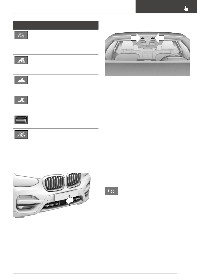
Button Function
Pause cruise control, refer to
page 202.
Continue cruise control with the last
setting, refer to page 203.
Without steering and lane control as‐
sistant:
Increase distance, refer to page 203.
Without steering and lane control as‐
sistant:
Reduce distance, refer to page 203.
With steering and lane control assis‐
tant:
Adjust distance, refer to page 203.
Rocker switch:
Set speed, refer to page 202.
With steering and lane control assis‐
tant:
Steering and lane control assistant
incl. Traffic Jam Assist on/off, refer to
page 206.
Radar sensor
The radar sensor is located in the front bumper.
Always keep radar sensor clean and unob‐
structed.
Camera
The camera is installed near the interior mirror.
Keep the windshield in front of the interior mirror
clean and clear.
Area of application
The system is best used on well-constructed
roads.
The minimum speed that can be set is
20 mph/30 km/h.
The maximum speed that can be set is
115 mph/180 km/h.
The system can also be activated when station‐
ary.
Switching on/off and interrupting
cruise control
Switching on
Press the button on the steering wheel.
The indicator lights in the instrument cluster light
up and the mark in the speedometer is set to the
current speed.
Cruise control is active. The current speed is
maintained and stored as desired speed.
DSC Dynamic Stability Control is switched on, if
necessary.
Switching off
To switch off the system while standing, step on
brake pedal at the same time.
Seite 201
Driver assistance systems
CONTROLS
201
Online Edition for Part no. 01402896703 - X/18
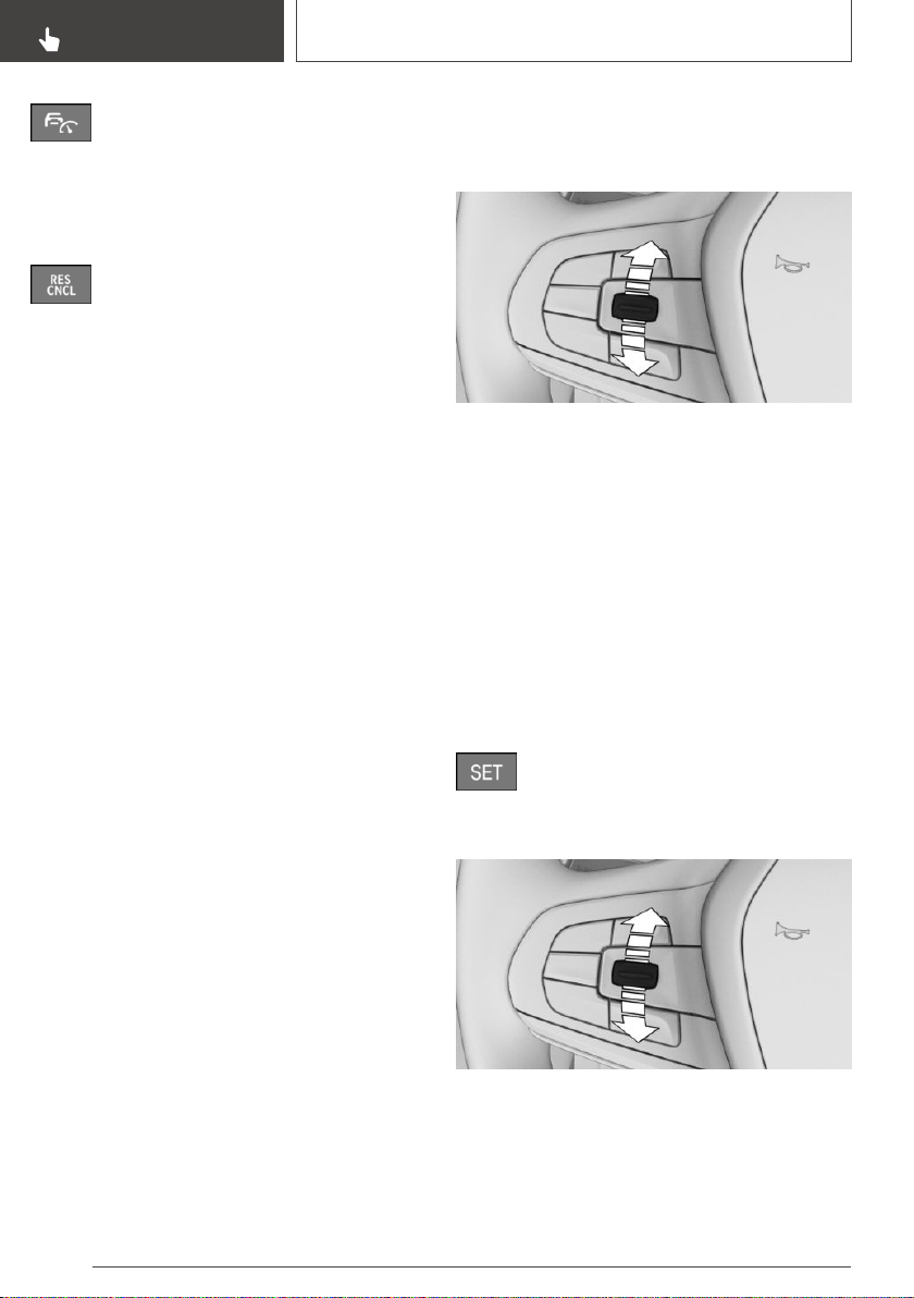
Press the button on the steering wheel.
The displays go out. The stored desired speed is
deleted.
Interrupting manually
When active, press the button on the
steering wheel.
If interrupting the system while stationary, press
on the brake pedal at the same time.
Interrupting automatically
The system is automatically interrupted in the
following situations:
▷ When the driver applies the brakes.
▷ When selector lever position D is disengaged.
▷ Dynamic Traction Control DTC is activated or
DSC Dynamic Stability Control is deactivated.
▷ If DSC Dynamic Stability Control intervenes.
▷ If the safety belt is unbuckled and the driver's
door is opened while the vehicle is standing
still.
▷ If the system has not detected objects for an
extended period, for instance on a road with
very little traffic without curb or shoulder
markings.
▷ If the detection range of the radar is impaired,
for instance by dirt or heavy fog.
▷ After a longer stationary period when the ve‐
hicle has been braked to a stop by the sys‐
tem.
Setting the speed
Maintaining and storing the speed
Press the rocker switch up or down once while
the system is interrupted.
When the system is switched on, the current
speed is maintained and stored as the desired
speed.
The stored speed is displayed, refer to
page 203, in the speedometer and briefly in the
instrument cluster.
DSC Dynamic Stability Control is switched on, if
necessary.
The speed can also be stored by pressing a but‐
ton.
Press the button.
Changing the speed
Press the rocker switch up or down repeatedly
until the desired speed is set.
If active, the displayed speed is stored and the
vehicle reaches the stored speed when the road
is clear.
Seite 202
CONTROLS
Driver assistance systems
202
Online Edition for Part no. 01402896703 - X/18
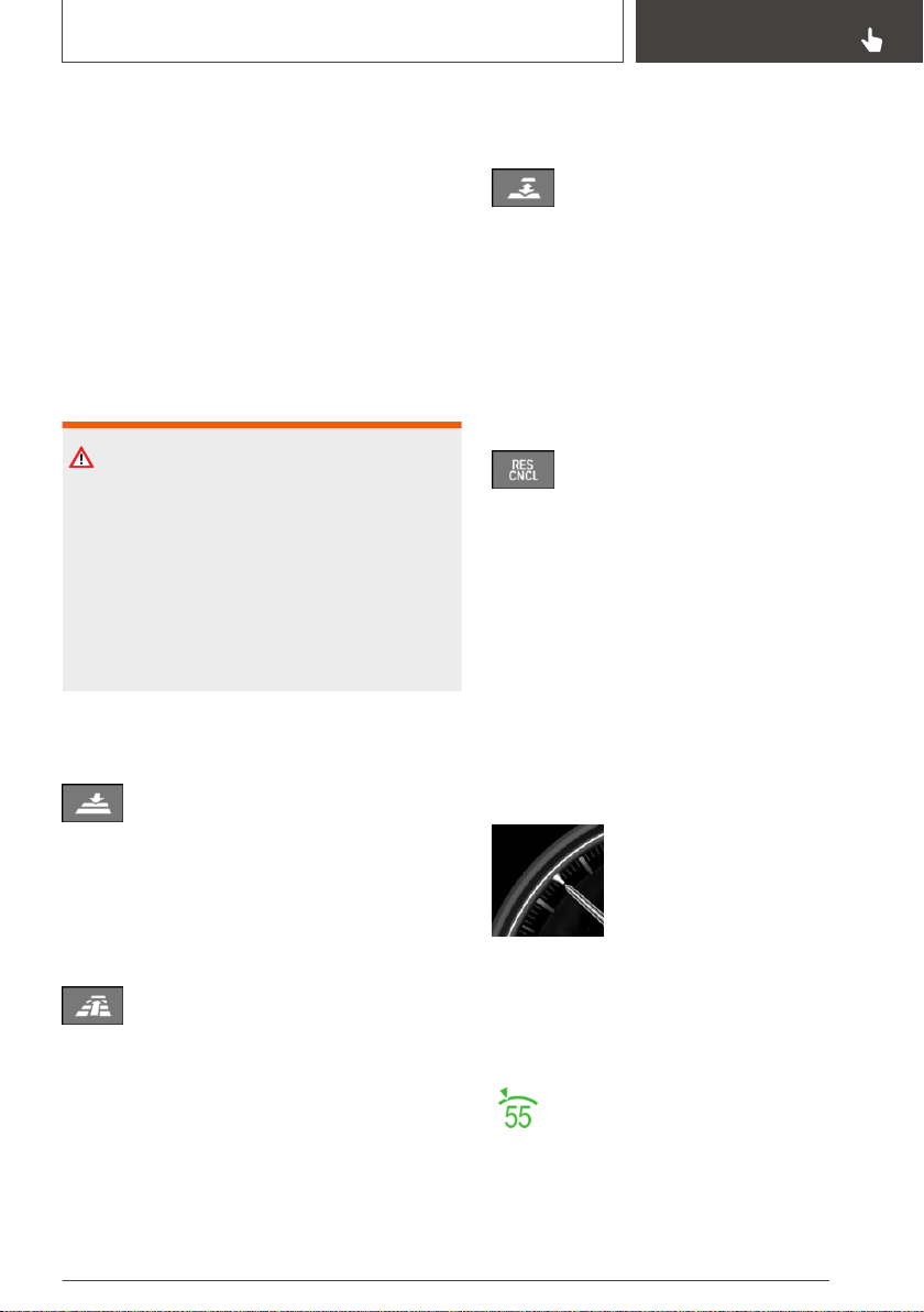
▷ Each time the rocker switch is pressed to the
resistance point, the desired speed increases
or decreases by 1 mph/1 km/h.
▷ Each time the rocker switch is pressed past
the resistance point, the desired speed
changes by a maximum of 5 mph/10 km/h.
Hold the rocker switch in position to repeat the
action.
Adjusting distance
Safety information
WARNING
The system cannot serve as a substitute for the
driver’s personal judgment. Due to the system
limits, braking can be late. There is a risk of ac‐
cidents or risk of damage to property. Be aware
to the traffic situation at all times. Adjust the
distance to the traffic and weather conditions
and maintain the prescribed safety distance,
possibly by braking.
Without steering and lane control
assistant: reducing distance
Press the button repeatedly until the
desired distance is set.
Instrument cluster will display selected distance,
refer to page 204.
Without steering and lane control
assistant: increasing distance
Press the button repeatedly until the
desired distance is set.
Instrument cluster will display selected distance,
refer to page 204.
With steering and lane control
assistant: adjusting distance
Press the button repeatedly until the
desired distance is set.
Continuing cruise control
An interrupted cruise control can be continued
by calling up the stored speed.
Make sure that the difference between current
speed and stored speed is not too large before
calling up the stored speed. Otherwise, uninten‐
tional braking or accelerating may occur.
Press the button with the system inter‐
rupted.
Cruise control is continued with the stored val‐
ues.
In the following cases, the stored speed value is
deleted and cannot be called up again:
▷ When the system is switched off.
▷ When drive-ready state is switched off.
Displays in the instrument
cluster
Display in the speedometer
▷ Green marking: system is ac‐
tive, the marking indicates the
desired speed.
▷ Orange/white marking: system
is interrupted, the marking in‐
dicates the stored speed.
▷ No marking: system is switched off.
Status display
The selected desired speed is hidden af‐
ter a brief time.
Seite 203
Driver assistance systems
CONTROLS
203
Online Edition for Part no. 01402896703 - X/18
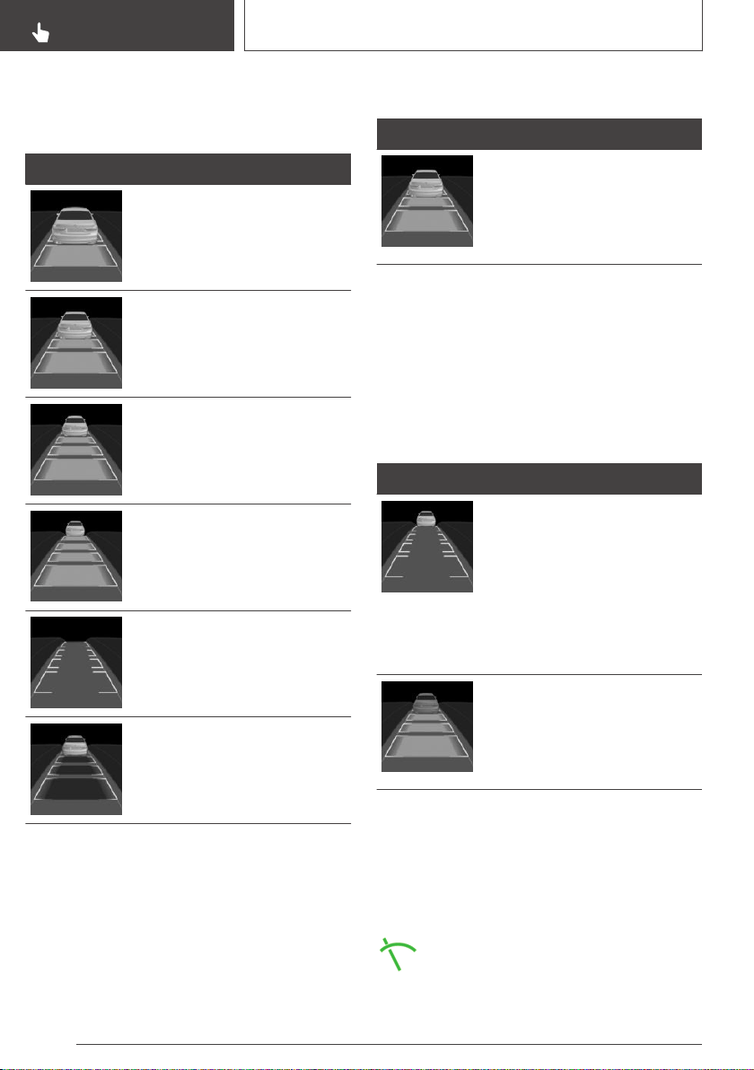
Distance to vehicle ahead of you
Selected distance to the vehicle ahead of you is
shown.
Symbol Description
Distance 1
Distance 2
Distance 3
Distance 4
This value is set automatically
after the system is switched on.
System interrupted.
No distance control display, as
the accelerator pedal is being
pressed.
Detected vehicle
Symbol Description
Green symbol:
A vehicle has been detected
ahead of you. The system main‐
tains the set distance to the ve‐
hicle in front.
As soon as the detected vehicle drives off, the
vehicle symbol in the distance indicator will move
away.
To accelerate, activate ACC, for instance by
briefly stepping on the accelerator pedal or
pressing the rocker switch.
Indicator/warning lights
Symbol Description
Vehicle symbol flashes:
The conditions are not adequate
for the system to work.
The system was deactivated but
applies the brakes until you ac‐
tively resume control by press‐
ing on the brake pedal or accel‐
erator pedal.
The vehicle symbol and dis‐
tance bars flash red and an
acoustic signal sounds:
Brake and make an evasive ma‐
neuver, if necessary.
Displays in the Head-up Display
Desired speed
Some system information can also be displayed
in the Head-up Display.
The symbol is displayed when the set
desired speed is reached.
Seite 204
CONTROLS
Driver assistance systems
204
Online Edition for Part no. 01402896703 - X/18
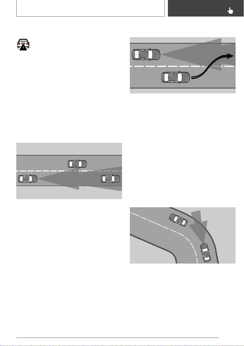
Distance information
The symbol is displayed when the dis‐
tance from the vehicle traveling ahead is
too short.
The distance information is active in the follow‐
ing situations:
▷ Active Cruise Control switched off.
▷ Display in the Head-up Display selected, refer
to page 154.
▷ Distance too short.
▷ Speed greater than approx. 40 mph/70 km/h.
System limits
Detection range
The detection capacity of the system and the
automatic braking capacity are limited.
Two-wheeled vehicles for instance might not be
detected.
Deceleration
The system does not decelerate in the following
situations:
▷ For pedestrians or similarly slow-moving road
users.
▷ For red traffic lights.
▷ For cross traffic.
▷ For oncoming traffic.
Swerving vehicles
A vehicle driving in front of you is not detected
until it is completely within the same lane as your
vehicle.
If a vehicle driving ahead of you suddenly
swerves into your lane, the system may not be
able to automatically restore the selected dis‐
tance. It may not be possible to restore the se‐
lected distance in certain situations, including if
you are driving significantly faster than vehicles
driving ahead of you, for instance when rapidly
approaching a truck. When a vehicle driving
ahead of you is reliably detected, the system re‐
quests that the driver intervene by braking and
carrying out evasive maneuvers, if needed.
Cornering
If the desired speed is too high for a curve, the
speed is reduced slightly, although curves can‐
not be anticipated in advance. Therefore, drive
into a curve at an appropriate speed.
The system has a limited detection range. Situa‐
tions can arise in tight curves where a vehicle
driving ahead will not be detected or will be de‐
tected very late.
Seite 205
Driver assistance systems
CONTROLS
205
Online Edition for Part no. 01402896703 - X/18

When you approach a curve the system may
briefly report vehicles in the next lane due to the
bend of the curve. If the system decelerates you
may compensate it by briefly accelerating. After
releasing the accelerator pedal the system is re‐
activated and controls speed independently.
Driving off
In some situations, the vehicle cannot drive off
automatically; for example:
▷ On steep uphill grades.
▷ From bumps in the road.
▷ With a heavy trailer.
In these cases, step on the accelerator pedal.
Weather
The following restrictions can occur under unfav‐
orable weather or light conditions:
▷ Poorer vehicle recognition.
▷ Short-term interruptions for vehicles that are
already recognized.
Examples of unfavorable weather or light condi‐
tions:
▷ Wet conditions.
▷ Snowfall.
▷ Slush.
▷ Fog.
▷ Glare.
Drive attentively, and react to the current traffic
situation. If necessary, intervene actively, for in‐
stance by braking, steering or evading.
Engine power
The desired speed is also maintained downhill.
The speed may not be maintained on uphill
grades if the engine power is insufficient.
In ECO PRO driving mode, the vehicle may in‐
tentionally exceed or drop below the set desired
speed in some situations, for instance on down‐
hill or uphill grades.
Malfunction
Radar sensor
The system cannot be activated if the radar sen‐
sor is not aligned correctly. This may be caused
by damage incurred, for instance during parking.
A Check Control message is displayed if the sys‐
tem fails.
Have the system checked by a dealer’s service
center or another qualified service center or re‐
pair shop.
The system may be impaired when the detection
range of the radar sensor is partially covered
such as by the license plate holder.
Camera
The function for detecting and responding when
approaching stationary vehicles may be limited in
the following situations:
▷ During calibration of the camera immediately
after vehicle delivery.
▷ If the camera is malfunctioning or dirty. A
Check Control message is displayed.
Steering and lane control
assistant
Concept
The system assists the driver in keeping the ve‐
hicle within the lane. For this purpose, the sys‐
tem executes supporting steering movements,
for instance when driving in a curve.
Seite 206
CONTROLS
Driver assistance systems
206
Online Edition for Part no. 01402896703 - X/18
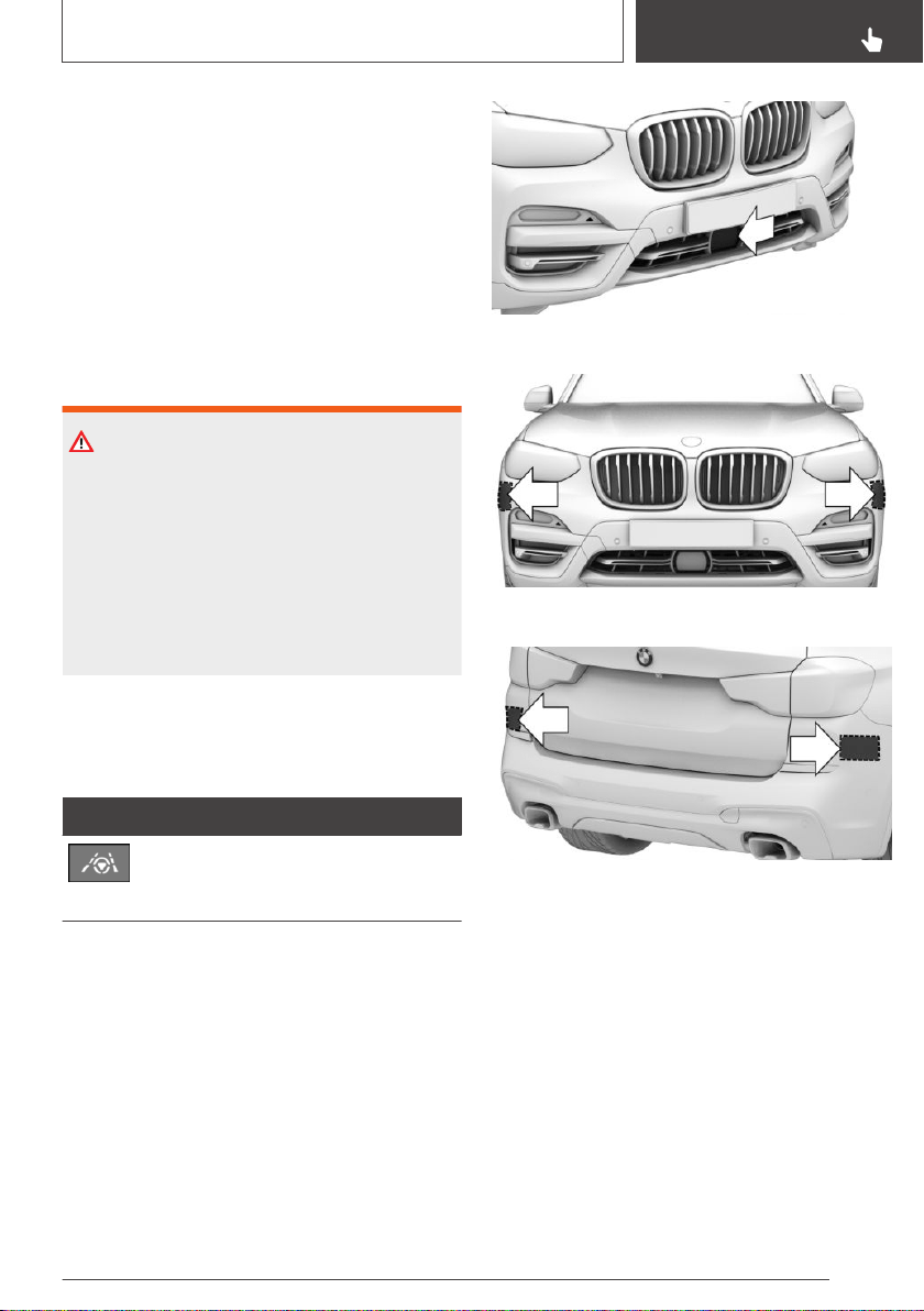
General information
The system determines the position of the lane
markings and the vehicle driving ahead using five
radar sensors and a camera.
Depending on the speed, the system orients it‐
self according to the lane markings or vehicles in
front.
Sensors on the steering wheel detect whether
the steering wheel is being touched.
Safety information
WARNING
The system cannot serve as a substitute for the
driver’s personal judgment in assessing the
traffic situation. Based on the limits of the sys‐
tem, it cannot independently react to all traffic
situations. There is a risk of an accident. Adjust
driving style to traffic conditions. Watch traffic
closely and actively intervene where appropri‐
ate.
Overview
Button on the steering wheel
Button Function
Steering and lane control assistant
incl. Traffic Jam Assist on/off, refer to
page 208.
Radar sensors
The radar sensors are located in the bumpers.
Front center bumper.
Front side bumper.
Rear bumper.
Always keep the bumper in the area of the radar
sensors clean and unobstructed.
Seite 207
Driver assistance systems
CONTROLS
207
Online Edition for Part no. 01402896703 - X/18
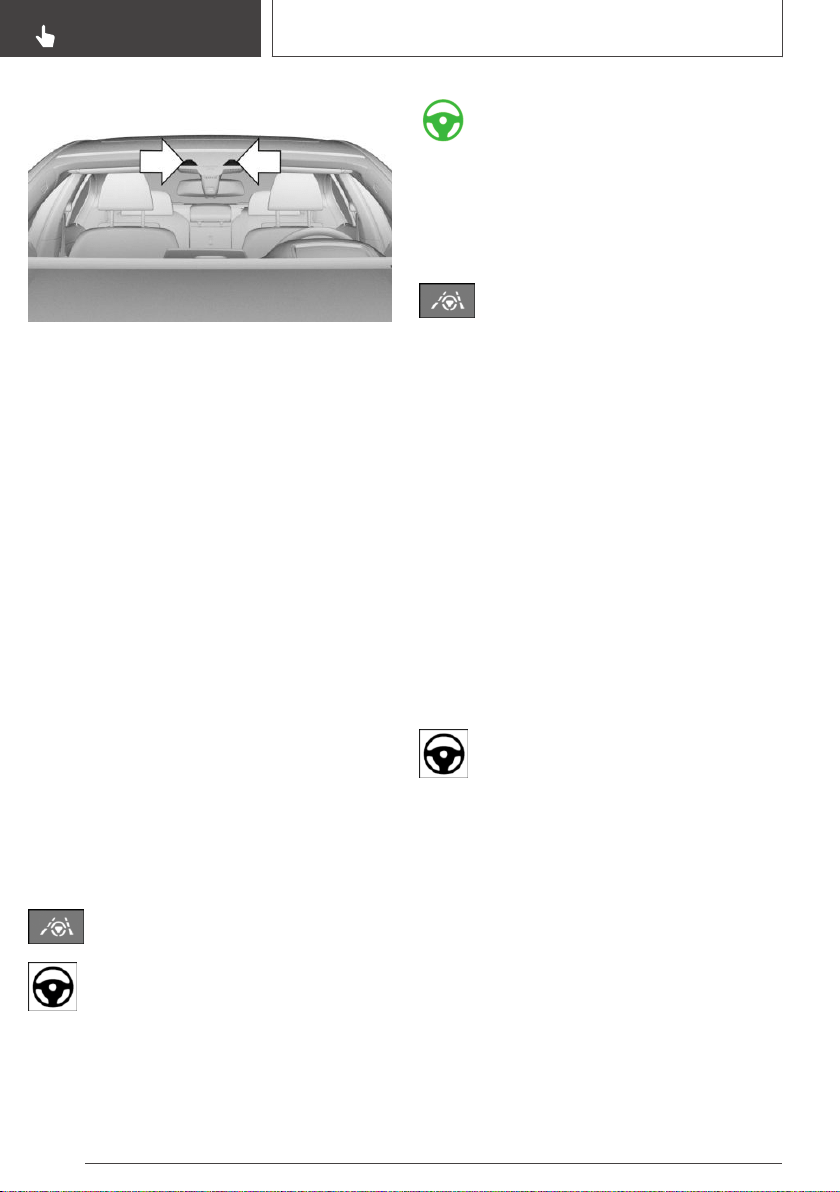
Camera
The camera is installed near the interior mirror.
Keep the windshield in front of the interior mirror
clean and clear.
Functional requirements
▷ Speed below 130 mph/210 km/h.
▷ Sufficient lane width.
▷ Above approx. 43 mph, 70 km/h: lane mark‐
ing on both sides is detected.
▷ Below approx. 43 mph, 70 km/h: lane marking
on both sides or a vehicle driving ahead is de‐
tected.
▷ Hands on the steering wheel rim.
▷ Wide curves.
▷ Drive in the center of the lane.
▷ Turn signal switched off.
▷ The sensor system calibration process is
complete.
Switching on/off
Switching on
Press the button on the steering wheel.
Steering wheel symbol lights up gray.
The system is on standby and does not
manipulate steering.
System activates automatically as soon as all
function conditions are fulfilled, refer to
page 208.
Steering wheel symbol lights up green.
The system is active.
With the system switched on, the person warn‐
ing with City braking function and the side colli‐
sion warning are active.
Switching off
Press the button on the steering wheel.
The indicator goes out.
The system does not perform supportive steer‐
ing wheel movements.
Interrupting automatically
The system is automatically interrupted in the
following situations:
▷ At a speed above 130 mph/210 km/h.
▷ When the steering wheel is released.
▷ When you manipulate steering.
▷ When you leave your own lane.
▷ When the turn signal is switched on.
▷ When the lane is too narrow.
▷ If for a particular time no lane marking is de‐
tected and there is no vehicle driving in front.
Steering wheel symbol lights up gray.
The system is on standby and does not
manipulate steering.
System activates automatically as soon as all
function conditions are fulfilled, refer to
page 208.
Seite 208
CONTROLS
Driver assistance systems
208
Online Edition for Part no. 01402896703 - X/18
Displays in the instrument
cluster
Symbol Description
Gray steering wheel symbol:
The system is on standby.
Green steering wheel symbol:
The system is activated.
Yellow steering wheel symbol
and a signal sounds, if applica‐
ble:
System interruption is imminent.
Green steering wheel symbol
and lane marking symbol:
The system supports the driver
in keeping the vehicle within the
lane.
Green steering wheel symbol,
gray lane marking symbol:
No lane marking detected, the
vehicle follows the vehicle
ahead.
The limits of steering support
when cornering may have been
reached.
Symbol Description
Yellow steering wheel symbol:
The hands are not grasping the
steering wheel. The system is
still active.
Red steering wheel symbol and
a signal sounds:
The hands are not grasping the
steering wheel. System interrup‐
tion is imminent.
The system does not perform
supportive steering wheel move‐
ments.
With Active Cruise Control, the
system may reduce the speed.
Displays in the Head-up Display
All system information can also be displayed in
the Head-up Display.
Lane change assistant
Concept
The system additionally supports the driver when
changing lanes on multilane roads.
Functional requirements
▷ The functional requirements of the steering
and lane control assistant are fulfilled, refer to
page 208.
▷ Driving on a road without pedestrians or cy‐
clists and with physical barriers to oncoming
traffic, such as crash barriers.
▷ Lane markings have been detected.
▷ Sensor system of the system is active and a
vehicle approaching from the rear can be de‐
tected.
▷ Active Blind Spot Detection and steering in‐
tervention are switched on, refer to page 181.
Seite 209
Driver assistance systems
CONTROLS
209
Online Edition for Part no. 01402896703 - X/18
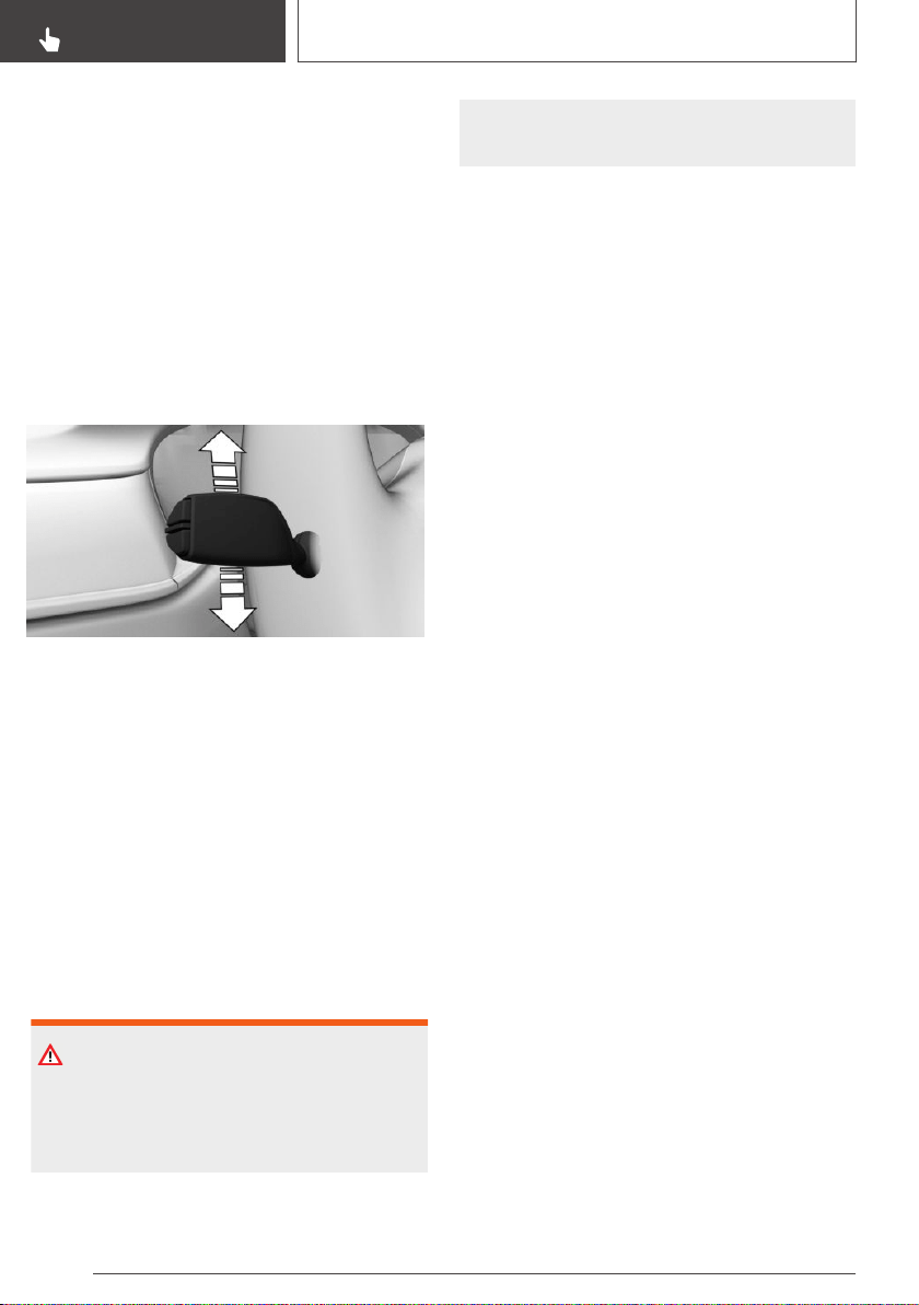
▷ Speed between approx. 43 mph, 70 km/h
and approx. 110 mph, 180 km/h.
Changing lanes
1. Ensure that the traffic situation permits
changing lanes.
2. Press the turn indicator lever, refer to
page 127, in the required direction to the
pressure point for signaling briefly and hold it
there.
Steering support in the required direction can
be detected a short time later.
After the lane change, the system helps keep the
vehicle in the new lane.
Canceling a lane change
If the turn signal lever is released too soon, the
system helps the driver keep to the original lane.
System limits
General information
The system cannot be activated or meaningfully
used in certain situations.
Safety information
WARNING
The system can react not at all, too late, incor‐
rectly, or without justification due to the system
limits. There is a risk of accidents or risk of
damage to property. Follow the information re‐
garding the system limits and actively intervene
if needed.
Hands on the steering wheel
The sensors cannot detect hand-steering wheel
contact in the following situations:
▷ Driving with gloves.
▷ Protective covers on the steering wheel.
Narrow lanes
When driving within narrow lanes, the system
cannot be activated or effectively used, for in‐
stance in the following situations:
▷ In construction areas.
▷ In rescue lanes.
▷ Within city limits.
Weather
The following restrictions can occur under unfav‐
orable weather or light conditions:
▷ Poorer recognition of vehicles and lane mark‐
ings.
▷ Short-term interruptions for vehicles that are
already recognized.
Examples of unfavorable weather or light condi‐
tions:
▷ Wet conditions.
▷ Snowfall.
▷ Slush.
▷ Fog.
▷ Glare.
Drive attentively, and react to the current traffic
situation. If necessary, intervene actively, for in‐
stance by braking, steering or evading.
Seite 210
CONTROLS
Driver assistance systems
210
Online Edition for Part no. 01402896703 - X/18
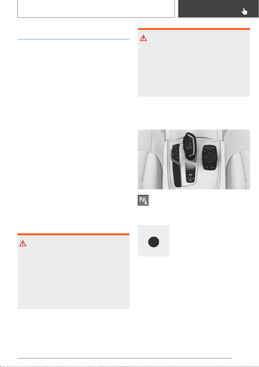
PDC Park Distance Control
Concept
PDC is a support when parking. Objects that you
are approaching slowly in front of or behind the
vehicle are indicated by signal tones and a dis‐
play on the Control Display.
With Parking Assistant: obstacles on the side of
the vehicle that are detected by the sensors of
the parking assistant, may also be reported by
the side protection function, refer to page 214.
General information
The ultrasound sensors for distance measure‐
ments are located in the bumpers and possibly
on the sides of the vehicle.
The maneuvering range, depending on the ob‐
stacle and environmental conditions, is approx.
6 ft/2 m.
An acoustic warning sounds in case of an im‐
pending collision at a distance to the object of
approx. 27 in/70 cm.
For objects behind the vehicle, the acoustic
warning is already issued at a distance to the ob‐
ject of approx. 5 ft/1.50 m.
Safety information
WARNING
The system cannot serve as a substitute for the
driver’s personal judgment in assessing the
traffic situation. Based on the limits of the sys‐
tem, it cannot independently react to all traffic
situations. There is a risk of an accident. Adjust
driving style to traffic conditions. Watch traffic
closely and actively intervene where appropri‐
ate.
WARNING
Due to high speeds when PDC Park Distance
Control is activated, the warning can be de‐
layed due to physical circumstances. There is a
risk of injury or risk of damage to property.
Avoid approaching an object too fast. Avoid
driving off fast while PDC Park Distance Control
is not yet active.
Overview
Button in the vehicle
Park assistance button
Ultrasound sensors
Ultrasound sensors of the PDC,
for instance in the bumpers.
Functional requirements
Ensure full functionality:
▷ Do not cover sensors, for instance with stick‐
ers, bicycle racks.
▷ Keep the sensors clean and unobstructed.
Seite 211
Driver assistance systems
CONTROLS
211
Online Edition for Part no. 01402896703 - X/18

Switching on/off
Switching on automatically
The system switches on automatically in the fol‐
lowing situations:
▷ If selector lever position R is engaged when
the engine is running.
▷ While approaching detected obstacles if the
speed is slower than approx. 2.5 mph/4 km/h.
The activation distance depends on the situa‐
tion in question.
You may switch automatic activation on and off
when obstacles are detected.
Via iDrive:
1.
"My Vehicle"
2. "Vehicle settings"
3. "Parking"
4. "Automatic PDC activation": depending on
the vehicle equipment.
5. "Automatic PDC activation"
The setting is stored for the driver profile cur‐
rently used.
Depending on equipment, an additional camera
view is also switched on.
Automatic deactivation during
forward travel
The system switches off when a certain driving
distance or speed is exceeded.
Switch the system back on, if needed.
Switching on/off manually
Press park assistance button.
▷ On: the LED lights up.
▷ Off: the LED goes out.
The rearview camera image is displayed if the re‐
verse gear is engaged when pressing the park
assistance button.
WARNING
Signal tones
General information
When approaching an object, an intermittent
sound indicates the position of the object. E.g., if
an object is detected to the left rear of the vehi‐
cle, a signal tone sounds from the left rear
speaker.
The shorter the distance to the object, the
shorter the intervals.
If the distance to a detected object is less than
approx. 10 inches/25 cm, a continuous tone is
sounded.
If there are objects in front of and behind the ve‐
hicle at the same time, with a distance smaller
than approx. 10 in/25 cm, an alternating constant
tone will sound.
Steptronic transmission: the intermittent tone
and constant tone are switched off if the selector
lever position P is engaged.
The intermittent tone is switched off after a short
time when the vehicle is stationary.
Volume
The ratio of the PDC signal tone volume to the
entertainment volume can be adjusted.
Via iDrive:
1.
"My Vehicle"
2. "iDrive settings"
3. "Tone"
4. "Volume settings"
5. "PDC"
6. Set the desired value.
The setting is stored for the driver profile cur‐
rently used.
Seite 212
CONTROLS
Driver assistance systems
212
Online Edition for Part no. 01402896703 - X/18
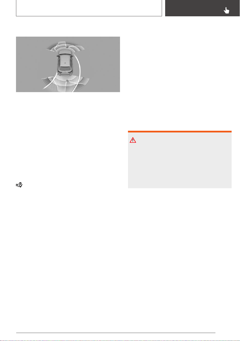
Visual warning
The approach of the vehicle to an object is
shown on the Control Display. Objects that are
farther away are already displayed on the Control
Display before a signal sounds.
The display appears as soon as PDC is activated.
The range of the sensors is represented in the
colors green, yellow and red.
Pathway lines are faded in for better estimation
of the required space.
When the image of the rearview camera is dis‐
played, the switch can be made to PDC or to a
different view with obstacle markings as needed:
"Rear view camera"
Crossing traffic warning, refer to page 230: de‐
pending on the equipment, it is warned in the
PDC display against vehicles approaching in the
front or rear from the side.
With parking assistant and
Steptronic transmission:
emergency braking function,
Active PDC
Concept
The emergency braking function of PDC initiates
an emergency braking in case of acute risk of
collision.
General information
Due to system limits, a collision cannot be pre‐
vented under all circumstances.
The function is available from walking speed
while backing up or rolling backward.
A press of the accelerator pedal interrupts the
braking intervention.
After emergency braking to a stop, further creep‐
ing toward an obstacle is possible. To creep to‐
ward the obstacle, lightly press the accelerator
pedal and release it again.
If the accelerator pedal is heavily depressed, the
vehicle drives off as usual. Manual braking is pos‐
sible at any time.
The system uses the ultrasound sensors of PDC
and parking assistant.
Safety information
WARNING
The system cannot serve as a substitute for the
driver’s personal judgment in assessing the
traffic situation. There is a risk of an accident.
Adjust driving style to traffic conditions. Watch
traffic and vehicle surroundings closely and ac‐
tively intervene where appropriate.
Activating/deactivating the system
Via iDrive:
1.
"My Vehicle"
2. "Vehicle settings"
3. "Parking"
4. "Active PDC with braking interv."
5. "Active PDC with braking interv."
The setting is stored for the driver profile cur‐
rently used.
System limits
The system cannot be used in the following sit‐
uations, for example:
▷ When Hill Descent Control, refer to page 195,
is active, the emergency braking function is
deactivated.
Seite 213
Driver assistance systems
CONTROLS
213
Online Edition for Part no. 01402896703 - X/18
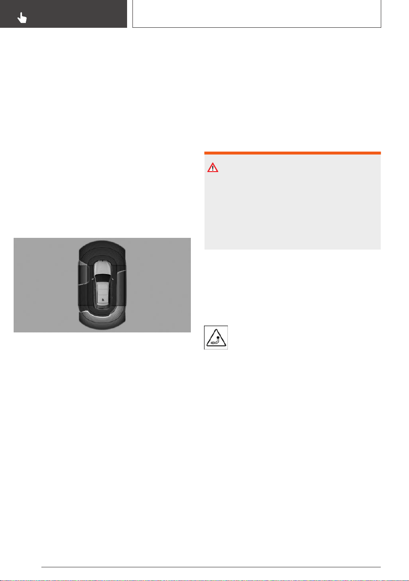
▷ When driving with a trailer.
If required, deactivate the system via iDrive
where applicable.
With Parking Assistant: side
protection
Concept
The system warns of obstacles on the side of
the vehicle.
General information
The system uses the ultrasound sensors of PDC
and parking assistant.
Display
To protect the sides of the vehicle, obstacle
markings are displayed on the vehicle at the
sides.
▷ Color markings: warning against detected ob‐
stacles.
▷ Gray markings, hatched area: no obstacles
were detected.
▷ No markings, black area: the area next to the
vehicle was not yet captured.
Limits of side protection
The system only displays stationary obstacles
that were previously detected by sensors while
passing them.
The system does not detect whether an obstacle
moves later on. If the vehicle is stationary, the
markings are shown in black after a certain time.
The area next to the vehicle must be newly cap‐
tured.
Side protection is not available, if the trailer
power socket is in use or trailer towing is acti‐
vated.
System limits
Safety information
WARNING
The system can react not at all, too late, incor‐
rectly, or without justification due to the system
limits. There is a risk of accidents or risk of
damage to property. Follow the information re‐
garding the system limits and actively intervene
if needed.
With trailer or trailer power socket in
use
With a trailer, a trailer power socket in use or
when trailer towing is activated, the two rear PDC
functions will be switched off.
White symbol is displayed.
Depending on the vehicle equipment,
the range of the sensors is shown as a
shaded area on the Control Display.
Limits of ultrasonic measurement
Ultrasonic measurements might not function in
the following situations:
▷ For small children and animals.
▷ For persons with certain clothing, for instance
coats.
▷ With external interference of the ultrasound,
for instance from passing vehicles or loud
machines.
▷ When sensors are dirty, iced over, damaged
or out of position.
Seite 214
CONTROLS
Driver assistance systems
214
Online Edition for Part no. 01402896703 - X/18
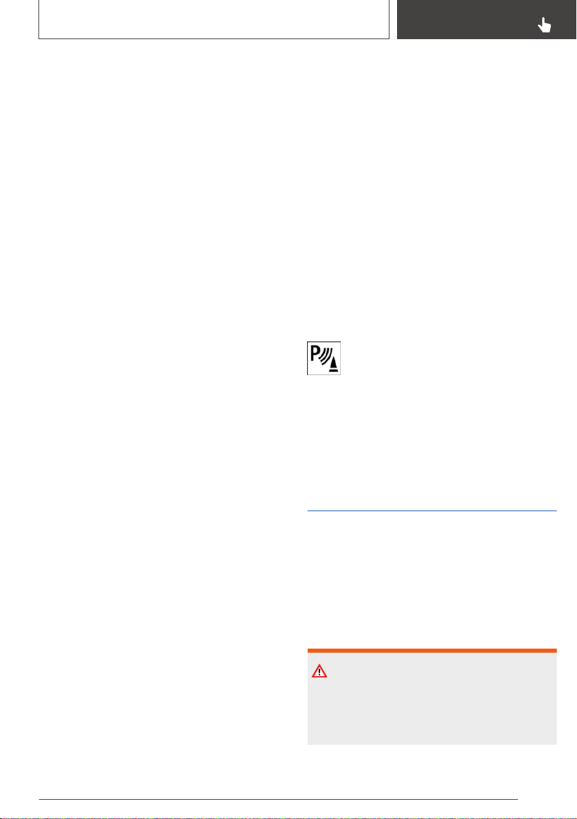
▷ Under certain weather conditions such as
high relative humidity, wet conditions, snow‐
fall, extreme heat, or strong wind.
▷ With tow bars and trailer couplings of other
vehicles.
▷ With thin or wedge-shaped objects.
▷ With moving objects.
▷ With elevated, protruding objects such as
ledges.
▷ With objects with corners, edges, and
smooth surfaces.
▷ With objects with a fine surface structure
such as fences.
▷ For objects with porous surfaces.
▷ With small and low objects, for instance
boxes.
▷ With obstacles and persons at the edge of
the lane.
▷ With soft obstacles or obstacles covered in
foam material.
▷ With plants and bushes.
▷ Low objects already displayed, for instance
curbs, can move into the blind area of the
sensors before or after a continuous tone
sounds.
▷ Cargo that extends beyond the perimeter of
the vehicle is not taken into account by the
system.
False warnings
The system may issue a warning under the fol‐
lowing conditions even though there is no obsta‐
cle within the detection range:
▷ In heavy rain.
▷ When sensors are very dirty or covered with
ice.
▷ When sensors are covered in snow.
▷ On rough road surfaces.
▷ On uneven surfaces, such as speed bumps.
▷ In large buildings with right angles and
smooth walls, for instance in underground ga‐
rages.
▷ In automatic vehicle washes.
▷ Due to heavy exhaust.
▷ When the trailer hitch cover is not on straight.
▷ Due to other ultrasound sources, for instance
sweeping machines, high pressure steam
cleaners or neon lights.
To prevent false alarms, switch off automatic
PDC activation on obstacle detection, refer to
page 212, for instance in automatic vehicle
washes.
Malfunction
A Check Control message is displayed.
White symbol is displayed, and the range
of the sensors is dimmed on the Control
Display.
PDC has failed. Have the system checked by a
dealer’s service center or another qualified serv‐
ice center or repair shop.
Without Surround View:
rearview camera
Concept
The rearview camera provides assistance in
parking and maneuvering backwards. The area
behind the vehicle is shown on the Control Dis‐
play.
Safety information
WARNING
The system cannot serve as a substitute for the
driver’s personal judgment in assessing the
traffic situation. There is a risk of an accident.
Adjust driving style to traffic conditions. Watch
Seite 215
Driver assistance systems
CONTROLS
215
Online Edition for Part no. 01402896703 - X/18
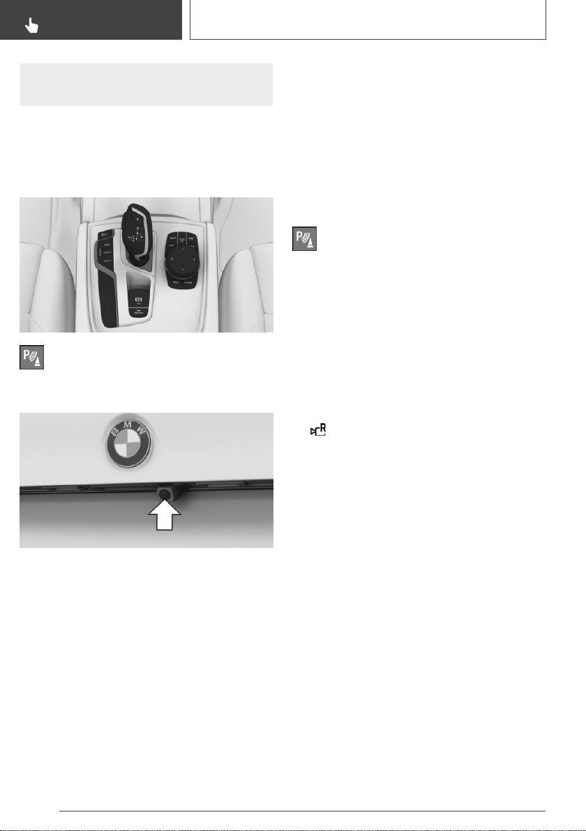
traffic and vehicle surroundings closely and ac‐
tively intervene where appropriate.
Overview
Depending on the vehicle
equipment: button in the vehicle
Park assistance button
Camera
The camera lens is located in the handle of the
tailgate.
The image quality may be impaired by dirt. If
necessary, clean the camera lens.
Switching on/off
Switching on automatically
The system is switched on automatically if selec‐
tor lever position R is engaged when the engine
is running.
Automatic deactivation during
forward travel
The system switches off when a certain driving
distance or speed is exceeded.
Switch the system back on, if needed.
Depending on the vehicle
equipment: switching on/off
manually
Press park assistance button.
▷ On: the LED lights up.
▷ Off: the LED goes out.
The parking assistance functions are shown on
the Control Display.
Switching the view via iDrive
If the rearview camera view is not displayed,
change the view via iDrive:
1.
Move the Controller to the left, if needed.
2. "Rear view camera"
The rearview camera image is displayed.
Functional requirements
▷ The rearview camera is switched on.
▷ The tailgate is fully closed.
▷ Keep the recording range of the camera
clear. Protruding cargo or roof rack systems
can limit the detection range of the camera.
▷ Trailers that are not connected at a trailer
socket can limit the detection range of the
camera.
Assistance functions
General information
More than one assistance function can be active
at the same time.
The assistance functions can be manually acti‐
vated.
Seite 216
CONTROLS
Driver assistance systems
216
Online Edition for Part no. 01402896703 - X/18
▷ "Parking aid lines".
Pathway lines and turning radius lines are dis‐
played, refer to page 217.
▷ "Obstacle marking".
Depending on the vehicle equipment, the ob‐
stacles detected by PDC Park Distance Con‐
trol are displayed, refer to page 217, by
markings.
▷ "Trailer hitch - zoom".
A zoomed image of the trailer hitch is dis‐
played, refer to page 218.
Parking aid lines
Pathway lines
Pathway lines help you to estimate the space re‐
quired when parking and maneuvering on level
roads.
Pathway lines depend on the steering angle and
are continuously adjusted to the steering wheel
movements.
Turning radius lines
Turning radius lines can only be superimposed
on the camera image together with pathway
lines.
Turning radius lines show the course of the
smallest possible turning radius on a level road.
Only one turning radius line is displayed after the
steering wheel is turned past a certain angle.
Parking using pathway and turning radius
lines
1.
Position the vehicle so that the red turning ra‐
dius line leads to within the limits of the park‐
ing space.
2. Turn the steering wheel to the point where
the green pathway line covers the corre‐
sponding turning radius line.
Obstacle marking
Depending on the vehicle equipment, obstacles
behind the vehicle are detected by the PDC Park
Distance Control sensors.
Obstacle markings can be faded into the image
of the rearview camera.
Seite 217
Driver assistance systems
CONTROLS
217
Online Edition for Part no. 01402896703 - X/18
The colored thresholds of the obstacle markings
match the markings of the PDC Park Distance
Control.
Zoom on trailer hitch
To make it easier to attach a trailer, you can
zoom in on the view of the trailer hitch.
Two static circle segments show the distance
between the trailer and the trailer hitch.
A docking line dependent on the steering angle
helps with aiming for the trailer with the trailer
hitch.
When zooming in, remember that the view may
no longer show certain obstacles.
Setting brightness and contrast
via iDrive
With the rearview camera switched on:
1.
Move the Controller to the left.
2.
▷ "Brightness"
▷ "Contrast"
3. Set the desired value.
System limits
Deactivated camera
If the camera is deactivated, for instance if the
tailgate is open, the camera image is displayed
hatched in gray.
Detection of objects
Very low obstacles as well as high, protruding
objects such as ledges may not be detected by
the system.
Depending on the vehicle equipment, some as‐
sistance functions also consider data from the
PDC Park Distance Control.
Follow the notes in the PDC Park Distance Con‐
trol chapter.
The objects displayed on the Control Display
may be closer than they appear. Do not estimate
the distance from the objects on the display.
Surround View with
Parking Assistant Plus
Concept
The system provides assistance in parking and
maneuvering. The area around the vehicle is
shown on the Control Display.
General information
Several cameras capture the area from different
selectable perspectives. In addition, assistance
functions, for instance guidelines, can be faded
into the display.
The following camera perspectives can be dis‐
played:
▷ Automatic camera perspective, refer to
page 220: the system shows the camera
perspective suitable for the respective driving
situation.
▷ Rearview camera, refer to page 220: for rep‐
resenting the areas behind the vehicle.
▷ Right-hand and left-hand side view, refer to
page 222: for representing the areas on the
sides of the vehicle.
▷ Camera perspective movable via iDrive, refer
to page 220.
Seite 218
CONTROLS
Driver assistance systems
218
Online Edition for Part no. 01402896703 - X/18
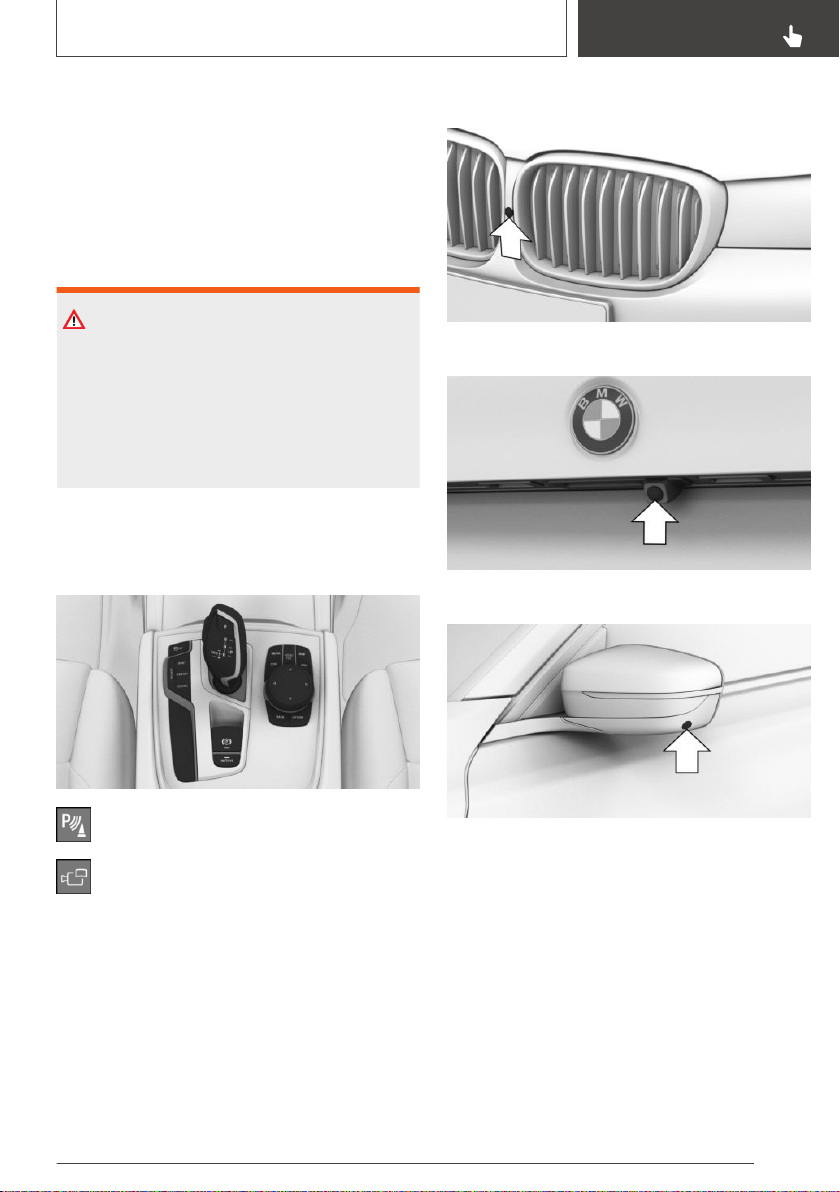
▷ Panorama View, refer to page 223: to
present cross traffic, for instance at junctions
and driveways, depending on the currently
engaged gear.
Depending on the view, the environment around
the vehicle or a part of it is depicted.
Safety information
WARNING
The system cannot serve as a substitute for the
driver’s personal judgment in assessing the
traffic situation. There is a risk of an accident.
Adjust driving style to traffic conditions. Watch
traffic and vehicle surroundings closely and ac‐
tively intervene where appropriate.
Overview
Buttons in the vehicle
Park assistance button
Panorama View
Cameras
Front camera
Rearview camera
One camera is located at the bottom of each ex‐
terior mirror housing.
The image quality may be impaired by dirt on the
camera lenses. If required, clean the camera
lenses.
Switching on/off
Switching on automatically
The system is switched on automatically if selec‐
tor lever position R is engaged when the engine
is running.
Seite 219
Driver assistance systems
CONTROLS
219
Online Edition for Part no. 01402896703 - X/18
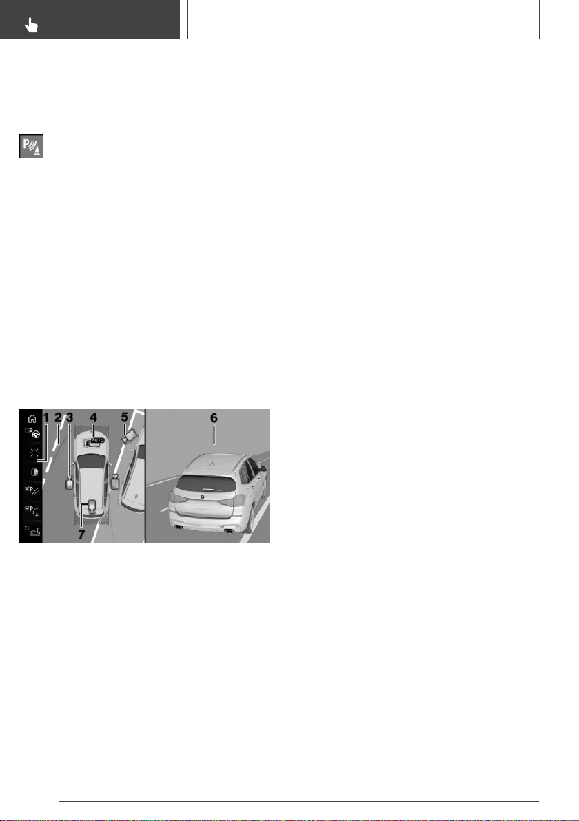
The camera perspective suitable for the respec‐
tive driving situation is displayed.
Switching on/off manually
Press park assistance button.
▷ On: the LED lights up.
▷ Off: the LED goes out.
The rearview camera cannot be switched off if
the reverse gear is engaged.
Automatic deactivation during
forward travel
The system switches off when a certain driving
distance or speed is exceeded.
Switch the system back on, if needed.
Camera perspective
Overview
1 Function bar
2 Selection window
3 Side view
4 Automatic camera perspective
5 Movable camera perspective
6 Camera image
7 Rearview camera
Selection window
The individual camera perspectives can be se‐
lected in the selection window via iDrive.
Side view
The side view can be selected for the right or left
vehicle side.
This view helps when positioning the vehicle at
the curb or with other obstacles on the side by
displaying the side surroundings.
The side view looks from rear to front and in case
of danger, focuses automatically on possible ob‐
stacles.
Automatic camera perspective
The automatic camera perspective shows a
steering-dependent view in the respective driv‐
ing direction.
This perspective adapts to the respective driving
situation.
As soon as obstacles are detected, the view
changes to a fixed display of the area in front or
at the rear behind the bumper or, if necessary,
changes to a side view.
When reverse gear is engaged, the automatic
camera perspective is closed and the system
uses a fixed perspective of the rearview camera.
If necessary, manually select the automatic cam‐
era perspective when reverse gear is engaged.
The automatic camera perspective will be re‐
tained for the current parking maneuver.
Movable camera perspective
With selection of the movable camera perspec‐
tive, a circle appears on the Control Display.
By turning the Controller or via touch function,
specified perspectives on the circle can be se‐
lected.
The current perspective is marked with a camera
symbol.
With BMW Gesture Control: the movable camera
perspective can be moved around the circle us‐
ing BMW Gesture Control, refer to page 53.
To leave the circle, move the Controller sideways
and press or tap the active camera symbol via
the touchscreen.
Seite 220
CONTROLS
Driver assistance systems
220
Online Edition for Part no. 01402896703 - X/18
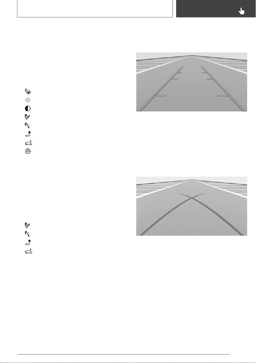
Rearview camera
This view shows the picture of the rearview cam‐
era.
Function bar
Assistance functions, refer to page 221, can be
activated via the function bar and settings ap‐
plied.
▷ "Parking Assistant", refer to page 225.
▷ "Brightness", refer to page 224.
▷ "Contrast", refer to page 224.
▷ "Parking aid lines", refer to page 221.
▷ "Obstacle marking", refer to page 222.
▷ "Trailer hitch - zoom", refer to page 222.
▷ "Car wash", refer to page 222.
▷ "Settings": apply settings, for instance to
use the activation points for Panorama View.
Assistance functions
General information
More than one assistance function can be active
at the same time.
The following assistance functions can be man‐
ually activated:
▷ "Parking aid lines".
▷ "Obstacle marking".
▷ "Trailer hitch - zoom".
▷ "Car wash".
The following assistance functions are automati‐
cally displayed:
▷ Side protection, refer to page 222.
▷ Door opening angle, refer to page 223.
Parking aid lines
Pathway lines
Pathway lines help you to estimate the space re‐
quired when parking and maneuvering on level
roads.
Pathway lines depend on the steering angle and
are continuously adjusted to the steering wheel
movements.
Turning radius lines
Turning radius lines can only be superimposed
on the camera image together with pathway
lines.
Turning radius lines show the course of the
smallest possible turning radius on a level road.
Only one turning radius line is displayed after the
steering wheel is turned past a certain angle.
Parking using pathway and turning radius
lines
1.
Position the vehicle so that the red turning ra‐
dius line leads to within the limits of the park‐
ing space.
Seite 221
Driver assistance systems
CONTROLS
221
Online Edition for Part no. 01402896703 - X/18
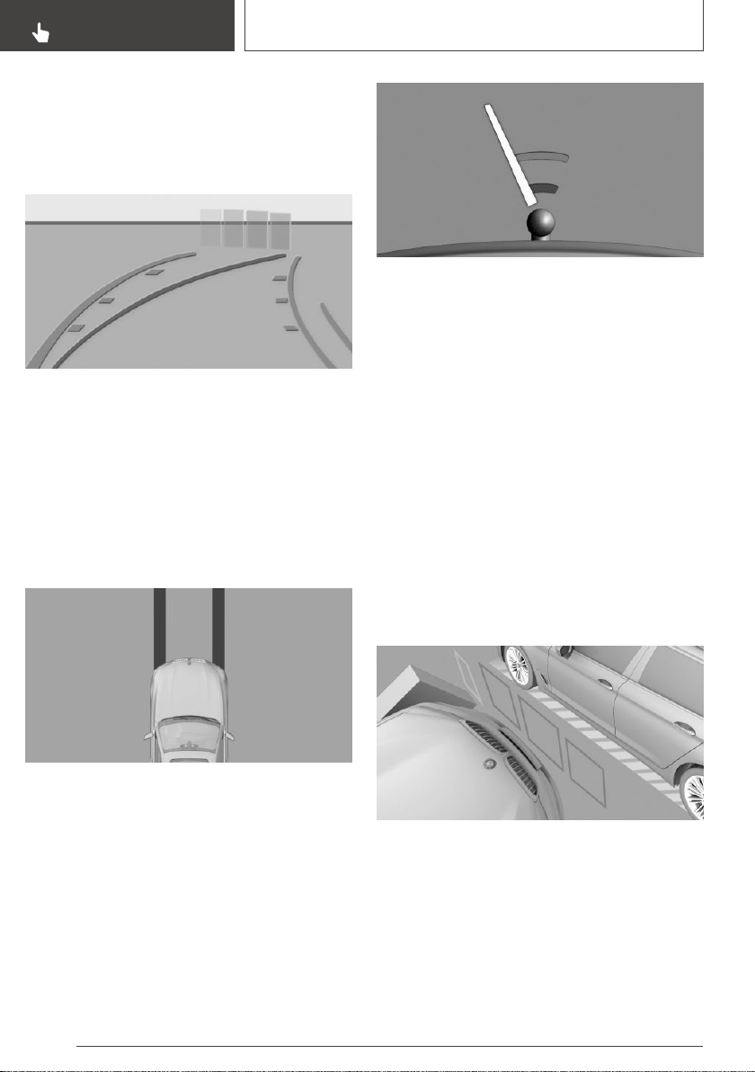
2. Turn the steering wheel to the point where
the green pathway line covers the corre‐
sponding turning radius line.
Obstacle marking
Obstacles behind the vehicle are detected by the
PDC Park Distance Control sensors.
Obstacle markings can be shown in the camera
image.
The colored thresholds of the obstacle markings
match the markings of the PDC Park Distance
Control.
Vehicle wash view
The vehicle wash view assists when entering a
vehicle wash by displaying the floor and the vehi‐
cle's own track.
Zoom on trailer hitch
To make it easier to attach a trailer, you can
zoom in on the view of the trailer hitch.
Two static circle segments show the distance
between the trailer and the trailer hitch.
A docking line dependent on the steering angle
helps with aiming for the trailer with the trailer
hitch.
Show the trailer hitch via iDrive, refer to
page 221.
When zooming in, remember that the view may
no longer show certain obstacles.
Side protection
Concept
The system warns of obstacles on the side of
the vehicle.
Display
To protect the sides of the vehicle, obstacle
markings are displayed on the vehicle at the
sides.
▷ No markings: no obstacles were detected.
▷ Color markings: warning against detected ob‐
stacles.
Seite 222
CONTROLS
Driver assistance systems
222
Online Edition for Part no. 01402896703 - X/18
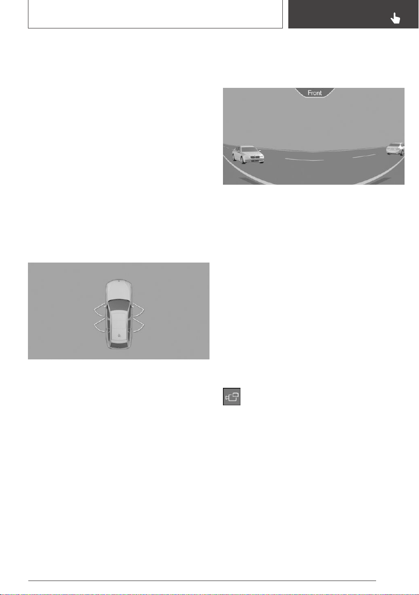
Limits of side protection
The system only displays stationary obstacles
that were previously detected by sensors while
passing them.
The system does not detect whether an obstacle
moves later on. For this reason, at standstill, the
markings are not shown anymore in the display
after a certain time. The area next to the vehicle
must be newly captured.
Door opening angle
Concept
If obstacle marking is activated, the system indi‐
cates fixed obstacles that obstruct the opening
angles of the doors.
The system does not provide a warning of ap‐
proaching traffic.
Steptronic transmission: the maximum opening
angles of the doors are displayed in selector
lever position P.
As soon as the vehicle begins moving, the open‐
ing angles are replaced by parking aid lines.
Limits of the display
The vehicle surroundings are displayed with dis‐
torted image for technical reasons.
Even if the symbols for the door opening angles
do not cross other objects on the Control Dis‐
play, the following needs to be noted when park‐
ing next to other objects:
Because of the perspective, higher, protruding
objects may be closer than they appear on the
Control Display.
Panorama View
Concept
The system provides an early look at cross traffic
at blind driveways and intersections.
General information
Road users concealed by obstacles to the left
and right of the vehicle can only be detected rel‐
atively late from the driver's seat. The cameras in
the front and rear capture the sideways traffic
area to improve the view.
Yellow lines in the screen display mark the front
and rear end of the vehicle.
The camera image shows different levels of dis‐
tortion in some areas and is thus not suitable for
distance estimations.
Display on the Control Display
Press the button when the engine is run‐
ning.
Depending on the driving direction, the image of
the respective camera is displayed:
▷ "front": front camera image.
▷ "rear": rear camera image.
Depending on the vehicle equipment, the cross‐
ing traffic warning, refer to page 230, can addi‐
tionally warn against oncoming vehicles using ra‐
dar sensors.
Seite 223
Driver assistance systems
CONTROLS
223
Online Edition for Part no. 01402896703 - X/18
With navigation system: activation
points
Concept
Positions where Panorama View should switch
on automatically can be stored as activation
points provided that a GPS signal is received.
General information
Up to ten activation points can be stored.
Activation points can be used when driving for‐
ward for the front camera.
Storing activation points
1.
Drive to the position at which the system is to
be switched on, and stop.
2.
Press button.
3. Move the Controller to the left.
4. "Add activation point"
The current position is displayed.
5. "Add activation point"
Activation points are, if possible, stored with
town/city and street address, or else with the
GPS coordinates.
Using activation points
The use of activation points can be switched on
and off.
1. Press button.
2. Move the Controller to the left.
3. "Settings"
4. "Panorama view, GPS-based"
5. "Panorama view, GPS-based"
Displaying activation points
1. Press button.
2. Move the Controller to the left.
3. "Show activation points"
A list of all activation points is displayed.
Renaming or deleting activation points
1.
Press button.
2. Move the Controller to the left.
3. "Show activation points"
A list of all activation points is displayed.
4. Select an activation point as needed.
5.
▷ "Rename"
▷ "Delete this activation point"
▷ "Delete all activation points"
Setting brightness and contrast
Brightness and contrast can be adjusted with
Surround View or Panorama View switched on.
Via iDrive:
1.
Move the Controller to the left.
2.
▷ "Brightness"
▷ "Contrast"
3. Set the desired value.
Functional limitations
The system can be used only to a limited extent
in the following situations:
▷ In poor light.
▷ In case of soiled cameras.
▷ With a door open.
▷ With the tailgate open.
▷ With exterior mirrors folded in.
Gray hatched areas with symbol, for instance
open door, in the camera image mark areas that
are currently not displayed.
System limits
Non-visible areas
Because of the camera angle, the areas under
the vehicle cannot be viewed by the cameras.
Seite 224
CONTROLS
Driver assistance systems
224
Online Edition for Part no. 01402896703 - X/18
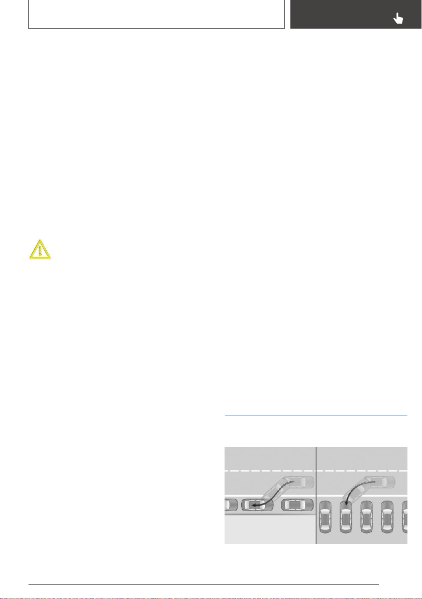
Detection of objects
Very low obstacles as well as high, protruding
objects such as ledges may not be detected by
the system.
Some assistance functions also consider data
from the PDC Park Distance Control.
Follow, refer to page 211, the notes in the PDC
Park Distance Control chapter.
The objects displayed on the Control Display
may be closer than they appear. Do not estimate
the distance from the objects on the display.
Malfunction
A camera malfunction is displayed on the Control
Display.
A yellow symbol is displayed and the re‐
cording range of the malfunctioning cam‐
era is displayed in black on the Control
Display.
Remote 3D View
Concept
With the proper equipment, the BMW Con‐
nected App and the camera images from Sur‐
round View can be used to display the vehicle
surroundings on a mobile device such as a
smartphone.
The function displays a momentary view of the
situation.
Functional requirements
▷ Data transmission must be activated, refer to
page 62.
▷ BMW Connected App must be installed on
the mobile device.
Switching the function on/off
Via iDrive:
1. With the standby state switched on: "My
Vehicle"
2. "iDrive settings"
3. "Data privacy"
4. "Remote 3D View"
Functional limitations
The system may not be fully functional or may
not be available in the following situations:
▷ In poor light.
▷ In case of soiled cameras.
▷ With a door or the tailgate open. Dark fields in
the display indicate areas that are not re‐
corded by the system.
▷ With exterior mirrors folded in.
▷ When other camera functions are being per‐
formed in the vehicle.
▷ When the vehicle moves faster than walking
speed.
▷ It may not be possible to use the function in
every country.
▷ For reasons of data protection, the function
can only be used three times within two
hours.
Parking Assistant
Concept
Seite 225
Driver assistance systems
CONTROLS
225
Online Edition for Part no. 01402896703 - X/18
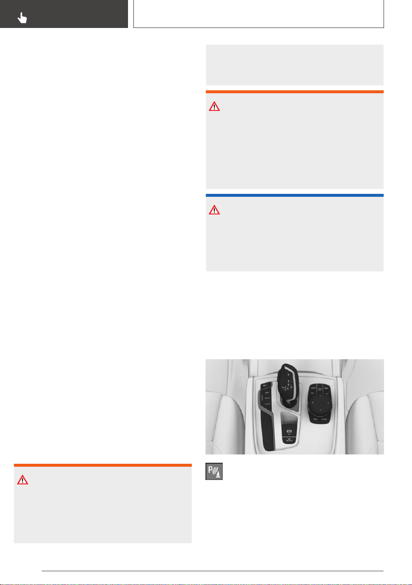
The system supports parking in the following sit‐
uations:
▷ When parking parallel to the road, parallel
parking.
▷ When reverse parking diagonally to the road,
diagonal parking. The system orients itself
with the middle of the parking space during
diagonal parking.
General information
Handling
Parking assistant handling is divided into three
steps:
▷ Switching on and activating.
▷ Parking space search.
▷ Parking.
System status and instructions on required ac‐
tions are displayed on the Control Display.
Ultrasound sensors measure parking spaces on
both sides of the vehicle.
Steptronic transmission
The parking assistant calculates the best possi‐
ble parking line and takes control of the following
functions during the parking procedure:
▷ Steering.
▷ Accelerating and braking.
▷ Changing the gears.
Press and hold the park assistance button for the
duration of the parking procedure.
Parking is automatic.
Safety information
WARNING
The system cannot serve as a substitute for the
driver’s personal judgment in assessing the
traffic situation. Based on the limits of the sys‐
tem, it cannot independently react to all traffic
situations. There is a risk of an accident. Adjust
driving style to traffic conditions. Watch traffic
closely and actively intervene where appropri‐
ate.
WARNING
If the trailer hitch is used, the parking assistant
can cause damage due to covered sensors.
There is a risk of accidents or risk of damage to
property. The parking assistant should not be
used during trailer towing or if the trailer hitch is
used, for instance bicycle rack.
NOTICE
The parking assistant can steer the vehicle over
or onto curbs. There is a risk of damage to
property. Watch traffic closely and actively in‐
tervene where appropriate.
The safety information for PDC Park Distance
Control, refer to page 211, and for opening the
tailgate, refer to page 89, applies in addition.
Overview
Button in the vehicle
Park assistance button
Seite 226
CONTROLS
Driver assistance systems
226
Online Edition for Part no. 01402896703 - X/18
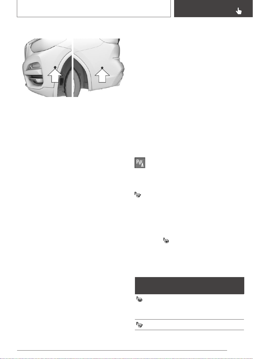
Ultrasound sensors
With the four side ultrasound sensors, arrows,
and the ultrasound sensors of PDC Park Dis‐
tance Control in the bumpers, the parking
spaces are measured and the distances to ob‐
stacles determined.
Functional requirements
Ultrasound sensors
Ensure full functionality:
▷ Do not cover sensors, for instance with stick‐
ers.
▷ Keep the sensors clean and unobstructed.
For measuring parking spaces
▷ Maximum speed while driving forward approx.
22 mph/35 km/h.
▷ Maximum distance to row of parked vehicles:
5 ft/1.5 m.
Suitable parking space
General information:
▷ Gap behind an object that has a min. length
of 1.7 ft/0.5 m.
▷ Gap between two objects with a minimum
length of approx. 1.7 ft/0.5 m.
Parallel parking to the road:
▷ Min. length of gap between two objects: your
vehicle's length plus approx. 2.6 ft/0.8 m.
▷ Minimum depth: approx. 5 ft/1.5 m.
Diagonal parking:
▷ Minimum width of the gap: own vehicle's
width plus approx. 2.3 ft/0.7 m.
▷ Minimum depth: your vehicle's length.
The depth of diagonal parking spaces must
be estimated by the driver. Due to technical
limitations, the system is only able to approxi‐
mate the depth of diagonal parking spaces.
For parking
▷ Doors and tailgate are closed.
▷ The parking brake is released.
Steptronic transmission:
▷ Driver's safety belt is fastened.
Switching on and activating
Switching on with the button
Press park assistance button.
The LED lights up.
The current status of the parking space search is
indicated on the Control Display.
Parking assistant is activated automatically.
Switching on with reverse gear
Shift into reverse.
The current status of the parking space search is
indicated on the Control Display.
To activate: "Parking Assistant"
Display on the Control Display
System activated/deactivated
Sym‐
bol
Meaning
Gray: the system is not available.
White: the system is available but not
activated.
The system is activated.
Seite 227
Driver assistance systems
CONTROLS
227
Online Edition for Part no. 01402896703 - X/18
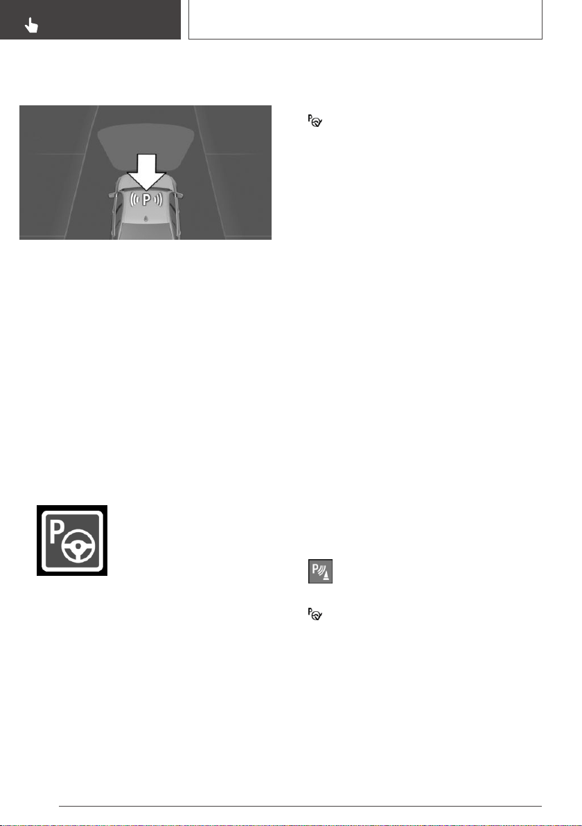
Parking space search and system
status
▷ Symbol P on the vehicle image: the parking
assistant is activated and the parking space
search is active.
▷ Control Display shows suitable parking
spaces at the edge of the road next to the ve‐
hicle symbol. When the parking assistant is
active, suitable parking spaces are high‐
lighted in color and a signal sounds. Switch
signal tone on/off, refer to page 229.
▷ If a diagonal or parallel parking space is clearly
detected, the system automatically adjusts
the suitable parking method. In the case of
parking spaces suitable for parallel and diago‐
nal parking, a selection menu is displayed. In
this case, the desired parking method must
be selected manually.
▷ The parking procedure is ac‐
tive. Steering control has been
taken over by system.
▷ Parking space search is always active when‐
ever the vehicle is moving forward slow and
straight, even if the system is deactivated.
When the system is deactivated, the displays
on the Control Display are shown in gray.
Parking using the parking
assistant
Parking
1.
Switching on and activating the parking assis‐
tant.
Engage the reverse gear and activate the
system or press the parking assistance but‐
ton, refer to page 227, on the Control Display.
Parking assistant is activated.
2. Drive by the row of parked vehicles at a
speed of up to approx. 22 mph/35 km/h and
at a distance of maximum 5 ft/1.5 m.
The status of the parking space search and
possible parking spaces are displayed on the
Control Display, refer to page 228.
3. Confirm the suggested parking space for the
parking procedure: switch on the turn signal
on the corresponding side.
The system takes over the steering.
4. Follow the instructions on the Control Dis‐
play.
Steptronic transmission:
Press and hold the park assistance button for
the duration of the parking procedure. At the
end of the parking procedure, the P selector
lever position is set.
The end of the parking procedure is indicated
on the Control Display.
5. Adjust the parking position yourself, if
needed.
Interrupting manually
The parking assistant can be interrupted at any
time:
▷ Steptronic transmission: release the
park assistance button during the park‐
ing procedure.
▷ "Parking Assistant" Select the symbol on
the Control Display.
Interrupting automatically
The system is interrupted automatically in the
following situations:
▷ If the driver grasps the steering wheel or
takes over steering.
▷ Possibly on snow-covered or slippery road
surfaces.
Seite 228
CONTROLS
Driver assistance systems
228
Online Edition for Part no. 01402896703 - X/18
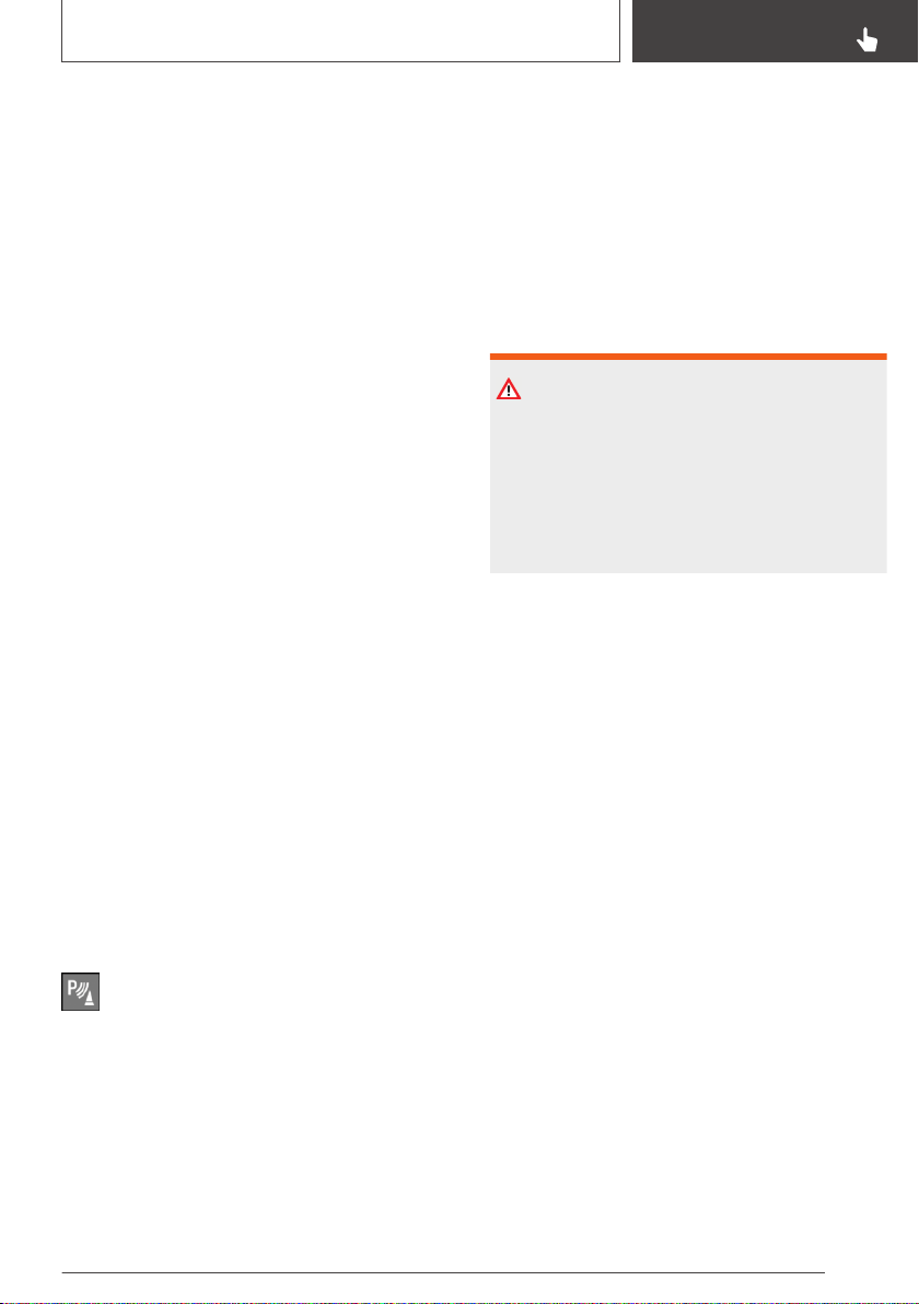
▷ When there are obstacles that are hard to
overcome, such as curbs.
▷ When there are obstacles that suddenly ap‐
pear.
▷ If the PDC Park Distance Control displays
clearances that are too small.
▷ If a maximum number of parking attempts or
the time taken for parking is exceeded.
▷ When switching to another function on the
Control Display.
Steptronic transmission:
▷ When the park assistance button is released.
▷ If the tailgate is open.
▷ If doors are open.
▷ When setting the parking brake.
▷ During acceleration.
▷ When the brake pedal remains pressed for an
extended period while the vehicle is station‐
ary.
▷ When unfastening the driver's safety belt.
A Check Control message is displayed.
Resuming
An interrupted parking procedure can be contin‐
ued, if needed.
Reactivate the parking assistant, refer to
page 227, and follow the instructions on the
Control Display.
Switching off
The system can be switched off manually:
Press park assistance button.
Switching signal tone for
suitable parking spaces on/off
Via iDrive:
1.
"My Vehicle"
2. "Vehicle settings"
3. "Parking"
4. "Parking Assistant"
5. "Sound if parking space detected"
The setting is stored for the driver profile cur‐
rently used.
System limits
Safety information
WARNING
The system can react not at all, too late, incor‐
rectly, or without justification due to the system
limits. There is a risk of accidents or risk of
damage to property. Follow the information re‐
garding the system limits and actively intervene
if needed.
No parking assistance
The parking assistant does not offer assistance
in the following situations:
▷ In tight curves.
▷ When towing a trailer.
▷ For diagonal parking spaces.
Functional limitations
The system may not be fully functional in the fol‐
lowing situations:
▷ On bumpy road surfaces such as gravel
roads.
▷ On slippery ground.
▷ On steep uphill or downhill grades.
▷ With accumulations of leaves/snow in the
parking space.
▷ With a mounted emergency wheel.
▷ In case of changes to an already-measured
parking space.
▷ With ditches or edges, for instance an edge
of a port.
Seite 229
Driver assistance systems
CONTROLS
229
Online Edition for Part no. 01402896703 - X/18
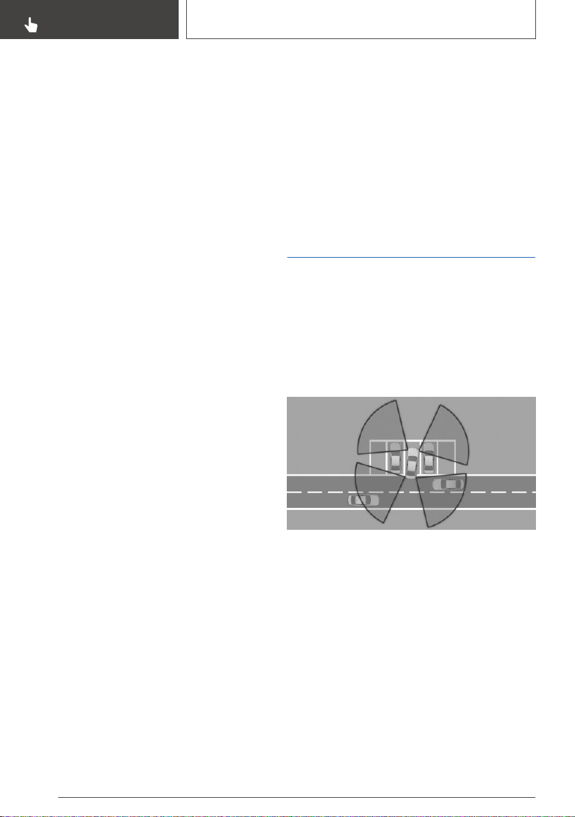
Limits of ultrasonic measurement
Ultrasonic measurements might not function in
the following situations:
▷ For small children and animals.
▷ For persons with certain clothing, for instance
coats.
▷ With external interference of the ultrasound,
for instance from passing vehicles or loud
machines.
▷ When sensors are dirty, iced over, damaged
or out of position.
▷ Under certain weather conditions such as
high relative humidity, wet conditions, snow‐
fall, extreme heat, or strong wind.
▷ With tow bars and trailer couplings of other
vehicles.
▷ With thin or wedge-shaped objects.
▷ With moving objects.
▷ With elevated, protruding objects such as
ledges.
▷ With objects with corners, edges, and
smooth surfaces.
▷ With objects with a fine surface structure
such as fences.
▷ For objects with porous surfaces.
▷ With small and low objects, for instance
boxes.
▷ With obstacles and persons at the edge of
the lane.
▷ With soft obstacles or obstacles covered in
foam material.
▷ With plants and bushes.
▷ Low objects already displayed, for instance
curbs, can move into the blind area of the
sensors before or after a continuous tone
sounds.
▷ Cargo that extends beyond the perimeter of
the vehicle is not taken into account by the
system.
Parking spaces that are not suitable may be de‐
tected or suitable parking spaces may not be de‐
tected at all.
Malfunction
A Check Control message is displayed.
The parking assistant failed. Have the system
checked by a dealer’s service center or another
qualified service center or repair shop.
Crossing traffic warning
Concept
At blind driveways or when driving out of diago‐
nal parking spaces, approaching cross traffic is
detected sooner by the system than is possible
from the driver's seat.
General information
Two radar sensors in the rear bumper monitor
the area behind the vehicle.
The system indicates approaching traffic.
Depending on the vehicle equipment, the traffic
area in front of the vehicle is monitored as well.
Two additional radar sensors are located in the
front bumpers.
Seite 230
CONTROLS
Driver assistance systems
230
Online Edition for Part no. 01402896703 - X/18
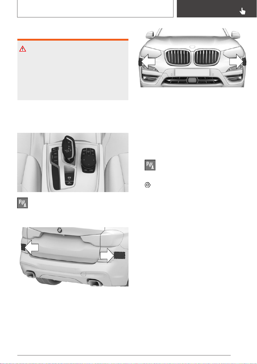
Safety information
WARNING
The system cannot serve as a substitute for the
driver’s personal judgment in assessing visibility
and traffic situation. There is a risk of an acci‐
dent. Adjust driving style to traffic conditions.
Watch traffic closely and actively intervene
where appropriate.
Overview
Button in the vehicle
Park assistance button
Radar sensors
The radar sensors are located in the rear
bumper.
Depending on the vehicle equipment, two addi‐
tional radar sensors are located in the front
bumpers.
Always keep the bumper in the area of the radar
sensors clean and unobstructed.
Switching on/off
Activating/deactivating the system
1. Press park assistance button.
2. Move the Controller to the left.
3. "Settings"
4. "Cross traffic alert"
5. "Cross traffic alert"
Switching on automatically
If the system was activated on the Control Dis‐
play, it is automatically switched on as soon as
PDC Park Distance Control or Panorama View is
active and a gear is engaged.
If reverse gear is engaged, the rear system is
switched on.
Depending on the vehicle equipment, the front
system is switched on when a forward gear is
engaged.
Switching off automatically
The system is automatically switched off in the
following situations:
▷ When the speed exceeds walking speed.
Seite 231
Driver assistance systems
CONTROLS
231
Online Edition for Part no. 01402896703 - X/18
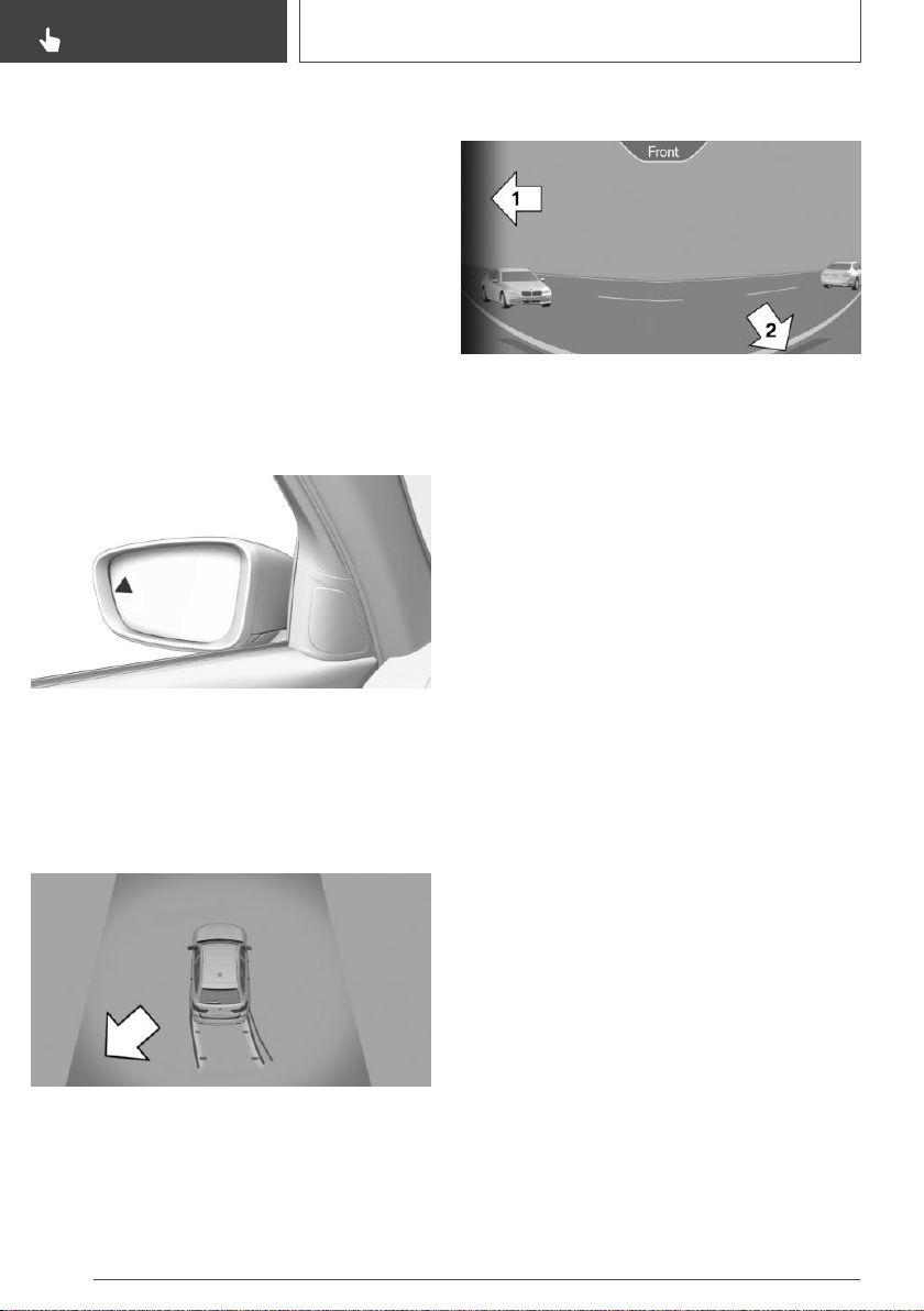
▷ With the steering and lane control assistant
active: when a certain driving distance is ex‐
ceeded.
▷ With an active parking operation of the park‐
ing assistant.
WARNING
General information
The respective display is called up on the Con‐
trol Display. A signal tone may sound and the
light in the exterior mirror may flash.
Light in the exterior mirror
The light in the exterior mirror flashes if vehicles
are detected by the rear sensors and your own
vehicle is moving backwards.
Display in the PDC Park Distance
Control view
In the PDC Park Distance Control view, the re‐
spective boundary area flashes red, if vehicles
are detected by the sensors.
Display in the camera view
The respective boundary area, arrow 1, in the
camera view flashes red, if vehicles are detected
by the sensors.
Yellow lines, arrow 2, mark the bumper of your
own vehicle.
Acoustic warning
In addition to the optical indicator, a warning sig‐
nal sounds if your own vehicle moves into the re‐
spective direction.
System limits
The system may not be fully functional in the fol‐
lowing situations:
▷ If the speed of the approaching vehicle is very
high.
▷ In heavy fog, wet conditions, or snowfall.
▷ In tight curves.
▷ If the bumper is dirty, iced up, or covered,
for instance by stickers.
▷ If cargo protrudes.
▷ If crossing objects move at a very slow speed.
▷ If other objects are in the capture range of the
sensors, that hide cross traffic.
If the trailer power socket is in use or trailer tow‐
ing is activated, for instance during operation
with trailer or bicycle rack, crossing traffic warn‐
ing is not available for the area behind the vehi‐
cle.
Seite 232
CONTROLS
Driver assistance systems
232
Online Edition for Part no. 01402896703 - X/18

Driving comfort
Vehicle features and
options
This chapter describes all standard, country-spe‐
cific and optional features offered with the series.
It also describes features that are not necessarily
available in your vehicle, e. g., due to the selected
options or country versions. This also applies to
safety-related functions and systems. When us‐
ing these functions and systems, the applicable
laws and regulations must be observed.
Adaptive chassis
Concept
This system reduces undesirable vehicle motion
when using a dynamic driving style or traveling
on uneven road surfaces.
General information
This enhances the driving dynamics and driving
comfort depending on the road surface condition
and driving style.
Tuning
The system offers several different damping set‐
tings.
The damping settings are assigned to the differ‐
ent driving modes of the Driving Dynamics Con‐
trol, refer to page 137.
Driving mode Damper tuning
COMFORT
ECO PRO
Balanced out
SPORT Firm
Adaptive M chassis
Concept
The Adaptive M chassis is a controllable sport
chassis/suspension. This system reduces unde‐
sirable vehicle motion when using a dynamic
driving style or traveling on uneven road surfa‐
ces.
This enhances the driving dynamics and driving
comfort depending on the road surface condition
and driving style.
General information
The system offers several different damping set‐
tings.
The damping settings are assigned to the differ‐
ent driving modes of the Driving Dynamics Con‐
trol, refer to page 137.
Driving mode Damper tuning
SPORT Firm
SPORT PLUS Firm
COMFORT/ECO PRO Balanced out
Performance Control
Performance Control enhances the agility of the
vehicle.
To increase maneuverability, wheels are braked
individually when a sporty driving style is used.
The resulting braking power is simultaneously
largely compensated by an engine intervention.
Seite 233
Driving comfort
CONTROLS
233
Online Edition for Part no. 01402896703 - X/18
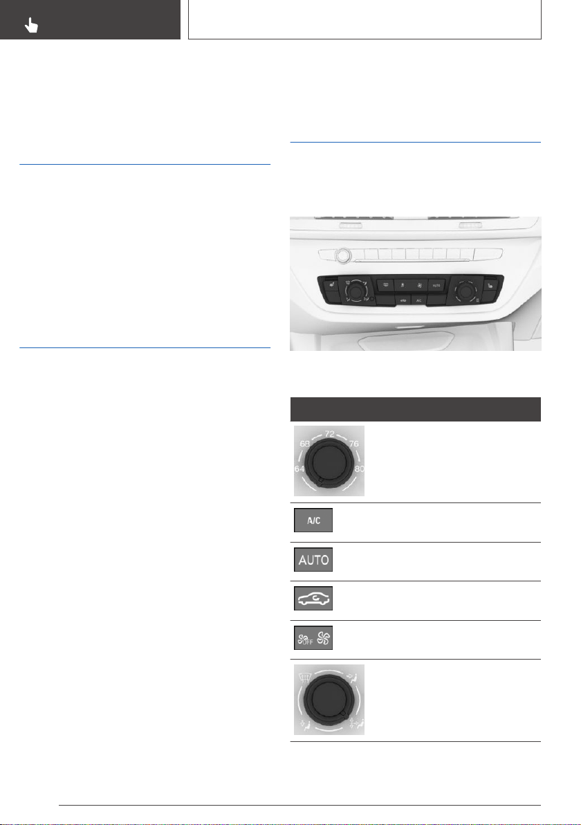
Climate control
Vehicle features and
options
This chapter describes all standard, country-spe‐
cific and optional features offered with the series.
It also describes features that are not necessarily
available in your vehicle, e. g., due to the selected
options or country versions. This also applies to
safety-related functions and systems. When us‐
ing these functions and systems, the applicable
laws and regulations must be observed.
Interior air quality
The air quality in the vehicle is improved by the
following components:
▷ Emission tested car's interior.
▷ Microfilter.
▷ Air conditioning system to control the tem‐
perature, air flow and recirculated-air mode.
Depending on the equipment specification:
▷ Microfilter/activated-charcoal filter.
▷ Ionization.
▷ Fragrancing.
▷ Automatic recirculated-air control AUC.
▷ Parked-car ventilation.
▷ Parked-car heating.
Automatic climate control
Overview
Buttons in the vehicle
Climate control functions
Button Function
Temperature, refer to page 235.
Climate control operation, refer
to page 235.
AUTO program, refer to
page 235.
Recirculated-air mode, refer to
page 236.
Air flow, manual, refer to
page 236.
Air distribution, manual, refer to
page 236.
Seite 234
CONTROLS
Climate control
234
Online Edition for Part no. 01402896703 - X/18
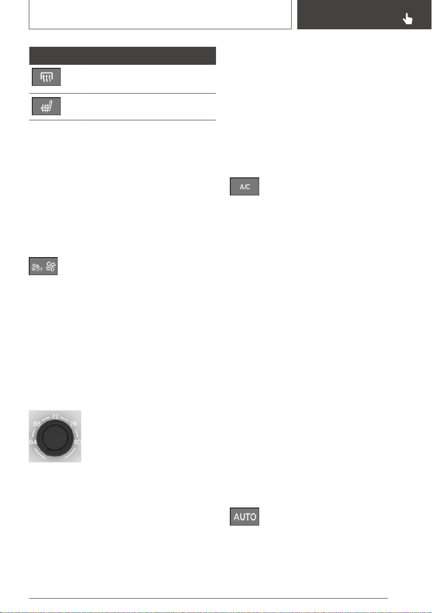
Button Function
Rear window defroster, refer to
page 237.
Seat heating, refer to page 112.
Switching on/off
Switching on
Press any button except for the following:
▷ Rear window defroster.
▷ Left side of air flow button.
▷ Seat heating.
Switching off
Press and hold the left button until the
system switches off.
Temperature
Concept
The automatic climate control achieves the set
temperature as quickly as possible, if needed, by
using the maximum cooling or heating capacity,
and then keeps it constant.
Settings
Turn the ring to set the desired
temperature.
Do not rapidly switch between dif‐
ferent temperature settings. Oth‐
erwise, the automatic climate
control will not have sufficient time to adjust the
set temperature.
Air conditioning
Concept
The air in the car's interior will be cooled and de‐
humidified and, depending on the temperature
setting, warmed again.
The car's interior can only be cooled with the
drive-ready state switched on.
Switching on/off
Press the button.
The LED is illuminated with air condi‐
tioning switched on.
Air conditioning is switched on with the engine
running.
Depending on the weather, the windshield and
side windows may fog up briefly when drive-
ready state is switched on.
The air conditioning is switched on automatically
with the AUTO program.
When using the automatic climate control, con‐
densation water develops and collects under‐
neath the vehicle.
AUTO program
Concept
The AUTO program cools, ventilates or heats
the car's interior automatically.
The air distribution and temperature are control‐
led automatically depending on the temperature
in the car's interior and the desired temperature
setting including the selected intensity of the air
flow.
Switching on/off
Press the button.
The LED is illuminated with the AUTO
program switched on.
Depending on the selected temperature and out‐
side influences, the air is directed to the wind‐
Seite 235
Climate control
CONTROLS
235
Online Edition for Part no. 01402896703 - X/18
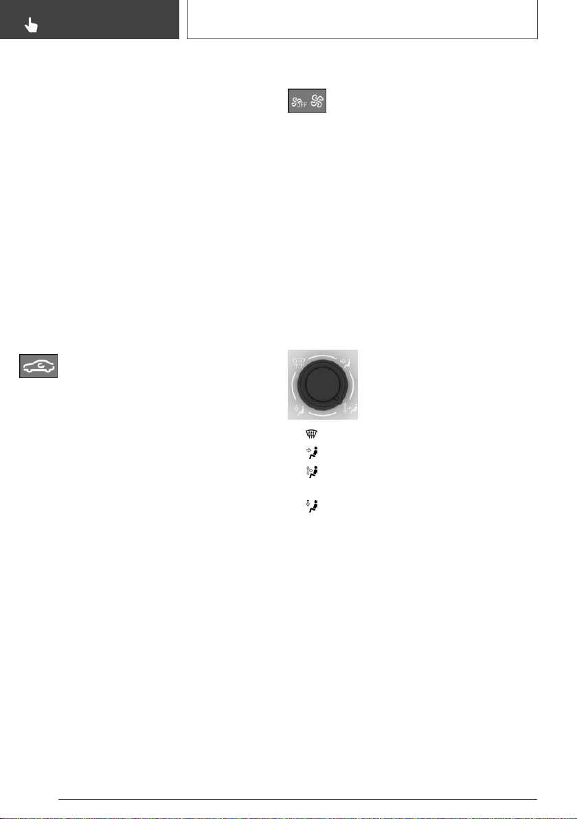
shield, side windows, upper body, and into the
floor area.
The air conditioning, refer to page 235, is
switched on automatically with the AUTO pro‐
gram.
The AUTO program is switched off automati‐
cally, when manual air distribution is set.
Recirculated-air mode
Concept
You may react to unpleasant odors or pollutants
in the immediate environment by temporarily
suspending the supply of outside air. The system
then recirculates the air flow within the vehicle.
Operation
Press button repeatedly to select an op‐
erating mode:
▷ LED off: outside air flows in continuously.
▷ LED on: the supply of outside air is perma‐
nently shut off.
To prevent window fogging, recirculated-air
mode switches off automatically after a certain
amount of time, depending on the environmental
conditions.
With constant recirculated-air mode, the air qual‐
ity in the car's interior deteriorates and the fog‐
ging of the windows increases.
If there is window condensation, switch off recir‐
culated-air mode or defog the windows, refer to
page 236.
Controlling the air flow manually
Concept
The air flow for climate control can be adjusted
manually.
Operation
Press the left or right side of the button:
decrease or increase air flow.
The intensity is indicated by LEDs. The highest
level is active when seven LEDs are lit.
The air flow of the automatic climate control may
be reduced automatically to save battery power.
Controlling the air distribution
manually
Concept
The air distribution for climate control can be ad‐
justed manually.
Operation
Turn the wheel to select the de‐
sired program or the desired in‐
termediate setting.
▷ Windows.
▷ Upper body region.
▷ Windows, upper body region, and floor
area.
▷ Floor area.
Defrosting windows and
removing condensation
Concept
Ice and condensation are quickly removed from
the windshield and the front side windows.
Settings
Make the following settings to defrost the win‐
dows and remove condensation:
▷ Direct the air distribution onto the windows.
▷ Increasing the air flow.
▷ Increase the temperature.
Seite 236
CONTROLS
Climate control
236
Online Edition for Part no. 01402896703 - X/18
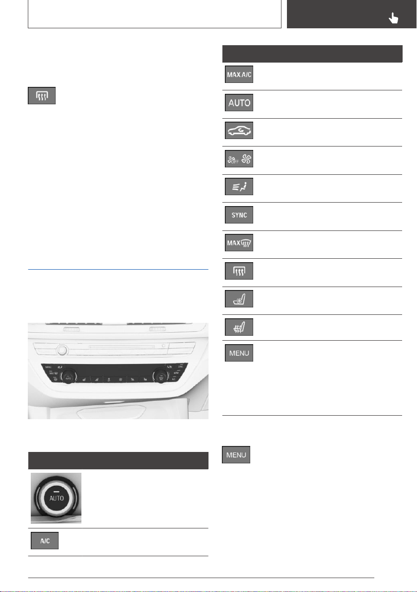
▷ Switch on the air conditioning if needed.
Rear window defroster
Press the button. The LED lights up.
The function is available with the engine running.
The rear window defroster switches off automat‐
ically after a certain period of time.
Microfilter
The microfilter removes dust and pollen from the
incoming air.
Have this filter changed during vehicle mainte‐
nance, refer to page 334.
Automatic climate control
with enhanced features
Overview
Buttons in the vehicle
Climate control functions
Button Function
Temperature, refer to page 238.
Climate control operation, refer
to page 238.
Button Function
Maximum cooling, refer to
page 238.
AUTO program, refer to
page 238.
Recirculated-air mode, refer to
page 239.
Air flow, manual, refer to
page 240.
Air distribution, manual, refer to
page 240.
SYNC program, refer to
page 240.
Defrost and defog window, refer
to page 240.
Rear window defroster, refer to
page 241.
Active seat ventilation, refer to
page 113.
Seat heating, refer to page 112.
Open the Climate menu, refer to
page 237.
For the following settings, for in‐
stance: upper body temperature
adjustment, parked-car ventila‐
tion.
Opening the Climate menu
Press the button.
The Climate menu is displayed.
All the climate control functions which can ad‐
justed via iDrive can be called up via the Climate
menu, e.g., upper body temperature adjustment,
parked-car ventilation.
Seite 237
Climate control
CONTROLS
237
Online Edition for Part no. 01402896703 - X/18
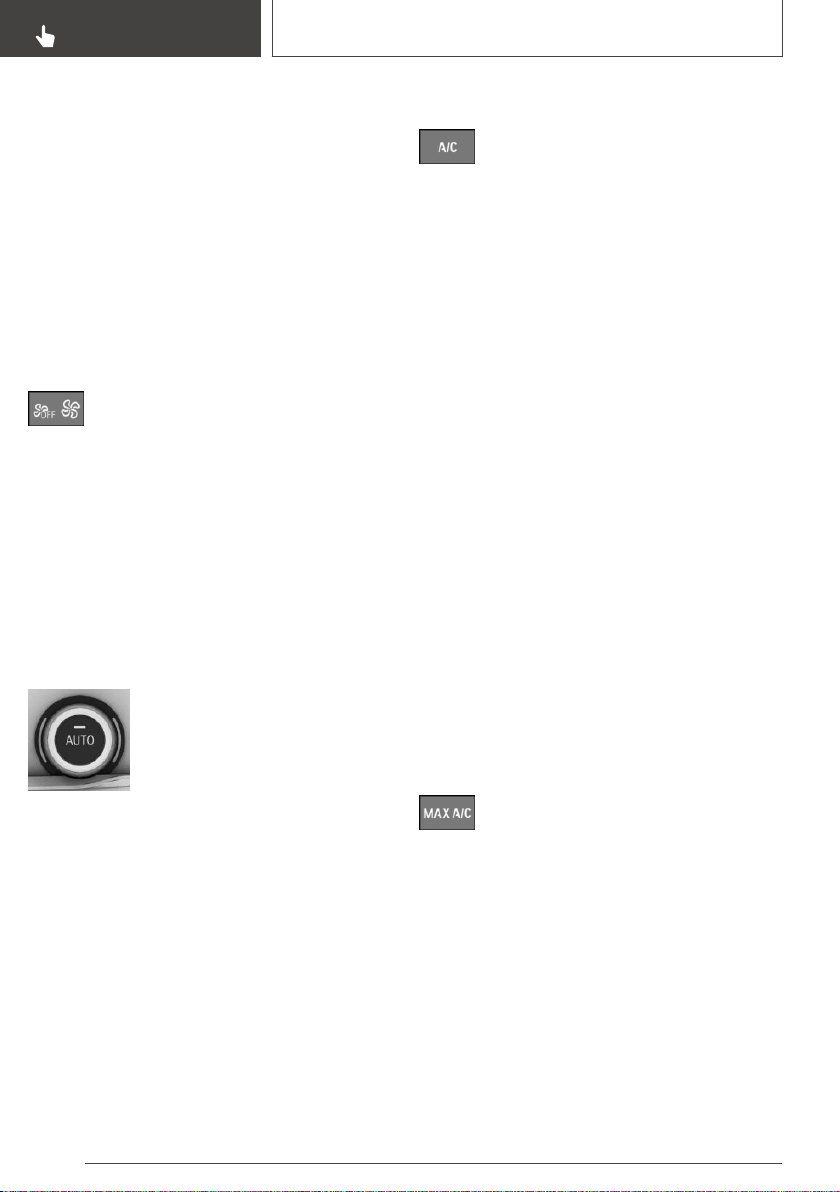
Switching on/off
Switching on
Press any button except for the following:
▷ Rear window defroster.
▷ Left side of air flow button.
▷ SYNC program.
▷ Seat heating.
▷ Seat ventilation.
Switching off
Press and hold the left button until the
system switches off.
Temperature
Concept
The automatic climate control achieves the set
temperature as quickly as possible, if needed, by
using the maximum cooling or heating capacity,
and then keeps it constant.
Settings
Turn the ring to set the desired
temperature.
Do not rapidly switch between dif‐
ferent temperature settings. Oth‐
erwise, the automatic climate
control will not have sufficient time to adjust the
set temperature.
Air conditioning
Concept
The air in the car's interior will be cooled and de‐
humidified and, depending on the temperature
setting, warmed again.
The car's interior can only be cooled with the
drive-ready state switched on.
Switching on/off
Press the button.
The LED is illuminated with air condi‐
tioning switched on.
Air conditioning is switched on with the engine
running.
Depending on the weather, the windshield and
side windows may fog up briefly when drive-
ready state is switched on.
The air conditioning is switched on automatically
with the AUTO program.
When using the automatic climate control, con‐
densation water develops and collects under‐
neath the vehicle.
Maximum cooling
Concept
The system is set to the lowest temperature, op‐
timum air flow and recirculated-air mode with the
drive-ready state switched on.
General information
The function is available with external tempera‐
tures above approx. 32 ℉/0 ℃ and with the
drive-ready state switched on.
Switching on/off
Press the button.
The LED is illuminated with the system
switched on.
Air flows out of the vents to the upper body re‐
gion. The vents need to be open for this.
Adjust air flow on the driver's side with the pro‐
gram active.
AUTO program
Concept
The AUTO program cools, ventilates or heats
the car's interior automatically.
Seite 238
CONTROLS
Climate control
238
Online Edition for Part no. 01402896703 - X/18
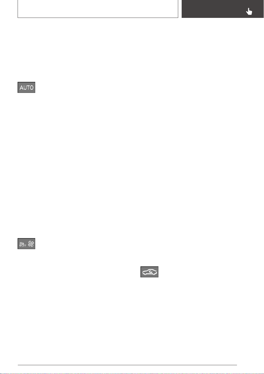
The air distribution and temperature are control‐
led automatically depending on the temperature
in the car's interior and the desired temperature
setting including the selected intensity of the air
flow.
Switching on/off
Press the button.
The LED is illuminated with the AUTO
program switched on.
Depending on the selected temperature, the in‐
tensity of the AUTO program, and outside influ‐
ences, the air is directed to the windshield, side
windows, upper body, and into the floor area.
The air conditioning, refer to page 238, is
switched on automatically with the AUTO pro‐
gram.
At the same time, a condensation sensor con‐
trols the program so as to prevent window con‐
densation as much as possible.
The AUTO program is switched off automati‐
cally, when manual air distribution is set.
Intensity
With the AUTO program switched on, the inten‐
sity can be set. This changes the automatic con‐
trol for the air flow and air distribution.
Press the left or right side of the button:
decrease or increase intensity.
The selected intensity is shown on the display of
the automatic climate control.
Automatic recirculated-air
control AUC
Concept
The automatic recirculated-air control AUC rec‐
ognizes odors or pollutants in the outside air.
The outside air supply is shut off and the interior
air is recirculated.
General information
If the system is activated, a sensor detects pollu‐
tants in the outside air and controls the shut-off
automatically.
If the system is deactivated, outside air continu‐
ously flows into the car's interior.
With constant recirculated-air mode, the air qual‐
ity in the car's interior deteriorates and the fog‐
ging of the windows increases.
Switching on/off
Via iDrive:
1.
"My Vehicle"
2. "Vehicle settings"
3. "Climate functions"
4. If necessary, "Air quality"
5. "Automatic air recirculation"
If there is window condensation, switch off recir‐
culated-air mode or defog the windows, refer to
page 240.
Recirculated-air mode
Concept
You may react to unpleasant odors or pollutants
in the immediate environment by temporarily
suspending the supply of outside air. The system
then recirculates the air flow within the vehicle.
Operation
Press button repeatedly to select an op‐
erating mode:
▷ LED off: outside air flows in continuously.
▷ LED on: the supply of outside air is perma‐
nently shut off.
To prevent window fogging, recirculated-air
mode switches off automatically after a certain
amount of time, depending on the environmental
conditions.
Seite 239
Climate control
CONTROLS
239
Online Edition for Part no. 01402896703 - X/18

With constant recirculated-air mode, the air qual‐
ity in the car's interior deteriorates and the fog‐
ging of the windows increases.
If there is window condensation, switch off recir‐
culated-air mode or defog the windows, refer to
page 240.
Controlling the air flow manually
Concept
The air flow for climate control can be adjusted
manually.
General information
To manually adjust air flow switch off AUTO pro‐
gram first.
Operation
Press the left or right side of the button:
decrease or increase air flow.
The selected air flow is shown on the display of
the automatic climate control.
The air flow of the automatic climate control may
be reduced automatically to save battery power.
Controlling the air distribution
manually
Concept
The air distribution for climate control can be ad‐
justed manually.
Operation
Press the button repeatedly to select a
program:
▷ Windows, upper body region, and floor area.
▷ Upper body region and floor area.
▷ Floor area.
▷ Windows and floor area.
▷ Windows: driver's side only.
▷ Windows and upper body.
▷ Upper body region.
The selected air distribution is shown on the dis‐
play of the automatic climate control.
If there is window condensation, defog the win‐
dows, refer to page 240.
SYNC program
Concept
The following settings of the driver's side can be
transferred to the front-passenger side and the
rear:
▷ Temperature.
▷ Air distribution.
Switching on/off
Press the button.
The LED is illuminated with the SYNC
program switched on.
The program is switched off automatically if the
settings on the front passenger side or in the
rear are changed.
Defrosting windows and
removing condensation
Concept
Ice and condensation are quickly removed from
the windshield and the front side windows.
Switching on/off
Press the button.
The LED is illuminated with the system
switched on.
The air flow can be adjusted manually with the
system switched on.
If there is window condensation, press
the button or switch on the air condi‐
Seite 240
CONTROLS
Climate control
240
Online Edition for Part no. 01402896703 - X/18
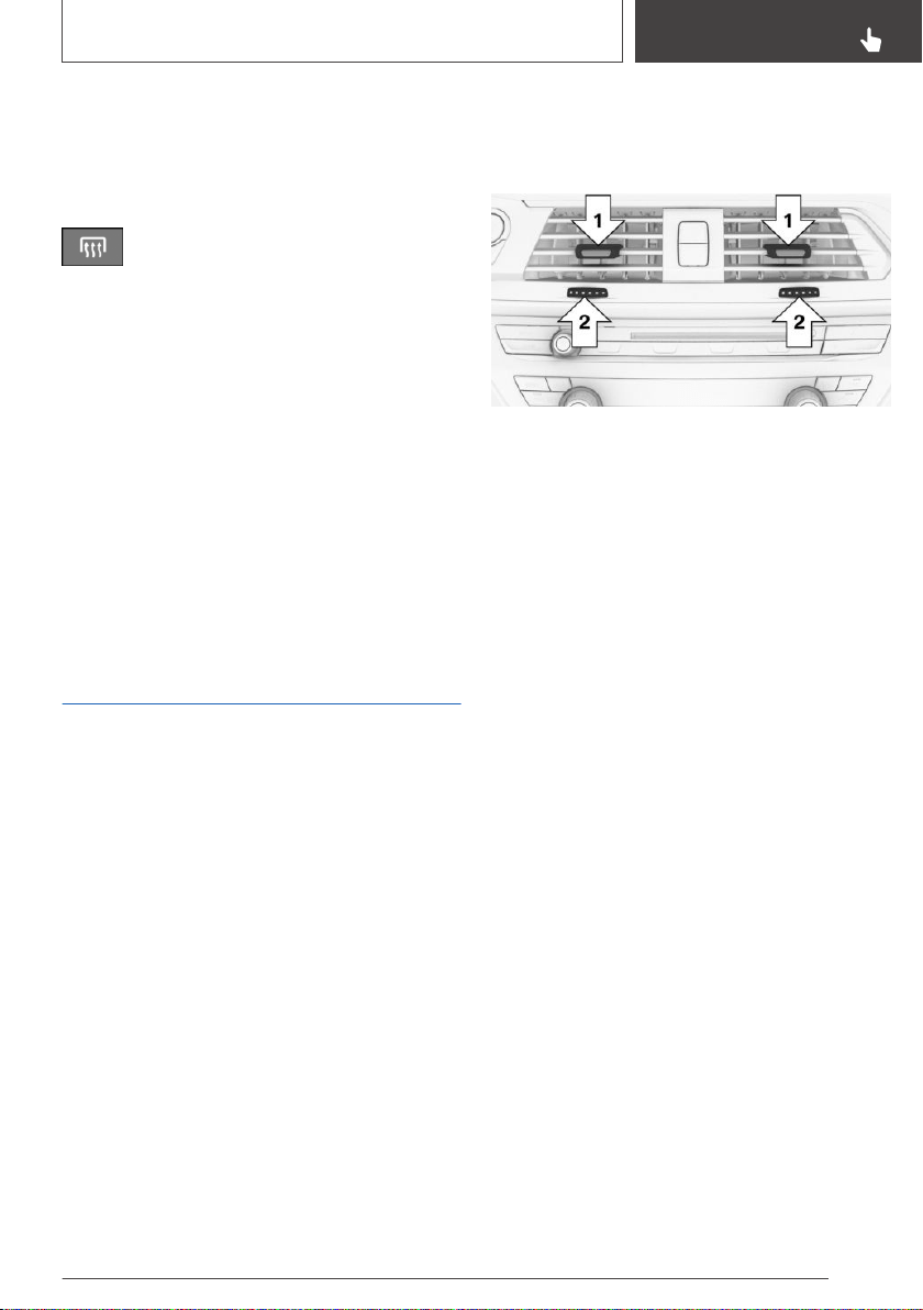
tioning to utilize the condensation sensor. Make
sure that air can flow to the windshield.
Rear window defroster
Press the button. The LED lights up.
The function is available with the engine running.
The rear window defroster switches off automat‐
ically after a certain period of time.
Microfilter/activated-charcoal
filter
The microfilter removes dust and pollen from the
incoming air.
The activated-charcoal filter also removes gas‐
eous pollutants from the outside air that enters
the vehicle.
Have this combined filter changed during vehicle
maintenance, refer to page 334.
Ventilation
Concept
The air flow directions can be individually ad‐
justed.
Adjusting the ventilation
General information
The air flow directions can be adjusted for direct
or indirect ventilation.
Direct ventilation
The air flow is directed towards the passengers.
The air flow heats or cools noticeably, depending
on the adjusted temperature.
Indirect ventilation
The air flow is not directed towards the passen‐
gers. The car's interior is warmed or cooled indi‐
rectly, depending on the set temperature.
Front ventilation
Overview
▷ Lever for changing the air flow direction, ar‐
row 1.
▷ Thumbwheel for variable opening and closing
of the vents, arrow 2.
Varying the temperature of the
ventilation
General information
The temperature of the ventilation in the upper
body area can be varied.
The temperature is individually adjusted, e.g.
colder toward blue, warmer toward red.
The air flow of the ventilation in the upper body
range heats or cools noticeably, depending on
the adjusted temperature.
This does not change the set interior tempera‐
ture for the driver and front passenger.
Settings
Via iDrive:
1.
"My Vehicle"
2. "Vehicle settings"
3. If necessary, "Climate functions"
4. "Temperature adjustment, upper body"
5. Set the desired temperature.
▷ Toward blue: colder.
▷ Toward red: warmer.
Seite 241
Climate control
CONTROLS
241
Online Edition for Part no. 01402896703 - X/18
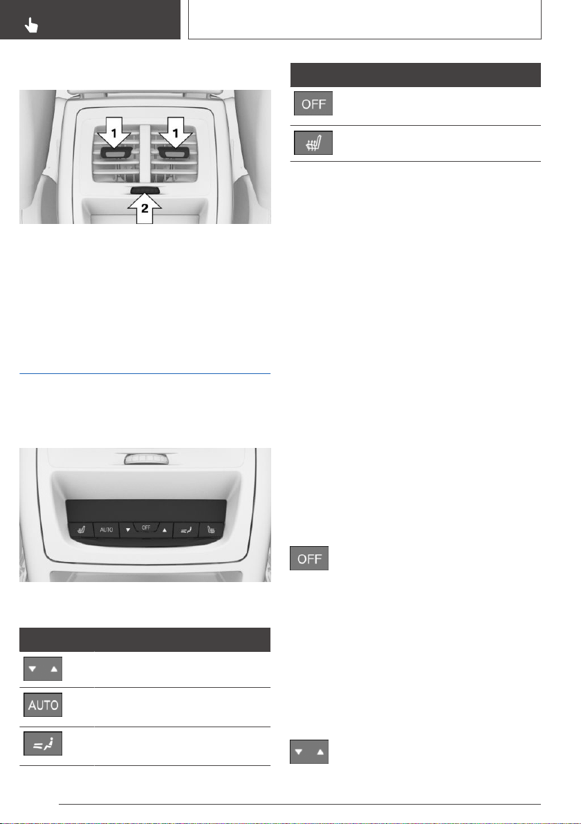
Ventilation in rear, center
▷ Lever for changing the air flow direction, ar‐
row 1.
▷ Thumbwheel for variable opening and closing
of the vents, arrow 2.
Rear automatic climate
control
Overview
Buttons in the vehicle
Climate control functions
Button Function
Temperature, refer to page 242.
AUTO program, refer to
page 243.
Air distribution, manual, refer to
page 243.
Button Function
Switch off the system, refer to
page 242.
Seat heating, refer to page 112.
Climate control functions in
detail
Switching on/off
Via iDrive
1.
"My Vehicle"
2. "Vehicle settings"
3. "Climate functions"
4. "Rear climate"
The rear automatic climate control is not ready
for operation if the automatic climate control is
switched off or if the function for defrosting the
windows and removing condensation is active.
Using the button: switching on
Press any button except for the following:
▷ OFF button.
▷ Seat heating.
Using the button: switching off
Press the button.
Temperature
Concept
The automatic climate control achieves the set
temperature as quickly as possible, if needed, by
using the maximum cooling or heating capacity,
and then keeps it constant.
Settings
Press the left or right side of the button:
decrease or increase temperature.
Seite 242
CONTROLS
Climate control
242
Online Edition for Part no. 01402896703 - X/18
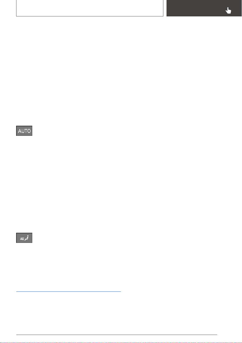
The selected temperature is shown on the dis‐
play of the automatic climate control.
Do not rapidly switch between different tempera‐
ture settings. Otherwise, the automatic climate
control will not have sufficient time to adjust the
set temperature.
AUTO program
Concept
Air flow, air distribution and temperature are con‐
trolled automatically.
Switching on/off
Press the button.
The LED is illuminated with the AUTO
program switched on.
Depending on the selected temperature and out‐
side influences, the air is directed to the upper
body and into the floor area.
Controlling the air distribution
manually
Concept
The air distribution for climate control can be ad‐
justed manually.
Operation
Press the button repeatedly to select a
program:
▷ Upper body region.
▷ Upper body region and floor area.
▷ Floor area.
Parked-car ventilation
Concept
The car's interior can be cooled or heated before
driving off with the parked-car ventilation. De‐
pending on set temperature and ambient tem‐
perature, the car's interior is ventilated or possi‐
bly heated using the residual engine heat.
General information
The system can be switched on and off directly
or via a preset departure time.
The activation time is determined based on the
external temperature. The system promptly
switches on before the selected departure time.
Functional requirements
▷ The vehicle is in idle state or standby state
and not in drive-ready state.
▷ Battery is sufficiently charged.
If parked-car ventilation is switched on, the
vehicle battery will be discharged. Thus, limit
the maximum activation time to save the ve‐
hicle battery. The system will be available
again after the engine is started or after a
short trip.
▷ Make sure that the vehicle's date and time
are set correctly.
▷ Open the vents to allow air to flow out.
Switching on/off directly
General information
There are different ways to switch the system on
or off.
The system switches off automatically after a
certain period of time. The system continues to
run for some time after being switched off.
Using the button
When the vehicle is in standby state, the parked-
car ventilation can be switched on or off via the
automatic climate control buttons.
Press any button except:
▷ Rear window defroster.
▷ Left side of air flow button.
▷ Seat heating.
Seite 243
Climate control
CONTROLS
243
Online Edition for Part no. 01402896703 - X/18

▷ SYNC program.
▷ MENU.
The system switches off after leaving and lock‐
ing the vehicle.
Via iDrive
1. "My Vehicle"
2. "Vehicle settings"
3. If necessary, "Climate functions"
4. "Comfort ventilation" or "Comfort heating/
ventilation"
5. "Activate now"
Via BMW display key
Switching on
1.
Switch on the display of the BMW display
key.
2. "Precondit. setting"
3. Tap the symbol or the symbol.
4. "Activate now"
5. "Start"
Switching off
1.
Switch on the display of the BMW display
key.
2. "Precondit. setting"
3. Tap the symbol or the symbol.
4. "Stop"
Display
symbol on the automatic climate control indi‐
cates the system is switched on.
REST is displayed on the automatic climate con‐
trol. The residual engine heat is used.
Departure time
Concept
Different departure times can be adjusted to en‐
sure a comfortable interior temperature in the ve‐
hicle at the time of departure.
▷ One-time departure time: the time can be
set.
The system is switched on once.
▷ Departure time with weekday: time and day
of the week can be set.
On the desired weekdays, the system will be
switched on promptly before the set depar‐
ture time.
The departure time is preselected in two steps:
▷ Set departure times.
▷ Activate departure times.
Setting the departure time
Via iDrive
1.
"My Vehicle"
2. "Vehicle settings"
3. If necessary, "Climate functions"
4. "Comfort ventilation" or "Comfort heating/
ventilation"
5. Select the desired departure time.
6. Set the departure time.
7. Select day of the week, if needed.
Via BMW display key
1.
Switch on the display of the BMW display
key.
2. "Precondit. setting"
3. Tap the symbol or the symbol.
4. Select the desired departure time.
5. Set the departure time.
6. Select day of the week, if needed.
7. "OK"
Seite 244
CONTROLS
Climate control
244
Online Edition for Part no. 01402896703 - X/18
Activating the departure time
Functional requirement
If a departure time is to influence the switching
on of parked-car ventilation, the respective de‐
parture time must be activated first.
Via iDrive
1. "My Vehicle"
2. "Vehicle settings"
3. If necessary, "Climate functions"
4. "Comfort ventilation" or "Comfort heating/
ventilation"
5. "For departure time"
6. Activate the desired departure time.
Via BMW display key
1.
Switch on the display of the BMW display
key.
2. "Precondit. setting"
3. Tap the symbol or the symbol.
4. Tap on symbol.
5. Activate the desired departure time.
Display
The symbol on the automatic climate
control signals an activated departure time.
Ambient air package
Concept
The Ambient Air Package can be used to clean
and scent the interior air with high-quality fra‐
grances.
Ionization is used to clean the air from sus‐
pended particles. Together with the selected fra‐
grance, ionization contributes to well-being and
relaxation while driving.
General information
Two different fragrances can be selected in the
vehicle. A variety of other fragrances is possible
by replacing the fragrance cartridges.
The following criteria can influence the percep‐
tion of scents in the car's interior:
▷ Automatic climate control settings.
▷ Temperature and air humidity.
▷ Time of day and season.
▷ Physical condition of the vehicle occupants,
for instance fatigue.
BMW recommends the use of genuine BMW
fragrance cartridges.
The genuine BMW fragrance cartridges are not
suitable for refilling. When a cartridge is empty,
replace it with a new fragrance cartridge.
Safety information
WARNING
Refilled genuine BMW fragrance cartridges can
cause the emission of harmful substances, mal‐
functions, and damage to the system. There is
a risk of injury or risk of damage to property. Do
not refill genuine fragrance cartridges. When a
cartridge is empty, replace it with a new fra‐
grance cartridge.
Ionization
Concept
Ionization cleans the car's interior air of sus‐
pended particles.
Switching on/off
Via iDrive:
1.
"My Vehicle"
2. "Vehicle settings"
3. "Climate functions"
Seite 245
Climate control
CONTROLS
245
Online Edition for Part no. 01402896703 - X/18

4. If necessary, "Air quality"
5. "Ionization"
The climate control display indicates that ioniza‐
tion is switched on.
Fragrancing
General information
Fragrancing is done at intervals in order to avoid
a habituation effect.
Two fragrance cartridges in the vehicle allow
switching between the fragrances.
The fragrance cartridges are located in the glove
compartment.
To ensure a pleasant fragrance inside of the ve‐
hicle when starting the trip, fragrancing can occur
prior to the trip. The system is automatically
switched on with the parked-car ventilation if fra‐
grancing was switched on at the end of the last
trip.
Functional requirements
▷ Fragrance cartridges are sufficiently filled.
▷ Interior temperature between 41 ℉/+5 ℃
and 104 ℉/+40 ℃.
▷ Open the vents to allow the fragrance to flow
out.
Selecting the fragrance
Two different fragrances can be selected in the
vehicle.
Via iDrive:
1.
"My Vehicle"
2. "Vehicle settings"
3. "Climate functions"
4. "Fragrance"
5. Select the desired setting.
The setting is stored for the driver profile cur‐
rently used.
Switching fragrancing on/off,
adjusting intensity
Via iDrive:
1. "My Vehicle"
2. "Vehicle settings"
3. "Climate functions"
4. "Fragrance"
5. "Level"
6. Select the desired setting.
Display
The illustrations on the Control Display show the
actual filling level of the fragrance cartridges.
Via iDrive:
1.
"My Vehicle"
2. "Vehicle settings"
3. "Climate functions"
4. "Fragrance"
The fill level of the current fragrance is dis‐
played.
5. Select the desired setting.
When an empty fragrance cartridge is indicated,
the cartridge still contains a fluid carrying the fra‐
grance. However, it is not sufficient for fragranc‐
ing.
When a fragrance cartridge requires replace‐
ment, a Check Control message is displayed
Inserting fragrance cartridges
The fragrance cartridges are located in the glove
compartment.
1.
Open the glove compartment, refer to
page 256.
2. Press on the bottom of the cartridge holder.
Seite 246
CONTROLS
Climate control
246
Online Edition for Part no. 01402896703 - X/18
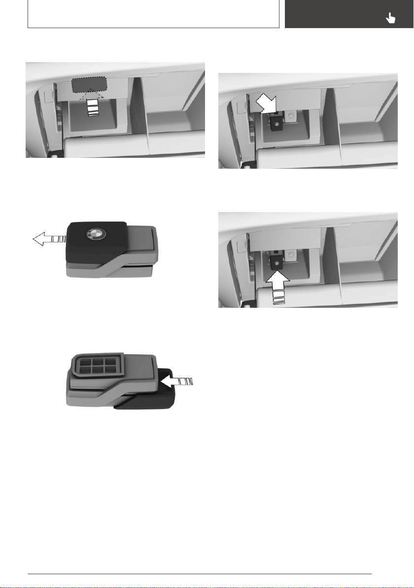
The cartridge holder slides down.
3. Remove the cover of the fragrance cartridge.
Hold the cover on the top to slide it from the
fragrance cartridge.
4. Insert the removed cover on the back side of
the fragrance cartridge.
5. Position fragrance cartridge such that the
chip faces away from the cartridge holder.
6. Insert the fragrance cartridge without pres‐
sure into the cartridge holder. The cartridge
snaps lightly into place.
7. Push the cartridge holder up, until it engages.
Make sure that no objects press against the
cartridge holder from below, otherwise the
function of the ambient air package could be
impacted.
8. Close the glove compartment.
Removing the fragrance cartridge
The fragrance cartridges are located in the glove
compartment.
1.
Open the glove compartment, refer to
page 256.
2. Press on the bottom of the cartridge holder.
Seite 247
Climate control
CONTROLS
247
Online Edition for Part no. 01402896703 - X/18
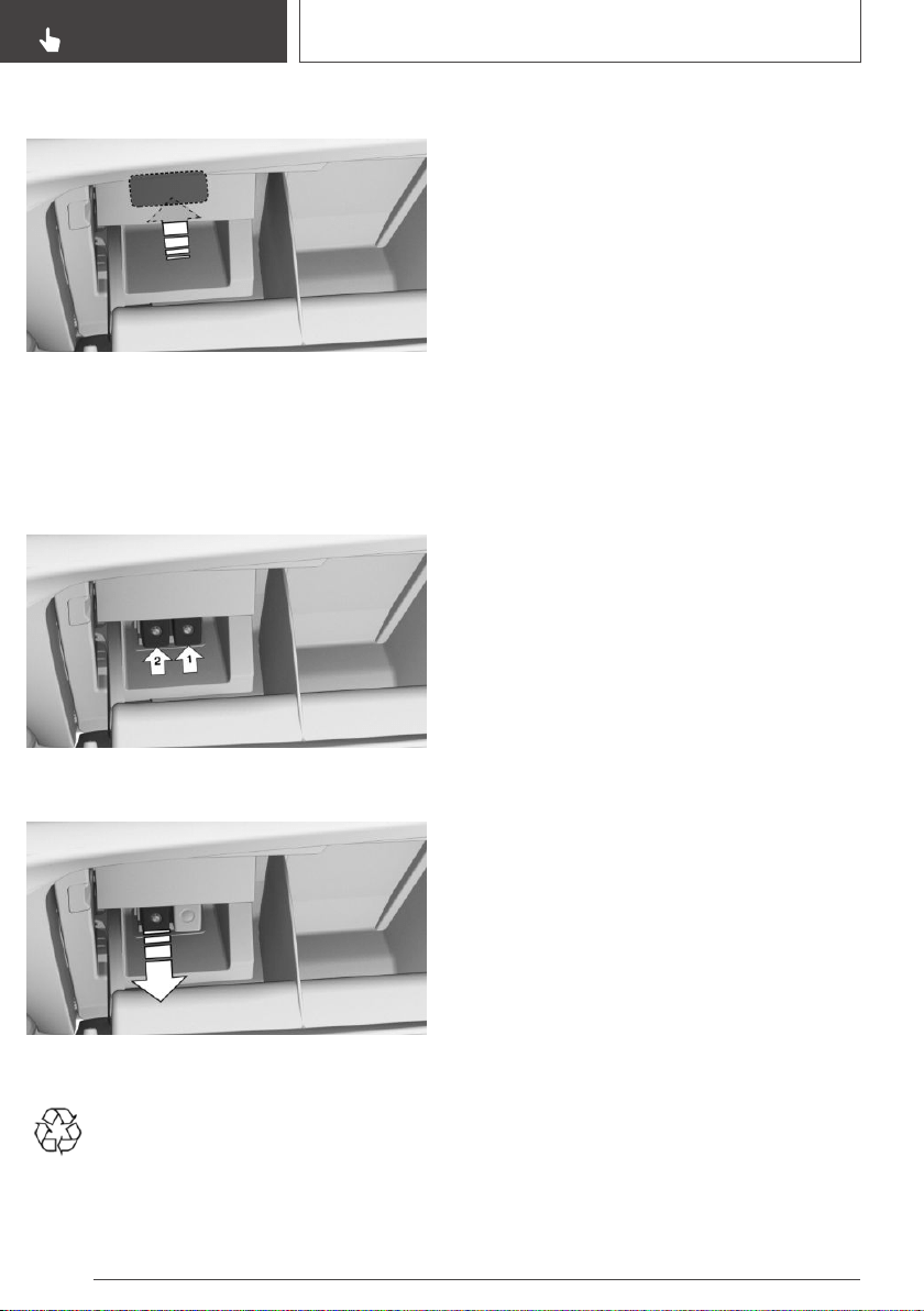
The cartridge holder slides down.
3. Pull desired fragrance cartridge from the
holder.
Fragrance cartridge, arrow 1: first fragrance
indicated on the Control Display.
Fragrance cartridge, arrow 2: second fra‐
grance indicated on the Control Display.
4. Pull desired fragrance cartridge from the
holder.
Recycling
Empty fragrance cartridges can be taken
to a dealer’s service center or another
qualified service center or repair shop for
recycling.
Seite 248
CONTROLS
Climate control
248
Online Edition for Part no. 01402896703 - X/18
Interior equipment
Vehicle features and
options
This chapter describes all standard, country-spe‐
cific and optional features offered with the series.
It also describes features that are not necessarily
available in your vehicle, e. g., due to the selected
options or country versions. This also applies to
safety-related functions and systems. When us‐
ing these functions and systems, the applicable
laws and regulations must be observed.
Integrated Universal
Remote Control
Concept
The integrated Universal Remote Control in the
interior mirror can operate up to 3 functions of
remote-controlled systems, such as garage door
drives, barriers or lighting systems.
General information
The Integrated Universal Remote Control repla‐
ces up to 3 different hand-held transmitters. To
operate the remote control, the buttons on the
interior mirror must be programmed with the de‐
sired functions. The hand-held transmitter for the
particular system is required in order to program
the remote control.
Before selling the vehicle, delete the stored func‐
tions for the sake of security.
If possible, do not install the antenna of the re‐
mote-controlled system, e.g. the garage gate
drive, near metal objects to ensure the best pos‐
sible operation.
Safety information
WARNING
The operation of remote-controlled systems
with the integrated universal remote control,
such as the garage door, may result in pinched
body parts. There is a risk of injury or risk of
damage to property. Make sure that the area of
movement of the respective system is clear
during programming and operation. Also follow
the safety information of the hand-held trans‐
mitter.
Compatibility
If this symbol is printed on the packaging
or in the owner's manual of the system to
be controlled, the system is generally
compatible with the integrated Universal Remote
Control.
Additional questions are answered by:
▷ A dealer’s service center or another qualified
service center or repair shop.
▷ www.homelink.com on the Internet.
HomeLink is a registered trademark of Gentex
Corporation.
Seite 249
Interior equipment
CONTROLS
249
Online Edition for Part no. 01402896703 - X/18

Control elements on the interior
mirror
▷ Buttons, arrow 1.
▷ LED, arrow 2.
▷ The hand-held transmitter, arrow 3, is re‐
quired for programming.
Programming
General information
The battery of the hand-held transmitter must be
fully charged at the time of programming to en‐
sure an optimal range of the integrated universal
remote control.
1.
Switch on standby state.
2. Initial setup:
Press and hold the two outer buttons on the
interior mirror simultaneously for approxi‐
mately 10 seconds until the LED flashes
green rapidly. This erases all programming of
the buttons on the interior mirror.
3. Press the interior mirror button to be pro‐
grammed. The LED on the interior mirror will
slowly begin flashing orange.
4. Hold the hand-held transmitter for the system
to be used approx. 1 to 12 in/2.5 to 30 cm
away from the buttons on the interior mirror.
The required distance depends on the hand-
held transmitter.
5. Press and hold the button of the desired
function on the hand-held transmitter.
Canada: if programming with the hand-held
transmitter was interrupted, hold down the in‐
terior mirror button and repeatedly press and
release the hand-held transmitter button for
2 seconds.
6.
▷ The LED lights up green: programming
completed.
Release the button.
▷ The LED flashes fast: programming is not
complete.
Press the button on the interior mirror for
2 seconds and release. Perform this pro‐
cedure three times to complete the pro‐
gramming procedure.
If the integrated universal remote control
remains nonoperational, continue with the
special features for change code wireless
systems.
▷ LED does not flash green after 60 sec‐
onds: programming not completed.
Repeat steps 3 to 6.
To program other functions on other buttons, re‐
peat steps 3 to 5.
Special feature of the rolling code
wireless system
If you are unable to operate the remote-control‐
led system after repeated programming, please
check if the system to be controlled features a
rolling code radio system.
Refer to the owner's manual for the system.
For systems with a rolling code radio system, the
integrated Universal Remote Control and the
system also have to be synchronized.
Please read the owner's manual to find out how
to synchronize the system.
Synchronizing is easier with the aid of a second
person.
Seite 250
CONTROLS
Interior equipment
250
Online Edition for Part no. 01402896703 - X/18

Synchronizing the universal remote control with
the system:
1. Park the vehicle within range of the remote-
controlled system.
2. Program the relevant button on the interior
mirror as described.
3. Locate and press the synchronizing button
on the system being programmed, e.g. at the
garage gate. You have approx. 30 seconds
for the next step.
4. Hold down the programmed button on the in‐
terior mirror for approximately 3 seconds and
then release it. If necessary, repeat this step
up to three times in order to finish synchroni‐
zation. Once synchronization is complete, the
programmed function will be carried out.
Reprogramming individual
buttons
1.
Switch on standby state.
2. Press and hold the interior mirror button to be
programmed.
3. As soon as the LED on the interior mirror
flashes orange after approx. 20 seconds, re‐
lease the button.
4. Hold the hand-held transmitter for the system
to be used approx. 1 to 12 in/2.5 to 30 cm
away from the buttons on the interior mirror.
The required distance depends on the hand-
held transmitter.
5. Press and hold the button of the desired
function on the hand-held transmitter.
Canada: if programming with the hand-held
transmitter was interrupted, hold down the in‐
terior mirror button and repeatedly press and
release the hand-held transmitter button for
2 seconds.
6. The LED can light up in different ways.
▷ The LED lights up green: the program‐
ming procedure is completed.
Release the button.
▷ The LED flashes fast: the hand-held
transmitter was detected but program‐
ming is not complete.
Press the button on the interior mirror for
2 seconds and release. Perform this pro‐
cedure three times to complete the pro‐
gramming procedure.
If the universal remote control remains
nonoperational, continue with the special
features for change code wireless sys‐
tems.
▷ LED does not flash green after 60 sec‐
onds: programming not completed.
Repeat steps 3 to 6.
Operation
WARNING
The operation of remote-controlled systems
with the integrated universal remote control,
such as the garage door, may result in pinched
body parts. There is a risk of injury or risk of
damage to property. Make sure that the area of
movement of the respective system is clear
during programming and operation. Also follow
the safety information of the hand-held trans‐
mitter.
The system, such as the garage door, can be op‐
erated using the button on the interior mirror
while the drive-ready or standby state is
switched on. To do this, hold down the button
within receiving range of the system until the
function is activated. The interior mirror LED
stays lit while the wireless signal is being trans‐
mitted.
Deleting stored functions
All stored functions will be deleted. The func‐
tions cannot be deleted individually.
Press and hold the two outer buttons on the in‐
terior mirror simultaneously for approximately
10 seconds until the LED on the interior mirror
flashes green rapidly.
Seite 251
Interior equipment
CONTROLS
251
Online Edition for Part no. 01402896703 - X/18
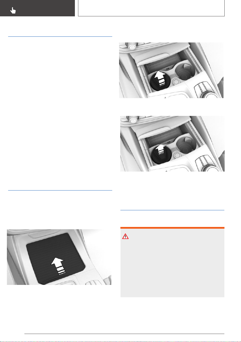
Sun visor
Glare shield
Fold the sun visor down or up.
Glare shield from the side
Folding out
1. Fold the sun visor down.
2. Unhook it from the holder and swing it to the
side.
Folding up
Proceed in the reverse order to close the sun vi‐
sor.
Vanity mirror
A vanity mirror is located in the sun visor behind
a cover. When the cover is opened, the mirror
lighting switches on.
Ashtray
Front center console
Opening
1.
Slide the cover forward.
2. The ashtray is located in a cup holder. Fold
the ashtray cover upward.
Emptying
Pull the ashtray with the closed cover out of the
cup holder.
Cigarette lighter
Safety information
WARNING
Contact with the hot heating element or the hot
socket of the cigarette lighter can cause burns.
Flammable materials can ignite if the cigarette
lighter falls down or is held against the respec‐
tive objects. There is a risk of fire and injuries.
Take hold of the cigarette lighter by its handle.
Make sure that children do not use the ciga‐
rette lighter and burn themselves.
Seite 252
CONTROLS
Interior equipment
252
Online Edition for Part no. 01402896703 - X/18
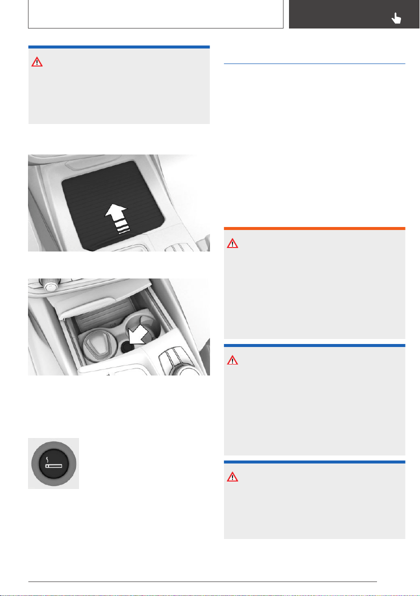
NOTICE
If metal objects fall into the socket, they can
cause a short circuit. There is a risk of damage
to property. Replace the cigarette lighter or
socket cover again after using the socket.
Front center console
Slide the cover forward.
The cigarette lighter is located between the cup
holders.
Operation
Push in the cigarette lighter.
The cigarette lighter can be re‐
moved as soon as it pops back
out.
Sockets
Concept
The lighter socket can be used as a socket for
electrical equipment when standby and drive-
ready state are switched on.
General information
The total load of all sockets must not exceed
140 watts at 12 volts.
Do not damage the socket by using non-com‐
patible connectors.
Safety information
WARNING
Devices and cables in the unfolding area of the
airbags, such as portable navigation devices,
can hinder the unfolding of the airbag or be
thrown around in the car's interior during un‐
folding. There is a risk of injury. Make sure that
devices and cables are not in the airbag's area
of unfolding.
NOTICE
Battery chargers for the vehicle battery can
work with high voltages and currents, which
means that the 12 volt on-board network can
be overloaded or damaged. There is a risk of
damage to property. Only connect battery
chargers for the vehicle battery to the starting
aid terminals in the engine compartment.
NOTICE
If metal objects fall into the socket, they can
cause a short circuit. There is a risk of damage
to property. Replace the cigarette lighter or
socket cover again after using the socket.
Seite 253
Interior equipment
CONTROLS
253
Online Edition for Part no. 01402896703 - X/18
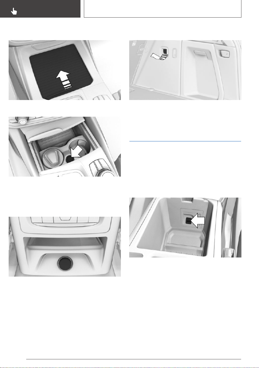
Front center console
Slide the cover forward.
A socket is located between the cup holders.
Pull off the cover.
Rear center console
A socket is located in the center console.
Pull off the cover.
In the cargo area
A socket is located on the right side in the cargo
area. Unfold the cover.
USB interface
General information
Follow the information regarding the connection
of mobile devices to the USB interface in the
section on USB connections, refer to page 66.
In the center armrest
A USB interface is located in the center armrest.
Properties:
▷ USB port Type A.
▷ For charging mobile devices and for data
transfer.
▷ Charge current: max. 2.1 A.
Seite 254
CONTROLS
Interior equipment
254
Online Edition for Part no. 01402896703 - X/18
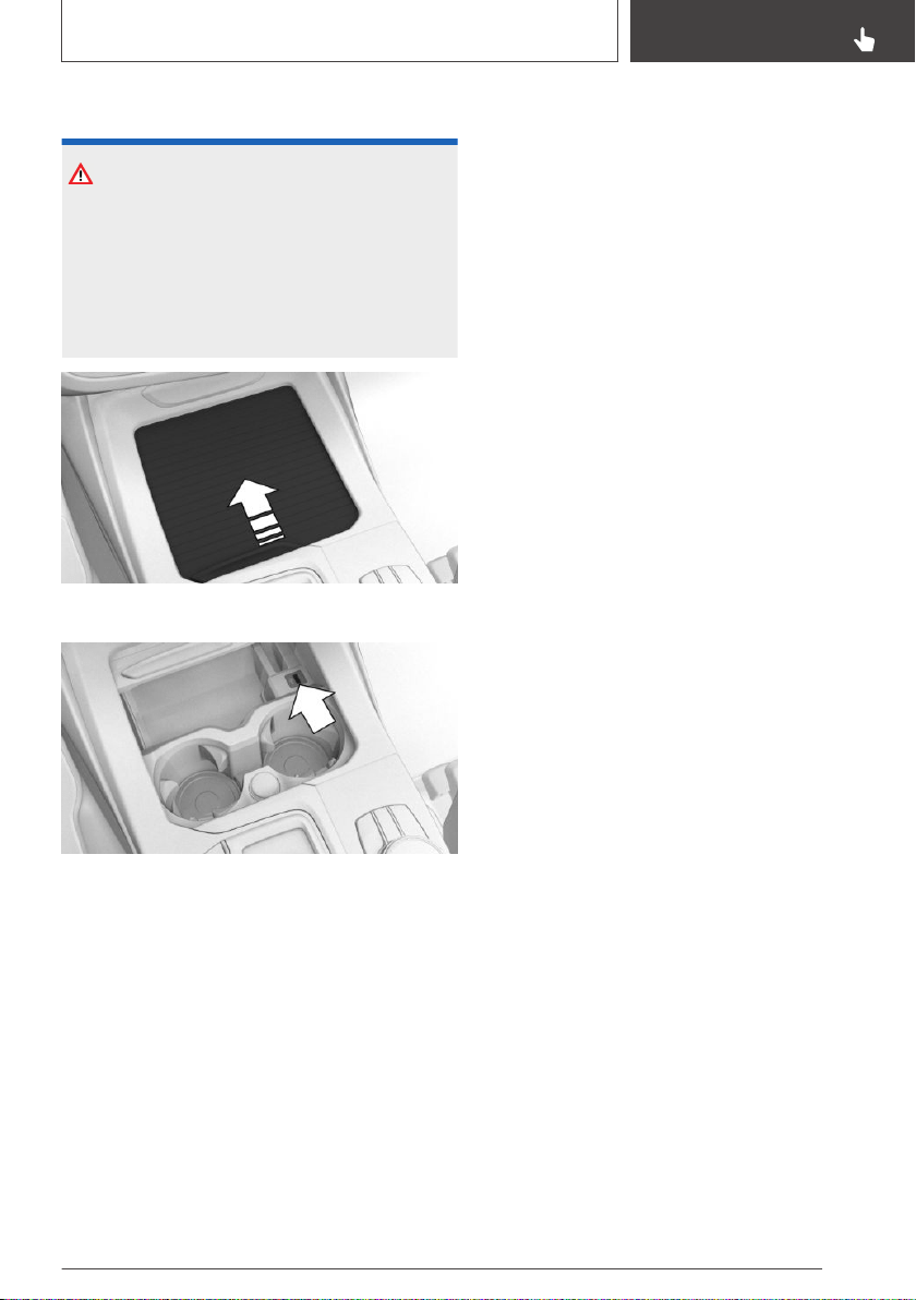
In the center console
NOTICE
Objects in the storage compartment, e.g., large
USB connectors, may block or damage the
cover when it is being opened or closed. There
is a risk of damage to property. Make sure that
the area of movement of the cover is clear
while opening and closing it.
Slide the cover forward.
A USB interface is located in the center console.
Properties:
▷ USB port Type A
▷ For charging mobile devices and for data
transfer.
▷ Charge current when equipped with tele‐
phone service: max. 2.1 A.
Seite 255
Interior equipment
CONTROLS
255
Online Edition for Part no. 01402896703 - X/18
Storage compartments
Vehicle features and
options
This chapter describes all standard, country-spe‐
cific and optional features offered with the series.
It also describes features that are not necessarily
available in your vehicle, e. g., due to the selected
options or country versions. This also applies to
safety-related functions and systems. When us‐
ing these functions and systems, the applicable
laws and regulations must be observed.
Safety information
WARNING
Loose objects or devices with a cable connec‐
tion to the vehicle, for instance mobile phones,
can be thrown into the car's interior while driv‐
ing, for instance in the event of an accident or
during braking and evasive maneuvers. There is
a risk of injury. Secure loose objects or devices
with a cable connection to the vehicle in the
car's interior.
NOTICE
Anti-slip pads such as anti-slip mats can dam‐
age the dashboard. There is a risk of damage to
property. Do not use anti-slip pads.
Storage compartments
The following storage compartments are availa‐
ble in the car's interior:
▷ Glove compartment on the front passenger
side, refer to page 256.
▷ Glove compartment on the driver's side, refer
to page 257.
▷ Compartments in the doors, refer to
page 257.
▷ Storage compartment in the center console,
refer to page 257.
▷ Center armrest, refer to page 258.
▷ Storage compartment in the rear center con‐
sole, refer to page 258.
▷ Pockets on the backrests of the front seats.
Glove compartment
Front passenger side
Safety information
WARNING
Folded open, the glove compartment protrudes
in the car's interior. Objects in the glove com‐
partment can be thrown into the car's interior
while driving, for instance in the event of an ac‐
cident or during braking and evasive maneu‐
vers. There is a risk of injury. Always close the
glove compartment immediately after using it.
Opening
Pull the handle.
Seite 256
CONTROLS
Storage compartments
256
Online Edition for Part no. 01402896703 - X/18
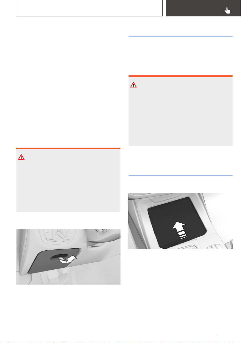
The light in the glove compartment switches on.
Closing
Fold cover closed.
Locking
The glove compartment can be locked with an
integrated key. This prevents access to the glove
compartment.
After the glove compartment is locked, the re‐
mote control can be handed over without the
integrated key, for instance when the vehicle is
parked by valet parking.
Driver's side
Safety information
WARNING
Folded open, the glove compartment protrudes
in the car's interior. Objects in the glove com‐
partment can be thrown into the car's interior
while driving, for instance in the event of an ac‐
cident or during braking and evasive maneu‐
vers. There is a risk of injury. Always close the
glove compartment immediately after using it.
Opening
Pull the handle.
Closing
Fold cover closed.
Compartments in the doors
General information
There are storage compartments in the doors.
Safety information
WARNING
Breakable objects, such as glass bottles or
glasses, can break in the event of an accident
or a braking or evasive maneuver. Broken glass
can be scattered in the car's interior. There is a
risk of injury or risk of damage to property. Do
not use any breakable objects while driving.
Only stow breakable objects in closed storage
compartments.
Storage compartment in
the center console
Opening
Slide the cover forward.
Closing
Slide the cover rearward.
Seite 257
Storage compartments
CONTROLS
257
Online Edition for Part no. 01402896703 - X/18
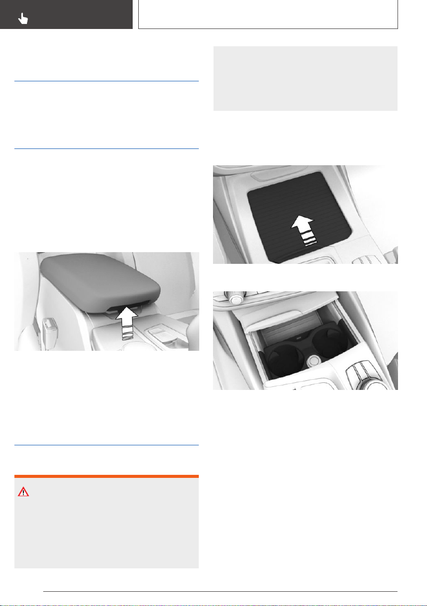
Storage compartment in
the rear center console
The rear center console contains one or two
storage compartments.
Center armrest
Front
General information
A storage compartment is located in the center
armrest between the seats.
Opening
Press the button.
Closing
Press cover down until it engages.
Cup holders
Safety information
WARNING
Unsuitable containers in the cup holder may
damage the cup holders or thrown into the
car's interior, such as in the event of an acci‐
dent, braking or evasive maneuver. Spilled liq‐
uids can distract from the traffic conditions and
lead to an accident. Hot drinks can damage the
cup holder or lead to scalding. There is a risk of
injury or risk of damage to property. Do not
force objects into the cup holder. Use light-
weight, unbreakable, and sealable containers.
Do not transport hot beverages.
Front
Opening
Slide the cover forward.
Two cup holders are located in the center con‐
sole.
Closing
Slide the cover rearward.
Seite 258
CONTROLS
Storage compartments
258
Online Edition for Part no. 01402896703 - X/18

Rear
Safety information
NOTICE
With an open cup holder, the center armrest
cannot be folded back up. There is a risk of
damage to property. Press back the covers be‐
fore the center armrest is folded up.
Opening
1.
Fold the center armrest forward.
2. Press the button.
Closing
Press both covers inward back against each
other.
Clothes hooks
Safety information
WARNING
Clothing articles on the clothes hooks can ob‐
struct the view while driving. There is a risk of
an accident. When suspending clothing articles
from the clothes hooks, ensure that they will
not obstruct the driver's view.
WARNING
Improper use of the clothes hooks can lead to a
risk of objects flying about during braking and
evasive maneuvers. There is a risk of injury and
risk of damage to property. Only hang light‐
weight objects, for instance clothing articles,
from the clothes hooks.
General information
The clothes hooks are located in the grab han‐
dles in the rear.
Seite 259
Storage compartments
CONTROLS
259
Online Edition for Part no. 01402896703 - X/18

Cargo area
Vehicle features and
options
This chapter describes all standard, country-spe‐
cific and optional features offered with the series.
It also describes features that are not necessarily
available in your vehicle, e. g., due to the selected
options or country versions. This also applies to
safety-related functions and systems. When us‐
ing these functions and systems, the applicable
laws and regulations must be observed.
Loading
Safety information
WARNING
High gross weight can overheat the tires, dam‐
age them internally and cause a sudden drop in
tire inflation pressure. Driving characteristics
may be negatively impacted, reducing lane sta‐
bility, lengthening the braking distances and
changing the steering response. There is a risk
of an accident. Pay attention to the permitted
load capacity of the tires and never exceed the
permitted gross weight.
WARNING
Loose objects or devices with a cable connec‐
tion to the vehicle, for instance mobile phones,
can be thrown into the car's interior while driv‐
ing, for instance in the event of an accident or
during braking and evasive maneuvers. There is
a risk of injury. Secure loose objects or devices
with a cable connection to the vehicle in the
car's interior.
WARNING
Improperly stowed objects can shift and be
thrown into the car's interior, for instance in the
event of an accident or during braking and eva‐
sive maneuvers. Vehicle occupants can be hit
and injured. There is a risk of injury. Stow and
secure objects and cargo properly.
NOTICE
Fluids in the cargo area can cause damage.
There is a risk of damage to property. Make
sure that no fluids leak in the cargo area.
Steps for Determining Correct
Load Limit
1.
Locate the statement “The combined weight
of occupants and cargo should never exceed
XXX kg or XXX lbs” on your vehicle’s placard.
2. Determine the combined weight of the driver
and passengers that will be riding in your ve‐
hicle.
3. Subtract the combined weight of the driver
and passengers from XXX kg or XXX lbs
4. The resulting figure equals the available
amount of cargo and luggage load capacity.
For example, if the “XXX” amount equals
1,400 lbs and there will be five 150 lbs pas‐
sengers in your vehicle, the amount of availa‐
ble cargo and luggage load capacity is
650 lbs (1,400–750 (5 x 150) = 650 lbs)
5. Determine the combined weight of luggage
and cargo being loaded on the vehicle. That
weight may not safely exceed the available
Seite 260
CONTROLS
Cargo area
260
Online Edition for Part no. 01402896703 - X/18
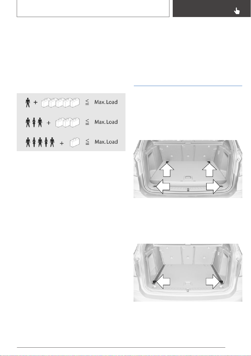
cargo and luggage load capacity calculated in
Step 4.
6. If your vehicle will be towing a trailer, load
from your trailer will be transferred to your ve‐
hicle. Consult this manual to determine how
this reduces the available cargo and luggage
load capacity of your vehicle.
Load
The maximum load is the sum of the weight of
the occupants and the cargo.
The greater the weight of the occupants, the
less cargo that can be transported.
Stowing and securing cargo
▷ Cover sharp edges and corners on the cargo.
▷ Heavy cargo: stow as far forward as possible,
directly behind and at the bottom of the rear
passenger seat backrests.
▷ Very heavy cargo: stow as far forward as pos‐
sible, directly behind and at the bottom of the
rear passenger seat backrests. When the rear
seat is not occupied, secure each of the outer
safety belts in the opposite buckle.
▷ If necessary, fold down the rear backrests to
stow large cargo.
▷ Do not stack cargo above the top edge of the
backrests.
▷ Use the cargo area partition net, refer to
page 266, to protect occupants. Make sure
that objects cannot penetrate the cargo area
partition net.
▷ Smaller and lighter cargo: secure with ratchet
straps or with a cargo net or draw straps.
▷ Larger and heavy cargo: secure with cargo
straps.
Lashing eyes in the cargo
area
General information
Attach load securing aids, such as lashing straps,
tensioning straps, draw straps or cargo nets, to
the lashing eyes in the cargo area.
Fixed lashing eyes
There are four lashing eyes in the cargo area for
securing cargo.
The front lashing eyes are located under covers.
Movable lashing eyes
To secure the cargo there are additional movable
lashing eyes in the cargo area.
Seite 261
Cargo area
CONTROLS
261
Online Edition for Part no. 01402896703 - X/18
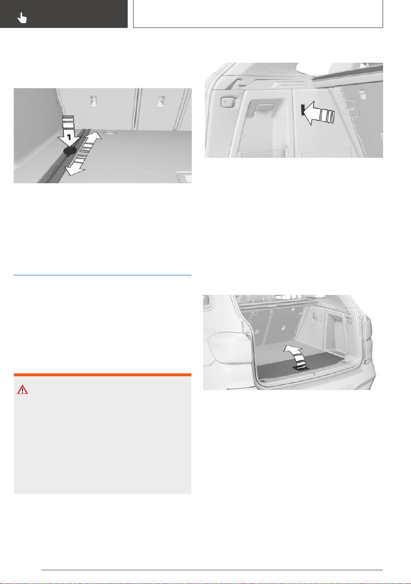
The lashing eyes may be located underneath the
cargo floor panel. The lashing eyes can be in‐
serted into the openings in the rails.
To slide the lashing eyes, press the button, ar‐
row 1. Make sure that the lashing eyes latch at
the new position.
Storage compartments in
the cargo area
Multi-function hook
General information
A multi-function hook is located on the left or
right side in the cargo area.
Safety information
WARNING
Improper use of the multi-function hooks can
lead to a risk of objects flying about during
braking and evasive maneuvers, for example.
There is a risk of injury and risk of damage to
property. Only hang lightweight objects,
such as shopping bags, from the multi-function
hooks. Only transport heavy luggage in the
cargo area if it has been appropriately secured.
Folding down
Press on the multi-function hook and turn until it
engages.
Retaining function for the cargo
floor panel
The cargo floor panel can be hooked onto the
right-hand multi-function hook.
Without storage compartment package:
1.
Fold the rear part of the cargo floor panel for‐
ward.
2. Lift the cargo floor panel up until it is over the
multi-function hook.
Seite 262
CONTROLS
Cargo area
262
Online Edition for Part no. 01402896703 - X/18
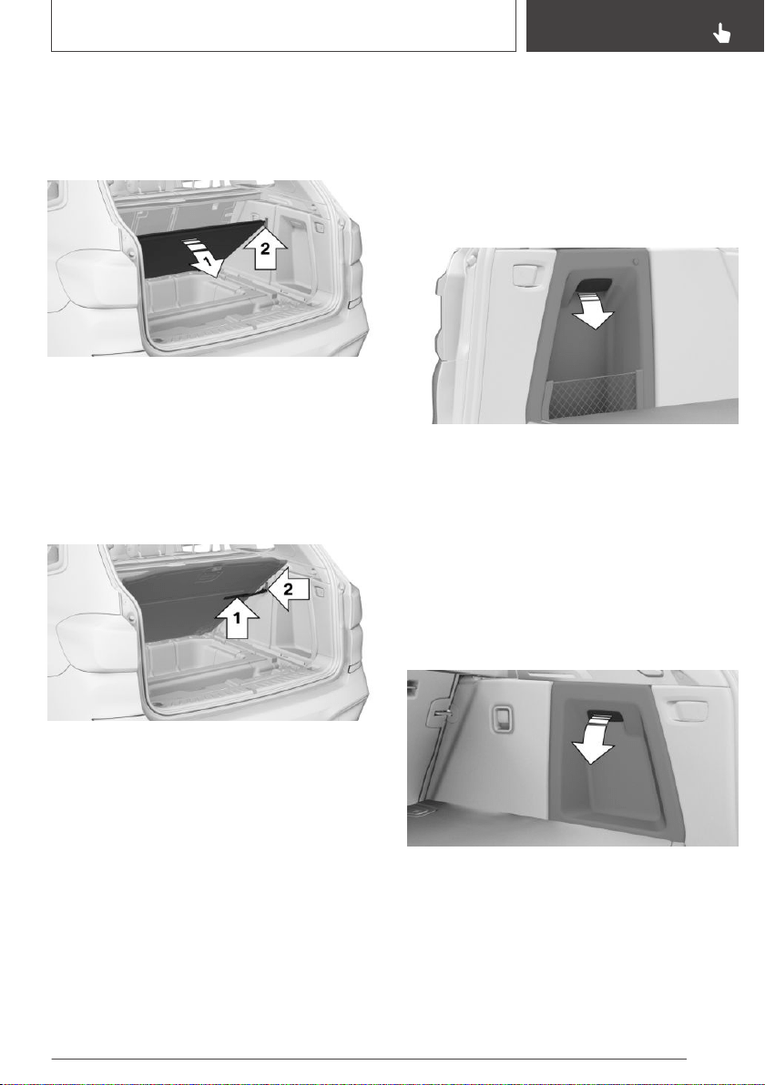
3. Fold down the multi-function hook, refer to
page 262.
4. Lower the cargo floor panel, arrow 1, until it is
resting on the multi-function hook, arrow 2.
With storage compartment package:
1.
Fold down the multi-function hook, refer to
page 262.
2. Lift the cargo floor panel.
3. Release the loop from the cargo floor panel.
4. Attach the loop, arrow 1, on the multi-func‐
tion hook, arrow 2.
Tensioning strap
A tensioning strap is available on the left side
trim for fastening small objects.
Net
Small objects can be stowed in the net on the
left side.
Left side storage compartment
General information
A storage compartment is located on the left
side in the cargo area.
Opening
Pull the handle.
Storage compartment on the
right side
General information
Depending on the vehicle equipment, a storage
compartment is located on the right side.
Opening
Pull the handle.
Seite 263
Cargo area
CONTROLS
263
Online Edition for Part no. 01402896703 - X/18
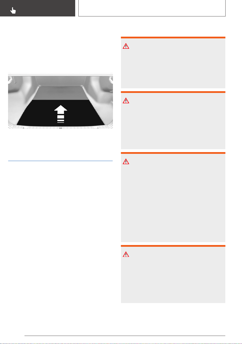
Storage compartment below
cargo floor panel
General information
There is a storage compartment under the cargo
floor panel.
Fold up the cargo floor panel.
Enlarging the cargo area
Concept
Depending on the vehicle equipment, the cargo
area can be enlarged as follows:
▷ The rear seat backrests can be folded down.
▷ The rear seat backrests can be moved into an
upright loading position using the cargo set‐
ting.
General information
The rear seat backrest is divided at a ratio of 40–
20–40. The side rear seat backrests and the
center section can be folded down separately.
Depending on the vehicle equipment, the rear
seat backrests can be folded down from the rear
or from the cargo area.
Safety information
WARNING
Danger of jamming with folding down the back‐
rests. There is a risk of injury or risk of damage
to property. Make sure that the area of move‐
ment of the rear backrest and the of the head
restraint is clear prior to folding down.
WARNING
If a rear seat backrest is not locked, unsecured
cargo can be thrown about the car’s interior;
for instance, in the event of an accident, braking
or an evasive maneuver. There is a risk of injury.
Make sure that the rear seat backrest is locked
after folding it back.
WARNING
The stability of the child restraint system is lim‐
ited or compromised with incorrect seat adjust‐
ment or improper installation of the child seat.
There is a risk of injuries or danger to life. Make
sure that the child restraint system fits securely
against the backrest. If possible, adjust the
backrest tilt for all affected backrests and cor‐
rectly adjust the seats. Make sure that seats
and backrests are securely engaged or locked.
If possible, adjust the height of the head re‐
straints or remove them.
WARNING
Once the rear seat backrest has been folded
down, the locking bracket protrudes into the
car's interior. There is a risk of damage to prop‐
erty. When the rear seat backrest is folded
down, pay attention to the protruding locking
bracket and keep this area unobstructed.
Seite 264
CONTROLS
Cargo area
264
Online Edition for Part no. 01402896703 - X/18
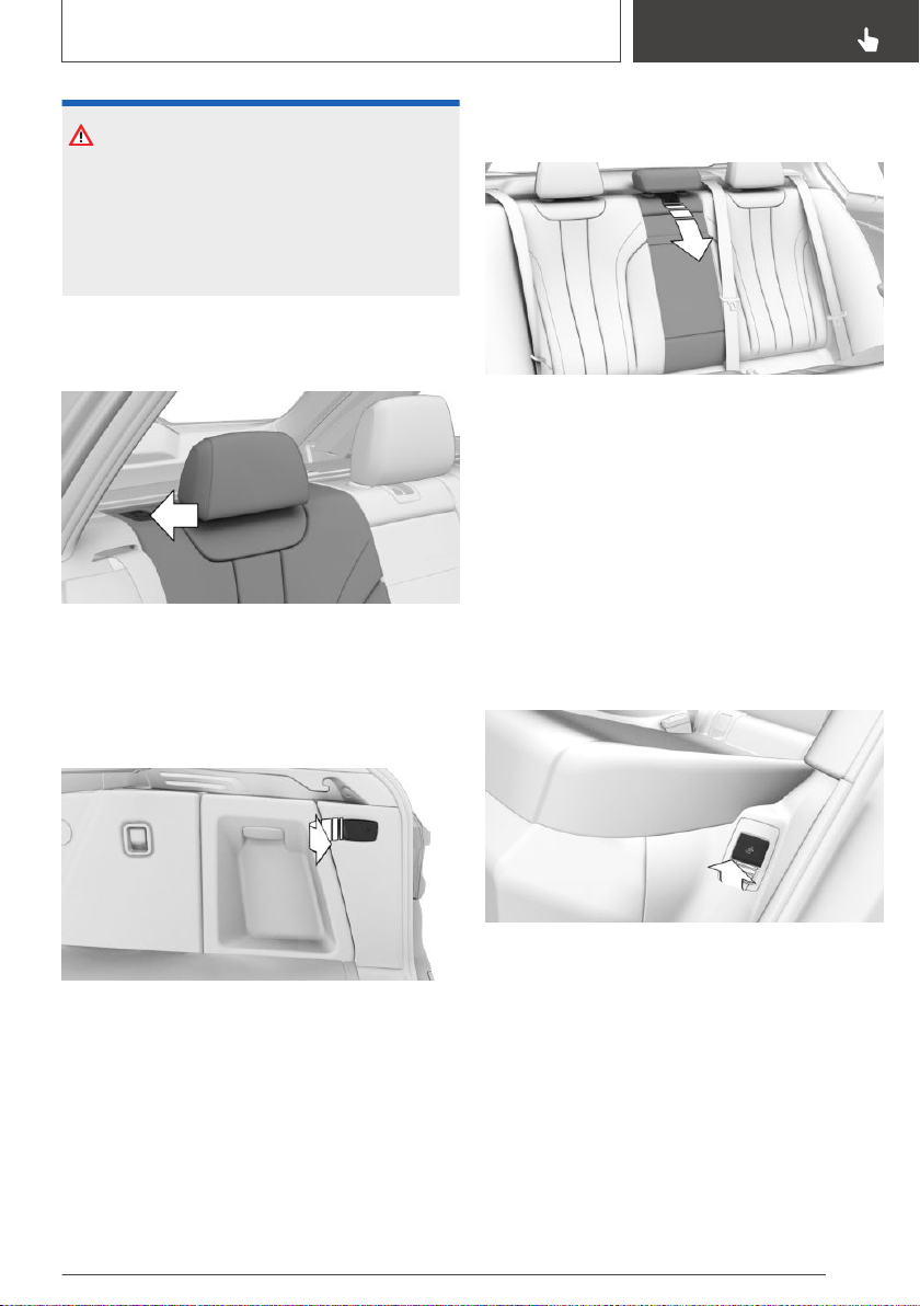
NOTICE
Vehicle parts can be damaged when folding
down the rear backrest. There is a risk of dam‐
age to property. Make sure that the area of
movement of the rear backrest including head
restraint is clear when folding down.
Folding down the rear seat
backrest from the rear
Pull the lever and fold the rear seat backrest for‐
ward.
Folding down the rear seat
backrest from the cargo area
Pull the lever inside the cargo area.
Left lever: the left and center rear seat backrests
fold forward.
Right lever: the right rear seat backrest folds for‐
ward.
Fold down the center section
1.
Fold down the center head restraint.
2. Press the button and pull the center section
forward.
Cargo position
General information
The rear seat backrests can be moved into an
upright loading position individually. An adjust‐
ment in several tilt stages is possible as needed.
The backrest tilt for the center section is ad‐
justed together with the left backrest.
Settings
1.
Pull the lever and hold it there.
2. Adjust the tilt of the rear seat backrest if re‐
quired.
Seite 265
Cargo area
CONTROLS
265
Online Edition for Part no. 01402896703 - X/18
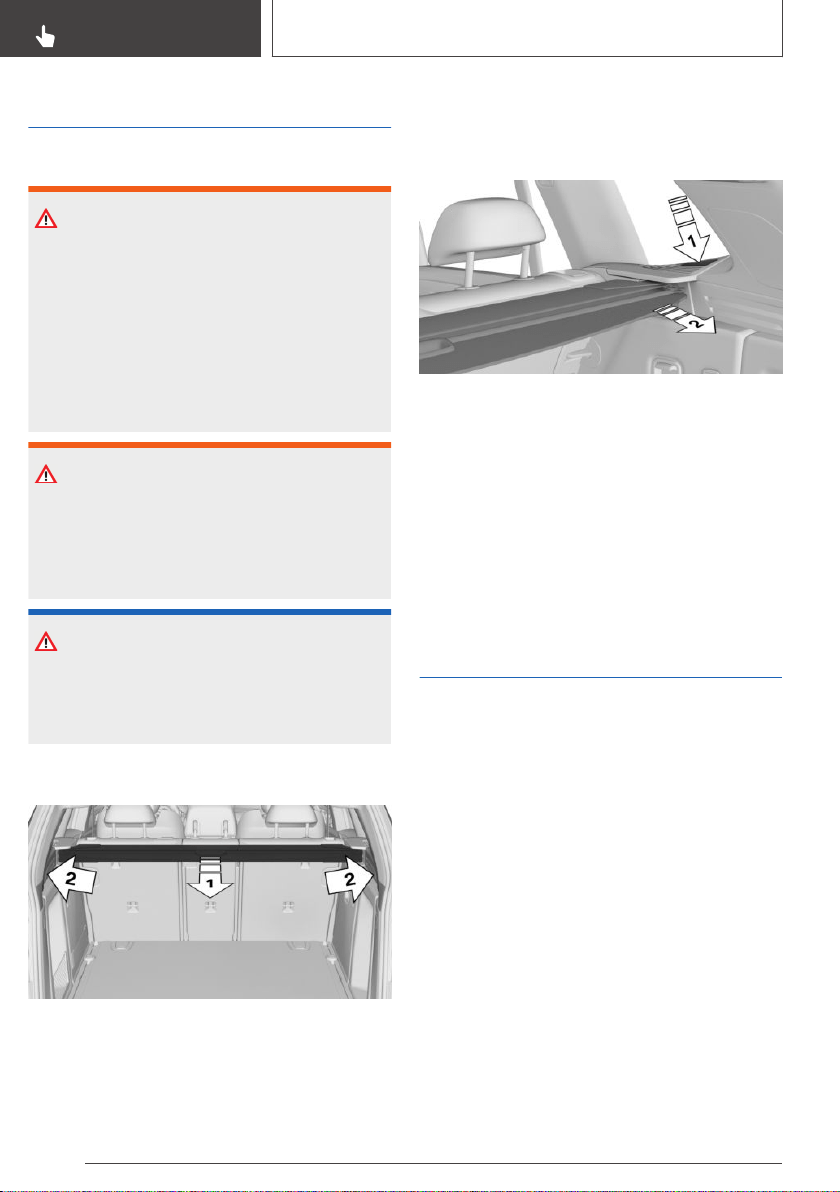
Cargo cover
Safety information
WARNING
Loose objects or devices with a cable connec‐
tion to the vehicle, for instance mobile phones,
can be thrown into the car's interior while driv‐
ing, for instance in the event of an accident or
during braking and evasive maneuvers. There is
a risk of injury. Secure loose objects or devices
with a cable connection to the vehicle in the
car's interior.
WARNING
A cargo cover that snaps back quickly can jam
body parts or cause damage. There is a risk of
injury or risk of damage to property. Do not let
the cargo cover snap back into place.
NOTICE
A cargo cover hooked in incorrectly can cause
damage. There is a risk of damage to property.
Hook the cargo cover on both sides.
Closing
Pull out the cargo cover, arrow 1, and hook both
sides into the brackets, arrow 2.
Removing
The cover can be removed to load bulky lug‐
gage.
Press the release button, arrow 1, and pull the
cargo cover out toward the rear, arrow 2.
The cargo cover can be stowed in the storage
compartment under the cargo floor panel.
Installing
Slide the cover forward horizontally into the two
side brackets. Make sure that the cover audibly
engages on both sides.
Cargo area partition net
General information
The cargo area partition net can be installed in
two different positions in the vehicle.
Seite 266
CONTROLS
Cargo area
266
Online Edition for Part no. 01402896703 - X/18
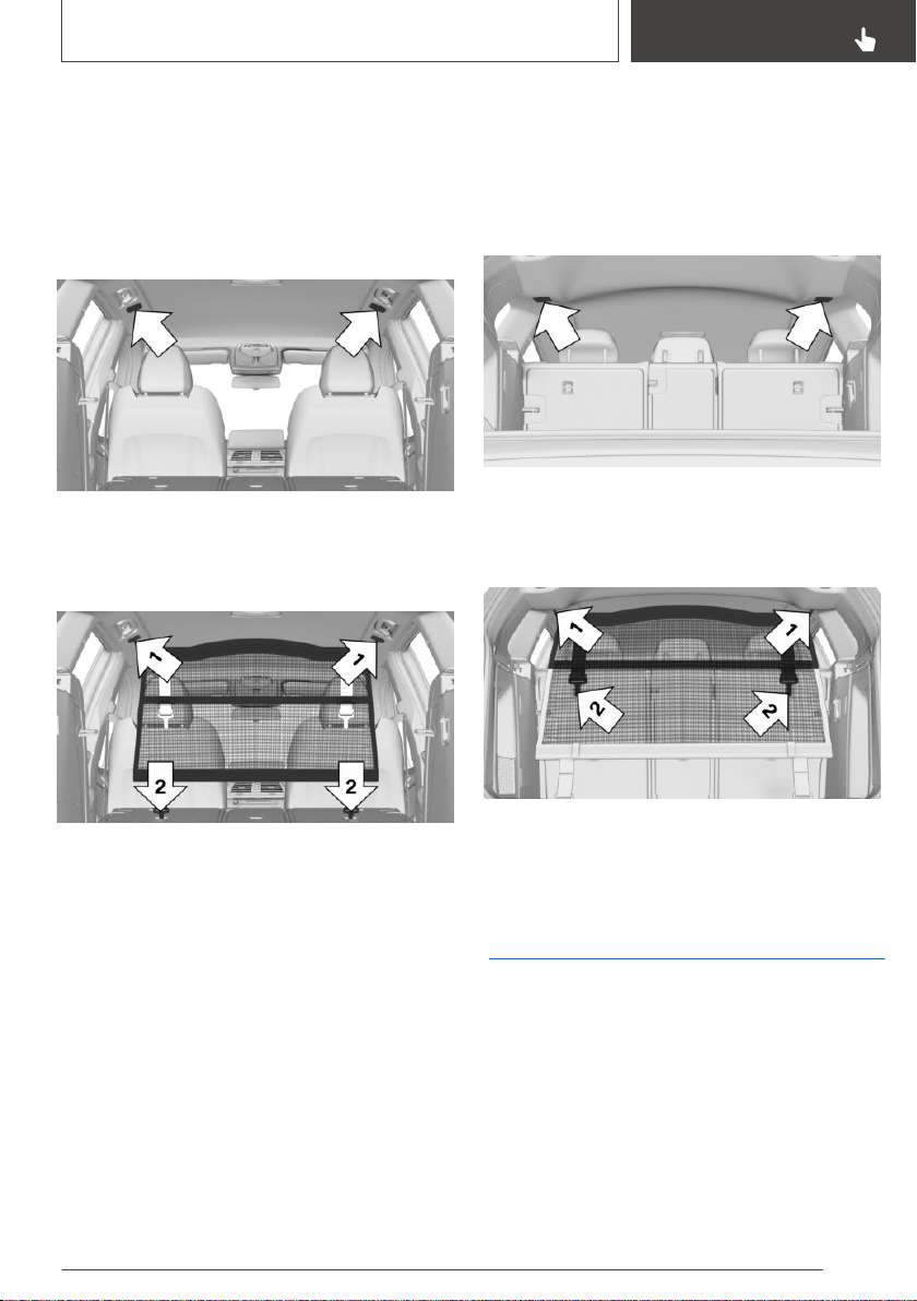
With the rear seat backrest
folded down
1. Fold down the rear seat backrests, refer to
page 264.
2. Open the front lids up on the roof frame until
they engage.
3. Insert each of the two top retaining pins of
the cargo area partition net into the recepta‐
cles until they reach the stop, arrow 1, and
push them forward.
4. Attach the cargo area partition net with the
lower two hooks into the two eyes on the
folded-down rear seat backrest, arrows 2.
You may need to lift the rear seat backrests
slightly in order to do this.
With the rear seat backrest
upright
1. Remove the cargo cover, refer to page 266.
2. Open the rear lids up on the roof frame until
they engage.
3. Insert each of the two top retaining pins of
the cargo area partition net into the recepta‐
cles until they reach the stop, arrow 1, and
push them forward.
4. Attach the cargo area partition net with the
upper two hooks into the two eyes on the
rear seat backrest, arrows 2.
Ski and snowboard bag
The ski and snowboard bag is contained in a
protective jacket in the cargo area.
Follow the installation and owner's manual in‐
cluded in the protective jacket.
Depending on the vehicle equipment: remove
the emergency wheel from the vehicle to mount
the ski and snowboard bag.
Seite 267
Cargo area
CONTROLS
267
Online Edition for Part no. 01402896703 - X/18

268
Online Edition for Part no. 01402896703 - X/18

DRIVING TIPS
Things to remember when driving ........................................................ 270
Trailer towing ........................................................................................... 275
Saving fuel ................................................................................................ 279
269
Online Edition for Part no. 01402896703 - X/18

Things to remember when driving
Vehicle features and
options
This chapter describes all standard, country-spe‐
cific and optional features offered with the series.
It also describes features that are not necessarily
available in your vehicle, e. g., due to the selected
options or country versions. This also applies to
safety-related functions and systems. When us‐
ing these functions and systems, the applicable
laws and regulations must be observed.
Breaking-in period
General information
Moving parts need to begin working together
smoothly.
The following instructions will help you to ach‐
ieve a long vehicle life and good efficiency.
During break-in, do not use the Launch Control,
refer to page 136.
Safety information
WARNING
Due to new parts and components, safety and
driver assistance systems can react with a de‐
lay. There is a risk of an accident. After instal‐
ling new parts or with a new vehicle, drive con‐
servatively and intervene early if necessary.
Observe the break-in procedures of the re‐
spective parts and components.
Engine, transmission, and axle
drive
Up to 1,200 miles/2,000 km
Do not exceed the maximum engine and road
speed:
▷ For gasoline engine 4,500 rpm and
100 mph/160 km/h.
▷ For diesel engine 3,500 rpm and
93 mph/150 km/h.
Avoid full load or kickdown under all circumstan‐
ces.
From 1,200 miles/2,000 km
The engine and vehicle speed can gradually be
increased.
Tires
Tire traction is not optimal due to manufacturing
circumstances when tires are brand-new; they
achieve their full traction potential after a break-in
time.
Drive conservatively for the first
200 miles/300 km.
Brake system
Brake discs and brake pads only reach their full
effectiveness after approx. 300 miles/500 km.
Drive moderately during this break-in period.
Following part replacement
Observe the break-in procedures again, if com‐
ponents mentioned above are replaced.
Seite 270
DRIVING TIPS
Things to remember when driving
270
Online Edition for Part no. 01402896703 - X/18

Driving on poor roads
Concept
Because of its greater ground clearance, the ve‐
hicle can be driven on a variety of road types and
qualities.
All-wheel drive can help improve forward mo‐
mentum.
Safety information
NOTICE
Objects in unpaved areas, for instance stones
or branches, can damage the vehicle. There is
a risk of damage to property. Do not drive on
unpaved terrain.
When driving on poor roads
For your own safety, for the safety of passengers
and of the vehicle, heed the following points:
▷ Familiarize yourself with the vehicle before
driving.
▷ Do not take risks when driving.
▷ Adjust the speed to the road surface condi‐
tions. The steeper and more uneven the road
surface, the slower the speed should be.
▷ When driving on steep uphill or downhill
grades: add engine oil and coolant up to near
the MAX mark.
▷ On steep downhill grades, use Hill Descent
Control HDC.
▷ Avoid that the chassis bottom coming in con‐
tact with the ground.
The ground clearance is no more than 7.8 in‐
ches/20 cm and can vary according to the ve‐
hicle's load.
▷ When wheels continue to spin, depress the
accelerator so that driving stability control
systems can distribute the driving force to the
wheels. Activate DTC Dynamic Traction Con‐
trol if available.
After a trip on poor roads
After a trip on poor roads, check wheels and tires
for damage to maintain driving safety. Clear
heavy soiling from the body.
General driving notes
Closing the tailgate
Safety information
WARNING
An open tailgate protrudes from the vehicle and
can endanger occupants and other traffic par‐
ticipants or damage the vehicle in the event of
an accident, braking or evasive maneuvers. In
addition, exhaust fumes may enter the car's in‐
terior. There is a risk of injury or risk of damage
to property. Do not drive with the tailgate open.
Driving with the tailgate open
If driving with the tailgate open cannot be
avoided:
▷ Close all windows and the glass sunroof.
▷ Greatly increase the air flow from the vents.
▷ Drive moderately.
Hot exhaust gas system
WARNING
During driving operation, high temperatures can
occur underneath the vehicle body, for instance
caused by the exhaust gas system. If combusti‐
ble materials, such as leaves or grass, come in
contact with hot parts of the exhaust gas sys‐
tem, these materials can ignite. There is a risk
of injury or risk of damage to property. Do not
remove the heat shields installed and never ap‐
ply undercoating to them. Make sure that no
combustible materials can come in contact with
hot vehicle parts in driving operation, idle or
Seite 271
Things to remember when driving
DRIVING TIPS
271
Online Edition for Part no. 01402896703 - X/18

during parking. Do not touch the hot exhaust
gas system.
Exhaust gas particulate filter
Concept
The exhaust gas particulate filter collects soot
particles. The soot particles are burned at high
temperatures to clean the exhaust gas particu‐
late filter as necessary.
General information
During several minutes of cleaning the following
may occur:
▷ Temporarily, the engine may run less
smoothly.
▷ A somewhat higher engine speed is neces‐
sary to reach usual performance.
▷ A slight amount of smoke coming from the
exhaust system, even after the engine is
switched off.
▷ Noises, such as those caused by the radiator
fan running, even several minutes after the
engine is switched off.
After-running of the radiator fan for several mi‐
nutes is normal even after short trips.
Mobile communication devices
in the vehicle
WARNING
Vehicle electronics and mobile phones can in‐
fluence one another. There is radiation due to
the transmission operations of mobile phones.
There is a risk of injury or risk of damage to
property. If possible, in the car's interior use
only mobile phones with direct connections to
an exterior antenna in order to exclude mutual
interference and deflect the radiation from the
car's interior.
Hydroplaning
On wet or slushy roads, a wedge of water can
form between the tires and road surface.
This phenomenon is referred to as hydroplaning.
It is characterized by a partial or complete loss of
contact between the tires and the road surface,
ultimately undermining your ability to steer and
brake the vehicle.
Driving through water
General information
When driving through water, follow the following:
▷ Drive through calm water only.
▷ Drive through water only if it is not deeper
than maximum 19.6 inches/50 cm.
▷ Drive through water no faster than walking
speed, up to 3 mph/5 km/h.
Safety information
NOTICE
When driving too quickly through too deep wa‐
ter, water can enter into the engine compart‐
ment, the electrical system or the transmission.
There is a risk of damage to property. When
driving through water, do not exceed the maxi‐
mum indicated water level and the maximum
speed for driving through water.
Braking safely
General information
The vehicle is equipped with the Antilock Brake
System ABS as a standard feature.
Perform an emergency stop in situations that re‐
quire such.
Steering is still responsive. You can still avoid any
obstacles with a minimum of steering effort.
Seite 272
DRIVING TIPS
Things to remember when driving
272
Online Edition for Part no. 01402896703 - X/18
Pulsation of the brake pedal and sounds from the
hydraulic circuits indicate that the Antilock Brake
System ABS is in its active mode.
In certain braking situations, the perforated brake
discs can emit functional noises. However, func‐
tional noises have no effect on the performance
and operational reliability of the brake.
Objects in the area around the
pedals
WARNING
Objects in the driver's floor area can limit the
pedal distance or block a depressed pedal.
There is a risk of an accident. Stow objects in
the vehicle such that they are secured and can‐
not enter into the driver's floor area. Use floor
mats that are suitable for the vehicle and can
be safely attached to the floor. Do not use
loose floor mats and do not layer several floor
mats. Make sure that there is sufficient clear‐
ance for the pedals. Ensure that the floor mats
are securely fastened again after they were re‐
moved, for instance for cleaning.
Driving in wet conditions
When roads are wet, salted, or in heavy rain, gen‐
tly press the brake pedal every few miles.
Ensure that this action does not endanger other
traffic.
The heat generated during braking dries brake
discs and brake pads and protects them against
corrosion.
In this way braking efficiency will be available
when you need it.
Hills
General information
Drive long or steep downhill gradients in the gear
that requires least braking effort. Otherwise, the
brakes may overheat and reduce brake effi‐
ciency.
You can increase the engine's braking effect by
shifting down, going all the way to first gear, if
needed.
Safety information
WARNING
Light but consistent brake pressure can lead to
high temperatures, brakes wearing out and
possibly even brake failure. There is a risk of an
accident. Avoid placing excessive stress on the
brake system.
WARNING
In idle state or with the engine switched off,
safety-relevant functions, for instance engine
braking effect, braking force boost and steering
assistance, are restricted or not available at all.
There is a risk of an accident. Do not drive in
idle state or with the engine switched off.
Brake disc corrosion
Corrosion on the brake discs and contamination
on the brake pads are increased by the following
circumstances:
▷ Low mileage.
▷ Extended periods when the vehicle is not
used at all.
▷ Infrequent use of the brakes.
▷ Aggressive, acidic, or alkaline cleaning
agents.
Corrosion buildup on the brake discs will cause a
pulsating effect on the brakes in their response -
generally this cannot be corrected.
Condensation water under the
parked vehicle
When using the automatic climate control, con‐
densation water develops and collects under‐
neath the vehicle.
Seite 273
Things to remember when driving
DRIVING TIPS
273
Online Edition for Part no. 01402896703 - X/18

Roof-mounted luggage
rack
General information
Installation only possible with roof rack.
Roof racks are available as special accessories.
Mounting
Follow the installation instructions of the roof
rack.
Be sure that adequate clearance is maintained
for tilting and opening the glass sunroof.
Loading
Because roof-mounted luggage racks raise the
vehicle's center of gravity when loaded, they
have a major effect on vehicle handling and
steering response.
Therefore, note the following when loading and
driving:
▷ Do not exceed the approved roof/axle loads
and the approved gross vehicle weight.
▷ Be sure that adequate clearance is main‐
tained for tilting and opening the glass sun‐
roof.
▷ Distribute the roof load uniformly.
▷ The roof load should not extend past the
loading area.
▷ Always place the heaviest pieces on the bot‐
tom.
▷ Secure the roof luggage firmly, for instance
using ratchet straps.
▷ Do not let objects project into the opening
path of the tailgate.
▷ Drive cautiously and avoid sudden accelera‐
tion and braking maneuvers. Take corners
gently.
Driving on racetracks
Higher mechanical and thermal loads during
racetrack operation lead to increased wear. This
wear is not covered by the warranty. The vehicle
is not designed for use in motor sports competi‐
tion.
Seite 274
DRIVING TIPS
Things to remember when driving
274
Online Edition for Part no. 01402896703 - X/18

Trailer towing
Vehicle features and
options
This chapter describes all standard, country-spe‐
cific and optional features offered with the series.
It also describes features that are not necessarily
available in your vehicle, e. g., due to the selected
options or country versions. This also applies to
safety-related functions and systems. When us‐
ing these functions and systems, the applicable
laws and regulations must be observed.
General information
The permissible trailer loads, axle loads, drawbar
node weights, and the permissible gross vehicle
weight are specified in the technical data.
The vehicle is equipped with an enhanced sus‐
pension system on the rear axle and, depending
on the vehicle type, with a more powerful cooling
system.
Before driving
Drawbar nose weight
The maximum load of the tractor is lowered by
the weight of the trailer hitch and the drawbar
nose weight. The drawbar nose weight increases
the vehicle weight. Do not exceed the approved
gross vehicle weight of the towing vehicle.
Loading
Distribute cargo as evenly as possible on the
cargo area.
Stow the load as low and close to the trailer axle
as possible. A low center of gravity in the trailer
increases the driving safety of the entire vehicle-
trailer combination.
Do not exceed the approved gross vehicle
weight of the trailer and the permissible trailer
load of the vehicle. The smaller value applies in
each case.
Tire inflation pressure
Note the tire inflation pressure of the vehicle and
trailer.
For the vehicle, the tire inflation pressure for
higher loads applies.
Information regarding the tire inflation pressure,
refer to page 296.
For the trailer, the specifications of the manufac‐
turer apply.
Flat Tire Monitor FTM
After correcting the tire inflation pressure or
hitching/unhitching a trailer, initialize the Flat Tire
Monitor, refer to page 317.
Tire Pressure Monitor TPM
After correcting the tire inflation pressure or
hitching/unhitching a trailer, reset the Tire Pres‐
sure Monitor, refer to page 310.
Exterior mirrors
Exterior mirrors, which allow the driver to see
both rear corners of the trailer, are available as
special accessories from a dealer’s service cen‐
ter or another qualified service center or repair
shop.
Power consumption
General information
Before starting to drive, check the function of the
trailer tail lights.
Seite 275
Trailer towing
DRIVING TIPS
275
Online Edition for Part no. 01402896703 - X/18
Keep the activation times of the electronic sys‐
tems/power consumers short when towing a
camper to save the vehicle battery power.
Trailer tail lights
▷ Turn signals/brake lights: 54 watts per side.
▷ Rear lights: 100 watts in total.
▷ Backup light: 54 watts in total.
Towing a trailer
General information
When driving with a trailer or load carrier and the
trailer socket not in use, some driver assistance
systems may have functional limitations or may
malfunction.
To prevent malfunctions, activate trailer towing,
refer to page 277.
When the trailer socket is in use or trailer towing
is activated, some driver assistance systems are
unavailable, or available to a limited extent. A
Check Control message is displayed where ap‐
plicable.
Safety information
WARNING
Depending on the design and loading of trail‐
ers, they may begin swinging at speeds ex‐
ceeding approx. 50 mph/80 km/h. There is a
risk of accidents or risk of damage to property.
Adapt your speed when driving with a trailer.
Immediately brake in the case of swinging. Ap‐
ply necessary steering corrections as carefully
as possible.
WARNING
The tire inflation pressure must be adjusted to
the increased axle load in trailer towing. Driving
with too low tire inflation pressure can damage
the tires. There is a risk of accidents or risk of
damage to property. Do not exceed a speed
of 60 mph / 100 km/h. Increase the tire inflation
pressure of the towing vehicle by 0.2 bar. Note
the maximum possible tire inflation pressure in‐
dicated on the tire.
Uphill grades
General information
In the interest of safety and to avoid hindering
the smooth flow of traffic, the towing of trailers is
permissible on uphill grades up to 12 %.
If higher trailer loads are approved at a later point
in time, the gradient limit is 8 %.
Starting on uphill grades
The parking brake is Automatically released
when the accelerator pedal is activated.
In order to prevent rolling back during starting,
use the parking brake.
1. Pull and release switch before starting
off.
The parking brake is set.
2. Accelerated enough to start off.
Hills
A vehicle-trailer combination has the tendency to
swing more readily on hills.
Manually shift down to the next lower gear be‐
fore driving on a hill and drive downhill slowly.
Seite 276
DRIVING TIPS
Trailer towing
276
Online Edition for Part no. 01402896703 - X/18
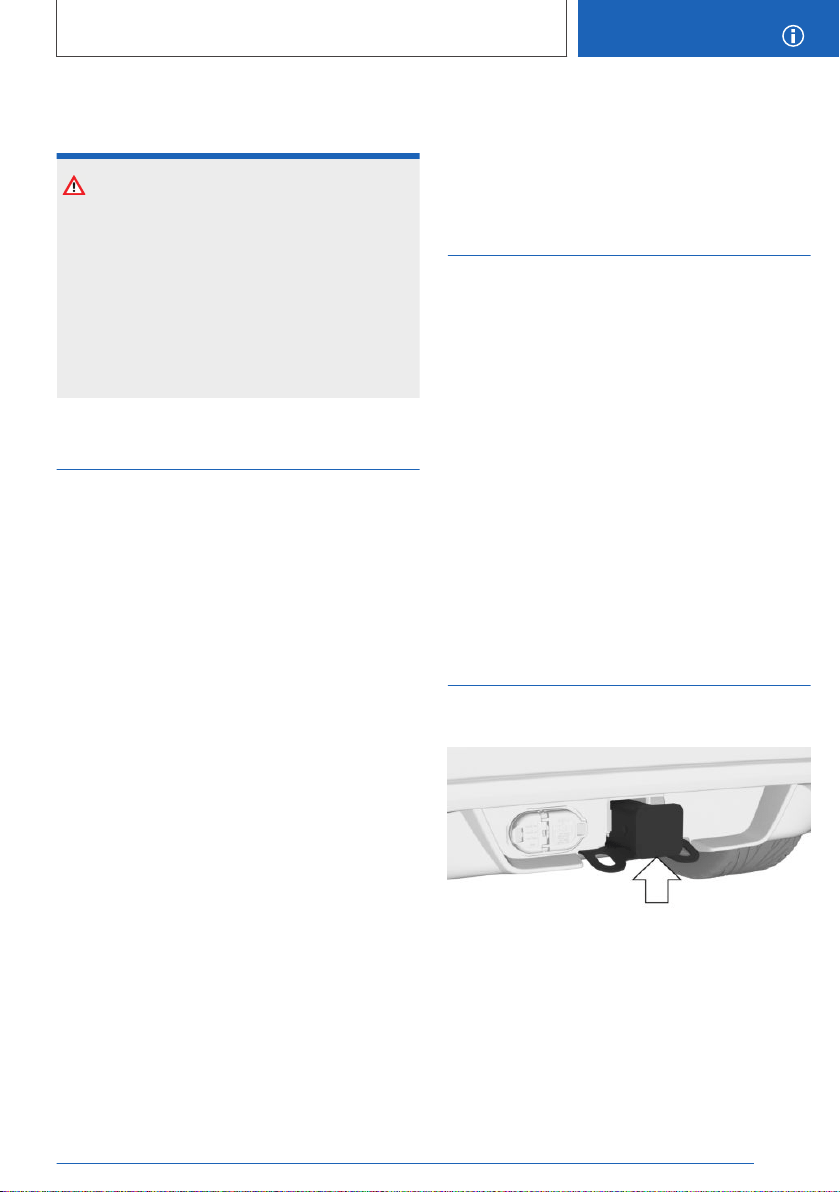
High loads and external
temperatures
NOTICE
On long trips with heavy trailer loads, high ex‐
ternal temperatures and low tank content, the
fuel system can overheat, which reduces the
engine performance. There is a risk of damage
to property. Refuel promptly. On long trips with
heavy trailer loads and high external tempera‐
tures, ensure that the fuel tank is more than
1/4 full.
Trailer stabilization control
Concept
This system supports the driver in stopping the
swinging of a trailer.
The trailer stabilization control detects swinging
and automatically brakes the vehicle quickly to
leave the critical speed range and stabilize the
vehicle-trailer combination.
General information
If the trailer power socket is in use but a trailer
has not been hitched, the system can become
active in certain driving situations, such as when
using a bicycle rack with lighting.
Functional requirement
The system is functional at speeds beginning at
approx. 40 mph/65 km/h while a trailer is being
towed and the trailer power socket is in use.
System limits
The system cannot intervene or not intervene in
time in the following situations, for instance:
▷ If a trailer jackknifes suddenly, for instance on
slippery roads or loose surfaces.
▷ If a trailer with a high center of gravity tilts, be‐
fore swinging is detected.
▷ If DSC Dynamic Stability Control is deacti‐
vated or has malfunctioned.
Activating trailer towing
Concept
When driving with a trailer or load carrier and the
trailer socket not in use, some driver assistance
systems may have functional limitations or may
malfunction. To prevent malfunctions, activate
trailer towing.
Activating trailer towing
Via iDrive:
1.
"My Vehicle"
2. "Vehicle settings"
3. "Trailer mode"
4. Activate trailer towing.
Mount for trailer hitch
General information
The mount for the trailer hitch is located on the
rear of the vehicle.
Information on suitable trailer hitches is found on
the underside of the mount, see arrow.
Follow the Maintenance Instructions, refer to
page 354.
Seite 277
Trailer towing
DRIVING TIPS
277
Online Edition for Part no. 01402896703 - X/18
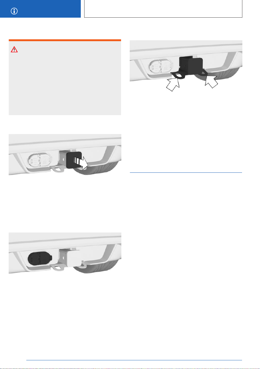
Safety information
WARNING
During driving operation, high temperatures can
occur underneath the vehicle body, for instance
caused by the exhaust gas system. Contact
with the hot components can cause burns.
There is a risk of injury. Do not touch hot com‐
ponents. Do not perform work in the vicinity of
hot components until after they have cooled
down.
Removing the cover
Pull the cover out of the back of the mount, and
stow it in the vehicle.
Trailer connector
The socket is located to the left of the mount for
the trailer hitch.
Fittings for trailer safety chain
There are two fittings on the mount for the trailer
hitch for securing the trailer safety chain.
Secure the trailer safety chain to the fittings for
increased safety when driving with a trailer.
Ensure that the trailer safety chain can move
freely and is not dragging on the ground.
Brake Controller
The vehicle manufacturer recommends that you
have a Brake Controller installed by a dealer’s
service center or another qualified service center
or repair shop.
Information on installing a Brake Controller can
be obtained from a dealer’s service center or an‐
other qualified service center or repair shop.
Seite 278
DRIVING TIPS
Trailer towing
278
Online Edition for Part no. 01402896703 - X/18

Saving fuel
Vehicle features and
options
This chapter describes all standard, country-spe‐
cific and optional features offered with the series.
It also describes features that are not necessarily
available in your vehicle, e. g., due to the selected
options or country versions. This also applies to
safety-related functions and systems. When us‐
ing these functions and systems, the applicable
laws and regulations must be observed.
Reducing fuel consumption
General information
The vehicle contains advanced technologies for
the reduction of consumption and emission val‐
ues.
Fuel consumption depends on a number of dif‐
ferent factors.
Carrying out certain measures, such as a moder‐
ate driving style and regular maintenance, can in‐
fluence fuel consumption and the environmental
impact.
Remove unnecessary cargo
Additional weight increases fuel consumption.
Remove attached parts following
use
Remove auxiliary mirrors, roof-mounted or rear
luggage racks which are no longer required fol‐
lowing use.
Attached parts on the vehicle impair the aerody‐
namics and increase the fuel consumption.
Close the windows and glass
sunroof
Driving with the glass sunroof and windows open
results in increased air resistance and raises fuel
consumption.
Tires
General information
Tires can affect consumption in various ways, for
instance tire size may influence consumption.
Check the tire inflation pressure
regularly
Check and, if needed, correct the tire inflation
pressure at least twice a month and before start‐
ing on a long trip.
Low tire inflation pressure increases rolling re‐
sistance and thus raises fuel consumption and
tire wear.
Drive away without delay
Do not wait for the engine to warm-up while the
vehicle remains stationary. Start driving right
away, but at moderate engine speeds.
This is the quickest way of warming the cold en‐
gine up to operating temperature.
Look well ahead when driving
Driving smoothly and proactively reduces fuel
consumption.
Avoid unnecessary acceleration and braking.
By maintaining a suitable distance to the vehicle
driving ahead of you.
Avoid high engine speeds
Driving at low engine speeds lowers fuel con‐
sumption and reduces wear.
Seite 279
Saving fuel
DRIVING TIPS
279
Online Edition for Part no. 01402896703 - X/18

If necessary, observe the vehicle's gear shift indi‐
cator, refer to page 147.
Use coasting conditions
When approaching a red light, take your foot off
the accelerator and let the vehicle coast to a halt.
For going downhill take your foot off the acceler‐
ator and let the vehicle roll.
The flow of fuel is interrupted while coasting.
Switch off the engine during
longer stops
Switching off the engine
Switch off the engine during longer stops, for in‐
stance at traffic lights, railroad crossings or in
traffic congestion.
Auto Start/Stop function
The Auto Start/Stop function of the vehicle auto‐
matically switches off the engine during a stop.
If the engine is switched off and then restarted
rather than leaving the engine running con‐
stantly, fuel consumption and emissions are re‐
duced. Savings can begin within a few seconds
of switching off the engine.
In addition, fuel consumption is also determined
by other factors, such as driving style, road con‐
ditions, maintenance or environmental factors.
Switch off any functions that are
not currently needed
Functions such as seat heating and the rear win‐
dow defroster require a lot of energy and in‐
crease fuel consumption, especially in city and
stop-and-go traffic.
Switch off these functions if they are not needed.
The ECO PRO driving mode supports the en‐
ergy conserving use of comfort features. These
functions are automatically deactivated partially
or completely.
Have maintenance carried out
Have the vehicle maintained regularly to achieve
optimal vehicle efficiency and service life. BMW
recommends that maintenance work be per‐
formed by a BMW dealer’s service center.
For information on the BMW Maintenance Sys‐
tem, refer to page 334.
ECO PRO
Concept
ECO PRO supports a driving style that saves on
consumption. For this purpose, the engine con‐
trol and comfort features, for instance the climate
control output, are adjusted.
Steptronic transmission: under certain conditions
the engine is automatically decoupled from the
transmission in the D selector lever position. The
vehicle continues traveling with the engine idling
to reduce consumption. The D selector lever po‐
sition remains engaged.
In addition, context-sensitive information, ECO
PRO tips, are displayed to assist with an efficient
driving style.
The achieved extended range is displayed in the
instrument cluster as bonus range.
General information
The system includes the following
EfficientDynamics functions and
EfficientDynamics displays:
▷ ECO PRO bonus range, refer to page 282.
▷ ECO PRO climate control, refer to page 281.
▷ Coasting driving condition, refer to page 283.
▷ Driving style analysis, refer to page 284.
Seite 280
DRIVING TIPS
Saving fuel
280
Online Edition for Part no. 01402896703 - X/18
Overview
Button
Activating ECO PRO
Press the button. ECO PRO is displayed
in the instrument cluster.
Configuring ECO PRO
INDIVIDUAL
Opening via the Driving Dynamics
Control
1.
Activate ECO PRO.
2. "Configure ECO PRO INDIVIDUAL"
Opening via iDrive
1.
"My Vehicle"
2. "Vehicle settings"
3. "Driving Experience Control"
4. "Configure ECO PRO INDIVIDUAL"
5. Select the desired setting.
The setting is stored for the driver profile cur‐
rently used.
Activating/deactivating ECO PRO
functions
The following ECO PRO functions can be acti‐
vated/deactivated:
▷ "ECO PRO speed warning"
▷ "Coasting"
▷ "ECO PRO seat climate control"
▷ "ECO PRO climate control"
▷ "ECO PRO sight"
Settings are stored for the driver profile currently
used.
ECO PRO limit
▷ Activate the ECO PRO limit:
"ECO PRO speed warning"
An ECO PRO tip is displayed if the speed of
the set ECO PRO limit is exceeded.
▷ Adjust the ECO PRO limit speed:
"Tip at:"
Select the desired speed.
Coasting
Efficiency can be optimized by disengaging the
engine and coasting with the engine idling.
Deactivate the function to use the braking effect
of the engine when traveling downhill.
ECO PRO seat climate control
The output of seat heating and, where applica‐
ble, seat ventilation is reduced when ECO PRO
is activated.
ECO PRO climate control
Climate control is set to be efficient.
That is, it is possible to deviate slightly from the
set temperature or to heat or cool the car's inte‐
rior more slowly, to economize on consumption.
The mirror heating is made available when exter‐
nal temperatures are very cold.
ECO PRO Sight
The output of exterior mirror heating and rear
window defroster is reduced.
Resetting the settings
Reset ECO PRO INDIVIDUAL to the standard
settings:
Seite 281
Saving fuel
DRIVING TIPS
281
Online Edition for Part no. 01402896703 - X/18
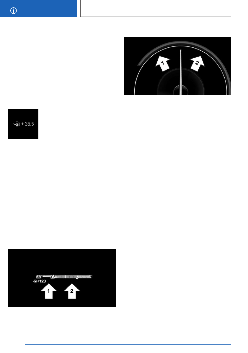
"Reset to ECO PRO STANDARD"
Display in the instrument cluster
General information
When ECO PRO driving mode is activated, the
display switches to a special configuration.
Some of the displays may differ from the display
in the instrument cluster.
ECO PRO bonus range
A modified driving style helps you
extend your driving range.
The range extension can be dis‐
played as the bonus range in the
instrument cluster.
The bonus range is shown in the range display.
Depending on the equipment, the blue bar seg‐
ments symbolize the gained range in stages.
If the bonus range appears in gray, the current
driving style is inefficient.
The display turns blue as soon as all conditions
for efficient driving are met.
The bonus range is automatically reset every
time the vehicle is refueled.
Consumption display
Instrument cluster without enhanced
features
Instrument cluster with enhanced features
Information about the current driving style
A pointer in the consumption display informs
about the current driving style:
▷ The current consumption in relation to the
average consumption is displayed.
▷ Pointer in the area of arrow 1: display of the
energy recovered by coasting or when brak‐
ing.
▷ Pointer in the area of arrow 2: display when
accelerating.
If the acceleration is inefficient, the area between
the average consumption and the current con‐
sumption is colored red.
In addition, the following information is displayed,
depending on the situation:
▷ Depending on the equipment: the total dis‐
tance driven while coasting, refer to
page 284.
▷ The total time that the engine has been
switched off, refer to page 122, during auto‐
matic engine stops.
▷ A gear shift indicator, refer to page 147, rec‐
ommending the use of a more efficient gear.
Indications on the Control
Display
Displaying EfficientDynamics
information
The current efficiency of the ECO PRO functions
can be displayed on the Control Display.
Seite 282
DRIVING TIPS
Saving fuel
282
Online Edition for Part no. 01402896703 - X/18

Via iDrive:
1. "My Vehicle"
2. "Technology in action"
3. "EfficientDynamics"
4. Select the symbol.
The following functions are displayed:
▷ Auto Start/Stop function.
▷ Energy recovery.
▷ Coasting.
Displaying consumption history
The following functions can be shown on the
Control Display:
▷ Average consumption.
▷ The distance traveled while coasting.
▷ The duration for which the Auto Start/Stop
function has switched off the engine.
Via iDrive:
1.
"My Vehicle"
2. "Technology in action"
3. "EfficientDynamics"
4. Select the symbol.
Vertical bars show consumption for the selected
route.
Selecting route length
Via iDrive:
1. Press button.
2. "Scaling:"
3. Select the desired setting.
Resetting consumption history
Via iDrive:
1. Press button.
2. "Reset consumption history"
Coasting
Concept
Under certain conditions the engine is automati‐
cally decoupled from the transmission in the D
selector lever position. The vehicle continues
traveling with the engine idling to reduce con‐
sumption. Selector lever position D remains en‐
gaged.
This driving condition is referred to as coasting.
As soon as you step on the brake or accelerator
pedal, the engine is automatically coupled again.
General information
Coasting is a component of the ECO PRO driv‐
ing mode.
Coasting is automatically activated when ECO
PRO mode is called via the Driving Dynamics
Control.
A proactive driving style helps the driver to use
the function often and supports the efficient ef‐
fect of coasting.
Functional requirements
The function is available in the speed range from
approximately 30 mph/50 km/h to
100 mph/160 km/h when the following condi‐
tions are met:
▷ Accelerator pedal not depressed.
▷ Brake pedal not depressed or only slightly
depressed.
▷ The selector lever is in selector lever position
D.
▷ Engine and transmission are at operating
temperature.
Operation via shift paddles
Concept
The coasting driving condition can be influenced
with the shift paddles.
Seite 283
Saving fuel
DRIVING TIPS
283
Online Edition for Part no. 01402896703 - X/18
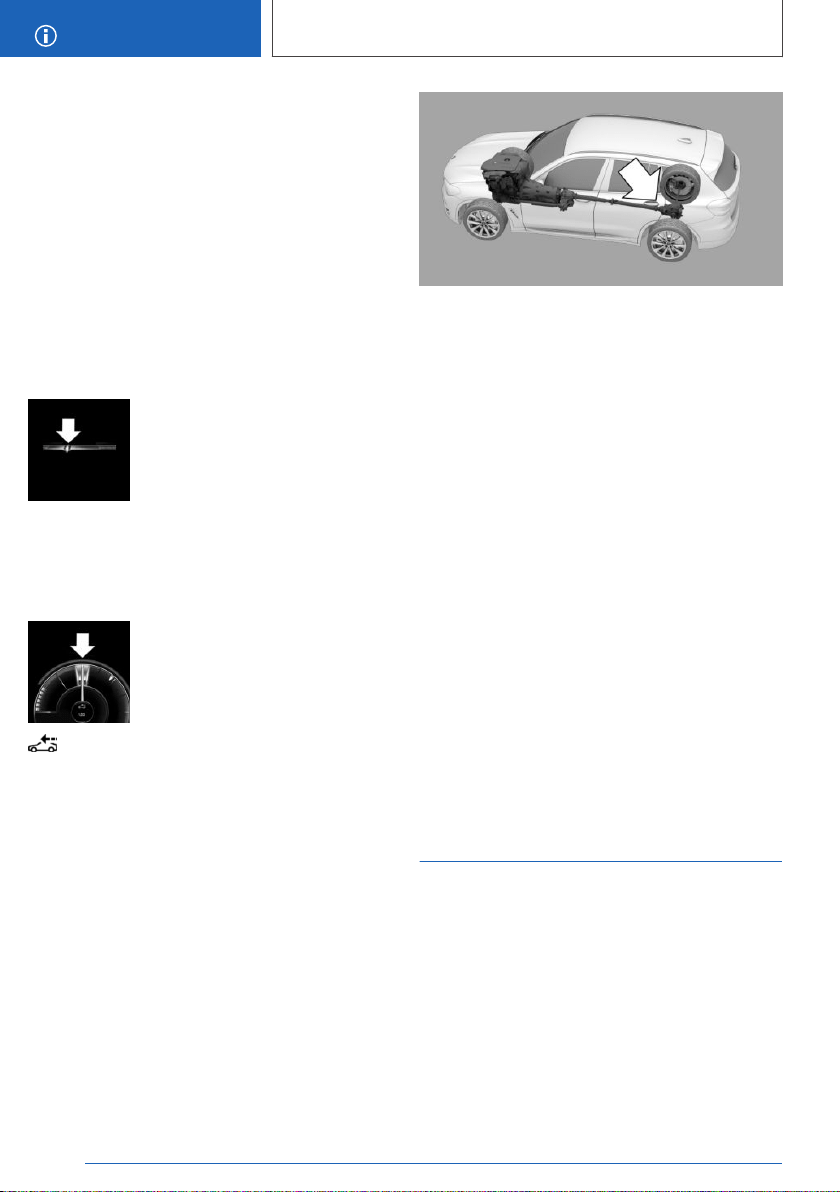
Activating/deactivating coasting via
shift paddles
1. Shift to the highest gear by pulling the right
shift paddle.
2. To activate coasting mode, actuate the right
shift paddle again.
To deactivate, actuate the left shift paddle.
Display
Instrument cluster without
enhanced features
The mark in the consumption dis‐
play below the tachometer is lo‐
cated at the zero point and is
backlit in blue. The tachometer
approximately indicates idle
speed.
Instrument cluster with enhanced
features
The mark in the consumption dis‐
play is located at the zero point
and is backlit in blue.
The distance traveled is indicated in coast‐
ing mode.
Display on the Control Display
The coasting mode is displayed in
EfficientDynamics while driving.
The distance traveled in coasting mode is shown
in the consumption history. The counter is reset
with every refueling.
Color code blue: coasting mode.
Display EfficientDynamics
information
Via iDrive:
1.
"My Vehicle"
2. "Technology in action"
3. "EfficientDynamics"
System limits
The function is not available under one of the fol‐
lowing conditions.
▷ DSC OFF or TRACTION activated.
▷ Driving in the dynamic limit range and on
steep uphill or downhill grades.
▷ Battery charge status temporarily too low or
vehicle electrical system drawing excessive
current.
▷ Trailer towing.
Driving style analysis
Concept
The function helps develop an especially effi‐
cient driving style and to conserve fuel.
For this purpose, the driving style is analyzed.
The assessment is done in various categories
and is displayed on the Control Display.
This display will help you adjust your driving style
and save some fuel.
Seite 284
DRIVING TIPS
Saving fuel
284
Online Edition for Part no. 01402896703 - X/18
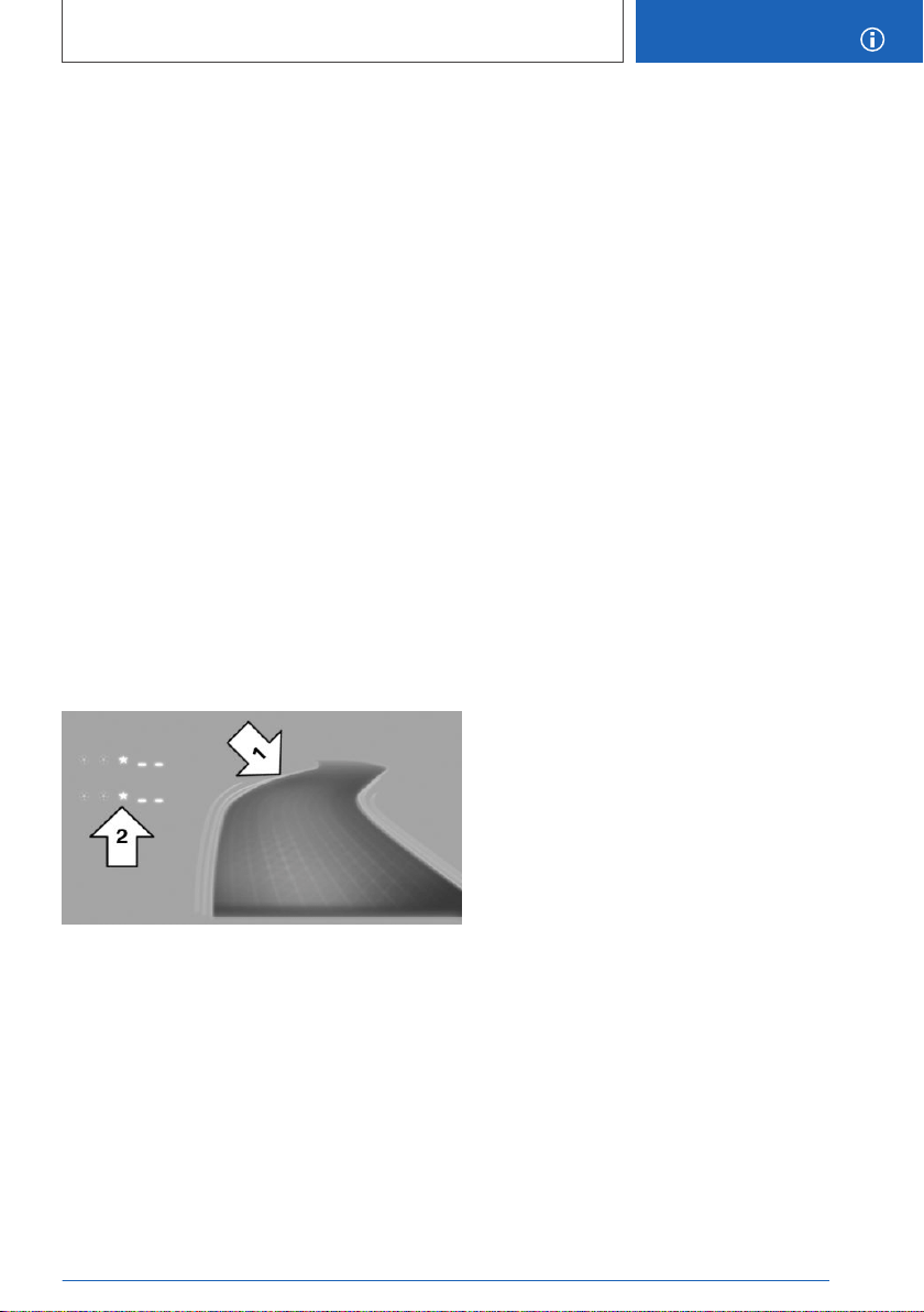
General information
The current trip is assessed.
To assist with an efficient driving style, ECO
PRO tips are displayed during driving.
The range of the vehicle can be extended by ad‐
justing your driving style.
This gain in range is displayed as a bonus range
in the instrument cluster and on the Control Dis‐
play.
Functional requirement
This function is available in ECO PRO mode.
Calling up ECO PRO driving style
analysis
Via iDrive:
1.
"My Vehicle"
2. "Technology in action"
3. "Driving style analysis"
Display on the Control Display
The display of the ECO PRO driving style analy‐
sis consists of a symbolized route and a lookup
table.
The road symbolizes the efficiency of the driving
style. The more efficient the driving style, the
smoother the depicted route becomes, arrow 1.
The table of values contains stars. The more effi‐
cient the driving style, the more stars are in‐
cluded in the table, arrow 2, and the faster the
bonus range increases.
If, on the other hand, the driving style is ineffi‐
cient, a more wavy road and a reduced number
of stars are displayed.
Seite 285
Saving fuel
DRIVING TIPS
285
Online Edition for Part no. 01402896703 - X/18
286
Online Edition for Part no. 01402896703 - X/18
MOBILITY
Refueling ................................................................................................... 288
Fuel ............................................................................................................ 290
Wheels and tires ...................................................................................... 296
Engine compartment .............................................................................. 325
Engine oil .................................................................................................. 328
Coolant ...................................................................................................... 332
Maintenance ............................................................................................. 334
Replacing components .......................................................................... 336
Breakdown assistance ........................................................................... 344
Care ........................................................................................................... 351
287
Online Edition for Part no. 01402896703 - X/18
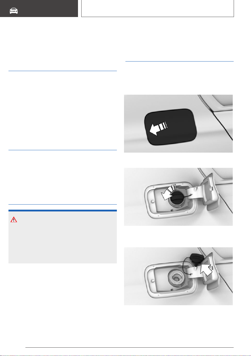
Refueling
Vehicle features and
options
This chapter describes all standard, country-spe‐
cific and optional features offered with the series.
It also describes features that are not necessarily
available in your vehicle, e. g., due to the selected
options or country versions. This also applies to
safety-related functions and systems. When us‐
ing these functions and systems, the applicable
laws and regulations must be observed.
General information
Follow the fuel recommendation, refer to
page 290, prior to refueling.
In vehicles with a diesel engine, the filler neck is
designed for refueling at diesel fuel pumps.
Safety information
NOTICE
With a driving range of less than
30 miles/50 km the engine may no longer have
sufficient fuel. Engine functions are not en‐
sured anymore. There is a risk of damage to
property. Refuel promptly.
Fuel cap
Opening
1. Briefly press the rear edge of the fuel filler
flap.
2. Turn the fuel cap counterclockwise.
3. Place the fuel cap in the bracket attached to
the fuel filler flap.
Seite 288
MOBILITY
Refueling
288
Online Edition for Part no. 01402896703 - X/18

Closing
WARNING
The retaining strap of the fuel cap can be jam‐
med and crushed during closing. The cap can‐
not be correctly closed. Fuel or fuel vapors can
escape. There is a risk of injury or risk of dam‐
age to property. Pay attention that the retaining
strap is not jammed or crushed when closing
the cap.
1. Fit the cap and turn it clockwise until you
clearly hear a click.
2. Close the fuel filler flap.
Manually unlocking fuel filler flap
It may be necessary in certain situations to un‐
lock the fuel filler flap manually, e.g. with an elec‐
trical fault.
Have fuel filler flap unlocked by a dealer’s service
center or another qualified service center or re‐
pair shop.
Follow the following when
refueling
General information
When refueling, insert the filler nozzle completely
into the filler pipe. Lifting up the fuel pump nozzle
during refueling causes:
▷ Premature switching off.
▷ Reduced return of the fuel vapors.
The fuel tank is full when the filler nozzle clicks
off the first time.
Make sure that the fuel cap is closed properly af‐
ter refueling, otherwise the emissions warning
light may light up.
Follow safety regulations posted at the gas sta‐
tion.
Safety information
NOTICE
Fuels are toxic and aggressive. Overfilling of the
fuel tank can damage the fuel system. Painted
surfaces may be damaged by contact with fuel.
Escaping fuel can harm the environment. There
is a risk of damage to property. Avoid overfilling.
Seite 289
Refueling
MOBILITY
289
Online Edition for Part no. 01402896703 - X/18

Fuel
Vehicle features and
options
This chapter describes all standard, country-spe‐
cific and optional features offered with the series.
It also describes features that are not necessarily
available in your vehicle, e. g., due to the selected
options or country versions. This also applies to
safety-related functions and systems. When us‐
ing these functions and systems, the applicable
laws and regulations must be observed.
Fuel recommendation
General information
Depending on the region, many gas stations sell
fuel that has been customized to winter or
summer conditions. Fuel that is available in win‐
ter, for instance helps make a cold start easier.
Gasoline
General information
For the best fuel efficiency, the gasoline should
be sulfur-free or very low in sulfur content.
Fuels that are marked on the gas pump as con‐
taining metal must not be used.
Fuels with a maximum ethanol content of 25 %,
i. e. E10 or E25, may be used for refueling.
Ethanol should meet the following quality stan‐
dards:
US: ASTM 4806–xx
CAN: CGSB-3.511–xx
xx: comply with the current standard in each
case.
Safety information
CAUTION
The use of poor-quality fuels may result in
harmful engine deposits or damage. Addition‐
ally, problems relating to drivability, starting and
stalling, especially under certain environmental
conditions such as high ambient temperature
and high altitude, may occur.
If drivability problems are encountered, we rec‐
ommend switching to a high quality gasoline
brand and a higher octane grade — AKI num‐
ber — for a few tank fills. To avoid harmful en‐
gine deposits, it is highly recommended to pur‐
chase gasoline from Top Tier retailers.
Failure to comply with these recommendations
may result in the need for unscheduled mainte‐
nance.
NOTICE
Even small quantities of the wrong fuel or
wrong fuel additives can damage the fuel sys‐
tem and engine. Furthermore, the catalytic
converter is permanently damaged. There is a
risk of damage to property. Do not refuel or add
the following in the case of gasoline engines:
▷ Leaded gasoline.
▷ Metallic additives, for instance manganese
or iron.
Do not press the Start/Stop button after refuel‐
ing with the wrong fuel. Contact a dealer’s serv‐
ice center or another qualified service center or
repair shop.
Seite 290
MOBILITY
Fuel
290
Online Edition for Part no. 01402896703 - X/18
NOTICE
Incorrect fuels can damage the fuel system and
the engine. There is a risk of damage to prop‐
erty. Do not use fuels with a higher percentage
of ethanol than recommended. Do not refuel
with fuels containing methanol, e.g. M5 to
M100.
NOTICE
Fuel that does not comply with the minimum
quality can compromise engine function or
cause engine damage. There is a risk of dam‐
age to property. Do not fill with fuel that does
not comply with the minimum quality.
Recommended fuel grade
BMW recommends AKI 91.
Minimum fuel grade
BMW recommends AKI 89.
If you use gasoline with this minimum AKI Rating,
the engine may produce knocking sounds when
starting at high external temperatures. This has
no effect on the engine life.
Diesel
Safety information
NOTICE
Even small quantities of the wrong fuel or
wrong fuel additives can damage the fuel sys‐
tem and engine. There is a risk of damage to
property.
Follow the following for diesel engines:
▷ Use only Ultra-Low Sulfur Diesel.
▷ Do not refuel with pure methyl ester.
▷ Only refuel with biodiesel with a maximum
of B5/5 % according to ASTM D975.
▷ Do not use gasoline.
▷ The vehicle manufacturer recommends
only using diesel additives which have
been classified as suitable.
Do not press the Start/Stop button after refuel‐
ing with the wrong fuel. Contact a dealer’s serv‐
ice center or another qualified service center or
repair shop.
Low-Sulfur Diesel
The engine of your BMW is designed for diesel
with low sulfur content:
Ultra-Low Sulfur Diesel ASTM D 975-xx.
xx: comply with the current standard in each
case.
Use only Ultra-Low Sulfur Diesel.
The fraction of biodiesel in the fuel must not ex‐
ceed 5 %, referred to as B5. Do not use gaso‐
line. If you do fill the tank with the wrong fuel, for
instance gasoline, do not start the engine as this
may damage the engine.
In the case of incorrect refueling, contact a deal‐
er’s service center or another qualified service
center or repair shop or Roadside Assistance.
If the fuel pump nozzle does not fit in the filler
pipe of your BMW, please check to ensure that
you are refueling at a diesel fuel pump that is
equipped with a diesel fuel pump nozzle.
In the event the Ultra-Low Sulfur Diesel fuel can‐
not be fully inserted into the fuel filler neck,
please contact BMW Roadside Assistance for in‐
structions on how to add fuel. For more informa‐
tion on Roadside Assistance, refer to page 345.
Seite 291
Fuel
MOBILITY
291
Online Edition for Part no. 01402896703 - X/18

BMW Advanced Diesel
Concept
BMW Advanced Diesel reduces nitrogen oxides
in the diesel emissions by injecting diesel ex‐
haust fluid into the exhaust system. A chemical
reaction takes place inside the catalytic converter
that minimizes nitrogen oxides.
General information
The vehicle has a tank that must be refilled.
To be able to establish the drive-ready state as
usual, there must be an adequate amount of die‐
sel exhaust fluid.
Diesel exhaust fluid can be refilled at any time.
Diesel exhaust fluid is available at many gas sta‐
tions.
If possible, refill diesel exhaust fluid using a fuel
pump, refer to page 293.
Diesel exhaust fluid at low
temperatures
Due to its physical properties, it is possible that
the diesel exhaust fluid may need to be replen‐
ished more frequently if exposed to tempera‐
tures under +23 ℉/-5 ℃.
At temperatures below +12 ℉/-11 ℃, it may
only be possible to measure and display the fill‐
ing level after a short drive.
At low temperatures, add diesel exhaust fluid
only immediately before driving off.
Displays in the instrument
cluster
Reserve level indicator
The reserve level indicator in the instrument
cluster provides information about the distance
that can still be driven with the current reserve
level.
Do not continue driving to the limit of the remain‐
ing travel distance, otherwise it may not be pos‐
sible to activate the drive-ready state again after
switching off.
▷ Light white: refill with diesel
exhaust fluid at the next op‐
portunity.
▷ Light yellow: not enough die‐
sel exhaust fluid present. The
remaining range is displayed
in the instrument cluster. Im‐
mediately refill with Diesel ex‐
haust fluid, refer to page 293.
Diesel exhaust fluid on minimum
The remaining range is displayed
in the instrument cluster. Add at
least 2.7 US gal/10 liters of diesel
exhaust fluid. The engine will con‐
tinue to run as long as it is not
switched off and all other operating conditions
are satisfied; sufficient fuel, for instance.
System malfunction
A Check Control message is displayed when
there is a system not working.
Visit the nearest dealer’s service center or an‐
other qualified service center or repair shop.
Have the diesel exhaust fluid
replenished
BMW recommends that diesel exhaust fluid be
added by the dealer’s service center within the
course of regular maintenance.
In addition, it may be necessary to have the fluid
replenished several times between maintenance
appointments under particular circumstances, for
instance if the vehicle is driven in a particularly
sporty style or if it is operated with a trailer.
The diesel exhaust fluid must be replenished as
soon as the reserve level indicator appears in the
instrument cluster to avoid not being able to re‐
establish the drive-ready state.
Seite 292
MOBILITY
Fuel
292
Online Edition for Part no. 01402896703 - X/18
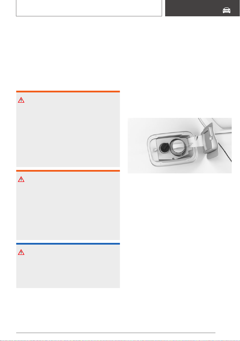
Replenishing diesel exhaust fluid
yourself in exceptional cases
General information
You can replenish Diesel exhaust fluid yourself in
exceptional cases, for instance to get to your
scheduled service.
Safety information
WARNING
Small amounts of ammonia fumes can escape
when opening the diesel exhaust fluid con‐
tainer. Ammonia fumes have a pungent odor
and irritate skin, mucous membranes, and eyes.
There is a risk of injury. Do not inhale escaping
ammonia fumes. Avoid the contact of articles of
clothing, skin or eyes with diesel exhaust fluid.
Do not swallow any diesel exhaust fluid. Keep
children away from diesel exhaust fluids.
WARNING
Operating materials, for instance oils, greases,
coolants, fuels, can contain harmful ingredients.
There is a risk of injuries or danger to life. Fol‐
low the instructions on the containers. Avoid
the contact of articles of clothing, skin or eyes
with operating materials. Do not refill operating
materials into different bottles. Store operating
materials out of reach of children.
NOTICE
The diesel exhaust fluid ingredients are very
aggressive. There is a risk of damage to prop‐
erty. Avoid contact of diesel exhaust fluid with
surfaces of the vehicle.
Suitable diesel exhaust fluid
▷ Recommended: BMW Diesel Exhaust Fluid.
With this bottle and its special adapter, diesel
exhaust fluid can be replenished simply and
safely.
▷ Alternatively recommended: NOx Diesel ex‐
haust fluid AUS 32.
Diesel exhaust fluid can be purchased at a deal‐
er’s service center or another qualified service
center or repair shop.
Refill quantity
When the reserve level indicator starts, add at
least 1.3 US gal/5 liters.
Tank for diesel exhaust fluid
The fuel cap for diesel exhaust fluids is next to
the fuel cap for the fuel tank.
Adding diesel exhaust fluid at the
fuel pump
General information
When refueling, insert the filler nozzle completely
into the filler pipe. Lifting up the fuel pump nozzle
during refueling causes:
▷ Premature switching off.
▷ Overflow of diesel exhaust fluid.
The tank for diesel exhaust fluid is full when the
filler nozzle clicks off the first time.
Depending on the filling nozzle, it may not be
possible to fill the tank for the diesel exhaust fluid
completely.
Follow safety regulations posted at the gas sta‐
tion.
Seite 293
Fuel
MOBILITY
293
Online Edition for Part no. 01402896703 - X/18
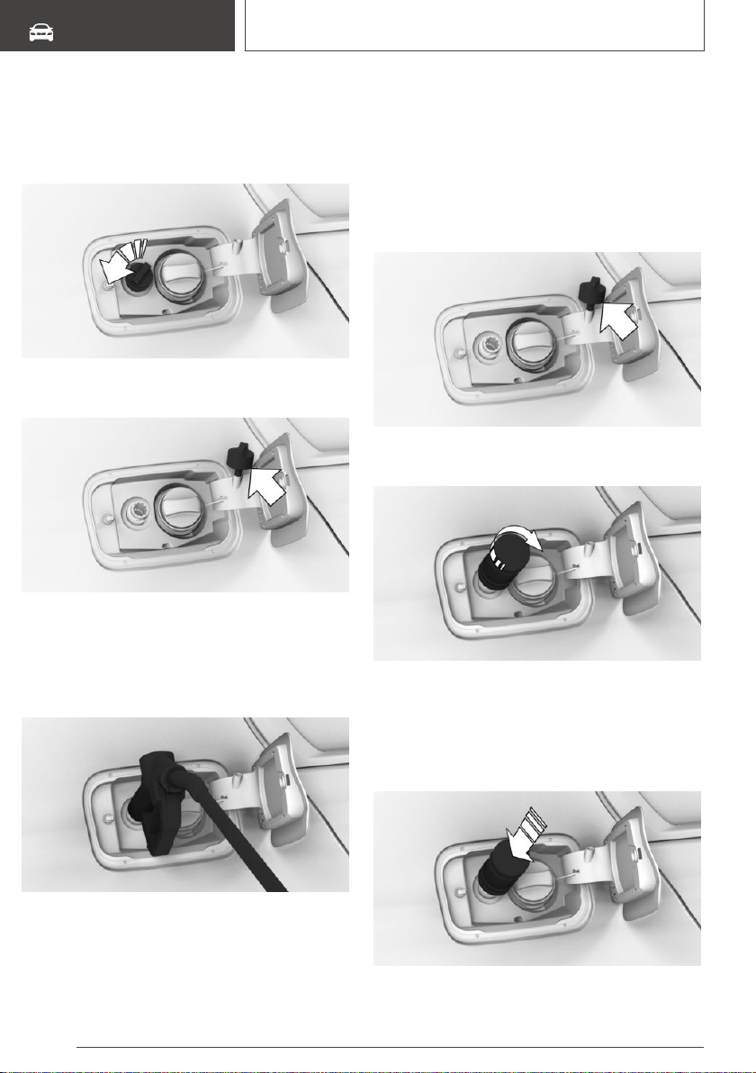
Adding diesel exhaust fluid
1. Open the fuel filler flap, refer to page 288.
2. Turn the fuel cap of the diesel exhaust fluid
tank counterclockwise and remove.
3. Place the fuel cap in the bracket attached to
the fuel filler flap.
4. Using the fuel pump nozzle, add at least the
recommended refilling quantity, refer to
page 293.
The fuel tank is full when the filler nozzle
clicks off the first time.
5. Replace the fuel cap and turn it clockwise.
6. Close the fuel filler flap.
Adding diesel exhaust fluid using a
bottle
1. Open the fuel filler flap, refer to page 288.
2. Turn the fuel cap of the diesel exhaust fluid
tank counterclockwise and remove.
3. Place the fuel cap in the bracket attached to
the fuel filler flap.
4. Place the bottle on it and turn it clockwise as
far as it will go.
5. Press the bottle down.
The vehicle tank will be filled.
The tank is full when the fill level in the bottle
no longer changes. It is not possible to over‐
fill.
Seite 294
MOBILITY
Fuel
294
Online Edition for Part no. 01402896703 - X/18
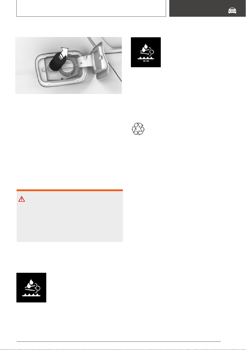
6. Pull back the bottle and unscrew it.
7. Replace the fuel cap and turn it clockwise.
8. Close the fuel filler flap.
Filling with an incorrect fluid
General information
A Check Control message is displayed when an
incorrect fluid is added.
In the case that an incorrect fluid was refilled,
contact a dealer’s service center or another
qualified service center or repair shop.
Safety information
WARNING
After adding an incorrect fluid, for instance anti‐
freeze for washer fluid, the system can heat
and ignite. There is a risk of fire and injuries. Do
not add incorrect fluids. Do not start the engine
after adding an incorrect fluid.
After filling diesel exhaust fluid
Reserve level indicator
The reserve level indicator will still
appear along with the remaining
range after refilling.
The drive-ready state can be es‐
tablished.
After several minutes of driving, the reserve level
indicator goes out.
Diesel exhaust fluid on minimum
After filling, the indicator is still
displayed.
The drive-ready state can only be
established after the indicator
goes out.
1. Press the Start/Stop button three times.
The indicator goes out after approx. 1 minute.
2. Press the Start/Stop button and establish the
drive-ready state.
Disposing of bottles
Have bottles for diesel exhaust fluid dis‐
posed of by a dealer's service center or
another qualified service center or repair
shop or take them to a collection point.
Do not dispose of empty bottles with household
waste unless this is permitted by local regula‐
tions.
Seite 295
Fuel
MOBILITY
295
Online Edition for Part no. 01402896703 - X/18
Wheels and tires
Vehicle features and
options
This chapter describes all standard, country-spe‐
cific and optional features offered with the series.
It also describes features that are not necessarily
available in your vehicle, e. g., due to the selected
options or country versions. This also applies to
safety-related functions and systems. When us‐
ing these functions and systems, the applicable
laws and regulations must be observed.
Tire inflation pressure
General information
The tire characteristics and tire inflation pressure
influence the following:
▷ The service life of the tires.
▷ Road safety.
▷ Driving comfort.
▷ Fuel consumption.
Safety information
WARNING
A tire with too little or no tire inflation pressure
may heat up significantly and sustain damage.
This will have a negative impact on aspects of
handling, such as steering and braking re‐
sponse. There is a risk of an accident. Regularly
check the tire inflation pressure, and correct it
as needed, for instance twice a month and be‐
fore a long trip.
Tire inflation pressure
specifications
In the tire inflation pressure table
The tire inflation pressure table, refer to
page 298, contains all tire inflation pressure
specifications for the specified tire sizes at the
ambient temperature. The tire inflation pressure
values apply to tire sizes approved by the manu‐
facturer of the vehicle for the vehicle type.
To identify the correct tire inflation pressure,
please note the following:
▷ Tire sizes of your vehicle.
▷ Maximum permitted driving speed.
On the Control Display
The current tire inflation pressure values and the
intended tire inflation pressure values for the
mounted tires can be displayed on the Control
Display.
To ensure that they are displayed correctly, the
tire sizes must be stored in the system and must
have been set, refer to page 310, for the
mounted tires.
The current tire inflation pressure value is lo‐
cated on each tire.
The intended tire inflation pressure value is lo‐
cated in the lower area of the Control Display.
Checking the tire inflation
pressure
General information
Tires heat up while driving. The tire inflation
pressure increases with the tire temperature.
Tires have a natural, consistent loss of tire infla‐
tion pressure.
The displays of inflation devices may under-read
by up to 0.1 bar/2 psi.
Seite 296
MOBILITY
Wheels and tires
296
Online Edition for Part no. 01402896703 - X/18
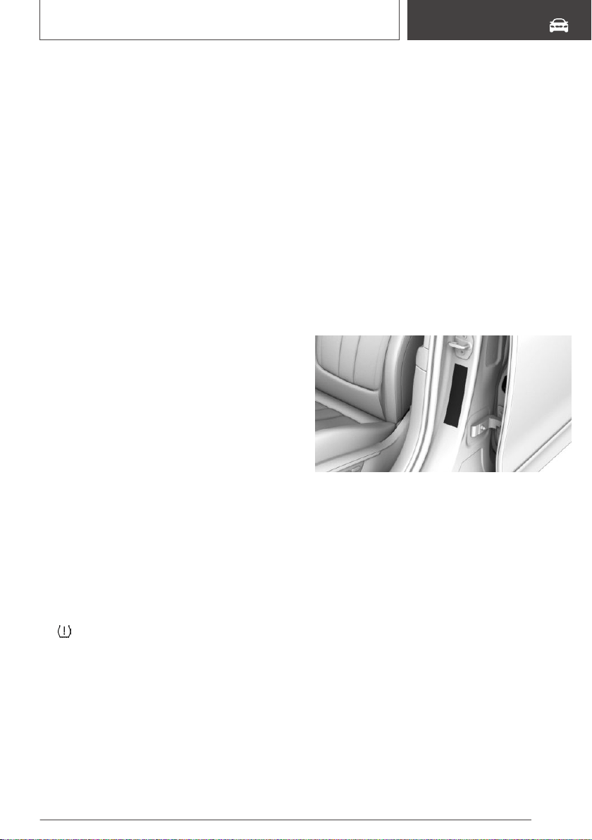
Checking using tire inflation
pressure specifications in the tire
inflation pressure table
The tire inflation pressure specifications in the
tire inflation pressure table only relate to cold
tires or tires at the same temperature as the am‐
bient temperature.
Only check the tire inflation pressure levels when
the tires are cold, i.e.:
▷ Driving range of max. 1.25 miles/2 km has not
been exceeded.
▷ If the vehicle has not moved again for at least
2 hours after a trip.
Check the tire inflation pressure of the emer‐
gency wheel in the cargo area regularly, and cor‐
rect it as needed.
1.
Determine, refer to page 296, the intended
tire inflation pressure levels for the mounted
tires.
2. Check the tire inflation pressure in all four
tires, using a pressure gage, for example.
3. Correct the tire inflation pressure if the cur‐
rent tire inflation pressure value deviates from
the specified value.
4. Check whether all valve caps are screwed
onto the tire valves.
Checking using the tire inflation
pressure specifications on the
Control Display
1.
"My Vehicle"
2. "Vehicle status"
3. "Tire Pressure Monitor"
4. Check whether the current tire inflation pres‐
sure levels deviate from the intended tire
pressure value.
5. Correct the tire inflation pressure if the cur‐
rent tire inflation pressure value deviates from
the intended value.
After correcting the tire inflation
pressure
With runflat tires:
Reinitialize the Flat Tire Monitor.
With Tire Pressure Monitor TPM:
With tires that cannot be found in the tire pres‐
sure values on the Control Display, reset the Tire
Pressure Monitor TPM.
Tire inflation pressures up to
100 mph/160 km/h
For speeds of up to 100 mph/160 km/h and for
optimum driving comfort, note the pressure val‐
ues in the tire inflation pressure table, refer to
page 298, and adjust as necessary.
These pressure values can also be found on the
tire inflation pressure label on the driver's door
pillar.
Do not exceed a speed of 100 mph/160 km/h.
Seite 297
Wheels and tires
MOBILITY
297
Online Edition for Part no. 01402896703 - X/18
Tire inflation pressure values up
to 100 mph/160 km/h
X3 xDrive30i, X3 sDrive30i, X3
xDrive30d
Tire size Pressure specifica‐
tions in bar/PSI
Specifications in
bar/PSI with cold
tires
225/60 R 18 104 H
M+S XL A/S RSC
225/60 R 18 104 H
M+S XL RSC
2.2 / 32 2.5 / 36
245/50 R 19 105 H
M+S XL A/S
Std/RSC
245/50 R 19 105
W XL RSC
245/50 R 19 105 V
M+S XL RSC
2.2 / 32 2.4 / 35
Front: 245/45 R 20
103 W XL RSC
2.2 / 32 -
Rear: 275/40 R 20
106 W XL RSC
- 2.4 / 35
Front: 245/45 R 20
103 Y XL Std
2.2 / 32 -
Rear: 275/40 R 20
106 Y XL Std
- 2.4 / 35
Front: 245/40 R 21
100 Y XL RSC
2.3 / 33 -
Rear: 275/35 R 21
103 Y XL RSC
- 2.6 / 38
Emergency wheel:
T 135/80 R 18 104
M
Speed up to a max. of
50 mph / 80 km/h
4.2 / 60
X3 M40i
Tire size Pressure specifica‐
tions in bar/PSI
Specifications in
bar/PSI with cold
tires
245/50 R 19 105
H M+S XL A/S
Std/RSC
245/50 R 19 105
W XL RSC
245/50 R 19 105 V
M+S XL RSC
2.2 / 32 2.4 / 35
Front: 245/45 R 20
103 W XL RSC
2.2 / 32 -
Rear: 275/40 R 20
106 W XL RSC
- 2.4 / 35
Front: 245/45 R 20
103 Y XL Std
2.2 / 32 -
Rear: 275/40 R 20
106 Y XL Std
- 2.4 / 35
Front: 245/40 R 21
100 Y XL RSC
2.3 / 33 -
Rear: 275/35 R 21
103 Y XL RSC
- 2.6 / 38
Emergency wheel:
T 135/80 R 18 104
M
Speed up to a max. of
50 mph / 80 km/h
4.2 / 60
Tire inflation pressures at max.
speeds above 100 mph/160 km/h
WARNING
In order to drive at maximum speeds in excess
of 100 mph/160 km/h, please observe, and, if
necessary, adjust tire pressures for speeds ex‐
ceeding 100 mph/160 km/h from the relevant
Seite 298
MOBILITY
Wheels and tires
298
Online Edition for Part no. 01402896703 - X/18
table on the following pages. Otherwise, tire
damage and accidents could occur.
For speeds over 100 mph/160 km/h and for opti‐
mum driving comfort, note the pressure values in
the tire inflation pressure table, refer to
page 299, and adjust as necessary.
Tire inflation pressure values
over 100 mph/160 km/h
X3 xDrive30i, X3 sDrive30i, X3
xDrive30d
Tire size Pressure specifica‐
tions in bar/PSI
Specifications in
bar/PSI with cold
tires
225/60 R 18 104 H
M+S XL A/S RSC
225/60 R 18 104 H
M+S XL RSC
245/50 R 19 105 H
M+S XL A/S
Std/RSC
245/50 R 19 105 W
XL RSC
245/50 R 19 105 V
M+S XL RSC
2.6 / 38 3.1 / 45
Front: 245/45 R 20
103 W XL RSC
2.7 / 39 -
Rear: 275/40 R 20
106 W XL RSC
- 3.1 / 45
Front: 245/45 R 20
103 Y XL Std
2.4 / 35 -
Rear: 275/40 R 20
106 Y XL Std
- 2.7 / 39
Tire size Pressure specifica‐
tions in bar/PSI
Front: 245/40 R 21
100 Y XL RSC
2.6 / 38 -
Rear: 275/35 R 21
103 Y XL RSC
- 2.9 / 42
Emergency wheel:
T 135/80 R 18 104
M
Speed up to a max. of
50 mph / 80 km/h
4.2 / 60
X3 M40i
Tire size Pressure specifica‐
tions in bar/PSI
Specifications in
bar/PSI with cold
tires
245/50 R 19 105
H M+S XL A/S
Std/RSC
245/50 R 19 105
W XL RSC
245/50 R 19 105 V
M+S XL RSC
2.6 / 38 3.1 / 45
Front: 245/45 R 20
103 W XL RSC
2.7 / 39 -
Rear: 275/40 R 20
106 W XL RSC
- 3.1 / 45
Front: 245/45 R 20
103 Y XL Std
2.4 / 35 -
Rear: 275/40 R 20
106 Y XL Std
- 2.7 / 39
Front: 245/40 R 21
100 Y XL RSC
2.6 / 38 -
Seite 299
Wheels and tires
MOBILITY
299
Online Edition for Part no. 01402896703 - X/18

Tire size Pressure specifica‐
tions in bar/PSI
Rear: 275/35 R 21
103 Y XL RSC
- 2.9 / 42
Emergency wheel:
T 135/80 R 18 104
M
Speed up to a max. of
50 mph / 80 km/h
4.2 / 60
Tire identification marks
Tire size
245/45 R 18 96 Y
245: nominal width in mm
45: aspect ratio in %
R: radial tire code
18: rim diameter in inches
96: load rating, not for ZR tires
Y: speed rating, before the R on ZR tires
Maximum tire load
Maximum tire load is the maximum permissible
weight for which the tire is approved.
Locate the maximum tire load on the tire sidewall
and the Gross Axle Weight Rating – GAWR – on
the certification label on the driver door B-pillar.
Divide the tire load by 1.1. It must be greater
than one-half of the vehicle’s Gross Axle Weight
Rating – GAWR. Note, front vs. rear GAWR and
tire loads, respectively.
Speed letter
Q = up to 100 mph/160 km/h
R = up to 106 mph/170 km/h
S = up to 112 mph/180 km/h
T = up to 118 mph/190 km/h
H = up to 131 mph/210 km/h
V = up to 150 mph/240 km/h
W = up to 167 mph/270 km/h
Y = up to 186 mph/300 km/h
Tire Identification Number
DOT code: DOT xxxx xxx 3818
xxxx: manufacturer code for the tire brand
xxx: tire size and tire design
3818: tire age
Tires with DOT codes meet the guidelines of the
U.S. Department of Transportation.
Tire age
Recommendation
Regardless of the tire tread, replace tires at least
every 6 years.
Manufacture date
You can find the manufacture date of the tire on
the tire's sidewall.
Designation Manufacture date
DOT … 3818 38th week, 2018
Uniform Tire Quality Grading
Quality grades can be found where applicable on
the tire sidewall between tread shoulder and
maximum section width.
E.g.: Treadwear 200; Traction AA; Temperature
A
DOT Quality Grades
Treadwear
Traction AA A B C
Temperature A B C
All passenger vehicle tires must conform to Fed‐
eral Safety Requirements in addition to these
grades.
Treadwear
The treadwear grade is a comparative rating
based on the wear rate of the tire when tested
Seite 300
MOBILITY
Wheels and tires
300
Online Edition for Part no. 01402896703 - X/18
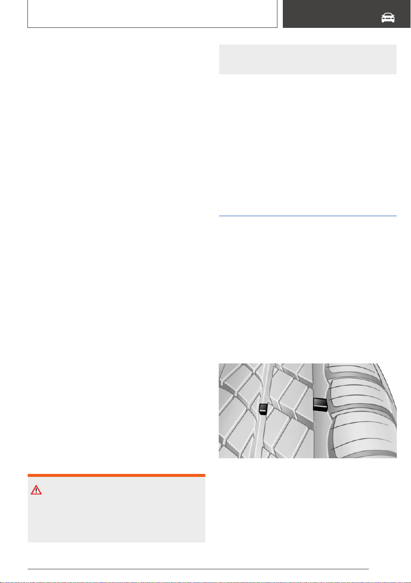
under controlled conditions on a specified gov‐
ernment test course. E.g., a tire graded 150
would wear one and one-half, 1 g, times as well
on the government course as a tire graded 100.
The relative performance of tires depends upon
the actual conditions of their use, however, and
may depart significantly from the norm due to
variations in driving habits, service practices and
differences in road characteristics and climate.
Traction
The traction grades, from highest to lowest, are
AA, A, B, and C.
Those grades represent the tire's ability to stop
on wet pavement as measured under controlled
conditions on specified government test surfa‐
ces of asphalt and concrete. A tire marked C may
have poor traction performance.
The traction grade assigned to this tire is based
on straight-ahead braking traction tests, and
does not include acceleration, cornering, hydro‐
planing, or peak traction characteristics.
Temperature
The temperature grades are A, the highest, B,
and C, representing the tire's resistance to the
generation of heat and its ability to dissipate heat
when tested under controlled conditions on a
specified indoor laboratory test wheel. Sustained
high temperature can cause the material of the
tire to degenerate and reduce tire life, and exces‐
sive temperature can lead to sudden tire failure.
The grade C corresponds to a level of perform‐
ance which all passenger vehicle tires must meet
under the Federal Motor Vehicle Safety Standard
No. 109. Grades Band A represent higher levels
of performance on the laboratory test wheel than
the minimum required by law.
WARNING
The temperature grade for this tire is estab‐
lished for a tire that is properly inflated and not
overloaded. Excessive speed, underinflation, or
excessive loading, either separately or in com‐
bination, can cause heat buildup and possible
tire failure.
RSC – Run-flat tires
Run-flat tires, refer to page 304, are labeled with
a circular symbol containing the letters RSC
marked on the sidewall.
M+S
Winter and all-season tires with better cold
weather performance than summer tires.
Tire tread
Summer tires
Do not drive with a tire tread of less than
0.12 in/3 mm, otherwise there is an increased
risk of hydroplaning.
Winter tires
Do not drive with a tire tread of less than
0.16 in/4 mm, as such tires are less suitable for
winter operation.
Minimum tread depth
Wear indicators are distributed around the tire's
circumference and have the legally required min‐
imum height of 0.063 inches/1.6 mm.
The positions of the wear indicators are marked
on the tire sidewall with TWI, Tread Wear Indica‐
tor.
Seite 301
Wheels and tires
MOBILITY
301
Online Edition for Part no. 01402896703 - X/18

Tire damage
General information
Inspect your tires regularly for damage, foreign
objects lodged in the tread, and tread wear.
Driving over rough or damaged road surfaces, as
well as debris, curbs and other obstacles can
cause serious damage to wheels, tires and sus‐
pension parts. This is more likely to occur with
low-profile tires, which provide less cushioning
between the wheel and the road. Be careful to
avoid road hazards and reduce your speed, es‐
pecially if your vehicle is equipped with low-pro‐
file tires.
Indications of tire damage or other vehicle mal‐
functions:
▷ Unusual vibrations.
▷ Unusual tire or running noises.
▷ Unusual handling such as a strong tendency
to pull to the left or right.
Damage can be caused by the following situa‐
tions, for instance:
▷ Driving over curbs.
▷ Road damage.
▷ Tire inflation pressure too low.
▷ Vehicle overloading.
▷ Incorrect tire storage.
Safety information
WARNING
Damaged tires can lose tire inflation pressure,
which can lead to loss of vehicle control. There
is a risk of an accident. If tire damage is sus‐
pected while driving, immediately reduce speed
and stop. Have wheels and tires checked. For
this purpose, drive carefully to the nearest deal‐
er’s service center or another qualified service
center or repair shop. Have vehicle towed or
transported as needed. Do not repair damaged
tires, but have them replaced.
WARNING
Tires can become damaged by driving over ob‐
stacles, e.g., curbs or road damage, at high
speed. Larger wheels have a smaller tire cross-
section. The smaller the tire cross-section, the
higher the risk of tire damage. There is a dan‐
ger of accidents and property damage. If possi‐
ble, drive around obstacles, or drive over them
slowly and carefully.
Changing wheels and tires
Mounting and wheel balancing
Have mounting and wheel balancing carried out
by a dealer’s service center or another qualified
service center or repair shop.
Wheel and tire combination
General information
You can ask the dealer’s service center or an‐
other qualified service center or repair shop
about the correct wheel/tire combination and
wheel rim versions for the vehicle.
Safety information
WARNING
Wheels and tires which are not suitable for your
vehicle can damage parts of the vehicle, for in‐
stance due to contact with the body due to tol‐
erances despite the same official size rating.
There is a risk of an accident. The manufac‐
turer of your vehicle strongly suggests that you
use wheels and tires that have been recom‐
mended by the vehicle manufacturer for your
vehicle type.
Seite 302
MOBILITY
Wheels and tires
302
Online Edition for Part no. 01402896703 - X/18
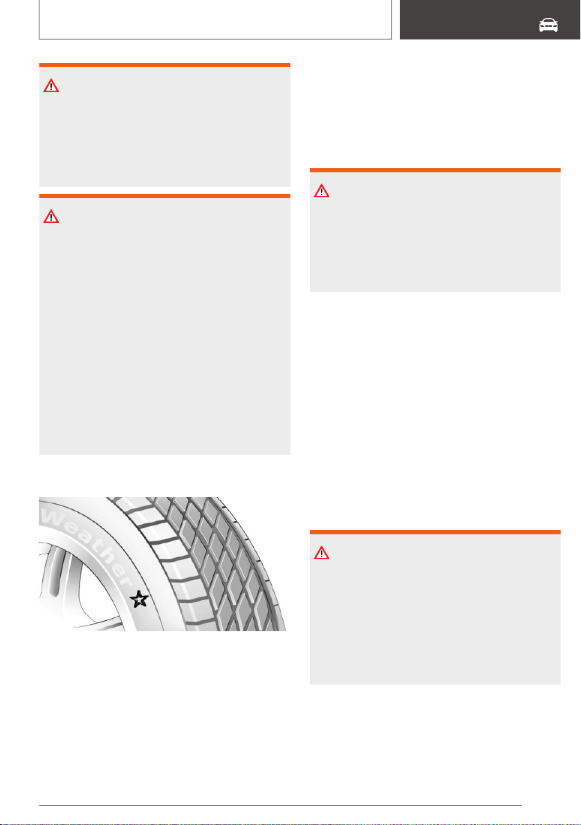
WARNING
Mounted steel wheels can cause technical
problems, for instance independent loosening
of the lug bolts, damage to the brake discs.
There is a risk of an accident. Do not mount
steel wheels.
WARNING
Incorrect wheel/tire combinations will have a
negative impact on the vehicle's handling and
on the function of a variety of systems, such as
the Anti-lock Brake System or Dynamic Stabil‐
ity Control. There is a risk of an accident. To
maintain good handling and vehicle response,
use only tires with a single tread configuration
from a single manufacturer. The manufacturer
of the vehicle recommends that you use
wheels and tires that have been recommended
by the vehicle manufacturer for your vehicle
type. Following tire damage, have the original
wheel/tire combination remounted on the vehi‐
cle as soon as possible.
Recommended tire brands
For each tire size, the manufacturer of the vehi‐
cle recommends certain tire brands. The tire
brands can be identified by a star on the tire
sidewall.
New tires
Tire traction is not optimal due to manufacturing
circumstances when tires are brand-new; they
achieve their full traction potential after a break-in
time.
Drive conservatively for the first
200 miles/300 km.
Retreaded tires
WARNING
Retreaded tires can have different tire casing
structures. With advanced age the service life
can be limited. There is a risk of an accident.
The manufacturer of your vehicle does not rec‐
ommend the use of retreaded tires.
The manufacturer of your vehicle does not rec‐
ommend the use of retreaded tires.
Winter tires
General information
Winter tires are recommended for operating on
winter roads.
Although so-called all-season M+S tires provide
better winter traction than summer tires, they
usually do not provide the same level of perform‐
ance as winter tires.
Safety information
WARNING
If the vehicle is equipped with an M Sport dif‐
ferential and all-weather tires on 19 inch rims,
this can alter handling, for instance the vehicle
may swerve off course. There is a risk of acci‐
dents or risk of damage to property. If the vehi‐
cle is equipped with an M Sport differential, do
not fit all-weather tires on 19 inch rims.
Maximum speed of winter tires
If the maximum speed of the vehicle is higher
than the permissible speed for the winter tires,
then attach a label showing the permissible maxi‐
Seite 303
Wheels and tires
MOBILITY
303
Online Edition for Part no. 01402896703 - X/18
mum speed in the field of view. The label is avail‐
able from a dealer’s service center or another
qualified service center or repair shop.
With winter tires mounted, observe and do not
exceed the permissible maximum speed.
Changing runflat tires
For your own safety, use only runflat tires. No
spare tire is available in the case of a flat tire. Fur‐
ther information is available from a dealer’s serv‐
ice center or another qualified service center or
repair shop.
Rotating wheels between axles
Different wear patterns can occur on the front
and rear axles depending on individual driving
conditions. The tires can be rotated in pairs be‐
tween the axles to achieve even wear. Further in‐
formation is available from a dealer’s service cen‐
ter or another qualified service center or repair
shop. After rotating, check the tire pressure and
correct, if needed.
Rotating the tires is not permissible on vehicles
with different tire sizes or rim sizes on the front
and rear axles.
Storing tires
Tire inflation pressure
Do not exceed the maximum tire inflation pres‐
sure indicated on the side wall of the tire.
Storage
Store wheels and tires in a cool, dry and dark
place.
Always protect tires against all contact with oil,
grease, and solvents.
Do not leave tires in plastic bags.
Remove dirt from wheels or tires.
Run-flat tires
Concept
Run-flat tires permit continued driving under re‐
stricted conditions even in the event of a com‐
plete loss of tire inflation pressure.
General information
The wheels consist of tires that are self-support‐
ing, to a limited degree, and possibly special
rims.
The support of the sidewall allows the tire to re‐
main drivable to a restricted degree in the event
of a tire inflation pressure loss.
Follow the instructions for continued driving with
a flat tire.
Safety information
WARNING
Your vehicle handles differently with a run-flat
with no or low inflation pressure; for instance,
your lane stability when braking is reduced,
braking distances are longer and the self-steer‐
ing properties will change. There is a risk of an
accident. Drive moderately and do not exceed a
speed of 50 mph/80 km/h.
WARNING
Heavy trailers can start swinging when continu‐
ing to drive with a flat tire. There is a risk of ac‐
cidents or risk of damage to property. Do not
exceed a speed of 35 mph/60 km/h when driv‐
ing with a trailer and a flat tire. Immediately
brake in the case of swinging. Apply necessary
steering corrections as carefully as possible.
Seite 304
MOBILITY
Wheels and tires
304
Online Edition for Part no. 01402896703 - X/18
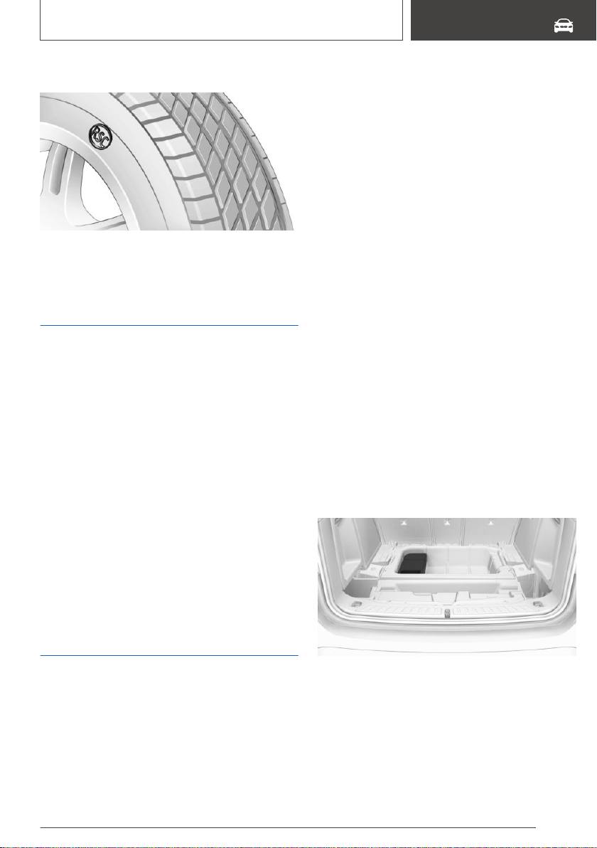
Label
The tires are marked on the tire sidewall with
RSC Run-flat System Component.
Repairing a flat tire
Safety measures
▷ Park the vehicle as far away as possible from
passing traffic and on solid ground.
▷ Switch on the hazard warning system.
▷ Secure the vehicle against rolling away by
setting the parking brake.
▷ Turn the steering wheel until the front wheels
are in the straight-ahead position and engage
the steering wheel lock.
▷ Have all vehicle occupants get out of the ve‐
hicle and ensure that they remain outside the
immediate area in a safe place, such as be‐
hind a guardrail.
▷ If necessary, set up a warning triangle at an
appropriate distance.
Mobility System
Concept
With the Mobility System, minor tire damage can
be sealed temporarily to enable continued travel.
To accomplish this, sealant is pumped into the
tires, which seals the damage from the inside.
General information
▷ Follow the instructions on using the Mobility
System found on the compressor and sealant
container.
▷ Use of the Mobility System may be ineffec‐
tive if the tire puncture measures approx.
1/8 inches/4 mm or more.
▷ Contact a dealer’s service center or another
qualified service center or repair shop if the
tire cannot be made drivable.
▷ If possible, do not remove foreign bodies that
have penetrated the tire. Only remove foreign
objects if they are visibly protruding from the
tire.
▷ Pull the speed limit sticker off the sealant
container and apply it to the steering wheel.
▷ The use of a sealant can damage the TPM
wheel electronics. In this case, have the elec‐
tronics checked and replaced at the next op‐
portunity.
▷ The compressor can be used to check the
tire inflation pressure.
Overview
Storage
The Mobility System is located in the compart‐
ment under the cargo floor panel.
Fold up the cargo floor panel.
Seite 305
Wheels and tires
MOBILITY
305
Online Edition for Part no. 01402896703 - X/18
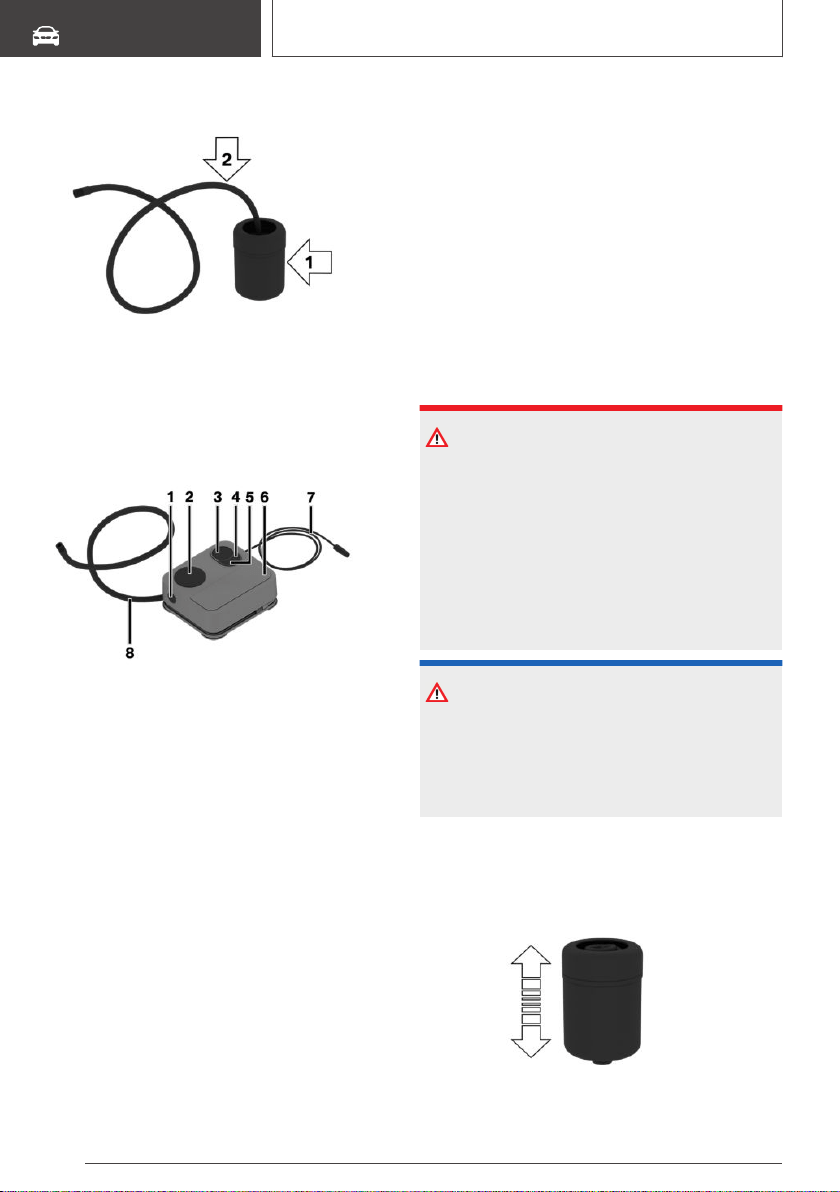
Sealant container
▷ Sealant container, arrow 1.
▷ Filling hose, arrow 2.
Observe use-by date on the sealant container.
Compressor
1 Sealant container unlocking
2 Sealant container holder
3 Tire pressure gage
4 Reduce tire inflation pressure button
5 On/off switch
6 Compressor
7 Connector/cable for socket
8 Connection hose
Safety measures
▷ Park the vehicle as far away as possible from
passing traffic and on solid ground.
▷ Switch on the hazard warning system.
▷ Secure the vehicle against rolling away by
setting the parking brake.
▷ Turn the steering wheel until the front wheels
are in the straight-ahead position and engage
the steering wheel lock.
▷ Have all vehicle occupants get out of the ve‐
hicle and ensure that they remain outside the
immediate area in a safe place, such as be‐
hind a guardrail.
▷ If necessary, set up a warning triangle at an
appropriate distance.
Filling the tire with sealant
Safety information
DANGER
If the exhaust pipe is blocked or ventilation is in‐
sufficient, harmful exhaust gases can enter into
the vehicle. The exhaust gases contain pollu‐
tants which are colorless and odorless. In en‐
closed areas, exhaust gases can also accumu‐
late outside of the vehicle. There is danger to
life. Keep the exhaust pipe free and ensure suf‐
ficient ventilation.
NOTICE
The compressor can overheat during extended
operation. There is a risk of damage to prop‐
erty. Do not run the compressor for more than
10 minutes.
Filling
1.
Shake the sealant container.
Seite 306
MOBILITY
Wheels and tires
306
Online Edition for Part no. 01402896703 - X/18
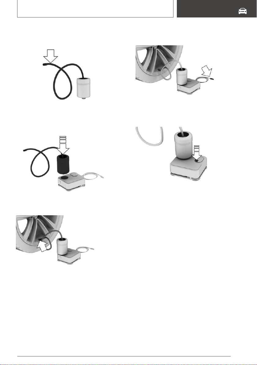
2. Pull filling hose completely out of the cover of
the sealant container. Do not kink the hose.
3. Slide the sealant container into the holder on
the compressor housing, ensuring that it en‐
gages audibly.
4. Screw the filling hose of the sealant container
onto the tire valve of the nonworking wheel.
5. With the compressor switched off, insert the
plug into the power socket inside the vehicle.
6. With standby state switched on or the engine
running, switch on the compressor.
Let the compressor run for max. 10 minutes to fill
the tire with sealant and achieve a tire inflation
pressure of approx. 2.0 bar.
While the tire is being filled with sealant, the tire
inflation pressure may sporadically reach approx.
5 bar. Do not switch off the compressor at this
point.
Checking and adjusting the tire
inflation pressure
Checking
1.
Switch off the compressor.
2. Read the tire inflation pressure on the tire
pressure gage.
To continue the trip, a tire inflation pressure of at
least 2 bar must be reached.
Seite 307
Wheels and tires
MOBILITY
307
Online Edition for Part no. 01402896703 - X/18
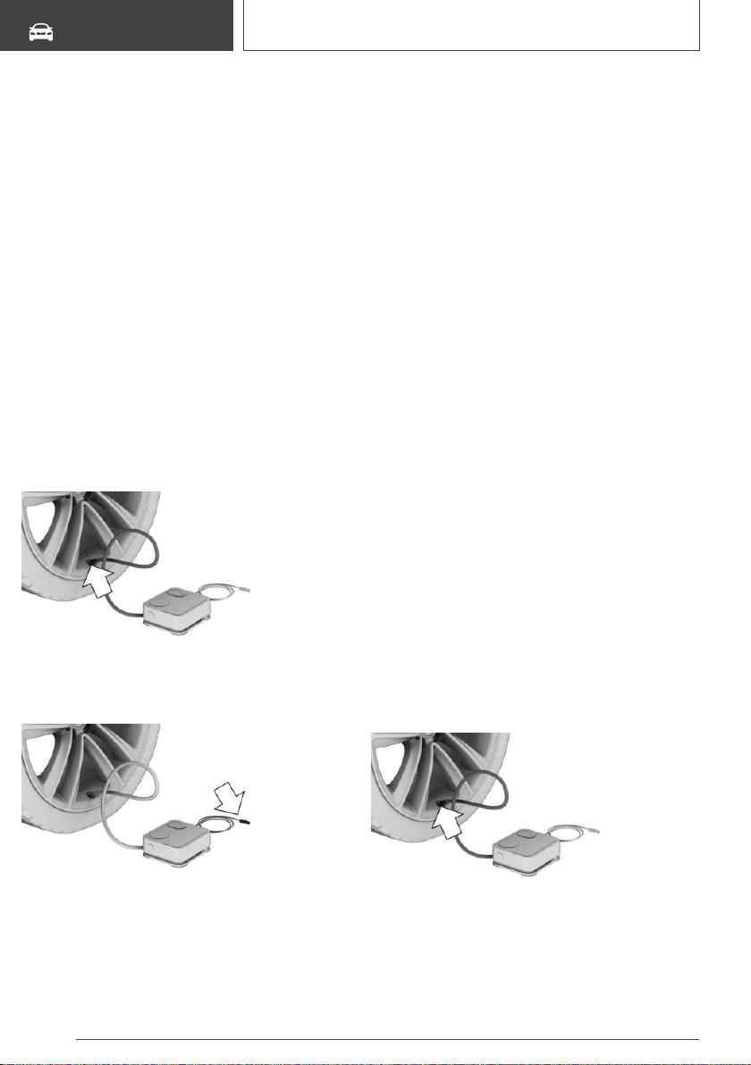
Removing and stowing the sealant
container
1. Unscrew the filling hose of the sealant con‐
tainer from the tire valve.
2. Press the red unlocking device.
3. Remove the sealant container from the com‐
pressor.
4. Wrap and store the sealant container in suita‐
ble material to avoid dirtying the cargo area.
Minimum tire inflation pressure is
not reached
1.
Pull the connector out of the power socket
inside the vehicle.
2. Drive 33 ft/10 m forward and back to distrib‐
ute the sealant in the tire.
3. Screw the connection hose of the compres‐
sor directly onto the tire valve stem.
4. Insert the connector into the power socket in‐
side the vehicle.
5. With standby state switched on or the engine
running, switch on the compressor.
If a tire inflation pressure of at least 2 bar can‐
not be reached, contact your dealer’s service
center or another qualified service center or
repair shop.
If a tire inflation pressure of at least 2 bar is
reached, see Minimum tire inflation pressure
is reached.
6. Unscrew the connection hose of the com‐
pressor from the tire valve.
7. Pull the connector out of the power socket
inside the vehicle.
8. Stow the Mobility System in the vehicle.
Minimum tire inflation pressure is
reached
1.
Unscrew the connection hose of the com‐
pressor from the tire valve.
2. Pull the connector out of the power socket
inside the vehicle.
3. Stow the Mobility System in the vehicle.
4. Immediately drive approx. 5 miles/10 km to
ensure that the sealant is evenly distributed in
the tire.
Do not exceed a speed of 50 mph/80 km/h.
If possible, do not drive at speeds less than
12 mph/20 km/h.
Adjustment
1.
Stop at a suitable location.
2. Screw the connection hose of the compres‐
sor directly onto the tire valve stem.
Seite 308
MOBILITY
Wheels and tires
308
Online Edition for Part no. 01402896703 - X/18
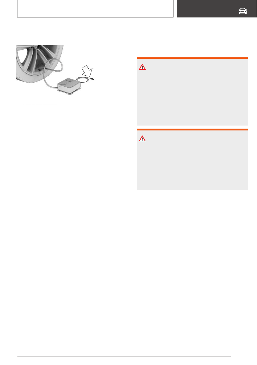
3. Insert the connector into the power socket in‐
side the vehicle.
4. Correct the tire inflation pressure to at least
2.0 bar.
▷ Increase tire inflation pressure: with
standby state switched on or the engine
running, switch on the compressor.
▷ Reduce tire inflation pressure: press the
button on the compressor.
5. Unscrew the connection hose of the com‐
pressor from the tire valve.
6. Pull the connector out of the power socket
inside the vehicle.
7. Stow the Mobility System in the vehicle.
Continuing the trip
Do not exceed the maximum permissible speed
of 50 mph/80 km/h.
Reinitialize the run-flat tires, refer to page 317.
Reset the Tire Pressure Monitor TPM, refer to
page 310.
Replace the nonworking tire and the sealant con‐
tainer of the Mobility System promptly.
Snow chains
Safety information
WARNING
With the mounting of snow chains on unsuita‐
ble tires, the snow chains can come into con‐
tact with vehicle parts. There is a risk of acci‐
dents or risk of damage to property. Only
mount snow chains on tires that are designated
by their manufacturer as suitable for the use of
snow chains.
WARNING
Insufficiently tight snow chains may damage
tires and vehicle components. There is a risk of
accidents or risk of damage to property. Make
sure that the snow chains are always suffi‐
ciently tight. Re-tighten as needed according to
the snow chain manufacturer's instructions.
Fine-link snow chains
The manufacturer of your vehicle recommends
use of fine-link snow chains. Certain types of
fine-link snow chains have been tested by the
manufacturer of the vehicle and recommended
as road-safe and suitable.
Information regarding suitable snow chains is
available from a dealer’s service center or an‐
other qualified service center or repair shop.
Use
Use only in pairs on the rear wheels, equipped
with the tires of the following size:
▷ 225/60 R 18.
▷ 245/50 R 19.
Follow the snow chain manufacturer's instruc‐
tions.
Seite 309
Wheels and tires
MOBILITY
309
Online Edition for Part no. 01402896703 - X/18

Do not initialize the run-flat tires after mounting
snow chains, as doing so may result in incorrect
readings.
Do not reset the Tire Pressure Monitor TPM af‐
ter mounting snow chains, as doing so may re‐
sult in incorrect readings.
When driving with snow chains, briefly activate
Dynamic Traction Control DTC to optimize the
forward momentum.
Maximum speed with snow
chains
Do not exceed a speed of 30 mph/50 km/h when
using snow chains.
Tire Pressure Monitor TPM
Concept
The system monitors tire inflation pressure in the
four mounted tires. The system warns you if
there is a loss of pressure in one or more tires.
General information
Sensors in the tire valves measure the tire infla‐
tion pressure and tire temperature.
Using the tire settings in iDrive, the system can
automatically display the specified target pres‐
sures and compare them with the actual tire in‐
flation pressures.
If tires are being used that are not specified on
the tire inflation pressure details on the vehicle,
refer to page 296, such as tires with special ap‐
proval, the system needs to be actively reset.
The system will then take over the actual tire in‐
flation pressures as the target pressures.
When operating the system, also note the addi‐
tional information found in the Tire inflation pres‐
sure, refer to page 296, chapter.
Safety information
WARNING
The display of the target pressures is not a
substitute for the tire inflation pressure details
on the vehicle. Incorrect entries in the tire set‐
tings can lead to incorrect target tire inflation
pressure values. In this case, it cannot be guar‐
anteed that the notification of a loss of tire infla‐
tion pressure will be reliable. There is a risk of
injury and risk of damage to property. Ensure
that the tire sizes of the mounted tires are dis‐
played correctly and match the details on the
tires and on the vehicle.
Functional requirements
The following conditions must be met for the
system; otherwise, reliable flagging of a loss of
tire inflation pressure is not assured:
▷ Every time a tire or wheel is changed, the
correct details on the mounted tires must be
entered in the tire settings, refer to
page 310.
▷ For tires with special approval:
▷ After a tire or wheel replacement, a reset
was performed with the correct tire infla‐
tion pressure.
▷ After the tire inflation pressure was ad‐
justed to a new value, a reset was per‐
formed.
▷ Wheels with TPM wheel electronics.
Tire settings
General information
The tire sizes of the mounted tires can be gath‐
ered from the tire inflation pressure details on the
vehicle, refer to page 296, or directly on the tires.
The tire details do not need to be re-entered
when the tire inflation pressure is corrected.
For summer and winter tires, the tire details en‐
tered last are stored. After a tire or wheel re‐
Seite 310
MOBILITY
Wheels and tires
310
Online Edition for Part no. 01402896703 - X/18

placement, the settings of the tire sets used last
can be selected.
Opening the menu
Via iDrive:
1. "My Vehicle"
2. "Vehicle status"
3. "Tire Pressure Monitor"
Changing settings
Via iDrive:
1.
"Tire settings"
2. Selecting tires:
▷ "Summer tires"
▷ "Winter tires/all-season tires"
3. "Current:"
4. Select the tire type that is mounted on the
rear axle:
▷ Tire size, e.g., 245/45 R18 96 Y.
▷ For tires with special approval: "Other tire"
5. Select the maximum road speed that will be
used with the tires.
6. "Confirm settings"
The measurement of the current tire inflation
pressure is started. The measurement progress
is displayed.
Status display
Current status
The system status can be displayed on the Con‐
trol Display, e.g., whether or not the system is ac‐
tive.
Via iDrive:
1.
"My Vehicle"
2. "Vehicle status"
3. "Tire Pressure Monitor"
The current status is displayed.
Current tire inflation pressure
The current tire inflation pressure is displayed for
each tire.
The current tire inflation pressures may change
during driving operation or depending on the ex‐
ternal temperature.
Current tire temperature
Depending on the model, the current tire tem‐
peratures are displayed.
The current tire temperatures may change while
driving or due to the external temperature.
Target pressure
The target pressure for the tires on the front and
rear axles is displayed.
The target pressures are values stored in the ve‐
hicle.
The specified target pressures take the influence
of driving operation and external temperature on
the tire temperature into account. The appropri‐
ate target pressure is always displayed, inde‐
pendent of the weather situation, tire tempera‐
tures and driving times.
The displayed target pressure may change and
may differ from the tire inflation pressure details
on the door pillar of the driver's door. The tire in‐
flation pressure can thus be corrected to the
value of the displayed target pressures.
The target pressure is immediately adjusted if
the vehicle load is changed in the tire settings.
Tire conditions
General information
Tire and system status are indicated by the color
of the wheels and a SMS text message on the
Control Display.
Any existing messages are not deleted if the dis‐
played target pressure is not reached after the
tire inflation pressure is corrected.
Seite 311
Wheels and tires
MOBILITY
311
Online Edition for Part no. 01402896703 - X/18
All wheels green
▷ The system is active and bases warnings on
the displayed target pressures.
▷ For tires with special approval: the system is
active and bases warnings on the tire inflation
pressures stored during the last reset.
One to four yellow wheels
A flat tire or major drop in the tire inflation pres‐
sure has occurred in the indicated tires.
Gray wheels
It may not be possible to identify tire inflation
pressure losses.
Possible causes:
▷ Malfunction.
▷ During tire inflation pressure measurement,
after confirmation of the tire settings.
▷ For tires with special approval: the system is
being reset.
For tires with special approval:
performing a reset
Via iDrive:
1.
"My Vehicle"
2. "Vehicle status"
3. "Tire Pressure Monitor"
4. Switch on drive-ready state and do not drive
off.
5. Reset tire inflation pressure: "Perform reset".
6. Drive away.
The wheels are displayed in gray and the follow‐
ing is displayed "Resetting Tire Pressure
Monitor…".
After driving faster than 19 mph/30 km/h for a
short period, the set tire inflation pressures are
accepted as the target tire inflation pressures.
The reset is completed automatically while driv‐
ing.
After a successfully completed reset, the wheels
on the Control Display are shown in green and
the following is displayed: "Tire Pressure Monitor
active. See label for recommended pressures.".
You may interrupt this trip at any time. When you
continue the reset resumes automatically.
Messages: for tires without
special approval
General information
A low tire inflation pressure may cause the DSC
Dynamic Stability Control to be switched on.
Safety information
WARNING
A damaged regular tire with low or missing tire
inflation pressure impacts handling, such as
steering and braking response. Run-flat tires
can maintain limited stability. There is a risk of
an accident. Do not continue driving if the vehi‐
cle is equipped with normal tires. Follow the in‐
formation on run-flat tires and continued driving
with these tires.
If a tire inflation pressure check is
required
Message
A symbol with a Check Control message ap‐
pears on the Control Display.
Symbol Possible cause
Inflation was not carried out accord‐
ing to specifications, e.g., when the
tire has not been sufficiently inflated
or in the case of a natural steady tire
pressure loss.
Measure
Check the tire pressure and correct as needed.
Seite 312
MOBILITY
Wheels and tires
312
Online Edition for Part no. 01402896703 - X/18
If the tire inflation pressure is too
low
Message
A yellow warning light is illuminated in
the instrument cluster.
In addition, a symbol with a Check Control mes‐
sage appears on the Control Display.
Symbol Possible cause
There is a tire inflation pressure loss.
Measure
1.
Reduce the vehicle speed. Do not exceed a
speed of 80 mph/130 km/h.
2. At the next opportunity, for instance at a gas
station, check the tire inflation pressure in all
four tires and correct if necessary.
If there is a significant loss of tire
inflation pressure
Message
A yellow warning light is illuminated in
the instrument cluster.
In addition, a symbol with the affected tire ap‐
pears in a Check Control message on the Con‐
trol Display.
Symbol Possible cause
There is a flat tire or a major loss in
tire inflation pressure.
Measure
1.
Reduce your speed and stop cautiously.
Avoid sudden braking and steering maneu‐
vers.
2. Check whether the vehicle is fitted with nor‐
mal tires or run-flat tires.
Run-flat tires, refer to page 304, are labeled
with a circular symbol containing the letters
RSC marked on the tire's sidewall.
Messages: for tires with special
approval
General information
A low tire inflation pressure may cause the DSC
Dynamic Stability Control to be switched on.
Safety information
WARNING
A damaged regular tire with low or missing tire
inflation pressure impacts handling, such as
steering and braking response. Run-flat tires
can maintain limited stability. There is a risk of
an accident. Do not continue driving if the vehi‐
cle is equipped with normal tires. Follow the in‐
formation on run-flat tires and continued driving
with these tires.
If a tire inflation pressure check is
required
Message
A symbol with a Check Control message ap‐
pears on the Control Display.
Seite 313
Wheels and tires
MOBILITY
313
Online Edition for Part no. 01402896703 - X/18
Sym‐
bol
Possible cause
Inflation was not carried out accord‐
ing to specifications, e.g., the tire has
not been sufficiently inflated.
The system has detected a wheel
change, but no reset was done.
The tire inflation pressure has fallen
below the level of the last reset.
No reset was performed for the sys‐
tem. The system issues a warning
based on the tire inflation pressures
stored during the last reset.
Measure
1.
Check the tire pressure and correct as
needed.
2. Perform a system reset.
If the tire inflation pressure is too
low
Message
A yellow warning light is illuminated in
the instrument cluster.
In addition, a symbol with a Check Control mes‐
sage appears on the Control Display.
Symbol Possible cause
There is a tire inflation pressure loss.
No reset was performed for the sys‐
tem. The system issues a warning
based on the tire inflation pressures
stored during the last reset.
Measure
1.
Reduce the vehicle speed. Do not exceed a
speed of 80 mph/130 km/h.
2. At the next opportunity, for instance at a gas
station, check the tire inflation pressure in all
four tires and correct if necessary.
3. Reset the system.
If there is a significant loss of tire
inflation pressure
Message
A yellow warning light is illuminated in
the instrument cluster.
In addition, a symbol with the affected tire ap‐
pears in a Check Control message on the Con‐
trol Display.
Symbol Possible cause
There is a flat tire or a major loss in
tire inflation pressure.
No reset was performed for the sys‐
tem. The system issues a warning
based on the tire inflation pressures
stored during the last reset.
Measure
1.
Reduce your speed and stop cautiously.
Avoid sudden braking and steering maneu‐
vers.
2. Check whether the vehicle is fitted with nor‐
mal tires or run-flat tires.
Run-flat tires, refer to page 304, are labeled
with a circular symbol containing the letters
RSC marked on the tire's sidewall.
Actions in the event of a flat tire
Normal tires
1.
Identify the damaged tire.
Check the tire inflation pressure in all four
tires, for instance using the tire pressure gage
of a flat tire kit.
For tires with special approval: if the tire infla‐
tion pressure in all four tires is correct, the
TPM may not have been reset. In this case,
perform the reset.
Seite 314
MOBILITY
Wheels and tires
314
Online Edition for Part no. 01402896703 - X/18
If tire damage cannot be found, contact a
dealer’s service center or another qualified
service center or repair shop.
2. Repair the flat tire, e.g., with a flat tire kit or by
changing the wheel.
Use of sealant, for instance from the flat tire kit,
may damage the TPM wheel electronics. Have
the electronics replaced at the next opportunity.
Run-flat tires
Safety information
WARNING
Your vehicle handles differently with a run-flat
with no or low inflation pressure; for instance,
your lane stability when braking is reduced,
braking distances are longer and the self-steer‐
ing properties will change. There is a risk of an
accident. Drive moderately and do not exceed a
speed of 50 mph/80 km/h.
WARNING
Heavy trailers can start swinging when continu‐
ing to drive with a flat tire. There is a risk of ac‐
cidents or risk of damage to property. Do not
exceed a speed of 35 mph/60 km/h when driv‐
ing with a trailer and a flat tire. Immediately
brake in the case of swinging. Apply necessary
steering corrections as carefully as possible.
Maximum speed
You may continue driving with a damaged tire at
speeds up to 50 mph/80 km/h.
Continued driving with a flat tire
Follow the following when continuing to drive
with a damaged tire:
1.
Avoid sudden braking and steering maneu‐
vers.
2. Do not exceed a speed of 50 mph/80 km/h.
3. Check the tire inflation pressure in all four
tires at the next opportunity.
For tires with special approval: if the tire infla‐
tion pressure in all four tires is correct, the
Tire Pressure Monitor may not have been re‐
set. In this case, perform the reset.
Possible driving range with a
depressurized tire
The distance for which it may be possible to
drive safely varies depending on how the vehicle
is loaded and used, e.g., speed, road conditions,
external temperature. The driving range may be
less but may also be more if an economical driv‐
ing style is used.
If the vehicle is loaded with an average weight
and used under favorable conditions, the dis‐
tance for which it may be safe to drive may be up
to 50 miles/80 km.
Vehicle handling with damaged tires
Vehicles driven with a damaged tire will handle
differently, potentially leading to conditions such
as the following:
▷ Greater likelihood of swerving off course.
▷ Longer braking distances.
▷ Changed self-steering properties.
Modify your driving style. Avoid abrupt steering
maneuvers or driving over obstacles, for instance
curbs or potholes.
Final tire failure
Vibrations or loud noises while driving can indi‐
cate the final failure of a tire.
Reduce speed and stop; otherwise, pieces of the
tire could come loose and cause an accident.
Do not continue driving. Contact a dealer’s serv‐
ice center or another qualified service center or
repair shop.
Seite 315
Wheels and tires
MOBILITY
315
Online Edition for Part no. 01402896703 - X/18

System limits
Temperature
The tire inflation pressure depends on the tire's
temperature.
Driving or exposure to the sun will increase the
tire's temperature, thus increasing the tire infla‐
tion pressure.
The tire inflation pressure is reduced when the
tire temperature falls again.
These circumstances may cause a warning
when temperatures fall very sharply.
Following a temperature-related warning, the tar‐
get pressures are displayed on the Control Dis‐
play again after a short distance.
Sudden tire pressure loss
The system cannot indicate sudden serious tire
damage caused by external circumstances.
Failure to perform a reset
Tires with special approval: the system will not
function correctly if a reset was not performed,
for example a flat tire may be indicated although
the tire inflation pressures are correct.
Malfunction
Message
The yellow warning light flashes and is
then illuminated continuously. A Check
Control message is displayed. It may not
be possible to identify tire pressure losses.
Measure
▷ A wheel without TPM wheel electronics is
mounted: have the wheels checked, if
needed.
▷ A wheel without TPM wheel electronics, such
as an emergency wheel, is mounted: have
the wheels checked, if needed.
▷ Malfunction: have the system checked.
▷ Interference caused by systems or devices
with the same radio frequency: after leaving
the area of the interference, the system auto‐
matically becomes active again.
▷ For tires with special approval: the system
was unable to complete the reset. Perform a
system reset again.
Declaration according to NHTSA/
FMVSS 138 Tire Pressure
Monitoring System
Each tire, including the spare (if provided) should
be checked monthly when cold and inflated to
the inflation pressure recommended by the vehi‐
cle manufacturer on the vehicle placard or tire in‐
flation pressure label. (If your vehicle has tires of
a different size than the size indicated on the ve‐
hicle placard or tire inflation pressure label, you
should determine the proper tire inflation pres‐
sure for those tires.) As an added safety feature,
your vehicle has been equipped with a tire pres‐
sure monitoring system (TPMS) that illuminates
a low tire pressure telltale when one or more of
your tires is significantly under-inflated. Accord‐
ingly, when the low tire pressure telltale illumi‐
nates, you should stop and check your tires as
soon as possible, and inflate them to the proper
pressure. Driving on a significantly under-inflated
tire causes the tire to overheat and can lead to
tire failure. Under-inflation also reduces fuel effi‐
ciency and tire tread life, and may affect the vehi‐
cle's handling and stopping ability. Please note
that the TPMS is not a substitute for proper tire
maintenance, and it is the driver's responsibility
to maintain correct tire pressure, even if under-
inflation has not reached the level to trigger illu‐
mination of the TPMS low tire pressure telltale.
Your vehicle has also been equipped with a
TPMS malfunction indicator to indicate when the
system is not operating properly. The TPMS
malfunction indicator is combined with the low
tire pressure telltale. When the system detects a
malfunction, the telltale will flash for approxi‐
mately one minute and then remain continuously
illuminated. This sequence will continue upon
subsequent vehicle start-ups as long as the mal‐
Seite 316
MOBILITY
Wheels and tires
316
Online Edition for Part no. 01402896703 - X/18

function exists. When the malfunction indicator is
illuminated, the system may not be able to de‐
tect or signal low tire pressure as intended.
TPMS malfunctions may occur for a variety of
reasons, including the installation of replacement
or alternate tires or wheels on the vehicle that
prevent the TPMS from functioning properly. Al‐
ways check the TPMS malfunction telltale after
replacing one or more tires or wheels on your ve‐
hicle to ensure that the replacement or alternate
tires and wheels allow the TPMS to continue to
function properly.
FTM Flat Tire Monitor
Concept
The system detects tire inflation pressure loss
on the basis of rotation speed differences be‐
tween the individual wheels while driving.
In the event of a tire inflation pressure loss, the
diameter and therefore the rotational speed of
the corresponding wheel changes. The differ‐
ence will be detected and reported as a flat tire.
The system does not measure the actual infla‐
tion pressure in the tires.
Functional requirements
The following conditions must be met for the
system; otherwise, reliable flagging of a loss of
tire inflation pressure is not assured:
▷ After a tire or wheel replacement, an initializa‐
tion was performed with the correct tire infla‐
tion pressure.
▷ After the tire inflation pressure was adjusted
to a new value, an initialization was per‐
formed.
Status display
The current status of the flat tire monitor can be
displayed, for instance whether the RPA is active.
Via iDrive:
1.
"My Vehicle"
2. "Vehicle status"
3. "Flat Tire Monitor"
The status is displayed.
Initialization required
An initialization must be performed in the follow‐
ing situations:
▷ After the tire inflation pressure has been ad‐
justed.
▷ After a tire or wheel replacement.
Performing initialization
When initializing, the set tire inflation pressures
serve as reference values in order to detect a flat
tire. Initialization is started by confirming the tire
inflation pressures.
Do not initialize the system when driving with
snow chains.
Via iDrive:
1.
"My Vehicle"
2. "Vehicle status"
3. "Flat Tire Monitor"
4. Switch on drive-ready state and do not drive
off.
5. Start the initialization with: "Perform reset"
6. Drive away.
The initialization is completed while driving,
which can be interrupted at any time.
The initialization automatically continues when
driving resumes.
Messages
General information
When a flat tire is indicated, DSC Dynamic Sta‐
bility Control is switched on, if needed.
Seite 317
Wheels and tires
MOBILITY
317
Online Edition for Part no. 01402896703 - X/18
Safety information
WARNING
A damaged regular tire with low or missing tire
inflation pressure impacts handling, such as
steering and braking response. Run-flat tires
can maintain limited stability. There is a risk of
an accident. Do not continue driving if the vehi‐
cle is equipped with normal tires. Follow the in‐
formation on run-flat tires and continued driving
with these tires.
Indication of a flat tire
A yellow warning light is illuminated in
the instrument cluster.
In addition, a symbol with a Check Control mes‐
sage appears on the Control Display.
Symbol Possible cause
There is a flat tire or a major loss in
tire inflation pressure.
Measure
1.
Reduce your speed and stop cautiously.
Avoid sudden braking and steering maneu‐
vers.
2. Check whether the vehicle is fitted with nor‐
mal tires or run-flat tires.
Run-flat tires, refer to page 304, are labeled
with a circular symbol containing the letters
RSC marked on the tire's sidewall.
Actions in the event of a flat tire
Normal tires
1.
Identify the damaged tire.
To do this, check the tire inflation pressure in
all four tires, for instance using the tire pres‐
sure gage of a flat tire kit.
If the tire inflation pressure in all four tires is
correct, the Flat Tire Monitor may not have
been initialized. In this case, initialize the sys‐
tem.
If identification of flat tire damage is not pos‐
sible, please contact a dealer’s service center
or another qualified service center or repair
shop.
2. Repair the flat tire, e.g., with a flat tire kit or by
changing the wheel.
Run-flat tires
Safety information
WARNING
Your vehicle handles differently with a run-flat
with no or low inflation pressure; for instance,
your lane stability when braking is reduced,
braking distances are longer and the self-steer‐
ing properties will change. There is a risk of an
accident. Drive moderately and do not exceed a
speed of 50 mph/80 km/h.
WARNING
Heavy trailers can start swinging when continu‐
ing to drive with a flat tire. There is a risk of ac‐
cidents or risk of damage to property. Do not
exceed a speed of 35 mph/60 km/h when driv‐
ing with a trailer and a flat tire. Immediately
brake in the case of swinging. Apply necessary
steering corrections as carefully as possible.
Maximum speed
You may continue driving with a damaged tire at
speeds up to 50 mph/80 km/h.
Seite 318
MOBILITY
Wheels and tires
318
Online Edition for Part no. 01402896703 - X/18

Continued driving with a flat tire
Follow the following when continuing to drive
with a damaged tire:
1. Avoid sudden braking and steering maneu‐
vers.
2. Do not exceed a speed of 50 mph/80 km/h.
3. Check the tire inflation pressure in all four
tires at the next opportunity.
If the tire inflation pressure in all four tires is
correct, the Flat Tire Monitor may not have
been initialized. In this case, initialize the sys‐
tem.
Possible driving range with a
depressurized tire
The distance for which it may be possible to
drive safely varies depending on how the vehicle
is loaded and used, e.g., speed, road conditions,
external temperature. The driving range may be
less but may also be more if an economical driv‐
ing style is used.
If the vehicle is loaded with an average weight
and used under favorable conditions, the dis‐
tance for which it may be safe to drive may be up
to 50 miles/80 km.
Vehicle handling with damaged tires
Vehicles driven with a damaged tire will handle
differently, potentially leading to conditions such
as the following:
▷ Greater likelihood of swerving off course.
▷ Longer braking distances.
▷ Changed self-steering properties.
Modify your driving style. Avoid abrupt steering
maneuvers or driving over obstacles, for instance
curbs or potholes.
Final tire failure
Vibrations or loud noises while driving can indi‐
cate the final failure of a tire.
Reduce speed and stop; otherwise, pieces of the
tire could come loose and cause an accident.
Do not continue driving. Contact a dealer’s serv‐
ice center or another qualified service center or
repair shop.
System limits
The system could be delayed or malfunction in
the following situations:
▷ A natural, even tire inflation pressure loss in
all four tires will not be recognized. Therefore,
check the tire inflation pressure regularly.
▷ Sudden serious tire damage caused by exter‐
nal circumstances cannot be recognized in
advance.
▷ When the system has not been initialized.
▷ When driving on a snowy or slippery road sur‐
face.
▷ Sporty driving style: spinning traction wheels,
high lateral acceleration (drifting).
▷ When driving with snow chains.
Changing wheels/tires
General information
When using run-flat tires or a flat tire kit, a wheel
does not always need to be changed immedi‐
ately when there is a loss of tire inflation pressure
due to a flat tire.
If needed, the tools for changing wheels are
available as accessories from a dealer’s service
center or another qualified service center or re‐
pair shop.
Safety information
DANGER
The vehicle jack is only provided for short-term
lifting of the vehicle for wheel changes. Even if
all safety measures are observed, there is a risk
of the raised vehicle falling, if the vehicle jack
tips over. There is a risk of injuries or danger to
Seite 319
Wheels and tires
MOBILITY
319
Online Edition for Part no. 01402896703 - X/18
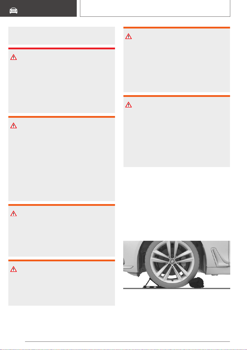
life. If the vehicle is raised, do not lie under the
vehicle and do not start the engine.
DANGER
Supports such as wooden blocks under the ve‐
hicle jack reduce the capacity of the vehicle
jack to bear weight. They have the potential to
exert too much strain on the vehicle jack, caus‐
ing it to tip over and the vehicle to fall. There is
a risk of injuries or danger to life. Do not place
supports under the vehicle jack.
WARNING
The jack, issued by the vehicle manufacturer, is
provided in order to perform a wheel change in
the event of a breakdown. The jack is not de‐
signed for frequent use; for example, changing
from summer to winter tires. Using the jack fre‐
quently may cause it to become jammed or
damaged. There is a risk of injury and risk of
damage to property. Only use the jack to attach
an emergency or spare wheel in the event of a
breakdown.
WARNING
On soft, uneven or slippery ground, for example
snow, ice, tiles, etc., the vehicle jack can slip
away. There is a risk of injury. If possible,
change the wheel on a flat, solid, and slip-re‐
sistant surface.
WARNING
The vehicle jack is optimized for lifting the vehi‐
cle and for the jacking points on the vehicle
only. There is a risk of injury. Do not lift any
other vehicle or cargo using the vehicle jack.
WARNING
If the vehicle jack is not inserted into the jacking
point provided for this purpose, the vehicle may
be damaged or the vehicle jack may slip when
it is being cranked up. There is a risk of injury or
risk of damage to property. When cranking up
the vehicle jack, ensure that it is inserted in the
jacking point next to the wheel housing.
WARNING
A vehicle that is raised on a vehicle jack may fall
off of the jack if lateral forces are exerted on it.
There is a risk of injury and risk of damage to
property. While the vehicle is raised, do not ex‐
ert lateral forces on the vehicle or pull abruptly
on the vehicle. Have a stuck wheel removed by
a dealer’s service center or another qualified
service center or repair shop.
Securing the vehicle against
rolling
General information
The vehicle manufacturer recommends to addi‐
tionally secure the vehicle against rolling away
when changing a wheel.
On a level surface
Place wheel chocks or other suitable objects in
front and behind the wheel that is diagonal to the
wheel to be changed.
Seite 320
MOBILITY
Wheels and tires
320
Online Edition for Part no. 01402896703 - X/18
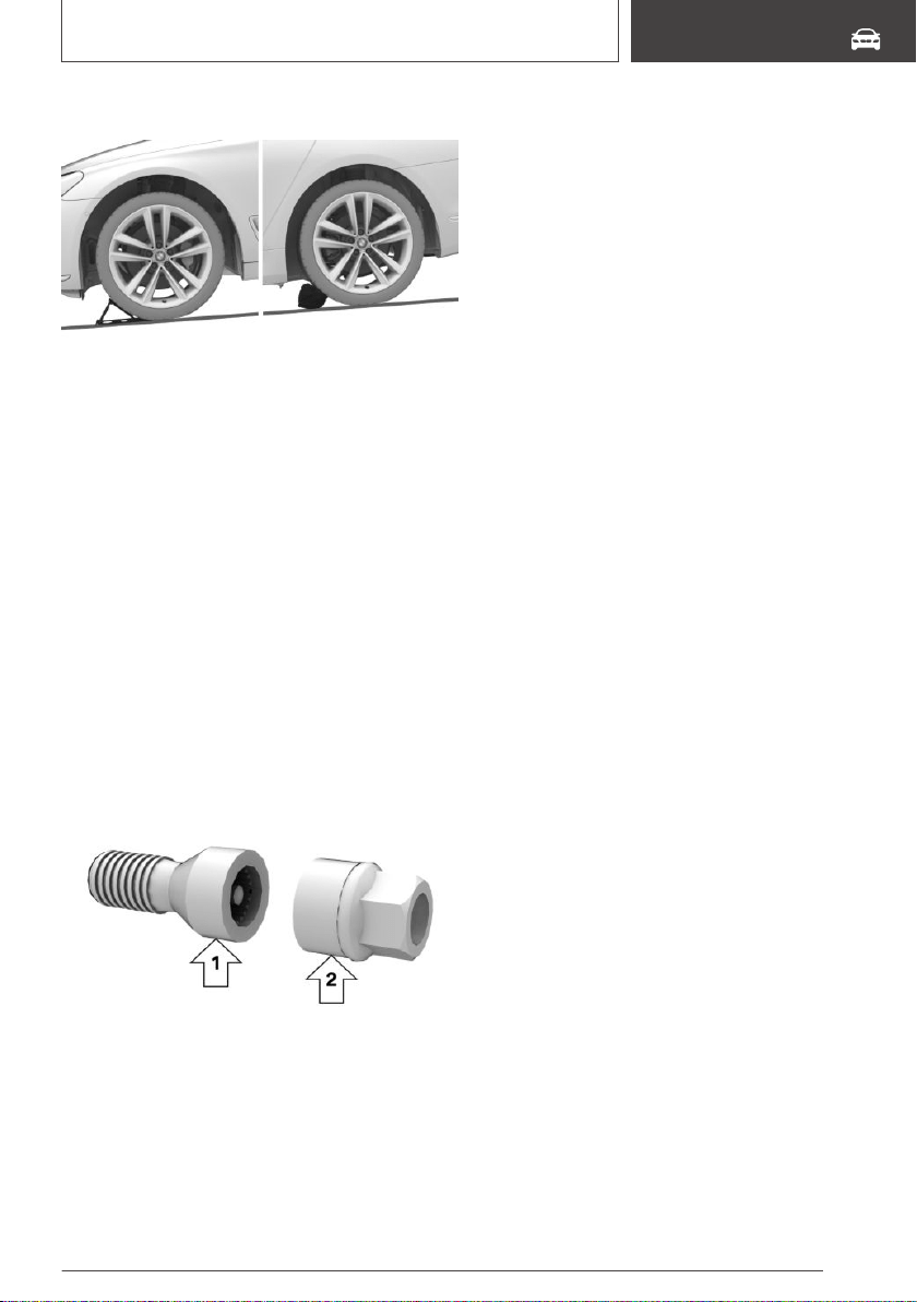
On a slight downhill gradient
If you need to change a wheel on a slight down‐
hill grade, place chocks and other suitable ob‐
jects, for instance a rock, under the wheels of
both the front and rear axles against the rolling
direction.
Lug bolt lock
Concept
The wheel lug bolts have a special coding. The
lug bolts can only be released with the adapter
which matches the coding.
Overview
The adapter of the lug bolt lock is in the onboard
vehicle tool kit or in a storage compartment close
to the onboard vehicle tool kit.
▷ Lug bolt, arrow 1.
▷ Adapter, arrow 2.
Unscrewing
1.
Attach the adapter to the lug bolt.
2. Unscrew the lug bolt.
3. Remove the adapter after unscrewing the lug
bolt.
Screwing on
1. Attach the adapter to the lug bolt. If neces‐
sary, turn the adapter until it fits on the lug
bolt.
2. Screw on the lug bolt. The tightening torque
is 140 Nm.
3. Remove the adapter and stow it after screw‐
ing on the lug bolt.
Preparing the vehicle
▷ Park the vehicle on solid and non-slip ground
at a safe distance from traffic.
▷ Switch on the hazard warning system.
▷ Set the parking brake.
▷ Engage a gear or move the selector lever to
position P.
▷ As soon as permitted by the traffic flow, have
all vehicle occupants get out of the vehicle
and ensure that they remain outside the im‐
mediate area in a safe place, such as behind a
guardrail.
▷ Depending on the vehicle equipment, get
wheel change tools and, if necessary, the
emergency wheel from the vehicle.
▷ If necessary, set up a warning triangle or port‐
able hazard warning light at an appropriate
distance.
▷ Secure the vehicle additionally against rolling.
▷ Loosen the lug bolts a half turn.
Seite 321
Wheels and tires
MOBILITY
321
Online Edition for Part no. 01402896703 - X/18
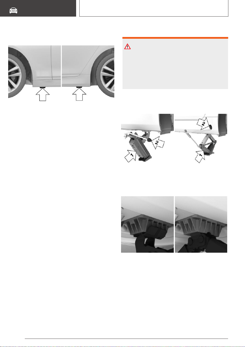
Jacking points for the vehicle
jack
The jacking points for the vehicle jack are lo‐
cated at the indicated positions.
Jacking up the vehicle
WARNING
Hands and fingers can be jammed when using
the vehicle jack. There is a risk of injury. Com‐
ply with the described hand position and do not
change this position while using the vehicle
jack.
1. Hold the vehicle jack with one hand, arrow 1,
and grasp the vehicle jack crank or lever with
your other hand, arrow 2.
2. Insert the vehicle jack into the rectangular re‐
cess of the jacking point closest to the wheel
to be changed.
Seite 322
MOBILITY
Wheels and tires
322
Online Edition for Part no. 01402896703 - X/18
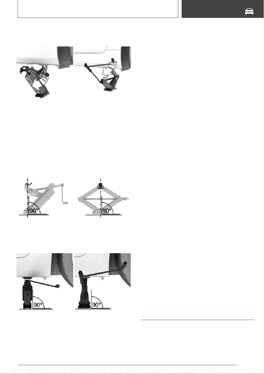
3. Extend the vehicle jack by turning the vehicle
jack crank or lever clockwise.
4. Take your hand away from the vehicle jack as
soon as the vehicle jack is under load and
continue turning the vehicle jack crank or
lever with one hand.
5. Make sure that the vehicle jack foot stands
vertically and at a right angle beneath the
jacking point.
6. Make sure that the vehicle jack foot stands
vertically and perpendicularly beneath the
jacking point after extending the vehicle jack.
7. Crank the vehicle up, until the vehicle jack is
with the entire surface on the ground and the
relevant wheel is maximum 1.2 inches/3 cm
above ground.
Mounting a wheel
Mount one emergency wheel only, as required.
1. Unscrew the lug bolts.
2. Remove the wheel.
3. Put the new wheel or emergency wheel on
and screw in at least two lug bolts in a cross‐
wise pattern until hand-tight.
If non-original light-alloy wheels of the vehicle
manufacturer are mounted, the accompany‐
ing lug bolts may have to be used as well.
4. Hand-tighten the remaining lug bolts and
tighten all lug bolts well in a crosswise pat‐
tern.
5. Turn the vehicle jack crank counterclockwise
to retract the vehicle jack and lower the vehi‐
cle.
6. Remove the vehicle jack and stow it securely.
After the wheel change
1.
Tighten the lug bolts crosswise. The tighten‐
ing torque is 101 lbs ft/140 Nm.
2. Stow the nonworking wheel in the cargo area,
if necessary.
The nonworking wheel cannot be stored un‐
der the cargo floor panel because of its size.
3. Check tire inflation pressure at the next op‐
portunity and correct as needed.
4. Reinitialize the run-flat tires.
Reset the Tire Pressure Monitor TPM.
5. Check to make sure the lug bolts are tight
with a calibrated torque wrench.
6. Have the damaged tire replaced at the near‐
est dealer’s service center or another quali‐
fied service center or repair shop.
Emergency wheel
Concept
In the event of a flat tire, the emergency wheel
can be used in place of the wheel with the defec‐
Seite 323
Wheels and tires
MOBILITY
323
Online Edition for Part no. 01402896703 - X/18
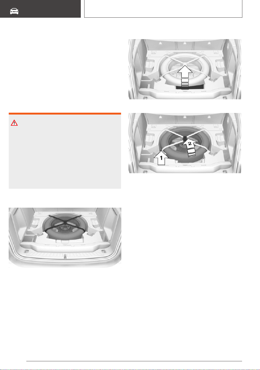
tive tire. The emergency wheel is only intended
for temporary use until the defective tire/wheel
has been replaced.
General information
Mount one emergency wheel only.
Also check the tire inflation pressure of the
emergency wheel in the cargo area regularly, and
correct it as needed.
Safety information
WARNING
The emergency wheel has particular dimen‐
sions. When driving with an emergency wheel,
changed driving properties may occur, for in‐
stance reduced lane stability when braking, lon‐
ger braking distance, and changed self-steering
properties in the limit area. There is a risk of an
accident. Drive moderately and do not exceed a
speed of 50 mph/80 km/h.
Overview
The emergency wheel and the wheel change
tools are located in the cargo area under the
cargo floor panel.
Removing the emergency wheel
1.
Fold the rear part of the cargo floor panel for‐
ward.
2. Lift the cargo floor panel up and attach it to
the folded-down multi-function hook.
3. Remove the cover.
4. Open the ratchet strap at the clasp, arrow 1.
5. Remove the emergency wheel from the stor‐
age well, arrow 2.
Inserting the emergency wheel
1.
Place the emergency wheel in the storage
well.
2. Tie the ratchet strap. Make sure that it is cor‐
rectly and firmly seated.
3. Install the cover.
4. Lift the cargo floor panel up slightly and fold
in the multi-function hook.
5. Lower the cargo floor panel and fold it toward
the rear.
Seite 324
MOBILITY
Wheels and tires
324
Online Edition for Part no. 01402896703 - X/18
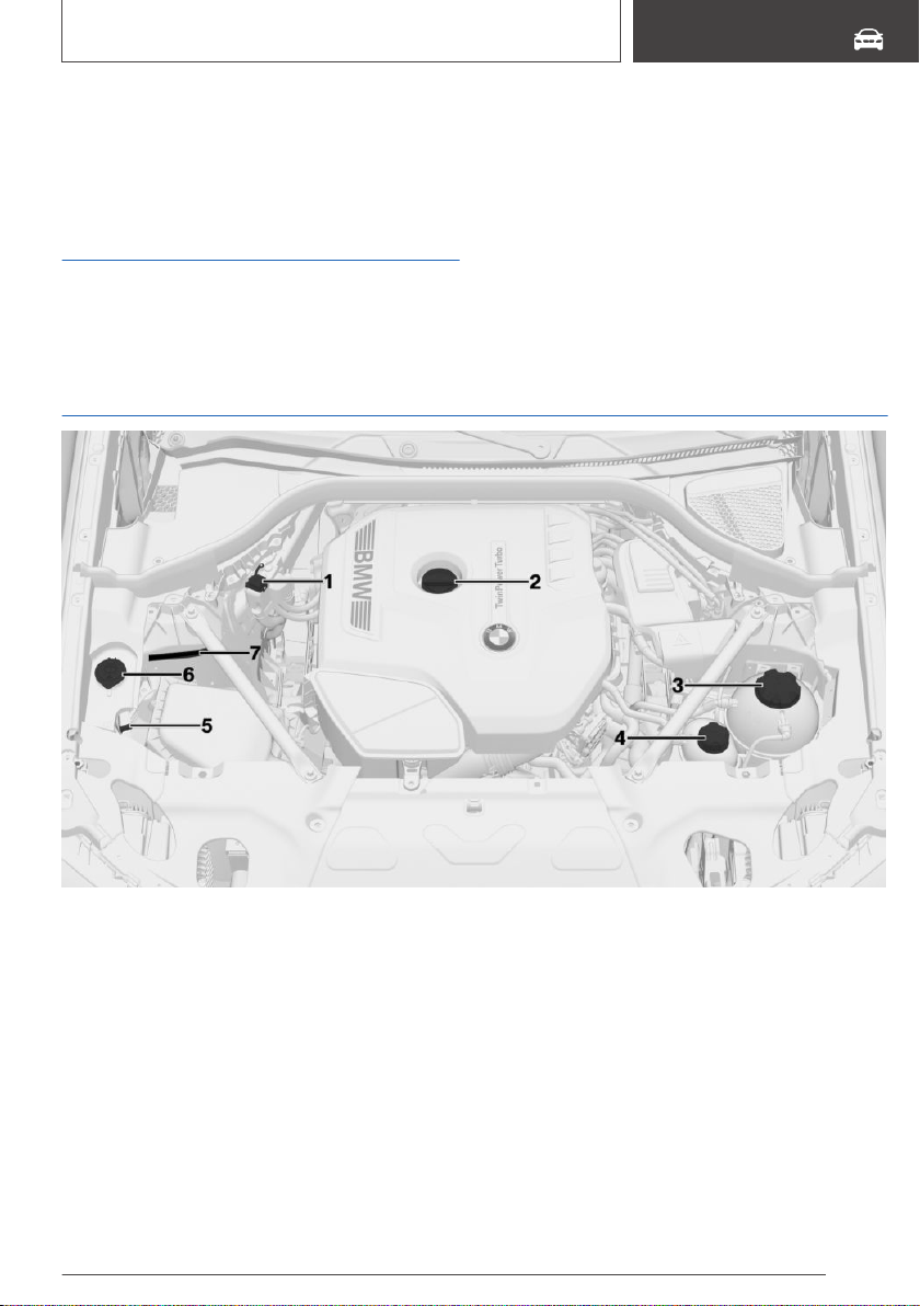
Engine compartment
Vehicle features and
options
This chapter describes all standard, country-spe‐
cific and optional features offered with the series.
It also describes features that are not necessarily
available in your vehicle, e. g., due to the selected
options or country versions. This also applies to
safety-related functions and systems. When us‐
ing these functions and systems, the applicable
laws and regulations must be observed.
Overview
1 Jump-starting, positive battery terminal
2 Oil filler neck
3 Coolant reservoir, engine
4 Coolant reservoir, auxiliary cooling
5 Jump-starting, negative battery terminal
6 Filler neck for washer fluid
7 Vehicle identification number
Seite 325
Engine compartment
MOBILITY
325
Online Edition for Part no. 01402896703 - X/18
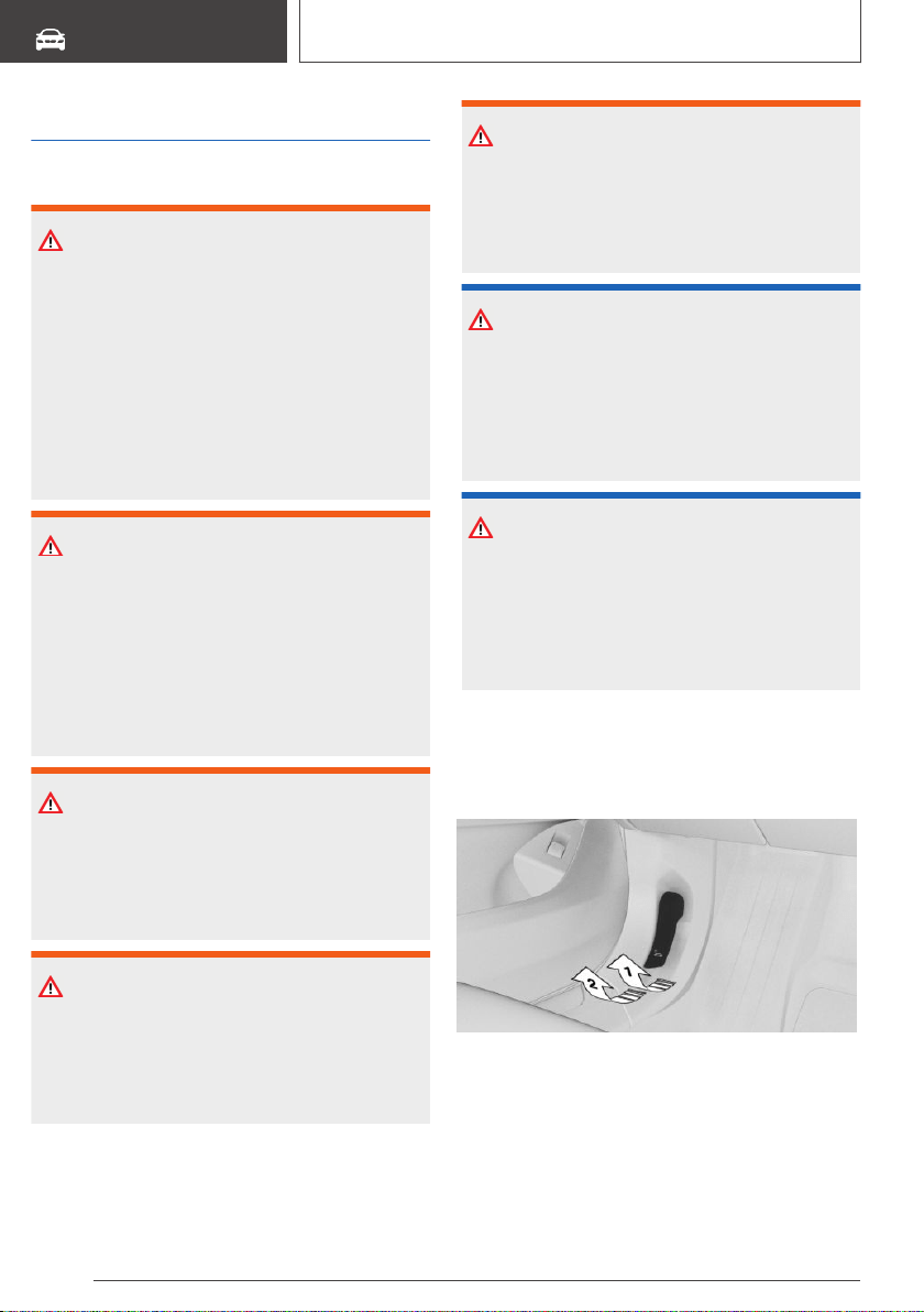
Hood
Safety information
WARNING
Improperly executed work in the engine com‐
partment can damage vehicle components and
impair vehicle functions. There is a risk of per‐
sonal and property damage. The manufacturer
of your vehicle recommends that, in the effort
to avoid such risks, work in the engine com‐
partment be performed by a dealer’s service
center or another qualified service center or re‐
pair shop.
WARNING
The engine compartment accommodates mov‐
ing components. Certain components in the
engine compartment can also move with the
vehicle switched off, for instance the radiator
fan. There is a risk of injury. Do not reach into
the area of moving parts. Keep articles of cloth‐
ing and hair away from moving parts.
WARNING
There are protruding parts, for instance locking
hook, on the inside of the hood. There is a risk
of injury. If the hood is open, pay attention to
protruding parts and keep clear of these areas.
WARNING
An incorrectly locked hood can open while driv‐
ing and restrict visibility. There is a risk of an ac‐
cident. Stop immediately and correctly close
the hood.
WARNING
Body parts can be jammed when opening and
closing the hood. There is a risk of injury. Make
sure that the area of movement of the hood is
clear during opening and closing.
NOTICE
Folded-away wipers can be jammed when the
hood is opened. There is a risk of damage to
property. Make sure that the wipers with the
wiper blades mounted are folded down onto
the windshield before opening the hood.
NOTICE
When the hood is closed, it must engage on
both sides. Pressing again can damage the
hood. There is a risk of damage to property.
Open the hood again and then close it energet‐
ically. Avoid pressing again.
Opening
1.
Pull lever, arrow 1.
Hood is unlocked.
2. After the lever is released, pull the lever again,
arrow 2.
Hood can be opened.
3. Be careful of protruding parts on the hood.
Seite 326
MOBILITY
Engine compartment
326
Online Edition for Part no. 01402896703 - X/18

Closing
Energetically close the hood from approx.
20 in/50 cm.
The hood must engage on both sides.
Seite 327
Engine compartment
MOBILITY
327
Online Edition for Part no. 01402896703 - X/18

Engine oil
Vehicle features and
options
This chapter describes all standard, country-spe‐
cific and optional features offered with the series.
It also describes features that are not necessarily
available in your vehicle, e. g., due to the selected
options or country versions. This also applies to
safety-related functions and systems. When us‐
ing these functions and systems, the applicable
laws and regulations must be observed.
General information
The engine oil consumption is dependent on
your driving style and driving conditions.
Therefore, regularly check the engine oil level af‐
ter refueling by taking a detailed measurement.
The engine oil consumption can increase in the
following situations, for example:
▷ Sporty driving style.
▷ Break-in of the engine.
▷ Idling of the engine.
▷ With use of engine oil types that are classified
as not suitable.
Different Check Control messages appear on the
Control Display depending on the engine oil
level.
Safety information
NOTICE
An engine oil level that is too low causes en‐
gine damage. There is a risk of damage to
property. Immediately add engine oil.
NOTICE
Too much engine oil can damage the engine or
the catalytic converter. There is a risk of dam‐
age to property. Do not add too much engine
oil. When too much engine oil is added, have
the engine oil level corrected by a dealer’s serv‐
ice center or another qualified service center or
repair shop.
Electronic oil measurement
General information
The electronic oil measurement has two measur‐
ing principles:
▷ Monitoring.
▷ Detailed measurement.
When making frequent short-distance trips or
using a dynamic driving style, for instance when
taking curves aggressively, regularly perform a
detailed measurement.
Monitoring
Concept
The engine oil level is monitored electronically
while driving and can be shown on the Control
Display.
If the engine oil level is outside its permissible
operating range, a Check Control message is
displayed.
A red indicator light indicates that the en‐
gine oil pressure is too low.
Functional requirements
A current measured value is available after ap‐
prox. 30 minutes of normal driving.
Seite 328
MOBILITY
Engine oil
328
Online Edition for Part no. 01402896703 - X/18
Displaying the engine oil level
Via iDrive:
1. "My Vehicle"
2. "Vehicle status"
3. "Engine oil level"
The engine oil level is displayed.
System limits
When making frequent short-distance trips or
using a dynamic driving style, it may not be pos‐
sible to calculate a measured value. In this case,
the measured value for the last, sufficiently long
trip is displayed.
Detailed measurement
Concept
The engine oil level is checked when the vehicle
is stationary and displayed via a scale.
If the engine oil level is outside its permissible
operating range, a Check Control message is
displayed.
General information
During the measurement, the idle speed is in‐
creased somewhat.
Functional requirements
▷ Vehicle is parked in a horizontal position.
▷ Steptronic transmission: selector lever in se‐
lector lever position N or P and accelerator
pedal not depressed.
▷ Engine is running and is at operating temper‐
ature.
Performing a detailed measurement
Via iDrive:
1.
"My Vehicle"
2. "Vehicle status"
3. "Engine oil level"
4. "Measure engine oil level"
5. "Start measurement"
The engine oil level is checked and displayed via
a scale.
Adding engine oil
General information
Only add engine oil when the message is dis‐
played in the instrument cluster. The quantity to
be added is indicated in the message shown on
the Control Display.
Only add suitable types of engine oil, refer to
page 330.
Safely park the vehicle and switch off drive-ready
state before adding engine oil.
Take care not to add too much engine oil.
Safety information
WARNING
Operating materials, for instance oils, greases,
coolants, fuels, can contain harmful ingredients.
There is a risk of injuries or danger to life. Fol‐
low the instructions on the containers. Avoid
the contact of articles of clothing, skin or eyes
with operating materials. Do not refill operating
materials into different bottles. Store operating
materials out of reach of children.
NOTICE
An engine oil level that is too low causes en‐
gine damage. There is a risk of damage to
property. Immediately add engine oil.
Seite 329
Engine oil
MOBILITY
329
Online Edition for Part no. 01402896703 - X/18
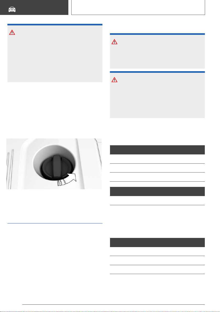
NOTICE
Too much engine oil can damage the engine or
the catalytic converter. There is a risk of dam‐
age to property. Do not add too much engine
oil. When too much engine oil is added, have
the engine oil level corrected by a dealer’s serv‐
ice center or another qualified service center or
repair shop.
Overview
The oil filler neck is located in the engine com‐
partment, refer to page 325.
Adding engine oil
1.
Open the hood, refer to page 326.
2. Open the lid counterclockwise.
3. Add engine oil.
4. Close the cap.
Engine oil types to add
General information
The engine oil quality is critical for the life of the
engine.
Only add the types of engine oil which are listed.
Safety information
NOTICE
Oil additives can damage the engine. There is a
risk of damage to property. Do not use oil addi‐
tives.
NOTICE
Incorrect engine oil can cause malfunctions in
the engine or damage it. There is a risk of dam‐
age to property. When selecting an engine oil,
make sure that the engine oil has the correct oil
rating.
Suitable engine oil types
Add engine oils that meet the following oil rating
standards:
Gasoline engine
BMW Longlife-01 FE.
BMW Longlife-14 FE+.
BMW Longlife-17 FE+.
Diesel engine
BMW Longlife-12 FE.
Alternative engine oil types
If an engine oil suitable for continuous use is not
available, up to 1 US quart/liter of an engine oil
with the following oil rating can be added:
Oil rating
API SL.
API SM.
API SN.
Seite 330
MOBILITY
Engine oil
330
Online Edition for Part no. 01402896703 - X/18
Viscosity grades
Viscosity grades
SAE 0W-20.
SAE 0W-30.
Viscosity grade SAE 0W-20 is not suitable for
diesel engines.
More information about suitable oil ratings and
viscosity grades of engine oils can be requested
from a dealer’s service center or another quali‐
fied service center or repair shop.
Engine oil change
NOTICE
Engine oil that is not changed in timely fashion
can cause increased engine wear and thus en‐
gine damage. There is a risk of damage to
property. Do not exceed the service data indi‐
cated in the vehicle.
The vehicle manufacturer recommends that you
have a dealer’s service center or another quali‐
fied service center or repair shop change the en‐
gine oil.
Seite 331
Engine oil
MOBILITY
331
Online Edition for Part no. 01402896703 - X/18
Coolant
Vehicle features and
options
This chapter describes all standard, country-spe‐
cific and optional features offered with the series.
It also describes features that are not necessarily
available in your vehicle, e. g., due to the selected
options or country versions. This also applies to
safety-related functions and systems. When us‐
ing these functions and systems, the applicable
laws and regulations must be observed.
General information
Coolant consists of water and additives.
Not all commercially available additives are suita‐
ble for the vehicle. Information about suitable ad‐
ditives is available from a dealer’s service center
or another qualified service center or repair shop.
Safety information
WARNING
With the engine hot and the cooling system
open, coolant can escape and lead to scalding.
There is a risk of injury. Only open the cooling
system with the engine cooled down.
WARNING
Additives are harmful and incorrect additives
can damage the engine. There is a risk of injury
and risk of damage to property. Do not allow
additives to come into contact with skin, eyes
or articles of clothing. Use suitable additives
only.
Coolant level
General information
Vehicles with gasoline engine feature two cool‐
ing circuits. Always check the coolant levels of
both coolant reservoirs and refill as needed.
The coolant level is indicted using minimum and
maximum markings. Depending on the coolant
reservoir, the minimum and maximum markings
are located at different locations.
Depending on the engine installation, the coolant
reservoir is located on the right side or the left
side of the engine compartment, refer to
page 325.
Checking the coolant level on the
side markings
1.
Let the engine cool.
2. Open the hood, refer to page 326.
3. The coolant level is correct if it lies between
the minimum and maximum marks on the
coolant reservoir.
Symbol Meaning
Maximum.
Minimum.
Checking the coolant level in the
filler neck
1.
Let the engine cool.
2. Open the hood, refer to page 326.
3. Turn the lid of the coolant reservoir slightly
counterclockwise to allow any excess pres‐
sure to dissipate, then open it.
4. Open the coolant reservoir lid.
Seite 332
MOBILITY
Coolant
332
Online Edition for Part no. 01402896703 - X/18
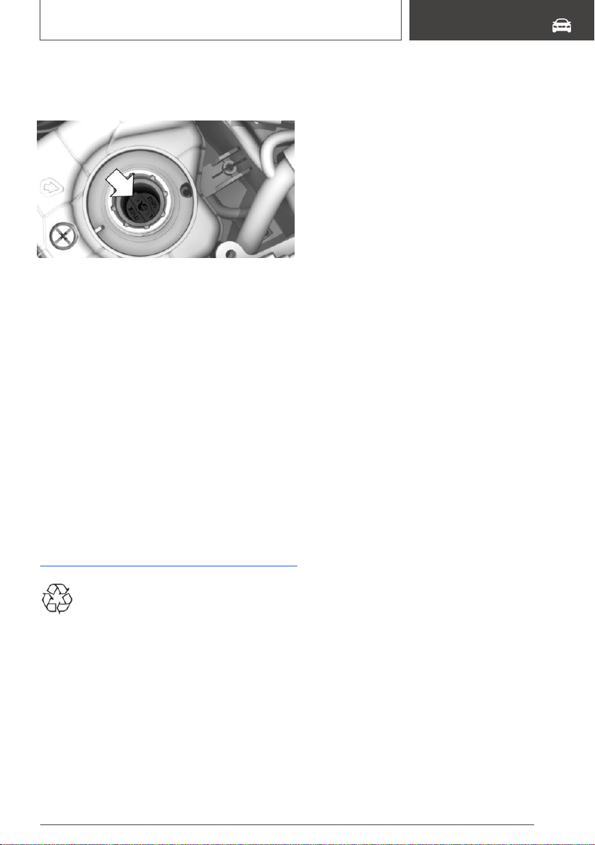
5. The coolant level is correct if it lies between
the minimum and maximum marks in the filler
neck.
6. Close the cap.
Adding
1.
Let the engine cool.
2. Open the hood, refer to page 326.
3. Turn the lid of the coolant reservoir slightly
counterclockwise to allow any excess pres‐
sure to dissipate, then open it.
4. Open the coolant reservoir lid.
5. If the coolant is low, slowly add coolant up to
the specified level; do not overfill.
6. Close the cap.
7. Have the cause of the coolant loss eliminated
as soon as possible.
Disposal
Comply with the relevant environmental
protection regulations when disposing of
coolant and coolant additives.
Seite 333
Coolant
MOBILITY
333
Online Edition for Part no. 01402896703 - X/18

Maintenance
Vehicle features and
options
This chapter describes all standard, country-spe‐
cific and optional features offered with the series.
It also describes features that are not necessarily
available in your vehicle, e. g., due to the selected
options or country versions. This also applies to
safety-related functions and systems. When us‐
ing these functions and systems, the applicable
laws and regulations must be observed.
BMW maintenance system
The maintenance system indicates required
maintenance measures, and thereby provides
support in maintaining road safety and the opera‐
tional reliability of the vehicle.
In some cases, scopes and intervals of the main‐
tenance system may vary according to the coun‐
try version. Replacement work, spare parts, fuels
and lubricants, and wear materials are calculated
separately. Further information is available from a
dealer’s service center or another qualified serv‐
ice center or repair shop.
Condition Based Service
CBS
Concept
Sensors and special algorithms take into account
the driving conditions of the vehicle. CBS uses
these to calculate the need for maintenance.
The system makes it possible to adapt the
amount of maintenance corresponding to your
user profile.
General information
Information on service requirements, refer to
page 146, can be displayed on the Control Dis‐
play.
Service data in the remote
control
Information on the required maintenance is con‐
tinuously stored in the remote control. The deal‐
er’s service center can read this data out and
suggest a maintenance scope for the vehicle.
Therefore, hand the service advisor the remote
control with which the vehicle was driven most
recently.
Storage periods
Storage periods during which the vehicle battery
was disconnected are not taken into account.
If this occurs, have a dealer's service center or
another qualified service center or repair shop
update the time-dependent maintenance proce‐
dures, such as checking brake fluid and, if neces‐
sary, changing the engine oil and the microfilter/
activated-charcoal filter.
Service and Warranty
Information Booklet for US
models and Warranty and
Service Guide Booklet for
Canadian models
Please consult your Service and Warranty Infor‐
mation Booklet for US models and Warranty and
Service Guide Booklet for Canadian models for
additional information on service requirements.
The manufacturer of your vehicle recommends
that maintenance and repair be performed by a
dealer’s service center or another qualified serv‐
Seite 334
MOBILITY
Maintenance
334
Online Edition for Part no. 01402896703 - X/18
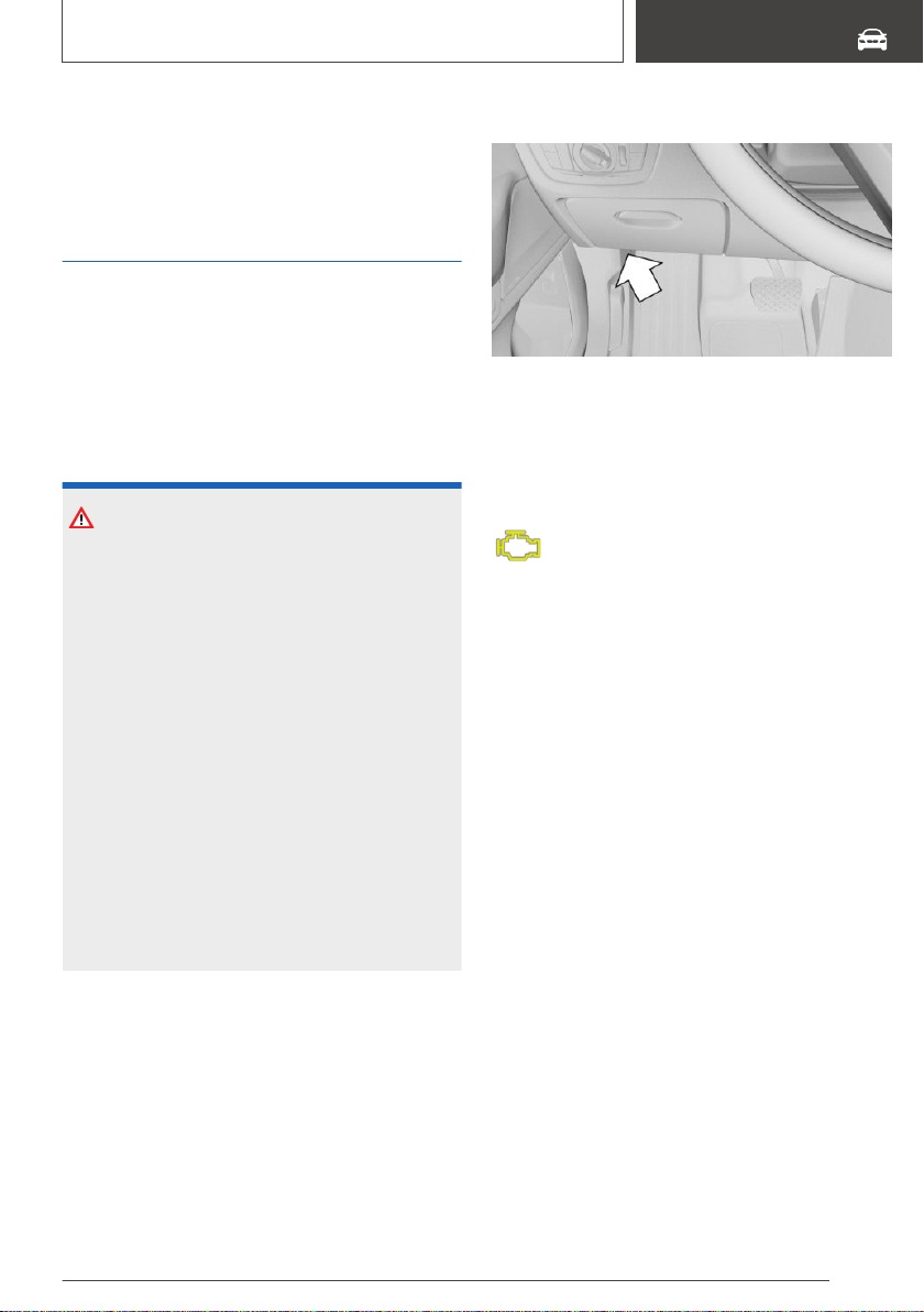
ice center or repair shop. Records of regular
maintenance and repair work should be retained.
Socket for OBD Onboard
Diagnosis
General information
Devices connected to the OBD socket trigger
the alarm system when the vehicle is locked. Re‐
move any devices connected at the OBD socket
before locking the vehicle.
Safety information
NOTICE
The socket for Onboard Diagnosis is an intri‐
cate component intended to be used in con‐
junction with specialized equipment to check
the vehicle’s primary emissions system. Im‐
proper use of the socket for Onboard Diagno‐
sis, or contact with the socket for Onboard Di‐
agnosis for other than its intended purpose,
can cause vehicle malfunctions and creates
risks of personal and property damage. Given
the foregoing, the manufacture of your vehicle
strongly recommends that access to the socket
for Onboard Diagnosis be limited to a dealer's
service center or another qualified service cen‐
ter or repair shop or other persons that have
the specialized training and equipment for pur‐
poses of properly utilizing the socket for On‐
board Diagnosis.
Position
There is an OBD socket on the driver's side for
checking the primary components in the vehi‐
cle's emissions.
Emissions
▷ The warning light lights up:
Emissions are deteriorating. Have the
vehicle checked as soon as possible.
▷ The warning light flashes under certain cir‐
cumstances:
This indicates that there is excessive misfiring
in the engine.
Reduce the vehicle speed and have the sys‐
tem checked immediately; otherwise, serious
engine misfiring within a brief period can seri‐
ously damage emission control components,
in particular the catalytic converter.
Seite 335
Maintenance
MOBILITY
335
Online Edition for Part no. 01402896703 - X/18
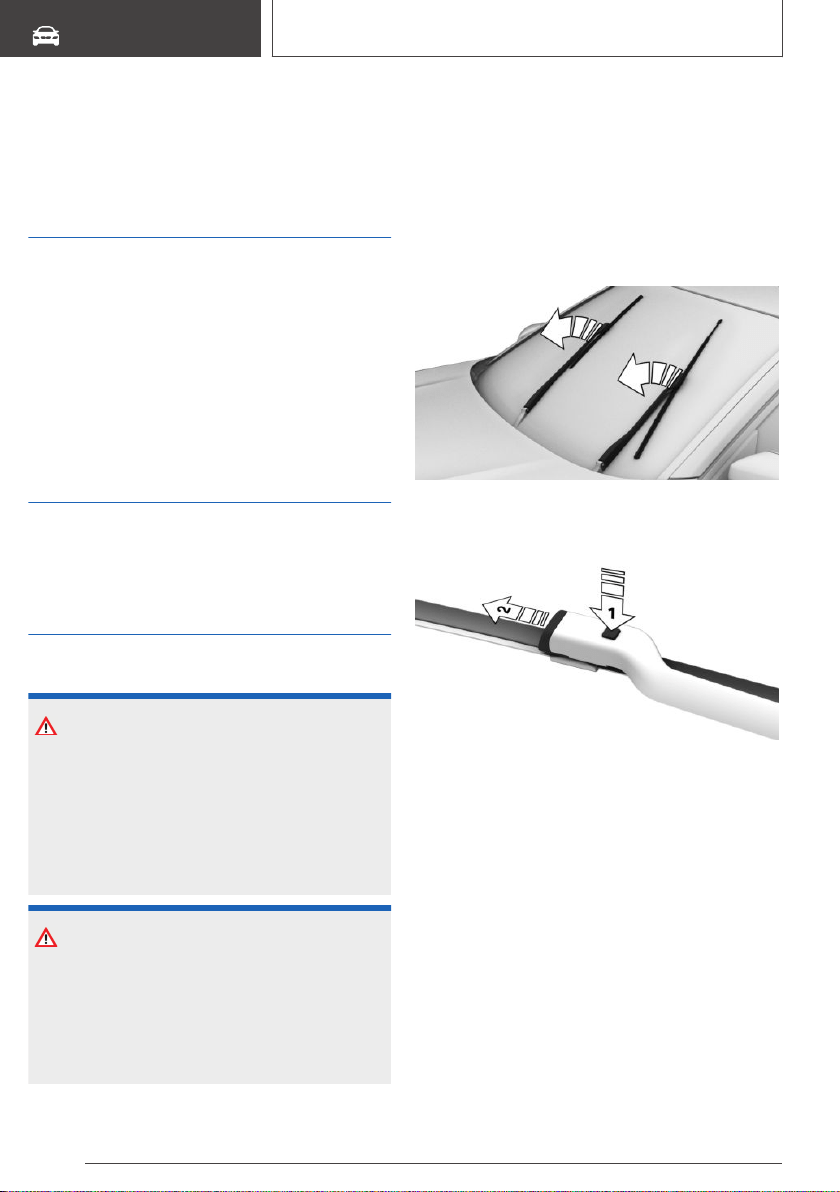
Replacing components
Vehicle features and
options
This chapter describes all standard, country-spe‐
cific and optional features offered with the series.
It also describes features that are not necessarily
available in your vehicle, e. g., due to the selected
options or country versions. This also applies to
safety-related functions and systems. When us‐
ing these functions and systems, the applicable
laws and regulations must be observed.
Onboard vehicle tool kit
The onboard vehicle tool kit is located under the
cargo floor panel.
Wiper blades
Safety information
NOTICE
The window may sustain damage if the wiper
falls onto it without the wiper blade installed.
There is a risk of damage to property. Hold the
wiper firmly when changing the wiper blade. Do
not fold or switch on the wiper without a wiper
blade installed.
NOTICE
Folded-away wipers can be jammed when the
hood is opened. There is a risk of damage to
property. Make sure that the wipers with the
wiper blades mounted are folded down onto
the windshield before opening the hood.
Replacing the front wiper blades
1. To change the wiper blades, fold up the wiper
arms, refer to page 130.
2. Lift the wiper all the way off of the windshield.
3. Press the button, arrow 1, and pull out the
wiper blade, arrow 2.
4. Insert the new wiper blade and press it on un‐
til it you hear it snap into the holder.
5. Fold down the wipers.
Seite 336
MOBILITY
Replacing components
336
Online Edition for Part no. 01402896703 - X/18
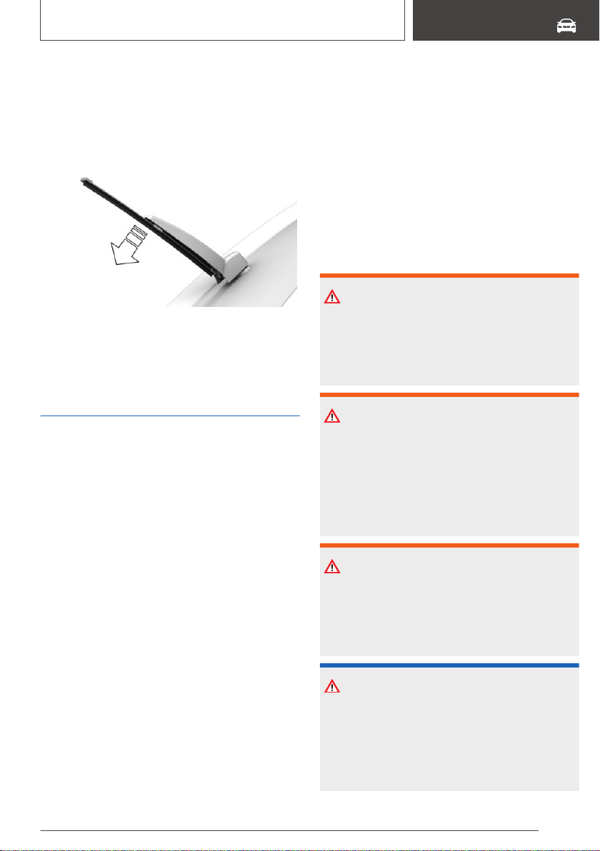
Replacing the rear wiper blade
The wiper blade is engaged at the end of the
wiper arm.
1. Lift off the wiper fully and pull off the wiper
blade, arrow.
2. Attach a new wiper blade. The wiper blade
must engage audibly.
3. Fold down the wipers.
Lights and bulbs
General information
Lights and bulbs
Lights and bulbs make an essential contribution
to vehicle safety.
Some items of equipment use light-emitting di‐
odes installed behind a cover as a light source.
These light-emitting diodes are related to con‐
ventional lasers and are officially designated as
Class 1 light-emitting diodes.
The manufacturer of the vehicle recommends
that you let a dealer’s service center or another
qualified service center or repair shop perform
the work in case of a malfunction.
A spare light box is available from a dealer’s serv‐
ice center or another qualified service center or
repair shop.
Follow the safety information, refer to page 337.
Headlight glass
Condensation can form on the inside of the
headlight glass in cool or humid weather. When
driving with the lights switched on, the conden‐
sation evaporates after a short time. The head‐
light glass does not need to be changed.
If despite driving with the headlights switched on,
increasing humidity forms, for instance water
droplets in the light, have the headlights
checked.
Safety information
WARNING
Bulbs can get hot during operation. Contact
with the bulbs can cause burns. There is a risk
of injury. Only change bulbs after they have
cooled off.
WARNING
Work on switched-on lighting systems can
cause short circuits. There is a risk of injury or
risk of damage to property. When working on
the lighting system, switch off the lights in
question. If necessary, heed the bulb manufac‐
turer's instructions.
WARNING
Intensive brightness can irritate or damage the
retina of the eye. There is a risk of injury. Do not
look directly into the headlights or other light
sources. Do not remove the LED covers.
NOTICE
Dirty bulbs have a reduced service life. There is
a risk of damage to property. Do not hold new
bulbs with your bare hands. Use a clean cloth
or something similar, or hold the bulb by its
base.
Seite 337
Replacing components
MOBILITY
337
Online Edition for Part no. 01402896703 - X/18
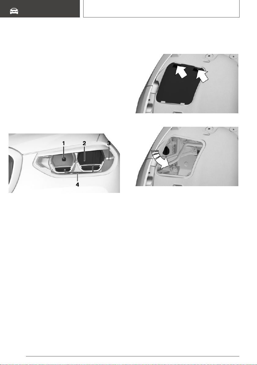
Front lights
LED headlights
General information
Follow the safety information, refer to page 337.
The low-beam headlights, side lights, and day‐
time running lights and the turn signals in the ex‐
terior mirror feature LED technology.
In the case of a malfunction, contact a dealer’s
service center or another qualified service center
or repair shop.
Overview
1 High beams/headlight flasher
2 Low beams
3 Turn signal
4 Daytime running lights/parking lights
Turn signal, bulb replacement
General information
Follow the safety information, refer to page 337.
24-watt bulb, PY24W
Replacing a bulb
1. In the wheel house, press the two retainer
tabs and fold down the cover.
2. Unscrew and remove the bulb holder.
3. Press the bulb gently into the bulb holder,
turn counterclockwise and remove it.
4. Insert the new bulb.
5. Mount the bulb holder.
6. Mount the lid.
High beams, bulb replacement
General information
Follow the safety information, refer to page 337.
55-watt bulb, H7.
Seite 338
MOBILITY
Replacing components
338
Online Edition for Part no. 01402896703 - X/18
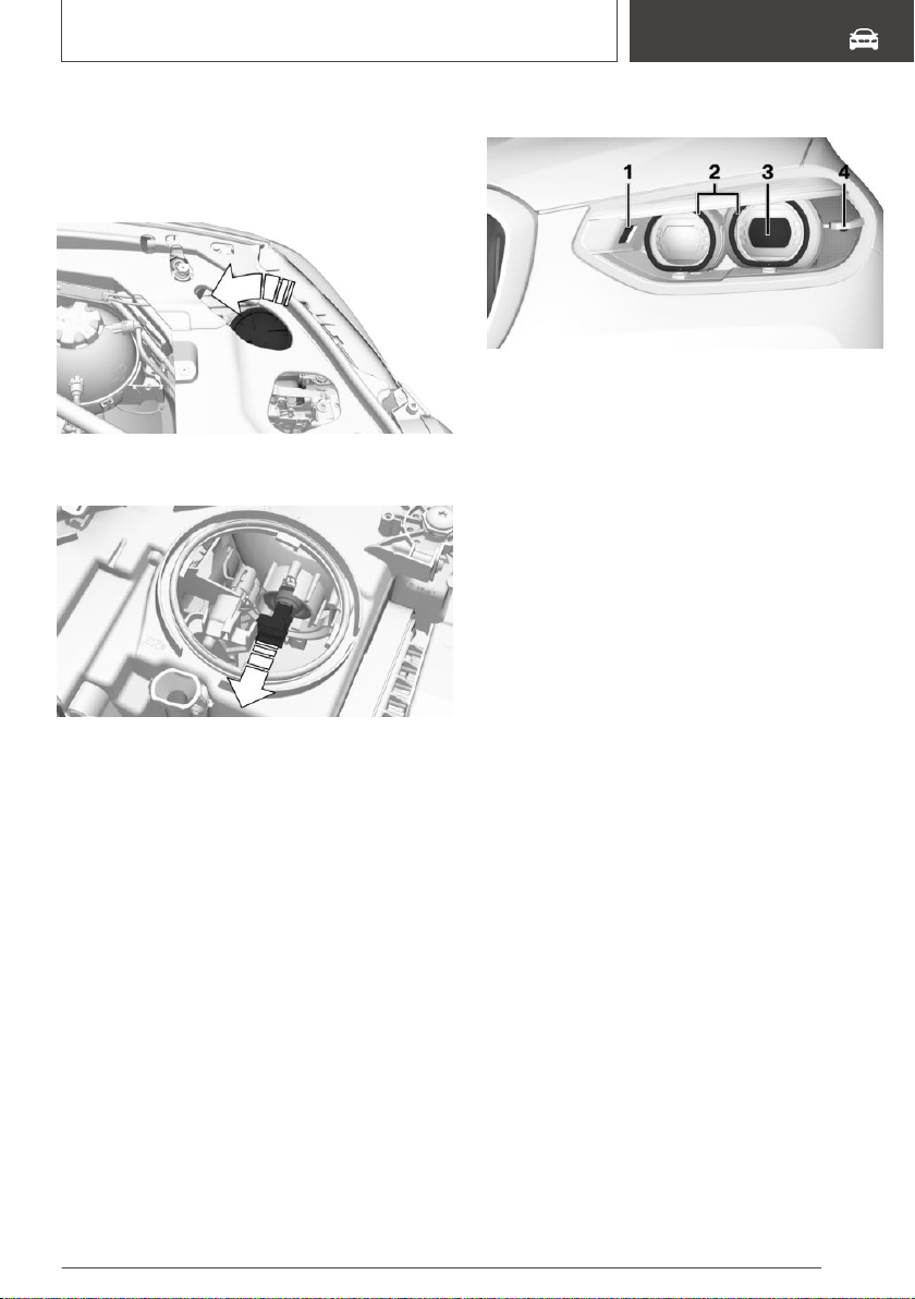
Replacing a bulb
1. Open the hood, refer to page 326.
2. Unscrew the lid counterclockwise and re‐
move it.
3. Pull the bulb holder out past the spring resist‐
ance point.
4. Pull off the bulb.
5. Insert the new bulb and attach the cover in
the reverse order.
Make sure that the connector is correctly
seated.
LED headlights with enhanced
features
General information
Follow the safety information, refer to page 337.
All front lights are designed with LED technol‐
ogy, with the exception of the two turn signals.
In the case of a malfunction, contact a dealer’s
service center or another qualified service center
or repair shop.
Overview
1 Cornering light
2 Daytime running lights/parking lights
3 Low beams/high beams
4 Turn signal
Turn signal, bulb replacement
General information
Follow the safety information, refer to page 337.
24-watt bulb, PY24W
Seite 339
Replacing components
MOBILITY
339
Online Edition for Part no. 01402896703 - X/18
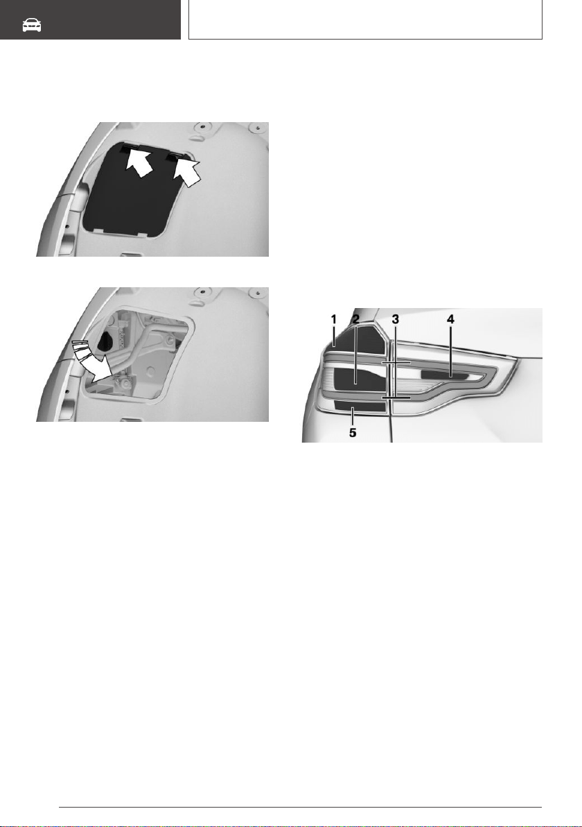
Replacing a bulb
1. In the wheel house, press the two retainer
tabs and fold down the cover.
2. Unscrew and remove the bulb holder.
3. Press the bulb gently into the bulb holder,
turn counterclockwise and remove it.
4. Insert the new bulb.
5. Mount the bulb holder.
6. Mount the lid.
Adaptive LED headlights
Follow the safety information, refer to page 337.
All lights feature LED technology.
In the case of a malfunction, contact a dealer’s
service center or another qualified service center
or repair shop.
LED front fog lights
Follow the safety information, refer to page 337.
LED front fog lights are made using LED tech‐
nology.
In the case of a malfunction, contact a dealer’s
service center or another qualified service center
or repair shop.
Tail lights
General information
Follow the safety information, refer to page 337.
With LED headlights or LED headlights with en‐
hanced features: the rear light features LED
technology.
With Adaptive LED headlights: all tail lights fea‐
ture LED technology.
In the case of a malfunction, contact a dealer’s
service center or another qualified service center
or repair shop.
Overview
1 Brake light
2 Turn signal
3 Tail lights
4 Reversing lights
5 Lower brake lights
Exterior tail lights, bulb replacement
General information
Follow the safety information, refer to page 337.
Brake lights, turn signal: 21-watt bulb, P21W.
Lower brake lights: 21 W bulb, H21W.
Seite 340
MOBILITY
Replacing components
340
Online Edition for Part no. 01402896703 - X/18
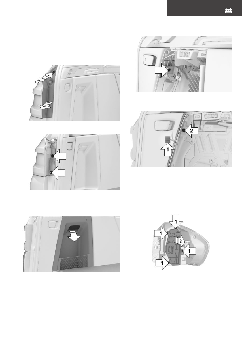
Removing the exterior tail light
1. Open the tailgate.
2. Use the screwdriver from the onboard vehicle
tool kit to loosen the clip, arrow 1, and re‐
move the cover, arrow 2.
3. Release both nuts.
4. Open the cover on the side trim in the cargo
area, arrow, and remove the warning triangle,
refer to page 344.
5. Loosen the screw and remove the holder.
6. Remove the connector, arrow 1, and loosen
the screw, arrow 2.
7. Detach the tail light from the body.
Replacing the bulbs
1.
Loosen the four fasteners on the bulb holder,
arrow 1, and detach the bulb holder from the
tail light, arrow 2.
2. Press the bulb gently into the bulb holder,
turn counterclockwise and remove it.
3. Proceed in the reverse order to insert the
new bulb and attach the bulb holder. Make
sure that the bulb holder is engaged in all fas‐
teners.
Seite 341
Replacing components
MOBILITY
341
Online Edition for Part no. 01402896703 - X/18
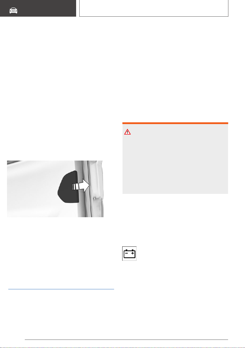
Installing the tail light
1. Install the tail light in reverse order of removal
and attach the connector.
2. Install the holder for the warning triangle and
attach the warning triangle.
3. Close the cover on the side trim in the cargo
area.
4. Fasten the cover with the clip.
Reversing light in the tailgate
General information
Follow the safety information, refer to page 337.
21-watt bulb, H21W.
Access to the light
1.
Open the tailgate.
2. Pull out the cover at the recessed grip, arrow.
Replacing a bulb
1.
Pull the bulb holder out of the reflector.
2. Press the bulb gently into the bulb holder,
turn counterclockwise and remove it.
3. To insert the new bulb and attach the bulb
holder, proceed in reverse order of removal.
Vehicle battery
General information
The battery is maintenance-free.
More information about the battery can be re‐
quested from a dealer’s service center or another
qualified service center or repair shop.
The manufacturer of your vehicle recommends
that you have a dealer’s service center or another
qualified service center or repair shop register
the vehicle battery to the vehicle after the battery
has been replaced. Once the battery has been
registered again, all comfort features will be avail‐
able without restriction and any Check Control
messages displayed which relate to comfort fea‐
tures will disappear.
Safety information
WARNING
Vehicle batteries that are not compatible can
damage vehicle systems and impair vehicle
functions. There is a risk of personal and prop‐
erty damage. Only vehicle batteries that are
compatible with your vehicle type should be in‐
stalled in your vehicle. Information on compati‐
ble vehicle batteries is available at your dealer’s
service center.
Charging the battery
General information
Make sure that the battery is always sufficiently
charged to guarantee that the battery remains
usable for its full service life.
A discharged battery is indicated by a red
indicator light.
The battery may need to be charged in the fol‐
lowing cases:
▷ When making frequent short-distance drives.
▷ If the vehicle is not used for more than a
month.
Seite 342
MOBILITY
Replacing components
342
Online Edition for Part no. 01402896703 - X/18
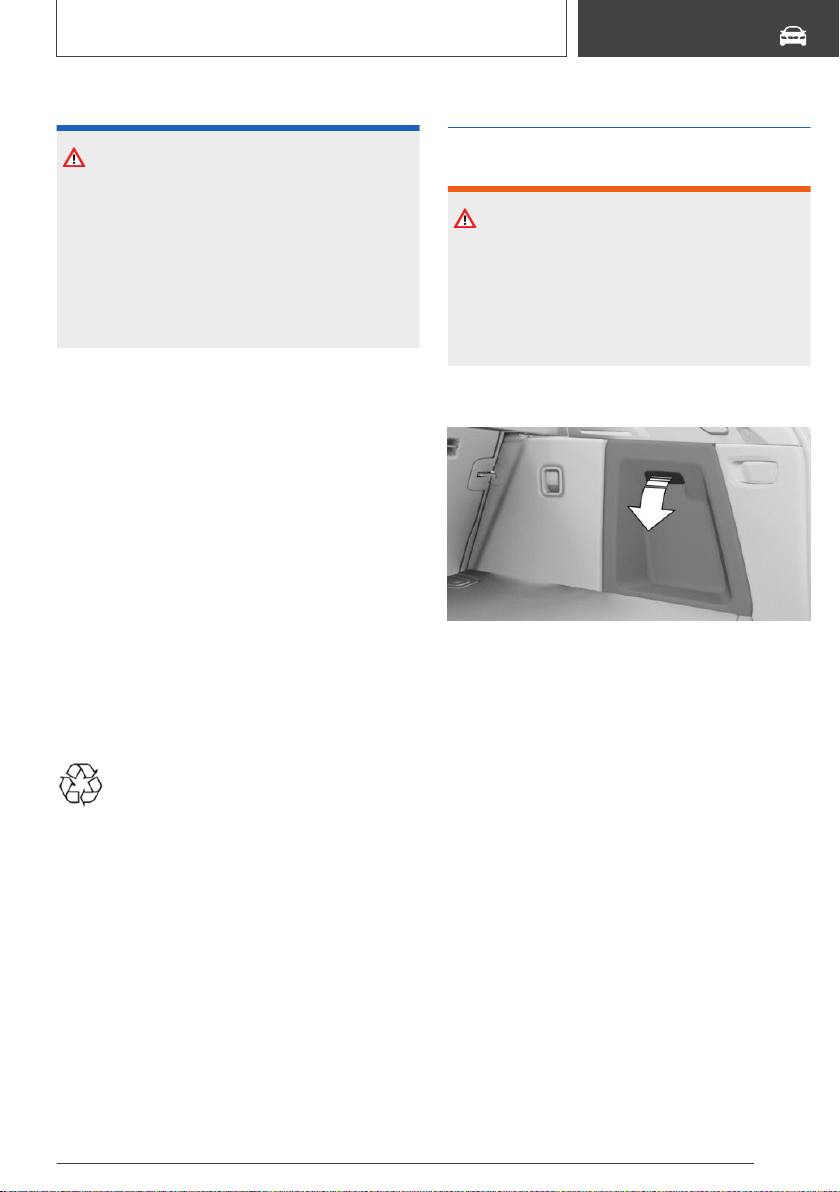
Safety information
NOTICE
Battery chargers for the vehicle battery can
work with high voltages and currents, which
means that the 12 volt on-board network can
be overloaded or damaged. There is a risk of
damage to property. Only connect battery
chargers for the vehicle battery to the starting
aid terminals in the engine compartment.
Starting aid terminals
In the vehicle, only charge the battery via the
starting aid terminals, refer to page 348, in the
engine compartment with the engine off.
Power failure
After a power loss, some equipment needs to be
newly initialized or individual settings updated, for
example:
▷ Memory function: store the positions again.
▷ Time: update.
▷ Date: update.
▷ Glass sunroof: initialize the system.
Disposing of old batteries
Have old batteries disposed of by a deal‐
er’s service center or another qualified
service center or repair shop or take
them to a collection point.
Maintain the battery in an upright position for
transport and storage. Secure the battery so that
it does not tip over during transport.
Fuses
Safety information
WARNING
Incorrect and repaired fuses can overload elec‐
trical lines and components. There is a risk of
fire. Never attempt to repair a blown fuse. Do
not replace a nonworking fuse with a substitute
of another color or amperage rating.
Accessing the fuses
Open the cover on the right side trim.
The fuse box is located behind the sound insula‐
tion.
Information on the fuse types and locations, as
well as the positions of any other fuse boxes, is
found on a separate sheet in the fuse box.
Replacing fuses
The vehicle manufacturer recommends that you
have a dealer's service center or another quali‐
fied service center or repair shop replace the
fuses.
Seite 343
Replacing components
MOBILITY
343
Online Edition for Part no. 01402896703 - X/18
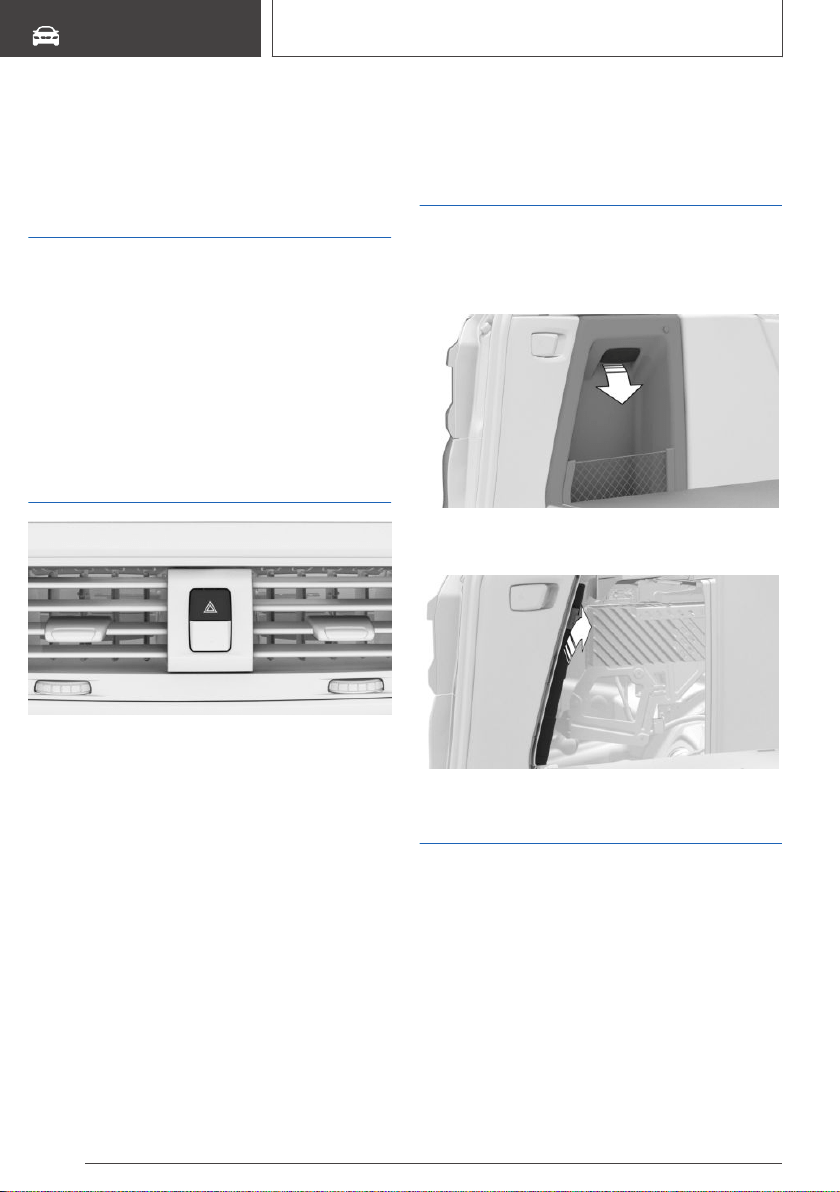
Breakdown assistance
Vehicle features and
options
This chapter describes all standard, country-spe‐
cific and optional features offered with the series.
It also describes features that are not necessarily
available in your vehicle, e. g., due to the selected
options or country versions. This also applies to
safety-related functions and systems. When us‐
ing these functions and systems, the applicable
laws and regulations must be observed.
Hazard warning flashers
The button is located in the center console.
The red light in the button flashes when the haz‐
ard warning flashers are activated.
Warning triangle
The warning triangle is located behind the left-
hand cover in the cargo area.
1. Open the cover on the left side trim.
2. Open the bracket and take the warning trian‐
gle out in the direction of the car's interior.
First-aid kit
General information
Some of the articles have a limited service life.
Check the expiration dates of the contents regu‐
larly and replace any expired items promptly.
Seite 344
MOBILITY
Breakdown assistance
344
Online Edition for Part no. 01402896703 - X/18

Storage
The first-aid kit is located behind the left-hand
cover in the cargo area.
To open, pull on the handle.
BMW Roadside Assistance
Concept
Contact the BMW Group Roadside Assistance if
assistance is needed in the event of a break‐
down.
General information
In the event of a breakdown, data on the vehi‐
cle's condition is sent directly to the manufac‐
turer of your vehicle.
Contact can also be made via a Check Control
message, refer to page 144.
Requirements
▷ Active ConnectedDrive contract, equipment
version with Intelligent emergency call or
BMW ConnectedDrive services.
▷ Cellular network reception.
▷ Standby state is switched on.
Starting Roadside Assistance
If the vehicle is equipped with Teleservices, sup‐
port is offered through Teleservice Diagnosis.
Via iDrive:
1.
"ConnectedDrive"
2. "BMW Assist"
3. "BMW Roadside Assistance"
The contact to the Roadside Assistance of
the manufacture is established.
A telephone number is displayed, if needed.
Select to dial the telephone number on a
connected mobile phone.
Teleservice Diagnosis
Teleservice Diagnosis enables the wireless
transmission of detailed vehicle data that is im‐
portant for vehicle diagnosis. This data is trans‐
mitted automatically.
Starting Teleservice Help
Depending on the country, the Teleservice Help
enables a more in-depth diagnosis of the vehicle
via wireless transmission.
You can launch Teleservice Help by requesting it
through the Service Specialist.
1.
Park the vehicle in a safe place.
2. Set the parking brake.
3. Control Display is switched on.
4. "Teleservice Help"
The driving ability of the vehicle can be restored
for specific functions.
If this is not possible, further measures will be ini‐
tiated, for instance Roadside Assistance will be
informed.
BMW Accident Assistance
Concept
BMW Group Accident Assistance can be con‐
tacted if assistance is needed in the event of an
accident.
General information
If the vehicle sensors detect a minor to moder‐
ately severe accident, which did not trigger any
airbags, a Check Control message appears on
Seite 345
Breakdown assistance
MOBILITY
345
Online Edition for Part no. 01402896703 - X/18
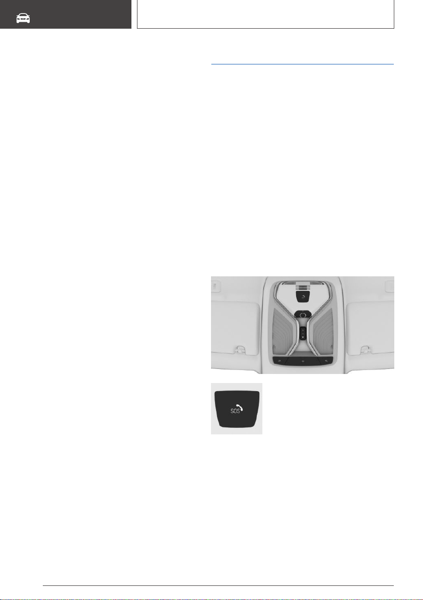
the instrument cluster. In addition, a text mes‐
sage appears on the Control Display.
When BMW Accident Assistance is activated,
data on the vehicle's condition is sent to BMW.
Requirements
▷ Active ConnectedDrive contract, equipment
version with Intelligent emergency call or
BMW ConnectedDrive services.
▷ Cellular network reception.
▷ Standby state is switched on.
Starting BMW Accident
Assistance
If an accident is detected
automatically
A text message relating to BMW Accident Assis‐
tance appears on the Control Display.
The connection can be established directly:
"BMW Accident Assist."
The Check Control message for BMW Accident
Assistance can also be called up from the stored
Check Control messages, refer to page 144, for
a certain length of time.
Starting manually
BMW Accident Assistance can also be con‐
tacted independently of the automatic accident
detection function.
Via iDrive:
1.
"ConnectedDrive"
2. "BMW Assist"
3. "BMW Accident Assistance"
Follow the displays on the Control Display. A
voice connection is established.
4. "End call"
The voice connection can be terminated.
Emergency Request
Intelligent emergency call
Concept
In case of an emergency, an Emergency Re‐
quest can be triggered automatically by the sys‐
tem or manually.
General information
Only press the SOS button in an emergency.
The Intelligent Assist system establishes a con‐
nection with the BMW Response Center.
For technical reasons, the Emergency Request
cannot be guaranteed under unfavorable condi‐
tions.
Overview
SOS button in the roofliner.
Functional requirements
▷ Standby state is switched on.
▷ The Assist system is functional.
▷ If the vehicle is equipped with intelligent
emergency call: the SIM card integrated in
the vehicle has been activated.
Seite 346
MOBILITY
Breakdown assistance
346
Online Edition for Part no. 01402896703 - X/18
Automatic triggering
Under certain conditions, for instance if the air‐
bags trigger, an Emergency Request is automati‐
cally initiated immediately after an accident of
corresponding severity. Automatic Collision Noti‐
fication is not affected by pressing the SOS but‐
ton.
Manual triggering
1. Touch the cover.
2. Press and hold the SOS button until the LED
in the area of the button illuminates green.
▷ The LED is illuminated green when an Emer‐
gency Request has been initiated.
If a cancel prompt appears on the Control
Display, the Emergency Request can be
aborted.
If the situation allows, wait in your vehicle until
the voice connection has been established.
▷ The LED flashes green when a connection to
the BMW Response Center has been estab‐
lished.
The BMW Response Center then makes
contact with you and takes further steps to
help you.
Even if you are unable to respond, the BMW
Response Center can take further steps to
help you under certain circumstances.
For this, data is transmitted to the BMW Re‐
sponse Center which serves to determine the
necessary rescue measures. E.g., the current
position of the vehicle, if it can be established.
Even if you can no longer hear the BMW Re‐
sponse Center through the loudspeakers, the
BMW Response Center may still be able to
hear you.
The BMW Response Center ends the Emer‐
gency Request.
Jump-starting
General information
If the battery is discharged, the engine can be
started using the battery of another vehicle and
two jumper cables. Only use jumper cables with
fully insulated clamp handles.
Safety information
DANGER
Contact with live components can lead to an
electric shock. There is a risk of injuries or dan‐
ger to life. Do not touch any components that
are under voltage.
WARNING
If the jumper cables are connected in the incor‐
rect order, sparking may occur. There is a risk
of injury. Pay attention to the correct order dur‐
ing connection.
NOTICE
In the case of body contact between the two
vehicles, a short circuit can occur during jump-
starting. There is a risk of damage to property.
Make sure that no body contact occurs.
Preparation
1.
Check whether the battery of the other vehi‐
cle has a voltage of 12 volts. The voltage in‐
formation can be found on the battery.
2. Switch off the engine of the assisting vehicle.
3. Switch off any electronic systems/power con‐
sumers in both vehicles.
Seite 347
Breakdown assistance
MOBILITY
347
Online Edition for Part no. 01402896703 - X/18
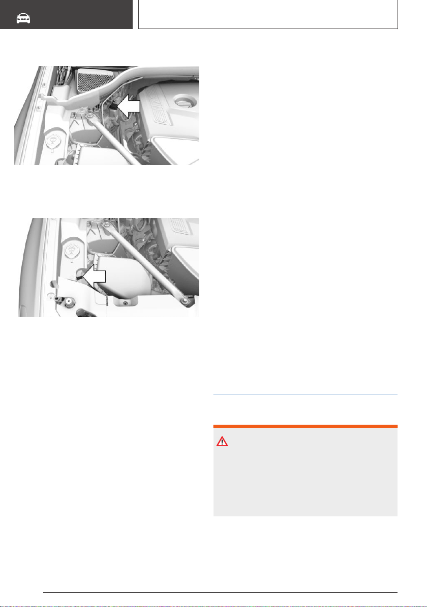
Starting aid terminals
The starting aid terminal in the engine compart‐
ment acts as the battery's positive terminal.
Open the cover of the starting aid terminal.
A special connection on the body acts as the
battery negative terminal.
Connecting the cables
Before you begin, switch off all unnecessary
electronic systems/power consumers, such as
the radio, on the assisting and receiving vehicle.
1.
Open the cover of the starting aid terminal.
2. Attach one terminal clamp of the positive
jumper cable to the positive terminal of the
battery, or to the corresponding starting aid
terminal of the vehicle providing assistance.
3. Attach the terminal clamp on the other end of
the cable to the positive terminal of the bat‐
tery, or to the corresponding starting aid ter‐
minal of the vehicle to be started.
4. Attach one terminal clamp of the negative
jumper cable to the negative terminal of the
battery, or to the corresponding engine or
body ground of assisting vehicle.
5. Attach the second terminal clamp to the neg‐
ative terminal of the battery, or to the corre‐
sponding engine or body ground of the vehi‐
cle to be started.
Starting the engine
Never use spray fluids to start the engine.
1. Start the engine of the assisting vehicle and
let it run for several minutes at an increased
idle speed.
If the vehicle to be started has a diesel en‐
gine: let the engine of the assisting vehicle
run for approx. 10 minutes.
2. Start the engine of the vehicle that is to be
started in the usual way.
If the first starting attempt is not successful,
wait a few minutes before making another at‐
tempt in order to allow the discharged battery
to recharge.
3. Let both engines run for several minutes.
4. Disconnect the jumper cables in the reverse
order.
Check the battery and recharge, if needed.
Tow-starting and towing
Safety information
WARNING
Due to system limits, individual functions can
malfunction during tow-starting/towing with the
Intelligent Safety systems activated. There is a
risk of an accident. Switch all Intelligent Safety
systems off prior to tow-starting/towing.
Seite 348
MOBILITY
Breakdown assistance
348
Online Edition for Part no. 01402896703 - X/18
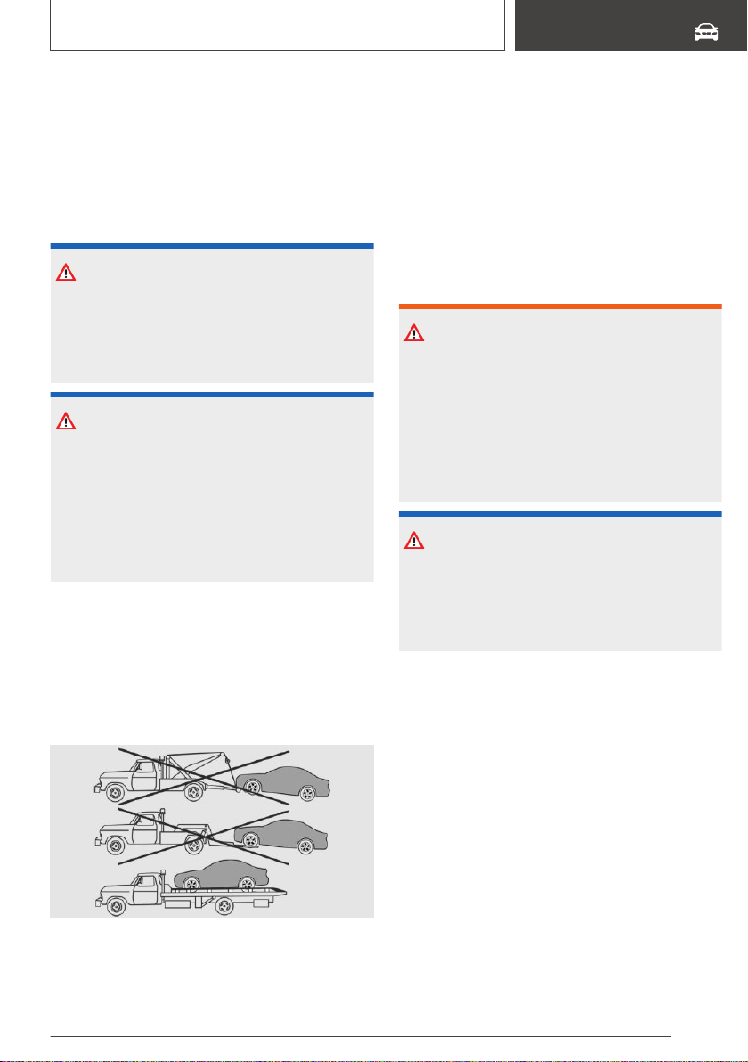
Steptronic transmission:
transporting the vehicle
General information
The vehicle is not permitted to be towed.
Safety information
NOTICE
The vehicle can be damaged when towing the
vehicle with a single lifted axle. There is a risk of
damage to property. The vehicle should only be
transported on a loading platform.
NOTICE
The vehicle can become damaged when lifting
and securing it.
There is a risk of damage to property.
▷ Lift the vehicle using suitable means.
▷ Do not lift or secure the vehicle by its tow
fitting, body parts, or suspension parts.
Pushing the vehicle
To remove a broken-down vehicle from the dan‐
ger area, it can be pushed for a short distance.
Roll or push, refer to page 133, the vehicle.
Tow truck
The vehicle should only be transported on a
loading platform.
Towing other vehicles
General information
Switch on the hazard warning system, depend‐
ing on local regulations.
If the electrical system has failed, clearly identify
the vehicle being towed by placing a sign or a
warning triangle in the rear window.
Safety information
WARNING
If the approved gross vehicle weight of the tow‐
ing vehicle is lighter than the vehicle to be
towed, the tow fitting can tear off or it will not
be possible to control the vehicle's response.
There is a risk of an accident. Make sure that
the gross vehicle weight of the towing vehicle is
heavier than the vehicle to be towed.
NOTICE
If the tow bar or tow rope is attached incor‐
rectly, damage to other vehicle parts can occur.
There is a risk of damage to property. Correctly
attach the tow bar or tow rope to the tow fitting.
Tow bar
The tow fittings used should be on the same
side on both vehicles.
Should it prove impossible to avoid mounting the
tow bar at an offset angle, please follow the fol‐
lowing:
▷ Maneuvering capability is limited going
around corners.
▷ The tow bar will generate lateral forces if it is
secured with an offset.
Tow rope
When starting to tow the vehicle, make sure that
the tow rope is taut.
Seite 349
Breakdown assistance
MOBILITY
349
Online Edition for Part no. 01402896703 - X/18
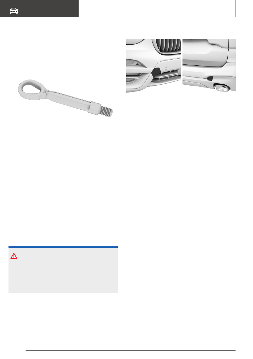
Use nylon ropes or straps, which will enable the
vehicle to be towed without jerking.
Tow fitting
General information
The screw-in tow fitting should always be carried
in the vehicle.
The tow fitting can be screwed in at the front or
rear of the vehicle.
The tow fitting is found in the onboard vehicle
tool kit, refer to page 336.
▷ Use only the tow fitting provided with the ve‐
hicle and screw it all the way in.
▷ Use the tow fitting for towing on paved roads
only.
▷ Avoid lateral loading of the tow fitting, for in‐
stance do not lift the vehicle by the tow fit‐
ting.
Safety information
NOTICE
If the tow fitting is not used as intended, there
may be damage to the vehicle or to the tow fit‐
ting. There is a risk of damage to property. Fol‐
low the notes on using the tow fitting.
Screw thread for tow fitting
Press on the mark on the edge of the cover to
push it out.
For covers which have an opening instead of a
marking, pull the cover out by the opening.
Tow-starting
Do not tow-start the vehicle.
Start the engine by jump-starting, refer to
page 347, if possible.
Have the reasons for the starting difficulties cor‐
rected by a dealer’s service center or another
qualified service center or repair shop.
Seite 350
MOBILITY
Breakdown assistance
350
Online Edition for Part no. 01402896703 - X/18

Care
Vehicle features and
options
This chapter describes all standard, country-spe‐
cific and optional features offered with the series.
It also describes features that are not necessarily
available in your vehicle, e. g., due to the selected
options or country versions. This also applies to
safety-related functions and systems. When us‐
ing these functions and systems, the applicable
laws and regulations must be observed.
Washing the vehicle
General information
Regularly remove foreign objects such as leaves
in the area below the windshield when the hood
is raised.
Wash your vehicle frequently, particularly in win‐
ter. Intense soiling and road salt can damage the
vehicle.
Steam blaster and high-pressure
washer
Safety information
NOTICE
When cleaning with high-pressure washers,
components can be damaged due to the pres‐
sure or temperatures being too high. There is a
risk of damage to property. Maintain sufficient
distance and do not spray too long continu‐
ously. Follow the operating instructions for the
high-pressure washer.
Distances and temperature
▷ Maximum temperature: 140 ℉/60 ℃.
▷ Minimum distance from sensors, cameras,
seals: 12 in/30 cm.
▷ Minimum distance from glass sunroof:
31.5 in/80 cm.
Automatic vehicle washes
Safety information
NOTICE
Improper use of automatic vehicle washes can
cause damage to the vehicle. There is a risk of
damage to property. Follow the following in‐
structions:
▷ Give preference to cloth vehicle washes or
those that use soft brushes in order to
avoid paint damage.
▷ Avoid vehicle washes with guide rails
higher than 4 in/10 cm to avoid damage to
the chassis.
▷ Observe the tire width of the guide rail to
avoid damage to tires and rims.
▷ Fold in exterior mirrors to avoid damage to
the exterior mirrors.
▷ Deactivate the wiper and, if necessary, rain
sensor to avoid damage to the wiper sys‐
tem.
Seite 351
Care
MOBILITY
351
Online Edition for Part no. 01402896703 - X/18

Driving into a vehicle wash with a
Steptronic transmission
Safety information
NOTICE
Selector lever position P is automatically en‐
gaged when standby state is switched off.
There is a risk of damage to property. Do not
switch standby state off in vehicle washes.
General information
In a vehicle wash, the vehicle must be able to roll
freely.
Roll or push the vehicle, refer to page 133.
Some vehicle washes do not permit persons in
the vehicle. The vehicle cannot be locked from
the outside when in selector lever position N. A
signal sounds when an attempt is made to lock
the vehicle.
Driving out of a vehicle wash
Make sure that the remote control is in the vehi‐
cle.
Switch on drive-ready state, refer to page 120.
Headlights
Do not rub wet headlights dry and do not use
abrasive or acidic cleaning agents.
Soak areas that have been dirtied, for instance
from insects, with shampoo and wash off with
water.
Thaw ice with de-icing spray; do not use an ice
scraper.
After washing the vehicle
After washing the vehicle, apply the brakes
briefly to dry them; otherwise, braking action can
be reduced. The heat generated during braking
dries brake discs and brake pads and protects
them against corrosion.
Completely remove all residues on the windows,
to minimize loss of visibility due to smearing and
to reduce wiper noises and wiper blade wear.
Vehicle care
Vehicle care products
General information
BMW recommends using vehicle care and
cleaning products from BMW. Suitable care
products are available from a dealer’s service
center or another qualified service center or re‐
pair shop.
Safety information
WARNING
Cleansers can contain substances that are dan‐
gerous and harmful to your health. There is a
risk of injury. When cleaning the interior, open
the doors or windows. Only use products in‐
tended for cleaning vehicles. Follow the in‐
structions on the container.
Vehicle paint
General information
Regular care contributes to driving safety and
value retention. Environmental influences in
areas with elevated air pollution or natural con‐
taminants, such as tree resin or pollen can affect
the vehicle's paintwork. Tailor the frequency and
extent of your vehicle care to these influences.
Aggressive substances such as spilled fuel, oil,
grease or bird droppings, must be removed im‐
mediately to prevent the finish from being altered
or discolored.
Seite 352
MOBILITY
Care
352
Online Edition for Part no. 01402896703 - X/18

Safety information
WARNING
Improperly performed work on the vehicle paint
can lead to a failure or malfunction of the radar
sensors and thereby result in a safety risk.
There is a risk of accidents or risk of damage to
property. Have paintwork or paintwork repairs
on bumpers of vehicles with radar sensors per‐
formed by a dealer’s service center or another
qualified service center or repair shop only.
Matte finish
Only use cleaning and care products suitable for
vehicles with matte finish.
Leather care
Remove dust from the leather regularly, using a
cloth or vacuum cleaner.
Otherwise, particles of dust and road grime chafe
in pores and folds, and lead to increased wear
and premature degradation of the leather sur‐
face.
To guard against discoloration, such as from
clothing, clean leather and provide leather care
roughly every two months.
Clean light-colored leather more frequently be‐
cause soiling on such surfaces is substantially
more visible.
Use leather care products; otherwise, dirt and
grease will gradually break down the protective
layer of the leather surface.
Upholstery material care
General information
Vacuum the upholstery regularly with a vacuum
cleaner.
If upholstery is very dirty, for instance with bever‐
age stains, use a soft sponge or microfiber cloth
with a suitable interior cleaner.
Clean the upholstery down to the seams using
large sweeping motions. Avoid rubbing the ma‐
terial vigorously.
Safety information
NOTICE
Open Velcro® fasteners on articles of clothing
can damage the seat covers. There is a risk of
damage to property. Ensure that any Velcro®
fasteners are closed.
Caring for special components
Light-alloy wheels
When cleaning the vehicle, use only neutral
wheel cleaners having a pH value from 5 to 9. Do
not use abrasive cleaning agents or steam jets
above 140 ℉/60 ℃. Follow the manufacturer's
instructions.
Aggressive, acidic or alkaline cleaning agents can
destroy the protective layer of adjacent compo‐
nents, such as the brake disc.
After cleaning, apply the brakes briefly to dry
them. The heat generated during braking dries
brake discs and brake pads and protects them
against corrosion.
Chrome surfaces
Carefully clean components such as the radiator
grille or door handles with an ample supply of
water, possibly with shampoo added, particularly
when they have been exposed to road salt.
Rubber components
Environmental influences can cause surface soil‐
ing of rubber parts and a loss of gloss. Use only
water and suitable cleaning agents for cleaning.
Treat especially worn rubber parts with rubber
care agents at regular intervals. When cleaning
rubber seals, do not use any silicon-containing
vehicle care products in order to avoid damage
or noises.
Seite 353
Care
MOBILITY
353
Online Edition for Part no. 01402896703 - X/18

Fine wood parts
Clean fine wood facing and fine wood compo‐
nents only with a moist rag. Then dry with a soft
cloth.
Kenaf
Only treat parts made of Kenaf fibers using suita‐
ble care products.
Plastic components
NOTICE
Cleansers that contain alcohol or solvents, such
as lacquer thinners, heavy-duty grease remov‐
ers, fuel, or such, can damage plastic parts.
There is a risk of damage to property. Clean
with a microfiber cloth. Dampen cloth lightly
with water.
Plastic components are e.g.:
▷ Imitation leather surfaces.
▷ Roofliner.
▷ Light lenses.
▷ Matt black spray-coated components.
▷ Painted parts in the car's interior.
Clean with a microfiber cloth.
Dampen cloth lightly with water.
Do not soak the roofliner.
Safety belts
WARNING
Chemical cleansers can destroy the safety belt
webbing. Missing protective effect of the safety
belts. There is a risk of injuries or danger to life.
Use only a mild soapy solution for cleaning the
safety belts.
Dirty belt straps impede the reeling action and
thus have a negative impact on safety.
Use only a mild soapy solution for cleaning the
installed belt straps.
Safety belts should only be allowed to retract if
they are dry.
Carpets and floor mats
WARNING
Objects in the driver's floor area can limit the
pedal distance or block a depressed pedal.
There is a risk of an accident. Stow objects in
the vehicle such that they are secured and can‐
not enter into the driver's floor area. Use floor
mats that are suitable for the vehicle and can
be safely attached to the floor. Do not use
loose floor mats and do not layer several floor
mats. Make sure that there is sufficient clear‐
ance for the pedals. Ensure that the floor mats
are securely fastened again after they were re‐
moved, for instance for cleaning.
The floor mats can be removed from the car's in‐
terior for cleaning.
If the floor carpets are very dirty, clean with a mi‐
crofiber cloth and water or a textile cleaner. To
prevent matting of the carpet, rub back and forth
in the direction of travel only.
Mount for trailer hitch
Keep the mount clean.
Regularly grease or oil bearings and sliding surfa‐
ces with resin-free greases or oils.
Before using steam cleaners or high pressure
cleaners on the vehicle, remove the ball head
and insert the cover into the mount.
Sensor/camera lenses
To clean sensors and camera lenses, use a cloth
moistened with a small amount of glass deter‐
gent.
Seite 354
MOBILITY
Care
354
Online Edition for Part no. 01402896703 - X/18
Displays, screens, and protective
glass of the Head-up Display
NOTICE
Chemical cleansers, moisture or fluids of any
kind can damage the surface of displays and
screens. There is a risk of damage to property.
Clean with a clean, antistatic microfiber cloth.
NOTICE
The surface of displays can be damaged with
improper cleaning. There is a risk of damage to
property. Avoid pressure that is too high and do
not use any scratching materials.
Clean with a clean, antistatic microfiber cloth.
Clean the protective glass of the Head-up Dis‐
play, refer to page 154, using a microfiber cloth
and commercially available dish-washing soap.
Long-term vehicle storage
When the vehicle is shut down for longer than
three months, special measures must be taken.
Further information is available from a dealer’s
service center or another qualified service center
or repair shop.
Seite 355
Care
MOBILITY
355
Online Edition for Part no. 01402896703 - X/18

356
Online Edition for Part no. 01402896703 - X/18
REFERENCE
Technical data .......................................................................................... 358
Appendix ................................................................................................... 361
Everything from A to Z ............................................................................ 362
357
Online Edition for Part no. 01402896703 - X/18

Technical data
Vehicle features and
options
This chapter describes all standard, country-spe‐
cific and optional features offered with the series.
It also describes features that are not necessarily
available in your vehicle, e. g., due to the selected
options or country versions. This also applies to
safety-related functions and systems. When us‐
ing these functions and systems, the applicable
laws and regulations must be observed.
General information
The technical data and specifications in the
Owner's Manual are used as guidance values.
The vehicle-specific data can deviate from this,
for instance due to the selected special equip‐
ment, country version or country-specific meas‐
urement method. Detailed values can be found in
the approval documents, on labels on the vehicle
or can be obtained from a dealer’s service center
or another qualified service center or repair shop.
Dimensions
The dimensions can vary depending on the
model version, equipment or country-specific
measurement method.
The specified heights do not take into account
attached parts, for instance a roof antenna, roof
racks or spoiler. The heights can deviate, for in‐
stance due to the selected special equipment,
tires, load and chassis version.
BMW X3
Width with mirrors in/mm 84.2/2,138
Width without mirrors in/mm 74.4-74.7/1,891-1,897
Height in/mm 66/1,676
Length in/mm 185.9-186.1/4,722-4,726
Wheelbase in/mm 112.8/2,864
Smallest turning radius diam. ft/m 39.4-39.7/12.0-12.1
Seite 358
REFERENCE
Technical data
358
Online Edition for Part no. 01402896703 - X/18

Weights
X3 sDrive30i
Approved gross vehicle weight lbs/kg 5,203/2,360
Load lbs/kg 893/405
Approved front axle load lbs/kg 2,403/1,090
Approved rear axle load lbs/kg 3,020/1,370
Approved roof load capacity lbs/kg 220/100
X3 xDrive30i
Approved gross vehicle weight lbs/kg 5,291/2,400
Load lbs/kg 893/405
Approved front axle load lbs/kg 2,557/1,160
Approved rear axle load lbs/kg 3,064/1,390
Approved roof load capacity lbs/kg 220/100
X3 M40i powered by BMW M
Approved gross vehicle weight lbs/kg 5,412/2,455
Load lbs/kg 915/415
Approved front axle load lbs/kg 2,623/1,190
Approved rear axle load lbs/kg 3,075/1,395
Approved roof load capacity lbs/kg 220/100
Trailer towing
X3 sDrive30i
Details about possible increases or a reduced trailer load can be requested from a dealer's service
center or another qualified service center or repair shop
Trailer load without brakes lbs/kg 1,653/750
Trailer load with brakes on uphill grades of up to 12 % lbs/kg 4,409/2,000
Seite 359
Technical data
REFERENCE
359
Online Edition for Part no. 01402896703 - X/18

X3 sDrive30i
Maximum drawbar nose weight lbs/kg 441/200
Approved rear axle load lbs/kg 2,983/1,353
Approved gross vehicle weight lbs/kg 4,949/2,245
X3 xDrive30i
Details about possible increases or a reduced trailer load can be requested from a dealer's service
center or another qualified service center or repair shop
Trailer load without brakes lbs/kg 1,653/750
Trailer load with brakes on uphill grades of up to 12 % lbs/kg 4,409/2,000
Maximum drawbar nose weight lbs/kg 441/200
Approved rear axle load lbs/kg 3,005/1,363
Approved gross vehicle weight lbs/kg 5,064/2,297
X3 M40i powered by BMW M
Details about possible increases or a reduced trailer load can be requested from a dealer's service
center or another qualified service center or repair shop
Trailer load without brakes lbs/kg 1,653/750
Trailer load with brakes on uphill grades of up to 12 % lbs/kg 4,409/2,000
Maximum drawbar nose weight lbs/kg 441/200
Approved rear axle load lbs/kg 3,023/1,371
Approved gross vehicle weight lbs/kg 5,110/2,318
Capacities
BMW X3
Fuel tank, approx. US gal/liters
17.2/65.0
Observe further information on fuel quality, refer
to page 290.
Seite 360
REFERENCE
Technical data
360
Online Edition for Part no. 01402896703 - X/18

Appendix
Any updates to the Owner's Manual of the vehi‐
cle are listed here.
Seite 361
Appendix
REFERENCE
361
Online Edition for Part no. 01402896703 - X/18

Everything from A to Z
Index
A
A/C button, see Air conditioning 238
ABS, Antilock Brake System 192
Acceleration Assistant, see Launch Control 136
Accessories and parts 10
Accident Assistance 345
Accident prevention, see Active Protection 189
ACC, see Active Cruise Control with Stop&Go
function 199
Activated charcoal filter 241
Activating trailer towing 277
Active Blind Spot Detection 181
Active Cruise Control with Stop&Go function,
ACC 199
Active damping control, see Adaptive suspen‐
sion 233
Active Guard, see Intelligent Safety 168
Active PDC, see Emergency brake function 213
Active Protection 189
Active seat ventilation 113
Adaptive brake assistant 192
Adaptive brake lights, see Brake force dis‐
play 189
Adaptive Light Control 159
Adaptive M chassis 233
ADAPTIVE, see Driving Dynamics Control 138
Adaptive suspension 233
Additives, engine oil types 330
After run of fan, see Exhaust gas particulate fil‐
ter 272
Airbags 164
Airbags, indicator and warning light 166
Air circulation, see Recirculated-air
mode 236, 239
Air conditioning 235, 238
Air distribution, manual 236, 240
Air flow, automatic climate control 236, 240
Air outlets, see Ventilation 241
Air pressure, tires 296
Alarm system 96
Alarm, unintentional 97
Alertness Assistant 190
All-season tires, see Winter tires 303
All-wheel-drive, see xDrive 194
Ambient air package 245
Ambient light 162
Antifreeze, see Washer fluid 131
Antilock Brake System, ABS 192
Anti-slip control, see DSC 192
Anti-theft protection, locking 77
Anti-theft protection, see Lug bolt lock 321
Apple CarPlay, connection to the vehicle 67
Approach control warning with City light braking
function 169
Approach control warning with light braking func‐
tion 169
Approved axle load 359
Approved total weight 359
Apps, see Owner's Handbook for Navigation, En‐
tertainment, Communication 8
Ashtray 252
Ashtray, front 252
Assistance when driving off, see Drive-off assis‐
tant 192
Assistance with breakdown 344
AUC Automatic Recirculating Air Control 239
Audio, see Owner's Manual for Navigation, En‐
tertainment and Communication 8
AUTO H button, see Parking brake 124
Automatic activation, see Individual activa‐
tion 113
Automatic climate control 234, 237
Automatic cruise control with Stop&Go func‐
tion 199
Automatic Curb Monitor, exterior mirror 110
Automatic deactivation, front-seat passenger air‐
bags 166
Automatic Differential Brake 195
Automatic headlight control 158
Seite 362
REFERENCE
Everything from A to Z
362
Online Edition for Part no. 01402896703 - X/18

Automatic Hold, see Parking brake 124
Automatic locking 95
Automatic Recirculating Air Control AUC 239
Automatic transmission, see Steptronic trans‐
mission 132
Automatic unlocking 95
Automatic vehicle wash 351
AUTO program, automatic climate con‐
trol 235, 238
AUTO program, intensity 239
Auto Start/Stop function 121
Average speed and average consumption 152
Axle loads, weights 359
B
Backrest curvature, see Lumbar support 103
Backrest, seats 102
Backrest tilt 103
Backrest, width 104
Bad road trips 271
Bandages, see First-aid kit 344
Bar for tow-starting/towing 349
Battery, changing, remote control of the vehi‐
cle 79
Battery, disposing of 343
Battery, vehicle 342
Being towed, see Tow-starting and towing 348
Belts, see Safety belts 104
Beverage holder, see Cup holders 258
Biodiesel 291
Blocking, power window, see Safety switch 99
Bluetooth connection 64
Blu-ray, see Owner's Handbook for Navigation,
Entertainment, Communication 8
BMW Advanced Diesel 292
BMW Assist, see Owner's Manual for Navigation,
Entertainment and Communication 8
BMW display key 81
BMW display key, malfunction 84
BMW Gesture Control 53
BMW maintenance system 334
Bonus range, ECO PRO 282
Bottle holder, see Cup holders 258
Brake assistant 192
Brake assistant, adaptive 192
Brake Controller 278
Brake discs, breaking in, see Brake system 270
Brake force display 189
Brake lights, brake force display 189
Brake lights, see Lights and bulbs 337
Brake pads, breaking in, see Brake system 270
Brake system 270
Braking, information 272
Breakdown assistance 344, 345
Breakdown, see FTM Flat Tire Monitor 317
Break-in 270
Break recommendation, see Alertness Assis‐
tant 190
Brightness, Control Display 61
Bulb replacement, see Lights and bulbs 337
Bulbs, replacing, see Lights and bulbs 337
Buttons on the steering wheel 36
Button, SOS, see Intelligent emergency call 346
Button, Start/Stop 120
Bypassing, see Jump-starting 347
C
Cable for tow-starting/towing 349
Calendar, see Owner's Handbook for Navigation,
Entertainment, Communication 8
California Proposition 65 Warning 10
Calling up mirror adjustment 95
Calling up seat adjustment 95
Camera-based assistance systems, see Intelli‐
gent Safety 168
Camera-based cruise control, see Active Cruise
Control with Stop&Go function 199
Camera lenses, care 354
Camera, rearview camera, without Surround
View 215
Camera, see Surround View 218
Can holder, see Cup holders 258
Care, Head-up Display 355
Care of displays, screens 355
Care, see Washing the vehicle 351
Care, vehicle 352
Cargo area 260
Cargo area, enlarging 264
Cargo area, loading, see Stowing and securing
cargo 261
Seite 363
Everything from A to Z
REFERENCE
363
Online Edition for Part no. 01402896703 - X/18

Cargo area partition net 266
Cargo area, storage compartments 262
Cargo cover 266
Cargo, stowing and securing 261
Cargo straps, see Lashing eyes in the cargo
area 261
Carpet, care 354
CarPlay, connection to the vehicle 67
Car seats, see Transporting children safely 115
Cartridge replacement, see Ambient air pack‐
age 245
Car wash 351
Car washing 351
Catalytic converter, see Hot exhaust gas sys‐
tem 271
CBS Condition Based Service 334
Cell phone, see Owner's Manual for Navigation,
Entertainment and Communication 8
Center armrest 258
Center console 38
Central Information Display (CID), see Control
Display 46
Central locking system 86
Central screen, see Control Display 46
Changes, technical, see For Your Own Safety 9
Changing parts 336
Changing wheels 319
Changing wheels/tires 302
Chassis number, see Vehicle identification num‐
ber 14
Check Control 141
Checking the engine oil level electronically 328
Checking the oil level electronically 328
Children, seating position 115
Children, transporting safely 115
Child restraint system LATCH 117
Child restraint systems, mounting 116
Child restraint systems, see Transporting chil‐
dren safely 115
Child safety locks 119
Child seat, mounting 116
Child seats, see Transporting children
safely 115
Chrome-plated surfaces, care 353
Chrome surfaces, care 353
Cigarette lighter 252
Cigarette lighter, front 253
Cleaning displays, screens 355
Cleaning, Head-up Display 355
Climate control 234, 237
Clothes hooks 259
Coasting 283
Coasting with engine decoupled, see Coast‐
ing 283
Coasting with idling engine 283
Cold starting, see Starting the engine 120
Combination switch, see Turn signals 127
Combination switch, see Washer/wiper sys‐
tem 128
Comfort Access 86
COMFORT, see Driving Dynamics Control 137
Communication, see Owner's Manual for Naviga‐
tion, Entertainment and Communication 8
Compact wheel, see Emergency wheel 323
Comparison of entries, see Entry comparison 44
Compartments in the doors 257
Compatible devices, see Suitable devices 64
Compressor 306
Computer, see Onboard Computer in the instru‐
ment cluster 150
Concierge Service, see Owner's Handbook for
Navigation, Entertainment, Communication 8
Condensation, removing from the win‐
dows 236, 240
Condensation water under the parked vehi‐
cle 273
Condition Based Service CBS 334
Confirmation signal from the vehicle 95
ConnectedDrive, see Owner's Manual for Navi‐
gation, Entertainment and Communication 8
Connecting device 63
Connecting electrical devices, see Sockets 253
Connecting, mobile devices 63
Connecting mobile phone 63
Connecting smartphone 63
Connecting telephone 63
Connections, Screen Mirroring 68
Consumption display, ECO PRO 282
Consumption, see Current consumption 151
Contacts, see Owner's Handbook for Navigation,
Entertainment, Communication 8
Container for washer fluid 131
Seite 364
REFERENCE
Everything from A to Z
364
Online Edition for Part no. 01402896703 - X/18

Continued driving with a flat tire 315, 319
Control Display 46
Control Display, settings 59
Controller 46, 47
Control systems, driving stability 192
Convenient closing with the remote control 78
Convenient opening with the remote control 77
Coolant 332
Coolant level 332
Coolant temperature 145
Cooling, maximum 238
Cooling system 332
Cornering light 159
Corrosion on brake discs 273
Cosmetic mirror 252
Crossing traffic warning 230
Cruise control 197
Cruise control, active with Stop&Go func‐
tion 199
Cruise control with distance control, see Active
Cruise Control with Stop&Go function 199
Cruise control without distance control, see
Cruise control 197
Cruising range 146
Cup holder 258
Cup holder, front 258
Cup holder, rear 259
Current consumption, Onboard Computer, con‐
sumption indicator, Onboard Computer 151
D
Damage, tires 302
Damping control, active, see Adaptive suspen‐
sion 233
Data memory 11
Data protection, settings 62
Data, see Deleting personal data in the vehi‐
cle 62
Data, technical 358
Date 60
Daytime running lights 159
DCC, see Cruise control 197
Defogging the windows 236, 240
Defrosting the windows 236, 240
Deleting personal data 62
Departure time, parked-car ventilation 244
Destination distance, Onboard Computer 151
Device list, displaying 69
Devices, managing 69
Diagnosis connection 335
Diesel exhaust fluid at low temperatures 292
Diesel exhaust fluid, having refilled 292
Diesel exhaust fluid on minimum 292
Diesel exhaust fluid, see BMW Advanced Die‐
sel 292
Diesel fuel 291
Diesel particulate filter, see Exhaust gas particu‐
late filter 272
Digital clock 146
Dimensions 358
Dimmable exterior mirrors 110
Dimmable interior mirror 110
Direct dial buttons, see Programmable memory
buttons 52
Direction indicator, see Turn signals 127
Display in the windshield, see Head-up Dis‐
play 154
Display key, malfunction 84
Display key, see BMW display key 81
Display lighting, see Instrument lighting 161
Displays 140
Displays and symbols 8
Displays, ECO PRO 282
Displays, screens 355
Disposal, coolant 333
Disposal, vehicle battery 343
Distance control, see PDC 211
Distance to destination, Onboard Computer 151
Divided screen view, see Split screen 45
Door opening angle, Surround View 221
Downhill control, see HDC Hill Descent Con‐
trol 195
Drawbar nose weight 359
Drive-off assistant 192
Drive-off assistant, see DSC 192
Driver assistance, see Intelligent Safety 168
Drive-ready state, idle state, and standby
state 41
Drive-ready state, see Starting the engine 120
Driver Fatigue Detector 190
Driver profiles 92
Seite 365
Everything from A to Z
REFERENCE
365
Online Edition for Part no. 01402896703 - X/18

Driver profiles, welcome screen 92
Driving Assistant, see Intelligent Safety 168
Driving comfort 233
Driving Dynamics Control 137
Driving instructions, break-in 270
Driving mode, ECO PRO 280
Driving mode, see Driving Dynamics Con‐
trol 137
Driving notes, general 271
Driving on bad roads 271
Driving on racetracks 274
Driving stability control systems 192
Driving style analysis, ECO PRO 284
Driving tips 271
Drying air, see Air conditioning 235, 238
DSC Dynamic Stability Control 192
DTC Dynamic Traction Control 194
DVD, Video, see Owner's Handbook for Naviga‐
tion, Entertainment, Communication 8
Dynamic damping, see Adaptive suspen‐
sion 233
Dynamic Stability Control DSC 192
Dynamic Traction Control DTC 194
E
ECO PRO 280
ECO PRO bonus range 282
ECO PRO displays 282
ECO PRO driving style analysis 284
ECO PRO INDIVIDUAL, see Driving Dynamics
Control 137
ECO PRO, see Driving Dynamics Control 137
Efficient4x4, see xDrive 194
Electronic oil measurement 328
Electronic Stability Program ESP, see DSC 192
E-mail, see Owner's Handbook for Navigation,
Entertainment, Communication 8
Emergency brake function when parking, Active
PDC 213
Emergency service, see Accident Assis‐
tance 345
Emergency service, see Breakdown assis‐
tance 345
Emergency unlocking, fuel filler flap 289
Emergency unlocking, transmission lock 136
Emergency wheel 323
Energy recovery, Onboard Computer 151
Energy savings, see Gear shift indicator 147
Engine, automatic Start/Stop function 121
Engine compartment 325
Engine compartment, working in 326
Engine coolant 332
Engine idling when driving, see Coasting 283
Engine oil 328
Engine oil, adding 329
Engine oil change 331
Engine oil filler neck 329
Engine oil temperature 145
Engine oil types to add 330
Engine start, jump-starting 347
Engine start, see Drive-ready state 120
Engine stopping, see Drive-ready state 120
Engine temperature 145
Entering a destination, see Owner's Handbook
for Navigation, Entertainment, Communica‐
tion 8
Entering an address, navigation, see Owner's
Manual for Navigation, Entertainment and Com‐
munication 8
Entertainment, see Owner's Manual for Naviga‐
tion, Entertainment and Communication 8
Entry comparison, navigation 44
Equipment, interior 249
Error displays, see Check Control 141
ESP Electronic Stability Program, see DSC 192
Evasion assistance 173
Exchanging wheels/tires 302
Exhaust gas particulate filter 272
Exhaust gas system 271
Exhaust, see Exhaust gas system 271
Exterior lighting during unlocking 77
Exterior lighting with the vehicle locked 78
Exterior mirror, Automatic Curb Monitor 110
Exterior mirror, automatic dimming feature 110
Exterior mirrors 109
Exterior mirrors, malfunction 109
External start 347
External temperature 146
Eyelet for towing 350
Eyes, see Lashing eyes in the cargo area 261
Seite 366
REFERENCE
Everything from A to Z
366
Online Edition for Part no. 01402896703 - X/18

F
Failure message, see Check Control 141
False alarm, see Avoiding unintentional
alarms 97
Fan after run, see Exhaust gas particulate fil‐
ter 272
Fan, see Air flow 236, 240
Fastening safety belts, see Safety belts 104
Filler neck for engine oil 329
Filter, see Microfilter 237
Finding charging stations, see Charging stations
and points of interest, see Owner's Handbook
for Navigation, Entertainment, Communica‐
tion 8
Fine wood parts, care 354
First-aid kit 344
Fittings for trailer safety chain, trailer towing 278
Flat tire, changing wheels 319
Flat tire, continued driving 315, 319
Flat tire message, FTM 317
Flat tire message, TPM 313
Flat Tire Monitor FTM 317
Flat tire, repairing 305
Flat tire, see Tire Pressure Monitor TPM 310
Flat tire warning light, FTM 317
Flat tire warning light, TPM 313
Flooding 272
Floor carpet, care 354
Floor mats, care 354
Fog, removing from the windows 236, 240
Fold-away position of the wipers 130
Fold back rear seat backrests 264
Foot brake 272
For Your Own Safety 9
Fragrance cartridge, see Ambient air pack‐
age 245
Fragrance, see Ambient air package 245
Fragrancing, see Ambient air package 245
Front airbags 164
Front center armrest 258
Front fog lights 161
Front fog lights, see Lights and bulbs 337
Front lights, see Lights and bulbs 337
Front-seat passenger airbags, automatic deacti‐
vation 166
Front-seat passenger airbags, indicator light 167
Front seats 102
FTM Flat Tire Monitor 317
Fuel 290
Fuel cap 288
Fuel filler flap 288
Fuel filler flap, unlocking manually 289
Fuel gage 145
Fuel quality 290
Fuel recommendation 290
Fuel, tank capacity 360
Fuses 343
G
Garage door opener, see Integrated Universal
Remote Control 249
Gasoline 290
Gasoline particulate filter, see Exhaust gas partic‐
ulate filter 272
Gear change, Steptronic transmission 132
Gear shift indicator 147
General driving notes 271
General settings 59
Gesture Control 53
Gestures, see BMW Gesture Control 53
Glare shield, see Sun visor 252
Glass sunroof, electric 99
Glass sunroof, initialize the system 101
Glove compartment 256
GPS geolocation, vehicle position 60
GPS, navigation, see Owner's Handbook for
Navigation, Entertainment, Communication 8
Gross weight, permissible for trailer towing 359
H
Handbrake, see Parking brake 124
Hand-held transmitter, alternating code 250
Hands-free device, see Owner's Handbook for
Navigation, Entertainment, Communication 8
Hazard warning flashers 344
HDC Hill Descent Control 195
Head airbags 164
Headlight control, automatic 158
Headlight courtesy delay feature 158
Seite 367
Everything from A to Z
REFERENCE
367
Online Edition for Part no. 01402896703 - X/18

Headlight courtesy delay feature, switching
on 79
Headlight flasher 127
Headlight glass 337
Headlights, care 352
Headlights, see Lights and bulbs 337
Head restraints, front 106
Head restraints, rear 107
Head-up Display 154
Head-up Display, care 355
Head-up Display, see Memory function 111
Head-up Display, standard view 154
Heated steering wheel 111
Heated steering wheel, individual activation 113
Heavy cargo, stowing cargo 261
Height, vehicle 358
High-beam Assistant 160
High beams 127
High beams/low beams, see High-beam Assis‐
tant 160
Hill Descent Control HDC 195
Hills 273
Hill start assistant, see Drive-off assistant 192
Holder for beverages, see Cup holders 258
HomeLink, see Integrated Universal Remote
Control 249
Homepage 8
Hood 326
Horn 36
Hot exhaust gas system 271
Hotline, see Owner's Handbook for Navigation,
Entertainment, Communication 8
Humidity in the headlight, see Headlight
glass 337
Hydroplaning 272
I
iBrake – PostCrash 190
Ice warning, see External temperature 146
Icy roads, see External temperature 146
Identification marks, tires 300
Identification number, see Vehicle identification
number 14
Idle state, standby state, and drive-ready
state 41
iDrive 44
Indicator and warning lights, see Check Con‐
trol 141
Individual activation 113
Individual air distribution 236, 240
Individual settings, see Driver profiles 92
Inductive charging of a smartphone, see Wireless
charging tray, see Owner's Manual for Naviga‐
tion, Entertainment, Communication 8
Inflation pressure monitor, see Tire Pressure
Monitor TPM 310
Inflation pressure, tires 296
Inflation pressure warning FTM, tires 317
Information 8
Initialization, Flat Tire Monitor FTM 317
Initialize, Tire Pressure Monitor TPM 312
Instrument cluster 140
Instrument lighting 161
Integrated key 84
Integrated Owner's Manual in the vehicle 72
Integrated Universal Remote Control 249
Intelligent Auto Start/Stop function 123
Intelligent emergency call 346
Intelligent Safety 168
Intended use 9
Intensity, AUTO program 239
Interior equipment 249
Interior lights 161
Interior lights during unlocking 77
Interior lights with the vehicle locked 78
Interior mirror 109
Interior mirror, automatic dimming feature 110
Interior motion sensor 97
Internet connection 67
Internet page 8
Intersection warning, see Approach control warn‐
ing with light braking function 169
Interval display, see Service requirements 146
IOM, see Integrated Owner's Manual in the vehi‐
cle 72
Ionization, see Ambient air package 245
J
Jacking points for the vehicle jack 322
Jam protection system, glass sunroof 100
Seite 368
REFERENCE
Everything from A to Z
368
Online Edition for Part no. 01402896703 - X/18

Jam protection system, windows 98
Joystick, Steptronic transmission 132
Jump-starting 347
Jump-starting terminals 348
K
Kenaf, care 354
Keyless Go, see Comfort Access 86
Key, mechanical 84
Key, see BMW display key 81
Key, see Remote control 76
Kickdown, Steptronic transmission 132
Knee airbag 165
L
Label on recommended tires 303
Lane change assistant 209
Lane control assistant, see Steering and lane
control assistant 206
Lane control assistant with active side collision
protection, see Side collision warning 185
Lane departure warning 178
Lane lines, Surround View 221
Lane threshold, warning 178
Language, setting on the Control Display 59
Lashing eyes in the cargo area 261
LATCH child restraint fixing system 117
Launch Control 136
Leather care 353
LED light carpet, see Welcome light 158
LEDs, replacing, see Lights and bulbs 337
Length, vehicle 358
Letters and numbers, entering 49
License plate light, see Lights and bulbs 337
Light-alloy wheels, care 353
Light control, adaptive 159
Light-emitting diodes, replacing, see Lights and
bulbs 337
Lighter, cigarettes 252
Lighting 157
Light in the exterior mirror, see Active Blind Spot
Detection 181
Light in the exterior mirror, see Crossing traffic
warning 230
Light replacement, see Lights and bulbs 337
Lights 157
Lights and bulbs 337
Light switch 157
List of all messages 61
Load 261
Loading 260
Location, vehicle position 60
Locking, automatic 95
Locking, see Opening and Closing 76
Locking, settings 94
Locking using the remote control 77
Lock, lug bolts 321
Locks, child safety 119
Low beams 157
Low beams, automatic, see High-beam Assis‐
tant 160
Lower back support 103
Low-Sulfur Diesel 291
Lug bolt lock 321
Luggage rack, see Roof-mounted luggage
rack 274
Lumbar support 103
M
Maintenance 334
Maintenance requirements, see Condition Based
Service CBS 334
Maintenance, see Service requirements 146
Maintenance system, BMW 334
Make-up mirror 252
Malfunction, BMW display key 84
Malfunction displays, see Check Control 141
Malfunction, remote control 80
Manual air distribution 236, 240
Manual air flow 236, 240
Manual brake, see Parking brake 124
Manual mode, Steptronic transmission 132
Manual operation, fuel filler flap 289
Map update, see Owner's Handbook for Naviga‐
tion, Entertainment, Communication 8
Marking, run-flat tire 304
Matte finish 353
Maximum cooling 238
Seite 369
Everything from A to Z
REFERENCE
369
Online Edition for Part no. 01402896703 - X/18

Maximum speed display, see Speed Limit
Info 148
Maximum speed of winter tires 303
M chassis, adaptive 233
Measurement, units of 60
Medical supplies, see First-aid kit 344
Memory function 111
Menu, instrument cluster, see Selection
lists 149
Menus, operating, see iDrive 44
Messages 61
Messages, see Check Control 141
Microfilter 237, 241
Minimum tread depth, tires 301
Mirror 109
Mirror, see Memory function 111
Mobile communication devices in the vehi‐
cle 272
Mobile devices, managing 69
Mobile phone, see Owner's Manual for Naviga‐
tion, Entertainment and Communication 8
Mobility System 305
Mode, ECO PRO 280
Modifications, technical, see For Your Own
Safety 9
Monitor, see Control Display 46
Mount for trailer hitch, care 354
Mounting for trailer hitch 277
Mounting of child restraint systems 116
MP3 player, see Audio, see Owner's Handbook
for Navigation, Entertainment, Communica‐
tion 8
Multi-function hook 262
Multifunction steering wheel, buttons 36
Multimedia, see Owner's Manual for Navigation,
Entertainment and Communication 8
Music hard disk, see Owner's Handbook for Nav‐
igation, Entertainment, Communication 8
N
Navigation data, Onboard Computer 151
Navigation, see Owner's Manual for Navigation,
Entertainment and Communication 8
Neck restraints, front, see Head restraints 106
Neck restraints, rear, see Head restraints 107
Net, cargo area 263
Neutral cleaner, see Light-alloy wheels 353
New wheels and tires 302
Nose weight, see Drawbar nose weight 359
Notes, see Owner's Handbook for Navigation,
Entertainment, Communication 8
No-touch opening and closing of the tailgate 88
Nylon rope for tow-starting/towing 349
O
OBD Onboard Diagnosis 335
Obstacle marking, rearview camera 216
Obstacle marking, Surround View 221
Octane rating, see Recommended fuel
grade 291
Odometer and trip odometer 151
Oil 328
Oil, adding 329
Oil change 331
Oil change interval, see Service require‐
ments 146
Oil filler neck 329
Oil types to add, engine 330
Onboard Computer in the instrument clus‐
ter 150
Onboard Computer on the Control Display 152
Onboard Diagnosis OBD 335
Onboard literature, printed 72
Onboard vehicle tool kit 336
On-call service, see Accident Assistance 345
On-call service, see Breakdown assistance 345
Online Entertainment, see Owner's Handbook
for Navigation, Entertainment, Communica‐
tion 8
Opening and closing 76
Operating concept, iDrive 44
Operating with the Controller 48
Operation via touchscreen 49
Outside air, see AUC 239
Overheating of engine, see Coolant tempera‐
ture 145
Overwintering, see Long-term vehicle stor‐
age 355
Owner's Manual media 72
Owner's Manual, printed 72
Seite 370
REFERENCE
Everything from A to Z
370
Online Edition for Part no. 01402896703 - X/18

P
Paint, vehicle 352
Pairing, mobile devices, see Connections 63
Panic alarm, see Panic mode 96
Panic mode 96
Panorama View, see Surround View 218
Panoramic glass sunroof, see Glass sunroof 99
Parallel Parking Assistant 225
Park Distance Control PDC 211
Parked-car ventilation 243
Parking aid, see PDC 211
Parking Assistant 225
Parking Assistant Plus, see Surround View 218
Parking Assistant, see Parking Assistant 225
Parking brake 124
Parking lights 157
Parking with Automatic Hold, see Parking
brake 124
Particulate filter, see Exhaust gas particulate fil‐
ter 272
Partition net 266
Parts and accessories 10
Passenger's side mirror, tilting, see Automatic
Curb Monitor, exterior mirror 110
Pathway lines, rearview camera 216
PDC Park Distance Control 211
Performance Control 233
Performance display, see Sport displays 153
Personal data, deleting 62
Personal profile, see Driver profiles 92
Person warning with City light braking func‐
tion 175
Plastic parts, care 354
PostCrash – iBrake 190
Power failure 343
Power windows 98
Pressure monitor, see Tire Pressure Monitor
TPM 310
Pressure, tires 296
Pressure warning FTM, tires 317
Printed onboard literature 72
Profiles, see Driver profiles 92
Programmable memory buttons, iDrive 52
Protective function, glass sunroof, see Jam pro‐
tection system 100
Protective function, windows, see Jam protec‐
tion system 98
Push-and-turn reel, see Controller 46, 47
Q
Queuing Assistant, see Steering and lane control
assistant 206
R
Racetrack operation 274
Radiator fan, see Exhaust gas particulate fil‐
ter 272
Radiator fluid 332
Radio-operated remote control, see Remote
control 76
Radio, see Owner's Manual for Navigation, En‐
tertainment and Communication 8
Rain sensor 128
Rapeseed-oil methyl ester RME 291
Rear automatic climate control 242
Rear collision prevention 188
Rear collision warning, see Rear collision preven‐
tion 188
Rear lights, see Lights and bulbs 337
Rear seat backrest tilt 104
Rear seats 104
Rearview camera, see Surround View 218
Rearview camera, without Surround View 215
Rear window defroster 237, 241
Rear window wiper, operation 130
Recirculated-air filter, see Microfilter/activated-
charcoal filter 241
Recirculated-air mode 236, 239
Recommended fuel grade 291
Recommended tire brands 303
Refueling 288
Remote 3D View 225
Remote control, additional 79
Remote control for audio, see Owner's Hand‐
book for Navigation, Entertainment, Communi‐
cation 8
Remote control, integrated key 84
Remote control, loss 79
Remote control, malfunction 80
Seite 371
Everything from A to Z
REFERENCE
371
Online Edition for Part no. 01402896703 - X/18

Remote control of the vehicle, changing the bat‐
tery 79
Remote control, opening/closing 76
Remote control, universal 249
Remote control with display, malfunction 84
Remote control with display, see BMW display
key 81
Remote services, app, see Owner's Handbook
for Navigation, Entertainment, Communica‐
tion 8
Removable ball head 277
Replacing parts 336
Replacing wheels/tires 302
Reporting safety malfunctions 15
RES CNCL button, see Active Cruise Control
with Stop&Go function 199
RES CNCL button, see Cruise control 197
Reserve warning, see Range 146
Reset, Tire Pressure Monitor TPM 312
Retreaded tires 303
Reversing lights, bulb replacement, see Lights
and bulbs 337
RME rapeseed-oil methyl ester 291
Roadside Assistance, see Accident Assis‐
tance 345
Roadside Assistance, see Breakdown assis‐
tance 345
Roadside parking lights 158
Roller sunblinds, rear side windows 99
Rolling code hand-held transmitter 250
RON recommended fuel grade 291
Roofliner 39
Roof load capacity 359
Roof-mounted luggage rack 274
Rope for tow-starting/towing 349
Route, navigation, see Owner's Handbook for
Navigation, Entertainment, Communication 8
RSC Run-flat System Component, see Run-flat
tires 304
RTTI, see Owner's Handbook for Navigation, En‐
tertainment, Communication 8
Rubber components, care 353
Run-flat tire 304
S
Safe braking 272
Safety belt reminder for driver's seat and front
passenger seat 106
Safety belt reminder for the rear seats 106
Safety belts 104
Safety belts, care 354
Safety locks, doors and windows 119
Safety package, see Active Protection 189
Safety switch, windows 99
Safety systems, see Airbags 164
Safety systems, see Intelligent Safety 168
Saving fuel 279
Screen Mirroring, connection 68
Screen, see Control Display 46
Screwdriver, see Onboard vehicle tool kit 336
Sealant, see Mobility System 305
Seat heating 112
Seat heating, individual activation 113
Seating position for children 115
Seat, see Memory function 111
Seats, front 102
Seats, rear 104
Seat ventilation, active 113
Seat ventilation, individual activation 113
Securing cargo 261
Selection list in instrument cluster 149
Selector lever, Steptronic transmission 132
Self-supporting tires, see Run-flat tires 304
Sensors, care 354
Service and warranty 11
Service Center, see Accident Assistance 345
Service requirements 146
Service requirements, see Condition Based
Service CBS 334
Services, ConnectedDrive, see Owner's Manual
for Navigation, Entertainment and Communica‐
tion 8
SET button, see Active Cruise Control with
Stop&Go function 199
SET button, see Cruise control 197
Set speed, see Active Cruise Control with
Stop&Go function 199
Settings, locking/unlocking 94
Settings on Control Display 59
Seite 372
REFERENCE
Everything from A to Z
372
Online Edition for Part no. 01402896703 - X/18

Shift paddles on the steering wheel 132
Side airbag 164
Side collision warning 185
Side protection, Surround View 221
Side protection without Surround View 214
Signaling, horn 36
Signals when unlocking, see Confirmation sig‐
nals from the vehicle 95
Sitting safely 102
Sizes, see Dimensions 358
Ski and snowboard bag 267
Slide/tilt glass roof, see Glass sunroof 99
Smallest turning radius 358
Smartphone, see Owner's Manual for Navigation,
Entertainment and Communication 8
Smoker's package 252
SMS, see Short messages, see Owner's Hand‐
book for Navigation, Entertainment, Communi‐
cation 8
SMS text message, supplementary 144
Snow chains 309
Socket for OBD Onboard Diagnosis 335
Sockets 253
Software update 70
Soot particulate filter, see Exhaust gas particulate
filter 272
SOS button, see Intelligent emergency call 346
Sound output, see Owner's Handbook for Navi‐
gation, Entertainment, Communication 8
Spare tire, see Emergency wheel 323
Special equipment, see Vehicle features and op‐
tions 9
Speed limit display, see Speed Limit Info 148
Speed Limit Info 148
Speed, see Average speed and average con‐
sumption 152
Speed warning 153
Split screen 45
Sport chassis/suspension, see Adaptive M chas‐
sis 233
Sport displays 153
SPORT INDIVIDUAL, see Driving Dynamics
Control 137
SPORT PLUS, see Driving Dynamics Con‐
trol 137
Sport program, Steptronic transmission 132
SPORT, see Driving Dynamics Control 137
Sport steering, variable 196
Stability control systems 192
Standard equipment, see Vehicle features and
options 9
Standard view, Head-up Display 154
Standby state, idle state and drive-ready
state 41
Start/stop, automatic function 121
Start/Stop button 120
Starting aid terminals 348
Starting, see Drive-ready state 120
Starting the engine, see Drive-ready state 120
Stations, AM/FM, see Owner's Handbook for
Navigation, Entertainment, Communication 8
Status control display, tires 311
Status field symbols 45
Status information, iDrive 45
Status of Owner's Manual 9
Status, vehicle 153
Steering and lane control assistant incl. Traffic
Jam Assist 206
Steering wheel, adjusting 111
Steering wheel, buttons 36
Steering wheel, see Memory function 111
Steptronic Sport transmission, see Steptronic
transmission 132
Steptronic transmission 132
Stopping the engine, see Drive-ready state 120
Storage compartment in the center console 257
Storage compartments in the cargo area 262
Storage compartments, locations 256
Storage, tires 304
Storing the vehicle 355
Stowing and securing cargo 261
Straps for cargo, see Lashing eyes in the cargo
area 261
Suitable devices 64
Suitable mobile phones 64
Summer tires, tread 301
Sun visor 252
Supplementary Owner's Manuals 72
Supplementary SMS text message 144
Surround View 218
Suspension settings, see Driving Dynamics Con‐
trol 137
Seite 373
Everything from A to Z
REFERENCE
373
Online Edition for Part no. 01402896703 - X/18

Swinging of trailer, see Trailer stabilization con‐
trol 277
Switches, see Cockpit 36
Switch for driving dynamics, see Driving Dynam‐
ics Control 137
Symbols and displays 8
SYNC program, automatic climate control 240
T
Tachometer 145
Tailgate, opening and closing with no-touch acti‐
vation 88
Tailgate via remote control 78
Tail lights, see Lights and bulbs 337
Technical changes, see For Your Own Safety 9
Technical data 358
Telephone, see Owner's Manual for Navigation,
Entertainment and Communication 8
Teleservices, see Owner's Handbook for Naviga‐
tion, Entertainment, Communication 8
Television, TV, see Owner's Handbook for Navi‐
gation, Entertainment, Communication 8
Temperature, automatic climate con‐
trol 235, 238
Temperature display, see External tempera‐
ture 146
Temperature, engine oil 145
Tensioning straps, cargo area 263
Theft alarm system, see Alarm system 96
Thigh support, sport seat 103
Tilt alarm sensor 97
Tilt, backrest 103
Tilting the passenger's side mirror, see Auto‐
matic Curb Monitor, exterior mirror 110
Time 59
Time of arrival, Onboard Computer 151
Tire brands, recommended 303
Tire damage 302
Tire identification marks 300
Tire inflation pressure 296
Tire inflation pressure monitor, see FTM Flat
Tire Monitor 317
Tire pressure 296
Tire Pressure Monitor TPM 310
Tire repair kit, see Mobility System 305
Tires and wheels 296
Tires, changing 302
Tire sealant, see Mobility System 305
Tire settings 310
Tires, run-flat 304
Tire tread 301
Tone, see Owner's Manual for Navigation, Enter‐
tainment and Communication 8
Tool 336
Torque display, see Sport displays 153
Touchpad 51
Touchscreen 49
Tow bar 349
Tow fitting 350
Towing 348
Tow rope 349
Tow-starting 348
TPM Tire Pressure Monitor 310
Traction control 194
TRACTION, driving dynamics 194
Traffic bulletins, see Owner's Handbook for Navi‐
gation, Entertainment, Communication 8
Traffic Jam Assist, see Steering and lane control
assistant 206
Trailer hitch, care 354
Trailer hitch, rearview camera 216
Trailer hitch, removable ball head 277
Trailer hitch, Surround View 221
Trailer loads 359
Trailer stabilization control 277
Trailer towing 275
Trailer towing, activation 277
Trailer towing, technical data 359
Transmission lock, electronic unlocking 136
Transmission, see Steptronic transmission 132
Transporting children safely 115
Travel information, see Onboard Computer on
the Control Display 152
Tread, tires 301
Trip computer 152
Triple turn signal activation 127
Trip odometer 151
Trip recorder, see Trip odometer 151
Turning circle 358
Turning circle line, Surround View 221
Turning radius lines, rearview camera 216
Seite 374
REFERENCE
Everything from A to Z
374
Online Edition for Part no. 01402896703 - X/18

Turn signal, indicator light 143
Turn signals, bulb replacement, see Lights and
bulbs 337
Turn signals, high beams, headlight flasher 127
TV, see Owner's Handbook for Navigation, En‐
tertainment, Communication 8
U
Unintentional alarm, avoiding 97
Units of measurement 60
Universal remote control 249
Unlock button, Steptronic transmission 132
Unlocking, automatic 95
Unlocking, see Opening and Closing 76
Unlocking, settings 94
Unlocking with the remote control 77
Unpaved roads, cross-country trips 271
Updates made after the editorial deadline 9
Update, software 70
Upholstery material care 353
USB connection 66
USB interface, position in vehicle 254
Used battery, disposing of 343
Use, intended 9
Using a smartphone via voice activation 56
V
Vanity mirror 252
Variable sport steering 196
Vehicle battery 342
Vehicle breakdown, see Breakdown assis‐
tance 344
Vehicle, break-in 270
Vehicle care 352
Vehicle care products 352
Vehicle features and options 9
Vehicle identification number 14
Vehicle key, see Remote control 76
Vehicle paint 352
Vehicle position, vehicle location 60
Vehicle status 153
Vehicle storage 355
Vehicle wash 351
Vehicle, washing 351
Ventilation 241
Ventilation, see Parked-car ventilation 243
Venting, see Ventilation 241
Vent, see Ventilation 241
Video, see Owner's Manual for Navigation, En‐
tertainment and Communication 8
VIN, see Vehicle identification number 14
Voice activation system 56
Voice command response, see Owner's Hand‐
book for Navigation, Entertainment, Communi‐
cation 8
W
Warning against cross traffic 230
Warning and indicator lights, see Check Con‐
trol 141
Warning light in the exterior mirror, see Active
Blind Spot Detection 181
Warning light in the exterior mirror, see Crossing
traffic warning 230
Warning messages, see Check Control 141
Warning triangle 344
Warranty 10
Washer fluid 131
Washer nozzles, windshield 129
Washer system 128
Washing the vehicle 351
Wash view, Surround View 221
Water on roads 272
Water, see Condensation water under the parked
vehicle 273
Website 8
Weights 359
Welcome light during unlocking 77
Welcome lights 158
Welcome screen, driver profiles 92
Wheelbase, vehicle 358
Wheel cleaner, light-alloy wheels 353
Wheels and tires 296
Wheels, changing 302
Wheels, see FTM Flat Tire Monitor 317
Width, vehicle 358
WiFi connection 67
WiFi hotspot 67
WiFi hotspot, see Internet connection 67
Seite 375
Everything from A to Z
REFERENCE
375
Online Edition for Part no. 01402896703 - X/18

Window defroster, rear 237, 241
Window, defrosting and defogging 236, 240
Windows, powered 98
Windshield washer fluid, see Washer fluid 131
Windshield washer nozzles 129
Windshield washer system, see Washer/wiper
system 128
Windshield wiper, see Wiper system 128
Winter storage, see Long-term vehicle stor‐
age 355
Winter tires 303
Winter tires, tread 301
Wiper blades, replacing 336
Wiper fluid, see Washer fluid 131
Wiper, fold-away position 130
Wiper, see Washer/wiper system 128
Wiper system 128
Wireless charging of a smartphone, see Wireless
charging tray, see Owner's Manual for Naviga‐
tion, Entertainment, Communication 8
Wireless charging tray, see Owner's Manual for
Navigation, Entertainment, Communication 8
Wood parts, care 354
Wordmatch principle, see Entry comparison 44
Wrench, see Onboard vehicle tool kit 336
X
xDrive 194
Seite 376
REFERENCE
Everything from A to Z
376
Online Edition for Part no. 01402896703 - X/18

*BL289670300N*
01402896703 ue

California Proposition 65
Warning
For vehicles sold in California:
Online Edition for Part no. 01402896703 - X/18
The Ultimate
Driving Machine®
BMW DRIVER'S GUIDE APP.
Your customized information about the vehicle in an app.
Optimized for smartphones & tablets. Can be used offline.
*BL289670300N*
01402896703 ue
Online Edition for Part no. 01402896703 - X/18