The direction of air can be controlled wherever you want to cool by adjusting the horizontal louver.
Adjusting the horizontal louver up and down will change vertial airflow.
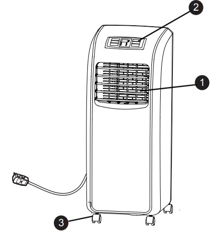
2. CONTROL PANEL AND DISPLAY
Easy-to-read digital display shows the set temperature and indicator lights show the operating mode. Simple push buttons make changing settings quick and easy.
3. SWIVELING CASTERS
Swiveling casters allow you to move the air conditioner easily on most floor surfaces.
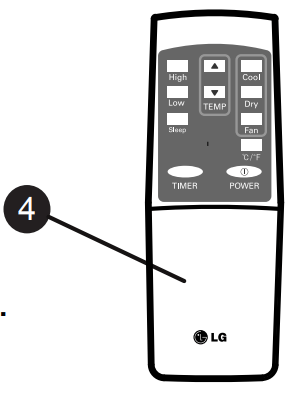
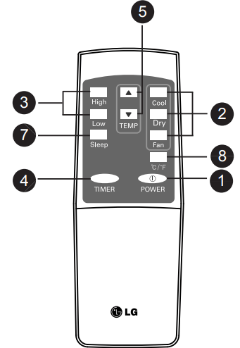
4. INFRARED REMOTE CONTROLLER
The remote controller allows you to adjust the temperature and operate most functions of the air conditioner from across the room.
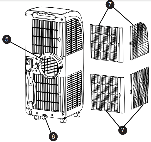
5. EXHAUST AIR OUTLET VENT
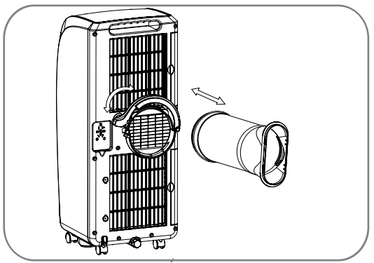
Insert the large adapter at end of the hose into the hole on the back of the air conditioner.Align the pins on the connector with the slots in the hole. Twist slightly clockwise until it locks into place.
6. BOTTOM DRAIN PORT
Used when water tank is full or free of using long time. Before moving the unit, drain the internal water collection tank completely by using bottom drain port.
7. AIR FILTER
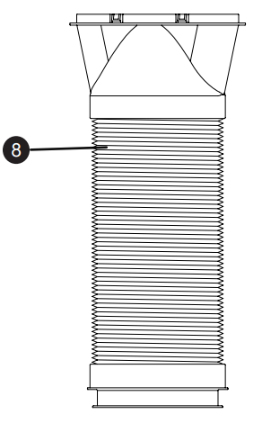
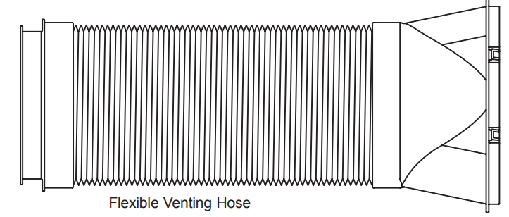
8. HOSE AND DIFFUSER
Use the diffuser and hose to connect the air conditioner to the window installation kit to vent exhaust air outside
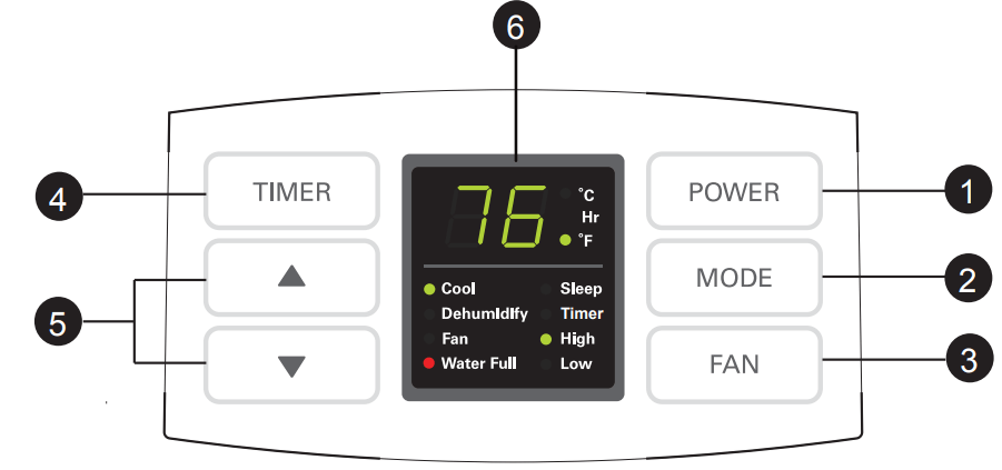
CONTROL PANEL AND REMOTE
Operation of functions is the same when using the remote or the control panel, unless otherwise stated.
For detailed instructions on each function,see the following pages.
1. POWER
Operation begins when this button is pressed and stops when you press the button again.
2. MODE
Press this button to select Cool,Dry(Dehumidify),Fan mode
3. FAN SPEED
Adjusts the circulation fan speed between High, Low fan speed.
4. TIMER
Press this button to set TIMER ON, TIMER OFF or NO TIMER
5. UP & DOWN
Press these buttons to set room temperature or timer when in Timer On/Off mode.
6. LED Display
Display different signals accordingly.
7. SLEEP MODE
Setting sleeping mode, the temperature will rise 1 °C after 2 hours, and another 2 hours later, rise 1 °C
8. CELSIUS AND FAHRENHEIT EXCHANGE BUTTON
HOW TO USE
BEFORE USING YOUR AIR CONDITIONER
PREPARING FOR OPERATION
Refer to the Installation Instructions included in this manual before using the air conditioner. Once the air conditioner has been properly assembled and installed:
Plug the power cord into its own dedicated properly grounded outlet. Do not plug other appliances into the same outlet, it could overload the outlet and create a fire hazard
Make sure the air conditioner and cord is positioned where it does not create a tripping hazard and will receive adequate ventilation. Do not place it directly next to furniture or objects that could block the vent openings.
Make sure that any items that could be blown over or damaged by the airflow from the fan are out of the airflow path.
UNPACKING THE AIR CONDITIONER
Remove and store packing materials for reuse. Remove any shipping tape before using the air conditioner. If the tape leaves behind any adhesive, rub a small amount of liquid dish soap onto it and wipe with a damp cloth. Do NOT use sharp instruments, alcohol, thinners, or abrasive cleaners to remove adhesive. They could damage the finish.
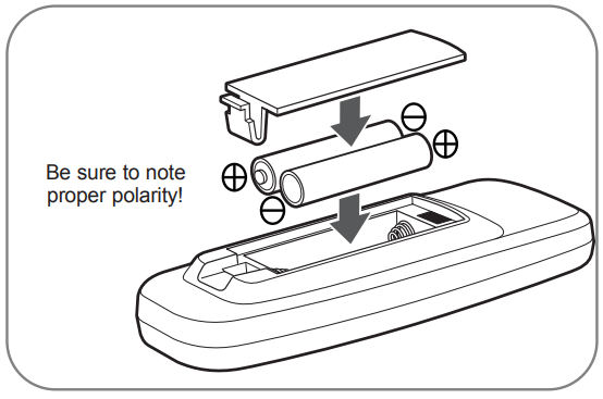
INSERTING BATTERIES IN THE REMOTE
Before using your remote, install the provided AAA batteries :
Press in the locking tab on the battery cover on the back of the remote and remove the cover
Insert two new alkaline AAA batteries into the battery compartment, being sure to note the proper polarity.
Reattach the battery cover, making sure the locking tab clicks into place.
USING THE CONTROLS
1. COOLING MODE
Press MODE button to choose Cool mode, the Cool mode indicator will flash.
Press UP or DOWN button to set room temperature between 65°F to 86°E .
· Press SPEED button (or High/Low button) to select high, low fan speed.
2. FAN MODE
Press MODE button (or Fan button) to choose Fan mode, the Fan mode indicator will flash.
Select the fan speed by press FAN button or press High / Low button directly.
The temperature can not be set.
3. DRY MODE
Select Dry button for dehumidify Mode.
In Dry mode fan speed is preset. Speed button is not available. The temperature can’t be set either.
· Press Swing button to make the louver swing (use remote control only).
4. TIMER MODE
When the appliance is switch off, press Timer button to set timer-on.
Press Up or Down button to adjust time from 1 hour to 24 hours. The Time on indicator will flash.
When the appliance is running, press Timer button to set timer-off.
5. SLEEP MODE
Setting sleep mode, the temperature will rise 1°C after 2 hours, and another 2 hours later, rise 1°C·
Then it will keep steady and low fan blow.
INSTALLATION INSTRUCTIONS
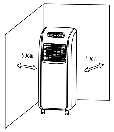
SELECTION OF INSTALLATION LOCATION
Install the unit on a flat and dry place.
For best performance,allow at least 50cm of air space on all sides of the unit for good air circulation.
ATTACHING THE HOSE AND DIFFUSER
Insert the large adapter end of the hose into the hole on the back of the air conditioner.
PREPARING FOR INSTALLATION
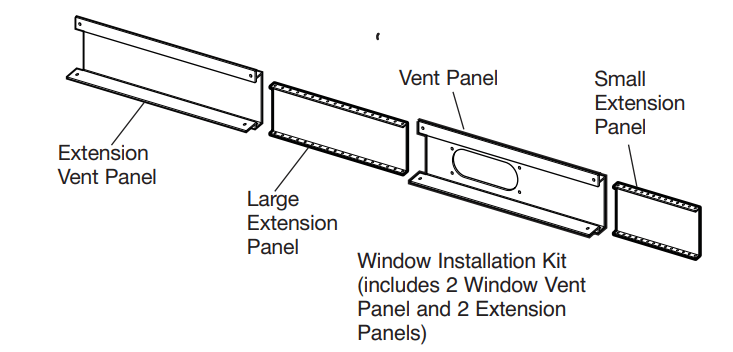
EXHAUST COMPONENTS
The following components are used for window venting. Not all components are used for every installation.
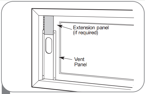
WINDOW VENT PANEL AND EXTENSIONS
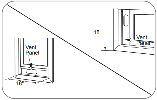
The window installation kit allows you to install the air conditioner in most vertical-sliding windows 18" to 48" wide, or casement-style windows from 18" to 48" high.
For an 18" window opening, use the window vent panel by itself.
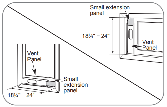
For window openings from 181⁄4" to 24", use the window vent panel and the small extension panel.
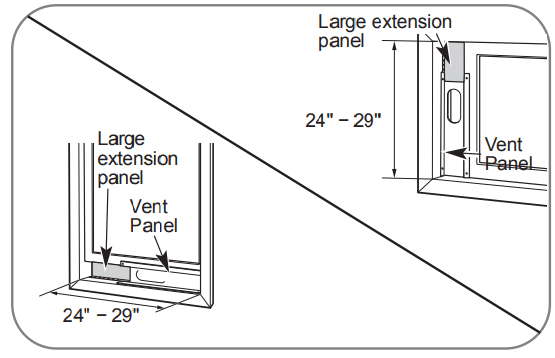
For window openings from 24" to 29", use the window vent panel and the large extension panel.
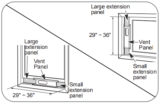
For window openings from 29" to 36", use the window vent panel and both extension panels.
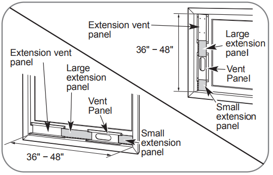
For window openings from 36″ to 48″, use both vent panels and both extension panels.
INSTALLATION IN VERTICAL SLIDING WINDOWS
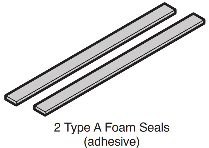
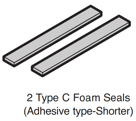
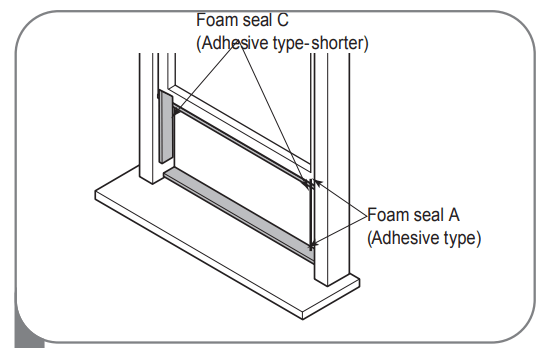
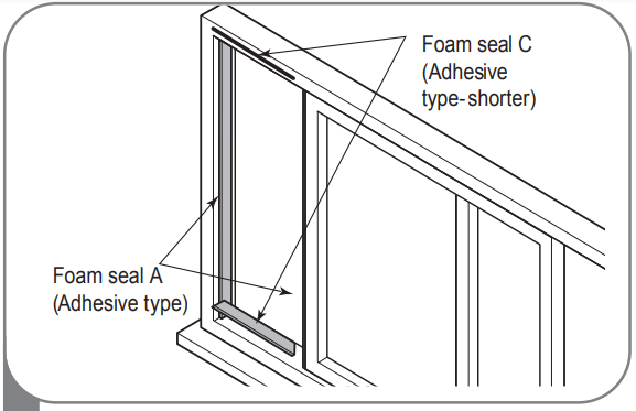
1. Cut the foam seal A(adhesive type) & C(adhesive type-shorter) to the proper length, and attach it to the window sash and frame
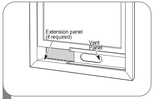
2. Insert the vent panel assembly, including extension panels, if needed, into the window opening. Extend the extension panels, if used.
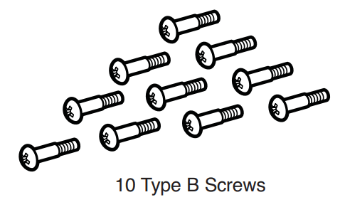
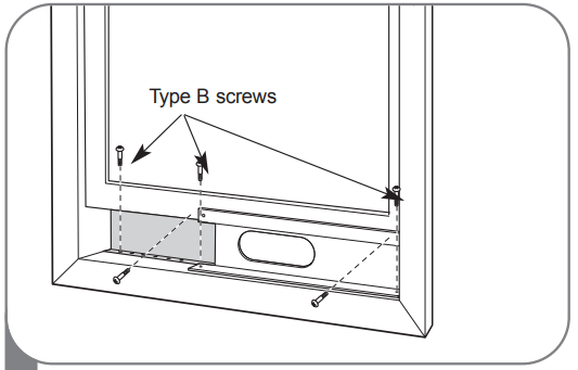
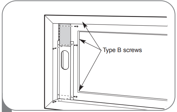
3. Carefully lower the window. Secure the vent panel in place with 4 type B screws, plus one screw for each extension:
Vent panel only: 4 type B screws
Vent panel and one extension: 5 type B screws
Vent panel and two extensions: 6 type B screws
Two vent panels and two extensions: 9 type B screws
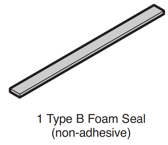
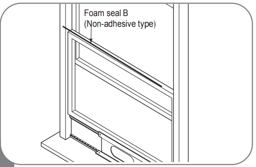
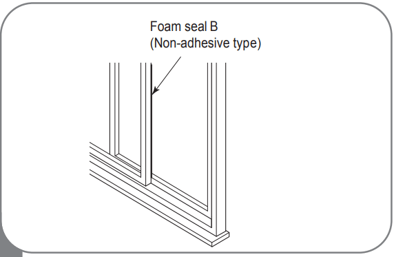
4. Cut the foam seal B(Non-adhesive type) to the window width. Stuff the foam seal B between the glass and the window to prevent air and insects from getting into the room.
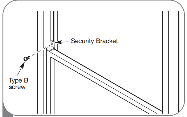
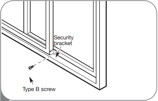
5. Install the security bracket with a type B screw, as shown.
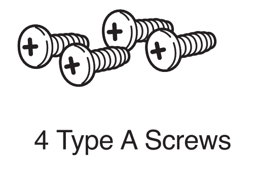
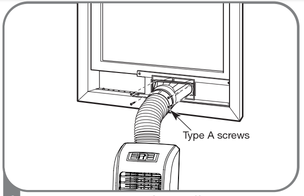
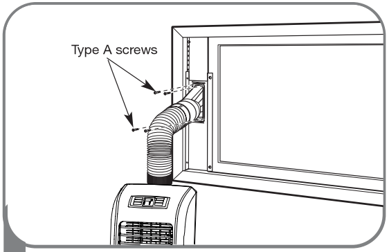
6. Insert the oval end of the diffuser into the window installation kit until the locking tabs engage. Secure in place with four Type A screws
INSTALLATION IN CASEMENT-STYLE WINDOWS
1. Cut the foam seal A(adhesive type) & C(adhesive type-shorter) to the proper length, and attach it to the window sash and frame.
2. Insert the vent panel assembly, including extension panels, if needed, into the window opening. Extend the extension panels, if used.
3. Carefully close the window. Secure the vent panel in place with 4 type B screws, plus one screw for each extension:
Vent panel only: 4 type B screws
Vent panel and one extension: 5 type B screws
Vent panel and two extensions: 6 type B screws
Two vent panels and two extensions: 9 type B screws
4. Cut the foam seal B(Non-adhesive type) to the window height. Stuff the foam seal B between the glass and the window to prevent air and insects from getting into the room.
5. Install the window security bracket with a type B screw, as shown.
6. Insert the oval end of the diffuser into the window installation kit until the locking tabs engage. Secure in place with four of the included screws.
CARE AND CLEANING
STORING THE AIR CONDITIONER
If the air conditioner will not be used for an extened period of time :
Drain the water collection tank completely and leave the bottom drain cap off long enough to allow any residual water to drain out. Once the tank is completely drained and no more water flows out, reinstall the cap.
Remove and clean the filter, allow it to dry completely, then reinstall it.
Remove the batteries from the remote.
Store the air conditioner in a cool,dry location, away from direct sunlight, extreme temperatures, and excessive dust.
Before using the air conditioner again :
Make sure the filter and drain cap are in place
Check the cord to make sure it is in good condition, with no cracks or damage.
Place new batteries in the remote.
Install the air conditioner as described in the Installation Instructions.
TROUBLESHOOTING
Problem
Possible Causes
Solutions
Air conditioner will not start
• The air conditioner plug is not completely inserted in the electrical outlet.
• The house fuse is blown or the circuit breaker has tripped
• Power failure.
• The integrated circuit breaker in the plug has tripped.
• FL appears in the display
• Room temperature is less than the set temperature.
• Make sure electrical plug is plugged completely into a live, properly grounded outlet.
• Replace the fuse or reset the circuit breaker. Make sure that there are no other appliances on the same circuit.
• If a power failure occurs, turn the power OFF. When power is restored, wait 3 minutes before restarting the air conditioner.
• Press the RESET button on the air conditioner plug. If the reset button will not stay engaged, unplug the air conditioner and contact a qualified service technician
• The water collection tank is full. Drain the tank and reset your settings.
• This is normal. The air conditioner automatically shuts off when the room equals or is less than the set temperature. Adjust the temperature setting,if needed.
Air conditioner does not cool properly
• Airflow is restricted.
• The air filter is dirty.
• The room is very hot, or not enough time allowed for cooling.
• Cold air is escaping.
• Cooling coils have iced up.
• Make sure there is sufficient clearance around the air conditioner and that the air inlet and outlet are not blocked by furniture, curtains, etc.
• Clean the air filter at least every two weeks. See the Care and Cleaning section.
• When first turned on, allow the air conditioner sufficient time to cool the room.
• Check for open furnace floor registers or cold air returns, or open windows or doors.
• In especially hot, humid weather and when the air conditioner is running frequently or for extended periods, ice can form on the cooling coils, blocking air flow. Set the controls to High Fan or High Cool, and set to a warmer temperature.
Air conditioner runs too often or too long
• Area to be cooled is too large for the air conditioner.
• Doors or windows are open.
• Consult your dealer for the air conditioner capacity necessary to cool the desired area.
• Make sure doors and windows are closed.
Problem
Description
Code appears in the display
FL
E1, E2
E4
• Protection ( Water-full protection, to prevent spilling)
• Sensor protection, to avoid occurrence of unit damage, auto-stop protection.
• When coil sensor feels coil temperature is ≤ 2 °C, the unit will stop and display E4 to defrost, and fan speed is low.
• When coil temperature runs up to ≥ 8°C ,the unit will re-cool.