USER MANUAL


1
1
1.1
1.2
1.3
2
2.1
2.2
2.3
3
3.1
3.2
3.3
3.4
3.5
4
4.1
4.2
4.3
4.4
5
5.1
5.2
5.3
6
6.1
7
7.1
7.2
8
8.1
9
9.1
9.2
10
11
11.1
11.2
11.3
12
12.1
12.2
13
13.1
13.2
2
4
6
10
11
16
18
20
21
22
23
24
26
Index
Important directions for safety and the environment
For your safety
Caring for the environment
Cleaning, sanitization and maintenance of the ice and/or water
dispenser (if present)
Installation
Installation
Connection to the electrical power supply
Connection to the water system
Before starting
Know your appliance
Main features
Main components
Electronic Control
Main control panel
Appliance switching on and off
Switching on and off
How to adjust the temperature for different requirements
Ice Maker activation
Information and malfunction messages on the display
Settings and Special Functions
Customization and language settings
Special functions activated through the Menu
Basic settings of the Menu
Internal Layout
Internal Layout (positioning, adjustment, removal)
Activation and use of the Ice Maker
Activation and use of the Ice Maker
Water Filter
Lighting
Lighting
Food Preservation
Recommendations for preserving fresh food
Recommendations for preserving frozen food
Recommended times for Food Preservation
Care and Cleaning
Care and Cleaning
Condenser cleaning
Internal cleaning
Troubleshooting Guide
Troubleshooting Guide
Malfunction messages appearing on the display
Menu Map
Functions
Setting
Page

2
1
1.1
B0900130 1
Product tested in accordante with EN62471
Risk Group 2
PRUDENZA:
NON FISSARE LA LAMPADA IN FUNZIONE.
PUÒ ESSERE DANNOSO PER GLI OCCHI.
CAUTION:
DO NOT STARE A T OPERATING LAMP.
MAY BE HARMFUL T O THE EYES.
Notes
Recommendations for correct
use of the appliance
For your safety
Important
Directions for avoiding
appliance damage
Warning
Indications for avoiding injury
to people
Important directions for safety and the environment
If this appliance is replacing an existing appliance which must be
removed or disposed of, make sure that it does not become a dan-
gerous trap for children by cutting its power supply cable and ren-
dering it impossible to close the door. Use the same caution at the
end of the lifespan of the new appliance.
This appliance is designed to refrigerate beverages and foods and
is intended for domestic use.
The appliance must be installed by following the instructions in the
Installation Guide, particular care should be taken not to obstruct the
vent openings of the appliance and of the built-in units.
The appliance features a concentrated lighting system with LED
lamps. Do not stare into these lamps when they are on to avoid pos-
sible eyesight damage.
This warning is also contained on the label attached to the inside of
the refrigerator door.
When the freezer is functioning do not touch the inner surfaces in
stainless steel with wet or damp hands, since skin may stick to the
very cold surfaces.
Do not use any type of electrical equipment inside of the food
conservation compartments.
When positioning the shelves, do not place fingers in the shelf
slide guides.
Do not position containers of ammable liquids near the appliance.
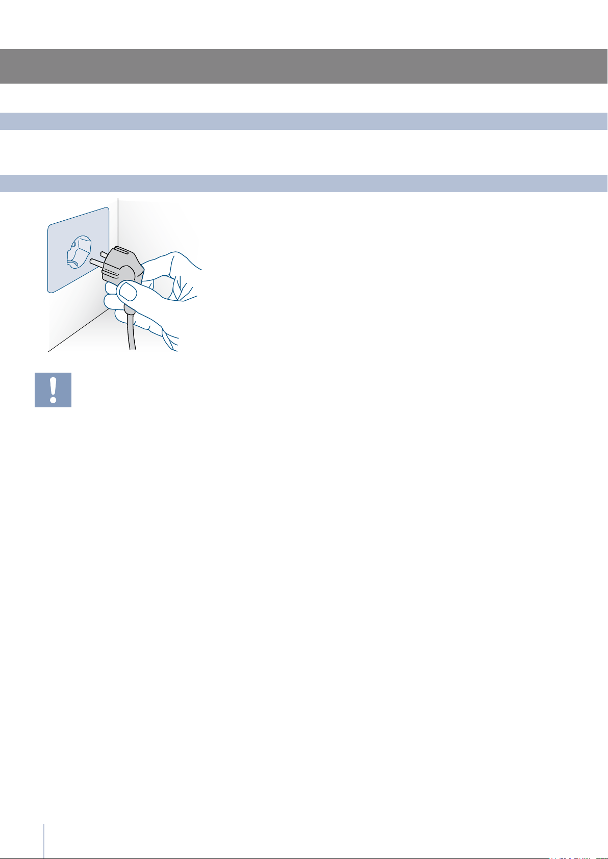
Completely switch off the appliance and unplug the power supply
cable during cleaning operations. If the plug is not easily reached, it
is a good idea to turn off the breaker or remove the fuse that controls
the socket that the appliance is connected to.
The packaging parts can be dangerous for children: do not allow
children to play with the plastic bags, plastic lm or Styrofoam.
Any repairs must be performed by a qualified Smeg Service tech-
nician.
This appliance is not intended for use by persons (including children)
with reduced physical, sensory or lack of experience and knowledge
unless they have been given supervision or instruction concerning use of
the appliance by a person responsible for their safety. Children should
be supervised to ensure that they do not play with the appliance.
Do not damage the appliance refrigerant circuit pipes.
Do not store explosive substances such as aerosol cans with a am-
mable propellant in this appliance.
3
1
1.2
1.3
Pay special attention to correct disposal procedure for all the pack-
aging materials.
The appliance must not be disposed of with urban waste. Contact lo-
cal waste disposal centers for on how to dispose of recyclable waste.
Prior to disposal, cut the power supply cord and make it impossible
to close the door.
During disposal, avoid damage to the refrigeration circuit.
The appliance does not contain hazardous substances for the atmos-
pheric ozone layer, neither in the refrigeration circuit nor in the insulation.
Caring for the environment
Important directions for safety and the environment
Failure to follow the instructions regarding sanitizing can compromise
the hygienic safety of the water dispensed.
When using the appliance for the rst time and every time the lter
is changed, it is recommended to let the water ow in the circuit using
the “Manual Cleaning” and discard the ice produced in the rst 24
hours.
If the water dispenser has not been used for more than 4/5 days, it is
advisable to clean the circuit and run off the rst litre of water.
Reposition the removable water dispenser (if present), ensuring your
hands are hygienically clean.
Clean the ice bucket or drawer regularly but using only drinking
water.
The lter must be changed when indicated on the control panel
or when the ice/water dispenser has not been used for more than 30
days.
With each lter replacement, sanitise the ice and/or water distribu-
tion system using a food grade disinfectant (with sodium hypochlo-
rite), which does not alter the characteristics of the materials, or use
the “Sanitising Kit” available from the After-Sales Service. Rinse with at
least 2 litres of water before use.
Only original spare parts supplied by the manufacturer should be
used when replacing components in the ice and water dispenser.
Any work on the appliance must be carried out by a qualied tech-
nician or the After-sales Service.
Cleaning, sanitization and maintenance of the ice and/or water dispenser (if present)
4
2
2.1
2.2
Make sure that installation is performed correctly, adhering to all direc-
tions in the specic installation manual provided with the appliance.
Installation
Connection to the electrical power supply
The appliance is equipped with a Schuko type 16A plug and must be
connected to the electrical power supply through a corresponding
Schuko socket.
Do not use extension cords and/or multiple adapters for the power
supply connection.
Do not use extension cords and/or mul-
tiple adapters for the power supply con-
nection.
Installation
5
2
2.3
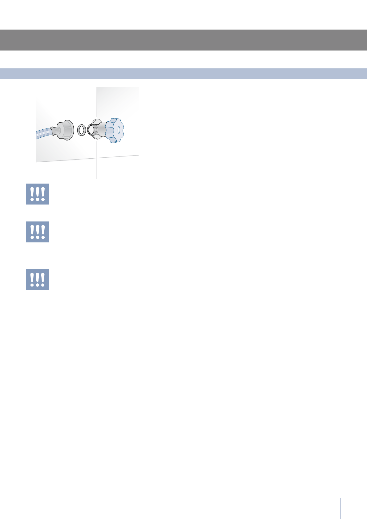
The models provided with Ice Maker require a connection to the do-
mestic water supply system. This can be executed through the pro-
vided water hose with 3/4” threading.
The system pressure must be between 0.05 MPa and 0.5 MPa (between
0.5 Bar and 5 Bar).
Differents pressures can cause malfunctions or leaks in the water sys-
tem. The appliance should be supplied only with drinkable water.
The appliance should be supplied only
with drinkable water.
Make sure that installation is performed
correctly, according to all of the directions
in the specic installation manual provid-
ed with the appliance.
Connection to the water system
Installation
Do not attempt to use a locally sourced
garden hose threaded adapter or braid-
ed supply line. It will strip the threads on
the appliance water connection sole-
noid.
6
3
3.1
3.2
Before starting
Know your appliance
Congratulations for having purchased your new Smeg:
from now on you can use our innovative conservation
system, which will allow you to keep all of your food in the
best way possible.
This manual will answer most of your questions about the
product’s features. Should you require further information,
please check our website
www.smeg.com
The Smeg Multizone refrigeration system and the efcient
separation of internal compartments ensures maximum
freshness and offers excellent conservation of foods in the
three compartments: refrigerator, Multizone.
It is also possible, should there be a need, to further in-
crease the exibility of the appliance by making the freezer
compartment operate as a refrigerator or as a Multizone
compartment
Electronic control guarantees constant temperature and
humidity levels set by the user and provides real-time com-
partment temperature readings.
An interactive menu (Menu) allows customized manage-
ment of appliance functions and the visualization of func-
tioning messages
Power save features to reduce consumption during Holi-
day periods
Ice Maker for automatic ice production of variable cube
size
Easily replaceable water lter located inside the refrigera-
tor
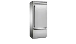
Main features
Stainless steel surface both inside and outside, with ne
aluminum trim
Patented hinge system that permits automatic door clos-
ing
External drawers with to self-closing system
Localized lighting with LEDs
Anti-tipping system by means of wall mounting brackets
7
3
3.3
10
11
12
13
14
15
16
2
3
4
7
8
9
Multizone
Before starting
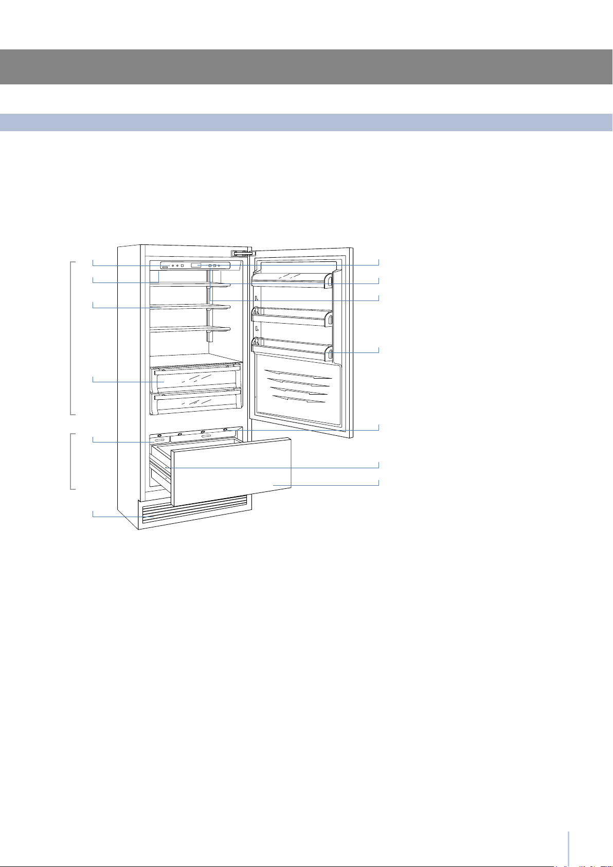
Main components
Single drawer Fridge
2 Control panel with Menu
3 Water Filter
4 Patented shelf positioning
system
7 Drawer with controlled
humidity
8 Automatic icemaker
9 Double refrigeration system
10 Temperature display
11 Sound signals
12 Holiday function
13 Spacious door shelves
14 Innovative lighting
15 Automatic door and
drawer closure
16 Frezer compartment
that can be transformed
into a refrigerator or 0°C
compartment
(Multizone function)
Fridge
3
3.3
3.3
Componenti principali
Componenti principali
3.5
3.4
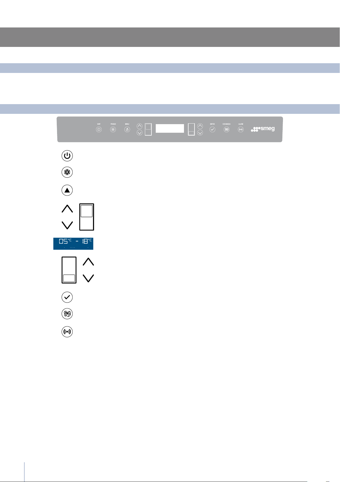
123456798
1
Unit
2
Fridge
3
Menu
4
Up/down
Fridge
5
Display
6
Up/Down
Freezer
(Multizone)
7
Enter
8
Ice maker
9
Alarm
8
Before starting
The electronic control system maintains constant temperature on the two compartments and visualizes it on the control
panel display.
It also allows user interaction making it possible to personalize settings of the various functions and to receive sound and/
or visual messages should occur any malfunction in the appliance.
Main control panel
Electronic Control
Switches the appliance (all compartments) between ON and STAND BY
(press for three seconds).
Allows switching on and off of only the refrigerator compartment
(press for three seconds).
Allows access to the appliance function menu
It shows the temperature of the refrigerator and freezer compartments,
the date and time, Menu functions and visual messages.
By selecting Up/Down the preset temperature can be changed ac-
cording to the selected function mode (freezer, refrigerator, 0°C).
Confirms activation or deactivation of the selections made in the
Menu.
Allows activating or deactivating the automatic ice production.
Blinks to signal user alerts such as door left open, also in combination with
a sound signal which can be deactivated by pressing the button.
Using the Up and Down buttons, it is possible to change the set tempera-
ture of the refrigerator and navigate through the interactive menu.
9
4
4.1
Appliance switching on and off
If at the rst startup the Standby message does not
appear, but another message appears, it means
that the appliance has already started the cooling
process. If this is the case, deactivate any possi-
ble sound signal by pressing the Alarm button
,
close the door and wait until the set temperature
is reached.
During the rst startup, it will not be possible to use
the Menu to modify the factory settings until the
preset temperature has been reached.
Each time the appliance is switched on it goes
trough a self-diagnosis procedure lasting three
minutes before completely starting up.
If only the refrigerator compartment is switched
off, the specic fan will continue to operate to
prevent the formation
of unpleasant odors and mold.
Before switching off the appliance for a long pe-
riod of time, remove all of the items inside and
leave the doors and drawers open to prevent the
formation of unpleasant odors and mold.
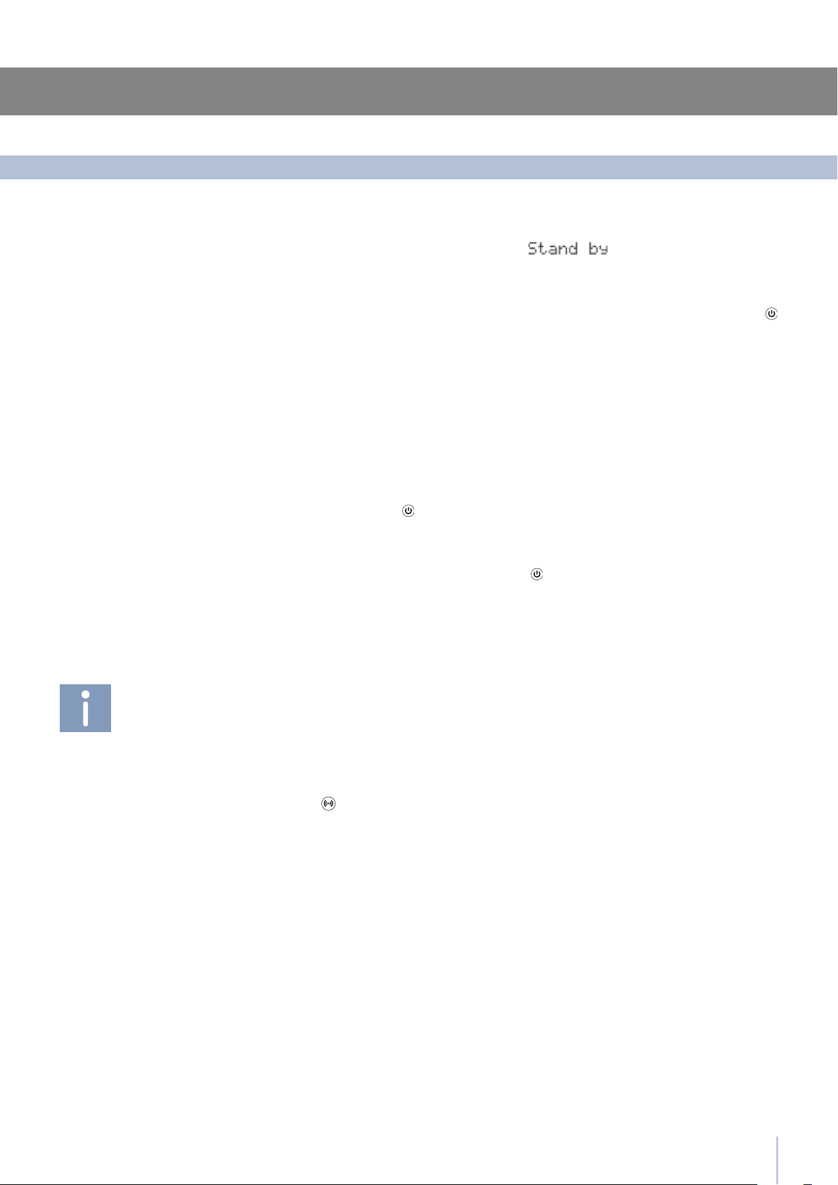
When the appliance is connected to the electrical power supply but
has not yet been switched on, the display shows the message
Tis is a safety message to warn that the appliance is connected to the
mains, and all the panel buttons are off.
To switch on all the appliance compartments, press the Unit button
for three seconds.
First startup
When the appliance is rst switched on the Multizone compartment is
set to the “freezer” mode. After switching on it remains always on and
can be switched off only by switching off the complete appliance.
During long absence periods it is recommended to switch off the refrigera-
tor by pressing the Unit button
for three seconds and disconnecting the
electrical plug or the breaker controlling the socket.
Completely empty the refrigerator, clean and dry it and leave the doors
and drawers partially open to prevent unpleasant odors.
Switching off the Refrigerator
Restarting
Switching off for long periods
Switching on and off
Use the same buttons to restart.
The freezer compartment always stays on and cannot be switched off
except by completely switching off the appliance by pressing the Unit
button for three seconds.
10
4
4.3
4.4
4.2
An integrated control system provides information through lighted sig-
nals or text messages visualized on the display.
The information signal is always visualized with a xed text message,
while a malfunction signal is visualized with blinking text.
The sound signal that accompanies some malfunction signals can be de-
activated by pressing the Alarm button on the main control panel.
The list of malfunction signals is located at the back of this manual.
Appliance switching on and off
Each model has been carefully tested before leaving the factory and
is adjusted in such a way to ensure high performance and low con-
sumption. Usually, it is not necessary to modify the settings.
Nevertheless, according to special needs, it is possible to modify the
set temperatures as follows:
Refrigeration Compartment
Freezer Compartment
(Multizone)
From +2°C to +8°C (from 35.6°F to 46.4°F), the recommended preset
temperature is +5°C (41°F).
To adjust the temperature use the Up/Down buttons
.
Upon touching these buttons the newly set temperature will appear in
the display. To modify this temperature, use the buttons until reaching
the desired temperature.
From -15°C to -22°C (from 5°F to -7.6°F), the recommended tempera-
ture is preset at -18° (0°F).
To adjust the temperature use the Up/Down buttons
.
Upon touching these buttons the newly set temperature will appear in
the display. To modify this temperature, use the buttons until reaching
the desired temperature.
In case the compartment is used as refrigerator or 0°C compartment
(Multizone function) the recommended and preset temperatures will
correspond to those indicated for the respective compartments.
The temperature shown can vary slightly in re-
spect to the set temperature following frequent
openings of the doors or insertion of room tem-
perature foods or large quantities of foods.
6 to 12 hours are necessary to reach the select-
ed temperature.
Ice Maker Activation
The Ice Maker button located on the main control panel permits
activation of the automatic icemaker.
The button is illuminated when the icemaker is functioning.
A prewash of the hydraulic circuit should be performed before acti-
vating the Ice Maker for the rst time. To do this touch at the same time
buttons Enter and Ice Maker .
After a few minutes the Ice Maker can be activated.
Information and malfunction messages on the display
How to adjust the temperature for different requirements
Do not activate the Ice Maker unless the appli-
ance is connected to the water mains.
11
5
5.1
5.2
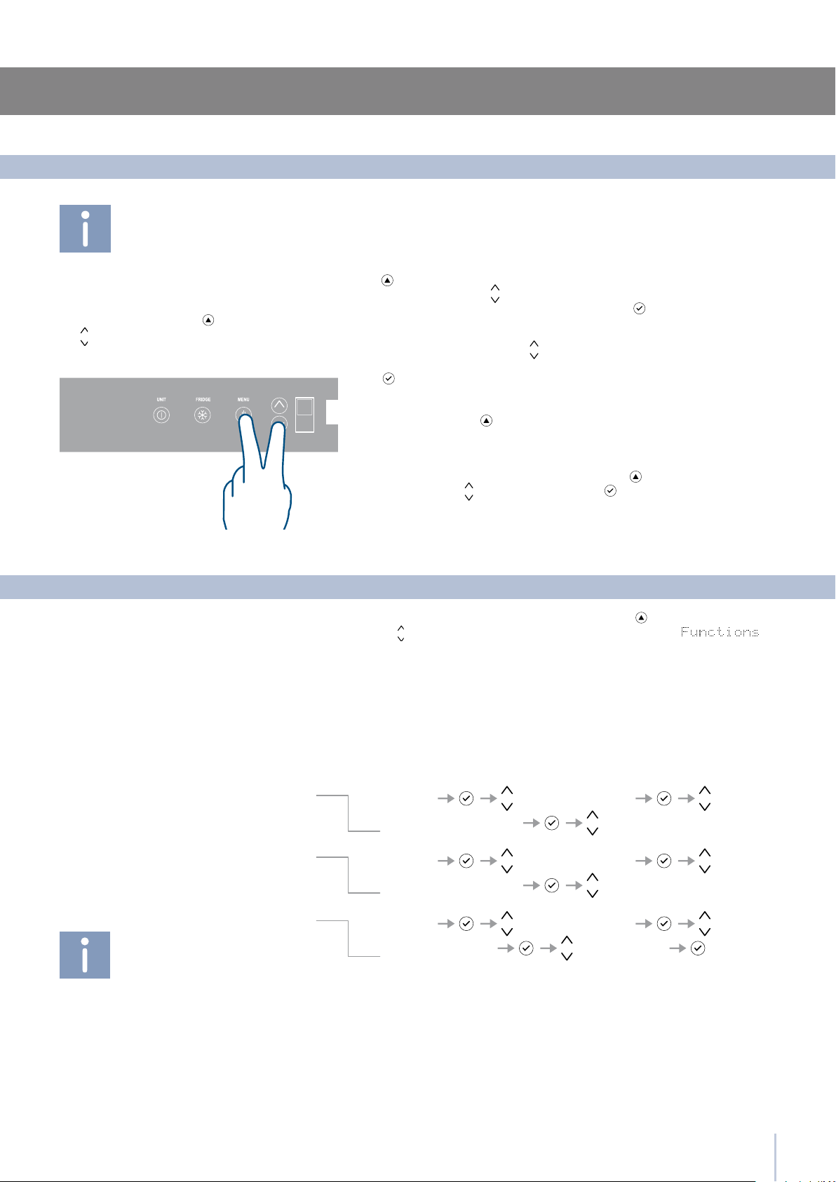
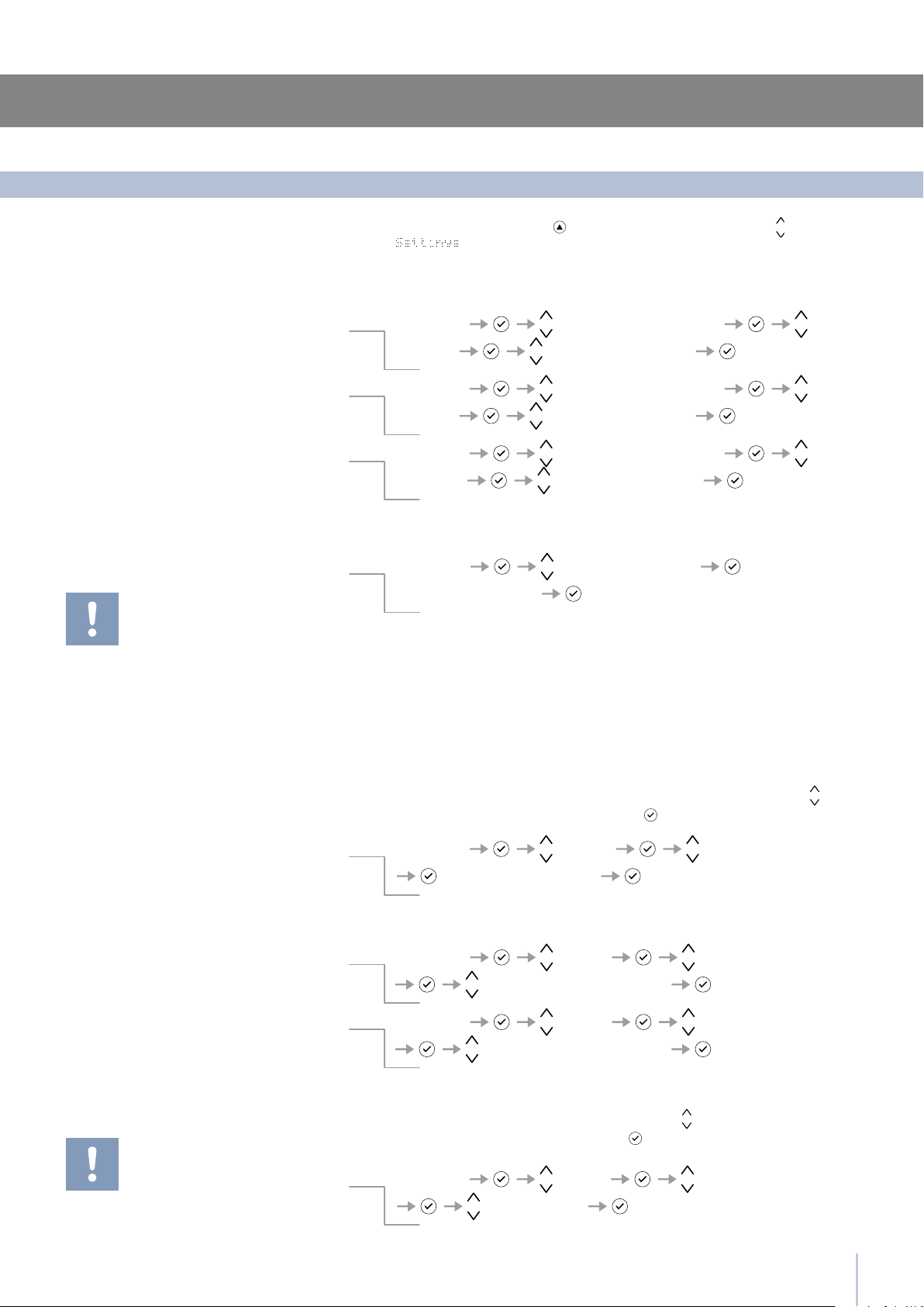
Functions Super Cooling
Super Cool ON/OFF Super Cool ON
Functions Super Cooling
Super Cool ON/OFF Super Cool OFF
Functions Super Cooling
Super Cool Time Set Hours: I
Super Cooling
Settings and Special Functions
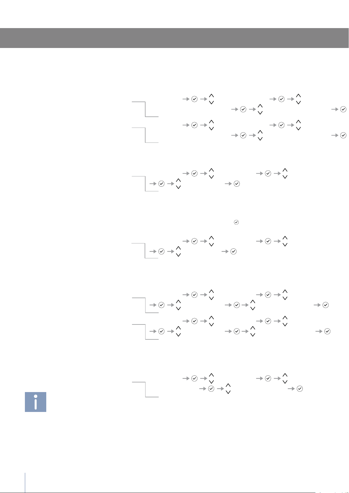
It is possible to customized the functions of your Smeg to adapt it to
diverse usage needs, resetting the main parameters (Settings) or acti-
vating special functions (Functions).
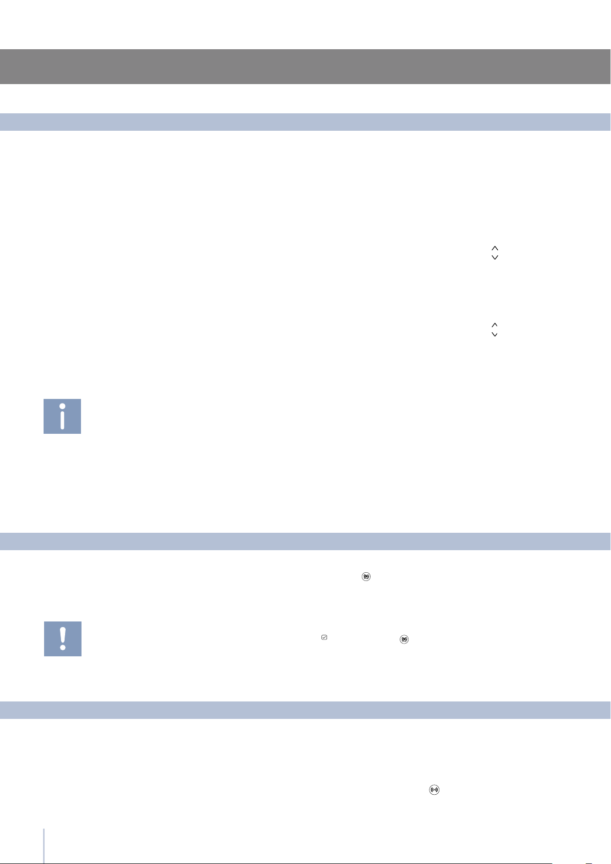
Functions are visualized on the main display by pressing the Menu but-
ton .
The Up/Down buttons permit scrolling the available functions, which
can be selected by pressing the Enter button . The display visualizes
the current functioning status.
Using the Up/Down buttons , it is also possible to scroll through the
selected function, activating or deactivating by pressing the Enter but-
ton . Once the function is conrmed, the display will automatically
visualize the main menu to select other functions.
At any time it is possible to return to the previous selection through the
SmegAccess button .
The language of the messages appearing on the display can be
changed by operating as follows:
Enter the Menu by pressing the Menu button select Settings via the
Up/Down buttons and conrm via Enter . Then select the Language
function and the desired language.
To prevent an inadvertent change to the settings
the keypad is automatically locked after a cer-
tain period of time.
To re-activate the Menu function, press simulta-
neously the Menu button and the Down but-
ton for at least three seconds.
Customization and language settings
Special functions activated through the Menu
The function lowers the refrigerator temperature to +2°C (35.6°F) for 12
hours, permitting more rapid cooling of food that has just been placed
in. Once the 12 hours have expired, the function deactivates automati-
cally, returning to the previously set temperature. It is possible to pro-
gram a timed activation of the function. After a prolonged interruption
of electrical current, it is necessary to reactivate the function.
It is possible to program the function with a delay of 1 to 12 hours.
To use special functions, select the Menu button
and use the Up/Down
button to access the menu, conrming the selection .
How to activate
How to deactivate
How to program timed activation
The various Shopping Modes help prepare the cooling,
Fridge and Multizone compartments for the introduc-
tion of a heat load which can consist of fresh food or
other items which may have warmed during transport.
The more quickly an item can be cooled or frozen the
better it will be preserved.
This mode can also be effective at maintaining com-
partment temperatures while entertaining when high-
er than average door and drawer openings are an-
ticipated.
12
5
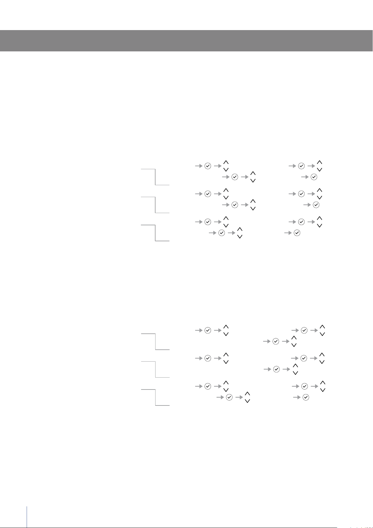
Functions Hodiday Fridge
Holiday ON/OFF Holiday ON
Functions Hodiday Fridge
Holiday ON/OFF Holiday OFF
Functions Hodiday Fridge
Holiday Time Set Days: I
Holiday fridge
Functions Shopping Multiz
Shopping Multizone ON/OFF Shopping ON
Functions Shopping Multiz
Shopping Multizone ON/OFF Super Cool OFF
Functions Shopping Multiz
Shopping Time Set Hours: I
It is possible to program a period from 1 to 90 days.
It is possible to program the function with a delay of 1 to 12 hours.
This function must be activated at least 24 hours before inserting room
temperature items into the freezer, or several hours before placing into
the freezer previously frozen items which have been subject to a slight
temperature rise. This function is automatically deactivated when the pro-
grammed time period expires. It is possible o program timed activation of
the function.
If interrupted by a prolonged interruption of the electrical power, it is nec-
essary to reactivate the function.
Shopping Multizone
This function (recommended in case of prolonged absences since it al-
lows considerable energy savings) brings the refrigerator compartment
temperature to +14°C (57.2°F). It is possible to program the duration, or it
can be manually deactivated upon re-entry after a period of absence.
This function remains active even if during the period of absence there is a
prolonged interruption of electrical power.
How to activate
How to activate
How to deactivate
How to program timed activation
How to deactivate upon re-entry
How to program the duration
Holiday Fridge
Settings and Special Functions
13
5
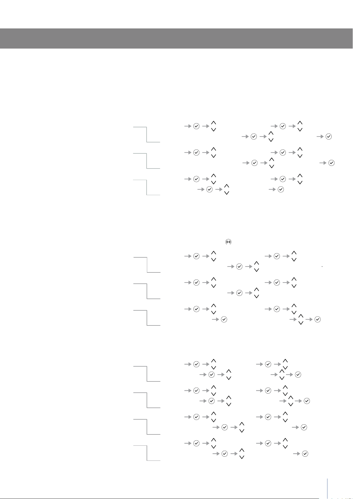
Functions Hodiday Multiz
Holiday Multizone ON/OFF Holiday ON
Functions Hodiday Multiz
Holiday Multizone ON/OFF Holiday OFF
Functions Hodiday Multiz
Holiday Time Set Days: I
Functions Bottle Cooler
Bottle Cooler ON/OFF Bottle Cooler ON
Functions Bottle Cooler
Bottle Cooler ON/OFF Bottle Cooler OFF
Functions Bottle Cooler
Set Cooling Time Set time : 20 min
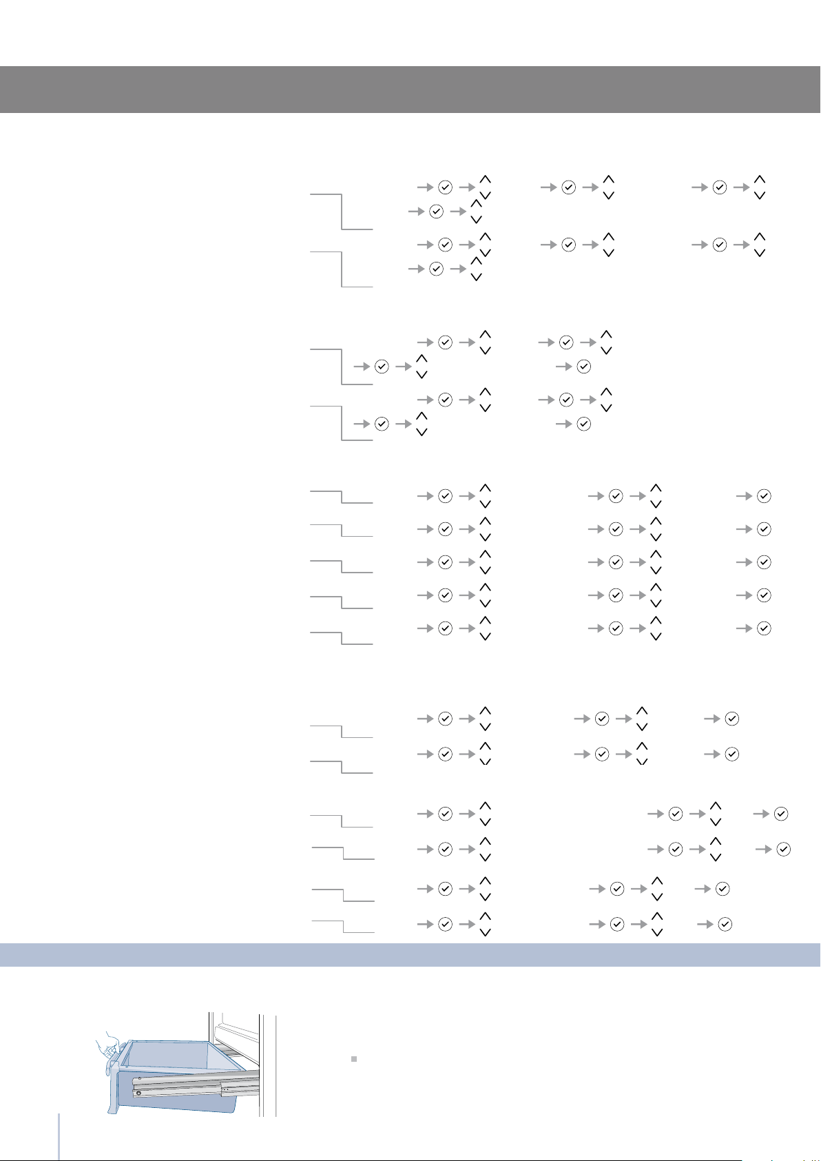
Functions Ice Maker
Set Cube Size Size: Large
Functions Ice Maker
Set Cube Size Size: Medium
Functions Ice Maker
SuperIce ON/OFF SuperIce ON
Functions Ice Maker
SuperIce ON/OFF SuperIce OFF
Settings and Special Functions
The IceMaker function permits selecting the size of the ice cubes, by
choosing between Large (base setting) or Medium, and activation of
the SuperIce function, which increases the quantity of produced ice.
The SuperIce function deactivates automatically after 24 hours.
This function can be activated when it is necessary to cool off bever-
ages quickly, by placing them inside the freezer compartment.
It is possible to select a duration of 1 to 45 minutes.
A sound signal will indicated when the optimal temperature has been
reached. After removing the beverages, deactivate the sound signal
by pressing the Alarm button
.
Bottle Cooler
Ice Maker
How to activate
How to activate the cube size function
How to deactivate
How to deactivate
How to program the duration
How to activate the SuperIce function
How to deactivate
It is possible to program a period from 1 to 90 days.
This function (recommended in case of prolonged absences since it
allows considerable energy savings) brings the Multizone compart-
ment temperature to - 18°C (46.4°F).
It is possible to program the duration, or it can be manually deacti-
vated upon re-entry after a period of absence.
This function remains active even if during the period of absence there
is a prolonged interruption of electrical power.
How to activate
How to deactivate upon re-entry
How to program the duration
Holiday Multizone
14
5
Functions Sabbath Mode
Sabbath Mode ON/OFF Sabbath Mode ON
Functions Sabbath Mode
Sabbath Mode ON/OFF Sabbath Mode OFF
Functions Water Filter Filter Status
View Status
Functions Water Filter Filter Status
Filter Reset
Functions Water Filter Filter Status
Filter Bypass Filter Bypass ON
Functions Water Filter Filter Status
Filter Bypass Filter Bypass OFF
Functions Water Filter Filter Status
View Status
Functions Water Filter Filter Status
Filter Reset
Functions Water Filter
Manual CleanEnter to confirm
The function makes it possible to comply to certain religious observ-
ances requiring that the operation of the appliance is not affected by
the opening or closing of the doors (the thermostatic control, the inner
lighting and the ice maker are deactivated).
The View Status function permits visualizing the time left before the
lter needs to be replaced.
The Reset Filter function sets to zero the time left before the lter needs
to be replaced. It is necessary to set the meter to zero each time the
cartridge is replaced. When the message “Change Filter” will appear
on the display press the Enter key
for 5 seconds.
This function is to be activated when it is not necessary to lter the
water, because excellent quality water is already available from the
home water system.
If ice production has been disabled or unused for a long period it is
recommended to perform a Manual Clean function to ush out water
which has sat in the system during this period. Repeat the operation
until the water is clean.
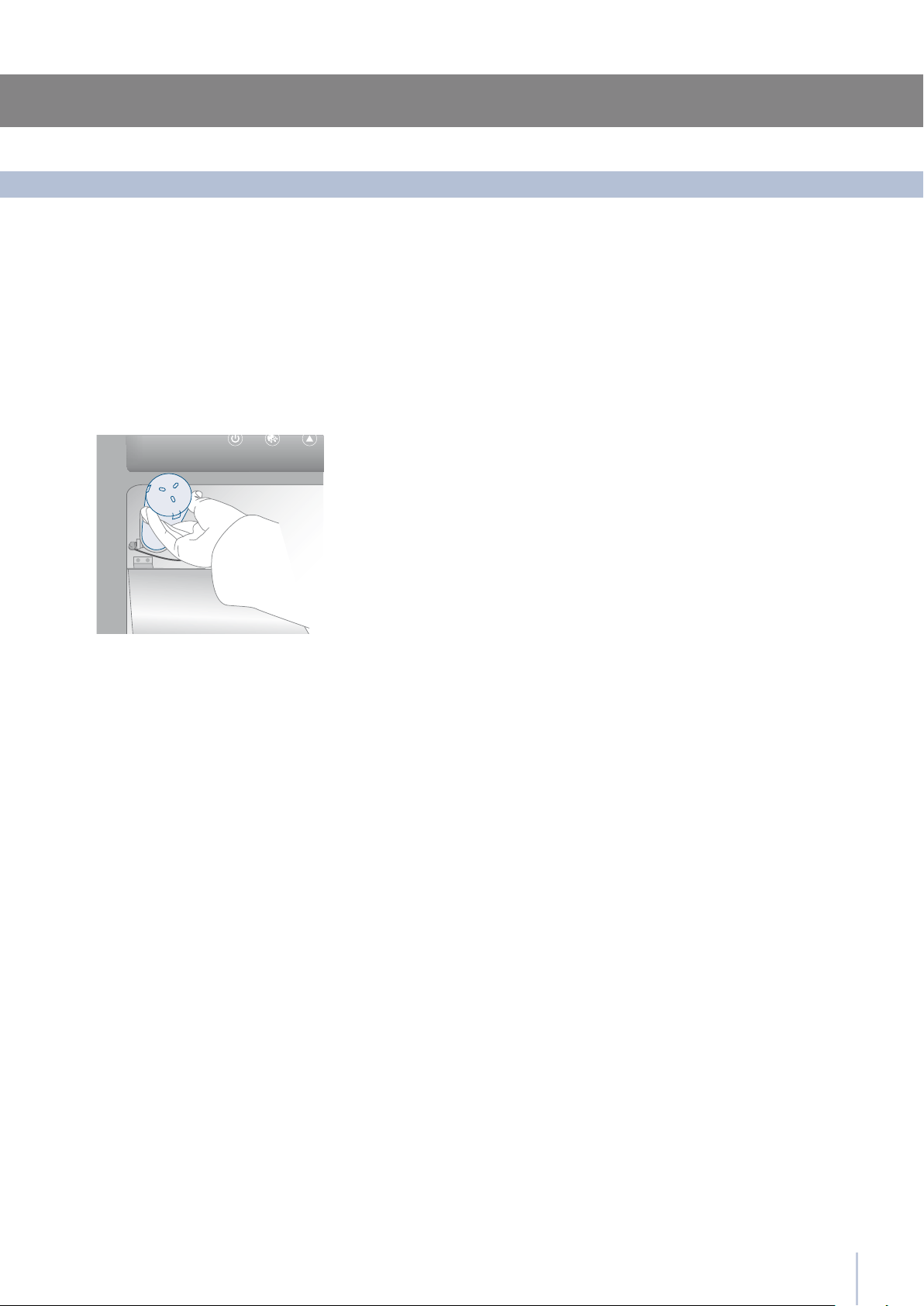
Correctly position the ice tray or another suit-
able container under the IceMaker to collect
water, then close the drawer.
At the end of the operation, wash the tray.
Sabbath Mode (Optional)
Water Filter
Reset Filter
Bypass Filter
Manual Clean, Water Filter
How to activate
How to deactivate
How to check the status of the lter
How to set the ltered water meter to zero
How to activate lter Bypass
How to deactivate lter Bypass
How to manually clean the lter
Settings and Special Functions
15
5
5.3
Settings Multizone Options
Fridge Enter to confirm
Settings Multizone Options
Fresco Enter to confirm
Settings Multizone Options
Freezer Enter to confirm
Settings Default Setting
Enter to confirm
Settings DateSet Date
DATE: 01-01-2009
Settings DateShow Date
DATE: 01-01-2009 On
Settings DateShow Date
DATE: 01-01-2009 Off
Settings Time Set Time
TIME: 01:01
Settings and Special Functions
Time
Set Time
How to set the time
This offers the possibility to reset default factory settings and can-
cels any previous changes.
Default Setting
How to reset default settings
Using this function it is possible to deactivate/activate the date visuali-
zation on the display.
Show Date
How to activate the date
How to deactivate the date
Date
Set Date
How to set the date
Select the Menu button
and used the Up/Down button to select
.
The freezer compartment can, if required, be converted to the re-
frigeration o 0°C operating mode.
Multizone Options
How to set the Fridge function
How to set the 0°C function
How to revert to the Freezer function
Basic settings of the Menu
ATTENTION: If the default settings are restored, the
default mode of the Multizone compartment is fre-
ezer mode. If it was previously being used in refri-
gerator or 0°C mode be sure to set it back to your
desired setting.
The display shows the hours and minutes in the format hh:mm and
with hh: blinking. Use the Up/Down buttons to modify the setting
and then conrm by pressing Enter to go on to the next setting.
Once the minutes are conrmed, the time will be set.
The display will show the date in the format dd:mm:yy
(day:month:year), the day will blink. Use the Up/Down buttons
to
modify the setting, conrm with Enter to go on to the next setting;
once the year is conrmed the date will be set.
After 6 months from the adjustment date / time will
appear on the display the message “Check Con-
denser”, you will have to check and clean the con-
denser area (as described on p. 23). Press the Enter
button for 5 seconds to delete the message from the
display.
16
5-6
6.1
Settings Time Set View
Set: 12
Settings Time Set View
Set: 24
Settings Time Show Time
TIME: 01:01 On
Settings Time Show Time
TIME: 01:01 Off
Settings Language italiano
Settings Language english
Settings Language français
Settings Language deutsch
Settings Language español
Settings Set ‘C
Settings Set ‘C/’F
Set ‘C/’F
Set ‘F
Settings ShowRoom Mode
ShowRoom Mode
On
Settings Off
Settings Child Lock
Child Lock
On
Settings Off
Showroom Mode
Child Lock
This function permits visualizing the temperature in Centigrade or Fahr-
enheit degrees. Normally, the appliance is set for visualization in cen-
tigrade degrees.
Set °C/°F
How to set the temperature in Centigrade
How to set the temperature in Fahrenheit
Internal Layout
Internal Layout (positioning, adjustment, removal)
0°C Drawer
Through this function it is possible to activate/deactivate the constant
visualization of the time.
The function allows selection of the language for the display messages.
This function selects the display at 12 or 24 h.
Show Time
How to activate the permanent time
How to deactivate
Language
Italian
English
French
German
Spanish
Set 12/24
How to set the display to 12 h
How to set the display to 24 h
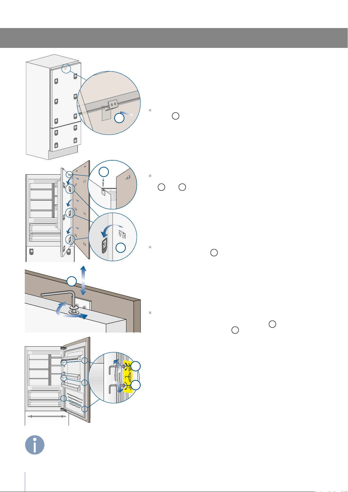
Fixed to the slide guides with two thumbscrews.
to remove the drawer, unscrew the thumbscrews and remove the
drawer.
How to activate
How to activate
How to deactivate
How to deactivate

17
1
2
6
Multizone Drawer
The upper Multizone can be removed using the same method used
for the 0°C drawer
to remove the inner Multizone drawer unscrew the thumbscrews.
When replacing the drawers, make certain the back of the drawers
engage under the clips on the slide guides.
Internal Layout
The door shelves can be easily removed for cleaning
Remove top caps
Hold the door shelf at the sides and push it upwards to release it from
its seat, then pull it outwards.
Reverse the procedure to reinstall.
Door Shelves
The shelves are sliding and can be easily re-positioned by the user as
follows:
lift or lower the shelf to the desired position
re-tighten the locking knob
Remove top caps and to remove a shelf it is necessary to slide it up
to the top
Shelves
Located in the upper drawer of the freezer compartment
after removal, make sure to reposition it correctly.
Ice Tray
Do not place hands or ngers near the Icemaker
when in function.
7
7.1
18
Activation and use of the Ice Maker
Activation and use of the Ice Maker
Do the ice cubes have an unusual odor?
Operating noises
Quite normal noises
Do not place any bottles or food for rapid cool-
ing in the ice cube container. The ice maker may
become blocked and be damaged.
If the ice is not used frequently is advisable to
empty the ice bin once every 8-10 days.
It is normal that some ice cubes stick to one
another. If the ice is not frequently used, the
older cubes can become opaque, and will
have a strange avor and become smaller.
The Icemaker automatically deactivates if the
Holiday function is activated.
When the Icemaker is started for the rst time,
it is recommended to dispose of the rst full
bin of ice.
If the equipment has been switched off for a
month or more, it is recommended to perform
a water cleaning cycle.
The ice maker will only produce ice with the
Multizone compartment set to Freezer Mode.
The ice maker will continue to operate even
when the ice bin is not in position
To activate the Ice Maker after installation of the appliance, press the
Icemaker button
.
Please note that 12 to 24 hours are necessary before ice production
may begin. The production is of 10 cubes per cycle in approximately
10 cycles in 24 hours.
The yield depends on the temperature set in the freezer, the room
temperature and the frequency of door opening.
If the appliance is operating without being connected to the water
system, make sure that the Icemaker is deactivated by pressing the
button .
The Ice Maker produces ice until the ice tray is full and will automati-
cally stop once the maximum level is reached.
With the SuperIce function, it is possible to increase the quantity of ice
produced a 24 hours, while the Set Cube Size function permits selec-
tion of the size of the produced ice cubes.
At factory default settings Ice Maker can produce approx. 100 ice
cubes within 24 hours.
Ice is a porous material which can absorb odors from the environment.
Ice cubes which have been in the ice cube container for a long time
may absorb odors, stick together and slowly become smaller.
We recommend that old ice cubes not be used.
Other means of preventing odors:
The ice cube container should be cleaned occasionally with warm
water. Make sure that you switch off the ice maker before clearing the
container. Rinse out and wipe dry.
Check the contents of the freezer for spoiled or out-of-date food.
All odorous foods should be wrapped thoroughly or stored in airtight
containers to prevent the build-up of odors.
The water lter may have to be replaced in some models.
In some cases the quality of the water connection in the house
should be checked.
Grumbling: refrigerating unit is running. Fan in the recirculating air
system is running.
Bubbling, humming or gurgling noises: refrigerant is owing through
the tubes.
Clicking: motor is switching on or off. Solenoid valve on the water
connection is opening/closing.
Rumbling: ice cubes are falling into the ice cube container.
Note: the appliance is powered by two independent compressors.
It is therefore normal to always have one of two compressors in opera-
tion.
19
7
7.2
Activation and use of the Ice Maker
Water Filter
Filter Replacement
The Water Filter makes available high-quality water for the production
of ice cubes. It provides up to 3000 liters of water for a maximum time
of 12 months.
On some models, on the upper right of the control panel it is possible to
monitor the use status of the lter: when the entire area is illuminated
the lter has just been replaced; the white illuminated area indicates
that the lter capacity is below 20%. When the lter is nearly expired
the message “Change Filter” will appear on the display.
Prior to changing the lter, switch off the Ice Maker by pressing the Ice-
Maker button. Then enter the Smeg Access Menu and set “Manual
Clean” function. At the end of the cleaning cycle remove the water from
the ice tray and wipe it dry.
Carefully rotate the lter cartridge for a quarter rotation in a counter
clockwise direction until it detaches from its housing. It is normal for a
small quantity of water to come out. Remove the cap of the new car-
tridge and insert it into the housing by gently rotating it for a quarter rota-
tion in a clockwise direction until it locks into place.
20
8
8.1
Lighting
Lighting
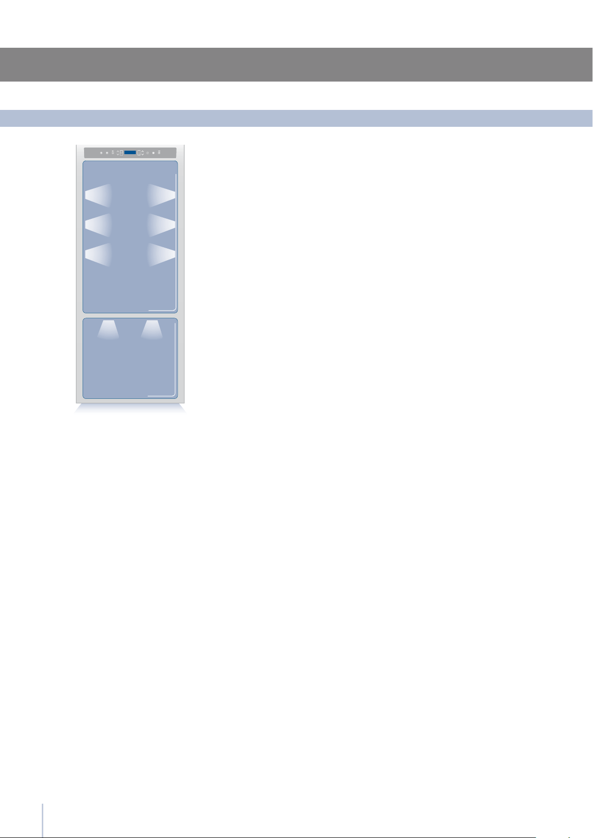
To provide optimum interior lighting, LED strips illuminate the refrigera-
tor compartment from the top and sets of LED lights directly illumi-
nate different areas of the refrigerator compartment and the freezer
drawer.
In case of malfunction and/or wearing out of the lighting system, the
repair should be carried out by a qualied Smeg Service technician.
21
9
9.1
9.2
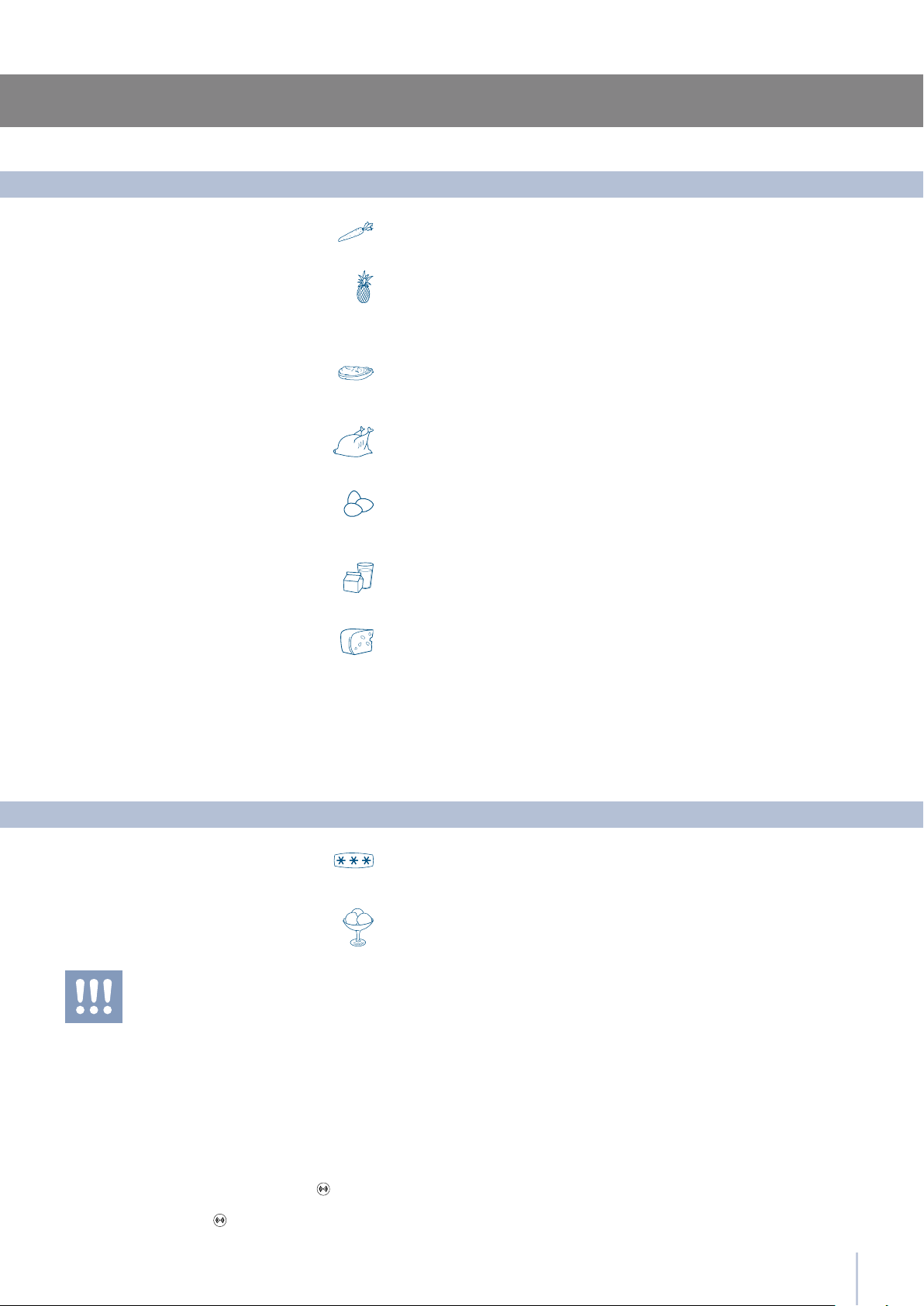
Food Preservation
Vegetables
Frozen food
Fruit
Ice cream
Packaged meat
Fresh meat, sh and poultry
Eggs
Milk, cream and fresh cheeses
Cheeses
Leftovers
Wash vegetables in cold water and dry well. Place vegetables in vacuum
packed containers, plastic containers or vegetable bags in a 0°C Drawer.
Place food in plastic bags for the freezer. These bags must be hermetically
sealed against air and humidity. Do not refreeze defrosted meat.
Wash and dry fresh fruit. Pack very aromatic fruit in plastic bags.
Fruit should be placed in the high humidity 0°C compartment.
The rmness of ice cream depends on the quantity of cream that it con-
tains. In general, high-quality ice cream has large amounts of cream,
therefore a very low temperature in the freezer will be necessary to
maintain its rmness.
Consequently, ice cream without much rmness is not necessarily an
indication of a temperature problem as raised above normal levels.
Place in the refrigerator in its original packaging.
After opening, wrap the remaining food in plastic bags or aluminum foil.
Remove the original packaging, then put in plastic bags or containers
and immediately place in the refrigerator.
Place the eggs in their package or container into the refrigerator with-
out washing them. Check the “best before” date and at any rate use
the eggs within two weeks of purchasing.
These should be kept in their original closed packaging. Place these on
refrigerator shelves and consume these within ve days of purchase.
Place these in the 0°C drawer in their original packaging.
Once opened, close these hermetically in plastic bags or aluminum foil.
Let these cool off and cover hermetically with aluminum foil or place
in sealed containers to prevent drying or the spread of odors.
Recommendations for preserving fresh food
Recommendations for preserving frozen food
After a prolonged interruption of electrical
power, once the electrical power is reacti-
vated, an audible signal will indicate if the
temperature has raised above normal lev-
els. In addition to this the display will show
for one minute the highest temperature de-
tected inside the compartments, to allow the
user to decide how to better use the food
items.
After one minute the display will resume nor-
mal operation, while the Alarm button will
continue to blink.
Press the Alarm button to display the high-
est recorded temperatures.

22
10
Recommended times for Food Preservation
Fresh foods
Preservation area
Time
Raw meats
Large cuts 0°C Compartment 4 days
Beef steaks, poultry and wild game 0°C Compartment 3 days
Ground meat 0°C Compartment 1-2 days
Carpaccio 0°C Compartment Immediately
Cooked meat
Boiled meat and roasted meat Refrigerator Compartment 2 days
Meat sauce Refrigerator Compartment 6 days
Fish
Raw and cooked sh 0°C Compartment 2 days
Other
Soups and broths Refrigerator Compartment 2 days
Pasta Refrigerator Compartment 2 days
Opened cold cuts 0°C Compartment 3 days
Fresh cheeses 0°C Compartment 2-3 days
Well sealed aged cheeses Refrigerator Compartment Several months
Eggs (fresh and unwashed) Refrigerator Compartment 2 weeks
Opened cans Refrigerator Compartment 2-3 days
Raw vegetables (in perforated bags) 0°C Compartment 1 week
Frozen foods
Preservation area
Time
Beef, veal, lamb and goat meat Freezer Compartment (steaks) 6-12 months
Beef, veal, lamb and goat meat Freezer Compartment (Meat with bone) 4-6 months
Ground beef Freezer Compartment 1-2 months
Pork Freezer Compartment (Without bones) 4-6 months
Pork Freezer Compartment (With bones) 2-3 months
Ground pork Freezer Compartment 1-2 months
Meat leftovers Freezer Compartment 2-3 months
Whole chicken and turkey Freezer Compartment 8-12 months
Goose, duck and pheasant Freezer Compartment 4-8 months
Fish Freezer Compartment 1-2 months
Shellsh Freezer Compartment 2-3 months
Cooked food Freezer Compartment 1-2 months
Vegetables Freezer Compartment 8-12 months
Fruit Freezer Compartment 6-12 months
Desserts and cakes Freezer Compartment 2-3 months
11
11.1
11.2
11.3
23
Care and Cleaning
Care and Cleaning
Condenser cleaning
Internal cleaning
Scrupulously follow the detailed directions that
can be found in the provided kit and never
use abrasive or metallic products which could
scratch and damage the satin nishing on the
appliance permanently.
Before performing any sort of cleaning, disconnect
the appliance from the electrical power supply.
Make sure you do not damage the refrigerant
circuit in any way.
Do not bring cold glass parts into contact with
boiling water.
Do not wash any parts of the refrigerator in a
dishwashing machine since this could damage
or irreparably deform the parts.
Clean the internal and removable parts by washing them with a solu-
tion of lukewarm water, a small amount of dishwashing detergent.
Rinse and dry right away.
Do not use mechanical devices or other methods to speed up defrosting.
The edges of the condenser are sharp, there-
fore use adequate protection for the hands and
arms when cleaning the condenser.
Do not use water on the electrical parts, lights
and control panel.
To clean the parts made of steel use a microber cloth and the sponge
provided in the kit with the appliance. Always use the cloth and sponge
in the direction of the steel’s satin nish.
Every now and then, to polish the steel, wipe with a slightly damp micro-
ber cloth.
Do not use the sponge on aluminium parts, such as the handles and the
proles of the glass shelves.
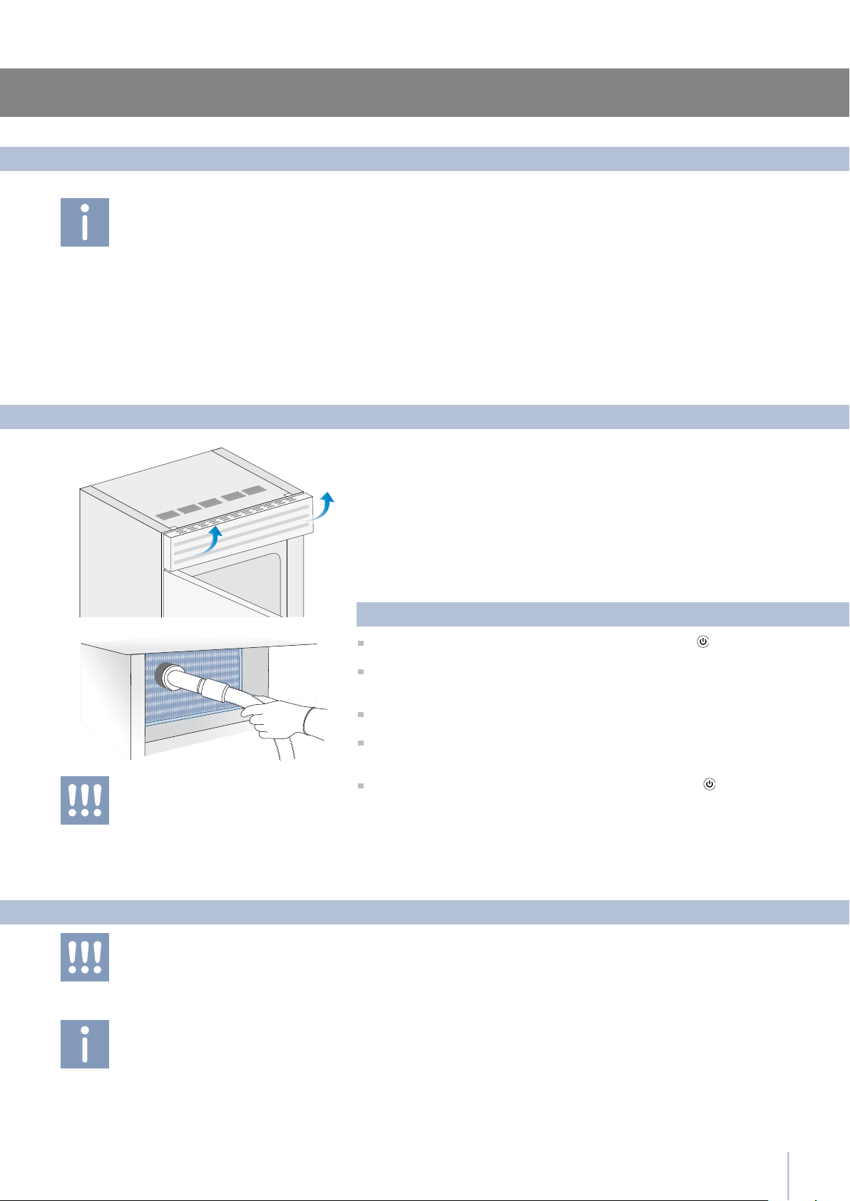
You should use special care to keep the ventilation openings in the ap-
pliance or in the cabinet that houses it free of obstructions.
A ventilation grille is located either at the top of the appliance or at the
bottom according to the model type.
To clean it use a vacuum cleaner with a soft brush attachment at maxi-
mum power, sweeping it along the vent slits. In case of a signicant dust
build up, the ventilation grille can be removed to allow a more accurate
cleaning.
Take care also to check the condition of the nned condenser and clean
it from dust if needed.
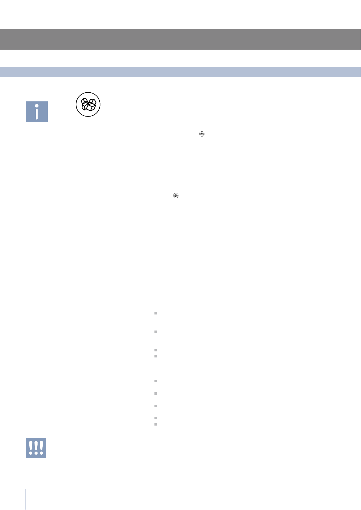
Operate as follows:
Switch off the appliance by pressing the Unit button on the main
control panel for approx 3 seconds.
On models with ventilation at the base remove the grille at the bottom
(magnetically attached) and take it off. On models with ventilation lift the
grille as shown in the picture.
Thoroughly clean the grille and the foam lter, by means of a vacuum
cleaner and the soft brush attachment.
Wait approx 30 minutes, until the nned condenser cools down to room
temperature, then clean it thoroughly from any dust build up as shown in
the picture, taking care not to damage it.
Start up the appliance again, by pressing the Unit button on the main
control panel for approx 3 seconds.

24
12
12.1
Troubleshooting Guide
Troubleshooting Guide
Did you leave the doors open for a long period of time?
Do the doors close perfectly?
If the doors do not close perfectly, contact your installer.
In case of frost or ice build up in the Crisper-0°C compartment, due
to frequent and prolonged opening of the doors, deactivate the
Crisper-0°C function via the button on the control panel. Wait until
the frost or ice melt, then remove the drawer and dry the sides and
bottom of the compartment.
Clean the appliance completely according to the instructions.
Hermetically cover all the food. Do not conserve food for prolonged
periods of time.
The appliance is designed to ensure a fully hermetic closure. When
the door is closed, a vacuum condition can occur: in this case it is
necessary to wait a few seconds until the pressure balances before
opening the door.
Ice or frost build up inside the refrigerator
or freezer
Unpleasant odors inside the refrigerator
The doors are difcult to open
If you notice malfunctions in your appliance, use this guide before
calling for service: this guide can help you personally resolve the
problem or could provide important information to be conveyed to
the service technician to ensure rapid and effective repair.
A malfunction is usually indicated by a message on the display.
Problems that cannot be solved by the user are signaled through a
malfunction code.
Is the appliance connected to the electrical power supply?
Is electrical power available at the electricity socket?
Is the Unit button
activated?
Is the unit in ‘Demo’ Mode?
Does the display show a malfunction code?
Is the temperature adjusted correctly?
Were the doors or drawers open for a long period of time?
Were large quantities of food recently inserted?
Is the unit in ‘Demo’ Mode?
Bear in mind that during very hot weather and with very high tem-
peratures in the room it is normal that the compressor remains on for
prolonged periods of time.
Were the doors or drawers open for a long period of time?
Were large quantities of food recently inserted?
Check that the doors are closed and that the food or containers do
not obstruct the perfect closure of the door.
Is one or more compartments in Shopping Mode?
It is normal to hear noises from the ventilators or compressors during
operation or during the defrost phase.
Noise could be more marked depending on the position of the appli-
ance and the surrounding environment.
If the climate is very humid, the formation of condensation is normal.
Opening the door or drawers for prolonged periods of time can con-
tribute to the formation of condensation.
In any case, make sure that the doors are always perfectly closed.
Malfunction message
The refrigerator or the freezer does not work
The refrigerator or the freezer
is warmer than usual
The appliance remains in function
for a long time period
If you hear unusual noises
Condensation inside and outside
of the refrigerator

25
12
12.2
Troubleshooting Guide
Malfunction indications appearing on the display
Display message Malfunction description
Power Failure!! Prolonged interruption of electrical power
the appliance resumes work automatically, the display shows the warmest temperatures
achieved
Door Fridge OPEN Fridge door open
the message appears after few minutes from the door opening
Multizone OPEN Freezer door open
the message appears after few minutes from the door opening
Replace lter Replace lter cartridge
the message appears after 365 days (Note: regular date and time)
Fridge too warm Fridge too warm
see Troubleshooting Guide
Fridge too cold Fridge too cold
wait for 12 hours: if malfunction persists call Customer Care for advice
MultiTemp too warm Freezer too warm
see Troubleshooting Guide
MultiTemp too cold Freezer too cold
wait for 12 hours: if malfunction persists call Customer Care for advice
Error Code... Functional problems
call Customer Care who may help you to salve the problem or put you in contact with the
nearest Service Agent
On average, the Ice Maker produces approximately 10 cubes of ice
every two and half hours.
When the Ice Maker is started for the rst time, it is recommended to
empty the rst full tray of ice cubes.
If the refrigerator was switched off for more than one month or if the car-
tridge was not changed for more than six months, it could be necessary
to replace the lter cartridge.
Contact a plumber or a water treatment expert to make sure that the
problem is not due to the water supply.
If the ice is not used frequently, it is possible that blocks of ice may form.
It is recommended to remove the block of ice cubes and then let the
Ice Maker ll the ice tray again.
Make sure that the Ice Maker is on (Icemaker button
on).
To switch on the Ice Maker press the button.
Make sure that the appliance is connected to the water supply.
The Ice Maker does not produce
sufcient amounts of ice
The ice has an unusual avor or color
If the unit you purchased was used as a show-
room model it may be in a special energy-saving
mode called Demo Mode where the appliance
appears to be operating (lights work and false
temperatures are displayed) but no cooling actu-
ally takes place. If you suspect your appliance is
in Demo Mode please contact your point of pur-
chase for assistance with disabling this feature.
The ice cubes freeze into one block
The Ice Maker does not work
13
13.1
FUNCTIONS
Shopping Fridge
Shopping Multiz
Shopping ON/OFF
Shopping ON/OFF
Holiday ON/OFF
Holiday ON/OFF
Shopping Fridge Off
Shopping Multiz Off
Holiday Fridge Off
Holiday Multiz Off
Bottle Cooler Off
Super Ice Off
Bypass Filter Off
View Status
Set Cooling Time
Set Cube Size
Sabbath Mode Off
Status Filter
Shopping Fridge On
Shopping Multizone
Holiday Fridge On
Holiday Multiz On
Bottle Cooler On
Super Ice On
Bypass Filter On
Reset Filter
Bypass Filter
Shopping Time
Shopping Time
Holiday Time
Holiday Time
Cooler ON/OFF
Super Ice ON/OFF
Sabbath Mode On
Manual Clean
Set Hours: 1
Set Hours: 1
Set Hours: 1
Set Hours: 1
Set Time: 20 min
Size: LARGE
Holiday Fridge
Holiday Multiz
Bottle Cooler
Ice Maker
Set Sabbath Mode
Water Filter
26
Smeg Access Menu Map
Functions
27
13
13.2
Bypass Filter Off
Bypass Filter On
SETTINGS
Multiz Options
Default Setting
Freezer
Fresco
Enter to Conrm
DATE: 01-01-2009 On
TIME: 01:01 On
Set: 24
Set Date
Set Time
italiano
français
english
ON
ON
Set °C
DATE: 01-01-2009 Off
TIME: 01:01 Off
Set: 12
Fridge
Show Date
Set View
Show Time
deutsch
español
OFF
OFF
Set °F
DATE: 01-01-2009
TIME: 01:01
Date
Time
Language
Child Lock
Showroom Mode
Set °C/°F
Smeg Access Menu Map
Setting


22-12-2014

SMEG EN

INSTALLATION GUIDE

IMPORTANT
Dimensions in parentheses are in inches.
Weights in parentheses are in pounds.
Temperatures in parentheses are in Fahrenheit degrees.

1
1
2
4
5
6
7
8
11
12
14
15
16
17
19
20
22
23
26
27
29
30
Installation Guide
Index
Page
Important Instructions
Important safety instructions
Children safety
Technical requirements
Appliance features and installation requirements
Installation niche features: Integrated
Installation niche features: Free-Standing
Preparing to install
Transport to installation site and unpacking
Electrical and Water connection
Levelling
Panels mounting
Decorative door and Bottom-Drawer panels layout
Decorative panels layout for Fridge with one Bottom-Drawer
Decorative panels layout for Fridge with Glass door and one Bottom-Drawer
Panels Dimensions One Bottom - Drawer (models)
Mounting panels to the door and the drawer
Installation
Built-in installation of single appliance
Built-in installation of two or more appliances
Free-standing installation two or more appliances
Completing the installation
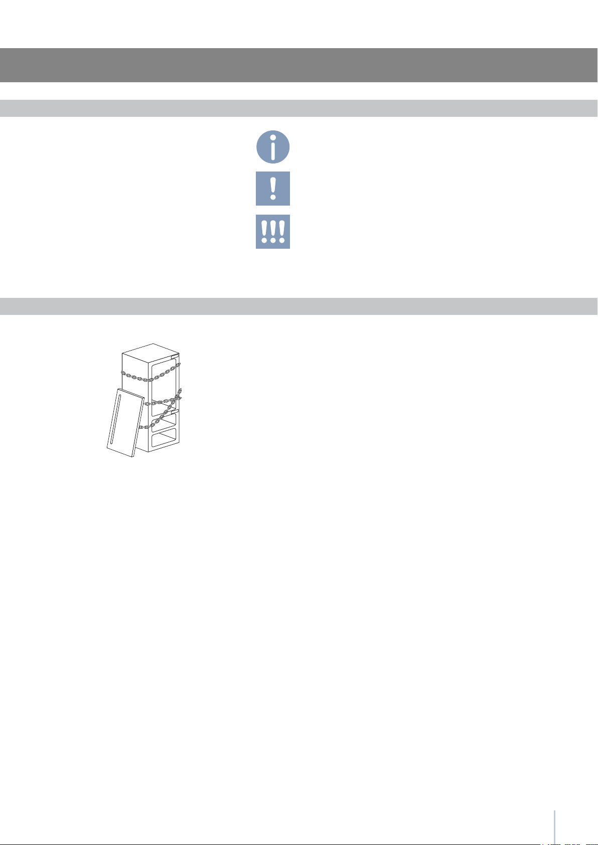
Anti-tipping safety assembly
Mounting the handles on stainless front
Ventilation
Post installation control
Start Up

2
3
Installation Guide
Symbols used in the Guide
Important safely instruction
Children safety
If this appliance is replacing an existing appliance which must be
removed or disposed of, make sure that it does not become a
dangerous trap for children by cutting its power supply cable and
rendering it impossible to close the door.
Use the same caution at the end of the lifespan of the new ap-
pliance.
Note
Tips for the correct use of the
appliance
Warning
directions to prevent injury
Important
Directions to avoid appliance
damage

4
Appliance features and installation requirements
60 Series w: 599 mm (23 5/8”)/ h: 2050 mm (80 3/4”)/ d: 610 mm (24”)
75 Series w: 749 mm (29 1/2”)/ h: 2050 mm (80 3/4”)/ d: 610 mm (24”)
90 Series w: 899 mm (35 3/8”)/ h: 2050 mm (80 3/4”)/ d: 610 mm (24”)
60 Series w: 586 mm (23”)/ h: 2120 mm (84”)/ d: 635 mm (25”)
75 Series w: 736 mm (29”)/ h: 2120 mm (84”)/ d: 635 mm (25”)
90 Series w: 8869 mm (34 7/8”)/ h: 2120 mm (84”)/ d: 635 mm (25”)
60 Series w: 650 mm (25 5/8”) / h: 2210 mm (87”)/ d: 800 mm (31 1/2”)
75 Series w: 800 mm (31 1/2”)/ h: 2210 mm (87”)/ d: 800 mm (31 1/2”)
90 Series w: 950 mm (37 3/8”) / h: 2210 mm (87”)/ d: 800 mm (31 1/2”)
60 Series w: 650 mm (25 5/8”) / h: 2260 mm (89”) / d: 800 mm (31 1/2”)
75 Series w: 800 mm (31 1/2”) / h: 2260 mm (89”) / d: 800 mm (31 1/2”)
90 Series w: 950 mm (37 3/8”) / h: 2260 mm (89”) / d: 800 mm (31 1/2”)
60 Series up to 230 kg (507 lb)
75 Series up to 275 kg (606 lb)
90 Series up to 295 kg (650 lb)
Europe Version: AC 220-240V 50 Hz / North America Version: 110V 60Hz
Europe Version: Schuko 16 A plug / North America Version: 15 A
from 0.1 MPa to 0.5 MPa (1 Bar - 5 Bar)
3/4” female attachment
Customized panels mounting Kit
Anti-tipping Kit (B04000200)
Lateral connecting kit (KCLIT/KCLIH)
4 mm (1/8”) allen wrench
Phillips head screwdriver
wood and percussion drill
2.5 mm (1/8”) bit for wood
8 mm (3/8”) bit for walls
17 mm (3/4”) wrench
Appliance dimensions
Integrated
Appliance dimensions
Free-Standing
Appliance dimensions
Integrated
Appliance dimensions
Free-Standing
Weight with packaging
Voltage
Power supply cable
Potable water supply pressure
Water supply tube
Provided installation accessories
Additional equipment necessary
5
min 2064 (81 )
A A
E W E W
140 (5 ) 140 (5 )
100 (4”)
100 (4”)
RI96: 900 (35 )
WI66: 600 (23 )
RI76: 750 (29 )
A
E
W
2064 mm (81 1/4”)
RI96: 900 mm (35 1/2”)
RI76: 750 mm (29 5/8”)
WI66: 600 mm (23 3/4”)
RI96: 1470 mm (57 7/8”)
RI76: 1320 mm (52”)
WI66: 1170 mm (46”)
105°
RI96: 899 mm (35 3/8”)
RI76: 749 mm (29 1/2”)
WI66: 599 mm (23 5/8”)
2050 mm (80 3/4”)
+ 25 mm (1”)
610 mm (24”)
992 (39”)
RI96: 1470 (57 )
RI76: 1320 (52”)
WI66: 1170 (46”)
RI96: 160 (6 )
RI76: 125 (5”)
WI66: 90 (3 )
560 (22”)
610 (24”)
RI96: 899 (35 ”)
RI76: 749 (29 ”)
WI66: 599 (23 ”)
10 (”)
105°
90°
610 (24”)
560 (22”)
610 (24”)
560 (22”)
1293 (50 )
474 (18 )
231 (9
) +
25 (1”)
500 (19 ) 500 (19 )
248 (9
)
+ 25 (1”)
231 (9
) +
25 (1”)
248 (9
)
+ 25 (1”)
20 ()
15 ()
15 ()
20 ()10 (”)
721 (28 ”) +25 (1”)
2050 (80 ”) +25 (1”)
2050 (80 ”) +25 (1”)
846 (33 ¼”) +25 (1”)
1168(46”)
330 (13”)
259 (10
)
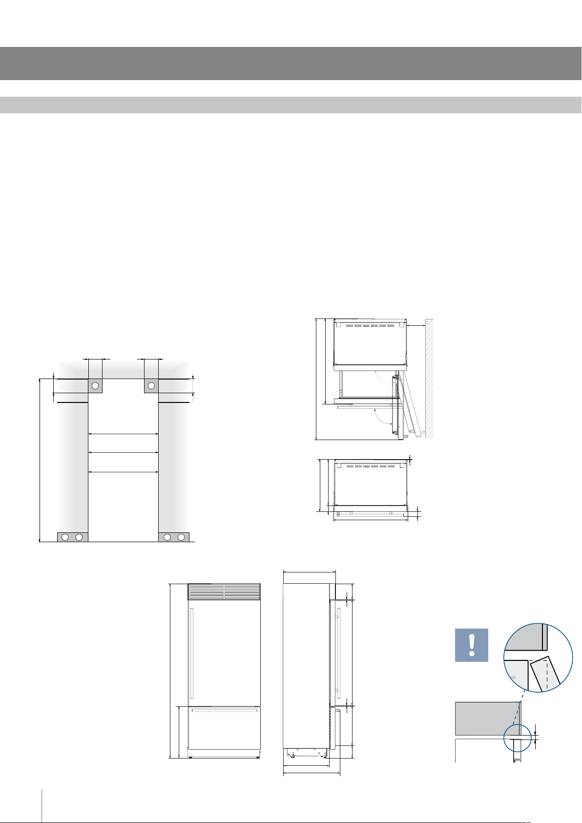
1T/0T 0H
Installation Guide
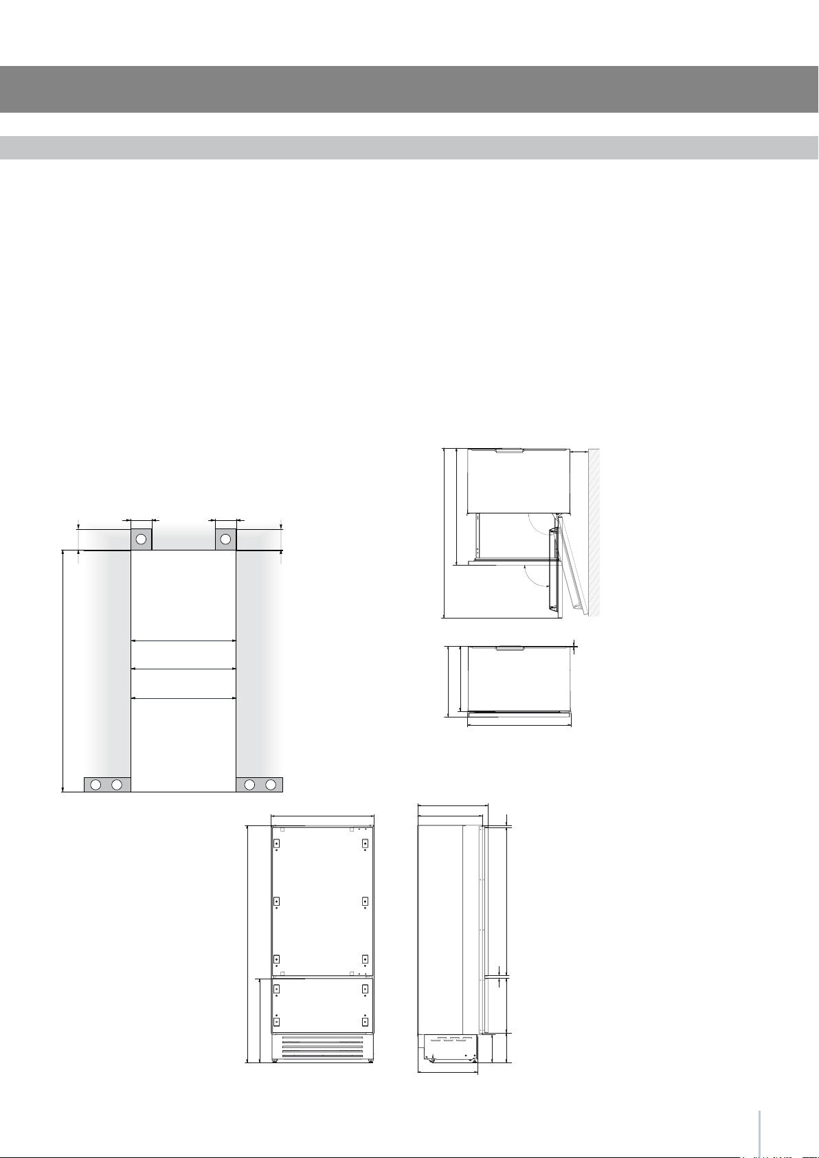
Installation niche features: Integrated Series
area to be left clear for the anti-tipping brackets
area to be left clear for the power supply cable
and water supply hose
Minimum Niche Height
Minimum Niche Width
Door Swing Clearance
Door Opening Angle
Width
Height
Depth with door (without panel)
Important: A 90° door opening
is sufcient to allow opening
and full extraction of the inner
drawers, even if the appliance
is installed directly adjacent to
a wall. Should an opening at
105° be desired, then the ap-
pliance should be positioned
at the distance from the wall
described in gure.
6
min 10 ()
A A
min 2134 (84”)
140 (5 ½”) 140 (5 ½”)
100 (4”)
100 (4”)
E W E W
RF396: 890 (35”)
WF366: 590 (23 ¼”)
RF376: 740 (29 ½”)
A
E
W
2134 mm (84”)
RF396: 890 mm (35”)
RF376: 740 mm (29 1/2”)
WF366: 590 mm (23 1/4”)
RF396: 1470 mm (57 7/8”)
RF376: 1320 mm (52”)
WF366: 1170 mm (46”)
105°
RF396: 886 mm (34 7/8”)
RF376: 736 mm (29”)
WF366: 586 mm (23”)
2120 mm (83 1/2”)
+ 25 mm (1”)
635 mm (25 ”)
1016 (40”)
RF396: 1470 (57 )
RF376: 1320 (52”)
WF366: 1170 (46”)
RF396: 230 (9)
RF376: 195 (7 )
WF366: 160 (6 )
560 (22”)
75 (3”)
RF396: 886 (34 ”)
RF376: 736 (29”)
WF366: 586 (23”)
10 (”)60 (2 ”)
105°
90°
635 (25”)
560 (22”)
2120 (83 ½”) +25 (1”)
613 (24 )+25 (1”)
635 (25)
128 (5) + 25 (1”)
695 (27 )
485 (19 )
1296 (50”)
195 (7 )
8 ()
8 ()
area to be left clear for the anti-tipping brackets
area to be left clear for the power supply cable
and water supply hose
Minimum Niche Height
Minimum Niche Width
Door Swing Clearance
Door Opening Angle
Width
Height
Depth with door
Installation niche features: Free-Standing Series
Important: A 90° door opening
is sufcient to allow opening
and full extraction of the inner
drawers, even if the appliance
is installed directly adjacent to
a wall. Should an opening at
105° be desired, then the ap-
pliance should be positioned
at the distance from the wall
described in gure.
7
1
4
1
2
3
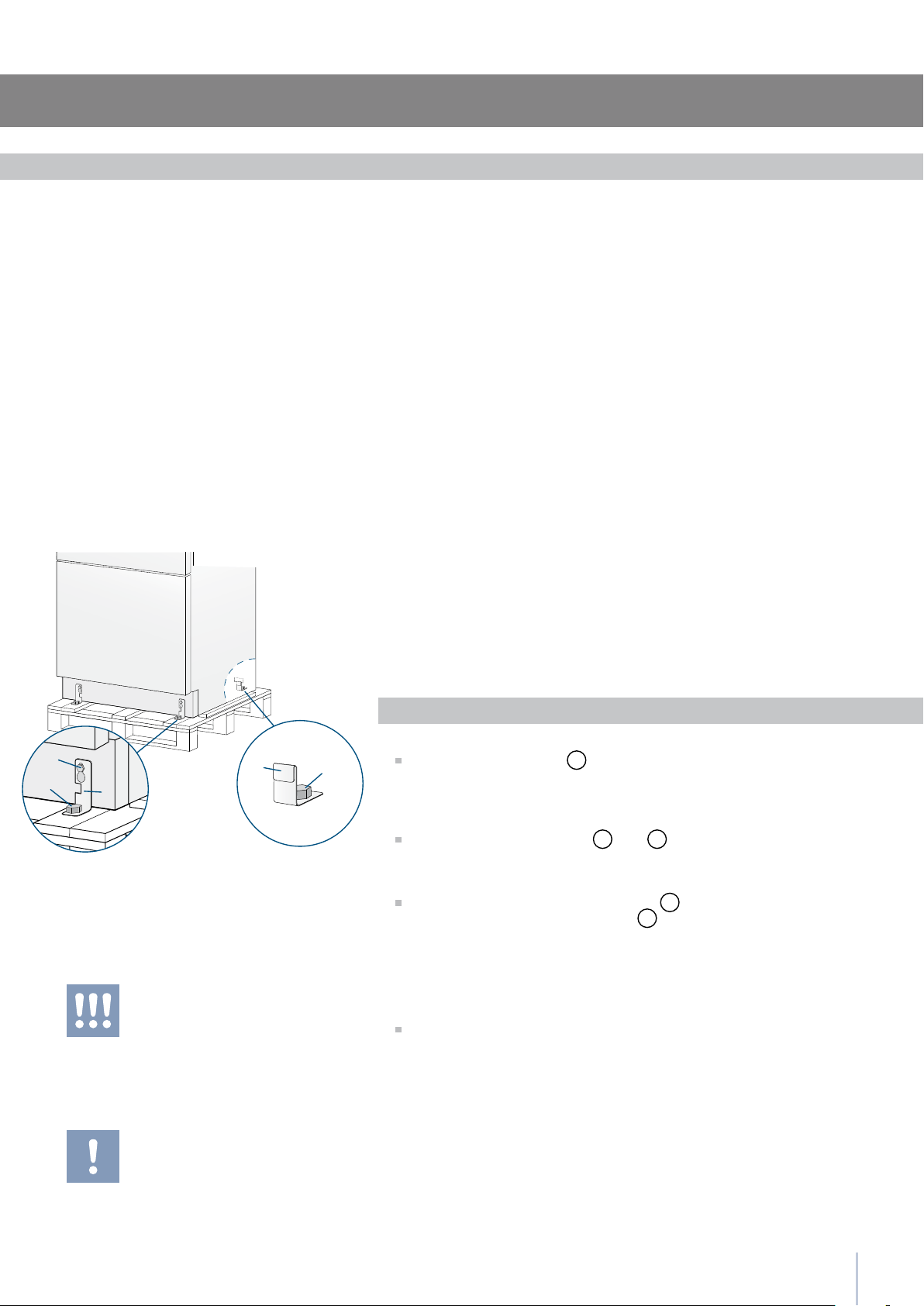
Installation Guide
The appliance is very heavy.
Take maximum care during handling to
avoid injury.
The appliance should always be transport-
ed in an erect position.
Avoid at all costs leaning it on its front side.
Preparing the installation
Transport to installation site
and unpacking
Since this is a large and heavy appliance, before transporting the ap-
pliance, check the access to the location where it will be installed
(door size, manoeuvring space in stairwells, etc.).
The appliance is attached to the base of the packaging (pallet) through
four bolts which can be removed using a 17 mm (3/4”) wrench.
It is recommended to use a manual transporting device to move the
appliance to the installation site, and only at this point to remove the
base of the packaging.
The appliance should always be transported in an erect position.
If this is not possible, transport the appliance laying on its rear side.
Once at the installation site, the appliance, which is equipped with four
wheels, can be taken off the pallet and positioned in the installation
area.
Operate as follows:
Take off the four bolts
1
securing the appliance to the pallet by
means of a 17 mm (3/4”) open spanner.
Remove the xing brackets
3
and
4
.
To remove the front xing bracket
3
, unscrew for one or two
turns the rear wheel adjusting bolt
2
by means of a 13 mm (1/2”)
box spanner, avoiding too much strenght while thightening the
nut, which could damage the leveling feet adjusting system.
From the back of the unit and by means of a suitable, high duty hand
trolley, take off the appliance and place it on the oor.
Be very careful to avoid any damage to oors. Delicate oors should be
protected with plywood, hard cardboard or similar material panels.
Series: All
EW
E W
EW
E W
8
E
W
E
W
Electrical and Water connection
A Schuko 16 A socket with an efcient grounding should be made
available for the electrical mains connection, as well as an omnipolar
switch which can easily be reached when the appliance is installed.
To connect to the water supply system (for appliances equipped with
ice makers) a tap with a male 3/4” connection should be provided,
which must also be easily accessible once the appliance is installed.
The appliance is provided with a water supply hose and seal kit which
is suitable for high water pressure and complies the Food Regulations.
The water lter cartridge, which is provided with the appliance, should
be installed according to the accompanying instructions.
Use only the new hose and the new gaskets which are supplied with
the appliance. Discard any hose and gasket which may have already
been installed.
Electrical cord length: 2,0 mt (78 3/4”)
Water connection line length: 2,5 mt (98 3/8”)
Series: All
Do not use extension cords or adapters.
Once the appliance has been connected to
the water system, turn the Ice Maker off (touch
the button
on control panel to switch it off)
before the main water is shut off.
The appliance should be connected only to
a drinkable water supply system.
The Built-in lter cannot make it safe to drink
any water which is not suitable for human
consumption.
Energy: Alternatives and Home Automation
If energy is supplied through an alternative energy power source
(solar, geothermal, etc..) or if home automation systems are installed,
it is necessary to install the Alternative Energy Kit to integrate the unit
into the power grid.
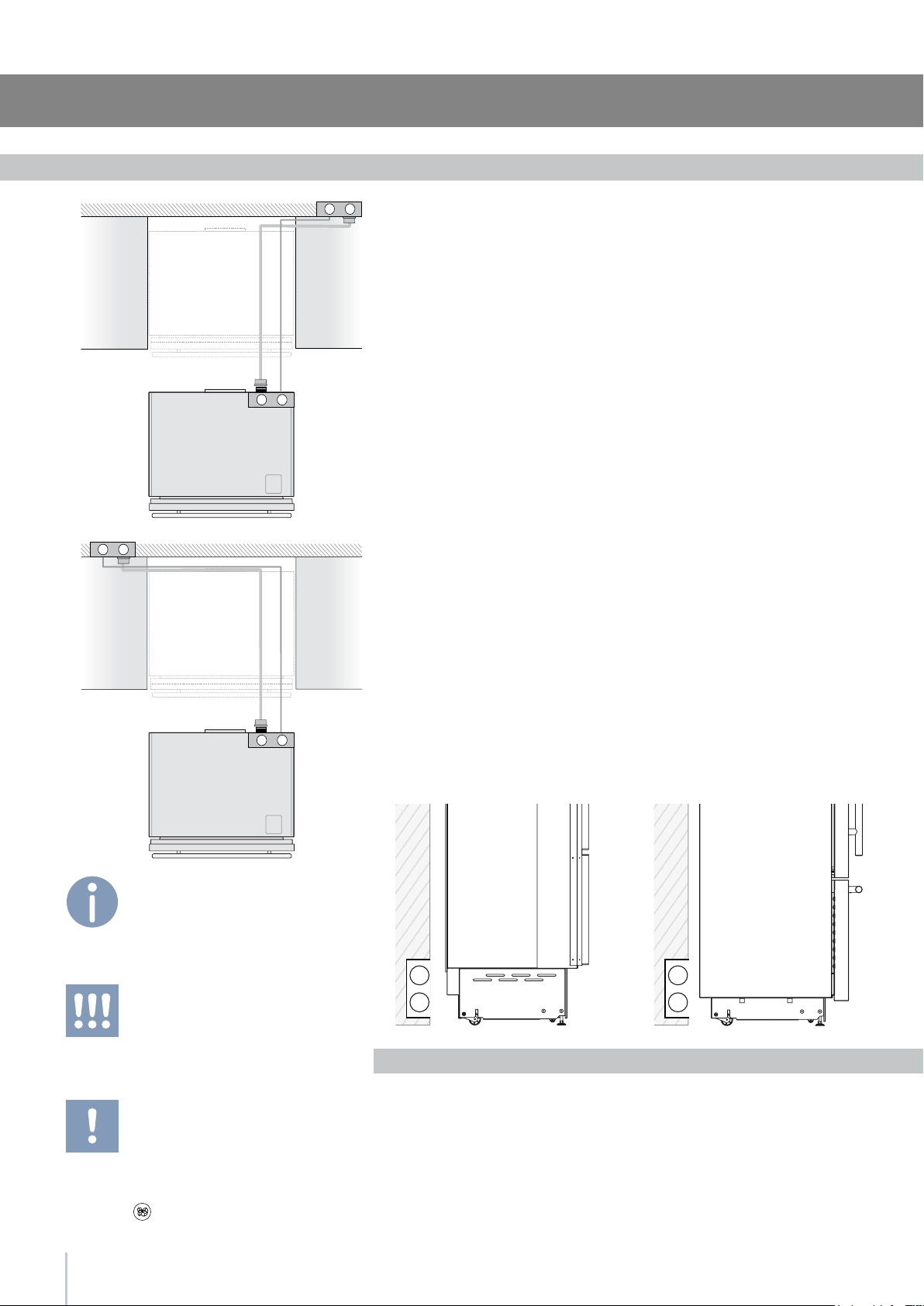
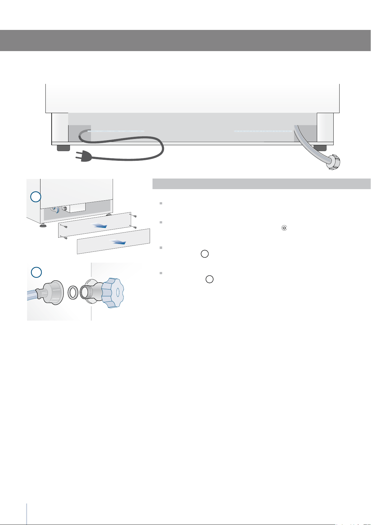
Electrical and water supply behind the unit
Integrated and Classic Series StandPlus and Free-Standing Series
2
1
9
Installation Guide
Back of appliance
Water connection
Electrical connection
Series: Integrated
Operate as follows:
Unwind the electric cable and connect it directly to the wall socket.
Make sure the appliance is in the Stand-by condition and that all
lights are off; should it be not so press the Unit button
to switch it
off.
Fit one end of the water hose onto the connector at the appli-
ance’s back
1
.
Fit the other end of the hose to the water tap, use the gaskets pro-
vided in the Owner’s Kit
2
.
StandPlus and Free-Standing Series
2
1
10
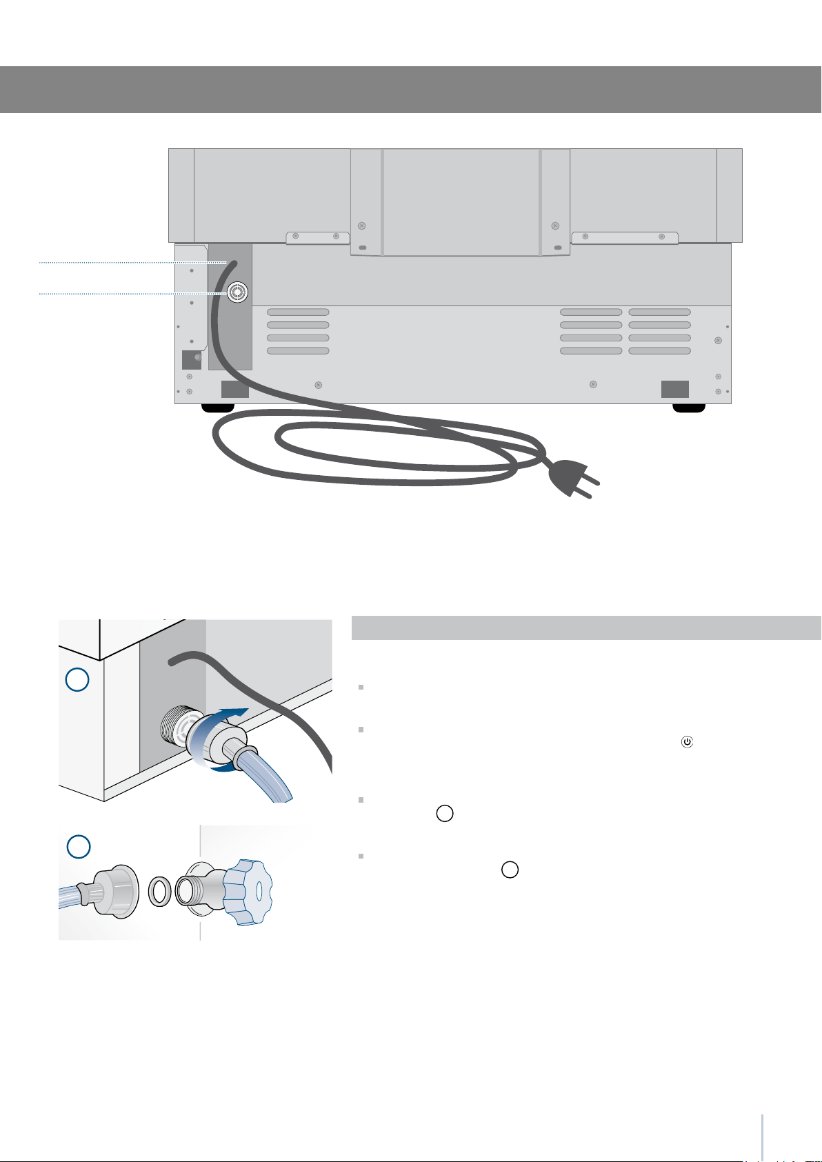
Series:Free-Standing
Operate as follows:
Unwind the electric cable and connect it directly to the wall socket.
Make sure the appliance is in the Stand-by condition and that all ights
are off; should it be not so press the Unit button to switch it off.
Connect the water line to the threaded connection at the base of the
unit, as in gure
1
.
Fit the other end of the hose to the water tap, use the gaskets provided
in the Owner’s Kit
2
.
Back of appliance
Front of appliance
Water connectionElectrical connection
11
1
2
1
2
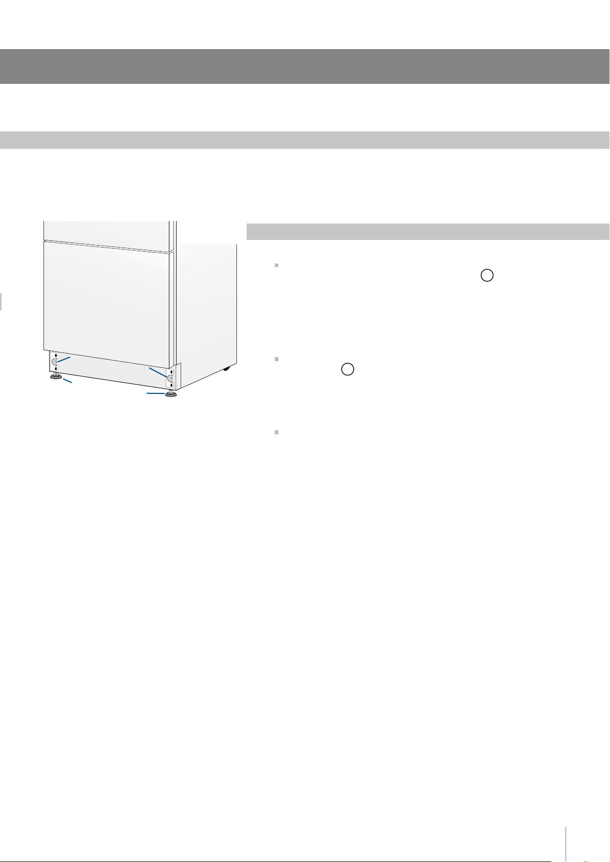
Installation Guide
Adjust the appliance level by means of the front levelling feet
and the rear adjustable wheels.
Operate as follows:
After removing the bottom plinth or grille (it is kept in position by
magnets), adjust the height of the levelling feet
1
by means of a 17
mm (3/4”) open spanner.
Then adjust the height of the rear wheels by turning the front
adjusting bolts
2
clockwise or anticlockwise as it may be required.
Remount the bottom plinth or grille.
Levelling
Series: All
12
1
2
3
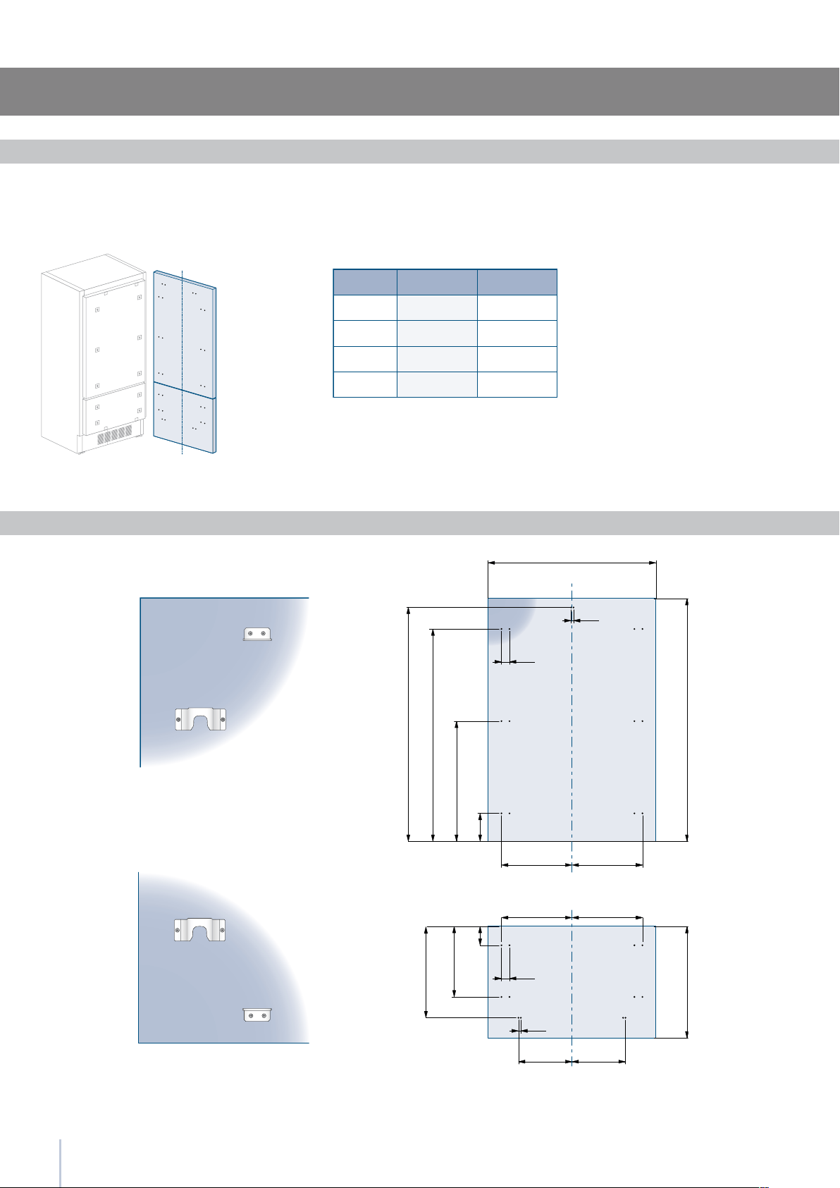
Decorative door and bottom-drawer panels layout
The dimensions of the panels are indicated in the table and draw-
ings on pages 18-21.
Nevertheless, according to the requirements for aligning with other
kitchen structures, the door panel can be higher than the upper
edge of the refrigerator door, and the drawer panel can be lower
than the edge of the drawer.
The panels must be mounted using special braces which attach
to adjustable devices provided on the door and drawer and with
brackets that anchor and adjust the panel’s vertical direction.
Braces, brackets and fixing screws are provided with the appliance
and must be applied to the panel as indicated.
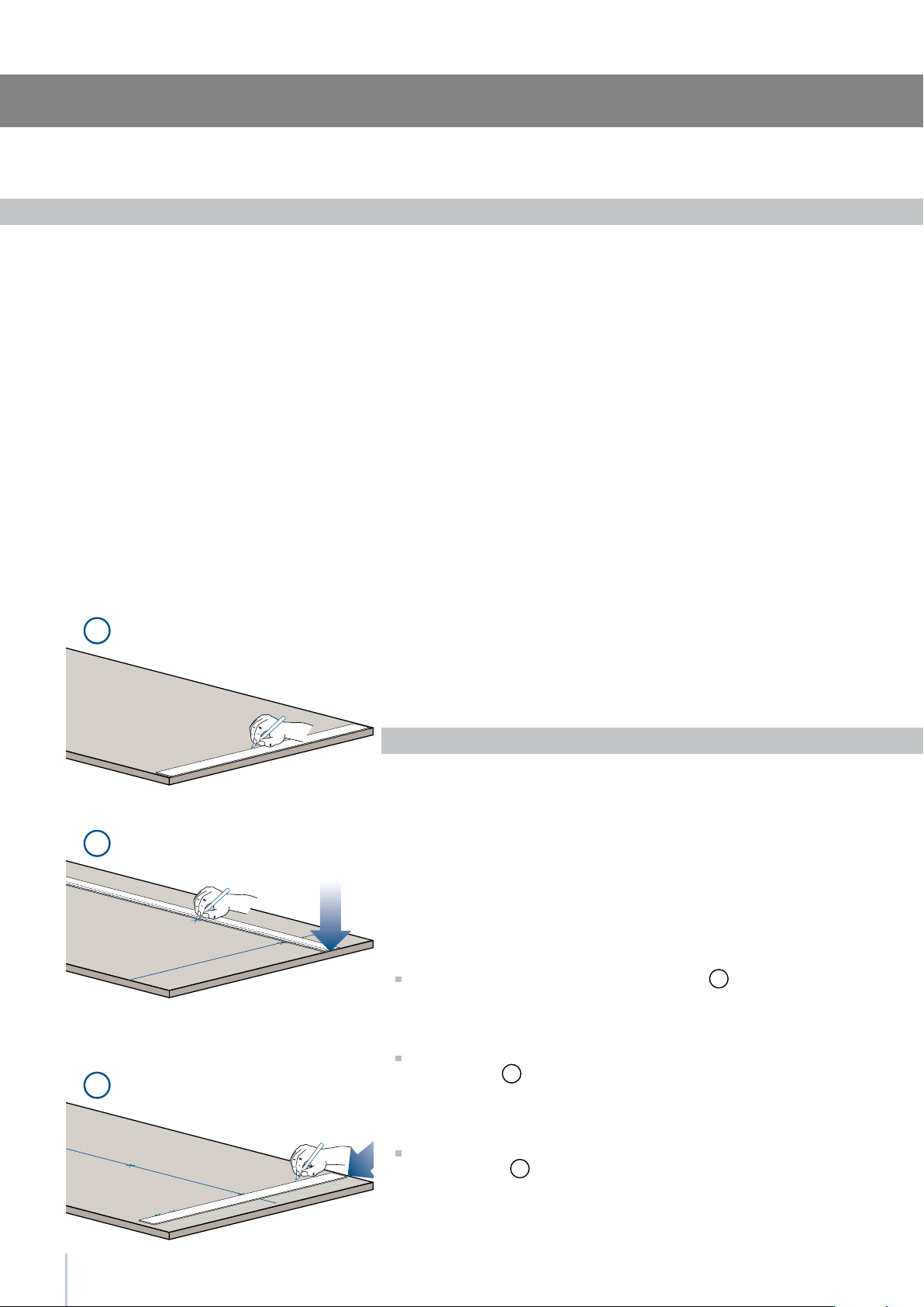
Operate as follows:
To prepare the panels to be mounted on the appliance, follow
these steps, working on the back of the panel.
Door Panel
Trace, a line dividing the panel width in half
1
.
Starting form the Bottom edge of the panel, mark the positioning
of the brackets
2
.
Following the corresponding table, mark the external and then
the internal hole
3
.
Series: Integrated
13
7
8
4
5
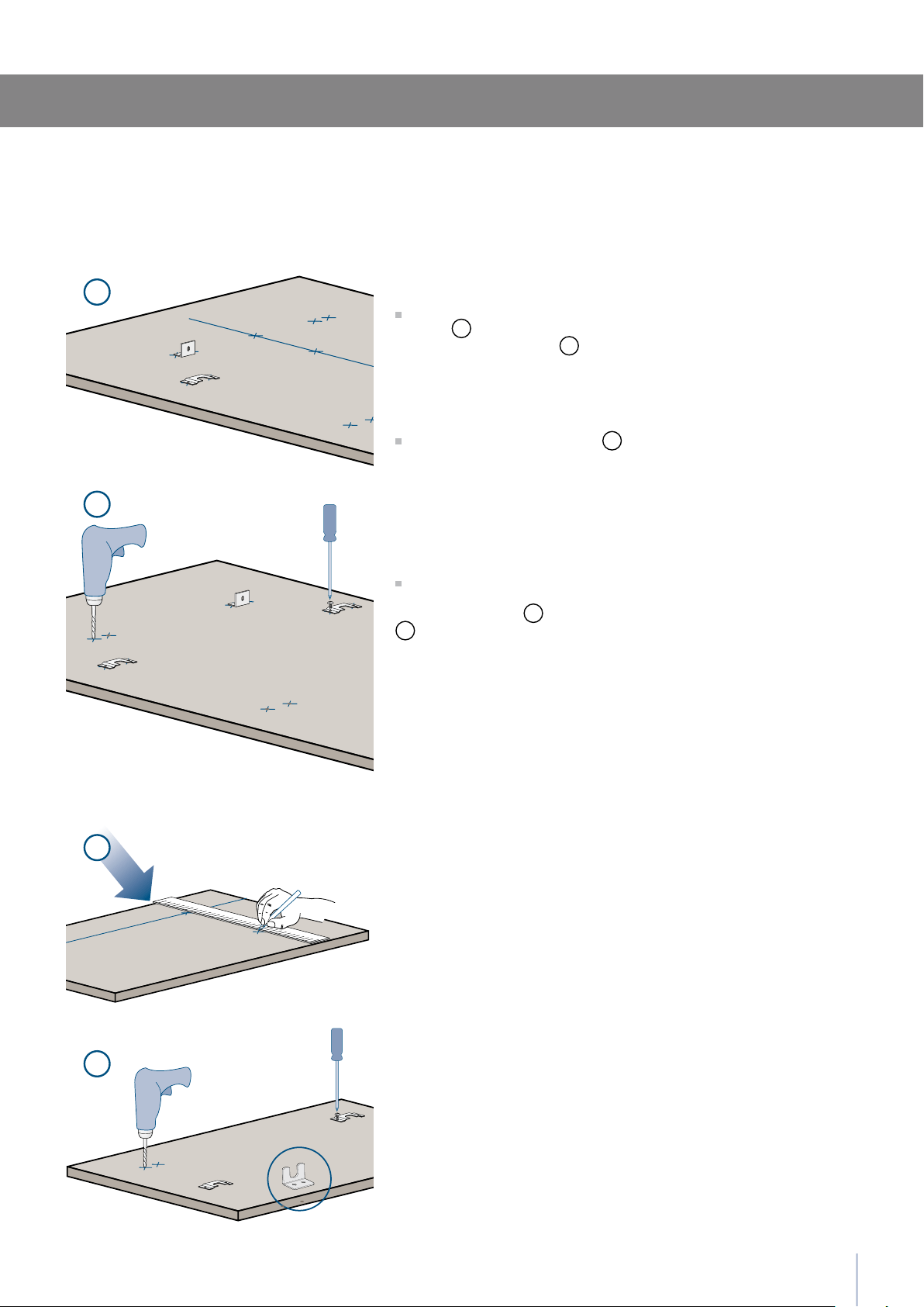
Installation Guide
Position the brackets on each set of marks to make sure they are
aligned
4
, then drill holes through the panel (pay close attention
to the panel’s thickness)
5
.
Screw the brackets in place
6
.
Drawer Panel
When preparing the Drawer Panel, follow the same instructions as
per the door panel, but make sure measurements are taken starting
from the top edge
7
. The support bracket faces the opposite way
8
(note imgs 4 and 8).
Series: Integrated
A
897 (35
)
418 (16
)
418 (16
)
B
C
354.5 (14”)
747 (29
)
343 (13
)
343 (13
)
279.5 (11”)F / G
14
B C
B C
A
F G
13 ()
13 (
)
34 (1
)
34 (1
)
1285 (50 )
1163 (45
)
660 (26”)
157 (6
)
min 1320 (52”)max 635 (25”)
507,5 (20”)
382 (15
)
100 (4”)
Decorative panels layout for Fridge with one Bottom-Drawer
Series 90
Series 75
Holes positions
Series: Integrated
15
H I
D E
A
F G
1286 (50 )
6,5 ()
6,5 (
)
1152,5 (45 )
650,5 (13
)
148,5 (5
)
13 ()
34 (1
)
34 (1
)
min 1320 (52”)
max 635 (25”)
507,5 (20”)
382 (15
)
100 (4”)
60: 327 (12 )
1075 (42 )
min 130 (5 )
115 (4
)
135 (5
)
135 (5
)
A
H
I
F / G
597 (23 ) 597 (23 )
203.5(8”) 203.5(8”)
276.5 (10
)
270.5 (10
)230.5 (9
)
236.5 (9
)
276.5 (10
)
276.5 (10
)268 (10
)
268 (10
)
D
E
Installation Guide
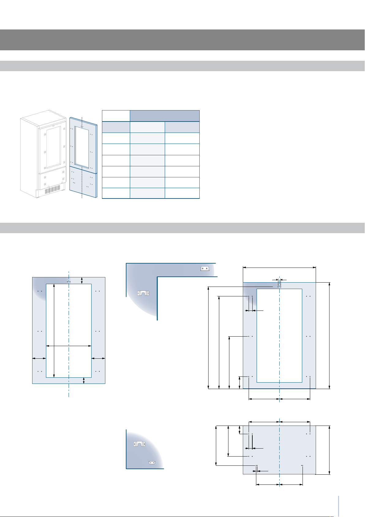
Decorative panels layout for Fridge with glass door and one Bottom-Drawer
Holes positionsDoor window dimensions
Series: Integrated
Series 60
Hinge Left
Hinge Right
16
899
749
599
897 (35 1/4”)
-
747 (29 3/8”) -
597 (23 3/4”) 327 (12 7/8”)
B
115 (4 )
min 130 (5 )
135
(5 )
135
(5 )
1075 (42 )
2050 (80 )
min 540 (21 )
max 635 (25”)
187 (7 )
A
3 ()
1320 (52”)
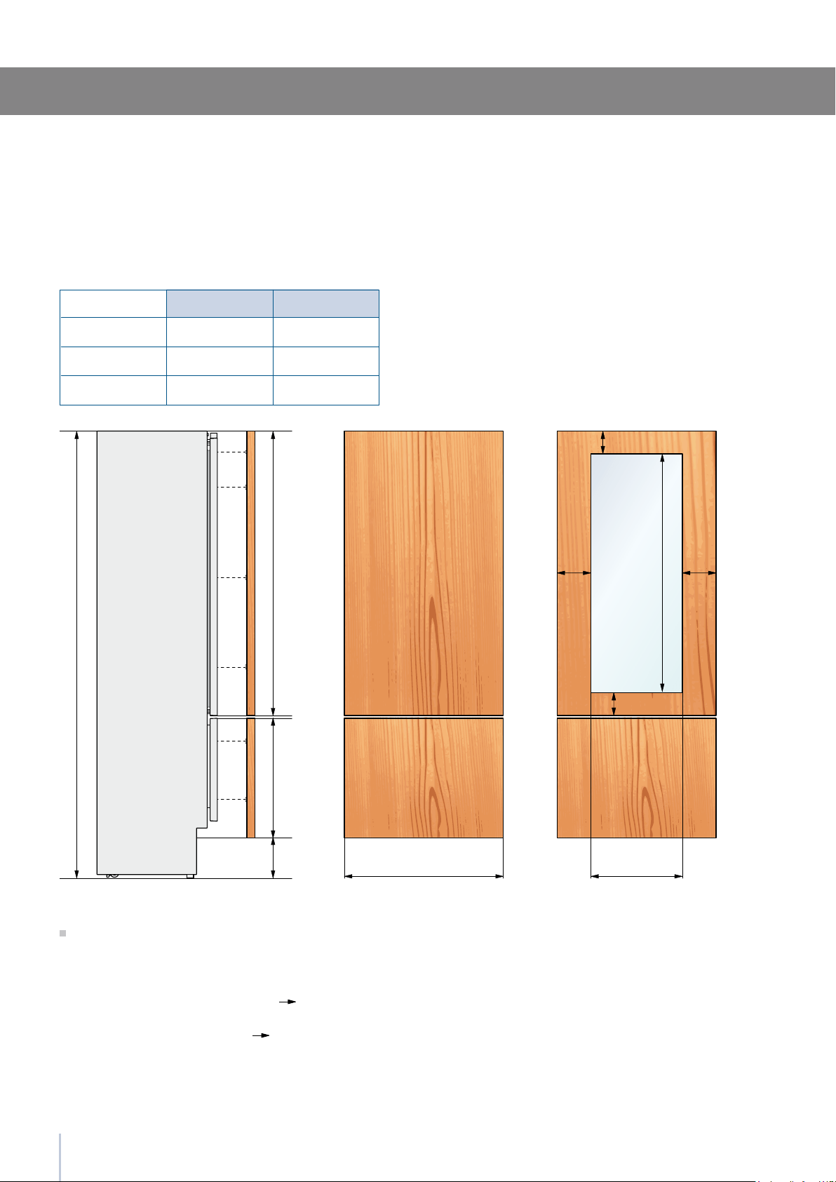
Examples of calculation
Integration in a kitchen column of total height 2160 mm (85”) and 150 mm (6”) kickplate.
(NOTE: In calculating the adjustment foot is considered to 0).
Drawer Calculation:
Kickplate 187 - 150 = 37 mm (1 1/2”)
540 + 37 = 577 mm (22 3/4”)
Upper Panel Calculation:
2160 - 2050 = 110 mm (4 3/8”)
1320 + 110 = 1430 mm (56 1/4”)
Total Height Calculation:
150 + 577 + 3 + 1430 = 2160 mm (85”)
Panels Dimensions One Bottom - Drawer
Door/Drawer Width
A
Series
Door Cutout Width
B
Series: Integrated
Panels with width ranging between 18 mm (3/4 in) and 28 mm (1 1/8 in).
Door panels with weight max of 23 kg (51 lb) and drawer panels with weight max of 11kg (25 lb)
17
1
2
3
4
5
Installation Guide
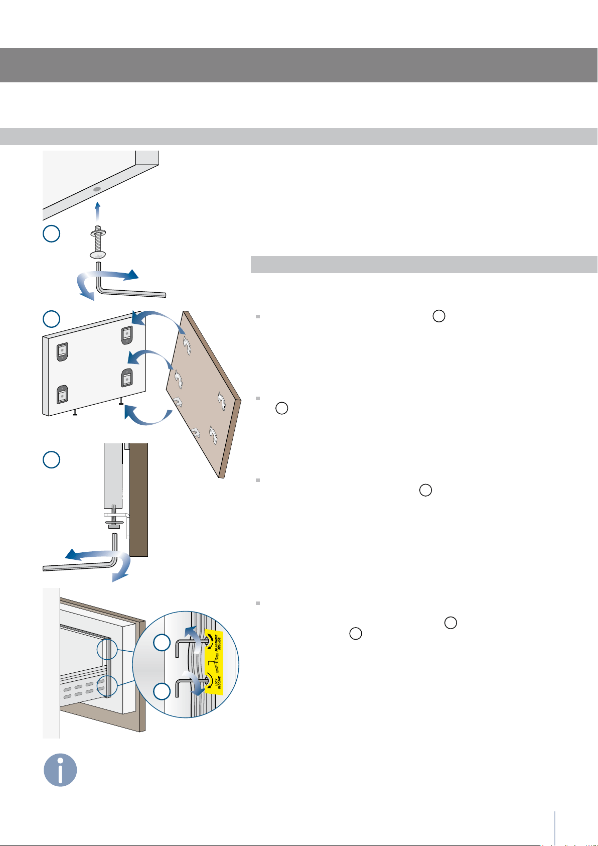
Mounting panels to the door and the drawer
Once all brackets and small brackets have been applied to the pan-
els, you can begin installing the bottom drawer.
Operate as follows:
Partially tighten the screw to the xing
1
.
Hook the bottom drawer panel starting from the xings on the bot-
tom
2
.
It is now possible to align panels to adjacent cabinets in height
using the lower alignment brackets,
3
tightening or untightening
the screws into position as needed. With the screw slighty tightened,
move the panel sideways to align it to the other panels on the unit or
other adjacent structures.
Depth alignment: working from the inside of the drawer, after lift-
ing up the magnetic seal, adjust the panel position so it is closer to or
further away from the door using the holes
4
and then secure the
panel using the holes
5
.
Series: Integrated
Once the front panel has been adjusted,
check that the gasket has been
repositioned correctly to assure the
door/drawer are closing correctly and
avoid operational errors of the unit.
18
6
8
9
7
10
11
Hook the panel to the fixing devices starting from the top aligning
bracket
6
.
At this point, alignment between the panel and adjacent cabi-
nets can be adjusted using the alignment bracket and small brack-
ets
7
and
8
.
Vertical alignment: tighten or loosen the screw in the brackets to
raise or lower the panel
9
.
Depth alignment: working from the inside of the door, after lift-
ing up the magnetic seal, adjust the panel position so it is closer to
or further away from the door using the holes
10
and then fix the
panel in position using the holes
11
.
Series: Integrated
Once the front panel has been adjusted,
check that the gasket has been
repositioned correctly to assure the
door/drawer are closing correctly and
avoid operational errors of the unit.
19
2
3
1
B
A
6,5 () 6,5 ()
20 ()
20 ()
22 ()
22 ()
22 () 22 ()
Installation Guide
Appliance Wall
or
furniture
Wall
or
furniture
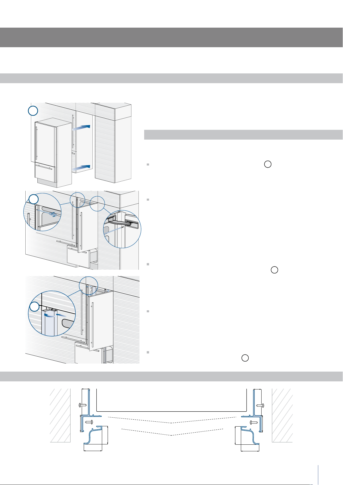
Installation
For a built-in installation, to close gaps between the appliance and
the adjacent cabinets, special side proles and aluminum covering
frames are provided.
Operate as follows:
Push the appliance into the installation niche
1
.
If the unit is to be installed inside a niche or within an enclosed
structure, it is necessary to design a ventilation shaft at the back of
the niche to assure proper ventilation at the back of the unit. A 5 mm
gap is sufcient to prevent overheating. Always mount front panels on
door and drawer before pushing the unit into its nal position inside the
niche or structure.
Secure the appliance to the adjacent cabinets by xing to these the
side proles previously mounted on the appliance
2
.
To make this operation easier keep the door and the drawer open.
Check the levelling of the appliance, adjusting its feet and wheels
to correct it.
Mount the proles the covering frames: rst insert them laterally and
then push rmly until a “click” is heard
3
.
A Connecting element B Alluminium frame
Built-in installation single appliance
Side proles mounting
Series: Integrated
20
1
2
3
4
5
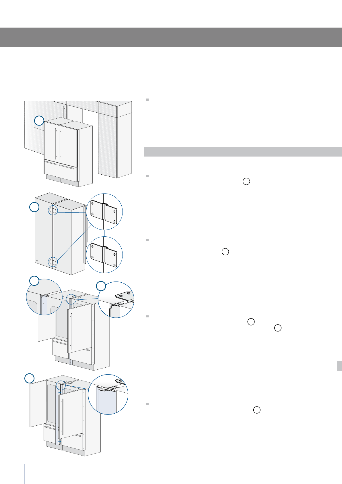
Required accessories to be ordered separately:
Central connection Kit
Special side proles and aluminum covering frames are provided for
closing gaps between the appliance and the adjacent cabinets.
Operate as follows:
Position the appliances in front of the installation area, leaving
enugh space to operate at their back
1
.
Move at the back of the appliances to mount the joining brackets:
x on side of the top and lower brackets to one of the appliances
and subsequently to the other
2
.
Place the two units side by side and join them at the front attaching
the two pro les with the supplied screws
3
.
Attach the bracket on top of the units as per gure
4
.
Finish off by mounting the central cover frame onto the central
profiles, by pushing it until a click is heard
5
.
Built-in installation two or more appliances
Series: Integrated
21
6
8
7
E
D
A
B
A
B
D
6,5 () 6,5 ()
20 ()
20 ()
22 ()
22 ()
22 () 22 ()
6,5 ()6,5 ()
18 ()
44,4 (1 )
18 ()
C
13 ()
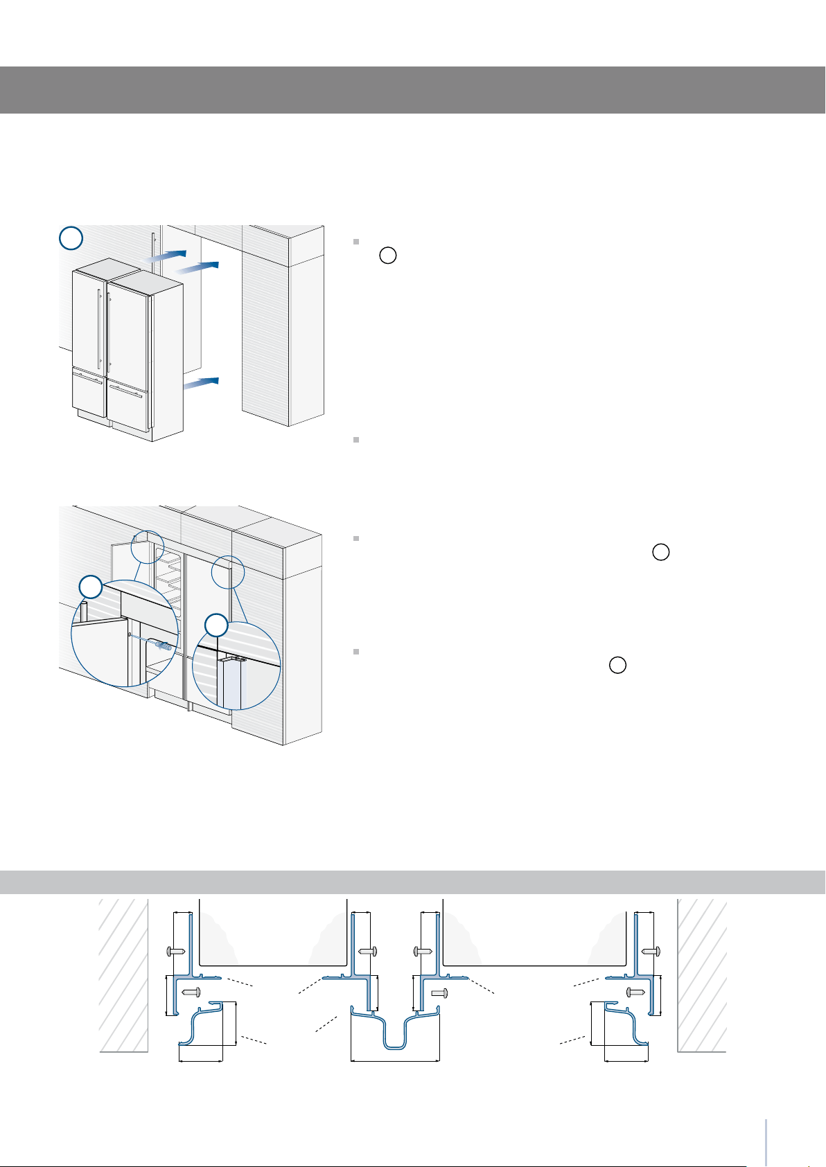
Installation Guide
Once completed the previous steps, push the units in their nal posi-
tion
6
.
If the units are to be installed inside a niche or within an enclosed
structure, it is necessary to design a ventilation shaft at the back of
the niche to assure proper ventilation at the back of the unit. A 5 mm
gap is sufcient to prevent overheating. Always mount front panels on
door and drawer before pushing the unit into its nal position inside the
niche or structure.
Check the levelling of the appliance, adjusting its feet and wheels
to correct it.
Secure the appliance to the adjacent cabinets by xing to these the
side proles previously mounted on the appliance
7
.
To make this operation easier keep the door and the drawer open.
Mount the covering frames onto the proles, rst insert them laterally
and then push rmly until a “click” is heard
8
.
Appliance Appliance
Wall
or
furniture
Wall
or
furniture
A Connecting element
B Alluminium frame
D Connecting element
E Aluminium frame
Side and central proles mounting
Series: Integrated
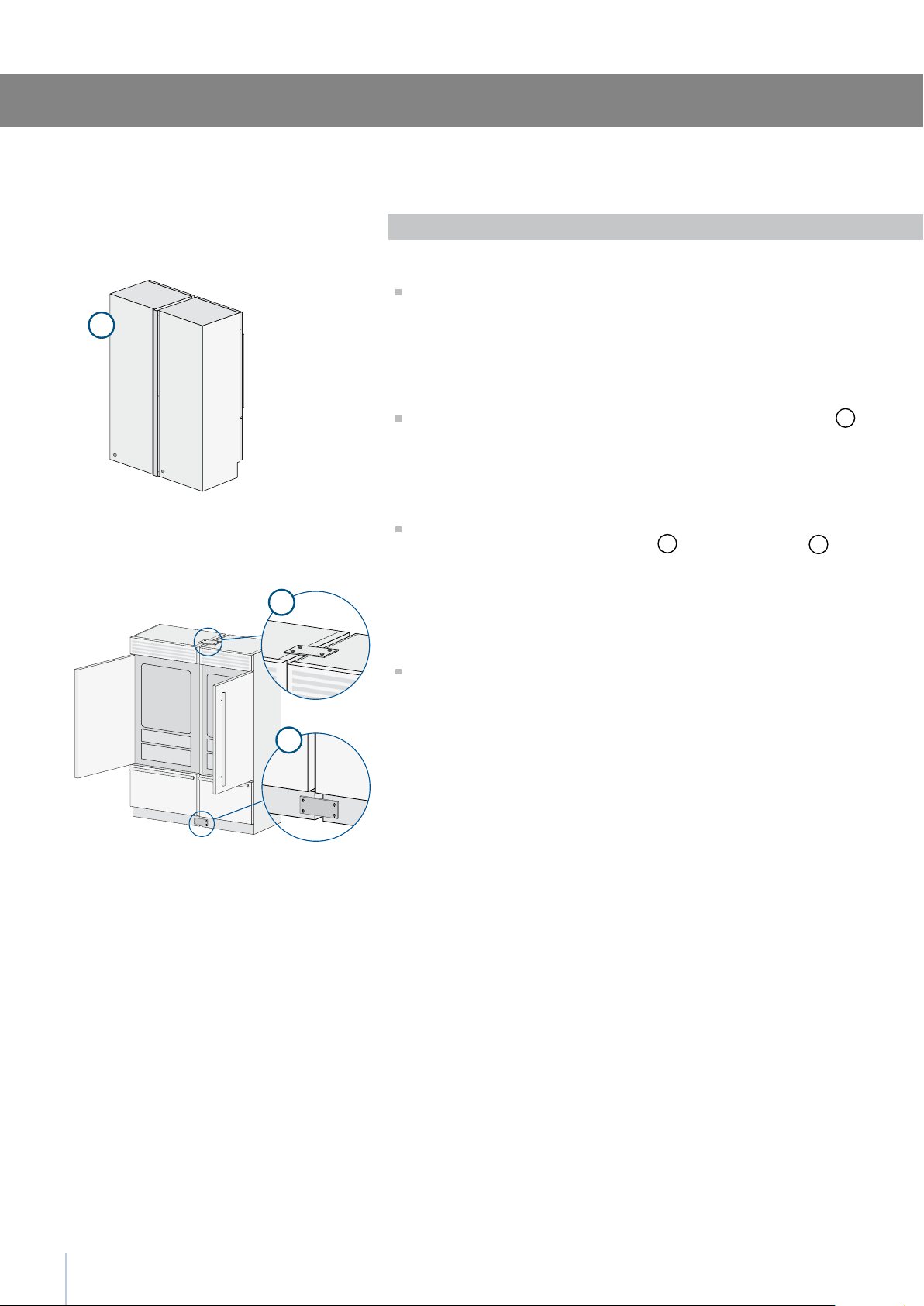
22
1
2
3
Free-standing installation
two or more appliances
Series: Integrated
Operate as follows:
Position the appliances in front of the installation area, leaving
enough space to operate at their back.
Move at the back of the appliances to mount the joining prole
1
Place the two units side by side and join them at the front attach the
bracket on top of the units as per gure
2
and at the bottom
3
.
Check the levelling of the appliance, adjusting its feet and wheels
to correct it.
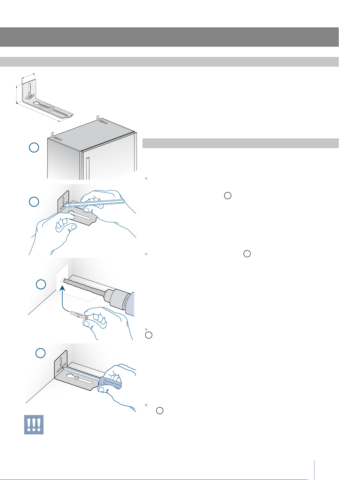
23
2 x
6 x
152 (6”)
59 (
2
”)
45 (1
”)
1
2
3
4
Installation Guide
To avoid danger of the appliance tipping over
it is mandatory to secure the appliance to the
wall by means of two special brackets.
To prevent the appliance from tipping over an extra-long kit is vailable
up on request if the appliance needs to remain distanced from the
wall, it is mandatory to install two brackets on the upper part of the
appliance for xing it securely to the wall.
Operate as follows:
The brackets should be applied as illustrated using the provided
screws and expansion plugs.
Place a bracket on the top of the appliance in correspondence to the
xing holes and against the wall
1
.
Mark up the holes position on the wall
2
.
Drill the wall with an 8 mm (3/8”) bit and insert the expansion plug
3
.
Reposition the bracket and x it rst to the cabinet and then to the
wall
4
.
Anti-tipping safety assembly
Series: Integrated
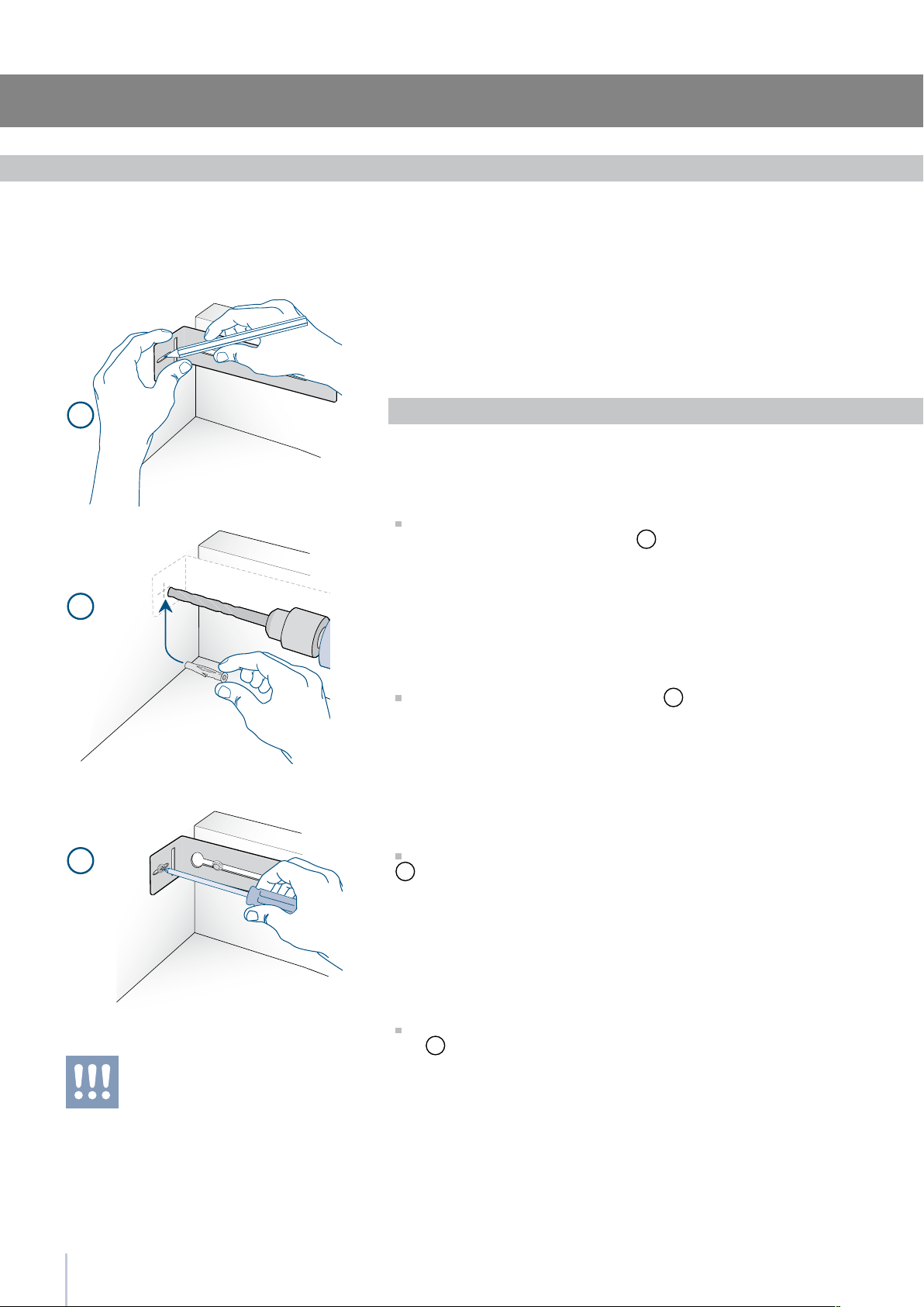
24
1
2
3
To avoid danger of the appliance tipping over
it is mandatory to secure the appliance to the
wall by means of two special brackets.
Anti-tipping safety assembly: full integration
To avoid danger of the appliance tipping over when opening full doors
and drawers, it is mandatory to install two brackets on the upper part
of the appliance for xing it securely to the wall.
The brackets should be applied as illustrated using the provided screws
and expansion plugs.
Operate as follows:
Place a bracket on the top of the appliance in correspondence to
the xing holes and against the wall
1
.
Mark up the holes position on the wall
2
.
Drill the wall with an 8 mm (3/8”) bit and insert the expansion plug
3
.
Reposition the bracket and x it rst to the cabinet and then to the
wall
4
.
Series:Free-Standing
Anti-tipping safety assembly
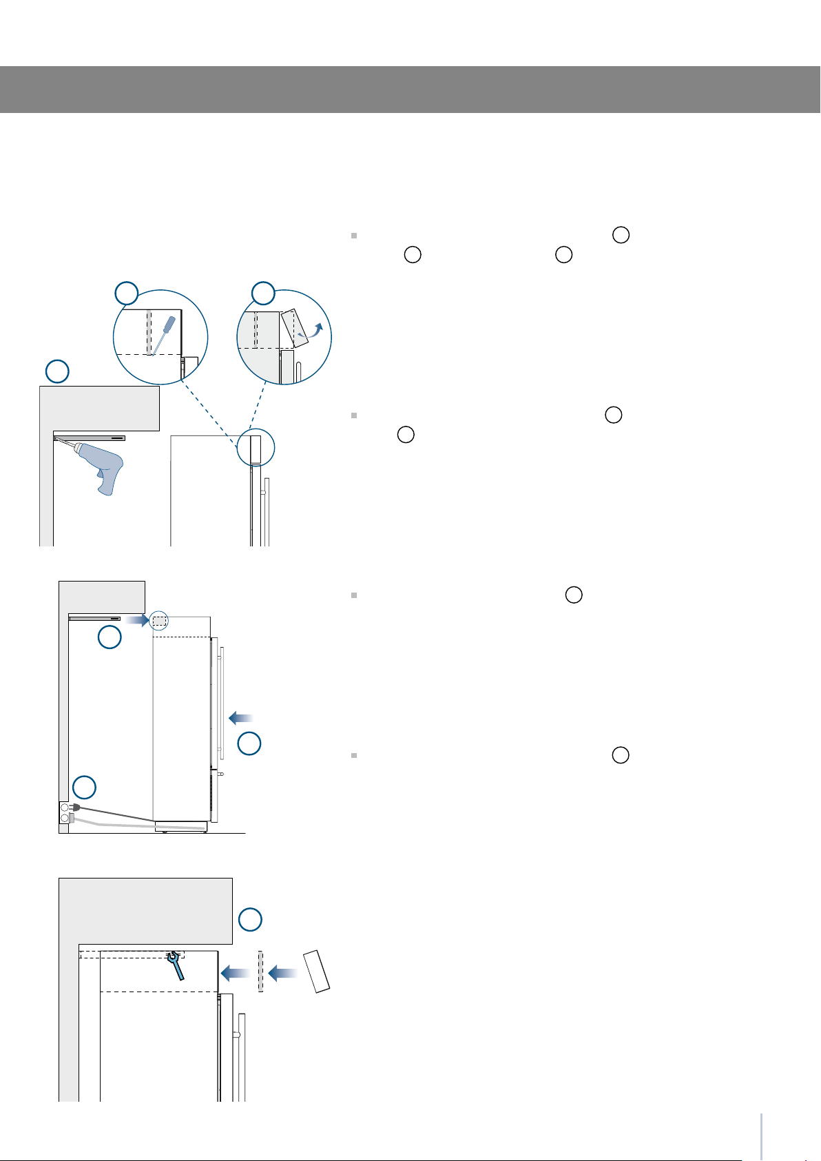
25
E
W
7
E
W
1
3
4
5
6
2
Installation Guide
Anti-tipping safety assembly: full integration
Series:Free-Standing
Fit the brackets and secure them to the wall
1
, remove the ventila-
tion grid
2
and the frontal closing
3
.
Make the electrical and water connection
4
(see page 8) and push
the unit
5
.
Insert the brackets to the rear holes
6
.
Fix brackets and reinstall the removed parts
7
.
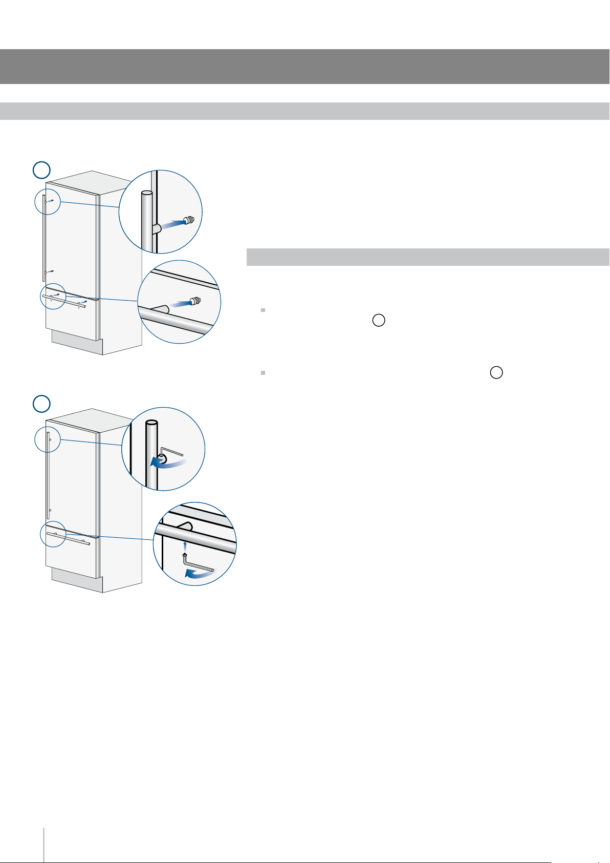
1
2
26
Mounting the handles on stainless front
To mount the handles onto the door and the drawer operate as follows:
Operate as follows:
Insert the two handle spacers onto the supports already available on
the door and the drawer
1
.
Screw in the Allen screws available on the handle
2
.
The screws must be tightened in by means of a 2.5 mm (1/8”) hex
wrench.
Series: Free-Standing
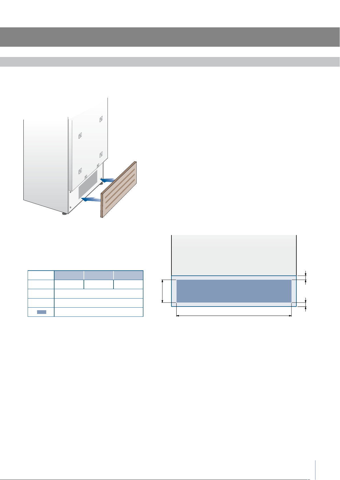
27
A
B
C
C
A 860 (33 ) 740 (29 )560 (22”)
> 100 (4”)
10 ()
50%
B
C
Installation Guide
Ventilation
899 Series 749 Series 599 Series
A forced air system assures ventilation through a grille positioned
in the lower front part of the unit. If the kitchen design includes a
kickplate, the latter has to be punched in order to maintain a sati-
sfactory air ow, as described in the drawing. Holes can be in any
shape and size, as long as the total area of the punched part equals
50% of the kickplate are.
In this case, to guarantee a better air ow, it is advisable to remove
the front grille included with the unit. The grille is secured to the unit
with magnetic plates and can be easily removed even by the end
user, to provide for regular cleaning procedures and remove dust.
If the grille is partially covered by the kitchen kickplate, it is advisable
to remove the grille in order to provide for a better airow.
Series: Integrated
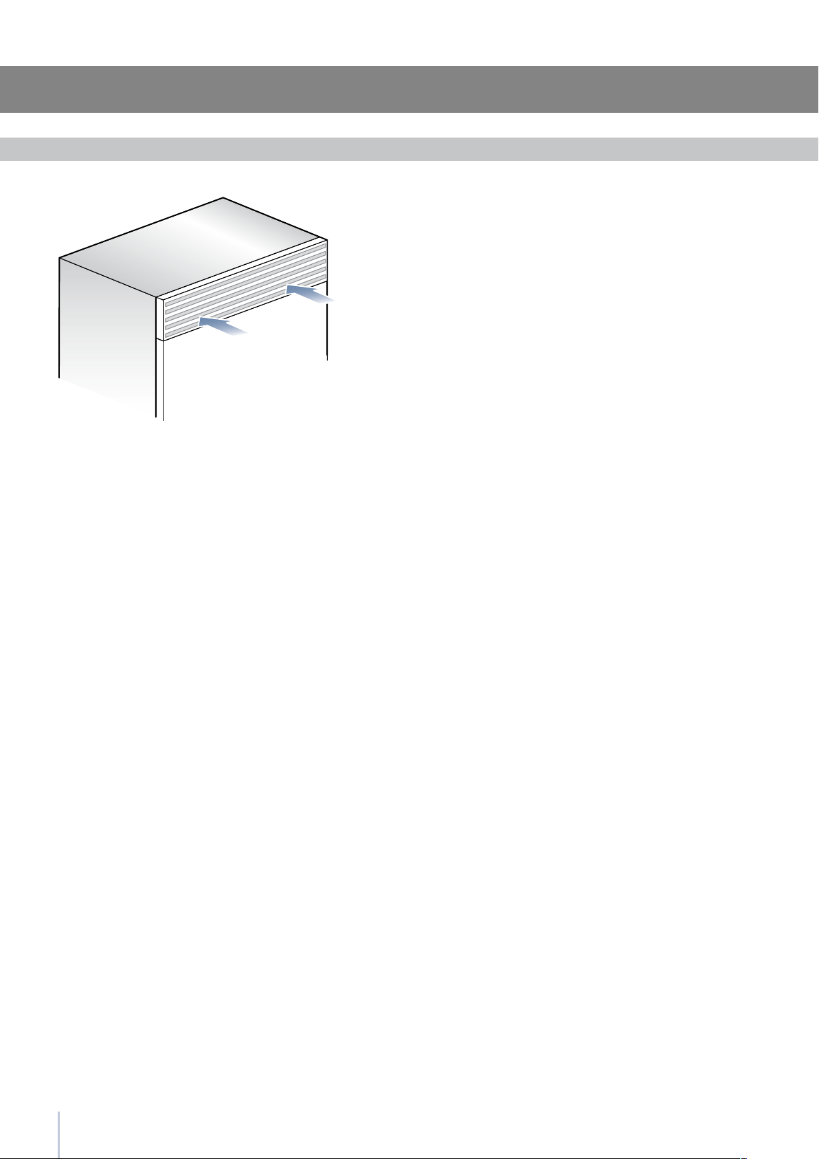
28
Ventilation
Ventilation is insured by a forced air system through a grille located in
the upper part of the appliance.
This grille should never be covered by panels or any other devices that
could reduce its efciency.
Please refer to page 5-6 to ensure correct air circulation.
Series:Free-Standing

29
Installation Guide
Post installation control
Check that the front levelling feet have been properly installed.
Check that the connection to the water system does not have any
leaks and that the closing tap is easily accessible.
Check that the electrical connection is correctly installed and that
the multipole switch and socket are easily accessible.
Check the perfect alignment of the appliance with adjacent
structures.
Check that all adhesive tape and external or internal temporary
protective devices have been removed.
Check the perfect closing of the doors and the smooth sliding of
the drawers and shelves.
Series: All
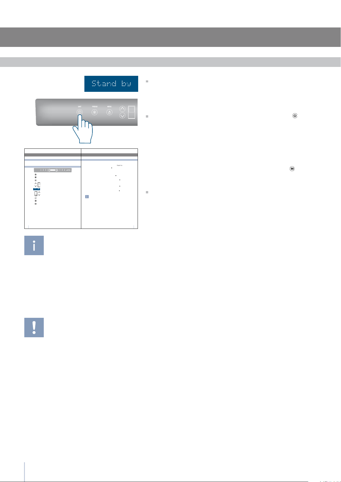
30
9
4
4.1
Accensione e spegnimento dell’apparecchiatura
Se alla prima accensione non appare la scritta
Stand-by, ma appaiono altre scritte, significa che
l’apparecchiatura ha già iniziato la procedura di
raffreddamento.
Dura nte l a pri ma ac cens ione non sarà poss ibile uti -
lizz are il men ù Menu pe r u n’ev entu ale mod ifica del le
prei mpost azio ni di fabb rica fin o al r aggiu ngime nto
dell a tem perat ura p reim post ata. È poss ibile tutt avia re-
gola re da s ubito l’ ora e l a d ata, par amet ri comun que
nece ssari per att ivare alc une f unzi oni speci ali.
Ad ogni accensione l’apparecchiatura esegue una
procedura di autodiagnosi della durata di 3 minuti pri-
ma di avviarsi completamente.
Se si spegne solo il vano Frigorifero, il relativo ven-
tilatore continua a funzionare autonomamente per
prevenire la possibile formazione di odori e muffe.
Prima di spegnere per un periodo lungo l’intera ap-
parecchiatura, rimuovere tutti gli alimenti conservati
e lasciare le porte ed i cassetti aperti per evitare il
formarsi di cattivi odori e muffe.
Quando l’apparecchiatura è collegata alla rete elettrica ma non è
stata ancora accesa viene visualizzato sul display il messaggio
Per accendere tutti i vani dell’apparecchiatura agire per 3 secondi
sul tasto Unit .
Alla prima accensione il vano Multizone è predisposto nella funzio-
nalità Freezer .
Prima accensione
Dopo la prima accensione si raccomanda di attendere almeno 12
ore, senza aprire le porte, prima di introdurre alimenti nell’apparec-
chiatura. Durante tale periodo disattivare eventuali messaggi sonori
sfiorando il tasto Alarm
.
Può essere spento solo attraverso lo spegnimento completo dell’ap-
parecchiatura.
Agire per 3 secondi sul tasto Unit
.
Durante periodi di assenza molto lunghi è consigliabile spegnere il
frigorifero agendo sul tasto Unit
per 3 secondi e staccando la spi-
na o agendo sull’interruttore omnipolare che lo alimenta.
Svuotarlo di tutto il suo contenuto, pulirlo ed asciugarlo e lasciare le
porte ed i cassetti parzialmente aperti per evitare la formazione di
cattivi odori.
Spegnimento vani Frigorifero
Spegnimento vano Multizone
Riaccensione
Spegnimento per lunghi periodi
Accensione e spegnimento
Agire nuovamente sugli stessi tasti per la riaccensione.
Il vano Freezer rimane sempre acceso e non può essere spento se
non attraverso lo spegnimento completo dell’apparecchiatura.
Agire per 3 secondi sul tasto Unit
.
3
3.3
3.3
Componenti principali
Componenti principali
3.5
3.4
123456798
1
Unit
2
Fridge
3
Menu
4
Up/down
Fridge
5
Display
6
Up/Down
Freezer
(Multizone)
7
Enter
8
Ice maker
9
Alarm
8
Il sistema di controllo elettronico mantiene costante la temperatura dei due vani e la visualizza sul display del pannello di con-
trollo; consente inoltre l’interazione dell’utente con il sistema di controllo, tramite l’impostazione personalizzata delle diverse
funzioni e l’invio di messaggi sonori e/o visivi, qualora si verificassero anomalie nel funzionamento dell’apparecchiatura.
Pannello di controllo principale
Controllo elettronico
Permette lo spegnimento completo e l’accensione dell’apparecchia-
tura (agire su di esso per 3 secondi).
Permette lo spegnimento e l’accensione del solo vano frigorifero (agire
su di esso per 3 secondi).
Permette l’accesso al menù delle funzioni dell’apparecchiatura
Visualizza le temperature dei vani frigorifero e freezer, la data e l’ora, le
funzioni Menu ed i messaggi visivi.
Tramite lo sfioramento dei tasti Up/Down è possibile variare la tempe-
ratura preimpostata a seconda delle scelte di utilizzo del vano (free-
zer , frigorifero o 0°C).
Permette di confermare l’attivazione o la disattivazione delle selezioni
operate attraverso Menu.
Permette di attivare o disattivare la produzione automatica di ghiaccio.
Lampeggia per segnalare eventuali anomalie di funzionamento, evi-
denziate anche attraverso un avviso sonoro, disattivabile attraverso lo
sfioramento del tasto.
Tramite lo sfioramento dei tasti Up (su) e Down (giù) è possibile variare
la temperatura già impostata per il frigorifero e muoversi all’interno
del menù interattivo.
Prima di iniziare
Start up
Series: All
If at the rst start - up the message Stand by does
not appear, but other messages appear, such
as Fridge too warm, Fresco too warm, Freezer
too warm, or sound signals are activated, it
means that the appliance has already started
the cooling process.
If this is the case, deactivate any possible acous-
tic signals by pressing the Alarm button, close
the door and wait until the set temperature is
reached.
To start the appliance, connect the plug to the electrical mains: at
this point, when opening the door, the control panel will usually visual-
ize the message “Stand by”, and all the panel keys be off
To turn on all the appliance compartments, press the Unit button
for three seconds. The display will show the message “Initial test” for
approx. 2 minutes. After this phase the compressors will start up and re-
main on until the default temperature set up in the factory is reached.
Do bear in mind that this condition could last several hours.
If the appliance is provided with an Ice Maker, prior to switching it
on make sure that the water lter cartridge is installed, then ll the
water system. To this purpose switch off the Ice Makerand performe a
manual clean procedure.
At the end switch the Ice Maker on again by touching the
button.
For further information about the appliance operation, refer to the
User Manual.
It is necessary to let the unit reach the correct
temperature before foods are stored inside.

Installation Guide


22-122014

GI-SMEG EN