INSTRUCTION FOR USE
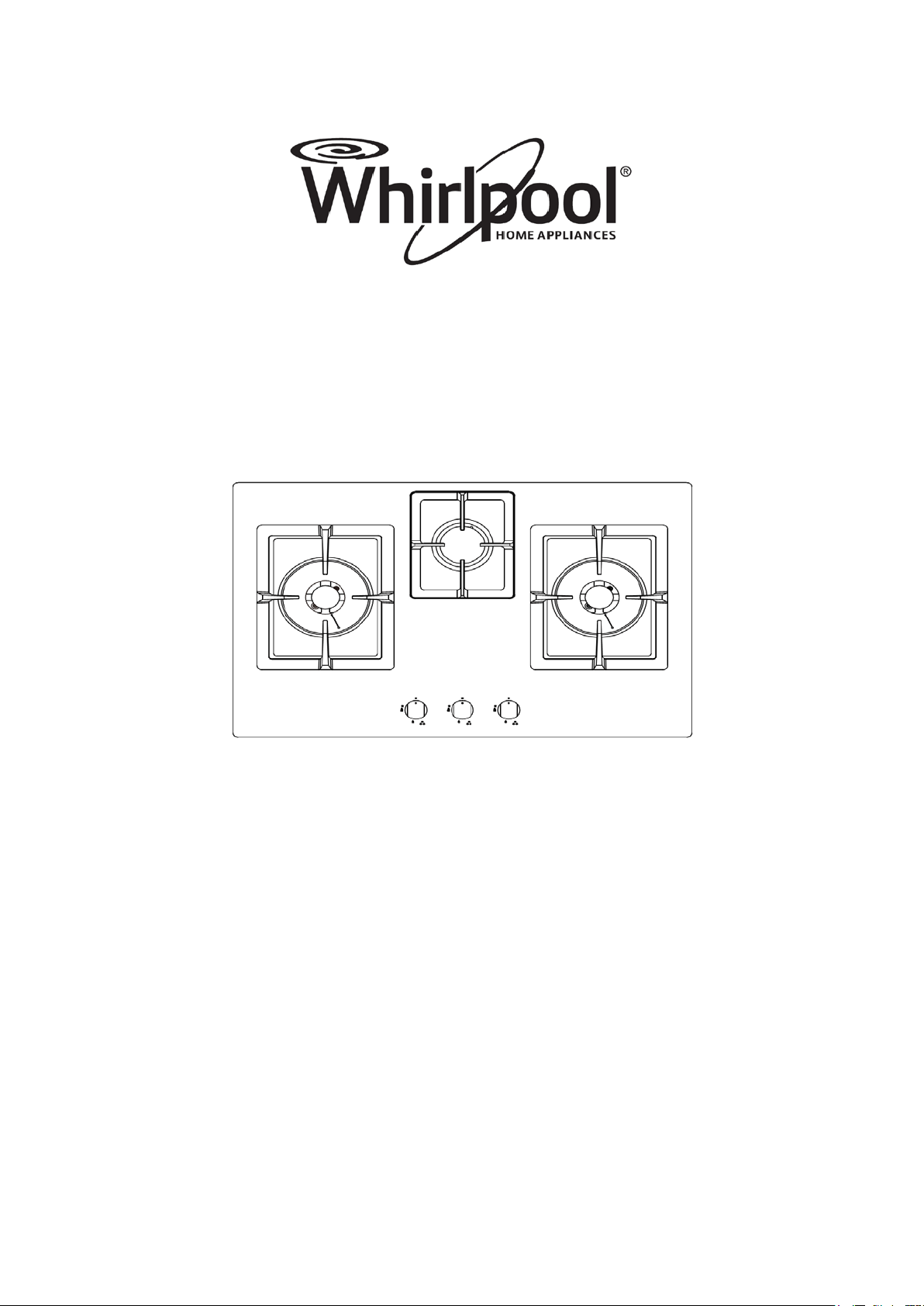
70 cm 3 burner, gas hob
AKC7330C/BLS-BT
1

For your safety
These instructions have been drawn up for your safety and that of others. You are
therefore requested to read them carefully before installing and using the appliance.
Keep this instruction manual for future reference as necessary. If the appliance is
sold or moved, make sure that the manual is handed over to the new user.
Installation
· Prior to installation, ensure that the local distribution conditions (nature of the gas
and gas pressure) and the adjustment of appliance are compatible.
· The adjustment conditions for this appliance are stated on the label(or data plate).
This appliance is not connected to a combustion products evacuation device. It shall
be installed or connected in accordance with current installation regulations.
Particular attention shall be given to the relevant requirements regarding ventilation.
· For an appliance that is likely to operate with several gases, these instructions shall
also state the operations and adjustments to be carried out when converting from one
gas to another. It should give, for each of the interchangeable injectors and calibrated
orifices, the markings for each gas and pressures that may be used.
· Installation of the appliance and its connection to the electrical mains must only be
carried out by QUALIFIED PERSONEL. Before doing any servicing, it is important
to check that the appliance is DISCONNECTED from the electrical mails.
· It is risky to modify or attempt to modify the characteristics of this product.
· After removing the appliance from the packaging, make sure that it is not damaged
and that the electrical lead is in perfect condition. Otherwise, contact your dealer
before putting the appliance into operation.
· The Manufacturer declines all responsibility in case of failure to comply with the
accident prevention regulations.
· Make sure that air circulates freely around the appliance. Poor ventilation creates a
shortage of oxygen
· Use of a gas cooking appliance produces heat and moisture in the room in which it is
installed. Ensure that the room is well ventilated by keeping the air intakes open and
in good working order or by installing an extractor hood with discharge pipe.
· If the appliance is used intensively for a long time the effectiveness of the ventilation
will have to be increased, for example by opening a window or increasing the power
of any electric extractor fan.
2

During use
·This product is designed to cook food inside ordinary homes and for non-professional
purposes. It should not be used for any other purpose.
· After using the appliance, make sure that all controls are in “CLOSED” or “OFF”
position.
· If you use an electrical socket close to this appliance, take care that the cables of the
appliances you are using are far away from the hot parts of this appliance.
·Never leave plastic, oil or any other flammable material around the hob when
cooking.
·If the Hob fails to light at the first time, then you should wait for I minute before you
try again.
Do not press the control knob for more than 15 seconds. If after 15 seconds, the
burner does not ignite, release the control knob and open the door or wait for at least 1
minute before making a new ignition attempt.
If the burner flame accidentally goes out, turn the control knob to the off position. Do
not attempt to re‐ignite immediately. WAIT for at least 1 minute before making an
attempt to ignite the burner again
Children’s safety
· This appliance must only be used by adults. Make sure that children do not touch the
controls or play with the appliance.
· The exposed parts of this appliance heat up during cooking and remain hot for some
time even after it is switched off. Keep children well away until the appliance has
cooled down.
Environmental protection advice
· All the materials used are environmentally compatible and recyclable. Please make
your contribution to conserving the environment by using the separate waste
collection channels available.
Decommissioned appliances
· Appliances which are no longer used or usable are not worthless waste. Through
environment-friendly disposal, a number of materials used in the production of your
appliance can be recovered.
· Find out about the current disposal options from your specialist dealer, or your local
authority.
· Before scrapping the appliances, cut the power supply lead and make it unusable.
3

Contents
For your safety .......................................................................................... 2
Installation ................................................................................................................................. 2
During use ................................................................................................................................. 3
Children’s safety ....................................................................................................................... 3
Environmental protection advice .............................................................................................. 3
Decommissioned appliances ..................................................................................................... 3
Technical Data ........................................................................................... 5
Instructions for the installation technician ............................................ 6
Installation premises ................................................................................................................. 6
Discharge of flue gases ............................................................................................................. 6
Connection to the gas supply .................................................................................................... 7
Connection ................................................................................................................................ 7
Building into fitted kitchen units ............................................................. 8
Insertion and fixing ...................................................................................................................8
On
base cabinet with door ......................................................................................................... 9
On base cabinet with oven ........................................................................................................ 9
Instructions for use ................................................................................. 10
The hob control knobs ............................................................................................................. 10
Dual triple flame version .........................................................................................................10
Li
ghting the burners ................................................................................................................ 11
For correct use of the hob ...................................................................... 11
Cleaning and maintenance ..................................................................... 12
General cleaning ..................................................................................................................... 12
Hob .......................................................................................................................................... 12
Ignition plug ............................................................................................................................ 12
Routine maintenance ............................................................................................................... 13
Warranty conditions ................................................................................................................ 13
4
Guide to reading the instructions
The following symbols will help you
When reading the instructions:
Safety information
“Step by step” instructions
Suggestions and Advice
Information concerning environmental protection
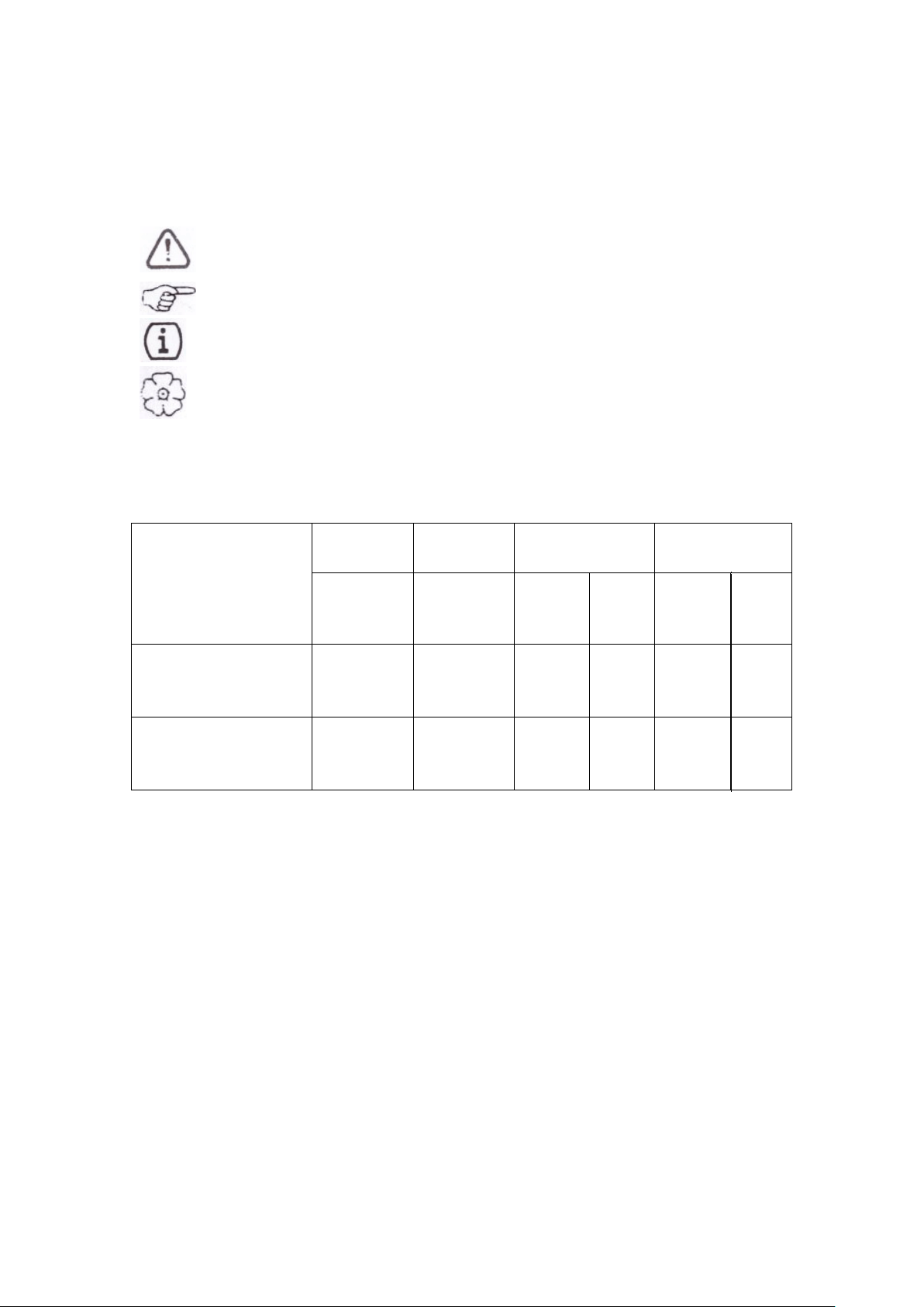
Technical Data
BURNER TYPE
MAX
OUTPUT
MIN
OUTPUT
Town Gas
10mbar
KW KW
Nozzle
(mm)
Cons
M
3
/h
Medium
Semi-rapid
Burner
1.75 0.65 1.80 0.397
Triple flame burner 3.80 1.9 3.50 0.862
Gas intake connection G1/2″
Electricity supply DC1.5Vac
5
LPG
30mbar
Nozzle
(mm)
C
ons
g/h
0.98 277
0.65 127
Instructions for the installation technician
CAUTION: This appliance must only be installed and used in rooms with
permanent ventilation to local standards.
Installation of the appliance and its connection to the electrical mains must only be
carried out by QUALIFIED PERSONEL.
Before doing any servicing, it is important to check that the
appliance is DISCONNECTED from the electrical mains. The
Manufacturer declines all responsibility for any damage arising
from installation in breach of the regulations in force or from
failure to comply with the accident prevention regulations.
Installation premises
For proper operation of a gas appliance, the air necessary for
the combustion of the gas must be able to flow into the room
naturally. The air must flow into the room directly through
openings in the outside walls. These openings must have an
unobstructed cross-section not less than 2m
3
/h for each kw of
power (see total power in kw on the appliance nameplate).
This opening must be constructed so that it will not be
obstructed from inside or outside, or constructed close to the
floor. The opening is recommended to be on the side opposite
to that on which the flue gases are discharged. If it is not
feasible to provide these openings in the room where the
appliance is installed, the necessary air may be taken from an adjacent room, provided
that:
·this room is not a bedroom or a hazardous environment;
·this room has ventilation;
·the ventilation between the room where the appliance is installed and the adjacent
room has openings.
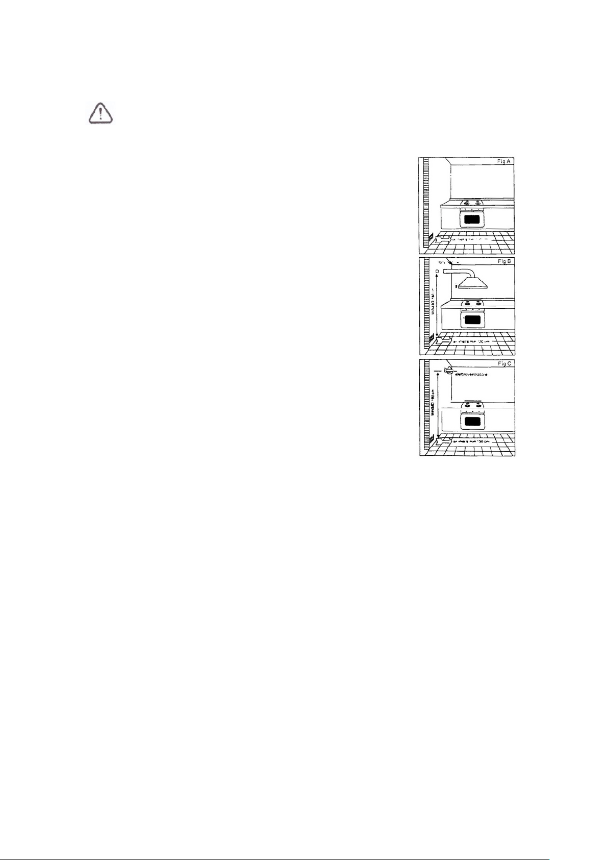
Discharge of flue gases
Gas cooking appliances must discharge their flue gases through hoods connected
directly to flues or the outdoors. If it is not possible to install the hood (fig. B) an
electric fan must be installed on the outside wall or the window of the room, provided
it is possible for the ventilation opening to be increased in proportion to the delivery
rate of the fan (fig. C). For a kitchen, the delivery rate of this electric fan must
guarantee an hourly air exchange of 3-5 times its volume. In both instances, the use of
flues already used by other appliances to discharge the flue gases is forbidden.
6
Connection to the gas supply
The gas connection must be made in accordance with the local
standards. When installing, fit a safety tap at the end of the
pipeline. The appliance leaves the factory tested and set for the
type of gas indicated on the plate inside the bottom guard, close
to the gas connection pipe. Make sure that the type of gas to be
supplied to the appliance is the same as that shown on the plate.
Otherwise, follow the instructions provided in the “Adapting to
different types of gas” section.
For maximum efficiency and minimum consumption, make sure
that the gas supply pressure complies with the values shown in
the gas used is different from that specified (or variable).A
suitable pressure regulator must be installed on the supply
pipeline.
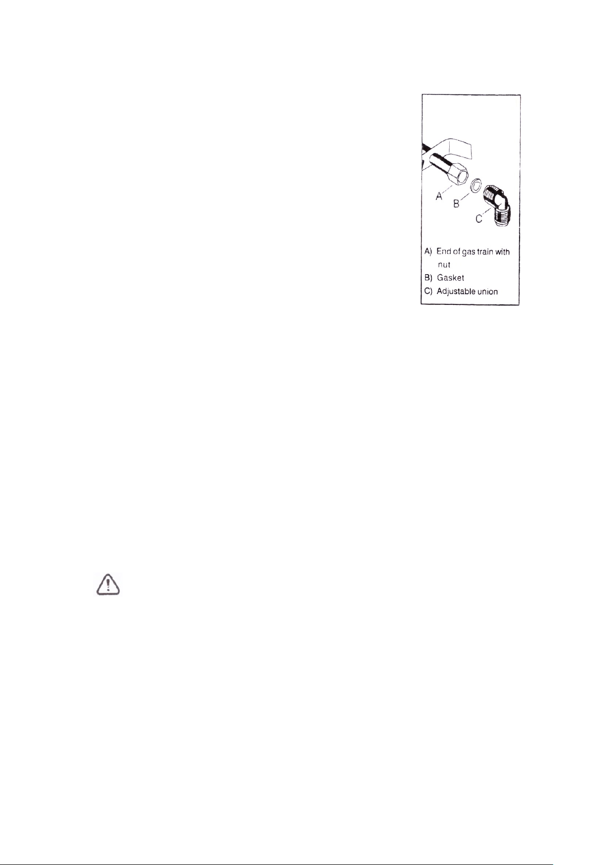
The union must be fitted on the end of the gas train. Complete with GJ1/2” other
places refer to G1/2” threaded nut, fitting the gasket between the components as
shown in the illustration. The gaskets must comply with the local standards. Screw the
parts together without forcing, fit the union so that it points in the direction required
then tighten all parts.
Connection
Make the connection to the gas system using a rigid metal pipe and regulation unions,
or with a stainless steel hose complying with the local standard. If metal hoses are
used, take care that they do not come into contact with mobile parts and are not
crushed. This must also be checked if the hob is to be combined with an oven.
The gas intake connection of the appliance has a “male thread.”
When making the connection, take care not to apply stresses of any kind to the
appliance.
When the installation is complete, always check that all the unions are
absolutely tight using a soapy solution. N
ever use a flame to make this
check.
7
Building into fitted kitchen units
These hobs are designed for installation in fitted kitchen units up to 600mm deep with
suitable characteristics.
Any cabinet side panels taller than the height of the hob itself must be at least 150mm
away from the opening into which the hob is inserted.
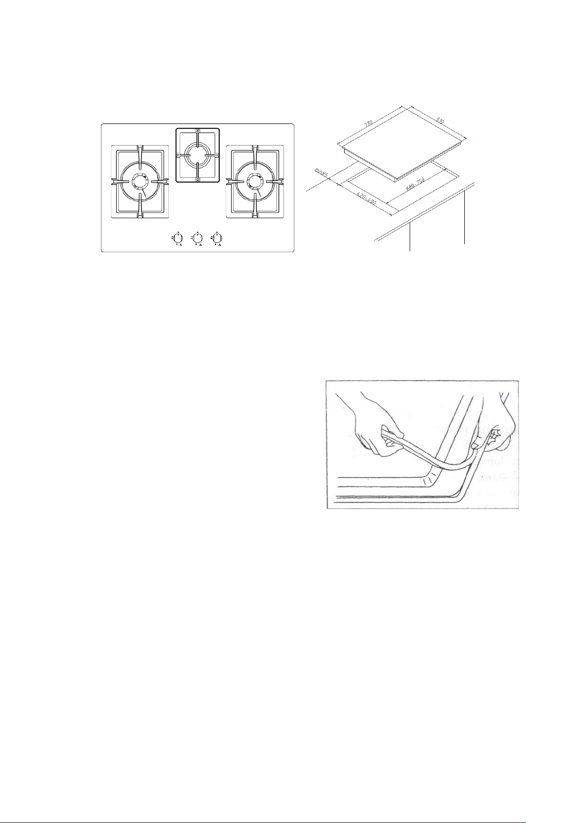
The dimensions of the hob and the installation opening are shown in the illustration.
Insertion and fixing
Before inserting the hob in the installation
opening, place the special gasket around the
bottom edge of the hob.
It is important to fix this gasket evenly, without
gaps or overlapping, to prevent liquid from
seeping underneath the hob.
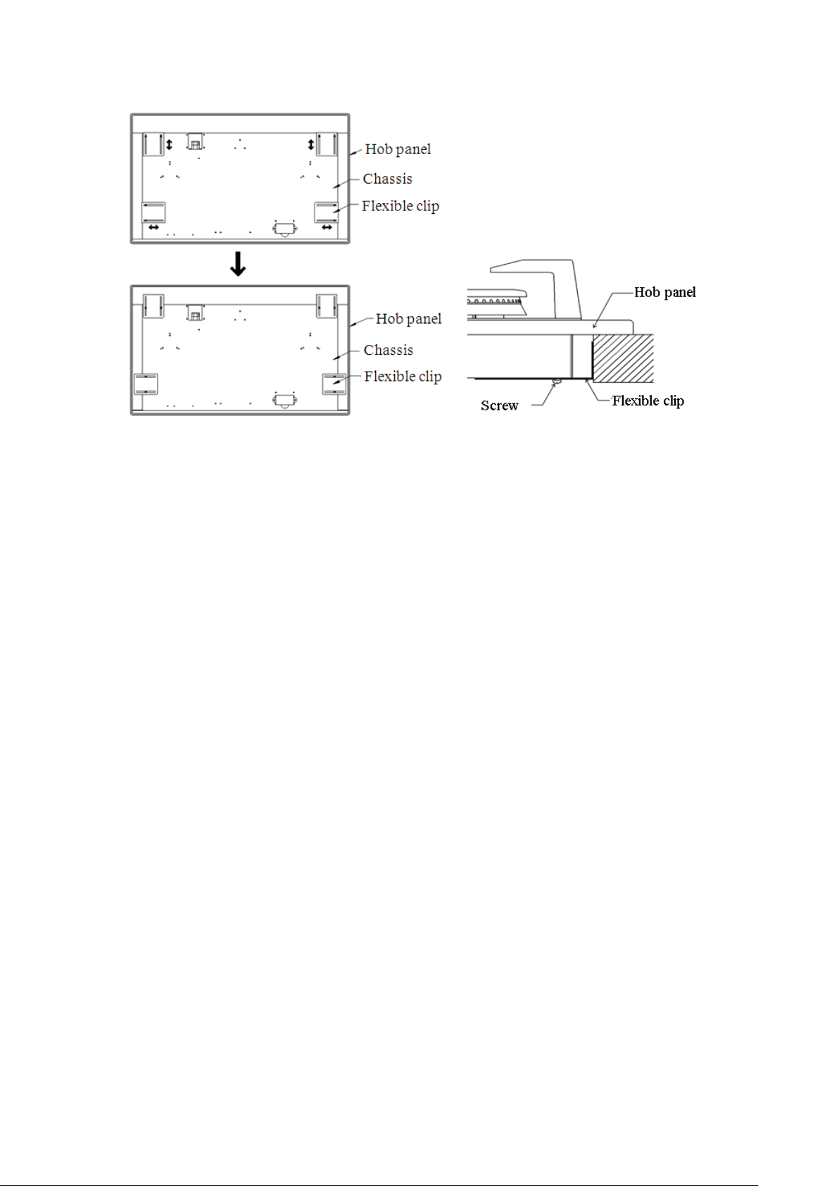
1) Remove the pan stands and the burner caps and turn the hob upside down, taking
care not to damage the ignition plugs and the thermocouples.
2) Place the gasket around the bottom edge of the hob as shown in the illustration on
the right.
3) Place the hob into the cabinet.
4) Loosen the 8 pcs of screws at two sides of the chassis.
5) Adjust the flexible clip to connect the side cabinet well and then tighten up these 8
pcs of screws.
8
In
stallation options
On base cabinet with door
When constructing the cabinet, suitable precautions must be taken to prevent contact
with the casing of the hob, which becomes very hot during operation. The
recommended method for overcoming this problem is illustrated in Fig.1
The panel underneath the hob must be easily removable to allow the hob to be locked
in position and released in case of servicing work
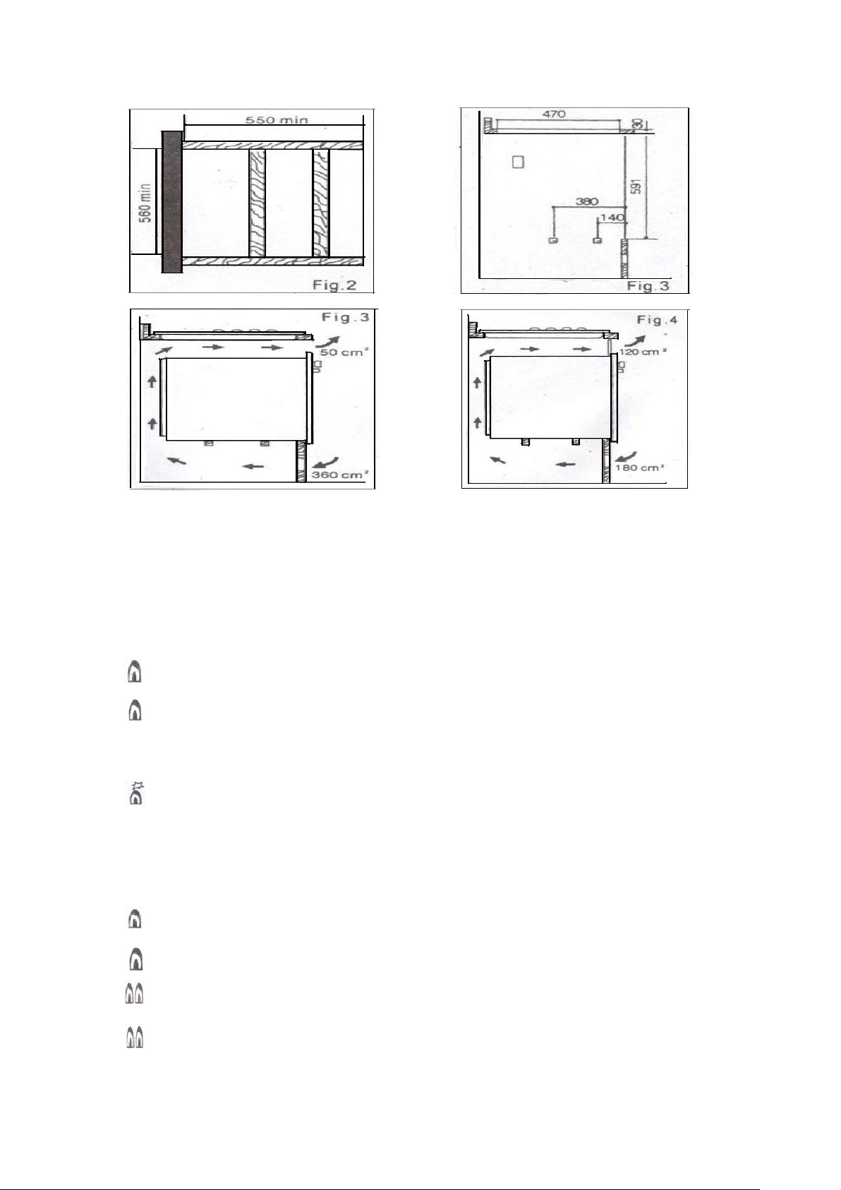
On base cabinet with oven
The installation compartment must have the dimensions shown in figures 2 and 3 and
must have supports to allow satisfactory ventilation. Two possible methods for
avoiding overheating are illustrated in figures 3 and 4. The electrical connections of
the hob and oven must be made separately both for electrical reasons and to simplify
removal of the oven through the front of the cabinet.
Extractor hoods must be at least 650 mm above the hob.
9
Instruct
ions for use
The hob control knobs
The symbols on the control knobs mean the following:
● no gas flow
maximum gas flow
minimum gas flow
All operating positions must be set between the maximum and minimum flow settings,
and never between the maximum setting and the closed position.
(Symbol present on version with lighting integrated in the Control knob)
Dual triple flame version
The symbols on the control knobs mean the following:
●
no gas flow
maximum gas flow from central burner
minimum gas flow from central burner
maximum gas flow from outer and central burners simultaneously
minimum gas flow from outer and central burners simultaneously
10

Lighting the burners
To obtain a flame more easily, light the burner before placing a cooking utensil
on the pan stand
To light a burner, proceed as follow: for version with lighting integrated in the
control knob push the knob of the burner fully down and turn it anticlockwise to the
“maximum flow” setting symbol, or press the button if the appliance has individual
lighting.
● After lighting the flame, keep the knob pressed for about 10 seconds: this
time is necessary to heat up the “thermocouple” (Fig.1-C) and activate the safety
valve, which would otherwise cut off the gas flow.
Then check that the flame is even and turn the control knob to adjust the flame as
required
In the instance of a power cut, place a flame near the burner and proceed as already
described.
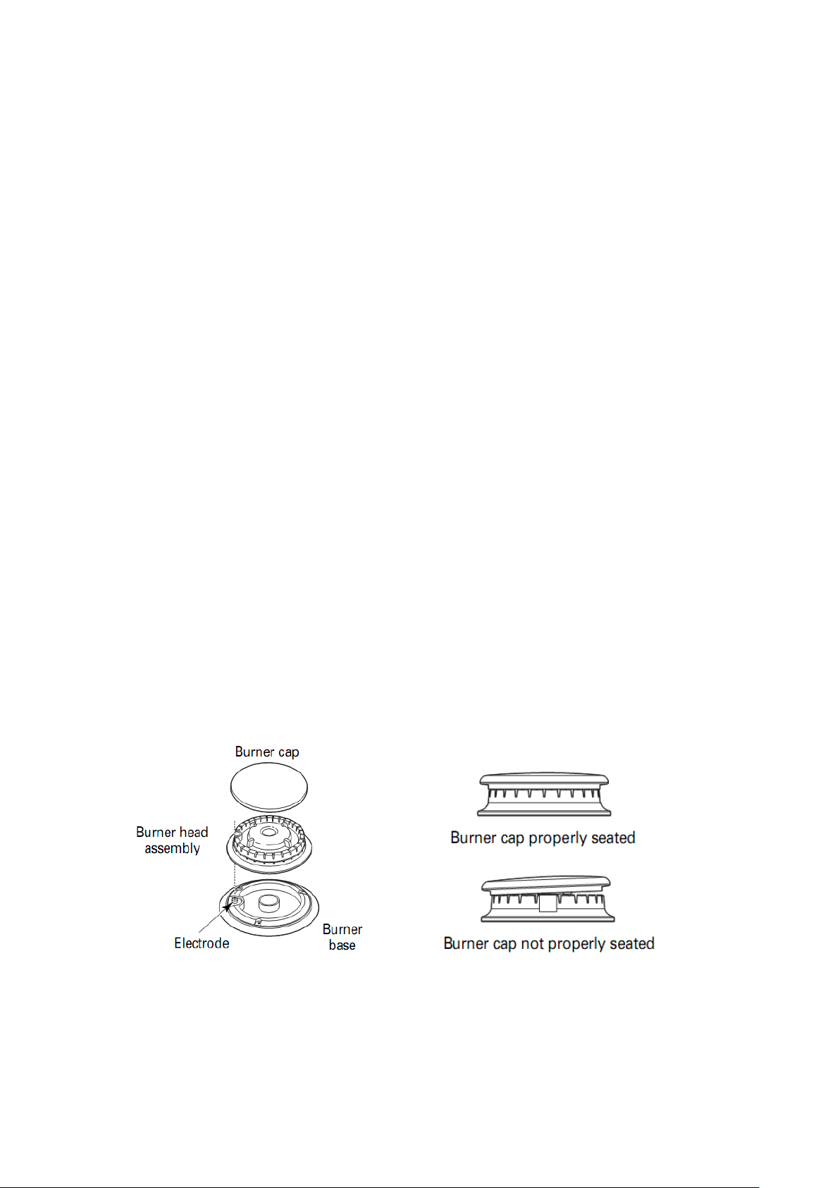
If the flame does not light after a few attempts, check that the “burner cap” and
“flame cap” are correctly positioned.
To turn off the flame, turn the control knob clockwise to the ● symbol.
Before removing pans from the burners, always lower or turn off the flame.
For correct use of the hob
For lower gas consumption and better efficiency: Use only flat-bottomed pans of
dimensions suitable for the burners, as shown in the table on the right. Also, as soon
as a liquid comes to the boil take care to turn the flame down to a level that will just
keep it boiling.
Burner minimum diameter maximum diameter
Large (rapid) 180mm 220mm
Medium (semi-rapid) 120mm 180mm
Small (Auxiliary) 100mm 160mm
Triple Flame 220mm 260mm
During cooking processes involving fats or oils, watch your foods carefully
because these substances may catch fire if brought to high temperatures.
11
C
l
eaning and maintenance
Before each operation, disconnect the appliance from the electrical mains and allow it
to cool down.
General cleaning
Wash enameled parts with lukewarm water and detergent: do not use abrasive
products which might damage them.
Wash the flame caps and burner caps often with boiling water and detergent, taking
care to remove all deposits
The hob pan stands can also be washed in a dishwasher
For stubborn dirt, use ordinary non-abrasive detergents or specific commercial
products. We strongly advise you not to use scouring pads—steel wool or acids.
Hob
Clean the hob regularly with a soft cloth wet with lukewarm water and a little liquid
detergent. Do not use the following products:
- household detergents or bleaches;
-alcohol or other flammable liquid;
- soaped scouring pads not suitable for non-stick utensils;
- steel wool scouring pads;
- stain removers for baths or sinks.
If the hob gets very dirty, use specific commercial products.
Ignition plug
Automatic burner ignition is provided (when installed) by a ceramic “plug” and a
metal electrode. Periodically clean these parts of the hob thoroughly. In addition, to
avoid ignition difficulties, check that the cavities in the burner are not obstructed.
To remove deposits from the burner cavities, remove the cap and separate the two
parts. After cleaning, put the two parts back together and return them correctly to their
12

position. After washing, replace the hob pan stands, checking that they are correctly
positioned.
Routine maintenance
Have the condition and efficiency of the gas pipe and the pressure regulator (if
installed) checked periodically. If anomalies are found, do not repair but have the
faulty part replaced.
To ensure good performance and safety, the gas regulator taps must be greased
periodically.
Periodic lubrication of the taps must only be carried out by qualified personel,
who must also be contacted if the appliance malfunctions.
Keep plastic, oil or any other flammable material away from the hob.
Warranty conditions
Your new appliance is covered by a warranty. The warranty conditions are provided in
full in the “Warranty conditions-Service centers” leaflet which you will find inside the
appliance.
Keep the fiscal receipt or delivery note, either of which documents your purchase of
the appliance and provides proof of date of purchase, in a safe place together with the
leaflet.
If the After-Sales Service is called in, show these documents to the staff. If this
procedure is not followed, the Service-Centre will have no option but to charge for
any repairs.
If necessary, you may find your nearest Centre by consulting the” Warranty conditions
Service centers
”.
13
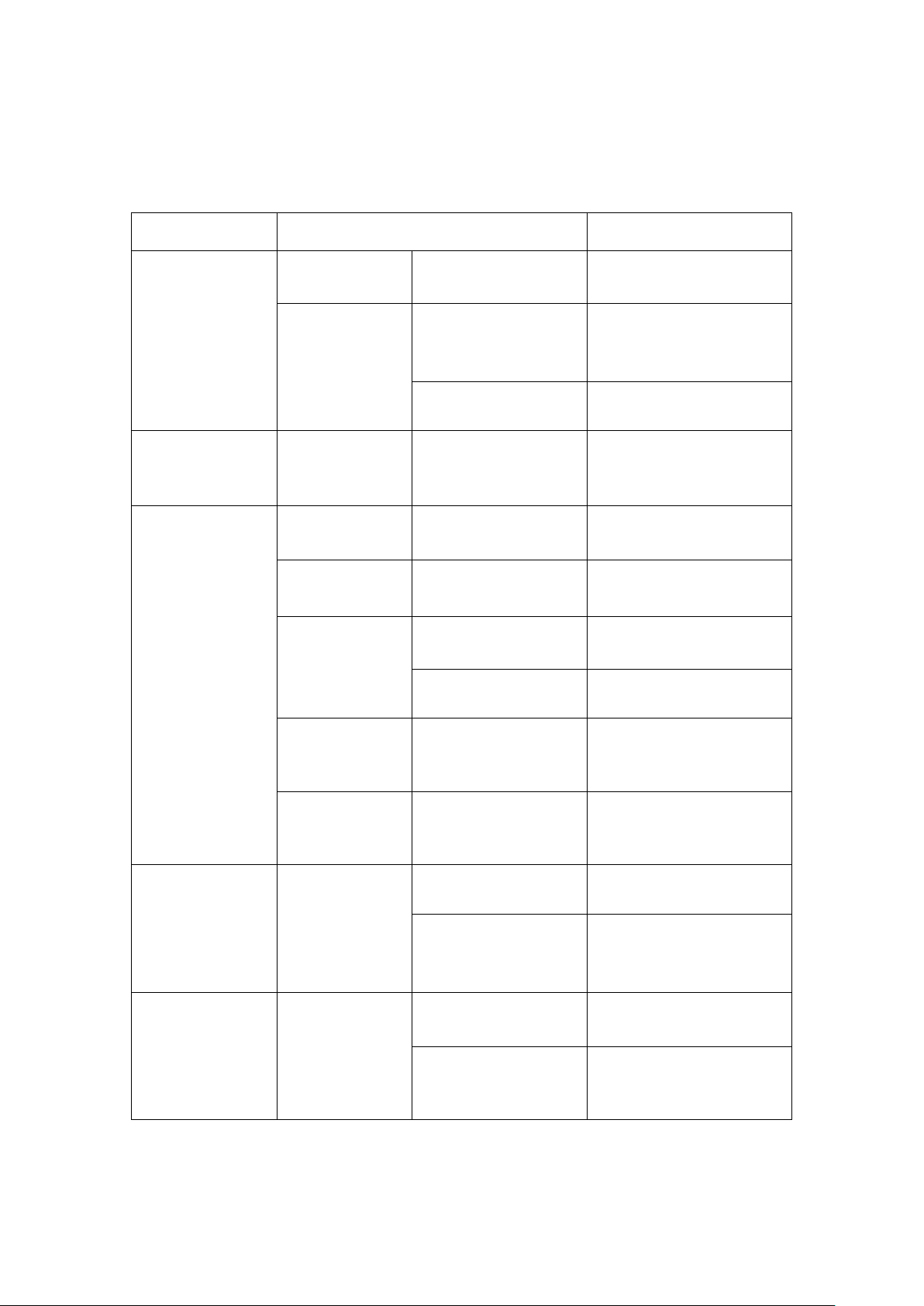
The
ignition
cannot
mak
e fire
or it is hard to
make fire.
Gas valve The valve is not
open or totally open.
Make sure the valve is
totally open.
Ga
s pipe There may be air in
the gas pipe.
Make ignition repeatedly
until it catches fire.
Burne
r cap
The burner cap is not
placed correctly.
Replace the burner cap.
So
me holes in the lid
are stuck.
Clean the holes of the
lid.
Spar
k pin The spark pin is wet
or contaminated by
the food.
Dry the spark pin and
clear away the food.
Gas
connecting
pipes
The gas connecting
pipes are stuck or
squashed.
Adjust or change the
connecting pipes.
Th
e fire goes out
during operation.
Thermocouple
The safety device is
contaminated.
Clean the thermocouple.
Th
e fire is so little
that it cannot touch
the thermocouple.
Adjust the flame a little
bigger.
Stra
nge smell.
Gas leaking
The gas supply pipe
is old and broken.
Change the gas supply
pipe.
The
main burner is
not on fire.
Make ignition again
after there is no strange
smell.
14
FA
Qs and Trouble shooting
FAQs
P
ossible Reasons
Solutions
Spar
k pin cannot
make fire.
Burner The burner is not
installed correctly.
Install the burner again.
Spar
k pin
Ignition electrode
and the hole are not
placed well.
Adjust the distance for
3- 4mm
The s
park pin is
broken.
Replace the broken
spark pin.
Th
e fire goes out
once release the
knob.
Safety valve
The time of press is
not long enough.
Press and turn the knob
again and keep 3 to 5
seconds after the burner
has fire.