3
Important Safety Information
10
Installation Instructions
Important Electrical Safety
Adjustments and Auxiliary Controls
4
Operating Instructions
The Controls on Your Zoneline
Care of Product
18
Helpful Information
Things That Are Normal
19
If Something Goes Wrong
Before You Call For Service
GE Service Numbers
Warranty
GE Appliances
Zoneline
®
Owner’s Manual
Zoneline Heat/Cool Models
2600 Series
GE Answer Center
®
800.626.2000
Welcome to the GE family. We’re
proud of our quality products and
we believe in dependable service.
You’ll see it in this easy-to-use
manual and you’ll hear it in the
friendly voices of our customer
service department.
Best of all, you’ll experience
these values each time you enjoy
the comfort of your Zoneline.
That’s important, because your
new Zoneline will be part of your
family for a long time.
Welcome
Staple your receipt to the inside back
cover of this manual. You will need it
to obtain service under warranty.
Write down the model and serial
numbers here.
They are on a label
behind the room cabinet.
Model number
Serial number
Date of purchase
Before using
your
Zoneline
Need Help?
Before you call for service,
there are a few things you can
do to help us serve you better.
Read this manual.
It contains
instructions to help you use and
maintain your Zoneline properly.
Save time and money.
Check the
section titled “If Something Goes
Wrong” before calling. This sec-
tion was designed to solve common
problems that might occur.
If you do need service, you can
relax knowing help is only a phone
call away. Toll-free customer service
numbers are included in the back
of this manual. Or call the
GE
Answer Center
®
at 800.626.2000,
24 hours a day, 7 days a week.
Help us
help you
800.626.2000
2
Start Here!

Important Safety Information
3
Read all safety information before using
• This Zoneline must be properly
installed in accordance with the
Installation Instructions before it
is used.
• Repair or replace immediately
all electric service cords that have
become frayed or otherwise
damaged.
• Unplug or disconnect the
Zoneline at the fuse box or
circuit breaker before making
any repairs.
NOTE:
We strongly recommend
that any servicing be performed
by a qualified individual.
SAVE THESE INSTRUCTIONS
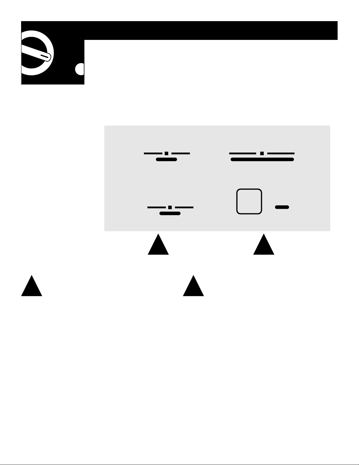
COOL—
For cooling
HEAT—
For heating
FAN—
For fan-only operation
The fan controls cooling or heating with
HIGH
or
LOW
fan speed operation. When set at
AUTO
, it
automatically switches between low and high to
adjust for room temperature changes.
The temp control is used to maintain the
room temperature. The compressor will cycle
on and off to keep the room at the same level
of comfort.
COOLER—
For cooler temperatures
WARMER—
For warmer temperatures
STOP/ON
—Stops heating, cooling and fan opera-
tion. Power remains connected to the Zoneline
and the Freeze Sentinel still functions.
The
CALL SVC
(call service) indicator will light
if the compressor fails to start. If the control is
set at
COOL
, the compressor stops and the fan
operates alone. If set at
HEAT
, it continues in the
HEAT
setting. Call for service as soon as possible.
4
Operating Instructions
The
controls
on your
Zoneline
2
2
1
Mode Control Temp Control
1
MODE
TEMP
FAN
COOL FAN HEAT
COOLER WARMER
HIGH LOW AUTO
STOP/ON
CALL
SVC
5
Energy Tips
Keep the vent control at
CLOSE
.
The air will be filtered and
circulated.
Set the
FAN
at
AUTO
. It switches
between low and high to adjust
for room temperature changes.
Adjust the air louvers straight out
to get the most hot or cool air into
the room.
The ventilation control lever is located at the
lower left side of the Zoneline unit, behind the
room cabinet.
When set at
CLOSE
, only the air inside the room
is circulated and filtered.
When set at
OPEN
, some outdoor air will be
drawn into the room. This will reduce the
heating or cooling effect.
43
3 4
Ventilation Control Air Direction
OPEN
CLOSE
Adjust the air louvers by moving them with
your fingers. To get the most hot or cool air
into the room, set the louvers straight out.
Vent
control
Air louvers

Operating Instructions
Other Zoneline features
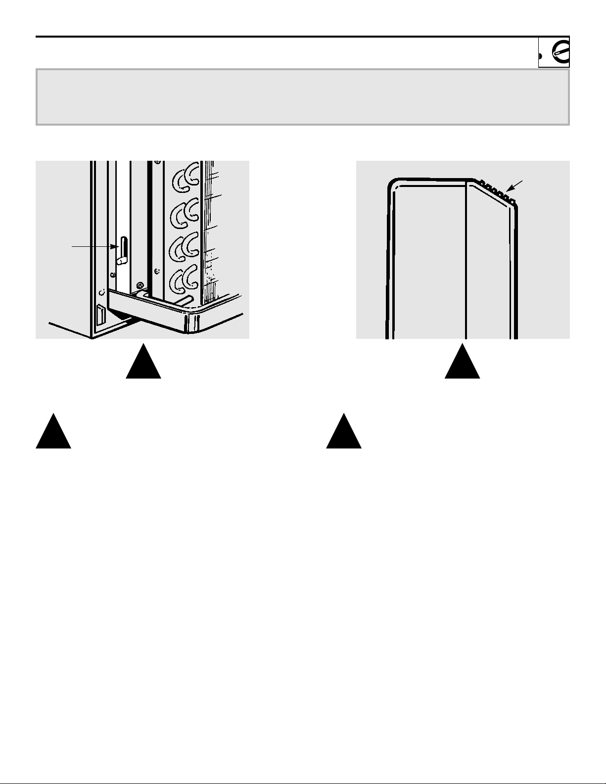
Additional controls are located
behind the room cabinet.
To remove:
Pull out to release it
from the tabs. Then lift up.
To replace:
Place the tabs over
the top rail. Push inward until
it snaps into place.
To Remove the
Room Cabinet
The fan switch 9 is located behind
the room cabinet.
This switch is set at continuous fan
(down) at the factory to provide
continuous fan operation in cool
or heat modes. Leaving the switch
in the continuous fan setting allows
continuous circulation of room air
and will result in a more balanced
temperature throughout the room.
If you want the fan to cycle on
and off with the compressor or
with the heater, move the switch
to cycle fan (up).
Fan Switch
6
9
ON
OFF
ON
OFF
Fan switch
Down—Continuous Fan
Up—Cycle Fan
1
1
2
2
Auxiliary Controls

The Freeze Sentinel feature
automatically turns on the
resistance heater and fan if the
room temperature (sensed at
the unit) drops to approximately
45°F. It will turn the heater off
when the temperature reaches
about 50°F.
The Freeze Sentinel helps prevent
plumbing damage in the room due
to sub-freezing temperatures.
The Freeze Sentinel is active as long
as power to the unit has not been
interrupted.
Freeze Sentinel
7
8
Operating Instructions
Care & Cleaning
Turn the Zoneline off and remove
the plug from the wall outlet
before cleaning.
To clean, use water and a mild
detergent. Do not use bleach or
abrasives.
Room Cabinet
and Case
The coils on the outdoor side of
the Zoneline should be checked
regularly. If they are clogged with
dirt or soot they may be profession-
ally steam cleaned, a service avail-
able through your GE service
outlet.
Outdoor Coils
In some installations, dirt or other
debris may be blown into the unit
from the outside and settle in the
base pan (the bottom of the unit).
Check it periodically and clean it
out, if necessary.
Base Pan
Turn the Zoneline off before cleaning.
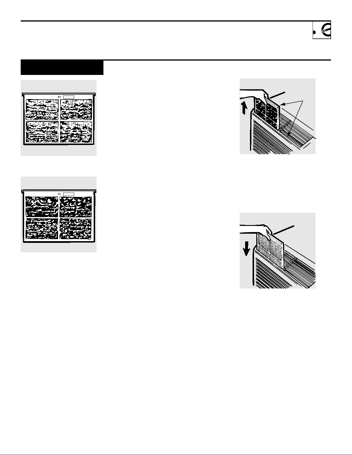
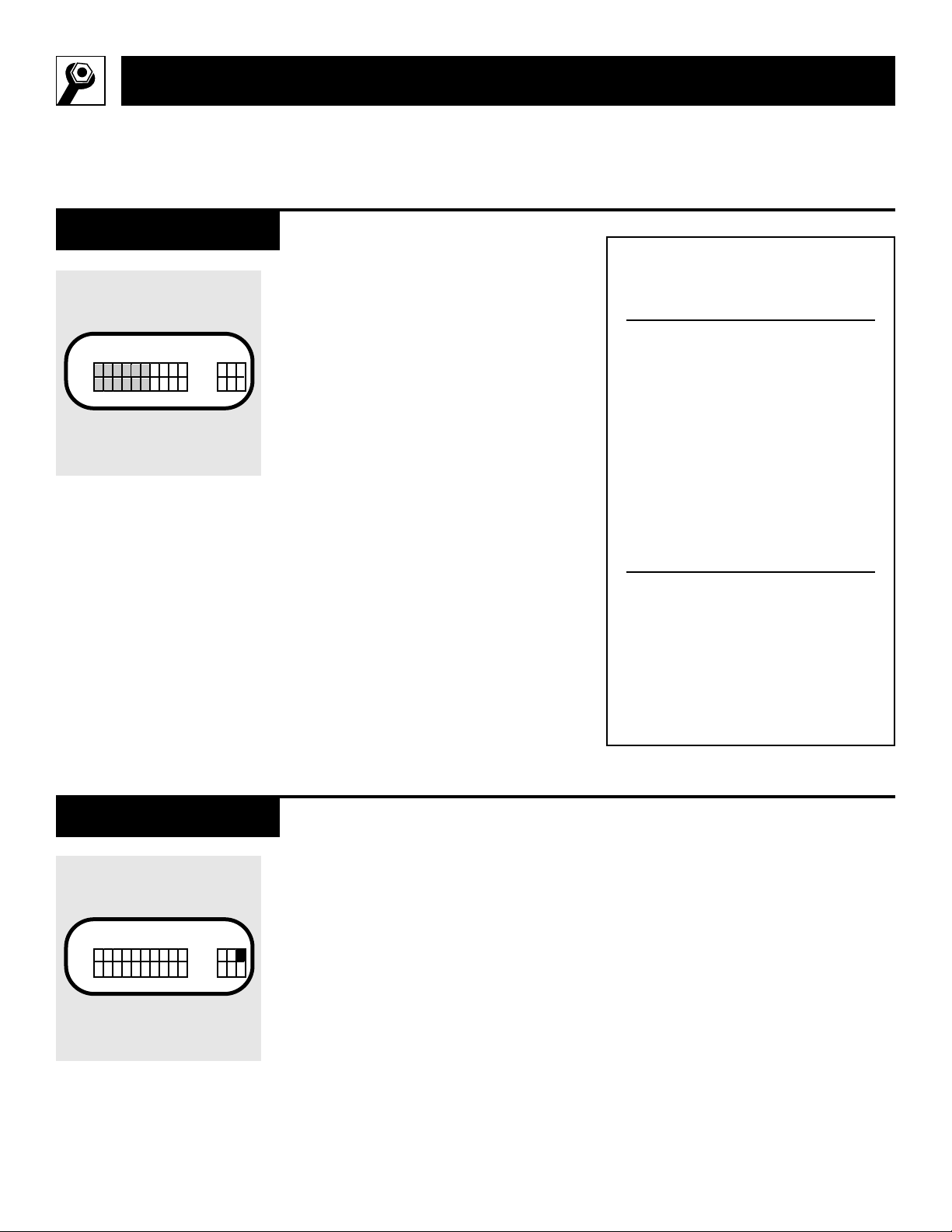
The Zoneline air filters should be
cleaned at least every 30 days.
Clogged filters reduce cooling,
heating and air flow.
Keeping these filters clean will:
• Decrease cost of operation.
• Save energy.
• Prevent clogged heat exchanger
coils.
• Reduce costly compressor
problems.
To remove the air filters:
To clean the air filters:
• Vacuum off the heavy soil.
• Run water through the filters.
• Dry thoroughly before replacing.
To replace the air filters:
NOTE:
Do not operate the Zoneline without
the filters in place. If a filter becomes
torn or damaged it should be
replaced immediately.
Operating without the filters in
place or with damaged filters will
allow dirt and dust to reach the in-
door coil and reduce the efficiency
of the unit.
Replacement filters are available
from your GE dealer, GE Service
and Parts Center or authorized
Customer Care® servicers.
Air Filters
30 days – needs cleaning
60 days – cooling, heating and
airflow are greatly reduced.
9
Pull
up
Push
down
2 air filters
FRONT
FRONT
10
• Follow National Electrical
Code (NEC) or local codes and
ordinances.
• For personal safety, this Zoneline
must be properly grounded.
• NEC requires units controlled
by NEC Class 2 low voltage remote
controls to be permanently
connected.
• Protective devices (fuses or circuit
breakers) acceptable for Zoneline
installations are specified on the
nameplate of each unit.
• Disconnect the power to the unit
before servicing by:
1
Removing the power cord
(if it has one) from the wall
receptacle.
or—
2
Removing the branch circuit
fuses or turning the circuit
breakers off at the panel.
CAUTION:
•
Before starting the installation, the
power to the direct connect wiring
should be off.
•
Do not use an extension cord with
this unit.
•
Aluminum house wiring may
present special problems—
consult a qualified electrician.
Important Notes
Installation Instructions
Important electrical safety—read carefully
•
Installer:
Leave these instructions
with the appliance.
•
Owner:
Keep these instructions
for future use.
A power connection kit must be
used to supply power to the
Zoneline unit. The appropriate kit
is determined by the voltage, the
means of electrical connection and
the amperage of the branch circuit.
Connections of 208 or 230 volt
circuits may be with a line cord kit
or a permanent connection kit.
Connections of 265 volt circuits
must be with a permanent connec-
tion kit. NEC requires permanent
connection for installations over
250 volts.
All wiring, including installation of
the receptacle, must be in accor-
dance with the National Electrical
Code and local codes, ordinances
and regulations.
Power Connection
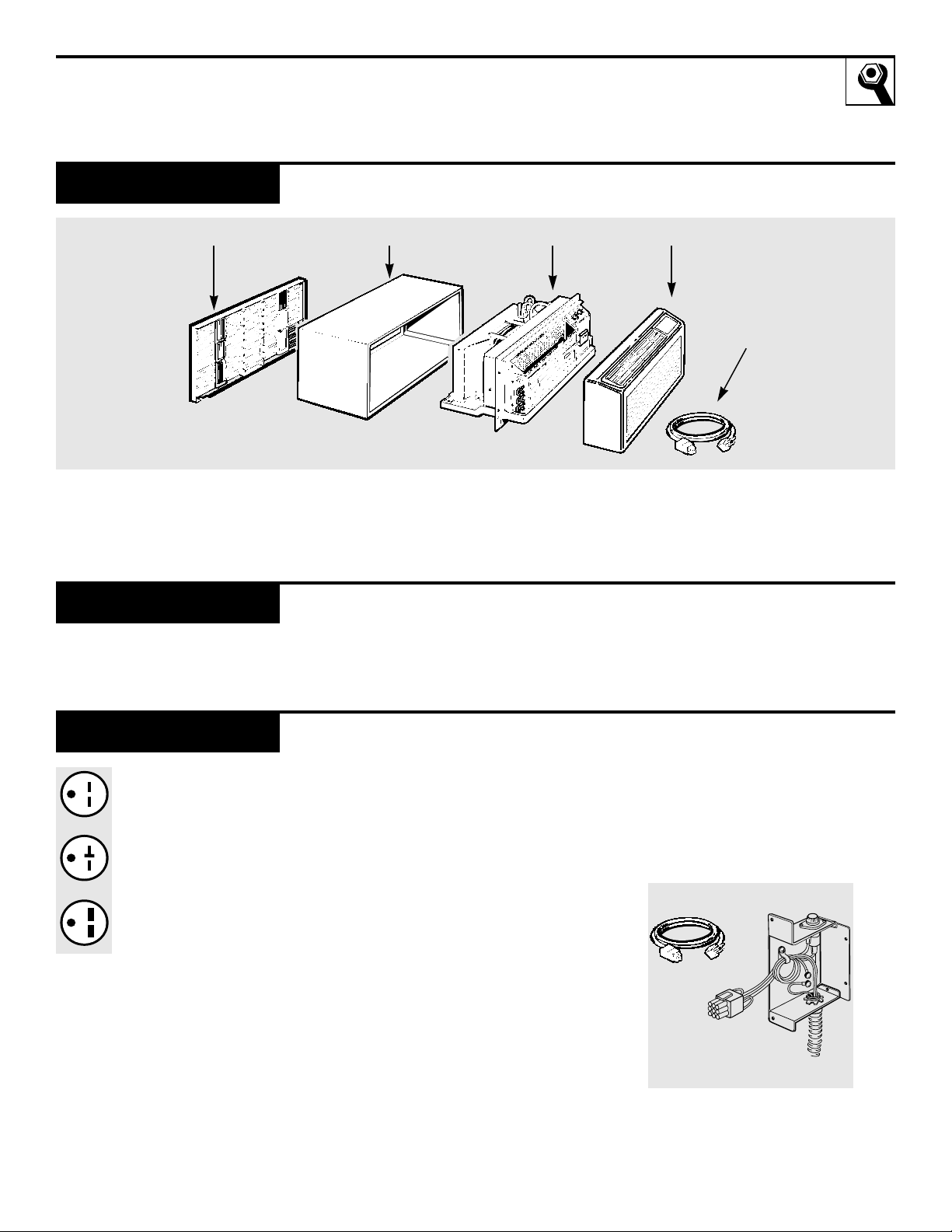
Tandem,
15 Amp.
Perpendicular
20 Amp.
Large Tandem
30 Amp.
11
Electrical wiring wall outlets
230/208 volt.
Parts Required
Exterior grille/louver** Wall case** Zoneline unit Room cabinet*
Power
connection
kit***
*Shipped with the Zoneline unit
**Check essential elements list on unit
***Line cord connection shown only as an example
• Phillips screwdriver
• Flat-blade screwdriver
Tools Needed

12
Installation Instructions
1
The RAB71 or RAB77 wall
case must be properly installed
per instructions packed with
the case.
2
Remove the corrugated stiffener
and the outdoor protective
panel. Use the slit in the out-
door panel as a handhold and
push out.
3
Install the exterior grille from
the room side following instruc-
tions packed with the grille.
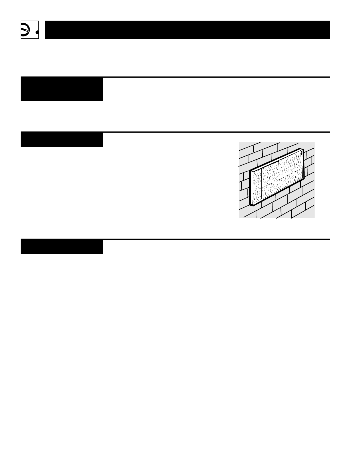
Insulated Wall Case
In some climates/applications
when the wall case projects into
the room, the use of an insulated
wall case will minimize moisture
condensed on the wall case
surfaces. The RAB71 wall case is
insulated. Insulation kit RAK901L
is available for use with RAB77 or
existing uninsulated wall cases
when needed.
Install the Wall Case
and Exterior Grille
Protective
panel
Slit
Stiffener
230/208 Volt Wall Plug Heater Wattage
Line Cord Kits Configuration Circuit Protective Device @ 230/208 Volts
RAK315 Tandem 15 Amp TD fuse or breaker 2.55/2.09 KW
RAK320 Perpendicular 20 Amp TD fuse or breaker 3.45/2.82 KW
RAK330* Large Tandem 30 Amp fuse or breaker 5.00/4.10 KW
230/208 Volt
Permanent Heater Wattage
Connection Kits Circuit Protective Device @ 230/208 Volts
RAK415/415L 15 Amp TD fuse or breaker 2.55/2.09 KW
RAK420/420L 20 Amp TD fuse or breaker 3.45/2.82 KW
RAK430/430L* 30 Amp TD fuse or breaker 5.00/4.10 KW
Kits ending in “L” have flexible conduit to reach from the kit to the knockout hole
(above right side inspection plate) in the RAK203 Sub-Base.
265 Volt
Permanent Heater Wattage
Connection Kits Circuit Protective Device @ 265 Volts
RAK515/515LF 15 Amp TD fuse 1.70 KW
RAK517/517LF 15 Amp TD fuse 3.00 KW
RAK520/520LF 20 Amp TD fuse 3.70 KW
RAK530/530LF* 30 Amp TD fuse 5.00 KW
Kits ending in “LF” have flexible conduit to reach from the kit to the knockout hole
(above right side inspection plate) in the RAK203 Sub-Base and have an Integral Fuse.
*Not recommended for use on 6000 BTUH units. (If this connection kit is used it will provide a maximum
heat of 3.45 KW at 230 volts and 3.7 KW at 265 volts.)
Power Connection
Chart
13
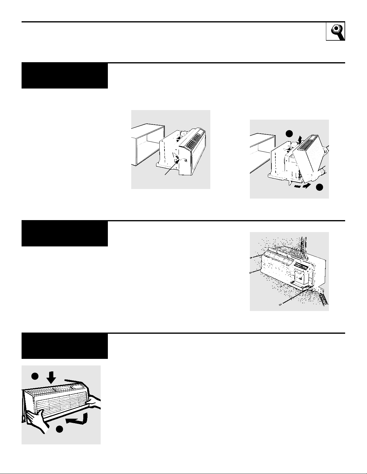
1
Remove shipping tape, if there is
any, from the room cabinet and
vent door.
2
Remove the room cabinet by
pulling it out at the bottom to
release it, then lift it up to clear
the rail along the unit top.
Remove Shipping Tape
and Room Cabinet
Shipping tape
Slide the unit into the wall case and
secure with four screws through the
unit flange holes.
If an insulated wall case is needed,
see Install the Wall Case and
Exterior Grille section on the previ-
ous page.
Install the Unit into
the Wall Case
Reinstall the room cabinet by
hooking the top over the rail along
the unit top, then pushing it in at
the bottom.
Replace the
Room Cabinet
1
2
1
2
14
Installation Instructions
Low Voltage Connectors & Auxiliary Controls
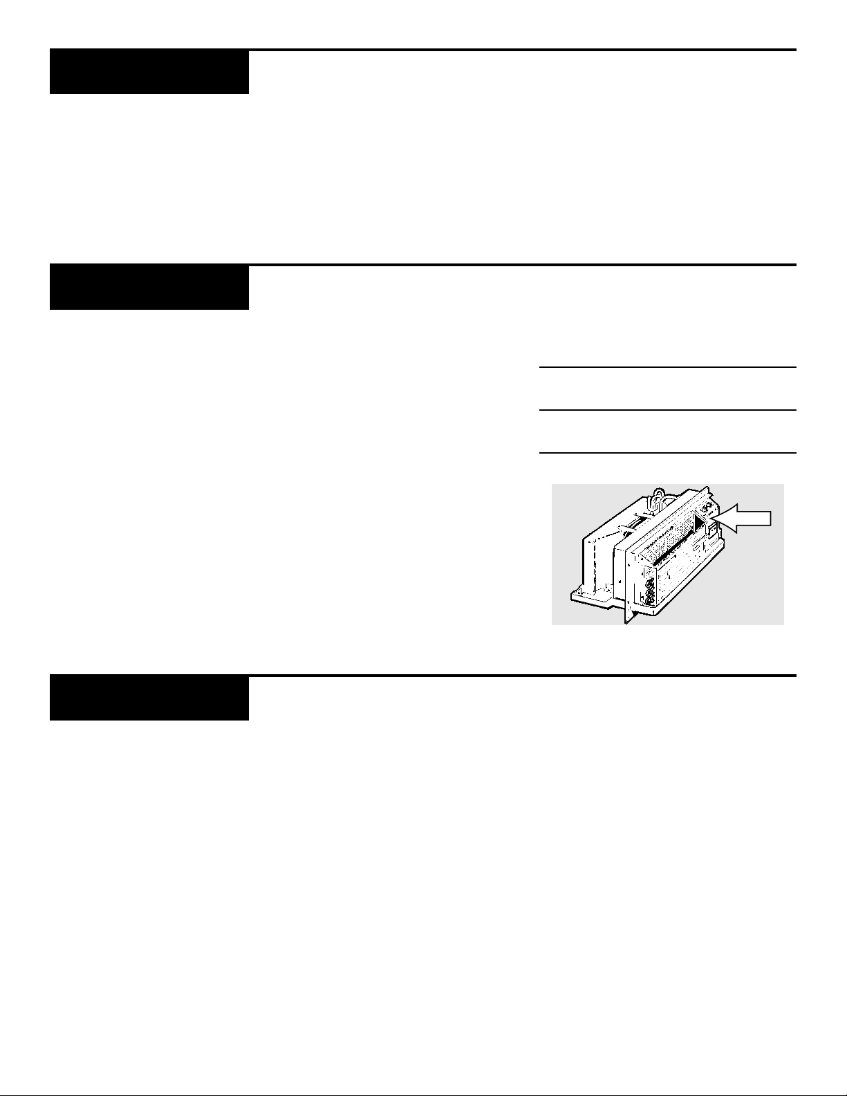
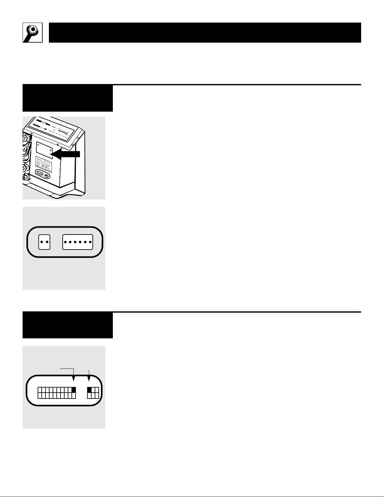
Remove the room cabinet. CDC
and remote control connectors,
with installation instructions, are
packed in a bag behind the metal
cover.
To access the connectors,
remove
the metal cover and save the screws
that hold the cover to the unit.
The connection points for the
Central Desk Control (CDC) and
the Class 2 Remote Thermostat are
also behind the metal cover.
IMPORTANT:
After the wire connections are com-
pleted, replace the cover to prevent
damage to the unit or personal injury.
Low Voltage
Connectors
The Zoneline can be controlled
by using the controls on the unit
or by a wall thermostat.
To switch to a wall thermostat con-
trol, move switch 10 to the
ON
(up)
position and connect the unit to a
4-wire Class 2 Remote Thermostat
(GE Model RAK163A or equiva-
lent), following the instructions
packed with the low voltage con-
nectors.
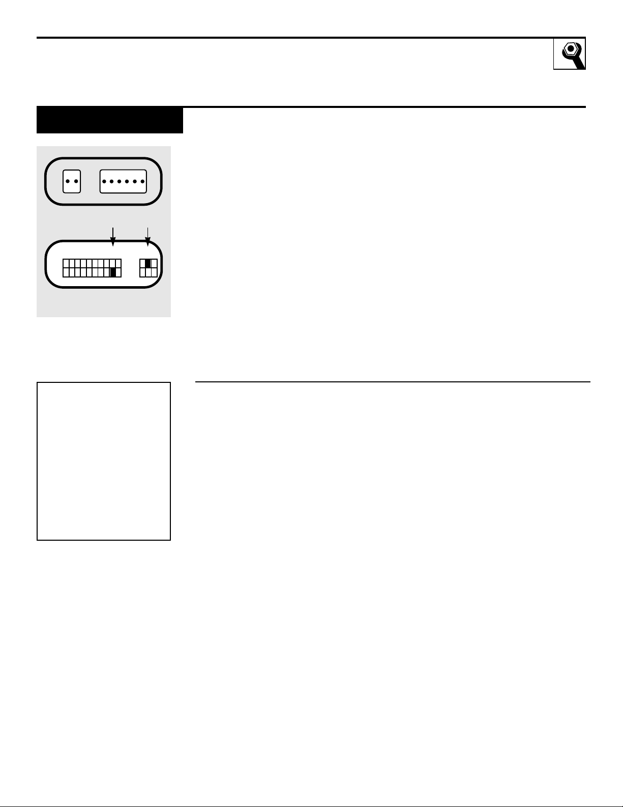
For some applications, it may be
desirable to operate on low fan
speed. Moving the auxiliary switch
11 to the
ON
(up) position will pro-
vide low fan speed in both heating
and cooling modes.
No external voltage should be
applied to the unit through the
Remote Thermostat terminals.
Remote Control/
Wall Thermostat
10 11
ON
OFF
ON
OFF
Class 2
Remote
Thermostat
Low fan speed
with Class 2
Remote
Thermostat
CDC
Auxiliary Controls
Class 2
Remote
Thermostat
Metal
cover
15
The Zoneline can be connected
to a switch at the front desk that
allows you to turn the unit on or
off without going to each unit.
When the front desk switch is open
the Zoneline is on. Turn the switch
to closed to turn it off.
For load shedding,
the CDC auxiliary
switch 9 must be in the
OFF
(down)
position and auxiliary switch 12
must be in the
ON
(up)position.
This provides fan operation while
the compressor or heater
is turned off.
Note:
The Freeze Sentinel remains active to
help protect against low temperature
damage even though the unit may be
off at the central control location.
Central Desk Control
9 12
ON
OFF
ON
OFF
Recommended wire size
for Central Desk Control
installation
Wire Size
Maximum
# AWG
Allowable
Length
#24 400 ft.
#22 600 ft.
#20 900 ft.
#18 1500 ft.
#16 2000 ft.
CDC
Load shedding
Auxiliary Controls
Follow the recommended wire
sizing in the table. Two wires must
be used from each CDC switch to
each individual unit.
Good wiring practices (e.g.
twisted pairs, separation from
power circuits) must be followed
to minimize induced voltages
which may harm the control
system.
DO NOT
use a common
buss in the CDC wiring.
A 24-volt transformer is contained
within the unit and no external
voltage should be applied to the
unit through the CDC terminals.
These terminals may also be used
as an interface for other systems
used to control the unit, such as
infrared detectors, key-activated
systems, etc.
16
Installation Instructions
Temperature limiting can reduce
energy costs by limiting the lowest
temperature that can be set on
cooling and the highest tempera-
ture that can be set on heating.
Temperature limiting is controlled
by setting the first six auxiliary
switches.
The first three are used to select
cooling range limits and the next
three are used to select heating
range limits.
Temperature Limiting
123456
ON
OFF
ON
OFF
COOLING LIMITS
Limit Switch Temp Range
Up F.
NONE 62 to 85
1 64 to 85
1 & 2 67 to 85
2 69 to 85
2 & 3 71 to 85
1 & 2 & 3 73 to 85
1 & 3 75 to 85
3 77 to 85
HEATING LIMITS
Limit Switch Temp Range
Up F.
NONE 60 to 85
4 60 to 80
4 & 5 60 to 76
5 60 to 74
5 & 6 60 to 73
4 & 5 & 6 60 to 71
4 & 6 60 to 69
6 60 to 67
The Zoneline has a diagnosis
feature. When switch 13 is moved
to the
ON
(up) position, the unit
will go through an operations
check of all components which
takes about two minutes. This diag-
nostic tool is intended for use by a
qualified technician.
Diagnosis Switch
Auxiliary Controls
13
ON
OFF
ON
OFF
Auxiliary Controls
17
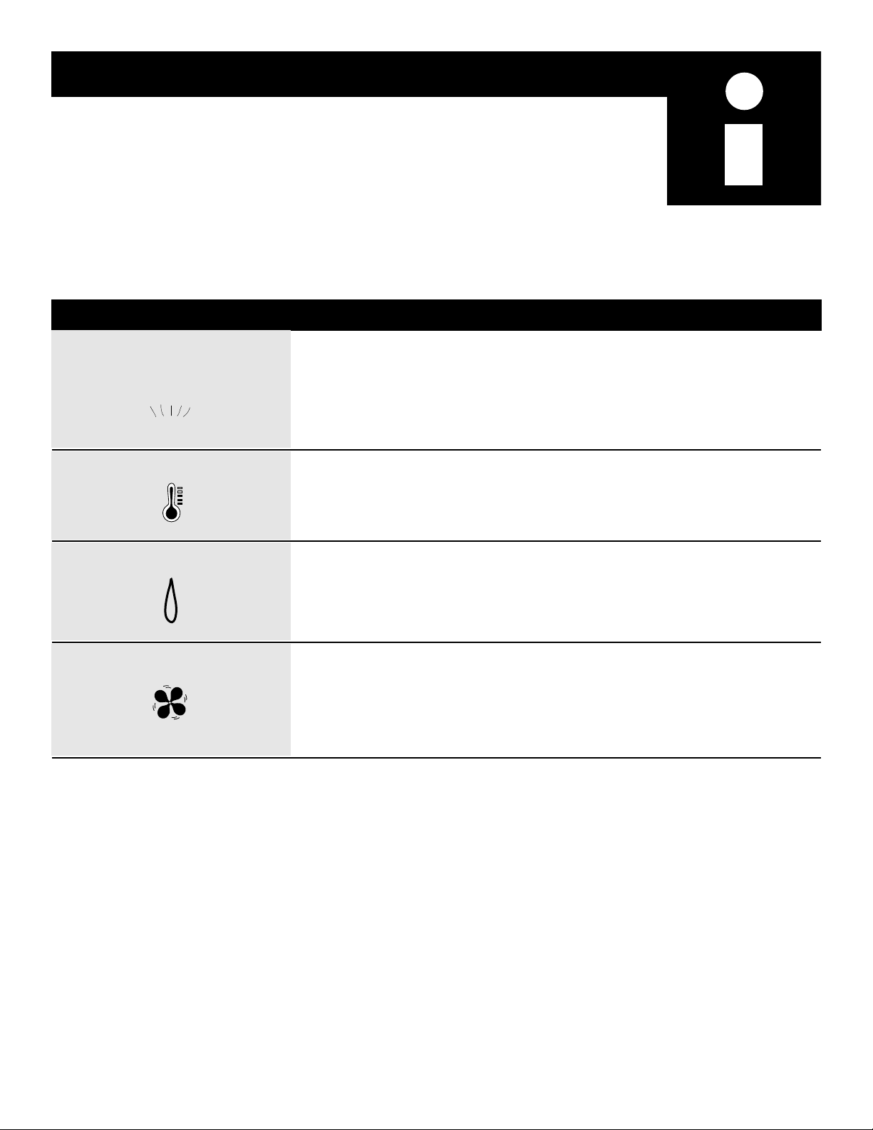
You may hear a pinging noise caused by water being picked up
and thrown against the condenser on rainy days or when the
humidity is high. This design feature helps remove moisture
and improve efficiency.
You may hear relays click when the controls cycle on and off or are
adjusted to change the room temperature.
Water will collect in the base pan during high humidity or on rainy
days. The water may overflow and drip from the outdoor side
of the unit.
The indoor fan runs continuously when the unit is operating in the
cooling mode, unless the fan switch behind the room cabinet is set
at cycle fan (up). This will cause the fan to cycle on and off with the
compressor.
Noise Explanation
WHIR!
D R I P
"CLICK"
P
I
N
G
!
Helpful Information
Things that are normal
18
Zoneline
Doesn’t Start
Zoneline Does Not
Cool or Heat as it
Should
The unit is unplugged • Make sure the Zoneline plug is
pushed completely into the outlet.
The fuse is blown/circuit • Check the house fuse/circuit breaker
breaker is tripped box and replace fuse or reset the
breaker.
The unit is waiting for the • This is normal. The Zoneline will start
compressor overload again after it resets.
protector to reset
Problem Possible Causes What to Do
Airflow is restricted • Make sure there are no curtains, blinds
or furniture blocking the front of the
Zoneline.
The temp control may • Turn the control to a lower or higher
not be set high or low number.
NOTE: The temperature limiter may
enough
be limiting the temperature range.
The air filter is dirty • Clean the filter at least every 30 days.
The room may have been • When the Zoneline is first turned on
hot or cold you need to allow time for the room to
cool down or warm up.
Air is escaping • Check for open furnace floor registers and
cold air returns.
• Set the vent control in the CLOSE position.
If Something Goes Wrong
Before you call for service
19
CALL SVC
Indicator Light
The compressor • Move the control to
STOP
and then
may have failed restart the unit. If the light reappears
within 30 minutes, call for service as
soon as possible.
Burning Odor at the
Start of Heating
Operation
Dust is on the surface of • This can cause a “burning” odor at the
the heating element beginning of the heating operation. This
odor should quickly fade.
The Air is Not Always
Cool or Hot during
Operation
The fan switch may be set • This causes the fan to blow room
at continuous fan (down) temperature air even when the
compressor or heater cycles off. The
continuous air movement provides
better overall temperature control.
Problem Possible Causes What to Do

20
Notes
Notes
21
22
800.626.2000
GE Service Numbers
We’ll be there!
Whatever your question about any
GE major appliance, GE Answer
Center
® information service is
available to help. Your call—and
your question—will be answered
promptly and courteously.
And you can call any time. GE
Answer Center
® service is open
24 hours a day, 7 days a week.
GE Answer Center
®
800-GE-CARES
(800-432-2737)
A GE consumer service professional
will provide expert repair service,
scheduled at a time that’s conve-
nient for you. Many GE Consumer
Service company-operated loca-
tions offer you service today or
tomorrow, or at your convenience
(7:00 a.m. to 7:00 p.m. weekdays,
9:00 a.m. to 2:00 p.m. Saturdays).
Our factory-trained technicians
know your appliance inside and
out—so most repairs can be han-
dled in just one visit.
In-Home Repair Service
800.626.2000
Upon request, GE will provide
Braille controls for a variety of
GE appliances, and a brochure
to assist in planning a barrier-free
kitchen for persons with limited
mobility. To obtain these items,
free of charge, call 800.626.2000.
Consumers with impaired hearing
or speech who have access to a
TDD or a conventional teletype-
writer may call 800-TDD-GEAC
(800-833-4322) to request informa-
tion or service.
For Customers With
Special Needs
We’re proud of our service and
want you to be pleased. If for some
reason you are not happy with the
service you receive, here are three
steps to follow for further help.
First,
contact the people who ser-
viced your appliance. Explain why
you are not pleased. In most cases,
this will solve the problem.
Next,
if you are still not pleased,
write all the details—including
your phone number—to:
Manager, Consumer Relations
GE Appliances, Appliance Park
Louisville, KY 40225
Finally,
if your problem is still
not resolved, write:
Major Appliance Consumer
Action Program
20 North Wacker Drive
Chicago, IL 60606
23
800-626-2224
You can have the secure feeling that GE Consumer Service will still
be there after your warranty expires.
Purchase a GE contract while your
warranty is still in effect and you’ll receive a substantial discount. With a
multiple-year contract, you’re assured of future service at today’s prices.
Service Contracts
800-626-2002
Individuals qualified to service
their
own appliances can have
parts or accessories sent directly
to their home. The GE parts system
provides access to over 47,000
parts…and all GE Genuine Renewal
Parts are fully warranted. VISA,
MasterCard and Discover cards
are accepted.
Care and cleaning instructions con-
tained in this manual cover proce-
dures to be performed by any user.
Other servicing generally should be
referred to qualified service person-
nel. Caution must be exercised,
since improper servicing may cause
unsafe operation.
Parts and Accessories
Further Service
What is Not
Covered
FULL ONE-YEAR WARRANTY
For one year from date of original purchase,
we will provide, free of charge, parts and on-
site service labor to repair or replace any
part
of the room air conditioner that fails because of
a
manufacturing defect.
FULL FIVE-YEAR WARRANTY
For five years from the date of original pur-
chase, we will provide, free of charge, parts
and on-site service labor to repair or replace
any part of the sealed refrigerating system (the
compressor, condenser, evaporator and all
connecting tubing) that fails because of a
manufacturing defect.
LIMITED 2ND THROUGH 5TH YEAR
PARTS WARRANTY
This limited 2nd through 5th year parts war-
ranty applies only to units purchased after
January 1, 1995. For the second through the
fifth year from date of original purchase,
General Electric will provide, free of charge,
parts that fail as a result of a manufacturing
defect. Parts covered are fan motors, switches,
thermostat, heater, heater protectors, com-
pressor overload, solenoids, circuit boards,
auxiliary controls, thermistors, Freeze
Sentinel, frost controls, ICR pump, capaci-
tors, varistors, and indoor blower bearing.
This is a limited parts only warranty, and does
not include labor or transportation to and
from the service shop.
**************************************
This warranty is extended to the original
purchaser and any succeeding owner for
products purchased for use in the 48 main-
land states, Hawaii and Washington, D.C. In
Alaska the warranty is the same except that
it is LIMITED because you must pay to ship
the product to the service shop or for the
service technician’s travel costs to your
home.
All warranty service will be provided by our
Factory Service Centers or by our autho-
rized Customer Care
®
servicers during nor-
mal working hours.
Should your appliance need service,
during warranty period or beyond, call
800-GE-CARES (800-432-2737).
Staple sales slip or cancelled check here. Proof of original purchase
date is needed to obtain service under warranty.
AIR
CONDITIONER
WARRANTY
What is Covered
Printed in Singapore
12-95 CG
Pub. No. 49-7340
Zoneline
2600 Series
• Service trips to to teach you how to use the
product.
Read your Owner’s Manual. If you then
have any questions about
operating the
product, please contact
your dealer or our
Consumer Affairs office at the address
below, or call, toll free:
GE Answer Center®
800.626.2000
consumer information service
• Improper installation.
If you have an installation problem,
or if the air conditioner is of improper
cooling or heating capacity for the intend-
ed use, contact your dealer or installer. You
are responsible for providing adequate
electrical connecting facilities.
• Replacement of fuses or resetting
of
circuit breakers.
• In commercial locations, labor necessary
to move the unit to a location where it is
accessible for service by an individual
technician.
• Failure of the product resulting from
modifications to the product or due to
unreasonable use including failure to
provide reasonable and necessary
maintenance.
•
Failure due to corrosion on models not
corrosion-protected.
•
Damage to product caused by improper
power supply voltage, accident,
fire, floods
or acts of God.
Some states do not allow the exclusion or limitation of incidental or consequential damages, so the above limitation or exclusion may not apply to
you. This warranty gives you specific legal rights, and you may also have other rights which vary from state to state. To know what your legal rights
are in your state, consult your local or state consumer affairs office or your state’s Attorney General.
Warrantor: General Electric Company If further help is needed concerning this warranty, write:
Manager—Consumer Affairs, GE Appliances, Louisville, KY 40225
WARRANTOR IS NOT RESPONSIBLE FOR CONSEQUENTIAL DAMAGES.