INSTALLATION AND SERVICE MUST BE PERFORMED BY A QUALIFIED INSTALLER.
IMPORTANT: SAVE FOR LOCAL ELECTRICAL INSPECTOR'S USE.
READ AND SAVE THESE INSTRUCTIONS FOR FUTURE REFERENCE.
Clearances and Dimensions
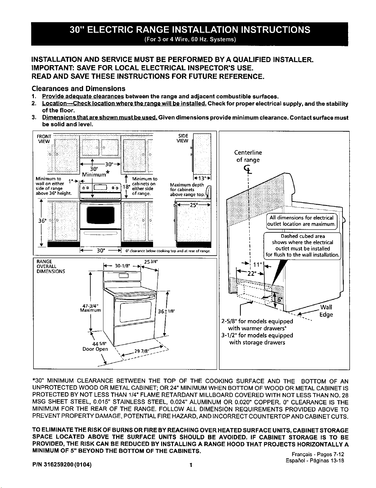
1. Provide adequate clearances between the range and adjacent combustible surfaces.
2. Location--Check location where the range will be installed. Check for proper electrical supply, and the stability
of the floor.
3. Dimensions that are shown must beused. Given dimensions provide minimum clearance. Contact surface must
be solid and level.
SidoevOf3r_ng:ight" __-_ ®o 1_ e_hraenrgiede
SIDE
VIEW
Maximum depth
fa_ro_ab_nne_Setop.
_25"--_
i :ii! iii:i
30" _ 0' clearance below cooking top and at rear of range.
RANGE
OVERALL
DIMENSIONS
253/4'
p- 30
44 5/8' _
Door Open _ 9 / ,,_....ak_>
Centerline
of range
outlet location are maximum,
Dashedcubedarea
shows where the electrical
outlet must beinstalled
forflush to the wall installation
/ Wall
-_.._Edge
2-5/8" for models equipped "'"
with warmer drawers"
3-1/2" for models equipped
with storage drawers
*30" MINIMUM CLEARANCE BETWEEN THE TOP OF THE COOKING SURFACE AND THE BOTTOM OF AN
UNPROTECTED WOOD OR METAL CABINET; OR 24" MINIMUM WHEN BOTTOM OF WOOD OR METAL CABINET IS
PROTECTED BY NOT LESS THAN 1/4" FLAME RETARDANT MILLBOARD COVERED WITH NOT LESS THAN NO. 28
MSG SHEET STEEL, 0.015" STAINLESS STEEL, 0.024" ALUMINUM OR 0.020" COPPER. O" CLEARANCE IS THE
MINIMUM FOR THE REAR OF THE RANGE. FOLLOW ALL DIMENSION REQUIREMENTS PROVIDED ABOVE TO
PREVENT PROPERTY DAMAGE, POTENTIAL FIRE HAZARD, AND INCORRECT COUNTERTOP AND CABINET CUTS.
TO ELIMINATE THE RISK OF BURNS OR FIRE BY REACHING OVER HEATED SURFACE UNITS, CABINET STORAGE
SPACE LOCATED ABOVE THE SURFACE UNITS SHOULD BE AVOIDED. IF CABINET STORAGE IS TO BE
PROVIDED, THE RISK CAN BE REDUCED BY INSTALLING A RANGE HOOD THAT PROJECTS HORIZONTALLY A
MINIMUM OF 5" BEYOND THE BOTTOM OF THE CABINETS.
Fran_ais- Pages7-12
Espa5ol- Pbginas13-18
PIN 316259200 (0104) 1
IMPORTANT SAFETY
INSTRUCTIONS
Iftheinformationinthismanualisnotfollowed
exactly,a fireorelectricalshockmay resultcausingproperty
damage, personalinjuryor death.
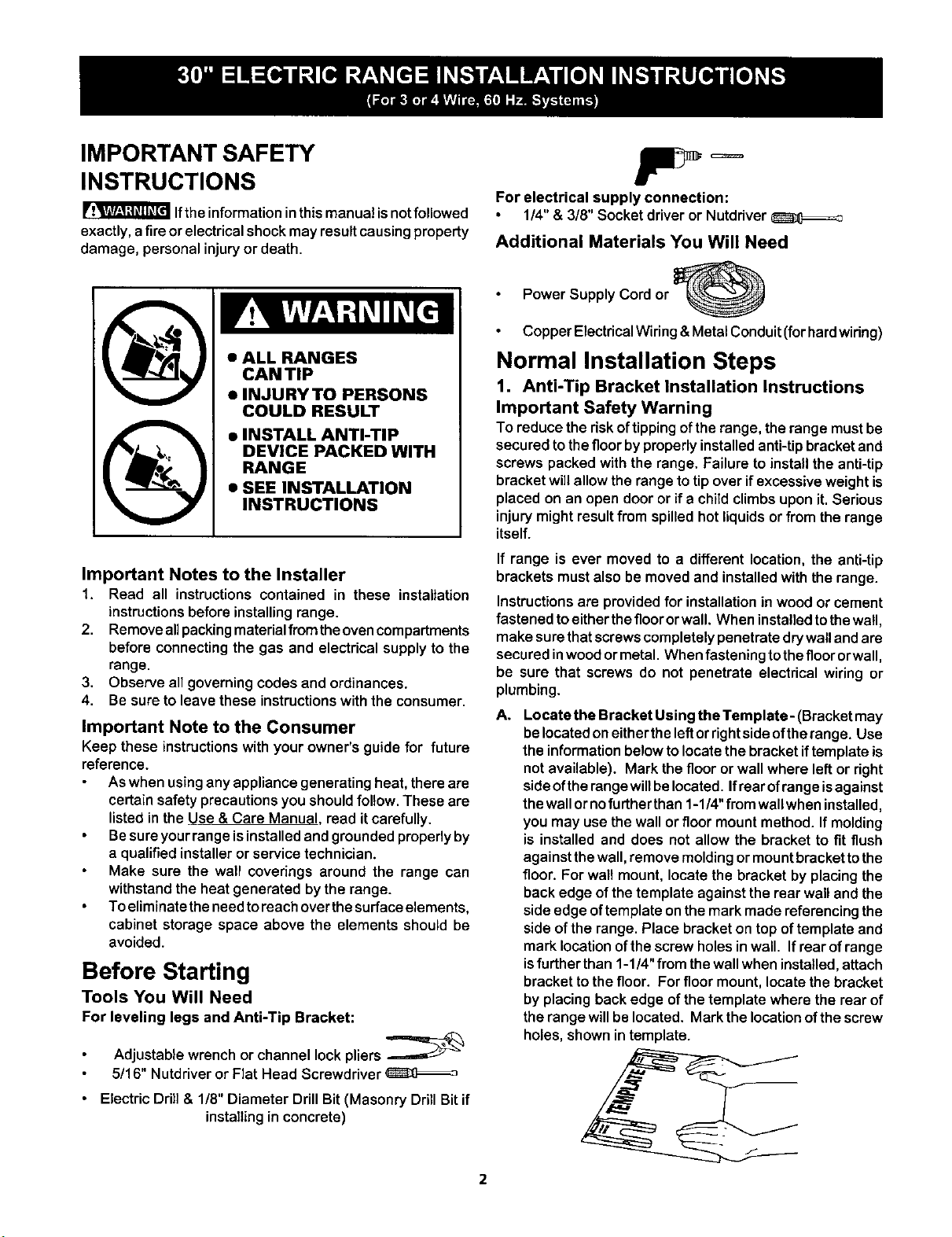
• INSTALL ANTI-TIP
DEVICE PACKED WITH
RANGE
• SEE INSTALLATION
INSTRUCTIONS
Important Notes to the Installer
1. Read all instructions contained in these installation
instructionsbefore installingrange.
2. Removeallpackingmaterialfromtheovencompartments
before connectingthe gas and electrical supplyto the
range.
3. Observe all governing codes and ordinances.
4. Be sure to leave these instructions with the consumer.
Important Note to the Consumer
Keep these instructions withyour owner's guide for future
reference.
As when using any appliance generating heat, there are
certain safety precautions you should follow. These are
listed in the Use & Care Manual. read it carefully.
Be sure your range isinstalled and grounded properly by
a qualified installer or service technician.
Make sure the wall coverings around the range can
withstand the heat generated by the range.
To eliminate the needto reach overthe surface elements,
cabinet storage space above the elements should be
avoided.
Before Starting
Tools You Will Need
For leveling legs and Anti-Tip Bracket:
Adjustablewrenchor channel lockpliers
5/16" Nutdriveror Flat Head Screwdriver
Electric Drill & 1/8" Diameter Drill Bit (Masonry Drill Bit if
installing in concrete)
For electrical supply connection:
1/4"& 3/8" Socket driver or Nutdriver
Additional Materials You Will Need
Power Supply Cord or
Copper Electrical Wiring &Metal Conduit (forhard wiring)
Normal Installation Steps
1, Anti-Tip Bracket Installation Instructions
Important Safety Warning
To reducethe riskoftippingof therange, therange mustbe
securedtothefloorbyproperlyinstalledanti-tipbracketand
screws packed with the range. Failureto installthe anti-tip
bracketwillallow the rangetotip over ifexcessiveweightis
placed on an open dooror if a child climbsupon it. Serious
injurymightresultfrom spilledhot liquidsor from the range
itself.
If range is ever moved to a different location,the anti-tip
brackets must also be moved and installed with the range.
Instructions are provided for installation in wood or cement
fastenedtoeitherthefloororwall. Wheninstalledtothewall,
make surethatscrewscompletelypenetratedrywallandare
securedinwoodormetal. Whenfastening tothefloororwall,
be sure that screws do not penetrate electrical wiring or
plumbing.
A. Locate the Bracket Using the Template- (Bracket may
belocatedoneitherthe leftorrightside oftherange. Use
the informationbelowtolocatethe bracketiftemplate is
notavailable). Mark the flooror wall where leftor right
sideoftherangewillbelocated.Ifrearofrangeisagainst
thewallornofurtherthan1-1/4"from wallwhen installed,
you may usethewall orfloor mountmethod. If molding
is installedand does not allowthe bracket to fit flush
againstthewall,remove moldingormountbracket tothe
floor. Forwall mount,locate the bracket by placingthe
backedge ofthe template againstthe rear walland the
side edge oftemplate onthemark madereferencingthe
sideofthe range. Place bracketon top oftemplate and
marklocationofthe screwholesinwall. Ifrear ofrange
isfurtherthan 1-1/4"from thewallwhen installed,attach
brackettothe floor. Forfloormount, locatethe bracket
byplacingbackedge ofthe template where the rear of
the rangewillbe located. Markthe locationofthescrew
holes,shown in template.
2
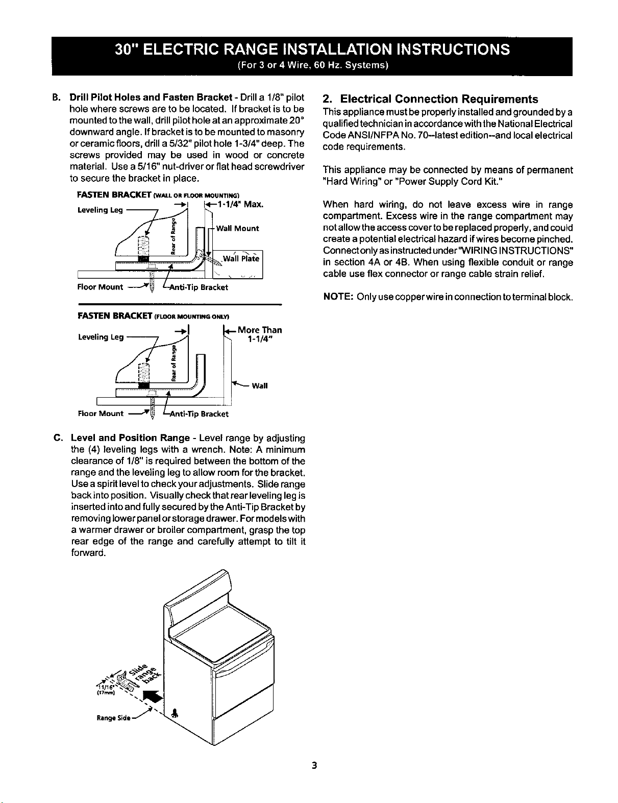
B. Drill Pilot Holes and Fasten Bracket- Drilla 1/8"pilot
holewhere screwsereto be located, Ifbracketisto be
mountedtothewall,drillpilotholeat anapproximate20°
downwardangle, Ifbracket istobe mountedtomasonry
orceramicfloors,drilla 5/32" pilothole 1-3/4"deep. The
screws provided may be used in wood or concrete
material, Usea 5/16" nut-driverorflathead screwdriver
to securethe bracketin place.
FASTEN BRACKET (W_LLORF1-OORMOUNTING)
"--_1 E<'--1-1/4" Max.
Wall Mount
, '................ lr.... I
Floor Mount .___Jr_ L-Anti-Tip Bracket
FASTEN BRACKET (FLOORMOUNTINGONLY}
-+1
Leveling Leg --
1-1/4"
2. Electrical Connection Requirements
Thisappliancemustbeproperlyinstalledandgroundedbya
qualifiedtechnicianinaccordancewiththeNationalElectrical
CodeANSI/NFPA No,70-latest edition--andlocalelectrical
code requirements.
This appliance may be connected by means of permanent
"Hard Wiring" or "Power Supply Cord Kit."
When hard wiring, do not leave excess wire in range
compartment. Excess wire in the range compartment may
not allow the access cover tobereplaced properly, andcould
create a potential electrical hazard ifwires become pinched.
Connect only asinstructed under'WIRING INSTRUCTIONS"
in section 4A or 4B. When using flexible conduit or range
cable use flex connector or range cable strain relief.
NOTE: Only usecopperwireinconnectiontoterminal block.
Floor Mount J _Bracket
C. Level and Position Range - Level range by adjusting
the (4) leveling legs with a wrench. Note: A minimum
clearance of 1/8"is required between the bottomofthe
range andthe levelinglegto allowroomfor the bracket.
Usea spiritleveltocheckyouradjustments. Sliderange
backinto position.Visuallycheckthatrear levelinglegis
insertedintoandfully securedbytheAnti-TipBracketby
removinglowerpanelorstoragedrawer. Formodelswith
a warmer drawer or broilercompartment,graspthetop
rear edge of the range and carefully attempt to tilt it
forward.
2A.Models with Factory Connected Power
Supply Cord
NOTE: Some models may be equipped with a factory
connectedthree (3) conductorpowersupplycord.
Mobile home installations,new branch circuit installations
(1996NEC) or areas where local codes do not permit
grounding through neutral require a four (4) conductor power
supply cord kit rated at 125/250 volts minimum and marked
for use with ranges. See Range Connection Opening Size
Chart for cord kit ampere rating information. Terminals on
end of wires must be either closed loop or open-end spade
lugs with upturned ends.
2B.Models Requiring Power Supply Cord Kit
RISK OF FIRE OR ELECTRICAL SHOCK MAY OCCUR IF
AN INCORRECT SIZE RANGE CORD KIT IS USED, THE
INSTALLATION INSTRUCTIONS ARE NOT FOLLOWED
OR STRAIN RELIEF BRACKET IS DISCARDED.
This appliance may be connected by means of a power
supply cord. Only a power supply cord kit rated at 125/250
volts minimum, and marked for use with ranges shall be
used. See chart on page 3 for cord kit ampere rating
information. Cord must have either three (3) or four (4)
conductors. Terminals on end ofwires must be either closed
loop or open-end spade lugswith upturned ends. Cord must
have strain relief clamp.
See section 4A for 3-wire or section 4B for 4-wire connection.
3. Electrical Connection to Range
The rear accesscover mustberemoved.To remove,loosen
center screw (one screw) and remove access cover. The
terminal blockwillthen be accessible.
Cover
Rear
of Range
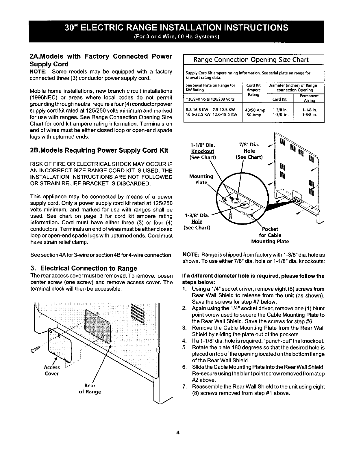
Range Connection Opening Size Chart
Supply Cord Kit ampere rating information. Seeserial plate on range for
kilowatt rating data.
See Serial Plate on Range for
KW Rating
120/240 Volts 120/208 Volts
8.8-16.5 KW 7.9-12.5 KW
16.6-22.5 KW 12,6-18.5 KW
Cord Kit Diameter (inches) of Range
Ampere connection Opening
Rating Permanent
Cord Kit Wirinq
40/50 tunp 1-3/8 in. 1-1/8 in.
50 Amp 1-3/8 in. 1-3/8 in,
1-1/8" Dia. 7/8" Dia. _"
Knockout Hole
(_) (See Chart) 4"
Hole _
(See Chart)
Pocket
for Cable
Mounting Plate
NOTE: Range isshipped from factory with 1-3/8" dia. hole as
shown. To use either 7/8" dia. hole or 1-1/8" dia. knockouts:
Ifa different diameter hole is required, please follow the
steps below:
1. Usinga 1/4"socketdriver,remove eight(8) screwsfrom
Rear Wall Shield to release from the unit (as shown).
Save the screwsfor step#7 below.
2. Again usingthe 1/4" socketdriver,remove one (1) blunt
pointscrewused to securethe Cable MountingPlate to
the Rear Wall Shield. Save the screws for step #6.
3. Remove the Cable Mounting Plate from the Rear Wall
Shield by sliding the plate out of the pockets.
4. If a 1-1/8"dia. holeisrequired,"punch-out"the knockout.
5. Rotate the plate 180 degrees so that the desired hole is
placed ontop ofthe opening located on thebottom flange
of the Rear Wal! Shield.
6. Slide the Cable Mounting Plate into the RearWall Shield.
Re-secure usingthe blunt point screw removed from step
#2 above.
7. Reassemble the Rear Wall Shield to the unit using eight
(8) screws removed from step #1 above.
4
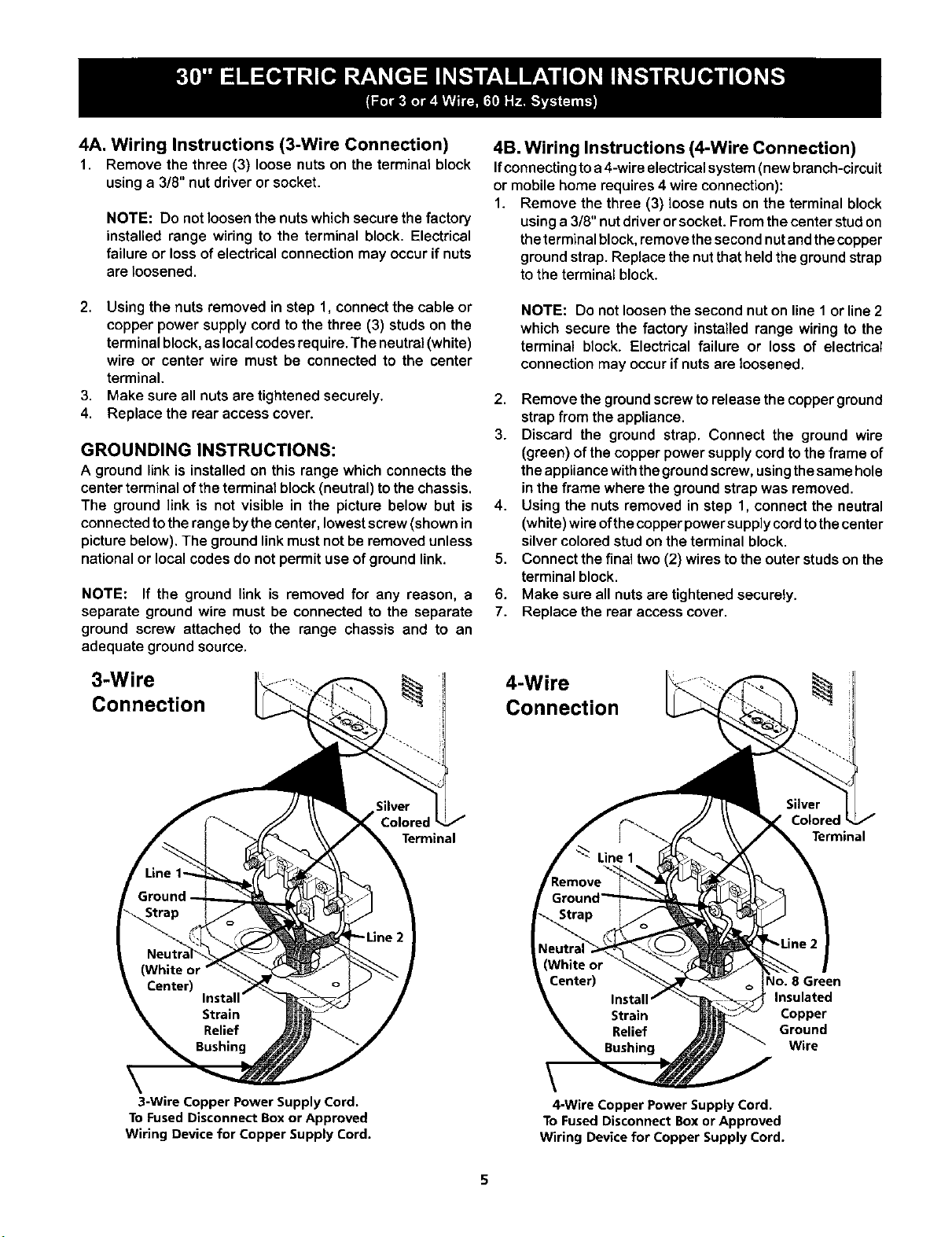
4A. Wiring Instructions (3-Wire Connection)
1. Remove the three (3) loose nutson the terminal block
usinga 3/8" nut driveror socket.
NOTE: Do not loosen the nuts whichsecure the factory
installed range wiring to the terminal block. Electrical
failure or lossof electricalconnectionmay occurifnuts
areloosened.
2. Usingthe nuts removed in step 1, connectthe cable or
copper power supply cord to the three (3) studs on the
terminal block, as local codes require. The neutral (white)
wire or center wire must be connected to the center
terminal.
3. Make sure all nuts are tightened securely.
4. Replace the rear access cover.
GROUNDING INSTRUCTIONS:
A ground link is installed on this range which connects the
center terminal of the terminal block (neutral) to the chassis.
The ground link is not visible in the picture below but is
connected to the range by the center, lowest screw (shown in
picture below). The ground link must not be removed unless
national or local codes do not permit use of ground link.
NOTE: If the ground link is removed for any reason, a
separate ground wire must be connected to the separate
ground screw attached to the range chassis and to an
adequate ground source.
3-Wire
Connection
4B. Wiring Instructions (4-Wire Connection)
Ifconnectingtoa 4-wireelectricalsystem(newbranch-circuit
or mobilehome requires4 wire connection):
1. Remove the three (3) loose nutson the terminal block
usinga 3/8" nutdriverorsocket. Fromthe center studon
theterminalblock, removethesecondnutandthecopper
groundstrap. Replacethenutthatheldthe groundstrap
to the terminal block.
NOTE: Do not loosenthe second nut on line 1 or line 2
which secure the factory installed range wiring to the
terminal block. Electrical failure or loss of electrical
connection may occur if nuts are loosened.
2. Remove the ground screw torelease the copper ground
strapfrom the appliance.
3. Discard the ground strap. Connect the ground wire
(green) of thecopper powersupplycordto theframe of
theappliancewiththegroundscrew,usingthesamehole
in the frame where the groundstrapwas removed.
4. Using the nuts removed in step 1, connectthe neutral
(white)wireofthecopperpowersupplycordtothecenter
silvercoloredstud on theterminal block.
5. Connect the finaltwo(2) wires tothe outerstudson the
terminal block.
6. Make sure all nuts aretightenedsecurely.
7. Replace the rear access cover.
4-Wire
Connection
Terminal
CoJore,
Terminal
\
3-Wire Copper Power Supply Cord.
To Fused Disconnect Box or Approved
Wiring Device for Copper Supply Cord.
4-Wire Copper Power Supply Cord.
To Fused Disconnect Box or Approved
Wiring Device for Copper Supply Cord.
40. 8 Green
Insulated
Copper
Ground
Wire
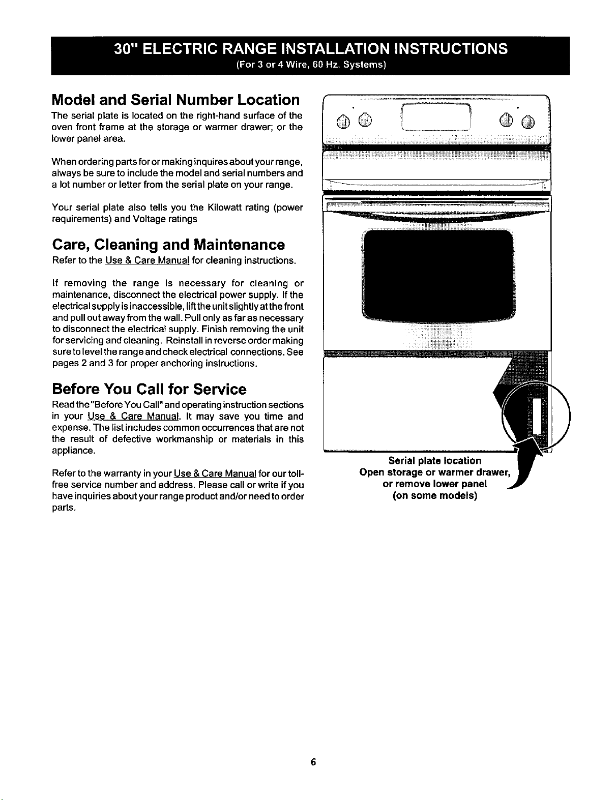
Model and Serial Number Location
The serial plate is located on the right-handsurface ofthe
oven front frame at the storage or warmer drawer; or the
lowerpanel area.
When ordering parts for or making inquires about your range,
always be sure to include the model and serial numbers and
a lot number or letter from the serial plate on your range.
Your serial plate also tells you the Kilowatt rating (power
requirements) and Voltage ratings
Care, Cleaning and Maintenance
Refer to the Use & Care Manual for cleaninginstructions.
If removing the range is necessary for cleaning or
maintenance, disconnect the electrical power supply. If the
electrical supply isinaccessible, liftthe unit slighUyat the front
and pull out away from the wall. Pull only asfar asnecessary
to disconnect the electrical supply. Finish removing the unit
for servicingandcleaning. Reinstallinreverseordermaking
sure to levelthe range and check electrical connections. See
pages 2 and 3 for proper anchoring instructions.
Before You Call for Service
Readthe"Before YouCall" andoperating instruction sections
in your Use & Care Manual. It may save you time and
expense. The list includes common occurrences that are not
the result of defective workmanship or materials in this
appliance.
Refer to the warranty inyour Use & Care Manual for our toll-
free service number and address. Please call or write if you
have inquiries about your range product and/or need to order
parts.
@® ............... @@
Serial plate location
Open storage or warmer drawer,
or remove lower panel
(on some models)

