
Viper SRT10
Chrysler Group LLC
OWNER’S MANUAL
2010
2010 Viper SRT10
10ZB27-126-AA First Edition Printed in U.S.A.
COUPE & ROADSTER

VEHICLES SOLD IN CANADA
With respect to any Vehicles Sold in Canada, the name
Chrysler Group LLC shall be deemed to be deleted and
the name Chrysler Canada Inc. used in substitution
therefore.
DRIVING AND ALCOHOL
Drunken driving is one of the most frequent causes of
accidents.
Your driving ability can be seriously impaired with blood
alcohol levels far below the legal minimum. If you are
drinking, don’t drive. Ride with a designated non-drinking
driver, call a cab, a friend, or use public transportation.
WARNING!
Driving after drinking can lead to an accident. Your
perceptions are less sharp, your reflexes are slower,
and your judgment is impaired when you have been
drinking. Never drink and then drive.
This manual illustrates and describes the operation of
features and equipment that are either standard or op-
tional on this vehicle. This manual may also include a
description of features and equipment that are no longer
available or were not ordered on this vehicle. Please
disregard any features and equipment described in this
manual that are not on this vehicle.
Chrysler Group LLC reserves the right to make changes
in design and specifications, and/or make additions to or
improvements to its products without imposing any
obligation upon itself to install them on products previ-
ously manufactured.
Copyright © 2009 Chrysler Group LLC

INSTALLATION OF RADIO TRANSMITTING
EQUIPMENT
Special design considerations are incorporated into this
vehicle’s electronic system to provide immunity to radio
frequency signals. Mobile two-way radios and telephone
equipment must be installed properly by trained person-
nel. The following must be observed during installation.
The positive power connection should be made directly
to the battery and fused as close to the battery as possible.
The negative power connection should be made to body
sheet metal adjacent to the negative battery connection.
This connection should not be fused.
Antennas for two-way radios should be mounted on the
roof or the rear area of the vehicle. Care should be used
in mounting antennas with magnet bases. Magnets may
affect the accuracy or operation of the compass on
vehicles so equipped.
The antenna cable should be as short as practical and
routed away from the vehicle wiring when possible. Use
only fully shielded coaxial cable.
Carefully match the antenna and cable to the radio to
ensure a low Standing Wave Ratio (SWR).
Mobile radio equipment with output power greater than
normal may require special precautions.
All installations should be checked for possible interfer-
ence between the communications equipment and the
vehicle’s electronic systems.
Viper
Chrysler Group LLC
OWNER’S MANUAL
2010
2010 Viper
10ZB27-126-AA First Edition Printed in U.S.A.


INTRODUCTION
CONTENTS
䡵 Introduction ........................... 4
䡵 How To Use This Manual .................. 4
䡵 Warnings And Cautions ................... 6
䡵 Vehicle Identification Number .............. 6
䡵 Vehicle Modifications/Alterations ............ 7
1

INTRODUCTION
Congratulations on selecting your new Chrysler Group
LLC vehicle. Be assured that it represents precision
workmanship, distinctive styling, and high quality - all
essentials that are traditional to our vehicles.
This Owner’s Manual has been prepared with the assis-
tance of service and engineering specialists to acquaint
you with the operation and maintenance of your vehicle.
It is supplemented by a Warranty Information Booklet,
located on the DVD, and various customer-oriented
documents. Please take the time to read these publica-
tions carefully. Following the instructions and recom-
mendations in this manual will help assure safe and
enjoyable operation of your vehicle.
NOTE: After you read the manual, it should be stored
in the vehicle for convenient referencing and remain
with the vehicle when sold, so that the new owner will
be aware of all safety warnings.
When it comes to service, remember that your authorized
dealer knows your vehicle best, has factory-trained tech-
nicians and genuine MOPAR威 parts, and cares about
your satisfaction.
HOW TO USE THIS MANUAL
Consult the Table of Contents to determine which section
contains the information you desire.
Since the specification of your vehicle depends on the
items of equipment ordered, certain descriptions and
illustrations may differ from your vehicle’s equipment
The detailed index at the back of this Owner’s Manual
contains a complete listing of all subjects.
Consult the following table for a description of the
symbols that may be used on your vehicle or throughout
this Owner’s Manual:
4 INTRODUCTION

INTRODUCTION 5

WARNINGS AND CAUTIONS
This Owner’s Manual contains WARNINGS against op-
erating procedures that could result in an accident or
bodily injury. It also contains CAUTIONS against proce-
dures that could result in damage to your vehicle. If you
do not read this entire manual, you may miss important
information. Observe all Warnings and Cautions.
VEHICLE IDENTIFICATION NUMBER
The Vehicle Identification Number (VIN) is on the left
front corner of the instrument panel and is visible from
outside the vehicle through the windshield. This number
also appears on the Automobile Information Disclosure
Label affixed to a window on your vehicle, the vehicle
registration, and the title.
NOTE: It is illegal to remove or alter the VIN.
Vehicle Identification Number
6 INTRODUCTION
VEHICLE MODIFICATIONS/ALTERATIONS
WARNING!
Any modifications or alterations to this vehicle could
seriously affect its roadworthiness and safety and
may lead to an accident resulting in serious injury or
death.
1
INTRODUCTION 7


THINGS TO KNOW BEFORE STARTING YOUR VEHICLE
CONTENTS
䡵 A Word About Your Keys ................. 12
▫ Ignition Key Removal .................. 12
▫ Key-In-Ignition Reminder ............... 13
䡵 Vehicle Security Alarm System ............. 13
▫ Rearming Of The System ................ 13
▫ To Arm The System ................... 13
▫ To Disarm The System ................. 15
▫ Electronic Immobilization System — Canada
Only .............................. 16
䡵 Illuminated Entry ...................... 17
䡵 Remote Keyless Entry (RKE) .............. 18
▫ To Unlock The Doors .................. 19
▫ To Lock The Doors .................... 20
▫ To Unlatch The Trunk/Liftgate ............ 21
▫ Using The Panic Alarm ................. 21
▫ Remote Open Window Feature ............ 21
▫ Programming Additional Transmitters ...... 22
▫ Battery Replacement ................... 22
2

▫ General Information ................... 23
䡵 Door Locks ........................... 24
▫ Manual Door Lock .................... 25
▫ Power Door Locks .................... 26
䡵 Windows ............................ 27
▫ Power Windows ...................... 27
▫ Auto-Down Feature ................... 29
▫ Wind Buffeting ....................... 29
䡵 Liftgate — Coupe Models Only ............ 29
䡵 Trunk Lock And Release — Convertible Models
Only ................................ 31
䡵 Trunk Safety Warning — Convertible Models
Only ................................ 31
▫ Trunk Emergency Release ............... 32
䡵 Occupant Restraints ..................... 32
▫ Lap/Shoulder Belts .................... 34
▫ Lap/Shoulder Belt Untwisting Procedure .... 38
▫ Enhanced Seat Belt Use Reminder System
(BeltAlert威) ......................... 39
▫ Automatic Locking Retractors
(ALR) Mode — If Equipped .............. 41
▫ Seat Belt Pretensioners — If Equipped ...... 41
▫ Seat Belts And Pregnant Women .......... 42
▫ Seat Belt Extender ..................... 42
▫ Driver And Passenger Supplemental
Restraint System (SRS) - Airbags .......... 42
▫ Airbag Deployment Sensors And Controls . . . 47
▫ Child Restraints ...................... 56
10 THINGS TO KNOW BEFORE STARTING YOUR VEHICLE

䡵 Break-In Recommendations ............... 63
䡵 Safety Tips ........................... 64
▫ Transporting Passengers ................ 64
▫ Exhaust Gas ......................... 64
▫ Safety Checks You Should Make Inside The
Vehicle ............................. 65
▫ Periodic Safety Checks You Should Make
Outside The Vehicle ................... 67
2
THINGS TO KNOW BEFORE STARTING YOUR VEHICLE 11

A WORD ABOUT YOUR KEYS
You can insert the double-sided keys into the locks with
either side up.
The authorized dealer that sold you your new vehicle has
the key code numbers for your vehicle’s locks. These
numbers can be used to order duplicate keys from your
authorized dealer or a locksmith. Ask your authorized
dealer for these numbers and keep them in a safe place.
Ignition Key Removal
1. Press the clutch pedal to the floor.
2. Bring the vehicle to a stop.
3. Place the shift lever into gear.
4. Apply the parking brake fully.
5. Press the key removal RELEASE button, turn the key
to place the ignition switch in the OFF/LOCK position,
and then pull the key out of the switch.
6. Release the clutch pedal.
Ignition Key Positions
1 — ACC 4 — ON/RUN
2 — OFF/LOCK 5 — RELEASE Button
3 — UNLOCK
12 THINGS TO KNOW BEFORE STARTING YOUR VEHICLE

NOTE: The Power Accessory Delay feature allows you
to operate the radio and the power windows for two
minutes after turning OFF the ignition switch. Removing
the key from the ignition switch and opening the driver’s
door will cancel this feature. Your authorized dealership
can enable or disable the Power Accessory Delay feature
as desired.
Key-In-Ignition Reminder
If you open the driver’s door when the key is in the
ignition, a chime will sound to remind you to remove the
key.
NOTE: The Key-In-Ignition reminder only sounds
when the ignition switch is placed in the OFF/LOCK or
ACC positions.
VEHICLE SECURITY ALARM SYSTEM
The Vehicle Security Alarm monitors the doors, trunk/
liftgate, and hood for unauthorized entry and the ignition
switch for unauthorized operation. If something triggers
the alarm, the Vehicle Security Alarm will prevent the
vehicle from starting. It will also sound the horn and
flash the park lights, the taillights and the fog lights.
Rearming of the System
If something triggers the alarm, and no action is taken to
disarm it, the Vehicle Security Alarm will turn off the
horn after three minutes, turn off all of the visual signals
(flashing lights) after 15 minutes, and then rearm itself.
To Arm the System
Remove the key from the ignition switch and either press
a power door LOCK switch while the driver’s or passen-
ger’s door is open or press the LOCK button on the
Remote Keyless Entry (RKE) transmitter. After the last
door is closed, or if all doors are closed, the system will
2
THINGS TO KNOW BEFORE STARTING YOUR VEHICLE 13

arm itself in approximately 16 seconds. During the
arming process, the Vehicle Security Light will flash at a
fast rate. Once the system is armed, the light will flash
once every six seconds.
NOTE:
•
The system will not cancel the arming process if you
open the hood or trunk/liftgate. It will, however,
cancel the arming process if you open a door or turn
on the ignition. If this occurs, and you wish to rearm
the system, simply repeat either of the previously
described arming sequences.
•
The Vehicle Security Light will remain on steady if the
hood or trunk/liftgate is open during the arming
process or if there is a fault in the system. If you verify
that the hood and trunk/liftgate are not open, and the
light remains on steady, see your authorized dealer for
service.
Entering the Trunk with the System Armed —
Convertible
NOTE: Using the key to open the trunk while the
system is armed will trigger the alarm.
Vehicle Security Light
14 THINGS TO KNOW BEFORE STARTING YOUR VEHICLE

Press the TRUNK button on the RKE transmitter to allow
access without triggering the alarm or having to disarm
the system. The trunk lid will pop open.
Entering the Liftgate with the System Armed —
Coupe
NOTE: Using the key to open the liftgate while the
Vehicle Security Alarm is armed will trigger the alarm.
Press the LIFTGATE button on the RKE transmitter to
allow access without triggering the alarm or having to
disarm the Vehicle Security Alarm. Then, within 30 sec-
onds, open the liftgate by using the key cylinder or the
LIFTGATE RELEASE switch located in the exterior lift-
gate handle.
NOTE: If you do not open the liftgate within 30 seconds,
the system will rearm and ignore the switch input.
After closing the liftgate, the Vehicle Security Alarm will
arm immediately without having to re-lock the vehicle.
To Disarm the System
There are two ways to disarm the system:
•
Use the key to unlock the driver’s door. The door lock
is located on the outside door panel beneath the
mirror.
Mechanical Door Lock
2
THINGS TO KNOW BEFORE STARTING YOUR VEHICLE 15

•
Press the UNLOCK button on the RKE transmitter.
The front and rear park lights and the turn signal
lights will flash to acknowledge the signal.
NOTE: The vehicle will not start unless the Vehicle
Security Alarm is disarmed by either method. Inserting
the key in the ignition WILL NOT disarm the system.
Furthermore, turning the ignition key to any position
while the Vehicle Security Alarm is armed will trigger an
alarm.
Tamper Alert
If something has triggered the Vehicle Security Alarm in
your absence, the Vehicle Security Light will flash twice
every six seconds. In addition, the horn will sound three
times when you disarm the Vehicle Security Alarm.
Electronic Immobilization System — Canada Only
The Electronic Immobilization system prevents unautho-
rized vehicle operation by disabling the engine. The
system does not need to be armed or activated. Operation
is automatic, regardless of whether the vehicle is locked
or unlocked.
To Arm the System
The Electronic Immobilization system will passively arm
30 seconds after the key is removed from the vehicle.
When the system is armed the Vehicle Security Light will
flash at a rate of a half-second ON, a half-second OFF, a
half-second ON, followed by a 10 second pause. While in
this mode the vehicle will not start.
NOTE:
•
If the Electronic Immobilization system is armed and
the vehicle is unlocked it will remain unlocked until
the driver presses either the LOCK button on the
RKE transmitter or the power door LOCK button on
16 THINGS TO KNOW BEFORE STARTING YOUR VEHICLE

the door. At this time the Vehicle Security Alarm will
also arm itself in approximately 16 seconds.
•
Always remove the key and RKE transmitter from the
vehicle, and lock all doors when leaving the vehicle
unattended.
To Disarm the System
Pressing the UNLOCK button on the RKE transmitter
after the Electronic Immobilization system is activated,
will allow the driver 60 seconds to start the vehicle.
Failure to complete the process within 60 seconds will
cause the system to passively re-arm. The driver must
repeat the process again by pressing the UNLOCK button
on the RKE transmitter to start the vehicle.
NOTE: Pressing the RKE transmitter UNLOCK button
during the 30 second Electronic Immobilization arming
process will allow the driver 60 seconds to start the
vehicle.
ILLUMINATED ENTRY
The interior lights will turn on whenever a door is
opened or the liftgate is opened (Coupe models) and the
dimmer switch is not in the defeat position.
The interior lights will turn on, remain on for approxi-
mately 30 seconds, and then fade to off if any of the
following occur:
•
A door is opened using the outside door handle and
then closed.
•
A door is unlocked using the Remote Keyless Entry
(RKE) transmitter.
•
A door is unlocked using the outside driver’s door key
cylinder.
The interior lights will turn on and remain on for about
four seconds and then fade to off if a door is opened
using the inside door handle.
2
THINGS TO KNOW BEFORE STARTING YOUR VEHICLE 17

NOTE: None of the courtesy lights will operate if the
dimmer control is in the “defeat” position (extreme
downward position), unless the overhead map/reading
lights are turned on manually.
REMOTE KEYLESS ENTRY (RKE)
This system allows you to lock or unlock the doors, open
the trunk/liftgate, or activate the Panic Alarm from
distances up to approximately 23 ft (7 m) using a Remote
Keyless Entry (RKE) transmitter. The RKE transmitter
does not need to be pointed at the vehicle to activate the
system.
RKE Transmitter
18 THINGS TO KNOW BEFORE STARTING YOUR VEHICLE

To Unlock the Doors
Press and release the UNLOCK button on the RKE
transmitter once to unlock the driver’s door or twice to
unlock both doors. The park lights and turn signal lights
will flash to acknowledge the signal and the illuminated
entry system will turn on. In addition, the words DOOR
UNLOCKED will flash in the odometer if one door is
unlocked or will remain on steadily if both doors are
unlocked.
NOTE: On Coupe models, pressing either the UNLOCK
button or the LIFTGATE button will allow liftgate access.
Remote Key Unlock, Driver Door/Both Doors First
This feature lets you program the system to unlock either
the driver’s door or both doors on the first press of the
UNLOCK button on the RKE transmitter. To change the
current setting, proceed as follows:
1. Press the UNLOCK button on a programmed RKE
transmitter for at least four seconds, but not longer than
10 seconds. Then, press the LOCK button.
2. Release both buttons at the same time.
3. Test the feature while outside of the vehicle, by
pressing the UNLOCK button on the RKE transmitter
with the ignition in the OFF/LOCK position, and the key
removed.
4. Repeat these steps if you want to return this feature to
its previous setting.
NOTE: Pressing the LOCK button on the RKE transmit-
ter while you are in the vehicle will activate the Vehicle
Security Alarm. Opening a door with the Vehicle Security
Alarm System activated will cause the alarm to sound.
Press the UNLOCK button to deactivate the Vehicle
Security Alarm System.
Flash Lights with Remote Key Lock
This feature will cause the park lights and turn signal
lights to flash when the doors are locked or unlocked
2
THINGS TO KNOW BEFORE STARTING YOUR VEHICLE 19

with the RKE transmitter. This feature can be turned on
or turned off. To change the current setting, proceed as
follows:
1. Press the LOCK button on a programmed RKE trans-
mitter for at least four seconds, but no longer then
10 seconds. Then, press the TRUNK/LIFTGATE button.
2. Release both buttons at the same time.
3. Test the feature while outside of the vehicle, by
pressing the LOCK/UNLOCK buttons on the RKE trans-
mitter with the ignition in the OFF/LOCK position, and
the key removed.
4. Repeat these steps if you want to return this feature to
its previous setting.
NOTE: Pressing the LOCK button on the RKE transmit-
ter while you are in the vehicle will activate the Vehicle
Security Alarm. Opening a door with the Vehicle Security
Alarm activated will cause the alarm to sound. Press the
UNLOCK button to deactivate the Vehicle Security
Alarm System.
To Lock the Doors
Press and release the LOCK button on the RKE transmit-
ter to lock the doors. The horn will chirp once and the
park lights and turn signal lights will flash to acknowl-
edge the signal.
Sound Horn with Remote Key Lock
This feature will cause the horn to chirp when the doors
are locked with the RKE transmitter. This feature can be
turned on or turned off. To change the current setting,
proceed as follows:
1. Press the LOCK button on a programmed RKE trans-
mitter for at least four seconds, but no longer then
10 seconds. Then, press the UNLOCK button.
2. Release both buttons at the same time.
20 THINGS TO KNOW BEFORE STARTING YOUR VEHICLE

3. Test the feature while outside of the vehicle, by
pressing the LOCK button on the RKE transmitter with
the ignition in the OFF/LOCK position, and the key
removed.
4. Repeat these steps if you want to return this feature to
its previous setting.
NOTE: Pressing the LOCK button on the RKE transmit-
ter while you are in the vehicle will activate the Vehicle
Security Alarm System. Opening a door with the Vehicle
Security Alarm System activated will cause the alarm to
sound. Press the UNLOCK button to deactivate the
Vehicle Security Alarm System.
To Unlatch the Trunk/Liftgate
Press and hold the TRUNK/LIFTGATE button on the
RKE transmitter for at least one second to unlatch the
trunk/liftgate. The parking lights and turn signal lights
will flash three times to acknowledge the signal.
Using the Panic Alarm
The Panic Alarm unlocks the driver’s door, turns on the
interior lights, flashes the park lights and fog lights, and
sounds the horn. The Panic Alarm will not work when
driving the vehicle.
To turn the Panic Alarm on or off, press and hold the
PANIC button on the RKE transmitter for at least one
second and release. The alarm can also be turned off by
inserting the key into the ignition switch and turning it to
the ON/RUN position. If not deactivated through the
RKE transmitter or the ignition switch, the alarm will
turn off automatically after three minutes.
Remote Open Window Feature
This feature allows you to remotely lower both front door
windows at the same time. To use this feature, press and
release the UNLOCK button on the RKE transmitter and
then immediately press and hold the UNLOCK button
until the windows lower to the level desired or until they
lower completely.
2
THINGS TO KNOW BEFORE STARTING YOUR VEHICLE 21

Programming Additional Transmitters
NOTE: You must have at least one programmed RKE
transmitter to perform this procedure. If you do not have
a programmed RKE transmitter, contact your authorized
dealer for details.
Use this procedure to program up to three additional
transmitters for your vehicle. To activate the program-
ming feature, proceed as follows:
1. Turn the ignition switch to the ON/RUN position.
2. Set the parking brake.
3. Press and hold the UNLOCK button for at least five
seconds, but no longer then 10 seconds on a previously
programmed RKE transmitter. Then, press the PANIC
button while still holding the UNLOCK button.
4. Release both buttons at the same time. A chime will
sound to signal that the programming feature is acti-
vated.
5. Within 30 seconds, press and release the LOCK button
and the UNLOCK button at the same time on the new
RKE transmitter.
6. Press and release any button one time on the new RKE
transmitter. A chime will sound to indicate that the new
RKE transmitter is programmed. An additional chime
will sound at the end of the 30-second programming
period. It will also sound if the ignition is switched OFF.
7. Repeat Steps 3 through 6 to program each additional
RKE transmitter.
Battery Replacement
The recommended replacement battery is 2016. This is a
generic battery, readily available at local retail stores.
NOTE:
•
Perchlorate Material — special handling may apply.
See www.dtsc.ca.gov/hazardouswaste/perchlorate.
22 THINGS TO KNOW BEFORE STARTING YOUR VEHICLE

•
Do not touch the battery terminals that are on the back
housing or the printed circuit board.
1. Separate the two halves of the RKE transmitter with a
flat blade screwdriver or similar object.
2. Remove and replace the battery. Avoid touching the
new battery with your fingers. Skin oils may cause
battery deterioration. If you touch a battery, clean it with
rubbing alcohol.
3. To assemble the RKE transmitter case, snap the two
halves together.
4. Test the RKE transmitter operation.
General Information
This RKE transmitter complies with FCC rules Part 15.
Operation is subject to the following conditions:
1. This device may not cause harmful interference.
2. This device must accept any interference that may be
received, including interference that may cause undes-
ired operation.
Separating RKE transmitter Halves
2
THINGS TO KNOW BEFORE STARTING YOUR VEHICLE 23

If your RKE transmitter fails to operate from a normal
distance, check for these two conditions:
1. Closeness to a radio transmitter, such as a radio station
tower, airport transmitter, and some mobile or CB radios
can affect transmitter operation. To verify if this is the
cause, move the vehicle to another area and test RKE
transmitter operation.
2. The RKE transmitter may become “out of sync” and
will no longer function if operated more than 255 times
while out of range of the vehicle (23 ft or 7 m) or if
operated while the vehicle battery is dead or discon-
nected. To “synchronize” the RKE transmitter, remove
the key from the ignition. Close the hood and all doors.
Press both buttons on the RKE transmitter for about
10 seconds. The horn will chirp once to acknowledge the
signal. Normal RKE transmitter operation should re-
sume.
3. The RKE transmitter battery may be weak or dead.
The expected life of the battery is a minimum of three
years.
DOOR LOCKS
WARNING!
•
Do not touch the exhaust pipe sill covers when
entering or exiting your vehicle. They can be hot
enough to burn you. Observe the warning labels
on each door closure panel.
•
For personal security and safety in the event of an
accident, lock the vehicle doors as you drive as
well as when you park and leave the vehicle.
•
When leaving the vehicle, always remove the key
from the ignition lock, and lock your vehicle.
Unsupervised use of vehicle equipment may cause
severe personal injuries and death.
(Continued)
24 THINGS TO KNOW BEFORE STARTING YOUR VEHICLE

WARNING! (Continued)
•
Never leave children alone in a vehicle. Leaving
unattended children in a vehicle is dangerous for a
number of reasons. A child or others could be
injured seriously or fatally. Don’t leave the key in
the ignition. A child could operate power win-
dows, other controls, or move the vehicle.
Manual Door Lock
The driver’s door can be locked or unlocked with the key.
The door lock is located on the outside door panel
beneath the mirror.
Mechanical Door Lock
2
THINGS TO KNOW BEFORE STARTING YOUR VEHICLE 25

Power Door Locks
A power door lock switch is on each door trim panel. Use
this switch to lock or unlock the doors.
NOTE: To prevent you from accidentally locking your
keys in the vehicle, the power door locks will not operate
if the key is in the ignition and the driver’s door is open.
Electronic Door Lock
This vehicle is equipped with a virtual lock system. Input
from the outside door handle is ignored if the vehicle is
virtually locked.
Door Lock Messaging
The words “DOOR UNLOCKED” will flash in the odom-
eter if one door is unlocked or will remain on steadily if
both doors are unlocked. A door is considered unlocked
if the inside door handle is pulled. With the key in the
ignition switch, this display will turn off approximately
40 seconds after switching OFF the ignition, or if the
Power Accessory Delay feature is active, it will turn off
approximately 40 seconds after the delay feature times
out.
Automatic Door Locks
This feature locks the doors automatically once vehicle
speed reaches 18 mph (29 km/h).
Power Door Lock Switch
26 THINGS TO KNOW BEFORE STARTING YOUR VEHICLE

NOTE: Input from the door handles is ignored once the
vehicle is moving faster than 5 mph (8 km/h).
Automatic Door Locks Programming
The Automatic Door Locks feature can be enabled or
disabled as follows:
1. Close all doors and place the key in the ignition.
2. Cycle the ignition switch between ON/RUN and
OFF/LOCK four times ending up in the OFF/LOCK
position.
3. Press the power door LOCK switch to lock the doors.
4. A single chime will indicate the completion of the
programming.
5. Repeat these steps if you want to return this feature to
its previous setting.
This feature can also be disabled at an authorized deal-
ership if desired.
NOTE: Use the Automatic Door Locks feature in accor-
dance with local laws.
WINDOWS
Power Windows
The power window switches are located between the
driver and passenger seats on the center tunnel bezel, just
to the left of the parking brake. The switch on the left side
controls the driver’s window and the switch on the right
controls the passenger’s window. The power window
switches are active when the ignition is in ON/RUN or
ACC position.
2
THINGS TO KNOW BEFORE STARTING YOUR VEHICLE 27

NOTE:
•
The Power Accessory Delay feature allows you to
operate the power windows for two minutes after
turning OFF the ignition switch. Removing the key
from the ignition switch and opening the driver’s door
will cancel this feature. Your authorized dealership can
enable or disable the Power Accessory Delay feature as
desired.
•
Windows cannot be driven up during Power Acces-
sory Delay with a door open. Furthermore, opening
the door will stop the window movement immediately
if the window is in the process of going up.
•
The window will lower slightly if it is closed com-
pletely when opening the door. The window will
return to its fully closed position after closing the door.
This action is necessary in order to clear the seal when
opening the door.
WARNING!
Never leave children in a vehicle with the key in the
ignition switch. Occupants, particularly unattended
children, can become entrapped by the power win-
dows while operating the power window switch.
Such entrapment may result in serious injury or
death.
28 THINGS TO KNOW BEFORE STARTING YOUR VEHICLE

Auto-Down Feature
Both windows have an Auto-Down feature. Press the
WINDOW switch to the second detent, release, and the
window will go down automatically. Press the switch a
second time in either direction to stop the window.
To open the window to a desired position, press and hold
the WINDOW switch in the first detent. Release the
switch when you want the window to stop.
Wind Buffeting
Wind buffeting can be described as the perception of
pressure on the ears or a helicopter-type sound in the
ears. Your vehicle may exhibit wind buffeting with the
windows down, or the top down (convertible models).
This is a normal occurrence and can be minimized by
adjusting one or both windows up or down slightly.
LIFTGATE — COUPE MODELS ONLY
The liftgate can be unlocked or locked by the Remote
Keyless Entry (RKE) transmitter or by activating either of
the power door lock switches located on the door trim
panels.
To unlock the liftgate with the RKE transmitter, press the
LIFTGATE button on the RKE transmitter for at least one
Power Window Switches
2
THINGS TO KNOW BEFORE STARTING YOUR VEHICLE 29

second. The parking lights and turn signal lights will
flash three times to acknowledge the signal.
NOTE: Pressing the UNLOCK button on the RKE
transmitter will also allow liftgate access.
Once unlocked, the liftgate can be opened or closed. To
open the liftgate, press the LIFTGATE RELEASE switch
located in the exterior liftgate handle and pull the liftgate
open with one fluid motion.
NOTE: The liftgate release switch will be ignored under
the following conditions:
•
When the ignition is in ON/RUN and the parking
brake is not set.
•
When vehicle speed is not 0 mph (0 km/h).
•
When all doors are locked (except for RKE transmitter
liftgate access). Refer to “Entering the Liftgate with the
System Armed — Coupe” under “Security Alarm
System” for additional information.
The word “DECK” will flash in the odometer when the
liftgate is open. With the key in the ignition switch, this
display will turn off approximately 40 seconds after
switching OFF the ignition, or if the Power Accessory
Delay feature is active, it will turn off approximately
40 seconds after the delay feature times out.
WARNING!
•
Driving with the liftgate open can allow poison-
ous exhaust gases into your vehicle. You and your
passengers could be injured by these fumes. Keep
the liftgate closed when you are operating the
vehicle.
•
If you are required to drive with the liftgate open,
make sure that all windows are closed, and the
climate control blower switch is set at high speed.
DO NOT use the recirculation mode.
30 THINGS TO KNOW BEFORE STARTING YOUR VEHICLE

Gas props support the liftgate in the open position.
However, because the gas pressure drops with tempera-
ture, it may be necessary to assist the props when
opening the liftgate in cold weather.
TRUNK LOCK AND RELEASE — CONVERTIBLE
MODELS ONLY
You can unlatch the trunk lid by pressing the TRUNK
button on the Remote Keyless Entry (RKE) transmitter
for at least one second. The park lights and turn signal
lights will flash three times to acknowledge the signal
and the trunk lid will pop open.
You can also unlatch the trunk lid with the key. The key
cylinder is located on the trunk lid.
The word “DECK” will flash in the odometer when the
trunk lid is open. With the key in the ignition switch, this
display will turn off approximately 40 seconds after
switching OFF the ignition, or if the Power Accessory
Delay feature is active, it will turn off approximately
40 seconds after the delay feature times out.
NOTE: Gas props support the trunk lid in the open
position. However, because the gas pressure drops with
temperature, it may be necessary to assist the props when
opening the trunk lid in cold weather.
TRUNK SAFETY WARNING — CONVERTIBLE
MODELS ONLY
WARNING!
Do not allow children to have access to the trunk,
either by climbing into the trunk from outside, or
through the inside of the vehicle. Always close the
trunk lid when your vehicle is unattended. Once in
the trunk, young children may not be able to escape.
If trapped in the trunk, children can die from suffo-
cation or heat stroke.
2
THINGS TO KNOW BEFORE STARTING YOUR VEHICLE 31

Trunk Emergency Release
The trunk of your vehicle is equipped with an emergency
release handle. It is located on the inside of the trunk lid,
near the latch, and is coated so that it glows in a darkened
trunk. Pull on the handle to open the trunk.
OCCUPANT RESTRAINTS
Some of the most important safety features in your
vehicle are the restraint systems:
•
Three-point lap and shoulder belts for all seating
positions
•
Advanced Front Airbags for driver and front passen-
ger
•
An energy-absorbing steering column and steering
wheel
•
Knee bolsters/blockers for front seat occupants
•
Seat belts incorporate pretensioners to enhance occu-
pant protection by managing occupant energy during
an impact event — if equipped
•
Passenger side seatbelt incorporates an Automatic
Locking Retractor (ALR), which locks the seat belt
webbing into position by extending the belt all the
Emergency Release
32 THINGS TO KNOW BEFORE STARTING YOUR VEHICLE

way out and then adjusting the belt to the desired
length to restrain a child seat or secure a large item in
a seat — if equipped
If you will be carrying children too small for adult-sized
seat belts, the seat belts or the Lower Anchors and Tether
for CHildren (LATCH) feature also can be used to hold
infant and child restraint systems. For more information
on LATCH, see Lower Anchors and Tether for CHildren
(LATCH).
NOTE: The Advanced Front Airbags have a multistage
inflator design. This allows the airbag to have different
rates of inflation based on the severity and type of
collision.
Please pay close attention to the information in this
section. It tells you how to use your restraint system
properly, to keep you and your passengers as safe as
possible.
WARNING!
In an accident, you and your passengers can suffer
much greater injuries if you are not properly buckled
up. You can strike the interior of your vehicle or other
passengers, or you can be thrown out of the vehicle.
Always be sure you and others in your vehicle are
buckled up properly.
Buckle up even though you are an excellent driver, even
on short trips. Someone on the road may be a poor driver
and cause an accident that includes you. This can happen
far away from home or on your own street.
Research has shown that seat belts save lives, and they
can reduce the seriousness of injuries in an accident.
Some of the worst injuries happen when people are
thrown from the vehicle. Seat belts reduce the possibility
2
THINGS TO KNOW BEFORE STARTING YOUR VEHICLE 33
of ejection and the risk of injury caused by striking the
inside of the vehicle. Everyone in a motor vehicle should
be belted at all times.
Lap/Shoulder Belts
Each seat belt is a combined lap/shoulder belt system.
The belt webbing retractor will lock only during very
sudden stops or impacts. This feature allows the shoulder
portion of the belt to move freely with you under normal
conditions. However, in an accident, the belt will lock
and reduce your risk of striking the inside of the vehicle
or being thrown out of the vehicle.
WARNING!
•
It is dangerous to ride in a cargo area, inside or
outside of a vehicle. In an accident, people riding
in these areas are more likely to be seriously
injured or killed.
(Continued)
WARNING! (Continued)
•
Do not allow people to ride in any area of your
vehicle that is not equipped with seats and seat
belts.
•
Be sure everyone in your vehicle is in a seat and
using a seat belt properly.
•
Wearing a seat belt incorrectly is dangerous. Seat
belts are designed to go around the large bones of
your body. These are the strongest parts of your
body and can take the forces of an accident the
best.
•
Wearing your belt in the wrong place could make
your injuries in an accident much worse. You
might suffer internal injuries, or you could even
slide out of part of the belt. Follow these instruc-
tions to wear your seat belt safely and to keep your
passengers safe, too.
(Continued)
34 THINGS TO KNOW BEFORE STARTING YOUR VEHICLE
WARNING! (Continued)
•
Two people should never be belted into a single
seat belt. People belted together can crash into one
another in an accident, hurting one another badly.
Never use a lap/shoulder belt or a lap belt for more
than one person, no matter what their size.
Lap/Shoulder Belt Operating Instructions
1. Enter the vehicle and close the door. Sit back and
adjust the seat.
2. The seat belt latch plate is located at the side of your
seat back. Grasp the latch plate and pull out the belt.
3. Slide the latch plate up the webbing as far as necessary
to make the belt go around your lap.
Latch Plate (Convertible Shown)
2
THINGS TO KNOW BEFORE STARTING YOUR VEHICLE 35
4. When the belt is long enough to fit, insert the latch
plate into the buckle until you hear a “click.”
WARNING!
•
A belt that is buckled into the wrong buckle will
not protect you properly. The lap portion could
ride too high on your body, possibly causing
internal injuries. Always buckle your belt into the
buckle nearest you.
•
A belt that is too loose will not protect you
properly. In a sudden stop, you could move too far
forward, increasing the possibility of injury. Wear
your seat belt snugly.
(Continued)
Latch Plate To Buckle (Convertible Shown)
36 THINGS TO KNOW BEFORE STARTING YOUR VEHICLE
WARNING! (Continued)
•
A belt that is worn under your arm is dangerous.
Your body could strike the inside surfaces of the
vehicle in an accident, increasing head and neck
injury. A belt worn under the arm can cause
internal injuries. Ribs aren’t as strong as shoulder
bones. Wear the belt over your shoulder so that
your strongest bones will take the force in a
collision.
•
A shoulder belt placed behind you will not protect
you from injury during an accident. You are more
likely to hit your head in a collision if you do not
wear your shoulder belt. The lap and shoulder belt
are meant to be used together.
5. Position the lap belt across your thighs, below your
abdomen. To remove slack in the lap belt portion, pull up
a little on the shoulder belt, as shown.
6. To loosen the lap belt if it is too tight, lift up on the
shoulder belt and pull on the lap belt. A snug belt reduces
the risk of sliding under the belt in an accident.
Removing Slack From Belt (Convertible Shown)
2
THINGS TO KNOW BEFORE STARTING YOUR VEHICLE 37
WARNING!
•
A lap belt worn too high can increase the risk of
internal injury in an accident. The belt forces
won’t be at the strong hip and pelvic bones, but
across your abdomen. Always wear the lap belt as
low as possible and keep it snug.
•
A twisted belt can’t do its job properly. In a
collision, it could even cut into you. Be sure the
belt is straight. If you can’t straighten a belt in
your vehicle, take it to an authorized dealer imme-
diately and have it fixed.
7. Position the shoulder belt on your chest so that it is
comfortable and not resting on your neck. The retractor
will withdraw any slack in the belt.
8. To release the belt, push the red button in the buckle.
The belt will retract automatically to its stowed position.
If necessary, slide the latch plate down the webbing to
allow it to retract fully.
WARNING!
A frayed or torn belt could rip apart in an accident
and leave you with no protection. Inspect the belt
system periodically, checking for cuts, frays, or loose
parts. Damaged parts must be replaced immediately.
Do not disassemble or modify the system. Seat belt
assemblies must be replaced after an accident if they
have been damaged (bent retractor, torn webbing,
etc.).
Lap/Shoulder Belt Untwisting Procedure
Use the following procedure to untwist a twisted lap/
shoulder belt.
38 THINGS TO KNOW BEFORE STARTING YOUR VEHICLE

1. Position the latch plate as close as possible to the
anchor point.
2. At about 6 to 12 in (15 to 30 cm) above the latch plate,
grasp and twist the belt webbing 180 degrees to create a
fold that begins immediately above the latch plate.
3. Slide the latch plate upward over the folded webbing.
The folded webbing must enter the slot at the top of the
latch plate.
4. Continue to slide the latch plate up until it clears the
folded webbing.
Enhanced Seat Belt Use Reminder System
(BeltAlert姞)
If the driver’s or front passenger’s (if equipped with belt
alert) seat belt has not been buckled within 60 seconds of
starting the vehicle and if the vehicle speed is greater
than 5 mph (8 km/h), the Enhanced Warning System
(BeltAlert威) will alert the driver or front passenger to
buckle the seat belt. The driver should also instruct all
other occupants to buckle their seat belts. Once the
warning is triggered, BeltAlert威 will continue to chime
and flash the Seat Belt Reminder Light for 96 seconds or
until the driver’s or front passenger’s seat belt is buckled.
BeltAlert威 will be reactivated if the driver’s or passen-
ger’s seat belt is unbuckled for more than 10 seconds and
the vehicle speed is greater than 5 mph (8 km/h).
For front passenger seats equipped with BeltAlert, your
vehicle is equipped to detect when it is occupied. The
BeltAlert威 warning system is not activated when the
front passenger seat is unoccupied. The BeltAlert威 warn-
ing system may be triggered when an animal or heavy
object is on the front passenger seat or when the seat is
folded flat (if equipped). It is recommended that pets be
restrained in the rear seat in pet harnesses or pet carriers
that are secured by seat belts and cargo is properly
stowed.
2
THINGS TO KNOW BEFORE STARTING YOUR VEHICLE 39

BeltAlert威 Programming
BeltAlert威 can be enabled or disabled by your authorized
dealer or by performing the following steps:
NOTE: Chrysler Group LLC does not recommend de-
activating BeltAlert威.
1. Close all doors.
2. Turn the ignition switch to the OFF/LOCK position.
3. Buckle the driver’s seat belt.
4. Turn the ignition switch to the ON/RUN position, but
do not start the engine. Wait for the Seat Belt Reminder
Light to turn off and then proceed to the next step.
NOTE: You must perform the following steps within
60 seconds of turning the ignition switch to the ON/RUN
position.
5. Within 60 seconds of turning the ignition switch to the
ON/RUN position, unbuckle and then re-buckle the
driver’s seat belt at least three times within 10 seconds,
ending with the seat belt buckled.
NOTE: Watch for the Seat Belt Reminder Light to turn
on while unbuckling the seat belt and turn off while
re-buckling the seat belt. It may be necessary to retract
the seat belt.
6. Turn the ignition switch to the OFF/LOCK position. A
single chime will sound to signify that you have com-
pleted the programming successfully.
BeltAlert威 can be reactivated by repeating this procedure.
NOTE:
When BeltAlert威 is deactivated, the Seat Belt
Reminder Light will continue to illuminate as long as the
driver’s seat belt or the passenger’s seat belt is unbuckled.
40 THINGS TO KNOW BEFORE STARTING YOUR VEHICLE

Automatic Locking Retractors (ALR) Mode —
If Equipped
In this mode, the shoulder belt is automatically pre-
locked. The belt will still retract to remove any slack in
the shoulder belt. The Automatic Locking Mode is avail-
able on all passenger-seating positions with a combina-
tion lap/shoulder belt.
When To Use The Automatic Locking Mode
Use the Automatic Locking Mode anytime a child safety
seat is installed in a seating position that has a belt with
this feature. Children 12 years old and under should
always be properly restrained in the rear seat.
How To Engage The Automatic Locking Mode
1. Buckle the combination lap and shoulder belt.
2. Grasp the shoulder portion and pull downward until
the entire belt is extracted.
3. Allow the belt to retract. As the belt retracts, you will
hear a clicking sound. This indicates the safety belt is
now in the Automatic Locking Mode.
How To Disengage The Automatic Locking Mode
Unbuckle the combination lap/shoulder belt and allow it
to retract completely to disengage the Automatic Locking
Mode and activate the vehicle sensitive (emergency)
locking mode.
Seat Belt Pretensioners — If Equipped
The seat belts for both front seating positions may be
equipped with pretensioning devices that are designed to
remove slack from the seat belt in the event of an
accident. These devices improve the performance of the
seat belt by assuring that the belt is tight about the
occupant early in an accident. Pretensioners work for all
size occupants, including those in child restraints.
2
THINGS TO KNOW BEFORE STARTING YOUR VEHICLE 41

NOTE: These devices are not a substitute for proper seat
belt placement by the occupant. The seat belt still must be
worn snugly and positioned properly.
The pretensioners are triggered by the Occupant Re-
straint Controller (ORC). Like the airbags, the pretension-
ers are single use items. A deployed pretensioner or a
deployed airbag must be replaced immediately.
Seat Belts and Pregnant Women
We recommend that pregnant women use the seat belts
throughout their pregnancy. Keeping the mother safe is
the best way to keep the baby safe.
Pregnant women should wear the lap portion of the belt
across the thighs and as snug across the hips as possible.
Keep the belt low so that it does not come across the
abdomen. That way the strong bones of the hips will take
the force if there is an accident.
Seat Belt Extender
If a seat belt is too short, even when extended fully, your
authorized dealer can provide you with a seat belt
extender. This extender should only be used if the
existing belt is not long enough. When it is not required,
remove the extender, and store it.
WARNING!
Using a seat belt extender when not needed can
increase the risk of injury in an accident. Only use a
seat belt extender when the seat belt is not long
enough when worn low and snug and in the recom-
mended seating positions. Remove and store the
extender when not needed.
Driver and Passenger Supplemental Restraint
System (SRS) - Airbags
This vehicle is equipped with airbags for the driver and
passenger as a supplement to the seat belt restraint
42 THINGS TO KNOW BEFORE STARTING YOUR VEHICLE

systems. The driver’s Advanced Front Airbag is mounted
in the steering wheel. The passenger’s Advanced Front
Airbag is mounted underneath a cover in the passenger’s
side of the instrument panel. The words SRS/AIRBAG is
embossed on the airbag covers.
NOTE: These airbags are certified to the new Federal
regulations for Advanced Airbags. The passenger’s Ad-
vanced Front Airbag is certified to the Federal regulations
that define Occupant Classification (Refer to “Airbag
Deployment Sensors and Controls”).
The airbags have a multistage inflator design. This allows
the airbag to have different rates of inflation that are
based on collision severity and occupant size.
WARNING!
•
No objects should be placed over or near the
airbag on the instrument panel, because any such
objects could cause harm if the vehicle is in a
collision severe enough to cause the airbag to
inflate.
(Continued)
Advanced Front Airbag and Knee Bolster Locations
1 — Driver And Passenger Advanced Front Airbag
2 — Knee Bolster
2
THINGS TO KNOW BEFORE STARTING YOUR VEHICLE 43
WARNING! (Continued)
•
Do not put anything on or around the airbag
covers or attempt to open them manually. You may
damage the airbags and you could be injured
because the airbags are no longer functional.
These protective covers for the airbag cushions are
designed to open only when the airbags are inflat-
ing.
•
Do not drill, cut, or tamper with the knee bolster
in any way.
•
Do not mount any accessories to the knee bolster
such as alarm lights, stereos, citizens band radios,
etc.
(Continued)
WARNING! (Continued)
•
Relying on the airbags alone could lead to more
severe injuries in a collision. The airbags work
with your seat belt to restrain you properly. In
some collisions, the airbags won’t deploy at all.
Always wear your seat belts even though you have
airbags.
•
Being too close to the steering wheel or instrument
panel during airbag deployment could cause seri-
ous injury. Airbags need room to inflate. Sit back,
extending your arms comfortably to reach the
steering wheel or instrument panel.
Knee Impact Bolsters
The Knee Impact Bolsters help protect the knees of the
driver and the passenger, and position front occupants
for the best interaction with the airbags.
44 THINGS TO KNOW BEFORE STARTING YOUR VEHICLE

While the seat belts are designed to protect the driver and
passenger in many types of collisions, the airbags will
deploy in certain frontal collisions depending on the
severity and type of collision. However, even in collisions
where the airbags deploy, all occupants need the seat
belts to keep them in the right position for the airbags to
protect properly.
NOTE:
•
The passenger airbag may not deploy if the Occupant
Classification System (refer to “Airbag Deployment
Sensors and Controls”) determines the seat is empty or
is occupied by someone that is classified in the “child”
category. This could be a child, a teenager, or even a
small adult. Therefore, even if the driver’s Advanced
Front Airbag deploys, the passenger’s Advanced Front
Airbag may not deploy.
•
Airbag covers may not be obvious in the interior trim;
but they will open during airbag deployment.
•
After any accident, the vehicle should be taken to an
authorized dealer immediately.
Airbag System Components
Your vehicle may be equipped with the following airbag
system components:
•
Occupant Restraint Controller (ORC)
•
Airbag Warning Light
•
Steering Wheel and Column
•
Instrument Panel
•
Knee Impact Bolster
•
Driver Advanced Front Airbag
•
Passenger Advanced Front Airbag
•
Front and Side Impact Sensors
2
THINGS TO KNOW BEFORE STARTING YOUR VEHICLE 45

•
Front Seat Belt Pretensioners, Seat Belt Buckle Switch,
and Seat Track Position Sensors
•
Occupant Classification System (OCS)
•
Occupant Classification Module (OCM)
•
Passenger Airbag Disable (PAD) Indicator Light
•
Flex Mat
Here are some simple steps you can take to minimize
the risk of harm from a deploying airbag:
1. An infant up to one year or approximately 20 lbs (9 kg)
should never ride in the vehicle because in the event of a
crash, the rear-facing child seat places them too close to
the passenger airbag.
2. An infant in a rear-facing child safety seat, designed
for a child up to one year or approximately 20 lbs (9 kg),
should never ride in the front seat of a vehicle equipped
with a passenger airbag, unless the airbag is shut OFF. An
airbag deployment can cause severe injury or death to an
infant in this position. Refer to “Passenger Airbag Dis-
abled (PAD) Indicator Light”.
3. A child who is not big enough to wear the vehicle seat
belt properly should be secured in a child safety seat or
booster seat. (Refer to “Child Restraints”)
4. An older child who does not use a child safety seat or
booster seat should ride buckled properly in their seat.
5. Never allow a child to place the shoulder belt behind
them or under the arm.
6. Never allow a child to lean forward toward the
instrument panel as a passenger airbag deployment
could cause severe injury or death to a child in this
position.
7. For a child from 1 to 12 years old: Move the passenger
seat as far back as possible. For a child from 20 to 60 lbs
(9 kg to 27 kg): Secure them in the appropriate child
46 THINGS TO KNOW BEFORE STARTING YOUR VEHICLE

safety seat or booster seat. If too large for a booster seat,
the child should wear the lap/shoulder belt properly.
8. Read the instructions provided with your child re-
straint to make sure that you are using it properly.
9. Read the instructions provided with your child safety
seat or booster seat to make sure that you are using it
properly.
10. All occupants should always wear their lap and
shoulder belts properly.
11. Position the driver seat and passenger seat as far
away from the instrument panel as practical to allow the
airbags room to inflate. Note that the power adjustable
pedals allow for more driver’s seat adjustment options.
Refer to “Adjustable Pedals” in “Understanding The
Features Of Your Vehicle” for details.
Airbag Deployment Sensors and Controls
Occupant Restraint Controller (ORC)
The ORC is part of a Federally regulated safety system
required for this vehicle.
The ORC determines if deployment of the front airbags in
a frontal or side collision is required. Based on the impact
sensors signals, a central electronic ORC deploys the
Advanced Front Airbags, as required, depending on the
severity and type of impact. The airbag inflators are
designed to provide different rates of inflation. Based on
the level of collision severity, the ORC determines the
proper rate of inflation. The ORC may modify the rate of
passenger airbag inflation or prevent passenger airbag
deployment based on input from the Occupant Classifi-
cation System (OCS). The ORC will not detect roll-over or
rear impacts.
2
THINGS TO KNOW BEFORE STARTING YOUR VEHICLE 47

Advanced Front Airbags are designed to provide addi-
tional protection by supplementing the seat belts in
certain frontal collisions depending on the severity and
type of collision. Advanced Front Airbags are not ex-
pected to reduce the risk of injury in rear, side, or rollover
collisions.
The Advanced Front Airbags will not deploy in all frontal
collisions, including some that may produce substantial
vehicle damage — for example, some pole collisions,
truck underrides, and angle offset collisions. On the other
hand, depending on the type and location of impact,
Advanced Front Airbags may deploy in crashes with
little vehicle front-end damage but that produce a severe
initial deceleration.
Because airbag sensors measure vehicle deceleration over
time, vehicle speed and damage by themselves are not
good indicators of whether or not an airbag should have
deployed.
Seat belts are necessary for your protection in all acci-
dents, and also are needed to help keep you in position,
away from an inflating airbag.
The ORC monitors the readiness of the electronic parts of
the airbag system whenever the ignition switch is in the
START or ON/RUN position. If the key is in the OFF
position, in the ACC position, or not in the ignition, the
airbag system is not on and the airbags will not inflate.
The ORC contains a backup power supply system that
may deploy the airbags even if the battery loses power or
it becomes disconnected prior to deployment.
The ORC turns on the Airbag Warning Light
and Passenger Airbag Disable (PAD) Indicator
Light for four to eight seconds as a self-check
when the ignition is first turned to ON/RUN.
After the self-check, the Airbag Warning Light will turn
off and the PAD Indicator Light will function normally
(Refer to “Passenger Airbag Disable (PAD) Indicator
48 THINGS TO KNOW BEFORE STARTING YOUR VEHICLE
Light”). If the ORC detects a malfunction in any part of
the system, it turns on the Airbag Warning Light either
momentarily or continuously. A single chime will sound
if the light comes on again after initial startup.
It also includes diagnostics that will illuminate the instru-
ment cluster Airbag Warning Light if a malfunction is
noted that could affect the airbag system. The diagnostics
also record the nature of the malfunction.
WARNING!
Ignoring the Airbag Warning Light in your instru-
ment panel could mean you won’t have the airbags to
protect you in a collision. If the light does not come
on, stays on after you start the vehicle, or if it comes
on as you drive, have an authorized dealer service the
airbag system immediately.
Driver Airbag/Passenger Airbag Inflator Units
The Driver Airbag Inflator Unit is mounted in the steer-
ing wheel. The Passenger Airbag Inflator Unit is
mounted underneath a cover in the passenger side of the
instrument panel. When the ORC detects a collision
requiring the Advanced Front Airbags, it signals the
inflator units. A large quantity of non-toxic gas is gener-
ated to inflate the airbags. Different airbag inflation rates
may be possible based on collision severity and occupant
size. The steering wheel hub trim cover and the upper
right side of the instrument panel separate and then fold
out of the way, as the airbags inflate to their full size. The
airbags inflate fully in about 50 to 70 ms. This is about
half of the time it takes to blink your eyes. The airbags
then deflate quickly while helping to restrain the driver
and passenger. The airbag gas is vented toward the
instrument panel through vent holes in the airbag mate-
rial. In this way, the airbags do not interfere with your
control of the vehicle.
2
THINGS TO KNOW BEFORE STARTING YOUR VEHICLE 49

Occupant Classification Module (OCM)
The Occupant Classification Module (OCM) is located
underneath the passenger seat. The OCM uses input
from the Flex Mat to classify the occupant in the passen-
ger seat into a size category. The OCM communicates this
information to the ORC. The ORC may modify the rate of
passenger airbag inflation or prevent passenger airbag
deployment based on occupant classification.
If there is a fault present in the OCS, the Airbag Warning
Light will turn on. This indicates that you should take the
vehicle to an authorized dealer for service. The Airbag
Warning Light will turn on whenever there is a fault
present, which can affect the operation of the airbag
system. If there is a fault present in the OCS, both the
PAD Indicator Light and the Airbag Warning Light will
illuminate to show that the passenger airbag is turned
off. Should this occur the passenger airbag would remain
off until the fault is cleared. If an object is lodged under
the seat and interferes with operation of the Flex Mat, a
fault will occur which turns on both the PAD Indicator
Light and the Airbag Warning Light. Once the lodged
object is removed, the fault will be cleared automatically
after a short period.
Passenger Airbag Disabled (PAD) Indicator Light
The Passenger Airbag Disabled (PAD) Indicator Light
indicates to the driver and passenger when the passenger
airbag is turned OFF. In the presence of an occupant
seated properly in the passenger seat, when the PAD
Indicator Light is illuminated, the passenger airbag is
turned OFF.
The passenger airbag will be enabled for most any size
adult who is seated properly in the passenger seat. The
passenger airbag may or may not be enabled for (de-
pending on size) a small teenager or a small adult who is
seated properly in the passenger seat. The driver and
passenger should always use the PAD Indicator Light as
an indication that the passenger is positioned properly in
50 THINGS TO KNOW BEFORE STARTING YOUR VEHICLE
their seat. If the PAD Indicator Light comes on when an
adult or teenager is in the passenger seat, have the
passenger reposition their self in the seat until the light
goes out. Remember, if the PAD Indicator Light is illu-
minated the passenger airbag will not inflate in the event
of a collision.
The passenger airbag will not be enabled for most any
size child who is seated properly in the passenger seat
and for most properly installed child restraint systems.
However, under certain conditions, even with a properly
installed child restraint system, the PAD Indicator Light
may not be on, even though the airbag is disabled. This
can occur if the child restraint is lighter than the thresh-
old weight necessary to turn the PAD Indicator Light on.
In any case, do not assume the airbag is turned off if the
PAD Indicator Light is not illuminated.
WARNING!
An infant in rear facing child safety seat, designed
for a child up to one year or approximately 20 lbs
(9 kg), should never ride in the front seat of a vehicle
equipped with a passenger airbag, unless the airbag
is shut OFF. An airbag deployment can cause severe
injury or death to an infant in this position.
Flex Mat
The Flex Mat is located beneath the passenger seat
cushion foam. The Flex Mat sends signals to the OCM for
classifying the occupant in the passenger seat.
Any weight on the seat will be sensed by the Flex Mat.
Therefore, the occupant in the passenger seat needs to sit
in a normal position (with their feet on or near the floor)
in order to be classified properly. If an occupant’s weight
is transferred to another part of the vehicle (like the door
or instrument panel), the system may not classify the
2
THINGS TO KNOW BEFORE STARTING YOUR VEHICLE 51

occupant properly. Furthermore, objects lodged under
the seat can prevent the occupant’s weight from being
measured properly and may result in the occupant being
classified improperly.
The passenger seat assembly contains critical compo-
nents that affect passenger airbag deployment. Correctly
functioning passenger seat components are critical for the
OCS to classify the passenger properly and calculate the
proper airbag deployment. Do not make any modifica-
tions to the passenger seat components, assembly, or to
the seat cover. If the seat, trim cover, or cushion needs
service for any reason, take the vehicle to your autho-
rized dealer. Only manufacturer approved seat accesso-
ries may be used.
The following requirements must be strictly adhered to:
•
Do not modify the passenger seat assembly or compo-
nents in any way.
•
Do not use prior or future model year seat covers not
designated for the specific model being repaired. Al-
ways use the correct seat cover specified for the
vehicle.
•
Do not replace the seat cover with an aftermarket seat
cover.
•
Do not add a secondary seat cover other than those
approved by Chrysler Group LLC/Mopar威.
52 THINGS TO KNOW BEFORE STARTING YOUR VEHICLE

•
At no time should any supplemental restraint system
(SRS) component or SRS related component or fastener
be modified or replaced with any part except those
which are approved by Chrysler Group LLC/Mopar威.
WARNING!
Unapproved modifications or service procedures to
the passenger seat assembly, its related components,
or seat cover may inadvertently change the airbag
deployment in case of a frontal crash. This could
result in death or serious injury to the passenger if
the vehicle is involved in a collision. A modified
vehicle may not comply with required Federal Motor
Vehicle Safety Standards (FMVSS) and/or Canadian
Motor Vehicle Safety Standards (CMVSS).
Enhanced Accident Response System
In the event of an impact causing airbag deployment, if
the communication network remains intact, and the
power remains intact, depending on the nature of the
event the ORC will determine whether to have the
Enhanced Accident Response System perform the follow-
ing functions:
•
Cut off fuel to the engine.
•
Flash hazard lights as long as the battery has power or
until the ignition key is turned off.
•
Turn on the interior lights, which remain on as long as
the battery has power or until the ignition key is
removed.
•
Unlock the doors automatically.
If a Deployment Occurs
The front airbags are designed to deflate immediately
after deployment.
2
THINGS TO KNOW BEFORE STARTING YOUR VEHICLE 53

NOTE: Front airbags will not deploy in all collisions.
This does not mean something is wrong with the airbag
system.
If you do have a collision, which deploys the airbags, any
or all of the following may occur:
•
The nylon airbag material may sometimes cause abra-
sions and/or skin reddening to the driver and front
passenger as the airbags deploy and unfold. The
abrasions are similar to friction rope burns or those
you might get sliding along a carpet or gymnasium
floor. They are not caused by contact with chemicals.
They are not permanent and normally heal quickly.
However, if you haven’t healed significantly within a
few days, or if you have any blistering, see your doctor
immediately.
•
As the airbags deflate, you may see some smoke-like
particles. The particles are a normal by-product of the
process that generates the non-toxic gas used for
airbag inflation. These airborne particles may irritate
the skin, eyes, nose, or throat. If you have skin or eye
irritation, rinse the area with cool water. For nose or
throat irritation, move to fresh air. If the irritation
continues, see your doctor. If these particles settle on
your clothing, follow the garment manufacturer’s in-
structions for cleaning.
Do not drive your vehicle after the airbags have de-
ployed. If you are involved in another collision, the
airbags will not be in place to protect you.
WARNING!
Deployed airbags and seat belt pretensioners cannot
protect you in another collision. Have the airbags,
seat belt pretensioners, and the front seat belt retrac-
tor assemblies replaced by an authorized dealer as
soon as possible. Also, have the Occupant Restraint
Controller System serviced as well.
54 THINGS TO KNOW BEFORE STARTING YOUR VEHICLE
Maintaining Your Airbag System
WARNING!
•
Modifications to any part of the airbag system
could cause it to fail when you need it. You could
be injured if the airbag system is not there to
protect you. Do not modify the components or
wiring, including adding any kind of badges or
stickers to the steering wheel hub trim cover or the
upper right side of the instrument panel. Do not
modify the front bumper, vehicle body structure,
or add aftermarket side steps or running boards.
•
It is dangerous to try to repair any part of the
airbag system yourself. Be sure to tell anyone who
works on your vehicle that it has an airbag system.
(Continued)
WARNING! (Continued)
•
Do not attempt to modify any part of your ad-
vanced airbag system. The airbag may inflate
accidentally or may not function properly if modi-
fications are made. Take your vehicle to an autho-
rized dealer for any advanced airbag system ser-
vice. If your seat including your trim cover and
cushion needs to be serviced in any way (includ-
ing removal or loosening/tightening of seat attach-
ment bolts), take the vehicle to your authorized
dealer. Only manufacturer approved seat accesso-
ries may be used. If it is necessary to modify the
airbag system for persons with disabilities, contact
your authorized dealer.
2
THINGS TO KNOW BEFORE STARTING YOUR VEHICLE 55

Airbag Warning Light
You will want to have the airbags ready to
inflate for your protection in a collision. The
Airbag Warning Light monitors the internal
circuits and interconnecting wiring associated
with airbag system electrical components. While the
airbag system is designed to be maintenance free, if any
of the following occurs, have an authorized dealer ser-
vice the airbag system immediately.
•
The Airbag Warning Light does not come on during
the four to eight seconds when the ignition switch is
first turned to the ON/RUN position.
•
The Airbag Warning Light remains on after the four to
eight-second interval.
•
The Airbag Warning Light comes on intermittently or
remains on while driving.
NOTE: If the speedometer, tachometer, or any engine
related gauges are not working, the Occupant Restraint
Controller (ORC) may also be disabled. The airbags may
not be ready to inflate for your protection. Promptly
check the fuse block for blown fuses. Refer to the label
located on the inside of the fuse block cover for the
proper airbag fuses. See your authorized dealer if the
fuse is good.
Child Restraints
Everyone in your vehicle needs to be buckled up all the
time, including babies and children. Every state in the
United States and all Canadian provinces require small
children ride in proper restraint systems. This is the law,
and you can be prosecuted for ignoring it.
56 THINGS TO KNOW BEFORE STARTING YOUR VEHICLE
WARNING!
In an accident, an unrestrained child, even a tiny
baby, can become a projectile inside the vehicle. The
force required to hold even an infant on your lap
could become so great that you could not hold the
child, no matter how strong you are. The child and
others could be injured badly. Any child riding in
your vehicle should be in a proper restraint for the
child’s size.
There are different sizes and types of restraints for
children from newborn size to the child almost large
enough for an adult safety belt. Always check the child
seat Owner’s Manual to ensure you have the correct seat
for your child. Use the restraint that is correct for your
child.
Infant and Child Restraints
•
Safety experts recommend that children ride
rearward-facing in the vehicle until they are at least
one year old and weigh at least 20 lbs (9 kg). Two types
of child restraints can be used rearward-facing: infant
carriers and “convertible” child seats.
•
The infant carrier is only used rearward-facing in the
vehicle. It is recommended for children who weigh up
to about 20 lbs (9 kg). “Convertible” child seats can be
used either rearward-facing or forward-facing in the
vehicle. Convertible child seats often have a higher
weight limit in the rearward-facing direction than
infant carriers do, so they can be used rearward-facing
by children who weigh more than 20 lbs (9 kg) but are
less than one year old. Both types of child restraints are
held in the vehicle by the lap/shoulder belt.
2
THINGS TO KNOW BEFORE STARTING YOUR VEHICLE 57

WARNING!
A rearward-facing infant restraint must not be used
in your vehicle unless the passenger airbag has been
turned off. A rearward-facing infant restraint may be
struck by a deploying passenger airbag, which may
cause severe or fatal injury to the infant.
Older Children and Child Restraints
Children who weigh more than 20 lbs (9 kg) and who are
older than one year can ride forward-facing in the
vehicle. Forward-facing child seats and convertible child
seats used in the forward-facing direction are for children
who weigh 20 to 40 lbs (9 to 18 kg) and who are older
than one year. These child seats are also held in the
vehicle by the lap/shoulder belt.
The belt-positioning booster seat is for children weighing
more than 40 lbs (18 kg), but who are still too small to fit
the vehicle’s seat belts properly. If the child cannot sit
with knees bent over the vehicle’s seat cushion while the
child’s back is against the seat back, they should use a
belt-positioning booster seat. The child and belt-
positioning booster seat are held in the vehicle by the
lap/shoulder belt.
Children Too Large for Booster Seats
Children who are large enough to wear the shoulder belt
comfortably, and whose legs are long enough to bend
over the front of the seat when their back is against the
seat back, should use the lap/shoulder belt in a rear seat.
•
Make sure that the child is upright in the seat.
•
The lap portion should be low on the hips and as snug
as possible.
•
Check belt fit periodically. A child’s squirming or
slouching can move the belt out of position.
58 THINGS TO KNOW BEFORE STARTING YOUR VEHICLE
•
If the shoulder belt contacts the face or neck, move the
child closer to the center of the vehicle. Never allow a
child to put the shoulder belt under an arm or behind
their back.
NOTE: For additional information, refer to
www.seatcheck.org or call 1–866–SEATCHECK. Cana-
dian residents, should refer to Transport Canada’s web-
site for additional information. http://www.tc.gc.ca/
roadsafety/safedrivers/childsafety/index.htm
WARNING!
Improper installation can lead to failure of a child
restraint. It could come loose in an accident. The
child could be injured badly or killed. Follow the
manufacturer’s directions exactly when installing a
child restraint.
Here are some tips on getting the most out of your child
restraint:
•
Before buying any restraint system, make sure that it
has a label certifying that it meets all applicable Safety
Standards. Chrysler Group LLC also recommends that
you make sure that you can install the child restraint in
the vehicle where you will use it before you buy it.
•
The restraint must be appropriate for your child’s
weight and height. Check the label on the restraint for
weight and height limits.
•
Carefully follow the instructions that come with the
restraint. If you install the restraint improperly, it may
not work when you need it.
•
Buckle the child into the seat according to the child
restraint manufacturer’s directions.
•
When your child restraint is not in use, secure it in the
vehicle with the seat belt or remove it from the vehicle.
2
THINGS TO KNOW BEFORE STARTING YOUR VEHICLE 59

Do not leave it loose in the vehicle. In a sudden stop or
accident, it could strike the occupants or seat backs
and cause serious personal injury.
Child Restraint Tether Anchor
Child restraints having tether straps and hooks
for connection to tether anchors have been
available for some time. In fact, many child
restraint manufacturers will provide add-on
tether-strap kits for some of their older products. There is
a tether strap anchor located behind the child tether
access cover behind the passenger seat.
To attach a child restraint tether strap:
1. Move the seat forward.
2. Move the seatback to its full forward position.
3. Remove the child tether access cover by prying either
side with a screwdriver or similar tool, as shown.
NOTE: While the child tether is in use, keep the access
cover in a safe place so that it can be replaced after use of
the child tether.
4. Pass the child restraint tether hook through either
opening in the seatback underneath the head restraint.
Child Tether Access Cover
60 THINGS TO KNOW BEFORE STARTING YOUR VEHICLE
5. Attach the tether hook to the anchor loop.
6. Move the seat to its farthest rearward position. Apply
body pressure to the seat to be sure the seat adjusters
have latched.
7. Return the seatback to an upright position.
8. Install the child restraint according to the manufactur-
er’s directions.
9. Remove slack from the tether strap according to the
child restraint manufacturer’s directions.
WARNING!
An incorrectly anchored tether strap could lead to
increased head motion and possible injury to the
child. Use only the anchor position directly behind
the child seat to secure a child restraint top tether
strap.
Tether Hook
2
THINGS TO KNOW BEFORE STARTING YOUR VEHICLE 61

Installing Child Restraints Using the Vehicle Seat
belt
The passenger seat belt is equipped with an automatic
locking retractor for child restraint system installation. It
is designed to keep the lap portion of the restraint held
tightly to the passenger seat (Refer to “Automatic Lock-
ing Mode”).
To restrain the child seat:
1. Pull enough webbing from the retractor to allow the
belt to pass through the child restraint and insert the latch
plate into the buckle until you hear a “click.”
2. Grasp the shoulder portion of the belt and pull all of
the webbing out of the retractor.
3. Allow some of the webbing to retract back into the
retractor. As the belt retracts, you will hear a clicking
sound indicating that the belt is now in Automatic
Locking Mode.
4. Tighten the lap portion of the belt and allow the excess
webbing to retract back to the retractor. If it still does not
make the child restraint secure, then secure the child
restraint with the Child Restraint Tether Anchor.
NOTE: Once the belt is in Automatic Locking Mode,
you will not be able to pull any more of the webbing out
of the retractor. In this mode, you will only be able to
retract excess webbing into the retractor to secure the
child restraint.
Transporting Pets
Deploying airbags could harm your pet. An unrestrained
pet will be thrown about and possibly injured, or injure a
passenger during panic braking or in an accident.
Pets should be restrained in pet harnesses or pet carriers
that are secured by seat belts.
62 THINGS TO KNOW BEFORE STARTING YOUR VEHICLE

BREAK-IN RECOMMENDATIONS
A long break-in period is not required for the drivetrain
(engine, transmission, and rear axle) in your new vehicle.
Following these few simple guidelines is all that is
necessary for a good break-in.
For the first 500 miles (800 km):
•
Keep your vehicle speed below the legal, posted speed
limit and your engine speed below 4,000 RPM.
•
Avoid driving at a constant speed, either fast or slow,
for long periods.
•
Do not make any full throttle starts and avoid full
throttle acceleration.
•
Use the proper gear for your speed range.
•
Wait until the engine has reached normal operating
temperature before driving at the recommended maxi-
mum break-in speed.
•
Avoid excessive idling.
•
Check the engine oil level at every fuel fill.
NOTE: A new engine will consume some oil during the
first few thousand miles (kilometers) of operation. This
should be considered a normal part of the break-in and
not interpreted as a sign of difficulty.
2
THINGS TO KNOW BEFORE STARTING YOUR VEHICLE 63
SAFETY TIPS
Transporting Passengers
NEVER TRANSPORT PASSENGERS IN THE CARGO
AREA.
WARNING!
•
Do not leave children or animals inside parked
vehicles in hot weather. Interior heat build-up may
cause serious injury or death.
•
It is extremely dangerous to ride in a cargo area,
inside or outside of a vehicle. In a collision, people
riding in these areas are more likely to be seri-
ously injured or killed.
•
Do not allow people to ride in any area of your
vehicle that is not equipped with seats and seat
belts.
•
Be sure everyone in your vehicle is in a seat and
using a seat belt properly.
Exhaust Gas
WARNING!
Exhaust gases can injure or kill. They contain carbon
monoxide (CO), which is colorless and odorless.
Breathing it can make you unconscious and can
eventually poison you. To avoid breathing (CO)
follow these safety tips:
Do not run the engine in a closed garage or in confined
areas any longer than needed to move your vehicle in or
out of the area.
If it is necessary to sit in a parked vehicle with the engine
running, adjust your heating or cooling controls to force
outside air into the vehicle. Set the blower at high speed.
64 THINGS TO KNOW BEFORE STARTING YOUR VEHICLE

If you are required to drive with the trunk/liftgate open,
make sure that all windows are closed and the climate
control BLOWER switch is set at high speed. DO NOT
use the recirculation mode.
The best protection against carbon monoxide entry into
the vehicle body is a properly maintained engine exhaust
system.
Whenever a change is noticed in the sound of the exhaust
system, when exhaust fumes can be detected inside the
vehicle, or when the underside or rear of the vehicle is
damaged, have a competent mechanic inspect the com-
plete exhaust system and adjacent body areas for broken,
damaged, deteriorated, or mispositioned parts. Open
seams or loose connections could permit exhaust fumes
to seep into the passenger compartment. In addition,
inspect the exhaust system each time the vehicle is raised
for lubrication or oil change. Replace as required.
Safety Checks You Should Make Inside the
Vehicle
Seat Belts
Inspect the belt system periodically, checking for cuts,
frays, and loose parts. Damaged parts must be replaced
immediately. Do not disassemble or modify the system.
Front seat belt assemblies must be replaced after a
collision. Rear seat belt assemblies must be replaced after
a collision if they have been damaged (i.e., bent retractor,
torn webbing, etc.). If there is any question regarding belt
or retractor condition, replace the belt.
Airbag Warning Light
The light should come on and remain on for four to eight
seconds as a bulb check when the ignition switch is first
turned ON. If the light is not lit during starting, see your
authorized dealer. If the light stays on, flickers, or comes
on while driving, have the system checked by an autho-
rized dealer.
2
THINGS TO KNOW BEFORE STARTING YOUR VEHICLE 65
Defroster
Check operation by selecting the defrost mode and place
the blower control on high speed. You should be able to feel
the air directed against the windshield. See your autho-
rized dealer for service if your defroster is inoperable.
Floor Mat Safety Information
Always use floor mats designed to fit the foot well of
your vehicle. Use only floor mats that leave the pedal
area unobstructed and that are firmly secured so that
they cannot slip out of position and interfere with the
pedals or impair safe operation of your vehicle in other
ways.
WARNING!
Pedals that cannot move freely can cause loss of
vehicle control and increase the risk of serious per-
sonal injury.
(Continued)
WARNING! (Continued)
•
Always make sure that floor mats are properly
attached to the floor mat fasteners.
•
Never place or install floor mats or other floor
coverings in the vehicle that cannot be properly
secured to prevent them from moving and inter-
fering with the pedals or the ability to control the
vehicle.
•
Never put floor mats or other floor coverings on
top of already installed floor mats. Additional
floor mats and other coverings will reduce the size
of the pedal area and interfere with the pedals.
•
Check mounting of mats on a regular basis. Al-
ways properly reinstall and secure floor mats that
have been removed for cleaning.
(Continued)
66 THINGS TO KNOW BEFORE STARTING YOUR VEHICLE
WARNING! (Continued)
•
Always make sure that objects cannot fall into the
driver foot well while the vehicle is moving.
Objects can become trapped under the brake pedal
and accelerator pedal causing a loss of vehicle
control.
•
If required, mounting posts must be properly
installed, if not equipped from the factory.
Failure to properly follow floor mat installation or
mounting can cause interference with the brake
pedal and accelerator pedal operation causing loss
of control of the vehicle.
Periodic Safety Checks You Should Make Outside
the Vehicle
Tires
Examine tires for excessive tread wear and uneven wear
patterns. Check for stones, nails, glass, or other objects
lodged in the tread. Inspect the tread and sidewall for
cuts and cracks. Check the wheel nuts for tightness.
Check the tires (including spare) for proper pressure.
Lights
Have someone observe the operation of exterior lights
while you work the controls. Check turn signal and high
beam indicator lights on the instrument panel.
Door Latches
Check for positive closing, latching, and locking.
Fluid Leaks
Check area under vehicle after overnight parking for fuel,
engine coolant, oil, or other fluid leaks. Also, if gasoline
fumes are detected or if fuel, power steering fluid, or
brake fluid leaks are suspected, the cause should be
located and corrected immediately.
2
THINGS TO KNOW BEFORE STARTING YOUR VEHICLE 67


UNDERSTANDING THE FEATURES OF YOUR VEHICLE
CONTENTS
䡵 Convertible Top Operation — If Equipped ..... 71
▫ To Lower The Top ..................... 71
▫ To Raise The Top ..................... 73
▫ Convertible Top Boot Cover Installation —
If Equipped ......................... 75
▫ Convertible Top Boot Cover Removal And
Storage ............................ 79
䡵 Mirrors .............................. 82
▫ Inside Day/Night Mirror ................ 82
▫ Outside Mirrors ...................... 83
▫ Power Mirrors ....................... 84
䡵 Seats ............................... 85
▫ Manual Seat Adjustments ............... 85
䡵 To Open And Close The Hood ............. 86
䡵 Lights .............................. 88
▫ Exterior And Interior Lighting Control ...... 88
▫ Headlights And Parking Lights ........... 88
▫ Headlight Time Delay .................. 89
▫ Daytime Running Lights ................ 89
3

▫ Lights-On Reminder ................... 90
▫ Battery Saver Feature — Exterior Lights ..... 90
▫ Fog Lights .......................... 90
▫ Turn Signals ......................... 91
▫ High Beam/Low Beam Select Switch ....... 91
▫ Flash-To-Pass ........................ 91
▫ Interior Lights ....................... 91
䡵 Windshield Wipers And Washers ........... 94
▫ Intermittent Wiper System ............... 95
▫ Mist Feature ......................... 96
▫ Windshield Washers ................... 96
䡵 Tilt Steering Column .................... 96
䡵 Adjustable Pedals ...................... 97
▫ Adjustable Foot Rest ................... 99
䡵 Electrical Power Outlets ................. 100
䡵 Console Features ...................... 102
䡵 Storage ............................. 103
䡵 Rear Window Features .................. 104
▫ Rear Window Defroster ................ 104
70 UNDERSTANDING THE FEATURES OF YOUR VEHICLE
CONVERTIBLE TOP OPERATION — IF EQUIPPED
WARNING!
The convertible top does not provide the structural
protection that a reinforced metal roof does and the
fabric top cannot be expected to prevent the ejection
of the occupants in a collision. Therefore, it is impor-
tant that all occupants wear their seat belts at all
times. Death or serious injuries could occur if you are
ejected from the vehicle during a collision.
CAUTION!
•
To insure that no damage occurs, be sure that the
vehicle is at a complete stop with the shift lever in
the NEUTRAL position before lowering or raising
the top.
•
Do not operate the convertible top with ice or
snow build up on the top. Damage to the top may
occur.
To Lower the Top
1. Lower the window in each door at least 1 in (2.5 cm).
2. Lower both sun visors.
3
UNDERSTANDING THE FEATURES OF YOUR VEHICLE 71

3. Depress the button located at the top of the latch and
then pull the latch handle downward and rearward.
4. Disengage the latch hook from the windshield receiver
rod and then pull the latch all the way back to the detent
stow position.
5. Pull the convertible top away from the windshield
header.
6. Raise both sun visors if so desired.
7. Open the trunk.
8. Pull the convertible top all the way back into the
storage well behind the seats.
Unlatching Convertible Top
Lowering the Convertible Top
72 UNDERSTANDING THE FEATURES OF YOUR VEHICLE

9. Push the leading edge of the top downward to engage
the downstack latch.
10. Close the trunk.
To Raise the Top
1. Lower the window in each door at least one inch.
2. Lower both sun visors.
3. Open the trunk.
4. Press downward on the convertible top and then press
the lever behind the driver seat to release the downstack
latch.
Convertible Top Latch
3
UNDERSTANDING THE FEATURES OF YOUR VEHICLE 73

5. Manually raise the convertible top until it meets the
windshield header.
6. Close the trunk.
7. From inside the vehicle, grasp the handles and pull the
convertible top toward the windshield header. Then,
push the latch handle forward so that the latch hook
engages the windshield receiver rod.
Raising Convertible Top
Aligning Convertible Top
74 UNDERSTANDING THE FEATURES OF YOUR VEHICLE

8. Ensure that the outboard locating pins are in their
respective receiving holes in the windshield header and
then push the latch handle forward all the way to close
the latch.
NOTE: Until the convertible top system has had ad-
equate time to break-in, it may take a greater effort to
engage the latch hook and close the latch. However,
several weeks of normal convertible top usage will
reduce these efforts.
9. Raise both sun visors if so desired.
10. Adjust the windows as desired.
Convertible Top Boot Cover Installation —
If Equipped
1. Open the trunk.
2. Lower the convertible top. Verify that the latch handle
is placed in the detent stow position.
3. Lay the unfolded boot cover across the convertible
top.
Unfolded Boot Cover
3
UNDERSTANDING THE FEATURES OF YOUR VEHICLE 75

4. Slide the boot cover pocket over the front corner of the
convertible top on the driver side of the vehicle. Then,
stretch and slide the boot cover pocket over the front
corner of the convertible top on the passenger side of the
vehicle.
5. Tuck the boot cover underneath the leading edge of
the convertible top.
Attaching Driver Side
Tucking Boot Cover
76 UNDERSTANDING THE FEATURES OF YOUR VEHICLE

6. On the passenger side of the vehicle, clip the tab under
the trunk lid stop and on the outer edge of the quarter
panel flange.
7. Push downward on the boot cover pocket to engage
the inboard tab.
Attaching Passenger Side Tab
Engaging Passenger Side Tab
3
UNDERSTANDING THE FEATURES OF YOUR VEHICLE 77

8. On the driver side of the vehicle, clip the tab under the
trunk lid stop and on the outer edge of the quarter panel
flange.
9. Push downward on the boot cover pocket to engage
the inboard tab.
10. Push downward on the boot cover behind driver seat
to lock down the boot cover.
Attaching Driver Side Tab
Engaging Driver Side Tab
78 UNDERSTANDING THE FEATURES OF YOUR VEHICLE

11. Stretch and smooth out the boot cover from the rear
of vehicle.
12. Close the trunk.
13. Ensure that the forward edge of the boot cover is
tucked in fully.
Convertible Top Boot Cover Removal and
Storage
1. Open the trunk.
2. On the driver side of the vehicle, pull upward on the
boot cover to disengage the inboard tab.
Locking Boot Cover
Disengaging Driver Side Tab
3
UNDERSTANDING THE FEATURES OF YOUR VEHICLE 79

3. Unclip the tab under the trunk lid stop and on the
outer edge of the quarter panel flange.
4. On the passenger side of the vehicle, pull upward on
the boot cover to disengage the inboard tab.
5. Unclip the tab under the trunk lid stop and on the
outer edge of the quarter panel flange.
Tab Under Trunk Lid Stop
Disengaging Passenger Side Tab
80 UNDERSTANDING THE FEATURES OF YOUR VEHICLE

6. Slide the boot cover pockets off the front corners of the
convertible top.
7. Fold the outer edges of the boot cover inward.
Tab Under Trunk Lid Stop
Folding Outer Edges
3
UNDERSTANDING THE FEATURES OF YOUR VEHICLE 81

8. Fold the boot cover again.
9. Place the boot cover into the bag and store it in the
trunk or a secure dry area.
10. Close the trunk.
MIRRORS
Inside Day/Night Mirror
Adjust the mirror to center on the view through the rear
window. A pivot system allows for horizontal and verti-
cal mirror adjustment.
Headlight glare can be reduced by moving the small
control under the mirror to the night position (toward the
rear of the vehicle). The mirror should be adjusted while
set in the day position (toward the windshield).
Folding Boot Cover
82 UNDERSTANDING THE FEATURES OF YOUR VEHICLE

Outside Mirrors
To receive maximum benefit, adjust the outside mirrors
to center on the adjacent lane of traffic and a slight
overlap of the view obtained from the inside mirror.
NOTE: The passenger side convex outside mirror will
give a much wider view to the rear, and especially of the
lane next to your vehicle.
WARNING!
Vehicles and other objects seen in the passenger side
convex mirror will look smaller and farther away
than they really are. Relying too much on your
passenger side mirror could cause you to collide with
another vehicle or other object. Use your inside
mirror when judging the size or distance of a vehicle
seen in the passenger side mirror.
Adjusting Rearview Mirror
3
UNDERSTANDING THE FEATURES OF YOUR VEHICLE 83

Power Mirrors
The power mirror switch is located on the driver’s door
trim panel below the door handle. Press the button
marked L (left) to select the driver-side outside mirror or
the button marked R (right) to select the passenger’s
outside mirror. After selecting a mirror, either press on
the top, bottom, left, or right side of the directional switch
and the mirror will move in the direction that the arrow
is pointing. To return the power mirror switch to the
neutral (off) position, press lightly on the push button not
previously pressed until the opposite push button pops
outward.
NOTE: When not in use, return the power mirror switch
to the neutral (off) position to prevent accidental mirror
movement.
Power Mirror Controls
84 UNDERSTANDING THE FEATURES OF YOUR VEHICLE

SEATS
Seats are a primary part of the Occupant Restraint System
of the vehicle. They need to be used properly for safe
operation of the vehicle.
WARNING!
•
Do not allow people to ride in any area of your
vehicle that is not equipped with seats and seat
belts. In an accident, people riding in these areas
are more likely to be seriously injured or killed.
•
Be sure everyone in your vehicle is in a seat and
using a seat belt properly.
Manual Seat Adjustments
Forward and Rearward Adjustment
The adjusting bar is at the front of the seat, near the floor.
Pull the bar upward to move the seat forward or rear-
ward. Release the bar once the seat is in the desired
position. Then, using body pressure, move forward and
rearward on the seat to be sure that the seat adjusters
have latched.
Seat Adjusting Bar
3
UNDERSTANDING THE FEATURES OF YOUR VEHICLE 85
WARNING!
•
Adjusting a seat while the vehicle is moving is
dangerous. The sudden movement of the seat
could cause you to lose control. The seat belt might
not be properly adjusted and you could be injured.
Adjust the seat only while the vehicle is parked.
•
Do not ride with the seatback reclined so that the
shoulder belt is no longer resting against your
chest. In an accident, you could slide under the
seat belt and be seriously or even fatally injured.
Use the recliner only when the vehicle is parked.
Recliner Adjustment
The recliner control is located on the outboard side of the
seat. To recline the seat, lean forward slightly, pull the
recliner control lever upward, lean backward until the
seat is in the desired position, and release the lever. To
return the seat to its full upright position, lean forward,
pull the recliner control lever upward and hold it until
the seat returns to its full upright position.
TO OPEN AND CLOSE THE HOOD
Two latches must be released to open the hood.
1. Reach into the lower right grille opening and pull the
primary hood latch forward.
Recliner Control
86 UNDERSTANDING THE FEATURES OF YOUR VEHICLE

2. Raise the front of the hood slightly and push the safety
catch handle to the right. The safety catch handle is
located under the front edge of the hood.
NOTE: Assist props will raise the hood to a normal
usage position. If greater access is required, the hood may
be pushed up at the front, raising the hood beyond the
initial opening height.
Hood Release Lever Hood Safety Catch
3
UNDERSTANDING THE FEATURES OF YOUR VEHICLE 87
CAUTION!
•
Do not leave the hood open in areas where strong
gusts of wind are likely. Such a place might be by
the side of the road where large trucks pass by.
Strong gusts of wind may damage your hood.
Always close the hood in such situations.
•
To prevent possible damage, do not slam the hood
to close it. Simply lower the hood until it is open
approximately 6 in (15 cm) and then drop it. This
should secure both latches. Never drive your ve-
hicle unless the hood is fully closed with both
latches engaged.
WARNING!
Be sure the hood is fully latched before driving your
vehicle. If the hood is not fully latched, it could open
when the vehicle is in motion and block your vision.
Failure to follow this warning could result in serious
injury or death.
LIGHTS
Exterior and Interior Lighting Control
The multifunction lever on the left side of the
steering column controls the operation of the
headlights, parking lights, turn signal lights, front
fog lights, instrument panel lights and interior lights.
Headlights and Parking Lights
Turn the end of the multifunction lever to the first detent
for parking light operation. Turn the end of the lever to
the second detent for headlight operation.
88 UNDERSTANDING THE FEATURES OF YOUR VEHICLE

Headlight Time Delay
This feature is particularly useful when exiting your
vehicle in an unlit area. It provides the safety of headlight
illumination for about 90 seconds after turning the igni-
tion switch OFF.
To activate the delay, turn the ignition switch OFF while
the headlights are still on. Then, turn off the headlights
within 45 seconds. The delay interval begins when the
headlight switch is turned off.
If you turn the headlights, parking lights, or ignition
switch ON again, the system will cancel the delay.
If you turn the headlights off before the ignition, they will
turn off in the normal manner.
This feature can be disabled at the authorized dealership,
if so desired.
Daytime Running Lights
The fog lights will come on as Daytime Running Lights,
whenever the ignition switch is ON, the headlights are
off, and the parking brake is off. The headlight switch
must be used for normal night time driving.
Multifunction Lever
3
UNDERSTANDING THE FEATURES OF YOUR VEHICLE 89

NOTE: This feature is standard on all Canadian vehicles
and cannot be disabled. For U.S. vehicles, this feature is
shipped disabled and can be enabled or disabled at a
authorized dealership, if so desired.
Lights-On Reminder
If the headlights or parking lights are on and the ignition
switch is turned OFF, a chime will sound when the
driver’s door is opened to alert the driver.
Battery Saver Feature — Exterior Lights
To protect the battery, the exterior lights will turn off
automatically three minutes after the ignition switch is
turned OFF. To restore exterior light operation, either
turn the ignition switch ON or cycle the headlight switch.
Fog Lights
To activate the front fog lights, turn on the parking
lights or the low beam headlights and pull out the
end of the multifunction lever.
NOTE: The fog lights will only operate with the head-
lights on low beam. Selecting high beam headlights will
turn off the fog lights.
Fog Light Operation
90 UNDERSTANDING THE FEATURES OF YOUR VEHICLE

Turn Signals
Move the multifunction lever upward or downward and
the corresponding turn signal indicator on the instru-
ment panel will flash to show proper operation of the
front and rear turn signal lights.
NOTE: If either light has a very fast flash rate, check for
a defective outside light bulb. If an indicator fails to light
when the lever is moved, it would suggest that the
indicator bulb is defective.
High Beam/Low Beam Select Switch
Pull the multifunction lever toward you to switch the
headlights to high beam. Pull the lever a second time to
switch the headlights back to low beam.
Flash-to-Pass
You can signal another vehicle with your headlights by
lightly pulling the multifunction lever toward you. This
will turn on the high beam headlights until the lever is
released.
Interior Lights
The interior lights will turn on whenever a door is
opened or the liftgate is opened (Coupe models) and the
dimmer switch is not in the defeat position.
Turn Signal Operation
3
UNDERSTANDING THE FEATURES OF YOUR VEHICLE 91

The interior lights will turn on, remain on for about
30 seconds, and then fade to off if any of the following
occur:
•
A door is opened using the outside door handle and
then closed.
•
A door is unlocked using the Remote Keyless Entry
(RKE) transmitter.
•
A door is unlocked using the outside driver’s door key
cylinder.
The interior lights will turn on and remain on for about
four seconds and then fade to off if a door is opened
using the inside door handle.
Courtesy/Reading Lights
Two courtesy/reading lights are located in the bottom of
the rearview mirror. You can turn these lights on and off
from the switches in the bottom of the mirror or from the
dimmer control in the multifunction lever. These lights
are also controlled automatically by the Illuminated
Entry system.
Courtesy lights are also found in the driver’s foot well,
the passenger’s foot well, and in the liftgate on Coupe
models. You can turn this light on and off from the
Courtesy/Reading Light Switches
92 UNDERSTANDING THE FEATURES OF YOUR VEHICLE
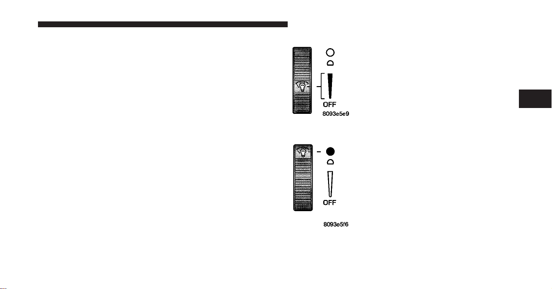
dimmer control in the multifunction lever. This light is
also controlled automatically by the Illuminated Entry
system.
Battery Saver Feature — Interior Lights
To protect the battery, the interior lights will turn off
automatically 15 minutes after the ignition switch is
moved to the OFF/LOCK position. This will occur if the
interior lights were switched on manually or are on
because a door is open or the liftgate is open (Coupe
models). To restore interior light operation, turn the
ignition switch to the ON/RUN position or cycle the
light switch.
Dimmer Control
The dimmer control is part of the multifunction lever. It
controls the operation of the interior lights and the
brightness of the instrument panel lights.
Instrument Panel Dimming
With the parking lights or headlights
on, rotate the dimmer control upward
to increase the brightness of the instru-
ment panel lights or rotate it down-
ward to decrease the brightness of the
instrument panel lights.
Interior Light (ON)
Rotate the dimmer control completely
upward to the second detent to turn
on the interior lights. The interior
lights will remain on when the dim-
mer control is in this position.
3
UNDERSTANDING THE FEATURES OF YOUR VEHICLE 93
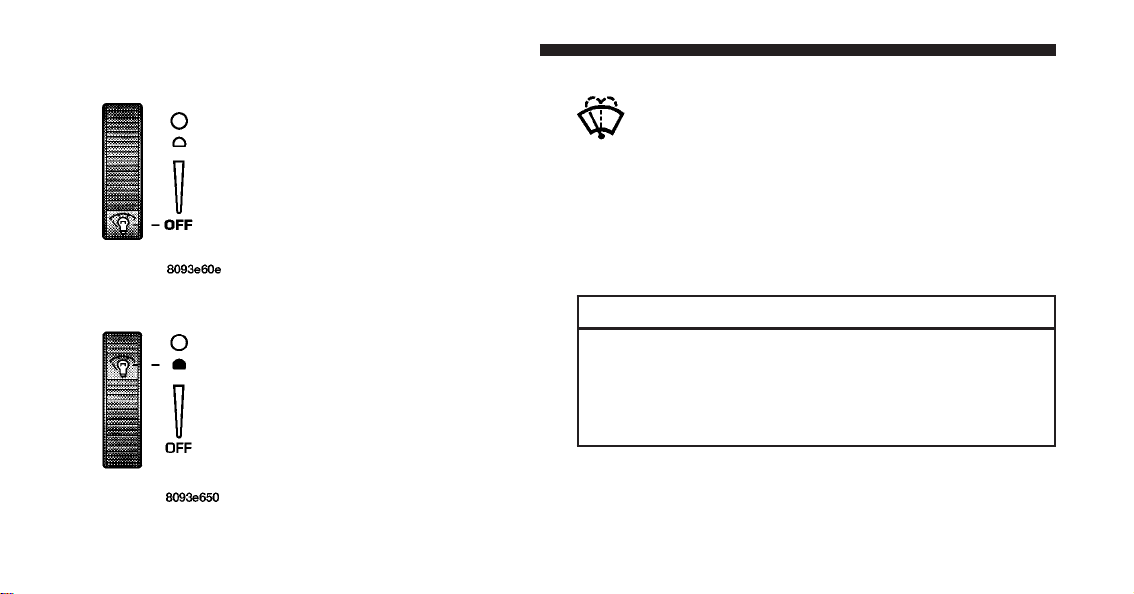
Interior Light Defeat (OFF)
Rotate the dimmer control to the ex-
treme bottom OFF position. The inte-
rior lights will remain off when the
doors are open.
Parade Mode (Daytime Brightness Feature)
Rotate the dimmer control to the first
detent (white semi-circle). This feature
brightens the odometer and radio dis-
play when the parking lights or head-
lights are on during daylight conditions.
WINDSHIELD WIPERS AND WASHERS
The windshield wiper/washer control lever is on
the right side of the steering column.
From the off position, push the windshield wiper/
washer control lever upward to the first detent past the
intermittent DEL setting for low-speed wiper operation,
or to the second detent past the intermittent DEL setting
for high-speed wiper operation.
CAUTION!
Turn the windshield wipers off when driving
through an automatic car wash. Damage to the wind-
shield wipers may result if the wiper switch is left in
any position other than off.
94 UNDERSTANDING THE FEATURES OF YOUR VEHICLE

Intermittent Wiper System
Use the intermittent wiper when weather conditions
make a single wiping cycle with a variable pause be-
tween cycles desirable. From the off position, push the
windshield wiper/washer control lever upward to the
first detent DEL position, and then rotate the end of the
lever to select the desired delay interval. There are seven
delay settings, which allow you to regulate the wipe
interval from a minimum of one cycle every second to a
maximum of approximately 15 seconds between cycles.
Rotating the lever upward decreases the delay time.
3
UNDERSTANDING THE FEATURES OF YOUR VEHICLE 95
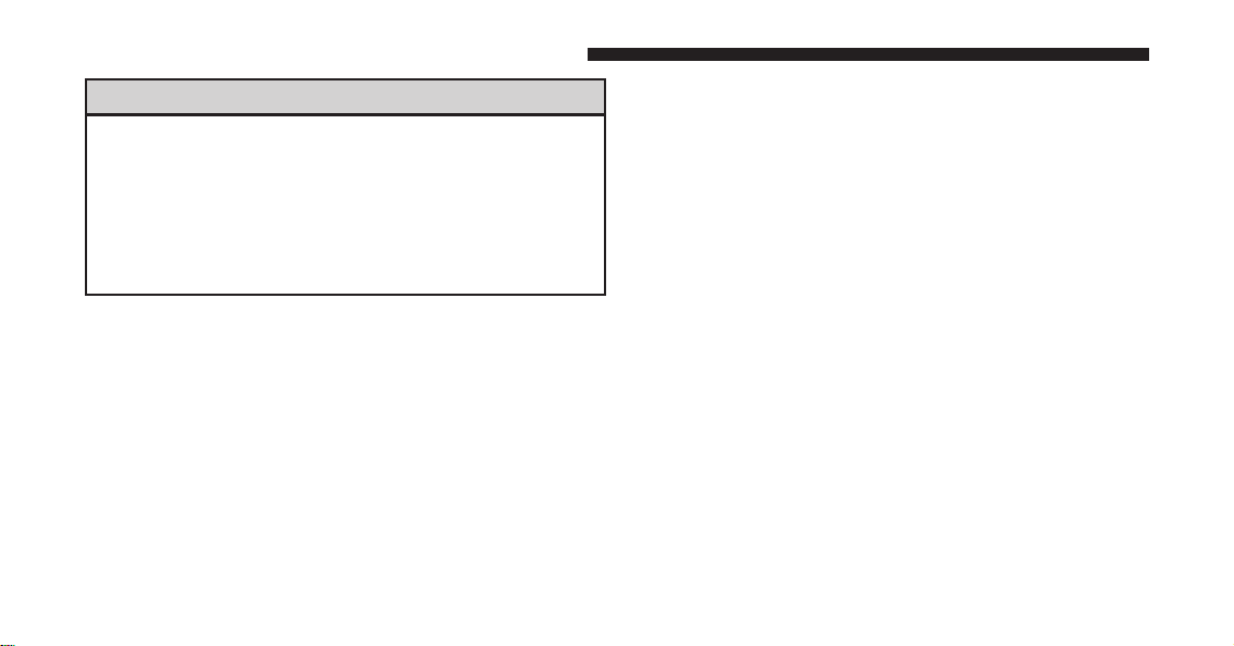
WARNING!
Sudden loss of visibility through the windshield
could lead to an accident. You might not see other
vehicles or other obstacles. To avoid sudden icing of
the windshield during freezing weather, warm the
windshield with defroster before and during wind-
shield washer use.
Mist Feature
From the off position, push the windshield wiper/
washer control lever downward to activate a single wipe
cycle to clear the windshield of road mist or spray from
a passing vehicle. The wipers will continue to operate
until you release the lever.
Windshield Washers
To use the washer, pull the windshield wiper/washer
control lever toward you and hold it for as long as
washer spray is desired.
If you activate the washer while the windshield wiper is
in the delay range, the wipers will operate in low-speed
for two wipe cycles after releasing the lever and then
resume the intermittent interval previously selected.
If you activate the washer while the windshield wiper is
turned off, the wipers will operate for two wipe cycles
and then turn off.
TILT STEERING COLUMN
The tilt release lever is located below the multifunction
lever on the left side of the steering column. To tilt the
column, simply pull the release lever downward and
then move the steering wheel upward or downward as
desired. When the column is in the desired position, push
the release lever upward to lock the column firmly in
place.
96 UNDERSTANDING THE FEATURES OF YOUR VEHICLE

WARNING!
Do not adjust the steering column while driving.
Adjusting the steering column while driving or driv-
ing with the steering column unlocked, could cause
the driver to lose control of the vehicle. Be sure the
steering column is locked before driving your ve-
hicle. Failure to follow this warning may result in
serious injury or death.
ADJUSTABLE PEDALS
The adjustable pedals system is designed to allow a
greater range of driver comfort for steering wheel tilt and
seat position. This feature allows the brake, accelerator,
and clutch pedals (if equipped) to move toward or away
from the driver to provide improved position with the
steering wheel.
Tilt Steering Column Lever
3
UNDERSTANDING THE FEATURES OF YOUR VEHICLE 97
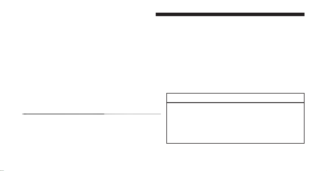
The adjustable pedals switch is recessed into the knee
bolster beneath the steering column.
To adjust the pedals:
1. Adjust the seat and steering column to a comfortable
position.
2. Either press the adjustable pedals switch forward to
move the pedals forward (toward the front of the ve-
hicle), or pull the switch rearward to move the pedals
rearward (toward the rear of the vehicle).
NOTE:
•
Always adjust the pedals to a position that allows full
pedal travel.
•
Further small adjustments may be necessary to find
the best possible seat/pedal position.
CAUTION!
Do not place any article under the adjustable pedals
or impede its ability to move as it may cause damage
to the pedal controls. Pedal travel may become lim-
ited if movement is stopped by an obstruction in the
adjustable pedal’s path.
Adjustable Pedals Switch
98 UNDERSTANDING THE FEATURES OF YOUR VEHICLE
WARNING!
Do not adjust the pedals while the vehicle is moving.
You could lose control and have an accident. Always
adjust the pedals while the vehicle is parked.
Adjustable Foot Rest
This feature allows the driver to adjust the foot rest
forward or backward and to rotate it upward or down-
ward to allow for greater driving comfort.
Adjustable Foot Rest
3
UNDERSTANDING THE FEATURES OF YOUR VEHICLE 99

To adjust the pedal:
1. Adjust the seat and steering column to a comfortable
position.
2. Using a 13 mm socket wrench, loosen the nut on the
pedal.
3. Slide the pedal either forward or backward and rotate
it upward or downward as desired.
4. Tighten the nut, being careful not to over tighten it.
ELECTRICAL POWER OUTLETS
Your vehicle is equipped with 12 Volt (13 Amp) power
outlets that can be used to power cellular phones, small
electronics and other low powered electrical accessories.
One power outlet is located on the top of the floor
console. To access, push downward on the top or the
outlet and release. Push the power outlet downward and
release a second time to store the power outlet back into
the console.
12 Volt Power Outlet
100 UNDERSTANDING THE FEATURES OF YOUR VEHICLE
An additional power outlet is located inside the center
console. Open the lid of the console to access this outlet.
NOTE: Do not exceed the maximum power of 160 Watts
(13 Amps) at 12 Volts. If the 160 Watt (13 Amp) power
rating is exceeded the fuse protecting the system will
need to be replaced.
WARNING!
To avoid serious injury or death:
•
Only devices designed for use in this type of
outlet should be inserted into any 12 Volt outlet.
•
Do not touch with wet hands.
•
Close the lid when not in use and while driving
the vehicle.
•
If this outlet is mishandled, it may cause an
electric shock and failure.
Center Console Power Outlet
3
UNDERSTANDING THE FEATURES OF YOUR VEHICLE 101

CAUTION!
•
Many accessories that can be plugged in draw
power from the vehicle’s battery, even when not in
use (i.e., cellular phones, etc.). Eventually, if
plugged in long enough, the vehicle’s battery will
discharge sufficiently to degrade battery life
and/or prevent the engine from starting.
•
Accessories that draw higher power (i.e., coolers,
vacuum cleaners, lights, etc.) will degrade the
battery even more quickly. Only use these inter-
mittently and with greater caution.
•
After the use of high power draw accessories, or
long periods of the vehicle not being started (with
accessories still plugged in), the vehicle must be
driven a sufficient length of time to allow the
generator to recharge the vehicle’s battery.
CONSOLE FEATURES
The front console has a removable ashtray, power outlet/
cigarette lighter, and power window switches.
The center console compartment is equipped with a
cigarette lighter/power outlet.
Front Console
102 UNDERSTANDING THE FEATURES OF YOUR VEHICLE

STORAGE
A glove box storage compartment is located on the
passenger side of the instrument panel.
Pull outward on the handle/latch to open this compart-
ment.
Glove Box Storage Compartment
Opening Glove Box Storage Compartment
3
UNDERSTANDING THE FEATURES OF YOUR VEHICLE 103
REAR WINDOW FEATURES
Rear Window Defroster
The rear window defroster button is located on the
climate control panel. Press this button to turn on
the rear window defroster and the heated outside mirrors
(if equipped). An indicator in the button will illuminate
when the rear window defroster is on. The rear window
defroster automatically turns off after approximately
10 minutes. For an additional five minutes of operation,
press the button a second time.
NOTE: To prevent excessive battery drain, use the rear
window defroster only when the engine is operating.
CAUTION!
Failure to follow these cautions can cause damage to
the heating elements:
•
Use care when washing the inside of the rear
window. Do not use abrasive window cleaners on
the interior surface of the window. Use a soft cloth
and a mild washing solution, wiping parallel to
the heating elements. Labels can be peeled off
after soaking with warm water.
•
Do not use scrapers, sharp instruments, or abra-
sive window cleaners on the interior surface of the
window.
•
Keep all objects a safe distance from the window.
104 UNDERSTANDING THE FEATURES OF YOUR VEHICLE

UNDERSTANDING YOUR INSTRUMENT PANEL
CONTENTS
䡵 Instrument Panel Features ............... 107
䡵 Instrument Cluster Descriptions ........... 108
▫ Speedometer ....................... 108
▫ Message Center ..................... 109
▫ Gauges And Indicator Lights ............ 116
䡵 Setting The Digital Clock ................ 118
▫ Clock Setting Procedure ............... 119
䡵 Sales Code RAH — AM And FM Stereo Radio
With CD Player And CD/DVD Changer
Controls............................. 119
▫ Radio Operation ..................... 119
▫ CD Player Operation .................. 123
▫ CD/DVD Changer Operation ........... 125
▫ Notes On Playing MP3 Files ............ 125
▫ Operation Instructions -
(CD Mode For MP3 Audio Play) ......... 128
4

䡵 Uconnect™ Multimedia (Satellite Radio) —
If Equipped .......................... 129
▫ System Activation .................... 129
▫ Electronic Serial Number/Sirius
Identification Number (ESN/SID) ......... 130
▫ Selecting Uconnect™ Multimedia (Satellite)
Mode In RBB, RAH, REV And RBK Radios . . 130
▫ Selecting Uconnect™ Multimedia (Satellite)
Mode In RBP, RBU, RAZ, RB1 And RBQ
Radios ............................ 131
▫ Selecting a Channel ................... 131
▫ Storing And Selecting Pre-Set Channels ..... 131
▫ Using The PTY (Program Type) Button
(If Equipped) ....................... 132
▫ PTY (Scan) Button .................... 132
▫ PTY (Seek) Button .................... 132
▫ Satellite Antenna ..................... 132
▫ Reception Quality .................... 133
䡵 Radio Antenna ....................... 133
䡵 CD/DVD Disc Maintenance .............. 133
䡵 Radio Operation And Cellular Phones ....... 134
䡵 Climate Controls ...................... 134
▫ Air Conditioning And Heating System ..... 134
▫ Operating Tips ...................... 137
106 UNDERSTANDING YOUR INSTRUMENT PANEL

INSTRUMENT PANEL FEATURES
1 — Air Outlet 7 — Speedometer/Odometer 13 — Climate Control
2 — Sound System Speaker 8 — Oil Pressure Gauge 14 — ENGINE START Button
3 — Main Message Center 9 — Passenger Airbag Off Light 15 — Voltage Gauge
4 — Fuel Gauge 10 — Passenger Airbag 16 — Engine Coolant Temperature Gauge
5 — Auxiliary Message Center 11 — Glove Compartment 17 — Engine Oil Temperature Gauge
6 — Tachometer 12 — Sound System Controls 18 — TRIP Button
4
UNDERSTANDING YOUR INSTRUMENT PANEL 107

INSTRUMENT CLUSTER DESCRIPTIONS
Speedometer
Shows the vehicle’s speed in miles-
per-hour (mph) and kilometers-per-
hour (km/h).
Odometer/Trip Odometer
The odometer shows the total distance the vehicle has
been driven.
NOTE: U.S. Federal regulations require that upon trans-
fer of vehicle ownership, the seller certify to the pur-
chaser the correct mileage that the vehicle has been
driven. If your odometer needs to be repaired or serviced,
the repair technician should leave the odometer reading
the same as it was before the repair or service. If s/he
cannot do so, then the odometer must be set at zero, and
a sticker must be placed in the door jamb stating what the
mileage was before the repair or service. It is a good idea
for you to make a record of the odometer reading before
the repair/service, so that you can be sure that it is
properly reset, or that the door jamb sticker is accurate if
the odometer must be reset at zero.
The trip odometer shows individual trip mileage. Press
and release the TRIP button once to switch the display
from odometer to trip odometer. Press and release the
TRIP button a second time to return the display to
odometer. While in trip mode, press and hold the TRIP
button for at least one second to reset the trip odometer
to zero.
108 UNDERSTANDING YOUR INSTRUMENT PANEL
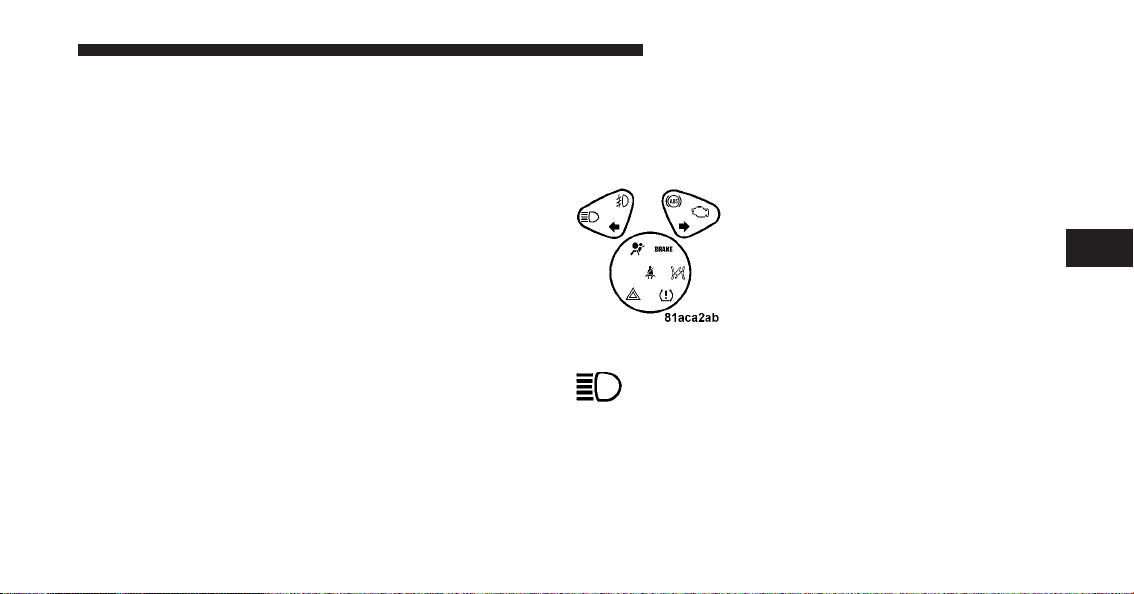
Liquid Crystal Display (LCD) Panel
The LCD panel at the bottom of the speedometer displays
specific messages for given conditions. These messages
are as follows:
•
The words “DOOR AJAR” will display if a door is not
closed completely. In addition, a single chime will
sound if you move the vehicle when a door is not
closed completely.
•
The words “DOOR UNLOCKED” will flash in the
display if one door is unlocked and will remain on
steady if both doors are unlocked.
•
The word “DECK” will flash in the display if the
trunk/liftgate is open.
•
The words “LOW TIRE” will flash slowly in the
display and a chime will sound if the tire pressure is
low.
•
The words “FLAT TIRE” will flash rapidly in the
display and a chime will sound if critically low tire
pressure is detected.
Message Center
When the appropriate conditions ex-
ist, the Message Center displays the
following indicators and warnings:
High Beam Light
This light will turn on when the high beam
headlights are on. Pull the Multifunction Lever on
the left side of the steering column toward you to switch
the headlights from low beam to high beam. Pull the
lever a second time to switch the headlights back to low
beam.
4
UNDERSTANDING YOUR INSTRUMENT PANEL 109
Front Fog Light Indicator
This indicator will illuminate when the front fog
lights are on.
Anti-Lock Brake (ABS) Warning Light
The amber Anti-Lock Brake Warning Light will
turn on and stay on briefly as a bulb check
when the ignition is first turned on. If the light
does not turn on during starting, see your
authorized dealer for service.
This light also illuminates at vehicle start-up to indicate
that the ABS self-check is in process. If the light remains
on after start-up, or turns on and remains on at road
speeds, it may indicate a system malfunction or that the
system is inoperative. In this case, the system reverts to
standard non-anti-lock brakes. If this occurs, safely bring
the vehicle to a complete stop as soon as possible and
cycle the ignition key to attempt to reset the ABS. If the
light remains on, see your authorized dealer immediately
to have the system serviced. Furthermore, if the red
BRAKE Warning Light and the amber ABS Warning
Light are on, and the parking brake is fully released, see
your authorized dealer immediately.
WARNING!
If the ABS and/or Brake Warning Lights illuminate,
please seek service immediately! Your vehicle will
have diminished braking capability and control if
ABS and/or service brake systems are not working
properly. Have your brake system serviced immedi-
ately.
Malfunction Indicator Light (MIL)
The Malfunction Indicator Light (MIL) is part
of an onboard diagnostic system called OBD.
The OBD system monitors engine control sys-
tems. The light will turn on when the key is in
the ON/RUN position before engine start. If the light
110 UNDERSTANDING YOUR INSTRUMENT PANEL
does not come on when turning the key from OFF/LOCK
to ON/RUN, have the condition checked promptly.
Certain conditions such as a loose or missing gas cap,
poor fuel quality, etc., may illuminate the light after
engine start. The vehicle should be serviced if the light
remains on through several of your typical driving
cycles. In most situations, the vehicle will drive normally
and will not require towing.
CAUTION!
Prolonged driving with the MIL on could cause
damage to the engine control system. It also could
affect fuel economy and drivability. If the MIL is
flashing, severe catalytic converter damage and
power loss will soon occur. Immediate service is
required.
WARNING!
A malfunctioning catalytic converter, as referenced
above, can reach higher temperatures than in normal
operating conditions. This can cause a fire if you
drive slowly or park over flammable substances such
as dry plants or wood or cardboard, etc. This could
result in death or serious injury to the driver, occu-
pants or others.
Turn Signal Indicators
The left or right arrow will flash in unison with the
corresponding front and rear turn signals when the
TURN SIGNAL switch is operated.
Hazard Indicators
Both turn signal arrows will flash in unison with the
front and rear turn signals when the HAZARD
WARNING button is operated.
4
UNDERSTANDING YOUR INSTRUMENT PANEL 111
NOTE: Leaving the hazard flashers on for extended
periods will wear down the battery.
Airbag Warning Light
This light will turn on for four to eight seconds
as a bulb check when the ignition switch is first
turned to ON/RUN. If the light is either not on
during starting, stays on, or turns on while
driving, then have the system inspected at an authorized
dealer as soon as possible. Refer to “Occupant Restraints”
in “Things To Know Before Starting Your Vehicle” for
further information.
Brake Warning Light
The red Brake System Warning Light turns on
when the ignition is first turned on. It should
stay on briefly as a bulb check. If the light does not turn
on during starting, have it repaired promptly. If the light
remains on following the bulb check, it may be an
indication that the parking brake is not released. If the
light remains on when the parking brake is released, it
indicates a possible hydraulic brake system malfunction.
In this case, immediate repair is necessary and continued
operation of the vehicle in this condition is dangerous.
NOTE: The light will turn on when the ignition switch
is in the ON/RUN position and the parking brake is
applied. This light shows only that the parking brake is
applied. It does not show the degree of brake application.
WARNING!
Driving a vehicle with the brake light on is danger-
ous. Part of the brake system has failed. It will take
longer to stop the vehicle. You could have an acci-
dent. Have the brakes checked immediately.
112 UNDERSTANDING YOUR INSTRUMENT PANEL

Electronic Throttle Control (ETC) Light
This light will turn on briefly as a bulb check
when turning on the ignition switch. It will also
turn on while the engine is running to warn of
a problem with the Electronic Throttle Control
(ETC) system.
•
If the light fails to turn on during the bulb check, see
your authorized dealer for service.
•
If the light turns on steady while the engine is running,
safely bring the vehicle to a complete stop as soon as
possible, cycle the ignition key, and then restart the
engine. The light should turn off. However, if the light
remains on steady, see your authorized dealer for
service as soon as possible.
•
If the light is flashing when the engine is running,
immediate service is required. If this occurs, you may
experience reduced vehicle performance, an elevated/
rough idle or engine stall, and your vehicle may
require towing.
Low Tire Pressure Telltale / TPMS Malfunction
Indicator
Each tire, including the spare (if provided),
should be checked monthly when cold and
inflated to the inflation pressure recommended
by the vehicle manufacturer on the vehicle
placard or tire inflation pressure label. (If your vehicle
has tires of a different size than the size indicated on the
vehicle placard or tire inflation pressure label, you should
determine the proper tire inflation pressure for those
tires.)
4
UNDERSTANDING YOUR INSTRUMENT PANEL 113

As an added safety feature, your vehicle has been
equipped with a Tire Pressure Monitoring System
(TPMS) that illuminates a low tire pressure telltale when
one or more of your tires is significantly under-inflated.
Accordingly, when the low tire pressure telltale illumi-
nates, you should stop and check your tires as soon as
possible and inflate them to the proper pressure. Driving
on a significantly under-inflated tire causes the tire to
overheat and can lead to tire failure. Under-inflation also
reduces fuel efficiency and tire tread life and may affect
the vehicle’s handling and stopping ability.
Please note that the TPMS is not a substitute for proper
tire maintenance, and it is the driver’s responsibility to
maintain correct tire pressure, even if under-inflation has
not reached the level to trigger illumination of the TPMS
low tire pressure telltale.
Your vehicle has also been equipped with a TPMS
malfunction indicator to indicate when the system is not
operating properly. The TPMS malfunction indicator is
combined with the low tire pressure telltale.
When the system detects a malfunction, the telltale will
flash for approximately one minute and then remain
continuously illuminated. This sequence will continue
upon subsequent vehicle start-ups as long as the mal-
function exists. When the malfunction indicator is illumi-
nated, the system may not be able to detect or signal low
tire pressure as intended.
TPMS malfunctions may occur for a variety of reasons,
including the installation of replacement or alternate tires
or wheels on the vehicle that prevent the TPMS from
functioning properly. Always check the TPMS malfunc-
tion telltale after replacing one or more tires or wheels on
your vehicle to ensure that the replacement or alternate
tires and wheels allow the TPMS to continue to function
properly.
114 UNDERSTANDING YOUR INSTRUMENT PANEL
CAUTION!
The Tire Pressure Monitor System (TPMS) has been
optimized for the original equipment tires and
wheels. The TPMS pressures have been established
for the tire size equipped on your vehicle. Undesir-
able operation or sensor damage may result when
using replacement equipment that is not of the same
size, type, and/or style. Aftermarket wheels can cause
sensor damage. Do not use aftermarket tire sealants
or balance beads if your vehicle is equipped with the
TPMS, as damage to the sensors may result.
WARNING!
Do not exceed 55 mph (88 km/h) if the LOW Tire
indicator is activated. Vehicle handling and braking
may be reduced. You could have an accident and be
severely or fatally injured.
Seat Belt Reminder Light
If the driver does not buckle their seat belt and
vehicle speed exceeds 5 mph (8 km/h), or if the
passenger does not buckle their seat belt within
10 seconds of vehicle speed exceeding 5 mph (8 km/h),
the Enhanced Seat Belt Use Reminder System
(BeltAlert威) will alert the occupant(s) to buckle their seat
belt(s). Once triggered, the BeltAlert威 will flash the Seat
Belt Reminder Light and chime for up to 96 seconds to
alert the occupant(s) to buckle their seat belt(s). If the
driver unbuckles their seat belt while vehicle speed is
greater than 5 mph (8 km/h), or if the passenger unbuck-
les their seat belt for more than 10 seconds while vehicle
speed is greater than 5 mph (8 km/h), the BeltAlert威 will
reactivate.
4
UNDERSTANDING YOUR INSTRUMENT PANEL 115
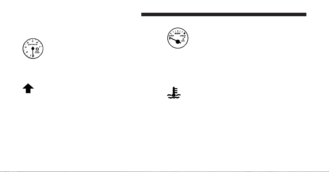
Gauges and Indicator Lights
Tachometer
This gauge shows engine speed in revolutions-
per-minute (RPM) times 1,000. Avoid excessive
engine speeds in any part of the red warning
zone, particularly when driving downhill or in
lower gears.
Skip Shift Indicator Light
This indicator is located in the Tachometer. When
the indicator light turns amber, it means that you
are being prevented from shifting the transmission from
First to Second or to Third gear. When the indicator light
turns red, it means that the tachometer gauge pointer is at
6000 RPM. This serves as a visual aid to shift before
reaching the red line. This warning will turn off when the
tachometer pointer falls below 5900 RPM.
Coolant Temperature Gauge
This gauge shows the engine coolant tempera-
ture. The gauge pointer will likely show higher
temperatures when driving in hot weather, up
mountain grades, or in heavy stop and go
traffic. If the red Warning Light turns on while driving,
safely bring the vehicle to a stop, and turn off the engine.
DO NOT operate the vehicle until the cause is corrected.
Engine Temperature Warning Light
The red Engine Temperature Warning Light is
located in the Coolant Temperature Gauge. It will
turn on to warn of an overheated engine condi-
tion. If this light turns on while driving, safely bring the
vehicle to a stop and turn off the engine. DO NOT
operate the vehicle until the cause is corrected.
116 UNDERSTANDING YOUR INSTRUMENT PANEL

Oil Temperature Gauge
This gauge shows the oil temperature. The
gauge pointer will likely show higher tempera-
tures when driving in hot weather, up moun-
tain grades, or in heavy stop and go traffic. If
the red Warning Light remains on after the bulb check or
turns on while driving, safely bring the vehicle to a
complete stop and turn off the engine. DO NOT operate
the vehicle until the cause is corrected.
Oil Pressure Gauge
This gauge shows engine oil pressure when the
engine is running. The pressure will vary with
engine speed, oil viscosity, and engine tem-
perature. Oil pressures will be higher as the
engine is warming up. The normal operating pressure is
between 20 and 80 psi (pounds per square inch). If the
pointer remains in the red range, safely bring the vehicle
to a complete stop and turn off the engine. DO NOT
operate the vehicle until the cause is corrected.
This gauge does not indicate the amount of oil in the
engine. The engine oil level must be checked under the
hood. Check the level often during severe usage.
Oil Pressure Warning Light
The red Oil Pressure Warning Light is located in
the Oil Pressure Gauge. It will turn on to indicate
low engine oil pressure. The light should turn on briefly
as a bulb check when the engine is first started. If the
light remains on or turns on while driving, safely bring
the vehicle to a complete stop and turn off the engine. DO
NOT operate the vehicle until the cause is corrected.
NOTE: This light does not indicate how much oil is in
the engine. The engine oil level must be checked using
the procedure shown in “Maintaining Your Vehicle”.
4
UNDERSTANDING YOUR INSTRUMENT PANEL 117
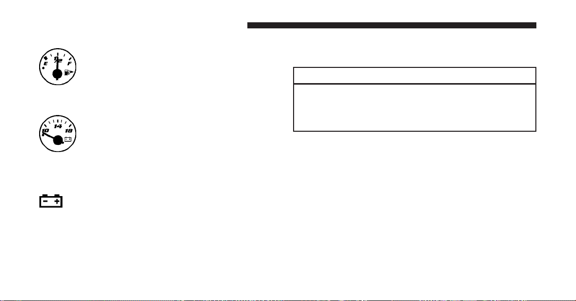
Fuel Gauge
This gauge shows the amount of fuel in the gas
tank. The reaction time of the gauge has been
slowed to avoid needle fluctuation during pe-
riods of high G force cornering.
Voltage Gauge
This gauge shows the electrical system voltage.
The normal operating voltage is from 12 to
14 Volts with the engine running. If the pointer
remains at either the high or low ends of the
scale, the electrical system should be serviced.
Charge System Light
The red Charge System Light is located in the
Voltage Gauge. It will turn on when there is a
charging system malfunction or a possible accessory
drive belt failure.
If jump starting is required, refer to “Jump Starting
Procedures” in “What To Do In Emergencies”.
CAUTION!
The accessory belt also drives the water pump. Op-
erating the vehicle with a failed belt can cause engine
overheating and possible severe engine damage.
SETTING THE DIGITAL CLOCK
The digital display panel on the radio displays the time in
hours and minutes. The display panel is operative when
the ignition switch is in the ON/RUN or ACC position.
Press and release the TIME button on the radio to display
the time. Press and release the button a second time to
turn off the time display.
118 UNDERSTANDING YOUR INSTRUMENT PANEL
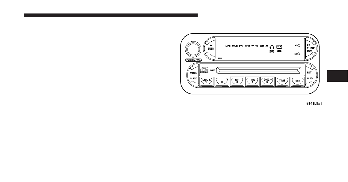
Clock Setting Procedure
1. Turn the ignition switch to the ON/RUN or ACC
position.
2. Using the point of a ballpoint pen or similar object,
press either the H (HOUR) or M (MINUTE) button on the
radio. The display will show the time.
3. Press the “H” button to set hours or the “M” button to
set minutes. The time setting will increase each time you
press a button.
SALES CODE RAH — AM AND FM STEREO
RADIO WITH CD PLAYER AND CD/DVD
CHANGER CONTROLS
NOTE: The radio sales code is located on the lower left
side of your radio faceplate.
Radio Operation
Power/Volume Control
Push the ON/VOL control to turn the radio on. Turn the
volume control clockwise to increase the volume.
RAH Radio
4
UNDERSTANDING YOUR INSTRUMENT PANEL 119

NOTE: Power to operate the radio is supplied through
the ignition switch. It must be in the ON or ACC position
to operate the radio.
PTY (Program Type)
Pressing the INFO button once while in FM mode will
turn on the PTY mode for five seconds. If no action is
taken during the five second time out, the PTY icon will
turn off. Pressing the TUNE button within five seconds
will allow the program format type to be selected. Many
radio stations do not currently broadcast PTY informa-
tion.
Toggle the TUNE button to select the following format
types:
Program Type Radio Display
Adult Hits Adult Hit
Classical Classical
Classic Rock Classic Rock
Program Type Radio Display
College College
Country Country
Information Inform
Jazz Jazz
Foreign Language Language
News News
Nostalgia Nostalgia
Oldies Oldies
Personality Personality
Public Public
Rhythm and Blues R & B
Religious Music Religious Music
Religious Talk Religious Talk
Rock Rock
Soft Soft
Soft Rock Soft Rock
120 UNDERSTANDING YOUR INSTRUMENT PANEL

Program Type Radio Display
Soft Rhythm and Blues Soft R&B
Sports Sports
Talk Talk
Top 40 Top 40
Weather Weather
By pressing the SEEK button when the PTY icon is
displayed, the radio will be tuned to the next frequency
station with the same selected PTY name. The PTY
function only operates when in the FM and Satellite (if
equipped) modes.
The radio display will flash “SEEK” and the selected PTY
program type when searching for the next PTY station. If
no station is found with the selected PTY program type,
the radio will return to the last preset station.
If a preset button is activated while in the PTY (Program
Type) mode, the PTY mode will be exited and the radio
will tune to the preset station.
Mode
Press the MODE button to select between, AM, FM, CD,
CD/DVD changer or the Satellite Radio (if equipped).
When the Satellite Radio (if equipped) is selected, “SA”
will appear in your radio display.
A disc may remain in the radio while in the Satellite or
radio mode.
Seek
Press and release the SEEK button to search for the next
station in either the AM, FM or Satellite mode. Press the
top of the button to seek up and the bottom to seek down.
The radio will remain tuned to the new station until you
make another selection. Holding the button in will by-
pass stations without stopping until you release it.
4
UNDERSTANDING YOUR INSTRUMENT PANEL 121

Tuning
Press the TUNE control up or down to increase or
decrease the frequency. If you press and hold the button,
the radio will continue to tune until you release the
button. The frequency will be displayed and continu-
ously updated while the button is pressed.
Balance
The Balance control adjusts the left-to-right speaker bal-
ance. Press the AUDIO button, select BALANCE, then
press SEEK + or SEEK ⫺ to adjust the balance.
Fade
The Fade control provides for balance between the front
and rear speakers. Press the AUDIO button, select FADE,
then press SEEK + or SEEK ⫺ to adjust the fade balance.
Tone Control
The Bass and/or Treble controls sound for the desired
tone. Press the AUDIO button, select Bass or TREBLE,
then press SEEK + or SEEK ⫺ to increase or decrease
amplification of the band.
To Set the Radio Pushbutton Memory
When you are receiving a station that you wish to
commit to pushbutton memory, press the SET button.
SET 1 will show in the display window. Select the
pushbutton you wish to lock onto this station and press
and release that button. If a station is not selected within
five seconds after pressing the SET button, the station
will continue to play but will not be locked into push-
button memory.
You may add a second station to each pushbutton by
repeating the above procedure with this exception: Press
the SET button twice and SET 2 will show in the display
window. Each button can be set for SET 1 and SET 2 in
122 UNDERSTANDING YOUR INSTRUMENT PANEL

both AM and FM. This allows a total of 10 AM and 10 FM
stations to be locked into memory. You can recall the
stations stored in SET 2 memory by pressing the push-
button twice.
To Change from Clock to Radio Mode
Press the TIME button to change the display between
radio frequency and time.
General Information
This radio complies with Part 15 of FCC rules and with
RSS-210 of Industry Canada. Operation is subject to the
following conditions:
1. This device may not cause harmful interference.
2.
This device must accept any interference received, in-
cluding interference that may cause undesired operation.
NOTE: Changes or modifications not expressively ap-
proved by the party responsible for compliance could
void the user’s authority to operate the equipment.
CD Player Operation
NOTE:
•
The ignition switch must be in the ON or ACC
position and the volume control ON before the CD
player will operate.
•
This Radio is capable of playing compact discs (CD),
recordable compact discs (CD-R), rewritable compact
discs (CD-RW), compact discs with MP3 tracks, and
multisession compact discs with CD and MP3 tracks.
Inserting The Compact Disc
CAUTION!
This CD player will accept only 4–3/4 in (12 cm) discs
only. The use of other sized discs may damage the
CD player mechanism.
You may either insert or eject a disc with the radio OFF.
4
UNDERSTANDING YOUR INSTRUMENT PANEL 123

If you insert a disc with the ignition ON and the radio
OFF, the display will show the time of day. If you insert
a disc with the ignition OFF, the display will show the
time of day for about five seconds, then go out.
If the power is ON, the unit will switch from radio to CD
mode and begin to play when you insert the disc. The
display will show the track number and index time in
minutes and seconds. Play will begin at the start of track
one.
Seek
Press the top of the SEEK button for the next selection on
the CD. Press the bottom of the button to return to the
beginning of the current selection, or return to the
beginning of the previous selection if the CD is within the
first 10 seconds of the current selection.
EJT — Eject
Press the EJT button and the disc will unload and move
to the entrance for easy removal. The unit will switch to
the radio mode.
If you do not remove the disc within 15 seconds, it will be
reloaded. The radio mode will continue to appear.
The disc can be ejected with the radio off.
FF/TUNE/RW
Press FF (Fast Forward) and the CD player will begin to
fast forward until FF is released. The RW (Rewind)
button works in a similar manner.
RND — Random Play
Press the RND button while the CD is playing to activate
Random Play. This feature plays the selections on the
compact disc in random order to provide an interesting
change of pace.
124 UNDERSTANDING YOUR INSTRUMENT PANEL

Press the SEEK button to move to the next randomly
selected track.
Press TUNE FF to fast forward through the tracks. Press
the FF button a second time to stop the fast forward
feature. If TUNE RW is pressed, the current track will
reverse to the beginning of the track and begin playing.
Press the RND button a second time to stop Random
Play.
CD/DVD Changer Operation
Press the MODE button to select between the CD player
and the optional remote CD/DVD changer.
Time
Press the TIME button to change the display from
elapsed CD or DVD playing time to time of day.
Notes On Playing MP3 Files
The radio can play MP3 files, however, acceptable MP3
file recording media and formats are limited. When
writing MP3 files, pay attention to the following restric-
tions.
Supported Media (Disc Types)
The MP3 file recording media supported by the radio are
CD-ROM, CD-R and CD-RW.
Supported Medium Formats (File Systems)
The medium formats supported by the radio are ISO 9660
Level 1 and Level 2 and includes the Joliet extension.
When reading discs recorded using formats other than
ISO 9660 Level 1 and Level 2, the radio may fail to read
files properly and may be unable to play the file nor-
mally. UDF and Apple HFS formats are not supported.
The radio uses the following limits for file systems:
•
Maximum number of directory levels: 15
4
UNDERSTANDING YOUR INSTRUMENT PANEL 125

•
Maximum number of files: 255
•
Maximum number of folders: 100
•
Maximum number of characters in file/folder names:
•
Level 1: 12 (including a separator ⬙.⬙ and a
3-character extension)
•
Level 2: 31 (including a separator ⬙.⬙ anda3-
character extension)
Multisession disc formats are supported by the radio.
Multisession discs may contain combinations of normal
CD audio tracks and computer files (including MP3 files).
Discs created with an option such as ⬙keep disc open after
writing⬙ are most likely multisession discs. The use of
multisession for CD audio or MP3 playback may result in
longer disc loading times.
Supported MP3 File Formats
The radio will recognize only files with the *.mp3 exten-
sion as MP3 files. Non-MP3 files named with the *.mp3
extension may cause playback problems. The radio is
designed to recognize the file as an invalid MP3 and will
not play the file.
When using the MP3 encoder to compress audio data to
an MP3 file, the bit rate and sampling frequencies in the
following table are supported. In addition, variable bit
rates (VBR) are also supported. The majority of MP3 files
use a 44.1 kHz sampling rate and a 192, 160, 128, 96 or
VBR bit rates.
126 UNDERSTANDING YOUR INSTRUMENT PANEL

MPEG
Specification
Sampling Fre-
quency (kHz)
Bit rate (kbps)
MPEG-1 Audio
Layer 3
48, 44.1, 32
320, 256, 224, 192,
160, 128, 112, 96,
80, 64, 56, 48, 40,
32
MPEG-2 Audio
Layer 3
24, 22.05, 16
160, 128, 144, 112,
96, 80, 64, 56, 48,
40, 32, 24, 16, 8
ID3 Tag information for artist, song title and album title
are supported for version 1 ID3 tags. ID3 version 2 is not
supported by the radios.
Playlist files are not supported. MP3 Pro files are not
supported.
Playback of MP3 files
When a medium containing MP3 data is loaded, the
radio checks all files on the medium. If the medium
contains a lot of folders or files, the radio will take more
time to start playing the MP3 files.
Loading times for playback of MP3 files may be affected
by the following:
•
Media - CD-RW media may take longer to load than
CD-R media
•
Medium formats - Multisession discs may take longer
to load than non-multisession discs
•
Number of files and folders - Loading times will
increase with more files and folders
To increase the speed of disc loading, it is recommended
to use CD-R media and single-session discs. To create a
single-session disc, enable the Disc at Once option before
writing to the disc.
4
UNDERSTANDING YOUR INSTRUMENT PANEL 127

Operation Instructions -
(CD Mode For MP3 Audio Play)
SEEK Button (CD Mode For MP3 Play)
Pressing the SEEK + button plays the next MP3 File.
Pressing the SEEK ⫺ button plays the beginning of the
MP3 file. Pressing the button within the first ten seconds
plays the previous file.
INFO Button (CD Mode for MP3 Play)
Press the INFO button while playing MP3 disc, and the
radio will scroll through the following TAG information:
Song Title, Artist, File Name, and Folder Name (if avail-
able).
Press the INFO button once more to return to ⬙elapsed
time⬙ priority mode.
RW/FF (CD Mode for MP3 Play)
Press the FF side of the button to move forward through
the MP3 selection. Press the RW side of the button to
move back through the MP3 selection.
AM/FM Button (CD Mode for MP3 Play)
Switches the Radio into the AM or FM Radio mode.
RND Button (CD Mode for MP3 Play)
Pressing this button plays files randomly.
DIR Button (CD Mode for MP3 Play)
Press the DIR Button to display folders, when playing an
MP3 discs that have a file/folder structure. Press DISC
up (button 1) or DISC down (button 5) to move through
the folders. Press the SET button to select a folder.
Operating Instructions - Uconnect™ Phone
(If Equipped)
Refer to Uconnect™ Phone section of the Owner’s
Manual.
128 UNDERSTANDING YOUR INSTRUMENT PANEL

Operating Instructions - Uconnect™ Multimedia
(Satellite Radio) Mode — (If Equipped)
Refer to the Uconnect™ Multimedia (Satellite Radio)
section of the Owner’s Manual.
Operating Instructions - Video Entertainment
System (VES)™ (If Equipped)
Refer to “Video Entertainment System (VES)™” in the
Uconnect™ User Manual located on the DVD for further
details.
Uconnect™ Multimedia (SATELLITE RADIO) —
IF EQUIPPED
Satellite radio uses direct satellite to receiver broadcast-
ing technology to provide clear digital sound, coast to
coast. The subscription service provider is Sirius Satellite
Radio. This service offers up to 100 channels of music,
sports, news, entertainment, and programming for chil-
dren, directly from its satellites and broadcasting studios.
System Activation
Sirius Satellite Radio service is pre-activated, and you
may begin listening immediately to the one year of
SIRIUS audio service that is included with the factory-
installed satellite radio system in your vehicle. Sirius will
supply a welcome kit that contains general information,
including how to setup your on-line listening account.
For further information, call the toll-free number 888-539-
7474, or visit the Sirius web site at www.sirius.com, or at
www.siriuscanada.ca for Canadian residents. Please have
the following information available when changing your
subscription:
1. The Electronic Serial Number/Sirius Identification
Number (ESN/SID).
2. Your Vehicle Identification Number (VIN).
4
UNDERSTANDING YOUR INSTRUMENT PANEL 129

Electronic Serial Number/Sirius Identification
Number (ESN/SID)
The Electronic Serial Number/Sirius Identification Num-
ber is needed to activate your Sirius Satellite Radio
system. To access the ESN/SID, refer to the following
steps:
ESN/SID Access with RBB, RAH, REV and RBK
Radios
With the ignition switch in the ACCESSORY position and
the radio OFF, press the Tape Eject or CD “EJT” button
(depending on the radio type) and TIME buttons simul-
taneously for three seconds. The first four digits of the
twelve-digit ESN/SID number will be displayed. Press
the SEEK UP (+) button to display the next four digits.
Continue to press the SEEK UP (+) button until all twelve
ESN/SID digits have been displayed. The SEEK DOWN
(-) will page down until the first four digits are displayed.
The radio will exit the ESN/SID mode when any other
button is pushed, the ignition is turned OFF, or five
minutes has passed since any button was pushed.
ESN/SID Access with RBP, RBU, RAZ, RB1 and
RBQ Radios
With the ignition switch in the ACCESSORY position and
the radio OFF, press the CD Eject and TIME buttons
simultaneously for three seconds. All twelve ESN/SID
numbers will be displayed. The radio will exit the
ESN/SID mode when any other button is pushed, the
ignition is turned OFF, or five minutes has passed since
any button was pushed.
Selecting Uconnect™ Multimedia (Satellite) Mode
in RBB, RAH, REV and RBK Radios
Press the MODE button repeatedly until ⬙SA⬙ appears in
the display. A CD or tape may remain in the radio while
in the Satellite radio mode.
130 UNDERSTANDING YOUR INSTRUMENT PANEL

Selecting Uconnect™ Multimedia (Satellite) Mode
in RBP, RBU, RAZ, RB1 and RBQ Radios
Press the MODE button repeatedly until the word
⬙SIRIUS⬙ appears in the display. These radios will also
display the following:
•
After three seconds, the current channel name and
channel number will be displayed for five seconds.
•
The current program type and channel number will
then be displayed for five seconds.
•
The current channel number will then be displayed
until an action occurs.
A CD or tape may remain in the radio while in the
Satellite radio mode.
Selecting a Channel
Press and release the SEEK or TUNE buttons to search for
the next channel. Press the top of the button to search up
and the bottom of the button to search down. Holding the
TUNE button causes the radio to bypass channels until
the button is released.
Press and release the SCAN button (if equipped) to
automatically change channels every seven seconds. The
radio will pause on each channel for seven seconds
before moving on to the next channel. The word ⬙SCAN⬙
will appear in the display between each channel change.
Press the SCAN button a second time to stop the search.
NOTE: Channels that may contain objectionable content
can be blocked. Contact Sirius Customer Care at 888-539-
7474 to discuss options for channel blocking or unblock-
ing. Please have your ESN/SID information available.
Storing and Selecting Pre-Set Channels
In addition to the 10 AM and 10 FM pre-set stations, you
may also commit 10 satellite stations to pushbutton
memory. These satellite channel pre-set stations will not
4
UNDERSTANDING YOUR INSTRUMENT PANEL 131

erase any AM or FM pre-set memory stations. Follow the
memory pre-set procedures that apply to your radio.
Using the PTY (Program Type) Button
(If Equipped)
Follow the PTY button instructions that apply to your
radio.
PTY (SCAN) Button
When the desired program type is obtained, press the
SCAN button within five seconds. The radio will play
seven seconds of the selected channel before moving to
the next channel of the selected program type. Press the
SCAN button a second time to stop the search.
NOTE: Pressing the SEEK or SCAN button while per-
forming a music-type scan will change the channel by
one and stop the search. Pressing a pre-set MEMORY
button during a music-type scan, will call up the memory
channel and stop the search.
PTY (SEEK) Button
When the desired program is obtained, press the SEEK
button within five seconds. The channel will change to
the next channel that matches the program type selected.
Satellite Antenna
To ensure optimum reception, do not place items on the
roof around the rooftop antenna location or strap items to
the trunk lid around the trunk lid antenna (if equipped).
Metal objects placed within the line of sight of the
antenna will cause decreased performance. Larger lug-
gage items such as bikes should be placed as far rearward
as possible, within the loading design of the rack. Do not
place items directly on or above the antenna.
132 UNDERSTANDING YOUR INSTRUMENT PANEL

Reception Quality
Satellite reception may be interrupted due to one of the
following reasons.
•
The vehicle is parked in an underground parking
structure or under a physical obstacle.
•
Dense tree coverage may interrupt reception in the
form of short audio mutes.
•
Driving under wide bridges or along tall buildings can
cause intermittent reception.
•
Placing objects over or too close to the antenna can
cause signal blockage.
RADIO ANTENNA
The radio antenna is located in the windshield.
CD/DVD DISC MAINTENANCE
To keep a CD/DVD in good condition, take the following
precautions:
1. Handle the disc by its edge; avoid touching the
surface.
2. If the disc is stained, clean the surface with a soft cloth,
wiping from center to edge.
3. Do not apply paper or tape to the disc; avoid scratch-
ing the disc.
4. Do not use solvents such as benzene, thinner, cleaners,
or anti-static sprays.
5. Store the disc in its case after playing.
6. Do not expose the disc to direct sunlight.
7. Do not store the disc where temperatures may become
too high.
4
UNDERSTANDING YOUR INSTRUMENT PANEL 133

NOTE: If you experience difficulty in playing a particu-
lar disc, it may be damaged (i.e., scratched, reflective
coating removed, a hair, moisture or dew on the disc)
oversized, or have protection encoding. Try a known
good disc before considering disc player service.
RADIO OPERATION AND CELLULAR PHONES
Under certain conditions, the cellular phone being on in
your vehicle can cause erratic or noisy performance from
your radio. This condition may be lessened or eliminated
by relocating the cellular phone antenna. This condition
is not harmful to the radio. If your radio performance
does not satisfactorily “clear” by the repositioning of the
antenna, it is recommended that the radio volume be
turned down or off during cellular phone operation.
CLIMATE CONTROLS
The Air Conditioning and Heating System is designed to
make you comfortable in all types of weather.
Air Conditioning and Heating System
Air Conditioning And Heater Controls
134 UNDERSTANDING YOUR INSTRUMENT PANEL
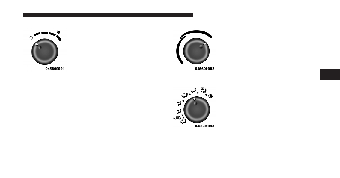
Blower Control
Use this control to regulate the
amount of air forced through the sys-
tem in any mode you select. Turn the
control clockwise to increase fan
speed. Turn the control to the O (Off)
position to shut off the fan and to
prevent any outside air from entering
the vehicle. This also turns off the A/C compressor.
NOTE: For vehicles equipped with Remote Start, the
climate controls will not function during Remote Start
operation if the blower control is left in the “O” (Off)
position.
Temperature Control
Use this control to regulate the tem-
perature of the air inside the passenger
compartment. The blue area of the
control indicates cooler temperatures
while the red area indicates warmer
temperatures.
Mode Control
Use this control to select the direction
of air flow.
NOTE: The dot between the mode control icons is a mix
position between the two modes.
4
UNDERSTANDING YOUR INSTRUMENT PANEL 135
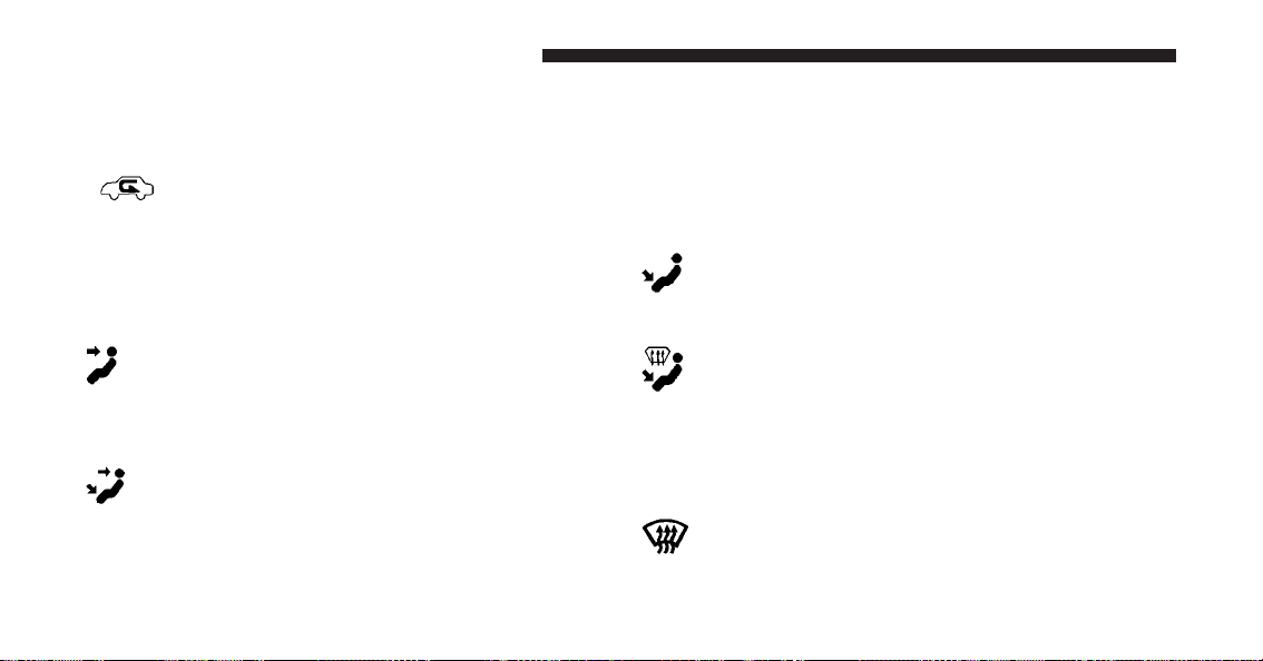
The mode settings are as follows:
•
Recirculation Control
Air is recirculated inside the vehicle. You may
choose between Bi-Level and Panel air outlets
while in this mode. Use this mode to tempo-
rarily block out any outside odors, smoke, or
dust and to cool the interior rapidly upon initial start up
in very hot or humid weather.
•
Panel
Air is directed through the outlets in the instrument
panel. These outlets can be adjusted to direct air
flow.
•
Bi-Level
Air is directed through the instrument panel and
floor outlets. A small amount of air is also directed
through the defrost outlets.
NOTE: There is a varying temperature differential be-
tween the upper and lower outlets for added comfort.
The warmer air goes to the floor outlets. This feature
provides improved comfort during sunny but cool con-
ditions.
•
Floor
Air is directed through the floor outlets with a
lesser amount through the defrost outlets.
•
Defrost/Floor
Air is directed through the windshield defrost and
the floor outlets. This setting works best in cold or
snowy conditions that require extra heat at the
windshield. This setting is good for maintaining comfort
while reducing moisture on the windshield.
•
Defrost
Air is directed through the windshield defrost
outlet. Use this mode with maximum fan and
temperature settings for best windshield defrosting.
136 UNDERSTANDING YOUR INSTRUMENT PANEL

NOTE: The air conditioning compressor operates in this
mode. This dehumidifies the air to help dry the wind-
shield. To improve fuel economy, leave in the Defrost
mode only when necessary.
Air Conditioning Control
With the fan control in the ON position, push the
A/C button to turn on the air conditioning com-
pressor. An indicator light above the button shows
that the Air Conditioning compressor is on. Conditioned
air is now directed through the outlets selected. Pushing
the button a second time turns the compressor OFF.
Slight changes in engine speed or power may be noticed
when the compressor is on. This is a normal occurrence
since the compressor will cycle on and off to maintain
comfort and increase fuel economy.
NOTE: If your air conditioning performance seems
lower than expected, check the front of the A/C con-
denser for an accumulation of dirt or insects.
Operating Tips
NOTE: Refer to the chart at the end of this section for
suggested control settings for various weather condi-
tions.
Summer Operation
The engine cooling system in air-conditioned vehicles
must be protected with a high-quality antifreeze coolant
to provide proper corrosion protection and to protect
against engine overheating. A solution of 50% ethylene
glycol antifreeze coolant and 50% water is recommended.
Refer to “Maintenance Procedures” in “Maintaining Your
Vehicle” for proper coolant selection.
Winter Operation
•
Use the Defrost mode to direct cold air away from the
occupants during engine warm-up in cold weather.
4
UNDERSTANDING YOUR INSTRUMENT PANEL 137

•
The blower air will heat faster in cold weather if you
use only the low blower speeds for the first ten
minutes of vehicle operation.
•
Use of the air Recirculation mode during winter
months is not recommended because it may cause
window fogging.
Vacation Storage
Anytime you store your vehicle, or keep it out of service
(i.e., vacation) for two weeks or more, run the air
conditioning system at idle for about five minutes in the
fresh air and high blower setting. This will ensure
adequate system lubrication to minimize the possibility
of compressor damage when the system is started again.
Window Fogging
Interior fogging on the windshield can be quickly re-
moved by turning the mode selector to Defrost. The
Defrost/Floor mode can be used to maintain a clear
windshield and provide sufficient heating. If side win-
dow fogging becomes a problem increase blower speed.
Vehicle windows tend to fog on the inside in mild but
rainy or humid weather.
Outside Air Intake
When operating the system, particularly during the win-
ter months, make sure the air intake, at the right side of
the hood, is free of ice, slush, snow, or other obstructions
such as leaves. Leaves collected in the air-intake plenum
may reduce airflow and plug the plenum water drains.
138 UNDERSTANDING YOUR INSTRUMENT PANEL
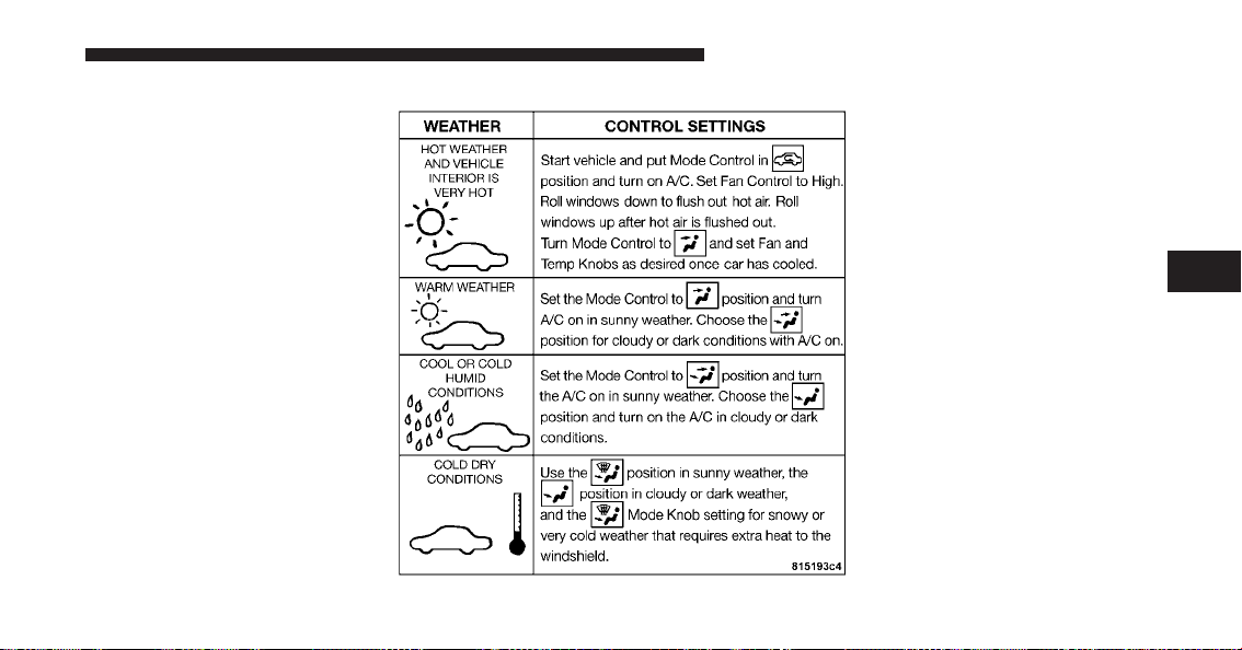
Control Setting Suggestions for Various Weather Conditions
4
UNDERSTANDING YOUR INSTRUMENT PANEL 139


STARTING AND OPERATING
CONTENTS
䡵 Starting Procedures .................... 144
▫ Normal Starting ..................... 144
▫ If Engine Fails To Start ................ 146
▫ After Starting ....................... 147
䡵 Manual Transmission ................... 147
▫ Recommended Shift Speeds ............. 149
▫ Skip Shift Indicator Light ............... 150
䡵 Driving On Slippery Surfaces ............. 151
▫ Acceleration ........................ 151
▫ Traction ........................... 151
䡵 Driving Through Water ................. 151
▫ Flowing/Rising Water ................. 152
▫ Shallow Standing Water ............... 152
䡵 Power Steering ....................... 154
▫ Power Steering Fluid Check ............. 154
䡵 Parking Brake ........................ 155
䡵 Brake System ........................ 157
▫ Brake Pad Break-In ................... 157
5

▫ Anti-Lock Brake System ............... 158
䡵 Tire Safety Information ................. 161
▫ Tire Markings ....................... 161
▫ Tire Identification Number (TIN) ......... 165
▫ Tire Terminology And Definitions ......... 166
▫ Tire Loading And Tire Pressure .......... 167
䡵 Tires — General Information ............. 171
▫ Tire Pressure ....................... 171
▫ Tire Inflation Pressures ................ 172
▫ Tire Pressures For High Speed Operation . . . 174
▫ Radial Ply Tires ..................... 174
▫ Tire Spinning ....................... 174
▫ Tread Wear Indicators ................. 175
▫ Life Of Tire ........................ 176
▫ Replacement Tires .................... 176
▫ Tire Storage ........................ 177
䡵 Snow Tires .......................... 178
䡵 Tire Rotation Recommendations ........... 178
䡵 Tire Pressure Monitor System (TPMS) ....... 179
▫ Low Tire Indicator ................... 179
䡵 Fuel Requirements ..................... 181
▫ 8.4L Engine ........................ 181
▫ Reformulated Gasoline ................ 181
▫ Gasoline/Oxygenate Blends ............. 182
▫ E-85 Usage In Non-Flex Fuel Vehicles ...... 182
▫ MMT In Gasoline .................... 183
142 STARTING AND OPERATING

▫ Materials Added To Fuel ............... 183
▫ Fuel System Cautions ................. 184
▫ Carbon Monoxide Warnings ............ 185
䡵 Adding Fuel ......................... 185
▫ Fuel Filler Cap (Gas Cap) .............. 185
䡵 Trailer Towing ........................ 187
䡵 Recreational Towing
(Behind Motorhome, Etc.) ................ 187
▫ Towing This Vehicle Behind Another Vehicle
(Flat Towing With All Four Wheels On The
Ground) ........................... 187
䡵 Ground Clearance ..................... 187
5
STARTING AND OPERATING 143
STARTING PROCEDURES
Before starting your vehicle, adjust your seat, adjust the
inside and outside mirrors, fasten your seat belt, and if
present, instruct any other occupant to buckle their seat
belt.
WARNING!
Never leave children alone in a vehicle. Leaving
children in a vehicle unattended is dangerous for a
number of reasons. A child or others could be injured
seriously or fatally. Do not leave the keys in the
ignition. A child could operate power windows,
other controls, or move the vehicle.
CAUTION!
Long periods of engine idling, especially at high
engine speeds, can cause excessive exhaust tempera-
tures, which can damage your vehicle. Do not leave
your vehicle unattended with the engine running.
Normal Starting
CAUTION!
The engine in your vehicle is designed for operation
down to 0°F (-18°C). Starting the engine below 0°F
(-18°C) creates a potential for scuffing or seizing of
internal components in this very high performance
engine. To prevent engine damage, do not start the
engine at temperatures below 0°F (-18°C).
144 STARTING AND OPERATING

NOTE:
•
You must disarm the security system in order to start
the engine. Refer to “Security Alarm System” in
“Things To Know Before Starting Your Vehicle” for
further information.
•
Normal starting of either a cold or a warm engine does
not require pumping or pressing the accelerator pedal.
However, if the engine has not started within three
seconds, slightly press the accelerator pedal while
continuing to crank. If the engine fails to start within
15 seconds, turn the key to the OFF/LOCK position,
wait five seconds, then repeat the “Normal Starting”
procedure.
To start the engine:
1. Fully apply the parking brake.
2. Press the clutch pedal to the floor.
NOTE: The engine will not start unless the clutch pedal
is pressed to the floor.
3. Place the shift lever in NEUTRAL
4. Insert the ignition key fully into the ignition switch
5. Turn the key to the ON/RUN position.
5
STARTING AND OPERATING 145
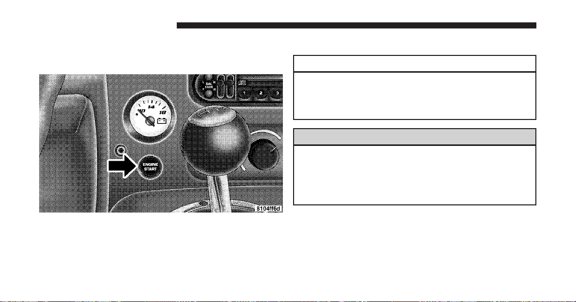
6. Press the red ENGINE START button located on the
instrument panel. Release the button when the engine
starts.
If Engine Fails to Start
CAUTION!
To prevent damage to the starter, do not crank the
engine for more than 15 seconds at a time. Wait 10 to
15 seconds before trying again.
WARNING!
•
Never pour fuel or other flammable liquid into the
throttle body air inlet opening in an attempt to
start the vehicle. This could result in flash fire
causing serious personal injury.
(Continued)
ENGINE START Button
146 STARTING AND OPERATING
WARNING! (Continued)
•
Do not attempt to push or tow your vehicle to get
it started. Unburned fuel could enter the catalytic
converter and once the engine has started, ignite
and damage the converter and vehicle. If the
vehicle has a discharged battery, booster cables
may be used to obtain a start from a booster
battery or the battery in another vehicle. This type
of start can be dangerous if done improperly, so
follow this procedure carefully. Refer to “Jump
Starting” in “What To Do In Emergencies” for
further information.
If the engine is flooded, it may start to run, but not have
enough power to continue running when the ENGINE
START button is released. If this occurs, continue crank-
ing up to 15 seconds with the accelerator pedal pushed
all the way to the floor. Release the accelerator pedal and
the ENGINE START button once the engine is running
smoothly.
If the engine shows no sign of starting after two 15 sec-
ond periods of cranking with the accelerator pedal held
to the floor, the “Normal Starting” procedure should be
repeated.
After Starting
The idle speed will automatically decrease as the engine
warms up.
MANUAL TRANSMISSION
NOTE: The parking brake should be engaged and the
shift lever placed into REVERSE before leaving the
vehicle, especially when parked on an incline.
5
STARTING AND OPERATING 147

Your vehicle is equipped with a high torque capacity dual
disc clutch. The clutch pedal must be fully pressed to the
floor during each shift. As you release the clutch pedal,
lightly press the accelerator pedal.
CAUTION!
Failure to press the clutch pedal fully to the floor may
cause increased shift efforts, and may result in dam-
age to the clutch and transmission.
Be sure the transmission is in first gear when moving
forward from a standing position.
CAUTION!
Failure to start out in first gear when moving forward
from a starting position may result in damage to the
clutch.
You will find it easier to use only the lower gears for most
city driving. For steady highway driving with light
accelerations, sixth gear is recommended.
Never drive with your foot resting on the clutch pedal, or
try to hold the vehicle on a hill with the clutch pedal
partially engaged. This will cause abnormal wear on the
clutch.
Never shift into REVERSE until the vehicle has come to a
complete stop.
NOTE:
•
Your vehicle is equipped with a transmission reverse
inhibitor system. When vehicle speed is greater than
3 mph (5 km/h), the reverse inhibitor activates to help
prevent shifts into REVERSE. When at a complete
stop, you may notice light shift efforts into REVERSE
with the ignition key ON, and increased shift efforts
148 STARTING AND OPERATING

into REVERSE with the ignition key OFF. This is
normal operation of the transmission reverse inhibitor
system.
•
Shifting gears during cold weather may require an
increased effort until the transmission lubricant is
warm. This is normal and not harmful to the transmis-
sion.
•
Due to the high performance nature of your drivetrain,
a certain amount of noise from the transmission is
normal. This noise can be most noticeable when the
vehicle is idling in NEUTRAL with the clutch engaged
(clutch pedal released), but it may also be heard when
driving. The noise may also be more noticeable when
the transmission is warm. This noise is normal and is
not an indication of a problem with your clutch or
transmission.
Recommended Shift Speeds
To use your manual transmission for fuel economy it
should be upshifted as listed below. Shift at the vehicle
speeds listed for acceleration. Earlier upshifts during
cruise conditions (relatively steady speeds) will result in
increased fuel economy, and may be used as indicated.
MANUAL TRANSMISSION
RECOMMENDED SHIFT SPEEDS
1-2 2-3 3-4 4-5 5-6
mph 15 25 40 45 50
(km/h) (24) (40) (64) (72) (80)
Higher upshift speeds may be used to obtain a desired
acceleration rate.
5
STARTING AND OPERATING 149
Skip Shift Indicator Light
There are times when you must shift the transmis-
sion directly from first gear into fourth gear instead
of from first gear into second gear. This is to help you get
the best possible fuel economy from your vehicle. This
occurs when engine coolant is higher than 106°F (41°C),
and vehicle speed is greater than 12 mph (19 km/h) but
less than 20 mph (32 km/h), and engine speed is less than
1,322 RPM, and the transmission is in first gear, and the
accelerator is at 1/4 throttle or less. The “Skip Shift
Indicator Light” located in the tachometer will turn
amber during these times.
When the “Skip Shift Indicator Light” turns amber, the
shift mechanism will only allow shifts from first gear to
fourth gear. After you shift the transmission into fourth
gear, you can press the clutch in and shift to another
forward gear.
Downshifting - Proper downshifting will improve fuel
economy and prolong engine life.
To maintain a safe speed and prolong brake life, down-
shift to maintain a safe speed when descending a steep
grade.
WARNING!
Skipping more than one gear while downshifting,
could cause you to lose control of your vehicle. You
could have an accident.
CAUTION!
If you skip more than one gear while downshifting
or downshift at too high an engine speed, you could
damage the engine, transmission, or clutch.
150 STARTING AND OPERATING
DRIVING ON SLIPPERY SURFACES
Acceleration
WARNING!
Rapid acceleration on slippery surfaces is dangerous.
You could lose control of the vehicle and possibly
have an accident. Accelerate slowly and carefully
whenever there is likely to be poor traction (ice,
snow, wet, mud, loose sand, etc.).
Traction
When driving on wet or slushy roads, it is possible for a
wedge of water to build up between the tire and road
surface. This is hydroplaning and may cause partial or
complete loss of vehicle control and stopping ability. To
reduce this possibility, the following precautions should
be observed:
1. Slow down during rainstorms or when roads are
slushy.
2. Slow down if road has standing water or puddles.
CAUTION!
Driving your vehicle through deep puddles at speeds
over 5 mph (8 km/h), may cause water to be ingested
into the engine. This can cause severe engine dam-
age.
3. Replace tires when tread wear indicators first become
visible.
4. Keep tires properly inflated.
5. Maintain enough distance between your vehicle and
the vehicle in front to avoid a collision in a sudden stop.
DRIVING THROUGH WATER
Driving through water more than a few inches/
centimeters deep will require extra caution to ensure
safety and prevent damage to your vehicle.
5
STARTING AND OPERATING 151
Flowing/Rising Water
WARNING!
Do not drive on or across a road or path where water
is flowing and/or rising (as in storm run-off). Flow-
ing water can wear away the road or path’s surface
and cause your vehicle to sink into deeper water.
Furthermore, flowing and/or rising water can carry
your vehicle away swiftly. Failure to follow this
warning may result in injuries that are serious or
fatal to you, your passengers, and others around you.
Shallow Standing Water
Although your vehicle is capable of driving through
shallow standing water, consider the following Caution
and Warning before doing so.
CAUTION!
•
Always check the depth of the standing water
before driving through it. Never drive through
standing water that is deeper than the bottom of
the tire rims mounted on the vehicle.
•
Determine the condition of the road or the path
that is under water and if there are any obstacles in
the way before driving through the standing wa-
ter.
•
Do not exceed 5 mph (8 km/h) when driving
through standing water. This will minimize wave
effects.
(Continued)
152 STARTING AND OPERATING
CAUTION! (Continued)
•
Driving through standing water may cause dam-
age to your vehicle’s drivetrain components. Al-
ways inspect your vehicle’s fluids (i.e., engine oil,
transmission, axle, etc.) for signs of contamination
(i.e., fluid that is milky or foamy in appearance)
after driving through standing water. Do not con-
tinue to operate the vehicle if any fluid appears
contaminated, as this may result in further dam-
age. Such damage is not covered by the New
Vehicle Limited Warranty.
•
Getting water inside your vehicle’s engine can
cause it to lock up and stall out, and cause serious
internal damage to the engine. Such damage is not
covered by the New Vehicle Limited Warranty.
WARNING!
•
Driving through standing water limits your vehi-
cle’s traction capabilities. Do not exceed 5 mph
(8 km/h) when driving through standing water.
•
Driving through standing water limits your vehi-
cle’s braking capabilities, which increases stop-
ping distances. Therefore, after driving through
standing water, drive slowly and lightly press on
the brake pedal several times to dry the brakes.
•
Getting water inside your vehicle’s engine can
cause it to lock up and stall out, and leave you
stranded.
•
Failure to follow these warnings may result in
injuries that are serious or fatal to you, your
passengers, and others around you.
5
STARTING AND OPERATING 153
POWER STEERING
The standard power steering system will give you good
vehicle response and increased ease of maneuverability
in tight spaces. The system will provide mechanical
steering capability if power assist is lost.
If for some reason the power assist is interrupted, it will
still be possible to steer your vehicle. Under these condi-
tions, you will observe a substantial increase in steering
effort, especially at very low vehicle speeds and during
parking maneuvers.
NOTE:
•
Increased noise levels at the end of the steering wheel
travel are considered normal and do not indicate that
there is a problem with the power steering system.
•
Upon initial start-up in cold weather, the power steer-
ing pump may make noise for a short amount of time.
This is due to the cold, thick fluid in the steering
system. This noise should be considered normal, and it
does not in any way damage the steering system.
WARNING!
Continued operation with reduced power steering
assist could pose a safety risk to yourself and others.
Service should be obtained as soon as possible.
CAUTION!
Prolonged operation of the steering system at the end
of the steering wheel travel will increase the steering
fluid temperature and it should be avoided when
possible. Damage to the power steering pump may
occur.
Power Steering Fluid Check
Checking the power steering fluid level at a defined
service interval is not required. The fluid should only be
154 STARTING AND OPERATING
checked if a leak is suspected, abnormal noises are
apparent, and/or the system is not functioning as antici-
pated. Coordinate inspection efforts through an autho-
rized dealer.
CAUTION!
Do not use chemical flushes in your power steering
system as the chemicals can damage your power
steering components. Such damage is not covered by
the New Vehicle Limited Warranty.
WARNING!
Fluid level should be checked on a level surface and
with the engine off to prevent injury from moving
parts and to ensure accurate fluid level reading. Do
not overfill. Use only manufacturer’s recommended
power steering fluid.
If necessary, add fluid to restore to the proper indicated
level. With a clean cloth, wipe any spilled fluid from all
surfaces. Refer to “Fluids, Lubricants, and Genuine Parts”
in “Maintaining Your Vehicle” for further information.
PARKING BRAKE
The parking brake should always be applied when the
driver is not in the vehicle.
WARNING!
Before leaving the vehicle, make sure you fully apply
the parking brake and shift the transmission into
REVERSE. Failure to do so may cause the vehicle to
roll and cause damage or injury.
As an added precaution when parking the vehicle, turn
the front wheels toward the curb on a downhill grade
and away from the curb on an uphill grade.
5
STARTING AND OPERATING 155
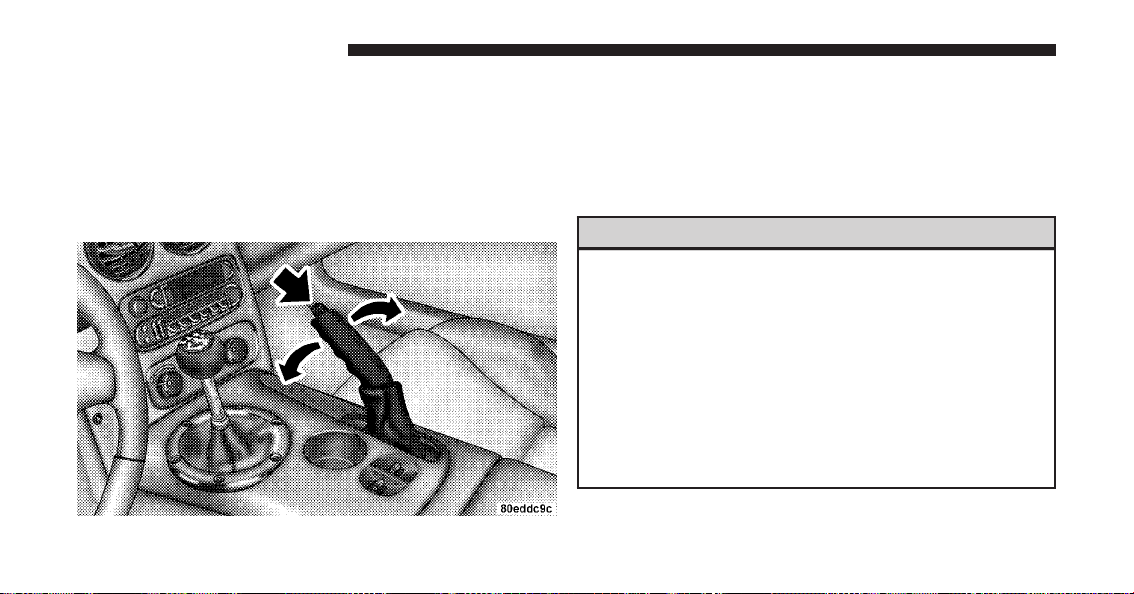
To apply the parking brake, grasp the handle and pull it
rearward until you feel resistance. To release the parking
brake, grasp the handle and pull it slightly while pressing
the button on the end of the handle. When the button
drops into the handle (releasing the lock), guide the
handle downward to its stop and then release the button
and the handle.
The “Brake System Warning Light” in the instrument
cluster will turn on when the ignition is in the ON/RUN
position and the parking brake is applied.
NOTE: This light only shows that the parking brake is
applied. It does not show the degree of brake application.
WARNING!
•
Never leave children alone in a vehicle. Leaving
children in a vehicle unattended is dangerous for a
number of reasons. A child or others could be
injured seriously or fatally. Do not leave the keys
in the ignition. A child could operate power win-
dows, other controls, or move the vehicle.
•
Be sure the parking brake is fully disengaged
before driving. Failure to do so can lead to brake
failure, and an accident.
Parking Brake
156 STARTING AND OPERATING
BRAKE SYSTEM
Your vehicle is equipped with dual hydraulic
brake systems. If either of the two hydraulic
systems loses normal capability, the remaining
system will still function. However, there will
be some loss of overall braking effectiveness. You may
notice increased pedal travel during application, greater
pedal force required to slow or stop, and potential
activation of the “Brake System Warning Light.”
In the event power assist is lost for any reason (i.e.,
repeated brake applications with the engine off) the
brakes will still function. However, the effort required to
brake the vehicle will be much greater than that required
with the power system operating.
Brake Pad Break-In
NOTE: Your vehicle is equipped with a high perfor-
mance braking system. The brake pads are a semi-
metallic compound, which offer superior fade resistance
for consistent operation. A compromise to using this type
of brake pad is that the brakes may squeal slightly under
certain weather and operating conditions (.i.e., during
light brake applications).
The brakes on your new vehicle do not require a long
break-in period. However, you should avoid repeated
hard brake applications from high speeds during initial
break-in. In addition, you should avoid severe brake
loading, such as may be encountered when descending
long mountain grades.
Safe Operating Tips
WARNING!
To use your brakes and accelerator more safely,
follow these tips:
(Continued)
5
STARTING AND OPERATING 157
WARNING! (Continued)
•
Do not “ride” the brakes by resting your foot on
the pedal. This could overheat the brakes and
result in unpredictable braking action, longer
stopping distances, or brake damage.
•
When descending mountains or hills, repeated
braking can cause brake fade with loss of braking
control. Avoid repeated heavy braking by down-
shifting the transmission whenever possible.
•
Do not drive too fast for road conditions, espe-
cially when roads are wet or slushy. A wedge of
water can build up between the tire tread and the
road. This hydroplaning action can cause loss of
traction, braking ability, and control.
(Continued)
WARNING! (Continued)
•
After going through deep water or a car wash,
brakes may become wet, resulting in decreased
performance and unpredictable braking action.
Dry the brakes by gentle, intermittent pedal action
while driving at very slow speeds.
Anti-Lock Brake System
The Anti-Lock Brake System (ABS) is designed to aid the
driver in maintaining vehicle control under adverse
braking conditions. The system operates with a separate
computer to modulate hydraulic pressure to prevent
wheel lock-up and help avoid skidding on slippery
surfaces.
NOTE: During severe braking conditions, a pulsing
sensation may occur and a clicking noise will be heard.
This is normal, indicating that the ABS is functioning.
158 STARTING AND OPERATING
The ABS conducts a low-speed self-test at about 12 mph
(20 km/h). If you have your foot lightly on the brake
while this test is occurring, you may feel slight pedal
movement. The movement can be more apparent on ice
and snow. This is normal.
The ABS pump motor runs during the self-test at 12 mph
(20 km/h) and during an ABS stop. The pump motor
makes a low humming noise during operation, which is
normal.
CAUTION!
The Anti-Lock Brake System (ABS) is subject to
possible detrimental effects of electronic interference
caused by improperly installed aftermarket radios or
telephones.
WARNING!
•
The Anti-Lock Brake System (ABS) contains sophis-
ticated electronic equipment that may be suscep-
tible to interference caused by improperly installed
or high output radio transmitting equipment. This
interference can cause possible loss of anti-lock
braking capability. Installation of such equipment
should be performed by qualified professionals.
•
Pumping of the anti-lock brakes will diminish
their effectiveness and may lead to an accident.
Pumping makes the stopping distance longer. Just
press firmly on your brake pedal when you need
to slow down or stop.
(Continued)
5
STARTING AND OPERATING 159
WARNING! (Continued)
•
The ABS cannot prevent the natural laws of phys-
ics from acting on the vehicle, nor can it increase
braking or steering efficiency beyond that af-
forded by the condition of the vehicle brakes and
tires or the traction afforded.
•
The ABS cannot prevent accidents, including
those resulting from excessive speed in turns,
following another vehicle too closely, or hydro-
planing.
•
The capabilities of an ABS equipped vehicle must
never be exploited in a reckless or dangerous
manner, which could jeopardize the user’s safety
or the safety of others.
All vehicle wheels and tires must be the same size and
type as the original equipment and the tires must be
properly inflated to produce accurate signals for the
computer.
WARNING!
Significant over or under-inflation of tires, or mixing
sizes of front or rear tires or wheels on the vehicle can
lead to loss of braking effectiveness.
160 STARTING AND OPERATING

Anti-Lock Brake Warning Light
The “Anti-Lock Brake Warning Light” will turn
on and stay on briefly as a bulb check when the
ignition is first turned on. If the light does not
turn on during starting, have it repaired
promptly.
This light also illuminates at vehicle start-up to indicate
that the ABS self-check is in process. If the light remains
on after start-up, or turns on and remains on at road
speeds, it may indicate a system malfunction or that the
system is inoperative. In this case, the system reverts to
standard non-anti-lock brakes. If this occurs, safely bring
the vehicle to a complete stop as soon as possible and
cycle the ignition key to attempt to reset the ABS. If the
light remains on, see your authorized dealer immediately
to have the system serviced. Also, if the “BRAKE Warn-
ing Light” and the “ABS Warning Light” are on, and the
parking brake is fully released, see your authorized
dealer immediately.
TIRE SAFETY INFORMATION
Tire Markings
1 — U.S. DOT Safety Stan-
dards Code (TIN)
4 — Maximum Load
2 — Size Designation 5 — Maximum Pressure
3 — Service Description 6 — Treadwear, Traction and
Temperature Grades
5
STARTING AND OPERATING 161

NOTE:
•
P (Passenger) - Metric tire sizing is based on U.S.
design standards. P-Metric tires have the letter “P”
molded into the sidewall preceding the size designa-
tion. Example: P215/65R15 95H.
•
European-Metric tire sizing is based on European
design standards. Tires designed to this standard have
the tire size molded into the sidewall beginning with
the section width. The letter ⬙P⬙ is absent from this tire
size designation. Example: 215/65R15 96H.
•
LT (Light Truck) - Metric tire sizing is based on U.S.
design standards. The size designation for LT-Metric
tires is the same as for P-Metric tires except for the
letters “LT” that are molded into the sidewall preced-
ing the size designation. Example: LT235/85R16.
•
Temporary spare tires are high-pressure compact
spares designed for temporary emergency use only.
Tires designed to this standard have the letter “T”
molded into the sidewall preceding the size designa-
tion. Example: T145/80D18 103M.
•
High flotation tire sizing is based on U.S. design
standards and it begins with the tire diameter molded
into the sidewall. Example: 31x10.5 R15 LT.
162 STARTING AND OPERATING

Tire Sizing Chart
EXAMPLE:
Size Designation:
P = Passenger car tire size based on U.S. design standards
ⴖ....blank....ⴖ = Passenger car tire based on European design standards
LT = Light truck tire based on U.S. design standards
T = Temporary spare tire
31 = Overall diameter in inches (in)
215 = Section width in millimeters (mm)
65 = Aspect ratio in percent (%)
— Ratio of section height to section width of tire
10.5 = Section width in inches (in)
R = Construction code
— ⬙R⬙ means radial construction
—⬙D⬙ means diagonal or bias construction
15 = Rim diameter in inches (in)
5
STARTING AND OPERATING 163

EXAMPLE:
Service Description:
95 = Load Index
— A numerical code associated with the maximum load a tire can carry
H = Speed Symbol
— A symbol indicating the range of speeds at which a tire can carry a load corresponding
to its load index under certain operating conditions
— The maximum speed corresponding to the speed symbol should only be achieved under
specified operating conditions (i.e., tire pressure, vehicle loading, road conditions, and
posted speed limits)
Load Identification:
ⴖ....blank....ⴖ = Absence of any text on the sidewall of the tire indicates a Standard Load (SL) tire
Extra Load (XL) = Extra load (or reinforced) tire
Light Load = Light load tire
C, D, E = Load range associated with the maximum load a tire can carry at a specified pressure
Maximum Load — Maximum load indicates the maximum load this tire is designed to carry
Maximum Pressure — Maximum pressure indicates the maximum permissible cold tire inflation pressure for
this tire
164 STARTING AND OPERATING

Tire Identification Number (TIN)
The TIN may be found on one or both sides of the tire,
however, the date code may only be on one side. Tires
with white sidewalls will have the full TIN, including the
date code, located on the white sidewall side of the tire.
Look for the TIN on the outboard side of black sidewall
tires as mounted on the vehicle. If the TIN is not found on
the outboard side, then you will find it on the inboard
side of the tire.
EXAMPLE:
DOT MA L9 ABCD 0301
DOT = Department of Transportation
— This symbol certifies that the tire is in compliance with the U.S. Department of Transportation tire
safety standards and is approved for highway use
MA = Code representing the tire manufacturing location (two digits)
L9 = Code representing the tire size (two digits)
ABCD = Code used by the tire manufacturer (one to four digits)
03 = Number representing the week in which the tire was manufactured (two digits)
—03 means the 3rd week.
01 = Number representing the year in which the tire was manufactured (two digits)
—01 means the year 2001
— Prior to July 2000, tire manufacturers were only required to have one number to represent the
year in which the tire was manufactured. Example: 031 could represent the 3rd week of 1981 or 1991
5
STARTING AND OPERATING 165

Tire Terminology and Definitions
Term Definition
B-Pillar The vehicle B-Pillar is a structural member of the body located
between the front and rear door (of a four-door vehicle) running
from the sill to the roof.
Cold Tire Pressure Cold tire inflation pressure is defined as the tire pressure after the
vehicle has not been driven for at least 3 hours, or driven less
than 1 mile (1.6 km) after sitting for a three hour period. Inflation
pressure is measured in units of PSI (pounds per square inch) or
KPa (kilopascals).
Maximum Inflation Pressure The maximum inflation pressure is the maximum permissible cold
tire inflation pressure for this tire. The max inflation pressure is
molded into the sidewall.
Recommended Inflation Pressure Vehicle manufacturer’s recommended tire inflation pressure as
shown on the tire placard.
Tire Placard A paper label permanently attached to the vehicle showing the
vehicle’s loading capacity, the original equipment tire size and the
recommended inflation pressure.
166 STARTING AND OPERATING

Tire Loading and Tire Pressure
Tire Placard Location
NOTE: The proper cold tire inflation pressure is listed
on the driver’s side B-Pillar.
Tire and Loading Information Placard
Tire Placard Location
Tire and Loading Information Placard
5
STARTING AND OPERATING 167

This placard tells you important information about
the:
1) number of people that can be carried in the vehicle
2) total weight your vehicle can carry
3) tire size designed for your vehicle
4) cold tire inflation pressures for the front, rear, and
spare tires.
Loading
The vehicle maximum load on the tire must not exceed
the load carrying capacity of the tire on your vehicle. You
will not exceed the tire’s load carrying capacity if you
adhere to the loading conditions, tire size, and cold tire
inflation pressures specified on the Tire and Loading
Information placard and in the “Vehicle Loading” section
of this manual.
NOTE: Under a maximum loaded vehicle condition,
gross axle weight ratings (GAWRs) for the front and rear
axles must not be exceeded. For further information on
GAWRs, vehicle loading, and trailer towing, refer to
“Vehicle Loading” in this section.
To determine the maximum loading conditions of your
vehicle, locate the statement “The combined weight of
occupants and cargo should never exceed XXX lbs or
XXX kg” on the Tire and Loading Information placard.
The combined weight of occupants, cargo/luggage and
trailer tongue weight (if applicable) should never exceed
the weight referenced here.
Steps for Determining Correct Load Limit
1. Locate the statement “The combined weight of occu-
pants and cargo should never exceed XXX lbs or XXX kg”
on your vehicle’s placard.
2. Determine the combined weight of the driver and
passengers that will be riding in your vehicle.
168 STARTING AND OPERATING

3. Subtract the combined weight of the driver and pas-
sengers from XXX lbs or XXX kg.
4. The resulting figure equals the available amount of
cargo and luggage load capacity. For example, if “XXX”
amount equals 1,400 lbs (635 kg) and there will be five
150 lb (68 kg) passengers in your vehicle, the amount of
available cargo and luggage load capacity is 650 lbs
(295 kg) (since 5 x 150 = 750, and 1400 – 750 = 650 lbs
[295 kg]).
5. Determine the combined weight of luggage and cargo
being loaded on the vehicle. That weight may not safely
exceed the available cargo and luggage load capacity
calculated in Step 4.
6. If your vehicle will be towing a trailer, load from your
trailer will be transferred to your vehicle. Consult this
manual to determine how this reduces the available
cargo and luggage load capacity of your vehicle.
NOTE:
•
The following table shows examples on how to calcu-
late total load, cargo/luggage, and towing capacities
of your vehicle with varying seating configurations
and number and size of occupants. This table is for
illustration purposes only and may not be accurate for
the seating and load carry capacity of your vehicle.
•
For the following example, the combined weight of
occupants and cargo should never exceed 865 lbs
(392 kg).
5
STARTING AND OPERATING 169
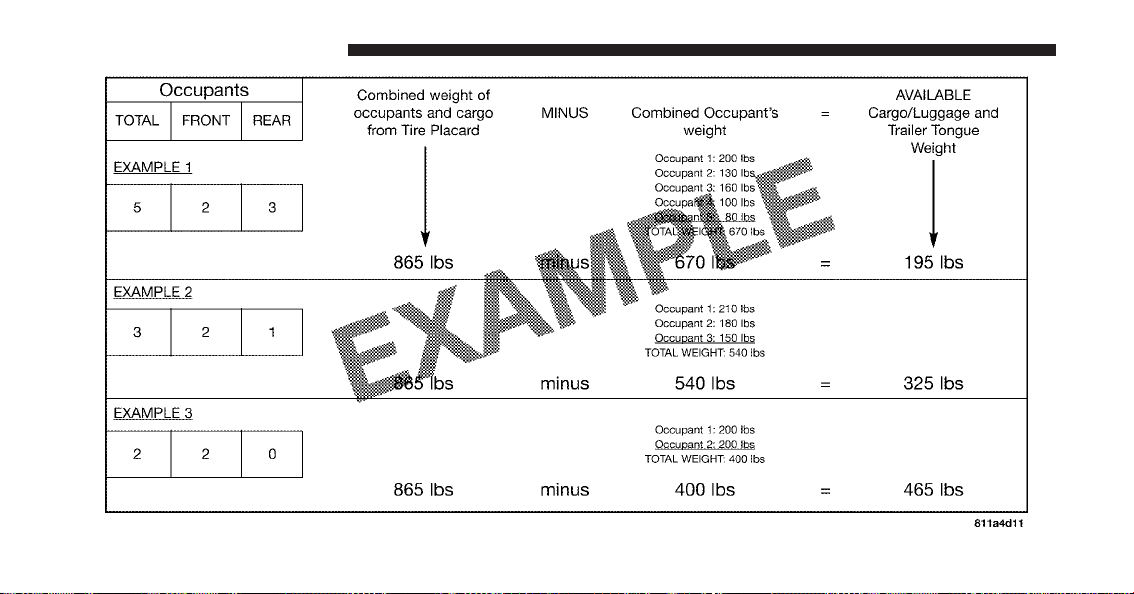
170 STARTING AND OPERATING
WARNING!
Overloading of your tires is dangerous. Overloading
can cause tire failure, affect vehicle handling, and
increase your stopping distance. Use tires of the
recommended load capacity for your vehicle. Never
overload them.
TIRES — GENERAL INFORMATION
Tire Pressure
Proper tire inflation pressure is essential to the safe and
satisfactory operation of your vehicle. Three primary
areas are affected by improper tire pressure:
Safety
WARNING!
•
Improperly inflated tires are dangerous and can
cause accidents.
•
Under-inflation increases tire flexing and can re-
sult in over-heating and tire failure.
•
Over-inflation reduces a tire’s ability to cushion
shock. Objects on the road and chuckholes can
cause damage that result in tire failure.
•
Unequal tire pressures can cause steering prob-
lems. You could lose control of your vehicle.
•
Over-inflated or under-inflated tires can affect
vehicle handling and can fail suddenly, resulting
in loss of vehicle control.
(Continued)
5
STARTING AND OPERATING 171
WARNING! (Continued)
•
Unequal tire pressures from one side of the ve-
hicle to the other can cause the vehicle to drift to
the right or left.
•
Always drive with each tire inflated to the recom-
mended cold tire inflation pressure.
Economy
Improper inflation pressures can cause uneven wear
patterns to develop across the tire tread. These abnormal
wear patterns will reduce tread life resulting in a need for
earlier tire replacement. Under-inflation also increases tire
rolling resistance and results in higher fuel consumption.
Ride Comfort and Vehicle Stability
Proper tire inflation contributes to a comfortable ride.
Over-inflation produces a jarring and uncomfortable
ride.
Tire Inflation Pressures
The proper cold tire inflation pressure is listed on the
driver’s side “B” Pillar.
Some vehicles may have Supplemental Tire Pressure
Information for vehicle loads that are less than the
maximum loaded vehicle condition. These pressure con-
ditions will be found in the “Supplemental Tire Pressure
Information” section of this manual.
The pressure should be checked and adjusted as well as
inspecting for signs of tire wear or visible damage at least
once a month. Use a good quality pocket-type gauge to
check tire pressure. DO NOT make a visual judgement
when determining proper inflation. Radial tires may look
properly inflated even when they are under-inflated.
172 STARTING AND OPERATING

CAUTION!
After inspecting or adjusting the tire pressure, al-
ways reinstall the valve stem cap. This will prevent
moisture and dirt from entering the valve stem,
which could damage the valve stem.
Inflation pressures specified on the placard are always
“cold tire inflation pressure.” Cold tire inflation pressure
is defined as the tire pressure after the vehicle has not
been driven for at least three hours, or driven less than
1 mile (1.6 km) after a three-hour period. The cold tire
inflation pressure must not exceed the maximum infla-
tion pressure molded into the tire sidewall.
Check tire pressures more often if subject to a wide range
of outdoor temperatures, as tire pressures vary with
temperature changes.
Tire pressures change by approximately 1 psi (7 kPa) per
12°F (7°C) of air temperature change. Keep this in mind
when checking tire pressure inside a garage, especially in
the Winter.
Example: If garage temperature = 68°F (20°C) and the
outside temperature = 32°F (0°C) then the cold tire
inflation pressure should be increased by 3 psi (21 kPa),
which equals 1 psi (7 kPa) for every 12°F (7°C) for this
outside temperature condition.
Tire pressure may increase from 2 to 6 psi (13 to 40 kPa)
during operation. DO NOT reduce this normal pressure
build up or your tire pressure will be too low.
5
STARTING AND OPERATING 173
Tire Pressures for High Speed Operation
The manufacturer advocates driving at safe speeds
within posted speed limits. Where speed limits or condi-
tions are such that the vehicle can be driven at high
speeds, maintaining correct tire inflation pressure is very
important. Increased tire pressure and reduced vehicle
loading may be required for high-speed vehicle opera-
tion. Refer to original equipment or an authorized tire
dealer for recommended safe operating speeds, loading
and cold tire inflation pressures.
WARNING!
High speed driving with your vehicle under maxi-
mum load is dangerous. The added strain on your
tires could cause them to fail. You could have a
serious accident. Do not drive a vehicle loaded to the
maximum capacity at continuous speeds above
75 mph (120 km/h).
Radial Ply Tires
WARNING!
Combining radial ply tires with other types of tires
on your vehicle will cause your vehicle to handle
poorly. The instability could cause an accident. Al-
ways use radial ply tires in sets of four. Never
combine them with other types of tires.
Cuts and punctures in radial tires are repairable only in
the tread area because of sidewall flexing. Consult your
authorized tire dealer for radial tire repairs.
Tire Spinning
When stuck in mud, sand, snow, or ice conditions, do not
spin your vehicle’s wheels faster than 30 mph (48 km/h).
Refer to “Freeing A Stuck Vehicle” in “What To Do In
Emergencies” for further information.
174 STARTING AND OPERATING
WARNING!
Fast spinning tires can be dangerous. Forces gener-
ated by excessive wheel speeds may cause tire dam-
age or failure. A tire could explode and injure some-
one. DO NOT spin your vehicle’s wheels faster than
30 mph (48 km/h) or for more than 30 seconds
continuously when you are stuck, and do not let
anyone near a spinning wheel, no matter what the
speed.
Tread Wear Indicators
Tread wear indicators are in the original equipment tires
to help you in determining when your tires should be
replaced.
These indicators are molded into the bottom of the tread
grooves. They will appear as bands when the tread depth
becomes 1/16 in (2 mm). When the tread is worn to the
tread wear indicators, the tire should be replaced.
1 — Worn Tire
2 — New Tire
5
STARTING AND OPERATING 175

Life of Tire
The service life of a tire is dependent upon varying
factors including, but not limited to:
•
Driving style
•
Tire pressure
•
Distance driven
WARNING!
Tires and the spare tire should be replaced after six
years, regardless of the remaining tread. Failure to
follow this warning can result in sudden tire failure.
You could lose control and have an accident resulting
in serious injury or death.
Keep dismounted tires in a cool, dry place with as little
exposure to light as possible. Protect tires from contact
with oil, grease, and gasoline.
Replacement Tires
The tires on your new vehicle provide a balance of many
characteristics. They should be inspected regularly for
wear and correct cold tire inflation pressure. The manu-
facturer strongly recommends that you use tires equiva-
lent to the originals in size, quality and performance
when replacement is needed. (Refer to the paragraph on
“Tread Wear Indicators”). Refer to the “Tire and Loading
Information” placard for the size designation of your tire.
The service description and load identification will be
found on the original equipment tire. Failure to use
equivalent replacement tires may adversely affect the
safety, handling, and ride of your vehicle. We recommend
that you contact your original equipment or an autho-
rized tire dealer with any questions you may have on tire
specifications or capability.
176 STARTING AND OPERATING
WARNING!
•
DO NOT use a tire, wheel size or rating other than
that specified for your vehicle. Some combinations
of unapproved tires and wheels may change sus-
pension dimensions and performance characteris-
tics, resulting in changes to steering, handling, and
braking of your vehicle. This can cause unpredict-
able handling and stress to steering and suspen-
sion components. You could lose control and have
an accident resulting in serious injury or death.
Use only the tire and wheel sizes with load ratings
approved for your vehicle.
•
Never use a tire with a smaller load index or
capacity, other than what was originally equipped
on your vehicle. Using a tire with a smaller load
index could result in tire overloading and failure.
You could lose control and have an accident.
(Continued)
WARNING! (Continued)
•
Failure to equip your vehicle with tires having
adequate speed capability can result in sudden tire
failure and loss of vehicle control.
CAUTION!
Replacing original tires with tires of a different size
may result in false speedometer and odometer read-
ings.
Tire Storage
Tire storage is addressed in the Michelin Limited Tire
Warranty Booklet.
Specific recommendations on guidelines for long term
tire storage for this vehicle should be requested of the
Michelin Tire Corporation 1-800-433-6838.
5
STARTING AND OPERATING 177

SNOW TIRES
There are no snow tires that are compatible with the
wheels on this vehicle.
TIRE ROTATION RECOMMENDATIONS
Tires on the front and rear axles of vehicles operate at
different loads and perform different steering, driving,
and braking functions. For these reasons, they wear at
unequal rates.
These effects can be reduced by timely rotation of tires.
The benefits of rotation are especially worthwhile with
aggressive tread designs such as those on all season type
tires. Rotation will increase tread life, help to maintain
mud, snow, and wet traction levels, and contribute to a
smooth, quiet ride.
Refer to “Maintenance Schedule” for the proper mainte-
nance interval. Remember, more frequent rotation is
permissible if desired. Also, correct for anything causing
rapid or unusual wear prior to performing the tire
rotation.
NOTE: Each wheel on your vehicle contains a tire
pressure sensor. The Tire Pressure Monitor System
(TPMS) learns the location of each sensor though system
programming. Although not required, the manufacturer
recommends reprogramming the TPMS after rotating the
tires so that the system can relearn each sensor’s location.
See your authorized dealer for system reprogramming.
Rotate the tires “side-to-side” as shown in the diagram.
178 STARTING AND OPERATING
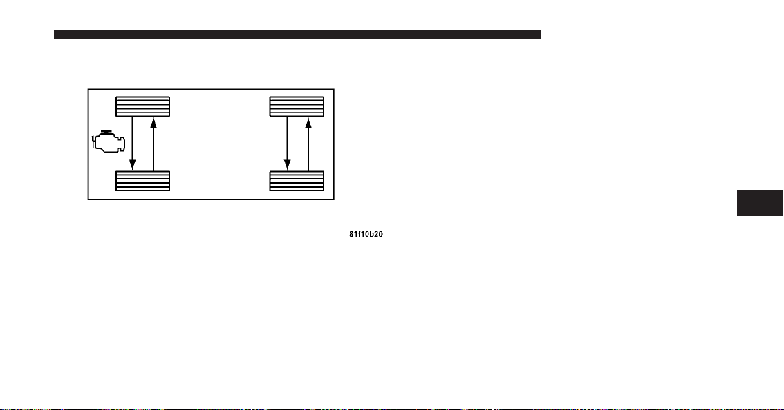
TIRE PRESSURE MONITOR SYSTEM (TPMS)
Low Tire Indicator
If tire pressure falls below 23 psi (159 kpa), the “Low Tire
Pressure Telltale” in the Message Center will illuminate,
a chime will sound, and the words “LOW TIRE” will
flash slowly in the Liquid Crystal Display (LCD) panel in
the bottom of the speedometer. If tire pressure falls below
18 psi (124 kpa), the “Low Tire Pressure Telltale” will
illuminate, a chime will sound, and the words “FLAT
TIRE” will flash rapidly in the display. You should obtain
immediate service if the low tire indicator is activated.
NOTE: Each wheel on your vehicle contains a tire
pressure sensor. The TPMS learns the location of each
sensor though system programming. Although not re-
quired, the manufacturer recommends reprogramming
the TPMS after rotating the tires so that the system can
relearn each sensor’s location. See your authorized dealer
for system reprogramming.
Tire Rotation
5
STARTING AND OPERATING 179
CAUTION!
The Tire Pressure Monitor System (TPMS) has been
optimized for the original equipment tires and
wheels. The TPMS pressures have been established
for the tire size equipped on your vehicle. Undesir-
able operation or sensor damage may result when
using replacement equipment that is not of the same
size, type, and/or style. Aftermarket wheels can cause
sensor damage. Do not use aftermarket tire sealants
or balance beads if your vehicle is equipped with the
TPMS, as damage to the sensors may result.
WARNING!
Do not exceed 55 mph (88 km/h) if the “LOW TIRE”
indicator is activated. Vehicle handling and braking
may be reduced. You could have an accident and be
severely or fatally injured.
TPMS Malfunction Warning
Your vehicle has also been equipped with a TPMS
malfunction indicator to indicate when the system is not
operating properly. The TPMS malfunction indicator is
combined with the low tire pressure telltale.
When the system detects a malfunction, the telltale will
flash for approximately one minute and then remain
continuously illuminated. This sequence will continue
upon subsequent vehicle start-ups as long as the mal-
function exists. When the malfunction indicator is illumi-
nated, the system may not be able to detect or signal low
tire pressure as intended.
TPMS malfunctions may occur for a variety of reasons,
including the installation of replacement or alternate tires
or wheels on the vehicle that prevent the TPMS from
functioning properly. Always check the TPMS malfunc-
tion telltale after replacing one or more tires or wheels on
180 STARTING AND OPERATING

your vehicle to ensure that the replacement or alternate
tires and wheels allow the TPMS to continue to function
properly.
FUEL REQUIREMENTS
8.4L Engine
The 8.4L engine is designed to meet all
emissions regulations and provide excel-
lent fuel economy and performance when
using high-quality premium unleaded
gasoline with an octane rating of 91 or
higher.
Light spark knock at low engine speeds is not harmful to
your engine. However, continued heavy spark knock at
high speeds can cause damage and immediate service is
required.
Poor quality gasoline can cause problems such as hard
starting, stalling, and hesitations. If you experience these
symptoms, try another brand of “premium” gasoline
before considering service for the vehicle.
Over 40 automobile manufacturers around the world
have issued and endorsed consistent gasoline specifica-
tions (the World Wide Fuel Charter, WWFC) which
define fuel properties necessary to deliver enhanced
emissions, engine performance, and durability for your
vehicle. The manufacturer recommends the use of gaso-
lines that meet the WWFC specifications if they are
available.
Reformulated Gasoline
Many areas of the country require the use of cleaner
burning gasoline referred to as “Reformulated Gasoline.”
Reformulated gasolines contain oxygenates, and are spe-
cifically blended to reduce vehicle emissions and im-
prove air quality.
5
STARTING AND OPERATING 181

The manufacturer supports the use of reformulated gaso-
lines. Properly blended reformulated gasolines will pro-
vide excellent performance and durability of engine and
fuel system components.
Gasoline/Oxygenate Blends
Some fuel suppliers blend unleaded gasoline with oxy-
genates such as 10% ethanol, MTBE, and ETBE. Oxygen-
ates are required in some areas of the country during the
winter months to reduce carbon monoxide emissions.
Fuels blended with these oxygenates may be used in
your vehicle.
CAUTION!
Do not use gasolines containing Methanol or E85
Ethanol. Use of these blends may result in starting
and driveability problems and may damage critical
fuel system components.
Problems that result from using methanol/gasoline or
E85 Ethanol blends are not the responsibility of the
manufacturer. While MTBE is an oxygenate made from
Methanol, it does not have the negative effects of
Methanol.
E-85 Usage In Non-Flex Fuel Vehicles
Non-FFV vehicles are compatible with gasoline contain-
ing 10% ethanol (E10). Gasoline with higher ethanol
content may void the vehicle’s warranty.
If a Non-FFV vehicle is inadvertently fueled with E-85
fuel, the engine will have some or all of these symptoms:
•
operate in a lean mode
•
OBD II “Malfunction Indicator Light” on
•
poor engine performance
•
poor cold start and cold drivability
•
increased risk for fuel system component corrosion
182 STARTING AND OPERATING

To fix a Non-FFV vehicle inadvertently fueled once with
E-85 perform the following:
•
drain the fuel tank (see your authorized dealer)
•
change the engine oil and oil filter
•
disconnect and reconnect the battery to reset the
engine controller memory
More extensive repairs will be required for prolonged
exposure to E-85 fuel.
MMT In Gasoline
MMT is a manganese containing metallic additive that is
blended into some gasoline to increase the octane num-
ber. Gasolines blended with MMT offer no performance
advantage beyond gasolines of the same octane number
without MMT. Gasolines blended with MMT have shown
to reduce spark plug life and reduce emission system
performance in some vehicles. The manufacturer recom-
mends using gasolines without MMT. Since the MMT
content of gasoline may not be indicated on the pump,
you should ask your gasoline retailer if his/her gasoline
contains MMT.
It is even more important to look for gasolines without
MMT in Canada, because MMT can be used at levels
higher than allowed in the United States. MMT is pro-
hibited in Federal and California reformulated gasolines.
Materials Added to Fuel
All gasoline sold in the United States is required to
contain effective detergent additives. Use of additional
detergents or other additives is not needed under normal
conditions and would result in additional cost. Therefore,
you should not have to add anything to the fuel.
5
STARTING AND OPERATING 183
Fuel System Cautions
CAUTION!
Follow these guidelines to maintain your vehicle’s
performance:
•
The use of leaded gas is prohibited by Federal law.
Using leaded gasoline can impair engine perfor-
mance, or damage the emission control system.
•
An out-of-tune engine, or certain fuel or ignition
malfunctions, can cause the catalytic converter to
overheat. If you notice a pungent burning odor or
some light smoke, your engine may be out-of-tune
or malfunctioning and may require immediate
service. Contact your authorized dealer for service
assistance.
(Continued)
CAUTION! (Continued)
•
The use of fuel additives, which are now being
sold as octane enhancers, is not recommended.
Most of these products contain high concentra-
tions of methanol. Fuel system damage or vehicle
performance problems resulting from the use of
such fuels or additives are not the responsibility of
the manufacturer.
NOTE: Intentional tampering with emissions control
systems can result in civil penalties being assessed
against you.
184 STARTING AND OPERATING
Carbon Monoxide Warnings
WARNING!
Carbon monoxide (CO) in exhaust gases is deadly.
Follow the precautions below to prevent carbon
monoxide poisoning:
•
Do not inhale exhaust gases. They contain carbon
monoxide, a colorless and odorless gas, which can
kill. Never run the engine in a closed area, such as
a garage, and never sit in a parked vehicle with the
engine running for an extended period. If the
vehicle is stopped in an open area with the engine
running for more than a short period, adjust the
ventilation system to force fresh, outside air into
the vehicle.
(Continued)
WARNING! (Continued)
•
Guard against carbon monoxide with proper
maintenance. Have the exhaust system inspected
every time the vehicle is raised. Have any abnor-
mal conditions repaired promptly. Until repaired,
drive with all side windows fully open.
•
Keep the trunk closed when driving your vehicle
to prevent carbon monoxide and other poisonous
exhaust gases from entering the vehicle.
ADDING FUEL
Fuel Filler Cap (Gas Cap)
The gas cap is located behind the fuel filler door above
the rear tire on the passenger side of the vehicle. To access
the gas cap, grasp the finger pull (on the left side of the
fuel filler door) and pull it open. The door will pivot
toward the front of the vehicle.
5
STARTING AND OPERATING 185
NOTE:
•
When the fuel nozzle “clicks” or shuts off, the fuel
tank is full.
•
The fuel tank filler tube has a restricting door about
2 inches (50 mm) inside the opening. If using a
portable container to add fuel, it must have a flexible
nozzle long enough to force open the restricting door.
CAUTION!
•
Damage to the fuel system or emission control
system could result from using an improper fuel
tank filler tube cap (gas cap).
•
A poorly fitting gas cap could let impurities into
the fuel system.
•
A poorly fitting gas cap may cause the “Malfunc-
tion Indicator Light” to turn on.
(Continued)
CAUTION! (Continued)
•
To avoid fuel spillage and overfilling, do not “top
off” the fuel tank after filling. When the fuel
nozzle “clicks” or shuts off, the fuel tank is full.
WARNING!
•
Never have any smoking materials lit in or near
the vehicle when the gas cap is removed or the
tank is being filled.
•
Never add fuel to the vehicle when the engine is
running.
•
A fire may result if gasoline is pumped into a
portable container that is inside of a vehicle. You
could be burned. Always place gas containers on
the ground while filling.
186 STARTING AND OPERATING
NOTE:
•
Tighten the gas cap until you hear a “clicking” sound.
This is an indication that the gas cap is tightened
properly. The “Malfunction Indicator Light” in the
instrument cluster may turn on if the gas cap is not
secured properly. Make sure that the gas cap is tight-
ened each time the vehicle is refueled.
•
If the gas cap is lost or damaged, be sure the replace-
ment cap is for use with this vehicle.
TRAILER TOWING
Trailer towing with this vehicle is not recommended.
RECREATIONAL TOWING
(BEHIND MOTORHOME, ETC.)
Towing This Vehicle Behind Another Vehicle
(Flat towing with all four wheels on the ground)
Recreational towing for this vehicle is not recommended.
NOTE: If the vehicle requires towing, make sure all four
wheels are off the ground.
GROUND CLEARANCE
The front and rear fascias and side sills ride low and
ground clearance is limited.
CAUTION!
Damage to the front and rear fascias and side sills can
occur if you disregard the low ground clearance in
these areas of your vehicle. Pay close attention when
parking to avoid running into parking curbs. Exer-
cise caution when entering or exiting steep drive-
ways, or when pulling off the road onto soft shoul-
ders.
5
STARTING AND OPERATING 187


WHAT TO DO IN EMERGENCIES
CONTENTS
䡵 Hazard Warning Flasher ................ 190
䡵 If Your Engine Overheats ................ 190
䡵 TIREFIT Kit ......................... 191
▫ TIREFIT Storage ..................... 192
▫ TIREFIT Kit Components And Operation . . . 192
▫ TIREFIT Usage Precautions ............. 194
▫ Sealing a Tire With TIREFIT ............. 196
䡵 Jump-Starting Procedures ................ 202
䡵 Freeing A Stuck Vehicle ................. 205
䡵 Towing A Disabled Vehicle ............... 206
6

HAZARD WARNING FLASHER
The Hazard Warning flasher switch is on the top of the
steering column, just behind the steering wheel.
Press the switch to turn on the Hazard Warning
flasher. When the switch is activated, all directional
turn signals will flash on and off to warn oncoming traffic
of an emergency. Press the switch a second time to turn
off the Hazard Warning flasher.
This is an emergency warning system and it should not
be used when the vehicle is in motion. Use it when your
vehicle is disabled and it is creating a safety hazard for
other motorists.
When you must leave the vehicle to seek assistance, the
Hazard Warning flasher will continue to operate even
though the ignition is placed in the OFF position.
NOTE: With extended use the Hazard Warning flasher
may wear down your battery.
IF YOUR ENGINE OVERHEATS
In any of the following situations, you can reduce the
potential for overheating by taking the appropriate ac-
tion.
Hazard Warning Switch
190 WHAT TO DO IN EMERGENCIES
•
On the highways — Slow down and use the highest
gear possible.
•
In city traffic — While stopped, put the transmission
in NEUTRAL, but do not increase engine idle speed.
•
In city traffic — While moving, shift into the highest
gear possible to reduce engine RPM.
NOTE: There are steps that you can take to slow down
an impending overheat condition:
•
If your air conditioner (A/C) is on, turn it off. The A/C
system adds heat to the engine cooling system and
turning the A/C off can help remove this heat.
•
You can also turn the temperature control to maximum
heat, the mode control to floor and the blower control
to high. This allows the heater core to act as a
supplement to the radiator and aids in removing heat
from the engine cooling system.
WARNING!
You or others can be badly burned by hot engine
coolant (antifreeze) or steam from your radiator. If
you see or hear steam coming from under the hood,
do not open the hood until the radiator has had time
to cool. Never try to open a cooling system pressure
cap when the radiator or coolant bottle is hot.
TIREFIT KIT
Small punctures up to
1
⁄
4
” (6 mm) in the tire tread can be
sealed with TIREFIT. Foreign objects (e.g., screws or
nails) should not be removed from the tire. TIREFIT can
be used in outside temperatures down to approximately
-4°F (-20°C).
This kit will provide a temporary tire seal, allowing you
to drive your vehicle up to 100 miles (160 km) with a
maximum speed of 55 mph (88 km/hr).
6
WHAT TO DO IN EMERGENCIES 191

TIREFIT Storage
The TIREFIT kit is located in the trunk.
TIREFIT Kit Components and Operation
1. Sealant Bottle
2. Deflation Button — If Equipped
3. Pressure Gauge
4. Power Button
TIREFIT Location
192 WHAT TO DO IN EMERGENCIES
5. Mode Select Knob
6. Sealant Hose (Clear with Yellow Cap)
7. Air Pump Hose (Black)
8. Power Plug
Using the Mode Select Knob and Hoses
Your TIREFIT kit may be equipped with either of the
following symbols to indicate the air or sealant mode.
Selecting Air Mode
Turn the Mode Select Knob (5) to this
position for air pump operation only.
Use the Black Air Pump Hose (7)
when selecting this mode.
Selecting Sealant Mode
Turn the Mode Select Knob (5) to this
position to inject the TIREFIT Sealant
and to inflate the tire. Use the Sealant
Hose (clear hose with the yellow cap)
(6) when selecting this mode.
Using the Power Button
Push and release the Power Button (4) once to
turn ON the TIREFIT kit. Push and release the
Power Button (4) again to turn OFF the TIRE-
FIT kit.
Using the Deflation Button — If Equipped
Press the Deflation Button (2) to reduce the air
pressure in the tire if it becomes over-inflated.
6
WHAT TO DO IN EMERGENCIES 193

TIREFIT Usage Precautions
•
Replace the TIREFIT Sealant Bottle (1) and Sealant
Hose (6) prior to the expiration date (printed on the
bottle label) to assure optimum operation of the sys-
tem. Refer to “Sealing a Tire with TIREFIT” section (F)
“Sealant Bottle and Hose Replacement”.
•
The Sealant Bottle (1) and Sealant Hose (6) is a one tire
application use. After each use, always immediately
replace these components at an authorized dealer.
•
When the TIREFIT sealant is in a liquid form, clean
water, and a damp cloth will remove the material from
the vehicle or tire and wheel components. Once the
sealant dries, it can easily be peeled off and properly
discarded.
•
For optimum performance, make sure the valve stem
on the wheel is free of debris before connecting the
TIREFIT kit.
•
You can use the TIREFIT air pump to inflate bicycle
tires. The kit also comes with two needles located in
the Accessory Storage Compartment (located on the
bottom of the air pump) for inflating sport balls, rafts,
or like inflatable items. However, use only the Air
Pump Hose (7) and make sure the Mode Select Knob
(5) is in the Air Mode when inflating such items to
avoid injecting sealant into them. The TIREFIT Sealant
is only intended to seal punctures less than
1
⁄
4
” (6mm)
diameter in the tread of your vehicle.
•
Do not lift or carry TIREFIT kit by hoses.
WARNING!
•
Do not attempt to seal a tire on the side of the
vehicle close to traffic. Pull far enough off the road
to avoid the danger of being hit when using the
TIREFIT kit.
(Continued)
194 WHAT TO DO IN EMERGENCIES
WARNING! (Continued)
•
Do not use TIREFIT or drive the vehicle under the
following circumstances:
−
If the cut or puncture in the tire tread is approxi-
mately 0.24 in. (6 mm) or larger.
−
If the tire has any sidewall damage.
−
If the tire has any damage from driving with
extremely low tire pressure.
−
If the tire has any damage from driving on a flat
tire.
−
If the wheel has any damage.
−
If you are unsure of the condition of the tire or
the wheel.
•
Keep TIREFIT away from open flame or heat
source.
(Continued)
WARNING! (Continued)
•
A loose TIREFIT kit thrown forward in a collision
or hard stop could endanger the occupants of the
vehicle. Always stow the TIREFIT kit in the place
provided. Failure to follow these warnings can
result in injuries that are serious or fatal to you,
your passengers, and others around you.
•
Take care not to allow the contents of TIREFIT to
come in contact with hair, eyes, or clothing. TIRE-
FIT is harmful if inhaled, swallowed, or absorbed
through the skin: It causes skin, eye, and respira-
tory irritation. Flush immediately with plenty of
water if there is any contact with eyes or skin.
Change clothing as soon as possible, if there is any
contact with clothing.
(Continued)
6
WHAT TO DO IN EMERGENCIES 195
WARNING! (Continued)
•
TIREFIT Sealant solution contains latex. In case of
allergic reaction or rash, consult a physician im-
mediately. Keep TIREFIT out of reach of children.
If swallowed, rinse mouth immediately with
plenty of water and drink plenty of water. Do not
induce vomiting! Consult a physician immedi-
ately.
•
Use the gloves provided in the Accessory Storage
Compartment (located on the bottom of the air
pump) when operating the TIREFIT kit.
Sealing a Tire with TIREFIT
(A) Whenever You Stop to Use TIREFIT:
1. Pull over to a safe location and turn ON the vehicle’s
Hazard Warning flashers.
2. Verify that the valve stem (on the wheel with the
deflated tire) is in a position that is near to the ground.
This will allow the TIREFIT Hoses (6) and (7) to reach the
valve stem and keep the TIREFIT kit flat on the ground.
This will provide the best positioning of the kit when
injecting the sealant into the deflated tire and running the
air pump. Move the vehicle as necessary to place the
valve stem in this position before proceeding.
3. Place the transmission in PARK (auto transmission) or
in Gear (manual transmission) and turn OFF the ignition.
4. Set the parking brake.
(B) Setting Up to Use TIREFIT:
1. Remove the gloves from the Accessory Storage Com-
partment (located on the bottom of the air pump) and
place them on your hands.
2. Turn the Mode Select Knob (5) to the Sealant Mode
position.
196 WHAT TO DO IN EMERGENCIES

3. Uncoil the Sealant Hose (6) and then remove the
yellow cap from the fitting at the end of the hose.
4. Place the TIREFIT kit flat on the ground next to the
deflated tire.
5. Remove the cap from the valve stem and then screw
the fitting at the end of the Sealant Hose (6) onto the
valve stem.
6. Uncoil the Power Plug (8) and then insert the plug into
the vehicle’s 12 Volt power outlet.
NOTE: Do not remove foreign objects (e.g., screws or
nails) from the tire.
(C) Injecting TIREFIT Sealant into the deflated
tire:
•
Always start the engine before turning ON the TIRE-
FIT kit.
NOTE: Manual transmission vehicles must have the
parking brake engaged and the shifter in NEUTRAL.
•
After pressing the Power Button (4), the sealant (white
fluid) will flow from the Sealant Bottle (1) through the
Sealant Hose (6) and into the tire.
NOTE: Sealant may leak out through the puncture in
the tire.
If the sealant (white fluid) does not flow within 0 –
10 seconds through the Sealant Hose (6):
1. Press the Power Button (4) to turn OFF the TIREFIT
kit. Disconnect the Sealant Hose (6) from the valve stem.
Make sure the valve stem is free of debris. Reconnect the
Sealant Hose (6) to the valve stem. Check that the Mode
Select Knob (5) is in the sealant mode position and not air
mode. Press the Power Button (4) to turn ON the TIREFIT
kit.
6
WHAT TO DO IN EMERGENCIES 197

2. Connect the Power Plug (8) to a different 12 Volt
power outlet in your vehicle or another vehicle, if avail-
able. Make sure the engine is running before turning ON
the TIREFIT kit.
3. The Sealant Bottle (1) may be empty due to previous
use. Call for assistance.
NOTE: If the Mode Select Knob (5) is on air mode and
pump is operating, air will dispense from the Air Pump
Hose (7) only, not the Sealant Hose (6).
If the sealant (white fluid) does flow through the
Sealant Hose (6):
1. Continue to operate pump until sealant is no longer
flowing through hose (typically takes 30 - 70 seconds). As
the sealant flows through the Sealant Hose (6), the
Pressure Gauge (3) can read as high as 70 psi (5 Bar). The
Pressure Gauge (3) will decrease quickly from approxi-
mately 70 psi (5 Bar) to the actual tire pressure when the
Sealant Bottle (1) is empty.
2. The pump will start to inject air into the tire immedi-
ately after the Sealant Bottle (1) is empty. Continue to
operate pump and inflate the tire to the pressure indi-
cated on the tire pressure label on the driver-side latch
pillar (recommended pressure). Check the tire pressure
by looking at the Pressure Gauge (3).
If the tire does not inflate to at least 26 psi (1.8 Bar)
pressure within 15 minutes:
•
The tire is too badly damaged. Do not attempt to drive
the vehicle further. Call for assistance.
NOTE: If the air pump is equipped with a Deflation
Button and the tire becomes over-inflated, press the
Deflation Button to reduce the tire pressure to the
recommended inflation pressure before continuing.
198 WHAT TO DO IN EMERGENCIES

If the tire inflates to the recommended pressure or is at
least 26 psi (1.8 Bar) pressure within 15 minutes:
1. Press the Power Button (4) to turn off the TIREFIT kit.
2. Remove the Speed Limit sticker from the top of the
Sealant Bottle (1) and place the sticker on the instrument
panel.
3. Immediately disconnect the Sealant Hose (6) from the
valve stem, reinstall the yellow cap on the fitting at the
end of the hose, and place the TIREFIT kit in the vehicle
storage location. Quickly proceed to (D) “Securing TIRE-
FIT Sealant in the Tire”.
CAUTION!
•
The metal end fitting from Power Plug (8) may get
hot after use, so should be handled carefully.
•
Failure to reinstall the yellow cap on the fitting at
the end of the Sealant Hose (6) can result in sealant
contacting your skin, clothing, and the vehicle’s
interior. It can also result in sealant contacting
internal TIREFIT kit components which may
cause permanent damage to the kit.
(D) Securing TIREFIT Sealant in the Tire:
Immediately after injecting sealant, and inflating tire,
drive the vehicle 5 miles (8 km) or 10 minutes to ensure
distribution of the TIREFIT Sealant within the tire. Do not
exceed 55 mph (88 km/h).
6
WHAT TO DO IN EMERGENCIES 199
WARNING!
TIREFIT is not a permanent flat tire repair. Have the
tire inspected and repaired or replaced after using
TIREFIT. Do not exceed 55 mph (88 km/h) until
having the tire repaired or replaced. Failure to follow
this warning can result in injuries that are serious or
fatal to you, your passengers, and others around you.
(E) After Securing TIREFIT Sealant in the Tire:
Follow Step (A) “Whenever You Stop to Use TIREFIT”
before continuing.
1. Turn the Mode Select Knob (5) to the Air Mode
position.
2. Uncoil the Air Pump Hose (7) and connect it to the
valve stem.
3. Check the pressure in the tire by reading the Pressure
Gauge (3).
If tire pressure is less than 19 psi (1.3 Bar) , the tire is too
badly damaged. Do not attempt to drive the vehicle
further. Call for assistance.
If the tire pressure is 19 psi (1.3 bar) or higher:
1. Press the Power Button (4) to on and inflate the tire to
the pressure indicated on the tire and loading informa-
tion label on the driver-side door opening.
NOTE: If the air pump is equipped with a Deflation
Button and the tire becomes over-inflated, press the
Deflation Button to reduce the tire pressure to the
recommended inflation pressure before continuing.
2. Disconnect the TIREFIT kit from the valve stem and
then reinstall the cap on the valve stem.
3. Place the TIREFIT kit in its proper storage area in the
vehicle.
200 WHAT TO DO IN EMERGENCIES

4. Have the tire inspected and repaired or replaced at the
earliest opportunity at an authorized dealer or tire ser-
vice center.
5. Replace the Sealant Bottle (1) and Sealant Hose (6)
assembly at your authorized dealer as soon as possible.
Refer to “(F) Sealant Bottle and Hose Replacement.”
NOTE: When having the tire serviced advise the autho-
rized dealer or service center that the tire has been sealed
using the TIREFIT service kit.
(F) Sealant Bottle and Hose Replacement:
1. Uncoil the Sealant Hose (6).
2. Locate the rectangular Sealant Bottle release button in
the recessed area where you place your fingers to unlatch
the hoses (6) (7) from their storage area.
3. Use the yellow cap on end of the Sealant Hose (6) to
depress the Sealant Bottle release button. The Sealant
Bottle (1) will pop up. Remove the bottle and dispose of
it accordingly.
4. Clean any remaining sealant from the TIREFIT hous-
ing.
5. Position the new Sealant Bottle (1) to the housing so
that the Sealant Hose (6) aligns with the hose slot in the
front of the housing and the alignment keys on the
bottom of the bottle align with the alignment slots in the
housing. Then, press the bottle into the housing. An
audible click will be heard, indicating the bottle is locked
in place.
6. Verify the yellow cap is installed on the fitting at the
end of the Sealant Hose (6) and return the hose to its
storage area (located on the bottom of the air pump).
7. Return the TIREFIT kit to its storage location in the
vehicle.
6
WHAT TO DO IN EMERGENCIES 201

JUMP-STARTING PROCEDURES
WARNING!
•
Take care to avoid the radiator cooling fans when-
ever the hood is raised. They can start anytime the
ignition switch is on. You can be hurt by the fans.
•
Take care to avoid the accessory drive whenever
the hood is raised. You can be hurt by the moving
components.
•
Do not attempt to push or tow your vehicle to get
it started. Unburned fuel could enter the catalytic
converter and once the engine has started, ignite
and damage the converter and vehicle. If the
vehicle has a discharged battery, booster cables
may be used to obtain a start from a booster
battery or the battery in another vehicle. This type
of start can be dangerous if done improperly, so
follow this procedure carefully.
(Continued)
WARNING! (Continued)
•
Battery fluid is a corrosive acid solution; do not
allow battery fluid to contact eyes, skin, or cloth-
ing. Do not lean over a battery when attaching
clamps or allow the clamps to touch each other. If
acid splashes in eyes or on skin, flush contami-
nated area immediately with large quantities of
water.
•
A battery generates hydrogen gas, which is flam-
mable and explosive. Keep flame or spark away
from the vent holes.
•
Do not use a booster battery or any other booster
source with an output that exceeds 12 Volts.
NOTE: The battery is located underneath an access
panel inside the rear compartment on the left side of the
vehicle. A remote battery terminal is located in the engine
compartment for jump-starting.
202 WHAT TO DO IN EMERGENCIES

1. Wear eye protection and remove any metal jewelry
such as watchbands or bracelets that might make an
inadvertent electrical contact.
2. When boost is provided by a battery in another
vehicle, park that vehicle within booster cable reach, but
without allowing the vehicles touch one another.
3. Set the parking brake, place the transmission in NEU-
TRAL, and turn the ignition OFF on both vehicles.
4. Turn off the heater, radio, and all unnecessary electri-
cal loads.
5. Remove the plastic cover from the remote jump-start
positive post (+) in the engine compartment. Refer to the
following illustration for remote jump-starting connec-
tions.
6. If you are jump-starting your vehicle, connect one
end of a jumper cable to the positive (+) terminal on the
booster battery. Connect the other end of the same cable
to the remote jump-start positive post (+).
7. If you are jump-starting another vehicle, connect one
end of a jumper cable to the remote jump-start positive
Remote Jump-Start Connections
6
WHAT TO DO IN EMERGENCIES 203
post (+). Connect the other end of the same cable to the
positive (+) terminal of the discharged battery.
8. If you are jump-starting your vehicle, connect the
other cable to the negative ⫺ terminal on the booster
battery. Connect the other end of the same cable to the ear
of the thermostat housing on the engine in your vehicle.
Make sure you have a good contact.
9. If you are jump-starting another vehicle, connect the
other cable to the ear of the thermostat housing on the
engine in your vehicle. Connect the other end of the same
cable to a good ground on the engine in the other vehicle.
Make sure that you have a good contact.
WARNING!
•
You should not try to start your vehicle by pushing
or towing.
(Continued)
WARNING! (Continued)
•
Do not connect the cable to the negative post of the
discharge battery. The resulting electrical spark
could cause the battery to explode.
•
During cold weather when temperatures are be-
low freezing point, electrolyte in a discharged
battery may freeze. Do not attempt jump-starting
because the battery could rupture or explode. The
battery temperature must be brought up above
freezing point before attempting jump-start.
10. Start the engine in the vehicle that has the booster
battery. Let the engine idle a few minutes.
11. Turn off the Vehicle Security Alarm System.
NOTE: The Vehicle Security Alarm System will prevent
the engine from starting.
204 WHAT TO DO IN EMERGENCIES
12. Start the engine in the vehicle with the discharged
battery. If engine does not start in 15 seconds, stop
cranking engine and allow starter to cool down before
cranking again.
13. When removing the booster cables, reverse the above
sequence exactly. Be careful of the moving belts and fans.
WARNING!
Any procedure other than above could result in:
•
Personal injury caused by electrolyte squirting out
the battery vent.
•
Personal injury or property damage due to battery
explosion.
•
Damage to charging system of booster vehicle or
of immobilized vehicle.
FREEING A STUCK VEHICLE
If your vehicle becomes stuck in mud, sand, or snow, it
can often be moved by a rocking motion. Turn your
steering wheel right and left to clear the area around the
front wheels. Then shift back and forth between RE-
VERSE and FIRST gear. Using the least accelerator pedal
pressure to maintain the rocking motion without spin-
ning the wheels is most effective.
CAUTION!
•
When “rocking” a stuck vehicle by moving be-
tween 1st and REVERSE, do not spin the wheels
faster than 15 mph (24 km/h), or drivetrain damage
may result.
(Continued)
6
WHAT TO DO IN EMERGENCIES 205
CAUTION! (Continued)
•
Revving the engine or spinning the wheels too fast
may lead to transmission overheating and failure.
It can also damage the tires. Do not spin the
wheels above 30 mph (48 km/h) while in gear (no
transmission shifting occurring).
WARNING!
Fast spinning tires can be dangerous. Forces gener-
ated by excessive wheel speeds may cause damage, or
even failure, of the axle and tires. A tire could
explode and injure someone. Do not spin your vehi-
cle’s wheels faster than 30 mph (48 km/h) or for
longer than 30 seconds continuously without stop-
ping when you are stuck. And do not let anyone near
a spinning wheel, no matter what the speed.
TOWING A DISABLED VEHICLE
Do not tow with sling-type equipment. Only use flatbed
equipment. Always comply with applicable state or local
towing ordinances.
CAUTION!
Towing with equipment other than flatbed types may
damage your vehicle.
206 WHAT TO DO IN EMERGENCIES

MAINTAINING YOUR VEHICLE
CONTENTS
䡵 Engine Compartment — 8.4L ............. 209
䡵 Onboard Diagnostic System (OBD II) ....... 210
䡵 Emissions Inspection And Maintenance
Programs ............................ 211
䡵 Replacement Parts ..................... 212
䡵 Dealer Service ........................ 212
䡵 Maintenance Procedures ................. 213
▫ Engine Oil ......................... 214
▫ Engine Oil Filter ..................... 216
▫ Engine Air Cleaner Filter ............... 216
▫ Maintenance-Free Battery .............. 217
▫ Battery Save Feature .................. 219
▫ Air Conditioner Maintenance ............ 221
▫ Body Lubrication .................... 223
▫ Windshield Wiper Blades ............... 223
▫ Adding Washer Fluid ................. 224
▫ Exhaust System ..................... 224
▫ Cooling System ..................... 227
▫ Brake System ....................... 232
7

▫ Manual Transmission ................. 235
▫ Hydraulic Clutch .................... 236
▫ Rear Axle .......................... 237
▫ Appearance Care And Protection From
Corrosion .......................... 237
▫ Aero Group — If Equipped ............. 241
䡵 Fuses .............................. 244
▫ Power Distribution Center .............. 244
▫ Mini-Power Distribution Center .......... 247
䡵 Vehicle Storage ....................... 247
䡵 Replacement Bulbs .................... 250
䡵 Bulb Replacement ..................... 251
▫
Auxiliary High Beam Headlamp, Front Park/
Turn Signal Lamp, Front Side Marker Lamp
. . 251
▫ High Intensity
Discharge Headlamps (HID) ............ 252
▫ Front Fog Lamp ..................... 253
▫ Taillamp, Tail/Stop Lamp, Rear Marker
Lamp ............................. 254
▫ Taillamp, Tail/Stop Lamp, Rear Marker
Lamp (Coupe Models) ................. 255
▫ Backup Lamp, Rear Turn Signal Lamp ..... 256
▫ License Lamp ....................... 259
䡵 Fluid Capacities ...................... 260
䡵 Fluids, Lubricants, And Genuine Parts ....... 261
▫ Engine ............................ 261
▫ Chassis ........................... 262
208 MAINTAINING YOUR VEHICLE
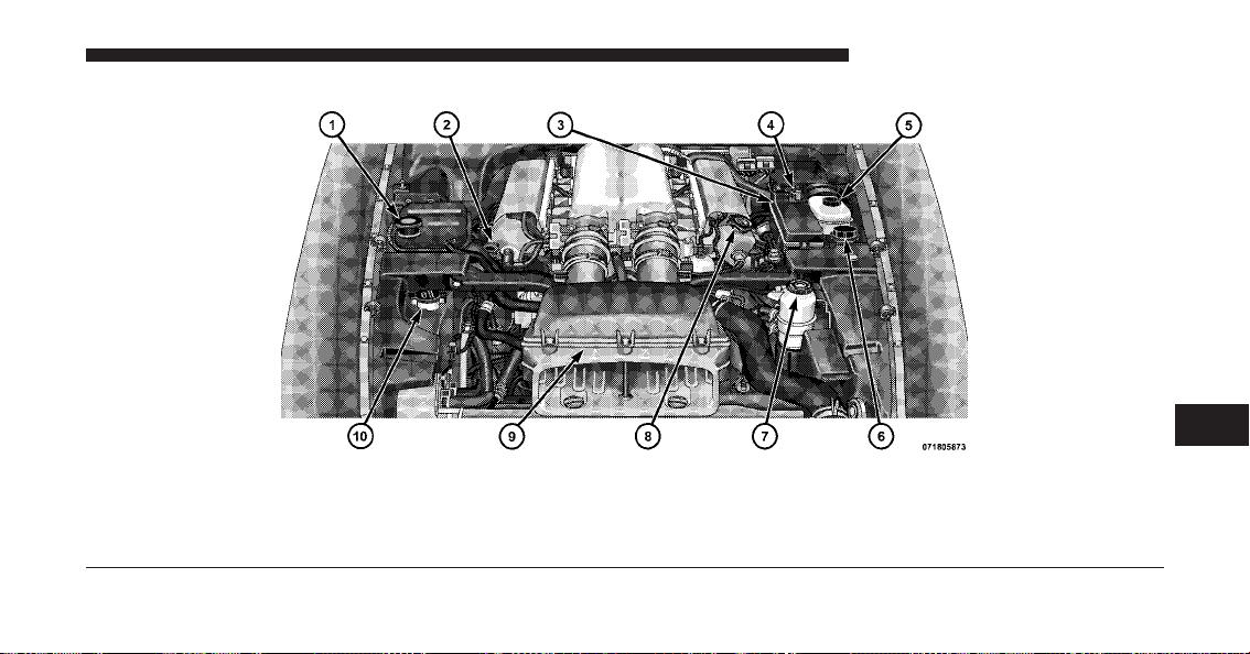
ENGINE COMPARTMENT — 8.4L
1 — Coolant Pressure Cap 6 — Clutch Fluid Reservoir
2 — Engine Oil Dipstick 7 — Power Steering Fluid Reservoir
3 — Power Distribution Center 8 — Engine Oil Fill
4 — Remote Jump Start Positive Battery Post 9 — Air Cleaner Filter
5 — Brake Fluid Reservoir 10 — Washer Fluid Reservoir
7
MAINTAINING YOUR VEHICLE 209

ONBOARD DIAGNOSTIC SYSTEM (OBD II)
To meet new government regulations and promote
cleaner air, your vehicle is equipped with a sophisticated
onboard diagnostic system called OBD II. This system
monitors the performance of the emissions and engine
control systems. When these systems are operating prop-
erly, your vehicle will provide excellent performance and
fuel economy, as well as engine emissions well within
current government regulations.
If any of these systems require service, the OBD II system
will turn on the Malfunction Indicator Light. It will also
store diagnostic codes and other information to assist
your service technician in making repairs. Although your
vehicle will usually be drivable and not need towing, see
your authorized dealer for service as soon as possible.
CAUTION!
Prolonged driving with the light on could cause
further damage to the emission control system. It
could also affect fuel economy and driveability. The
vehicle must be serviced before any state emissions
tests can be performed.
If the light is flashing, severe catalytic converter damage
and power loss will soon occur. Immediate service is
required.
If the gas cap is not tightened properly, the light may
come on. Be sure the gas cap is tightened every time you
add fuel.
210 MAINTAINING YOUR VEHICLE

EMISSIONS INSPECTION AND MAINTENANCE
PROGRAMS
In some localities, it may be a legal requirement to pass
an inspection of your vehicle’s emissions control system.
Failure to pass could prevent vehicle registration.
For states that require an Inspection and Mainte-
nance (I/M), this check verifies the “Malfunction
Indicator Light (MIL)” is functioning and is not
on when the engine is running, and that the OBD II
system is ready for testing.
Normally, the OBD II system will be ready. The OBD II
system may not be ready if your vehicle was recently
serviced, recently had a dead battery or a battery replace-
ment. If the OBD II system should be determined not
ready for the I/M test, your vehicle may fail the test.
Your vehicle has a simple ignition key-actuated test,
which you can use prior to going to the test station. To
check if your vehicle’s OBD II system is ready, you must
do the following:
1. Turn the ignition switch to the ON position, but do not
crank or start the engine.
2. If you crank or start the engine, you will have to start
this test over.
3. As soon as you turn the ignition switch to the ON
position, you will see the MIL symbol come on as part of
a normal bulb check.
4. Approximately 15 seconds later, one of two things will
happen:
a. The MIL will flash for about 10 seconds and then
return to being fully illuminated until you turn OFF
7
MAINTAINING YOUR VEHICLE 211

the ignition or start the engine. This means that your
vehicle’s OBD II system is not ready and you should
not proceed to the I/M station.
b. The MIL will not flash at all and will remain fully
illuminated until you turn OFF the ignition or start the
engine. This means that your vehicle’s OBD II system
is ready and you can proceed to the I/M station.
If your OBD II system is not ready, you should see your
authorized dealer or repair facility. If your vehicle was
recently serviced or had a battery failure or replacement,
you may need to do nothing more than drive your
vehicle as you normally would in order for your OBD II
system to update. A recheck with the above test routine
may then indicate that the system is now ready.
Regardless of whether your vehicle’s OBD II system is
ready or not, if the MIL is illuminated during normal
vehicle operation you should have your vehicle serviced
before going to the I/M station. The I/M station can fail
your vehicle because the MIL is on with the engine
running.
REPLACEMENT PARTS
Use of genuine MOPAR威 parts for normal/scheduled
maintenance and repairs is highly recommended to en-
sure the designed performance. Damage or failures
caused by the use of non-MOPAR威 parts for maintenance
and repairs will not be covered by the manufacturer’s
warranty.
DEALER SERVICE
Your authorized dealer has the qualified service person-
nel, special tools, and equipment to perform all service
operations in an expert manner. Service Manuals are
available which include detailed service information for
your vehicle. Refer to these Service Manuals before
attempting any procedure yourself.
212 MAINTAINING YOUR VEHICLE
NOTE: Intentional tampering with emissions control
systems may void your warranty and could result in civil
penalties being assessed against you.
WARNING!
You can be badly injured working on or around a
motor vehicle. Only do service work for which you
have the knowledge and the proper equipment. If
you have any doubt about your ability to perform a
service job, take your vehicle to a competent me-
chanic.
MAINTENANCE PROCEDURES
The pages that follow contain the maintenance service
recommendations by the engineers who designed your
vehicle.
Besides those maintenance items specified in the fixed
maintenance schedule, there are other components which
may require servicing or replacement in the future.
CAUTION!
•
Failure to properly maintain your vehicle or per-
form repairs and service when necessary could
result in more costly repairs, damage to other
components or negatively impact vehicle perfor-
mance. Immediately have potential malfunctions
examined by an authorized Chrysler Group LLC
dealership or qualified repair center.
•
Your vehicle has been built with improved fluids
that protect the performance and durability of
your vehicle and also allow extended maintenance
intervals. Do not use chemical flushes in these
components as the chemicals can damage your
engine, transmission, power steering or air condi-
tioning. Such damage is not covered by the New
Vehicle Limited Warranty. If a flush is needed
because of component malfunction, use only the
specified fluid for the flushing procedure.
7
MAINTAINING YOUR VEHICLE 213

Engine Oil
Checking Oil Level
To assure proper engine lubrication, the engine oil must
be maintained at the correct level. Check the oil level at
regular intervals, such as every fuel stop. The best time to
check the oil level is approximately five minutes after a
fully warmed engine is turned off or before starting the
engine after it has sat overnight.
Checking the oil while the vehicle is on level ground also
will improve the accuracy of the oil level readings. Add
oil only when the level is below the SAFE mark.
CAUTION!
Overfilling or underfilling will cause oil aeration or
loss of oil pressure. This could damage your engine.
Change Engine Oil
Road conditions and your kind of driving affect the
interval at which your oil should be changed. Check the
following list to see if any apply to you.
•
Day or night temperatures are below 32°F (0°C)
•
Stop and go driving
•
Extensive engine idling
•
Driving in dusty conditions
•
Short trip driving of less than 10 miles (16.2 km)
•
More than 50% of your driving is at sustained high
speeds during hot weather, above 90°F (32°C)
NOTE: If ANY of these apply to you, then change your
engine oil every 3,000 miles (5 000 km) or three months,
whichever comes first, and follow “Maintenance Sched-
ule B.” Refer to “Maintenance Schedule” for further
information.
214 MAINTAINING YOUR VEHICLE

If none of these apply to you, then change your engine oil
at every interval shown on “Maintenance Schedule A.⬙
Refer to “Maintenance Schedule” for further information.
NOTE: Under no circumstances should oil change in-
tervals exceed 6,000 miles (10 000 km) or six months,
whichever comes first.
Engine Oil Selection
For best performance and maximum protection under all
types of operating conditions, the manufacturer only
recommends full synthetic engine oils that meet the
requirements of Chrysler Material Standard MS-10725
and are approved to MB 229.3 or MB 229.5.
The manufacturer recommends the use of a full synthetic
5W-40 or equivalent engine oil.
CAUTION!
Do not use chemical flushes in your engine oil as the
chemicals can damage your engine. Such damage is
not covered by the New Vehicle Limited Warranty.
Engine Oil Viscosity (SAE Grade)
SAE 5W-40 engine oil is preferred for use in all operating
temperatures.
The engine oil filler cap also shows the recommended engine
oil viscosity for your engine. For information on engine oil
filler cap location, refer to “Engine Compartment” in “Main-
taining Your Vehicle” for further information.
Synthetic Engine Oils
You may use synthetic engine oils provided the recom-
mended oil quality requirements are met, and the recom-
mended maintenance intervals for oil and filter changes
are followed.
7
MAINTAINING YOUR VEHICLE 215

Materials Added to Engine Oil
Do not add supplemental materials, other than leak
detection dyes, to the engine oil. Engine oil is an engi-
neered product and its performance may be impaired by
supplemental additives.
Disposing of Used Engine Oil and Oil Filters
Care should be taken in disposing of used engine oil and
oil filters from your vehicle. Used oil and oil filters,
indiscriminately discarded, can present a problem to the
environment. Contact your authorized dealer, service
station, or governmental agency for advice on how and
where used oil and oil filters can be safely discarded in
your area.
Engine Oil Filter
The engine oil filter should be replaced with a new filter
at every engine oil change.
Engine Oil Filter Selection
This manufacturer’s engines have a full-flow type oil
filter. Use a filter of this type for replacement. The quality
of replacement filters varies considerably. Only high
quality filters should be used to assure most efficient
service. MOPAR威 engine oil filters are a high quality oil
filter and are recommended.
Engine Air Cleaner Filter
For normal driving conditions, inspect and replace the
engine air cleaner filter at the intervals shown on “Main-
tenance Schedule A.” For vehicles driven frequently in
dusty or under severe conditions, inspect and replace the
engine air cleaner filter at the intervals shown on “Main-
tenance Schedule B.” Refer to “Maintenance Schedule”
for further information.
216 MAINTAINING YOUR VEHICLE
WARNING!
The air induction system (air cleaner, hoses, etc.) can
provide a measure of protection in the case of engine
backfire. Do not remove the air induction system (air
cleaner, hoses, etc.) unless such removal is necessary
for repair or maintenance. Make sure that no one is
near the engine compartment before starting the
vehicle with the air induction system (air cleaner,
hoses, etc.) removed. Failure to do so can result in
serious personal injury.
Engine Air Cleaner Filter Selection
The quality of replacement engine air cleaner filters varies
considerably. Only high quality filters should be used to
assure most efficient service. MOPAR威 engine air cleaner
filters are a high quality filter and are recommended.
Maintenance-Free Battery
The top of the maintenance-free battery is permanently
sealed. You will never have to add water, nor is periodic
maintenance required.
The battery is located underneath an access panel inside
the rear compartment on the left side of the vehicle. A
remote battery terminal is located in the engine compart-
ment for jump-starting. Refer to “Jump-Starting Proce-
dures” in “What To Do In Emergencies” for further
information.
7
MAINTAINING YOUR VEHICLE 217
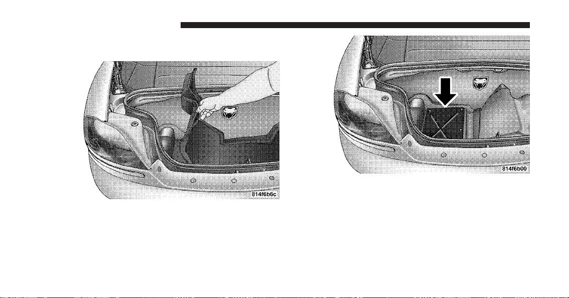
To gain access to the battery, remove the floor portion of
the rear compartment carpet.
Accessing The Battery
Battery Location
218 MAINTAINING YOUR VEHICLE
WARNING!
•
Battery fluid is a corrosive acid solution and can
burn or even blind you. Do not allow battery fluid
to contact your eyes, skin, or clothing. Do not lean
over a battery when attaching clamps. If acid
splashes in eyes or on skin, flush the area imme-
diately with large amounts of water.
•
Battery gas is flammable and explosive. Keep
flame or sparks away from the battery. Do not use
a booster battery or any other booster source with
an output greater than 12 Volts. Do not allow cable
clamps to touch each other.
•
Battery posts, terminals, and related accessories
contain lead and lead compounds. Wash hands
after handling.
CAUTION!
•
It is essential when replacing the cables on the
battery that the positive cable is attached to the
positive post and the negative cable is attached to
the negative post. Battery posts are marked posi-
tive (+) and negative (-) and are identified on the
battery case. Cable clamps should be tight on the
terminal posts and free of corrosion.
•
If a “fast charger” is used while the battery is in
the vehicle, disconnect both vehicle battery cables
before connecting the charger to the battery. Do
not use a “fast charger” to provide starting voltage.
Battery Save Feature
The Battery Save feature conserves battery power when
storing the vehicle. It allows for up to three months of
7
MAINTAINING YOUR VEHICLE 219

storage time without losing radio and engine controller
memory. Using this feature is an alternative to discon-
necting the battery.
NOTE: This vehicle is designed to sit in storage with a
fully charged battery for up to 30 days. If you plan to
store the vehicle longer than 30 days, we recommend
doing one of the following:
•
Disconnect the battery.
•
Use the battery charger.
•
Put the vehicle into Battery Save mode (3-month
charge).
To Activate the Battery Save Feature
1. Insert the key into the ignition switch.
2. Cycle the ignition switch from OFF/LOCK to ACC
four times. Leave the switch in the OFF/LOCK position
after the fourth cycle.
3. Push the driver’s power door lock switch in the up
direction. A single chime will sound and the horn will
chirp to indicate that the process has begun.
4. Remove the key from the ignition switch and exit the
vehicle. The Battery Save Feature will be enabled 45 sec-
onds after all doors are closed.
NOTE:
•
Turning the ignition switch to the ON/RUN position
at any time will cancel activation of the Battery Save
Feature.
•
The Remote Keyless Entry (RKE) and the exterior
passenger door handle will not work when the Battery
Save feature is enabled. Enter the vehicle by using the
key to unlock the door manually and by using the
exterior driver door handle to open the door.
220 MAINTAINING YOUR VEHICLE
•
The Vehicle Security Alarm is disabled when the
Battery Save Feature is enabled. Therefore, the vehicle
is not protected when the Battery Save Feature is
enabled.
•
The exterior and interior lighting functions will not
work when the Battery Save Feature is enabled.
To Deactivate the Battery Save Feature
1. Press the exterior driver’s door handle once to wake
up the vehicle. Then, press the handle again to open the
door.
NOTE: If the door does not open (vehicle is armed),
press the RKE UNLOCK button to unlock the vehicle.
2. Insert the key into the ignition switch.
3. Turn the ignition switch to the ON/RUN position. The
Battery Save Feature will turn off.
NOTE: If the ignition switch is NOT turned to ON/
RUN position, the Battery Save Feature will be enabled
45 seconds after the driver’s door is closed.
Air Conditioner Maintenance
For best possible performance, your air conditioner
should be checked and serviced by an authorized dealer
at the start of each warm season. This service should
include cleaning of the condenser fins and a performance
test. Drive belt tension should also be checked at this
time.
CAUTION!
Do not use chemical flushes in your air conditioning
system as the chemicals can damage your air condi-
tioning components. Such damage is not covered by
the New Vehicle Limited Warranty.
7
MAINTAINING YOUR VEHICLE 221
NOTE: If A/C performance seems less then normal,
check the front of the A/C condenser (located in front of
the radiator) for dirt and insect accumulation. Clean with
a gentle water spray as required. Front end fascia protec-
tors may reduce air flow to the condenser and radiator,
reducing A/C and engine cooling performance.
WARNING!
•
Use only refrigerants and compressor lubricants
approved by the manufacturer for your air condi-
tioning system. Some unapproved refrigerants are
flammable and can explode, injuring you. Other
unapproved refrigerants or lubricants can cause
the system to fail, requiring costly repairs. Refer to
Warranty Information Book, located on the DVD,
for further warranty information.
(Continued)
WARNING! (Continued)
•
The air conditioning system contains refrigerant
under high pressure. To avoid risk of personal
injury or damage to the system, adding refrigerant
or any repair requiring lines to be disconnected
should be done by an experienced technician.
Refrigerant Recovery and Recycling
R-134a Air Conditioning Refrigerant is a hydrofluoro-
carbon (HFC) that is endorsed by the Environmental
Protection Agency and is an ozone-saving product. How-
ever, the manufacturer recommends that air conditioning
service be performed by authorized dealers or other
service facilities using recovery and recycling equipment.
NOTE: Use only manufacturer approved A/C System
Sealers, Stop Leak Products, Seal Conditioners, Compres-
sor Oil, and Refrigerants.
222 MAINTAINING YOUR VEHICLE

Body Lubrication
Locks and all body pivot points, including such items as
seat tracks, door hinge pivot points and rollers, liftgate,
tailgate, sliding doors and hood hinges, should be lubri-
cated periodically with a lithium based grease, such as
MOPAR威 Spray White Lube or equivalent, to assure
quiet, easy operation and to protect against rust and
wear. Prior to the application of any lubricant, the parts
concerned should be wiped clean to remove dust and
grit; after lubricating excess oil and grease should be
removed. Particular attention should also be given to
hood latching components to insure proper function.
When performing other underhood services, the hood
latch, release mechanism and safety catch should be
cleaned and lubricated.
The external lock cylinders should be lubricated twice a
year, preferably in the Fall and Spring. Apply a small
amount of a high quality lubricant, such as MOPAR威
Lock Cylinder Lubricant or equivalent directly into the
lock cylinder.
Windshield Wiper Blades
Clean the rubber edges of the wiper blades and the
windshield periodically with a sponge or soft cloth and a
mild nonabrasive cleaner. This will remove accumula-
tions of salt or road film.
Operation of the wipers on dry glass for long periods
may cause deterioration of the wiper blades. Always use
washer fluid when using the wipers to remove salt or dirt
from a dry windshield.
Avoid using the wiper blades to remove frost or ice from
the windshield. Keep the blade rubber out of contact with
petroleum products such as engine oil, gasoline, etc.
7
MAINTAINING YOUR VEHICLE 223
NOTE: Life expectancy of wiper blades varies depend-
ing on geographical area and frequency of use. Poor
performance of blades may be present with chattering,
marks, water lines or wet spots. If any condition is
present please proceed to clean wiper blades with humid
cloth removing any debris that may be affecting its
function.
Adding Washer Fluid
The windshield washer fluid reservoir is located in the
front of the engine compartment on the passenger side of
the vehicle. Be sure to check the fluid level in the
reservoir at regular intervals. Fill the reservoir with
windshield washer solvent (not engine coolant (anti-
freeze) and operate the system for a few seconds to flush
out the residual water.
WARNING!
Commercially available windshield washer solvents
are flammable. They could ignite and burn you. Care
must be exercised when filling or working around
the washer solution.
Exhaust System
The best protection against carbon monoxide entry into
the vehicle body is a properly maintained engine exhaust
system.
If you notice a change in the sound of the exhaust system;
or if exhaust fumes can be detected inside the vehicle; or
when the underside or side of the vehicle is damaged;
have a competent technician inspect the complete ex-
haust system and adjacent body areas for broken, dam-
aged, deteriorated, or mispositioned parts. Open seams
or loose connections could permit exhaust fumes to seep
224 MAINTAINING YOUR VEHICLE
into the passenger compartment. In addition, inspect the
exhaust system each time the vehicle is raised for lubri-
cation or oil change. Replace as required.
WARNING!
Exhaust gases can injure or kill. They contain carbon
monoxide (CO) which is colorless and odorless.
Breathing it can make you unconscious and can
eventually poison you. To avoid breathing CO, refer
to “Safety Tips/Exhaust Gas” in “Things To Know
Before Starting Your Vehicle” for further informa-
tion.
CAUTION!
The catalytic converter requires the use of unleaded
fuel only. Leaded gasoline will destroy the effective-
ness of the catalyst as an emissions control device
and may seriously reduce engine performance and
cause serious damage to the engine.
Under normal operating conditions, the catalytic con-
verter will not require maintenance. However, it is im-
portant to keep the engine properly tuned to assure
proper catalyst operation and prevent possible catalyst
damage.
7
MAINTAINING YOUR VEHICLE 225
CAUTION!
Damage to the catalytic converter can result if your
vehicle is not kept in proper operating condition.
Have your vehicle serviced promptly in the event of
engine malfunction, particularly when involving en-
gine misfire or other apparent loss of performance.
Continued operation of your vehicle with a severe
malfunction could cause the converter to overheat,
resulting in possible damage to the converter and the
vehicle.
NOTE: Intentional tampering with emissions control
systems can result in civil penalties being assessed
against you.
WARNING!
A hot exhaust system can start a fire if you park over
materials that can burn. Such materials might be
grass or leaves coming in contact with your exhaust
system. Do not park or operate your vehicle in areas
where your exhaust system can contact anything that
can burn.
In unusual situations involving grossly malfunctioning
engine operation, a scorching odor may indicate severe
and abnormal catalyst overheating. If this should occur,
safely bring the vehicle to a complete stop, shut the
engine off, and allow the vehicle to cool. Thereafter,
obtain service, including a tune-up to manufacturer’s
specifications immediately.
226 MAINTAINING YOUR VEHICLE
To minimize the possibility of catalytic converter dam-
age:
•
Do not shut off the engine or interrupt the ignition
when the transmission is in gear and the vehicle is in
motion.
•
Do not try to start the engine by pushing or towing the
vehicle.
•
Do not idle the engine with any spark plug wires
disconnected or removed, such as when diagnostic
testing, or for prolonged periods during very rough
idling or malfunctioning operating conditions.
Cooling System
WARNING!
•
When working near the radiator cooling fans,
disconnect each fan motor lead or turn the ignition
switch to the OFF position. The fans are tempera-
ture controlled and can start any time the ignition
switch is in the ON position.
•
You or others could be badly burned by hot engine
coolant (antifreeze) or steam from your radiator. If
you see or hear steam coming from under the
hood, do not open the hood until the radiator has
had time to cool. Never try to open a cooling
system pressure cap when the radiator is hot.
Coolant Checks
Check engine coolant (antifreeze) protection every
12 months (before the onset of freezing weather, where
applicable). If the engine coolant (antifreeze) is dirty or
7
MAINTAINING YOUR VEHICLE 227

rusty in appearance, the system should be drained,
flushed, and refilled with fresh engine coolant (anti-
freeze). Check the front of the A/C condenser/radiator
for any accumulation of bugs, leaves, etc. If dirty, clean by
gently spraying water from a garden hose vertically
down the face of the condenser/radiator.
Check the coolant recovery bottle tubing for brittle rub-
ber, cracking, tears, cuts, and tightness of the connection
at the bottle and radiator. Inspect the entire system for
leaks.
With the engine at normal operating temperature (but
not running), check the cooling system pressure cap for
proper vacuum sealing by draining a small amount of
engine coolant (antifreeze) from the radiator drain cock.
If the cap is sealing properly, the engine coolant (anti-
freeze) will begin to drain from the coolant recovery
bottle. DO NOT REMOVE THE COOLANT PRESSURE
CAP WHEN THE COOLING SYSTEM IS HOT.
Cooling System – Drain, Flush, and Refill
If the engine coolant (antifreeze) is dirty or contains a
considerable amount of sediment, clean and flush with a
reliable cooling system cleaner. Follow with a thorough
rinsing to remove all deposits and chemicals. Properly
dispose of the old engine coolant (antifreeze).
Refer to “Maintenance Schedule” for the proper mainte-
nance intervals.
Selection of Coolant
Use only the manufacturer’s recommended engine cool-
ant (antifreeze). Refer to “Fluids, Lubricants, and Genu-
ine Parts” in “Maintaining Your Vehicle” for further
information.
228 MAINTAINING YOUR VEHICLE

CAUTION!
•
Mixing of engine coolant (antifreeze) other than
specified HOAT engine coolant (antifreeze), may
result in engine damage and may decrease corro-
sion protection. If a non-HOAT engine coolant
(antifreeze) is introduced into the cooling system
in an emergency, it should be replaced with the
specified engine coolant (antifreeze) as soon as
possible.
•
Do not use water alone or alcohol-based engine
coolant (antifreeze) products. Do not use addi-
tional rust inhibitors or antirust products, as they
may not be compatible with the radiator engine
coolant (antifreeze) and may plug the radiator.
•
This vehicle has not been designed for use with
Propylene Glycol based engine coolant (anti-
freeze). Use of Propylene Glycol based engine
coolant (antifreeze) is not recommended.
Adding Coolant
Your vehicle has been built with an improved engine
coolant (antifreeze) that allows extended maintenance
intervals. This engine coolant (antifreeze) can be used up
to five years or 102,000 miles (170 000 km) before replace-
ment. To prevent reducing this extended maintenance
period, it is important that you use the same engine
coolant (antifreeze) throughout the life of your vehicle.
Please review these recommendations for using Hybrid
Organic Additive Technology (HOAT) engine coolant
(antifreeze). When adding engine coolant (antifreeze):
•
The manufacturer recommends using MOPAR威 Anti-
freeze/Coolant 5 Year/100,000 Mile Formula HOAT
(Hybrid Organic Additive Technology) or equivalent.
•
Mix a minimum solution of 50% HOAT engine coolant
and distilled water. Use higher concentrations (not to
exceed 70%) if temperatures below ⫺34°F (⫺37°C) are
anticipated.
7
MAINTAINING YOUR VEHICLE 229

•
Use only high purity water such as distilled or deion-
ized water when mixing the water/engine coolant
(antifreeze) solution. The use of lower quality water
will reduce the amount of corrosion protection in the
engine cooling system.
Please note that it is the owner’s responsibility to main-
tain the proper level of protection against freezing ac-
cording to the temperatures occurring in the area where
the vehicle is operated.
NOTE: Mixing engine coolant (antifreeze) types will
decrease the life of the engine coolant (antifreeze) and
will require more frequent coolant changes.
Cooling System Pressure Cap
The cap must be fully tightened to prevent loss of engine
coolant (antifreeze), and to insure that engine coolant
(antifreeze) will return to the radiator from the coolant
recovery bottle.
The cap should be inspected and cleaned if there is any
accumulation of foreign material on the sealing surfaces.
WARNING!
•
The warning words “DO NOT OPEN HOT” on
the cooling system pressure cap are a safety pre-
caution. Never add engine coolant (antifreeze)
when the engine is overheated. Do not loosen or
remove the cap to cool an overheated engine. Heat
causes pressure to build up in the cooling system.
To prevent scalding or injury, do not remove the
pressure cap while the system is hot or under
pressure.
•
Do not use a pressure cap other than the one
specified for your vehicle. Personal injury or en-
gine damage may result.
230 MAINTAINING YOUR VEHICLE

Disposal of Used Coolant
Used ethylene glycol based engine coolant (antifreeze) is
a regulated substance requiring proper disposal. Check
with your local authorities to determine the disposal
rules for your community. To prevent ingestion by ani-
mals or children, do not store ethylene glycol based
engine coolant (antifreeze) in open containers or allow it
to remain in puddles on the ground. If ingested by a child
or pet, seek emergency assistance immediately. Clean up
any ground spills immediately.
Coolant Level
The coolant bottle provides a quick visual method for
determining that the engine coolant (antifreeze) level is
adequate. With the engine idling, and warm to normal
operating temperature, the level of the engine coolant
(antifreeze) in the bottle should be between the ranges
indicated on the bottle.
The radiator normally remains completely full, so there is
no need to remove the radiator cap unless checking for
engine coolant (antifreeze) freeze point or replacing en-
gine coolant (antifreeze). Advise your service attendant
of this. As long as the engine operating temperature is
satisfactory, the coolant bottle need only be checked once
a month.
When additional engine coolant (antifreeze) is needed to
maintain the proper level, it should be added to the
coolant bottle. Do not overfill.
Points to Remember
NOTE: When the vehicle is stopped after a few miles
(kilometers) of operation, you may observe vapor coming
from the front of the engine compartment. This is nor-
mally a result of moisture from rain, snow, or high
humidity accumulating on the radiator and being vapor-
ized when the thermostat opens, allowing hot engine
coolant (antifreeze) to enter the radiator.
7
MAINTAINING YOUR VEHICLE 231

If an examination of your engine compartment shows no
evidence of radiator or hose leaks, the vehicle may be
safely driven. The vapor will soon dissipate.
•
Do not overfill the coolant recovery bottle.
•
Check engine coolant (antifreeze) freeze point in the
coolant bottle. If engine coolant (antifreeze) needs to
be added, contents of the coolant bottle also must be
protected against freezing.
•
If frequent engine coolant (antifreeze) additions are
required, or if the level in the coolant recovery bottle
does not drop when the engine cools, the cooling
system should be pressure tested for leaks.
•
Maintain engine coolant (antifreeze) concentration at
50% HOAT engine coolant (antifreeze) (minimum)
and distilled water for proper corrosion protection of
your engine, which contains aluminum components.
•
Make sure that the radiator and coolant recovery
bottle overflow hoses are not kinked or obstructed.
•
Keep the front of the radiator clean. If your vehicle is
equipped with air conditioning, keep the front of the
condenser clean.
•
Do not change the thermostat for Summer or Winter
operation. If replacement is ever necessary, install
ONLY the correct type thermostat. Other designs may
result in unsatisfactory cooling performance, poor gas
mileage, and increased emissions.
Brake System
In order to assure brake system performance, all brake
system components should be inspected periodically.
Refer to “Maintenance Schedule” for the proper mainte-
nance intervals.
232 MAINTAINING YOUR VEHICLE
WARNING!
Riding the brakes can lead to brake failure and
possibly an accident. Driving with your foot resting
or riding on the brake pedal can result in abnormally
high brake temperatures, excessive lining wear, and
possible brake damage. You would not have your full
braking capacity in an emergency.
Master Cylinder – Brake Fluid Level Check
Check the fluid level in the master cylinder immediately
if the brake system warning light indicates system fail-
ure.
Check the fluid level in the master cylinder when per-
forming underhood services.
Clean the top of the master cylinder area before removing
the cap. If necessary, add fluid to bring the fluid level up
to the requirements described on the brake fluid reser-
voir.
Overfilling of fluid is not recommended because it may
cause leaking in the system.
With disc brakes, fluid level can be expected to fall as the
brake pads wear. However, low fluid level may be caused
by a leak and a checkup may be needed.
Use only the manufacturer’s recommended brake fluid.
Refer to “Fluids, Lubricants, and Genuine Parts” in
“Maintaining Your Vehicle” for further information. Use
of a brake fluid that may have a lower initial boiling
point or unidentified as to specification, may result in
sudden brake failure during hard prolonged braking.
7
MAINTAINING YOUR VEHICLE 233
WARNING!
•
Use only manufacturer’s recommended brake
fluid. Refer to “Fluids, Lubricants, and Genuine
Parts” in “Maintaining Your Vehicle” for further
information. Using the wrong type of brake fluid
can severely damage your brake system and/or
impair its performance. The proper type of brake
fluid for your vehicle is also labeled on the origi-
nal factory installed hydraulic master cylinder
reservoir.
(Continued)
WARNING! (Continued)
•
To avoid contamination from foreign matter or
moisture, use only new brake fluid or fluid that
has been in a tightly closed container. Keep the
master cylinder reservoir cap secured at all times.
Brake fluid in a open container absorbs moisture
from the air resulting in a lower boiling point.
This may cause it to boil unexpectedly during hard
or prolonged braking, resulting in sudden brake
failure. This could result in a accident.
•
Overfilling the brake fluid reservoir can result in
spilling brake fluid on hot engine parts, causing
the brake fluid to catch fire. Brake fluid can also
damage painted and vinyl surfaces, care should be
taken to avoid its contact with these surfaces.
(Continued)
234 MAINTAINING YOUR VEHICLE
WARNING! (Continued)
•
Do not allow petroleum based fluid to contami-
nate the brake fluid. Brake seal components could
be damaged, causing partial or complete brake
failure. This could result in an accident.
Change Brake Fluid
Brake fluid will tend to absorb moisture from the atmo-
sphere over time. If the fluid becomes contaminated with
water, brake performance will deteriorate. Therefore, the
brake fluid must be changed at the intervals specified in
the “Maintenance Schedule.” Refer to “Maintenance
Schedule” for further information. See your authorized
dealer for service.
Manual Transmission
Transmission Fluid Level Check
Check the fluid in the transmission when performing
other underhood services.
Check the fluid level by removing the fill plug located on
the left side of the transmission. The fluid level should be
at the bottom of the fill hole. Add fluid, if necessary, to
maintain the proper level. Refer to “Fluids, Lubricants,
and Genuine Parts” in “Maintaining Your Vehicle” for
further information.
CAUTION!
Using a transmission fluid other than the manufac-
turer’s recommended fluid may cause deterioration
in transmission shift quality and/or damage to the
transmission. Refer to “Fluids, Lubricants, and
Genuine Parts” in “Maintaining Your Vehicle” for
further information.
Change Transmission Fluid
Refer to “Maintenance Schedule” for the proper mainte-
nance intervals. If contaminated with water, change the
fluid immediately. See your authorized dealer for service.
7
MAINTAINING YOUR VEHICLE 235
Hydraulic Clutch
Master Cylinder – Clutch Fluid Level Check
Check the fluid in the clutch master cylinder when
performing underhood services.
Clean the top of the master cylinder area before removing
the cap. If necessary, add fluid to the reservoir.
Do not overfill. Overfilling can cause clutch release
problems as the clutch wears. A low fluid level may
indicate a leak, in which case, hydraulic clutch linkage
replacement may be required. The fluid level in the
reservoir will rise as the clutch wears - do not remove
fluid.
Use only the manufacturer’s recommended clutch fluid.
Refer to “Fluids, Lubricants, and Genuine Parts” in
“Maintaining Your Vehicle” for further information.
WARNING!
Overfilling the clutch fluid reservoir can result in
spilling clutch fluid on hot engine parts and the
clutch fluid catching fire.
Use only clutch fluid that has been in a tightly closed
container to avoid contamination from foreign matter.
CAUTION!
•
Do not allow petroleum base fluid to contaminate
the clutch fluid, all clutch seal components could
be damaged causing partial or complete clutch
failure.
•
Clutch fluid can damage the finish of your vehicle.
Do not allow clutch fluid to contact any painted
surface.
236 MAINTAINING YOUR VEHICLE

Change Clutch Fluid
Clutch fluid will tend to absorb moisture from the
atmosphere over time. If the fluid becomes contaminated
with water, clutch performance will deteriorate. There-
fore, the clutch fluid must be changed at the intervals
specified in “Maintenance Schedule.” Refer to “Mainte-
nance Schedule” for further information. See your autho-
rized dealer for service.
Rear Axle
Axle Lubricant Level Check
Check the exterior of the axle for evidence of gear oil
leakage every 12 months or 6,000 miles (10 000 km). This
check should be made with the vehicle level and sup-
ported by the suspension, with the vehicle on the ground
or raised on an axle and wheel type hoist. The axle
lubricant level should be between the bottom of the filler
plug and a point approximately 3/8 in (9.5 mm) below
the filler plug. If adding axle lubricant, use only the
manufacturer’s recommended axle lubricant. Refer to
“Fluids, Lubricants, and Genuine Parts” in “Maintaining
Your Vehicle” for further information.
NOTE: The Limited Slip Differential requires that a
friction control additive be added when draining and
refilling the axle lubricant.
Change Axle Lubricant
Refer to “Maintenance Schedule” for the proper mainte-
nance intervals. Change the lubricant immediately if
contaminated with water. See your authorized dealer for
service.
Appearance Care and Protection from Corrosion
Protection of Body and Paint from Corrosion
Vehicle body care requirements vary according to geo-
graphic locations and usage. Chemicals that make roads
7
MAINTAINING YOUR VEHICLE 237

passable in snow and ice, and those that are sprayed on
trees and road surfaces during other seasons, are highly
corrosive to the metal in your vehicle.
The following maintenance recommendations will enable
you to obtain maximum benefit from the corrosion
resistance built into your vehicle.
Washing
•
Wash your vehicle regularly. Always wash your ve-
hicle in the shade using MOPAR威 Car Wash or equiva-
lent, or a mild car wash soap, and rinse the panels
completely with clear water.
•
If insects, tar, or other similar deposits have accumu-
lated on your vehicle, use MOPAR威 Super Kleen Bug
and Tar Remover or equivalent to remove.
•
Use a high quality cleaner wax, such as MOPAR威
Cleaner Wax or equivalent to remove road film, stains,
and to protect your paint finish. Take care never to
scratch the paint.
•
Avoid using abrasive compounds and power buffing
that may diminish the gloss or thin out the paint
finish.
CAUTION!
Use of power washers exceeding 1,200 psi (8 274 kPa)
can result in damage or removal of paint and decals.
Wheel and Wheel Trim Care
All wheels and wheel trim, especially aluminum and
chrome-plated wheels should be cleaned regularly with a
mild soap and water to prevent corrosion. To remove
heavy soil, use MOPAR威 Wheel Cleaner or equivalent, or
select a nonabrasive, non-acidic cleaner. Do not use
238 MAINTAINING YOUR VEHICLE

scouring pads, steel wool, a bristle brush or metal pol-
ishes. Only MOPAR威 cleaners or equivalent are recom-
mended. Do not use oven cleaner. Avoid automatic car
washes that use acidic solutions or harsh brushes that
may damage the wheels’ protective finish.
Convertible Top Care – Convertible Models Only
Use a mild detergent to clean the top. Avoid heavy
scrubbing and rinse with plenty of clean water. Allow to
dry thoroughly before storage.
Stain Repel Fabric Cleaning Procedure –
If Equipped
Stain Repel seats may be cleaned in the following man-
ner:
•
Remove as much of the stain as possible by blotting
with a clean, dry towel.
•
Blot any remaining stain with a clean, damp towel.
•
For tough stains, apply MOPAR威 Total Clean or
equivalent, or a mild soap solution to a clean, damp
cloth and remove the stain. Use a fresh, damp towel to
remove soap residue.
•
For grease stains, apply MOPAR威 Multi-Purpose
Cleaner or equivalent, to a clean, damp cloth and
remove the stain. Use a fresh, damp towel to remove
soap residue.
•
Do not use any harsh solvents or any other form of
protectants on Stain Repel products.
Interior Care
Use MOPAR威 Total Clean or equivalent to clean fabric
upholstery and carpeting.
Interior Trim should be cleaned starting with a damp
cloth, a damp cloth with MOPAR威 Total Clean or equiva-
lent, then MOPAR威 Spot & Stain Remover or equivalent,
7
MAINTAINING YOUR VEHICLE 239

if absolutely necessary. Do not use harsh cleaners or
Armor All威. Use MOPAR威 Total Clean or equivalent to
clean vinyl upholstery.
Leather or Vinyl Seat/Trim Care and Cleaning
Leather is best preserved by regular cleaning with a
damp soft cloth. Small particles of dirt can act as an
abrasive and damage the leather surface and should be
removed immediately with a damp cloth. Stubborn soils
can be removed easily with a soft cloth and MOPAR威
Total Clean or equivalent. Care should be taken to avoid
soaking the leather with any liquid. Please do not use
polishes, oils, cleaning fluids, solvents, detergents, or
ammonia-based cleaners to clean the leather. Application
of a leather conditioner is not required to maintain the
original condition.
Glass Surfaces
All glass surfaces should be cleaned on a regular basis with
MOPAR威 Glass Cleaner or any commercial household-type
glass cleaner. Never use an abrasive type cleaner. Use
caution when cleaning inside rear windows equipped with
electric defrosters. Do not use scrapers or other sharp
instruments which may scratch the elements.
When cleaning the rearview mirror, spray cleaner on the
towel or rag that you are using. Do not spray cleaner
directly on the mirror.
Cleaning Plastic Instrument Cluster Lenses
The lenses in front of the instruments in this vehicle are
molded in clear plastic. When cleaning the lenses, care
must be taken to avoid scratching the plastic.
1. Clean with a wet soft rag. A mild soap solution may be
used, but do not use high alcohol content or abrasive
cleaners. If soap is used, wipe clean with a clean damp
rag.
2. Dry with a soft tissue.
240 MAINTAINING YOUR VEHICLE

Seat Belt Maintenance
Do not bleach, dye or clean the belts with chemical
solvents or abrasive cleaners. This will weaken the fabric.
Sun damage will also weaken the fabric.
If the belts need cleaning, use MOPAR威 Total Clean or
equivalent, a mild soap solution, or lukewarm water. Do
not remove the belts from the vehicle to wash them.
Replace the belts if they appear frayed or worn or if the
buckles do not work properly.
Dry with a soft tissue.
Aero Group — If Equipped
Please review all of the precautionary notes regarding the
Aero Group option.
1. Front Splitter
The front splitter will not flex or compress against
impacts from the front. If an impact does occur, have the
splitter inspected. A cracked or delaminated splitter
should be replaced.
Front Splitter
7
MAINTAINING YOUR VEHICLE 241
Always leave ample room and be sure to educate anyone
you allow to operate the vehicle.
CAUTION!
Use care when approaching parking blocks, tall
speed bumps and garage curbs. These surfaces can
damage your splitter.
Use caution when driving up to sloped surfaces or over
speed bumps. Approaching a speed bump or a slope at a
slight angle may improve your clearance.
CAUTION!
•
Hard contact with steep ramps may cause damage
to your splitter.
•
Replace rub strips when they are worn down to
3/8 inch (10 mm) on the front edge. This will avoid
damage to the carbon fiber panel
WARNING!
Do not install the ACR track extension and/or dive
planes on a vehicle equipped with the Aero Group
option. The aerodynamic balance of this set up is
unstable and can cause the loss of control.
2. Rear Wing
Do not operate the vehicle with the rear wing removed.
The aerodynamic balance of this set up is unstable and
can cause a loss of control.
242 MAINTAINING YOUR VEHICLE
WARNING!
Use extra caution when closing the rear deck lid on
the ARY convertible. Due to the added weight of the
rear wing the deck lid will close at a higher rate of
speed and can cause injury.
3. Carbon Fiber
The clear coated carbon fiber panels will have some
variation and minor waviness in the woven pattern. This
is inherent to the process and a sign of its authenticity.
All carbon fiber materials are susceptible to UV degra-
dation during long exposure to the sun. The ACR woven
carbon components use the latest technology in the resin
system and the clear coat. As with any automotive
coating, storing your vehicle in a covered location will
guarantee a long lasting finish.
The rear wing is molded with unidirectional carbon fiber
and painted in body color. Some patterned or linear
conditions may be visible in the painted carbon fiber
surfaces. This is also a normal result of the carbon fiber
process.
Rear Wing
7
MAINTAINING YOUR VEHICLE 243
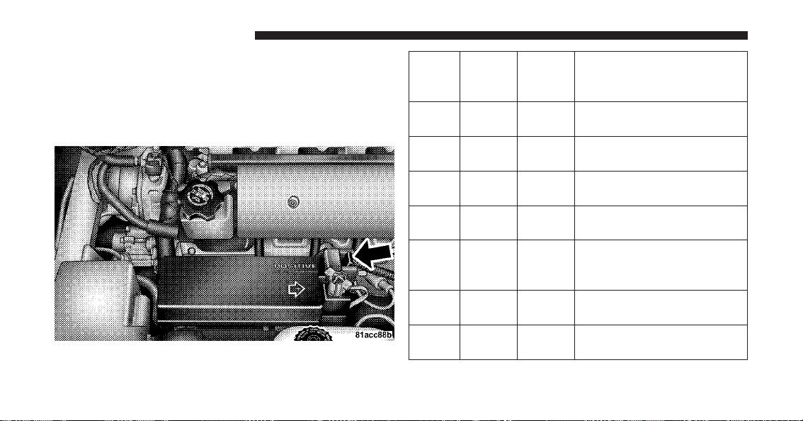
FUSES
Power Distribution Center
The Power Distribution Center is located in the engine
compartment on the driver’s side of the vehicle. This
center contains fuses and relays.
Cavity Car-
tridge
Fuse
Mini-
Fuse
Description
1 40 Amp
Green
— Blower Motor
2 40 Amp
Green
— Anti-Lock Brakes (ABS)
Pump Feed/Starter
3 30 Amp
Pink
— Body Control Module
(BCM) – Battery Feed
4 20 Amp
Blue
— Amplifier
5 30 Amp
Pink
— Ignition Switch Run/
Accessory Feed – Win-
dows
6 40 Amp
Green
— Body Control Module
(BCM) – Battery Feed
7 30 Amp
Pink
— Anti-Lock Brakes (ABS)
Module
Power Distribution Center
244 MAINTAINING YOUR VEHICLE

Cavity Car-
tridge
Fuse
Mini-
Fuse
Description
8 30 Amp
Pink
— Ignition Switch Run/
Accessory Feed
9 40 Amp
Green
— Headlights
10 30 Amp
Pink
— Ignition Switch Run Feed
11 — 20 Amp
Yellow
Auto Shutdown Relay
(ASD)
12 — 20 Amp
Yellow
Cigar Lighter
13 — 15 Amp
Blue
Hazard Flasher
14 — 20 Amp
Yellow
Auto Shutdown Relay
(ASD)
15 — 25 Amp
Clear
Rear Window Defogger
(EBL)
Cavity Car-
tridge
Fuse
Mini-
Fuse
Description
16, 17 — 20 Amp
Yellow
Power Outlet
18 — 15 Amp
Blue
Ignition Off Draw (IOD)
19 — 15 Amp
Blue
Horn
20 — 15 Amp
Blue
Air Conditioning (A/C)
Clutch Relay
21 — 15 Amp
Blue
Stop Light Switch
22 — 25 Amp
Clear
Fuel Pump/Powertrain
Control Module (PCM)
23, 24 — 10 Amp
Red
Airbag
60, 61 — 15 Amp
Blue
Ignition Run/Start Relay
Feed
7
MAINTAINING YOUR VEHICLE 245
Cavity Car-
tridge
Fuse
Mini-
Fuse
Description
62, 63 — 15 Amp
Blue
Gauges
5, 6 — 10 Amp
Red
Airbag
7, 8 — 20 Amp
Yellow
Wiper Switch
9, 10 — 20 Amp
Yellow
Left HID Headlight
11, 12 — 20 Amp
Yellow
Right HID Headlight
CAUTION!
•
When installing the Power Distribution Center
cover, it is important to ensure the cover is prop-
erly positioned and fully latched. Failure to do so
may allow water to get into the Power Distribution
Center, and possibly result in an electrical system
failure.
•
When replacing a blown fuse, it is important to
use only a fuse having the correct amperage rating.
The use of a fuse with a rating other than indicated
may result in a dangerous electrical system over-
load. If a properly rated fuse continues to blow, it
indicates a problem in the circuit that must be
corrected.
246 MAINTAINING YOUR VEHICLE

•
Fill the fuel tank. This will prevent water condensation
inside the tank. If you plan to store your vehicle more
than two months, add an anti-oxidant fuel stabilizer to
the fuel tank.
•
Change the oil to remove any corrosive combustion
related acids in the crankcase.
•
Check that the radiator coolant level of protection is to
at least -20°F (-29°C).
•
Make sure that all tires are inflated to the optimum
pressure.
•
Wash and wax the vehicle to protect the finish.
•
Store the vehicle in a dry, well-ventilated location.
•
Move the wiper blades away from the windshield.
•
Block the wheels. Do not apply the parking brake.
•
Cut blocks of plywood about the same size of the tires.
Cover each block with indoor/outdoor carpeting and
place them between the tires and concrete. This will
prevent tire flat spotting.
•
For long-term storage, remove the tires and put the
vehicle up on blocks. Stack the tires on plywood and
cover with a tarp to prevent flat spotting.
•
If the vehicle will be subjected to freezing tempera-
tures, either remove the battery and store it in a dry,
well ventilated area or connect a trickle charger
(1.5 Amp) with automatic shutdown / overcharge
protection to the battery. However, do not leave the
trickle charger hooked up to the battery without being
plugged in to a 110 Volt AC outlet, as this will result in
further drain on the vehicle’s battery. If the vehicle is
not going to be driven in the next three weeks, perform
the battery recharge procedure in the Service Manual.
Then, either disconnect the battery at the negative
248 MAINTAINING YOUR VEHICLE

terminal or use the “Battery Save Feature” to conserve
battery power. Refer to “Maintenance Procedures/
Battery Save Feature” in “Maintaining Your Vehicle”
for further information.
NOTE: Disconnecting the battery causes the engine
control system to lose memory of some “learned” func-
tions. After reconnecting the battery, the engine may run
rough until the control module “relearns” these func-
tions. Using the Battery Save Feature will prevent the
engine controller from loosing its memory.
CAUTION!
Use care when disconnecting the remote positive
cable. It is connected to the battery and can short out
to any metal on the vehicle. Always tape or wrap the
exposed cable end to prevent electrical shorts.
Check the battery every four to six weeks to ensure that
the voltage is above 12.40 Volts. The voltage will drop
more rapidly in hot temperatures. If battery voltage
drops below 12.40 Volts, follow the battery recharge
procedure in the Service Manual.
NOTE: To help prevent the battery from discharging
during shorter periods of inactivity, perform the follow-
ing:
1. Make sure that the trunk/liftgate, hood, doors, win-
dows, and convertible top are completely closed.
2. Make sure that Remote Keyless Entry (RKE) transmit-
ter is operating and that the battery is good.
3. Make sure that the HOOD, TRUNK/LIFTGATE, and
DOOR switches are in adjustment. Perform the quick
system check, which follows:
Use the remote transmitter to set the alarm. If the alarm
SET light comes on and flashes, the system is operating
7
MAINTAINING YOUR VEHICLE 249

properly. If not, there is a problem with a switch or the
system. See your authorized dealer for service.
•
Cover the vehicle whenever possible to prevent acci-
dental damage to the finish.
REPLACEMENT BULBS
LIGHT BULBS – Interior Bulb Number
Message Center Indicators .................. 103
Cluster ................................ 103
Gauge Pack ............................103
Heater Control ........................... 37
Interior Lamp ......................... 212–2
Courtesy Foot Well Lights ..................194
Cargo Lamp (Coupe Liftgate) ................168
LIGHT BULBS – Exterior
(Convertible Models) Bulb Number
Low/High Beam High Intensity Discharge
(HID) Headlamp ....Serviced at authorized dealer only
Auxiliary High Beam Headlamp ..... (HB3A) 9005XS
Front Park/Turn Signal Lamp............. 3157AK
Fog Lamp .......................(H10 U) 9145
Front Side Marker Lamp..................2886X
Center High Mounted Stop Lamp
(CHMSL)................ 16LED(not serviceable)
Tail/Stop Lamp .........................3157
Taillamp ............................... 194
Rear Marker Lamp ....................... 194
Backup Lamp .......................... 3157
Rear Turn Signal Lamp .................3457AK
License Lamp ........................... 168
250 MAINTAINING YOUR VEHICLE
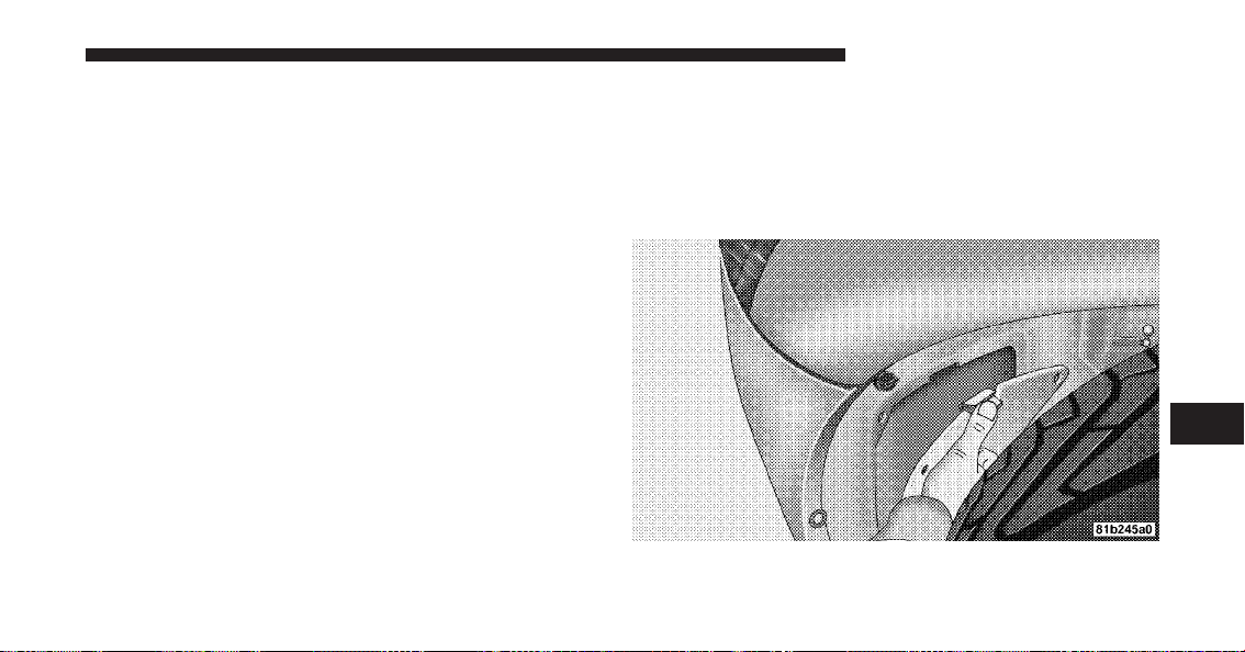
LIGHT BULBS – Exterior
(Coupe Models) Bulb Number
Low/High Beam High Intensity Discharge (HID)
Headlamp.........Serviced at authorized dealer only
Auxiliary High Beam Headlamp ..... (HB3A) 9005XS
Front Park/Turn Signal Lamp............. 3157AK
Fog Lamp .......................(H10 U) 9145
Front Side Marker Lamp..................2886X
Center High Mounted Stop Lamp (CHMSL). . . 16 LED
(not serviceable)
Tail/Stop/Turn Signal Lamp ................3157
Rear Marker Lamp ....................... 194
Backup Lamp .......................... 3157
License Lamp ........................... 168
NOTE: Upon turning the High Intensity Discharge
(HID) Headlamps on, there is a blue hue to the lamps.
This diminishes and becomes more white after approxi-
mately 10 seconds as the system charges.
BULB REPLACEMENT
Auxiliary High Beam Headlamp, Front Park/Turn
Signal Lamp, Front Side Marker Lamp
1. Remove the push pin from the upper outer corner of
the splash shield and remove the splash shield.
7
MAINTAINING YOUR VEHICLE 251
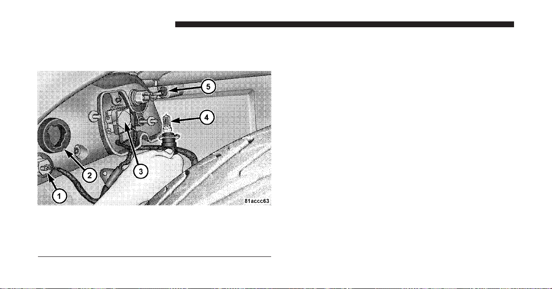
2. Turn the appropriate bulb and socket assembly coun-
terclockwise, and then pull it out of the headlamp
assembly.
3. Pull the bulb out of the socket assembly.
4. Push the replacement bulb into the socket assembly.
5. Reinstall the bulb and socket assembly into the head-
lamp assembly, and then turn it clockwise.
6. Install the splash shield and push pin.
High Intensity Discharge Headlamps (HID)
The headlamps are a type of high voltage discharge tube.
High voltage can remain in the circuit even with the
headlamp switch off and the key removed. Because of
this, you should not attempt to service a headlamp bulb
yourself. If a headlamp bulb fails, take your vehicle to
an authorized dealer for service.
1 — Front Side Marker Lamp
2 — Front Park/Turn Signal Lamp
3 — Low/High Beam HID Headlamp
4 — Auxiliary High Beam Headlamp
5 — Headlamp Adjustment — Aim Up and Down
252 MAINTAINING YOUR VEHICLE
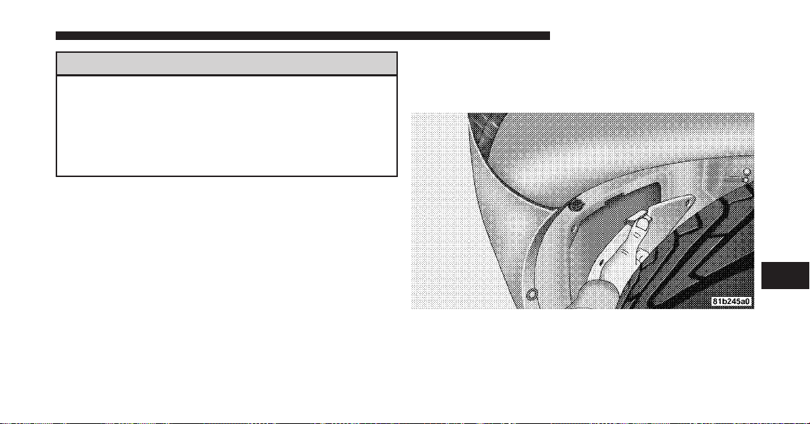
WARNING!
A transient high tension occurs at the bulb sockets of
High Intensity Discharge (HID) headlamps when the
headlamp switch is turned ON. It may cause serious
electrical shock or electrocution if not serviced prop-
erly. See your authorized dealer for service.
NOTE:
•
When the High Intensity Discharge (HID) headlamps
are turned on, there is a blue hue to the lamps. This
diminishes and becomes more white after approxi-
mately 10 seconds as the system charges.
•
If High Intensity Discharge (HID) headlamps are not
working, cycle the headlamp switch four times to see
if it will restrike.
Front Fog Lamp
1. Remove the push pin from the upper outer corner of
the splash shield and remove the splash shield.
7
MAINTAINING YOUR VEHICLE 253
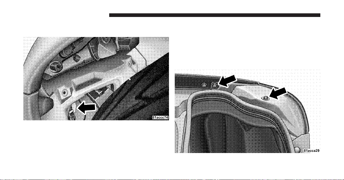
2. Turn the bulb and socket assembly counterclockwise,
and then pull it out of the front fog lamp assembly.
3. Pull the bulb out of the socket assembly.
4. Push the replacement bulb into the socket assembly.
5. Reinstall the bulb and socket assembly into the front
fog lamp assembly, and then turn it clockwise.
6. Install the splash shield and push pin.
Taillamp, Tail/Stop Lamp, Rear Marker Lamp
1. Open the trunk
2. Remove the two fasteners and then remove the access
panel.
254 MAINTAINING YOUR VEHICLE
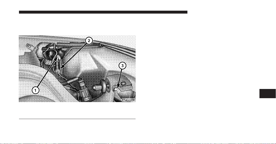
3. Turn the appropriate bulb and socket assembly coun-
terclockwise, and then pull it out of the upper lamp
assembly.
4. Pull the bulb out of the socket assembly.
5. Push the replacement bulb into the socket assembly.
6. Reinstall the bulb and socket assembly into the upper
lamp assembly, and then turn it clockwise.
7. Install the access panel and the two fasteners.
8. Close the trunk.
Taillamp, Tail/Stop Lamp, Rear Marker Lamp
(Coupe Models)
For bulb replacement, see your authorized dealer.
1 — Rear Marker Lamp
2 — Tail/Stop Lamp
3 — Taillamp
7
MAINTAINING YOUR VEHICLE 255
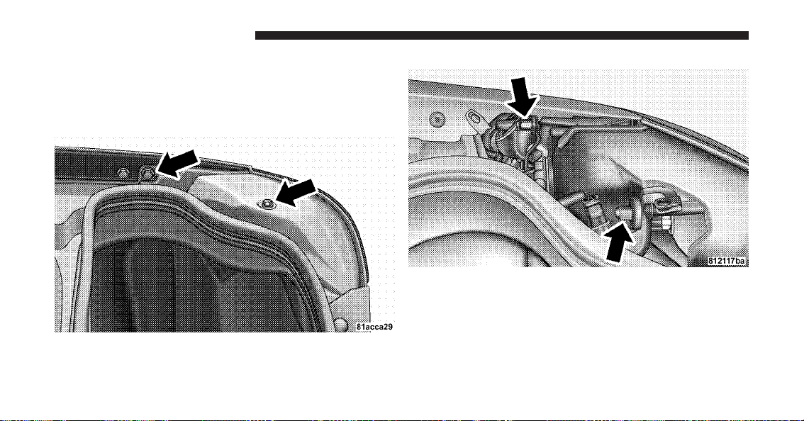
Backup Lamp, Rear Turn Signal Lamp
1. Open the trunk.
2. Remove the two fasteners and then remove the access
panel.
3. Remove the three upper lamp assembly retaining nuts.
256 MAINTAINING YOUR VEHICLE
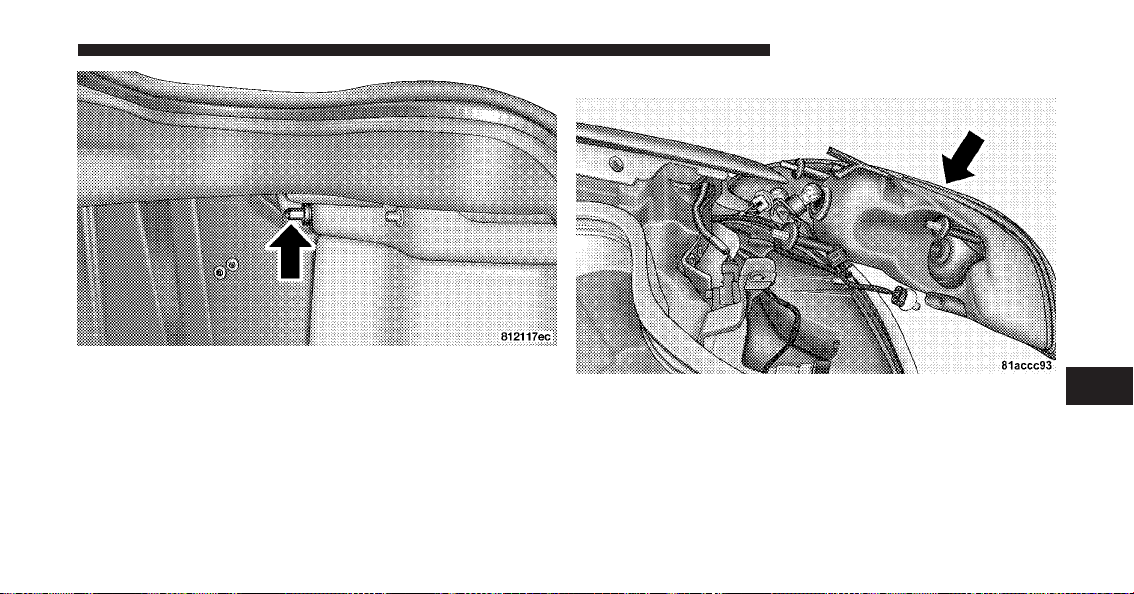
4. Remove the three bulb and socket assemblies from the
upper lamp assembly by turning them counterclockwise
and then pulling them out of the upper lamp assembly.
5. Remove the upper lamp assembly.
7
MAINTAINING YOUR VEHICLE 257
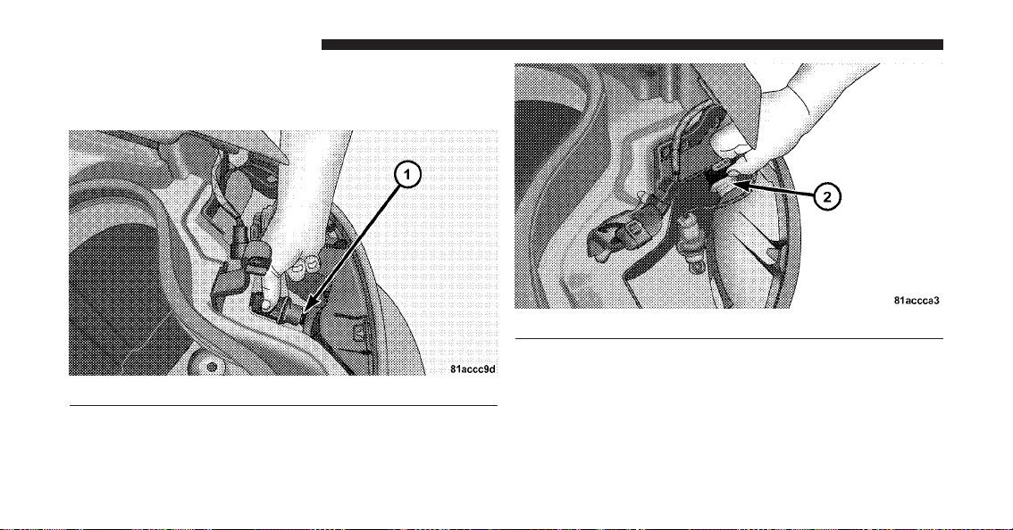
6. Turn the appropriate bulb and socket assembly coun-
terclockwise, and then pull it out of the lower lamp
assembly.
7. Pull the bulb out of the socket assembly.
8. Push the replacement bulb into the socket assembly.
9. Reinstall the bulb and socket assembly into the lower
lamp assembly, and then turn it clockwise.
1 — Backup Lamp
2 — Rear Turn Signal Lamp
258 MAINTAINING YOUR VEHICLE
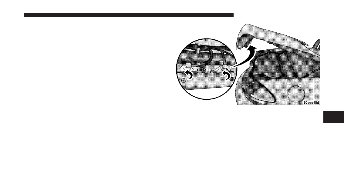
10. Reinstall the three bulb and socket assemblies into
the upper lamp assembly, and turn them clockwise.
11. Reinstall the upper lamp assembly and the three
retaining nuts.
12. Install the access panel and the two fasteners.
13. Close the trunk.
License Lamp
1. Open the trunk.
2. Turn the bulb and socket assembly counterclockwise,
and then pull it out of the housing.
3. Pull the bulb out of the socket assembly.
4. Push the replacement bulb into the socket assembly.
5. Reinstall the bulb and socket assembly into the hous-
ing, and then turn it clockwise.
6. Close the trunk.
7
MAINTAINING YOUR VEHICLE 259

FLUID CAPACITIES
U.S. Metric
Fuel (Approximate) 16 Gallons 60.6 Liters
Engine Oil with Filter
8.4 Liter Engine (SAE 5W-40, API Certified) 11 Quarts 10.4 Liters
Cooling System *
8.4 Liter Engine (MOPAR威 Engine Coolant/Antifreeze 5
Year/100,000 Mile Formula or equivalent)
16 Quarts 15 Liters
* Includes heater and coolant recovery bottle filled to MAX level.
260 MAINTAINING YOUR VEHICLE

FLUIDS, LUBRICANTS, AND GENUINE PARTS
Engine
Component Fluid, Lubricant, or Genuine Part
Engine Coolant MOPAR威 Antifreeze/Coolant 5 Year/100,000 Mile Formula HOAT (Hy-
brid Organic Additive Technology) or equivalent.
Engine Oil For best performance and maximum protection under all types of operat-
ing conditions, the manufacturer only recommends full synthetic engine
oils that meet the requirements of Chrysler Material Standard MS-10725
and are approved to MB 229.3 or MB 229.5. The manufacturer recom-
mends the use of a full synthetic 5W-40 or equivalent engine oil.
Engine Oil Filter MOPAR威 Engine Oil Filter or equivalent.
Spark Plugs RE10PMC5 (Gap 0.050 in [1.27 mm])
Fuel Selection Premium Unleaded 91 Octane Only or Higher
7
MAINTAINING YOUR VEHICLE 261

Chassis
Component Fluid, Lubricant, or Genuine Part
Transmission MOPAR威 ATF+4威 Automatic Transmission Fluid or equivalent licensed
ATF+4威 product.
Rear Axle MOPAR威 Synthetic Gear and Axle Lubricant SAE 75W-140 or equivalent,
with Limited Slip Additive Friction Modifier.
Brake Master Cylinder MOPAR威 Brake and Clutch Fluid DOT 4 Motor Vehicle or equivalent.
Power Steering Reservoir MOPAR威 Power Steering Fluid + 4, MOPAR威 ATF+4威 Automatic Trans-
mission Fluid or equivalent licensed ATF+4威 product.
262 MAINTAINING YOUR VEHICLE

MAINTENANCE SCHEDULES
CONTENTS
䡵 Emissions Control System Maintenance ...... 264
䡵 Maintenance Schedules ................. 264
▫ Maintenance Schedule B ............... 267
▫ Maintenance Schedule A ............... 278
8
M
A
I
N
T
E
N
A
N
C
E
S
C
H
E
D
U
L
E
S

EMISSIONS CONTROL SYSTEM MAINTENANCE
The Scheduled Maintenance services listed in bold type
must be done at the times or mileages specified to ensure
the continued proper functioning of the emissions control
system. These and all other maintenance services in-
cluded in this manual, should be done to provide best
vehicle performance and reliability. More frequent main-
tenance may be needed for vehicles in severe operating
conditions, such as dusty areas and very short trip
driving.
Inspection and service should also be done anytime a
malfunction is suspected.
NOTE: Maintenance, replacement or repair of the emis-
sions control devices and systems on your vehicle may be
performed by any automotive repair establishment or
individual using any automotive part that has been
certified pursuant to U.S. EPA or in the State of Califor-
nia, California Air Resources Board regulations.
MAINTENANCE SCHEDULES
There are two maintenance schedules that show the
required service for your vehicle.
First is “Maintenance Schedule B.” It is for vehicles that
are operated under the conditions that are listed below
and at the beginning of the schedule.
•
Day or night temperatures are below 32°F (0°C).
•
Stop and go driving.
•
Extensive engine idling.
•
Driving in dusty conditions.
•
Short trips of less than 10 miles (16 km).
•
More than 50% of your driving is at sustained high
speeds during hot weather, above 90°F ( 32°C).
8
M
A
I
N
T
E
N
A
N
C
E
S
C
H
E
D
U
L
E
S
264 MAINTENANCE SCHEDULES

NOTE:
•
If ANY of these apply to you then change your engine
oil every 3,000 miles (5000 km) or three months,
whichever comes first, and follow the maintenance
recommendations in “Maintenance Schedule B” in this
section.
•
If ANY of these apply to you, then flush and replace
the engine coolant every 102,000 miles (170 000 km) or
60 months, whichever comes first, and follow the
maintenance recommendations in “Maintenance
Schedule B” in this section.
•
Most vehicles are operated under the conditions listed
for “Maintenance Schedule B.⬙
Second is “Maintenance Schedule A.” It is for vehicles
that are not operated under any of the conditions listed
under “Maintenance Schedule B.⬙
Use the schedule that best describes your driving condi-
tions. Where time and mileage are listed, follow the
interval that occurs first.
NOTE: Under no circumstances should oil change
intervals exceed 6,000 miles (10 000 km) or six months,
whichever comes first.
CAUTION!
Failure to perform the required maintenance items
may result in damage to the vehicle.
8
M
A
I
N
T
E
N
A
N
C
E
S
C
H
E
D
U
L
E
S
MAINTENANCE SCHEDULES 265

At Each Stop for Fuel
•
Check the engine oil level about five minutes after a
fully warmed engine is shut off. Checking the oil level
while the vehicle is on level ground will improve the
accuracy of the oil level reading. Add oil only when
the level is at or below the ADD or MIN mark.
•
Check the windshield washer solvent and add if
required.
Once a Month
•
Check tire pressure and look for unusual wear or
damage.
•
Inspect the battery, and clean and tighten the terminals
as required.
•
Check the fluid levels of the coolant reservoir, brake
master cylinder, power steering, and transmission,
and add as needed.
•
Check all lights and all other electrical items for correct
operation.
At Each Oil Change
•
Change the engine oil filter.
•
Inspect the exhaust system.
NOTE: Also, inspect the exhaust system if you notice a
change in the sound of the exhaust system, or if the
exhaust fumes can be detected inside the vehicle.
•
Inspect the brake hoses.
•
Inspect the suspension components.
•
Lubricate door hinges and check springs.
•
Check the engine coolant level, hoses, and clamps.
•
Check power steering fluid level.
8
M
A
I
N
T
E
N
A
N
C
E
S
C
H
E
D
U
L
E
S
266 MAINTENANCE SCHEDULES

MAINTENANCE SCHEDULE B
Follow “Maintenance Schedule B” if you usually operate
your vehicle under one or more of the following condi-
tions.
•
Day or night temperatures are below 32°F (0°C).
•
Stop and go driving.
•
Extensive engine idling.
•
Driving in dusty conditions.
•
Short trips of less than 10 miles (16 km).
•
More than 50% of your driving is at sustained high
speeds during hot weather, above 90°F (32°C).
NOTE:
•
If ANY of these apply to you, then change your engine
oil every 3,000 miles (5000 km) or three months,
whichever comes first, and follow the maintenance
recommendations in “Maintenance Schedule “B” in
this section.
•
If ANY of these apply to you, then flush and replace
the engine coolant every 102,000 miles (170 000 km) or
60 months, whichever comes first, and follow the
maintenance recommendations in “Maintenance
Schedule B” in this section.
8
M
A
I
N
T
E
N
A
N
C
E
S
C
H
E
D
U
L
E
S
MAINTENANCE SCHEDULES 267

Miles 3,000 6,000 9,000 12,000 15,000 18,000
(Kilometers) (5 000) (10 000) (15 000) (20 000) (25 000) (30 000)
Change engine oil and engine oil filter, if not
replaced at 3 months.
XXXXX X
Rotate the tires.〫〫 XX X
Inspect and replace the air cleaner filter, if
necessary.
X
Inspect the transmission fluid. X
Inspect the brake linings. X
Change the rear axle fluid. X
Change the brake fluid. X
Lubricate the front and rear suspension ball
joints.
X
8
M
A
I
N
T
E
N
A
N
C
E
S
C
H
E
D
U
L
E
S
268 MAINTENANCE SCHEDULES

Miles 21,000 24,000 27,000 30,000 33,000 36,000
(Kilometers) (35 000) (40 000) (45 000) (50 000) (55 000) (60 000)
Change engine oil and engine oil filter, if not
replaced at 3 months.
XXXXX X
Rotate the tires.〫〫 XX X
Inspect and replace the air cleaner filter, if
necessary.
X
Inspect and replace the PCV valve, if neces-
sary.
X
Change the transmission fluid. X
Inspect the transmission fluid. X
Inspect the brake linings. X X
Change the rear axle fluid. X X
Change the brake and clutch fluid. X
Change the brake fluid. X
Lubricate the front and rear suspension ball
joints.
X
8
M
A
I
N
T
E
N
A
N
C
E
S
C
H
E
D
U
L
E
S
MAINTENANCE SCHEDULES 269

Miles 39,000 42,000 45,000 48,000 51,000 54,000
(Kilometers) (65 000) (70 000) (75 000) (80 000) (85 000) (90 000)
Change engine oil and engine oil filter, if not
replaced at 3 months.
XXXXX X
Rotate the tires.〫〫 XX X
Inspect and replace the engine air cleaner fil-
ter, if necessary.
X
Inspect and replace the auto tension drive
belt, if necessary.
X
Change the transmission fluid. X
Inspect the brake linings. X
Change the rear axle fluid. X
Change the brake and clutch fluid. X
Lubricate the front and rear suspension ball
joints.
X
8
M
A
I
N
T
E
N
A
N
C
E
S
C
H
E
D
U
L
E
S
270 MAINTENANCE SCHEDULES

Miles 57,000 60,000 63,000 66,000 69,000 72,000
(Kilometers) (95 000) (100 000) (105 000) (110 000) (115 000) (120 000)
Change engine oil and engine oil filter, if not
replaced at 3 months.
XXXXX X
Rotate the tires.〫〫 XX X
Inspect and replace the air cleaner filter, if
necessary.
X
Inspect and replace the PCV valve, if neces-
sary.
X
Flush and replace engine coolant at
60 months, if not done at 102,000 miles.
X
Inspect and replace the auto tension drive
belt, if necessary.‡
X
Inspect the transmission fluid. X
8
M
A
I
N
T
E
N
A
N
C
E
S
C
H
E
D
U
L
E
S
MAINTENANCE SCHEDULES 271

Miles 57,000 60,000 63,000 66,000 69,000 72,000
(Kilometers) (95 000) (100 000) (105 000) (110 000) (115 000) (120 000)
Change the transmission fluid. X
Inspect the brake linings. X X
Change the rear axle fluid. X X
Change the brake fluid. X
Change the brake and clutch fluid. X
Lubricate the front and rear suspension ball
joints.
X
8
M
A
I
N
T
E
N
A
N
C
E
S
C
H
E
D
U
L
E
S
272 MAINTENANCE SCHEDULES

Miles 75,000 78,000 81,000 84,000 87,000 90,000
(Kilometers) (125 000) (130 000) (135 000) (140 000) (145 000) (150 000)
Change engine oil and engine oil filter, if not
replaced at 3 months.
XXXXX X
Rotate the tires.〫〫 XX X
Inspect and replace the air cleaner filter, if
necessary.
XX
Inspect and replace the PCV valve, if neces-
sary.
X
Inspect and replace the auto tension drive
belt, if necessary.‡
XX
Inspect the transmission fluid. X
Inspect the brake linings. X
Change the rear axle fluid. X
Change the brake fluid. X
Lubricate the front and rear suspension ball
joints.
XX
8
M
A
I
N
T
E
N
A
N
C
E
S
C
H
E
D
U
L
E
S
MAINTENANCE SCHEDULES 273

Miles 93,000 96,000 99,000 102,000 105,000 108,000
(Kilometers) (155 000) (160 000) (165 000) (170 000) (175 000) (180 000)
Change engine oil and engine oil filter, if not
replaced at 3 months.
XXXXXX
Rotate the tires.〫〫 XXX
Inspect and replace the engine air cleaner fil-
ter, if necessary.
X
Replace the spark plugs. X
Replace the ignition cables. X
Flush and replace the engine coolant, if not
replaced at 60 months.
X
Inspect and replace the auto tension drive
belt, if necessary.‡
X
Change the transmission fluid. X
8
M
A
I
N
T
E
N
A
N
C
E
S
C
H
E
D
U
L
E
S
274 MAINTENANCE SCHEDULES

Miles 93,000 96,000 99,000 102,000 105,000 108,000
(Kilometers) (155 000) (160 000) (165 000) (170 000) (175 000) (180 000)
Inspect the transmission fluid. X
Inspect the brake linings. X X
Change the rear axle fluid. X X
Change the brake and clutch fluid. X
Change the brake fluid. X
Lubricate the front and rear suspension ball
joints.
X
8
M
A
I
N
T
E
N
A
N
C
E
S
C
H
E
D
U
L
E
S
MAINTENANCE SCHEDULES 275

Miles 111,000 114,000 117,000 120,000
(Kilometers) (185 000) (190 000) (195 000) (200 000)
Change engine oil and engine oil filter, if not replaced at
3 months.
XXXX
Rotate the tires.〫〫 XX
Inspect and replace the engine air cleaner filter, if necessary. X
Inspect and replace the PCV valve, if necessary. X
Flush and replace the engine coolant, if not replaced at
102,000 months.
X
Inspect and replace the auto tension drive belt, if necessary.‡ X
Change the transmission fluid. X
Inspect the brake linings. X
8
M
A
I
N
T
E
N
A
N
C
E
S
C
H
E
D
U
L
E
S
276 MAINTENANCE SCHEDULES

Miles 111,000 114,000 117,000 120,000
(Kilometers) (185 000) (190 000) (195 000) (200 000)
Change the rear axle fluid. X
Change the brake and clutch fluid. X
Lubricate the front and rear suspension ball joints. X
‡ This maintenance is not required if previously replaced.
〫〫 Although not required, the manufacturer recom-
mends reprogramming TPMS after rotating tires so sys-
tem can relearn tire pressure sensor location. Refer to
“Tire Pressure Monitor System (TPMS)” in “Starting and
Operating” for further information.
Inspection and service should also be performed anytime
a malfunction is observed or suspected. Retain all
receipts.
8
M
A
I
N
T
E
N
A
N
C
E
S
C
H
E
D
U
L
E
S
MAINTENANCE SCHEDULES 277

MAINTENANCE SCHEDULE A
Miles 6,000 12,000 18,000 24,000 30,000
(Kilometers) (10 000) (20 000) (30 000) (40 000) (50 000)
[Months] [6] [12] [18] [24] [30]
Change engine oil and engine oil filter. X X X X X
Rotate the tires.〫〫 X XXXX
Inspect and replace the engine air cleaner filter, if
necessary.
X
Inspect the transmission fluid. X X
Inspect the brake linings. X
Change the rear axle fluid. X
Change the brake fluid. X
Lubricate the front and rear suspension ball joints. X
8
M
A
I
N
T
E
N
A
N
C
E
S
C
H
E
D
U
L
E
S
278 MAINTENANCE SCHEDULES

Miles 36,000 42,000 48,000 54,000 60,000
(Kilometers) (60 000) (70 000) (80 000) (90 000) (100 000)
[Months] [36] [42] [48] [54] [60]
Change engine oil and engine oil filter. X X X X X
Rotate the tires.〫〫 XXXX X
Inspect and replace the engine air cleaner filter, if necessary. X
Inspect and replace the PCV valve, if necessary. X
Flush and replace the engine coolant at 60 months, if not
done at 102,000 miles.
X
Inspect and replace the auto tension drive belt, if necessary. X
Change the transmission fluid. X
Inspect the transmission fluid. X X
Inspect the brake linings. X X
Change the rear axle fluid. X X
Change the brake and clutch fluid. X
Change the brake fluid. X
Lubricate the front and rear suspension ball joints. X
8
M
A
I
N
T
E
N
A
N
C
E
S
C
H
E
D
U
L
E
S
MAINTENANCE SCHEDULES 279

Miles 66,000 72,000 78,000 84,000 90,000
(Kilometers) (110 000) (120 000) (130 000) (140 000) (150 000)
[Months] [66] [72] [78] [84] [90]
Change engine oil and engine oil filter. X X X X X
Rotate the tires.〫〫 XXXXX
Inspect and replace the engine air cleaner filter, if
necessary.
X
Inspect and replace the PCV valve, if necessary. X
Inspect and replace the auto tension drive belt, if
necessary.‡
XX
Change the transmission fluid. X
Inspect the transmission fluid. X
Inspect the brake linings. X X
Change the rear axle fluid. X X
Change the brake and clutch fluid. X
Change the brake fluid. X
Lubricate the front and rear suspension ball
joints.
X
8
M
A
I
N
T
E
N
A
N
C
E
S
C
H
E
D
U
L
E
S
280 MAINTENANCE SCHEDULES

Miles 96,000 102,000 108,000 114,000 120,000
(Kilometers) (160 000) (170 000) (180 000) (190 000) (200 000)
[Months] [96] [102] [108] [114] [120]
Change engine oil and engine oil filter. X X X X X
Rotate the tires.〫〫 XXXXX
Inspect and replace the engine air cleaner filter, if
necessary.
X
Inspect and replace the PCV valve, if necessary. X
Replace the spark plugs. X
Replace the ignition cables. X
Flush and replace the engine coolant, if not re-
placed at 60 months.
X
Flush and replace the engine coolant, if not re-
placed at 102,000 miles.
X
Inspect and replace the auto tension drive belt, if
necessary.‡
XXX
Inspect the transmission fluid. X X
Change the transmission fluid. X
8
M
A
I
N
T
E
N
A
N
C
E
S
C
H
E
D
U
L
E
S
MAINTENANCE SCHEDULES 281

Miles 96,000 102,000 108,000 114,000 120,000
(Kilometers) (160 000) (170 000) (180 000) (190 000) (200 000)
[Months] [96] [102] [108] [114] [120]
Inspect the brake linings. X
Change the rear axle fluid. X
Change the brake and clutch fluid. X
Lubricate the front and rear suspension ball
joints.
X
‡ This maintenance is not required if previously replaced.
〫〫 Although not required, the manufacturer recom-
mends reprogramming TPMS after rotating tires so sys-
tem can relearn tire pressure sensor location. Refer to
“Tire Pressure Monitor System (TPMS)” in “Starting and
Operating” for further information.
Inspection and service should also be performed anytime
a malfunction is observed or suspected. Retain all
receipts.
8
M
A
I
N
T
E
N
A
N
C
E
S
C
H
E
D
U
L
E
S
282 MAINTENANCE SCHEDULES
WARNING!
•
You can be badly injured working on or around a
motor vehicle. Do only service work for which you
have the knowledge and the right equipment. If
you have any doubt about your ability to perform
a service job, take your vehicle to a competent
mechanic.
(Continued)
WARNING! (Continued)
•
Failure to properly inspect and maintain your
vehicle could result in a component malfunction
and effect vehicle handling and performance. This
could cause an accident
8
M
A
I
N
T
E
N
A
N
C
E
S
C
H
E
D
U
L
E
S
MAINTENANCE SCHEDULES 283


IF YOU NEED CONSUMER ASSISTANCE
CONTENTS
䡵 Suggestions For Obtaining Service For Your
Vehicle .............................. 287
▫ Prepare For The Appointment ........... 287
▫ Prepare A List ...................... 287
▫ Be Reasonable With Requests ............ 287
䡵 If You Need Assistance ................. 287
▫ Chrysler Group LLC Customer Center ..... 288
▫ Chrysler Canada Inc. Customer Center ..... 288
▫ In Mexico Contact .................... 288
▫ Customer Assistance For The Hearing Or
Speech Impaired (TDD/TTY) ............ 289
▫ Service Contract ..................... 289
䡵 Warranty Information .................. 290
䡵 MOPAR威 Parts ....................... 290
䡵 Reporting Safety Defects ................ 290
▫ In The 50 United States And
Washington, D.C. .................... 290
▫ In Canada ......................... 291
䡵 Publication Order Forms ................ 291
9

䡵 Department Of Transportation Uniform Tire
Quality Grades ........................ 293
▫ Treadwear ......................... 293
▫ Traction Grades ..................... 293
▫ Temperature Grades .................. 294
286 IF YOU NEED CONSUMER ASSISTANCE

SUGGESTIONS FOR OBTAINING SERVICE FOR
YOUR VEHICLE
Prepare For The Appointment
If you’re having warranty work done, be sure to have the
right papers with you. Take your warranty folder. All
work to be performed may not be covered by the
warranty. Discuss additional charges with the service
manager. Keep a maintenance log of your vehicle’s
service history. This can often provide a clue to the
current problem.
Prepare A List
Make a written list of your vehicle’s problems or the
specific work you want done. If you’ve had an accident
or work done that is not on your maintenance log, let the
service advisor know.
Be Reasonable With Requests
If you list a number of items and you must have your
vehicle by the end of the day, discuss the situation with
the service advisor and list the items in order of priority.
At many authorized dealers, you may obtain a rental
vehicle at a minimal daily charge. If you need a rental, it
is advisable to make these arrangements when you call
for an appointment.
IF YOU NEED ASSISTANCE
The manufacturer and its authorized dealers are vitally
interested in your satisfaction. We want you to be happy
with our products and services.
Warranty service must be done by an authorized dealer.
We strongly recommend that you take the vehicle to an
authorized dealer. They know your vehicle the best, and
are most concerned that you get prompt and high quality
service. The manufacturer’s authorized dealers have the
facilities, factory-trained technicians, special tools, and
the latest information to ensure the vehicle is fixed
correctly and in a timely manner.
9
IF YOU NEED CONSUMER ASSISTANCE 287

This is why you should always talk to an authorized
dealer’s service manager first. Most matters can be re-
solved with this process.
•
If for some reason you are still not satisfied, talk to the
general manager or owner of the authorized dealer-
ship. They want to know if you need assistance.
•
If an authorized dealership is unable to resolve the
concern, you may contact the manufacturer’s customer
center.
Any communication to the manufacturer’s customer cen-
ter should include the following information:
•
Owner’s name and address
•
Owner’s telephone number (home and office)
•
Authorized dealership name
•
Vehicle Identification Number (VIN)
•
Vehicle delivery date and mileage
Chrysler Group LLC Customer Center
P.O. Box 21–8004
Auburn Hills, MI 48321–8004
Phone: (800) 423–6343
Chrysler Canada Inc. Customer Center
P.O. Box 1621
Windsor, Ontario N9A 4H6
Phone: (800) 465–2001
In Mexico contact:
Av. Prolongacion Paseo de la Reforma, 1240
Sante Fe C.P. 05109
Mexico, D. F.
In Mexico City: 5081-7568
Outside Mexico City: 1-800-505-1300
288 IF YOU NEED CONSUMER ASSISTANCE

Customer Assistance For The Hearing Or Speech
Impaired (TDD/TTY)
To assist customers who have hearing difficulties, the
manufacturer has installed special TDD (Telecommuni-
cation Devices for the Deaf) equipment at its customer
center. Any hearing or speech impaired customer, who
has access to a TDD or a conventional teletypewriter
(TTY) in the United States, can communicate with the
manufacturer by dialing 1–800–380–CHRY.
Canadian residents with hearing difficulties that require
assistance can use the special needs relay service offered
by Bell Canada. For TTY teletypewriter users, dial 711
and for Voice callers, dial 1 800 855-0511 to connect with
a Bell Relay Service operator.
Service Contract
You may have purchased a service contract for a vehicle
to help protect you from the high cost of unexpected
repairs after the manufacturer’s New Vehicle Limited
Warranty expires. The manufacturer stands behind only
the manufacturer’s service contracts. If you purchased a
manufacturer’s service contract, you will receive Plan
Provisions and an Owner Identification Card in the mail
within three weeks of the vehicle delivery date. If you
have any questions about the service contract, call the
manufacturer’s Service Contract National Customer Hot-
line at 1-800-521-9922 (Canadian residents, call 1-800-485-
2001).
The manufacturer will not stand behind any service
contract that is not the manufacturer’s service contract. It
is not responsible for any service contract other than the
manufacturer’s service contract. If you purchased a ser-
vice contract that is not a manufacturer’s service contract,
and you require service after the manufacturer’s New
Vehicle Limited Warranty expires, please refer to the
contract documents, and contact the person listed in
those documents.
9
IF YOU NEED CONSUMER ASSISTANCE 289

We appreciate that you have made a major investment
when you purchased the vehicle. An authorized dealer
has also made a major investment in facilities, tools, and
training to assure that you are absolutely delighted with
the ownership experience. You’ll be pleased with their
sincere efforts to resolve any warranty issues or related
concerns.
WARNING!
Engine exhaust, some of its constituents, and certain
vehicle components contain, or emit, chemicals
known to the State of California to cause cancer and
birth defects, or other reproductive harm. In addi-
tion, certain fluids contained in vehicles and certain
products of component wear contain, or emit, chemi-
cals known to the State of California to cause cancer
and birth defects, or other reproductive harm.
WARRANTY INFORMATION
See the Warranty Information Booklet, located on the
DVD, for the terms and provisions of Chrysler Group
LLC warranties applicable to this vehicle and market.
MOPAR姞 PARTS
MOPAR威 fluids, lubricants, parts, and accessories are
available from an authorized dealer. They are recom-
mended for your vehicle in order to help keep the vehicle
operating at its best.
REPORTING SAFETY DEFECTS
In the 50 United States and Washington, D.C.
If you believe that your vehicle has a defect that could
cause a crash or cause injury or death, you should
immediately inform the National Highway Traffic Safety
Administration (NHTSA) in addition to notifying the
manufacturer.
290 IF YOU NEED CONSUMER ASSISTANCE

If NHTSA receives similar complaints, it may open an
investigation, and if it finds that a safety defect exists in
a group of vehicles, it may order a recall and remedy
campaign. However, NHTSA cannot become involved in
individual problems between you, your authorized
dealer, and the manufacturer.
To contact NHTSA, you may either call the Auto Safety
Hotline toll free at 1–888–327–4236 (TTY: 1–800–424–
9153), or go to http://www.safercar.gov; or write to:
Administrator, NHTSA, 1200 New Jersey Avenue, SE.,
West Building, Washington, D.C. 20590. You can also
obtain other information about motor vehicle safety from
http://www.safercar.gov.
In Canada
If you believe that your vehicle has a safety defect, you
should contact the Customer Service Department imme-
diately. Canadian customers who wish to report a safety
defect to the Canadian government should write to:
Transport Canada, Motor Vehicle Defect Investigations
and Recalls, 2780 Sheffield Road, Ottawa, Ontario K1B
3V9.
PUBLICATION ORDER FORMS
To order the following manuals, you may use either the
website or the phone numbers listed below. Visa, Mas-
tercard, American Express, and Discover orders are ac-
cepted. If you prefer mailing your payment, please call
for an order form.
NOTE: A street address is required when ordering
manuals (no P.O. Boxes).
9
IF YOU NEED CONSUMER ASSISTANCE 291

•
Service Manuals
These comprehensive Service Manuals provide the
information that students and professional technicians
need in diagnosing/troubleshooting, problem solving,
maintaining, servicing, and repairing Chrysler Group
LLC vehicles. A complete working knowledge of the
vehicle, system, and/or components is written in
straightforward language with illustrations, diagrams,
and charts.
•
Diagnostic Procedure Manuals
Diagnostic Procedure Manuals are filled with dia-
grams, charts and detailed illustrations. These practi-
cal manuals make it easy for students and technicians
to find and fix problems on computer-controlled ve-
hicle systems and features. They show exactly how to
find and correct problems the first time, using step-by-
step troubleshooting and drivability procedures,
proven diagnostic tests and a complete list of all tools
and equipment.
•
Owner’s Manuals
These Owner’s Manuals have been prepared with the
assistance of service and engineering specialists to
acquaint you with specific Chrysler Group LLC ve-
hicles. Included are starting, operating, emergency
and maintenance procedures as well as specifications,
capabilities and safety tips.
Call toll free at:
•
1–800–890–4038 (U.S.)
•
1–800–387–1143 (Canada)
Or
Visit us on the Worldwide Web at:
•
www.techauthority.com
292 IF YOU NEED CONSUMER ASSISTANCE
DEPARTMENT OF TRANSPORTATION UNIFORM
TIRE QUALITY GRADES
The following tire grading categories were established by
the National Highway Traffic Safety Administration. The
specific grade rating assigned by the tire’s manufacturer
in each category is shown on the sidewall of the tires on
your vehicle.
All passenger car tires must conform to Federal safety
requirements in addition to these grades.
Treadwear
The Treadwear grade is a comparative rating, based on
the wear rate of the tire when tested under controlled
conditions on a specified government test course. For
example, a tire graded 150 would wear one and one-half
times as well on the government course as a tire graded
100. The relative performance of tires depends upon the
actual conditions of their use, however, and may depart
significantly from the norm due to variations in driving
habits, service practices, and differences in road charac-
teristics and climate.
Traction Grades
The Traction grades, from highest to lowest, are AA, A, B,
and C. These grades represent the tire’s ability to stop on
wet pavement, as measured under controlled conditions
on specified government test surfaces of asphalt and
concrete. A tire marked C may have poor traction perfor-
mance.
WARNING!
The traction grade assigned to this tire is based on
straight-ahead braking traction tests, and does not
include acceleration, cornering, hydroplaning, or
peak traction characteristics.
9
IF YOU NEED CONSUMER ASSISTANCE 293
Temperature Grades
The temperature grades are A (the highest), B, and C,
representing the tire’s resistance to the generation of heat
and its ability to dissipate heat, when tested under
controlled conditions on a specified indoor laboratory
test wheel. Sustained high temperature can cause the
material of the tire to degenerate and reduce tire life, and
excessive temperature can lead to sudden tire failure. The
grade C corresponds to a level of performance, which all
passenger car tires must meet under the Federal Motor
Vehicle Safety Standard No. 109. Grades B and A repre-
sent higher levels of performance on the laboratory test
wheel, than the minimum required by law.
WARNING!
The temperature grade for this tire is established for
a tire that is properly inflated and not overloaded.
Excessive speed, under-inflation, or excessive load-
ing, either separately or in combination, can cause
heat buildup and possible tire failure.
294 IF YOU NEED CONSUMER ASSISTANCE

INDEX
10

About Your Brakes .......................157
ABS (Anti-Lock Brake System) ............110,158
Accessory Delay, Power ..................13,28
Adding Engine Coolant (Antifreeze) .......... 229
Adding Fuel ........................... 185
Adding Washer Fluid .....................224
Adjustable Pedals ........................97
Air Cleaner, Engine (Engine Air Cleaner Filter) . . . 216
Air Conditioner Maintenance ...............221
Air Conditioning .................. 134,137,221
Air Conditioning Controls .................134
Air Conditioning, Operating Tips ............139
Air Conditioning Refrigerant .............221,222
Air Conditioning System .............134,137,221
Air Pressure, Tires ....................113,172
Airbag ................................42
Airbag Deployment ..................... 47,53
Airbag Light ................... 48,49,56,65,112
Airbag Maintenance ....................... 55
Airbag On/Off Switch ..................... 58
Alarm System (Security Alarm) ............... 13
Alterations/Modifications, Vehicle ............. 7
Antenna .............................. 133
Antenna, Satellite Radio ................... 132
Antifreeze (Engine Coolant) .............. 228,260
Capacities ...........................260
Disposal ............................231
Anti-Lock Brake System (ABS) .............. 158
Anti-Lock Warning Light ................110,161
Anti-Theft Security Alarm (Theft Alarm) ........13
Appearance Care ........................ 237
Auto Down Power Windows ................ 29
Automatic Door Locks ..................... 26
Auxiliary Electrical Outlet (Power Outlet) ......100
Auxiliary Power Outlet ...................100
Battery ............................ 118,217
Emergency Starting .....................202
296 INDEX

Jump Starting .........................202
Keyless Transmitter Replacement (RKE) ....... 22
Location .......................... 202,217
Saving Feature (Protection) ............... 219
Storing Vehicle ........................219
Belts, Seat .......................... 32,34,65
Body Mechanism Lubrication ............... 223
Boot, Convertible Top ...................75,79
B-Pillar Location ........................ 167
Brake, Parking ..........................155
Brake System ........................ 157,232
Anti-Lock (ABS) ....................157,158
Fluid Check .......................233,262
Master Cylinder ....................... 233
Warning Light ........................ 112
Break-In Recommendations, New Vehicle .....63,157
Bulb Replacement ....................... 251
Bulbs, Light .......................... 67,250
Capacities, Antifreeze (Engine Coolant) ........260
Capacities, Fluid ........................ 260
Caps, Filler
Fuel ...............................185
Power Steering ........................ 154
Radiator (Coolant Pressure) ...............230
Car Washes ............................238
Carbon Monoxide Warning ...............64,185
CD (Compact Disc) Changer ................125
CD (Compact Disc) Player ...............119,123
Cellular Phone .......................... 134
Charging System Light .................... 118
Chart, Tire Sizing ........................ 163
Check Engine Light
(Malfunction Indicator Light) ...............211
Checking Your Vehicle For Safety .............64
Checks, Safety ........................... 64
Child Restraint ......................56,58,62
Child Restraint Tether Anchors ............... 60
10
INDEX 297

Circuit Breakers .........................244
Clean Air Gasoline .......................181
Climate Control .........................134
Clock ................................118
Clutch Fluid ........................... 236
Compact Disc (CD) Maintenance ............. 133
Console ..............................102
Console, Floor ..........................102
Contract, Service ........................ 289
Convertible .............................71
Convertible Boot ....................... 75,79
Convertible Top ....................... 71,239
Convertible Top Maintenance ............... 239
Coolant Pressure Cap (Radiator Cap) .......... 230
Cooling System ......................... 227
Adding Coolant (Antifreeze) .............. 229
Coolant Capacity ......................260
Coolant Level ......................227,231
Disposal of Used Coolant ................231
Drain, Flush, and Refill .................. 228
Inspection ........................... 231
Points to Remember ....................231
Pressure Cap .........................230
Radiator Cap ......................... 230
Selection of Coolant (Antifreeze) ......228,260,261
Customer Assistance .....................287
Daytime Running Lights ................... 89
Dealer Service ..........................212
Defroster, Rear Window ................... 104
Defroster, Windshield ...................66,136
Delay (Intermittent) Wipers .................95
Diagnostic System, Onboard ................210
Dimmer Control ......................... 93
Dimmer Switch, Headlight ..................91
Dipsticks
Power Steering ........................ 154
298 INDEX

Disposal
Antifreeze (Engine Coolant) ............... 231
Door Locks .............................24
Door Locks, Automatic .................... 26
Doors .................................24
Driving
On Slippery Surfaces ...................151
Through Flowing, Rising,
or Shallow Standing Water ...............151
Electric Remote Mirrors ....................84
Electrical Outlet, Auxiliary (Power Outlet) ...... 100
Electronic Throttle Control Warning Light ...... 113
Emergency Brake ........................155
Emergency, In Case of
Freeing Vehicle When Stuck ............... 205
Hazard Warning Flasher ................. 190
Jump Starting .........................202
Overheating .......................... 190
Towing ............................. 206
Emission Control System Maintenance ...... 211,264
Engine ...............................209
Air Cleaner ..........................216
Break-In Recommendations ................63
Checking Oil Level ..................... 214
Compartment ......................... 209
Coolant (Antifreeze) .................227,261
Cooling .......................... 116,227
Exhaust Gas Caution ................ 30,64,185
Fails to Start ..........................146
Flooded, Starting ......................146
Fuel Requirements ..................181,260
Oil ........................... 214,260,261
Oil Change Interval ....................214
Oil Disposal ..........................216
Oil Filter ............................ 216
Oil Selection .......................215,260
Overheating .......................116,190
10
INDEX 299

Engine Oil Viscosity ................... 215,260
Engine Oil Viscosity Chart ................. 215
Enhanced Accident Response Feature ..........53
Ethanol ............................... 182
Exhaust Gas Caution ............30,64,185,224,225
Exhaust System ....................... 64,224
Express Down Windows ................... 21
Exterior Finish Care ...................... 238
Exterior Lights ..........................67
Filters
Air Cleaner ..........................216
Engine Oil ........................ 216,261
Engine Oil Disposal ....................216
Finish Care ............................ 238
Flashers
Hazard Warning ....................111,190
Turn Signal ...................... 67,91,111
Flash-To-Pass ........................... 91
Flooded Engine Starting ...................146
Floor Console ..........................102
Fluid Capacities ......................... 260
Fluid Leaks ............................. 67
Fluid Level Checks
Brake ............................233,262
Capacities ...........................260
Clutch Fluid .......................... 236
Cooling System ....................... 227
Engine Oil ...........................214
Manual Transmission ................ 235,262
Power Steering ..................... 154,262
Fluids ................................261
Fluids, Lubricants and Genuine Parts ..........261
Fog Lights ......................... 88,90,110
Four-Way Hazard Flasher ..................190
Freeing A Stuck Vehicle ................... 205
Fuel ................................. 181
Adding ............................. 185
300 INDEX

Clean Air ............................181
Ethanol ............................. 182
Filler Cap (Gas Cap) ....................185
Gasoline ............................ 181
Gauge ..............................118
Methanol ............................182
Octane Rating ...................... 181,261
Requirements ...................... 181,260
Tank Capacity ........................ 260
Fuel System Caution .....................186
Fueling ............................... 185
Fuses ................................ 244
Gas Cap (Fuel Filler Cap) ..................185
Gasoline, Clean Air ......................181
Gasoline (Fuel) .........................181
Gasoline, Reformulated ................... 181
Gauges ...............................116
Coolant Temperature .................... 116
Fuel ................................ 118
Oil Pressure .......................... 117
Speedometer .........................108
Tachometer ..........................116
Voltmeter ............................118
General Information ...................... 23
Glass Cleaning ..........................240
Ground Clearance .......................187
Hazard
Driving Through Flowing, Rising,
or Shallow Standing Water ...............151
Hazard Warning Flasher ................ 111,190
Headlights ..........................88,252
High Beam ...........................91
High Beam/Low Beam Select Switch .........91
Lights On Reminder .....................90
Passing ..............................91
Switch ............................... 88
10
INDEX 301

Time Delay ........................... 89
Heater ...............................134
High Beam Indicator ..................... 109
High Beam/Low Beam Select (Dimmer) Switch . . . 91
Hood Release ........................... 86
Hydraulic Clutch Fluid .................... 236
Ignition ...............................12
Key ................................12
Ignition Key Removal .....................12
Illuminated Entry ........................ 17
Infant Restraint ........................ 56,57
Inflation Pressure Tires .................... 113
Inside Rearview Mirror ....................82
Instrument Panel and Controls .............. 107
Instrument Panel Lens Cleaning ............. 240
Interior Appearance Care ..................239
Interior Lighting .......................88,91
Interior Lights ......................... 91,93
Intermittent Wipers (Delay Wipers) ............95
Introduction .............................4
Jump Starting ..........................202
Key-In Reminder ......................... 13
Keyless Entry System ...................... 18
Keys .................................12
Knee Bolster ............................ 42
Lane Change and Turn Signals ............... 91
Lap/Shoulder Belts .......................34
Latch Plate .............................35
Latches ................................67
Hood ...............................86
Lead Free Gasoline ......................181
Leaks, Fluid ............................ 67
Life of Tires ............................176
Liftgate ................................ 29
302 INDEX

Light Bulbs .............................67
Lights ...............................67,88
Airbag ........................49,56,65,112
Anti-Lock .........................110,161
Anti-Lock Warning ..................... 110
Battery Saver ........................90,93
Brake Warning ........................ 112
Bulb Replacement ...................... 250
Courtesy/Reading ...................... 92
Daytime Running .......................89
Dimmer Switch, Headlight ................ 91
Electronic Throttle Control Warning .........113
Engine Temperature Warning .............. 116
Exterior .............................. 67
Fog .............................. 90,110
Hazard Warning Flasher ..............111,190
Headlight Switch .......................88
Headlights .........................88,252
Headlights On Reminder .................90
High Beam ........................91,109
High Beam Indicator ....................109
Illuminated Entry ....................... 17
Instrument Cluster ......................88
Intensity Control ....................... 93
Interior ............................91,93
Lights On Reminder .....................90
LowTire ............................113
Malfunction Indicator (Check Engine) ........ 110
Map Reading .......................... 92
Oil Pressure .......................... 117
Park ................................88
Passing ..............................91
Reading .............................92
Seat Belt Reminder .....................115
Service ........................... 250,251
Service Engine Soon (Malfunction Indicator) . . . 110
Tire Pressure Monitoring (TPMS) ........113,179
Turn Signal ...................... 67,91,111
10
INDEX 303

Voltage .............................118
Loading Vehicle
Tires ............................... 167
Locks ................................. 24
Door ................................24
Power Door ...........................26
Low Tire Indicator ....................... 179
Low Tire Pressure System ..................179
Lubrication, Body ....................... 223
Maintenance Free Battery .................. 217
Maintenance Procedures ................... 213
Maintenance Schedule .................... 264
Light Duty Schedule “B” ................. 267
Schedule “A” ......................... 278
Schedule “B” ......................... 267
Malfunction Indicator Light (Check Engine) . . 110,211
Manual, Service ......................... 291
Manual Transmission ..................... 147
Fluid Level Check ................... 235,262
Lubricant Selection .....................262
Shift Speeds ..........................149
Message Center ......................... 109
Methanol .............................182
Mirrors ................................ 82
Electric Remote ........................84
Outside ............................ 83,84
Rearview .............................82
Modifications/Alterations, Vehicle ............. 7
Monitor, Tire Pressure System ............... 179
Mopar Parts ......................... 212,290
MTBE/ETBE ...........................182
Multi-Function Control Lever ................88
New Vehicle Break-In Period ................ 63
304 INDEX

Occupant Restraints ..................... 32,53
Octane Rating, Gasoline (Fuel) ..............181
Odometer .............................108
Trip ................................ 108
Oil, Engine .......................214,260,261
Capacity ............................260
Change Interval ....................... 214
Checking ............................ 214
Dipstick .............................214
Disposal ............................216
Filter ............................ 216,261
Filter Disposal ........................216
Materials Added to .....................216
Pressure Gauge ....................... 117
Recommendation ................... 215,260
Viscosity ............................260
Oil Filter, Selection .......................216
Onboard Diagnostic System .............. 210,211
Operator Manual (Owner’s Manual) ............ 4
Outside Rearview Mirrors .................. 83
Overheating, Engine ......................190
Owner’s Manual (Operator Manual) ......... 4,291
Paint Care ............................. 237
Paint Damage .......................... 237
Panic Alarm ............................ 21
Parking Brake .......................... 155
Parking On Hill ......................... 155
Passing Light ...........................91
Pedals, Adjustable ........................97
Pets .................................. 62
Pets, Transporting ........................ 62
Placard, Tire and Loading Information ......... 167
Polishing and Waxing .....................238
Power
Accessory Delay ......................13,28
Brakes .............................. 157
Distribution Center (Fuses) ............... 244
10
INDEX 305

Door Locks ...........................26
Mirrors .............................. 84
Outlet (Auxiliary Electrical Outlet) ..........100
Steering .............................154
Windows ............................. 27
Windows, Express Down .................21
Pregnant Women and Seat Belts .............. 42
Pretensioners
Seat Belts ............................41
Programming Transmitters
(Remote Keyless Entry) .................... 22
Radial Ply Tires .........................174
Radiator Cap (Coolant Pressure Cap) .......... 230
Radio Antenna .........................133
Radio Operation ........................ 134
Radio, Satellite (Uconnect威 studios) ...........129
Radio (Sound Systems) .................... 119
Rear Axle (Differential) ....................237
Rear Liftgate ............................29
Rear Window Defroster ...................104
Rear Window Features ....................104
Rearview Mirrors ........................82
Reclining Front Seats ...................... 86
Recreational Towing ......................187
Reformulated Gasoline ....................181
Refrigerant ............................ 222
Reminder, Lights On ...................... 90
Reminder, Seat Belt .................... 39,115
Remote Keyless Entry (RKE) ................. 18
Remote Trunk Release ..................... 31
Replacement Parts .......................212
Replacement Tires ....................... 176
Reporting Safety Defects ...................290
Restraints, Child ......................... 56
Restraints, Infant .........................57
Restraints, Occupant ......................32
Rocking Vehicle When Stuck ................205
306 INDEX

Rotation, Tires .......................... 178
Safety Checks Inside Vehicle .................65
Safety Checks Outside Vehicle ...............67
Safety Defects, Reporting ..................290
Safety, Exhaust Gas .....................30,64
Safety Information, Tire ...................161
Safety Tips ............................. 64
Satellite Radio Antenna ................... 132
Satellite Radio (Uconnect威 studios) ........... 129
Schedule, Maintenance .................... 264
Scheduled Maintenance ...................213
Seat Belt Reminder ..................... 39,115
Seat Belts .......................... 32,34,65
And Pregnant Women ................... 42
Child Restraint ................... 56,57,58,62
Extender ............................. 42
Inspection ............................65
Maintenance .........................241
Operating Instructions ...................35
Pretensioners ..........................41
Reminder ............................ 115
Untwisting Procedure .................... 38
Seats .................................85
Adjustment ...........................85
Reclining .............................86
Security Alarm (Theft Alarm) ................13
Selection of Coolant (Antifreeze) .......... 228,261
Selection of Oil .........................215
Service Assistance .......................287
Service Contract ......................... 289
Service Engine Soon Light
(Malfunction Indicator) ....................110
Service Manuals ........................291
Setting the Clock ........................118
Shift Indicator Light ...................116,150
Shift Speeds ......................... 147,149
Shift Speeds, Manual Transaxle ..............149
10
INDEX 307

Shoulder Belts ........................... 34
Signals, Turn .......................67,91,111
Slippery Surfaces, Driving On ...............151
Snow Tires ............................ 178
Speedometer ........................... 108
Starting ...............................144
Emergency (Jump Starting) ............... 202
Engine Fails to Start ....................146
Starting and Operating .................... 144
Starting Procedures ...................... 144
Steering
Power .............................. 154
Tilt Column ........................... 96
Storage ...............................247
Storage, Vehicle ......................... 138
Stuck, Freeing .......................... 205
Supplemental Restraint System - Airbag ........42
Synthetic Engine Oil ...................... 215
Tachometer ............................ 116
Temperature Gauge, Engine Coolant .......... 116
Theft Alarm (Security Alarm) ................13
Theft System (Security Alarm) ...............13
Tilt Steering Column ...................... 96
Tire and Loading Information Placard .........167
Tire Identification Number (TIN) .............165
Tire Markings .......................... 161
Tire Safety Information .................... 161
TIREFIT .............................. 191
Tires ............................ 67,171,293
Aging (Life of Tires) ....................176
Air Pressure .......................... 171
General Information .................... 171
High Speed .......................... 174
Inflation Pressures .....................172
Life of Tires ..........................176
Load Capacity .....................167,168
Pressure Monitor System (TPMS) ...........179
308 INDEX

Quality Grading ....................... 293
Radial .............................. 174
Replacement ......................... 176
Rotation ............................178
Safety ........................... 161,171
Sizes ...............................163
Snow Tires ........................... 178
Spinning ............................ 174
Storage ............................. 177
Tread Wear Indicators ................... 175
Top Cover ..............................75
Towing ............................ 187,206
Disabled Vehicle .......................206
Recreational .......................... 187
Traction ..............................151
Trailer Towing ..........................187
Transmission ........................... 235
Fluid ...............................262
Shifting .......................... 147,149
Transmitter Battery Service
(Remote Keyless Entry) .................... 22
Transmitter Programming
(Remote Keyless Entry) .................... 22
Transmitter, Remote Keyless Entry (RKE) ...... 18,22
Transporting Pets ........................62
Tread Wear Indicators .................... 175
Trip Odometer ..........................108
Trunk Release, Emergency ..................32
Trunk Release Remote Control ...............31
Turn Signals ....................... 88,91,111
Uniform Tire Quality Grades ................293
Unleaded Gasoline ....................... 181
Untwisting Procedure, Seat Belt .............. 38
Upholstery Care ...................... 239,240
Vehicle Identification Number (VIN) ............ 6
Vehicle Loading ......................... 168
10
INDEX 309

Vehicle Modifications/Alterations ..............7
Vehicle Storage .......................138,247
Vehicle Theft Alarm (Security Alarm) ..........13
Vinyl Trim ............................. 240
Viscosity, Engine Oil ................... 215,260
Voltmeter ............................. 118
Warning Flasher, Hazard ..................190
Warnings and Cautions ..................... 6
Warranty Information ..................... 290
Washer, Adding Fluid ..................... 224
Washers, Windshield ................. 94,96,224
Washing Vehicle ......................... 238
Water
Driving Through ......................151
Waxing and Polishing .....................238
Wheel and Wheel Trim ....................238
Wheel and Wheel Trim Care ................238
Wind Buffeting .......................... 29
Window Fogging ........................138
Windows .............................. 27
Power ...............................27
Windows, Express Down ................... 21
Windshield Defroster ...................66,136
Windshield Washers ..................94,96,224
Windshield Wiper Blades .................. 223
Windshield Wipers .......................94
Wiper Blade Replacement .................. 223
Wipers, Intermittent ....................... 95
310 INDEX

Chrysler Group LLC
10ZB27-126-AB
2nd Edition
Printed in U.S.A.