OWNER’S
MANUAL
Ateca
575012720BE
Inglés
575012720BE (11.17)
Ateca Inglés (11.17)
SEAT recommends
SEAT GENUINE OIL
SEAT recommends
Castrol EDGE Professional
SEAT S.A. is permanently concerned about continuous development of its types and models. For this reason we ask you to under-
stand, that at any given time, changes regarding shape, equipment and technique may take place on the car delivered. For this reason
no right at all may derive based on the data, drawings and descriptions in this current handbook.
All texts, illustrations and standards in this handbook are based on the status of information at the time of printing. Except for error
or omission, the information included in the current handbook is valid as of the date of closing print.
Re-printing, copying or translating, whether total or partial is not allowed unless SEAT allows it in written form.
SEAT reserves all rights in accordance with the “Copyright” Act.
All rights on changes are reserved.
❀
This paper has been manufactured using bleached non-chlorine cellulose.
© SEAT S.A. - Reprint: 15.11.17
About this manual
This manual contains a description of the
equipment supplied with the vehicle at the
time this manual was published. Some of the
units described herein will not be available
until a later date or are only available in cer-
tain markets.
Because this is a general manual for the
ATECA, some of the equipment and functions
that are described in this manual are not in-
cluded in all types or variants of the model;
they may vary or be modified depending on
the technical requirements and on the mar-
ket; this is in no way deceptive advertising.
The illustrations are intended as a general
guide and may vary from the equipment fitted
in your vehicle in some details.
The steering indications (left, right, forward,
reverse) appearing in this manual refer to the
normal driving movements of the vehicle ex-
cept when otherwise indicated.
The audiovisual material only is intended to
help users to understand certain car function-
alities better. It does not replace the instruc-
tion manual. Please use the instruction manu-
al to obtain more comprehensive information
and indications.
The equipment marked with an aster-
isk* is fitted as standard only in certain
versions, and is only supplied as op-
tional extras for some versions, or are
only offered in certain countries.
® All registered marks are indicated with
®. Although the copyright symbol does
not appear, it is a copyrighted mark.
>> The section is continued on the follow-
ing page.
Important warnings on a given page
Detailed contents on a given page
General information on a given page
Emergency information on a given page
WARNING
Texts preceded by this symbol contain infor-
mation on safety. They warn you about possi-
ble dangers of accident or injury.
CAUTION
Texts with this symbol draw your attention to
potential sources of damage to your vehicle.
For the sake of the environment
Texts preceded by this symbol contain rele-
vant information concerning environmental
protection.
Note
Texts preceded by this symbol contain additio-
nal information.
This manual is divided into six large parts,
which are:
1. The essentials
2. Safety
3. Emergencies
4. Operation
5. Tips
6. Technical data
At the end of this manual, there is a detailed
alphabetical index that will help you quickly
find the information you require.

Foreword
Thi
s
In
struction Manual and its correspond-
ing supplements should be read carefully to
familiarise yourself with your vehicle.
Besides the regular care and maintenance of
the vehicle, its correct handling will help pre-
serve its value.
For safety reasons, always note the informa-
tion concerning accessories, modifications
and part replacements.
If selling the vehicle, give all of the on-board
documentation to the new owner, as it
should be kept with the vehicle.
You can access the information in this man-
ual using:
●
Thematic table of contents that follows the
manual’s general chapter structure.
●
Visual table of contents that uses graphics
to indicate the pages containing “essential”
information, which is detailed in the corre-
sponding chapters.
●
Alphabetical index with many terms and
synonyms to help you find information.
WARNING
Read and always observe safety informa-
tion concernin
g the passenger's front air-
bag ››› page 90, Important information
regarding the front passenger's airbag.
Thank you for trusting in us.
We wish you safe and enjoya-
ble motoring.
SEAT, S.A.

Related videos
Always connected
www.seat.com/youtube-af/se326/fulllink
››› page 123
››› Booklet Navigation system
Smart solutions
www.seat.com/youtube-af/se326/blindspot
››› page 237
››› page 249
››› page 265
Lighting
www.seat.com/youtube-af/se326/fullled
››› page 144
Autonomous driving
www.seat.com/youtube-af/se326/stauassist
››› page 221
››› page 233
››› page 242
Hands-free
www.seat.com/youtube-af/se326/electricboot
››› page 129
››› page 137

Frequently Asked Ques-
tion
s
Before driving
How do you adjust the seat? ››› page 18
How do you adjust the steering wheel? ››› page 20
How do you adjust the exterior mirrors? ››› page 20
How do you turn on the exterior lights? ››› page 30
How does the automatic gearbox selector lever work?
››› page 49
How do you refuel? ››› page 56
How do you activate the windscreen wipers and wind-
screen washer system? ››› page 32
Emergency situations
A warning lamp lights up or flashes. What does this
mean? ››› page 46
How do you open the bonnet? ››› page 17
How do you perform a jump start? ››› page 69
Where is the vehicle tool kit located? ››› page 64
How do you repair a tyre with the anti-puncture kit?
››› page 63
How do you change a wheel? ››› page 64
How do you change a fuse? ››› page 61
How do you change a light? ››› page 62
How do you tow a vehicle? ››› page 68
Useful tips
How do you set the time? ››› page 115
When should the vehicle inspection should be per-
formed? ››› page 43
What functions do the buttons/thumbwheels on the
steering wheel perform? ››› page 121
How do you remove the luggage compartment cover?
››› page 167
How do you drive in an economical and environmental-
ly-friendly way? ››› page 201
How do you check and top up the engine oil?
››› page 57
How do you check and top up the engine coolant?
››› page 58
How do you top up the windscreen washer fluid?
››› page 59
How do you check and top up the brake fluid?
››› page 59
How do you check and adjust tyre pressure values?
››› page 308
Vehicle washing tips ››› page 285
Functions of interest
Easy Connect, CAR menu ››› page 33
How does the START-STOP system work? ››› page 208
What parking assistants are available? ››› page 262
How does the rear assist work? ››› page 270
How does the adaptive cruise control work?
››› page 221
How can the SEAT driving mode be adjusted?
››› page 242
How does the lane departure warning system work?
››› page 230
How does tyre pressure monitoring work? ››› page 312
How do you open the vehicle without a key (Keyless Ac-
cess)? ››› page 129
Interior lighting and ambient light ››› page 152


Table of Contents
Table of Contents
The e
s
senti
als . . . . . . . . . . . . . . . . . . . . . . . . 7
Exterior view . . . . . . . . . . . . . . . . . . . . . . . . . . . . 7
Exterior view . . . . . . . . . . . . . . . . . . . . . . . . . . . . 8
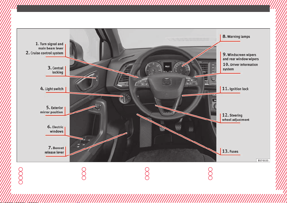
Driver-side general instrument panel (left-
hand drive) . . . . . . . . . . . . . . . . . . . . . . . . . . . . . 9
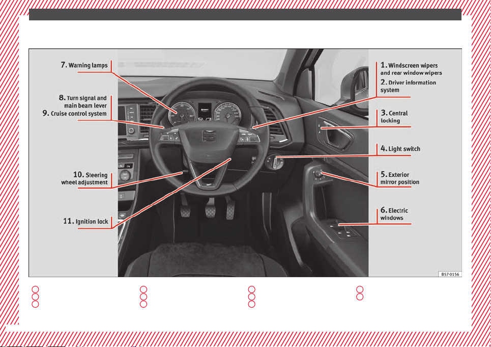
Driver-side general instrument panel (right-
hand drive) . . . . . . . . . . . . . . . . . . . . . . . . . . . . . 10
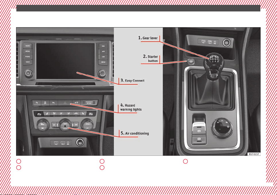
Centre console . . . . . . . . . . . . . . . . . . . . . . . . . . 11
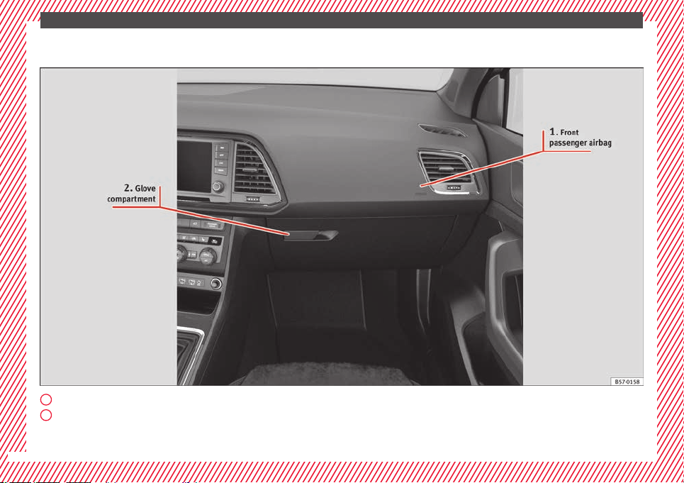
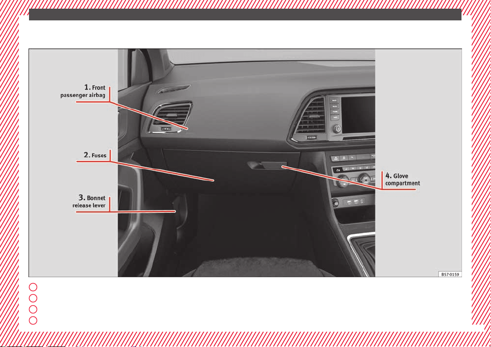
Passenger-side general instrument panel (left-
hand drive) . . . . . . . . . . . . . . . . . . . . . . . . . . . . . 12
Passenger-side general instrument panel
(right-hand drive) . . . . . . . . . . . . . . . . . . . . . . . . 13
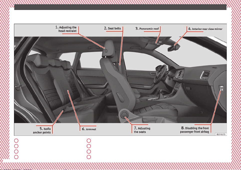
Interior view . . . . . . . . . . . . . . . . . . . . . . . . . . . . 14
How it works . . . . . . . . . . . . . . . . . . . . . . . . . . . . 15
Unlocking and locking . . . . . . . . . . . . . . . . . . . . 15
Before driving . . . . . . . . . . . . . . . . . . . . . . . . . . . 18
Airbags . . . . . . . . . . . . . . . . . . . . . . . . . . . . . . . . 21
Child seats . . . . . . . . . . . . . . . . . . . . . . . . . . . . . 24
Starting the vehicle . . . . . . . . . . . . . . . . . . . . . . 30
Lights and visibility . . . . . . . . . . . . . . . . . . . . . . 30
Easy Connect . . . . . . . . . . . . . . . . . . . . . . . . . . . 33
Driver information System . . . . . . . . . . . . . . . . . 36
Status display . . . . . . . . . . . . . . . . . . . . . . . . . . . 40
Cruise control . . . . . . . . . . . . . . . . . . . . . . . . . . . 44
Warning lamps . . . . . . . . . . . . . . . . . . . . . . . . . . 46
Gearbox lever . . . . . . . . . . . . . . . . . . . . . . . . . . . 49
Air conditioning . . . . . . . . . . . . . . . . . . . . . . . . . 51
Fluid Level control . . . . . . . . . . . . . . . . . . . . . . . 56
Emergencies . . . . . . . . . . . . . . . . . . . . . . . . . . . . 61
Fuses . . . . . . . . . . . . . . . . . . . . . . . . . . . . . . . . . . 61
Bulbs . . . . . . . . . . . . . . . . . . . . . . . . . . . . . . . . . . 62
Action in the event of a puncture . . . . . . . . . . . 62
Changing a wheel . . . . . . . . . . . . . . . . . . . . . . . 64
Snow chains . . . . . . . . . . . . . . . . . . . . . . . . . . . . 67
Emergency towing of the vehicle . . . . . . . . . . . 68
How to jump start . . . . . . . . . . . . . . . . . . . . . . . . 69
Changing the wiper blades . . . . . . . . . . . . . . . . 71
Safety . . . . . . . . . . . . . . . . . . . . . . . . . . . . . . . . 73
Safe driving . . . . . . . . . . . . . . . . . . . . . . . . . . . . 73
Safety first! . . . . . . . . . . . . . . . . . . . . . . . . . . . . . 73
Advice about driving . . . . . . . . . . . . . . . . . . . . . 73
Correct position of the vehicle occupants . . . . 74
Pedal area . . . . . . . . . . . . . . . . . . . . . . . . . . . . . . 78
Seat belts . . . . . . . . . . . . . . . . . . . . . . . . . . . . . . 79
Why wear a seat belt . . . . . . . . . . . . . . . . . . . . . 79
How to properly adjust your seatbelt . . . . . . . . 82
Seat belt tensioners . . . . . . . . . . . . . . . . . . . . . . 83
Airbag system . . . . . . . . . . . . . . . . . . . . . . . . . . 84
Brief introduction . . . . . . . . . . . . . . . . . . . . . . . . 84
Airbag safety instructions . . . . . . . . . . . . . . . . . 86
Deactivating airbags . . . . . . . . . . . . . . . . . . . . . 88
Transporting children safely . . . . . . . . . . . . . . . 90
Safety for children . . . . . . . . . . . . . . . . . . . . . . . 90
Child seats . . . . . . . . . . . . . . . . . . . . . . . . . . . . . 91
Event Data Recorder . . . . . . . . . . . . . . . . . . . . . . 94
Description and operation . . . . . . . . . . . . . . . . . 94
Emergencies . . . . . . . . . . . . . . . . . . . . . . . . . . 95
Self-help . . . . . . . . . . . . . . . . . . . . . . . . . . . . . . . 95
Vehicle tool kit, anti-puncture kit* . . . . . . . . . . 95
Tyre repair . . . . . . . . . . . . . . . . . . . . . . . . . . . . . . 95
Manual unlocking/locking . . . . . . . . . . . . . . . . . 97
Changing the windscreen wiper blades . . . . . . 97
Tow-starting and towing . . . . . . . . . . . . . . . . . . 98
Fuses and bulbs . . . . . . . . . . . . . . . . . . . . . . . . . 102
Fuses . . . . . . . . . . . . . . . . . . . . . . . . . . . . . . . . . . 102
Changing a bulb . . . . . . . . . . . . . . . . . . . . . . . . . 106
Change the front bulbs . . . . . . . . . . . . . . . . . . . 107
Change the rear bulbs . . . . . . . . . . . . . . . . . . . . 109
Side turn signals . . . . . . . . . . . . . . . . . . . . . . . . 111
Operation . . . . . . . . . . . . . . . . . . . . . . . . . . . . . 113
Controls and displays . . . . . . . . . . . . . . . . . . . . 113
General instrument panel . . . . . . . . . . . . . . . . . 112
Instruments and warning/control lamps . . . . . 114
Instruments . . . . . . . . . . . . . . . . . . . . . . . . . . . . 114
Control lamps . . . . . . . . . . . . . . . . . . . . . . . . . . . 119
Introduction to the Easy Connect system* . . . . 120
System settings (CAR)* . . . . . . . . . . . . . . . . . . . 120
Communications and multimedia . . . . . . . . . . . 121
Controls on the steering wheel* . . . . . . . . . . . . 121
Multimedia . . . . . . . . . . . . . . . . . . . . . . . . . . . . . 123
Opening and closing . . . . . . . . . . . . . . . . . . . . . 125
Central locking . . . . . . . . . . . . . . . . . . . . . . . . . . 125
Anti-theft alarm system* . . . . . . . . . . . . . . . . . . 134
Rear lid (luggage compartment) . . . . . . . . . . . . 137
Controls for the windows . . . . . . . . . . . . . . . . . . 139
Sunroof* . . . . . . . . . . . . . . . . . . . . . . . . . . . . . . . 141
Lights and visibility . . . . . . . . . . . . . . . . . . . . . . 144
Lights . . . . . . . . . . . . . . . . . . . . . . . . . . . . . . . . . 144
Visibility . . . . . . . . . . . . . . . . . . . . . . . . . . . . . . . 152
Windscreen wiper and window wiper sys-
tems . . . . . . . . . . . . . . . . . . . . . . . . . . . . . . . . . . 153
Mirror . . . . . . . . . . . . . . . . . . . . . . . . . . . . . . . . . 155
Seats and head restraints . . . . . . . . . . . . . . . . . 156
Adjusting the seats and headrests . . . . . . . . . . 156
Seat functions . . . . . . . . . . . . . . . . . . . . . . . . . . 158
Transport and practical equipment . . . . . . . . . 160
Storage compartments . . . . . . . . . . . . . . . . . . . 160
Storing objects . . . . . . . . . . . . . . . . . . . . . . . . . . 162
Roof carrier* . . . . . . . . . . . . . . . . . . . . . . . . . . . . 168
Air conditioning . . . . . . . . . . . . . . . . . . . . . . . . . 170
Heating, ventilation and cooling . . . . . . . . . . . . 170
Auxiliary heater (additional heater)* . . . . . . . . 177
Driving . . . . . . . . . . . . . . . . . . . . . . . . . . . . . . . . 181
Starting and stopping the engine . . . . . . . . . . . 181
Braking and parking . . . . . . . . . . . . . . . . . . . . . 186
Manual gearbox . . . . . . . . . . . . . . . . . . . . . . . . . 192
5

Table of Contents
Automatic gearbox/DSG automatic gear-
bo
x*
. . . . . . . . . . . . . . . . . . . . . . . . . . . . . . . . . . . 193
Ad
dress . . . . . . . . . . . . . . . . . . . . . . . . . . . . . . . . 200
Run-in and economical driving . . . . . . . . . . . . . 201
Power management . . . . . . . . . . . . . . . . . . . . . . 203
Engine management and exhaust gas purifica-
tion system . . . . . . . . . . . . . . . . . . . . . . . . . . . . . 204
Driving tips . . . . . . . . . . . . . . . . . . . . . . . . . . . . . 206
Driver assistance systems . . . . . . . . . . . . . . . . . 208
Start-Stop System* . . . . . . . . . . . . . . . . . . . . . . . 208
Hill Descent Control (HDC) . . . . . . . . . . . . . . . . . 210
Auto Hold Function . . . . . . . . . . . . . . . . . . . . . . . 211
Cruise control system (CCS)* . . . . . . . . . . . . . . . 212
Speed limiter . . . . . . . . . . . . . . . . . . . . . . . . . . . 214
Emergency brake assist system (Front As-
sist)* . . . . . . . . . . . . . . . . . . . . . . . . . . . . . . . . . . 217
Adaptive Cruise Control ACC* . . . . . . . . . . . . . . 221
Lane Assist system* . . . . . . . . . . . . . . . . . . . . . . 230
Traffic Jam Assist . . . . . . . . . . . . . . . . . . . . . . . . 233
Emergency Assist . . . . . . . . . . . . . . . . . . . . . . . . 234
Blind spot detector (BSD) with parking assis-
tance (RCTA)* . . . . . . . . . . . . . . . . . . . . . . . . . . . 237
SEAT Drive Profile* . . . . . . . . . . . . . . . . . . . . . . . 242
Traffic sign detection system* . . . . . . . . . . . . . . 245
Fatigue detection (break recommendation)* . . 248
Park Assist* . . . . . . . . . . . . . . . . . . . . . . . . . . . . 249
Parking System Plus (ParkPilot)* . . . . . . . . . . . 257
Parking aid (Park Pilot)* . . . . . . . . . . . . . . . . . . 262
Top View Camera* . . . . . . . . . . . . . . . . . . . . . . . 265
Rear Assist (Rear View Camera)* . . . . . . . . . . . . 270
Towing bracket device* . . . . . . . . . . . . . . . . . . . 273
Trailer mode . . . . . . . . . . . . . . . . . . . . . . . . . . . . 273
Advice . . . . . . . . . . . . . . . . . . . . . . . . . . . . . . . . 284
Care and maintenance . . . . . . . . . . . . . . . . . . . . 284
Accessories and modifications to the vehi-
cle . . . . . . . . . . . . . . . . . . . . . . . . . . . . . . . . . . . . 284
Care and cleaning . . . . . . . . . . . . . . . . . . . . . . . 285
Vehicle exterior care . . . . . . . . . . . . . . . . . . . . . . 285
Caring for the vehicle interior . . . . . . . . . . . . . . 289
Checking and refilling levels . . . . . . . . . . . . . . . 292
Filling the tank . . . . . . . . . . . . . . . . . . . . . . . . . . 292
Fuel . . . . . . . . . . . . . . . . . . . . . . . . . . . . . . . . . . . 293
AdBlue
®
. . . . . . . . . . . . . . . . . . . . . . . . . . . . . . . 295
Engine compartment . . . . . . . . . . . . . . . . . . . . . 298
Engine oil . . . . . . . . . . . . . . . . . . . . . . . . . . . . . . 300
Cooling system . . . . . . . . . . . . . . . . . . . . . . . . . . 302
Brake fluid . . . . . . . . . . . . . . . . . . . . . . . . . . . . . 303
Windscreen washer reservoir . . . . . . . . . . . . . . 304
Battery . . . . . . . . . . . . . . . . . . . . . . . . . . . . . . . . . 305
Wheels . . . . . . . . . . . . . . . . . . . . . . . . . . . . . . . . 307
Wheels and tyres . . . . . . . . . . . . . . . . . . . . . . . . 307
Tyre monitoring systems . . . . . . . . . . . . . . . . . . 311
Temporary spare wheel . . . . . . . . . . . . . . . . . . . 314
Winter service . . . . . . . . . . . . . . . . . . . . . . . . . . . 315
Technical data . . . . . . . . . . . . . . . . . . . . . . . . 317
Technical specifications . . . . . . . . . . . . . . . . . . 317
Important . . . . . . . . . . . . . . . . . . . . . . . . . . . . . . 317
Vehicle identification data . . . . . . . . . . . . . . . . . 317
Information on fuel consumption . . . . . . . . . . . 318
Trailer mode . . . . . . . . . . . . . . . . . . . . . . . . . . . . 319
Wheels . . . . . . . . . . . . . . . . . . . . . . . . . . . . . . . . 319
Engine data . . . . . . . . . . . . . . . . . . . . . . . . . . . . . 320
Dimensions . . . . . . . . . . . . . . . . . . . . . . . . . . . . . 327
Index . . . . . . . . . . . . . . . . . . . . . . . . . . . . . . . . . 329
6
The essentials
How it works
Un
loc
k
ing and locking
Doors
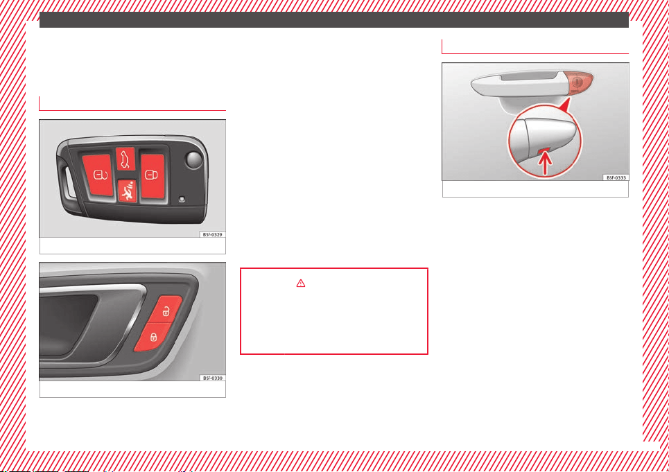
Fig. 1 Remote control key: buttons.
Fig. 2 Driver door: central locking switch.
Locking and unlocking the vehicle using the
k
ey
●
L
oc
king: press the ››› Fig. 1 button.
●
Locking the vehicle without activating the
anti-theft system: Press the ››› Fig. 1 button
for a second time within 2 seconds.
●
Unlocking: press the ››› Fig. 1 button.
●
Unlocking the rear lid: Hold down the
››› Fig. 1 button for at least 1 second.
Locking and unlocking with the central lock-
ing switch
●
Locking: press the ››› Fig. 2 button. None
of the doors can be opened from the outside.
The doors can be opened from the inside by
pulling the inside door handle.
●
Unlocking: press the ››› Fig. 2 button.
››› in Description on page 125
››› page 125
››› page 15, ››› page 16
Unlocking or locking of driver door
Fig. 3 Driver door lever: hidden lock cylinder.
If the central locking system should fail to op-
er
at
e, the driv
er door can still be locked and
unlocked by turning the key in the lock.
As a general rule, when the driver door is
locked manually all other doors are locked.
When it is unlocked manually, only the driver
door opens. Please observe the instructions
relating to the anti-theft alarm system
›››
page 125.
●
Unfold the vehicle key blade
›››
page 126.
●
Insert the key shaft into the lower opening
in the cover on the driver door handle
››› Fig. 3 (arrow) then remove the cover up-
wards.
●
Insert the key blade into the lock cylinder
to unlock or lock the vehicle.
»
15
The essentials
Special Characteristics
●
The anti-theft alarm will remain active when
v
ehic
l
es are unlocked. However, the alarm
will not be triggered ›››
page 125.
●
After the driver door is opened, you have
15 seconds to switch on the ignition. Once
this time has elapsed, the alarm is triggered.
●
Switch the ignition on. The electronic im-
mobilizer recognises a valid vehicle key and
deactivates the anti-theft alarm system.
Note
The anti-theft alarm is not activated when the
vehicl
e is locked manually using the key
shaft ›››
page 125.
Emergency locking of doors without
door cylinder
Fig. 4 Locking the door manually.
If the central locking system should fail to
w
ork
at
any time, doors with no lock cylinder
will have to be locked separately.
A mechanical locking device (only visible
when the door is open) is provided on the
front passenger door.
●
Pull the cap out of the opening.
●
Insert the key in the inside slot and turn it
to the right as far as it will go (if the door is
on the right side) or to the left (if the door is
on the left side).
Once the door has been closed it can no lon-
ger be opened from the outside. Pull the inte-
rior door handle once to unlock and open the
door.
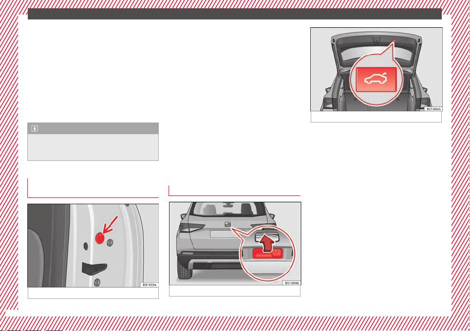
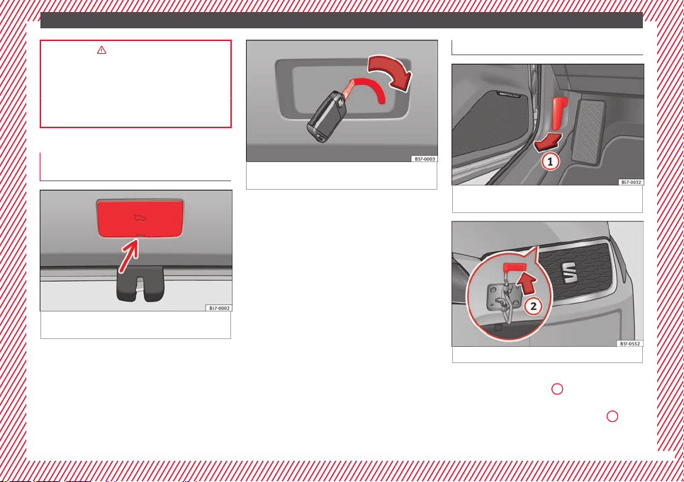
Rear lid
Fig. 5 Rear lid: handle
Fig. 6 Rear lid: button to close rear lid.
The rear lid opening system operates electri-
c
al
ly*. It
is activated by exerting slight pres-
sure on the handle ››› Fig. 5.
To lock/unlock, press the button or button
››› Fig. 1 on the remote control key.
A warning appears on the instrument panel
display if the rear lid is open or not properly
closed.* An audible warning is also given if it
is opened while the vehicle is moving faster
than 6 km/h (4 mph)*.
Opening and closing
●
Opening the rear lid: Exert slight pressure
on the handle. The rear lid opens automati-
cally.
●
Closing the rear lid: hold one of the han-
dles on the inner trim and close it by sliding
down, or press the button on the rear lid*
››› Fig. 6.
16
The essentials
››› in Rear lid automatic locking on
page 139
››› page 137
››› page 17
Manual release mechanism for the
rear lid
Fig. 7 Luggage compartment: access to man-
ual
r
el
ease.
Fig. 8 Luggage compartment: emergency re-
lea
se.
The rear lid can be unlocked manually from
in
s
ide in the ev
ent of an emergency.
●
Remove the cover using the key blade as a
lever ››› Fig. 7.
●
To unlock the rear lid, push the lever in the
direction of the arrow using the key blade
››› Fig. 8.
Bonnet
Fig. 9 Release lever in the driver's footwell
ar
e
a.
Fig. 10 Cam under the bonnet
●
Opening the bonnet: Pull the lever under
the d
a
shbo
ard ››› Fig. 9
1
.
●
Lift up the bonnet. Press the release catch
u
nder the bonnet
up
wards ››› Fig. 10
2
. The
arr
e
s
ter hook under the bonnet is released.
»
17
The essentials
●
The bonnet
c
an be opened. R
elease the
bonnet stay and secure it in the fixture de-
signed for this in the bonnet.
››› in Working in the engine compart-
ment on page 299
››› page 298
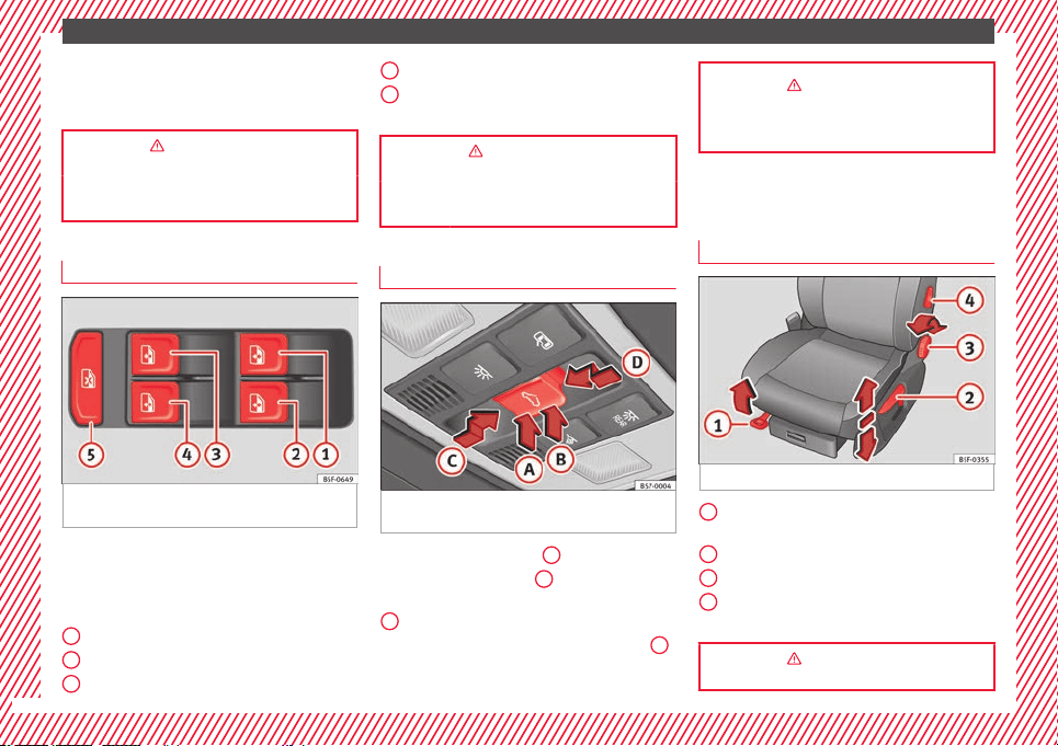
*Controls for the windows
Fig. 11 Detail of the driver door: controls for
the w
indo
w
s.
●
Opening the window: Press the b
utt
on.
●
C
losing the window: Pull the button.
Buttons on the driver door
Window on the front left door
Window on the front right door
Window on the rear left door
1
2
3
Window on the rear right door
Saf
ety
sw
itch for deactivating the electric
window buttons in the rear doors.
››› in Electric opening and closing of
windows on page 140
››› page 139
Panoramic roof*
Fig. 12 On the interior roof lining: sunroof
b
utt
on.
●
Opening: press button
C
backwards.
●
Closing: press button
D
forwards.
●
To tilt open: press the rear part of button
B
.
●
Lowering: press the front part of button
A
.
4
5
››› in Introduction on page 141
››› page 141
Before driving
M
anua
l
ly adjusting the front seats
Fig. 13 Front seats: manual seat adjustment.
Forward/back: pull the lever and move
the se
at
f
orwards or backwards.
Raising/lowering: pull/push the lever.
Tilting the backrest: turn the hand wheel.
Lumbar support: move the lever until the
required position is achieved.
››› in Manual adjustment of the seats
on page 156
1
2
3
4
18
The essentials
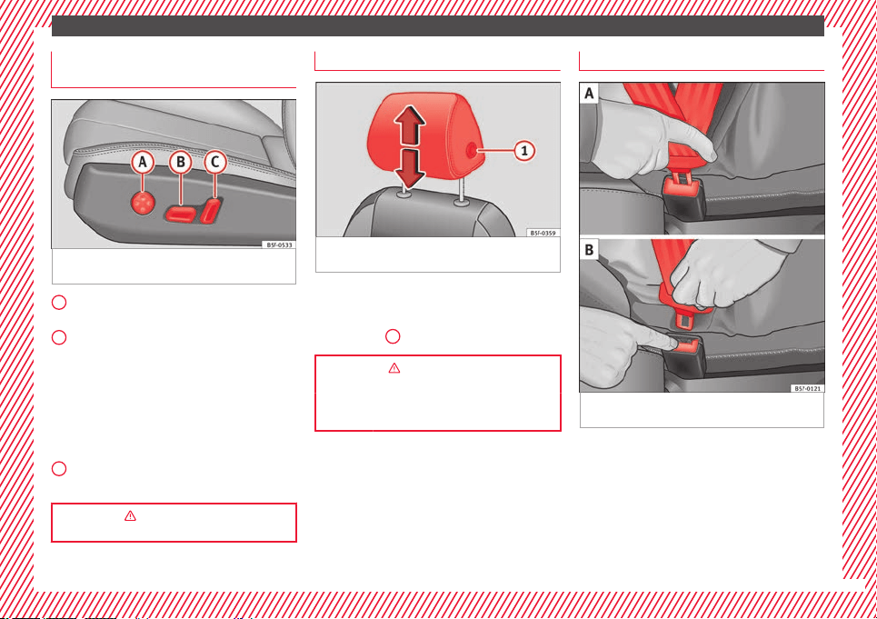
Electric adjustment of the driver's
se
at*
Fig. 14 Driver's seat: electric seat adjust-
ment
.
Adjusting the lumbar support: press the
b
utt
on ac
cording to the desired position.
Seat up/down: Press the button
up/down. To adjust the front of the seat
cushion, press the front of the button
up/down. To adjust the rear of the seat
cushion, press the rear of the button
up/down.
Seat forwards/backwards: press the but-
ton forwards/backwards.
Backrest further upright/further reclined:
press the button forwards/backwards.
››› in Electric driver's seat adjustment*
on page 157
A
B
C
Adjusting the head restraints
Fig. 15 Front seat: adjustment of the head re-
s
tr
aint
.
●
Grab the sides of the head restraints with
both h
and
s
and push upwards to the desired
position. To lower it, repeat the same action,
pressing the
1
button on the side.
››› in Correct adjustment of front head
restraints on page 77
››› page 77, ››› page 157
Adjustment of the seat belt
Fig. 16 Positioning and removing the seat
belt
b
uc
kle.
»
19
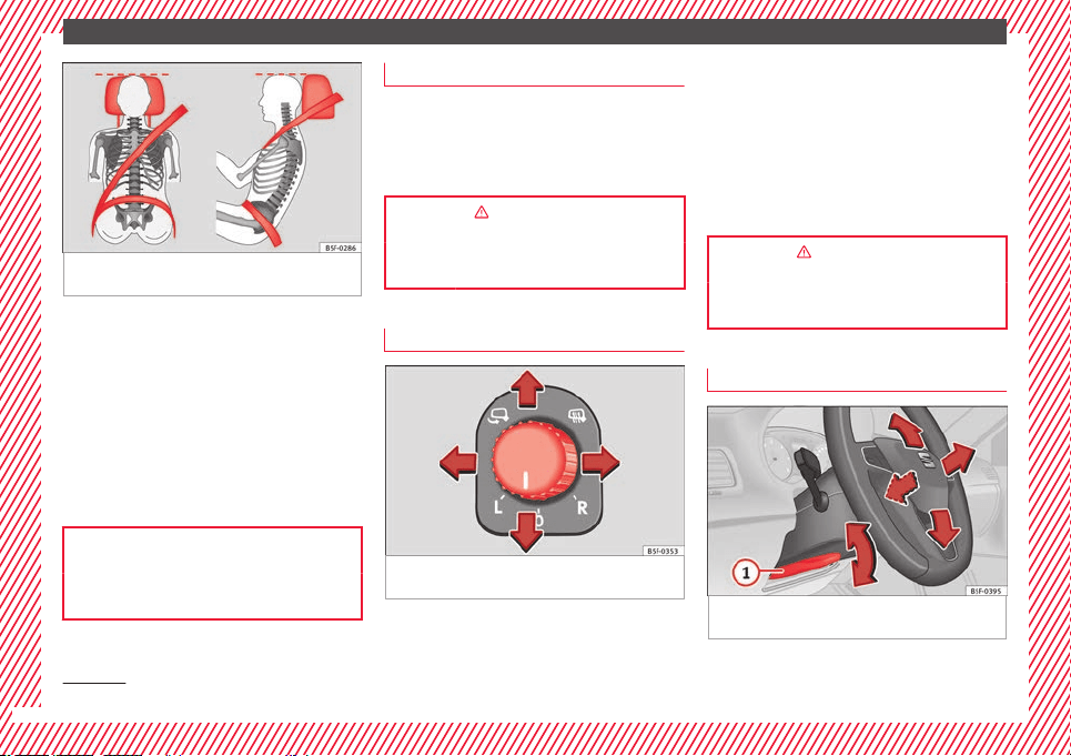
The essentials
Fig. 17 Correct seat belt and head restraint
position
s, viewed from front and the side.
To adjust the seat belt around your should-
er
s, a
dju
st the height of the seats.
The shoulder part of the seat belt should be
well centred over it, never over the neck. The
seat belt lies flat and fits comfortably on the
upper part of the body.
The lap part of the seat belt lies across the
pelvis, never across the stomach. The seat
belt lies flat and fits comfortably on the pel-
vis.
››› page 80
››› page 82
Seat belt tensioners
During a collision, the seat belts on the front
seats and s
ide rear seats
1)
tighten automati-
cally.
The tensioner can be triggered only once.
››› in Maintenance and disposal of belt
tensioners on page 84
››› page 83
Adjusting the exterior mirrors
Fig. 18 Detail of the driver door: control for
the e
xt
erior mirr
or.
Adjusting the exterior mirrors: Turn the knob
t
o the c
orr
esponding position:
Turning the knob to the desired posi-
tion, adjust the mirrors on the driver
side (L, left) and the passenger side (R,
right) to the direction desired.
Depending on the equipment fitted on
the vehicle, the mirrors may be heated
according to the outside temperature.
Folding in mirrors.
››› in Adjusting the exterior rear-view
mirrors on page 156
››› page 155
Adjusting the steering wheel
Fig. 19 Lever in the lower left side of the
s
t
eerin
g column.
L/R
1)
Depending on version/market.
20
The essentials
●
Adju
s
tin
g the position of the steering
wheel: Pull the ››› Fig. 19
1
lever down,
mo
v
e the s
teering wheel to the desired posi-
tion and lift the lever back up until it locks.
››› in Adjusting the steering wheel po-
sition on page 75
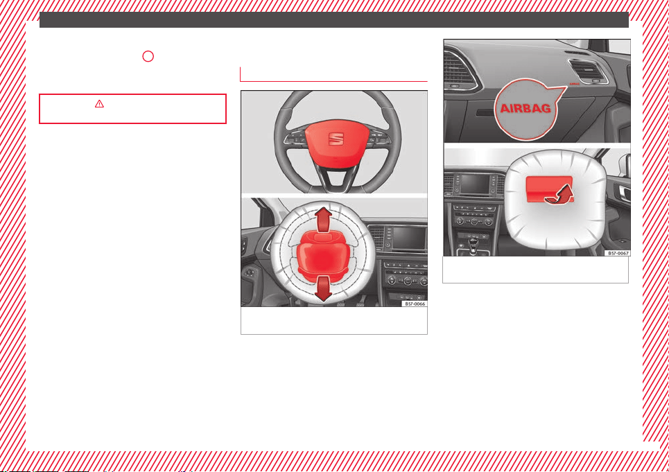
Airbags
Fr
ont
airb
ags
Fig. 20 Driver airbag located in steering
wheel
.
Fig. 21 Front passenger airbag located in
d
a
sh p
anel.
The front airbag for the driver is located in
the s
t
eerin
g wheel ››› Fig. 20 and the airbag
for the front passenger is located in the dash
panel ››› Fig. 21. Airbags are identified by the
word “AIRBAG”.
When the driver and front passenger airbags
are deployed, the covers remain attached to
the steering wheel and dashboard, respec-
tively ››› Fig. 20 ››› Fig. 21.
In conjunction with the seat belts, the front
airbag system gives the front occupants ad-
ditional protection for the head and chest in
»
21
The essentials
the event of a severe frontal collision ›
›
›
in
Fr
ont
airb
ags on page 86.
Their special design allows the controlled es-
cape of the propellant gas when an occupant
puts pressure on the bag. Thus, the head and
chest are protected by the airbag. After the
collision, the airbag deflates sufficiently to
allow visibility.
››› page 86
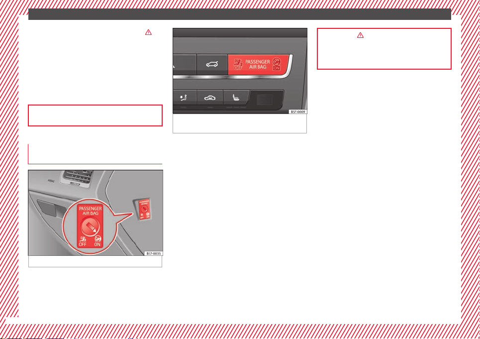
Deactivating the front passenger front
airb
ag
Fig. 22 Front passenger front airbag switch.
Fig. 23 Dash panel: control lamp for deactiva-
ted front
passenger airbag in centre console.
To deactivate the front passenger front air-
b
ag:
●
Sw
it
ch the ignition off.
●
Open the door on the front passenger side.
●
Insert the key into the slot of the switch for
deactivating the front passenger airbag
››› Fig. 22. About 3/4 of the key should enter;
this is as far as it will go.
●
Turn the key gently to the position. If
you have difficulty, ensure that you have in-
serted the key as far as it will go.
●
Close the front passenger door.
●
Check, with the ignition switched on, that
the control lamp remains lit where it
says in the centre of the
dash panel ››› Fig. 23.
››› in Activation and deactivation of
front passenger airbag* on page 89
››› page 88
22
The essentials
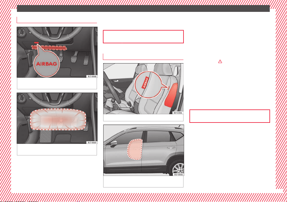
Knee airbag*
Fig. 24 On the driver side: location of the
knee airb
ag
Fig. 25 On the driver side: radius of action of
the knee airb
ag.
The knee airbag is located on the driver side
belo
w the d
a
sh panel ››› Fig. 24. Airbags are
identified by the word “AIRBAG”.
The area framed in red (deployment area)
››› Fig. 25 is covered by the knee airbag when
it is deployed. Objects should never be
placed or mounted in this area.
››› page 86
Side airbags*
Fig. 26 Side airbag in driver's seat.
Fig. 27 Illustration of completely inflated side
airb
ag
s
on the left side of the vehicle.
The side airbags are located in the driver's
se
at
and fr
ont passenger seat backrests
››› Fig. 26. The locations are identified by the
text “AIRBAG” in the upper region of the
backrests.
In conjunction with the seat belts, the side
airbag system provides additional protection
for the upper body in the event of a severe
side collision ›››
in Side airbags* on
p
ag
e 86
.
In a side collision, the side airbags reduce
the risk of injury to passengers to the areas
of the body facing the impact. In addition to
their normal protection, the seat belts also
hold the passengers in the event of a side
collision; this is how these airbags provide
maximum protection.
››› page 86
23
The essentials
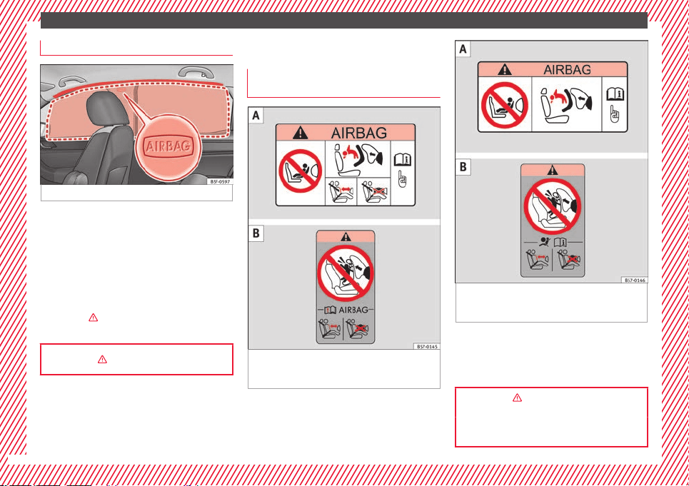
Head-protection airbags*
Fig. 28 Location of head-protection airbags.
The head-protection airbags are located on
both s
ide
s
in the interior above the doors
››› Fig. 28 and are identified with the text
“AIRBAG”.
In conjunction with the seat belts, the head-
protection airbag system gives the vehicle
occupants additional protection for the head
and upper body in the event of a severe side
collision ›››
in Curtain airbags* on
p
ag
e 87
.
››› in Curtain airbags* on page 87
Child seats
Impor
t
ant
information regarding the
front passenger's airbag
Fig. 29 Airbag stickers - version 1: on the
p
a
s
senger-side sun blind and on the rear
frame of the front passenger's door .
Fig. 30 Airbag stickers - version 2: on the
p
a
s
senger-side sun blind and on the rear
frame of the front passenger's door .
A sticker with important information about
the p
a
s
senger airbag is located on the pas-
senger's sun visor and/or on the passenger
side door frame.
››› in Important information regarding
the front passenger's airbag on page 91
››› page 90
24
The essentials
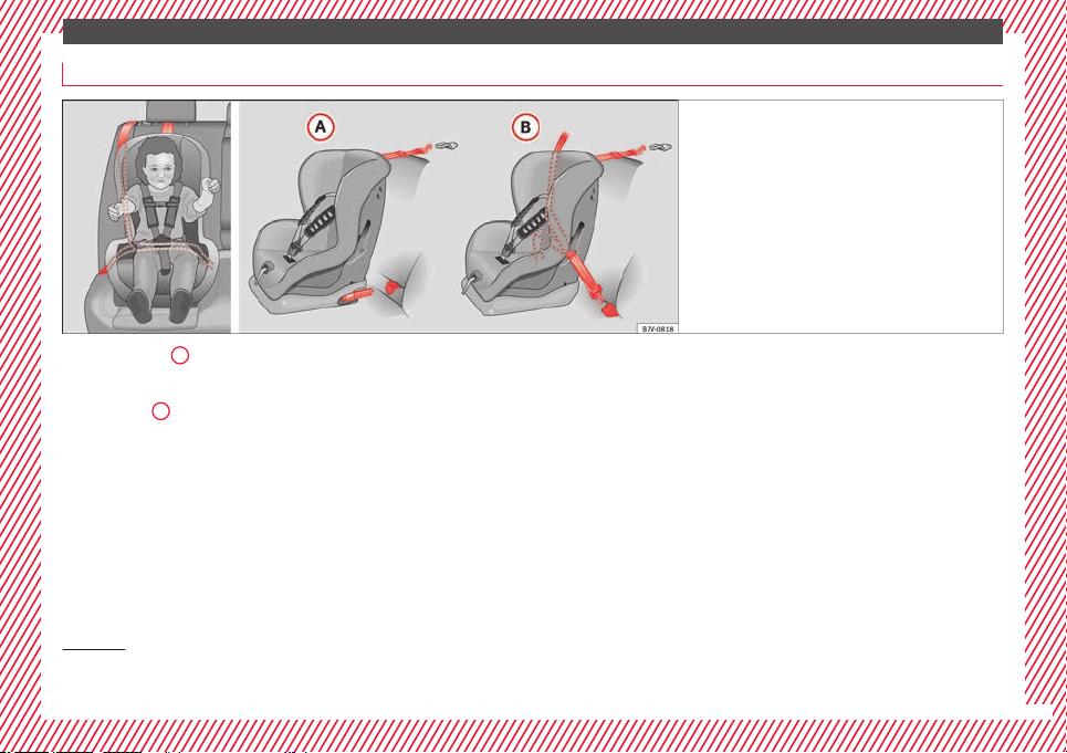
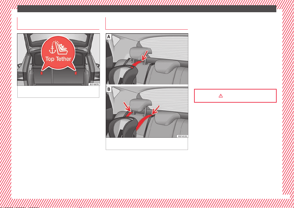
Securing child seats
Fig. 31 On the rear seats: Possible installations
for the chi
ld seat.
Figure ›
›› Fig. 31
A
shows the basic child re-
s
tr
aint
system mounting using lower retain-
ing rings and the upper retaining strap. Fig-
ure ››› Fig. 31
B
shows the child restraint
sy
s
t
em mounting using the vehicle seat belt.
The seat belt may be used to secure univer-
sal type child seats to the vehicle seats
marked with a U in the table below.
●
In a front passenger seat without height ad-
justment: It is necessary to place the front
passenger seat in its rearmost position
1)
.
●
In a front passenger seat with height ad-
justment: it is necessary to place the front
passenger seat in its rearmost and highest
position
1)
.
To correctly use a child seat in the back, the
front backrest must be adjusted so that there
is no contact with the child seat in the back
in the case that it goes opposite to the direc-
tion of the car. In the case of front facing re-
straint systems, the front backrest must be
adjusted so that there is no contact with the
child's feet.
To adjust the passenger seat to accommo-
date a child's seat and get the seat belt in a
perfect position, adjust the passenger back-
rest as far forward as possible
1)
.
If a semi-universal type chair is to be instal-
led, in which the method of attachment to
the car is through the seat belt and support
bracket, it should never be installed in the
central rear seat as the ground clearance is
lower than in other places and the support
bracket will not allow the seat to remain suffi-
ciently stable.
The systems include the child restraint sys-
tem mounting with an upper retaining strap
(Top Tether) and lower anchoring points on
the seat.
»
1)
Compliance with current national legislation and
the manufact
urer's instructions is required when us-
ing or installing child seats.
25
The essentials
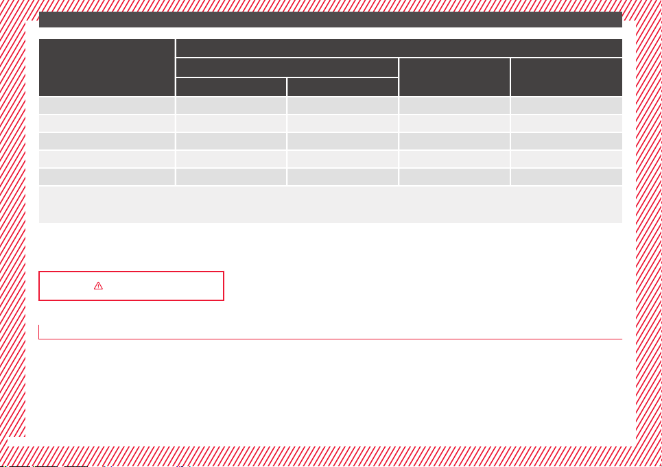
Weight group
Seating position
Front passenger seat
a)
Rear side seat Rear central seat
b)
airbag on airbag off
Group 0 to 10 kg X U
c)
U U
Group 0+ to 13 kg X U
c)
U U
Group I 9 to 18 kg X U
c)
U U
Group II 15 to 25 kg X UF
c)
UF UF
Group III 22 to 36 kg X UF
c)
UF UF
X: It is not compatible to install chairs in this configuration.
U: Suitable for universal restraint systems for use in this weight group.
UF: Acceptable for front-facing universal-category child restraint systems approved for this mass group.
a)
Compliance with current national legislation and the manufacturer's instructions is required when using or installing child seats.
b)
For semi-universal chairs where the securing system is the car safety belt and the support bracket, do not use them in the centre rear seat.
c)
Seats without height adjustment should be placed in their rearmost position. Seats with height adjustment should be placed in their rearmost and highest position.
››› in Safety instructions on page 91
Securing child seats with “ISOFIX” and Top Tether*
Child seats can be secured quickly, easily
and s
af
ely
on the rear outer seats with the
“ISOFIX” and Top Tether* system.
Two “ISOFIX” retaining rings are fitted on
each rear seat. In some vehicles, the rings
are secured to the seat frame and, in others,
they are secured to the rear floor. The “ISO-
FIX” rings are located between the rear seat
backrest and the seat cushioning ››› Fig. 32.
The Top Tether* rings are located on the rear
part of the backrests of the rear seats (be-
hind the seat backrest or in the boot)
››› Fig. 33.
To understand the compatibility of the "ISO-
FIX" systems in the vehicle, consult the table
below.
The body weight permitted and information
regarding sizes A to F is indicated on the la-
bel on child seats with “universal” or “semi-
universal” certification.
26
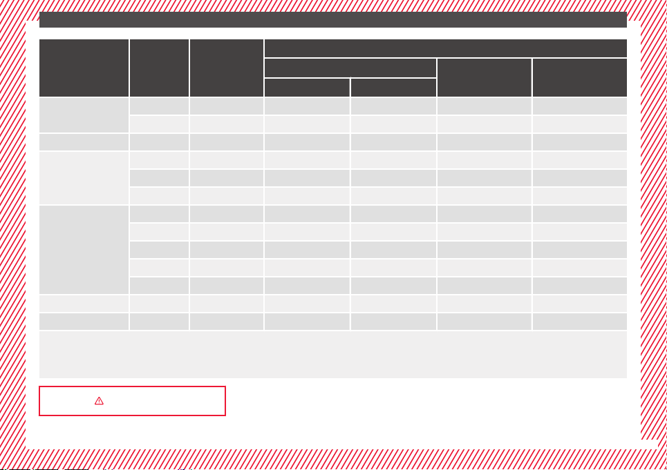
The essentials
Weight group Size class
Electrical equip-
ment
Vehicle Isofix positions
Front passenger seat
Rear side seat Rear central seat
airbag on airbag off
Baby carrier
F ISO/L1 X X X X
G ISO/L2 X X X X
Group 0 to 10 kg E ISO/R1 X X IL X
Group 0+ to 13 kg
E ISO/R1 X X IL X
D ISO/R2 X X IL X
C ISO/R3 X X IL X
Group I 9 to 18 kg
D ISO/R2 X X IL X
C ISO/R3 X X IL X
B ISO/F2 X X IUF/IL X
B1 ISO/F2X X X IUF/IL X
A ISO/F3 X X IUF/IL X
Group II 15 to 25 kg --- --- --- ---
Group III 22 to 36 kg --- --- --- ---
IUF: Suitable for forward-facing ISOFIX universal child restraint systems approved for use in this mass group.
IL: Suitable for certain ISOFIX child restraint systems (CRSs) listed in the attached list. This relates to ISOFIX CRSs that can be for the specific vehicle, restricted or semi-universal
categories.
: ISOFIX position not suitable for ISOFIX child restraint systems for this weight group or size class.
››› in Safety instructions on page 91
27
The essentials
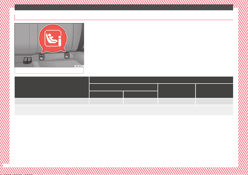
Securing child seats with the “ISOFIX/i-Size” ISOFIX System
Fig. 32 ISOFIX/iSize securing rings.
You are obliged to follow the seat manufac-
turer's
instructions.
●
Press the child seat onto the “ISOFIX” re-
taining rings ››› Fig. 32 until the child seat is
heard to engage securely. If the child seat is
equipped with Top Tether* anchor points, se-
cure it to the correspondent ring ››› Fig. 33.
Observe the manufacturer's instructions.
●
Pull on both sides of the child seat to en-
sure that it is properly anchored.
Child seats with the “ISOFIX” and Top Tether*
attachment system are available from Techni-
cal Services.
Vehicle i-Size positions
Front passenger seat
Rear side seat Rear central seat
airbag on airbag off
Child restraint system approved under ECE R129 X X i-U X
i-U Valid position for front-facing and rear-facing child restraint systems approved under ECE R129.
X: Invalid position for child restraint systems approved under ECE R129.
28
The essentials
Securing child seats with the Top
T
ether* r
et
aining straps
Fig. 33 Position of the Top Tether rings on the
b
ac
k
of the rear seat.
Child seats with the Top Tether system come
w
ith a s
tr
ap for securing the seat to the vehi-
cle anchor point, located at the back of the
rear seat backrest and provide greater re-
straint.
The objective of this strap is to reduce for-
ward movements of the child seat in a crash,
to reduce the risk of injuries to the head from
hitting the inside of the vehicle.
Using the Top Tether in rear-facing mounted
seats
Currently, there are very few rear-facing child
safety seats that have Top Tether. Please
carefully read and follow the seat manufac-
turer instructions to learn the proper way to
install the Top Tether strap.
Securing the Top Tether* to the an-
chorage point
Fig. 34 Retainer strap: adjustment and as-
semb
ly
ac
cording to the Top Tether belt.
Securing the retainer strap
●
Follow the manufacturer's instructions to
dep
lo
y
the child seat Top Tether retainer
strap.
●
Place the belt under the head restraint of
the back seat ››› Fig. 34 (depending on the in-
structions of the chair itself, lift or remove the
head restraint if necessary).
●
Slide the strap and secure it properly with
the anchorage of the backrest ››› Fig. 33.
●
Firmly tighten the strap following the manu-
facturer's instructions.
Releasing the retaining strap
●
Loosen the strap following the manufactur-
er's instructions.
●
Push the lock and release it from the an-
choring support.
››› in Safety instructions on page 91
29
The essentials
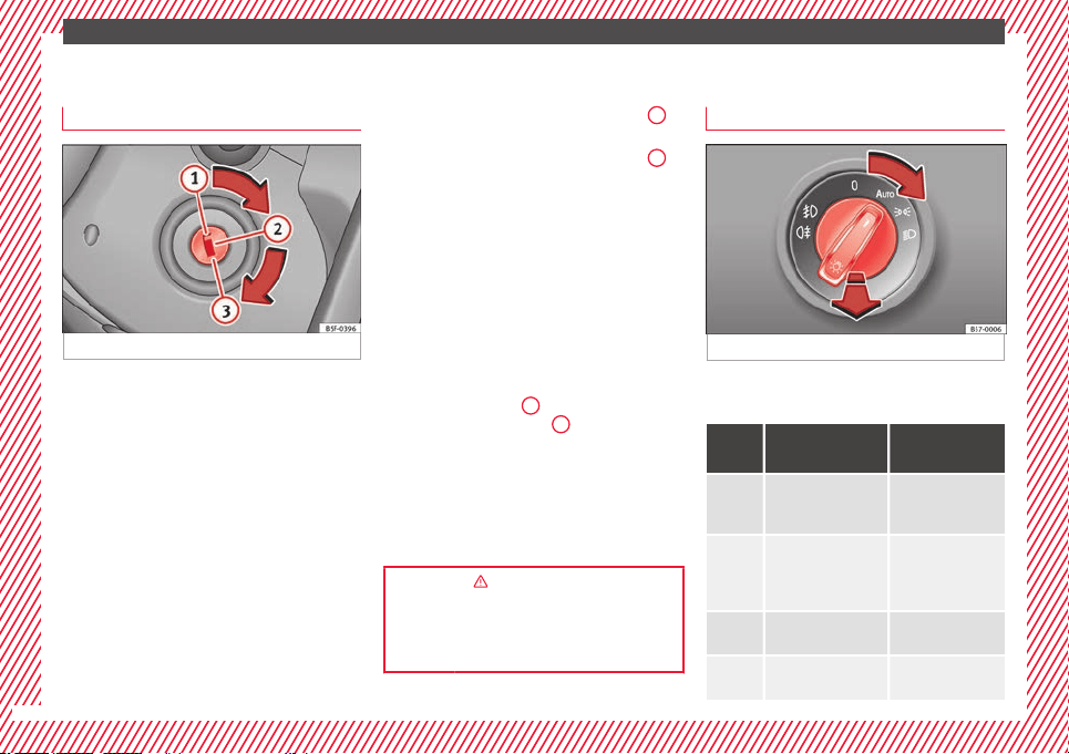
Starting the vehicle
Ignition loc
k
Fig. 35 Ignition key positions.
Switch ignition on: Place the key in the igni-
tion and s
t
ar
t the engine.
Locking and unlocking the steering wheel
●
Engaging the steering wheel lock: Remove
the key from the ignition and turn the wheel
until it locks. Depending on the country, in
vehicles with an automatic gearbox, to re-
move the key the gear lever must be in the P
position. If necessary, press the locking key
on the selector lever and release it again.
●
Unlocking the steering wheel: Put the key
into the ignition and turn it at the same time
as the steering wheel in the direction indica-
ted by the arrow. If it is not possible to turn
the steering wheel, it may be because it is
locked.
Turning on/switching off the ignition, glow
plugs reheating
●
Switch ignition on: Turn the key to the
2
position.
●
Switch ignition off. Turn the key to the
1
position.
●
Diesel vehicles :
The glo
w p
lugs reheat
when the ignition is switched on.
Starting the engine
●
Manual gearbox: press the clutch pedal all
the way down and move the gearbox lever in-
to neutral.
●
Automatic gearbox: Press the brake pedal
and move the selector lever to the P position
or into N.
●
Turn the key to the
3
position. The key au-
t
om
atic
ally returns to the
2
position. Do not
pr
e
s
s the accelerator.
Start-Stop System*
When you stop and release the clutch pedal,
the Start-Stop system* turns off the engine.
The ignition remains switched on.
››› in Switching the ignition on and
starting the engine with the key on
page 182
››› page 181
Lights and visibility
Light
sw
it
ch
Fig. 36 Dash panel: light control.
●
Turn the switch to the required position
›
›
›
Fig. 36.
Sym-
bol
Ignition switched
off
Ignition is
switched on
Fog lights, dipped
beam and side lights
off.
Daylight running
lights switched on.
The “Coming home”,
“Leaving home” and
Welcome lights may
be switched on.
Automatic control of
dipped beam and
daytime running
light.
Side light on.
Daylight running
lights switched on.
Dipped beam head-
light off
Dipped beam
switched on.
30

The essentials
Fr
ont fog lights: mo
v
e the switch to the
first position, from positions , or .
Rear fog light: move the switch completely
from positions , or .
●
Switching off fog lights: Push the switch or
turn it to the position.
››› in Side light and dipped beam head-
light on page 144
››› page 144
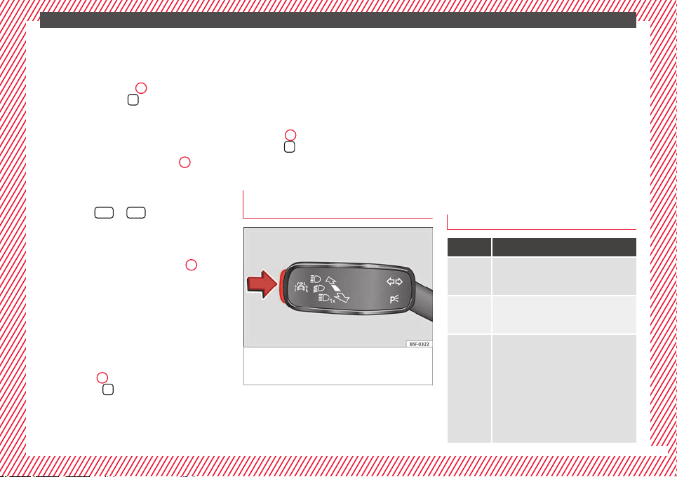
Turn signal and main beam lever
Fig. 37 Turn signal and main beam lever.
More the lever to the required position:
Right
t
urn s
ignal: Right-hand parking
light (ignition switched off).
1
Left turn signal: Left-hand parking light
(ignition sw
it
c
hed off).
Main beam switched on: Control lamp
lit up on the instrument panel.
Headlight flasher: lit up when the lever is
pushed. Control lamp lit up.
Lever all the way down to switch it off.
››› in Turn signal and main beam lever
on page 145
››› page 145
Hazard warning lights
Fig. 38 Dash panel: switch for hazard warn-
in
g lights.
Switched on, for example:
●
When approaching a traffic jam
2
3
4
●
In an emer
g
ency
●
The
vehicle has broken down
●
When towing or being towed
››› in Hazard warning lights
on
page 150
››› page 149
Interior lights
Fig. 39 Detail of headliner: front interior light-
in
g.
Knob Function
Switches interior lights off.
Switches interior lights on.
»
31
The essentials
Knob Function
Central position
or
a)
Door contact switch-on.
The interior lights come on automati-
cally when the vehicle is unlocked, a
door is opened or the key is removed
from the ignition.
The light goes off a few seconds af-
ter all the doors are closed, the vehi-
cle is locked or the ignition is switch-
ed on.
Turning the reading light on and off
a)
Depending on version.
Ambient light*: light guide on door panel.
Lighting can be selected from 8 possible col-
ours via the
menu and the
S
ET
TINGS
func-
tion b
utt
on.
››› page 152
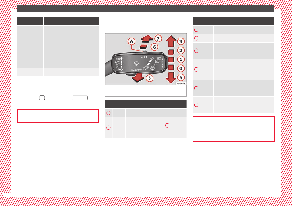
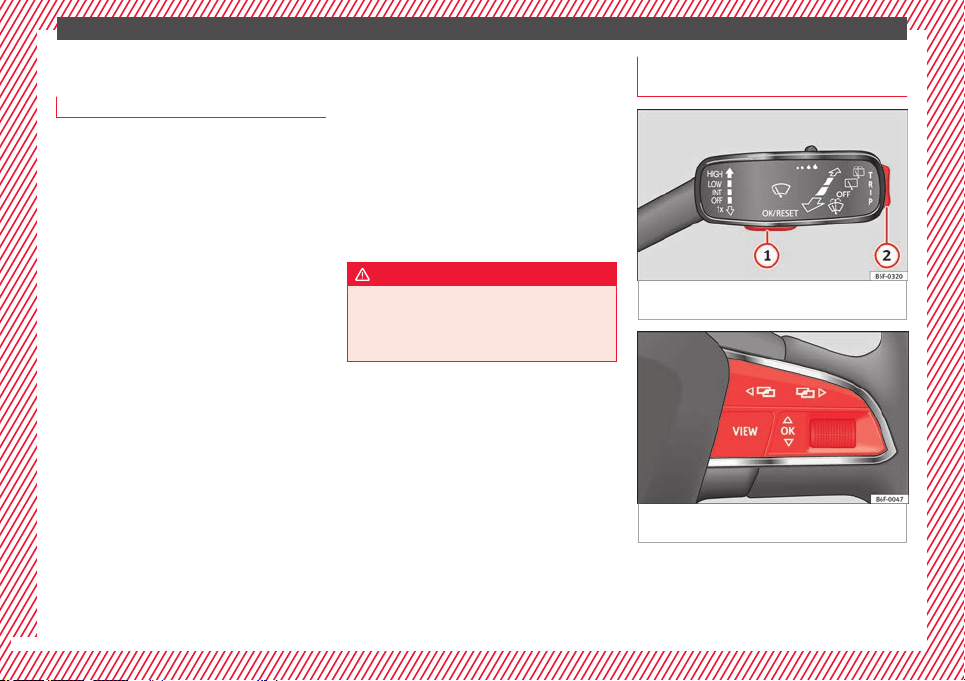
Windscreen wipers and window wiper
b
l
a
de
Fig. 40 Operating the windscreen wiper and
r
e
ar w
iper.
More the lever to the required position:
0
Windscreen wiper off.
1
Windscreen wipers interval wipe.
Using the control ››› Fig. 40
A
adjust the
interval (vehicles without rain sensor), or
the sensitivity of the rain sensor.
More the lever to the required position:
2
Slow wipe.
3
Continuous wipe.
4
Short wipe. Brief press, short clean. Hold
the lever down for more time to increase
the wipe frequency.
5
Automatic wipe. The windscreen washer
function is activated by pushing the lever
forwards, and simultaneously the wind-
screen wipers start.
6
Interval wipe for rear window. The wiper
will wipe the window approximately every
six seconds.
7
The rear window wash function is activa-
ted by pressing the lever, and the rear
wiper starts simultaneously.
››› page 153
››› page 71
32
The essentials
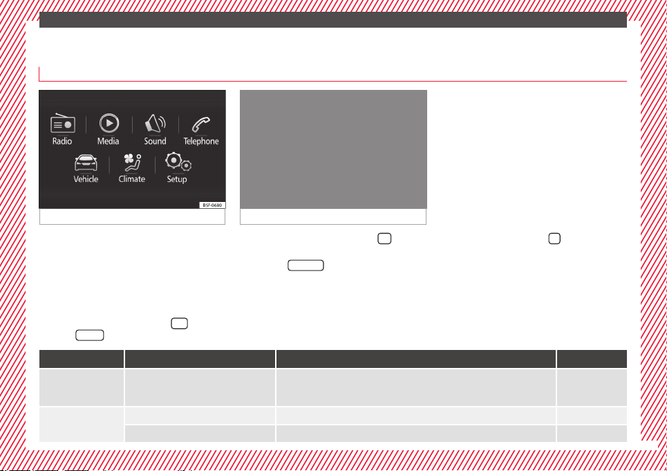
Easy Connect
CAR menu settin
g
s
Fig. 41 Easy Connect: Main menu. Fig. 42 Easy Connect: CAR menu.
The actual number of menus available and
the n
ame of
the
various options will depend
on the vehicle’s electronics and equipment.
●
Switch the ignition on.
●
If the Infotainment System is off, switch it
on.
●
Press the Infotainment button
and
then the
V
ehic
l
e
function button ›
›
›
Fig. 41,
or, press the Infotainment button
to go to
the Vehicle menu ›
›
›
Fig. 42.
●
Press the
SETTINGS
function button to open
the Vehicle settings menu.
●
To select a function in the menu, press the
de
s
ir
ed button.
When the function button check box is activa-
ted , the function is active.
Pressing the menu button
will always take
y
ou t
o the l
ast menu used.
Any changes made using the settings menus
are automatically saved on closing those me-
nus.
Menu Submenu Possible setting Description
ESC system
–
Activation and deactivation of the traction control system (ASR) and the electronic sta-
bility control (ESC) system, selecting the Sport / Off-road* mode of the electronic sta-
bility control (ESC Sport)
››› page 189
Tyres
Tyre pressure monitoring Tyre pressure storing (Calibration) ››› page 311
Winter tyres Activation and deactivation of the speed warning, adjusting the speed warning value ››› page 315
»
33

The essentials
Menu Submenu Possible setting Description
Lights
Light assist
Dynamic Light Assist, Light Assist, motorway function, turning-on time, headlamp
range adjustment, automatic lights when raining, one-touch signalling, travel mode.
››› page 144
Vehicle interior lighting Brightness of instrument panel and controls ››› page 151
Coming Home/Leaving Home function Switch-on time of the “Coming home” and “Leaving home” functions
››› page 148
››› page 149
Driver assistance
ACC (adaptive cruise control) Activation and deactivation: default distance level, driving profiles. ››› page 221
Front Assist (emergency brake as-
sist system)
Activation and deactivation: Front Assist, advance warning, distance warning display ››› page 217
Lane Assist (system warning you
if you leave the lane)
Activation and deactivation of lane departure warning, adaptive lane guidance ››› page 230
Detection of traffic signs Display on the instrument panel, activation and deactivation of the speed warning ››› page 245
Trailer
Trailer recognition (display of traffic signs for vehicles with trailer), use to calculate the
route, maximum speed for trailer
››› page 273
Fatigue detection Activation and deactivation ››› page 248
Parking and ma-
noeuvring
ParkPilot
Automatic activation, front volume, front sound treble, rear volume, rear sound treble,
adjust Infotainment volume
››› page 257,
››› page 262
Auto Hold Switching on and off when starting off ››› page 211
Electric parking brake Switching on and off automatically ››› page 186
Braking while manoeuvring func-
tion
Switching on and off ››› page 262
Displaying the parking space Switching on and off
Ambient lighting – Switching on and off, selecting brightness, colour, area or total ››› page 152
34

The essentials
Menu Submenu Possible setting Description
Mirrors and wind-
screen wipers
Mirrors
Synchronised regulation, lower the rear-view mirror when reversing, fold in after park-
ing, rear-view mirror heating, dim in the dark
››› page 20,
››› page 155
Windscreen wipers
Activate and deactivate automatic windscreen wipers in case of rain, wipe when re-
versing
››› page 32
Opening and clos-
ing
Electric windows control
Convenience opening, automatic closure in case of rain, automatic closure with cen-
tral locking
››› page 140
Central locking system
Unlocking doors, automatic lock/unlock when driving, “Easy Open” audible confirma-
tion, “Easy Entry” convenient entry function, automatic opening of the rear lid, interior
monitoring
››› page 125
Instrument panel
–
Current consumption, average consumption, volume to refuel, convenience consum-
ers, ECO Advice, travelling time, distance travelled, average speed, digital speed dis-
play, speed warning, oil temperature, coolant temperature, reset data “when setting
off”, reset data for “total calculation”, traffic signal detection
››› page 36
Date and time – Time source, time, select time zone, time format, date, date format –
Units –
Distance, speed, temperature, volume, fuel consumption, GNC consumption, electric
consumption, pressure
–
Service – Chassis number, date of next SEAT service inspection, date of next oil change service ››› page 43
Factory settings
All Restore all settings –
Individual
Lights, driver assistance, parking and manoeuvring, background lighting, rear view
mirrors and windscreen wipers, opening and closing, instrument panel
–
››› in CAR menu on page 120
35
The essentials
Driver information System
Intr
oduction
With the ignition switched on, it is possible
to re
ad the different functions of the display
by scrolling through the menus.
In vehicles with multifunction steering wheel,
the multifunction display can only be operat-
ed with the steering wheel buttons.
The number of menus displayed on the in-
strument panel will vary according to the ve-
hicle electronics and equipment.
A specialised workshop will be able to pro-
gramme or modify additional functions, ac-
cording to the vehicle equipment. SEAT rec-
ommends visiting a SEAT Official Service.
Some menu options can only be read when
the vehicle is at a standstill.
As long as a priority 1 warning is displayed, it
will not be possible to read the menus
›››
page 40. Some warning messages can
be confirmed and made to disappear with the
windscreen wiper lever button or the multi-
function steering wheel button.
The information system also provides the fol-
lowing information and displays (depending
on the vehicle's equipment):
Driving data
›››
page 38
■
MFD from departure
■
MFD from ref
uelling
■
MFD total calculation
Assist systems ››› page 39
Navigation ››› Booklet Navigation system
Audio ››› Booklet Radio or ››› Booklet Naviga-
tion system
Telephone ››› Booklet Radio or ››› Booklet
Navigation system
Vehicle status ››› page 33
WARNING
Any distraction may lead to an accident, with
the risk of
injury.
●
Do not operate the instrument panel con-
trols when driving.
Using the menus on the instrument
p
anel
Fig. 43 Windscreen wiper lever: control but-
t
on
s.
Fig. 44 Right side of multifunction steering
wheel: c
ontr
o
l buttons.
The driver information system is controlled
w
ith the mu
ltif
unction steering wheel buttons
››› Fig. 44 or with the windscreen wiper lever
››› Fig. 43 (if the vehicle is not equipped with
multifunction steering wheel).
36
The essentials
Enabling the main menu
●
Switch the ignition on.
●
If a message or vehicle pictogram appears,
pr
e
s
s button ››› Fig. 43
1
on the windscreen
w
iper l
ev
er or button
on the multifunction
s
t
eerin
g wheel ››› Fig. 44.
●
If managed from the windscreen wiper lev-
er: to display the main screen or to return to
the main menu from another menu, hold
down the rocker button ››› Fig. 43
2
.
●
If managed from the multifunction steering
whe
e
l:
the main menu list is not displayed.
To go from point to point in the main menu,
press button
or
several times
›
›
›
Fig. 44.
Select a submenu
●
Press the rocker switch ››› Fig. 43
2
on the
w
ind
s
creen wiper lever up or down or turn
the thumbwheel of the multifunction steering
wheel ››› Fig. 44 until the desired option ap-
pears marked on the menu.
●
The selected option is displayed between
two horizontal lines. In addition, a triangle is
displayed on the right:
●
To consult the submenu option, press but-
ton ››› Fig. 43
1
on the windscreen wiper
l
ev
er or b
utton
on the multifunction steer-
in
g wheel
›
››
Fig. 44.
Making changes according to the menu
●
With the rocker switch on the windscreen
wiper lever or the thumbwheel of the multi-
function steering wheel, make the desired
changes. To increase or decrease the values
more quickly, turn the thumbwheel faster.
●
Mark or confirm the selection with button
››› Fig. 43
1
on the windscreen wiper lever
or b
utt
on
on the multifunction steering
wheel
›
›
› Fig. 44.
Button for the driver assistance sys-
tems*
Fig. 45 On the turn signal and main beam
he
a
dlight
lever: button for the driver assis-
tance systems
With the turn signal and main beam head-
light
l
ev
er button, you can activate or deacti-
vate the driver assistance systems displayed
in the Assist systems menu
›››
page 208.
Activate or deactivate a driver assistance
system
●
Briefly press the button ››› Fig. 45 in the di-
rection of the arrow to open the menu As-
sist systems.
●
Select the driver assistance system and ac-
tivate or deactivate it ››› page 36. A mark indi-
cates that driver assistance system is switch-
ed on.
Selection menu
Menu Function
Driving
data
Information and possible configurations
of the multifunction display (MFD)
››› page 38.
Assist
systems
Information and possible configurations
of the driver assistance systems
››› page 39, ››› page 33.
Naviga-
tion
Information instructions from the activa-
ted navigation system: when a route guid-
ance is activated, the turning arrows and
proximity bars are displayed. The appear-
ance is similar to the Easy Connect sys-
tem.
If route guidance is not activated, the di-
rection of travel (compass) and the name
of the street along which you are driving
are shown ››› Booklet Navigation system.
»
37
The essentials
Menu Function
Audio
Station display on the radio.
Track name on the CD.
Track name in Media mode ››› Booklet Ra-
dio or ››› Booklet Navigation system.
Tele-
phone
Information and possible configurations
of the mobile phone preinstallation
››› Booklet Radio or ››› Booklet Navigation
system.
Vehicle
status
Display of the current warning or informa-
tion texts and other system components,
depending on the equipment
››› page 120.
Driving data
The MFD (multifunction display) shows differ-
ent
v
alues for the journey and the consump-
tion.
Changing between display modes on the
MFD
●
In vehicles without multifunction steering
wheel: Press the rocker switch
on the
w
ind
s
creen wiper lever ››› Fig. 43.
●
Vehicles with a multifunction steering
wheel: turn the thumbwheel ››› Fig. 44.
Multifunction display memory
The multifunction display is equipped with
three memories that work automatically: MFD
from departure, MFD from refuelling and MFD
total calculation. On the screen display, you
can read which memory is currently dis-
played.
●
Toggle between memories with the ignition
on and the memory displayed: Press the
button on the windscreen wiper lever
or the
button of the multifunction steering
wheel
.
Menu Function
MFD from
departure
Display and storage of the values for
the journey and the consumption from
when the ignition is switched on to
when it is switched off.
If the journey is continued in less than
2 hours after the ignition is switched
off, the new data is added to the data
already stored in the memory. The
memory will automatically be deleted if
the journey is interrupted for more than
2 hours.
MFD from
refuelling
Display and storage of the values for
the journey and the consumption. By
refuelling, the memory will be erased
automatically.
Menu Function
MFD total
calcula-
tion
The memory records the values for a
specific number of partial trips, up to a
total of 19 hours and 59 minutes or 99
hours and 59 minutes, or 1999.9 km or
9999 km, depending on the model of
instrument panel. On reaching either of
these limits
a)
, the memory is automati-
cally erased and starts to count from 0
again.
a)
It varies according to the instrument panel version.
Erasing a memory manually
●
Select the memory that you wish to erase.
●
Hold the
button of the multifunction
s
t
eerin
g wheel or the
button of the multi-
f
u
nction wheel
pressed down for about 2 sec-
onds.
Personalising the displays
In the Easy Connect system you can adjust
which of the possible displays of the MFD can
be shown on the instrument panel display
with the
button and the
S
ET
TINGS
function
b
utt
on
›
››
page 120.
38
The essentials
Data summary
Menu Function
Current fuel
consumption
The current fuel consumption dis-
play operates throughout the jour-
ney, in litres/100 km; and with the
engine running and the vehicle
stopped, in litres/hour.
Average fuel
consumption
After turning on the ignition, aver-
age fuel consumption in li-
tres/100 km will be displayed after
travelling about 100 metres. Other-
wise horizontal lines are displayed.
The value shown is updated approxi-
mately every 5 seconds.
ACT
®
*: Depending on the equip-
ment, number of active cylinders.
Operating
range
Approximate distance in km that can
still be travelled with the fuel re-
maining in the tank, assuming the
same style of driving is maintained.
This is calculated using the current
fuel consumption.
Travelling
time
This indicates the hours (h) and mi-
nutes (min) since the ignition was
switched on.
Journey
Distance covered in km (m) after
switching on the ignition.
Average
speed
The average speed will be shown af-
ter a distance of about 100 metres
has been travelled. Otherwise hori-
zontal lines are displayed. The value
shown is updated approximately ev-
ery 5 seconds.
Menu Function
Digital dis-
play of
speed
Current speed displayed in digital
format.
Speed warn-
ing at ---
km/h or Speed
warning at
--- mph
If the stored speed is exceeded (be-
tween 30 - 250 km/h, or 19 -
155 mph), an audible warning is
given together with a visual warn-
ing.
Detection of
traffic
signs
The traffic signs detected are dis-
played.
Oil tempera-
ture
Updated engine oil temperature dig-
ital display
Coolant tem-
perature
gauge
Digital display of the current temper-
ature of the liquid coolant.
Convenience
consumers
Information about the vehicle’s
main convenience consumers. It is
displayed by means of a consump-
tion indicator bar.
Eco tips Tips on how to save fuel.
Reset data
“when set-
ting off”
Reset journey data when setting off.
Reset data
for “total
calculation”
Reset travel journey to zero.
Storing a speed with the speed warning
●
Select the display Speed warning at
---
km/h (---
mph)
●
Press the button
on the windscreen
w
iper l
ev
er or the button
on the multifunc-
tion s
t
eerin
g wheel to store the current speed
and activate the warning.
●
To switch system on: adjust to the desired
speed within 5 seconds using the rocker
switch
on the windscreen wiper lever or
b
y
t
urning the thumbwheel on the multifunc-
tion steering wheel. Next, press the button
or
again or wait several seconds.
The s
peed i
s
stored and the warning activa-
ted.
●
To switch system off: press the but-
ton
or
. The stored speed is de-
l
et
ed.
Assist systems menu
Menu Function
ACC
Adaptive cruise control (ACC) dis-
play ››› page 221.
Front Assist
Switching the monitoring system on
and off ››› page 217.
Lane Assist*
Switching the Lane Assist system on
or off ››› page 231.
Blind spot*
Switching the Blind Spot Detection
system (BSD) on or off ››› page 237
»
39
The essentials
Menu Function
Detection of
traffic
signs
Display of traffic signs ››› page 245:
Fatigue de-
tection*
Switching the fatigue detection on
or off (pause recommendation)
››› page 248.
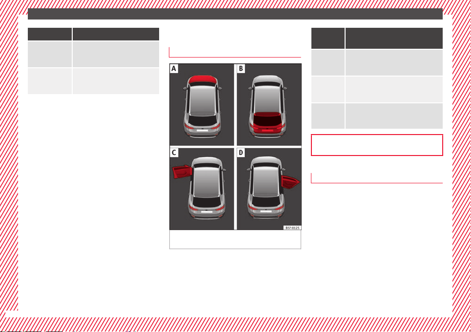
Status display
Bonnet, r
e
ar lid and door
s open
Fig. 46 A: bonnet open; B: rear lid open; C:
fr
ont
l
eft door open; D: right rear door open.
When the ignition is switched on or when
driv
in
g, the bonnet, r
ear lid or doors that are
open will be indicated on the instrument pan-
el display, and, as applicable, this will be in-
dicated audibly. The display may vary accord-
ing to the type of instrument panel fitted.
Illustra-
tion
Key to ››› Fig. 46
A
Do not continue driving!
The bonnet is open or is not properly
closed ››› page 298.
B
Do not continue driving!
The rear lid is open or is not properly
closed ››› page 137.
C, D
Do not continue driving!
A vehicle door is open or is not properly
closed ››› page 125.
››› page 115
Warning and information messages
The system runs a check on certain compo-
nents
and f
u
nctions when the ignition is
switched on and while the vehicle is moving.
Faults in the operation are displayed on the
screen using red and yellow symbols and
messages on the instrument panel display
(›››
page 119) and, in some cases, with
audible warnings. The display may vary ac-
cording to the type of instrument panel fitted.
40
The essentials
Priority 1 warning (red symbols)
Symbol flashing or lit; partly combined with audible
warnings.
Stop the vehicle! It is dangerous ››› in Warning
and control lamps on page 119 !
Check the function that is faulty and repair it. If necessa-
ry, request assistance from specialised personnel.
Priority 2 warning (yellow symbols)
Symbol flashing or lit; partly combined with audible
warnings.
A faulty function, or fluids which are below the correct
levels may cause damage to the vehicle! ›››
in Warn-
ing and control lamps on page 119
Check the faulty function as soon as possible. If neces-
sary, request assistance from specialised personnel.
Informative text
Information relating to different vehicle processes.
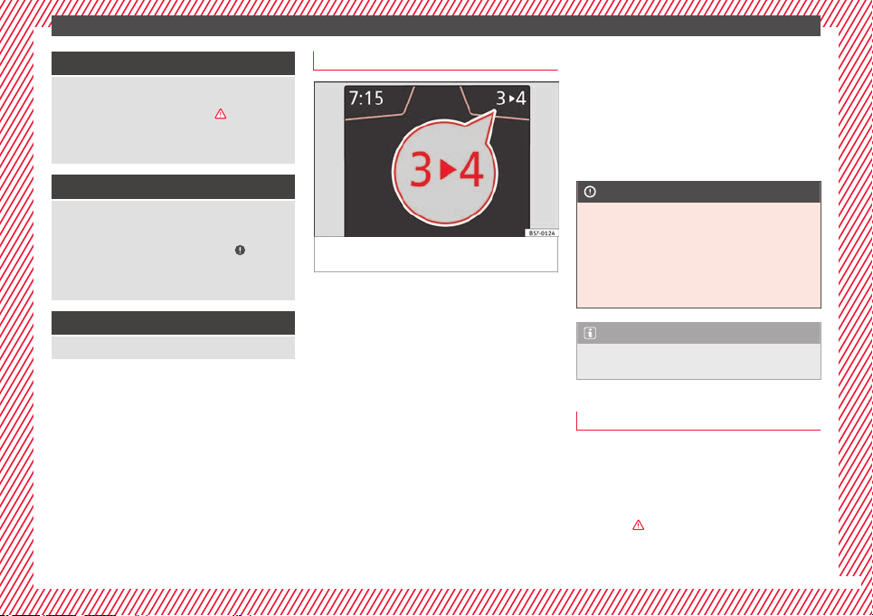
Gear-change indicator
Fig. 47 Instrument panel: gear-change indica-
t
or (m
anual
gearbox).
A gear change will be recommended if the
g
e
ar
you are in is not the most economical
choice. If no gear-change is recommended, it
means that you are already in the most eco-
nomical gear.
Vehicles with a manual gearbox
The following display symbols ››› Fig. 47
mean:
●
Change to a higher gear: the suggested
g
ear appears to the right of the current gear
when a higher gear is recommended.
●
Change to a lower gear: the suggested
gear appears to the left of the current gear
when a lower gear is recommended.
The gear recommendation may occasionally
skip a gear (2nd 4th).
Vehicles with an automatic gearbox*
The disp
lay is only visible in tiptronic mode
›››
page 195.
The following display symbols mean:
●
Shifting up a gear
●
Shifting down a gear
CAUTION
The gear-change indicator is intended to help
save f
uel, but it is not intended to recom-
mend the right gear for all driving situations.
In certain situations, only the driver can
choose the correct gear (for instance when
overtaking, driving up a steep gradient or
towing a trailer).
Note
The display disappears from the instrument
panel when
you press the clutch pedal.
Outside temperature display
When the outside temperature is below +4°C
(+39°F), the “ic
e c
r
ystal” symbol (warning of
risk of freezing) is also displayed. At first, this
symbol flashes and then it remains lit until
the outside temperature rises above +6°C
(+43°F)
›››
in Indications on the display on
p
ag
e 117
.
»
41
The essentials
When the vehicle is at a standstill or when
tr
av
el
ling at very low speeds, the tempera-
ture displayed may be higher than the true
outside temperature as a result of the heat
produced by the engine.
The temperatures measured range from
-40°C to +50°C (-40°F to +122°F).
Engine oil temperature display
Vehicles without multifunction steering
wheel
●
Press the rocker switch ›
›
›
Fig. 43
2
until
the m
ain menu ap
pe
ars. Enter into Driving
data. With the button
2
move to the oil
t
emper
at
ure gauge.
Vehicles with multifunction steering wheel
●
Enter the submenu Driving data and
turn the thumbwheel until the oil tempera-
ture display appears.
The engine reaches its operating temperature
when in normal driving conditions, the oil
temperature is between 80°C (180°F) and
120°C (250°F). If the engine is required to
work hard and the outside temperature is
high, the engine oil temperature can in-
crease. This does not present any problem as
long as the warning lamps
›››
table on
page 47 or ››› table on page 47 do not
appear on the display.
Additional consumers
●
Operation with the windscreen wiper lever*:
Pres
s the rocker switch ››› Fig. 43
2
until the
main menu appe
ars. Enter into the section
Driving data. With the rocker switch,
move to the display Convenience con-
sumers.
●
Operation with the multi-function steering
wheel*: move with the buttons
or
to Driving data and enter with
OK. Turn
the right thumbwheel until the Conven-
ience consumers display appears.
In addition, a scale will inform you of the cur-
rent sum of all the additional appliances.
Saving tips
Tips on how to save fuel will be displayed in
c
ondition
s
that increase fuel consumption.
Follow them to reduce consumption. The indi-
cations appear automatically only with the ef-
ficiency programme. After a time, the tips will
disappear automatically.
If you wish to hide a saving tip immediately
after it appears, press any button on the
windscreen wiper lever*/multifunction steer-
ing wheel*.
Note
●
If y
ou hide a saving tip, it will reappear af-
ter you switch the ignition on again.
●
The saving tips do not appear in all situa-
tions, but rather with a large separation of
time.
Speed warning device
The speed warning device warns the driver
when they hav
e exceeded the pre-set speed
limit by 3 km/h (2 mph). An audible warning
signal sounds, and the warning lamp and
the driver message Speed limit excee-
ded! will be displayed simultaneously on the
instrument panel. The warning lamp
switches off when reducing speed below the
stored maximum limit.
Speed warning programming is recommen-
ded if you wish to be reminded of a maxi-
mum speed, such as when travelling in a
country with different speed limits or for a
maximum speed for winter tyres.
Setting speed limit warning
You can use the radio or the Easy Connect* to
set, alter or cancel the speed limit warning.
●
Vehicles with radio: pres
s the
SETUP
button
> c
ontr
o
l button Driver Assistant >
Speed warning.
42
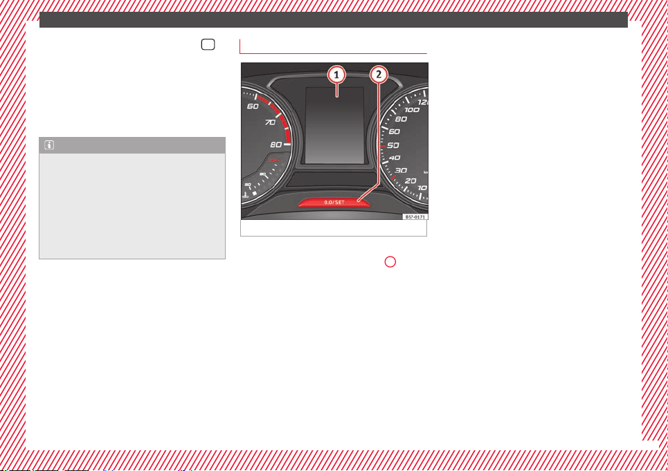
The essentials
●
V
ehicle
s
with Easy Connect: Press the
button and the function button SETTINGS >
Driver assistance > ACC > Dis-
tance.
The w
arnin
g limit
can be set from 30 to
240 km/h (20 to 149 mph). The adjustment
is made at 10 km/h (5 mph) intervals.
Note
●
Plea
se bear in mind that, even with the
speed warning function, it is still important
to keep an eye on the vehicle speed with the
speedometer and to observe the legal speed
limits.
●
The speed limit warning function in the ver-
sion for some countries warns you at a speed
of 120 km/h (75 mph). This is a factory-set
speed limit.
Service intervals
Fig. 48 Instrument panel
The service interval indication appears on the
in
s
trument
panel display ››› Fig. 48
1
.
S
EA
T di
stinguishes between services with en-
gine oil change (e.g. Oil change service) and
services without engine oil change (e.g. In-
spection).
In vehicles with Services established by time
or mileage, the service intervals are already
pre-defined.
In vehicles with LongLife Service, the inter-
vals are determined individually. Thanks to
technological progress, maintenance work
has been greatly reduced. Because of the
technology used by SEAT, with this service
you only need to change the oil when the ve-
hicle so requires. To calculate this change
(max. 2 years), the vehicle's conditions of
use and individual driving styles are consid-
ered. The advance warning first appears 20
days before the date established for the cor-
responding service. The kilometres (miles)
remaining until the next service are always
rounded up to the nearest 100 km (miles)
and the time is given in complete days. The
current service message cannot be viewed
until 500 km after the last service. Prior to
this, only lines are visible on the display.
Inspection reminder
When the Service date is approaching, when
the ignition is switched on a Service remind-
er is displayed.
Vehicles without text messages: a span-
ner will be displayed on the instrument
panel plus an indication in km.
The kilometres indicated are the maximum
number of kilometres that can be travelled
until the next service. After a few seconds,
the display mode changes. A clock symbol
appears and the number of days until the
next service is due.
Vehicles with text messages: Service in
--- km or --- days will be shown on the
instrument panel display.
»
43
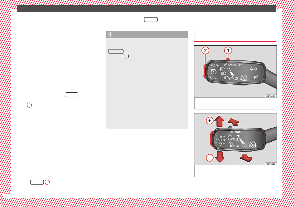
The essentials
Service due
When the ser
v
ic
e date is due, an audible
warning is given when the ignition is switch-
ed on and the spanner displayed on the
screen flashes for a few seconds .
Vehicles with text messages: Service now
will be shown on the instrument panel dis-
play.
Reading a service notification
With the ignition switched on, the engine off
and the vehicle at a standstill, the current
service notification can be read:
Press and hold the button
0.0/SET
for more
th
an 5 sec
ond
s to consult the service mes-
sage
2
.
When the ser
v
ic
e date has passed, a minus
sign is displayed in front of the number of kil-
ometres or days.
Vehicles with text messages: the following
message is displayed: Service --- km
(miles) or --- days ago.
Resetting service interval display
If the service was not carried out by a SEAT
dealership, the display can be reset as fol-
lows:
●
Switch off the ignition, press and hold the
button
0.0/SET
2
.
●
Switch ignition back on.
●
R
el
e
ase the button
0.0/SET
and press it
ag
ain f
or the ne
xt 20 seconds.
Note
●
The servic
e message disappears after a few
seconds, when the engine is started or when
OK/RESET
is pressed on the windscreen wiper
lever
, or
OK
on the multifunction steering
wheel.
●
In v
ehicles with the LongLife system in
which the battery has been disconnected for
a long period of time, it is not possible to cal-
culate the date of the next service. Therefore
the service interval display may not be cor-
rect. In this case, bear in mind the maximum
service intervals permitted in the ››› Booklet
Maintenance Programme.
●
If you reset the display manually, the next
service interval will be indicated as in vehi-
cles with fixed service intervals. For this rea-
son we recommend that the service interval
display be reset by a SEAT authorised Dealer.
Cruise control
Oper
atin
g the c
ruise control system
(CCS)*
Fig. 49 On the left of the steering column:
sw
it
c
hes and controls for operating the CCS
Fig. 50 On the left of the steering column:
thir
d l
ev
er to operate the CCS.
44

The essentials
Operation of the turn signal lever
●
Switching on the CCS: Move switch
›
›
›
Fig. 49
1
to .
The system is on. If no
s
peed h
as been programmed, the system will
not control it.
●
Activating the CCS: Press button ››› Fig. 49
2
in the ar
e
a.
The current speed is
memorised and controlled.
●
Temporarily switching off the CCS: Move
switch ››› Fig. 49
1
to
or push the
br
ak
e. The cruise control system is switched
off temporarily.
●
Reactivating the CCS: Press button
››› Fig. 49
2
in
. The memorised speed
i
s saved and controlled again.
●
Increasing stored speed during CCS regula-
tion: press button
2
in
. The vehicle ac-
c
elerates until the new stored speed.
●
Reducing stored speed during CCS regula-
tion: press button
2
in t
o lower the
s
peed b
y 1 km/h (1 mph). Speed is reduced
until reaching the new stored speed.
●
Switching off the CCS: Move switch
››› Fig. 49
1
to .
The system is disconnec-
t
ed and the memori
sed speed is deleted.
Operation using the third lever
●
Switching on the CCS: move the third lever
to ››› Fig. 50. The system switches on but it
does not control the speed as no speed has
been programmed.
●
Activating the CCS: press the ››› Fig. 50
button. It memorises and maintains the cur-
rent speed.
●
Temporarily switching off the CCS: move
the lever to ››› Fig. 50 and release it or
press the brake pedal. The cruise control sys-
tem is switched off temporarily.
●
Reactivating the CCS: move the lever to
››› Fig. 50 and release it. The memo-
rised speed is saved and controlled again.
●
Switching off the CCS: move the third lever
to position ››› Fig. 50. The system is dis-
connected and the memorised speed is de-
leted.
››› in Operation on page 213
››› page 212
45
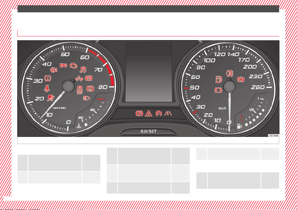
The essentials
Warning lamps
On the in
s
trument
panel
Fig. 51 Instrument panel, on dash panel.
Red warning lamps
Central warning lamp: additional
information on the instrument pan-
el display
–
Parking brake on.
››› page
186
Do not continue driving!
The brake fluid level is too low or
there is a fault in the brake system.
››› page
188
Lit up or flashing:
Do not continue driving!
Fault in the steering.
››› page
200
Driver or passenger has not fas-
tened seat belt.
››› page
79
Use the foot brake!
››› page
222
Yellow warning lamps
Central warning lamp: additional
information on the instrument pan-
el display
–
46
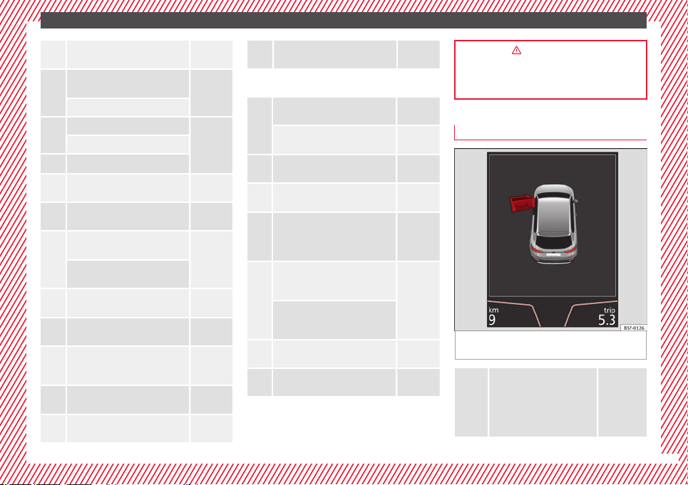
The essentials
Front brake pads worn.
››› page
188
it lights up: Fault in the ESC, or dis-
connection caused by the system.
››› page
189
flashes: ESC or ASR activated.
ASR manually deactivated.
››› page
189
ESC in Sport mode.
ABS faulty or does not work.
Rear fog light switched on.
››› page
144
lights up or flashes: fault in the
emission control system.
››› page
204
it lights up: pre-heating of diesel
engine.
››› page
205
flashes: fault in the diesel engine
management.
fault in the petrol engine manage-
ment.
››› page
205
lights up or flashes: fault in the
steering system.
››› page
200
Tyre pressure too low, or fault in
the tyre pressure monitoring sys-
tem.
››› page
311
Fuel tank almost empty.
››› page
118
Fault in airbag system and seat
belt tensioners.
››› page
89
Lane Assist is switched on, but not
active.
››› page
230
Other warning lamps
Left or right turn signal.
››› page
145
Hazard warning lights on.
››› page
149
Trailer turn signals.
››› page
273
it lights up green: Auto Hold activa-
ted.
››› page
211
it lights up green: Press the brake
pedal!
It blinks in green: the selector lever
locking button has not engaged.
››› page
193
it lights up green: cruise control ac-
tivated or speed limiter switched
on and active.
››› page
212
it blinks in green: the speed set by
the speed limiter has been excee-
ded.
it lights up green: Lane Assist is
switched on and active.
››› page
230
Main beam on or flasher on.
››› page
145
››› in Warning and control lamps on
page 119
››› page 119
On the instrument panel display
Fig. 52 On the instrument panel display: door
open.
Do not continue driving!
With the corresponding indi-
cation: door(s), rear lid or bon-
net open or not properly
closed.
››› page
125
››› page
137
››› page
298
»
47
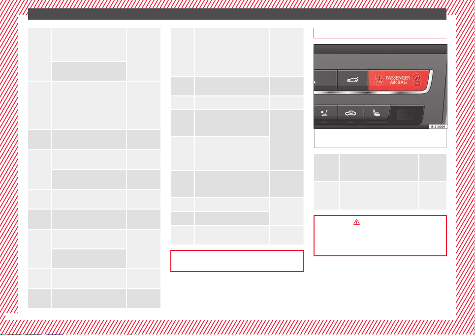
The essentials
Ignition:
Do not carry on
driving! Engine coolant level
too low, coolant temperature
too high
››› page
302
Flashing: Fault in the engine
coolant system.
Do not continue driving!
Engine oil pressure too low. If
the warning lamp flashes,
stop driving, even if the oil
level is correct. Do not even
run the engine at idle speed!
››› page
300
Fault in the battery.
››› page
305
Driving light totally or partially
faulty.
››› page
106
Fault in the cornering light
system.
››› page
148
Diesel particulate filter
blocked
››› page
205
Level of windscreen washer
fluid too low.
››› page
153
Flashing: Fault in the oil level
detection. Control manually.
››› page
300
Ignition: Insufficient engine
oil.
Fault in the gearbox.
››› page
200
Light Assist on.
››› page
146
it lights up white: Hill Descent
Control (HDC) is active.
it lights up grey: Hill Descent
Control (HDC) is not active.
The system is switched on, but
is not adjusting.
››› page
210
Immobiliser active.
››› page
133
Service interval display ››› page 43
Mobile telephone is connec-
ted via Bluetooth to the origi-
nal telephone device.
››› Booklet
Audio or
navigation
system
Mobile telephone battery
charge meter. Available only
for devices pre-installed in fac-
tory.
Freezing warning. The outside
temperature is lower than
+4°C (+39°F).
››› page 41
Start-Stop system activated.
››› page
208
Start-Stop system unavailable.
Low consumption driving sta-
tus
››› page
116
››› page 115
On the instrument panel
Fig. 53 Warning lamp for disabling the front
p
a
s
senger airbag.
Front passenger front airbag is
disabled (
).
››› page
89
The front passenger front airbag
is activated (
).
››› page
89
››› in Activation and deactivation of
front passenger airbag* on page 89
››› page 88
48
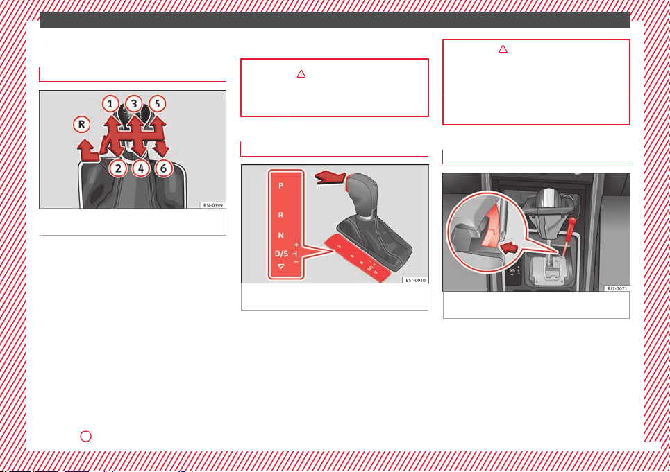
The essentials
Gearbox lever
M
anua
l
gearbox
Fig. 54 Gear shift pattern of a 5 or 6-speed
m
anual
g
earbox.
The position of the gears is indicated on the
g
e
arbo
x lever ››› Fig. 54.
●
Press the clutch pedal and keep your foot
right down.
●
Move the gearbox lever to the required po-
sition.
●
Release the clutch.
Selecting reverse gear
●
Press the clutch pedal and keep your foot
right down.
●
With the gearbox lever in neutral, push it
downwards, move it to the left as far as it will
go and then forwards to select reverse
››› Fig. 54
R
.
●
R
el
e
ase the clutch.
››› in Changing gear on page 192
››› page 192
Automatic gearbox*
Fig. 55 Automatic gearbox: selector lever po-
s
ition
s.
Parking lock
R
ev
er
se gear
Neutral (idling)
Drive (forward)
Tiptronic mode: pull the lever forwards
(+) to go up a gear or backwards (–) to
go down a gear.
P
R
N
D/S
+/–
››› in Selector lever positions on
page 194
››› page 193
››› page 49
Manual release of the selector lever
Fig. 56 Selector lever: manual release from
po
s
ition P
.
Should the power supply be interrupted,
ther
e i
s
a manual unlocking device located
under the console of the selector lever, on
the right. Releasing the selector lever re-
quires a certain degree of practical skill.
●
Unlocking: use the flat part of a screwdriver
blade.
»
49
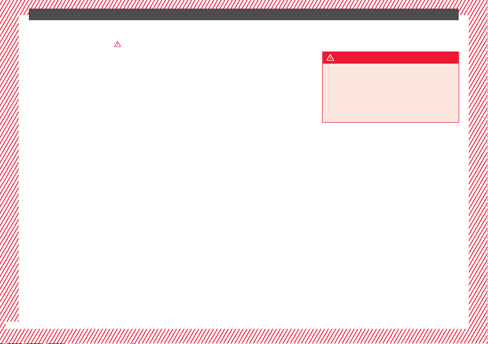
The essentials
Removing the cover from the selector lever
●
Apply the handbrake ›
›
›
to ensure that
the c
ar doe
s
not move.
●
Carefully pull the corners of the selector
lever boot and twist it upwards above the lev-
er handle.
Releasing the selector lever
●
Using a screwdriver, press and hold the yel-
low unlocking tab sideways ››› Fig. 56.
●
Press the interlock button on the selector
lever and move the selector lever to posi-
tion N.
●
After carrying out the manual release, at-
tach the selector lever boot on the gearbox
console again.
If the power supply should ever fail (e.g. dis-
charged battery) and the vehicle has to be
pushed or towed, the selector lever must first
be moved to position N, after operating the
manual release mechanism.
WARNING
The selector lever may be moved out of posi-
tion P only when the h
andbrake is firmly ap-
plied. If this does not work, secure the vehi-
cle with the brake pedal. On a slope the vehi-
cle could otherwise start to move inadver-
tently after shifting the selector lever out of
position P - accident risk!
50
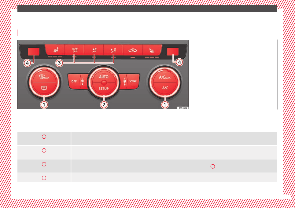
The essentials
Air conditioning
Ho
w doe
s
Climatronic* work?
Fig. 57 In the centre console: Climatronic con-
trol
s
To switch a specific function on, press the ap-
pr
opri
at
e button. Press the button again to
switch off the function.
The LED on each control lights up to indicate
that the respective function of a control has
been switched on.
1
Temperature
The left and right sides can be adjusted separately: Turn the control to adjust the temperature
2
Fan
The power of the fan is automatically adjusted. The fan is also adjusted manually by turning the control.
3
Air distribution
The airflow adjusts automatically for comfort. You can also switch it on manually using the buttons
3
.
4
Indications on the temperature display screen selected for the right and left sides.
»
51
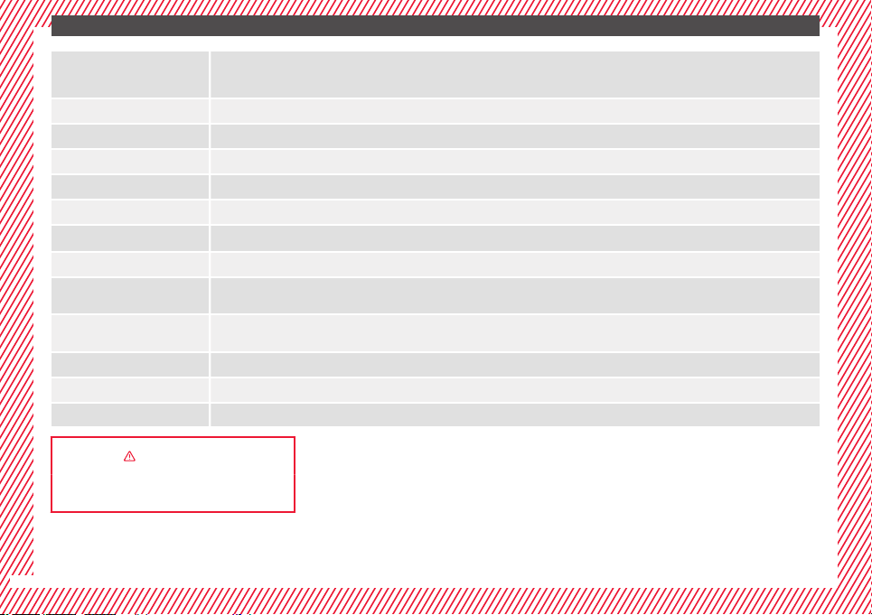
The essentials
Defrost function
The air drawn in from outside the vehicle is directed at the windscreen and air recirculation is automatically switched off. To defrost the wind-
screen more quickly, the air is dehumidified at temperatures over approximately +3°C (+38°F) and the fan runs at maximum output.
The air is directed at the chest of driver and passengers by the dash panel air vents.
Air distribution towards the footwell.
Upward air distribution.
Heated rear window: this only works when the engine is running and switches off automatically after a maximum of 10 minutes.
Air recirculation
Seat heating buttons
Press the button to switch on or off the cooling system.
Press the button to make maximum cooling capacity available. The recirculation of air and the cooling system turn on automatically and air distri-
bution adjusts automatically to the position
.
When the warning light for button
lights up, the settings on the driver side also apply to the passenger side. Press the button or the temper-
ature control on the passenger side
Automatic adjustment of temperature, fan, and air distribution. Press the button: the warning lamp on the button will light up
.
Press the configuration button
: the air conditioning operation menu will be displayed on the Easy Connect system screen.
Switching off
Turn the blower control to the
position or press the
button.
››› in Introduction on page 171
››› page 170
52
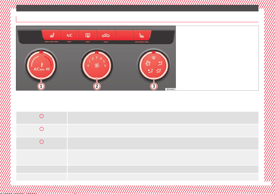
The essentials
How does the manual air conditioning work*?
Fig. 58 In the centre console: Manual air condi-
tioning contr
ols.
To switch a specific function on, press the ap-
pr
opri
at
e button. Press the button again to
switch off the function.
The LED on each control lights up to indicate
that the respective function of a control has
been switched on.
1
Temperature
Turn the control to adjust the temperature
2
Fan
Setting 0: blower and manual air conditioning switched off
Level 6: maximum fan level.
3
Air distribution
Rotate the continuous control to direct the airflow to the desired area.
Defrost function
The airflow is directed at the windscreen. Air recirculation is automatically switched off or is not switched on. Increase the fan power to clear the
windscreen of condensation as soon as possible. To dehumidify the air, the cooling system will automatically switch on.
The air is directed at the chest of driver and passengers by the dash panel air vents.
Distribution of air towards the chest and the footwell area.
»
53
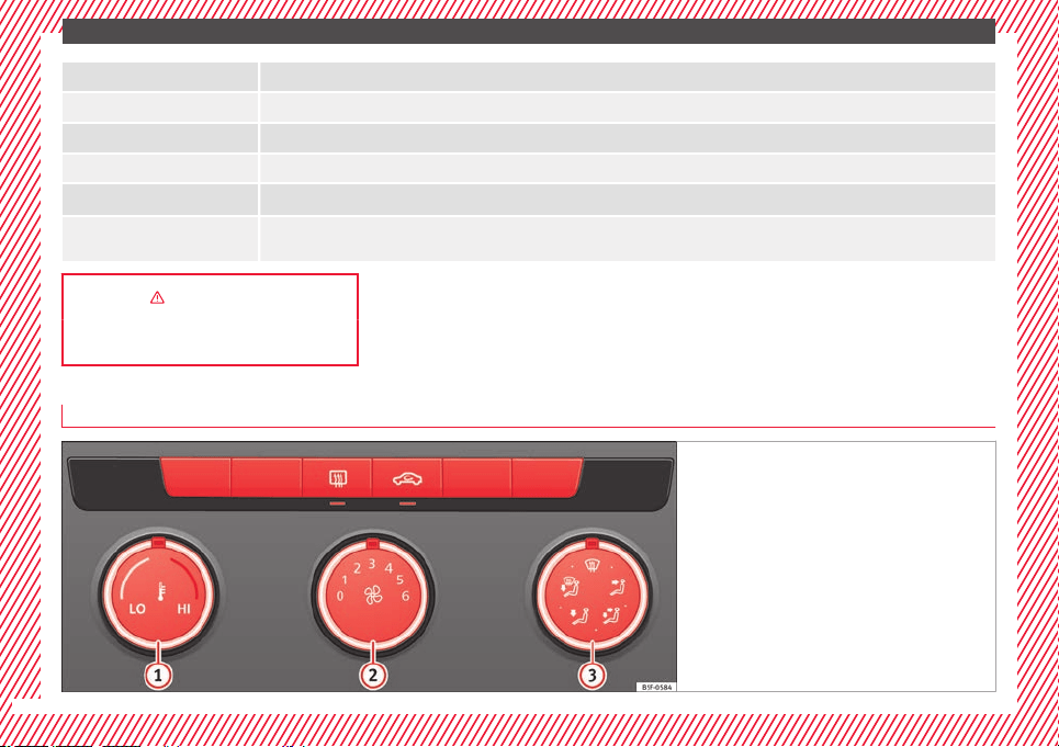
The essentials
Air distribution towards the footwell.
Air distribution towards the windscreen and the footwell.
Heated rear window: this only works when the engine is running and switches off automatically after a maximum of 10 minutes.
Air recirculation
Seat heating buttons
Maximum cooling power. The recirculation of air and the cooling system turn on automatically and air distribution adjusts automatically to the
position
››› in Introduction on page 171
››› page 170
How does the heating and the fresh air system work?
Fig. 59 In the centre console: heating system and
fresh air c
ontrols.
54
The essentials
To switch a specific function on, press the ap-
pr
opri
at
e button. Press the button again to
switch off the function.
The LED on each control lights up to indicate
that the respective function of a control has
been switched on.
1
Temperature
Turn the control to adjust the temperature. The temperature cannot be lower than that of the exterior air temperature, as this system cannot cool
or dehumidify the air
2
Fan
Setting 0: blower, heating and fresh air systems switched off
Level 6: maximum fan level
3
Air distribution
Rotate the continuous control to direct the airflow to the desired area.
Defrost function
The airflow is directed at the windscreen.
The air is directed at the chest of driver and passengers by the dash panel air vents.
Distribution of air towards the chest and the footwell area.
Air distribution towards the footwell.
Air distribution towards the windscreen and the footwell.
Heated rear window: this only works when the engine is running and switches off automatically after a maximum of 10 minutes
Air recirculation ››› page 174
Seat heating buttons
››› in Introduction on page 171
››› page 170
55
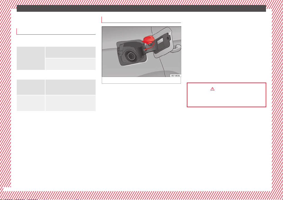
The essentials
Fluid Level control
Fi
l
lin
g capacities
Tank level
Petrol and diesel
engines
Front-wheel drive vehicles:
50 l, of which approx. 7 l reserve
Four-wheel drive vehicles:
55 l, of which approx. 8.5 l reserve
Capacity of the windscreen washer fluid container
Versions without
headlight washer
system
approx. 3 litres
Versions with
headlight washer
system
approx. 5 litres
Fuel
Fig. 60 Fuel tank flap with tank cap attached.
The flap that covers the tank cap is unlocked
and loc
k
ed aut
omatically using the central
locking.
Opening the fuel tank cap
●
Open the fuel tank flap by pressing on the
left side.
●
Unscrew the cap by turning it to the left.
●
Place it in the space on the hinge of the
open flap ››› Fig. 60.
Closing the fuel tank cap
●
Unscrew the cap by turning it to the right as
far as it will go.
●
Close the lid.
››› in Refuelling on page 292
››› page 292
56
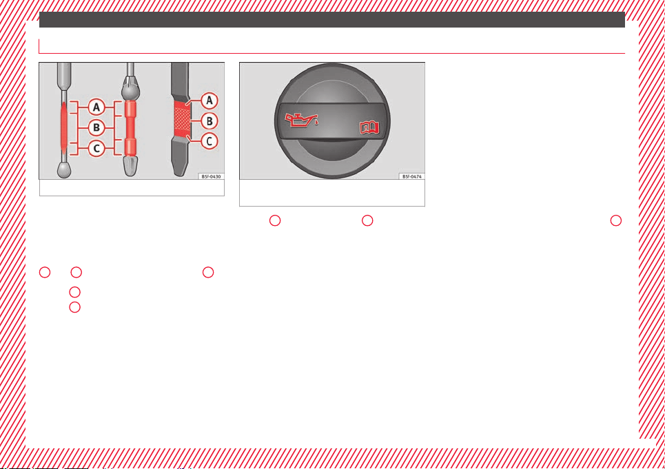
The essentials
Oil
Fig. 61 Engine oil dipstick. Fig. 62 In the engine compartment: Engine
oil fi
ller cap.
The level is measured using the dipstick loca-
t
ed in the en
gine c
ompartment
›››
page 298.
The oil should leave a mark between zones
A
and
C
. It should never exceed zone
A
.
●
Zone
A
: Do not add oil.
●
Zone
B
: You can add oil but keep the level
in th
at
zone.
●
Zone
C
: Add oil up to zone
B
.
T
op
pin
g up engine oil
●
Unscrew cap from oil filler opening.
●
Add oil slowly.
●
At the same time, check the level to ensure
you do not add too much.
●
When the oil level reaches at least zone
B
,
u
n
s
crew the engine oil filler cap carefully.
Engine oil additives
No type of additive should be mixed with the
engine oil. The deterioration caused by these
additives is not covered by the warranty.
»
57
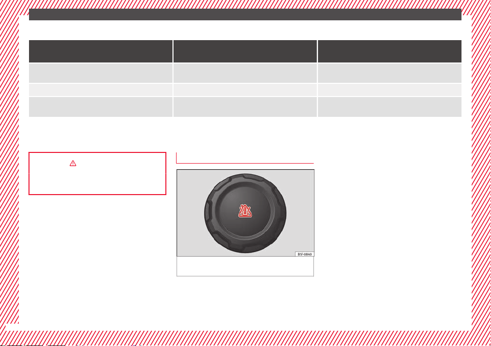
The essentials
Engine oil specifications
Engine type Flexible service (LongLife)
Set Service (dependent on time/distance travel-
led)
Petrol engines
VW 508 00
VW 504 00
a)
VW 504 00
Engines with particulate filter (DPF)
b)
VW 507 00 VW 507 00
Diesel engines without particulate filter (DPF) –
VW 505 01
c)
VW 506 01
c)
a)
Use of engine oil compliant with the VW 504 00 specification instead of VW 508 00 may have a slight negative effect on the vehicle’s exhaust gas values.
b)
Only use recommended oils, otherwise you may damage the engine.
c)
If the quality of the fuel available in the country does not fulfil the EN 228 (for petrol) and EN 590 (for diesel) standards.
››› in Changing engine oil on page 302
››› page 300
Coolant
Fig. 63 Engine compartment: coolant expan-
s
ion t
ank
cap.
The coolant tank is located in the engine
c
omp
ar
tment ›››
page 298.
When the engine is cold, replace the coolant
when the level is below .
Coolant specifications
The engine cooling system is supplied from
the factory with a specially treated mixture of
water and at least 40 % of the additive G13
(TL-VW 774 J), purple. This mixture gives the
necessary frost protection down to -25°C
(-13°F) and protects the light alloy parts of
the engine cooling system against corrosion.
It also prevents scaling and considerably rai-
ses the boiling point of the coolant.
To protect the cooling system, the percentage
of additive must always be at least 40 %,
even in warm climates where anti-freeze pro-
tection is not required.
If for weather reasons further protection is
necessary, the proportion of additive may be
58
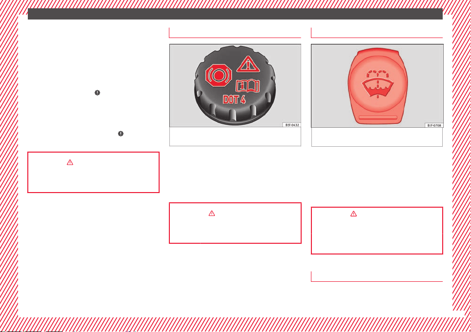
The essentials
increased, but only up to 60 %; otherwise an-
tifr
eez
e pr
otection will diminish and this will
worsen cooling.
When the coolant is topped up, use a mixture
of distilled water and at least 40 % of the
G13 or G12 plus-plus (TL-VW 774 G) additive
(both are purple) to obtain an optimum anti-
corrosion protection ›››
in Topping up cool-
ant on p
ag
e 303
. The mixture of G13 with
G12 plus (TL-VW 774 F), G12 (red) or G11
(green-blue) engine coolants will significant-
ly reduce anti-corrosion protection and
should therefore be avoided ›››
in Topping
up c
oo
l
ant on page 303.
››› in Topping up coolant on page 303
››› page 302
Brake fluid
Fig. 64 Engine compartment: brake fluid res-
er
v
oir c
ap.
The brake fluid reservoir is located in the en-
gine c
omp
ar
tment ›››
page 298.
The level should be between the and
marks. If it is below , please visit a Techni-
cal Service.
››› in Top up brake fluid on page 304
››› page 303
Windscreen washer
Fig. 65 In the engine compartment: wind-
s
c
r
een washer reservoir top.
The windscreen washer reservoir is located in
the en
gine c
omp
artment ›››
page 298.
To top up, mix water with a product recom-
mended by SEAT.
In cold temperatures, add anti-freeze.
››› in Checking and topping up the
windscreen washer reservoir on
page 304
››› page 304
Battery
The battery is located in the engine compart-
ment
›
›
›
page 298. It does not require
»
59

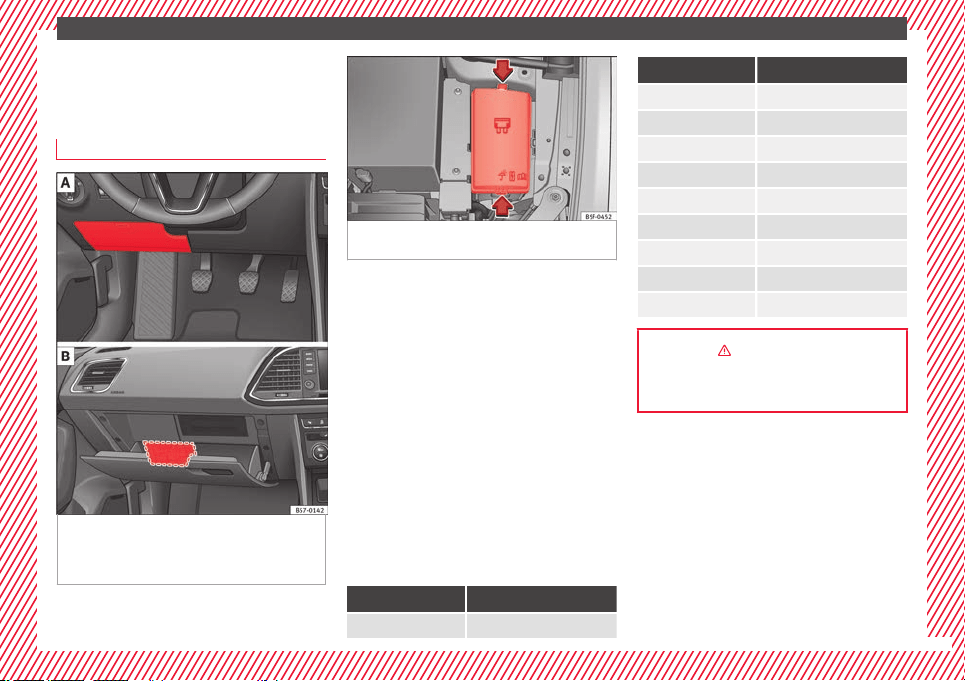
The essentials
Emergencies
F
u
se
s
Fuse location
Fig. 66 Left-hand drive: fuse box cover on
the driv
er-side dash panel. Right-hand
drive: fuse box behind the glove compart-
ment.
Fig. 67 In the engine compartment: fuse box
cov
er.
Underneath the instrument panel (left-hand
driv
e)
The f
u
se box is located behind the storage
compartment ››› Fig. 66 .
Behind the glove compartment (right-hand
drive)
The fuse box is located behind the glove
compartment ››› Fig. 66 . To be able to ac-
cess the fuse box ›››
page 103.
In the engine compartment
Press the locking tabs to release the fuse box
cover ››› Fig. 67.
Identifying fuses situated below the dash
panel by colours
Colour Amp rating
Black 1
Colour Amp rating
Purple 3
Light brown 5
Brown 7.5
Red 10
Blue 15
Yellow 20
White or transparent 25
Green 30
Orange 40
››› in Introduction on page 102
››› page 102
61
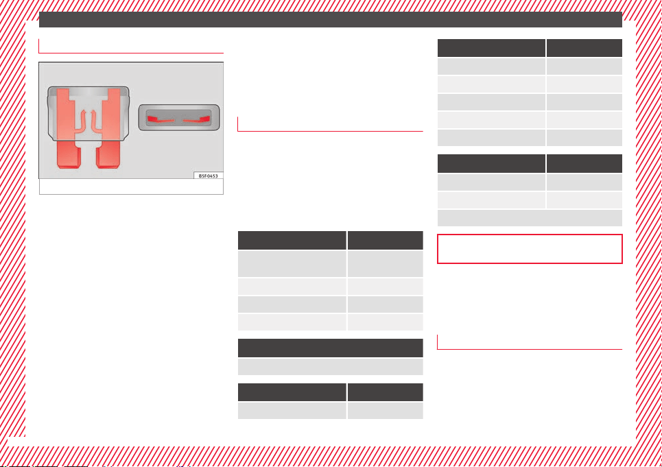
The essentials
Replacing a blown fuse
Fig. 68 Image of a blown fuse.
Preparation
●
Switch off the ignition, lights and all elec-
tric
al
equipment
.
●
Open the corresponding fuse box
›››
page 103.
Identifying a blown fuse
A fuse is blown if its metal strip is ruptured
››› Fig. 68.
●
Point a lamp at the fuse to see if it has
blown.
To replace a fuse
●
Remove the fuse.
●
Replace the blown fuse by one with an
identical amperage rating (same colour and
markings) and identical size.
●
Replace the cover again or close the fuse
box lid.
Bulbs
Bulbs (12 V)
Note: Depending on the level of equipment
fitted in the
vehicle, LEDs may be used for
part or all of the interior and/or exterior light-
ing. LEDs have an estimated life that exceeds
that of the vehicle. If an LED light fails, go to
an authorised workshop for its replacement.
Light source used for each function
Halogen headlights. Type
Daytime running light/side
light
LED (it cannot be re-
placed)
Dipped beam headlights H7 LL
Main beam headlights H7 LL
Turn signal PY21W
Full-LED main headlights
No bulbs may be replaced. All functions are with LEDs
Front fog light Type
Fog/cornering lights* H8
Rear lights Type
Brake light/tail light P21W LL
Side lights P21W LL
Turn signal PY21W LL
Retro fog light P21W LL
Reverse lights W16W
LED rear lights Type
Turn signal PY21W LL
Reverse lights W16W
The remaining functions work with LEDs
››› page 106
Action in the event of a punc-
t
ur
e
Wh
at to do first
●
Park the vehicle on a horizontal surface
and in a s
af
e p
lace as far away from traffic as
possible.
●
Apply the handbrake.
●
Switch on the hazard warning lights.
●
Manual gearbox: select the 1st gear.
62
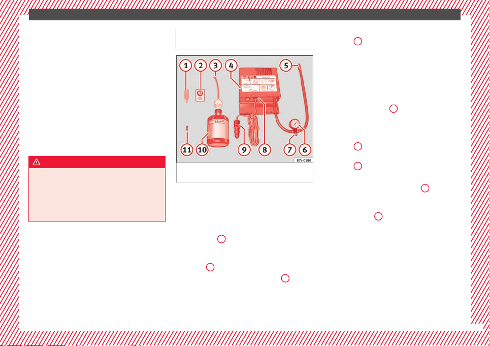
The essentials
●
A
utomatic
ge
arbox: Move the selector lever
to position P.
●
If you are towing a trailer, unhitch it from
your vehicle.
●
Have the vehicle tool kit ›››
page 95
and the spare wheel* ready
›››
page 314.
●
Observe the applicable legislation for each
country (reflective vest, warning triangles,
etc.).
●
All occupants should leave the vehicle and
wait in a safe place (for instance behind the
roadside crash barrier).
WARNING
●
Alwa
ys observe the above steps and pro-
tect yourself and other road users.
●
If you change the wheel on a slope, block
the wheel on the opposite side of the car with
a stone or similar to prevent the vehicle from
moving.
Repairing a tyre with the anti-punc-
t
ur
e k
it
Fig. 69 Standard representation: contents of
the anti-p
u
nct
ure kit.
The anti-puncture kit is located under the
floor p
anel
in the lug
gage compartment.
Sealing the tyre
●
Unscrew the tyre valve cap and insert. Use
the ››› Fig. 69
1
tool to remove the insert.
Pl
ac
e it
on a clean surface.
●
Shake the tyre sealant bottle vigorously
››› Fig. 69
10
.
●
Screw the inflator tube ›
›
›
Fig. 69
3
into
the se
al
ant
bottle. The bottle's seal will break
automatically.
●
Remove the lid from the filling tube
››› Fig. 69
3
and screw the open end of the
t
ube int
o the ty
re valve.
●
With the tyre sealant bottle upside down,
fill the tyre with the contents of the sealant
bottle.
●
Remove the bottle from the valve.
●
Place the insert back into the tyre valve us-
ing the tool ››› Fig. 69
1
.
Infl
atin
g the ty
re
●
Screw the compressor tyre inflator tube
››› Fig. 69
5
into the tyre valve.
●
Check that the air bleed screw is closed
›
›
›
Fig. 69
7
.
●
Start the engine and leave it running.
●
Insert the connector ›
›
›
Fig. 69
9
into the
v
ehic
l
e's 12-volt socket ›››
page 162.
●
Turn the air compressor on with the ON/OFF
switch ››› Fig. 69
8
.
●
Keep the air compressor running until it
r
e
ac
hes 2.0 to 2.5 bar
(29-36 psi/200-250 kPa). A maximum of 8
minutes.
●
Disconnect the air compressor.
●
If it does not reach the pressure indicated,
unscrew the tyre inflator tube from the valve.
●
Move the vehicle 10m so that the sealant is
distrib
uted throughout the tyre.
»
63
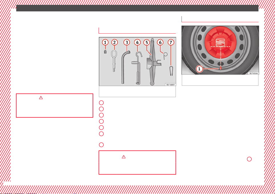
The essentials
●
Sc
r
ew the c
ompressor tyre inflator into the
valve.
●
Repeat the inflation process.
●
If the indicated pressure still cannot be
reached, the tyre is too badly damaged. Stop
and request assistance from an authorised
technician.
●
Disconnect the air compressor. Unscrew
the tyre inflator tube from the tyre valve.
●
When the tyre pressure is between 2.5 and
2.0 bars, continue driving without exceeding
80 km/h (50 mph).
●
Check the pressure again after 10 minutes
›››
page 97.
››› in TMS (Tyre Mobility System)* on
page 95
››› page 95
Changing a wheel
V
ehic
l
e tool kit
Fig. 70 Underneath the floor panel of the lug-
g
ag
e c
ompartment: vehicle tool kit.
An adapter for the anti-theft wheel bolts*
T
o
wline anc
horage
Box spanner for wheel bolts*
Crank handle for jack
Jack*
Hook for extracting the central wheel
trims*
Clip for removing the wheel bolt caps.
››› in What to do first on page 63
››› page 95
1
2
3
4
5
6
7
Central wheel trim*
Fig. 71 Correct positioning of the central
wheel
trim f
or s
teel rims.
The central trims must be removed for access
t
o the wheel
bo
lts.
Removing
●
Attach the wire hook (vehicle tools) to one
of the chambers of the central wheel trim.
●
Insert the box spanner through the hook,
supporting it on the tyre and remove the
wheel trim.
Fitting
●
Fit the central wheel trim onto the rim. The
bottom of the “S” of the SEAT badge should
align with the inflation valve
›››
Fig. 71
1
.
●
Press the central trim firmly until it locks in
w
ith an audib
l
e click.
64
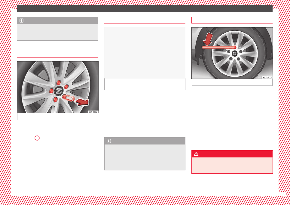
The essentials
Note
There is also a valve mark on the back of the
centra
l wheel trim that indicates the correct
alignment.
Wheel bolt caps*
Fig. 72 Wheel: wheel bolts with caps.
Removal
●
Fit the plastic clip (vehicle tools
›
›
›
Fig. 70
7
) over the cap until it clicks into
p
l
ac
e
›››
Fig. 72.
●
Remove the cap with the plastic clip.
Anti-theft wheel bolts
Fig. 73 Anti-theft wheel bolt with cap and
a
d
apt
er.
●
Remove the wheel cover* or the cap*.
●
Insert the special adapter (vehicle tools)
ont
o the anti-thef
t
wheel bolt and push it on
as far as it will go.
●
Insert the wheel brace (vehicle tools) onto
the adapter as far as it will go.
●
Remove the wheel bolt ››› page 65.
Note
Make a note of the code number of the anti-
theft wheel
bolt and keep it in a safe place,
but not in your vehicle. If you need a new
adapter, you can obtain it from the SEAT Offi-
cial Service, indicating the code number.
Loosening the wheel bolts
Fig. 74 Wheel: loosen the wheel bolts.
●
Insert the box spanner (vehicle tools) onto
the wheel
bo
lt
as far as it will go. An adapter
is required to unscrew or tighten the anti-
theft wheel bolts ››› page 65.
●
Turn the wheel bolt approximately one turn
to the left ››› Fig. 74 (arrow). To apply the re-
quired torque, hold the wheel brace at the
end. If it is not possible to loosen a wheel
bolt, carefully apply pressure with one foot
on the end of the box spanner. Hold on to the
vehicle for support and take care not to slip.
WARNING
Slightly loosen the wheel bolts (one turn) be-
fore r
aising the vehicle with the jack*. If not,
an accident may occur.
65
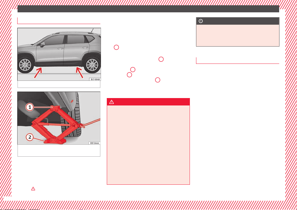
The essentials
Raising the vehicle
Fig. 75 Crossbar: marks.
Fig. 76 Strut: mounting the jack on the vehi-
c
l
e.
●
Place the jack* (vehicle tools) on firm
gr
ou
nd. If
necessary use a large, strong
board or similar support. If the surface is slip-
pery (for example tiles) place the jack on a
rubber mat or similar to prevent it from slip-
ping ›››
.
●
Find the s
up
por
t point on the strut (sunken
area) closest to the wheel to be changed
››› Fig. 75.
●
Turn the jack* crank handle, located below
the strut support point, to raise it until the
tab
1
›
›› Fig. 76
i
s below the housing provi-
ded.
●
Align the jack* so that tab
1
“grips” onto
the hou
s
in
g provided on the strut and the
mobile base
2
is resting on the ground. The
b
a
se p
late
2
should fall vertically with re-
s
pect
t
o the support point
1
.
●
Continue turning the jack* until the wheel
i
s
s
lightly lifted off the ground.
WARNING
●
Make s
ure that the jack* remains stable. If
the surface is slippery or soft, the jack* could
slip or sink, respectively, with the resultant
risk of injury.
●
Only raise the vehicle with the jack* sup-
plied by the manufacturer. Other vehicles
could slip, with the consequent risk of injury.
●
Only mount the jack* on the support points
designed for this purpose on the strut, and
always align the jack correctly. If you do not,
the jack* could slip as it does not have an ad-
equate grip on the vehicle: risk of injury!
●
The height of the parked vehicle can
change as a result of variations in tempera-
ture and loading.
CAUTION
The vehicle must not be raised on the cross-
bar. On
ly place the jack* on the points de-
signed for this purpose on the strut. Other-
wise, the vehicle may be damaged.
Removing and fitting a wheel
Change the wheel after loosening the wheel
bolts and r
aising the vehicle with the jack.
Taking off the wheel
●
Unscrew the wheel bolts using the box
spanner and p
lace them on a clean surface.
●
Take off the wheel.
Putting on the spare wheel
When fitting tyres with a compulsory rotation
direction, observe the instructions in
›››
page 67.
●
Mount the wheel.
●
Screw on the wheel bolts in position and
tighten them loosely with a box spanner.
●
Carefully lower the vehicle using the jack*.
●
Tighten the wheel bolts in diagonal pairs
using the wheel brace.
The wheel bolts should be clean and turn
easily. Before fitting the spare wheel, inspect
66

The essentials
the wheel condition and hub mounting surfa-
c
e
s.
These surfaces must be clean before fit-
ting the wheel.
Tyres with compulsory direction of ro-
tation
A directional tread pattern can be identified
by the arr
ows on the sidewall that point in
the direction of rotation. Always observe the
direction of rotation indicated when fitting
the wheel to guarantee optimum properties
of this type of tyres with regard to grip,
noises, wear and aquaplaning.
If it is absolutely necessary to fit the spare
tyre* against the direction of rotation, drive
with care as this means the tyre does not of-
fer optimum driving properties. This is of par-
ticular importance when the road surface is
wet.
To return to directional tread tires, replace
the punctured tyre as soon as possible and
restore the obligatory direction of rotation of
all tyres.
Subsequent work
●
Alloy wheels: r
ep
l
ace the wheel bolt caps.
●
Plate wheels: fit the central wheel rim again
›››
page 64.
●
Return all tools to their proper storing loca-
tion.
●
If the replaced wheel does not fit in the
spare wheel housing, store it safely in the
luggage compartment ›››
page 162.
●
Check the tyre pressure of the newly moun-
ted tyre as soon as possible.
●
In vehicles fitted with a tyre pressure indi-
cator, adjust the pressure and store the read-
ing in the radio/Easy Connect system*
›››
page 311.
●
Have the tightening torque of the wheel
bolts checked as soon as possible with a tor-
que wrench (it should be 140 Nm). Mean-
while, drive carefully.
●
Have the flat tyre replaced as quickly as
possible.
Snow chains
Use
Snow chains should only be used on the
fr
ont
wheel
s.
Check that they are correctly seated after
driving for a few yards; correct the position if
necessary, in accordance with the manufac-
turer's fitting instructions. Keep your speed
below 50 km/h (30 mph).
If there is a danger of being trapped despite
having mounted the chains, it is best to disa-
ble the driving wheels (ASR) in the ESC
›››
page 191, Switching on/off the ESC
and ASR.
Snow chains will improve braking ability as
well as traction in winter conditions.
For technical reasons snow chains may only
be used with the following wheel rim/tyre
combination.
215/60 R16 Chains with links of maximum 15 mm
215/55 R17 Chains with links of maximum 15 mm
215/50 R18 Chains with links of maximum 15 mm
Other dimensions do not allow chains
Remove any central wheel trims and the rim
rin
g bef
or
e fitting snow chains.
Remove the chains when roads are free of
snow. Driving characteristics worsen, and the
wheels become damaged quickly and may
even be rendered unusable.
67
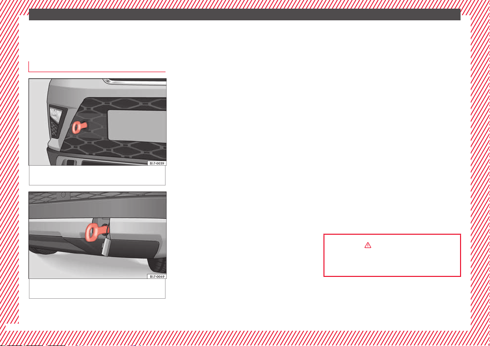
The essentials
Emergency towing of the vehi-
c
l
e
T
owing
Fig. 77 Right side of the front bumper: tow-
line anc
hor
ag
e screwed in.
Fig. 78 Right side of the rear bumper: towline
anc
hor
ag
e screwed in.
Towline anchorages
Att
ac
h the b
ar or rope to the towline ancho-
rages.
The towline anchorages are located under
the floor panel in the luggage compartment,
next to the vehicle tools ›››
page 95.
Screw the towline anchorage into the screw
connection ››› Fig. 77 o ››› Fig. 78 and tighten
it with the wheel brace.
Tow rope or tow bar
The tow bar offers increased safety and a
lower risk of damage.
The tow rope is recommended when there is
no tow bar. It must be elastic so that it does
not damage the vehicle.
Notes for the driver of the towing vehicle
●
The tow rope must be taut before you drive
off.
●
Release the clutch very carefully when start-
ing the vehicle (manual gearbox), or acceler-
ate gently (automatic gearbox).
Driving style
Towing requires some experience, especially
when using a tow rope. Both drivers should
realise how difficult it is to tow a vehicle. In-
experienced drivers should not attempt to
tow.
Do not pull too hard with the towing vehicle
and take care to avoid jerking the tow rope.
When towing on an unpaved road, there is al-
ways a risk of overloading and damaging the
anchorage points.
Switch on the ignition so that the turn sig-
nals, windscreen wipers and windscreen
washer can work. Ensure that the steering
wheel is unlocked and moves freely.
Place the gear lever in neutral on vehicles
with a manual gearbox. With an automatic
gearbox, place the lever in N.
To brake, press the brake pedal firmly. The
brake servo does not work when the engine
is switched off.
The power steering only works when the igni-
tion is switched on and the vehicle is moving,
provided that the battery is sufficiently charg-
ed. Otherwise, it will need more force.
Ensure that the tow rope remains taut at all
times.
››› in Introduction on page 98
››› page 98
68
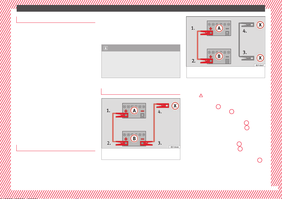
The essentials
Tow-starting
If the engine will not start, first try starting it
usin
g the battery of another vehicle
››› page 69. You should only attempt to tow-
start a vehicle if charging the battery does
not work. This is done by leveraging wheel
movement.
When tow-starting a vehicle with a petrol en-
gine, do not tow it more than a short dis-
tance, otherwise unburned fuel can enter the
catalytic converter.
●
Engage 2nd or 3rd gear before moving off.
●
Press the clutch and hold the pedal down.
●
Switch the ignition on.
●
Once both vehicles are moving, release the
clutc
h.
●
As soon as the engine has started, press
the clutch and move the gear lever to neutral.
How to jump start
Jump leads
The jump lead must have a sufficient wire
c
r
o
ss section.
If the engine fails to start because of a dis-
charged battery, the battery can be connec-
ted to the battery of another vehicle to start
the engine.
Jump leads must comply with standard DIN
72553 (see cable manufacturer's instruc-
tions). The wire cross section must be at least
25 mm
2
for petrol engines and at least
35 mm
2
for diesel engines.
Note
●
The vehic
les must not touch each other,
otherwise electricity could flow as soon as
the positive terminals are connected.
●
The discharged battery must be properly
connected to the on-board network.
How to jump start: description
Fig. 79 Diagram of connections for vehicles
w
ithout
Start Stop system
Fig. 80 Diagram of connections for vehicles
with St
art Stop system
Jump lead terminal connections
Sw
it
c
h off the ignition of both vehicles
›››
.
C
onnect
one end of
the red jump lead to
the positive
+
terminal of the vehicle
w
ith the fl
at
battery
A
›
›
› Fig. 79
.
Connect the other end of the red jump
lead to the positive terminal
+
in the
v
ehic
l
e providing assistance
B
.
F
or
vehicles without Start-Stop system:
connect one end of the black jump lead
to the negative terminal
–
of the vehi-
c
l
e pr
oviding the current
B
›
›
› Fig. 79
.
For vehicles with Start-Stop system: con-
nect one end of the black jump lead
X
to a suitable ground terminal, to a solid
piec
e of
met
al in the engine block, or to
the engine block itself ››› Fig. 80.
»
1.
2.
3.
4a.
4b.
69
The essentials
Connect the other end of the b
lac
k
jump
lead
X
to a solid metal component bol-
t
ed t
o the en
gine block or to the engine
block itself of the vehicle with the flat
battery. Do not connect it to a point near
the battery
A
.
P
o
s
ition the leads in such a way that
they cannot come into contact with any
moving parts in the engine compart-
ment.
Starting
Start the engine of the vehicle with the
boosting battery and let it run at idling
speed.
Start the engine of the vehicle with the
flat battery and wait for 2 or 3 minutes
until the engine is running.
Removing the jump leads
Before you remove the jump leads,
switch off the dipped beam headlights if
they are switched on.
Turn on the heater blower and heated
rear window in the vehicle with the flat
battery. This helps minimise voltage
peaks which are generated when the
leads are disconnected.
When the engine is running, disconnect
the leads in reverse order to the details
given above.
5.
6.
7.
8.
9.
10.
11.
Make sure the battery clamps have sufficient
metal-to-metal contact with the battery termi-
nals.
If the engine fails to start after about 10 sec-
onds, switch off the starter and try again after
about 1 minute.
WARNING
●
Plea
se note the safety warnings referring to
working in the engine compartment
›››
page 298.
●
The battery providing assistance must have
the same voltage as the flat battery (12V) and
approximately the same capacity (see imprint
on battery). Failure to comply could result in
an explosion.
●
Never use jump leads when one of the bat-
teries is frozen. Danger of explosion! Even af-
ter the battery has thawed, battery acid could
leak and cause chemical burns. If a battery
freezes, it should be replaced.
●
Keep sparks, flames and lighted cigarettes
away from batteries, danger of explosion.
Failure to comply could result in an explo-
sion.
●
Observe the instructions provided by the
manufacturer of the jump leads.
●
Do not connect the negative cable from the
other vehicle directly to the negative terminal
of the flat battery. The gas emitted from the
battery could be ignited by sparks. Danger of
explosion.
●
Never attac
h the negative cable to fuel sys-
tem components or the brake lines in the oth-
er vehicle.
●
The non-insulated parts of the battery
clamps must not be allowed to touch. The
jump lead attached to the positive battery
terminal must not touch metal parts of the ve-
hicle, this can cause a short circuit.
●
Position the leads in such a way that they
cannot come into contact with any moving
parts in the engine compartment.
●
Do not lean on the batteries. This could re-
sult in chemical burns.
Note
The vehicles must not touch each other, oth-
erwi
se electricity could flow as soon as the
positive terminals are connected.
70
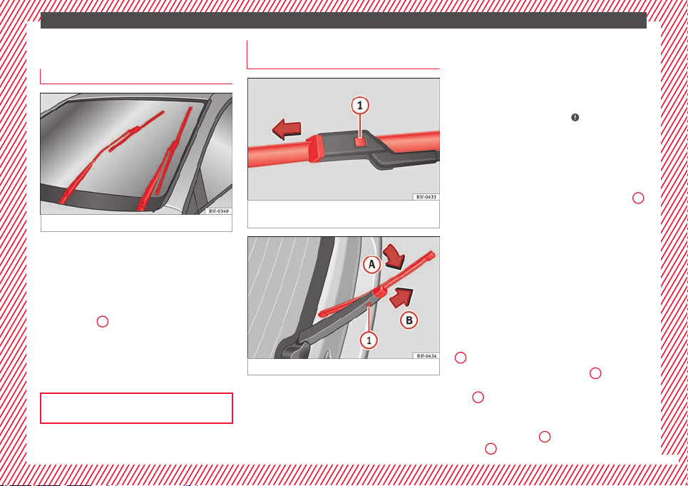
The essentials
Changing the wiper blades
W
ind
s
creen wipers service position
Fig. 81 Wipers in service position.
The wiper arms can be raised when the wip-
er
s
ar
e in service position ››› Fig. 81.
●
Close the bonnet ›››
page 298.
●
Switch the ignition on and off.
●
Press the windscreen wiper lever down-
wards briefly
4
›
›
› p
age 32.
Before driving, always lower the wiper arms.
Using the windscreen wiper lever, the wind-
screen wiper arms return to their initial posi-
tion.
››› page 97
Changing the windscreen and rear
w
indo
w w
iper blades
Fig. 82 Changing the windscreen wiper
b
l
a
des
Fig. 83 Changing the rear wiper blade
Raising and lowering windscreen wiper arms
●
Place the windscreen wipers in the service
po
s
ition ›
›› page 71.
●
Grip the wiper arms only by the blade's fas-
tening point.
Cleaning windscreen wiper blades
●
Raise the wiper arms.
●
Use a soft cloth to remove dust and dirt
from the windscreen wiper blades.
●
If the blades are very dirty, a sponge or
damp cloth may be used ›››
in Changing
the w
ind
s
creen and rear window wiper
blades on page 98.
Changing the windscreen wiper blades
●
Lift and unfold the wiper arms.
●
Press and hold release button ››› Fig. 82
1
and pull gently on the wiper blade in the di-
r
ection of
the arr
ow.
●
Fit a new wiper blade of the same length
and design on to the wiper arm and hook it
into place.
●
Rest the wiper arms back onto the wind-
screen.
Changing the rear wiper blade
●
Raising/lowering the wiper arm.
●
Turn the blade slightly ››› Fig. 83 (arrow
A
).
●
Hold down the release button
1
while
g
ently
p
ulling the blade in the direction of ar-
row
B
.
●
Insert a new blade of the s
ame l
en
gth and
type in the rear wiper arm in the opposite di-
rection to the arrow
B
and hook into place
b
utt
on
1
.
»
71

Safe driving
Safety
Saf
e driv
in
g
Safety first!
WARNING
●
This m
anual contains important informa-
tion about the operation of the vehicle, both
for the driver and the passengers. The other
sections of the on-board documentation also
contain further information that you should
be aware of for your own safety and for the
safety of your passengers.
●
Ensure that the on-board documentation is
kept in the vehicle at all times. This is espe-
cially important when lending or selling the
vehicle to another person.
Advice about driving
B
ef
or
e setting off
For your own safety and the safety of your
p
a
s
sengers, always note the following points
before every trip:
–
Make sure that the vehicle's lights and turn
signals are working properly.
–
Check tyre pressure.
–
Ensure that all windows provide a clear and
good view of the surroundings.
–
Make sure all luggage is secured
››› page 162.
–
Make sure that no objects can interfere
with the pedals.
–
Adjust front seat, head restraint and mir-
rors properly according to your size.
–
Ensure that the passengers in the rear
seats always have the head restraints in
the in-use position ››› page 77.
–
Instruct passengers to adjust the head re-
straints according to their height.
–
Protect children with appropriate child
seats and properly applied seat belts
››› page 90.
–
Assume the correct sitting position. Instruct
your passengers also to assume a proper
sitting position ››› page 74.
–
Fasten your seat belt securely. Instruct your
passengers also to fasten their seat belts
properly ››› page 79.
What affects driving safety?
As a driver, you are responsible for yourself
and
y
our p
assengers. When your concentra-
tion or driving safety is affected by any cir-
cumstance, you endanger yourself as well as
others on the road ›››
, for this reason:
–
Always pay attention to traffic and do not
g
et
di
stracted by passengers or telephone
calls.
–
Never drive when your driving ability is im-
paired (e.g. by medication, alcohol, drugs).
–
Observe traffic laws and speed limits.
–
Always reduce your speed as appropriate
for road, traffic and weather conditions.
–
When travelling long distances, take
breaks regularly - at least every two hours.
–
If possible, avoid driving when you are tired
or stressed.
WARNING
When driving safety is impaired during a trip,
the risk of
injury and accidents increases.
Safety equipment
Never put your safety or the safety of your
p
a
s
sengers in danger. In the event of an acci-
dent, the safety equipment may reduce the
»
73
Technical dataAdviceOperationEmergenciesSafety
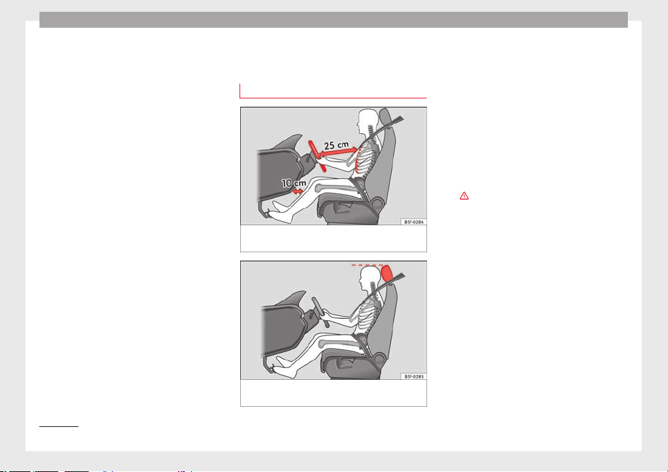
Safety
risk of injury. The following points cover part
of
the s
af
ety equipment in your SEAT
1)
:
●
three-point seat belts,
●
belt tension limiters for the front and rear
side seats,
●
belt tensioners for the front and rear side
seats,
●
front airbags,
●
knee airbags,
●
side airbags in the front seat backrests,
●
head-protection airbags,
●
“ISOFIX” anchor points for child seats in
the rear side seats with the “ISOFIX” system,
●
height-adjustable front head restraints,
●
rear head restraints with in-use position
and non-use position,
●
adjustable steering column.
The safety equipment mentioned above
works together to provide you and your pas-
sengers with the best possible protection in
the event of an accident. However, these
safety systems can only be effective if you
and your passengers are sitting in a correct
position and use this equipment properly.
Safety is everyone's business!
Correct position of the vehicle
occupants
Correct sitting position for the driver
Fig. 84 The proper distance between driver
and s
t
eerin
g wheel.
Fig. 85 Correct head restraint position for the
driv
er
.
For your own safety and to reduce the risk of
injur
y
in the ev
ent of an accident, we recom-
mend the following adjustments for the driv-
er:
–
Adjust the steering wheel so that there is a
distance of at least 25 cm between the
steering wheel and the centre of your chest
››› Fig. 84.
–
Move the driver's seat forwards or back-
wards so that you are able to press the ac-
celerator, brake and clutch pedals to the
floor with your knees still slightly angled
›››
.
–
Ensure that you can reach the highest point
of
the s
t
eering wheel.
–
Adjust the head restraint so that its upper
edge is at the same level as the top of your
head, or as close as possible to the same
level as the top of your head ››› Fig. 85.
–
Move the seat backrest to an upright posi-
tion so that your back rests completely
against it.
–
Fasten your seat belt securely ››› page 79.
–
Keep both feet in the footwell so that you
have the vehicle under control at all times.
Adjustment of the driver's seat ››› page 156.
1)
Depending on the version/market.
74
Safe driving
WARNING
●
An incorrect
sitting position of the driver
can lead to severe injuries.
●
Adjust the driver's seat so that there is at
least 25 cm distance between the centre of
the chest and the centre of the steering
wheel ››› Fig. 84. If you are sitting closer than
25 cm, the airbag system cannot protect you
properly.
●
If your physical constitution prevents you
from maintaining the minimum distance of 25
cm, contact a specialised workshop. The
workshop will help you decide if special spe-
cific modifications are necessary.
●
When driving, always hold the steering
wheel with both hands on the outside of the
ring at the 9 o'clock and 3 o'clock positions.
This reduces the risk of injury when the driver
airbag is triggered.
●
Never hold the steering wheel at the 12
o'clock position, or in any other manner (e.g.
in the centre of the steering wheel). In such
cases, if the airbag is triggered, you may sus-
tain injuries to the arms, hands and head.
●
To reduce the risk of injury to the driver
during sudden braking manoeuvres or an ac-
cident, never drive with the backrest tilted far
back! The airbag system and seat belts can
only provide optimal protection when the
backrest is in an upright position and the
driver is wearing his or her seat belt correct-
ly.
●
Adjust the head restraint properly to ach-
ieve optimal protection.
Adjusting the steering wheel position
Read the additional information carefully
›››
page 20.
WARNING
●
Never adju
st the position of the steering
wheel when the vehicle is moving, as this
could cause an accident.
●
Move the lever up firmly so the steering
wheel position does not accidentally change
during driving. risk of accident!
●
Make sure you are capable of reaching and
firmly holding the upper part of the steering
wheel: risk of accident!
●
If you adjust the steering wheel so that it
points towards your face, the driver airbag
will not protect you properly in the event of
an accident. Make sure that the steering
wheel points towards your chest.
Correct position for the front passen-
g
er
For your own safety and to reduce the risk of
injur
y
in the ev
ent of an accident, we recom-
mend the following adjustments for the front
passenger:
–
Move the front passenger seat back as far
as possible
›››
.
–
Mo
v
e the se
at backrest to an upright posi-
tion so that your back rests completely
against it.
–
Adjust the head restraint so that its upper
edge is at the same level as the top of your
head, or as close as possible to the same
level as the top of your head ››› page 77.
–
Always keep both feet in the footwell in
front of the front passenger seat.
–
Fasten your seat belt securely ››› page 79.
It is possible to deactivate the front passen-
ger airbag in exceptional circumstances
››› page 89.
Adjusting the front passenger seat
››› page 156.
WARNING
●
An incorrect
sitting position of the front
passenger can lead to severe injuries.
●
Adjust the front passenger seat so that
there is at least 25 cm between your chest
and the dash panel. If you are sitting closer
than 25 cm, the airbag system cannot protect
you properly.
●
If your physical constitution prevents you
from maintaining the minimum distance of 25
cm, contact a specialised workshop. The
workshop will help you decide if special spe-
cific modifications are necessary.
»
75
Technical dataAdviceOperationEmergenciesSafety

Safety
●
Alwa
ys keep your feet in the footwell when
the vehicle is moving; never rest them on the
dash panel, out the window or on the seat. An
incorrect sitting position exposes you to an
increased risk of injury in case of a sudden
braking or an accident. If the airbag is trig-
gered, you could sustain severe injuries due
to an incorrect sitting position.
●
To reduce the risk of injury to the front pas-
senger in events such as sudden braking ma-
noeuvres or an accident, never travel with the
backrest tilted far back! The airbag system
and seat belts can only provide optimal pro-
tection when the backrest is in an upright po-
sition and the front passenger is wearing his
or her seat belt properly. The further the seat
backrests are tilted to the rear, the greater
the risk of injury due to incorrect positioning
of the belt web or to the incorrect sitting po-
sition!
●
Adjust the head restraint correctly in order
to achieve maximum protection.
Correct sitting position for rear seat
p
a
s
sengers
To reduce the risk of injury in the event of a
s
ud
den br
aking manoeuvre or an accident,
passengers on the rear seat bench must con-
sider the following:
–
Sit up straight.
–
Adjust the head restraint to the correct po-
sition ››› page 77.
–
Always keep both feet in the footwell in
front of the rear seat.
–
Fasten your seat belt securely ››› page 79.
–
Use an appropriate child restraint system
when you take children in the vehicle
››› page 90.
WARNING
●
If the pa
ssengers in the rear seats are not
sitting properly, they could sustain severe in-
juries.
●
Adjust the head restraint correctly in order
to achieve maximum protection.
●
Seat belts can only provide optimal protec-
tion when seat backrests are in an upright
position and the vehicle occupants are wear-
ing their seat belts correctly. If passengers In
the rear seats are not sitting in an upright po-
sition, the risk of injury due to incorrect posi-
tioning of the seat belt increases.
Examples of incorrect sitting posi-
tion
s
Seat belts can provide optimal protection on-
ly
when the belt
w
ebs are properly posi-
tioned. Incorrect sitting positions substan-
tially reduce the protective function of seat
belts and increase the risk of injury due to in-
correct seat belt position. As the driver, you
are responsible for all passengers, especially
children.
–
Never allow anyone to assume an incorrect
sitting position in the vehicle while travel-
ling ›››
.
The f
o
l
lowing list contains examples of sit-
ting positions that could be dangerous for all
vehicle occupants. The list is not complete,
but we would like to make you aware of this
issue.
Therefore, whenever the vehicle is in motion:
●
Never stand in the vehicle.
●
Never stand on the seats.
●
Never kneel on the seats.
●
Never tilt your seat backrest far to the rear.
●
Never lean against the dash panel.
●
Never lie on the rear bench.
●
Never sit on the front edge of a seat.
●
Never sit sideways.
●
Never lean out of a window.
●
Never put your feet out of a window.
●
Never put your feet on the dash panel.
●
Never put your feet on the surface of a seat.
●
Do not allow anyone to travel in the foot-
well.
●
Never travel without wearing the seat belt.
●
Do not allow anyone to travel in the lug-
gage compartment.
76
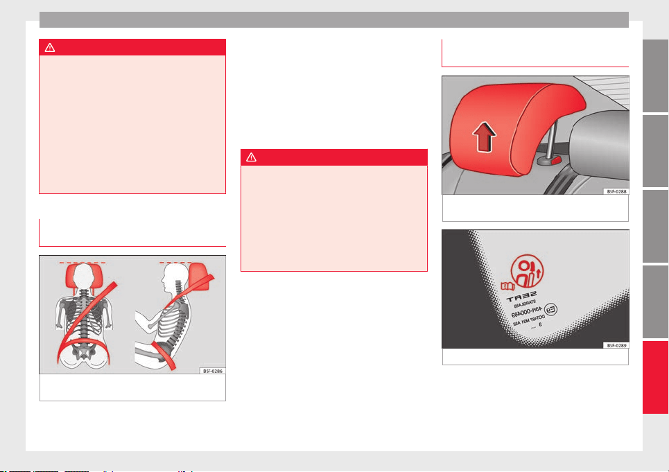
Safe driving
WARNING
●
Any inc
orrect sitting position increases the
risk of severe injuries. Sitting in an incorrect
position exposes the vehicle occupants to se-
vere injuries if airbags are triggered, by strik-
ing a vehicle occupant who has assumed an
incorrect sitting position.
●
Before the vehicle moves, assume the prop-
er sitting position and maintain it throughout
the trip. Before every trip, instruct your pas-
sengers to sit properly and to stay in this po-
sition during the trip ››› page 74, Correct posi-
tion of the vehicle occupants.
Correct adjustment of front head re-
s
tr
aint
s
Fig. 86 Correctly adjusted head restraint as
v
iew
ed fr
om the front and the side.
Read the additional information carefully
›
›
›
page 19.
Properly adjusted head restraints are an im-
portant part of passenger protection and can
reduce the risk of injuries in most accident
situations.
●
Adjust the head restraint so that its upper
edge is, as far as possible, at the same level
as the top of your head, or at the very least,
at eye level ››› Fig. 86.
WARNING
●
Trav
elling with the head restraints removed
or improperly adjusted increases the risk of
severe injuries. An improper adjustment of
the head restraints may cause death in an ac-
cident and increase the risk of suffering inju-
ries during abrupt braking actions or unex-
pected manoeuvres.
●
The head restraints must always be adjus-
ted according to the height of the passenger.
Correct adjustment of rear head re-
s
tr
aint
s
Fig. 87 Head restraints in the correct posi-
tion.
Fig. 88 Head restraint position warning label.
Properly adjusted head restraints are an im-
por
t
ant
part of the passenger protection and
can reduce the risk of injuries in most acci-
dent situations
»
77
Technical dataAdviceOperationEmergenciesSafety
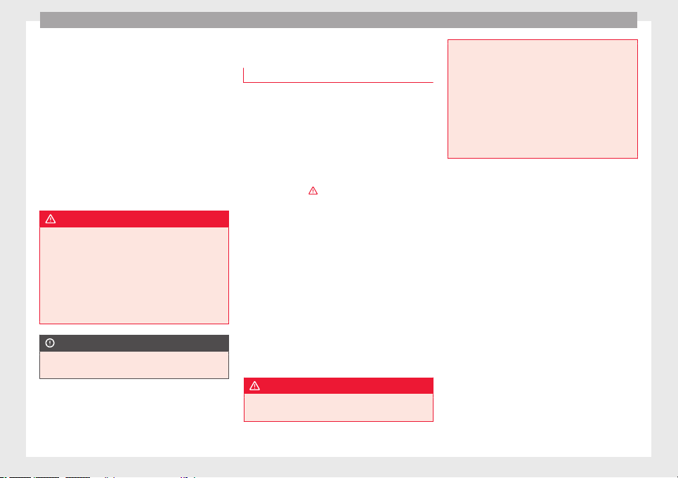
Safety
Rear head restraints
–
The rear head restraints have 2 positions:
u
se
and
non-use.
–
One position for use (head restraint raised)
››› Fig. 87. In this position, the head re-
straints are used normally, protecting pas-
sengers along with the rear seat belts.
–
And one position for non-use (head re-
straint lowered).
–
To fit the head restraints in position for use,
pull on the edges with both hands in the
direction of the arrow.
WARNING
●
Under no circ
umstances should the rear
passengers travel while the head restraints
are in the non-use position. See the warning
label located on the rear side fixed window
››› Fig. 88.
●
Do not swap the centre rear head restraint
with either of the outer seat rear head re-
straints. Risk of injury in case of an accident!
CAUTION
Note the instructions on the adjustment of
the head r
estraints ››› page 157.
Pedal area
P
ed
a
ls
–
Ensure that you can always press the accel-
erator
, brake and clutch pedals unimpaired
to the floor.
–
Ensure that the pedals can return unim-
paired to their initial positions.
–
Ensure that the floor mats are securely fas-
tened during the trip and do not obstruct
the pedals
›››
.
On
ly
u
se floor mats which leave the pedals
clear and which are secured to prevent them
from slipping. You can obtain suitable floor
mats from a specialised dealership. Fasten-
ers* for floor mats are fitted in the footwells.
If a brake circuit fails, the brake pedal must
be pressed down thoroughly in order to stop
the vehicle.
Wear suitable footwear
Always wear shoes which support your feet
properly and give you a good feeling for the
pedals.
WARNING
●
Res
tricting pedal operation can lead to crit-
ical situations while driving.
●
Never la
y or fit floor mats or other floor cov-
erings over the original floor mats. This
would reduce the pedal area and could ob-
struct the pedals. Risk of accident.
●
Never place objects in the driver footwell.
An object could move into the pedal area and
impair pedal operation. In the event of a sud-
den driving or braking manoeuvre, you will
not be able to operate the brake, clutch or ac-
celerator pedal. Risk of accident!
78
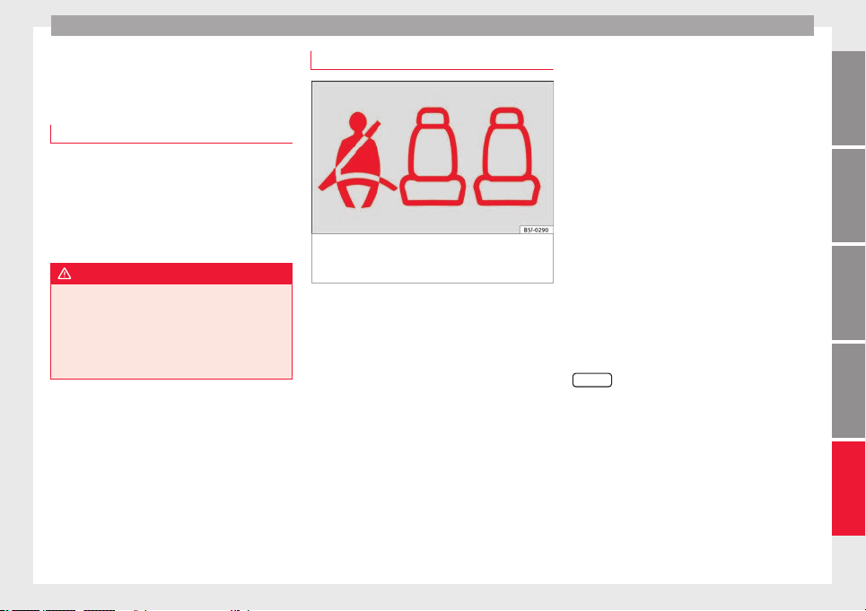
Seat belts
Seat belts
Wh
y
w
ear a seat belt
Number of seats
Your vehicle has five se
ats, two in the front
and three in the rear. Each seat is equipped
with a three-point seat belt.
In some versions, your vehicle is approved
only for four seats. Two front seats and two
rear seats.
WARNING
●
Never tran
sport more than the permitted
amount of people in your vehicle.
●
Every vehicle occupant must properly fas-
ten and wear the seat belt belonging to his or
her seat. Children must be protected with an
appropriate child restraint system.
Seat belt control lamp*
Fig. 89 Instrument panel: right rear seat oc-
c
upied and c
orr
esponding seat belt fastened
display.
The control lamp illuminates to remind the
driv
er t
o f
asten his seat belt.
Before starting the vehicle:
–
Fasten your seat belt securely.
–
Instruct your passengers to fasten their
seat belts properly before driving off.
–
Protect children by using a child seat ac-
cording to the child's height and weight.
When the ignition is switched on, the control
lamp in the instrument panel lights up (de-
pending on the model version) if the driver or
passenger have not fastened their seat belts.
An audible warning signal will sound for a
few seconds if the seat belts are not fastened
as the vehicle drives off and reaches a speed
of more than approximately 25 km/h
(15 mph) or if the seat belts are unfastened
while the vehicle is in motion. The warning
light will also flash .
The lamp goes out when the driver and
passenger seat belts are fastened with the ig-
nition switched on.
Rear seat belts fastened display*
Depending on the model version, when the
ignition is switched on, the seat belt status
display ››› Fig. 89 on the instrument panel in-
forms the driver whether the passengers in
the rear seats have fastened their seat belts.
The symbol indicates that the passenger in
this seat has fastened “his or her” seat belt.
When a seat belt in the rear seats is fastened
or unfastened, the seat belt status is dis-
played for approximately 30 seconds. The in-
dication can be hidden by pressing the
0.0/SET
button on the dash panel.
The se
at
belt
status flashes for a maximum of
30 seconds when a seat belt in the rear seats
is unfastened while the vehicle is in motion.
An audible warning will also be heard if the
vehicle is travelling at over 25 km/h
(15 mph).
79
Technical dataAdviceOperationEmergenciesSafety
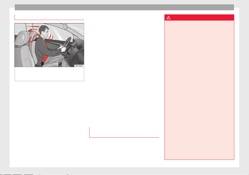
Safety
The protective function of seat belts
Fig. 90 Drivers with properly worn seat belts
w
i
l
l not be thrown forward in the event of sud-
den braking.
Properly worn seat belts hold the occupants
in the pr
oper po
s
ition. They also help prevent
uncontrolled movements that may result in
serious injury and reduce the risk of being
thrown out of the vehicle in case of an acci-
dent.
Vehicle occupants wearing their seat belts
correctly benefit greatly from the ability of the
belts to absorb kinetic energy. In addition,
the front part of your vehicle and other pas-
sive safety features (such as the airbag sys-
tem) are designed to absorb the kinetic ener-
gy released in a collision. Taken together, all
these features reduce the releasing kinetic
energy and consequently, the risk of injury.
This is why it is so important to fasten seat
belts before every trip, even when "just driv-
ing around the corner".
Ensure that your passengers wear their seat
belts as well. Accident statistics have shown
that wearing seat belts is an effective means
of substantially reducing the risk of injury
and improving the chances of survival when
involved in a serious accident. Furthermore,
properly worn seat belts improve the protec-
tion provided by airbags in the event of an
accident. For this reason, wearing a seat belt
is required by law in most countries.
Although your vehicle is equipped with air-
bags, the seat belts must be fastened and
worn. The front airbags, for example, are only
triggered in some cases of head-on collision.
The front airbags will not be triggered during
minor frontal or side collisions, rear-end colli-
sions, overturns or accidents in which the air-
bag trigger threshold value in the control unit
is not exceeded.
Therefore, you should always wear your seat
belt and ensure that all vehicle occupants
have fastened their seat belts properly before
you drive off!
Important safety instructions for the
use of seat belts
–
Always wear the seat belt as described in
thi
s
section.
–
En
sure that the seat belts can be fastened
at all times and are not damaged.
WARNING
●
If seat
belts are worn incorrectly or not at
all, the risk of severe injuries increases. The
optimal protection from seat belts can be
achieved only if you use them properly.
●
Fasten your seat belt before every trip -
even when driving in town. Other vehicle oc-
cupants must also wear the seat belts at all
times, otherwise they run the risk of being in-
jured.
●
The seat belt cannot offer its full protection
if the seat belt is not positioned correctly.
●
Never allow two passengers (even children)
to share the same seat belt.
●
Always keep both feet in the footwell in
front of your seat as long as the vehicle is in
motion.
●
Never unbuckle a seat belt while the vehi-
cle is in motion. Risk of fatal injury.
●
The seat belt must never be twisted while it
is being worn.
●
The seat belt should never lie on hard or
fragile objects (such as glasses or pens, etc.)
because this can cause injuries.
●
Do not allow the seat belt to be damaged or
jammed, or to rub on any sharp edges.
●
Never wear the seat belt under the arm or
in any other incorrect position.
●
Bulky and unfastened clothing (such as an
overcoat over a sweater) impairs the proper
fit and function of the seat belts, reducing
their capacity to protect.
80
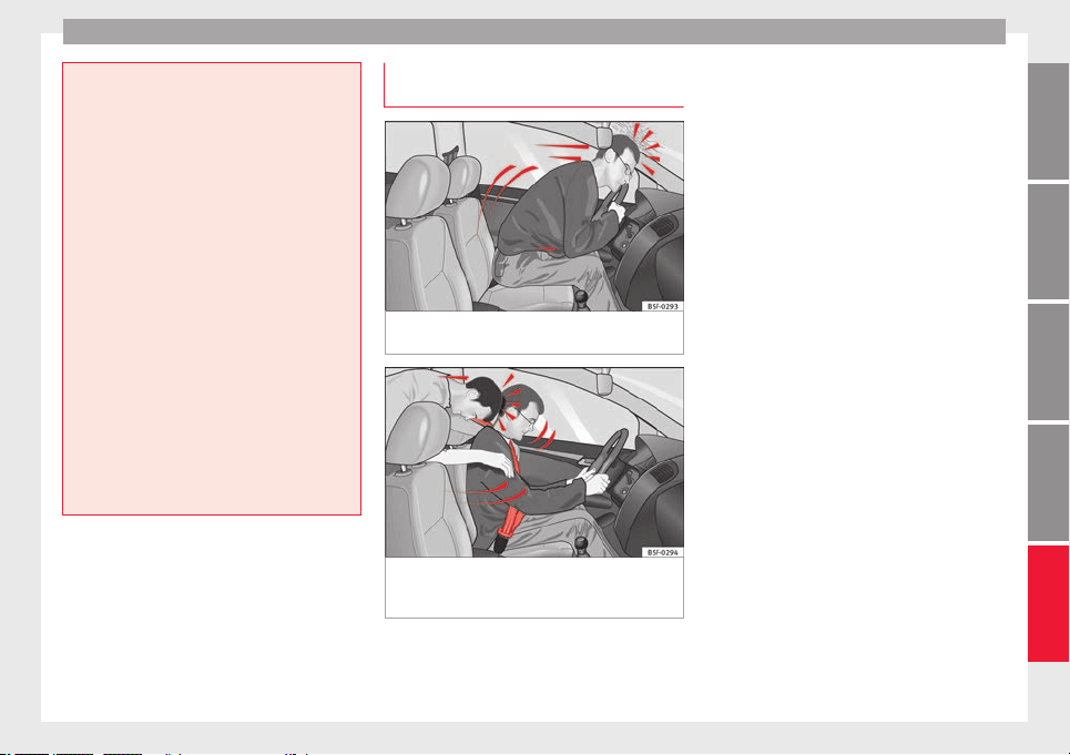
Seat belts
●
The slot in the se
at belt buckle must not be
blocked with paper or other objects, as this
can prevent the latch plate from engaging se-
curely.
●
Never use seat belt clips, fastening rings or
similar items to alter the position of the belt
webbing.
●
Frayed or torn seat belts or damage to the
connections, belt retractors or parts of the
buckle could cause severe injuries in the
event of an accident. Therefore, you must
check the condition of all seat belts at regular
intervals.
●
Seat belts which have been worn in an acci-
dent and have been stretched must be re-
placed by a specialised workshop. Renewal
may be necessary even if there is no apparent
damage. The belt anchorage should also be
checked.
●
Do not attempt to repair a damaged seat
belt yourself. The seat belts must not be re-
moved or modified in any way.
●
The belts must be kept clean, otherwise the
retractors may not work properly.
Head-on collisions and the laws of
ph
y
s
ics
Fig. 91 A driver not wearing a seat belt is
thr
o
wn f
orward violently.
Fig. 92 The unbelted passenger in the rear
se
at
i
s thrown forward violently, hitting the
driver who is wearing a seat belt.
It is easy to explain how the laws of physics
w
ork
in the c
ase of a head-on collision: when
a vehicle starts moving, a type of energy
called “kinetic energy” is created both in the
passengers and inside the vehicle.
The amount of “kinetic energy” depends on
the speed of the vehicle and on the weight of
the vehicle and of its passengers. The higher
they are, the more energy there is to be “ab-
sorbed” in the event of an accident.
The most significant factor, however, is the
speed of the vehicle. If the speed doubles
from 25 km/h (15 mph) to 50 km/h
(30 mph), for example, the corresponding ki-
netic energy is multiplied by four.
Given that the passengers of the vehicle in
our example do not have their seat belts fas-
tened, in the event of a collision the entire
amount of the passengers' kinetic energy will
be only absorbed by the mentioned impact.
Even at speeds of 30 km/h (19 mph) to
50 km/h (30 mph), the forces acting on bod-
ies in a collision can easily exceed one tonne
(1000 kg). At greater speed these forces are
even higher.
Vehicle occupants not wearing seat belts are
not “attached” to the vehicle. In a head-on
collision, they will move forward at the same
speed their vehicle was travelling just before
the impact. This example applies not only to
head-on collisions, but to all accidents and
collisions.
Even at low speeds the forces acting on the
body in a collision are so great that it is not
»
81
Technical dataAdviceOperationEmergenciesSafety
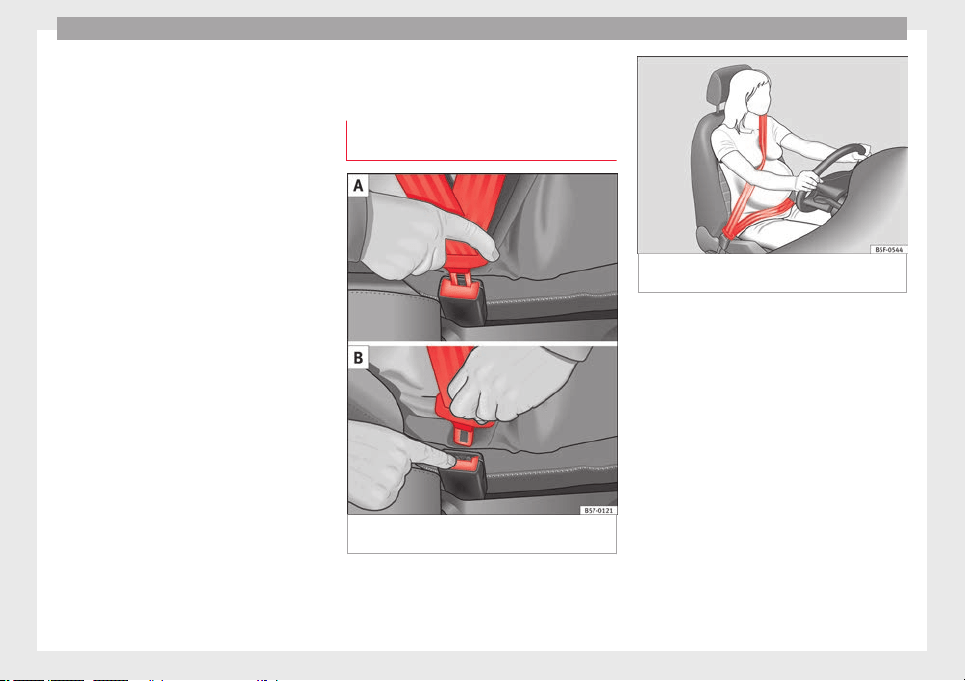
Safety
possible to brace oneself with one's hands.
In a fr
ont
al
collision, unbelted passengers
are thrown forward and will make violent con-
tact with the steering wheel, dash panel,
windscreen or whatever else is in the way
››› Fig. 91.
It is also important for rear passengers to
wear seat belts properly, as they could other-
wise be thrown forward violently through the
vehicle interior in an accident. Passengers in
the rear seats who do not use seat belts en-
danger not only themselves but also the front
occupants ››› Fig. 92.
How to properly adjust your
seatbelt
Fastening and unfastening your seat
belt
Fig. 93 Positioning and removing the seat
belt
b
uc
kle.
Fig. 94 Position of seat belt during pregnan-
cy
.
Read the additional information carefully
›
›
›
page 19.
Fasten your seat belt
The seat belt cannot offer its full protection if
the seat belt is not positioned correctly.
●
Adjust the seat and head restraint correctly.
●
To fasten the belt, take hold of the latch
plate and pull it slowly across your chest and
lap.
●
Insert the latch plate into the buckle for the
appropriate seat and push it down until it is
securely locked with an audible click
›››
Fig. 93 A.
82
Seat belts
●
P
u
l
l the belt to ensure that the latch plate is
securely engaged in the buckle.
The seat belts are equipped with an automat-
ic retractor on the shoulder strap. Full free-
dom of movement is permitted when the
shoulder belt is pulled slowly. However, dur-
ing sudden braking, during travel in steep
areas or bends and during acceleration, the
automatic retractor on the shoulder belt is
locked.
The automatic belt retractors on the front
seats and side rear seats are
1)
fitted with
seat belt tensioners ››› page 83.
Releasing the seat belt
●
Press the red button on the belt buckle
››› Fig. 93 B. The latch plate is released and
springs out ›››
.
●
Guide the belt back by hand so that it rolls
up e
a
s
ily and the trim is not damaged.
Positioning seat belts
Seat belts offer their maximum protection on-
ly when they are properly positioned.
WARNING
●
The seat belt
s offer best protection only
when the backrests are in an upright position
and the seat belts have been fastened prop-
erly.
●
Never p
ut the latch plate in the buckle of
another seat. If you do this, the seat belt will
not protect you properly and the risk of injury
is increased.
●
Never unbuckle a seat belt while the vehi-
cle is in motion. If you do, you increase the
risk of sustaining severe or fatal injuries.
●
An incorrectly worn seat belt can cause se-
vere injuries in the event of an accident.
●
For pregnant women, the lap part of the
seat belt must lie as low as possible over the
pelvis, never across the stomach, and always
lie flat so that no pressure is exerted on the
abdomen ››› Fig. 94.
●
Always engage the retractor lock when you
are securing a child seat in group 0, 0+ or 1
››› page 90.
●
Read and observe the warnings ››› page 80.
Seat belt tensioners
Ho
w the se
at
belt tensioner works
Read the additional information carefully
›
›
›
page 20.
The seat belts for the front seats and the side
rear seats
1)
are equipped with belt tension-
ers. The belt tensioners are activated by sen-
sors, although only in severe head-on, lateral
and rear-end collisions. This retracts and
tightens the seat belts, reducing the forward
motion of the occupants.
The belt tensioners will not be triggered in
the event of minor collisions, if the vehicle
overturns, or in accidents where no major
forces act on the vehicle.
Note
●
If the seat
belt tensioners are triggered, a
fine dust is produced. This is normal and it is
not an indication of fire in the vehicle.
●
The relevant safety requirements must be
observed when the vehicle or components of
the system are scrapped. Specialised work-
shops are familiar with these regulations,
which are also available to you.
Maintenance and disposal of belt ten-
s
ioner
s
The belt tensioners are components of the
se
at
belts
that are installed in the seats of
your vehicle. If you work on the belt tension-
ers or remove and install parts of the system
when performing other repair work, the seat
»
1)
Depending on version/market.
83
Technical dataAdviceOperationEmergenciesSafety
Safety
belt may be damaged. The consequence may
be th
at, in the ev
ent
of an accident, the belt
tensioners function incorrectly or may not
function at all.
So that the effectiveness of the seat belt ten-
sioner is not reduced and that removed parts
do not cause any injuries or environmental
pollution, regulations, which are known to
the specialised workshops, must be ob-
served.
WARNING
●
Improper use or r
epairs not carried out by
qualified mechanics increase the risk of se-
vere or fatal injuries. The belt tensioners may
fail to trigger or may trigger in the wrong cir-
cumstances.
●
Never attempt to repair, adjust, remove or
install parts of the belt tensioners or seat
belts.
●
The seat belt tensioner, seat belt and auto-
matic retractor cannot be repaired.
●
Any work on the belt tensioners and seat
belts, including the removal and refitting of
system parts in conjunction with other repair
work, must be performed by a specialised
workshop only.
●
The belt tensioners will only provide pro-
tection for one accident and must be changed
if they have been activated.
Airbag system
Brief
intr
oduction
Wh
y is it so important to wear a seat
belt and to sit correctly?
For the inflating airbags to achieve the best
protection, the se
at belt must always be worn
properly and the correct sitting position must
be assumed.
The airbag system is not a substitute for seat
belts, but it is an integral part of the vehicle's
overall passive safety system. Please bear in
mind that the airbag system can only work ef-
fectively when the vehicle occupants are
wearing their seat belts correctly and have
adjusted the head restraints properly. There-
fore, it is most important to properly wear the
seat belts at all times, not only because this
is required by law in most countries, but also
for your safety
›››
page 79, Why wear a seat
belt.
The airbag inflates in a matter of seconds, so
if you are not properly seated when the air-
bag is triggered, you may sustain fatal inju-
ries. Therefore, it is essential that all vehicle
occupants assume a correct sitting position
while travelling.
Sharp braking before an accident may cause
a passenger not wearing a seat belt to be
thrown forward into the area of the deploying
airbag. In this case, the inflating airbag may
inflict critic
al or fatal injuries on the occu-
pant. This also applies to children.
Always maintain the greatest possible dis-
tance between yourself and the front airbag.
This way, the front airbags can completely
deploy when triggered, providing their maxi-
mum protection.
The most important factors that will trigger
an airbag are: the type of accident, the angle
of collision and the speed of the vehicle.
Whether or not the airbags are triggered de-
pends primarily on the vehicle deceleration
rate resulting from the collision and detected
by the control unit. If the vehicle deceleration
occurring during the collision and measured
by the control unit remains below the speci-
fied reference values, the front, side and/or
curtain airbags will not be triggered. Take in-
to account that the visible damage in a vehi-
cle involved in an accident, no matter how
serious, is not a determining factor for the
airbags to have been triggered.
WARNING
●
Wearin
g the seat belt incorrectly or assum-
ing an incorrect sitting position can lead to
critical or fatal injuries.
●
All vehicle occupants, including children,
who are not properly belted can sustain criti-
cal or fatal injuries if the airbag is triggered.
Children up to 12 years old should always
84
Airbag system
travel on the rear seat. Never transport
chil
dren in the vehicle if they are not restrain-
ed or the restraint system is not appropriate
for their age, size or weight.
●
If you are not wearing a seat belt, or if you
lean forward or to the side while travelling or
assume an incorrect sitting position, there is
a substantially increased risk of injury. This
increased risk of injury will be further in-
creased if you are struck by an inflating air-
bag.
●
To reduce the risk of injury from an inflating
airbag, always wear the seat belt properly
››› page 79.
●
Always adjust the front seats properly.
Description of airbag system
Read the additional information carefully
›
›
›
page 21.
The airbag system is not a substitute for the
seat belts. The airbag system offers addition-
al protection for the driver and passenger in
combination with the seat belts.
The airbag system comprises the following
modules (as per vehicle equipment):
●
Electronic control unit
●
Front airbags for driver and passenger
●
Knee airbag for the driver
●
Side airbags
●
Head airbag
●
Airbag control lamp on the instrument
panel ››› page 89
●
Key-operated switch for front passenger air-
bag
●
Control lamp for disabled/enabled status
of the front passenger airbag.
The airbag system operation is monitored
electronically. The airbag control lamp will il-
luminate for a few seconds every time the ig-
nition is switched on (self-diagnosis).
There is a fault in the system if the control
lamp :
●
does not light up when the ignition is
switched on ››› page 89,
●
turns off after 4 seconds after the ignition
is switched on,
●
turns off and then lights up again after the
ignition is switched on,
●
illuminates or flashes while the vehicle is
moving.
The airbag system is not triggered if:
●
the ignition is switched off
●
there is a minor frontal collision
●
there is a minor side collision
●
there is a rear-end collision
●
the vehicle turns over.
WARNING
●
The seat belt
s and airbags can only provide
maximum protection if the occupants are
seated correctly ››› page 74, Correct position
of the vehicle occupants.
●
If a fault has occurred in the airbag system,
have the system checked immediately by a
specialised workshop. Otherwise there is a
danger that during a collision, the system
may fail to trigger, or not trigger correctly.
Airbag activation
The airbags deploy extremely rapidly, within
thou
s
andths
of a second, to provide addi-
tional protection in the event of an accident.
A fine dust may develop when the airbag de-
ploys. This is normal and it is not an indica-
tion of fire in the vehicle.
The airbag system is only ready to function
when the ignition is on.
In special accidents instances, several air-
bags may activate at the same time.
In the event of minor head-on and side colli-
sions, rear-end collisions, overturning or roll-
over of the vehicle, airbags do not activate.
Activation factors
The conditions that lead to the airbag system
activating in each situation cannot be gener-
alised. Some factors play an important role,
»
85
Technical dataAdviceOperationEmergenciesSafety
Safety
such as the properties of the object the vehi-
c
l
e hits
(hard/soft), angle of impact, vehicle
speed, etc.
Deceleration trajectory is key for airbag acti-
vation.
The control unit analyses the collision trajec-
tory and activates the respective restraint
system.
If the deceleration rate is below the prede-
fined reference value in the control unit the
airbags will not be triggered, even though
the accident may cause extensive damage to
the car.
The following airbags are triggered in seri-
ous head-on collisions:
●
Driver airbag.
●
Front passenger front airbag
●
Knee airbag for the driver.
The following airbags are triggered in seri-
ous side-on collisions:
●
Front side airbag on the side of the acci-
dent.
●
Curtain (head) airbag on the side of the ac-
cident.
In an accident with airbag activation:
●
the interior lights switch on (if the interior
light switch is in the courtesy light position);
●
the hazard warning lights switch on;
●
all doors are unlocked;
●
the fuel supply to the engine is cut.
Airbag safety instructions
Front airbags
Read the additional information carefully
›››
page 21.
WARNING
●
The deployment
space between the front
passengers and the airbags must not in any
case be occupied by other passenger, pets
and objects.
●
The airbags provide protection for just one
accident; replace them once they have de-
ployed.
●
It is also important not to attach any ob-
jects such as cup holders or telephone
mountings to the surfaces covering the air-
bag units.
●
Do not attempt to modify components of
the airbag system in any way.
Knee airbag*
Read the additional information carefully
›
›
›
page 23.
WARNING
●
The knee airbag is
deployed in front of the
driver's knees. Always keep the deployment
areas of the knee airbags free.
●
Never not fix objects to the cover or in the
deployment area of the knee airbag.
●
Adjust the driver's seat so that there is a
distance of at least 10 cm (4 inches) between
your knees and the location of the this air-
bag. If your physical constitution prevents
you from meeting these requirements, make
sure you contact a specialised workshop.
Side airbags*
Read the additional information carefully
›
›
›
page 23.
WARNING
●
If y
ou do not wear a seat belt, if you lean
forward, or are not seated correctly while the
vehicle is in motion, you are at a greater risk
of injury if the side airbag system is triggered
in an accident.
●
In order for the side airbags to provide their
maximum protection, the prescribed sitting
position must always be maintained with
seat belts fastened while travelling.
●
In a side-on collision the side airbags will
not work if the sensors do not correctly meas-
ure the pressure increase on the interior of
the doors, due to air escaping through the
86
Airbag system
areas with holes or openings in the door pan-
el.
●
Never driv
e if the interior door panels have
been removed or if the panels have not been
correctly fitted.
●
Never drive the vehicle if the loudspeakers
in the door panels have been removed, un-
less the holes left by the loudspeakers have
been closed properly.
●
Always check that the openings are closed
or covered if loudspeakers or other equip-
ment are fitted inside the door panels.
●
Occupants of the outer seats must never
carry any objects or pets in the deployment
space between them and the airbags, or al-
low children or other passengers to travel in
this position. It is also important not to at-
tach any accessories (such as cup holders) to
the doors. This would impair the protection
offered by the side airbags.
●
The built-in coat hooks should be used only
for lightweight clothing. Do not leave any
heavy or sharp-edged objects in the pockets.
●
Great forces, such as hard blows or kicks,
must not be exerted upon the backrest bol-
ster because the system may be damaged. In
this case, the side airbags would not be trig-
gered.
●
Under no circumstances should protective
covers be fitted over seats with side airbags
unless the covers have been approved for use
in your vehicle. Because the airbag deploys
from the side of the backrest, the use of con-
ventional seat covers would obstruct the side
airbag, seriously reducing the airbag's effec-
tivenes
s.
●
Any damage to the original seat upholstery
or around the seams of the side airbag units
must be repaired immediately by a special-
ised workshop.
●
The airbags provide protection for just one
accident; replace them once they have de-
ployed.
●
Any work on the side airbag system or re-
moval and installation of the airbag compo-
nents for other repairs (such as removal of
the front seat) should only be performed by a
specialised workshop. Otherwise, faults may
occur during the airbag system operation.
●
Do not attempt to modify components of
the airbag system in any way.
Curtain airbags*
Read the additional information carefully
›
›
›
page 24.
WARNING
●
In order for the he
ad-protection airbags to
provide their maximum protection, the pre-
scribed sitting position must always be main-
tained with seat belts fastened while travel-
ling.
●
For safety reasons, the curtain airbag must
be disabled in those vehicles fitted with a
screen dividing the interior of the vehicle.
See your technical service to make this ad-
justment
.
●
There must be no other persons, animals or
objects between the occupants of the outer
seats and the deployment space of the head-
protection airbags so that the head-protec-
tion airbag can deploy completely without re-
striction and provide the greatest possible
protection. Therefore, sun blinds which have
not been expressly approved for use in your
vehicle may not be attached to the side win-
dows
●
The built-in coat hooks should be used only
for lightweight clothing. Do not leave any
heavy or sharp-edged objects in the pockets.
Please, do not hang the clothes on coat hang-
ers.
●
The airbags provide protection for just one
accident; replace them once they have de-
ployed.
●
Any work on the head-protection airbag
system or removal and installation of the air-
bag components for other repairs (such as re-
moval of the roof lining) should only be per-
formed by a specialised workshop. Other-
wise, faults may occur during the airbag sys-
tem operation.
●
Do not attempt to modify components of
the airbag system in any way.
●
The side and head airbags are managed
through sensors located in the interior of the
front doors. To ensure the correct operation of
the side and curtain airbags neither the
doors nor the door panels should be modified
in any way (e.g. fitting loudspeakers). If the
»
87
Technical dataAdviceOperationEmergenciesSafety
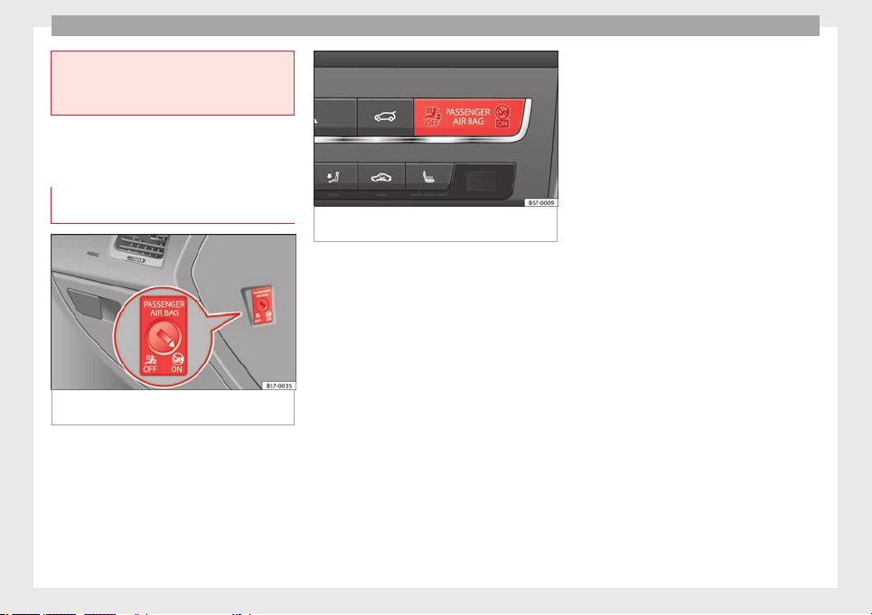
Safety
front door is damaged, the airbag system
may
not work correctly. All work carried out
on the front door must be done in a special-
ised workshop.
Deactivating airbags
Activation and de
activation of front
passenger airbag*
Fig. 95 Switch for activating and deactivating
the fr
ont
p
assenger airbag.
Fig. 96 Dash panel: control lamp for deactiva-
ted front
passenger airbag in centre console.
Deactivate the front passenger front airbag
on
ly
if
you have to use a rear-facing child
seat in the front passenger seat.
SEAT recommends fitting the child seat in the
rear seat to avoid having to deactivate the
front passenger airbag.
Front passenger front airbag switch
When the front passenger airbag is deactiva-
ted, this means that only the front passenger
front airbag is deactivated. All the other air-
bags in the vehicle remain activated.
Disconnect the front passenger front airbag
●
Switch the ignition off.
●
Open the door on the front passenger side.
●
Insert the key into the slot of the switch for
deactivating the front passenger airbag
››› Fig. 95. About 3/4 of the key should enter;
this is as far as it will go.
●
Turn the key gently to the position. If
you have difficulty, ensure that you have in-
serted the key as far as it will go.
●
Close the front passenger door.
●
Check, with the ignition switched on, that
the control lamp remains lit where it
says in the centre of the
dash panel ››› Fig. 96.
Connect the front passenger front airbag
●
Switch the ignition off.
●
Open the front passenger door.
●
Insert the key into the slot of the switch for
deactivating the front passenger airbag
››› Fig. 95. About 3/4 of the key should enter,
as far as it will go.
●
Turn the key gently to the position. If you
have difficulty, ensure that you have inserted
the key as far as it will go.
●
Close the front passenger door.
●
Check, with the ignition switched on, that
the control lamp does not remain lit
where it says in the cen-
tre of the dash panel ››› Fig. 96. The con-
trol lamp lights up for 60 seconds and then
goes off.
88
Airbag system
WARNING
●
The driver of the
vehicle is responsible for
disabling or switching on the airbag.
●
Always switch off the ignition before disa-
bling the front passenger airbag! Failure to do
so could result in a fault in the airbag deacti-
vation system.
●
Never leave the key in the airbag disabling
switch as it could get damaged or enable or
disable the airbag during driving.
●
If for any reason an airbag is deactivated,
reactivate it as soon as possible so that it can
fulfil its protective function.
Airbag system control lamps
It lights up on the combi-in-
strument
Fault in airbag
system and seat
belt tensioners.
Have the system checked immedi-
ately by a specialised workshop.
It lights up on the dash panel
Front passenger
front airbag disa-
bled.
Check whether the airbag should
remain disabled
It lights up on the dash panel
Front passenger
front airbag ena-
bled.
The control lamp switches off auto-
matically 60 seconds after the igni-
tion is switched on
Several warning and control lamps light up
for a few sec
onds when the ignition is switch-
ed on, signalling that the function is being
verified. They will switch off after a few sec-
onds.
If the airbag and seat belt tensioner system
control lamp remains on or flashes, it indi-
cates a malfunction in the airbag and seat
belt tensioner system
›››
. Have the system
c
hec
k
ed immediately by a specialised work-
shop.
If the front passenger airbag is deactivated,
the warning lamp re-
mains lit on the dash panel to remind you
that the airbag is deactivated. If, with the
front passenger airbag deactivated, this lamp
does not remain lit or if it is lit together with
the control lamp on the dash panel, there
is a fault in the airbag system
›››
. If the
c
ontr
o
l lamp is flashing, there is a fault in the
disabling of the airbag system
›››
. Have the
sy
s
t
em checked immediately by a specialised
workshop.
WARNING
In the event of a fault in the airbag and seat
belt ten
sioner system, the airbags and seat
belts may not trigger correctly, may fail to
trigger or m
ay even trigger unexpectedly.
●
The vehicle occupants run the risk of sus-
taining severe or fatal injuries. Have the sys-
tem checked immediately by a specialised
workshop.
●
Do not mount a child seat in the front pas-
senger seat or remove the mounted child
seat! The front passenger front airbag may
deploy during an accident in spite of the
fault.
CAUTION
Always pay attention to any lit control lamps
and to the corr
esponding descriptions and in-
structions to avoid damage to the vehicle or
harm to the occupants.
89
Technical dataAdviceOperationEmergenciesSafety

Safety
Transporting children safely
Saf
ety
f
or children
Introduction
For safety reasons, as we have learned from
accident
statistics, we recommend that chil-
dren under 12 years of age travel in the rear
seats. Depending on their age, height and
weight, children travelling in rear seats must
use a child seat or a seat belt. For safety rea-
sons, the child seat should be installed in the
rear seat, behind the front passenger seat or
in the centre back seat.
The physical laws involved and the forces
acting in a collision apply also to children
›››
page 81. But unlike adults, children do not
have fully developed muscle and bone struc-
tures. This means that children are subject to
a greater risk of injury.
To reduce the risk of injuries, children must
always use special child restraint systems
when travelling in the vehicle.
We recommend the use of child safety prod-
ucts from the SEAT Original Accessories Pro-
gramme, which includes systems for all ages
made by “Peke” (not for all countries) (see
www.seat
.com).
These systems have been especially de-
signed and approved, complying with the
ECE-R44. regulation.
SEAT recommends securing the child seats
shown on the website as described below:
●
Child seats in the opposite direction of
travel (group 0+): ISOFIX and support bracket
(Peke G0 Plus + ISOFIX Base (RWF)).
●
Child seats in the direction of travel (group
1): ISOFIX and Top Tether (Peke G1 ISOFIX
DUO Plus).
●
Child seats in the direction of travel (group
2): seat belt and ISOFIX (Peke G3 KIDFIX)
1)
.
●
Child seats in the direction of travel (group
3): with seat belt (Peke G3 KIDFIX)
1)
.
Follow the manufacturer's instructions and
observe any statutory requirements when in-
stalling and using child seats. Always read
and note ››› page 90.
We recommend you always carry the manu-
facturer's Child Seat Instruction Manual to-
gether with the on-board documentation.
Important information regarding the
front passenger's airbag
Read the additional information carefully
›››
page 24.
Read and always observe the safety informa-
tion included in the following chapters:
●
Safety distance with respect to the passen-
ger airbag ››› page 84.
●
Objects between the passenger and the
passenger side airbag ›››
in Front airbags
on p
ag
e 86
.
The passenger side front airbag, when ena-
bled, is a serious risk for a child that is facing
backward since the airbag can strike the seat
with such force that it can cause serious or
fatal injuries. Children up to 12 years old
should always travel on the rear seat.
Therefore we strongly recommend you to
transport children on the rear seats. This is
the safest location in the vehicle. Alternative-
ly, the front passenger airbag can be disa-
bled with a key-operated switch
›››
page 88.
When transporting children, use a child seat
suitable for the age and size of each child
›››
page 92.
1)
Temporarily, the child seat recommended by the
Acc
essories Programme for groups 2 and 3 will be
ROMER KIDFIX XP
©
instead of Peke G3 KIDFIX. It is
available from the SEAT website.
90
Transporting children safely
WARNING
●
If a chi
ld seat is secured to the front pas-
senger seat, the risk to the child of sustain-
ing critical or fatal injuries in the event of an
accident increases.
●
An inflating front passenger airbag can
strike the rear-facing child seat and project it
with great force against the door, the roof or
the backrest.
●
Never install a child seat facing backwards
on the front passenger seat unless the front
passenger front airbag has been disabled.
Risk of potentially fatal injuries to the child!
However, if it is necessary, in exceptional ca-
ses, to transport a child in the front passen-
ger seat, the front passenger front airbag
must always be disabled ››› page 89. If the
passenger seat has a height adjustment op-
tion, move it to the highest, most upright po-
sition. If you have a fixed seat, do not install
any child restraint system in this location.
●
For those vehicles that do not include a key
lock switch to deactivate the airbag, the vehi-
cle must be taken to a technical service. Do
not forget to reconnect the airbag when an
adult wants to sit in the front passenger seat.
●
All vehicle occupants, especially children,
must assume the proper sitting position and
be properly belted in while travelling.
●
Never hold children or babies on your lap,
this can result in potentially fatal injuries to
the child!
●
Never allow a child to be transported in a
vehicle without being properly secured, or to
stand up or kneel on a seat while travelling.
In an accident, the c
hild could be flung
through the vehicle, causing possibly fatal in-
juries to themselves and to the other vehicle
occupants.
●
If children assume an improper sitting posi-
tion when the vehicle is moving, they expose
themselves to greater risk of injury in the
event of a sudden braking manoeuvre or in an
accident. This is particularly important if the
child is travelling on the front passenger seat
and the airbag system is triggered in an acci-
dent; as this could cause serious injury or
even death.
●
A suitable child seat can protect your child!
●
Never leave a child alone in the child seat
or inside the vehicle because depending on
the season, very high temperatures may be
reached inside a parked vehicle, which could
be fatal.
●
Children who are less than 1.5 metres tall
must not wear a normal seat belt without a
child seat, as this could cause injuries to the
abdominal and neck areas during a sudden
braking manoeuvre or in an accident.
●
Do not allow the seat belt to become twis-
ted and the seat belt should be properly in
place ››› page 79.
●
Only one child may occupy a child seat
››› page 91, Child seats.
●
When a child seat is mounted in the rear
seats, the door child-proof lock should be ac-
tivated ››› page 134.
Child seats
Saf
ety
in
structions
Read the additional information carefully
›››
page 24.
WARNING
When travelling, children must be secured in
the vehic
le with a restraint system suitable
for age, weight and size.
●
Read and always observe information and
warnings concerning the use of child seats
››› page 90.
WARNING
The retaining rings are designed only for use
with “ISOFIX” and Top
Tether* system child
seats.
●
Never secure other child seats that do not
have the “ISOFIX” or Top Tether* system, or
retaining belts or objects to the fastening
rings - this can result in potentially fatal inju-
ries to the child.
●
Ensure that the child seat is secured cor-
rectly using the “ISOFIX” and Top Tether* se-
curing rings.
WARNING
An undue installation of the safety seat will
incre
ase the risk of injury in the event of a
crash.
»
91
Technical dataAdviceOperationEmergenciesSafety

Safety
●
Never tie the ret
ainer strap to a hook in the
luggage compartment.
●
Never secure or tie luggage or other items
to the lower anchorages (ISOFIX) or the upper
ones (Top Tether).
Categorisation of child seats into
groups
Use only child seats that are officially ap-
prov
ed and suitable for the child.
These seats are subject to the ECE-R 44 or
ECE-R 129 standard. ECE-R stands for: Eco-
nomic Commission for Europe Regulation.
The child seats are grouped into 5 catego-
ries:
Group 0: Up to 10 kg (up to around 9
months)
Group 0+: Up to 13 kg (up to around 18
months)
Group 1: from 9 to 18 kg (up to approx. 4
years old)
Group 2: from 15 to 25 kg (up to approx. 7
years old)
Group 3: From 22 to 36 kg (over around 7
years old)
Child seats that have been tested and ap-
prov
ed under the ECE-R 44 or ECE-R 129
standard bear the test mark ECE-R 44 or ECE-
R 129 on the seat (the letter E in a circle with
the test number below it).
Follow the manufacturer's instructions and
observe any statutory requirements when in-
stalling and using child seats.
We recommend you to always include the
manufacturer's Child Seat Instruction Manual
together with the on-board documentation.
SEAT recommends you use child seats from
the Original Accessories Catalogue. These
child seats have been designed and tested
for use in SEAT vehicles. You can find the
right child seat for your model and age group
at SEAT dealers.
Child seats by approval category
Child seats may have the approval category
of universal, semi-universal, vehicle specific
(all according to the ECE-R 44 standard) or i-
Size (according to the ECE-R 129 standard).
●
Universal: Child seats with universal appro-
val can be installed in all vehicles. There is
no need to consult any list of models. In the
case of universal approval for ISOFIX, the
child seat is additionally provided with a Top
Tether belt.
●
Semi-universal: semi-universal approval, in
addition to the standard requirements of uni-
versal approval, requires safety devices to
lock the child seat, which require additional
testing. Child seats with semi-universal ap-
proval include a list of vehicle models for
which they can be installed.
●
Vehicle-specific: vehicle-specific approval
requires a dynamic test of the child seat for
each vehicle model separately. Child seats
with vehicle-specific approval also include a
list of vehicle models for which they can be
installed.
●
i-Size: Child seats with i-Size approval must
meet the requirements prescribed in the ECE-
R 129 standard in relation to installation and
safety. Child seat manufacturers can tell you
which seats have i-Size approval for this vehi-
cle.
Attachment systems
Depending on the country, different attach-
ment
sy
s
tems are used for safely installing
child seats.
Attachment systems overview
●
ISOFIX: ISOFIX is a standardised attach-
ment system allowing quick and safe attach-
ment of child seats in the vehicle. ISOFIX at-
tachment establishes a rigid connection be-
tween the child seat and the car body.
92
Transporting children safely
The child seat has two rigid attachment clips,
c
al
l
ed connectors. These connectors are fit-
ted into the ISOFIX attachment rings found
between the seat cushion and the backrest of
the vehicle's back seat (on the sides). ISOFIX
attachment systems are used mainly in Eu-
rope ›››
page 26. If necessary, ISOFIX at-
tachment may have to be supplemented with
a Top Tether belt or a support bracket.
●
Automatic three-point seat belt. Whenever
possible, it is preferable to attach the child
seats with the ISOFIX system rather than at-
taching them with an automatic three-point
seat belt ›››
page 25.
Additional attachment:
●
Top Tether: The Top Tether belt is guided
over the back of the rear seat and attached to
an anchor point with a hook. Anchor points
are located at the back of the rear seat back-
rest on the boot side ›››
page 29. The
rings for retaining the Top Tether belt are
marked with an anchor symbol.
●
Support bracket: Some child seats rest on
the floor of the vehicle with a support brack-
et. The support bracket prevents the child
seat from tipping forward in the event of im-
pact. Child seats fitted with a support bracket
should only be used in the passenger seat
and side rear seats ›››
. For the assembly of
thi
s
type of
seat you should also consult the
list of approved vehicles for this assembly,
available in the instructions for child restraint
systems.
Recommended systems for attaching child
seats
SEAT recommends attaching child seats as
follows:
●
Baby carriers or child seats in the opposite
direction of travel: ISOFIX and support brack-
et or iSize.
●
Child seats in the direction of travel: ISO-
FIX and Top Tether.
WARNING
Incorrect use of the support bracket can
cause seriou
s or fatal injury.
●
Make sure the support bracket is correctly
and safely installed.
93
Technical dataAdviceOperationEmergenciesSafety

Safety
Event Data Recorder
D
e
s
cription and operation
Your vehicle has an event data recorder
(EDR).
The EDR’s fu
nction is to record data in the
event of a mild or serious accident. These da-
ta are used to support the analysis of how
different vehicle systems behaved.
The EDR records, over a reduced time range
(normally 10 seconds or less), dynamic driv-
ing data and data from the restraint systems,
such as:
●
How different vehicle systems worked.
●
Whether the driver and the occupants were
wearin
g their seatbelts.
●
How hard the acceleration or brake pedal
was pressed.
●
Vehicle speed.
These data will provide a better understand-
ing of the circumstances of the accident.
Data from the driving assist systems are also
recorded. This includes data such as whether
the systems were inactive or active and if
such action had an impact on the vehicle’s
dynamic behaviour, changing its path in the
aforementioned situations, accelerating or
decelerating the vehicle.
Depending on vehicle equipment, this in-
cludes data from systems such as:
●
Adaptive Cruise Control (ACC)
●
Emergency brake assist system (Front As-
sist).
●
Park Pilot system
●
Parking aid system (Park Assist).
●
Lane Assist
The EDR data are only recorded in specific ac-
cident situations. No data are recorded in
normal driving conditions.
No audio or video data inside or around the
vehicle are recorded. Under no circumstances
are personal data such as name, age, or gen-
der recorded. Nevertheless, third parties
(such as criminal proceedings authorities)
may relate the contents of the EDR data to
other data sources and create a personal ref-
erence in the context of an accident investi-
gation.
In order to read the EDR data it is necessary
to access (if legally permitted to do so) the
vehicle's ODB (“On-Board-Diagnose”) inter-
face while the vehicle is switched on.
SEAT will not have access to EDR data unless
the owner (or, in “Leasing” cases, the lessee
or hirer) gives their consent. There may be ex-
ceptions to this, depending on legal or con-
tractual provisions.
Due to legal requirements in safety-related
products, SEAT may use the EDR data for field
research and in order to improve vehicle sys-
tem quality. Any data used for the purposes
of research will be treated anonymously (in
other words, no reference will be made to the
vehicle, their owner or the lessee/hirer).
94
Self-help
Emergencies
Self
-help
V
ehic
le tool kit, anti-puncture kit*
The tools and anti-puncture kit* are stored
under the floor panel
in the luggage compart-
ment.
To access the vehicle tools:
–
Lift up the floor surface by the plastic han-
dle unti
l it is fastened to the tabs on both
sides.
Depending on the vehicle equipment, the an-
ti-puncture kit* is located under the floor
panel in the luggage compartment.
The tool kit includes:
●
Jack*
●
Wire hook for pulling off the wheel cov-
er*/wheel bolt cap clip.
●
Box spanner for wheel bolts*
●
Towline anchorage
●
Adapter for the anti-theft wheel bolts*
●
Towing bracket device
Some of the items listed are only provided in
certain model versions, or are optional ex-
tras.
Note
The jack does not generally require any main-
tenanc
e. If required, it should be greased us-
ing universal type grease.
Tyre repair
TMS (T
yre Mobility System)*
Read the additional information carefully
›››
page 63
The Anti-puncture kit* (Tyre Mobility System)
will reliably seal punctures caused by the
penetration of a foreign body of up to about
4 mm in diameter. Do not remove foreign ob-
jects, e.g. screws or nails, from the tyre.
After inserting the sealant residue in the tyre,
you must again check the tyre pressure about
10 minutes after starting the engine.
You should only use the tyre mobility set if
the vehicle is parked in a safe place, you are
familiar with the procedure and you have the
necessary tyre mobility set! Otherwise, you
should seek professional assistance.
Do not use the tyre sealant in the following
cases:
●
If the wheel rim has been damaged.
●
In outside temperatures below -20°C (-4°F).
●
In the ev
ent of
cuts or perforations in the
tyre greater than 4 mm.
●
If you have been driving with very low pres-
sure or a completely flat tyre.
●
If the sealant bottle has passed its use by
date.
WARNING
Using the tyre mobility system can be dan-
gerou
s, especially when filling the tyre at the
roadside. Please observe the following rules
to minimise the risk of injury:
●
Stop the vehicle safely as soon as possible.
Park it at a safe distance from surrounding
traffic to fill the tyre.
●
Ensure the ground on which you park is flat
and solid.
●
All passengers and particularly children
must keep a safe distance from the work area.
●
Turn on the hazard warning lights to warn
other road users.
●
Use the tyre mobility system only if you are
familiar with the necessary procedures. Oth-
erwise, you should seek professional assis-
tance.
●
The tyre mobility set is intended for tempo-
rary emergency use only until you can reach
the nearest specialised workshop.
●
Replace the repaired tyre with the tyre mo-
bility set as soon as possible.
»
95
Technical dataAdviceOperationEmergenciesSafety
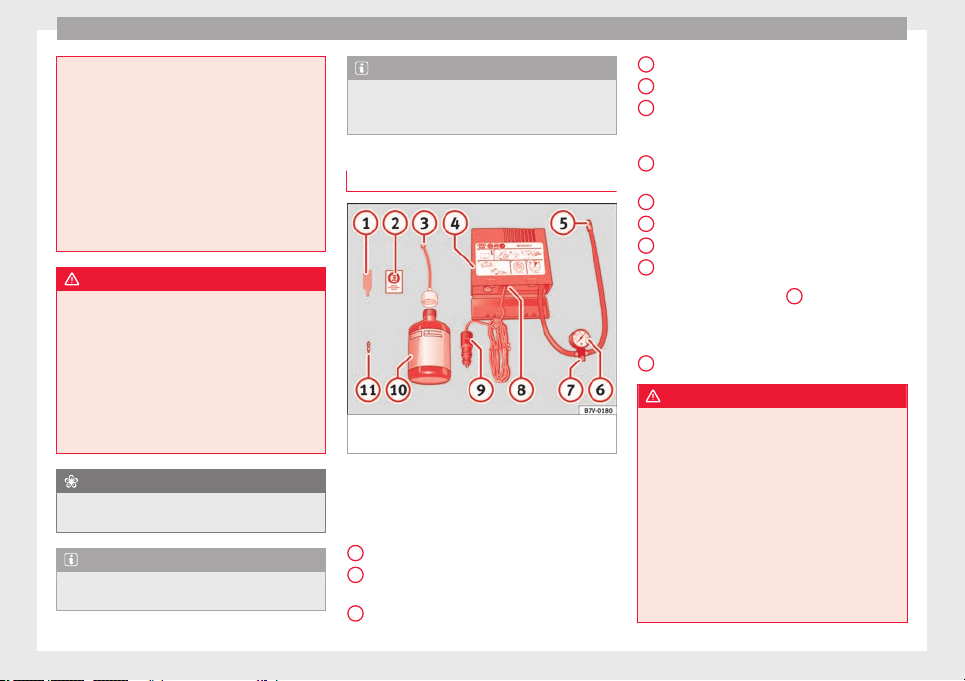
Emergencies
●
The seal
ant is a health hazard and must be
cleaned immediately if it comes into contact
with the skin.
●
Always keep the tyre mobility set out of the
reach of small children.
●
Never use an equivalent jack, even if it has
been approved for your vehicle.
●
Always stop the engine, apply the hand-
brake lever firmly and engage gear if using a
manual gearbox, in order to reduce the risk of
vehicle involuntary movement.
WARNING
A tyre filled with sealant does not have the
same perf
ormance properties as a conven-
tional tyre.
●
Never drive faster than 80 km/h (50 mph).
●
Avoid heavy acceleration, hard braking and
fast cornering.
●
Drive for only 10 minutes at a maximum
speed of 80 km/h (50 mph) and then check
the tyre.
For the sake of the environment
Dispose of used or expired sealant observing
any l
egal requirements.
Note
A new bottle of sealant can be purchased at
SEAT de
alerships.
Note
Take into account the separate instruction
manual
of the tyre mobility set* manufactur-
er.
Contents of the tyre mobility system*
Fig. 97 Standard representation: contents of
the anti-p
u
nct
ure kit.
The anti-puncture kit is located underneath
the floor c
o
v
ering in the luggage compart-
ment. It includes the following components
››› Fig. 97:
Tyre valve remover
Sticker indicating maximum speed “max.
80 km/h” or “max. 50 mph”
Filler tube with cap
1
2
3
Air compressor
T
ube f
or infl
ating tyres
Warning provided by tyre pressure moni-
toring system (it can also be integrated in
the compressor).
Air bleed screw (in its place, the compres-
sor may have a button).
ON/OFF switch
12 volt connector
Bottle of sealant
Spare tyre valve
The valve insert remover
1
has a gap at the
lo
w
er end f
or a valve insert. The valve insert
can only be screwed or unscrewed in this
way. This also applies to its replacement part
11
.
WARNING
When inflating the wheel, the air compressor
and the inflator t
ube may become hot.
●
Protect hands and skin from hot parts.
●
Do not place the hot flexible inflator tube or
hot air compressor on flammable material.
●
Allow them to cool before storing the de-
vice.
●
If it is not possible to inflate the tyre to at
least 2.0 bars (29 psi / 200 kPa), the tyre is
too badly damaged. The sealant is not in a
good condition to seal the tyre. Do not con-
tinue driving. Seek specialist assistance.
4
5
6
7
8
9
10
11
96
Self-help
CAUTION
Switch off the air compressor after a maxi-
mum of 8 operation
al minutes to avoid over-
heating! Before switching on the air compres-
sor again, let it cool for several minutes.
Check after 10 minutes of driving
Screw the inflator tube ›››
Fig. 97
5
again
and check
the pressure on the gauge
6
.
1.3 bar (19 ps
i / 130 kPa) and lower:
●
Stop the vehicle! The tyre c
annot be sealed
sufficiently with the tyre mobility set.
●
You should obtain professional assistance
›››
.
1.4 b
ar (20 p
s
i / 140 kPa) and higher:
●
Set the tyre pressure to the correct value
again.
●
Carefully resume your journey until you
reach the nearest specialised workshop with-
out exceeding 80 km/h (50 mph).
●
Have the damaged tyre replaced.
WARNING
Driving with an unsealed tyre is dangerous
and can cau
se accidents and serious injury.
●
Do not continue driving if the tyre pressure
is 1.3 bar (19 psi / 130 kPa) and lower.
●
Seek spec
ialist assistance.
Manual unlocking/locking
Introduction
Read the additional information carefully
›››
page 16, ›››
page 17.
The doors, rear lid and panoramic tilting sun-
roof can be locked manually and partially
opened, for example if the key or the central
locking is damaged.
WARNING
Opening and closing doors carelessly can
cause seriou
s injury.
●
If the vehicle is locked from outside, the
doors and windows cannot be opened from
the inside.
●
Never leave children or disabled people
alone in the car. They could be trapped in the
car in an emergency and will not be able to
get themselves to safety.
●
Depending on the time of the year, temper-
atures inside a locked and closed vehicle can
be extremely high or extremely low resulting
in serious injuries and illness or even death,
particularly for young children.
WARNING
Getting in the way of the doors and the rear
lid is d
angerous and can lead to serious in-
jury.
●
Open and close the doors and the rear lid
only when there is nobody in the way.
CAUTION
When opening and closing in an emergency,
caref
ully disassemble components and then
reassemble them carefully to avoid damage
to the vehicle.
Changing the windscreen wiper
b
l
a
des
Changing the windscreen and rear
window wiper blades
Read the additional information carefully
›
›
›
page 71.
The windscreen wiper blades are supplied as
standard with a layer of graphite. This layer is
responsible for ensuring that the wipe is si-
lent. If the graphite layer is damaged, the
noise of the water as it is wiped across the
windscreen will be louder.
Check the condition of the wiper blades regu-
larly. If the wipers scrape across the glass,
»
97
Technical dataAdviceOperationEmergenciesSafety
Emergencies
they should be changed if they are damaged,
or c
l
e
aned if they are dirty ›››
.
Dam
ag
ed w
indscreen wiper blades should be
replaced immediately. These are available
from qualified workshops.
WARNING
Worn or dirty windscreen wiper blades reduce
vis
ibility and increase the risk of accident
and serious injury.
●
Always replace damaged or worn wind-
screen wiper blades or blades that no longer
clean the windscreen properly.
CAUTION
●
Damaged or dir
ty windscreen wipers could
scratch the glass.
●
If products containing solvents, rough
sponges or sharp objects are used to clean
the blades, the graphite layer will be dam-
aged.
●
Never use fuel, nail varnish remover, paint
thinner or similar products to clean the win-
dows.
●
In icy conditions, always check that the
wiper blades are not frozen to the glass be-
fore using the wipers. In cold weather, it may
help to leave the vehicle parked with the wip-
ers in service position ›››
page 71.
CAUTION
●
To prev
ent damage to the bonnet and the
wiper arms, only leave them in the service
position.
●
Before driving, always lower the wiper
arms.
Tow-starting and towing
Introduction
Tow-starting me
an
s
starting the engine of
the vehicle while another pulls it.
Towing means one vehicle pulling another
that is not roadworthy.
Always consider the legal provisions relating
to tow-starting and towing.
For technical reasons, towing a vehicle with a
discharged battery is not allowed. The jump
start should be used instead
›››
page 69.
If the vehicle comes with the Keyless Access
system, towing is only allowed with the igni-
tion on!
The vehicle battery drains if the vehicle is
towed with the engine switched off and the
ignition connected. Depending on the battery
charge status, the drop in voltage may be so
large, even after just a few minutes, that no
electrical device in the vehicle may work e.g.
the hazard warning lights. In vehicles with
the Keyless Access system, the steering
wheel could lock ›››
.
WARNING
A vehicle with no power should never be tow-
ed.
●
During towing, never switch off the ignition
with the st
arter button. Otherwise, the elec-
tronic lock of the steering column could sud-
denly get blocked and it would be impossible
to steer the vehicle. This could cause an acci-
dent, serious injury and loss of control of the
vehicle.
●
If during towing the vehicle runs out of
power, stop towing immediately and request
the assistance of specialist personnel.
WARNING
Vehicle handling and braking capacity
chan
ge considerably during towing. Please
observe the following instructions to mini-
mise the risk of serious accidents and injury:
●
As the driver of the vehicle being towed:
–
You should depress the brake much hard-
er as the brake servo does not operate.
Pay the utmost attention to avoid crash-
ing into the towing vehicle.
–
More strength is required at the steering
wheel as the power steering does not op-
erate when the engine is switched off.
●
As the driver of the towing vehicle:
98
Self-help
–
Acc
elerate with particular care and cau-
tion.
–
Avoid sudden braking and manoeuvres.
–
Brake earlier than usual and more
smoothly.
CAUTION
●
T
o avoid d
amaging the vehicle, for example
the paint, remove and replace the lid and
towing eye carefully.
●
Unburnt fuel could enter the catalytic con-
verter and damage it during towing.
Indications for tow-starting
Vehicle's should not generally be tow-star-
t
ed.
The jump s
tart should be used instead
›››
page 69.
For technical reasons, towing the following
vehicles is not allowed:
●
Vehicles with an automatic gearbox.
●
If the vehicle battery is discharged, be-
cause in vehicles with the Keyless Access
locking and ignition system the steering re-
mains locked and the electronic parking
brake cannot be deactivated nor can the elec-
tronic lock of the steering column be re-
leased if they are activated.
●
If the battery is flat, it is possible that the
engine control units may not operate correct-
ly.
However, if the vehicle must absolutely be
tow-started (in the case of manual gearbox-
es):
●
Engage the 2nd or 3rd gear.
●
Keep the clutch pressed down.
●
Switch on the ignition and the hazard warn-
ing lights.
●
Once both vehicles are moving, release the
clutch.
●
Once the engine starts, press the clutch
and disengage the gear to avoid colliding
with the towing vehicle.
CAUTION
When tow-starting, unburnt fuel could enter
the cata
lytic converter and damage it.
Note
The vehicle can only be tow-started if the
electronic
parking brake and, if appropriate,
the electronic lock of the steering column are
deactivated. If the vehicle has no power sup-
ply or there is an electric system fault, the
engine must be tow-started to deactivate the
electronic parking brake and the electronic
lock of the steering column.
Indications for towing
Tow rope or tow bar
It is
safer for the vehicle to be towed using a
tow bar, avoiding damage to the vehicle. A
tow rope should only be used if a tow bar is
not available.
A tow rope should be slightly elastic to avoid
damage to both vehicles. It is advisable to
use a tow rope made of synthetic fibre or sim-
ilarly elastic material.
Only attach the tow rope or the tow bar to the
towing eyes provided or a towing bracket.
If the vehicle is factory-equipped with a tow-
ing bracket, it is only allowed to tow with a
tow bar if this has been specially designed to
be installed with a tow hitch
›››
page 276.
When the vehicle needs to be towed:
Check whether the vehicle may be towed
›››
page 100, Cases where towing a vehicle
is not allowed.
●
Switch the ignition on.
●
Put the gearbox lever in neutral or the se-
lector l
ever in the N
›››
page 192 position.
●
Do not allow the vehicle to be towed at
speeds of over 50 km/h (30 mph).
●
The vehicle must not be towed further than
50 km (30 mile
s).
»
99
Technical dataAdviceOperationEmergenciesSafety
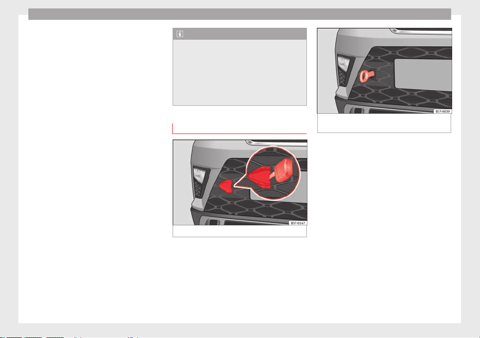
Emergencies
●
If
a br
e
akdown lorry is used, vehicles with
automatic transmission are only allowed to
be towed with the front wheels suspended.
Towing vehicles with four-wheel drive
(4Drive)
Four-wheel drive vehicles (4Drive) can be
towed using a tow bar or tow rope. If the ve-
hicle is towed with the front or rear axle sus-
pended, the engine must be switched off,
otherwise the transmission may be damaged.
Cases where towing a vehicle is not allowed
●
If, due to a fault, the gearbox is out of lubri-
cant.
●
If the vehicle battery is discharged, be-
cause the steering remains locked and, if ap-
propriate, the electronic parking brake can-
not be deactivated or the electronic lock of
the steering column released.
●
If a distance above 50 km needs to be trav-
elled.
●
When, for example, after an accident, the
smooth rotation of the wheels or the steering
operation cannot be guaranteed.
When the vehicle is to tow another vehicle:
●
Observe legal requirements.
●
Keep in mind the instructions in the man-
ual on towing vehicles.
Note
The vehicle can only be towed if the electron-
ic park
ing brake and the electronic lock of the
steering column are deactivated. If the vehi-
cle has no power supply or there is an electric
system fault, the engine must be tow-started
›››
page 69 to deactivate the electronic
parking brake and the electronic lock of the
steering column.
Fitting the front towing eye
Fig. 98 Front bumper on right: remove the lid.
Fig. 99 Front bumper on right: towline an-
chorag
e screwed in.
The housing of the screw towing eye is on the
right
s
ide of
the front bumper behind a lid
››› Fig. 98.
The towing eye should always be kept in the
vehicle.
Bear in mind the instructions for towing
››› page 99.
Fitting the towline anchorage
●
Remove the towing eye from the vehicle
tool kit in the luggage compartment
››› page 95.
●
Extract the lid for the towing eye using the
vehicle key blade (if you do not have the spe-
cific tool), pressing on the side and levering
gently from left to right.
●
Remove the lid and let it hang from the ve-
hicle.
100
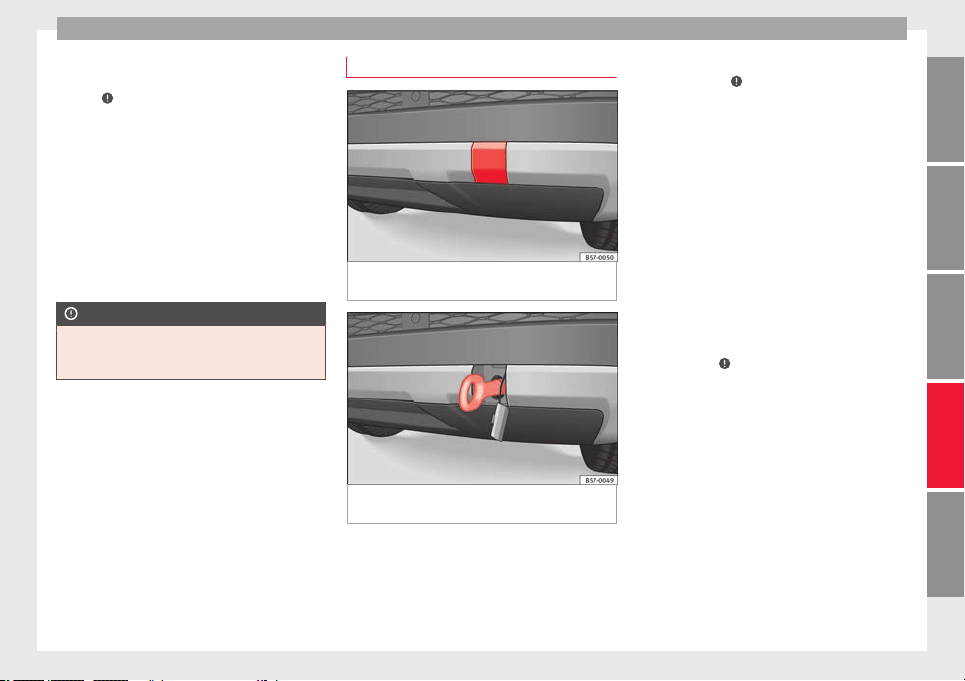
Self-help
●
Sc
r
ew the t
owing eye in the housing by
turning it to the maximum anticlock-
wise ›››
. Use a suitable object that can
c
omp
l
etely and securely tighten the towing
eye in its housing.
●
After towing, unscrew the towing eye clock-
wise with a suitable object.
●
Insert the side tab of the lid into the open-
ing of the bumper and press until the tab is
properly clipped into the bumper.
●
Clean the towing eye if necessary and then
store it in the luggage compartment along
with the other vehicle tools.
CAUTION
The towing eye must always be completely
and firmly tight
ened. Otherwise, it could be
released while towing and tow-starting.
Fitting the rear towing eye
Fig. 100 Rear bumper on right: remove the
lid.
Fig. 101 Rear bumper on right: towline an-
c
hor
ag
e screwed in.
The housing of the screw towing eye is on the
right
s
ide of
the rear bumper behind a lid
››› Fig. 100. Vehicles equipped as standard
with a towing bracket do not have any hous-
ing for the screw towing eye behind the lid. In
this case, the tow hitch needs to be extracted
or installed and used for towing
››› page 273, ›››
.
B
e
ar in mind the in
structions for towing
››› page 99.
Assemble the rear towing eye (cars without a
factory-equipped towing bracket)
●
Remove the towing eye from the vehicle
tool kit in the luggage compartment
››› page 95.
●
Press the upper side of the lid ››› Fig. 100 to
unclip it.
●
Remove the lid and let it hang from the ve-
hicle.
●
Screw the towing eye in the housing by
turning it to the maximum anticlockwise
››› Fig. 101 ›››
. Use a suitable object that
c
an c
omp
letely and securely tighten the tow-
ing eye in its housing.
●
After towing, unscrew the towing eye clock-
wise with a suitable object.
●
Insert the upper flange of the lid into the
opening of the bumper and press the lower
side of the lid until the upper flange is inser-
ted into the bumper.
●
Clean the towing eye if necessary and then
store it in the luggage compartment along
with the other vehicle tools.
»
101
Technical dataAdviceOperationEmergenciesSafety
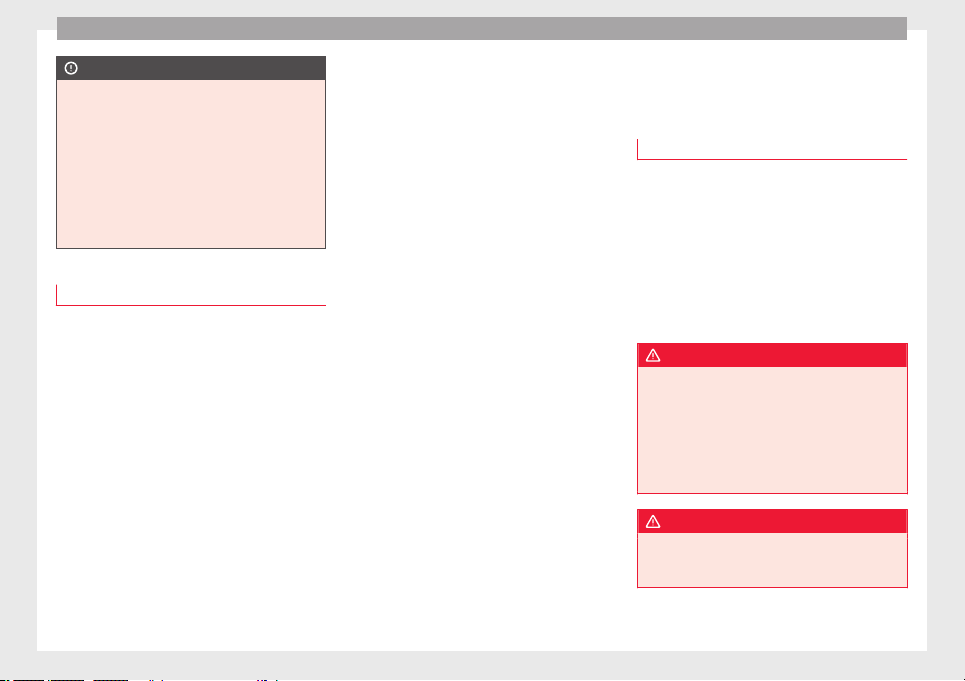
Emergencies
CAUTION
●
The tow
ing eye must always be completely
and firmly tightened. Otherwise, it could be
released while towing and tow-starting.
●
If the vehicle is factory-equipped with a
towing bracket, it is only allowed to tow with
a tow bar if this has been specially designed
to be installed with a tow hitch. If an unsuita-
ble tow bar is used, both the tow hitch and
the vehicle may be damaged. Instead, a tow
rope should be used.
Driving tips for towing
Towing requires some expertise and experi-
enc
e, e
s
pecially when using a tow rope. Both
drivers should be familiar with the difficulties
involved in towing. For this reason, inexper-
ienced drivers should abstain from towing.
During towing, it should be ensured that no
impermissible tractive forces or shocks are
generated. When towing on an unpaved
road, there is always a risk of overloading
and damaging the anchorage points.
During towing, the towing vehicle can signal
the change of direction even with the hazard
warning lights turned on. To do so, at the
same time, the turn signal lever must be op-
erated with ignition switched on. Meanwhile,
the hazard warning lights will go off. When
the turn signal lever is returned to the rest
position, the hazard warning lights will be
automatically reactivated.
Notes for the driver of the towed vehicle
●
Leave the ignition on, so that the steering
is not blocked, and the electronic parking
brake may be deactivated and the turn sig-
nals and wash/wipe operated.
●
More strength is required at the steering
wheel as the power steering does not oper-
ate when the engine is switched off.
●
You should depress the brake much harder
as the brake servo does not operate. Avoid
hitting the towing vehicle.
●
Bear in mind the information and instruc-
tions in the manual of the vehicle to be tow-
ed.
Notes for the driver of the towing vehicle
●
Accelerate with particular care and caution.
Avoid sharp manoeuvres.
●
Brake earlier than usual and smoothly.
●
Bear in mind the information and instruc-
tions in the manual of the towed vehicle.
Fuses and bulbs
F
u
se
s
Introduction
In general, a fuse can be assigned to various
electrical
components. Likewise, an electrical
component can be protected by several
fuses.
Only replace fuses when the cause of the
problem has been solved. If a newly inserted
fuse blows after a short time, you must have
the electrical system checked by a special-
ised workshop as soon as possible.
WARNING
The high voltages in the electrical system can
give serious
electrical shocks, causing burns
and even death!
●
Never touch the electrical wiring of the igni-
tion system.
●
Take care not to cause short circuits in the
electrical system.
WARNING
Using unsuitable fuses, repairing fuses or
bridging a curr
ent circuit without fuses can
cause a fire and serious injury.
102
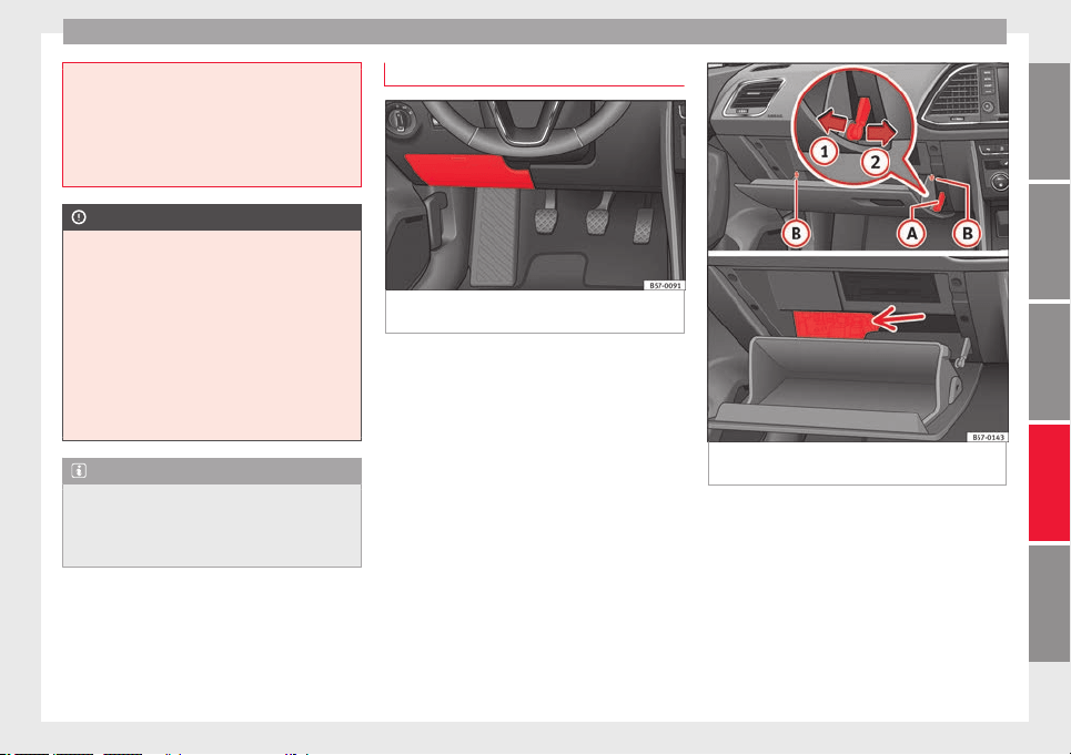
Fuses and bulbs
●
Never use a f
use with a higher value. Only
replace fuses with a fuse of the same amper-
age (same colour and markings) and size.
●
Never repair a fuse.
●
Never replace a fuse by a metal strip, staple
or similar.
CAUTION
●
T
o prev
ent damage to the vehicle's electric
system, before replacing a fuse always turn
off the ignition, the lights and all electrical
elements and remove the key from the igni-
tion.
●
If you replace a fuse with higher-rating
fuse, you could cause damage to another part
of the electrical system.
●
Protect the fuse boxes when open to pre-
vent the entry of dust or humidity as they can
damage the electrical system.
Note
●
One component m
ay have more than one
fuse.
●
Several components may run on a single
fuse.
Vehicle interior fuses
Fig. 102 On the driver-side dash panel (left-
h
and driv
e): f
use box cover.
Fig. 103 Glove compartment (right-hand
driv
e): A
c
cess to the fuse box.
Opening and closing the fuse box situated
belo
w the d
a
sh panel (left-hand drive)
●
Opening: fold the cover down ››› Fig. 102.
●
Closing: push back the cover it in until it
clicks into place.
Fuses behind the glove compartment (right-
hand drive)
To be able to access the fuse box:
»
103
Technical dataAdviceOperationEmergenciesSafety
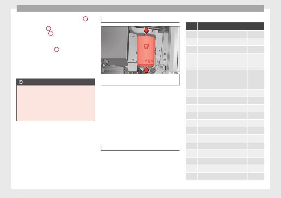
Emergencies
●
Undo the openin
g limit
er ›
›› Fig. 103
A
in
tw
o s
t
eps: first, unlock the limiter by pulling
back on it (arrow
1
) and then move it gently
t
o the right
(arr
ow
2
). Remove the guide
when the c
o
v
er is in the normal opening po-
sition (30°).
●
Free the side pivots
B
to release the cover
t
o its
sec
ond opening position (60°).
Follow the same procedure in reverse order to
return the glove compartment to its normal
position.
CAUTION
●
Alwa
ys carefully remove the fuse box cov-
ers and refit them correctly to avoid problems
with your vehicle.
●
Protect the fuse boxes when open to avoid
the entry of dust or humidity. Dirt and humid-
ity inside fuse boxes can cause damage to
the electrical system.
Engine compartment fuses
Fig. 104 In the engine compartment: fuse box
c
o
v
er.
To open the engine compartment fuse box
●
Open the bonnet ›
›
›
page 298.
●
Press the locking tabs to release the fuse
box cover ››› Fig. 104.
●
Then lift the cover out.
●
To fit the cover, place it on the fuse box.
Push the locking tabs down until they click
audibly into place.
Fuse placement
Read the additional information carefully
›
›
›
page 61
Only replace fuses with a fuse of the same
amperage (same colour and markings) and
size.
Fuses in the vehicle interior
No. Consumers/Amps
1 Adblue (SCR) 30
5 Gateway 5
6 Automatic gearbox lever 5
7
Air conditioning and heating con-
trol panel, back window heating,
auxiliary heating.
10
8
Diagnosis, handbrake switch,
light switch, reverse light, interior
lighting, driving mode, lit-up door
sill
10
9 Steering column 5
10 Radio display 7.5
11 Left lights 40
12 Radio 20
14 Air conditioner fan 40
15 Steering column release 10
16 Connectivity Box. 7.5
17 Instrument panel 7.5
18 Rear camera 7.5
19 Kessy 7.5
21 4x4 Haldex Control Unit 15
22 Trailer 15
104
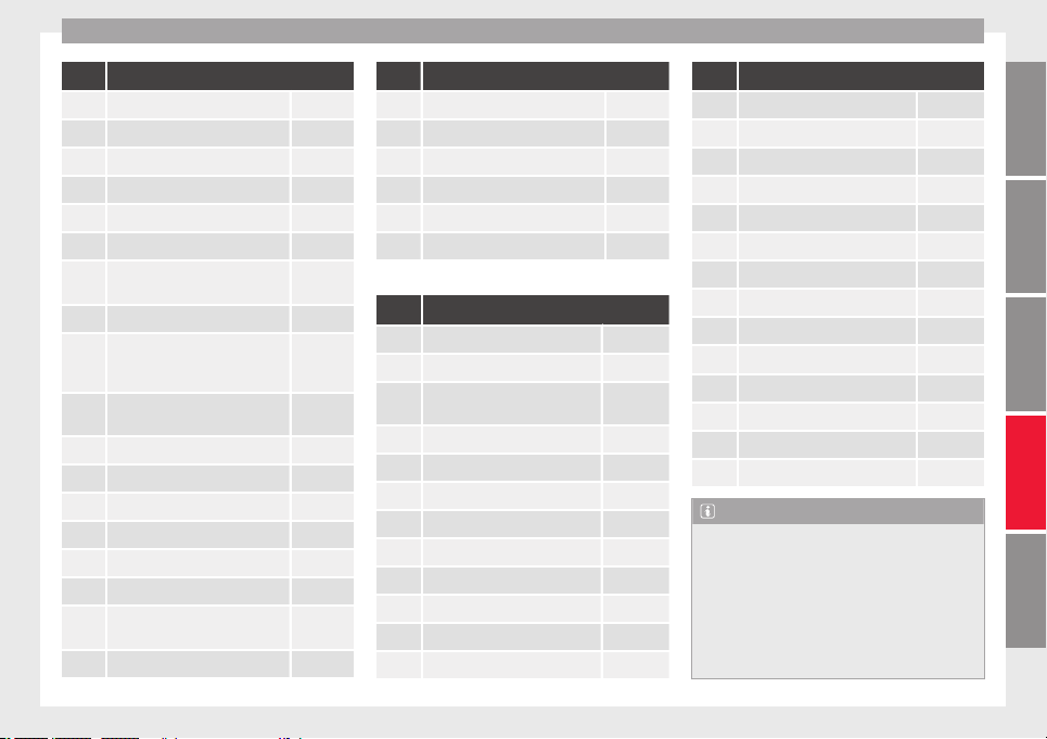
Fuses and bulbs
No. Consumers/Amps
23 Electric sunroof 30
24 Right lights 40
25 Left door 30
26 Heated seats 30
27 Interior light 30
28 Trailer 25
32
Control unit for parking aid, front
camera and radar
7.5/10
33 Airbag 5
34
Reverse switch, climate sensor,
electrochromic mirror, rear power
sockets (USB)
7.5
35
Diagnosis, headlight control unit,
headlight adjuster
10
36 Right LED headlight 7.5
37 Left LED headlight 7.5
38 Trailer 25
39 Right door 30
40 12V socket 20
42 Central locking 40
43
SEAT Sound, beats sound CAN
and MOST.
30
44 Trailer 15
No. Consumers/Amps
45 Electric driver's seat 15
47 Rear window wiper 15
49 Starter motor; clutch sensor 5
50 Electric rear lid 40
52 Driving mode. 15
53 Heated rear window 30
Fuse arrangement in engine compartment
No. Consumers/Amps
1 ESP control unit 25
2 ESP control unit 40
3
Engine control unit (diesel/pet-
rol)
30/15
4 Engine sensors 5/10
5 Engine sensors 7.5
6 Brake light sensor 5
7 Engine power supply 10
8 Lambda probe 10/15
9 Engine 5/10/20
10 Fuel pump control unit 15/20
11 PTC 40
12 PTC 40
No. Consumers/Amps
13 Automatic gearbox control unit 15/30
14 Heated windscreen 40
15 Horn 15
16 Petrol pump 5/15/20
17 Engine control unit 7.5
18 Terminal 30 (positive reference) 5
19 Front windscreen washer 30
20 Alarm horn 10
22 Engine control unit 5
23 Starter motor 30
24 PTC 40
31 Pressure pump 15
33 Gearbox pump 30
37 Parking heating 20
Note
●
In the vehic
le, there are more fuses than
those indicated in this chapter. These should
only be changed by a specialised workshop.
●
Positions not containing a fuse do not ap-
pear in the following tables.
●
Some of the equipment listed in the tables
below pertain only to certain versions of the
model or are optional extras.
»
105
Technical dataAdviceOperationEmergenciesSafety
Emergencies
●
Plea
se note that the above lists, while cor-
rect at the time of printing, are subject to
change.
Changing a bulb
Topic intr
oduction
Read the additional information carefully
›››
page 62.
Changing bulbs requires a certain degree of
practical skill.
If you choose to change the engine compart-
ment lamps yourself, remember that it is a
dangerous area ›››
in Working in the en-
gine c
omp
ar
tment on page 299.
Always use identical bulbs with the same
designation. The name can be found on the
base of the bulb holder.
Depending on how equipped the vehicle is,
there are different sets of headlights and tail
lights:
●
Halogen headlights.
●
Full-LED main headlights*
●
Rear bulb light
●
LED rear light*
Full-LED headlight system*
Full-LED headlights handle all light functions
(daylight, side light, turn signal, dipped
beam and route light) with light emitting di-
odes (LEDs) as a light source.
Full-LED headlights are designed to last the
lifetime of the car and light bulbs cannot be
replaced. In case of headlight failure, go to
an authorised workshop to have it replaced.
WARNING
●
Take p
articular care when working on com-
ponents in the engine compartment if the en-
gine is warm. Risk of burns.
●
Bulbs are highly sensitive to pressure. The
glass can break when you touch the bulb,
causing injury.
●
When changing bulbs, please take care not
to injure yourself on sharp edges, in particu-
lar on the headlight housing.
CAUTION
●
Remov
e the ignition key before working on
the electric system. Otherwise, a short circuit
could occur.
●
Switch off the lights and the parking light
before changing a bulb.
●
Take good care to avoid damaging any com-
ponents.
For the sake of the environment
Please ask your specialist retailer how to dis-
pose of u
sed bulbs in the proper manner.
Note
●
Plea
se check at regular intervals that all
lighting (especially the exterior lighting) on
your vehicle is functioning properly. This is
not only in the interest of your own safety,
but also that of all other road users.
●
Before changing a bulb, make sure you
have the correct new bulb.
●
Do not touch the glass part of the bulb with
your bare hands, use a cloth or paper towel
instead, since the fingerprints left on the
glass will vaporise as a result of the heat gen-
erated by the bulb, they will be deposited on
the reflector and will impair its surface.
●
Depending on the level of equipment fitted
in the vehicle, LEDs may be used for part or
all of the interior and/or exterior lighting.
LEDs have an estimated life that exceeds than
that of the car. If an LED light fails, go to an
authorised workshop for its replacement.
106
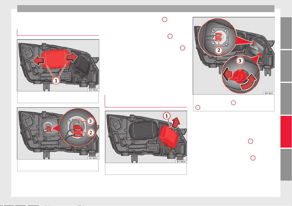
Fuses and bulbs
Change the front bulbs
Dip
ped be
am he
adlight
Fig. 105 In the engine compartment: remove
the lid.
Fig. 106 In the engine compartment: dipped
be
am he
a
dlight.
Follow the steps indicated:
R
ai
se the bonnet
.1.
Move the loops ››› Fig. 105
1
in the di-
r
ection of
the arr
ow and remove the cov-
er.
Remove connector ››› Fig. 106
2
from
the b
u
l
b.
Unclip the retainer spring ››› Fig. 106
3
pressing clockwise and inwards.
Extr
act
the b
ulb and fit the replacement
so that the lug on the base fits into the
recess on the reflector.
Installation involves all of the above
steps in reverse sequence.
Main beam headlight bulb and turn
signal bulb
Fig. 107 In the engine compartment: remove
the lid.
2.
3.
4.
5.
6.
Fig. 108 In the engine compartment: main
be
am he
a
dlight bulb
2
and turn signal bulb
3
.
Follow the steps indicated:
M
ain be
am he
adlight bulb
Raise the bonnet.
Move the loop ››› Fig. 107
1
in the di-
r
ection of
the arr
ow and remove the cov-
er.
Slide connector ››› Fig. 108
2
to the left
or right
and p
u
ll.
Remove the bulb by disconnecting the
connector.
Installation involves all of the above
steps in reverse sequence.
»
1.
2.
3.
4.
5.
107
Technical dataAdviceOperationEmergenciesSafety
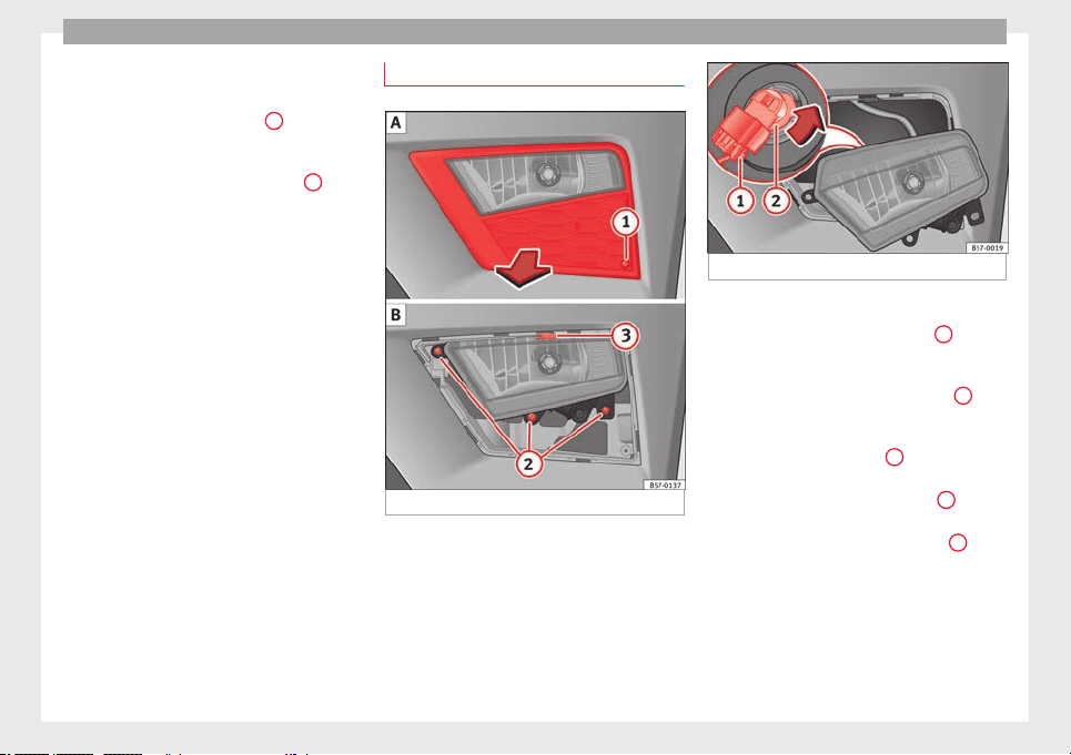
Emergencies
Turn signal bulb
R
ai
se the bonnet
.
Move the loop ››› Fig. 107
1
in the di-
r
ection of
the arr
ow and remove the cov-
er.
Turn the bulb holder ››› Fig. 108
3
anti-
c
loc
k
wise and pull.
Remove the bulb by pressing on the
bulb holder and turning it anticlockwise
at the same time.
Installation involves all of the above
steps in reverse sequence.
1.
2.
3.
4.
5.
Front fog light bulb*
Fig. 109 Fog light: extracting the grille.
Fig. 110 Fog light: remove the bulb holder
Follow the steps indicated:
R
emo
v
e the screw ››› Fig. 109
1
fr
om
the f
og light
grille using a screwdriver
and extract the grille.
Remove the 3 screws ››› Fig. 109
2
.
R
emo
v
e the metal clip situated on the
upper part of the fog light by pulling
away from the vehicle
3
and e
xtract
the f
og light
.
Remove connector
›››
Fig. 110
1
from
the b
u
l
b.
Turn the bulb holder
›››
Fig. 110
2
anti-
c
loc
k
wise and pull.
Remove the bulb by pressing on the
bulb holder and turning it anticlockwise
at the same time.
Installation involves all of the above
steps in reverse sequence.
Check that the bulb works properly.
1.
2.
3.
4.
5.
6.
7.
8.
108
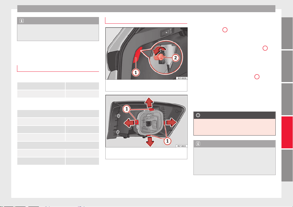
Fuses and bulbs
Note
Due to the difficulty of accessing fog light
bul
bs, have them replaced at a Technical
Service or specialised workshop.
Change the rear bulbs
Overv
iew of tail lights
Tail lights on side panel
Turn signal PY21W NA LL
Side light and brake light P21W LL
Tail lights on the rear lid
Left side
Side lights P21W LL
Fog light/side light P21W LL
Reverse light W16W
Right side
Side lights 2 x P21W LL
Reverse light W16W
The table corresponds to a right-hand traffic
v
ehic
l
e. The position of lights may vary ac-
cording to the country.
Rear bulbs (in the side panel)
Fig. 111 Luggage compartment: access to the
bo
lt
sec
uring the tail light unit.
Fig. 112 Retaining tabs on reverse side of tail
light
.
Follow the steps indicated:
Chec
k
whic
h of the bulbs is defective.
Open the rear lid.
1.
2.
Remove the lid, levering it with the flat
side of a screwdriver into the recess
››› Fig. 111
1
.
R
emo
v
e the bulb connector.
Unscrew the light securing bolt by hand
or using a screwdriver ››› Fig. 111
2
.
R
emo
v
e the light from the body, gently
pulling it toward you, and place on a
clean, smooth surface.
Disassemble the bulb holder unlocking
the securing tabs ››› Fig. 112
1
.
Ch
an
g
e the damaged bulb.
To refit follow the steps in reverse order,
taking special care when fitting the bulb
holder. The securing tabs must click into
place.
CAUTION
Take care when removing the rear light unit to
make s
ure there is no damage to the paint-
work or any of its components.
Note
●
Make s
ure you have a soft cloth ready to
place under the glass on the rear light unit, to
avoid any scratches.
●
In the case of LED lights, change only the
turn signal bulb.
3.
4.
5.
6.
7.
8.
9.
109
Technical dataAdviceOperationEmergenciesSafety
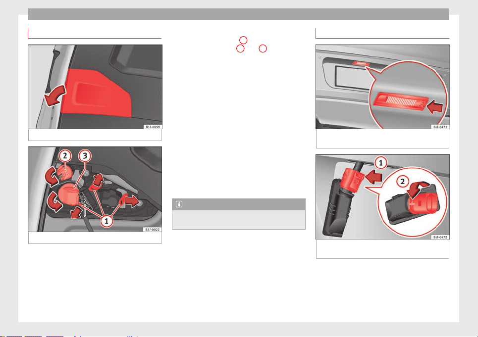
Emergencies
Rear lights (in the rear lid)
Fig. 113 Rear lid open: remove the lid.
Fig. 114 Remove the bulb holder.
The rear lid must be open to change the
b
u
l
bs.
Follow the steps indicated:
Remove the rear lid cover in the direc-
tion indicated ››› Fig. 113.
1.
Unlock the securing tabs from the bulb
holder ››› Fig. 114
1
or turn the bulb
ho
l
der t
o the left
2
and
3
.
R
emo
v
e the bulb holder from its loca-
tion.
Lightly press the defective bulb into the
bulb holder, then turn it to the left and
remove it.
Fit the new bulb, pressing it into the
bulb holder and turn it to the right as far
as it will go.
Use a cloth to remove any fingerprints
from the glass part of the bulb.
Check that the new bulb works properly.
Carry out the same actions in reverse or-
der for assembly and pay special atten-
tion to placing the bulb holder, ensuring
that the tabs are properly secured.
Note
For LED pilots, you can only change the re-
verse b
ulb.
2.
3.
4.
5.
6.
7.
8.
Changing number plate light bulbs
Fig. 115 In the rear bumper: number plate
light
.
Fig. 116 Number plate light: Remove the bulb
ho
l
der
.
Follow the steps indicated:
Pr
e
s
s the number plate light in the direc-
tion of the arrow ››› Fig. 115.
Remove the number plate light.
1.
2.
110
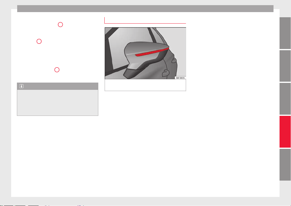
Fuses and bulbs
Turn the connector lock ›
›
›
Fig. 116 in the
direction of arrow
1
and pull on the
c
onnect
or
.
Rotate the bulb holder in the direction of
arrow
2
and extract it with the bulb.
R
ep
l
ace the defective bulb with a new
bulb with the same features.
Insert the bulb holder in the number
plate light and turn in the opposite di-
rection of arrow
2
until it stops.
Plug the c
onnect
or int
o the bulb holder.
Note
Depending on how equipped the vehicle is,
the number plat
e lights may be LEDs. LEDs
have an estimated life that exceeds than that
of the car. If a light with LEDs fails, go to an
authorised workshop for replacement.
3.
4.
5.
6.
7.
Side turn signals
Fig. 117 Turn signal integrated in the rear
v
iew mirr
or
The side turn signals are LEDS and are inte-
gr
at
ed in the e
xterior mirrors.
In case of failure, go to an authorised work-
shop to have them replaced.
111
Technical dataAdviceOperationEmergenciesSafety
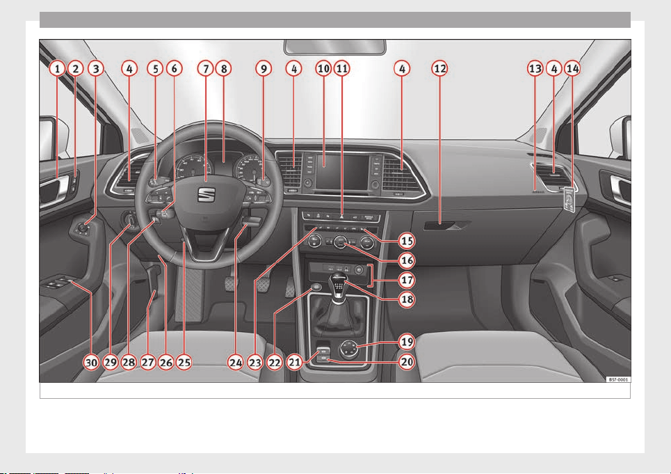
Operation
Fig. 118 Instruments and controls.
112
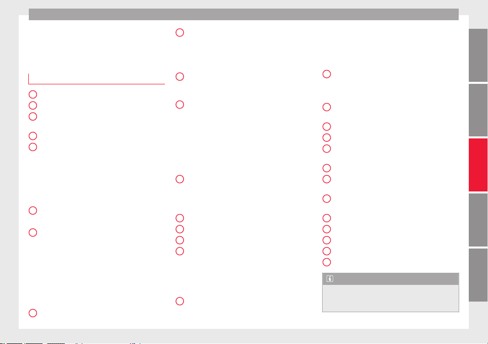
Controls and displays
Operation
C
ontr
o
ls and displays
General instrument panel
Door release lever
Central
locking switch . . . . . . . . . . . . 128
Control for the electric adjustment
of the exterior mirrors . . . . . . . . . . . . . 155
Air outlets . . . . . . . . . . . . . . . . . . . . . . . . 174
Control lever for:
–
Turn sign
als and main beam
headlights . . . . . . . . . . . . . . . . . . . . . 145
–
Lane Assi
st . . . . . . . . . . . . . . . . . . . . . 230
–
Main beam assist . . . . . . . . . . . . . . . 146
–
Cruise control system (CCS) . . . . . 212
Depending on equipment fitted:
–
Lever f
or cruise control . . . . . . . . . . 212
Steering wheel with horn and
–
Driver airbag . . . . . . . . . . . . . . . . . . . 21
–
On-board c
omputer controls . . . . 36
–
Controls for radio, telephone,
navigation and speech dialogue
system
›››
Booklet Radio
–
Paddle levers for tiptronic gear-
shift (automatic gearbox) . . . . . . . 195
Instrument panel . . . . . . . . . . . . . . . . . 114
1
2
3
4
5
6
7
8
Control lever for:
–
W
ind
s
creen wipers and washer . . 153
–
Wipe and wash system . . . . . . . . . . 153
–
On-board computer . . . . . . . . . . . . . 36
Depending on equipment fitted: ra-
dio or display for Easy Connect
(navigation, radio, TV/video) . . . . . . 120
Depending on the equipment, but-
tons for:
–
Start-Stop system . . . . . . . . . . . . . . . 208
–
Park a
ssist system . . . . . . . . . . . . . . 262
–
Hazard warning lights . . . . . . . . . . 149
–
Tyre pressure switch . . . . . . . . . . . . 313
–
Airbag off display . . . . . . . . . . . . . . . 88
Depending on the equipment,
glove c
ompartment with: . . . . . . . . . 161
–
CD pla
yer* and/or SD card*
››› Booklet Radio
Front passenger airbag . . . . . . . . . . . 21
Front passenger airbag switch . . . . 88
Passenger seat heating control . . . . 158
Depending on the equipment, con-
trol
s for:
–
Heating and ventilation system or
manual air conditioner . . . . . . . . . .54, 53
–
Automatic
air conditioner . . . . . . . 51
Depending on the equipment:
–
USB/A
UX
-IN inp
ut . . . . . . . . . . . . . . 123
9
10
11
12
13
14
15
16
17
–
Light
er/po
w
er socket . . . . . . . . . . . 162
–
Connectivity Box/Wireless Charg-
er* . . . . . . . . . . . . . . . . . . . . . . . . . . . . . 123
–
Storage compartment
Gear lever for:
–
Manual gearbox . . . . . . . . . . . . . . . . 192
–
Automatic gearbox . . . . . . . . . . . . . 193
Rotating control(Driving Experience
button) for driving modes . . . . . . . . . 242
Auto Hold switch . . . . . . . . . . . . . . . . . 211
Electronic parking brake switch . . . 186
Starter button (Keyless Access lock-
ing and ignition system) . . . . . . . . . . 183
Driver's seat heating control . . . . . . 158
Ignition lock (vehicles without Key-
less Access) . . . . . . . . . . . . . . . . . . . . . . 181
Steering column adjustment lev-
er . . . . . . . . . . . . . . . . . . . . . . . . . . . . . . . . 20
Knee airbag . . . . . . . . . . . . . . . . . . . . . . 23
Bonnet lock release . . . . . . . . . . . . . . . 299
Headlight range control . . . . . . . . . . . 151
Headlight switch . . . . . . . . . . . . . . . . . 144
Electric windows . . . . . . . . . . . . . . . . . 139
Note
●
Some of the equipment li
sted in this sec-
tion is only fitted on certain models or are op-
tional extras.
»
18
19
20
21
22
23
24
25
26
27
28
29
30
113
Technical dataAdviceOperationEmergenciesSafety
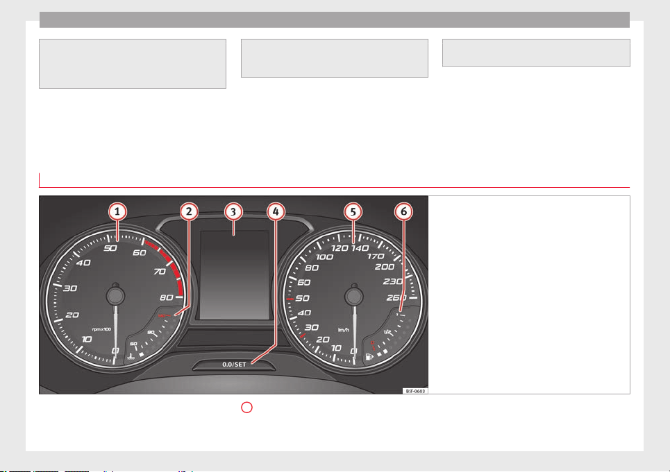
Operation
●
A separat
e Instructions Manual is enclosed
if the vehicle is equipped with a factory-fitted
radio, CD player, AUX IN connection or navi-
gation system.
●
The arrang
ement of switches and controls
on right-hand drive models* may be slightly
different from the layout shown in
››› page 112. However, the symbols used to
identify
the controls are the same.
Instruments and warning/control lamps
Instrument
s
View of instrument panel
Fig. 119 Instrument panel, on dash panel.
Details of the instruments ›
›
›
Fig. 119: Rev counter (with the engine running, in
hundreds of revolutions per minute).
1
The beginning of the red zone of the rev
c
ou
nt
er indicates the maximum speed in
any gear after running-in and with the
114
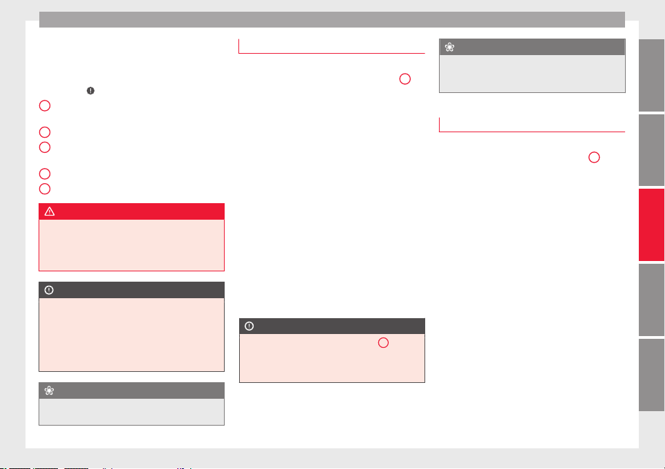
Instruments and warning/control lamps
engine hot. However, it is advisable to
c
h
an
ge up a gear or move the selector
lever to D (or lift your foot off the acceler-
ator) before the needle reaches the red
zone ›››
.
En
gine c
oo
lant temperature display
››› page 117.
Displays on the screen ››› page 115.
Adjuster button and display
››› page 117.
Speedometer.
Fuel gauge ››› page 118.
WARNING
Any distraction may lead to an accident, with
the risk of
injury.
●
Do not operate the instrument panel con-
trols when driving.
CAUTION
●
To prev
ent damage to the engine, the rev
counter needle should only remain in the red
zone for a short period of time.
●
When the engine is cold, avoid high revs
and heavy acceleration and do not make the
engine work hard.
For the sake of the environment
Changing up a gear in time reduces fuel con-
sumption and noise.
2
3
4
5
6
Revolution counter
The rev counter indicates the number of en-
gine revo
lutions per minute ››› Fig. 119
1
.
Together w
ith the gear-change indicator, the
rev counter offers you the possibility of using
the engine of your vehicle at a suitable
speed.
The start of the red zone on the dial indicates
the maximum engine speed which may be
used briefly when the engine is warm and af-
ter it has been run in properly. Before reach-
ing this range, you should change to a higher
gear for vehicles with a manual gearbox or for
automatic gearboxes put the selector lever in
“D” or take your foot off the accelerator ped-
al.
We recommend that you avoid high revs and
that you follow the recommendations on the
gear-change indicator. Consult the additional
information in
›››
page 41, Gear-change
indicator.
CAUTION
Never allow the rev counter needle
1
››› Fig. 119 to go int
o the red zone on the
scale for more than a very brief period, other-
wise there is a risk of engine damage.
For the sake of the environment
Changing up a gear early will help you to save
fuel and minimi
se emissions and engine
noise.
Indications on the display
A variety of information can be viewed on the
instrument
panel display ››› Fig. 119
3
, de-
pending on the v
ehicle equipment:
●
Bonnet, rear lid and doors open
›››
page 40.
●
Warning and information messages
›››
page 40.
●
Distance travelled
›››
page 117.
●
Time
›››
page 116.
●
Navigation instructions.
●
Outside temperature
›››
page 41.
●
Compass
›››
page 116.
●
Shift lever position
›››
page 193.
●
Recommended gear (manual gearbox)
›››
page 41.
●
Multifunction display (MFD) and menus
with different setting options
›››
page 36.
●
Service interval display
›››
page 43.
●
Second speed display
›››
page 116.
●
Speed warning function
›››
page 42.
»
115
Technical dataAdviceOperationEmergenciesSafety

Operation
●
St
ar
t
-Stop system status display
››› page 208.
●
Active cylinder management display
(ACT
®
)* ››› page 202
●
Signs recognised by the traffic signal de-
tection system ››› page 245
●
Low consumption driving status (ECO)
››› page 116
●
Engine code (MKB) ››› page 117.
Distance travelled
The odometer registers the total distance
travelled by the car.
The odometer (trip) shows the distance
travelled since the last odometer reset. The
last digit of the trip recorder indicates distan-
ces of 100 metres or one tenths of a mile.
●
Briefly press the button ››› Fig. 119
4
to re-
set
the trip r
ec
order to 0.
●
Keep the button
4
pressed for about 3
sec
ond
s
and the previous value will be dis-
played.
Time
●
To set the time, keep the button ››› Fig. 119
4
pressed for more than 3 seconds to select
the hour or minut
e di
s
play.
●
To continue setting the time, press the up-
per or lower part of the button
4
. Hold but-
ton down to scroll through the numbers
quic
k
ly
.
●
Press the button
4
again in order to finish
settin
g the time.
The time c
an al
so be set on the Easy Connect
system using the
button and the function
b
utt
on
SETTINGS > Date and time
›››
page 33.
Compass
With the ignition on and the navigation sys-
tem on, the cardinal point corresponding to
the direction of travel of the vehicle is dis-
played on the instrument panel.
Selector lever position
The selected gear is displayed on the side of
the selector lever and on the instrument pan-
el display. In positions D and S, and with the
Tiptronic, the corresponding gear is also dis-
played.
Recommended gear (manual gearbox)
The recommended gear in order to save fuel
is displayed on the instrument panel while
you are driving ›››
page 41.
Second speed display (mph or km/h)
In addition to the speedometer, the speed
can also be displayed in a different unit of
measurement (in miles or in km per hour).
This option cannot be deactivated in models
destined for countries in which the second
speed must always be visible.
The second speed display can be adjusted in
the Easy Connect system by means of the
button and the function button SETTINGS >
Units ›
›
›
page 33.
Speed warning
When the speed setting is exceeded, this will
be indicated on the instrument panel display.
This is very useful, for example when using
winter tyres that are not designed for driving
at the maximum speed of the vehicle
›››
page 42.
The speed warning settings can be adjusted
in the Easy Connect system by means of the
button and the function button SET-
TINGS > Driver Assistance
›
›
›
page 33.
Start-Stop operating display
Updated information relating to the status is
displayed on the instrument panel
››› page 208.
Low consumption driving status (ECO)*
Depending on the equipment, when driving,
the “ECO” display appears on the instrument
panel when the vehicle is in low consump-
tion status due to active cylinder manage-
ment (ACT
®
)* ››› page 202.
116
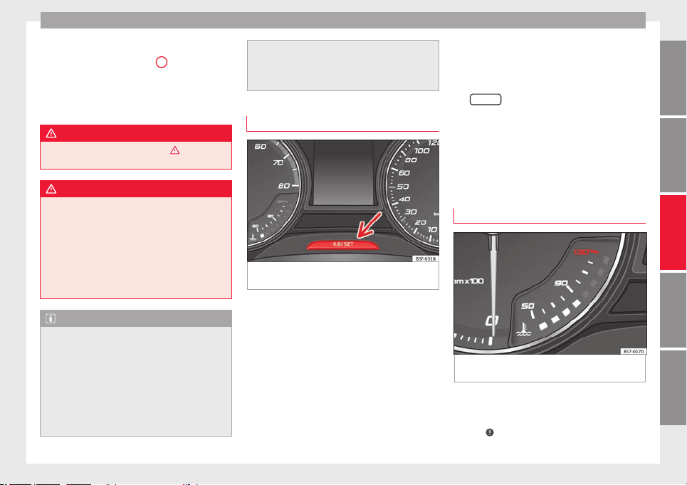
Instruments and warning/control lamps
Identifying letters on engine (MKB)
Ho
l
d the b
utton ››› Fig. 119
4
down for more
th
an 15 sec
ond
s to display the identifying
letters of the vehicle engine (MKB). To do
this, the ignition must be switched on and
the engine switched off.
WARNING
Observe the safety warnings ›››
in Warning
and contro
l lamps on page 119.
WARNING
Even though outside temperatures are above
freezin
g, some roads and bridges may be icy.
●
At outside temperatures above +4°C
(+39°F), even when the “ice crystal” symbol
is not visible, there may still be patches of ice
on the road.
●
The outside temperature sensor takes a
guideline measurement.
Note
●
Different
versions of the instrument panel
are available and therefore the versions and
instructions on the display may vary. In the
case of displays without warning or informa-
tion texts, faults are indicated exclusively by
the warning lamps.
●
Depending on the equipment, some set-
tings and instructions can also be carried out
in the Easy Connect system.
●
When severa
l warnings are active at the
same time, the symbols are shown succes-
sively for a few seconds and will stay on until
the fault is rectified.
Odometer
Fig. 120 Instrument panel: odometer and re-
set
b
utt
on.
The distance covered is displayed in “kilome-
tr
e
s” or mi
les “m”. It is possible to change
the measurement units (kilometres
“km”/miles “m”) in the radio/Easy Connect*.
Please refer to the Easy Connect* Instructions
Manual for more details.
Odometer/trip recorder
The odometer shows the total distance cov-
ered by the vehicle.
The trip recorder shows the distance that has
been travelled since it was last reset. It is
used to measure short trips. The last digit of
the trip recorder indicates distances of 100
metres or tenths of a mile.
The trip recorder can be set to zero by press-
ing
0.0/SET
›
›› Fig. 120
.
F
ault display
If there is a fault in the instrument panel, the
letters DEF will appear in the trip recorder
display. Have the fault repaired immediately,
as far as is possible.
Coolant temperature gauge
Fig. 121 Instrument panel: coolant tempera-
t
ur
e g
auge
For vehicles with no coolant temperature
g
aug
e, a c
ontrol lamp appears for high
coolant temperatures ››› page 302. Please
note ›››
.
»
117
Technical dataAdviceOperationEmergenciesSafety
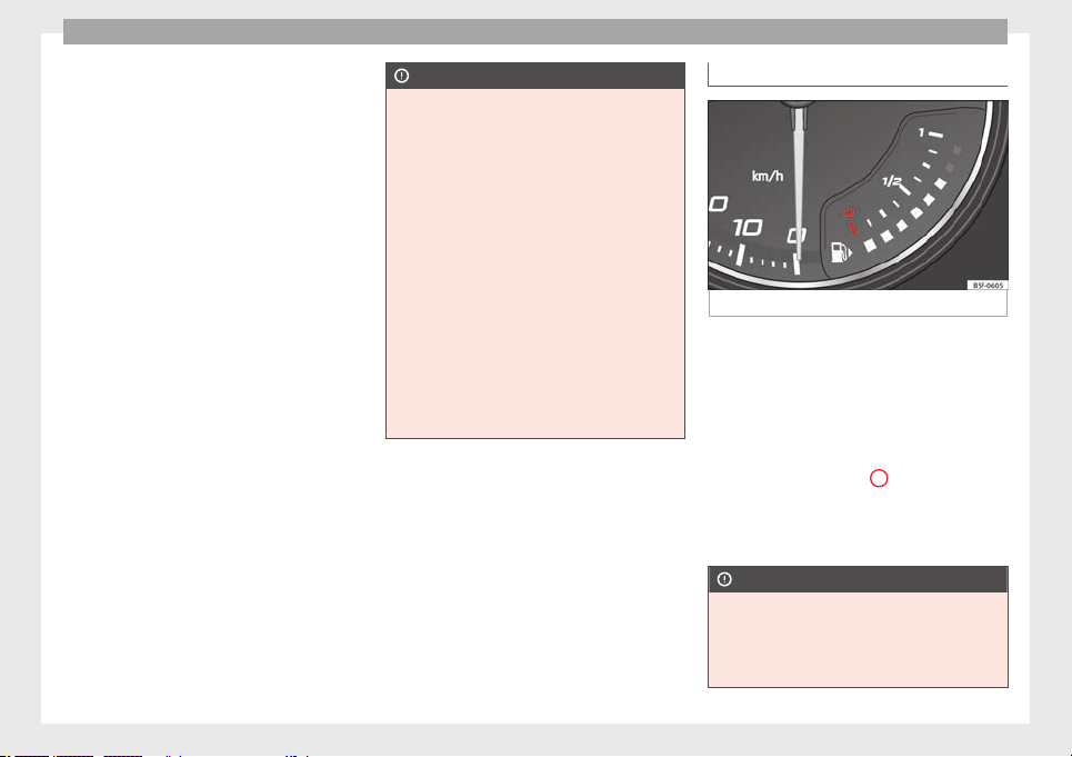
Operation
The coolant temperature gauge only works
when the ignition i
s
sw
itched on ››› Fig. 121.
In order to avoid engine damage, please read
the following notes for the different tempera-
ture ranges.
Engine cold
If only the diodes in the lower part of the
scale light up, this indicates that the engine
has not yet reached operating temperature.
Avoid high revs and heavy acceleration and
do not make the engine work hard.
Normal temperature
If in normal operations, the diodes light up
until the central zone, it means that the en-
gine has reached operating temperature. At
high outside temperatures and when making
the engine work hard, the diodes may contin-
ue lighting up and reach the upper zone. This
is no cause for concern, provided the control
lamp does not light up on the instrument
panel digital display.
Heat range
When the diodes light up in the upper area of
the display and the control lamp appears
on the instrument panel display, the coolant
temperature is excessive ››› page 302.
CAUTION
●
To ens
ure a long useful life for the engine,
avoid high revs, driving at high speed and
making the engine work hard for approxi-
mately the first 15 minutes when the engine
is cold. The phase until the engine is warm al-
so depends on the outside temperature. If
necessary, use the engine oil temperature*
›››
page 42 as a guide.
●
Additional lights and other accessories in
front of the air inlet reduce the cooling effect
of the coolant. At high outside temperatures
and high engine loads, there is a risk of the
engine overheating.
●
The front spoiler also ensures proper distri-
bution of the cooling air when the vehicle is
moving. If the spoiler is damaged this can re-
duce the cooling effect, which could cause
the engine to overheat. Seek specialist assis-
tance.
Fuel level
Fig. 122 Fuel gauge.
The display ›
›
› Fig. 122
only works when the
ignition is switched on. When the display rea-
ches the reserve mark, the lower diode lights
up in red and the control lamp appears
››› page 114. When the fuel level is very low,
the lower diode flashes in red.
The distance to empty fuel level is displayed
on the instrument panel
3
›
›
› Fig. 119
.
The capacity of the fuel tank of your vehicle is
given in the Technical data section
›››
page 56.
CAUTION
Never run the fuel tank completely dry. An ir-
regu
lar fuel supply could cause misfiring. In
this way the unburned fuel can reach the ex-
haust system, which could cause the catalytic
converter to overheat resulting in damage.
118
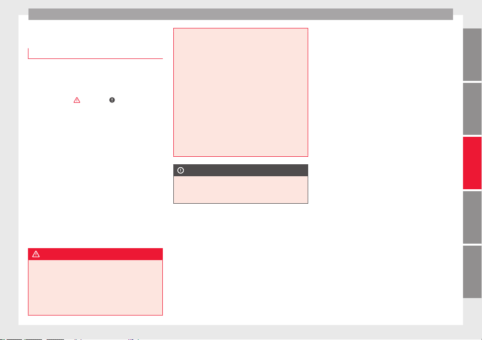
Instruments and warning/control lamps
Control lamps
W
arnin
g and c
ontrol lamps
Read the additional information carefully
›››
page 46.
The control and warning lamps are indicators
of warnings, ›››
, faults ››› or certain func-
tions. Some c
ontrol and warning lamps come
on when the ignition is switched on, and
switch off when the engine starts running, or
while driving.
Depending on the model, additional text
messages may be viewed on the instrument
panel display. These may be purely informa-
tive or they may be advising of the need for
action
›››
page 114, Instruments.
Depending upon the equipment fitted in the
vehicle, instead of a warning lamp, some-
times a symbol may be displayed on the in-
strument panel.
When certain control and warning lamps are
lit, an audible warning is also heard.
WARNING
If the warning lamps and messages are ignor-
ed, the vehic
le may stall in traffic, or may
cause accidents and severe injuries.
●
Never ignore the warning lamps or text
messages.
●
Stop the vehicle safely as soon as possible.
●
Park the
vehicle away from traffic and en-
sure that there are no highly flammable ma-
terials under the vehicle that could come into
contact with the exhaust system (e.g. dry
grass, fuel).
●
A faulty vehicle represents a risk of acci-
dent for the driver and for other road users. If
necessary, switch on the hazard warning
lamps and put out the warning triangle to ad-
vise other drivers.
●
Before opening the bonnet, switch off the
engine and allow it to cool.
●
In any vehicle, the engine compartment is a
hazardous area and could cause severe inju-
ries ››› page 298.
CAUTION
Failure to heed the control lamps and text
mess
ages when they appear may result in
faults in the vehicle.
119
Technical dataAdviceOperationEmergenciesSafety
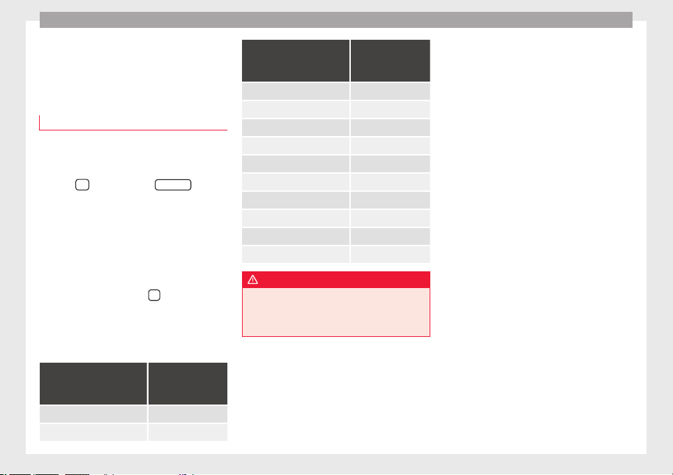
Operation
Introduction to the Easy
C
onnect
sy
stem*
System settings (CAR)*
CAR menu
Read the additional information carefully
›››
page 33
To select the settings menus, press the Easy
Connect
button and the
S
ET
TINGS
func-
tion b
utt
on.
The act
ual number of menus available and
the name of the various options in these me-
nus will depend on the vehicle’s electronics
and equipment.
When the function button check box is activa-
ted , the function is active.
Pressing the menu button
will always take
y
ou t
o the l
ast menu used.
Any changes made using the settings menus
are automatically saved on closing those me-
nus.
Function buttons in the
vehicle settings
menu
Page
ESC system ››› page 189
Tyres ››› page 311
Function buttons in the
vehicle settings
menu
Page
Driver assistance ››› table on page 33
Parking and manoeuvring ››› page 262
Vehicle lights ››› table on page 33
Mirrors and windscreen wipers ››› table on page 33
Opening and closing ››› table on page 33
Multifunction display ››› table on page 33
Date and time ››› table on page 33
Units ››› table on page 33
Service ››› page 115
Factory settings ››› table on page 33
WARNING
Any distraction may lead to an accident, with
the risk of
injury. Operating the Easy Connect
system while driving could distract you from
traffic.
120
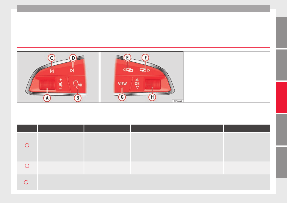
Communications and multimedia
Communications and multimedia
C
ontr
o
ls on the steering wheel*
Operating the audio, telephone and navigation system with voice control
Fig. 123 Controls on the steering wheel.
The steering wheel includes a multifunction
modu
l
e fr
om where it is possible to control
the audio, telephone and radio/navigation
functions without needing to distract the
driver.
Button Radio Media (except AUX) AUX Telephone
a)
Navigation
a)
A
Turn
Turn volume up/down. You do
not need to be in audio mode
(radio).
Turn volume up/down. You do
not need to be in audio mode
(media).
Turn volume up/down. You do
not need to be in audio mode
(media).
Turn volume up/down. You do
not need to be in telephone
mode.
Turn announcement volume
up/down. You do not need to
be in navigation mode but
there has to be an announce-
ment active when you adjust
the volume.
A
Press
Mute volume. Mute volume. Mute volume. Mute incoming call.
Mute the current navigation an-
nouncement.
B
a)
Activate/deactivate voice control.
This function can be used from any mode (audio, media, navigation, assistants, vehicle status, travel data). When the system is in telephone mode this button’s function
is deactivated during the ongoing call, and without Radio/Media functionality (except AUX).
»
121
Technical dataAdviceOperationEmergenciesSafety

Operation
Button Radio Media (except AUX) AUX Telephone
a)
Navigation
a)
C
/
D
Search for the previous/next
station
b)
.
Short press: Switch to the pre-
vious/next song.
Hold down: Fast rewind/for-
ward
c)
.
No function
– There is no active call: Ra-
dio/Media functionality (ex-
cept AUX)
– Active call: no function
No function for the other
modes (navigation, assistants,
vehicle status, travel data).
E
/
F
a)
Change instrument panel menu.
This function can be used from any mode (audio, media, navigation, assistants, vehicle status, travel data).
G
Coloured instrument panel: switch to the previous menu.
Monochrome instrument panel: switch to the previous function.
H
Turn
Coloured instrument panel: List
of stations available (only if
the instrument panel is in au-
dio menu).
Coloured instrument panel:
next track (only if the instru-
ment panel is in audio menu).
No function
– There is no active call: List of
latest calls.
– Active call: access the call
options list (call on hold, hang
up, mute microphone, private
number, etc.).
– Active route: access the view
to halt guidance to destination.
– No active route: list of recent
destinations.
H
Press
Acts on the instrument panel or confirms the instrument panel menu option depending on the menu option.
a)
According to the vehicle's equipment package.
b)
This action can be performed when you are listening to the radio; there is no need to be in audio-radio mode.
c)
These actions can be performed when you are listening to media; there is no need to be in audio-radio mode.
122
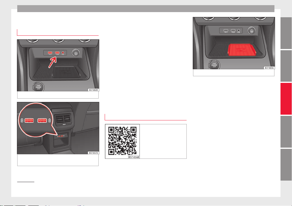
Communications and multimedia
Multimedia
USB/A
UX
-INP
ort
Fig. 124 Centre console: USB/AUX-IN input.
Fig. 125 Centre console, rear section: USB
c
onnect
or
s.
Depending on the special characteristics and
the c
ou
ntr
y, the vehicle may have a
USB/AUX-IN port.
The USB/AUX-IN port can be found in the
storage compartment area of the centre con-
sole ››› Fig. 124.
The operating description is located in the re-
spective Instruction Manuals of the audio
system or the navigation system.
Depending on the equipment and the coun-
try, the vehicle may also have USB connec-
tions exclusively for charging or as a power
socket.
These USB ports are located at the rear of the
console, between the front seats ››› Fig. 125.
Connectivity Box* / Wireless Charger*
Fig. 126 Related video
Fig. 127 Centre console: Connectivity Box.
Depending on the features and the country,
the
v
ehic
le may have one of these two op-
tions: Connectivity Box or Wireless Charger.
With the Connectivity Box you can charge
your mobile device wirelessly with Qi
1)
tech-
nology, while also reducing the radiation in
the vehicle and getting better reception.
With the Wireless Charger you only have the
wireless charging function if your mobile de-
vice has Qi technology.
The Connectivity Box/Wireless Charger is in
the storage compartment area of the centre
console ››› Fig. 127.
The operating description is located in the re-
spective Instruction Manuals of the audio
system or the navigation system.
»
1)
Qi technology allows you to charge your mobile
phone wirel
essly.
123
Technical dataAdviceOperationEmergenciesSafety

Operation
Note
Your mobile device must support the Qi wire-
les
s inductive charging interface standard for
proper operation.
124
Opening and closing
Opening and closing
C
entr
a
l locking
Description
Read the additional information carefully
›››
page 15
The vehicle can be locked and unlocked via
the central locking system. There are several
methods, depending on the vehicle equip-
ment:
●
key with remote control
›››
page 127,
●
lock on driver door (emergency opening
›››
page 15) or
●
interior central locking switch
›››
page 128.
Unlocking one side of the vehicle only
When you lock the vehicle with the key, the
doors and the rear lid are locked. When you
open the door, you can either unlock only the
driver door, or all the vehicle doors. To select
the required option, use Easy Connect*
›››
page 128.
Auto Lock*
The Auto Lock function locks the doors and
the rear lid when the vehicle exceeds a speed
of about 15 km/h (9 mph).
The vehicle is unlocked again when the igni-
tion key is removed. Alternatively, the vehicle
can also be unlocked via the central locking
switch or by pulling one of the inside door
handles. The Auto Lock function can be
switched on and off on the sound system or
on the Easy Connect* system ››› page 128.
In the event of an accident in which the air-
bags inflate, the doors will be automatically
unlocked to facilitate access and assistance.
Anti-theft alarm system*
If the anti-theft alarm system senses interfer-
ence with the vehicle it triggers an audible
and visible alarm.
The anti-theft alarm system is automatically
switched on when locking the vehicle. It
switches off when the vehicle is unlocked
from a distance.
When the driver door is unlocked with the
key, you should switch on the ignition within
15 seconds. Otherwise the alarm will be trig-
gered. On some export versions, the alarm is
triggered immediately when you open a door.
To deactivate the alarm, press the button
on the remote control key, or switch on the
ignition. After a certain time, the alarm will
automatically switch off.
Switch off the vehicle interior monitoring and
tow-away protection if you wish to prevent
the alarm from being triggered accidentally
››› page 136.
Turn signals
The turn signals will flash twice when the ve-
hicle is unlocked and once when the vehicle
is locked.
If it does not flash, this indicates that one of
the doors, the rear lid or the bonnet is not
closed correctly.
Accidental lock-out
The central locking system prevents you from
being locked out of the vehicle in the follow-
ing situations:
●
If the driver door is open, the vehicle can-
not be locked with the central locking switch
››› page 128.
Lock the vehicle with the remote control key,
when all the doors and the rear lid have been
closed. This prevents the accidental locking
of the vehicle.
WARNING
Do not leave anyone (especially children) in
the vehic
le if it is locked from the outside and
the anti-theft security system* is enabled, as
the doors and windows cannot then be
opened from the inside. Locked doors could
delay assistance in an emergency, potentially
putting lives at risk.
»
125
Technical dataAdviceOperationEmergenciesSafety
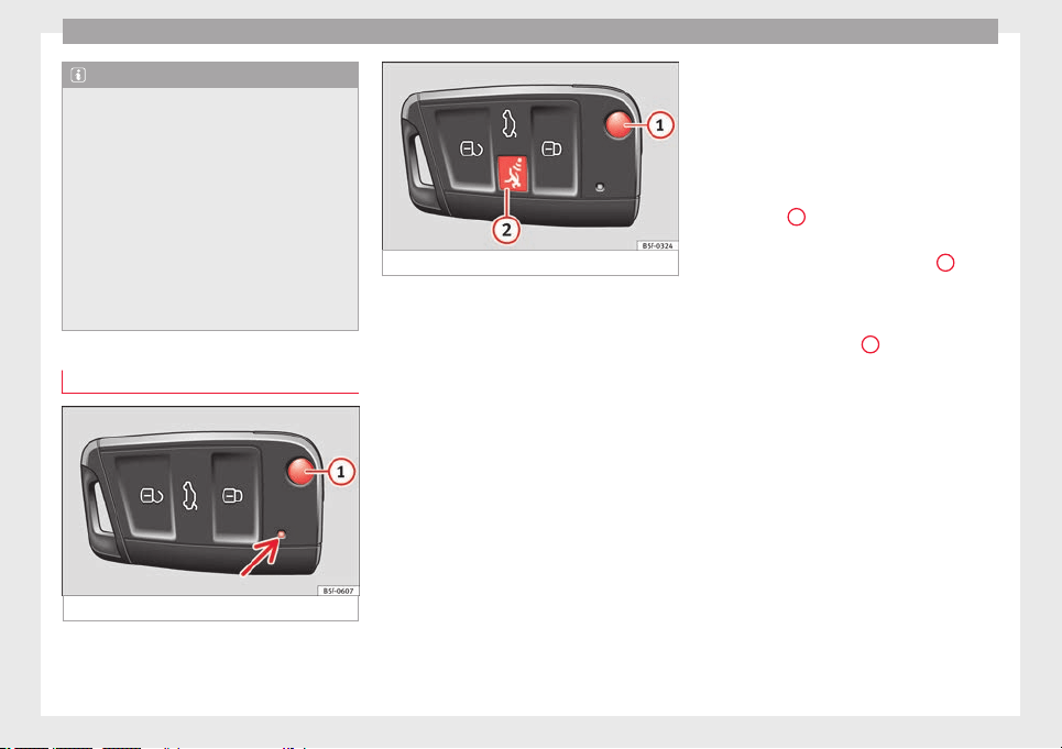
Operation
Note
●
Never le
ave any valuable items in the vehi-
cle unattended. Even a locked vehicle is not a
safe.
●
If the diode on the driver door sill lights up
for about 30 seconds when the vehicle is
locked, the central locking system or anti-
theft alarm* is not working properly. You
should have the fault repaired at a SEAT Offi-
cial Service or specialised workshop.
●
The vehicle interior monitoring of the anti-
theft alarm* system will only function as in-
tended if the windows and the sunroof* are
closed.
Car key
Fig. 128 Vehicle key
Fig. 129 Vehicle key with alarm button.
Vehicle key
W
ith the
v
ehicle key the vehicle may be
locked or unlocked remotely ››› page 125.
The vehicle key includes an emitter and bat-
tery. The receiver is in the interior of the vehi-
cle. The range of the vehicle key with remote
control and new battery is several metres
around the vehicle.
If it is not possible to open or close the vehi-
cle using the remote control key, this should
be re-synchronised ››› page 134 or the bat-
tery changed ››› page 133.
Different keys belonging to the vehicle may
be used.
Control lamp on the vehicle key
When a button on the vehicle key is pressed,
the control lamp flashes ››› Fig. 128 (arrow)
once briefly, but if the button is held down for
a longer period the control lamp flashes sev-
eral times, such as in convenience opening.
If the vehicle key control lamp does not light
up when the button is pressed, replace the
key's battery ››› page 133.
Unfolding and folding the key shaft
Press button
1
›
›› Fig. 128
or ›
›› Fig. 129 to
unlock and unfold the key shaft.
To fold the shaft away, press button
1
and
f
o
l
d the key shaft in until it locks in place.
Alarm button*
Only press alarm button
2
in the event of an
emer
g
ency!
When the alarm button is press-
ed, the vehicle horn is heard and the turn sig-
nals are switched on for a short time. When
the alarm button is pressed again, the alarm
is switched off.
Spare key
To obtain a spare key and other vehicle keys,
the vehicle chassis number is required.
Each new key contains a microchip which
must be coded with the data from the vehicle
electronic immobiliser. A vehicle key will not
work if it does not contain a microchip or the
microchip has not been encoded. This is also
true for keys which are specially cut for the
vehicle.
126
Opening and closing
The vehicle keys or new spare keys can be
o
bt
ained fr
om a SEAT Official Service, a spe-
cialised workshop or an approved key service
qualified to create this kind of key.
New keys or spare keys must be synchron-
ised before use ››› page 134.
CAUTION
All of the vehicle keys contain electronic com-
ponents. Prot
ect them from damage, impacts
and humidity.
Note
●
Only u
se the key button when you require
the corresponding function. Pushing the but-
ton unnecessarily could accidentally unlock
the vehicle or trigger the alarm. It is also pos-
sible even when you are outside the radius of
action.
●
Key operation can be greatly influenced by
overlapping radio signals close to the vehicle
working in the same range of frequencies, for
example, radio transmitters or mobile tele-
phones.
●
Obstacles between the remote control and
the vehicle, bad weather conditions and dis-
charged batteries can considerably reduce
the range of the remote control.
●
If the buttons of the vehicle key are press-
ed ››› Fig. 128 or ››› Fig. 129 or one of the cen-
tral locking buttons ››› page 128 is pressed
repeatedly in short succession, the central
locking briefly disconnects as protection
against overloading. The vehicle is then un-
locked. L
ock it if necessary.
Unlocking/Locking by remote control
Read the additional information carefully
›››
page 15
The vehicle will be locked again automatical-
ly if you do not open one of the doors or the
rear lid within 30 seconds after unlocking the
car. This function prevents the vehicle from
remaining unlocked if the unlocking button is
pressed by mistake. This does not apply if
you press the button for at least one sec-
ond.
In vehicles with a security central locking
feature (selective unlocking of side doors)
››› page 127, when the button is pressed
once, only the driver door and the fuel tank
flap are unlocked. When the button is press-
ed a second time, all the vehicle doors are
unlocked.
WARNING
Observe the safety warnings ›››
in Descrip-
tion on page 125
.
Note
●
Do not use the r
emote control key until the
vehicle is visible.
●
Other function
s of the remote control key
››› page 140, Convenience opening and clos-
ing.
Selective unlocking system
The selective unlocking system allows you to
only u
nlock the driver door and the fuel tank
flap. All other doors and the rear lid remain
locked.
Unlocking the driver door and tank flap
–
Press (once) the butt
on on the remote
control key or turn the key once in the
opening direction.
Unlocking all the doors, the rear lid and the
tank flap simultaneously.
–
Within 5 seconds, press (twice) the but-
ton on the remote control key, or turn the
key twice within 5 seconds in the opening
direction.
The anti-theft security system* and the anti-
theft alarm* are immediately disabled if you
unlock only the driver door, without unlock-
ing the other doors.
In vehicles with Easy Connect*, you can pro-
gramme the security central locking system
directly ››› page 128.
127
Technical dataAdviceOperationEmergenciesSafety
Operation
Adjusting the central locking
You can use Easy Connect* to select which
doors ar
e unlocked with the central locking
system. Using the radio or the Easy Connect*
system, you can select whether the vehicle
automatically closes with the “Auto Lock”
programme at speeds of more than 15 km/h
(9 mph).
Programming the unlocking of the doors (ve-
hicles with Easy Connect)
–
Select:
button > SETTINGS f
u
nction
b
utton > Opening and closing > Cen-
tral locking > Unlocking doors.
Programming the Auto Lock (vehicles with
radio)
–
Select:
SETUP
button > control button
Central locking > Locking while
driving.
Pr
ogr
ammin
g the Auto Lock (vehicles with
Easy Connect)
–
Select:
button > SETTINGS f
u
nction
b
utton > Opening and closing > Cen-
tral locking > Locking while
driving.
Unlocking doors
You can choose to unlock all the doors or
only the driver door when you unlock the
vehicle. In all the options, the fuel tank flap
is also unlocked.
With the Driver setting, when you press the
button on the remote control key once, on-
ly the driver door is unlocked. If that button is
pressed twice, the rest of the doors and the
rear lid will be unlocked.
In vehicles with a conventional key, turn the
key in the door lock, in the direction of open-
ing, twice within 2 seconds.
If the button is pressed, all the vehicle
doors are locked. At the same time, a confir-
mation signal* is heard.
Auto Lock while driving
If you select on, all the vehicle doors are
locked at speeds above 15 km/h (9 mph).
Central locking switch
Read the additional information carefully
›
›
›
page 15
Please note the following when using the
central locking switch to lock your vehicle:
●
It is not possible to open the doors or the
rear lid from the outside (for safety reasons,
e.g. when stopped at traffic lights).
●
The LED in the central locking switch lights
up when all the doors are closed and locked.
●
You can open the doors individually from
the inside by pulling the inside door handle.
●
In the event of an accident in which the air-
bags inflate, doors locked from the inside will
be automatically unlocked to facilitate access
and assistance.
WARNING
●
The centra
l locking switch also operates
when the ignition is switched off and auto-
matically locks all the vehicle doors when the
button is pressed.
●
The central locking switch does not operate
if the vehicle is locked from the outside and
the anti-theft security system is switched on.
●
Locked doors could delay assistance in an
emergency, potentially putting lives at risk.
Do not leave anyone, especially children, in
the vehicle.
Note
Your vehicle will lock automatically when it
reac
hes a speed of about 15 km/h (9 mph)
(Auto Lock) ››› page 125. You can unlock the
vehicle again using the button on the cen-
tral locking switch.
128
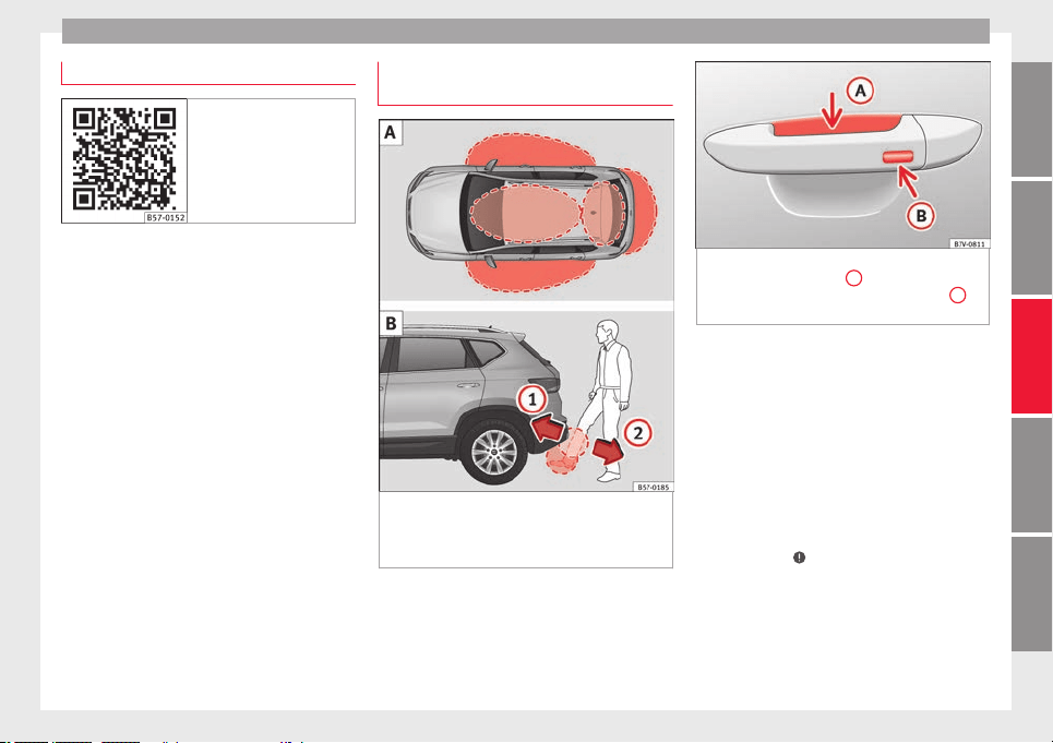
Opening and closing
Related video Keyless Access
Fig. 130 Handsfree
Unlocking and locking the vehicle
w
ith K
eyl
ess Access*
Fig. 131 Keyless Access locking and ignition
sy
s
t
em: In the proximity of the car.
Opening the rear lid with sensor-controlled
opening (Easy Open)
Fig. 132 Keyless Access locking and ignition
syst
em: sensor surface
A
for unlocking in-
side the door handl
e and sensor surface
B
for locking on the exterior of the handle.
Depending on the equipment, the vehicle
m
a
y
have the Keyless Access system.
Keyless Access is a key-free locking and igni-
tion system to unlock and lock the vehicle
without actively using its key. To do this, all
that is required is to have a valid vehicle key
in the detection area where you are attempt-
ing to access the vehicle ››› Fig. 131 and to
touch one of the sensor surfaces on the door
handles ››› Fig. 132 or operate the soft-
touch/handle on the rear lid
››› page 137 ›››
.
The
v
ehic
le can be unlocked and locked via
the front doors only. When doing so, the re-
mote control key must be no further than ap-
prox. 1.5 m from the door handle.
»
129
Technical dataAdviceOperationEmergenciesSafety

Operation
It does not matter where you carry the key, for
in
s
t
ance whether it is in your jacket pocket or
in a briefcase.
Once the doors have been locked, they can-
not be opened again immediately. This will
enable you to check that the doors are prop-
erly closed.
If you wish, when unlocking, you can unlock
only the corresponding door or the entire ve-
hicle. The necessary adjustments can be per-
formed in vehicles with a driver information
system ›››
page 33.
General information
If a valid key is in the proximity of the car,
››› Fig. 131 the Keyless Access locking and
starting system gives the key entry as soon
as one of the sensor surfaces on the door
handles is touched or the softtouch/handle
on the rear lid is operated. The following fea-
tures are then available without having to
use the vehicle key actively:
●
Keyless-Entry: unlocking the vehicle using
the handles of the front doors or the soft-
touch/handle on the rear lid.
●
Keyless-Exit: locking the vehicle using the
sensor of the driver or passenger door han-
dle.
●
Easy Open: opening the rear lid moving one
foot below the rear bumper.
●
Press & Drive: keyless starting of the en-
gine with the starter button ››› page 181.
The central locking and locking systems oper-
ate in the same way as a normal locking and
unlocking system. Only the controls change.
Unlocking the vehicle is confirmed with a
double flash of the indicator lights; locking
by a single flash.
If the vehicle is locked and then all doors and
the rear lid are closed leaving the last key
used inside the vehicle and none outside,
the vehicle will not lock immediately. All the
vehicle's indicator lights will flash four times.
The vehicle will lock after a few seconds if
you do not open any door or the rear lid.
The vehicle will lock again after a few sec-
onds if you unlock the vehicle but fail to open
any door or boot hatch.
Unlocking and opening the doors (Keyless-
Entry)
●
Grip one of the front door handles. In doing
this, the sensor surface ››› Fig. 132
A
(arrow)
on the h
andl
e i
s touched and the vehicle un-
locks.
●
Open the door.
On vehicles with selective opening or info-
tainment system configuration, pulling the
door handle twice will unlock all doors.
On vehicles without a “Safe” security sys-
tem: shutting and locking doors (Keyless-Ex-
it)
●
Switch the ignition off.
●
Close the driver's door.
●
Touch (once) the locking sensor surface
B
(arrow) on one of the front door handles. The
door th
at
i
s used must be closed.
On vehicles with a “Safe” security system:
shutting and locking doors (Keyless-Exit)
●
Switch the ignition off.
●
Close the driver's door.
●
Touch (once) the sensor surface
B
(arrow)
on one of
the fr
ont
door handles. The vehicle
locks with the “Safe” ››› page 133 system.
The door that is used must be closed.
●
Touch (twice) the sensor surface
B
(arrow)
of
one of
the fr
ont door handles to lock the
vehicle without activating the “Safe” security
system ››› page 133.
Unlocking and locking the boot hatch
When the vehicle is locked, the rear lid auto-
matically unlocks on opening if there is a val-
id vehicle key in the proximity ››› Fig. 131 .
Open or close the rear lid normally.
After closing, the hatch locks automatically. If
the complete vehicle is unlocked, the rear lid
will not lock automatically after closing it.
130
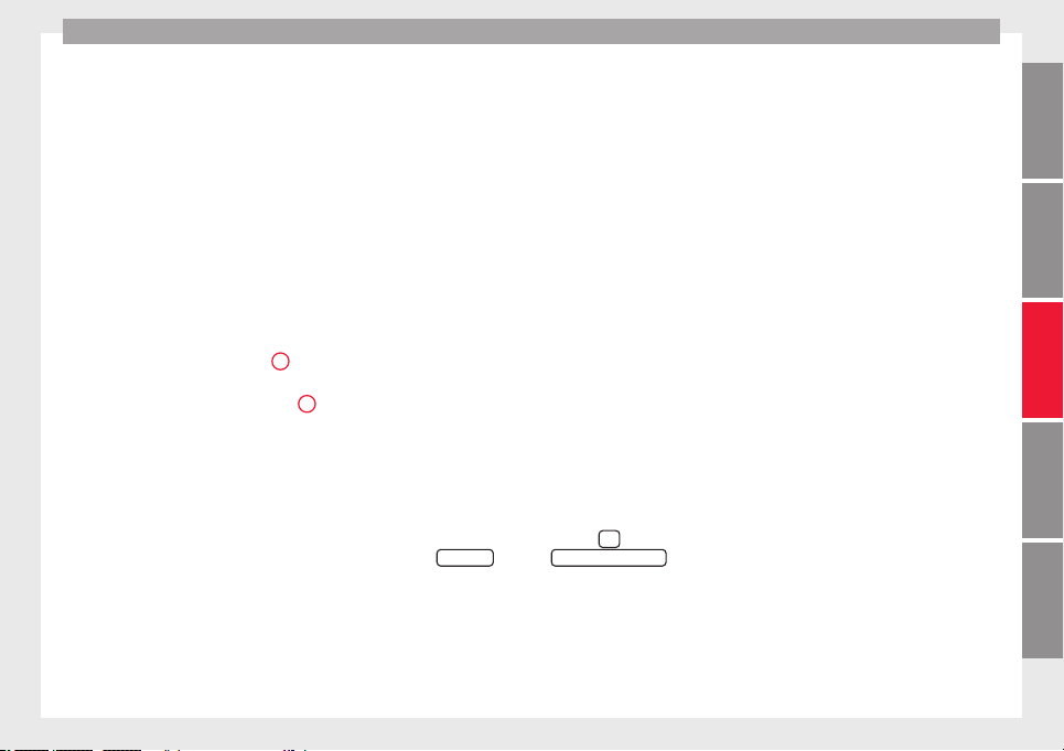
Opening and closing
Rear lid with sensor-controlled open-
in
g/c
lo
sing (Easy Open)
If there is a valid vehicle key in the proximity
››› Fig. 131 of the rear lid, it is possible to
unlock and open or close it moving one foot
in the area of the sensors ››› Fig. 131 loca-
ted under the rear bumper.
●
Switch the ignition off.
●
Stand in front of the rear bumper, in the
middle.
●
With a brisk movement, bring your foot and
lower leg as close as you can to the bumper.
The lower part of the leg needs to be close to
the upper sensor area and your foot to the
lower sensor area ››› Fig. 131
1
.
●
Quickly remove your foot and lower leg
fr
om the sen
sor ar
eas ››› Fig. 131
2
. The
r
e
ar lid w
ill be automatically opened.
●
If the rear lid fails to open, repeat the pro-
cedure after a few seconds.
The third brake light flashes once to show the
boot has opened with the Easy Open func-
tion.
The rear lid can be closed with another foot
movement similar to the opening one (provi-
ded a valid vehicle key is in the proximity of
the rear lid).
When closed, the rear lid automatically locks
if the vehicle has been locked beforehand
and there is no valid key inside.
While the rear lid is in motion (either opening
or closing), it can be stopped with another
foot movement similar to the opening one
(provided a valid vehicle key is in the proxim-
ity of the rear lid).
The Easy Open feature is not available or only
has limited availability in the following situa-
tions (examples):
●
If the rear bumper is very dirty.
●
If the rear bumper is wet with salt water,
e.g. after having driven on gritted roads.
●
If the electrical unlocking tow hitch is not
covered.
●
If the vehicle has been equipped at a later
time with a tow bracket.
In the event of heavy rain, the Easy Open fea-
ture may take a little longer to open the boot
or may deactivate automatically, to avoid the
boot opening by accident, e.g. because of
the running water.
The Easy Open function can be connected
and disconnected permanently in the info-
tainment system by pressing the
button
and the
S
ET
TINGS
and the
Openin
g and c
lo
sing
function buttons ›
›
›
page 33.
What happens when locking the vehicle with
a second key
If there is a vehicle key inside the vehicle and
it is locked from the outside with a second
vehicle key, the key inside the vehicle is
blocked for engine ignition ››› page 181. In
order to enable engine ignition, the button
on the key inside the vehicle needs to be
pressed.
Automatically disabling sensors
If the vehicle is not locked or unlocked for a
long period of time, the proximity sensors on
the passenger doors are automatically disa-
bled.
If one of the sensor surfaces on the door han-
dles is often activated in an unusual manner
with the vehicle locked (e.g. by the branches
of a bush rubbing against it), all proximity
sensors are disabled for a certain period of
time.
Sensors will again be enabled:
●
After a time.
●
OR: if the vehicle is unlocked with the
button on the key.
●
OR: if the boot is opened.
●
OR: if the vehicle is unlocked manually with
the key.
Keyless Access temporary disconnection
function*
You can deactivate the vehicle's Keyless Ac-
cess unlocking for a locking and unlocking
cycle.
»
131
Technical dataAdviceOperationEmergenciesSafety
Operation
●
Mo
v
e the g
ear lever to position P (if the ve-
hicle has automatic gearbox), since other-
wise the vehicle cannot be locked.
●
Close the door.
●
Push the central locking button on the
remote control and touch the locking sensor
surface ››› Fig. 132
B
on the driver door han-
dl
e onc
e w
ithin the following 5 seconds. Do
not grip the door handle, otherwise the vehi-
cle will not lock. Deactivation is also possible
if the vehicle is locked through the driver’s
door lock.
●
To check that the function has been deacti-
vated, wait at least 10 seconds, grip and pull
on the door handle. The door should not
open.
The next time the door can only be unlocked
via the remote control or the lock cylinder.
The next time the door is locked/unlocked,
Keyless Access will be active again.
Convenience functions
To close all the electric windows using the
convenience function, keep a finger on the
locking sensor surface
B
(arrow) of the door
h
andl
e f
or a few seconds until the windows
have closed.
The doors opened by touching the sensor
surface of the door handle depend on the
settings that have been activated in the info-
tainment system with the
button and the
SETTINGS
and
Openin
g and c
lo
sing
function but-
t
on
s.
WARNING
If there is a valid key in the proximity of the
rear lid, in some c
ases the Easy Open func-
tion may be accidentally activated and the
rear lid will open, for example, when sweep-
ing under the rear bumper, when directing a
water jet or high pressure steam to the area
or when carrying out maintenance work or re-
pairs in that area. If accidentally opened, the
rear lid could injure somebody situated in its
area of operation or cause material damage.
●
Therefore, always make sure that there is
no unsupervised valid key in the area near
the rear lid.
●
Before carrying out any maintenance or re-
pair work on the vehicle, always disable the
Easy Open feature via the infotainment sys-
tem.
●
Before washing the vehicle, always disable
the Easy Open feature via the infotainment
system.
●
Before attaching a bicycle rack or a trailer,
››› page 273, always disable the Easy Open
feature via the infotainment system.
CAUTION
The sensor surfaces on the door handles
coul
d engage if hit with a water jet or high
pressure steam if there is a valid vehicle key
in the proximity. If at least one of the electric
windows is open and the sensor surface
B
(arrow) on one of the handles is activated
continuous
ly, all windows will close.
Note
●
If
the v
ehicle battery has little or no charge,
or the vehicle key battery is almost or entire-
ly out of charge, you will probably not be able
to lock or unlock the vehicle with the Keyless
Access system. The vehicle can be unlocked
or locked manually ››› page 97.
●
To control the proper locking of the vehicle,
the release function is disabled for approx. 2
seconds.
●
If the message Keyless access system
faulty is displayed on the screen of the
dash panel, abnormalities may occur in the
operation of the Keyless Access system. Con-
tact a specialised workshop. SEAT recom-
mends visiting a SEAT dealership for this.
●
Depending on the function set on the info-
tainment system for the mirrors, the exterior
mirrors will unfold and the surround lighting
will come on when unlocking the vehicle us-
ing the sensor surface on the driver and pas-
senger door handles ››› page 155.
●
If there is no valid key inside the vehicle or
the system fails to detect one, a warning will
display on the dash panel screen. This could
happen if any other radio frequency signal in-
terferes with the key signal (e.g. from a mo-
bile device accessory) or if the key is covered
by another object (e.g. an aluminium case).
132
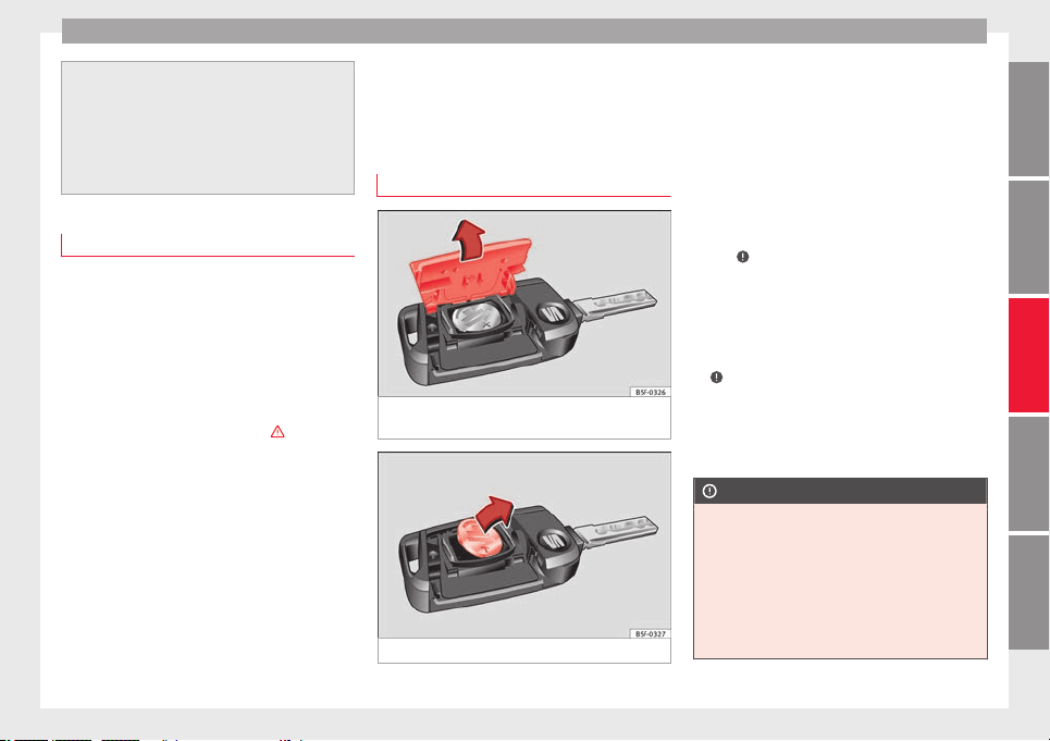
Opening and closing
●
If the sensor
s are very dirty, e.g. have a lay-
er of salt, the correct functioning of the sen-
sors on the door handles may be affected. In
this case, clean the vehicle.
●
If the vehicle is equipped with an automatic
gearbox, it may only be locked in the gear
stick is in position P.
Anti-theft security system (Safelock)*
The following message is displayed on the in-
strument p
anel to remind the driver that
when the vehicle is closed from the outside,
the anti-theft security system is switched on.
Do not forget the Safelock.
Please see Instruction Manual. The
vehicle cannot be opened from inside. This
makes it more difficult for unauthorised per-
sons to break into the vehicle ›››
in De-
s
c
ription on p
age 125.
The anti-theft security system can be switch-
ed off each time the vehicle is locked:
●
Turn the key a second time to the lock posi-
tion, in the door lock, within two seconds. If
necessary, remove the protective cover on
the driver door handle ›››
page 15 or
●
Press the button on the remote control
key for a second time within 2 seconds.
The flashing frequency of the diode in the
door sill immediately confirms the process.
Initially, the diode flashes in a fast sequence
for a brief period, then it stops for approxi-
mately 30 seconds and, lastly continues
flashing slowly.
Replacing the battery
Fig. 133 Vehicle key: opening the battery
c
omp
ar
tment.
Fig. 134 Vehicle key: removing the battery.
SEAT recommends you ask a specialised
w
ork
shop t
o replace the battery.
The battery is located to the rear of the vehi-
cle key, under a cover.
Changing the battery
●
Unfold the vehicle key blade ››› page 126.
●
Remove the cover from the back of the ve-
hicle key ››› Fig. 133 in the direction of the ar-
row ›››
.
●
Extract the battery from the compartment
u
s
in
g a suitable thin object ››› Fig. 134.
●
Place the new battery in the compartment
as shown ››› Fig. 134, pressing in the oppo-
site direction to that shown by the arrow
›››
.
●
Fit the cover as shown ›
›
›
Fig. 133, pressing
it onto the vehicle key casing in the opposite
direction to that shown by the arrow until it
clicks into place.
CAUTION
●
If the batt
ery is not changed correctly, the
vehicle key may be damaged.
●
Use of unsuitable batteries may damage
the vehicle key. For this reason, always re-
place the dead battery with another of the
same voltage, size and specifications.
●
When fitting the battery, check that the po-
larity is correct.
»
133
Technical dataAdviceOperationEmergenciesSafety
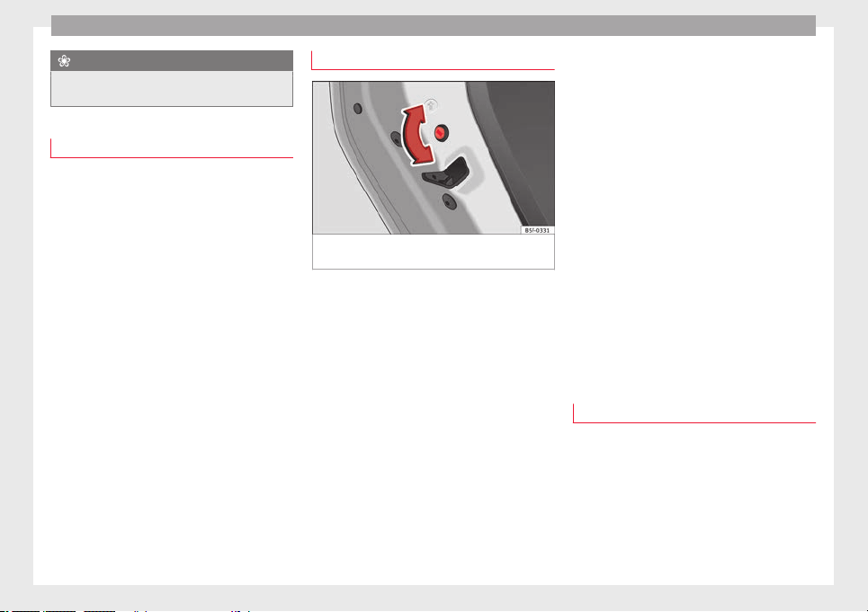
Operation
For the sake of the environment
Please dispose of your used batteries correct-
ly and with r
espect for the environment.
Synchronising the vehicle key
If the button is pressed frequently outside
of the
vehicle range, it is possible that the ve-
hicle can no longer be locked or unlocked us-
ing the key. In this case, the key must be re-
synchronised as described below:
●
Unfold the vehicle key blade
›››
page 126.
●
If necessary, remove the cover from the
driver door lever
›››
page 15.
●
Press the button on the vehicle key. For
this, it must remain with the vehicle.
●
Open the vehicle within one minute using
the key blade. The key has been synchron-
ised.
●
If necessary, fit the cap.
Childproof lock
Fig. 135 Childproof lock on the left hand side
door
.
The childproof lock prevents the rear doors
fr
om bein
g opened fr
om the inside. This sys-
tem prevents minors from opening a door ac-
cidentally while the vehicle is running.
This function is independent of the vehicle
electronic opening and locking systems. It
only affects rear doors. It can only be activa-
ted and deactivated manually, as described
below:
Activating the childproof lock
–
Unlock the vehicle and open the door in
which you wish to activate the childproof
lock.
–
With the door open, rotate the groove in
the door using the ignition key, clockwise
for the left hand side doors ››› Fig. 135 and
anti-clockwise for the right hand side
doors.
Deactivating the childproof lock
–
Unlock the vehicle and open the door
whose childproof lock you want to deacti-
vate.
–
With the door open, rotate the groove in
the door using the ignition key, anti-clock-
wise for the left hand side doors ››› Fig. 135
and clockwise for the right hand side
doors.
Once the childproof lock is activated, the
door can only be opened from the outside.
The childproof lock can be activated or deac-
tivated by inserting the key in the groove
when the door is open, as described above.
Anti-theft alarm system*
Description
The anti-theft alarm makes it more difficult to
br
e
ak
into the vehicle or steal it.
The anti-theft alarm is automatically turned
on when the vehicle is locked with the key.
●
The turn signal light will flash twice on
opening and deactivating the alarm.
134
Opening and closing
●
The t
urn s
ign
al light will flash once on clos-
ing and activating the alarm.
When does the system trigger an alarm?
The anti-theft alarm siren will be triggered for
about 30 seconds accompanied by sound
and optical (flashing) warning signals and
will be repeated about ten times when the
vehicle is locked and the following unauthor-
ised actions are attempted:
●
Opening a door that is mechanically un-
locked using the vehicle key without switch-
ing on the ignition in the next 15 seconds (in
certain markets, such as the Netherlands,
there is no 15 second waiting time and the
alarm is activated immediately on opening
the door).
●
A door is opened.
●
The bonnet is opened.
●
The rear lid is opened.
●
When the ignition is switched on with a
non-authorised key.
●
When the vehicle battery is disconnected.
●
Movement inside the vehicle (in vehicles
with interior monitoring ››› page 136).
●
When the vehicle is towed (in vehicles with
anti-tow system ››› page 136).
●
When the vehicle is raised (in vehicles with
anti-tow sy
stem ››› page 136).
●
When the vehic
le is transported on a ferry
or by rail (vehicles with an anti-tow system or
vehicle interior monitoring ››› page 136).
●
When a trailer connected to the anti-theft
alarm system is disconnected.
How to turn OFF the alarm
Unlock the vehicle with the unlocking button
on the key or turn on the ignition with a valid
key.
Note
●
After 28 d
ays, the indicator light will be
switched off to prevent the battery from ex-
hausting if the vehicle has been left parked
for a long period of time. The alarm system
remains activated.
●
If, after the audible warning goes off, an-
other monitored area is accessed (e.g. the
rear lid is opened after a door has been
opened), the alarm is triggered again.
●
The anti-theft alarm is not activated when
the vehicle is locked from within using the
central locking button .
●
If the driver door is unlocked mechanically
with the key, only the driver door is unlocked,
the rest of the doors remain locked. Only
when the ignition has been turned on will the
other doors be available - but not unlocked -
and the central locking button will be activa-
ted.
●
If the v
ehicle battery is run down or flat
then the anti-theft alarm will not operate cor-
rectly.
●
Vehicle monitoring remains active even if
the battery is disconnected or not working for
any reason.
●
The alarm is triggered immediately if one of
the battery cables is disconnected while the
alarm system is active.
Vehicle interior monitoring and anti-
tow sy
stem*
It is a monitoring or control function incorpo-
r
at
ed in the anti-thef
t alarm* which detects
unauthorised vehicle entry by means of ultra-
sound.
Activation
–
It is automatically switched on when the
anti-theft alarm is activated.
Deactivation
–
Open the vehicle with the key, either me-
chanically or by pressing the button on
the remote control. The time period from
when the door is opened until the key is in-
serted in the contact should not exceed 15
seconds, otherwise the alarm will be trig-
gered.
»
135
Technical dataAdviceOperationEmergenciesSafety
Operation
–
Pr
e
s
s the button on the remote control
twice. The volumetric sensor and tilt sen-
sors will be deactivated. The alarm system
remains activated.
The vehicle interior monitoring and the anti-
tow system are automatically switched on
again next time the vehicle is locked.
The vehicle interior monitoring and anti-tow
sensor (tilt sensor) are automatically switch-
ed on when the anti-theft alarm is switched
on. In order to activate it, all the doors and
the rear lid must be closed.
If you wish to switch off the vehicle interior
monitoring and the anti-tow system, it must
be done each time that the vehicle is locked;
if not, they will be automatically switched on.
The vehicle interior monitoring and the anti-
tow system should be switched off if animals
are left inside the locked vehicle (otherwise,
their movements will trigger the alarm) or
when, for example, the vehicle is transported
or has to be towed with only one axle on the
ground.
False alarms
Interior monitoring will only operate correctly
if the vehicle is completely closed. Please ob-
serve related legal requirements.
The following cases may cause a false alarm:
●
Open windows (partially or fully).
●
Panoramic/tilting sunroof open (partially or
completely).
●
Movement of objects inside the vehicle,
such as loose papers, items hanging from
the rear vision mirror (air fresheners), etc.
Note
●
If the v
ehicle is relocked and the alarm is
activated without the volumetric sensor func-
tion, relocking will activate the alarm with all
its functions, except the volumetric sensor.
This function is reactivated when the alarm is
switched on again, unless it is deliberately
switched off.
●
If the alarm has been triggered by the volu-
metric sensor, this will be indicated by a
flashing of the warning lamp on the driver
door when the vehicle is opened. The flash is
different to the flash indicating the alarm is
activated.
●
The vibration of a mobile phone left inside
the vehicle may cause the vehicle interior
monitoring alarm to trigger, as both sensors
react to movements and shakes inside the ve-
hicle.
●
If on activating the alarm, any door or the
rear lid is open, only the alarm will be activa-
ted. The vehicle interior monitoring and the
anti-tow system will only be activated once
all the doors are closed (including the rear
lid).
Deactivating the vehicle interior moni-
t
orin
g and anti-t
ow system*
When the vehicle is locked, the alarm will be
trigger
ed if movements are detected in the
interior (e.g. by animals) or if the vehicle's in-
clination is changed (e.g. during transport).
You can prevent the alarm from being trig-
gered accidentally by switching off the vehi-
cle interior monitoring and/or tow-away pro-
tection.
●
To switch off the interior monitoring and
tow-
away protection, switch off the ignition
and, using the Infotainment system, select:
button >
S
ET
TINGS
function button > Open-
in
g and c
lo
sing > Central locking > Switch off
alarm.
●
When the vehicle is locked now, the vehicle
interior monitoring and the tow-away protec-
tion are switched off until the next time the
door is opened.
If the anti-theft security system (Safelock)*
›››
page 133 is switched off, the vehicle interi-
or monitoring and the tow-away protection
are automatically switched off.
WARNING
Observe the safety warnings ›››
in Descrip-
tion on page 125
.
136
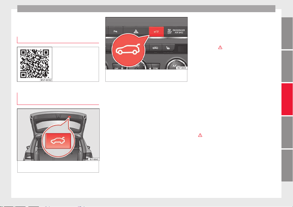
Opening and closing
Rear lid (luggage compart-
ment)
R
el
at
ed video
Fig. 136 Handsfree
Rear lid with electric opening and
c
lo
s
ing*
Fig. 137 Rear lid open: button to close the
r
e
ar lid immedi
ately.
Fig. 138 Centre console: button to open and
close r
ear lid.
Opening the rear lid
●
Unlock the vehicle ›
›
›
page 125 and briefly
press the handle of the rear lid. On vehicles
with Keyless Access you can directly press
the handle of the rear lid. The rear lid is un-
locked if an authorised key is recognised in
the proximity of the vehicle.
●
OR: press the button on the centre console
for at least one second
›››
Fig. 138. The but-
ton also works when the ignition is switched
off.
●
OR: Press and hold the button on the
vehicle key for approx. 1 second. If the vehi-
cle is locked, only the rear lid is unlocked
(the doors remain locked).
●
OR: on vehicles with Keyless Access and
sensor-controlled opening you can open the
rear lid by moving one foot in the area of the
sensors located below the rear bumper (Easy
Open). The rear lid will be automatically
opened.
Closing the rear lid
●
Briefly press the button on the rear lid
››› Fig. 137 ›››
.
●
OR: pr
ess the
b
utton located on the
centre console until the rear lid is closed
››› Fig. 138.
●
OR: on vehicles with Keyless Access, press
and hold the vehicle key button until the
rear lid is closed or move one foot in the area
of the sensors located below the rear bumper
(Easy Open) ››› page 129. The vehicle key
must not be further than approx. 1.5 m from
the luggage compartment and should not be
in the vehicle.
●
OR: manually move the rear lid in the direc-
tion of closing until it closes automatically.
●
The rear lid goes down automatically to the
final position and also closes automatically
›››
.
Int
erruptin
g openin
g or closing
After beginning to open or close the rear lid,
the action can be halted by pressing one of
the buttons.
Continue opening or closing the rear lid by
hand. To do this, some force will have to be
used.
»
137
Technical dataAdviceOperationEmergenciesSafety
Operation
If you press one of the b
utt
on
s again, the
rear lid will move again in the original direc-
tion.
If the rear lid is met with resistance or an ob-
stacle during the automatic opening or clos-
ing, opening or closing will be interrupted
immediately. For the closing process, the rear
lid opens again slightly.
●
Check why it has not been possible to open
or close the rear lid.
●
Try to open or close the rear lid again.
●
If necessary, the rear lid can be opened or
closed by hand using reasonable force.
Special feature for pulling a trailer
If the factory-fitted towing bracket is electri-
cally connected to a trailer ››› page 273, the
electric rear lid can only be opened or closed
with the buttons on the rear lid itself.
Acoustic warnings
Throughout the process of opening or closing
the rear lid, acoustic warnings can be heard.
Exception: when the rear lid is opened man-
ually using the handle or the Easy Open func-
tion with the movement of the foot or closed
using the button on the rear lid itself
››› Fig. 137.
Modifying and memorising the opening an-
gle
If the space behind or above the vehicle is
less than the travel area of the rear lid, you
can change the opening angle of the rear lid.
To memorise a new opening angle, the rear
lid must be open at least halfway.
●
Interrupt the opening process in the de-
sired position.
●
Press the button ››› Fig. 137 on the rear
lid for at least 3 seconds.
The opening angle is memorised. Memorisa-
tion is indicated by blinking of the hazard
warning lights and an audible warning.
Resetting and memorising the opening angle
For the rear lid to reopen completely, the
opening angle must be reset and memorised
again.
●
Release the rear lid and open it to the
memorised height.
●
Lift the rear lid by hand as far as it goes. To
do this, some force will have to be used.
●
Press the button ››› Fig. 137 on the rear
lid for at least 3 seconds.
●
This resets and memorises the factory-set
opening angle. Memorisation is indicated by
blinking of the hazard warning lights and an
audible warning.
Automatic protection against overheating
If the system is operated repeatedly in a
short space of time, it automatically switches
off to prevent overheating.
Once the system is cool again, the function
can be reused. Until then, the rear lid can on-
ly be opened and closed by hand using rea-
sonable force.
If with the rear lid open the vehicle battery is
disconnected ››› page 305 or the corre-
sponding fuse burns out ››› page 102, the
system will have to be reset. This requires
closing the rear lid completely once.
Emergency unlocking
›››
page 17
WARNING
If a lot of snow builds up on the rear lid or it
is he
avily loaded, the rear lid may not open
or, after opening, it may lower by itself due to
the extra weight and cause serious injury.
●
Do not open the rear lid when there is a lot
of snow on it or when carrying a load (e.g. on
a rack).
●
Before opening the rear lid, remove the
snow or the load.
WARNING
If the rear lid is closed incorrectly or without
due care, it
could result in serious injury.
138
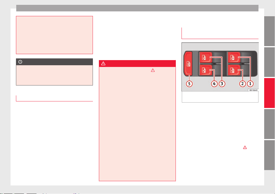
Opening and closing
●
Never le
ave the vehicle unattended or allow
children to play inside or next to it, especially
if the rear lid is open. Children could enter
the luggage compartment, close the rear lid
and become trapped. A locked vehicle can
reach extremely high and low temperatures,
depending on the time of year, thus causing
serious injuries, illness or even death.
CAUTION
Before opening or closing the rear lid, make
s
ure th
at there is enough space to open or
close it, e.g. when pulling a trailer or in a ga-
rage.
Rear lid automatic locking
Where the vehicle has been locked by press-
in
g the b
utt
on on the remote control with
the rear lid open, the rear lid will lock auto-
matically when closed.
The automatic rear lid locking time extension
function can be activated. Where this func-
tion is activated and once the rear lid has
been unlocked by pressing the button on
the remote control key ››› page 127, the rear
lid can be re-opened for a certain length of
time.
Where required, the automatic tailgate lock-
ing time extension function can be activated
or deactivated at an Authorised SEAT Service,
which will provide all the necessary informa-
tion.
Before the vehicle locks automatically, there
is a risk of intruders getting into the vehicle.
Therefore, we recommend you always lock
the vehicle by pressing the button on the
remote control or by using the central locking
button.
WARNING
Observe the safety warnings ›››
in Intro-
duction on page 97
.
●
Always close the rear lid properly. Risk of
accident or injury.
●
The rear lid must not be opened when the
reverse or rear fog lights are lit. This may
damage the tail lights.
●
Do not close the rear lid by pushing it down
with your hand on the rear window. The glass
could smash. Risk of injury!
●
Ensure the rear lid is locked after closing it.
If not, it may open unexpectedly while driv-
ing.
●
Closing the rear lid without observing and
ensuring it is clear could cause serious injury
to you and to third parties. Make sure that no
one is in the path of the rear lid.
●
Never drive with the rear lid open or half-
closed, exhaust gases may penetrate into the
interior of the vehicle. Danger of poisoning!
●
If you only open the rear lid, do not leave
the key inside. The vehicle cannot be opened
if the key is left inside.
Controls for the windows
El
ectric
openin
g and closing of win-
dows
Fig. 139 Detail of the driver door: controls for
the w
indo
w
s.
Read the additional information carefully
›
›
›
page 18
The front and rear electric windows can be
operated by using the controls on the driver
door. The other doors each have a switch for
their own window.
Always close the windows fully if you park
the vehicle or leave it unattended ›››
.
Y
ou c
an u
se the electric windows for approx.
10 minutes after switching off the ignition if
neither the driver door nor the front passen-
ger door has been opened and the key has
not been removed from the ignition.
»
139
Technical dataAdviceOperationEmergenciesSafety
Operation
Safety switch *
The s
af
ety
switch ››› Fig. 139
5
on the driver
door c
an be u
sed t
o disable the electric win-
dow buttons on the rear doors.
Safety switch not pressed: buttons on rear
doors are activated.
Safety switch pressed: buttons on rear doors
are deactivated.
The safety control symbol lights up in yel-
low if the buttons on the rear doors are
switched off.
WARNING
Observe the safety warnings ›››
in Intro-
duction on page 97
.
●
Incorrect use of the electric windows can
result in injury.
●
Never close the rear lid without observing
and ensuring it is clear, to do otherwise could
cause serious injury to you and third parties.
Make sure that no one is in the path of a win-
dow.
●
If the ignition is switched on, the electric
equipment could be activated with risk of in-
jury, for example, in the electric windows.
●
The doors can be locked using the remote
control key. This could become an obstacle
for assistance in an emergency situation.
●
Therefore always take the key with you
when you leave the vehicle.
●
The electric w
indows will work until the ig-
nition has been switched off and one of the
front doors has been opened.
●
If necessary, use the safety switch to disa-
ble the rear electric windows. Make sure that
they have been disabled.
Note
If the window is not able to close because it
i
s s
tiff or because of an obstruction, the win-
dow will automatically open again
››› page 140. If this happens, check why the
window could not be closed before attempt-
ing to close it again.
Roll-back function
The roll-back function reduces the risk of in-
jur
y
when the el
ectric windows close.
●
If a window is obstructed when closing au-
tomatically, the window stops at this point
and lowers immediately ›››
.
●
Next, check why the window does not close
bef
or
e att
empting it again.
●
If you try within the following 10 seconds
and the window closes again with difficulty
or there is an obstruction, the automatic clos-
ing will stop working for 10 seconds.
●
If the window is still obstructed, the win-
dow will stop at this point.
●
If there is no obvious reason why the win-
dow cannot be closed, try to close it again by
pulling the tab within ten seconds. The win-
dow closes with maximum force. The roll-
back function is now deactivated.
●
If more than 10 seconds pass, the window
will open fully when you operate one of the
buttons. One-touch closing is reactivated.
WARNING
Observe the safety warnings ›››
in Electric
opening and clo
sing of windows on page 140.
●
The roll-back function does not prevent fin-
gers or other parts of the body getting
pinched against the window frame. Risk of
accident.
Convenience opening and closing
Use the convenience opening/closing func-
tion t
o e
a
sily open/close all the windows
from the outside.
Convenience open function
–
Press and hold the button on the remote
control key until all the windows have
reached the desired position, or
–
First unlock the vehicle using the button
on the remote control key and then keep
the key in the driver door lock until all the
140
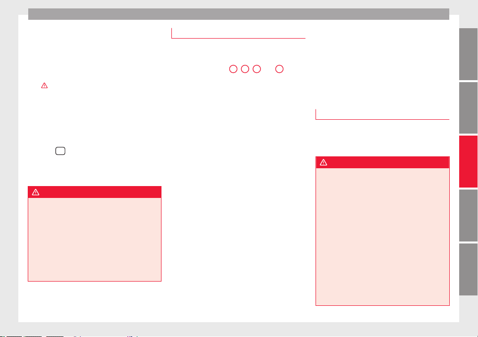
Opening and closing
windows have reached the required posi-
tion.
C
on
v
enience close function
–
Press and hold the button on the remote
control key until all the windows are closed
›››
, or
–
Lock the driver's door with the key and hold
the k
ey
in the <z
itat>lock</zitat> position un-
til all the windows are closed
Programming convenience opening in the
Easy Connect*
–
Select:
button > SETTINGS f
u
nction
b
utton > Opening and closing > Open-
ing the window by holding down
button or > Front window on/off.
WARNING
●
Never clo
se the windows without due care
or proper control. There is a risk of suffering
injury.
●
For safety reasons, you should only use the
remote control open and close functions with-
in about 2 metres of the vehicle. To avoid in-
juries, always keep an eye on the windows
when pressing the button to close them. The
windows stop moving as soon as the button
is released.
One-touch opening and closing
One-touch opening and closing means you
do not hav
e to hold down the button.
Buttons ››› Fig. 139
1
,
2
,
3
and
4
have
two pos
itions for opening windows and two
for closing them. This makes it easier to open
and close windows to the desired position.
One-touch closing
–
Pull up the window button briefly up to the
second position. The window closes fully.
One-touch opening
–
Push down the window button briefly up to
the second pos
ition. The window opens
fully.
Resetting one-touch opening and closing
The automatic open and close function will
not work if the battery has been temporarily
disconnected. The function can be restored
as follows:
–
Close the window as far as it will go by lift-
ing and holding the electric window switch.
–
Release the switch and then lift it again for
1 second. This will re-enable the automatic
function.
If you push (or pull) a button to the first
stage, the window will open (or close) until
you release the button. If you push or lift the
button briefly to the second stage, the win-
dow will open (one-touch opening) or close
(one-touch closing) automatically. If you op-
erate the button while the window is opening
or closing, it stops at this position.
Sunroof*
Introduction
The sunroof consists of two glass parts. The
rear p
art is fixed and cannot be opened. It al-
so has a sun blind.
WARNING
If the sunroof is used negligently or without
pay
ing due attention, it can cause serious in-
jury.
●
Open or close the sunroof and the sun blind
only when no one is in their path of move-
ment.
●
Never leave any key inside the vehicle
when exiting.
●
Never leave a child or any other person who
may need help in the vehicle, especially if
they have access to the vehicle key. If using
they key unattended, they could lock the ve-
hicle, start the engine, switch on the ignition
and activate the sunroof.
●
After switching off, it is still possible to
open or close the sunroof during a short
»
141
Technical dataAdviceOperationEmergenciesSafety
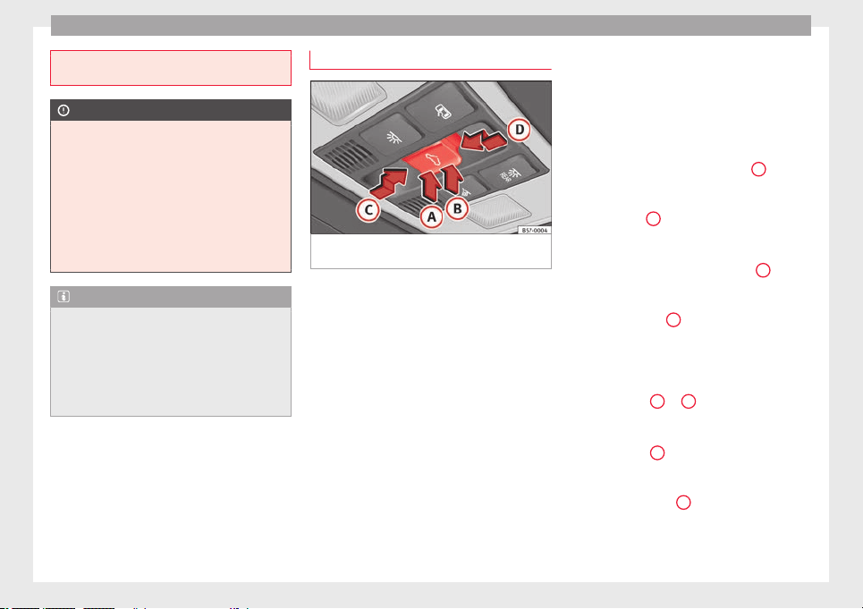
Operation
space of time provided that neither the driver
nor pas
senger door is opened.
CAUTION
●
T
o prev
ent damage, during winter tempera-
tures remove any ice or snow that might be
on the car roof before opening the sunroof or
adjusting the tilt position.
●
Before leaving the vehicle or in case of rain-
fall, always close the sunroof. With the sun-
roof open or in a tilted position, water can en-
ter the interior and can cause considerable
damage to the electrical system. As a result,
other damage can occur in the vehicle.
Note
●
Leav
es and other loose objects that accu-
mulate on the sunroof rails should be regular-
ly cleaned away either by hand or with a vac-
uum.
●
If the sunroof does not work correctly, the
anti-trap function will not work either. Con-
tact a specialised workshop.
Opening and closing the sunroof
Fig. 140 On the interior roof lining: sunroof
b
utt
on.
The sunroof only works when the ignition is
sw
it
c
hed on. Once the ignition has been
switched off, you can still open or close the
sunroof for a few minutes provided the driver
door and the front passenger door are not
opened.
The sun blind automatically opens along with
the sunroof if completely closed or if in front
of the sunroof. The sun blind remains in the
previous position and does not automatically
close with the sunroof. The sun blind can on-
ly be closed completely once the sunroof has
been closed.
The button
›››
Fig. 140 has two levels. The
first level switches the sunroof to the tilted
position, opening or closing it fully or partial-
ly.
On the second level, the sunroof automatical-
ly moves to the corresponding final position
after briefly pressing the button. Activating
the button again stops the automatic func-
tion.
Adjusting the tilt position of the sunroof
●
Press the rear part of the button
B
to the
fir
s
t
level.
●
Automatic operation: briefly press the rear
part of button
B
to the second level.
C
lo
s
ing the sunroof from a tilted position
●
Press the front part of the button
A
to the
fir
s
t
level.
●
Automatic operation: briefly press the front
part of the button
A
to the second level.
St
op
pin
g the automatic operation by adjust-
ing the tilted position of the sunroof or by
closing the sunroof
●
Press button
A
or
B
again.
Openin
g the s
u
nroof
●
Press button
C
backwards to the first lev-
el
.
●
Aut
om
atic operation to comfort position:
briefly press button
C
backwards to the sec-
ond l
ev
el
.
142
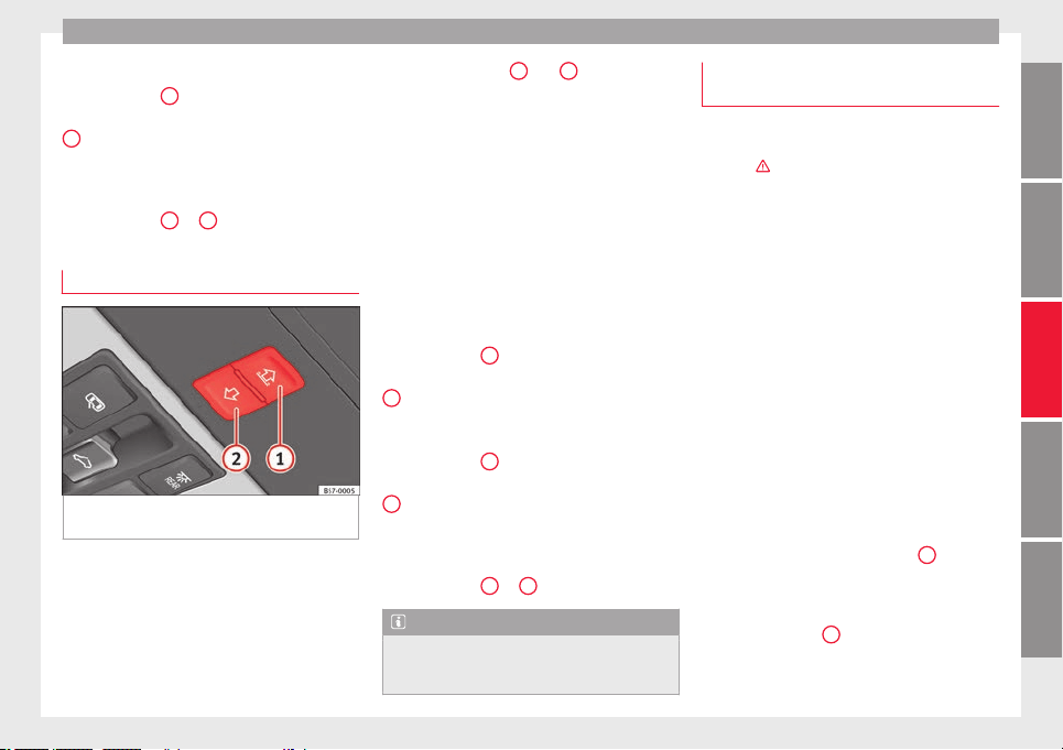
Opening and closing
Closing the sunroof
●
Press button
D
forwards to the first level.
●
Automatic operation: briefly press button
D
forwards to the second level.
St
op
pin
g the automatic operation during the
opening or closing
●
Press button
C
or
D
again.
Opening and closing the sun blind
Fig. 141 On the interior roof lining: switches
f
or the s
u
n blind.
The electrical sun blind works when the igni-
tion i
s
sw
itched on.
When the sunroof is in its most tilted posi-
tion, the sun blind automatically goes into a
ventilation position. The sun blind remains in
this position also with the sunroof closed.
Buttons ››› Fig. 141
1
and
2
have two lev-
el
s.
The fir
st level opens or closes the sun
blind fully or partially.
By briefly pressing the button to the second
level, the sun blind automatically moves to
the corresponding final position. Activating
the button again stops the automatic func-
tion.
Once the ignition has been switched off, you
can still open or close the sun blind for a few
minutes provided the driver door and the
front passenger door are not opened.
Opening the sun blind
●
Press button
1
to the first level.
●
Automatic operation: briefly press button
1
to the second level.
C
lo
s
ing the sun blind
●
Press button
2
to the first level.
●
Automatic operation: briefly press button
2
to the second level.
St
op
pin
g the automatic operation during the
opening or closing
●
Press button
1
or
2
again.
Note
When the sunroof is open, the electric sun
blind can on
ly be closed to the front edge of
the sunroof.
Anti-trap function of the panoramic
s
lidin
g s
unroof and the sun blind
The anti-trap function can reduce the risk of
injury when c
losing the sunroof and the sun
blind ›››
. If the sunroof or sun blind en-
count
er resistance or an obstacle when clos-
ing, they reopen immediately.
●
Check why the sunroof or sun blind do not
close.
●
Try to close the sunroof or sun blind again.
●
If the sunroof or sun blind cannot be closed
due to an ob
stacle or some resistance, it
stops at the corresponding position and then
opens. For automatic closing, a new closing
attempt might take place.
●
If the sunroof or sun blind is still unable to
close, close it without the anti-trap function.
Closing the sunroof or sun blind without the
anti-trap function
●
Sunroof: within approx. 5 seconds of hav-
ing activated the roll-back function, press the
button
›››
Fig. 140 to the second level in
the direction of arrow
›››
Fig. 140
D
until the
s
u
nr
oof closes completely.
●
Sun blind: within approx. 5 seconds of hav-
ing activated the anti-trap function, press
button
›››
Fig. 141
2
until the sun blind
c
lo
se
s completely.
●
The sunroof or sun blind close without the
anti-trap function intervening!
»
143
Technical dataAdviceOperationEmergenciesSafety
Operation
●
If
the s
u
nroof or sun blind will still not
close, visit a specialised workshop.
WARNING
Closing the sunroof or sun blind without the
anti-trap fu
nction can cause serious injuries.
●
Always be careful when closing the sunroof
and sun blind.
●
No person should ever remain in the way of
the sunroof or sun blind, especially when
closing without the anti-trap function.
●
The anti-trap function does not prevent fin-
gers or other parts of the body from becom-
ing trapped against the roof frame and inju-
ries occurring.
Lights and visibility
Light
s
R
el
ated video
Fig. 142 Vehicle lights
Side light and dipped beam headlight
Read the additional information carefully
›
›
›
page 30
The driver is personally responsible for the
correct use and adjustment of the lights in all
situations.
Audible warnings to advise the driver that
the lights have not been switched off
If the key is not in the ignition and the driver
door is open, an audible warning signal is
heard in the following cases: this is a remind-
er to turn off the lights.
●
When the parking light is on ››› page 145.
●
When the light switch is in position or
.
WARNING
The side lights or daytime running lights are
not bright enough t
o illuminate the road
ahead and to ensure that other road users are
able to see you.
●
Always use your dipped beam head lights if
it is raining or if visibility is poor.
WARNING
If the headlights are set too high and not
used corr
ectly, there is a risk of dazzling or
distracting other road users. This could result
in a serious accident.
●
Always make sure that the headlights are
correctly adjusted.
Note
The legal requirements regarding the use of
vehicl
e lights in each country must be ob-
served.
144
Lights and visibility
Daytime running lights
The daytime running lights consist of individ-
ual lights, inte
grated in the front headlights.
By connecting the daytime running lights,
these lights are switched on
1)
›››
.
The daytime ru
nning lights switch on every
time the ignition is switched on, if the switch
is in positions or , according to the level
of exterior lighting.
When the light switch is in position , a
light sensor automatically switches dipped
beam on and off (including the control and
instrument lighting) or the daytime running
lights depending on the level of exterior
lighting.
WARNING
●
Never drive w
ith daytime lights if the road
is not well lit due to weather or lighting con-
ditions. Daytime lights do not provide
enough light to illuminate the road properly
or be seen by other road users.
●
On vehicles with rear lights with bulbs,
when activating the daytime running light
the rear lights are not switched on. A vehicle
which does not have the rear lights on may
not be visible to other drivers in the dark-
ness, in the case of heavy rain or in condi-
tions of poor visibility.
Turn signal and main beam lever
Read the additional information carefully
›››
page 31
Push the lever all the way down to turn off
the corresponding function.
Convenience turn signals
For the one-touch signalling, when the igni-
tion is switched on, move the lever as far as
possible upwards or downwards and release
the lever. The turn signal will flash three
times.
One-touch signalling is activated and deacti-
vated in the Easy Connect system via the
button and the function button SETTINGS >
Lights > One-touch signalling
›
›
›
page 33.
In vehicles that do not have the correspond-
ing menu, this function can be deactivated in
a specialised workshop.
WARNING
Improper or lack of use of the turn signals, or
forg
etting to deactivate them can confuse
other road users. This could result in a seri-
ous accident.
●
Alwa
ys give warning when you are going to
change lane, overtake or when turning, acti-
vating the turn signal in good time.
●
As soon as you have finished changing
lane, overtaking or turning, switch the turn
signal off.
WARNING
Incorrect use of the headlights may cause ac-
c
idents
and serious injury, as the main beam
may distract or dazzle other drivers.
Note
●
If the con
venience turn signals are operat-
ing (three flashes) and the other convenience
turn signals are switched on, the active part
stops flashing and only flashes once in the
new part selected.
●
The turn signal only works when the igni-
tion is switched on. The hazard warning
lights also work when the ignition is switch-
ed off.
●
If a trailer turn signal malfunctions, the
control lamp will stop flashing (trailer turn
signals) and the vehicle turn signal will flash
at double speed.
●
The main beam headlights can only be
switched on if the dipped beam headlights
are already on.
»
1)
On vehicles equipped with rear LED lights, the rear
side light i
s switched on as well.
145
Technical dataAdviceOperationEmergenciesSafety
Operation
●
In col
d or damp weather conditions, the
headlights, tail lights and turn signals may
mist up inside temporarily. This is normal and
in no way effects the useful life of the vehicle
lighting system.
Automatic dipped beam control
*
The automatic dipped beam control is merely
intended as
an aid and is not able to recog-
nise all driving situations.
When the light switch is in position , the
vehicle lights and the instrument panel and
switch lighting switch on and off automatical-
ly in the following situations ›››
in Daytime
ru
nnin
g light
s on page 145:
Automatic switching
on
Automatic switching
off
The photo sensor detects
darkness, for example,
when driving through a
tunnel.
When adequate lighting is
detected.
The rain sensor detects
rain and activates the
windscreen wipers.
When the windscreen wip-
ers have been inactive for
a few minutes.
WARNING
If the road is not well lit and other road users
cannot see the
vehicle well enough or at all,
accidents may occur.
●
The automatic
dipped beam control ()
only switches on the dipped beam when
there are no changes in brightness, and not,
for example when it is foggy.
Main beam assist*
Main beam assist (Light Assist)
The main beam a
ssist acts within the limits
of the system and depending on environmen-
tal and traffic conditions. Once switched on,
the system is activated as of a speed of
about 60 km/h (37 mph) and is deactivated
below about 30 km/h (18 mph) ›››
.
When the sy
s
t
em is activated and the camera
detects other vehicles that may be dazzled,
the main beam is automatically switched off.
Otherwise, the main beam is automatically
switched on.
The main beam assist generally detects illu-
minated areas and deactivates the main
beam when passing through a town, for ex-
ample.
Switching the main beam assist on and off
Func-
tion
Use
Activate:
– Switch the ignition on and turn the light
switch to position
.
– From the base position, move the main
beam and turn signal lever forwards
››› page 145. When the warning lamp
is
displayed on the instrument panel display,
the main beam assist is switched on.
To switch
system
off:
– Switch off the ignition.
– OR: turn the light switch to a different po-
sition to
››› page 144.
– OR: with main beam on, move the main
beam and turn signal lever backwards.
– OR: move the main beam and turn the
signal lever forwards to manually switch
the main beam on. The main beam assist
will then be deactivated.
Malfunctions
The f
o
l
lowing conditions may prevent the
main beam headlight control from turning off
the headlights in time or from turning off al-
together:
●
In poorly lit towns with highly reflective
signs.
●
Other insufficiently lit road users (such as
pedestrians or cyclists).
●
On tight bends and steep slopes (bumps)
and when oncoming vehicles are partially ob-
scured.
146
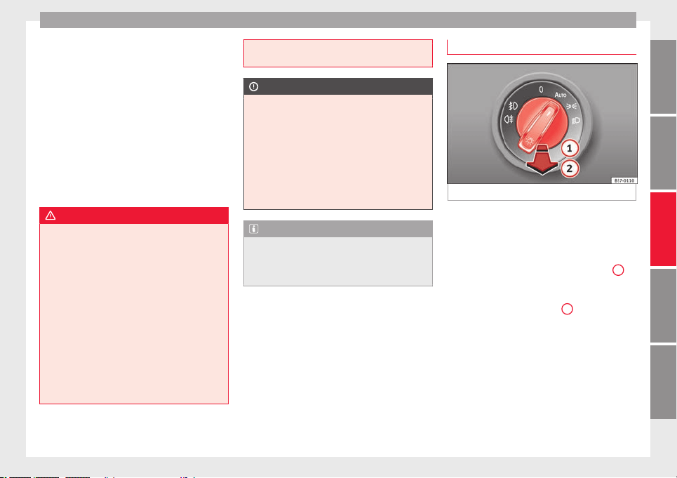
Lights and visibility
●
When the driv
er
s
of other oncoming vehi-
cles (such as a truck) can see over a guard
rail in the centre of the road.
●
If the camera is damaged or the power sup-
ply is cut off.
●
In fog, snow and heavy rain.
●
With dust and sand turbulence.
●
With loose gravel in the field of vision of
the camera.
●
When the field of vision of the camera is
misted up, dirty or covered by stickers, snow,
ice, etc.
WARNING
The convenience features of the main beam
ass
ist should not encourage the taking of
risks. The system is not a replacement for
driver concentration.
●
You are always in control of the main beam
and adapting it to the light, visibility and traf-
fic conditions.
●
It is possible that the main beam headlight
control does not recognise all driving situa-
tions and is limited under certain circumstan-
ces.
●
When the field of vision of the camera is
dirty, covered or damaged, operation of the
main beam control may be affected. This also
applies when changes are made to the vehi-
cle lighting system, for example, if additional
headlight
s are installed.
CAUTION
To avoid affecting the operation of the sys-
t
em, tak
e the following points into considera-
tion:
●
Clean the field of vision of the camera regu-
larly and make sure it is free of snow and ice.
●
Do not cover the field of vision of the cam-
era.
●
Check that the windscreen is not damaged
in the area of the field of vision of the camera.
Note
Main beam and headlight flasher can be
turned on and off m
anually at any time with
the turn signal and main beam lever
››› page 145.
Fog lights
Fig. 143 Dash panel: light control.
The warning lamps or al
so sho
w
, on the
light switch or instrument panel, when the
fog lights are on.
●
Switching on front fog lights* : pull the
light switch to the first point ››› Fig. 143
1
,
fr
om po
s
itions , or .
●
Switching on the rear fog light : com-
pletely pull the light switch
2
from position
, or
.
●
T
o sw
itch off the fog lights, press the light
switch or turn it to position .
»
147
Technical dataAdviceOperationEmergenciesSafety

Operation
Note
The rear fog light can dazzle drivers behind
you. Y
ou should use the rear fog light only
when visibility is very poor.
Cornering lights*
1)
When turning slowly or on very tight bends,
the cornering lights
are activated automati-
cally. The cornering lights may be integrated
in the fog lights and are switched on only at
speeds of less than 40 km/h (25 mph).
When reverse gear is engaged, the cornering
lights on both sides of the vehicle switch on,
in order to better illuminate the area for park-
ing.
“Coming home” function
This function may be connected/disconnec-
t
ed thr
ough the r
adio menu. The “Coming
Home” and/or “Leaving Home” delay time
may also be set (default: 30 sec).
Vehicle with halogen headlights
In the “Coming Home” function, the daytime
running lights (DRL), the rear side lights and
the licence plate lights are turned on.
Vehicle with full-LED headlights
In the “Coming Home” function, the dipped
beams, the daytime running lights (DRL), the
rear side lights, the number plate lights and
the courtesy lights in the rear view mirror
(Welcome Light) switch on.
Automatic* activation of “Coming Home”
For vehicles with a light and rain sensor (rota-
ry light switch in position ).
●
Switch off the engine and remove the key
from the ignition with the rotary light switch
in position ›››
page 30.
●
The automatic “Coming Home” function is
only active when the light sensor detects
darkness.
●
When the car door is opened, the “Coming
Home” lighting comes on.
Manual “Coming Home” activation
For vehicles with a light and rain sensor (rota-
ry light switch without position ).
●
Switch off the engine and remove the key
from the ignition.
●
Activate the headlight flashers for approxi-
mately 1 second.
●
Activated for any position of the rotary light
switch.
●
When the car door is opened, the “Coming
Home” lighting comes on. The headlights are
turned off 60 seconds after the vehicle door
is opened.
Deactivation
●
If no door has been closed, they go out au-
tomatically after 60 seconds.
●
After the last door has been closed, the
headlights will be switched off after the
“Coming Home” delay (as established in the
radio menu) has elapsed.
●
On turning the light switch to position
›››
page 30.
●
When the ignition is switched on (when
starting the engine).
1)
This function is not available on vehicles equipped
with fu
ll-LED headlights.
148
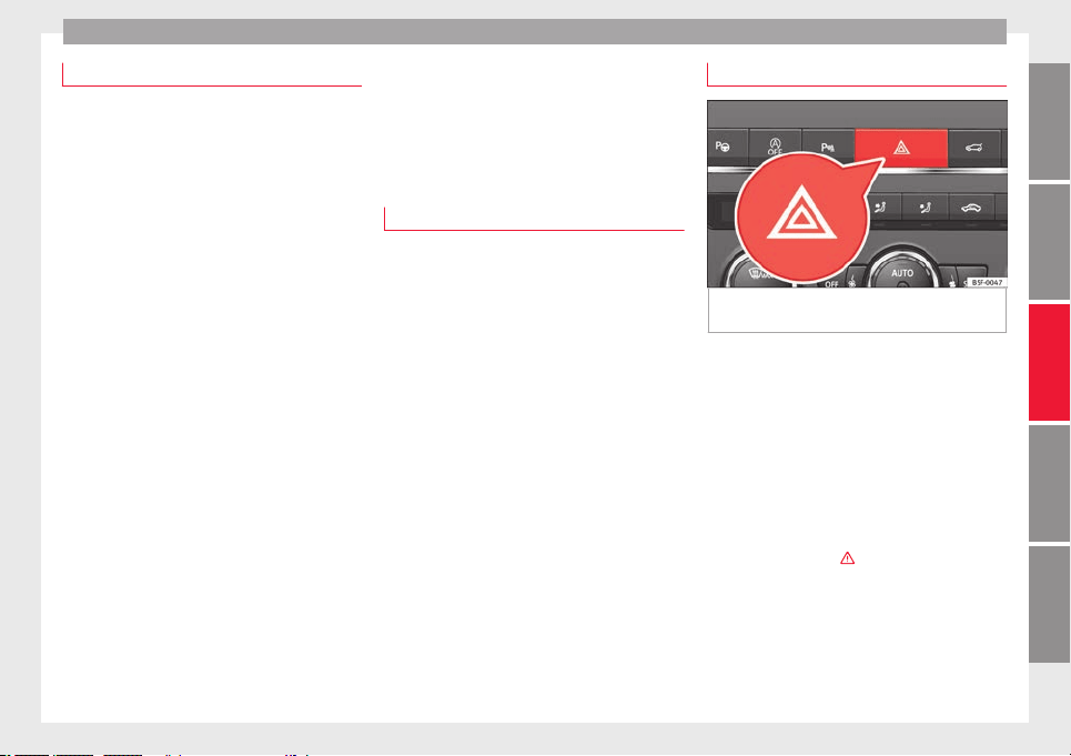
Lights and visibility
Function “Leaving Home”
The “Leaving Home” function is only availa-
ble f
or vehicles with a light and rain sensor
(rotary light switch in position ).
This function may be connected/disconnec-
ted through the radio menu. The “Leaving
Home” function switch-off delay may also be
set (default: 30 sec).
Vehicle with halogen headlights
In the “Leaving Home” function, the daytime
running lights (DRL), the rear side lights and
the licence plate lights are switched on.
Vehicle with full-LED headlights
In the “Leaving Home” function, the dipped
beams, the daytime running lights (DRL), the
rear side lights, the number plate lights and
the courtesy lights in the rear view mirror
(“Welcome Light”) switch on.
Activation
●
When the vehicle is unlocked using the re-
mote contr
ol.
●
The “Leaving Home” function is only activa-
ted when the rotary light switch is in position
and the light sensor detects darkness.
Deactivation
●
When the “Leaving Home” delay period
ends (default: 30 sec).
●
When the vehicle is locked using the re-
mote control.
●
When the light control is switched into a
position other than .
●
With the ignition is switched on.
Welcome light*
3 Valid for vehicles with a light and rain sensor
(light sw
itch in position ) and Full LED head-
lights.
The Welcome light is a light located on the
exterior mirrors facing the ground which is
switched on or off if the lights control is in
the position and the “Coming Home” /
“Leaving Home” function is switched on or
off.
Hazard warning lights
Fig. 144 Dash panel: switch for hazard warn-
in
g lights.
Read the additional information carefully
›
›
›
page 31
The hazard warning lights are used to draw
the attention of other road users to your vehi-
cle in emergencies.
If your vehicle breaks down:
1. Park your vehicle at a safe distance from
moving traffic.
2. Press the button to switch on the hazard
warning lights ›››
.
3. Switch the ignition off.
4. Apply the handbrake.
5. For a manual gearbox, engage 1st gear;
f
or an aut
om
atic gearbox, move the gear
lever to P.
»
149
Technical dataAdviceOperationEmergenciesSafety
Operation
6. Use the warning triangle to draw the atten-
tion of
other r
o
ad users to your vehicle.
7. Always take the vehicle key with you when
you leave the vehicle.
All turn signals flash simultaneously when
the hazard warning lights are switched on.
The two turn signal turn signal lamps
and the turn signal lamp in the switch will
flash at the same time. The simultaneous
hazard warning lights also work when the ig-
nition is switched off.
Emergency braking warning
If the vehicle brakes suddenly and continu-
ously at a speed of more than 80 km/h (50
mph), the brake light flashes several times
per second to warn the vehicles driving be-
hind. If you continue braking, the hazard
warning lights will come on automatically
when the vehicle comes to a standstill. They
switch off automatically when the vehicle
starts to move again.
WARNING
●
The risk of
an accident increases if your ve-
hicle breaks down. Always use the hazard
warning lights and a warning triangle to draw
the attention of other road users to your sta-
tionary vehicle.
●
Due to the high temperatures that the cata-
lytic converter can reach, never park in an
area where the catalytic converter could come
into contact with highly inflammable materi-
als, f
or example dry grass or spilt petrol. This
could start a fire.
Note
●
The b
atter
y will run down if the hazard
warning lights are left on for a long time,
even if the ignition is switched off.
●
The use of the hazard warning lights de-
scribed here is subject to the relevant statu-
tory requirements.
Parking lights
When the parking light is switched on, (right
or l
ef
t
turn signal), the front side light and
the rear light on the corresponding side of
the vehicle stay lit. The parking lights can on-
ly be activated with the ignition switched off
and the turn signal and main beam lever in
the central position, before being triggered.
Parking light on both sides
With the ignition switched off and the light
sw
it
c
h in position , when locking the vehi-
cle from the outside, the parking lights on
both sides of the vehicle light up. In doing
so, only the side lights of both headlights
light up, and additionally the tail lights will
do so partially.
Motorway light*
The motorway light is available on vehicles
equipped with f
ull-LED lights.
The function is connected/disconnected via
the corresponding Easy Connect system
menu.
●
Activation: when going above 110 km/h
(68 mph) for more than 30 seconds, the dip-
ped beam raises slightly to increase the driv-
er's visibility distance.
●
Deactivation: when reducin
g the speed of
the car below 100 km/h (62 mph), the dip-
ped beam returns to its normal position.
Driving abroad
The light beam of the dipped beam lights is
a
symmetric: the s
ide of
the road on which
you are driving is lit more intensely.
When a car that is manufactured in a country
that drives on the right travels to a country
that drives on the left (or vice versa), it is nor-
mally necessary to cover part of the headlight
bulbs with stickers or to change the adjust-
ment of the headlights to avoid dazzling oth-
er drivers.
In such cases, the regulations specify certain
light values that must be complied with for
designated points of the light distribution.
This is known as “Tourist light”.
150
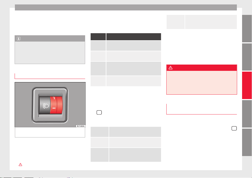
Lights and visibility
The light distribution of the halogen and full-
LED he
a
dlights
allows the specific “tourist
light” values to be met without the need for
stickers or changes in the settings.
Note
“Tourist light” is only allowed temporarily. If
you are p
lanning a long stay in a country that
drives on the other side, you should take the
vehicle to an Authorised Technical Service to
change the headlights.
Headlight range control
Fig. 145 Next to the steering wheel: Head-
light
r
an
ge control
The headlight range control ›
›
›
Fig. 145 is
modified according to the value of the head-
light beam and the vehicle load status. This
offers the driver optimum visibility and the
headlights do not dazzle oncoming drivers
›››
.
The headlights can only be adjusted when
the dip
ped be
am i
s switched on.
To reset, turn switch ››› Fig. 145:
Value Vehicle load status
a)
Two front occupants, luggage compart-
ment empty
All seats occupied, luggage compartment
empty
All seats occupied, luggage compartment
full. With trailer and minimum drawbar
load.
Driver only, luggage compartment full With
trailer and maximum drawbar load.
a)
If the vehicle load does not correspond to those shown in the
table, it is possible to select intermediary positions.
OR:
Using the Easy Connect system, by means of
the
button and the function button SET-
TINGS > Lights > Headlight height
adjustment
›
›
›
page 33).
Setting 0
Two front occupants, luggage compart-
ment empty
Setting 1
All seats occupied, luggage compart-
ment empty
Setting 2
All seats occupied, luggage compart-
ment full. With trailer and minimum
drawbar load.
Setting 3
Driver only, luggage compartment full
Driving with trailer and minimum draw-
bar load.
Dynamic headlight range control
The contro
l is not mounted in vehicles with
dynamic headlight range control. The head-
light range is automatically adjusted accord-
ing to the vehicle load status when they are
switched on.
WARNING
Heavy objects in the vehicle may mean that
the headlight
s dazzle and distract other driv-
ers. This could result in a serious accident.
●
Adjust the light beam to the vehicle load
status so that it does not blind other drivers.
Lighting of the instrument panel,
s
c
r
eens and controls
Depending on the model, the lighting of the
in
s
trument
panel and controls can be adjus-
ted in the Easy Connect system, using the
button and the SETTINGS f
u
nction b
utton
›››
page 33.
With the ignition on and without light activa-
tion, the instrument panel lighting remains
activated in daytime light conditions. The
lighting is reduced as the exterior light di-
minishes. In some cases, e.g. when driving
»
151
Technical dataAdviceOperationEmergenciesSafety
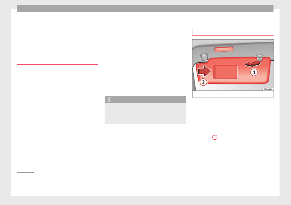
Operation
through a tunnel without the
f
u
nction
active, the instrument panel lighting may
even switch off. The objective of this function
is to provide the driver with a visual indica-
tion that he or she should activate the dip-
ped beam.
Interior and reading lights
1)
Read the additional information carefully
›››
page 31
Glove compartment and luggage compart-
ment lighting*
When opening and closing the glove com-
partment on the front passenger side and the
rear lid, the respective light will automatically
switch on and off.
Footwell lighting*
The lights in the footwell area below the dash
(driver and front passenger sides) will switch
on when the doors are opened and will de-
crease in intensity while driving. The intensity
of these lights can be adjusted using the ra-
dio menu (see Easy Connect > Light
Settings > Interior lighting
›››
page 33).
Ambient light*
The ambient light lights up the area of the
centre console, the footwell area and, de-
pending on the version, the front door pan-
els.
The ambient lighting in the door panels may
change colour. The brightness and colour of
these lights can be adjusted using the radio
menu (see Easy Connect > Light Set-
tings > Interior lighting
›››
page 33).
Note
The reading lights switch off when the vehi-
cle i
s locked using a key or after several mi-
nutes if the key is removed from the ignition.
This prevents the battery from discharging.
Visibility
S
u
n
visors
Fig. 146 Sun visor
Options for adjusting driver and front pas-
sen
g
er s
un visors:
●
Lower the sun visor towards the wind-
screen.
●
The sun visor can be pulled out of its
mounting and turned towards the door
››› Fig. 146
1
.
●
Swing the sun visor towards the door, lon-
git
udin
al
ly backwards.
1)
Depending on the level of equipment fitted in the
vehicl
e, LEDs can be used for the following interior
lights: front courtesy light, rear courtesy light, foot-
well light, sun blind and glove compartment light.
152
Lights and visibility
Vanity mirror light
Ther
e m
a
y be a vanity mirror, with a cover, on
the rear of the sun visor. When the cover is
opened
2
a light comes on.
The l
amp g
oe
s out when the vanity mirror
cover is closed or the sun visor is pushed
back up.
WARNING
Folded sun blinds can reduce visibility.
●
Always store sun blinds and visors in their
housin
g when not in use.
Note
The light above the sun visor automatically
switc
hes off after a few minutes in certain
conditions. This prevents the battery from
discharging.
Windscreen wiper and window
w
iper sy
s
tems
Window wiper lever
Read the additional information carefully
›
›
›
page 32
CAUTION
If the ignition is switched off with the wind-
scr
een wipers active, they complete their
wipe before returning to the rest position.
When switching the ignition back on, the
windscreen wiper will continue to operate at
the same wiping level. Ice, snow and other
obstacles on the windscreen may damage the
wiper and the windscreen wiper motor.
●
If necessary, remove snow and ice from the
windscreen wipers before starting your jour-
ney.
●
Carefully lift the frozen windscreen wipers
from the glass. SEAT recommends a de-icer
spray for this operation.
●
Do not switch on the windscreen wipers if
the windscreen is dry. Cleaning with the
windscreen wipers while dry can cause dam-
age.
●
In icy conditions, always check that the
wiper blades are not frozen to the glass be-
fore using the wipers. In cold weather, it may
help to leave the vehicle parked with the wip-
ers in service position ›››
page 71.
Note
●
The winds
creen and window wipers only
function when the ignition is switched on and
the bonnet or rear lid, respectively, are
closed.
●
The interval wipe speed varies according to
the vehicle speed. The faster the vehicle is
moving, the more often the windscreen is
cle
aned.
●
The rear wiper is automatically switched on
when the windscreen wiper is on and the car
is in reverse gear.
Windscreen wiper functions
Windscreen wiper performance in different sit-
uations
If the vehicle is at a
standstill
The activated position provision-
ally changes to the previous posi-
tion.
During automatic
wipe
The air conditioner comes on for
approximately 30 seconds in air
recirculation mode to prevent the
smell of the windscreen washer
fluid entering the inside the vehi-
cle.
For the interval wipe
Intervals between wipes depend
on the vehicle's speed. The high-
er the vehicle speed the shorter
the intervals.
Heated windscreen washer jets*
The he
atin
g on
ly thaws the frozen jets, it
does not thaw the water in the washer hoses.
When the ignition is switched on the heated
windscreen washer jets automatically adjust
the heat depending on the ambient tempera-
ture.
»
153
Technical dataAdviceOperationEmergenciesSafety
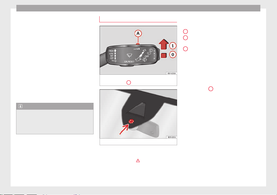
Operation
Headlight wash/wipe system*
The he
a
dlight
washers/wipers clean the
headlight lenses.
After the ignition is switched on, the first and
every fifth time the windscreen washer is
switched on, the headlights are also washed.
Therefore, the windscreen wiper lever should
be pulled towards the steering wheel when
the dipped beam or main beam are on. Any
incrusted dirt (such as insects) should be
cleaned regularly (e.g. when refuelling).
To ensure the headlight washers work cor-
rectly in winter, any snow which has got into
the bumper jet supports should be cleaned
away. If necessary, remove snow with an anti-
icing spray.
Note
The wiper will try to wipe away any obstacles
that ar
e on the windscreen. The wiper will
stop moving if the obstacle blocks its path.
Remove the obstacle and switch the wiper
back on again.
Rain sensor*
Fig. 147 Windscreen wiper lever: adjusting
the r
ain sen
sor
A
Fig. 148 Rain sensor sensitive surface
The rain sensor controls the frequency of the
w
ind
s
creen wiper intervals, depending on
the amount of rain ›››
. The sensitivity of the
r
ain sen
sor c
an be adjusted manually. Man-
ual wipe ››› page 153.
Move the lever to the required position
››› Fig. 147:
Rain sensor off.
Rain sensor on; automatic wipe if neces-
sary.
Setting sensitivity level of rain sensor
–
Set control to the right: highly sensi-
tive.
–
Set control to the left: less sensitive.
When the ignition is switched off and then
back on, the rain sensor stays on and starts
operating again when the windscreen wipers
are in position
1
and the vehicle is travel-
lin
g at
mor
e than 16 km/h (10 mph).
Rain sensor modified behaviour
Possible causes of faults and mistaken read-
ings on the sensitive surface ››› Fig. 148 of
the rain sensor include:
●
Damaged blades: a film of water on the
damaged blades may lengthen the activation
time, reduce the washing intervals or result
in a fast and continuous wipe.
●
Insects: insects on the sensor may trigger
the windscreen wiper.
●
Salt on roads: in winter, salt spread in the
roads may cause an extra long wipe when the
windscreen is almost dry.
●
Dirt: dry dust, wax, coating on glass (Lotus
effect) or traces of detergent (car wash) may
0
1
A
154
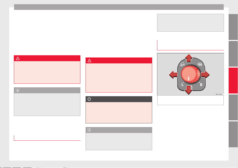
Lights and visibility
reduce the effectiveness of the rain sensor or
m
ak
e it
react more slowly, later or not at all.
●
Cracked windscreen: the impact of a stone
will trigger a single wipe cycle with the rain
sensor on. Next the rain sensor detects the
reduction in the sensitive surface area and
adapts accordingly. The behaviour of the sen-
sor will vary with the size of the damage
caused by the stone.
WARNING
The rain sensor may not detect enough rain
to swit
ch on the wipers.
●
If necessary, switch on the wipers manually
when water on the windscreen obstructs visi-
bility.
Note
●
Cle
an the sensitive surface of the rain sen-
sor regularly and check the blades for dam-
age ››› Fig. 148 (arrow).
●
To remove wax and coatings, we recom-
mend a window cleaner containing alcohol.
Mirror
Anti-d
azz
l
e rear view mirror
It is dangerous to drive if you cannot see
c
l
e
arly through the rear window.
Rear view mirror with automatic anti-dazzle
function*
The anti-dazzle function is activated every
time the ignition is switched on.
When the anti-dazzle function is enabled, the
interior rear vision mirror will darken auto-
matically according to the amount of light it
receives. The anti-dazzle function is cancel-
led if reverse gear is engaged.
WARNING
In the event that an automatic anti-dazzle
rear
vision mirror breaks, an electrolyte fluid
may leak. This could cause irritation to the
skin, eyes and respiratory organs. If you
come into contact with this liquid, it must be
rinsed with large quantities of water. If neces-
sary, get medial help.
CAUTION
In the event that an automatic anti-dazzle
rear
vision mirror breaks, an electrolyte fluid
may leak. This liquid attacks plastic surfaces.
Clean it with a wet sponge as soon as possi-
ble.
Note
●
If the light inc
ident in the interior rear vi-
sion mirror is obstructed (e.g. with the sun
blind*), the anti-dazzle rear vision mirror with
automatic setting will not operate perfectly.
●
When the interior lights
are on or reverse
gear engaged, the mirrors do not darken with
automatic adjustment for anti-dazzle posi-
tion.
Adjusting the exterior rear-view mir-
rors
Fig. 149 Driver door: control for the exterior
mirr
or
.
Read the additional information carefully
›
›
›
page 20
Synchronized regulation of the exterior mir-
rors
●
In the Settings - Convenience menu,
select whether or not the exterior mirrors
should move in synchronisation.
»
155
Technical dataAdviceOperationEmergenciesSafety
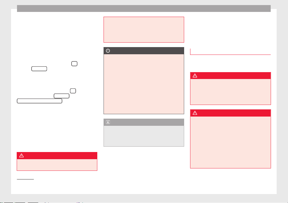
Operation
●
T
urn the kno
b t
o position L
1)
.
●
Adjust the left-hand exterior mirror. The
right exterior mirror will be adjusted at the
same time (synchronised).
●
If necessary the right exterior mirror adjust-
ment may need correcting. turn the control to
position R
1)
.
●
In the Easy Connect system the exterior mir-
rors can be adjusted using the
button
and the
S
ET
TINGS
function button.
F
o
l
d in the exterior mirrors after parking
(convenience function)*
The Easy Connect system, the
button and
the f
u
nction b
uttons
SETTINGS
and
Mirr
or
s
and windscreen wipers
can be used to
h
av
e the e
xterior mirrors fold in when the ve-
hicle is parked ››› page 120.
When the vehicle is locked with the remote
control, by pressing for more than approxi-
mately 1 second the exterior mirrors are fol-
ded in automatically. When the vehicle is
opened with the remote control, the exterior
mirrors are deployed automatically.
WARNING
Convex or wide-angle* exterior mirrors give a
larg
er field of vision. However, they make ob-
jects look smaller and further away than they
rea
lly are. If you use these mirrors to esti-
mate the distance to vehicles behind you
when changing lane, you could misjudge the
distance. Risk of accident!
CAUTION
●
If
one of the mirr
or housings is knocked out
of position (e.g. when parking), the mirrors
must first be fully retracted with the electric
control. Do not readjust the mirror housing by
hand, as this will interfere with the mirror ad-
juster function.
●
Before washing the vehicle in an automatic
car wash, please make sure to retract the ex-
terior mirrors to prevent them from being
damaged. Electrically retractable exterior
mirrors must not be folded in or out by hand.
Always use the electrical power control.
Note
If the electrical adjustment should fail to op-
erate, both of
the mirrors can be adjusted by
hand by lightly pressing the edge of the mir-
ror glass.
Seats and head restraints
Adju
s
tin
g the seats and headr-
ests
Manual adjustment of the seats
Read the additional information carefully
›››
page 18
WARNING
The safe driving chapter contains important
information, tip
s, suggestions and warnings
that you should read and observe for your
own safety and the safety of your passengers
››› page 73.
WARNING
●
Adjust
the front seats only when the vehi-
cle is stationary. Failure to follow this instruc-
tion could result in an accident.
●
Be careful when adjusting the seat height.
Careless or uncontrolled adjustment can
cause injuries.
●
The front seat backrests must not be re-
clined for driving. Otherwise, seat belts and
the airbag system might not protect as they
should, with the subsequent danger of injury.
1)
Regulation in right-hand drive vehicles is symmet-
rical.
156
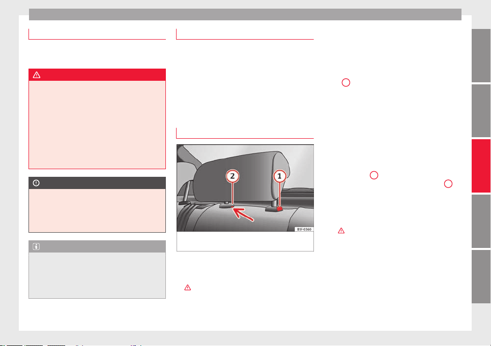
Seats and head restraints
Electric driver's seat adjustment*
Read the additional information carefully
›››
page 19
WARNING
●
If the electric
front seats are used negli-
gently or without paying due attention, it can
cause serious injury.
●
The front seats can also be electrically ad-
justed when the ignition is switched off. Nev-
er leave a child or any other person who may
need help in the vehicle.
●
In the event of an emergency, electrical ad-
justment can be stopped by pressing any
control.
CAUTION
To avoid damaging the electrical components
of the front
seats, please refrain from kneel-
ing on the seat or applying sharp pressure at
a single point to the seat cushion and back-
rest.
Note
●
It ma
y not be possible to electrically adjust
the seat if the vehicle battery is very low.
●
If the engine is started while the seats are
being electrically adjusted, the adjustment
will stop.
Adjusting the front head restraints
Read the additional information carefully
›››
page 19
Adjust the head restraint ›››
page 19 so
that as far as possible the top of the head re-
straint is level with the top of your head.
When this is not possible, try to get as close
as possible to this position.
Adjustment of the rear head restraints
Fig. 150 Rear centre head restraint: release
point
.
When transporting people in the back seat,
p
l
ac
e the head restraints of the occupied
seats at a minimum of the next socket up
›››
.
Adjusting the head restraints
–
To set the head restraint higher, grasp the
s
ide
s
with both hands and move it up-
wards, until you see it engage.
–
To set the head restraint lower down, press
the
1
›
›› Fig. 150
b
utton and move it
downwards.
Removing the head restraint
To remove the head restraint, the correspond-
ing backrest must be partially folded forward.
–
Unlock the backrest ››› page 159.
–
Move the head restraint upwards until it ar-
rives to the top.
–
Press button
1
›
›
› Fig. 150
, while simulta-
neously pressing on the security hole
2
››› Fig. 150 with a flat
screwdriver a maxi-
mum of 5 mm wide, and remove the head
restraint.
–
Move the backrest until it engages properly
›››
.
Fittin
g the he
a
d restraint
To mount the external head restraints, the
corresponding backrest must be partially fol-
ded forward.
–
Unlock the backrest ››› page 159.
–
Insert the head restraint bars into the
guides until they perceptibly engage. It
»
157
Technical dataAdviceOperationEmergenciesSafety
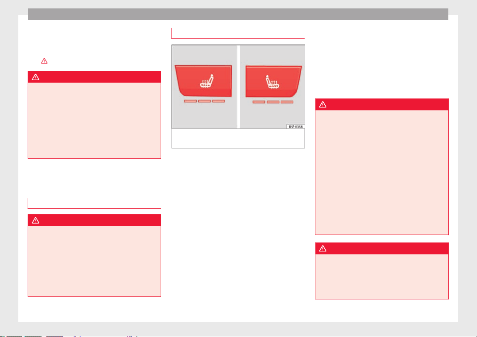
Operation
should not be possible to remove the head
r
e
s
traint from the backrest.
–
Move the backrest until it engages properly
›››
.
WARNING
●
Plea
se observe the general notes
››› page 77.
●
Remove the rear head restraints only when
it is necessary for the placement of a child
seat ››› page 90. After removing a child seat,
remount the head restraint immediately.
Travelling with the head restraints removed
or improperly adjusted increases the risk of
severe injuries.
Seat functions
Intr
oduction
WARNING
Inappropriate use of the seat functions can
cause sev
ere injuries.
●
Assume the proper sitting position before
your trip and remain in it throughout. This al-
so applies to the other occupants.
●
Always keep hands, fingers, feet and other
parts of the body away from the operating ra-
dius and the adjustment of seats.
Seat heating
Fig. 151 In the centre console: front seats
he
atin
g sw
itch
The seat cushions can be heated electrically
when the ignition i
s
sw
itched on. The back-
rest is also heated in some versions.
The seat heating should not be engaged in
any of the following conditions:
●
The seat is unoccupied.
●
The seat has a covering.
●
There is a child seat installed in the seat.
●
The seat cushion is wet or damp.
●
The indoor or outdoor temperature is great-
er than 25°C (77°F).
Activate
Press the button or . Seat heating is
switched on fully.
Adjusting the heating output
Press the button or repeatedly until the
desired intensity level is reached.
Deactivating
Press the button or until all warning
lamps switch off.
WARNING
Children and people who cannot perceive
pain or temper
ature because of medications,
paralysis or chronic diseases (e.g. diabetes)
or have a limited perception of these, may
suffer burns to the back, buttocks or legs
when using seat heating, an occurrence that
may entail a very lengthy recovery period or
from which it may not be possible to recover
fully. Seek medical advice if you have doubts
regarding your health.
●
People with limited pain and temperature
thresholds must never use seat heating.
●
If an abnormality in the device's tempera-
ture control is detected, have it checked by a
specialist workshop.
WARNING
If the fabric of the cushion is wet, this can ad-
versely
affect the operation of the seat heat-
ing, increasing the risk of burns.
●
Make sure the seat cushion is dry prior to
using the seat heater.
158
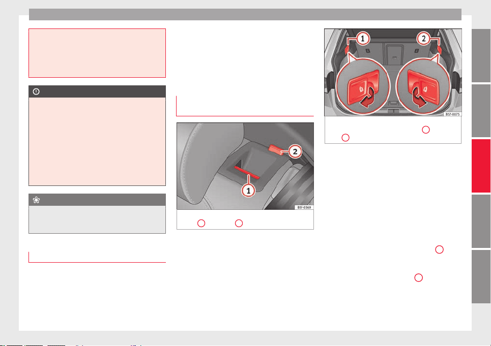
Seats and head restraints
●
Do not sit
on the seat with clothing that is
wet or damp.
●
Do not leave clothing that is wet or damp
on the seat.
●
Do not spill liquid on the seat.
CAUTION
●
T
o avoid d
amaging the heating elements of
the seat heaters, please do not kneel on the
seat or apply sharp pressure to a single point
on the seat cushion or backrest.
●
Liquids, sharps objects and insulating ma-
terials (e.g. covers or child seats) can damage
the seat heating.
●
In the event of smells, switch off the seat
heating immediately and have it inspected by
a specialised workshop.
For the sake of the environment
The seat heating should remain on only when
needed. Otherwi
se, it is an unnecessary fuel
waste.
Front centre armrest
The centre armrest can be adjusted to various
l
ev
el
s.
Adjusting the centre armrest
–
To adjust the tilt, lift the armrest from the
starting position so that it is engaged.
–
To return the armrest to the starting posi-
tion, remove the armrest from the upper
fixed position and lower it.
The armrest can be moved backwards and
forwards.
Folding down and lifting the rear seat
backrest
Fig. 152 On the rear seat backrest: release
c
at
c
h
1
; red mark
2
.
Fig. 153 In the luggage compartment: levers
for remot
e release of the left part
1
and right
part
2
of the rear seat backrest.
The rear seat backrest is split and each part
be lo
w
er
ed separately to extend the luggage
compartment.
When the rear seat backrest is lowered no-
body else can travel in the corresponding
seats (not even a child).
Lowering the rear seat backrest with the un-
lock button
●
Lower the head restraint properly.
●
Push the unlock button ››› Fig. 152
1
for-
w
ar
d
s and at the same time lift the backrest.
●
The rear seat backrest is not engaged when
the red marking of the button
2
is visible.
L
o
w
ering the rear seat backrest with the re-
mote release lever
●
Lower the head restraint properly.
»
159
Technical dataAdviceOperationEmergenciesSafety
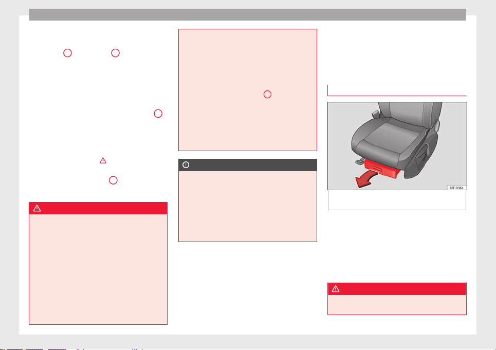
Operation
●
Open the r
e
ar lid.
●
P
ull the remote release lever of the left part
››› Fig. 153
1
or right part
2
of the backrest
in the dir
ection of
the arr
ow. The released
part of the rear seat backrest is folded auto-
matically down and forwards.
●
If this occurs, close the rear lid.
The rear seat backrest is not engaged when
the red marking of the button ››› Fig. 152
2
is visible.
F
o
l
ding up the rear seat backrest
●
Lift the backrest and press it firmly into the
lock until it engages ›››
.
●
It should not be possible to see the red
m
ark
of
the unlock button
2
.
●
The backrest must be properly engaged.
WARNING
Serious injuries can be caused if the rear seat
back
rest is lowered or lifted without due care
and attention.
●
Never lower or lift the rear seat backrest
while driving.
●
Do no trap or damage the seat belt when
raising the rear seat backrest.
●
When lowering or lifting the rear seat back-
rest, keep your hands, fingers, feet and other
body parts out of its path.
●
For the rear seat belts to offer the necessa-
ry protection all the parts of the rear backrest
must be properly engaged. This is particular-
ly import
ant in the case of the centre rear
seat. If someone is seated in a seat whose
backrest is not properly engaged they will fly
forward, along with the backrest, during an
accident or a sudden driving or braking ma-
noeuvre.
●
A red signal on the button
2
warns that
the back
rest is not engaged. Always check
that the red marking is not visible when the
backrest is in the upright position.
●
When the rear seat backrest is lowered or is
not properly engaged nobody else can travel
in the corresponding seats (not even a child).
CAUTION
Serious damage can be caused to the vehicle
and other obj
ects if the rear seat backrest is
lowered or lifted without due care and atten-
tion.
●
Before lowering the rear seat backrest, al-
ways adjust the front seats so that neither
the head restraints nor the cushions of the
rear backrest can hit them.
Transport and practical
equipment
St
or
ag
e compartments
Storage areas under the front seats*
Fig. 154 Storage compartment under the
fr
ont
se
ats.
There is a storage compartment with a cover
u
nder e
ac
h front seat.
The drawer* is opened by pulling on the han-
dle of the cover ››› Fig. 154.
To close the drawer, press the cover until it
locks into position.
WARNING
●
The draw
ers will hold a maximum weight of
1.5 kg.
160
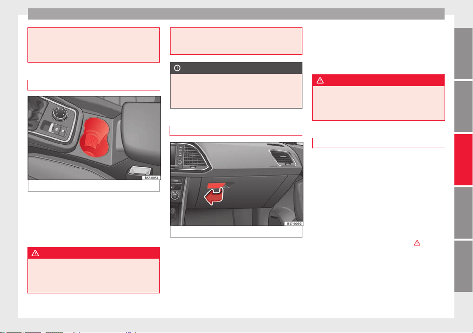
Transport and practical equipment
●
Do not drive w
ith the drawer cover open.
There is an injury risk for passengers if the
cargo is released in case of sudden braking or
an accident.
Drink holders
Fig. 155 Centre console: front drink holders.
Front drink holders
–
Place drinks in the holder ›
›
›
Fig. 155.
Placement of two drinks is possible. There
is also the possibility of placing larger plas-
tic bottles in the trims of the doors.
WARNING
●
Do not pl
ace any hot drinks in the drink
holder while the vehicle is moving. Hot drinks
could spill and cause burns, which may cause
an accident.
●
Do not use h
ard china cups or glasses.
These could cause injury in the event of an
accident.
CAUTION
You should avoid putting open drinks con-
t
ainers
in the drink holders. The drinks could
otherwise spill over and cause damage to e.g.
the electrical equipment or the seat covers.
Glove compartment
Fig. 156 Glove compartment
Opening/closing
–
To open the glove compartment, pull the
h
andl
e in the dir
ection of the arrow.
–
To close the glove compartment, move the
cover upwards until it engages.
Depending on the vehicle equipment, the CD
player is located in the glove compartment.
Separate operating instructions are enclosed
for this equipment in the corresponding In-
struction Manual.
WARNING
The cover of the glove compartment should
alwa
ys be closed while driving. Failure to fol-
low this instruction could result in an acci-
dent.
Other storage compartments
You will find more object holders, compart-
ments
and s
up
ports in other parts of the ve-
hicle:
●
In the top of the glove compartment in ve-
hicles that do not have a CD reader. The load
of the compartment should not exceed
1.2 kg.
●
In the centre console under the centre arm-
rest*.
●
Coat hooks in the door frames
›››
.
●
Other storage compartments are found in
the r
e
ar se
at, to the left and the right of the
seats.
»
161
Technical dataAdviceOperationEmergenciesSafety
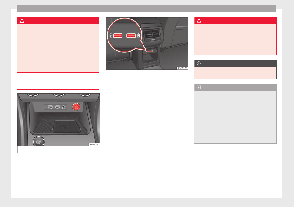
Operation
WARNING
●
Plea
se make sure that any items of clothing
hanging from the coat hooks do not obstruct
your view to the rear.
●
The coat hooks should only be used for
lightweight clothing. Do not leave any heavy
or sharp objects in the pockets.
●
Do not use clothes hangers to hang up the
clothing, as this could interfere with the func-
tion of the head-protection airbags.
Power sockets
Fig. 157 Centre console: 12 volt socket
Fig. 158 Centre console, rear section: USB
power soc
kets.
●
Remove the cap located on the centre con-
so
l
e of
the socket ››› Fig. 157.
●
Insert the plug of the electrical appliance
into the power socket.
Electrical equipment can be connected to the
12 volt power socket. The appliances connec-
ted to each power socket must not exceed a
power rating of 120 Watt.
USB power sockets
Depending on the equipment and the coun-
try, the vehicle may also have USB connec-
tions exclusively for charging or as a power
socket.
These USB ports are located at the rear of the
console, between the front seats ››› Fig. 158.
These connectors can work at a maximum
power of up to 10.5 W per port.
They are not intended for file playback.
WARNING
The power socket works only when the igni-
tion is on. Impr
oper use may cause serious
injury or even fire. Children should therefore
not be left in the vehicle unattended if the
button is also left behind. Otherwise there is
a possibility that they may be injured.
CAUTION
Always use the correct type of plugs to avoid
damagin
g the sockets.
Note
●
The use of el
ectrical appliances with the
engine switched off will cause a battery dis-
charge.
●
Should the connected appliance overheat,
immediately switch it off and disconnect it
from the socket.
●
Before switching the ignition on or off, un-
plug the appliances from the USB ports to
protect them from any damage caused by
fluctuations in voltage.
Storing objects
L
o
a
ding the luggage compartment
All luggage and other loose objects must be
s
af
ely
secured in the luggage compartment.
Unsecured objects which shift back and forth
162
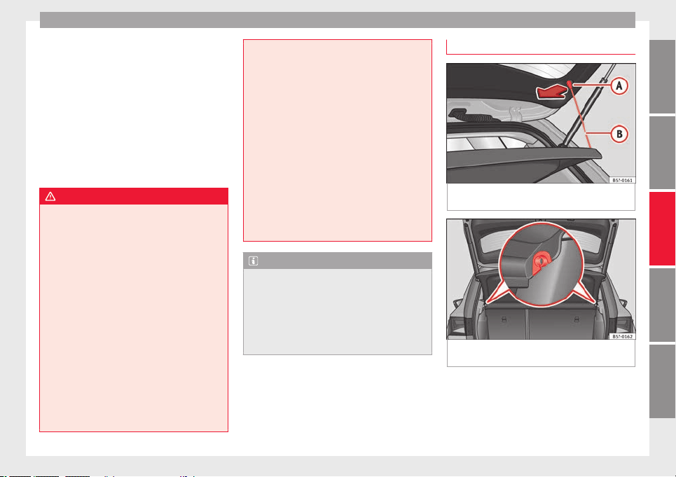
Transport and practical equipment
could impair the driving safety or driving
c
h
ar
acteristics of the vehicle by shifting the
centre of gravity.
–
Distribute the load evenly in the luggage
compartment.
–
Place heavy objects as far forward as possi-
ble in the luggage compartment.
–
Place the heavy objects first.
–
Secure heavy objects to the fitted fastening
rings ››› page 165.
WARNING
●
Loose lug
gage and other objects in the lug-
gage compartment could cause serious inju-
ries.
●
Always stow objects in the luggage com-
partment and secure them on the fastening
rings.
●
Use suitable straps to secure heavy ob-
jects.
●
During sudden manoeuvres or accidents,
loose objects can be thrown forward, injuring
vehicle occupants or passers-by. This in-
creased risk of injury will be further increased
if a loose object is struck by an inflating air-
bag. If this happens, objects may shoot out-
ward like a missile. Risk of fatal injury.
●
Please note that the centre of gravity may
shift when transporting heavy objects; this
may affect vehicle handling and lead to an ac-
cident. Therefore, it is essential to adjust
your speed and driving style accordingly, to
avoid acc
idents.
●
Never exceed the allowed axle weights or
allowed maximum weight. If said weights are
exceeded, the driving characteristics of the
vehicle may change, leading to accidents, in-
juries and damage to the vehicle.
●
Never leave your vehicle unattended, espe-
cially when the rear lid is open. Children
could climb into the luggage compartment,
closing the door behind them; they will be
trapped and run the risk of death.
●
Never allow children to play in or around
the vehicle. Close and lock all the doors and
the rear lid when you leave the vehicle. Be-
fore you lock the vehicle, make sure that
there are no adults or children in the vehicle.
Note
●
Air circ
ulation in the vehicle helps reduce
fogging of the windows. Used air escapes
through ventilation slits in the side trim of
the luggage compartment. Ensure that the
ventilation slots are never covered.
●
Straps for securing the load to the fasten-
ing rings are commercially available.
Luggage compartment shelf
Fig. 159 In the luggage compartment: remov-
in
g and in
s
talling the rear shelf.
Fig. 160 In the luggage compartment: remov-
in
g and in
s
talling the rear shelf.
The luggage compartment cover blocks the
v
iew int
o the lug
gage compartment.
»
163
Technical dataAdviceOperationEmergenciesSafety
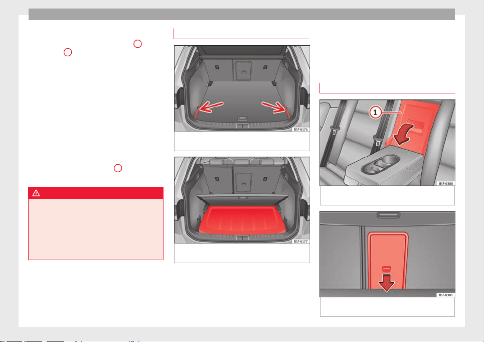
Operation
Removing
●
Detach the cord loops ›
›
›
Fig. 159
B
from
their hook
s
A
.
●
Remove the rear shelf from the side sup-
por
ts
›
›› Fig. 160 by pulling it upwards and
then take it out.
If necessary, the rear shelf can be stored un-
der the luggage compartment double floor
››› page 164.
Fitting
●
Insert the cover horizontally so that the “re-
cess” fits onto the axis of the supports
››› Fig. 160 and press down until it engages.
●
Hook the loops ››› Fig. 159
B
to the rear
lid.
WARNING
●
The luggag
e compartment cover must al-
ways be fixed properly (risk of accident).
●
The luggage compartment cover should not
be used as a storage shelf. Articles placed on
this cover could cause injury to vehicle occu-
pants in an accident or if the brakes are ap-
plied suddenly.
Storing the rear shelf
Fig. 161 In the luggage compartment: covers
f
or s
t
oring the rear shelf.
Fig. 162 In the luggage compartment: fitting
the s
t
or
age compartment shelf.
The rear shelf can be stored under the lug-
g
ag
e c
ompartment variable floor.
●
Remove the left and right covers
››› Fig. 161.
●
Press the rear shelf until it engages in its
housing ››› Fig. 162.
●
Put the left and right covers in their original
position.
Tailboard for transporting long items*
Fig. 163 On the rear seat backrest: opening
the t
ai
l
board.
Fig. 164 In the luggage compartment: open-
in
g the t
ai
lboard.
164
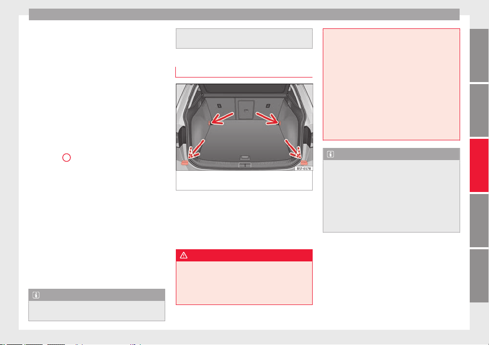
Transport and practical equipment
On the rear seat, behind the central armrest,
ther
e i
s
a tailboard for transporting long
items in the interior, such as skis.
To avoid soiling the interior, dirty objects
should be wrapped (e.g. in a blanket) before
they are inserted through the tailboard.
When the armrest is down, nobody may trav-
el in the centre rear seat.
Opening the tailboard
●
Lower the centre armrest.
●
Pull the release lever in the direction of the
arrow and push the tailboard cover
››› Fig. 163
1
down and forwards.
●
Open the rear lid.
●
Insert the long objects through the gap
fr
om the lug
g
age compartment.
●
Secure the objects with the seatbelt.
●
Close the rear lid.
Closing the tailboard
●
Lift the tailboard cover until it engages. The
red mark on the luggage compartment side
should never be visible.
●
Close the rear lid.
●
Lift the centre armrest if necessary.
Note
The tailboard can also be opened from the
luggag
e compartment. To do so, press the re-
lease lever down, in the direction of the ar-
row
, and the cover upwards ››› Fig. 164.
Fastening rings*
Fig. 165 In the luggage compartment: fasten-
in
g rin
g
s
In the front and rear part of the luggage com-
p
ar
tment
there are fastening rings to secure
the luggage ››› Fig. 165.
In order to use the front fastening rings, they
must be lifted beforehand.
WARNING
If unsuitable or damaged belts or retaining
strap
s are used, they could break in the event
of braking or an accident. Objects could then
be launched across the passenger compart-
ment and cause serious or fatal injuries.
●
Alwa
ys use belts or retaining straps that
are suitable and in a good condition.
●
Belts and retaining straps should be se-
curely fastened to the fastening rings.
●
Objects in the luggage compartment that
are unsecured could move suddenly and mod-
ify the handling of the vehicle.
●
Secure all objects, little and large.
●
Never exceed the maximum tensile load of
the fastening ring when securing objects.
●
Never secure a child seat to the fastening
rings.
Note
●
The maximum t
ensile load that the fasten-
ing rings can support is 3.5 kN.
●
Belts and securing systems for the appro-
priate load can be obtained from specialised
dealerships. SEAT recommends visiting a
SEAT dealership for this.
●
The fastening rings are rendered unusable
for versions with a spare wheel.
165
Technical dataAdviceOperationEmergenciesSafety

Operation
Retaining hooks
Fig. 166 In the luggage compartment: retain-
in
g hook
s
At the rear of the luggage compartment, on
the l
ef
t
and right, there are fixed retaining
hooks ››› Fig. 166.
The retaining hooks have been designed to
secure light shopping bags.
WARNING
Never use the retaining hooks as fastening
rings. In c
ase of sudden braking or an acci-
dent, the hooks could break.
CAUTION
Each hook is designed for a maximum load of
2.5 kg.
Net bag*
Fig. 167 In the luggage compartment: net
b
ag hook
ed t
o the ground.
Fig. 168 In the luggage compartment: rings
1
and hooks
2
for attaching the net bag.
The luggage compartment prevents light lug-
g
ag
e fr
om moving. The net bag has a zip and
can be used to store small objects.
The net bag can be hooked up to the luggage
compartment in different ways.
Hooking the net bag into the luggage com-
partment floor
●
As applicable, lift the front fastening rings
››› Fig. 167
2
.
●
Secure the net hooks to the fastening rings
2
›
››
. The bag zip should be facing up-
w
ar
d
s.
●
Secure the net hooks to the fastening rings
1
.
Hook
the net
b
ag next to the load threshold
●
Secure the short net hooks to the fastening
rings ››› Fig. 168
1
›
›
› . The bag zip should
be f
ac
in
g upwards.
●
Secure the straps in the bag hooks
2
.
R
emo
v
ing the net bag
The hooked up net bag is taut ›››
.
●
Remove the hooks and the net bag straps
fr
om the f
a
stening rings and from the bag
hooks.
●
Store the net bag in the luggage compart-
ment.
WARNING
To secure the elastic net bag on the fastening
rings
it must be stretched out. Once hooked
up it is taut. If the net bag is hooked up or un-
hooked incorrectly the hooks could cause in-
juries.
166
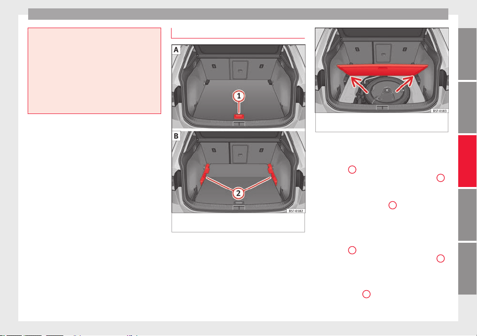
Transport and practical equipment
●
Alwa
ys secure the net hooks properly so
that they do not suddenly release from the
fastening rings when hooking or unhooking
them.
●
On hooking or unhooking them, protect
your eyes and face in case the hooks are re-
leased suddenly.
●
Always hook up the net bag hooks in the
described order. If a hook is unexpectedly re-
leased the risk of injury is increased.
Luggage compartment variable floor
Fig. 169 Luggage compartment variable
floor: r
ai
sed po
sition; lowered position.
Fig. 170 Luggage compartment variable
floor: sloped pos
ition.
Variable floor in the high position
●
To move from the low position to the high
po
s
ition, lif
t the floor using the handle
››› Fig. 169
1
, and pull it back until the front
of
the floor h
a
s fully passed the supports
2
.
●
Move the floor forward over the supports as
f
ar a
s
the rear seat backrest and then lower
the floor with the handle
1
.
V
ari
ab
le floor in the low position
●
To move from the high position to the low
position, lift the floor using the handle
››› Fig. 169
1
, and pull it back until the front
of
the floor h
a
s fully passed the supports
2
.
●
Now let the front part fall to the floor and
s
lide the floor f
or
wards as far as the rear seat
backrest; lower the floor at the same time
with the handle
1
.
»
167
Technical dataAdviceOperationEmergenciesSafety
Operation
Variable floor in the tilted position
When the
v
ari
able floor is tilted you can ac-
cess the spare wheel/anti-puncture kit area.
●
Lift the variable floor in the high position
using the handle
1
›
›› Fig. 169
, p
ull it up
and push it towards the backrest of the rear
seats until the floor folds along the hinge line
and the movable part of the floor is resting
on itself.
●
Rest the floor on its housings ››› Fig. 170
(arrows).
Variable floor with folded seats
●
To move from the high position to the low
position, lift the floor using the handle
››› Fig. 169
1
and pull it back a little.
●
Push the variable floor towards the folded
r
e
ar se
ats with the handle
1
using some
do
wn
w
ard pressure so that the moving part
of the floor is flush with the backs of the rear
seats.
WARNING
During a sudden driving or braking manoeu-
vre, or in the event
of an accident, objects
could be flung though the interior and cause
serious or fatal injuries.
●
Always secure objects, even when the lug-
gage compartment floor is properly lifted.
●
Only objects that do not protrude more
than 2/3 the height of the floor may be car-
ried between the rear seat and the raised lug-
gage c
ompartment floor.
●
Only objects that do not weigh than ap-
proximately 7.5 kg may be carried between
the rear seat and the raised luggage compart-
ment floor.
CAUTION
●
The m
aximum w
eight that can be loaded on
the luggage compartment variable floor in
the top position is 150 kg.
●
Do not let the luggage compartment floor
fall when closing it. Always carefully guide it
downwards in a controlled manner. Other-
wise, the lining and the floor of the luggage
compartment could be damaged.
Note
SEAT recommends the use of straps to secure
obj
ects to retaining rings.
Roof carrier*
Intr
oduction
The vehicle roof has been designed to opti-
mi
se aer
ody
namics. For this reason, cross
bars or conventional roof carrier systems can-
not be secured to the roof water drains.
As the roof water drains are integrated in the
roof to reduce air resistance, only SEAT-ap-
proved cross bars and roof carrier systems
can be used.
Cases in which cross bars and the roof carri-
er system should be disassembled.
●
When they are not used.
●
When the vehicle is washed in a car wash.
●
When the vehicle height exceeds the maxi-
mum height, for example, in some garages.
WARNING
When heavy or bulky loads are transported
on the roof c
arrier system, car driving per-
formance is affected, as the centre of gravity
shifts and there is greater wind resistance.
●
Always secure the load properly using belts
or retaining straps that are suitable and in a
good condition.
●
Bulky, heavy, long or flat loads have a neg-
ative effect on aerodynamics, the centre of
gravity and driving performance.
●
Avoid sudden braking and manoeuvres.
●
Adapt your speed and driving style at all
times to suit visibility, weather, road and traf-
fic conditions.
CAUTION
●
Remov
e the cross bars and the roof carrier
system before entering a car wash.
168
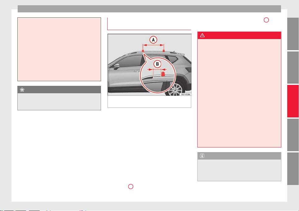
Transport and practical equipment
●
Vehicl
e height is increased by the installa-
tion of cross bars or a roof carrier system and
the load secured on them. For this purpose,
check that your vehicle's height does not sur-
pass the headspace limit, for example, for un-
derpasses or for entering garage doors.
●
Cross bars, the roof carrier system and the
load secured on them should not interfere
with the roof aerial or hamper the path of the
panoramic sun roof and the rear lid.
●
On opening the rear lid make sure that it
does not knock into the roof load.
For the sake of the environment
When cross bars and a roof carrier system are
inst
alled, the increased air resistance means
that the vehicle uses more fuel.
Attach the cross bars and the roof car-
rier sy
s
t
em
Fig. 171 Attachment points for the roof rail-
in
g
s
for the roof carrier system.
The crossbars are the basis of a series of spe-
c
i
al
roof carrier systems. For safety reasons,
special fixtures must be used to safely trans-
port luggage, bicycles, skis, surf boards or
boats on the roof. Suitable accessories can
be acquired at SEAT dealerships.
Always secure the crossbars and the roof car-
rier system properly. Always take the assem-
bly instructions that come with the crossbars
and the roof carrier system in question into
account.
The crossbars are assembled on the roof rail-
ings. The distance between crossbars
››› Fig. 171
A
should be between 70 and 90
c
m and the di
s
tance between the crossbars
and the brackets of the roof railings
B
must
be 15 c
m.
WARNING
Incorrect attachment and use of the cross-
bars
and the roof carrier system may cause
the whole system to detach from the roof and
cause an accident and injuries.
●
Always take the manufacturer assembly in-
structions into account.
●
Use only crossbars and the roof carrier sys-
tem when they are in perfect condition and
are properly secured.
●
Secure the crossbars and the roof carrier
system properly.
●
Check threaded joints and attachments
travelling and if necessary tighten them after
you have travelled a short distance. When
making long trips, check the threaded joints
whenever you stop for a rest.
●
Always fit the special roof carrier systems
correctly for wheels, skis and surfboards, etc.
●
Do not modify or repair the crossbars or
roof carrier system.
Note
Always read the assembly instructions that
come with the c
rossbars and the roof carrier
system carefully and keep them in the vehi-
cle.
169
Technical dataAdviceOperationEmergenciesSafety
Operation
Loading the roof carrier system
The load can only be secured if the crossbars
and the roof c
arrier system are properly in-
stalled ›››
.
Maximum authori
sed roof load
The maximum permissible roof load is 75 kg.
This figure comes from the combined weight
of the roof carrier, the cross bars and the load
itself on the roof ›››
.
Alwa
ys check the weight of the roof carrier
system, the cross bars and the weight of the
load to be transported and weigh them if
necessary. Never exceed the maximum au-
thorised roof load.
If you are using cross bars and a roof carrier
with a lower weight rating, you will not be
able to carry the maximum authorised roof
load. In this case, do not exceed the maxi-
mum weight limit for the roof carrier which is
listed in the fitting instructions.
Distributing a load
Distribute loads uniformly and secure them
correctly
›››
.
Chec
k
att
achments
Once the cross bars and roof carrier system
have been installed, check the bolted con-
nections and attachments after a short jour-
ney and subsequently with a certain frequen-
cy.
WARNING
Exceeding the maximum authorised roof load
can re
sult in accidents and considerable vehi-
cle damage.
●
Never exceed the maximum authorised
load on the roof and on the axles or the vehi-
cle's maximum authorised weight.
●
Never exceed the load capacity of the cross
bars and the roof carrier system, even if the
maximum authorised roof load has not been
reached.
●
Secure heavy items as far forward as possi-
ble and distribute the vehicle load uniformly.
WARNING
If the load is loose or not secured, it could fall
from the roof
carrier system or cause acci-
dents and injuries.
●
Always use belts or retaining straps that
are suitable and in a good condition.
●
Secure the load properly.
Air conditioning
He
atin
g,
ventilation and cool-
ing
Introduction
Read the additional information carefully
›››
page 51
Viewing Climatronic information
On the screen of Climatronic control unit and
on the screen of the factory-fitted Easy Con-
nect system, the theoretical values of the
temperature zones are shown.
The unit of temperature measurement can be
changed in the Easy Connect system.
Dust and pollen filter
The dust and pollen filter with its activated
charcoal cartridge serves as a barrier against
impurities in the air taken into the vehicle in-
terior.
The dust and pollen filter must be changed
regularly so that air conditioner performance
is not adversely affected.
If the filter loses efficiency prematurely due
to use in areas with very high levels of air
pollution, the filter must be changed more
frequently than stated in the Service Sched-
ule.
170
Air conditioning
WARNING
Reduced visibility through the windows in-
cre
ases the risk of serious accidents.
●
Always ensure that all windows are free of
ice and snow, and that they are not fogged,
so as to maintain good visibility of everything
outside.
●
The maximum heat output required to de-
frost windows as quickly as possible is only
available when the engine has reached its
normal running temperature. Only drive when
you have good visibility.
●
Always ensure that you use the heating
system, fresh air system, air conditioner and
the heated rear window to maintain good visi-
bility to the outside.
●
Never leave the air recirculation on for a
long period of time. If the cooling system is
switched off and air recirculation mode
switched on, the windows can mist over very
quickly, considerably limiting visibility.
●
Switch air recirculation mode off when it is
not required.
WARNING
Stuffy or used air will increase fatigue and re-
duce driver c
oncentration possibly resulting
in a serious accident.
●
Never leave the fresh air fan turned off or
use the air recirculation for long periods of
time; the air in the vehicle interior will not be
refreshed.
CAUTION
●
To rep
lace the pollen filter, always visit a
service centre.
●
Switch the air conditioner off if you think it
may be broken. This will avoid additional
damage. Have the air conditioner checked by
a specialised workshop.
●
Repairs to the air conditioner require spe-
cialist knowledge and special tools. SEAT rec-
ommends visiting a SEAT Official Service.
Note
●
When the coolin
g system is turned off, air
coming from the outside will not be dried. To
prevent fogging of the windows, SEAT recom-
mends leaving the cooling system (compres-
sor) turned on. To do this, press the button
. The button lamp should light up.
●
The maximum heat output required to de-
fros
t windows as quickly as possible is only
available when the engine has reached its
normal running temperature.
●
Keep the air intake slots in front of the
windscreen free of snow, ice and leaves to en-
sure heating and cooling are not impaired,
and to prevent the windows from misting
over.
Operating the Climatronic through the
E
a
sy
Connect system*
3 Applies to vehicles with a Media System
Touc
h/Colour.
Fig. 172 Easy Connect screen: air conditioner
menu.
In the Easy Connect system it is also possible
t
o per
f
orm various adjustments to the Clima-
tronic.
Open the air conditioner menu
●
Press the
button on the Climatronic
c
ontr
o
l panel.
●
OR: press the
button in Easy Connect.
W
ith the r
ot
ating switch select the air con-
ditioner menu and open it.
On the touch screen you can see and change
the current settings, for example, the temper-
ature set for the driver and passenger sides,
the air distribution and the fan speed.
»
171
Technical dataAdviceOperationEmergenciesSafety
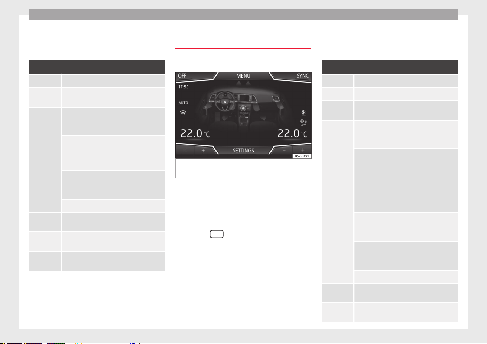
Operation
To switch a function on or off, or to select a
s
ubmenu,
y
ou must press the corresponding
function button.
Function button: Function
OFF Switch off and switch on the Climatronic.
SYNC
Synchronise driver and front passenger
temperatures.
SETTINGS
The air conditioning settings submenu is
opened. The following settings can also
be adjusted:
Air conditioning profile.: Adjust
the power of the fan in AUTO mode. You
can choose between low, medium and
high.
Automatic air recirculation:
Switching automatic air recirculation on
and off ››› page 174.
BACK
: Close the submenu.
*
The auxiliary heater submenu opens.
*
It enables manual switching on or off of
the windscreen heater.
It enables activation and deactivation of
the PureAir and opens the submenu.
Operating the Climatronic through the
E
a
sy
Connect system*
3 Applies to vehicles with Media System Plus / Navi
Sy
stem / Navi System Plus.
Fig. 173 Easy Connect screen: air conditioner
menu.
In the Easy Connect system it is also possible
t
o per
f
orm various adjustments to the Clima-
tronic.
Open the air conditioner menu
●
Press the
button on the Climatronic
c
ontr
o
l panel.
On the top of the screen you can see and
change the current settings, such as, for ex-
ample, the temperature set for the driver side
and for that of passenger. Temperatures up
to +22°C (+72°F) are shown with blue arrows,
and temperatures over +22°C (+72°F) with
red arrows.
To switch a function on or off, or to select a
submenu, you must press the corresponding
function button.
Function button: Function
OFF Climatronic is switched off.
ON Climatronic is switched on.
SYNC
Synchronise driver and front passenger
temperatures.
SETTINGS
The air conditioning settings submenu is
opened. The following settings can also
be adjusted:
Automatic supplementary heater:
to activate/deactivate the automatic acti-
vation of the auxiliary heating for colder
countries (only for engines with auxiliary
heating). With the option deactivated, de-
pending on the outside temperature the
heating may need more time than normal
to reach a comfortable temperature.
Automatic windscreen heating*: to
switch the automatic windscreen heating
on and off ››› page 175.
Automatic air recirculation: to
switch automatic air recirculation on and
off ››› page 174.
BACK
: to close the submenu.
*
The auxiliary heater submenu opens.
*
It enables manual switching on or off of
the windscreen heater.
172
Air conditioning
Function button: Function
It enables activation and deactivation of
the PureAir and opens the submenu.
Air conditioning user instructions
The interior cooling system only works when
the engine is
running and fan is switched on.
The air conditioner operates most effectively
with the windows and the panoramic sliding
sunroof closed. However, if the vehicle has
heated up after standing in the sun for some
time, the air inside can be cooled more quick-
ly by opening the windows and the panoram-
ic sliding sunroof briefly.
Climatronic: change the temperature unit on
the screen of the radio or on the factory-fit-
ted navigation system
Changing the temperature display from Cel-
sius to Fahrenheit on radio or on the factory-
fitted navigation system is done using the
menu on the instrument
panel
›››
page 36.
The cooling system cannot be activated
If the air conditioning system cannot be
switched on, this may be caused by the fol-
lowing:
●
The engine is not running.
●
The fan is switched off.
●
The air conditioner fuse has blown.
●
The outside temperature is lower than ap-
proximately +3°C (+38°F).
●
The air conditioner compressor has been
temporarily switched off because the engine
coolant temperature is too high.
●
Another fault in the vehicle. Have the air
conditioner checked by a specialised work-
shop.
Special Characteristics
If the humidity and temperature outside the
vehicle are high, condensation can drip off
the evaporator in the cooling system and
form a pool underneath the vehicle. This is
normal and does not indicate a leak!
Note
After starting the engine, any residual humid-
ity in the air conditioner c
ould mist over the
windscreen. Switch on the defrost function as
soon as possible to clear the windscreen of
condensation.
173
Technical dataAdviceOperationEmergenciesSafety
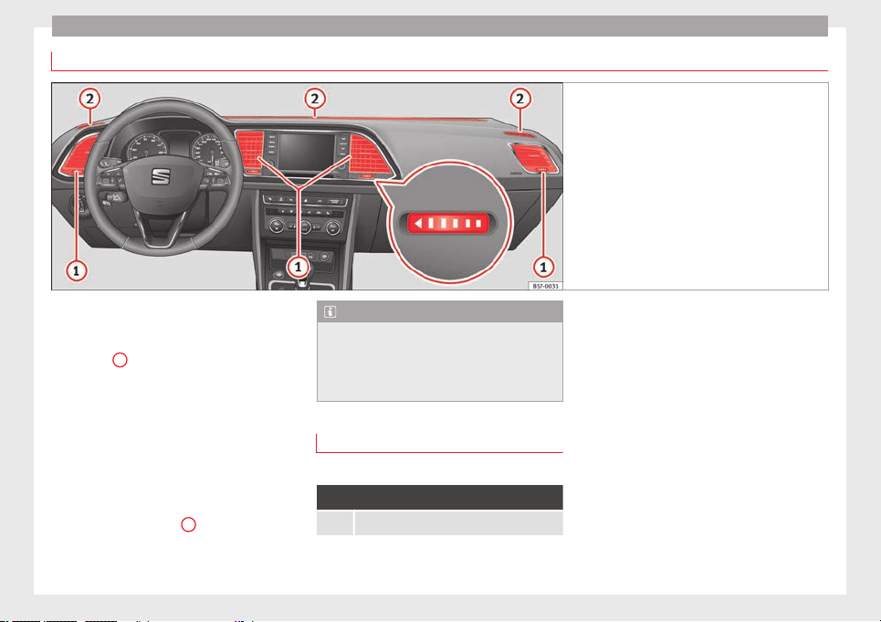
Operation
Air outlets
Fig. 174 On the dash panel: air vents
Air vents
T
o en
s
ure proper heating, cooling and venti-
lation in the vehicle interior, air vents
››› Fig. 174
1
should remain open.
●
Turn the corresponding thumbwheel (de-
t
ai
l) in the r
equired direction to open and
close the air vents. When the thumbwheel is
in the position, the corresponding air vent
is closed.
●
Change the air direction using the ventila-
tion grille lever.
There are other additional, non-adjustable air
vents in the dash panel
2
, in the footwell
and in the r
e
ar ar
ea of the interior.
Note
Food, medicine and other heat or cold sensi-
tive ob
jects should never be placed in front of
the air outlets as they may be damaged or
made unsuitable for use by the air coming
from the air vents.
Air recirculation mode
Basic points
Air recirculation:
Manual recirculation
Air recirculation mode prevents the ambient
air fr
om ent
erin
g the interior.
When the outside temperature is very high,
selecting manual air recirculation mode for a
short period refreshes the vehicle interior
more quickly.
For safety reasons, air recirculation mode is
switched off when the button is press-
ed or the air distributor turned to .
Switching the manual air recirculation mode
on and off
To switch system on: press the button un-
til the warning lamp lights up.
To switch system off: press the button un-
til the warning lamp goes off.
174
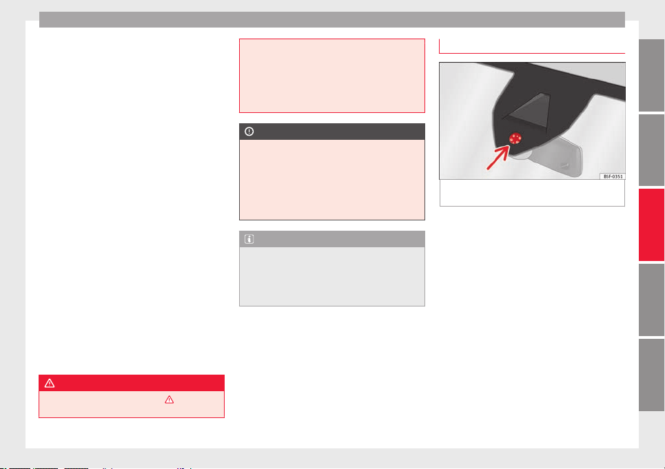
Air conditioning
Functioning mode of automatic air recircula-
tion (air c
onditionin
g menu)
W
ith the automatic air recirculation mode ac-
tivated, the entry of fresh air into the cabin
interior is enabled. If the system detects a
high concentration of hazardous substances
in the ambient air, air recirculation mode is
switched on automatically. When the level of
impurities drops to within a normal range, re-
circulation mode is switched off.
The system is unable to detect unpleasant
smells.
The air recirculation will not connect auto-
matically in versions without humidity sensor
and in the following external conditions:
●
The outside temperature is lower than +3°C
(+38°F).
●
The cooling system is switched off and the
outside temperature is below +10°C (+50°F).
●
The cooling system is switched off, the out-
side temperature is below +15°C (+59°F) and
the windscreen wipers are switched on.
Activation/deactivation of automatic air recir-
culation is done in the air conditioner menu,
under Configuration.
WARNING
Observe the safety warnings ›››
in Intro-
duction on page 171
.
●
If the coo
ling system is switched off and air
recirculation mode switched on, the windows
can mist over very quickly, considerably limit-
ing visibility.
●
Switch air recirculation mode off when it is
not required.
CAUTION
Do not smoke when air recirculation is
sw
itc
hed on in vehicles with an air condition-
er. The smoke taken in could lie on the cool-
ing system vaporiser and on the activated
charcoal cartridge of the dust and pollen fil-
ter, leading to a permanently unpleasant
smell.
Note
Climatronic: air recirculation mode is activa-
ted to pr
event exhaust gas or unpleasant
odours from entering the vehicle interior
when it is in reverse and while the automatic
windscreen wiper is working.
Heated windscreen*
Fig. 175 Windscreen humidity and tempera-
t
ur
e sen
sor.
The heated windscreen is comprised of a set
of
he
at
ed wires placed between the layers of
the windscreen which, when electric current
is supplied to them, heat up and cause the
temperature of the glass to rise.
Its function is to assist the air-conditioning
system to prevent the windscreen from mist-
ing up or to demist it faster if it does mist up.
The system can be switched on manually or
automatically.
Manual activation
●
Press the button in the Climatronic
control panel.
●
Press the function button to switch the
windscreen heating on or off.
»
175
Technical dataAdviceOperationEmergenciesSafety

Operation
Automatic activation
T
o f
ac
ilitate use of the heated windscreen it
can turn on automatically.
The Climatronic control panel can detect the
danger of the windscreen misting thanks to
its temperature and humidity sensors,
switching the system on or off accordingly
››› Fig. 175. Moreover, it will also be activated
automatically when the button is
pressed on the Climatronic control panel.
Adjust it as follows for it to switch on auto-
matically:
●
Press the button in the Climatronic
control panel.
●
Press the SETTINGS function button on the
infotainment system.
●
Switch the function on or off by pressing
the
Automatic windscreen heating
function but-
t
on.
176
Air conditioning
Auxiliary heater (additional
he
at
er)*
Intr
oduction
The auxiliary heater runs on fuel from the ve-
hicle's
tank and can be used while you are
driving and when the vehicle is stationary.
The auxiliary heater can be switched on using
the fast heating button of the air condition-
ing controls, with the remote control or by
previously programming a departure time in
the auxiliary heater menu of the infotainment
system.
In winter, with the auxiliary heater switched
on, you can defog the windscreen and leave
it free of ice and snow (if it is a thin layer) be-
fore you start driving.
If the outside temperature is very high, the
vehicle interior can be ventilated with the en-
gine off using the auxiliary heater.
WARNING
Swallowing a battery with a 20 mm diameter
or any other b
utton battery can cause serious
and even fatal injuries within a very short
time.
●
Always keep the remote control, keyrings
with batteries, the spare batteries, button
batteries and all other batteries over 20 mm
out of reach of children.
●
If y
ou suspect that someone may have
swallowed a battery, seek immediate medical
attention.
WARNING
The auxiliary heater exhaust fumes contain
c
arbon monox
ide, an odourless and colour-
less toxic gas. Carbon monoxide can cause
people to lose consciousness. It can also
cause death.
●
Never switch on the auxiliary heater or
leave it running in enclosed spaces or areas
with no ventilation.
●
Never programme the auxiliary heater so
that it switches itself on and is running in an
enclosed space or an area with no ventila-
tion.
WARNING
The components of the auxiliary heater are
extremely
hot and could cause a fire.
●
Always park your vehicle so that no part of
the exhaust system can come in contact with
easily flammable materials that might be be-
low the vehicle, such as dried grass.
CAUTION
Never place food, medicines or other temper-
ature-
sensitive objects close to the air vents.
Food, medicines and other objects sensitive
to heat or cold may be damaged or made un-
suitable for use by the air coming from the
vents.
Note
After switching the engine on with a 12-volt
b
atter
y that is heavily discharged or newly
changed or after a jump start some system
settings (such as the time, the date, the per-
sonalised comfort settings and the program-
ming) might be altered or deleted. Check and
correct these settings once the battery is suf-
ficiently charged.
Switching on and off the auxiliary
he
at
er
Switching the auxiliary heater on:
Manually with the fast heating button of the air
conditioner controls. The control lamp of the
button will light up ››› page 170.
Manually with the remote control ››› page 178.
Automatically by programming and activating a
departure time ››› page 179.
Switching the auxiliary heater off:
Manually with the fast heating button of the air
conditioner controls. The control lamp of the
button goes off ››› page 170.
Manually with the remote control ››› page 178.
»
177
Technical dataAdviceOperationEmergenciesSafety
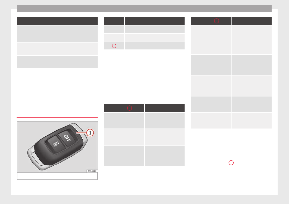
Operation
Switching the auxiliary heater off:
Automatically once the programmed departure
time has arrived or after the programmed oper-
ating time has elapsed ››› page 179.
Automatically when the control lamp
(fuel
level indicator) ››› page 292 lights up.
Automatically when the 12-volt battery charge
is too low ››› page 305.
Special feature
Once swit
ched off, the auxiliary heater will
continue to operate for a short period of time
in order to burn the fuel remaining in the sys-
tem and also to expel the exhaust fumes.
Remote control
Fig. 176 Auxiliary heater: remote control.
Fig. 176 Meaning
Switch the auxiliary heater on
Switch the auxiliary heater off
1
Control lamp
If the buttons of the remote control are press-
ed unnece
ssarily, it could switch on the auxil-
iary heater involuntarily, even when it is out
of range or when the control lamp is flashing.
Control lamp on the remote control
When the buttons are pressed, the control
lamp on the remote control provides the user
with different information:
Control lamp
1
Meaning
It will light for about 2 sec-
onds in green.
The auxiliary heater has
been switched on using
the
button.
It will light for about 2 sec-
onds in red.
The auxiliary heater has
been switched off using
the
button.
It flashes green slowly for
approximately 2 seconds
(approximately 4 times per
second).
No on
a)
signal has been
received.
Control lamp
1
Meaning
It flashes green quickly for
approximately 2 seconds
(approximately 10 times
per second).
The auxiliary heater is
locked.
Possible causes: The fuel
tank is almost empty, the
12-volt battery charge is
too low or there is a fault.
It flashes orange for ap-
proximately 2 seconds
(approximately 4 times per
second).
No off
a)
signal has been
received.
It will light for about 2 sec-
onds in orange, then
green or red.
The remote control battery
is almost flat. However,
the on or off signal has
been received.
It will light for about 2 sec-
onds in orange, then it
flashes green or red.
The remote control battery
is almost flat. No on or off
signal has been received.
It flashes orange for ap-
proximately 5 seconds.
The remote control battery
is flat. No on or off signal
has been received.
a)
The remote control is out of range. In this case it will be nec-
essary to get closer to the vehicle and press the corresponding
button again.
Replacing the remote control battery
If, when pressing the buttons of the remote
control, control lamp
1
flashes orange for
ap
pr
o
ximately 5 seconds or it does not
switch on, the remote control battery will
need replacing.
178
Air conditioning
The battery is located beneath a cover on the
b
ac
k
of the remote control.
●
To open the cover, lift it slightly at the bot-
tom and slide it down.
●
Remove the old battery.
●
Insert the new battery. When doing so, take
into account the polarity and use batteries of
the same type ›››
.
●
Replace the battery cover by inserting the
t
ab
s
at the top and pressing the bottom.
Range
The receiver is inside the vehicle. The remote
control, when fitted with new batteries, has a
range of several hundred metres. Obstacles
between the remote control and the vehicle,
bad weather conditions and discharged bat-
teries can considerably reduce the range of
the remote control.
CAUTION
●
The radio fr
equency remote control con-
tains electronic components. Therefore, avoid
getting it wet and exposing it to knocks or di-
rect sunlight.
●
The use of inappropriate batteries may
damage the radio frequency remote control.
For this reason, always replace the used bat-
tery with another of the same voltage, size
and specifications.
For the sake of the environment
●
Plea
se dispose of your used batteries cor-
rectly and with respect for the environment.
●
The remote control battery may contain
perchlorate. Observe the legal provisions re-
garding disposal.
●
Care should be taken so as not to operate
the remote control unintentionally so as to
prevent the auxiliary heater being switched
on accidentally.
Programming the auxiliary heater
Before pr
ogramming it, check that the vehi-
c
l
e's date and time are set correctly
›››
.
The aux
i
li
ary heater is programmed in the
Auxiliary heater menu of the infotain-
ment system.
Open the Auxiliary heater menu.
●
Press the button in the Climatronic
control panel.
●
Press the function button.
Function button: function
Switch off
: The auxiliary heater is immediately switched
off.
Function button: function
Heat
,
Ventilate
: Set to heat or ventilate the vehicle interi-
or when the auxiliary heater is switched on. By pressing
the function button
, you can select the desired
mode.
Set
: Opens the Auxiliary heater menu.
Departure time 1
,
Departure time 2
,
Departure time 3
:
Three different departure times (hh.mm) may be
programmed. If the auxiliary heater should only
be switched on a certain day of the week, this can
also be selected.
Duration
: The duration determines the operating
time of the auxiliary heater when switched on us-
ing the fast heating button
on the air condi-
tioning controls. The duration is also used to cal-
culate the departure time for the manual air con-
ditioner. It can be set between 10 and 60 mi-
nutes at 10-minute intervals.
This returns to the main menu.
The programmed departure time determines
the ap
pr
o
ximate time it should take to reach
the temperature set in the vehicle. The start
of the heating operation is determined auto-
matically depending on the outside tempera-
ture.
Checking the programming
When a departure time is activated and the
ignition is switched off the control lamp of
the fast heating button lights up for ap-
proximately 10 seconds.
»
179
Technical dataAdviceOperationEmergenciesSafety
Operation
WARNING
Never programme the auxiliary heater so that
it swit
ches itself on and is running in an en-
closed space or an area with no ventilation.
The auxiliary heater exhaust fumes contain
carbon monoxide, an odourless and colour-
less toxic gas. Carbon monoxide can cause
people to lose consciousness. It can also
cause death.
Operating instructions
The auxiliary heater exhaust system located
belo
w the
v
ehicle must be kept clear of snow,
mud and other objects. The exhaust fumes
must be able to exit freely. The emissions
generated by the auxiliary heater are re-
moved via an exhaust pipe fitted underneath
the vehicle.
On heating the vehicle interior, depending on
the outside temperature, the warm air is first
directed at the windscreen and then to the
rest of the vehicle interior through the air
vents. Directing the diffusers – towards the
windows for example – can affect air distribu-
tion.
When will the auxiliary heater not be activa-
ted?
●
The auxiliary heater requires about as
much pow
er as the dipped beam headlights.
If the 12-volt battery charge is too low, the
auxiliary heater switches off automatically
and cannot be sw
itched on. This avoids prob-
lems when starting the engine.
●
The heating must be activated every time
you want to set off. Similarly, the departure
time must reactivate each time.
●
The control lamp (fuel level indicator)
lights up.
Note
●
Noises
will be heard while the auxiliary
heater is running.
●
When the air humidity is high and the in-
side temperature low, condensation from the
heating and ventilating system may evapo-
rate when the auxiliary heater is switched on.
In this case, steam may be released from un-
derneath the vehicle. This does not mean
that there is a vehicle malfunction.
●
If the vehicle is tilted, e.g. if parked on a
slope, the operation of the auxiliary heater
may be restricted if the fuel tank level is low
(just above the reserve level).
●
If the auxiliary heater is used a number of
times for a long period of time, the 12-volt
battery will lose its charge. To recharge the
battery, the vehicle must be driven for a num-
ber of kilometres from time to time. As a
guideline: The journey should last approxi-
mately as long as the heater was connected.
●
At temperatures below +5°C (+41°F), the
auxiliary heater may switch itself on automat-
ically when the engine is switched on. The
auxiliary heater is switched off again after a
cert
ain time.
180
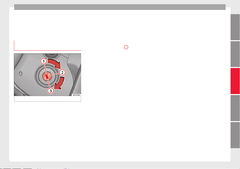
Driving
Driving
St
ar
tin
g and stopping the en-
gine
Switching the ignition on and starting
the engine with the key
Fig. 177 Ignition key positions.
Read the additional information carefully
›
›
›
page 30
Diesel engines can take a few seconds longer
than usual to start on cold days. Therefore
the clutch pedal (manual gearbox) or the
brake pedal (automatic gearbox) must re-
main pressed until the engine starts up. Dur-
ing preheating, the warning lamp remains
lit.
The preheating time depends on the coolant
and exterior temperatures. With the engine at
operating temperature, or at outside temper-
atures above +8°C, the warning lamp will
light up for about one second. This means
that the engine starts immediately.
If the engine does not immediately start up,
interrupt the starting process and try again
after 30 seconds. To start the engine again,
return the key to position
1
.
St
ar
t
-Stop System*
If the vehicle is stopped and the Start-Stop
system* switches off the engine, the ignition
remains switched on.
Automatic gearbox: before leaving the vehi-
cle, make sure that the ignition is switched
off and the selector lever is in position P.
Driver messages on the instrument panel
display
Press the clutch
This message appears on vehicles with a
manual gearbox if the driver tries to start the
engine without having the clutch pedal
pressed. The engine will only start if you
press the clutch pedal.
Press the brake
This message appears on vehicles with an
automatic gearbox if the driver tries to start
the engine without having the brake pedal
pressed.
Select N or P
This message appears if you try to start or
stop the engine when the selector lever of
the automatic gearbox is not in position P or
N. The engine can only start or stop in certain
positions.
Engage position P; the vehicle
can move; doors can only close in
position P.
For safety reasons, this driver message ap-
pears and an audible warning sounds if the
selector lever of the automatic gearbox is not
in position P after you switch off the ignition.
Put the selector lever in position P, otherwise
the vehicle could roll away.
Gear change: selector lever in
the drive position!
This driver message is displayed when the
selector lever is not in the position P when
the driver door is opened. Additionally, a
buzzer will sound. Put the selector lever in
position P, otherwise the vehicle could roll
away.
Ignition is switched on
This driver message is displayed and a buz-
zer is sounded when the driver door is
opened with the ignition switched on.
»
181
Technical dataAdviceOperationEmergenciesSafety
Operation
WARNING
●
Never run the en
gine in confined spaces, as
the exhaust gases are poisonous.
CAUTION
Avoid high engine speeds, full throttle and
extreme lo
ad conditions until the engine has
reached its normal operating temperature,
otherwise this can damage the engine.
For the sake of the environment
Do not warm up the engine by idling it. You
should driv
e off as soon as you start the en-
gine. This will help avoid unnecessary ex-
haust emissions.
Note
●
If it i
s difficult to turn the ignition key to
the position
2
, turn the steering wheel to
both sides
to release the steering lock.
●
When starting from cold, the engine may be
a little noisy for the first few seconds until oil
pressure has built up in the hydraulic valve
lifters. This is quite normal, and no cause for
concern.
●
If the vehicle battery is disconnected and
reconnected, the key must remain in the posi-
tion
1
for around 5 seconds before starting
up.
●
Vehic
les with automatic gearbox: depend-
ing on the country, after switching off the ig-
nition, you can only remove the ignition key if
the selector lever is in position “P” (parking
lock). Next, the sel
ector lever is locked.
Switching off the engine with the key
Switching off the engine
–
Stop the vehicle.
–
Turn the ignition key to position
1
››› Fig. 177.
Engagin
g the steering wheel lock
In vehicles with automatic gearbox, the igni-
tion key can only be removed when the selec-
tor lever is in position P.
–
Remove the key from the ignition in posi-
tion
1
›
›
› Fig. 177
›››
.
–
Turn the steering wheel until you hear it en-
g
ag
e.
P
ossible vehicle theft is prevented with the
steering lock engaged.
WARNING
●
Never swit
ch the engine off until the vehi-
cle is stationary. The brake servo and power
steering functions will not be completely cov-
ered under warranty. More force may also be
needed to turn the steering wheel or to brake.
As you cannot steer and brake in the normal
manner, there is a greater risk of accidents
and serious injury.
●
Never remo
ve the key from the ignition if
the vehicle is in motion. Otherwise, the steer-
ing could suddenly lock, making it impossible
to steer the vehicle: risk of accident!
●
Always take the key with you when you
leave the vehicle. This is particularly impor-
tant if there are children in the vehicle, as
they might otherwise be able to start the en-
gine or use power-operated equipment (e.g.
the electric windows), which could cause in-
juries.
CAUTION
If the engine has been running under high
load f
or a long time, there is a risk of heat
building up in the engine compartment after
it has been switched off; this could cause en-
gine damage. For this reason, you should idle
the engine for approximately 2 minutes be-
fore you switch it off.
Note
After the engine is switched off the radiator
fan ma
y run on for up to 10 minutes, even if
the ignition is switched off. It is also possible
that the fan turns itself on once more if the
coolant temperature increases due to the
heat accumulated in the engine compartment
or due to its prolonged exposure to solar ra-
diation.
182
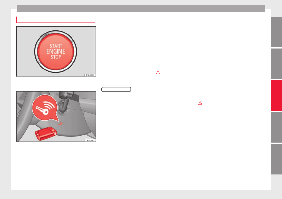
Driving
Starter button*
Fig. 178 In the lower part of the centre con-
so
l
e: s
tarter button.
Fig. 179 On the right of the steering column:
emer
g
ency
start.
The vehicle engine can be started with a
s
t
ar
ter button (Press & Drive). To do so, there
must be a valid key inside the vehicle in the
area of the front or rear seats.
In vehicles with the Keyless Access
››› page 125 system, the engine can also be
started with the key in the luggage compart-
ment.
Opening the driver's door when exiting the
vehicle activates the electronic lock on the
steering column if the ignition is disabled.
Switching the ignition on/off manually
Briefly push the starter button without touch-
ing the brake or clutch pedal ›››
.
F
or
v
ehicles with both manual and automatic
transmission, the starter button text
START ENGINE STOP
flashes like a heartbeat
when the sy
s
t
em is preset for switching the
ignition on and off.
Automatic ignition switch-off
If the driver leaves the vehicle, taking the ve-
hicle key with them but leaving the ignition
on, the ignition is not switched off automati-
cally. The ignition is switched off automati-
cally by pressing the lock button on the re-
mote control or manually by pressing the
sensor surface on the door lever ››› Fig. 132
Emergency starting function
If no valid key is detected inside the vehicle,
an emergency start-up will be required. The
relevant message will appear in the dash
panel display. This may happen when, for ex-
ample, the battery of the vehicle key button
is very low or flat:
●
Immediately after pushing the starter but-
ton, keep the vehicle key next to the right
trim of the steering column ››› Fig. 179, as
close as possible to the Kessy logo.
●
The ignition connects and the engine starts
automatically.
Emergency disconnection
If the engine does not switch off after briefly
pressing the starter button, an emergency
disconnect will be required:
●
Press the starter button twice within 3 sec-
onds or press it once for more than 1 sec-
ond ›››
.
●
The engine turns off automatically.
En
gine r
e
start feature
If no valid key is detected inside the vehicle
after the engine stops, you will only have 5
seconds to restart it. A warning will display
on the dash panel screen.
After this interval, it will not be possible to
start the engine without a valid key inside
the vehicle.
»
183
Technical dataAdviceOperationEmergenciesSafety
Operation
Automatic deactivation of the ignition on ve-
hic
l
e
s with the Start-Stop system
The ignition is switched off automatically
when the vehicle is stopped and the auto-
matic engine shutdown is active, if:
●
The driver's seat belt is not fastened,
●
the driver does not step on any pedal,
●
the driver door is opened.
After automatically turning off the ignition, if
the dipped beam is on, the side light re-
mains on for approx. 30 minutes (if the bat-
tery is sufficiently charged). If the driver locks
the vehicle or manually turns off the light, the
side light goes out.
WARNING
Any accidental movement of the vehicle could
res
ult in serious injury.
●
When switching on the ignition, do not
press the brake or clutch pedal, otherwise
the engine could start immediately.
WARNING
If vehicle keys are used negligently or with-
out due car
e, this may cause accidents and
serious injury.
●
Never leave any key inside the vehicle
when exiting. Otherwise, a child or unauthor-
ised person could lock the vehicle, start the
engine or connect the ignition and, in this
way, operate electronic equipment (e.g. the
window
s).
Note
●
B
efor
e leaving the vehicle, always discon-
nect the ignition manually and, if appropri-
ate, take into account the instructions on the
screen of the dash panel.
●
If the vehicle is stationary for a long time
with the ignition on, the vehicle battery
might be discharged and it might not be pos-
sible to start the engine.
●
In diesel vehicles, there may be a delay in
the engine starting if it requires preheating.
●
If during the STOP phase you press the
START ENGINE STOP
button, the ignition is
switc
hed off and the button flashes.
●
If the indication “Start-Stop system deacti-
vated: Start the engine manually” is dis-
played on the dash panel display, the
START ENGINE STOP
button will blink.
Starting the engine
3 Valid for vehicles: with Keyless Access
Step
Starting the engine with the starter
button ››› page 183 (Press & Drive).
1.
Press and hold the brake pedal until step 5
is performed.
Step
Starting the engine with the starter
button ››› page 183 (Press & Drive).
1a.
In vehicles with a manual gearbox: press
and hold the clutch down until the engine
starts.
2.
Put the gearbox lever in neutral or the selec-
tor lever in position P or N.
3.
Briefly press the starter button ››› Fig. 178
without pressing the accelerator. For the en-
gine to start there must be a valid key in the
vehicle.
After starting the engine, the light of the
START ENGINE STOP
button changes to a fixed
light indicating that the engine has started.
4.
If the engine does not start, stop and wait
for approx. 1 minute before trying again. If
necessary, perform an emergency start
››› page 183.
5.
Disconnect the electronic parking brake
when you are about to start driving
››› page 186.
WARNING
Never leave the vehicle with the engine run-
ning, es
pecially if a gear or gear range is en-
gaged. The vehicle could then suddenly move
or something strange could happen that
would cause damage, fire or serious injury.
WARNING
Cold start sprays could explode or cause a
sudden inc
rease in the engine speed.
184
Driving
●
Never use s
prays to cold start the engine.
CAUTION
●
The s
tar
ter motor or the engine may be
damaged if you try to start the engine while
driving or if you restart it immediately after
switching it off.
●
If the engine is cold, avoid high engine
speeds, pushing the engine too hard and rap-
id acceleration.
●
Do not start the engine by pushing the ve-
hicle or towing it. Unburnt fuel could enter
the catalytic converter and damage it.
Note
●
Do not wait
until the engine warms up with
the vehicle stationary; if you have good visi-
bility through the windows, start driving im-
mediately. This helps the engine reach oper-
ating temperature faster and reduces emis-
sions.
●
Electrical components with a high power
consumption are switched off temporarily
when the engine starts.
●
When starting with a cold engine, noise
levels may briefly increase. This is quite nor-
mal, and no cause for concern.
●
When the outside temperature is below
+5°C (+41°F), if the engine is diesel, some
smoke may appear under the vehicle when
the fuel-operated auxiliary heater is on.
Stopping the engine
3 Valid for vehicles: with Keyless Access
Step
Switch off the engine with the starter
button ››› page 183.
1. Stop the vehicle completely ››› .
2.
Press and hold the brake pedal until the step
4 is performed.
3.
If you are driving an automatic vehicle, place
the selector lever in position P.
4.
Connect the electronic parking brake
››› page 186.
5.
Briefly press the start-up button ››› Fig. 178.
The
START ENGINE STOP
button blinks again. If
the engine fails to switch off, perform an
emergency disconnect ››› page 183.
6.
If the vehicle is equipped with a manual
gearbox, put it into 1st or reverse.
WARNING
Never switch off the engine while the vehicle
is mo
ving. This could cause loss of control of
the vehicle, accidents and serious injury.
●
The airbags and belt tensioners do not
work when the ignition is switched off.
●
The brake servo does not work with the en-
gine off. Therefore, you need to press the
break pedal harder to brake the vehicle.
●
Pow
er steering does not work when the en-
gine is not running. You need more strength
to steer when the engine is switched off.
●
If the ignition is switched off, the steering
column could be locked, making it impossible
to control the vehicle.
CAUTION
If the engine is made to work hard for a long
time, it
ma
y overheat after being switched
off. To prevent damage to the engine before
switching it off, leave it idle for approx. 2 mi-
nutes in neutral.
Note
After switching off the engine, the cooling fan
may
continue to operate in the engine com-
partment for a few more minutes, even with
the ignition off. The radiator fan is automati-
cally switched off.
“My Beat” Function
For vehicles with a convenience key there is
the “M
y
B
eat” function. This feature provides
an additional indication of the vehicle igni-
tion system.
When accessing the vehicle, e.g. by opening
the doors with the remote control, the
START ENGINE STOP
button flashes, calling at-
t
ention t
o the r
elevant starter system button.
»
185
Technical dataAdviceOperationEmergenciesSafety
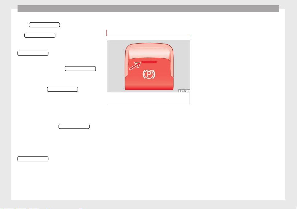
Operation
Upon switching the ignition on/off, the light
of
the
S
T
ART ENGINE STOP
button flashes. With
the en
gine sw
it
ched off, after a few seconds,
the
STOP ENGINE START
button stops flashing
and g
oe
s
out.
With the engine running, the
START ENGINE STOP
button light stays on, indi-
c
atin
g th
at the engine is running. The time
that lapses between the moment the user
starts the engine with the
START ENGINE STOP
button and the lighting changes from flash-
in
g t
o fi
xed will depend on specific engine
size characteristics. Upon switching the igni-
tion off with the
START ENGINE STOP
button, it
s
t
ar
ts flashing again.
In vehicles with the Start-Stop system, the
“My Beat” function also offers additional in-
formation:
●
When the engine stops during the Stop
phase, the light of the
START ENGINE STOP
but-
t
on s
t
ays on, since, even though the engine
is off, the Start-Stop system is active.
●
When the engine cannot be stated again
with the Start-Stop system, ››› page 208, and
needs to be started manually, the
START ENGINE STOP
button flashes to indicate
thi
s
f
act.
Braking and parking
Electronic parking brake
Fig. 180 In the lower part of the centre con-
so
l
e: el
ectronic parking brake button.
The electronic parking brake replaces the
h
andbr
ak
e.
Activating the electronic parking brake
The electronic parking brake can be activated
whenever the vehicle is at a standstill, even
when the ignition is switched off. Activate it
whenever you leave or park the vehicle.
●
Pull and hold the ››› Fig. 180 button.
●
The parking brake is activated when the
control light of the ››› Fig. 180 button (arrow)
and the red control light of the display in
the dash panel are on.
●
Release the button.
Releasing the electronic parking brake
●
Switch the ignition on.
●
Press the button ››› Fig. 180. At the same
time step hard on the brake pedal or, if the
engine is running, press the accelerator ped-
al slightly.
●
The control light of the ››› Fig. 180 button
(arrow) and the red control light of the dis-
play in the dash panel go out.
Automatic release of the electronic parking
brake on starting the engine
The electronic parking brake is automatically
switched off when starting if, after the driv-
er's door is closed and the driver's seat belt
fastened, any of the following situations take
place:
●
On vehicles with an automatic gearbox: A
gear range is engaged or the vehicle is
switched to another one and the accelerator
pedal is lightly pressed.
●
In vehicles with a manual gearbox: The
clutch pedal is pressed fully before starting
off and the accelerator is pedal lightly press-
ed.
●
To facilitate certain manoeuvres there are
exceptions that allow the automatic parking
brake to be released without the driver's seat
belt being fastened.
The parking brake can be prevented from be-
ing automatically released by continuously
186
Driving
pulling up the ›
›
›
Fig. 180 switch when
starting off.
The electronic parking brake is not discon-
nected until the button is released. This
can facilitate starting off when a heavy load
is towed ››› page 273.
Automatic activation of the electronic park-
ing brake when exiting the vehicle incorrect-
ly
In vehicles with automatic transmission, the
electronic parking brake is activated auto-
matically when exiting the vehicle incorrectly
if:
●
The selector lever is in the D/S or R posi-
tion or in the Tiptronic selector gate.
●
AND: the vehicle is stationary.
●
AND: the driver door is open.
Emergency braking function
Only use the emergency brake function if you
are unable to stop the vehicle with the foot
brake ›››
.
●
Pull and hold the ›
›
›
Fig. 180 button in
this position to forcefully stop the vehicle. At
the same time, an acoustic warning can be
heard.
●
To stop the braking process, release the
button or press the accelerator.
WARNING
The improper use of the electronic parking
brake c
an cause accidents and serious injury.
●
Never use the electronic parking brake to
stop the vehicle, unless it is an emergency.
Braking distances can be considerably lon-
ger, since, under certain circumstances, only
the rear wheels brake. Always use the foot
brake.
●
Never accelerate from the engine when a
gear range or a gear is engaged and the en-
gine is running. The vehicle could move, even
if the electronic parking brake is activated.
CAUTION
To prevent the vehicle from unintentionally
movin
g when parking it, first apply the elec-
tronic parking brake and then remove your
foot from the brake pedal.
Note
●
In vehic
les with a manual gearbox, releas-
ing the clutch and accelerating at the same
time automatically disconnects the electronic
parking brake.
●
If the vehicle battery is flat, it will not be
possible to disconnect the electronic parking
brake. Use the jump-start ›››
page 69.
●
When the electronic parking brake is ap-
plied or released, noises may be heard.
●
The system performs automatic and audi-
ble tests sporadically in the parked vehicle if
some time elapses without the electronic
parkin
g brake being used.
Parking
The electronic parking brake should always
be applied when the
vehicle is parked.
Always note the following points when park-
ing the vehicle:
–
Use the brake pedal to stop the vehicle.
–
Apply the electronic parking brake.
–
Put it in 1st gear.
–
Switch the engine off and remove the key
from the ignition. T
urn the steering wheel
slightly to engage the steering lock.
–
Never leave a vehicle key in the vehicle.
Additional notes on parking the vehicle on
gradients:
Turn the steering wheel so that the vehicle
rolls against the kerb if it started to roll.
●
If the vehicle is parked facing downhill,
turn the front wheels so that they point to-
wards the kerb.
●
If the vehicle is parked facing uphill, turn
the front wheels so that they point away from
the kerb.
»
187
Technical dataAdviceOperationEmergenciesSafety
Operation
●
Sec
ur
e the
vehicle as usual by applying the
electronic parking brake firmly and putting it
in 1st gear.
WARNING
●
Take me
asures to reduce the risk of injury
when you leave your vehicle unattended.
●
Never park where the hot exhaust system
could ignite inflammable materials, such as
dry grass, low bushes, spilt fuel etc.
●
Never allow vehicle occupants to remain in
the vehicle when it is locked. They would be
unable to open the vehicle from the inside,
and could become trapped in the vehicle in
an emergency. In the event of an emergency,
locked doors will delay assistance to vehicle
occupants.
●
Never leave children alone in the vehicle.
They could set the vehicle in motion, for ex-
ample, by releasing the electronic parking
brake or the gearshift lever, which would
cause the vehicle to move, but uncontrolla-
bly.
●
Depending on weather conditions, it may
become extremely hot or cold inside the vehi-
cle. This can be fatal.
Information on the brakes
New brake pads
F
or the fir
s
t 400 km (250 miles), new brake
pads have not yet reached their maximum
braking capacity, and need to be “run in”
first. However, you can compensate for the
slightly reduced braking effect by applying
more pressure on the brake pedal. Avoid
overloading the brakes while running them
in.
Wear
The rate of wear on the brake pads depends
a great deal on how you drive and the condi-
tions in which the vehicle is operated. This is
a particular problem in urban traffic and
short stretches, or with very sporty driving.
Depending on the speed, the braking force
and the environmental conditions (for exam-
ple, the temperature, air humidity, etc.)
noises may be produced on braking.
Wet roads or road salt
In certain situations (for example, on driving
through flooded areas, in severe downpours
or after washing the vehicle) the braking ac-
tion could be delayed if the discs and pads
are damp, or frozen in winter. In this case the
brakes should be “dried” by pressing the
brake pedal several times.
At high speed and with the windscreen wip-
ers activated, the brake pads will briefly
touch the brake discs. This takes place, al-
though unnoticeable to the driver, at regular
intervals to improve the response time of the
brakes when they are wet.
The effectiveness of the brakes can also be
temporarily reduced if the vehicle is driven
for some distance without using the brakes
when there is a lot of salt on the road in win-
ter. The layer of salt that accumulates on the
discs and pads can be removed by gently ap-
plying the brakes a few times.
Corrosion
There may be a tendency for corrosion to
form on the discs and dirt to build up on the
brake pads if the vehicle is used infrequently
or the brakes are not used very often.
If the brakes are not used frequently, or if
rust has formed on the disks, it is advisable
to clean off the pads and disks by braking
firmly a few times at a moderately high speed
›››
.
F
au
lt
in the brake system
If the brake pedal travel should ever increase
suddenly, this may mean that one of the two
brake circuits has failed. Drive immediately
to the nearest specialised workshop and
have the fault repaired. Drive there slowly
and remember that you will have to apply
more pressure on the brake pedal and allow
for longer stopping distances.
188
Driving
Low brake fluid level
M
alf
u
nctions can occur in the brake system if
the brake fluid level is too low. The brake flu-
id level is monitored electronically.
Brake servo
The brake servo increases the pressure you
apply to the brake pedal. It works only when
the engine is running.
WARNING
●
Apply
the brakes heavily to clean the brake
system only in a suitable traffic situation. Do
not put other road users in danger: there is
risk of causing an accident.
●
Ensure the vehicle does not move while in
neutral, when the engine is stopped. Failure
to follow this instruction could result in an
accident.
●
If the brake fluid loses its viscosity and is
subjected to heavy use, vapour bubbles can
form in the brake system. This reduces the ef-
ficiency of the brakes.
CAUTION
●
Never let
the brakes “drag” by leaving your
foot on the pedal when it is not necessary to
brake. This overheats the brakes, resulting in
longer stopping distances and greater wear.
●
Before driving down a long, steep gradient,
it is advisable to reduce speed and select a
lower gear. This makes use of engine braking
and relieves the brakes. If you still have to
use the brak
es, it is better to brake firmly at
intervals than to apply the brakes continu-
ously.
Note
●
If
the brak
e servo is out of action, for exam-
ple when the car is being towed, you will
have to press the brake pedal considerably
harder than normal to make up for the lack of
servo assistance.
●
If you wish to equip the vehicle with acces-
sories such as a front spoiler or wheel covers,
it is important that the flow of air to the front
wheels is not obstructed, otherwise the
brakes can overheat.
Hydraulic Brake Assist (HBA)
Electronic stability control (ESC)
The E
SC
help
s to improve safety. It reduces
the tendency to skid and improves the stabil-
ity and roadholding of the vehicle. The ESC
detects critical handling situations, such as
vehicle understeer or oversteer, or wheelspin
on the driving wheels. It stabilises the vehi-
cle by braking individual wheels or by reduc-
ing the engine torque. The warning lamp will
flash on the instrument panel when the ESC
is intervening .
The ESC includes the anti-lock brake system
(ABS), the hydraulic brake assist (HBA), the
traction control system (ASR), electronic dif-
ferential lock (EDS), electronic torque control
(XDS) and tractor-trailer sway mitigation*.
ESC also helps stabilise the vehicle by chang-
ing the torque.
Anti-lock brake system (ABS)
ABS prevents the wheels from locking up un-
der braking until the vehicle has reached a
virtual standstill. You can continue to steer
the vehicle even when the brakes are on full.
Keep your foot on the brake pedal and do not
pump the brakes. You will feel the brake ped-
al pulsate while the ABS is working.
Hydraulic Brake Assist (HBA)
The brake assist system can reduce the re-
quired braking distance. The braking force is
automatically boosted if you press the brake
pedal quickly in an emergency. You must
keep pressing the brake pedal until the dan-
ger has passed.
Traction control system (ASR)
In the event of wheelspin, the traction control
system reduces the engine torque to match
the amount of grip available. This helps the
car to start moving, accelerate or climb a gra-
dient.
Electronic differential lock (EDL)
When the EDL detects wheelspin, it brakes
the spinning wheel and directs the power to
»
189
Technical dataAdviceOperationEmergenciesSafety
Operation
the other driven wheel. This function is active
up t
o ap
pr
oximately 100 km/h (62 mph).
To prevent the disc brake of the braked wheel
from overheating, the EDL cuts out automati-
cally if subjected to excessive loads. The ve-
hicle can still be driven. The EDL will switch
on again automatically when the brake has
cooled down.
Tractor-trailer sway mitigation*
If the vehicle is pulling a trailer, it will control
the following: Tractor-trailers tend to sway.
When the swaying of the trailer is felt by the
vehicle and detected by the ESC, it will auto-
matically brake the towing vehicle within the
limits of the system and mitigate the sway.
Tractor-trailer sway mitigation is not available
in all countries.
Electronic torque management (XDS)
When taking a curve, the driveshaft differen-
tial mechanism allows the outer wheel to turn
at a higher speed than the inner wheel. In
this way, the wheel that is turning faster (out-
er wheel) receives less drive torque than the
inner wheel. This may mean that in certain
situations the torque delivered to the inner
wheel is too high, causing the wheels to
spin. On the other hand, the outer wheel is
receiving a lower drive torque than it could
transmit. This causes an overall loss of lateral
grip on the front axle, resulting in understeer
or “lengthening” of the trajectory.
The XDS system can detect and correct this
effect via the sensors and signals of the ESC.
Via the ESC, the XDS will brake the inside
wheel and counter the excess driving torque
of that wheel. This means that the driver's
desired trajectory is much more precise.
The XDS system works in combination with
the ESC and is always active, even when ASR
traction control is disconnected, or the ESC in
Sport mode or disconnected.
Multi-collision brake
In an accident, the multi-collision brake can
help the driver by braking to avoid the risk of
skidding during the accident, which could
lead to further collisions.
The multi-collision brake works for front, side
or rear accidents, when the airbag control
unit records its activation level and the acci-
dent takes place at a speed of over 10 km/h
(6 mph). The ESC automatically brakes the
vehicle, as long as the accident has not dam-
aged the ESC, the brake hydraulics or the on-
board network
The following actions control automatic brak-
ing during the accident:
●
When the driver presses the accelerator,
the automatic braking does not take place.
●
When the braking pressure through press-
ing the brake pedal is greater than the sys-
tem’s braking pressure the vehicle will brake
automatically.
●
Multi-collision braking will not be available
if ESC is malfunctioning.
WARNING
●
The ESC, ABS, ASR, EDS
and the electronic
torque control system cannot exceed the lim-
its imposed by the laws of physics. Always
bear this in mind, especially on wet or slip-
pery roads. If you notice the systems cutting
in, you should reduce your speed immediate-
ly to suit the road and traffic conditions. Do
not be encouraged to take risks by the pres-
ence of more safety systems. If you do, an ac-
cident may occur.
●
Please remember that the accident risk al-
ways increases if you drive fast, especially in
corners or on a slippery road, or if you follow
too close behind the vehicle in front of you.
The ESC, ABS, brake assist, EDS and the elec-
tronic torque control system cannot prevent
accidents: risk of accidents!
●
Accelerate with caution on slippery surfa-
ces (for example, icy or snow-covered). De-
spite the control systems, the driven wheels
could spin, affecting the stability of the vehi-
cle: risk of accident!
Note
●
The ABS and ASR wi
ll only operate correctly
if the four wheels have identical tyres. Any
differences in the rolling radius of the tyres
190

Driving
can cause the system to reduce engine power
when this i
s not desired.
●
The regulating processes of the systems
can make noises when they intervene.
●
If the warning lamp lights up, or alter-
natively, there could be a fault ››› page 119.
Switching on/off the ESC and ASR
The ESC is switched on automatically when
the engine is
started, and only works when
the engine is running and includes the ABS,
EDS and ASR systems.
The ASR function should only be switched off
in situations in which traction is insufficient,
including:
●
When driving in deep snow or on surfaces
that ar
e not very firm.
●
To “free” the vehicle if it gets stuck.
Then switch the ASR function back on.
Depending on the finishes and versions,
there is the possibility of disconnecting only
the ASR or activating the ESC Sport mode.
Disable ASR
The Easy Connect system menu is used to
switch off the ASR ››› page 120. The traction
control system will be disabled.
The control lamp lights up. For vehicles
with a driver information system* the driver
will be informed that ASR is disabled.
Activate ASR
The Easy Connect system menu ››› page 120
is used to switch on the ASR. The traction
control system will be enabled.
The control lamp switches off. For vehicles
with a driver information system* the driver
will be informed that ASR is enabled.
ESC in “Sport” mode
Sport mode can be connected via the Easy
Connect ››› page 120 system menu. In front-
wheel drive vehicles, the interventions by the
ESC and the ASR are limited. In four-wheel
drive vehicles, the interventions by the ESC
are limited and the ASR is switched off com-
pletely ›››
.
The c
ontr
o
l lamp lights up. For vehicles
with a driver information system* the driver
will be informed that:
Electronic Stability Control
(ESC): sport. Warning! Limited
stability
Disable ESC “Sport” mode
Through the Easy Connect system menu
››› page 120. The warning lamp will switch
off. For vehicles with a driver information sys-
tem* the driver will be informed that:
Electronic Stability Control
(ESC): On
ESC in “Offroad”
1)
mode
Turn the Driving Experience button to select
the Offroad mode and connect it
››› page 243. The interventions of the ESC, as
well as of the ASR, EDS and the ABS, adapt to
irregular terrain.
In the following exceptional situations it may
make sense to activate the Offroad mode to
allow the wheels to spin:
●
When “swinging” the vehicle to get it un-
stuck.
●
Driving in deep snow or on loose surfaces.
●
When driving on rough terrain with much of
the car's weight is lifted off the wheels (axle
articulation).
»
1)
Only for 4Drive models.
191
Technical dataAdviceOperationEmergenciesSafety
Operation
●
St
eep de
s
cents with braking on unpaved
terrain.
For your safety we recommend that you turn
off the Offroad mode when it is not absolute-
ly necessary.
Disable the ESC Offroad mode
Turn the Driving Experience button to select a
different driving mode ››› page 243.
ESC in “Snow” mode
1)
Turn the Driving Experience button to select
the “Snow” mode and connect it.
››› page 243 Traction control system (ASR) in-
terventions adjust to the adhesion of snowy
roads.
Disable the ESC “Snow” mode
Turn the Driving Experience button to select a
different driving mode ››› page 243.
WARNING
The ESC Sport mode should be activated only
when traffic c
onditions and the ability of the
driver allow it. Danger of skidding!
●
With ESC in Sport mode, the stabilising
function will be limited to allow for a sportier
drive. The driving wheels could spin and the
vehicle could skid.
WARNING
You should only activate the Offroad Mode or
disab
le the ASR if the experience of the driver
and traffic conditions allow it. Danger of skid-
ding!
●
With the Offroad mode activated, the stabi-
lisation function is limited. In particular, if
the road is too smooth and slippery, the driv-
ing wheels could spin and the vehicle could
skid.
Note
If the ASR or the ESC is disconnected or the
Sport
mode is selected, cruise control* will
be switched off.
Manual gearbox
Ch
an
gin
g gear
Read the additional information carefully
›
›
›
page 49
In some countries the clutch pedal must be
fully pressed down for the engine to start.
Selecting reverse gear
●
Engage reverse gear only when the vehicle
is stopped.
Changing down gears
While driving, changing down a gear must al-
ways be done gradually, i.e. to the gear di-
rectly below and when the engine speed is
not too high ›››
. Changing down while by-
p
a
s
sing one or various gears at high speeds
or at high engine speeds can damage the
clutch and the gearbox, even if the clutch
pedal remains depressed ›››
.
WARNING
When the engine is running, the vehicle will
star
t to move as soon as a gear is engaged
and the clutch released. This is also the case
with the electronic parking brake switched
on.
●
Never engage reverse gear when the vehi-
cle is moving.
WARNING
If the gear is changed down inappropriately
by sel
ecting a gear that is too low, you may
lose control of the vehicle, causing an acci-
dent and serious injuries.
CAUTION
When travelling at high speeds or at high en-
gine speeds, sel
ecting a gear that is too low
can cause considerable damage to the clutch
and the gearbox. This can also occur if the
1)
Only for 4Drive models.
192
Driving
clutch pedal is pressed and held and it does
not eng
age.
CAUTION
To prevent damage and avoid premature
w
ear
, please observe the following:
●
Do not rest your hand on the gear lever
while driving. The pressure applied by your
hand is transmitted to the gearbox selector
forks.
●
Always ensure that the vehicle is complete-
ly stopped before engaging the reverse gear.
●
Always press the clutch to the floor when
changing gears.
●
Never hold the vehicle “on the clutch” on
hills with the engine on.
Automatic gearbox/DSG auto-
m
atic
g
earbox*
Introduction
Your vehicle is equipped with an electronical-
ly
c
ontr
olled manual gearbox. Torque be-
tween the engine and the gearbox is trans-
mitted via two independent clutches. They re-
place the torque converter found on conven-
tional automatic gearboxes and allow for
smooth, uninterrupted acceleration of the ve-
hicle.
The tiptronic system allows the driver to
change gears manually if desired
››› page 195, Engaging gears with the trip-
tonic mode*.
Selector lever positions
Read the additional information carefully
›››
page 49
The selector lever position engaged is high-
lighted on the display in the instrument clus-
ter. With the selector lever in the manual
gearbox positions G, D, E and S, the engaged
gear is also indicated on the display.
P – Parking lock
When the selector lever is in this position,
the driven wheels are locked mechanically.
The parking lock must be engaged only when
the vehicle is stationary
›››
.
The int
erloc
k
button (the button on the selec-
tor lever handle) must be pressed in and si-
multaneously the brake pedal must be de-
pressed before moving the selector lever ei-
ther in or out of position P.
R – Reverse gear
Reverse gear must be engaged only when the
vehicle is stationary and the engine is idling
›››
.
To move the selector lever to position R, the
int
erloc
k
button must be pressed in and at
the same time the brake pedal must be de-
pressed. The reverse lights come on when
the selector lever is in the R position with the
ignition on.
N – Neutral (idling)
With the selector lever in this position, the
gear is in neutral.
D/S – Permanent drive (forward) position
The selector lever in the D/S position enables
the gears to be controlled in normal mode (D)
or Sport (S). To select Sport mode (S), move
the selector lever backwards. Moving the lev-
er again will select normal mode (D). The se-
lected driving mode is shown on the instru-
ment panel display.
In normal mode (D), the gearbox automatical-
ly selects the best gear ratio. This depends
on the engine load, the road speed and the
dynamic gear control programme (DCP).
Sport mode (S) must be selected for a sporty
driving style. This setting makes use of the
engine's maximum power output. When ac-
celerating the gear shifts will be noticeable.
Press the brake pedal to move the selector
lever from N to D/S when the vehicle is sta-
tionary or at speeds below 3 km/h (2 mph)
›››
.
»
193
Technical dataAdviceOperationEmergenciesSafety
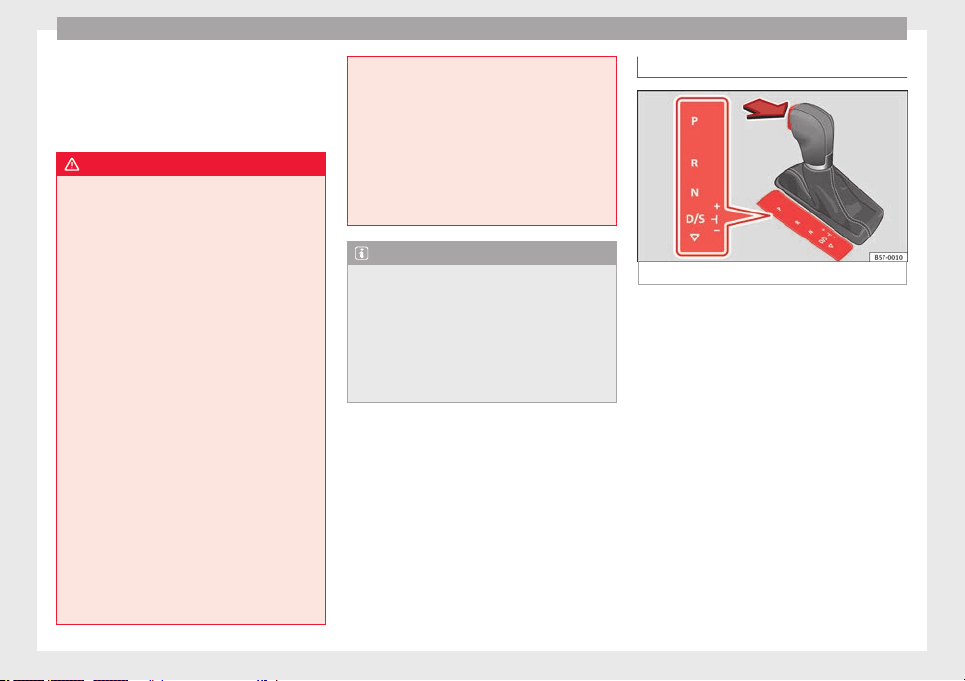
Operation
Under certain circumstances (e.g. when driv-
in
g in mou
nt
ains) it can be advantageous to
switch temporarily to tiptronic mode
››› page 195, in order to manually select gear
ratios to suit the driving conditions.
WARNING
●
Take c
are not to accidentally press the ac-
celerator pedal when the vehicle is stopped.
The vehicle could otherwise start moving im-
mediately (in some cases even if the parking
brake is engaged) resulting in the risk of an
accident.
●
Never move the selector lever to R or P
when driving. Failure to follow this instruc-
tion could result in an accident.
●
With selector lever in any position (except
P) the vehicle must always be held with the
foot brake when the engine is running. This is
because an automatic gearbox still transmits
power even at idling speed, and the vehicle
tends to “creep”. The accelerator pedal must
on no account be pressed inadvertently when
a gear is engaged with the vehicle stationary.
The vehicle could otherwise start moving im-
mediately (in some cases even if the parking
brake is engaged) resulting in the risk of an
accident.
●
While you are selecting a gear and the vehi-
cle is stopped with the engine running, do
not accelerate. Failure to follow this instruc-
tion could result in an accident.
●
As a driver you should never leave your ve-
hicle if the engine is running and a gear is en-
gaged. If you have to leave your vehicle while
the engine is
running, you must apply the
handbrake and engage the parking lock (P).
●
To avoid accidents, apply the handbrake
and put the selector lever in position P before
opening the bonnet and working on the vehi-
cle with the engine running. Please always
observe the important safety warnings
››› page 298, Working in the engine compart-
ment.
Note
●
If
the select
or lever is moved accidentally
to N when driving, release the accelerator and
let the engine speed drop to idling before se-
lecting gear range D or S again.
●
Should the power supply to the selector
lever be interrupted in position P, the selector
lever will be locked. If this should happen the
manual release can be used ›››
page 49.
Selector lever lock
Fig. 181 Selector lever lock.
The selector lever lock prevents gears from
bein
g en
g
aged inadvertently, so that the ve-
hicle is not set in motion unintentionally.
The selector lever lock is released as follows:
–
Switch the ignition on.
–
Press the brake pedal and, at the same
time, hold the lock button in the direction
of the arrow ››› Fig. 181.
Automatic selector lever lock
With the ignition switched on, the selector
lever is locked in the positions P and N. The
brake pedal must be pressed to release the
lever while pressing the release button if the
selector lever is in the position P. As a re-
minder for the driver, with the lever in posi-
tions P or N the following message will be
shown on the display:
194
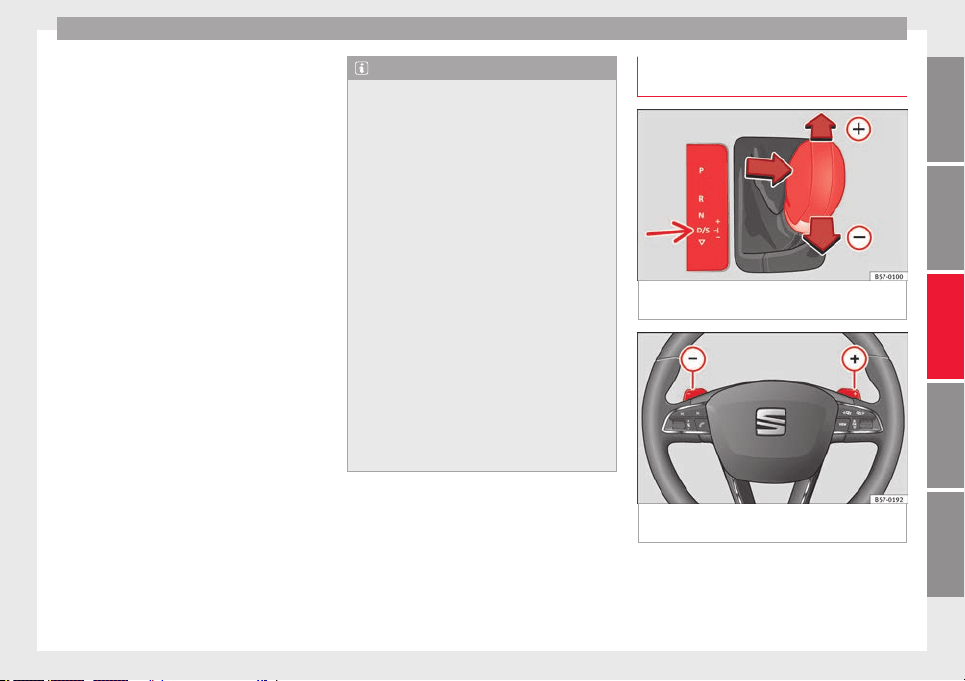
Driving
When stationary, apply footbrake
while selecting a gear.
L
ev
el
lock only engages with the vehicle sta-
tionary and at speeds of up to 5 km/h
(3 mph). At speeds of over 5 km/h (3 mph)
the lever lock is automatically deactivated in
position N.
The selector lever lock is not engaged if the
selector lever is moved quickly through posi-
tion N (e.g. when shifting from R to D). This
makes it possible, for instance, to rock the
vehicle “backwards and forwards” if it is
stuck. The selector lever lock engages auto-
matically if the brake pedal is not depressed
and the lever is in position N for more than
about two seconds.
Interlock button
The interlock button on the selector lever
handle prevents the driver from inadvertently
engaging certain gears. Press the button in
to disengage the selector lever lock.
Safety interlock for ignition key
Depending on the country, once the ignition
has been turned off, the key may be removed
only if the gear selector is in position P. While
the key is not in the ignition, the selector lev-
er is locked in position P.
Note
●
If the select
or lever lock does not engage,
there is a fault. The transmission is interrup-
ted to prevent the vehicle from accidentally
moving. Follow the procedure below in order
for the selector lever lock to engage again:
–
With a 6-speed gearbox: press the brake
pedal and release it again.
–
With a 7-speed gearbox: press the brake
pedal. Move the selector lever to posi-
tion P or N and subsequently engage a
gear.
●
Despite a gear being engaged, the vehicle
does not move forwards or back. Proceed to
the next mode:
–
When the vehicle does not move in the
required direction, the system may not
have the gear range correctly engaged.
Press the brake pedal and engage the
gear range again.
–
If the vehicle still does not move in the
required direction, there is a system mal-
function. Seek specialist assistance and
have the system checked.
Engaging gears with the triptonic
mode*
Fig. 182 Centre console: changing gear with
tiptr
onic
Fig. 183 Steering wheel: automatic gearbox
l
ev
er
s
The tiptronic gives the driver the option to
c
h
an
ge gears manually.
»
195
Technical dataAdviceOperationEmergenciesSafety
Operation
Changing gear manually with the selector
l
ev
er
It
is possible to change to tiptronic mode,
both when the vehicle is stopped and while
driving.
–
To switch to tiptronic mode, move the se-
lector lever from position D/S to the right.
As soon as the change is made the selector
level will be shown in the position M on the
instrument panel display (for example M4
means that the fourth gear is engaged).
–
Move the selector lever forwards
+
to se-
l
ect
a higher g
ear ››› Fig. 182.
–
Move the selector lever backwards
–
to
sel
ect
a lo
wer gear.
Changing gear manually with the gearshift
paddles*
The gearshift paddles can be used when the
selector lever is in the position D/S or M.
–
Press the gearshift paddle
+
to select a
higher g
e
ar ›
›› Fig. 183.
–
Press the gearshift paddle
–
to select a
lo
w
er g
ear.
–
With the selector lever in position D/S, if no
paddle is operated during a short period of
time, the gearbox control system switches
back to automatic mode. To switch to per-
manent manual gear change using the
gearshift paddles, move the selector lever
from position D/S to the right.
When accelerating, the gearbox automatical-
ly shifts up into the next gear shortly before
the maximum engine speed is reached.
If you select a lower gear, the automatic gear-
box will not shift down until there is no risk of
over-revving the engine.
When the kick-down feature is used, the
gearbox shifts down to a lower gear, depend-
ing on road speed and engine speed.
Driving tips
The gearbox changes gear ratios automatical-
ly
a
s
the vehicle moves.
The engine can only start with the selector
lever in position P or N. At low temperatures,
below -10°C (50°F), the engine can only start
with the selector lever in position P.
Starting the vehicle
–
Press and hold the brake pedal.
–
Press and hold the interlock button (the
button on the selector lever handle), move
the selector lever to the desired position,
for instance D
›››
page 193, and release the
interlock button.
–
Wait for the gearbox to engage the gear (a
slight movement can be felt).
–
Release the brake and press the accelerator
›››
.
Stopping briefly
–
Apply the foot brake to hold the vehicle
briefly
when s
t
ationary (for instance at traf-
fic lights). Do not press the accelerator.
Stopping/Parking
If the driver door is opened and the selector
lever is not in position P, the vehicle could
move. The driver message will be: Gear
change: selector lever in the
drive position!. Additionally, a buzzer
will sound.
–
Press and hold the brake pedal ›››
.
–
Apply the handbrake.
–
Move the selector lever to position P.
Ho
l
din
g the car on a hill
–
Always apply the brake pedal firmly to pre-
vent the vehicle from “moving backwards;
if necessary, apply the handbrake” ›››
.
Do not tr
y
t
o stop the vehicle “rolling back”
by increasing the engine speed when a
gear is engaged (pressing the accelerator)
›››
.
St
ar
tin
g off uphill
–
Apply the handbrake.
–
Once you have engaged a gear press the
accelerator carefully and disengage the
handbrake.
196
Driving
Driving down hills: in some s
it
uation
s (on
mountain roads or when towing a trailer or
caravan) it can be advantageous to switch
temporarily to the manual gearbox pro-
gramme so that the gear ratios can be selec-
ted manually to suit the driving conditions
›››
.
On l
ev
el
ground it is sufficient to move the
selector lever to position P. On slopes, first
engage the parking brake and then put the
selection lever into the P position. This
avoids overloading the locking mechanism
and it will be easier to move the selector lev-
er from position P.
WARNING
Observe the safety warnings ›››
in Selector
lever po
sitions on page 194.
●
Never allow the brake to rub and do not use
the brake pedal too often or for long periods.
Constant braking causes overheating in the
brakes. This could significantly reduce brak-
ing power, increase braking distance or even
result in the total failure of the brake system.
●
To avoid rolling back on gradients always
hold the vehicle with the footbrake or hand-
brake if you have to stop.
CAUTION
●
If y
ou stop the vehicle on a gradient, do not
attempt to stop it from rolling by depressing
the accelerator when a gear has been selec-
ted. This could cause overheating and dam-
age the automatic gearbox. Apply the hand-
brake firm
ly or press the brake pedal in order
to prevent the vehicle from rolling back.
●
If you allow the car to roll with the selector
lever in position N with the engine switched
off, the automatic gearbox will be damaged
as it will not be lubricated.
●
In certain driving situations or traffic condi-
tions, such as frequently starting, prolonged
“creeping” of the vehicle or traffic jams with
continuous stoppages, the gearbox could
overheat causing damage! If the warning
lamp lights up, stop the vehicle as soon as
possible and wait for the gearbox to cool
››› page 200.
Kick-down feature
The kick-down feature allows maximum ac-
c
el
er
ation to be reached.
When the accelerator pedal is pressed right
down past the point of resistance at full throt-
tle, the gearbox will shift down to a lower
gear, depending on road speed and engine
speed. The upshift to the next higher gear is
delayed until the engine reaches maximum
rpm.
WARNING
Please note that if the road surface is slip-
pery or w
et, the kick-down feature could
cause the driving wheels to spin, which could
res
ult in skidding.
Launch control program
3 Valid for vehicles: with Launch-Control/6-Speed
DSG w
ith diesel engines superior to 125 kW and pet-
rol engines superior to 140 kW.
The Launch control programme enables maxi-
mum acceleration.
Important: the engine must have reached op-
erating temperature and the steering wheel
must not be turned.
The engine speed for launch-control is differ-
ent on petrol and diesel engines. To use the
launch-control you must disconnect the anti-
slip regulation (ASR) through the Easy Con-
nect system menu ››› page 120. The warning
lamp will stay switched on or will flash
slowly depending on whether or not the vehi-
cle has a driver information system*.
On vehicles with the driver information sys-
tem, the ESC lamp lights up permanently and
the corresponding text message Stability
control deactivated (temporary) ap-
pears on the instrument panel to indicate the
deactivation status.
»
197
Technical dataAdviceOperationEmergenciesSafety
Operation
–
When the en
gine i
s
running, switch off the
traction control (ASR)
1)
.
–
Turn the selector lever to the position “S”
or tiptronic, or else select the sport driv-
ing mode from the SEAT Drive Profile*
››› page 242.
–
Press the brake pedal firmly with your left
foot and hold it down for at least one sec-
ond.
–
With your right foot, press the accelerator
down to the full throttle or kick-down posi-
tion. The engine speed will stabilise at
about 3,200 rpm (petrol engine) or about
2,000 rpm (diesel engine).
–
Take your left foot off the brake pedal.
WARNING
●
Alwa
ys adapt your driving style to the traf-
fic conditions.
●
Only use the launch control programme
when road and traffic conditions permit, and
make sure your manner of driving and accel-
erating the vehicle does not inconvenience or
endanger other road users.
●
Make sure that the ESC remains switched
on. Please note that when the ASR and ESC
are deactivated, the wheels may start to spin,
causing the vehicle to lose grip. Risk of acci-
dent!
●
After putting the vehicle into gear, the
“sport” mode of
the ESC should be deactiva-
ted again by briefly pressing the
OFF
but-
ton.
Note
●
Af
ter u
sing the Launch control programme,
the temperature in the gearbox may have in-
creased considerably. In this case, the pro-
gramme could be disabled for several mi-
nutes. The programme can be used again af-
ter the cooling phase.
●
Accelerating with the Launch control pro-
gramme places a heavy load on all parts of
the vehicle. This can result in increased wear
and tear.
Downhill speed control*
The downhill speed control function helps
the driv
er when driv
in
g down steep gradi-
ents.
Downhill speed control is activated when the
selector lever is in D/S and the driver applies
the foot brake. The automatic gearbox auto-
matically engages a lower gear that is suita-
ble for the slope. The downhill speed control
function attempts to maintain the speed at
which the vehicle was travelling when the
foot brake was applied (subject to the laws of
physics and technical drive limitations). It
may be necessary to adjust the speed again
using the foot brake in certain situations. Giv-
en that the downhill speed control can only
change down to 3rd gear, on very steep de-
scents the tiptronic mode may be required. In
this case, manually reduce the tiptronic to
2nd or 1st gear to use the engine brake and
reduce the charge on the brakes.
Downhill speed control is deactivated as
soon as the road levels out again or you
press the accelerator pedal.
On vehicles with cruise control system*
››› page 212, downhill speed control is acti-
vated when you set a cruising speed.
WARNING
The downhill speed control cannot defy the
law
s of physics. Therefore, speed cannot be
maintained constant in all situations. Always
be prepared to use the brakes!
1)
Vehicles without driver information system: the
warning l
amp flashes slowly/Vehicles with driver in-
formation system: the warning lamp stays on.
198
Driving
Inertia mode
The inertia mode enables the kinetic energy
of the v
ehicle to be harnessed enabling cer-
tain stretches to be driven without using the
accelerator. This enables fuel to be saved.
Use the inertia mode to “let the vehicle roll”
before, for example, arriving in a town.
Switching on inertia mode
Important: selector lever must be in position
D, gradients below 12 %.
–
Select, in SEAT Drive Profile*, Eco mode
›››
page 242.
–
Take your foot off the accelerator.
The driver message Inertia will be dis-
played. At speeds higher than 20 km/h (12
mph), the gearbox will automatically disen-
gage and the vehicle will roll freely, without
the effect of the engine brake. While the vehi-
cle rolls, the engine runs at idling speed.
Stopping inertia mode
–
Press the brake or the accelerator pedal.
To make use of the braking force and switch
off the engine again, simply press the brake
pedal briefly.
Applying both the inertia mode (= prolonged
section with less energy) and the switching
off using inertia (= shorter section without
the need for fuel) facilitates improved fuel
consumption and emission balance.
WARNING
●
If the inerti
a mode has been switched on,
take into account, when approaching an ob-
stacle and releasing the accelerator pedal,
that the vehicle will not decelerate in the usu-
al manner: risk of accident!
●
When using inertia mode while travelling
down hills, the vehicle can increase speed:
risk of accident!
●
If other users drive your vehicle, warn them
about inertia mode.
Note
●
Inertia mode i
s only available in eco (SEAT
Drive Profile*) driving mode.
●
The driver message Inertia is only dis-
played with the current consumption. In iner-
tia mode the gear will no longer be displayed
(for example “E” will appear instead of “E7”).
●
On downhill sections with gradients above
15 %, the inertia mode will automatically be
switched off temporarily.
Emergency program
A backup programme is in place if a fault
shou
l
d oc
cur in the control system.
If all the positions of the selector lever are
shown over a light background on the instru-
ment panel display, there is a system fault
and the automatic gearbox will operate in
with the backup programme. When the back-
up programme is activated, it is possible to
drive the vehicle, however, at low speeds and
within a selected range of gears. In some ca-
ses driving in reverse gear may not be possi-
ble.
CAUTION
If the gearbox operates with the backup pro-
gramme, tak
e the vehicle to a specialised
workshop and have the fault repaired without
delay.
Clutch
Clutch overheating! Please
stop!
The clut
ch has overheated and could be dam-
aged. Stop the vehicle and wait for the gear-
box to cool with the engine at idling speed
and the selector lever in position P. When the
warning lamp and the driver message switch
off, have the fault corrected by a specialised
workshop without delay. If the warning lamp
and the driver message do not switch off, do
not continue driving. Seek specialist assis-
tance.
199
Technical dataAdviceOperationEmergenciesSafety
Operation
Gearbox malfunctions
Gearbox: Fault! Stop the ve-
hicle and place the lever in the
position P.
Ther
e i
s
a fault in the gearbox. Stop the vehi-
cle in a safe place and do not continue driv-
ing. Seek specialist assistance.
Gearbox: System fault! You
may continue driving.
Have the fault corrected by a specialised
workshop without delay.
Gearbox: System fault! You
can continue driving with re-
strictions. Reverse gear disa‐
bled
Take the vehicle to a specialised workshop
and have the fault repaired without delay.
Gearbox: System fault! You
can continue driving in D until
switching off the engine
Stop the vehicle in a safe place well away
from moving traffic. Seek specialist assis-
tance.
Gearbox: too hot. Adapt your
driving accordingly
Continue driving at moderate speeds. When
the warning lamp switches off, you can con-
tinue driving in a normal manner.
Gearbox: press the brake and
engage a gear again.
If the fault was caused by a gearbox with a
high temperature, this driver message will be
displayed when the gearbox has cooled
again.
Address
Electromechanical steering
Electro-mechanical power steering assists
the driv
er when s
t
eering.
Electro-mechanical power steering adapts
electronically to the speed of the car, torque
and turning angle.
If the power steering should fail at any time
or the engine is switched off (for instance
when being towed), the car can still be
steered. However, more effort than normal
will be required to turn the steering wheel.
Driver warning lamps and messages
(in red) Faulty steering! To
park the vehicle
If the warning lamp remains on and the driver
indication appears, the power steering could
be faulty.
Do not continue driving. Seek specialist as-
sistance.
(in yellow) Steering: System
fault! You may continue driving.
If the warning lamp comes on, the steering
could react with more difficultly or more sen-
sitivity than normal. In addition, when driving
in a straight line the steering wheel may be
off-centre.
Drive slowly to a specialised workshop and
have the fault repaired.
(in yellow) Steering lock:
fault! Go to an Official Service
The electronic steering lock is malfunction-
ing.
Go to a specialised workshop as soon as
possible and have the fault repaired.
WARNING
Take it immediately to a specialised work-
shop and have the f
ault repaired: risk of acci-
dent!
Note
If the lamp (in red) or else
(in yellow)
lights up briefly, you may continue driving.
200

Driving
Run-in and economical driving
R
u
nnin
g in the engine
A new vehicle should be run in over a dis-
tance of
1500 km (1000 miles). For the first
1,000 km the engine speed should not ex-
ceed 2/3 of the maximum permissible engine
speed. In doing so, do not accelerate at full
throttle and do not drive with a trailer! From
1000 to 1500 km (600 to 1000 miles) you
can gradually increase the engine rpm and
road speed.
During its first few hours of running, the in-
ternal friction in the engine is greater than
later on when all the moving parts have bed-
ded down.
How the vehicle is driven for the first 1,500
km influences the future engine perform-
ance. Subsequently, also drive at a moderate
rate, especially when the engine is still cold:
this will lead to less engine wear and tear
and will prolong its useful life.
You should also avoid driving with the engine
speed too low. Change down to a lower gear
when the engine no longer runs “smoothly”.
If the engine revs too much, cut fuel injection
to protect the engine.
Environmental compatibility
Environmental protection is a top priority in
the design, c
hoice of materials and manufac-
ture of your new SEAT.
Constructive measures to encourage recy-
cling
●
Joints and connections designed for easy
dismantling.
●
Modular construction to facilitate disman-
tling.
●
Increased use of single-grade materials.
●
Plastic parts and elastomers are marked in
accor
dance with ISO 1043, ISO 11469 and
ISO 1629.
Choice of materials
●
Use of recycled materials.
●
Use of compatible plastics in the same part
if its components are not easily separated.
●
Use of recycled materials and/or materials
originating from renewable sources.
●
Reduction of volatile components, includ-
ing odour, in plastic materials.
●
Use of CFC-free coolants.
Ban on heavy metals, with the exceptions
dictated by law (Annex II of ELV Directive
2000/53/EC): cadmium, lead, mercury, hexa-
valent chromium.
Manufacturing methods
●
Reduction of the quantity of thinner in the
protective wax for cavities.
●
Use of plastic film as protection during ve-
hicle transport.
●
Use of solvent-free adhesives.
●
Use of CFC-free coolants in cooling sys-
tems.
●
Recycling and energy recovery from resi-
dues (RDF).
●
Improvement in the quality of waste water.
●
Use of systems for the recovery of residual
heat (thermal recovery, enthalpy wheels,
etc.).
●
The use of water-soluble paints.
Economical and environmentally-
friendly driving
Fuel consumption, environmental pollution
and w
e
ar t
o the engine, brakes and tyres de-
pends largely on driving style. Fuel consump-
tion can be reduced by 10-15% with an eco-
nomical driving style and proper anticipation
of traffic conditions. The following section
gives you some tips on lessening the impact
on the environment and reducing your oper-
ating costs at the same time.
»
201
Technical dataAdviceOperationEmergenciesSafety

Operation
Active cylinder management (ACT
®
)*
D
ependin
g on
vehicle equipment, the active
cylinder management (ACT
®
) may automati-
cally deactivate some of the engine cylinders
if the driving situation does not require too
much power. When it is switched off, no fuel
is injected into these cylinders, hence total
fuel consumption may be reduced. The num-
ber of active cylinders can be seen on the in-
strument panel display ›››
page 37.
Foresight when driving
Acceleration causes the vehicle to consume
more fuel. If you think ahead when driving,
you will need to brake less and thus acceler-
ate less. Wherever possible, let the car roll
slowly to a stop, with a gear engaged (for in-
stance when you can see that the next traffic
lights are red). This takes advantage of the
engine braking effect, reducing wear on the
brakes and tyres. Emissions and fuel con-
sumption will drop to zero due to the overrun
fuel cut-off.
Changing gear to save energy
An effective way of saving is to change in ad-
vance to a higher gear. Running the engine at
high rpm in the lower gears uses an unneces-
sary amount of fuel.
Manual gearbox: shift up from first to second
gear as soon as possible. In any case, we rec-
ommend that you change to a higher gear
upon reaching 2,000 rpm. Choosing the right
gear enables fuel savings. Select the highest
possible gear appropriate for the driving sit-
uation (the engine should continue function-
ing with cyclical regularity).
Automatic gearbox: accelerate gradually and
without reaching the “kick-down” position.
Avoid driving at high speed
Avoid travelling at top speed, whenever pos-
sible. Fuel consumption, emission of harmful
gases and noise pollution multiply dispropor-
tionately as speed is increased. Driving at
moderate speeds will help to save fuel.
Reduce idling time
In vehicles with the Start-Stop system idling
is automatically reduced. In vehicles without
the Start-Stop system it is worth switching off
the engine, for example, at level crossings
and at traffic lights that remain red for long
periods of time. When an engine has reached
operating temperature, and depending on
the cylinder capacity, keeping it switched off
for a minimum of about 5 seconds already
saves more than the amount of fuel necessa-
ry for restarting.
The engine takes a long time to warm up
when it is idling. Mechanical wear and pollu-
tant emissions are also especially high dur-
ing this initial warm-up phase. It is therefore
best to drive off immediately after starting
the engine. Avoid running the engine at high
speed.
Regular maintenance
Regular servicing helps in saving fuel even
before the engine is started. A well-serviced
engine gives you the benefit of improved fuel
efficiency as well as maximum reliability and
an enhanced resale value. A badly serviced
engine can consume up to 10% more fuel
than necessary.
Avoid short journeys
The engine and catalytic converter need to
reach their optimal operating temperature in
order to minimise fuel consumption and
emissions.
A cold engine consumes a disproportionate
amount of fuel. The engine reaches its work-
ing temperature after about four kilometres
(2.5 miles), when fuel consumption will re-
turn to a normal level.
Check tyre pressure
Always make sure the tyres are inflated to the
correct pressures ››› page 308 to save fuel. If
the pressure is below half bar, fuel consump-
tion may increase by 5%. Due to the greater
rolling resistance, under-inflation also increa-
ses tyre wear and impairs handling.
Do not use winter tyres all year round as they
increase fuel consumption by up to 10%.
202

Driving
Avoid carrying unnecessary loads
Giv
en th
at
every kilo of extra weight will in-
crease the fuel consumption, it is advisable
to always check the luggage compartment to
make sure that no unnecessary loads are be-
ing transported.
Since the luggage rack increases the aerody-
namic drag of the vehicle, you should remove
it when not needed. At speeds of 100-120
km/h (62-75 mph), this will save 12% of fuel.
Save electrical energy
The engine drives the alternator, thereby gen-
erating electricity. This implies that any in-
crease in power consumption also increases
fuel consumption! For this reason, switch off
any unneeded electrical devices. Devices that
use a lot of electricity includes the blower at
a high setting, the rear window heating or
the seat heating*.
Power management
This system helps to ensure reliable
starting
The power management controls the distribu-
tion of
el
ectric
al energy and thus helps to en-
sure that there is always enough power avail-
able to start the engine.
If a vehicle with a conventional electrical sys-
tem is left parked for a long time, the battery
will gradually lose its charge because certain
electrical devices, such as the electronic
gearbox lock continues to draw current even
when the ignition is off. In some cases there
may not be enough power available to start
the engine.
Your vehicle is equipped with an intelligent
power management system to control the
distribution of electrical energy. This signifi-
cantly improves reliability when starting the
engine, and also prolongs the useful life of
the battery.
The main functions incorporated in the power
management system are battery diagnosis,
residual current management and dynamic
power management.
Battery diagnosis
The battery diagnosis function constantly
registers the condition of the battery. Sen-
sors detect the battery voltage, battery cur-
rent and battery temperature. This enables
the system to calculate the current power lev-
el and charge condition of the battery.
Residual current management
The residual current management reduces
power consumption while the vehicle is
parked. It controls the supply of power to the
various electrical devices while the ignition is
switched off. The system takes the battery di-
agnosis data into consideration.
Depending on the power level of the battery,
switch off the individual electrical devices
one after the other to prevent the battery
from losing too much charge and to ensure
that the engine can be started reliably.
Dynamic power management
While the vehicle is moving, this function dis-
tributes the available power to the various
electrical devices and systems according to
their requirements. The power management
ensures that on-board systems do not con-
sume more electrical power than the alterna-
tor can supply, and thus maintains the maxi-
mum possible battery power level.
Note
●
Neither is the po
wer management system
able to overcome the given physical limits.
Please remember that the power and useful
life of the battery are limited.
●
When there is a risk that the vehicle will
not start, the alternator power failure or low
battery charge level warning lamp will be
shown ››› page 119.
Flat battery
Starting ability has first priority.
»
203
Technical dataAdviceOperationEmergenciesSafety
Operation
Short trips, city traffic and low temperatures
al
l
p
lace a heavy load on the battery. In these
conditions a large amount of power is con-
sumed, but only a small amount is supplied.
The situation is also critical if electrical devi-
ces are in use when the engine is not run-
ning. In this case power is consumed when
none is being generated.
In these situations you will be aware that the
power management system is intervening to
control the distribution of electrical power.
When the vehicle is parked for long periods
If you do not drive your vehicle for a period of
several days or weeks, the power manage-
ment will gradually shut off the electrical de-
vices one by one or reduce the amount of cur-
rent they are using. This limits the amount of
power consumed and helps to ensure relia-
ble starting even after a long period. Some
convenience functions, such as remote vehi-
cle opening, may not be available under cer-
tain circumstances. These functions will be
restored when you switch on the ignition and
start the engine.
With the engine switched off
For example, if you listen to the sound sys-
tem with the engine switched off the battery
will run down.
If the energy consumption means there is a
risk that the engine will not start, a text will
appear in vehicles with a driver information
system*.
This driver indicator tells you that you must
start the engine so that the battery can re-
charge.
When the engine is running
Although the alternator generates electrical
power, the battery can still become dis-
charged while the vehicle is being driven.
This can occur when a lot of power is being
consumed but only a small amount supplied,
especially if the battery is not fully charged
initially.
To restore the necessary energy balance, the
system will then temporarily shut off the elec-
trical devices that are using a lot of power, or
reduce the current they are consuming. Heat-
ing systems in particular use a large amount
of electrical power. If you notice, for instance,
that the seat heating* or the rear window
heater is not working, they may have been
temporarily switched off or regulated to a
lower heat output. These systems will be
available again as soon as sufficient electri-
cal power is available.
You may also notice that the engine runs at a
slightly faster idling speed when necessary.
This is quite normal, and no cause for con-
cern. The increased idling speed allows the
alternator to meet the greater power require-
ment and charge the battery at the same
time.
Engine management and ex-
haust gas purification system
Introduction
WARNING
●
Becau
se of the high temperatures which
can occur in the exhaust purification system
(catalytic converter or diesel particulate fil-
ter), do not park the vehicle where the ex-
haust can come into contact with flammable
materials under the car (e.g. on grass or at
the forest edge). Fire hazard!
●
Do not apply wax underneath the vehicle
around the area of the exhaust system: Fire
hazard!
Note
While the control lamps , , or re-
main lit, ther
e may be engine problems, fuel
consumption may increase and the engine
may lose power.
204

Driving
Catalytic converter
3 Applies to vehicles with petrol engine
The v
ehicle must only be used with unleaded
petrol, otherwise the catalytic converter will
be irreparably damaged.
Never drive until the tank is empty; an irregu-
lar supply of fuel can cause faulty combus-
tion. In these cases, unburned fuel reaches
the exhaust system, which can overheat and
damage the catalytic converter.
Diesel particulate filter
3 Applies to vehicles with diesel engine
The die
sel engine particulate filter eliminates
most of the soot from the exhaust gas sys-
tem. Under normal driving conditions, the fil-
ter cleans itself. The diesel particulate filter is
cleaned automatically without need for indi-
cation by the warning lamp . This may be
noticed because the engine idle speed in-
creases and an odour may be detected.
If automatic filter purification cannot be car-
ried out (because only short trips are taken,
for example), soot will accumulate on the fil-
ter and the Diesel particulate filter warning
lamp will switch on.
Facilitate the automatic filter cleaning proc-
ess by driving in the following manner: drive
for approximately 15 minutes at a minimum
speed of 60 km/h (37 mph) in 4th or 5th gear
(automatic gearbox: gear S). Maintain the en-
gine speed at ap
proximately 2,000 rpm. The
rise in temperature causes the soot on the fil-
ter to burn. On completion of the cleaning
the warning lamp will switch off. If the warn-
ing lamp does not switch off, go immediately
to a specialised workshop to rectify the prob-
lem.
Engine management*
This warning lamp monitors the engine man-
ag
ement
sy
stem for petrol engines.
The warning lamp (Electronic Power Con-
trol) lights up when the ignition is switched
on while system operation is being verified. It
should go out once the engine is started.
If there is a fault in the electronic engine
management system while you are driving,
this warning lamp will light up. Take the vehi-
cle to a specialised workshop as soon as
possible and have the engine checked.
Emission control system*
Control lamp fl
a
she
s:
When there is misfiring that can damage the
catalytic converter. Reduce speed and drive
carefully to the nearest specialised workshop
to have the engine checked.
The control lamp lights up:
If a fault has developed during driving which
has reduced the quality of the exhaust gas
(e.g. lambda probe fault). Reduce speed and
drive carefully to the nearest specialised
workshop to have the engine checked.
Engine pre-heating/fault system*
The warning lamp lights up to show that the
glow plug
s are preheating the diesel engine.
The control lamp lights up
If the control lamp lights up when the en-
gine is started it means that the glow plugs
are preheating. The engine can be started
straight away when the lamp switches off.
Control lamp flashes
If a fault develops in the engine management
system while you are driving, the glow plug
system lamp will flash . Take the vehicle to
a specialised workshop as soon as possible
and have the engine checked.
205
Technical dataAdviceOperationEmergenciesSafety
Operation
Driving tips
Driv
in
g on flooded r
oads
To prevent damage to the vehicle when driv-
ing through w
ater, for example, along a floo-
ded road, please observe the following:
●
The water should never come above the
lower edge of the bodywork.
●
Drive at pedestrian speed.
WARNING
After driving through water, mud, sludge,
etc., the br
aking effect can be delayed slight-
ly due to moisture build-up on the discs and
brake pads. Applying the brakes carefully
several times will remove the moisture and
restore the full braking effect.
CAUTION
●
Driving thr
ough flooded areas may severely
damage vehicle components such as the en-
gine, transmission, running gear or electrical
system.
●
Whenever driving through water, the Start-
Stop system* must be switched off
››› page 208.
Note
●
Check the depth of
the water before enter-
ing the flooded zone.
●
Do not st
op in the water, drive in reverse, or
stop the engine in any situation.
●
Note that vehicles travelling in the opposite
direction may splash water that could exceed
the maximum permitted water height for your
vehicle.
●
Avoid driving through salt water (corro-
sion).
Four-wheel drive
3 Valid for vehicles: with four-wheel drive
On f
our-wheel drive models, the engine pow-
er is distributed to all four wheels
General notes
On four-wheel drive vehicles, the engine
power is distributed to all four wheels. The
distribution of power is controlled automati-
cally according to your driving style and the
road conditions. Also see ››› page 189.
The four-wheel drive is specially designed to
complement the superior engine power. This
combination gives the vehicle exceptional
handling and performance capabilities, both
on normal roads and in more difficult condi-
tions, such as snow and ice. Even so (or per-
haps especially for this reason), it is impor-
tant to observe certain safety points ›››
.
Winter tyres
Th
ank
s
to four-wheel drive, your vehicle will
have plenty of traction in winter conditions,
even with the standard tyres. Nevertheless,
we still recommend that winter tyres or all-
season tyres be fitted on all four wheels to
give even better braking response.
Snow chains
On roads where snow chains are mandatory,
this also applies to cars with four-wheel drive
›››
page 67.
Changing tyres
On vehicles with four-wheel drive, all four
tyres must have the same rolling circumfer-
ence. Also avoid using tyres with varying
tread depths ››› page 309.
Off-roader?
Your SEAT is not an off-road vehicle: it does
not have enough ground clearance to be
used as such. It is therefore best to avoid
rough tracks and uneven terrain as much as
possible.
WARNING
●
Even w
ith four-wheel drive, you should al-
ways adjust your speed to suit the condi-
tions. Do not let the extra safety features
tempt you into taking any risks when driving.
Risk of accident!
206

Driving
●
The brakin
g capability of your vehicle is
limited by the tyres' grip. It is therefore no
different from a car without four-wheel drive.
So do not be tempted to drive too fast on firm
or slippery roads just because the vehicle
still has good acceleration in these condi-
tions. Risk of accident!
●
On wet roads bear in mind that the front
wheels may start to “aquaplane” and lose
contact with the road if the car is driven too
fast. If this should happen, there will be no
sudden increase in engine speed to warn the
driver, as occurs with a front-wheel drive car.
For this reason you should always choose a
driving speed suitable for the road condi-
tions. Risk of accident!
207
Technical dataAdviceOperationEmergenciesSafety
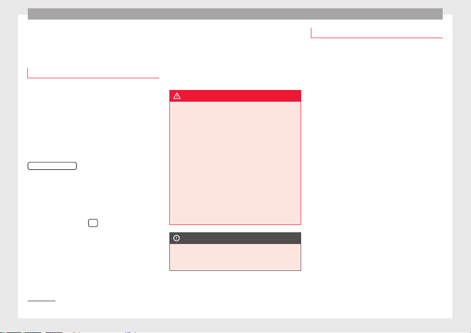
Operation
Driver assistance systems
St
ar
t
-Stop System*
Description and operation
The Start-Stop system helps save fuel and re-
duce CO
2
emi
ssions.
In Start-Stop mode, the engine will automati-
cally switch off when the vehicle stops or is
stopping; for example when stopping at traf-
fic lights. The ignition remains switched on
during the stopping phase. The engine auto-
matically switches back on when required. In
this situation, the light of the
START ENGINE STOP
button stays on
1)
.
As
soon a
s
the ignition is switched on, the
Start-Stop function is automatically activa-
ted.
Further information about the Start-Stop sys-
tem can be found in the Easy Connect sys-
tem: by pressing the
button in the Vehi-
cle status menu.
B
a
s
ic requirements for the Start-Stop mode
●
The driver door must be closed.
●
The driver must have their seat belt fas-
tened.
●
The bonnet must be closed.
●
The engine must have reached a minimum
service temperature.
●
The reverse gear must not be engaged.
●
The vehicle must not be on a very steep
slope.
WARNING
●
Never swit
ch the engine off until the vehi-
cle is stationary. The brake servo and power
steering functions will not be completely cov-
ered under warranty. More force may also be
needed to turn the steering wheel or to brake.
As you cannot steer and brake in the normal
manner, there is a greater risk of accidents
and serious injury.
●
Never remove the key from the ignition if
the vehicle is in motion. Otherwise, the steer-
ing could lock making it impossible to steer
the vehicle.
●
To avoid injury, make sure that the Start-
Stop system is switched off when working in
the engine compartment ››› page 210.
CAUTION
The Start-Stop system must always be
switc
hed off when driving through flooded
areas ››› page 210.
Stopping/Starting the engine
Vehicles with a manual gearbox
–
Before stopping the vehicle or when it is
stop
ped, put it into neutral and release the
clutch pedal. The engine will switch off. The
warning lamp will appear on the instru-
ment panel display. The engine may stop
before the vehicle comes to a halt in the
deceleration phase (at 7 km/h).
–
When the clutch pedal is pressed the en-
gine will start up again. The warning lamp
will switch off.
Vehicles with an automatic gearbox
–
Use the foot brake to bring the vehicle to a
stop and k
eep the brake pedal pressed
down with your foot. The engine will switch
off. The warning lamp will appear in the
display. The engine may stop before the ve-
hicle comes to a halt in the deceleration
phase (at 7 km/h or 2 km/h, depending on
the vehicle’s gearbox).
–
When you take your foot off the brake pedal
the engine will start up again. The warning
lamp will switch off. In vehicles with the Au-
to Hold* system, when the system is active,
the engine will not start if you remove your
foot from the brake pedal. The car starts
when you press the accelerator pedal.
1)
Only in vehicles with Keyless Access.
208
Driver assistance systems
Additional information related to the auto-
m
atic
g
earbox
The engine stops when the selector lever is in
the positions P, D, N and S, in addition to
when in manual mode. With the selector lev-
er in position P, the engine will also remain
switched off when you take your foot off the
brake pedal. In order to start the engine up
again the accelerator must be pressed, or an-
other gear engaged or the brake released.
If the selector lever is placed in position R
during the stopping phase, the engine will
start up again.
Change from position D to P to prevent the
engine from accidentally starting when
changing and passing by position R.
Additional information about vehicles with
Adaptive Cruise Control (ACC)
In vehicles with ACC function, the engine will
start up again in certain operating conditions
if the radar sensor detects that the vehicle
ahead drives off again.
Note
●
In vehic
les with an automatic gearbox, you
can control whether the engine should switch
off or not by reducing or increasing the brake
force applied. While the vehicle remains stop-
ped, the engine will not stop if the brake ped-
al is slightly pressed, in traffic jams with fre-
quent stopping and starting for example. As
soon as strong pressure is applied to the
brake ped
al, the engine will stop.
●
In vehicles with manual gearbox, during
the stopping phases the brake pedal must re-
main depressed to prevent the vehicle from
moving.
●
If the engine “stalls” in vehicles with man-
ual gearbox, it can be directly started up
again by immediately pressing the clutch
pedal.
General notes
The system can interrupt the Start-Stop mode
fr
equently
f
or different reasons.
The engine does not switch off
Before the stopping phase, the system veri-
fies whether certain conditions are met. The
engine does not switch off, in the following
situations for example:
●
The engine has not yet reached the mini-
mum required temperature for the Start-Stop
mode.
●
The interior temperature selected for the air
conditioner has not yet been reached.
●
The interior temperature is very high/low.
●
Defrost function button activated
›››
page 51.
●
The parking aid* is switched on.
●
The batter
y is very low.
●
The steering wheel is overly turned or is be-
ing turned.
●
If there is a danger of misting.
●
After engaging reverse gear.
●
In case of a very steep gradient.
The indication is shown on the instrument
panel display, and in addition, the driver in-
formation system* shows, .
The engine starts by itself
During a stopping phase the normal Start-
Stop mode can be interrupted in the follow-
ing situations: The engine restarts by itself
without involvement from the driver.
●
The interior temperature differs from the
value selected on the air conditioner.
●
Defrost function button activated
›››
page 51.
●
The brake has been pressed several times
consecutively.
●
The battery is too low.
●
High power consumption.
Note
In vehicles with an automatic gearbox, if the
selector l
ever is placed in position D, N or S
after engaging reverse gear, the vehicle must
be driven at a speed faster than 10 km/h (6
»
209
Technical dataAdviceOperationEmergenciesSafety
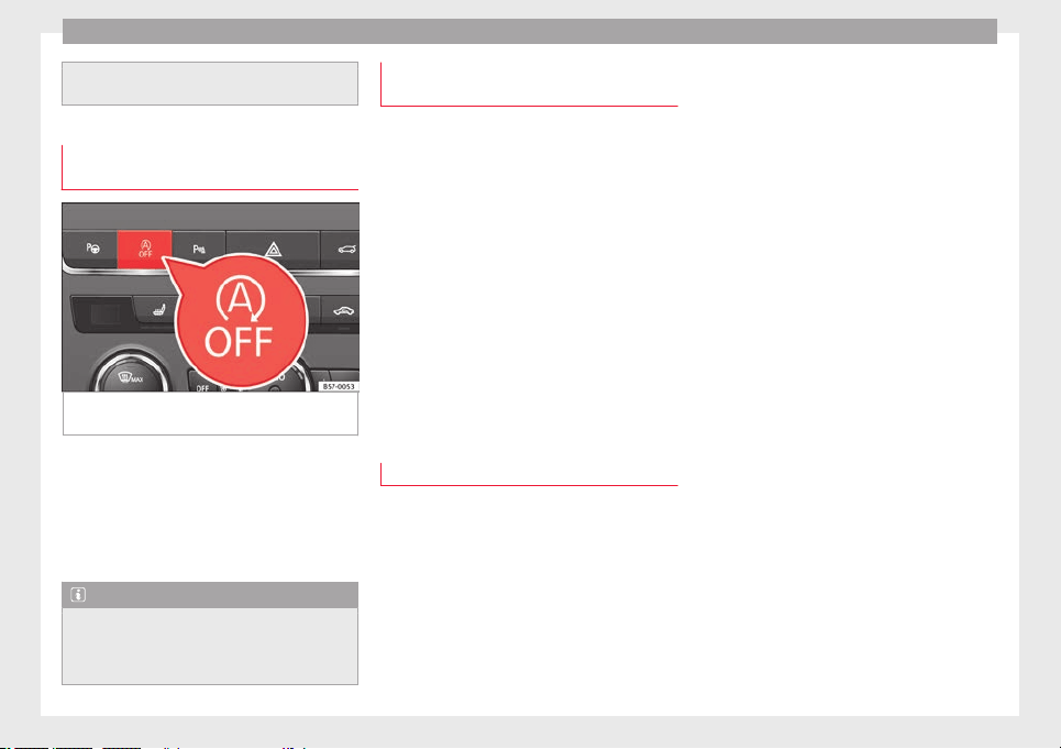
Operation
mph) for the system to return to conditions in
which the engine c
an be stopped.
Manually switching on/off the Start-
Stop sys
tem
Fig. 184 Centre console: Start-Stop system
b
utt
on.
If you do not wish to use the system, you can
sw
it
c
h it off manually.
–
To manually switch on/off the Start-Stop
system, press the button. The button
symbol remains lit up yellow when the sys-
tem is switched off.
Note
The system is automatically switched on each
time the engine is
deliberately stopped dur-
ing a stopping phase. The engine will start
automatically.
Driver messages on the instrument
p
anel
di
splay
Start-Stop system deactivated.
Start the engine manually
This driv
er message is displayed when cer-
tain conditions are not met during the stop-
ping phase and the Start-Stop system cannot
restart the engine. The engine must be star-
ted manually.
Start-Stop system: Fault! Func-
tion not available
There is a fault in the Start-Stop system. Take
the vehicle to a workshop to have the fault
repaired.
Hill Descent Control (HDC)
Des
cription and operation
3 Valid for vehicles: 4Drive
Hi
ll Descent Control limits the speed on steep
descents by automatically braking all four
wheels, both when moving forward and in re-
verse. As the anti-lock brake system remains
active, it prevents the wheels from locking. In
vehicles with manual transmission, the Hill
Descent Control adapts the theoretical speed
without slowing the engine below its idling
speed.
After starting the descent of a slope below
30 km/h (18 mph), speed is
limited to a min-
imum of 2 km/h (1 mph) and a maximum of
30 km/h (18 mph). When appropriate, the
driver may increase or decrease the speed
within the limit by pressing the accelerator or
the brake. At this point the function is inter-
rupted and, if necessary, it is then reactiva-
ted.
Even so, it is imperative that the surface
guarantees sufficient adhesion. For this rea-
son, the Hill Descent Control will not fulfil its
function when, for example, descending a
slope with a frozen or slippery surface.
Hill Descent Control is available when the
dash panel display shows the message .
Hill Descent Control automatically intervenes
if the following conditions are met:
●
The vehicle engine is running.
●
The Offroad driving profile has been selec-
ted ››› page 242. Driving at a speed below 30
km/h (18 mph) (the message is shown on
the dash panel display).
●
The slope of the descent is at least 10%
when driving forward and 9% when driving in
reverse.
●
The brake and the accelerator are not
pressed.
Hill Descent Control is deactivated on press-
ing the brake and the accelerator or if the
slope is below 5%. The function may be
210
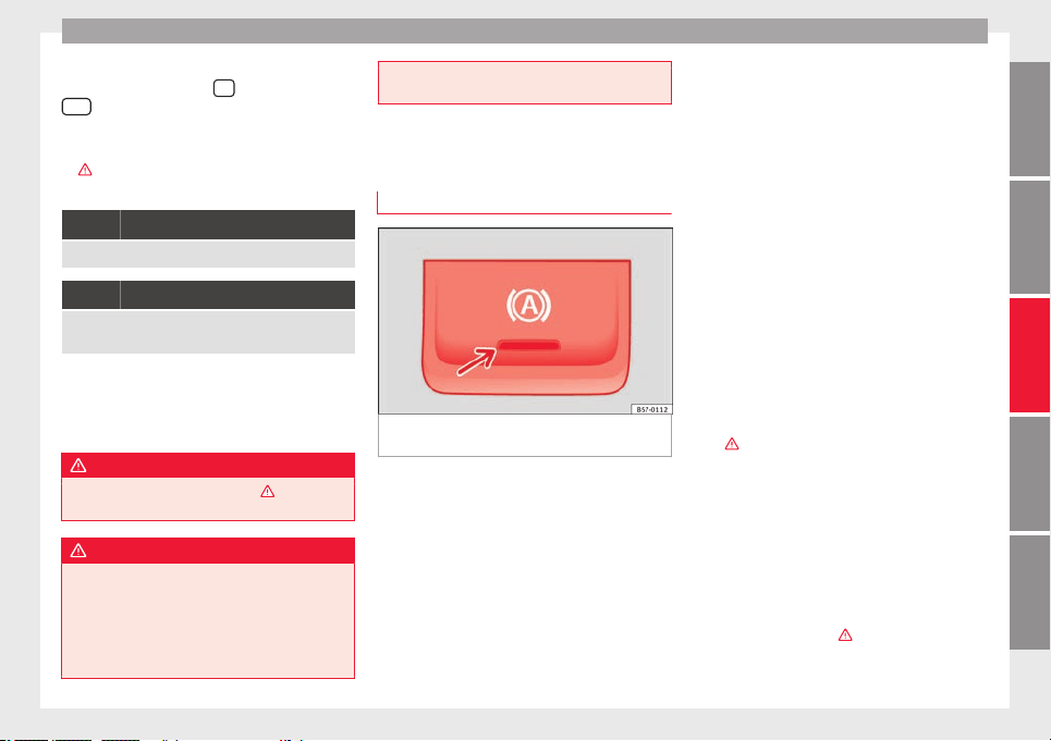
Driver assistance systems
disconnected manually in the Easy Connect
sy
s
t
em by pressing the
button and the
HDC
function button ›
›
›
Fig. 42.
Control lamps
›››
in Warning and control lamps on
p
ag
e 119
.
It lights up white
Hill Descent Control is active.
It lights up grey
Hill Descent Control is not active. The system is switched
on, but is not adjusting.
Some warning and control lamps will light up
briefly
when the ignition i
s
switched on to
check certain functions. They will switch off
after a few seconds.
WARNING
Observe the safety warnings ›››
in Warning
and contro
l lamps on page 119.
WARNING
Always be ready to brake. Otherwise, an acci-
dent cou
ld occur and cause injury.
●
Hill Descent Control is only an auxiliary
system that in some situations may not suffi-
ciently brake the vehicle when going down a
slope.
●
The speed of the
vehicle may increase de-
spite the intervention of Hill Descent Control.
Auto Hold Function
Des
cription and operation
Fig. 185 In the lower part of the centre con-
so
l
e: Aut
o Hold function button.
The control light of the ›
›
›
Fig. 185 button
remains on when the Auto Hold function is
connected.
Once connected, the Auto Hold function as-
sists the driver in keeping the vehicle station-
ary at repeated intervals or for a certain peri-
od of time with the engine running, for exam-
ple, when going up a slope, when stopped at
traffic lights or in heavy traffic with intermit-
tent stops.
When connected, the Auto Hold function au-
tomatically prevents the vehicle from rolling
when stationary without pressing the brake
pedal.
After detecting that the vehicle is stationary
and the brake pedal has been released, the
Auto Hold function holds the vehicle. The
driver can lift their foot off the brake pedal.
When the driver touches the accelerator ped-
al or accelerates slightly to continue driving,
the Auto Hold function releases the brake.
The vehicle moves according to the slope of
the road.
If the vehicle is stationary and one of the con-
ditions required by the Auto Hold function is
impaired, it disconnects itself and the but-
ton's control light goes out ››› Fig. 185. The
electronic parking brake connects automati-
cally, if necessary, to park the vehicle safe-
ly ›››
.
C
ondition
s
for keeping the vehicle stationary
with the Auto Hold function
●
The driver door must be closed.
●
The driver's seat belt must be fastened.
●
The engine is running.
Switching the Auto Hold function on and off
Press the button ›››
. The control lamp on
the b
utt
on g
oes out when the Auto Hold func-
tion is switched off.
»
211
Technical dataAdviceOperationEmergenciesSafety
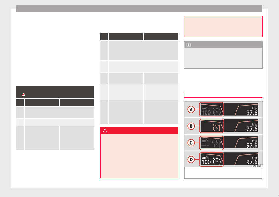
Operation
Automatically engaging and disengaging the
Aut
o Ho
l
d function
If the Auto Hold function was switched on
with the button before disengaging the ig-
nition, the function will remain on after the
ignition is re-engaged.
If the Auto Hold function was not switched
on, it will automatically remain off next time
the ignition is engaged.
The Auto Hold function is automatically
switched on if the following conditions are
met:
All conditions must be met at the same time
›››
:
Manual gearbox Automatic gearbox
1. The vehicle is kept stationary with the brake ped-
al on a flat surface or on a slope.
2. The engine rotates “correctly”.
Upon pressing the
clutch and accelerating
at the same time, the
brake releases gradu-
ally.
Upon accelerating, the
brake releases gradu-
ally.
The Auto Hold function is automatically
t
urned off
if
the following conditions are
met:
Manual gearbox Automatic gearbox
1.
If any of the conditions mentioned on
››› page 211, Conditions for keeping the vehicle
stationary with the Auto Hold function are no lon-
ger met.
2.
If the engine is running irregularly or an anomaly
is detected.
3.
If the engine is turned
off or stalls.
If the engine is switch-
ed off.
4.
The clutch and the ac-
celerator are pressed at
the same time.
If the accelerator is
pressed.
5.
If any of the tyres has
only minimal contact
with the ground, e.g. in
the case of axle articu-
lation.
WARNING
The smart technology incorporated into the
Auto Hol
d function cannot defy the laws of
physics; it only works within the limits of the
system. The greater convenience provided by
the Auto Hold function should never tempt
you to take any risk that may compromise
safety.
●
Never leave the vehicle running and with
the Auto Hold function switched on.
●
The Auto Hol
d function cannot always keep
the vehicle stationary uphill or downhill or
stop it sufficiently, for example, on slippery
or frozen surfaces.
Note
Before entering a car wash, always switch off
the Aut
o Hol
d function, because if the elec-
tronic parking brake is automatically connec-
ted, it may cause damage.
Cruise control system (CCS)*
Oper
ation
Fig. 186 Instrument panel display: CCS status
indic
ation
s.
212
Driver assistance systems
Read the additional information carefully
›
›
›
page 44
The cruise control system (CCS) is able to
maintain the set speed from 20 km/h (15
mph).
The CSS only reduces vehicle speed by ceas-
ing to accelerate, not by actively braking the
vehicle ›››
.
C
ontr
o
l lamp
When the warning lamp is lit, cruise con-
trol is active.
Several warning and control lamps light up
for a few seconds when the ignition is switch-
ed on, signalling that the function is being
verified. They will switch off after a few sec-
onds.
Displayed on the CCS screen
Status Fig. 186:
CCS temporarily switched off. The set
speed is displayed in small or darkened
figures.
System error. Contact a specialised work-
shop.
CCS switched on. The speed memory is
empty.
The CCS is switched on. The set speed is
displayed in large figures.
A
B
C
D
WARNING
Use of the cruise control could cause acci-
dents and sev
ere injuries if it is not possible
to drive at a constant speed maintaining the
safety distance.
●
Do not use the cruise control in heavy traf-
fic, if the distance from the vehicle in front is
insufficient, on steep roads, with several
bends or in slippery circumstances (snow,
ice, rain or loose gravel), or on flooded roads.
●
Never use the CCS when driving off-road or
on unpaved roads.
●
Always adapt your speed and the distance
to the vehicles ahead in line with visibility,
weather conditions, the condition of the road
and the traffic situation.
●
To avoid unexpected operation of the cruise
control system, turn it off every time you fin-
ish using it.
●
It is dangerous to use a set speed which is
too high for the prevailing road, traffic or
weather conditions.
●
When travelling down hills, the CCS cannot
maintain a constant speed. The vehicle tends
to accelerate under its own weight. Select a
lower gear or use the foot brake to slow the
vehicle.
WARNING
Observe the safety warnings ›››
in Warning
and contro
l lamps on page 119.
Operating the cruise control system*
Read the additional information carefully
›››
page 44
The value indicated in the table in brackets
(in mph, miles per hour) only refers to instru-
ment panels with indications in miles.
Changing gear in CCS mode
The CCS decelerates as soon as the clutch
pedal is pressed, intervening again automati-
cally after a gear is engaged.
Travelling down hills with the CCS
When travelling down hills the CCS cannot
maintain a constant speed. Slow the vehicle
down using the brake pedal and reduce
gears if required.
Automatic off
The cruise control system (CCS) is switched
off automatically or temporarily:
●
If the system detects a fault that could af-
fect the w
orking order of the CCS.
●
If you press and maintain the accelerator
pedal for a certain time, driving faster than
the stored speed.
●
If the dynamic driving control systems in-
tervene (e.g. ASR or ESC).
●
If the airbag is triggered.
213
Technical dataAdviceOperationEmergenciesSafety
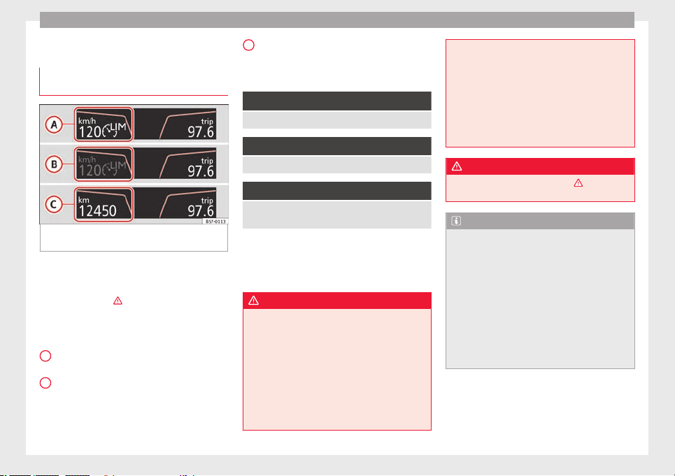
Operation
Speed limiter
Di
s
p
lay messages and warning and
control lamp
Fig. 187 On the instrument panel display:
me
s
s
ages on the status of the speed limiter.
The speed limiter helps avoid exceeding a
s
peed indiv
idual
ly programmed upwards of
approximately 30 km/h (19 mph) driving in
forwards gears ›››
Display messages on the speed limiter
St
at
u
s ››› Fig. 187:
The speed limiter is active. The last
speed set is displayed in large figures.
The speed limiter is not active. The last
speed set is displayed in small or dark-
ened figures.
A
B
The speed limiter is switched off. The to-
t
al
mi
leage is displayed.
Warning and control lamp
Lights up green
The speed limiter is switched on and active.
Flashes green
The speed set by the speed limiter has been exceeded.
Lights up
The adaptive cruise control (ACC) and the speed limiter
are active.
Some warning and control lamps will light up
briefly
when the ignition i
s
switched on to
check certain functions. They will switch off
after a few seconds.
WARNING
After use, always switch off the speed limiter
to prev
ent the speed being regulated against
your wishes.
●
The speed limiter does not relieve the driv-
er of their responsibility to drive at the appro-
priate speed. Do not drive at high speed if not
necessary.
●
Using the speed limiter with adverse
weather conditions is dangerous and can
cause serious accidents, e.g. because of
C
aquaplaning, snow, ice, leaves, etc. You
should u
se the speed limiter function only
when traffic, road and weather conditions al-
low it to be used safely.
●
When driving downhill, the speed limiter
cannot limit the vehicle speed. Its speed will
increase due to its own weight. In this case,
select a lower gear or use the foot brake to
slow the vehicle.
WARNING
Observe the safety warnings ›
››
in Warning
and contro
l lamps on page 119.
Note
●
Different
versions of the instrument panel
are available and therefore the versions and
instructions on the display may vary.
●
If when switching the ignition off, the
cruise control system (CCS), the adaptive
cruise control (ACC) or the speed limiter were
switched on, then the cruise control system
or the adaptive cruise control will automati-
cally switch themselves on when the ignition
is back on. However, no speed will be stored.
The last set speed of the speed limiter will be
stored.
214
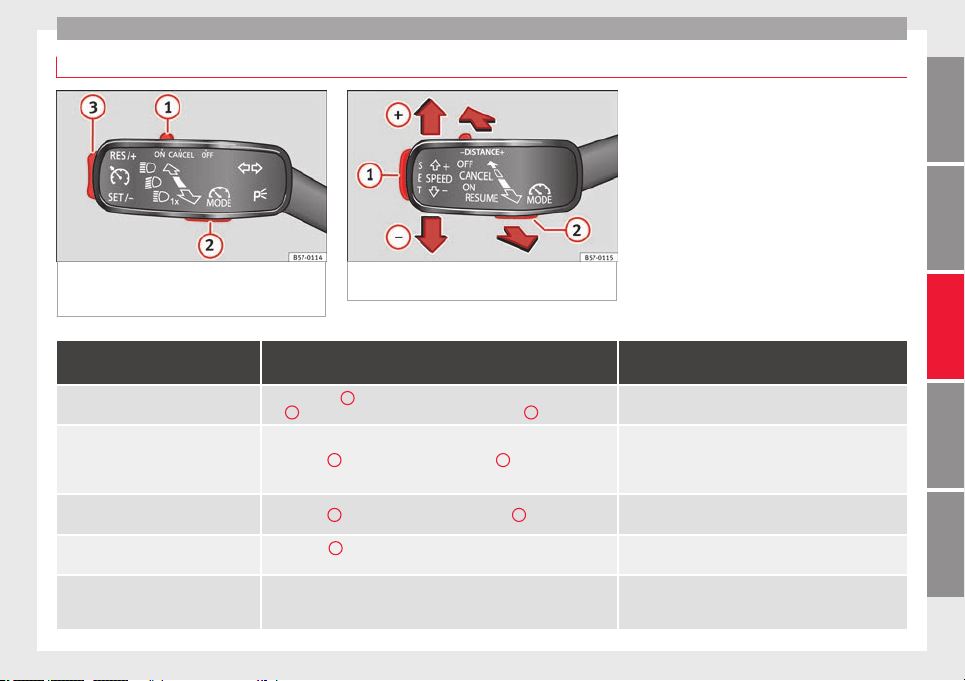
Driver assistance systems
Operate the speed limiter
Fig. 188 On the left of the steering column:
contro
l and buttons to operate the speed lim-
iter.
Fig. 189 On the left of the steering column:
third lev
er for operating the speed limiter.
Function
Position of the turn signal lever ››› Fig. 188 or the third lever
››› Fig. 189
Effect
Switching on the speed limiter
Move controller
1
of the turn signal lever to the
position and press but-
ton
2
or move the third lever forward and press button
2
.
The system switches on. The last set speed of the speed lim-
iter is stored. It does not take effect yet.
Switching between the speed limiter and
cruise control (CCS) or the adaptive cruise
control (ACC) (with the speed limiter
switched on)
Press button
2
on the turn signal lever or button
2
on the third lever
It switches between the speed limiter and the CCS or the
adaptive cruise control (ACC).
Activating the speed limiter Press button
3
on the turn signal lever or button
1
on the third lever.
The current speed is stored as the maximum speed and the
limiter is switched on.
Temporarily switching off the speed limit-
er limitation
Place control
1
of the turn signal lever in position
or move the third
lever into position
.
The limiter is switched off temporarily. The speed will be
stored.
Temporarily switch off the speed limiter
limitation pressing down the accelerator
(kick-down)
Press down on the accelerator beyond the point of resistance (e.g. to over-
take). Surpassing the set speed switches the speed limiter off temporarily.
The limiter is switched off temporarily. The speed will be
stored. The limiter is reactivated automatically after return-
ing to less than the set speed.
»
215
Technical dataAdviceOperationEmergenciesSafety
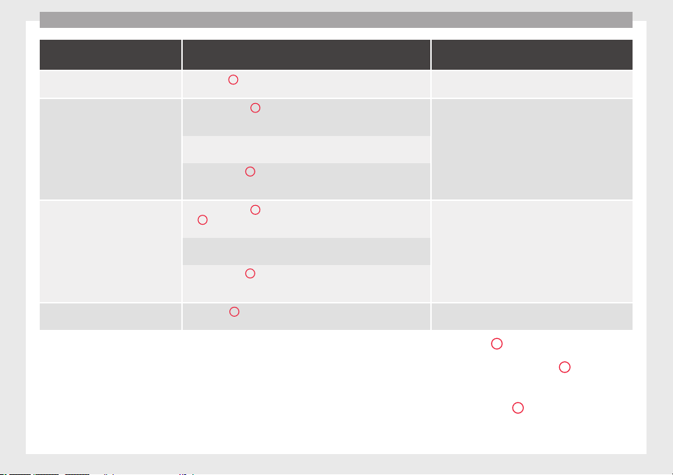
Operation
Function
Position of the turn signal lever ››› Fig. 188 or the third lever
››› Fig. 189
Effect
Switching the speed limiter on again
Press button
3
on the turn signal lever or move the third lever into posi-
tion
.
The speed is limited to the set speed as soon as the speed
you are driving at is lower than the speed set as maximum.
Increasing the set speed of the limiter
Briefly press button
3
on the turn signal lever in the
area or move
the third lever into position
to increase the speed in small incre-
ments of 1 km/h (1 mph) and set it.
The speed is limited to the set value
Press
on the third lever to increase the speed in increments of
10 km/h (5 mph) and set it.
Hold down button
3
on the turn signal lever in the area
or hold
down
to increase continuously in increments of 10 km/h (5 mph)
and set it.
Reducing the set speed of the limiter
Briefly press button
3
on the turn signal lever in the
area or press
1
on the third lever to reduce the speed in small increments of 1 km/h
(1 mph) and set it.
The speed is limited to the set value
Press
on the third lever to reduce the speed in increments of
10 km/h (5 mph) and set it.
Hold down button
3
on the turn signal lever in the
area or hold
down
to reduce the speed continuously in increments of 10 km/h
(5 mph) and set it.
Switching off the speed limiter
Move control
1
of the turn signal lever into position
or the third lever
into position
.
The system switches off
The values shown in the table in brackets, in
mph, ar
e di
s
played only in instrument panels
with indications in miles.
Going down slopes with the speed limiter
If the set speed of the speed limiter is excee-
ded while driving downhill, soon afterwards
the warning and control lamps flash
››› page 214 and an acoustic warning may
sound. In this case, use the foot brake to
slow the vehicle or, if necessary, select a low-
er gear.
Switching off temporarily
If you wish to temporarily switch off the
speed limiter, e.g. to overtake, move control
››› Fig. 188
1
of the turn signal lever into po-
s
ition
or the third lever into pressure
point or press button
2
on any lever.
Af
t
er o
vertaking, the speed limiter can be
switched on with the previously set speed by
pressing button
3
on the turn signal lever in
the ar
e
a
or by moving the third lever in-
to pressure point.
216
Driver assistance systems
Switch the speed limiter off temporarily by
pr
e
s
sing down the accelerator (kick-down)
If the accelerator is pressed right down (kick-
down) and the set speed is exceeded be-
cause driver wishes to do so, the limiter is
temporarily disabled.
To confirm it being switched off an acoustic
signal sound once. While the limiter is off,
the warning and control lamp flashes.
When the accelerator is no longer pressed
down and the speed is reduced below the set
value, the limiter switches on again. The con-
trol lamp will light up and remain lit.
Automatic off
The speed limiter is automatically switched
off:
●
If the system detects a fault that could neg-
atively affect the working order of the limiter.
●
If the airbag is triggered.
CAUTION
For automatic switching off due to system
failur
es, for security reasons, the limiter is
only completely switched off when the driver
stops pressing the accelerator at some point
or consciously switches off the system.
Emergency brake assist system
(Fr
ont
As
sist)*
Topic introduction
Fig. 190 On the instrument panel display:
pr
e-w
arnin
g messages.
The objective of the emergency brake assist
sy
s
t
em is to prevent head-on collisions
against objects that may be in the vehicle’s
path or minimise the consequences of such
impacts.
Within the limitations imposed by the envi-
ronmental conditions and by the system it-
self, the function acts in staggered fashion,
depending on how critical the situation is. In-
itially it warns the driver, and if the driver’s
reaction does not occur or is insufficient, it
activates an independent emergency brak-
ing.
The function is intended to prevent collisions
with parked vehicles or vehicles in the same
lane travelling in the same direction, or with
pedestrians crossing the vehicle’s path. It
may fail to activate in other danger situa-
tions.
The Front Assist function is active within a
range of speeds between 4 km/h (2.5 mph)
and 250 km/h (156 mph). Depending on
speed, traffic conditions and driver behav-
iour, some of the sub-functions described be-
low are omitted in order to optimise the sys-
tem’s general behaviour.
The Front Assist is a driving assistance func-
tion that can never replace the driver’s atten-
tion.
Safety distance warning
If the system detects a situation of danger
because the vehicle is too close to the vehi-
cle ahead, it will warn the driver by means of
an indication on the instrument panel display
.
The timing of the warning varies depending
on driver behaviour and the traffic situation.
Advance warning
If the system detects a possible collision with
the vehicle in front, it may alert the driver by
means of an audible warning and an indica-
tion on the instrument panel display
››› Fig. 190.
»
217
Technical dataAdviceOperationEmergenciesSafety
Operation
The warning moment varies depending on
the tr
affic
s
ituation and driver behaviour. At
the same time, the vehicle will prepare for a
possible emergency braking ›››
.
C
ritic
a
l warning
If the driver fails to react to the pre-warning
(advance warning), the system may actively
intervene in the brakes and generate a brief
jolt to warn the driver of the imminent danger
of a collision.
Automatic braking
If the driver also fails to react to the critical
warning, the system may initiate independ-
ent emergency braking by progressively in-
creasing the braking effect in accordance
with how critical the situation is.
Driver emergency brake assist system
Faced with an imminent collision, the system
may detect that the driver is not braking hard
enough to avoid the collision. In this case, it
will automatically increase the braking effect.
Due to certain driving circumstances and the
limitations of its operation, there are some
cases in which the system cannot prevent a
collision, although it can significantly mini-
mise the consequences by reducing the
speed and the force of the impact.
WARNING
Observe the safety warnings ›››
in Warning
and contro
l lamps on page 119.
WARNING
The Front Assist system cannot change the
law
s of physics or replace the driver in terms
of keeping control of the vehicle and reacting
to a possible emergency situation.
WARNING
Following a Front Assist emergency warning,
pay
immediate attention to the situation and
try to avoid the collision by braking or by
dodging the obstacle, as applicable.
●
If the Front Assist does not work as descri-
bed in this chapter (e.g. it repeatedly inter-
venes unnecessarily), switch it off.
●
Adapt your speed and safe distance to the
vehicle in front of you at all times to suit visi-
bility, weather, road and traffic conditions.
●
The Front Assist alone cannot avoid acci-
dents and serious injuries.
●
In complex driving situations, occasionally
the Front Assist may issue warnings and in-
tervene in braking unnecessarily, for example
at traffic islands.
●
If the operation of the Front Assist is im-
paired, for example, by dirt or because the ra-
dar sensor has lost its settings, the system
may issue unnecessary warnings and inter-
vene inopportunely in the braking.
●
The Front As
sist does not react to animals
or vehicles crossing your path or approaching
head-on down the same lane.
●
The Front Assist does not react to pedes-
trians walking in the same direction or ap-
proaching head-on down the same lane.
●
The driver must always be ready to take
over the control of the vehicle.
●
When the Front Assist causes a braking,
the brake pedal is “harder”.
●
Automatic interventions by the Front Assist
on the brakes may be interrupted by pressing
the clutch, accelerator or moving the wheel.
Note
●
When the Front As
sist is connected, the in-
dications on the instrument panel screen may
be concealed by warnings from other func-
tions, such as an incoming call.
●
When the Front Assist causes a braking,
the brake pedal is “harder”.
●
Automatic interventions by the Front Assist
on the brakes may be interrupted by pressing
the clutch, accelerator or moving the wheel.
●
The Front Assist may brake the vehicle until
it stops completely. However, the brake sys-
tem does not halt the vehicle permanently.
Use the foot brake!
●
If the Front Assist does not work as descri-
bed in this chapter (e.g. in intervenes several
times unnecessarily), switch it off. Have the
system checked by a specialised workshop.
SEAT recommends visiting a SEAT dealership.
218
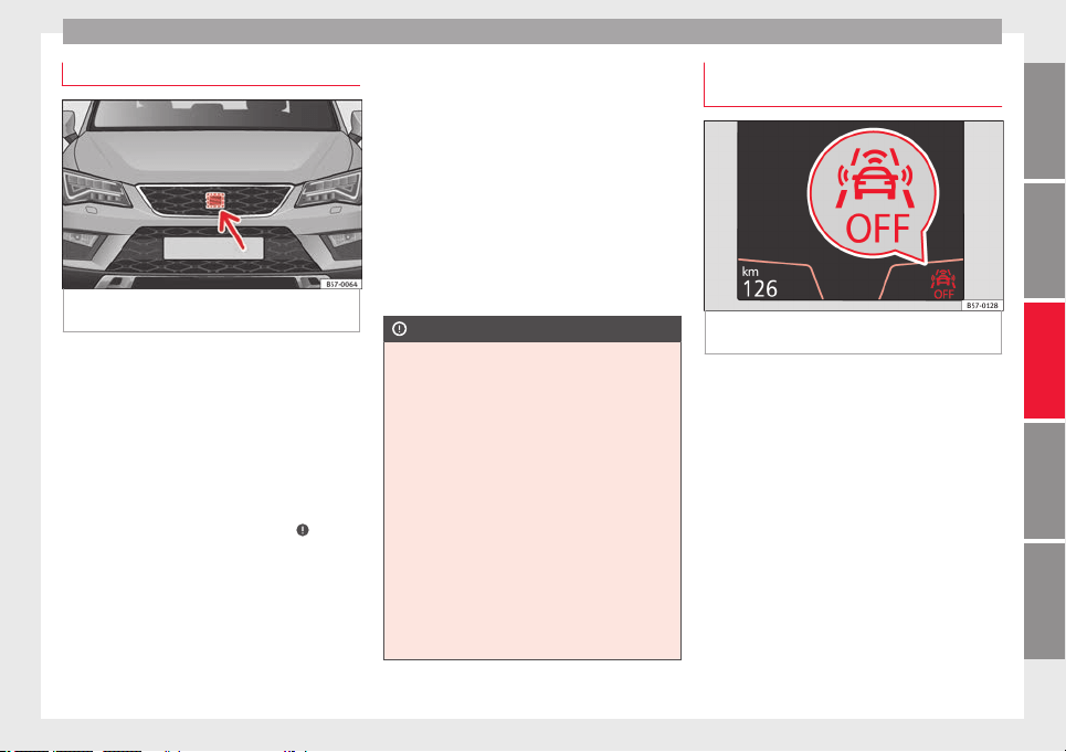
Driver assistance systems
Radar sensor
Fig. 191 On the front behind the SEAT badge:
r
a
d
ar sensor.
On the front behind the SEAT badge, a radar
sen
sor h
a
s been installed to capture the traf-
fic situation ››› Fig. 191.
The radar sensor's visibility may be impaired
by dirt, mud or snow, or by environmental in-
fluences such as rain or mist. In this case, the
Front Assist does not work. The instrument
panel displays the following message:
Front Assist: No sensor vision! If
necessary clean the radar sensor ›››
.
When the r
a
d
ar sensor begins to operate
properly again, the Front Assist will automati-
cally be available again. The message will
disappear from the instrument panel display.
Front Assist operation may be affected by a
strong radar reverse reflection. This may oc-
cur, for example, in a closed car park or due
to the presence of metallic objects (e.g. rails
on the road or sheets used in road works).
The area in front of and around the radar sen-
sor should not be covered with adhesives,
additional or similar headlights, as this may
negatively affect Front Assist operation.
If the front of the vehicle is not properly re-
paired or structural modifications are made
to it, for example if the suspension is low-
ered, Front Assist operation may be affected.
SEAT recommends visiting a SEAT dealership
for this purpose.
CAUTION
If you have the sensation that the radar sen-
sor is d
amaged or has lost its settings, dis-
connect the Front Assist. This will avoid pos-
sible dangerous situations caused by a sys-
tem malfunction. If this occurs have it adjus-
ted.
●
The sensor may become damaged or lose
its settings when knocked, for example, dur-
ing a parking manoeuvre. This may compro-
mise the system's efficacy or disconnect it.
●
Repairs to the radar sensor require special-
ist knowledge and special tools. SEAT recom-
mends visiting a SEAT dealership for this pur-
pose.
●
Clean away the snow with a brush and the
ice preferably with a solvent-free de-icer
spray.
Operating the Emergency braking as-
s
i
s
tance system (Front Assist)
Fig. 192 On the instrument panel display:
Fr
ont
As
sist switched off message.
The Front Assist is active whenever the igni-
tion i
s
sw
itched on.
When the Front Assist is switched off, so too
are the advance warning function (pre warn-
ing) and the distance warning.
SEAT recommends leaving the Front Assist al-
ways switched on. Exceptions ››› page 220,
Switching the Front Assist off temporarily in
the following situations.
Switching the Front Assist on and off
With the ignition switched on, the Front As-
sist can be switched on and off as follows:
●
Select the corresponding menu option us-
ing the butt
on for the driver assistance sys-
tems ›››
page 36.
»
219
Technical dataAdviceOperationEmergenciesSafety
Operation
●
OR: sw
it
c
h the system on and off in Easy
Connect using the
button and the
S
ET
TINGS
and
Driv
er a
s
sistance
function but-
t
on
s
›››
page 33.
When Front Assist is switched off, the instru-
ment panel will inform that it has been
switched off with the following indicator
››› Fig. 192.
Activating or deactivating the pre-warning
(advance warning)
The pre-warning function (advance warning)
can be switched on or off in the Easy Connect
system with the
button and the
S
ET
TINGS
and
Driv
er a
s
sistance
function buttons
›
›
›
page 33.
The system will store the setting for the next
time the ignition is switched on.
SEAT recommends keeping the pre-warning
function switched on at all times.
Depending on the infotainment system in-
stalled in the vehicle, the advance warning
function may be adjusted as follows:
●
Advance
●
Medium
●
Delayed
●
Deactivated
SEAT recommends driving with the function
in “Medium” mode.
Switching distance warning on and off
If the safe distance with regard to the vehicle
in front is exceeded, the relevant warning will
appear on the instrument panel display
. In this case, increase the safe dis-
tance.
The distance warning can be switched on and
off in the Easy Connect system using the
button and the
S
ET
TINGS
and
Driv
er a
s
sistance
function buttons
›
›
›
page 33.
The system will store the setting for the next
time the ignition is switched on.
SEAT recommends keeping the distance
warning switched on at all times.
Switching the Front Assist off tempo-
rarily in the following situations
In the following situations the Front Assist
shou
l
d be de
activated due to the system's
limitations:
●
When the vehicle is to be towed.
●
If the vehicle is on a test bed.
●
When the radar sensor is damaged.
●
If the radar sensor takes a heavy knock, for
example in a rear collision.
●
If it intervenes several times unnecessarily.
●
If the radar sensor is covered temporarily
with some kind of accessory, such as an ad-
ditional headlight or the like.
●
When the vehicle is to be loaded on a lorry,
ferry or train.
System limitations
The Front Assist has certain physical limita-
tions inher
ent to the system. Thus, in certain
circumstances, some of the system's reac-
tions may be inopportune from the driver's
standpoint. So pay attention in order to inter-
vene if necessary.
The following conditions may cause the Front
Assist not to react or to do so too late:
●
In the first few instants of driving after
switc
hing on the ignition, due to the system’s
initial auto-calibration.
●
On taking tight bends or complex paths.
●
Pressing the accelerator all the way down.
●
If the Front Assist is switched off or dam-
aged.
●
If the ASR has been disconnected or the
ESC activated in Sport mode manually
›››
page 191.
●
If the ESC is controlling.
●
If several brake lights of the vehicle or elec-
trically
connected trailer are damaged.
220
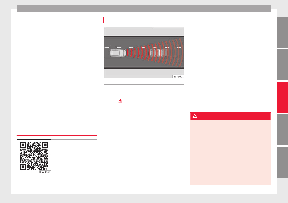
Driver assistance systems
●
If
the r
a
dar sensor is dirty or covered.
●
If there are metal objects, e.g. rails on the
road or sheets used in road works.
●
If the vehicle is reversing.
●
If the vehicle over-accelerates.
●
In case of snow or heavy rain.
●
In case of narrow vehicles, such as motor-
bikes.
●
Misaligned vehicles.
●
Vehicles crossing the other's path.
●
Vehicles approaching in the opposite direc-
tion.
●
Special loads and accessories of other ve-
hicles that jut out over the sides, backwards
or over the top.
Adaptive Cruise Control ACC*
Related video
Fig. 193 Autonomous
driving
Introduction
Fig. 194 Detection area.
The adaptive cruise control (ACC) i
s
an e
xten-
sion of the normal cruise control system
(CCS) ›››
.
The A
C
C
function allows the driver to program
a cruise speed of between 30 and 210 km/h
(18 and 150 mph) and to select the distance
required with regard to the vehicle in front.
The ACC will adapt the vehicle's cruise speed
at all times, maintaining a safe distance with
the vehicle in front based on its speed.
When driving behind another vehicle, the
ACC function reduces speed until it is the
same as that of the vehicle ahead and main-
tains the set distance between the vehicles.
If the vehicle ahead accelerates, the adaptive
cruise control also accelerates, going no
higher than the target speed programmed.
If the vehicle is equipped with automatic
gearbox, the ACC can brake the vehicle until
it stops completely if a vehicle in front of it
stops.
The distance programmed should be in-
creased when the road surface is wet.
Driver intervention prompt
During driving, the ACC is subject to certain
limitations inherent in the system. In other
words, in certain circumstances the driver will
have to adjust speed him or herself, as well
as the distance from other vehicles.
In this case, the instrument panel screen will
warn you to intervene by applying the brake
and a warning tone will be heard
››› page 223.
WARNING
The intelligent technology in the ACC cannot
over
come the system's inherent limitations
or change the laws of physics. If used negli-
gently or involuntarily, it may cause serious
accidents and injuries. The system is not a re-
placement for driver awareness.
●
Adapt your speed and safe distance to the
vehicle in front of you at all times to suit visi-
bility, weather, road and traffic conditions.
●
Do not use the ACC when visibility is bad,
on steep roads, with several bends or in slip-
pery circumstances such as snow, ice, rain or
loose gravel, or on flooded roads.
»
221
Technical dataAdviceOperationEmergenciesSafety
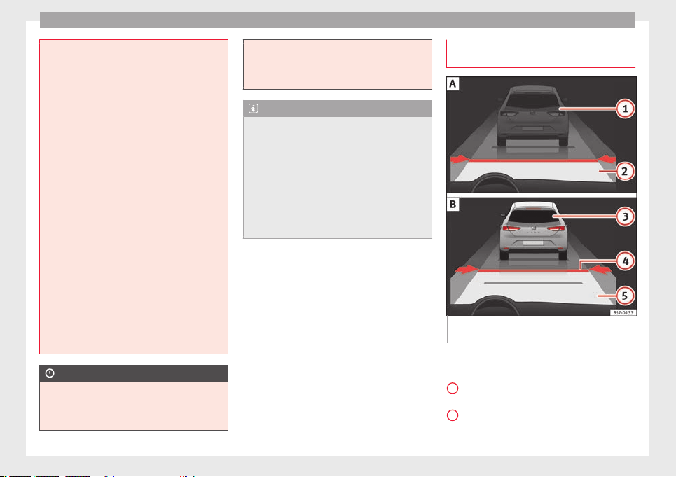
Operation
●
Never use the A
CC when driving off-road or
on unpaved roads. The ACC has been de-
signed for use on paved roads only.
●
The ACC does not react on approaching a
fixed obstacle, such as the tail of a traffic
jam, a damaged vehicle or a vehicle stopped
at the traffic lights.
●
The ACC only reacts to people if a pedes-
trian monitoring system is available. In addi-
tion, the system does not react to animals or
vehicles crossing your path or approaching
head-on down the same lane.
●
If the ACC does not reduce speed sufficient-
ly, brake the vehicle immediately by applying
the pedal.
●
If you are driving using the spare wheel,
the ACC system could automatically switch
off during the journey. Switch off the system
when starting off.
●
If the vehicle continues to move involuntar-
ily after a driver intervention prompt, brake
the vehicle by applying the pedal.
●
If the dash panel displays a driver interven-
tion prompt, adjust the distance yourself.
●
The driver should be ready to accelerate or
brake by him/herself at all times.
CAUTION
If you have the sensation that the radar sen-
sor is d
amaged, disconnect the ACC. This will
avoid possible damage. If this occurs have it
adjusted.
●
Repair
s to the radar sensor require special-
ist knowledge and special tools. SEAT recom-
mends visiting a SEAT dealership for this pur-
pose.
Note
●
If
the AC
C system does not work as descri-
bed in this chapter, do not use it until it has
been checked by a specialised workshop.
SEAT recommends visiting a SEAT dealership
for this purpose.
●
Maximum speed with the ACC activated is
limited to 210 km/h (150 mph).
●
When the ACC is switched on, strange
noises may be heard during automatic brak-
ing cause by the braking system.
Indications on the display, warning
and c
ontr
o
l lamps
Fig. 195 On the instrument panel display: (A)
A
C
C
inactive (Standby). (B) ACC active.
Status display
Indic
ation
s
on the display ››› Fig. 195:
Vehicle ahead detected. ACC is not active
and is not regulating your speed.
Distance from the vehicle ahead. ACC is
not active and is not regulating your dis-
tance.
1
2
222
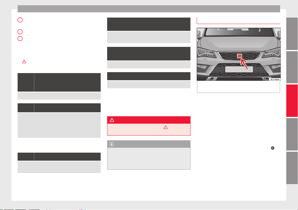
Driver assistance systems
Vehicle ahead detected. ACC is active and
i
s
r
egulating your speed.
Distance level 2 set by the driver.
ACC is active and is regulating your dis-
tance based on speed.
Warning and control lamps
›››
in Warning and control lamps on
p
ag
e 119
.
The speed reduction by the ACC to
maintain the distance from the vehi-
cle in front is not sufficient.
Brake! apply the foot brake! Driver intervention prompt.
The ACC is not currently available.
a)
With the vehicle stationary, switch off the engine and
start it up again. Check the SEAT badge area on the front
››› Fig. 196 (in case it is dirty or icy or it has been hit). If
it is still unavailable, refer to a specialised workshop to
have the system inspected.
a)
The symbol on the instrument panels with colour display is in
colour.
The ACC is active.
No vehicle is detected in front. The programmed speed
remains constant.
3
4
5
If the symbol is white: the ACC is ac-
tive.
A vehicle in front has been detected. The ACC adjusts
speed and distance from the vehicle in front.
If the symbol is grey: ACC is inactive
(Standby)
The system is switched on, but is not adjusting.
It lights up green
The ACC is active.
Some warning and control lamps will light up
briefly
when the ignition i
s
switched on to
check certain functions. They will switch off
after a few seconds.
WARNING
Observe the safety warnings ›››
in Warning
and contro
l lamps on page 119.
Note
When the ACC is connected, the indications
on the instrument
panel screen may be con-
cealed by warnings from other functions,
such as an incoming call.
Radar sensor
Fig. 196 On the front behind the SEAT badge:
r
a
d
ar sensor.
On the front behind the SEAT badge, a radar
sen
sor h
a
s been installed to capture the traf-
fic situation ››› Fig. 196.
The radar sensor's visibility may be impaired
by dirt, mud or snow, or by environmental in-
fluences such as rain or mist. In this case the
adaptive cruise control (ACC) does not work.
The instrument panel displays the following
message: ACC: No sensor vision! If
necessary, clean the SEAT badge area ›››
.
When the r
a
d
ar sensor begins to operate
properly again, the ACC will automatically be
available again. The message on the instru-
ment panel screen will switch off and the ACC
will be reactivated again.
ACC operation may be affected by a strong ra-
dar reverse reflection. This may occur, for ex-
ample, in a closed car park or due to the
»
223
Technical dataAdviceOperationEmergenciesSafety
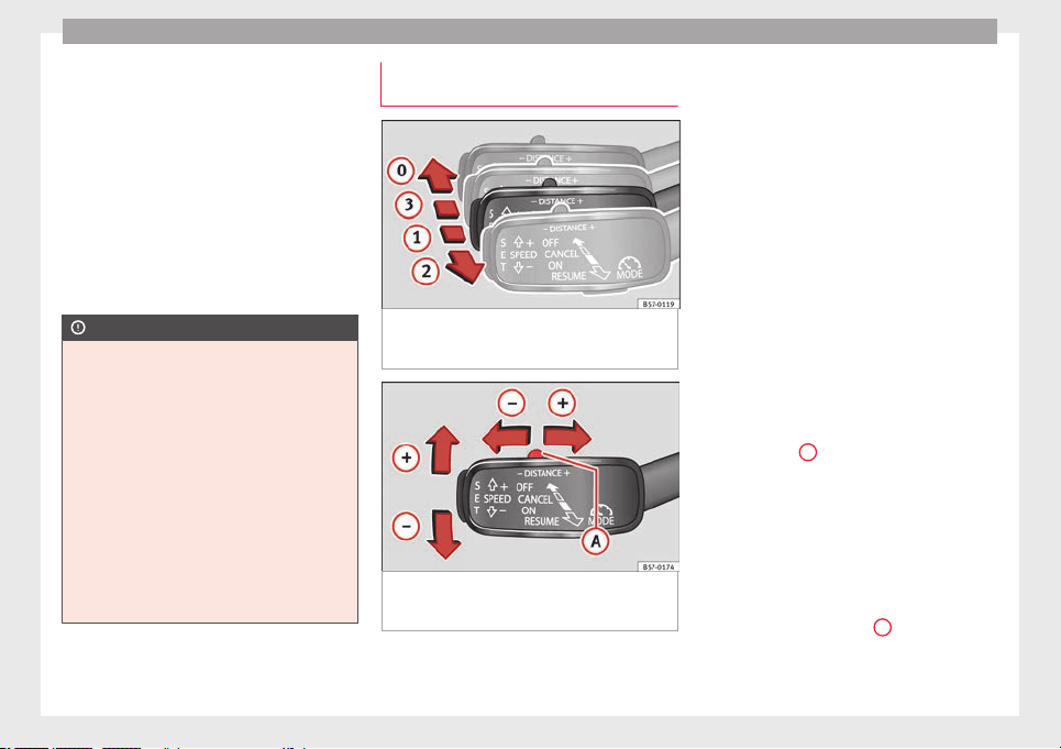
Operation
presence of metallic objects (e.g. rails on the
r
o
a
d or sheets used in road works).
The area in front of and around the radar sen-
sor should not be covered with adhesives,
additional or similar headlights, as this may
negatively affect ACC operation.
If the front of the vehicle is not properly re-
paired or structural modifications are made
to it, for example, if the suspension is low-
ered, ACC operation may be affected. In this
scenario, SEAT recommends visiting a SEAT
dealership.
CAUTION
If you have the sensation that the radar sen-
sor is d
amaged or has lost its settings, dis-
connect the ACC. This will avoid possible
damage. If this occurs have it adjusted.
●
The sensor may become damaged or lose
its settings when knocked, for example, dur-
ing a parking manoeuvre. This may compro-
mise the system's efficacy or disconnect it.
●
Repairs to the radar sensor require special-
ist knowledge and special tools. SEAT recom-
mends visiting a SEAT dealership for this pur-
pose.
●
Clean away the snow with a brush and the
ice preferably with a solvent-free de-icer
spray.
Operating the Adaptive Cruise Control
A
C
C
Fig. 197 On the left of the steering column:
thir
d l
ev
er for operating the Adaptive Cruise
Control.
Fig. 198 On the left of the steering column:
thir
d l
ev
er for operating the Adaptive Cruise
Control.
When the Adaptive Cruise Control (ACC) is
c
onnect
ed, the gr
een control lamp will
light up on the instrument panel, and the
programmed speed and ACC status will be
displayed ››› Fig. 195.
What ACC settings are possible?
●
Setting your speed ››› page 224.
●
Setting your distance ››› page 225.
●
Connecting and activating the ACC
››› page 225.
●
Disconnecting and deactivating the ACC
››› page 225.
●
Adjusting the default distance level at the
start of your journey ››› page 225.
●
Adjusting the driving profile ››› page 225.
●
Conditions in which the ACC does not react
››› page 225.
Setting speed
To set your speed, move the third lever loca-
ted in position
1
upwards or downwards un-
ti
l
the de
sired speed is shown on the instru-
ment panel display. The speed adjustment is
made at 10 km/h (6 mph) intervals.
Once you are driving, if you wish to set the
current speed as the vehicle’s cruise speed
and activate the ACC, press the button
››› Fig. 198. If you wish to increase or reduce
speed by intervals of 1 km/h (0.6 mph),
move the lever to position
2
›
›
›
Fig. 197 or
press the button, respectively.
The set speed can be changed when the ve-
hicle is stopped or during driving, as you like.
224
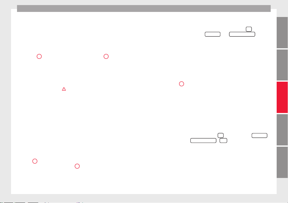
Driver assistance systems
Any modification to the programmed speed
w
i
l
l be shown on the bottom left part of the
instrument panel display ››› Fig. 195.
Setting your distance level
To increase/reduce the distance level, press
the rocker switch towards the left/right
››› Fig. 198
A
.
The in
s
trument
panel display shows the mod-
ification of the distance level. There are 5 dis-
tance levels to choose from. SEAT recom-
mends level 3. The set distance can be
changed when the vehicle is stopped or dur-
ing driving, as you like ›››
.
C
onnectin
g and activ
ating the ACC
To connect and activate the ACC, the position
of the gearbox selector lever, the vehicle
speed and the position of the third level of
the ACC must all be taken into account.
●
With a manual gearbox, the gearbox selec-
tor lever must be in any gear except first, and
speed must be greater than approximately 30
km/h. With an automatic gearbox, the gear-
box selector lever must be in position D or S.
●
To activate the ACC, with the third lever in
position
1
press the b
utt
on or mo
ve the
third lever of the ACC to position
2
›››
Fig. 197. At this
point, the image of the
ACC on the instrument panel display will
switch to Active mode ››› Fig. 195.
When the ACC function is active, the vehicle
travel
s at a set speed and distance from the
vehicle ahead. Both speed and distance can
be changed at any time.
Disconnecting and deactivating the ACC
To disconnect the ACC move the lever to the
0
position ›
›› Fig. 197
(en
gaged). An ACC
deactivated message appears and the
function is totally deactivated.
If you do not wish to disconnect the ACC, just
to switch it temporarily to inactive mode
(Standby), move the third lever to position
3
››› Fig. 197 or pres
s the brake pedal.
It will also switch to inactive mode (Standby)
if the vehicle is stopped and the driver door
is opened.
Adjusting the default distance level at the
start of your journey.
In wet road conditions, you should always set
a larger distance with regard to the vehicle in
front than when driving in dry conditions.
The following distances can be preselected:
●
Very short
●
Short
●
Media
●
Long
●
Very long
In the Easy Connect system you can adjust
the dist
ance level that will be applied when
the ACC is connected using the
button
and the
S
ET
TINGS
and
Driv
er a
s
sistance
function
b
utt
on
s ›››
page 33.
Changing the driving profile
In vehicles with SEAT Drive Profile, the driving
profile selected can have an influence on the
ACC’s acceleration and braking behaviour
››› page 242.
In vehicles without SEAT Drive Profile, the be-
haviour of the ACC can also be affected by se-
lecting any of the following drive profiles in
the Easy Connect system:
●
Normal
●
Sport
●
Eco
●
Convenience
In this case, you should access the ACC set-
tings using the
button and the
S
ET
TINGS
>
Driv
er a
s
sistance
>
A
C
C
function buttons
›
›
›
page 33.
The following conditions may lead the ACC
not to react:
●
If the accelerator is pressed.
●
If there is no gear engaged.
●
If the ESC is controlling.
»
225
Technical dataAdviceOperationEmergenciesSafety
Operation
●
If
the driv
er i
s not wearing his/her seat
belt.
●
If several brake lights of the vehicle or elec-
trically connected trailer are damaged.
●
If the vehicle is reversing.
●
Driving faster than 210 km/h (150 mph).
Driver messages
ACC not available
The system can no longer continue to guar-
antee safe vehicle detection and will be de-
activated. The sensor has lost its setting or is
damaged. Take the vehicle to a specialised
workshop and have the fault repaired.
ACC and Front Assist: cur-
rently not available. No sensor
vision
This message will be displayed to the driver if
the radar sensor's vision is impaired due, for
example, to leaves, snow, heavy fog or dirt.
Clean the SEAT badge ››› Fig. 196.
ACC: currently not available.
Gradient too steep
The maximum road slope has been excee-
ded, hence safe ACC operation cannot be
guaranteed. The ACC cannot be switched on.
ACC: only available in D, S
or M
Select the D/S or M position on the selector
lever.
ACC: parking brake applied
The ACC is deactivated if the parking brake is
applied. The ACC is available once again after
the parking brake is released.
ACC: currently not available.
Intervention of stability con-
trol
The message for the driver is displayed when
the electronic stability control (ESC) inter-
venes. In this case, the ACC is automatically
switched off.
ACC: Take action!
The message for the driver is displayed if,
when the vehicle starts up on a hill with a
mild slope, the vehicle rolls back even al-
though the ACC is activated. Apply the brake
to stop the vehicle from moving/colliding
with another vehicle.
ACC: speed limit
The message for the driver is displayed if, in
vehicles with manual gearbox, the current
speed is too low for the ACC mode.
The speed to be stored must be at least
30 km/h (18 mph). The speed limiter
switches off if the speed falls below 20 km/h
(12 mph).
ACC: available as of the 2nd
gear
The ACC is operational as of the 2nd gear
(manual gearbox).
ACC: engine speed
The message for the driver is displayed if,
when the ACC accelerates or brakes, the driv-
er does not shift up or down a gear in time,
which means exceeding or not reaching the
permissible engine speed. The ACC switches
itself off. A buzzer warning is heard.
ACC: clutch pressed
Vehicles with a manual gearbox: pressing the
clutch pedal for longer abandons control
mode.
Door open
Vehicles with automatic gearbox: the ACC
cannot be activated with the vehicle station-
ary and the door open.
WARNING
There is a danger of rear collision when the
minimum dist
ance to the vehicle in front is
exceeded and the speed difference between
both vehicles is so great that a speed reduc-
tion by the ACC will not suffice. In this case
the brake pedal should be applied immedi-
ately.
●
The ACC may not be able to detect all situa-
tions properly.
●
“Stepping” on the accelerator may cause
the ACC not to intervene in braking. Driver
226
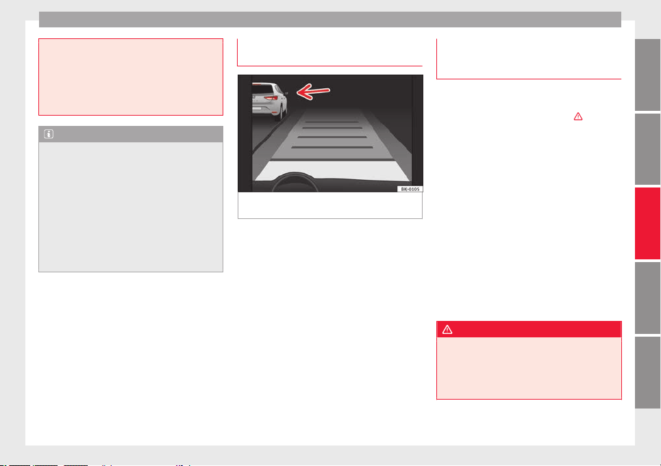
Driver assistance systems
braking will have priority over intervention by
the speed contr
ol or adaptive cruise control.
●
Always be ready to use the brakes!
●
Observe country-specific provisions gov-
erning obligatory minimum distances be-
tween vehicles.
Note
●
The pr
ogrammed s
peed is erased once the
ignition or the ACC are switched off.
●
When the traction control system (ASR) is
deactivated during acceleration or else the
ESC is activated in Sport* Mode
(››› page 120), the ACC switches off automati-
cally.
●
In vehicles with the Start-Stop system, the
engine switches off automatically during the
ACC stopping phase and restarts automatical-
ly to begin driving.
Function for preventing overtaking in
an in
s
ide l
ane
Fig. 199 On the instrument panel display:
A
C
C
active, vehicle detected in an outer lane.
The adaptive cruise control (ACC) has a func-
tion th
at
help
s avoid overtaking while driving
in inside lanes at certain speeds.
If another vehicle is detected travelling at a
slower speed in an outer lane, it is displayed
on the multifunction display ››› Fig. 199.
To avoid overtaking while driving in an inside
lane the system will gently brake, and in ac-
cordance with the speed will prevent the car
from overtaking. The driver can override this
function at any time by pressing the accelera-
tor pedal. At low speeds the function is inac-
tive, for greater comfort in a traffic jam or in
city traffic.
Deactivating the Adaptive Cruise Con-
trol ACC temporarily in certain situa-
tions
In the following situations the Adaptive
Cruise C
ontrol (ACC) should be deactivated
due to the system's limitations ›››
:
●
When changing lanes, on tight bends and
round
abouts, in acceleration and decelera-
tion lanes on motorways or in sections with
road works to prevent involuntary accelera-
tion to reach the programmed speed.
●
When going through a tunnel, as operation
coul
d be affected.
●
On roads with several lanes, when other ve-
hicles are driving more slowly in the overtak-
ing lane. In this case, slower vehicles will be
overtaken on the right.
●
In case of heavy rain, snow or spray, as the
vehicle in front might not be detected proper-
ly or, in certain circumstances, might not be
detected at all.
WARNING
If the ACC does not switch off in the situa-
tions de
scribed, serious accidents and inju-
ries may occur.
●
Always switch off the ACC in critical situa-
tions.
»
227
Technical dataAdviceOperationEmergenciesSafety
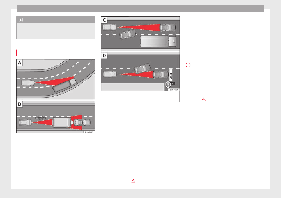
Operation
Note
If you do not switch off the ACC in the afore-
mentioned situation
s, you may commit a le-
gal offence.
Special driving situations
Fig. 200 (A) Vehicle on a bend. (B) Motorcy-
c
li
s
t ahead out of range of the radar sensor.
Fig. 201 (C) Vehicle changing lanes. (D) One
v
ehic
l
e turning and another stationary.
The adaptive cruise control (ACC) has certain
ph
y
s
ical limitations inherent in the system.
For example, certain reactions of the ACC, in
certain circumstances, may be unexpected or
come late from the driver's point of view. So
pay attention in order to intervene if necessa-
ry.
For example, the following traffic situations
call for the utmost attention:
Starting driving after a stopping phase (only
vehicles with automatic gearbox)
After a stopping phase, the ACC may begin
driving automatically when the vehicle in
front drives off ›››
.
When the ACC halts the vehicle (e.g. traffic
j
am), the in
s
trument panel display shows the
ACC ready to start message. If the ve-
hicle ahead drives off again, the ACC will also
do so automatically.
If the vehicle ahead does not drive off again,
the vehicle can be kept indefinitely in the
ACC ready to start status by operating
the third lever repeatedly towards position
2
›
›› Fig. 197
or b
y pressing the brake pedal.
If the Press the brake message is shown
on the instrument panel, press the brake. If
you do not, an acoustic warning will be heard
and the ACC will switch to inactive mode
(Standby). At this point, the vehicle may be-
gin to move towards the stopped vehicle
ahead ›››
.
Ov
er
t
aking
When the turn signal lights up before the ve-
hicle begins an overtaking manoeuvre, the
ACC accelerates the vehicle automatically
and thus reduces the distance from the vehi-
cle in front.
When the vehicle enters the overtaking lane,
if the ACC does not detect another vehicle in
front, it accelerates until it reaches the pro-
grammed speed and maintains it.
System acceleration can be interrupted at
any time by pressing the brake or moving the
third lever backwards ››› page 224.
228

Driver assistance systems
Driving through a bend
On ent
erin
g or e
xiting bends, the radar sen-
sor may no longer determine the vehicle in
front or react to a vehicle in the adjacent lane
››› Fig. 200 A. In these situations the vehicle
may brake unnecessarily or fail to react to re-
act to the vehicle in front. In this case, the
driver has to intervene by accelerating or in-
terrupting the braking process by applying
the brake or pushing the third lever back-
wards ››› page 224.
Driving in tunnels
When driving through tunnels the radar sen-
sor may be limited. Switch off the ACC in tun-
nels.
Narrow or misaligned vehicles
The radar sensor can only detect narrow or
misaligned vehicles when they are within
range ››› Fig. 200 B. This applies particularly
to narrow vehicles such as motorbikes. In
these cases, you should brake as necessary.
Vehicles with special loads and accessories
Special loads and accessories of other vehi-
cles that jut out over the sides, backwards or
over the top may be out of the ACC's range.
Switch off the ACC when driving behind vehi-
cles with special loads and accessories or
when overtaking them. In these cases, you
should brake as necessary.
Other vehicles changing lanes
Vehicles changing lanes a short distance
away from your own can only be detected
when they are within range of the sensors.
Consequently, the ACC will take longer to re-
act ››› Fig. 201 C. In these cases, you should
brake as necessary.
Stationary vehicles
The ACC does not detect stationary objects
while driving, such as traffic tails or damaged
vehicles.
If a vehicle detected by the ACC turns or
moves over and there is a stationary vehicle
in front of it, the ACC will not react to it
››› Fig. 201 D. In these cases, you should
brake as necessary.
Vehicles driving in the opposite direction
and vehicles crossing your path
The ACC does not react to vehicles approach-
ing from the opposite direction or vehicles
crossing your path.
Metal objects
Metal objects, e.g. rails on the road or sheets
used in road works, can confuse the radar
sensor and cause the ACC to react wrongly.
Factors that may affect how the radar sensor
operates
If laser sensor operation is impaired, due to
heavy rain, spray, snow or mud, the ACC is
deactivated temporarily. The relevant text
message will appear in the dash panel dis-
play. If necessary clean the SEAT
badge ››› Fig. 196.
When the radar sensor begins to operate
properly again, the ACC will automatically be
available again. The message on the instru-
ment panel screen will switch off and the ACC
will be reactivated again.
ACC operation may be affected by a strong ra-
dar reverse reflection, for example in a closed
car park.
Trailer mode
When driving with trailer the ACC controls
less dynamically.
Overheated brakes
If the brakes overheat, for example after
abrupt braking or in long and steep slopes,
the ACC may be deactivated temporarily. The
relevant text message will appear in the dash
panel display. In this case, adaptive cruise
control cannot be activated.
Adaptive cruise control can be reactivated
once brake temperature has cooled suffi-
ciently. The message will disappear from the
instrument panel display. If the message ACC
»
229
Technical dataAdviceOperationEmergenciesSafety
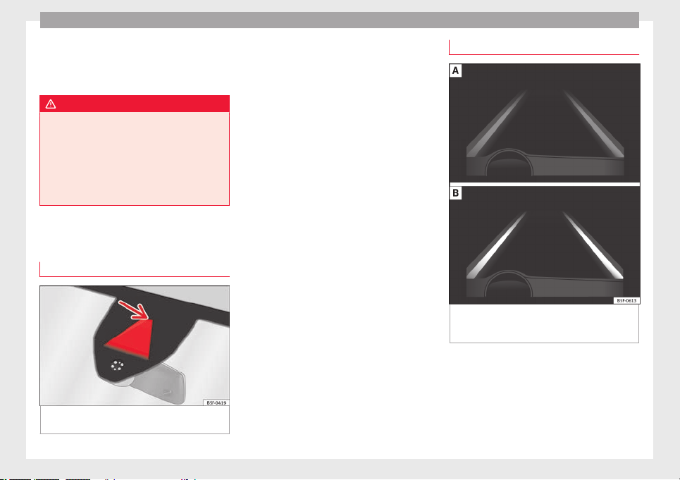
Operation
not available r
em
ain
s on for quite a long
time it means that there is a fault. Contact a
specialised workshop. SEAT recommends vis-
iting a SEAT dealership.
WARNING
If you do not heed the Press the brake
mess
age, the vehicle may initiate an involun-
tary movement and could crash into the vehi-
cle ahead. In any event, before driving off,
check that the road is clear. The radar sensor
may not detect obstacles on the road. This
could cause an accident and serious injuries.
If necessary, apply the brake.
Lane Assist system*
Intr
oduction
Fig. 202 In the windscreen: field of vision of
the Lane As
s
i
st system camera.
Using the camera located in the windscreen,
the Lane As
s
i
st system detects the possible
lines dividing the lanes. When the vehicle in-
voluntarily approaches a dividing line it has
detected, the system notifies the driver with
a corrective steering movement. The purpose
is not only to warn the driver, but also to
keep the vehicle inside the lane. This move-
ment can be over-regulated at any time.
No warning is produced with the turn signals
activated, given that the Lane Assist system
understands that a lane change is required.
Indications on the display and lamps
Fig. 203 On the instrument panel display: In-
dic
ation on the Lane As
s
ist system display
(example 1).
230
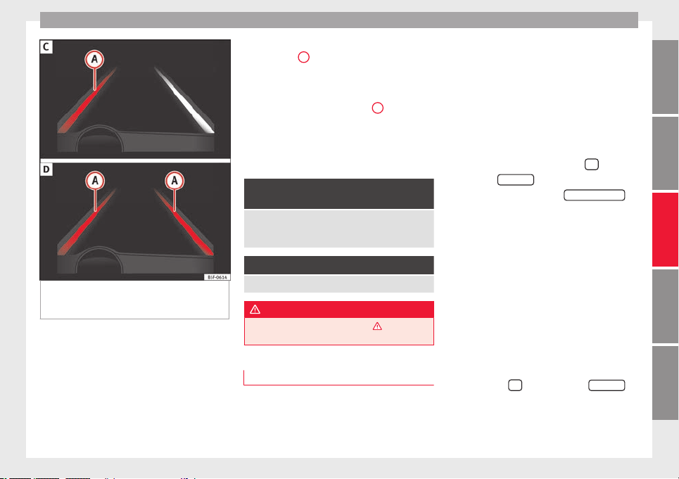
Driver assistance systems
Fig. 204 On the instrument panel display: In-
dic
ation on the Lane As
s
ist system display
(example 2).
Status display
The sy
s
t
em is active, but not available,
either because the minimum speed has
not been reached or because the lane
lines are not recognised ››› Fig. 203 A.
The system is active and available, both
lane lines are recognised. The steering
angle is not being corrected at this mo-
ment ››› Fig. 203 B.
–
–
The system is operational, the highligh-
ted line
A
indicates that there was a
ri
sk
of
involuntarily crossing the lane
line and that the steering is being adjus-
ted to correct the angle ››› Fig. 204 C.
The two highlighted lines
A
light up si-
mu
lt
aneou
sly when both lane lines are
recognised and the Lane Assist function
is active ››› Fig. 204 D.
Control lamps
It lights up yellow: Lane Assist active
but not available.
The system can not accurately recognise the lane.
Please see page 232, the Lane Assist system is not
available (the control lamp is lit up yellow).
It lights up green
Lane Assist system active and available.
WARNING
Observe the safety warnings ›››
in Warning
and contro
l lamps on page 119.
Operating mode
Steering wheel vibration
The f
o
l
lowing situations can cause vibration
in the steering wheel and require the driver
to take active control of driving:
–
–
●
When the steering angle assist value re-
quired to keep the vehicle in the lane is high-
er than the system’s maximum operating val-
ue.
●
If the system ceases to display the lane
lines while assisting with steering.
Switching the Lane Assist system on or off
Through the Easy Connect system
●
Press the Easy Connect button
●
Press the
S
ET
TINGS
function button
●
Press the function button
Driv
er a
s
sistance
to
open the menu.
OR: U
s
in
g the Driving Assist button on
the turn signal lever* ›››
page 37.
Lane Assist with lane centring guide
The Lane Centring Guide function is in-
tended to keep the vehicle in the centre of
the lane.
If the driver has a tendency to veer slightly off
centre in the lane, the system adapts to driv-
er preferences.
The Lane Centring Guide function is ac-
tivated/deactivated in the Easy Connect sys-
tem using the
button and the
S
ET
TINGS
function button ›
›
›
page 120.
»
231
Technical dataAdviceOperationEmergenciesSafety

Operation
Self-deactivation: the Lane As
s
i
st system can
be automatically deactivated if there is a sys-
tem malfunction. The control lamp
disappears.
Hands-Off Function
In the absence of steering wheel activity the
system alerts the driver with acoustic signals
and a text message on the dash panel asking
to actively take over the steering.
If the driver does not react to this, the system
also alerts the driver with a little shaking mo-
tion through the brakes and, if the vehicle
has it, activates the Emergency Assist func-
tion ››› page 234.
In vehicles without Emergency Assist, the
adaptive lane guidance function will be disa-
bled after the corresponding warnings to the
driver.
The lane assist system is active but it is not
available (the control lamp is lit up yellow)
●
When driving at speeds below 65 km/h (38
mph).
●
When the Lane Assist system does not de-
tect the dividing lines of the road. For exam-
ple, in the event warnings indicating road
works, and snow, dirt, moisture or reflec-
tions.
●
When the radius of a curve is too small.
●
When no road markings can be seen.
●
When the distance to the next marking to
too great.
●
When the system does not detect any clear
and active steering movement during a long
period of time.
●
Temporarily, in the event of very dynamic
driving styles.
●
If a turn signal is activated.
●
With the stability control system (ESC) in
Sport mode or switched off.
BSD Plus (Lane Assist with Blind Spot Detec-
tor)*
The BSD Plus function is achieved by activat-
ing the Lane Assist and BSD functions
››› page 237. In this case, the Lane Assist
function expands its functions in the follow-
ing way:
If the driver tries to change lane and there is
a vehicle in the blind spot:
●
The lamp flashes in the corresponding
rear-view mirror even though the turn signal
has not been activated.
●
The steering wheel vibrates to warn the
driver of the risk of collision.
●
torque is applied to correct the steering
and return the vehicle to its lane.
Switching off the Lane Assist system in the
following situations
Due to the limits of the Lane Assist system,
switch it off in the following situations:
●
When more attention is required of the
driver
●
When driving in a sporty style
●
In unfavourable weather conditions
●
On roads in poor condition
●
In areas of road works
WARNING
The intelligent technology in the Lane Assist
syst
em cannot change the limits imposed by
the laws of physics and by the very nature of
the system. Careless or uncontrolled use of
the Lane Assist system may cause accidents
and injury. The system is not a replacement
for driver awareness.
●
Always adapt your speed and the distance
to the vehicles ahead in line with visibility,
weather conditions, the condition of the road
and the traffic situation.
●
Always keep your hands on the steering
wheel so it can be turned at any time.
●
The Lane Assist system does not detect all
road markings. The road surfaces, road struc-
tures or objects in poor condition can be in-
correctly detected as road markings under
certain circumstances by the Lane Assist sys-
tem. In such situations, switch the Lane As-
sist system off immediately.
232
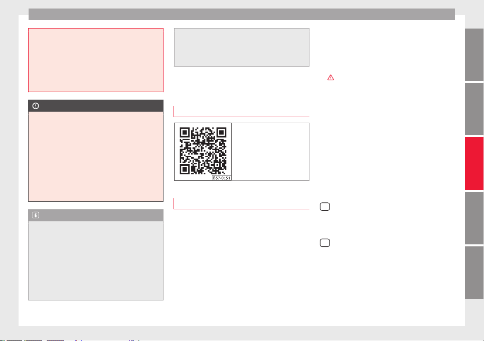
Driver assistance systems
●
Plea
se observe the indications on the in-
strument panel and act as is necessary.
●
Always pay attention to the vehicle's sur-
roundings.
●
When the area of vision of the camera be-
comes dirty, covered or is damaged, the Lane
Assist system function can be affected.
CAUTION
In order to avoid influencing the operation of
the sy
st
em, the following points must be tak-
en into account:
●
Regularly clean the area of vision of the
camera and keep it in a clean state, without
snow or ice.
●
Do not cover the area of vision of the cam-
era.
●
Check that the area of vision of the wind-
screen camera is not damaged.
Note
●
The lane depar
ture warning system has
been exclusively developed for driving on
paved roads only.
●
If the Lane Assist system does not work as
described in this chapter, do not use it and
contact a specialised workshop.
●
Before starting a journey, verify that the
field of vision of the camera is not covered
››› Fig. 202.
●
Alwa
ys keep the field of vision of the cam-
era clean.
●
If there is a fault in the system, have it
checked by a specialised workshop.
Traffic Jam Assist
Relat
ed video
Fig. 205 Autonomous
driving
Description and operation
Traffic Jam Assist helps the driver keep the
c
ar w
ithin its
lane and to move in convoy in
case of traffic congestion or slow traffic.
Traffic Jam Assist is an additional function of
Lane Assist ››› page 230 and combines Lane
Assist functions with Adaptive Cruise Control
(ACC)
›››
page 221. Therefore, it is essential
that you read these two chapters carefully
and note the limitations of the systems and
the information about them.
Operation of Traffic Jam Assist
At speeds of below 60 km/h (40 mph), Traffic
Jam Assist can maintain a (temporary) dis-
tance preset by the driver with respect to the
vehicle ahead and help stay within the lane
›››
.
T
o do thi
s, the sy
stem automatically controls
the accelerator, brakes and steering, and
slows the vehicle, stopping it fully if neces-
sary, when faced with a vehicle in front that
has stopped. It automatically moves off again
when the vehicle ahead moves.
Traffic Jam Assist is designed only for use on
motorways and wide roads. Therefore, never
use it in city traffic.
Technical requirements for using Traffic Jam
Assist
●
Lane departure warning must be activated:
button > SETTINGS > Driver as-
sistance > Lane departure warning
(Lane Assist) ›
›
›
page 33.
●
The Lane Centring Guide must be activated:
button > SETTINGS > Driver as-
sistance > Lane departure warning
(Lane Assist)
●
Adaptive Cruise Control (ACC) must be con-
nect
ed and activ
e ›
›› page 224.
●
The speed must be below 60 km/h
(38 mph).
»
233
Technical dataAdviceOperationEmergenciesSafety
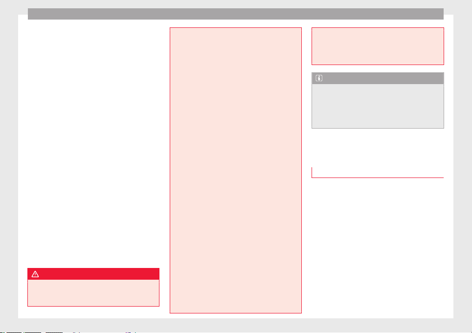
Operation
Traffic Jam Assist is not active (the Lane As-
s
i
s
t control light turns yellow)
●
If any of the conditions mentioned on
page 233, Technical requirements for using
Traffic Jam Assist are no longer met.
●
If any of the conditions required for opera-
tion of the Lane Assist are not met
››› page 230.
●
If any of the conditions necessary for the
adaptive cruise control (ACC) to work are no
longer fulfilled ››› page 221.
Situations in which Traffic Jam Assist must
be switched off
Due to the limitations of the system, Traffic
Jam Assist must always be switched off in the
following situations:
●
When more attention is required by the
driver.
●
When driving in a very sporty style.
●
In adverse weather conditions, e.g. in case
of snow or heavy rain.
●
When driving on roads in poor condition.
●
In sections with roadworks.
●
In city journeys.
WARNING
The smart technology incorporated into Traf-
fic Jam Ass
ist cannot defy the laws of phys-
ics; it only works within the limits of the sys-
tem. Accidents and severe injury may occur if
Traffic
Jam Assist is used negligently or invol-
untarily. The system is not a replacement for
driver awareness.
●
Adapt your speed and safe distance to the
vehicle in front of you at all times to suit the
visibility, weather, road and traffic condi-
tions.
●
Do not use Traffic Jam Assist in city jour-
neys.
●
Do not use Traffic Jam Assist if there is poor
visibility, for example, in case of snow, ice,
rain or loose gravel, or on steep or slippery
sections or flooded roads.
●
Do not use Traffic Jam Assist offroad or on
roads where the surface is not firm. Traffic
Jam Assist has been designed for use on
paved roads only.
●
Traffic Jam Assist does not react to people
or animals or vehicles crossing your path or
that approach you head-on down the same
lane.
●
If Traffic Jam Assist does not reduce speed
sufficiently, brake the vehicle immediately by
applying the pedal.
●
If the vehicle continues to move when you
wish it to stop after a driver intervention
prompt, brake the vehicle by applying the
pedal.
●
If driver intervention is requested on the
dash panel display, immediately resume con-
trol of the vehicle.
●
Keep your hands on the wheel at all times
to be ready to intervene in the steering at any
time. The driver is always responsible for
keeping the
vehicle in its own lane.
●
Always be prepared to take charge of driv-
ing (accelerating or braking) yourself.
Note
●
If
T
raffic Jam Assist does not work as de-
scribed in this chapter, stop using it and con-
tact a specialised workshop.
●
If the system is faulty, take it to a special-
ised workshop and have it checked.
Emergency Assist
D
e
s
cription and operation
Emergency Assist detects whether there is in-
activ
ity
b
y the driver and can automatically
keep the car within the lane and stop it alto-
gether if necessary. This way the system can
actively help avoid an accident.
Emergency Assist is an additional function of
Lane Assist ››› page 230 and combines Lane
Assist functions with Adaptive Cruise Control
(ACC) ››› page 221. Therefore, it is essential
that you read these two chapters carefully
and note the limitations of the systems and
the information about them.
234

Driver assistance systems
Operation of Emergency Assist
Emer
g
ency
Assist detects when the driver
ceases to perform any activity and repeatedly
requests that he/she regain active control of
the vehicle, through the use of optical and
acoustic warnings and by applying the
brakes.
If the driver continues to do nothing, the sys-
tem automatically takes over the accelerator,
brakes and steering in order to brake the ve-
hicle and keep it in its lane ›››
. When the
Emer
g
ency
Assist is actively adjusting, the
hazard warning lights come on ››› page 149
and the vehicle makes slight zigzag move-
ments in the lane in order to warn other driv-
ers.
If the remaining braking distance is suffi-
cient, if necessary the system slows down the
vehicle until it stops completely and auto-
matically switches on the electronic parking
brake ››› page 186.
Switching the Emergency Assist on and off
The Emergency Assist is switched on auto-
matically when the Lane Assist is switched on
››› page 230.
Technical requirements for using the Emer-
gency Assist
●
The adaptive cruise control (ACC) must be
switched on ››› page 221.
●
The Lane Assist must be switched on
››› page 230.
●
The selector lever must be in the D/S posi-
tion or in the Tiptronic selector gate.
●
The system must have detected a lane sep-
aration line on both sides of the vehicle
››› Fig. 204.
The following conditions may cause the
Emergency Assist not to react or to switch off
automatically:
●
If the driver accelerates, brakes or moves
the steering wheel.
●
If any of the conditions mentioned in
››› page 235, Technical requirements for us-
ing the Emergency Assist are not fulfilled.
●
If any of the conditions required for opera-
tion of the Lane Assist are not met
››› page 230.
●
If any of the conditions necessary for the
adaptive cruise control (ACC) to work are no
longer fulfilled ››› page 221.
WARNING
The smart technology incorporated into the
Emergency
Assist cannot overcome the limits
imposed by the laws of physics; it only works
within the limits of the system. The driver is
responsible for driving the vehicle.
●
Adapt your speed and safe distance to the
vehicle in front of you at all times to suit the
visibility, weather, road and traffic condi-
tions.
●
Keep
your hands on the wheel at all times
to be ready to intervene in the steering at any
time.
●
The Emergency Assist alone cannot always
avoid accidents or serious injuries.
●
If the operation of the Emergency Assist is
impaired, for example if the radar sensor of
the adaptive cruise control (ACC) or the Lane
Assist camera are covered or have lost their
settings, the system may intervene inoppor-
tunely in braking or in steering.
●
The Emergency Assist does not react to
people or animal or vehicles crossing your
path or which approach you head-on in the
same lane.
WARNING
If the Emergency Assist Intervenes inoppor-
tunely
, serious accidents and injuries may oc-
cur.
●
If the Emergency Assist does not operate
properly, switch off the Lane Assist
››› page 230. Doing so will also switch off the
Emergency Assist.
●
Have the system checked by a specialised
workshop. SEAT recommends visiting a SEAT
dealership for this.
»
235
Technical dataAdviceOperationEmergenciesSafety

Operation
Note
●
Automatic
interventions by the Emergency
Assist on the brakes may be interrupted by
pressing the accelerator or brake or by mov-
ing the wheel.
●
Hazard warning lights that come on auto-
matically can be switched off by pressing the
accelerator or the break, moving the steering
wheel or pressing the hazard warning light
switch.
●
If this occurs, the Emergency Assist may
decelerate the vehicle until it comes to a com-
plete stop.
●
When the Emergency Assist is activated, it
is only available again after the ignition has
been switched off and back on again.
236
Driver assistance systems
Blind spot detector (BSD) with
p
ark
in
g assistance (RCTA)*
Related video
Fig. 206 Smart solutions
Introduction
The blind spot detector (BSD) helps to detect
the tr
affic
s
ituation behind the vehicle.
The integrated parking assistant (RCTA) helps
the driver when backing out of a parallel
parking spot and in manoeuvring.
The blind spot detector has been developed
for driving on paved roads.
WARNING
The smart technology incorporated into the
blind spot
detector (BSD) with parking assis-
tance (RCTA) included cannot overcome the
limits imposed by the laws of physics; it only
works within the limits of the system. Acci-
dents and severe injury may occur if the blind
spot detection system or the rear cross traffic
alert are used negligently or involuntarily.
The syst
em is not a replacement for driver
awareness.
●
Adapt your speed and safe distance to the
vehicle in front of you at all times to suit visi-
bility, weather, road and traffic conditions.
●
Keep your hands on the wheel at all times
to be ready to intervene in the steering at any
time.
●
Pay attention to the control lamps that may
come on in the external rear view mirrors and
on the instrument panel, and follow any in-
structions they may give.
●
The blind spot assistant could react to any
special constructions that might be present
on the sides of the vehicle: e.g. high or irreg-
ular dividers. This may cause erroneous warn-
ings.
●
Never use the blind spot detector with rear
cross traffic alert on unpaved roads. The blind
spot detector with rear cross traffic alert has
been designed for use on paved roads.
●
Always pay attention to the vehicle's sur-
roundings.
●
Never use the blind spot detector or the
parking assistant if the radar sensors are
dirty.
●
The external rear view mirror control lamps
may have limited functionality due to solar
radiation.
CAUTION
●
The rad
ar sensors on the rear bumper may
be damaged or shifted in the event of a colli-
sion, for example, when entering or exiting a
parking space. This may result in the system
disconnecting itself, or at least possibly hav-
ing its functionality diminished.
●
In order to ensure that the radar sensors
work properly, keep the rear bumper free of
snow and ice and do not cover it.
●
The rear bumper should only be painted
with paint authorised by SEAT. The blind spot
detector's functions may be limited or work
incorrectly if other paints are used.
Note
If the blind spot detector with parking assis-
tant doe
s not work as described in this chap-
ter, do not use it and contact a specialised
workshop.
Control lamps
Control lamp in external rear view mirrors:
Lights up
Lights up once briefly: the blind spot detector is activa-
ted and ready to operate.
Lights up: blind spot detector has detected a vehicle in
the blind spot.
»
237
Technical dataAdviceOperationEmergenciesSafety
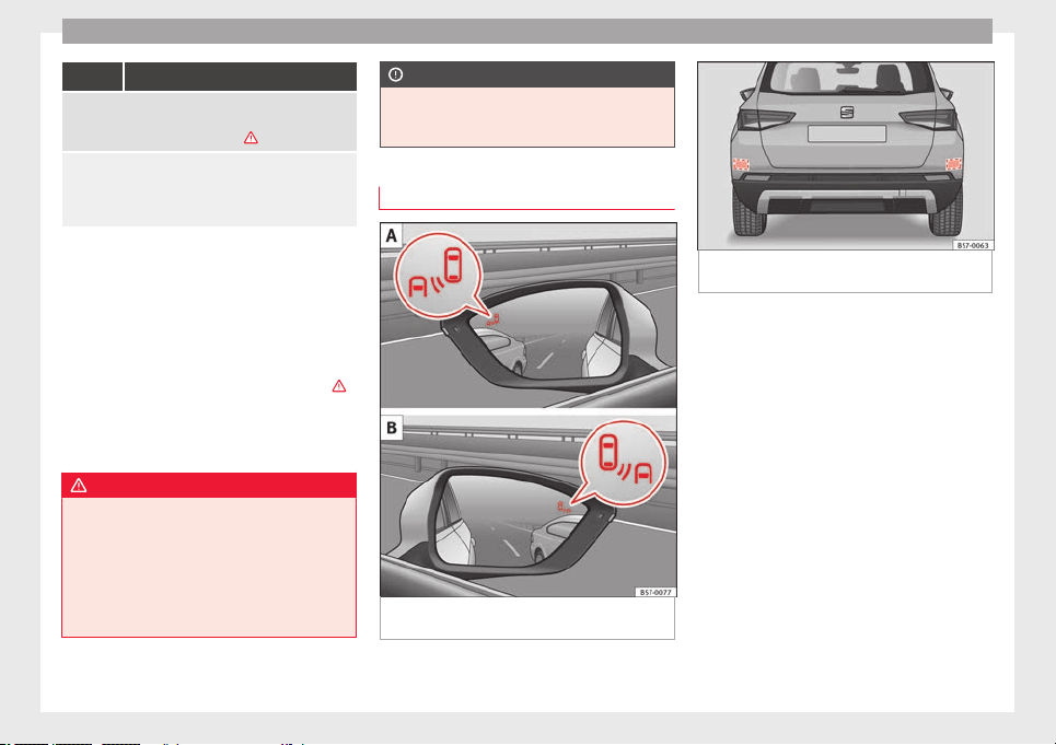
Operation
Flashes
The blind spot detector has detected a vehicle in the
blind spot and the turn signal has been turned on in the
direction of the detected vehicle ›››
.
For vehicles that are also equipped with Lane Assist
››› page 230, a warning to switch lanes will also appear
even though the turn signal has not been engaged
(blind spot detector “Plus”).
Some warning and control lamps will light up
briefly when the ignition is
switched on to
check certain functions. They will switch off
after a few seconds.
If there are no indications from the control
lamp in the external rear view mirror, this
means that the blind spot detector has not
detected any other vehicles in the area
›››
.
If
the dip
ped be
am is on, then the control
lamps in the external rear view mirrors will be
dimmed (night mode).
WARNING
If the warning lamps and the corresponding
mess
ages are ignored when they light up, the
vehicle may stall in traffic and cause acci-
dents and severe injuries.
●
Never ignore the warning lamps or messag-
es.
●
Carry out the necessary operations.
CAUTION
Failure to heed the control lamps and corre-
sponding t
ext messages when they light up
may result in damage to the vehicle.
Blind spot detector (BSD)
Fig. 207 In the exterior mirrors: indication of
the b
lind s
pot
detector.
Fig. 208 Rear view of the vehicle: radar sen-
sor zone
s.
The blind spot detector uses radar sensors to
monit
or the ar
e
as behind the vehicle
››› Fig. 208. The system does this by measur-
ing the vehicle's distance from other vehicles
and its speed differential. The blind spot de-
tector will not work at speeds of less than ap-
prox. 15 km/h (9 mph). The system uses opti-
cal signals in the external rear view mirrors to
notify the driver.
Indication in the external rear view mirrors
The control lamp (expanded view) provides
an indication in the corresponding external
mirror ››› Fig. 207 regarding the traffic situa-
tion behind the vehicle, if it is deemed to be
critical. The control lamp of the left-hand ex-
ternal mirror indicates the traffic situation to
the left of the vehicle, and the control lamp of
the right-hand external mirror indicates the
traffic situation to the right of the vehicle.
238

Driver assistance systems
In the case of retrofitted tinted windows or
w
indo
w
s with tinted film, the indications of
the external mirrors may not be seen clearly
or correctly.
Keep the external mirrors clean and free of
snow and ice, and do not cover them with ad-
hesives or other similar materials.
Radar sensors
The radar sensors are located on the left and
right of the bumper and are not visible from
the outside ››› Fig. 208. The sensors monitor
both the blind spot and traffic behind the ve-
hicle ››› Fig. 209, ››› Fig. 210. The range to the
sides of the vehicle is a bit larger than the
width of a lane.
The lane width is not detected individually,
but is rather pre-configured in the system.
Thus if you are driving in wide lanes or in be-
tween two lanes, the indications may be in-
correct. Furthermore, the system can detect
vehicles driving in the lane next to you (if
there are any), and can also detect stationary
objects such as dividers, and thus give an in-
correct indication.
239
Technical dataAdviceOperationEmergenciesSafety
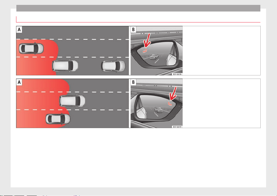
Operation
Driving situations
Fig. 209 Schematic diagram: Pas
sing sit-
uation with traffic behind the vehicle. Indi-
cation from the blind spot detector in the left-
hand external mirror.
Fig. 210 Schematic diagram: Situation of
pa
ssing and then moving into the right-hand
lane. Indication from the blind spot detec-
tor in the right-hand external mirror.
In the following situations, an indication will
be di
s
p
layed in the external mirror ››› Fig. 209
(arrow) or ››› Fig. 210 (arrow):
●
When being overtaken by another vehicle
››› Fig. 209 .
●
When overtaking another vehicle
››› Fig. 210 with a speed differential of ap-
prox. 10 km/h (6 mph). If the vehicle is pass-
ing at a considerably higher speed, no indi-
cation will be displayed.
The faster the vehicle approaches, the sooner
an indication will be displayed in the external
mirror, because the blind spot detector takes
into account the speed differential with other
vehicles. Thus even though the distance from
the other vehicle is identical, the indication
will appear sooner in some cases and later in
others.
Physical limitations inherent to the system
In some situations the blind spot detector
may not interpret the traffic situation correct-
ly. E.g. in the following situations:
●
on tight bends;
●
in the case of lanes with different widths;
●
at the top of slopes;
●
in adverse weather conditions;
240
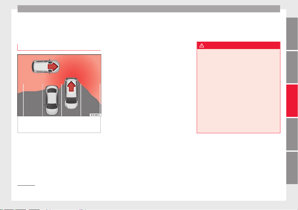
Driver assistance systems
●
in the c
a
se of
special constructions to the
side of the vehicle, e.g., high or irregular di-
viders.
Parking assistant (RCTA)
Fig. 211 Schematic representation of the rear
c
r
o
ss traffic alert: zone monitored around the
vehicle exiting the parking space.
The parking assistant uses the radar sensors
on the r
e
ar b
umper ››› Fig. 208 to monitor the
traffic crossing behind the vehicle as it backs
out of a parallel parking space or as it is be-
ing manoeuvred, for example in very low visi-
bility conditions.
If the system detects that someone else on
the road is approaching the rear of the vehi-
cle ››› Fig. 211, an acoustic alarm is heard.
In addition to the acoustic alarm, the driver is
also informed by means of a visual signal on
the radio screen. This signal is displayed in
the form of a red strip at the back of the im-
age of the vehicle on the radio screen. This
strip displays the side of the vehicle towards
which traffic is approaching.
1)
Automatic braking to reduce damages
If the rear cross traffic alert detects that
someone else on the road is approaching the
rear of the vehicle and the driver does not
step on the brake, the system will engage the
brakes automatically.
The parking system helps the driver by auto-
matically engaging the brakes to reduce any
damage. The system will brake automatically
if the vehicle is reversing at a speed of ap-
proximately 1-12 km (1-7 mph). Once it has
detected that the vehicle has stopped, the
system will keep the vehicle stopped for ap-
prox. 2 seconds.
After automatically braking to reduce dam-
age, the system will not be able to automati-
cally brake again for approximately 10 sec-
onds.
You can interrupt the automatic braking by
stepping hard on the accelerator pedal or the
brake pedal in order to regain control of the
vehicle.
WARNING
The smart technology incorporated into the
rear c
ross traffic alert cannot overcome the
limits imposed by the laws of physics; it only
works within the limits of the system. The
parking assistant function should not tempt
you into taking any risks. The system is not a
replacement for driver awareness.
●
The system should never be used in limited
visibility conditions or complicated traffic,
e.g., in high-traffic areas or when crossing
multiple lanes.
●
Be sure to always be aware of the vehicle's
surroundings, since the system often fails to
detect things such as bicycles or pedestrians.
●
The rear cross traffic alert itself will not
brake the vehicle to a complete stop.
1)
It is only displayed if the vehicle is equipped with
a parkin
g system.
241
Technical dataAdviceOperationEmergenciesSafety
Operation
Using the blind spot detector (BSD)
w
ith p
ark
ing assistant (RCTA)
Activating and deactivating the blind spot
detector (BSD) w
ith parking assistant (RCTA)
The blind spot detector with parking assis-
tant can be switched on and off by accessing
the Assistance systems menu on the
dash panel display using the steering wheel
controls. If the vehicle is equipped with a
multifunction camera, it can also be ac-
cessed by means of the driver assistance sys-
tems key located on the main beam head-
light lever.
Open the Assistants menu.
●
Blind spot
●
Exit Assist
If the verification box on the control panel is
checked , the functionality will be automat-
ically activated at ignition.
When the blind spot detector is ready to op-
erate, the indications in the external mirrors
will turn on briefly as confirmation.
When the vehicle is restarted, the last adjust-
ment in the system will remain active.
If the blind spot detector was automatically
deactivated, it will only be possible to restart
the system after turning the vehicle off and
restarting it.
Automatic deactivation of the blind spot de-
tector (BSD)
The r
adar sensors of the blind spot detector
with rear cross traffic alert will be automati-
cally deactivated when, among other rea-
sons, one of the sensors is detected to be
permanently covered. This may be the case if,
for example, there is a layer of snow or ice in
front of one of the sensors.
The relevant text message will appear in the
dash panel display.
Trailer mode
The Blind spot detector and the rear cross
traffic alert will be automatically deactivated
and it will be impossible to activate them if
the tow hitch is electrically connected to a
trailer or other similar object.
As soon as the driver starts to drive with a
trailer connected electrically to the vehicle, a
message will appear on the instrument panel
display indicating that the blind spot detec-
tor and the rear cross traffic alert are deacti-
vated. Once the trailer has been unhitched
from the vehicle, if you want to use the blind
spot detector and the rear cross traffic alert,
you will have to reactivate them in the corre-
sponding menu.
If the towing hitch is not factory equipped,
then the blind spot detector and the rear
cross traffic alert will have to be deactivated
manually when driving with a trailer.
SEAT Drive Profile*
Related video
Fig. 212 Autonomous
driving
Introduction
The SEAT Drive Profile enables the driver to
c
hoo
se betw
een four profiles or modes, Eco,
Normal, Sport and Individual, that
modify the behaviour of various vehicle func-
tions, providing different driving experiences.
In addition, the 4Drive version features the
Offroad and Snow profiles.
The Individual profile can be configured
according to personal preferences. The other
profiles have a fixed configuration.
Description
Depending on the equipment fitted in the ve-
hic
l
e,
SEAT Drive Profile can operate on the
following functions:
242
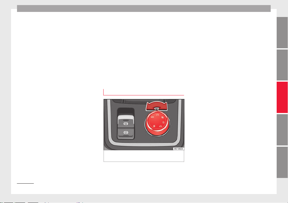
Driver assistance systems
Engine
D
ependin
g on the pr
ofile selected, the en-
gine responds more spontaneously or more
in harmony with the movements of the accel-
erator. Additionally, when the Eco profile is
selected, the Start-Stop function is automati-
cally activated.
In vehicles with automatic transmission, the
gear change points are modified to position
them in lower or higher engine speed ranges.
Additionally, the Eco profile activates the in-
ertia function, enabling consumption to be
further reduced.
In manual gearbox vehicles, the Eco profile
causes the gear change recommendation in-
dications that appear on the dash panel to
vary, facilitating more efficient driving.
Address
The power steering varies its driving modes
and adapts to the profile selected, thus offer-
ing the best behaviour for each situation.
Air conditioning
In vehicles with Climatronic, this can operate
in Eco mode, especially restricting fuel con-
sumption.
Adaptive cruise control (ACC)
The acceleration gradient of the adaptive
cruise control varies according to the active
driving profile ››› page 221.
Electronic stability control (ESC)
In the Offroad and Snow driving profiles,
the electronic stability Control (ESC)
››› page 189 adjusts to adapt to the terrain.
In addition, hill descent control (HDC) is acti-
vated in the Offroad profile ››› page 210.
Adjusting driving profile
Fig. 213 Centre console: Driving Experience
b
utt
on.
You can select the Eco, Normal, Sport, In-
dividual, Offroad
1)
and Snow
1)
pr
ofi
l
es in
the following way:
●
Turn the Driving Experience button until the
required profile lights up on the Easy Con-
nect system display as well as on the Driving
Experience button ››› Fig. 213.
●
OR: select the required profile on the
touch-screen of the Easy Connect system, in
the menu that opens up on turning the
Driving Experience button.
The features of each profile can be seen by
pressing the Profile information button of the
Easy Connect system display.
In the Individual profile it is possible to
configure the characteristics of the vehicle
using the Profile setup button of the Easy
Connect system display.
An icon on the Easy Connect system display
provides information about the active profile
if it is different than Normal. The selector
identifies the profile chosen by means of a
red LED light.
»
1)
Only for 4Drive models.
243
Technical dataAdviceOperationEmergenciesSafety
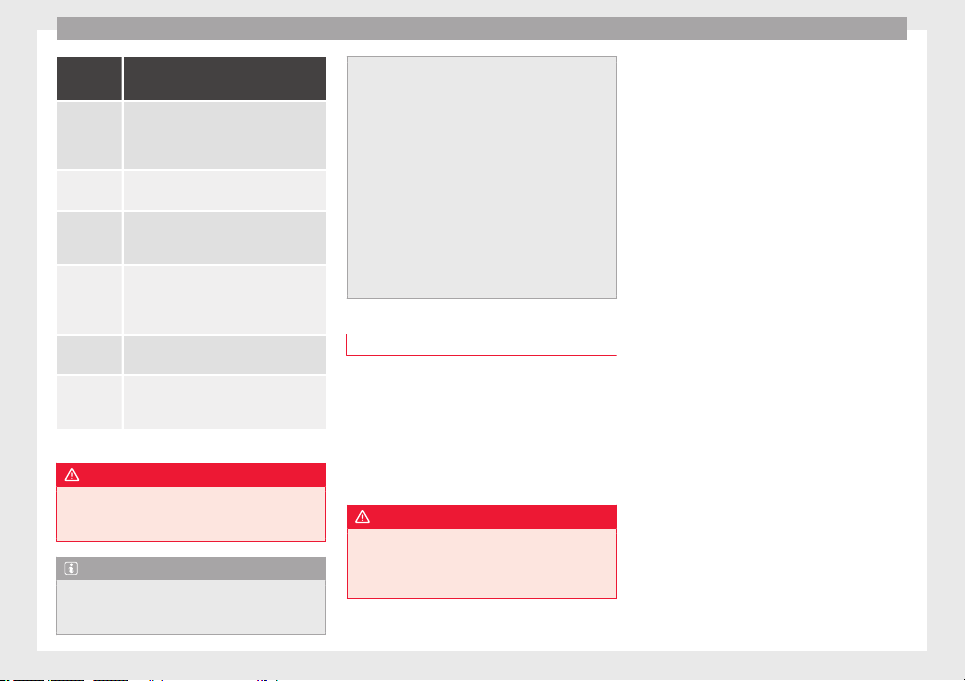
Operation
Driving
profile
Characteristics
Eco
Places the vehicle in a particularly low
state of consumption, facilitating a fuel-
saving driving style that is respectful to
the environment.
Normal
Offers a balanced driving experience,
suitable for everyday use.
Sport
Provides a complete dynamic perform-
ance in the vehicle, enabling the user a
more sporty driving style.
Individ-
ual
It allows you to personalise the configura-
tion. The functions that can be adjusted
depend on the equipment fitted in the ve-
hicle.
Offroad
a)
It adjusts the vehicle's parameters in or-
der to maintain optimal off-road driving.
Snow
a)
It adjusts the vehicle's behaviour for driv-
ing on slippery road surfaces, optimising
grip and manoeuvrability.
a)
Only for 4Drive models.
WARNING
When operating SEAT Drive Profile, pay atten-
tion to al
l traffic: doing otherwise could cause
an accident.
Note
●
When the vehic
le is switched off it will al-
ways store the driving profile that was selec-
ted when the ignition key was removed. Nev-
ertheless, when the engine is restarted, the
engine and the ge
ar will not restart in the set-
ting selected. For engine and gear to revert to
the desired position, select the correspond-
ing drive profile again or press the Easy Con-
nect system button repeatedly.
●
When the vehicle is restarted after using
the Offroad or Snow settings, the system is
always activated in the Normal profile.
●
Your speed and driving style must always
be adjusted to visibility, weather, and traffic
conditions.
●
The Eco profile is not recommended when
towing a vehicle.
Kick-down
The Kick-down feature allows maximum ac-
c
el
er
ation to be reached.
If the Eco* profile has been selected in the
SEAT Drive Profile ››› page 243 and the
accelerator is pressed beyond a hard point,
the engine power is automatically controlled
to give your vehicle maximum acceleration.
WARNING
Please note that if the road surface is slip-
pery or w
et, the kick-down feature could
cause the driving wheels to spin, which could
result in skidding.
244
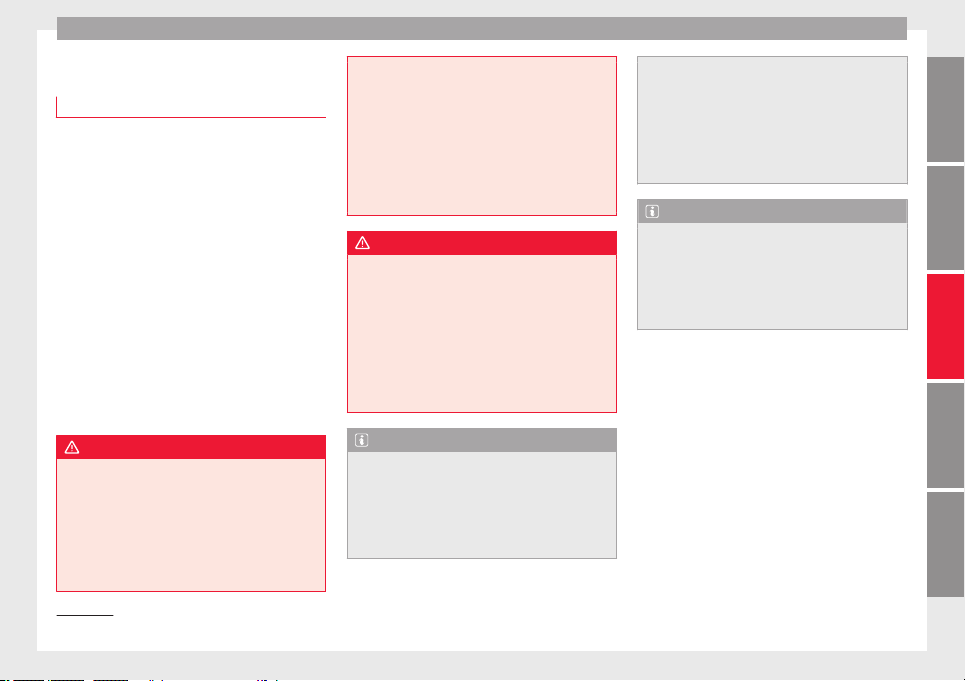
Driver assistance systems
Traffic sign detection system*
1)
Intr
oduction
The traffic sign detection system records the
stand
ard traffic signs in front of the vehicle
with a camera located on the base of the in-
terior mirror and provides information about
speed limits and overtaking prohibitions.
Within its limitations, the system also dis-
plays additional signals, such as time-specif-
ic prohibitions, signs for vehicles towing trail-
ers
›››
page 273 or limitations that only apply
in the event of rain. Even on journeys without
signs, the system may display any applicable
speed limits.
In Germany, on motorways and vehicle roads,
besides speed limits and overtaking provi-
sions the system also displays the end of
prohibition signs. The valid speed limit at the
time in other countries is always shown.
WARNING
The technology in the traffic sign detection
syst
em cannot change the limits imposed by
the laws of physics and only works within the
system's limits. Do not let the extra conven-
ience afforded by the traffic sign detection
system tempt you into taking any risks when
driving. The system is not a replacement for
driver awareness.
●
Adapt
your speed and driving style to suit
visibility, weather, road and traffic condi-
tions.
●
Poor visibility, darkness, snow, rain and fog
may lead to the system failing to display traf-
fic signs or not displaying them correctly.
●
If the camera's field of vision is dirty, cov-
ered or damaged, system operation may be
impaired.
WARNING
The driving recommendations and traffic indi-
c
ations
shown on the traffic sign detection
system may differ from the actual current
traffic situation.
●
The system may not detect or correctly
show all the traffic signs.
●
Traffic signs and traffic regulations have
priority over the recommendations and dis-
plays provided by the system.
Note
In order not to compromise the system's op-
eration, pl
ease take the following points into
account:
●
Regularly clean the area of vision of the
camera and keep it in a clean state, without
snow or ice.
●
Do not co
ver the field of vision of the cam-
era.
●
Always replace damaged or worn blades
when required to avoid lines on the camera's
field of vision.
●
Check that the windscreen is not damaged
in the area of the camera's field of vision.
Note
●
The u
se of out
dated maps on the naviga-
tion system may cause the system to show
traffic signs incorrectly.
●
In the waypoints mode of the navigation
system, the traffic sign detection system is
only partly available.
1)
System available depending on the country.
245
Technical dataAdviceOperationEmergenciesSafety
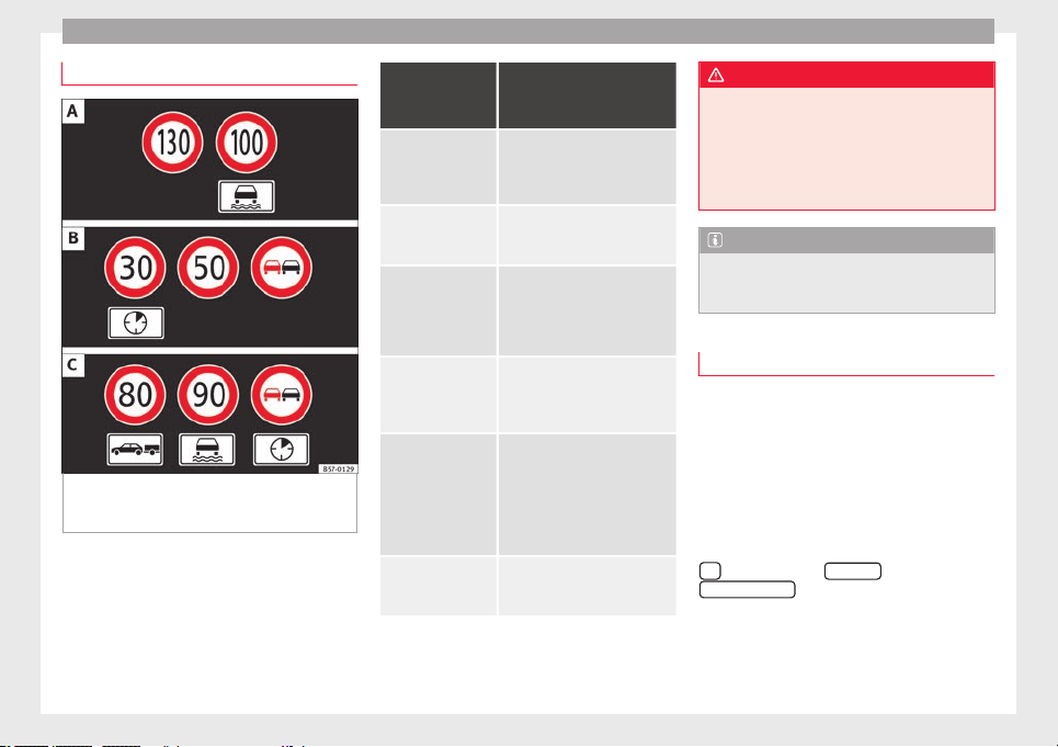
Operation
Indication on display
Fig. 214 On the instrument panel display: ex-
amp
l
e
s of speed limits or overtaking prohibi-
tions with their respective additional signs.
The traffic signs detected by the system are
di
s
p
layed on the dash panel display
››› Fig. 214 and, depending on the navigation
system fitted in the vehicle, on the infotain-
ment system as well ›››
page 33.
Traffic sign de-
tection system
messages
Cause and solution
There are no
traffic signs
available
The system is booting up.
OR ELSE: the camera has not rec-
ognised any obligation or pro-
hibition signs.
Error: Detec-
tion of traffic
signs
There is a fault in the system.
Have the system checked by a
specialised workshop.
Speed warning
currently un-
available.
The speed warning function of
the traffic sign detection system
is faulty.
Have the system checked by a
specialised workshop.
Detection of
traffic signs:
Clean the wind-
screen!
The windscreen is dirty in the
camera area.
Clean the windscreen.
Detection of
traffic signs:
Limited at the
moment
The navigation system is not
transmitting any data.
Check that the navigation sys-
tem's maps are up-to-date.
OR ELSE: the vehicle is currently
in a region that is not included
in the navigation system's map.
No data availa-
ble
The traffic sign detection system
does not work in the current
country.
WARNING
If messages are ignored, the vehicle may stall
in traffic and c
ause accidents and severe inju-
ries.
●
Never ignore the messages displayed.
●
Stop the vehicle at the next opportunity
and in a safe place.
Note
Failure to heed the control lamps and corre-
sponding t
ext messages when they light up
may result in damage to the vehicle.
Operation
The traffic sign detection system does not
w
ork
in al
l countries. Keep this in mind when
travelling abroad.
Activating and deactivating traffic sign dis-
play on the instrument panel
The permanent display of traffic signs on the
instrument panel can be activated or deacti-
vated in the infotainment system using the
button and the
S
ET
TINGS
and
Driv
er As
s
istance
function buttons.
Di
s
p
lay of traffic signs
When the traffic sign detection system is con-
nected, a camera located on the base of the
interior rear-view mirror records the traffic
246
Driver assistance systems
signs in front of the vehicle. After checking
and ev
aluatin
g the inf
ormation from the cam-
era, the navigation system and the current
vehicle data, up to three valid traffic signs
are displayed ››› Fig. 214 B in conjunction
with their corresponding additional signs.
The sign that is currently valid for the
driver is shown in the left side of the
screen For example, a maximum speed
limit of 130 km/h (100 mph)
››› Fig. 214 A.
A sign valid only in certain circum-
stances, e.g. 100 km/h (60 mph) is
shown second, together with the addi-
tional rain sign.
If the windscreen wiper is
working while you are driving, the signal
with the additional rain sign will be
shown first, on the left, as it is the one
that is applicable at the time.
A sign valid only with restrictions, e.g.
No overtaking at certain times, will be
displayed third ››› Fig. 214 C.
Speed warning
If the system detects that the permitted
speed is exceeded, it may warn the driver
with a “gong” and visually with a message
on the dash panel display.
The speed warning can be adjusted or deacti-
vated completely in the infotainment system
using the
button and the
S
ET
TINGS
and
First:
Second:
Additional sign:
Third:
Driver Assistance
function buttons
›
›
›
page 33. The speed is adjusted in
steps of 5 km/h (3 mph) within a range of be-
tween 0 km/h (mph) and 20 km/h (12 mph)
above the maximum speed permitted.
Trailer mode
In vehicles equipped with a towing bracket
device from the factory and a trailer that is
electrically connected to the vehicle, it is pos-
sible to activate or deactivate the display of
specific traffic signs for vehicles with trailer,
such as speed limits or overtaking prohibi-
tions. Activation or deactivation is performed
on the infotainment system using the
button and the
S
ET
TINGS
and
Driv
er As
s
istance
function buttons
›
›
›
page 33.
For trailer mode, the display of speed limits
applicable to the type of trailer or to the legal
provisions can be adjusted. The speed is ad-
justed in steps of 10 km/h (5 mph) within a
range of between 60 km/h (40 mph) and
130 km/h (80 mph). If it is adjusted to a
speed greater than that which is permitted in
the country in question for driving with a
trailer, the system automatically displays the
usual speed limits, e.g. in Germany 80 km/h
(50 mph).
If the speed warning for the trailer is deacti-
vated, the system displays the speed limits
as if there were no trailer hitched.
Limited operation
The traffic sign detection system has certain
limitations. The following cases may lead the
system to operate with limitations or not at
all:
●
In the case of poor visibility, e.g. in snow,
rain, fog or intense mist.
●
In cases of dazzling, e.g. caused by head-
on traffic or by the sun.
●
When driving at high speeds.
●
If the camera is covered or dirty.
●
If the traffic signs are out of the camera's
field of vision.
●
If the traffic signs are partially or totally
covered, e.g. by trees, snow, dirt or other ve-
hicles.
●
In the case of traffic signs that do not fulfil
the regulations.
●
In the case of damaged or bent traffic
signs.
●
In the case of variable messages on over-
head or gantry signs (LED-based variable traf-
fic signs or other lighting units).
●
If the maps on the navigation system are
not up-to-date.
●
In the case of adhesives affixed to vehicles
that depict traffic signs, e.g. speed limits on
lorries.
247
Technical dataAdviceOperationEmergenciesSafety
Operation
Fatigue detection (break rec-
ommend
ation)*
Intr
oduction
The Fatigue detection informs the driver
when their driving beh
aviour shows signs of
fatigue.
WARNING
Do not let the comfort afforded by the Fatigue
detection sys
tem tempt you into taking any
risks when driving. Take regular breaks, suffi-
cient in length when making long journeys.
●
The driver always assumes the responsibil-
ity of driving to their full capacity.
●
Never drive if you are tired.
●
The system does not detect the tiredness of
the driver in all circumstances. Consult the in-
formation in the section ››› page 248, System
limitations.
●
In some situations, the system may incor-
rectly interpret an intended driving manoeu-
vre as driver tiredness.
●
No warning is given in the event of the ef-
fect called microsleep!
●
Please observe the indications on the in-
strument panel and act as is necessary.
Note
●
Fatigue detection h
as been developed for
driving on motorways and well paved roads
only.
●
If there is a fault in the system, have it
checked by a specialised workshop.
Function and operation
Fig. 215 On the instrument panel display: fa-
tigue det
ection symbo
l
.
Fatigue detection determines the driving be-
h
av
iour of
the driver when starting a journey,
making a calculation of tiredness. This is
constantly compared with the current driving
behaviour. If the system detects that the driv-
er is tired, an audible warning is given with a
sound and an optic warning is shown with a
symbol and complementary message on the
instrument panel display ››› Fig. 215. The
message on the instrument panel display is
shown for approximately 5 seconds, and de-
pending on the case, is repeated. The system
stores the last message displayed.
The message on the instrument panel display
can be switched off by pressing the
button on the windscreen wiper lever or the
b
utt
on
on the multi function steering
wheel
›
›
›
page 36.
The message can be recalled to the instru-
ment panel display using the multifunction
display ›››
page 36.
Conditions of operation
Driving behaviour is only calculated on
speeds above about 65 km/h (40 mph) up to
around 200 km/h (125 mph).
Switching on and off
Fatigue detection can be activated or deacti-
vated in the Easy Connect system with the
button and the
S
ET
TINGS
function button
›
›
›
page 33. A mark indicates that the ad-
justment has been activated.
System limitations
The Fatigue detection has certain limitations
inherent to the system. The following condi-
tions can limit the Fatigue detection or pre-
vent it from functioning.
●
At speeds below 65 km/h (40 mph)
●
At speeds above 200 km/h (125 mph)
248
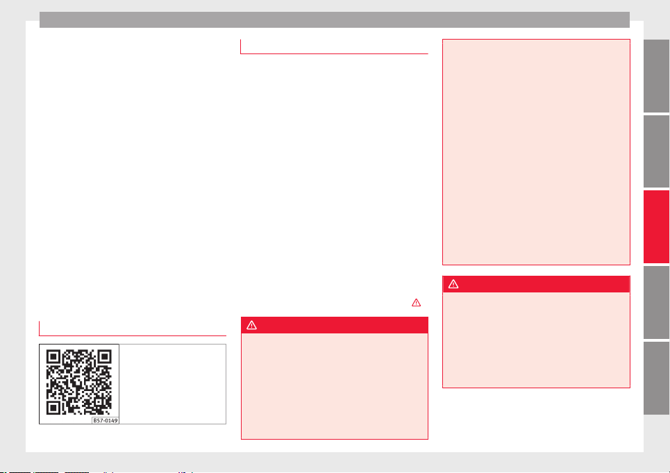
Driver assistance systems
●
When c
ornerin
g
●
On r
oads in poor condition
●
In unfavourable weather conditions
●
When a sporty driving style is employed
●
In the event of a serious distraction to the
driver
Fatigue detection will be restored when the
vehicle is stopped for more than 15 minutes,
when the ignition is switched off or when the
driver has unbuckled their seat belt and
opened the door.
In the event of slow driving during a long pe-
riod of time (below 65 km/h, 40 mph) the
system automatically re-establishes the tired-
ness calculation. When driving at a faster
speed the driving behaviour will be recalcula-
ted.
Park Assist*
Related video
Fig. 216 Smart solutions
Introduction
The Park Assist system is an additional func-
tion of ParkPi
lot ››› page 257 and helps the
driver to:
●
find a suitable parking space,
●
select a parking mode,
●
park driving in reverse in suitable perpen-
dicular and parallel spaces,
●
park driving forwards in suitable perpen-
dicular spaces,
●
exit a parking space driving forwards from
a paral
lel space.
In vehicles with a Park Assist system and fac-
tory radio the front, rear and side areas are
represented, and the position of obstacles is
shown relative to the vehicle.
The Park Assist system is subject to certain
limitations inherent to the system and its use
requires special attention by the driver
›››
.
WARNING
The technology used in the park assist sys-
tem inv
olves a series of limitations inherent
in the actual system and in the use of ultra-
sonic sensors. The use of Park Assist should
never tempt you to take any risk that may
compromise safety. The system is not a re-
placement for driver awareness.
●
Any accidental movement of the vehicle
could result in serious injury.
●
Adapt
your speed and driving style at all
times to suit visibility, weather, road and traf-
fic conditions.
●
Certain surfaces of objects and garments
do not reflect the ultrasound sensors' sig-
nals. The system cannot detect, at least cor-
rectly, these objects or people wearing such
clothes.
●
Ultrasound sensor signals may be affected
by external sound sources. In certain circum-
stances this may prevent them from detect-
ing people or objects.
●
The ultrasound sensors have blind spots in
which obstacles and people are not regis-
tered.
●
Monitor the area around the vehicle at all
times, since the ultrasound sensors do not
detect small children, animals or certain ob-
jects in all situations.
WARNING
Quick turns of the steering wheel when park-
ing or ex
iting a parking space with Park As-
sist can cause serious injury.
●
Do not hold the steering wheel during ma-
noeuvres to park or exit a parking space until
the system requests it. Doing so disables the
system during the manoeuvre, resulting in
the parking being cancelled.
»
249
Technical dataAdviceOperationEmergenciesSafety
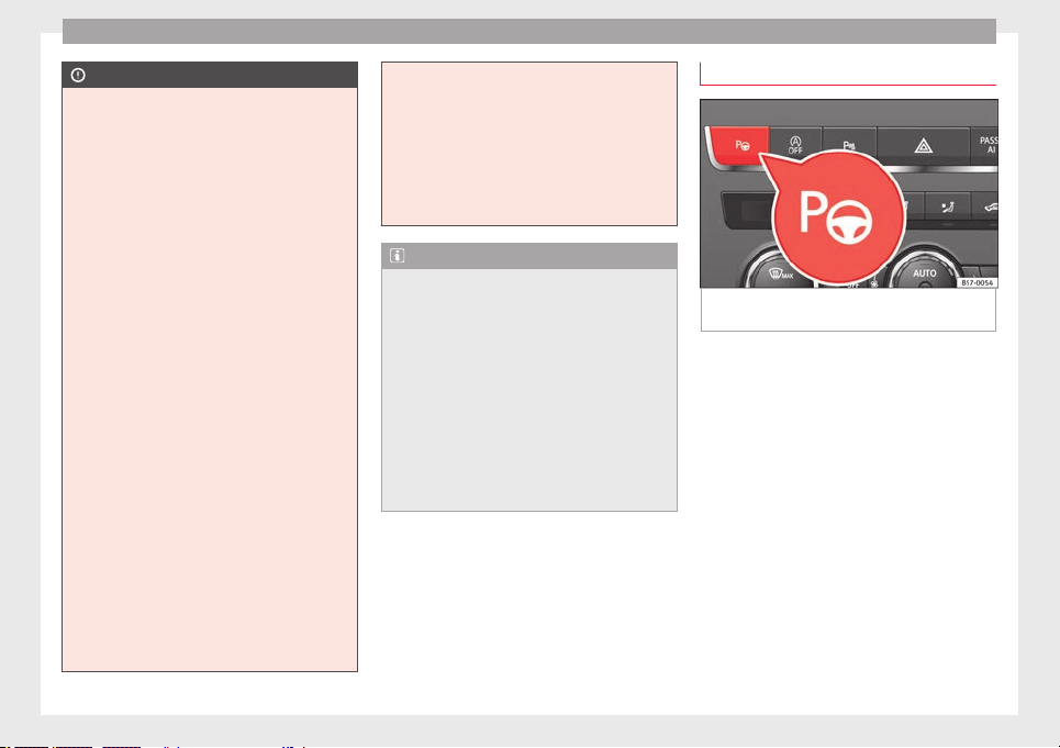
Operation
CAUTION
●
In cert
ain circumstances, the ultrasonic
sensors do not detect objects such as trailer
tongues, bars, fences, posts or thin trees, or
an open (or opening) rear lid, which could
damage the vehicle.
●
Retrofitting of certain accessories to the ve-
hicle, such as a bicycle rack, may interfere
with the operation of the Park Assist system
and cause damage.
●
The Park Assist system uses as a reference
parked vehicles, curbs and other objects.
Make sure that the tyres and wheels are not
damaged while parking. If necessary, oppor-
tunely interrupt the parking manoeuvre to
avoid damaging the vehicle.
●
The ultrasound sensors on the bumper may
be damaged or shifted in the event of a colli-
sion, for example, when entering or exiting a
parking space.
●
If you use high-pressure or vapour equip-
ment to clean the ultrasound sensors, do not
apply it directly unless very briefly and al-
ways from a distance of more than 10 cm.
●
A registration plate or plate holder on the
front with larger than the space for the regis-
tration plate, or a registration plate that is
curved or warped can cause:
–
false detections,
–
loss of sensor visibility.
–
cancellation of the parking manoeuvre or
defective parking.
●
If one of the u
ltrasonic sensors is damaged,
the area corresponding to that group of sen-
sors (front or rear) is deactivated and cannot
be activated until the fault is corrected. How-
ever, you can still use the sensors of the oth-
er bumper as per usual. If there is a fault in
the system, consult a specialist workshop.
SEAT recommends visiting a SEAT dealership
for this.
Note
●
In or
der to guar
antee good system opera-
tion, keep the ultrasound sensors of the
bumper clean, free of snow or ice, and do not
cover them with adhesives or other objects.
●
Certain sources of noise, such as rough as-
phalt or paving stones and the noise of other
vehicles can induce the Park Assist system or
ParkPilot to give erroneous warnings.
●
In order to become familiar with the system
and its functions, SEAT recommends that you
practice operating the Park Assist system in
an area where there is not too much traffic or
in a car park.
Description of the Park Assist system
Fig. 217 At the top of the centre console: but-
t
on t
o sw
itch on the Park Assist system.
The components of the Park Assist system
ar
e the u
ltr
asonic sensors located in the front
and rear bumpers, the button
›››
Fig. 217
to switch the system on and off and the mes-
sages on the instrument panel display.
Prematurely stopping or automatically inter-
rupting the manoeuvres for parking or exit-
ing a parking space
Park Assist interrupts the manoeuvres for
parking or exiting a parking space in any of
the following cases:
●
Press the
button.
●
The speed exceeds approximately 7 km/h
(4 mph).
●
The driver takes hold of the steering wheel.
250

Driver assistance systems
●
The p
ark
in
g manoeuvre does not end with-
in approximately 6 minutes following activa-
tion of the automatic steering.
●
There is a fault in the system (the system is
temporarily unavailable).
●
ASR is switched off.
●
ASR or ESC intervene with regulation.
●
The driver door is opened.
To restart the manoeuvre it is necessary that
none of these things occur and that the
button is pressed again.
Special Characteristics
The Park Assist system is subject to certain
limitations inherent to the system. For exam-
ple, it is therefore not possible to enter or exit
a parking space on sharp bends.
While entering or exiting a parking space, a
brief signal sounds to prompt the driver to
change between forward and reverse gears
(depending on the case). In successive ma-
noeuvres, the assistant tells the driver to
change gears, at the latest, when the contin-
uous audible signal is given (object present
at a distance of ≤30 cm) by Park Pilot.
When the Park Assist system turns the steer-
ing wheel with the vehicle stationary, the in-
strument panel also displays the symbol .
Keep the brake pedal depressed while the
symbol remains on the dash panel display to
turn the wheels with the vehicle stopped.
This way, the system will require fewer ma-
noeuvres to complete the parking action.
Trailer mode
The Park Assist system cannot be switched
on if the factory-fitted towing bracket
››› page 273 is electrically connected to a
trailer.
After changing a wheel
If, after changing a wheel, the vehicle stops
entering and exiting parking spaces correctly,
the circumference of the new wheel may be
different and the system may need to adapt
to it. The adaptation is automatic and takes
place during driving. Making turns slowly and
in both directions (20 km/h [12 mph]) for a
few minutes may contribute to this adapta-
tion process ›››
in Introduction on
p
ag
e 249
.
251
Technical dataAdviceOperationEmergenciesSafety
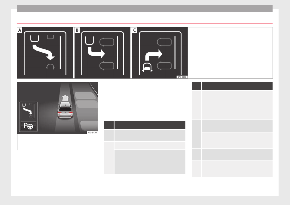
Operation
Selecting a parking mode
Fig. 218 Overview of reduced displays for park-
ing modes:
Parallel parking in reverse. Per-
pendicular parking in reverse. Perpendicular
parking forwards.
Fig. 219 On the instrument panel display:
disp
laying the Park Assist system with re-
duced display.
Selecting a parking mode with Park Assist
w
ith prior s
t
ep in front of the space
After activating the Park Assist system and
after detecting a parking space, the display
on the instrument panel proposes a parking
mode. The Park Assist system selects the
parking mode automatically. The selected
mode is shown on the instrument panel dis-
play ››› Fig. 219. The reduced display of other
possible parking modes is also shown
››› Fig. 218. If the mode selected by the sys-
tem does not correspond to the desired
mode, you can select another mode by press-
ing the button ››› Fig. 217.
Action
1.
The necessary conditions to park with Park Assist
have to be met ››› page 254.
2.
Press the
button.
A control lamp on the
button lights up when
the system is switched on. Additionally, the se-
lected parking mode is shown on the instrument
panel display and the reduced display shows an-
other parking mode it can be changed to.
Action
3.
Turn on the corresponding turn signal towards
the side of the road where you are parking. The
instrument panel displays the side correspond-
ing to the road. By default, if the turn signal is
not on, it parks on the right in the direction of
traffic.
4.
If necessary, press the
button again to change
to the next parking mode.
Once you have switched to all possible parking
modes, if the
button is pressed again, the
system switches off.
5.
Press the
button again to switch the system
back on.
6.
Follow the instructions displayed on the instru-
ment panel while paying attention to traffic and
drive the vehicle past the parking space.
252
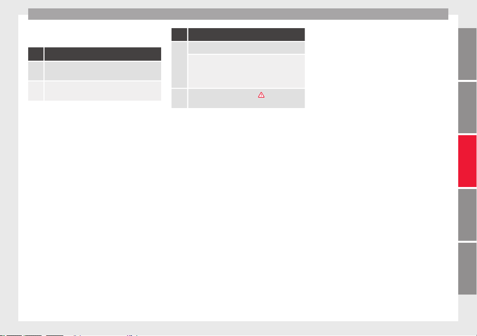
Driver assistance systems
Special case of perpendicular parking space
t
o p
ark
forwards without driving past first
Action
1.
The necessary conditions to park with Park Assist
have to be met ››› page 254.
2.
Drive forward towards the parking space while
paying attention to traffic and stop the vehicle.
Action
3.
Press the
button once.
A control lamp on the
button lights up when
the system is switched on. Additionally, the se-
lected parking mode is shown on the instrument
panel display without reduced display.
4.
Release the steering wheel ››› in Introduction
on page 249.
253
Technical dataAdviceOperationEmergenciesSafety
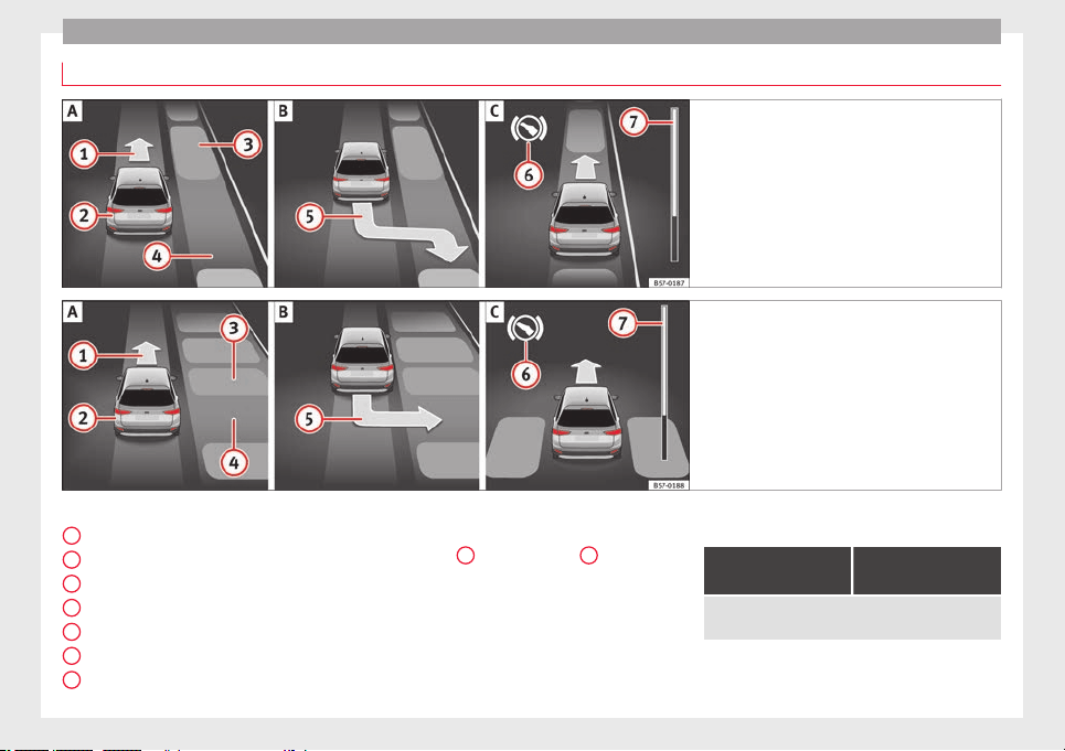
Operation
Park with Park Assist
Fig. 220 On the instrument panel display: paral-
lel p
arking. Finding a parking space. Park-
ing position. Manoeuvring.
Fig. 221 On the instrument panel display: per-
pendicul
ar parking. Finding a parking space.
Parking position. Manoeuvring.
Key to Fig. 220 and Fig. 221:
M
e
s
sage to move forwards
Your vehicle
Parked vehicle
Parking space detected
Message to park
Message to press the brake pedal
Progress bar
1
2
3
4
5
6
7
Progress bars
The pr
ogr
e
ss bar
››› Fig. 220
7
and ›
›› Fig. 221
7
on the
s
c
r
een of the instrument panel displays the
relative distance to be covered. The greater
the distance, the fuller the progress bar.
When driving forward, the content of the pro-
gress bar decreases upwards, and when re-
versing, it decreases downwards.
Necessary conditions to park with Park As-
sist
For parallel parking
spaces
For perpendicular
parking spaces
The traction control system (ASR) must be turned on
››› page 191.
254
Driver assistance systems
For parallel parking
spaces
For perpendicular
parking spaces
Do not exceed approxi-
mately 40 km/h (25 mph)
when driving past the
parking space.
Do not exceed approxi-
mately 20 km/h (12 mph)
when driving past the
parking space.
Keep a distance between 0.5 and 2.0 metres when driv-
ing past the parking space.
Length of the space:
length of the vehicle +
0.8 metres
Width of the space: width
of the vehicle + 0.8 me-
tres
Do not exceed approximately 7 km/h (4 mph) when
parking.
Parking
Do the following:
1.
The necessary conditions have to be met to park
with Park Assist ››› page 254 and the parking
mode must be selected ››› page 252.
2.
Look at the display on the instrument panel to
see if the space has been detected as “appropri-
ate” and if the correct position for parking has
been reached ››› Fig. 220
or ››› Fig. 221
.
The space is considered “appropriate” if the dis-
play on the instrument panel shows the message
to park
5
.
3.
Stop the vehicle and, after a brief pause, engage
the reverse gear.
4.
Release the steering wheel ››› in Introduction
on page 249.
Do the following:
5.
Please note the following message: Active au-
tomatic steering. Watch out around
you.
While you keep watch around you, carefully start
accelerating up to no more than 7 km/h (4 mph).
During the parking manoeuvre, the system only
takes charge of the steering. You, as the driver,
have to accelerate, engage the clutch if necessa-
ry, change gears and brake.
6.
Reverse until the ParkPilot continuous signal is
heard.
OR: reverse until the instrument panel displays
the message to go forwards ››› Fig. 220
or ››› Fig. 221
.
OR: reverse until the instrument panel displays
the message Park Assist finished.
The progress bar
7
indicates the distance to
cover ››› page 254.
7.
Press down the brake pedal until the Park Assist
system has finished turning the steering wheel.
OR: until the
symbol on the instrument panel
display switches off.
8. Select first gear.
Do the following:
9.
Go forward until the ParkPilot continuous signal
is heard.
OR: go forward until the instrument panel display
shows the message to reverse.
The Park Assist system steers the vehicle forward
and back until it centres it in the space ››› Fig. 220
or ››› Fig. 221
.
10.
For best results, wait at the end of each manoeu-
vre until the Park Assist system has finished turn-
ing the steering wheel.
The parking manoeuvre ends when a correspond-
ing message is displayed on the instrument panel
and, in some cases, an acoustic signal sounds.
Note
If the manoeuvre is terminated prematurely
during park
ing, the result may not be the
best.
255
Technical dataAdviceOperationEmergenciesSafety
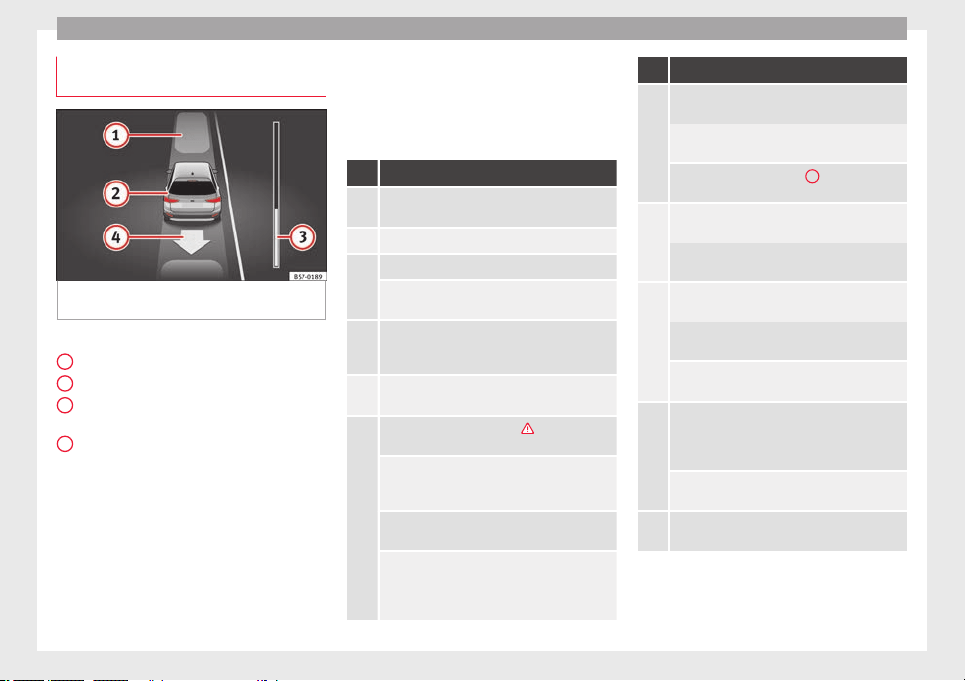
Operation
Exiting a parking space with Park As-
s
i
s
t (only for parallel spaces)
Fig. 222 On the instrument panel display: ex-
itin
g a p
ar
allel parking space.
Key to the Fig. 222:
P
ark
ed
vehicle
Your vehicle in reverse gear
Progress bar to indicate the distance left
to cover
Message giving the proposed manoeuvre
to exit the parking space
Necessary conditions to exit a parking space
with Park Assist
●
Only for parallel parking spaces
●
The traction control system (ASR) must be
turned on
›››
page 191.
●
Length of the space: length of the vehicle
+ 0.5 metres
1
2
3
4
●
Do not
e
x
ceed approximately 7 km/h
(4 mph) when exiting the parking space.
Exiting a parking space
Do the following:
For parallel parking spaces
1.
The necessary conditions to exit a parking space
with Park Assist have to be met ››› page 256.
2. Switch on the engine ››› page 181.
3.
Press the
button ››› Fig. 217.
A control lamp on the
button lights up when
the system is switched on.
4.
Turn on the corresponding turn signal towards
the road you will enter when exiting the parking
space.
5.
Engage reverse gear or turn the selector lever to
position R.
6.
Release the steering wheel ››› in Introduction
on page 249.
Please note the following message: Active
automatic steering. Watch out around
you.
While you keep watch around you, carefully start
accelerating up to no more than 7 km/h (4 mph).
When exiting the parking space, the system only
takes charge of the steering. You, as the driver,
have to accelerate, engage the clutch if necessa-
ry, change gears and brake.
For parallel parking spaces
7.
Reverse until the ParkPilot continuous signal is
heard.
OR: reverse until the instrument panel display
shows the message to go forward.
The progress bar ››› Fig. 222
3
indicates the dis-
tance to cover ››› page 254.
8.
Press down the brake pedal until the Park Assist
system has finished turning the steering wheel.
OR: press down the brake pedal until the
sym-
bol on the instrument panel display switches off.
9.
Go forward until the ParkPilot continuous signal
is heard.
OR: go forward until the instrument panel display
shows the message to reverse.
The Park Assist system steers the vehicle forward
and back until it can exit the space.
10.
The vehicle can exit the space when a corre-
sponding message is displayed on the instru-
ment panel and, in some cases, an acoustic sig-
nal sounds.
Take charge of the steering with the turning an-
gle set by the Park Assist system.
11.
Paying attention to the traffic, exit the parking
space.
256
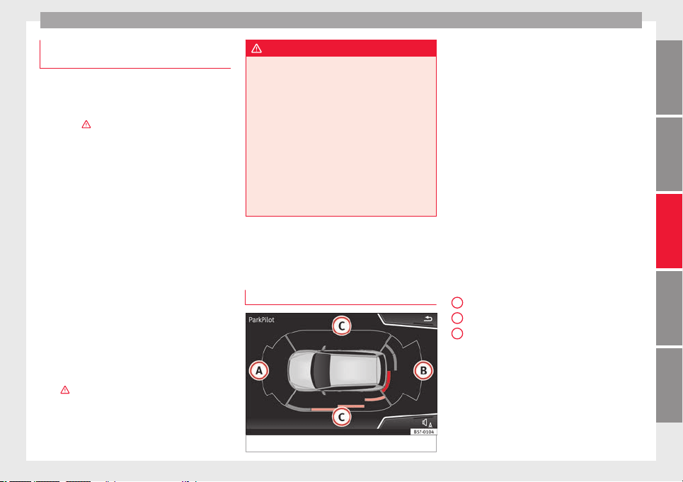
Driver assistance systems
Automatic braking intervention by
P
ark
As
sist
Park Assist helps the driver by automatically
brakin
g in certain situations.
The driver is always responsible for braking
in time ›››
.
Automatic
braking intervention to avoid ex-
ceeding the speed limit
To avoid exceeding the speed limit of approx-
imately 7 km/h (4 mph) when entering or
leaving a parking space, the brakes may acti-
vate automatically. After automatically acti-
vating the brakes, the manoeuvres to enter or
exit a parking space may continue.
The brakes are only automatically activated
once for each attempt to enter or exit a park-
ing space. If the speed of approximately
7 km/h (4 mph) is exceeded again, the corre-
sponding operation is halted.
Automatic braking to reduce damages
Depending on certain conditions, the Park
Assist system can automatically brake the ve-
hicle when faced with an obstacle, briefly ac-
tioning and holding down the brake ped-
al
›››
. Following this the driver must press
the br
ak
e ped
al.
Automatic braking intervention to reduce
damage leads to the parking manoeuvre fin-
ishing.
WARNING
The automatic braking intervention by Park
Assi
st should never tempt you to take any
risk that may compromise safety. The system
is not a replacement for driver awareness.
●
The Park Assist system is subject to certain
limitations inherent to the system. In certain
situations, the automatic braking interven-
tion may only work in a limited way or not
work at all.
●
Always be ready to use the brakes yourself!
●
The automatic braking intervention will end
after approximately 1.5 seconds. Following
this, brake the vehicle yourself.
Parking System Plus (ParkPi-
lot)*
D
e
s
cription
Fig. 223 Represented area.
During parking, P
ark
in
g System Plus assists
the driver by visually and audibly warning
them about obstacles detected in front of
and behind the vehicle.
There are ultrasound sensors integrated in
the front and rear bumpers. When they detect
an obstacle, you are alerted by audible warn-
ings and visually on the Easy Connect sys-
tem.
In the event of danger of a frontal collision,
the audible warnings come from the front of
the vehicle, and in the event of the danger of
a rear-end collision they come from the rear.
Make particularly sure that the sensors are
not covered by adhesives, residues and the
like, as this could affect the system's opera-
tion. Cleaning instructions ››› page 287.
The approximate measurement range of the
sensors is:
1.20 m
1.60 m
0.90 m
As you approach the obstacle, the time inter-
val between the audible warnings will be re-
duced. When you reach around 0.30 m the
warning will be constant: do not continue to
move forward (or backward)!
If you maintain separation from the obstacle,
the volume of the warning begins to reduce
»
A
B
C
257
Technical dataAdviceOperationEmergenciesSafety
Operation
after four seconds (does not affect the tone
of
the c
on
stant warning).
In order to view the entire periphery of the ve-
hicle, the vehicle must be moved a few me-
tres forwards and backwards. Thus, the miss-
ing areas are screened and obstacles at the
sides of the vehicle are displayed
››› Fig. 223
C
.
S
pec
i
al features of ParkPilot with Area View
In the following situations the screened area
on the side of the vehicle is automatically
hidden:
●
When a vehicle door is opened.
●
When the ASR is switched off.
●
When there is ASR or ESC regulation.
●
If the vehicle remains stationary for more
than approximately 3 minutes.
WARNING
●
Alwa
ys pay attention, also when looking
straight ahead, to traffic and the vehicle sur-
roundings. The assistance systems are not a
replacement for driver awareness. When in-
serting or removing the vehicle from a park-
ing space, or when performing similar ma-
noeuvres the driver always assumes the re-
sponsibility.
●
Adapt your speed and driving style at all
times to suit visibility, weather, road and traf-
fic conditions.
●
The ultra
sound sensors have blind spots in
which obstacles and people are not regis-
tered. Pay special attention to children and
animals.
●
Always keep visual control of the vehicle
surroundings: use the mirrors for additional
help.
CAUTION
Parking Aid functions may be negatively af-
f
ected b
y different factors that may lead to
damage to the vehicle or its immediate sur-
rounds:
●
Under certain circumstances, the system
does not detect or display certain objects:
–
Objects such as chains, trailer draw bars,
fences, posts and thin trees.
–
Objects that are located above the sen-
sors, such as protrusions in a wall.
–
Objects with certain surfaces or struc-
tures, such as wire mesh fences or pow-
der snow.
●
Certain surfaces of objects and garments
do not reflect the ultrasound sensors' sig-
nals. The system cannot detect these objects
or people wearing such clothes correctly.
●
Ultrasound sensor signals may be affected
by external sound sources. In certain circum-
stances this may prevent them from detect-
ing people or objects.
●
Please note that low obstacles detected by
the system may no longer be registered by
the sensors as the car moves closer, so the
syst
em will not give any further warning. In
certain circumstances, objects such as high
kerbs that could damage the bottom of the
vehicle are not detected either.
●
If the first warning from the ParkPilot is ig-
nored, the vehicle could suffer considerable
damage.
●
The knocks or damage on the radiator
grille, bumper, wheel arch and vehicle under-
body can adjust the orientation of the sen-
sors. This can affect the parking aid function.
In this case, have the function checked by a
specialised workshop.
●
A registration plate or plate holder on the
front with larger than the space for the regis-
tration plate, or a registration plate that is
curved or warped can cause:
–
false detections,
–
loss of sensor visibility.
Note
●
In cert
ain situations, the system can give a
warning even though there is no obstacle in
the detected area, e.g:
–
with rough or cobbled floors or ground
with long grass;
–
with external ultrasound sources, such as
cleaning vehicles or other vehicles equip-
ped with ultrasound systems;
–
in downpours, intense snow, hail or
dense exhaust gases,
258
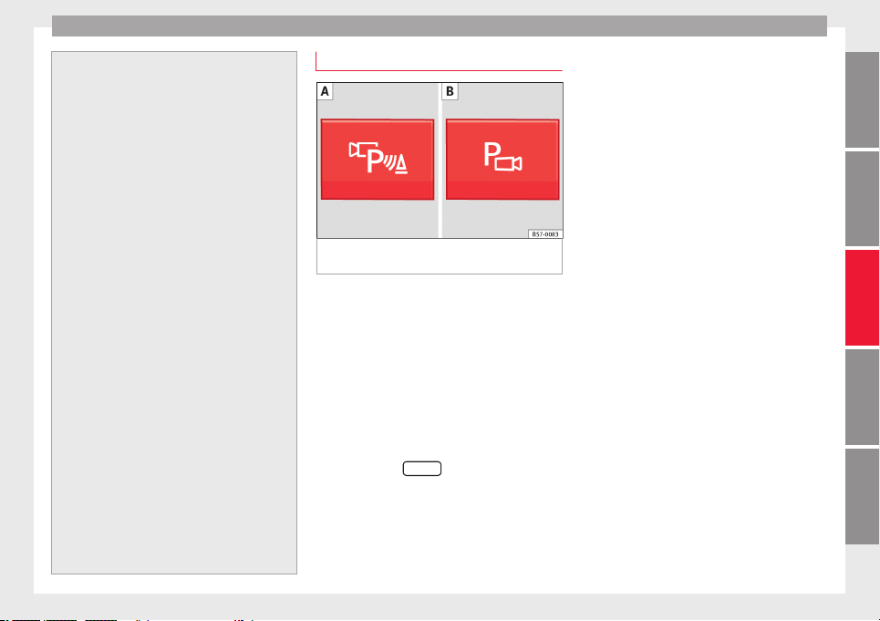
Driver assistance systems
–
if the number pl
ate is not perfectly se-
cured to the bumper surface,
–
or in locations such as the brow of a hill.
●
In order to guarantee good system opera-
tion, keep the ultrasound sensors clean, free
of snow or ice, and do not cover them with
adhesives or other objects.
●
If you use high-pressure or vapour equip-
ment to clean the ultrasound sensors, apply
it directly only very briefly and always from a
distance of more than 10 cm.
●
Retrofitting of accessories to the vehicle,
such as a bicycle rack, may interfere with the
operation of the Parking Aid.
●
Fitting certain accessories to the front of
the vehicle, such as a plate holder with ad-
vertising, may interfere with the operation of
the Park Assist.
●
In order to familiarise yourself with the sys-
tem, it is advised that you practice parking in
an area or car park that is free from traffic.
There must be good weather and light condi-
tions.
●
The volume and tone of the warnings can
be modified, in addition to the indications
››› page 265.
●
In vehicles without an infotainment system,
these parameters can be modified in a SEAT
Official Service or in a specialised workshop.
●
Please observe information on towing a
trailer ››› page 265.
●
The display on the Easy Connect screen
shows a slight time delay.
Parking Aid operation
Fig. 224 Centre console: Park Assist button
(dependin
g on the
v
ersion).
Manual connection of Parking Aid
●
Press the b
utt
on
once.
Manual disconnection of Parking Aid
●
Press the button again.
Manual disconnection of Parking Aid display
(the audible sounds remain active)
●
Press a button on the main menu of the fac-
tory-assembled infotainment system.
●
OR: press the
BACK
function button.
Aut
om
atic
connection of Parking Aid
●
Engage reverse gear or turn the selector
lever to position R.
●
OR: If the vehicle approaches an obstacle
that is in its forwards path at a speed below
10 km/h (6 mph) ››› page 260. The obstacle
is detected as of a distance of approx. 95 cm
if the automatic connection is activated in
the infotainment system. A reduced display is
shown.
●
OR: If the vehicle moves backwards.
Automatic disconnection of Parking Aid
●
Move the selector lever to position P.
●
OR: accelerate to more than approx.
10 km/h (6 mph) forward.
Temporary suppression of sound in Parking
Aid
●
Press the function button.
Change from reduced view to full view
●
Engage reverse gear or turn the selector
lever to position R.
●
OR: press the car icon in reduced view.
If necessary, switch to the rear-assist image
(Rear View Camera “RVC”)
●
Engage reverse gear or turn the selector
lever to position R.
●
OR: Press the RVC function button.
A short confirmation signal will be heard and
the button symbol will light up yellow when
the system is switched on.
259
Technical dataAdviceOperationEmergenciesSafety
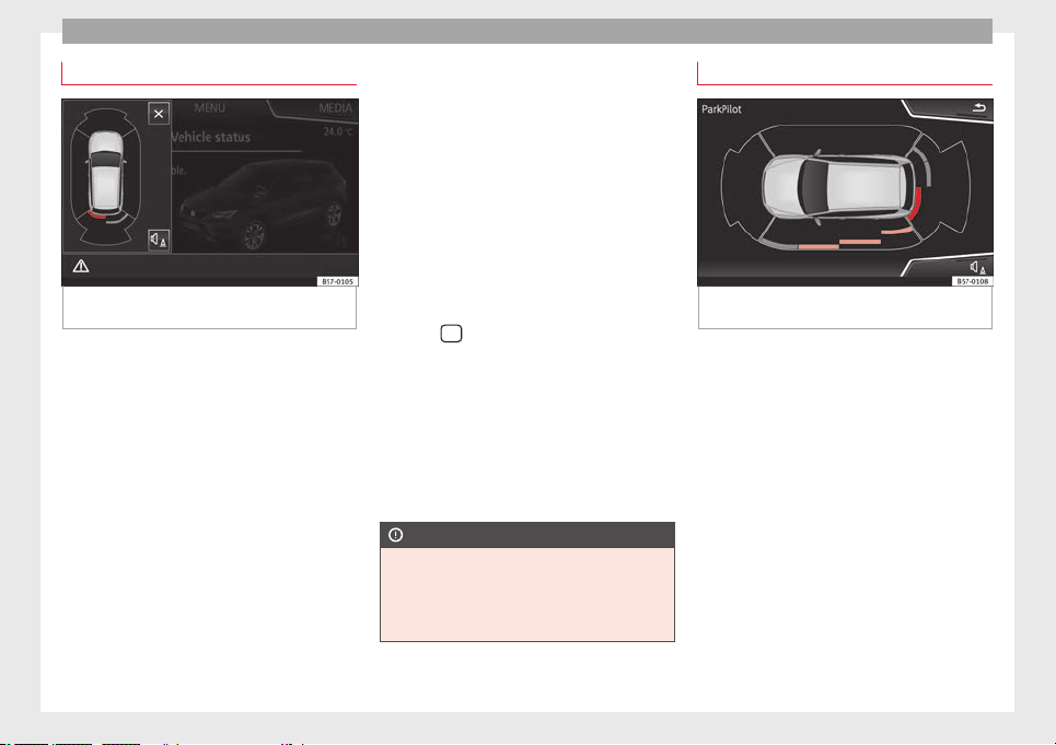
Operation
Automatic activation
Fig. 225 Miniature indication of automatic ac-
tiv
ation.
When the Parking System Plus is switched on
aut
om
atic
ally, a miniature of the vehicle will
be displayed and the segments will be
shown on the left side of the screen
››› Fig. 225.
Automatic activation occurs when slowly ap-
proaching an obstacle located in front of the
vehicle. It only operates every time the speed
is reduced below approximately 10 km/h (6
mph) for the first time.
If the parking aid is switched off using the
button, the following actions must be carried
out in order for it to automatically switch on:
●
Switch off the ignition and switch it on
again.
●
OR: accelerate above 10 km/h (6 mph) be-
fore reducing speed below this number
again.
●
OR: place the selector lever in position P
and then move it from this position.
●
OR: switch on and off the automatic activa-
tion in the Easy Connect system menu.
The automatic activation with parking aid
miniature indication can be switched on and
off from the Easy Connect system menu
›››
page 33:
●
Switch the ignition on.
●
Select:
button > Settings > Parking
and manoeuvring.
●
Select the Automatic activation op-
tion.
When the f
u
nction button check box is
activated , the function is on.
If the system has been activated automatical-
ly, an audible sound warning will only be giv-
en when obstacles in front are at a distance
of less than 50 cm.
CAUTION
The automatic connection of the Parking Aid
only w
orks when you are driving slowly. If
driving style is not adapted to the circum-
stances, an accident and serious injury or
damage may be caused.
Segments of the visual indication
Fig. 226 Parking Aid display on the Easy Con-
nect
sy
s
tem screen.
The distance of separation from the obstacle
c
an be e
s
timated using the segments around
the vehicle.
The optical indication of the segments works
as follows:
they are displayed when
the obstacle is not within the vehicle's
trajectory or the direction of travel is in
the opposite direction to its location,
and also when the electronic parking
brake is activated.
obstacles located in the
vehicle's trajectory and which are more
than 30 cm away from the vehicle are
displayed in yellow.
White segments:
Yellow segments:
260

Driver assistance systems
obstacles that are less than
30 c
m a
w
ay from the vehicle are dis-
played in red.
Moreover, with the SEAT Media System
Plus/Navi System/Navi System Plus radios, a
yellow trail indicates the vehicle's expected
trajectory based on the steering angle.
Whenever the obstacle is located in the vehi-
cle’s direction of travel, the corresponding
audible warning will sound.
As the vehicle approaches an obstacle, the
segments are displayed closer to the vehicle.
When the penultimate segment is displayed,
this means that the vehicle has reached the
collision zone. In the collision zone, the ob-
stacles are represented in red, including
those out of the path. Do not continue to
move forward (or backward) ›››
in Descrip-
tion on p
ag
e 258
, ›››
in Description on
p
ag
e 258
!
In the event the car is equipped with the Top
View Camera system, Park Assist visual guid-
ance will appear in accordance with the view
selected in the Top View Camera system.
Adjusting the display and audible
warnings
The settings for the display and audible
w
arnin
g
s are controlled via the Easy Con-
nect*.
Red segments:
Automatic activation
on – activates the Automatic activa-
tion option ››› page 260.
off – deactivates the Automatic ac-
tivation option ››› page 260.
Front volume*
Volume in the front and rear area.
Front sound settings/sharpness*
Frequency (tone) of the sound in the front
area.
Rear volume*
Volume in the rear area.
Rear sound settings/sharpness*
Frequency (tone) of the sound in the rear
area.
Adjust volume
With the parking aid switched on, the active
audio/video source volume will be reduced
to the intensity of the selected setting.
Error messages
When the Parking Aid is activated or when it
i
s
sw
itched on, if a message reporting a Park-
ing aid error is displayed on the instrument
panel, there is a fault in the system.
If the fault does not disappear before discon-
necting the ignition, the next time that the
parking aid is engaged in reverse, no audible
signal of the existence of a fault will be is-
sued.
If there is a fault in the parking aid system a
message will appear on the instrument panel
indicating the error. In addition the key
LED will blink.
If there is a fault in a sensor, the symbol is
displayed on the Easy Connect display in
front of/behind the vehicle. If a rear sensor is
faulty, only the obstacles in area
A
are dis-
p
l
a
yed ››› Fig. 223. If a front sensor is faulty,
only the obstacles in area
B
are displayed.
Hav
e the f
au
lt corrected by a specialised
workshop without delay.
261
Technical dataAdviceOperationEmergenciesSafety
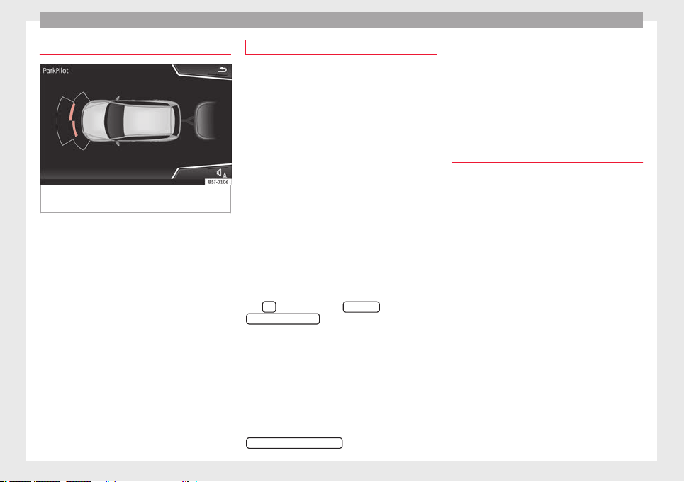
Operation
Driving with a trailer
Fig. 227 ParkPilot display on the screen with
tr
ai
l
er attached.
In vehicles equipped with a towing bracket
dev
ic
e fr
om the factory, when the trailer is
connected electrically, the Parking Aid rear
sensors will not be activated when reverse
gear is engaged, when the selector lever is
turned to position R or when the button is
pressed.
The distance to possible obstacles at the rear
of the vehicle and at its sides will not be dis-
played on the screen and will not be indica-
ted by means of audible sound signals.
The Easy Connect system screen will only dis-
play objects detected at the front, and the ve-
hicle's trajectory will be hidden.
Braking while manoeuvring function*
3 Only valid with Parking System Plus
As soon a
s an obstacle is detected while re-
versing, the braking while manoeuvring func-
tion activates the emergency braking. De-
pending on the equipment, the braking while
manoeuvring function can also activate
emergency braking while moving forwards.
The emergency braking function is used to
minimise collisions. Vehicle speed must not
be higher than 10 km/h.
The braked manoeuvre function is active or
inactive when the parking light is lit or off, re-
spectively. If an emergency braking is activa-
ted, the function will remain inactive until the
gear is changed.
The Parking System’s limitations apply.
The braking while manoeuvring function is
controlled in the Easy Connect system with
the
button and the
S
ET
TINGS
and
P
ark
and m
anoeuvre
function buttons.
●
on – permits the u
se of the braking
while manoeuvring function.
●
off – does not permit the use of the
braking while manoeuvring function.
Temporary suppression of emergency brak-
ing
●
When the function is deactivated with the
Brakin
g while manoeuvring
button that appears
on the P
arking System s
c
reen of the Easy
Connect system.
●
Whenever any of the car doors, rear lid or
bonnet are opened.
Parking aid (Park Pilot)*
Description
Assorted assistance systems – which vary
depending on the equipment fitt
ed in the car
– will help you when parking or manoeu-
vring.
The rear parking aid is an audible assistant
that warns of obstacles located behind the
vehicle.
There are sensors integrated in the rear
bumper. When they detect an obstacle, you
are alerted by audible warnings and visually
on the Easy Connect system.
If the Top View Camera* is installed, the rear
parking aid will issue an audible warning
about objects near the rear of the vehicle,
and the Top View Camera* image will be
available on the Easy Connect screen, giving
a real image of the objects around the car.
Make particularly sure that the sensors are
not covered by adhesives, residues, dirt and
the like, as this could affect the system's op-
eration. Cleaning instructions ››› page 287.
262
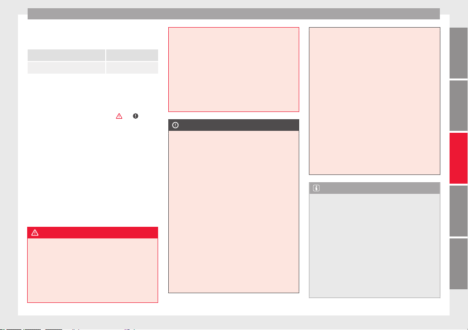
Driver assistance systems
The approximate measurement range of the
r
e
ar sen
sors is:
side area 0.60 m
central area 1.60 m
As you approach the obstacle, the time inter-
val betw
een the audible warnings will be re-
duced. When you reach around 0.30 m the
warning will be constant: Do not continue to
move forward (or backward) ›››
, ››› !
If y
ou maintain separation from the obstacle,
the volume of the warning begins to reduce
after four seconds (does not affect the tone
of the constant warning).
Activating/Deactivating
When engaging reverse gear, the parking aid
is automatically switched on. This is con-
firmed with a short warning.
On disengaging reverse gear, the parking aid
system is switched off.
WARNING
●
Alwa
ys pay attention, also when looking
straight ahead, to traffic and the vehicle sur-
roundings. The assistance systems are not a
replacement for driver awareness. When in-
serting or removing the vehicle from a park-
ing space, or when performing similar ma-
noeuvres the driver always assumes the re-
sponsibility.
●
Adapt
your speed and driving style at all
times to suit visibility, weather, road and traf-
fic conditions.
●
The ultrasound sensors have blind spots in
which obstacles and people are not regis-
tered. Pay special attention to children and
animals.
●
Always keep visual control of the vehicle
surroundings: use the mirrors for additional
help.
CAUTION
Parking Aid functions may be negatively af-
f
ected b
y different factors that may lead to
damage to the vehicle or its immediate sur-
rounds:
●
Under certain circumstances, the system
does not detect or display certain objects:
–
Objects such as chains, trailer draw bars,
fences, posts and thin trees.
–
Objects that are located above the sen-
sors, such as protrusions in a wall.
–
Objects with certain surfaces or struc-
tures, such as wire mesh fences or pow-
der snow.
●
Certain surfaces of objects and garments
do not reflect the ultrasound sensors' sig-
nals. The system cannot detect these objects
or people wearing such clothes correctly.
●
Ultrasound sensor signals may be affected
by external sound sources. In certain circum-
stances this may prevent them from detect-
ing peopl
e or objects.
●
Please note that low obstacles detected by
the system may no longer be registered by
the sensors as the car moves closer, so the
system will not give any further warning. In
certain circumstances, objects such as high
kerbs that could damage the bottom of the
vehicle are not detected either.
●
If the first warning from the ParkPilot is ig-
nored, the vehicle could suffer considerable
damage.
●
The knocks or damage on the radiator
grille, bumper, wheel arch and vehicle under-
body can adjust the orientation of the sen-
sors. This can affect the parking aid function.
In this case, have the function checked by a
specialised workshop.
Note
●
In cert
ain situations, the system can give a
warning even though there is no obstacle in
the detected area, e.g:
–
with rough or cobbled floors or ground
with long grass;
–
with external ultrasound sources, such as
cleaning vehicles or other vehicles equip-
ped with ultrasound systems;
–
in downpours, intense snow, hail or
dense exhaust gases,
–
if the number plate is not perfectly se-
cured to the bumper surface,
»
263
Technical dataAdviceOperationEmergenciesSafety
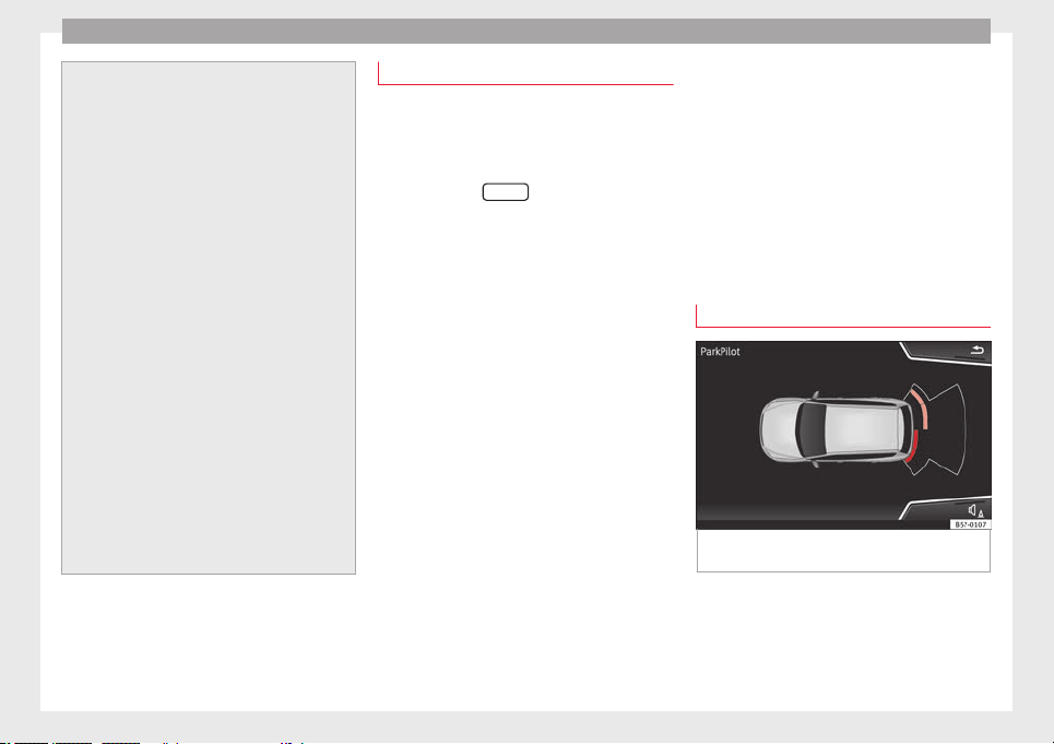
Operation
–
or in locations
such as the brow of a hill.
●
In order to guarantee good system opera-
tion, keep the ultrasound sensors clean, free
of snow or ice, and do not cover them with
adhesives or other objects.
●
If you use high-pressure or vapour equip-
ment to clean the ultrasound sensors, apply
it directly only very briefly and always from a
distance of more than 10 cm.
●
Retrofitting of accessories to the vehicle,
such as a bicycle rack, may interfere with the
operation of the Parking Aid.
●
In order to familiarise yourself with the sys-
tem, it is advised that you practice parking in
an area or car park that is free from traffic.
There must be good weather and light condi-
tions.
●
The volume and tone of the warnings can
be modified, in addition to the indications
››› page 265.
●
In vehicles without an infotainment system,
these parameters can be modified in a SEAT
Official Service or in a specialised workshop.
●
Please observe information on towing a
trailer ››› page 265.
●
The display on the Easy Connect screen
shows a slight time delay.
Parking Aid operation
Manual disconnection of Parking Aid display
(the audible sou
nds remain active)
●
Press a button on the main menu of the fac-
tory-assembled infotainment system.
●
OR: press the
BACK
function button.
Parkin
g Aid connection
●
Engage reverse (for manual gears) or set
the selector lever to R (for automatic gears).
Parking Aid disconnection
●
Place the selector level in position P, N or D
(for autom
atic gearboxes) or disengage re-
verse (for manual gearboxes). If you set the
lever to N or D, the system will remain active
for approximately 8 seconds before switching
off, except with Top View Camera*, when it
will be switched off immediately after engag-
ing reverse.
Temporary suppression of sound in Parking
Aid
●
Press the function button. If you have the
Top View Camera* system installed, you can-
not use the temporary suppression of sound
in Parking Aid.
Switch from reduced to full-screen view if the
rear assist is fitted (Rear View Camera
“RVC”)
●
Press the car icon in the reduced view.
If necessary, switch to the rear-assist image
(Rear View Camera “RVC”)
●
Engage reverse gear or turn the selector
lever to position R.
●
OR: press the RVC function icon.
Segments of the visual indication
Fig. 228 Parking Aid display on the Easy Con-
nect
sy
s
tem screen.
The distance to the obstacles can be estima-
t
ed w
ith the help of
the segments at the rear
of the vehicle.
The optical indication of the segments works
as follows:
264
Driver assistance systems
they are displayed if the
o
b
s
tacle is not in the vehicle's direction
of travel, even when the electronic park-
ing brake is activated.
obstacles located in the
vehicle's trajectory and which are more
than 30 cm away from the vehicle are
displayed in yellow.
obstacles that are less than
30 cm away from the vehicle are dis-
played in red.
Whenever the obstacle is located in the vehi-
cle’s direction of travel, the corresponding
audible warning will sound.
As the vehicle approaches an obstacle, the
segments are displayed closer to the vehicle.
When the penultimate segment is displayed,
this means that the vehicle has reached the
collision zone. In the collision zone, the ob-
stacles are represented in red, including
those out of the path. Do not continue to re-
verse ›››
in Description on page 263, ›
›
›
in Description on page 263 !
If
y
ou are equipped with the Top View
Camera*
Segments are not displayed when the vehicle
is equipped with Top View Camera*.
The PDC system will issue an audible warning
for objects that are near the rear of the vehi-
cle, and the Top View Camera* image will be
White segments:
Yellow segments:
Red segments:
available on the screen, giving a real image
of the objects around the car.
Adjusting the display and audible
warnings
The settings for the display and audible
warning
s are controlled via the Easy Con-
nect*.
Rear volume*
Volume in the rear area.
Rear sound settings/sharpness*
Frequency (tone) of the sound in the rear
area.
Adjust volume
With the parking aid switched on, the active
audio/video source volume will be reduced
to the intensity of the selected setting.
Error messages
When the Parking Aid is activated or when it
i
s
sw
itched on, if a message reporting a Park-
ing aid error is displayed on the instrument
panel, there is a fault in the system.
If the fault disappears before disconnecting
the ignition, the next time that the parking
aid is engaged in reverse, no audible signal
of the existence of a fault will be issued.
If there is a fault in a sensor, the symbol is
displayed on the Easy Connect display.
Have the fault corrected by a specialised
workshop without delay.
Towing bracket
In vehicles equipped with a towing bracket
device fr
om the factory, when the trailer is
connected electrically, the Parking Aid rear
sensors will not be activated when reverse
gear is engaged (manual gears) nor when the
selector lever is turned to position R (auto-
matic gears).
Top View Camera*
Relat
ed video
Fig. 229 Smart solutions
265
Technical dataAdviceOperationEmergenciesSafety
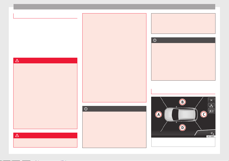
Operation
Introduction
Using 4 cameras, the system generates a rep-
resent
ation that is shown on the infotain-
ment system display. The cameras are loca-
ted on the radiator grille, the exterior mirrors
and the rear lid.
The functions and representations of the
Area View system may vary depending on
whether or not the vehicle has ParkPilot.
WARNING
The image from the cameras does not make it
poss
ible to calculate the distance to the ob-
stacles (people, vehicles, etc.) precisely, so
using them could cause serious accidents
and injury.
●
The camera lenses augment and distort the
visual field and the objects on the screen are
seen differently and imprecisely.
●
Certain objects may not be shown or may
not be shown very clearly, for example, posts
or thin rails, due to the screen resolution or if
light conditions are insufficient.
●
The cameras have blind spots in which ob-
stacles and people are not registered.
●
The camera lens must be kept free, without
snow or ice, and should not be covered.
WARNING
The smart technology incorporated into the
Top V
iew Camera* system cannot overcome
the limits imposed by the laws of physics and
it only
works within the limits of the system.
The greater convenience provided by the Area
View system should never tempt you to take
any risk that may compromise safety. If used
negligently or involuntarily, it may cause se-
rious accidents and injuries. The system is
not a replacement for driver awareness.
●
Adapt your speed and driving style to suit
visibility, weather, road and traffic condi-
tions.
●
Do not be distracted from the traffic by
looking at the screen.
●
Monitor the area around the vehicle at all
times, since the cameras do not capture small
children, animals and certain objects in all
situations.
●
The use of a number plate may interfere in
the views shown on the screen, since the
cameras' field of vision may be reduced.
●
The system will probably be unable to rep-
resent all areas clearly.
CAUTION
●
The camera im
ages are only two-dimen-
sional. Due to a lack of spatial depth, objects
that jut out or holes on the road, for example,
are more difficult to detect or may not be
seen at all.
●
In certain circumstances, the camera does
not capture objects such as beams, fences,
posts or thin trees, which could damage the
vehicle.
●
The syst
em displays the auxiliary lines and
boxes regardless of the vehicle's environ-
ment, no objects are detected. The driver is
responsible for determining that the vehicle
will fit in the parking space.
CAUTION
In order to guarantee good system operation,
k
eep the camer
as clean, free of snow or ice,
and do not cover them with adhesives or oth-
er objects.
●
Never use abrasive cleaning products to
clean the camera lenses.
●
Do not use hot or warm water to remove ice
or snow from the camera lenses. Doing so
could damage the lenses.
Area View system
Fig. 230 Display of the Area View system: aer-
i
al
view.
266
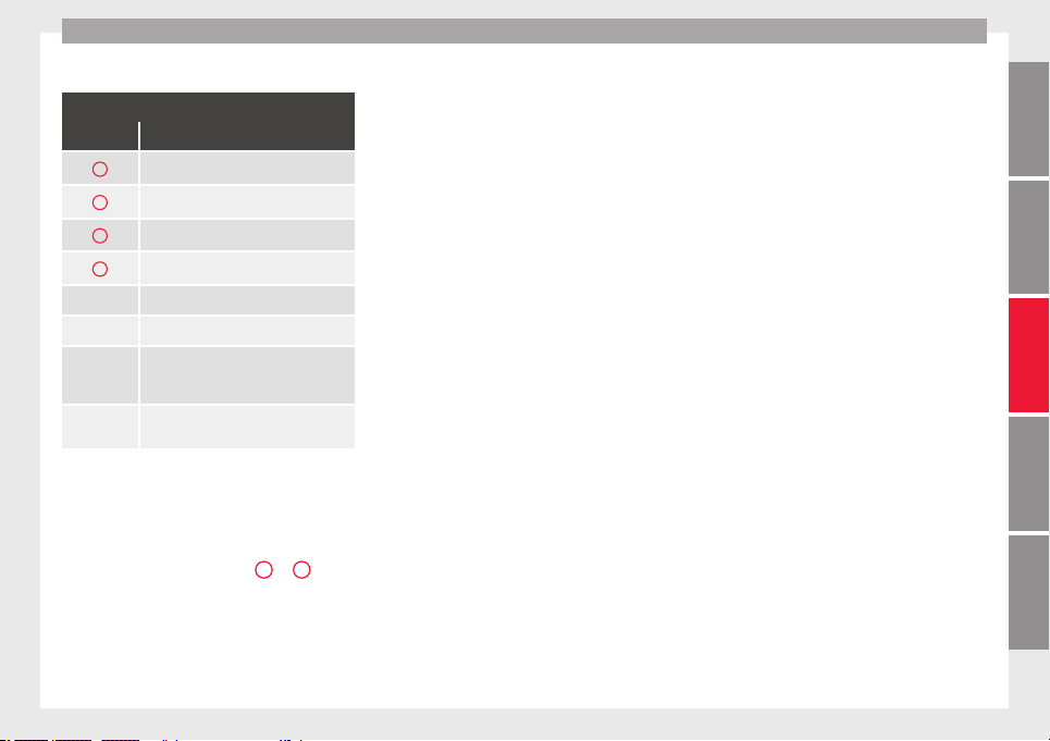
Driver assistance systems
There are four different views to choose from:
Key to the Fig. 230:
Symbol Meaning
A
Front camera area
B
Right camera area
C
Rear camera area
D
Left camera area
Exit the current display.
Three-dimensional views
Depending on the equipment: connect-
ing and disconnecting the ParkPilot
sound.
Setting the display: brightness, contrast
and colour.
The aerial view is generated by combining
the im
ag
e
s from all the cameras
››› Fig. 230. The aerial view can be selected
by pressing the vehicle in the area.
Select the corresponding view by pressing
the different areas ››› Fig. 230
A
to
D
of the
aeri
al
view or the reduced aerial view.
Conditions necessary for the use of the Area
View system
●
The doors and the rear lid must be closed.
●
The image must be reliable and clear. For
this reason, for example, the camera lens
must be clean.
●
The area around the vehicle must be clearly
and totally visible.
●
The area for parking or manoeuvring
should be a flat surface.
●
The vehicle should not be loaded very
heavily at the rear.
●
The driver must be used to the system.
●
There should be no damage to the vehicle
in the camera area. If the position or installa-
tion angle of the cameras have been
changed, e.g. after a rear-end collision, the
system should be checked by a specialised
workshop.
Camera image view
●
Aerial view (bird's eye view): to obtain a
panoramic view of the vehicle , three-di-
mensional views, from different camera posi-
tions.
●
Front Camera (front view): to observe traffic
ahead of the vehicle (vehicles crossing) ,
for front parallel parking , when approach-
ing an obstacle and in off-road driving .
●
Side cameras (side view): to view the area
close to the sides of the vehicle, both on the
left and on the right , or a combination of
both sides .
●
Rear camera (rear view): To observe traffic
behind the vehicle (vehicles crossing) , for
reverse perpendicular parking , for reverse
parallel parking and for hitching a trailer
to the vehicle .
The selected view is displayed on the right
side of the screen. The reduced aerial view
shown on the right side displays the view
framed in yellow. In addition, the right mar-
gin of the screen displays the menu options
possible and the views (the so-called
“modes”) of the camera in question. The ac-
tive view (mode) at the time is highlighted.
The reduced aerial view can be hidden by
pressing the symbol to thus display the se-
lected view full-screen.
267
Technical dataAdviceOperationEmergenciesSafety
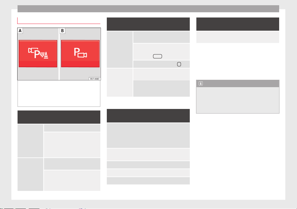
Operation
Instructions for use
Fig. 231 Centre console: button for activat-
in
g/de
activ
ating the Area View system man-
ually in combination with the parking aid sys-
tem () or else with the rear ParkPilot system
().
Connecting and disconnecting the Area View
system
Manual con-
nection of the
display:
Press the
button ››› Fig. 231 once.
The infotainment system screen dis-
plays the aerial view ››› Fig. 230. If
you press the
button when driving
above 15 km/h (9 mph), the image
will not be displayed.
Automatic con-
nection of the
display:
Engage reverse gear.
OR: The vehicle moves backwards.
The view of the image of the vehicle's
rear camera is shown in parallel park-
ing mode with the reduced aerial
view.
Connecting and disconnecting the Area View
system
Manual discon-
nection of the
display:
Press the
button ››› Fig. 231
again.
OR: press a button on the factory-
equipped infotainment system, for
example the
RADIO
button.
OR: press the function button
.
Automatic dis-
connection of
the display:
Drive forward at more than approx.
15 km/h (9 mph).
OR: switch the ignition off. The Area
View system menu disappears imme-
diately.
Special characteristics
Examples of optical illusions caused by the
cameras:
The images on the area view system cameras are only
two-dimensional. Due to a lack of spatial depth, it is dif-
ficult or impossible to make out on-screen any holes
there may be on the ground, objects jutting out from the
ground or parts protruding from other vehicles.
Situations in which the objects or other vehicles appear
to be further away or closer than they really are:
– On moving from a horizontal plane to a slope.
– On moving from a slope to a horizontal plane.
– If the vehicle is heavily loaded at the rear.
Examples of optical illusions caused by the
cameras:
– If the vehicle approaches protruding objects. These
objects may be outside the cameras' angle of visibility.
Trailer mode
The Area
View system conceals, in the rear
camera area, all the auxiliary guiding lines
when the factory-fitted towing bracket is con-
nected electrically to a trailer ››› page 273.
Note
In order to become familiar with the system
and its f
unctions, SEAT recommends that you
practice handling the Area View system in an
area where there is not too much traffic or in
a car park.
268
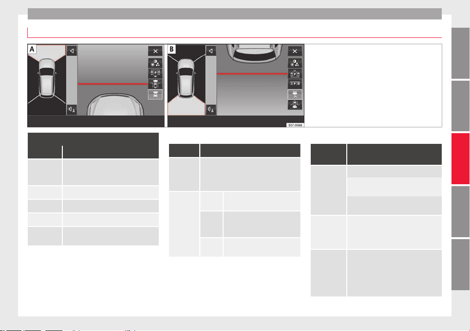
Driver assistance systems
Top View Camera system menus (modes)
Fig. 232 Display on the Area View system
scr
een: Front camera: off-road view Rear
camera: off-road view
Key to the Fig. 232:
Symbol Meaning
Depending on the equipment: connect-
ing and disconnecting the ParkPilot
sound.
Showing the reduced display.
Hiding the reduced display.
Exiting the Area View system screen:
Setting the display: brightness, contrast
and colour.
Aerial views (bird's eye view)
View On-screen display of all cameras
Main
mode
The vehicle and its immediate vicinity
seen from above are shown. Depending
on the equipment, the ParkPilot's path
may also be displayed.
Three-di-
mensional
views
The vehicle and its vicinity seen
from above are shown.
The vehicle and its vicinity seen
from above are shown oblique-
ly.
The vehicle and its vicinity seen
obliquely are shown.
Swipe the infotainment system display with
y
our fin
g
er in the direction of the arrows to
change the angle of vision in the three-di-
mensional views of the vehicle and its vicini-
ty.
Front camera views (front view)
View
On-screen display of the front
camera
Cross traffic
at the front
Left area of the screen: street to the left.
Central area of the screen: area directly
in front of the vehicle.
Right area of the screen: street to the
right.
Parallel park-
ing
The area in front of the vehicle is
shown. Orientation lines are shown to
give guidance.
Off-road
The area directly in front of the vehicle
seen from above is shown. For example,
on a slope, in order to see the area di-
rectly in front of the vehicle. The red line
is shown at a distance of approx. 0.4 m
from the vehicle.
»
269
Technical dataAdviceOperationEmergenciesSafety
Operation
Side camera views (side view)
View
On-screen display of the side
cameras
Right and left
sides
The areas located directly to the side of
the vehicle seen from above are repre-
sented in order to navigate possible ob-
stacles more precisely. The orange aux-
iliary lines are shown at a distance of
approx. 0.4 m from the vehicle.
Left side
The area directly next to the vehicle, on
the driver's or front passenger's side, is
displayed, and the blind spots all along
the vehicle can be seen. The orange
auxiliary line is shown at a distance of
approx. 0.4 m from the vehicle.
Right side
Rear camera views (rear view)
View
On-screen display of the rear
camera
Parallel park-
ing
The area behind the vehicle is shown.
Auxiliary lines are shown to give guid-
ance.
Parallel park-
ing
The vehicle's initial position on initiat-
ing this function will be a decisive fac-
tor in determining the place where the
manoeuvre executed by the assistant
will end.
View
On-screen display of the rear
camera
Off-road or
hitching a
trailer func-
tion
The vehicle's rear is presented. The red
auxiliary line establishes the safety dis-
tance.
Green and red semicircular auxiliary
lines are displayed in vehicles with a
factory-fitted towing bracket. The auxili-
ary lines indicate the distance from the
towing bracket. The distance between
the auxiliary lines (green and red) is ap-
prox. 0.3 m. The orange auxiliary line in-
dicates, depending on the turn of the
steering wheel, the pre-calculated di-
rection of the towing bracket.
In vehicles with a factory-fitted towing
bracket, the distance from the red auxil-
iary line to the vehicle is approx. 0.4 m.
No other auxiliary line is displayed.
Cross traffic
at the rear
Left area of the screen: street to the left.
Central area of the screen: area directly
behind the vehicle.
Right area of the screen: street to the
right.
Rear Assist (Rear View Cam-
er
a)*
Oper
atin
g and safety warnings
WARNING
●
The Rear As
sist does not make it possible
to precisely calculate the distance from ob-
stacles (people, vehicles, etc.) and nor can it
overcome the system's own limits, hence us-
ing it may cause serious accidents and inju-
ries if used negligently or without due care.
The driver should be aware of his/her sur-
roundings at all times to ensure safe driving.
●
The camera lens expands and distorts the
field of vision and displays the objects on the
screen in a different, vague manner. The per-
ception of distances is also distorted by this
effect.
●
Due to the screen resolution or insufficient
light conditions, some items may be dis-
played in an unsatisfactory manner or not at
all. Take special care with thin posts, fences,
railings or trees that might not be displayed
on screen and could damage the vehicle.
●
The rear assist has blind spots where it is
not possible to represent people or objects
(small children, animals and certain objects
cannot be detected in its field of vision). Mon-
itor the vehicle's surrounding area at all
times.
●
Keep the camera lens clean, free of ice and
snow, and do not cover it.
270
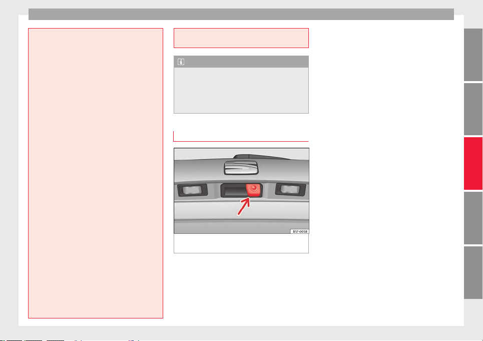
Driver assistance systems
●
The syst
em is not a replacement for driver
awareness. Supervise the parking operation
at all times, as well as the vehicle's surround-
ing area. Adapt your speed and driving style
at all times to suit visibility, weather, road
and traffic conditions.
●
Do not be distracted from the traffic by
looking at the screen.
●
The images on the rear assist screen are
only two-dimensional. Due to a lack of spatial
depth, protruding parts or holes in the road,
for example, are more difficult to detect or
may not be seen at all.
●
Vehicle load modifies the representation of
the orientation lines displayed. The width
represented by the lines diminishes with ve-
hicle load. Pay special attention to the vehi-
cle's surroundings when the inside of the ve-
hicle of the luggage compartment is carrying
a heavy load.
●
In the following situations, the objects or
other vehicles shown in the navigation sys-
tem display appear to be further away or
closer than they really are: Pay special atten-
tion:
–
On moving from a horizontal plane to a
slope.
–
On moving from a slope to a horizontal
plane.
–
If the vehicle is heavily loaded at the
rear.
–
When the vehicle approaches objects
that are not on the ground surface or are
jutting out from it. These objects may al-
so be outside the camera's angle of vi-
sion when rev
ersing.
Note
●
It
is
important to take great care and pay
special attention if you are not yet familiar
with the system.
●
Rear assist will not be available if the vehi-
cle's rear lid is open.
Instructions for use
Fig. 233 In the rear lid handle: location of the
r
e
ar a
ssist camera.
A camera installed in the rear lid handle as-
s
i
s
ts the driver in reverse parking or manoeu-
vring ››› Fig. 233. The camera image is viewed
together with orientation lines projected by
the system on the Easy Connect system
screen. The bottom of the screen displays
part of the bumper corresponding to the
number plate area that will be used as refer-
ence by the driver.
Rear assist settings
Rear assist offers the user the possibility to
change the image's brightness, contrast and
colour settings.
To change these settings:
●
Park the vehicle in a safe place.
●
Apply the parking brake.
●
Switch the ignition on.
●
If necessary, switch on the Easy Connect
system.
●
Engage reverse gear or turn the selector
lever to position R.
●
Press the function button displayed on
the right of the image.
●
Make the desired adjustments on the menu
by pressing the –/+ function buttons or by
moving the corresponding scroll button.
Necessary conditions for parking and ma-
noeuvring with the rear assist
The system should not be used in the follow-
ing cases:
●
If the image displayed is not very reliable or
is distorted, for example low visibility or dirty
lens.
»
271
Technical dataAdviceOperationEmergenciesSafety

Operation
●
If
the ar
e
a behind the vehicle is not dis-
played very clearly or is incomplete.
●
If the vehicle is heavily loaded at the rear.
●
If the position and installation angle of the
camera have been changed, e.g. after a rear-
end collision. Have the system checked by a
specialised workshop.
Familiarising yourself with the system
To familiarise yourself with the system, the
orientation lines and their function, SEAT rec-
ommends practising parking and manoeu-
vring with the rear assist in a place without
too much traffic or in a car park when there
are good weather and visibility conditions.
Cleaning the camera lens
Keep the camera lens clean and clear of snow
and ice:
●
Moisten the lens using a normal alcohol-
based glass cleaning product and clean the
lens with a dry cloth.
●
Remove snow using a small brush.
●
Use de-icing spray to remove any ice.
CAUTION
●
Never use abr
asive cleaning products to
clean the camera lens.
●
Do not use hot or warm water to remove ice
or snow from the camera lens. Doing so could
damage the camera.
Parking and manoeuvring with the
r
e
ar a
ssist
Fig. 234 Display on the Easy Connect system
s
c
r
een: orientation lines.
Switching the system on and off
●
The rear assist will switch on when the igni-
tion i
s
on or the en
gine running, on engaging
reverse gear (manual gearbox) or on chang-
ing the selector lever to the R position (auto-
matic gearbox).
●
The system switches off 8 seconds after
disengaging reverse gear (manual gearbox)
or removing the selector lever from the R po-
sition (automatic gearbox). The system will
also disconnect immediately after the igni-
tion is switched off.
●
The camera will stop transmitting images
above the speed of 15 km/h (9 mph) with re-
verse engaged.
In combination with the Parking System Plus
››› page 262, the camera image will cease to
be transmitted immediately when reverse
gear is disengaged or when the selector lever
is moved from the R position, and the optical
information provided by the Parking Aid sys-
tem will be displayed.
Also in combination with the system, the rear
assist image can also be concealed:
●
By pressing one of the Infotainment system
buttons on the display.
●
OR: By pressing the miniature vehicle that
appears on the left of the screen (which
switches to the full-screen mode of the Park-
ing System Plus's optical system).
If you wish to display the rear assist image
again:
●
Disengage reverse, or change the selector
lever's position, engage reverse again or
move the selector lever to position R.
272

Towing bracket device*
●
OR: Pr
e
s
s the RVC function button
1)
Meaning of the orientation lines
››› Fig. 234
Side lines: extension of the vehicle (the
approximate width of the vehicle plus the
rear view mirrors) on the road surface.
End of the side lines: the area marked in
green ends approximately 2 m behind
the vehicle on the road surface.
Intermediate line: indicates a distance of
approximately 1 m behind the vehicle on
the road surface.
Red horizontal line: indicates a safe dis-
tance of approximately 40 cm at the rear
of the vehicle on the road surface.
Parking manoeuvre
●
Place the vehicle in front of the parking
space and engage reverse gear (manual
gearbox) or move the selector to the R posi-
tion (automatic gearbox).
●
Reverse slowly, and turn the steering wheel
so that the side orientation lines lead to-
wards the parking space.
1
2
3
4
●
Guide the
v
ehic
le into the parking space so
that the side orientation lines run parallel to
it.
Towing bracket device*
T
r
ai
ler mode
Introduction
Take into account country-specific regula-
tions about
driving with a trailer and the use
of a towing bracket.
The vehicle has been developed primarily for
carrying people, although it can also be used
to tow a trailer if fitted with the correspond-
ing technical equipment. This additional load
has an effect on the useful life, fuel con-
sumption and vehicle performance and in
some cases can reduce the service intervals.
Driving with a trailer requires more force from
the vehicle, and thus more concentration
from the driver.
In winter, winter tyres should be fitted on
both the vehicle and the trailer.
Maximum vertical load technically permissi-
ble on the coupling
The maximum vertical load technically per-
mitted from the trailer draw bar on the towing
bracket's tow hitch is 80 kg.
»
1)
WARNING: the RVC function b
utton will only be ac-
tivated and available when the reverse gear is en-
gaged or the selector lever is set to position R.
273
Technical dataAdviceOperationEmergenciesSafety
Operation
Vehicles with the Start-Stop system
If
the
v
ehicle has a factory-fitted towing
bracket or one that is retrofitted by SEAT, the
Start-Stop system operates as normal. No
special characteristics need to be taken into
account.
If the system does not recognise the trailer or
the trailer bracket has not been retrofitted by
SEAT, the Start-Stop system must be discon-
nected by pressing the corresponding button
in the lower part of the centre console before
driving with the trailer, and it should remain
off for the rest of the journey ›››
.
V
ehic
l
es with driving profile selection
If you are going to be towing a trailer, the use
of the Eco driving profile is not recommen-
ded. You are advised to select another of the
available driving profiles before beginning to
drive with a trailer.
WARNING
Never use the trailer to transport people,
since it
would put their life in danger and is
also prohibited.
WARNING
Undue use of the towing bracket may cause
injury and ac
cidents.
●
Only use the towing bracket if it is in a per-
fect state of repair and is properly secured.
●
Never modify
or repair the towing bracket
in any way.
●
In order to reduce the danger of injury in
the event of rear-end collisions and to avoid
injury to pedestrians and cyclists when park-
ing the vehicle, cover or remove the tow hitch
when you are not using a trailer.
●
Never fit a towing bracket “with weight dis-
tribution” or “load compensation”. The vehi-
cle has not been designed for this type of
towing bracket. The towing bracket could fail
and the trailer could be released from the ve-
hicle.
WARNING
Driving with a trailer and transporting heavy
or larg
e objects can affect driving properties
and even cause an accident.
●
Always secure the load properly using belts
or straps that are suitable and in good condi-
tion.
●
Adapt your speed and driving style at all
times to suit visibility, weather, road and traf-
fic conditions.
●
Trailers with a high centre of gravity are
more likely to overturn than those with a low
one.
●
Avoid sudden braking and manoeuvres.
●
Take great care when overtaking.
●
Reduce speed immediately if you notice
that the trailer is swaying, however slightly.
●
Never drive at
more than 80 km/h (50 mph)
when towing a trailer (or at more than
100 km/h (60 mph) in exceptional circum-
stances). This also applies in countries where
driving at higher speeds is permitted. Take
into account the speed limit for vehicles with
trailers in the corresponding country, as it
could be less than the speed limit for vehi-
cles without a trailer.
●
Never attempt to “straighten” the towing
vehicle and trailer while accelerating.
WARNING
If the towing bracket has been retrofitted by a
non-SEA
T workshop, the Start-Stop system
must be disconnected manually whenever
driving with a trailer. Otherwise the brake
system could be damaged and could conse-
quently cause a serious accident or injury.
●
Always disconnect the Start-Stop system
manually when using a towing bracket that
has not been fitted by a SEAT workshop.
Note
●
Befor
e hitching or unhitching a trailer, al-
ways deactivate the anti-theft alarm
››› page 125. Otherwise, the tilt sensor could
cause the alarm to go off.
●
Do not drive with a trailer for the engine's
first 1000 km ››› page 201.
●
SEAT recommends that, if possible, the tow
hitch be disassembled or covered when it is
274
Towing bracket device*
not going to be used. In the event of a rear-
end col
lision, the damage to the vehicle
could be greater if the bracket is fitted.
●
Some retrofitted towing brackets cover the
rear towing eye. In these cases, the towing
eye should not be used for tow-starting or for
towing other vehicles. For this reason, if the
vehicle has been retrofitted with a towing
bracket, always keep the tow hitch in the ve-
hicle when you disassemble it.
Control lamp
Lamp on button lights up
The tow hitch is not securely locked in position.
Check that the towing bracket is locked ››› page 276.
Some warning and control lamps will light up
briefly
when the ignition i
s
switched on to
check certain functions. They will switch off
after a few seconds.
WARNING
If the warning lamps and the corresponding
mess
ages are ignored when they light up, the
vehicle may stall in traffic and cause acci-
dents and severe injuries.
●
Never ignore the warning lamps or messag-
es.
●
Stop the vehicle at the next opportunity
and in a safe place.
CAUTION
Failure to heed the control lamps and corre-
sponding t
ext messages when they light up
may result in damage to the vehicle.
Technical requirements
Vehicles that are factor
y-equipped with a
towing bracket fulfil all the technical and le-
gal requirements for driving with a trailer.
If the vehicle is retrofitted with a towing
bracket, only a bracket that is authorised for
the maximum authorised load of the trailer
that is to be towed may be fitted. The towing
bracket must be suitable for the vehicle and
the trailer and must be properly secured to
the vehicle's chassis. Only use a towing
bracket that has been authorised by SEAT for
this vehicle. Always check and take into ac-
count the towing bracket manufacturer's in-
structions. Never fit a towing bracket “with
weight distribution” or “load compensation”.
Towing bracket fitted on the bumper
Never fit a towing bracket to the bumper or to
the area where the bumper is mounted. The
towing bracket should not impair the bum-
per's function. Do not make modifications or
repairs to the exhaust system or the brake
system. Make regular checks to ensure that
the towing bracket is secure.
Engine cooling system
Driving w
ith a trailer increases the load on
the engine and cooling system. The cooling
system should have sufficient coolant and be
prepared for the additional effort involved in
driving with a trailer.
Trailer brakes
If the trailer has its own brake system, please
take the relevant legal requirements into ac-
count. Never connect the trailer's brake sys-
tem to the vehicle's brake system.
Tow rope
Always use a cable between the vehicle and
the trailer ››› page 278.
Trailer rear lights
The trailer's rear lights should comply with
the statutory safety regulations ››› page 278.
Never connect the trailer's rear lights directly
to the vehicle's electric system. If you are not
sure that the trailer's electrical connection is
correct, have it checked by a specialised
workshop. SEAT recommends visiting a SEAT
dealership for this.
Exterior mirrors
If you cannot see the area behind the trailer
with the exterior mirrors of the towing vehi-
cle, additional mirrors will have to be instal-
led in accordance with the regulations of the
»
275
Technical dataAdviceOperationEmergenciesSafety
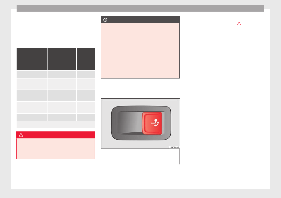
Operation
country in question. The exterior mirrors
shou
l
d be a
djusted before you start driving
and must provide a sufficient field of vision
at the rear.
Trailer maximum electricity consumption
Consumers Europe, Asia,
Africa, South
America and
Central America
Australia
Brake lights (total) 84 Watts 108 Watts
Turn signal (on each
side)
42 Watts 54 Watts
Side lights (on each
side)
50 Watts 100 Watts
Reverse lights (in
total)
42 Watts 54 Watts
Rear fog light 42 Watts 54 Watts
Never exceed the values indicated!
WARNING
If the towing bracket is wrongly fitted or is
not the right one, the tr
ailer could become
detached from the vehicle and cause serious
injury.
CAUTION
●
If the re
ar lights of the trailer are not cor-
rectly connected, the vehicle's electronic sys-
tem may be damaged.
●
If the trailer absorbs excessive electric cur-
rent, the vehicle's electronic system may be
damaged.
●
Never connect the trailer's electric system
directly to the electrical connections of the
tail lights or any other power sources. Only
use the connections intended for providing
electric current to the trailer.
Electrical unlocking tow hitch
Fig. 235 On the right side of the luggage
c
omp
ar
tment: button for unlocking the tow
hitch.
The tow hitch is located in the bumper. The
el
ectric
al
unlocking tow hitch cannot be dis-
assembled.
There should be no person, animal or object
in the path of the tow hitch ›››
.
Un
loc
k
the tow hitch and remove it
●
Stop the vehicle and connect the electronic
parking brake ››› page 186.
●
Switch off the engine.
●
Open the rear lid.
●
Pull the ››› Fig. 235 button briefly. The tow
hitch unlocks electrically and automatically
turns outwards. The control lamp in the but-
ton will flash ››› Fig. 235.
●
Remove the tow hitch with your hand until
you feel and see that it has engaged and the
control lamp on the button stays on.
●
Close the rear lid.
Cover the tow hitch
●
Stop the vehicle and apply the electronic
parking brake.
●
Switch off the engine.
●
Unhook the trailer and interrupt the electri-
cal connection between it and the vehicle. If
you are using an adapter, remove it from the
trailer's power socket.
●
Open the rear lid.
●
Pull the ››› Fig. 235 button briefly. The tow
hitch unlocks electrically.
276
Towing bracket device*
●
T
urn the t
o
w hitch under the bumper with
your hand until you feel and see that it en-
gages and the control lamp on the ››› Fig. 235
button stays on.
●
Close the rear lid.
Meaning of control lamp
●
If the warning light of the button ››› Fig. 235
is flashing, this means that the tow hitch has
not been attached properly or is damaged
›››
.
●
If the warning lamp s
t
a
ys on with the rear
lid open, the tow hitch is correctly in place
both when engaged and when covered.
●
The control lamp of the button will go off
approx. 1 minute after closing the rear lid.
WARNING
Undue use of the towing bracket may cause
injury and ac
cidents.
●
Only use the tow hitch if it is properly en-
gaged.
●
Always ensure that no person, animal or
object is to be found in the path of the tow
hitch.
●
Never use a tool or instrument while the
tow hitch is moving.
●
Never press the ››› Fig. 235 button when
there is a trailer hooked to the vehicle or
when a carrier system or other accessories
are mounted on the tow hitch.
●
If the to
w hitch is not attached properly, do
not use it. Instead, go to a specialised work-
shop and have the towing bracket checked.
●
If you detect any fault in the electrical sys-
tem or in the towing bracket, contact a speci-
alised workshop and ask them to check it.
●
If the ball has a diameter of less than 49
mm at any one point, do not use the towing
bracket under any circumstances.
CAUTION
If you clean the vehicle with high-pressure or
s
te
am devices, do not point the jet directly
towards the retractable tow hitch or the trail-
er power socket, as this may damage the
joints or remove the grease necessary for lu-
brication.
Note
At extremely low temperatures, the tow hitch
may
be impossible to use. In this case, place
the vehicle in a warmer location (for example,
a garage).
Fitting a bicycle carrier on the retract-
ab
l
e t
ow hitch
The maximum allowed weight of the carrier
sy
s
t
em, including the load, is 75 kg. The car-
rier system should not protrude more than
700 mm backwards from the spherical head.
Only carrier systems on which up to 3 bikes
can be mounted are allowed. Heavier bicy-
cles must be mounted as close to the vehicle
as possible (tow hitch).
WARNING
The incorrect use of the tow hitch with a bicy-
cle r
ack mounted on the tow hitch can cause
accidents and injury.
●
Never exceed the maximum weight or the
limits indicated above.
●
The bicycle rack may not be mounted to the
neck of the hitch below the ball because, due
to the shape of the neck and depending on
the rack model, the rack could be incorrectly
mounted on the vehicle.
●
Always read and take the manufacturer as-
sembly instructions into account.
CAUTION
If the maximum weight and limits indicated
above ar
e exceeded, the vehicle may suffer
considerable damage.
●
Never exceed the values indicated!
Note
SEAT recommends removing, as far as possi-
ble, a
ll removable parts of the bicycles before
setting off. These parts include, for example,
baskets and saddlebags, child seats or bat-
teries. This improves aerodynamics and the
centre of gravity of the rack system.
277
Technical dataAdviceOperationEmergenciesSafety
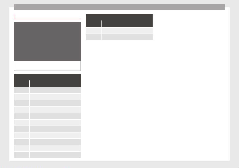
Operation
Hooking up and connecting a trailer
Fig. 236 Schematic diagram: assignment of
the pins of the trailer's power socket.
Key to the Fig. 236:
Pin Meaning
1 Left turn signal
2 Rear fog light
3 Earth for pins 1, 2, 4, 5, 6, 7 and 8
4 Right turn signal
5 Rear light, right
6 Brake lights
7 Rear light, left
8 Reverse lights
9 Permanent live
10 Live charge cable
11 Earth for pin 10
Key to the Fig. 236:
Pin Meaning
12 Unassigned
13 Earth for pin 9
Trailer power socket
The vehic
le is fitted with a 13-pole power
socket for the electrical connection between
the trailer and the vehicle. With the engine
running, electrical devices on the trailer re-
ceive power from the electrical connection
(pin 9 and pin 10 of the trailer power socket).
If the system detects that a trailer has been
connected electrically, the electrical equip-
ment on the trailer will receive voltage
through this connection (pins 9 and 10). Pin
9 has a permanent live. This powers, for ex-
ample, the trailer's interior lighting. Electrical
devices such as a fridge in a caravan only re-
ceive electrical power if the engine is running
(through pin 10).
To avoid overloading the electrical system,
you cannot connect the ground wires of pin
3, pin 11 or pin 13.
If the trailer has a 7-contact connector, you
will need to use an adapter cable. In this case
the function corresponding to pin 10 will not
be available.
Tow rope
The tow r
ope must always be securely fixed
to the towing vehicle and loose enough so
that the vehicle can handle turns smoothly.
However, make sure that the cable does not
rub on the ground while driving.
Trailer rear lights
Always check the trailer's rear lights to en-
sure they are working correctly and that they
comply with the relevant safety regulations.
Make sure that the maximum permissible
power that can be absorbed by the trailer is
not exceeded ››› page 276.
Connection to the anti-theft system
The trailer is included in the anti-theft system
if the following conditions are met:
●
If the vehicle is factory-equipped with an
anti-theft alarm and towing bracket.
●
If the trailer is electrically connected to the
towing vehicle through the trailer power
socket.
●
If the electrical systems of the vehicle and
trailer are in perfect condition and have no
faults or damage.
●
If the vehicle is locked with the key and the
anti-theft alarm is activated.
When the vehicle is locked, the alarm is trig-
gered if the electrical connection with the
trailer is cut off.
278
Towing bracket device*
Before hitching or unhitching a trailer, always
t
urn off
the anti-thef
t alarm. Otherwise, the
tilt sensor could cause the alarm to go off.
Trailers with LED rear lights
For technical reasons, trailers fitted with LED
rear lights cannot be connected to the anti-
theft alarm system.
When the vehicle is locked, the alarm does
not go off when the electrical connection with
the trailer is cut if it has rear lights with light-
emitting diodes.
If the Eco driving profile was selected when
hitching the trailer, this will automatically
switch to the Normal profile. If the system
cannot detect the attached trailer or if the
towing bracket has been retrofitted by an au-
to repair shop other than SEAT, you must
manually select the Normal profile before you
start driving with a trailer attached. To recon-
nect the Eco profile once the trailer has been
unhitched, switch the ignition off and back
on once.
WARNING
If the cables are improperly or incorrectly
connected, it
may lead to an excessive
amount of current supplied to the trailer,
which can cause abnormalities in the entire
vehicle electronic system, as well as acci-
dents and serious injuries.
●
Ensur
e that any repairs that need to be car-
ried out on the electrical system are carried
out by a specialised workshop.
●
Never connect the trailer's electric system
directly to the electrical connections of the
tail lights or any other power sources.
WARNING
Contact between the pins of the trailer power
soc
ket
can cause short circuits, overloading
of the electrical system or failure of the light-
ing system, and consequently can cause acci-
dents and serious injuries.
●
Never connect the pins of the trailer power
socket to each other.
●
Make sure any work on bent pins is carried
out by a specialised workshop.
CAUTION
Do not leave the trailer connected to the vehi-
cle when p
arked; place it on its support
wheel or its supports. If the vehicle rises or
falls due, for example, to a variation of the
load or a burst tyre, increased pressure will
be placed on the towing bracket and the trail-
er, and both the vehicle and the trailer can be
damaged.
Note
●
In case of
malfunctioning of the electrical
systems of the vehicle or trailer, as well as of
the anti-theft system, have these checked out
by a s
pecialised workshop.
●
If the trailer accessories consume energy
through the power socket to the trailer and
the engine is turned off, the battery will dis-
charge.
●
If the vehicle battery is running low, the
electrical connection with the trailer will be
automatically cut.
Loading a trailer
Technically permissible maximum trailer
w
eight
and
vertical load on the coupling de-
vice
The technically permissible maximum trailer
weight is the weight that the vehicle can tow
›››
. The vertical load on the coupling load
i
s
e
xerted vertically from above on the tow
hitch of the towing bracket ››› page 319.
The information on the maximum trailer
weight and vertical load on the coupling de-
vice contained in the type plate of the towing
bracket are experimental values only. The
correct figures for your specific model, which
may be lower than these figures, are given in
the vehicle documentation. The information
in the vehicle documentation takes prece-
dence at all times.
»
279
Technical dataAdviceOperationEmergenciesSafety
Operation
To promote safety while driving, SEAT recom-
mend
s
m
aking the most of the maximum ver-
tical load technically permissible on the cou-
pling device ››› page 273. An insufficient ver-
tical load has a negative influence on the be-
haviour of both the vehicle and trailer.
The vertical load increases the weight on the
rear axle, reducing the vehicle's carrying ca-
pacity.
Gross combination weight of the towing ve-
hicle and trailer
The gross combination weight is the actual
weight of the loaded vehicle plus the actual
weight of the loaded trailer.
In some countries trailers are classified into
distinct categories. SEAT recommends ob-
taining information from a specialised work-
shop regarding which type of trailer is most
suitable for your vehicle.
Trailer loading
The weight of the towing vehicle and trailer
must be balanced. In order to do this, the
load must be as close as possible to the max-
imum vertical load technically permissible on
the coupling point, and it must be evenly dis-
tributed between the back and front of the
trailer:
●
Distribute loads in the trailer so that heavy
objects are as near to the axle as possible or
above it.
●
Secure the trailer load properly.
Tyre pressure
Set the tyre pressure of the trailer tyres in ac-
cordance with the trailer manufacturer's rec-
ommendations.
When towing a trailer, inflate the tyres of the
towing vehicle with the maximum allowable
pressure ››› page 308.
WARNING
If the maximum permissible axle weight, the
maximum lo
ad technically permissible on the
coupling point, the maximum authorised ve-
hicle weight or the gross combination weight
of the towing vehicle and trailer are excee-
ded, accidents and serious injuries may oc-
cur.
●
Never exceed the values indicated!
●
The actual weight on the front and rear
axles must never exceed the maximum per-
missible axle weight. The weight on the front
and rear axles must never exceed the maxi-
mum permissible weight.
WARNING
A shift in weight could jeopardize the stabili-
ty and security
of the towing vehicle and
trailer, which could lead to accidents and se-
rious injuries.
●
Always load the trailer correctly.
●
Alwa
ys secure the load properly using belts
or straps that are suitable and in good condi-
tion.
Driving with a trailer
Adjusting the headlights
When tow
ing a trailer, the front part of the ve-
hicle could lift up, and if the dipped beams
are on, this could dazzle other drivers. Use
the headlight range control to lower the cone
of light. If you do not have headlight range
control, have the headlights adjusted by a
specialised workshop.
Special characteristics of driving with a trail-
er
●
If your trailer has an overru
n brake, brake
gently at first and then rapidly. This will pre-
vent the jerking that can be caused by the
locking of trailer wheels.
●
Due to the gross combination weight of the
towing vehicle and trailer, the braking dis-
tance increases.
●
When going down a slope, go into a lower
gear (if using a manual gearbox or the tip-
tronic automatic gearbox mode) to take ad-
vantage of the braking power provided by the
engine. Otherwise, the braking system could
overheat and even fail.
280
Towing bracket device*
●
The tr
ai
l
er weight, as well as the gross com-
bination weight of the towing vehicle and
trailer, change the centre of gravity and the
properties of the vehicle.
●
If the towing vehicle is empty and the trail-
er is loaded, then the load distribution is in-
correct. Under these conditions, drive slowly
and with extra caution.
Hill starts with a trailer
Depending on the slope of the hill and the
combination weight of the towing vehicle
and trailer, the vehicle might start rolling
backwards slightly when you first start up.
For hill-starting with a trailer, do the follow-
ing:
●
Press and hold the brake pedal.
●
Press the button to disconnect the elec-
tronic parking brake ››› page 186.
●
If the vehicle is equipped with a manual
gearbox, push the clutch pedal all the way
down.
●
Put the vehicle into first gear or turn the se-
lector lever to position D/S ››› page 192.
●
Pull out the button and hold it in that
position to stop the towing vehicle and trailer
with the electronic parking brake.
●
Release the brake pedal.
●
Start driving slowly. To do this, in the case
of a manual gearbox, slowly release the
clutch pedal.
●
Do not release the button until the en-
gine has sufficient force to start driving.
WARNING
If a trailer is pulled incorrectly, this may lead
to los
s of control of the vehicle and serious
injury.
●
Driving with a trailer and transporting
heavy or large objects will change the vehicle
handling and braking distances.
●
Always drive cautiously and carefully.
Brake earlier than usual.
●
Adapt your speed and driving style at all
times to suit visibility, weather, road and traf-
fic conditions. Slow down, especially when
driving down hills or slopes.
●
Accelerate with particular care and caution.
Avoid sudden braking and manoeuvres.
●
Take great care when overtaking. Reduce
speed immediately if you notice that the trail-
er is swaying, however slightly.
●
Never attempt to “straighten” the towing
vehicle and trailer while accelerating.
●
Take into account the speed limit for vehi-
cles with a trailer, as it could be lower than
for vehicles without a trailer.
Stabilisation of the towing vehicle
and tr
ai
l
er
The stabilisation of the towing vehicle and
trail
er together is an additional function of
the electronic stability control (ESC).
If the system detects that the trailer is sway-
ing, it intervenes automatically with the driv-
er steering recommendation to reduce the
swaying of the trailer.
Requirements for the stabilisation of the
towing vehicle and trailer
●
The vehicle is factory-equipped with a tow-
ing brac
ket or has been retro-fitted with a
compatible towing bracket.
●
The ESC and ASR are active. The control
lamp or is not lit up on the instrument
panel.
●
The trailer is electrically connected to the
towing vehicle through the trailer power
socket.
●
The vehicle is travelling at over 60 km/h
(approx. 37 mph).
●
The maximum vertical load technically per-
missible is being utilised on the coupling de-
vice.
●
The trailer has a rigid draw bar.
●
If the trailer has brakes, it must be equip-
ped with a mechanical overrun brake.
»
281
Technical dataAdviceOperationEmergenciesSafety
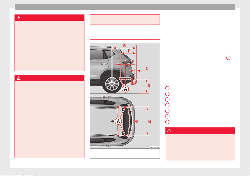
Operation
WARNING
The enhanced security provided by the elec-
tric st
ability control of the towing vehicle and
trailer should not lead you to take any risks
that could compromise your safety.
●
Adapt your speed and driving style at all
times to suit visibility, weather, road and traf-
fic conditions.
●
Accelerate with caution when the road is
slippery.
●
When adjusting any settings, stop acceler-
ating.
WARNING
The electric stability control for the towing
vehicl
e and trailer may not correctly detect all
driving conditions.
●
When the ESC is switched off, the stabilisa-
tion of the towing vehicle and trailer is also
switched off.
●
The stability system does not always detect
light and unstable trailers, so it may not sta-
bilise these correctly.
●
When driving on slippery surfaces with
poor grip, the trailer can even interfere with
the stability system.
●
Trailers with a high centre of gravity can tip
even without having previously swayed.
●
If a trailer is not attached, but the trailer
power socket is connected (e.g. installation
of a bicycle rack with lights), repeated auto-
matic braking may occur in extreme driving
conditions.
Retrofitting a towing bracket
Fig. 237 Limits and attachment points for ret-
r
ofittin
g a t
owing bracket.
SEAT recommends that towing brackets be
r
etr
ofitt
ed at a specialised workshop. For ex-
ample, it may very well be necessary to ad-
just the cooling system or mount thermal pro-
tection plates. SEAT recommends visiting a
SEAT dealership for this.
If a towing bracket is retrofitted, the distance
specifications should always be kept in
mind. The distance between the centre of the
spherical head and the road ››› Fig. 237
D
must never be less than that indicated. This
al
so ap
p
lies when the vehicle is fully loaded,
including the technically permissible maxi-
mum vertical load on the coupling device.
Distance specifications ››› Fig. 237:
Attachment points
932.5 mm
65 mm min.
350-420 mm
220 mm
615.5 mm
1,043 mm
WARNING
If the cables are improperly or incorrectly
connected, thi
s may lead to malfunctions in
the entire vehicle electronic system, as well
as to accidents and serious injuries.
●
Never connect the trailer's electric system
to the electrical connections of the tail lights
A
B
C
D
E
F
G
282
Towing bracket device*
or any other unsuitable power sources. Only
use suit
able connectors to connect the trail-
er.
●
The towing bracket should be retrofitted
only at a specialised workshop.
WARNING
If the towing bracket is badly fitted or unsuit-
ab
le, the tr
ailer may separate from the vehi-
cle while driving. This could cause serious ac-
cidents and fatal injuries.
Note
Only use towing brackets that have been ap-
prov
ed by SEAT for the model in question.
283
Technical dataAdviceOperationEmergenciesSafety
Advice
Advice
C
ar
e and m
aintenance
Accessories and modifications
to the vehicle
Accessories, replacement parts and
repair work
Always ask your dealer or specialist retailer
f
or a
dv
ice before purchasing accessories and
replacement parts.
Your vehicle is designed to offer a high
standard of active and passive safety. For this
reason, we recommend that you ask a SEAT
Official Service for advice before fitting ac-
cessories or replacement parts. Your SEAT Of-
ficial Service has the latest information from
the manufacturer and can recommend acces-
sories and replacement parts which are suita-
ble for your requirements. They can also an-
swer any questions you might have regarding
official regulations.
We recommend you to use only SEAT acces-
sories and Genuine SEAT parts
®
. SEAT has
tested these parts and accessories for suita-
bility, reliability and safety. SEAT Official
Services have the necessary experience and
facilities to ensure that the parts are installed
correctly and professionally.
Any retro-fitted equipment which has a direct
effect on the vehicle and/or the way it is driv-
en, such as a cruise control system or elec-
tronically-controlled suspension, must be
approved for use in your vehicle and bear the
e mark (the European Union's authorisation
symbol).
If any additional electrical devices are fitted
which do not serve to control the vehicle it-
self (for instance a refrigerator box, laptop or
ventilator fan, etc.), they must bear the
sign (manufacturer conformity declaration in
the European Union).
WARNING
Accessories, for example telephone holders
or cup hol
ders, should never be fitted on the
covers, or within the working range of the air-
bags. Otherwise, there is a danger of injury if
the airbag is triggered in an accident.
Technical modifications
Modifications must always be carried out ac-
c
or
din
g to our specifications.
Unauthorised modifications to the electronic
components, software, wiring or data transfer
in the vehicle may cause malfunctioning. Due
to the way the electronic components are
linked together in networks, other indirect
systems may be affected by the faults. This
can seriously impair safety, lead to excessive
wear of components, and also invalidate your
vehicle registration documents.
You will appreciate that your SEAT dealership
cannot be held liable for any damage caused
by modifications and/or work performed in-
correctly.
We therefore recommend that all work should
be performed by a SEAT Official Service using
genuine SEAT parts
®
.
WARNING
Incorrectly performed modifications or other
work on
your vehicle can lead to malfunctions
and cause accidents.
Radio transmitters and office equip-
ment
Radio transmitters (fixed installation)
An
y
r
etrofit installations of radio transmitters
in the vehicle require prior approval. SEAT
generally authorises in-vehicle installations
of approved types of radio transmitters provi-
ded that:
●
The aerial is installed correctly.
●
The aerial is installed on the exterior of the
vehicle (and shielded cables are used togeth-
er with non-reflective aerial trimming).
●
The effective transmitting power does not
exceed 10 Watts at the aerial base.
284
Care and maintenance
A SEAT Official Service and specialised work-
shop w
i
l
l be able to inform you about options
for installing and operating radio transmitters
with a higher transmitting power.
Mobile radio transmitters
Commercial mobile telephones or radio
equipment might interfere with the electron-
ics of your vehicle and cause malfunctions.
This may be due to:
●
No external aerial.
●
External aerial incorrectly installed.
●
Transmitting power more than 10 W.
You must, therefore, do not operate portable
mobile telephones or radio equipment inside
the vehicle without a properly installed exter-
nal aerial ›››
.
Pl
e
a
se note also that the maximum range of
the equipment can only be achieved with an
external aerial.
Business equipment
Retrofit installation of business or private
equipment in the vehicle is permitted, provi-
ded the equipment cannot interfere with the
driver's immediate control of the vehicle and
that any such equipment carries the mark.
Any retrofit equipment that could influence
the driver's control of the vehicle must have a
type approval for your vehicle and must carry
the e mark.
WARNING
Mobile telephones or radio equipment which
is oper
ated inside the vehicle without a prop-
erly installed external aerial can create exces-
sive magnetic fields that could cause a health
hazard.
Note
●
The post
erior fitting of electric and elec-
tronic equipment in this vehicle affects its li-
cence and could lead to the withdrawal of the
vehicle registration document under certain
circumstances.
●
Please use the mobile telephone/radio op-
erating instructions.
Care and cleaning
Gener
a
l
information
Regular and careful care helps to m
aint
ain
the
value of the vehicle. This may also be one
of the requirements for upholding any war-
ranty claims in the event of corrosion or paint
defects.
SEAT Official Services and specialist retailers
carry stocks of suitable car care materials.
Please follow the instructions for use on the
packaging.
WARNING
●
Cle
aning products and other materials used
for car care can be damaging to your health if
misused.
●
Always keep care products in a safe place,
out of the reach of children. Failure to comply
could result in poisoning.
For the sake of the environment
●
If pos
sible, use environmentally friendly
products.
●
The remains of car care products should not
be disposed of with ordinary household
waste.
Vehicle exterior care
W
a
shin
g the vehicle
The longer substances such as insects, bird
dr
op
pin
gs, resinous tree sap, road dirt, in-
dustrial deposits, tar, soot or road salt and
other aggressive materials remain on the ve-
hicle, the more damage they do to the paint-
work. High temperatures (for instance due to
strong sunlight) further intensify the corro-
sive effect.
After the period when salt is put on the roads
it is important to have the underside of the
vehicle washed thoroughly.
»
285
Technical dataAdviceOperationEmergenciesSafety
Advice
Automatic car washes
B
ef
or
e going through a car wash, be sure to
take the usual precautions such as closing
the windows and roof. If the vehicle has spe-
cial accessories such as spoilers or a roof
rack, it is advisable to consult the car wash
tunnel operator.
It is best to use a car wash without revolving
bristles if possible.
Washing the vehicle with a high pressure
cleaner
When washing the vehicle with a high-pres-
sure cleaner, always follow the operating in-
structions for the equipment. This applies
particularly to the operating pressure and the
spraying distance. Do not hold the nozzle too
close to soft materials such as rubber hoses
or seals. The same applies for the parking aid
sensors*, which are located in the rear
and/or front bumper.
Do not use a nozzle that sprays the water out
in a direct stream or one that has a rotating
jet for forcing off dirt.
Factory-fitted adhesive sheets
The following indications should be taken in-
to account to avoid damaging adhesive
sheets:
●
Do not use high pressure cleaners.
●
Do not use scrapers to remove ice or snow
from the sheets.
●
Do not polish the adhesive sheets.
●
Do not use dirty cloths or sponges.
●
It is preferable to wash them with a soft
sponge and gentle neutral soap.
Washing the car by hand
When washing the car by hand, use plenty of
water to soften the dirt first, and rinse off as
well as possible.
Then clean the vehicle with a soft sponge,
glove or brush using only slight pressure.
You should start on the roof and work down.
Special car soap should only be used for very
persistent dirt.
Rinse the sponge or glove thoroughly and of-
ten.
Wheels, sills and similar should be cleaned
last. Use a second sponge for this.
WARNING
●
The vehic
le should only be washed with the
ignition switched off. Failure to follow this in-
struction could result in an accident.
●
Do not clean the underside of chassis, the
inside of wheel arches or wheel trims without
protecting your hands and arms. You may cut
yourself on sharp-edged metal parts. Other-
wise, there is a risk of sustaining cuts.
●
When washin
g the car during the winter
season: water and ice in the brake system
can reduce braking effectiveness: risk of acci-
dent!
CAUTION
●
Do not
wa
sh the vehicle in direct sunlight –
otherwise the paint can be damaged.
●
Do not use sponges, abrasive household
sponges or similar to clean insect remains.
This could damage the surface.
●
Clean off stubborn dirt (insects, etc.) from
the headlights at regular intervals, for in-
stance when filling the fuel tank. The head-
lights should only be washed with water, do
not wipe them with a dry cloth or sponge. It
is best to use soapy water.
●
Never wash tyres with a jet that sprays the
water out in a direct stream. This could dam-
age the tyres even if the spray is kept at a
distance and only used for a very short time.
●
Before washing the vehicle in an automatic
car wash, please make sure to retract the ex-
terior mirrors to prevent them from being
damaged. Electrically retractable exterior
mirrors must not be folded in or out by hand,
always use the electrical power control.
CAUTION
●
Befor
e washing the vehicle in an automatic
car wash, please proceed as follows to lock
the wiper arms so that they are not moved to-
wards the top of the windscreen:
286
Care and maintenance
–
the bonnet mus
t be closed.
–
switch the ignition on and off.
–
press the windscreen wiper lever forward
briefly (windscreen washer function).
This will lock the wiper arms.
For the sake of the environment
The car should only be washed in special
w
ash b
ays. These areas are prepared to pre-
vent oily water from getting into the public
drains. In some places, washing vehicles out-
side the areas intended for this purpose is
prohibited.
Camera sensors and lenses
●
Use a small brush to remove snow and a
de-ic
er s
pr
ay to remove ice.
●
Clean the sensors with a solvent-free prod-
uct and a soft, dry cloth.
●
Moisten the camera lens using a standard
alcohol-based glass cleaning agent and
clean the lens with a dry cloth. In the active
lane assist*, the area in front of the lens is
normally cleaned with the windscreen wash-
er.
CAUTION
●
When you c
lean the vehicle with a pressure
washer:
–
Stay
a suitable distance from the sensors
on the front and rear bumpers.
–
Do not clean the camera lenses or sur-
rounding area with the pressure washer.
●
Never use warm or hot water to remove
snow and ice from the reverse camera lens,
as it could crack the lens.
●
Never use abrasive cleaning agents on the
lens.
Waxing and polishing
Care
W
ax
in
g protects the paintwork. It is time to
apply a coat of good wax when water no lon-
ger forms droplets and rolls off the clean
paintwork.
Even if a wax solution is used regularly in the
vehicle washing tunnel, it is advisable to pro-
tect the paint with a hard wax coating at least
twice a year.
In the summer, you will find it is much easier
to remove dead insects (which accumulate
on the bumper and the front of the bonnet) if
the car has been treated with care products
recently.
Polishing
Polishing is only necessary if the paint has
lost its shine, and the gloss cannot be
brought back by putting on wax.
If the polish does not contain wax, a wax
product should be applied after polishing.
CAUTION
●
Do not use po
lishes and hard wax on pain-
ted parts with a matt finish or on plastic
parts.
●
Do not apply paint polishes to the side trim
that runs around the panoramic roof and ends
on the windscreen. However, it can be treated
with hard wax.
Trims
In respect for the environment, the silver-
p
l
at
ed trims on the body are made of pure
aluminium (they do not contain chrome).
Dirt or marks on the trim mouldings should
be removed with a cleaning product with a
neutral PH (do not use a chrome cleaner).
Body polish is also unsuitable for use on trim
mouldings. The intensive cleaning fluids of-
ten used before the car goes into a car wash
may contain alkaline substances, which can
cause dull or milky patches when they dry
out.
SEAT Official Services carry stocks of cleaning
products which have been tested for use on
your vehicle and are not harmful to the envi-
ronment.
287
Technical dataAdviceOperationEmergenciesSafety
Advice
Plastic parts
Plastic parts are cleaned with a power wash-
er. If thi
s is not sufficient, plastic parts
should only be treated with a special solvent-
free plastic cleaning agent. Do not use paint-
work cleaners, polishes or wax on plastic
parts.
Carbon parts
The carbon parts on your vehicle have a pain-
t
ed s
ur
face. They do not need any special
care and are cleaned just like any other pain-
ted part
›››
page 285.
Paint damage
Minor damage to the paint, such as scratches
or s
t
one c
hips, should be touched up without
delay before the metal starts to corrode. Suit-
able touch-up brushes or sprays for your car
can be obtained from a SEAT Official Service.
The number of the original paint finish on the
vehicle is given on the data sticker
›››
page 317.
If corrosion is already visible it must be thor-
oughly removed by a specialised workshop.
Windows
Clear vision is an essential safety factor.
The winds
creen must not be cleaned with in-
sect remover or wax, otherwise the wind-
screen wipers will not function properly (jud-
dering).
Traces of rubber, oil, grease or silicone can
be removed with a window cleaning solution
or a silicone remover. Wax residue can only
be removed with a special cleaner. Your SEAT
Official Service will be able to provide you
with more detailed information.
The windows should also be cleaned on the
inside at regular intervals.
Use a separate cloth or chamois to dry the
windows. Cloths used for waxing and polish-
ing contain residues that will cause smears
on the glass.
WARNING
Do not use water-repellent coatings on the
winds
creen. In bad visibility conditions (e.g.
in the rain, dark or with a low sun), these
coatings may cause dazzle: risk of accident!
Such coatings can also cause the windscreen
wiper blades to make noise.
CAUTION
●
Remov
e snow and ice from windows and ex-
terior mirrors with a plastic scraper only. To
avoid scratches caused by dirt on the glass,
the scr
aper should only be pushed in one di-
rection and not moved to and fro.
●
The heating element for the rear window is
located on the inner side of the window. To
avoid damaging them, do not apply stickers
to these heating elements.
●
Never use warm or hot water to remove
snow and ice from windows and mirrors. This
could cause the glass to crack!
Rims
The wheels require regular attention to pre-
ser
v
e their ap
pearance. It is important to re-
move road salt and brake dust by washing
the wheels at regular intervals, otherwise the
finish will be impaired.
After washing, the wheels should only be
cleaned with an "acid-free" cleaning agent
for alloy wheels. This is available from SEAT
Official Services and specialist retailers. Nev-
er leave the cleaning agent on the rims for
any longer than specified in the instructions
before rinsing it off. If the wheel cleaner fluid
contains acid it can attack the surfaces of the
wheel bolts.
Car polish or other abrasive agents should
not be used for maintaining the rims. If the
protective coating is damaged, e.g. by flying
stones, the damaged area should be re-
paired immediately.
288
Care and maintenance
WARNING
Please note when cleaning the wheels that
water
, ice and road salt can impair the effec-
tiveness of the brakes; this can cause an acci-
dent.
Exhaust pipe
It is important to remove road salt and brake
dust
by washing the wheels at regular inter-
vals, otherwise the exhaust tail pipe material
could be damaged. To remove impurities, do
not use rim, paint or chrome cleaners or oth-
er abrasive products. Clean the exhaust tail
pipes with cleaning products that are suita-
ble for stainless steel.
SEAT Official Services carry stocks of cleaning
products that have been tested and ap-
proved for use on your vehicle.
Caring for the vehicle interior
Screen f
or the radio/Easy Connect*
and control panel*
The display can be cleaned with a soft cloth
and a pr
of
e
ssionally available “LCD cleaner”.
Moisten the cloth with a small amount of the
cleaning fluid.
The Easy Connect control panel* should first
be cleaned with a brush so that no dirt goes
into the device or between the keys and
housing. Next, we recommend cleaning the
Easy Connect control panel* using a cloth
dampened with water and washing-up liquid.
CAUTION
●
To avoid s
cratching the screen, do not wipe
the display with a dry cloth.
●
To avoid damage, ensure that no liquid
goes into the Easy Connect control panel*.
Plastic and leatherette parts
Plastic parts and leatherette can be cleaned
w
ith a d
amp c
loth. If this is not sufficient,
plastic parts and leatherette should only be
treated with a special solvent-free plastic
cleaner.
Textile covers and trim parts
Textile covers and trim parts (e.g. seats, door
trim) shou
l
d be c
leaned regularly with a vac-
uum cleaner. This will remove surface dirt
which could otherwise be rubbed into the
textile material during use. Do not use steam
cleaners, as the steam could carry the dirt
deeper into the textile material.
Normal cleaning
We recommend that you use a soft sponge or
a commercially available lint-free, micro-fibre
cloth for normal cleaning. Only use brushes
on floor coverings and mats, as other textile
surfaces could become damaged.
In the case of normal surface dirt you can use
a foam cleaner. Use a sponge to spread the
foam on the textile surface and to work it into
the material lightly. However, make sure that
the textile material does not become soaking
wet. Then dab off the foam with a dry and ab-
sorbent cloth (e.g. a micro-fibre cloth) and
vacuum off any residue once the surface is
completely dry.
Cleaning stains
Treat drink stains (such as coffee or fruit
juice, etc.) with a cleaning solution for deli-
cate fabrics. This solution should be applied
with a sponge. If the stains are difficult to re-
move, a washing paste can be applied direct-
ly onto the stain and worked into the fabric.
The surface will then have to be wiped with
clear water to remove any residue left by the
paste. To do so, use a damp cloth or sponge
and then dab the stain with an absorbent
cloth.
Remove chocolate or make-up stains with a
cleaning paste (for e.g., soft soap). Then re-
move the soap with water (wet sponge).
»
289
Technical dataAdviceOperationEmergenciesSafety
Advice
A spirit-based cleaner can be used to remove
gr
e
a
se, oil, lipstick or ball point pen. Then
dab the dissolved grease or colour particles
off with an absorbent cloth or similar. You
may also have to treat the stain once more
using washing paste and water.
If the covers or textile trim panels are badly
soiled we recommend that you have them
cleaned by a professional cleaning company
with a shampoo and spray.
Note
Open Velcro fasteners on clothes can damage
the seat upho
lstery. Make sure they are
closed.
Natural leather
General information
Our r
an
g
e of leathers is large. The main type
used is particularly nappa in various forms,
that is, leather with a smooth surface in dif-
ferent colours.
The amount of dye used determines the ap-
pearance and properties of leather. If the
leather is left in a more natural state, it re-
tains its typical natural napped appearance
and confers excellent all-weather properties
to the seats. Fine veins, healed scars, insect
bites, wrinkles and a subtle variation in shad-
ing remain visible; these are the characteris-
tic features of genuine natural leather.
Natural napped leather does not have a pro-
tective surface coating of dye. It is therefore
somewhat more prone to damage. This
should be borne in mind if children or pets
often travel in the car, or if there are other
factors that could lead to damage.
Types of leather with a coloured surface coat-
ing are likely to be more resistant to damage.
This has a great advantage for day-to-day
use. However, this means that the typical
natural characteristics of the surface are less
apparent, though this does not affect quality.
Cleaning and care
Due to the natural properties of the specially
selected hides employed, the finished leath-
er has a certain sensitivity to grease and dirt,
etc. so a degree of care is required in every-
day use and when looking after the leather.
Dark clothing (especially if damp or incorrect-
ly dyed) may stain leather upholstery on the
seats. Dust and grit in the pores and seams
can scratch and damage the surface. There-
fore leather should be cleaned at regular in-
tervals, depending on the actual amount of
use. When they have been in use for a certain
time, your car seats will acquire a typical and
unmistakable patina. This is characteristic for
leather as a natural product and is a sign of
genuine quality.
To maintain the value of natural leather you
should note the following points:
CAUTION
●
Avoid e
xposing leather to direct sunlight
for long periods, otherwise it may tend to
lose some of its colour. If the car is left for a
prolonged period in the bright sun, it is best
to cover the leather.
●
Sharp-edged objects on clothing, such as
belts, zip fasteners, rivets or similar, can also
leave permanent scratches and rough marks
on the surface of the leather.
Note
●
Use a suit
able impregnating cream with ul-
tra-violet protection at regular intervals and
after cleaning. The cream nourishes and
moisturises the leather, keeps it supple and
able to breathe. A protective film will also
form.
●
Clean the leather every 2 to 3 months and
remove fresh dirt as soon as possible.
●
Remove stains from fresh ball-pen and oth-
er inks, lipstick, shoe cream and similar
stains as soon as possible.
●
Preserve the colour of the leather. A special
coloured cream will renew the colour of the
leather when required and will eliminate dif-
ferences in colour.
290
Care and maintenance
Cleaning and care of leather uphols-
t
er
y
Natural leather requires an extra degree of at-
tention and car
e.
Normal cleaning
–
Moisten a cotton or woollen cloth with wa-
ter and wipe over the leather surfaces.
More stubborn dirt
–
More stubborn dirt can be removed using a
mild so
ap solution (pure liquid soap: two
tablespoons dissolved in one litre of wa-
ter).
–
Do not let the water soak through the leath-
er or penetrate into the seams.
–
Then wipe off with a soft, dry cloth.
Removal of stains
–
Remove fresh water-based stains such as
coffee, tea, juices, blood etc. with an ab-
sorbent cloth or kitchen roll, or use the
cleaning agent from the care set for dried-
on stains.
–
Remove fresh grease-based stains that
have not penetrated the surface such as
butter, mayonnaise, chocolate, etc. with an
absorbent cloth or kitchen roll or with the
cleaning agent from the care set.
–
Treat fat-based, dried-in stains with grease-
dissolving spray.
–
Treat less common stains on leather, such
as ball-pen and other inks, felt-tip pens,
nail polish, dispersion paint, shoe cream
etc. with a special leather stain remover.
Leather maintenance
–
The leather should be treated regularly
(about twice a year) with a special leather-
care product.
–
Apply these products very sparingly.
–
Then wipe off with a soft cloth.
Should you have questions regarding the
care and cleaning of the leather upholstery in
your vehicle, we recommend that you contact
your SEAT Official Service. Our representa-
tives will be happy to advise you and tell you
about the product range for leather conserva-
tion, for example:
●
Cleaning and care set.
●
Coloured leather-care cream.
●
Stain remover for ball-pen inks, shoe cream
etc.
●
Grease dissolving spray.
●
New products and further developments
CAUTION
On no account use solvents (such as petrol,
turpentine), wax
polish, shoe cream or simi-
lar materials.
Cleaning Alcantara upholstery
Removing dust and dirt
–
Moisten a cloth just a lit
tle and wipe down
the seat covers.
Removing stains
–
Moisten a cloth with lukewarm water or di-
luted whit
e spirits.
–
Dab at the stain. Start at the outside and
work inwards.
–
Dry the clean area with a soft cloth.
Do not use leather cleaning products on Al-
cantara seat covers.
You may use a suitable soap on dust and dirt.
Dust and grit in the pores and seams can
scratch and damage the surface. If the car is
left standing in the sun for long periods, Al-
cantara leather should be protected against
direct sunlight to prevent it from fading. How-
ever, slight colour variations will arise in nor-
mal use.
»
291
Technical dataAdviceOperationEmergenciesSafety
Advice
CAUTION
●
Do not use so
lvents, wax polish, shoe
cream, stain removers, leather cleaning prod-
ucts or any similar products on Alcantara.
●
To avoid damage, stubborn stains should
be removed by a specialised workshop.
●
On no account use brushes, hard sponges
or similar utensils.
Seat belts
–
Keep the seat belts clean.
–
For cleaning, use a mild solution of soap
and w
at
er
.
–
Check the condition of the seat belts at reg-
ular intervals.
The retract function may not operate properly
in very dirty belts. Make sure that the inertia
reel seat belts are completely dry before al-
lowing them to retract.
CAUTION
●
Do not remo
ve the seat belts from the vehi-
cle to clean them.
●
Do not use chemical cleaning agents on the
seat belts, as this can damage the webbing.
Ensure that the seat belts do not come into
contact with corrosive fluids.
●
If you find any damage to the belt webbing,
belt fittings, the belt retractor or the buckle,
the belt in question must be replaced by a
speci
alised workshop.
Checking and refilling levels
Fi
l
lin
g the tank
Refuelling
Read the additional information carefully
›››
page 56
If the automatic filler nozzle is operated cor-
rectly, it will switch itself off as soon as the
fuel tank is “full”. Do not try to put in more
fuel after the nozzle cuts out, as this will fill
the expansion chamber in the fuel tank.
The correct fuel grade for your vehicle is giv-
en on a sticker on the inside of the fuel tank
flap. Further notes on fuel can be found at
›››
page 293.
The capacity of your vehicle's fuel tank is giv-
en in
›››
page 56.
WARNING
Fuel is highly flammable and can cause seri-
ous b
urns and other injuries.
●
When refuelling, turn off the engine, the
auxiliary heater ››› page 177 and turn off the
ignition for safety reasons.
●
Do not smoke when filling the fuel tank or a
canister. Naked flames are forbidden in the
vicinity due to the risk of explosion.
292
Checking and refilling levels
●
Obser
ve legislation governing the use,
storage and carrying of a spare fuel canister
in the vehicle.
●
For safety reasons we do not recommend
carrying a spare fuel canister in the vehicle.
In an accident the canister could be damaged
and could leak.
●
If, in exceptional circumstances, you have
to carry a spare fuel canister, please observe
the following points:
–
Never fill fuel into the spare fuel canister
if it is inside or on top of the vehicle. An
electrostatic charge could build up during
filling, causing the fuel vapour to ignite.
Danger of explosion. Always place the
canister on the ground to fill it.
–
Insert the filling nozzle as far as possible
into the spare fuel canister.
–
If the spare fuel canister is made of met-
al, the filling nozzle must be in contact
with the canister during filling. This
helps prevent an electrostatic charge
building up.
–
Never spill fuel in the vehicle or in the
luggage compartment. Fuel vapour is ex-
plosive. Risk of fatal accident!
CAUTION
●
If any
fuel is spilt onto the vehicle, it
should be removed immediately. It could oth-
erwise damage the paintwork.
●
Never run the tank completely dry. An irreg-
ular fuel supply could cause misfiring. As a
result, unburnt fuel could enter the exhaust
system and damage the catalytic converter.
●
When filling the fuel tank after having run it
completely dry on a vehicle with a diesel en-
gine, the ignition must be switched on for at
least 30 seconds before starting the engine.
When you then start the engine it may take
longer than normal (up to one minute) to
start firing. This is because air needs to be
bled from the fuel system while starting.
For the sake of the environment
Do not overfill the fuel tank, it may cause the
fuel t
o overflow if it becomes warm.
Note
There is no emergency mechanism for the
manual
release of the fuel tank flap. If neces-
sary, request assistance from specialised per-
sonnel.
Note
Diesel vehicles are fitted with a protective de-
vice th
at prevents the insertion of the wrong
fuel hose
1)
. It is only possible to refuel with
Diesel nozzles.
●
If the pump nozzle is worn, damaged, or if
it is very small, it is possible that it will not
be able to open the protective device. Before
trying to insert the pump nozzle by turning it,
try a different pump or request specialist
help.
●
If you fill the tank from a reserve fuel canis-
ter, the protective device will not open. One
way to resolve this is to pour the fuel in very
slowly.
Fuel
T
y
pe
s of petrol
The correct grade of petrol is listed inside the
f
uel
t
ank flap.
The vehicle is equipped with a catalytic con-
verter and must only be run on unleaded pet-
rol. The petrol must comply with European
Standard EN 228 or German standard DIN
51626-1 and must be unleaded. You can re-
fuel with a maximum ethanol proportion of
»
1)
Depending on country
293
Technical dataAdviceOperationEmergenciesSafety
Advice
10 % (E10). The types of petrol are differenti-
at
ed b
y
their octane rating (RON).
The following titles appear on the corre-
sponding adhesive on the fuel tank flap:
Super unleaded 95 octane or normal 91 oc-
tane unleaded petrol
We recommend you use super 95 octane pet-
rol. If this is not available: normal 91 octane
petrol, with a slight decrease in power.
Super unleaded petrol with a minimum of 95
octanes
You should use super petrol with a minimum
of 95 octanes.
If super is not available, in an emergency you
may refuel with normal 91 octane petrol. In
this case only use moderate engine speeds
and a light throttle. Refuel with super as soon
as possible.
Super unleaded 98 octane or super 95 oc-
tane unleaded petrol
We recommend you use super plus 98 octane
petrol. If this is not available: super 95 oc-
tane petrol, with a slight decrease in power.
If super is not available, in an emergency you
may refuel with normal 91 octane petrol. In
this case only use moderate engine speeds
and a light throttle. Refuel with super as soon
as possible.
Petrol additives
The quality of the fuel influences the behav-
iour, power and service life of the engine.
This is why the petrol you use should carry
suitable additives already included by the
petrol industry, free of metals. These addi-
tives will help to prevent corrosion, keep the
fuel system clean and prevent deposits from
building up in the engine.
If good-quality petrol with metal-free addi-
tives is not available or engine problems
arise, the necessary additives must be added
when refuelling ›››
.
Not
al
l
petrol additives have been shown to
be effective. The use of unsuitable petrol ad-
ditives may cause significant damage to the
engine and the catalytic converter. Metal ad-
ditives should never be used. Metal additives
may also be contained in petrol additives for
improving anti-detonation ratings or octane
ratings ›››
.
S
EA
T r
ecommends “genuine Volkswagen
Group Fuel Additives for petrol engines”.
These additives can be bought at SEAT deal-
ers, where information on how to use them
can also be obtained.
CAUTION
●
Do not ref
uel if the filler indicates that the
fuel contains metal. LRP (lead replacement
petrol) fuels contain high concentrations of
metal additives. Using them may damage the
engine!
●
Never r
efuel with fuels containing a large
proportion of ethanol (for example, E50, E85).
This could damage the fuel system.
●
Just filling one full tank of leaded fuel or
fuel containing other metal additives would
seriously impair the efficiency of the catalytic
converter.
●
Only use fuel additives that have been ap-
proved by SEAT. Octane boosting or anti-
knock additives may contain metal additives
that could seriously damage the engine or
the catalytic converter. These additives must
not be used.
●
High engine speed and full throttle can
damage the engine when using petrol with an
octane rating lower than the correct grade for
the engine.
Note
●
You ma
y use petrol with a high octane num-
ber than the one recommended for your en-
gine.
●
In those countries where unleaded petrol is
not available, you may refuel with a fuel with
a low lead content.
Diesel fuel
Please note the information on the inside of
the f
uel
t
ank flap.
294
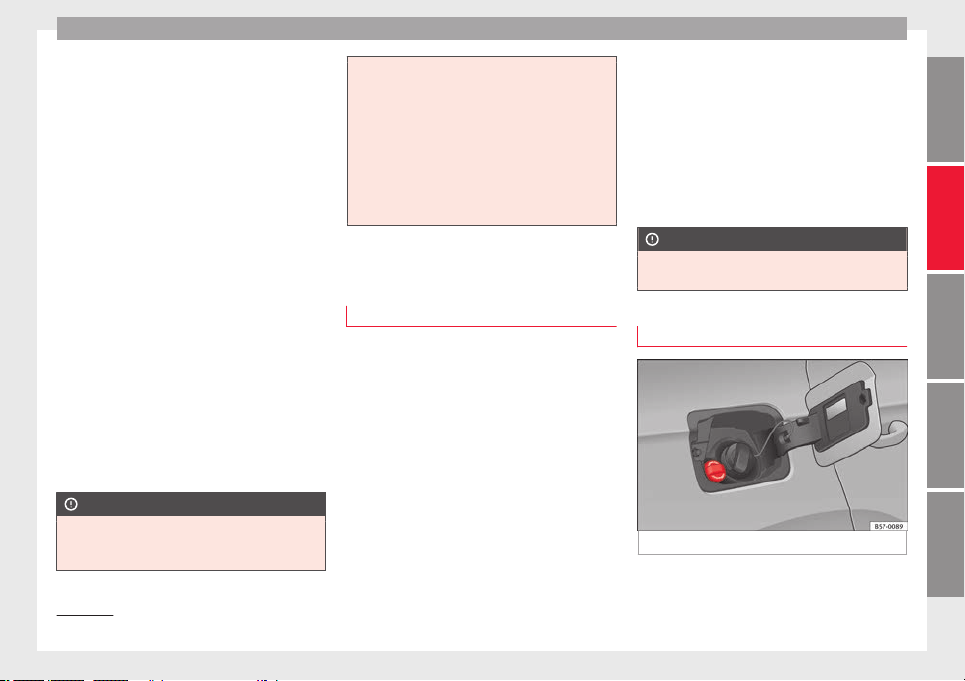
Checking and refilling levels
We recommend the use of die
sel
f
uel which
complies to European standard EN 590. If
diesel fuel which meets European standard
EN 590 is not available, the Cetane number
(CZ) must, at minimum, be 51. If the engine
is equipped with a particulate filter, the sul-
phur content of the fuel must be below 50
parts per million.
Winter-grade diesel
Summer fuel becomes thicker in winter and it
is more difficult to start the engine. For this
reason, petrol stations in some countries al-
so offer winter diesel with improved fluidity
when cold (winter-grade diesel).
Water in the fuel filter
1)
If your vehicle has a diesel engine and is
equipped with a fuel filter with a water sepa-
rator, the instrument panel may display the
following warning:
Water in the
fuel filter. If this is the case, take the
vehicle to a specialised workshop so that
they can drain the fuel filter.
CAUTION
●
The vehic
le is not designed for the use of
FAME fuel (biodiesel). The fuel system would
be damaged if you used biodiesel.
●
Do not mix
fuel additives, the so-called
“thinners”, petrol or similar additives with
diesel fuel.
●
If poor-quality diesel fuel is used, it may be
necessary to drain the fuel filter more fre-
quently than is specified in the Maintenance
Programme. We recommend having this done
by a specialised workshop. If water is allowed
to collect in the filter, this can cause engine
performance problems.
AdBlue
®
Inf
orm
ation on AdBlue
®
The consumption of AdBlue
®
depend
s
on
y
our personal driving style, the temperature
of the system and on the outdoor tempera-
ture when the vehicle is used.
AdBlue
®
freezes at temperatures of -11°C
(+13°F). The system has heating elements
that guarantee its operation even at low tem-
peratures.
The AdBlue
®
tank level capacity is approxi-
mately 11 litres.
The AdBlue
®
tank should never be empty.
When the distance to empty drops below
2400 km, a warning to refill the AdBlue
®
tank
will appear on the dash panel display
››› page 295. If this information is ignored,
later on it will not be possible to re-start the
engine. If this warning does not appear, it is
not necessary to refill the AdBlue
®
tank.
AdBlue
®
is a registered brand of the German
Association of the Automotive Industry (VDA)
and is also known as AUS32 or DEF (Diesel
Exhaust Fluid).
CAUTION
Filling the AdBlue
®
tank e
xcessively can
cause damage to the tank.
Refilling AdBlue
®
Fig. 238
AdBlue tank cap.
»
1)
Valid for the market: Algeria.
295
Technical dataAdviceOperationEmergenciesSafety
Advice
Operations prior to refilling
P
ark
the
vehicle on a flat surface. If the vehi-
cle is not parked on a flat surface, but, for ex-
ample, on a slope or on the side of a curb,
the level indicator may not detect the load
properly.
If a warning message about AdBlue
®
levels
appears on the dash panel display, fill at
least the minimum amount required (approx.
5 litres). Only after adding this amount will
the system detect that AdBlue
®
has been
added and you will be able to start the en-
gine again. The maximum amount that can
be refilled is 11 litres.
Switch the ignition off. If the ignition is not
switched off during refilling, the warning to
refill may continue to appear on the instru-
ment panel display.
Fill with a refill bottle
Only use AdBlue
®
that complies with ISO
22241-1. Only use original containers.
●
Open the tank cover ››› Fig. 238.
●
Unscrew the tank cap by turning it in an an-
ti-clockwise direction.
●
Please observe the manufacturer's instruc-
tions, indicated on the refill bottle.
●
Check the expiry date.
●
Remove the cap of the refill bottle.
●
Insert the neck of the bottle in the tank fill-
er neck vertically and screw the bottle on by
hand, by turning it in a clockwise direction.
●
Press the refill bottle in the direction of the
filler neck and hold it in this position.
●
Wait until the contents of the refill bottle
have been poured into the AdBlue
®
tank. Do
not compress or break the bottle!
●
Turn the bottle in a counter-clockwise direc-
tion and gently pull it upwards ›››
.
●
The AdBlue
®
t
ank
i
s full when no more liq-
uid comes out of the bottle.
●
Screw on the tank cap in a clockwise direc-
tion until it is tightly closed.
●
Close the fuel tank flap.
Operations before driving
●
After refilling the tank, only switch on the
ignition.
●
Leave the ignition on for at least 30 sec-
onds for the system to detect the fluid load.
●
Make sure you wait for at least 30 seconds
before starting the engine!
Refilling the dispenser with AdBlue
Valid for vehicles with selective catalytic re-
duction.
●
Open the tank cap.
●
Turn the SCR tank cap anti-clockwise
››› Fig. 238.
●
Add AdBlue until the nozzle stops for the
first time.
●
Close the SCR tube by turning it clockwise
until you hear a click.
WARNING
AdBlue
®
should on
ly be stored in the original
container, which should be tightly closed and
kept in a safe place.
●
Never keep AdBlue
®
in empty food contain-
ers, bottles or other similar containers. Other
people may confuse it for other products.
●
Keep AdBlue
®
out of the reach of children.
CAUTION
●
When refil
ling, the nozzle grip should be
aligned downward. Otherwise the nozzle will
not connect automatically.
●
Do not try to add any more additive after
the nozzle has stopped for the first time. The
AdBlue tank could overflow and AdBlue could
spill out.
●
Only use AdBlue
®
that complies with ISO
22241-1. Only use original containers.
●
Never mix AdBlue
®
with water, fuel or addi-
tives. Any type of damage caused by such a
mixture will not be covered by the warranty.
●
Never pour AdBlue
®
into the fuel tank. This
could result in engine damage.
●
Do not carry the refill bottle inside the vehi-
cle. If there is a leak (due to temperature
296

Checking and refilling levels
changes or damage to the bottle), the
AdBlue
®
may
damage the vehicle.
For the sake of the environment
Dispose of the refill bottle in an environment-
friendly
manner
.
Note
You can buy refill bottles that are adequate
for AdBlue
®
use at
SEAT dealerships.
297
Technical dataAdviceOperationEmergenciesSafety
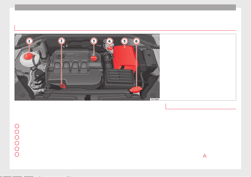
Advice
Engine compartment
Chec
k
in
g levels
Fig. 239 Diagram for the location of the various
elements.
From time to time, the levels of the different
fluid
s
in the
vehicle must be checked. Never
fill with incorrect fluids, otherwise serious
damage to the engine may be caused.
Coolant expansion tank
Engine oil dipstick
Engine oil filler cap
Brake fluid reservoir
Vehicle battery (underneath the cover)
Windscreen washer reservoir
1
2
3
4
5
6
The checking and refilling of service fluids
ar
e c
arried out
on the components men-
tioned above. These operations are descri-
bed in ››› page 298.
Overview
You will find further explanations, instruc-
tions and restrictions on the technical speci-
fications as of ››› page 317.
Working in the engine compartment
Read the additional information carefully
›››
page 17
Always be aware of the danger of injury and
scalding as well as the risk of accident or fire
when working in the engine compartment
(e.g. when checking and refilling fluids). Al-
ways observe the warnings listed below and
follow all general safety precautions. The en-
gine compartment of the vehicle is a poten-
tially hazardous area ›››
.
298
Checking and refilling levels
WARNING
●
Switc
h the engine off, remove the key from
the ignition and apply the hand brake. If the
vehicle has a manual gearbox, place the lever
in neutral; if it has an automatic gearbox,
place the selector lever in position P. Wait for
the engine to cool down.
●
Keep children away from the engine com-
partment.
●
Never spill liquids used for vehicle opera-
tion on the engine compartment, as these
may catch fire (e.g. the antifreeze in coolant).
●
Take care not to cause short circuits in the
electrical system, especially when working
on the battery.
●
If working inside the engine compartment,
remember that, even when the ignition is
switched off, the radiator fan may start up au-
tomatically, and therefore there is a risk of in-
jury.
●
Never cover the engine with additional in-
sulating materials such as a blanket. Risk of
fire!
●
Do not unscrew the cap on the coolant ex-
pansion tank when the engine is hot. The
cooling system is under pressure.
●
Protect face, hands and arms by covering
the cap with a large, thick rag to protect
against escaping coolant and steam.
●
If it is necessary to work in the engine com-
partment while the engine is running, the ro-
tating components (for example, poly-V belt,
alternator, radiator fan) and the high voltage
ignition syst
em are an additional hazard.
●
Observe the following additional warnings
if work on the fuel system or the electrical
system is necessary:
–
Always disconnect the battery from the
on-board network.
–
Do not smoke.
–
Never work near naked flames.
–
Always keep an approved fire extinguish-
er immediately available.
CAUTION
When topping up fluids make sure the correct
fluid is p
ut into the correct filler opening, oth-
erwise this can cause serious malfunctions or
engine damage.
For the sake of the environment
Inspect the ground underneath your vehicle
regu
larly so that any leaks are detected at an
early stage. If you find spots of oil or other
fluids in the area where it was parked, have
your vehicle inspected at the workshop.
Note
In right-hand drive vehicles* some brake flu-
id reser
voirs are on the other side of the en-
gine compartment ››› Fig. 239.
Opening the bonnet
Read the additional information carefully
›››
page 17
The bonnet is released from inside the vehi-
cle.
Check that the windscreen wiper arms are
not unfolded. Otherwise the paint may be
damaged.
The bonnet can only be unlocked when the
driver door is open.
WARNING
Never open the bonnet if you see steam or
drips of
coolant being released from the en-
gine compartment. Failure to comply could
result in burns. Wait until no steam or coolant
can be seen before opening the bonnet.
Closing the bonnet
–
Slightly lift the bonnet.
–
Release the bonnet stay before pressing it
b
ac
k
into its support.
–
Carefully close the bonnet.
–
Press the bonnet down until it locks into
place.
–
Make sure that the bonnet catches onto its
clasp. Do not press down too hard
›››
.
»
299
Technical dataAdviceOperationEmergenciesSafety

Advice
WARNING
●
For saf
ety reasons the bonnet must always
be completely closed when the vehicle is
moving. Therefore, after closing the bonnet,
always check that the locking element is
properly engaged. This is the case if the bon-
net is flush with the adjacent body panels.
●
Should you notice that the bonnet is not
safely secured when the vehicle is moving,
stop the vehicle immediately and close the
bonnet. Failure to follow this instruction
could result in an accident.
Engine oil
Gener
a
l
notes
The engine comes with a special, multi-grade
oi
l
th
at can be used all year round.
Because the use of high-quality oil is essen-
tial for the correct operation of the engine
and its long useful life, when topping up or
changing oil, use only those oils that comply
with VW standards.
The specifications (VW standards) set out in
the following page should appear on the con-
tainer of the service oil; when the container
displays the specific standards for petrol and
diesel engines together, it means that the oil
can be used for both types of engines.
We recommend that the oil change indicated
in the Maintenance Programme, be per-
formed by a technical service or specialised
workshop.
The correct oil specifications for your engine
are listed in the ›››
page 58, Engine oil
specifications.
Service intervals
Service intervals can be flexible (LongLife
service) or fixed (dependent on time/dis-
tance travelled).
If the PR code that appears on the back of the
Maintenance Programme booklet is PR QI6,
this means that your vehicle has the LongLife
service programmed. If it lists the codes QI1,
QI2, QI3, QI4 or QI7, the interval service is
dependent on time/distance travelled.
Flexible service intervals (LongLife service
intervals*)
Special oils and processes have been devel-
oped which, depending on the characteris-
tics and individual driving profiles, enable
the extension of the oil change service (Long-
Life service intervals).
Because this oil is essential for extending the
service intervals, it must only be used ob-
serving the following indications:
●
Avoid mixing it with oil for fixed service in-
tervals.
●
Only in exceptional circumstances, if the
engine oil level is too low ››› page 301,
Checking engine oil level and LongLife oil is
not available, it is permitted to top up (once)
with oil for fixed service intervals
›››
page 58 (up to a maximum of 0.5 li-
tres).
Fixed service intervals*
If your vehicle does not have the “LongLife
service interval” or it has been disabled (by
request), you may use oils for fixed service
intervals, which also appear in
›››
page 58, Engine oil specifications. In
this case, your vehicle must be serviced after
a fixed interval of 1 year/15,000 km (10,000
miles)(whatever comes first) ››› Booklet
Maintenance Programme.
●
In exceptional circumstances, if the engine
oil level is too low ››› page 301, Checking en-
gine oil level and you cannot obtain the oil
specified for your vehicle, you can add a
small quantity of oil conforming to the speci-
fication ACEA A2 or ACEA A3 (petrol engines)
or ACEA B3 or ACEA B4 (diesel engines) (up
to 0.5 l).
Vehicles with diesel particulate filter*
The Maintenance Programme states whether
your vehicle is fitted with a diesel particulate
filter.
300
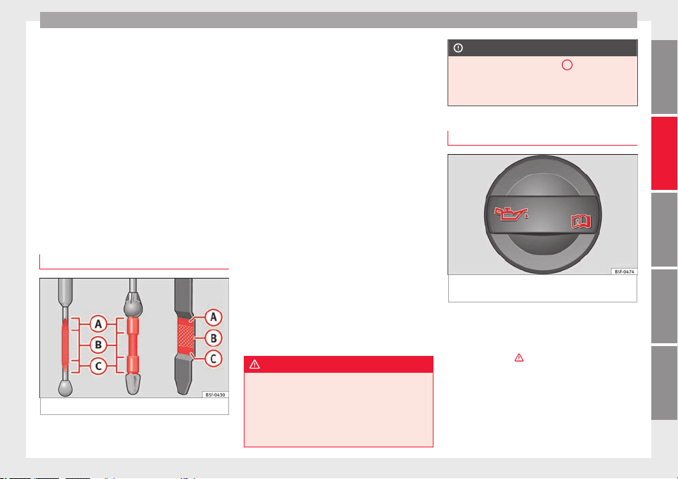
Checking and refilling levels
Only VW 507 00 engine oil, with reduced ash
f
orm
ation, m
ay be used in diesel engines
equipped with particulate filter. Using other
types of oil will cause a higher soot concen-
tration and reduce the life of the DPF. There-
fore:
●
Avoid mixing this oil with other engine oils.
●
Only in exceptional circumstances, if the
engine oil level is too low ››› page 301,
Checking engine oil level and you cannot ob-
tain the oil specified for your vehicle, you can
use a small quantity of oil (once) conforming
to the VW 506 00, VW 506 01, VW 505 00,
VW 505 01 or ACEA B3/ACEA B4 specification
(up to 0.5 l).
Checking engine oil level
Fig. 240 Engine oil dipstick.
Read the additional information carefully
›
›
›
page 57
The engine oil dipstick indicates the level of
the oil.
Checking oil level
–
Park the vehicle in a horizontal position.
–
Briefly run the engine at idle speed until
the operating temperature is reached and
then stop.
–
Wait for about two minutes.
–
Pull out the dipstick. Wipe the dipstick with
a clean cloth and insert it again, pushing it
in as far as it will go.
–
Then pull it out once more and check the oil
level ››› Fig. 240. Top up with engine oil if
necessary.
Depending on how you drive and the condi-
tions in which the vehicle is used, oil con-
sumption can be up to 0.5 l/1000 km. Oil
consumption is likely to be higher for the first
5,000 km. For this reason the engine oil level
must be checked at regular intervals, prefera-
bly when filling the tank and before a jour-
ney.
WARNING
Any work carried out in the engine compart-
ment or on the engine mu
st be carried out
cautiously.
●
When working in the engine compartment,
always observe the safety warnings
››› page 298.
CAUTION
If the oil level is above area
A
, do not start
the engine. Thi
s could result in damage to the
engine and catalytic converter. Contact a
Technical Service.
Topping up engine oil
Fig. 241 In the engine compartment: Engine
oi
l
fi
ller cap.
Read the additional information carefully
›
›
›
page 57
Before opening the bonnet, read and observe
the warnings ›››
in Working in the engine
c
omp
ar
tment on page 299.
The position of the oil filler opening is shown
in the corresponding engine compartment il-
lustration ››› page 298.
Engine oil specification ›››
page 58.
»
301
Technical dataAdviceOperationEmergenciesSafety
Advice
WARNING
Oil is highly inflammable! Ensure that no oil
comes
into contact with hot engine compo-
nents when topping up.
CAUTION
If the oil level is above area ›››
Fig. 240
A
, do
not st
art the engine. This could result in dam-
age to the engine and catalytic converter.
Contact a specialised workshop.
For the sake of the environment
The oil level must never be above area
›››
Fig. 240
A
. Otherwise oil can be drawn in
through the cr
ankcase breather and escape
into the atmosphere via the exhaust system.
Note
Before a long trip, we recommend finding an
engine oil
that conforms to the correspond-
ing VW specifications and recommend keep-
ing it in the vehicle. This way, the correct en-
gine oil will always be available for a top-up if
needed.
Changing engine oil
Read the additional information carefully
›
›
›
page 57.
The engine oil must be changed at the inter-
vals given in the service schedule.
We recommend that you have the engine oil
changed by a Technical Service.
The oil change intervals are shown in the
Maintenance Programme.
WARNING
Only change the engine oil yourself if you
have the s
pecialist knowledge required!
●
Before opening the bonnet, read and ob-
serve the warnings ››› page 298.
●
Wait for the engine to cool down. Hot oil
may cause burn injuries.
●
Wear eye protection to avoid injuries, such
as acid burns, caused by splashes of oil.
●
When removing the oil drain plug with your
fingers, keep your arm horizontal to help pre-
vent oil from running down your arm.
●
Wash your skin thoroughly if it comes into
contact with engine oil.
●
Engine oil is poisonous! Used oil must be
stored in a safe place out of the reach of chil-
dren.
CAUTION
No additives should be used with engine oil.
This c
ould result in engine damage. Any dam-
age caused by the use of such additives
would not be covered by the factory warranty.
For the sake of the environment
●
Becau
se of disposal problems and the spe-
cial tools and specialist knowledge required,
we recommend that you have the engine oil
and filter changed by a Technical Service.
●
Never pour oil down drains or into the
ground.
●
Use a suitable container when draining the
used oil. It must be large enough to hold all
the engine oil.
Cooling system
T
op
pin
g up coolant
Read the additional information carefully
›
›
›
page 58
Top up coolant when the level is below the
MIN (minimum) mark.
Checking coolant level
–
Park the vehicle in a horizontal position.
–
Switch the ignition off.
–
Read off the coolant level on coolant ex-
pansion tank. When the engine is cold, the
coolant level should be between the marks.
When the engine is hot, it may be slightly
above the upper mark.
302
Checking and refilling levels
Topping up coolant
–
Wait for the engine to cool down.
–
Cover the coolant expansion tank cap with
a c
loth and c
ar
efully unscrew it to the left
›››
.
–
Top up the coolant only if there is still cool-
ant
in the e
xp
ansion tank, otherwise you
could damage the engine. If there is no
coolant in the expansion tank, do not con-
tinue driving. You should obtain professio-
nal assistance ›››
.
–
If there is still some coolant in the expan-
s
ion t
ank, t
op up to the upper mark.
–
Top up with coolant until the level becomes
stable.
–
Screw the cap back on correctly.
Any loss of coolant fluid normally indicates a
leak in the cooling system. Take the vehicle
straight to a specialised workshop to have
the cooling system examined. If there are no
leaks in the engine cooling system, a loss of
coolant can only occur if the coolant boils
and is forced out of the system as a result of
overheating.
WARNING
●
The coolin
g system is under pressure. Do
not unscrew the cap on the coolant expan-
sion tank when the engine is hot: risk of
burns!
●
The antifreeze and c
oolant fluid can be a
health hazard. Therefore, the antifreeze
should be stored in the original container in a
safe place out of reach of children. Failure to
comply could result in poisoning.
●
If working inside the engine compartment,
remember that, even when the ignition is
switched off, the radiator fan may start up au-
tomatically, and therefore there is a risk of in-
jury.
WARNING
If there is not enough anti-freeze in the cool-
ant
sys
tem, the engine may fail leading to se-
rious damage.
●
Please make sure that the percentage of
additive is correct with respect to the lowest
expected ambient temperature in the zone in
which the vehicle is to be used.
●
When the outside temperature is very low,
the coolant could freeze and the vehicle
would be immobilised. In this case, the heat-
ing would not work either and inadequately
dressed passengers could die of cold.
CAUTION
Do not top up the expansion tank with cool-
ant fluid if it
is empty! Air could enter the
cooling system. In this case, stop driving.
Seek specialist assistance. Otherwise, there
is a risk of engine damage.
CAUTION
The original additives should never be mixed
with coo
lants which are not approved by
SEAT. Otherwise, you run the risk of causing
severe damage to the engine and the engine
cooling system.
●
If the fluid in the expansion tank is not pur-
ple but is, for example, brown, this indicates
that the G13 additive has been mixed with an
inadequate coolant. The coolant must be
changed as soon as possible if this is the
case! This could result in serious faults and
engine damage.
For the sake of the environment
Coolants and additives can contaminate the
envir
onment. If any fluids are spilled, they
should be collected and correctly disposed
of, with respect to the environment.
Brake fluid
T
op up br
ak
e fluid
Read the additional information carefully
›
›
›
page 59
Checking the brake fluid level
The brake fluid level must be between the
MIN and MAX markings.
»
303
Technical dataAdviceOperationEmergenciesSafety
Advice
However, if the brake fluid level goes down
notic
e
ab
ly in a short time, or drops below the
MIN mark, there may be a leak in the brake
system. Seek specialist assistance. A warn-
ing light on the instrument panel display
monitors the brake fluid level ››› page 119.
In right-hand drive vehicles the brake fluid
reservoir is on the other side of the engine
compartment.
Changing brake fluid
The regular intervals at which the brake fluid
should be replaced are listed in the Mainte-
nance Programme. We recommend you have
it replaced at a SEAT Official Service, during
an Inspection Service.
WARNING
●
Brake fluid shou
ld be stored in the closed
original container in a safe place out of reach
of children. Risk of poisoning!
●
If the brake fluid is left in the system for
too long and the brakes are subjected to
heavy use, vapour bubbles may form in the
brake system. This would seriously affect the
efficiency of the brakes and the safety of the
vehicle. This may cause an accident.
CAUTION
Brake fluid should not come into contact with
the vehic
le paintwork, as it is abrasive.
Windscreen washer reservoir
Chec
k
in
g and topping up the wind-
screen washer reservoir
Read the additional information carefully
›››
page 59
Check the water level in the windscreen
washer reservoir regularly and top up as re-
quired.
The container for the windscreen washer con-
tains the cleaning fluid for the windscreen,
the rear window and the headlight washer
system*.
●
Open the bonnet
›››
page 298.
●
The windscreen washer reservoir is marked
with the symbol on the cap.
●
Check there is enough windscreen water in
the reservoir.
Recommended windscreen wipers
●
For the hottest seasons we recommend
summer G 052 184 A1 for clear glass. Propor-
tions of the mixture in the washer fluid tank:
1:100 (1 part concentrate per 100 parts wa-
ter).
●
All year round, G 052 164 A2 for clear
glass. Approximate proportion of the winter
mixture, up to -18°C (0°F): 1:2 (1 part con-
centrate per 2 parts water); otherwise, a 1:4
proportion of mixture in the washer fluid
tank.
Capacity
The reservoir holds approximately 3 litres in
versions without headlight washer and 5 li-
tres in versions with headlight washer.
WARNING
If the water from the windscreen washer does
not cont
ain enough anti-freeze, it may freeze
on the windscreen and rear window, reducing
forward and rear visibility.
●
In winter, ensure the windscreen washer
contains enough anti-freeze.
●
In cold conditions, you should not use the
windscreen wiper system unless you have
warmed the windscreen with the ventilation
system. The antifreeze could freeze on the
windscreen and reduce visibility.
WARNING
Never mix an unsuitable antifreeze or other
simil
ar additives with the windscreen washer
water. A greasy layer may be formed on the
windscreen which will impair visibility.
●
Use clean water with a window cleaner rec-
ommended by SEAT.
●
If necessary, add a suitable antifreeze to
the water in the reservoir.
304

Checking and refilling levels
CAUTION
●
Do not mix
cleaning products recommen-
ded by SEAT with other products. This could
lead to flocculation and may block the wind-
screen washer jets.
●
When topping up service fluids, make abso-
lutely certain that you fill the fluids into the
correct reservoirs. Using the wrong fluids
could cause serious malfunctions and engine
damage!
●
Not having windscreen wiper fluid reduces
visibility through the windscreen, and leads
to loss of visibility in headlights in models
with headlight washer.
Battery
Gener
a
l
information
Read the additional information carefully
›
›
›
page 59.
The battery is located in the engine compart-
ment and is almost maintenance-free. It is
checked as part of the Inspection Service.
Nevertheless, check the terminals are clean
and have the correct tightening torque, espe-
cially in summer and winter.
Disconnecting the battery
The battery should only be disconnected in
exceptional cases. When the battery is dis-
connected, some of the vehicle's functions
are “lost” (››› table on page 305). These
functions will require resetting after the bat-
tery is reconnected.
Deactivate the anti-theft alarm* before you
disconnect the battery Otherwise the alarm
will be triggered.
Function Reprogramming
One-touch function of
the electric windows
››› page 141, One-touch
opening and closing.
Remote control key
If the vehicle does not re-
spond to the key, they
should be synchronised
››› page 134.
Digital clock ››› page 116.
ESC warning lamp
After driving for a few me-
tres, the warning lamp goes
out again.
If the vehicle is not used for long periods
The
v
ehic
le has a system for monitoring the
current consumption when the engine is left
unused for long periods of time ››› page 203.
Some functions, such as the interior lights, or
the remote door opening, may be temporarily
disabled to prevent the battery from running
flat. These functions will come back on as
soon as the ignition is switched on and the
engine started.
Winter conditions
During the winter, the starting power may be
reduced, and if necessary, the battery should
be charged ›››
in Important safety warn-
in
g
s
for handling a vehicle battery on
page 306
Important safety warnings for han-
dling a vehicle battery
All work on batteries requires specialist
kno
wl
edg
e. Please refer to a SEAT Official
Service or a workshop specialising in batter-
ies: risk of burns or exploding battery!
The battery must not be opened. Never try to
change the fluid level of the battery. Other-
wise explosive gas is released from the bat-
tery that could cause an explosion.
Wear eye protection.
Battery acid is very corrosive and caustic. Wear
protective gloves and eye protection. In the event
of electrolyte splashes, rinse off with plenty of
water.
Fires, sparks, open flames and smoking are pro-
hibited.
The battery should only be charged in a well-ven-
tilated zone. Risk of explosion!
Keep children away from acid and batteries!
»
305
Technical dataAdviceOperationEmergenciesSafety
Advice
WARNING
●
When repairin
g or working on the electrical
system, proceed as follows:
–
1. Remove the key from the ignition. The
negative cable on the battery must be
disconnected.
–
2. When the repair is finished, reconnect
the negative pole of the battery.
●
Switch off all electrical devices before re-
connecting the battery. Reconnect first the
positive cable and then the negative cable.
Never reverse the polarity of the connections.
This could cause an electrical fire.
●
Ensure that the vent hose is always connec-
ted to the battery.
●
Never use damaged batteries. This could
cause an explosion! Replace a damaged bat-
tery immediately.
CAUTION
●
Never dis
connect the battery if the ignition
is switched on or if the engine is running.
This could damage the electrical system or
electronic components.
Charging the battery
Terminals for charging the battery are fitted
in the en
gine c
omp
artment.
–
Note the warnings ›››
in Important safety
w
arnin
g
s for handling a vehicle battery on
page 306 and ›››
.
–
Switch off all electrical devices. Remove the
ignition k
ey
.
–
R
aise the bonnet ››› page 299.
–
Open the battery cover.
–
Connect the charger clamps as described
to the positive pole of the battery (+) and
exclusively to an earth on the bodywork
(–).
–
Only use a charger which is compatible for
use with 12 V nominal voltage batteries.
The charge must not exceed a voltage of 15
V.
–
Now connect the battery charger to the
power socket and switch on.
–
After charging the battery: switch off the
battery charger and disconnect the power
socket cable.
–
Finally disconnect the charger cables from
the battery.
–
Replace the battery cover correctly.
–
Close the bonnet ››› page 299.
Important: Before you charge the battery
make sure you read the manufacturer's in-
structions for using the battery charger.
WARNING
Never charge a battery that has frozen: re-
plac
e battery! Failure to do so may lead to an
explosion.
Note
Use only the terminals in the engine compart-
ment to c
harge the battery.
Replacing the battery
The new battery should have the same speci-
fic
ation
s
(amperage, load and voltage) as the
used battery.
Your vehicle is equipped with an intelligent
power management system to control the
distribution of electrical energy
›››
page 203.
The power management function ensures
that the battery is charged much more effi-
ciently than on vehicles without a power
management system. To maintain this func-
tion after replacing the battery, we recom-
mend that the replacement battery used is of
the same make and type as the original fitted
battery. To make proper use of the power
management function after the battery has
been changed, have the battery coded to the
power management mode at a specialised
workshop.
306
Wheels
CAUTION
●
Some vehic
les, for example those with the
Start-Stop system* are fitted with a special
battery (AGM-type or EFB-type battery). If any
other type of battery is fitted, the Start-Stop
function may be considerably reduced and
the vehicle may not stop on repeated occa-
sions.
●
Make sure that the vent hose is always at-
tached to the original opening on the side of
the battery. Gases or battery acid can other-
wise escape and possibly cause damage.
●
The battery holder and clamps must always
be correctly secured.
●
Before starting any work on the battery, al-
ways observe the warnings listed under
››› page 305, Important safety warnings for
handling a vehicle battery.
●
Do not forget to replace the battery cover-
ings, where applicable. It is a protection for
high temperatures. This in turn extends the
vehicle service life.
For the sake of the environment
Batteries contain toxic substances includ-
ing s
ulphuric acid and lead. They must be
disposed of appropriately and must not be
disposed of with ordinary household waste.
Make sure disconnected batteries cannot tip
over. Sulphuric acid could be spilt!
Wheels
Wheel
s
and ty
res
General notes
–
When driving with new tyre
s, be especially
careful during the first 500 km (300 miles).
–
If you have to drive over a kerb or similar
obstacle, drive very slowly and as near as
possible at a right angle to the obstacle.
–
Check from time to time if the tyres are
damag
ed (punctures, cuts, cracks or
dents). Remove any foreign objects embed-
ded in the treads.
–
Damaged wheels and tyres must be re-
placed immediately.
–
Keep grease, oil and fuel off the tyres.
–
Replace any missing valve caps as soon as
possible.
–
Mark the wheels before taking them off so
that they rotate in the same direction when
put back.
–
When removed, the wheels or tyres should
be stored in a cool, dry and preferably dark
place.
New tyres
New tyres do not give maximum grip straight
away and should therefore be “run in” by
driving carefully and at moderate speeds for
about the first 500 km (300 miles). This will
also increase the useful life of the tyres.
The tread depth of new tyres may vary, ac-
cording to the type and make of tyre and the
tread pattern.
Concealed damage
Damage to tyres and rims is often not readily
visible. If you notice unusual vibration or the
car pulling to one side, this may indicate that
one of the tyres is damaged. Reduce speed
immediately if there is any reason to suspect
that damage may have occurred. Inspect the
tyres for damage. If no external damage is
visible, drive slowly and carefully to the near-
est specialised workshop and have the car
inspected.
Tyres with directional tread pattern
An arrow on the tyre sidewall indicates the di-
rection of rotation on single drive tyres. Al-
ways note the direction of rotation indicated
when mounting the wheel. This guarantees
optimum grip and helps to avoid aquaplan-
ing, excessive noise and wear.
Retrofitting accessories
If you wish to change or fit wheels, rims or
wheel trims, we recommend that you consult
with a SEAT Official Service centre for advice
regarding current techniques.
307
Technical dataAdviceOperationEmergenciesSafety
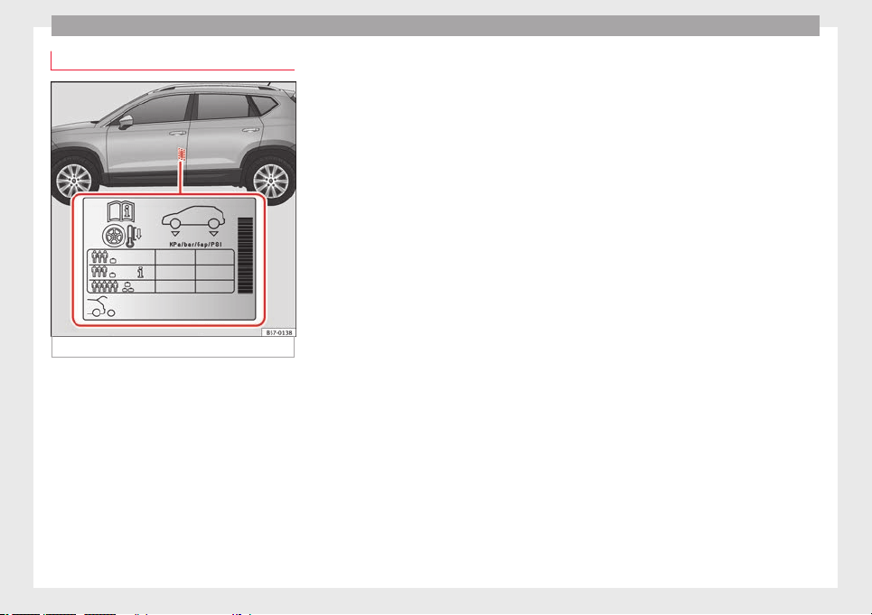
Advice
Service life of tyres
Fig. 242 Location of the tyre pressure sticker.
Correct inflation pressures and sensible driv-
in
g h
ab
its will increase the useful life of your
tyres.
●
Check tyre pressure at least once a month,
and also prior to any long trip.
●
The tyre pressure should only be checked
when the tyres are cold. Do not reduce the
pressure of warm tyres.
●
Adjust tyre pressure to the load being car-
ried by the vehicle.
●
In vehicles with a tyre pressure indicator,
save the modified pressure of tyres
››› page 311, ››› page 308.
●
Avoid fast cornering and hard acceleration.
●
Inspect the tyres for irregular wear from
time to time.
The useful life of your tyres depends on the
following factors:
Tyre pressure
The tyre inflation pressures are listed on a
sticker on the rear of the front left door frame
››› Fig. 242.
Insufficient or excessive pressure greatly re-
duces the useful life of the tyres and adverse-
ly affects vehicle performance and ride. Cor-
rect inflation pressures are very important,
especially at high speeds.
Depending on the vehicle, tyre pressure can
be adjusted to medium load to improve driv-
ing comfort (tyre pressure ). When driving
with comfort tyre pressure fuel consumption
may increase slightly.
The tyre pressure must be adjusted according
to the load the vehicle is carrying. If the vehi-
cle is going to carry the maximum load, the
tyre pressure should be increased to the max-
imum value indicated on the sticker
››› Fig. 242.
Do not forget the spare wheel when checking
the tyre pressures: Keep this spare wheel in-
flated to the highest pressure required for the
road wheels.
In the case of a minimised temporary spare
wheel (125/70 R18) inflate to a pressure of
4.2 bar as indicated on the tyre pressure la-
bel ››› Fig. 242.
Driving style
Fast cornering, heavy acceleration and hard
braking (squealing tyres) all increase tyre
wear.
Wheel balance
The wheels on new vehicles are balanced.
However, certain circumstances may lead to
imbalance (run-out), which is detected as vi-
brations in the steering wheel.
Unbalanced wheels should be rebalanced, as
they otherwise cause excessive wear on
steering, suspension and tyres. A wheel must
also be rebalanced when a new tyre is fitted
or if a tyre is repaired.
Incorrect wheel alignment
Incorrect running gear alignment causes ex-
cessive tyre wear, impairing the safety of the
vehicle. If you notice excessive tyre wear, you
should check wheel alignment at a SEAT Offi-
cial Service.
308
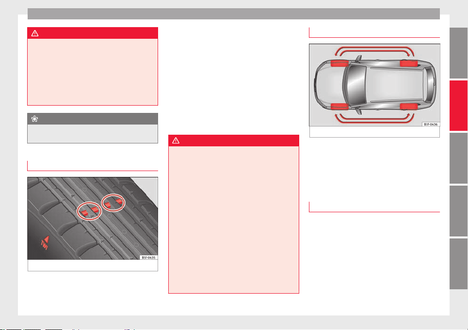
Wheels
WARNING
●
Alwa
ys adapt the tyre pressure accordingly
when the vehicle load changes.
●
A tyre with low air pressure has to flex a lot
more when the vehicle is heavily loaded or at
high speeds, therefore causing overheating
to occur. Under these conditions, the tyre
bead may be released or the tyre may burst.
Risk of accident!
For the sake of the environment
Under-inflated tyres will increase fuel con-
sumption.
Wear indicators
Fig. 243 Tyre tread: tread wear indicators
Tread wear indicators indicate if a tyre is
w
orn.
The origin
al
tyres on your vehicle have
1.6 mm high “tread wear indicators” running
across the tread. Depending on the manufac-
turer, there will be 6 to 8 of them spaced at
equal distances around the tyre. Markings on
the tyre sidewall (for instance the letters
“TWI” or a triangle) indicate the positions of
the tread wear indicators.
The minimum tread depth required by law is
1.6 mm (measured in the tread grooves next
to the tread wear indicators). (Different fig-
ures may apply in other countries.)
WARNING
The tyres must be replaced at the latest when
the trea
d is worn down to the tread wear indi-
cators. Failure to follow this instruction could
result in an accident.
●
Especially in difficult driving conditions
such as wet or icy roads. It is important that
the tyre tread be as deep as possible and be
approximately the same on the tyres of both
the front and the rear axles.
●
The scant driving safety due to insufficient
tread depth is particularly evident in vehicle
handling, when there is a risk of “aquaplan-
ing” in deep puddles of water and when driv-
ing through corners, and braking is also ad-
versely affected.
●
The speed has to be adapted accordingly,
otherwise there is a risk of losing control over
the vehicle.
Interchanging tyres
Fig. 244 Interchanging tyres.
To ensure that the wear is equal on all tyres
the wheel
s
shou
ld be changed round from
time to time according to the system
››› Fig. 244. The useful life of all the tyres will
then be about the same time.
New tyres or new wheels
–
All four wheels must be fitted with tyres of
the s
ame type, s
iz
e (rolling circumference)
and preferably the same tread pattern.
–
Tyres should be replaced at least in pairs
and not individually (i.e. both front tyres or
both rear tyres together).
–
Do not use tyres whose effective size ex-
ceeds the dimensions of the factory-ap-
proved makes of tyre.
»
309
Technical dataAdviceOperationEmergenciesSafety
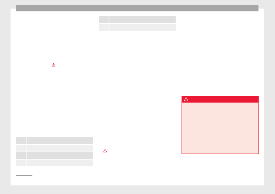
Advice
–
If
y
ou wish to fit the vehicle with rims or
tyres different to those installed in manu-
facture, it is advisable to consult a SEAT Of-
ficial Service before purchasing them.
The tyres and wheel rims are an essential
part of the vehicle's design. The tyres and
rims approved by SEAT are specially matched
to the characteristics of the vehicle and make
a major contribution to good roadholding
and safe handling ›››
.
The s
iz
e
s of the rims and tyres approved for
your vehicle are listed in the vehicle docu-
mentation (e.g. EC Certificate of Conformity or
COC document
1)
). The vehicle documentation
varies depending on the country of resi-
dence.
A knowledge of tyre designations makes it
easier to choose the correct tyres. The follow-
ing wording can be read on the sides of the
tyre:
215/60 R16 95V
This contains the following information:
215 Tyre width in mm
60 Height/width ratio in %
R Tyre construction: Radial
16 Rim diameter in inches
95 Load rating code
V Speed index
The manufacturing date is also indicated on
the tyr
e sidewall (possibly only on the outer
part):
DOT... 2216...
it means, for example, that the tyre was man-
ufactured in the 22nd week of 2016.
But note that with some types of tyre, the ac-
tual tyre size can differ from the nominal size
marked on the tyre (for instance 215/60 R16
95 V), and there may be significant differen-
ces in the contours of the tyres, even though
the tyres are marked with the same nominal
size. When replacing the tyres, it is therefore
important to make sure that the actual size
of the new tyres does not exceed the dimen-
sions of the factory-approved makes of tyre.
Failure to observe this requirement can af-
fect the clearance needed for the tyres. If the
tyres rub against the bodywork, in certain
circumstances the tyres, running gear or
bodywork and pipes may be damaged, and
vehicle safety could be severely impaired
›››
.
If
y
ou use tyres that are approved by SEAT
you can be sure that the actual tyre dimen-
sions will be correct for your vehicle. If you
decide to fit a different type of tyre, you must
obtain the appropriate manufacturer's certif-
icate from the tyre retailer to confirm that
the tyres are suitable for your vehicle. Keep
this certificate in a safe place.
Your SEAT Official Service will be able to ad-
vise you on which tyres may be fitted to your
vehicle.
It is best to have all servicing of wheels and
tyres performed by a specialised workshop.
They are familiar with the procedure and
have the necessary special tools and spare
parts as well as the proper facilities for dis-
posing of the old tyres respecting the envi-
ronment.
WARNING
●
It is
very important to ensure that the tyres
you have chosen have adequate clearance.
When selecting replacement tyres, do not re-
ly entirely on the nominal tyre size marked on
the tyre, since the effective tyre size can dif-
fer significantly depending on the manufac-
turer. Inadequate tyre clearance can result in
damage to the tyres or the vehicle, causing a
serious safety risk. Risk of accident! It may
also invalidate the vehicle's registration for
use on public roads.
1)
COC = certificate of conformity.
310
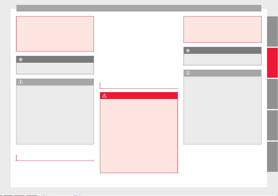
Wheels
●
Avoid ru
nning the vehicle on tyres that are
more than 6 years old. If you have no alterna-
tive, you should drive slowly and with extra
care at all times.
●
If wheel trims are fitted after the car is pur-
chased, ensure that there is an adequate flow
of air for cooling the brake system.
For the sake of the environment
Old tyres must be disposed of according to
the l
aw
s in the country concerned.
Note
●
A SEA
T Service Centre should be consulted
to find out whether wheels or tyres of differ-
ent sizes to those originally fitted by SEAT
can be fitted, and to find out about the com-
binations allowed between the front axle
(axle 1) and the rear axle (axle 2).
●
Never mount used tyres if you are not sure
of their “previous history”.
●
For technical reasons, it is not generally
possible to use the wheels from other vehi-
cles. In some cases, this may also be true for
the same model of wheel.
Wheel bolts
The wheel
bolts ar
e m
atched to the rims.
When installing different wheels (for instance
alloy wheels or wheels with winter tyres) it is
important to use the correct wheel bolts with
the right length and correctly shaped bolt
heads. This ensures that wheels are fitted se-
curely and that the brake system functions
correctly.
The wheel bolts must be clean and turn easi-
ly.
A special adapter is required to turn the anti-
theft wheel bolts* ›››
page 65.
Tyre monitoring systems
Introduction
WARNING
Unsuitable handling of the wheels and tyres
may
lead to sudden tyre pressure losses, to
tread separation or even to a blow-out.
●
Check tyre pressures regularly and ensure
they are maintained at the pressures indica-
ted. Tyre pressure that is too low could cause
overheating, resulting in tread detachment or
even burst tyres.
●
Tyre pressure should be that indicated on
the label when the tyres are cold at all times
››› page 319.
●
Regularly check the cold inflation pressure
of the tyres. If necessary, change the tyre
pressure of the vehicle tyres while they are
cold.
●
Regu
larly check your tyres for damage and
wear.
●
Never exceed the maximum permitted
speed or loads specified for the type of tyre
fitted on your vehicle.
For the sake of the environment
Under-inflated tyres lead to increased fuel
c
ons
umption and tyre wear.
Note
●
Driv
in
g f
or the first time with new tyres at a
high speed can cause them to slightly ex-
pand, which could then produce an air pres-
sure warning.
●
Only replace used tyres with those author-
ised by SEAT for the corresponding type vehi-
cle.
●
Do not only rely on the tyre monitoring sys-
tem. Regularly check your tyres to ensure
that the tyre pressure is correct and that the
tyres are not damaged due to puncture, cuts,
tears and impacts/dents. Remove objects
from the tyres only when they have not
pierced the tyres.
311
Technical dataAdviceOperationEmergenciesSafety
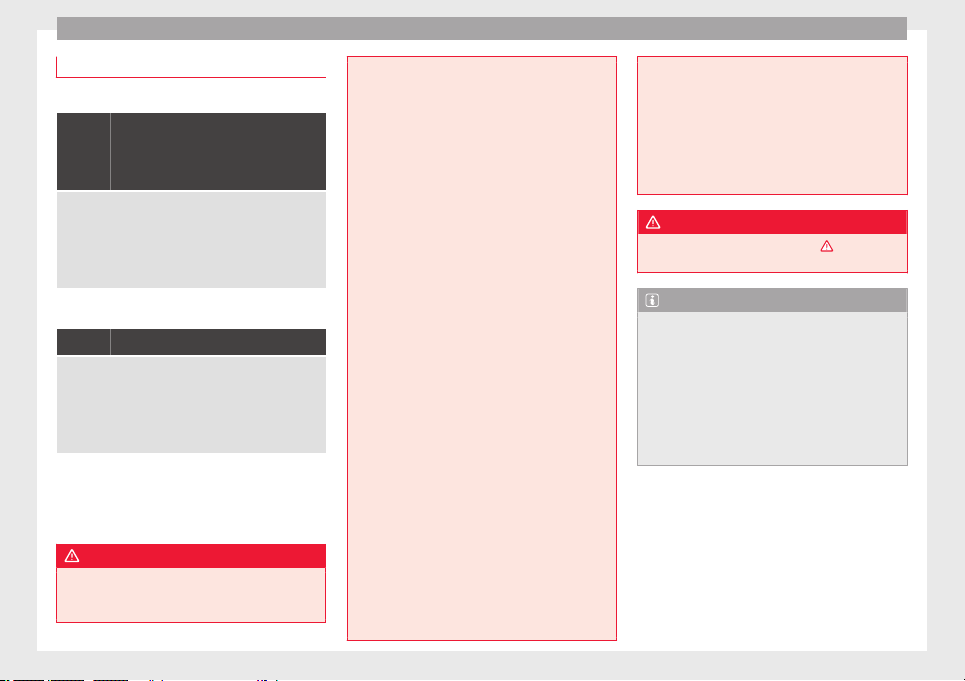
Advice
Tyre monitoring control lamp
If a light appears
The pressure in one or more tyres has
clearly reduced in comparison to the
tyre pressure set by the driver or the
tyre has structural damage.
Additionally, an audible warning can be heard and a text
message can be seen on the instrument panel display.
Stop! Reduce speed immediately! Stop the vehicle
safely as soon as possible. Avoid sudden manoeuvres
and braking! Check all tyres and pressures. Replace any
damaged tyres.
If flashing
System malfunction
The control lamp flashes for approximately one minute
and then lights up permanently.
If tyre pressure is correct, switch the ignition off and on
again. If the control lamp remains lit up, the tyre moni-
toring indicator can be calibrated. Have the system
checked by a specialised workshop.
Several warning and control lamps light up
f
or a f
ew sec
onds when the ignition is switch-
ed on while the function is verified. They will
switch off after a few seconds.
WARNING
When the tyres are inflated at different pres-
sure
s or at a pressure that is too low then a
tyre may be damaged resulting in a loss of
control of the vehicle and a serious or fatal
accident
.
●
If the warning lamp lights up, stop im-
mediately and check the tyres.
●
If the tyres are inflated at different pres-
sures or if a tyre pressure is too low, this will
increase tyre wear, negatively affecting vehi-
cle stability and increasing braking distan-
ces.
●
If tyres are inflated at different pressures or
a tyre pressure is too low, a tyre may be dam-
aged and burst resulting in a loss of control
of the vehicle.
●
The driver is responsible for ensuring that
all of the vehicle tyres are correctly inflated
to the right pressure. The recommended tyre
pressure is indicated on the label
››› page 319.
●
The tyre monitoring system can only oper-
ate correctly if all of the tyres are inflated to
the correct pressure when cold.
●
Driving with tyres at the wrong pressure
can damage them and result in an accident.
Ensure that the tyre pressures of all the tyres
correspond to the vehicle load.
●
Before starting a journey, always inflate
tyres to the correct pressure.
●
Tyres with insufficient pressure are subjec-
ted to more flexing. Due to this, the tyre
could become excessively hot, causing tread
separation and also tyre blow-out.
●
With an overloaded vehicle at high speed,
the tyres can overheat and burst resulting in
a loss of vehicle control.
●
Tyr
e pressures which are too high or too
low reduce the useful life of the tyre, affect-
ing vehicle performance.
●
If a tyre has not been punctured and it does
not have to be changed immediately, drive to
the nearest specialised workshop at a moder-
ate speed and have the tyre checked and in-
flated to the correct pressure.
WARNING
Observe the safety warnings ›
››
in Warning
and contro
l lamps on page 119.
Note
●
If ex
cessively low tyre pressure is detected
with the ignition on, an audible warning will
sound. In the event that there is a fault in the
system, an audible warning will sound.
●
Driving on dirt tracks for a long period of
time or driving in a sporty style can tempora-
rily deactivate the TPMS. The control lamp
shows a fault, but disappears when road con-
ditions or the driving style change.
312
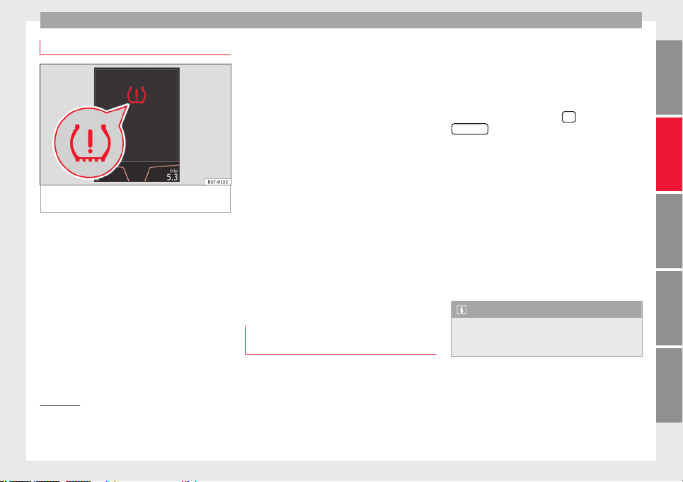
Wheels
Tyre monitoring indicator
Fig. 245 Instrument panel: warning of loss of
ty
r
e pr
essure.
The tyre monitor indicator compares wheel
r
ev
o
lutions and, with this information, the
tread of each wheel using the ABS sensors. If
the rolling circumference of one or more
wheels has changed, the tyre monitoring in-
dicator will indicate this on the instrument
panel through a warning lamp and a warning
to the driver ››› Fig. 245. When only one spe-
cific tyre is affected, its position within the
vehicle will be indicated.
Loss of pressure: Check left
tyre pressure!
Wheel tread change
The wheel tread changes when:
●
Tyre pressure is manually changed
●
Tyre pressure is insufficient
●
Tyre structure is damaged
●
The vehicle is unbalanced because of a
load
●
The wheels on an axle are subject to a
heavier load (e.g. with a heavy load).
●
The vehicle is fitted with snow chains
●
The temporary spare wheel is fitted
●
The wheel on one axle is changed
There may be a delay in the reaction of the
tyre monitoring indicator or it may not in-
dicate anything under certain circumstances
(e.g. sporty driving, snow-covered or un-
paved roads, or when driving with snow
chains).
Calibrating the tyre monitoring indica-
tor
After changing the tyre pressure or replacing
one or mor
e wheel
s, the ty
re monitoring indi-
cator must be recalibrated. Do the same, for
example, when the front and rear wheels are
swapped.
●
Switch the ignition on.
●
Store the new tyre pressure in the Easy
Connect
1)
system with the
button and the
S
ET
TINGS
function button ›
›
›
page 33.
●
In vehicles without radio: press and hold
down the button with the ignition on,
until an acoustic signal is heard.
When driving, the system self-calibrates the
tyre pressure provided by the driver and the
wheels fitted. After a long journey with varied
speeds the programmed values are collected
and monitored.
With the wheels under very heavy loads, the
tyre pressure must be increased to the total
recommended tyre pressure before the cali-
bration ››› page 319.
Note
●
The tyre monit
oring indicator does not
function when there is a fault in the ESC or
ABS ››› page 189.
»
1)
In vehicles that are not equipped with the Easy
Connect sy
stem, the switch for adjusting tyre pres-
sure is located in the centre console next to the haz-
ard warning lights.
313
Technical dataAdviceOperationEmergenciesSafety
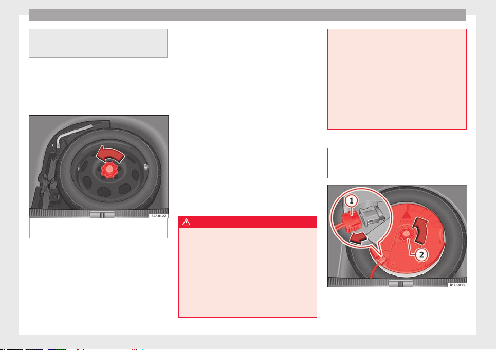
Advice
●
An erroneous
indication may be given when
snow chains are in use because they increase
the tread of the wheel.
Temporary spare wheel
General
information
Fig. 246 Compact temporary spare wheel:
r
ai
sed floor p
anel.
The temporary spare wheel has been de-
s
igned t
o be u
sed for short periods of time.
Have the tyres checked and replaced as soon
as possible at a SEAT Official Service or at a
specialised workshop.
Please note the following restrictions when
using the compact temporary spare wheel.
The compact temporary spare wheel is de-
signed specifically for this model. For this
reason, do not use a temporary spare wheel
from a different type of vehicle.
Removing the temporary spare wheel
–
Lift and hold up the floor panel to remove
the temporary spare wheel.
–
Turn the thumb wheel anti-clockwise
››› Fig. 246.
–
Take out the temporary spare wheel.
Chains
For technical reasons, snow chains must not
be used on the temporary spare wheel.
If you have a puncture on one of the front
wheels when using snow chains, fit the tem-
porary spare wheel in place of one of the rear
wheels. Fit the snow chains on the rear wheel
that you have removed and replace the punc-
tured front wheel with this wheel.
WARNING
●
After fittin
g the temporary spare wheel,
check the tyre pressures as soon as possible.
Failure to do so may cause an accident. The
tyre pressure is listed on the back of the left
front door frame ››› Fig. 242.
●
Do not drive at over 80 km/h (50 mph)
when the temporary spare wheel is fitted on
the vehicle: risk of accident!
●
Never travel more than 200 km using a tem-
porary spare wheel.
●
Avoid he
avy acceleration, hard braking and
fast cornering: risk of accident!
●
Never use more than one temporary spare
wheel at the same time, risk of accident.
●
No other type of tyre (normal summer or
winter tyre) may be fitted on the compact
temporary spare wheel rim.
●
If you are driving using the spare wheel,
the ACC system could automatically switch
off during the journey. Switch off the system
when starting off.
Extraction of the spare wheel in vehi-
c
l
e
s with SEAT SOUND 10 speakers
(with subwoofer)*
Fig. 247 In the luggage compartment: re-
mo
v
e the s
ubwoofer.
314
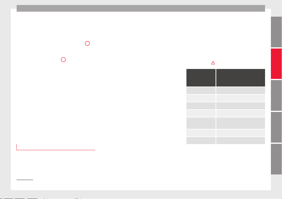
Wheels
To remove the spare wheel, you must first re-
mo
v
e the s
ubwoofer.
●
Lift and secure the luggage compartment
floor as described in ››› page 168.
●
Disconnect the subwoofer ››› Fig. 247
1
speaker cable.
●
Turn the securing wheel in an anti-clock-
w
i
se dir
ection ››› Fig. 247
2
.
●
Remove the s
ub
woofer
speaker and the
spare wheel.
●
When re-mounting the spare tyre, place the
subwoofer on the base of the wheel rim with
care. When doing so, the tip of the “FRONT”
arrow on the subwoofer should point for-
ward.
●
Reconnect the speaker cable and firmly ro-
tate the securing wheel clockwise so that the
subwoofer system and wheel are firmly in
place.
Winter service
Winter tyres
–
Winter tyres must be fitted on a
l
l
four
wheels.
–
Only use winter tyres that are approved for
your vehicle.
–
Please note that the maximum permissible
speed for winter tyres may be lower than
for summer tyres.
–
Also note that winter tyres are no longer ef-
fective when the tread is worn down.
–
After fitting the wheels you must always
check the tyre pressures. When doing so,
take into account the correct tyre pressures
listed on the rear of the front left door
frame ››› page 308.
In winter road conditions winter tyres will
considerably improve vehicle handling. The
design of summer tyres (width, rubber com-
pound, tread pattern) gives less grip on ice
and snow. This applies particularly to vehi-
cles equipped with wide section tyres or with
high speed tyres (code letters H, V or Y on
the sidewall).
Only use winter tyres of the correct type ap-
proved for your vehicle. The sizes of these
tyres are specified in the vehicle's docu-
ments (e.g. EC Certificate of Conformity or
COC
1)
). The vehicle documentation varies de-
pending on the country of residence. See al-
so ››› page 309.
Winter tyres lose a great deal of their proper-
ties when the tread is worn down to a depth
of 4 mm.
The performance of winter tyres is also se-
verely impaired by ageing, even if the tread is
still much deeper than 4 mm.
Winter tyres are subject to the following max-
imum speed limits according to speed rating
code letter: ›››
Speed rating
code letter
››› page 309
Maximum speed limit
Q 160 km/h (100 mph)
S 180 km/h (112 mph)
T 190 km/h (118 mph)
H 210 km/h (130 mph)
V
240 km/h (149 mph) (please note
relevant restrictions)
W 270 km/h (168 mph)
Y 300 km/h (186 mph)
Vehicles capable of exceeding these speeds
mu
s
t
have an appropriate sticker attached so
that it is visible to the driver. Suitable stickers
are available from the SEAT Official Service
»
1)
COC = certificate of conformity.
315
Technical dataAdviceOperationEmergenciesSafety
Advice
and specialised workshop. Please note the
r
e
gu
lations to this effect in your country.
“All-weather” tyres can also be used instead
of winter tyres.
Using winter tyres with V-rating
Please note that the generally applicable
240 km/h (149 mph) speed for winter tyres
with the letter V is subject to technical re-
strictions; the maximum permissible speed
for your vehicle may be significantly lower.
The maximum speed limit for these tyres de-
pends directly on the maximum axle weights
for your car and on the listed weight rating of
the tyres being used.
It is best to contact a SEAT Official Service to
check the maximum speed which is permissi-
ble for the V-rated tyres fitted on your car on
the basis of this information.
WARNING
Exceeding the maximum speed permitted for
the winter ty
res fitted on your car can cause
tyre failure, resulting in a loss of control of
the vehicle – risk of accident.
For the sake of the environment
Summer tyres should be fitted again as soon
as po
ssible after the winter period; they give
better handling on roads which are free of
snow and ice. Summer tyres perform with
less rolling noise, tyre wear and – most im-
portant – reduce fuel consumption.
316
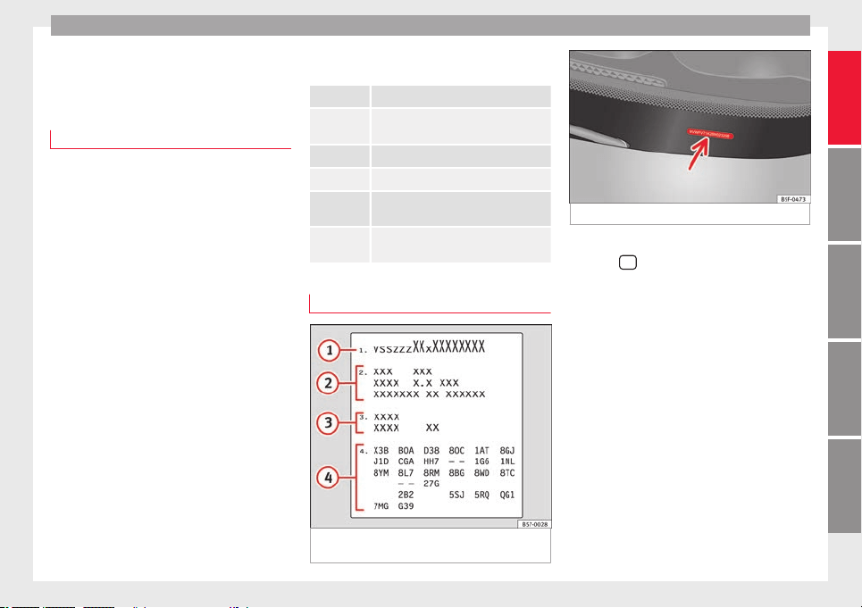
Technical specifications
Technical data
T
ec
hnic
al specifications
Important
The information in the vehicle documentation
alway
s takes precedence over the informa-
tion in this Instruction Manual.
All technical specifications provided in this
documentation are valid for the standard
model in Spain. The vehicle data card inclu-
ded in the Maintenance Programme or the
vehicle registration documents shows which
engine is installed in the vehicle.
The figures may be different depending
whether additional equipment is fitted, for
different models, for special vehicles and for
other countries.
Abbreviations used in the Technical Specifi-
cations
section
kW Kilowatt, engine power measurement.
PS
Pferdestärke (horsepower), formerly used
to denote engine power.
rpm Revolutions per minute - engine speed.
Nm Newton metres, unit of engine torque.
CZ
Cetane number, indication of the diesel
combustion power.
RON
Research octane number, indication of
the knock resistance of petrol.
Vehicle identification data
Fig. 248 Vehicle data sticker (luggage com-
p
ar
tment).
Fig. 249 Chassis number.
VIN in the Easy Connect
●
Select:
button > SETTINGS f
u
nction
b
utton > Service > Chassis number.
Chassis number
The VIN is located in the Easy Connect, on the
vehicle data sticker and under the wind-
screen, on the driver side ››› Fig. 249. Also
the VIN is located in the engine compart-
ment, on the left-hand side in the direction of
travel. The number is engraved on the top
side rail, and is partially covered.
Type plate
The type plate is located on the right side
door pillar. Vehicles for certain export coun-
tries do not have a type plate.
»
317
Technical dataAdviceOperationEmergenciesSafety
Technical data
Vehicle data sticker
The
v
ehic
le data sticker is under the carpet
trim in the luggage compartment, in the
spare wheel well. A sticker with the vehicle
data is attached to the inside cover of the
Maintenance Programme.
The following information is provided on the
vehicle data sticker: ››› Fig. 248
Vehicle identification number (chassis
number)
Vehicle type, model, capacity, engine
type, finish, engine power and gearbox
type
Engine code, gearbox code, external
paint code and internal equipment code
Optional extras and PR numbers
Identifying letters
The identifying letters of the engine can be
viewed on the instrument panel when the en-
gine is switched off and the ignition is on.
●
Hold down the button
0.0/SET
on the dash
p
anel
f
or more than 15 seconds.
1
2
3
4
Information on fuel consump-
tion
F
uel
c
onsumption
Approved consumption values are derived
from mea
surements performed or supervised
by certified EU laboratories, according to the
legislation in force at the time (for more infor-
mation, see the Publications Office of the Eu-
ropean Union on the EUR-Lex website: © Eu-
ropean Union, http://eur-lex.europa.eu/) and
apply to the specified vehicle characteristics.
The values relating to fuel consumption and
CO
2
emissions can be found in the documen-
tation provided to the purchaser of the vehi-
cle at the time of purchase.
Fuel consumption and CO
2
emissions depend
on the equipment/features of each individual
vehicle, as well as on the driving style, road
conditions, traffic conditions, environmental
conditions, load or number of passengers.
Note
In practice, and considering all the factors
mentioned here, con
sumption values can dif-
fer from those calculated in the current Euro-
pean regulations.
Weights
Kerb weight refers to the basic model with a
fuel t
ank filled to 90% capacity and without
optional extras. The figure quoted includes
75 kg to allow for the weight of the driver.
Special versions, optional equipment fittings
or retro-fitting accessories will increase the
weight of the vehicle ›››
.
WARNING
●
Plea
se note that the centre of gravity may
shift when transporting heavy objects; this
may affect vehicle handling and lead to an ac-
cident. Always adjust your speed and driving
style to suit road conditions and require-
ments.
●
Never exceed the gross axle weight rating
or the gross vehicle weight rating. If the per-
missible axle load or the permissible total
weight is exceeded, the driving characteris-
tics of the vehicle may change, which could
lead to accidents, injuries and damage to the
vehicle.
318
Technical specifications
Trailer mode
T
r
ai
ler weights
Trailer weight
The trail
er weights and drawbar loads ap-
proved are selected in intensive trials accord-
ing to precisely defined criteria. The ap-
proved trailer weights are valid for vehicles in
the EU for maximum speeds of 80 km/h (50
mph) (in certain circumstances up to 100
km/h (62 mph)). The figures may be different
in other countries. All data in the official vehi-
cle documentation takes precedence over
these data at all times
›››
.
Dr
a
wb
ar loads
The maximum permitted drawbar load on the
ball joint of the towing bracket must not ex-
ceed 88 kg.
In the interest of road safety, we recommend
that you always tow approaching the maxi-
mum drawbar load. The response of the trail-
er on the road will be poor, if the drawbar
load is too small.
If the maximum permissible drawbar load
cannot be met (e.g. with small, empty and
light-weight single axle trailers or tandem
axle trailers with a wheelbase of less than 1
metre), a minimum of 4% of the actual trailer
weight is legally required for the drawbar
load.
WARNING
●
For saf
ety reasons, you should not drive at
speeds above 80 km/h (50 mph) when towing
a trailer. This also applies in countries where
higher speeds are permitted.
●
Never exceed the maximum trailer weights
or the drawbar load. If the permissible axle
load or the permissible total weight is excee-
ded, the driving characteristics of the vehicle
may change, leading to accidents, injuries
and damage to the vehicle.
Wheels
T
y
r
e pressure, snow chains and wheel
bolts
Tyre pressure
The s
tic
k
er with the tyre pressure values can
be found on the back of the left front door
frame. The tyre pressure values given there
are for cold tyres. The slightly raised pres-
sures of warm tyres must not be reduced.
›››
The pressure for win
t
er
tyres is 0.2 bar
(2.9 psi / 20 kPa) higher than that of summer
tyres.
Snow chains
Snow chains may be fitted only to the front
wheels, and only for the following tyres:
215/60 R16 Chains with links of maximum 15 mm
215/55 R17 Chains with links of maximum 15 mm
215/50 R18 Chains with links of maximum 15 mm
Other dimensions do not allow chains
Wheel bolts
After the wheel
s have been changed, the
tightening torque of the wheel bolts should
be checked as soon as possible with a torque
wrench ›››
. The tightening torque for steel
and alloy
wheels is 140 Nm.
WARNING
●
Check the ty
re pressure at least once per
month. Checking the tyre pressure is very im-
portant. If the tyre pressure is too high or too
low, there is an increased danger of accidents
- particularly at high speeds.
●
If the tightening torque of the wheel bolts
is too low, they could loosen while the vehi-
cle is in motion. Risk of accident! If the tight-
ening torque is too high, the wheel bolts and
threads can be damaged.
Note
We recommend that you ask your Technical
Servic
e for information about appropriate
wheel, tyre and snow chain size.
319
Technical dataAdviceOperationEmergenciesSafety

Technical data
Engine data
P
etr
o
l engine 1.0 85 kW (115 PS)
Power output in kW (PS) at rpm Maximum torque (Nm at rpm) No. of cylinders/displacement (cm
3
) Fuel
85 (115)/5,000-5,500 200/2,000-3,500 3/999 Super 95 RON/Normal 91 RON
a)
a)
Slight power loss.
Outputs and weights
Top speed (km/h) 183 (5)
Acceleration from 0-80 km/h (seconds) 7.2
Acceleration from 0-100 km/h (seconds) 11.0
Maximum authorised weight (kg) 1,830
Weight in running order (with driver) (kg) 1,280
Maximum authorised weight on front axle (kg) 940
Maximum authorised weight on rear axle (kg) 940
Permitted roof load (kg) 75
Maximum trailer weight without brakes (kg) 640
Weight of trailer with brakes on gradients up to 8% (kg) 1,500
Weight of trailer with brakes on gradients up to 12% (kg) 1,300
320

Technical specifications
Petrol engine 1.4 110 kW (150 CV) Start-Stop ACT
®
Power output in kW (PS) at rpm Maximum torque (Nm at rpm) No. of cylinders/displacement (cm
3
) Fuel
110 (150)/5,000-6,000 250/1,500-3,500 4/1,395 Super 95 RON/Normal 91 RON
a)
a)
Slight power loss.
Outputs and weights 2WD Manual 2WD Automatic 4WD Manual 4WD Automatic
Top speed (km/h) 201 (5) 198 (6) 192 (5) 189 (5)
Acceleration from 0-80 km/h (seconds) 5.9 6.0 6.0 5.9
Acceleration from 0-100 km/h (seconds) 8.5 8.6 9.0 8.9
Maximum authorised weight (kg) 1,900 1,920 2,000 2,010
Weight in running order (with driver) (kg) 1,359 1,375 1,460 1,476
Maximum authorised weight on front axle (kg) 970 990 1,000 1,010
Maximum authorised weight on rear axle (kg) 980 980 1,050 1,050
Permitted roof load (kg) 75 75 75 75
Maximum trailer weight without brakes (kg) 670 680 730 730
Weight of trailer with brakes on gradients up to 8% (kg) 1,850 1,800 1,950 1,950
Weight of trailer with brakes on gradients up to 12% (kg) 1,800 1,600 1,900 1,900
321
Technical dataAdviceOperationEmergenciesSafety

Technical data
Petrol engine 2.0 140 kW (190 PS) Start-Stop
Power output in kW (PS) at rpm Maximum torque (Nm at rpm) No. of cylinders/displacement (cm
3
) Fuel
140 (190)/4,200-6,000 320/1,450-4,200 4/1,984 Super 95 RON/Normal 91 RON
a)
a)
Slight power loss.
Outputs and weights 4WD
Top speed (km/h) 212(5)
Acceleration from 0-80 km/h (seconds) 5.2
Acceleration from 0-100 km/h (seconds) 7.9
Maximum authorised weight (kg) 2,080
Weight in running order (with driver) (kg) 1,536
Maximum authorised weight on front axle (kg) 1,070
Maximum authorised weight on rear axle (kg) 1,060
Permitted roof load (kg) 75
Maximum trailer weight without brakes (kg) 750
Weight of trailer with brakes on gradients up to 8% (kg) 2,000
Weight of trailer with brakes on gradients up to 12% (kg) 1,900
322

Technical specifications
Diesel engine 1.6 85 kW (115 PS)
Power output in kW (PS) at rpm Maximum torque (Nm at rpm) No. of cylinders/displacement (cm
3
) Fuel
85 (115)/3,250-4,000 250/1,500-3,250 4/1,598
Diesel according to standard EN 590, min.
51 CZ
Outputs and weights
Top speed (km/h) 184 (6)
Acceleration from 0-80 km/h (seconds) 8.2
Acceleration from 0-100 km/h (seconds) 11.5
Maximum authorised weight (kg) 1,910
Weight in running order (with driver) (kg) 1,375
Maximum authorised weight on front axle (kg) 1,030
Maximum authorised weight on rear axle (kg) 930
Permitted roof load (kg) 75
Maximum trailer weight without brakes (kg) 680
Weight of trailer with brakes on gradients up to 8% (kg) 1,700
Weight of trailer with brakes on gradients up to 12% (kg) 1,500
323
Technical dataAdviceOperationEmergenciesSafety

Technical data
Diesel engine 2.0 105 kW (143 PS)
Power output in kW (PS) at rpm Maximum torque (Nm at rpm) No. of cylinders/displacement (cm
3
) Fuel
105 (143)/3,500-4,000 320/1,750-3,000 4/1,968
Diesel according to standard EN 590, min.
51 CZ
Outputs and weights Automatic
Top speed (km/h) 192 (5)
Acceleration from 0-80 km/h (seconds) 6.4
Acceleration from 0-100 km/h (seconds) 9.2
Maximum authorised weight (kg) 1,970
Weight in running order (with driver) (kg) 1,435
Maximum authorised weight on front axle (kg) 1,080
Maximum authorised weight on rear axle (kg) 940
Permitted roof load (kg) 75
Maximum trailer weight without brakes (kg) 710
Weight of trailer with brakes on gradients up to 8% (kg) 1,900
Weight of trailer with brakes on gradients up to 12% (kg) 1,800
324

Technical specifications
Diesel engine 2.0 110 kW (150 PS)
Power output in kW (PS) at rpm Maximum torque (Nm at rpm) No. of cylinders/displacement (cm
3
) Fuel
110 (150)/3,500-4,000 340/1,750-3,000 4/1,968
Diesel according to standard EN 590, min.
51 CZ
Outputs and weights 2WD Manual 2WD Automatic 4WD
Top speed (km/h) 201 (6) 200 (6) 196 (6)
Acceleration from 0-80 km/h (seconds) 6.2 5.9 6.0
Acceleration from 0-100 km/h (seconds) 8.8 8.7 9.0
Maximum authorised weight (kg) 1,990 2,010 2,100
Weight in running order (with driver) (kg) 1,453 1,483 1,548
Maximum authorised weight on front axle (kg) 1,060 1,090 1,080
Maximum authorised weight on rear axle (kg) 940 930 1,070
Permitted roof load (kg) 75 75 75
Maximum trailer weight without brakes (kg) 700 720 750
Weight of trailer with brakes on gradients up to 8% (kg) 1,900 1,900 2,000
Weight of trailer with brakes on gradients up to 12% (kg) 1,900 1,900 2,000
325
Technical dataAdviceOperationEmergenciesSafety

Technical data
Diesel engine 2.0 140 kW (190 PS)
Power output in kW (PS) at rpm Maximum torque (Nm at rpm) No. of cylinders/displacement (cm
3
) Fuel
140 (190)/3,500-4,000 400/1,750-3,250 4/1,968
Diesel according to standard EN 590, min.
51 CZ
Outputs and weights 4WD Automatic
Top speed (km/h) 212 (6)
Acceleration from 0-80 km/h (seconds) 4.7
Acceleration from 0-100 km/h (seconds) 7.5
Maximum authorised weight (kg) 2,130
Weight in running order (with driver) (kg) 1,589
Maximum authorised weight on front axle (kg) 1,120
Maximum authorised weight on rear axle (kg) 1,060
Permitted roof load (kg) 75
Maximum trailer weight without brakes (kg) 750
Weight of trailer with brakes on gradients up to 8% (kg) 2,100
Weight of trailer with brakes on gradients up to 12% (kg) 2,100
326
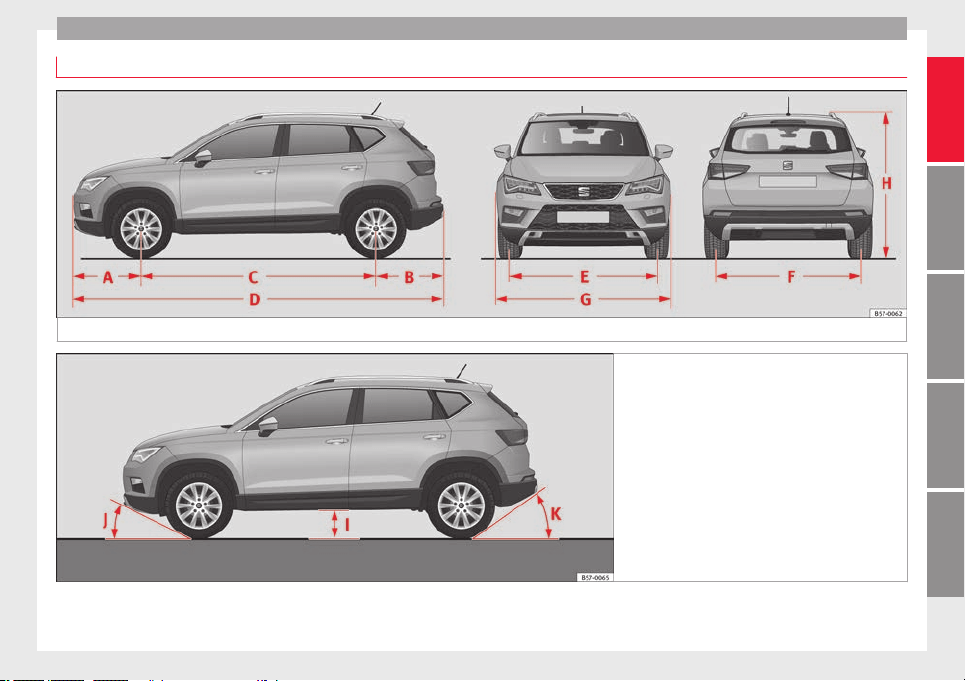

Technical data
››› Fig. 250, ››› Fig. 251 2WD 4WD
A Front projection (mm) 868 868
B Rear projection (mm) 857 865
C Wheelbase (mm) 2,638 2,630
D Length (mm) 4,363
E Front
a)
track (mm) 1,576 1,572
F Back
a)
track (mm) 1,541 1,544
G Width (mm) 1,841
H Height at kerb weight (mm)
1,601
b)
1,615
c)
1,611
b)
1,625
c)
I Ground clearance between the axles (mm) 176 189
J Front projection angle limited by the bumper maximum 19.4° maximum 20.6°
K Rear projection angle limited by the bumper maximum 27.9° maximum 25.5°
Turning radius (m) 10.8
a)
This data will change depending on the type of wheel rim.
b)
Distance to the roof.
c)
Dimension to the roof bars.
328

Index
Index
A
ABS
s
e
e
Anti-lock brake system . . . . . . . . . . . . . . . 189
ACC . . . . . . . . . . . . . . . . . . . . . . . . . . . . . . . . . . . . 221
radar sensor . . . . . . . . . . . . . . . . . . . . . . . . . . . 223
Accessories . . . . . . . . . . . . . . . . . . . . . . . . . 162, 284
Adaptive cruise control . . . . . . . . . . . . . . . . . . . . 221
function for preventing overtaking in an inside
lane . . . . . . . . . . . . . . . . . . . . . . . . . . . . . . . . 227
indications on the display . . . . . . . . . . . . . . . . 222
malfunction . . . . . . . . . . . . . . . . . . . . . . . . . . . . 222
radar sensor . . . . . . . . . . . . . . . . . . . . . . . . . . . 223
special driving situations . . . . . . . . . . . . . . . . . 228
warning and control lamp . . . . . . . . . . . . . . . . 222
Adaptive Cruise Control
deactivating temporarily . . . . . . . . . . . . . . . . . 227
operating . . . . . . . . . . . . . . . . . . . . . . . . . . . . . . 224
AdBlue
information . . . . . . . . . . . . . . . . . . . . . . . . . . . . 295
maximum filling capacity . . . . . . . . . . . . . . . . . 295
refilling . . . . . . . . . . . . . . . . . . . . . . . . . . . . . . . 295
specification . . . . . . . . . . . . . . . . . . . . . . . . . . . 295
tank capacity . . . . . . . . . . . . . . . . . . . . . . . . . . . 295
Additional consumers (efficiency program) . . . . . 42
Adjusting
front head restraints . . . . . . . . . . . . . . . . . . . . . . 77
front seats . . . . . . . . . . . . . . . . . . . . . . . . . . . . . 156
lights . . . . . . . . . . . . . . . . . . . . . . . . . . . . . . . . . 151
rear head restraints . . . . . . . . . . . . . . . . . . . . . 157
seats . . . . . . . . . . . . . . . . . . . . . . . . . . . . . . . . . . 74
Adjusting the head restraints
front head restraints . . . . . . . . . . . . . . . . . . . . . 157
Adjustment
CAR menu . . . . . . . . . . . . . . . . . . . . . . . . . . . . . 120
front head restraints . . . . . . . . . . . . . . . . . . . . . 157
rear head restraints . . . . . . . . . . . . . . . . . . . . . . 77
Airbag covers . . . . . . . . . . . . . . . . . . . . . . . . . . . . . 21
Airbags . . . . . . . . . . . . . . . . . . . . . . . . . . . . . . . . . . 84
description . . . . . . . . . . . . . . . . . . . . . . . . . . . . . 85
Airbag system . . . . . . . . . . . . . . . . . . . . . . . . . . 21, 84
activation . . . . . . . . . . . . . . . . . . . . . . . . . . . . . . 85
control lamp . . . . . . . . . . . . . . . . . . . . . . . . . . . . 89
deactivation of front airbag . . . . . . . . . . . . . . . . 88
description . . . . . . . . . . . . . . . . . . . . . . . . . . . . . 85
front airbags . . . . . . . . . . . . . . . . . . . . . . . . . 21, 86
functioning . . . . . . . . . . . . . . . . . . . . . . . . . . . . . 85
head-protection airbags . . . . . . . . . . . . . . . . . . 24
knee airbags . . . . . . . . . . . . . . . . . . . . . . . . . . . . 23
side airbags . . . . . . . . . . . . . . . . . . . . . . . . . . . . 23
Air conditioning
auxiliary heater . . . . . . . . . . . . . . . . . . . . . . . . . 177
Climatronic . . . . . . . . . . . . . . . . . . . . . . . . 51, 170
heated windscreen . . . . . . . . . . . . . . . . . . . . . . 175
heating and fresh air . . . . . . . . . . . . . . . . . . . . . 54
manual air conditioning . . . . . . . . . . . . . . . . . . . 53
user instructions . . . . . . . . . . . . . . . . . . . . . . . . 173
Air outlets . . . . . . . . . . . . . . . . . . . . . . . . . . . . . . . 174
Air recirculation . . . . . . . . . . . . . . . . . . . . . . . . . . 174
Alcantara: cleaning . . . . . . . . . . . . . . . . . . . . . . . 291
Ambient lighting . . . . . . . . . . . . . . . . . . . . . . . . . 152
Anti-freeze . . . . . . . . . . . . . . . . . . . . . . . . . . . . . . . 58
Anti-lock brake system . . . . . . . . . . . . . . . . . . . . . 189
Anti-puncture . . . . . . . . . . . . . . . . . . . . . . . . . . 63, 95
Anti-puncture kit . . . . . . . . . . . . . . . . . . . . . . . . 63, 95
check after 10 minutes . . . . . . . . . . . . . . . . . . . . 97
Anti-puncture set . . . . . . . . . . . . . . . . . . . . . . . . . . 95
Anti-slip regulation . . . . . . . . . . . . . . . . . . . . . . . 189
Anti-theft alarm . . . . . . . . . . . . . . . . . . . . . 125, 134
trailer . . . . . . . . . . . . . . . . . . . . . . . . . . . . . . . . . 279
vehicle interior monitoring and anti-tow pro-
tection . . . . . . . . . . . . . . . . . . . . . . . . . . . . . . 136
Anti-theft security system . . . . . . . . . . 15, 125, 133
Anti-theft system
trailer . . . . . . . . . . . . . . . . . . . . . . . . . . . . . . . . . 278
Anti-tow protection . . . . . . . . . . . . . . . . . . . . . . . 136
Anti-trap function
sun blind (sunroof) . . . . . . . . . . . . . . . . . . . . . . 143
sunroof . . . . . . . . . . . . . . . . . . . . . . . . . . . . . . . 143
Area view system (Top View Camera)
special characteristics . . . . . . . . . . . . . . . . . . . 268
Aspects to note before setting off . . . . . . . . . . . . . 73
Assistance systems
ACC . . . . . . . . . . . . . . . . . . . . . . . . . . . . . . . . . . 221
adaptive cruise control . . . . . . . . . . . . . . . . . . . 221
Auto Hold function . . . . . . . . . . . . . . . . . . . . . . 211
blind spot detector (BSD) with parking assis-
tance (RCTA) . . . . . . . . . . . . . . . . . . . . . . . . . 237
cruise control system . . . . . . . . . . . . . . . . . . . . 212
Emergency Assist . . . . . . . . . . . . . . . . . . . . . . . 234
emergency brake assist (Front Assist) . . . . . . . 217
fatigue detection . . . . . . . . . . . . . . . . . . . . . . . 248
Hill Descent Control . . . . . . . . . . . . . . . . . . . . . 210
Park Assist . . . . . . . . . . . . . . . . . . . . . . . . . . . . 249
parking assistance (RCTA) . . . . . . . . . . . . . . . . 237
parking system Plus . . . . . . . . . . . . . . . . . . . . . 257
Rear parking aid . . . . . . . . . . . . . . . . . . . . . . . . 262
speed limiter . . . . . . . . . . . . . . . . . . . . . . . . . . . 214
Top View Camera . . . . . . . . . . . . . . . . . . . . . . . 265
traffic jam assist . . . . . . . . . . . . . . . . . . . . . . . . 233
traffic sign detection system . . . . . . . . . . . . . . 245
tyre monitoring . . . . . . . . . . . . . . . . . . . . . . . . . 312
tyre monitoring indicator . . . . . . . . . . . . . . . . . 313
tyre monitoring systems . . . . . . . . . . . . . . . . . 311
Assisted starting . . . . . . . . . . . . . . . . . . . . . . . . . . 69
329

Index
Audible warning signal
lights
. . . . . . . . . . . . . . . . . . . . . . . . . . . . . . . . . 144
se
at
belt not fastened . . . . . . . . . . . . . . . . . . . . 79
warning and control lamps . . . . . . . . . . . . . . . 119
Auto Hold . . . . . . . . . . . . . . . . . . . . . . . . . . . . . . . 211
Auto Hold function . . . . . . . . . . . . . . . . . . . . . . . . 211
Auto Lock (central locking) . . . . . . . . . . . . . . . . . 125
Automatic car washes
switching the Auto Hold function off . . . . . . . . 212
Automatic dipped beam control . . . . . . . . . . . . . 146
Automatic gearbox . . . . . . . . . . . . . . . . . . . . . . . . 193
downhill speed control . . . . . . . . . . . . . . . . . . 198
driving tips . . . . . . . . . . . . . . . . . . . . . . . . . . . . 196
emergency program . . . . . . . . . . . . . . . . . . . . . 199
kick-down feature . . . . . . . . . . . . . . . . . . . . . . . 197
launch control program . . . . . . . . . . . . . . . . . . 197
manual release of the selector lever . . . . . . . . . 49
safety interlock for ignition key . . . . . . . . . . . . 181
selector lever lock . . . . . . . . . . . . . . . . . . . . . . . 194
selector lever positions . . . . . . . . . . . . . . . . . . 193
steering wheel with gear shift paddles . . . . . . 195
tiptronic . . . . . . . . . . . . . . . . . . . . . . . . . . 193, 195
towing . . . . . . . . . . . . . . . . . . . . . . . . . . . . . . . . . 99
AUX-IN . . . . . . . . . . . . . . . . . . . . . . . . . . . . . . . . . . 123
Auxiliary heater . . . . . . . . . . . . . . . . . . . . . . . . . . 177
activating . . . . . . . . . . . . . . . . . . . . . . . . . . . . . 179
electric consumers . . . . . . . . . . . . . . . . . . . . . . 180
operating instructions . . . . . . . . . . . . . . . . . . . 180
programming . . . . . . . . . . . . . . . . . . . . . . . . . . 179
remote control . . . . . . . . . . . . . . . . . . . . . . . . . 178
remote control range . . . . . . . . . . . . . . . . . . . . 179
special features . . . . . . . . . . . . . . . . . . . . . . . . 178
switching off . . . . . . . . . . . . . . . . . . . . . . . . . . . 177
switching on . . . . . . . . . . . . . . . . . . . . . . . . . . . 177
things to note . . . . . . . . . . . . . . . . . . . . . . . . . . 180
B
Battery . . . . . . . . . . . . . . . . . . . . . . . . . . . . . . . . . . 133
replacement in the remote control (auxiliary
heater) . . . . . . . . . . . . . . . . . . . . . . . . . . . . . . 178
Before setting off . . . . . . . . . . . . . . . . . . . . . . . . . . 73
Belt tensioners
control lamp . . . . . . . . . . . . . . . . . . . . . . . . . . . . 89
Belt tightening . . . . . . . . . . . . . . . . . . . . . . . . . . . . 83
Bench seat . . . . . . . . . . . . . . . . . . . . . . . . . . . . . . 159
Bicycle rack
fitting on the retractable tow hitch . . . . . . . . . 277
maximum load . . . . . . . . . . . . . . . . . . . . . . . . . 277
Biodiesel . . . . . . . . . . . . . . . . . . . . . . . . . . . . . . . . 294
Blind spot detector (BSD) . . . . . . . . . . . . . . . . . . 237
control lamps . . . . . . . . . . . . . . . . . . . . . . . . . . 237
driving situations . . . . . . . . . . . . . . . . . . . . . . . 240
indication in the external rear view mirror . . . 238
malfunction . . . . . . . . . . . . . . . . . . . . . . . . . . . . 237
operating . . . . . . . . . . . . . . . . . . . . . . . . . . . . . . 238
towing . . . . . . . . . . . . . . . . . . . . . . . . . . . . . . . . 242
Bonnet . . . . . . . . . . . . . . . . . . . . . . . . . . . . . 17, 298
opening the bonnet . . . . . . . . . . . . . . . . . . . . . 299
Brake fluid . . . . . . . . . . . . . . . . . . . . . . . . . . . . . . . 59
Brakes . . . . . . . . . . . . . . . . . . . . . . . . . . . . . . . . . . 188
brake fluid . . . . . . . . . . . . . . . . . . . . . . . . . . . . . 303
brake servo . . . . . . . . . . . . . . . . . . . . . . . . . . . . 188
electronic parking brake . . . . . . . . . . . . . . . . . 186
emergency braking function . . . . . . . . . . . . . . 187
new brake pads . . . . . . . . . . . . . . . . . . . . . . . . 188
Braking
front assist . . . . . . . . . . . . . . . . . . . . . . . . . . . . 189
BSD
see Blind spot detector (BSD) . . . . . . . . . . . . . 237
BSD Plus . . . . . . . . . . . . . . . . . . . . . . . . . . . . . . . . 232
C
Camera
cleaning . . . . . . . . . . . . . . . . . . . . . . . . . . . . . . 287
cleanliness . . . . . . . . . . . . . . . . . . . . . . . . . . . . 245
Lane Assist . . . . . . . . . . . . . . . . . . . . . . . . . . . . 230
Capacities . . . . . . . . . . . . . . . . . . . . . . . . . . . . . . . . 56
AdBlue tank . . . . . . . . . . . . . . . . . . . . . . . . . . . 295
fuel tank . . . . . . . . . . . . . . . . . . . . . . . . . . . . . . 118
windscreen washer water . . . . . . . . . . . . . . . . 304
Car-care products . . . . . . . . . . . . . . . . . . . . . . . . . 285
Catalytic converter . . . . . . . . . . . . . . . . . . . . . . . . 204
malfunction . . . . . . . . . . . . . . . . . . . . . . . . . . . . 204
CCS . . . . . . . . . . . . . . . . . . . . . . . . . . . . . . . . . . . . . 44
CD-ROM player (navigation) . . . . . . . . . . . . . . . . 161
Central locking . . . . . . . . . . . . . . . . . . . . . . . . . . . 125
adjusting . . . . . . . . . . . . . . . . . . . . . . . . . . . . . . 128
anti-theft alarm . . . . . . . . . . . . . . . . . . . . . . . . . 134
central locking switch . . . . . . . . . . . . . . . . . . . . 128
electric windows . . . . . . . . . . . . . . . . . . . . . . . . 140
emergency locking . . . . . . . . . . . . . . . . . . . . . . . 16
Keyless Access . . . . . . . . . . . . . . . . . . . . . . . . . 129
Panoramic sliding/tilting sunroof . . . . . . . . . . 140
remote control key . . . . . . . . . . . . . . . . . . . . . . 127
selective unlocking system . . . . . . . . . . . . . . . 127
Central wheel trim . . . . . . . . . . . . . . . . . . . . . . . . . 64
Centre console . . . . . . . . . . . . . . . . . . . . . . . . . . . . 11
Cetane number (diesel fuel) . . . . . . . . . . . . . . . . 294
Changing a bulb . . . . . . . . . . . . . . . . . . . . . . . . . . 106
dipped beam . . . . . . . . . . . . . . . . . . . . . . . . . . 107
fog light . . . . . . . . . . . . . . . . . . . . . . . . . . . . . . . 108
main beam . . . . . . . . . . . . . . . . . . . . . . . . . . . . 107
number plate light . . . . . . . . . . . . . . . . . . . . . . 110
rear bulb in the side panel . . . . . . . . . . . . . . . . 109
rear light in the rear lid . . . . . . . . . . . . . . . . . . . 110
turn signal . . . . . . . . . . . . . . . . . . . . . . . . . . . . . 107
Changing a wheel . . . . . . . . . . . . . . . . . . . . . . . . . 64
subsequent work . . . . . . . . . . . . . . . . . . . . . . . . 67
330

Index
Changing gear
en
g
agin
g gears (manual gearbox) . . . . . . . . . 192
Changing settings
CAR menu . . . . . . . . . . . . . . . . . . . . . . . . . . . . . . 33
Changing the blades . . . . . . . . . . . . . . . . . . . . . . . 97
Changing the wiper blades . . . . . . . . . . . . . . . . . . 71
Charging the battery . . . . . . . . . . . . . . . . . . . . . . 306
Checking levels
engine compartment . . . . . . . . . . . . . . . . . . . . 298
Childproof locks
electric windows . . . . . . . . . . . . . . . . . . . . . . . . 139
Child seats . . . . . . . . . . . . . . . . . . . . . . . . . . . . 24, 91
categorisation into groups . . . . . . . . . . . . . . . . . 92
ISOFIX system . . . . . . . . . . . . . . . . . . . . . . . . . . . 26
safety instructions . . . . . . . . . . . . . . . . . . . . 24, 90
securing with seat belt . . . . . . . . . . . . . . . . . . . . 25
Top Tether system . . . . . . . . . . . . . . . . . . . . . 26, 29
Cleaning . . . . . . . . . . . . . . . . . . . . . . . . . . . . . . . . 285
alcantara . . . . . . . . . . . . . . . . . . . . . . . . . . . . . . 291
carbon parts . . . . . . . . . . . . . . . . . . . . . . . . . . . 288
Easy Connect control panel . . . . . . . . . . . . . . . 289
exhaust pipe . . . . . . . . . . . . . . . . . . . . . . . . . . . 289
fabrics . . . . . . . . . . . . . . . . . . . . . . . . . . . . . . . . 289
leather . . . . . . . . . . . . . . . . . . . . . . . . . . . . . . . . 290
natural leather . . . . . . . . . . . . . . . . . . . . . . . . . 291
plastic parts . . . . . . . . . . . . . . . . . . . . . . 288, 289
radio screen . . . . . . . . . . . . . . . . . . . . . . . . . . . 289
rims . . . . . . . . . . . . . . . . . . . . . . . . . . . . . . . . . . 288
seat belts . . . . . . . . . . . . . . . . . . . . . . . . . . . . . 292
trims . . . . . . . . . . . . . . . . . . . . . . . . . . . . . . . . . 287
washing the vehicle . . . . . . . . . . . . . . . . . . . . . 285
windows . . . . . . . . . . . . . . . . . . . . . . . . . . . . . . 288
Climatronic . . . . . . . . . . . . . . . . . . . . . . . . . . . . . . . 51
Close
sunroof . . . . . . . . . . . . . . . . . . . . . . . . . . . . . . . 142
windows . . . . . . . . . . . . . . . . . . . . . . . . . . . . . . 139
Closing . . . . . . . . . . . . . . . . . . . . . . . . . . . . . . . . . 125
bonnet . . . . . . . . . . . . . . . . . . . . . . . . . . . . . . . . 299
rear lid . . . . . . . . . . . . . . . . . . . . . . . . . . . . . . . . 137
sun blind (sunroof) . . . . . . . . . . . . . . . . . . . . . . 143
sunroof . . . . . . . . . . . . . . . . . . . . . . . . . . . . . . . 142
windows . . . . . . . . . . . . . . . . . . . . . . . . . . . . . . 139
Clutch (warning lamp) . . . . . . . . . . . . . . . . . . . . . 199
Coming Home . . . . . . . . . . . . . . . . . . . . . . . . . . . . 148
Coming Home function . . . . . . . . . . . . . . . . . . . . 148
Connectivity Box . . . . . . . . . . . . . . . . . . . . . . . . . . 123
Control and warning lamps . . . . . . . . . . . . . 46, 119
adaptive cruise control . . . . . . . . . . . . . . . . . . . 222
airbags . . . . . . . . . . . . . . . . . . . . . . . . . . . . . . . . 88
airbag system . . . . . . . . . . . . . . . . . . . . . . . . . . . 89
applying the brake . . . . . . . . . . . . . . . . . . . . . . 222
ASR . . . . . . . . . . . . . . . . . . . . . . . . . . . . . . . . . . 191
audible warning signal . . . . . . . . . . . . . . . . . . 119
blind spot detector (BSD) . . . . . . . . . . . . . . . . 237
cruise control system (CCS) . . . . . . . . . . . . . . . 212
depress the brake . . . . . . . . . . . . . . . . . . . . . . . 217
diesel particulate filter . . . . . . . . . . . . . . . . . . . 204
electromechanical steering . . . . . . . . . . . . . . . 200
emission control . . . . . . . . . . . . . . . . . . . . . . . . 205
engine management . . . . . . . . . . . . . . . . . . . . 205
engine pre-heating/fault system . . . . . . . . . . . 205
ESC . . . . . . . . . . . . . . . . . . . . . . . . . . . . . . . . . . 191
gear change . . . . . . . . . . . . . . . . . . . . . . . . . . . 200
Hill Descent Control . . . . . . . . . . . . . . . . . . . . . 210
instrument panel . . . . . . . . . . . . . . . . . . . . . 46, 48
instrument panel display . . . . . . . . . . . . . . . . . . 47
Lane Assist . . . . . . . . . . . . . . . . . . . . . . . . . . . . 230
lights . . . . . . . . . . . . . . . . . . . . . . . . . . . . . . . . . 144
parking assistant (RCTA) . . . . . . . . . . . . . . . . . 237
refuelling . . . . . . . . . . . . . . . . . . . . . . . . . . . . . . 292
remote control (auxiliary heater) . . . . . . . . . . . 178
seat belt . . . . . . . . . . . . . . . . . . . . . . . . . . . . . . . 79
speed limiter . . . . . . . . . . . . . . . . . . . . . . . . . . . 214
Start-Stop . . . . . . . . . . . . . . . . . . . . . . . . . . . . . 208
tow hitch . . . . . . . . . . . . . . . . . . . . . . . . . . . . . . 277
towing bracket . . . . . . . . . . . . . . . . . . . . . . . . . 275
tyre monitoring system . . . . . . . . . . . . . . . . . . 312
Controls and displays
general instrument panel . . . . . . . . . . . . . . . . . 113
Controls for the windows . . . . . . . . . . . . . . . 18, 139
Controls on the steering wheel
operating the audio, telephone and naviga-
tion system . . . . . . . . . . . . . . . . . . . . . . . . . . 121
Coolant
checking level . . . . . . . . . . . . . . . . . . . . . . . . . . 302
Cooling
coolant temperature gauge . . . . . . . . . . . . . . . 117
Cooling system
checking coolant . . . . . . . . . . . . . . . . . . . . . . . 302
topping up coolant . . . . . . . . . . . . . . . . . . . . . . 302
Cornering
lights . . . . . . . . . . . . . . . . . . . . . . . . . . . . . . . . . 148
Correct position . . . . . . . . . . . . . . . . . . . . . . . . . . . 74
driver . . . . . . . . . . . . . . . . . . . . . . . . . . . . . . . . . . 74
front passenger . . . . . . . . . . . . . . . . . . . . . . . . . 75
Correct sitting position
rear seat passengers . . . . . . . . . . . . . . . . . . . . . 76
Cruise control . . . . . . . . . . . . . . . . . . . . . . . . 44, 212
operation . . . . . . . . . . . . . . . . . . . . . . . . . . . . . . 213
Cruise control system . . . . . . . . . . . . . . . . . . . . . . 212
warning and indication lamp . . . . . . . . . . . . . . 212
D
Dangers in not using the seat belt . . . . . . . . . . . . 81
Dash panel . . . . . . . . . . . . . . . . . . . . . . . . . . . . . . . 46
Data sticker . . . . . . . . . . . . . . . . . . . . . . . . . . . . . . 317
Deactivating the front passenger front airbag . . . 22
Deactivation of front airbag . . . . . . . . . . . . . . . . . . 88
Defective bulbs
changing a bulb . . . . . . . . . . . . . . . . . . . . . . . . 106
331

Index
Diesel
die
sel
p
articulate filter . . . . . . . . . . . . . . . . . . . 204
engine oil . . . . . . . . . . . . . . . . . . . . . . . . . . . . . 300
preheating . . . . . . . . . . . . . . . . . . . . . . . . . . . . 181
refuelling . . . . . . . . . . . . . . . . . . . . . . . . . . . . . . 294
Diesel particulate filter
malfunction . . . . . . . . . . . . . . . . . . . . . . . . . . . . 204
Digital clock . . . . . . . . . . . . . . . . . . . . . . . . . . . . . 114
Dimensions . . . . . . . . . . . . . . . . . . . . . . . . . . . . . . 327
Direction of rotation
tyres . . . . . . . . . . . . . . . . . . . . . . . . . . . . . . . . . . . 67
Display . . . . . . . . . . . . . . . . . . . . . . . . . . . . 114, 115
Display messages
speed limiter . . . . . . . . . . . . . . . . . . . . . . . . . . . 214
Display of traffic signs on the instrument panel
activate . . . . . . . . . . . . . . . . . . . . . . . . . . . . . . . 246
deactivate . . . . . . . . . . . . . . . . . . . . . . . . . . . . . 246
Disposal
belt tensioners . . . . . . . . . . . . . . . . . . . . . . . . . . 83
Distance control
see Adaptive cruise control . . . . . . . . . . . . . . . 221
Door cylinder . . . . . . . . . . . . . . . . . . . . . . . . . . . . . 15
Door handle . . . . . . . . . . . . . . . . . . . . . . . . . . . . . . 15
Door lock . . . . . . . . . . . . . . . . . . . . . . . . . . . . . . . . . 15
Door release lever . . . . . . . . . . . . . . . . . . . . . . . . 113
Doors
childproof locks . . . . . . . . . . . . . . . . . . . . . . . . 134
opening and closing . . . . . . . . . . . . . . . . . . . . . 15
Downhill speed control . . . . . . . . . . . . . . . . . . . . 198
Downhill speed control function . . . . . . . . . . . . . 198
Drawer . . . . . . . . . . . . . . . . . . . . . . . . . . . . . . . . . . 160
Drink holders . . . . . . . . . . . . . . . . . . . . . . . . . . . . 161
Driver
see Correct sitting position . . . . . . . . . 74, 75, 76
Driver-side general instrument panel
left-hand drive . . . . . . . . . . . . . . . . . . . . . . . . . . . 9
right-hand drive . . . . . . . . . . . . . . . . . . . . . . . . . 10
Driver information system
engine oil temperature display . . . . . . . . . . . . . 42
operation through the windscreen wiper lever . 36
Driving
driving abroad . . . . . . . . . . . . . . . . . . . . . . . . . 150
driving through water . . . . . . . . . . . . . . . . . . . . 206
economical . . . . . . . . . . . . . . . . . . . . . . . . . . . . 201
safe . . . . . . . . . . . . . . . . . . . . . . . . . . . . . . . . . . . 73
towing . . . . . . . . . . . . . . . . . . . . . . . . . . . . . . . . 102
Driving abroad
headlights . . . . . . . . . . . . . . . . . . . . . . . . . . . . . 150
Driving data
data summary . . . . . . . . . . . . . . . . . . . . . . . . . . . 39
memory . . . . . . . . . . . . . . . . . . . . . . . . . . . . . . . . 38
Driving in winter
trailer . . . . . . . . . . . . . . . . . . . . . . . . . . . . . . . . . 273
Driving mode . . . . . . . . . . . . . . . . . . . . . . . . . . . . 243
Driving on flooded roads . . . . . . . . . . . . . . . . . . . 206
Driving profile . . . . . . . . . . . . . . . . . . . . . . . . . . . . 243
DSG . . . . . . . . . . . . . . . . . . . . . . . . . . . . . . . . . . . . 193
Duplicate keys . . . . . . . . . . . . . . . . . . . . . . . . . . . 126
Dust and pollen filter . . . . . . . . . . . . . . . . . . . . . . 170
Dynamic lights range control . . . . . . . . . . . . . . . . 151
E
E10
see Ethanol (fuel) . . . . . . . . . . . . . . . . . . . . . . . 293
Easy Connect . . . . . . . . . . . . . . . . . . . . . . . . 33, 120
Easy Open . . . . . . . . . . . . . . . . . . . . . . . . . . . . . . . 129
things to note . . . . . . . . . . . . . . . . . . . . . . . . . . 132
EDL
see Electronic differential lock . . . . . . . . . . . . . 189
Efficiency program
additional consumers . . . . . . . . . . . . . . . . . . . . 42
saving tips . . . . . . . . . . . . . . . . . . . . . . . . . . . . . . 42
Electrical accessories
see Power socket . . . . . . . . . . . . . . . . . . . . . . . 162
Electric windows . . . . . . . . . . . . . . . . . . . . . . 18, 139
convenience opening and closing . . . . . . . . . 140
Electromechanical steering . . . . . . . . . . . . . . . . . 200
lamp . . . . . . . . . . . . . . . . . . . . . . . . . . . . . . . . . 200
Electronic differential lock . . . . . . . . . . . . . . . . . . 189
Electronic immobiliser . . . . . . . . . . . . . . . . . . . . . . 15
Electronic self-locking . . . . . . . . . . . . . . . . . . . . . 189
Electronic stability control (ESC) . . . . . . . . . . . . . 189
Electronic torque management (XDS) . . . . . . . . . 190
Emergencies . . . . . . . . . . . . . . . . . . . . . . . . . . . . . . 95
anti-puncture kit . . . . . . . . . . . . . . . . . . . . . . . . . 95
automatic gearbox emergency program . . . . . 199
bulbs . . . . . . . . . . . . . . . . . . . . . . . . . . . . . . . . . . 62
changing a wheel . . . . . . . . . . . . . . . . . . . . . . . . 64
emergency towing of the vehicle . . . . . . . . . . . . 68
fuses . . . . . . . . . . . . . . . . . . . . . . . . . . . . . . . . . . 61
hazard warning lights . . . . . . . . . . . . . . . . . . . 149
jump leads . . . . . . . . . . . . . . . . . . . . . . . . . . . . . 69
manual unlocking and locking . . . . . . . . . . . . . 97
puncture . . . . . . . . . . . . . . . . . . . . . . . . . . . . . . . 62
replacing a blown fuse . . . . . . . . . . . . . . . . . . . . 62
replacing the battery . . . . . . . . . . . . . . . . . . . . 306
vehicle tool kit . . . . . . . . . . . . . . . . . . . . . . . . . . 95
Emergency Assist . . . . . . . . . . . . . . . . . . . . . . . . . 234
see Emergency Assist . . . . . . . . . . . . . . . . . . . . 234
switching off . . . . . . . . . . . . . . . . . . . . . . . . . . . 235
switching on . . . . . . . . . . . . . . . . . . . . . . . . . . . 235
Emergency braking assistance system
indications on the display . . . . . . . . . . . . . . . . 217
malfunction . . . . . . . . . . . . . . . . . . . . . . . . . . . . 218
operating . . . . . . . . . . . . . . . . . . . . . . . . . . . . . . 219
radar sensor . . . . . . . . . . . . . . . . . . . . . . . . . . . 219
switching off temporarily . . . . . . . . . . . . . . . . . 220
system limitations . . . . . . . . . . . . . . . . . . . . . . 220
Emergency braking function . . . . . . . . . . . . . . . . 187
Emergency braking warning . . . . . . . . . . . . . . . . 150
332

Index
Emergency operation
fr
ont
p
assenger door . . . . . . . . . . . . . . . . . . . . . 16
selector lever . . . . . . . . . . . . . . . . . . . . . . . . . . . 49
Emission control system
control lamp . . . . . . . . . . . . . . . . . . . . . . . . . . . 205
Emissions data . . . . . . . . . . . . . . . . . . . . . . . . . . . 317
Engine
assisted starting . . . . . . . . . . . . . . . . . . . . . . . . . 69
noises . . . . . . . . . . . . . . . . . . . . . . . . . . . . . . . . 185
preheating . . . . . . . . . . . . . . . . . . . . . . . . . . . . 181
running in . . . . . . . . . . . . . . . . . . . . . . . . . . . . . 201
Start-Stop system . . . . . . . . . . . . . . . . . . . . . . . 208
starting . . . . . . . . . . . . . . . . . . . . . . . . . . . . . . . 181
starting up (driver messages with the mechan-
ical contact) . . . . . . . . . . . . . . . . . . . . . . . . . . 181
switching off (key) . . . . . . . . . . . . . . . . . . . . . . 182
Engine and ignition
automatic ignition switch-off . . . . . . . . . . . . . . 183
My Beat . . . . . . . . . . . . . . . . . . . . . . . . . . . . . . . 185
preheating the engine . . . . . . . . . . . . . . . . . . . 184
starting the engine . . . . . . . . . . . . . . . . . . . . . . 184
starting the engine with Press & Drive . . . . . . 184
stopping the engine . . . . . . . . . . . . . . . . . . . . . 185
Engine compartment . . . . . . . . . . . . . . . . . . 17, 298
battery . . . . . . . . . . . . . . . . . . . . . . . . . . . . 59, 305
brake fluid . . . . . . . . . . . . . . . . . . . . . . . . . 59, 303
closing the bonnet . . . . . . . . . . . . . . . . . . . . . . 299
coolant . . . . . . . . . . . . . . . . . . . . . . . . . . . 58, 302
engine oil . . . . . . . . . . . . . . . . . . . . . . . . . 57, 301
opening the bonnet . . . . . . . . . . . . . . . . . . . . . 299
safety notes . . . . . . . . . . . . . . . . . . . . . . . . . . . 298
windscreen washer reservoir . . . . . . . . . . 59, 304
Engine coolant . . . . . . . . . . . . . . . . . . . . . . . . . . . . 58
G 12 plus-plus . . . . . . . . . . . . . . . . . . . . . . . . . . 58
G 13 . . . . . . . . . . . . . . . . . . . . . . . . . . . . . . . . . . . 58
specifications . . . . . . . . . . . . . . . . . . . . . . . . . . . 58
Engine data . . . . . . . . . . . . . . . . . . . . . . . . . . . . . . 320
Engine fault
control lamp . . . . . . . . . . . . . . . . . . . . . . . . . . . 205
Engine management . . . . . . . . . . . . . . . . . . . . . . 204
control lamp . . . . . . . . . . . . . . . . . . . . . . . . . . . 205
Engine oil . . . . . . . . . . . . . . . . . . . . . . . . . . . 57, 300
changing . . . . . . . . . . . . . . . . . . . . . . . . . 300, 302
checking oil level . . . . . . . . . . . . . . . . . . . . . . . 301
consumption . . . . . . . . . . . . . . . . . . . . . . . . . . . 301
dipstick . . . . . . . . . . . . . . . . . . . . . . . . . . . . . . . 301
inspection service . . . . . . . . . . . . . . . . . . . . . . 300
maintenance intervals . . . . . . . . . . . . . . . . . . . 300
oil properties . . . . . . . . . . . . . . . . . . . . . . . . . . . 58
specifications . . . . . . . . . . . . . . . . . . . . . . . . . . 300
temperature display . . . . . . . . . . . . . . . . . . . . . . 42
topping up . . . . . . . . . . . . . . . . . . . . . . . . . . . . 301
Environment
ecological driving . . . . . . . . . . . . . . . . . . . . . . . 201
environmental compatibility . . . . . . . . . . . . . . 201
Environmental tips
filling the tank . . . . . . . . . . . . . . . . . . . . . . . . . 293
refuelling . . . . . . . . . . . . . . . . . . . . . . . . . . . . . . 292
Equipment . . . . . . . . . . . . . . . . . . . . . . . . . 162, 284
ESC
electronic stability control (ESC) . . . . . . . . . . . 189
Multi-collision brake . . . . . . . . . . . . . . . . . . . . . 190
Sport Mode . . . . . . . . . . . . . . . . . . . . . . . . . . . . 191
Ethanol (fuel) . . . . . . . . . . . . . . . . . . . . . . . . . . . . 293
Event Data Recorder . . . . . . . . . . . . . . . . . . . . . . . . 94
Exhaust gas purification system
catalytic converter . . . . . . . . . . . . . . . . . . . . . . 204
diesel particulate filter . . . . . . . . . . . . . . . . . . . 204
Exhaust pipe: cleaning . . . . . . . . . . . . . . . . . . . . 289
Exhaust purification system for vehicles with
diesel engines . . . . . . . . . . . . . . . . . . . . . . . . . 295
Exiting a parking space with Park Assist . . . . . . 256
Exterior lighting
changing a bulb . . . . . . . . . . . . . . . . . . . . . . . . 106
Exterior mirrors
adjusting . . . . . . . . . . . . . . . . . . . . . . . . . . . . . . . 20
driving with a trailer . . . . . . . . . . . . . . . . . . . . . 275
Exterior rear-view mirrors
adjusting the exterior rear-view mirrors . . . . . 155
exterior . . . . . . . . . . . . . . . . . . . . . . . . . . . . . . . 155
heated . . . . . . . . . . . . . . . . . . . . . . . . . . . . . . . . 155
Exterior view . . . . . . . . . . . . . . . . . . . . . . . . . . . . . 7, 8
External aerial . . . . . . . . . . . . . . . . . . . . . . . . . . . . 284
F
Fastening rings . . . . . . . . . . . . . . . . . . . . . . . . . . . 165
Fatigue detection . . . . . . . . . . . . . . . . . . . . . . . . . 248
Filling the tank . . . . . . . . . . . . . . . . . . . . . . . . . . . 292
Floor mats . . . . . . . . . . . . . . . . . . . . . . . . . . . . . . . . 78
Fluid Level control . . . . . . . . . . . . . . . . . . . . . . . . . 56
Fog light bulb . . . . . . . . . . . . . . . . . . . . . . . . . . . . 108
Four-wheel drive
snow chains . . . . . . . . . . . . . . . . . . . . . . . . . . . 206
towing . . . . . . . . . . . . . . . . . . . . . . . . . . . . . . . . . 99
winter tyres . . . . . . . . . . . . . . . . . . . . . . . . . . . . 206
Four wheel drive . . . . . . . . . . . . . . . . . . . . . . . . . . 206
Front airbags . . . . . . . . . . . . . . . . . . . . . . . . . . 21, 86
Front armrest . . . . . . . . . . . . . . . . . . . . . . . . . . . . 159
Front Assist . . . . . . . . . . . . . . . . . . . . . . . . . . . . . . 189
indications on the display . . . . . . . . . . . . . . . . 217
Front passenger front airbag
control lamp . . . . . . . . . . . . . . . . . . . . . . . . . . . . 89
deactivation . . . . . . . . . . . . . . . . . . . . . . . . . . . . 22
Front seat
manual adjustment . . . . . . . . . . . . . . . . . . . . . . 18
Fuel . . . . . . . . . . . . . . . . . . . . . . . . . . . . . . . . 56, 293
consumption . . . . . . . . . . . . . . . . . . . . . . . . . . . 318
diesel . . . . . . . . . . . . . . . . . . . . . . . . . . . . . . . . . 294
ethanol . . . . . . . . . . . . . . . . . . . . . . . . . . . . . . . 293
fuel gauge . . . . . . . . . . . . . . . . . . . . . . . . . . . . . 118
333

Index
refuelling . . . . . . . . . . . . . . . . . . . . . . . . . . . . . . 293
s
av
in
g . . . . . . . . . . . . . . . . . . . . . . . . . . . . . . . . 201
Fuel consumption
engine cut-off due to inertia . . . . . . . . . . . . . . 201
why does fuel consumption increase? . . . . . . 204
Fuel tank cap
opening and closing . . . . . . . . . . . . . . . . . . . . . 56
Fuel tank flap
opening and closing . . . . . . . . . . . . . . . . . . . . . 56
Full-LED Headlights . . . . . . . . . . . . . . . . . . . . . . . 106
Function Leaving Home . . . . . . . . . . . . . . . . . . . . 149
Fuses . . . . . . . . . . . . . . . . . . . . . . . . . . . . . . . 61, 102
fuse box . . . . . . . . . . . . . . . . . . . . . . . . . . 103, 104
identifying blown fuses . . . . . . . . . . . . . . . . . . . 62
identifying by colours . . . . . . . . . . . . . . . . . . . . . 61
preparation before replacing . . . . . . . . . . . . . . . 62
replacing . . . . . . . . . . . . . . . . . . . . . . . . . . . . . . . 62
G
Gear-change indicator . . . . . . . . . . . . . . . . . . . . . . 41
Gearbox DSG
see Automatic gearbox . . . . . . . . . . . . . . . . . . . 193
Gearbox lever . . . . . . . . . . . . . . . . . . . . . . . . . . . . . 49
Gear change . . . . . . . . . . . . . . . . . . . . . . . . . . . . . . 49
automatic . . . . . . . . . . . . . . . . . . . . . . . . . . . . . . 49
kick-down . . . . . . . . . . . . . . . . . . . . . . . . . . . . . 244
manual gearbox . . . . . . . . . . . . . . . . . . . . . . . . 192
manual gear change . . . . . . . . . . . . . . . . . . . . . . 49
Gear engaged . . . . . . . . . . . . . . . . . . . . . . . . . . . . . 49
Gear recommendation . . . . . . . . . . . . . . . . . . . . . . 41
Gear shift paddles (automatic gearbox) . . . . . . . 195
General instrument panel
control lamps . . . . . . . . . . . . . . . . . . . . . . . . . . . 46
controls and displays . . . . . . . . . . . . . . . . . . . . 113
engine compartment . . . . . . . . . . . . . . . . . . . . 298
warning lamps . . . . . . . . . . . . . . . . . . . . . . . . . . 46
Glove compartment . . . . . . . . . . . . . . . . . . . . . . . 161
H
Hand brake
see Parking brake . . . . . . . . . . . . . . . . . . . . . . . 186
Hazard warning lights . . . . . . . . . . . . . . . . . 31, 149
HDC
see Hill Descent Control . . . . . . . . . . . . . . . . . . 210
Head-on collisions and their laws of physics . . . . 81
Head-protection airbags
description . . . . . . . . . . . . . . . . . . . . . . . . . . . . . 24
safety instructions . . . . . . . . . . . . . . . . . . . . . . . 87
Headlights
changing a bulb . . . . . . . . . . . . . . . . . . . . . . . . 106
driving abroad . . . . . . . . . . . . . . . . . . . . . . . . . 150
headlight washers . . . . . . . . . . . . . . . . . . . . . . 153
Head restraints . . . . . . . . . . . . . . . . . . . . . . . . . . . . 19
adjustment . . . . . . . . . . . . . . . . . . . . . . . . . . . . 157
front head restraints . . . . . . . . . . . . . . . . . . . . . . 77
rear head restraints . . . . . . . . . . . . . . . . . . . . . . 77
Headrests . . . . . . . . . . . . . . . . . . . . . . . . . . . . . . . . 19
adjustment . . . . . . . . . . . . . . . . . . . . . . . . . . . . 157
front . . . . . . . . . . . . . . . . . . . . . . . . . . . . . . . . . . . 77
Heated rear window . . . . . . . . . . . . . . . . . . . . . 52, 54
Heated windscreen . . . . . . . . . . . . . . . . . . . . . . . 175
Heating and fresh air . . . . . . . . . . . . . . . . . . . . . . . 54
Hill Descent Control
control lamp . . . . . . . . . . . . . . . . . . . . . . . . . . . 210
Horn . . . . . . . . . . . . . . . . . . . . . . . . . . . . . . . . . . . 113
How to jump start . . . . . . . . . . . . . . . . . . . . . . . . . . 69
description . . . . . . . . . . . . . . . . . . . . . . . . . . . . . 69
I
Identifying letters on engine . . . . . . . . . . . . . . . . 317
Ignition . . . . . . . . . . . . . . . . . . . . . . . . . . . . . 30, 181
Ignition lock . . . . . . . . . . . . . . . . . . . . . . . . . 30, 181
see Starter button . . . . . . . . . . . . . . . . . . . . . . . 183
Incorrect position . . . . . . . . . . . . . . . . . . . . . . . . . . 76
Indications on the display . . . . . . . . . . . . . . . . . . 115
ACT . . . . . . . . . . . . . . . . . . . . . . . . . . . . . . . . . . 202
adaptive cruise control . . . . . . . . . . . . . . . . . . . 222
assist systems submenu . . . . . . . . . . . . . . . . . . 39
compass . . . . . . . . . . . . . . . . . . . . . . . . . . . . . . 116
distance travelled . . . . . . . . . . . . . . . . . . . . . . . 116
doors, bonnet and rear lid open . . . . . . . . . . . . 40
driver information system . . . . . . . . . . . . . . . . . 36
driving data . . . . . . . . . . . . . . . . . . . . . . . . . . . . . 38
ECO . . . . . . . . . . . . . . . . . . . . . . . . . . . . . . . . . . 116
Emergency brake assist system (Front Assist) 217
engine oil . . . . . . . . . . . . . . . . . . . . . . . . . . . . . . 42
MKB . . . . . . . . . . . . . . . . . . . . . . . . . . . . . . . . . . 117
outside temperature . . . . . . . . . . . . . . . . . . . . . . 41
recommended gear . . . . . . . . . . . . . . . . . . . . . 116
SEAT Drive Profile . . . . . . . . . . . . . . . . . . . . . . . 242
second speed display . . . . . . . . . . . . . . . . . . . 116
selector lever positions . . . . . . . . . . . . . 116, 193
service intervals . . . . . . . . . . . . . . . . . . . . . . . . . 43
speed warning . . . . . . . . . . . . . . . . . . . . . . . . . 116
Start-Stop . . . . . . . . . . . . . . . . . . . . . . . . . . . . . 116
time . . . . . . . . . . . . . . . . . . . . . . . . . . . . . . . . . . 116
traffic signs . . . . . . . . . . . . . . . . . . . . . . . . . . . . 246
tyre monitoring . . . . . . . . . . . . . . . . . . . . . . . . . 313
warning and control lamps . . . . . . . . . . . . . . . 223
warning and information messages . . . . . . . . . 40
Inertia mode . . . . . . . . . . . . . . . . . . . . . . . . . . . . . 199
Infotainment system . . . . . . . . . . . . . . . . . . . . . . . 33
Inspection . . . . . . . . . . . . . . . . . . . . . . . . . . . . . . . 300
Inspection service . . . . . . . . . . . . . . . . . . . . . . . . 300
Instrument panel . . . . . . . . . . . . . . . . . . . . . . . . . 114
display . . . . . . . . . . . . . . . . . . . . . . . . . . . 114, 115
instruments . . . . . . . . . . . . . . . . . . . . . . . . . . . . 114
menus . . . . . . . . . . . . . . . . . . . . . . . . . . . . . . . . . 36
odometer . . . . . . . . . . . . . . . . . . . . . . . . . . . . . . 117
service interval indication . . . . . . . . . . . . . . . . . 43
warning and control lamps . . . . . . . . . . . . . . . 119
334

Index
Instruments . . . . . . . . . . . . . . . . . . . . . . . . . . . . . 114
Int
erior lights
. . . . . . . . . . . . . . . . . . . . . . . . . . . . .
31
Interior view . . . . . . . . . . . . . . . . . . . . . . . . . . . . . . 14
ISOFIX . . . . . . . . . . . . . . . . . . . . . . . . . . . . . . . . 26, 28
ISOFIX system . . . . . . . . . . . . . . . . . . . . . . . . . . . . . 26
J
Jack . . . . . . . . . . . . . . . . . . . . . . . . . . . . . . . . . . 64, 95
mounting points . . . . . . . . . . . . . . . . . . . . . . . . . 66
Journey data . . . . . . . . . . . . . . . . . . . . . . . . . . . . . . 36
Jump leads . . . . . . . . . . . . . . . . . . . . . . . . . . . . . . . 69
K
Key-operated switch . . . . . . . . . . . . . . . . . . . . . . . . 88
Keyless-Entry
see Keyless Access . . . . . . . . . . . . . . . . . . . . . . 129
Keyless-Exit
see Keyless Access . . . . . . . . . . . . . . . . . . . . . . 129
Keyless Access
Easy Open . . . . . . . . . . . . . . . . . . . . . . . . . . . . . 129
Keyless-Entry . . . . . . . . . . . . . . . . . . . . . . . . . . 129
Keyless-Exit . . . . . . . . . . . . . . . . . . . . . . . . . . . . 129
Press & Drive . . . . . . . . . . . . . . . . . . . . . . . . . . . 183
special characteristics . . . . . . . . . . . . . . . . . . . 132
starting the engine . . . . . . . . . . . . . . . . . . . . . . 184
unlocking and locking the vehicle . . . . . . . . . . 129
Keyless Access locking and ignition system
see Keyless Access . . . . . . . . . . . . . . . . . . . . . . 129
Keys
assign key . . . . . . . . . . . . . . . . . . . . . . . . . . . . . 126
car key . . . . . . . . . . . . . . . . . . . . . . . . . . . . . . . . 126
driver messages (mechanical contact) . . . . . . 181
remote control . . . . . . . . . . . . . . . . . . . . . . . . . 126
replacing the battery . . . . . . . . . . . . . . . . . . . . 133
spare key . . . . . . . . . . . . . . . . . . . . . . . . . . . . . . 126
synchronising . . . . . . . . . . . . . . . . . . . . . . . . . . 134
unlocking and locking . . . . . . . . . . . . . . . 15, 127
Kick-down
automatic gearbox . . . . . . . . . . . . . . . . . . . . . . 197
manual gearbox . . . . . . . . . . . . . . . . . . . . . . . . 244
Knee airbags
safety information . . . . . . . . . . . . . . . . . . . . . . . 23
L
Lane Assist . . . . . . . . . . . . . . . . . . . . . . . . . . . . . . 230
cleaning the camera area . . . . . . . . . . . . . . . . . 287
Lane Assist system
see Lane Assist . . . . . . . . . . . . . . . . . . . . . . . . . 230
Launch control (automatic gearbox) . . . . . . . . . . 197
Leather: care . . . . . . . . . . . . . . . . . . . . . . . . . . . . . 290
Leaving Home . . . . . . . . . . . . . . . . . . . . . . . . . . . . 149
Lifting the vehicle . . . . . . . . . . . . . . . . . . . . . . . . . . 66
Light Assist . . . . . . . . . . . . . . . . . . . . . . . . . . . . . . 146
Lighting of the instrument panel . . . . . . . . . . . . . 151
Lights . . . . . . . . . . . . . . . . . . . . . . . . . . . . . . 30, 144
audible signals . . . . . . . . . . . . . . . . . . . . . . . . . 144
AUTO . . . . . . . . . . . . . . . . . . . . . . . . . . . . . . . . . 146
changing a bulb . . . . . . . . . . . . . . . . . . . . . . . . 106
coming home . . . . . . . . . . . . . . . . . . . . . . . . . . 148
cornering lights . . . . . . . . . . . . . . . . . . . . . . . . 148
daytime running lights . . . . . . . . . . . . . . . . . . . 145
dipped beam headlight . . . . . . . . . . . . . . . . . . 144
fog light . . . . . . . . . . . . . . . . . . . . . . . . . . . . . . . 147
hazard warning lights . . . . . . . . . . . . . . . . . . . . 31
interior lights . . . . . . . . . . . . . . . . . . . . . . . . . . 152
leaving home . . . . . . . . . . . . . . . . . . . . . . . . . . 149
light control . . . . . . . . . . . . . . . . . . . . . . . . . . . 144
lighting of instruments . . . . . . . . . . . . . . . . . . 151
lighting of the controls . . . . . . . . . . . . . . . . . . . 151
lights range control . . . . . . . . . . . . . . . . . . . . . 151
main beam lever . . . . . . . . . . . . . . . . . . . . . . . . 145
main beam lights . . . . . . . . . . . . . . . . . . . . . . . 144
main beams . . . . . . . . . . . . . . . . . . . . . . . . . . . . 31
motorway light . . . . . . . . . . . . . . . . . . . . . . . . . 150
parking lights . . . . . . . . . . . . . . . . . . . . . . . . . . 150
reading lights . . . . . . . . . . . . . . . . . . . . . . . . . . 152
side lights . . . . . . . . . . . . . . . . . . . . . . . . . . . . . 144
switch . . . . . . . . . . . . . . . . . . . . . . . . . . . . . . . . . 30
turn signal lever . . . . . . . . . . . . . . . . . . . . . . . . 145
welcome light . . . . . . . . . . . . . . . . . . . . . . . . . . 149
Lights range control . . . . . . . . . . . . . . . . . . . . . . . 151
Load compartment in the luggage compartment
see Loading the luggage compartment . . . . . 162
Loading the luggage compartment . . . . . . . . . . . 162
Loading the vehicle
fastening rings . . . . . . . . . . . . . . . . . . . . . . . . . 165
luggage compartment . . . . . . . . . . . . . . . . . . . . 16
roof carrier system . . . . . . . . . . . . . . . . . . . . . . 170
tailboard for transporting long items . . . . . . . 164
trailer . . . . . . . . . . . . . . . . . . . . . . . . . . . . . . . . . 279
Locking and unlocking
in the door cylinder . . . . . . . . . . . . . . . . . . . . . . 15
Locking the front passenger door manually . . . . . 16
Luggage . . . . . . . . . . . . . . . . . . . . . . . . . . . . . . . . 162
Luggage compartment . . . . . . . . . . . . . . . . . . . . . . 16
automatic locking . . . . . . . . . . . . . . . . . . . . . . . 139
electric opening and closing . . . . . . . . . . . . . . 137
luggage compartment lighting . . . . . . . . . . . . 152
luggage compartment variable floor . . . . . . . . 167
manual release mechanism . . . . . . . . . . . . . . . . 17
net bag . . . . . . . . . . . . . . . . . . . . . . . . . . . . . . . 166
shelf . . . . . . . . . . . . . . . . . . . . . . . . . . . . . . . . . 163
special characteristics of the electric rear lid . 138
storing the rear shelf . . . . . . . . . . . . . . . . . . . . 164
see also Loading the luggage compartment . 162
Luggage compartment floor . . . . . . . . . . . . . . . . 167
Luggage compartment variable floor . . . . . . . . . 167
Luggage net
luggage compartment . . . . . . . . . . . . . . . . . . . 166
Lumbar support . . . . . . . . . . . . . . . . . . . . . . . . . . 156
335

Index
M
M
ain be
am a
ssist . . . . . . . . . . . . . . . . . . . . . . . . . 146
Main beam lever . . . . . . . . . . . . . . . . . . . . . . . . . . 145
Main panel
turn signal and main beam lever . . . . . . . . . . . 145
Maintenance intervals . . . . . . . . . . . . . . . . . . . . . 300
Malfunction
adaptive cruise control . . . . . . . . . . . . . . . . . . . 222
catalytic converter . . . . . . . . . . . . . . . . . . . . . . 204
clutch . . . . . . . . . . . . . . . . . . . . . . . . . . . . . . . . . 199
diesel particulate filter . . . . . . . . . . . . . . . . . . . 204
emergency braking assistance system (Front
Assist) . . . . . . . . . . . . . . . . . . . . . . . . . . . . . . 218
gearbox . . . . . . . . . . . . . . . . . . . . . . . . . . . . . . . 200
towing bracket . . . . . . . . . . . . . . . . . . . . . . . . . 279
Manual air conditioning . . . . . . . . . . . . . . . . . . . . 53
Manual gearbox . . . . . . . . . . . . . . . . . . . . . . . . . . 192
towing . . . . . . . . . . . . . . . . . . . . . . . . . . . . . . . . . 99
Manual release mechanism
rear lid . . . . . . . . . . . . . . . . . . . . . . . . . . . . . . . . . 17
Manual unlocking and locking . . . . . . . . . . . . . . . 97
Maximum trailer weight
loading the trailer . . . . . . . . . . . . . . . . . . . . . . . 279
MFD
see Driver information system . . . . . . . . . . . . . . 36
Mirror . . . . . . . . . . . . . . . . . . . . . . . . . . . . . . . . . . 155
Mobile . . . . . . . . . . . . . . . . . . . . . . . . . . . . . . . . . . 284
Mobile telephones . . . . . . . . . . . . . . . . . . . . . . . . 284
Model plate . . . . . . . . . . . . . . . . . . . . . . . . . . . . . . 317
Multi-collision brake . . . . . . . . . . . . . . . . . . . . . . 190
Multi-function display (MFD) . . . . . . . . . . . . . . . . . 36
Multimedia . . . . . . . . . . . . . . . . . . . . . . . . . . . . . . 123
My Beat . . . . . . . . . . . . . . . . . . . . . . . . . . . . . . . . . 185
N
Natural leather
cleaning . . . . . . . . . . . . . . . . . . . . . . . . . . . . . . 291
Navigation system
CD-ROM player . . . . . . . . . . . . . . . . . . . . . . . . . 161
Net bag
luggage compartment . . . . . . . . . . . . . . . . . . . 166
Noises
adaptive cruise control . . . . . . . . . . . . . . . . . . . 222
auxiliary heater . . . . . . . . . . . . . . . . . . . . . . . . . 180
brakes . . . . . . . . . . . . . . . . . . . . . . . . . . . . . . . . 188
ESC . . . . . . . . . . . . . . . . . . . . . . . . . . . . . . . . . . 191
parking brake . . . . . . . . . . . . . . . . . . . . . . . . . . 187
tyres . . . . . . . . . . . . . . . . . . . . . . . . . . . . . . 67, 307
Number of seats . . . . . . . . . . . . . . . . . . . . . . . . . . . 79
O
Odometer . . . . . . . . . . . . . . . . . . . . . . . . . . . . . . . 117
partial . . . . . . . . . . . . . . . . . . . . . . . . . . . . . . . . 114
reset button . . . . . . . . . . . . . . . . . . . . . . . . . . . 117
total . . . . . . . . . . . . . . . . . . . . . . . . . . . . . . . . . . 114
Oil change . . . . . . . . . . . . . . . . . . . . . . . . . . . . . . . 302
Oil properties . . . . . . . . . . . . . . . . . . . . . . . . . . . . . 58
On-board computer
see Driver information system . . . . . . . . . . . . . . 36
One-touch opening and closing
electric windows . . . . . . . . . . . . . . . . . . . . . . . . 141
Open and close
windows . . . . . . . . . . . . . . . . . . . . . . . . . . . . . . 139
Opening . . . . . . . . . . . . . . . . . . . . . . . . . . . . . . . . 125
bonnet . . . . . . . . . . . . . . . . . . . . . . . . . . . . . . . . 299
fuel tank flap . . . . . . . . . . . . . . . . . . . . . . . . . . . 292
rear lid . . . . . . . . . . . . . . . . . . . . . . . . . . . . . . . . 137
sun blind (sunroof) . . . . . . . . . . . . . . . . . . . . . . 143
sunroof . . . . . . . . . . . . . . . . . . . . . . . . . . . . . . . 142
windows . . . . . . . . . . . . . . . . . . . . . . . . . . . . . . 139
Opening and closing . . . . . . . . . . . . . . . . . . 15, 125
bonnet . . . . . . . . . . . . . . . . . . . . . . . . . . . . . . . . 299
by remote control . . . . . . . . . . . . . . . . . . . . . . . 127
fuel tank flap . . . . . . . . . . . . . . . . . . . . . . . . . . . 292
in the door cylinder . . . . . . . . . . . . . . . . . . . . . . 15
rear lid . . . . . . . . . . . . . . . . . . . . . . . . . . . . . . . . . 16
rear lid with electric opening and closing . . . . 137
sunroof . . . . . . . . . . . . . . . . . . . . . . . . . . . . . . . 142
with the central locking switch . . . . . . . . . . . . 128
Operating malfunction
Park Assist . . . . . . . . . . . . . . . . . . . . . . . . . . . . 249
sunroof . . . . . . . . . . . . . . . . . . . . . . . . . . . . . . . 142
Outside temperature . . . . . . . . . . . . . . . . . . . . . . . 41
P
Paint . . . . . . . . . . . . . . . . . . . . . . . . . . . . . . . . . . . 287
care . . . . . . . . . . . . . . . . . . . . . . . . . . . . . . . . . . 287
damage . . . . . . . . . . . . . . . . . . . . . . . . . . . . . . . 288
Paintwork
code . . . . . . . . . . . . . . . . . . . . . . . . . . . . . . . . . . 317
Panoramic sliding sunroof
convenience opening and closing . . . . . . . . . 140
see also Sunroof . . . . . . . . . . . . . . . . . . . . . . . . 141
Park Assist . . . . . . . . . . . . . . . . . . . . . . . . . . . . . . 249
automatic braking intervention . . . . . . . . . . . . 257
automatic interruption . . . . . . . . . . . . . . . . . . . 250
conditions for exiting a parking space . . . . . . 256
exiting a parking space (only for parallel
spaces) . . . . . . . . . . . . . . . . . . . . . . . . . . . . . 256
operating malfunction . . . . . . . . . . . . . . . . . . . 249
parallel parking . . . . . . . . . . . . . . . . . . . . . . . . 254
parking conditions . . . . . . . . . . . . . . . . . . . . . . 254
perpendicular parking . . . . . . . . . . . . . . . . . . . 254
see Park Assist . . . . . . . . . . . . . . . . . . . . . . . . . 249
stopping prematurely . . . . . . . . . . . . . . . . . . . . 250
Parking . . . . . . . . . . . . . . . . . . . . . . . . . . . . 187, 196
with Park Assist . . . . . . . . . . . . . . . . . . . . . . . . 254
Parking aid
adjusting the display and audible warn-
ings . . . . . . . . . . . . . . . . . . . . . . . . . . . 261, 265
336

Index
automatic activation . . . . . . . . . . . . . . . . . . . . 260
driv
in
g w
ith a trailer . . . . . . . . . . . . . . . . . . . . . 262
malfunction . . . . . . . . . . . . . . . . . . . . . . . 261, 265
rear parking aid . . . . . . . . . . . . . . . . . . . . . . . . 262
sensors and camera: cleaning . . . . . . . . . . . . . 287
towing bracket . . . . . . . . . . . . . . . . . . . . . . . . . 265
visual indication . . . . . . . . . . . . . . . . . . . 260, 264
Parking aid system
see Parking aid . . . . . . . . . . . . . . . . . . . . 257, 262
Parking assistance
parking system plus . . . . . . . . . . . . . . . . . . . . . 257
see Park Assist . . . . . . . . . . . . . . . . . . . . . . . . . 249
surroundings warning . . . . . . . . . . . . . . . . . . . 257
Parking assistance (RCTA) . . . . . . . . . . . . . . . . . . 237
control lamp . . . . . . . . . . . . . . . . . . . . . . . . . . . 237
Parking assistant . . . . . . . . . . . . . . . . . . . . . . . . . 241
Parking assistant (RCTA) . . . . . . . . . . . . . . . . . . . 241
Parking brake . . . . . . . . . . . . . . . . . . . . . . . . . . . . 186
activate . . . . . . . . . . . . . . . . . . . . . . . . . . . . . . . 186
automatic activation . . . . . . . . . . . . . . . . . . . . 187
automatic release . . . . . . . . . . . . . . . . . . . . . . . 186
emergency braking function . . . . . . . . . . . . . . 187
release . . . . . . . . . . . . . . . . . . . . . . . . . . . . . . . . 186
Parking distance warning system
see Parking aid . . . . . . . . . . . . . . . . . . . . 257, 262
Parking (automatic gearbox) . . . . . . . . . . . . . . . . 196
ParkPilot
see Parking aid . . . . . . . . . . . . . . . . . . . . 257, 262
Particulate filter (diesel) . . . . . . . . . . . . . . . . . . . 204
Parts . . . . . . . . . . . . . . . . . . . . . . . . . . . . . . . . . . . 284
Passenger
see Correct sitting position . . . . . . . . . 74, 75, 76
Passenger-side instrument panel
left-hand drive . . . . . . . . . . . . . . . . . . . . . . . . . . 12
right-hand drive . . . . . . . . . . . . . . . . . . . . . . . . . 13
Pedals . . . . . . . . . . . . . . . . . . . . . . . . . . . . . . . . . . . 78
Petrol
additives . . . . . . . . . . . . . . . . . . . . . . . . . . . . . . 293
refuelling . . . . . . . . . . . . . . . . . . . . . . . . . . . . . . 293
Plastic parts: cleaning . . . . . . . . . . . . . . . . 288, 289
Polishing . . . . . . . . . . . . . . . . . . . . . . . . . . . . . . . . 287
Positioning seat belts
during pregnancy . . . . . . . . . . . . . . . . . . . . . . . . 83
seat belts . . . . . . . . . . . . . . . . . . . . . . . . . . . . . . 83
Power . . . . . . . . . . . . . . . . . . . . . . . . . . . . . . . . . . 162
Power management . . . . . . . . . . . . . . . . . . . . . . . 203
Power socket . . . . . . . . . . . . . . . . . . . . . . . . . . . . 162
trailer . . . . . . . . . . . . . . . . . . . . . . . . . . . . . . . . . 278
Power steering
see Electromechanical steering . . . . . . . . . . . . 200
Pre-heating system
control lamp . . . . . . . . . . . . . . . . . . . . . . . . . . . 205
Preheating . . . . . . . . . . . . . . . . . . . . . . . . . . . . . . 181
Preheating the engine . . . . . . . . . . . . . . . . . . . . . 184
Press & Drive
starter button . . . . . . . . . . . . . . . . . . . . . . . . . . 183
starting the engine . . . . . . . . . . . . . . . . . . . . . . 184
Puncture
action . . . . . . . . . . . . . . . . . . . . . . . . . . . . . . . . . 62
R
Racks . . . . . . . . . . . . . . . . . . . . . . . . . . . . . . . . . . . 161
Radar sensor . . . . . . . . . . . . . . . . . . . . . . . . 219, 223
Radio-operated remote control
see Keys . . . . . . . . . . . . . . . . . . . . . . . . . . . . . . 126
Radio screen: cleaning . . . . . . . . . . . . . . . . . . . . 289
Radio transmitters . . . . . . . . . . . . . . . . . . . . . . . . 284
Rain sensor . . . . . . . . . . . . . . . . . . . . . . . . . . . . . . 154
control of the function . . . . . . . . . . . . . . . . . . . 154
Raising the vehicle . . . . . . . . . . . . . . . . . . . . . . . . . 66
RCTA . . . . . . . . . . . . . . . . . . . . . . . . . . . . . . . . . . . 241
see Parking assistance (RCTA) . . . . . . . . . . . . . 237
Rear
headrests . . . . . . . . . . . . . . . . . . . . . . . . . . . . . . 77
Rear-view mirror
anti-dazzle . . . . . . . . . . . . . . . . . . . . . . . . . . . . 155
interior anti-dazzle . . . . . . . . . . . . . . . . . . . . . . 155
Rear Assist . . . . . . . . . . . . . . . . . . . . . . . . . . . . . . 270
instructions for use . . . . . . . . . . . . . . . . . . . . . 271
parking . . . . . . . . . . . . . . . . . . . . . . . . . . . . . . . 272
screen . . . . . . . . . . . . . . . . . . . . . . . . . . . . . . . . 271
special characteristics . . . . . . . . . . . . . . . . . . . 271
Rear Assist system . . . . . . . . . . . . . . . . . . . . . . . . 270
Rear bulbs in the side panel
disassemble the rear light . . . . . . . . . . . . . . . . 109
Rear lid . . . . . . . . . . . . . . . . . . . . . . . . . . . . . . . 16, 17
see also Luggage compartment . . . . . . . . . . . 137
Rear lights in the rear lid
disassemble the bulb holder . . . . . . . . . . . . . . 110
Rear parking aid . . . . . . . . . . . . . . . . . . . . . . . . . . 262
Rear seat backrest
folding down . . . . . . . . . . . . . . . . . . . . . . . . . . . 159
folding down and lifting the backrest . . . . . . . 159
lifting . . . . . . . . . . . . . . . . . . . . . . . . . . . . . . . . . 159
Rear seat passengers
see Correct sitting position . . . . . . . . . 74, 75, 76
Rear shelf
storing . . . . . . . . . . . . . . . . . . . . . . . . . . . . . . . . 164
Rear View Camera . . . . . . . . . . . . . . . . . . . . . . . . . 270
Refuelling
fuel gauge . . . . . . . . . . . . . . . . . . . . . . . . . . . . . 118
opening fuel tank flap . . . . . . . . . . . . . . . . . . . 292
Remote control key
unlocking and locking . . . . . . . . . . . . . . . . . . . 127
Remote control (auxiliary heater) . . . . . . . . . . . . 178
replacing the battery . . . . . . . . . . . . . . . . . . . . 178
Removing and attaching head restraints . . . . . . 157
Repair work . . . . . . . . . . . . . . . . . . . . . . . . . . . . . . 284
337

Index
Replacement
p
ar
ts
. . . . . . . . . . . . . . . . . . . . . . . . . . . . . . . . . 284
Replacement parts . . . . . . . . . . . . . . . . . . . . . . . . 284
Replacing the battery
of the vehicle key . . . . . . . . . . . . . . . . . . . . . . . 133
Reset the trip recorder . . . . . . . . . . . . . . . . . . . . . 117
Retaining hooks . . . . . . . . . . . . . . . . . . . . . . . . . . 166
Retrofitting
towing bracket . . . . . . . . . . . . . . . . . . . . . . . . . 282
Reverse gear (automatic gearbox) . . . . . . . . . . . 193
Revolution counter . . . . . . . . . . . . . . . . . . . 114, 115
Rims
changing a wheel . . . . . . . . . . . . . . . . . . . . . . . . 64
cleaning . . . . . . . . . . . . . . . . . . . . . . . . . . . . . . 288
Roll-back function
windows . . . . . . . . . . . . . . . . . . . . . . . . . . . . . . 140
RON (petrol) . . . . . . . . . . . . . . . . . . . . . . . . . . . . . 293
Roof carrier . . . . . . . . . . . . . . . . . . . . . . . . . . . . . . 168
Roof carrier system . . . . . . . . . . . . . . . . . . . . . . . . 168
Roof load . . . . . . . . . . . . . . . . . . . . . . . . . . . . . . . . 170
technical data . . . . . . . . . . . . . . . . . . . . . . . . . . 170
Roof luggage rack
attach the cross bars . . . . . . . . . . . . . . . . . . . . 169
Roof rack . . . . . . . . . . . . . . . . . . . . . . . . . . . . . . . . 168
Running in
new brake pads . . . . . . . . . . . . . . . . . . . . . . . . 188
new engine . . . . . . . . . . . . . . . . . . . . . . . . . . . . 201
new tyres . . . . . . . . . . . . . . . . . . . . . . . . . . . . . . 307
S
Safe driving . . . . . . . . . . . . . . . . . . . . . . . . . . . . . . 73
Safelock . . . . . . . . . . . . . . . . . . . . . . . . . . . . . . . . 133
see also Anti-theft security system . . . . . . . . . 125
Safety
child safety . . . . . . . . . . . . . . . . . . . . . . . . . . . . . 90
child seats . . . . . . . . . . . . . . . . . . . . . . . . . . . . . . 90
deactivating the front passenger airbag . . . . . . 22
safe driving . . . . . . . . . . . . . . . . . . . . . . . . . . . . . 73
Safety equipment . . . . . . . . . . . . . . . . . . . . . . . . . . 73
Safety information
knee airbags . . . . . . . . . . . . . . . . . . . . . . . . . . . . 23
Safety instructions
belt tensioners . . . . . . . . . . . . . . . . . . . . . . . . . . 83
head-protection airbags . . . . . . . . . . . . . . . . . . 87
side airbags . . . . . . . . . . . . . . . . . . . . . . . . . . . . 86
use of seat belts . . . . . . . . . . . . . . . . . . . . . . . . . 80
using child seats . . . . . . . . . . . . . . . . . . . . . 24, 90
Safety interlock for ignition key . . . . . . . . . . . . . . 181
Saving fuel
inertia mode . . . . . . . . . . . . . . . . . . . . . . . . . . . 199
Saving tips (efficiency program) . . . . . . . . . . . . . . 42
Seat
electric seat . . . . . . . . . . . . . . . . . . . . . . . . . . . . 19
heating . . . . . . . . . . . . . . . . . . . . . . . . . . . . . . . 158
Seat belt position
for pregnant women . . . . . . . . . . . . . . . . . . . . . . 19
seat belts . . . . . . . . . . . . . . . . . . . . . . . . . . . . . . 19
Seat belts . . . . . . . . . . . . . . . . . . . . . . . . . . . . . . . . 79
adjustment . . . . . . . . . . . . . . . . . . . . . . . . . . 19, 82
cleaning . . . . . . . . . . . . . . . . . . . . . . . . . . . . . . 292
control lamp . . . . . . . . . . . . . . . . . . . . . . . . . . . . 79
protective function . . . . . . . . . . . . . . . . . . . . . . . 80
purpose . . . . . . . . . . . . . . . . . . . . . . . . . . . . . 79, 84
safety instructions . . . . . . . . . . . . . . . . . . . . . . . 80
unfastened . . . . . . . . . . . . . . . . . . . . . . . . . . . . . 81
Seat belt tensioners . . . . . . . . . . . . . . . . . . . . . 20, 83
SEAT Drive Profile . . . . . . . . . . . . . . . . . . . . . . . . . 242
Seat heating . . . . . . . . . . . . . . . . . . . . . . . . . . . . . 158
Seats
adjustment . . . . . . . . . . . . . . . . . . . . . . . . . . . . 156
rear seat backrest . . . . . . . . . . . . . . . . . . . . . . . 159
Selective catalytic reduction
see Exhaust purification system (diesel) . . . . 295
Selective unlocking system . . . . . . . . . . . . . . . . . 127
Selector lever lock . . . . . . . . . . . . . . . . . . . . . . . . 194
Selector lever (automatic gearbox)
malfunction . . . . . . . . . . . . . . . . . . . . . . . . . . . . 194
manual release mechanism . . . . . . . . . . . . . . . . 49
positions . . . . . . . . . . . . . . . . . . . . . . . . . . . . . . 193
Service intervals . . . . . . . . . . . . . . . . . . . . . . . . . . . 43
Service notification: read . . . . . . . . . . . . . . . . . . . . 44
Side airbags
description . . . . . . . . . . . . . . . . . . . . . . . . . . . . . 23
safety instructions . . . . . . . . . . . . . . . . . . . . . . . 86
Signal lever . . . . . . . . . . . . . . . . . . . . . . . . . . . . . . . 31
Sliding panoramic sunroof . . . . . . . . . . . . . . . . . . 18
Snow chains . . . . . . . . . . . . . . . . . . . . . . . . . 67, 319
four-wheel drive . . . . . . . . . . . . . . . . . . . . . . . . 206
Spanner symbol . . . . . . . . . . . . . . . . . . . . . . . . . . . 43
Special characteristics
area view system (Top View Camera) . . . . . . . 268
high-pressure cleaning devices . . . . . . . . . . . . 277
tow-starting . . . . . . . . . . . . . . . . . . . . . . . . . . 98, 99
towing . . . . . . . . . . . . . . . . . . . . . . . . . . . . . . . . . 98
trailer mode . . . . . . . . . . . . . . . . . . . . . . . . . . . 280
Speed limiter . . . . . . . . . . . . . . . . . . . . . . . 212, 214
control lamp . . . . . . . . . . . . . . . . . . . . . . . . . . . 214
display message . . . . . . . . . . . . . . . . . . . . . . . . 214
operate . . . . . . . . . . . . . . . . . . . . . . . . . . . . . . . 215
warning lamp . . . . . . . . . . . . . . . . . . . . . . . . . . 214
Speed warning device . . . . . . . . . . . . . . . . . . . . . . 42
Sport Mode . . . . . . . . . . . . . . . . . . . . . . . . . . . . . . 191
Stabilisation of the towing vehicle and trailer . . 281
Start-Stop . . . . . . . . . . . . . . . . . . . . . . . . . . . . . . . 208
Start-Stop system
driver messages . . . . . . . . . . . . . . . . . . . . . . . . 210
lamps . . . . . . . . . . . . . . . . . . . . . . . . . . . . . . . . 208
operation . . . . . . . . . . . . . . . . . . . . . . . . . . . . . . 208
starting and stopping the engine . . . . . . . . . . 208
switching off and on . . . . . . . . . . . . . . . . . . . . . 210
338

Index
the engine does not switch off . . . . . . . . . . . . 209
the en
gine s
t
arts by itself . . . . . . . . . . . . . . . . 209
Starter button . . . . . . . . . . . . . . . . . . . . . . . . . . . . 183
Starting the engine . . . . . . . . . . . . . . . . . . . . . . . 181
Starting the vehicle . . . . . . . . . . . . . . . . . . . . . . . . 30
Steering
electromechanical steering . . . . . . . . . . . . . . . 200
engaging the steering lock . . . . . . . . . . . . . . . 182
Steering wheel
adjusting . . . . . . . . . . . . . . . . . . . . . . . . . . . . . . . 75
adjustment . . . . . . . . . . . . . . . . . . . . . . . . . . . . . 20
gear shift paddles (automatic gearbox) . . . . . 195
Storage area
front seat . . . . . . . . . . . . . . . . . . . . . . . . . . . . . . 160
Storage compartments . . . . . . . . . . . . . . . 160, 161
glove compartment . . . . . . . . . . . . . . . . . . . . . 161
glove compartment lighting . . . . . . . . . . . . . . 152
Storing objects
trailer . . . . . . . . . . . . . . . . . . . . . . . . . . . . . . . . . 273
Sun blinds
anti-trap function (sunroof) . . . . . . . . . . . . . . . 143
sunroof . . . . . . . . . . . . . . . . . . . . . . . . . . . . . . . 143
Sun protection . . . . . . . . . . . . . . . . . . . . . . . . . . . 152
Sunroof . . . . . . . . . . . . . . . . . . . . . . . . . . . . . . . . . 141
anti-trap function . . . . . . . . . . . . . . . . . . . . . . . 143
closing . . . . . . . . . . . . . . . . . . . . . . . . . . . . . . . . 142
opening . . . . . . . . . . . . . . . . . . . . . . . . . . . . . . . 142
operating malfunction . . . . . . . . . . . . . . . . . . . 142
sun blind . . . . . . . . . . . . . . . . . . . . . . . . . . . . . . 143
Sun visors . . . . . . . . . . . . . . . . . . . . . . . . . . . . . . . 152
Switch
hazard warning lights . . . . . . . . . . . . . . . . . . . 149
Switching off the engine
with the key . . . . . . . . . . . . . . . . . . . . . . . . . . . . 182
Switching off the lights . . . . . . . . . . . . . . . . . . . . 144
Switching on the lights . . . . . . . . . . . . . . . . . . . . 144
Switching the ignition on and off . . . . . . . . 30, 181
System Easy Connect . . . . . . . . . . . . . . . . . . . . . . 120
T
Tailboard for transporting long items . . . . . . . . . 164
Tail lights
changing a bulb . . . . . . . . . . . . . . . . . . . . . . . . 106
Taking care of your vehicle . . . . . . . . . . . . . . . . . 285
exterior . . . . . . . . . . . . . . . . . . . . . . . . . . . . . . . 285
interior . . . . . . . . . . . . . . . . . . . . . . . . . . . . . . . . 289
Technical data
capacity . . . . . . . . . . . . . . . . . . . . . . . . . . . . . . . 304
roof load . . . . . . . . . . . . . . . . . . . . . . . . . . . . . . 170
vertical load on the coupling . . . . . . . . . . . . . . 273
Technical modifications . . . . . . . . . . . . . . . . . . . . 284
Technical specifications . . . . . . . . . . . . . . . . . . . . 317
Textiles: cleaning . . . . . . . . . . . . . . . . . . . . . . . . . 289
Things to note
towing . . . . . . . . . . . . . . . . . . . . . . . . . . . . . . . . 100
Tightening torque of wheel bolts . . . . . . . . . . . . 319
Tiptronic (automatic gearbox) . . . . . . . . . . 193, 195
Top speed . . . . . . . . . . . . . . . . . . . . . . . . . . . . . . . . 42
Top Tether . . . . . . . . . . . . . . . . . . . . . . . . . . . . . 26, 29
Top Tether system . . . . . . . . . . . . . . . . . . . . . . 26, 29
Top View Camera . . . . . . . . . . . . . . . . . . . . . . . . . 265
see Top View Camera system . . . . . . . . . . . . . . 265
Top View Camera system
Instructions for use . . . . . . . . . . . . . . . . . . . . . 268
menus . . . . . . . . . . . . . . . . . . . . . . . . . . . . . . . . 269
modes . . . . . . . . . . . . . . . . . . . . . . . . . . . . . . . . 269
screen . . . . . . . . . . . . . . . . . . . . . . . . . . . . . . . . 268
Tow-starting . . . . . . . . . . . . . . . . . . . . . . . . . . . . . . 69
Tow-starting the engine . . . . . . . . . . . . . . . . . . . . . 99
special characteristics . . . . . . . . . . . . . . . . . . . . 98
Tow hitch
control lamp . . . . . . . . . . . . . . . . . . . . . . . . . . . 277
electrical unlocking . . . . . . . . . . . . . . . . . . . . . 276
Towing
blind spot detector (BSD) . . . . . . . . . . . . . . . . 242
special characteristics . . . . . . . . . . . . . . . . . . . 242
Towing bracket . . . . . . . . . . . . . . . . . . . . . . . . . . . 276
also see Trailer . . . . . . . . . . . . . . . . . . . . . . . . . 276
control lamp . . . . . . . . . . . . . . . . . . . . . . . . . . . 275
electrical unlocking tow hitch . . . . . . . . . . . . . 276
fitting a bicycle rack . . . . . . . . . . . . . . . . . . . . . 277
malfunction . . . . . . . . . . . . . . . . . . . . . . . . . . . . 279
retrofitting . . . . . . . . . . . . . . . . . . . . . . . . . . . . . 282
Towing the vehicle . . . . . . . . . . . . . . . . . . 68, 98, 99
automatic gearbox . . . . . . . . . . . . . . . . . . . . . . . 99
driving tips . . . . . . . . . . . . . . . . . . . . . . . . . . . . 102
four-wheel drive . . . . . . . . . . . . . . . . . . . . . . . . . 99
front towing eye . . . . . . . . . . . . . . . . . . . . . . . . 100
manual gearbox . . . . . . . . . . . . . . . . . . . . . . . . . 99
rear towing eye . . . . . . . . . . . . . . . . . . . . . . . . . 101
special characteristics . . . . . . . . . . . . . . . . . . . . 98
things to note . . . . . . . . . . . . . . . . . . . . . . . . . . 100
tow bar . . . . . . . . . . . . . . . . . . . . . . . . . . . . . . . . 99
towing not allowed . . . . . . . . . . . . . . . . . . . . . . . 99
with towing bracket . . . . . . . . . . . . . . . . . . . . . . 99
Towline anchorages . . . . . . . . . . . . . . . . . . . . . 68, 95
Tow rope . . . . . . . . . . . . . . . . . . . . . . . . . . . 275, 278
Traffic Jam Assist . . . . . . . . . . . . . . . . . . . . . . . . . 233
malfunctions . . . . . . . . . . . . . . . . . . . . . . . . . . . 234
situations in which Traffic Jam Assist must be
switched off . . . . . . . . . . . . . . . . . . . . . . . . . . 234
Traffic sign detection system . . . . . . . . . . . . . . . . 245
limited operation . . . . . . . . . . . . . . . . . . . . . . . 247
operation . . . . . . . . . . . . . . . . . . . . . . . . . . . . . . 246
speed warning . . . . . . . . . . . . . . . . . . . . . . . . . 247
trailer . . . . . . . . . . . . . . . . . . . . . . . . . . . . . . . . . 247
windscreen damage . . . . . . . . . . . . . . . . . . . . . 245
Traffic Sign Detection System . . . . . . . . . . . . . . . 246
indication on display . . . . . . . . . . . . . . . . . . . . 246
Traffic signs
indication on display . . . . . . . . . . . . . . . . . . . . 246
339

Index
Trailer . . . . . . . . . . . . . . . . . . . . . . . . . . . . . . . . . . 273
a
dju
s
ting the headlights . . . . . . . . . . . . . . . . . 280
anti-theft alarm . . . . . . . . . . . . . . . . . . . . . . . . . 279
anti-theft system . . . . . . . . . . . . . . . . . . . . . . . 278
connecting . . . . . . . . . . . . . . . . . . . . . . . . . . . . 278
exterior mirrors . . . . . . . . . . . . . . . . . . . . . . . . . 275
hooking up . . . . . . . . . . . . . . . . . . . . . . . . . . . . 278
loading . . . . . . . . . . . . . . . . . . . . . . . . . . . . . . . 279
malfunction . . . . . . . . . . . . . . . . . . . . . . . . . . . . 279
maximum trailer weight . . . . . . . . . . . . . . . . . . 279
mode . . . . . . . . . . . . . . . . . . . . . . . . . . . . 280, 319
parking aid . . . . . . . . . . . . . . . . . . . . . . . 262, 265
power socket . . . . . . . . . . . . . . . . . . . . . . . . . . . 278
rear LED lights . . . . . . . . . . . . . . . . . . . . . 275, 278
rear lights . . . . . . . . . . . . . . . . . . . . . . . . 275, 278
retrofitting a towing bracket . . . . . . . . . . . . . . 282
stabilisation of the towing vehicle and trailer 281
technical requirements . . . . . . . . . . . . . . . . . . 275
tow rope . . . . . . . . . . . . . . . . . . . . . . . . . 275, 278
trailer mode . . . . . . . . . . . . . . . . . . . . . . . . . . . 280
unlocking the electrical unlocking tow hitch . 276
vertical load on the coupling . . . . . . . . . 273, 279
Trailer mode
also see towing bracket . . . . . . . . . . . . . . . . . . 273
see Driving with a trailer . . . . . . . . . . . . . . . . . 273
Trailer weights . . . . . . . . . . . . . . . . . . . . . . . . . . . 319
Transporting children . . . . . . . . . . . . . . . . . . . . . . . 90
Transporting items
fastening rings . . . . . . . . . . . . . . . . . . . . . . . . . 165
roof carrier . . . . . . . . . . . . . . . . . . . . . . . . . . . . . 168
roof carrier system . . . . . . . . . . . . . . . . . . . . . . 168
Transporting objects
loading the trailer . . . . . . . . . . . . . . . . . . . . . . . 279
net bag . . . . . . . . . . . . . . . . . . . . . . . . . . . . . . . 166
retaining hooks . . . . . . . . . . . . . . . . . . . . . . . . 166
roof carrier system . . . . . . . . . . . . . . . . . . . . . . 170
tailboard for transporting long items . . . . . . . 164
trailer mode . . . . . . . . . . . . . . . . . . . . . . . . . . . 280
Trims
cleaning . . . . . . . . . . . . . . . . . . . . . . . . . . . . . . 287
Turn signal convenience function . . . . . . . . . . . . 145
Turn signal lever . . . . . . . . . . . . . . . . . . . . . . . . . . 145
Tyre Mobility Set . . . . . . . . . . . . . . . . . . . . . . . . . . . 63
components . . . . . . . . . . . . . . . . . . . . . . . . . . . . 96
inflating a tyre . . . . . . . . . . . . . . . . . . . . . . . . . . . 96
sealing a tyre . . . . . . . . . . . . . . . . . . . . . . . . . . . 96
Tyre Mobility System
see Anti-puncture kit . . . . . . . . . . . . . . . . . . . . . 95
Tyre monitoring system . . . . . . . . . . . . . . . . . . . . 311
tyre monitoring indicator . . . . . . . . . . . . . . . . . 313
Tyre pressure . . . . . . . . . . . . . . . . . . . . . . . 308, 319
Tyre profile . . . . . . . . . . . . . . . . . . . . . . . . . . . . . . 309
Tyre repair . . . . . . . . . . . . . . . . . . . . . . . . . . . . . . . . 95
Tyre repair kit . . . . . . . . . . . . . . . . . . . . . . . . . . . . . 95
see also Anti-puncture kit . . . . . . . . . . . . . . . . . 95
Tyres . . . . . . . . . . . . . . . . . . . . . . . . . . . . . . . . . . . 307
accessories . . . . . . . . . . . . . . . . . . . . . . . . . . . . 307
changing . . . . . . . . . . . . . . . . . . . . . . . . . . . . . . . 64
dimensions . . . . . . . . . . . . . . . . . . . . . . . . . . . . 309
interchanging . . . . . . . . . . . . . . . . . . . . . . . . . . 309
new tyres . . . . . . . . . . . . . . . . . . . . . . . . . . . . . . 309
repair kit . . . . . . . . . . . . . . . . . . . . . . . . . . . . . . . 95
service life . . . . . . . . . . . . . . . . . . . . . . . . . . . . . 308
tyre pressure . . . . . . . . . . . . . . . . . . . . . . . . . . . 308
wear indicators . . . . . . . . . . . . . . . . . . . . . . . . . 309
with compulsory direction of rotation . . . . . . . . 67
with directional tread pattern . . . . . . . . . . . . . 307
Tyre tread depth . . . . . . . . . . . . . . . . . . . . . . . . . . 309
Tyre wear . . . . . . . . . . . . . . . . . . . . . . . . . . . . . . . . 309
U
Unfastening your seat belt . . . . . . . . . . . . . . . . . . 82
Unfasten the seat belt . . . . . . . . . . . . . . . . . . . . . . 19
Unlocking and locking . . . . . . . . . . . . . . . . . . . . . . 15
by remote control . . . . . . . . . . . . . . . . . . . . . . . 127
with Keyless Access . . . . . . . . . . . . . . . . . . . . . 129
with the central locking switch . . . . . . . . . . . . 128
Upholstery: cleaning
alcantara . . . . . . . . . . . . . . . . . . . . . . . . . . . . . . 291
upholstery . . . . . . . . . . . . . . . . . . . . . . . . . . . . . 289
USB . . . . . . . . . . . . . . . . . . . . . . . . . . . . . . . . . . . . 123
USB/AUX-IN Port . . . . . . . . . . . . . . . . . . . . . . . . . 123
V
Vanity mirror . . . . . . . . . . . . . . . . . . . . . . . . . . . . . 152
Vehicle
chassis number . . . . . . . . . . . . . . . . . . . . . . . . 317
data label . . . . . . . . . . . . . . . . . . . . . . . . . . . . . 317
identification data . . . . . . . . . . . . . . . . . . . . . . 317
identification number . . . . . . . . . . . . . . . . . . . . 317
raising . . . . . . . . . . . . . . . . . . . . . . . . . . . . . . . . . 66
unlocking and locking the vehicle with Keyless
Access . . . . . . . . . . . . . . . . . . . . . . . . . . . . . . 129
Vehicle battery . . . . . . . . . . . . . . . . . . . . . . . 59, 305
assisted starting . . . . . . . . . . . . . . . . . . . . . . . . . 69
charge level . . . . . . . . . . . . . . . . . . . . . . . . . . . . 203
charging . . . . . . . . . . . . . . . . . . . . . . . . . . . . . . 306
connecting and disconnecting . . . . . . . . . . . . 305
disconnect and connect . . . . . . . . . . . . . . . . . . . 44
power management . . . . . . . . . . . . . . . . . . . . . 203
replacing . . . . . . . . . . . . . . . . . . . . . . . . . . . . . . 306
winter conditions . . . . . . . . . . . . . . . . . . . . . . . 305
Vehicle care
natural leather . . . . . . . . . . . . . . . . . . . . . . . . . 291
windscreen wipers service position . . . . . . . . . 71
Vehicle interior monitoring and anti-tow system 136
activation . . . . . . . . . . . . . . . . . . . . . . . . . . . . . 135
Vehicle seats . . . . . . . . . . . . . . . . . . . . . . . . . . . . . 79
Vehicle tool kit . . . . . . . . . . . . . . . . . . . . . . . . . 64, 95
Ventilation slits . . . . . . . . . . . . . . . . . . . . . . . . . . 163
340

Index
Vertical load on the coupling . . . . . . . . . . . . . . . . 273
V
er
tic
al load on the trailer coupling
loading the trailer . . . . . . . . . . . . . . . . . . . . . . . 279
W
Warning symbols
see Control and warning lamps . . . . . . . . . . . . 119
Warning triangle . . . . . . . . . . . . . . . . . . . . . . . . . . 149
Washing the vehicle . . . . . . . . . . . . . . . . . . . . . . . 285
sensors . . . . . . . . . . . . . . . . . . . . . . . . . . . . . . . 249
things to note . . . . . . . . . . . . . . . . . . . . . . . . . . 132
Weights . . . . . . . . . . . . . . . . . . . . . . . . . . . . . . . . . 318
Welcome light . . . . . . . . . . . . . . . . . . . . . . . . . . . . 149
What negatively affects driving safety? . . . . . . . . 73
Wheel balance . . . . . . . . . . . . . . . . . . . . . . . . . . . 308
Wheel bolts . . . . . . . . . . . . . . . . . . . . . . . . . . . . . . 319
anti-theft . . . . . . . . . . . . . . . . . . . . . . . . . . . . . . . 65
caps . . . . . . . . . . . . . . . . . . . . . . . . . . . . . . . . . . . 65
loosening . . . . . . . . . . . . . . . . . . . . . . . . . . . . . . 65
tightening torque . . . . . . . . . . . . . . . . . . . . . . . 311
Wheels . . . . . . . . . . . . . . . . . . . . . . . . . . . . 307, 319
central wheel trim . . . . . . . . . . . . . . . . . . . . . . . . 64
chains . . . . . . . . . . . . . . . . . . . . . . . . . . . . . . . . 319
changing . . . . . . . . . . . . . . . . . . . . . . . . . . . . 64, 66
new wheels . . . . . . . . . . . . . . . . . . . . . . . . . . . . 309
snow chains . . . . . . . . . . . . . . . . . . . . . . . . . . . . 67
temporary spare wheel . . . . . . . . . . . . . . . . . . 314
Wheel spanner . . . . . . . . . . . . . . . . . . . . . . . . . . . . 95
Wheel trim
removing . . . . . . . . . . . . . . . . . . . . . . . . . . . . . . . 65
Windows
electric . . . . . . . . . . . . . . . . . . . . . . . . . . . . 18, 139
removing ice . . . . . . . . . . . . . . . . . . . . . . . . . . . 288
Window wiper . . . . . . . . . . . . . . . . . . . . . . . . . . . . 153
Window wiper blade . . . . . . . . . . . . . . . . . . . . . . . . 32
Windscreen
heated . . . . . . . . . . . . . . . . . . . . . . . . . . . . . . . . 175
windscreen and rear window wiper blades
changing . . . . . . . . . . . . . . . . . . . . . . . . . . . . . . . 71
cleaning . . . . . . . . . . . . . . . . . . . . . . . . . . . . . . . 71
Windscreen and rear window wiper blades . . . . . 97
Windscreen washer . . . . . . . . . . . . . . . . . . . 59, 153
Windscreen washer water
capacity . . . . . . . . . . . . . . . . . . . . . . . . . . . . . . . 304
checking . . . . . . . . . . . . . . . . . . . . . . . . . . . . . . 304
topping up . . . . . . . . . . . . . . . . . . . . . . . . . . . . 304
Windscreen wiper and rear window wiper sys-
tems
service position . . . . . . . . . . . . . . . . . . . . . . . . . 71
Windscreen wipers . . . . . . . . . . . . . . . . . . . . 32, 153
functions . . . . . . . . . . . . . . . . . . . . . . . . . . . . . . 153
headlight washer system . . . . . . . . . . . . . . . . . 153
heated windscreen washer jets . . . . . . . . . . . . 153
lifting the wiper blade . . . . . . . . . . . . . . . . . . . . 71
rain sensor . . . . . . . . . . . . . . . . . . . . . . . . . . . . 154
replacing the wiper blades . . . . . . . . . . . . . . . . 71
service position . . . . . . . . . . . . . . . . . . . . . . . . . 71
special characteristics . . . . . . . . . . . . . . . . . . . 153
window wiper lever . . . . . . . . . . . . . . . . . . . . . . 153
Winter conditions
battery . . . . . . . . . . . . . . . . . . . . . . . . . . . . . . . . 305
defrosting the windows . . . . . . . . . . . . . . . . . . 288
diesel . . . . . . . . . . . . . . . . . . . . . . . . . . . . . . . . . 294
snow chains . . . . . . . . . . . . . . . . . . . . . . . . . . . . 67
taking care of your vehicle . . . . . . . . . . . . . . . . 285
tyres . . . . . . . . . . . . . . . . . . . . . . . . . . . . . . . . . . 315
Winter driving
sunroof . . . . . . . . . . . . . . . . . . . . . . . . . . . . . . . 142
Winter operation
headlight washers . . . . . . . . . . . . . . . . . . . . . . 154
heated windscreen washer jets . . . . . . . . . . . . 153
salt on the roads . . . . . . . . . . . . . . . . . . . . . . . . 154
Winter tyres . . . . . . . . . . . . . . . . . . . . . . . . . . . . . . 315
four-wheel drive . . . . . . . . . . . . . . . . . . . . . . . . 206
Wireless Charger . . . . . . . . . . . . . . . . . . . . . . . . . 123
X
XDS . . . . . . . . . . . . . . . . . . . . . . . . . . . . . . . . . . . . 190
341


SEAT S.A. is permanently concerned about continuous development of its types and models. For this reason we ask you to under-
stand, that at any given time, changes regarding shape, equipment and technique may take place on the car delivered. For this reason
no right at all may derive based on the data, drawings and descriptions in this current handbook.
All texts, illustrations and standards in this handbook are based on the status of information at the time of printing. Except for error
or omission, the information included in the current handbook is valid as of the date of closing print.
Re-printing, copying or translating, whether total or partial is not allowed unless SEAT allows it in written form.
SEAT reserves all rights in accordance with the “Copyright” Act.
All rights on changes are reserved.
❀
This paper has been manufactured using bleached non-chlorine cellulose.
© SEAT S.A. - Reprint: 15.11.17
About this manual
This manual contains a description of the
equipment supplied with the vehicle at the
time this manual was published. Some of the
units described herein will not be available
until a later date or are only available in cer-
tain markets.
Because this is a general manual for the
ATECA, some of the equipment and functions
that are described in this manual are not in-
cluded in all types or variants of the model;
they may vary or be modified depending on
the technical requirements and on the mar-
ket; this is in no way deceptive advertising.
The illustrations are intended as a general
guide and may vary from the equipment fitted
in your vehicle in some details.
The steering indications (left, right, forward,
reverse) appearing in this manual refer to the
normal driving movements of the vehicle ex-
cept when otherwise indicated.
The audiovisual material only is intended to
help users to understand certain car function-
alities better. It does not replace the instruc-
tion manual. Please use the instruction manu-
al to obtain more comprehensive information
and indications.
The equipment marked with an aster-
isk* is fitted as standard only in certain
versions, and is only supplied as op-
tional extras for some versions, or are
only offered in certain countries.
® All registered marks are indicated with
®. Although the copyright symbol does
not appear, it is a copyrighted mark.
>> The section is continued on the follow-
ing page.
Important warnings on a given page
Detailed contents on a given page
General information on a given page
Emergency information on a given page
WARNING
Texts preceded by this symbol contain infor-
mation on safety. They warn you about possi-
ble dangers of accident or injury.
CAUTION
Texts with this symbol draw your attention to
potential sources of damage to your vehicle.
For the sake of the environment
Texts preceded by this symbol contain rele-
vant information concerning environmental
protection.
Note
Texts preceded by this symbol contain additio-
nal information.
This manual is divided into six large parts,
which are:
1. The essentials
2. Safety
3. Emergencies
4. Operation
5. Tips
6. Technical data
At the end of this manual, there is a detailed
alphabetical index that will help you quickly
find the information you require.
OWNER’S
MANUAL
Ateca
575012720BE
Inglés
575012720BE (11.17)
Ateca Inglés (11.17)
SEAT recommends
SEAT GENUINE OIL
SEAT recommends
Castrol EDGE Professional