ENGLISH ESPAÑOL
OWNER’S MANUAL
DRYER
Read this owner’s manual thoroughly before operating the appliance
and keep it handy for reference at all times.
www.lg.com
DLE7200*E (Elec)
DLG7201*E (Gas)
MFL67731095

2 TABLE OF CONTENTS
TABLE OF CONTENTS
3
PRODUCT FEATURES
4
SAFETY INSTRUCTIONS
5 IMPORTANT SAFETY INSTRUCTIONS
7 GROUNDING INSTRUCTIONS
8 CALIFORNIA SAFE DRINKING WATER AND
TOXIC ENFORCEMENT ACT
9 FCC Notice
9 FCC RF Radiation Exposure Statement
10 PRODUCT SPECIFICATIONS
11
PRODUCT OVERVIEW
11 Parts
11 Accessories
11 Safety Tether Kit
11 Two-Way Reversible Door (on some models)
12
INSTALLATION
12 Installation Overview
12 Product Specifications
13 Installation Location Requirements
13 Clearances
15 Leveling the Dryer
15 Reversing the Door
23 Installing the Side Vent Kit
24 Venting the Dryer
26 Connecting Gas Dryers
28 Connecting Electric Dryers
32 Final Installation Check
33 Installation Test (Duct Check)
35
OPERATION
35 Using the Dryer
36 Check the Lint Filter Before Every Load
36 Sorting Loads
36 Loading the Dryer
37 Using the LG EasyLoad
TM
38 Control Panel
40 Cycle Guide
42 Cycle Settings and Options
44 SMART FUNCTIONS
46
MAINTENANCE
46 Regular Cleaning
47
TROUBLESHOOTING
47 FAQs: Frequently Asked Questions
47 User Support Videos
48 Before Calling for Service
55
SMART DIAGNOSIS™
55 Using Smart Diagnosis
TM
56
WARRANTY (USA)
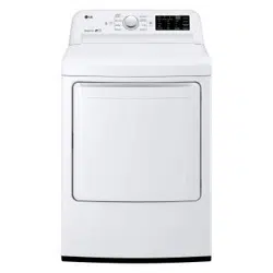
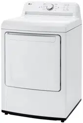
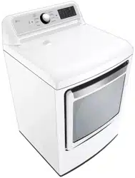
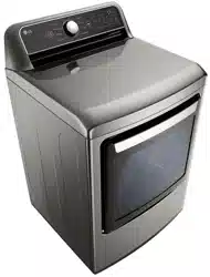
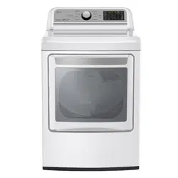
3PRODUCT FEATURES
ENGLISH
PRODUCT FEATURES
Easy-to-Use Control Panel
An entire selection of user-friendly functions make operating the dryer easy.
Two-Way Easy-Access Reversible Door
The LG EasyLoad
TM
can be tilted open from the top, hamper-style, allowing you to easily load the dryer without items falling
on the floor. The door still swings open to provide easy access for unloading or loading of bulkier items. The door hinge can
be reversed to adjust to the installation location.
Flow Sense
TM
Duct Blockage Sensing System Indicator
The Flow Sense
TM
duct blockage sensing system detects and alerts you to restrictions in the installed household ductwork
that reduce exhaust airflow through the dryer. If you see the alert: Clean or repair the ducts to remove the restrictions. Keep
your ducts free of blockage to help increase efficiency and reduce long drying times caused by blocked ducts.
Smart ThinQ™
Download the new LG smart phone app to set options, self-diagnose and troubleshoot problems with the appliance, and
other useful features. This function uses Wi-Fi.
C
E
R
T
I
F
I
E
D
D
E
S
I
G
N
4 SAFETY INSTRUCTIONS
SAFETY INSTRUCTIONS
Your safety and the safety of others is very important.
We have provided many important safety messages in this manual and on your appliance. Always read and
obey all safety messages.
This is the safety alert symbol.
This symbol alerts you to potential hazards that can kill or hurt you and others.
All safety messages will follow the safety alert symbol and either the word DANGER, WARNING, or
CAUTION.
These words mean:
DANGER
-
You will be killed or seriously injured if you
do not
immediately follow instructions.
WARNING
- You may be killed or seriously injured if you do not follow instructions.
CAUTION
- You may be slightly injured or cause damage to the product if you do not follow
instructions.
All safety messages will tell you what the potential hazard is, tell you how to reduce the chance of injury,
and tell you what may happen if the instructions are not followed.
WARNING – Risk of Fire
Install the clothes dryer according to the manufacturer’s instructions and local codes.
Do not install a clothes dryer with flexible plastic venting materials. If flexible metal (foil type) duct is installed,
it must be of a specific type identified by the appliance manufacturer as suitable for use with clothes dryers.
Flexible venting materials are known to collapse, be easily crushed, and trap lint. These conditions will obstruct
clothes dryer airflow and increase the risk of fire.
To reduce the risk of severe injury or death, follow all installation instructions.
Save these instructions.
WARNING
FIRE OR EXPLOSION HAZARD
Failure to follow safety warnings exactly could result in serious injury, death or property damage.
—Do not store or use gasoline or other flammable vapors and liquids in the vicinity of this or any other
appliance.
—WHAT TO DO IF YOU SMELL GAS
Do not try to light any appliance.
Do not touch any electrical switch; do not use any phone in your building.
Clear the room, building or area of all occupants.
Immediately call your gas supplier from a neighbor’s phone. Follow the gas supplier’s instructions.
If you cannot reach your gas supplier, call the fire department.
—Installation and service must be performed by a qualified installer, service agency or the gas supplier.

5SAFETY INSTRUCTIONS
ENGLISH
IMPORTANT SAFETY INSTRUCTIONS
WARNING
To reduce the risk of fire, electric shock, or injury to persons when using your appliance, follow basic
precautions, including the following:
Installation
Keep area around the exhaust opening and adjacent
surrounding areas free from the accumulation of lint,
dust, and dirt.
Do not install or store this appliance where it will be
exposed to the weather.
Do not place items exposed to cooking oils in
your dryer.
Items contaminated with cooking oils may
contribute to a chemical reaction that could cause a
load to catch fire.
Properly ground the dryer to conform with all
governing codes and ordinances.
Follow the details
in the installation instructions. Electric shock may result
if the dryer is not properly grounded.
Before use, the dryer must be properly installed as
described in this manual.
Electric shock may result if
the dryer is not properly grounded.
Install and store the dryer where it will not be exposed to
temperatures below freezing or exposed to the weather.
All repairs and servicing must be performed by
authorized service personnel unless specifically
recommended in this Owner’s Manual. Use only
authorized factory parts.
Failure to follow this warning
may result in serious injury, fire, electric shock, or death.
To reduce the risk of electric shock, do not install
the dryer in humid spaces.
Failure to follow this
warning may result in serious injury, fire, electric shock,
or death.
Connect to a properly rated, protected, and sized
power circuit to avoid electrical overload.
Improper
power circuits may melt, creating electric shock and/or
fire hazard.
Remove all packing items and dispose of all
shipping materials properly.
Failure to do so may
result in burns, fire, explosion, or death.
Place the dryer at least 18 inches (45.7 cm) above
the floor for a garage installation.
Failure to do so
may result in burns, fire, explosion, or death.
Keep all packaging from children.
Packaging material
can be dangerous for children. There is a risk of
suffocation.
Do not install near another heat source such as a
stove, oven or heater.
Failure to follow this warning
may result in product deformation, smoke, or fire.
Do not place candles, smoking materials, or other
flammables on top of the product. Dripping wax, smoke,
or fire may result.
Remove all protective vinyl film from the product.
Failure to do so may result in product damage, smoke,
or fire.
Gas dryers MUST be exhausted to the outside.
Failure to follow these instructions may result in fire or
death.
The dryer exhaust system must be exhausted to the
outside of the dwelling. If the dryer is not exhausted
outdoors, some fine lint and large amounts of moisture
will be expelled into the laundry area. An accumulation
of lint in any area of the home may create a health and
fire hazard.
Use only rigid, semi-rigid or flexible metal 4-inch
(10.2 cm) diameter duct inside the dryer cabinet or
for exhausting to the outside. Use of plastic or other
combustible ductwork may cause a fire. Punctured
ductwork may cause a fire if it collapses or becomes
otherwise restricted in use or during installation.
Ductwork is not provided with the dryer, and you
should obtain the necessary ductwork locally. The
end cap should have hinged dampers to prevent
backdraft when the dryer is not in use.
Failure to
follow these instructions may result in fire or death.
The exhaust duct must be 4 inches (10.2 cm) in
diameter with no obstructions. The exhaust duct
should be kept as short as possible. Make sure to
clean old ducts before installing your new dryer.
Failure to follow these instructions may result in fire or
death.
Rigid, semi-rigid or flexible metal ducting is
recommended for use between the dryer and the
wall. All non-rigid metal transition duct must be
UL-listed. Use of other materials for transition
duct could affect drying time.
Failure to follow these
instructions may result in fire or death.
Do not use sheet metal screws or other fasteners
which extend into the duct that could catch lint and
reduce the efficiency of the exhaust system. Secure
all joints with duct tape. For complete details, follow
the Installation Instructions.
Failure to follow these
instructions may result in fire or death.
Certain internal parts are intentionally not grounded
and may present a risk of electronic shock only
during servicing.
Service personnel - do not contact the following
parts while the appliance is energized: CONTROL
BOARD
6 SAFETY INSTRUCTIONS
Operation
Read all instructions before using the appliance.
Do not dry articles that have been previously
cleaned in, washed in, soaked in, or spotted with
gasoline, dry-cleaning solvents, or other flammable
or explosive substances, as they give off vapors
that could ignite or explode.
Do not reach into the appliance if the drum is
moving.
Do not allow children to play on or in the appliance.
Close supervision of children is necessary when
the appliance is used near children.
Do not use fabric softeners or products to eliminate
static unless recommended by the manufacturer of
the fabric softener or product.
Do not use heat to dry articles containing foam
rubber or similarly textured rubber-like materials.
Do not tamper with controls.
Always check the inside of the dryer for foreign
objects. Failure to follow these instructions may
result in fire or death.
Do not store plastic, paper, or clothing that may
burn or melt on top of the dryer during operation.
Failure to follow these instructions may result in fire
or death.
Be careful when opening and closing the door.
Fingers and hands can get caught in the door and
cause injury if the door drops forward unexpectedly.
Do not place heavy items on or lean against the
top of the door when it is open.
Do not attempt to pull the hamper door open
more than 40 degrees. The dryer could tip
forward, causing injury or damage.
Do not place items on the top of the dryer.
Steam (steam model):
Do not open the dryer door during steam
cycles. Failure to follow these instructions may
result in a burn hazard.
Do not dry articles that have been previously
cleaned in, washed in, soaked in, or spotted
with gasoline, dry-cleaning solvents, or other
flammable or explosive substances as they give
off vapors that could ignite or explode. Failure to
follow these instructions may result in fire or death.
SAVE THESE INSTRUCTIONS
Do not fill the steam feeder with gasoline,
dry cleaning solvents, or other flammable or
explosive substances. Failure to follow these
instructions may result in fire or death.
Do not touch the steam nozzle in the drum
during or after the steam cycles. Failure to follow
these instructions may result in a burn hazard.
Do not fill the steam feeder with hot water (over
86 °F/30 °C). Failure to follow these instructions
may result in a burn hazard.
Maintenance
Do not repair or replace any part of the appliance
or attempt any servicing unless specifically
recommended in the user maintenance instructions
or in published user-repair instructions that you
understand and have the skills to carry out.
Clean the lint filter before or after each load.
The interior of the appliance and exhaust duct
should be cleaned periodically by qualified service
personnel.
Before the appliance is removed from service
or discarded, remove the door to the drying
compartment.
Certain internal parts are intentionally not grounded
and may present a risk of electronic shock only
during servicing.
Service personnel - do not contact the following
parts while the appliance is energized: CONTROL
BOARD
WARNING
Fire Hazard
Failure to follow safety warnings exactly could
result in serious injury, death or property damage.
Do not install a booster fan in the exhaust duct.
Install all clothes dryers in accordance with the
installation instructions of the manufacturer of the
dryer.

7SAFETY INSTRUCTIONS
ENGLISH
GROUNDING INSTRUCTIONS
WARNING
Improper connection of the equipment-grounding conductor may result in a risk of electric shock.
Check with a qualified electrician or service person if you are in doubt that the appliance is properly
grounded.
This appliance must be grounded. In the event
of malfunction or breakdown, grounding will reduce
the risk of electric shock by providing a path of least
resistance for electric current.
This appliance must be equipped with a cord
having an equipment-grounding conductor and
a grounding plug. The plug must be plugged into
an appropriate outlet that is properly installed and
grounded in accordance with all local codes and
ordinances.
Do not modify the plug. If it will not fit the outlet,
have a proper outlet installed by a qualified
electrician.
This appliance must be connected to a
grounded metal, permanent wiring system or
an equipment-grounding conductor must be
run with the circuit conductors and connected
to the equipment-grounding terminal or lead
on the appliance. Electric shock may result if the
dryer is not properly grounded.
The dryer should always be plugged into its
own individual electrical outlet which has a
voltage rating that matches the rating plate. This
provides the best performance and also prevents
overloading house wiring circuits which can cause
a fire hazard from overheated wires.
Never unplug the dryer by pulling on the power
cord. Always grip the plug firmly and pull
straight out from the outlet. The power cord may
be damaged, resulting in a risk of fire and electric
shock.
Repair or replace immediately all power
cords that have become frayed or otherwise
damaged. Do not use a cord that shows cracks
or abrasion damage along its length or at either
end. The power cord may melt, creating electric
shock and/or fire hazard.
When installing or moving the dryer, be careful
not to pinch, crush, or damage the power cord.
This will prevent injury and damage to the dryer
from fire and electric shock.
Do not, under any circumstances, cut or
remove the ground prong from the power cord.
To prevent personal injury or damage to the dryer,
the electrical power cord must be plugged into a
properly grounded outlet.
For personal safety, this dryer must be properly
grounded. Failure to do so may result in electric
shock or injury.
Refer to the installation instructions in this
manual for specific electrical requirements for
your model. Failure to follow these instructions
may create an electric shock hazard and/or a fire
hazard.
This dryer must be plugged into a properly
grounded outlet. Electrical shock may result if
the dryer is not properly grounded. Have the
wall outlet and circuit checked by a qualified
electrician to make sure the outlet is properly
grounded. Failure to follow these instructions
may create an electric shock hazard and/or a fire
hazard.
8 SAFETY INSTRUCTIONS
CALIFORNIA SAFE DRINKING WATER AND TOXIC
ENFORCEMENT ACT
This act requires the Governor of California to publish a list of substances known to the state to cause cancer,
birth defects, or other reproductive harm and requires businesses to warn customers of potential exposure to
such substances.
Gas appliances can cause minor exposure to four of these substances, namely benzene, carbon monoxide,
formaldehyde, and soot, caused primarily by the incomplete combustion of natural gas or LP fuels.
Properly adjusted dryers will minimize incomplete combustion. Exposure to these substances can be
minimized further by properly venting the dryer to the outdoors.
WARNING
This product contains chemicals known to the State of California to cause cancer and birth defects or other
reproductive harm. .

9SAFETY INSTRUCTIONS
ENGLISH
FCC Notice (For transmitter module contained in this product)
This equipment has been tested and found to comply with the limits for a Class B digital device, pursuant to Part
15 of the FCC Rules. These limits are designed to provide reasonable protection against harmful interference
in a residential installation. This equipment generates, uses, and can radiate radio frequency energy and, if not
installed and used in accordance with the instructions, may cause harmful interference to radio communications.
However, there is no guarantee that interference will not occur in a particular installation. If this equipment does
cause harmful interference to radio or television reception, which can be determined by turning the equipment off
and on, the user is encouraged to try to correct the interference by one or more of the following measures:
- Reorient or relocate the receiving antenna.
- Increase the separation between the equipment and the receiver.
- Connect the equipment to an outlet on a circuit different from that to which the receiver is connected.
- Consult the dealer or an experienced radio/TV technician for help.
This device complies with part 15 of the FCC Rules. Operation is subject to the following two conditions:
(1) this device may not cause harmful interference and
(2) this device must accept any interference received, including interference that may cause undesired operation
of the device.
Any changes or modifications in construction of this device which are not expressly approved by the party
responsible for compliance could void the user’s authority to operate the equipment.
FCC RF Radiation Exposure Statement
This equipment complies with FCC radiation exposure limits set forth for an uncontrolled environment. This
transmitter must not be co-located or operating in conjunction with any other antenna or transmitter.
This equipment should be installed and operated with a minimum distance of 20 cm (7.8 inches) between
the antenna and your body. Users must follow the specific operating instructions for satisfying RF exposure
compliance.

10 SAFETY INSTRUCTIONS
PRODUCT SPECIFICATIONS
Model LCW-004
Frequency Range 2412 MHz to 2462 MHz
Output Power (Max)
IEEE 802.11b: 22.44 dBm
IEEE 802.11g: 24.68 dBm
IEEE 802.11n: 24.11 dBm
OPEN SOURCE SOFTWARE NOTICE
To obtain the source code contained in this product, under GPL, LGPL, MPL and other open source
licenses, please visit http://opensource.lge.com.
In addition to the source code, all referred license terms, warranty disclaimers and copyright notices are
available for download.
LG Electronics will also provide open source code on CD-ROM for a fee covering the cost of performing
such distribution (including media, shipping and handling) upon email request to op[email protected].
This offer is valid for three (3) years from the date of purchase of the product.
11PRODUCT OVERVIEW
ENGLISH
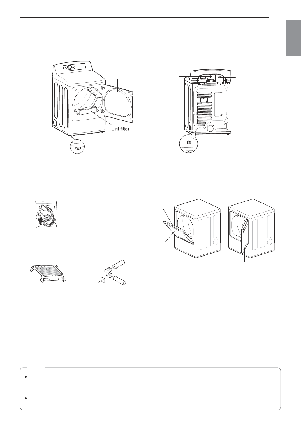
PRODUCT OVERVIEW
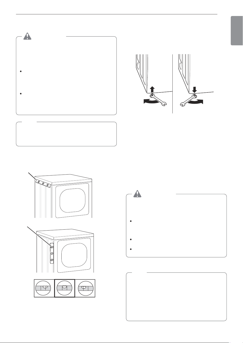
Parts
Control
panel
Leveling
feet
Reversible
door
Power cord
location
(gas models)
Water inlet valve
(on some models)
Exhaust duct
outlet
Terminal block
access panel
(electric models)
Gas connection
location
(gas models)
Accessories
Included Accessories
Optional Accessories
Side vent kit
(sold separately)
Kit No. 383EEL9001B
Safety Tether Kit
(on some models)
Drying rack
(sold separately)
No. 3750EL0001C
Release
Hamper
door
Swing door
The LG EasyLoad™ feature allows you to open the
dryer door from the top, hamper-style, when loading the
dryer to help guide clothes into the drum and prevent
them from falling onto the floor. When unloading the
dryer or loading bulkier items, use the swing door for
easy access to the drum.
Safety Tether Kit
This optional kit helps prevent the dryer tipping if children climb on the door or if someone should fall onto the
door. It is recommended that you install this kit, depending on your situation, but it is not required. Follow the
customer installation instructions included with the kit to properly install the kit. If you do not install the kit, store it
out of reach of children.
NOTE
For your safety and for extended product life, use only authorized components. The manufacturer is not
responsible for product malfunction or accidents caused by the use of separately purchased unauthorized
components or parts.
The images in this guide may be different from the actual components and accessories, which are subject
to change by the manufacturer without prior notice for product improvement purposes.
Two-Way Reversible Door
(on some models)
12 INSTALLATION
INSTALLATION
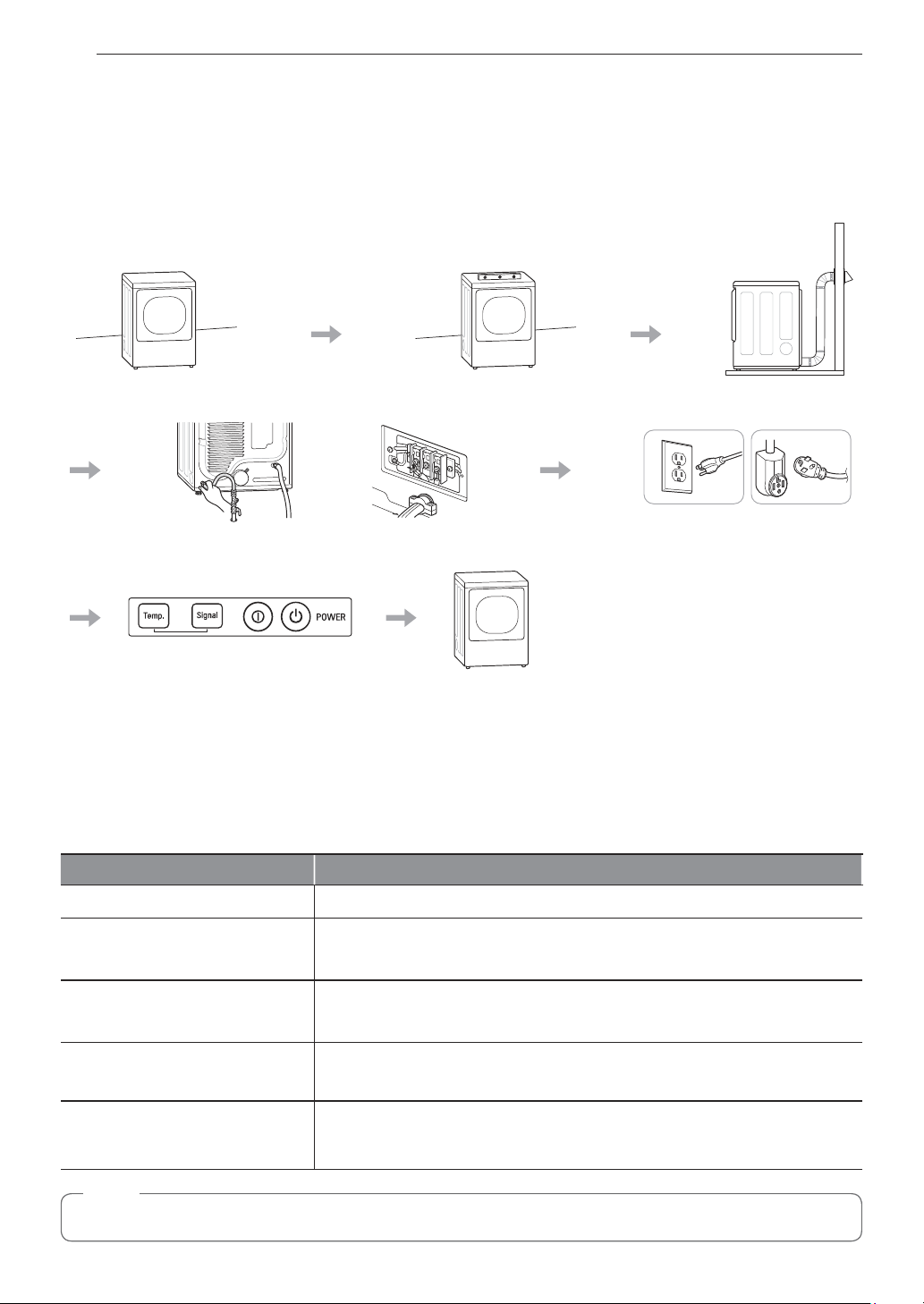
Installation Overview
Please read the following installation instructions first after purchasing this product or transporting it to another
location.
Check and choose
the proper location
Connect gas dryers
Connect electric dryers
Plug in the power cord
Installation test Test run
Gas dryer Electric dryer
Level the dryer
Vent the dryer
Product Specifications
The appearance and specifications listed in this manual may vary due to constant product improvements.
Dryer Models DLE7200*E, DLG7201*E
Electrical requirements Please refer to the rating label regarding detailed information.
Gas requirements
NG: 4–10.5-inch WC
LP: 8–13-inch WC
Dimensions
27” (W) X 28 15/16” (D) X 44 1/4” (H), 50 1/4” (D with door open)
68.6 cm (W) X 73.4 cm (D) X 112.3 cm (H), 127.5 cm (D with door open)
Net weight
Gas dryer : 132.5 lb (60.1 Kg)
Electric dryer : 129.8 lb (58.9 Kg)
Drying capacity
- Normal cycle IEC 7.3 cu.ft. (22.5 lb/10.2 kg)
NOTE
Model numbers can be found on the cabinet inside the door.
13INSTALLATION
ENGLISH
Installation Location Requirements
WARNING
Read all installation instructions completely before installing and operating the dryer! It is important that you
review this entire manual before installing and using the dryer. Detailed instructions concerning electrical
connections, gas connections, and exhaust requirements are provided on the following pages.
The installation requires:
A location that allows for proper exhaust installation. A gas dryer must be exhausted to the outdoors. See
Venting the Dryer.
A grounded electrical outlet located within 2 ft. (61 cm) of either side of the dryer. See Connecting Electric
Dryers .
A sturdy floor to support the total dryer weight of 200 lb (90.7 kg). The combined weight of a companion
appliance should also be considered.
No other fuel-burning appliance can be installed in the same closet as a dryer.
Do not operate the dryer at temperatures below 45 °F (7 °C). At lower temperatures, the dryer might not shut off
at the end of an automatic cycle. This can result in longer drying times. The dryer must not be installed or stored
in an area where it will be exposed to water and/or weather. Check code requirements. Some codes limit, or do
not permit, installation of the dryer in garages, closets, mobile homes or sleeping quarters. Contact your local
building inspector.
NOTE
The floor must be level, with a maximum slope of 1 inch (2.5 cm) under the entire dryer.
Clothes may not tumble properly, and automatic sensor cycles may not operate correctly if dryer is not
level.
For a garage installation, you will need to place the dryer at least 18 inches (46 cm) above the floor. The
standard pedestal is 15 inches (38.1 cm). You will need 18 inches (46 cm) from the garage floor to the
bottom of the dryer.
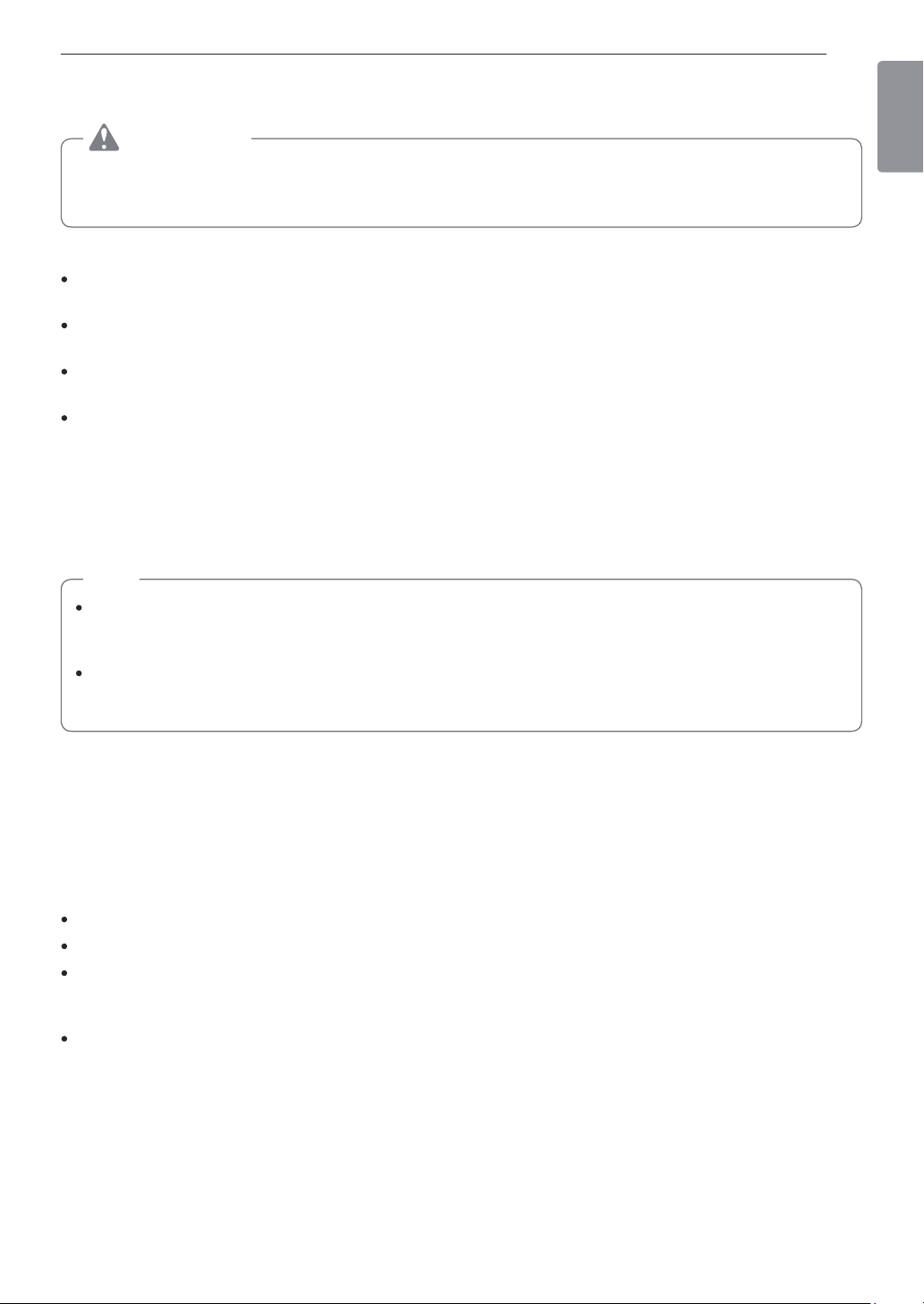
Clearances
Installation Spacing for Recessed Area or Closet Installation
The following spacing dimensions are recommended for this dryer. This dryer has been tested for clearances of
1 inch (2.5 cm) on the sides and rear. Recommended clearances should be considered for the following reasons:
Additional clearances should be considered for ease of installation and servicing.
Additional clearances might be required for wall, door and floor moldings.
Additional clearances should be considered on all sides of the dryer to reduce noise transfer.
For closet installation, with a door, minimum ventilation openings in the top and bottom of the door are
required. Louvered doors with equivalent ventilation openings are acceptable.
Companion appliance spacing should also be considered.
14 INSTALLATION
Closet Ventilation Requirements
Closets with doors must have both an upper and lower vent to prevent heat and moisture buildup in the closet.
One upper vent opening with a minimum opening of 48 sq. in. (310 cm
2
) must be installed no lower than 6 feet
above the floor. One lower vent opening with a minimum opening of 24 sq. in. (155 cm
2
) must be installed no
more than one foot above the floor. Install vent grills in the door or cut down the door at the top and bottom to
form openings. Louvered doors with equivalent ventilation openings are also acceptable.
NOTE
There should be at least a little space around the dryer (or any other appliance) to eliminate the transfer of
vibration from one appliance to another. If there is enough vibration, it could cause appliances to make noise
or come into contact, causing paint damage and further increasing noise.
Installation Spacing for Recessed Area or Closet
Closet Door Vent
Requirements
3"
(7.6 cm)
14" max.*
(35.6 cm)
1"
(2.5 cm)
1"
(2.5 cm)
27"
(68.6 cm)
3"
(7.6 cm)
50
1
/
4
"
(127.5 cm)
28
15
/
16
"
(73.4 cm)
18" min.
(45.7 cm)
21
1
/
4
"
(54 cm)
48 in.
2
(310 cm
2
)
24 in.
2
(155 cm
2
)
* Required spacing
Installation Spacing for Cabinet
For cabinet installation with a door, minimum ventilation openings in the top of the cabinet are required.
* Required spacing
7"
*
(17.8 cm)
7"
*
(17.8 cm)
5"
*
(12.7 cm)
1"
(2.5 cm)
1"
*
(2.5 cm)
1"
(2.5 cm)
28
15
/
16
"
(73.4 cm)
27"
(68.6 cm)
15INSTALLATION
ENGLISH
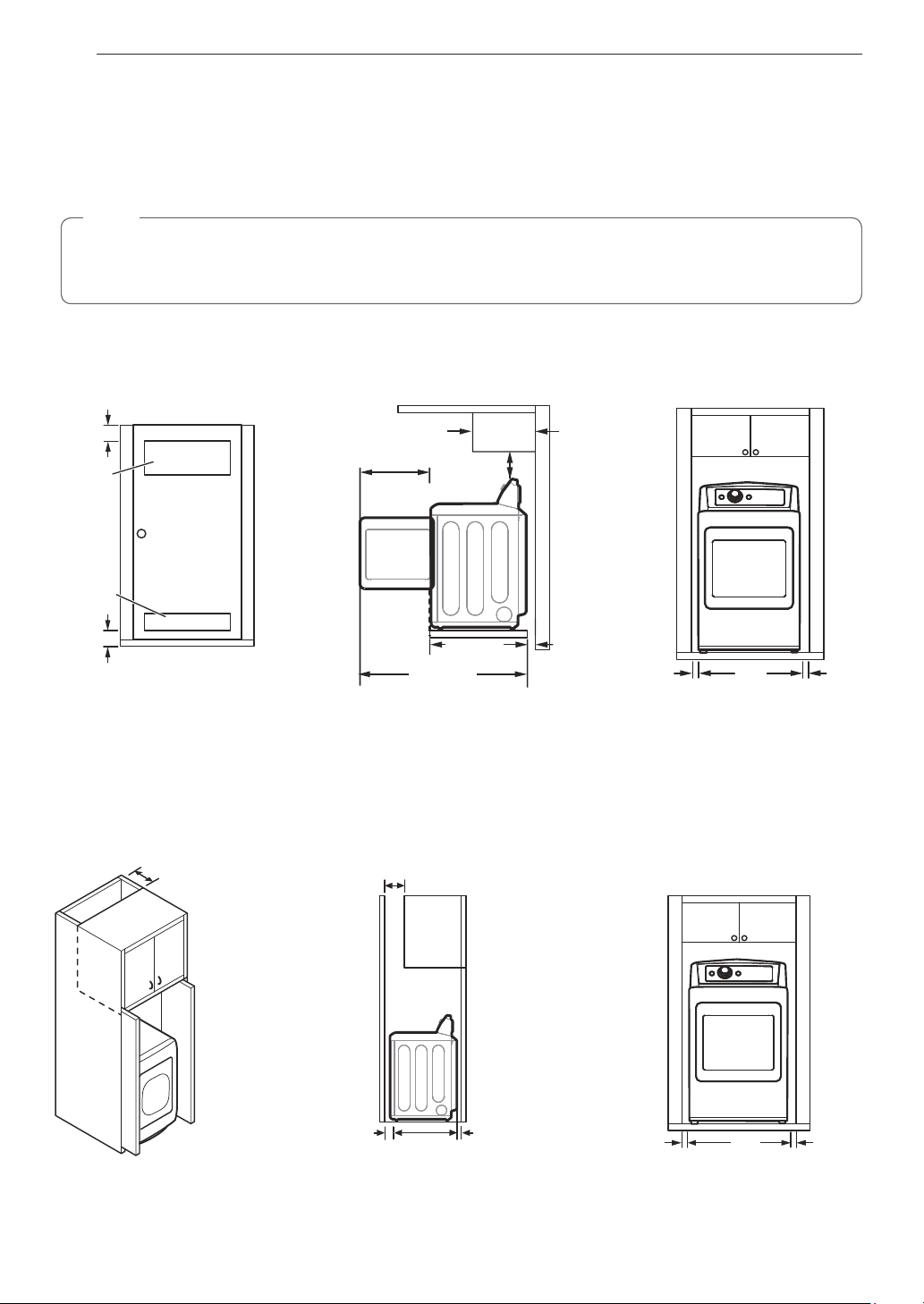
Leveling the Dryer
WARNING
To reduce the risk of injury to persons, adhere
to all industry recommended safety procedures
including the use of long-sleeved gloves and
safety glasses. Failure to follow this warning may
result in serious injury or death.
The appliance is heavy. Two or more people
are required when installing the dryer. Failure to
follow this warning may result in serious injury
or death.
To ensure that the dryer provides optimal drying
performance, it must be level. To minimize
vibration, noise, and unwanted movement, the
floor must be a perfectly level, solid surface.
NOTE
Adjust the leveling feet only as far as necessary
to level the dryer. Extending the leveling feet more
than necessary may cause the dryer to vibrate.
1
Position the dryer in the final location. Check
levelness of dryer from side to side. Repeat from
front to back.
Place level here
Place level here
Not Level Not LevelLevel
2
Use an adjustable wrench to turn the leveling
feet. Unscrew the legs to raise the dryer or
screw in the legs to lower it. Raise or lower with
the leveling feet until the dryer is level from side
to side and front to back. Make sure that all four
leveling feet are in firm contact with the floor.
If you are installing the dryer on the optional pedestal,
you must use the leveling feet on the pedestal to level the
dryer. The dryer leveling feet should be fully retracted.
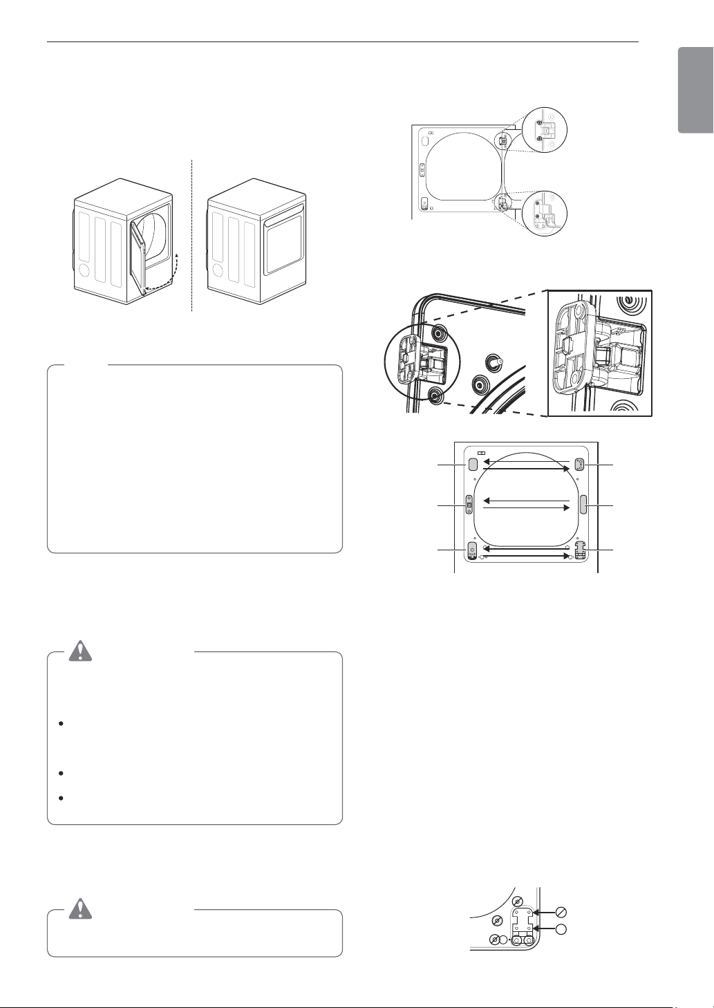
Reversing the Door
Tools Required
Phillips or large flat-blade screwdriver (for hinge screws)
Small flat-blade screwdriver (for lifting out parts)
WARNING
The dryer door is very large and heavy.
Failure to follow the instructions below can result
in damage to the dryer, property damage or
personal injury.
To avoid damage to the dryer or the door,
support the door with a stool or box that fits
under the door, or have an assistant support
the weight of the door.
Avoid dropping the door to prevent damage to
the door or the floor.
Unplug the dryer or turn off power at the main
circuit breaker before beginning door reversal.
Door Reversal Instructions
NOTE
The instructions here are for changing the door
swing from a right to a left side hinge. If the
door has been reversed, and it is necessary to
change it back, use care when following these
instructions.
Some of the illustrations and the left/right
references will be reversed, and you will need to
read the instructions carefully.
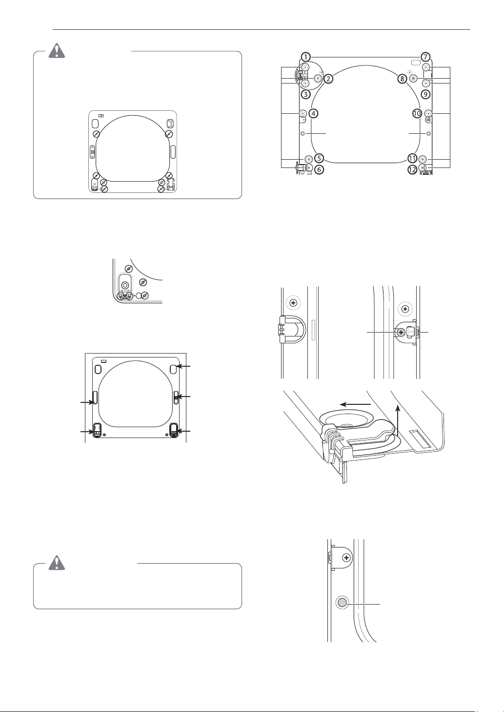
16 INSTALLATION
4
With the door on a protected surface, remove
the 16 screws on the sides of the door and
lift off the inner door frame using a flat blade
screwdriver. Remove the latch hook and blank
and install them on the opposite side.
Latch hookBlank
Inner door
frame
5
Remove the 4 screws securing the hinges to
the door frame. Remove the two plastic cover
caps. Reinstall the hinges and cover caps on the
opposite sides from which they were removed.
Cover cap
Hinge
assembly
6
With the hinges and cover caps in the new
locations, remount the inner door frame onto the
outer door frame with the screws removed in
step 4 above.
WARNING
Be sure to support the weight of the door before
installing the hinge screws.
Swing door
1
Open the door from the side so that the hinge
screws are accessible.
WARNING
Be sure to support the weight of the door before
removing the hinge screws.
2
Remove the four hinge screws.
While supporting the door, remove the four hinge
screws, two from each hinge. Set the door aside
face down on a protected surface to prevent
damage to the door or the work surface.
3
Reverse the components on the cabinet.
hinge
hinge
cover
hinge
cover
latch
mechanism
latch
hole
cover
hinge
a. Use a Phillips screwdriver to remove the two
screws and the latch mechanism on the front
panel of the cabinet.
b. Remove the latch hole cover by gently prying it
up with a flat blade screwdriver, being careful
not to scratch the paint. Install the latch hole
cover on the opposite side, where the latch
mechanism was removed. Install the latch
mechanism in the position from which you
removed the latch hole cover, using the two
screws removed in step a.
c. Remove the hinge cover by gently prying it up
with a flat blade screwdriver, being careful not
to scratch the paint. Rotate the hinge cover
180 degrees and install it on the opposite side,
where the hinge was attached.
17INSTALLATION
ENGLISH
7
Reinstall the door.
While supporting the door, install the four hinge
screws removed in step 2. Test the swing of
the door to make sure the hinges and latch are
properly aligned and that the door opens, closes
and latches properly.
Swing
Door
Easy Load
TM
Door (on some models)
NOTE
The door reversal procedure for the Easy Load
door is far more complex than for a conventional
swing door. Read through these instructions in
their entirety before beginning the process, to
judge whether you prefer to have the procedure
done by a professional installer or service person.
The instructions here are for changing the door
swing from a right to a left side hinge. If the door
has been reversed, and it is necessary to change
it back, use care when following these instructions.
Some of the illustrations and the left/right
references will be reversed, and you will need to
read the instructions carefully.
Tools Required
Phillips or large flat-blade screwdriver (for hinge screws)
Small flat-blade screwdriver (for lifting out parts)
WARNING
The dryer door is very large and heavy.
Failure to follow the instructions below can result
in damage to the dryer, property damage or
personal injury.
To avoid damage to the dryer or the door,
support the door with a stool or box that fits
under the door, or have an assistant support
the weight of the door.
Avoid dropping the door to prevent damage to
the door or the floor.
Unplug the dryer or turn off power at the main
circuit breaker before beginning door reversal.
ON THE CABINET :
1
Open the door from the side so that the hinge
screws are accessible.
WARNING
Be sure to support the weight of the door before
installing the hinge screws.
2
Remove the door from cabinet.
a. While supporting the door, remove the four
hinge screws.
Two large
screws
Two small
screws
b. Lift the door slightly to disengage the hinge
support and remove the door from the cabinet.
Set the door aside face down on a protected
work surface.
3
Reverse the components on the cabinet.
Upper
hinge
Hinge
cover
Hinge
latch
mechanism
Latch
hole
cover
Hinge
bracket
a. Use a Phillips screwdriver to remove the two
screws and the latch mechanism on the front
panel of the cabinet.
b. Remove the latch hole cover by gently prying it
up with a flat blade screwdriver, being careful
not to scratch the paint. Install the latch hole
cover on the opposite side, where the latch
mechanism was removed. Install the latch
mechanism in the position from which you
removed the latch hole cover, using the two
screws removed in step a.
c. Remove the hinge cover by gently prying it up
with a flat blade screwdriver, being careful not
to scratch the paint. Rotate the hinge cover
180 degrees and install it on the opposite side,
where the upper hinge was attached.
d. Reverse the hinge and the hinge bracket at
the bottom of the cabinet. Remove the two
screws from the hinge bracket at the bottom
right and remove the hinge bracket. Remove
the lower of the two screws behind the hinge
bracket. Do NOT remove the upper screw
behind the hinge bracket. Set the parts aside.
18 INSTALLATION
CAUTION
Do NOT remove any of the eight screws on the
face of the cabinet (marked below). Doing so
could result in damage to the dryer and the need
for a service call to repair the dryer.
e. Remove the three screws on the hinge at the
bottom left. Remove the hinge and reinstall it
on the right side. The top screw will occupy
the hole where you removed the screw behind
the hinge bracket in step d.
f. Install the hinge bracket removed in step d on
the bottom left side, first installing one screw
behind the hinge bracket.
hinge
cover
hinge
bracket
latch hole
cover
latch
mechanism
hinge
Cabinet Reversal complete
ON THE DOOR:
4
Lift off the door cover.
With the door laid inside facing up on a protected
surface, remove the twelve screws on the
inside of the door. (The two bottom screws wil
be different from the rest.) Carefully lift off the
door cover with the help of a small flat blade
screwdriver inserted in the upper left corner.
WARNING
The edges of the door cover may be sharp. Take
care when handling, or wear gloves to avoid
injury.
Hole
plug
Twelve screws
Side
Interlock
button
5
Switch the door strike and the blank cover.
Remove the two screws on the door cover that
secure the door strike.
Switch the door strike and the blank cover,
installing them on the opposite sides from which
they were removed.
It may be difficult to insert the two screws in the
door strike on the opposite side. Use a cordless
screwdriver if necessary.
Long
screw
Short
screws
Blank cover Door strike
Pull
Raise
Remove blank cover
Gently pry out the hole plug on the side of
the door cover and install it in the hole on the
opposite side.
Hole
plug
Set the door cover aside.
19INSTALLATION
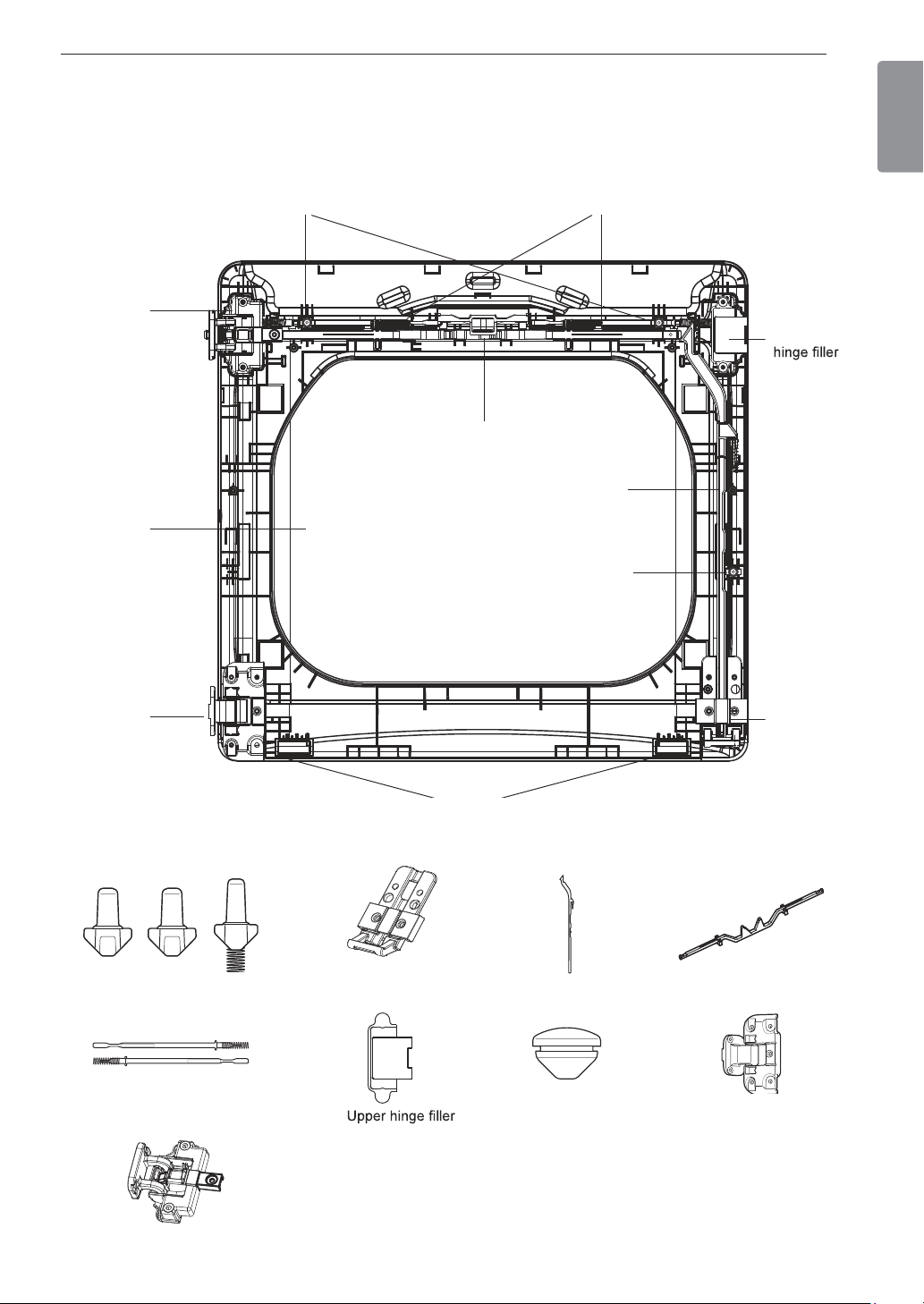
ENGLISH
6
Reverse the components inside the door.
You will now be removing and reversing various components inside the door. See below for a detailed
diagram and identification of the inner structure and parts of the door. (The diagram shows the “before view”
of the door, with the default set-up for a right side hinge swing. After following these instructions, the door
should be a mirror image of the illustration.)
Upper
Side lock rod
Side Interlock button
Lower
hinge
bracket
Bumpers
Inner lock rodsTop interlock buttons
Top lock rod
Upper
hinge
assembly
Glass
Lower
hinge
assembly
Interlock buttons
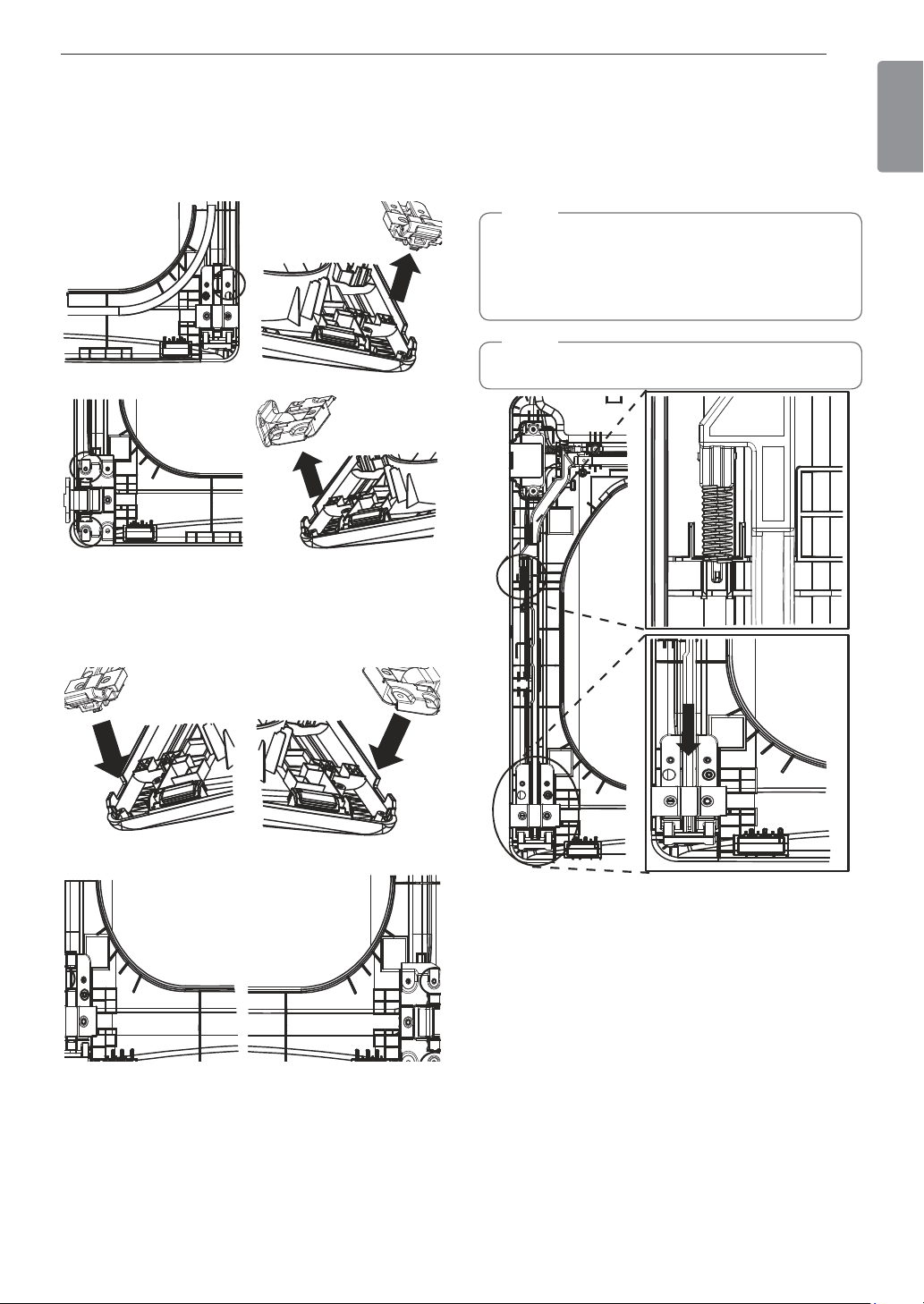
Upper hinge assembly
Inner lock rods
Lower hinge bracket Top lock rod
Lower hinge assembly
Side lock rod
Hole plug
20 INSTALLATION
7
Lift out the gray interlock button in the side
of the door.
Make sure to remove the spring with the
interlock button and to keep the two together.
Set the interlock button aside. Do not confuse
this with the interlock buttons from the top of the
outer door.
8
Remove the side lock rod.
Remove the side lock rod from the lower hinge
bracket by lifting the top end of the rod and
sliding it toward the top of the door. The spring
should remain attached to the lock rod. Set the
lock rod aside.
Spring
9
Reverse the upper hinge assembly and hinge
filler.
a. Remove the screw connecting the upper
hinge assembly to the top lock rod and set it
aside.
b. Lift out the upper hinge filler (on the right) and
set it aside.
c. Lift out the upper hinge assembly (on the left).
d. Slide the upper lock rod to the right. Rotate
the upper hinge assembly 180 degrees, and
install it over the lock rod on the right, where
it on the upper left side of the door.
f. Insert and tighten the screw connecting the
upper hinge assembly to the top lock rod,
removed in step a.
Assemble screw
21INSTALLATION
ENGLISH
10
Reverse the lower hinge bracket and hinge
assembly.
a. Remove one screw from the lower hinge
bracket (on the right) and lift it out. Remove
two screws from the lower hinge assembly (on
the left) and lift it out.
b. Rotate the lower hinge assembly 180
degrees and install it on the right side using
the two screws removed in step a.
c. Mount the lower hinge bracket on the lower
left with the screw removed in step a.
11
Install the side lock rod.
a. Flip the side lock rod over and insert the
lower end into the left hinge bracket.
b. Lower the rod into the guides on the door
while compressing the spring inside the
recess.
NOTE
Make sure the top of the side lock rod is beside
the top lock rod and the two do not overlap each
other. If they are not aligned properly, the door will
not operate properly.
NOTE
Make sure the spring stays on the side lock rod.
22 INSTALLATION
12
Reinstall the side interlock button.
Install the side interlock button on the opposite
side from which it was removed.
NOTE
Make sure the spring is on the interlock button
and is centered in the compartment.
13
Reinstall the door cover.
a. Clean the glass on the door and door cover,
if necessary.
b. Make sure the three gray interlock buttons
are properly installed and that the top and
side lock rods intersect properly.
c. Carefully lower the door cover into place,
aligning the holes in the cover with the three
interlock buttons and the bumpers on the
bottom edge. You may need to force fit the
door cover.
d. Once the door cover is in place, secure it
with the 12 screws removed in step 4.
NOTE
Make sure the three interlock buttons are aligned
with the holes in the door cover.
Two different screws
NOTE
Ten similar screws are inserted in the top and
sides of the door cover. The two different screws
are inserted in the bottom edge.
14
Reassemble the door on cabinet.
While supporting the door, insert the hinge
support into the slot in the door and slide the
door down slightly to seat it. Install the four
hinge screws removed in step 2. Test the
swing of the door to check the alignment of the
hinges and latch. Make sure the door opens,
closes, and latches properly in both directions.
Two large screws
Two small screws
NOTE
If the door is damaged, or if the door does not
work after reassembly, contact the call center at
1-800-243-0000.
23INSTALLATION
ENGLISH
Installing the Side Vent Kit
WARNING
Use a heavy metal vent.
Do not use plastic or thin foil ducts.
Clean old ducts before installing this dryer.
To reduce the risk of injury to persons, adhere
to all industry recommended safety procedures
including the use of long-sleeved gloves and
safety glasses.
Failure to follow all of the safety warnings in this
manual could result in property damage, injury
to persons, or death.
The dryer is shipped to vent to the rear. It can also
be configured to vent to the bottom or side (right-side
venting is not available on gas models).
An adapter kit, part number 383EEL9001B, may be
purchased from an LG retailer. This kit contains the
necessary duct components to change the dryer vent
location.
1
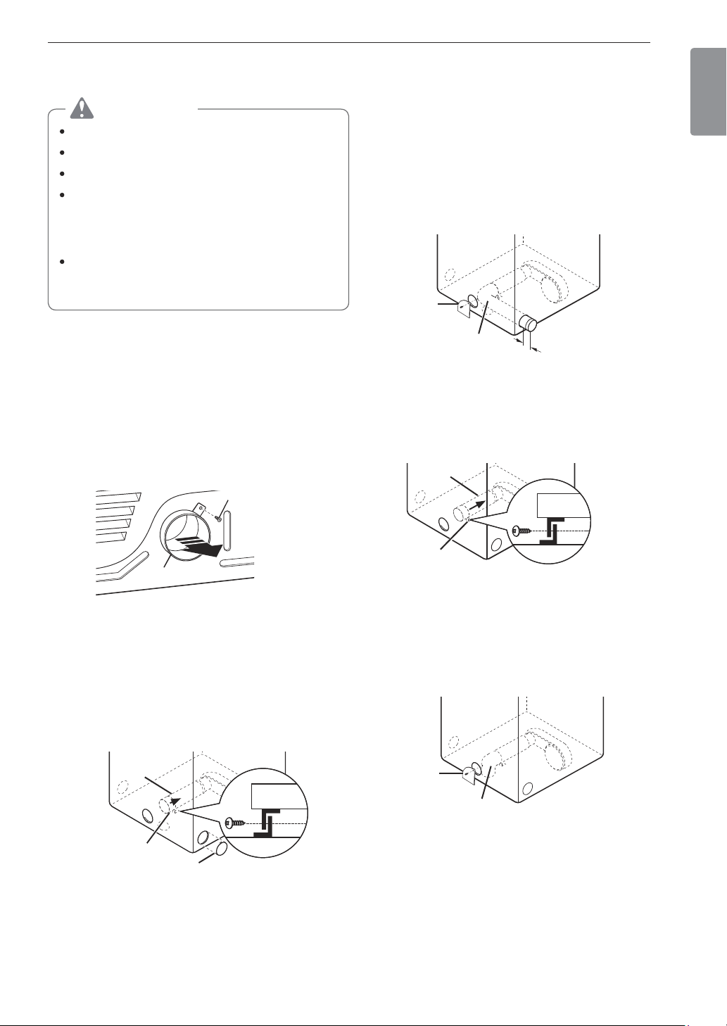
Remove the rear exhaust duct retaining screw.
Pull out the exhaust duct.
Retaining Screw
Rear Exhaust
Duct
Option 1: Side Venting
2
Press the tabs on the knockout and carefully
remove the knockout for the desired vent
opening (right-side venting is not available on
gas models). Press the adapter duct onto the
blower housing and secure to the base of the
dryer as shown.
Adapter
Duct
Bracket
Knockout
3
Preassemble a 4-inch (10.2 cm) elbow to the
next 4-inch (10.2 cm) duct section, and secure
all joints with duct tape. Be sure that the male
end of the elbow faces AWAY from the dryer.
Insert the elbow/duct assembly through the
side opening and press it onto the adapter duct.
Secure it in place with duct tape. Be sure that
the male end of the duct protrudes 1½ inches
(3.8 cm) to connect the remaining ductwork.
Attach the cover plate to the back of the dryer
with the included screw.
Cover
Plate
Elbow
1
½
"
(3.8 cm)
Option 2: Bottom Venting
2
Press the adapter duct onto the blower housing
and secure it to the base of the dryer as shown.
Adapter
Duct
Bracket
3
Insert the 4-inch (10.2 cm) elbow through the
rear opening and press it onto the adapter duct.
Be sure that the male end of the elbow faces
down through the hole in the bottom of the
dryer. Secure it in place with duct tape. Attach
the cover plate to the back of the dryer with the
included screw.
Cover
Plate
Elbow
24 INSTALLATION
Venting the Dryer
WARNING
To reduce the risk of fire or explosion, electric
shock, property damage, injury to persons or
death when using this appliance, follow basic
safety precautions, including the following:
Do not crush or collapse ductwork. Failure to
follow these instructions may result in fire or death.
Do not allow ductwork to rest on or contact
sharp objects. Failure to follow these instructions
may result in fire or death.
If connecting to existing ductwork, make sure it
is suitable and clean before installing the dryer.
Failure to follow these instructions may result in fire
or death.
Venting must conform to local building codes.
Failure to follow these instructions may result in fire
or death.
Gas dryers MUST exhaust to the outdoors.
Failure to follow these instructions may result in fire
or death.
Use only 4-inch (10.2 cm) rigid, semi-rigid or
flexible metal ductwork inside the dryer cabinet
and for venting outside. Failure to follow these
instructions may result in fire or death.
To reduce the risk of fire, combustion, or
accumulation of combustible gases, DO
NOT exhaust dryer air into an enclosed and
unventilated area, such as an attic, wall, ceiling,
crawl space, chimney, gas vent, or concealed
space of a building. Failure to follow these
instructions may result in fire or death.
To reduce the risk of fire, DO NOT exhaust the
dryer with plastic or thin foil ducting. Failure to
follow these instructions may result in fire or death.
The exhaust duct must be 4 inches (10.2 cm)
in diameter with no obstructions. The exhaust
duct should be kept as short as possible. Make
sure to clean any old ducts before installing
your new dryer. Failure to follow these instructions
may result in fire or death.
Rigid, semi-rigid or flexible metal ducting is
recommended for use between the dryer and
the wall. All non-rigid metal transition duct
must be UL-listed. Use of other materials for
transition duct could affect drying time. Failure
to follow these instructions may result in fire or
death.
DO NOT use sheet metal screws or other
fasteners which extend into the duct that
could catch lint and reduce the efficiency of
the exhaust system. Secure all joints with duct
tape. Failure to follow these instructions may result
in fire or death.
Do not exceed the recommended duct length
limitations noted in the chart. Failure to follow
these instructions may result in extended drying
times, fire or death.
Ductwork is not provided with the dryer. You
should obtain the necessary ductwork locally.
The vent hood should have hinged dampers to
prevent backdraft when the dryer is not in use.
Failure to follow these instructions may result in fire
or death.
The total length of flexible metal duct must not
exceed 8 ft. (2.4 m).
In Canada, only those foil-type flexible ducts,
if any, specifically identified for use with the
appliance by the manufacturer should be used.
In the United States, only those foil-type flexible
ducts, if any, specifically identified for use with the
appliance by the manufacturer and that comply
with the Outline for Clothes Dryer Transition Duct,
Subject 2158A, should be used.
Ductwork
Wall Cap Type
Number
of 90°
Elbows
Maximum length
of 4-inch (10.2 cm)
diameter rigid metal
duct
Recommended
4"
(10.2 cm)
4"
(10.2 cm)
0 65 ft.(19.8 m)
1 55 ft.(16.8 m)
2 47 ft.(14.3 m)
3 36 ft.(11.0 m)
4 28 ft.(8.5 m)
2
1
/
2
"
(6.35 cm)
Use only for
short run
installations
0 55 ft.(16.8 m)
1 47 ft.(14.3 m)
2 41 ft.(12.5 m)
3 30 ft.(9.1 m)
4 22 ft.(6.7 m)
NOTE
Deduct 6 ft. (1.8 m) for each additional elbow. Do
not use more than four 90° elbows.
25INSTALLATION
ENGLISH
Routing And Connecting Ductwork
NOTE
Follow the guidelines below to maximize drying
performance and reduce lint buildup and
condensation in the ductwork. Ductwork and
fittings are NOT included and must be purchased
separately.
Use 4-inch (10.2 cm) diameter rigid, semi-rigid
or flexible metal ductwork.
The exhaust duct run should be as short as
possible.
Use as few elbow joints as possible.
The male end of each section of exhaust duct
must point away from the dryer.
Use duct tape on all duct joints.
Insulate ductwork that runs through unheated
areas in order to reduce condensation and lint
buildup on duct surfaces.
Incorrect or inadequate exhaust systems
are not covered by the dryer warranty. Dryer
failures or service required because of such
exhaust systems will not be covered by the
dryer warranty.
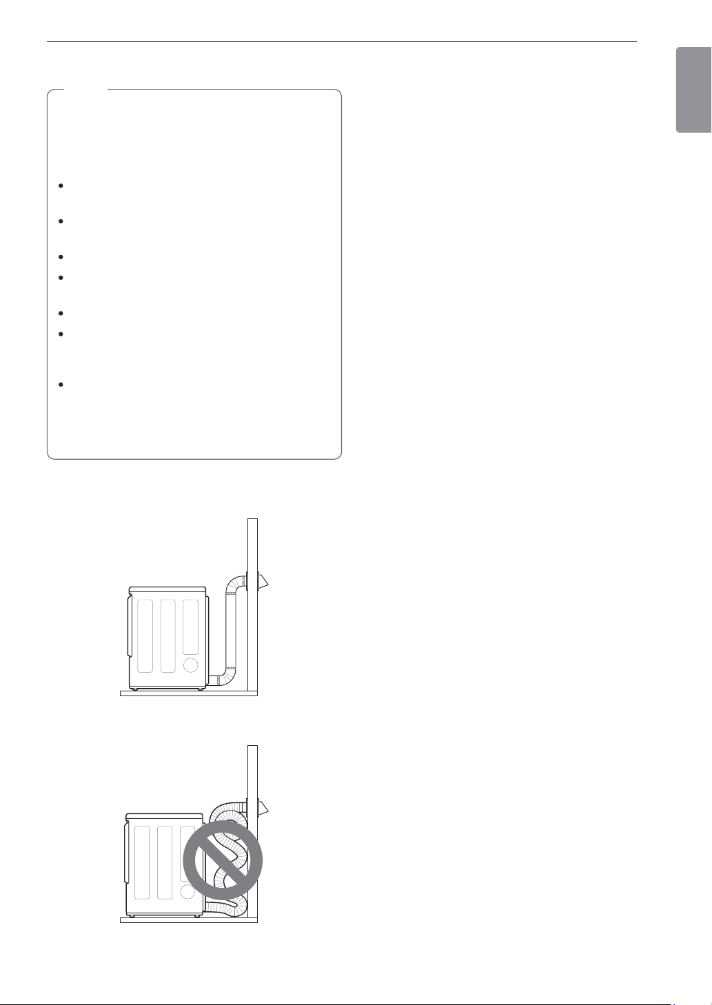
Correct Venting
Incorrect Venting
26 INSTALLATION
Connecting Gas Dryers
WARNING
To reduce the risk of fire or explosion, electric
shock, property damage, injury to persons, or
death when using this appliance, follow basic
safety precautions.
Gas Supply Requirements
As shipped from the factory, this dryer is
configured for use with natural gas (NG). It can
be converted for use with propane (LP) gas.
Gas pressure must not exceed 8 inches
(20.3 cm) of water column for NG, or 13 inches
(33 cm) of water column for LP.
A qualified service or gas company technician
must connect the dryer to the gas service.
Failure to follow these instructions may result
in fire, explosion, or death.
Isolate the dryer from the gas supply system
by closing its individual manual shutoff valve
during any pressure testing of the gas supply.
Failure to do so may result in fire, explosion, or
death.
Supply line requirements: Your laundry room
must have a rigid gas supply line to the dryer.
In the United States, an individual manual
shutoff valve MUST be installed within at least
6 ft. (1.8 m) of the dryer, in accordance with
the National Fuel Gas Code ANSI Z223.1 or
Canadian gas installation code CSA B149.1.
A 1/8-inch (0.3 cm) NPT pipe plug must be
installed. Failure to do so may result in fire,
explosion, or death.
If using a rigid pipe, the rigid pipe should be
½ inch IPS. If acceptable under local codes and
ordinances and when acceptable to your gas
supplier, 3/8-inch (1 cm) approved tubing may
be used where lengths are less than 20 ft.
(6.1 m). Larger tubing should be used for
lengths in excess of 20 ft. (6.1 m). Failure to do
so may result in fire, explosion, or death.
Connect the dryer to the type of gas shown on
the nameplate. Failure to do so may result in fire,
explosion, or death.
To prevent contamination of the gas valve,
purge the gas supply of air and sediment before
connecting the gas supply to the dryer. Before
tightening the connection between the gas
supply and the dryer, purge remaining air until
the odor of gas is detected. Failure to do so may
result in fire, explosion, or death.
DO NOT use an open flame to inspect for gas
leaks. Use a noncorrosive leak detection fluid.
Failure to do so may result in fire, explosion, or
death.
Use only a new AGA- or CSA-certified gas
supply line with flexible stainless steel
connectors. Failure to do so may result in fire,
explosion, or death.
Securely tighten all gas connections. Failure to
do so may result in fire, explosion, or death.
Use Teflon tape or a pipe-joint compound
that is insoluble in propane (LP) gas on all
pipe threads. Failure to do so may result in fire,
explosion, or death.
DO NOT attempt any disassembly of the dryer;
disassembly requires the attention and tools of
an authorized and qualified service technician
or company. Failure to follow this warning may
result in fire, explosion, or death.
Electrical Requirements for Gas
Models Only
Do not, under any circumstances, cut or remove
the third (ground) prong from the power cord.
Failure to follow this warning may result in fire,
explosion, or death.
For personal safety, this dryer must be properly
grounded. Failure to follow this warning may result
in fire, explosion, or death.
This dryer must be plugged into a 120-VAC,
60-Hz. grounded outlet protected by a
15-ampere fuse or circuit breaker.
Failure to follow
this warning may result in fire, explosion, or death.
Where a standard 2-prong wall outlet is
encountered, it is your personal responsibility
and obligation to have it replaced with a
properly grounded 3-prong wall outlet. Failure to
follow this warning may result in fire, explosion, or
death.
Plug dryer into a 120 VAC,
60 Hz grounded 3-prong
outlet.
WARNING
ELECTRIC SHOCK HAZARD
Failure to follow safety warnings could result in
serious injury or death.
This dryer is equipped with a three-prong
grounding plug for protection against shock
hazard and should be plugged directly into a
properly grounded three-prong receptacle. Do not
cut or remove the grounding prong from this plug.
27INSTALLATION
ENGLISH
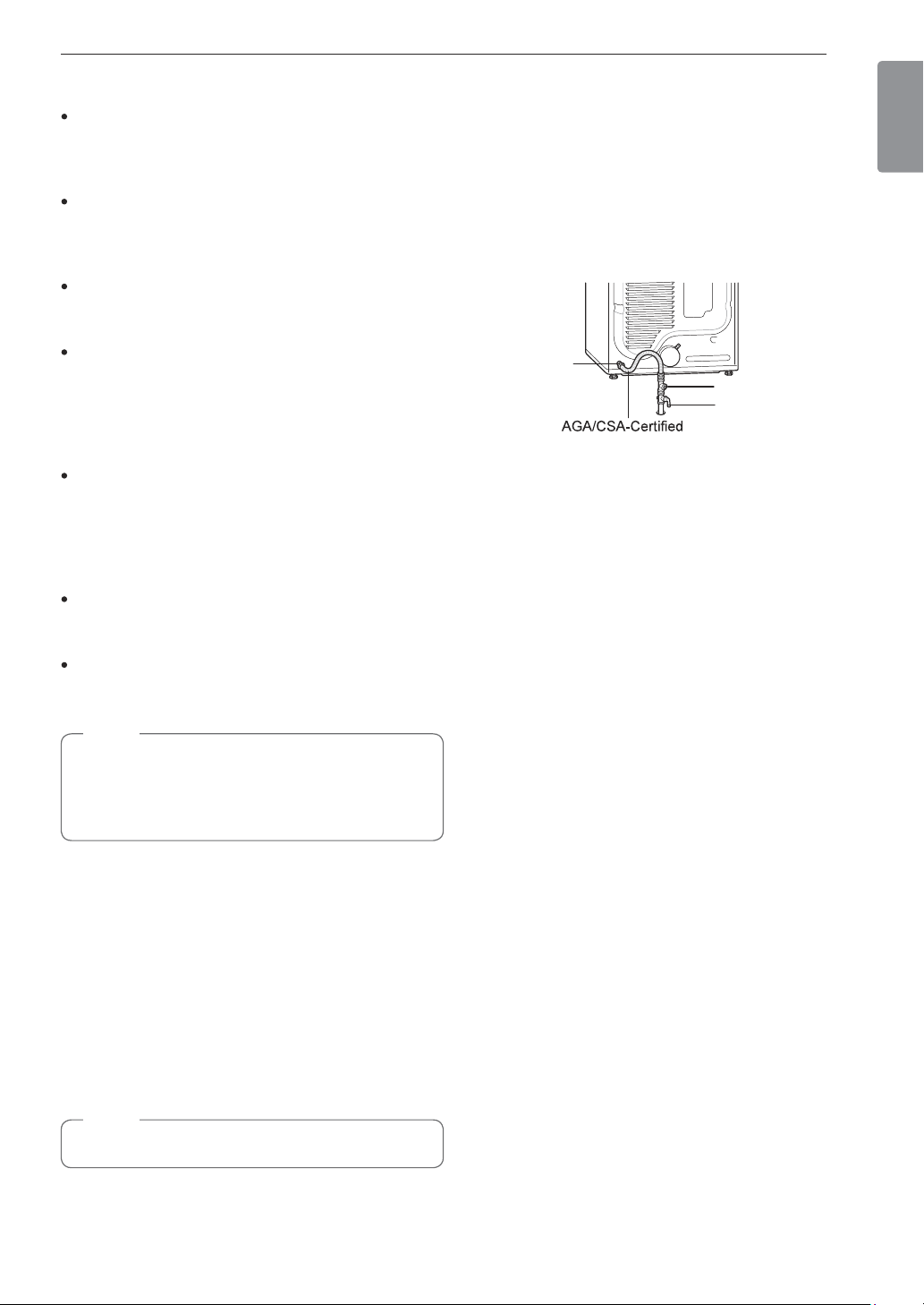
Connecting the Gas Supply
Installation and service must be performed
by a qualified installer, service agency, or the
gas supplier. Failure to do so may result in fire,
explosion, or death.
Use only a new stainless steel flexible
connector and a new AGA-certified connector.
Failure to do so may result in fire, explosion, or
death.
A gas shutoff valve must be installed within 6 ft.
(1.8 m) of the dryer. Failure to do so may result in
fire, explosion, or death.
The dryer is configured for natural gas when
shipped from the factory. Make sure that the
dryer is equipped with the correct burner nozzle
for the type of gas being used (natural gas or
propane gas). Failure to do so may result in fire,
explosion, or death.
If necessary, the correct nozzle (for the LP
nozzle kit, order part number 383EEL3002D)
should be installed by a qualified technician
and the change should be noted on the dryer.
Failure to do so may result in fire, explosion, or
death.
All connections must be in accordance with
local codes and regulations. Failure to do so may
result in fire, explosion, or death.
Gas dryers MUST exhaust to the outdoors.
Failure to do so may result in fire, explosion, or
death.
NOTE
This dryer is configured from the factory for
natural gas (NG). If the dryer is to be used with
propane (LP) gas, it must be converted by a
qualified service technician.
1
Make sure that the gas supply to the laundry
room is turned OFF and the dryer is unplugged.
Confirm that the type of gas available in your
laundry room is appropriate for the dryer.
2
Remove the shipping cap from the gas fitting at
the back of the dryer. Be careful not to damage
the threads of the gas connector when removing
the shipping cap.
3
Connect the dryer to your laundry room’s gas
supply using a new flexible stainless steel
connector with a 3/8-inch NPT fitting.
NOTE
DO NOT use old connectors.
4
Securely tighten all connections between the
dryer and your laundry room’s gas supply.
5
Turn on your laundry room’s gas supply.
6
Check all pipe connections (both internal and
external) for gas leaks with a noncorrosive leak-
detection fluid.
7
Proceed to Venting the Dryer.
3/8"
NPT gas
Connection
Stainless Steel
Flexible Connector
1/8" NPT Pipe Plug
Gas Supply Shutoff
Valve
High-Altitude Installations
The BTU rating of this dryer is AGA-certified for
elevations below 10,000 feet.
If your gas dryer is being installed at an elevation
above 10,000 feet, it must be derated by a qualified
technician or gas supplier.

28 INSTALLATION
Connecting Electric Dryers
Electrical Requirements for Electric
Models Only
WARNING
To help prevent fire, electric shock, serious injury,
or death, the wiring and grounding must conform
to the latest edition of the National Electrical
Code, ANSI/NFPA 70 and all applicable local
regulations. Please contact a qualified electrician
to check your home’s wiring and fuses to ensure
that your home has adequate electrical power to
operate the dryer.
This dryer must be connected to a grounded
metal, permanent wiring system, or an
equipment-grounding conductor must be run
with the circuit conductors and connected
to the equipment-grounding terminal or lead
on the dryer. Failure to do so may result in fire,
explosion, or death.
The dryer has its own terminal block that must
be connected to a separate 240 VAC, 60-Hertz,
single-phase circuit, fused at 30 amperes (the
circuit must be fused on both sides of the
line). ELECTRICAL SERVICE FOR THE DRYER
SHOULD BE OF THE MAXIMUM RATE VOLTAGE
LISTED ON THE NAMEPLATE. DO NOT
CONNECT THE DRYER TO 110-, 115-, OR 120-
VOLT CIRCUIT. Failure to follow these instructions
may result in fire, explosion, or death.
If the branch circuit to dryer is 15 ft. (4.5 m)
or less in length, use UL (Underwriters
Laboratories) listed No. 10 AWG wire (copper
wire only), or as required by local codes. If
over 15 ft. (4.5 m), use UL-listed No. 8 AWG
wire (copper wire only), or as required by local
codes. Allow sufficient slack in wiring so the
dryer can be moved from its normal location
when necessary. Failure to do so may result in
fire, explosion, or death.
The power cord (pigtail) connection between
the wall receptacle and the dryer terminal block
IS NOT supplied with the dryer. Type of pigtail
and gauge of wire must conform to local codes
and with instructions on the following pages.
Failure to follow these instructions may result in
fire, explosion, or death.
A 4-wire connection is required for all mobile
and manufactured home installations, as well
as all new construction after January 1, 1996.
A 4-wire connection must be used where local
codes do not permit grounding through the
neutral wire. Failure to do so may result in fire,
explosion, or death.
Do not modify the plug and internal wire provided
with the dryer.
The dryer should be connected to a 4-hole outlet.
If the plug does not fit the outlet, a proper outlet will
need to be installed by a qualified electrician.
Special Electrical Requirements for
Mobile or Manufactured Homes
Any installation in a manufactured or mobile
home must comply with the Manufactured Home
Construction and Safety Standards Title 24 CFR,
Part 3280 or Standard CAN/ CSA Z240 MH and
local codes and ordinances. If you are uncertain
whether your proposed installation will comply with
these standards, please contact a service and
installation professional for assistance.
A 4-wire connection is required for all mobile
and manufactured home installations, as well
as all new construction after January 1, 1996.
Failure to do so may result in fire, explosion, or
death.
A gas dryer must be permanently attached to the
floor.
The electrical connection for an electric dryer must
be a 4-wire connection. More detailed information
concerning the electrical connection is provided in
the Connecting Electric Dryers section.
To reduce the risk of combustion and fire, the dryer
must be vented to the outside.
DO NOT vent the dryer under a manufactured
home or mobile home.
Electric dryers may be vented to the outside using
the back, left, right, or bottom panel.
Gas dryers may be vented to the outside using the
back, left, or bottom panel. Gas dryers may not
be vented to the outside using the right side panel
because of the burner housing.
The dryer exhaust duct must be affixed securely to
the manufactured or mobile home structure, and
the exhaust duct must be made of a material that
will resist fire and combustion. It is recommended
that you use a rigid, semi-rigid or flexible metal
duct.
DO NOT connect the dryer exhaust duct to any
other duct, vent, chimney, or other exhaust duct.
Make sure the dryer has adequate access to
outside fresh air to ensure proper operation. The
opening for outside fresh air must be at least 25 sq.
in (163 cm
2
).
It is important that the clearance of the duct from
any combustible construction be at least 2 inches
(5 cm), and when venting the dryer to the outdoors,
the dryer should be installed with a clearance of at
least 1 inch (2.5 cm) at the sides and back of the
dryer.
Venting materials are not supplied with the dryer.
You must obtain the venting materials necessary
for proper installation.
29INSTALLATION
ENGLISH
WARNING
Connect the power cord to the terminal block.
Connect each wire in the power cord to the
terminal block screw with the matching colored
wire. The terminal block wire colors are indicated
in the manual. Failure to follow these instructions
may result in a short or overload.
Grounding through the neutral conductor is
prohibited for: (1) new branch-circuit installations,
(2) mobile homes, (3) recreational vehicles, and
(4) areas where local codes prohibit grounding
through the neutral conductor.
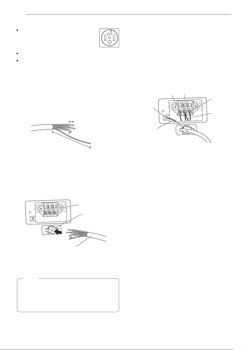
Four-Wire Power Cord
A 4-wire connection is required for
all mobile and manufactured home
installations, as well as all new
construction after January 1, 1996.
A UL-listed strain relief is required.
Use a 30-amp, 240-volt, 4-wire, UL-listed power
cord with #10 AWG-minimum copper conductor and
closed loop or forked terminals with upturned ends.
1
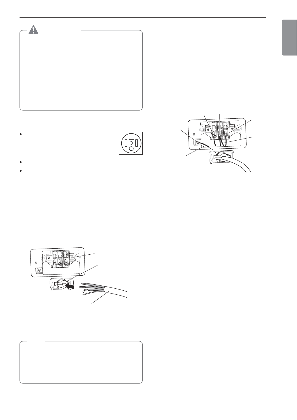
Remove the terminal block access cover on the
upper back of the dryer.
2
Install a UL-listed strain relief into the power cord
through-hole.
3
Thread a 30-amp, 240-volt, 4-wire, UL-listed
power cord with #10 AWG-minimum copper
conductor through the strain relief.
Terminal Block
UL-Listed
Strain Relief
UL-Listed 4-Wire Power Cord
4
Transfer the dryer’s ground wire from behind the
green ground screw to the center screw of the
terminal block.
NOTE
This dryer is supplied with the neutral wire
grounded. This white ground wire MUST BE
MOVED to the neutral terminal when a 4-wire
cord is to be used, or where grounding through
the neutral conductor is prohibited.
5
Attach the two hot leads of the power cord to the
outer terminal block screws.
6
Attach the white neutral wire to the center screw
of the terminal block.
7
Attach the power cord ground wire to the green
ground screw.
8
Tighten all screws securely.
9
Reinstall the terminal block access cover.
Hot
(Red)
Neutral
(White)
Hot
(Black)
Ground
Screw
Power Cord
Ground Wire
White Wire
moved from
Ground
Screw
30 INSTALLATION
Four-Wire Direct Wire
A 4-wire connection is required for
all mobile and manufactured home
installations, as well as all new
construction after January 1, 1996.
A UL-listed strain relief is required.
Use UL-listed 4-wire #10 AWG-minimum copper
conductor cable. Allow at least 5 ft. (1.5 m) of wire
to allow for removal and reinstallation of the dryer.
1
Remove 5 inches (12.7 cm) of the outer covering
from the wire. Remove 5 inches (12.7 cm)
of insulation from the ground wire. Cut off
approximately 1½ inches (3.8 cm) from the other
three wires and strip 1 inch (2.5 cm) of insulation
from each wire. Bend the ends of the three
shorter wires into a hook shape.
Ground Wire
1" (2.5 cm)
5"
(12.7 cm)
2
Remove the terminal block access cover on the
upper back of the dryer.
3
Install a UL-listed strain relief into the power cord
through-hole.
4
Thread the 4-wire #10 AWG-minimum copper
power cable prepared in step 1 through the
strain relief.
Terminal Block
UL-Listed
Strain Relief
UL-Listed 4-Wire Power Cord
5
Transfer the dryer’s ground wire from behind the
green ground screw to the center screw of the
terminal block.
NOTE
This dryer is supplied with the neutral wire
grounded. This white ground wire MUST BE
MOVED to the neutral terminal when a 4-wire
cord is to be used, or where grounding through
the neutral conductor is prohibited.
6
Attach the two hot leads of the power cord to the
outer terminal block screws.
7
Attach the white neutral wire to the center screw
of the terminal block.
8
Attach the power cord ground wire to the green
ground screw.
9
Tighten all screws securely.
10
Reinstall the terminal block access cover.
Hot
(Red)
Neutral
(White)
Hot
(Black)
Ground
Screw
Power Cord
Ground Wire
White Wire
moved from
Ground
Screw
31INSTALLATION
ENGLISH
WARNING
Connect the power cord to the terminal block.
Connect each wire in the power cord to the
terminal block screw with the matching colored
wire. The terminal block wire colors are indicated
in the manual. Failure to follow these instructions
may result in a short or overload.
Grounding through the neutral conductor is
prohibited for: (1) new branch-circuit installations,
(2) mobile homes, (3) recreational vehicles, and
(4) areas where local codes prohibit grounding
through the neutral conductor.
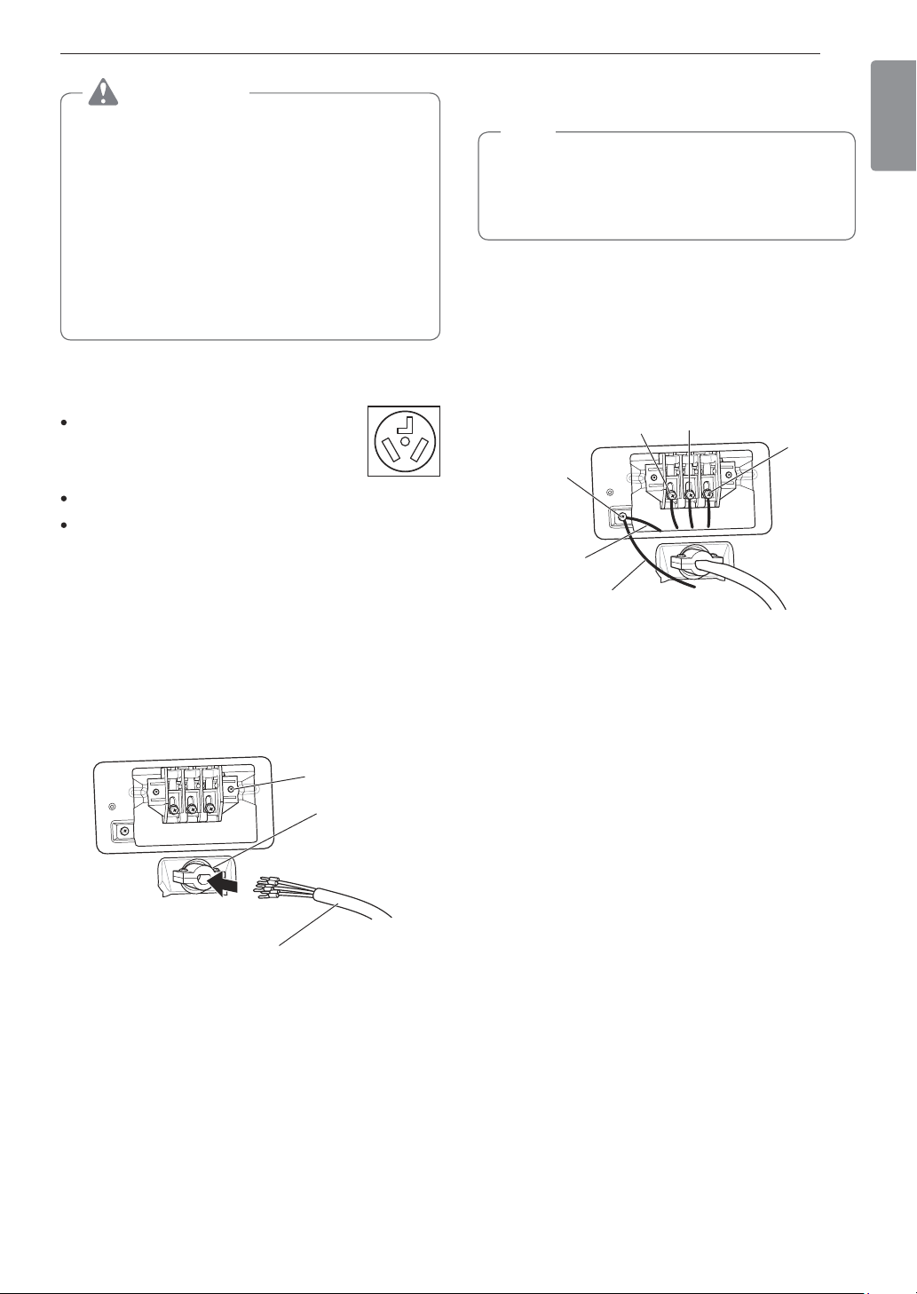
Three-Wire Power Cord
A 3-wire connection is NOT permitted
on new construction after January 1,
1996.
A UL-listed strain relief is required.
Use a 30-amp, 240-volt, 3-wire, UL-listed power
cord with #10 AWG-minimum copper conductor and
closed loop or forked terminals with upturned ends.
1
Remove the terminal block access cover on the
upper back of the dryer.
2
Install a UL-listed strain relief into the power cord
through-hole.
3
Thread a 30-amp, 240-volt, 3-wire, UL-listed
power cord with #10 AWG-minimum copper
conductor through the strain relief.
Terminal Block
UL-Listed
Strain Relief
UL-Listed 3-Wire Power Cord
4
Attach the two hot leads (black and red) of the
power cord to the outer terminal block screws.
5
Attach the neutral (white) wire to the center
terminal block screw.
NOTE
The dryer is supplied with the neutral conductor
grounded. If a 3-wire cord is to be used and is
allowed, make sure the white neutral grounding
wire is connected to the green ground screw.
6
Connect the external ground (if required by local
codes) to the green ground screw.
7
Tighten all screws securely.
8
Reinstall the terminal block access cover.
Hot
(Red)
Neutral
(White)
Hot
(Black)
Ground
Screw
External Ground
Wire (If required
by local codes)
White Wire
from Dryer
harness
32 INSTALLATION
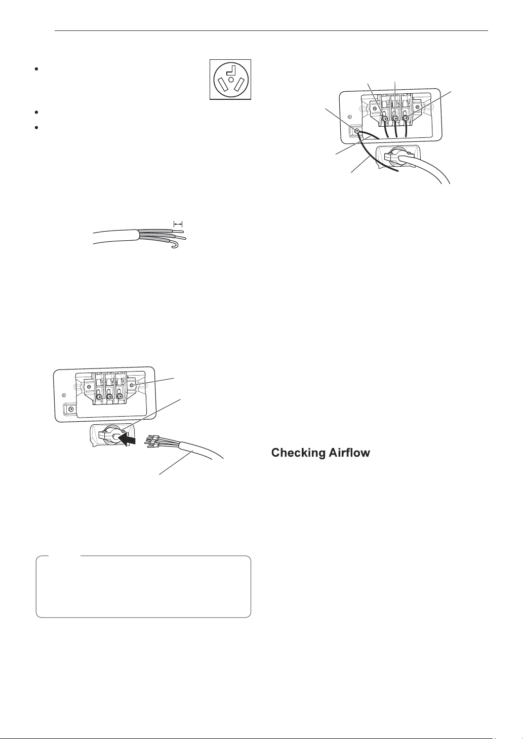
Three-Wire Direct Wire
A 3-wire connection is NOT permitted
on new construction after January 1,
1996.
A UL-listed strain relief is required.
Use UL-listed 3-wire, #10 AWG-minimum copper
conductor cable. Allow at least 5 ft. (1.5 m) length
to allow for removal and installation of dryer.
1
Remove 3½-inch (8.9 cm) of the outer covering
from the wire. Strip 1 inch (2.5 cm) insulation
from each wire. Bend the ends of the three wires
into a hook shape.
1" (2.5 cm)
2
Remove the terminal block access cover on the
upper back of the dryer.
3
Install a UL-listed strain relief into the power cord
through-hole.
4
Thread the 3-wire, #10 AWG-minimum copper
conductor power cable prepared in step 1
through the strain relief.
Terminal
Block
UL-Listed
Strain Relief
UL-Listed 3-Wire Power Cord
5
Attach the two hot leads (black and red) of the
power cord to the outer terminal block screws.
6
Attach the neutral (white) wire to the center
terminal block screw.
NOTE
The dryer is supplied with the neutral conductor
grounded. If a 3-wire cord is to be used and is
allowed, make sure the white neutral grounding
wire is connected to the green ground screw.
7
Connect the external ground (if required by local
codes) to the green ground screw.
8
Tighten all screws securely.
9
Reinstall the terminal block access cover.
Hot
(Red)
Neutral
(White)
Hot
(Black)
Ground
Screw
External Ground
Wire (If required by
local codes)
White Wire
from Dryer
harness
Final Installation Check
Once you have completed the installation of the dryer
and it is in its final location, confirm proper operation
with the following tests and the Installation Test (Duct
Check) on the following page.
Testing Dryer Heating
GAS MODELS
Close the dryer door, press the POWER button to turn
the dryer on, and start the dryer on a heat setting.
When the dryer starts, the igniter should ignite the
main burner.
ELECTRIC MODELS
Close the dryer door, press the POWER button to turn
the dryer on, and start the dryer on a heat setting.
The exhaust air should be warm after the dryer has
been operating for 3 minutes.
Effective dryer operation requires proper airflow.
The adequacy of the airflow can be measured by
evaluating the static pressure. Static pressure in the
exhaust duct can be measured with a manometer,
placed on the exhaust duct approximately 2 ft. (60.9
cm) from the dryer. Static pressure in the exhaust duct
should not exceed 0.6-inch (1.5 cm). The dryer should
be checked while the dryer is running with no load.
Checking Levelness
Once the dryer is in its final location, recheck the
dryer to be sure it is level. Make sure it is level front
to back and side to side, and that all four leveling feet
are firmly on the floor.
Checking Venting
Vent ductwork should be checked for lint buildup
and cleaned at least once per year. If any noticeable
reduction in drying performance occurs, check duct
for obstructions and blockages.
33INSTALLATION
ENGLISH
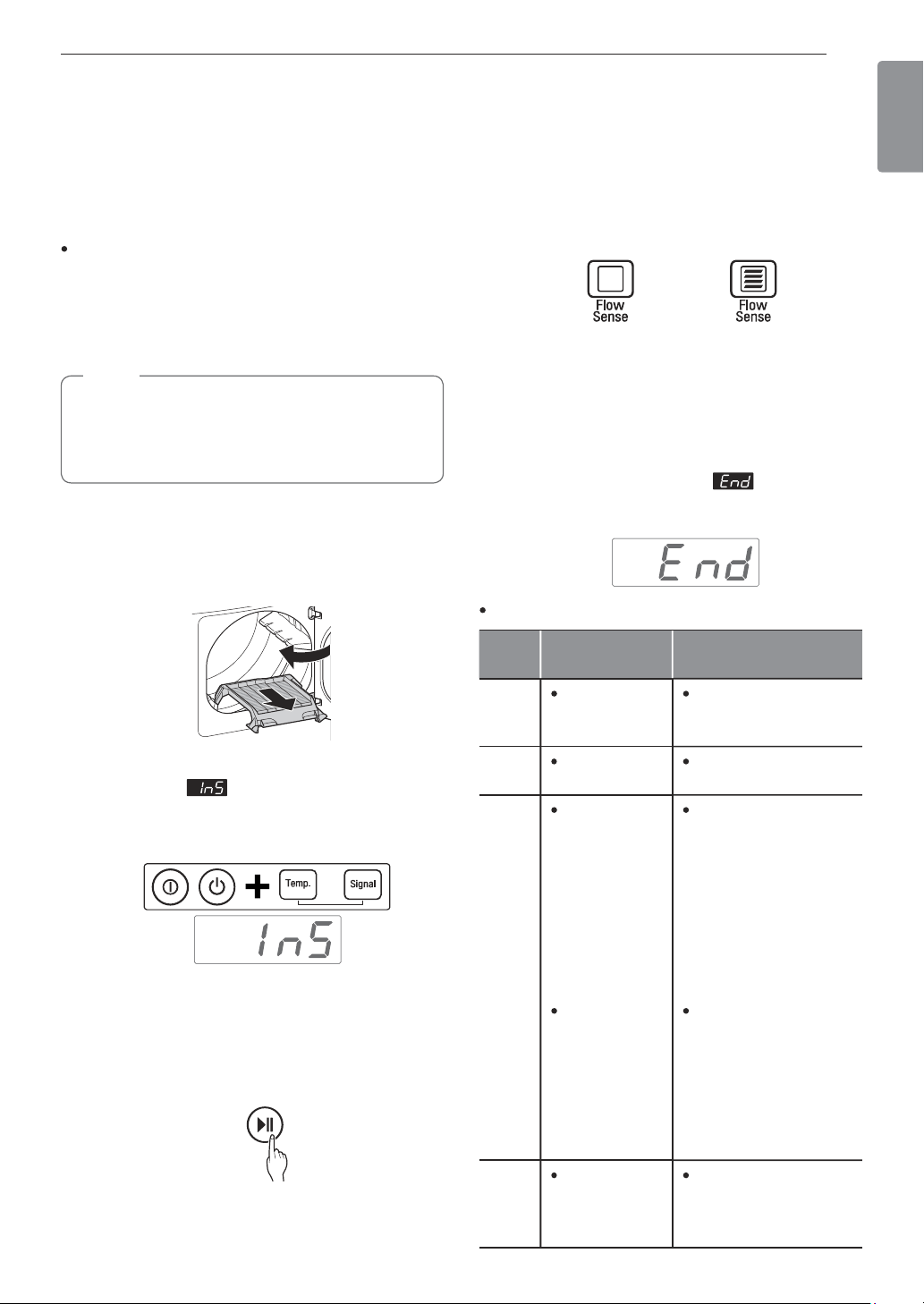
Installation Test (Duct Check)
Once you have completed the installation of the
dryer, use this test to make sure the condition of the
exhaust system is adequate for proper operation of
the dryer. This test should be performed to alert you
to any serious problems in the exhaust system of
your home.
This dryer features Flow Sense™, an innovative
sensing system that automatically detects
blockages and restrictions in dryer ductwork.
Keeping ductwork clean of lint buildup and free of
restrictions allows clothes to dry faster and reduces
energy use.
NOTE
The dryer should be cool before starting this test.
If the dryer was warmed up during installation, run
the AIR DRY cycle for a few minutes to reduce
the interior temperature.
To activate the installation test:
1
Remove the drying rack and literature, and
then close the door.
Do not load anything in the drum for this test, as
in may affect the accuracy of the results.
2
Press and hold the POWER, Temp., and Signal
buttons until and a usage count alternate
in the display. (The usage count indicates the
number of cycles run with no load during the last
5 cycles.)
3
Press the START/PAUSE button.
The dryer will start the test, which will last about
2 minutes. The heat will be turned on and the
temperatures in the drum will be measured and
displayed. A chime sounds when the test portion
of the cycle is complete.
4
Check the display for results.
During the test cycle, monitor the Flow Sense™
display on the control panel. If no bars are
displayed, when the cycle ends, the exhaust
system is adequate. If the exhaust system is
severely restricted, the display will show four
bars. Other problems may also be shown with
error codes. See the chart below for error code
details and solutions.
NO BARS:
OK
FOUR BARS:
RESTRICTED
Four bars indicates that the exhaust system is
severely restricted. Have the system checked
immediately, as performance will be poor.
5
End of cycle.
At the end of the test cycle, will display.
The test cycle will end and the dryer will shut off
automatically after a short delay.
Check the error code before you call for service
Error
Code
Possible
Causes
Solutions
tE1
or
tE2
Temperature
sensor
failure.
Turn off the dryer and
call for service.
HS
Humidity
sensor failure.
Turn off the dryer and
call for service.
PS
or PF
or nP
Electric
dryer power
cord is not
connected
correctly, or
house power
supply is
incorrect.
House fuse is
blown, circuit
breaker
has tripped,
or power
outage has
occurred.
Check the power
supply or the
connection of the
power cord to the
terminal block. Refer
to the Connecting
Electric Dryers
section of this
manual for complete
instructions.
Reset circuit breaker
or replace fuse. Do
not increase the
fuse capacity. If the
problem is a circuit
overload, have
it corrected by a
qualified electrician.
gAS
Gas supply or
service turned
off. (Gas
Model only.)
Confirm that house
gas shutoff and the
dryer gas shutoff are
both fully open.
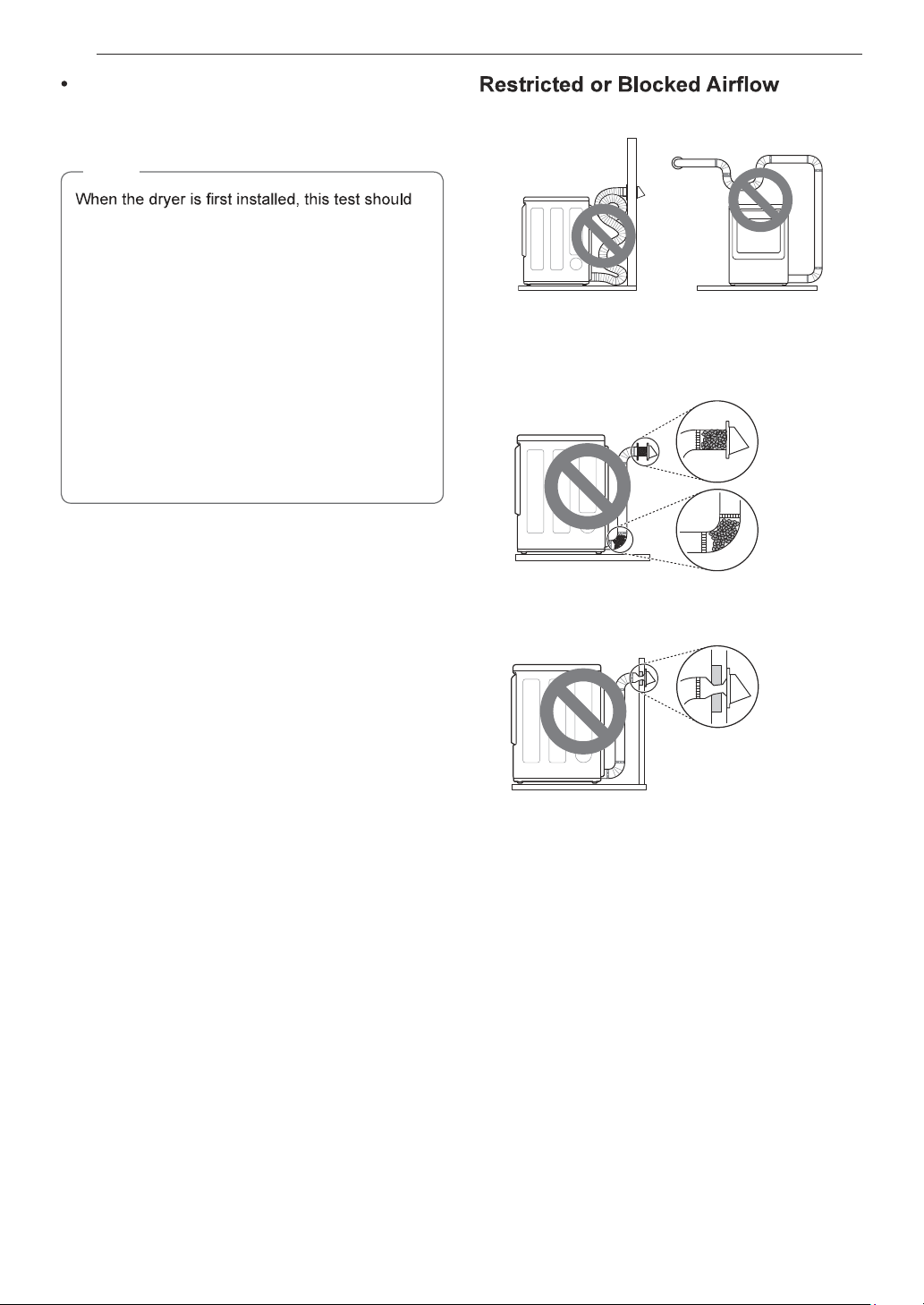
34 INSTALLATION
Check the duct condition
If the Flow Sense
TM
LED is turned on, check the
exhaust system for restrictions and damage. Repair
or replace the exhaust system as needed.
NOTE
be performed to alert you to any existing
problems with the exhaust duct in your home.
However, since the test performed during normal
operation provides more accurate information on
the condition of the exhaust duct than does the
installation test, the number of bars displayed
during the two tests may not be the same.
Do not interrupt the test cycle, as this could result
in inaccurate results.
Even if no bars are displayed during the test
cycle, some restrictions may still be present in the
exhaust system. Refer to the Venting the Dryer
section of this manual for complete exhaust
system and venting requirements.
Avoid long runs or runs with multiple elbows or bends.
Excess or crushed
transition duct
Too many elbows or
exhaust too long
Check for blockages and lint buildup.
Lint
buildup or
blockage
Make sure the ductwork is not crushed or restricted.
Crushed
or
damaged
exhaust
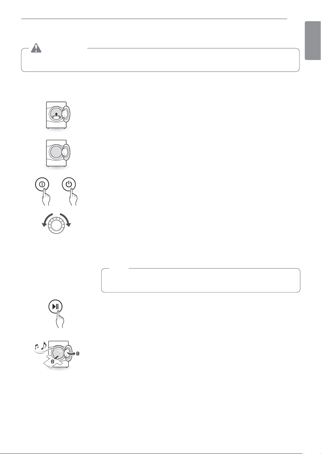
35OPERATION
ENGLISH
OPERATION
WARNING
To reduce the risk of fire, electric shock, or injury to persons, read this entire manual, including the
IMPORTANT SAFETY INSTRUCTIONS, before operating this dryer.
Using the Dryer
1 Clean the Lint Filter
If the lint filter has not already been cleaned, lift out the filter and remove the lint
from the last load. This will help ensure the fastest and most efficient drying perfor-
mance. Make sure to reinstall the filter, pressing down until it clicks firmly into place.
The dryer will not operate without the lint filter in place.
2 Load the Dryer
Load the dryer with the wet laundry from the washer. If the load is extra large,
you may need to divide it into smaller loads for proper performance and fabric
care.
3 Turn on The Dryer
Press the POWER button to turn ON the dryer. The cycle LEDs will illuminate and a
chime will sound.
4 Select a Cycle
Turn the cycle selector knob in either direction until the LED for the desired
cycle is on. The preset temperature, dry level, and option settings for that cycle
will be shown. Refer to page 40. Default settings for the selected cycle can
now be changed if desired. This can be done using the cycle modifier buttons
as shown on page 38. Cycle options can be added using the option buttons as
shown on page 42-43.
NOTE
Not all options or modifiers are available on all cycles. A different chime will
sound and the LED will not come on if the selection is not allowed.
5 Begin the Cycle
Press the START/PAUSE button to begin the cycle. The cycle can be paused at
any time either by opening the door or by pressing the START/PAUSE button.
If the cycle is not restarted within 60 minutes of being paused, the dryer will shut off
and the settings will be lost.
6 End of Cycle
When the cycle is finished, the chime will sound. Immediately remove your
clothing from the dryer to reduce wrinkling. If Wrinkle Care is selected, the dryer
will tumble briefly every few minutes to help prevent wrinkles from setting in the
clothes.
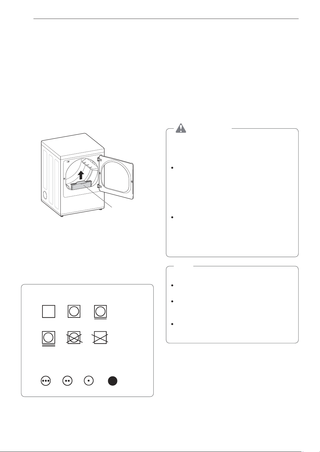
36 OPERATION
Check the Lint Filter Before
Every Load
Always make sure the lint filter is clean before starting
a new load; a clogged lint filter will increase drying
time. To clean, pull the lint filter straight up and roll
any lint off the filter with your fingers. Do not rinse or
wash the filter to remove lint. Push the lint filter firmly
back into place. See Regular Cleaning for more
information.
Always ensure the lint filter is properly installed before
running the dryer. Running the dryer with a loose or
missing lint filter will damage the dryer and articles in
the dryer.
Lint Filter
Sorting Loads
Fabric Care Labels
Most articles of clothing feature fabric care labels that
include instructions for proper care.
Fabric Care Labels
Heat setting
High
Medium Low
No heat/air
Tumble dry
Dry
Normal
Permanent Press/
wrinkle resistant
Gentle/
delicate
Do not
tumble dry
Do not dry
(used with do not wash)
Group Similar Items
For best results, sort clothes into loads that can be
dried with the same drying cycle.
Different fabrics have different care requirements, and
some fabrics will dry more quickly than others. For
best fabric care results, always dry fabrics with similar
care requirements together.
Loading the Dryer
WARNING
To reduce the risk of fire, electric shock, or
injury to persons when using this appliance,
follow basic precautions, including the
following:
Check all pockets to make sure that they are
empty. Items such as clips, pens, coins, and
keys can damage both your dryer and your
clothes. Flammable objects such as lighters
or matches could ignite, causing a fire.
Failure to do so may result in fire, explosion, or
death.
Never dry clothes that have been exposed
to oil, gasoline, or other flammable
substances. Washing clothes will not
completely remove oil residues. Failure to
obey this warning may result in fire, explosion,
or death.
NOTE
Loading Tips
Combine large and small items in the same
load.
Damp clothes will expand as they dry. Do not
overload the dryer; clothes require room to
tumble and dry properly.
Close zippers, hooks, and drawstrings to
prevent these items from snagging or tangling
on other clothes.
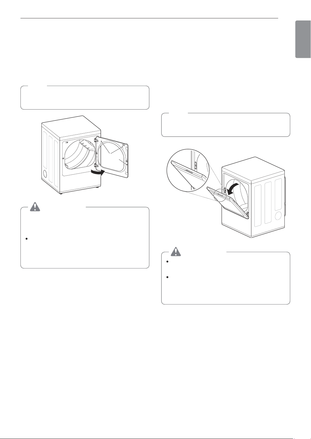
37OPERATION
ENGLISH
Using the LG EasyLoad
TM
Swing Door
Use the swing door when unloading, or when loading
bulkier items, for easy access to the drum.
To open the swing door, grasp the top of the door on
the side opposite the hinge and pull.
NOTE
Make sure the hamper door release is completely
closed before using the swing door.
Swing door
Interlock
Buttons
WARNING
Do not press the three interlock buttons when
the door is open. The door may fall off and cause
serious injury.
Do not place heavy items on or lean against
the top of the door when it is open.
The dryer could tip forward, causing injury or
property damage.
Hamper Door (on some models)
Use the hamper door when loading. The hamper door
opens about 40 degrees and acts as a chute to help
guide items into the drum and help prevent items from
falling onto the floor. It also comes in handy when
unloading a few small items, helping prevent the rest
of the laundry from being pulled onto the floor.
To open the hamper door, press the release on the
top of the door and pull the door forward.
Make sure laundry is fully inserted in the drum before
closing the door.
NOTE
Make sure the swing door latch is completely
closed before pressing the hamper door release.
Hamper door release
40°
Hamper door
WARNING
Do not attempt to pull the hamper door open
more than 40 degrees.
Be careful when opening and closing the door.
Fingers and hands can get caught in the door
and cause injury if the door drops forward
unexpectedly.
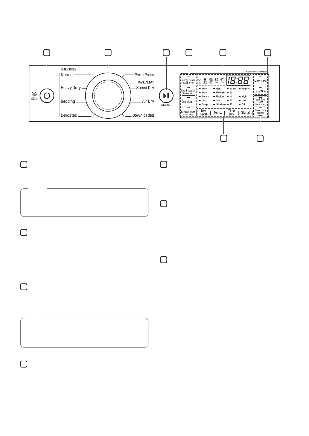
38 OPERATION
Control Panel
1 2 3 5 64
47
1
POWER Button
Press to turn the dryer ON. Press again to turn the
dryer OFF.
NOTE
Pressing the POWER button during a cycle will
cancel that cycle and any load settings will be
lost.
2
Cycle Selector Knob
Turn this knob to select the desired cycle. Once
the desired cycle has been selected, the standard
presets are shown in the display. On Manual Dry
cycles, these settings can be adjusted using the cycle
modifier buttons any time before starting the cycle.
3
START/PAUSE Button
Press this button to start the selected cycle. If the
dryer is running, use this button to pause the cycle
without losing the current settings.
NOTE
If you do not press the START/PAUSE button to
resume a cycle within 60 minutes, the dryer turns
off automatically.
4
Cycle Option Buttons
The option buttons allow you to select additional cycle
options. Certain buttons also allow you to activate
special functions by pressing and holding the button
for 3 seconds.
5
Time and Status Display
The display shows the settings, estimated time
remaining, options, and status messages for the
dryer.
6
MORE TIME/LESS TIME Buttons
Use these buttons with the Time Dry and other
Manual Dry cycles to adjust the drying time. Press the
MORE TIME button to increase the selected manual
cycle time by 1 minute; press the LESS TIME button
to decrease the cycle time by 1 minute.
7
Cycle Modifier Buttons
Use these buttons to select the desired cycle settings
for the selected cycle. The current settings are shown
in the display. Press the button for that modifier to
select other settings.
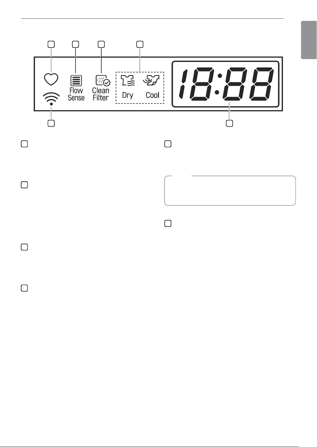
39OPERATION
ENGLISH
8 119 10
1213
8
Custom PGM
If you have a special combination of settings that
you use frequently, you can save these settings as a
Custom Program.
9
Flow Sense
™
Duct Blockage Sensing System
Indicator
The Flow Sense™ duct blockage sensing system
detects and alerts you to blockages in the ductwork
that reduce exhaust flow from the dryer. Maintaining
a clean exhaust system improves operating efficiency
and helps minimize service calls, saving you money.
10
Clean Filter Reminder
The display will show Clean Filter when the dryer is
turned on as a reminder to check the filter. It turns off
when the START/PAUSE button is pressed.
11
Cycle Completion Indicator with Check Filter
Reminder
This portion of the display shows which stage of the
drying cycle is currently underway (Dry, Cool).
12
Estimated Time Remaining
This display shows the estimated time remaining for
SENSOR DRY cycles or the actual time remaining for
Time Dry or MANUAL DRY cycles.
NOTE
The cycle time on SENSOR DRY cycles may
fluctuate as the dryer recalculates drying time for
optimal results.
13
WI-FI Indicator
When the appliance is connected to the internet
through a home Wi-Fi network, this indicator appears.
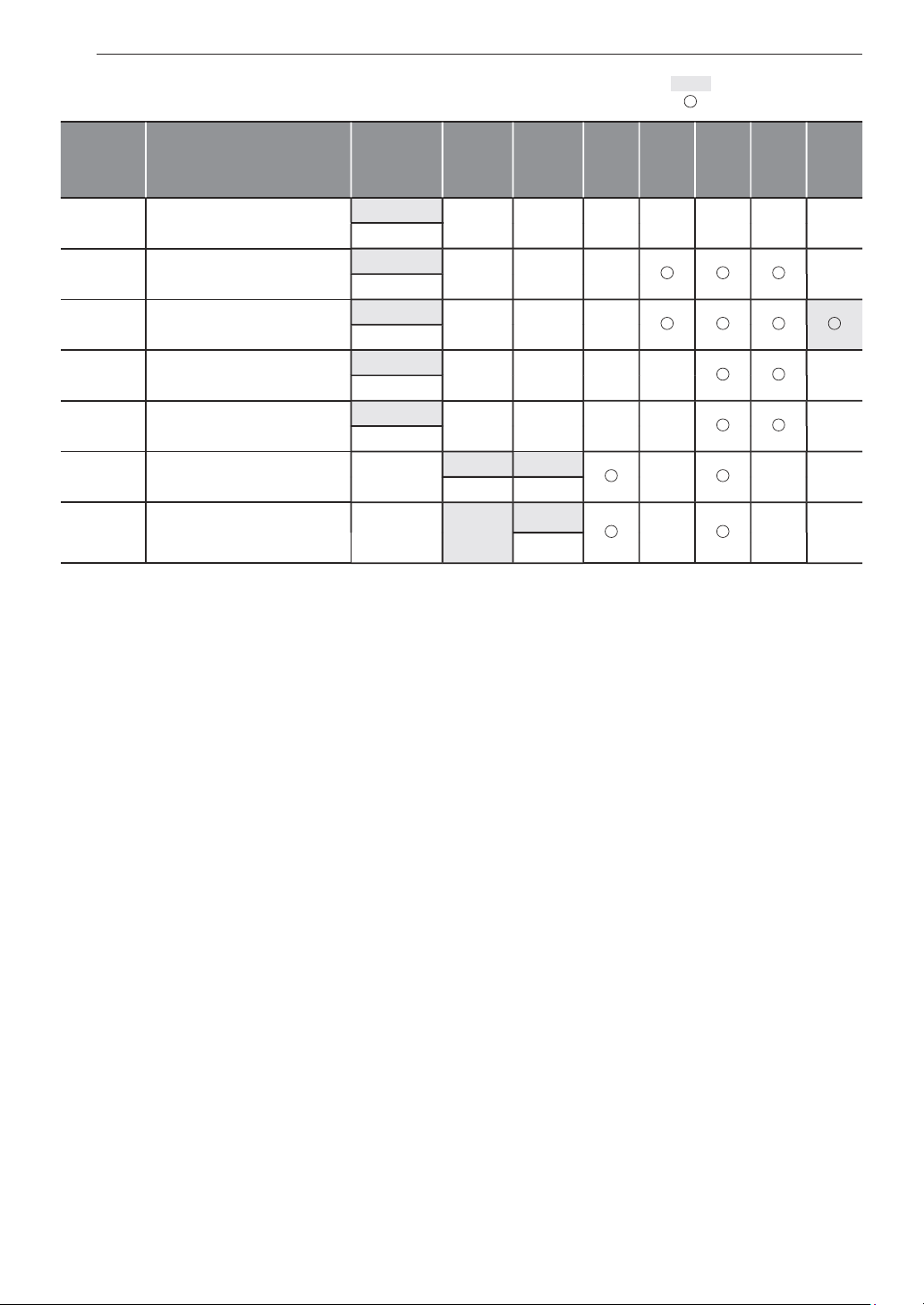
40 OPERATION
Cycle Guide
Cycle Fabric Type Dry Level Temp. Time
More
Time/
Less
Time
Anti-
bac-
terial
Wrinkle
Care
Damp
Dry
Signal
Energy
Saver
Bedding Comforters, pillows, shirts
Normal Dry
Medium 55
Adjustable
Heavy
Duty
Jeans, heavyweight items
Normal Dry
High 54
Adjustable
Normal Work clothes, corduroys, etc.
Normal Dry
Medium
Elec : 57
Gas : 63
Adjustable
Perm.
Press
Permanent press, synthetic
items
Normal Dry
Low 32
Adjustable
Delicates Lingerie, sheets, blouses
Normal Dry
Low 28
Adjustable
Speed Dry
For small loads with short
drying times
Auto
High 25
Adjustable Adjustable
Air Dry
For items that require heat-
free drying such as plastics
or rubber
Off No Heat
30
Adjustable
= default setting
= allowable option

41OPERATION
ENGLISH
Sensor dry cycles
Sensor dry cycles utilize LG’s unique dual sensor
system to detect and compare the moisture level
in clothes and in the air and adjust the drying time
as needed to ensure superior results. The dryer
automatically sets the dryness level and temperature
at the recommended setting for each cycle. The
estimated time remaining will be shown in the display.
NOTE
To protect your garments not every dryness level,
temperature, or option is available with every
cycle. See the Cycle Guide for details.
Downloaded
If you download a cycle using the Smart ThinQ
application, it will be placed in the downloaded cycle
position. Choose the Downloaded cycle to run the
downloaded cycle.
Manual dry cycles
Use manual dry cycles to select a specific amount
of drying time and a drying temperature. When a
manual dry cycle is selected, the Estimated Time
Remainng display shows the actual time remaining
in your cycle. You can change the actual time in the
cycle by pressing More Time or Less Time.
CERTIFIED BY NSF/P154
NSF International (formerly the National Sanitation
Foundation), certifies that the Anti Bacterial cycle
reduces 99.9% of bacteria on laundry, and none of
the bacteria will carry over onto the next laundry load.
The default settings for the Anti Bacterial cycle
are High temperature and Very Dry. These default
settings cannot be changed.
Do NOT use this cycle with delicate items or
fabrics.

42 OPERATION
Cycle Settings and Options
SENSOR DRY cycles have preset settings that
are selected automatically. MANUAL DRY cycles
have default settings, but you may also customize
the settings using the cycle modifier buttons. Press
the button for that option to view and select other
settings.
Dry Level
Selects the level of dryness for the cycle. Press
the Dry Level button repeatedly to scroll through
available settings.
This option is only available with SENSOR DRY
cycles.
The dryer will automatically adjust the cycle time.
Selecting More Dry or Very Dry will increase
the cycle time, while Less Dry or Damp Dry will
decrease the cycle time.
Use a Less Dry or Damp Dry setting for items that
you wish to iron.
Temp.
Adjusts the temperature setting. This allows precise
care of your fabrics and garments. Press the Temp.
button repeatedly to scroll through available settings.
Time Dry
Allows you to manually select the drying time, from 20
to 60 minutes, in 10-minute increments. Use this for
small loads or to remove wrinkles.
More Time/Less Time
Use the More Time/Less Time buttons to add or
reduce the drying time of a MANUAL DRY cycle in
1-minute increments.
Signal (Option)
Press the Signal (Option) button repeatedly to
change the volume or turn on/off the button tones and
the end of cycle melody.
Cycle Option Buttons
The dryer features several additional cycle options to
customize cycles to meet individual needs. Certain
option buttons also feature a special function that
can be activated by pressing and holding that option
button for 3 seconds. (See Special Functions on the
following page for details.)
Adding Cycle Options to a Cycle:
1
Turn on the dryer and turn the cycle selector
knob to select the desired cycle.
2
Use the cycle modifier buttons to adjust the
settings for that cycle.
3
Press the cycle option button(s) for the option
you would like to add. A confirmation message is
shown in the display.
4
Press the START/PAUSE button to start the
cycle. The dryer starts automatically.
Wrinkle Care
Selecting this option will tumble the load periodically
for up to 3 hours after the selected cycle, or until the
door is opened. This is helpful in preventing wrinkles
when you are unable to remove items from the dryer
immediately.
Damp Dry Signal
With this option, the dryer will signal when the load
is approximately 80% dry. This allows you to remove
faster- drying lightweight items or items that you
would like to iron or hang while still slightly damp.

43OPERATION
ENGLISH
Special Functions
Some cycle option buttons also activate secondary
functions. These special functions are marked with an
asterisk (*). Press and hold the option button marked
with the special function to activate it.
Drum Light
The drum is equipped with a blue LED that illuminates
when the dryer is turned on. This light automatically
turns off when the door is closed and the cycle starts.
To turn on the light during a cycle, press the Drum
Light button. The drum light will illuminate and then
turn off automatically after four minutes.
* Control Lock
Use this option to prevent unwanted use of the dryer
or to keep cycle settings from being changed while
the dryer is operating.
Press and hold the button marked Control Lock for
3 seconds to activate or deactivate the Control Lock
function. The Control Lock icon will be shown in the
display, and all controls will be disabled except the
POWER button.
NOTE
Once set, Control Lock remains active until it is
manually deactivated. Control Lock must be turned off
to run another cycle. To deactivate Control Lock, press
and hold the
Control Lock
button for 3 seconds.
Energy Saver (on some models)
This option helps to reduce energy consumption in
the Normal cycle, depending on the load size.
When the Energy Saver option is selected, the cycle
begins with an air dry section and the drying time is
increased.
NOTE
The Energy Saver option is turned on by default in
the Normal cycle. Turn off the Energy Saver option
for a faster Normal cycle which begins with heated
drying.
* Default On/Off
This option allows the Energy Saver settings to be
changed. To run a Normal cycle without the Energy
Saver option, press and hold the Energy Saver button
for three seconds. ON or OFF appears in the display.
Custom PGM
If you have a special combination of settings that
you use frequently, you can save these settings as a
custom program.
Saving a Custom Program:
1
Turn on the dryer and turn the cycle selector
knob to select the desired cycle.
2
Use the cycle setting buttons to adjust the
settings for that cycle.
3
Press the cycle option button(s) for the option you
would like to add. A confirmation message will be
shown in the display.
4
Press and hold the Custom PGM button for 3
seconds.
NOTE
You may save only one custom program at a
time. Pressing and holding the Custom PGM
button will overwrite any previously saved custom
program.
Recalling a Custom Program:
1
Turn on the dryer.
2
Press the Custom PGM button.
3
Press the START/PAUSE button to start the
cycle.
44 OPERATION
SMART FUNCTIONS
Application Installation
Search for the LG Smart ThinQ application from
the Google Play Store on a smart phone. Follow
instructions to download and install the application.
Product Registration
1
Run the LG Smart ThinQ application on a smart
phone.
2
Create an account and sign in.
3
Select Register.
4
Select Top Load Dryer.
5
Follow the instructions on the smart phone to
register the appliance and connect it to a Wi-Fi
network.
To verify the Wi-Fi connection, check the Wi-Fi
icon( ) on the control panel is lit.
NOTE
LG Smart ThinQ is not responsible for any
network connection problems or any faults,
malfunctions, or errors caused by network
connection.
The machine supports 2.4 GHz Wi-Fi networks
only.
If the appliance is having trouble connecting
to the Wi-Fi network, it may be too far from
the router. Purchase a Wi-Fi repeater (range
extender) to improve the Wi-Fi signal strength.
The Wi-Fi connection may not connect or may
be interrupted because of the home network
environment.
The network connection may not work properly
depending on the internet service provider.
The surrounding wireless environment can
make the wireless network service run slowly.
This information is current at the time of
publication.
The application is subject to change for
appliance improvement purposes without notice
to users.
Using the Wi-Fi Function
Communicate with the appliance from a smart phone
using the convenient smart features.
Using the Wi-Fi Function
1
Select the appliance in the application.
2
Select the menu on the upper right side to
access settings and features.
Dryer Cycle (Remote Start +
Download Cycle)
Remote Start
Use a smart phone to control the appliance remotely.
Or monitor the cycle operation to see the remaining
time left in the cycle.
NOTE
You must first register the appliance and
connect to a gateway in order to use the
Remote Start function.
Using Remote Start
1
Press and hold the REMOTE START button. The
Remote LED on the control panel is illuminated.
2
Start a cycle from the application on a smart
phone. If the cycle is not started, the machine
will wait to start the cycle until it is turned off or
the Remote Start mode is disabled.
Download Cycle
Download new and specialized cycles that are not
included in the standard cycles on the appliance.
Appliances that have been successfully registered
can download a variety of specialty cycles specific
to the appliance. Only one cycle can be stored
on the appliance at a time. Once Download Cycle
is completed in the dryer, the product keeps the
downloaded cycle until a new cycle is downloaded.
NOTE
You must first register the appliance and
connect to a gateway in order to use the
Download Cycle function.
45OPERATION
ENGLISH
Push Alerts (Smart Message)
When the cycle is complete or the appliance has
problems, you have the option of receiving push
notifications on a smart phone.
NOTE
You must first register the appliance and
connect to a gateway in order to use the Push
Alerts function.
Smart Diagnosis™
This function provides useful information for
diagnosing and solving issues with the appliance
based on the pattern of use.
NOTE
You must first register the appliance and
connect to a gateway in order to use the Smart
Diagnosis function.
Energy Monitoring
The dryer’s energy usage is affected by the cycle
and options so you may see some changes in energy
usage from one cycle to another.
NOTE
You must first register the appliance and
connect to a gateway in order to use the Energy
Monitoring function.
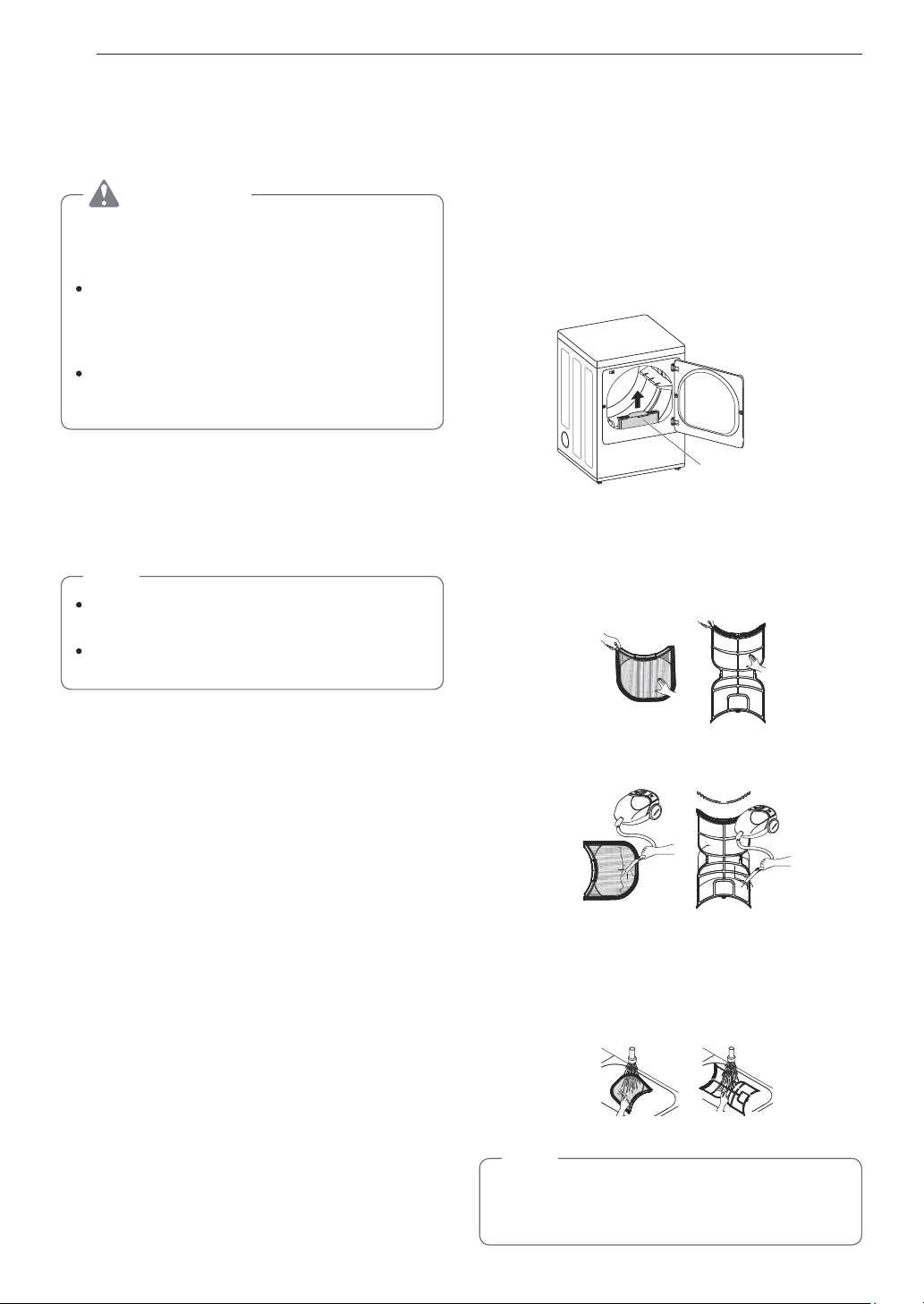
46 MAINTENANCE
MAINTENANCE
Regular Cleaning
WARNING
To reduce the risk of fire, electric shock, or injury
to persons when using this appliance, follow basic
precautions, including the following:
Unplug the dryer before cleaning to avoid
the risk of electric shock. Failure to follow
this warning may cause serious injury, fire,
electric shock, or death.
Never use harsh chemicals, abrasive
cleaners, or solvents to clean the washer.
They will damage the finish.
Cleaning the Exterior
Proper care of your dryer can extend its life. The
outside of the machine can be cleaned with warm
water and a mild, nonabrasive household detergent.
Immediately wipe off any spills with a soft, damp cloth.
NOTE
Do not use methylated spirits, solvents, or
similar products.
Never use steel wool or abrasive cleansers;
they can damage the surface.
Cleaning the Interior
Wipe around the door opening and seal with a soft,
damp cloth to prevent lint and dust buildup that could
damage the door seal.
Clean the window with a soft cloth dampened with
warm water and a mild, nonabrasive household
detergent, then wipe dry.
The stainless steel drum can be cleaned with a
conventional stainless steel cleaner, used according
to the manufacturer’s specifications. Never use steel
wool or abrasive cleansers; they may scratch or
damage the surface.
Cleaning Around and Under the Dryer
Vacuum lint and dust from around the dryer and
underneath it regularly. Vent ductwork should be
checked for lint buildup and cleaned at least once per
year. If any noticeable reduction in airflow or drying
performance occurs, immediately check ductwork for
obstructions and blockages.
Maintaining Ductwork
Vent ductwork should be checked for lint buildup once
per month and cleaned at least once per year. If any
noticeable reduction in airflow or drying performance
occurs, immediately check ductwork for obstructions
and blockages. Contact a qualified technician or
service provider.
Cleaning the Lint Filter
Always clean the lint from the filter after every cycle.
Lint Filter
To clean, open the dryer door and pull the lint filter
straight up. Then:
1
For everyday cleaning, roll any lint off the filter
with your fingers, or
2
Vacuum the lint filter.
3
If the lint filter has become very dirty or clogged
with fabric softener, wash the lint filter in warm,
soapy water and allow it to dry thoroughly before
reinstalling.
NOTE
NEVER operate the dryer without the lint filter in
place. NEVER operate the dryer with a wet lint
filter.

47TROUBLESHOOTING
ENGLISH
TROUBLESHOOTING
FAQs: Frequently Asked Questions
Q: When I press a button, why does my dryer beep and then nothing happens?
A: The Control Lock feature is turned on. To turn off Control Lock, turn the dryer on, then press and hold
the button that has *Control Lock on or under it for 3 seconds.
Q: Why does my dryer take so long to dry clothes?
A: Proper airflow is critical to the efficient operation of clothes dryers. A lint filter which is full of lint or
clogged with fabric softener sheet residue can reduce the airflow to the point that the time required
to dry clothing will be greatly increased. Another factor affecting dry time is your home exhaust
system. An exhaust system which is dirty and clogged with lint, or is excessively long, needs to be
professionally cleaned or repaired.
Q: Why does my dryer start by itself every few minutes?
A: This is how the Wrinkle Care feature works. The dryer runs briefly every few minutes for up to 3 hours
after the cycle finishes. This feature is designed to help prevent wrinkles from setting in when the
dryer is not unloaded immediately after the cycle is finished.
User Support Videos
For further assistance, there are videos and tutorials
available through the LG.com website.
1
On the lg.com/us home page, click on the Support
menu tab to bring up the menu selections. Select
Video Tutorials.
2
Select Appliances and Dryers in the search menu
on the new page.
Scan this QR code to quickly access the
video search page on the LG website.
Once there, select Appliances and Dryers
in the search box.
48 TROUBLESHOOTING
Before Calling for Service
This dryer is equipped with an automatic error-monitoring system to detect and diagnose problems at an early
stage. If the dryer does not function properly or does not function at all, check the following before you call for
service.
Operation
Problem Possible Cause Solutions
The Flow Sense
TM
indicator remains
active after clearing
the restriction in the
venting.
After clearing the restriction, the
Flow Sense
TM
system requires
multiple, consecutive cycles to
determine that the performance
value has improved before the
Flow Sense
TM
indicator is reset.
If the Flow Sense
TM
indicator remains
active for more than five cycles after
the restriction has been cleared, call for
service.
Dryer will not turn on Power cord is not properly
plugged in.
Make sure that the plug is securely
plugged into a grounded outlet matching
the dryer’s rating plate.
House fuse is blown, circuit
breaker has tripped, or power
outage has occurred.
Reset circuit breaker or replace fuse. Do
not increase fuse capacity. If the problem
is a circuit overload, have it corrected by
a qualified electrician.
Dryer does not heat House fuse is blown, circuit
breaker has tripped, or power
outage has occurred.
Reset circuit breaker or replace fuse. Do
not increase fuse capacity. If the problem
is a circuit overload, have it corrected by
a qualified electrician.
NOTE
Due to the design of electric dryers,
it is possible for a circuit problem to
allow an electric dryer to run without
heat.
Gas supply or service is turned
off (gas models only).
Confirm that the house gas shutoff and
the dryer gas shutoff valves are both fully
open. Even if gas is not supplied to the
dryer, it will run and display error code.
Verify that other gas appliances in the
home are working normally.
Energy Saver option selected
(on some models)
If using the Cotton/Normal cycle, deselect
the energy saver option. The Energy
Saver option is selected by default. This
option reduces energy use by adding
an air dry section to the beginning of the
cycle. It is normal to feel no heat at the
beginning of the cycle while in Energy
Saver mode.
Display show error
code nP
Electric dryer power cord is not
connected correctly, or house
power supply is incorrect.
Check the power supply or the connection
of the power cord to the terminal block.
Display show error
code gAS
Gas supply or service turned off
(gas models only).
Confirm that house gas shutoff and the
dryer gas shutoff are both fully open.

49TROUBLESHOOTING
ENGLISH
Problem Possible Cause Solutions
Clothes take too long to
dry
Exhaust ducts are blocked, dirty,
or duct run is too long.
Confirm that the exhaust duct is properly
configured and free of debris, lint, and
obstructions. Make sure that outside wall
dampers can open properly and are not
blocked, jammed, or damaged.
Load is not properly sorted. Separate heavy items from lightweight
items. Larger and heavier items take
longer to dry. Light items in a load with
heavy items can fool the sensor because
the light items dry faster.
Clothes take too long to
dry
Large load of heavy fabrics. Heavy fabrics take longer to dry because
they tend to retain more moisture. To help
reduce and maintain more consistent
drying times for large and heavy fabrics,
separate these items into smaller loads of
a consistent size.
Dryer controls are not set
properly.
Use the appropriate control settings for
the type of load you are drying. Some
loads may require an adjustment of the
dry level setting for proper drying.
Lint filter needs to be cleaned. Remove the lint from the filter before
every load. With the lint removed, hold
the filter up to a light to see if it is dirty or
clogged. With some loads that produce
high amounts of lint, such as new bath
towels, it may be necessary to pause the
cycle and clean the filter during the cycle.
House fuse is blown, circuit
breaker has tripped, or power
outage has occurred.
Reset circuit breaker or replace fuse. Do
not increase fuse capacity. If the problem
is a circuit overload, have it corrected by
a qualified electrician.
NOTE
Due to the design of electric dryers,
it is possible for a circuit problem to
allow an electric dryer to run without
heat.
Dryer is overloaded. Divide extra large loads into smaller
loads for better drying performance and
efficiency.
Dryer is underloaded. If you are drying a very small load, add a
few extra items to ensure proper tumbling
action. If the load is very small and you
are using SENSOR DRY cycles, the
electronic control cannot properly sense
the dryness of the load and may shut off
too soon. Use TIME DRY or add some
extra wet clothes to the load.

50 TROUBLESHOOTING
Problem Possible Cause Solutions
Clothes take too long to
dry
Energy Saver option selected
(on some models)
If using the Cotton/Normal cycle, deselect
the Energy Saver option. This option
reduces energy use by adding an air dry
section to the beginning of the cycle.
Drying time is not
consistent
Heat settings, load size, or
dampness of clothing is not
consistent.
The drying time for a load will vary
depending on the type of heat used
(electric, natural gas, or LP gas), the
size of the load, the type of fabrics, the
wetness of the clothes, and the condition
of the exhaust duct and lint filter. Even an
unbalanced load in the washer can cause
poor spinning, resulting in wetter clothes
which will take longer to dry.

51TROUBLESHOOTING
ENGLISH
Performance
Problem Possible Cause Solutions
Greasy or dirty spots
on clothes
Fabric softener used incorrectly. Confirm and follow the instructions
provided with your fabric softener.
Clean and dirty clothes are being
dried together.
Use your dryer to dry only clean items.
Soil from dirty clothes can transfer to the
clean clothes in the same or later loads.
Clothes were not properly
cleaned or rinsed before being
placed in the dryer.
Stains on dried clothes could be stains
that were not removed during the washing
process. Make sure that clothes are being
completely cleaned or rinsed according
to the instructions for your washer and
detergent. Some difficult soils may require
pre-treating prior to washing.
Clothes are wrinkled Clothes dried too long (over
dried).
Over drying a load of laundry can lead to
wrinkled clothes. Try a shorter drying time
or LESS DRY setting and remove items
while they still retain a slight amount of
moisture.
Clothes left in dryer too long after
cycle ends.
Use the WRINKLE CARE option. This
feature will tumble the clothes briefly
every few minutes for up to 3 hours to
help prevent wrinkling.
Clothes are shrinking Garment care instructions are not
being followed.
To avoid shrinking your clothes, always
consult and follow fabric care instructions.
Some fabrics will naturally shrink when
washed. Other fabrics can be washed but
will shrink when dried in a dryer. Use a
low or no heat setting.
Lint on clothes Lint filter not cleaned properly. Remove the lint from the filter before
every load. With the lint removed, hold
the filter up to a light to see if it is dirty
or clogged. If it looks dirty, follow the
cleaning instructions. With some loads
that produce high amounts of lint, it may
be necessary to clean the filter during the
cycle.
Laundry not sorted properly. Some fabrics are lint producers (i.e., a
fuzzy white cotton towel) and should be
dried separately from clothes that are lint
trappers (i.e., a pair of black linen pants).
52 TROUBLESHOOTING
Problem Possible Cause Solutions
Lint on clothes Excess static in clothes. Use a fabric softener to reduce static
electricity. Be sure to follow the
manufacturer’s instructions. Overdrying
a load of laundry can cause a buildup of
static electricity. Adjust settings and use a
shorter drying time, or use SENSOR DRY
cycles.
Dryer is overloaded. Divide extra large loads into smaller loads
for drying.
Tissue, paper, etc., left in pockets. Check pockets thoroughly before washing
and drying clothes.
Excess static in clothes
after drying
Fabric softener is not used or
used incorrectly.
Use a fabric softener or the STATIC
SHIELD option, if equipped, to reduce
static electricity. Be sure to follow the
manufacturer’s instructions.
Clothes dried too long
(overdried).
Overdrying a load of laundry can cause
a buildup of static electricity. Adjust
settings and use a shorter drying time, or
use AUTO DRY cycles. Select a LESS
DRY setting on SENSOR DRY cycles, if
necessary.
Drying synthetics, permanent
press, or synthetic blends.
These fabrics are naturally more prone to
static buildup. Try using fabric softener, or
use LESS DRY and/or shorter TIME DRY
time settings.
Clothes have damp
spots after a SENSOR
DRY cycle.
Very large load or very small load.
Single large item such as a
blanket or comforter.
If items are too tightly packed or too
sparse the sensor may have trouble
reading the dryness level of the load. Use
a Time Dry cycle for very small loads.
Large, bulky items such as blankets
or comforters can sometimes wrap
themselves into a tight ball of fabric. The
outside layers will dry and register on the
sensors, while the inner core remains
damp. When drying a single bulky item, it
may help to pause the cycle once or twice
and rearrange the item to unwrap and
expose any damp areas.
To dry a few remaining damp items from
a very large load or a few damp spots
on a large item after a sensor cycle has
completed, empty the lint trap, then set a
Time Dry cycle to finish drying the item(s).
53TROUBLESHOOTING
ENGLISH
Error Codes
Problem Possible Cause Solutions
Error code: tE1 through
tE7
Temperature sensor failure. Turn off the dryer and call for service.
Display shows error
code: PS (electric
dryers only)
Power cord is connected
incorrectly.
Check the connection of the power cord
to the terminal block.
*Flow Sense
TM
indicator
shows four bars during
the drying cycle or the
display shows "d80"
after drying
* This warning light
is not a dryer failure
and is not covered by
the dryer warranty.
Contact a duct cleaning
service to set up an
appointment to have
your exhaust system
cleaned and inspected.
Exhaust system is too long or
has too many turns/restrictions.
Install a shorter or straighter duct run. See
the Installation Instructions for details.
Partial blockage of the ductwork
due to lint buildup or other
foreign object.
Ductwork should be checked/cleaned
immediately. Dryer can be used in this
condition, but drying times will be longer
and energy consumption will increase.
The appliance has detected a
restriction in the external dryer
venting.
If exhaust restrictions are sensed by the
Flow Sense
TM
system, the indicator will
remain on for 2 hours after the end of the
cycle. Opening the door or pressing the
POWER button will turn off the display.
The Flow Sense
TM
indicator remains
active after clearing
the restriction in the
venting.
After clearing the restriction, the
Flow Sense
TM
system requires
multiple, consecutive cycles to
determine that the performance
value has improved before the
Flow Sense
TM
indicator is reset.
If the Flow Sense
TM
indicator remains
active for more than five cycles after
the restriction has been cleared, call for
service.
indicator light is on
during the drying cycle
Lint filter not cleaned properly.
Remove the lint from the filter before
every load. With the lint removed, hold
the filter up to a light to see if it is dirty or
clogged. If it looks dirty, follow the cleaning
instructions. With some loads that produce
high amounts of lint, it may be necessary
to clean the filter during the cycle.
54 TROUBLESHOOTING
Problem Possible Cause Solutions
The display shows d90,
d95
The duct work is about 90%-95%
blocked.(“d90” or “d95” error
code is displayed for 2 hours
only)
House exhaust system blocked.
Do not use the dryer until the exhaust
system has been cleaned and/or repaired.
Using the dryer with a severely restricted
exhaust is dangerous and could result in
a fire or other property damage.
Check the outside dryer vent while the
dryer is operating to make sure there is
strong airflow.
If the exhaust system is extremely long,
have it repaired or rerouted.
Keep the area around the dryer clean and
free of clutter.
Check vent hood for damage or lint
clogging.
Make sure the area around the vent hood
is clear.
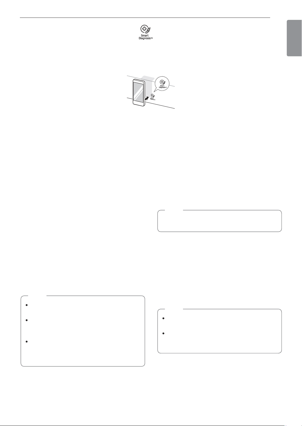
55SMART DIAGNOSIS™
ENGLISH
SMART DIAGNOSIS™
Should you experience any problems with your dryer, it has the capability of transmitting data to your smart
phone using the LG Smart Laundry Application or via your telephone to the LG call center.
Smart Diagnosis™ cannot be activated unless your dryer is turned on by pressing the POWER button. If your
dryer is unable to turn on, then troubleshooting must be done without using Smart Diagnosis™.
Using Smart Diagnosis
TM
Smart Diagnosis™ Using Your Smart
Phone
1
Download the LG Smart Laundry & DW
application on your smart phone.
2
Open the LG Smart Laundry application on your
smart phone. Press the right arrow button to
advance to the next screen.
3
Press the Record button on the smart phone and
then hold the mouthpiece of the smart phone
near the Smart Diagnosis™ logo on the dryer.
4
With the phone held in place, press and hold the
Temp. button for 3 seconds.
5
Keep the phone in place until the tone
transmission has finished. The display will count
down the time.
6
When the recording is complete, view the
diagnosis by pressing the Next button on the
phone.
NOTE
Call quality differences by region may affect
the function.
Use a home telephone for better
communication performance, resulting in
better service.
Poor call quality may result in poor data
transmission from your phone to the machine,
which could cause Smart Diagnosis
TM
to
malfunction.
Smart Diagnosis™ Through the Call
Center
1
Call the LG call center at: (LG U.S.)
1-800-243-0000
(LG Canada) 1-888-542-2623.
2
When instructed to do so by the call center
agent, hold the mouthpiece of your phone over
the Smart Diagnosis™ logo on the machine.
Hold the phone no more than one inch from (but
not touching) the machine.
NOTE
Do not touch any other buttons or icons on the
display screen.
3
Press and hold the Temp. button for 3 seconds.
4
Keep the phone in place until the tone
transmission has finished. The display will count
down the time.
5
Once the countdown is over and the tones have
stopped, resume your conversation with the call
center agent, who will then be able to assist you
in using the information transmitted for analysis.
NOTE
For best results, do not move the phone while
the tones are being transmitted.
If the call center agent is not able to get an
accurate recording of the data, you may be
asked to try again.

56 WARRANTY (USA)
WARRANTY (USA)
Should your LG Dryer (“Product”) fail due to a defect in materials or workmanship under normal home use,
during the warranty period set forth below, LG will at its option repair or replace the product. This limited warranty
is valid only to the original retail purchaser of the product and applies only when purchased and used within the
United States including U.S. Territories. Proof of original retail purchase is required to obtain warranty service
under this limited warranty.
Warranty Period Scope of Warranty HOW SERVICE IS HANDLED
One (1) year from date of
original retail purchase
Parts and Labor
LG will provide parts and labor to repair or replace
defective parts.
Ten (10) years from date of
original retail purchase
Dryer drum
10years warranty on Dryer Drum, including parts &
labor.
Replacement products and parts are warranted for the remaining portion of the original warranty period or
ninety (90) days, whichever is greater.
Replacement products and parts may be new or remanufactured.
THIS WARRANTY IS IN LIEU OF ANY OTHER WARRANTY, EXPRESS OR IMPLIED, INCLUDING WITHOUT
LIMITATION, ANY WARRANTY OF MERCHANTABILITY OR FITNESS FOR A PARTICULAR PURPOSE. TO
THE EXTENT ANY IMPLIED WARRANTY IS REQUIRED BY LAW, IT IS LIMITED IN DURATION TO THE
EXPRESS WARRANTY PERIOD ABOVE. NEITHER THE MANUFACTURER NOR ITS U.S. DISTRIBUTOR
SHALL BE LIABLE FOR ANY INCIDENTAL, CONSEQUENTIAL, INDIRECT, SPECIAL, OR PUNITIVE
DAMAGES OF ANY NATURE, INCLUDING WITHOUT LIMITATION, LOST REVENUES OR PROFITS, OR
ANY OTHER DAMAGE WHETHER BASED IN CONTRACT, TORT, OR OTHERWISE.
Some states do not allow the exclusion or limitation of incidental or consequential damages or limitations on how
long an implied warranty lasts, so the above exclusion or limitation may not apply to you. This warranty gives you
specific legal rights and you may also have other rights that vary from state to state.
THIS LIMITED WARRANTY DOES NOT COVER:
Service trips to deliver, pick up, or install or repair the product; instruction to the customer on operation of
the product; repair or replacement of fuses or correction of wiring or plumbing, or correction of unauthorized
repairs/installation.
Failure of the product to perform during power failures and interruptions or inadequate electrical service.
Damage caused by leaky or broken water pipes, frozen water pipes, restricted drain lines, inadequate or
interrupted water supply or inadequate supply of air.
Damage resulting from operating the Product in a corrosive atmosphere or contrary to the instructions outlined
in the Product’s owner’s manual.
Damage to the Product caused by accidents, pests and vermin, lightning, wind, fire, floods, or acts of God.
Damage or failure caused by unauthorized modification or alteration, or if it is used for other than the intended
purpose, or any water leakage where the unit was not properly installed.
Damage or failure caused by incorrect electrical current, voltage, or plumbing codes, commercial or industrial
use, or use of accessories, components, or consumable cleaning products that are not approved by LG.
Damage caused by transportation and handling, including scratches, dents, chips, and/or other damage to the
finish of your product, unless such damage results from defects in materials or workmanship and is reported
within one (1) week of delivery.
Damage or missing items to any display, open box, discounted, or refurbished Product.
Products with original serial numbers that have been removed, altered, or cannot be readily determined. Model
and Serial numbers, along with original retail sales receipt, are required for warranty validation.
Increases in utility costs and additional utility expenses.
Repairs when your Product is used in other than normal and usual household use (e.g. commercial use, in
offices and recreational facilities) or contrary to the instructions outlined in the Product’s owner’s manual.
57WARRANTY (USA)
ENGLISH
Costs associated with removal of your Product from your home for repairs.
The removal and reinstallation of the Product if it is installed in an inaccessible location or is not installed in
accordance with published installation instructions, including LG’s owner’s and installation manuals.
Damage resulting from misuse, abuse, improper installation, repair, or maintenance. Improper repair includes
use of parts not approved or specified by LG.
Filter is clogged.
Not heating, long dry
time
Clean the lint filter.
Duct is clogged.
Not heating, long dry
time
Clean the hood and
duct.
Excessive duct
length and/or multiple
elbows
Not heating, long dry
time
Keep exhaust ducts
as short as possible,
using as few elbows
and bends as
possible.
Improperly connected
power cord or
electrical outlet issue.
No Power
Not Heating
Reconnect power
cord, replace house
fuse or reset breaker.
If outlet is issue,
electrician may be
required.
Gas valve is not
turned on. (Gas Dryer)
Not heating
Open the gas valve
Door Reversal
Instructions for door
reversal can be
found in the owner’s
manual.
The cost of repair or replacement under these excluded circumstances shall be borne by the consumer.
TO OBTAIN WARRANTY SERVICE AND ADDITIONAL INFORMATION
For additional product information, visit the LG website at http://www.lg.com
For assistance using this product or to schedule service, contact LG Electronics at 1-800-243-0000.
For further assistance, write: LG Electronics, 201 James Record Road, Huntsville, Alabama 35813