

Dear Owner,
we would like to thank you f or your
purchase of a Porsche Sports car.
Judging b y t he car you hav e chosen ,
you are a motorist of a special breed,
and you are probably no novice when it
comes to automobiles.
Remember however, as with any vehicle,
you should take time to fam iliarize
yourself with your Porsche and its
performa nce characteristics. Alway s
drive within your o wn unique capabilities
as a driver and your level of experienc e
with your Porsche. E nsure that anyone
else driving your Porsche does t he
same. To prevent or minimize injury,
always use your safety belts. Never
consume alcohol or drugs before or
during the operat ion of your vehi cle.
This Owner’s Man ual contain s a h ost
of useful inf ormation. Please take the
time to read this manu al before you driv e
your new Porsche. Become familiar with
the operation of your Porsche car for
maximum safety and operating pleasure.
The better you know y our Porsche,
the more pleasure you will experience
driving your new car. Always keep your
Owner’s Manual in th e car, and give it
to the new owner if you ever sell your
Porsche.
A separate Maintenance Booklet
explains how you can keep your P orsche
in top driving condition by having
it serviced regularly. A separate
Warranty and Customer Inform ation
Book let contains detailed inform ation
about the warrant ies cover ing your
Porsche.
For U.S. only:
If you believe that your ve hicle has a fault
which could cause a crash, injur y o r
death, you should immediately inform
the National High way Tra ffic Safety
Administrat ion (NHTSA) in addition to
notifying Porsc he Cars North America,
Inc. (Porsche Cars N.A.).
If NHTSA receive s similar c omplaints,
it may open an investigation , and if it
finds that a safety problem ex ists in a
group of vehicles, it may order a recall
and remedy campaign . However, NHTSA
cannot become involved in individual
problems between you and your dealer,
or Porsche Cars N.A..
To contact NHTSA, you may call
the Vehicle Safety Hotline toll-free
at 1–888–327– 4236 (TTY:
1–800–424–9153); go t o
http://www.safercar.go v; or write to:
Administrator, NHTSA, 400 Seventh
Street, SW., Washington, DC 2059 0.
You can also obtain other informa-
tion about motor vehicle safety from
http://www.safercar.go v.
Your car has thousands of parts and
comp onents which have been designed
and manufactured in accordance with
Porsche’s high standards of engineering
quality and safety.
Any alteration of the vehicle may
negate or interfere with those
safety features buil t in to the vehicle.
Modications may be carried out
1
Downloaded from www.ManualsFile.com manuals search engine

on your vehicle only if approved by
Porsche.
Your Porsche is int ended to be used in
a safe manner obeying the local laws
and in the light of driving conditions
faced by you, and in acco rdanc e with
the instr uctions provided in this Owner’s
Manual.
Do not misuse your Porsche by
ignoring those laws and dri ving con-
ditions , or by ignoring the ins truc-
tions in this manual. Any alteration
or misuse of the vehicle can lead to
accidents and severe or fatal person
al injuries.
The fitting of racing tires (e.g. slicks)
for sporting events is not ap proved by
Porsc he. Very high cornering speeds
can be achieved with racing tires.
However, the resulting transv erse
acceleration values would jeopardize
the adequate supply o f oil to the engine.
Porsche therefore will not accept
any warranty or accept any liabil ity
for damage occurring as a result of
non-compliance with this provision.
Regularly che ck your vehicle for
signs o f damage . Damaged or
missing aerodynamic comp onents
such as spoilers or underside pan-
els affect the driving behavior and
therefore mus t be replaced immedi-
ately.
Your car may have all or some of the
components described in this manual.
Should you have difficulty understanding
any of the explanations of features or
equipment inst alled in your vehicle,
contact your authorized Porsche dealer.
He/Sh e will be glad to assist you. Also
check w ith your dealer on other available
options or equipment.
Throughout this booklet, left is desig nat-
ed as the driver’s side of the vehicle, and
right as the passe nger’s side of the vehi-
cle.
Text, illustrations and specifications in
this man ual are based on the information
available at the time of printing .
It has always been Porsche’s policy
to continuously improve its products.
Porsche , therefore, reserve s the
right to make changes in desi gn and
specification, and to make additions
or improvements in its product without
incurr ing any obligation to ins tall them on
products previously manufactured.
We wish you many miles of safe and
pleasurable driving in your Porsche.
Warning!
For your own protection and longer
service life of your car, pleas e
follow all operatin g instr uctions and
special warnings. These special
warnings use the safety alert symbol,
followe d by the words Danger,
Warning and Caution. Th ese
special warnings contain important
mess ages regarding your safety
and/o r the potential for dama ge to
your Porsche. Ignoring the m could
result in serious mechanical failure,
serious personal injury or de ath.
2
Downloaded from www.ManualsFile.com manuals search engine

Do not alte r your Porsc he. Any alter-
ation could create dangerous con-
ditions or defeat safety engineering
features built into y our car.
Do not misuse your Porsche. Use it
safely, and consistent ly with the law,
acco rding to the driving conditions,
and the instructio ns in this manual.
Alteration or misuse of your Porsche
could cause accidents a nd severe or
fatal personal inj uries.
3
Downloaded from www.ManualsFile.com manuals search engine

Imprint
WKD 987 021 07
5/06
© Dr. Ing. h.c. F. Porsche AG
Porsche, the Porsche crest, Boxster, PCCB,
Tiptronic and Tequipment are registered
trademarks and the distinctive shapes of
Porsch e automobiles are trademarks of
Dr. Ing. h.c. F. Porsche AG.
All rights reserved.
Printed in Germany
32654
Note to owners
In Canada, this manual is also avai lable in French.
To obtain a copy cont act your deale r or write to:
Note aux proprietaires
Au Canada, ce manuel est également di sponible
en fra ncais. Pour en obtenir un exemplaire,
adressez-vous à votre concessionnaire ou écrivez
à l’a dresse ci-dessous.
Porsche Cars Canada, Ltd.
Automobiles Porsche Canada, LTEE
5045 Orbitor Drive
Building #8, Suite 200
Mississauga, O n tario
Canada L4W 4Y4
Telephone number for customer ass istance:
1-800-PORSCHE / Option 3
4
Downloaded from www.ManualsFile.com manuals search engine

Fuel Quality
Your engine i s designed to provide optimum performance and fuel econom y using unle aded premium fuel with an octane r a ting of 98 RON
(93 CLC or AKI). Porsche therefore recommends the use of these fuels in your vehicle.
Porsche also recognizes that these fuels may not always be available. Be assured that your vehicle will operate properly on unleaded premium fuels with octane
numbers of at least 95 RON (90 CLC or AKI), since the engine’s “Electronic Octane™ knock co ntrol” will adapt the ignitio n timing, if necessary.
Fuels containing alcohol and e ther
Some areas of the U.S. require oxygenated f uels during certain portions of the year. Oxygenated fuels are fuels which contain alcohols (suc h as methanol or etha-
nol) or ether (such as MTBE).
Under normal conditions, the amount of these co mpounds in the fuel will not affect driveability.
You may use oxy genated fuels in your Porsche, provided the octane requirements for your vehicle are met. We recommend, howe v er, that you change to a differ-
ent fuel or s tation if any of the following problems occur with your vehicle:
– Deterioration of driveability and performance.
– Substan tially reduced fuel economy.
– Vapor lock and non-start problems, especially at high altit ude or at h igh temperature.
– Engine malfu nction or stalling.
Fuels containing MMT
Some North American fu els contain an octane enhancing ad ditive c alled methylcyclopentadienyl manganese tricarbony l (MMT) . If such fuels are used, your emis-
sion control system performance may be negatively affected. The chec k eng ine warning lights on your instrument panel may turn on. If this occurs, Porsche
recommends you stop using fuels containing MMT.
5
Downloaded from www.ManualsFile.com manuals search engine

Porsche and the Environment
Environmental gu idelines
We develop and produce exclusive vehicles with
advanced environmental and safety technology
and a great abilit y to fascinate.
Our envir onmental pol icy is based on the
following principles:
– The maximum possible use of en v ironmental
and safety tec hnology that is eco nomically
justifiable.
– Economical usage of en ergy an d resources.
– Involvement of our business partners and
contrac tors in our efforts to protect the
environment.
– Open d ialogue with all socia l groups.
California Propositi on 65 Warning
Warning!
Engine exhaust, some of its constituents, and
certain vehicle components contain or emit
chemicals known to the State of Califor n ia
to cause cancer and birth defects or other
reproductive ha rm. In addition, certain fluids
contained in vehicles and certain products of
component w ear con tain or emit chemicals
known to the State of California to cause
cancer and birth defects or other reproductive
harm.
Prod uction
Whethe r in production or repair, Porsche always
relies on environmentally friendly technology. An
example of this is the water-based paint used in our
painting installations. Water-base paints and new
painting methods reduce solvent emissions b y 70
per cent. The water used in the painting installation
is recirculated. Waste water leaves the Porsche
factory only after being appropriately treated.
A waste-management system has been introduced
to reduce the amount of waste while simultaneous-
ly increasing the recycling rate.
Environmentally friendly vehicles
Modern environmental technology ensures
complia nce with all emission la ws applicable
worldwide.
It has the following advantages:
– Rapid operational readiness of the cat alytic
converters ensures low emissions, even in
short-trip operation.
– Reliable operation and good emission con trol
over a long useful life.
Please observe the chapter ”FUEL ECONOMY”
on page 219.
6
Downloaded from www.ManualsFile.com manuals search engine

Recycl ing - f or a Porsche, this is virtually
an academic question
More than two-thirds of all Porsches ever built are
still running.
Just in case recycling is ever necessary, we
take the following precautionary measures:
– Identification o f all materials.
– Use of recyclabl e materials.
– Reusable components designed for simple
removal.
– These reasons result in a further inc rease in
the recycling rate which is currently 80 per
cent.
Emission control is built in
Innovative engine technology c ombines high
engine performance and environmental compatibil-
ity.
The engine diagnosis system electronically
monitors the components and systems tha t affect
exhaus t gases .
This continuous monitoring and fault storage ena-
bles swift, reliable diagnosis and fault detection .
Any fa ult messa ges are indicated to the driver by
the “Check En gine” warning light and the on-board
computer.
Please observe the chapter ”WARNINGS
ON THE INSTR UMENT PANEL A ND THE
ON-BOARD COMPUTER” on page 134.
7
Downloaded from www.ManualsFile.com manuals search engine

General safety instructions
Porsche Ceramic Composite Brake
(PCCB )
Please observe the chapter ”BRAK ES” on page
64.
The high-performance brake system is designed
for optimal braking effect at all speeds and
temperatures. Certain speeds, braking f orces
and a mbient conditions (such as temperature and
humidity) therefore might cau se brake noise s.
Wear on t he different components and braking
system, such as brake pads and brake discs ,
depends to a great extent on the in dividual driving
style and the conditi ons of use and therefore
cannot be expressed in actual m iles on the road.
The values co mmunica ted by Porsche are based
on normal operation a d apted to traffic. Wear
increases considerably when the vehicle is driven
on race tracks or through an aggressive driving
style.
Please consult an authorized Porsche dealer
about the current guidelines in effect before
such use of your vehicle.
Setting and oper ation vehicle components
when driving
Warning!
There is a danger of an accident if you oper-
ate o r set the on-board computer, radio, navi-
gation syste m, telephone or other equipment
when drivin g. This could distract yo u from
the traf c and cause you to lose co ntrol of the
vehicle resulting in serious personal injury or
death.
Operate the equipment whil e driving only if the
traffi c situation allows you to do so safely.
Carry out a ny complicated opera ting or setting
procedures only with the vehicle stationary.
Portable fuel containers
Danger!
Portable fuel containers may leak, whet her
they are full or partially empty. Fuel leaking
from a portab le container carried in your
vehicle could, in c ase of an a ccident, cause a
re or explosion, resulting in serious personal
injury or death.
Never carry additional fuel in portable contain-
ers in your vehicle.
8
Downloaded from www.ManualsFile.com manuals search engine

Engine exhaust
Danger!
Engine exhaust is dangerous if inhaled.
Engine exhaust fumes have many compo-
nents which you can smell. Th ey also contain
carbon monoxide (CO), which is a co lorless
and o dorless gas. Carbon monoxide can
cause unconsciousness and even death if
inhaled.
Never start or let the engine run in an
enclosed, unv entilated area. It is not rec-
ommended to sit in your car for prolonged
periods with the engine on and the car not
moving.
Ground clearance
Caution!
Risk of damage. The vehicle may touch
the ground as a result of reduced ground
clearance.
Drive carefully and slowly on steep slopes
(e.g. parking lots, curb s, uneven roads, lift ing
platfor ms, etc.).
Avoid steep ramps.
9
Downloaded from www.ManualsFile.com manuals search engine


Controls , Instruments
Dear Porsche Owner ...................................... 15
Before driving off... ......... ............. .................. 16
In the driver’s seat. .. ...................................... 17
On the road... ................................................ 18
Break in hints for the f irst 2000 miles/3000
kilometers .................................................... 19
Never invite car theft! ..................................... 21
Keys ............................................................ 22
Key with Radio Remote Control ....................... 23
Central Locking in Cars w ithout Alarm System . . 25
Central Locking in Cars with Alarm System . . . .... 28
Doors .......................................................... 31
Alarm System, Pas senger Compartment Monitor-
ing ......................................................... ...... 32
Power Windows ............................................ 34
Mirrors ................................................. ........ 36
Seat Adjustment ............................................ 40
Seat Memory ................................................ 43
Heated Seats ................................................ 45
Steering Wheel Adjustment ............................. 46
Multi-functional steering wheel .... . ................... 47
Sun Visors .................................................... 48
Safety Belts ....... ........................................... 49
Airbag Systems ............................................ 52
Child Restraint Systems .................... ............ . 58
LATCH System Child seat bracket on t he passen-
ger’s seat ..................................................... 61
Clutch Pedal ................................................. 62
Parking Brake ............................................... 63
Brakes ....................................... .................. 64
ABS Brake System ........................................ 67
Sports Ex haust System .................................. 69
Sport Mode .................. ............ ............. ....... 70
Porsche Stab ility Management (PSM) ............... 71
Porsch e Active Suspension Management
(PASM) ................................ ......................... 74
Retractable Rear Spoiler ................................ 75
Parking Aids ................................................. 77
Operation, Instruments .................................. 79
Ignition/Starter Switch with anti-theft Steering
Lock ........................................... ................. 81
Starting and Stopping Engine .......................... 83
Instrument Panel USA Models ......................... 85
Instrument Panel Canada Models ... ................. 87
Autom atic Speed Control In dicator Light .......... 89
Instrument Illumination ......................... .......... 90
Trip Odometer .............. ............ ............. ....... 91
Speedometer ............................................... 92
Tachom eter ....................... ............ ............. .. 93
Turn Signal Indicator Light .............................. 93
Cooling system ............................................. 94
Tiptronic S .................................................... 95
Fuel ............................................................. 96
Clock ........................................................... 97
Battery ......................................................... 98
Check Engine Warning Light ................. .......... 99
Central Warning Light ................................... 100
Brake Warning Light ..................................... 101
On-Board Compute r (BC) .............................. 102
LIMIT Acoustic warning signal for speed lim it .. 105
INFO Warning mess ages .............................. 108
TEL Telephone information ........................... 109
CHRONO Sto p watch .................................... 112
TPC Tire Pressure Monitoring ... ............. ....... 119
OIL Display and measurement of the engine oil
level ................................ ........................... 128
SET Basic setting on on-board computer ...... .. 131
General inform ation regarding t he on-board
compu ter func tions ............... ...................... 133
Warnings o n the instrument pa nel and the on-board
compu ter ...... ............. ................................ 134
Light Switch ................................................ 144
Turn Signal/ Headlight Dimmer/Parki ng light /
Flasher Lever ................ ............. ................. 146
Windshield Wiper / Washer Lever .................. 147
Autom atic Speed Control ............................. 149
Air conditioning ........................................... 152
Autom atic air conditioning system ................. 155
Central and side vents .................................. 158
Fresh-air intake ............................ ............... 158
Emergency Flasher Switch ....................... . ... 159
Ashtray ...................................................... 160
Cigarette Lighter ......................................... 161
Sockets ..................................................... 162
Interior lights .............................................. 163
Storage in the passenger compartment ......... 164
Cupholder ........ ............ ............. ............ ..... 166
Luggage Stor age on Engine Compartment
Lid ............................................................. 168
Fire extinguisher .......................................... 169
Controls, In s truments
13
Downloaded from www.ManualsFile.com manuals search engine

Trunk En trapment ........................................ 170
Luggage compartment lids .......................... 172
Front Luggage Compartment ..................... ... 174
Rear Luggage Compartment ................ ........ 176
Porsche Communication Management (PCM) . 177
Car Audio Operation/Tips ............................. 178
HomeLin k ................................................... 181
14Controls, Instru ments
Downloaded from www.ManualsFile.com manuals search engine

Dear Porsche Owner
A lot has gone into the manufacture of your
Porsche, including advanced en gineering , rigid
quality control and demanding inspections. These
engineering an d safety features w ill be enhanced
by you...
the safe driver...
– who knows her/his car and all co ntrols,
– who maintains the vehicle properly,
– who uses driving skills wisely, and alw ays
drives within her/his own capabilities and the
level of familia rity with the vehicle.
You will find helpful hints in this manual on how to
perform mos t of the ch ecks lis ted on the following
pages. If in doubt, ha v e these checks performed
by your authorized Porsche dealer.
Controls, In s truments
15
Downloaded from www.ManualsFile.com manuals search engine

Before driving off...
Check the following items rst
Turn the engine off before you attempt any
checks or repairs on the vehic le.
Be sure the tires are inflated cor rectly. Check
tires for damage a nd tire wear.
See that wheel bolt s are properly t i ghtened
and not loose or missing.
Check engine oil level, add if necessary. Make
it a habit to have engine oil ch ecked with eve ry
refueling.
Check all fluid levels such as windshield
washer and brake fl uid levels.
Be sure the vehicle batt e ry is well charged and
cranks the engine properl y.
Check all do ors and lids for proper operation
and latch them properly.
Check and if necessary replace worn or
cracked wiper blad es.
See that all windows are clear and unobstruct-
ed.
Check air intake slots and area between front
lid and windshield. Ensure that th ese areas
are free of snow and ice, so the heater and the
windshie ld wipe rs work properly.
If a child wil l be riding in the vehicle, check child
seat/child seat restraint system to ensure that
restraints are properly adjusted.
Check all exterior an d interior lights for
operation and that the lenses are cle an.
Check the headlights for proper aim, and if
necessary, have them adjusted.
Check under the vehicle for lea ks.
Be sure all luggage is stowed securely.
Emergency equipment
It is good practice to carry emergency eq u ipment
in your vehicle. Some of the items you should have
are: window scraper, snow brush, container or
bag of sand or s alt, emergency light, small shovel,
first-aid kit, etc.
16Controls, Instru ments
Downloaded from www.ManualsFile.com manuals search engine

In the driver’s seat...
Check operation of the horn.
Position seat for easy reach o f foot pedals
and controls. To reduce the possibility of
injury from the airbag deployment, you should
always sit back as far from the stee ri ng wheel
as is practical, while still maintaining full
vehicle control.
Adjust the inside a nd outside rear view mirrors.
Buckle your s afety belts.
Check operation of the foot and parking brake.
Check all warning and indicator lights with
ignition on and engi ne not running.
Start engi ne and check all warning displays for
warning symbols.
Never leave an idlin g car unattended.
Lock doors from in side, especially with
children in the car to prevent inadve rtent
openin g of doors from inside or outside. Drive
with doors locked.
Controls, In s truments
17
Downloaded from www.ManualsFile.com manuals search engine
On the road...
Never drive after you have consumed alcohol
or drugs.
Always have your safety b elt fastened.
Always drive defensively. Expect the unexpect-
ed.
Use signals to indicate turns and lane c hanges.
Turn on headlights at dusk or when the driving
conditio ns warrant it.
Always keep a safe distance from the vehicle
in front of you, depending on traffi c, road and
weather condit ions.
Reduce speed at night and during inclement
weather. Driving in wet weather requires
caution and reduced speeds, particularly
on roads with standing water, as the handling
charac teristics of the vehicle may b e impaired
due to hydroplanin g of the tires.
Always observe speed limits and obey road
signs and traffic laws.
When tired, get well off the road, stop and take
a rest. Turn the engine off . Do no t sit in the
vehicle with engine idling.
Please observe the chapter ”ENGINE
EXHAUST” on page 9.
When parked, alway s set the parking brake.
Move the Tiptronic selector lever to ” P“ or t h e
gearshift lever to reverse or first gear. On hills
also turn the front wheels toward the curb .
When emergency repairs become necessary,
move the vehicle well off the road. Turn on
the emergency flashe r and use other warning
devices to alert other motorists. Do not park
or operate the vehicle in areas where the hot
exhaust system may come in contact with dry
grass, brush, spilled fuel or other flammable
material.
Make it a habit to have the engine oil checked
with every refueling.
Danger!
Danger of re in engine compartment due
to burning cigars or cigarettes. Serious
personal injury or death could result from
re in th e engine compartment.
Do not throw any lit cigars or cigarettes out
of the vehicle. They can be blown into the air
inlets by the air flow a nd cause a fire in the
engine compartment.
Please obser ve the chapter ”ASHTRAY” on
page 160.
18Controls, Instru ments
Downloaded from www.ManualsFile.com manuals search engine

Break in hints for the rst 2000
miles/3000 kilome ters
The following tips will be helpful in obtaining
optimum performance from your new Porsche.
Despite the most modern, high-precision manufac-
turing methods, the m oving parts must still wear
in with each other. This wearing-in occurs mainly in
the first 2000 miles/3000 k ilometers.
Therefore:
Preferably t ake longer trips.
Avoid frequent col d starts w ith short-distance
driving when ever pos sible.
Avoid full throttle starts and abrupt stops.
Do not exceed maximum engine speed of
4200 rpm (revolutions per minute).
Do not run a cold engine at high rpm eith er in
Neutral or in gear.
Do not let the engine labor, especially when
driving uphill. Shift to the next lower gear in
time (u se the most favorable rpm range ).
Never lug the engin e in high gear at low
speeds. This rule app lies at all times, not just
during the break-in period.
Do not participate in motor ra cing events,
sports driv ing sch ools, etc. during the first
2000 miles/3 000 kilometers.
There may be a slight stif fness in the steering,
gear-shifting or other controls during the break-in
period which will gradually disappear.
Break in brake pads and break discs
New brake pads and discs have to be “broken in”,
and therefore only attain optimal friction when
the car has covered several hundred miles or
km. The slightly reduced braking ability must be
compensated for by pressing the brake pedal
harder. This also applies whenever th e brake pads
and brake dis cs are replaced.
New tires
New tires do not have maximum traction. They
tend to be slippery.
Break in new tires by driving at m oder-
ate sp eeds during the first 60 miles to
120 miles/100 km to 200 km. L onger braking
distances must be anticipated.
Engine oil and fuel consumption
During the break-in period oil and fuel consumption
may be high er than normal.
As always, the rate of oil consu mption depends
on the quality and viscosity of oil, the speed at
which the e ngine is operated, the climat e and road
conditions, as well as the amount of dilution and
oxidation of the lubricant.
Make a habit of checking engine oil with every
refueling, add if necessary.
Controls, In s truments
19
Downloaded from www.ManualsFile.com manuals search engine
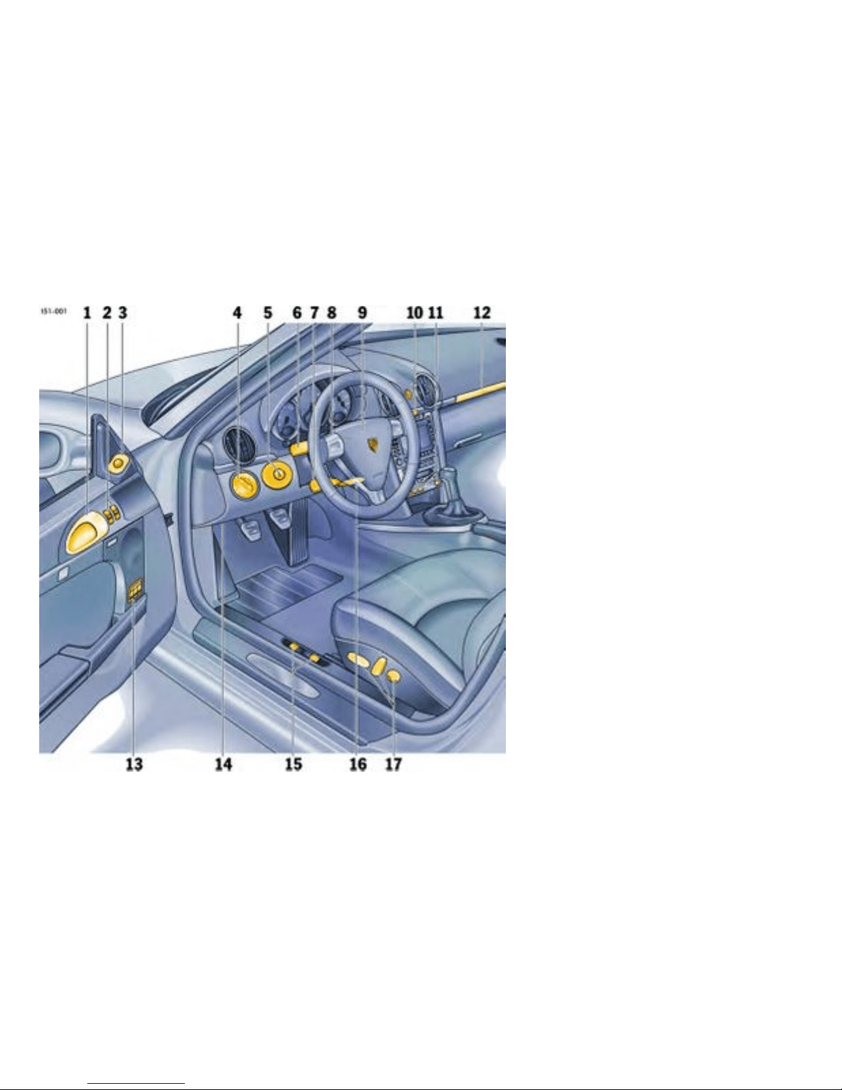
1 Inner door handle
2 Power windows
3 Door mirror control
4 Light switch
5 Ignition / starter switch
6 Turn signal / h eadlight dimmer, asher lev er
7 Operating lever for o n-board computer
8 For vehicles with Tiptronic: Toggle switches for
Tiptronic
9 Horn
10 Emergency asher switch, central lockin g
switch
11 Switches for rear spoile r, Porsche Activ
Suspension Ma nagement (PASM), Sport mode,
Porsche Stab ility Management (PSM), Sports
exhaust system
12 Cupho lder
13 Switch for seat memory
14 Diagnostic so cket
15 Lid release
16 Steering-wheel adjust ment
17 Seat adjustment
20Controls, Instru ments
Downloaded from www.ManualsFile.com manuals search engine

Never invite car theft!
An unlocked c ar with the key in the ignition lock
invites car th eft.
A steering wheel lock and a gong alarm are
standa rd eq uipment in your Porsche. The gong
alarm will sound if yo u open the driver’s door while
the key is still in the ignition lock. It is y our reminder
to pull the key out of t he ignit ion lock and to lock
the doors.
Warning!
Any uncontrolled movement of the vehicle
may resu lt in property damage, serious
personal injur y or death. Never leave your
vehicle unattended with the key in th e igni tion
lock, especially if c hildren and/or pe ts are left
unattended in the vehicle. They can operate
power wind ows and othe r cont rols. If the
engine is le ft running, they may accidentally
engage the shift lever. Serious personal injury
or death could result from loss of control of
the vehicle.
Always remove the ignition key.
Always set the parking brake.
Lock the doors with the remote control.
Warning!
Risk o f a s erious accident. The steeri ng
column will lock when you remove the key
while you are driving or as the car is rolling
to a stop. You will not be able to steer the car.
Serious personal injury or death coul d result
from loss of control of the vehic le.
Never remove the key from the steering lock
while you are driving.
To protect your vehicle and your
posses sions from t heft, you should always
proce ed as follows when leaving your
vehicle:
Close windows.
Close convertible top (with the convertible top
open, the passenger compartment monitoring
system is always swit ched off).
Lock glove co m partment.
Remove ignition key.
Close storage tray betwe en the seats.
Remove valuables (e.g. car documents,
telephone, house keys) from the car.
Lock d oors.
Controls, In s truments
21
Downloaded from www.ManualsFile.com manuals search engine

Keys
General in formation regarding the keys
Please observe the chapte r ”ALARM SYSTEM,
PASSENGER COMPARTMENT MONITORI NG”
on page 32.
Two main keys and one s pare key are supplied wi th
your Porsche. These key s operate all the loc ks on
your vehicle.
Be careful with y our car keys: do not part with
them except under e xceptional circumstanc-
es.
To avoid battery run-down, always remove the
ignition key from the i gnition lock.
Replacement keys
Order of r eplacemen t keys
Replacement car keys can be obtained only from
your authorize d Porsche dealer, and this can
sometimes be very time-consumin g. You should
therefore always keep the spare key on your
person. Keep it in a safe place (e.g. wallet), but
under no ci rcumstances in or on the vehicl e.
The key codes of new keys have to be “reported”
to the car control unit by your aut horized Porsche
dealer.
A total of 6 car keys can be reported to the control
unit.
Disabling key codes
If a key is lost, the key codes can be disabled by
an authorized Porsche dealer. All the remaining
car keys are required for this purpose. Disabling
the code ens u res that the car can be started only
using authorized keys.
Note
Please note that the other locks can still be
opened with the disabled key.
Immobilizer
There is a transponder (an electronic component)
in the key grip, containing a stored code. When the
ignition is switched on, the ignitio n lock checks the
code. The im mobilizer can be switched off and the
engine started only using an authorized ignition
key.
Switching off the immobilizer
Insert the i gnition key into the ignition lock.
If the ignition is lef t on for more than 2 mi nutes
without the engine being started, the immobilizer is
switche d on again.
If this happe ns, turn the ignition key to the left
before starting the engine. The imm obilizer
is switched off again, and the eng ine can be
started.
Please observe the chapter ”IGN ITION/START-
ER SWITCH WITH ANTI-THEFT STEERING
LOCK” on page 81.
Switching on the immobilizer
Remove ignition key.
Security wheel bolts
If wheels have to be removed during a repair-
shop visit, do not forget to hand over the sock-
et fo r the security wheel bolts along with the
car key.
22Controls, Instru ments
Downloaded from www.ManualsFile.com manuals search engine
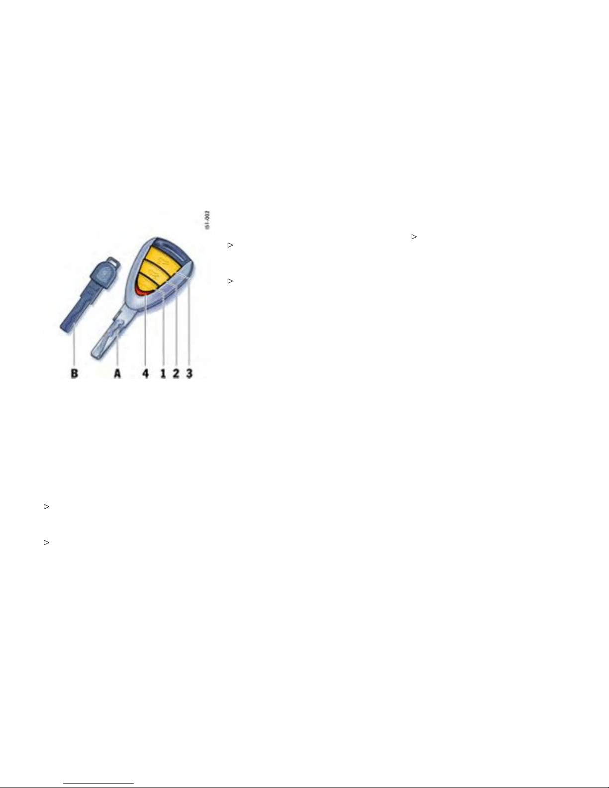
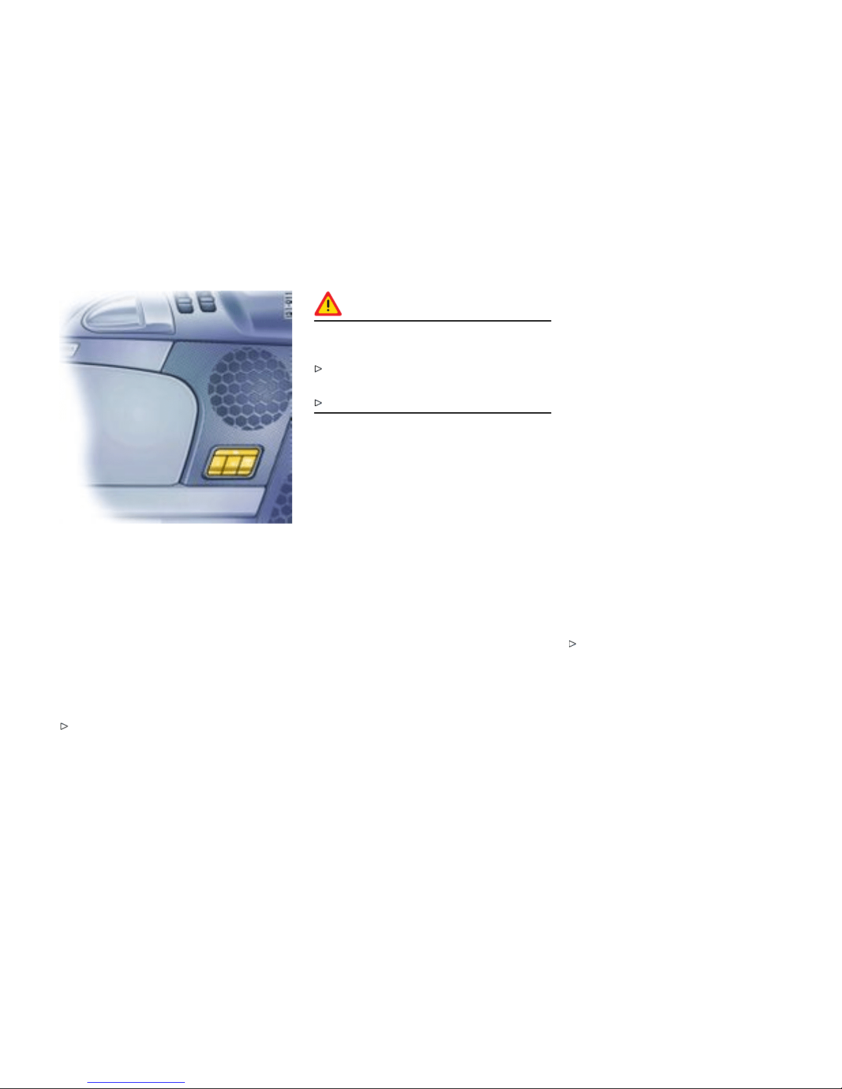
A - Main key
1 - Cent ral locking butt on
2 - Button for front luggage compartment lid
3 - Button for rear luggage compartment lid
4 - Ligh t-emitting diode
B - Spare key
Key wit h Radio Remote C ontrol
Unlocking the vehicle
Press button 1.
Locking the vehicle
Press button 1.
Switching off the alarm syste m if it is
triggered accide ntally
Press button 1.
Unlocking front lu ggage compartment
Press button 2 for approx. two seconds.
Unloc king rear luggage compartmen t
Press butt on 3 fo r approx. two seconds.
If the vehicl e was locked before the luggage com-
partment is opened, it is unlocked simultaneously
with the luggage compartment. In vehicles with
seat memory the stored seat and door mirror posi-
tions are automatically s et. The vehicle will be
locked again approx. 15 seconds after the lug-
gage compartment is closed if none of the doors
was opened.
Note
Your authorized Porsche dealer can program
further types of unlocking .
Type 1
The relocking time of the doors can be adjusted to
suit your individual requirements (4 - 120 seconds).
Type 2
The doors stay locked whe n the luggage compart-
ment is unlocked.
Malfunction of the remote control
The remote control ma y not functi on correctly due
to local radio wave interference. The vehicle will
then not lock properly. This can be identified by the
missing locking sound and the missin g check-back
signal of the hazard warning lig hts.
If this should occur:
Controls, In s truments
23
Downloaded from www.ManualsFile.com manuals search engine

Lock the vehicle with the key in the door.
The remote-control standby function
switches off after 7 days
If the vehicle is not started or unlocked with
the remote control within five days, the remote
control standby function is switched of f (to prevent
discharging of the car battery).
1. In this case, unlock the driver’s door with the
key a t the door lock. Leave the door closed in
order to preven t the alarm system from being
triggered.
2. Press button 1 on the remote control.
The remote control is now activated again and the
alarm system is switched off.
Note
Do not insert the ignition key into the ignition
lock if the vehicle battery is discharged. Th e
ignition key can no longer be remov ed.
The key cannot be remo ved until the vehicle
electric al system is supplied with power again.
Please observe the chapter ”EMERGENCY
UNLOCKING OF THE FRONT LUGGAGE
COMPARTMENT LID” on p age 266.
Please observe the chapter ”EMERGENCY
STARTING WITH JUMPER CABLES” on page
273.
24Controls, Instru ments
Downloaded from www.ManualsFile.com manuals search engine

Central Locking i n Cars w ithout
Alarm System
Gener al informati on regarding centra l
lockin g
This device complies with:
Part 15 of the FCC Rules
RSS-210 of Industry Canada.
Operation is subject to the following two condi-
tions:
1. This device may not cause harmful inter f er-
ence, and
2. this device must accept any interference
received, in cluding interference that may
cause undesired operation.
Note
The m anufactu rer is not responsible for an y
radio or TV interference caused by unauth orized
modific ations to this equipmen t. Such modifi cation
could void the user’s authority to operate the
equip m ent.
Warning!
Any changes or mod ifications not expressly
approved by Porsche could void the user’s
authority to operate this equipment.
Please observe the chapter ”LOAD SWITC H-
OFF A FTER 2 HOUR S OR 7 DAYS” on page
265.
Please observe the chapter ”SEAT MEMORY”
on page 43.
Both car doors and the filler flap can be centrally
unlock ed or locked with the remote control.
Any person remaining in the locked car can
open the door with the inner door hand le:
3. Pull inner door handle once to unlock door
lock.
4. Pull inner door handle again to open door.
Automatic relocking
If the car is unlocked by remote c ontrol and
none of the car doors is opened within approx.
60 seconds, automatic relocking takes place. This
relocking time can be adapted to your individual
requirements (4 - 120 seconds) by an authorize d
Porsche dealer.
Emergency ope ration - opening
Unlock the driver’s door with the key at the
door lock.
Emer gency operation - closi ng
Lock the driver’s door with the k ey at the door
lock. If there is a defect in the central locking
system, all f u n ctioning elements of the central
locking system will be locked.
The fault should be remedied im mediately at an
authorized Porsche dealer.
Indication by emer gency asher
If the remote control is used for unloc king or
locking, a response is provided by the emergency
flasher:
– Unlock ing - s ingle flash.
– Locking - do uble fl ash.
Overload protection
If the central locking system is operated more
than ten times within a minute, further opera tion is
blocke d for 30 seconds.
Controls, In s truments
25
Downloaded from www.ManualsFile.com manuals search engine
Central locking switch
The central locking switch on the dashboard lets
you loc k and unlo ck both doors electrically.
Note
If the doors are locked with the key or remote
control, the y can not be opened by pressing th e
central locking switc h.
Locking
Press the rocker-switch. Indicator light in the
rocker swit ch ligh ts up if ign ition is on. If the
doors w ere locked with the cen tral locki ng
switch, they can be opene d by pulling the inner
door handle twice.
Unlocking
Press the rocker-switch. Indicator light goes
off.
Automatic door locking
Your authorized Porsche dealer can program
diverse types of automatic door locking in the
control unit of the central locking sys tem.
Type 1
Doors lo ck automatically when the ignition is
switched on.
Type 2
Doors lock automatically when a speed of 3 -
6 mph (5 - 10 km/h) is exceeded.
Type 3
Doors lo ck automatically when the ignition is
switched on. If doors are opened with the engi ne
running, they lock again automatically when a
speed of 3 - 6 mph (5 - 10 km/h) is exceeded.
Type 4
The d oors do not lock automatically.
Note
Automatically locked doors can be unlock ed with
the central locking button or opened by pulling o n
the ins ide door handle twice.
On ve hicles with the Sport Chrono p ackage Plus,
the PCM can be used to activat e automatic door
locking.
26Controls, Instru ments
Downloaded from www.ManualsFile.com manuals search engine

Please observe the chapter “Indi v idual
Memory” in the separate PCM operating
instructions.
Warning!
In an emergency situation wh ere you need to
exit the car through an automatically locked
door, remember the following procedure to
open the do or.
Unlock the doors by pressing the central
locking butto n or
pull the inside door handle twice to open the
door.
Controls, In s truments 27
Downloaded from www.ManualsFile.com manuals search engine

Central Locking i n Cars with Alarm
System
General information regarding central
lockin g
This device complies with:
Part 15 of the FCC Rules
RSS-210 of Industr y Cana da.
Operation is subject to the following two condi-
tions:
1. This device may not cause harmful interf er-
ence, and
2. this device must acce p t any interference
received, including interference that may
cause undesired ope ration.
Note
The manufacturer is not responsible for any
radio or TV interference caused by unauth orized
modifications to this equip ment. Such mod ification
could void the user’s authority to operate the
equipment.
Warning!
Any c hanges or modificatio n s not expressly
approved by Porsche could void the user’s
authority to operate this equip ment.
Please observe the chapter ”LOAD SWITCH-
OFF AFTER 2 HOURS OR 7 DAYS” on page
265.
Please observe the chapter ”SEAT MEMORY”
on page 43.
Both car doors and the filler flap can be centrally
unlocked or locked with the remote control.
The vehicle cannot be locked if the driver ’s door is
not completely closed.
A short s ignal from t he alar m horn will draw your
attenti on to t h e fact that the following components
are not c ompletely closed when you try to lock the
vehicle :
– Doors
– Lugga ge co mpar tment lids
– Conve rtible-top lock
– Glove comp artm e nt
– Passenger compartment
Unlockin g the vehicl e by using the key in the door
lock and opening the door may activate the alarm
system within 10 seconds.
Note
On vehicles with the Sport Chrono Package Plus,
the PCM can be used to activa te automatic door
locking.
Please observe the chapter “Indivi dual
Memory” in the separate PCM operating
instructions.
Automatic relocking
If the car is unlocked by remote co n trol and
none of the car doors is opened within approx.
60 se conds, automatic relocking takes place. This
relocking time can be ad apted to your individual
requirements (4 - 120 seconds) by an aut horized
Porsche dealer.
Locking conditions
Lock car once. The doors cannot be opened
from the outside. Alarm sy stem and pas sen-
ger c ompartment monitoring are switched on.
If a person or animal remains in the vehicle:
Quickly lock car twice: The doors cannot
be opened from the outside. The passenger
compa rtment monitoring is switched off.
Unlocking the door with the inner door handl e
Any pe rson remaining in the locked car can open
the door with the in ner door handle:
1. Pull inner door handle once to unlock door
lock.
2. Pull inner door handle agai n to open door.
Note
Inform any person remaining in the car that the
alarm system will be triggered if the door is
opened.
28Controls, Instru ments
Downloaded from www.ManualsFile.com manuals search engine
Emergency operation - opening
Unlock the driver’s door with the key at the
door lock. Open do or with in 20 seconds and
insert the ignition key into the ignition lock
within 10 seconds to prevent t he alarm system
from being trigge red.
Note on operation
If the door is not opened within approx. 20 sec-
onds, automati c relocking takes place. The alarm
system will be triggered by the next unlocking of
the door:
Insert the ignition key into the ignit ion lock to
switch off the alar m system.
Emergency opera tion - closing
Lock the driver’s door with the key at the
door lock. If there is a defect in the central
locking syste m, all functioning elements of
the central locking system will be locked. The
alarm system is switched on. The passenger
compartment monitoring system is switched
off.
The fault should be remedied immediately at an
authorized Por s che dealer.
Indication by emergency asher and
alarm horn
If the remote control is used for unlock ing or
locking, a response is provided by the emergency
flasher:
– Unlocking - single flash.
– Locking - double fla sh.
– Locking twice - con tinuous illumination for
approx. 2 seconds and short alarm-hor n
signal.
Central locking swi tch
The central lo c king switch on the dashboard lets
you lock and unlock both doors electrically.
Note
If the doors are locked with t he key or remote
control, they can not be opened by pressing the
central locking switch.
Locking
Press the rocker-switch. Indicator light lights
up if ignition is o n.
Controls, In s truments
29
Downloaded from www.ManualsFile.com manuals search engine

Unlocking
Press the rocker-switch. Indicator light goes
out.
If the doors were locked with the central locking
switch, they c an be opened by p ulling th e inner
door handle:
1. Pull inner door handle once to unlock door
lock.
2. Pull inner door handle again to open door.
Automatic door locking
Your authorized Porsche dealer can program
diverse types of automatic door lockin g in the
control unit of the central locking system.
Type 1
Doors lock automatic ally when the igniti on is
switched on.
Type 2
Doors lock automatica lly when a speed of 3 -
6 mph (5 - 10 km/h) is exce eded.
Type 3
Doors lock automatic ally when the igniti on is
switch ed on. If doors are opened with the engine
running, they lock again automatically when a
speed of 3 - 6 mph (5 - 10 km/h) is ex ceeded.
Type 4
The do ors do not lock automatically.
Note
Autom atically locked d oors can be unlocked with
the central locking button or opene d by pulling on
the inside door handl e twice.
On vehicles with the Sport Chrono Package Plus,
the PCM can be used to activa te automatic door
locking.
Please observe the chapter “Individual
Memor y” in the separate PCM operating
instructions.
Warning!
In an emergency situation wh ere you need to
exit the car through an automatically locked
door, reme mber t he following procedure to
open the door.
Unlock the doors by pressing the central
locking butto n or
pull the inside door handle twice to open the
door.
Fault indication
A double horn signal during locking indicates a
defect in the central locking or alarm system. Have
the defect remedied at an authorized Porsche
dealer.
Overload protection
If the central locking system is operated more
than ten times within a minute, furthe r operation is
blocked for 30 seconds.
30Controls, Instru ments
Downloaded from www.ManualsFile.com manuals search engine
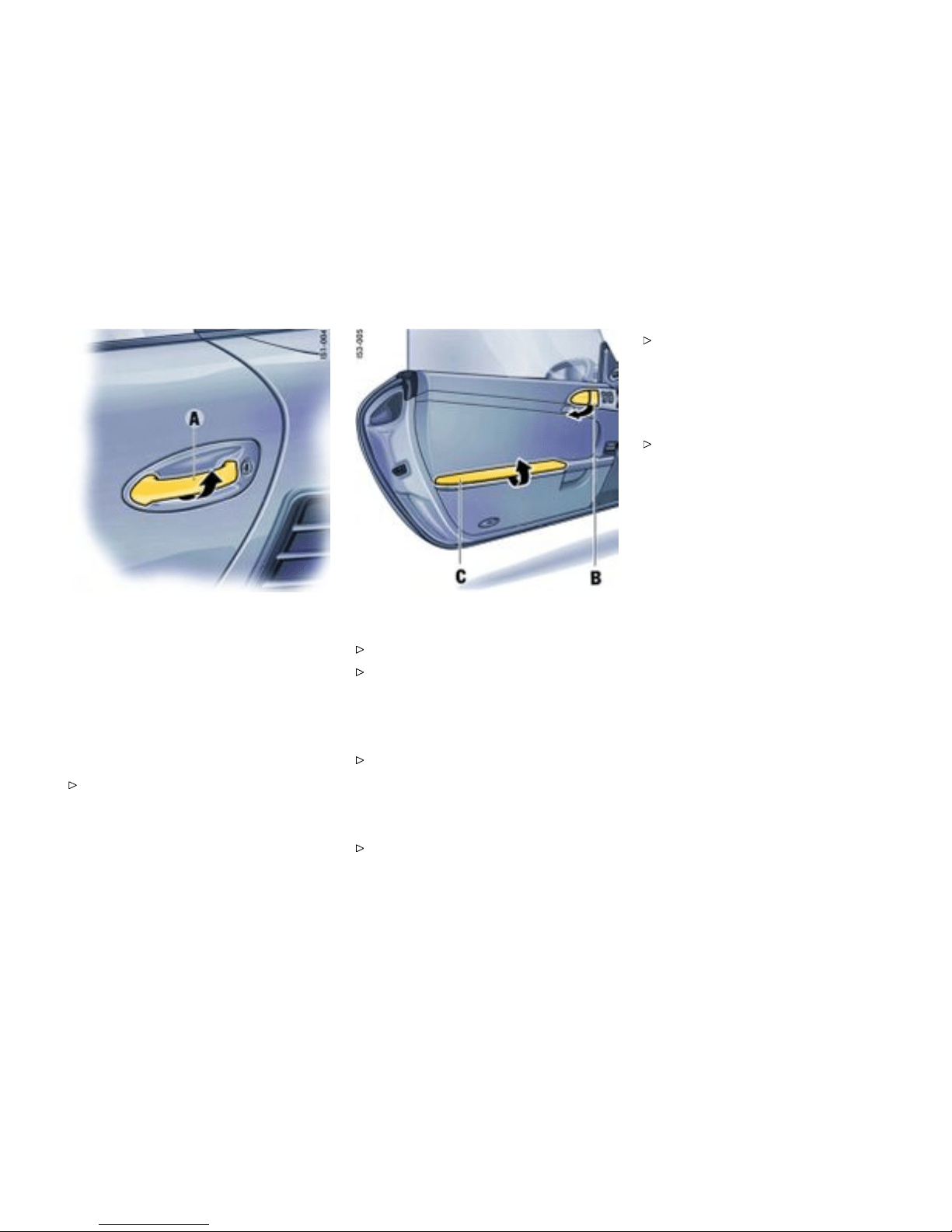
Doors
Automatic lowe ring of the door w indows
If the door windows are closed, they will be
automatically opened by a few millimeters when
the doors are opened and, when the doors are
closed, they will b e closed again. This makes it
easier to open and close the d oors and protects
the seals.
Therefore, you should pull the door handle
slowly so that the door window can be lowered
before the door is ope ned.
Opening doors fr om outside
Unlock vehicle with the remote control.
Pull door hand le A slowly so that the d oor
window can be lowered before the door is
opened.
Opening unlocked doors from insid e
Pull door hand le B sl owly so that the door
window can be lowered before the door is
opened.
Opening locked doors from in side
Slowly pull door handle B twice.
Please observe the chapter ”LOCKING
COND ITIONS” on page 28.
Door storage tray
Opening st orage tray
Open the cover.
Keep the doo r storage tray C cl osed while drivin g
for safety reasons.
Controls, In s truments
31
Downloaded from www.ManualsFile.com manuals search engine
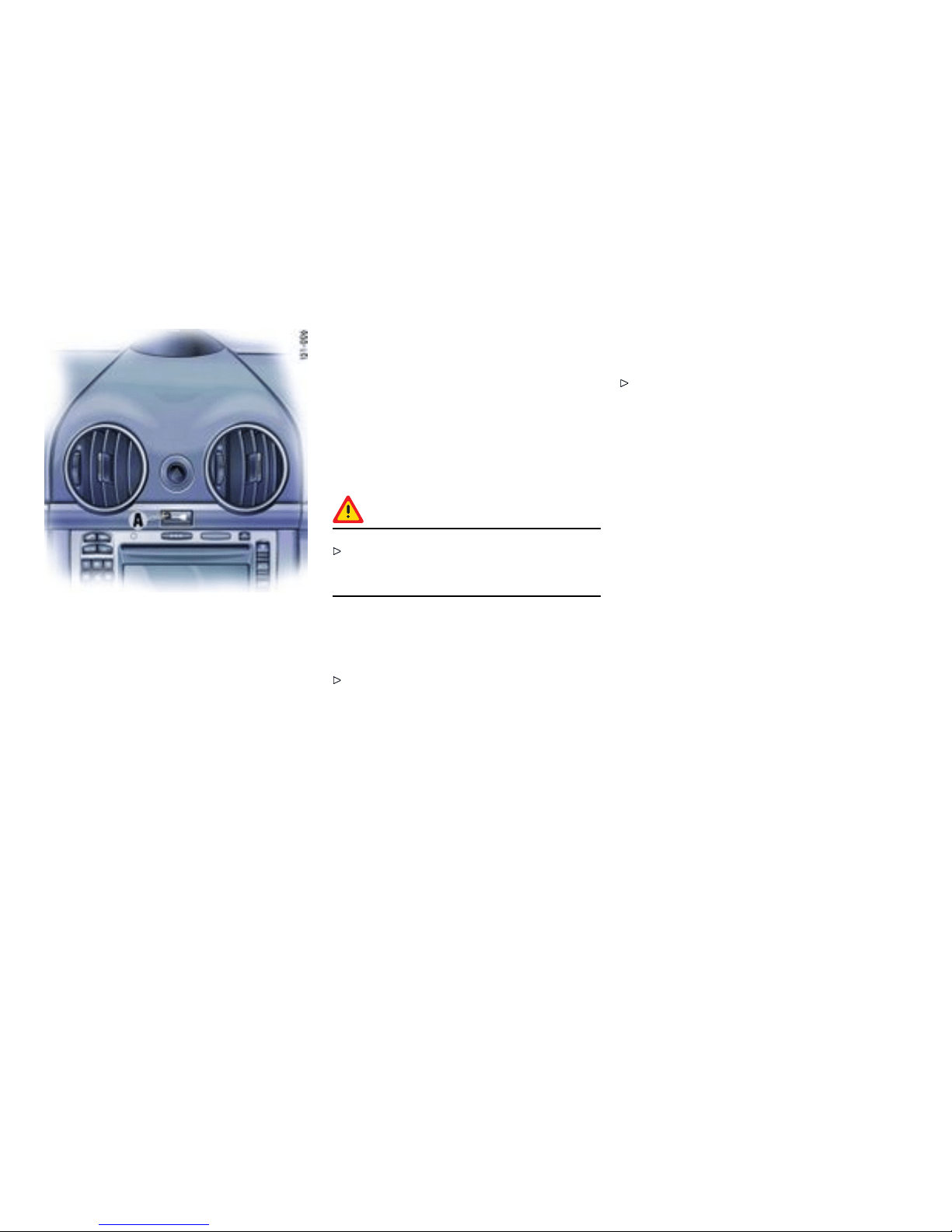
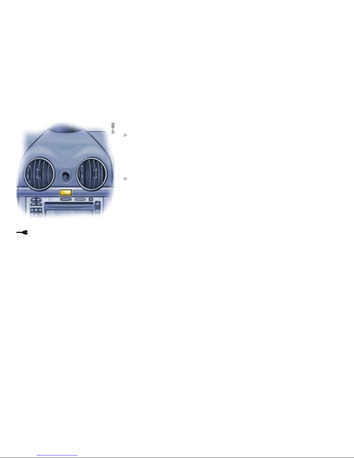
A - Light-e mitting diode for alarm system
Alarm System, P assenger
Compartmen t Monitor ing
Readiness for operation
This device complies with:
Part 15 of the FCC Rules
RSS-210 of Industr y Cana da.
Operation is subject to the following two condi-
tions:
1. This device may not cause harmful interf er-
ence, and
2. this device mu st accept any interference
received, including interference tha t may
cause undesired operation.
Note
The manufacturer is not responsible for any
radio or TV interference caused by unauthorized
modific ations to this equipment. Su ch modi fication
could void the use r’ s auth ority to opera te the
equipment.
Warning!
Any changes or mo difications not expressly
approved by Porsche could void the user’s
autho ri ty to operate this e q uipment.
The alarm system and passenger compartment
monitoring system are switched on when the doors
are locked with the key or remot e con trol.
Please observe the chapter ”CENTRAL
LOCKING IN CARS WITH ALARM SYSTEM”
on page 28.
Unlocking th e vehicle by using the key in the
door lock and openi ng the door may activate
the alarm s ystem within 10 seconds.
Note
The passenger compartment monitoring system
is always swit ched off when the convertible top is
open.
Switch ing off the alarm s ystem if it is
triggered accidentally
Unlock the vehicle with the remote control.
The al arm system and passenger compar tment
monitoring system are switched off automatically
when the doors are unlocked.
Functi on indicat ion
If the alarm system is activated, light-emitting
diode A on the dashboard fla shes.
If, after lockin g, the light-emitting diode does
not fla sh or, after ten seconds, it e mits double
flashes, then not all alarm contacts are closed.
Additionally, a brief horn signal sounds.
When the doors are unlocked, the alarm system
and passenger compartment monitoring system
are switche d of f and the light-emitt ing diode goes
off.
When the alarm is armed, the following
areas are m onitored
– Doors
– Front and rear lids
– Convertible -top lock
– Glove compartment
– Passenger compart ment
If one of these alarm contacts is interrupted, th e
alarm horn sounds for approximate ly 3 minutes.
32Controls, Instru ments
Downloaded from www.ManualsFile.com manuals search engine

Additionally, the emergency flasher and the pas-
senger compartment light flash for approximately
four m inutes. When the alarm is triggered, the
light-emitting diode cha n ges ov er to double flash-
es.
In order not to limit the action range of the passen-
ger compartment monitoring system:
Do not fold the backrests forward.
Deactivating the passenge r compartment
monitoring system for one lock ing process
If a person or animal remains in the car while it is
locked, the passenger compartment monitoring
system must be sw itched off.
Quickly lock car twice. The doors are locked
but can be opened from the inside:
1. Pull inner door handle once to unlock do or
lock.
2. Pull inner door handle again to open do or.
Note
Inform any person remaining in the car that the
alarm system will be trigge red if the door is
opened.
Fault indication
A double horn signal during locking indicates a
defect in the central locking or alarm system.
Have the defect remedied at an authorized
Porsche deal er.
Controls, In s truments
33
Downloaded from www.ManualsFile.com manuals search engine
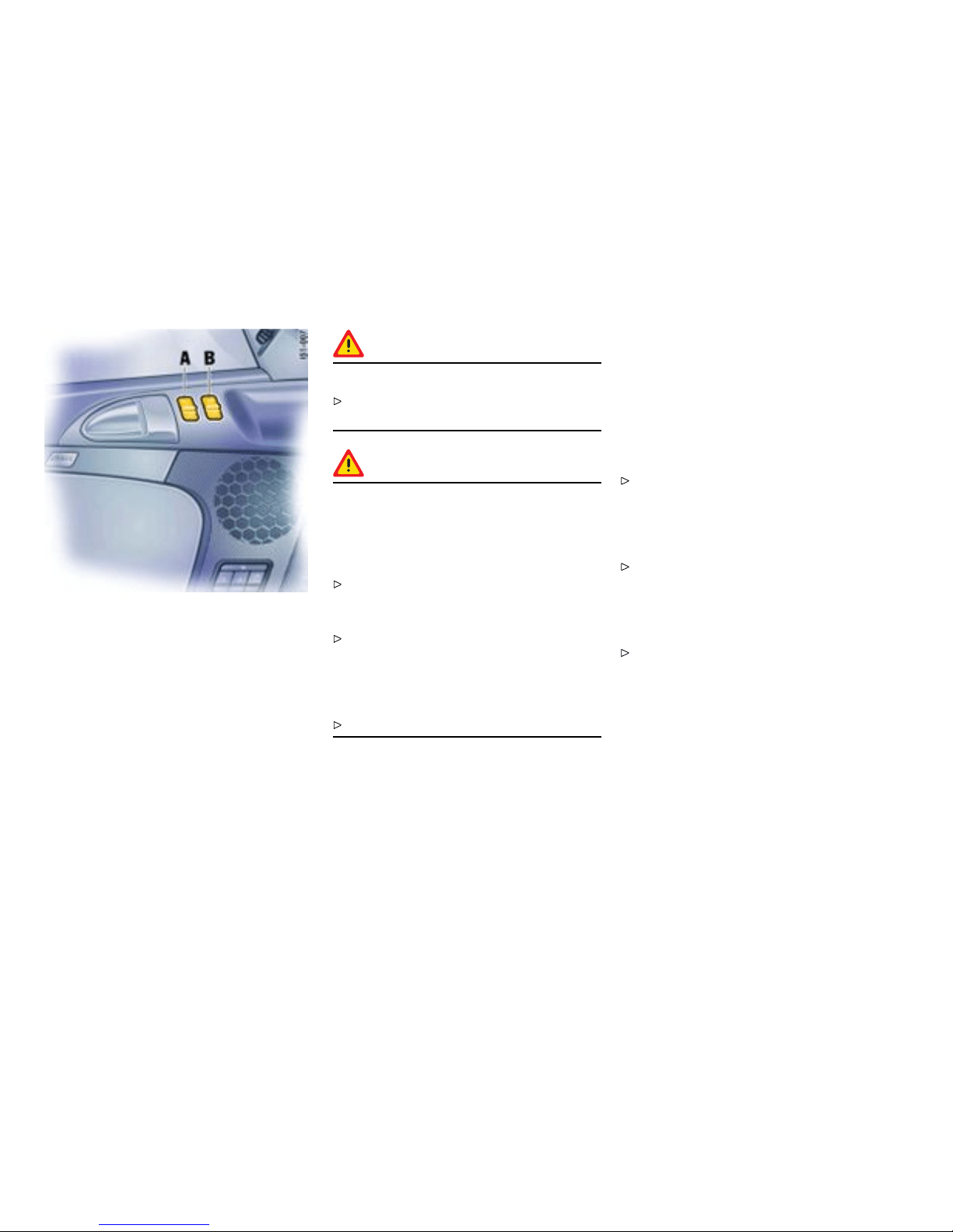
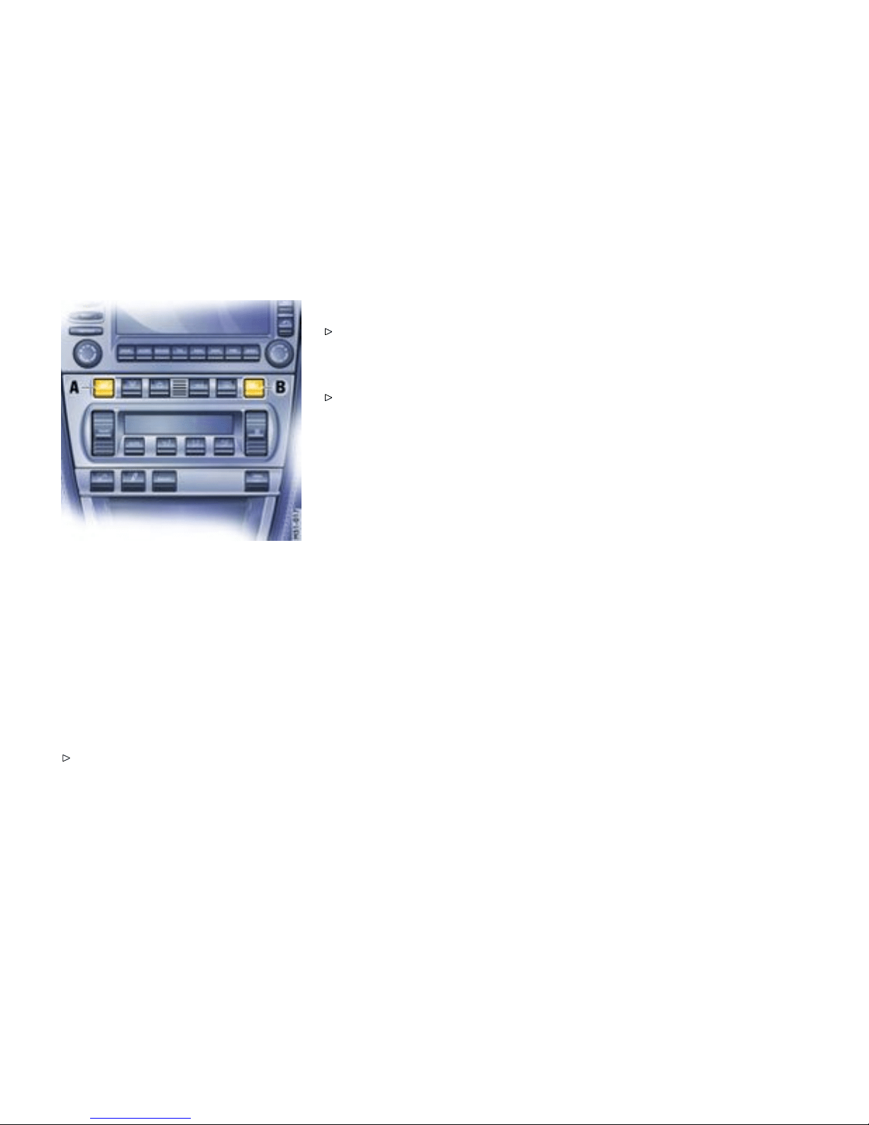
A - Power window in driver’s door
B - Power w indow in passenger’s door
Power Windows
Readi ness for operation of pow er windows
– When the ignition is switched on (engine
switched on or off) or
– with doors closed and ignition key withdrawn,
but only until door is first opened. One-touch
operation for closing the door windows is
availab le only when the ignition is s witched on.
Warning!
Risk of an accident.
Do not put anything on or near the windows
that may interfere with the driver’s vision.
Warning!
Risk of injury when the door windows close.
This applies especially if th e wi ndows are
closed with the one-touch operation, because
with this function the window goes up auto-
matic ally.
Make sure that fingers, hands, arms and
other body parts are not in the way when the
windows are closed.
Remove the ignition key to shut off power to
the window switches when the v ehicle is not
attended by a responsi ble pers on. Unifo rmed
persons could injure themselves by operating
the p ower windows.
Do not leave children in the car u n attended.
Opening/closing windows
Control over rocker switch
The two rocker s witches in the driver’s door
and th e switc h in the passenger’s doo r have a
two-stage funct ion.
Opening win dow with the rocker sw itch
Press the rocker switch dow n to the first stage
until the window has reached th e desired
position.
Closing win d ow with the rocker switch
Press the rocker switc h up wards to the first
stage until t he window has reached the desired
position.
One-touch operation
Press the rocke r switch upwards or down-
wards to the second stage. Window moves to
its fin al position. Press again to sto p the win-
dow in the desired position.
One-touch operation for closing the passen ger’s
window is available once the window is approxi-
mately half-w ay closed.
Anti-c rushing protection
If the door window is bloc ked during closing, it will
stop and open again by about an inch.
34Controls, Instru ments
Downloaded from www.ManualsFile.com manuals search engine

Warning!
Risk of ser ious pe rsonal injuries. If the rocker
switch “A” is pressed again within 10 secon ds
of the window being bloc ked, th e window will
close with its full closing force. Anti-cru shing
protection is disabled.
Once the anti-crushing protection acts to stop
the window and opens it slightly, do not press
the rocker switch again within 10 seconds
without checking to make sure that nothing is
blocking the path of the window. The win d ow
will close with full closing force.
One-touch operation is disabled for 10 seconds
after blockage of a side window.
Automatic window lowering
Please observe the chapter ”DOORS” on page
31.
Please obse rve the chapter ”CONVERTIBLE
TOP” on page 194.
Storing end position of the wind ows
If the batter y is disconnected and reconnected, the
windows will not be raised autom atically when the
door is closed.
1. Close the windows with the rocker switch
once.
2. Press the rocker switch upwards again to
store the end position of the wi ndows in the
control unit.
Controls, In s truments
35
Downloaded from www.ManualsFile.com manuals search engine
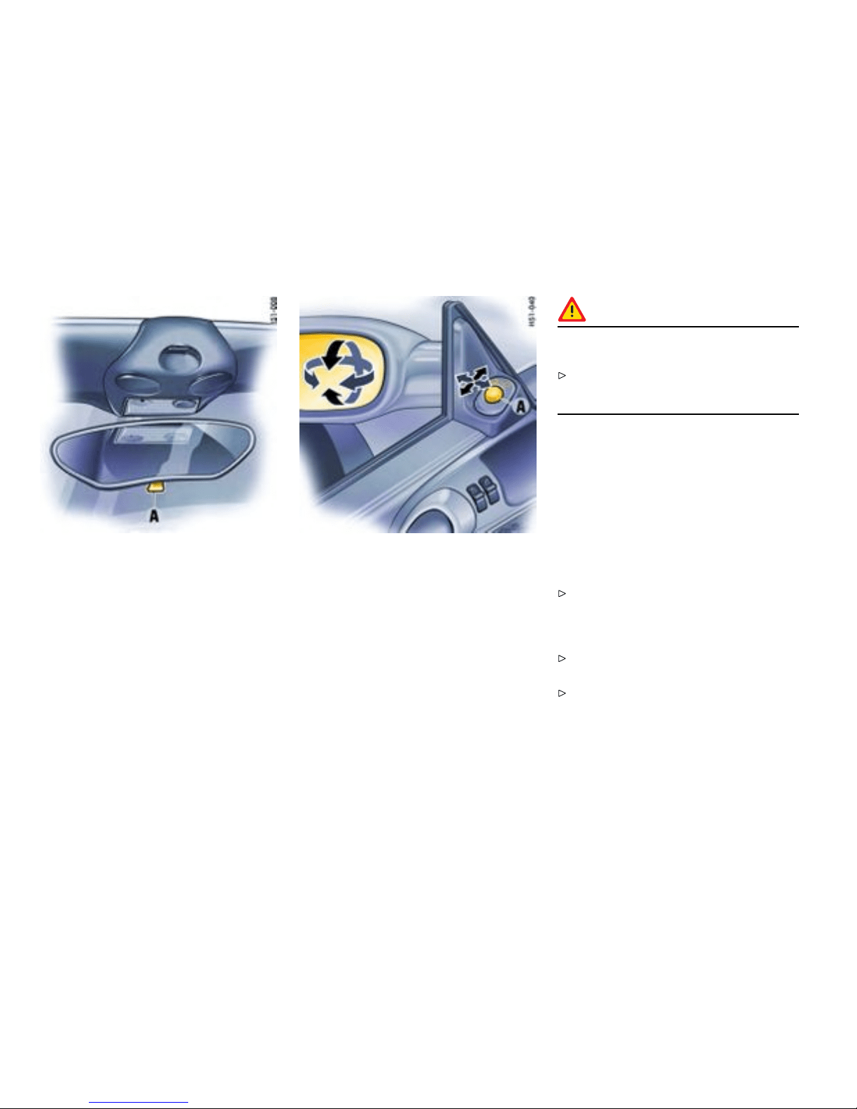
Mirrors
Inside mirror
When the mirror is being adjust ed, the anti-glare
lever A must point forwa rd.
Basic position: lever forward
Anti-glare position: l ever back
Door mi rrors
Function
Before driving the vehicle , adju st the outside and
inside mirrors. It is imp ortant for safe driving th at
you have good vision to the rear.
Warning!
Risk of an accident, resulting in serious
personal injur y or death.
Do not put anything on or near the windows or
the mirrors that may interfere with the driver’s
vision.
Adjusting
1. Switch on ign ition.
2. By tur n ing the control sw itch A, select the
driver’s side or the passeng er’s side.
3. Move t he door mirror glasses in the appropri-
ate d irection by til ting the control sw itch.
If the electrical adjus tment facility fails
Adjust mirror by pressing on the mirror face.
Automatically swivelling down mirror on the
passenger ’s side
Please observe the chapt er ”SEAT MEMORY”
on page 43.
Please observe the chapt er ”PARKING AIDS”
on page 77.
36Controls, Instru ments
Downloaded from www.ManualsFile.com manuals search engine
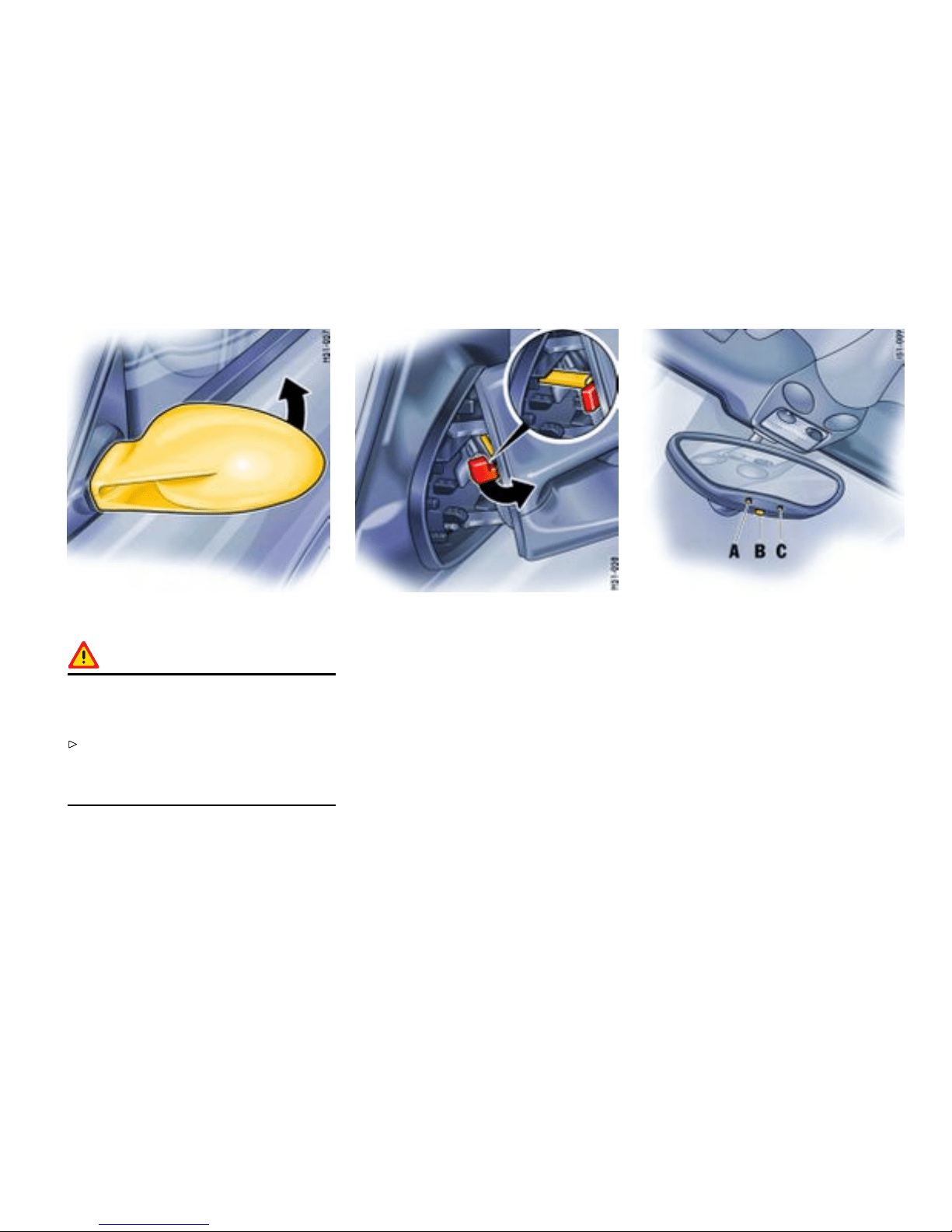
Folding in door mirro r s
Warning!
Danger of injury to ngers if the mirror
accidentally ips back when being folded
in.
Exercise ex treme caution when folding in
mirror by hand. Do not let go of the mirror
before the locking lever is locked or the mirror
is fully unfolded.
1. Push mirror towards the door window and
contin ue to hold it (high spring force).
2. Swivel the locking l ever up to the stop and
slowly let g o of the mirror.
Unfolding door mirrors
1. Push mirror towards the doo r wind ow and
continue to hold it (high spri ng force). Th e
locking lever disengages au tomatical ly.
2. Move mirror back to unfolded position by
hand. D o not let g o of the mirror beforehand.
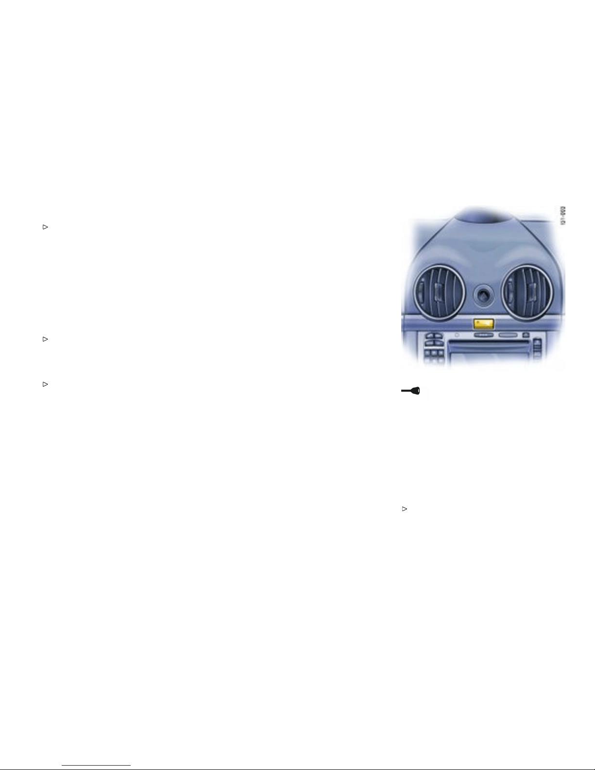
A - Sensor
B - Switch fo r automatic an ti-glare operation
C - Light-em itting dio de
Automatic anti- glare interior mirror and
door mirrors
Function
Sensors on the front and rear sides of the interior
mirror measure the incident light. The mirrors
automatically change to anti-glare position or
revert to the ir normal state, depending on the
light intensity. When reverse gear is selected,
automatic anti-glare operation is switched off.
Controls, In s truments
37
Downloaded from www.ManualsFile.com manuals search engine
Note
The incident light in the area of the sensors
must not be restricted, e.g. by stickers on the
windshi eld.
Switching off the automatic anti- glare
operation
Press switch B. Light-emitting diode C goes
out.
Switching on the autom atic anti-glare
operation
Press switch B. Light-emitting diode C lights
up.
Warning!
Risk o f injury. Electrolyte uid can emerge
from a broken mirror glass. This uid irri t ates
the sk i n and eyes .
If the electrolyte fluid should come into c ontact
with the eyes or skin, immediately rinse it off
with clean wat er. See a doctor if necessary.
Warning!
Risk of dam age to the paintwork, le ather
and plastic parts. Electrolyte ui d can be
removed only while it is still wet.
Clean the affected parts with water.
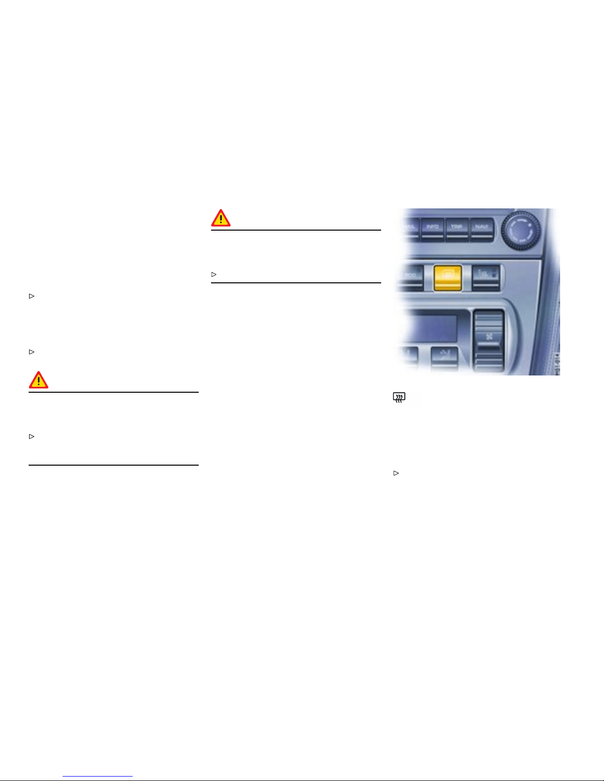
Heated rear window/ Door mirror
heating
The h eated rear window/do or mirror heater is
ready for operation when the i gnition is on.
Switching on
Press button. The li ght-emitting diode in the
button lights up.
After approx. 15 minutes, the heater switches off
automatically. The heate r can be switched back o n
by pressin g the button again.
38Controls, Instru ments
Downloaded from www.ManualsFile.com manuals search engine


Seat Adjustment
Gener al information
Warning!
The seat may move unexpectedly if you
attempt to adjust while driving. This could
cause sudden loss of control, resulting in
serious personal inj ury or death .
Do not adjust seats while the vehicle is in
motion. The backrest locks must be engaged
at all times while the vehicle is in motion.
Warning!
Safet y belts only offer protection when
the b ackrest is upright and the belt s are
properly positioned on the body. Improperly
positioned safety be lt s or safety belts worn
by passengers in an excessively reclined
position can cause serio us pers onal inj ury or
death in an accident.
Do not operate the car w i th the driver or
passenger back rests excessively reclined
(see “ Seat pos ition”).
Seat position
An ergonomically correct sitting position is
important for safe and fatigue -free driving. We
recommend the following procedure for adjustin g
the driver’s seat to suit i ndividual requirements:
1. Vehicles with manual transmission:
Adjust the seat until, with the clutch pedal
fully depressed, your leg remains at a sli ght
angle . Vehicles with Tiptronic S: Adjust the
seat until, with your left foot on the footrest,
your left leg remains at a slight angle.
2. Rest yo ur outstretched arm on the steering
wheel. Set the bac krest angle and the steer-
ing-wheel posi tion so that your wrist rests
on the outer rim o f the steering wheel. At
the same time, the shoulders must still be in
noticeable co n tact with the backrest.
3. Adjust the seat height to give yourself enough
headroom and a good overview of the vehicle.
4. Electrically adj ustable seat: Adjust the seat
angle until your thighs rest lightly on the seat
cushion.
Manually adjustable comf ort seat/sports
seat
A - Seat height
Use lever A in a pumping movement:
Upwards - seat moves upwards
Downwards - seat moves downwards
B - Fore and aft
Raise locking lever B. Move seat to d esired
position and release lever. Ensure that the seat
engages correctly.
40Controls, Instru ments
Downloaded from www.ManualsFile.com manuals search engine
C - Backrest angle
Operate switch C until the desired backrest
angle is reached.
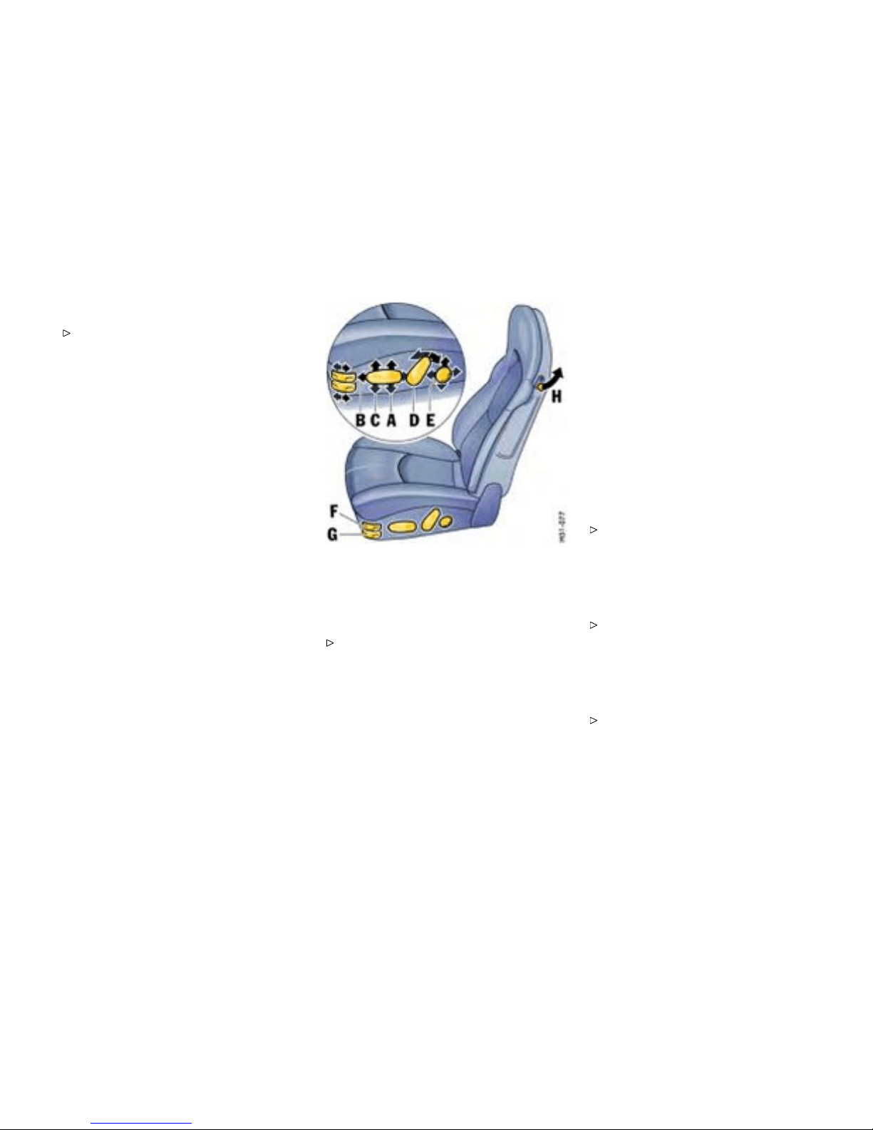
Electr ically adjustable comfort
seat/sports seat
Adjustment
Press the sw itch in the direction indicated by
the arrow until the desired setting is reached.
A - Seat height adjustment
B - Fore-and-aft position adjust ment
C - Seat angle adj ustment
D - Backrest angle adjustment
E - Lumbar support (pelvis and spinal column
support)
To permit a relaxed sitting postu re, the backrest
curvatu re i s continuously adjustab le in vertical and
horizontal directions for individual pelvis and spinal
column support.
Press the switch in the direction in dicated by
the arrow until the desired backrest curvature
is reached.
F - Adjus ting the backrest side bolsters
(electrically adjustab le s ports seat only)
Push forward or pull backward swit ch F until
the side bolsters are adjusted to the shape of
the body.
G - Adjusting the seat cushion side bolsters
(electrically adjustab le s ports seat only)
Push forward or pull backward swit ch G until
the side bolsters are adjusted to the shape of
the body.
Controls, In s truments
41
Downloaded from www.ManualsFile.com manuals search engine
Seat backrest
Folding forward
Pull up lever H in the side pa rt of the backrest
and fold the backrest fo rward.
Folding back
Tilt ba ck and enga ge the backrest so that it can n ot
tip forward when the car is braked.
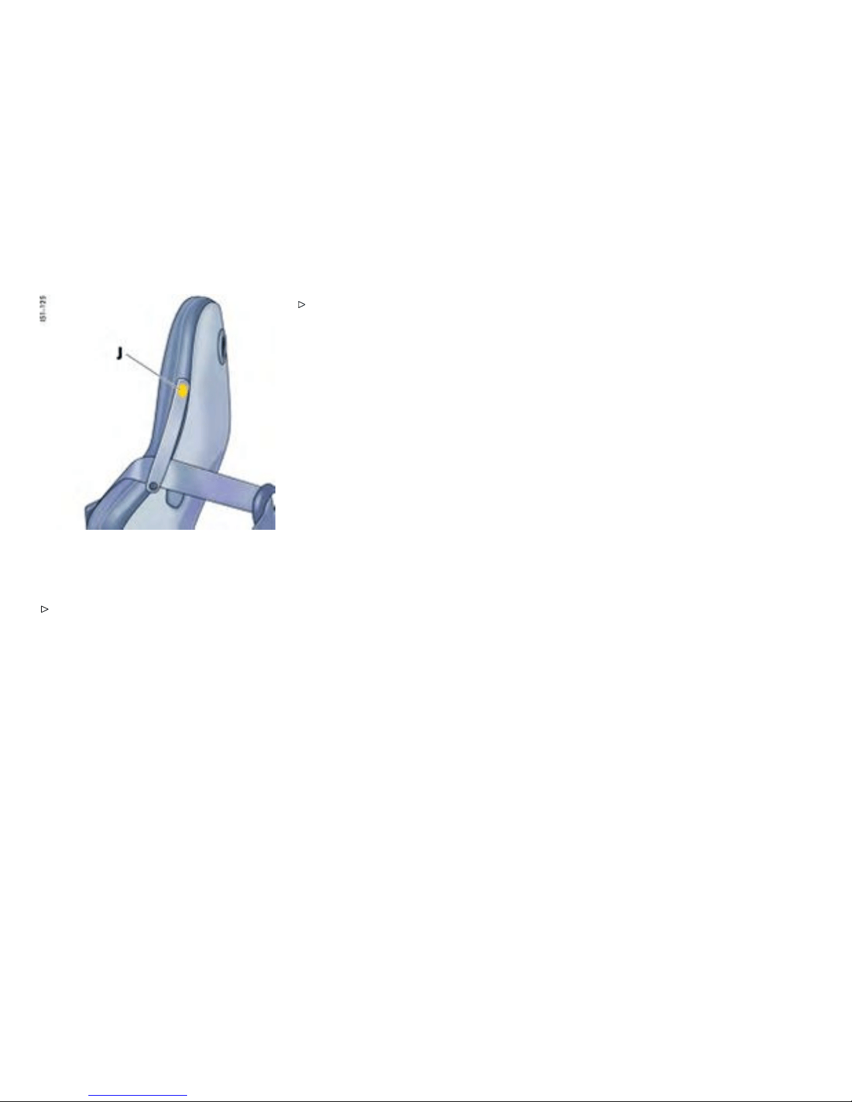
Sports seat only
The se at belt can be fixed to the seat backrest with
the retaining strap, so that it can be reached more
easily for buckling up.
Releas e button J at the top of the retaining
strap, insert the seat belt and fasten the strap
once more.
42Controls, Instru ments
Downloaded from www.ManualsFile.com manuals search engine
M - Memory butto n
1 - Key button
2, 3 - Pe rson buttons
Seat M emory
Individual seat and d oor mirror settings
Individu al seat and door mirror settings can be
stored and recalled for the driver’s positi on.
Further individual setting option s are available in
vehicles with the Sport Chrono Pac kage Plus.
Please observe the chapter “Indi v idual
Memory” in the separate PCM operating
instructions.
Warning!
Risk of crushing due to uncontrolled recall of
a seat setting.
Cancel automatic adjustment by pressing any
of the seat adjustment buttons.
Do not leave children in the vehicle unattended.
Operation with person buttons 2, 3
Storing seat position
1. Switch on ignition. Reverse gear must not be
engaged.
2. Set the desired seat and door-mirror positions.
3. Keep memory button M d epressed and
addition ally press person button 2 or 3. The
individual setting is now stored under th e
desired person button.
Recalling seat positio n
The seat position can only be called up when the
vehicle is stationary.
1. Switch on the igni tion or open the driv er’s
door.
2. Press person button until the seat has reached
its final posit ion. Th e door mirror and the
lumbar support setting will be completed e v en
if the person button is not kept depressed.
Note
Automatic sea t adjustment can be interrupted
immed iately by releasing the button.
Controls, In s truments 43
Downloaded from www.ManualsFile.com manuals search engine

Operating with the remote control of the
vehicle k ey
Individual assignment of t he remote control
Each remote control (up to six) can be ass igned
an individual seat and door mirror position.
The stored seat and door mirror position is set
automatically when the vehicle is unlocked using
the co rresponding remote control.
Storing seat position
1. Switch the ignit ion on with the desired v ehicle
key. Reverse gear mus t not be engaged.
2. Set the desired seat and door-mirror positions.
3. Keep memory button M dep ressed and
additionally press key button 1. The individual
setting is now assign ed to this remote cont rol
and to the key but t o n.
Storing in dividual lowered position of the
passenger’s door mirror as a parking aid
Once the driver’s seat setting has been stored, an
individual lowered position of the passenger’s door
mirror may be stored for driv ing in reverse:
1. Apply the handbrake.
2. Switch the ignit ion on with the desired v ehicle
key.
3. Engage reverse gear.
4. Select passenger sid e with mirror switch. Th e
passenger’s mirror swivels down wards.
5. Set passenger’s door mirror to desired final
position.
6. Keep memory button M d epressed and
addition ally press key button 1. The individual
settin g is now assi gned to this remote control
and to the key button.
Recalling seat position
Unlock the locked vehicle or the luggage
compartment with the remote control. The
stored se at positi on is automatically set.
The s eat position assigned to a remote control
can also be recalled with the key button 1 if the
corresponding key was us ed to switch on the
ignition.
If no seat position has been assigned to a remote
control, the key button will not work.
Note on operation
Automatic seat adjust ment can be interrup ted
immediately:
by switching on the ignition,
by pressing the central locking button,
by pressing any memo ry or seat adjustment
button.
Clearing th e stored seat position
1. Switch the ignition on with the des ired vehicle
key.
Press memory button twice and key button 1
once consecutively.
44Controls, Instru ments
Downloaded from www.ManualsFile.com manuals search engine
A - Seat heating, left
B - Seat heating, right
Heated Seats
Switching on
Readiness for operation
Two-stage seat heating is ready for operation when
the ignition is on.
High heati ng power
Press button. Both li ght-emitting diodes in the
button light up.
Low hea ting power
Press the rocker- switch symbol again. One
light-emitting diode in the button lights up.
Switching off
Press button. Light -emitting diodes go out.
Controls, In s truments
45
Downloaded from www.ManualsFile.com manuals search engine
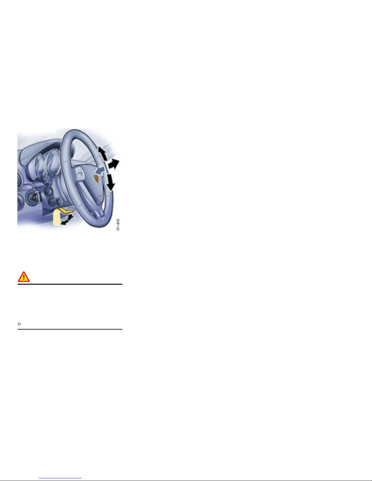
Steering Wheel Adjustment
Adjusting steeri ng wheel height and
longitudinal direction
Warning!
Risk of accident. The steering w heel may
move further than desired if you attem pt to
adjust it whe n driving. You may lose control of
the vehicle, causi ng seriou s personal injury or
death.
Do not adjust the steering wheel when driving.
1. Insert the ignition key fully into ignition lock.
2. Push the lock ing lever down wards.
3. Adjust steering wheel to fit the chosen
backrest a ngle and your seat position by
moving the steering wheel up or down and
longitudinally.
4. Swivel l ocking lever back until you feel it
engage. If necessary, move the steering wheel
slightly up or dow n and longitudinally.
46Controls, Instru ments
Downloaded from www.ManualsFile.com manuals search engine
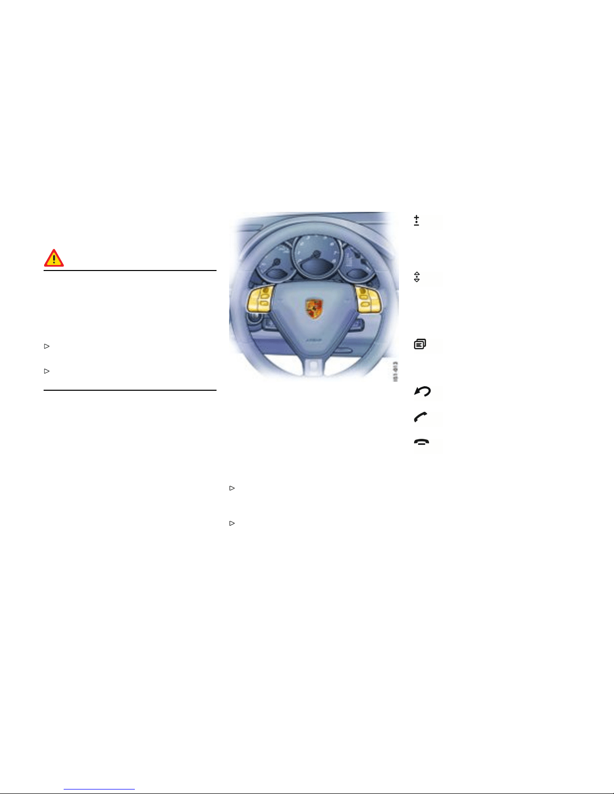
Multi-fun ctional steering wh eel
Function
Warning!
There is a dan ger of accident if you set or
operate the on-board computer, radio,
navigation system, telephone or other
equipment when driving. This could distract
you from the trafc and cause you to l ose
control of the vehicle.
Operate these components while driving only i f
the traffic situation allows you to do so safely.
Carry out any compl icated o perating or se tting
procedures only with the vehicle stationary.
Depending on the equipmen t in y our vehicle, you
can use the function keys of the multi-functional
steering wheel to operate th e following Porsche
communication systems:
– PCM,
– Telephone,
– Radio with CD drive,
– CD ch anger.
Readiness for operation of
multi-functio nal steering wheel
The multi-functional steering wheel is ready for
opera tion when the ignition and PCM are switched
on.
Operating the function keys
Please read the separate PCM operating
instructions before operating the function
keys.
The rotary knobs at the top left and right of the
steering whee l can also be pressed.
Turn volume control
Upwards - increase volume.
Downwards - decrease volume.
Press volume control
To switc h volume/mu te on and off.
Turn rotary kn ob
To select/mark function in the PCM. To
do this, turn the rotary knob upward or
downward.
Press rotary knob
To activate selected function.
Press screen button
To call the stored PCM function.
The bu tton can be assigne d the desired
function in the PCM.
Press Bac k button
To move back in the PCM menu.
Press Handset Pickup b utton
To accept a telephone call.
Press Handset Hangup button
To end or refuse a telephone call.
Controls, In s truments
47
Downloaded from www.ManualsFile.com manuals search engine
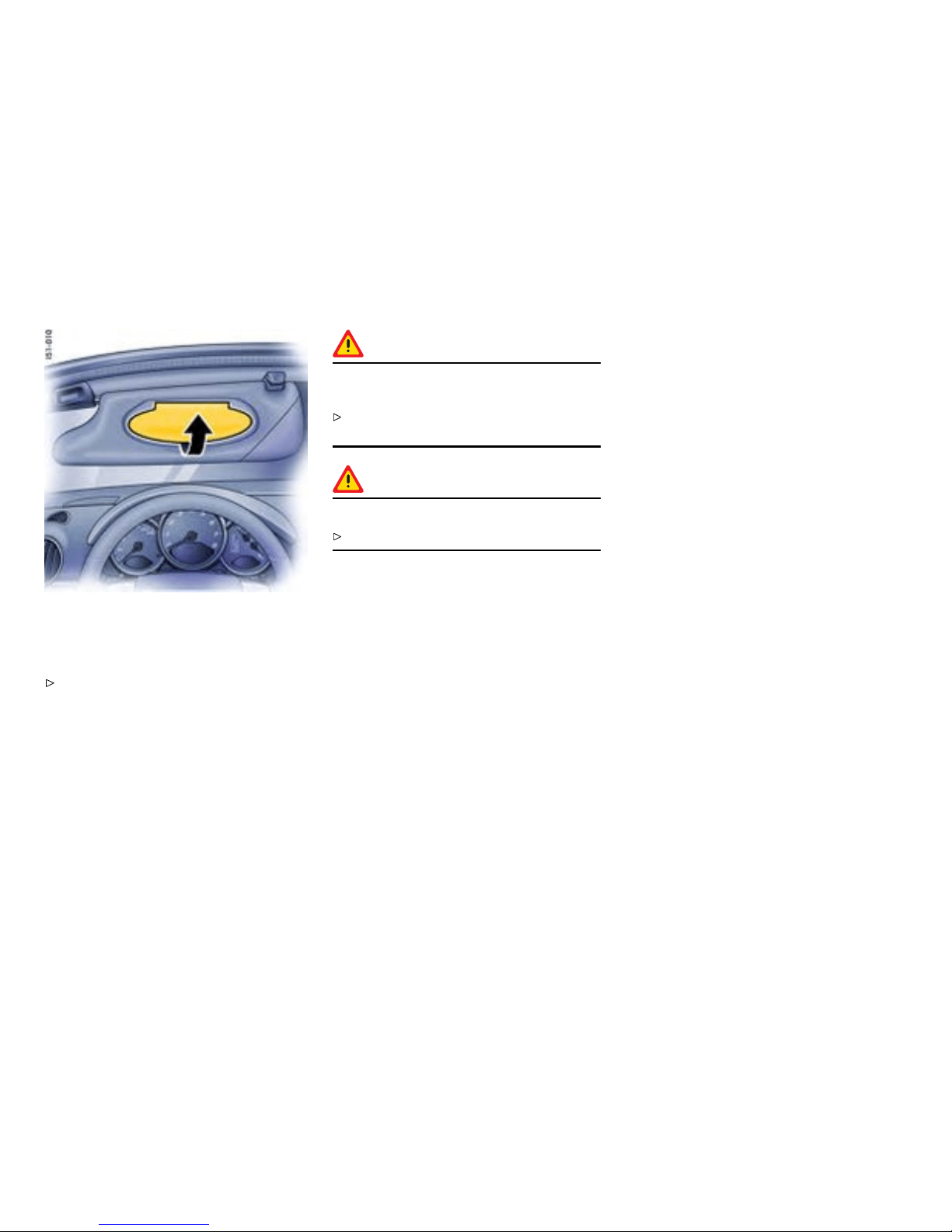
Sun Visors
Swivel the sun visors
Swing the sun visors down to p reven t glare
from the front.
Vanity m irror
The vanity mirror on the rear of the sun visor i s
covered by a lid.
Warning!
Risk of injur y in an accident or risk of damage
to mirror lid and convertible top.
Keep the lid closed while driving and when
closing the convertible top.
Warning!
Risk of damage.
Do not force the lid beyond its end positi on.
In the case of an illuminated vanity mi rror, the light
is switched on when the lid is opene d.
48Controls, Instru ments
Downloaded from www.ManualsFile.com manuals search engine
Safety B elts
Gener al information
Warning!
Alway s make sure you r and your passengers’
safety belts are properly fastened while the
vehicle is in mot ion. Failure to follow safety
belt warnings may result in serious personal
injury or death.
For your and your passengers’ protection, use
safety belts at all times while the vehicle is in
motion.
Use appropriate child restraint systems for all
small children.
Warning!
Proper wea ring of safe t y belts
Safety belts must be positioned on the body as
to restrain the upper body and lap from sliding
forward. Improperly positioned safety bel ts
can cause serio us personal injury or death in
case of an accident.
The shoulder belt sho u ld always rest on your
upper body. The should er belt should never be
worn behind your back or under your arm.
For m aximum effectiveness, the lap belt
should be w orn low across the hips.
Pregnant women should position the belt as
low as possible across the pel vis. Make sure it
is not pressing ag ainst th e abdomen.
Belts should not be worn twisted.
Do no t wear belts over rigid or breakable
objects in or on your clothing, such as eye
glasses, pens, keys, etc. as these may cause
injury.
Several layers of hea vy clothing may interfere
with proper positioning of belts.
Belts must not rub against sharp objects or
damage may occur to the belt.
Two occu pants should never sha re the same
belt at the s ame tim e.
Warning!
Care and maintenance
Keep belt buckles free of any o bstruction that
may prevent a secure locking.
Belts that have been subjected to exces s-
sive st retch forces in an accident must be
inspected or replaced to ensure their contin-
ued effectiveness in restraining you. The same
applie s to belt tensioner sys tems which hav e
been triggered. In addition, the anchor points
of the belts should be checked.
If safety belts do not work properly, see yo ur
authorized Pors che dealer immediately.
If the belts show damage to webbing, bind-
ings, buckles or retractors, they should be
replaced to ensure safe operation.
Do not modify or disassemble the safety belts
in you r vehicle.
The belts must be k e pt clean or the retractors
may not work properly.
Please observe the chapter ”CAR CARE
INSTR UCTIONS” on p age 233 .
Never bleach or dye safety belts.
Do not allow safety belts to retract until they
are completely dry after cleaning or this may
cause damage to t he belt.
Controls, In s truments 49
Downloaded from www.ManualsFile.com manuals search engine
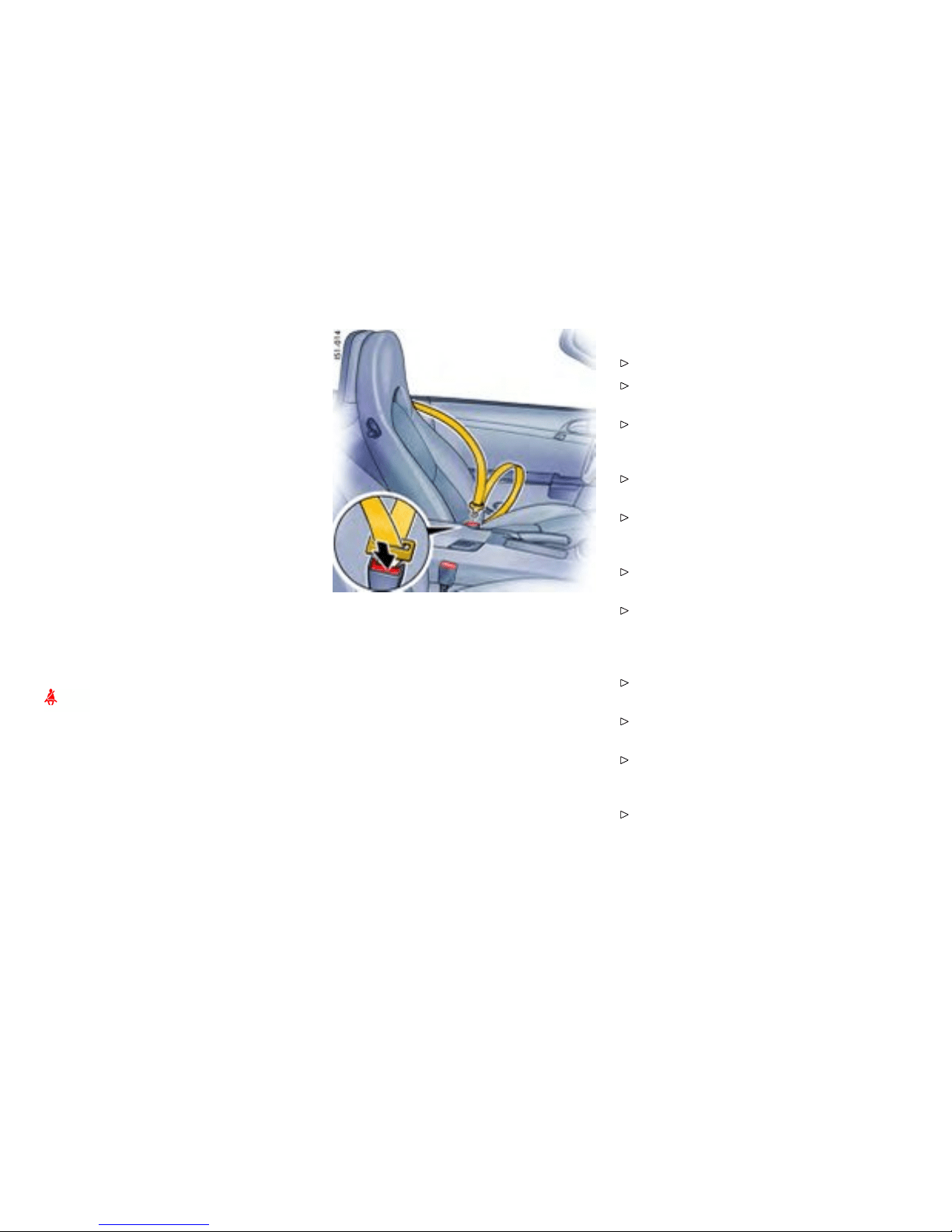
Belt tensioner
Depending on the force of an impact, fastened
safety belts are tightened in a n accident.
The belt tensioners are triggered by:
– Front, side and rear impacts of sufficie n t
severit y.
– Vehicle rollover.
Note
The belt tensioner system can be tr iggered only
once; the system must be replaced afterward.
If there is a fault in the belt -tensioner system, the
airbag warning light lights up.
Work may be perfo rmed on the belt-tensio ner
system only by an authorized Porsche dealer.
Smoke is released when the belt tensioners are
triggered. This does not i ndicate a fire in the
vehicle.
Safety B elt Warning System
An audio-visual warning sys tem is interconnect-
ed with the driver’s safety belt.
Every time the ignitio n is t urned on, the gong will
sound for about 6 seconds to remind d river and
passenger to b uckle up. In addition, the gong
will sound for approx. 90 seconds if the vehicle
speed exceeds 15 mph ( 24 km/h). The safety belt
warning light in the instrument panel and on-board
computer will go off as soon as the drive r has
buckled up.
Inertia reel retractor
The combination lap/shoulder belt with inertia reel
locking mechanism adjusts automatically to your
size and movements as long as the pull on the belt
is slow.
Rapid deceleration during hard braking or a
collision locks the belt. The belt will al so lock
when you d rive up or down a steep hill or in a sharp
curve, otherwise, the shoulder belt will not inhibit
your upper body movement.
Fastening the safety belt
Assume a comfortable s itting po sition.
Please observe the chapter ”SEAT POSITION”
on page 40.
The shoulder belt should always rest on your
upper body. The shoulder belt should never be
worn behind your back or under your arm.
Grasp belt and pull the belt in a continuous
slow motion across your chest and lap.
Insert belt tongue into buckle on inboard side
of seat. Push down until it securely locks with
an audible click. Pull the belt to c heck.
Pull shoulder s ection to mak e sure belt fits
snugly across the pelvis.
Belts should f it snugly across the pelvis and
chest. Make sure there is no slack in the belt.
Releasing the safety b elt
Push i n release button (arrow) on buckle. Belt
tongue will spring out of buckle.
To release a latched belt, lean back to take the
body pressure off the belt.
To store lap/shoulder belt, allow the belt to
retract as you guide the latch to its stowed
position.
Please observe the chapter ”AUT OMATIC
LOCKING RETRACTOR ” on p age 60.
50Controls, Instru ments
Downloaded from www.ManualsFile.com manuals search engine

Safety belts
If it becomes necessary to clean the belts, you can
use an y mil d washing agent. Allow the belts to dry
prior to retracting, but avoid direct sunlight.
Only use suitable cleaners. If unsuitable
cleaners are used or any att empt is made
to dy e or bleach the belts, the webbin g may be
weaken ed and thus constitute a safety risk.
Controls, In s truments
51
Downloaded from www.ManualsFile.com manuals search engine

Airbag Systems
Gener al information
The airbags in combin ation with the safety belts
make up a sa f ety system wh ich offers the driver
and the passenger the greatest known protection
from injuries in cas e of accident. Your vehicle
is equipped w ith a weight se nsing sys tem for
the passenger’s seat in accordance with U.S.
Federal/Canadian Motor Vehicle Safet y Standard
208.
Even if your vehicle is equipped with airb ags, the
safety belts must be w orn at all times, because
the front airbag system is only deployed by frontal
collisions with an impact of sufficient s everity.
Below the deployment threshold of the airbag
system, and during types o f collisions which do not
cause the actuation of the system, the safety belts
provide the primary protection to the occu pants
when correctly worn. Therefore, all persons
within the v ehicle must wear safety belts at all
times (in ma n y states, state law requi res the use of
safety belts).
Please observe the chapter ”SAFETY BELTS”
on page 49.
The front a irbags are located under the padded
steering wheel panel on the driver’s side and, on
the pas senger’s side, in the dashboard. The side
airbags for the front seats are installed on the
side in the seat backrests. The head airbags are
installed in th e door linings.
Danger!
To provide optimal occup ant protection, air-
bags must inate at very high speed. If you
are not wearing your safety belt or are too
close to the airbag when it is de ployed, inat-
ing a irbags can result in serious personal inju-
ry or death. Improper handling of the weight
sensing system can unintentionally impair
switching the passenger’s a irbag of f and on.
Make sure there are no people, animals or
object s between th e driver or passenger and
the area into which the airbag in flates.
Sit ba ck as far from the dashbo ard or steering
wheel as is practi cal, while still maintaining full
vehicle control.
Always hold the steering wheel by the outer
rim. Never rest y our hands on the airbag
panel.
Always fasten seat belts because triggering
of the airbag system depends on the force and
angle of impact.
Do no t transport heavy objec ts on or in front
of the passenger’s seat. These could impair
the f unction of the airbag, the seat belts, and
weigh t sensin g.
Do not hang objects (e.g. jackets, coats, coat
hangers) over the backrest.
Always keep the lid of th e doo r stora ge com-
partment closed. Objects must not protrude
out of the door storage compartment.
No changes may be made to the wiring or
components of the airbag sy stem.
Do not add any additional cove ri ngs or sticker s
to the steering wheel or in the area of the
passenger airbag, side airbags and head
airbags. Doin g so may adversely affect the
functioning o f the airbag sy stem or cause
harm t o the occupa n ts if the airbag system
should deploy.
Do not modify the seat coverings. Do not
attach additional cushions, protective cov er-
ings, or pillow s to the passenger’s seat. Do
not a ffix things to the passenger’s seat or cov-
er it with other materials. Do not cover the
back of the backrest. Do not make changes
to the passenger’s seat and to the sea t base
frame.
Do not undertake any wiring for electrical
accesso ry equipment in the vicinity of t h e
airbag wiring harnesses. Doing so may
disable the airbag system or c ause inadvertent
inflation.
If the warning light comes on, the airbag
system should be repaired immediately by
your authorized Porsche dealer.
52Controls, Instru ments
Downloaded from www.ManualsFile.com manuals search engine

Always keep feet in the footwell while driving.
Do not put feet on the dashboa rd or the seat
area. Do n ot lean against the inside of the
door or outside the window while the vehicle is
moving.
Using accessories not approved by Porsche
can cause the weight sensing system to be
impaired.
Do not squeeze obje cts, such as the fire
extinguisher, or first aid kit under the seat.
Only have seats removed and installed by
an aut horized Porsc he dealer so that weight
sensing components will not be damaged.
Give your passenger all of th e information in
this chapter.
Note
Airbag components (e. g. steering wheel, door
lining, seats) may be disassembled only by an
authorized Por s che dealer.
When di sposing of a used airbag unit, our safety
instruc tions must be followe d. These instructions
can be obtained at any authorized Porsc h e dea l er.
Function of the airbag sy stem
Airbags are a supplemen tal safety system. Your
primary protection comes from your safet y bel ts.
The front airbags are triggered during a frontal
collision of sufficient force and direction. In the
event of a side impact of corresponding force, the
side airbag o n the impact side is triggered.
The inflation process g enerates the amount of
gas required to fill the airbags at the ne cessary
pressure in fractions of a s econd.
Airbags help to protect the head and uppe r body,
while simultaneously damping the motion of the
driver and p assenger in the impact direction in the
event of a frontal impact or side impact.
In order to help provide protection in severe
collisions which can cause death and serious injury,
airbags must inflate extremely rapidly. Such high
speed inflation has a negative but unavoidable side
effe ct, which is that it can and does cause injuries,
includi ng facial and arm abrasions, b ruising and
broken bones. You can help minimize such injurie s
by always wearing your safe t y belt s.
There are many types of accidents in which
airbags are not expected to deploy. Th ese include
accidents where the airbags would provide no
benefit, such as a rear impact against your vehicle.
Other accidents where the airb ags are designed
not t o deploy are those where the risk of inju ry from
the a i rbag de ployment could exceed any protective
benefits, such as in low speed accidents or higher
speed accidents where the vehicle decelerates
over a long er time. Since airbag deploym ent does
not occur in all acc idents, this f u rther emphasizes
the need for you and your passen ger to always
wear safety belts.
Your vehicle is e quipped with a crash sensing and
diagnostic module. This modu le will record the use
of the seat belt restrai nt system by the d river and
passenger whe n the airbags and/or belt tensioner
work.
Advanced Airbag
Your vehicle is equipped with a weight sensing
system for the passenger’s seat in accordance
with U.S. Federal/Canadian Mo tor Vehicle Safety
Standard 208. Depen d ing on the w eight a cting on
the passenger’s seat, the p assenger’s airbag will
automatically be switched on and off.
Depending on the angle an d force of impact,
the passenger’s airb ag which is activated will be
triggered d uring a collisio n.
Precondition for switching the passenger’s airbag
on and off , depending on weight:
– Vehicles equipped with key-operated airbag
deactivation de vice: Switch position AUTO.
– Ignition key is inserted .
Seat adjustment for the passenger’s sea t
If the seat is in an extreme position (e.g. , the
backrest is in contact with the engine comp a rtment
wall), the backrest can warp. Warping of the
backrest can lead to malfunctions.
Controls, In s truments
53
Downloaded from www.ManualsFile.com manuals search engine
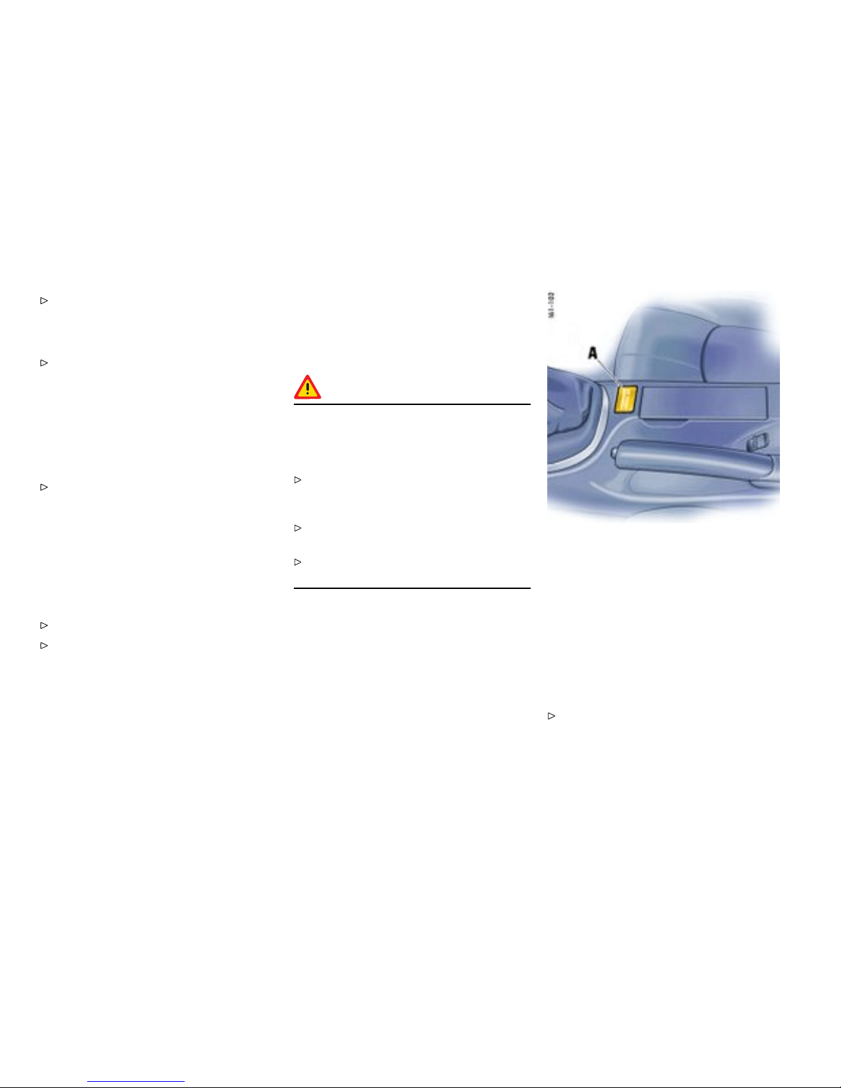
Correct the seat adjustment. Ensure that the
seat is not jammed and is self-supporting.
Ensure that the backrest is in the upright
position.
Do not trans port a lo ad and objects behin d
and under the passenger’s seat. If the load
or obje cts are under the seat, it can cause
malfunctions.
If the weight on th e passenger’s seat is reduced
significantly, e.g., by supporting weight on the
armrest, the passenger’s airbag can be switched
off.
Select an upright seat position, and do n ot
support weight on the armrests or lean out of
the wi ndow. Always keep feet in the footwell
while driving. Do not put feet on the dashboard
or the seat area. Do not lean again st the inside
of the door or outside th e windo w while the
vehicle is mo ving.
If the passenger’s seat is warped signif icantly, a
message is displayed on the on-board computer:
Correct the seat adjustment.
Please obse rve the chapter ”WARNINGS
ON THE INSTR UMENT PANEL AN D THE
ON-BOARD COM PUTER” on page 134.
Vehicle modica tions to accommodate
persons with disab ilities
Because modifications to your vehicle could
compromise your advanced airbag sys tem, please
call 1 -800-PORSCHE prior to having your vehicle
modifie d.
Automatic deacti vation of the passenger’s
airba gs
Danger!
The use of a child restraint syste m in the
passenger seat can result in serious personal
injury or death t o the child from an airbag
deployment.
Please observe the chapter ”PASSENGER
AIRBAG OF F INDICATOR LAMP DOES NOT
LIGHT UP” on page 55.
Before transporting a child on the passenger’s
seat:
Please observe the chapter ”CHILD
RESTR AINT SYSTEMS” on page 58.
– When an up to one-year old child i s seat ed
in the child restraint s ystem, the front airbag
is automatica lly deactivated o n the passe n ger
side.
– When an adult is seated in the front seat the
front airbag remains a ctive on the passenger‘s
side.
A - PASSENGER AIRBAG OFF indicator lamp
Note on operation
Although not d esired, it can occur in t h e case of
heavier children that the passen ger airbags remain
active or, in the case of very light adults or young
persons , that the passenger airbag is deactivated.
The condition of the passenger airbag system is
shown by the indicator lamp A.
If in doubt:
Please observe the chapte r ”PASSENGER
AIRBAG OFF INDICATOR LAMP DOE S NOT
LIGHT UP” on page 55.
54Controls, Instru ments
Downloaded from www.ManualsFile.com manuals search engine

Please obse rve the chapter ”KEY-OPERATED
AIRBAG DEAC TIVATION DEVI CE” on page 56.
Please obse rve the chapter ”CHILD
RESTRAINT SYSTEMS” on page 58.
Please observe the chapter ”LATCH SYSTEM
CHILD SEAT BRACKET ON THE PASSEN GER’S
SEAT” on page 61.
Note
After inserting the igniti on key, the PASSENGER
AIRBAG OFF warning light lights up for a few
seconds as a bulb check.
PASSE NGER AIRBAG OFF indicator lamp
lights up
– The p assenger’s airbag is switched off.
PASSE NGER AIRBAG OFF indicator lamp
does not light up
– The p assenger’s airbag is active and ready for
operation.
– If the passenger’s seat is not occupied, the
PASSENGER AIRBAG OFF indicator lamp will
also not light up, even though the passenger’s
airbag is sw itched off.
Danger !
Risk o f serious personal injury or death
due to the passenger airbag triggering
unintentionally. When the ignition is on a nd
the up to one-y ear old child is seated in the
child restraint system on the passenger’s
seat, the indicator lamp „PASSENGER AIRBAG
OFF“ must be on. If the “PASSENGER AIRBAG
OFF” i ndicator lamp does not light up, it could
indica te a fault in the system. In this case:
On veh icles w ith key-operated airbag d eactiva-
tion device: Switch to posit ion OFF.
On veh icles w ithout key-operated airb ag
deactivation device: Do not drive.
Have the fault remedied at your nearest
authorized Pors che dealer.
Note
The key switch for switching off the passenger’s
airbag in co mbination with the LATCH attachment
bracket are not installed at the factory. They can
be retrofitted.
Please see your authorized Porsche deal er.
Warn ing light and wa rning
message
Faults are indicated by a warning light in the
instrument panel and a me ssage on the on-board
computer.
Please observe the chapt er ”WARNINGS
ON THE INSTRUMENT PANEL AND THE
ON-BOARD COMPUTER” on page 134.
In the following cases you should imme-
diately consult an authorized Porsche
dealer in order to assure the airbag sys-
tem is functioning properly:
– If the warning light does not light up when the
ignition key is inserted or
– If the warning light does not go out once the
engine is running or
– If the warn ing light appears while driving.
Airbag m aintena nce
In order to ensure long -term functioning, the airba g
system must be inspected by an authorized
Porsche dealer at the inter vals recommended in
your Maintenance Booklet.
Note
If you sell your Porsche, notify the purchaser that
the vehicle is equipped with airbags, and refer
them to the chap ter, “Airbag Systems“, in the
Owner’s Manual (safety and disposal rules).
Controls, In s truments
55
Downloaded from www.ManualsFile.com manuals search engine
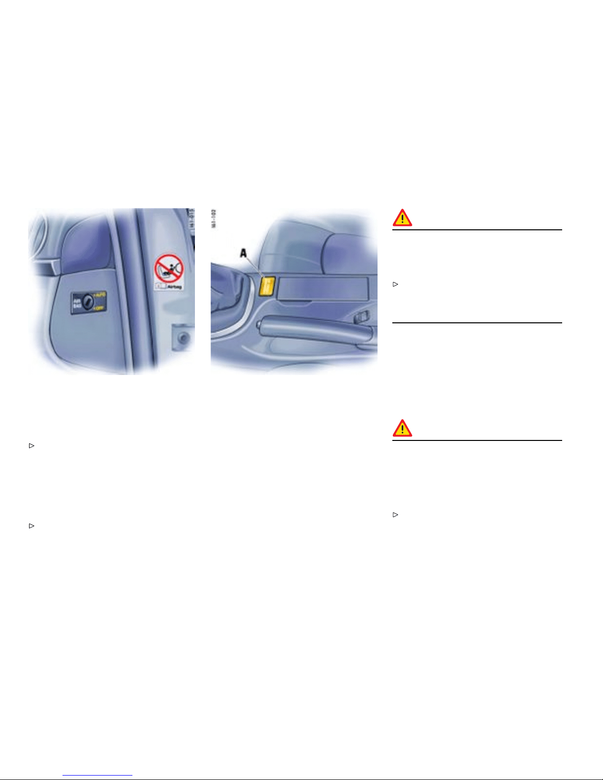
Further in f ormation on th e air bag system can be
found o n stickers at tached to the sun v isors.
For special recomm endations on the use of ch ild
restraints:
Please observe the chapte r ”CHILD
RESTRAINT S YSTEMS” on page 58.
Key-operated airbag deactivation device
If in doubt about the status of the airbag, you
can s witch off the pass enger’s airbag on t h e key
switch.
Switch off the passenger’s airb ag on t he key
switch using th e vehicle key.
A - PASSENGER AIRBAG OFF indicator lamp
Switch position AUTO - passenger’s airbag system
is active
Switch position OFF - pas senger’s airbag system is
switched off
Danger!
Risk of serious per sonal injury or death for
passenger if passenger’s airbag remains
switched off after the child restraint system is
removed.
Make sure that t he key switch is switched to
AUTO once the child seat has been removed,
in order to provide protectio n to the adult
occupants.
Warning light “PASSENGE R AIRBAG OFF”
If the airbag on the passenger’s side is swi tched
off:
– Warning light “PASSENGER AIRBAG OFF”
is continuously lit w h en the ignition key is
inserted.
Danger!
Risk of serious personal injury or death from
the p assenge r’s airbag. If the “PASSENGER
AIRBAG OFF ” warning light is n ot lit when the
ignition key is inserted and the Airbag OFF
switch is switched to the OFF-Position, this
could indicate a fault in the system.
Do not install a child restraint system on the
passenger’s seat.
56Controls, Instru ments
Downloaded from www.ManualsFile.com manuals search engine

Have the fault remedied imme diately. Please
see your authorized Porsche dealer.
Note
The key switch for switching off the passenger’s
airbag in combination with the LATCH attac hment
bracket are not installed at the factory. They can
be retrofitted.
Please see your authorized P orsche dealer.
Controls, In s truments
57
Downloaded from www.ManualsFile.com manuals search engine
Child R estraint Systems
Porsche recommends that all inf ants and children
be restrained in child restra int systems at all times
while t he vehicle is in motion in accordance with
applicable laws.
Use only child restraint systems with the LATCH-
system recommended by Porsche. These sys-
tems have been tested and adjuste d to the interior
of your Porsche and the a ppropriate ch ild age
groups. Other systems have not been tested and
could entail an increased risk of injury or death.
You can obtain child sea ts that are LATCH compati-
ble at your authorized Porsche dealer.
Always observ e the separate installation
instructions for your child seat.
The use of infant or child restraints is required by
law in all 50 states of the U.S. and all Can adian
provinces. The child restraint system should b e
one that complies wit h U.S. Federal/Canadian
Motor Vehicle Safety Standards and should
be sec ured by a l ap belt or lap belt portion of a
lap-shou lder belt or for child seats equipped with
the LATCH sytem (Lower Ancho rage and Tether
for Children, also known as ISOFIX) to t h e LATCH
anchorages. A statement by the seat manufactu rer
of com pliance with this standard can be found
on the instruction label on the restraint and in the
instruction manual provided with the restraint.
Danger!
The use of a child restraint syste m in the
passenger seat can result in serious personal
injury or death t o the child from an airbag
deployment. To reduce risk of injury from
an inating airbag in an accident, Porsche
strongly recommends:
Please observe the chapter ”PASSENGER
AIRBAG OF F INDICATOR LAMP DOES NOT
LIGHT UP” on page 55.
Please observe the chapter ”CHILD
RESTR AINT SYSTEMS” on page 58.
Note
The ke y switch for switch ing off the passenger’s
airbag and the LATCH attac h ment bracket are not
installed at the factory. They can b e retrofitted.
Please see your authorized Porsche dealer.
Danger!
Risk of serious personal injury or death to the
child.
Follow all child restraint instruc tions and
warnings in this manual.
– When using an infant or child restraint system,
be sure to follow all ma nufacturer’s instruc-
tions on installation and use.
– Infants and small children should never be held
on the lap, nor should they share a safety belt
with another occupant while the vehicle is in
motion.
– Children too big for child restraint systems
should use regular safety belts. A sho ulder
belt can be used providing it does not cross
the face or the nec k of the c hild.
– Choose a ch ild restraint system according to
the a g e and size of the child.
– Child restraint sy stems that are damaged or
have b een heavily st ressed in an accident must
be replaced immediately.
– Do not affix thing s to child restraint systems or
cover it wit h other materials.
– Your authorized Porsc he deal er will be glad
to ad vise you about the installation possi bility
for a Porsche child restraint system which
allows a key-operated airba g deac tivation of
the passenger’ s airbag.
– The key-operated airbag dea ctivation device
installation requires special programming
available only from your authorized Porsche
dealer.
Please observe the chapter ”KEY-OPERATED
AIRBAG DEACTIVATION DEVICE” on page 56.
58Controls, Instru ments
Downloaded from www.ManualsFile.com manuals search engine

Direction of installation for child restraint
systems
Children up to 9 months old
Children of this age mus t be transported in a
restraint system which is installed on the passen-
ger’s seat facing rearward.
The p assenger’s airbag must be deactivate d.
Children aged between 9 months and 6 years
Children of this age are held in child restraint
systems facing forward.
The passenger’s airba g must be deactivated
when these systems are used on the passen-
ger’s seat.
Children aged between 6 and 12 years
Children of this age are held in child restraint
systems facing forward.
The passenger’s airba g must be deactivated
when these systems are used on the passen-
ger’s seat. The passenger’s airbag must be
activate d for children weighing over 59 lbs.
(27 kg ).
Using c hild restraint system s in the
passenger seat
Danger !
The use of a child restraint syste m in the
passenger seat can result in serio us personal
injury or death to the child from an airbag
deployment. To reduce ris k of injury from
an inating airbag in an accid ent, Porsche
strongly recommends:
Please observe the chapter ”PASSENGER
AIRBAG OFF INDICATOR LAMP DOES NOT
LIGHT UP” on page 55.
Please obse rve the chapte r ”CHILD
RESTRAINT SYSTEMS” on page 58.
Child restraint system for up to one-year old
children
– Make sure that the PASSENGER AIRBAG OFF
indicator lamp lights up.
– Adjust the passenger’s s eat as f ar away from
the airbag as possibl e.
Danger!
Risk of serious personal injury or death
due to the passenger airbag triggering
uninte ntionally. When the ignition is on and
the u p to one-year old child i s seated in t he
child restraint system on the passenger’s
seat the in dicator lamp „PASSENGER AIRBAG
OFF“ must be on. If the “PASSENGER AIRBAG
OFF” indicator lamp does not light up, it could
indicate a fault in the system. In this case:
Do not use a child restraint system on the
passenger’s seat.
On vehicles w ith key-operated airbag deactiva-
tion device: Switch to posit ion OFF.
Have the fault remedied at your nearest
authorized Porsche dealer.
Child restraint syst em for childr en older tha n
one year
Your vehicle is equipped with a weight sensing
system for the passenger’s seat in accordance
with U.S. Federal Motor Vehicle Safety Stan dard
208. Depending on the weight acting on the
passenger’s seat, the passenger’s airbag will
automatically be switched on or off.
Controls, In s truments
59
Downloaded from www.ManualsFile.com manuals search engine
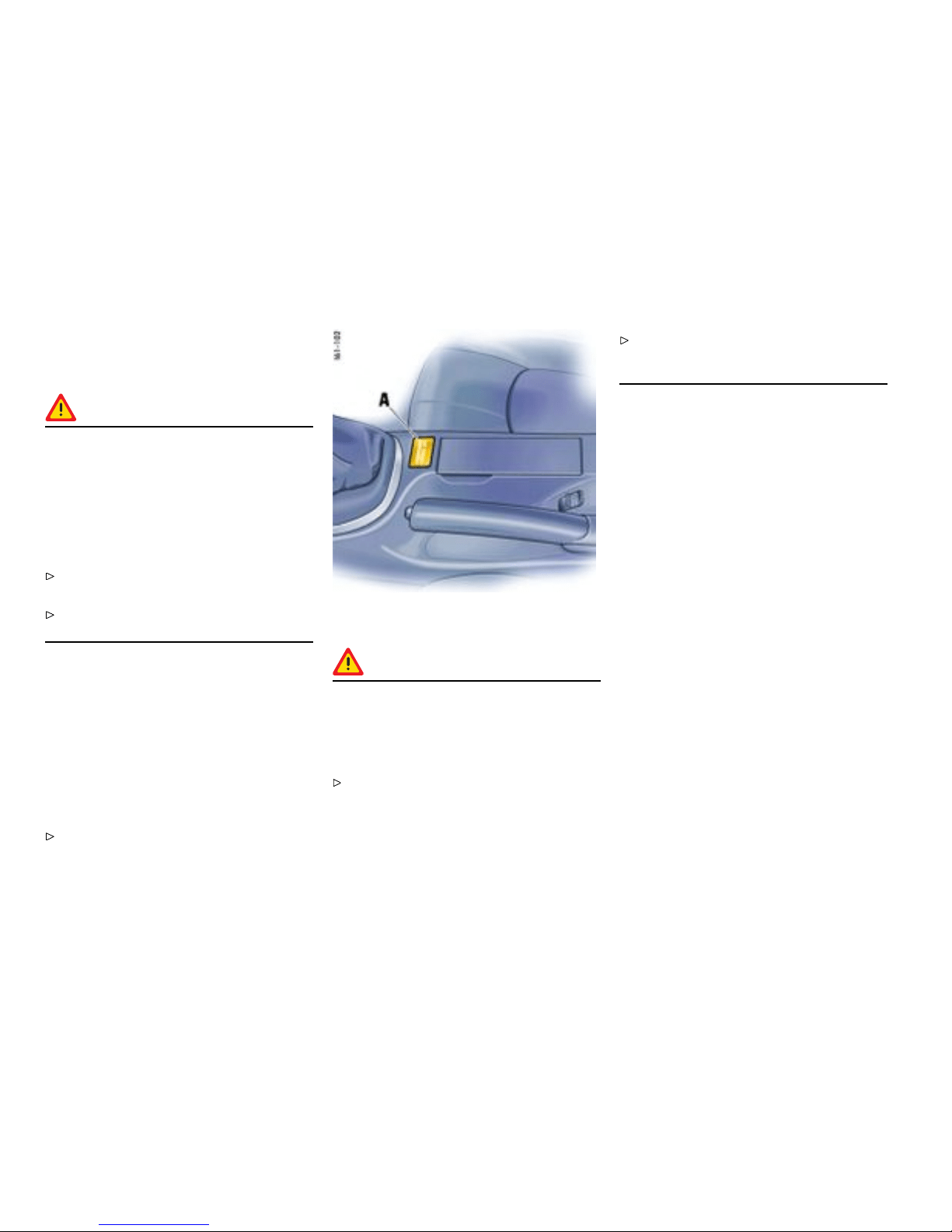
Small adult passenge rs
Make sure that the PASSENGER AIRBAG OFF
indicato r lamp does not light up.
Danger!
Risk of serious personal injury or dea t h due
to the passen ger’s airbag not triggering.
When the igni tion is on and the small adult
passenger is seated on the p assenger’s seat,
the indicator lamp “PASSENGER AIRB AG OFF”
must be off. If the “PASSENGER AIRBAG OFF”
indicator lamp light s up, it could indicate a
fault in the system. In this case:
Do not carry a passenger in the passenger’s
seat.
Have the fault remedied at the nearest
authorized Por s che dealer.
Automatic locking retractor
The safety belt for the passenger is equipped
with an automatic locking retractor for securing
the child restraint s ystem. When activated, this
retractor allows you to securely fasten the child
restraint system in place so tha t inadvertent
movements will not occur.
Before transporting a child on the passenger seat:
Please observe the chapte r ”CHILD
RESTRAINT S YSTEMS” on page 58.
A - PASSENGER AIRBAG OFF indicator lamp
Danger!
Risk of serious personal injury or death to
the child, when excessive force is a cting on
the passenger’s seat due to the seat belt. In
such cases, the passenger’s airbag can be
switch ed on uninte ntionally.
After fastening the child restraint system, do
not ad just the seat.
Check the condition of the passenger airbag
system shown by the indicator lamp A in the
central console.
Activating the automatic locking retractor
1. If a child restraint system must be fastened to
the passenger’s sea t, adjust the passenger’s
seat as far away from the airbag as possible.
2. Fasten child seat.
3. Pull the safety be lt retractor completely out. At
this point the lockin g mechanism is acti vated.
4. Insert the safety belt tongu e into the b uckle
and make certain that it is properly latche d.
Make no more adjustme nts to the seat.
5. Allow the safety belt to retract until it is tight
on the child restraint system. You may further
tighten the belt by pulling on it to allow more
of it to retract. Make sure that excessive seat
belt forces do not occur by moving the seat
with the child seat installed.
Releasing the safety b elt
1. Unbuckle the safety belt latch .
2. Then make certai n that the belt has fully
retracted. A t this point the automatic locking
feature will be disengaged. Seek appropriate
advice from your authorized Porsche dealer
about the possible installation of a Porsche
child restraint system.
60Controls, Instru ments
Downloaded from www.ManualsFile.com manuals search engine
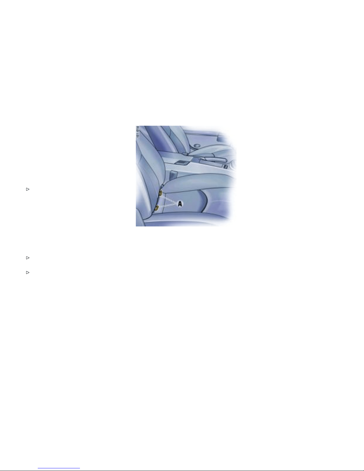
LATCH System Chi ld seat bracket
on the passenger ’s seat
Gener al information regarding the LATCH
child seat system
The key switch for switching off the passenger’s
airbag and the LATCH attachment bracket are not
installed at the factory. They can be retrofitted.
Please see your authorized Porsche dealer.
Porsche recommends the use of a Porsche
Child Seat with Lower Anchorage and Tether for
Children sys tem (LATCH). These syst ems have
been tested an d adjusted to the interior of your
Porsche and the appropriate c hild age groups.
Other systems have not been tested and could
entail an increased risk o f injury.
You can obtain child seats that are LATCH compati-
ble at your authorized Porsche dealer.
Always observe the separate installation
instructions for your child seat.
Please obse rve the chapter ”CHILD
RESTRAINT SYSTEMS” on page 58.
Installing a LATCH child seat system
1. Secure the child seat t o retaining lugs A as
outlined in the instruction manual f o r the child
seat.
2. Pull th e child seat to check that both fastening
points are engaged correctly.
Note
Make sure that the key switch is switched t o AUTO
once the child seat has been removed, in order to
provide protection to the adult occ u pants.
Controls, In s truments
61
Downloaded from www.ManualsFile.com manuals search engine
Clutch Pe dal
The c lutch pedal must be depressed f ully
before the starter will engage.
Warning!
Risk of an accident.
Always check the movement of the clutch
pedal before driving and make sure that it is
not obstructed by a floor mat or any other
object.
Secure the floor mat to prevent it from sliding
into positions that could interfere with the safe
operation of your vehicle. Your Porsche dealer
will be glad to offer you nonskid floor mats of
the co rrect size.
Warning!
To avoid damage to the clutch and tr ansmis-
sion:
Always depress the clutch ped al fully when
changing gears.
Do not hold the car on a steep grade with the
clutch pedal partially depressed.
Should the free tr avel of the clutch pedal suddenly
become larger, it could mean a malfunctio n of the
clutch.
See your Porsche dealer for correction.
62Controls, Instru ments
Downloaded from www.ManualsFile.com manuals search engine
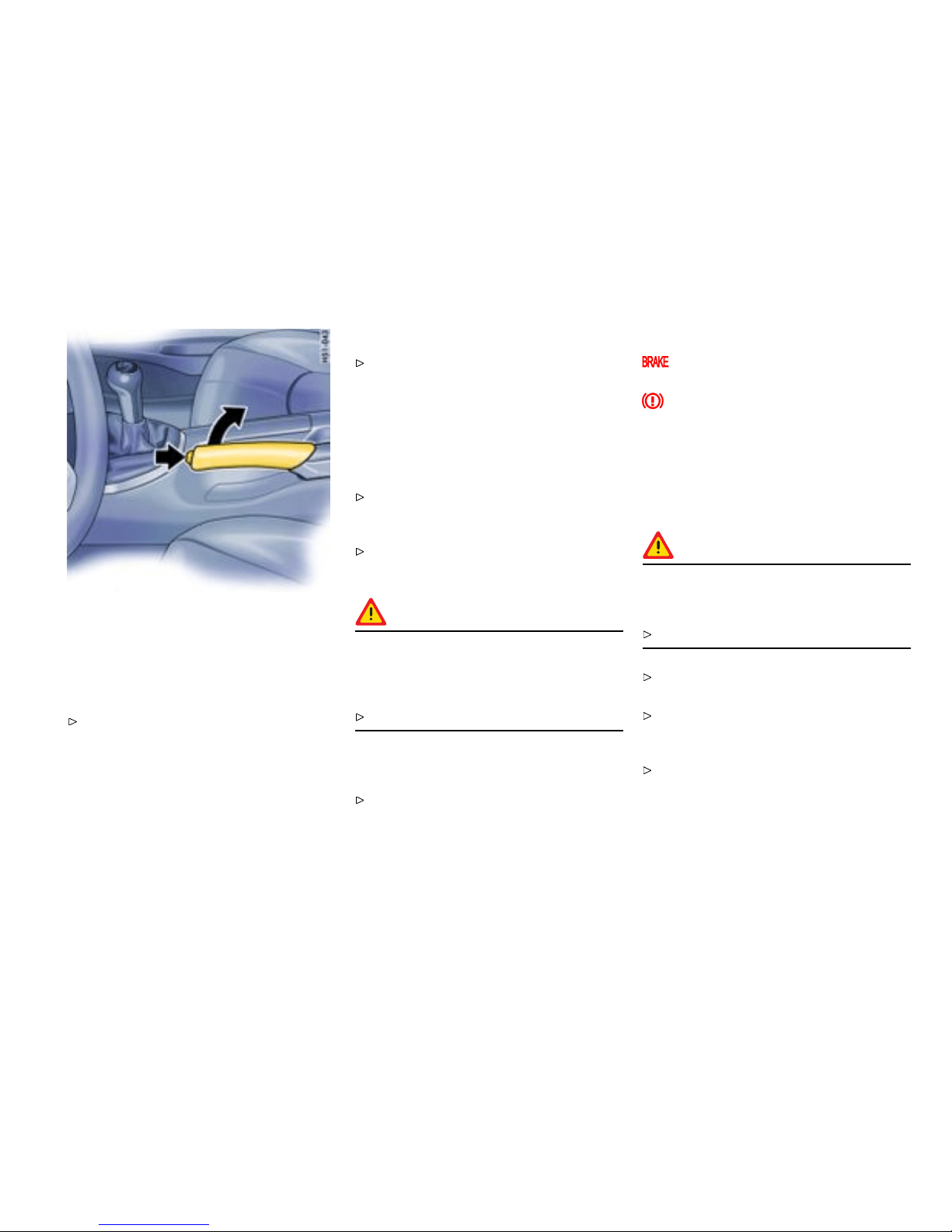
Parking Brake
Function of the parking brake
Parking brake force is mecha nically transferred to
the rear wh eels by means of ca bles.
Use the parking brake only after the vehicle
has co me to a full stop.
Setting the parking brake
Pull the lever all the way up (see arrow). With
the ignition on, the parking brake warni ng
lights in the i n strument panel and on-board
computer will come on if the lever is even
slightly raised. A firm pull upward is required
to properly engage the parking brake. If the
brake is not fully set, the vehicle may roll
without control.
Move the selector lev er to “P ” (Tiptronic) or
move the gea rshift lever to reverse or first
gear ( Manual transmission).
Before exiting the vehicle, make sure that the
parking brake is f u lly set and the vehicle is n ot
moving at all.
Danger !
Risk o f serious personal injury or death. A
partially engaged parking brake may allow
the vehicle to roll, causing serious personal
injury or death to any person in its path.
Engage the parking brake fully.
Relea sing the parking brake
Pull the leve r slightly up as you depress the
release butt on A, and then push the lever al l
the way down.
Warni ng lights
Parkin g brake warning light USA
Parking brake warning light Cana da
The w arning l ights in the instrument panel and
on-board computer wi ll go out after the parking
brake is ful ly released. The war ning lights are not
an indicator th at the parking brake is f ully set; it
is only intended to be a warning to release the
parking brake before driving the car.
Caution!
A partially engaged brake will overh eat the
rear brakes, reduce their effectiveness and
cause excessive w ear.
Release the parking brake fully.
When parking your car, always set the parking
brake by pulling all the way up on th e leve r.
Move the selector lever to “P” (Tip tronic ) or
move the gearshift lever to reverse or first
gear (Manual transmi ssion).
On hills also turn the front wheels towards the
curb.
Controls, In s truments
63
Downloaded from www.ManualsFile.com manuals search engine
Brakes
Gener al information
Make i t a habit to check the operation of your
brakes before driving.
Keep in mind that the braking distance increases
very rapidly as the speed increases. At 60 mph
or 100 km/h, for example, it is not twice but four
times longer than 30 mph or 50 km/h. Tire traction
is also less effective when the roads are wet or
slippery.
Therefore, always main tain a safe distance
from the c ar in front of you.
Vehicles without P orsche Ceramic
Composite Brake (PCCB)
Even though the brake discs consist of alloyed
grey cast iron, they will unavoidably start to
corrode if your car is par ked for an extended
period. The brakes wil l tend to “rub” as a result.
The nat ure, extent a nd effects of corrosion depend
on the amou nt of ti me the vehicle was parked,
whether granular or l iquid road salt was spread
and whether grease-dissolving agents were used
in car washes. If the braking comfort is noticeably
impaired, we recommend having the brake system
checked by experts at an authorized Porsche
dealer.
Brake system function
Your Porsche is equipped with a power assisted
hydraulic dual circuit brake system with disc
brake s at the front and rear. Both circuits functi on
independently. One brake circuit operates the front
and the other operates the rear.
If one brake circuit has failed, the other will sti l l
operate. However, you will notice an increased
pedal travel when you a pply the brakes. Failure of
one brake circuit will ca use the stopping distance
to increase.
Warning!
Risk of an accide nt, resulti ng in serious
personal injury or death. In the unlikely eve nt
of hydraulic failure of one brake circuit:
Push t he brake pedal down firmly and hold it in
that position. A mechanical linkage activates
the second circuit, and yo u will be able to bring
the vehicle to a stop.
After bringing your vehicle to a complete stop,
avoid driving the vehicle and instead have
it towed to the nea rest authorized Porsche
dealer for repair.
Brake warn ing ligh t USA
Brake warnin g light Cana da
If the warning lights in the instrument panel and
on-board computer go on while driving, the brake
fluid level ma y be too low, or (if the brake pedal
travel has increased) one of the two brake circuits
may have failed.
A greater braking pressure will b e required,
stopping distances wil l be longer and the brakin g
behavior will change, particularly in curves.
With correctly adjusted brakes, and a correctly
working brak e system, the peda l trave l to the point
of brak e actuation should be 1-3/1 6" to 1-9/16"
or 30 to 40 mm. Whenever the brake pedal travel
exceed s this distanc e, have the brake system
checked.
Brake pedal
Warning!
Risk of an accident, resulting in serious
persona l injury or death. Any obstruction of
the brake pedal could increase the stopping
distan ce.
Always check the movement of the brake
pedal before driving and make sure that it is
not obstructed by a floor mat or any other
object.
64Controls, Instru ments
Downloaded from www.ManualsFile.com manuals search engine

Secure the floor mat to prevent it from sliding
into positions that could interfe re with the safe
operation of your veh icle. Your Porsche dealer
will be glad to offer you nonskid floo r mats of
the co rrect size.
Note
In case one of the two brake circuits fails,
increased pedal travel is required to bring your
vehicle to a full stop.
Warning!
To avoid overheating and premature wear of
the b rakes:
Before descending a steep grade, reduce
speed and shift the transmis sion into a lower
gear or driving position to control speed.
Do not ”ride the brakes” by resting your foot
on the pedal when not intending to apply brake
pressure.
Do not hold the pedal down too long or too
often. This could cause the brakes to get hot
and not function properly.
Brake bo oster
The brake booster assists braking only when
the engine is running.
When the car is moving while the engi ne is not
running, or if the brake booste r is defective, more
pressure on the brake pedal is required to bring
the car to a stop. If this happens, ABS and PSM will
also not operate.
Moistu re or road salt on brakes affects braking.
When the vehicle is driven on salted roads for
extended peri ods, the brakes should be washed
down thoroughly ab out every 2 weeks. A n auto -
matic carw as h fac ility cannot do this job properly.
Brakes will d ry after a few cautious brake applica-
tions.
Warning!
Risk of an accident, resulting in serious
personal inju ry or death. Driving through
water may reduce traction. Moisture on
brakes from road wate r, car wash, or coating
of road salt may affect braking efciency.
Cautiously apply brakes to test brakes after
being exposed.
Brake wear
Your car ha s excellent brakes, but they are still
subject to we ar. T he rate at which they wear
depends on how the brakes are used .
Have th e brake system inspe cted at the
intervals recommended in your Maintenance
Booklet.
Warning light USA
Warning lig ht Canada
If the warning lights in the instr ument panel and
on-board computer stay on when the engine is
running or come on while driving, the brake pads
are worn, excessively.
Do not continue to operate the vehicle. Have
your authorize d Porsche dealer inspect or
replace the brake pads .
Controls, In s truments 65
Downloaded from www.ManualsFile.com manuals search engine

Brake pads
Wear on the brake pads and brake di s cs depends
to a great extent on the driving style and the condi-
tions of use and therefore cannot be expressed in
actual miles on the road.
The high-performance brake system is designed
for optimal braking effect at all speeds and
temperatures. Certain speeds, braking f orces
and a mbient conditions (such as temperature and
humidity) therefore migh t cau se ”brake noises“.
New brake pads or linings
New brake pads and brake discs have to b e
“broken in”, and therefore only attain optimal
friction when the car has covered several hundred
miles or km. The slightly reduced braking ability
must be compensated for by pressing the brake
pedal harder. This also applies whenever the brake
pads and brake discs are replaced.
66Controls, Instru ments
Downloaded from www.ManualsFile.com manuals search engine
ABS Bra ke System
(Antilock Brake System)
The A BS system represents a major contribution to
the enhancement of active s afety in your vehicle.
This system prevents the wheels f rom locking in a
panic s top on almost all road surfaces.
With the A BS system i n your vehicle, the
following areas ar e enhanced:
Steering, vehicle remains steerable under all
braking forces when ABS is engaged.
Good directional control, no swerving caused by
locking of wheels under braking conditions.
Shorter stopping distance, stopping distances
are usually reduced be cause controlled braking is
maximized.
Prevention of wheel lock up, no brake- induced
sliding and thus no localized tire wear from
emergency braking.
The crucial advantage of the ABS system o v er
a conventional brake system is in the area of
maintaining directional control and mane uverability
of the car i n emergency situations.
Warning!
The increased control that is provided should
not induce you to take greater risks with
your safety. The limits dictated by the laws of
physics cannot be overcome, even with ABS.
The r isk of accidents due to i nappropriate
speed cannot be reduced, even by the ABS .
The driver bears the responsibility for all
driving maneuvers.
Adapt your d riving style to the prevailing road
and weather conditions.
Obey all traffic laws .
Warning!
Other vehicles not equipped with the ABS
system may not be abl e to maintain co ntrol,
especia lly on wet or poor road surfaces and
thus may be more likely to impact you from
behind.
To minimize that risk, use your ABS system
to increase your ab ility to maneuver to avoid
dangerous situation s and not m erely to try to
stop in the shortest distance possible.
Operation of the ABS sys tem
A wheel speed sensor is mounted to each of the
four wheels. If wheel lock-up of either of the front
wheels or the rear wheels is sensed du ring braking,
the brake pressure is adjust ed automatically until
the wheel no longer slips.
If braking forces approach the wheel lock-up point
for all wheels (panic braking) the ABS system will
intervene to provide a rapid ryth m ic braking. The
proper oper ation of ABS is perceived by the driver
as a pulsating brake pedal in co n junction with
audible noise and perhaps some vibration.
If you experience these sens ations while
driving or a road surface with questionable
traction, reduce vehicle speed ap propriate for
the prevailing road conditions.
If full braking should be necess ary, press the
brake pedal all th e way down throughout the
entire brakin g procedure, regardless of the
pulsating pedal. Do not ease up on pressure
applied to the pedal .
The functional readiness of all the main electrical
components of the ABS is checke d by an elec tronic
monitoring system bot h before and while you drive.
Warning light USA
Warning lig ht Canada
When the ignition i s switched on the ABS war ning
light will light up while the system is electronically
Controls, In s truments
67
Downloaded from www.ManualsFile.com manuals search engine

interrogated and goes out when the engine is
started if the c h eck is not yet complete. If t he
ABS wa rning lamp fails to go out, this indicates
that ABS has been deactivated due to a fault. If
the warning lights in the instrument panel and
on-board computer l ight up while you are driving,
this indicates that a fault has occurred. In both
cases, normal b raking, as in vehicles with o ut ABS,
is still retained.
The ABS system should, however, be examine d
at an authorized Porsche dealer immediately to
prevent the occur rence of further faults.
If the ABS system becomes inope rative, take
your vehicle to your authorized Porsche dealer
immediately.
Warning!
Risk of an accident, resulting in serious
personal injury or death. The control unit
of the ABS brake syst em is set f or standard
tire size. If non-standard tires are installed,
the control unit may misinterpret the speed
of the vehic le, because of the variant data it
receives f rom the sensors on the axles.
Use only tire makes and types tested by
Porsche.
68Controls, Instru ments
Downloaded from www.ManualsFile.com manuals search engine

Sports Exhaust System
Sports exhaust system for
vehic les without sports mo de
The sports exhaust system can be switched on and
off when the ignition is switched on us ing button A.
When the sports exhaust system is switched on,
the light-emitting diode in the button lights up.
Sports exhaust system for vehicles wit h
sports mode
The spor t exhaust system can be switche d on and
off when th e ignition is on using the SPORT button
B.
Switching on the sports mode actuates the
markedly sporty PASM shock-ab sorber tuning .
However, should you wish to have a more c om-
fortable shock absorbe r setting, but still use the
characteristics of the sport m ode and the sport
exhaust syste m, the PASM can be switch ed to Nor-
mal mode separately.
To do so press the PASM button C. The
light-emitting d iode in the PASM button goes
out.
Please observe the chapter ”SPORT MODE” on
page 70.
Please observe the chapter ”PORSCHE
ACTIVE SUSPENSION MANAGEMENT (PASM)”
on page 74.
Controls, In s truments
69
Downloaded from www.ManualsFile.com manuals search engine
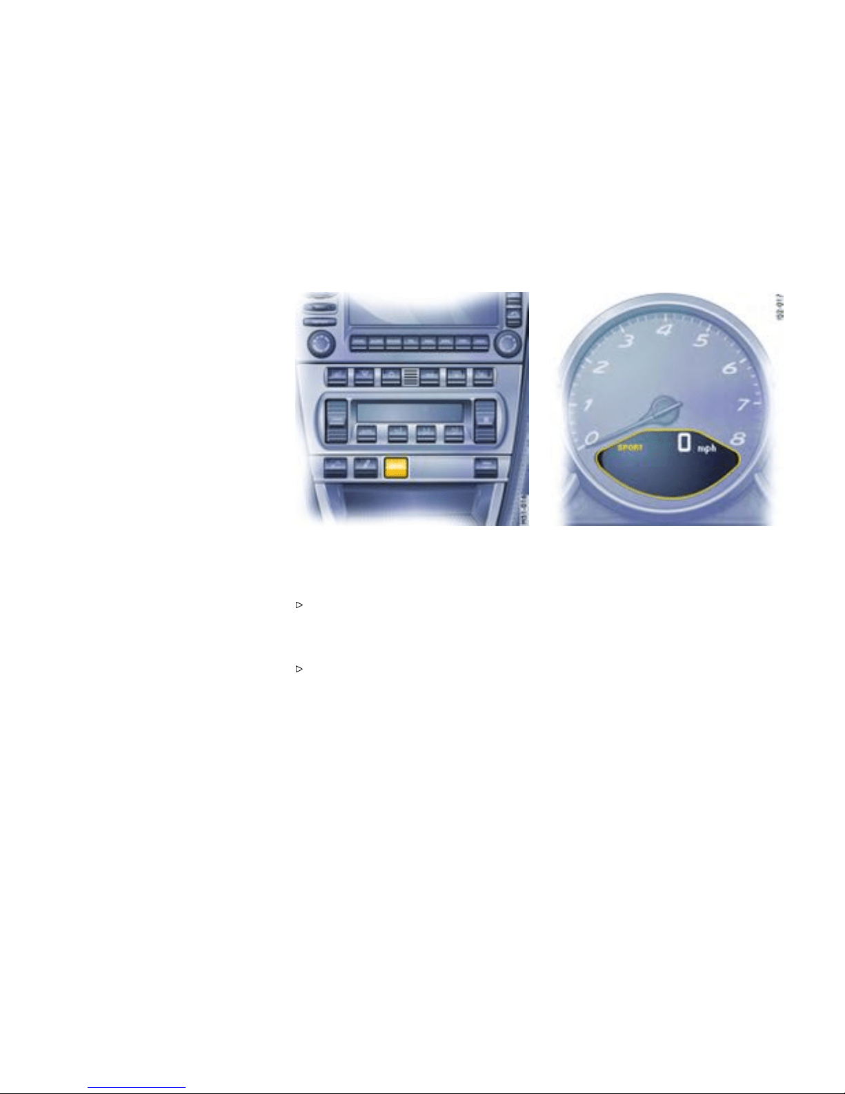
Sport M o d e
Function
A sportier car set-up is obtained when Sport mode
is switched on. Interventions by the Porsche
control systems are intentionally shifted tow ards
greater agilit y and driving performance.
– PASM (Porsche Active Suspension
Management) is automatically changed
to Sport mode, resulting in a stiffer susp ension
setup.
– The Tiptronic S switches to a sporty gear-
changing map and short ens the gear shifting
periods. Gear changes take pla ce fast er.
– PSM (Porsche Stability Management) c ontrol
is sporty. PSM interventions are later than in
Normal mod e. The driver can maneuver the
vehicle with greater agi lity at its performance
limits, without having to dispense with the
assistan ce of PSM in emergency situations.
This helps to achieve optimal lap times,
par ticularly on race circuits with a dry road
surface.
– The electronic accelerator pedal reacts
sooner, and the engine is more responsive t o
throttle inputs. When Sport mode is switched
on, this function is activated only after the
driver has bri efly released the accelerat or
pedal.
– The r pm limit er characteristic is “harder”, i.e.
the engine is immediately t hrottled when the
performance limits are reached.
Please observe the appropriate chapt ers PSM,
PASM and Tiptronic S.
Switching Spor t mode on and off
Press SPORT button in the center console.
When Sport mode is switched on, the light-
emitting diode in t h e SPORT button is lit.
When Sport mode is switched on, the logo SPORT
appears next to the digital speedometer.
Switching Sport m ode on and off simultaneously
activates and deactivates the Sport mode of the
PASM.
If the Sport mode of the PASM was acti vated with
the PASM button, it will remain on.
After the ignition is switched off, Sport mode
and PASM Sport mode are automatically reset
to No rmal mode.
70Controls, Instru ments
Downloaded from www.ManualsFile.com manuals search engine

Porsche Stability Management
(PSM)
Gener al information regarding PSM
PSM is an ac tive control system for stabilizati on of
the vehicle during extreme driving maneuvers.
Warning!
Risk of an accident, resulting in serious
person al inju ry or death. The increased
control that is provide d should not induce
you to take greater risks with y our safety. The
limits dictated by the laws of p hysics c annot
be ov ercome, even with PSM. The risk of
accidents due to inappropriate speed cann ot
be reduced, even by PSM. The driver bear s
the responsibility for all driving maneuvers.
Adapt your driving st yle to the prevaili ng road
and weather conditions.
Obey all traffic laws.
Advantages of PSM
– Superio r tractio n and lane- holding ability in all
driving situat ions - even on road surfaces with
varying friction.
– The sy stem compensates for undesired vehi-
cle reaction s (Ferra ria effect) when the driver
releases the accelerator pedal or brakes on
bends. This compensation functions up to the
maximum later al acceleration.
– PSM actively stabiliz es the vehicle during
dynamic driving maneuvers ( e.g. rapid
steerin g movements, during lane c hanges
or on alternati n g curves).
– Improved braking stability in curves and on
different or varying road surfaces.
Readiness for operation
PSM is switched on automatically every time you
start the engine.
Function
Sensors at t he wheels, brak es, steering syst em
and engine continuously mea sure:
– Speed
– Direction of t ravel (steering angle)
– Lateral acceleration
– Rate of turn abo u t the vertical a xis
PSM uses these values to determine the direction
of travel desired by the driver. PSM inter venes and
corrects the course if the actual direction of motion
deviates from the desired course (steering-wheel
position): It brakes individual wheels as needed. In
addition, the engine power may be manipulated in
order to stabilize the vehicle.
The events below inform the drive r of PSM control
operations and warn him to adapt her/h is driving
style to the road conditions:
– The multi-functional information light on the
instrument panel flashes.
– Hydraulic noises can be heard.
– The vehicle decelerates and steering-wheel
forces are altered as the PSM c ontrols the
brakes .
– Reduce d engine power.
– The brake ped al pulsates and its position is
changed duri n g braking. In order to achiev e
full ve hicle deceleration, foot pressure must be
increased after beginning of the brake peda l
pulsing.
Examples of PSM control operations
– If the front wheels of the vehicle drift on a bend,
the rear wheel on the inside of the bend i s
braked and the engine power is reduced if
necessary.
– If the rear of the vehicle swings out on a bend,
the front wheel on the outside of th e bend is
braked.
Controls, In s truments
71
Downloaded from www.ManualsFile.com manuals search engine
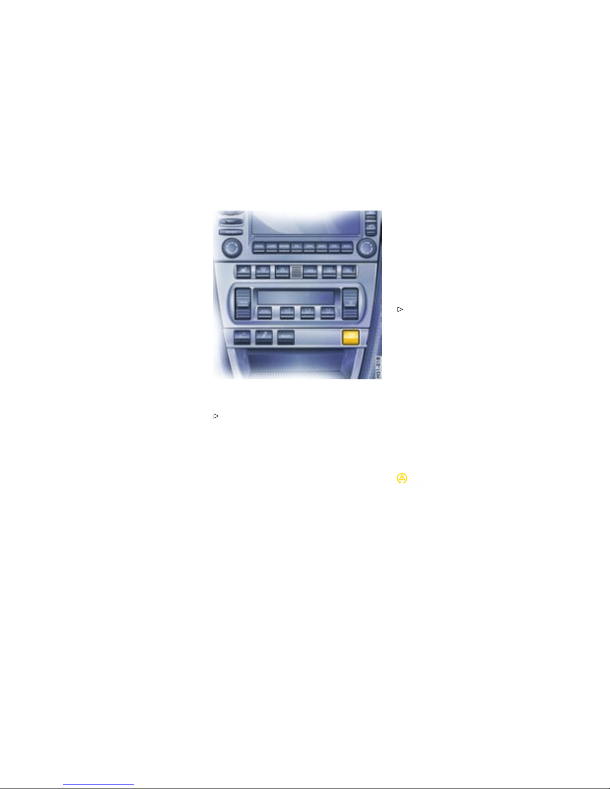
PSM sho uld always be switched o n during
“normal” driving.
However, it may be adv a ntageous to switch off
PSM temporarily in exceptiona l situations, f or
example:
– On a loose surface or in deep snow,
– When “rocking the vehicle free”, or
– When using snow chains.
Switching off PSM
Press the PSM OFF button. PSM is switched
off after a short delay. The light-emitting diode
in the butt on is illuminated. When the PSM is
switched off, the multifunc tional PSM light on
the instrument pane l is lit and a message i s
shown by the on-board compute r. An acoustic
signal also sounds.
The following functions stabilize the vehicle in
emergency situations, even with PSM switched off:
– When PSM is off, the vehicle is stabilized as
soon as one of the two front wheels ent ers the
ABS control range.
– When PSM is off and Sport mode is on, the
vehicle is stabilized as soon as both front
wheels enter the ABS control range.
One-s i ded spinning of the wheels is reduced,
even with PSM switched off, to enable optimum
traction on all drive wheels.
Switching PSM back on
Press PSM OFF button. PSM is switched on
after a short de lay. The l ight-emitting diode
in the button and the multifunc t ional PSM
light go out. The on-board compu ter shows a
message.
Sport mode
A sportier car set-up is obtained when Spor t mode
is switched on. PSM interventions are lat er than in
Norma l mode; the vehicle can be maneuvered with
greater agility at its performance limits, witho ut
the need to dispense with the assis tance o f PSM
in emergency situations. This helps to achieve
optimal lap times, pa rticularly on race circuits and
a dry road surface.
Multifunctional PSM light
– The multifunctional ligh t on the instrument
panel lights up for a la mp check when the
ignition is switched on.
– The light indic ates a c ontrol opera tion by
flashing, including when PSM is switched off
72Controls, Instru ments
Downloaded from www.ManualsFile.com manuals search engine

(brake control in the event of one-si ded wheel
spin).
– In conjunction with a message on the on-board
computer, the li ght indicates that PSM is
switched off. An ac oustic s ignal also sounds.
– Faults are display ed by the light in conjunction
with a message on the on-board computer.
PSM is out of order.
Please consult an authorized Porsche dealer.
Please observe the chapter ”PUTTING
VEHICLE INT O OPERATION” on page 270.
Towing
Please observe the chapter ”TOWING” on page
292.
Checks on test stands
When c arrying out brake tests on roller test
stands a max imum testing s peed of 5 mph
(8 km/h) must not be ex ceeded.
Handbrake checks on the roller brake tester
must be performe d only with the ignition switched
off.
Controls, In s truments
73
Downloaded from www.ManualsFile.com manuals search engine
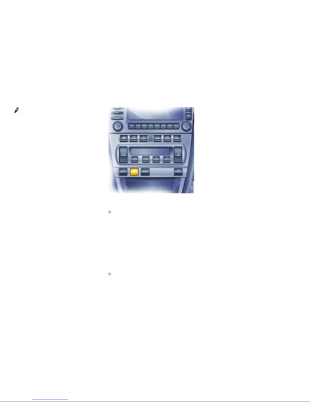
Porsche Active Suspension
Management (PA SM)
Function
PASM makes two running-gear setups availabl e to
the driver: “Nor mal” and “Sport”. The selection is
made v ia a button on the center console.
After the ignition is switched off, PASM is automati-
cally reset to Normal mode.
In Normal mode the running gear is in a sporty and
comfortable setup . Sport mode of fers a markedly
sporty sho ck absor ber tuni ng (e.g. for driving on
the race circuit).
The variable su s pension system selects the appro-
priate damping level for each wheel acco rding to
the sit uation and conditions of drivin g.
Example: If the vehicle is dri ven in a ma rkedly
sporty manner in Normal mode, PASM automat-
ically adapts the shock-absorber behavior to the
driving situati on in th is case as well.
Switching on PASM Sport mode
Press PASM button in the center console.
When PASM Sport mode is switched on, the
light-emitting diode in the button is illuminated
and a message is shown by the on-b oard
computer.
Switching off PASM Sport mode
Press PASM bu tton in the center console. The
light-emitting d iode in the button g oes out and
the on-board computer dis plays a message for a
limited amo u nt of ti me.
Please observe the chapter ”SPORTS
EXHAU ST SYSTEM” on page 69.
74Controls, Instru ments
Downloaded from www.ManualsFile.com manuals search engine
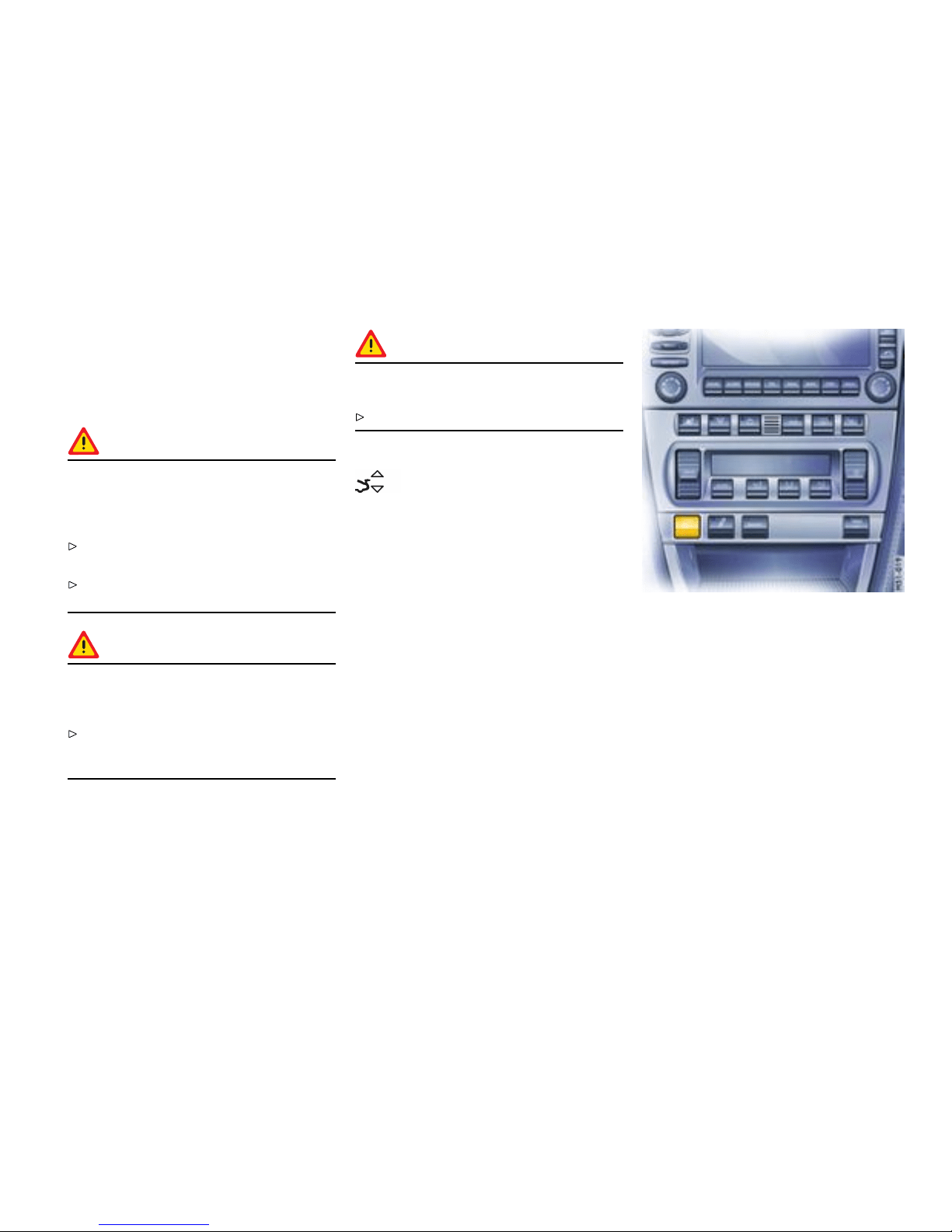
Retractable Rear Spoiler
Function
The rear spoiler improves driving stability, especial-
ly at higher speeds.
Warning!
Risk of accident. If the rear spoiler can not be
extended, driving stability will be adversely
affected by increased rear axle lift , which
could lead to loss of co ntrol.
Adapt your driving style and speed to the
change d driving behavior.
Have the fault remedied at an authorized
Porsche deal er.
Warning!
Risk of injury during manual retract ion or
extension of the rear spoiler with the vehicle
stationary.
Make sure that no persons or objects are
within the ra n ge of movement of the rear
spoiler.
Caution!
Risk of damage from pushing the vehicle by
the rear spoiler.
Do not push the vehicle a t the rear spoiler.
Warning light
The warning light i n the on-board computer lights
up when the rear spoiler does not extend over
75 m p h (120 km/h) or i ts end position is not
reached.
Autom atic control
The rear spoiler extends at approx. 75 mph
(120 km/h) and retracts again at approx. 50 mph
(80 km/h).
If the automatic control fails, the warning light lights
up and the rear spoiler must be manually extended
before driving.
Manual control
Manual extending and retractin g
When the ignition is on, the rear spoiler can be
extended and retracted manually using the button
in the center console.
Note
When the rear spoiler is extended manually, the
automatic control does not operate and the rear
spoiler must be manually retracted.
Controls, In s truments
75
Downloaded from www.ManualsFile.com manuals search engine

Extending
Press button briefly. The rear s poiler extends
to its final position. The l ight-emitt ing diode in
the button lights up. The rear spoiler remains
extended even after switching off the ignition.
Retracting
at speeds between 0 and 20 mph
(0 and 30 km/h): Press and hold button until
the rear spoiler has reached its fin al position.
The light-emitting diode in the butto n goes out.
The rear spoiler changes to automatic mode.
at sp eeds between 20 and 60 mph
(30 an d 100 km/h): Press button briefly.
The rear spoiler retracts, the light-emitting
diode in the button goes out. The rear spoiler
changes to automatic mode.
at speeds ov er 60 mph (100 km/ h): Press
button briefly. The rear spoiler remains
extended, the light-emitting diode in the
button goes out. Th e rear spoiler changes
to aut omatic mode.
Manually retracting an extended rear spoiler
after swit ching on the ig nition agai n
1. Press button briefly. The light-emitting diode in
the button lights up. The rear spoiler is now in
manual mode.
2. Press and hold button until the rear spoiler has
reached its final position. The light-emitting
diode in the button goes out. The rear spoiler
change s to automatic mode.
Fixed rear spoiler
Caution!
Risk of damage to rear spoiler.
Please consult the operator before using
autom atic car washes.
Do n ot push the vehicle by the spoiler.
76Controls, Instru ments
Downloaded from www.ManualsFile.com manuals search engine
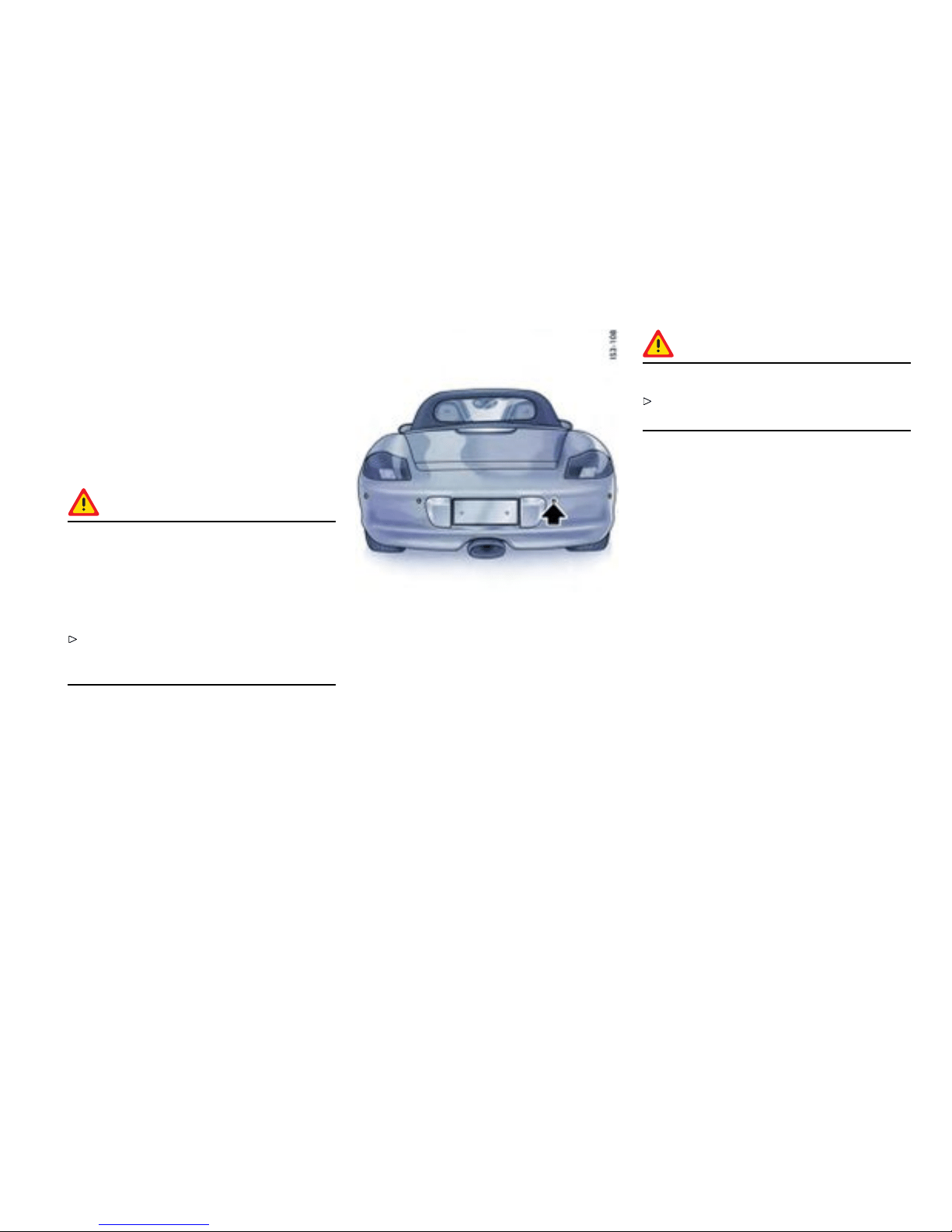
Parking Aids
Parking Assist ant (ParkAs sistant)
Function of the parking assistant
When the drive r bac ks up, the park ing as sistant
system indica tes the distan ce betw een the car
and a large obstacle behind it, by means of signal
tones.
Danger!
Risk of serious pe rsonal injury or death.
ParkAssistant cannot detect small objects
such as children and pets. Despite use of th e
parking assistant system, the driver is still
responsible for taking due care and assessing
obstacles when backing up.
Make su re that no persons, especially small
children, animals or obstacles are within the
maneuvring area.
The p arking assistant system is activated automati-
cally when reverse gear is selected and the ignition
is on.
Note
Be aware that the parking assistant system is
not sw itched on if the car rolls backward without
reverse gear being engaged.
Ultrasound sen sors
Sensors
Four ultrasou nd sensors in the rear bu mper
measure the distance to the closest obstacle.
– Range middle sensors around 60 in./150 cm
– Range outer sensors around 24 in./60 cm
Obstacles cannot be detecte d in the “blind” sensor
area (e.g. near the ground).
Note
The sensors mu st always be kept free of dust,
ice and snow in order to ensure that they are fully
functional.
Caution!
To avoid damaging t he sensors:
Maintain sufficient d istance when cleaning with
steam-jet units.
Signal ton es/function
When reverse gear is selected, the pa rking
assistant confirms that it is switched on by issuing
a short signal tone. A detect ed obstacle is
signalled by an intermittent tone. The intervals
decrease as the obstacle is approached. A
continuous tone sound s when the distance
becomes less than one foot . This continuous tone
can stop if the obstacle is approached closer than
one foot. The radio volume should not be so
loud as to d rown out the signal tones.
Limits of ultrasonic measurement
The parking assistant system cannot detect:
– sound-absorbing obstacles (e.g. winter
operati on, powder snow),
– sound-reflecting obstacles (e.g. glass
surfaces, flat painted surfaces)
– and very thi n obstacles.
Other ultrasound sources (e.g. pneumatic brakes
of other vehicl es, jack hammers) can interfere with
detection of obstacles.
Controls, In s truments
77
Downloaded from www.ManualsFile.com manuals search engine
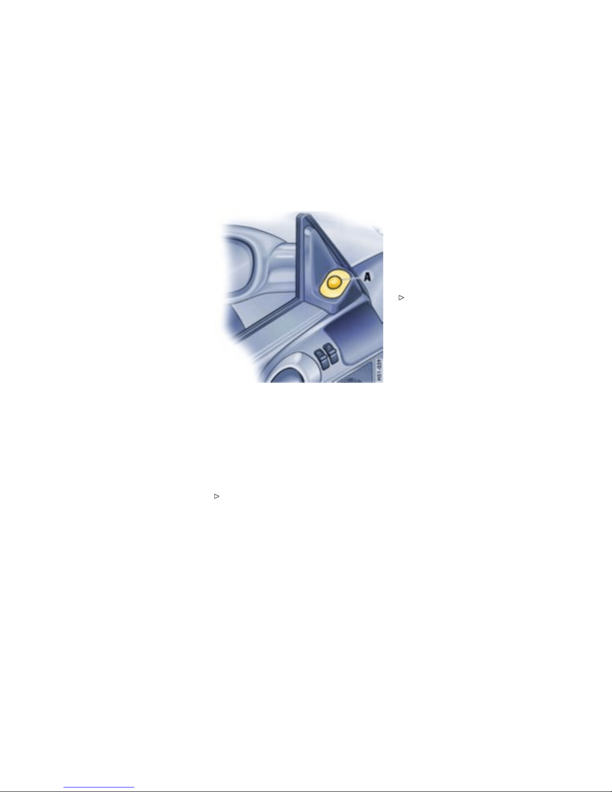
Fault indication
The p arking a ssistant system indicates a fault in
two ways:
– After reverse gear has been selected, the
short sign al tone is followed by a co ntinuous
tone of the same pitch: This ind icates that
sensors are soiled or covered with ice.
– After reverse gear has been selected, the
short sign al tone is followed by a co ntinuous
tone wi th a much lower pitch: This i ndicates
a gen eral syste m fault. Please have the fault
remedied at an authorized Porsche dealer.
A - Control switch for door mirror adjustment
Swivelling down m irror glass on t he
passenger’s side
Function
On vehicles w ith seat memory you can act ivate an
additional parking aid.
Please observe the chapter ”SEAT MEMORY”
on page 43.
– When reverse gear is engage d, the mirror
glass on the passenge r’s side swivels down
slightly to show the curb area.
Preconditions
– Vehicle must be equipped with seat me mory.
– Set th e control switch A to “passenger’s side”.
– Reverse gear must be engaged.
Returning mirror glass to its origi nal position
Drive forwards with a speed of over 4 mp h
(6 km/ h) or
– Set th e control switch A to “driver’s side”.
78Controls, Instru ments
Downloaded from www.ManualsFile.com manuals search engine

Operation, Instruments
Overvie w of the functions
1. Light switch
2. Turn signals/ headlight dimmer/flasher lever
3. Ignition Lock/locking the steering column
4. Hands-free m icrophone for telep hone
5. Horn
6. Windsh ield wiper/washer lever
7. Porsche Communication Management/Radio
8. Interior tempe rature sensor, GPS antenna
9. Emergency flash er switch
10. Ce ntral locking button, Re adiness display for
alarm system
11. C upholder
12. Operating lever f or on-board computer
13. Locking le ver for steering-wheel adjustment
14. Operating lever for cruise control
15. Co ntrol panel for heating, ventilation and air
conditi oning system
16. Buttons f or rear spoiler, Porsche Activ e
Suspension Man agement (PASM), S port Mode,
Porsche Stability Managemen t (PSM ), Sports
exhaust syste m
17. Seat heating, left/right
Controls, In s truments
79
Downloaded from www.ManualsFile.com manuals search engine
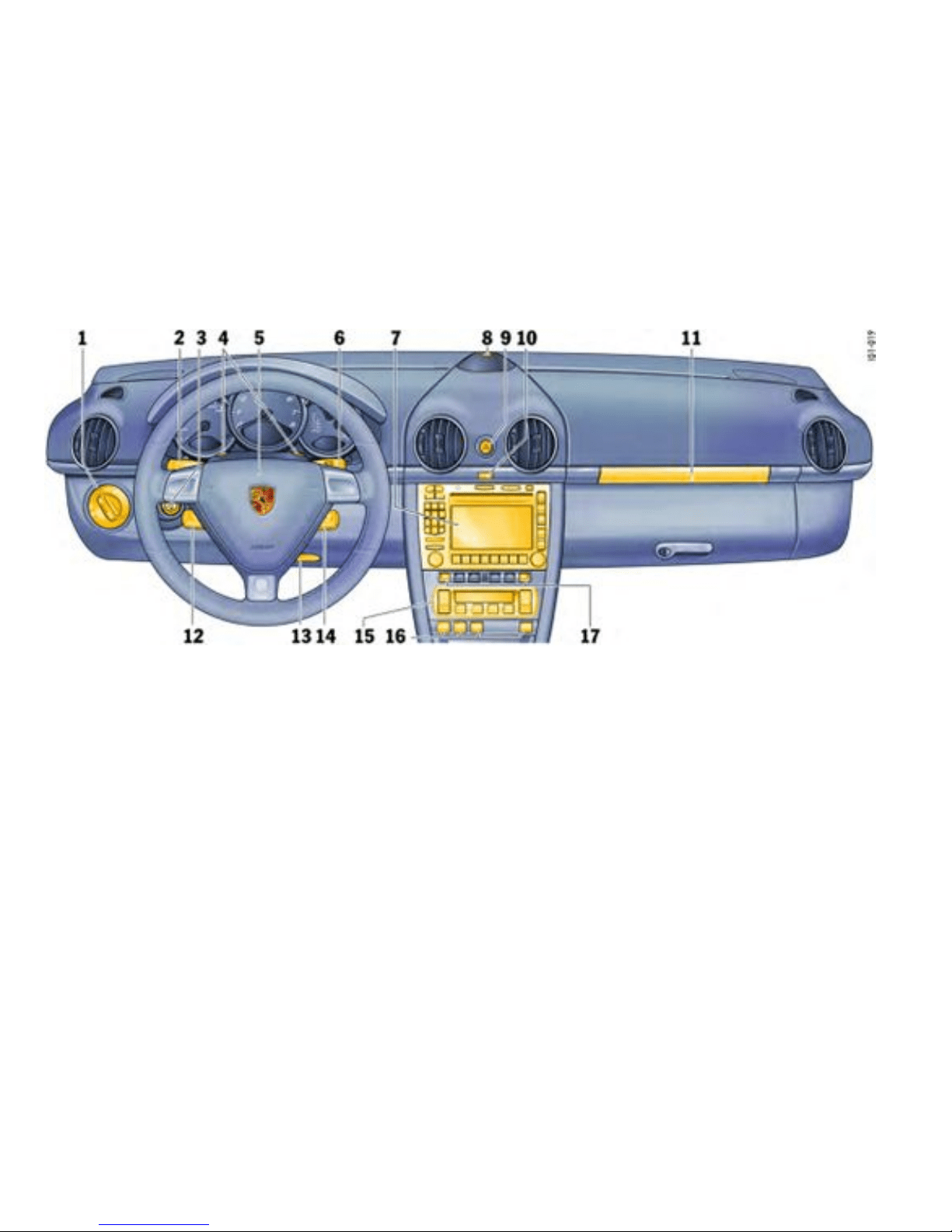
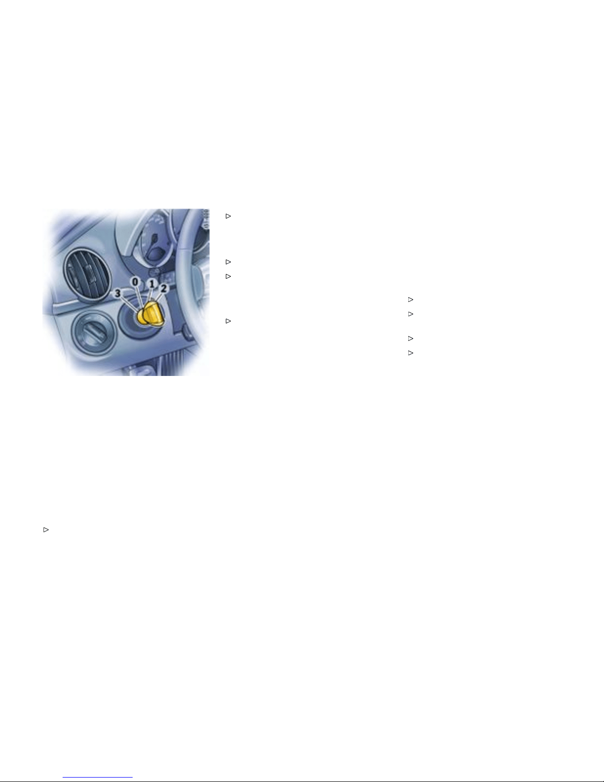
0 - Initial position
1 - Ignit ion on
2 - Start engine
3 - Ignit ion off
Ignition/Starter Swi tch with
anti-theft Steering Lock
The ign ition lock has a total of four ignit ion lock
positions. The ignition key rebounds to the initial
position from every ignition lock posit ion.
For your safety, fasten safety belts.
Please observe the chapter ”IMMOBILIZER” on
page 22.
Please observe the chapter ”KEY WITH RADIO
REMOTE CONTROL” on pag e 23.
Before starting the engine
Apply the foot brake.
Manual tran smission: Move the gearshift
lever into neutral. The clutch pedal must
be depressed fully before the starter will
engage.
Tiptronic: Mo ve the selector lever to P or N.
Switch p osition 0
Initial position
The ignition k ey cannot be withdrawn when the
ignition is switched on or when the engine has been
started.
To withdraw the ignition key:
Stop the vehi cle.
On vehicles with Tiptronic S: Move selector
lever to position P.
Switch igniti on off.
Remove ignit ion key.
Controls, In s truments
81
Downloaded from www.ManualsFile.com manuals search engine

Switch position 1
Ignition on
Turn ignition key to position 1. Ignition is
switched on.
Note on operation
All electrical equipment can be switched on.
Please observe the chapter ”SET BASIC
SETTIN G ON ON-BOARD C OMPUTE R” on page
131.
Switch position 2
Start engine
Turn ignition key t o ignition lock position 2.
Please observe the chapter ”STARTING AND
STOPPING ENGINE” on page 83.
Switch position 3
Ignition off
Turn ignition key t o ignition lock position 3.
Locking the steering colum n
Automatic locking
The steering column is automatically lock ed when
the ig nition key is w ithdrawn from the i gnition lock.
Warning!
Risk of an accide nt, resulti ng in serious
personal injury or death. The steering wheel
will l ock and wil l cause loss of steering.
Never remove ke y from the ignition lock or turn
the key off while the vehicle is moving.
Always withdraw the ignition ke y when
leaving the vehicle.
Automat ic unlocking
The steering column is automatically unlocked
when the i gnition key is inserted into the ignition
lock.
Note
To avo i d battery run - down, always remove the
ignition key from the ignition lock.
Please observe the chapter ”LOAD SWITCH-
OFF AFTER 2 HOURS OR 7 DAYS” on page
265.
Gong
If you leave the key in the ignition/steering lock, a
gong will sound when the driver’s door is ope ned.
This is a reminder to remove the key.
82Controls, Instru ments
Downloaded from www.ManualsFile.com manuals search engine
Starting and Stopping Engine
Starting Procedures
Please observe the chapter ”IMMOBILIZER” on
page 22.
Please observe the chapte r ”EMISSION
CONTROL SYSTEM” on page 225.
Warning!
Serious personal injury or death may result if
you a re involved in a collision wit hout having
fastened the safety belts.
Fasten safety belts before driving away.
Before starting the engine
Apply the foot brake.
Manua l transmission: Move the gearshift
lever into neutral. The clutc h pedal must
be depressed fully bef ore the starte r will
engage.
Tiptronic: Move the selector lever to P or N.
Temperature sensors on the engine automatically
provide the correct fu el/air m ixture required
for starting. Therefore, it is not necessary to
depress the accelerator pedal while starting a
cold o r a warm engine.
Starting the engine
Turn ignition key to ignition lock position 2.
As soon as the engine starts, release the
ignition key.
The first operation of the starter is ended automat-
ically when the engine starts. If the engine does
not start, subsequent s tarter operations will not be
ended automatically.
If the engine fails to start after 10 or 15 seconds of
cranki n g:
Wait about 10 se conds before engaging th e
starter again.
When starting the engine, be ready to drive
immediately. Drive vehicle at moderate
speeds and avoid en gine speeds above
4200 rpm during the first 5 mi nutes.
Do not let the engine idle to warm up.
Danger!
Engine exhaust fumes have man y compo-
nents which you can smell. They also contain
carbon mon oxide (CO), which is a colorless
and odorless gas. Carbon mon oxide c an
cause unconsciousness and even death if
inhaled.
Never start or let the engine run in an
enclosed, unventilated area. It is not rec-
ommended to sit in your car for prolonged
periods with the engine on and the car not
moving.
Danger!
An unattended vehicle with a r unning engine
is po tentially hazardous. If warning lights
should come on to indicate improper opera-
tion, they would go unnoticed.
Never leave the engine idl ing unattended.
Danger!
Dange r of re.
Do not park or operate the vehicle in areas
where the hot exhaust system may come in
contact with dry grass, brush, fuel spill or
other flammable material.
Controls, In s truments
83
Downloaded from www.ManualsFile.com manuals search engine
If your car c atches on fire for any reaso n, call
the fire depart ment. Do not endang er your life
by attempting to put out the fire.
Stoppi ng engine
Turn key back to p osition 3.
Do not stop engine immediately after hard
or extended driving. Keep engine runn ing
at inc reased idle for abou t two minutes to
prevent excessive heat build-up before turning
off engine.
To avoid battery run-down, always remove the
ignition key from the i gnition lock.
Make sure that whe n you leave the car, even
briefly, you have withdrawn the ignition key.
Engage the steering lock by moving the
steering whee l to th e left or right. Turn
the ste ering w h eel to t h e loc king position
before you switch off the engine so that you
don’t have to exert yourself when lock ing or
unlocking the steering.
Warning!
Danger of injury. Hot engine compartment
comp onents can burn skin on contact.
Before worki ng on any part in the engine
compartment, turn the e ngine off and let i t
cool down sufficiently.
Engine-compartment blower, radiator fan
The radiator and radiator fans are in the front of the
car. The engine-compartment blow er is mounted in
the engine compartment.
Warning!
Risk of injur y. After the eng ine is switche d
of f, the engine-comp artm ent temperatures
is monitored for approx. 30 minutes. During
this period, and depend ing on temperature,
the engine-compartment blowe r may cont in-
ue to run or start t o run.
Carry out work in these areas only with the
engine off and exercise extreme caution.
Warning!
Risk o f injury. T he radiator f ans in the f ront
end of the car may be operating or unex-
pectedly start operating when the engine is
switched on.
Carry out w ork in these areas only with the
engine switched off.
Auto matic garage door
The ign ition sy stem in your Porsche may interfere
with your electronically operated garag e door.
To check this, drive your Porsche clo se to the
garage door. Make s u re not to interfere with
the operating rang e of the door.
Run the engine at different speeds.
If the garage door opens or closes without you
operating the garage door unit in your car, contact
the dealer who installed the automatic garage door
to have the frequency and/or coding of th e garage
door signal changed or modified.
84Controls, Instru ments
Downloaded from www.ManualsFile.com manuals search engine

Instrument Panel USA Models
Overview
Also refer to the corresponding chapte r in the
Owner’s Manu al.
1. Speedo m eter with analogue display
2. Tire pressure warning light
3. Turn signal indicator light left/right
4. Tachometer
5. High beam indicator light
6. ABS warning light
7. Cooling system Temperature gauge, warning
light
8. Fuel Level gauge, warning lig h t
9. Adjusting butt on for instrument illumination
and tri p counter
10. Odometer and daily trip mileage display
11. Automatic speed control in d icator li ght
12. L ight sensor for instrument illumination
13. Airbag warning lig ht
14. Emission control warnin g light (Check Eng ine)
15. Ce ntral warning light
16. On-board computer display
17. Po rsche Sta bility Management Multifunctional
PSM light
18. Brake warning light
19. Sa fety belt warning light
20. Tiptronic indicat or
21. Cl ock and outside temperature display
22. Adjustment button for clock
When the ignition is s witched on, the warning
lights light up for a lamp c heck.
Note
Warnings that have been given are stored in the
appropriate control uni t mem ory and can be read
out at an authorized Porsche dealer.
This information can help to warn you about
situatio ns whic h may be hazardous to you or your
car.
Controls, In s truments
85
Downloaded from www.ManualsFile.com manuals search engine
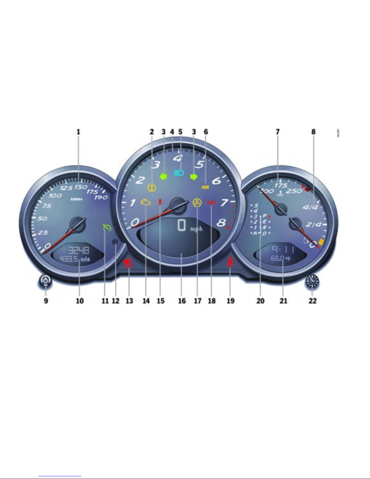

Instrumen t Panel Canada Mo dels
Overview
Also refer to the corresponding chapte r in the
Owner’s Manu al.
1. Speedo m eter with analogue display
2. Tire pressure warning light
3. Turn signal indicator light left/right
4. Tachometer
5. High beam indicator light
6. ABS warning light
7. Cooling system Temperature gauge, warning
light
8. Fuel Level gauge, warning lig h t
9. Adjusting butt on for instrument illumination
and tri p counter
10. Odometer and daily trip mileage display
11. Automatic speed control in d icator li ght
12. L ight sensor for instrument illumination
13. Airbag warning lig ht
14. Emission control warnin g light (Check Eng ine)
15. Ce ntral warning light
16. On-board computer display
17. Po rsche Sta bility Management Multifunctional
PSM light
18. Brake warning light
19. Sa fety belt warning light
20. Tiptronic indicat or
21. Cl ock and outside temperature display
22. Adjustment button for clock
When the ignition is s witched on, the warning
lights light up for a lamp c heck.
Note
Warnings that have been given are stored in the
appropriate control uni t mem ory and can be read
out at an authorized Porsche dealer.
This information can help to warn you about
situatio ns whic h may be hazardous to you or your
car.
Controls, In s truments
87
Downloaded from www.ManualsFile.com manuals search engine
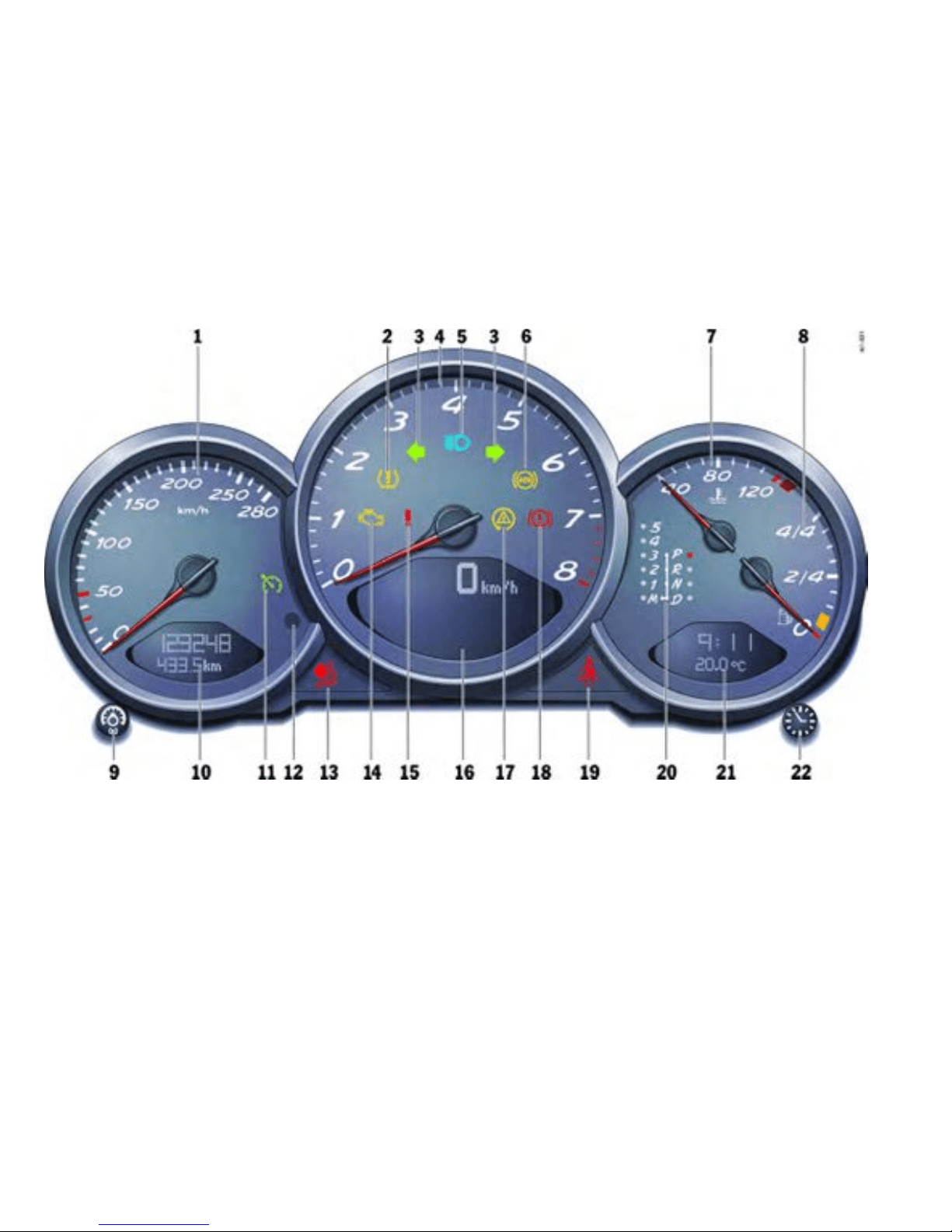
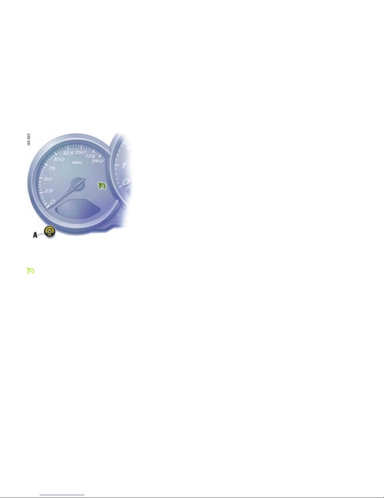
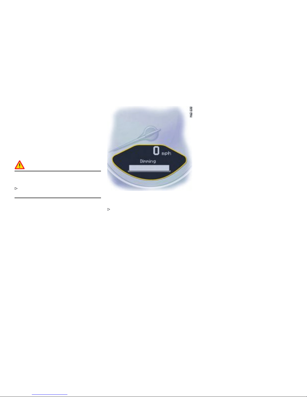
Instrument Illumination
Function
The illumination is au tomatically adjusted to the
ambient brightness by the light sensor in the
tachom eter.
In addition, when the car lights are switched on, the
instrument and switch symbol brightness can be
manually adjusted.
Warning!
Risk of loss of cont rol or an accident, resulti ng
in personal in j ury or death.
Do not reach through the steering-w heel
spokes while driving.
Dimming instrument illumination
Turn adjustment button A in the appropriate
direction and hold it until the desired bright-
ness has been reached. The ch osen level of
brightness is indicated by a bar display in the
display field of the on-b oard compute r.
Note
When the car lights are switched on, the scale light-
ing for light dials switches on and off automatically
depending on the ambient brightness.
90Controls, Instru ments
Downloaded from www.ManualsFile.com manuals search engine
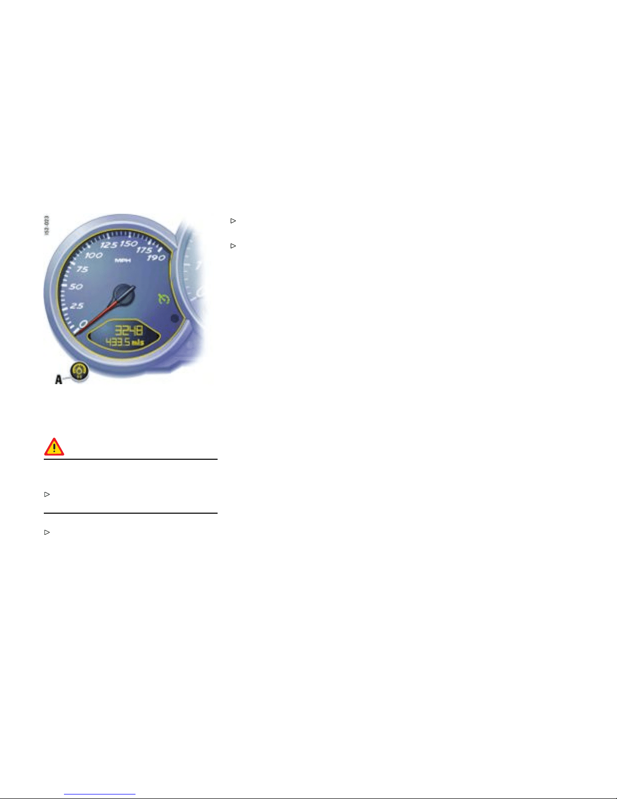
Trip Odometer
Resetting to zero
Warning!
Risk of loss of c ontrol or accident, resulting in
personal injury or d eath.
Do not reach through the steering-w heel
spokes while drivin g.
Press adjustment button A for approximately
one s econd or
Reset the distance in the “SET” menu of the
on-board computer.
Please obse rve the chapter ”SET BASIC
SETTING ON ON-BOARD COMPUTER” on page
131.
After exceedi ng 6213 miles or 9999 kilometers,
the counter returns to “0”.
Controls, In s truments
91
Downloaded from www.ManualsFile.com manuals search engine
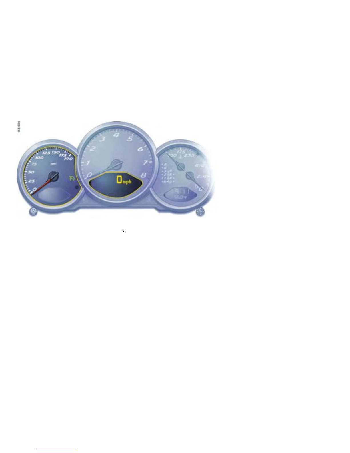
Speedometer
Indication
The di gital speedometer is integrated in th e
on-board computer. The indication changes from
mph t o km/h when the units are c h anged from
miles to kilometers.
Changi ng over between Miles / Ki lometer s
The units of the distance and speed displ ays can
be changed in the “ SET” menu of the on-board
computer.
Please observe the chapter ”SET BASIC
SETTING ON ON-BOARD COMPUTER” on p age
131.
92Controls, Instru ments
Downloaded from www.ManualsFile.com manuals search engine

Tachometer
Indication
The t achomete r shows the e ngine s peed in
revolutions per minute (rpm). The begin n ing of
the red marks at the right end of the scale indicates
the maximum permissible engine rpm. A sp eed
limiter prevents the engine from being overrevved
during acce leration. Before reaching this area, the
next higher gear should be selected. Shif t to the
next lower ge ar when the engine rpm drops below
1500 rpm.
Caution!
To a void severe engine damage.
Always observe the engine rpm before
down-s hifting to a lower gear, so you do not
exceed the maximum engine rpm.
Turn Signal Indicator Light
Indication
Flashes in synchronism with the turn s ignals.
Left arrow - left turn signals
Right arrow - right turn signal s
If the frequency of the displ ay becomes
noticeably fast er, check the operation of the
turn signals.
High Beam
Indicator light
Lights when high beam or headlight flasher is
switche d on. The indicator l ight goes out when the
high b eams are switched off.
Controls, In s truments
93
Downloaded from www.ManualsFile.com manuals search engine

Cooling system
Temperature gauge (ignition on)
USA: Display i n F
Canada: Display in C
Pointe r to th e left - engine cold
Avoid high engine speeds and heavy engi n e
loading.
Pointer in the middle - normal operating temper-
ature
The po inter may move up t o the red area when
engine is heavily loaded and outside temperature
is high, but should return to “normal” when engin e
load is reduced.
Warning light “A”
If the coolant temperature is too high, the
warning light comes on. Additionall y, a warning
is displayed in the on-board computer.
Pull off the road, turn off the engine and allow
to cool.
Check radiator and air passages in front end of
car for obstructions.
Check coola nt level. If necessary, add coo lant
and have fault remedied at an author ized
Porsche dealer.
Please observ e the chapter ”COOLANT
LEVEL ” on page 21 0.
Note
To prevent excessive temperatures, the co oling-air
passag es must not be restricted by coverings (e.g.
films, “stone guards”).
If the coolant level is to o low, the warning li ght
ashes. Additionally, a warning is displayed in the
on-board computer.
Switch engine off and allow to cool.
Add coolant.
Have the cause of the fault remedied at an
authorized Porsche dealer.
Please observe the chapte r ”COOLANT
LEVEL” on page 210.
Caution!
Risk of engine damage.
If the warning lights come on even though
coolant level is correct, do not continue
driving .
Have the fault remedied at the nearest
authorized Porsche dealer.
Engine compa rtment blo wer fan
In addition, this warning light ashes to indicate a
fault in the engine compartment blower fan.
Have the caus e of the fa ult remedied at a n
authorized Porsche dealer.
94Controls, Instru ments
Downloaded from www.ManualsFile.com manuals search engine

Tiptronic S
Indica tor for selector lever position and
engag ed gear
When the engine is running, the sel ector lev er
positio n and engaged gear are indicated.
If the selector lever is between two
positions:
– The corresponding selector lever position in
the instrument cluster flashes and
– The warning “Selector leve r not engaged”
appears on the display of the on-board
computer.
Engage the selector lever correctly.
If there is a fault in the transmission:
– The display for 4th gear and the engaged
selector lever position flash on and off
alternately.
– The warning “Tiptronic emergency run”
appears on the on-board computer.
Please observe the chapter ”EMERGENCY
PROGRAM” on page 191.
Have t h e fault repaired immed iately at an
authorized Pors che dealer.
Please observe the chapter ”TIPTRONIC S” on
page 187.
Controls, In s truments
95
Downloaded from www.ManualsFile.com manuals search engine
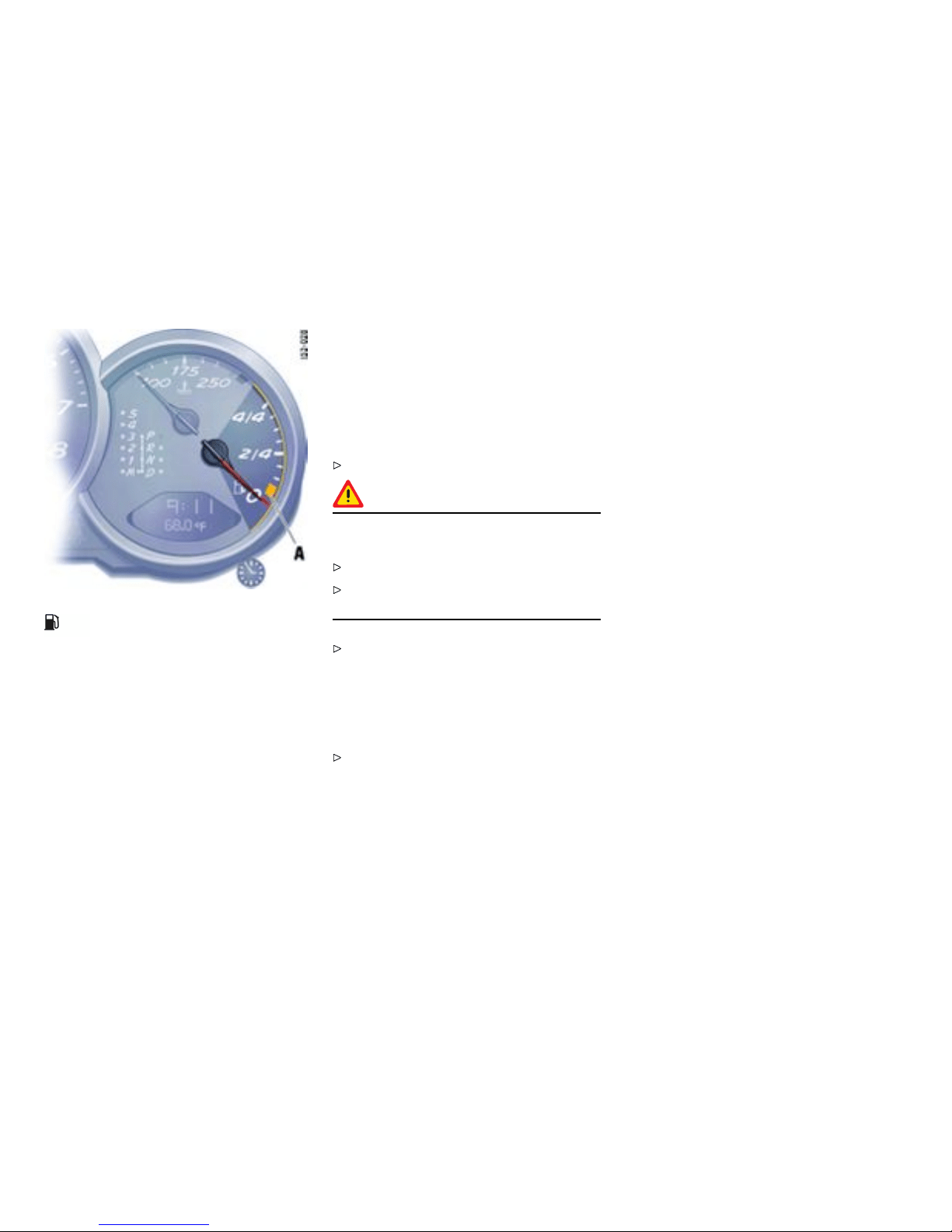
Fuel
Level gauge
When the ignit ion is on the fuel level is displayed.
Refill vo lume approx. 16.9 U.S.gallons (64 liters).
If the vehicle’s inclination changes (e.g. going up
or downhill), m inor deviations in the indication may
occur.
Note
If a small quantity of fuel is added to a near l y empty
fuel tank, the fuel gauge cannot measure the add ed
fuel accurately. The ”remaining range“ readout will
also be inco rrect.
Warning light “A”
When the engine is running, th e warning light
of the level gauge lights up if less than approx.
2.6 U.S.gallons (10 liters) of fuel remains in the
tank or the range on remaining fuel falls below
approx. 30 miles (50 km). Additionally, a warnin g is
displayed in the on-board computer.
Fill up at the next opportuni ty.
Caution!
To prevent damage to the emission cont rol
system and engine.
Never drive the tan k com pletely o ut of fuel.
Avoid high cornering speeds after the warning
lights have come on.
Please observe the chapter ”EMISSION
CONTROL SYSTEM” on page 225.
If the level gauge warning lig ht ashes, there
has been a system fault. Addition ally, a warning is
displayed in the on-board computer. There will th en
be no reserve warning.
To remedy the fault, go to an authorized
Porsche dealer.
96Controls, Instru ments
Downloaded from www.ManualsFile.com manuals search engine
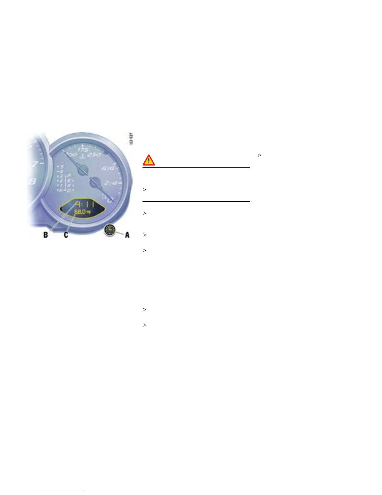
A - Adjustment bu tton for clock
B - Clock
C - Outside temperature display
Clock
Automatic switching off
The clock is blanked out approximately four
minutes after the ignition is switched off or w hen
the car is locked.
Setting the time
Conditi on
Warning!
Risk of loss of control or acc ident, resulting in
serious personal injury or death.
Do not reach through the steering-w heel
spokes while driving .
Switch ignition on.
Setting hours
Press adjustment button A for about one
second. Hour display flashes.
Turn bu t ton in the appropriate direction :
to righ t - increase hours figure
to left - decrease hours figure.
Adjustment in hours - turn button briefly.
Fast adjustment (display cycles) - turn and hold
button.
Setting minutes
Press adjustment button a gain. Minutes
display flashes.
Set by rotating as in ho urs mode.
Leaving adjustment m ode
Automatically after one minute or:
Press adjustment button again.
When adjustment mode is deliberately left by
pressing the butto n, the time begins precisely
to the seco nd.
Note
The ti me mode can be changed between 12 h and
24 h in the on-bo ard computer.
Outside temperature
The outside temperatu re di splay C does not
indicate, if ice is on the road. Even if a temperature
above 32°F (0°C ) is displayed, ice may still form
on the road, for instance on bridges or whe n the
road passes through a heavily shade d area.
Controls, In s truments
97
Downloaded from www.ManualsFile.com manuals search engine

Battery
Droppi ng battery vo ltage
If the batter y voltage drops abruptly, a warning
message will be displayed by the on-board
computer.
If the warni ng is displayed by the on-board
computer while the engine is running or while
driving:
Stop th e car in a safe place and stop the
engine.
Possible causes
– Defect in the batte ry charging system.
– Broken drive belt.
Warning!
Risk of engine damage with resultant loss
of control and accident, leading to serious
person al injur y or death. A broken drive belt
means there is no power assistance to the
steering (more effort is required to steer) and
coolant pump function will stop.
Do not cont inue driving.
Have the fault remedied at the nearest
authorized Por s che dealer.
98Controls, Instru ments
Downloaded from www.ManualsFile.com manuals search engine

Check Engine Warning Light
The warning light in the instrument panel co mes on
when the ignition is first turned on and remains on
briefly as a bulb check. If the light does not c ome
on, have the bulb replaced promptly.
If the warning lights in the instrument panel and
on-board computer come on and remain on while
driving, it suggests:
– a potential engine control problem and the
need for system service or
– an imp roperly fastened tank cap or
– refueling with eng ine runni ng.
Please observe the chapter ”WAR NINGS
ON THE INSTRUMENT PANEL AND THE
ON-BOARD COMPUTER” on page 134.
Although the vehicle is usua lly driveable and will not
require towing, see your dealer for service as soon
as poss ible.
Caution!
If the Check engine light in the instrument
panel is ashing, severe catalytic converter
damage and power loss will soon occur.
Prolonged d riving with the Check engine
light on cou ld cause damage to the emission
control system. It also could affect fu el
economy and driveability.
Have t h e fault remedied at the nearest
authorized Pors che dealer immediately.
Controls, In s truments 99
Downloaded from www.ManualsFile.com manuals search engine

Central Warning Light
Warning messages in the INFO me nu
The central warning light on the instr u ment panel
lights up if there are warning messages in the INFO
menu.
The m essages can be called in the on-bo ard
computer INFO menu:
Please observe the chapte r ”INFO WARNING
MESSAGES” on page 108.
100Controls, Instruments
Downloaded from www.ManualsFile.com manuals search engine

Brake Warning Li ght
Indication
Brake warning lig ht USA
Brake warning light Canada
The w a rning lig h t on the in strument panel lights up:
– if the handbrake is on,
– if the brake fluid level is low,
– if the brake pads have reached the wear limit,
– if the brake circuit division is defective.
Addition ally, a warning is displayed by the on-board
computer.
Please observe the chapter ”WAR NINGS
ON THE INSTRUMENT PANEL AND THE
ON-BOARD COMPUTER” on page 134.
Controls, Instruments
101
Downloaded from www.ManualsFile.com manuals search engine
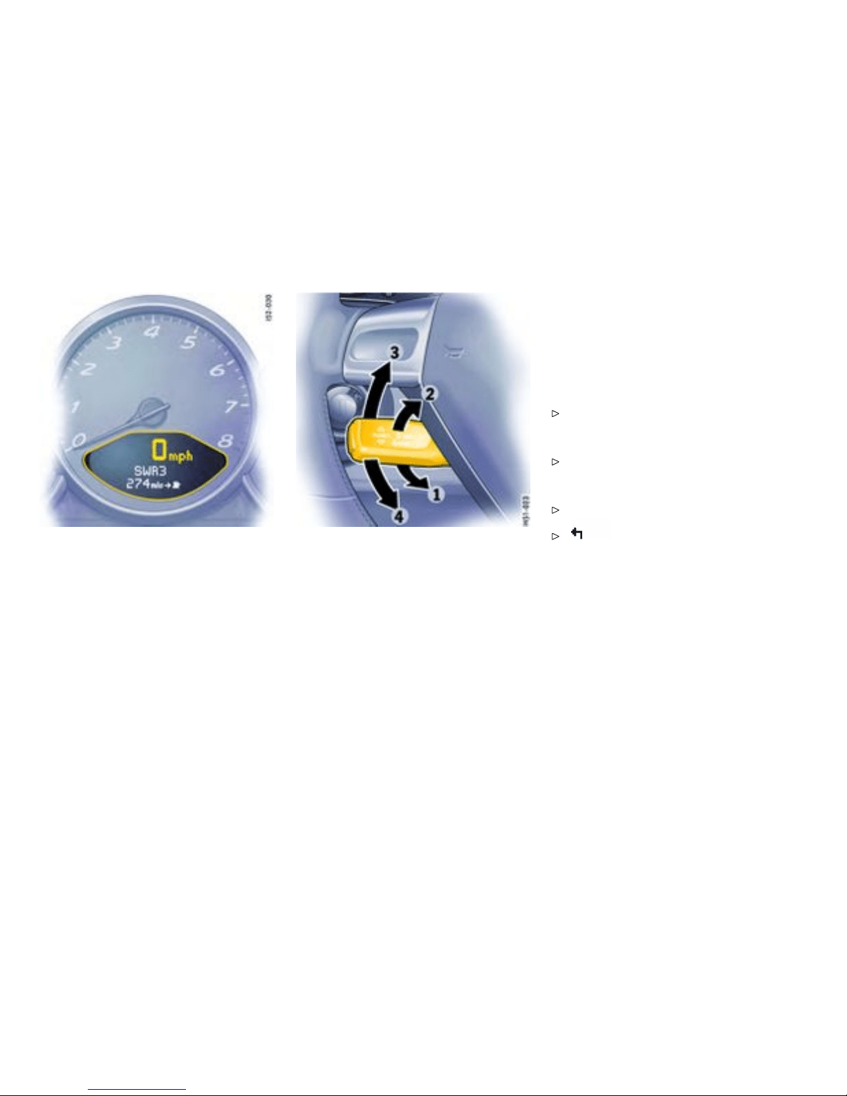
On-Board Compute r (BC)
Display eld
The d isplay field is beneath the tachometer.
Readiness for operation
– With ignition switched on,
– with engine running.
Operation, controls
It is not possi ble to describe all details of the
on-board computer functions in this Owner’s
Manual. However, the examples will quickly
familiarize you with the operational principle and
help you to navigate through the menu structure.
You can restore the factory default settings at any
time by using the “SET” menu.
Operating lever
Operation
The on-board computer is operated with the lo wer
left le v er on the steering column.
Selecting functions of the on-board computer
Push lever up 3 or down 4.
Conrming selection (Enter)
Push the lever forward 1.
Moving ba ck one or sev eral selection levels
Pull the lever back 2 once or several t imes or
Select the arrow on the on-board
computer display with the operating lever and
push the operating lever for ward 1.
Note
You can always return to the basic menu by pulling
the operating lever several times.
102Controls, Instruments
Downloaded from www.ManualsFile.com manuals search engine
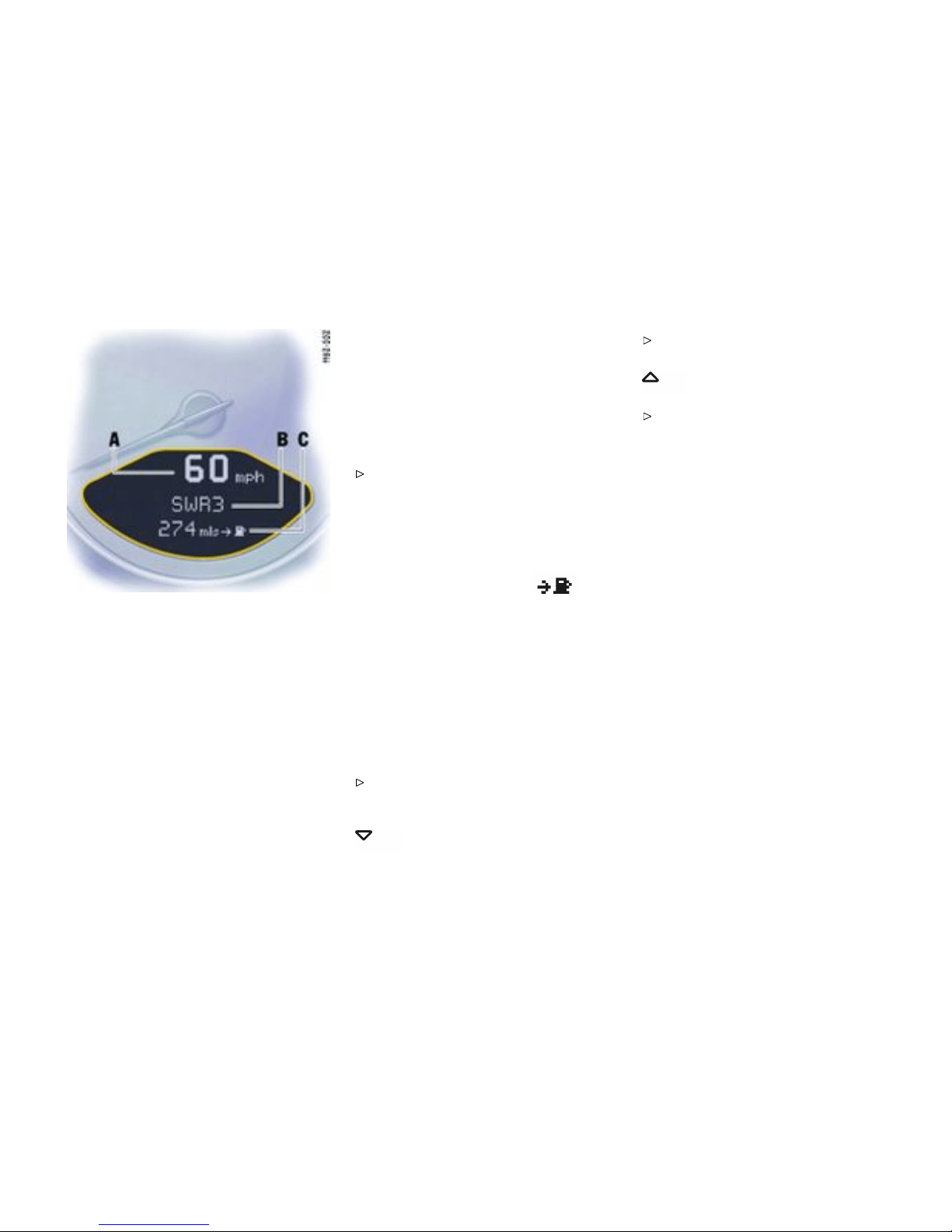
A - Digital speedometer
B - Central display
C - Bottom display
Functi ons and display possibilities
Options
Note
The available it ems and displays in the on -board
computer depend on the equi p ment of your
vehicle. For thi s reason it is pos sible that some of
the items and displays shown here are not available
in your on-bo ard computer.
Basic setting
– Central display: .... Radio stati on
The central line B o f the on-board computer can be
selected in th e SET menu.
Calling o n-board co mputer functions in display
“C”
Push operating lever up or down (selection
field D must be switched off).
The following displays can be called step by step:
– Average speed (ø mph),
– Average consumption (ø mpg),
– Rang e on remaining fuel (mls
).
– Tire pressure
– Navigation information (if activated in the SET
menu).
Note
The values “A v erage s peed”, “Average con sump-
tion” and “Daily trip mileage” can be reset t o zero in
the S ET menu.
Switching selection eld “D” on or off
Push operating lever forward or back.
Arrow symb ol “E” for continuation
Arrow symbol
Push operating lever down in order to pag e
through the menu.
Arrow symbol
Push operating lever up i n order to page
through the menu.
Controls, Instruments
103
Downloaded from www.ManualsFile.com manuals search engine

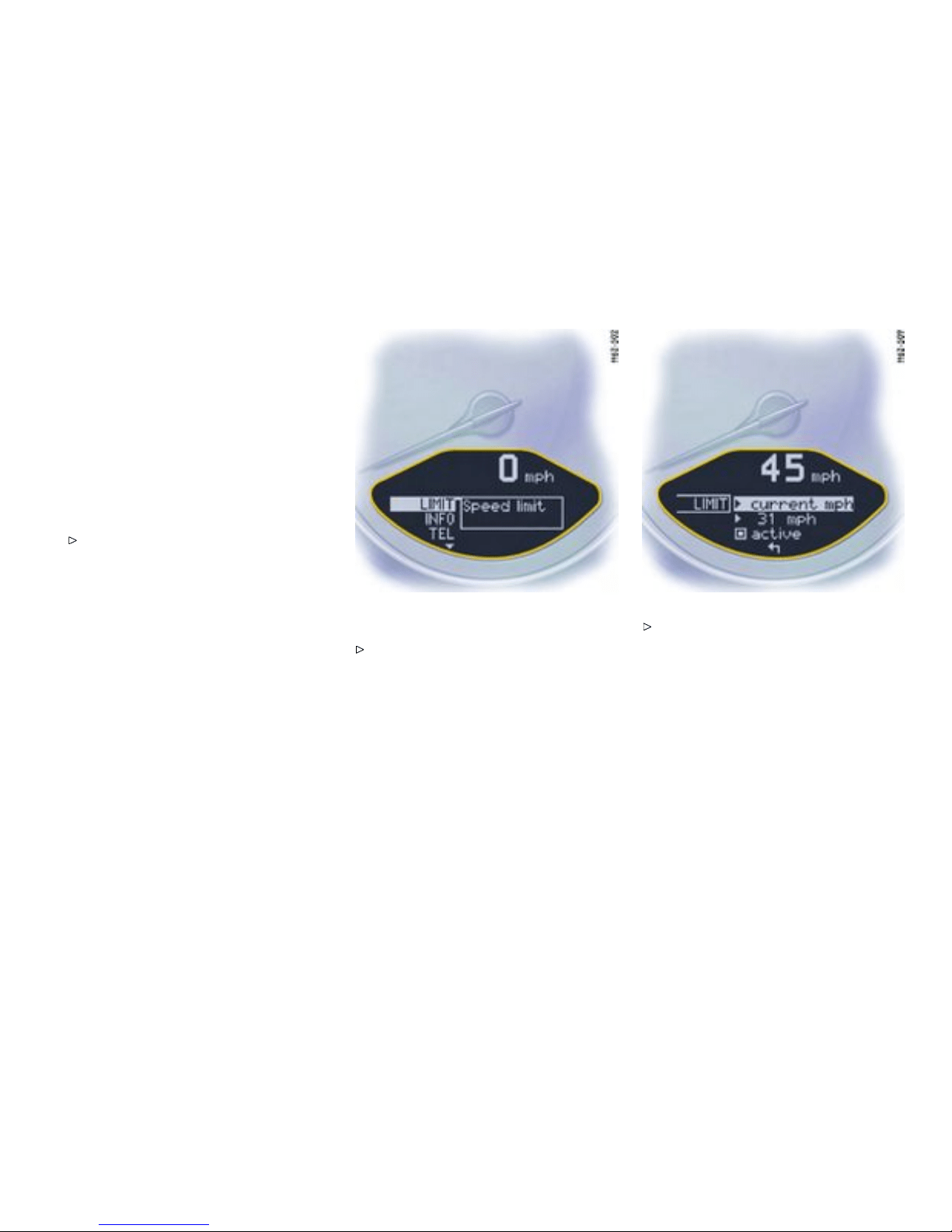
LIMIT Acoustic warning signal for
speed limit
Function
The acoustic warning signal can be activated for
speeds above 6 m ph (10 km/h). The signal sounds
when the preset speed is exce eded. Fo r the signal
to sound again, the driving speed must fall below
the preset speed by at l east 3 mph (5 km/h).
Switching on selection eld “D”
Push op erating lever fo rward.
Settin g the spee d
Select LIMIT with the operating lever.
Push operating lever forward.
Controls, Instruments
105
Downloaded from www.ManualsFile.com manuals search engine

Option 1 : Acc epting current spe ed
Push operating lever forward.
The acoustic warning signal is ac tivated f or the
current speed.
Display:
Option 2: Presetting speed
Select “LIM I T active” with the operating lever:
not active
active
If “not active”, push the operating lever
forwa rd.
Select “xx mph” with t he operating lever.
Push operating lever forward.
106Controls, Instruments
Downloaded from www.ManualsFile.com manuals search engine

Push o perating lever slightly up or down until
the desired speed is reached.
upwards: speed is increased
downwards: speed is decreased
Note
Holdin g the lever up or down for a longer period will
adjust the speed in step s of 6 mph (10 km/h).
Push op erating lever fo rward.
Switch ing the acoustic warning signa l of f
Select “LIMIT active” with the operating lever.
Push op erating lever fo rward.
Display:
Controls, Instruments 107
Downloaded from www.ManualsFile.com manuals search engine

INFO W arning me ssages
Switching on selec tion eld “D”
Push operating lever forward.
Calling warning messages
Select INFO with the operating lever.
Push operating lever forward.
Any existing warning message s can be called
using the operating lever. You also can call warning
messages which were cancelled during the trip (but
only until the next time the ignitio n is switched on).
Push operating lever forward.
Push operating leve r forwards or pull back-
wards. The display returns to the Info menu.
108Controls, Instruments
Downloaded from www.ManualsFile.com manuals search engine
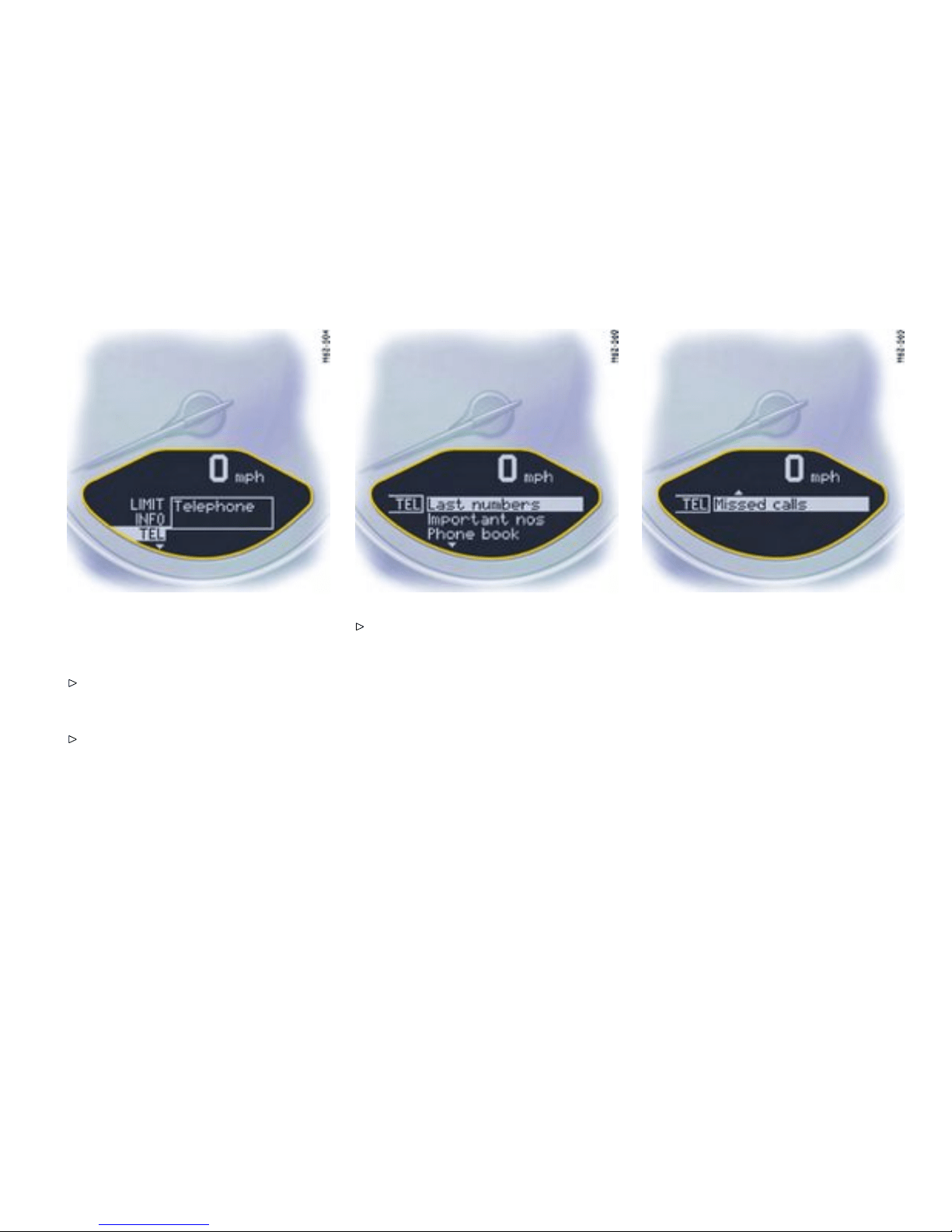
TEL Te lephone i nformation
Switching on selection eld “D”
Push op erating lever fo rward.
Calling telephone informat ion
Select TEL wi th the operati ng lever.
Push operating lever forward. Note
You can recall phone calls, e.g. calls that arrived
during your absence, via the menu item “Missed
calls”.
Controls, Instruments
109
Downloaded from www.ManualsFile.com manuals search engine
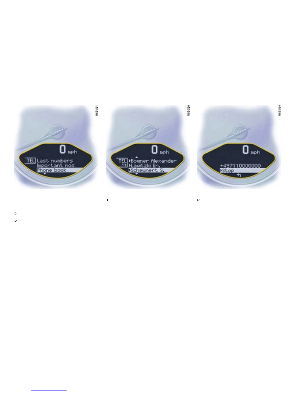
Example: Selecting from the telephone
book and calling
Select “Phone book” with the operating lever.
Push operating lever forward.
Select a person to call and push the operating
lever forward. The connection is esta blished.
Push the operating lever forward to end the
call.
110Controls, Instruments
Downloaded from www.ManualsFile.com manuals search engine
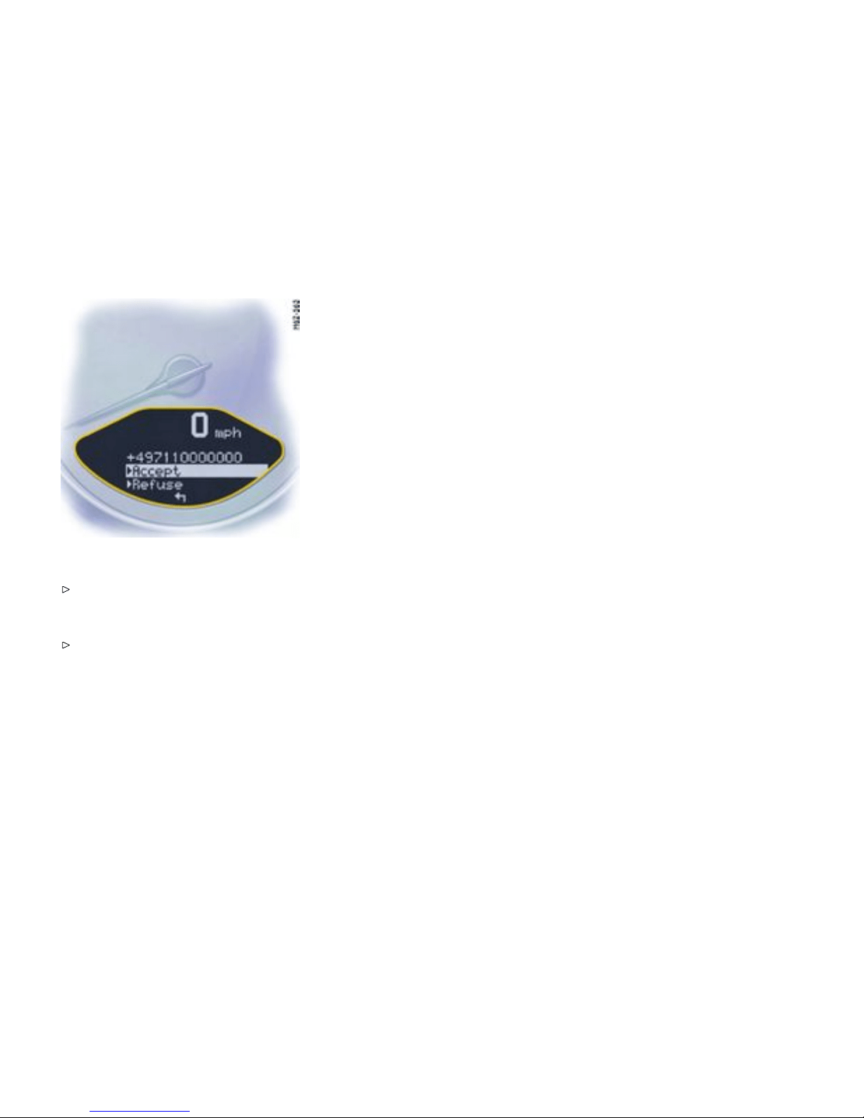
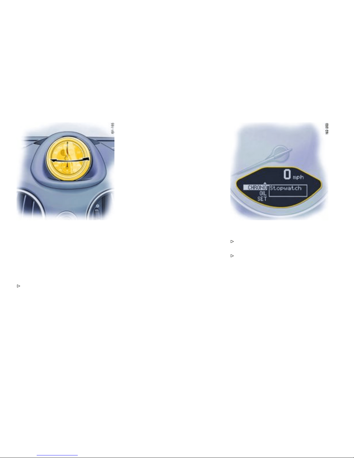
CHRONO Stopwatch
Function
You can use the stopwatch to m easure time
intervals, e.g. on the race circuit or on work-related
journeys. Measured lap times can be stored and
evaluated if the vehicle is equipped with Porsche
Commun ication Management (PCM).
Please observe the chapte r “Sport display” in
the separate PCM operating instructions.
Stopwatch on the instrument p anel
The stopwatch has an analogue and a digital
display. The large pointer of the analogue disp lay
measures the seconds. The two small pointers
measure hours and minutes. The display re-starts
at ze ro after 12 hours. Seconds and increments
of 1/100th of a second can be read on the digital
display. The digital display and the d isplay in the
on-board computer can indicate up to 99 hour s and
59 minutes.
The stopwatch can be swiv elled both to the left and
to the right.
Stopwatch displays:
– on the stopwatch on the instrument pane l,
– in the on-board computer menu CHRONO,
– on the performance displa y in the P CM.
Starti ng/stopping stop watch
All stopwatch displays are started and stopped via
the on-board computer menu CHRONO.
Note on operation
When you leave the CHRONO me nu while the
stopwa tch is running, measurement will continue.
The stopwatch stops after the ignition is switched
off. If the ignition is switched on again within
approx. 4 minutes, the stopwatch will continue
to ru n .
The on ly way to reset the stopwatch to zero is by
selecting “Rese t” in the CHRONO me nu.
Starting the timing
Push operating lever forward. The selection
field is switched on.
Select CHRO N O with the operating lever.
112Controls, Instruments
Downloaded from www.ManualsFile.com manuals search engine
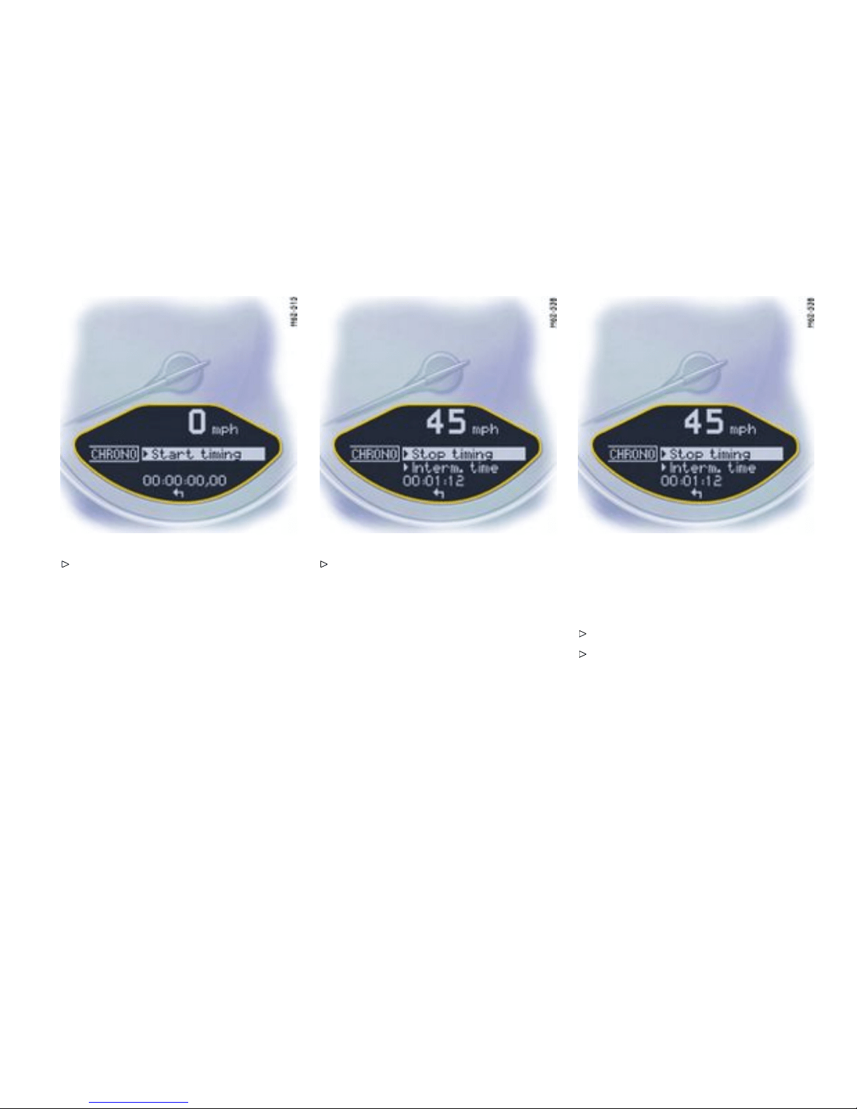
Push op erating lever fo rward. Push operating lever forward. The time runs
on all stopwatch displays. The on-board
computer displ ay changes to the “Stop
timing/Intermediate time” selection.
Note
PCM: The p erformance display in the “Trip/Sport
display/Begin trip” menu must be selected in order
to an alyse th e data in th e PCM.
Stopping the timing
After time measurement is started, the on-board
compu ter display changes to the “Stop tim-
ing/Intermediate time”.
Select “Stop timing” with the operating lever.
Push lever forward. The time is stopped in all
stopwatch displays, and the on-board compu-
ter d isplay changes to the “Continue/Reset”
selection.
Controls, Instruments
113
Downloaded from www.ManualsFile.com manuals search engine
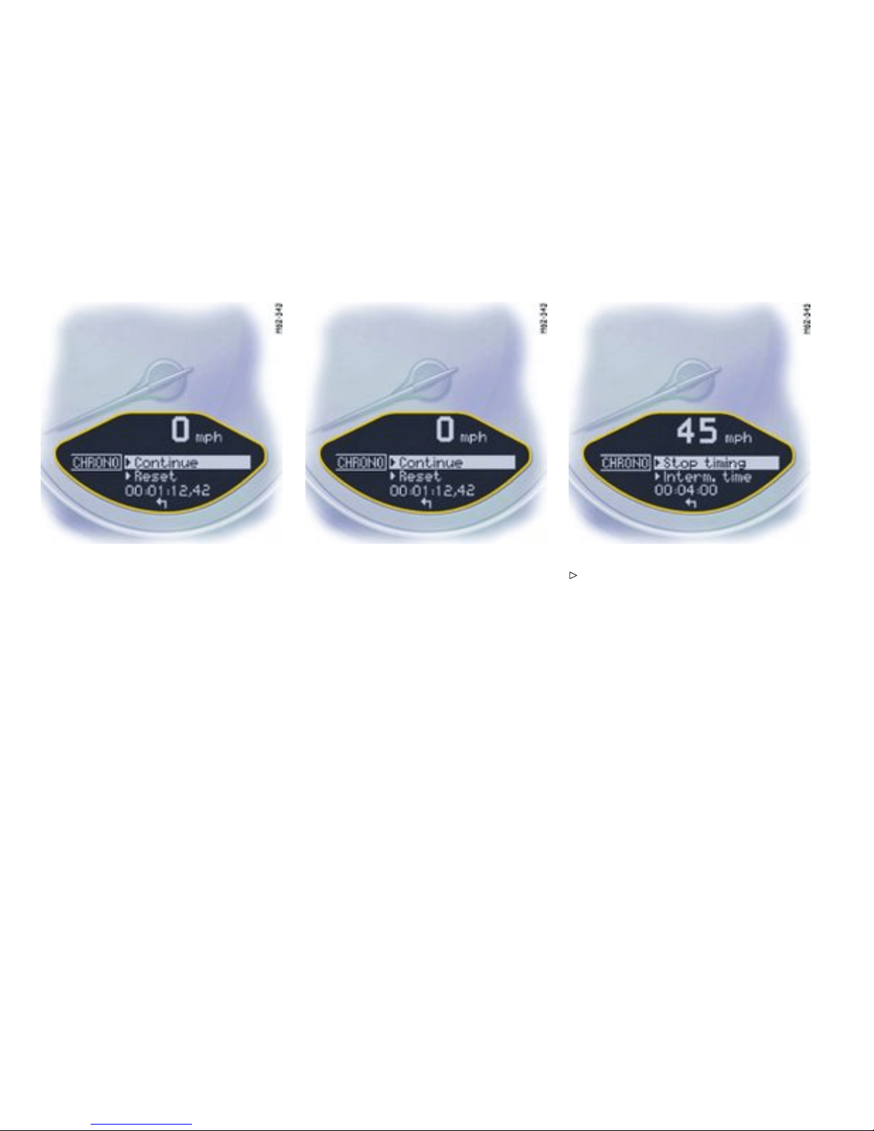
The tim ing can be c ontinued or reset to zero.
Note
PCM: After timing has been stopped, a promp t
asking whether the t ime is to be stored appears on
the PCM.
Continue timing
After timing has been stopped, the on-board
compu ter display changes to the “Continue/Reset”
selection.
Push operating lever forward. The stopwatch
displays cont inue the timin g.
The on-board computer display returns to the “Stop
timing/Intermediate time” selection. You can stop
the stopwatch or measure an int e rmediate time.
114Controls, Instruments
Downloaded from www.ManualsFile.com manuals search engine

Resett ing the time
After timing has been stopped, the on-board
comput er display changes to the “Continue /Reset”
selection.
Select “Reset” with the operating lever.
Push operating lever forward. Th e display
returns to the “Start t iming” selection. The
stopwatch displays in the instr ument panel a nd
the on -board computer are reset to zero.
Controls, Instruments
115
Downloaded from www.ManualsFile.com manuals search engine
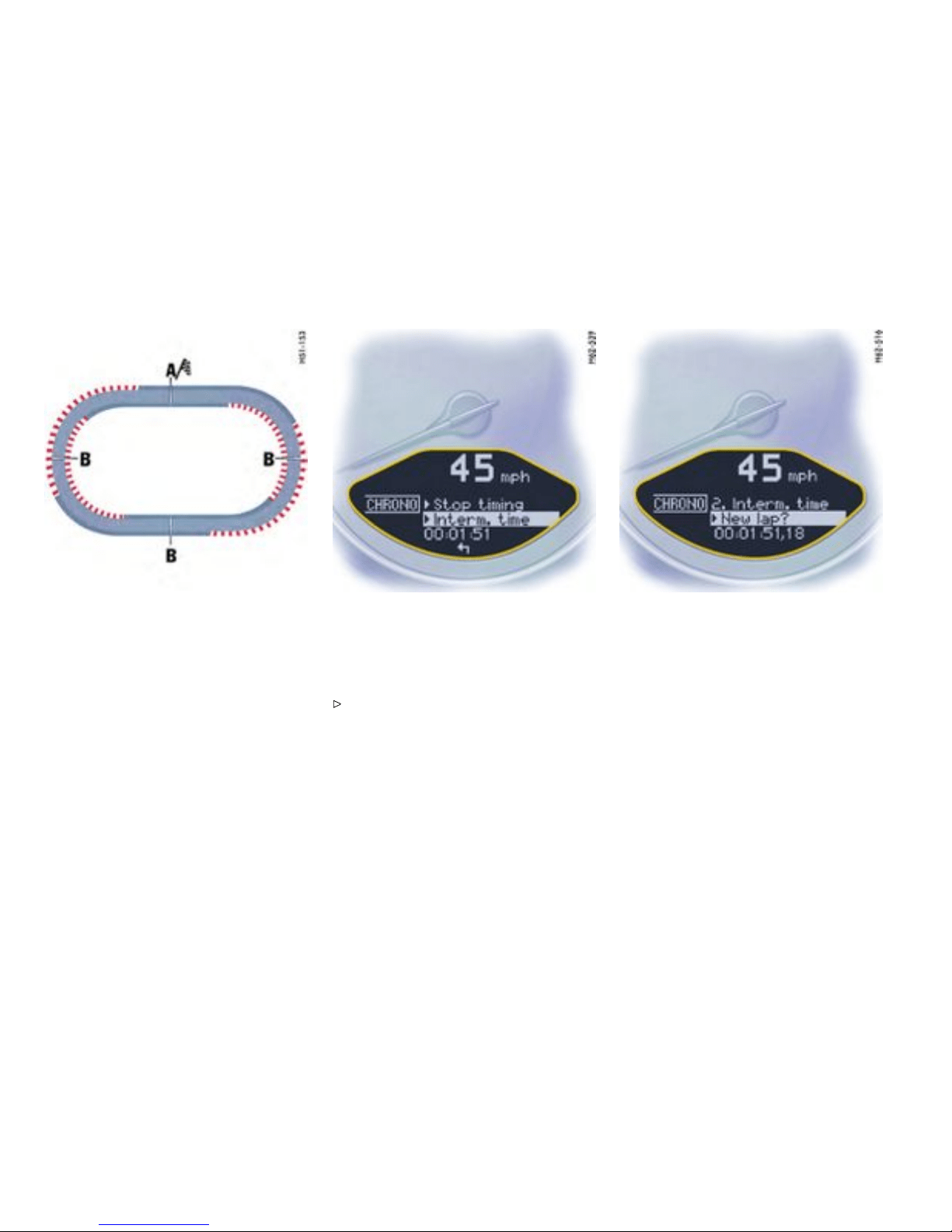
A - Lap
B - Intermediate time
Displa ying intermediate ti mes
Several intermediate times can be displayed for a
route or for a lap on the race circuit. The int erme-
diate times B are for your information. Measured
lap times A can be stored and evaluated if the
vehicle is equipped with Porsche Communication
Management (PCM).
To display an interm ediate time:
After timing has been started, the on-board compu-
ter display c h anges to the “Stop timing/Interm edi-
ate time” selection.
Selec t “Intermediate time” with the operating
lever and push the operating lever forwards.
The in termediate time will be displayed for approx.
5 seco nds. The on-board computer display then
returns to the “Stop timing/Interm e diate t ime”
selection.
116Controls, Instruments
Downloaded from www.ManualsFile.com manuals search engine
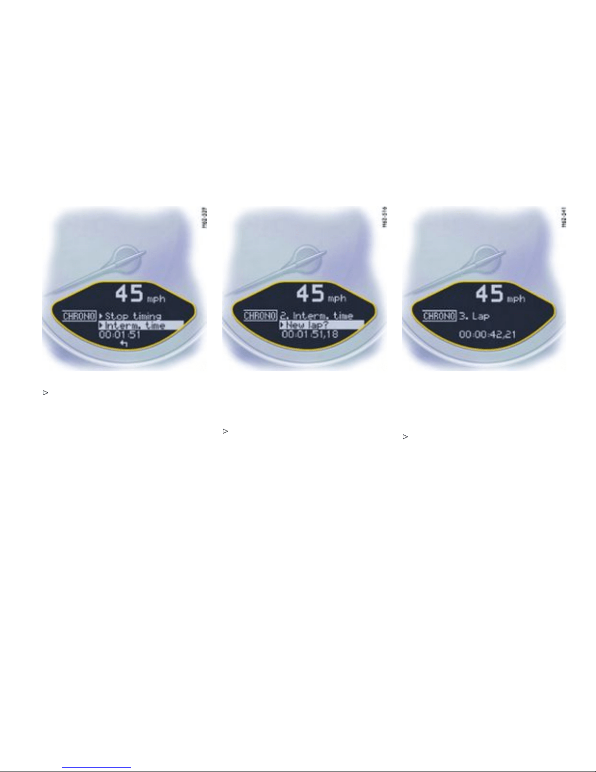
You can stop the stopwatc h or measure
another intermediate time.
In order to start timing a new lap:
The “New lap ?” selection appears for 5 seconds
after selection of “Intermedia te time”.
Select “New lap?” with the operating lever and
push the oper ating lever forwards.
The new lap is displayed on the on-board computer
and th e PCM. Timing on the on-board computer and
on the PCM begins from zero. The stopwa tch in the
instrument pan el continues to show the t otal time .
The on-board computer display returns to the
“Stop timing/Intermediate time” selection
after a short period.
Controls, Instruments
117
Downloaded from www.ManualsFile.com manuals search engine

You can stop the stopwatch or measure
another intermediate time o r a ne w lap.
Note
PCM: If you wish to store the lap time in the
PCM, the performance disp lay in the “Trip/Sport
display/Begin trip” menu of the PCM must be
selecte d.
118Controls, Instruments
Downloaded from www.ManualsFile.com manuals search engine

TPC Ti re Pressu re Monitor ing
Function
Please obse rve the chapter ”TIRE PRES SURE
FOR COLD TIRES” on page 304.
The Ti re Pressure Monitorin g continuously moni-
tors tire pressure and tire tempe rature on all four
wheels and warns t he driver when the tire pressure
is too low.
The d isplay as well as the settings for the Tire
Pressure Monito ring take place on the on-board
computer. H owever, you mu st still adjust the tire
pressure on the wheel .
The dri ver is responsible for filling the tires
correctly and making the c orrect settings on
the on-board computer.
The Tire Pressure Monitoring offe rs the follow ing
functions:
– Display of the act ual tire pressure while the
vehicle is in motion
– Display of the deviation from t he required
pressure (refilling pressure)
– Display of currently set tire size and type
– Tire pressure warnings in two stages
Caution!
Despite the advan tages offered by the Tire
Pressure Monitoring, it i s still the d river’s
responsibility to update the correspon ding
settings in the on-board computer and
main tain the pressure in the tires. Low tire
pressure reduces the road safety of the
vehicle and destroys t he tire and wheel.
When a flat tire has been displa yed, immediate-
ly stop in a suitabl e place and check the tires
for da m age. If necessary, remedy the damage
with a tire sealant.
Do not by any means conti n ue to drive with
defective tires.
Sealing the tire with tire sealant is only an
emergency repair, so y ou can drive to the next
authorized Porsche dealer. The maximum
permitted spee d is 50 mph (80 km/h).
Do not drive with tires whose tire pressure
drops again in a short pe riod of time. In cases
of doubt, have tires checked by an authorized
Porsche dealer.
Damaged tires must be im mediately replaced
by an autho rized Porsche d ealer. Tire
repairs are not permissible under any
circumstances.
If the Tire Pressure Monitoring is defective
(e.g. defective whee l transmitter), contact
an authorized Porsche dealer immediately
and h ave the dama ge repaired. The tire
pressure will no t be monitored by a defective
Tire Pressure Monitoring.
Tires lose air over time witho ut a tire defect
being present. A tire pressure warning
will then appear in the on-board computer
display. Co rrect the tire pressure at the next
opportunity.
The Tire Pressure Monitoring gives a warning
about tire damage due to natural pressure loss
as well as about a gradual loss of pressure
due to foreign objects. The Tire Pressure
Monitoring cannot warn you about tire damage
that occurs suddenly (e.g. flat tire due to
abrupt external effects).
Controls, Instruments 119
Downloaded from www.ManualsFile.com manuals search engine
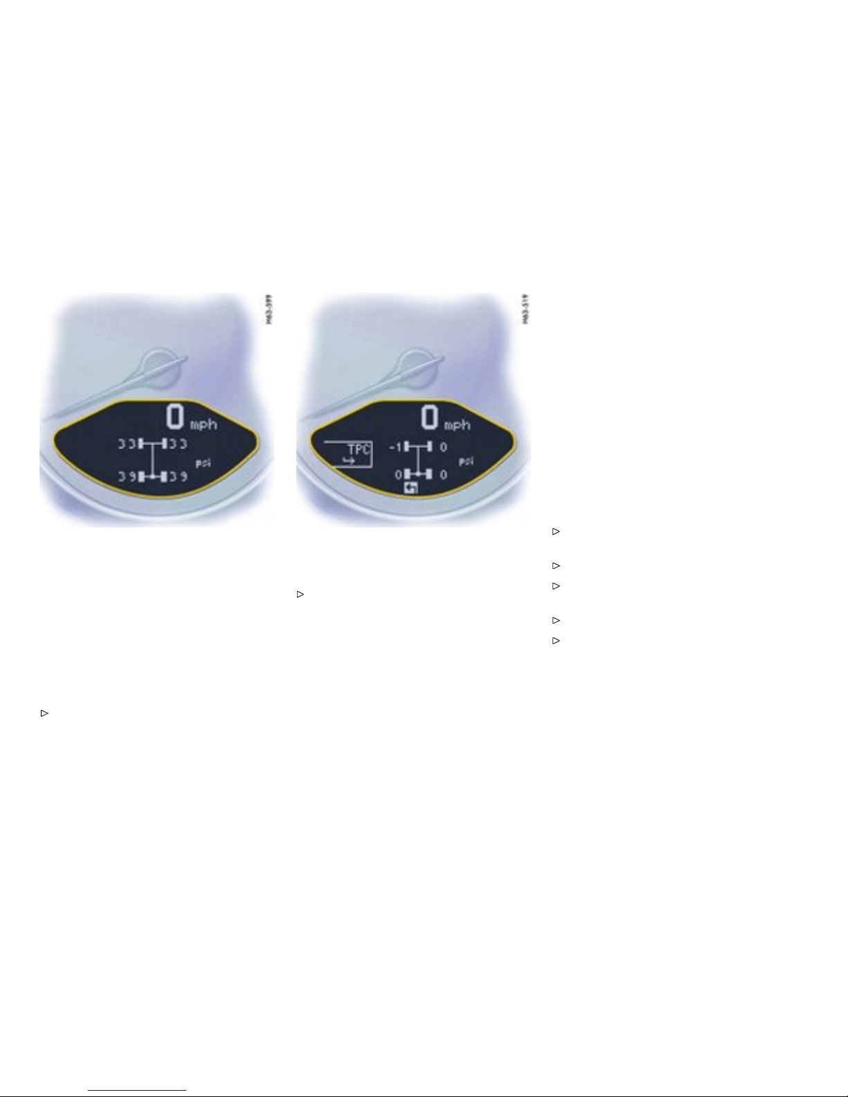
Settings in the on-bo ard comput er
Tire pressur e function of the on-b oard
computer
The tire pressure function of the on-board compu-
ter displays the tire pressures (actual pressure)
dependent on tempera ture in the four wheels. You
can watch the tire pressure rise as the temp erature
increases while driving. This display is o nly for
information.
Under no circums t ances should the tire
pressures be changed based on this display.
Calling th e tire pressu re function of the
on-board computer
Push operating lever up or down until the
tire pressure function of the o n-board com-
puter appears. (The selection field m ust be
switched off.)
Pressure info in Tire pressure menu
In accordance with physical principles, the air
pressure changes as the temperature changes.
The tire pressure in creases or decreases by
around 1.5 psi (0.1 bar) for every 18°F (10°C )
change in temperature.
The Tire Pressure Monitoring takes this relationship
between tire pressure and temperature into
account.
You can read the tire pressures to be correct-
ed in this display.
The ti re pressure to be corrected (refill pressure)
is indicated on the displayed wheel . Example: If
“-1.5 psi (-0.1 bar)” is displayed, 1.5 psi (0.1 bar)
must be adde d to this tire.
Note
The Tire pressure menu can only be called up when
the vehicle is statio nary.
Calling up the “Info pressure” display
Push operating lever forward in order to switch
on the selection field.
Select “TPC” with the opera ting lev er.
Push operating leve r forw ard. Th e displ ay
changes to the Tire pressure menu .
Select “Info pressure” with the operating lever.
Push operating lever forward.
Note
After the ignition is switched on, it can take up
to approx. 1 minute before all tire pressures are
displayed. Dashes (“-.-”) appear instead of the tire
pressures.
120Controls, Instruments
Downloaded from www.ManualsFile.com manuals search engine
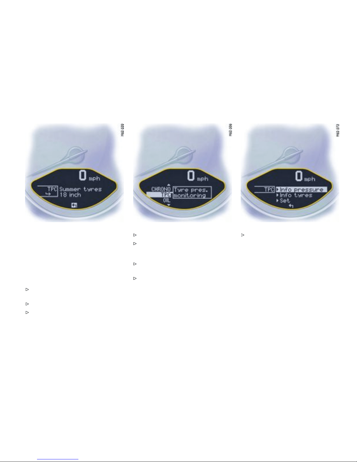
Tire type info in Tire pressure menu
Information about the currently set tires:
– Tire type: Summer tires, winter tires
– Tire size: 17, 18, 19 inch
“Info ti res” shows t he current tire settings.
Calling up the “Info tires” display
Push operating lever f orward in order to switch
on the selection field.
Select “TPC” with the operating lever.
Push operating lever forward. The display
changes to the Tire pressure menu.
Select “Info tires” with the operating lever.
Push operating lever forward.
Tire selection in the “Set” menu
Push operating lever forward in order to switch
on the selec tion field.
Select “TPC” with the operating lever.
Push operating lever forward. The display
change s to the Tire pressure men u.
Controls, Instruments
121
Downloaded from www.ManualsFile.com manuals search engine

Select “Set” with the operating lever. Push t he ope rating lever forward.
Select desired tire type: summer or winter.
Push operating lever forward. A display for
confirming the selected type of tire appears.
Select “Continue” and push the operating lever
forward.
122Controls, Instruments
Downloaded from www.ManualsFile.com manuals search engine
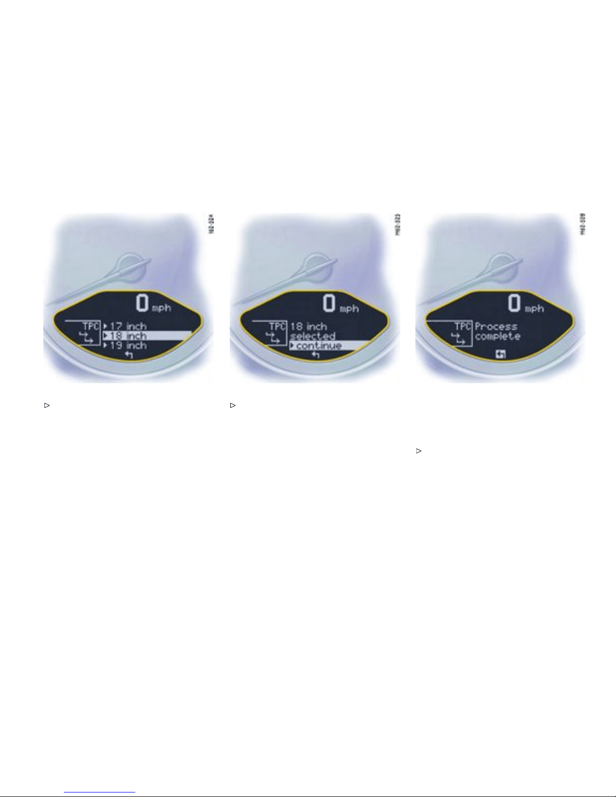
Select the appropriate tire size (17, 18 or 19
inch) and push oper ating lever forwards. A
display for c onfirmin g the selected tire size
appears.
Note
This menu is only displayed when different tire
sizes are approved.
Select “Continue” and push the operating lever
forward.
Setting of the tire characteristics has only been
successfully complete d whe n the message
“Process com plete” is displayed by the on-board
computer.
Select arrow (Back) and push the operating
lever forward. The display returns to the
Tire pressure menu. The on-board computer
additionally d isplays the message “System
learning”.
Note
The message “Process aborted” appears if the
setting process is interrupted. All entrie s made
up to this point are los t, and the o riginal settings
remain in effec t. Only if the message “Process
Controls, Instruments
123
Downloaded from www.ManualsFile.com manuals search engine
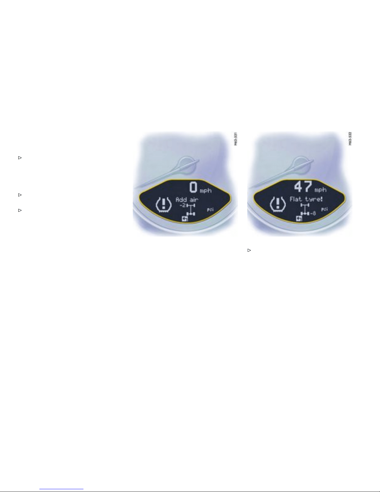
complete” appears aft er the setting s have been
made will the Tire Pressure Monit o ring re-learn the
wheels.
Please observe the chapter ”SYSTEM LEARN-
ING” on page 125.
Before fitting tires with sizes which are not stored
in the on-board computer, the missi ng information
should be supplemented in t he on-board computer.
Please cons u lt your authoriz ed Porsche
dealer.
Use only tires approved by Porsche.
The available items in the Tire pressure menu
depend on th e equipment of your vehicle. For this
reason it is possib le that some of th e items shown
here are not available on your on-board computer’ s
display.
Tire pressure warnings
The Tire Pressure Monitoring war ns about loss in
pressure in two stages, depending on the amount
of pressure lo ss:
Stage 1 - Add air
(3 to 6 ps i (0.2 to 0.4 bar) loss in pressure)
Stage 2 - Flat tire
(from 6 ps i (0.4 bar) loss in pressure)
Stage 1 - Add air
The pressure in the tire is too low by 3 to 6 p si (0.2
to 0.4 bar). Driving with insufficient tire pressure
reduces the road safety of the vehicle and destroys
the t ire a n d wheel.
The ti re pressure warning contains the
affected tire with the tire pressure to be
added. Correct the tire pressure at the next
opportunity.
This tire pressure warning appears with vehicle
stopped and can be acknowledged. The tire
pressure warning light in the instrument panel goes
out when the tire pressure has been co rrected.
Stage 2 - Flat tire
The p ressure in the tire has dropped by more than
6 psi (0.4 bar). T his signi ficant pressure loss is a
danger to road safety.
124Controls, Instruments
Downloaded from www.ManualsFile.com manuals search engine
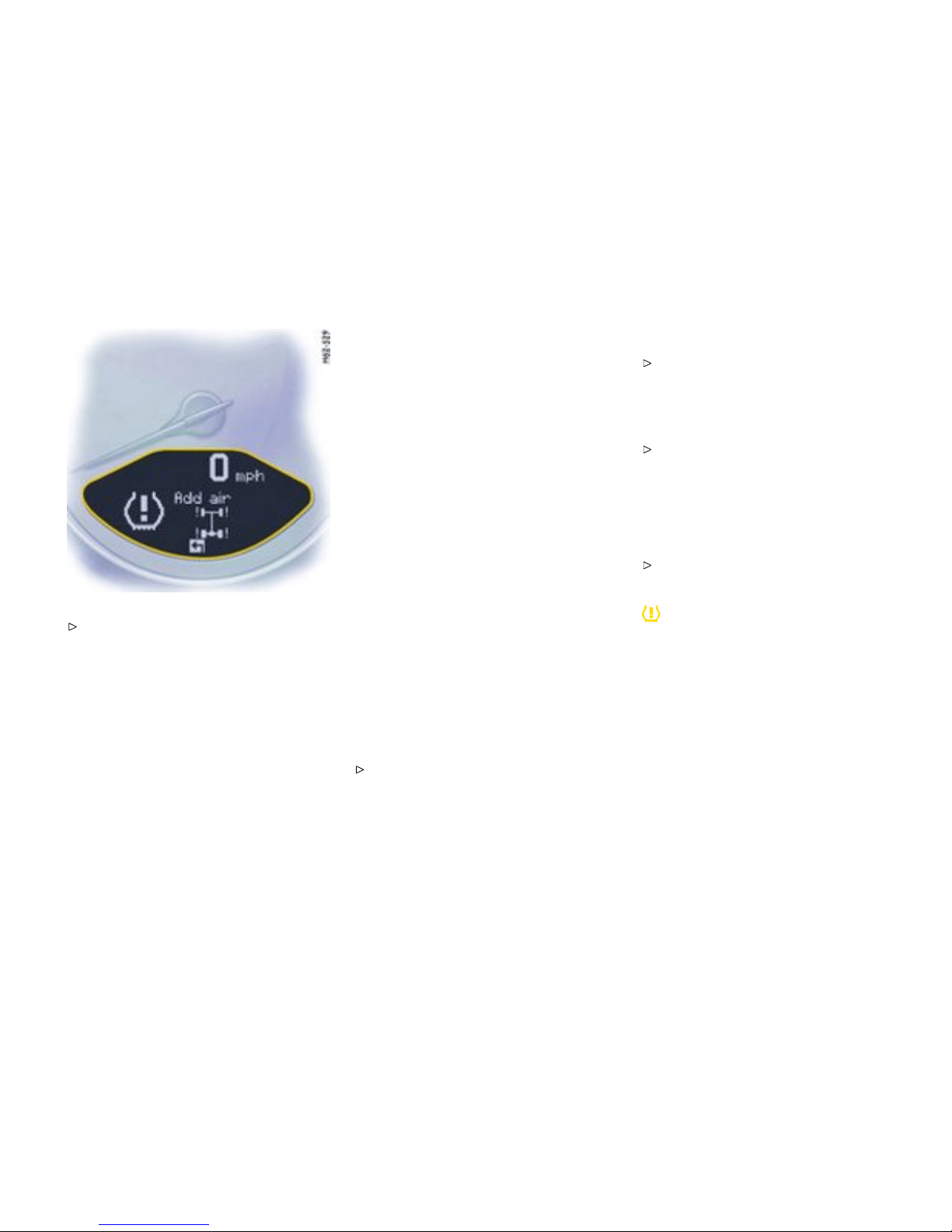
When the tire pressure warning has appe ared
on the on-board computer, stop immediately at
a suitable location. Che c k the tire for s i gns of
damage. If necessary, fill in tire sealant and set
the correct tire pressure.
This tire pressure warning appears when driving
and can be acknowledged. The tire pressure
warning light in the instrument p anel goes out when
the tire pressure ha s been corrected.
System l earning
The Tire Pressure Mon itoring begins to “learn” the
wheels after a wheel change, wheel transmitter
replacemen t or update of the tire settings. Durin g
this proce ss, the Tire Pressure Monitoring recog-
nizes the tires and thei r locations. The on-board
computer displ ayes the message “TPC inactive -
system learni ng”.
The Tire Pressure Monitoring requires a certain
amou n t of time to learn the wheels. D uring this
time, the current tire pressures are not available on
the on-board-computer:
– The display of the Tire pressure functio n of the
on-board computer s hows lines.
– The requi red pressures for cold tires at
68°F (20°C ) are indicated in the Info pressure
display in the Tire pressure menu.
– Tire pressure warnings are issued without tire
pressure and position information (gure) as
soon as the vehic le’s own wheels have been
detected and the tire press ure warning li ght
has gone out.
Position and pressure information is displayed as
soon as the Tire Pressure Monitoring ha s assigned
the wheels id entified as bel onging to the vehicle to
the c orrect wheel positio ns.
The wheel learning process takes place exclusively
when the vehicle is being driven.
Manually check the tire pressure at all wheels
and correct the tire pressure to the required
value.
Changing a wheel and replaci ng t ires
New wheels must be fitted with radio transm it-
ters for the Tire Pressure Monitoring. Before
tires are changed, the batte ry charge state of
the w heel transmitters should be checked at
an authorized Porsche deal er.
Switch the ignition off when changing a wheel.
The t ire settings o n the on-board computer must be
updated after changing a wheel.
A message appears if the characteristics of the
new tires do not agree with the on-board computer
settings .
Update the on-board computer settings when
the v ehicle is stationary the next time.
Warning light
The warning light in the speedometer lights up :
– When a loss in pressure has been detected
– If the Tire Pressure Mon itoring is faulty
– When learning newly mounted wheels/wheel
sensors, as long as the vehicle’s own wheels
have not yet been recognized.
The tire pressure warning light in the instr ument
panel goes out only when the cause of the fault has
been rectifi ed.
Controls, Instruments
125
Downloaded from www.ManualsFile.com manuals search engine

No monitoring
In the event of faults the Tire Pressure Monito ring
cannot monito r the tire pressure. The war ning
light on the instrument panel lights up and a
corresponding message appears on the on-board
computer.
Monitor ing is not active when:
– the Tire Pressu re Monitoring is faul ty,
– wheel transm itters for the Tire Pressure
Monito ring are miss ing,
– temporarily after changing a wheel (learning
phase),
– more than four wheel tra n smitters are detect-
ed,
– there is external interfe rence by other radio
sources, e.g. wireless h eadphones,
– tire temperatures are too high.
Please obse rve the chapter ”WARNINGS
ON THE INSTR UMENT PANEL AN D THE
ON-BOARD COM PUTER” on page 134.
126Controls, Instruments
Downloaded from www.ManualsFile.com manuals search engine
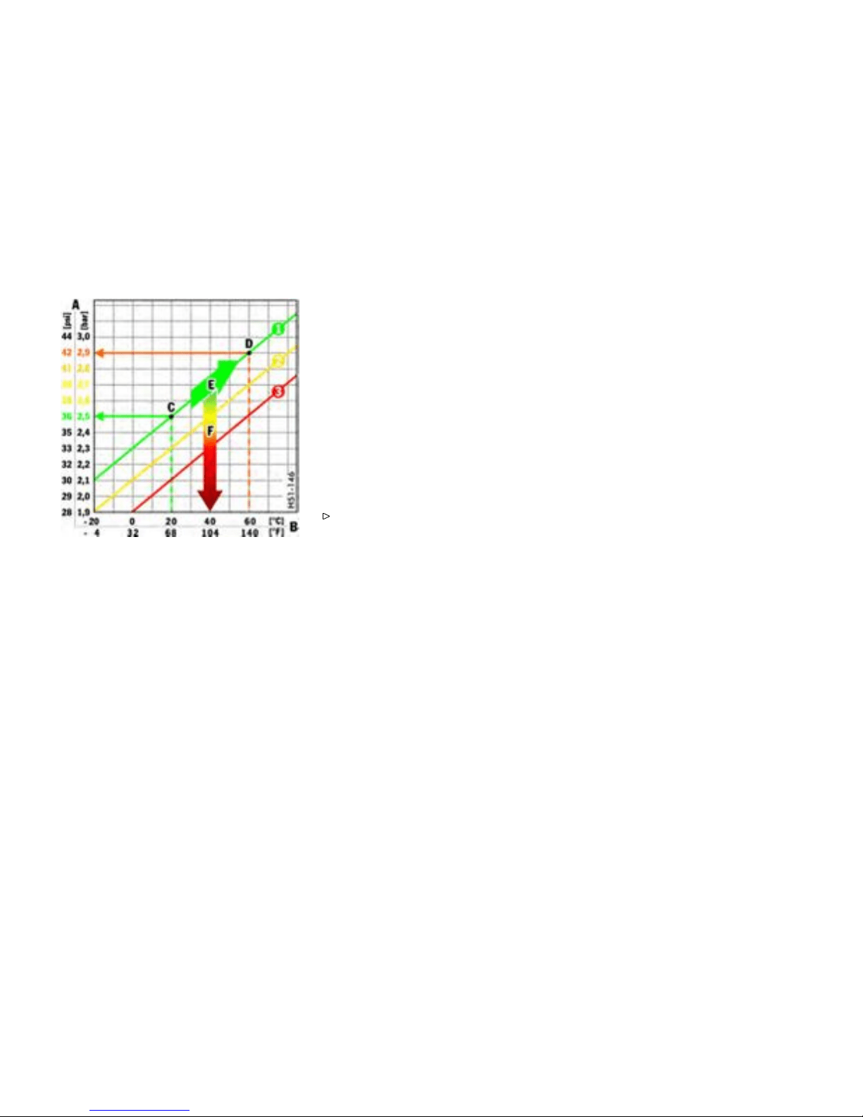
A Tire pressure
B Tire temperature
C Tire pressures for cold tires
D Tire pressure for hot tires
E Pressure increase as the result of tempera-
ture increase
F Pressure drop in faulty/leaki ng tires
1. Required-pressure line
2. Warning stage 1 (from -3 to -6 psi (-0.2 bar
to -0.4 bar))
3. Warning stage 2 (from -6 ps i (-0.4 bar))
Pressure increase as the result of
tempe rature incr ease
In acc ordance with physical principles, the air
pr
essure changes as the temperatu re c hanges.
The ti re pressure in creases or decreases by
around 1.5 psi (0.1 bar) for every 18°F (10°C )
change in temperature.
The Tire Pressure Monitoring take s this relationship
between tire pressure and temperature into
account.
Tire pressure specications
Information on tire pressure for public roads can
be found in this Owner’s Manual i n the Technical
Data chapter or on the tire-pressure plate in the left
door aperture. These values apply to cold tires at
68°F (20°C ).
Please observe the chapter ”TIRE PRES SURE
FOR COLD TIRES” on page 304.
Controls, Instruments
127
Downloaded from www.ManualsFile.com manuals search engine
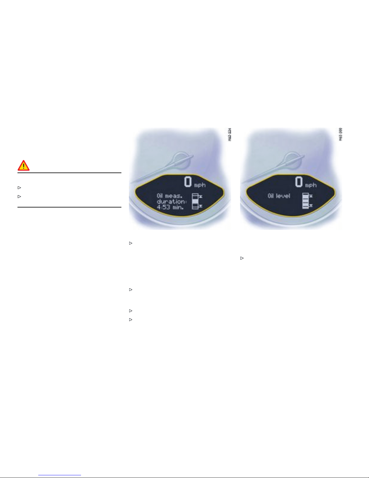
OIL Dis play and measurement of
the engi ne oil level
Condit ions for mea suring the oil level
Caution!
Risk of engine damage.
Regularly chec k the oil lev el after refueling.
Do not allow the o il level to fall below the
minimum mar k.
1. It is important to ensure that the vehicle is
horizontal for correct oil level measurement
to occ ur.
2. Engine is off.
3. Ignition on.
Oil return time
Before the oil level is measured, the engine oil
has to have flowed back into the oil pan. The time
taken for the engine oil to flow back depends on the
engine temperature and how long the engine has
been stopped.
This waiting time is c ounted down in the on-board
computer displ ay when the ignition is switched on.
The oil level display segments start to “c ycle”.
It is best to measure the en gine oil level before
embar king on a journey (if the vehicle has not
been driven for an extended period) or with
the engine a t operating temperature. Shorter
waiting times are achieved in this way.
Initiating oil level measurement
Switch ignition on (do not start the engine).
The engine-oil level measurement display
appears in the on-b oard computer.
Allow waiting time t o elapse.
Once the measurement has been comp leted,
you can read o ff the engine oil level on the
segment display.
– If the segments are filled in up to the top line,
the oil level has reached the maximum mark.
Under no ci rcumstances add engine oi l.
128Controls, Instruments
Downloaded from www.ManualsFile.com manuals search engine

– If only the bottom segment is fi lled in, the oil
level has reached the minimum mark.
Add engine oil immediately.
– If the bottom segment flashes, the oil level has
dropped to below the minimum mark.
Add engine oil immediately.
The difference be tween the minimum and max-
imum marks on the segment d isplay is approx.
1.2 liters. Each segment of the display corre-
sponds to approx. 0.4 liter.
Add engine oi l if necessary.
Please observe the chapte r ”ENGINE OIL
LEVEL” on page 213.
Never add more engine oil than required
to reach the maximum mark.
Oil level measurement during r efueling
The oil level is aut omaticall y measured during
refueling.
Precondit ions
1. Ignition is switched off.
2. If the engine is at operat i ng temperature, at
least 5 minutes must elapse between parking
the vehicle and starting the engine.
3. Refuelin g completed within 15 minutes.
When the ignition is s witched on, the engine oil level
is shown on the segment display.
Measurement will be stopped if the above require-
ments are not m et.
Start oil level m easurement in the “OIL“ menu
or
Start oil l evel measurement by swit ching on
the ignition.
Failure
A failure of the o il level display is indicated by a
warning message in the on-board computer.
Controls, Instruments
129
Downloaded from www.ManualsFile.com manuals search engine
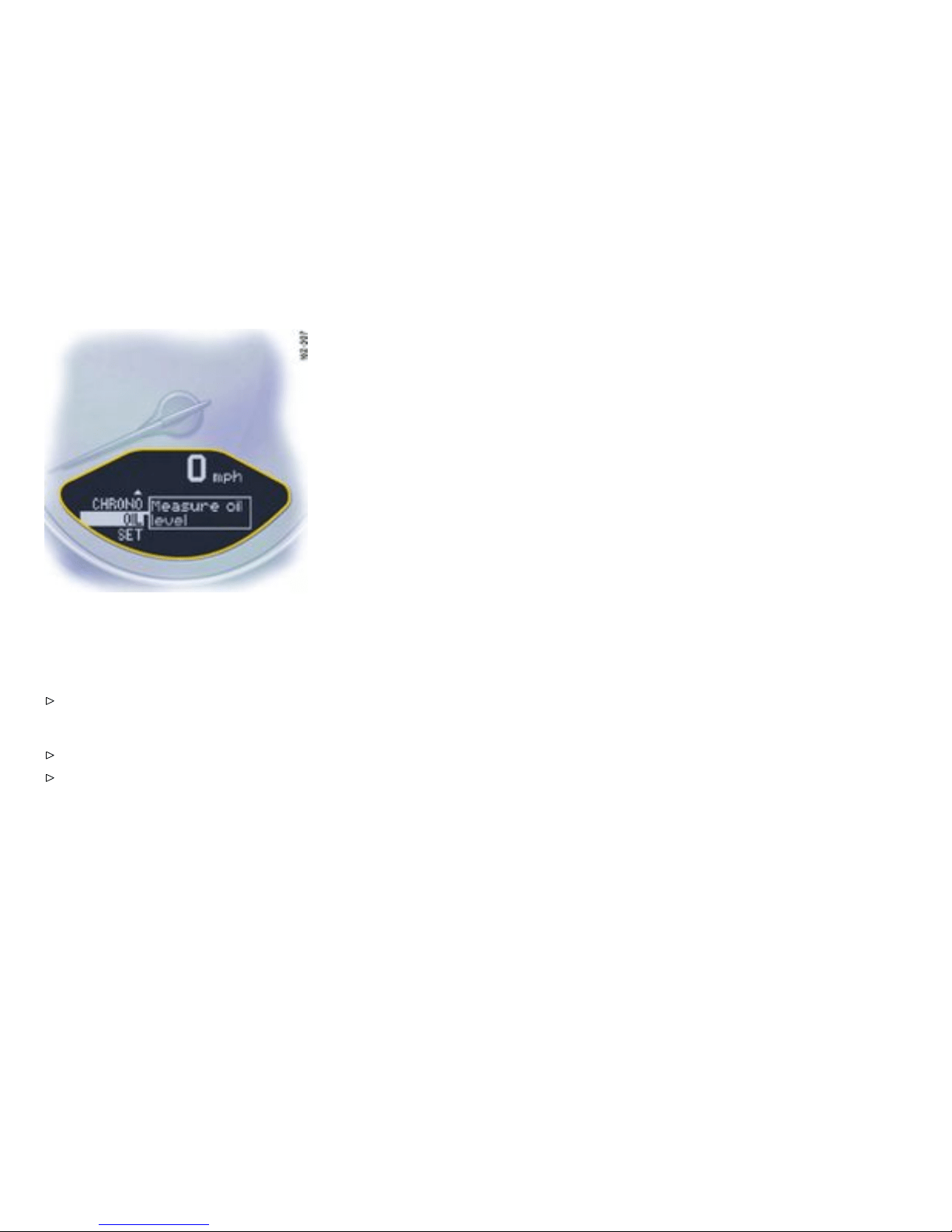
The oil lev el measurement can also be
initiated in the “OIL ” menu:
Switching o n selection eld “D”
Push operating lever forward.
Initiatin g measurement
Select “OIL” with the operatin g lever.
Push operating lever forward. Measurement is
started.
130Controls, Instruments
Downloaded from www.ManualsFile.com manuals search engine
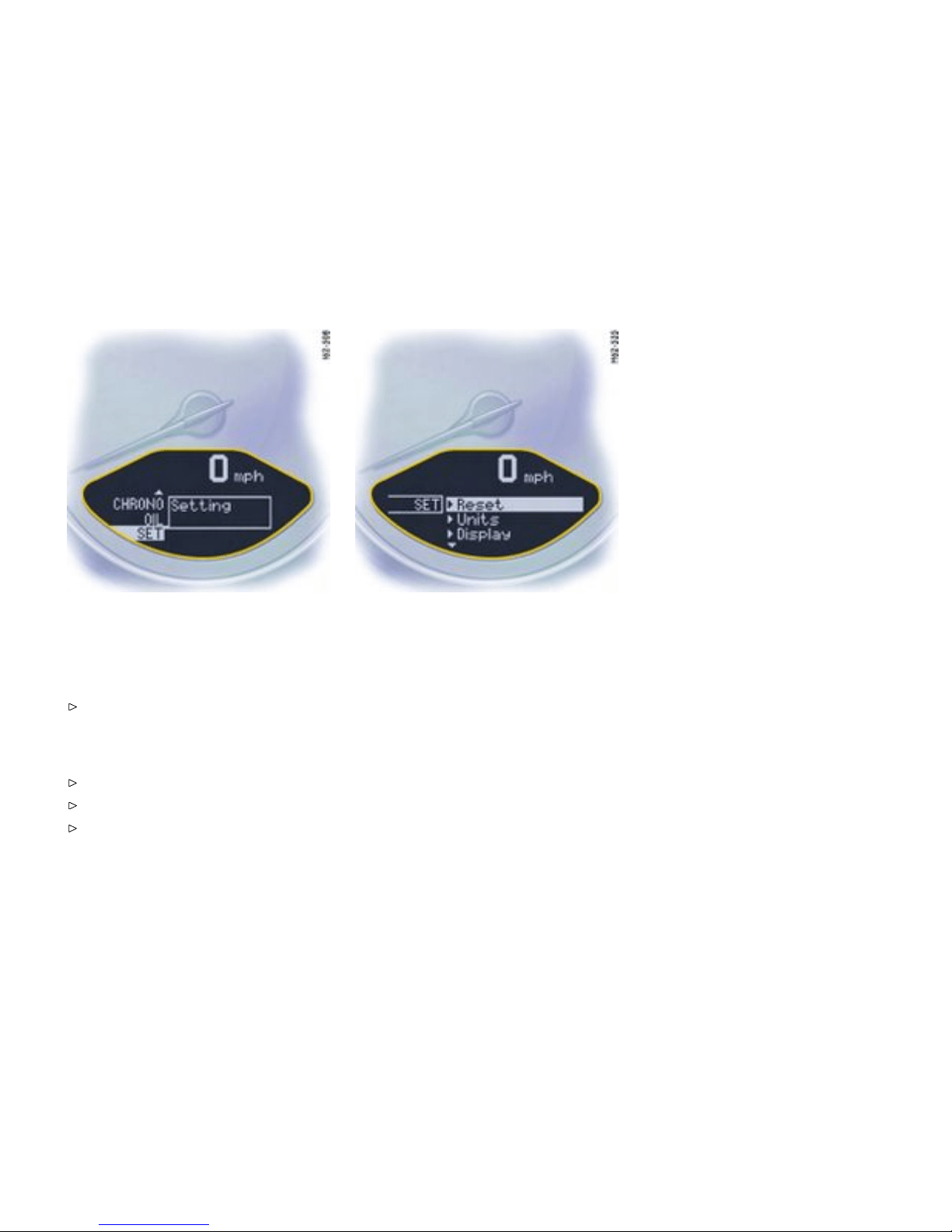
SET Bas ic setting on on-board
computer
Switching on selection eld “D”
Push op erating lever fo rward.
Changing the basic set ting of the on-board
computer
Select “SET” with the opera ting lev er.
Push op erating lever fo rward.
Select the d esired function with the operating
lever:
Reset
– Reset all,
– Reset averag e consumption,
– Reset average spee d,
– Reset trip counter
Units
– Speed ometer: km - km/h, miles - m ph
– Consumption: l/100 km, mls/gal (USA), mpg
(UK), km/l
– Temperature: Celsius, Fahrenheit
– Tire pressure: bar, p si
Display (Select central line of the
on-board computer)
Change di splay
– Audio information (set radio station)
– Range on remaining fuel
– Empty
Telephone Info
– When Telephone information is active, incom-
ing telephone calls are displayed on t he
on-board computer.
Controls, Instruments
131
Downloaded from www.ManualsFile.com manuals search engine
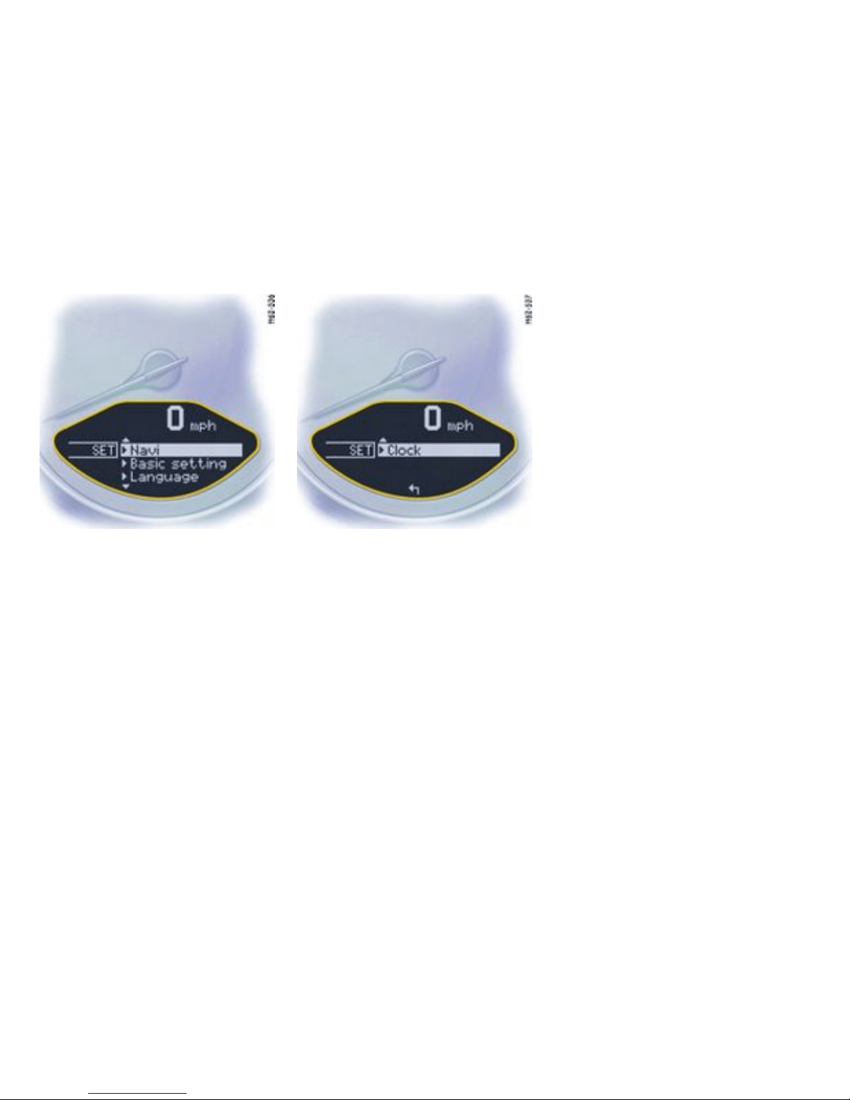
Navigat ion
– Integrated in th e BC (Navigation instructions
can b e recalled on the on-board computer
display)
– When turning off (Navigation instructions are
only sh own before changing direction)
Basic setting
– Restore the basic setting of t he on-bo ard
computer
Language
– Select langua ge versi on
12/24h mode
Select time mode:
– 12h (small squares on th e right side o f the time
display for AM/PM),
– 24h
132Controls, Instruments
Downloaded from www.ManualsFile.com manuals search engine

General information regarding the
on-board computer functions
Range on remaining fuel
The range on remaining fuel is continuou sly
recalculated during the journey based on the
fuel level, current consumption and average
consumption. The more the fuel level falls, the
more spontaneously the display reacts. For
this reason, the range on remaining fuel is not
displaye d if less than 9 miles (15 kilometers).
If the vehicle’s inclination changes while driving
or refueling, incor rect range i nformation may
tempor a rily be given.
Note
If the tank is nearly empty and you top up with
only a small quanti ty of fuel, an accu rate range on
remaining fuel is impossibl e.
Average c onsumption and average speed
The values displayed a re based on the distance
travelled since the last reset to “zero”.
You can set the starting time for a measurement
before or during the trip. Switch ing the ignition off
does not reset the measurements. It is therefore
possible to collect values over long periods.
Disconnecting the car batter y will cause these
memories to be erased.
Tire pressure
The Tire pressure function of the on-board
computer displays the tire pressures dependent
on temperature in the four wh e els. You can watch
the t ire pressure ris e and fall while driving. The
display is only for information. To correct the tire
pressures, always use the displayed values from
the “Info pressure” disp lay in the Tire pressure
menu.
Controls, Instruments
133
Downloaded from www.ManualsFile.com manuals search engine

Warnings on the instrument panel and the on-board computer
Overview of the warnings
If a warning message appe ars, always refer to the corresponding chapters in t h e Owner’s Manual. Warning mess ages are iss ued on ly if all measurement precon-
ditions are met. Therefore, check all fluid levels regularly - in partic ular, always check the engine oil level after refueling.
Instrument panel On-boa rd computer
Text display on on-board
comp uter Meaning/measure
Seat belt Driver and passenge rs must fasten
their seat belts.
Handb rake Handbrake is st ill on.
Ignition key not removed
Replace battery in ignition key Replace the remote-control battery.
Ignition lock faulty, please go to
workshop
Have the fault remedied at a n
autho rized Porsche dealer.
Ignition lock fault y, visit workshop
now
Have the fault remedied at a n
autho rized Porsche dealer.
Relieve steeri ng Relieve the steering lock by moving
the steering wheel to the left or right.
Steering locke d
The s teering wheel lock remains
engaged. Have the fault remedied at
an authorized Porsche deal er.
Lights on Low beam/side light on.
134Controls, Instruments
Downloaded from www.ManualsFile.com manuals search engine

Instrument panel On-board computer
Text display on on-board
computer Meaning/measure
Parking light on
Left/rig h t parking light on.
Check left/right dipped beam (lo w
beam)
also applies to:
front side lights, direction indicator,
high beam, fog lights, side indicator
light, brake light, tail light, rear fog
light, reversing light, raised brake
light, side marker
The reported light is faulty. Check
bulb. Have the fault remedied at an
authorized Pors che dealer.
Daytim e driving lights off Daytime driving lights switch off
when the engine is shut off . Switch
on lig hts if n ecessary.
Headlight beam adjustment faulty Have t he fault remedied at an
authorized Pors che dealer.
Front lid not closed
Close luggage com partment lid
properly.
Rear lid not closed
Close en gine compartment lid
properly.
Rain sensor faulty Have t h e fault remedied at an
authorized Pors che dealer.
Refill washer fluid
Controls, Instruments 135
Downloaded from www.ManualsFile.com manuals search engine
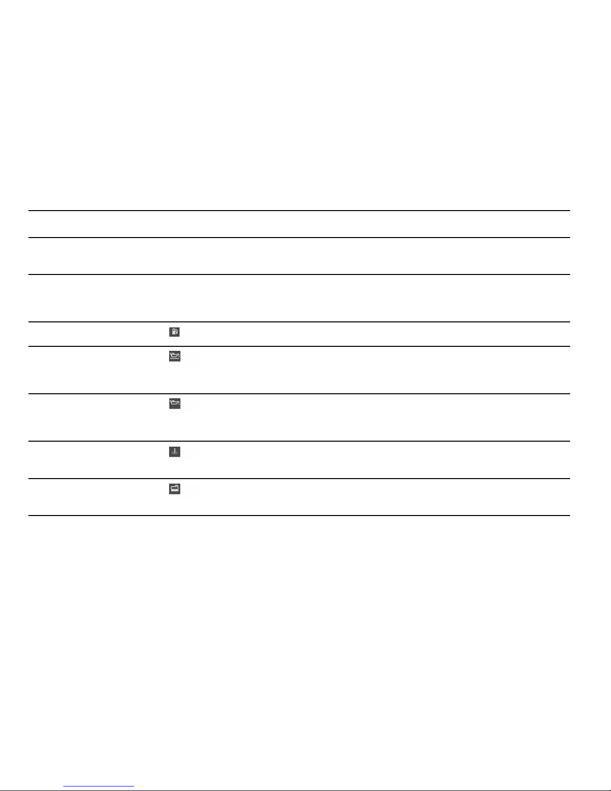
Instrument panel On-boa rd computer
Text display on on-board
comp uter Meaning/measure
LIMIT
Cannot be accepted with vehicle
stopped
The current speed can only be
accep ted for the acoustic warnin g
signal when the vehicle is in motion.
LIMIT 30 Selected spe ed limit (e.g. 30 mph)
for the acou stic warning signal has
been exceeded. Adjust your speed if
necessary.
Fuel g auge warning light
Consider remaining range Refuel at next opportuni ty.
Check engine oil level Start engine oil l evel measurement in
the on-board com p uter.
The v ehicle m ust be horizontal and
the ignition must be switch ed on.
Engine oil pressure too low
Stop immediately at a suitable p lace,
measure oil level with the on-board
compu ter and, if necessary, add
engine oil.
Warning light
Temperature gauge
Engine temperature too high
Switch engine off and let it cool.
Check coolant level and, if neces-
sary, add coolant.
Temperat u re gauge warning light
flashes
Check coolant level Switc h engine off and let it cool.
Check coolant level and, if neces-
sary, add coolant.
136Controls, Instruments
Downloaded from www.ManualsFile.com manuals search engine
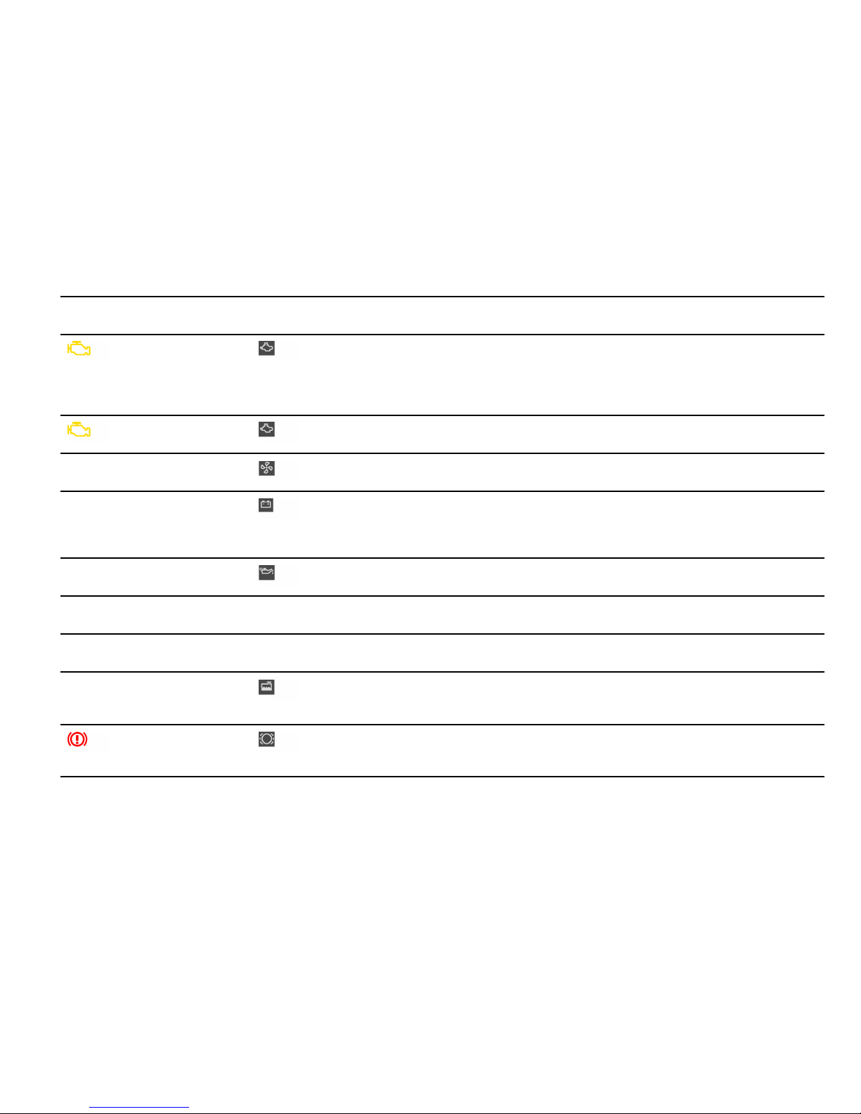
Instrument panel On-board computer
Text display on on-board
computer Meaning/measure
Engine diagnostics - workshop
Stop immediat ely at a suitable place
and check tank cap f or proper
fasteni n g. If the tank cap was
fastened correctly, consult your
authorized Pors che dealer.
Reduced engine power
Consult your authorized Porsche
dealer.
Temperature gauge warning light
flashes
Failure of engine compartment
blower
Consult your authorized Porsche
dealer.
Warning Battery/g e nerator
Stop at a safe place and switch
the engine off. Do not co ntinue
driving. Have the fault remedied at
an au thorized Porsche dealer.
Oil pressu re gauge faulty Have t h e faul t remedied at an
authorized Pors che dealer.
Oil level display faulty Have the fault remedied at an
authorized Pors che dealer.
Oil temperature gauge faulty Have t he fault remedied at an
authorized Pors che dealer.
Indicator faulty Coolant indicator failed. Have the
fault remedied at an authorized
Porsche dealer.
Brake pad wear Have t h e brak e pads changed
immediately at an authorized
Porsche dealer.
Controls, Instruments 137
Downloaded from www.ManualsFile.com manuals search engine
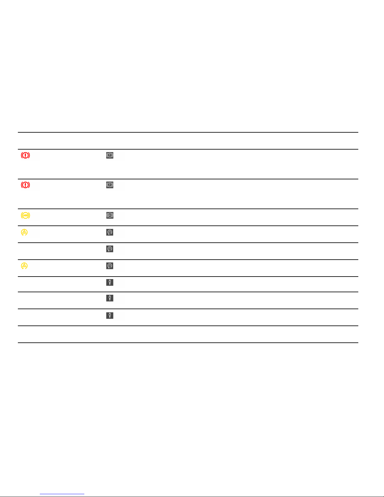
Instrument panel On-boa rd computer
Text display on on-board
comp uter Meaning/measure
Warning - Brake fluid level Stop immediately in a suitable place.
Do not continue driving. Have the
fault remedied at an authorized
Porsche dealer.
Warning - Brake circuit division
Stop immediat ely in a suitable pla ce.
Do not continue driving. Have the
fault remedied at an authorized
Porsche dealer.
ABS failure Have the f ault remedied at an
autho rized Porsche dealer.
PSM off Porsche Stability Management has
been switched off.
PSM on Porsch e Stabil ity Management has
been switched on.
PSM failure Have the fault remedied at a n
autho rized Porsche dealer.
PASM Nor mal/Sport Indicato r for selecte d PASM mode
PASM fail u re Have the fault remedied at a n
autho rized Porsche dealer.
PASM indicator faulty Have t he fault remedied at an
autho rized Porsche dealer.
Sport mode failure Have the fault remedied at an
autho rized Porsche dealer.
138Controls, Instruments
Downloaded from www.ManualsFile.com manuals search engine
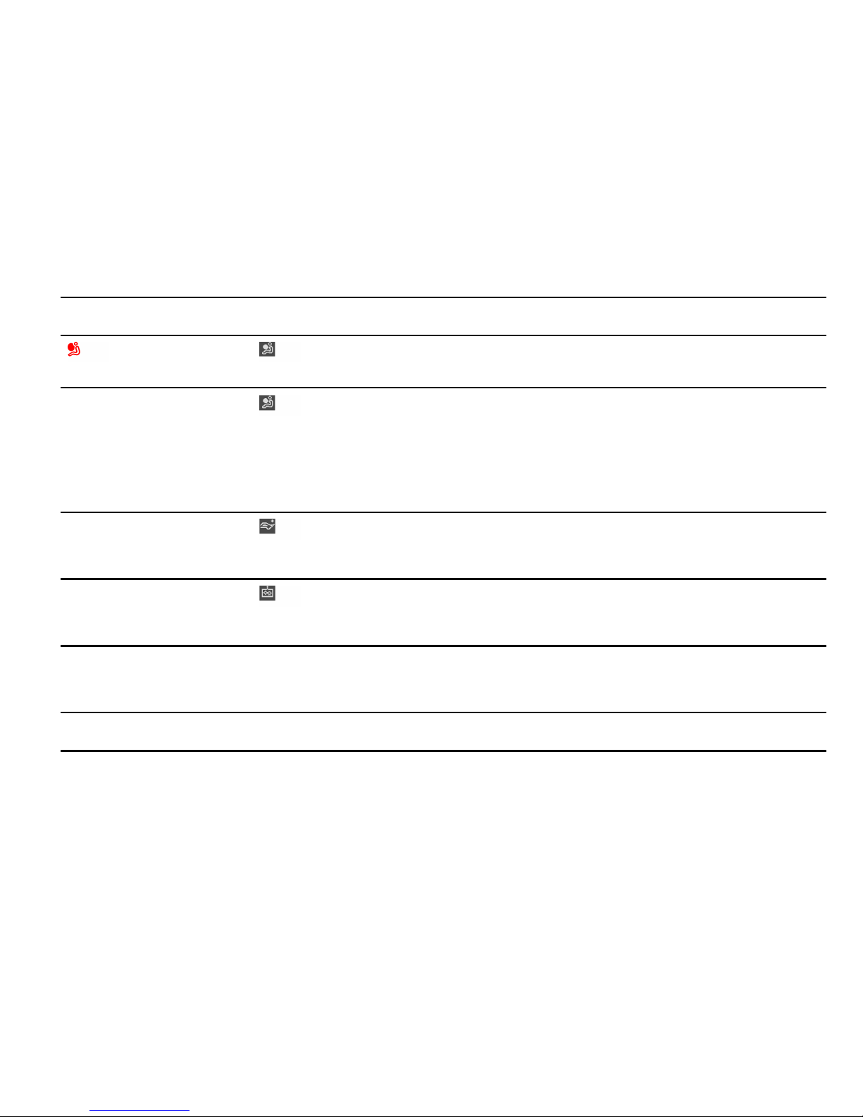
Instrument panel On-board computer
Text display on on-board
computer Meaning/measure
Airbag system fault Airbag is faulty. Have the fault
remedied at an authorized Porsche
dealer.
Check passenger’s seat setting
Weight sensing is impaired on the
passenger’s s eat (Ad v anced Ai rbag).
When the backrest is in contact with
the engine compartment wall, the
backrest can warp. Correct the
seating position, set the backrest
upright , do not support weight on t he
armrests, or lift on the hand les.
Failure spoil er control Driving stabil ity is impaired. Adjust
your driving style. Reduce speed.
Have t h e faul t remedied at an
authorized Pors che dealer.
Display of selector le ver pos ition
flashes
Selector lever is not engaged Tiptronic S:
Selector lever can be between two
position s. Engage the selector lever
correctly.
Move selector lever to P
Tiptronic S:
Move selector l ever to posit ion P
before withd rawing key from ignition
lock.
Apply brake
Tiptronic S:
Apply the br ake when starting.
Controls, Instruments 139
Downloaded from www.ManualsFile.com manuals search engine

Instrument panel On-boa rd computer
Text display on on-board
comp uter Meaning/measure
Depress c lutch pedal Manua l transmission:
Depress clutch pe d al when starting.
Move selector lever to position
P or N
Tiptronic S:
The vehicle can be started only in the
select or lever position P or N.
Display of selector le ver pos ition
flashes
Tiptronic emergency run
Have the fault remedied at a n
autho rized Porsche dealer.
System fault Go to works hop Several systems may have failed.
Adjust your driving style. Reduce
speed. Have the fault remedied at an
autho rized Porsche dealer.
Failure of fuel le vel ind icator
Workshop
Have the fault remedied at a n
autho rized Porsche dealer.
Service in mls/days (km/days) Service indicator.
Bring the vehicle in for service no
later than after the distance/time
shown has elapsed. Please observe
the a dditional information in the
“Maintenance” booklet.
Service now Service indicator.
Have your vehicle servic ed at an
autho rized Porsche dealer.
140Controls, Instruments
Downloaded from www.ManualsFile.com manuals search engine

Instrument panel On-board computer
Text display on on-board
computer Meaning/measure
Flat T ire Tire Pressure Monitori ng has
detected a serious p ressure loss.
Stop in a s uitable p lace and check
tires for damage. Fi ll in tire sealant if
necessary.
Add air The Tire Pressure Monitoring has
detected a gradual pressure loss.
Correct tire pressure at the nex t
opportunity.
TPC inactive
System learning
The Ti re Pressure Monitoring is
learning the wheels on the vehicle.
The Ti re Pressure Monitoring is
searching for the tires and their
position . During this period the
current pressure specifications
are not available on the on-board
computer.
TPC inactive
The Ti re Pressure Monitoring is
faulty. Consult your authorized
Porsche dealer.
Controls, Instruments 141
Downloaded from www.ManualsFile.com manuals search engine
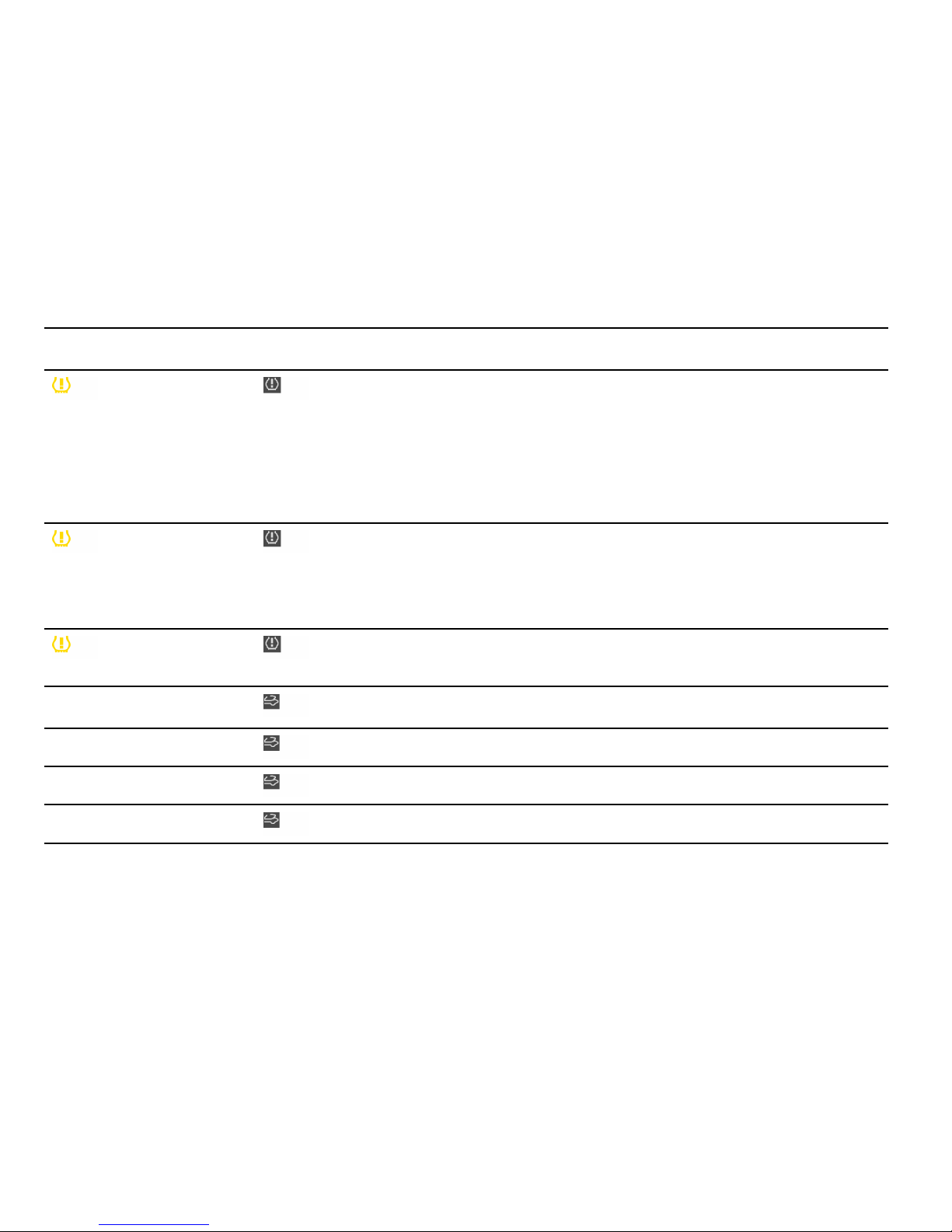
Instrument panel On-boa rd computer
Text display on on-board
comp uter Meaning/measure
TPC inactive
Brief disturbance
TPC inactive
Too many wheel transmitters
The Tire Pressure Monitoring
is temporarily deactivated by
excessive tire temp eratures
(approx. 120 C (248F)) or
external interference (e.g. from
other wheel transmitters inside
the car). Once the source of the
interference is removed, the system
is automatically reactivate d .
Wheel change? Inpu t new TPC
settings
Update the settings in the TPC menu
of the on-board computer at the next
opportunity. Wrong entries will affect
the correct pressure inform ation in
the m enu. The safety of your veh icle
is at risk.
TPC
Indicato r fault y
The display of the Tire Pressure
Monitoring is faulty. Consult your
autho rized Porsche dealer.
Failure Converti ble-top control Have the fault remedied at an
autho rized Porsche dealer
Convertible top not in limit position
Fully o pen or close convertible top.
Opening convertible top Message goes out in final position.
Closing convertible top Messag e goes out i n fin al position.
142Controls, Instruments
Downloaded from www.ManualsFile.com manuals search engine

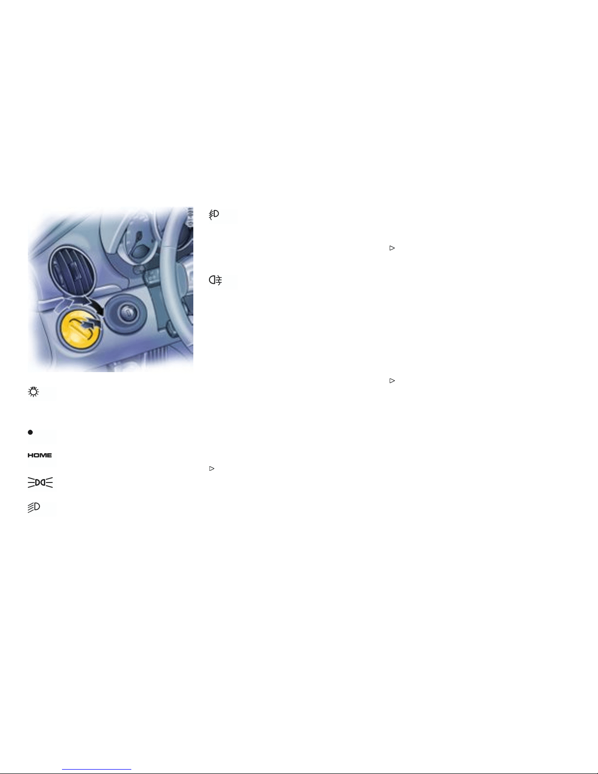
Light S witch
Switch settings
Lights switched off
Welcome Home Function
Parking lights, side marker lights,
license plate light, instrument illumination
Low beam, high beam
Only with ignition on
Fog lights in addition to parking lights or
low beam:
Pull switch to first click.
Indicator light on.
The fo g lights will go out automatically
when the high beams are switched on.
Rear fog light in addition to the fog
lights:
Pull switch to secon d click.
Indicator light on.
Warn ing chime
If the ignitio n key is withdrawn and the door is
opened while the l ights (not the parking light or
Welcome Home lighting) are on, a chime warns of
possibl e battery discharge.
In some countries, differences are possible
due to provisions of law.
Vehicles with Sport Chrono Plus Package
Further ind ividual light functions (e.g. daytime
driving lights) are available in vehicle s with the
Sport Chrono Plus Package.
Please observe the chapter “Indivi dual
Memory” in the separate PCM operating
instructions.
Welcome Home Lighting
Switching on
Move light switch to the HOME position.
For improved visibili ty and security whe n you get in
and out of the car, the fog lights and the tail lights
remain on for a certain p eriod of time:
– When you get out of the car, the lights are
turned on fo r approx. 30 secon ds after the
door is opened. The off-d elay time resumes
when the vehicle is locked. On vehicles with
the Sp ort Chrono Plus Package, the PCM can
be used to set the off-delay time. This sett ing
also changes the lighting period for unlock ing
the vehicle.
Please observe the chapter “Individual
Memor y” in the separate PCM operating
instructions.
– The lights are turned on for approx. 30 sec-
onds w hen the veh i cle is unlocked. The
lights go out if the igniti on is switched on or
when leaving the Welcome Home lighting
If the ignition key is withdrawn and the door is
opened while the lights (not t he parking light
left/right) are on, a gong warns of possible battery
discharge.
In some countries, differences are possible
due t o provisions of law.
144Controls, Instruments
Downloaded from www.ManualsFile.com manuals search engine

Automatic Headlight Beam Adjustment
Vehicles with Bi-Xenon headlights feature
automa tic headlight beam adjustment.
When the ignition is switch ed on, the level of
the headlight beam automatical l y changes in
accordance with t he vehic le load. The level of
the headlight beam is aut omatically kept constant
during acceleration and braking.
Checking operation
1. Switch the low beam on.
2. Inser t ignition key and switch ignition on. The
light beam first dips all the way down and is
then adapted to the vehicle load.
If these test items are not met, the headlight beam
adjustment must be checked by an authorized
Porsche dealer.
Controls, Instruments
145
Downloaded from www.ManualsFile.com manuals search engine
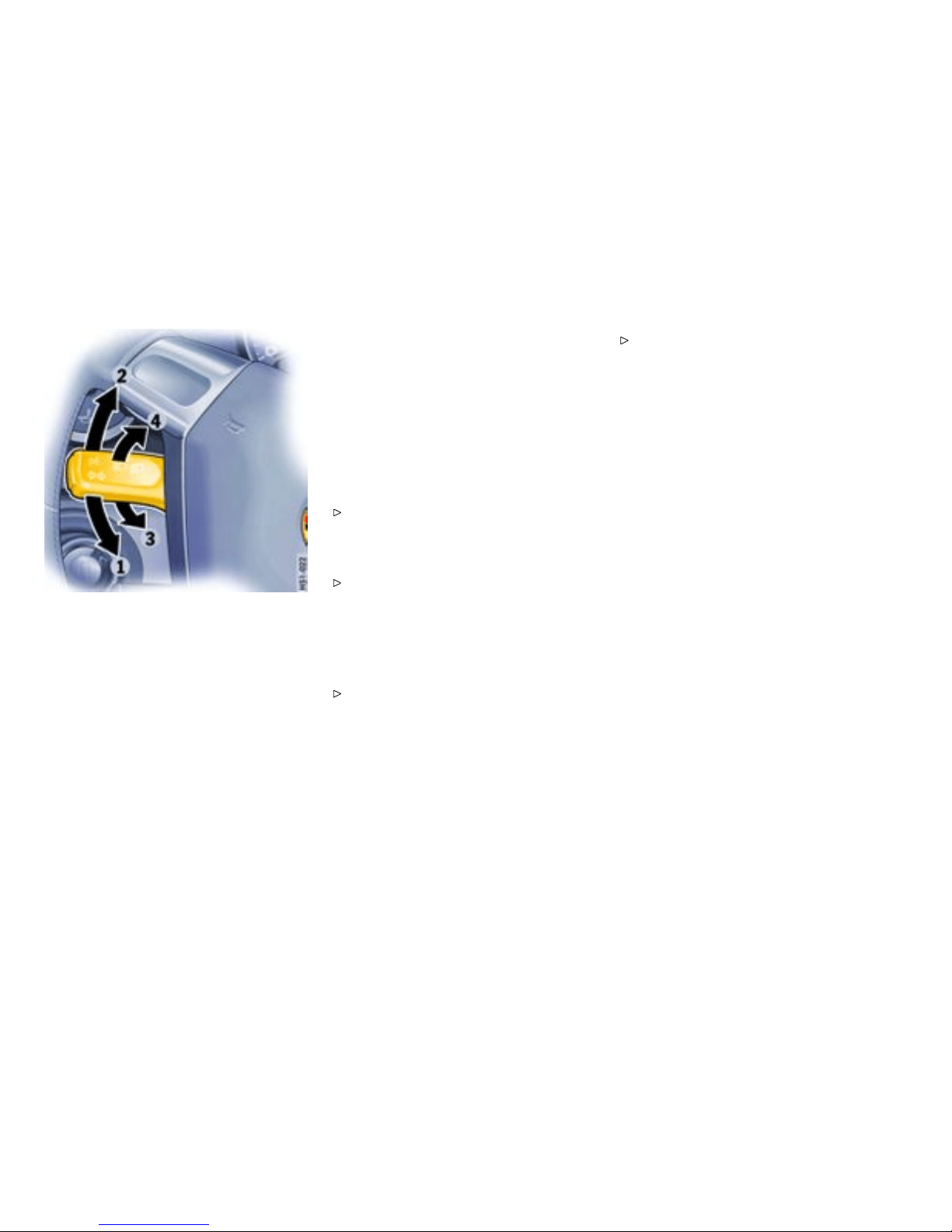
Turn Signal/ Headl ight
Dimmer/Parking light / Flasher
Lever
Operation
Turn sig nals, low beam and high beam are ready
for operation when the ignition is o n.
1 - Turn signal left
2 - Turn signal righ t
Push the l ever to the upper or lower pressure
point - turn signals flash three times
3 - High beam
4 - Headlight flasher
Lever in center position - Low beam
When high beam and headlight flasher are select-
ed, the blue indicator ligh t in the tach ometer is lit.
The turn signal lever turns off automatically
when the steering wheel is straightened out after
completing a turn.
Lane ch anger
To indicate your inte n tion wh en changing lanes
on the freeway, slightly lift or d epress the le v er
to the resistance point. The lever will return to
the OFF position when released.
If the frequency of the display becomes
noticeable faster, check the operation of the
turn signal bulbs.
Headlight asher
(With ignition on or off)
To flash the headlights to on comming moto r-
ists, slightly p ull the lever toward the steering
wheel and then release it. The blue indicator
light in the t achometer will go on / off as you
pull/release the lever.
Parking light
The parking light can only be switched on when the
ignition is s witched off.
Move the lever up or down to s witch o n the
right or left parking light.
146Controls, Instruments
Downloaded from www.ManualsFile.com manuals search engine
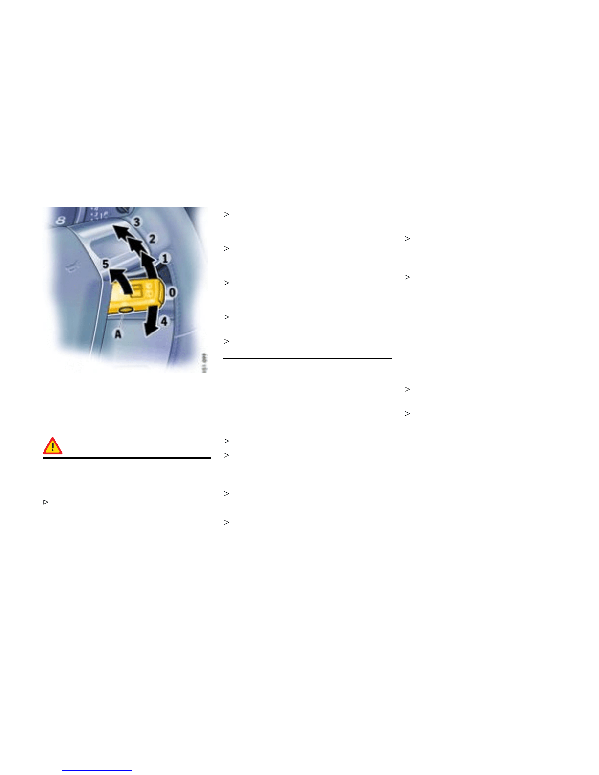
Windshie ld Wiper / Washe r Lever
General information to the windshield
wipers
Warning!
Dange r of injury when the windshield wipers
operate unin tentionally. Risk of damage to
the windshield and wiper system.
Avoid running the wiper blades over a dry
windshield to prevent scratching the glass.
Spray washer fluid on the windshield first. A
scratched windshield w ill reduce visibility.
Always loosen wipe r blades from frozen glass
before oper ating w ipers to prevent damage to
the wiper motor or b lades.
Always switch off winds hield wipers in car
wash to prevent them wip ing unintentionally
(intermittent or sensor operati on).
Always switch off windshield wipers before
cleaning the windshield to avoid unintentional
operation (intermittent or sensor op eration).
Do not opera te the headlight washer in c ar
washes.
Do not operate headlight wa sher whe n it is
frozen.
Wiper and headli ght washer system
0 – Windshield wipers off
1 – Intermittent/rain sensor oper ation for
front windshield wipers
Move wiper lever upwards to the first click.
Please observe the chapter ”RAIN SENSOR” on
page 148.
2 – Windshield wipers slow
Move w iper lev er upwards to the second click.
3 – Windshield w ipers fast
Move wi per leve r upw ards to the third click .
4 – Front windshield wiper - one-touch opera-
tion:
Move wiper lever downwards. The winds hield
wipers wipe once.
5 – Windshield w ipers and washer system:
Pull wiper lever towards the stee ring wh eel.
The washer system sprays and wipes while
the lever is p ulled towards the steering wheel.
When the wiper lever is released, a few drying
wipes are executed.
A - Headlig ht washer (Ve hicles with
Bi-Xe non headlights):
The washer sprays only while low beam or high
beam is switched on.
Briefly push button A to operate headlight
washer system.
If heavily soil ed, repeat wash.
The headlight washer system automatically sprays
once for every ten times the front windshield
washer system is o perated.
Note
The windshield washer nozz les are heated when
the ignition is on, as a precaution against freezing.
Controls, Instruments
147
Downloaded from www.ManualsFile.com manuals search engine

Wipe inte rval control
Function
On vehi cles without a rain sensor, the wiping
interva ls can be adjusted in four steps.
Decreasing intervals
Adjust switch A upwards. The setting is
confirmed by one wipe of the windshield.
Increasing intervals
Adjust switch A downwards.
Rain sensor
In vehicles with a rain senso r the amount of ra infall
(snowfall too) which has se t tled on the windshield is
measured. Wiper speed is automatically adjusted
accordingly.
Switching on
Move wiper lever upwards to the fi rst click.
Switching off
Move wiper lever to po sition 0.
The rain senso r remains switched off if the wiper
lever is already in posit ion 1 when the ignit io n is
switched on.
To switch the rain sensor on again :
Move wiper lever to po sition 0 and then to
position 1 or
Opera te windshield washer system 5 or
Change the sensitivity of the rain sens or with
four-stage switch A.
Switch-on is confirmed by one wipe of the wind-
shield.
On vehicles with the Sport Chrono Plus Package,
further rain sensor functions can be selected via
the PCM.
Please observe the chapter “Indivi dual
Memory” in the separate PCM operating
instructions.
Changing the sensitivi ty of the ra in sensor
Sensitivity can be set with switch A in 4 stages:
Adjust switch A up wards - high sensitivity.
The setting is confirmed b y one wipe of the
windshield.
Adjust switch A downwards - lo w sensitivity.
Maintenance note
Periodically clean the wiper blades with a win -
dow cleaner, especially after the vehicle has
been washed in a c ar wash . We recommend
Porsche window cleaner. If they are very dirty
(e.g. with insect remains), they can be cleaned
with a spon ge or c loth.
If the wiper blades rub or squeak, this may be as a
result of t h e following:
If the vehic le is washed in an automatic car wash,
wax residues may be adhering to the windshield.
These wax residues can be removed using a
window cleaner concentrate.
Please observe the chapter ”WASHER FLUID”
on page 228.
Please contact your authorized Porsche d ealer fo r
further information.
The wiper blades may be damaged.
Replace damaged wiper blad es as soon as
possible.
148Controls, Instruments
Downloaded from www.ManualsFile.com manuals search engine
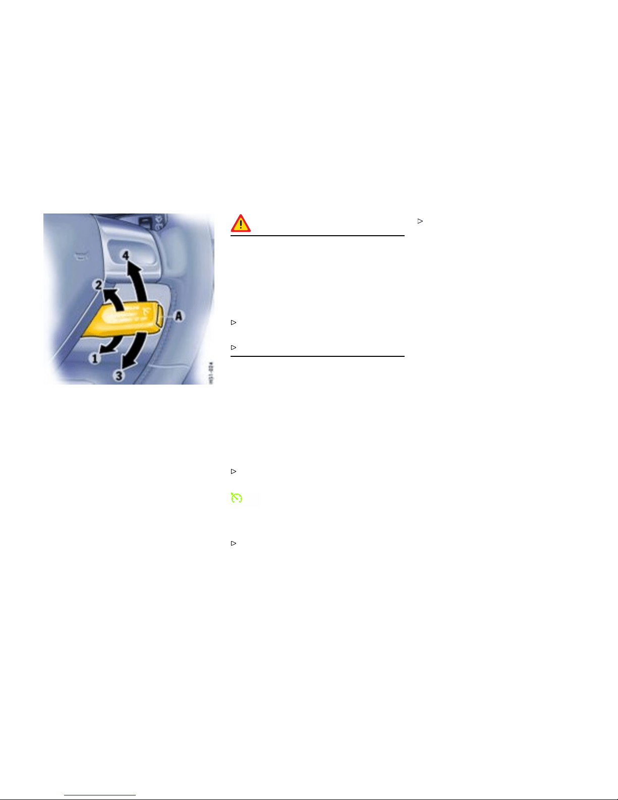
A - Automatic speed control readiness off/on
1 - + SPEED/SET (ac celerate/store)
2 - - SPEED (decelerat e)
3 - OFF (interrupt)
4 - RES UME
Automatic Speed Control
Function
The au tomatic speed control maintains any
selected speed betw een 15 mph and 145 mph
(30 km/h and 240 km/h) without you h aving t o
use the accelerator pedal. The a u tomatic speed
control is o perated with the lev er on the steering
wheel.
Warning!
Risk of an accident, resulting in serious
personal injury or death. A constant speed
may not be safe in heavy t raf c, or on win ding
or slippery roads. With the speed control
system engaged, the engine speed will not
return to idle when removing the foot from the
accelerator pedal.
Do not use the speed control when it may be
unsafe to keep the car at a constant speed.
Observe all l ocal and national speed limits.
Vehicles with Tiptronic S
Additional downshifts are carried out to help
maintai n the pre-selecte d speed (especially when
driving downhill).
Switch automatic speed co ntrol readi ness
on
Press button A on the automatic speed cont rol
lever.
This green indicator light in the speedom-
eter now indicates readiness.
Hold and store speed
Bring the car to the desired speed with the
accelerator.
Then briefly push th e operating lever forward
(position 1).
Controls, Instruments
149
Downloaded from www.ManualsFile.com manuals search engine

Acceler ating (e .g. to overtake)
Option 1
Increase the speed as usual with the accele r-
ator. When you ease off th e accelerator, the
previously s aved val ue is se t again.
Option 2
Push operating lever forwa rd (position 1) until
the desired speed is reached. The sp eed
reached is maintained and stored when the
lever is released.
Option 3
Push lever slig htly forwards (positio n 1)
(a max imum of 10 times). The s p eed is
increased by 1 m p h (1.6 km/h) each time.
Note on operation
Speed control oper ation is automatically interrupt-
ed if the speed is increased by more than approx.
16 mph (25 km/h) fo r longer than 20 seconds.
Decelerating
Option 1
Pull operating lever towards the steering wh eel
(position 2) until the desired speed is reached.
The speed reached is maintained and stored
when the l ever is released.
Option 2
Briefly move lever towards the steering wheel
(position 2) (a maximum of 10 times) . The
speed is reduced by 1 mph (1.6 km/h) each
time.
Vehicles with Tiptron ic S
Additional downshifts are carried out to imp rove
deceleration (especially when driving down hill).
Interrupting automatic speed contro l
operation
Manual in terruption
Pull operating lever do wnwards brie fly
(position 3) or
Operate brak e or clutch pedal or
Switch Tiptronic transmission to selector lever
positio n N.
Please observe the chapte r ”TIPTRONIC S” on
page 187.
The speed driven bef ore the interruption remains
stored in the memory.
Automatic speed control operation is
interrupted automatically:
– If the set v ehicle speed is exceeded by more
than approx. 16 mph (25 km/h) for longer than
20 seconds.
– If the actual vehicle speed falls to approx.
6 mph (10 km/h) below the set vehicle speed
for lon ger than 5 seconds (upward slopes).
– For PSM control operations.
Resuming the stored speed
Briefly push operating lever upwards (position
4). The speed control accelerates/decele r-
ates the vehicle to the stored speed.
150Controls, Instruments
Downloaded from www.ManualsFile.com manuals search engine

The stored speed should only be recalled when
traffic conditions an d the road surface so permit.
Switching autom atic speed control
readiness off
Press button A on the automatic speed
control lever. The green readiness light in
the sp eedometer goes off.
When the vehic le is parked and the ignition
switched off, the memor y is cleared.
Note
On upward or downward slopes, the set speed
cannot always be maintaine d by the auto m atic
speed control.
To obtain sufficient engine braking or a better
engine -speed range, therefore, you have to select
a lower gear.
Controls, Instruments
151
Downloaded from www.ManualsFile.com manuals search engine
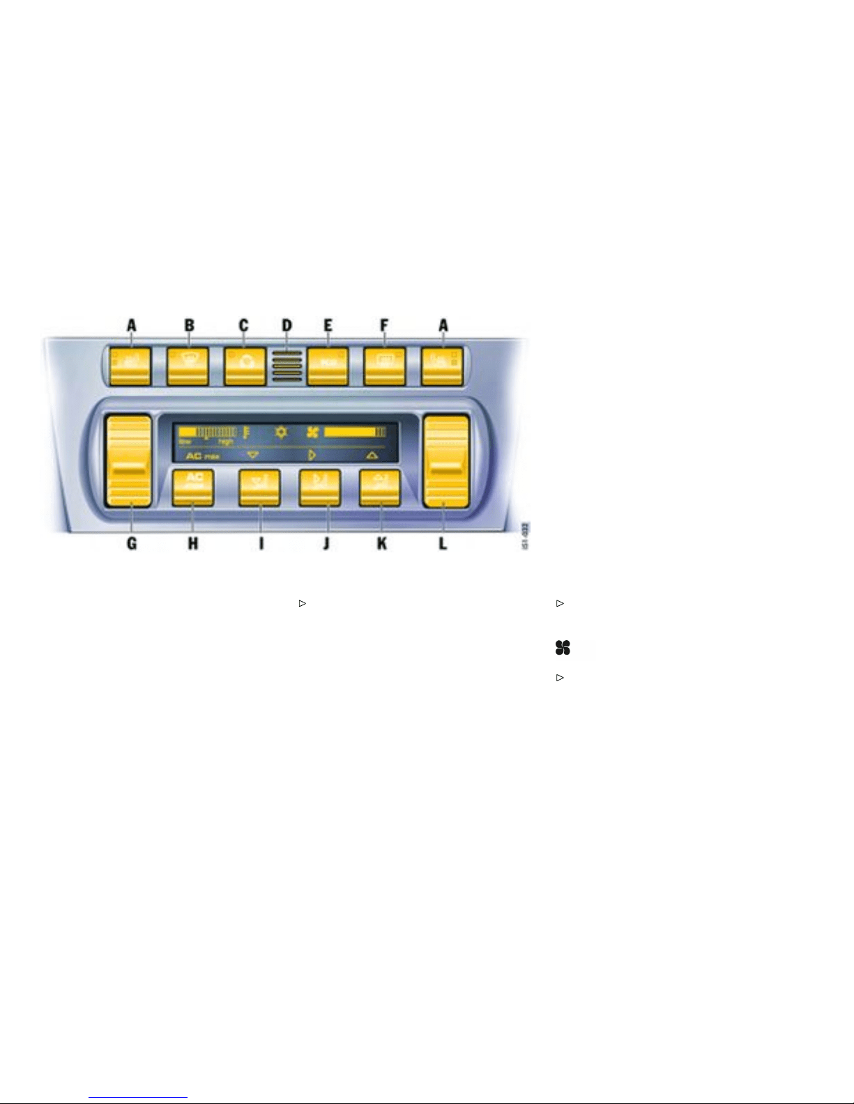
A - Seat heating
B - Defrosting the windshield
C - Recirculating -air button
D - Tempe rature sensor
E - ECO button (air-conditioning compressor
off/on)
F - Heated rear window
G - Temperature button
H - AC max
I - Air distribution to footwell
J - Air distribution to central and side vents
K - Ai r distribution to windshield
L - Blower speed butto n
Air conditioning
The display panel shows the following
Air quantity, air distribution, and temperature can
be se t on the control panel.
– Temperature
– Air-conditioning compressor on/off
– Blower speed
– AC max
– Air dis tribution
Setting temperature
Press butt on G u p wards or do wnwards
respectively.
The s elected t emperature is shown on the di splay
by a bar display.
If a bar cannot be seen , the temperature is set to
maximum cold.
If all bars can be seen, the temperature is set to
maximum warm.
Note
For maximum cooling, activate AC max button
H.
Adjust ing blower speed
Press button L upwards or downwards
respectively.
The blower speed is shown on the disp lay by a bar
display.
The compressor is switched of f at low blower
speeds.
152Controls, Instruments
Downloaded from www.ManualsFile.com manuals search engine
Defrosting the wi ndshield
Press button B (switch on or off). The light-
emitting diode in the button lights up. The
windshie ld is demisted or defrosted as quickly
as possible. Air flows to the windshield only.
Recirculating-air setting
Function
The outside-ai r supply is interrupted and only the
inside air is circulated.
Warning!
Risk o f accident due to impaired vision,
resulting in se rious p ersonal injury or death.
In recirculating-air setting, the windows may
fog up.
Only sel ect recirculating-air setti ng for short
periods.
If the windows fog up, switch recirculating-air
setting off immediately by pressing the
recirculating-air b utton again and select the
“Defrost windshield” function.
Switching circulating-air mode on or off
Press circulating-air button C. The light-
emitting diod e in the button lights up.
ECO - switching the air-condit ioning
compressor on and off
The air con d itioning compressor switches off
automa tically at temperatures below approx.
37°F /3°C and ca nnot be switched on , even
manually.
Whenev er outside temp eratures exceed ap p rox.
37°F /3°C , the air-con ditioning compressor can
be switched on or off manually.
The compressor can be switched off manua l to
save fuel.
Press ECO butto n E. The light-emittin g diode
in the button ligh ts up. The compressor is
switche d off.
If the interior temperature is too high, switch
on the compressor again.
To dry incoming air in damp weather, do not s witch
off the air-conditioning compressor. This prevents
misting of windows.
AC max operation
In AC max operation, the i nterior o f your vehicle is
cooled as quickly as possible.
Press AC max button H. The l ight-emitt ing
diode in the button lights up.
Controls, Instruments
153
Downloaded from www.ManualsFile.com manuals search engine

Air distri bution
Settings
The ind ividual air distributions ca n be combined
as desired. If an air distribution is not selected, no
symbol appears in the display panel. Air flows then
from all vents as well a s to the windshield.
Recommended setting in Summer - Air distri bution
to cen t ral and side vents
Recommended s etting in Winter - Air distribution to
footwell and windshield
Air distribution to footwell
Press button I. The selection appears on the
display panel. The air flows to the footwell.
Air distribution to center and side
vents
Press button J. T he selection appears on the
display panel. The ai r flows from the central
and si de vents . Vents must be open.
Air distribution to windshield
Press button K. The sele ction ap pears on the
display panel . The air flows to the windshield.
Information on air-conditioning
compressor
– May s witch off briefly to ensure sufficient
engine cooling if the engine is operati ng under
extreme load.
– The air cond itioning compressor switches off
automa tically at temperatures below approx.
37°F /3°C and ca nnot be switched on , even
manually.
– Opera tes most effectively with the windows
closed. If the vehicle has been in the sun for
a long time, it is a good idea to ventilate the
interior briefl y with the windows open.
– Depending on the o utside temperature and
humid ity, condensation c an drip from the
evaporator and form a pool under the car. This
is no rmal and not a sign of leakage.
If unc ooled air flows out when the lowest
tempe rature has been set, switch off the air
conditioning co mpressor and have the fault
remedied. Please contact your authorized
Porsche dealer for further information .
154Controls, Instruments
Downloaded from www.ManualsFile.com manuals search engine
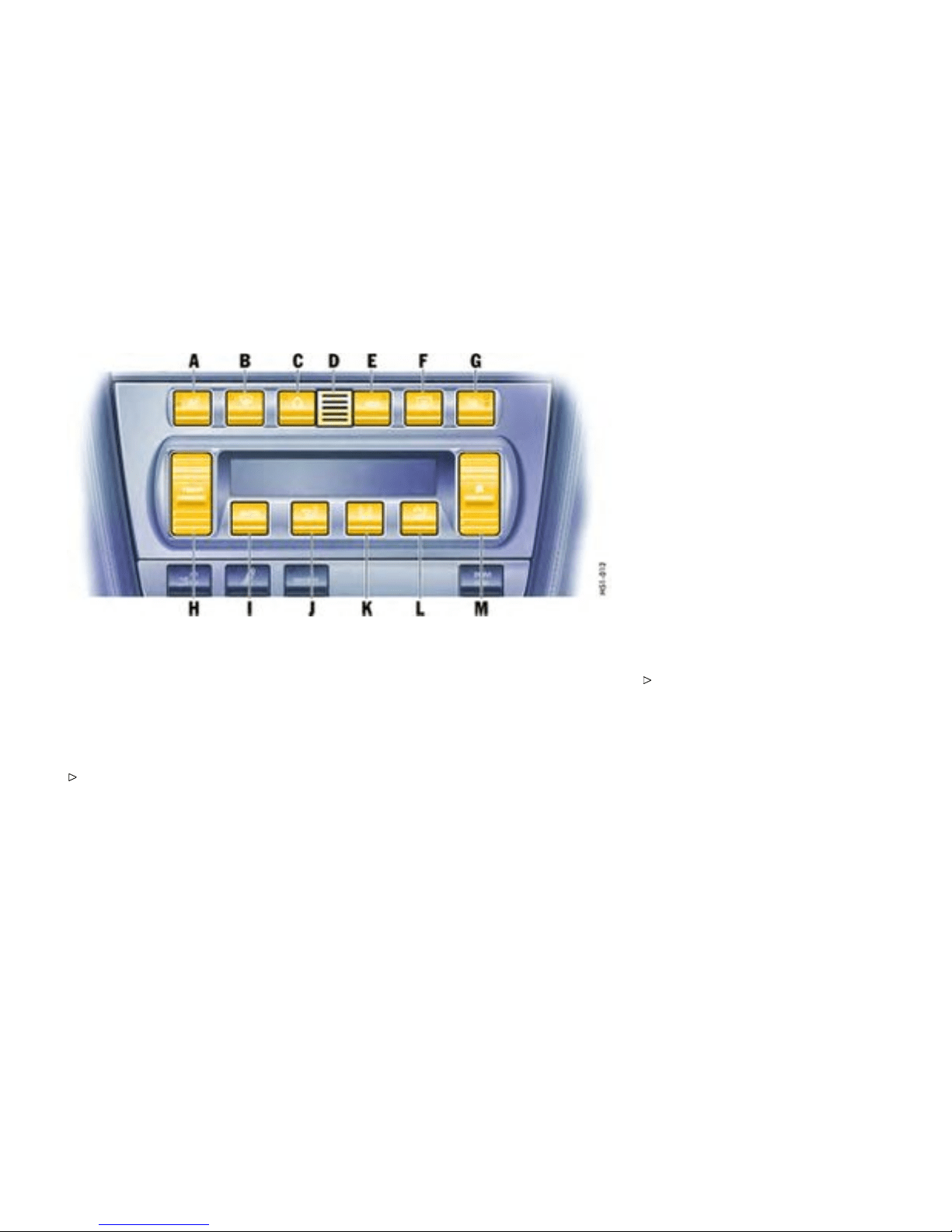
A - Seat heating, left
B - Defrosting the windshield
C - Recirculating -air button
D - Temperature sensor
E - ECO button (air-conditi oning compressor
off/on)
F - Heated rear window/door mirror heating
G - Seat heater, right
H - Temperature button
I - AUTO button (automatic mode)
J - Air distribution to footwell
K - Air distribution to cen tral and side vents
L - Air distribution to windshield
M - Blower spee d button
Automatic air conditioning system
Automatic mode
The automatic air-co nditioning system cont rols
the preselected interior temperature completely
automatically. If necessary, the autom atic system
can be manually inf luenced.
Press AUTO button I. AUTO will appe ar on the
display panel. Air quantity an d distribution are
automatically controlled and variations are
compensated.
All automatic setting functions can be individually
changed. This sett ing is retained until the appropri-
ate function button is pressed again or the AUTO
button is pressed.
Setting t e mperature
Press butt on H upwards or d o wnwards
respectively.
To suit personal com fort, the interior t em-
perature can be adjusted between 61°F and
85°F /16°C and 29.5°C .
Recom mendation: 7 2F/22C.
If “LO” or “HI” app ears on the display, the system is
operating at maximum cooling or he ating power.
Automatic control is no longer active.
Controls, Instruments
155
Downloaded from www.ManualsFile.com manuals search engine
Note
If the preselected temperature is changed, the
blower speed can increase au tomatically in
automatic mode. The desired temperature is
reached more quickly this way.
Sensors
To avoid affecting the perf ormance of the air-condi-
tioning system:
Do not cover the sun sen sor on the instrument
panel or the temperature sensor D.
Defrosting the windshield
Press button B (switch on or off). Th e wind-
shield is demisted or defrosted as quickly as
possible . Air flows to the windshield only. The
light-emitting di ode in the button lights up.
ECO - switching comp ressor for
air-conditionin g system on and off
The ai r conditioning compressor switches off
automatically at temperatures below approx.
37°F /3°C and cannot be switched on, even
manually.
Whenever outside temperatures exceed approx.
37°F /3°C , the air-conditioning compressor is
always switched on in aut omatic mode.
The compressor can be switched off manually to
save fuel, but control comfort is the n limited:
Press ECO button E. The compressor is
switched of f. The light-emitting diode in t he
button lights up.
If the interior temperature is too high, switch
compressor back on or press AUTO button.
To dry incomi ng air in damp weat her, do not switch
off the air-conditioning compressor. This prevents
misting of windows.
Adjusting blower speed
Press butt on M upwards or downwards
respectively. The preset blower spe ed is
increased or decreased.
The speed stages are indicated by a bar display.
The compressor is switc hed of f at low blower
speeds.
If the button is pressed downwards at the lowest
blower stage, the blower and auto matic control are
switched off. “OFF” will appear on the display field.
Pressing th e button upwards or pressing the AUTO
button switches the blower and automatic control
back on again.
Recirculating -air setting
Function
The outside-air supply is in terrupted and only the
inside air is circulated.
Warning!
Risk of accident due to impaired vision,
resulting in serious personal injury or death.
In recirculatin g-air setting, the windows may
fog u p.
Only select recirculating-air setti ng for shor t
periods.
If the windows fog up, switch recirculating-air
setting off immediately by pressing the
recirculating-air button again and select the
“Defrost windshield” functi on.
Switching recirculatin g-air setting o n or off
Press button C. T he light-emitting diode in the
button lights up.
Over approx. 37°F/3°C
If the air-conditioning compressor was off, it
switche s on automatically. The duration of
recirculating-air setting is not limited.
156Controls, Instruments
Downloaded from www.ManualsFile.com manuals search engine

Below approx. 37°F/3°C
The air-conditioning compressor is switched off.
Recirculating -air setting is automatically ended
after approx. 3 minutes.
Air distribution
Settings
The in dividual air distributions can be combined as
desired.
Recommended setting in Summer - Air distribution
to central and side vents
Recommended setting in Winter - Air distribution to
footwell and winds hield
Air distribution to footwell
Press button J. T he air flows t o the footwell.
The selection appears on the displ ay panel.
Air distribution to center and side
vents
Press button K. The air flows from the central
and side vent s. Vents must be open. The
selection appears on the display panel.
Air distribution to windshield
Press button L. The air flows to the windshield.
The selection appears on the displ ay panel.
Note on operation
On veh i cles with the Sport Chrono Package
Plus, individual air conditioning settings can
be sto red on your car k ey. Pleas e observe the
chapte r “Individual Memory” in the separate
PCM operating instructions.
Inform ation on air-conditioning
compressor
– May s witch off briefly to ensure sufficient
engine coolin g if the engine is operating under
extreme lo ad.
– The air conditioning compressor switches off
automatically a t temperatures below approx.
37°F /3°C and cannot be swit ched on, even
manual l y.
– Opera tes most effectively with the wind ows
closed. If the vehicle has been in the s un for
a long time, it is a good idea to ventilate the
interior briefly with the windows open.
– Depending on the o utside temperature and
humid ity, condensation can drip from the
evapor ator an d form a pool under the car. T h is
is no rmal and not a sign of l eakage.
If uncooled air flows out when the lowest
temperature has been se t, switch off the air
conditioning c ompressor and have the fault
remedied. Please contact your authorized
Porsche dealer for further information.
Controls, Instruments
157
Downloaded from www.ManualsFile.com manuals search engine
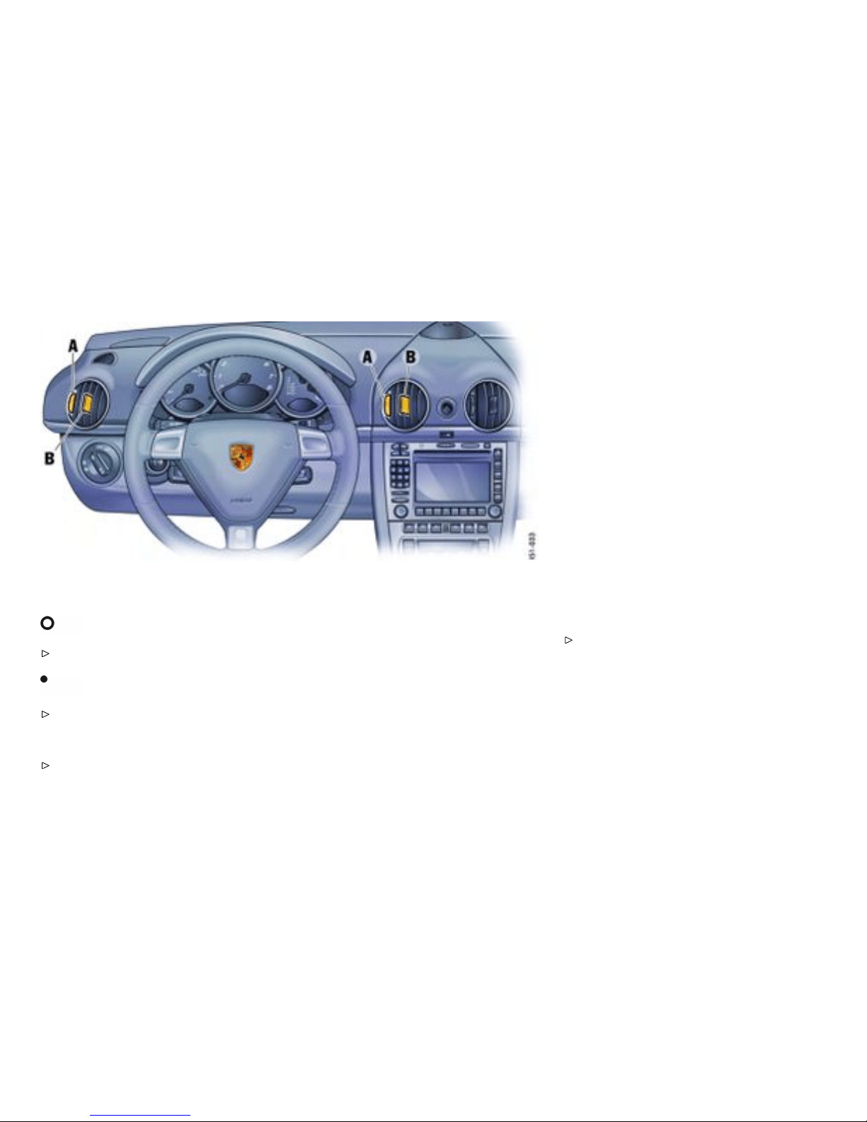
A - Continuous opening and closin g
B - Setting vent direction
Central and side vents
Opening vents
Rotate thumb wheel upward.
Closing vents
Rotate thumb wheel downw ard.
Changing air ow direction
Swivel the ve nt fins in the desired direction.
Outsid e air or conditioned air can be delivered from
all vents depending on the air-distribution setting
on the operating panel.
Fresh-air intake
In order to ensure un hindered air intake:
Keep the fresh-air intake between the wind-
shield and the luggage compartment lid free
from snow, ice and leaves.
158Controls, Instruments
Downloaded from www.ManualsFile.com manuals search engine
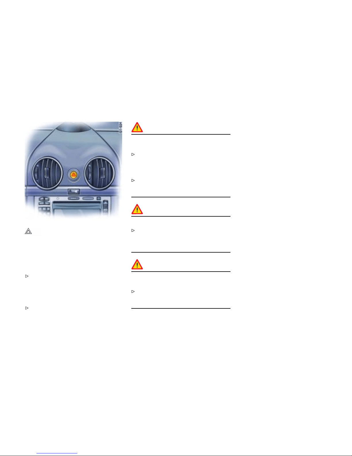
Emergenc y Flasher Switch
Switching on and off
Operational readiness of t he eme rgency flasher
does not dep end on the ignition lock and turn signal
lever position.
If your car is disabled or parked under emer-
gency conditions switch on the emergency
flasher in the dashboard. All turn signals and
the indicator light in the switch flash with the
same frequency.
Press butto n.
Warning!
Risk of ac cident, resulting in serio us per sonal
injury or death.
Wheneve r stalled or stopped for emergency
repairs, move the car well off the road. Switch
on the emergency flash er and mark the car
with road fl ares or other warning devi ces.
Do not remain in the car. Someon e approach-
ing from the rear may not realize your vehicle
is stopped and cause a collision.
Warning!
Danger of re.
Do not park or operate the vehicle in a reas
where the hot exhaust system m ay come in
contact with dry grass, bru sh, fuel spill or
other flammable material.
Warning!
Hot engine compartment components can
burn skin on contact.
Before working on any part in the engine
compartment, turn the eng ine off and let it
cool d own sufficiently.
Controls, Instruments 159
Downloaded from www.ManualsFile.com manuals search engine
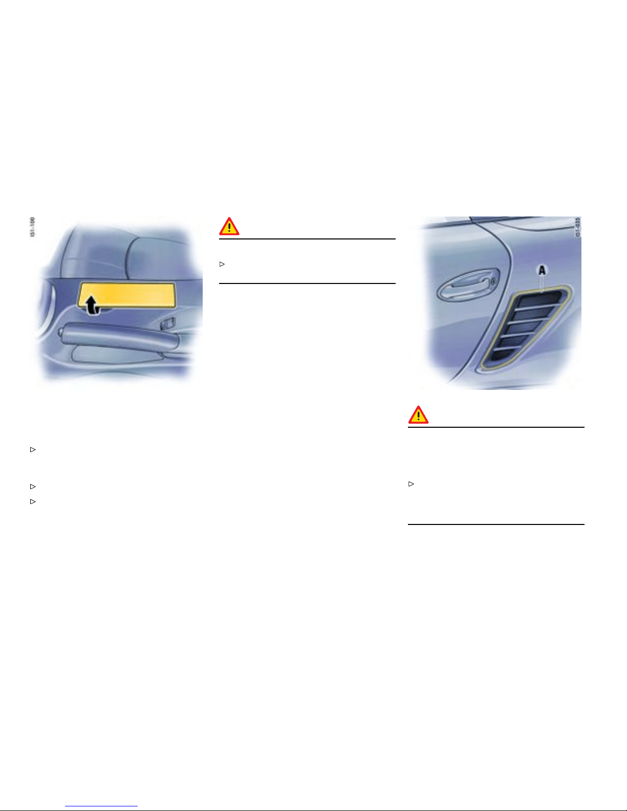
Ashtray
Opening
Open ashtray lid.
Emptying
Open ashtray and carefully pull out ash insert.
Leave ashtray lid open. Push in ash inser t.
Warning!
Danger of re.
Never use ashtray for waste paper disposal,
as it could pose a fire hazard.
Danger!
Dange r of re in engine compartment due
to burning c igars or cigarettes. Serious
personal injur y or death could result from
re in th e engine compartment.
Do not throw any lit cigars or cigarettes out
of the vehicle. They can be blown into the air
inlets A by the a ir flow and cause a fi re in the
engine compartment.
160Controls, Instruments
Downloaded from www.ManualsFile.com manuals search engine
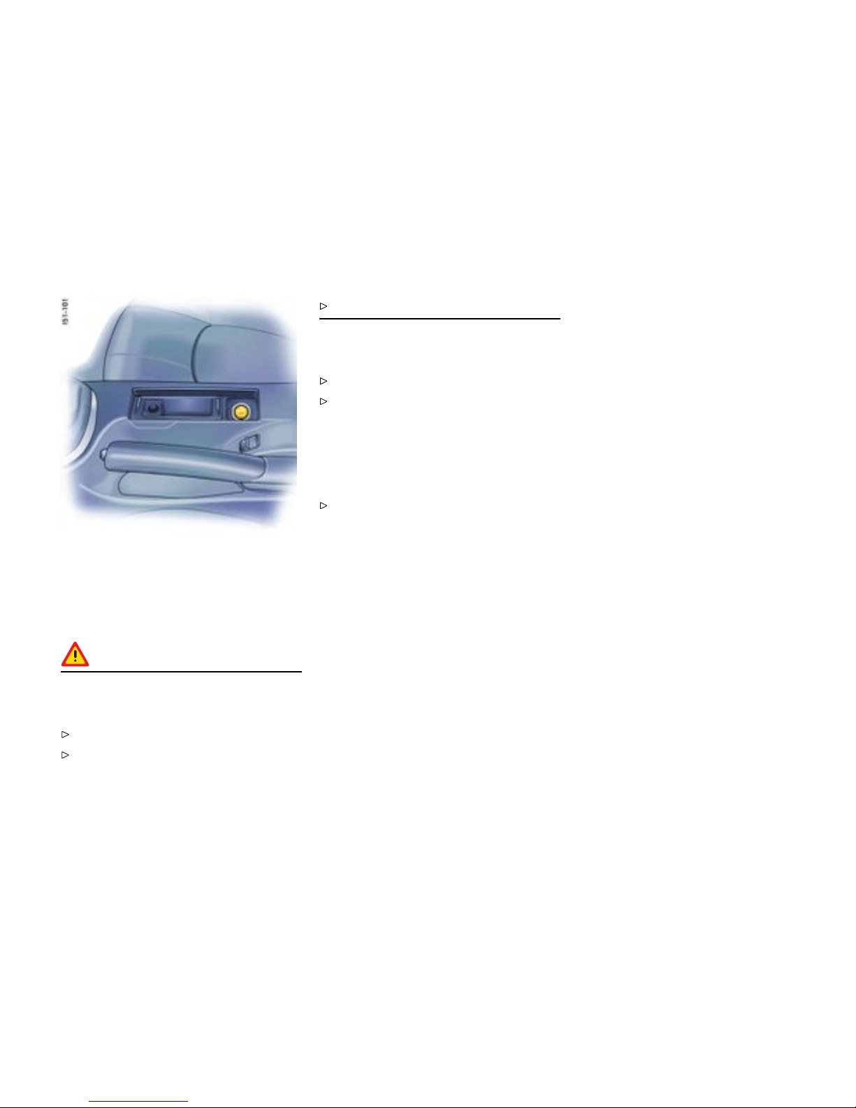
Cigarette Lighter
Readiness for oper ation
The cigarette lighte r is ready for use regardless of
the ignition lock position.
Warning!
Dange r of re and burning. The cigarette
lighter is ready for use, regardles s of the
ignition lock posi tion.
Never leave unsup ervised c h ildren in the car.
Never touch the heating e lement or sides of
the lighter.
Hold the lighter by the k n o b only.
Heating lighter
Open ashtray lid.
Push in knob of the cigarette lighter. When
ready for use, the lighte r will snap back.
Note on operation
The lighter recep tacle is not to be used for
electrical accessories (except for the tire filling
compressor).
Please observe the chapter ”SOCKETS” on
page 162.
Controls, Instruments
161
Downloaded from www.ManualsFile.com manuals search engine
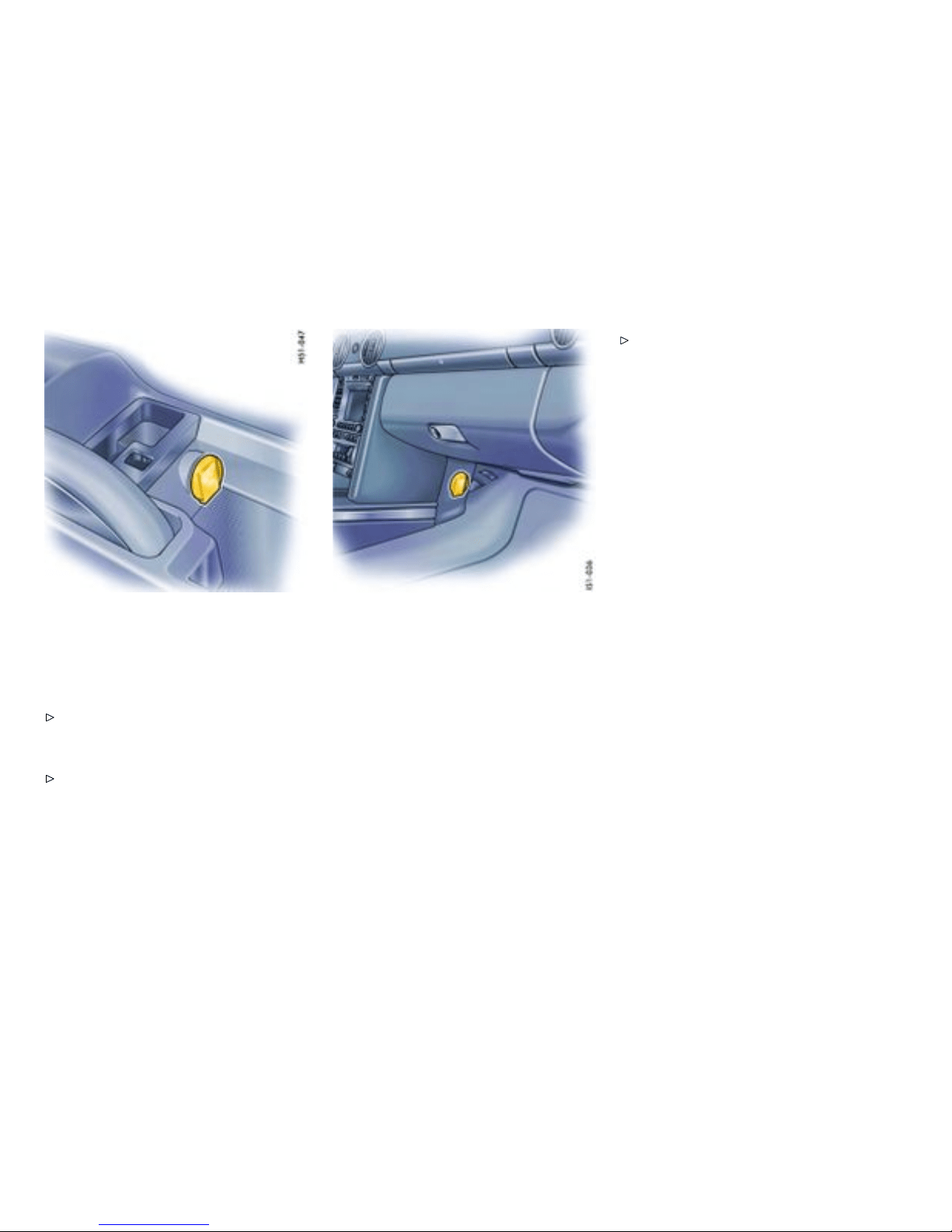
In storage tray between the seats
Sockets
Electrical accessories should preferably be
connected to the 12 V sockets.
Please obse rve the maximum power consump-
tion.
Note on operation
The tire fill ing com pressor must be connected
to the cigarette l i ghter.
In the passenger’s f ootwell
Note on operation
The sockets and thus the connected electrical
accesso ries will function even if th e ignition is
switch ed off or the ignition key is wi thdrawn.
If the engine is not running and the accessor ies are
switched on, the vehicle battery will b e discharged.
Do not operate addi tional accesso ries for more
than 5 minutes when engine is off. Continuing to
do so may drain the battery such that it may go
completely dead.
Maxim um power con sumption for both
sockets together: 70 W.
Please observe the power specifications from
the accessory manuf acturer.
162Controls, Instruments
Downloaded from www.ManualsFile.com manuals search engine
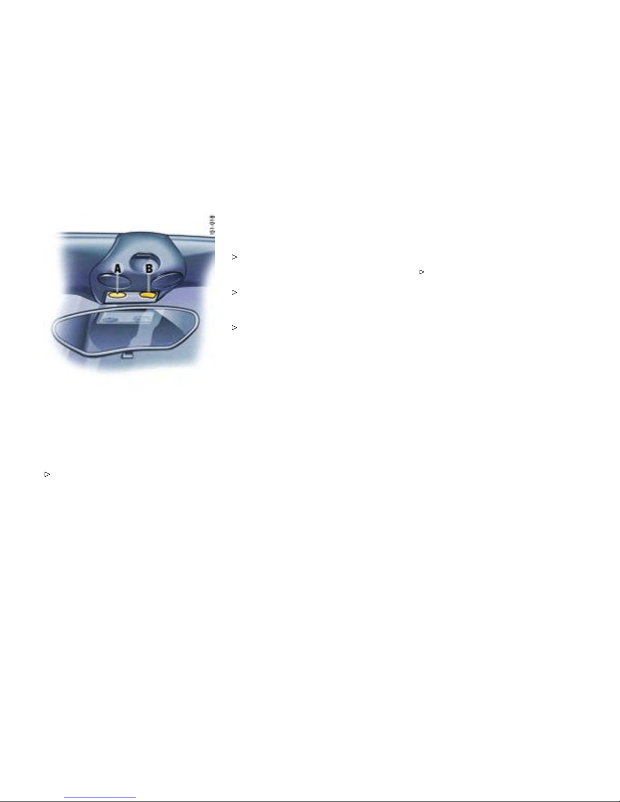
A - Orientation light
B - Interior light sw itch, footwell light
Interior lights
Automatic disconnection
Please observe the chapter ”LOAD SWITCH-
OFF AFTER 2 HOURS OR 7 DAYS” on page
265.
Interior light, footwell lights
Switching off
Press left h alf of switch.
Switching to continuous illumination
Press right half of switch.
Switching on and off automatically
Move switch to center po sition.
The lights a re switched on when a door is
unlocked or o pened or when the ignition key is
withdr awn from the ignition lock.
The lights a re switched off with a de lay of approx.
30 seconds after the door is closed.
The lights go out immediately as soon as the
ignition key is inserted in the ignition lock or the
vehicle is locked.
Orientation light
The li ght-emitting diode in the interior light
improves your orientation inside the vehicle when it
is dark.
Note on operation
On vehicles w ith Sport Chrono Package Plus, the
brightness of the orientation light can be changed
in PCM.
Please observe the chapter “Individual
Memory” in t h e separate PCM operating
instructions.
Controls, Instruments
163
Downloaded from www.ManualsFile.com manuals search engine
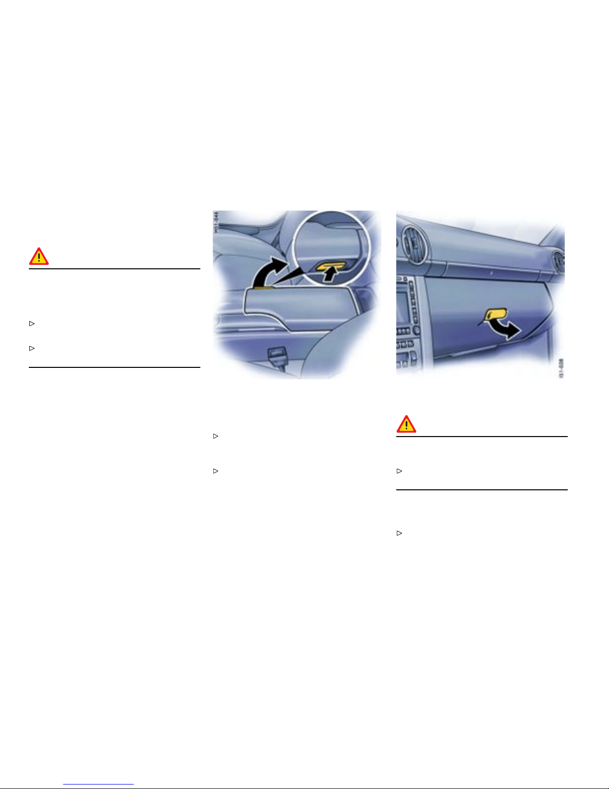
Storage in the passenger
compartme nt
Warning!
Unsecu red luggage and heavy obje cts may
come loose during braking, rapid directional
change s or in an accident an d cause serious
personal injury or death.
Do not carry items of luggage or objects in the
passenger compartment unsecured.
Do not transport any heavy objects in the
oddments trays .
Additi onal storage possibil ities
– in the doors,
– in the door sill ne xt to the passenger’s seat ,
– in the center console,
– clothes hook on back of seat backrest,
– oddments tray with c oin holder between seats,
– glove compartment with CD and pen holder,
– on engine compartment lid.
Oddments tray between the seats
Opening
Press release button and lift the lid. There is a
coin holder and socket in the forward part of
the oddments tray.
Please observe the chapter ”SOCKETS” on
page 162.
Glove compartm ent
Warning!
Danger of injury b y the glove com partment lid
in cas e of an accident.
Keep the glove compartment lid close d while
driving .
Opening
Pull the catch and open the lid.
164Controls, Instruments
Downloaded from www.ManualsFile.com manuals search engine
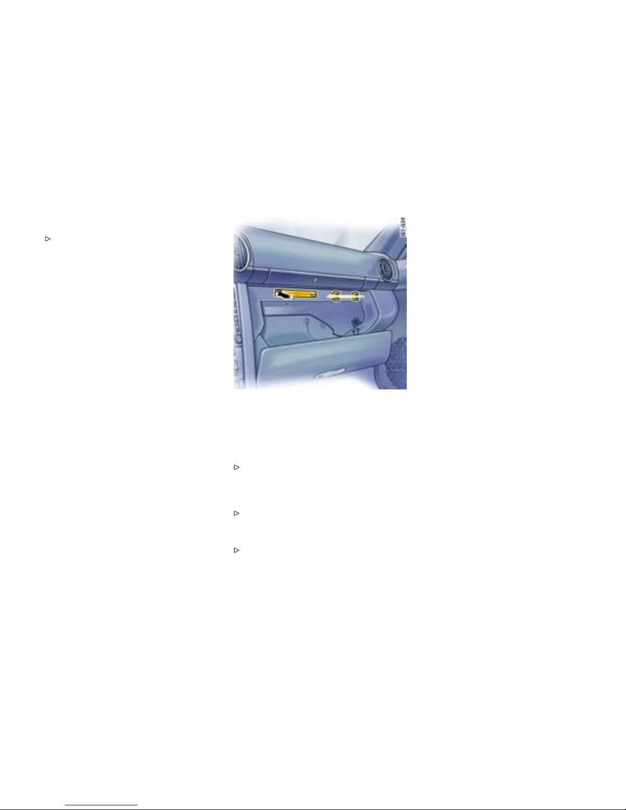
Locking
Lock the catch to secure the contents against
unauthorized access.
CD holder
Occupied drawers are indicated by a red wi ndow.
Opening drawers
Push the button of the drawer you wish to
open.
Closing d rawers
Fold up drawer and close until i t engages.
Pen holder
A pen can be clipped in on the r ight side of the
CD holder.
Controls, Instruments
165
Downloaded from www.ManualsFile.com manuals search engine
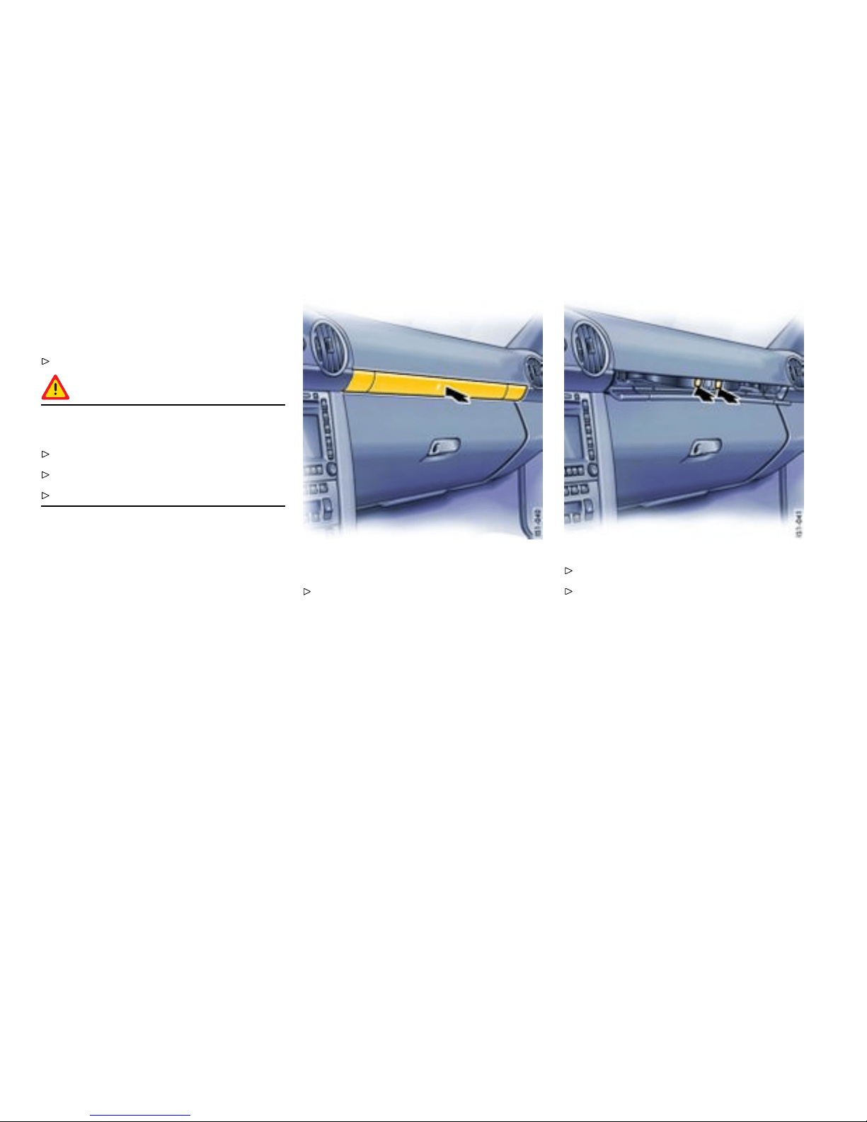
Cupholder
Holder for d rinks cans and cups
Keep the cupholder closed while drivin g.
Warning!
Risk of scalding or damage due to spilling
drinks.
Only use beverage containers which fit.
Never put overfull containers in the c upholder.
Never use hot drinks.
Extending cupholder
Press the panel. The panel opens.
Press the symbol for the respectiv e cuphol der.
Close panel in the middle .
166Controls, Instruments
Downloaded from www.ManualsFile.com manuals search engine
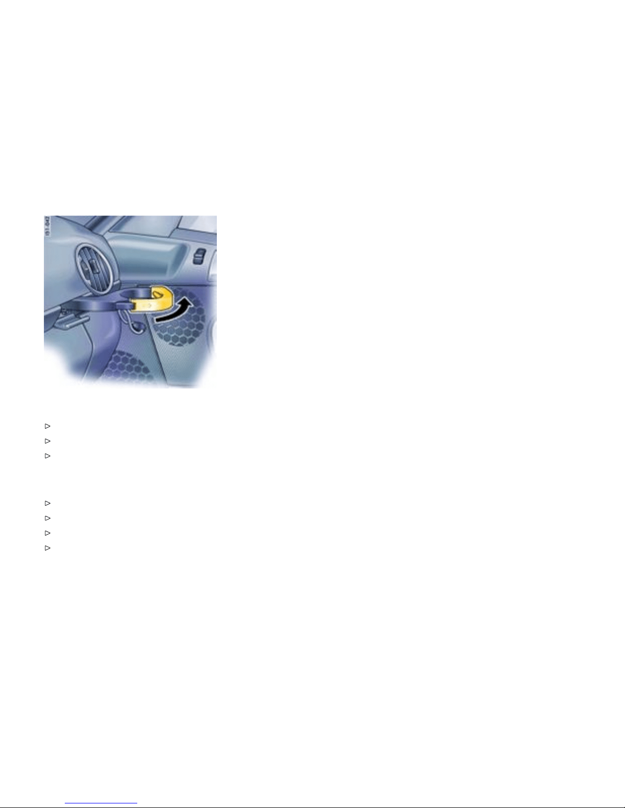
Pulling cupholder out
Pull out holder (arrow).
Insert container.
Carefully slid e holder inwards to adjust it to the
container size.
Closin g cupholder
Push cupholder drawer in.
Open panel in the middle.
Close and engage the cuphol d er.
Close panel in the middle.
Controls, Instruments
167
Downloaded from www.ManualsFile.com manuals search engine
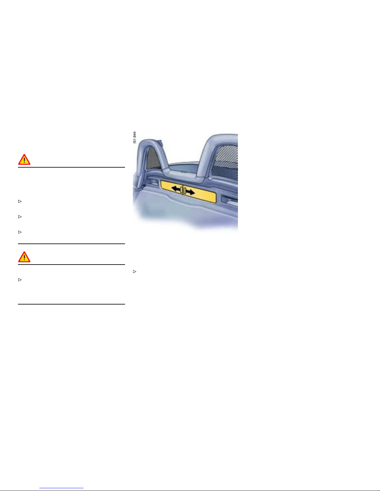
Luggage Storage o n Engine
Compartment Lid
Warning!
Unsecu red luggage and heavy obje cts may
come loose during braking, rapid directional
change s or in an accident an d cause serious
personal injury or death.
Do not carry items of luggage or objects in the
passenger compartment unsecured.
Do not transport any heavy objects in the
oddments trays .
Kept shutters of the storage box closed while
driving.
Warning!
Risk of dama ge.
Items of lugga ge or ob jects must neither
hinder convertible top movement nor be in
contact with the convertible top or rear window
in such a w ay as to cause abrasion damage.
Storage box
Opening center storage tray
Move both shutters in the direction indicated
by the arrows.
168Controls, Instruments
Downloaded from www.ManualsFile.com manuals search engine
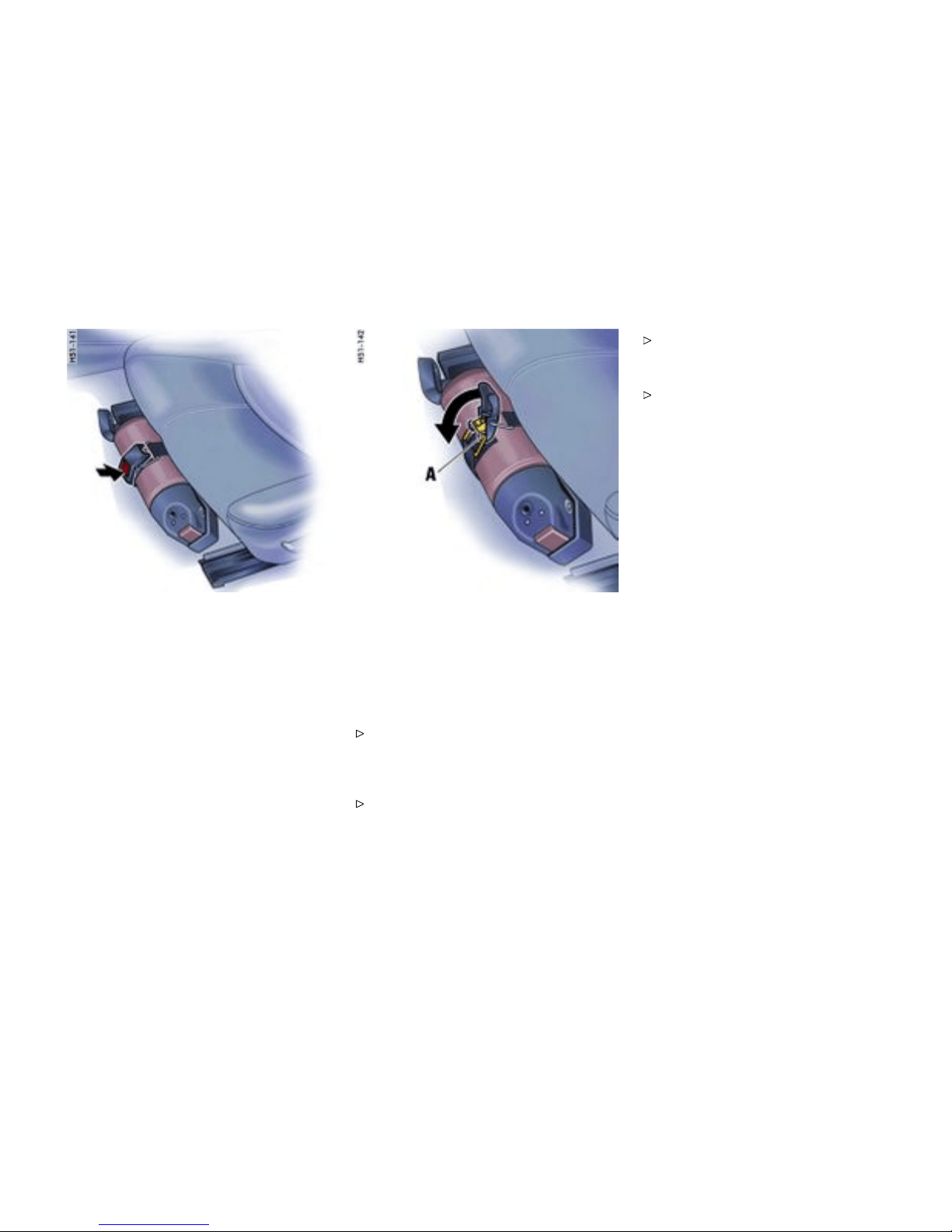
Fire extinguisher
Taking out re extin guisher
In cars with a fire extinguisher, the extinguisher is
fitted to the front of the driver’s seat.
1. Hold fire extinguisher with one hand and press
the PRESS button on the fastening strap with
the other hand (arrow).
2. Remove fire extinguisher from mounting.
Inser t ing re extin guisher
1. Place fire extinguisher in the mounting.
2. Engag e fastening strap lug A in the tension
jack and close tension jack (arrow).
Note
Pay at tention to the final control date on the
fire extinguisher. If the fire extinguisher is used
after its expiration date has elapsed, it may not
operate properly.
Follow the operating instructions on the fi re
extingui sher.
The functional ability of the fire extinguisher
should be checked by a speci alist workshop
every 1-2 years.
After use, have the fire extinguisher refilled.
Controls, Instruments
169
Downloaded from www.ManualsFile.com manuals search engine
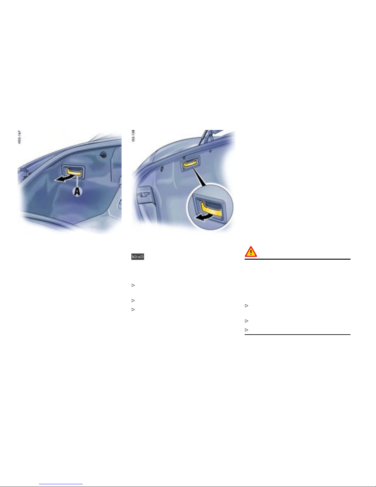
Front luggag e compartment
Trunk Entrapment
Your vehicle is equipped with an interna l front/rear
trunk release mechanism.
A person trapped in the luggage compartment
can release the lid from the inside using unlocking
handle A. The handl e A is fluorescent and glows in
the dark.
Rear luggage compartment
Warning message
A warning message in the on-board computer
lights up when unlocking handle A is ope rated.
Stop the vehic le immediately when the warning
message lights up.
Check the luggage compartment.
Close the lid.
Front luggage compartmen t l id
Function with vehicle stationary
If the luggage compart ment lid is unlocked with
unlocking handle A, the lid can be opened from the
inside immediately.
Function with vehicle in motion
If the luggage compart ment lid is unlocked with
unlocking handle A when a speed of 2 mph
(3 km/h) is exceeded , the warning message in
the on-board computer lights up. At the same
time, the lid is unlocked and the latch striker pops
into the catch-hook position. The li d lock is fully
released a s soon as th e car slows to less than
2 mph (3 km/h), an d the trapped person can open
the lid immediately.
Danger!
Risk of accident. If the warning message in
the on-board computer lights up when the
vehicle is in motion, th e lid may im pact in
front of the wind shield and can tear off. You
can lose control of the vehicle, and serious
personal injury or death may result.
Stop the vehicle imme diately when the warning
message lights up.
Check the luggage compartment.
Close the lid.
170Controls, Instruments
Downloaded from www.ManualsFile.com manuals search engine

Rear luggage compartmen t lid
If the rear luggage compar tment lid is unl ocked
with unlocking handle A, the lid opens immediately.
Stop th e vehicle immediately when the warning
message ligh ts up.
Check the lu ggage compartment.
Close the lid.
Note
The front lid cannot be opened from the inside i f the
battery is disconnected or empty.
Safety reasons therefore require that you
unscrew the latch striker of the front lid lock if
you plan to put the vehi cle out of operation for
an ex tended period .
Please consult your authorized Porsche dealer.
They will advise you about the necessary meas-
ures.
Note
When loading the luggage compartment,
make sure that i tems o f luggage or o ther
objects cannot become caught on handle A .
This could cause the luggage compartment to
open unintentio nally.
Controls, Instruments
171
Downloaded from www.ManualsFile.com manuals search engine
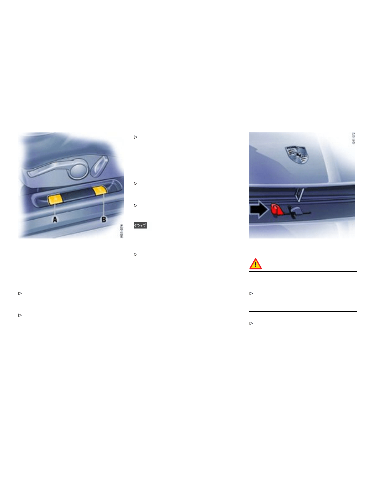
A - Opening front lug gage compartment lid
B - Opening rear luggage compartment li d
Luggage compartment lids
Unlocking
Operate the appropriate pull-button ne xt to the
driver’s seat. The luggage compartment is
illuminat ed when the respective lid is open.
Please observe the chap ter ”LOAD SWITCH-
OFF AFTER 2 HOUR S OR 7 DAYS” on page
265.
The luggage compartment lid can also be unl ocked
with the radio remote control.
Please observe the chapter ”KEY WITH RADIO
REMO TE CONTROL” on page 23.
Note
If the vehicle batte ry is discharged, the front
luggage comp artment lid can be opened only
by co nnecting an external ele ctrical powe r source.
Please observ e the chapt er ”EMERGENCY
UNLOCKING OF THE FRONT LUGGAGE
COMPARTMENT LID” on page 266.
Please obser ve the description inside the fuse
box li d.
Warning message
A warning message in the on-board computer
comes on if the lids are not completely c losed.
Fully close the lid.
Opening front luggage compartment lid
Caution!
Risk of damage to luggage compartment lid
or windshield wipers.
Make sure that the windshield wipers are not
folded out forwards when opening the luggage
compa rtment lid.
Raise l id slightly and unlatc h the safety catch
with the lever (arrow).
172Controls, Instruments
Downloaded from www.ManualsFile.com manuals search engine

Closing front and rear luggage
compartment lid
Lower the lid and close it.
Push the lid closed with the palm of your hand
in the area of the lock. Check that the lid has
correctly engaged in the lock.
Warning!
Risk of loss of control or an accident, result ing
in serious personal i njury o r deat h.
Should you no tice at any time while driving that
one of the lids is not secured properly, please
stop immediately in a suitable place and c lose
it. Th e front lid may fl y up impairing vision.
Controls, Instruments 173
Downloaded from www.ManualsFile.com manuals search engine
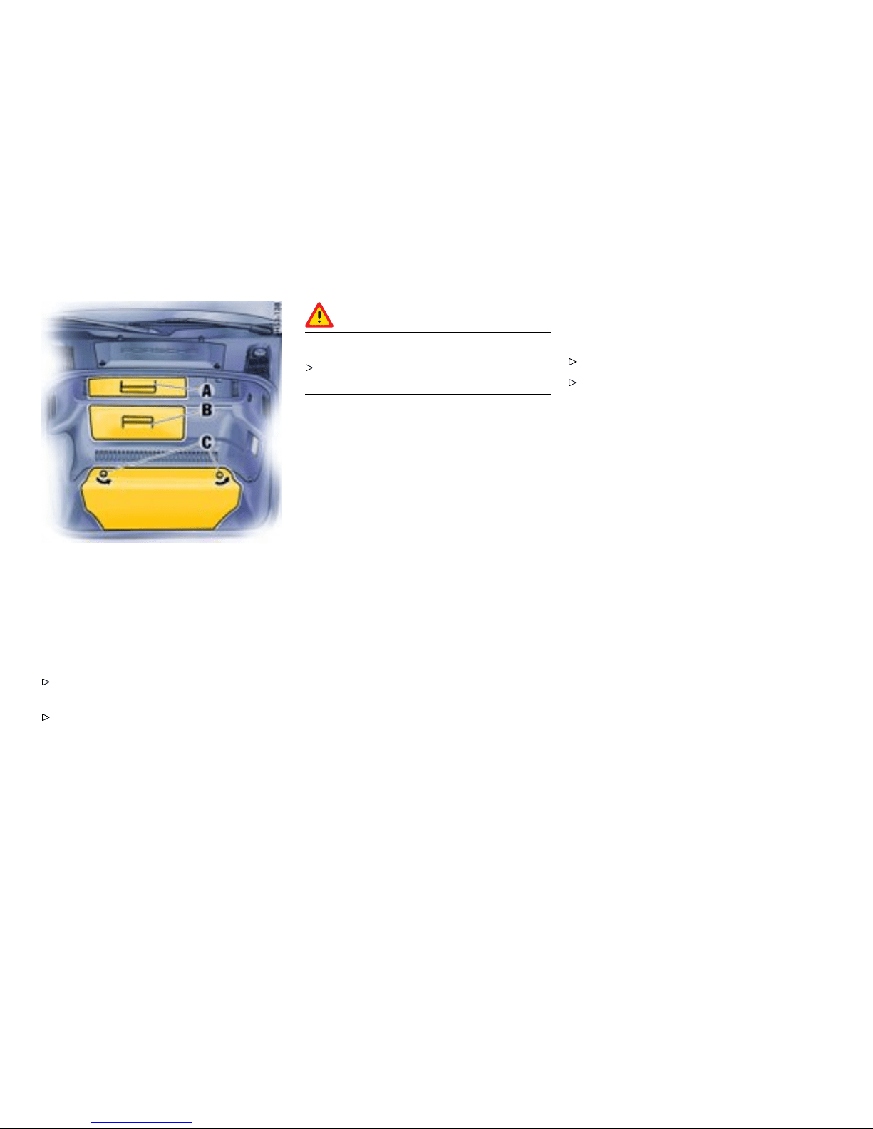
Front L uggage Compartment
Access covers
(on vehicles with DVD navigation or CD changer)
Opening
Grasp access cover A or B at the handle and
open.
The dri ve for DVD na vigation and the CD
changer can be found behind the access cover
B.
Caution!
Risk of damage.
Do not store any heavy, damp or heat-sensitive
objects behi nd the access covers.
Tool box
Opening
Unlock turn-lo cks C.
Open tool box and place it on the fl oor of the
luggage compartment.
174Controls, Instruments
Downloaded from www.ManualsFile.com manuals search engine
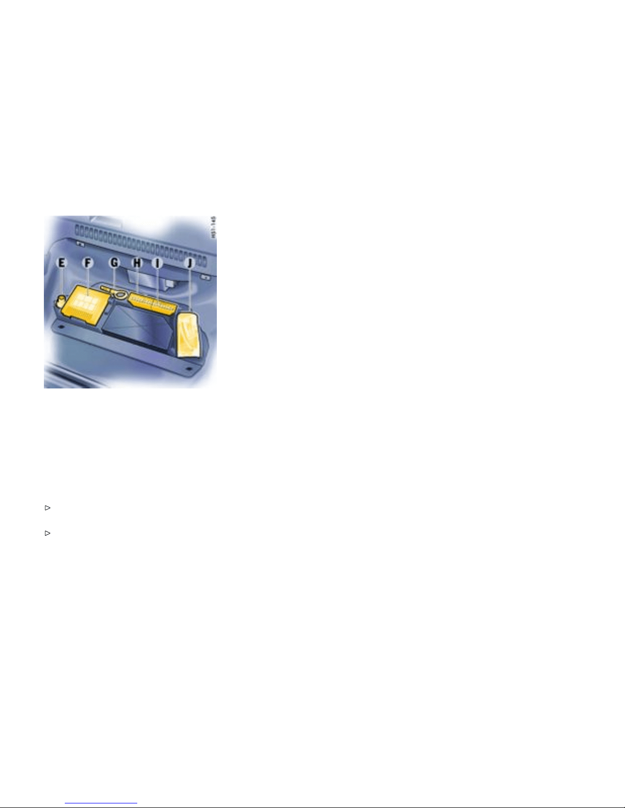
E - Adapter for s ecurity wheel bolts
F - Tire lling compressor
G - Towing hook
H - Tool kit
I - Lever for convertible top emergency
operation (unde r the tool kit)
J - Tire sealant
Closing
Insert tool box into the guid e pegs in the
luggage compartment floor.
Close tool box and l ock the turn-locks C.
Controls, Instruments
175
Downloaded from www.ManualsFile.com manuals search engine
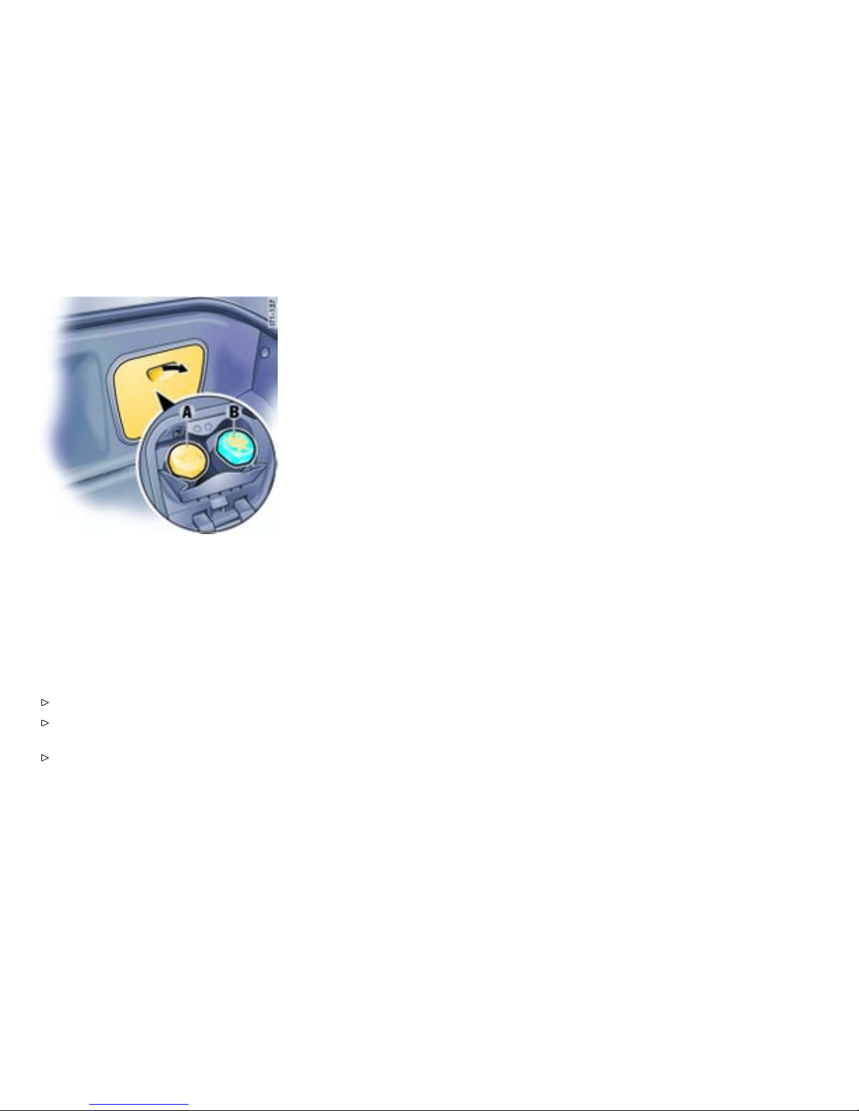
A - Topping up engine oi l
B - Check coolant level, top up if necessary
Rear Luggage Co mpartment
The refilling points for engine oil and coolant are
located behind the service flap in the rear luggage
compartment.
Opening the service ap
Open the flap by pulling the handhold.
Please observe the chapter ”ENG INE OIL
LEVEL” on page 213.
Please observe the chapte r ”COOLANT
LEVEL” on page 210.
176Controls, Instruments
Downloaded from www.ManualsFile.com manuals search engine

Porsche Communication
Manageme nt (PCM)
General informati on to the Porsche
Communication Management (PCM)
Refer to the separate operating in structions
before putting the PCM into operation.
Please observe the chapter ”LOAD SWITCH-
OFF AFTER 2 HOURS OR 7 DAYS” on page
265.
Warning!
There is danger of accident if you set or
operate the on-board computer, radio,
navigation system, telephone or other
equipment when driving. This could distract
you from trafc and cause you to lose control
of the vehic le resulting in serious personal
injury or death.
Operate the components whi le drivin g only if
the traffic situation allows you to do safely.
Carry out any compl icated o perating or se tting
procedures only with the vehicle stationary.
The reception condi tions for the radio module
integrated in the PCM change continuously as
you drive. Interference from buildings, terrain and
the weather is unavo idable. FM stereo reception
is particularly susceptible to varying reception
conditi ons.
Electronic accessories shoul d only be retrofitted
by your authorized Porsche dealer.
Accessories which have not been tested and
approved by Porsche may impair radio func tion
and recep tion.
Navigation
When put i nto operation for the first time, a
distance of approx. 31 miles (5 0 km) must be
driven in order for the navigation system to
complete the process of fine calibration. The
same applies when the tires are changed (e.g.
summer/snow tires) or new tires fitted. Full
location accuracy is not yet achieved during the
fine-ca libration process.
If the vehicle has been transported (e.g. ferry,
car train), the system may take a few minut es to
determine th e current location a fter it has been
switched on.
Seriou s tire slip (e.g. spinning wheels on sn ow)
may result in temporarily inaccurate nav igation.
When the b attery has been disconnected, it m ay
take u p to 15 minutes before the navigation syste m
becomes operational again.
Controls, Instruments
177
Downloaded from www.ManualsFile.com manuals search engine

Car Aud io Operation/Tips
Gener al information
For radio operation see your rad io man ual
which is inc luded with your on-b oard litera-
ture.
Please observe the chap ter ”LOAD SWITCH-
OFF AFTER 2 HOUR S OR 7 DAYS” on page
265.
FM reception
A vehicle is not an ideal place to listen to a radio .
Because the vehicle moves, reception conditions
are constantly ch anging. Buildings, terrain, signal
distance and noise from other vehicles are all
working against good reception. S ome conditions
affecting FM may appear to be problems when they
are not.
The following characteristics are completely
normal for a given reception area, and they do
not indicate any problem with the radio itself.
Note
Electronic accessories should only be in stalled by
your a uthorized Porsche dealer. Equipment which
has not been tested and approved by Porsch e may
impair radio function and reception.
Fading and drifting
FM range is limited to about 25 miles (40 k m),
except for some high power stations.
If a vehicle is moving away from the desired
station’ s tran smitter, the signa l will t end to fade
and/or drift. This con dition is more prevalent
with FM than AM, and is of ten acc ompanied by
distortion. Fading and drifting can be minimized to
a certain degree by careful attention to fine tuning
or selection of a stronger signal.
Static and uttering
When the line-of-sight link between a transmitter
and vehicle is blocked by large buildings or mo un-
tains, the radio sound may be a ccompanied with
static or fluttering because of the charac teristic of
FM. In a similar effect, a fluttering noise is some-
times heard when driving along a tree-lined road.
This static and fluttering can be reduced by adjust-
ing th e tone control for greater bass response until
the disturbance has passed.
Multipath
Because of the reflecting characteristics of FM,
direct and reflected signals may reach th e antenna
at the same time (multipath) and cancel each other
out. As a v ehicle moves through these electronic
dead spots, the listener may hear a momentary
flutter or loss of recep tion.
Station swapping
When t wo FM stations are close to each other, and
an electronic dead spot, such as static or multipath
area, interrupts the original signal, some times
the stronger secon d signal will be selected
automatically until the original one returns. This
swapping can also occur as you drive away from
the selected station and approach another station
of a stronger signal.
178Controls, Instruments
Downloaded from www.ManualsFile.com manuals search engine
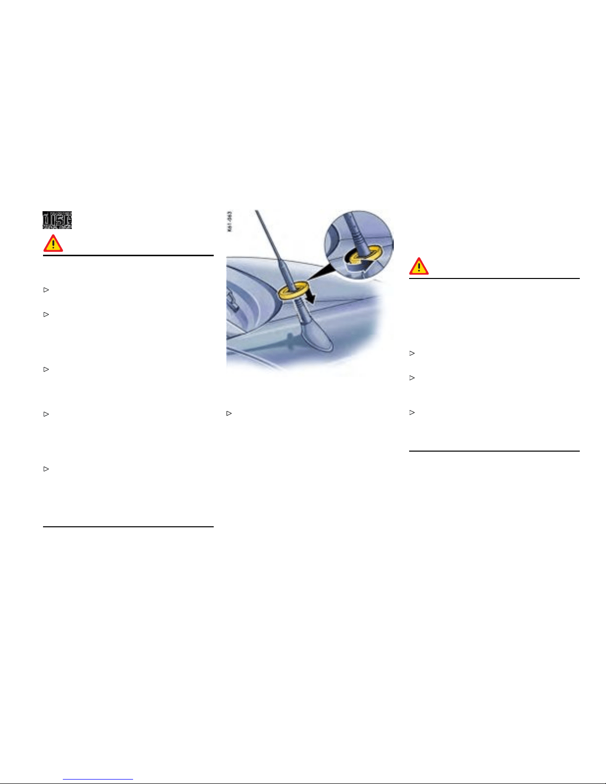
Compact disc pla yer
Caution!
To avoid damage to compact disc player and
discs.
Use only comp act discs labeled as shown ,
having no dirt, damage or warpage.
Never attempt to di sassemble or o il any part
of the player unit. Do not insert any object
other than a disc into the slot. Remember
there are no us er-serviceable parts inside the
compac t disc player.
Do not allow the disc to susta in any finger-
prints, scrapes or s tickers on the surfaces.
This may caus e poor sound qualit y. Hold the
disc only on the edge or center hole.
When not in use, take the disc out of the
player, put the disc back into its case and
store it away from dust, heat, damp and direct
sunlight. Leaving the disc on the d ashboard in
the su n can damage the disc.
If the disc gets di rty, clean the disc by wiping
the su rfaces from the center to th e outside
in a radial di rection with a soft cloth. Do
not use a conventional record cleaner or
anti-static record preservative. Disc cl eaners
are available in audio stores.
Antenna
Always unscrew the external antenna be fore
using an automatic car-wash.
Car Tele phone and Aftermark et Alarms
Important legal and safety information
regarding the use of cellular telephones:
Danger!
Risk of an accident. Severe personal injury or
death can result in the event of a n acci dent.
Looking awa y from the road or turning your
attent ion away from your driving can cause an
accident and lead to serious personal injury
or dea th.
When using your cellular telephone, you should
always:
Give full attention to your driving - pull off the
road and park be fore making or answering a
call if traffic conditions so require; and
Keep both h ands on the steering wheel - use
hands-free operation (if available) - pull off
the road and park before using a hand-held
telepho ne.
Some states may prohibit the use of cellular
telephones wh ile driving a vehicle. Check the laws
and regulati ons on the use of cellular telephones in
the areas w here you drive.
It is essential to obser v e the instructions of the
telephone manufactu rer before pu tting th e
telepho ne into oper ation.
Controls, Instruments
179
Downloaded from www.ManualsFile.com manuals search engine
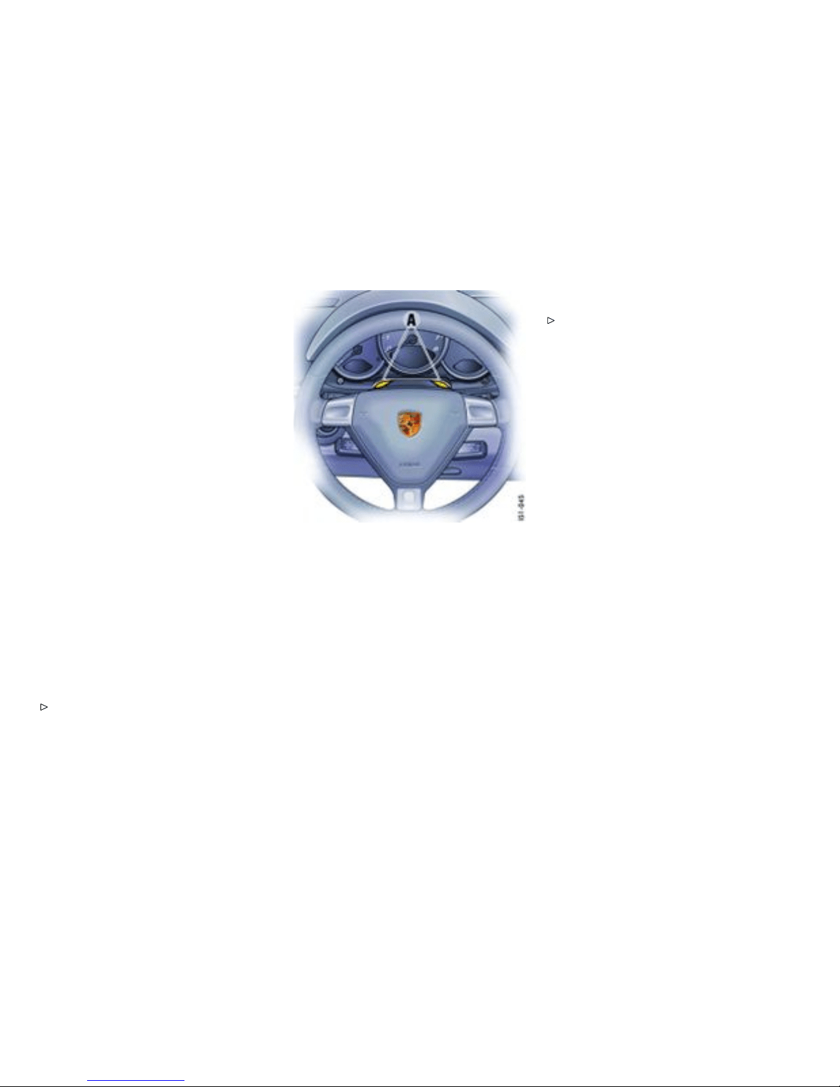
Any po rtable telephone or radio transmitter whi ch
is used in a Porsche mus t be properly installed
in accordance with the technical requirements of
Porsche.
The transmission power must not exceed
10 W. The devices must possess a type approval
for your vehicle and have an “e” symbol.
If you should require equipment wit h trans mission
power values greater than 10 W, please consult
your authorized Porsche dealer for this p urpose.
He is familiar with the technical requirements for
installing devi ces of this kin d .
The an tennas for all radios and telephones w ith a
transmitting antenna must be externally mounted.
The improper installation o f radios or telephones
or use of a radio or telephone with a transmitting
antenna insid e the car may cause the warning
lights to come on.
Improper installation of such equipment can create
a discharged b attery or excessive current draw
from added equipment.
If aftermarket systems are install ed by non-deal-
ership technicians or outside the s elling dealer,
problems may result. Installation of a f termarke t
equipment is n ot covered under the New Car War-
ranty.
Consult your authorized Porsche dealer ab out
the installation of no n Porsche approved
equip m ent.
Hands-fre e microph one
Hands-free microphones A installed at the f actory
must be adapted to the type of telephone in use.
Your authoriz ed Porsche dealer will be pleased to
advise you.
Reception quality
The recept ion quality of your car telephone
will change constantly when you are driving.
Interference caused by buildin gs, landscape and
weather is unavoidable. It ma y become particularly
diffi cult to hear when using the hands-free function
due to external noise suc h as engine and wind
noise.
Automatic car-wash
Unscrew the external an tennas be fore using an
automatic car-wash.
180Controls, Instruments
Downloaded from www.ManualsFile.com manuals search engine
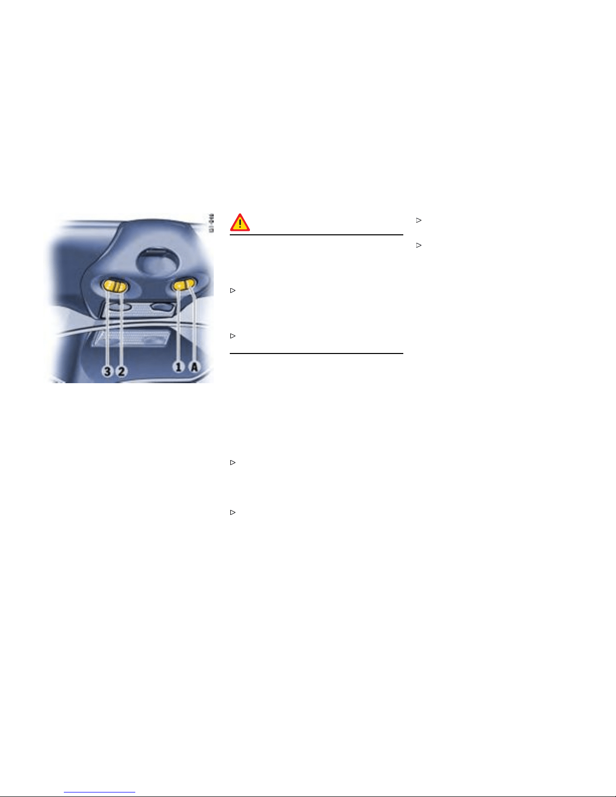
1-3 - Programmable buttons
A - Light-emitting diode for status identication
HomeLink
Function of the Home Link
The programmable HomeLink replaces up to three
original hand-held tran smitters used to operate
various devices (e.g. garage door, gate to the
property, alarm system).
You can program buttons 1 to 3 with a frequency
of an original handheld transmitter.
Warning!
Risk of accident when using the HomeLink
if persons, animals or objects are within the
range of m ovement of the equipment that is
being operated.
When using the HomeLink, ensure that no
persons, animals or objects are within the
range of movement of the equipment that is
being operated.
Observe the safety notes for the original
hand-held transmitter.
Preconditions for operating and
progr amming t he HomeLink:
– Ignition is switched on.
– Fog l ights are switched off.
To operate the respective device:
Press the appropriate b utton (1, 2 or 3).
Light-em itting diode A lights up during signal
transfer.
Note on operation
Always use the Hom eLink opener in the direc-
tion of travel. Otherwise, range restrictions
cannot be ruled out.
Before selling the vehicle, delete the pro-
grammed signals of the HomeLink.
Please read the instruct i ons for the original
hand-held transmitter to find out whether the
original transmitter is equip ped with fixed or
changeable code.
Controls, Instruments
181
Downloaded from www.ManualsFile.com manuals search engine
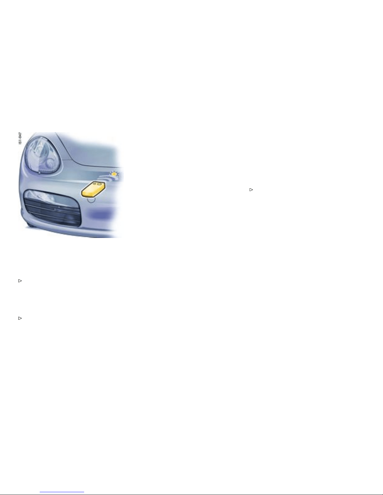
Alloca ting signals to the buttons
Prior to programming th e HomeLink for the
rst time
Please follow the operating instructions for the
original hand-held tra n smitter.
The following process deletes the standa rd codes
set at the factory. Do not repeat the process if you
program further buttons.
Keep the two outer button s 1 and 3
depressed for approx. 20 seconds until
light-emitting diode A begins to fl ash quick -
ly. All programmed si gnals of buttons 1 to 3
are deleted.
HomeLink with xed code system
1. Press the de sired button until the light-emitting
diode begins to flash slow ly. You then have
approx. 5 minute s to p erform ste ps 2 and 3.
2. Hold th e original hand-held transmitter approx.
0 to 12 in. (0 to 30 cm) in front of the marked
posit ion (figure) on the vehicle.
3. Press the transmit butto n on the original
hand-held transmitter until the fog li ghts flash
three times (up to approx. 45 seconds).
4. Repeat steps 1 to 3 to allocate other buttons.
Note
Several attempts with dif ferent distances between
the vehicle and the original hand-held transmitter
might be necessary.
The f og lights will flash once the 5 minutes hav e
been exceeded. Programming must be repeated
from the beginning in this case.
HomeLink with changeable cod e system
1. Allocate the required k eys as for the systems
with fixed code (steps 1 to 3).
2. To synchronise the system: Press the pro-
grammi ng button on the recei ver for the
garage door actuat or. Afterwards, you usu-
ally h ave approx. 30 seconds to initiate step 3.
3. Press the all ocated HomeLink button twice.
(With some devices, the button to b e allocated
must be pressed a third time in order to
complete the setting process.)
4. Repeat the programming steps t o alloc ate
other buttons .
Note
Please consul t an authorized Porsc he dealer
if you have not been able to s uccessfully
allocate signals for the garage door opener
to the buttons even though you have carefully
followed the instruct ions in this chapter and
the operating instruct ions for the original
hand-held transmitter.
To reprogram a single button:
1. Press the desired button until the li ght-
emittin g diode begins to flash slowly (approx.
20 seconds). You then have approx. 5 minutes
to perform steps 2 and 3.
2. Hold the original hand-held tra n smitter approx.
0 to 30 cm in front of the marked position
(figure) on the vehicle.
3. Press the transmit button on the original
hand-hel d transmitter until the fog lights flash
three times (up to approx. 45 seconds).
4. Repeat steps 1 to 3 to allocate other butto n s.
182Controls, Instruments
Downloaded from www.ManualsFile.com manuals search engine

Note
Several attempts with different distanc es between
the vehicle and the hand-h eld trans mitter might be
necessary.
The fo g lights will flash once the 5 minutes have
been exceeded. Programmin g mu st be repeated
from the beginning in thi s case .
Deleting programmed signals of the HomeLink
(e.g., when selling the vehicle)
Keep the two outer button s 1 and 3 depressed
for approx. 20 seconds until light-e mitting diode A
begins to flash quick ly. All programmed signals of
buttons 1 to 3 are de leted.
Controls, Instruments
183
Downloaded from www.ManualsFile.com manuals search engine


Manual T ransmission, Clutch
Gener al information
The positions of the gears a re shown on the shift
diagram on th e gearshift lever.
Warning!
Risk of accident, resulting in serio us personal
injury or death.
Do not obstruct the pedal travel with floor mats
or other objects. Nonskid floor mats of the
correct size are available at your authorized
Porsche dealer.
Warning!
To avoid damage to the clutch and tr ansmis-
sion:
Always depress the clutch ped al fully when
changing gears. Make sure that the gearshift
lever is com pletely engaged.
Only shi ft into reverse when the car has come
to a complete stop.
When shifting gears , always ensure th at the
clutch pedal is fully depressed and the gear
has fully engaged.
Select reverse only when vehicle is stationar y.
Select an appropriately l ow gear on upward
and downward slopes. This will ensure
optimu m use of engine power and engin e
braking.
When rever se gear is selected and the ignition is
on, the backup lights are illuminated.
Permitted engine s peed
You should change into a higher gear before
the needle reaches the red mark o n the
tachometer, or ease off the accelerator.
If the red zone is reached during acceleration, fuel
feed is interr upted.
Caution!
Risk of engi ne damage (overrevving) when
shiftin g down to a lower gea r.
Take care not to exceed the maximum
permitted engine speed when shifting down.
186Shifting Gear
Downloaded from www.ManualsFile.com manuals search engine
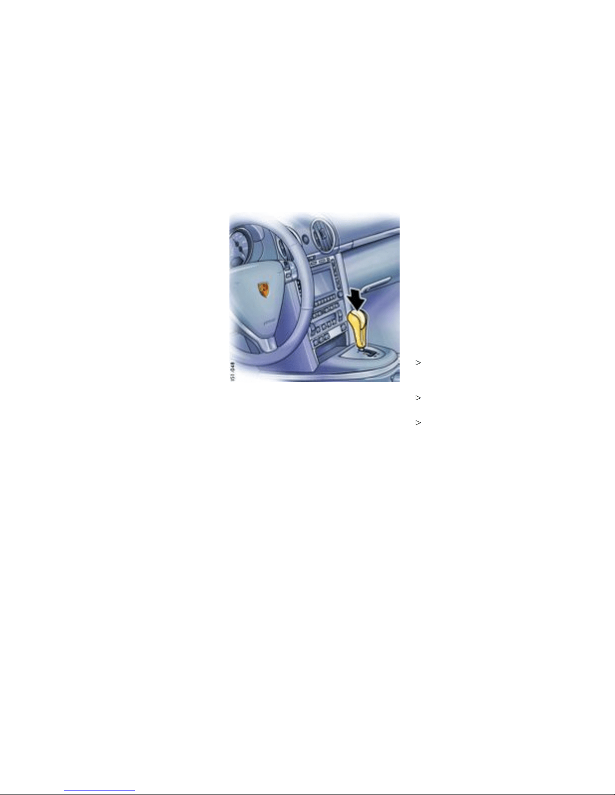
Tiptronic S
Function of Tiptronic S
The Porsche Tiptronic is a five-speed transmission
with a n “automatic” and a “manual” selection
mode.
In automatic select ion mode (selector leve r
position D), gear changing is au tomatic. You can
change temporarily from automatic to manu al
mode using the rocker switches on the steering
wheel.
In manual selection mode (selector lever
position M), you change gear using the rocker
switches on t he steering wh eel.
You can change between selector le ver position D
and M as you wish while driving.
Note
Take care not to operate the rocker switches
on the stee ring wheel inadvertently in e ither
auto matic or manual mode, thereby tri ggering
undesired gear changes.
Keylock position
The ig nition key can be withdrawn only in selector
lever position P.
Transmission selecto r l ever
Changing the selecto r lever position
The s elector l ever is locked with the ignition key
withdrawn.
The selector lever can be moved from position P or
N only with:
– the ignition switched on,
– the b rake pedal pressed and
– the release butto n pressed.
Release b utton
The release button (arrow) in the selector lever
prevents unintentional gear changes.
The release button must be pressed when shifting
to position R or P.
Starti ng
The e ngine can be started only if the brake pedal is
depressed and the selector lever is in position P or
N.
Moving off
Only select th e desi red position f or moving off
(D, M or R) when the engine is idling and the
brake pedal is depressed.
Since the vehicle creeps when in gear, do not
release the brake until you want to move off.
After selecting a gear, do not accelerate until
you can feel that the gear is engaged.
Shifting Gear
187
Downloaded from www.ManualsFile.com manuals search engine

Selector lever position and engaged gear
Indicator
When the engine is running, the selector lever
position and eng a ged gear are indicated.
If the selector lever i s between tw o positions:
– The corresponding selector lever positio n in
the ins trument cluster flashe s and
– the warning “Selector lever not engaged”
appears in the on-board compute r.
Engage the selector lever correctly.
– The selector lever position is displayed
immediately after the correct po sition has
been detected.
– The current gear is shown afte r a bri ef
detection perio d.
If there is a fault in the transmission:
– The 4th-gear and the selector lever position
select ed displays flash in a lternatio n.
– The warning “Tiptronic emergency run”
appears on the on-board com puter.
Please observ e the chapt er ”EMERGENCY
PROGRAM” on page 191.
– Have the fault remedied at an authorized
Porsche dealer.
188Shifting Gear
Downloaded from www.ManualsFile.com manuals search engine

Selector Lever P ositions
P - Parking lock
Engage parking lock only when vehicle is
station ary.
Engage parking lock after apply ing the
handbrake and release it before releasing
the handbrake.
The ig nition key can be withdrawn only in selector
lever position P.
R - Reverse
Select only if car is st ationary and the brake is
applied.
N - Neutral
Selector lever position N must be selec ted for
towing or in car washes, for e xample.
Select the desired position for moving off (D,
M or R) only when the engine is idling and while
depressing the brak e pedal.
D - Autom atic selection mode
Mode of operation
Select position D for “normal” driving. The
gears are shifted automatically according to
the accelerator position and speed.
Depending on the way the vehicle is driven and
on the resistance (e.g. uphill), the gear-changing
points are shifte d towards higher or lower engine-
speed ranges. The accelerator position, driving
speed, engin e speed, longitudinal and lateral
accele ration and the road profile all have an
influence on the gear-changing char acteristic.
Unwanted up ward shifts, e.g. before bends, a re
prevented by swiftly releasing the accelerator
pedal.
Depending on latera l acceleration, upward shifts
on bends are not made until the engine-speed limit
is reached.
Under brakin g, and depending on the amount of
decele ration, the Tiptronic shifts down earlier. For
subsequent cornering, the right gear is engaged
when pressure is applied to the brakes before the
bend. The bend is taken in the right gea r, and when
you accelerate out of the bend you do not have to
shift down.
Sport mo de switche d on
Please observe the chapter ”SPORT MODE” on
page 70.
If the Sport mode program me is switched on,
Tiptronic switches to a sporty gear-changing map
and short ens the shifting per iods.
Initial Drive-off
In 2nd gea r, the vehicle drives off with the throttle
only slightly open. Drive off in 1st gear with the
throttle open wider or when the engine is c old.
Shifting ge ar on the st eering wheel
With the toggle switches on the steering whe el, you
can change temporarily from automatic selection
mode D to manual mode M.
Advanta ges:
– Shifting down before bends and on entering
built-up areas.
– Shiftin g down on downward slopes (e ngine
braking).
– Shifting down for b rief spurts of acceleration.
– Selecting 1st gear for moving off.
The manual selection mode remains engaged:
– for cornering (depend ing on the lateral
acceleration) and overrunnin g,
– when the vehicle is stationary (e.g. at a
junction).
The system leaves manual selection mode:
– autom atically after approx. 8 seconds (unless
cornering or overrunning),
Shifting Gear
189
Downloaded from www.ManualsFile.com manuals search engine
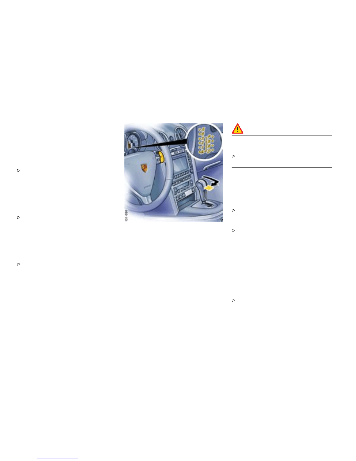
– if you depress the accelerator to kick down,
– after m oving o ff.
Temporary change-down
Conditions: Speed is higher than approx. 33 mph
(54 km/h).
Depress accelerator quickly. The Tiptronic
changes temporarily to the sportiest gear-
changing map, i.e. to the highest possible
gear-c hanging points. Correspondingly, the
transmission shifts down imme diately by one
or two gears.
Ending the function:
Release the accelerator markedly.
Kickdown
The kickdown function is active in selector lever
position D, even if you te mporarily change to
manual mode M u sing the toggle switches on the
steering wheel.
For optimum acceleration, e.g. when o vertak-
ing, d epress the accelerator pedal beyond the
full-throttle point (kickdown).
The transmission shifts down depending o n the
speed of travel and engine speed. Upward shifts
occur at the highest possible engine speeds.
These gear-changing speeds remain active until
the accelerator is released to approx. 80% of the
wide open throttle position.
M - Manual S election Mode
Mode of operation
The currently selected gear is retained if you
change from D to M.
If you shif t from M to D, the gear-changing map
suitable for your current driving style is selected
and the appropriate gea r is selected.
Warning!
The kickdown function is not active in man ual
selection mode “M”.
Therefore shift down manually when accele rat-
ing (e.g. to overtake).
Two toggle switches in the upper steering-wheel
spokes let yo u comfortably an d reliably select the
five fo rward gears.
Shifting up
Press upper part (+) of a toggl e swi tch.
Shifting down
Press lower part (-) of a toggle switch.
Depending on driving spee d and engine speed,
you can shift up or down at any time. Gear changes
which would exceed the upper or lower engine-
speed limit are not executed by the controller.
You can shift down two gears at once by quickly
pressing th e toggle switches twice.
If the engine-speed limit is reached, an auto matic
upward shift is performed or, just before idling
speed is reached, a downward shift is performed.
Select an appropriately l ow gear on upward
and downward slopes. This will ensure
optimu m use of en gine po wer and engine
braking.
190Shifting Gear
Downloaded from www.ManualsFile.com manuals search engine
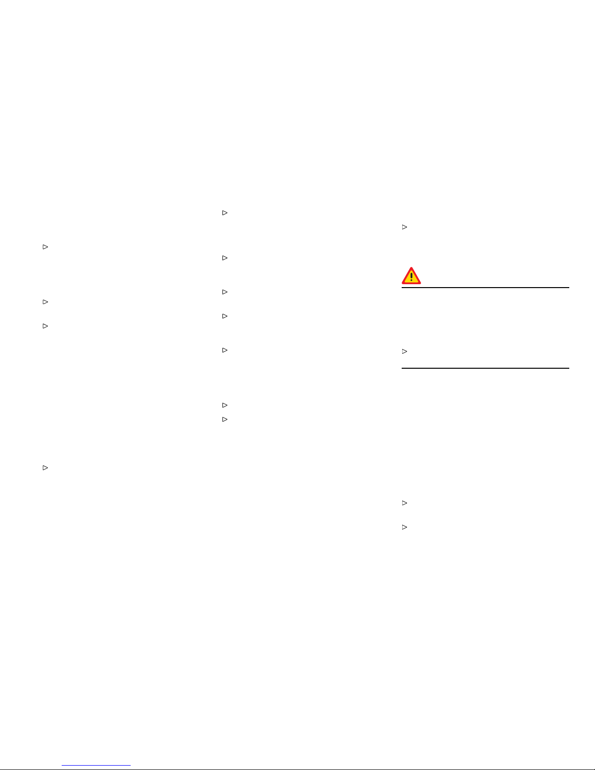
If manual mo de fails, the control electronics switch
to automatic mode. In this event, t h e inst rument
cluster will display selector lever position D.
To remedy the fault, plea se consult an author-
ized Porsche dealer.
PSM switched off and/or Sport mode switched
on
Please observe the chapter ”SWIT CHING OFF
PSM” on page 72.
Please observe the chapter ”SPOR T MODE” on
page 70.
If the PSM is switched off and/o r Sport mode is
switched on, an automatic upshift does not occur
when the eng ine spee d limit is reached.
Cancelling upshift suppression
The restriction can be cancelled for o n e gear
change by depressing t h e accelerator to kickdown.
If, for example, the engin e speed limit is reached
during overtaking and the automatic upshift does
not occur, the transmission in this case shifts up by
accelerating to kickdown.
Depress the accelerator p edal beyond the
full-throttle point (kickdown).
Manual mo de failure
If manual mo de fails, the control electronics switch
to automatic mode. In this event, t h e inst rument
cluster will display selector lever position D.
Have t he fault remedied. Consul t an author-
ized Porsche dealer.
Stopping
For a brief stop, e.g. at a traffic light, leave the
selector lever in dr ive position and hold the
vehicle with the brak e pedal.
For a longer stop with the engine running,
select position N (neutral).
Do not hold the car on a slope using the
accelerator. Use the brake peda l or the
handbrake inste ad.
Before leaving the vehicle, always apply the
handbrake and move the selector lever to
position P.
Parking
Go easy on the accelerator.
When parking or maneuvering in a small
space, control the speed by careful use of
the footbrake.
Driving in winter
In win tery road conditions i t is advisable to ta ke
steep inclines in manual mode. This prevents the
occurrence of gear changes that could cause
wheels pin.
Tow-starting, towing
Please observe the chapter ”TOWING” on page
292.
Emergency prog ram
Warning!
Reverse gear lock monitoring is disabled in
the emergency running program. Damage
to the vehicle may result as well as loss of
control, if the vehicle is moving forward fast
enoug h to cause rear wheel lockup.
Do not shift i nto R while the v ehicle is moving
forwa rd.
A transmission fault is indicated by the follow ing
symptoms:
– The display for 4th-gear and the engaged
selector lever position flash on and off
altern ately.
– The warning “Tiptronic emergency run”
appears in the on-b oard computer.
– The t ransmission no longer shifts. Regardless
of selector lever posi tion, 4th is the only
forward gear still available.
Adapt your driving style to the changed
handling.
To remedy the fa ult, please consult an a uthor-
ized Porsche dealer.
Shifting Gear
191
Downloaded from www.ManualsFile.com manuals search engine


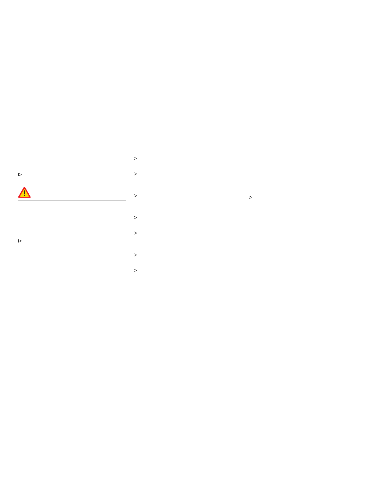
Convertible Top
General in formation to the convertible top
Brief operating instructions c an be found on th e
back s ide of the driver’s s un visor.
Please observe the chapt er ”CAR CARE
INSTRU CTIONS” on page 233.
Warning!
When opening or c losing the convertible
top, serious personal injury may occu r if a
person’s body parts are near or in the way
of the convertible top mechanism’s moving
parts.
Make absolut ely sure that nobod y can be
injured by the con vertible-top mechanism or
the conver ti ble-top compartme nt lid.
Do not operate convertible top:
– At temperatures be low 32°F /0°C .
– When one side of the car is on a curb, a hoist
or a jack.
– When items of luggage or other objects
hinder the convertible top movement or
are in abra s i ve contact with the convertible
top or rear window. Ite ms of luggage or
objects on the luggage tray above the engine
compartment lid must be put in the storage
box o r be secured to prevent their sliding out.
Keep shutters of the storage box closed while
driving .
Drive only with the convertible top fully open or
closed.
Avoid frequent o p eration of the convertible top
with the engine off; the vehicle batter y wou l d
be unintentionally disc harged rapidly.
When opening or closing the convertible top,
ensure there i s sufficient clearance above the
convertible top (e.g. in the garage).
To prevent damp stains and abrasions, only
open the convertible top in a dry, clean state.
Park your car in the sha de whenever possible,
as the fabric, rubber material and color can be
harmed by long exposure to s unlight.
The co nvertible to p may only be actuated
during driving on even surfaces.
The convertible top must not be use d with
strong cou nter wind (ove r approx. 50 mph/ 80
km/h).
Door windows
If the door windows are closed, they will autom at-
ically be lowered a few centimeters before the
convertible top is opened or closed.
Conditi ons for ope rating the convertibl e
top
– The ig nition m ust be switc h ed on (engine
running or off).
– Maximum speed 30 mph (50 km/h) The
opening/closing process o f the conve rtible
top will be interrupted if th e maximum speed is
exceeded.
Reduce speed . Press button again . The
opening/closing process i s ended.
194Mobile Roofs
Downloaded from www.ManualsFile.com manuals search engine
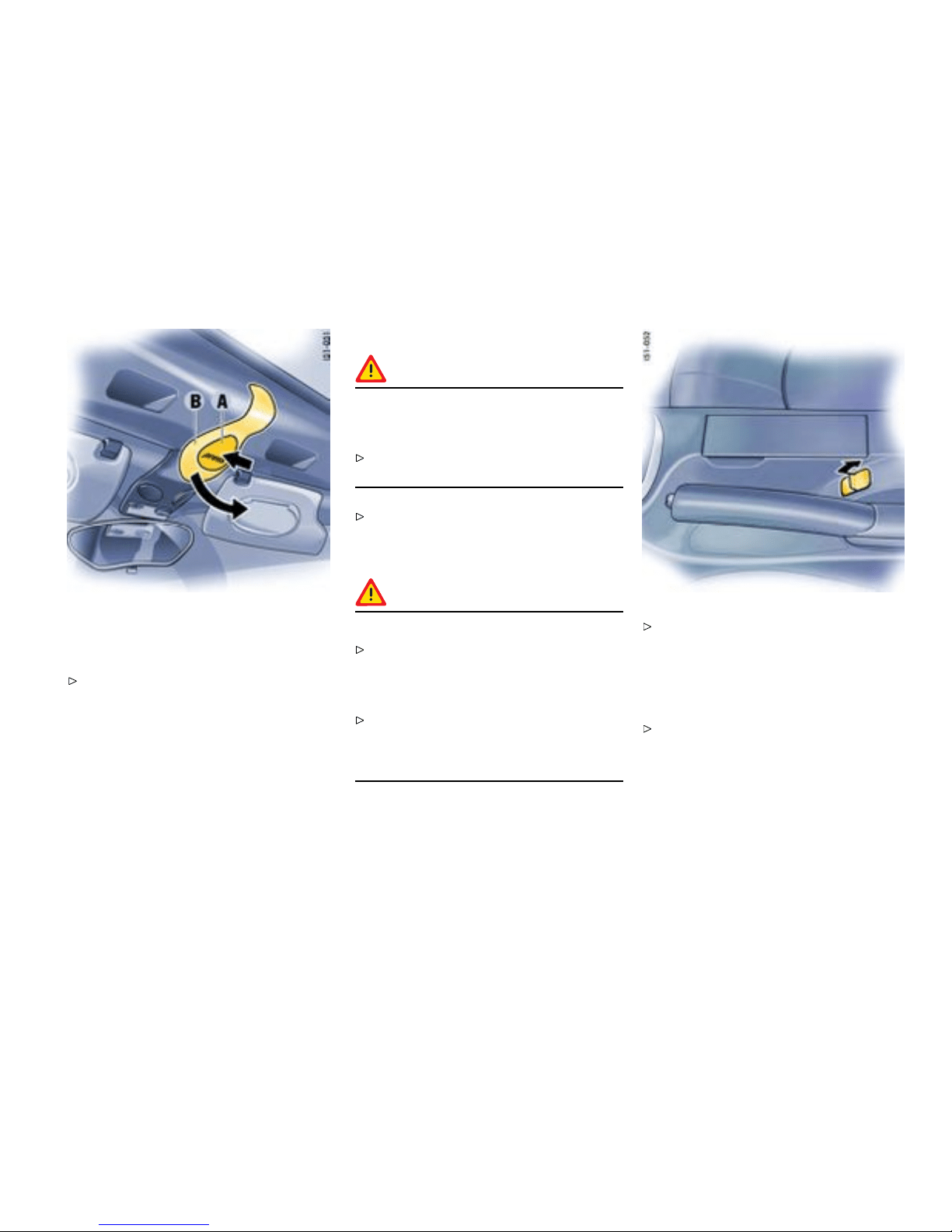
Opening convertible top
Releasing the latching lever
Press on the release plate A. Latc hing lever B
pops into engaging position.
Releasing convertible top
Caution!
Risk of damage by the locking hooks on the
roof frame when the latching lever is no t
engaged correctly.
Make sure that the latch ing lever is felt to
engage when opening.
Swivel l atching lever B to the rear u ntil it is felt
to engage.
Opening th e convertibl e top with the button
Warning!
Risk o f injury.
When opening the convertible top, make
sure that nobody can be injured by the
convertible-top mechanism or the convertibl e-
top compartment li d.
In order to abort co nver tible top opera tion in
the event of danger: up to 6 mph (10 km/h),
release the button immediately, over 6 mph
(10 km/h), activate the button briefly.
Up to 6 mph (10 km/h): Pull the button
back and hold without interruption until the
convertible top is in the fi n al position and the
message on the on-board computer goes
out. In case of danger, release the button.
Convertible top operation stops.
From 6 mph (10 km/h) to 3 0 mp h
(50 km/h): Pull butt on back briefly, the con-
vertible top opens automatically. The mes -
sage in on-board computer goes out. In cas e
of danger, pull the button ba ck again, the con-
vertible top operation stops.
Mobile Roofs
195
Downloaded from www.ManualsFile.com manuals search engine
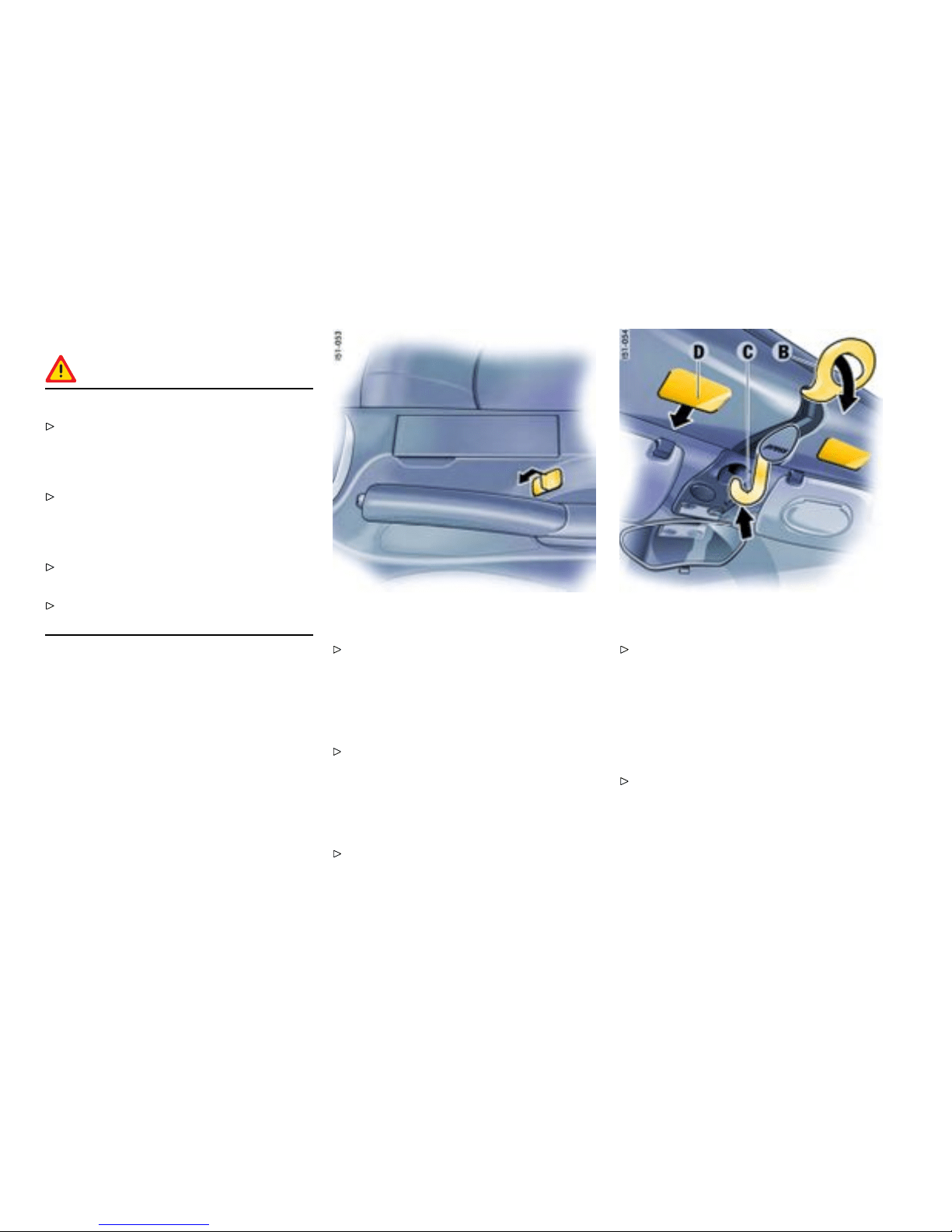
Closin g t he convert ible top
Warning!
Danger of injury and damage.
When closing the convertible top, make
sure that nobody can be injured by the
convertible-top mechanism or the convertible-
top compartment lid.
In order to abort convertible top operation in
the event of danger: up to 6 mph (10 km/h),
release the button imme diately, o v e r 6 mph
(10 km/h), acti v ate the button briefly.
Keep the lids of the make - up mirrors in the sun
visors closed when closing the convertible top.
Lock the convertible top with the latch i ng lever
after automati c closing.
Closing convertible top with the button
Up t o 6 mph (10 km/h): Push the button
forwa rd and hold withou t interruption until the
convertible top is in the final position and the
message on the on-board computer goes
out. In case of danger, release the button.
Convertibl e top operation stops.
From 6 mph (10 km/h) to 3 0 mph
(50 km/h): Push button forward briefly, the
convertible top closes automatically. The mes-
sage i n on-board computer goes out. In case
of danger, push the button forward again, the
convertible top operat ion stops.
Lock convertible top with the latchi ng lever.
Locking the convertible top
Swivel latching lever B to the front until it is felt
to eng age. The locking hook mus t engage in
the receptacle on the windshield frame C.
Note
If the convertible top has been opened for a longer
period, it could be necessary to assist the locking
hook engage C.
With the vehicle stationar y, press and hold the
button for convertible top operation a nd pull
the convertible top to the wi ndshield using the
handle recess D.
196Mobile Roofs
Downloaded from www.ManualsFile.com manuals search engine

Emergency operation
Before perform ing emergency ope ration,
please check : Was the ignition switched on
and the hand brake a pplied? Are the ele ctrical
fuses defectiv e?
Please observe the chapter ”ELECTRICAL
SYSTE M” on p age 265.
Warning!
There is a danger of injury and risk of damage
during emergency operation. There is a
danger of crushing or pinching body parts
at all moveable convertible t op parts which
could cause serious personal injury.
Take great care when performing emergency
operation.
Do not operate the convertible top during and
after emergency operation.
Lever off joint rods only with the greatest c are.
If the convertible top is not in t h e rearward final
position, the convertible-top compartment
lid or the convertible top could fall down
when the joint rods are levered off. For this
reason, hold convertible top or conver tible-top
compartment lid f irmly bef ore levering off the
second joint rod.
During emergency operation, e nsure that the
paint is not damaged.
1. Remove the ignition k ey so that the converti ble
top is not operated uninte ntionally.
2. On both sides of the car, unclip t h e black rod
cover A and pull it up and out.
3. Take lever B out of the tool k it.
Warning!
Danger of crushing or pinching.
Lever off joint rods only with the greatest care.
If the convertible top is not in the rearward final
position, the convertible-top compartment
lid or the convertible top could fall down
when the j oint rods are levered off. For this
reason, hold conve rtibl e top or conver tible-top
compartment lid firmly before levering off the
second joint rod.
Mobile Roofs 197
Downloaded from www.ManualsFile.com manuals search engine
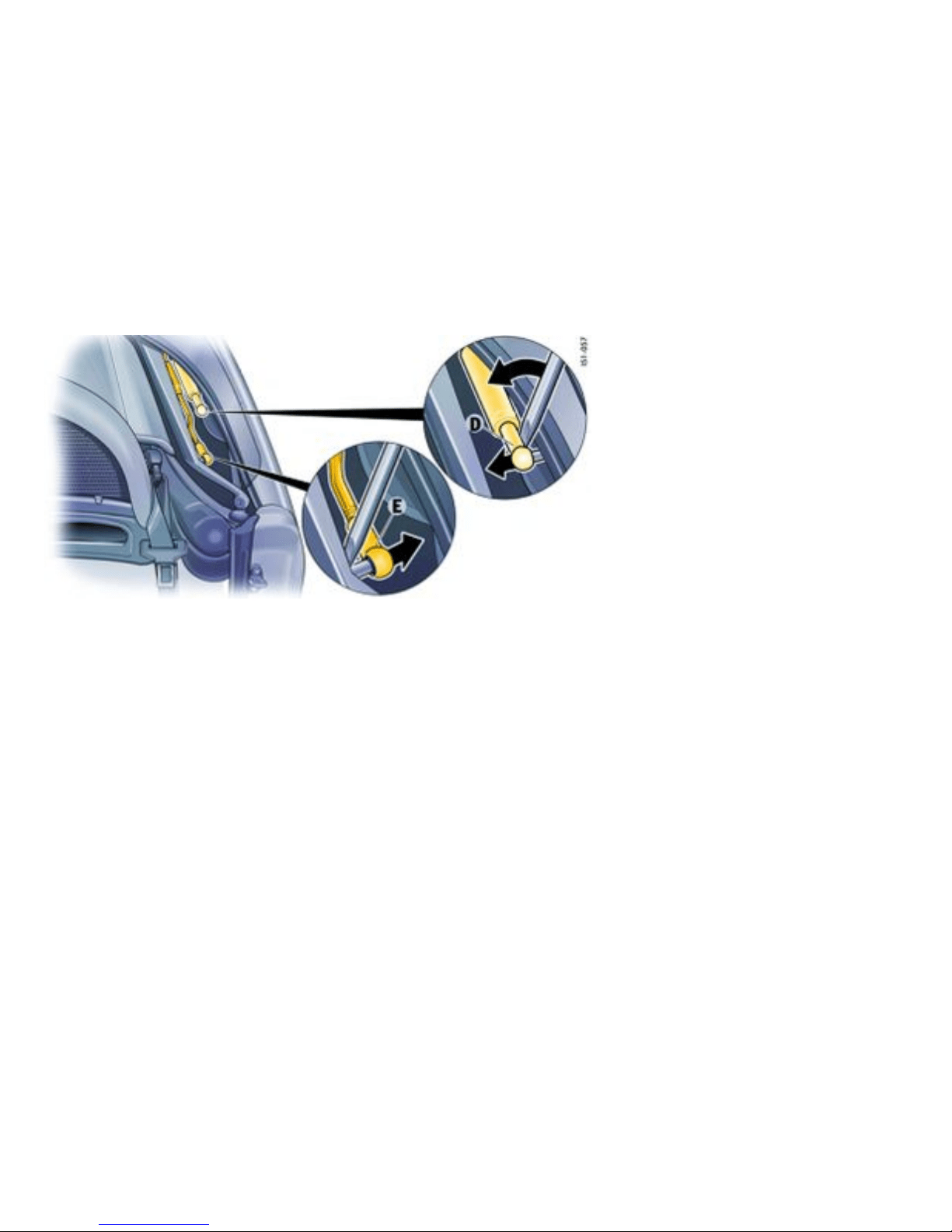
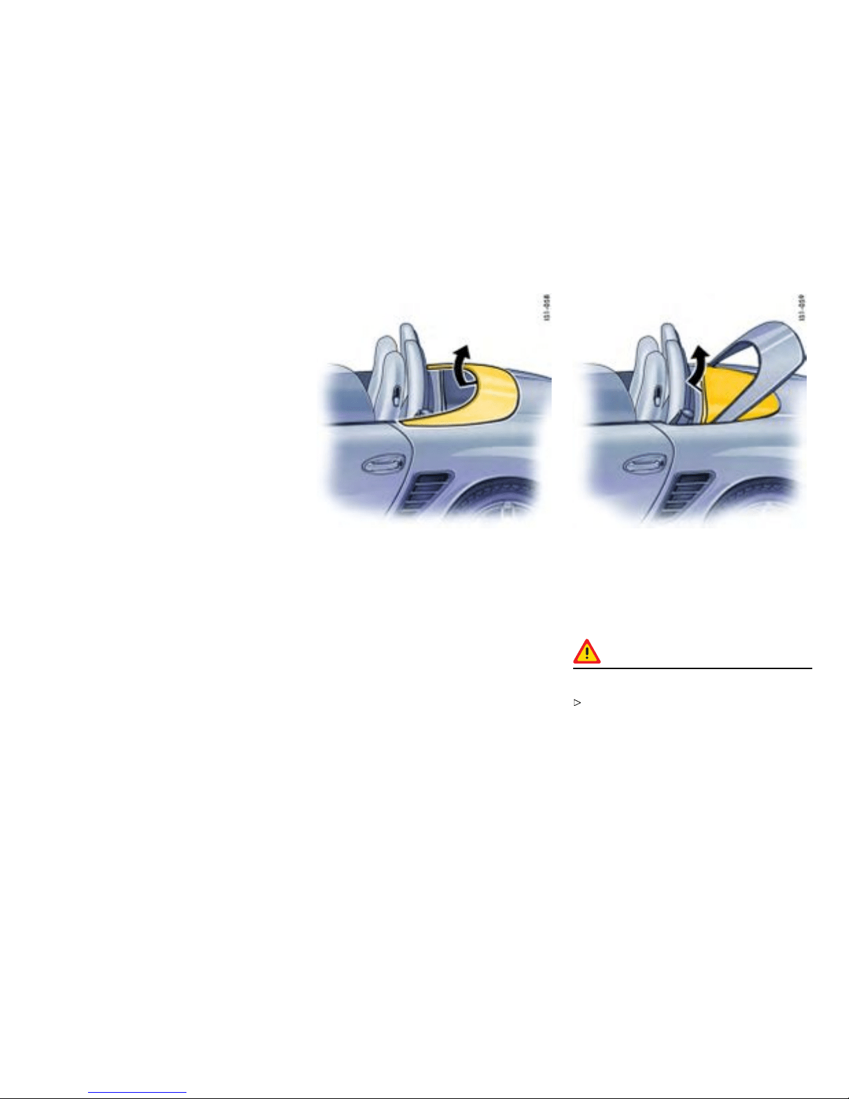
The po sition and access ibility of the joint rods
change depen ding on the position of the converti-
ble top. It c an be helpful to fold up the rear part of
the convertible top.
4. Lever joint rod D (black fastening) off the ball
head with blade of lever B. As the c onnection is
under spring tension, a corresponding amount
of force is required to l ever off the ball head,
creating danger of crushing and pinching.
5. When levering off joint rod D on the other
side of the vehicle, the convertible-top
compartment cover mus t be held so that it
does not fall down in an uncontrolled manner
to protect against injury from a fallen cover.
6. Grasp convertible-top compartment cover in
the center and set up completely (arrow).
7. Lever joint rod E (white fastening) off the ball
head w ith blade of lever B. A corresponding
amount of f orce is required to lever off the
ball head, creating danger of crushing and
pinching.
8. When levering off joint rod E on the other side
of the vehicle, the c onvertible top must be held
so that it does not fall down in an uncontrolled
manner to protect against injury from a fa llen
cover.
9. Lift convertible top with both hands (arrow)
and close.
10. Lock conv ertible top.
11. Carefully lower convertible-top compartment
cover.
Caution!
Danger of damage at the convertible to p.
After emergency operation, do not operate the
convertible top with the rocker switch.
Mobile Roofs
199
Downloaded from www.ManualsFile.com manuals search engine

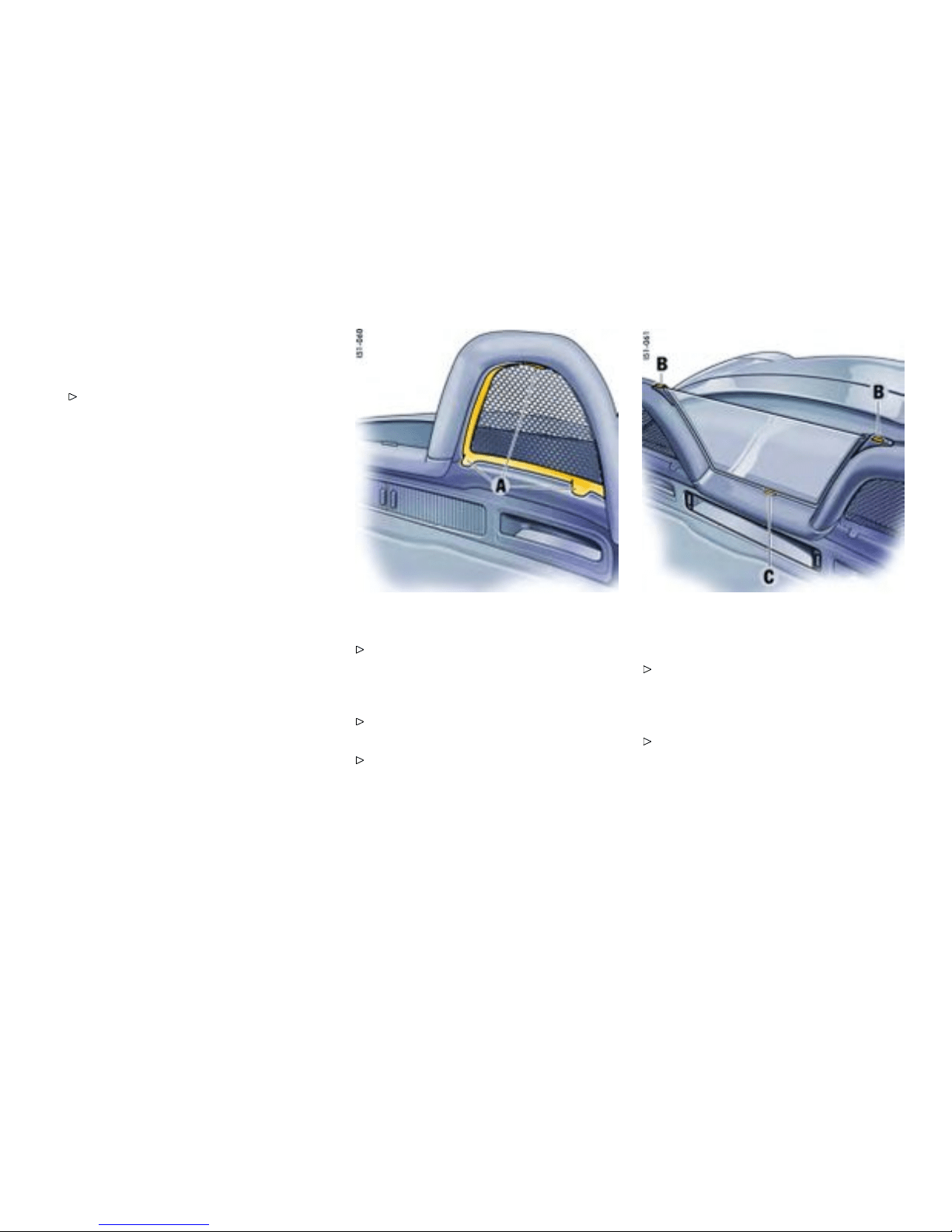
Windstop
General information to the windstop
Make sure that all windstop parts are fastened
securely, especially when driving with the
convertible top open.
Note
When t he convertible top is closed, it is a good
idea to remove the center secti on of the windstop
to permit good ven tilation of the i nterior or for
demisting the rear wind ow. This is pa rticularly th e
case in cold, wet weather.
Remo ving out er windstop parts
Press windstop parts to the rear and u p out of
the roll-over bar and tak e it out.
Installing outer windstop p arts
First insert the windstop parts in the roll-over
bar from the rear, then push it up into the bar.
Make sure that the three pla stic tongues A fully
engage in the roll-over bar.
Remov ing centra l section of windstop
parts
Press release button s B and take out the
windstop toward the rear.
Installing center section of windstop
First i nsert the windstop in receiver C from the
rear, then, one after the other, press forward
until both upper mounts B engage audibly.
Mobile Roofs
201
Downloaded from www.ManualsFile.com manuals search engine
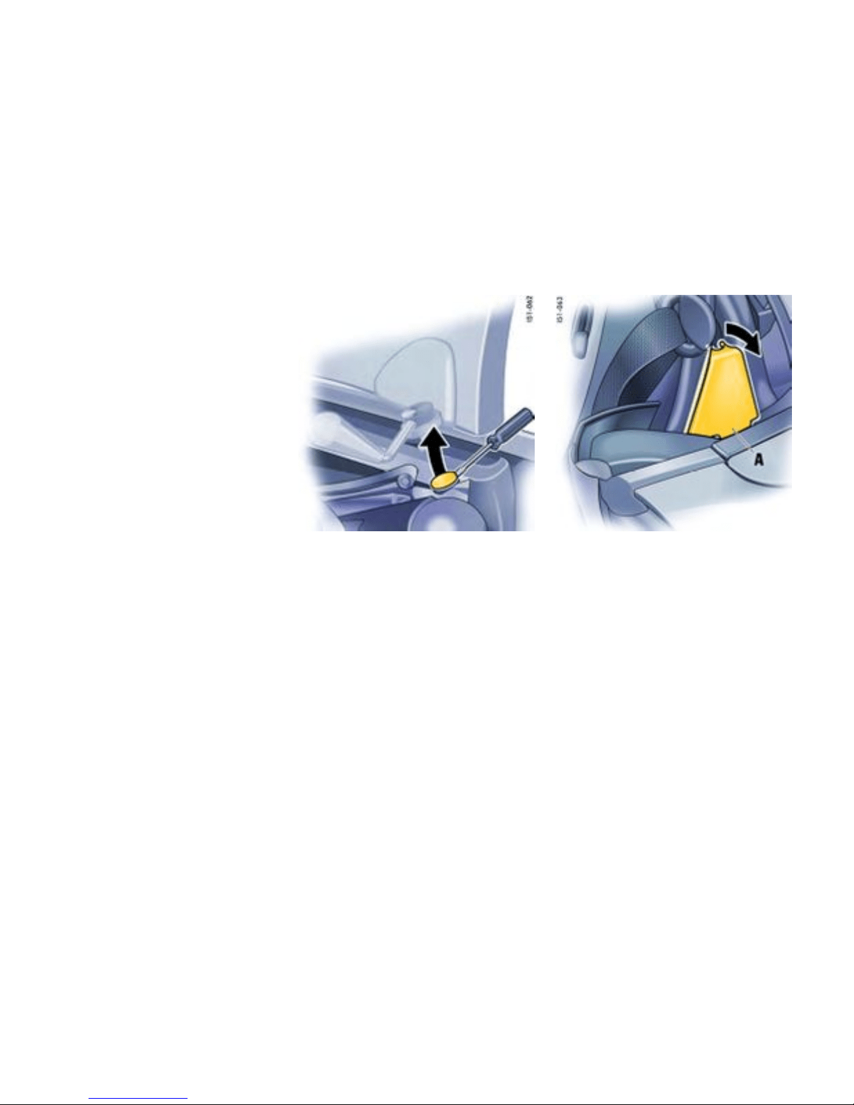
Hardtop
Keeping
Since the convertible top stays open for a long
time, it mus t be absolutely dry and clean before
being opened. This prevents damp stains and
abrasion damage.
Your autoriz ed Porsche deale r will be plea sed to
advise you about co rrect hardtop st orage.
Note
The inserts for locking of the pivot locks are not
installed on v ehicles delivered without a hardtop. It
is essential to have the necess a ry parts retrofitted
by an auth o rized Porsche dealer bef ore a hardtop
is fitted for th e first time.
Fitting the hardtop
1. Open doors and convertible top.
2. Carefully remove both plastic covers (arrow)
out of the pivot l ocks, using a screwdriver.
Store plastic covers.
Note
These p lastic covers are included with vehicles that
are factory-equipped with a hardtop.
3. Pull off cove r A on the roll-over bar.
202Mobile Roofs
Downloaded from www.ManualsFile.com manuals search engine
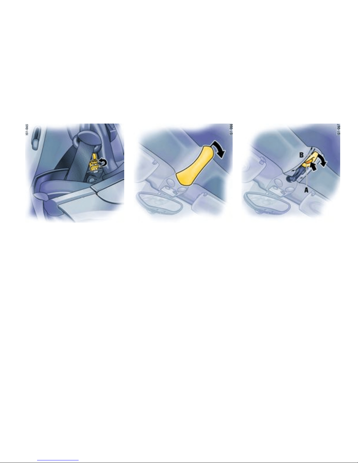
4. Remove the connector of the con vertible top
heated rear window and insert into the rear
empty socket .
5. Remove cover from front locking lever
(arrow).
6. Press red locking button of the front locking
lever (arrow A). O pen latch completely (arrow
B).
Mobile Roofs
203
Downloaded from www.ManualsFile.com manuals search engine
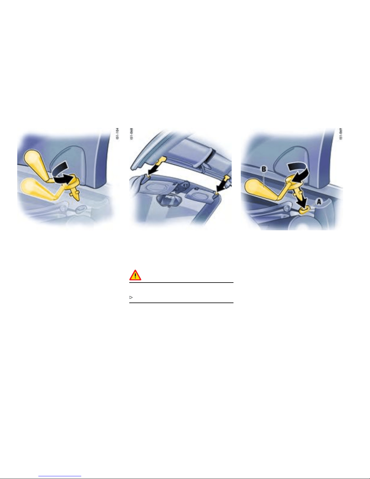
7. Put both pivot locks in the opening posit ion on
the hardtop. The handles must point inwards.
8. With one person on each side, grasp hardtop
and c arefully lift over the car.
9. Insert hardtop front into the sockets on the
windshield frame.
Warning!
Danger of pinching ngers or hands.
Evenly lowe r the hardtop at both sides.
10. Lower hardtop at rear. The pivot locks must be
completely sunken int o the locks (arrow A). If
necessary, move latching lever slightly.
11. Swing both latching levers to the rear until they
can b e felt to engage (arrow B).
204Mobile Roofs
Downloaded from www.ManualsFile.com manuals search engine
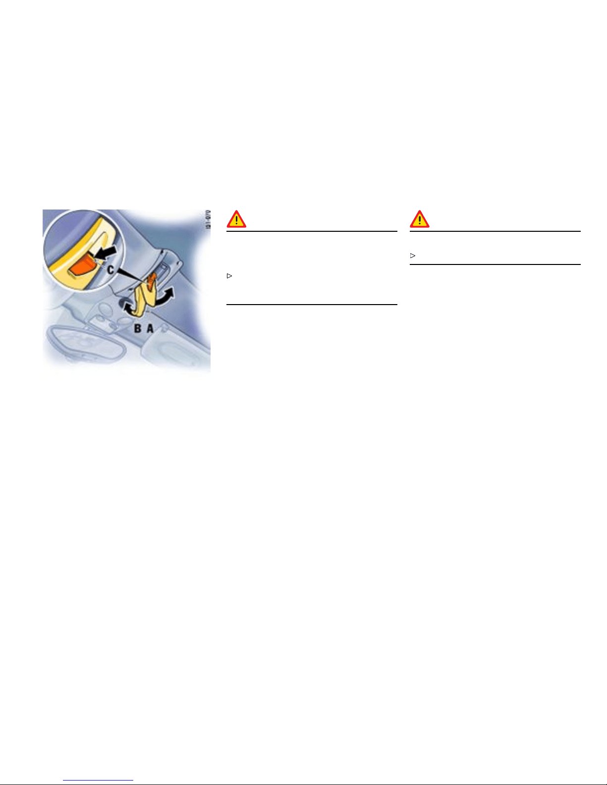
12. Swing locking lever of f ront latch to the rear
(arrow A). The locking hook mu st engage in t he
windshield frame (arrow B). When the hardtop
is correctly latched, the white marking stripe
on the red locking button (arrow C) must be
visible.
Caution!
Risk of damage due to inadvertent operation
of th e conver t ible top when the hardtop is
tted.
Make sure that front locking le ver A is always
correctly lock ed. This disables the conve rtible-
top drive.
13. Fit cover on the front locking lever.
14. Insert the p lug of the hardtop heated rear
window into the soc ket.
Removing the ha rdtop
1. Make sure that the hardtop is placed on a
clean, s oft surface.
2. Open d oors.
3. Remove cover from the front locking lever.
4. Open front latch.
5. Open rear pivot locks (swivel inwards). Unplug
plug o f the hardtop heated rear window.
6. With one person on each side, grasp the
hardtop. Lif t hardtop at rear and pull out of
the sockets on the windsh ield frame at front.
Warning!
Danger of pinching ngers or hands.
Evenly lift the hardtop at both sides.
7. Carefully lift the hardtop up and off the vehicle
to the rear.
8. Close front hardtop latch. Fit cover on the front
latch.
9. Close pivot locks on the vehicle with the plastic
covers.
10. Remove the connector of the convertible top
heated rear wind ow from the empt y socket
and i nsert into the socket.
Mobile Roofs
205
Downloaded from www.ManualsFile.com manuals search engine
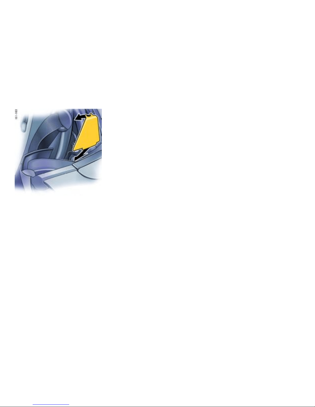

Mainten ance, Car Care
Exercise Ext reme Caution when Working on y our
Vehicle ......................................... .............. 208
Wiper Blades .............................................. 209
Coolant Level .............................................. 210
Engine Oil ....... ............................................ 212
Engine Oil Level ........................................... 213
Engine Oil Recommendation .............. ........... 215
Brake Fluid Leve l ..................................... .... 217
Fuel Economy ............................................. 219
Operating your Porsche in other Countries ..... 220
Fuel ........................................................... 221
Portable fuel containers ............ ............. ...... 223
Fuel Re commendations ................................ 224
Emission Control Syste m ........................ ..... 225
How Emission Control Works ................... ..... 226
Fuel Ev a poration Control ..................... . . ....... 227
Washer Fluid ......................................... ...... 228
Power Steering ........................................... 229
Filter .......................................................... 230
Automatic Transmission Fluid ....... ................. 231
Manual Transmission Oil ............................... 232
Car Care Instructions ................................... 233
Maintenance, Car Care
207
Downloaded from www.ManualsFile.com manuals search engine

Exercise Extreme Ca u t ion when
Working on your Vehicle
Danger!
Ignoring the following instructions may cause
serious personal inj ury or death .
The engine co mpartment of any motor vehicle
is a potentially hazardous area. If you are not
fully familiar with proper repair procedures, do
not at tempt the adjustments described on the
following pages. This caution applies to the
entire vehicle.
Only w ork on your vehicle outdoors or in a well
ventilated area.
Ensure that there are no open flames in
the area of your vehicle at any time when
fuel fu mes might be present. Be espe cially
cautious of s uch dev ices such as hot water
heaters which ignite a flame intermittently.
Before working on any part in the engine com-
par tment, turn th e engine off and let it cool
down suffici ently. Hot engine compartment
components can burn skin on co ntact.
Be alert and cau tious around engine at all
times while t he engine is running. If work has
to be performed with the engine running,
always set the parking brake, an d make sure
the shift lever is in neutr al or the selector lever
is in position P or N.
In particular, be very careful t o ensure that
items of clothing (ties, shirt, sl eeves etc.),
jewelry, long hair, hand or fi ngers cannot get
caught in t h e engine-compartment blower, fan,
belts or othe r mov ing parts. The radiat or and
radiator fans are in the front of the car. The
fans can st art or continue running as a fu nction
of temperature, even with the engine switched
off. Carry out work in these areas only with the
engine off and exercise extreme caution.
Your Porsche is equipped with an electronic
ignition system. When the ignition is on,
high voltage is present in all wires con nected
with the ignition s ystem; therefore, exercise
extreme caution when working on any part of
the engine w hile the ignition is on or the engine
is running.
Always place the vehicle on stable supports if
work h as to be carried out under the vehicle.
Jacks are not suitable for this kind of work.
When workin g under the car without safety
stands but with the wheels on the ground,
make sure the car is on level ground, the
wheels are blocked, and that the engi ne
cannot be st arted. Remove the ignition key.
Do not smoke or allow an open flame around
the battery or fuel. Keep a fire extinguisher in
close reach.
Incomp lete or improper s ervicing may cause
problems in the operation of the car. If in
doubt about any servicing, have it done by
your a uthorized Porsche deal e r. Improper
maintenance during th e warranty period may
affect your Porsche war ranty coverage.
Supplies of fluids, e.g. engine oil, brake flu id
or c oolant, are hazardous to your health . Keep
these fluids out of children’s reach and dispo se
of them in accordance with the appropriate
regulations.
Some countries require additional tools and
special spare parts to be carried. Please make
enquiries befo re dr iving abroad.
Power m easurements
Power meas urements on dynamometers are not
approved by Porsche.
Worki ng in the engine compar tment
Have the necessary work in the engine compart-
ment done by your authorized Porsche dealer.
208Maintenance, Car Care
Downloaded from www.ManualsFile.com manuals search engine
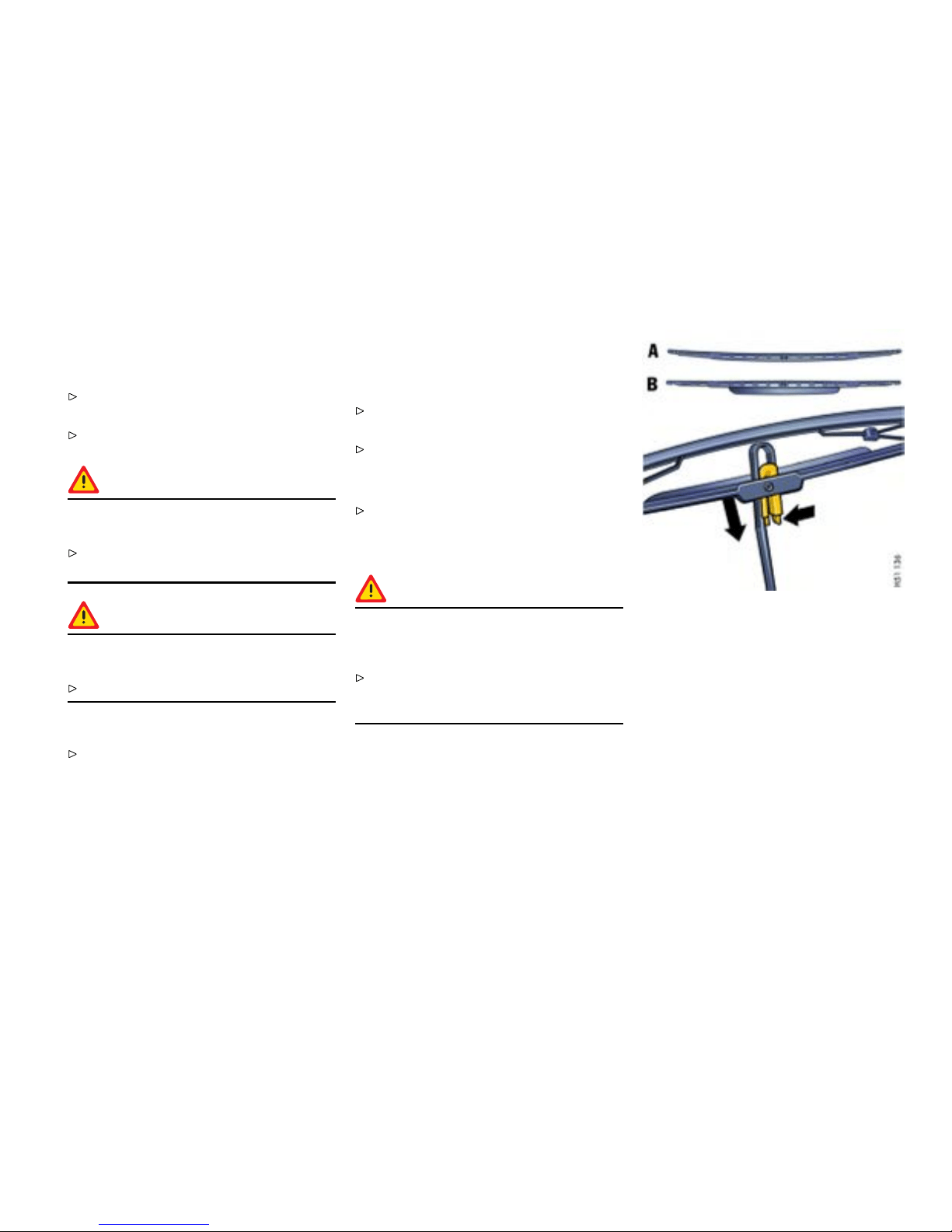
Wiper Blades
General information to the wipe r blades
When wiper performance deteriorates,
replace the wiper s.
Please observe the chapter ”CAR CARE
INSTR UCTIONS ” on page 233.
Caution!
Risk of damage if the wiper arm accidentally
falls back on to t he window.
Always hold the wiper arm secu rely when
replacing the wiper blade.
Caution!
Risk of damage if wiper blades that are frozen
in pla ce are loosened improperly.
Thaw the wiper blades befo re loosening them.
Maintenance note
Periodically clean the wiper blades with
Porsche window cleaner, especially after the
vehicle has been washed in a car wash . If they
are very dirty (e.g. with insec t remains), they
can be cleaned with a sponge or cloth.
If the wiper blades rub or squeak, this can be as a
result of t h e following:
If the vehicle is washed in an automatic car wash,
wax residu es may adhere to the windshield . These
wax residues can be remo v ed by using window
cleaner concentrate.
Please obse rve the chapte r ”WASH ER FLUID”
on page 228.
Please contact your authori zed Porsche dealer
for further information.
The wiper blades may be damaged.
Replace damaged w iper blades as soon as
possible.
Changing windshield wiper blades
Caution!
Risk of damage. If a wi per blade is not
changed properly, it can come loose when
the c ar is moving.
Check whethe r the wiper blade is seated
securely. The wiper blade must engage the
wiper arm properly.
1. Apply the handbrake.
2. Switch the wipers off (position 0) and remove
the ignition key.
3. Fold windshield wiper arm away from th e
windshi eld.
A - Passeng er’s side, curved wiper blade
B - Driver’s side, wiper blade with spoiler
4. Press togethe r the plastic spring of the wiper
blade (right arrow). Pull wiper blade out of
wiper arm.
5. Insert new wiper blade until you feel it engage.
Ensure that the new wip er blade is inserted
into t he wiper arm in th e same position:
– direction of the spoiler on the driver side,
– curvat ure on the passenger side.
6. Carefully fold wiper arm back onto the wind-
shield.
Maintenance, Car Care
209
Downloaded from www.ManualsFile.com manuals search engine
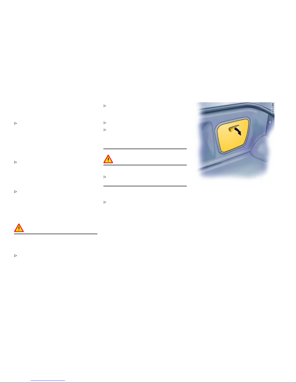
Coolant Level
General in formation to the coolant
Please observe the chapter ”EXER CISE
EXTREME CAUTION WH EN WORKING O N
YOUR VEHICLE” on page 208.
The cooling system is filled at the factory with
a permanent coolant. It provides year-round
protection from corrosion and freezing down to
-31°F (-35°C ).
Only use antifreeze authorized by Porsche.
Checki ng coolant level
The expansion tank for the cool ant is located in the
rear luggage compartment under the service flap.
Check the co olant level regularly.
When the engine is cold and the car is level the
fluid level must lie between the “M in.” and “Max.”
markings.
Topping off coolant
Warning!
Danger of serious personal injury or death
from scalding. Coolant is hazardous to your
health, and may be fatal if swallowed.
Do not open the cap of the expansion t ank
while the engine is hot.
Allow the engine to cool down before openi ng
the cap and protect your hand s, arms and face
from any possible escape of hot coolant.
Keep coolant out of children’s reach.
Also, keep coolant away from yo ur pets. They
can be att racted to it should there be a spill,
or to used coolant left in an open container.
Coolant can be deadly to p ets if consumed .
Warning!
Risk of damage from ov er owing coolant.
Take care while topping off coolant not to soil
the luggage compartment or i tems of luggage.
1. Switch engin e off and let it cool.
Please observe the chapter ”COOLING
SYSTEM” on page 94.
2. Open the service flap by p ulling the handhold.
210Maintenance, Car Care
Downloaded from www.ManualsFile.com manuals search engine
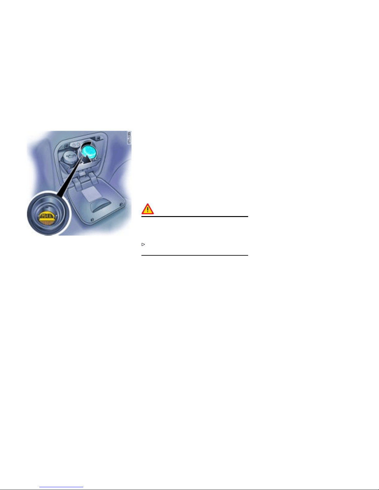
3. Cover the expansion tank cap with a th ick
rag. Open cap slowly and carefully and allow
overpressure to escape. Then unscrew cap
completely.
4. Only add a mixture of antifreeze and water
in equal parts, and do not exceed the “Max.”
mark.
Antifreeze in coolant:
50% gives protection do wn to -31°F (-35°C )
60% gives protection do wn to -58°F (-50°C )
5. Screw cap firmly on.
6. Close service flap.
If in an emergency pure water has been added,
the m ix ratio must be corrected at an authorized
Porsche dealer.
Marked loss of coolant i ndicates leakage in the
cooling system. The cause should imm ediately be
remedied at an authorized Porsche dealer.
Radiator fans
The radiator and r adiator fans are in the front of the
vehicle .
Warning!
Risk of injury. The fans can start running as a
function of temperat ure, even with the engine
switc hed off.
Exercise ex treme caution when working in the
area of the radiator fan s .
Maintenance, Car Care 21 1
Downloaded from www.ManualsFile.com manuals search engine

Engine O i l
Engine oil c onsumption
It is normal for y our engi ne to consume oil. The
rate of oil c onsumpti on depends on the quality
and viscosity of oil, the spe ed at which the engine
is operated, the climate, road conditions as well
as the amount of dilution and oxidation of the
lubrican t .
If the vehicle is used for repeated short trips, and
consumes a normal amount of oil, th e engine oil
measurement may not show any drop in the oil
level at all, even after 600 miles (1000 km) or
more. This is becau se the oil is gradually becoming
diluted with fuel or mois ture, making it appear
that the oil level has not changed. The diluting
ingredients evaporate out when the vehic le is
driven at hi gh speeds, as on an expressway,
making it then appear that oil is excessi vely
consume d after driving at high spe eds.
If the conditions you drive your vehicle in are dusty,
humid, or hot , the frequency of the oil change
intervals should be greater.
If the vehicle is driv en at a high rate of spe ed,
climatic conditions are warm, and the load is
high, t he oil s hould be checked more frequen tly,
as driv ing conditions will determine th e rate of oil
consumption.
– The engine in your vehicle depends on oil
to lubricate and cool all of its moving parts.
Therefore, the e ngine oil should be checked
regularly and kept at the required level.
– Make it a habit to have the engine oil level
checked with every fuel filling.
– The oil pressure warning ligh t is not an o il
level indicator. The oil pressure warning light
indicates serious engine damage may be
occuring when lit, if engine rpm i s above idle
speed.
212Maintenance, Car Care
Downloaded from www.ManualsFile.com manuals search engine
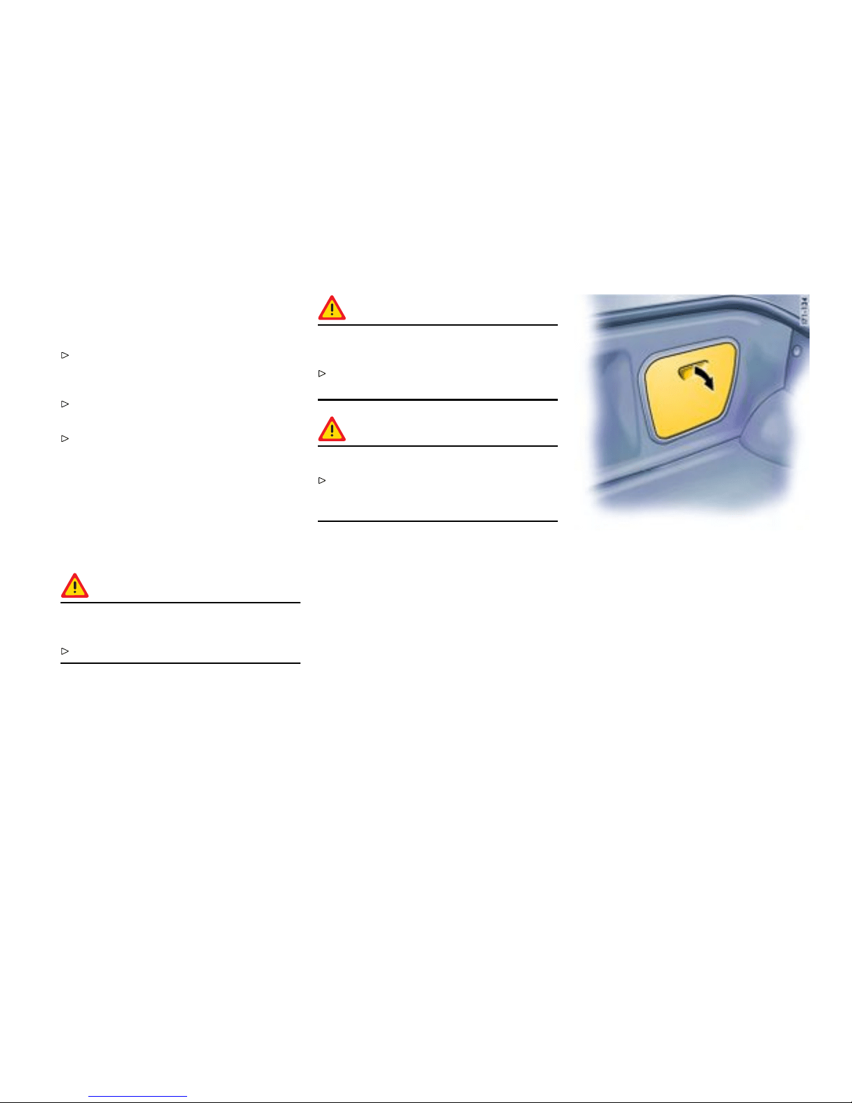
Engine Oil Level
Checki ng the oil level
Please observe the chapter ”EXERCISE
EXTREME CAUTION WHEN WORKING ON
YOUR VEHICLE” on page 208.
Regularly check the oil level using the on-board
computer after the vehicle is refuelled.
Please observe the chapter ”OIL DISPLAY AND
MEASUREMENT OF THE ENGINE OI L LEVEL”
on page 128.
The difference be tween the minimum and max-
imum marks on the segment d isplay is approx.
1.2 liters. Each segment of the display corre-
sponds to approx. 0.4 liter.
Toppin g off engine oil
Warning!
Engine oil is hazardous to your health and
may b e fat al if swallowed.
Keep engine oil out of children’s reach.
Warning!
Used engine oil contains chemicals that have
caused cancer in laboratory anim als.
Always protect your skin by wa shing thorough-
ly with soap and water.
Caution!
Risk of damage from overowing engine oil.
Take care while checking and topp ing up
engine oil no t to soil the luggage compartment
or items of luggage.
The oil inlet o pening is located in the rear lug gage
compartment under the service flap.
1. The on-board computer indicates how much oil
must be added.
2. Open the service flap by pulling the handhold .
Maintenance, Car Care
213
Downloaded from www.ManualsFile.com manuals search engine
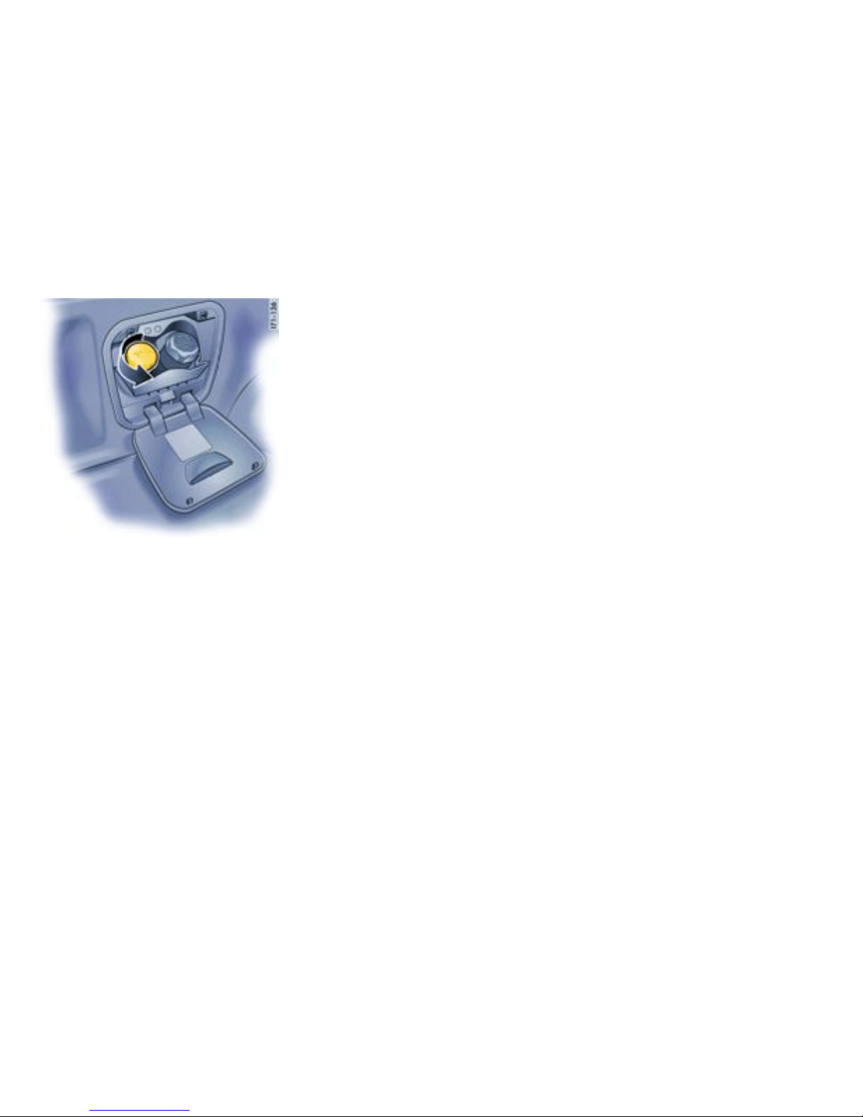
3. Unscrew cap of the oil filler opening.
4. Add at most half a liter o f engine oil at a time.
5. Measure oil level again with the on-board
computer.
6. Add more engine oil if ne cessary. Nev er add
more engine oil than required to reach the
max. mark.
7. Close cap carefully.
8. Close service flap.
214Maintenance, Car Care
Downloaded from www.ManualsFile.com manuals search engine

Engine Oil Recommendation
Recommended oil viscosity rang es dependent on ambient temperatures
Ambient temperature seasonal
SAE Viscosity Range engine oils
generally ab ove -13°F (-25°C ) SAE 0W-40, 5W-40, 5W-50 approved by Porsche
genera lly below -13 °F (-2 5°C ) SAE 0W-40 approved by Porsche
Suitable oils are:
Use only engin e oils tested and approved by Porsche (Porsche approval list). Your athorized Porsche d ealer will be pleased to advise you.
You will find a sticker in the service flap which provides i nformation (manufacturer) about the ini tial factory filling of yo ur engine.
Generally you can find th e manuf acturer suggestions on the oil containers or as a bulletin on the market.
Oil change
The engine oil has to be changed at the intervals
listed in your Main tenance Schedule.
Please observe the chapter ”CAPACITIES” on
page 306.
We recommend that you have the engine oi l
changed at your Porsche dealer, who has the
required oils and the necessary filling equipment.
If you suspect an oil leak in the engine have your
dealer check it out immed iately.
All current engine oils are compatible with e ach
other, i. e. when makin g an oil change it is not
neces sary to flush the engine if you wish to use a
different brand or grade of oil. Since, however,
each brand of oil h as a sp ecial composition,
you should, if possibl e, use the same oil brand
if it becomes neces sary to top up between oil
change s.
Porsche engines have long intervals between
oil changes. You can make best use of these
long oil change intervals by using multigrade oils
since these are largely independent of seasonal
fluctua tions in tempe rature.
If your vehicle is used frequently in stop-and-go
traffic in cold weather, the engine will not always
be properly warmed up. Condensation from
products of combustion may accumulate in the
oil. In this case, it is advisable to chang e the oil
m
ore frequently s o tha t your engine once again has
100% efficient oil.
Engine oil perform ance class
Engine oil is not o nly a lubricant, but also serves to
keep the engine clean, to neutralize the dirt which
penetrates into the engine through combustion
and to protect the engine against corrosion. To
perform these functions, the oil is provided with
additives which have been specially developed
for these fun ctions. The efficiency of an oil is
expressed, for example, by the API, ILSAC or ACEA
classifi cations.
Viscosity
Like all liquids, engi ne oil i s viscous when cold,
and th in-bodied when warm. The vi scosity of an oil
is expressed by its SAE class. For cold viscosity
(me
sured at temperatures below 32°F (0°C ))
Maintenance, Car Care
215
Downloaded from www.ManualsFile.com manuals search engine

the SAE class is give n as a number and the letter
”W“ (as in winter), for hot viscosity (measured at
212°F (100°C )) the SAE class is given only as a
number.
The viscosity of an oil is, therefore, a lways the
same i f it has the same number of an SAE class.
Oils with tw o viscosities are ca lled multigrade oils;
oils with only one viscosity are termed single-grade
oils.
Single-grade oils cannot be used in your engine.
The viscosity of the engine oil for your Porsch e has
to be chos en according to the ambient tempera -
ture given in the engine oil recommendation table.
216Maintenance, Car Care
Downloaded from www.ManualsFile.com manuals search engine
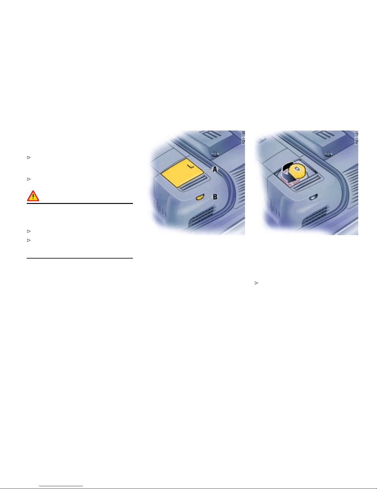
Brake F luid Level
Use of brak e uid
Please observe the chapter ”EXERCISE
EXTREME CAUTION WHEN WORKING ON
YOUR VEHICLE” on page 208.
Use only new (unus ed) Original Porsche
brake uid.
Warning!
Brake uid is ha zardous to your health, and
may b e fatal if s wallowed. Brake uid also
attack s paintwork.
Keep brake fluid out of children’s reach.
Take c are while topping off brak e fluid not to
soil the luggage compartment o r items of
luggage.
Checking the brake uid lev el
The reservoir for the hydraulic braking and clutch
syste ms is in the front luggage compartment.
1. Open and remove cover flap A.
2. Regulary check the brake-fluid lev el on the
transparent expansion tank through the
window B. The fluid level should always lie
between the “Min” and “Max” marks.
A sligh t decrease in the fluid level due to wear
and automatic readjustment of the dis c brakes is
norma l. If, however, th e fluid level falls markedly
or below the “Min” mark, the braking system may
have developed a l eak.
Have the braking sys tem checked immediately
at an authorized Porsche dealer.
Changing the brake uid
Brake fluid absorbs moisture from the air over
time. T his accumulation of water lowers the boiling
point and, under certain operating conditions,
can affect the braking action. Therefore have the
Maintenance, Car Care
217
Downloaded from www.ManualsFile.com manuals search engine

brake fl u id changed in accordance with the change
intervals stated in the brochure “Maintenance”.
Warni ng lights
Warning ligh t USA
Warning light Canada
The brake-fluid warn ing light s in the instrument
panel and on-board com puter indicate:
– brake-fluid level too low,
– in conjunction with large pedal travel, braking-
circuit failure.
If the warning lights should light up when
driving:
Stop immediat ely in a suitable place.
Do not continue driving. Please have the fault
remedied at your nearest authorized Porsche
dealer.
218Maintenance, Car Care
Downloaded from www.ManualsFile.com manuals search engine

Fuel Economy
Fuel economy will vary depending on where,
when and how you drive, optional equipment
installed, and the general con dition of your
car. A car tuned to specications and correct-
ly maintained, will help you to a chieve optimal
fuel economy.
Have your vehicle tuned to specifications. Air
cleaner should be dirt free to allow proper
engine “breathing”. Batter y should be fully
charged. Wheels should be properly aligned.
Tires should be inflated to the correct pres-
sure.
Always monitor your fuel consumption.
Drive smoothly, avoid abrupt changes in s peed
as mu ch as p ossible.
Avoid jack rabbit starts and sudden stops.
Do not driv e longe r than necessary in the lower
gears. Shifting into a higher gear early without
lugging the engine will help save fuel.
Prolonged “warm up” idling wastes gas. Start
the vehicle just before you are ready to drive.
Accelerate slowly and smoothly.
Switch off the engine if stationary for longer
periods (traffic lights, jams, leve l crossings).
Any additional weight carried in the vehicle
reduces fuel economy. Always keep cargo to a
minimum and remove all unnecessary items .
Organize your trips to take in several errands
in one trip.
All electrical a ccessories contribute to
increased fuel consumption.
Only swi tch on the air conditioning when
necess ary.
The EPA estimated miles per gallon (mpg)
is to be used for comparison purposes,
actual mileage may be different from the
estimated mpg, depending on your driving
speed, weath er conditions and trip length.
Your actual highw ay mileage will probably be
less than the estimated mpg.
Please observe all local and nat ional spe ed
limits.
Maintenance, Car Care
219
Downloaded from www.ManualsFile.com manuals search engine

Operating your Porsche in other
Countries
Government regulati ons in the United S tates and
Canada require that au tomobiles meet specif ic
emission regulations and safety standards.
Therefore, cars built for the U.S. and Canada differ
from vehic les sold in other countries.
If you plan to take your Porsche outside the
continental limits of the United States or Canada,
there is the possibility that
– unleaded fuel may not be availa ble;
– unleaded fuel may have a considerably lower
octane rating . Excessive engine knock and
serious damage to both engine and catalytic
converters could result;
– service may be inadequate due to lack of
proper service facil ities, tools or diagnostic
equip m ent;
– replacement parts may not be available or very
difficult to get.
Porsche cannot be responsible for the
mechanical damage that co uld result
because of in adequate fuel, serv ice or parts
availabil ity.
If you purchased your Porsche abroad and want
to bring it back home, be sure to find out about
shipping and forwarding requirements, a s well as
current import and customs regulations.
220Maintenance, Car Care
Downloaded from www.ManualsFile.com manuals search engine
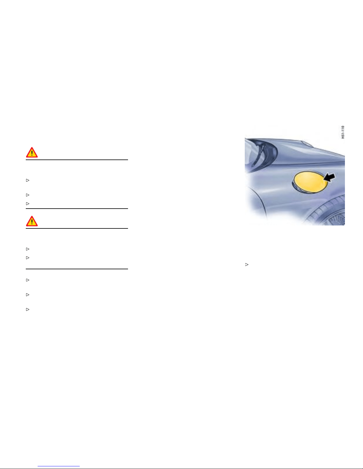
Fuel
Gener al information
Warning!
Fuel is highly ammable and h armful to
health.
Fire, open flame and smoking are prohibited
when handling fuel.
Avoid contact with skin or clothing.
Do not inhale fuel vapors.
Warning!
To prevent damage to t he emission control
system and engine:
Never drive the tank completely out of fuel.
Avoid high cor nering speeds aft er the warning
lights have come on.
Please observe the chapter ”FUEL ECONOMY”
on page 219.
Please observe the chapte r ”EMISSION
CONTROL SYSTEM” on page 225.
Please observe the chapter ”FUEL” on page
221.
Check engine warning light
If the warn ing lights in the instrument panel an d
on-board computer come on and remain on while
driving, it su ggests:
– an improperly fastened tank cap or
– refueling with eng ine running.
Open ing the ller ap
The fil ler opening is under the filler flap in the front
right fender.
With the vehicle unlocked, press on the front
part of the filler flap (arrow) to open the flap.
The filler flap is centrally locked along with the
other locks.
Maintenance, Car Care
221
Downloaded from www.ManualsFile.com manuals search engine
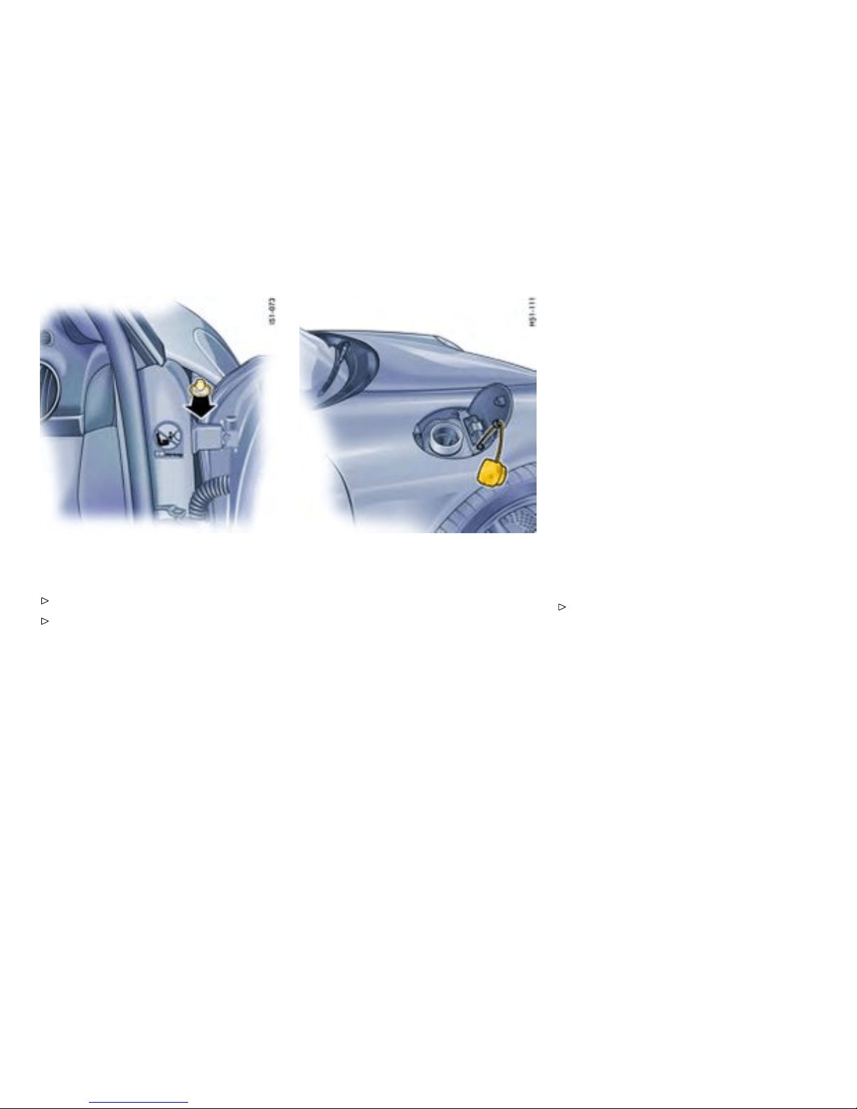
If there is a defect in the automatic unlocki ng
system:
Open t he pass enger door.
Pull the ring in the right-hand door aperture
(arrow).
Refuel ing
Fuel tank capacity
The fuel filling capa city is approx. 16.9 U.S.g allons
(64 liters), of which approx. 2.64 U.S.gallons
(10 liters) is reserve.
Porsche does not recommend the use of fuel
additive s.
Fuel is highly ammable and harmful to
health .
Procedure
1. Important: Stop the engine and switch off the
ignition.
2. Slowly unscrew the tank cap . Hang the tank
cap on the plastic strap of the filler flap .
3. Insert fuel-hose nozzle fully into the filler neck
with the handle of the fuel-hose nozzle facing
down.
4. Do not add further fuel once the c orrectly
operated automatic fuel-hose nozzle has
switche d of f. Fuel could s pray or could run
over in warm temperatures.
5. Replace the tank cap immediately after
refueling and turn it until you hear it and feel
it engage.
If you lose the tank cap, you must replace
it onl y with an original par t to reduce the
possibility of a re in the event of a collision.
Note
The o il level is automatica lly meas ured during
refueling.
Please observe the chapter ”OIL DISPLAY AND
MEASUREMENT OF THE ENGINE OI L LEVEL”
on page 128.
222Maintenance, Car Care
Downloaded from www.ManualsFile.com manuals search engine

Portable fuel containers
Danger!
Portable fuel containers, full or partially
empty, may leak causing an explosion, or
result in re in case of an accident.
Never carry additional fuel in porta ble contain-
ers in your vehicle.
Maintenance, Car Care 22 3
Downloaded from www.ManualsFile.com manuals search engine

Fuel Recommendation s
Your Porsche is equippe d with catalytic converte rs
and must use UNLEADED FUEL ONLY.
Your engine is designed to provide op timum
performance and fuel economy using unleaded
premium fuel with an octan e rati ng of 98 RON
(93 CLC or AKI). Po rsche therefore recommends
the use of these fuels in your vehicle.
Porsche also recognizes that these fue ls may not
always be available. Be assured that your vehicle
will operate proper ly on unleaded premium fuels
with oc tane numbers of at least 95 RON (90 CLC
or AKI), since the engine ’s ”Electronic Octane™
knock control“ will adapt the igniti on timi n g, if
necessary.
The use of UNLEADED FUEL ONLY is critic ally
important to the life of the catalytic convert-
ers. Deposits from leaded fue ls will ruin the
converters and make it ineffective as an emis-
sion control device.
Cars wi th catalytic converters have a smaller fuel
tank opening, and g as station pump s have smal ler
nozzles. This will prevent accidental pumping of
leaded fuel into cars with catalyti c convert ers.
Unleaded fuels may not be ava i lable outside the
continental U.S. and Canada. Therefore, we
recommend you do not take your car to areas
or countries where unleaded fuel may not be
availab le.
Octane ratings
Octane rating indicates a fuel’s ability to resist
detonation. The refo re, buying the correct octane
gas is important to p revent engine ”damage“.
The RON octane rating is based on the research
method. The CLC (U.S. Cost of Living Council
octane rating) or AKI (antiknock index) oct ane
rating usually disp layed on U.S. fuel pumps is
calculated as research octane number plus moto r
octane number, divided by 2, that is written as:
RON + MON
R + M
2
or
2
The CLC or AKI octane rating is usually lower than
the RON rating:
For example: 95 RON equals 90 CLC or AKI.
Fuels containing alcohol and e ther
Some areas of the U.S. require oxygenated fuels
during certain portions of the yea r. Oxygenated
fuels are fuels w hich contain al cohols (s uch as
methan ol or ethanol) or ether (such as MTBE).
Under normal conditions, the amount of these
compounds in the fuel will not affect driveability.
You may us e oxygenated fuels in your Porsche,
provided the octane requirements f or your vehicle
are met. We recommend, however, to change
to a different fuel or station if any of the following
problems occur with you r vehicle:
– Deterioration of drivea bility and performa nce.
– Substantially reduced fuel economy.
– Vapor lock and non-start problems, especially
at high altitude or at high temperature.
– Engine malfu nction or stalling.
Fuels containing MMT
Some North American fuels co n tain an octane
enhancing additive called methylcyclopentadienyl
manganese tricarbonyl (MMT).
If such fuels are used, your emission con trol
system performance may be negatively affected.
The ch eck engine warning light on yo ur instrument
panel may turn on. If this occurs, Porsche recom-
mends you stop using fuels containing MMT.
224Maintenance, Car Care
Downloaded from www.ManualsFile.com manuals search engine
Emission Control System
In the inter est of clean air
Pollution of our environment has become a
problem tha t is of increasing concern to all of
us. We urge you to join us in o ur efforts for cleaner
air in controlling the pollutants emitted from the
automobile.
Porsche has developed an emission control
system that controls or reduces those parts of the
emissi on that can be harmful to our e n vironment.
Your Porsche is equipped with such a s ystem.
Porsche warr ants the Emission Control System in
your new car under the terms and con d itions s et
forth in the Warranty Bookl et.
You, as the owner of the vehicle, have the respon-
sibility to provide regular maintenance service for
the vehicle and to keep a record of all maintenance
work performed. To facilitate record keeping, have
the se rvice performed by authorized Porsche deal-
ers. They have Porsche trained technicians and
special tools to provide fast and efficient service.
To assu re efcient operation of the
Emissi on Control S ystem
Have your vehicle maintained properly and
in accordance with the recommendations
described in your Maintenance Booklet. Lack
of proper m aintenance, as well as improper
use of the vehicle, will impair the function of
the emission control system and could lead to
damage.
Do not alter or remove any component of the
emission control system.
Do no t alter or remove any device, such as
heat shields, switches, ignition wires, valves,
etc., which are designed t o protect your
vehicle’s emis sion con trol system. In addition
to seri ous engine damage, this can result in
a fire if excess raw fue l reaches the exha ust
system.
Do not continue to operate your vehicle if
you detect engine misfire or other unusual
operating conditions.
Parking
Warning!
Dange r of re resulting in serious personal
injury or death.
Do not park or operate the vehicle in areas
where the hot exhaust system may come in
contact with dry grass, brush, fuel spill or
other flammable material.
If your car catches on fire for any reason, call
the fire depart ment. Do not endanger your life
by attempting to put out the fire.
Undercoating
Danger!
Dange r of re resulting in serious personal
injury or death.
Do not apply addition al undercoating or
rust-proofing on or near the e xhaust manifold ,
exhaust pipes, catal ytic conv erters or heat
shields. During driving the substance used for
undercoating could overheat and ignite.
Maintenance, Car Care 22 5
Downloaded from www.ManualsFile.com manuals search engine

How Em ission Control Works
When an automobile engine is ru nning, it uses
energy generated through the com bustion of a
mixture of air an d fuel. Depending on whether a car
is driv en fast or slo wly or whether the engine is cold
or hot, some of the fuel (hydrocarbons) may not be
burned compl etely, but may be discharged into the
engine crankcase or exhaust system. Additional
hydrocarbons may enter the atmosphere through
evaporation of fuel from the fue l tank. These
hydrocarbons (HC), when released into the air,
contribute to undesirable polluti on.
In addition, carbon monoxide (CO) a nd oxides of
nitrogen (NOx) contribute to engin e emissions.
They, too, are formed during the combustion
process and discharged into the exhaus t system.
To reduce these po llutants, your Porsche is
equipped with a precise ly calibrated fuel injection
system to a ssure a finely balanced air/fuel mixture
under all operating conditions.
Oxygen sensor
The oxygen sensor, in stalled in the exhaust
pipe continuous ly senses the oxyge n content
of the exhaust and signals the information to an
electronic control unit. The control unit corrects
the air/fuel rati o, so the eng ine always receives an
accurat e ly metered air/fuel mixture.
Crankcase venti lation
Through crankcase ventilation, und esirable
emissions from the engine crank case are not
permitted to reach the outside atmosphere. These
emissions are recirculated from the crankcase to
the a ir intake system. From here the emissions
mix with the intake air and are later burned in the
engine.
Catalytic conver ters
The catalytic converters are e fficient ”clean-up“
devices built into the exhaust system of the vehicle.
The catalytic converters burn the undesirable
pollutants in the exhaust gas before it is released
into the atmosphere.
The exclusive use of un l eaded fuel is critically
important for the life of the catalytic convert-
ers. Therefore, only unleaded fuel must be
used.
The catalytic conver ters will be damaged by:
– push or tow starting t he vehi cle,
– misfiring of the en gine,
– turning off the ignition while the vehicle is
moving or
– driving until the fuel tank is completely empty,
– by other unusual operating conditions.
Do not cont inue to operate your vehicle under
these conditi ons, sinc e raw fuel might reach
the catalytic converters. This cou ld result in
overheating of the converters. Federal law
prohibits u se of leaded fuel in this car.
226Maintenance, Car Care
Downloaded from www.ManualsFile.com manuals search engine

Fuel Evaporation Control
Fuel tan k ve nting
The evaporation chamber and the carbon canister
prevent fuel from escaping to the atmosphere at
extreme high outside tem peratures, when driving
abruptly around curves and when the car is parked
at an incline or in any other nonlevel po sition.
Vapor control system and storage
When the fuel tank is filled, vapors are collec ted
in the evaporation c hamber by a vent li ne leading
the vapors to the ca rbon canister where they are
stored as long as the engine does not run.
Purge system
When the engine is running, the fuel vapors from
the canister will be mixed with fresh air from the
ambient air of the canister. This mixt ure will be
directed t o the i ntake air housing by the ta nk vent
line, mi xed with the intake air an d burned during
normal combustion.
Maintenance, Car Care
227
Downloaded from www.ManualsFile.com manuals search engine
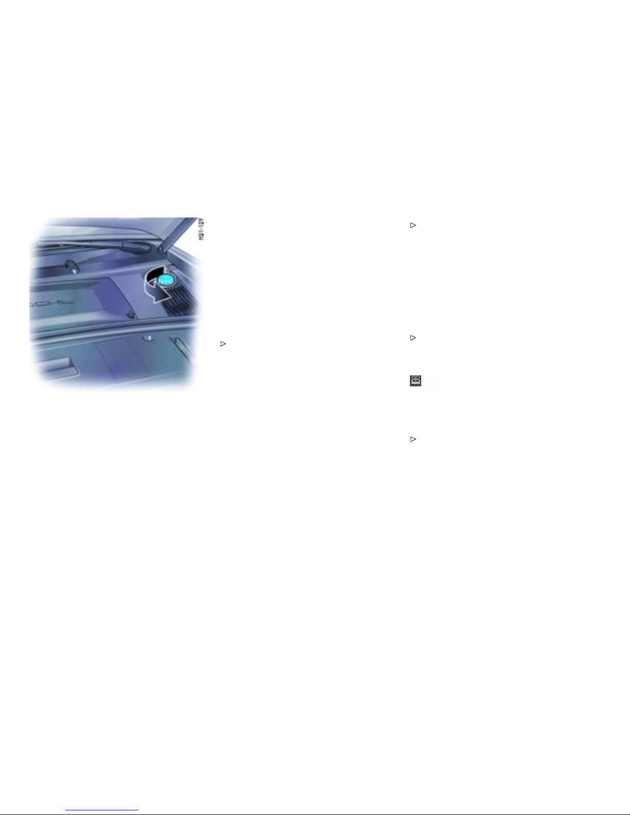
Washer F luid
Capac ity
– Without head light clea ning system: approxi-
mately 2.6 qu arts (2.5 liters).
– With headlight cleaning system: approximately
6.3 quarts (6 liters).
Washer uid
General i nformation on washer uid
The reserv oir, with a blue screw cap, is in the front
luggage compartment, to the rear left.
Clean water is generally not enough to clean
the windshield and headligh ts. Depending on
the season, mix the water with the a ppropriate
additives. Follow the instructions for the mixture
ratio.
Only use window cleaner concentrate which
meets the following requirements.
– Dilutability 1:100
– Phosphate-free
– Suitab le for plastic headlight lenses.
We recommend window clean er concentrates
approved by Po rsche. Your authorized Porsche
dealer will be pleased to advise you.
Summer lling
Water + window cleaner concentrate at the mixing
ratio indicated on the c ontainer.
Winter lling
Water + antifreeze protection + window cleaner
concentrate at the mixing ratio indicated on the
container.
Please note all the information on the c ontain-
ers of the window cleaner conce ntrate or the
antifreeze protection.
Adding w asher uid
1. Pleas e note all the information on the refill
container of the cleaning age nt.
2. Open c ap of the w asher-fluid reservoir (arrow).
3. Add washer fluid and close cap properly.
Do not use engine coolant anti-freeze or any
other solution that can damage the car’s paint,
in the washer reservoir.
Warning light
If less than 0.52 quarts (0.5 liter) remains, a
warning message appears o n the on-board
computer.
Add washer f luid.
228Maintenance, Car Care
Downloaded from www.ManualsFile.com manuals search engine

Power Steering
Warning!
Risk of accident resulting in serious personal
injury or death. When the eng ine is stopped
(e.g. when being towed) or the hydraulic
system fails, there is no assistance for
steering. Therefore, substantially more force
will have to be exert ed in order to s teer.
Exercise great care when being towed.
Have the fault remedied at your nearest
authorized Porsche de aler.
Note
The flow noise heard at full steering lock is system
related and does not indicate a defect in the
steerin g system.
Checking hydrau lic uid
Please observe the chapter ”EXERCISE
EXTREME CAUTION WHEN WORKING ON
YOUR VEHICLE” on page 208.
The reservoir is in the engine compartment.
Regular check ing of hydraulic fluid is part of
servicing.
Maintenance, Car Care
229
Downloaded from www.ManualsFile.com manuals search engine

Filter
Air lter
The air filter is on the left-hand side of the engine
compartment.
A dirty air filter not only reduces engine perform-
ance, but can lead to prematu re engine wear.
Regular filter replacement is part of the routine
maintenance service.
In dust y conditions, check the filter element
more frequently and replac e if necessary.
Combination lter
The fresh air passing through the combination filter
into the pass enger c ompartment is virtually free of
dust, pollen, and unpleasant odors.
If the outsid e air is polluted by exhaust fumes,
press the c irculating-air button.
A dirty filter can be t he cause of reduce d air
throughput:
Have the filt er replaced by an authorized
Porsche dealer.
Regular filter replacement is part of the routine
maintenance service.
230Maintenance, Car Care
Downloaded from www.ManualsFile.com manuals search engine

Automatic Transmiss ion Fluid
The torque converter and the transmission are
lubricated with Automatic Transmissio n Fluid (ATF).
The fin al drive requires transmission o il.
Please observe the chapter ”CAPACITIES” on
page 306.
Do not tow the car or run the engine with out ATF
in the transmission. The automatic transmission
may be dama ged by even a tiny speck of dirt, only
a clea n funnel or spout must be used whe n adding
ATF.
The ATF and transmission oil has to be check ed
and changed at the interval s listed in your Mainte-
nance Schedule.
We recommend that you have the ATF and t rans-
mission oil changed at your Porsche dealer, who
has the required lubricants a nd the necessary filling
equip m ent.
If you suspect an oil leak in t h e transmission ,
have your authorized Porsche dealer check it out
immediately.
Maintenance, Car Care
231
Downloaded from www.ManualsFile.com manuals search engine

Manual Transmission Oil
The transmission oil has to be checked and
changed at the intervals listed in your Maintenance
Schedule.
Please observe the chapt er ”CAPACITIES ” on
page 306.
We recommend that you have the transmission
oil changed at your Porsche dealer, who has
the required lubricants and t h e necessary filling
equipment.
If you suspect an oil leak in the transmission,
have your authorized Porsche dealer check it out
immediately.
232Maintenance, Car Care
Downloaded from www.ManualsFile.com manuals search engine

Car Care Instruct i ons
Long-t erm maintenance of value
Please observe the chapter ”EXERCISE
EXTREME CAUTION WHEN WORKING ON
YOUR VEHICLE” on page 208.
Regular and correct care helps to maintain
the value of your car and is also a precondi-
tion for the New Vehicle Warranty a nd the Anti
Corrosion Warranty.
Your autho rized Porsche dealer has specially
developed car-care products from the
Porsche program available either singly or as
complete car-care sets. They will be pleased
to help you select suitable products.
Whether you use Porsche products o r othe r
commercially available cleaning agents rs t
make sure of their correct application.
A Porsche that is well-cared for can loo k like new
for ye ars. It all depends on the amount of care the
owner is willing to give the car.
Warning!
Risk of serious personal i njury or damage to
the vehicle or property. Cleaning agents m ay
be hazardous t o your healt h. Most chemical
cleaners are co ncentrates whi ch require
dilution. High concentrations might cause
problems r anging from irritation to serious
injury as well as dama ge to your vehicle.
Keep c leaning agents out of reach from
children.
Observe all c aution labels.
Always read directions on the container
before using any product. These directions
may co ntain in formation necessary to avoid
personal injury.
Do not use fuel, kerosene, naphtha, nail polish
remover or other volatile cleaning fluid s. They
may be toxic, flammable or hazardous in other
ways. Only use spot removing fluids in a well
vented area.
Do not clean the underside of chassis,
fenders, wheel covers , etc., without protecting
your hands and arms as you may cut yoursel f
on sharp-edged metal parts.
Moist u re and road sal t on brakes may affect
brakin g efficiency.
Test the brakes after each vehicle washing.
Car washing
Washing
The best method of protecting your car from the
damaging effects of the e nvironment is frequent
washing and the application of a preservative. The
underside of your v ehicle sh ould also be thoroughly
washed for cinders, sal t or sanding at winter’s end .
The lo n ger salt, road dust and industrial dust,
dead insects, bird droppings or subs tances f rom
trees (resin, pollen) are allo wed to remain on the
bodywork, the more seri ous is their harmful effect.
New cars should be washed carefully with plenty
of clear water to protect the new paint work. Dark
paint finishes show up the smallest of surface
damage (e.g., scratches) more readily than lighter
colors.
Dark colors are also more susceptible to scratch-
ing b ecause of the composition of their pigments
and require particularly careful paint care.
Do not wash your car in bright sunlight or while
the bodywork i s still hot.
When washing by hand, use abundant wa ter, a
soft sponge or wash brush, an d Porsche car
shampoo.
Begin by spraying the body thoroughly with
water to rinse away loose dirt.
Maintenance, Car Care
233
Downloaded from www.ManualsFile.com manuals search engine
After washing, rinse the car with plenty of
water and then dry with a chamois leather. Do
not use the same chamois leat her for drying
as you use for cl eaning the windshield and
windows.
Warning!
Moisture which g ets on to the brakes during
a car wash can reduce braking efciency o r
make the b rakes pull u nevenly which could
increase the danger of an accident, causing
serious personal injuries or death.
Always apply the brakes a few times after
washing the car to test braking efficiency and
dry the brake discs. When doing this, t ake
care not to hamper other road users behind
you (traffic conditions permitting).
Convertible top
Never remove snow and ice using a s harp
edged object .
Incorrect care and treatment can damag e the
convertible top and cause leaks. Any repair work
can be done by your authorized Porsche dealer.
Note
No folding top is 100% l eak proof.
Due to the constant chang ing of l oads and strains
to which a car is s ubject to when drivin g on roads,
minor wind noise an d seep age at joints between
the top, body and doors on convertible tops
cannot be c ompletely sealed in certain areas.
Therefore small leaks are considered normal
for these models. In addition, your convertible
top should not be washed in a car wash. The
top may experience damage by the brus h es or
may experience leaks due to the high pressure
water streams directed in areas which would not
encounter wa ter in normal driving conditions .
Cleaning
Caution!
Risk of damage due to the cleaning jet of the
high-pressure cleaning equipment or hot wax
treatmen t .
Do not clean the c onvertible top with high-
pressure cleaning equipment.
Do not use the hot wax treatment.
Do not wash the c o nvertible top each time the car
is was hed. It is usually sufficient to spray or wash it
with clean wa ter.
Brush dust off the convertible top in the
direction of the weave using a soft brush.
Only if there is heavy dirt, wet the convertibl e
top with lukewarm water and the Porsche
Wash-Shampoo & convertib le-top cleaner,
using a sponge or soft brush, and rub gently.
Rinse Wash-Shampoo & convertible-to p
cleaner thoroughly off the convertible top
with clean water.
After washing it, treat the c o n vertible-top
cover at least once a year with the s pecial
Porsche convertible-top care product. Do not
allow t he convertible-top care product to come
into c ontact with paint or windows. If it does,
remove immediately.
If there is leakage in the convertible-top cover
or at its seams or folds, the s pecial Po rsche
convertible-top care product can be used.
Please note the i nformatio n on the c ontainer.
Remove bird droppings immediately since the
acid in them will make the rubbe r swell and the
convertible top will b ecome leaky.
Open convertible top only when it is completely
dry, otherwise damp stains an d scrub ma rks
may occur which cannot be removed.
Try to remove spots from th e conv ertible-top
cover by rubbing c arefully with a sof t rubber
sponge.
Automatic car washes
Optional add -o n parts or parts which project
beyond the contours of th e vehic le may be
234Maintenance, Car Care
Downloaded from www.ManualsFile.com manuals search engine

damaged by design features (e.g. brushes) of
automa t i c car washes.
The following parts are parti cularly suscepti-
ble to damage:
– Convertible top (hot wax treatment cannot be
used, as the wax attacks th e convertible top
material),
– Windshield wipers (always switch them off
to prevent them wiping unintentionally in
intermittent or sensor ope ration)
– Externa l telepho ne antenna (always unscrew)
– Fixed rear spoiler or extended rear spoiler
– Wheels (the wider the rim and the lower the tire
height, the greater the risk of damage)
– High-glo ss wheels (to prevent these from
getting scratched, do not clean with the
wheel-c leaning brushes of the car wash).
Please consult the operator before us ing
automatic car washes.
Wash and dry by hand all points not reached
by a car wash, such as door and lid seams or
door sills.
Note
Automa tic car washes spray water at o d d angl e s
and high pressures, which are not seen in normal
driving. Therefore, water can sometimes find its
way into the passengers compartment during or
shortly after the car wash.
Door locks
To prevent the door locks from freezing during
the cold season, the lock cylinders should be
covered duri ng a wash.
Should the locks freeze, use an ordinary
de-icer. In many cases, a well warmed key
can help. Never use excessive force.
Paint
Never rub a dusty car with a dry cloth since
dust particles are abrasive and could dull and
damage the surface fin ish.
The paintwork of your car is exposed to all types of
mechanical and chemical conditions, particularly
climatic ones such as bright sunlight, ra in, frost
and snow. Ultraviolet light, rapid changes in
temperature, rain, snow, industrial dust and
chemical deposits constantly attack the paint
which is onl y able to withstand such exposure in t he
long t erm if it is g iven regular care and attention.
Do not apply silicone polishes to the wind-
shield, windows or convertible top.
Do not treat matt-painted components w ith
preservatives or polishes as this will spoil the
matte effe ct.
Preservation
The paint surface becomes dull over time due to
weatheri ng. It is therefore necessary to preserve
the paint regularly.
This keeps the paint shiny and elastic. D irt is
prevented f rom adhering to the paint surface and
industri al dust is prevente d from penetrating the
paint.
Provided it is washed and treated with preservative
regularly, the brand new finish of your vehi cle will
be retained for y ears to come.
Maintenance, Car Care
235
Downloaded from www.ManualsFile.com manuals search engine
Simply apply paint preservative after washin g
the vehicle an d polis h it smooth.
Polishing
Do no t resort to u sing Pors che polish until it
becomes evident that the normal preservatives
no lon ger produce the desired finish.
Spots and stains
Remove tar stains, grease, oil spots and
dead i nsects as soon as possible with Insect
Remover. They can cause discoloration if
allowed to remain on the paintwork.
Wash the affected area immediately after
treating it.
Minor pai nt damage
Have minor paint da mage, such as scratches,
scores or chips caused by flying stones,
repaired immedia tely by your authoriz ed
Porsche dealer before corrosion sets in.
However, if there are already traces of corrosion,
they must first be removed carefully and thorough-
ly. Coat the area with a rust-proofing prim er and
finish off with a to p coat. The paint code and color
number are found on the data bank in the Mainte-
nance booklet and on th e filler flap.
Cleaning and preserving engine
compartment
The engine compartment and the surface of the
engine are treated with a corrosion-inhibitor at the
factory.
If de greasing solvents are used to clean the
engine compartment or the engine is washed
down, the process almost invariably removes the
corrosion-inhibiting coating. It is then absolutely
necessary to have a durable preservative app lied
to all surfaces , body seams, joints and as semblies
in the engine compartment. This also applies when
corrosion-inhibitor parts are replaced.
Caution!
Risk of damage to the alter nator.
Do not point the cleaning jet directly at the
alternator, or cover the alternator.
Effect ive corrosion-proofing is particularly impor-
tant during the cold weathe r season. If your car
is driven frequently in areas where salt has been
spread on the roads, the whole engine c ompart-
ment should be cle aned thoroughly after the winter
to prevent salt from causing any lasting damage. A
full under-body wash should also be performed at
the same time.
Windows
The road dust which settles on the windshield
and windows contains particles of tire rub ber
and oil residue. The interior trim and upholstery
release particles, particula rly in s trong sunlight,
which collect on the insid es of the windows. These
deposits are augmented by impurities in the air
which enters the car through the fresh air vents.
Clean all wind ows regularly, inside and outside,
with Porsche window cleaner.
If you use a chamois leather for the windows,
do not use it for paintwork as it wil l other wise
pick up a certain amount of preservative or
polish and could sm ear the windows and thus
impair vision.
Remove dead insects with the Porsche i n sect
remover.
Note
Door windows feature a water-repellent (hydropho-
bic) coating which prevents soili ng of the windo ws.
This coating is subject to natural wear and can be
renewed.
Consult an authorize d Porsche dealer.
Wiper blades
Wiper blades that are in perfekt condition are vital
for a clear view.
236Maintenance, Car Care
Downloaded from www.ManualsFile.com manuals search engine

Replace the wiper blades twi ce per year
(before and after the cold season) or whenever
wiper performanc e deteriorates.
Periodically clean the wiper blades with
Porsche window cleaner, especially after the
vehicle has been washed in a car wash . If they
are very dirty (e.g. with insec t remains), they
can be cleaned with a sponge or cloth.
Undercoating
The underside of your car is durably protected
against chemical and mechanical i nfluences.
As it is not possible to ex clude t h e risk of damage
to this protective coating in day to day driving,
it is a dvisable to have the underside of the c ar
inspected at certain inter vals - preferably before
the st art of winter and again in spring - and the
undercoating restored as necessary.
Your authorize d Porsche dealer is familiar with
the bodyseal treatment procedures and has
the necessary equipment for applying factory
approved m aterials. We recommend that you
entrust them with such work and inspections.
Unlike convent ional sp ray oils, undercoating and
rust-proofing compounds based on bitumen or wax
do not attack the sound- proofing materials applied
at the factory.
Warning!
Danger of re resulting in serio us per sonal
injury or death.
Do not appl y addit ional un dercoating or
rust-proofing on or near the exhaust manifold,
exhaust pipes, catalytic converters or heat
shields. During driving the substance used for
undercoating could overheat and ignite.
Before applying fresh underseal, carefully
remove dep osits or dirt and grease. Once it
has dried, the new undercoatin g compound
forms a tough protective coating which
provides efficient rust-proofing of the floor
panels and components.
Always apply a fresh coating of suitable
preservative to unprotected areas after
cleaning the underside of the body, the
transm ission, the engine or carrying out
repairs to under-body, engine or transmission
components.
Effective rust-proofing is particula rly important dur-
ing the cold weathe r season. If your car is dr iven
frequently in areas where salt has been spread
on the roads, the whole engine compartment
should be cleaned thoroughly after the winter to
prevent salt from causing any lasting damage. A
full under-body wash shoul d also be performed at
the same time.
Door, roof, lid and window seals
Wash dirt (e.g. abrasion, dust, road salts) from
all seals regularly using warm soapy water.
Do not use any che mical cleaning agents or
solvents.
When there is a frost hazard, the outer door seals
and the front and rear lid seals can be protected
against freezing into place by a suitable care
product.
In order to preven t damage to the anti-friction
coating, the inner door seals, the convertible
top s eals and hardtop seals mus t not be
treated with care products.
Stainless steel exh aust tailpipes
Stainless steel exhaust tailpipes can disco lor due
to soiling, strong heat, and combustion residues.
The original polish can be achieved again using
commercially available metal polishing paste or
metal polish.
Maintenance, Car Care
237
Downloaded from www.ManualsFile.com manuals search engine
Headlights, lights, interior and exterior
plasticparts, adhesive lms
Use only clean water and a little dishwa shing
detergent to clean light lenses, plastic
headlight lenses, plasti c parts and surfaces.
Do not clean when dry. Use a soft spong e or
a soft, lint-free cloth. Gently wipe the surface
without applyi ng too much pressure. The
Porsche inside window clea ner is also suitable
for cleaning plastic surfaces. Follow the
cleaning instr uctions on the container. Never
use other chemical cleaners or solvents.
Rinse cl eaned surfaces with clear water.
Light alloy wheels
Please obse rve the chapter ”WASHI NG” on
page 233.
Warning!
Danger of a ccident resulting in serious
personal injur y or death if cleaning agents
(e.g. wheel cleaning agents) come into
contact with the brake discs. Th e resulting
lm on the brake discs can impair braking
performance.
Make sure that no cleaning agent come s into
contact with the brake discs.
If cleaning agent has come into contact with
the brake discs, thoroughly clean the brake
discs with a strong jet of wa ter.
Paying attention to any road users behind you,
dry the brake discs by applying the brakes at
short inter vals.
Pitting may occur if metal lic particles which cause
contact corrosion (e.g. brass or coppe r in brake
dust) are allowed to remain on the aluminum for too
long.
If possible, wash the wheels with a sponge or
wash brush about every two week s. In areas
where salt is spread on winter roads or there
is a lot of airborne industrial dust, it is best to
clean the wheels w eekly. The Porsche Li ght
Alloy Wheel Cleaner (ph-value 9.5) can be
used for t his purpose. If the ph-value of
the detergent is incorrect, t he protective
coating on the wheels w ill be destroyed.
Polishes which dissolve ox ides, such as those
frequently used for other metals, or abrasive
tools or agents are unsuitable beca use they
break down the oxide lm of the protective
coating and will cause discoloration of t he
wheel.
Every three months, after cleaning, co at the
wheels with a car wax or non-corrosive grease
(vaseline).Using a clean cloth thoroughly rub
the g rease into the surface.
Leathe r
Characteristics and s pecial features
The n atural surface marki ngs of leather, e.g.
creases, hea led sca rs, insect sting ma rks,
structural differences and slight variations in shade
and grain add to the attractiveness of the natu ral
leather product.
A special mention mu st be made here of natural
leather.For natural leather, carefully selected hides
of the highest quality are used. It is not cove red
completely with dye on production. “Nature’s
signatu re” is therefore easi ly recognizable. This
fine material is dis tinguished by an outs tanding
seating comfort, special suppleness a nd a typical
patina.
Leather care and treatment
Clean all types of leather regularly to remove
fine dust usin g a soft, damp, whit e woolen
cloth or a commercially available microfiber
cloth.
Remove heavy contamination with Porsche
leather cleaner. Please always follow the
instructions for use given on the containers.
Caustic cleaners and hard cleaning objects
must not be used.
Perforated leather must under no circum-
stances get wet on its reverse side.
238Maintenance, Car Care
Downloaded from www.ManualsFile.com manuals search engine
Once c leaned, leather (par ticularly the heavily
stressed leather s eats) must be treated only with
Porsche leather care liqu id.
Fabric, upholstery, carpets a nd oor-mats
Use only a vacuum cleaner or a medium stiff
brush.
Remove stains and spots with Porsche stain
remover.
The Po rsche range of acce ssories includes
nonskid floor-mats to protect the carpets in
summer and winter.
Warning!
Risk o f an accident resulting in serious
personal injury or d eath.
Always chec k the movement of th e pedals
before driving and make sure that they are not
obstructed by a floor mat or an y other object.
Secure the floor mat to prevent it from sliding
into positions that could interfe re with the safe
operati on of your vehi cle - d o not lay them
loosely in the vehi cle. Your Porsche dealer will
be glad to offer you nonskid-floor mats of the
correct size.
Alcantara
Regular care
Do not use a leather care product to clean
Alcantara.
For regular care it is sufficient to clea n the cover
with a soft brush.
Heavy abra sion or rubbing when cleaning causes a
permanent change in the surface.
Cleaning when light ly soiled
Wet a soft cloth with water or a neutra l soap
solution and wipe off the dirt.
Cleaning when heavily soiled
Wet a soft cloth with lukewarm wat er or
thinned white spirit and dab the dirt from the
outside in.
Safety b elts
If it becomes necessary to clean the belts, you can
use any mild washing agent. Allow the belts to dry
prior to retractin g, but avoid direct sunligh t.
Only use suitable cleaners. If unsuitable
cleaners are used or any attempt is made
to dye or bleach the belts, the webbing may be
weaken ed and thus constitute a safety risk.
Storing your Porsche
If you intend to store your Porsche for a prolonged
period, please consult your author ized Porsche
dealer. The staff w ill be g lad to advise you on the
most su itable a nd necessary m ethods.
Clean your vehicle tho roughly inside and
outside . Clean the engine compartment.
The u nder carriage and chassis components
should be free of dirt and salt deposits.
Fill up the fuel tank.
Chang e the oil and oil filter, and run th e engine
for several minutes.
Increase the tire pressure to 58 psi ( 4 bar). It
is no t recommended to lift th e vehic le, due to
the possibility of c orrosion on shock absorber
piston shafts. The ve hicle should be moved
slightly, approximately every four weeks, to
prevent flat spot on the tires.
Climate c ontrol
The air conditioning system should be in good
working condition and fully charged.
Windshield/Headlight washer
Check and correct antifreeze/cleaning
solution level as necessary.
Maintenance, Car Care
239
Downloaded from www.ManualsFile.com manuals search engine

Electrical system
Remove the battery from the vehicle and store
it in a cool dry place, not on a cement floor.
When the battery is dis connected, the
alarm system is deactivated.
Recharge the battery ev e ry 3 months. If the
battery remains in the vehicle with the cables
connect ed, it is necessary to check, remove
and recharge the battery every 2-3 weeks. Do
not fast charge the battery.
Please obse rve the chapter ”BATTERY” on
page 268.
Vehicle interior
The interior must be dry, especially in the area
of the floor carpets. The use of drying agents
(Silica-Gel) is recommended in veh icles with
leather interior and in areas w ith high humidity. The
recommended amo unt is 3 fabric bags of 1 .1 lbs.
(500 grams) each placed on the floor carpets.
Windo ws, doors, lids and top must be c losed. The
air vents should be opened.
240Maintenance, Car Care
Downloaded from www.ManualsFile.com manuals search engine

Practic al Tips, Em ergency Service
Exercise Extreme Caution wh en Working on your
Vehicle ......................................... .............. 242
Tires/Wheels .............................................. 243
Loading Information ............................... ...... 254
Flat Tire .............................. ........................ 2 56
Lifting the Vehicle ........................ ............ .... 258
Wheel Bolts ................................................ 260
Changing a wheel .............. .......................... 261
Spacers ..................................................... 263
Electrical System ....................................... . 265
Battery ....................................................... 268
Emergency Starting with Jumper Cables ....... . 273
Replacing bulbs ................................ ........... 2 75
Headlights .................................................. 277
Turn signal light ........................................... 281
Side marker light ......................................... 283
Tail light ...................................................... 284
Additional brake light ............................... .... 284
License plate lights ...................................... 285
Luggage compartment/footwell lights ........... 286
Interior light ................................................ 287
Door guard/curb light .................................. 288
Adjusting Headlights .................................... 289
Towing .............. ......................................... 292
Practical Tips, Emergency Service
241
Downloaded from www.ManualsFile.com manuals search engine

Exercise Extreme Ca u t ion when
Working on your Vehicle
Danger!
Ignoring the following instructions may cause
serious personal inj ury or death .
The engine co mpartment of any motor vehicle
is a potentially hazardous area. If you are not
fully familiar with proper repair procedures, do
not at tempt the adjustments described on the
following pages. This caution applies to the
entire vehicle.
Only w ork on your vehicle outdoors or in a well
ventilated area.
Ensure that there are no open flames in
the area of your vehicle at any time when
fuel fu mes might be present. Be espe cially
cautious of s uch dev ices such as hot water
heaters which ignite a flame intermittently.
Before working on any part in the engine com-
par tment, turn th e engine off and let it cool
down suffici ently. Hot engine compartment
components can burn skin on co ntact.
Be alert and cau tious around engine at all
times while t he engine is running. If work has
to be performed with the engine running,
always set the parking brake, an d make sure
the shift lever is in neutr al or the selector lever
is in position P or N.
In particular, be very careful t o ensure that
items of clothing (ties, shirt, sl eeves etc.),
jewelry, long hair, hand or fi ngers cannot get
caught in t h e engine-compartment blower, fan,
belts or othe r mov ing parts. The radiat or and
radiator fans are in the front of the car. The
fans can st art or continue running as a fu nction
of temperature, even with the engine switched
off. Carry out work in these areas only with the
engine off and exercise extreme caution.
Your Porsche is equipped with an electronic
ignition system. When the ignition is on,
high voltage is present in all wires con nected
with the ignition s ystem; therefore, exercise
extreme caution when working on any part of
the engine w hile the ignition is on or the engine
is running.
Always support your car with safety stands if it
is necessary to work under the car. Jacks are
not suitable for this kind of work.
When workin g under the car without safety
stands but with the wheels on the ground,
make sure the car is on level ground, the
wheels are blocked, and that the engi ne
cannot be st arted. Remove the ignition key.
Do not smoke or allow an open flame around
the battery or fuel. Keep a fire extinguisher in
close reach.
Incomp lete or improper s ervicing may cause
problems in the operation of the car. If in
doubt about any servicing, have it done by
your a uthorized Porsche deal e r. Improper
maintenance during th e warranty period may
affect your Porsche war ranty coverage.
Supplies of fluids, e.g. engine oil, brake flu id
or c oolant, are hazardous to your health . Keep
these fluids out of children’s reach and dispo se
of them in accordance with the appropriate
regulations.
Some countries require additional tools and
special spare parts to be carried. Please make
enquiries befo re dr iving abroad.
Worki ng in the engine compar tment
Have the necessary work in the engine compart-
ment done by your authorized Porsche dealer.
242Practical Tips, Emergency Service
Downloaded from www.ManualsFile.com manuals search engine
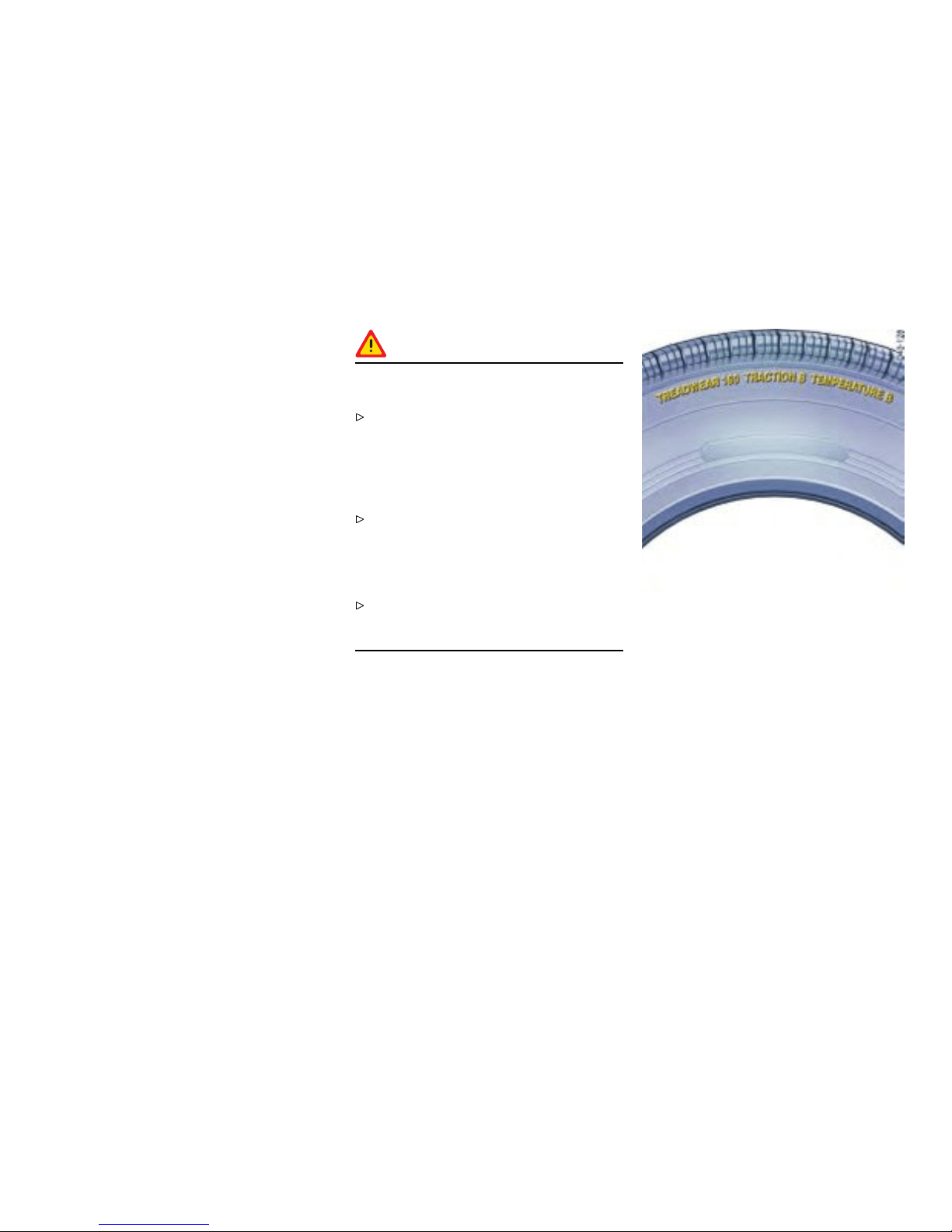
Tires/Wheels
The original equipmen t tires and wheel rims on
your Porsche comply with all applicable Federal
Motor Vehicle Safety Standards.
For your safe ty remember the follo wing:
– Wheel rims and wheel bolts are matc hed to fit
your Porsche.
– If you intend to use ot h er than original equip -
ment wheels, be sure that they conform to
Porsche spec ifications for your model. Only
tires with the same make and with the same
specification code (e.g. “N0”, “N1”...) can be
mounted.
– The u se of wheel rims and wheel bolts that
do not meet specif ications of the original
factory installed equipment will affect the safe
operati on of your vehi cle.
– Before you plan on exchanging wheels, or
snow tires already mounted on the w heel rims,
consult your authorized Porsche dealer. Your
dealer has the technical informati on necessary
to advise you which wheel rims and wheel
bolts are compatible with the original factory
installations.
Danger !
Risk of loss of control and serious per sonal
injury or death.
If while driving, your vehicle experiences a
sudden vibration or ri de disturbance, and/or
you suspect that possible damage to your
tires or vehicle has occ urred, you should
immediately reduce your speed without
excessive use of the brakes.
Stop t h e vehi cle as soon as possible, and
inspect the tires. I f you canno t deter mine th e
cause for the disturbance, have you r vehicle
towed to the n earest Porsche or tire dealer to
have your ve hicle or tire(s) inspe cted.
Continuing to operate the v ehicle without
correction could result in a loss of control and
serious personal injury.
Example
Uniform Tire Quality Gradin g
Quality grades can be f ound where applicable
on the tire sidewall between tread s houlder and
maximum section width.
All passenger car tires must conform to Federal
Safety Requirements in a ddition to thes e grades.
Treadwea r
The treadwear grad e is a comparative rating based
on the wear rate of the tire when tested under
controlled condition s on a specific go v ernment
test c ourse. For example, a tire graded 150 would
Practical Tips, Emergency Service
243
Downloaded from www.ManualsFile.com manuals search engine
wear on e and a half (1-1/2) times as well on the
government cou rse as a tire graded 100. The
relative performance of tires depends upon the
actual conditions of their use , however, and may
depart significantly from the norm due to variatio ns
in driving habits, service practi ces and differences
in road characteristics and clima te.
Temperature A, B, C
The temperature grades are A ( the highest), B
and C, representing th e tire’s resistance to the
generation of heat and its ability to dissipate
heat when tested under cont rolled conditions on
a specified indoor laboratory test wheel. Sust ained
high temperatures can cause the material of
the tire to degene rate and reduce tire life, and
excessive temperature can lead to sud den tire
failure. The grade C corresponds to a level of
performance which all passenger car tires must
meet under the Federal Motor Vehicle Safety
Standard No. 109. Grades B and A represent
higher levels of performance on the laboratory test
wheel than the minimum required by law.
Warning!
The temperature grade for this tire is estab-
lished for a tire that is properly inflated and
not overloaded. Excessive speed, underinfla-
tion, or excessive l oading, either separately
or in combination, can c ause heat buildup and
possible tire failure, resulting loss of co ntrol,
leadin g to serious personal injury or death.
Tire pressures
Warning!
Incorrect tire pressure causes increased
tire wear and adversel y affects road han-
dling. This could lead to tire fa i lure, resulting
in loss of control, leading to serious personal
injury or death.
Always use an accurate tire pressure gauge
when checking inflation pressures.
Do not exce ed the maximum tire pressure
listed on the tire sidewall.
Please observe the chapt er ”TIRE PRESSURE
PLATE” on page 297.
Cold tire inflation pressure means: all tires
must be cold, ambient temperature maximum
(68°F /20°C ), when adjusting the inflat ion
pressure. Avoid sunlight striking the tires
before measuring cold pressures, sin ce
the pressures would ris e from temperature
influenc e.
Valve caps protect the valve from dust and
dirt, and thus from leakage. Always screw
caps tightly down. Replace missing caps
immediately.
Use only plastic valve caps.
244Practical Tips, Emergency Service
Downloaded from www.ManualsFile.com manuals search engine
Do not use commercially available sealant
or tire infl ating bottles. Only use Porsch e
approved tire sealant.
Please obse rve the chapter ”TIRE PRES SURE
FOR COLD TIRES” on page 304.
Each tire, including the spare (if provided ), should
be checked every 2 weeks when cold 68°F (20°C )
and inflated to the inflation pressure recommended
in this Owner ’ s Manual or on the tire-pressure plate
in the left door aperture. If your vehicle has tires
of a different size than the size indi cated in this
Owner’s Manual or on the tire-pressure plate, you
should determine the proper ti re inflation pressure
for those tires.
As an added safety feature, your veh icle has been
equipped with a tire pressure monitoring (TPC) that
illuminates a low t ire pressure message when one
or more of your tires is significantly under-inflated.
Accordingly, when th e low tire pressure message
illumina tes, you should stop and check your tires
as soon as possible, and inflate them to the proper
pressure. Driving on a significantly under-inflated
tire causes the tire to overheat and can lead to tire
failure. Under-inflation also reduces fuel efficiency
and ti re tread life, and may affect the vehicle’s
handling and stoppi ng ability.
Please note that the TPC is not a substitute for
proper tire maintenance, and it is the driver’s
responsibility to maintain correct tire pressure,
even if under-inflation has not reached the level to
trigger illumination of the TPC low tire pressure
message.
On vehicles with tire pressure monito ring:
Please obse rve the chapte r ”TPC TIRE
PRESSURE MONITORING” on page 119.
When tires are warm, the tire pressure is
increased.
Never let air out of hot tires. This could cause
the tire pressure to fall below the prescribed
value.
Insufficient tire filling pressure can cause tires to
overheat and thus b e dam aged - even invisibly. Hid-
den tire damage is not eliminated by subsequently
correcting the tire pressure.
Overloadi ng
Danger !
Risk of dam age to vehicle parts, loss of
control and serious pers onal injury or death.
Do not overload your vehic le. Be careful about
the roof lo ad.
If loading the vehicle also correct the tire
pressure. Tire pressure for load ed vehi cle
can be found on the tire pressure plate and in
the chapter technical data.
Never exceed the specified axle load. Over-
loading can shorten the service life of the tires
and car, as well as l ead to dangerous vehicle
reactions and long braking distan ces. Damage
due to overloading is not covered by the ve hi-
cle warranty.
Please observe the chapter ”LOADING
INFORMATION” on page 254.
Please observe the chapter ”TIRE PRESSURE
FOR COLD TIRES” on page 304.
Practical Tips, Emergency Service
245
Downloaded from www.ManualsFile.com manuals search engine
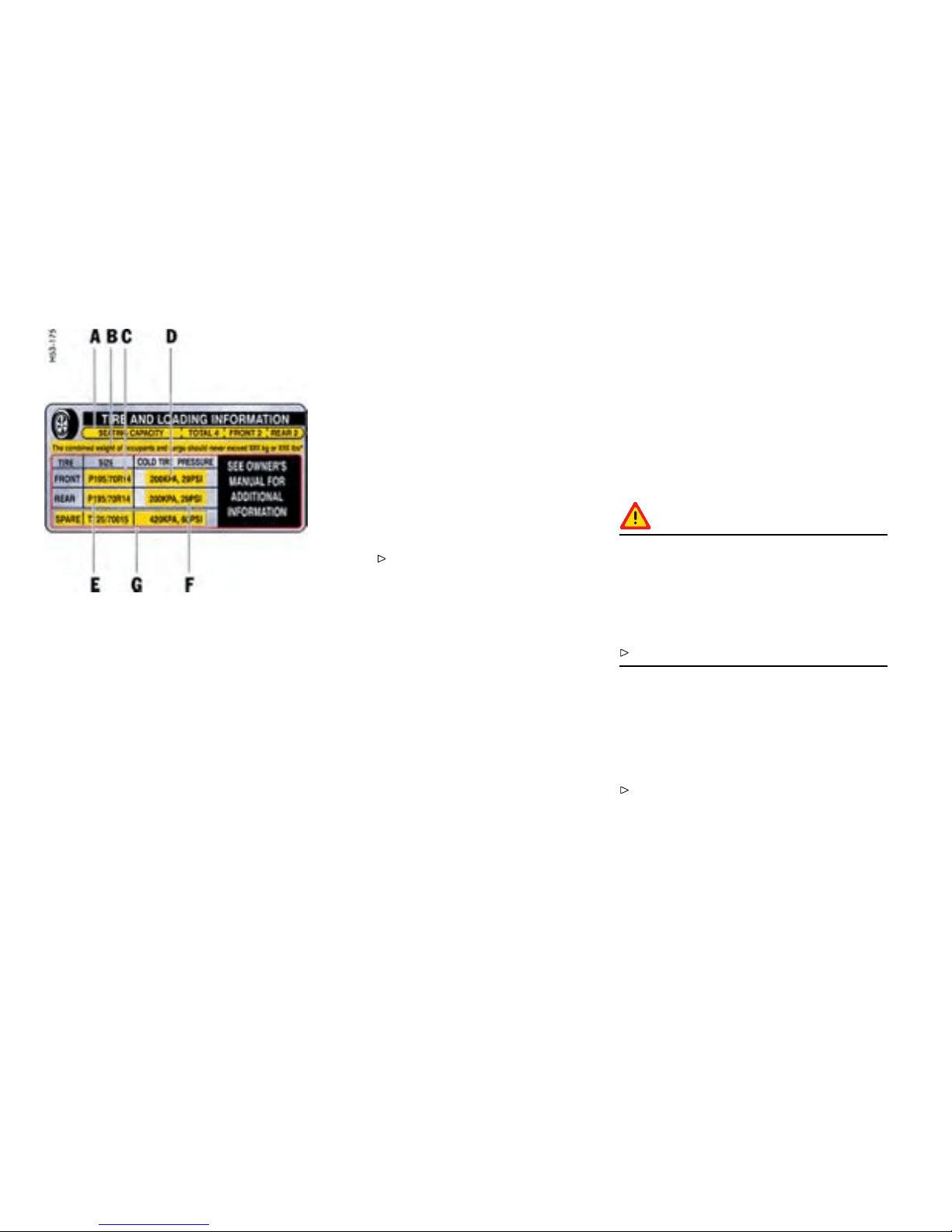
Example of a tire pressure plate
Tire pressure plate
Information on the tire pressure plate
A
Seating capacity
Maximum number of vehicle occupants,
including the driver.
B Vehicle load limit
Is the maximum total weight limit
specif ied of the load (passengers
and cargo) for the vehicle. This is the
maximum weight of passenge rs and
cargo that can be loaded into the vehicle.
Please observe the chapter
”LOADIN G INFORMATION” on page
254.
C Tire size for the front axle
Check with your authorize d Pors che
dealer abo u t the current release status.
D
Recommended tire pressure for t he front
axle
These values are for cold tires
(68°F /20°C ).
E
Tire size f or the rear axle
Check with your authorize d Pors che
dealer abo u t the current release status.
F
Recommended tire pressure for the rear
axle
These values are for cold tires
(68°F /20°C ).
G
In vehi cles with collapsible spare wheel:
Size and tire pressure of the spare
wheel.
Tire traction
Warning!
When driving on wet or slushy roads, a wedge
of wa ter may build up between the tires
and the road. This phe nomenon is known
as “hydroplane” and may cause partial or
complete loss of traction, vehicle cont rol or
stopping abili ty.
Reduce spee d on wet surface to prevent this.
Tire life
Tire life depends on various factors, i. e., road
surfaces, traffic and weather conditions, driving
habits, type of tires and tire care.
Inspect your tires for wear and damage bef ore
driving off. If you notice uneven or su bstantial
wear, wheels might n eed alignment or tires
should be balanced or replaced.
246Practical Tips, Emergency Service
Downloaded from www.ManualsFile.com manuals search engine
Tire wear
The original equipmen t tires on your Porsche have
built-in tire wear indicators. They are molded into
the bottom of the tread grooves and will appear as
approximately 1/2 in. (12 mm) bands when the tire
tread depth is down to 1/16 of an in. (1.6 mm) .
When the indicators ap pear in two or more
adjacent grooves, it is time to replace the tires.
We recommend, howev er, that you do not let the
tires wear down to this extent. Worn tires cannot
grip the road surface properly and are even less
effective on wet roads.
In the Unite d States , state laws may govern the
minimum tread depth permissible. Follow all su ch
laws.
Danger!
Driving on worn tires can result in loss of
control of the veh icle and coul d caus e serious
personal injur i es or death.
Do not drive with worn tires or ti res s howing
cuts or bruises as they ma y lead to sudden
deflation and loss of control wh ich could cause
severe personal injury.
Special ized hig h performance tires on high
performance sports c ars exhibit more wear
than those on a family sedan, or even a high
performance sedan. Therefore, it is important
to ch eck your tire pressure and condition at
least every two weeks.
If you notice that tires are wearing unevenly,
consult your Porsche dealer. Uneven wear may
not a lways be due to improper wheel alignment. It
can be the result of individual driving habit s such as
cornering at high s peeds. If the tire pressure is not
checked and adjusted regularly, abnormal tire wear
can also occ u r.
Tire car e
Avoid damaging tires and wheel rims.
If you must drive over a curb or other obstacle,
drive slowly and at an obtuse angle.
Check tires for uneven wear and damage
before driving off.
Remove imbedded material.
Replace worn or damaged tires immediately.
Keep oi l , fuel, brake fluid, etc. away from t ires.
Replace missing valve stem caps .
Keep ti res inflated correctly.
Wash tires when washing the vehicle. Also
clean in ner sid e of wheels.
Do not use abrasive cleaners when washing
the wh eels.
Check wheel rims for corrosion.
Remove road salt, if dr iving in winter.
Tire damage, puncture
Check tires for imbedded mate rial, cuts,
punctu res, cracks and bulges (side wall)
before driving of f .
In case of ti re damage, where it is uncertain
whether there is a break in the ply with all its
consequ ences or tire damage caused by therm al
or mechanical overloading due to lo ss of pressu re
or any other prior damage, we recommend that the
tire be replaced for safety reasons.
If one faulty tire is replaced it s hould be noted that
the difference in tread depth on one ax le must not
exceed 30 %. Handling inconsistencies may result.
Perform a visual inspection if necessary.
Danger!
Risk of serious personal injury or death.
Driving the vehicle with low tire pressure
increases risk of a tire failure an d resulting
loss of control. Furthermore, low tire pressure
increases rate of wear of the affected tires.
Check tires - including sidewalls - regularly for
foreign bodies, nicks, cuts, cracks and bulges.
Practical Tips, Emergency Service
247
Downloaded from www.ManualsFile.com manuals search engine
After driving off road, examine tires for si gns
of damage such as cuts, tears, b ulges or
foreign objects stuck in the tread. Replace a
damage d tire if necessary.
Cross curb edges slowly and at right angles
if poss ible. Avoid driving over steep or s harp
curbs.
In cases of doubt, have the wheel (particular ly
the inner side) checked by an authorized
Porsche dealer.
Tire replaceme nts
If in doubt, contact your Porsche deale r. Use only
tire makes and types approved by Porsche.
If you do not use a Porsche recommended
replacement tire, make sure that you pur-
chase your new tires from a reputable tire
dealer and that the dealer complies with all
manufacturers warnings for tho se tires.
Only tires with the same make a nd with the
same specication code (e.g. “N0”, “N1”...)
can b e mounted.
Before mounting new tires, check with your
Pors che dealer about the current release
status.
Use tires with “ZR” qua lity sta ndards. The re are
currently no standards concerning tire strength at
speeds above 150 mph (240 km/h).
Tires should be replaced no less than on one axle
at the time. Only tires of the same make and type
must be used. Mixed tires are not permissible.
Initially, new tires do not have the ir full t raction. You
should therefore drive at moderate speeds during
the first 60 - 120 miles (100 - 200 km).
If new tires are insta lled only on one axle, a
noticeable change in handling occurs due to
the different tread depth of the other tires. This
happens especially if only rear tires are replaced.
However, this condition disappears as the n ew
tires are broken in.
Please adjust your driving style accordingly.
Installation of new tires should only be done by a
qualified tire technician.
Valves
Rubber valve stems must be replaced every time
a tire is replace d. For metal valves, the installation
and replacement instructions must be ob served.
Use only genuine Porsche metal valves.
Protect the valve inserts against soiling wi th
valve caps. Soiled va lve inse rts can cause a
gradual loss of air.
Use only plastic valve caps.
Parking at the curb
Warning!
Hard impacts against c urbs (or trafc islands)
are dangerous and may cause hidden tire
damage whic h is not noticeable until later.
Such damag e can result in acci dents a t high
speeds causing serious personal injury or
death. Depen ding on the force o f impact, the
edge of th e rim can also be dam aged.
If yo u are in doubt, have the wheel checked by
an expert, particularly if you suspect damage
on the inside.
248Practical Tips, Emergency Service
Downloaded from www.ManualsFile.com manuals search engine

If you must drive over a curb or other obstacle,
drive sl owly an d at an obtuse angle. Exercise
care when parking alon g curbs .
Wheel alignment, wheel balancing
As a precaution, have wheels with summer
tires balanced in the sprin g, and those with
mud and snow tires before winter. Unbalanced
wheels may affect car handling and tire life. Only
the specified weights may be used for wheel
balanc ing. Self -adhesive weights must not come
into contact with cleaning agents, since they could
drop off. Uneven tread wear indicat es wheel
imbala nce. In this event, the vehicle should be
checked at an authorized Porsc h e dealer.
Warning!
If, during a trip, uneven running or vibrations
occur that could be caused by damage to
tires or the car, the speed must be reduced
immediately, but without braking sharply.
If you contin ue your trip without having the
cause of t he fault remedied, you might lose
control of your ve hicle which could cause
serious perso nal injury or death.
Stop the vehicle and check the tires.
If no cause fo r the fault can be found , drive
carefully to the n earest authorized Po rsche
dealer.
Removing and storing tires
After changing, adjust tire pressure and torque
wheel bolts diagonally to 94 ft.lb. (130 Nm).
Tires must always remain on the same side
of the vehicle. When wheels are removed,
the direction of rotation and position of each
wheel should be marked .
Example
FR (front ri ght), FL , RR and R L.
Wheels must always be fitted in accordance with
their marking.
The percep tion that tire durability and performance
are immune to t he effects of storage and age
is unfounded. Chemical additives, which make
the rubber el astic, lose their effectiveness in the
course of time a n d the rubber beco mes bri ttle and
cracks.
Therefore, the tires should be inspected from
time to time.
Note
Under no ci rcumstances should tires older than 6
years be used on your Porsche.
The age of the tire can be obtained from the
“DOT” code number. If, for example, the last four
numbers read 070 6, then the tire was produced in
the 7th week of 2006.
Store tires in a cool and dry place.
Practical Tips, Emergency Service
249
Downloaded from www.ManualsFile.com manuals search engine

Snow tire s
For a better grip on snow and ice, use radial M+S
tires with studs. Check w ith your local Motor
Vehicle Bureau for possible restrictions.
Danger!
Risk of loss of control and damage to the
vehicle as well as serious pers onal injury or
death. The standard tires prole and rubber
mixture are optimized for wet and dry dri v i ng
conditio ns, and may not prove favora ble for
snow conditio ns.
Therefore install M+S tires before driving in
such conditions.
Before mounting snow tires, consult with
your Porsche deal er. He has the technical
information necessary to advise you on wheel
and tire compatibility.
Snow tires should have the same load capacity as
original equipment tires and shou ld be mounted on
all four wheels. Snow tires with studs should be run
at moderate speeds when new in order to give the
studs time to settle .
Danger!
Tires with badly worn treads and studs are
very dangerous and could cause acci dents
resulting in seri ous personal injuries or death.
Make sure they are replaced immediately.
Do not drive a vehicle equipped with snow
tires at prolonged high spee d. Snow tires
do not have the same degree of traction on
dry, wet or s nowfree roads as a no rmal tire.
Furthermore, snow tires wear rapidly und er
these conditi ons.
Comply with all state and local laws governing
snow tire and tread depth requirements.
Danger!
Risk o f accident and serious personal injury
or death due to exces sive speed.
Always chec k the maximum speed rating on
the t ire sidewall on a ny tire on t he vehicle.
Never exceed the maximum speed ratin g of
the ti res.
Fit wi nter tires to both axles well before the
cold season begins. Your authorized Porsche
dealer will be pleased to advise you.
Maintenance note
We recommend fitting wint er tires on the vehicle at
temperatures below 45°F (7°C ).
Winter tires lose their traction capability when their
tread depth falls below 5/32 in. (4 mm).
250Practical Tips, Emergency Service
Downloaded from www.ManualsFile.com manuals search engine

Snow ch ains
Caution!
Risk of damage to body, axle or brake compo-
nents.
Fit snow chains only to the rear whee ls, and
only with the tire/rim combinatio n listed
in the Technic al Data. To ens ure adequate
clearance between chain and body, Porsche
recommends only the use of fine-link chains
such as those approved by P orsche.
Follow instructi ons issued by the supplier of
the chains.
Diffe rent states and count ries have varying
statutory requirements regarding maximum
speed. Check with l ocal authorities for possible
restrictions.
Remove chain s as soon as the roads are free of ice
and snow.
Fitting snow chains
The use of snow chains is n ot permi tted w hen
5 mm spacers are mounted.
Caution!
Risk of damage to the wheel housings if the
5 mm spacers are not removed before tting
snow chain s.
To permit the fitting of snow chains, have the
5 mm spacers removed on all 4 wheels.
To fit/remove the spacers: Please consult an
authorized Pors che dealer.
Please observe the chapter ”SPACERS ” on
page 263.
Tire designations
Due to new speed and load ratings for radial tires,
new designations have come into force for snow
tires for your Po rsche.
The designation to be used for ZR tires is e.g.,
265/40 ZR 18 (Z = code letter for radial tires for
speeds above 150 mph / 240 km/h).
Practical Tips, Emergency Service
251
Downloaded from www.ManualsFile.com manuals search engine
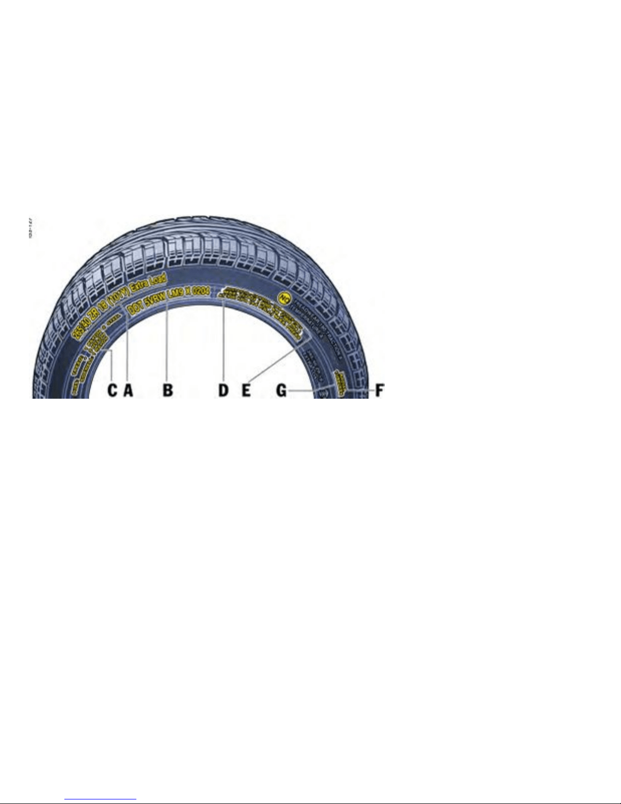
Example of Inscription
Inscrip tion on radial tire
A Tire size
Examp le: P 265/40 ZR 18 1 01 Y
– P - The tire is designed for Passenger vehicle.
This information is not included on all tires.
– 265 - Indication of tire width in mm
– 40 - Indication of tire he ight to tire width ratio in
percent
– ZR - code letter for radial tires for speeds
above 150 mph (240 km/h). The re are cu r-
rently no standa rds concerning tire strength at
speeds above 150 mph (240 km/h).
– R- Belt type code letter for radial
– 18 - Indication of rim diameter in inches
– 101 - Load capacity coefficient
– Y - Speed code letter
– XL (Extra Load) - Tire with increased load
rating
B TIN (Ti re Identication Number)
Example: DOT x x xx xxxx xxxx
– DOT The DOT symbol indicates that the tires
comply with the requirement s of the US
Department of Transportation and provides
informa tion abo ut:
– first two-digit code means manufac ture’s
identification m ark.
– second two-digit code means tire size.
– third four-digit code means tire type code.
252Practical Tips, Emergency Service
Downloaded from www.ManualsFile.com manuals search engine
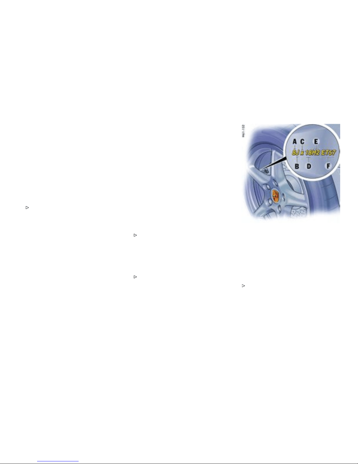
– fourth four-digit c ode means date of manu-
facture. If, for example, the l ast four numbers
read 0204, the tire was produced in the 2nd
week of 2004.
C Tire ply composition and material
The number of layers in the tread and sidewalls and
their material composition.
D Maximu m permissible ination pressure
The maximum permissible co ld inflation pressure
to whic h a tire can be inflated.
Do not exce ed the permissible inflation
pressure.
E Maximum Load rating
The maximum load in kilograms and pounds can be
carried by the tire. If you replace tires always use a
tire that has the same maximum load rating as th e
factory installe d tire.
F Radial
The identification indicates if the tire has radial
structure.
G Term of tubeless or tube tire
Identif ication f or tubeless tires.
Speed code letter
The s peed code letter indicates the maximum
permissible speed fo r the tire. This code letter is
shown on the tire sidewall.
T = up to 118 mph (190 km/h)
H = up to 131 mph (210 km/h)
V = up to 150 mph (240 km/h)
W = up to 167 mph (270 km/h)
Y = up to 186 mph (300 km/h)
Tip on driving
Tires with a maximum speed rating that i s lower
than the specified maximum vehicle speed may be
mounted only if they bear an M+S ide ntification on
the t ire sidewall.
Please note that in addition to the winter tires,
all-season and all-terrain tires are also subj ect
to spe ed limits and bear this identification.
Inscrip tion on light alloy wheel s
Mainte nance note
Protect the valve inserts against soiling with
valve caps. Use only plastic valve caps. Soiled
valve i nserts can cause a gradual loss of air.
A - Rim width in inches
B - Rim-ange contour code letter
C - Symbol for drop-center rim
D - Rim d iameter in inches
E - Double hump
F - Rim offset in mm
Note on operation
The rim width in inches A and the rim offset F
are visible from the outside. This information
can be found near the tire valve.
Practical Tips, Emergency Service
253
Downloaded from www.ManualsFile.com manuals search engine
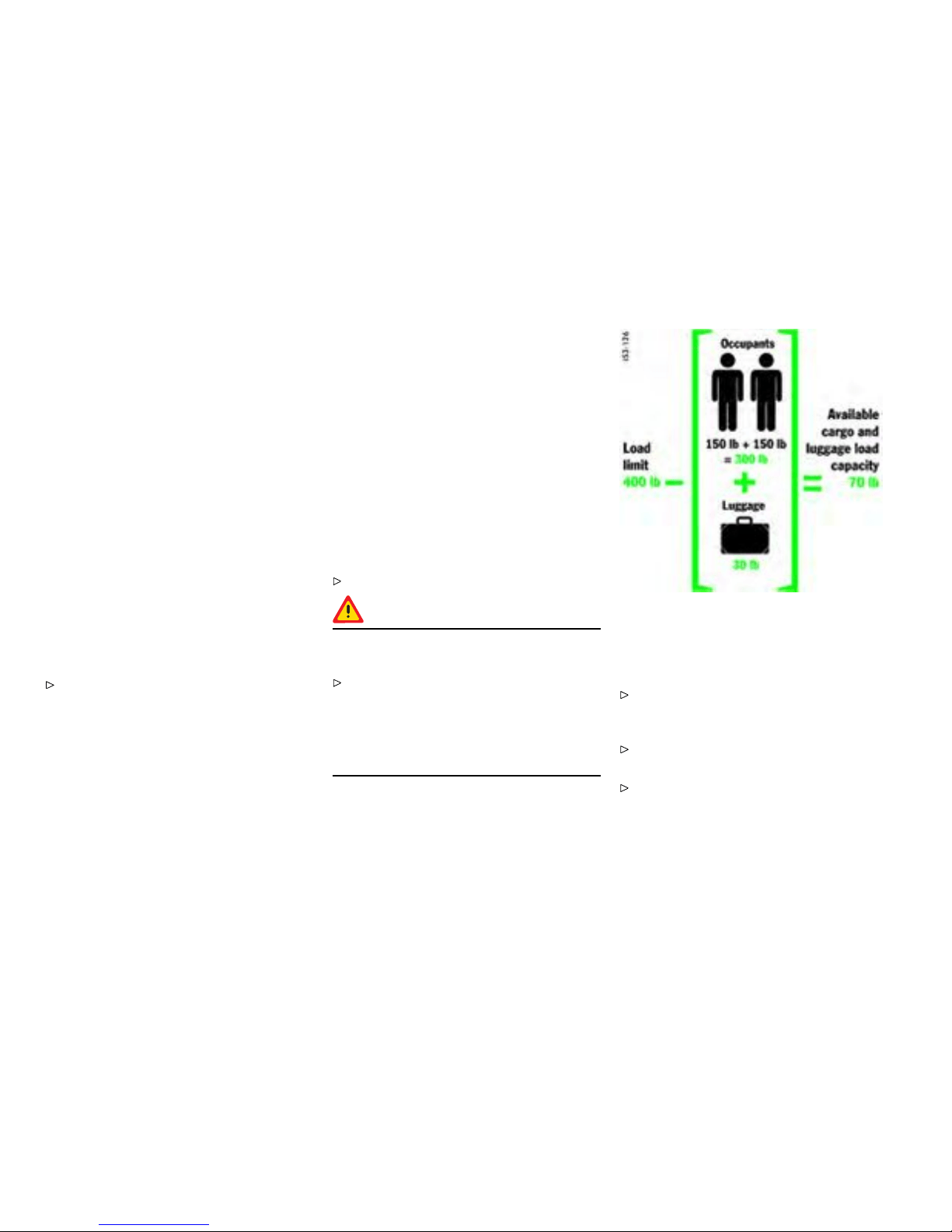
Loading Information
Denitions
The Curb weight - actual weight of your vehicle
- vehicle weight including sta ndard and optional
equipment, fluid s and emergency tools. This
weight does not include passengers and cargo.
The Gross Vehicle Weight is sum of the curb
weight and the weight of passengers and cargo
combine d.
The Gross Vehicle Weight Rat ing is the maxi-
mum total weight of vehicle, passengers, luggage
and optional equipment.
The Gross Axle Weight Rating is the maximum
load limit for the front or the rear axle. This
information is located on the safe ty compliance
sticker located in the driver’s side door jamb.
For determining the compatibili ty of the tire and
vehicle load capabilit ies:
Please obse rve the chapter ”TIRES, RIMS,
TRACK S” on page 301.
The load capacity coefficient (e.g. “101”) is a
minimum requirement.
The Gross Combined Weight R ating is the maxi-
mum total weight rating of vehicle, passengers and
cargo.
The Vehicle Capacity Weight - Load Limit - is the
maximum total weight limit specified of the load
(passengers an d cargo) for the vehicl e. This is the
maximum weight of passeng ers and cargo that can
be loaded into the vehicle. This information can be
found on th e tire pressure plate.
The maximum loaded vehicle wei ght is the sum
of cur b weight, accessory we ight, vehicle capacity
weight and production options weight.
The load rating is the maximum load that a ti re is
rated to carry for a given inflati on pressure.
The maximum load rating is t he load rating for a
tire at th e maximum p ermissble inflation pressure.
The c argo capacity is the permissible weight of
cargo, the subt racted weight of passengers from
the load limit.
Never exceed the permissible limits.
Danger!
Risk of loss of control, damage to vehicle and
serio us personal injury or death.
Never exceed the specified axle loads.
Overloading can shorten the service life of
the t ires and car, as wel l as le ad to dangerous
vehicle reactions and long braki ng distances.
Damage due to ov erloading is not covered by
the vehicle w arranty.
Example for determin ing the combi ned wei ght of
occupants and cargo
Vehicle Load Capacity
The combined weight of oc cupants and cargo
should never exceed the weight s hown on the
tire plate in the vehicle.
Please observe the chapt er ”TIRE PRESSURE
PLATE” on page 297.
Never exceed the numbe r of passenge rs
shown on the tire pressure plate in the vehicle.
254Practical Tips, Emergency Service
Downloaded from www.ManualsFile.com manuals search engine

Determining the co mbined wei ght of occupants
and cargo :
Add th e weight of all occupants and then add
the total luggage weight (gure).
Steps for determining correct load limit
1. Locate the statement "The combi ned weight of
occupants and cargo should never ex ceed XXX
pounds" on your vehi cle’s placard (depending
on the date of m a nufacture).
2. Determin e the combined weight of the driver
and passenger that will be riding in your
vehicle.
3. Subtract the combin ed weig ht of the driver and
passenger from XXX kilograms or XXX pounds.
4. The resulting figure equals the available
amount of c argo and luggage load capacity.
For example, if the " XXX" amount equals 400
lbs. and there will be two - 150 lb passengers
in your vehicle, the amount of available cargo
and luggage lo ad capacity is 100 lbs. (400 -
300 (2 x 1 50) = 1 00 lbs.).
5. Determine the combined weight of luggage
and c argo being loaded on the vehicle. That
weight may not safely exceed the available
cargo and luggage loa d capacity calculated in
Step 4.
Practical Tips, Emergency Service
255
Downloaded from www.ManualsFile.com manuals search engine
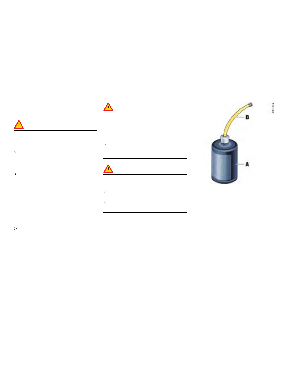
Flat Tire
Gener al information
Warning!
Failure to follow these instr uctions may result
in serious p ersonal injury or death to you or to
bystanders.
If you have a flat tire, move a sa f e distance
off the road. Turn the emergency flasher on
and use other warning devices to alert other
motorists. Set the parking brake.
Do not park your vehicle where it may contact
dry grass, brus h or other flammable materials.
The ho t parts of the exhaust s ystem could set
such materials on fire, thereby causing both
property damage and serious personal injury
or death.
A tire sealant and compressor with pressure
tester are located in the too lbox in the luggage
compartment.
Please observe the safety and opera ting
instructi ons on the special sealant bottle with
a spec ial Porsc he part number an d on the
compressor - these are essential.
Caution!
Sealing the tire with the tire repair kit is only
an emergency repair. Even with the tire
air-tight, it may be used only for s hort trips
in an emergency. The max i mum permitted
speed is 50 mph (80 km/h).
Do not use commercially available sea lant or
tire inflating bottles. Use only the tire sealant
located in the luggage compartment.
Warning!
Risk of accident resulting in serious per sonal
injury or death.
Have tires replaced by a special ist workshop
as soon as possible.
Avoid hard acceleration and high corn ering
speeds.
A - Filler bottle
B - Filler hose
Tire sealant
Usage
The ti re sealant ca n be used to seal small cuts,
especia lly in th e tire tread.
Sealing the tire wit h the tire sealant is only an
emergency repair, so you c an drive to the next
workshop. Even with the tire air-tight, it may be
used only for short trip s in an em ergency.
256Practical Tips, Emergency Service
Downloaded from www.ManualsFile.com manuals search engine
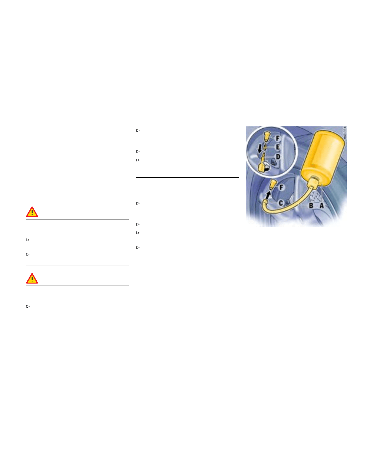
The tire se alant an d a c ompressor with pressure
tester can be found in the tool box in the lu ggage
compartment.
The tire sealant comprises :
– A filler bottle
– A filler hose
– A valve turner and
– A spare val ve insert
– A stic ker denoting the maximum permissible
speed for the driver’s field of vi sion.
Danger!
Risk of accident resulting in serious personal
injury or death.
Use the tire sealant only in the case of cuts or
punctures no larger than 0.15 in. (4 mm).
Never use the tire seala nt if the rim is dam-
aged.
Warning!
The sealant is highly ammable and harmful
to health.
Fire, naked flame and smoking are prohibited
when handling tire sealant.
Avoid contact with skin, eyes and clothing
due to caust ic chemical properties of the tire
sealant.
Keep tire sealant away from children.
Do no t inhale vapors, du e to c onsequent harm
to personal health resulting in serious p ersonal
injury or death.
In case of contact with the sealant:
If sealant gets on the skin or i n the eyes,
thoroughly r inse the affec ted part of the body
off immediately.
Change soiled clothing immediately.
Get medical a ttention immediately in the event
of an allergic reaction.
If sealant was swallowed, thoroughly rinse out
the mouth without dela y and drink plenty of
water. D o not induce vomiting. Get medical
attention immediately.
A - Filler bottle
B - Filler hose
C - Plug of the ller hos e
D - Valve turner
E - Valve insert
F - Tire valve
Inserting sealant
1. Leave the object that caused the punctu re in
the tire.
2. Remove sealant and the enclosed sticker from
the luggage compartment.
3. Adhere the sticker in the driver’ s field of vision.
4. Shake filler bottle A.
Practical Tips, Emergency Service
257
Downloaded from www.ManualsFile.com manuals search engine
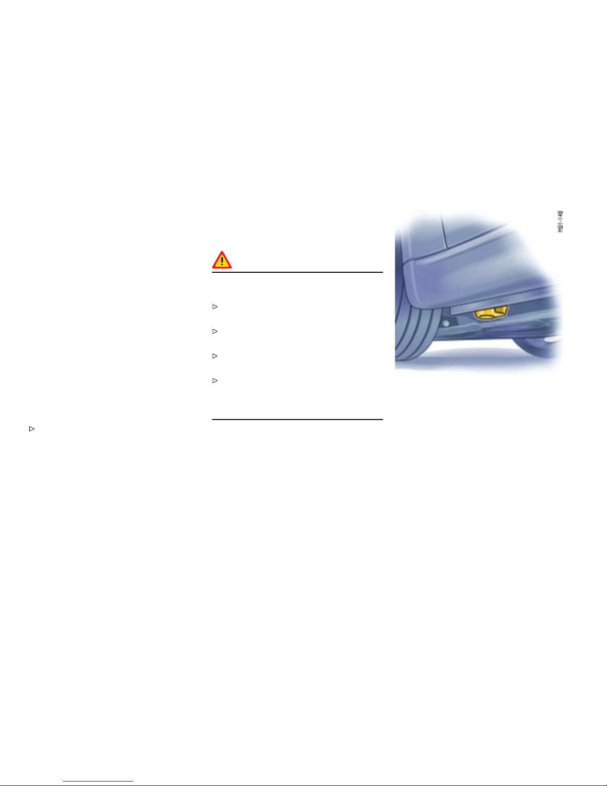
5. Screw filler hose B onto the filler bottle. Th e
filler bottle is now open.
6. Unscrew valve cap from tire valve F.
7. Remove valve insert E from the tire valve with
valve turner D. Keep the valve insert in a clean
and d r y place.
8. Remove plug C of the filler hose B.
9. Push filler hose onto the tire valve.
10. Hold filler bottle highe r than the level of the tire
valve and press it together forcefully until the
bottle is completely emptied into the tire.
11. Pu ll filler hose off the tire valve.
12. Twist the valve insert firmly into the tire valve
using the valve turner.
13. Connect the co mpressor to the cigarette
lighter and inflate the tire to the prescribed tire
pressure.
Please observe the chapt er ”TIRE PRESSURE
FOR COLD TIRES” on page 304.
14. Screw valve cap onto the tire valve.
15. Ch eck the tire pressure after driving for
around 10 minute s. If the tire pressure is
less than 22 psi (1.5 bar), do not continue
driving. If a value of more than 22 p si (1.5 bar)
is indicated, c orrect the pressure to the
prescribed value.
16. Pl ease consult your authorized Porsche
dealer.
Care Instructions
After drying, any sealant that emerges can be
peeled off like a film.
Warning!
Risk of accident resulting in serious per sonal
injury or death.
Have the tire replaced by an authorized
Porsche dealer immed iately.
Avoid hard acceleration and high corn ering
speeds.
Do not exceed maximum s p eed of 50 m ph
(80 km/h).
Please always observe the safety and oper-
ating instructions, which can be found in the
separate operating ins tructions for the sealant
and on the compressor.
Front jacking point
Lifting the Vehicle
Lifting the vehicle wi th a lifting platform or
garage lift
The car must be raised only at the illustrated
jacking points.
258Practical Tips, Emergency Service
Downloaded from www.ManualsFile.com manuals search engine
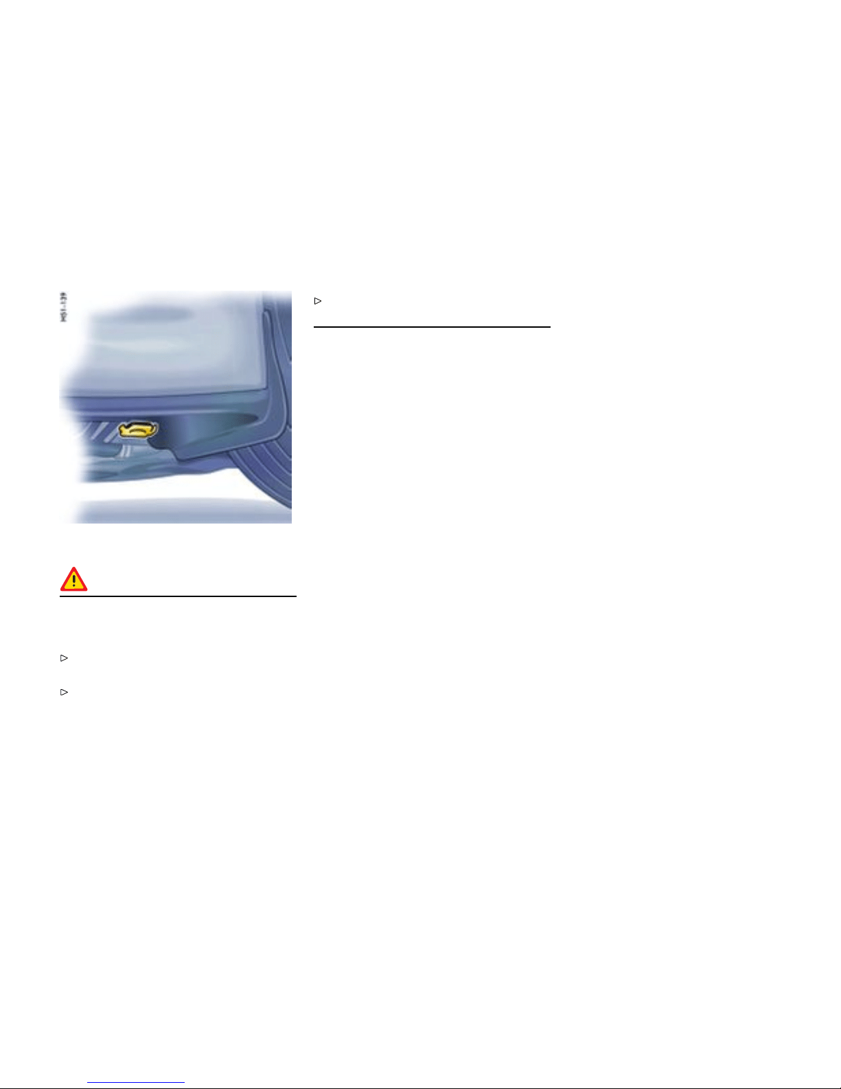
Rear jacking point
Danger!
Serious personal injury or death and /or
serious damage to the engine or the vehicle
may occur, if you lift the vehicle improperly.
Never lift th e vehic le at any othe r place than
the jacking points.
Never lift th e vehic le by the engine, transmis-
sion or axles.
Do not damage any sensitive components in
the vic inity of the jacking points.
Platform lift
Before the car is driven on to a lifting platform,
it must be ensured that there is enough space
between the lifting platform and the vehicle.
Garage lift
A garage lift may be used only at t h e illustrated
jacking points.
Practical Tips, Emergency Service
259
Downloaded from www.ManualsFile.com manuals search engine
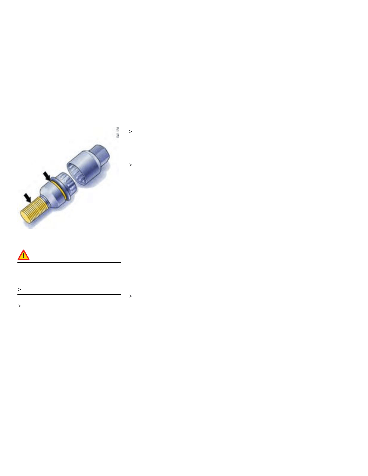
Wheel Bolts
Danger!
Risk of wheel bolt breakage and whee l
separation, resulti ng in serious personal
injury or death.
Follow all instructions concerning wheel bolts.
Always clean the wheel bolts before fitting.
Apply a thin coat of Optimoly TA (aluminum
paste) on the thread and between the bolt
head and movable spherical cap ring (arrows).
The bearing surface of the spherical cap
facing the wheel mus t not be greased.
Replac e dam aged wheel bolts. Only use
the Original Porsche wheel bolts speci ally
designed for this vehicle type.
Tightening torque
Tightening torque of wheel bolts:
130 Nm/96 ftlb.
Wheel Securing Bolts
If the wheels have to be removed at the works hop,
please do not forget to hand over the wrench
socket for the wheel securing bolts along with
the car key.
The wrench socket for the wheel securing bolts is
in the tool box.
To loosen or tighten the w heel bolt with anti-the f t
protection, a wrench s ocket with the appropriat e
coding must be used be tween the wheel bolt and
the wheel-bolt spanne r.
When positio ning the wrench socket, en sure
that it engages fully in the teeth of th e wheel
bolt.
260Practical Tips, Emergency Service
Downloaded from www.ManualsFile.com manuals search engine
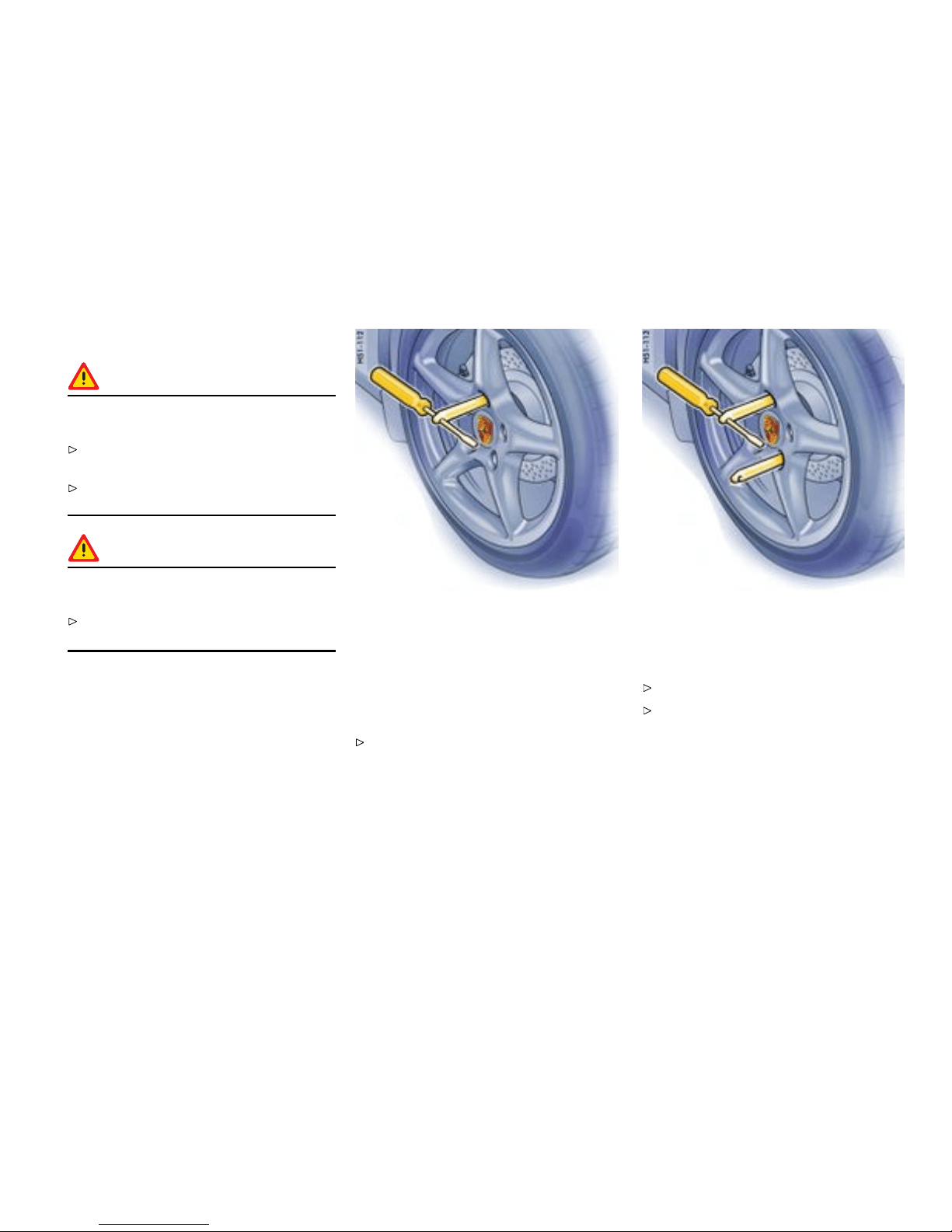
Changing a wheel
Danger!
Risk of serious personal injury or death. The
car may slip off the jack.
Make s ure that no one is in the vehicle when
jacking up and chan ging a wheel.
Always place the car on stable supports if work
has to be c arried out under the car.
Warning!
Risk o f damage to the brake discs of the
Porsche Ceramic Composite Brake (PCCB).
Always screw in both assembl y aids when
changing a w heel.
Note
The to ols required for changing a wheel (e.g. jack,
wheel bolt wrench, assembly aids) are not supplied
with the car. T h ey are availa ble at your authorized
Porsche dealer.
1. Fully apply the handbrake, engage 1st gear or
select position P and withdraw the ignitio n key.
2. Secure the car against rolling away, e.g. by
means of w edges under the wheels on the
opposite side. This is particularly important on
slopes.
Screw in assembly aid for vehi cles without
Porsche Ceramic Composite Brake
3. Slightly slack en the wheel bolts of the wheel to
be changed.
4. Raise the car until the wheel lifts off the
ground.
Please observe the chapter ”LIFTING THE
VEHICLE WITH A LIFT ING P LATFORM OR
GARAGE LIFT” on page 258.
Screw in tw o assembly a ids for vehicles with
Porsche Ceramic Composite B rake
Note on operation
To remove or mount the spacers:
Please observe the chapter ”SPACERS” on
page 263.
5. Remove 1 or 2 wheel bolts (see respective
illustra tion). Screw in assembly aids instead of
the w heel bolts. Remove the remaining wheel
bolts.
6. Take the wheel off and put a new whee l on.
Practi cal Tips, Emergency Service
261
Downloaded from www.ManualsFile.com manuals search engine

7. Screw in wheel bo lts; remove assembly aids
and screw in the remaining wheel bolts. Initially
tighten bolts in di agonally opposite sequence
so that the wheel is centered.
Please obse rve the chapter ”WHEEL BOLTS”
on page 260.
8. Lower the car comp letely.
9. Tighten wheel bolts in diagonally opposite
sequenc e.
Immediately after cha nging a wheel, use
a torque wrench to check the prescribed
tightening torque (130 Nm/96 ftlb.).
Checking tire pre ssure with a pressure
gauge
Please observe the chapter ”TPC TIRE
PRESSURE MONITORING” on page 119.
1. Remove the valve ste m cap from the tire.
2. Press the pressure gauge onto the valve stem.
Note on operation
Do not press too hard or force the valve stem
sideways, or air will escape. If the sound of air
escaping from the tire is heard, reposition the
pressure gauge.
3. Read the tire pressure on the gauge stem and
compare it to the permissible tire pressure.
This information can be fou nd on the tire
pressure plate in the left do or aperture or in
the chapter Technical Data.
Please obser ve the chapter ”TIRE PRESSURE
FOR COLD TIRES” on page 304.
4. Remove the pressure gauge.
262Practical Tips, Emergency Service
Downloaded from www.ManualsFile.com manuals search engine

Spacers
Gener al information to the use of spacers
Use th e spacers only together with wheels
and fastening parts approved by Porsche.
Before hav ing spacers fitted, find out a b out the
current authorization status.
Mount ing an emergency spare wheel
If 5 mm spacers are fitted, th ese must not be
removed to mount an emergency spare wheel.
Fitting s now chains
The use of snow chains is n ot permi tted w hen
5 mm spacers are mounted.
Caution!
Risk o f dam age to wheel housings if the 5 mm
spacers are not removed before tting snow
chains .
In order t o enable the fitting of snow chai ns,
have the 5 mm spacers removed on all 4
wheels.
Note on op eration
To fit/remove the spacers: Please consult an
authorized Porsche de aler.
Removing/mounting the spacers
Required scope of p arts if the spacers are
removed
Short co u ntersunk screws (M6x12) Part No:
900.269.047.09
1 set of short wheel bolts Part No:
996.361.203.02
Short anti -theft protection devices Part No:
996.361.057.01
Practical Tips, Emergency Service
263
Downloaded from www.ManualsFile.com manuals search engine
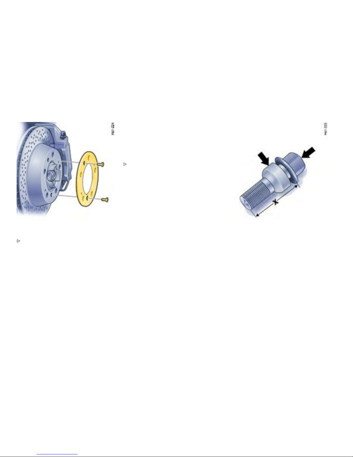
Removing the spacers
Please observe the chapter ”CHANGING A
WHEEL” on page 261.
1. Unscrew bo th coun tersunk screws (M6x16) on
the wheel hub.
2. Remove the spacer.
3. Fasten the brake disc with the short
M6x12 countersunk screws, part No.
900.269.047.09 . Tightening torque 10 Nm
(7.5 ftlb.).
4. For wheel mou nting without a spacer,
5 mm shorter wheel bolts (part No:
996.3 61.203.02) must be used. Tighten-
ing t orque 130 Nm (96 ftlb.).
Mounting the spacers
Please observe the chapter ”CHANGING A
WHEE L” on page 261.
1. Remove wheel
2. Unscrew both countersunk screws (M6x12) on
the b reak disc.
3. Fasten the spacer with the long M6x16
countersunk screws. Tightening torque
10 Nm (7.5 ftlb .).
4. Fit wheel. To do this use the longer wheel
bolts for fastening the wheels. Tightening
torque 130 Nm (96 ftlb.).
Long wheel bolt, X - bolt length approx. 50 mm,
Arrows - marks
Wheel bolt i dentifying features
The long wheel bolts are identified on the face
surface of the bolt head with GT or in red, or the
moveable spherical cap ring is galvanised in red.
The long wheel bolts must only be used together
with 5 mm spacers fitted.
The short wheel bolts are not marked in color. The
short wheel bolts must only be used without 5 mm
spacers fitted.
Tighteni ng torque for both wheel bolts:
130 N m (96 ftlb.).
264Practical Tips, Emergency Service
Downloaded from www.ManualsFile.com manuals search engine
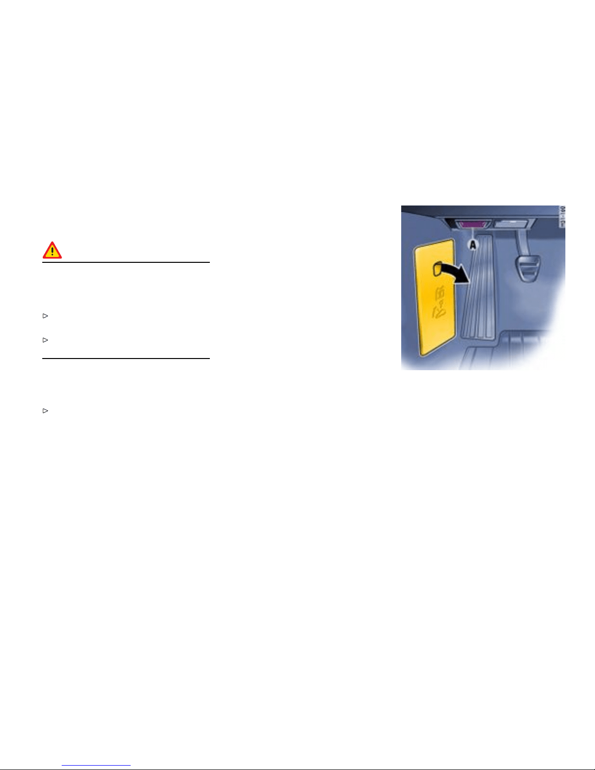
Electrical System
Gener al information
Warning!
Risk of short circuit and re, resulting in
serious personal injury or death. Replacing
fuses or relays with the engine running or the
ignition on could cause electrical shoc k.
Disconnected the battery during all work on
the electrical system.
Please observe the chapter ”BATTERY” on
page 268.
In order to avoi d damage and faults in electrical or
electronic systems, electrical accessories should
be installed at your author ized Porsche dealer.
Only use accessories authorized by Porsche.
Relays
Defective relays should be changed only by an
authorized workshop.
Alarm sy stem, central lockin g
The status of the central locking and alarm system
is not changed by disconnecting t he battery. When
the battery is disconnected, the alarm system
ceases to fu nction.
Overlo ad protection
If the central locking system is operated more
than ten times within a minute, further operation is
blocked for 30 seconds.
Load switch-off af ter 2 hours or 7 days
If the ignition key is removed, loads which are
switched on or are in standby mode (such as the
luggage compartment light, interior light and
radio) are automatically switched of f after approx.
2 hours.
If the vehicle is not started or unlocked with the
remote control within 7 days, the remot e control
standby function is s witched of f (to save the vehicle
battery ).
1. In this case, unlock the driver’s door with the
key at the door lock. Leave the door closed in
order to prevent the alarm system from being
triggered.
2. Press butt on 1 on the remote control.
The remote control is now activated again.
A - Diagnostic socket
Replacing fuses
In order to prevent damage to the electr i cal system
due to short c ircuits and overloads, the individual
circuits are protecte d by fuses. T h e fuse box is
located in th e driver’s footwell.
Practical Tips, Emergency Service
265
Downloaded from www.ManualsFile.com manuals search engine
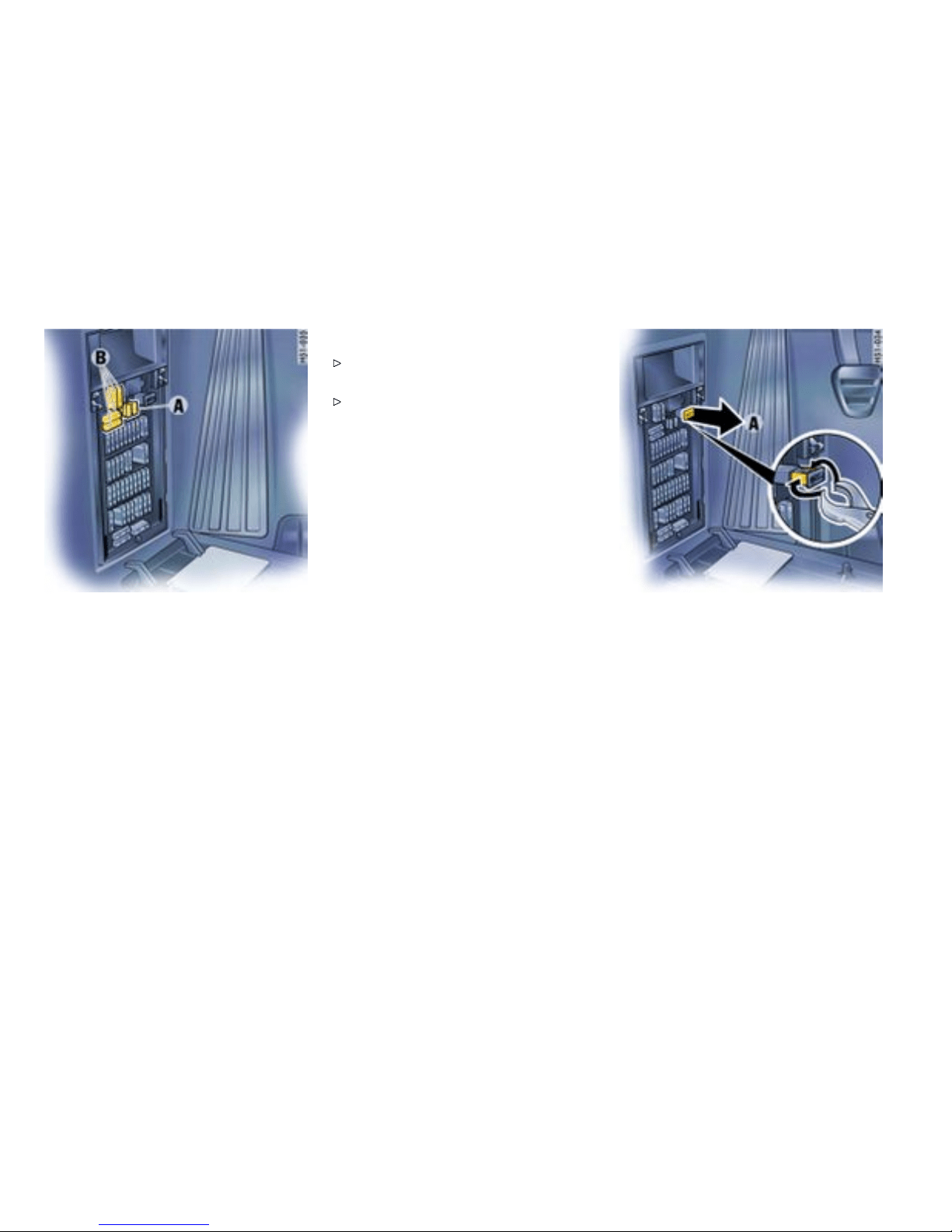
A - Plastic gripper
B - Spare fuses
1. Switch off the load with the defective fuse.
2. Pull off plasti c cover at the finger hole (arrow).
The fuse plan and instructions for emer-
gency unlocking o f the luggage compart-
ment lid can be found on the inner side of the
cover.
3. Remove the corresponding fuse from its slot
using the plast ic gripper A in order to check it.
A blown fuse can be iden tified by the melted
metal strip.
4. Replace only with fu ses of the same rating.
Note
If a fuse blows repeatedly consult an author-
ized Porsche dealer.
Never try to “repair” f u ses: you may cause
serious damage to other parts of the electrical
system.
Emerg ency unlocking of the front luggag e
compartment lid
If the battery is discharged, the l id can be opened
only with the aid of a d onor battery.
Unlocking lid
1. Use the key to unlock the vehicle at the door
lock.
2. Remove plastic cover over the fuse box.
3. Pull out positive terminal A in the fuse box.
4. Use a jump er cable to connect the positive
terminal of the donor batte ry with positive
terminal A in the fuse box.
Note
If the vehicle was locked, the alarm ho rn will s ound
when the negative cable is connected.
5. Use the second jumper cable to c onnect the
negative terminal of the d onor battery with
latch striker B.
6. Unlock the front luggage compartment lid
with the remote control. The alarm system is
switched off.
266Practical Tips, Emergency Service
Downloaded from www.ManualsFile.com manuals search engine
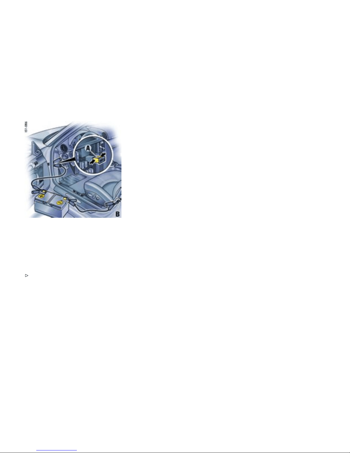
7. Disconnect the negative cable first, then the
positive cable .
8. Push the positive ter minal A into the fuse box
and p u sh on the plastic fuse box cover.
Note
The engine can not be started with this method.
Please observe the chapte r ”EMERGENCY
STARTIN G WITH JUMPER CABLES” on page
273.
Practical Tips, Emergency Service
267
Downloaded from www.ManualsFile.com manuals search engine
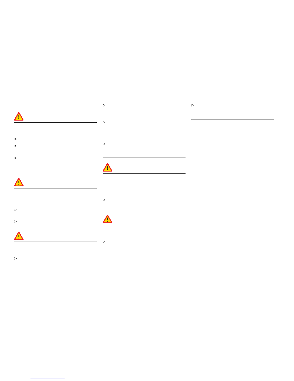
Battery
Warning!
Risk of short circuit and re, resulting in
serious personal inj ury or death .
Observe all warning notes on the battery.
Disconnect the battery during all w ork on the
electrical syste m .
Do not lay tools or other meta l objec ts on the
battery as they could cause a short circuit
across the battery terminal.
Warning!
Hydrogen gas generated by the battery
could cause an explosion, resulting in se rious
personal injury or death.
Do not expo se the battery to an open flame,
electric a l spark or a lit cigarette.
Do not wipe batte r y with a dry cloth.
Warning!
Risk of serious personal injury or death and
damage to the fabric, metal or paint.
Wear eye protection.
Do not allow battery acid to come in contact
with your s kin, eyes, fabric or painted surfac-
es.
If you get electrolyte, which i s an acid, in your
eyes or on your skin , immediately rinse with
cold water for several minutes and call a
doctor.
Spilled electrolyte must be rinsed off at o nce
with a solution of baking soda and wate r to
neutral ize the acid.
Warning!
Batter y posts, term inals and related acces-
sories contain lead and lead compounds,
chemicals known to the State of California to
cause cancer and reproductive harm.
Always protect your skin by washing thorough-
ly with soap and water.
Warning!
Risk of explo sion as a result of static charge,
resulting in seri ous personal i njury or death.
Do not wipe the battery with a dry cloth.
Eliminate potential elec trostatic charge by
touching the vehicle before touching the
battery.
268Practical Tips, Emergency Service
Downloaded from www.ManualsFile.com manuals search engine

Charge st ate
A wel l charged battery will not only prevent start ing
problems but will also last longer.
In order to avoid un intended battery dischar ge
Switch off unnecessary el ectrical loads in cit y
traffic, on short trips o r in a line or traffic.
Always remove the ignition key from the
ignitio n switch when leaving the car.
Avoid frequent operation of the Porsche
Communication Management system when
the engine is not running.
Battery care
Ensure that battery is se curely mounted.
Keep terminals and connections clean
and properly tightened. Corrosion can be
prevented by coatin g the terminals and
connections wit h pet roleum jelly or silicone
spray.
Ensure that vent caps are securely tightened
to prevent spillage.
Checking the electrolyte uid level
Generally, the electrolyte level must be checked
more often in summer than in winter, and more
often when driving long distances.
When adding water, use only clean contai ners.
In no case may alcohol (e.g. window cleaner
residues) be permit ted to enter the battery.
Unscrew an d open the filler vent caps of each
cell.
With the car on a leve l surface, the fluid level should
meet the indicator mark in each cell.
If necessary, top up with distilled water.
Do not use acid. Only fill up to the mark,
otherwise the electrolyte will overflow when
the battery is being charged and cause
damage.
Battery c harging
Autom otive batteries l oose their ef f iciency when
not in use. The charge available in your battery
can be measured with a battery hydrometer. We
recommend that the battery voltage be test ed
by your Porsche dealer who has the appropriate
equipment.
If the car is not driven for prolonged perio d s, the
battery must be charged at least every 6 weeks.
A discharged battery a llows rapid formation of
sulfates, leading to permature deterioration of the
plates.
Danger!
Hydrogen gas gene rated by the battery
could cause an explosion, resulting in s erious
person a l injury or death.
Charge battery i n a well ventilated area.
Never charge a frozen battery. It may explode
because of gas trapped in the ice. Allow a
frozen battery to thaw out first.
If you get electrolyte, which is an acid, in y our
eyes or on your skin, immediately rinse with
cold water for several minutes and call a
doctor.
Practical Tips, Emergency Service 26 9
Downloaded from www.ManualsFile.com manuals search engine

Slow batte ry charching
1. Pay attention to all warnings and follow
instructions that come with your battery
charger.
2. When c harging, ensure adequate ventilation.
3. Remove battery.
Please observe the chapte r ”REMOVING THE
BATTERY” on pag e 271.
4. All vent caps should be open. The fluid level
should meet the indicator mark in each cell.
5. Ensure that charger is switched off - danger of
short circuit!
6. Connect charger cables. Charger cables
must be connected POSITIV (+) to POSITIV
(+) and NEGATIVE (-) to NEGATIVE (-).
7. Switch on charger. Normally a battery should
be charged at no more than 10 percent of its
rated capacity. Rated capacity of the battery in
your vehicle is listed on the battery housin g.
8. After ch arging, turn off charger and d i s connect
charger cables.
9. Tighten the vent caps and reinstall battery.
Please observe the chapter ”EMERGENCY
STARTING WITH JUMPER CABLES” on page
273.
Winter operation
The capacity and ability of the battery to store
power decreases at low outsi de temperatures.
Additionally, more power is consumed wh ile
starting, and the headlights, heater, rear window
defogger, etc., are used more frequently.
Let yo ur Porsche dealer test the battery’s
capacity before winter sets in.
The battery will discharge more quickly if your
vehicle is n ot drive n on a daily basis over a dist ance
of se veral miles. The more ofte n you drive your
vehicle, and the longer the distance driven each
trip, the more opportunity the vehic le’s charging
system will have to recharge the battery.
Replacing the battery
The service life of the battery is subject to normal
wear; it depends g reatly on care, climatic condi-
tions and driving conditions (distances, loads).
Only use an original Porsc h e battery with the
correct pa rt number, as a replacement.
Please observe the dispos al instructions for
batteries.
Puttin g vehicle int o operation
After the battery is connected o r after an exhaus-
tively discharged battery is charged, the mul-
tifunctional PSM light lights up on the instrume nt
panel and a message appears on the on-board
computer to indicate a fault.
This fault can be remedied wit h a f ew simple steps:
1. Start the engine.
2. With the ve h icle stationary, perfo rm a few
steering movements to the left and right and
then drive a short distance in a straight line
until the multi functinal PSM light goes out
and the message on the on-board computer
disappears.
3. If the warnings do not disappear, then: Drive
carefully to the nearest qualified specialist
workshop. Have the fault remedied .
4. After the warn ings disappear, s top the vehicle
in a suitabl e place.
5. Perform adaptation of the power windows:
Please obser ve the chapter ”STOR ING END
POSITION OF THE WINDOWS” on page 35.
Ignition key/ignition lock
Do not insert the ignit ion key into the ignit ion
lock i f the vehicle battery is discharged. The
ignition key can no longer be removed.
The key cannot be removed until the vehicle
electrical system is supplied with power again.
Please observe the chapter ”EMERGENCY
UNLOCKING OF THE FRONT LUGGAGE
COMPARTMENT LID” on page 266.
Please observe the chapter ”EMERGENCY
STARTING WITH JUM PER CABLES” on page
273.
270Practical Tips, Emergency Service
Downloaded from www.ManualsFile.com manuals search engine
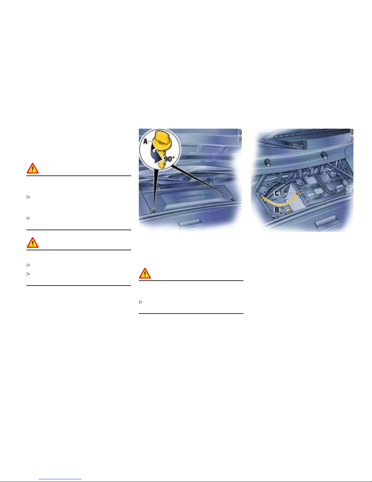
Remov ing the battery
The required tool is in the tool k it.
The battery is located in the front luggage compart-
ment under a black plastic lid.
Warning!
Risk of damage to alternator and ele ctronic
control units.
Do not disconnect battery while the engine is
running. This also applies to cars equipped
with a battery main switch.
Never drive t he car with a disconnected
battery.
Warning!
Risk of caustic bu rns from escaping acid.
Keep vent caps on to avo id spillage.
Do not tilt the ba ttery wh en removing and
installin g it.
1. Switch off engine and all electrical loads.
2. Open turn-locks A. Remove plastic lid.
3. Pull off vent hose C.
Danger !
Risk of short ci rcuit and explosion, resulting in
serious personal injury or death.
Important: disconnect the negative (-) ground
wire first, and then the positive (+) cable.
4. Important: disconnect the negative (-) ground
wire first, and then the positive (+) cable -
danger of sho rt circuit!
5. Unscrew fastening screw B.
6. Remove battery.
Installing the batt ery
1. Put ba ttery in and push it all the way to the
stop.
2. Screw in fastening screw B.
Practical Tips, Emergency Service
271
Downloaded from www.ManualsFile.com manuals search engine
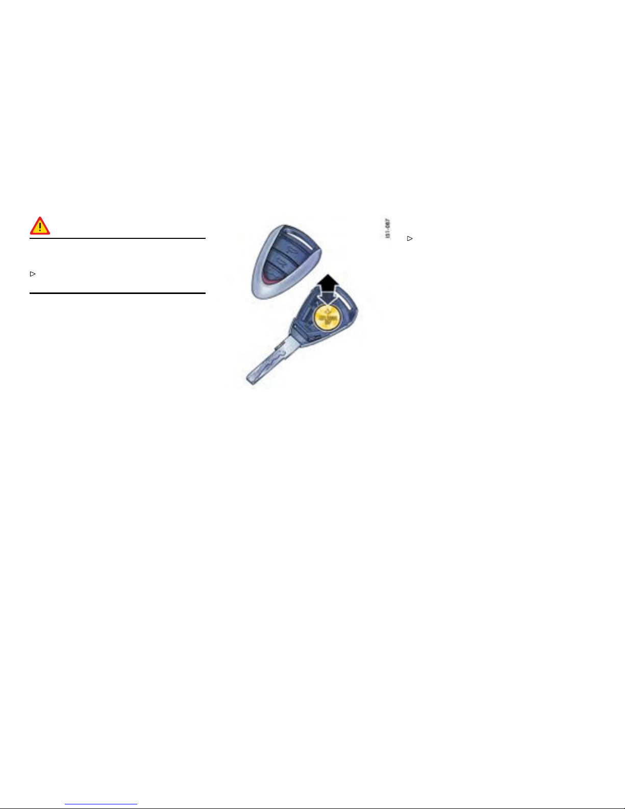
Danger!
Risk of short circuit and explosion, resulting in
serious personal injury or death.
Important: connect the positive (+ ) cable first,
and th e n the negat ive (-) ground wire.
3. Important: connect the positive (+) cable first,
and th e n the negat ive (-) ground wire - risk of
short circuit!
4. Push on centr al vent hose C.
5. Fit plas tic lid. Lock turn-locks A.
Replacing the remot e-control battery
The battery s hould be changed wh en the range of
the radio remote control becomes smaller or when
the light-emitt ing diode no longer flashes w hen the
remote control is operated.
1. Using your finger nail or a small screwdriver,
carefully lift off the cover of the key grip
(arrow).
2. Replace battery (paying attention to the
polarit y). Replacement battery - Lith ium CR
2032, 3 volts
3. Replace the cover and press together firmly.
Please observe the dispos al instructions for
batteries.
Note
Please dispose of ba tteries in compliance with
any and all g overnment regulations.
272Practical Tips, Emergency Service
Downloaded from www.ManualsFile.com manuals search engine
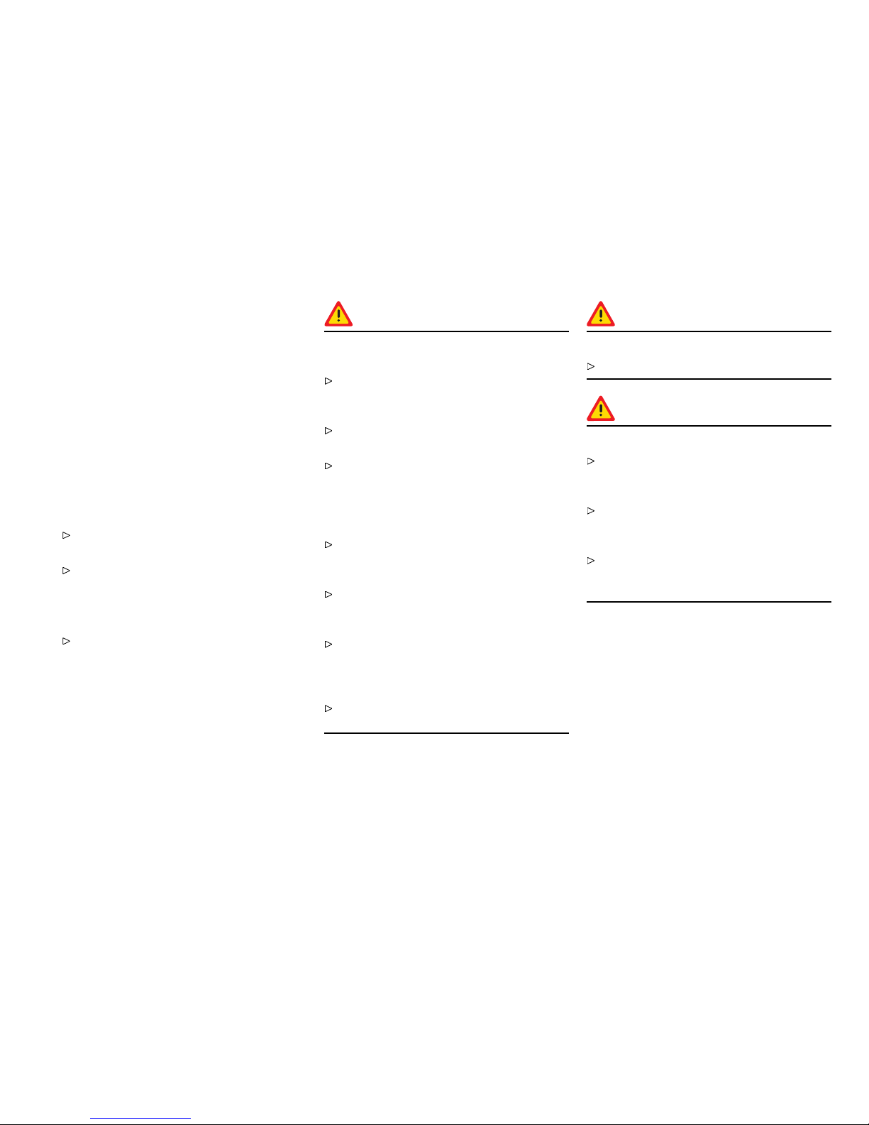
Emergency Starting with Jumper
Cables
Gener al information
If the battery is discharged, e.g. in winter or after
the car has been parked for a long time, the battery
of ano ther car can be us ed for starting w ith the
help o f jumper cables. Make sure the voltage of
both batteries is the same. Both batteries must
be 12 volt types. The capacity (Ampere hours, Ah)
of the booster battery must not be substantially
less than that of the discharged battery. The
discharged battery must be correctly connected to
the vehicle’s electrical system.
Please observe the chapter ”BATTERY” on
page 268.
Please observe the chapte r ”EMERGENCY
UNLOCKING OF THE FRONT LUGGAGE
COMPARTMENT LID” on page 266.
Note
Do not try to sta rt the car by pushing or
towing. Damage to the catal ytic converters
and other components of t h e car may result.
Danger !
Risk o f short circuit, damage and explosion,
resulting in se rious p ersonal injury or death.
Use on ly jumper cabl es of adequate diameter
cross-section and fitted with compl etely
insulated alligator clips.
Follow all warnings and instructions of the
jumper cable manufacturer.
When connecting jumper cabl es, mak e sure
that they cannot get caught in any mov ing
par ts in the engine compartment. Th e jumper
cables must be long enough so that neither
vehicles nor cables touch another.
The ve hicles must not be in contact, otherwise
current migh t flow as soon as the p ositive
terminals are connected.
The cable clamps mu st not be allowed to
contact each othe r when one end of the
jumper cables are connected to a battery.
Ensure that tools or conductive jewelry (rings,
chains , watch straps) do not come into contact
with the positive jumper cable or the positive
battery post.
Improper hook-up of jumper cables can ruin
the alternator.
Warning!
Danger of caustic burns.
Do not lean over the battery.
Warning!
Danger of gas explosion.
Improper use of booster battery to start a
vehicle may cause an explosion, resulting in
seriou s personal injury or death.
Keep sources of ignition away from the
battery, e.g. open flame, burning cigarettes or
sparking due to cable contact or welding work.
A discharged battery can freeze even at
23°F /-5°C . Before connecting jumper cables,
a frozen battery must be thawed out.
Practical Tips, Emergency Service 27 3
Downloaded from www.ManualsFile.com manuals search engine

Connect jumper cables in the following
sequence:
Always observe the sequence below:
1. Connect the positive lead (red) to the
positive termi nal of the discharged battery
first, then connect it to the positive terminal of
the donor battery.
2. First connect t h e neg ative c able (black)
to the negati ve terminal of the donor battery,
then connect i t to a suitable grounding point on
the vehicle with the discharged battery. This
grounding point must lie as far as possible
from the b attery. For exam ple, a solid metal
par t or the engine blo ck are suitable grounding
points. If no suitable grounding points are to
be found on either vehicle, the negative cable
must carefully be connected directly to the
negative terminal of th e batt ery. If a suitable
grounding point is to be found on l y on the
donor vehicle, the negative cable mu st first be
connected to the terminal of the discharged
battery, then to the grounding point of the
donor vehicle.
3. Run the engine of the donor car at a higher
speed.
4. Start the engine. An attempted start using
jumper cables shoul d not last more than
15 sec onds. Then allow a waiting period o f
at least one minute.
Note
Before disconnecting the jumper cables, electrical
loads such as the heated rear window and the
heating fan blower sh ould be switched on (the
vehicle ’s lights must not be sw itched on). This
reduces voltage peaks which may occur w h en
disconn ecting the jumper cables.
5. With the engine running, remove bot h jump
leads in reverse order.
274Practical Tips, Emergency Service
Downloaded from www.ManualsFile.com manuals search engine
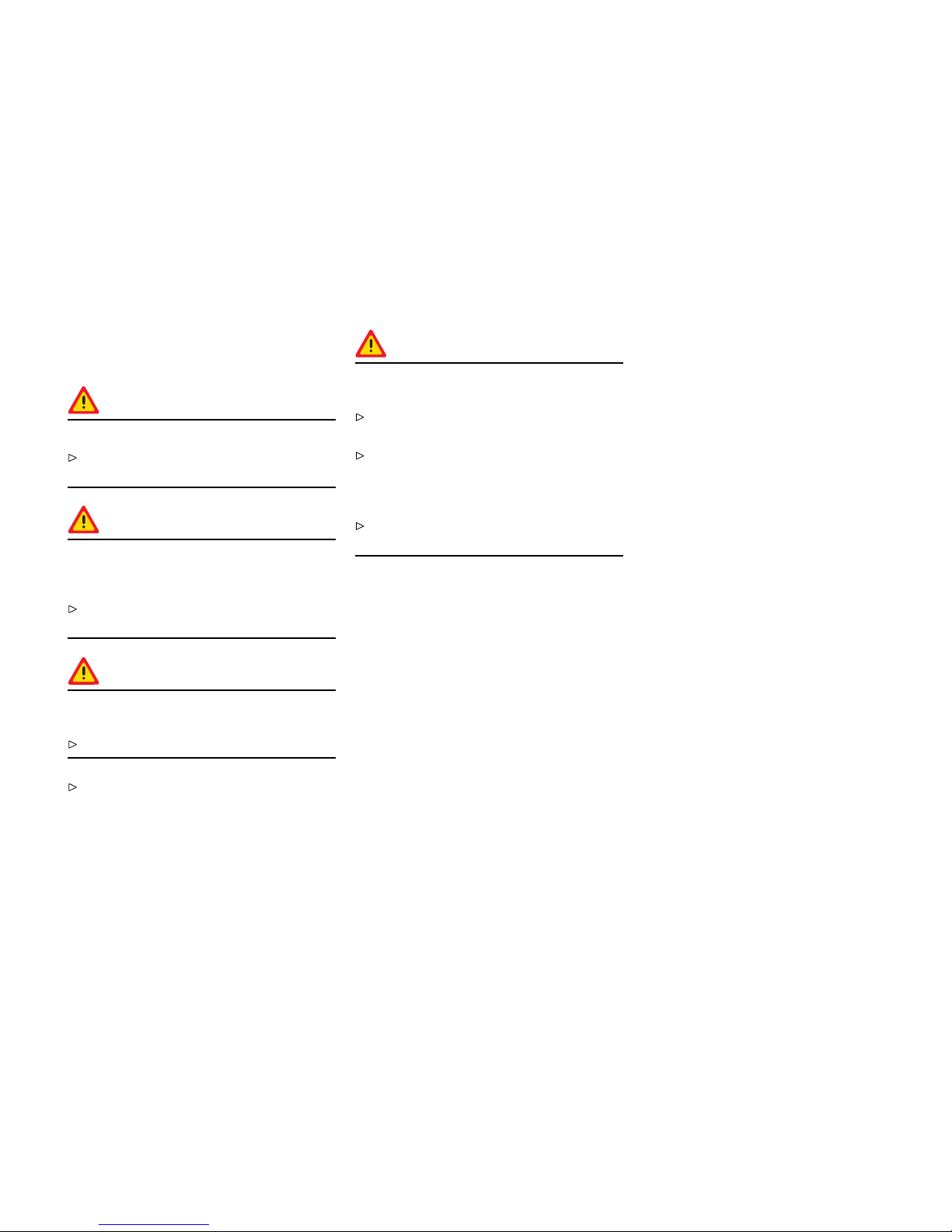
Replacing bulbs
Gener al information
Warning!
Risk of short circuit.
Always switch off the relevant components
when changing bulbs.
Danger!
Risk of serious personal injury or death. The
Bi-Xeno n headlights are under high voltage
when installe d.
Exercise ex treme caution when working in t he
area of th e Bi-Xenon headlights.
Warning!
Risk of damage. Bulbs of a higher wattage
can damage the lamp housing.
Only use the bulbs specified in the bulb chart.
New bulbs must be clean and free from oil,
grease and fingerprints. T herefore, never
touch bulbs with your bare hands. Use a
cloth or soft paper while replacing bulbs.
Caution!
Risk of damage to head l ights due to excessive
temp eratures and abrasion.
Attach no coverings ( e.g. films, “stone
guards”) in the area of the headlights.
Use soapy water only to clean light lenses
and p lastic headlight lenses. In no case may
chemical cleaners or other volatile cleaning
fluids be used.
To prevent scratches, do not rub with a dry or
merely moist cloth, tissu e or insect sponges.
Practical Tips, Emergency Service 27 5
Downloaded from www.ManualsFile.com manuals search engine

Bulb cha rt
Type, rating
Halogen low beam H7, 55 W
Low beam with Bi-Xenon headligh
Philips, D2S 35 W
Halogen high beam
H 9, 65 W
Additional high beam with Bi-Xenon headli ght H 11, 55 W
Fog light
H8, 35 W
Tail light, rear fog light, brake light, tail l ight P21, 4 W
Tail light, reflector P21, 5 W
Reversing light
P21 W
Turn signal light, front and rear LL PY21 W (long-life)
Door g uard-/curb light/footwell light/ lugg age com-
par tment light
W5 W
Parking light W5 W Blue-Vision
License plate light
C5 W
Side marker Light W3 W
276Practical Tips, Emergency Service
Downloaded from www.ManualsFile.com manuals search engine
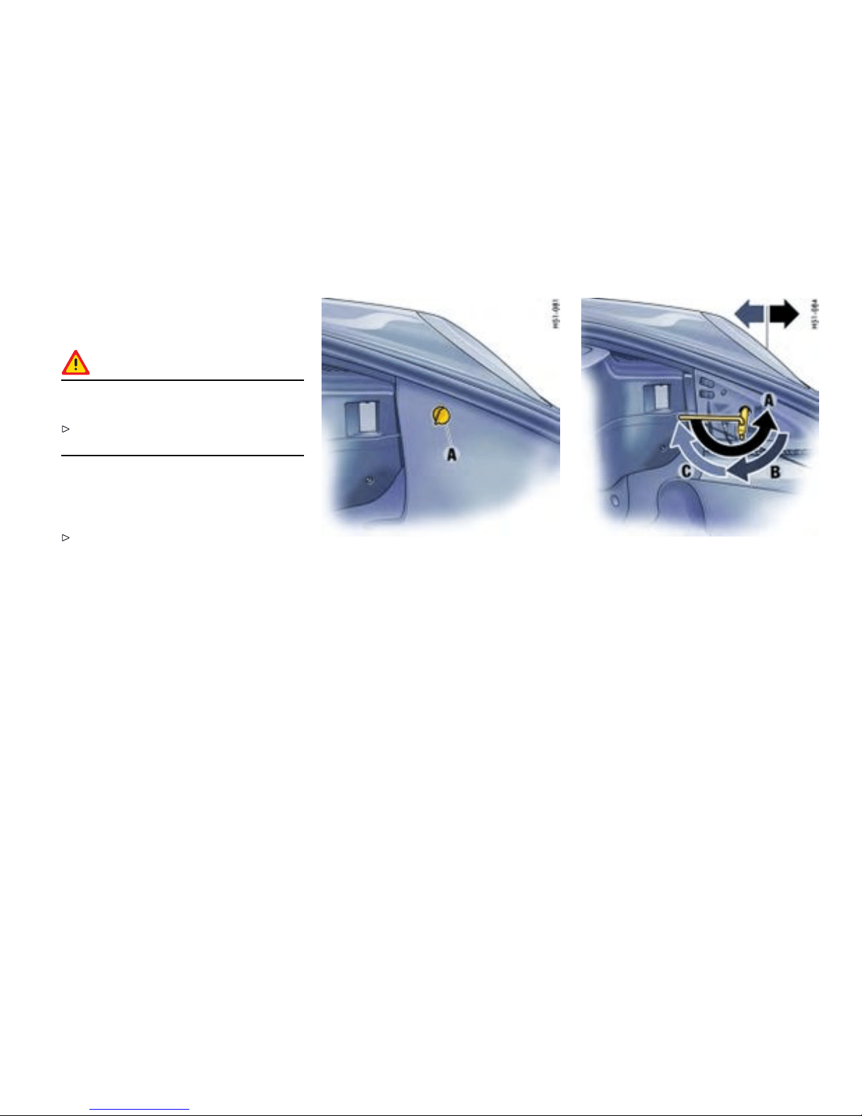
Headlights
Gener al information
Caution!
Risk of damage to headlights due to abrasion
and excessive temperatures.
Do not af f ix any coverings (e.g . “stone guards”
or films) in the area of the headlights.
Note
The headlights can mist up depen ding on the
temper ature and humidity.
To ensu re o ptimum ventilation, do not cover
the gap between headlight a n d body (e.g.
“stone guards” o r films ).
Removal
1. Unscrew plastic nu t A. Detach side carpeting.
2. Remove rubber plugs from the unlocking
opening.
3. Place socket wrench (tool kit) o n the unlocking
spindle . The tongue o f the wrench shoul d point
horizontally to the rear.
4. Turn socket wrench approx. 180° A. The
headlight is unlocked and pushed forward
slightly during this process.
5. Turn socket wrench back until it is pointing
vertically d ownward B and l eave in position.
6. The headlight is now unlocked and can be
pulled forward out of the fender.
Practical Tips, Emergency Service
277
Downloaded from www.ManualsFile.com manuals search engine
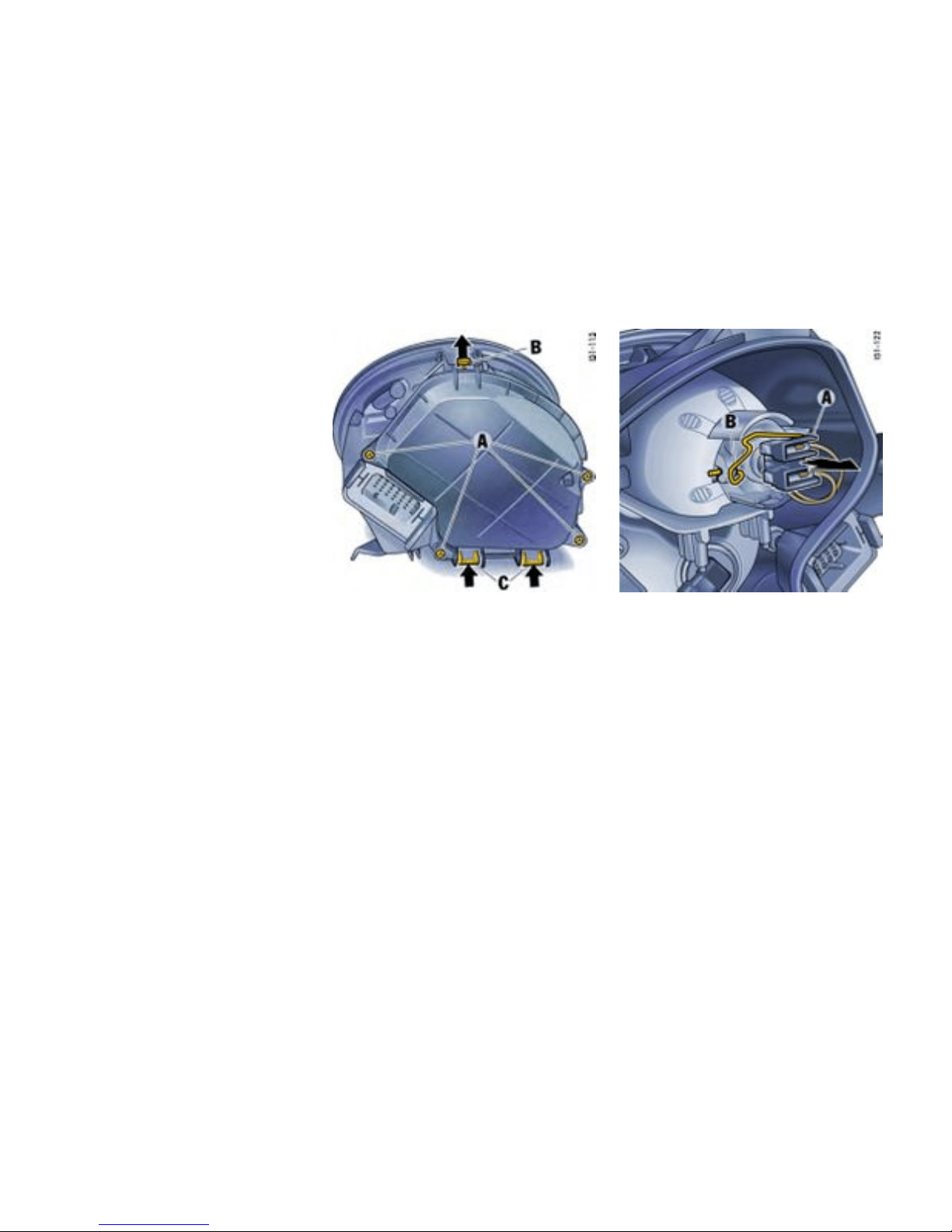
Installing
1. Insert headlight into the guide rails and push it
fully into the fender.
2. Push headlight to the rear and at the same
time turn the socket wrench until it po ints
horizontally to the rear C. The headli ght
locking device must perceptibly and audibl y
engage.
3. Insert the rubber plug into the unlocking
opening and secure the carpet. Check the
function of all lights.
Low beam, high beam and additional high
beam
Opening the lid of t he headlight housing
1. Unscrew the 4 screws A.
2. First lif t release tab B, then push both release
tabs C upwards and take off lid.
Halogen headlights: Changing bulb f or low
beam
1. Pull off plug A.
2. Disengage fixing loop B.
3. Replace defective bulb. When doing so,
ensure bulb is seated properly.
4. Reassemble in reverse order.
278Practical Tips, Emergency Service
Downloaded from www.ManualsFile.com manuals search engine
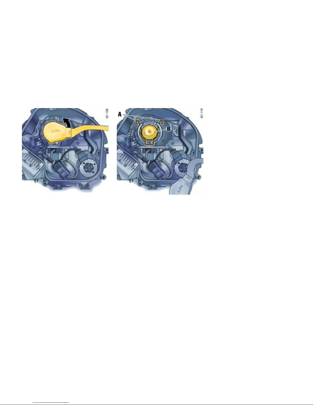
Bi-Xenon headlight : Changing bu lb for low
beam and high beam
1. Turn the plug counter-clockwise (bayonet lock )
and pu ll it off.
2. Disengage both fixing loops A.
3. Replace defe ctive bulb B. When doi ng so,
ensure bulb is seated properly.
4. Engage both fixing loops A, push on plug and
turn ri ght as far as the stop.
Practical Tips, Emergency Service
279
Downloaded from www.ManualsFile.com manuals search engine
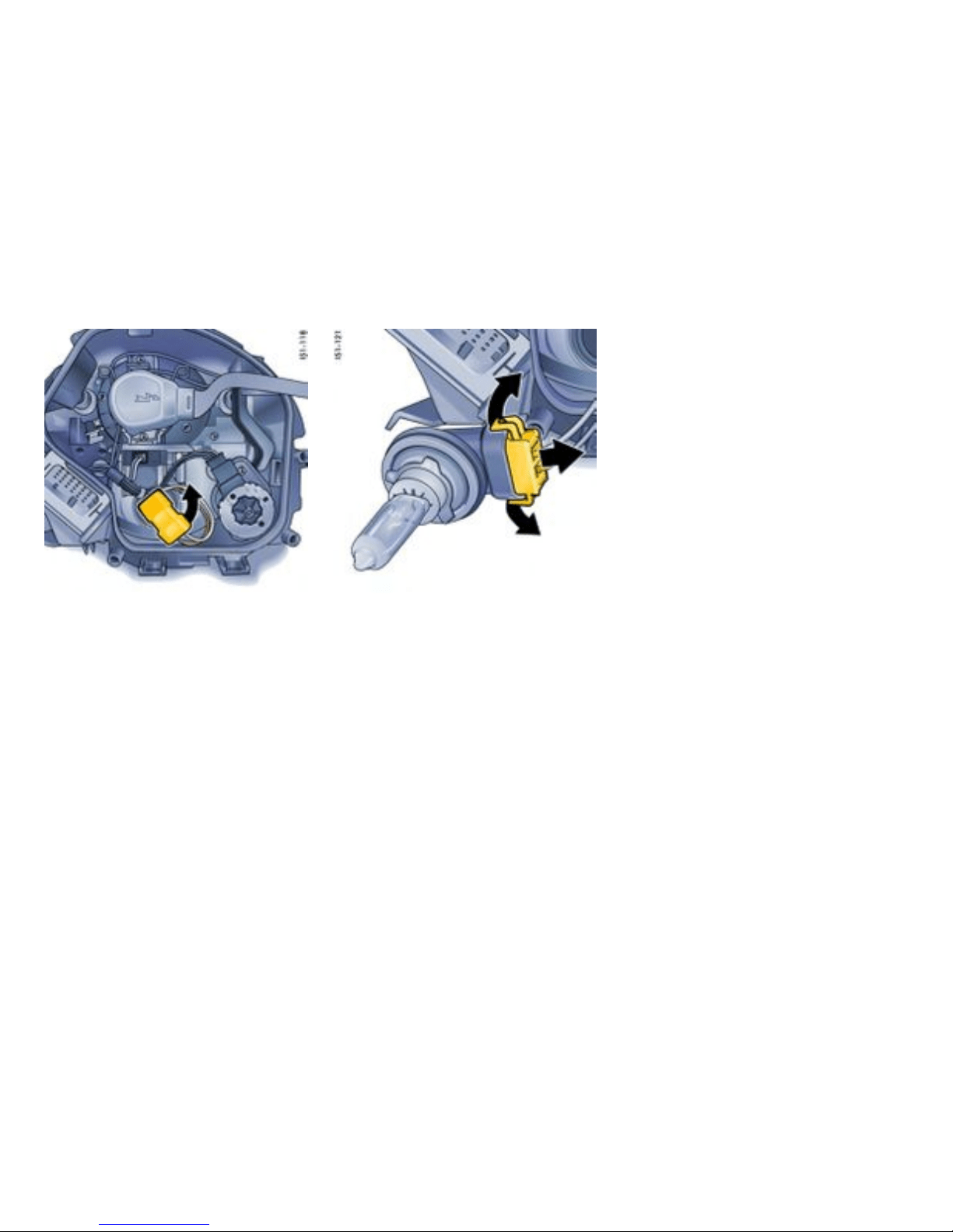
Changing bulb for high beam or a dditional hig h
beam (Bi-Xenon headlight)
1. Turn the bul b holde r. Turn it counter-clockwise
on the left headlight and clockwise on the right
headlight. Take bulb holder out of the headlight
housing.
2. Pull both plug release tabs a part . Pull plug out
of the bulb holder.
3. Replace the defecti ve bulb with bulb holder.
4. Reassemble in reverse order.
Closing lid of headlight housing
1. Push on lid until it perceptibly engages.
2. Fasten lid with the 4 screws.
280Practical Tips, Emergency Service
Downloaded from www.ManualsFile.com manuals search engine
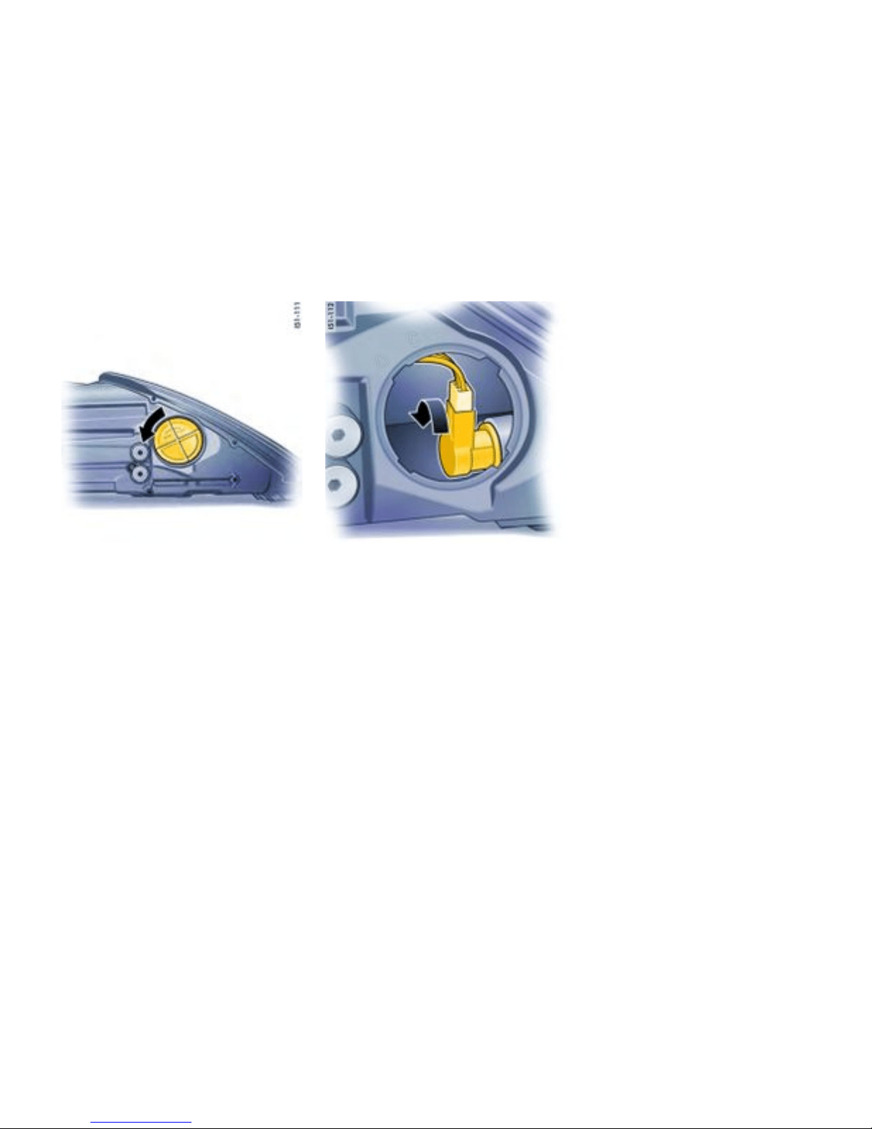
Turn sign al light
Changing bulb
1. Turn lid counter-cl ockwise and pull it off.
2. Turn bulb holde r counter-clockwise (b ayonet
lock).
3. Replace the defective bulb (bayonet fitting) .
4. Insert lamp holder and turn it clockwise.
5. Replace lid and close.
Practical Tips, Emergency Service
281
Downloaded from www.ManualsFile.com manuals search engine
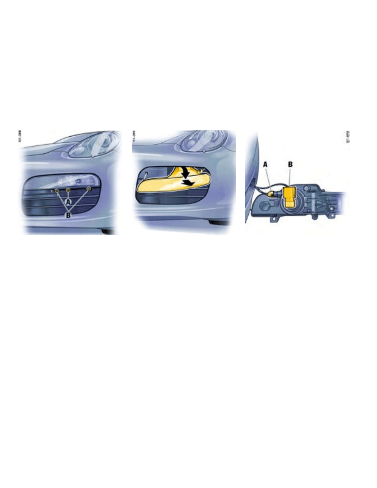
A - Fog light heigh t adju stment
B - Fastening screw
Fog light/parking light
Changing bulb
1. Loosen the two screws B.
2. Lower headlight slightly dow nward and
disengage loca ting cam in cover projection.
Unscrew light downwards at a n angl e.
A - Parking light
B - Fog ligh t
3. Turn the holder counter-clockwi se and pull it
out. Replace defective bulb (bayonet lock).
Push holder back in and turn towards the right.
282Practical Tips, Emergency Service
Downloaded from www.ManualsFile.com manuals search engine

4. Put guide pin of headlight on the guide rail,
engage locat ing cam in cover projection,
press headlight to the rear and push upward
until it can be fel t to engage.
5. Screw in both screws.
6. Check operation of the headlight.
Side marker light
Changing bulb
1. Remove cap in the wheel housing liner with the
screwdriver.
2. Insert the screwdriver into the opening in the
wheel h ousing liner parallel to the direction
indicator housing (in direction of travel). By
pressing with the screwdriver, disengage
the securing spring of the direction indicator
housing .
3. Remove indica tor light and undo bulb holder
(bayone t lock ).
4. Remove the bulb from the holder and replace
it. Insert holder. Check operation of the light .
5. Insert the direction indicator’s retaining l ugs
A into the side s ection at the front. Push in
direction ind icator until the securi ng spring B is
felt to engage.
6. Press cap in to the wheel housing line r.
Practical Tips, Emergency Service
283
Downloaded from www.ManualsFile.com manuals search engine
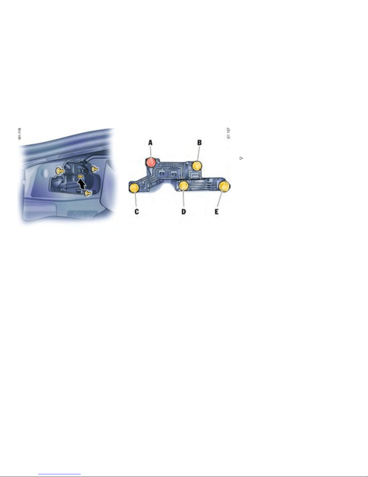
Tail light, left
Tail light
Changing bulbs
1. Remove carpe ting co v ering the tail light.
Unscrew the securing nuts to do this.
2. Press the mounting of the lam p brack et
upwards (arrow) and remove the bulb holder.
A - Turn signal light
B - Reversing light
C - Rear fog light, rear light
D - Tail light
E - Brake light, rear light
3. Replace the defective bulb (bayonet fitting).
4. Reassemble in reverse order. Check operation
of the light.
Additional brake light
The light-emitting diodes of the additional brake
light cannot be replaced individually.
Have the defective brake light replaced at an
authorized Porsche dealer.
284Practical Tips, Emergency Service
Downloaded from www.ManualsFile.com manuals search engine
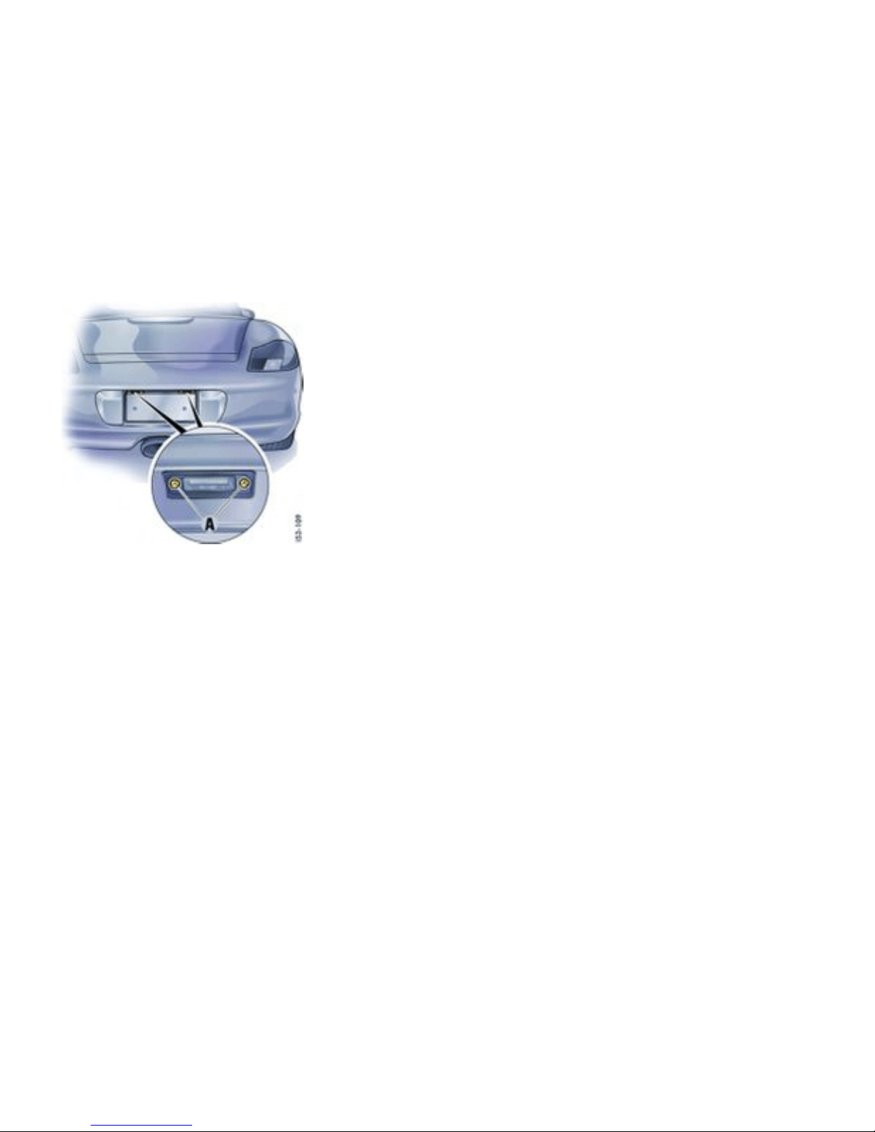
License plate ligh ts
Changing bulb
1. Unscrew both screws A and remove th e light
lens.
2. Remove defective bulb from between the
contact springs and replace it.
3. Reassemble in reverse order. Check operation
of the light.
Practical Tips, Emergency Service
285
Downloaded from www.ManualsFile.com manuals search engine
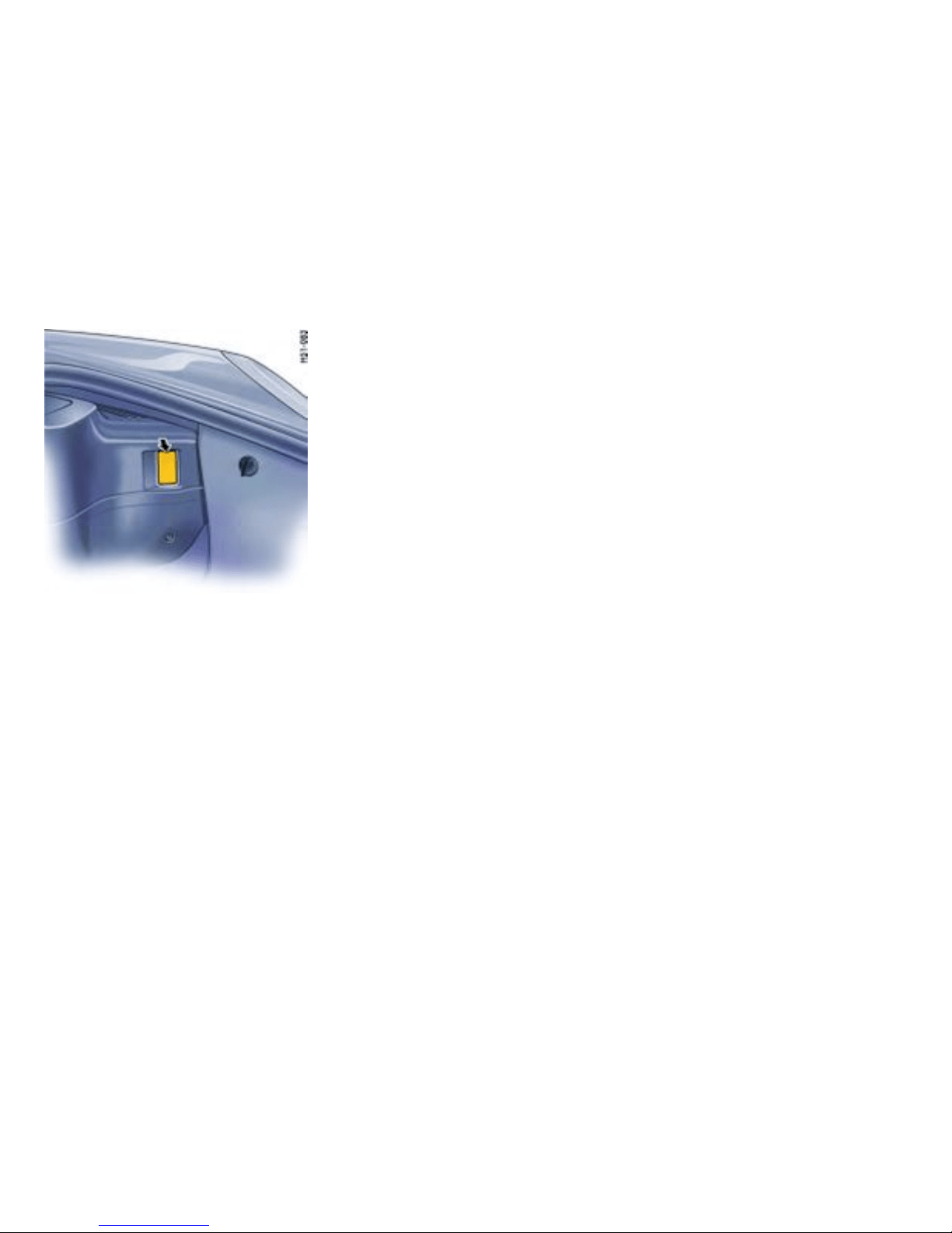
Example: Front luggage compartment light
Luggage compartment /footwell
lights
Changing bulb
1. With a screwdriver (arrow), carefully push out
the light.
2. Remove defective bulb from betw een the
contact springs and replace it.
3. Insert the light into the cut-ou t, first from one
side then from the other. Check opera tion.
286Practical Tips, Emergency Service
Downloaded from www.ManualsFile.com manuals search engine
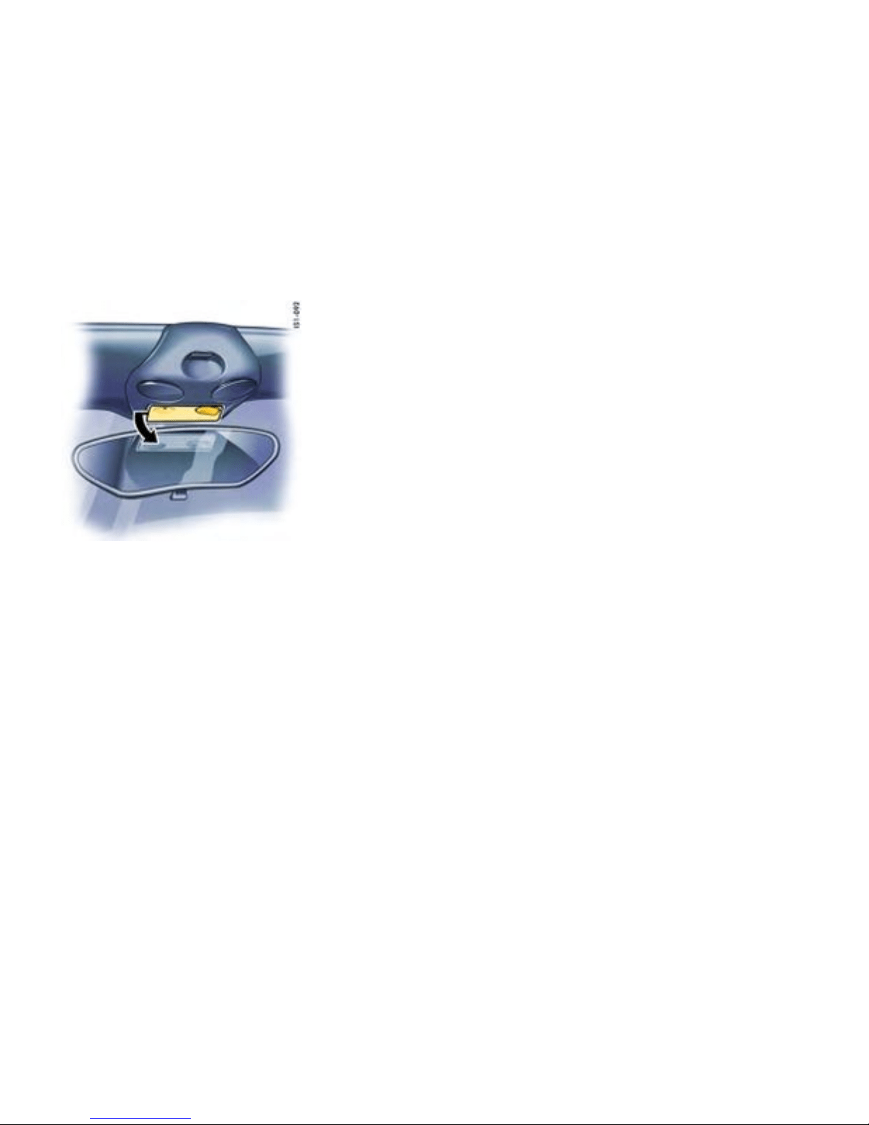
Interior light
Changing bulb
1. With a screwdriver (arrow), carefully press
light out of the cutout in the lining.
2. Undo bulb holder (bay onet mount). Remove
bulb a nd replace i t.
3. Reassemble in reverse order. Check operation
of the light.
Practical Tips, Emergency Service
287
Downloaded from www.ManualsFile.com manuals search engine
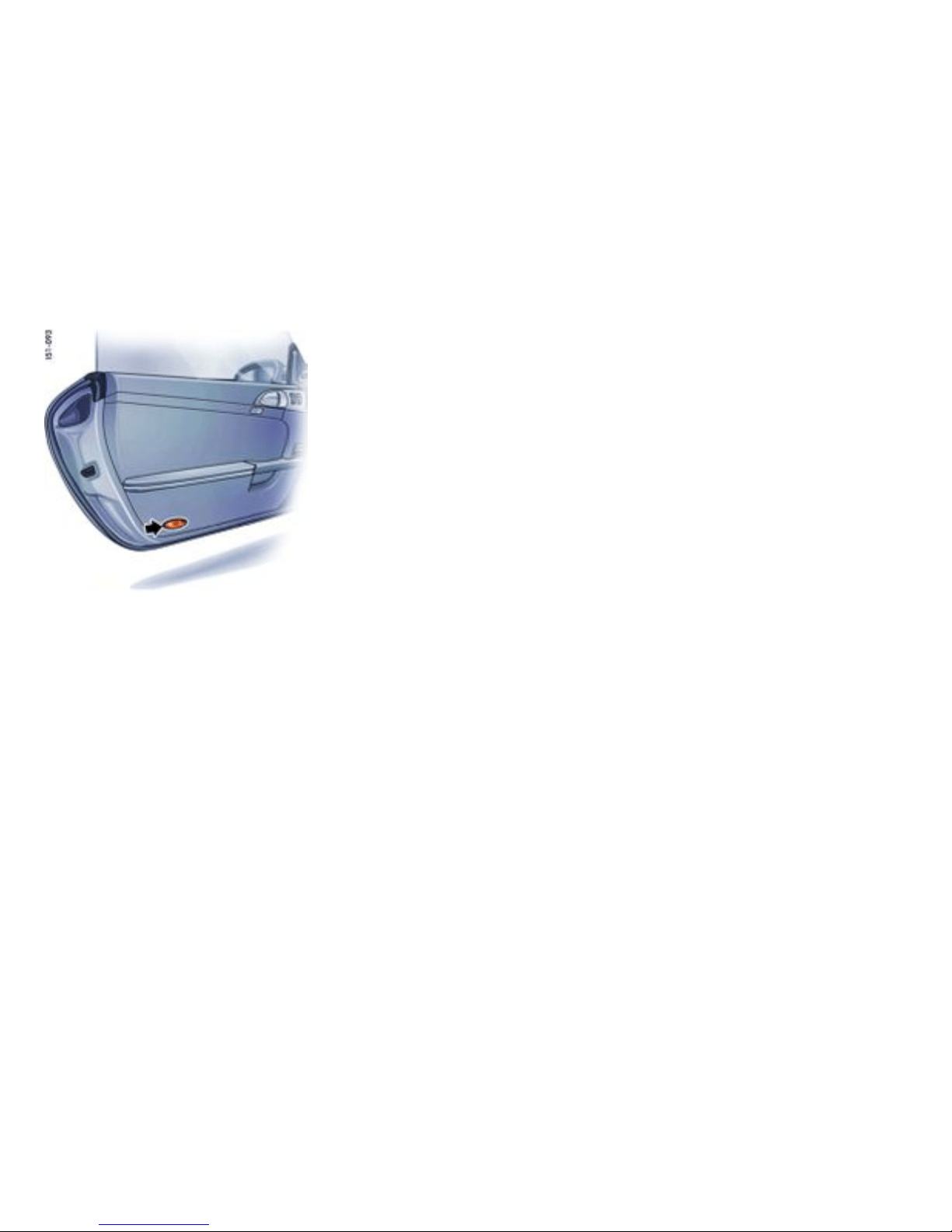
Door guard/curb l ight
Changing bulb
1. With a screwdriver (arrow), carefully push out
the light.
2. Pull bu lb holder out of light housing. Remov e
defective bulb and replace it.
3. Install bulb holder and insert the light. Check
operation.
288Practical Tips, Emergency Service
Downloaded from www.ManualsFile.com manuals search engine
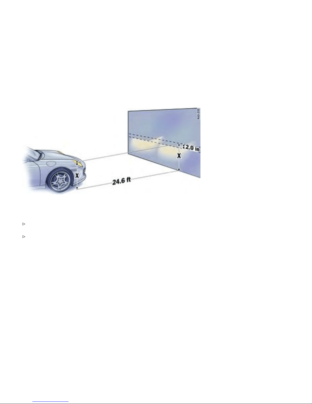
Adjusting Headlights
Adjustment
Please observe the chapter ”REP LACING
BULBS” on page 275.
Please obse rve the chapter ”TIRE PRES SURE
FOR COLD TIRES” on page 304.
The adjustment is m ade with the vehicle ready to
drive a nd the fuel tank completely filled.
The d river’s seat must be loaded by a person or a
165 lbs. (75 kg) weight and the tire pressures must
meet the prescribed values. After being loaded,
the car must be rolled a few mete rs so that the
suspens ion can settle.
For checking the headlight adj ustment, the v ertical
position of the cuto ff of the lowbeam (see fig.)
has to be projected on a vertical screen (wall) in
distance of 24.6 ft. (7.5 m) from the front lens of
the headlamp. The correct position of the cutoff
is 2.0 in. (5 cm) at 24 .6 ft. or 7.5 m (0.4°) below a
horizon tal line, x in. from ground to the center of
the h eadlamp lens.
Practical Tips, Emergency Service
289
Downloaded from www.ManualsFile.com manuals search engine
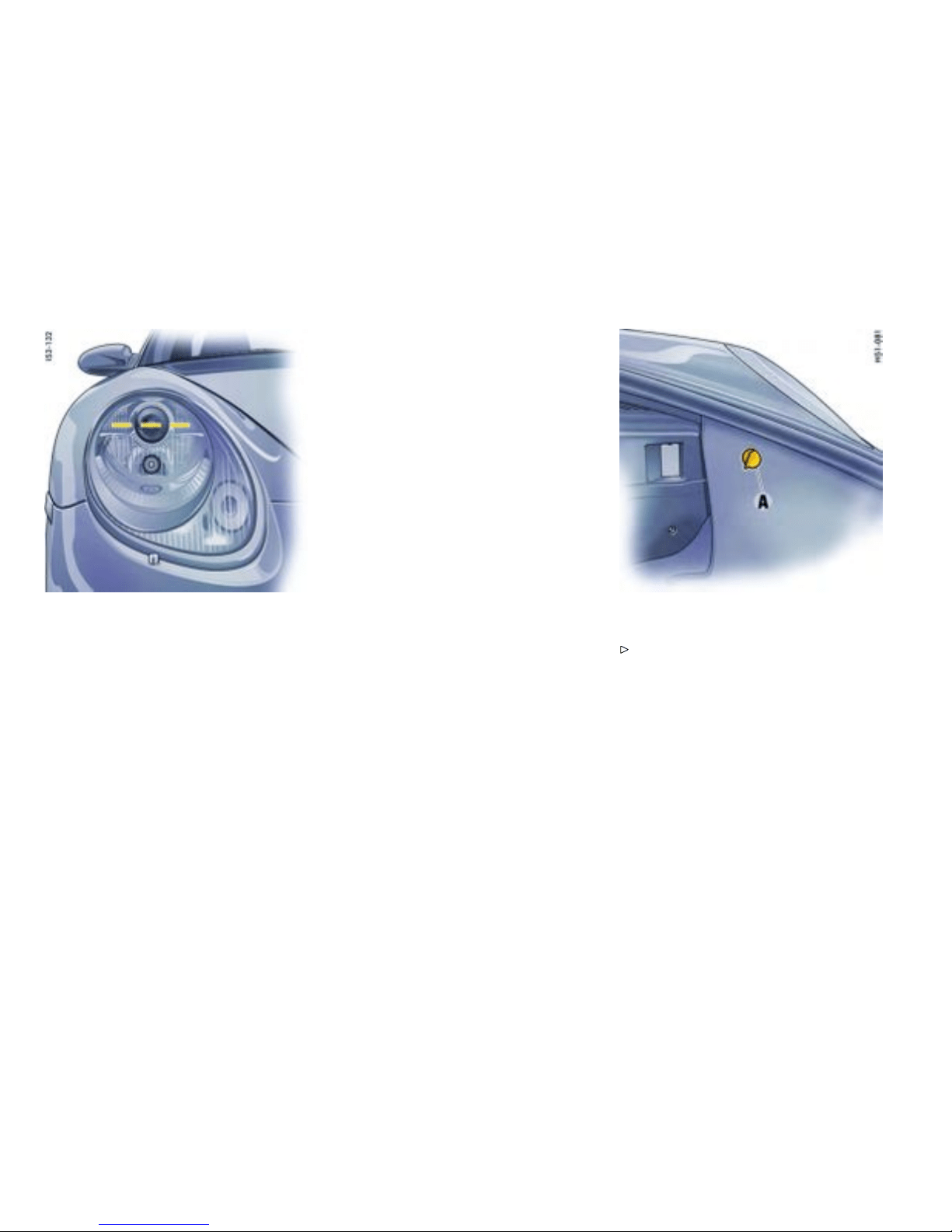
Lateral adjustment of the headlights should be
carried out at a specialist w orkshop with an optic al
adjustment unit.
Distance
Visual aim shall be performed at not less than
24.6 ft. (7.5 m) (this value is a rounded down
conversion from the 25-foot distance typical of
field aim usin g a screen). The 24.6 ft. (7.5 m)
distance is measured from the headlamp lens to
the viewing screen.
Floor
The s urface upon which the vehicle rests is flat and
approximate ly level.
Screen
The screen upon which headlamp beams are
projected is perpendicular to the floor and the
vehicle ’s longit udinal axis, fla t, uniformly ligh t in
color, unobstructed, and wide and high enough
to accommodate the vehicle b eam patterns t o be
aimed.
The screen should be wide enough to provide
at least 3.3 ft. (1 m) of space outboard of the
vehicle ’s headlamp spacing.
Adjustment screws
Detach side carpeting in luggage compart-
ment. Therefore unscrew plastic nut A. O pen
the cover of the appropriate ad justment screw.
The setting is adjust ed by turning the h exagon
socket screws right or left, as appropriate.
290Practical Tips, Emergency Service
Downloaded from www.ManualsFile.com manuals search engine
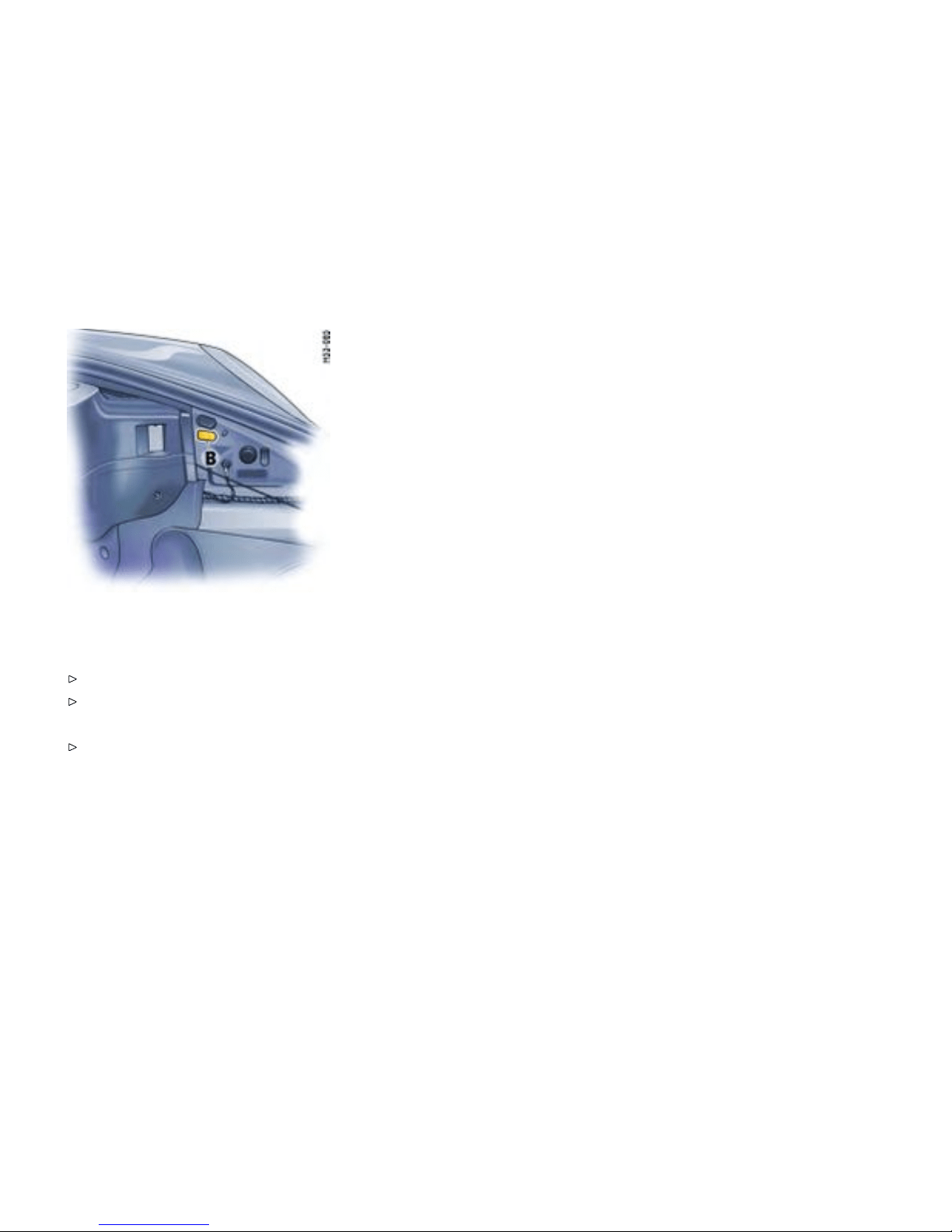

Towing
Certain state statu tes and local ordinances prohibit
towing with a chain, rope or even a tow bar. In
addition, damage to your vehicle may result from
improper procedu res. Consult your authorized
Porsche dealer for d etails.
Vehicle t owing
Flat be d towing is the preferred type of towing
to be used on Porsche vehicles. Under certain
circumstances, wheel lifts may be us ed when the
vehicle will not roll. The vehicle mus t be t owed
with a ll four wheels off the ground, otherwise
damage to the vehicle may result.
Towing hook
The to wing hook is stored in the tool box in the
luggage compartment.
Caution!
Risk of damage to the vehicle.
Use the towing hook only for an emergency to
remove the vehicle off the road. The towing
hook is to be used only to p ull the vehicle onto
the flat bed, tractor or to wing ap paratus if the
vehicle will roll freely. Under no circumstances
is the vehicle to be secured using the towing
hook.
Never use t h e towing hoo k to tow this or a ny
other vehicle.
Bear in min d the limited ground clearence of
your car on uneven surfaces.
292Practical Tips, Emergency Service
Downloaded from www.ManualsFile.com manuals search engine
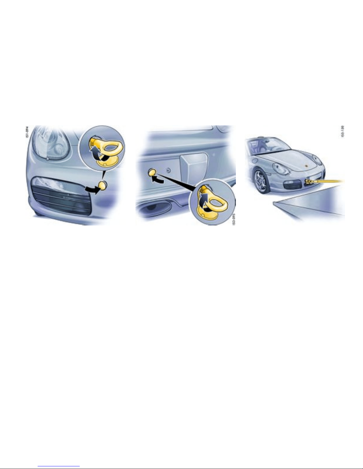
Fitting towing hook
When fitting o n the rear of the vehicle, the license
plate must be removed.
1. Press the l ower edge of the appropriate
plastic cover into the bumper until the cover
disengages.
2. Pull cov er out of the bumper and let it hang by
its thread.
3. Completely screw in the towing hook.
Removing towing hoo k
1. Unscrew th e towi ng hook.
2. Insert plastic cover at t he lower edge of the
opening.
3. Fold the co ver up and press on its upper edge
to engage it in the bumper.
When removing on the rear of th e vehicle, the
license plate must be mounted.
Pulling vehicle onto at bed
1. Position wooden ramps at the base of the flat
bed t o reduce the angle of the pull.
2. Reel in the hoist cable and check the undersi de
of the vehicle for any interference.
Practical Tips, Emergency Service
293
Downloaded from www.ManualsFile.com manuals search engine
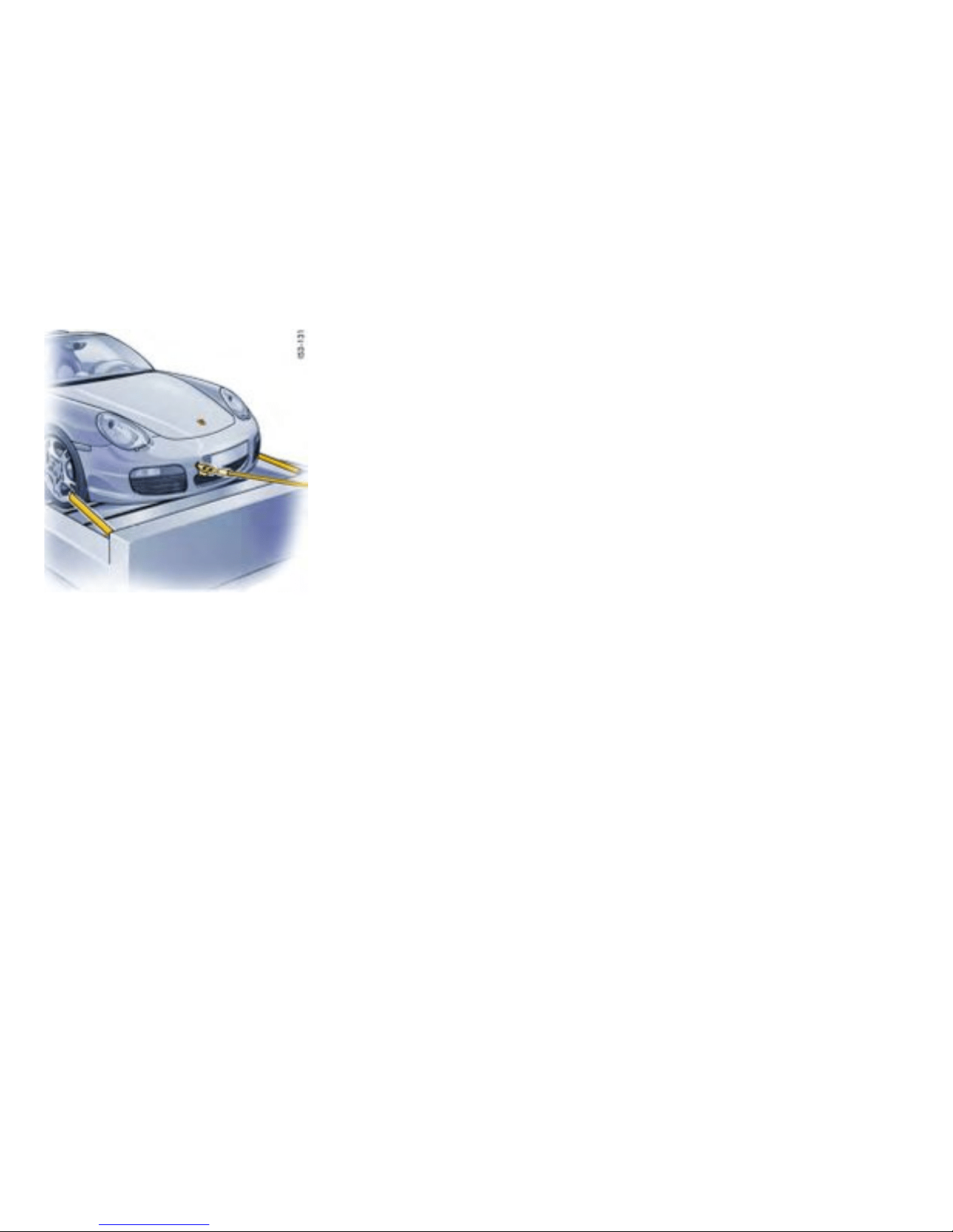
Tying down vehicle on at bed
1. Carefully feed towing straps through the
opening in th e rear wheels. Make sure metal
par ts of straps do not damage rim. Make sure
the st rap is f l at over the rim bead. Make sure
brake backing plate is not damaged.
2. Secure strap s to rear of fla t bed.
3. Reel in hoist cable only far enough to tension
tie-down straps.
4. Carefully feed towing straps through the
opening in th e front wh eels. Make sure metal
par ts of straps do not damage rim. Make sure
the st rap is f l at over the rim bead. Make sure
brake backing plate is not damaged.
5. Secure straps to front of flat bed.
6. Release tensi on on hoist cable, but do not
disconnect. Use hoist cable as a safe ty cabl e.
294Practical Tips, Emergency Service
Downloaded from www.ManualsFile.com manuals search engine

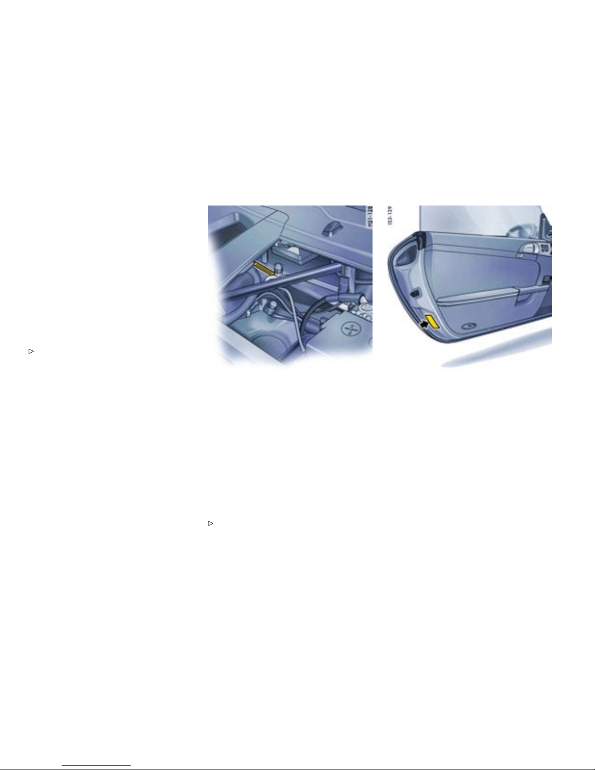
Vehicle Identication
Ordering spare parts
When ordering spa re parts or making inquiries,
please always quote the vehicle ident ification
number.
Vehicle data bank
The vehicle dat a bank is attached to the insid e of
the ”Maintenance“ booklet. It c ontains all important
data about you r car.
Note
This data bank cannot be re-ordered if it is lost
or damaged.
This label contains the followi ng info rmation:
1. Vehicle Identifi cation No .
2. Type/Ty pe desc ription
3. Engine code/Tr ansmission code
4. Paint No./Interior
5. Optional equipment
Vehicl e identication number
Position
In accordance with Federal Safe ty Regulations, the
vehicle identification numb er of your car is located
at the bottom left of the windshield frame and can
be seen from th e outside.
The vehicle identificati on number is in the front
luggage com p artment under the battery cov er and
at the bottom left behind the windshield.
Removing t h e battery cover
Please observe the chapter ”BATTERY” on
page 268.
Safet y compliance sticker
The saf ety compliance sticke r is your assu rance
that y our new Porsche comp lies with all applica-
ble Federal Motor Vehicle Sa fety Standards which
were in effect at the ti me the vehicle was manufac-
tured.
The st icker also shows the month and year of
production and the vehicle identification number of
your car (perforations) as well as the Gross Vehicle
Weight Rating and the Gross Axle Weight Ra ting.
296Vehicle Identif ication, Technical Data
Downloaded from www.ManualsFile.com manuals search engine
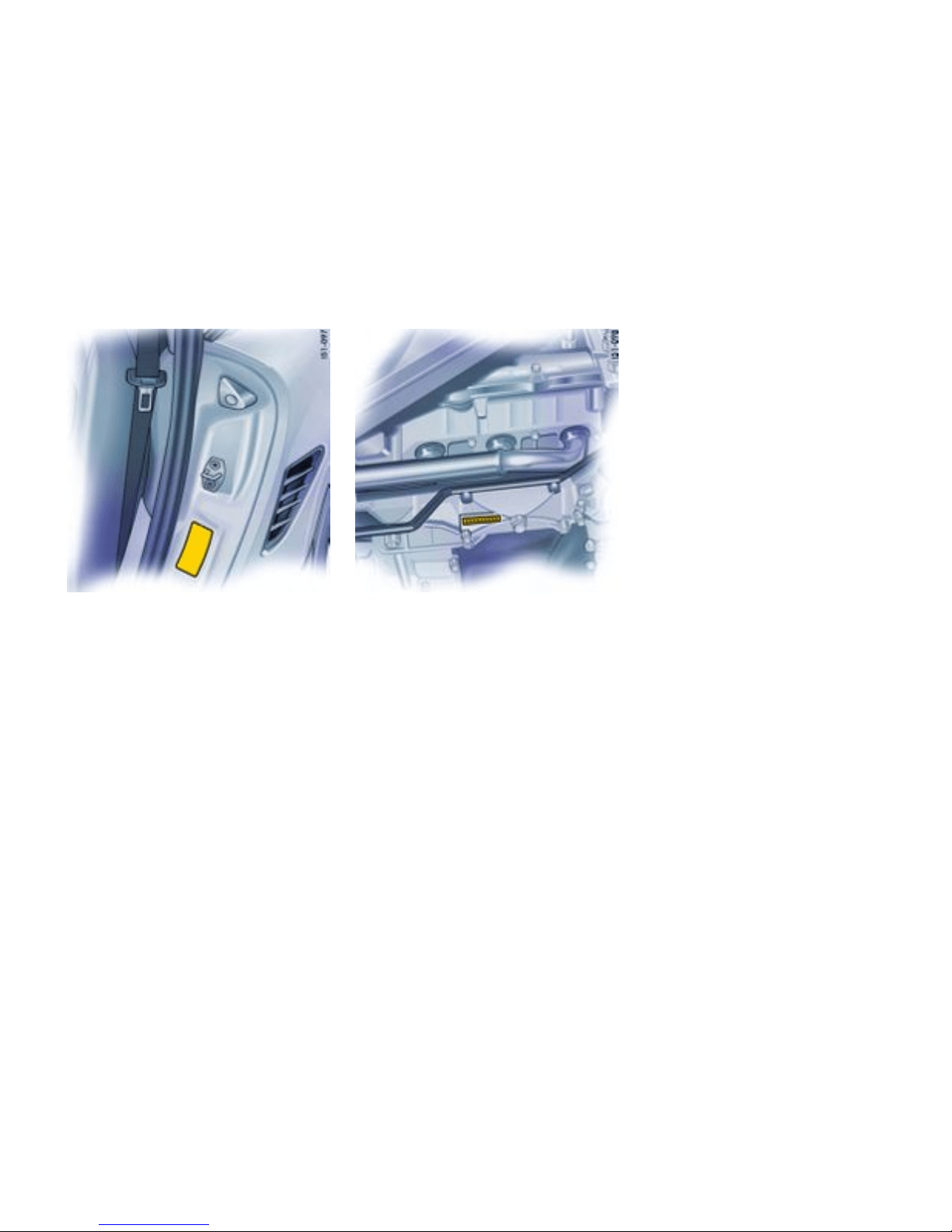

Technical Data
Engine data
Boxste r Boxster S
Type M 97/20 M 97/21
Horizontally opposed engine, liquid cooled Horizontally opposed e ngine, liquid cooled
Number of cy linders 6 6
Bore
3.37 in./85.5 mm 3.78 in./96 mm
Stroke 3.07 in./78 m m 3.07 in./78 mm
Cubic capac ity 163.96 cu.in./2687 cm³ 206.67 cu.i n./3387 cm³
Net-horsepower, SAE J 1349 245 hp/180 kW 295 hp/21 7 kW
at crankshaft speed 6500 rpm 6250 rpm
Net torque, SAE J 1349 201 ft.lb./273 Nm 251 ft.lb./340 Nm
at crankshaft s peed 4600 - 6000 rpm 4400 - 6000 rpm
Engine oil consumpti on
up to 1.5 liters/1000 km (1.6 q u arts/622 miles) up to 1.5 liters/1000 k m (1.6 quarts/62 2 miles)
298Vehicle Identif ication, Technical Data
Downloaded from www.ManualsFile.com manuals search engine

Transmission
Boxster
Gear ratios
5-speed
manual transmission
6-speed
manual transmission
Tiptronic S
1st gear 3.50 : 1 3.67 : 1 3.66 : 1
2nd ge ar 2.12 : 1 2.05 : 1 2.00 : 1
3rd gear 1.43 : 1
1.41 : 1 1.41 : 1
4th gear
1.09 : 1 1.13 : 1 1.00 : 1
5th gear
0.84 : 1 0.97 : 1 0.74 : 1
6th gear 0.82 : 1
Reverse
3.44 : 1 3.33 : 1 4.10 : 1
Final drive ratio
3.75 : 1 3.875 : 1 4.37 9 : 1
Vehicle Identification, Technical Data
299
Downloaded from www.ManualsFile.com manuals search engine

Boxster S
Gear ratios
6-speed
manual transmission
Tiptronic S
1st gear
3.31 : 1 3.66 : 1
2nd ge ar 1.95 : 1 2.00 : 1
3rd gear
1.41 : 1 1.41 : 1
4th ge ar
1.13 : 1 1.00 : 1
5th ge ar
0.97 : 1 0.74 : 1
6th gear 0.82 : 1
Reverse
3.00 : 1 4.10 : 1
Final drive ratio
3.875 : 1 4.1 61 : 1
300Vehicle Identif ication, Technical Data
Downloaded from www.ManualsFile.com manuals search engine

Tires, Rims, Tracks
Boxster Tires Rim Rim offset Track
Summer tires front 205/55 ZR 17 91Y 6.5 J x 17 H2
55 mm
58.7 in./1490 mm
rear
235/50 ZR 17 96Y 8 J x 17 H2 40 mm 60.4 in./1534 mm
or
front 235/40 ZR 18 91Y 8 J x 18 H2
57 mm
58.5 in./1486 mm
rear
265/40 ZR 18 101Y XL 9 J x 18 H 2 43 mm 60.2 in./1528 mm
or
front 235/35 ZR 19 87Y 8 J x 19 H2
57 mm
58.5 in./1486 mm
rear
265/35 ZR 19 94Y 9.5 J x 19 H2 46 mm 60.0 i n./1522 mm
Snow tires front 205/55 R 17 91V M+S 6.5 J x 17 H2
55 mm
58.7 in./1490 mm
rear
235/50 R 17 96V M+S * 8 J x 17 H 2 40 mm 60.4 in./1534 mm
or
front 235/40 R 18 91V M+S 8 J x 18 H2
57 mm
58.5 in./1486 mm
rear
255/40 R 18 95V M+S * 9 J x 18 H 2 43 mm 60.2 in./1528 mm
The load capacity coefficient (e.g. “91”) and m aximum speed code letter (e.g. “V”) are minimum requirements.
Vehicle Identification, Technical Data
301
Downloaded from www.ManualsFile.com manuals search engine

Boxster S
Tires Rim Rim offset Track
Summ er tires front 235/40 ZR 18 91Y 8 J x 18 H2
57 mm
58.5 in./1486 mm
rear
265/4 0 ZR 18 101Y XL 9 J x 18 H2 43 mm 60.2 in./1528 mm
or
front 235/35 ZR 19 87Y 8 J x 19 H2
57 mm
58.5 in./1486 mm
rear
265/3 5 ZR 19 94Y 9.5 J x 19 H2 46 mm 60.0 in./1522 mm
Snow tires front 235/40 R 18 91V M+S 8 J x 18 H2
57 mm
58.5 in./1486 mm
rear
255/40 R 18 95V M+S * 9 J x 18 H2 43 mm 60.2 in./1528 mm
The load capacity coefficient (e.g. “91”) and maximum speed code letter (e.g. “Y”) are minimum requirements.
When changing tires or fitting new ones:
Please observe the chapter ”WHEEL BOLTS” on page 260.
Danger!
Installation of sizes not autho rized by Porsche may have a dangerous effect on the driving st ability and c ould result in se v ere person al injury or
death.
Before mounting new tires, check with your Porsche d ealer about th e current releas e status.
302Vehicle Identif ication, Technical Data
Downloaded from www.ManualsFile.com manuals search engine

Tire and rim sizes
Extensive tests are performed before specific ti res and whe els are approved by Po rsche. Your Porsche dealer has infor-
mation about approved ti res and wheels and is happy to assist you. If aftermarket tires and/or wheels are installed which
are not approved by Porsche, the vehicle’s roadability and handl ing char acteristics might be impaired. Sinc e Porsche has
no data on such combinations, Po rsche cannot stand behi nd the safety or dur ability of these aftermarket combinations.
Snow chains * Can be mounted only on the rear wheels; m aximum speed 30 mph/50 km/h. Use only Porsche authorized fine-link
cross-type or edge chains. Snow chain cle arance can be guaranteed only wi th the tire + rim combination
marked.
Vehicle Identification, Technical Data
303
Downloaded from www.ManualsFile.com manuals search engine

Tire pressure for cold tires
Summer and snow tires
17 inch wheels
front 29 psi (2,0 bar)
rear
36 psi (2,5 bar)
18 inc h wheels front 29 ps i (2,0 bar)
rear
36 psi (2,5 bar)
19 inc h wheels front 32 ps i (2,2 bar)
rear
36 psi (2,5 bar)
These tire pressures apply only to the tire makes and types approved by Porsch e.
Please observe the chapter ”WHEEL BOLTS” on page 260.
Please observe the chapter ”TPC TIRE PRESSURE MONITORING ” on page 119.
304Vehicle Identif ication, Technical Data
Downloaded from www.ManualsFile.com manuals search engine

Driving Performance
At DIN empty weight and half load, without perfo rmance-inhibiting extra equipment.
Boxster Manual trans mission
Tiptronic S
Top trac k speed
5-speed transmission
6-speed transmission
160 mph/258 km/h
162 mph/260 km/h
156 mph/251 km/h
Acceleration 0 - 60 mph 5.8 seconds 6.7 seconds
Acceler ation 0 - 100 km/h (62 mph) 6.1 se conds 7.0 seconds
Boxst er S
Manua l trans mission
Tiptronic S
Top trac k speed
169 mph/272 km/h 164 mph/264 km/h
Acceleration 0 - 60 mph
5.1 seconds
5.8 seconds
Acceler ation 0 - 100 km/ h (62 mph)
5.4 seconds
6.1 seconds
Vehicle Identification, Technical Data
305
Downloaded from www.ManualsFile.com manuals search engine

Capacities
Use only fluids and fuels authorized by Po rsche. Your authorized Porsche deal er will gladly advise you.
Your Porsc he has been desig ned so that it is not necessary to mix any additives with oils or fuels.
Engine
Oil change quantity wi thout oil filter approx. 1.98 U.S.gallons/7.5 liters
Oil change quantity with oil filter approx. 2.05 U.S.gallons/7.75 liters
Please observe the chapter ”ENGINE OIL RECOMMENDATION” on page 215.
Coolant
Boxster
Manual transmission: approx. 5.81 U.S.gallons/22 liters
Tiptronic S : approx. 5.92 U.S.gallons/22.4 lite rs
Boxster S
Manual transmission: app rox. 5.89 U.S.gallons/22.3 liters
Tiptronic S : approx. 6.42 U.S.gallons/24.3 lite rs
Manua l tran smissio n and differential
5-speed: approx. 2.4 quarts/2.25 lite rs , 6-speed: approx. 3 quarts/2.8 liters
Tiptronic S approx. 2.51 U.S.gallons/9.5 liters
Differential with Tiptronic S approx. 0.21 U.S.gallons/0.8 liters
Power steer i ng
approx. 1.1 quarts/1 liter hydraulic fluid Pentosin CHF 11 S
®
or CHF 202 S
®
Brake uid
approx. 0.4 quarts/0.39 liters; use only Origin al Porsche brake flui d
306Vehicle Identif ication, Technical Data
Downloaded from www.ManualsFile.com manuals search engine

Windshield washer
approx. 0.66 U.S.gallons/2.5 liters without headlight washer
approx. 1.59 U.S.gallons/6 liters with headlight washer
Fuel tank
Refill volume approx. 16.9 U.S.gallons/64 liters , including ap prox. 2.6 U.S.ga llons/10 liters reserve.
Fuel quality
Your engine is designed to provide optimum performa nce and fuel economy using unleaded premi-
um fuel with an octane rating of 98 RON (93 CLC or AKI). Porsche therefore recommen ds the use
of these fuels in your vehicle. Porsc he also recognizes that these fuels may not always be available. Be
assured that your vehicle will operate properly on unleaded premium fu els with octane num bers of at least
95 RON (90 CLC or AKI), since the engine’s “Electronic Octane™ kno ck control” will adapt the ignition
timing, if necessary.
Vehicle Identification, Technical Data
307
Downloaded from www.ManualsFile.com manuals search engine

Weights
Boxster Manual transmissio n
Tiptronic S
Empty weight (depen ding o n equipment) 2877 lbs. to 3131 lbs. 3009 lbs. to 3230 lbs.
1305 kg to 1420 kg 1365 kg to 1465 kg
Maximum gross weight
3571 lbs./1620 kg 3671 lbs./1665 kg
Maximum axle load, front
1)
1709 lbs./775 kg 1709 lbs./775 kg
Maximum axle load, rear
1)
2017 lbs./915 kg 2017 lbs./915 kg
Boxster S
Manual transmission
Tiptronic S
Empty weight (depen ding o n equipment) 2987 lbs. to 3153 lbs. 3075 lbs. to 3241 lbs.
1355 kg to 1430 kg 1385 kg to 1470 kg
Maximum gross weight
3594 lbs./1630 kg 3682 lbs./1670 kg
Maximum axle load, front
1)
1709 lbs./775 kg 1709 lbs./775 kg
Maximum axle load, rear
1)
2072 lbs./940 kg 2072 lbs./940 kg
1)
The maximum gross weight must not be exceeded.
Note: If additional acc essories are installed, the useful l oad wil l be corresponding ly less.
308Vehicle Identif ication, Technical Data
Downloaded from www.ManualsFile.com manuals search engine

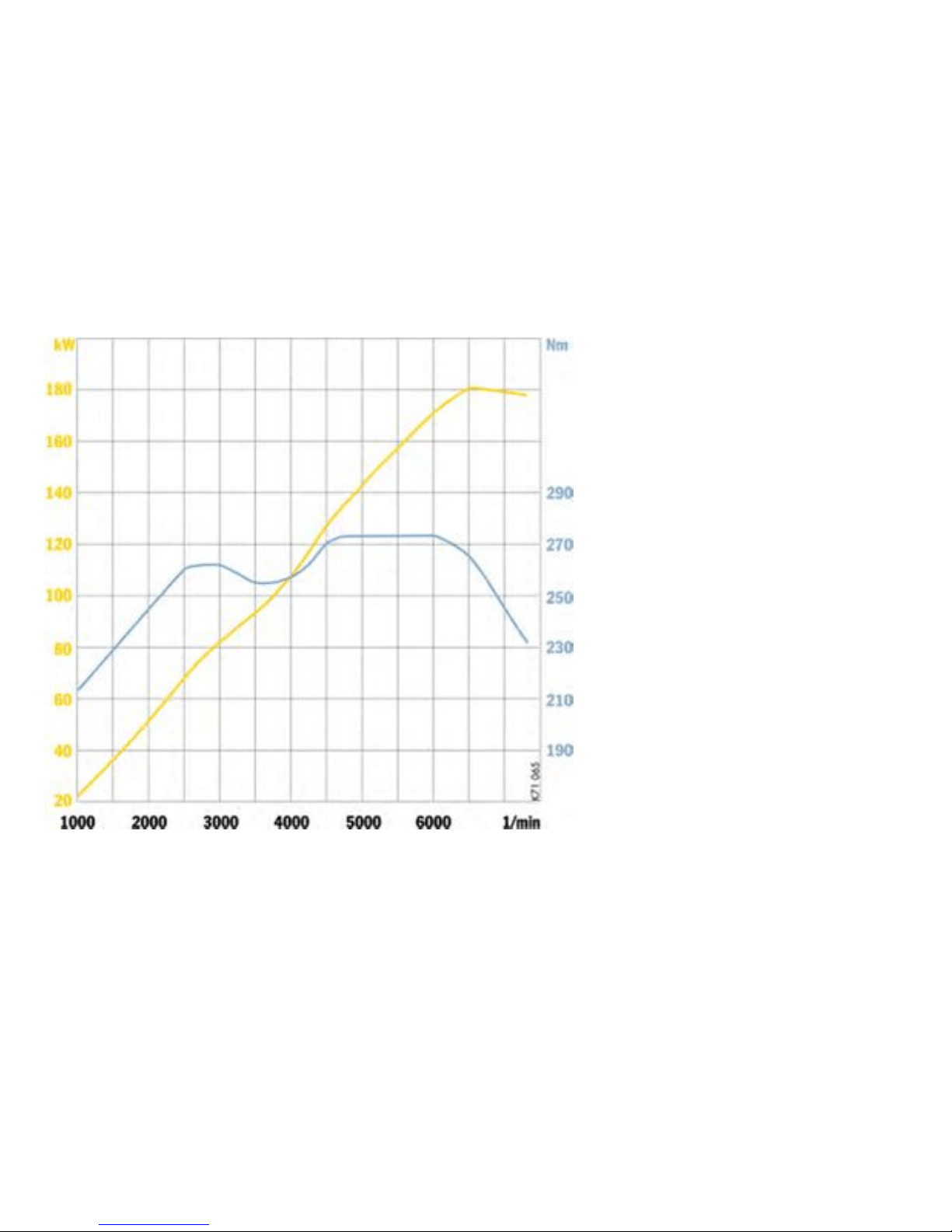
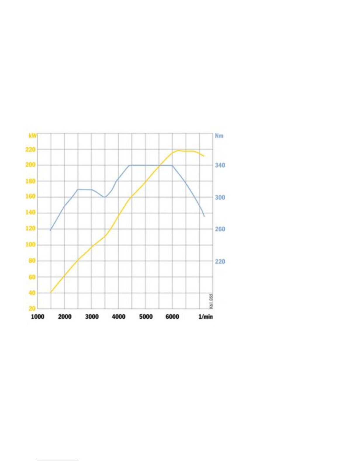
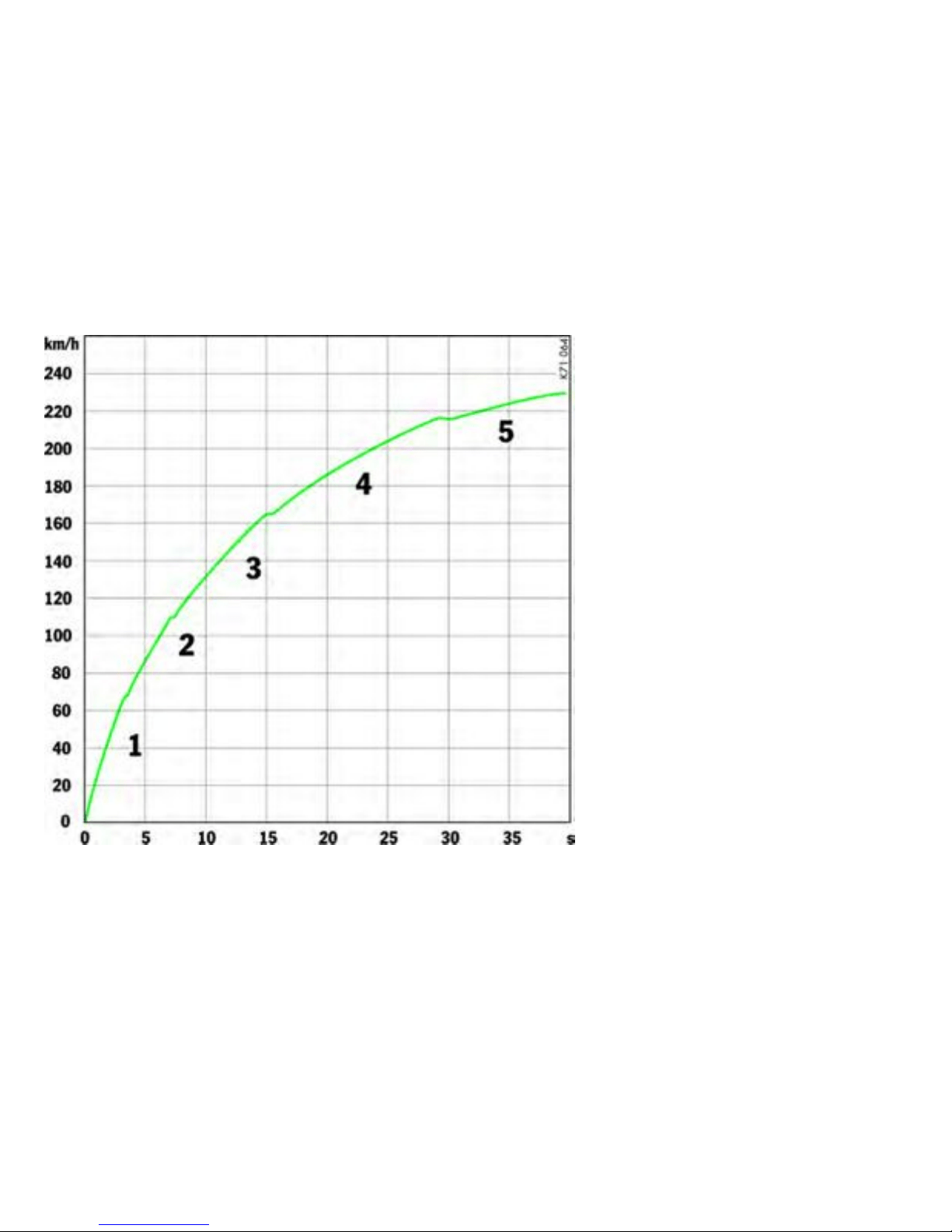
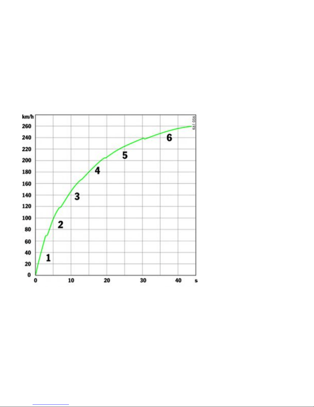

Index
A
ABS (antilock bra ke system) .............. ............. 67
Advanced Airbag ........................................... 53
Air co n ditioning ................................... 152, 15 5
Air distribution .................................... 152, 155
Air filter ...................................................... 230
Air-conditioning compressor ................. 154, 157
Airbag ....................................................... ... 52
Function ................................................. 53
Warning light ........................................... 55
Alarm system .............................................. 179
Alcantara ................................................... 239
Antenna .................... ................. 179, 180, 235
Antilock brake s ystem ... ................................. 67
Warning light ........................................... 67
Ashtray ...... ................................................ 1 60
Assistant ...................................................... 77
Audio operation ........................................... 178
Auto-button air conditioning .......................... 155
Automatic
Anti-glare mirrors .................................... 37
Car washes .......................................... 233
Door loc king ............. .............................. 30
Headlight beam adjustment .................... 145
Speed control ......................................... 89
Automat i c air conditioning system ................. 155
Average consumption ..................... ..... 1 03, 133
Average speed .................................... 103, 133
B
Backrest
Adjustment ............................................. 41
Release ................................................. 42
Battery ....................................................... 268
Care ............................................... ..... 269
Charge state ......................................... 269
Putting vehicle into operation .................. 270
Remote control ..................................... 272
Removing ............................................. 271
Warning light ............. .............................. 98
Winter operat io n ...... ............................. 270
Before driving off ............. ............. ........... 16, 17
Blower adjustment .............................. 152, 155
Brake light .................................................. 284
Brakes
Brake pad warning light .......................... 10 1
Fluid ............................................ 217, 306
Fluid warning light .................................. 218
Pads .... ............................................ 19, 66
Test stand ............................................ .. 73
Bulbs
Chart ................................. .................. 276
Replac ing .. ................................... 275, 276
C
Cabriolet .................................................... 194
Canholder .................................................. 166
Capacit ies, overview .................................... 306
Car care ..................................................... 208
Car telephone ............................................. 179
Car washes . ............................................... 233
Catalyt ic converters .................................... 226
Cautions ............................................ 208, 242
Central locking ........................................ 25, 28
Emergency operation ........................ 25, 29
Central vents ......... ..................................... 158
Central warning light .................................... 100
Changing wheels
Assembly aids for w h eel changes ............ 261
Check engine
Warning light ........................................... 99
Checkin g pressure .......................... ............ 262
Child restraint systems ........ .......................... 58
Chime .............. .......................................... 144
CHRONO Stopwatch ....... ............ ................. 112
Circulating-air butto n ............................ 152, 155
Clock ................................................... 97, 132
Clutch ........................................................ 186
Clutch pedal ................................................. 62
Combination filter ........................................ 230
Comfort seat ............ ............ ............. ........... 40
Coming Hom e mode .................................... 144
Compact disc
Holder ................................................. 165
Player .................................................. 179
Storage ................................. .............. 174
Convertible top ........................................... 194
Care ................................................ .... 234
314Index
Downloaded from www.ManualsFile.com manuals search engine

Coolant ........................................ 94, 210, 306
Level ................................................... 210
Temperature gauge ................................. 94
Warning light ........................................... 94
Cooling system ........................... .......... 94, 210
Cruise control ............................................ ... 89
Cupholder .................................................. 166
D
Dashboard ................................................... 79
Data bank ................................ ................... 296
Defrosting windows ............................. 152, 15 5
Diagno stic socket ................................. 19, 265
Dimensions ..................................... ........... 309
Dipped beam ......................... ..................... 277
Door ............................................................ 31
Guard lights .......................................... 288
Handles ............................... .................. 31
Locks ............................................ 31, 235
Mirror heating ......................................... 38
Windows ................. .......... 31, 34, 194, 236
Driving hints ....... ........................................... 15
Driving i n winter ........................................... 191
Driving performance .. ............. ............ ......... 305
Drop-center rim ........................................... 253
DVD Navigation ........................................... 174
E
Electrical system ......................................... 265
Emergency flasher ...................................... 159
Emergency operation .................. .................. 29
Central locking .................................. 25, 29
Convertible top ............ ............ ............. 197
Lids ................................... .................. 266
Tank cap ... ........................................... 222
Emergency program, Tiptronic ..................... 191
Emergency service ...................................... 242
Emergency starting with jumper ca bles .......... 274
Emiss ion control system ............. 7, 99, 225, 226
Engine
Checking the oil level ....... . ..................... 128
Exhaust ............................. ...................... 9
Number ................. ............ ............. ..... 297
Oil consumption .................. .................... 19
Oil level indicator ................................... 128
Oils ...................................................... 306
Speeds .................................................. 19
Starting ................................................. 81
Switching off .......................................... 81
Engine com p art ment
Blower ............................................. 84, 94
Lid ....................................................... 172
Lid warning light .................................... 172
Environment ................................................... 6
F
Fire extinguisher .......................................... 169
Flat tire ...................... ................................. 256
Floor mats .................................................. 239
Fog lights ............................... .... 144, 282, 284
Footw ell light ... ........................................... 286
Front lid ...................................................... 172
Fuel ................................................. 5, 96, 221
Containers ........................................ ....... 8
Econom y ..... ............. ............ ............. .. 219
Evapo ration .......................................... 22 7
Level gauge ............................................ 96
Level warning light ................................... 96
Portable C ontainers .............................. 223
Recommendation ......... ......................... 224
Tank ............................................ 221, 222
Function keys ................................................ 47
Fuses ......................................................... 265
G
Garage door opener .................................... 181
Garage lift ................................... ............... 259
Gearchanging ...................................... ....... 186
Glove compartment ..................................... 164
Gong ...................................... 21, 82, 105, 144
Ground clearance ............................................ 9
H
Handbrake ................................................... 63
Hardtop ........... .......................................... 202
Headlights .......................................... 146, 277
Adjusting ...................................... 289, 290
Cleaning system ........................... 147, 306
Headlig ths
Cleaning system ................................... 228
Heated rear window ........................... .... 38, 205
Heating .... .......................................... 152, 155
High beam
Indicator light ............... ............. ............ .. 93
Lever ................ ........................... 144, 146
Home mode ............. ................................... 144
Index
315
Downloaded from www.ManualsFile.com manuals search engine

HomeLin k ................................................... 181
Hoods ................................................ 170, 172
Horn ...................................................... 19, 28
I
Identificat io n number ................. .................. 296
Ignition lock .................................... 81, 84, 187
Immob ilizer .................................................. 22
Instrum ent
Illumination ............................................. 90
Lights ........................... ....................... 144
Panel ........ ............................................. 85
Interior lights .............................................. 287
Interior mirror .......................................... ..... 36
J
Jumper cables ................ .................... 273, 274
K
Keylock ...................................................... 187
Keys ............................................................ 2 2
with remote control ................................. 23
L
LATCH System .............................................. 6 1
Leather care ............................................... 238
License plate light ............. .......................... 144
Lids ............................ ....................... 170 , 172
Emergency unlocki ng ............................ 266
Light
Flashe r .................................. 93, 144, 146
Low beam .................................... 144, 146
Switch ............................... .................. 146
Light alloy wheels ........................................ 238
Inscription ......................................... ... 253
Load switch-off .................. ............ ............. 265
Loading information ..................................... 254
Locking .................................................. 26, 29
Luggage compartment ....... ......... 174, 176, 286
Lid warning light ....................... ............. 172
Lids ............................................. ........ 172
M
Maintenance .. ........................................ ..... 208
Make-up mirror ........... ................................... 48
Maximu m permitted engine sp eeds ......... 19, 186
Mirrors ......................................................... 36
Anti-glare .................................... ............ 3 7
Multi-F unctional steering wheel
Function keys .............. ............ ............. .. 47
N
Navigation .................................................. 177
Notes on
Car care ............................. .................. 233
Maintenance ........... ............ .................. 208
Number plate ligh t .......................... ..... 144, 285
O
Octane rating .............................................. 224
Off delay .................................................... 144
Oil ............................................................. 306
Checking level .................. .................... 128
Consumption .......................................... 19
Level checks ........ ................................ 213
Level i ndicator ...................................... 128
On-board computer ................................. 8, 102
Basic settings ........................... ............ 131
Language versions ................................ 132
On-board literature .......................................... 1
Orientation light ........................................... 163
Outside temperature indicato r ........................ 97
P
Paint
Care ................................................ .... 233
ParkAssistant ............................................... 77
Parking
Aids ....................................................... 77
Assistant ................................................ 78
Brake .................................................... 63
Light .................................................... 144
Particle filt er ................................. .............. 230
Plastic parts ............................................... 238
Platform lift ................................................. 259
Porsch e Active Suspension Management
(PASM) ......................................................... 74
Porsche Ceramic Composite Brake (P CCB) ........ 8
Porsc he Communication Management ....... 8, 177
Porsche Stabili ty Management (PSM) ............... 71
Lighting ........ ......................................... 72
Power measurements .................................. 208
Power steering fluid level ............... ....... 229, 306
Power windows ............................... 31, 34, 194
Practical tips ............................................... 242
316Index
Downloaded from www.ManualsFile.com manuals search engine

R
Radiator fans .............................................. 211
Radio reception ............ ............ ................... 178
Rain sensor ........................ ............. ........... 148
Range on remaini ng fuel ....................... 103, 133
Rear fog light ...................................... 144, 284
Rear lid ...................................................... 17 1
Rear spoiler ............................................ 75, 76
Rear view mirrors . ......................................... 36
Rear window defogger ................................... 38
Relays ............ ............................................ 265
Release button ............................................ 187
Remote control ............................................. 23
Replac ement key .......................................... . 22
Replacing bulbs ................................ ........... 2 76
Replacing wiper blades ................................ 209
Retractable spoiler ............................. ........... 75
Rims
Diameter .. ............. ............ ............. ...... 253
Rim width ............................................. 253
S
Safety Belt
Warning light ........................................... 50
Safety belts .................................... 49, 51, 239
Safety compliance sticker ............................ 296
Sealing set ............. .................................... 2 56
Seals, care of ............................................. 237
Seat ................................................. ........... 40
Adjustme nt ..................................... .. 40, 41
Heating .................................................. 45
Memory ........................................... ...... 43
Selector lever ................. ............................ 187
Selector lever position indicator ...... 95, 188, 189
Service flap ....................... ......... 176, 210, 213
Shifting gear ............................................... 186
Shiftlock ..................................................... 187
Side lights .................................................. 284
Side marke r light ........ ......................... 144, 283
Side vents .................................................. 158
Snow chains ........................... .... 251, 302, 304
Snow tires ................. ......................... 250, 301
Socket s ................................................ ..... 162
Spacers ..................................................... 263
Spare key ..................................................... 22
Spare wheel ................................................ 304
Speed code letter ........................................ 252
Speed control ............................... 89, 149, 152
Speed limit ............................. ............ 105, 252
Speedometer ............................................... 92
Spoiler ......................................................... 75
Fixed ..................................................... 76
Retractable ........................... ................. 75
Sport mode ....................... ............... 70, 72, 74
Sports ex haust system .................................. 69
Sports seat .......... ............. ............ ............. .. 40
Stability management system (PSM) ................ 71
Starting ............................................ ...... 81, 82
Starting and stopping the engine . .................... 81
Steering wheel
Adjustment ............................................. 46
Buttons .................. ................................ 47
Lock .......................................... 81, 82, 84
Rocker switches ............... .................... 187
Toggle switches .................................... 187
Stopwatch .................................................. 112
Storage options ..... ..................................... 164
Storing your Porsche ................................... 239
Sun visors ............................ ............ ............ 48
T
Tachometer .................................................. 93
Tail light ...................................................... 284
Tank ................................. ................. 221, 222
Cap ..................... ................................ 222
Ventilation system ................. ................ 227
Telephone .................................................. 179
Temperature setting ............................ 152, 15 5
Temperature, outside indicator ....................... 97
Test stan d, mea surements ............................. 73
Theft protection ............... ............ ............. .... 21
Tiptronic ................................... ................. 187
Indicator ................................................ 95
Tire Pressure Monitoring .............................. 119
Tires ........... .......................... 19, 243, 301, 302
Checking pressure ................................ 262
Inscription ............................................ 252
Loading information .............................. 254
Pressure ...................................... 244, 302
Pressure plate .................................... .. 297
Sealant ...... .......................................... 256
Sidew all ............................................... 252
Size ..................................................... 252
Tires and tire care .................. ...................... 243
Tools ....... .................................................. 1 74
Towing ............................................... 292, 293
Index
317
Downloaded from www.ManualsFile.com manuals search engine

Track ......................................................... 301
Transmission .............................. 1 86, 299, 300
Fluid .................................... 231, 232, 306
Trunk en trapment ...................... .......... 170 , 171
Turn signals .......................................... 93, 146
U
Undercoatin g .................. .................... 225, 237
V
Valves ........................................................ 248
Vanity mirror ................................................. 48
Vehicle
Care ................................................... . 233
Data bank .................................. ........... 296
Identificati on number ............................. 296
Putting into operation ............... ............. 270
Washing ............................................... 233
Ventilation .................................................. 155
Vents ...... ........................................... 152, 15 5
Viscosity, engine oil ..................................... 215
W
Warning messages ................................ ...... 134
Washer fluid ............ ............................ 228, 306
Washer lever .............................................. . 147
Washing ..................................................... 233
Weights ............................ .......................... 308
Welcome Home Function .................... .......... 144
Wheel ................................. 238, 243, 301, 302
Bolts .............................................. 22, 260
Changing ....................................... ...... 261
Checking pressure ................................ 262
Inscription ......................................... ... 252
Loading infor mation .............................. 254
Pressure plate ...................................... 297
Sidew all ............................................... 252
Size ..................................................... 252
Tire pressure ........................................ 24 4
Tire sealant .. ......................... ............... 256
Windows ................................. 31, 34, 194, 236
Washer nozzles ...................... ............... 147
Washer system ............................. 228, 306
Windshield wipers ................................ 147, 209
Replacing ............................................. 209
Windstop .................................................... 201
Winter driving
Jumper cable s ........ ............ ............. ..... 274
Winter operation
Battery ................................................ 270
Coolant ................................................ 21 0
Seals ............................ ....................... 23 7
Snow chains ......................................... 251
Tires ................................ .................... 250
Washer fluid .......................................... 228
Wiper blades ........................................ 209
318Index
Downloaded from www.ManualsFile.com manuals search engine