User Manual for Portable Air Conditioner
PART NAMES
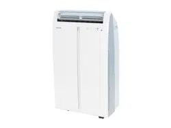
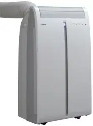
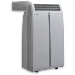
FRONT VIEW
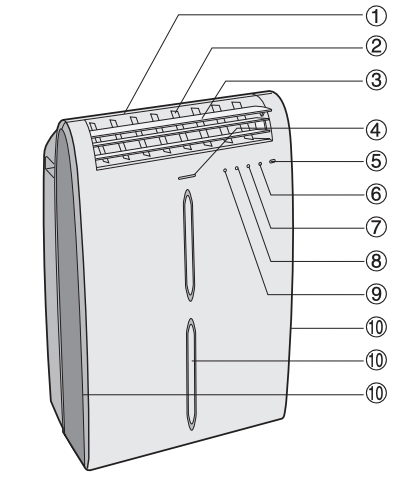
1 Air Outlet
2 Vertical louvers
3 Horizontal louvers
4 PLASMACLUSTER Lamp (blue)
5 Remote control signal receiver window
6 POWER Button
7 OPERATION Lamp (red)
8 TIMER Lamp (orange)
9 MEGA COOL Lamp (green)
10 Air inlet
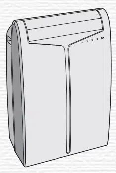
REAR VIEW
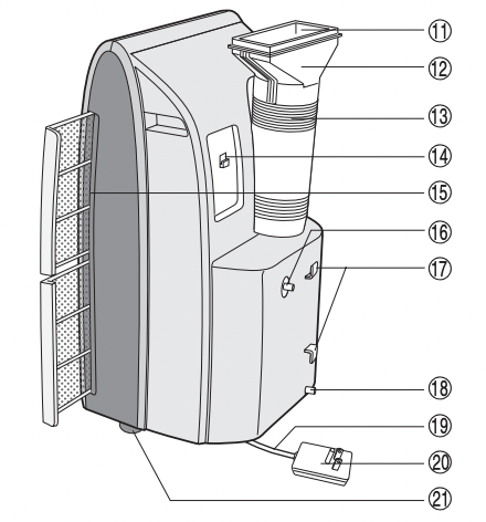
11 Exhaust air outlet
12 Window exhaust adapter
13 Exhaust hose
14 Remote control hook
15 Air filters
16 Drainage nozzle and stopcock
17 Power supply cord hooks
18 Drainpipe nozzle and stopcock
19 Power supply cord
20 Power plug
21 Casters(4)
NOTE: Actual unit might vary slightly from above illustration.
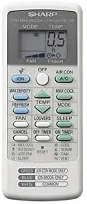
REMOTE CONTROL
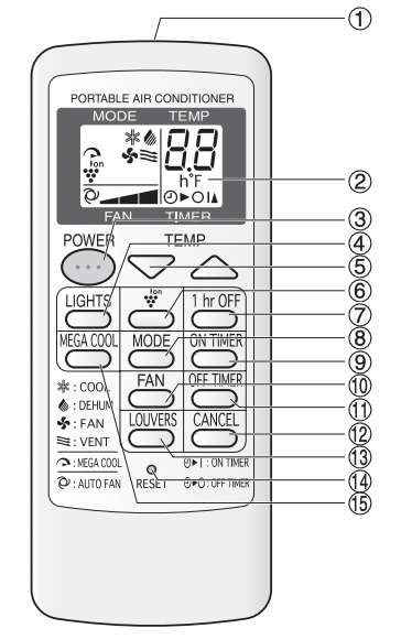
1 Transmitter
2 Display
3 POWER Button
4 LIGHTS Button
5 TEMPERATURE Button
6 PLASMACLUSTER Button
7 1 hr OFF Button
8 MODE Button
9 ON TIMER Button
10 FAN Button
11 OFF TIMER Button
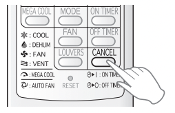
12 CANCEL Button
13 LOUVERS Button
14 RESET Button
15 MEGA COOL Button
REMOTE CONTROL DISPLAY

16 MODE SYMBOLS
 : COOL
 : DEHUMIDIFICATION
 : FAN
: FAN
 : VENTILATION
17 MEGA COOL SYMBOL
18 PLASMACLUSTER SYMBOL
19 FAN SPEED SYMBOLS
 : AUTO
 : Manual setting
20 TEMPERATURE AND TIMER COUNT DOWN INDICATOR
21 TRANSMITTING SYMBOL
22 ON TIMER / OFF TIMER SYMBOL
INSTALL WINDOW PANEL
Installation in a double-hung sash window
(See page 12 for installation in a sliding sash window. )
|
1. Connect the rain guards to the insect guard net. Insert all three projections on each rain guard into the holes in the insect guard net. Side “A” will now be at the top, as indicated in the diagram.
2. Attach the guard combined above to the window panel Push the insect guard net fi rmly to ensure that its four projections fi t into the holes in the window panel. Side “A” will now be at the top, as indicated in the diagram.
3. Cut the foam seal A (adhesive type) to the proper length and attach it to the window stool.
4. Attach the window panel to the window stool.
If the inner width of the window is between 22" (559mm) and 24" (609mm) inclusive.
The window panel cannot be installed in windows less than 22" (559mm) wide, as you will be unable to shut the exhaust cover.
(1) Remove the adjustment panel from the window panel, and cut the window panel to the same width as the window.
(2) Open the window sash and place the window panel on the window stool
(3) Secure the window panel to the window stool with 2 screws.
|
|


|
|
If the inner width of the window is between 24" (609mm) and 36.8" (934mm) inclusive.
- (1) Open the window sash and place the window panel on the window stool.
- (2) Slide the adjustment panel to fi t the window frame width.
- (3) Secure the window panel to the stool with 3 screws.
If the inner width of the window is between 36.8" (934mm) and 48" (1219mm) inclusive.
- (1) Attach the extension panel to the adjustment panel.
- (2) Open the window sash and place the window panel on the window stool.
- (3) Slide the adjustment and extension panels to fit the window frame width.
- (4) Secure the window panel to the window stool with 4 screws.
5. Cut the foam seals (adhesive type) A and B to the proper length and attach it to the window panel. Attach foam seal A to the window panel and extension panel, and attach foam seal B to the adjustment panel.
6. Close the window sash securely against the Window panel.
7. Cut the foam seal to an appropriate length and seal the opening between the top of the inner window sash and the outer window sash.
8. Attach the bracket with a screw.
|
|


|
Installation in a sliding sash window
(See page 10 for installation in a double-hung window.)
|
1. Connect the rain guards to the insect guard net.
Insert all three projections on each rain guard into the holes in the insect guard net. Side “A” will now be at the top, as indicated in the diagram.
2. Attach the guard combined above to the window panel.
Push the insect guard net firmly to ensure that its four projections fit into the holes in the window panel. Side “A” will now be at the top, as indicated in the diagram, when it is installed in the window.
3. Cut the foam seal A (adhesive type) to the proper length and attach it to the window frame.
4. Install the window panel into the window frame.
If the inner height of the window is between 22" (559mm) and 24" (609mm) inclusive.
The window panel cannot be installed in windows less than 22" (559mm) high, as you will be unable to shut the exhaust cover.
- (1) Remove the adjustment panel from the window panel, and cut the window panel to the same height as the window.
- (2) Open the window sash and place the window panel on the window frame.
- (3) Secure the window panel to the window frame with 2 screws.
|
|

|
|
If the inner height of the window is between 24" (609mm) and 36.8" (934mm) inclusive.
- (1) Open the window sash and place the window panel on the window frame.
- (2) Slide the adjustment panel to fi t the window frame height.
- (3) Secure the window panel to the window frame with 3 screws.
If the inner height of the window is between 36.8" (934mm) and 48" (1219mm) inclusive.
- (1) Attach the extension panel to the adjustment panel.
- (2) Open the window sash and place the window panel on the window frame.
- (3) Slide the adjustment and extension panels to fi t the window frame height.
- (4) Secure the window panel to the window frame with 4 screws.
5. Cut the foam seals (adhesive type) A and B to the proper length and attach them to the window panel.
Attach foam seal A to the window panel and extension panel, and attach foam seal B to the adjustment panel.
6. Close the window sash securely against the Window panel.
7. Cut the foam seal to an appropriate length and seal the opening between the side of the inner window sash and the outer window sash.
8. Attach the bracket with a screw.
|
|


|
INSTALLATION AND REMOVAL OF EXHAUST HOSE
The exhaust hose must be installed or removed in accordance with the usage mode.
| MODE |
EXHAUST HOSE |
| COOL, FAN, VENTILATION, DEHUMIDIFICATION with no container |
Install |
| DEHUMIDIFICATION with container(minimum capacity 31/2 gallons) |
Remove |
Installation of the exhaust hose
|
1. Attach the window exhaust adapter to the exhaust hose.
Extend one end of the exhaust hose and insert it into the window exhaust adapter, and turn it (approx. three times) until it stops.
Make sure they are securely attached.
2. Attach the exhaust hose adapter to the unit.
Insert the two projections on the exhaust hose adapter into the two holes on the unit, and firmly attach them to each other.
3. Slide and open the exhaust cover on the window panel, and attach the window exhaust adapter.
Surface of window exhaust adapter marked "TOP" should be at the top when it is installed in a double-hung sash window.
Surface of window exhaust adapter marked "TOP" should be on the window frame side when it is installed in a sliding sash window.
|
|
 |
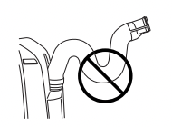
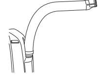
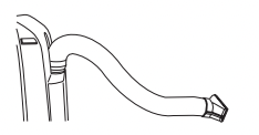
The exhaust hose should be as short as possible for operational effi ciency; however, it must not be twisted or bent.
Unacceptable
Acceptable
Acceptable
Removal of the exhaust hose
|
1. Remove the window exhaust adapter.
Pull out and remove the window exhaust adapter by pushing down two “PUSH” markings, and slide and close the exhaust cover in the window panel.
2. Remove the exhaust hose adapter from the unit.
Lift up and remove the exhaust hose adapter from the unit by pushing down on the two projections.
|
|
 |
PRE-OPERATION CHECKS
POWER PLUG CHECK
This air conditioner uses a fused power plug. Always check the power plug before use.
- Press the RESET button.
- Insert the power plug into the wall socket.
- Press the TEST button. You will hear a CLICK if the circuit breaker is functioning correctly.
- Press the RESET button until you hear another CLICK.
The circuit breaker is activated, power is supplied, and the air conditioner is now ready for use.
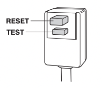
Do not attempt to use the air conditioner if the above procedure cannot be performed. Disconnect the power plug and call for service.
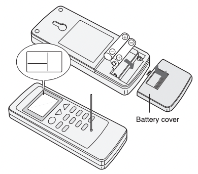
LOADING BATTERIES
Use two AAA (R03) batteries.
1. Remove the battery cover at the back of the remote control.
2. Insert batteries into the compartment, making sure the  and
and  polarities are correctly aligned.
- Lines will appear on the display when batteries are properly installed.
3. Reattach the battery cover.
4. Press the RESET button using a thin pointed implement.
NOTES:
- The battery should last approximately one year under normal use.
- When replacing the batteries, always change both batteries at the same time, and make sure they are the same type.
- If the remote control does not operate normally after replacing the batteries, press the RESET button using a thin pointed implement.
- If you will not be using the unit for a prolonged period, remove the batteries from the remote control.
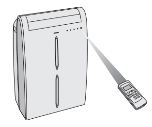
HOW TO USE THE REMOTE CONTROL
Point the remote control towards the units signal receiver window and press the desired button. A beep will sound when the unit receives the signal.
- Make sure nothing, such as curtains, blocks the signal receiver window.
- The remote control operates up to 23 feet (7 meters) away.
CAUTION
- Do not expose the signal receiver window to direct sunlight. This may adversely affect its operation. If necessary, close the curtains to block out the sunlight.
- Use of a fl uorescent lamp in the same room may interfere with transmission of the signal.
- The unit may be affected by signals emitted from other remote controllers for televisions, VCRs or other equipment used in the same room.
- Do not leave the remote control exposed to direct sunlight or near a heater. Protect the remote control from moisture and shock which can discolor or damage it.
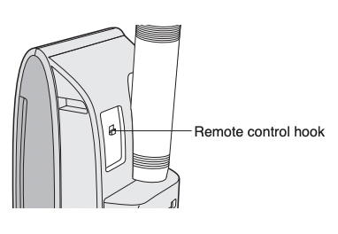
To prevent the remote control from being misplaced, hook it to the unit when not in use.
When attached, to remove the remote control from the unit, lift the remote control up slightly and pull it out.
COOL MODE
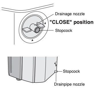
Install the exhaust hose (See Page14), turn the drainage nozzle to the CLOSE position, and check the drainage nozzle is covered with the stopcock.
Ensure that the stopcock is securely inserted into the lower drainpipe nozzle and that the nozzle has not been damaged.
 |
|
1. Press the MODE button to select COOL mode.

2. Press the POWER button to start operation.
- The red OPERATION lamp on the unit will light.
3. Press the TEMPERATURE button to set the desired temperature.
- The temperature can be set within the range of 64°F to 86°F.

4. Press the FAN button to set the desired fan speed.

TO TURN OFF
Press the POWER button again.
- The red OPERATION lamp on the unit will turn off.
|
DEHUMIDIFICATION MODE
In this mode, the air conditioner dehumidifies the room.
Ensure that the stopcock is securely inserted into the lower drainpipe nozzle and that the nozzle has not been damaged
Dehumidification with container
1. Remove the exhaust hose (See Page 15)
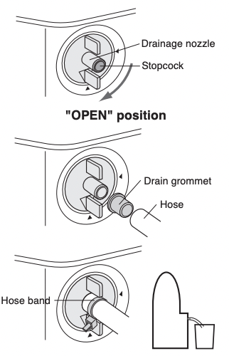
2. Turn the drainage nozzle to the OPEN position.
3. Pull the stopcock out from the drainage nozzle.
• When the stopcock is removed, a small amount of water may be discharged from the drainage nozzle.
• Always perform this procedure with the unit turned off. Drain water will spout out if attempted during operation.
4. Attach the drain grommet to a standard commercially-available hose. (5/8" inner diameter, 7/8" outer diameter)
5. Attach the hose to the drainage nozzle, and secure it with the hose band.
• Insert the hose securely into a container with a minimum capacity of 31/2 gallons. Be sure to monitor the water level in the container and empty as necessary. Do not operate in dehumidify mode for more than 8 hours at a time. Be sure to empty the water container whenever dehumidify mode is started. Failure to empty the water container can cause the container to overfl ow and cause damage to underlying materials.
• Set the hose sloping downwards for easier drainage. Moreover, do not bend the hose at any point, nor allow the end to be submerged in water.
Dehumidification with no container
If draining of the water is not desirable, install the exhaust hose (See Page 14), turn the drainage nozzle to the CLOSE position, and check that the drainage nozzle is covered with the stopcock. In this operation, the water tank inside the unit may become full, the unit will stop operating and the TIMER, OPERATION and MEGA COOL lamps will blink. In this case, drain out the water within the unit (See Page 27).
 |
|
1. Press the MODE button to select DEHUMIDIFICATION mode.

2. Press the power button to start operation.
- The red OPERATION lamp on the unit will light.
- The temperature cannot be set.
- The fan speed is preset to AUTO and cannot be changed.
TO TURN OFF
Press the POWER button again.
- The red OPERATION lamp on the unit will turn off.
|
CAUTION When operating dehumidification with container, the unit generates heat during dehumidification mode and the room temperature will rise. Operate dehumidification with no container if you don't want the room temperature to rise. This will help to slightly drop the room temperature, but dehumidification performance will become less effective than when operating dehumidification with container.
FAN MODE
In this mode, the air conditioner simply circulates the air without cooling it.
Install the exhaust hose (See Page14), turn the drainage nozzle to the CLOSE position, and check the drainage nozzle is covered with the stopcock.
Ensure that the stopcock is securely inserted into the lower drainpipe nozzle and that the nozzle has not been damaged.
 |
|
1. Press the MODE button to select FAN mode.

2. Press the POWER button to start operation.
• The red OPERATION lamp on the unit will light.
• The temperature cannot be set.
3. Press the FAN button to set the desired fan speed.

TO TURN OFF
Press the POWER button again.
- The red OPERATION lamp on the unit will turn off.
|
VENTILATION MODE
In this mode, the air conditioner ventilates the air to outdoors.
Install the exhaust hose (See Page 14), turn the drainage nozzle to the CLOSE position, and check the drainage nozzle is covered with the stopcock.
Ensure that the stopcock is securely inserted into the lower drainpipe nozzle and that the nozzle has not been damaged.
 |
|
1. Press the MODE button to select VENT mode.

2. Press the POWER button to start operation.
• The red OPERATION lamp on the unit will light.
• The temperature cannot be set.
3. Press the FAN button to set the desired fan speed.
• Although the louvers are closed and no air blows out into the room, the external ventilation fan speed changes.

TO TURN OFF
Press the POWER button again.
• The red OPERATION lamp on the unit will turn off.
|
TO CHANGE AIR FLOW DIRECTION
UP / DOWN AIR FLOW DIRECTION
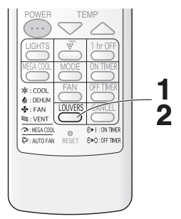
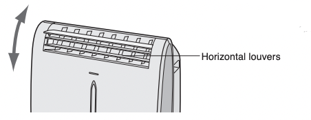
1. Press the LOUVERS button on the remote control.
• The horizontal louvers will swing continuously.
2. Press the LOUVERS button again when the horizontal louvers are at the desired position.
• The horizontal louvers will stop moving.
• The adjusted position will be memorized and the same position will be set automatically when operated the next time.
NOTE
• During VENTILATION mode, UP/DOWN air fl ow direction cannot be changed.
LEFT / RIGHT AIR FLOW DIRECTION
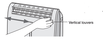
Hold the vertical louver as shown in the diagram and adjust the air fl ow direction.
CAUTION
Never attempt to adjust the horizontal louvers manually.
- Manual adjustment of the horizontal louvers can cause the unit to malfunction when the remote control is used for adjustment.
- When the horizontal louvers are positioned at the lowest position in the COOL or DEHUMIDIFICATION mode for an extended period of time, condensation may result.
Do not adjust the vertical louvers to the extreme left or right in the COOL mode with the fan speed set to "QUIET ( )" for an extended period of time. Condensation may form on the louvers.
PLASMACLUSTER OPERATION
The Plasmacluster ion generator inside the air conditioner will release positive and negative Plasmacluster ions into the room. Approximately the same number of positive and negative ions are released into the air.
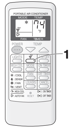
1. Press the PLASMACLUSTER button during operation.
- The remote control will display “
 ”.
”.
- The blue PLASMACLUSTER lamp on the unit will light.
TO CANCEL
Press the PLASMACLUSTER button again.
- The PLASMACLUSTER lamp on the unit will turn off.
NOTES:
- Use of the PLASMACLUSTER function will be memorized and it will be activated the next time you turn on the air conditioner.
- To turn off the PLASMACLUSTER Lamp, press the LIGHTS button.
- PLASMACLUSTER operation cannot be set during VENTILATION mode.
MEGA COOL OPERATION
In this operation, the air conditioner fan works at extra high speed with a setting temperature of 59°F.
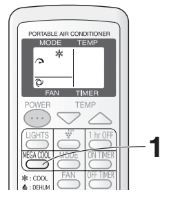
1. Press the MEGA COOL button during cooling mode.
- The remote control will display "
 " .
" .
- The temperature display will go off.
- The green MEGA COOL lamp on the unit will light.
TO CANCEL
Press the MEGA COOL button again.
- MEGA COOL operation is also cancelled when the mode is changed, or when the unit is turned off.
- The green MEGA COOL lamp on the unit will turn off.
NOTES:
- You cannot set the temperature or fan speed during MEGA COOL operation.
- The fan returns to the HIGH speed setting after the unit has run for 30 minutes in MEGA COOL mode.
- The extra high fan speed may automatically slow down to protect the unit.
ONE-HOUR OFF TIMER
When the ONE-HOUR OFF TIMER is set, the unit will automatically turn off after one hour.
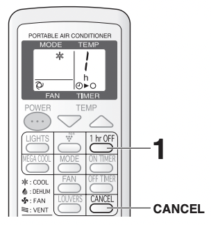
1. Press the 1hr OFF button.
- The remote control displays “
 ”.
”.
- The orange TIMER lamp on the unit will light.
- The unit will stop operating after one hour.
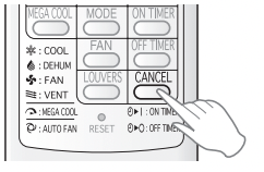
TO CANCEL
Press the CANCEL button.
- The orange TIMER lamp on the unit will turn off. Alernatively, turn the unit off by pressing the POWER button.
- The red OPERATION lamp and the orange TIMER lamp on the unit will turn off.
NOTES:
- The ONE-HOUR OFF TIMER operation has priority over ON TIMER and OFF TIMER operations.
- If the ONE-HOUR OFF TIMER is set while the unit is not operating, the unit will operate for an hour at the formerly set condition.
- If you wish to operate the unit for another hour before the ONE-HOUR OFF TIMER is activated, press the 1hr OFF TIMER button again during operation.
TIMER OPERATION
ON TIMER
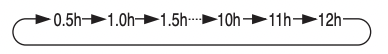
The unit will turn on automatically according to your setting. Timer duration can be set from a minimum of half an hour (30 minutes) to a maximum of 12 hours.
Up to 9.5 hours, you can set in half-hour (30-minute) increments and from 10 to 12 hours, in 1-hour increments.
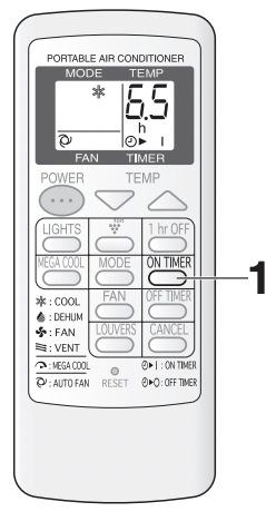
Display shown when you set the unit to turn on 6.5 hours later.
Point the remote control at the signal receiver window on the unit.
1 Press the ON TIMER button.
• The time setting will change as you press the button as follows.
Hold the button down to speed through the settings.
- The orange TIMER lamp on the unit will light.
- The unit will emit a beep when it receives the signal.
- The time setting will count down to show the remaining time.
Select the mode, temperature, fan speed setting and PLASMACLUSTER operation as desired.
- When the temperature is set with the ON TIMER, the temperature will show in the display for 5 seconds and then return to the time display.
- If you do not change the setting, the unit will operate using the most recent setting.
TO CANCEL TIMER
Press the CANCEL button.
• The orange TIMER lamp on the unit will turn off.
OFF TIMER
The unit will turn off automatically according to your setting. Timer duration can be set from a minimum of half an hour (30 minutes) to a maximum of 12 hours. Up to 9.5 hours, you can set in half-hour (30-minutes) increments and from 10 to 12 hours, in 1-hour increments.
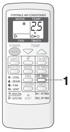
Display shown when you set the unit to turn off 2.5 hours later.
Point the remote control at the signal receiver window on the unit.
1 Press the OFF TIMER button and set the time as desired.
- The time setting will change as you press the button as follows.
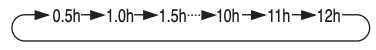
Hold the button down to speed through the settings.
- The orange TIMER lamp on the unit will light.
- The unit will emit a beep when it receives the signal.
- The time setting will count down to show the remaining time.
TO CANCEL TIMER
Press the CANCEL button.
- The orange TIMER lamp on the unit will turn off.
NOTES ON TIMER SETTING AND OPERATION
- The latest time setting will be memorized and will appear on the remote control display the next time you set the OFF TIMER or ON TIMER.
- The OFF TIMER and ON TIMER can not be set together. Only the most recent TIMER setting will be valid.
- While the ONE-HOUR OFF TIMER is set, the OFF TIMER and ON TIMER is settings are unavailable.
- If the ONE-HOUR OFF TIMER is set while the OFF TIMER or ON TIMER activated, the ON TIMER or OFF TIMER setting will be cancelled.
- If a power failure occurs while the OFF TIMER or ON TIMER is set, the TIMER setting will be cancelled and will not be retrieved even after the power is restored.
MAIN UNIT OPERATION
Use this mode when the remote control is not available
1. Press the POWER button on the unit.
- The red OPERATION lamp on the unit will light.
- If the unit has not been unplugged since it was last operated, it will resume operation at its last settings.
- If the unit has been unplugged since it was last operated, it will resume operation in the cooling mode, set at 68˚F. The fan speed set to AUTO.
TO TURN OFF
Press the POWER button again.
- The red OPERATION lamp on the unit will turn off.
NOTES:
- Upon starting MAIN UNIT operation, the drainage pump inside the unit runs for about a minute, which may produce an audible gurgling sound.
DRAINAGE
Prepare for drainage and drain out water within the unit in the following cases.
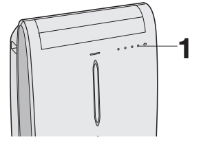
If the unit stops operating and the TIMER, OPERATION and MEGA COOL lamps are blinking. (This indicates that the water tank inside the unit is full.)
|
1 Make sure to turn the unit off.
2 Turn the drainage nozzle to the OPEN position.
3 Pull the stopcock out from the drainage nozzle.
• When the stopcock is removed, a small amount of water may be discharged from the drainage nozzle.
4 Attach the drain grommet to a standard commercially available hose. (5/8" inner diameter, 7/8" outer diameter)
5 Attach the hose to the drainage nozzle, and secure it with the hose band.
• Prepare for draining, as drain water will come out through the hose during operation.
6 Press the POWER button on the unit twice.
• The water will drain out through the drainage hose. Maximum amount of water that may be drained out is approximately 41/ 5 pints.
• The OPERATION, TIMER and MEGA COOL lamps will be blinking.
7 When drainage water stops running out from the hose, turn the unit off by pressing POWER button.
• This will take about one minute.
8 Remove the hose from the drainage nozzle, and replace the stopcock.
• Keep the hose band and drain grommet in case of re-used.
9 Turn the drainage nozzle to the CLOSE position.
|
|
 |
Whenever the unit is moved (to prevent water within the unit from spilling). When the unit is not used for a long time.
1 Carry out the above procedures from 1 to 5.
2 Press the POWER button on the unit.
• The water will drain out through the drainage hose. Maximum amount of water that may be drained out is approximately 41/ 5 pints.
• The OPERATION lamps will light.
3 When drainage water stops running out from the hose, turn the unit off by pressing POWER button.
• This will take about one minute.
4 Remove the hose from the drainage nozzle, and replace the stopcock.
• Keep the hose clamp and drain grommet in case of re-used.
5 Turn the drainage nozzle to the CLOSE position.
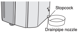
6 Remove the stopcock from the drainpipe nozzle, and completely drain any water within the unit.
• Always prepare a receptacle to collect the water before draining. Maximum amount of water that may be drained out is approximately 2/ 5 pints.
7 Replace the stopcock to the drainpipe nozzle.
MAINTENANCE
Be sure to disconnect the power from the wall socket before performing any maintenance.
CLEANING THE FILTERS
If the fi lter is clogged with dust, the airfl ow will be reduced, resulting in poor cooling performance. The fi lter should be cleaned every two weeks.
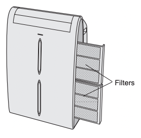
1 REMOVE THE FILTERS
• Gently pull the filter handle to the right and slide the filter out of the unit.
2 CLEAN THE FILTERS
• Use a vacuum cleaner to remove any dust. If the filters are very dirty, wash them with detergent and rinse carefully with clean water. Dry the filters in the shade before reinstalling them.
3 REINSTALL THE FILTERS
• Hold the filter handle and gently push the filter back into place. Never operate the unit without the filter. Doing so may result in serious damage to the unit.
CLEANING THE UNIT AND THE REMOTE CONTROL
Wipe them with a soft, dry cloth or with a cloth moistened with a mild soap. Carefully remove any residue by wiping with a damp cloth and dry completely. Avoid splashing water onto the unit. Water can dangerously damage the electrical insulation. Never use harsh chemicals or abrasive cleaners on any part of the unit. To avoid damaging the unit, do not use hot water (120°F/50°C or hotter) when cleaning.
CLEANING THE INSECT GUARD NET
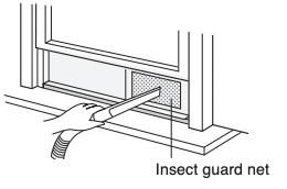
The cooling performance may be reduced or stop completely if the insect guard net becomes clogged with dust.
Periodically remove the window exhaust adapter from the window panel and clean the insect guard net with a vacuum cleaner.
MAINTENANCE AFTER AIR CONDITIONER SEASON
- Perform drainage to drain out water within the unit. (See Page 27 "When the unit is not used for a long time").
- Operate the unit in the FAN or VENTILATION mode for about half a day to thoroughy dry inside the unit.
- Clean the filters, then reinstall them.
BEFORE CALLING FOR SERVICE
If the unit appears to be malfunctioning, check the following points before calling for a service.
AIR CONDITIONER DOES NOT OPERATE AT ALL
- Is the unit plugged in or is the plug loose?
- Has the fuse blown or is the circuit breaker tripped?
- Did you restart the unit within 3 minutes of a power failure? If the power was off for less than 3 minutes when, you restarted the air conditioner, a protective device may cause the compressor to shut off, preventing cooling for about 5 minutes.
- Are the OPERATION, TIMER and MEGA COOL lamps blinking? The water tank inside the unit is full. It must be drained. (See page27)
- Check the power plug. (See page16)
AIR CONDITIONER DOES NOT COOL PROPERLY
- Is it set to FAN, DEHUMIDIFICATION or VENTILATION mode?
Cooling does not take place in these modes. Change the MODE setting.
- Are the filters clogged with dust?
Clean and replace the filters.
- Is the cooling coil frozen?
No air will blow out if the cooling coil is frozen.
Run the air conditioner in FAN mode with the fan speed set to "HIGH" until all ice dissipates.
- Is the temperature set properly?
- Is the window exposed to direct sunlight?
Close the curtains or blinds to minimize solar energy heating the room.
- Is the exhaust hose too long?
For efficient operation, make the hose as short as possible. The exhaust hose must not be twisted or bent.
SOUNDS
- The unit may seem rather loud for the first 2 to 3 minutes when the unit is turned on. This is the sound of the compressor starting-up and is perfectly normal.
- A soft, swishing noise can be heard immediately after the unit is turned on or off, and also during operation. This is the sound of the refrigerant flowing inside the unit.
- A low buzzing noise is emitted when the unit is generating Plasmacluster ions.
- This air conditioner evaporates water condensed during cooling operation within the unit through the exhaust air outlet. Although water flowing sound way be heard, this is normal.
- An audible gurgling sound may be heard for about a minute upon starting AUXILIARY mode. This is sound of running drainage pump inside the unit.
- An audible gurgling sound may be heard when the unit is operated on a gently sloping floor. Place the unit on a level floor.
TIMER DOES NOT WORK PROPERLY
- If a power failure occurs while the TIMER is set, the TIMER setting will be cancelled and will not be retrieved even after the power is restored. This is normal for this unit.
THE UNIT FAILS TO REACT TO THE REMOTE CONTROL SIGNAL
- Check the batteries in the remote control. Replace if necessary.
- Try to send the signal again with the remote control pointed directly at the unit’s signal receiver window.
- Check whether the remote control batteries are installed with the polarities properly aligned.
THE DISCHARGED AIR HAS AN ODOR
- Plasmacluster ion generator emit small traces of ozone which may produce an odor. These ozone emissions are below safety levels.