Loading ...
Loading ...
Loading ...
10 11
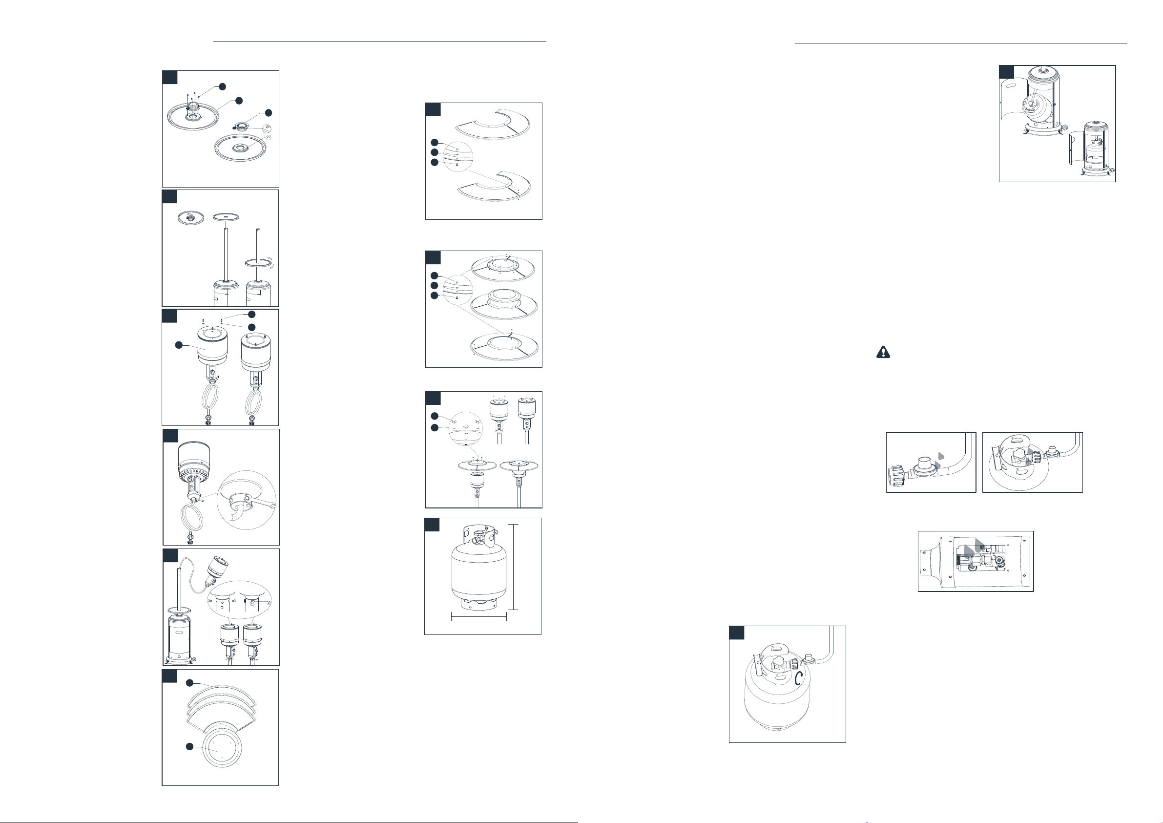
5. Beverage table installation
5-1. Revised the table
(D). Attached the table
connector (E) to the table,
secure them with four M5 X
8 screws (CC).
5-2. Turn the handle of
connector in a clockwise
direction, put the hole in
the middle of the table
through the pole. Turn the
table in a clockwise
direction to tighten and in a
counter-clockwise
direction to loosen.
Note: If table can not be
tightened, turn the handle
of connector in a counter-
clockwise direction a little,
then turn the table in a
clockwise direction to
tighen.
6. Attach reflector stud (FF)
and three washers Ø8 (GG)
to screen cover. Tighten the
reflector studs.
7. Attach head assembly to
post.
7-1. Unscrew four stainless
steel bolts (LL).
7-2. Load head assembly
by inserting hose into post.
Insert head assembly into
post. Control knob should
be above decal on post.
Attach head assembly to
post, and loosely install
four stainless steel bolts.
Tighten bolts securely.
8. WARNING: Remove
protective cover before
assembling.
Note: If necessary for
proper alignment of
reflector sections, loosen
each bolt prior to further
assembly and retighten
after sections are aligned.
Note: If table cannot be
tightened, turn the handle
of connector in a counter-clockwise direction a little,
then turn the table in a clockwise direction to tighen.
9. Reflector plate assembly:
9-1. Slide two reflector
panels together.
Insert one screw M6 X 10
(II). Slide one washer Ø6
(HH) over threaded end
of screw M6 X 10 (II) and
screw on cap nut (JJ)
loosely.
9-2. Slide reflector plate
onto reflector panels.
Insert one screw M6 X 10
(II). Slide one washer Ø6
over threaded end of
screw M6 X 10 (II) and
screw on cap nut (JJ)
loosely. Repeat
procedure to complete
the assembly of all four
sections. Fully tighten all
of the screws in the
rolled edge.
10. Support heater. Slide
three washers washer
Ø8 (GG) over threaded
end of spacer. Locate
reflector assembly on 3
studs. Install three
washers Ø8 on studs
and securely tighten
wing nuts (KK) but do
not overtighten.
11. Connect hose and
regulator to cylinder. The
propane gas and cylinder
are sold separately.
Every part of the heater
shall be secure against
displacement and shall be
constructed to maintain a
fixed relationship between
essential parts under
normaland reasonable
conditions of handling
and usage. Parts not permanently secured shall be designed
so they cannot be incorrectly assembled and cannot be
improperly located or misaligned in removing or replacing
during cleaning or other servicing.
Use a standard 20 lb. propane cylinder only (approximately
12.2 in. / 31cm. in diameter and 17.9 in./ 45.5cm high).
Use this heater only with a propane vapor withdrawal supply
system. See chapter 5 of the standard for storage and
handling of liquefied petroleum gas, ANS/NFPA 58. Your local
library or fire department should have this book. Storage
of an appliance indoors is permissible only if the cylinder
5-1
D
E
CC
5-2
Tighten
Loosen
6
C
FF
GG
7-1
7-2
8
B
A
9-1
TT
JJ
HH
II
JJ
HH
II
9-2
TT
10
KK
GG
11
Standard 20 lb. tank
17.9in. / 45.5cm
12.2in. / 31cm
INSTALLATION INSTRUCTIONS
is disconnected and removed from the appliance. A
cylinder must be stored outdoors in a well-ventilated
area out of the reach of children. A disconnected cylinder
must have dust caps tightly installed and must not
be stored in a building, garage or any other enclosed
area. The maximum inlet gas supply pressure: 250 psi
/1750 kPa. The minimum inlet gas supply pressure:
25psi/175kPa. Manifold pressure with regulator provided:
11 inch W.C/ 2.74 kPa. The pressure regulator and hose
assembly supplied with the appliance must be used.
The installation must conform with local codes, or in
the absence of local codes, with national fuel gas code,
ANS Z223.1/NFPA54, natural gas and propane Installation
Code, CSA B149.1, or propane storage and handling code,
B149.2.
The knob on the LP tank must be closed. Make sure that
the knob is turned clockwise to a full stop. The cylinder
supply system must be arranged for vapor withdrawal.
Check that the control knob on the control unit is turned
off. Hold the regulator in one hand and insert the nipple
into the valve outlet. Be sure the nipple is centered in
the valve outlet. The coupling nut connects to the large
outside threads on the valve outlet. Hand-tighten the
coupling nut clockwise until it comes to a full stop.
Firmly tighten by hand only.
To Disconnect: Fully close the tank valve by turning
clockwise. Turn the coupling nut counterclockwise until
the regulator assembly detaches.
A dented, rusted or damaged propane cylinder may
be hazardous and should be checked by your cylinder
supplier. Never use a propane cylinder with a damaged
valve connection.
The propane cylinder must be constructed and
marked in accordance with the specifications for LP
gas cylinders of the U.S. Department of Transportation
(DOT) or the standard for cylinders, spheres and tubes
for transportation of dangerous goods and commission,
CAN/CSA-B339.
The cylinder must have a listed overfilling prevention
device.
The cylinder must have a connection device compatible
with the connection for the appliance.
The cylinder used must include a collar to protect the
cylinder valve.
Never connect an unregulated propane cylinder to the
heater.
12. Screw regulator
onto gas hose. Do
not cross-thread.
Tighten securely. Attach
regulator to cylinder.
Complete attachment.
13. Install cylinder.
WARNING:
• Do not store a spare LP-gas cylinder under or
near this appliance;
• Never fill the cylinder beyond 80 percent full;
• Place the dust cap on the cylinder valve outlet
whenever the cylinder is not in use. Only install
the type of dust cap on the cylinder valve that is
provided with the cylinder valve. Other type of
caps or plugs may result in leakage of propane.
LEAK CHECK
WARNING:
• Perform all leak tests outdoors.
• Extinguish all open flames.
• NEVER leak test when smoking.
• Do not use the heater until all connections have
been leak tested and do not leak.
Regulator / Cylinder
connection
Hose / Regulator
connection
1. Make 2-3 oz. of leak check solution (one part liquid
dishwashing detergent and three parts water).
2. Apply several drops of solution where hose
attaches to regulator.
3. Apply several drops of solution where regulator
connects to cylinder.
4. Make sure all patio heater and light valves are OFF.
5. Turn cylinder valve ON.
If bubbles appear at any connection, there is a leak.
1. Turn cylinder valve OFF.
2. If leak is at hose/regulator connection: tighten
connection and perform another leak test. If bubbles
continue appearing, the hose should be returned to
the place of purchase.
12
13
INSTALLATION INSTRUCTIONS
Loading ...
Loading ...
Loading ...