2019 FIAT
®
500X USER GUIDE
19FD-926-AA
First Edition
©2018 FCA US LLC. All Rights Reserved.
FIAT is a registered trademark of FCA Group Marketing S.p.A., used under license by FCA US LLC.
App Store is a registered trademark of Apple Inc. Google Play Store is a registered trademark of Google.
Whether it’s providing information about specifi c product features, taking a tour through your vehicle’s
heritage, knowing what steps to take following an accident or scheduling your next appointment, we know
you’ll fi nd the app an important extension of your FIAT
®
brand vehicle. Simply download the app, select
your make and model and enjoy the ride. To get this app, go directly to the App Store
®
or
Google Play
®
Store and enter the search keyword “FIAT” (U.S. residents only).
www.fi atusa.com/en/owners (U.S.) provides special offers tailored to your needs, customized vehicle
galleries, personalized service records and more. To get this information, just create an account and check
back often.
Get warranty and other information online – you can review and print or download a copy of the Owner’s
Manual, Navigation/Uconnect manuals and the limited warranties provided by FCA US LLC for your vehicle
by visiting www.mopar.com (U.S.) or www.owners.mopar.ca (Canada). Click on the applicable link
in the “Popular Topics” area of the www.mopar.com (U.S.) or www.owners.mopar.ca (Canada)
home page and follow the instructions to select the applicable year, make and model of your vehicle.
Download a FREE electronic copy
of the most up-to-date Owner’s Manual, media and warranty booklet by visiting:
www.mopar.com/en-us/care/owners-manual.html (U.S. residents) or
www.owners.mopar.ca (Canadian residents)
fi atusa.com (U.S.) or fi atcanada.com/en (Canada)

The driver’s primary responsibility is the safe operation of the vehicle. Driving while distracted can result in loss of vehicle
control, resulting in a collision and personal injury. FCA US LLC strongly recommends that the driver use extreme caution
when using any device or feature that may take their attention off the road. Use of any electrical devices, such as cellular
telephones, computers, portable radios, vehicle navigation or other devices, by the driver while the vehicle is moving is
dangerous and could lead to a serious collision. Texting while driving is also dangerous and should never be done while the
vehicle is moving. If you fi nd yourself unable to devote your full attention to vehicle operation, pull off the road to a safe location
and stop your vehicle. Some states or provinces prohibit the use of cellular telephones or texting while driving. It is always the
driver’s responsibility to comply with all local laws.
IMPORTANT:
Get warranty and other information online – you can review and print or download a copy of the Owner’s
Manual, Navigation/Uconnect manuals and the limited warranties provided by FCA US LLC for your vehicle by visiting
www.mopar.com
(U.S.) or
www.owners.mopar.ca
(Canada). Click on the applicable link in the “Popular Topics” area
of the
www.mopar.com
(U.S.) or
www.owners.mopar.ca
(Canada) home page and follow the instructions to select
the applicable year, make and model of your vehicle.
This guide has been prepared to help you get quickly acquainted with your new FIAT
®
brand vehicle and to provide
a convenient reference source for common questions. However, it is not a substitute for your Owner’s Manual.
For complete operational instructions, maintenance procedures and important safety messages, please consult your
Owner’s Manual, Navigation/Uconnect manuals found on the website on the back cover and other Warning Labels in
your vehicle.
Not all features shown in this guide may apply to your vehicle. For additional information on accessories to help
personalize your vehicle, visit www.mopar.com (U.S.), www.mopar.ca (Canada) or your local FIAT
®
brand dealer.
If you are the fi rst registered retail owner of your vehicle, you may obtain a complimentary printed copy of the
Warranty Booklet by calling 1-888-242-6342 (U.S.) or 1-800-387-1143 (Canada) or by contacting your dealer.
Driving after drinking can lead to a collision. Your perceptions are less sharp, your refl exes are slower and your
judgment is impaired when you have been drinking. Never drink and then drive.
WARNING
DRIVING AND ALCOHOL: Drunk driving is one of the most frequent causes of collisions. Your driving
ability can be seriously impaired with blood alcohol levels far below the legal minimum. If you are drinking,
don’t drive. Ride with a designated non-drinking driver, call a cab, a friend or use public transportation.
WARNING: Operating, servicing and maintaining a passenger vehicle or off-road
highway motor can expose you to chemicals including engine exhaust, carbon monoxide,
phthalates, and lead, which are known to the State of California to cause cancer and birth
defects or other reproductive harm. To minimize exposure, avoid breathing exhaust, do
not idle the engine except as necessary, service your vehicle in a well-ventilated area and
wear gloves or wash your hands frequently when servicing your vehicle. For more
information go to: www.p65Warnings.ca.gov/passenger-vehicle.

Congratulations on selecting your new FCA US
LLC vehicle. Be assured that it represents precision
workmanship, distinctive styling, and high quality.
ALWAYS drive safely and pay attention to the
road.ALWAYS drive safely with your hands on the
steering wheel. You have full responsibility and
assume all risks related to the use of the fea tures
and applications in this vehicle. Only use the
features and applications when it is safe to do so.
Failure to do so may result in an accident involving
serious injury or death.
This guide illustrates and describes the operation
of features and equipment that are either stan-
dard or optional on this vehicle. This guide may
also include a description of features and equip-
ment that are no longer available or were not
ordered on this vehicle. Please disregard any
features and equipment described in this guide
that are not available on this vehicle. FCAUSLLC
reserves the right to make changes in design and
specifications and/or make additions to or im-
provements to its products without imposing any
obligation upon itself to install them on products
previously manufactured.
This User Guide has been prepared to help you
quickly become acquainted with the important
features of your vehicle. It contains most things
you will need to operate and maintain the vehicle,
including emergency information.
When it comes to service, remember that your
authorized dealer knows your vehicle best, has
fac tory-trained technicians and genuine MOPAR®
parts, and cares about your satisfaction.
HOW TO FIND YOUR
OWNER’S MANUAL ONLINE
This publication has been prepared as a reference
item to help you quickly become acquainted with
the most important features and processes of
your vehicle. It cont ains most things you will need
to operate and maintain the vehicle, including
emergency information and procedures.
This User Guide is not a replacement for the
full Owner’s Manual, and does not fully cover
every operation and procedure possible with
your vehicle.
For more detailed descriptions of the topics dis-
cussed in this User Guide, as well as information
covering features and processes not covered in this
User Guide, the full vehicle Owner’s Manual can be
accessed for free online in a printer-friendly PDF
format.
To get the full Owner’s Manual or applicable
supplement for your vehicle, follow the appro-
priate web address below:
www.mopar.com/en-us/care/owners-manual.html
(U.S. Residents)
www.owners.mopar.ca (Canadian Residents)
FCA US LLC is committed to protecting our
environment and natural resources. By converting
from paper to electronic delivery for the majority
of the user information for your vehicle, together
we greatly reduce the demand for tree-based
products and lessen the stress on our environment.
WELCOME FROM FCA US LLC
1
HOW TO USE THIS MANUAL
Essential Information
Each time direc tion instructions (left/right or
forwards/backwards) about the vehicle are given,
these must be intended as regarding an occupant in
the driver's seat. Special cases not complying with
this rule will be properly specified in the text.
The figures in this User Guide are provided by
way of example only: this might imply that some
details of the image do not correspond to the
actual arrangement of your vehicle.
In addition, the User Guide has been conceived
considering vehicles with the steering wheel on
the left side; it is therefore possible that in vehicles
with the steering wheel on the right side, the
position or construction of some controls is not
exactly mirror-like with respect to the figure.
To identify the chapter with the information
needed you can consult the index at the end of
this User Guide.
Chapters can be rapidly identified with dedicated
graphic tabs, at the side of each odd page. Afew
pages further there is a key for getting to know
the chapter order and the relevant symbols in the
tabs. There is always a textual indication of the
current chapter at the side of each even page.
Symbols
Some vehicle components have colored labels
whose symbols indicate precautions to be ob-
served when using this component. Refer to
“Warning Lights and Messages” in “Getting To
Know Your Instrument Panel” for further infor-
mation on the symbols used in your vehicle.
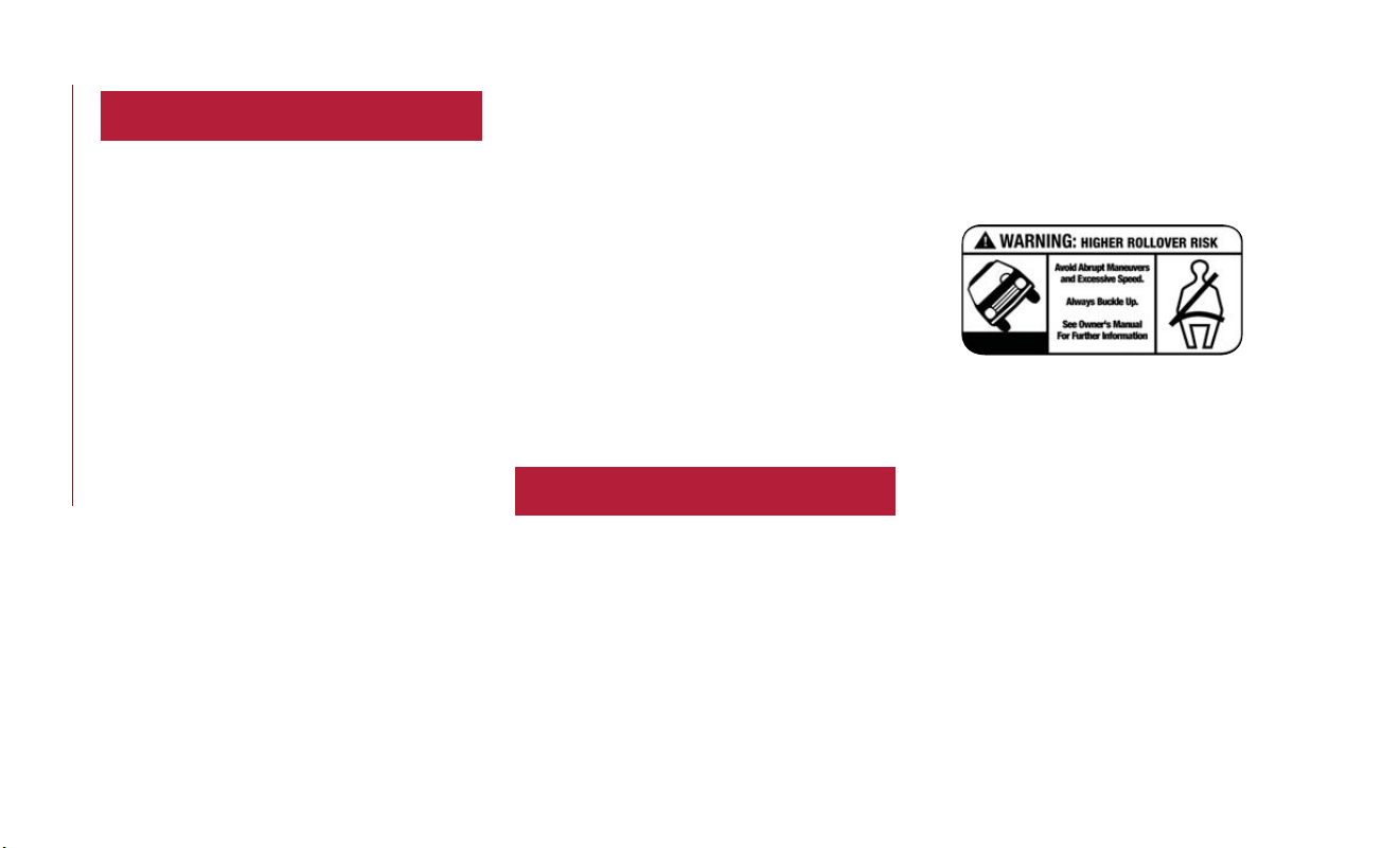
ROLLOVER WARNING
Utility vehicles have a significantly higher rollover
rate than other types of vehicles.This vehicle has
a higher ground clearance and a higher center of
gravity than many passenger vehicles. It is capable
of performing better in a wide variety of off-road
applications. Driven in an unsafe manner, all
vehicles can go out of control. Because of the
higher center of gravity, if this vehicle is out of
control it may roll over while some other vehicles
may not.
Do not attempt sharp turns, abrupt maneuvers,
or other unsafe driving actions that can cause loss
of vehicle control. Failure to operate this vehicle
safely may result in a collision, rollover of the
vehicle, and severe or fatal injury. Drive carefully.
Failure to use the driver and passenger seat belts
provided is a major cause of severe or fatal injury.
In fact, the U.S. government notes that the
universal use of existing seat belts could cut the
highway death toll by 10,000 or more each year
and could reduce disabling injuries by two million
annually. In a rollover crash, an unbelted person is
significantly more likely to die than a person
wearing a seat belt. Always buckle up.
Rollover Warning Label
HOW TO USE THIS MANUAL
2

WARNINGS AND CAUTIONS
While reading this User Guide you will find a
series of WARNINGS to be followed to prevent
incorrect use of components which could cause
accidents or injuries.
There are also CAUTIONS that must be followed
to prevent against procedures that could result in
damage to your vehicle.
HOW TO USE THIS MANUAL
3

4


WELCOME FROM FCA US LLC
HOW TO FIND YOUR OWNER’S MANUAL
ONLINE ..........................1
HOW TO USE THIS MANUAL
HOW TO USE THIS MANUAL .............2
Essential Information ..................2
Symbols .........................2
ROLLOVER WARNING .................2
WARNINGS AND CAUTIONS .............3
GRAPHICAL TABLE OF CONTENTS
INSTRUMENT PANEL ..................9
INTERIOR ........................10
GETTING TO KNOW YOUR VEHICLE
KEYS ...........................11
Key Fob With Remote Control ...........11
IGNITIONSWITCH ..................13
Models Wit h Keyless Enter-N-Go — Passive
Entry .........................13
REMOTE STARTING SYSTEM — IF EQUIPPED . . . 14
How To Use Remote Start .............14
To Enter Remote Start Mode ............14
General Information .................15
VEHICLE SECURITY ALARM — IF EQUIPPED . . . 15
To Arm The System .................15
To Disarm The System ...............15
Disabling .......................16
DOORS .........................16
Keyless Enter-N-Go .................16
Child Locks ......................20
SEATS ..........................21
Manual Adjustment (Rear Seats) .......... 21
Heated Seats — If Equipped ............23
HEAD RESTRAINTS ..................23
Front Adjustment ................... 24
Rear Adjustment ...................24
Front Removal .................... 24
Rear Removal .....................25
STEERING WHEEL ...................25
Tilt/Telescoping Steering Column ..........25
Heated Steering Wheel — If Equipped ....... 26
EXTERIOR LIGHTS ..................26
Headlights .......................26
Daytime Running Lights (DRL) — If Equipped ... 27
High Beams ......................27
Automatic Lighting — If Equipped .........28
Parking Lights .....................28
Headlight Delay ...................28
Front Fog Lights — If Equipped ...........28
Turn Signals ......................29
Courtesy Lights/Approaching Lights ......... 29
WIPERS AND WASHERS ...............29
Front Wiper Operation ............... 29
Rain Sensor — If Equipped ............. 30
Rear Window Wiper/Washer ............ 31
CLIMATE CONTROLS .................33
Automatic Climate Control Overview ....... 33
Climate Control Functions .............. 39
Automatic Temperature Control (ATC) ......40
Operating Tips .................... 40
WINDOWS .......................41
Driver's Door Controls ............... 41
HOOD .........................43
Opening ........................ 43
Closing ........................ 44
LIFTGATE ........................44
Opening ........................ 44
Closing ........................ 44
INTERNAL EQUIPMENT ................44
Power Outlets ....................44
Cigar Lighter — If Equipped ............ 45
GETTING TO KNOW YOUR
INSTRUMENT PANEL
INSTRUMENT CLUSTER DISPLAY ..........46
Instrument Cluster Display Control Buttons .... 46
Engine Oil Change Reset .............. 47
Instrument Cluster Display Main Menu .......47
WARNING LIGHTS AND MESSAGES ........47
Red Warning Lights .................. 48
Yellow Warning Lights ................50
Yellow Indicator Lights ................ 54
Green Indicator Lights ................ 55
White Indicator Lights ................ 56
Blue Indicator Lights .................56
Gray Indicator Lights .................56
ONBOARD DIAGNOSTIC SYSTEM — OBD II . . . 56
Onboard Diagnostic System (OBD II)
Cybersecurity ..................... 57
SAFETY
AUXILIARY DRIVING SYSTEMS ............58
Blind Spot Monitoring (BSM) — If Equipped ...58
Full Brake Control System With Mitigation ....61
Tire Pressure Monitor System (TPMS) ....... 64
OCCUPANT RESTRAINT SYSTEMS .........67
Occupant Restraint Systems .............67
Important Safety Precautions ............67
Seat Belt Systems ...................68
Supplemental Restraint Systems (SRS) ....... 74
TABLE OF CONTENTS
6

Child Restraints .................... 85
Transporting Pets .................. 96
SAFETY TIPS ......................96
Transporting Passengers ............... 96
Exhaust Gas .....................96
Safety Checks You Should Make Inside The
Vehicle ........................97
Periodic Safety Checks You Should Make Outside
The Vehicle ......................99
STARTING AND OPERATING
STARTING THE ENGINE ...............100
Stopping The Engine ................100
ENGINE BREAK-IN RECOMMENDATIONS ....100
ELECTRIC PARK BRAKE (EPB) ............101
DYNAMIC SELECTOR — IF EQUIPPED ......103
Warning Messages ................. 103
STOP/START SYSTEM .................103
Automatic Mode .................. 103
Possible Reasons The Engine Does Not
Autostop .......................104
To Start The Engine While In Autostop Mode ..105
To Manually Turn Off The Stop/Start System ..105
To Manually Turn On The Stop/Start System ... 106
SPEED CONTROL ...................106
To Activate ..................... 106
To Set A Desired Speed ..............106
To Resume Speed .................107
Deactivation ..................... 107
ADAPTIVE CRUISE CONTROL (ACC) —
IF EQUIPPED ......................107
To Activate/Deactivate ...............107
Activating Adaptive Cruise Control (ACC) ....108
To Set A Desired ACC Speed ...........108
To Resume ..................... 108
To Vary The Speed Setting ............. 109
Setting The Following Distance In ACC ...... 110
General Information ................ 110
REAR PARK ASSIST — IF EQUIPPED ........111
Park Assist Sensors .................111
Enabling And Disabling Park Assist .........112
Service The Rear Park Assist System ........112
Park Assist System Usage Precautions ....... 112
FRONT AND REAR PARK ASSIST —
IF EQUIPPED ......................114
Park Assist Sensors .................114
Enabling And Disabling Park Assist .........114
LANESENSE — IF EQUIPPED ............115
LaneSense Operation ................ 115
Turning LaneSense On Or Off .......... 115
LaneSense Warning Message ............116
Changing LaneSense Status ............. 116
PARKVIEW REAR BACK UP CAMERA .......117
ADDING FUEL ....................118
Materials Added To Fuel ..............119
TRAILER TOWING ..................120
Trailer Towing Weights
(Maximum Trailer Weight Ratings) ........ 120
RECREATIONAL TOWING
(BEHIND MOTORHOME, ETC.) ..........120
Towing This Vehicle Behind Another Vehicle ... 120
IN CASE OF EMERGENCY
HAZARD WARNING FLASHERS ..........122
BULB REPLACEMENT .................122
Replacement Bulbs .................122
FUSES ..........................123
Engine Compartment Fuses/Distribution Unit ..123
Body Computer Fuse Center ........... 125
Rear Cargo Fuse/Relay Distribution Unit .....126
JACKING AND TIRE CHANGING .........126
J
ack Location/Spare Tire Stowage — If Equipped
..127
Preparations For Jacking .............. 128
Jacking Instructions ................. 129
Road Tire Installation ................132
TIRE SERVICE KIT — IF EQUIPPED .........133
Tire Service Kit Storage .............. 133
Tire Service Kit Components And Operation ... 133
Tire Service Kit Usage Precautions ........134
Replacing The Sealant ................135
JUMPSTARTING ....................135
Preparations For Jump Start ............136
Jump Starting Procedure .............. 136
IF YOUR ENGINE OVERHEATS ...........137
GEAR SELECTOR OVERRIDE ............138
FREEING A STUCK VEHICLE ............139
TOWING A DISABLED VEHICLE ..........140
All Wheel Drive (AWD) Models ......... 141
Tow Eye Usage — If Equipped ..........141
ENHANCED ACCIDENT RESPONSE SYSTEM
(EARS) ..........................143
EVENT DATA RECORDER (EDR) ..........143
SERVICING AND MAINTENANCE
SCHEDULED MAINTENANCE ...........144
Maintenance Plan ..................144
Heavy Duty Use Of The Vehicle ..........147
ENGINE COMPARTMENT ..............148
1.3L Turbo Engine ................. 148
7

RAISING THE VEHICLE ................149
TIRES ..........................149
Tire Safety Information .............. 149
Tires — General Information ........... 156
Tire Types ...................... 160
Spare Tires — If Equipped ............ 161
Wheel And Wheel Trim Care ...........163
DEPARTMENT OF TRANSPORTATION UNIFORM
TIRE QUALITY GRADES ...............164
Treadwear ......................164
Traction Grades ...................165
Temperature Grades ................165
TECHNICAL SPECIFICATIONS
WHEEL AND TIRE TORQUE SPECIFICATIONS . 166
Torque Specifications ................166
FLUID CAPACITIES ..................167
FLUIDS AND LUBRICANTS .............167
Engine ........................167
Chassis ........................ 168
MOPAR ACCESSORIES ................168
Authentic Accessories By Mopar .......... 168
MULTIMEDIA
CYBERSECURITY ...................170
UCONNECT 4/4 NAV WITH 7-INCH DISPLAY
...171
Uconnect 4/4 NAV At A Glance ......... 171
Drag & Drop Menu Bar ..............172
Radio ........................ 172
Media Hub — USB/Audio Jack (AUX) —
If Equipped ..................... 173
Uconnect 4 NAV Navigation ........... 175
Android Auto — If Equipped ........... 176
Apple CarPlay Integration — If Equipped ....177
UCONNECT SETTINGS ...............178
STEERING WHEEL AUDIO CONTROLS ......179
Left Switch .....................179
Right Switch .....................179
UCONNECT PHONE ................180
Uconnect Phone (Bluetooth Hands Free Calling ) . 180
Pairing (Wirelessly Connecting) Your Mobile Phone
To The Uconnect System
..............181
Common Phone Commands (Examples) ....184
Mute (Or Unmute) Microphone During Call ..184
Transfer Ongoing Call Between Handset And
Vehicle .......................184
Phonebook ..................... 184
Call Browsing — If Equipped ...........184
Browsing Favorites — If Equipped ......... 184
Voice Command Tips ...............184
Changing The Volume ................ 185
Using Do Not Disturb ...............185
Incoming Text Messages .............. 185
Browsing Text Messages .............. 186
UCONNECT VOICE RECOGNITION QUICK
TIPS ...........................187
Introducing Uconnect ................187
Get Started ..................... 187
Basic Voice Commands ............... 188
Radio .........................188
Media ........................188
Phone ........................ 189
Navigation (4 NAV) — If Equipped ........189
Siri Eyes Free — If Equipped ........... 190
Using Do Not Disturb ...............190
Android Auto — If Equipped ........... 190
Apple CarPlay — If Equipped ...........191
General Information ................ 192
Additional Information ............... 192
CUSTOMER ASSISTANCE
IF YOU NEED ASSISTANCE .............193
FCA US LLC Customer Center ..........193
FCA Canada Inc. Customer Center ........193
In Mexico Contact .................193
Puerto Rico And U.S. Virgin Islands ........193
Customer Assis tance For The Hearing Or Speech
Impaired (TDD/TTY) ................ 194
Service Contract .................. 194
REPORTING SAFETY DEFECTS ...........195
In The 50 United States And Washington, D.C...195
In Canada ......................195
PUBLICATION ORDER FORMS ...........195
INDEX
........................197
TABLE OF CONTENTS
8

INSTRUMENT PANEL
Instrument Panel
1 — Headlight Switch 6 — Windshield Wiper Lever
2 — Multifunction Lever 7 — Uconnect System
3 — Instrument Cluster Display Controls 8 — Switch Panel
4 — Instrument Cluster 9 — Climate Controls
5 — Speed Controls 10 — Front USB Port And AUX Jack
9
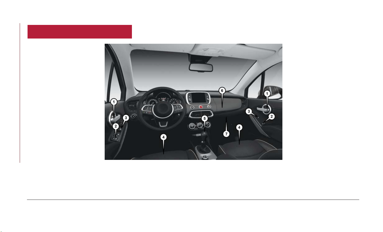
INTERIOR
Interior Features
1 — Door Handles 5 — Gear Selector
2 — Door Locks 6 — Upper Glove Compartment
3 — Window Switches 7 — Lower Glove Compartment
4 — Seats
GRAPHICAL TABLE OF CONTENTS
10

KEYS
Key Fob With Remote Control
The key fob with Remote Control contains a
Remote Keyless Entry feature. The Remote Key-
less Entry system allows you to lock or unlock the
doors and liftgate or activate the Panic Alarm
from distances up to approximately 66 ft (20 m)
using a handheld key fob. The key fob does not
need to be pointed at the vehicle to activa te the
system.
Key Fobs In case the ignition switch does not change with
the push of a button, the key fob may have a low
or fully depleted battery. A low key fob battery
can be verified by referring to the instrument
cluster, which will display directions to follow.
To Unlock The Doors And Liftgate
P
ush and release the unlock button on the key fob
once to unlock the driver's door or twice within
five seconds to unlock all doors and the liftgate.
All
doors can be programmed to unlock on the
first push of the unlock button. Refer to “Uconnect
Settings” in “Multimedia” in the Owner’s Manual for
further information.
NOTE:
If
the vehicle is unlocked by a key fob, and no door
is opened within 60 seconds, the vehicle will re-lock
and if equipped, the security alarm will arm.
Keyless Ignition Key Fob
1 — Unlock
2 — Lock
3 — Remote Start
4 — Panic
5 — Emergency Key
11

To Lock The Doors And Liftgate
Push and release the lock button on the key fob
to lock all doors and liftgate.
The turn signal lights will flash and the horn will
chirp to acknowledge the signal. Ref er to
“Uconnect Settings” located in “Multimedia” for
further programmable information.
If the vehicle is equipped wit h Passive Entry, refer
to “Keyless Enter-N-Go — Passive Entry” located
in “Doors” in “Getting To Know Your Vehicle” for
further information.
Vehicles Equipped With Keyless Enter-N-Go —
Passive Entry
If one or more doors are open, or the liftgate is
open, the doors will lock. The doors will unlock
again automatically if the key is left inside the
passenger compartment, otherwise the doors will
stay locked.
Request For Additional Key Fobs
NOTE:
Only key fobs that are programmed to the vehicle
electronics can be used to start and operate the
vehicle. Once a key fob is programmed to a vehicle,
it cannot be programmed to any other vehicle.
WARNING!
• Always remove the key fobs from the
vehicle and lock all doors when leaving the
vehicle unattended.
• Always remember to place the ignition in
the OFF mode.
Duplication of key fobs may be performed at an
authorized dealer. This procedure consists of
programming a blank key fob to t he vehicle
electronics. A blank key fob is one that has never
been programmed.
NOTE:
• When having the Sentry Key Immobilizer Sys-
tem serviced, bring all vehicle keys with you to
an authorized dealer.
• Keys must be ordered to the correct key cut to
match the vehicle locks.
General Information
The following regulatory statement applies to all
radio frequency (RF) devices equipped in this
vehicle:
This device complies with Part 15 of the FCC
Rules and with Industry Canada license-exempt
RSS standard(s). Operation is subject to the
following two conditions:
1. This device may not cause harmful interfer-
ence, and
2. This device must accept any interference
received, including interference that may cause
undesired operation.
NOTE:
Changes or modifications not expressly approved
by the party responsible for compliance could
void the user’s authority to operate the equip-
ment.
GETTING TO KNOW YOUR VEHICLE
12

IGNITION SWITCH
Models With Keyless Enter-N-Go — Passive
Entr y
This fea ture allows the driver to operate the
ignition switch with the push of a button as long
as the key fob is in t he passenger compartment.
The push button ignition has three operating
positions. The three positions are OFF, ON, and
RUN.
NOTE:
If the ignition switch does not change with the
push of a button, the key fob may have a low or
dead battery. In this situation, a back up method
can be used to operate the ignition switch. Put
the nose side (side opposite of the emergency
key) of the key fob ag ainst the ENGINE START/
STOP button and push to operate the ignition
switch.
NOTE:
The vehicle will not st art if the key fob is located
inside the cargo area and the liftgate is opened.
WARNING!
• When leaving the vehicle, always remove the
key fob from the vehicle and lock your
vehicle.
• Never leave children alone in a vehicle, or
with access to an unlocked vehicle.
WARNING!
• Allowing children to be in a vehicle unat-
tended is dangerous for a number of rea-
sons. A child or others could be seriously or
fatally injured. Children should be warned
not to touch the parking brake, brake pedal
or the gear selector.
•
Do not leave the key fob in or near the
vehicle, or in a location accessible to children,
and do not leave the ignition in the ON or
RUN mode. A child could operate power
windows, other controls, or move the vehicle.
• Do not leave children or animals inside
parked vehicles in hot weather. Interior heat
build-up may cause serious injury or death.
CAUTION!
An unlocked vehicle is an invitation for thieves.
Always remove key fob from the vehicle and
lock all doors when leaving the vehicle una t-
tended.
NOTE:
F
or further information, refer to "Starting The
Engine," in "Starting And Operating" in the Owner’s
Manual.
Engine Start/Stop Button
13

REMOTE STARTING SYSTEM —
IF EQUIPPED
Push the remote start button on the key fob
twice within five seconds. Pushing the remote
start button a third time shuts the engine off.
To drive the vehicle, push the START/STOP button
to turn the ignition to the ON/RUN mode.
NOTE:
• With remote start, the engine will only run for
15 minutes (timeout) unless the ignition is
placed in the ON/RUN mode.
• The vehicle must be started with the key after
two consecutive timeouts.
How To Use Remote St art
• Push Remote Star t button on the key fob twice
within five seconds. Pushing the Remote Start
button a third time shuts the engine off.
• To drive the vehicle, push unlock button, and
place the ignition in the ON/RUN position.
• With remote start, the engine will only run for
15 minutes (timeout) unless the ignition key is
placed in the ON/RUN position.
• The vehicle must be started with the key after
two consecutive timeouts.
All of the following conditions must be met before
the engine will remote start:
• Gear Selector in PARK
• Doors closed
• Hood closed
• Liftgate closed
• Hazard switch off
• Brake switch inac tive (brake pedal not pushed)
• Battery at an acceptable charge level
• PANIC button not pushed
• System not disabled from previous remote start
event
• Vehicle alarm system indicator flashing
• Ignition in STOP/OFF position
• Fuel level meets minimum requirement
WARNING!
• Do not start or run an engine in a closed
garage or confined area. Exhaust gas con-
tains Carbon Monoxide (CO) which is
odorless and colorless. Carbon Monoxide
is poisonous and can cause serious injury
or death when inhaled.
• Keep key fobs away from children. Opera-
tion of the Remote Star t System, windows,
door locks or other controls could cause
serious injury or death.
To Enter Remote Start Mode
Push and release the Remote Start button on the
key fob twice within five seconds. The vehicle
doors will lock, the turn signals will flash twice, and
the horn will chirp twice. Then the engine will
start, and the vehicle will remain in the Remote
Start mode for a 15-minute cycle.
NOTE:
• If an engine fault is present or fuel level is low,
the vehicle will start and then shut down in
10 seconds.
GETTING TO KNOW YOUR VEHICLE
14

• The park lamps will turn on and remain on
during Remote Start mode.
•
For security, power window operation is disabled
when the vehicle is in the Remote Start mode.
• The engine can be started two consecutive
times (two 15-minute cycles) with the key fob.
However, the ignition must be placed in the
ON/RUN position before you can repeat the
start sequence for a third cycle.
General Information
T
he following regulatory statement applies to all radio
frequency (RF) devices equipped in this vehicle:
This device complies with Part 15 of the FCC
Rules and with Industry Canada license-exempt
RSS standard(s). Operation is subject to the
following two conditions:
1.
This device may not cause harmful interference,
and
2. This device must accept any interference re-
ceived, including interference that may cause
undesired operation.
NOTE:
Changes or modifications not expressly approved
by the party responsible for compliance could void
the user’s authority to operate the equipment.
VEHICLE SECURITY ALARM —
IF EQUIPPED
The vehicle security alarm monitors the vehicle
doors, hood, lif tgate, and the Keyless Enter-N-Go
— Ignition for unauthorized operation.While the
vehicle security alarm is armed, interior switches
for door locks and lif tgate release are disabled.
If something triggers the alarm, the vehicle secu-
rity alarm will provide the following audible and
visible signals:
• The horn will pulse.
• The turn signals will flash.
• The vehicle security light in the instrument
cluster will flash.
To Arm The System
Follow these steps to arm the vehicle security
alarm:
1. Make sure the vehicle’s ignition is placed in the
“OFF” mode.
2. Perform one of the following methods to lock
the vehicle:
• Push the lock button on the interior power
door lock switch with the driver and/or
passenger door open.
• Push the lock button on the exterior
Passive Entry Door Handle with a valid key
fob available in the same exterior zone
(refer to "Doors" in "Getting To Know Your
Vehicle" in your Owner’s Manual for fur-
ther information).
• Push the lock button on the key fob.
3. If any doors are open, close them.
To Disarm The System
The vehicle security alarm can be disarmed using
any of the following methods:
• Push t he unlock button on the key fob.
• Grasp the passive entry door handle to unlock
the door, refer to "Doors" in "Getting To Know
Your Vehicle" in your Owner’s Manual for fur-
ther information.
• Cycle the ignition out of the off mode to disarm
the system.
15

NOTE:
• The driver's door key cylinder and the liftgate
button on the key fob cannot arm or disarm the
vehicle security alarm.
• The vehicle security alarm remains armed dur-
ing liftgate entry. If someone enters the vehicle
through the liftgate and opens any door, the
alarm will sound.
• When the vehicle security alarm is armed, the
interior power door lock switches will not
unlock the doors.
The vehicle security alarm is designed to protect
your vehicle. However, you can create conditions
where the system will give you a false alarm. If
one of the previously described arming se-
quences has occurred, the vehicle security alarm
will arm, regardless of whether you are in the
vehicle or not. If you remain in the vehicle and
open a door, the alarm will sound. If this occurs,
disarm the vehicle security alarm.
If the vehicle security alarm is armed and the
battery becomes disconnected, the vehicle secu-
rity alarm will remain armed when the battery is
reconnected; the exterior lights will flash, and the
horn will sound. If this occurs, disarm the vehicle
security alarm.
Disabling
To completely disable the alarm (e.g. in the case
of long inactivity of the car), lock the doors by
turning the vehicle key in the exterior door lock
cylinder.
NOTE:
If
the batteries in the key fob discharge in the event
of a failure to the system or to switch off the alarm,
place the ignition in the ON/RUN position.
DOORS
Keyless Enter-N-Go
The Passive Entry system is an enhancement to
the vehicle’s Remote Keyless Entry system and a
feature of Keyless Enter-N-Go.This feature allows
you to lock and unlock t he vehicle’s door(s)
without having to push the key fob lock or unlock
buttons.
NOTE:
• Passive Entry can be enabled or disabled. Refer
to “Uconnect Settings” in “Multimedia” for
further information.
• If wearing gloves on your hands, or if it has been
raining/snowing on the Passive Entry door
handle, the unlock sensitivity can be affected,
resulting in a slower response time.
• If the vehicle is unlocked by the Passive Entry
Door Handle, and no door goes ajar within 60
seconds, the vehicle will re-lock and if equipped,
the security alarm will arm.
•
The key fob may not be detected by the vehicle
passive entry system if it is located next to a
mobile phone, laptop, or other electronic device;
these devices may interfere with the key fob’s
wireless signal and prevent the passive entry
system from locking/unlocking the vehicle.
GETTING TO KNOW YOUR VEHICLE
16

To Unlock From The Driver's Side
With a valid Passive Entry key fob within 5 ft
(1.5 m) of the driver's door handle, grab the front
driver door handle to unlock the driver's door
automatically.
NOTE:
If “Unlock All Doors 1st Press” is programmed, all
doors will unlock when you grab hold of the front
driver’s door handle. To select between “Unlock
Driver Door 1st Press” and “Unlock All Doors 1st
Press,” refer to “Uconnect Settings” in “Multime-
dia” for further information.
To Unlock From The Passenger Side
With a valid Passive Entry key fob within 5 ft
(1.5 m) of the passenger door handle, grab the
front passenger door handle to unlock all four
doors and the liftgate automatically.
NOTE:
All doors will unlock when the front passenger
door handle is grabbed regardless of the driver’s
door unlock preference setting (“Unlock Driver
Door 1st Press” or “Unlock All Doors 1st Press”).
To Lock The Vehicle’s Doors And Liftgate
With one of the vehicle’s Passive Entry key fob
within 5 ft (1.5 m) of the driver or passenger
front door handles, push the door handle lock
button to lock all four doors.
Do NOT grab t he door handle when pushing the
door handle lock button. This could unlock the
door(s).
Grab The Door Handle To Unlock
Push The Door Handle Button To Lock
17

NOTE:
• After pushing the door handle button, you must
wait two seconds before you can lock or unlock
the doors, using any Passive Entry door handle.
This is to allow you to verify that the vehicle is
locked by pulling the door handle, without the
passive entry system reacting and unlocking.
• The Passive Entry system will not operate if the
key fob batter y is dead.
The vehicle doors can also be locked by using the
lock button located on the vehicle’s interior door
panel.
Preventing Inadvertent Locking Of Passive Entry
Key Fob In Vehicle (FOBIK-Safe)
To minimize the possibility of unintentionally
locking a Passive Entry key fob inside your vehicle,
the Passive Entry system is equipped with an
automatic door unlock feature.
FOBIK-Safe only executes in vehicles with Passive
Entr y. There are three situations that trigger a
FOBIK-Safe search in any Passive Entry vehicle:
• A lock request is made by a valid Passive Entry
key fob while a door is ajar.
• A lock request is made by the Passive Entry
door handle while a door is ajar.
• A lock request is made by the door panel switch
while the door is ajar.
When any of these situations occur, after all ajar
doors are shut, the FOBIK-Safe search will be
executed. If it finds a Passive Entry key fob inside
the car, and it does not find any Passive Entry key
fobs outside the car, then the car will unlock and
alert the customer.
NOTE:
T
he vehicle will only unlock the doors when a valid
Passive Entry key fob is detected inside the vehicle,
and no valid Passive Entry key fob is detected outside
the vehicle. The vehicle will not unlock the doors
when any of the following conditions are met:
• The doors are manually locked using the door
lock knobs.
• There is a valid Passive Entry key fob outside the
vehicle and within 5 ft (1.5 m) of either Passive
Entr y door handle.
Emergency Unlocking Driver Door
If the Remote Keyless Entry key fob battery is low
or dead, t he emergency key can be used to unlock
the driver side door lock cylinder.
To release the emergency key, proceed as follows:
1. Slide the emergency key release button to the
side.
2. Remove the emergency key from the key fob
with remote control housing.
NOTE:
The Emergency Key can be inserted into the door
lock cylinder in either direction.
Do NOT Grab The Handle And Button
When Locking
GETTING TO KNOW YOUR VEHICLE
18

If a key fob is detected inside of the vehicle, and
no other active key fob is detected outside of the
vehicle, the doors will automatically unlock and
the turn signals will flash. This system will remain
active to prevent accidentally leaving the key fob
in the vehicle if Passive Entry is manually disabled.
WARNING!
• Never leave children alone in a vehicle, or
with access to an unlocked vehicle. Allowing
children to be in a vehicle unattended is
dangerous for a number of reasons. A child
or others could be severely injured or killed.
Children should be warned not to touch the
parking brake, brake pedal, or the gear
selector. Do not leave the key fob in or near
the vehicle, or in a location accessible to
children, and do not leave the ignition of a
vehicle equipped with Keyless Enter- N-Go
in the ON/RUN mode. A child could start
the vehicle, operate power windows, other
controls, or move the vehicle.
•
Do not leave children or animals inside parked
vehicles in hot weather. Interior heat build-up
may cause them to be severely injured or
killed.
To Unlock/Enter The Liftgate
The liftgate Passive Entry unlock feature is built
into the electronic liftg ate release. With a valid
Passive Entry key fob within 3 ft (1.0m)ofthe
liftgate, push the Electronic Liftgate release to
open with one fluid motion.
NOTE:
If “Unlock All Doors 1st Press” is programmed in
the instrument cluster display, if equipped, the
liftgate will unlock along with the vehicle doors.
If "Unlock Driver Door 1st Press" is programmed
in
Uconnect, the liftgate will unlock when you push
the electronic lock/unlock button on the liftgate.
For further information, refer to “Uconnect Set-
tings” in “Multimedia.”
To Lock The Liftgate
With a valid Passive Entry key fob within 3 ft
(1.0 m) of the liftgate, push the Passive Entry lock
button located to the right of electronic liftgate
release.
While the vehicle is moving, if the liftgate is closed
properly, it will lock automatically when the vehicle
reaches a speed of 12.5 mph (20 km/h) or over.
This fea ture can be disabled using the instrument
cluster. For further information, refer to “Instru-
ment Cluster Display” in “Getting To Know Your
Instrument Panel” in the Owner’s Manual.
NOTE:
The liftgate Passive Entry lock button will lock all
doors and the liftgate. The liftgate unlock feature
is built into the electronic liftgate release.
Passive Entry Liftgate Release Button
1 — Electronic Liftgate Handle
2 — Passive Entry Lock Button
19

Activation/Deactivation Of Keyless Enter-N-Go
Keyless Enter-N-Go can be activated or deacti-
vated through the instrument cluster display or
through the Uconnect system.
General Information
The following regulatory statement applies to
all radio frequency (RF) devices equipped in t his
vehicle:
This device complies with Part 15 of the FCC
Rules and with Industry Canada license-exempt
RSS standard(s). Operation is subject to the
following two conditions:
1. This device may not cause harmful interfer-
ence, and
2. This device must accept any interference
received, including interference that may cause
undesired operation.
NOTE:
Changes or modifications not expressly approved
by the party responsible for compliance could void
the user’s authority to operate the equipment.
Child Locks
T
o provide a safer environment for small children
riding in the rear seats, the rear doors are equipped
with a Child-Protection Door Lock system.
To use the system, open each rear door, use a flat
blade screwdriver (or ignition key) and rotate the
dial to the lock or unlock position. When the
system on a door is engaged, that door can only
be opened by using the outside door handle even
if the inside door lock is in the unlocked position.
NOTE:
• When the child lock system is engaged, the
door can only be opened by using the outside
door handle even though the inside door lock is
in the unlocked position.
•
After diseng aging the Child-Protection Door
Lock system, always test the door from the inside
to make certain it is in the desired position.
• After engaging the Child-Protection Door Lock
system, always test the door from the inside to
make certain it is in the desired position.
• For emergency exit with the system engaged,
rotate the lock button to the unlocked position,
roll down the window, and open the door with
the outside door handle.
WARNING!
Avoid trapping anyone in a vehicle in a colli-
sion. Remember that the rear doors can only
be opened from the outside when the Child-
Protection locks are engaged.
Example Child-Protection Door Lock
Location
GETTING TO KNOW YOUR VEHICLE
20

SEATS
Seats are a part of the Occupant Restraint System
of the vehicle.
WARNING!
• It is dangerous to ride in a cargo area, inside
or outside of a vehicle. In a collision, people
riding in these areas are more likely to be
seriously injured or killed.
• Do not allow people to ride in any area of
your vehicle that is not equipped with seats
and seat belts. In a collision, people riding in
these areas are more likely to be seriously
injured or killed.
• Be sure everyone in your vehicle is in a seat
and using a seat belt properly.
Manual Adjustment (Rear Seats)
WARNING!
Do not pile luggage or cargo higher than the
top of the seatback. This could impair visibility
or become a dangerous projec tile in a sudden
stop or collision.
Manual Folding Second Row Seat
The manual folding split rear seat increases the
storage of the rear cargo area.
NOTE:
• Prior to folding the rear seat down, it may be
necessary to position the front seat to its
mid-track position. Be sure that the front seats
are fully upright and positioned forward, this will
allow the rear seat to fold down easily.
• You may experience deformation in the seat
cushion from the seat belt buckles if the seats
are left folded for an extended period of time.
This is normal and by simply opening the seats
to the open position, over time the seat cushion
will return to its normal shape.
WARNING!
• It is extremely dangerous to ride in a cargo
area, inside or outside of a vehicle. In a
collision, people riding in t hese areas are
more likely to be seriously injured or killed.
• Do not allow people to ride in any area of
your vehicle that is not equipped with seats
and seat belts.
• Be sure everyone in your vehicle is in a seat
and using a seat belt properly.
Partial Enlargement Of Cargo Area
Enlargement of the left side of the cargo area
allows you to carry a single passenger on the right
side of t he rear seat, while the enlargement of the
right side allows you to carry two passengers.
Proceed as follows:
1. Remove the rear shelf (if equipped).
2. Fully lower the rear seat head restraints.
21

3. Move the safety belts to the outboard side of
the seat and rest them on the seat belt guide.
4. Pull the seatback release lever to fold the left
or right rear seatback completely forward.
Cargo Area Enlargement
Folding both sides of the rear sea t provides
additional storage in the rear cargo area.
Proceed as follows:
1. Remove the rear shelf (if equipped).
2. Fully lower the rear seat head restraints.
3. Move the safety belts to the outboard side of
the seat.
4.
Pull the seatback release lever to fold both sides
of the rear seatbacks completely forward.
Seatback Repositioning
NOTE:
If interference from the cargo area prevents the
seatback from fully locking, you will have difficulty
returning the seat to its proper position.
1. Move the safety belts to the seat belt guides
on the top edge of the seat to ensure the
seatbacks properly latch.
2. Lift the seatbacks,pushing them back until they
lock on both the latches. Verify the red
notches are no longer visible on the release
lever. If the red notches are visible, the seat-
back is not secure.
WARNING!
Be certain that the seatback is securely locked
into position. If the seatback is not securely
locked into position t he seat will not provide
the proper stability for child seats and/or
passengers. An improperly latched seat could
cause serious injury.
Rear Seatback Release Levers
Cargo Area
GETTING TO KNOW YOUR VEHICLE
22

Heated Seats — If Equipped
The heated seat switches are located on the
instrument panel.
You can choose between two heating levels:
• Push the heated seat button
once to turn
the HI setting on.
• Push the heated seat button
a second time
to turn the LO setting on.
• Push the heated seat button
a third time to
turn the heating elements off.
If
the HI-level setting is selected, the system will
automatically switch to LO-level after approximately
145 minutes of continuous operation. At t hat time,
the display will change from HI to LO, indicating the
change. The LO-level setting will turn off automati-
cally after approximately 60 minutes.
NOTE:
The engine must be running for the heated seats
to operate.
Auto On Comfort — If Equipped
If
the external temperature is below 40 °F (4.4°C)
at each star t-up of the vehicle the heated seat
functionality of the driver's seat is turned on to
HI-level.
Refer to “Uconnect Settings” in “Multimedia” in
the Owner’s Manual for further information.
WARNING!
•P
ersons who are unable to feel pain to the
skin because of advanced age, chronic illness,
diabetes, spinal cord injury, medication, alco-
hol use, exhaustion or other physical condi-
tion must exercise care when using the seat
heater. It may cause burns even at low
temperatures, especially if used for long peri-
ods of time.
• Do not place anything on the seat or
seatback that insulates against heat, such as a
blanket or cushion. This may cause the seat
heater to overheat. Sitting in a seat that has
been overheated could cause serious burns
due to the increased surface temperature of
the seat.
HEAD RESTRAINTS
Head restraints are designed to reduce t he risk of
injur y by restricting head movement in the event
of a rear impact. Head restraints should be
adjusted so that the top of the head restraint is
located above the top of your ear.
WARNING!
• All occupants, including the driver, should not
operate a vehicle or sit in a vehicle’s seat
until the head restraints are placed in their
proper positions in order to minimize the
risk of neck injury in the event of a crash.
• Head restraints should never be adjusted
while the vehicle is in motion. Driving a
vehicle with the head restraints improperly
adjusted or removed could cause serious
injur y or death in the event of a collision.
23

Front Adjustment
Y
our vehicle is equipped with driver and passenger
head restraints.
To raise the head restraint, pull upward on the
head restraint. To lower the head restraint, push
the adjustment button, located on the base of the
head restraint, and push downward on the head
restraint.
Rear Adjustment
Your vehicle is equipped with two outboard head
restraints and one center head restraint for its
rear passengers. The rear head restraints can be
raised or lowered.When the center seat is being
occupied, the head restraint should be in t he
raised position. When there are no occupants in
the center seat, the head restraint can be lowered
for maximum visibility for the driver.
To raise the head restraint, pull upward on the
head restraint. To lower the head restraint, push
the adjustment button, located at the base of the
head restraint, and push downward on the head
restraint.
Front Removal
To
remove the head restraint recline the backrest
of the seat to avoid interference with the roof.
Raise the head restraint as far as it can go then push
the release button and adjustment button at the
Front Head Restraint
1 — Release Button
2 — Adjustment Button
Rear Head Restraint
1 — Release Button
2 — Adjustment Button
GETTING TO KNOW YOUR VEHICLE
24
base of each post while pulling the head restraint
up. To reinst all the head restraint, put the head
restraint posts into the holes and push downward.
Then adjust it to the appropriate height.
NOTE:
Do not reposition the head restraint 180 degrees
to the incorrect position in an attempt to gain
additional clearance to the back of t he head.
WARNING!
• A loose head restraint thrown forward in a
collision or hard stop could cause serious
injur y or death to occupants of the vehicle.
Always securely stow removed head re-
straints in a location outside the occupant
compartment.
• ALL the head restraints MUST be reinstalled
in the vehicle to properly protect the occu-
pants. Follow the re-installation instructions
above prior to operating the vehicle or
occupying a seat.
Rear Removal
To remove the head restraint, raise it as far as it
can go then push the release button and adjust-
ment button at the base of each post while pulling
the head restraint up. To reinstall the head
restraint, put the head restraint posts into the
holes and push downward. Then adjust it to the
appropriate height.
NOTE:
Do not reposition the head restraint 180 degrees
to the incorrect position in an attempt to gain
additional clearance to the back of t he head.
WARNING!
• A loose head restraint thrown forward in a
collision or hard stop could cause serious
injur y or death to occupants of the vehicle.
Always securely stow removed head re-
straints in a location outside the occupant
compartment.
• ALL the head restraints MUST be reinstalled
in the vehicle to properly protect the occu-
pants. Follow the re-installation instructions
above prior to operating the vehicle or
occupying a seat.
STEERING WHEEL
Tilt/Telescoping Steering Column
This feature allows you to tilt the steering column
upward or downward. It also allows you to
lengthen or shorten the steering column. The
tilt/telescoping lever is located below the steering
wheel at the end of the steering column.
To unlock the steering column, push the tilt/
telescoping lever downward (toward the floor).
Tilt/Telescoping Steering Wheel Lever
25

To tilt the steering column, move the steering
wheel upward or downward as desired. To
lengthen or shorten the steering column, pull the
steering wheel outward or push it inward as
desired.
To lock the steering column in position, pull the
tilt/telescoping lever upward until fully engaged.
WARNING!
Do not adjust the steering column while
driving. Adjusting the steering column while
driving or driving with the steering column
unlocked, could cause the driver to lose con-
trol of the vehicle. Failure to follow this
warning may result in serious injury or death.
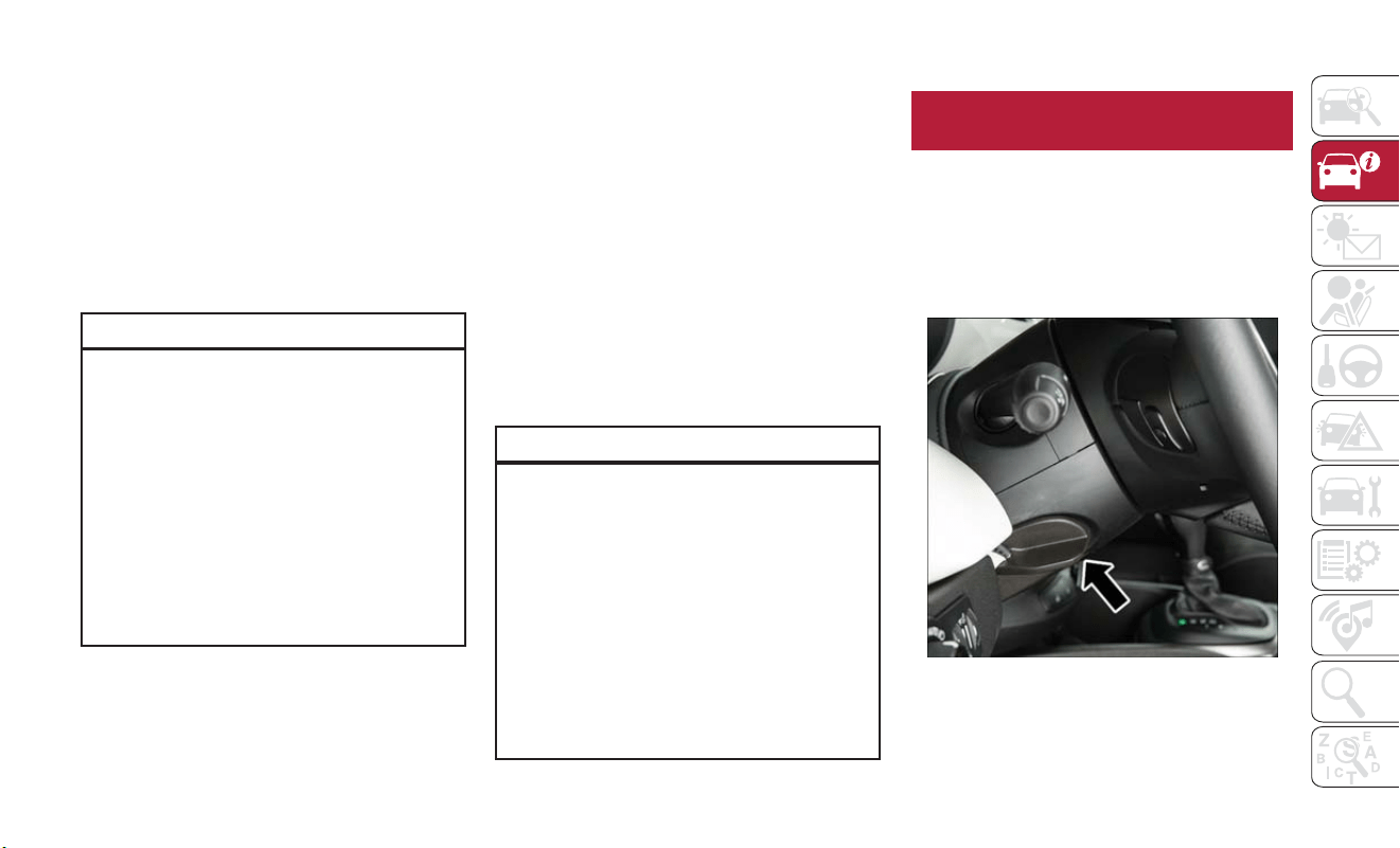
Heated Steering Wheel — If Equipped
The steering wheel contains a heating element
that helps warm your hands in cold weather. The
heated steering wheel has only one temperature
setting. Once the heated steering wheel switch
has been turned on, it will operate for an
average of 80 minutes or more before automati-
cally shutting off.This time may vary depending on
the environmental temperature. The heated
steering wheel can shut off early or may not turn
on when the steering wheel is already warm.The
heated steering wheel control button is located
on the center of the instrument panel below the
climate controls.
Auto On Comfort — If Equipped
If
the external temperature is below 40 °F (4.4°C)
at each start-up of the vehicle the heated steering
wheel functionality is turned on.
Refer to “Uconnect Settings” in “Multimedia” in
the Owner’s Manual for further information.
WARNING!
• Persons who are unable to feel pain to the
skin because of advanced age, chronic illness,
diabetes, spinal cord injury, medication, alco-
hol use, exhaustion, or other physical condi-
tions must exercise care when using the
steering wheel heater. It may cause burns
even at low temperatures, especially if used
for long periods.
WARNING!
• Do not place anything on the steering wheel
that insulates against heat, such as a blanket
or steering wheel covers of any type and
material. This may cause the steering wheel
heater to overheat.
EXTERIOR LIGHTS
Headlights
The headlight switch is located on the left side of
the instrument panel. The headlight switch con-
trols the operation of the headlights, parking
lights, daytime running lights, fog lights and the
dimming of the instrument cluster and interior
lighting.
GETTING TO KNOW YOUR VEHICLE
26

Turning on the headlights will illuminate the
instrument cluster and the controls loca ted on
the instrument panel.
Daytime Running Lights (DRL) — If Equipped
The Daytime Running Lights (DRLs), if enabled by
the Uconnect settings, will turn on when the key
is placed in the RUN position and the park brake
is not applied.
The DRLs will be disabled during turn signal
operation and resume operation when the turn
signal operation has ended.
High Beams
To turn on the high beam headlights, push t he
turn signal lever forward (toward the front of the
vehicle) and an indicator will illuminate in the
cluster. To turn off the high beams, pull the turn
signal lever rearward (toward the rear of the
vehicle).
NOTE:
The headlights must be on for the high beams to
activate.
Headlight Switch
1 — Headlights Off
2 — Parking Lights
3 — Headlights On
4 — Automatic Headlights
5 — Dimmer Controls
6 — Fog Lights
High Beam And Turn Signal Controls
1 — Turn Signals
2 — High Beam Headlights
3 — Flash To Pass
4 — LaneSense On/Off
27

Automatic Lighting — If Equipped
Light Sensor
The light sensor is equipped wit h an infrared LED,
located on the windshield. It detects changes in
light intensity outside the vehicle, based on the
sensitivity of light set by using the Menu on the
display or on the Uconnect system.
T
he higher the sensitivity, the lesser t he amount of
external light required for controlling the lighting.
Automatic Headlights
Turn the headlight switch to the AUTO position.
When the automatic headlights are enabled, the
headlight time delay is active. After the ignition
switch is placed in the STOP mode, the headlights
will automatically turn off after a period of time,
depending on the timing set through the
Uconnect settings. The automatic headlights can
also be turned off manually by moving the
headlight switch out of the AUTO position.
The timing of the headlights is adjustable between
0, 30, 60 and 90 seconds.
Parking Lights
Rotate the headlight switch to the first position
to turn on the parking lights. The parking light
indicator in the cluster will illuminate.
Headlight Delay
This feature provides t he safety of headlight
illumination for up to 90 seconds when leaving
your vehicle in an unlit area.
The time delay of the headlights is programmable
between 0, 30, 60 and 90 seconds.
Headlight Delay Activation
To activate the delay feature, place the ignition in
the STOP position while the headlights are still
on. Then, turn off the headlights within two
minutes. The delay interval begins when the
headlight switch is turned of f.
Headlight Delay Disable
The feature is disabled by placing the ignition in
RUN mode.
If
you shut off the lights before the ignition is
turned on, they will turn off in the normal manner.
NOTE:
The lights must be turned off within two minutes
of placing the ignition in STOP mode to activate
this feature.
Front Fog Lights — If Equipped
The front fog light switch is built into the headlight
switch.
To activate the front fog lights, turn on the parking
lights or the low beam headlights and push the
headlight switch. To turn off the front fog lights,
push the headlight switch a second time or turn
off the headlight switch.
An indicator light in the instrument cluster illumi-
nates when the fog lights are turned on.
NOTE:
• The fog lights will operate with t he low beam
headlights or parking lights on. Selecting the high
beam headlights will turn off the fog lights.
GETTING TO KNOW YOUR VEHICLE
28

• The fog lights also function as cornering lights.
Therefore there will be times when only one
light is on.
• If the ignition is turned OFF with the fog lights
on, they will remain on when the ignition is
turned back ON.
Turn Signals
Move the multifunction lever up or down and the
arrows on each side of the instrument cluster
flash to show proper operation of the front and
rear turn signal lights.
When the Daytime Running Lights are on and a
turn signal is activated, the Daytime Running Lamp
will turn off on the side of the vehicle in which
the turn signal is flashing. The Daytime Running
Lamp will turn back on when the turn signal is
turned off.
Courtesy Lights/Approaching Lights
This fea ture allows the driver to locate the vehicle
when parked in dark areas. It can be enabled and
disabled through the Uconnec t system under the
“Greeting Lights” setting.
When the vehicle is unlocked, the low beam
headlights, parking lights, and sidemarkers will turn
on for 25 seconds. Once a door is opened, the
lights will remain on for an additional ten seconds,
then automatically turn off.
The lights can also be turned off by:
• Locking t he door.
•
Moving the ignition out of the STOP (OFF/LOCK)
position.
WIPERS AND WASHERS
Front Wiper Operation
The windshield wiper/washer controls are located
on the lever on the right side of the steering
column. The front wipers are operated by rotat-
ing a switch, located on the end of the lever.
Windshield Wiper Stalk
1 — Windshield Washer Operation
2 — Rear Washer Operation
3 — Rear Wiper Operation
4 — Intermittent Wiper Controls
5 — Mist Feature
29

CAUTION!
Always remove any buildup of snow that
prevents the windshield wiper blades from
returning to the “park” position. If the wind-
shield wiper switch is turned off, and the
blades cannot return to the “park” position,
damage to the wiper motor may occur.
Windshield Wiper Operation
Rotate the windshield wiper knob to one of the
two detent positions for intermittent settings, the
third detent for low wiper operation and the
fourth for high wiper operation.
Windshield Washer Operation
To use the washer, pull the lever toward you and
hold while spray is desired. If the lever is pulled
while in the intermittent setting, the wipers will
turn on and operate for several wipe cycles after
the lever is released, and then resume the
intermittent interval previously selected.
If the lever is pulled while the wipers are in the
off position, the wipers will operate for several
wipe cycles, then turn off.
WARNING!
Sudden loss of visibility through the windshield
could lead to a collision.You might not see other
vehicles or other obstacles.To avoid sudden icing
of the windshield during freezing weather, warm
the windshield with the defroster before and
during windshield washer use.
Mist
Use this feature when weather conditions make
occasional usage of the wipers necessary. Push
the lever upward to the MIST position and
release for a single wiping cycle.
NOTE:
The mist feature does not activate the washer
pump; therefore, no washer fluid will be sprayed
on the windshield. The wash function must be
used in order to spray the windshield with washer
fluid.
Rain Sensor — If Equipped
This feature senses moisture on the windshield
and automatically activates the wipers for the
driver. The feature is especially useful for road
splash or overspray from the windshield washers
of the vehicle ahead. Rotate the end of the
multifunction lever to one of two settings to
activate this feature.
NOTE:
If the end of the multifunction lever rotates from
the off (O) position to the first intermittent
setting or from the first intermittent setting to
the second intermittent setting, the wipers will
perform a round up to clean the windshield.
The sensitivity of the system can be adjusted with
the multifunction lever. Wiper delay position one
is the least sensitive, and wiper delay position two
is the most sensitive. Setting one should be used
for normal rain conditions, and can be used if the
driver desires less wiper sensitivity. Setting two
can be used if the driver desires more sensitivity.
Place the wiper switch in the off (O) position
when not using the system.
GETTING TO KNOW YOUR VEHICLE
30

NOTE:
• The Rain Sensing feature will not operate when
the wiper switch is in the low or high-speed
position.
• The Rain Sensing feature may not func tion
properly when ice, or dried salt water is present
on the windshield.
• Use of Rain-X or products containing wax or
silicone may reduce Rain Sensing performance.
• The Rain Sensing feature can be turned on and
off using the Uconnect System, refer to
“Uconnect Settings” in “Multimedia” in your
Owner’s Manual for further information.
The Rain Sensing system has protection features
for the wiper blades and arms, and will not
operate under the following conditions:
• Low Ambient Temperature — When the igni-
tion is firs t turned to RUN, the Rain Sensing
system will not operate until the wiper switch is
moved, vehicle speed is greater than 0 mph
(0 km/h), or the outside temperature is greater
than 32°F (0°C).
• Transmission In NEUTRAL Position — When
the ignition is in RUN mode, and the automatic
transmission is in the NEUTRAL position, the
Rain Sensing system will not operate until the
wiper switch is moved, vehicle speed is greater
than 3 mph (5 km/h), or the gear selector is
moved out of the NEUTRAL position.
Remote Start Mode Inhibit — On vehicles
equipped with Remote Starting system, Rain
Sensing wipers are not operational when the
vehicle is in the remote start mode. Once the
operator is in the vehicle and has placed the
ignition switch in RUN mode, rain sensing wiper
operation can resume, if it has been selected, and
no other inhibit conditions (mentioned previ-
ously) exist.
Rain Sensing Wipers — Inhibition — When the
user switches the ignition from OFF to RUN with
the windshield wiper lever already in the inter-
mittent position, no wipe cycle is performed for
safety reasons. This temporary inhibition avoids
accidental activations of the wiping (e.g. during
the hand washing of the windshield, blocking the
blades in ice/snow conditions).
The user can activate the Rain Sensing Wipers in
three ways:
• Moving the lever in off (O) position and then in
intermittent positions.
• One MIST command actuation.
• The vehicle speed exceeds 3 mph (5km/h) and
the rain sensor detects the presence of rain.
Rear Window Wiper/Washer
The rear wiper/washer controls are located on
the lever on the right side of the steering column.
The rear wiper/washer is operated by rotating a
switch, located at the middle of the lever.
Rotate the center portion of the lever upward to
the first detent for intermittent operation and to
the second detent for continuous rear wiper
operation.
31

To use the washer, push the lever forward and
hold while spray is desired. If the lever is pushed
while in the intermittent setting, the wiper will
turn on and operate for several wipe cycles after
the end of the lever is released, and then resume
the intermittent interval previously selected.
NOTE:
• As a protective measure, the pump will stop if
the switch is held for more than 30 seconds.
Once the lever is released, the pump will
resume normal operation.
•
When front wipers are continuous and the
vehicle is shifted in REVERSE, the rear wiper will
perform one round up to clean the rear window.
If the lever is pushed while the wiper is in the off
position, the wiper will operate for several wipe
cycles, then turn off.
If the rear wiper is operating when the ignition is
turned to the STOP mode, the wiper will auto-
matically return to the “park” position.
Rear Window Defroster
The rear window defroster button is located with
the Climate Controls on the instrument panel.
Push this button to turn on the rear window
defroster. An indicator in the button will illumi-
nate when the rear window defroster is on. The
rear window defroster automatically turns off
after approximately 20 minutes. To manually shut
the defroster off, push t he button a second time.
Auto-On Comfort — If Equipped
T
he rear window defroster will turn on automati-
cally whenever the engine is started and the
outside temperature is less than 40°F (4.4°C).This
function can be activated and deactivated t hrough
the Uconnect system. Refer to “Uconnect Settings”
in “Multimedia” in the Owner’s Manual for further
information.
CAUTION!
Failure to follow these cautions can cause
damage to the heating elements:
• Use care when washing the inside of the
rear window. Do not use abrasive window
cleaners on the interior surface of the
window. Use a soft cloth and a mild washing
solution, wiping parallel to the heating ele-
ments. Labels can be peeled off after soak-
ing with warm water.
• Do not use scrapers, sharp instruments, or
abrasive window cleaners on the interior
surface of the window.
• Keep all objects a safe distance from the
window.
GETTING TO KNOW YOUR VEHICLE
32

CLIMATE CONTROLS
Automatic Climate Control Overview
Automatic Temperature Controls (ATC)
33

Automatic Climate Control Descriptions
Icon Description
MAX A/C Setting
MAX A/C sets the system for maximum cooling performance. Rotate the driver temperature control adjust knob counterclock-
wise for MAX A/C. Both driver and passenger temperature displays will show MAX A/C LO. In MAX A/C, the blower speed and
mode position can be adjusted to desired user settings. Pressing other settings will cause the MAX A/C operation to switch to the
selected setting and MAX A/C to exit.
A/C Button
Push the A/C Control Button to change the current setting. The indicator illuminates when the A/C is ON. Pushing the AUTO
control button will cause the A/C operation to change to AUTO mode and the A/C indicator will turn off.
SYNC Button
Push the Sync button to toggle the Sync feature ON/OFF. The Sync indicator will illuminate when this feature is enabled. Sync is
used to synchronize the passenger temperature setting with the driver temperature setting. Changing the passenger temperature
setting while in Sync mode will automatically exit this feature and return to the separate management of air temperatures in the
two zones.
Recirculation Button
Press and release this button to change the system between Recirculation mode and outside air mode. Recirculation can be used
when outside conditions such as smoke, odors, dust, or high humidity are present. Recirculation can be used in all modes. Recircula-
tion may be unavailable if conditions exist that could create fogging on the inside of the windshield. The A/C can be deselected
manually without disturbing the mode control selection. Continuous use of the Recirculation mode may make the inside air stuffy
and window fogging may occur. Extended use of this mode is not recommended.
AUTO Button — If Equipped
Pushing this button will automatically control the interior cabin temperature by adjusting airflow distribution and amount. Perform-
ing this function will cause the automatic climate controls to change between manual mode and automatic modes. Refer to “Auto-
matic Operation” within this section for more information.
GETTING TO KNOW YOUR VEHICLE
34
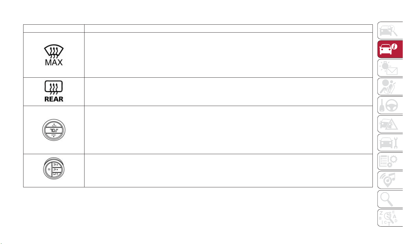
Icon Description
MAX Defrost Button
Push the MAX Defrost button to change the current airflow setting to Defrost mode. The indicator illuminates when this feature
is on. Performing this function will cause the automatic climate controls to change to manual mode. The blower speed increases to
full (all LEDs on) when MAX Defrost mode is selected, the air conditioning compressor is turned on (LED on), both driver and
passenger temperature controls are set to (HI), defrost mode is selected (LED on), rear defroster is turned on (LED on) and the
air recirculation is turned off (LED off). If the MAX Defrost mode is turned off, the climate system will return to the previous
setting.
Rear Defrost Button
Push the Rear Defrost button to turn on the rear window defroster and the heated outside mirrors (if equipped). An indicator
will illuminate when the rear window defroster is on. The rear window defroster automatically turns OFF after 20 minutes.
Passenger Temperature Knob
Provides the passenger with independent temperature control. Rotate the adjustment knob to set desired temperature shown in
the Temperature Display. The set temperature is shown on the display. Turning the control knob completely in one direction or
the other activates the HI (maximum heating ) or LO (maximum cooling) functions shown in the display, respectively. To deactivate
these functions, turn t he temperature knob to the desired temperature.
NOTE:
Rotating the Passenger Temperature Control knob while in Sync mode will automatically exit Sync.
Blower Control Knob
Blower control is used to regulate the amount of air forced through the climate system. Adjusting the blower will cause the auto-
matic mode to change to manual operation. The speeds can be selected by rotating the Blower Control adjustment knob.
35

Icon Description
Windshield Mode
Windshield Mode
Air comes from the outlets directed at the windshield meant for defrosting, and side window demisting. This setting works best in
cold or snowy conditions that require extra heat to the windshield.
Panel Mode
Panel Mode
Air comes from the outlets in t he instrument panel. Each of these outlets can be individually adjusted to direct the flow of air.
The air vanes of the center outlets and outboard outlets can be moved up and down or side to side to regulate airflow direction.
There is a shut off wheel located below the air vanes to shut off or adjust the amount of airflow from these outlets.
Floor Mode
Floor Mode
Air comes from the floor outlets. A slight amount of air is directed through the defrost and side window demister outlets.
Bi-Level Mode
Bi-Level Mode
Bi-Level Mode is obtained by pressing both the Panel Mode button and the Floor Mode button, activating them both. Air comes from
the instrument panel outlets and floor outlets. A slight amount of air is directed through the defrost and side window demister outlets.
NOTE:
Bi-Level Mode is designed under comfort conditions to provide cooler air out of the panel outlets and warmer air from the floor
outlets.
GETTING TO KNOW YOUR VEHICLE
36

Icon Description
Mix Mode
Mix Mode
Mix Mode is obtained by pressing both the Windshield Mode button and the Floor Mode button, activating them both. Air is
directed through the floor, defrost, and side window demister outlets. This setting works best in cold or snowy conditions that
require extra heat to the windshield. This setting is good for maintaining comfort while reducing moisture on the windshield.
Climate Control Power Button
Press and release this button to turn the Climate Control on/off.
Driver Temperature Knob
Provides the driver with independent temperature control. Rotate the adjustment knob to set desired temperature shown in the
Temperature Display. Rotate fully counterclockwise for maximum A/C (LO). The set temperature is shown on the display. Turning
the control knob completely in one direction or the other activates the HI (maximum heating) or LO (maximum cooling) func-
tions shown in the display, respectively. To deactivate these functions, turn the temperature knob to the desired temperature.
37

Climate Control System Compressor
Push the A/C Control button to activate/
deactivate the compressor (activation is indicated
by the LED on the button turning on).
T
he system remembers that the compressor has
been turned off, even after the engine has stopped.
Pushing the A/C button will stop AUTO MODE
(AUTO LED will turn off). To restore automatic
control of compressor, push the AUTO button
again.
NOTE:
With the compressor off, air cannot be intro-
duced to the passenger compartment with a
temperature lower than the outside tempera-
ture. Under certain environmental conditions,
windows could fog rapidly since the air is not
dehumidified.
MAX A/C
MAX A/C sets the system for maximum cooling
performance.
Rotate the driver temperature control adjust
knob counterclockwise for MAX A/C. Both driver
and passenger temperature displays will show
MAX A/C LO.
In MAX A/C, the blower speed and mode
position can be adjusted to desired user settings.
Pressing other settings will cause the MAX A/C
operation to switch to the selected setting and
MAX A/C to exit.
Rapid Window Demisting (MAX-Defrost
Function)
Push the MAX-defrost button to activate (LED
on) t he windshield and side window demisting
function.
The Climate Control system carries out the
following operations:
• Turns on the air conditioning compressor when
environmental conditions are suitable.
• Turns air recirculation off.
• Sets blower fan to the maximum speed.
• Directs air flow to windshield and front side
window diffusers.
• Activates the heated rear window defrost.
• Activates the heated windshield (if equipped).
• Displays the fan speed (Blower Control Indica-
tor LED illuminated).
When the function is activated, t he AUTO button
LED turns off. With the function activated, the
only possible manual adjustments are pushing the
A/C control button, adjusting the fan speed and
turning the heated rear window off.
When the Recirculation Control or AUTO buttons
are pushed, the Climate Control system will deac-
tivate the Front Defrost (MAX-DEF) function.
Selecting the footwell/windshield or only wind-
shield distribution activates the Climate Control
system compressor and the air recirculation is set
to outside air intake.
This logic guarantees optimum visibility at the win-
dows. Max-defrost is also available in manual mode.
Rear Window Defrosting
Push and release the rear window defrost button
to turn the function on/off.
Activation of this function is indicated by the rear
defrost indicator light on the instrument panel
turning on. The function is automatically deacti-
vated after 20 minutes. If equipped, push the rear
defrost button to activate the defrosting of door
mirrors and heated rear window.
GETTING TO KNOW YOUR VEHICLE
38
CAUTION!
To avoid causing damage to the rear window
defroster heating filaments do not af fix stick-
ers or other objects to the inside of the rear
glass.
Turning Off The Climate Control System
Push the ON/OFF button.
With the Climate Control system off:
• Air recirculation is on, isolating the passenger
compartment from the outside.
• The A/C compressor is off.
• The blower is off.
• The heated rear window can be activated/
deactivated.
NOTE:
The Climate Control unit stores the tempera-
tures set before the system was turned off and
restores them when one of the following knobs/
buttons is pushed:
• A/C
• Recirculation
• Max Defrost
• Blower Increase
• AUTO
To restart the Climate Control system in fully
automatic mode, push the AUTO button.
System Maintenance
In Winter, the Climate Control system must be
turned on at least once a month for approximately
ten minutes.
Have the system inspected at an authorized
dealership before the summer.
NOTE:
The system uses R-1234yf (refrigerant) which
does not pollute the environment in the event of
accidental leakage. Under no circumstances is the
use of R-134a (refrigerant) allowed.
Climate Control Functions
A/C (Air Conditioning)
The Air Conditioning (A/C) button allows the
operator to manually activate or deactivate the
air conditioning system.When the air conditioning
system is turned on, cool dehumidified air will
flow through the outlets into the cabin. For
improved fuel economy, push the A/C button to
turn of f the air conditioning and manually adjust
the blower and airflow mode settings. Also, make
sure to select only Panel, Bi-Level or Floor modes.
NOTE:
• For Manual Climate Controls, if the system is in
Mix, Floor or Defrost Mode, the A/C can be
turned off, but the A/C system shall remain
active to prevent fogging of the windows.
• If fog or mist appears on the windshield or side
glass, select Defrost mode, and increase blower
speed if needed.
• If your air conditioning performance seems
lower than expected, check the front of the A/C
condenser (located in front of the radiator), for
an accumulation of dirt or insects. Clean with a
gentle water spray from the front of the
radiator and through the condenser.
Recirculation
In cold weather, use of Recirculation mode may
lead to excessive window fog ging. The Recircula-
tion feature may be unavailable if conditions exist
that could create fogging on the inside of the
windshield.
39

Automatic Temperature Control (ATC)
Automatic Operation
1. Push the AUTO button on the faceplate.
2. Next, adjust the temperature you would like
the system to maintain by adjusting the tem-
perature control buttons. Once the desired
temperature is displayed, the system achieves
and automatically maintains that comfort level.
3.
When the system is set up for your comfort
level, it is not necessary to change the settings.
You experience the greatest efficiency by simply
allowing the system to function automatically.
NOTE:
• It is not necessary to move the temperature
settings for cold or hot vehicles. The system
automatically adjusts the temperature, mode,
and blower speed to provide comfort as quickly
as possible.
•
The temperature can be displayed in U.S. or
Metric units by selecting the US/Metric customer-
programmable fea ture.
T
o provide you with maximum comfort in the
Automatic mode during cold start-ups, the blower
fan remains on low until t he engine warms up.
The blower increases in speed and transition into
Auto mode.
Manual Operation Override
This system offers a full complement of manual
override features. The AUTO symbol in the front
ATC display will be turned off when the system is
being used in the manual mode.
NOTE:
The system will not automatically sense the
presence of fog, mist or ice on the windshield.
Defrost mode must be manually selected to clear
the windshield and side glass.
Operating Tips
Winter Operation
To ensure the best possible heater and defroster
performance, make sure the engine cooling sys-
tem is functioning properly and the proper
amount, type, and concentration of coolant is
used. Use of the Air Recirculation mode during
Winter months is not recommended, because it
may cause window fogging.
Vacation/Storage
Before you store your vehicle, or keep it out of
service (i.e., vacation) for two weeks or more, run
the air conditioning system at idle for about five
minutes, in fresh air with the blower setting on
high. This will ensure adequate system lubrication
to minimize the possibility of compressor damage
when the system is started again. If you are
leaving your vehicle dormant for more than four
weeks, disconnect the negative cable from the
battery. Refer to “Jump Starting Procedures” in “In
Case Of Emergency” for further information.
Window Fogging
Vehicle windows tend to fog on the inside in mild,
rainy, and/or humid weather. To clear the win-
dows, select Defrost or Mix mode and increase
the front blower speed. Do not use the Recircu-
lation mode without A/C for long periods, as
fogging may occur.
CAUTION!
Failure to follow these cautions can cause
damage to the heating elements:
• Use care when washing the inside of the
rear window. Do not use abrasive window
GETTING TO KNOW YOUR VEHICLE
40

CAUTION!
cleaners on the interior surface of the
window. Use a soft cloth and a mild
washing solution, wiping parallel to the
heating elements. Labels can be peeled off
after soaking with warm water.
• Do not use scrapers, sharp instruments, or
abrasive window cleaners on the interior
surface of the window.
• Keep all objec ts a safe distance from the
window.
Outside Air Intake
Make sure the air intake, loca ted directly in front of
the windshield, is free of obstructions, such as
leaves. Leaves collected in the air intake may reduce
airflow, and if they enter the plenum, they could
plug the water drains. In Winter months, make sure
the air intake is clear of ice, slush, and snow.
Cabin Air Filter
The climate control sys tem filters out dust and
pollen from the air. Cont act an authorized dealer
to service your cabin air filter, and to have it
replaced when needed.
WINDOWS
Driver's Door Controls
The power window switch is located on the
driver’s door panel. The driver’s power window
switch controls the operation of all the windows.
There are single window controls on each pas-
senger door trim panel, which operate the pas-
senger door windows. The window controls will
operate only when the ignition is in the ON/RUN
or START position.
NOTE:
The power window switches will remain active
for up to three minutes after the ignition is cycled
to the STOP/OFF position. Opening either front
door will cancel this feature.
WARNING!
Never leave children unattended in a vehicle,
and do not let children play with power
windows. Do not leave the key fob in or near
the vehicle, or in a location accessible to
children, and do not leave the ignition of a
vehicle equipped with Keyless Enter-N-Go in
the ACC or ON/RUN mode. Occupants,
particularly unattended children, can become
entrapped by the windows while operating the
power window switches. Such entrapment
may result in serious injury or death.
Power Window Switches
41

Auto-Down Feature — If Equipped
T
he driver and passenger power window switches
have an Auto-Down feature. Push the switch for
half a second and release it; t he window will go
down automatically.
To stop the window from going all the way down
during the Auto-Down operation, push up or pull
down on the switch briefly when the window has
reached the desired position.
To open the window part way (manually), push
the window switch down briefly and release.
Auto-Up Feature With Auto-Reverse
Protection — If Equipped
The driver and front passenger power window
switches also have an Auto-Up feature. Pull the
window switch up for about half a second and
release it; the window will go up automatically.
To stop the window from going all the way up
during the Auto-Up operation, pull up or push
down on the switch briefly.
To partially close the window (manually), pull the
window switch up briefly and release it.
NOTE:
• If the window runs into any obstacle during
auto-closure, it will reverse direction and then
go back down. Remove the obstacle and use the
window switch again to close the window.
• Any impact due to rough road conditions may
trigger the auto-reverse function unexpectedly
during auto-closure. If this happens, pull the
switch lightly and hold to close t he window
manually.
WARNING!
There is no auto-reverse protection when the
window is almos t closed. To avoid personal
injur y be sure to clear your arms, hands, fingers
and all objects from the window path before
closing.
Window Lockout Switch
The window lockout switch on the driver's door
trim panel allows you to disable the window
controls on the rear passenger doors. To disable
the window controls, push and release the win-
dow lockout button. The light on the window
lockout switch will illuminate to signal that the
feature has been activated and the passenger
windows can only be adjusted by the driver.
Window Lockout Switch
GETTING TO KNOW YOUR VEHICLE
42

To enable the passenger window controls, push
and release the window lockout button again, and
the indicator light on the button will turn off.
Wind Buffeting
Wind buffeting can be described as the percep-
tion of pressure on the ears or a helicopter-type
sound in the ears. Your vehicle may exhibit wind
buffeting with the windows down, or the sunroof
(if equipped) in certain open or partially open
positions. This is a normal occurrence and can be
minimized. If the buffeting occurs with the rear
windows open, open the front and rear windows
together to minimize the buffeting. If the buffeting
occurs with the sunroof open, adjust the sunroof
opening to minimize the buffeting or open any
window.
HOOD
Opening
The hood release lever (to open the primary
latch) and safety latch (to open the secondary
latch) must be released to open the hood.
1. Pull the hood release lever located under the
driver’s side of the instrument panel.
2. Move to the outside of the vehicle.
3. Push the safety latch release lever toward the
passenger side of the vehicle. The safety latch
is located behind the center front edge of the
hood.
4. Remove the support rod from the locking tab
and insert it into the seat located on the
underside of the hood.
NOTE:
• Before lifting the hood, check that the wiper
arms are not in motion and not in the lifted
position.
• While lif ting the hood, use both hands.
• Vehicle must be at a stop and the transmission
must be in PARK.
Safety Latch Release Lever Location
Safety Latch Release Lever
43

Closing
1. Hold up the hood with one hand and with the
other hand remove the support rod from its
seat and reinsert it into the locking tab.
2. Lower the hood to approximately 12 inches
(30 cm) from the engine compartment and
drop it. Make sure that the hood is completely
closed.
WARNING!
Be sure the hood is fully latched before driving
your vehicle. If the hood is not fully latched, it
could open when the vehicle is in motion and
block your vision. Failure to follow this warning
could result in serious injury or death.
CAUTION!
To prevent possible damage, do not slam the
hood to close it. Lower hood to approximately
12 inches (30 cm) and drop the hood to close.
Make sure hood is fully closed for both latches.
Never drive vehicle unless hood is fully closed,
with both latches engaged.
LIFTGATE
The liftgate release function is disabled when the
vehicle is in motion.
Opening
Opening From Outside
To unlock the liftgate from the outside, squeeze
the electronic liftgate release and pull the liftgate
open with one fluid motion.
When opening the door, the turn signal lights will
flash twice and the interior dome light will
illuminate. The interior dome light will turn off
automatically by closing the liftgate. Refer to
“Interior Lights” in “Getting To KnowYourVehicle”
in the Owner’s Manual for further information.
If the liftga te is left open, the interior dome light
will shut off after a few minutes to conserve
battery life.
Internal Emergency Release
Proceed as follows:
1. Lower the headrests and fold the seatbacks .
2. Using the supplied screwdriver (located under
cargo floor in tool kit), remove the yellow tab
from the liftgate latching mechanism.
3. With the yellow tab removed, insert the
screwdriver into the now open release tab
slot to trigger the release of the liftgate .
Closing
Grasp the liftgate closing handle and lower the
liftgate.
NOTE:
Before closing the liftgate, make sure to be in
possession of the key because the liftgate will be
locked automatically.
INTERNAL EQUIPMENT
Power Outlets
There is one 12 Volt (13 Amp) power outlet in
this vehicle, located under the HVAC controls.
This power outlet can power mobile phones,
electronics and other low power devices.
GETTING TO KNOW YOUR VEHICLE
44

This power outlet is located in front of the gear
selector.
NOTE:
The power outlet can be changed to “battery”
powered all the time by switching the power
outlet Engine Compartment Fuses/Distribution
Unit fuse from location F84 to F23.
NOTE:
•
Do not exceed the maximum power of 160Watts
(13 Amps) at 12 Volts. If the 160 Watt (13 Amp)
power rating is exceeded, the fuse protecting the
system will need to be replaced.
• Power outlets are designed for accessory plugs
only. Do not insert any other object in the
power outlet as this will damage the outlet and
blow the fuse. Improper use of the power
outlet can cause damage not covered by your
new vehicle warranty.
Cigar Lighter — If Equipped
This is located on the instrument panel, below the
climate controls.To activate the cigar lighter, push
and release the knob. After a few seconds the
knob automatically returns to its initial position,
and the cigar lighter is ready for use.
WARNING!
When the cigar lighter is in use it becomes
very hot. To avoid serious injury, handle the
cigar lighter with care. Always check that the
cigar lighter has turned off.
NOTE:
• Always check that the cigar lighter is switched
off.
• Do not connect devices with power higher than
180W to the socket. Do not damage the socket
by using unsuitable adaptors.
Power Outlet
Engine Compartment Fuses
F84 Fuse 20A Yellow Instrument Panel
Power Outlet.
45

INSTRUMENT CLUSTER
DISPLAY
Your vehicle may be equipped with an instrument
cluster display, which offers useful information to
the driver. With the ignition in the STOP/OFF
position, opening/closing of a door will activate
the display for viewing, and display the total miles,
or kilometers, in the odometer. The instrument
cluster display is designed to display important
information about the vehicle’s systems and fea-
tures. Using a driver interactive display located on
the instrument panel, your instrument cluster
display can show you how systems are working
and give you warnings when they aren’t. The
steering wheel mounted controls allow you to
scroll through and enter the main menus and
submenus.You can access the specific information
you want and make selections and adjustments.
Instrument Cluster Display Control Buttons
The system allows the driver to select informa-
tion by pushing the following buttons mounted on
the steering wheel:
The instrument cluster display features a driver
interactive display that is located in the instrument
cluster. Pushing the controls on the left side of
the steering wheel allows the driver to select
vehicle information and Personal Settings.
• Push the up arrow button to scroll upward
through the main menus and submenus (Speed-
ometer, Vehicle Info, Driver Assist, Fuel Economy,
Trip, Audio, Messages, Screen Set Up).
• Push the down arrow button to scroll down-
ward through the main menu and submenus
(Speedometer, Vehicle Info, Driver Assist, Fuel
Economy,Trip,Audio, Messages, Screen Set Up).
• Push the right arrow button to access the
information screens or submenu screens of a
main menu item.
• Push the back/left arrow button to access the
information screens or submenu screens of a
main menu item.
• Push the OK button to access/select the infor-
mation screens or submenu screens of a main
menu item. Push and hold the OK button for
two seconds to reset displayed/selected fea-
tures that can be reset.
Instrument Cluster Display Controls
GETTING TO KNOW YOUR INSTRUMENT PANEL
46

Engine Oil Change Reset
Your vehicle may be equipped with an engine oil
change indicator system.The “Change Engine Oil”
message will display in the instrument cluster
display. The engine oil change indicator system is
duty cycle based, which means the engine oil
change interval may fluctuate , dependent upon
your personal driving style.
Unless reset, this message will continue to display
each time you turn the ignition switch to the
ON/RUN position. To reset the oil change indi-
cator system (after performing the scheduled
maintenance), refer to the following procedure.
1. Turn the ignition switch to the ON position
(do not start the engine).
2. Fully push the accelerator pedal slowly, three
times, within 10 seconds.
3. Turn the ignition switch to the OFF/LOCK
position.
NOTE:
If the indicator message illuminates when you
start the vehicle, the oil change indicator system
did not reset. If necessary, repeat this procedure.
Instrument Cluster Display Main Menu
The Main Menu is composed of several options that
can be selected using the control buttons above.
NOTE:
• The display mode of the menu items varies
depending on the type of display.
• For some items, a submenu is provided.
• In the Uconnect system, some items on the
menu are not shown on the instrument cluster
display.
Menu Items
The Menu has the following options:
• Speedometer
• Trip
• Dynamic Selector
• Vehicle Info
• Driver Assist
• Audio
• Phone
• Navigation
• Messages
• Vehicle Settings
For further information on vehicle menu options,
refer to “Instrument Cluster Display” in “Getting
To Know Your Instrument Panel” in the Owner’s
Manual.
WARNING LIGHTS AND
MESSAGES
The warning/indicator lights will illuminate in the
instrument panel together with a dedicated mes-
sage and/or acoustic signal when applicable.These
indications are indicative and precautionary and as
such must not be considered as exhaustive and/or
alternative to the information cont ained in the
Owner’s Manual, which you are advised to read
carefully in all cases. Always refer to the informa-
tion in this chapter in the event of a failure
indication. All active telltales will display first if
applicable. The system check menu may appear
different based upon equipment options and
current vehicle sta tus. Some telltales are optional
and may not appear.
47

Red Warning Lights
— Air Bag Warning Light
This warning light will illuminate to indicate a fault
with the air bag, and will turn on for four to eight
seconds as a bulb check when the ignition is
placed in the ON/RUN or ACC/ON/RUN posi-
tion. This light will illuminate with a single chime
when a fault with the air bag has been detected,
it will stay on until the fault is cleared. If the light
is either not on during startup, stays on, or turns
on while driving, have the system inspected at an
authorized dealer as soon as possible.
— Brake Warning Light
This warning light monitors various brake func-
tions, including brake fluid level and parking brake
application. If the brake light turns on it may
indicate that the parking brake is applied, that the
brake fluid level is low, or that there is a problem
with the anti-lock brake system reservoir.
If the light remains on when the parking brake has
been disengaged, and the fluid level is at the full
mark on the master cylinder reservoir, it indicates
a possible brake hydraulic system malfunction or
that a problem with the Brake Booster has been
detected by the Anti-Lock Brake System (ABS) /
Electronic Stability Control (ESC) system. In this
case, the light will remain on until the condition
has been corrected. If t he problem is related to
the brake booster, the ABS pump will run when
applying the brake, and a brake pedal pulsation
may be felt during each stop.
The dual brake system provides a reserve braking
capacity in the event of a failure to a portion of
the hydraulic system. A leak in either half of the
dual brake system is indicated by the Brake
Warning Light, which will turn on when the brake
fluid level in the master cylinder has dropped
below a specified level.
The light will remain on until the cause is
corrected.
NOTE:
The light may flash momentarily during sharp
cornering maneuvers, which change fluid level
conditions. The vehicle should have service per-
formed, and the brake fluid level checked.
If brake failure is indicated, immediate repair is
necessar y.
WARNING!
Driving a vehicle with the red brake light on is
dangerous. Part of the brake system may have
failed. It will take longer to stop the vehicle.
You could have a collision. Have the vehicle
checked immediately.
Vehicles equipped with the Anti-Lock Brake Sys-
tem (ABS) are also equipped with Electronic
Brake Force Distribution (EBD). In the event of
an EBD failure, the Brake Warning Light will turn
on along with the ABS Light. Immediate repair to
the ABS system is required.
Operation of t he Brake Warning Light can be
checked by turning the ignition switch from the
OFF position to the ON/RUN position. The light
should illuminate for approximately two seconds.
The light should then turn off unless the parking
brake is applied or a brake fault is detected. If the
light does not illuminate, have the light inspected
by an authorized dealer.
GETTING TO KNOW YOUR INSTRUMENT PANEL
48

The light also will turn on when the parking brake
is applied with the ignition switch in the ON/RUN
position.
NOTE:
This light shows only that the parking brake is
applied. It does not show the degree of brake
application.
— Battery Charge Warning Light
This warning light will illuminate when the battery
is not charging properly. If it stays on while the
engine is running, there may be a malfunction with
the charging system. Contact an authorized
dealer as soon as possible.
This indicates a possible problem with the elec-
trical system or a related component.
— Coolant Temperature Warning Light
This light warns of an overheated engine condi-
tion. If the light turns on while driving, safely pull
over and stop the vehicle. If the A/C system is on,
turnitoff. Also, shift the transmission into NEU-
TRAL and idle t he vehicle. If the temperature
reading does not return to normal, turn t he
engine off immediately and call for service.
NOTE:
As the coolant temperature gauge approaches
"H," this indicator will illuminate and a single chime
will sound.
— Door Open Warning Light
This indicator will illuminate when one or more
door(s) are not fully closed.
NOTE:
If the vehicle is moving and a door is opened,
there will also be a single chime.
— Electric Power Steering Fault Warn-
ing Light
This warning light will turn on when there's a fault
with the EPS (Electric Power Steering) system.
Refer to “Power Steering” in “Starting And
Operating” in the Owner’s Manual for further
information.
WARNING!
Continued operation with reduced assist could
pose a safety risk to yourself and others. Service
should be obtained as soon as possible.
— Electronic Throttle Control (ETC)
Warning Light
This warning light will illuminate to indicate a
problem with the Electronic Throttle Control
(ETC) system. If a problem is detected while the
vehicle is running, the light will eit her stay on or
flash depending on the nature of the problem.
Cycle the ignition when the vehicle is safely
and completely stopped and the transmission is
placed in the PARK position.The light should turn
off. If the light remains on with the vehicle
running, your vehicle will usually be drivable;
however, see an authorized dealer for service as
soon as possible.
NOTE:
This light may turn on if the accelerator and brake
pedals are pressed at the same time.
If the light continues to flash when the vehicle is
running, immediate service is required and you
may experience reduced performance, an
elevated/rough idle, or engine stall and your
vehicle may require towing.The light will come on
when the ignition is placed in the ON/RUN or
49

ACC/ON/RUN position and remain on briefly as
a bulb check. If the light does not come on during
starting, have the system checked by an autho-
rized dealer.
— Hood Open Warning Light —
If Equipped
This warning light will illuminate when the hood is
left open and not fully closed.
— Oil Pressure Warning Light
T
his warning light will illuminate to indicate low
engine oil pressure. If the light turns on while
driving, stop the vehicle, shut off the engine as soon
as possible, and contact an authorized dealer.
A chime will sound when this light turns on.
Do not operate the vehicle until the cause is
corrected. This light does not indicate how much
oil is in the engine. The engine oil level must be
checked under the hood.
— Seat Belt Reminder Warning Light
This warning light indicates when the driver or
passenger seat belt is unbuckled. When the
ignition is first placed in the ON/RUN or ACC/
ON/RUN position and if the driver’s seat belt is
unbuckled, a chime will sound and the light will
turn on. When driving, if the driver or front
passenger seat belt remains unbuckled, the
Seat Belt Reminder Light will flash or remain on
continuously and a chime will sound.
Refer to “Occupant Restraint Systems” in “Safety”
for further information.
— Transmission Fault Warning Light
This light will illuminate (together with a message
in the instrument cluster display and a buzzer) to
indicate a transmission fault. Contact an autho-
rized dealer if the message remains after restart-
ing the engine.
— Vehicle Security Warning Light —
If Equipped
This light will flash at a fast rate for approximately
15 seconds when the vehicle security alarm is
arming, and then will flash slowly until the vehicle
is disarmed.
— Trunk Open Warning Light
This indicator will illuminate when the trunk is
open and not fully closed.
Yellow Warning Lights
— Adaptive Cruise Control (ACC)
Fault Warning Light — If Equipped
This warning light will illuminate to indicate a fault
in the ACC system. Contact a local authorized
dealer for service.
For further information, refer to “Adaptive Cruise
Control (ACC)” in “Starting And Operating.”
— Anti-Lock Brake (ABS) Warning
Light
This warning light monitors the Anti-Lock Brake
System (ABS). The light will turn on when the
ignition is placed in the ON/RUN or ACC/ON/
RUN position and may stay on for as long as four
seconds.
If the ABS light remains on or turns on while
driving, then the Anti-Lock portion of the brake
system is not functioning and service is required
as soon as possible. However, the conventional
brake system will continue to operate normally,
assuming the Brake Warning Light is not also on.
GETTING TO KNOW YOUR INSTRUMENT PANEL
50

If theABS light does not turn on when the ignition
is placed in the ON/RUN or ACC/ON/RUN
position, have the brake system inspected by an
authorized dealer.
— Electronic Park Brake Warning
Light
This warning light will illuminate to indicate the
Electronic Park Brake is not functioning properly
and service is required. Contact an authorized
dealer.
— Electronic Stability Control (ESC)
Active Warning Light — If Equipped
This warning light will indicate when the Elec-
tronic Stability Control system is Active.The “ESC
Indicator Light” in the instrument cluster will
come on when the ignition is placed in the
ON/RUN or ACC/ON/RUN position, and when
ESC is activated. It should go out with t he engine
running. If the “ESC Indicator Light” comes on
continuously with the engine running, a malfunc-
tion has been detected in the ESC system. If this
warning light remains on after several ignition
cycles, and the vehicle has been driven several
miles (kilometers) at speeds greater than 30 mph
(48 km/h), see an authorized dealer as soon as
possible to have the problem diagnosed and
corrected.
• The “ESC Off Indicator Light” and the “ESC
Indicator Light” come on momentarily each
time the ignition is placed in the ON/RUN or
ACC/ON/RUN position.
• The ESC system will make buzzing or clicking
sounds when it is active. This is normal; the
sounds will stop when ESC becomes inactive.
• This light will come on when the vehicle is in an
ESC event.
— Electronic Stability Control (ESC) Off
Warning Light — If Equipped
This warning light indicates the Electronic Stability
Control (ESC) is off.
Each time the ignition is turned to ON/RUN or
ACC/ON/RUN, the ESC system will be on, even
if it was turned off previously.
— External Light Failure Indicator
Light — If Equipped
The External Light Failure Indicator will come on
when a failure to one of the following lights is
detected:
• Direction Indicators
• Backup Lights
• Parking Lights
• Daytime Running Lights
• License Plate Lights
The failure relating to these lights could be:
• One or more blown bulbs
• A blown protection fuse
• A break in the electrical connection
— Loose Fuel Filler Cap Warning Light
— If Equipped
This warning light will illuminate when the fuel
filler cap is loose. Properly close t he filler cap to
disengage the light. If the light does not turn off,
please see an authorized dealer.
51

— Low Fuel Warning Light
When the fuel level reaches approximately 1.3–
1.8 gal (5–7 L) this light will turn on, and remain
on until fuel is added.
— Engine Check/Malfunction Indica-
tor Warning Light (MIL)
The Engine Check/Malfunction Indicator Light
(MIL) is a part of an Onboard Diagnostic System
called OBD II that monitors engine and automatic
transmission control systems. This warning light
will illuminate when the ignition is in the ON/
RUN position before engine start. If the bulb
does not come on when turning the ignition
switch from OFF to ON/RUN, have the condition
checked promptly.
Certain conditions, such as a loose or missing gas
cap, poor quality fuel, etc., may illuminate the light
after engine start. The vehicle should be serviced
if the light stays on through several typical driving
styles. In most situations, the vehicle will drive
normally and will not require towing.
When the engine is running, the MIL may flash to
alert serious conditions that could lead to immedi-
ate loss of power or severe catalytic converter
damage. The vehicle should be serviced by an
authorized dealer as soon as possible if this occurs.
WARNING!
A malfunctioning catalytic converter, as refer-
enced above, can reach higher temperatures
than in normal operating conditions. This can
cause a fire if you drive slowly or park over
flammable substances such as dry plants,
wood, cardboard, etc.This could result in death
or serious injury to the driver, occupants or
others.
CAUTION!
Prolonged driving with the Malfunc tion Indica-
tor Light (MIL) on could cause damage to the
vehicle control system. It also could affect fuel
economy and driveability. If the MIL is flashing,
severe catalytic converter damage and power
loss will soon occur. Immediate service is
required.
— Service Warning Light — If
Equipped
The “Maintenance Plan” includes vehicle mainte-
nance at fixed intervals. For further information,
refer to "Scheduled Maintenance” in “Servicing
And Maintenance”. This message is displayed au-
tomatically along with the warning light when the
key is turned to MAR/ON/RUN - 1242 miles
(2,000 km) or 30 days before these deadlines, and
reappears every time the key is turned to MAR/
ON/RUN. The indication will appear in miles or
kilometers according to the "Unit Of Measure-
ment" settings. When the next scheduled service
is approaching and the key is turned to MAR/
ON/RUN, the word “Service” will appear on the
display, followed by the number of miles or
kilometers left. Contact an authorized dealership.
The operations in the “Maintenance Plan” will be
performed and the message will be reset.
— Service Stop/Start System Warning
Light — If Equipped
This warning light will illuminate when the Stop/
Start system is not functioning properly and
service is required. Contact an authorized dealer
for service.
GETTING TO KNOW YOUR INSTRUMENT PANEL
52

— Tire Pressure Monitoring System
(TPMS) Warning Light
The warning light switches on and a message is
displayed to indicate that the tire pressure is
lower than the recommended value and/or that
slow pressure loss is occurring. In these cases,
optimal tire duration and fuel consumption may
not be guaranteed.
Should one or more tires be in the condition
mentioned above, the display will show the indi-
cations corresponding to each tire.
CAUTION!
Do not continue driving with one or more flat
tires as handling may be compromised. Stop the
vehicle, avoiding sharp braking and steering. If a
tire puncture occurs, repair immediately using
the dedicated tire repair kit and contact an
authorized dealer as soon as possible.
Each tire, including the spare (if provided), should
be checked monthly when cold and inflated
to the inflation pressure recommended by the
vehicle manufacturer on the vehicle placard or
tire inflation pressure label. (If your vehicle has
tires of a different size than the size indicated on
the vehicle placard or tire inflation pressure label,
you should determine the proper tire infla tion
pressure for those tires.)
As an added safety feature, your vehicle has been
equipped with a Tire Pressure Monitoring System
(TPMS) that illuminates a low tire pressure telltale
when one or more of your tires is significantly
under-inflated. Accordingly, when the low tire
pressure telltale illuminates, you should stop and
check your tires as soon as possible, and inflate
them to the proper pressure. Driving on a
significantly under-inflated tire causes the tire to
overheat and can lead to tire failure. Under-
inflation also reduces fuel efficiency and tire tread
life, and may affect the vehicle’s handling and
stopping ability.
Please note that the TPMS is not a substitute for
proper tire maintenance, and it is the driver’s
responsibility to maintain correct tire pressure,
even if under-inflation has not reached the level
to trigger illumination of the TPMS low tire
pressure telltale.
Y
our vehicle has also been equipped with a TPMS
malfunction indicator to indicate when the system
is not operating properly. The TPMS malfunction
indicator is combined with the low tire pressure
telltale.When the system detects a malfunction, the
telltale will flash for approximately one minute and
then remain continuously illuminated.This sequence
will continue upon subsequent vehicle start-ups
as long as the malfunc tion exists. When the mal-
function indicator is illuminated, the system may not
be able to detect or signal low tire pressure as
intended. TPMS malfunctions may occur for a
variety of reasons, including the installation of
replacement or alternate tires or wheels on the
vehicle that prevent the TPMS from functioning
properly. Always check the TPMS malfunction tell-
tale after replacing one or more tires or wheels on
your vehicle to ensure that the replacement or
alternate tires and wheels allow the TPMS to
continue to function properly.
CAUTION!
The TPMS has been optimized for the original
equipment tires and wheels. TPMS pressures
and warning have been established for the tire
53

CAUTION!
size equipped on your vehicle. Undesirable
system operation or sensor damage may result
when using replacement equipment that is not
of the same size, type, and/or style. Aftermar-
ket wheels can cause sensor damage. Using
aftermarket tire sealants may cause the Tire
Pressure Monitoring System (TPMS) sensor to
become inoperable.After using an aftermarket
tire sealant it is recommended that you take
your vehicle to your authorized dealer to have
your sensor func tion checked.
— Transmission Temperature Warning
Light
This light indicates that the transmission fluid
temperature is running hot. This may occur with
severe usage, such as trailer towing. If this light
turns on, safely pull over and stop the vehicle.
Then, shif t the transmission into PARK and run
the engine at idle or slightly higher until the light
turns off.
WARNING!
If you continue operating the vehicle when the
Transmission Temperature Warning Light is
illuminated you could cause the fluid to boil
over, come in contact with hot engine or
exhaust components and cause a fire.
CAUTION!
Continuous driving with the Transmission Tem-
perature Warning Light illuminated will even-
tually cause severe transmission damage or
transmission failure.
— Service LaneSense Warning Light —
If Equipped
This warning light will illuminate when the Lane-
Sense system is not operating and requires ser-
vice. Please see an authorized dealer.
— LaneSense Warning Light —
If Equipped
The LaneSense Warning Light will be solid yellow
when the vehicle is approaching a lane marker.
The warning light will flash when t he vehicle is
crossing the lane marker.
Refer to “LaneSense — If Equipped" in “Starting
And Operating” for further information.
— Audio System Failure Light —
If Equipped
This light will illuminate to report a failure of the
Audio System. Contac t an authorized dealership
as soon as possible.
Yellow Indicator Lights
— Full Brake Control System Indicator
Light — If Equipped
This telltale will turn on to warn you of a possible
collision with the vehicle in front of you.
— Full Brake Control System Off
Indicator Light — If Equipped
This indicator light illuminates to indicate that the
Full Brake Control System is off.
— Fuel Cutoff Failure Light —
If Equipped
This light will illuminate if there is a fuel cutoff
failure. If this light illuminates, take it to an
authorized dealer and have them inspect it.
GETTING TO KNOW YOUR INSTRUMENT PANEL
54

— Fuel Cutoff Indicator Light — If
Equipped
This telltale will illuminate after an accident has
occurred, and the sys tem has shut the fuel off.
— Fuel Level Sensor Failure
This light illuminates when there is a fuel level
sensor failure. If this light illuminates, take it to an
authorized dealer and have them inspect it.
— Icy Road Condition Indicator Light
— If Equipped
This light will illuminate during an icy road condi-
tion.
— Exterior Bulb Failure Indicator Light
— If Equipped
This light will illuminate when there is a malfunc-
tion in one of the exterior bulbs.
— Immobilizer Fail / VPS Electrical
Alarm Indicator Light
This telltale will illuminate when the vehicle
security alarm system has detected an attempt to
break into the vehicle.
NOTE:
After cycling the ignition to the ON/RUN posi-
tion, the Vehicle Security Warning Light could
illuminate if a problem with the system is de-
tected. This condition will result in the engine
being shut off after two seconds.
Green Indicator Lights
— Speed Control Set Indicator Light
— If Equipped
This light will turn on when the speed control is
set to the desired speed. Refer to “Speed Con-
trol” in “Starting And Operating” for further
information.
— Front Fog Indicator Light — If
Equipped
This indicator light will illuminate when the front
fog lights are on.
— Park/Headlight On Indicator Light
This indicator light will illuminate when the park
lights or headlights are turned on.
— Turn Signal Indicator Lights
When t he left or right turn signal is activated, the
turn signal indicator will flash independently and the
corresponding exterior turn signal lamps will flash.
Turn signals can be activated when the multifunc-
tion lever is moved down (left) or up (right).
NOTE:
• A continuous chime will sound if the vehicle is
driven more than 1 mile (1.6 km) with either
turn signal on.
• Check for an inoperative outside light bulb if
either indicator flashes at a rapid rate.
— LaneSense Indicator Light —
If Equipped
The LaneSense indicator light illuminates solid
green when both lane markings have been de-
tected and the system is “armed” and ready to
provide visual and torque warnings if an uninten-
tional lane departure occurs.
Refer to “LaneSense — If Equipped" in “Starting
And Operating” for further information.
55

— Stop/Start Active Indicator Light —
If Equipped
This indicator light will illuminate when the Stop/
Start function is in “Autostop” mode.
White Indicator Lights
— LaneSense Indicator Light —
If Equipped
When the LaneSense system is ON, but not
armed, the LaneSense indicator light illuminates
solid white. This occurs when only left, right, or
neither lane line has been detec ted. If a single lane
line is detected, the system is ready to provide
only visual warnings if an unintentional lane de-
parture occurs on the detected lane line.
Refer to “LaneSense — If Equipped" in “Starting
And Operating” for further information.
— Light Sensor Failure
This light illuminates when there is light sensor
failure. If this light illuminates, have an authorized
dealer inspect it.
— Speed Warning Indicator Light —
If Equipped
When Set Speed Warning is turned on, the speed
warning telltale will illuminate in the instrument
cluster with a number matching the set speed.
When the set speed is exceeded, a single chime
will sound along wit h pop up message of “Speed
Warning Exceeded.” Speed Warning can be
turned on and off in the instrument cluster
display, for further information refer to “Instru-
ment Cluster Display Menu Items” in “Getting To
Know Your Instrument Panel.”
The number “55” is only an example of a speed
that can be set.
Blue Indicator Lights
— High Beam Indicator Light
This indicator light will illuminate to indicate that
the high beam headlights are on. With the low
beams activated, push the multifunction lever
forward (toward the front of the vehicle) to turn
on the high beams. Pull the multifunction lever
rearward (toward the rear of the vehicle) to turn
off the high beams. If the high beams are off, pull
the lever toward you for a temporary high beam
on, "flash to pass" scenario.
Gray Indicator Lights
— Speed Control Ready/Cancelled
Indicator Light
This light will turn on when the speed control has
been turned on, but not set, or cancelled by the
driver. Refer to “Speed Control — If Equipped” in
“Starting And Operating” for further information.
ONBOARD DIAGNOSTIC
SYSTEM — OBD II
Your vehicle is equipped with a sophisticated
Onboard Diagnostic system called OBD II. This
system monitors the performance of the emis-
sions, engine, and transmission control systems.
When these systems are operating properly, your
vehicle will provide excellent performance and
fuel economy, as well as engine emissions well
within current government regulations.
GETTING TO KNOW YOUR INSTRUMENT PANEL
56

If any of these systems require service, the OBD
II system will turn on the Malfunction Indicator
Light (MIL). It will also store diagnostic codes and
other information to assist your service technician
in making repairs. Alt hough your vehicle will
usually be drivable and not need towing, see an
authorized dealer for service as soon as possible.
CAUTION!
• Prolonged driving with the MIL on could
cause further damage to the emission con-
trol system. It could also affect fuel economy
and driveability.The vehicle must be serviced
before any emissions tests can be per-
formed.
• If the MIL is flashing while the vehicle is
running, severe catalytic converter damage
and power loss will soon occur. Immediate
service is required.
Onboard Diagnostic System (OBD II)
Cybersecurity
Your vehicle is required to have an Onboard
Diagnostic system (OBD II) and a connection
port to allow access to information related to the
performance of your emissions controls. Autho-
rized service technicians may need to access this
information to assist with the diagnosis and ser-
vice of your vehicle and emissions system.
WARNING!
• ONLY an authorized service technician
should connect equipment to the OBD II
connection port in order to read the VIN,
diagnose, or service your vehicle.
• If unauthorized equipment is connec ted to
the OBD II connection port, such as a
driver-behavior tracking device, it may:
WARNING!
•
Be possible that vehicle systems,including
safety related systems, could be impaired
or a loss of vehicle control could occur
that may result in an accident involving
serious injury or death.
• Access, or allow others to access, infor-
mation stored in your vehicle systems,
including personal information.
For further information, refer to “Cybersecurity”
in “Multimedia” in your Owner’s Manual.
57

AUXILIARY DRIVING SYSTEMS
Blind Spot Monitoring (BSM) — If Equipped
The Blind Spot Monitoring (BSM) sys tem uses
two radar-based sensors, located inside the rear
bumper fascia, to detect highway licensable ve-
hicles (automobiles, trucks, motorcycles, etc.) that
enter the blind spot zones from the rear/front/
side of the vehicle.
When the vehicle is started, the BSM warning
light will momentarily illuminate in both outside
rear view mirrors to let the driver know that the
system is operational. The BSM system sensors
operate when the vehicle is in any forward gear
or REVERSE and enters stand-by mode when the
vehicle is in PARK.
The BSM detection zone covers approximately
one lane width on both sides of the vehicle,
10 ft (3 m).The zone length starts at the outside
mirror and extends approximately 20 ft (6 m)
beyond t he rear bumper of the vehicle.The BSM
system monitors the detection zones on both
sides of the vehicle when the vehicle speed
reaches approximately 6 mph (10 km/h) or higher
and will alert the driver of vehicles in these areas.
NOTE:
• The BSM system does NOT alert the driver
about rapidly approaching vehicles tha t are
outside the detection zones.
• If a trailer is connected to the vehicle, it is
necessar y to deactivate BSM system manually by
settings menu to avoid a miss-detection. Refer
to “Uconnect Settings” in “Multimedia” in your
Owner’s Manual for further information.
T
he area on the rear fascia where the radar sensors
are located must remain free of snow, ice, and
dirt/road contamination so that the BSM system
can function properly. Do not block the radar
sensors located on the rear fascia with foreign
objects (bumper stickers, bicycle racks, etc.).
The BSM system notifies the driver of objects in
the detection zones by illuminating the BSM
warning light located in the outside mirrors, in
addition to sounding an audible (chime) alert
(whenever the turn signal is activated) and reduc-
ing the radio volume. Refer to “Modes Of Op-
eration” in this section for further information.
The BSM system monitors the detection zone
from three different entry points (side, rear, front)
while driving to see if an alert is necessary. The
BSM system will issue an alert during these types
of zone entries.
Entering From The Side
Vehicles that move into your adjacent lanes from
either side of the vehicle.
Entering From The Rear
V
ehicles that come up from behind your vehicle on
either side and enter the rear detection zone with
a relative speed of less than 31 mph (50 km/h).
Overtaking Traffic
If you pass another vehicle slowly with a relative
speed less than 15 mph (25 km/h) and the vehicle
remains in the blind spot for approximately
1.5 seconds, the warning light will be illuminated.
If the difference in speed between t he two
vehicles is greater than 15 mph (25 km/h), the
warning light will not illuminate.
SAFETY
58
The BSM system is designed not to issue an alert on
stationary objects such as guardrails, posts, walls,
foliage, berms, etc. However, occasionally the system
may alert on such objects. This is normal operation
and your vehicle does not require service.
The BSM system will not alert you of objects that
are traveling in the opposite direction of the
vehicle in adjacent lanes.
WARNING!
The Blind Spot Monitoring system is only an
aid to help detect objects in the blind spot
zones. The BSM system is not designed to
detect pedestrians, bicyclists, or animals. Even if
your vehicle is equipped with the BSM system,
always check your vehicle’s mirrors, glance over
your shoulder, and use your turn signal before
changing lanes. Failure to do so can result in
serious injury or death.
Rear Cross Path (RCP)
The Rear Cross Path (RCP) feature is intended to
aid the driver when backing out of parking spaces
where their vision of oncoming vehicles may be
blocked. Proceed slowly and cautiously out of the
parking space until the rear end of the vehicle is
exposed. The RCP system will then have a clear
view of the cross traffic and if an oncoming
vehicle is detected, alert the driver.
RCP monitors the rear detection zones on both
sides of the vehicle, for objects that are moving
toward the side of the vehicle with a minimum
speed of approximately 1 mph (2 km/h), to objects
moving a maximum of approximately 22 mph
(35 km/h), such as in parking lot situations.
NOTE:
In a parking lot situation, oncoming vehicles can be
obscured by vehicles parked on either side. If the
sensors are blocked by other structures or ve-
hicles, the system will not be able to alert the
driver.
When RCP is on and the vehicle is in REVERSE, the
driver is alerted using both t he visual and audible
alarms, including reducing the radio volume.
WARNING!
RCPisnotabackupaidsystem. It is intended
to be used to help a driver detec t an oncom-
ing vehicle in a parking lot situation. Drivers
must be careful when backing up, even when
WARNING!
using RCP. Always check carefully behind your
vehicle, look behind you, and be sure to
check for pedestrians, animals, other vehicles,
obstructions, and blind spots before backing
up. Failure to do so can result in serious injury
or death.
Modes Of Operation
Three selectable modes of operation are available
in the Uconnect System. Refer to “Uconnect
Settings” in “Multimedia” in your Owner’s Manual
for further information.
Blind Spot Alert Lights Only
When operating in Blind Spot Alert mode, the
BSM system will provide a visual alert in the
appropriate side view mirror based on a detected
object. However, when the system is operating in
Rear Cross Path (RCP) mode, the system will
respond with both visual and audible alerts when
a detected object is present. Whenever an au-
dible alert is requested, the radio is muted.
59

Blind Spot Alert Lights/Chime
When operating in Blind Spot Alert Lights/Chime
mode, the BSM system will provide a visual alert
in the appropriate side view mirror based on a
detected object. If the turn signal is then acti-
vated, and it corresponds to an alert present on
that side of the vehicle, an audible chime will also
be sounded.Whenever a turn signal and detected
object are present on the same side at the same
time, both the visual and audible alerts will be
issued. In addition to the audible alert, the radio (if
on) will also be muted.
NOTE:
Whenever an audible alert is requested by the
BSM system, the radio is also muted.
When the system is in RCP, the system will
respond with both visual and audible alerts when
a detected object is present. Whenever an au-
dible alert is requested, the radio is also muted.
Turn/hazard signal status is ignored; the RCP state
always requests the chime.
Blind Spot Alert Off
When the BSM system is turned off, there will be
no visual or audible alerts from either the BSM or
RCP systems.
NOTE:
The BSM system will store the current operating
mode when the vehicle is shut off. Each time the
vehicle is started the previously stored mode will
be recalled and used.
Blind Spot Monitoring Fault Warnings
Sensor Blinded
In the case of a sensor blinded:
• BSM Mirror Warning Lights are turned on
continuously.
• An instrument cluster message will display
“Blind Spot Monitoring Unavailable - Wipe
Rear Bumper Corners.”
NOTE:
The rear bumper must be clean and free of any
obstructing debris.
System Not Available
In the case of the system being temporary
unavailable:
• BSM Mirror Warning Lights are turned on
continuously.
•
An instrument cluster message will display
“Blind
Spot Monitoring Temporary Unavailable.”
In the case of the sys tem being completely
unavailable:
• A chime will turn on.
• An instrument cluster message will display
“Blind Spot Monitoring Unavailable - Service
Required.”
NOTE:
Vehicle must be t aken to the nearest authorized
dealer for service.
SAFETY
60

General Information
The following regulatory statement applies to all
Radio Frequency (RF) devices equipped in this
vehicle:
This device complies with Part 15 of the FCC
Rules and with Industry Canada license-exempt
RSS standard(s). Operation is subject to the
following two conditions:
1.
This device may not cause harmful interference.
2. This device must accept any interference re-
ceived, including interference that may cause
undesired operation.
NOTE:
Changes or modifications not expressly approved
by the party responsible for compliance could void
the user’s authority to operate the equipment.
Full Brake Control System With Mitigation
The Full Brake Control system with mitigation
provides the driver with audible warnings, visual
warnings (within the instrument cluster display),
and may apply a brake jerk to warn the driver
when it detects a potential frontal collision.
The warnings and limited braking are intended to
provide the driver with enough time to react,
avoid or mitigate the potential collision.
NOTE:
• Full Brake Control System monitors the infor-
mation from the forward looking sensors as
well as the Electronic Brake Controller (EBC),
to calculate the probability of a forward colli-
sion. When the system determines that a for-
ward collision is probable, the driver will be
provided with audible and visual warnings and
may provide a brake jerk warning.
• If the driver does not take action based upon
these progressive warnings, then the system will
provide a limited level of active braking to help
slow the vehicle and mitigate the potential
forward collision. If the driver reacts to the
warnings by braking and the system determines
that the driver intends to avoid the collision by
braking but has not applied sufficient brake
force, the system will compensate and provide
additional brake force as required.
After the end of the intervention of automatic
braking, the transmission may remain in last gear
stored: therefore the car could lurch forward,
once the brakes release a few seconds later. If the
Full Brake Control System event stops the vehicle
completely, the system will hold the vehicle at
standstill for two seconds and then release the
brakes.
If a Full Brake Control System event begins at a
speed below 26 mph (42 km/h), the system may
provide the maximum braking possible to mitigate
the potential forward collision. If the Full Brake
Control System event stops the vehicle com-
pletely, the system will hold the vehicle at standstill
for two seconds and then release the brakes.
When the system determines a collision with the
vehicle in front of you is no longer probable, the
warning message will be deactivated.
Full Brake Control System Message
61

NOTE:
• The minimum speed for Full Brake Control
System activation is 3 mph (5 km/h).
• The Full Brake Control System alerts may be
triggered on objects other than vehicles such as
guard rails or sign posts based on the course
prediction. This is expected and is a part of
normal Full Brake Control System activation and
functionality.
• The Full Brake Control System is intended for
on-road use only. If the vehicle is taken off-road,
the Full Brake Control System system should be
deactivated to prevent unnecessary warnings to
the surroundings.
WARNING!
The Full Brake Control System is not intended
to avoid a collision on its own, nor can the Full
Brake Control System detect every type of
potential collision. The driver has the respon-
sibility to avoid a collision by controlling the
vehicle via braking and steering. Failure to
follow this warning could lead to serious injury
or death.
Turning Full Brake Control System On Or
Off
The Full Brake Control System menu setting is
located in the Uconnect settings.
NOTE:
The default status of Full Brake Control System is
“Warning + Active Braking.” This allows the
system to warn you of a possible collision with
the vehicle in front of you and enable the active
braking.
• Changing the Full Brake Control System status
to “Off” deactiva tes the system, so no warning
or active braking will be available in case of a
possible collision
• Changing the Full Brake Control System status
to “Only Warning” prevents the system from
providing limited active braking, or additional
brake support if the driver is not braking
adequately in the event of a potential frontal
collision, but maintains the audible and visual
warnings.
Changing the status of the system is only possible
with the vehicle at a complete stop.
NOTE:
The Full Brake Control System state is not kept in
memor y from one key cycle to the next. If the
system is turned off, it will turn on when the
vehicle is restarted.
Changing Full Brake Control System Sensitivity
By changing the settings on the menu of the
Uconnect system, you can change the sensitivity
of the system by choosing one of the following
three options: "Near", "Medium" or "Far". Ref er to
“Multimedia” in your Owner’s Manual for further
information.
The default option is "Medium". This setting
provides that the system notify the driver of a
possible accident with the vehicle ahead of it
when the latter is at a standard distance, inter-
mediate between the other two possible settings.
By setting the sensitivity of the system to "Far", the
system will warn the driver of a possible accident
with the vehicle in front when the latter is at a
greater distance, giving you the chance to act on
the brakes in a more limited and gradual. This
setting gives the driver the maximum possible
time of reaction to prevent a possible accident.
SAFETY
62

By changing t he option to "Near", the system will
warn the driver of a possible accident with the
vehicle ahead of it when the la tter is a reduced
distance.This setting offers a reaction time to the
driver lower than the settings "Medium" and "Far",
in the case of a potential accident, while a more
dynamic driving of the car.
The setting of the sensitivity of the sys tem is
maintained in memory when the engine is
switched off.
Full Brake Control System Limited Warning
If the instrument cluster display reads “Brake
Control Limited Functionality” or “Brake Control
Limited Functionality Clean Front Windshield”
momentarily, there may be a condition that limits
Full Brake Control System functionality. Although
the vehicle is still drivable under normal condi-
tions, the active braking may not be fully available.
Once the condition that limited the system
performance is no longer present, the system will
return to its full performance s tate. If the prob-
lem persists, see an authorized dealer.
Service Full Brake Control System Warning
If the system turns off, and the instrument cluster
display displays:
• Service Brake Control
This indicates there is an internal system fault.
Although the vehicle is still drivable under normal
conditions, have the system checked by an autho-
rized dealer.
“Brake Control Front Radar Sensor Temporarily
Blocked” Warning
The “Brake Control Front Radar Sensor Tempo-
rarily Blocked” warning will display when condi-
tions temporarily limit system performance. This
most often occurs a t times of poor visibility, such
as in snow or heavy rain. The system may also
become temporarily blinded due to obstructions,
such as mud, dirt or ice. In these cases, the
instrument cluster display will display “Brake Con-
trol Front Radar Sensor Temporarily Blocked” and
the system will deactivate.
The “Brake Control Front Radar Sensor Tempo-
rarily Blocked” message can sometimes be dis-
played while driving in highly reflective areas
(i.e. tunnels with reflective tiles, or ice and snow).
The system will recover after the vehicle has left
these areas. Under rare conditions, when the
radar is not tracking any vehicles or objects in its
path this warning may temporarily occur.
If weather conditions are not a factor, the driver
should examine the sensor. It may require clean-
ing or removal of an obstruction. The sensor is
located behind the lower grille. In absence of
visible obstructions on the bumper, it could be
necessar y to wipe off the radar directly on the
surface, after having the radar cover removed. It’s
recommended that an authorized dealer per-
forms this operation.
NOTE:
• If the “Brake Control Front Radar Sensor Tem-
porarily Blocked” message occurs frequently
(e.g. more than once on every trip) without any
snow, rain, mud, or other obstruction, have t he
radar sensor realigned at an authorized dealer.
• Installing a snow plow, front-end protector, an
aftermarket grille or modifying the grille is not
recommended. Doing so may block the sensor
and inhibit Full Brake Control System operation.
63

Precautions While Driving With Full Brake
Control System
In certain driving conditions, such as:
• Driving in the vicinity of a curve
• Small vehicles and/or not aligned to the lane
• Lane changing of other vehicles
• Passing of vehicles in an oncoming intersection
The intervention of t he system could be unex-
pected or delayed. The driver must therefore
always pay particular attention, while maintaining
control of the car to drive in complete safety.
Driving In The Vicinity Of A Curve
Entering or exiting a large curve, the system could
detect the presence of a vehicle that is in front of
the car, but that does not preside in the same lane.
In cases such as this, the system might respond.
Small Vehicles And/Or Not Aligned To The Lane
The system is not able to detect the presence of
vehicles that are in front of the car but placed
outside the field of action of the radar sensor and
could therefore not react in the presence of small
vehicles such as bicycles or motorcycles.
Lane Changing Of Other Vehicles
Vehicles that suddenly change lane, while standing
in the traffic lane of their car and inside the field
of action of the radar sensor may cause the
intervention of the system.
Passing Of Vehicles In An Oncoming Intersection
The system could temporarily react to a vehicle
that crossed the range of the radar sensor, in an
oncoming intersection.
General Information
The following regulatory statement applies to all
Radio Frequency (RF) devices equipped in this
vehicle:
This device complies with Part 15 of the FCC
Rules and with Industry Canada license-exempt
RSS standard(s). Operation is subject to the
following two conditions:
1.
This device may not cause harmful interference.
2. This device must accept any interference
received, including interference that may cause
undesired operation.
NOTE:
Changes or modifications not expressly approved
by the party responsible for compliance could void
the user’s authority to operate the equipment.
Tire Pressure Monitor System (TPMS)
The Tire Pressure Monitor System (TPMS) will
warn the driver of a low tire pressure based on
the vehicle recommended cold tire pressure.
The tire pressure will vary with temperature by
about 1 psi (7 kPa) for every 12° F (6.5° C). This
means that when the outside temperature de-
creases, the tire pressure will decrease. Tire
pressure should always be set based on cold
inflation tire pressure. This is defined as the tire
pressure after the vehicle has not been driven for
at least three hours, or driven less than 1 mile
(1.6 km) after a three hour period.The cold tire
inflation pressure must not exceed the maximum
inflation pressure molded into the tire sidewall.
Refer to “Tires – General Informa tion” in “Servic-
ing And Maintenance” for information on how to
properly inflate the vehicle’s tires. The tire pres-
sure will also increase as the vehicle is driven, this
is normal and there should be no adjustment for
this increased pressure.
SAFETY
64

The TPMS will warn the driver of a low tire
pressure if the tire pressure falls below the low
pressure warning limit for any reason, including
low temperature effects, or natural pressure loss
through the tire.
The TPMS will continue to warn the driver of low
tire pressure as long as the condition exists, and
will not turn off until the tire pressure is a t or
above the recommended cold tire pressure on
the placard. Once the low tire pressure warning
(Tire Pressure Monitoring Tellt ale Light) illumi-
nates, you must increase the tire pressure to the
recommended cold tire pressure in order for the
Tire Pressure Monitoring Telltale Light to turn off.
The system will automatically update and the
Tire Pressure Monitoring Telltale Light will turn
off once the system receives t he updated tire
pressures. The vehicle may need to be driven for
up to 20 minutes above 15 mph (24 km/h) in
order for the TPMS to receive this information.
For example, your vehicle may have a recom-
mended cold (parked for more than three hours)
tire pressure of 30 psi (207 kPa). If the ambient
temperature is 68° F (20° C) and the measured
tire pressure is 27 psi (186 kPa), a temperature
drop to 20° F (-7° C) will decrease the tire
pressure to approximately 23 psi (159 kPa). This
tire pressure is sufficiently low enough to turn on
the Tire Pressure MonitoringTell tale Light. Driving
the vehicle may cause t he tire pressure to rise to
approximately 27 psi (186 kPa), but the Tire
Pressure MonitoringTelltale Light will still be on. In
this situation, the Tire Pressure Monitoring Telltale
Light will turn off only after the tires are inflated
to the vehicle’s recommended cold tire pressure
value.
CAUTION!
• The TPMS has been optimized for the
original equipment tires and wheels. TPMS
pressures and warnings have been estab-
lished for the tire size equipped on your
vehicle. Undesirable system operation or
sensor damage may result when using re-
placement equipment that is not of the
same size, type, and/or style. Aftermarket
wheels can cause sensor damage. Using
aftermarket tire sealants may cause the Tire
Pressure Monitoring System (TPMS) sensor
CAUTION!
to become inoperable. After using an after-
market tire sealant it is recommended that
you take your vehicle to an authorized
dealership to have your sensor function
checked.
• After inspecting or adjusting the tire pres-
sure, always reinstall the valve stem cap.This
will prevent moisture and dirt from entering
the valve stem, which could damage the Tire
Pressure Monitoring Sensor.
NOTE:
• The TPMS is not intended to replace normal tire
care and maintenance, or to provide warning of
a tire failure or condition.
• The TPMS should not be used as a tire pressure
gauge while adjusting your tire pressure.
• Driving on a significantly under-inflated tire
causes the tire to overheat and can lead to tire
failure. Under-inflation also reduces fuel effi-
ciency and tire tread life, and may affect the
vehicle’s handling and stopping ability.
65

• The TPMS is not a substitute for proper tire
maintenance, and it is t he driver’s responsibility
to maintain correct tire pressure using an
accurate tire gauge, even if under-inflation has
not reached the level to trigger illumination of
the Tire Pressure Monitoring Telltale Light.
• Seasonal temperature changes will affect tire
pressure, and the TPMS will monitor the actual
tire pressure in the tire.
Base System
This is the TPMS warning indicator lo-
cated in the instrument cluster.
The TPMS uses wireless technology with wheel
rim mounted electronic sensors to monitor tire
pressure levels. Sensors, mounted to each wheel
as part of the valve stem, transmit tire pressure
readings to the Receiver Module.
NOTE:
It is particularly important for you to check the
tire pressure in all of the tires on your vehicle
regularly and to maintain the proper pressure.
The TPMS consists of the following components:
• Receiver Module.
• Four Tire Pressure Monitoring Sensors.
• Tire Pressure Monitoring Telltale Light.
Tire Pressure Monitoring Low Pressure Warnings
The Tire Pressure Monitoring Telltale Light will
illuminate in the instrument cluster, an acoustic
signal will be activated, and the “Check left or
right front/rear tire” text message will display
when one or more of the four active road tire
pressures are low. Should this occur, you should
stop as soon as possible, check the inflation
pressure of each tire on your vehicle, and inflate
each tire to the vehicle’s recommended cold
placard pressure value. The system will automati-
cally update and the Tire Pressure Monitoring
Light will extinguish once the updated tire pres-
sures have been received. The vehicle may need
to be driven for up to 20 minutes above 15 mph
(24 km/h) to receive this information.
Check TPMS Warnings
The Tire Pressure Monitoring Telltale Light will
flash on and off for 75 seconds and remain on
solid when a system fault is detected, an audible
chime will be activated and the “Service Tire
Pressure Monitoring System” text message will
display. If the ignition is cycled, this sequence
will repeat providing the system fault still exists.
The Tire Pressure Monitoring Telltale Light will
turn off when the fault condition no longer exists.
A system fault can occur with any of the following
scenarios:
• Jamming due to electronic devices or driving
next to facilities emitting the same radio fre-
quencies as the TPM sensors.
• Installing some form of aftermarket window
tinting that affects radio wave signals.
• Snow or ice around the wheels or wheel
housings.
• Using tire chains on the vehicle.
• Using wheels/tires not equipped with TPM
sensors.
NOTE:
Your vehicle may be equipped with a compact
spare wheel and tire assembly.
• The compac t spare tire does not have a tire
pressure monitoring sensor. Therefore, the
TPMS will not monitor the tire pressure in the
compact spare tire.
SAFETY
66

• If you install the compac t spare tire in place of
a road tire that has a pressure below the
low-pressure warning limit, upon the next igni-
tion cycle, a chime will sound and the Tire
Pressure Monitoring Telltale Light will still turn
ON due to the low tire.
•H
owever, af ter driving the vehicle for up to
20 minutes above 15 mph (24 km/h), the Tire
Pressure Monitoring Telltale Light will flash on and
off for 75 seconds and then remain on solid.
• This occurs for each subsequent ignition cycle, a
chime will sound and the Tire Pressure Moni-
toring Telltale Light will flash on and off for
75 seconds and then remain on solid.
• Once you repair or replace the original road tire
and reinstall it on the vehicle in place of the
compact spare tire, the TPMS will update auto-
matically and the Tire Pressure Monitoring Tell-
tale Light will turn OFF, as long as no tire
pressure is below the low-pressure warning
limit in any of the four active road tires. The
vehicle may need to be driven for up to
20 minutes above 15 mph (24 km/h) in order
for the TPMS to receive this information.
General Information
The following regulatory statement applies to all
radio frequency (RF) devices equipped in this
vehicle:
This device complies with Part 15 of the FCC
Rules and with Industry Canada license-exempt
RSS standard(s). Operation is subject to the
following two conditions:
(1) This device may not cause harmful interfer-
ence, and
(2) This device must accept any interference
received, including interference that may cause
undesired operation.
NOTE:
Changes or modifications not expressly approved
by the party responsible for compliance could
void the user’s aut hority to operate the equip-
ment.
OCCUPANT RESTRAINT
SYSTEMS
Some of the most important safety fea tures in
your vehicle are the restraint systems:
Occupant Restraint Systems
• Seat Belt Systems
• Supplemental Restraint Systems (SRS) Air Bags
• Child Restraints
Some of the safety features described in this
section may be standard equipment on some
models, or may be optional equipment on others.
If you are not sure, ask an authorized dealer.
Important Safety Precautions
Please pay close attention to the information in
this section. It tells you how to use your restraint
system properly, to keep you and your passengers
as safe as possible.
67

Here are some simple steps you can take to
minimize the risk of harm from a deploying air bag:
1. Children 12 years old and under should always
ride buckled up in the rear seat of a vehicle
with a rear seat.
2. A child who is not big enough to wear the
vehicle seat belt properly (Refer to “Child
Restraints” in this section for further informa-
tion) must be secured in the appropriate child
restraint or belt-positioning booster seat in a
rear seating position.
3. If a child from 2 to 12 years old (not in a
rear-facing child restraint) must ride in the
front passenger seat, move the seat as far back
as possible and use the proper child restraint
(Refer to “Child Restraints” in this section for
further information).
4. Never allow children to slide the shoulder belt
behind them or under their arm.
5. You should read the instructions provided
with your child restraint to make sure that you
are using it properly.
6. All occupants should always wear their lap and
shoulder belts properly.
7. The driver and front passenger seats should
be moved back as far as practical to allow the
front air bags room to inflate.
8. Do not lean against the door or window. If
your vehicle has side air bags, and deployment
occurs, the side air bags will inflate forcefully
into the space between occupants and the
door and occupants could be injured.
9. If the air bag system in t his vehicle needs to be
modified to accommodate a disabled person,
refer to “Customer Assistance” for customer
service contact information.
WARNING!
• Never place a rear-facing child restraint in
front of an air bag. A deploying passenger
front air bag can cause death or serious
injur y to a child 12 years or younger, includ-
ing a child in a rear-facing child restraint.
• Never install a rear-facing child restraint in
the front seat of a vehicle. Only use a
rear-facing child restraint in the rear seat.
If the vehicle does not have a rear seat, do
not transport a rear-facing child restraint in
that vehicle.
Seat Belt Systems
Buckle up even though you are an excellent
driver, even on short trips. Someone on the road
may be a poor driver and could cause a collision
that includes you. This can happen far away from
home or on your own street.
Research has shown that seat belts save lives, and
they can reduce the seriousness of injuries in a
collision. Some of the worst injuries happen when
people are thrown from the vehicle . Seat belts
reduce the possibility of ejection and the risk of
injur y caused by striking the inside of the vehicle.
Everyone in a motor vehicle should be belted at
all times.
Enhanced Seat Belt Use Reminder System
(BeltAlert)
Driver And Passenger BeltAlert — If Equipped
BeltAlert is a feature intended to remind the
driver and outboard front seat passenger (if
equipped with outboard front passenger seat
BeltAlert) to buckle their seat belts. The Bel t
Alert feature is active whenever the ignition
switch is in the START or ON/RUN position.
SAFETY
68

Initial Indication
If the driver is unbuckled when the ignition switch
is first in the START or ON/RUN position, a
chime will signal for a few seconds. If the driver or
outboard front seat passenger (if equipped with
outboard front passenger seat BeltAlert) is un-
buckled when the ignition switch is first in the
START or ON/RUN position the Seat Belt Re-
minder Light will turn on and remain on until both
outboard front seat belts are buckled. The out-
board front passenger seat BeltAlert is not active
when an outboard front passenger seat is unoc-
cupied.
BeltAlert Warning Sequence
The BeltAlert warning sequence is activated
when the vehicle is moving above a specified
vehicle speed range and the driver or outboard
front seat passenger is unbuckled (if equipped
with outboard front passenger seat BeltAlert)
(the outboard front passenger sea t BeltAlert is
not active when the outboard front passenger
seat is unoccupied). The BeltAlert warning se-
quence s tarts by blinking the Seat Belt Reminder
Light and sounding an intermittent chime. Once
the BeltAlert warning sequence has completed,
the Seat Belt Reminder Light will remain on until
the seat belts are buckled.The BeltAlert warning
sequence may repeat based on vehicle speed until
the driver and occupied outboard front seat
passenger seat bel ts are buckled. The driver
should instruct all occupants to buckle their seat
belts.
Change of Status
If the driver or outboard front seat passenger (if
equipped with outboard front passenger seat
BeltAlert) unbuckles their seat belt while the
vehicle is traveling, the BeltAlert warning se-
quence will begin until the seat belts are buckled
again.
T
he outboard front passenger seat BeltAlert is not
active when the outboard front passenger seat is
unoccupied. BeltAlert may be triggered when an
animal or other items are placed on the outboard
front passenger seat or when the seat is folded fla t
(if equipped). It is recommended that pets be
restrained in the rear seat (if equipped) in pet
harnesses or pet carriers that are secured by seat
belts, and cargo is properly stowed.
BeltAlert can be activated or deactivated by an
authorized dealer. FCA US LLC does not recom-
mend deactivating BeltAlert.
NOTE:
If BeltAlert has been deactivated and the driver
or outboard front seat passenger (if equipped
with outboard front passenger seat BeltAlert) is
unbuckled the Seat Belt Reminder Light will turn
on and remain on until the driver and outboard
front seat passenger seat belts are buckled.
Lap/Shoulder Belts
All seating positions in your vehicle are equipped
with lap/shoulder belts.
The seat belt webbing retractor will lock only
during very sudden stops or collisions.This feature
allows the shoulder part of the seat belt to move
freely with you under normal conditions. How-
ever, in a collision the seat belt will lock and
reduce your risk of striking the inside of the
vehicle or being thrown out of the vehicle.
WARNING!
• Relying on the air bags alone could lead to
more severe injuries in a collision. The air
bags work with your seat belt to restrain
69

WARNING!
you properly. In some collisions, the air bags
won’t deploy at all. Always wear your seat
belt even though you have air bags.
• In a collision, you and your passengers can
suffer much greater injuries if you are not
properly buckled up. You can strike the
interior of your vehicle or other passengers,
or you can be thrown out of the vehicle.
Always be sure you and others in your
vehicle are buckled up properly.
• It is dangerous to ride in a cargo area, inside
or outside of a vehicle. In a collision, people
riding in these areas are more likely to be
seriously injured or killed.
• Do not allow people to ride in any area of
your vehicle that is not equipped with seats
and seat belts.
• Be sure everyone in your vehicle is in a seat
and using a seat belt properly. Occupants,
including the driver, should always wear their
seat belts whether or not an air bag is also
provided at their seating position to mini-
mize the risk of severe injury or death in the
event of a crash.
WARNING!
• Wearing your seat belt incorrectly could
make your injuries in a collision much worse.
You might suffer internal injuries, or you
could even slide out of the sea t belt. Follow
these instructions to wear your seat belt
safely and to keep your passengers safe, too.
• Two people should never be bel ted into a
single seat belt. People belted together can
crash into one another in a collision, hurting
one another badly. Never use a lap/shoulder
belt or a lap belt for more than one person,
no matter what their size.
WARNING!
• A lap belt worn too high can increase the
risk of injury in a collision. The seat belt
forces won’t be at the strong hip and pelvic
bones, but across your abdomen. Always
wear the lap part of your seat belt as low as
possible and keep it snug.
• A twisted seat belt may not protect you
properly. In a collision, it could even cut into
you. Be sure the seat belt is flat against your
body, without twists. If you can’t straighten
WARNING!
a seat belt in your vehicle, take it to an
authorized dealer immediately and have it
fixed.
• A seat belt that is buckled into the wrong
buckle will not protect you properly.The lap
portion could ride too high on your body,
possibly causing internal injuries. Always
buckle your seat belt into the buckle nearest
you.
• A seat belt that is too loose will not protect
you properly. In a sudden stop, you could
move too far forward, increasing the possi-
bility of injury. Wear your seat bel t snugly.
• A seat belt that is worn under your arm is
dangerous.Your body could strike the inside
surfaces of the vehicle in a collision, increas-
ing head and neck injury. A seat belt worn
under the arm can cause internal injuries.
Ribs aren’t as strong as shoulder bones.
Wear the seat belt over your shoulder so
that your strongest bones will take the force
in a collision.
• A shoulder belt placed behind you will not
protect you from injury during a collision.
You are more likely to hit your head in a
SAFETY
70

WARNING!
collision if you do not wear your shoulder
belt.The lap and shoulder belt are meant to
be used together.
• A frayed or torn seat belt could rip apart in
a collision and leave you with no protection.
Inspect the seat belt system periodically,
checking for cuts, frays, or loose parts.
Damaged parts must be replaced immedi-
ately. Do not disassemble or modify the seat
belt system. Seat belt assemblies must be
replaced after a collision.
Lap/Shoulder Belt Operating Instructions
1. Enter the vehicle and close the door. Sit back
and adjust the seat.
2. The seat belt latch plate is above the back of
the front seat, and next to your arm in the
rear seat (for vehicles equipped with a rear
seat). Grasp the latch plate and pull out the
seat belt. Slide the latch plate up the webbing
as far as necessary to allow the seat belt to go
around your lap.
3. When the seat belt is long enough to fit, insert
the latch plate into the buckle until you hear a
“click.”
4. Position the lap belt so that it is snug and lies
low across your hips, below your abdomen. To
remove slack in the lap belt portion, pull up on
the shoulder belt.To loosen the lap belt if it is
too tight, tilt the latch plate and pull on the lap
belt.A snug seat belt reduces the risk of sliding
under the seat belt in a collision.
5. Position the shoulder belt across the shoulder
and chest with minimal, if any slack so that it is
comfortable and not resting on your neck.
The retractor will withdraw any slack in the
shoulder belt.
6. To release the seat belt, push the red button
on the buckle. The seat belt will automatically
retract to its stowed position. If necessary, slide
the latch plate down the webbing to allow the
seat belt to retract fully.
Pulling Out The Latch Plate
1 — Seat Belt Buckle
2 — Seat Belt Latch Plate
71
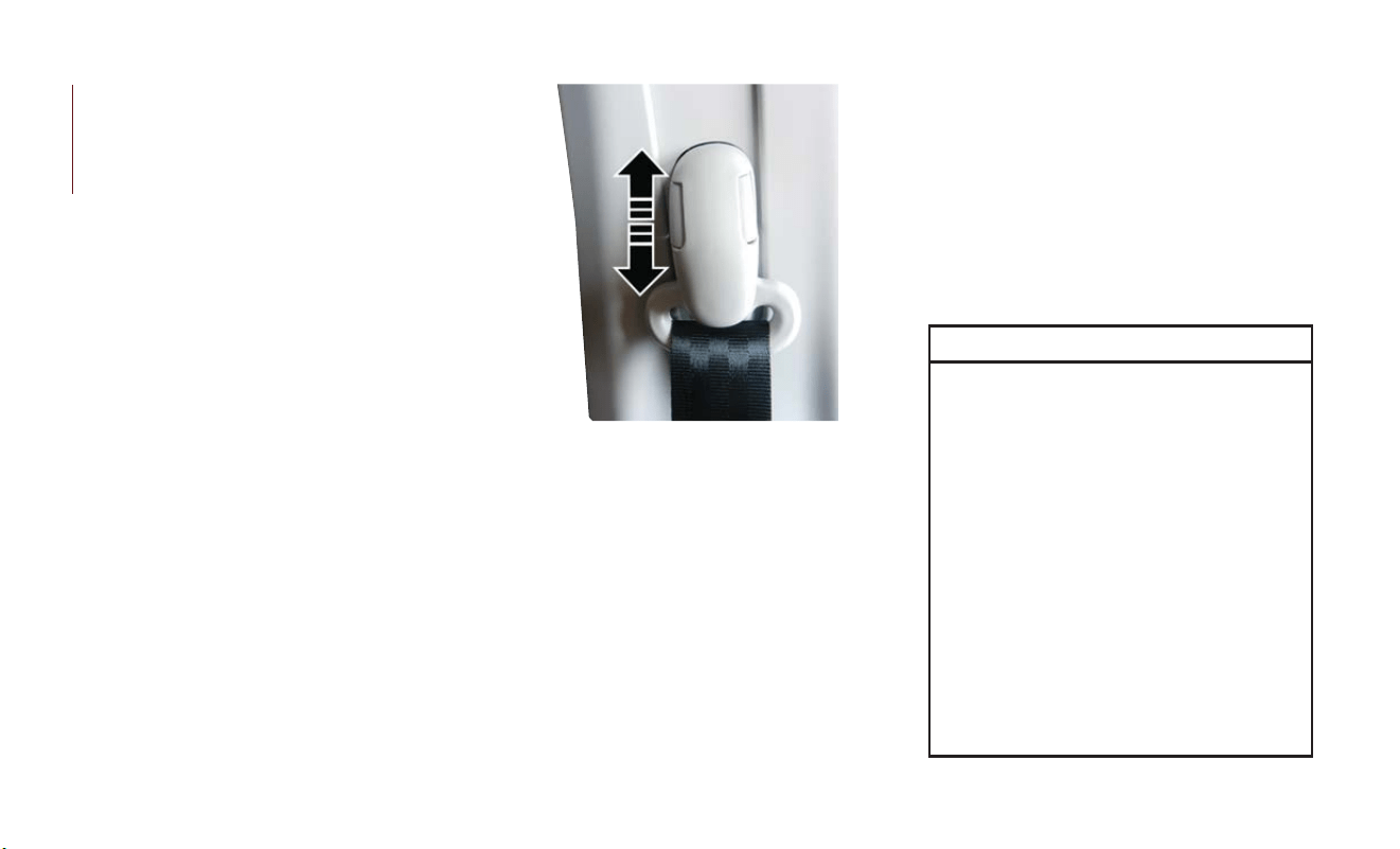
Lap/Shoulder Belt Untwisting Procedure
Use the following procedure to untwist a twisted
lap/shoulder belt.
1. Position the latch plate as close as possible to
the anchor point.
2. At about 6 to 12 inches (15 to 30 cm) above
the latch plate, grasp and twist the seat belt
webbing 180 degrees to create a fold that
begins immediately above the latch plate.
3. Slide the latch plate upward over the folded
webbing. The folded webbing must enter the
slot at the top of the latch plate.
4. Continue to slide the latch plate up until it
clears the folded webbing and the seat belt is
no longer twisted.
Adjustable Upper Shoulder Belt Anchorage
In
the driver and outboard front passenger seats,
the top of the shoulder belt can be adjusted
upward or downward to position the seat belt away
from your neck. Push or squeeze the anchorage
button to release the anchorage, and move it up or
down to the position that serves you best.
As a guide, if you are shorter than average, you
will prefer the shoulder belt anchorage in a lower
position, and if you are taller than average, you will
prefer the shoulder belt anchorage in a higher
position. After you release the anchorage button,
trytomoveitupordowntomakesurethatitis
locked in position.
NOTE:
The adjustable upper shoulder belt anchorage is
equipped with an Easy Up fea ture. This feature
allows the shoulder belt anchorage to be adjusted
in the upward position without pushing or
squeezing the release button.To verify the shoul-
der belt anchorage is latched, pull downward on
the shoulder belt anchorage until it is locked into
position.
WARNING!
• Wearing your seat belt incorrectly could
make your injuries in a collision much worse.
You might suffer internal injuries, or you
could even slide out of the seat belt. Follow
these instructions to wear your seat belt
safely and to keep your passengers safe, too.
• Position the shoulder belt across the shoul-
der and chest with minimal, if any slack so
that it is comfortable and not resting on
your neck. The retractor will withdraw any
slack in the shoulder belt.
•
Misadjustment of the seat belt could reduce
the effectiveness of the safety belt in a crash.
• Always make all seat belt height adjustments
when the vehicle is stationary.
Adjustable Anchorage
SAFETY
72

Seat Belts And Pregnant Women
Seat belts must be worn by all occupants including
pregnant women: the risk of injury in the event of
an accident is reduced for the mother and the
unborn child if they are wearing a seat belt.
Position the lap belt snug and low below the
abdomen and across the strong bones of the hips.
Place the shoulder belt across the chest and away
from the neck. Never place the shoulder belt
behind the back or under the arm.
Seat Belt Pretensioner
The front outboard seat belt system is equipped
with pretensioning devices that are designed to
remove slack from the seat belt in the event of a
collision. These devices may improve the perfor-
mance of the seat belt by removing slack from the
seat belt early in a collision. Pretensioners work
for all size occupants, including those in child
restraints.
NOTE:
These devices are not a substitute for proper seat
belt placement by the occupant.The seat belt still
must be worn snugly and positioned properly.
The pretensioners are triggered by the Occupant
Restraint Controller (ORC). Like the air bags, the
pretensioners are single use items. A deployed
pretensioner or a deployed air bag must be
replaced immediately.
Energy Management Feature
The front outboard seat belt system is equipped
with an Energy Management feature that may
help further reduce the risk of injury in the event
of a collision.The sea t belt system has a retractor
assembly that is designed to release webbing in a
controlled manner.
Switchable Automatic Locking Retractors
(ALR)
The seat belts in the passenger seating positions
are equipped wit h a Switchable Automatic Lock-
ing Retractor (ALR) which is used to secure a
child restraint system. For additional information,
refer to “Installing Child Restraints Using The
Vehicle Seat Belt” under the “Child Restraints”
section of this manual.The figure below illustrates
the locking feature for each seating position.
Pregnant Women And Seat Belts
ALR = Switchable Automatic Locking
Retractor
73

If the passenger seating position is equipped with
an ALR and is being used for normal usage, only
pull the seat belt webbing out far enough to
comfortably wrap around the occupant’s mid-
section so as to not activate the ALR. If the ALR
is activated, you will hear a clicking sound as the
seat belt retracts. Allow the webbing to retract
completely in this case and then carefully pull out
only the amount of webbing necessary to com-
fortably wrap around the occupant’s mid-section.
Slide the latch plate into t he buckle until you hear
a "click."
In Automatic Locking Mode, the shoulder belt is
automatically pre-locked. The seat belt will still
retract to remove any slack in t he shoulder belt.
Use the Automatic Locking Mode anytime a child
restraint is installed in a seating position that has
a seat belt with this feature. Children 12 years old
and under should always be properly restrained in
the rear seat of a vehicle with a rear seat.
WARNING!
• Never place a rear-facing child restraint in
front of an air bag. A deploying passenger
front air bag can cause death or serious
WARNING!
injur y to a child 12 years or younger, includ-
ing a child in a rear-facing child restraint.
• Never install a rear-facing child restraint in
the front seat of a vehicle. Only use a
rear-facing child restraint in the rear seat. If
the vehicle does not have a rear seat, do not
transport a rear-facing child restraint in that
vehicle.
How To Engage The Automatic Locking Mode
1. Buckle the combination lap and shoulder belt.
2. Grasp the shoulder portion and pull down-
ward until the entire seat belt is extracted.
3. Allow the seat belt to retract. As the seat belt
retracts, you will hear a clicking sound. This
indicates the seat belt is now in the Automatic
Locking Mode.
How To Disengage The Automatic Locking Mode
Unbuckle the combination lap/shoulder belt and
allow it to retract completely to disengage the
Automatic Locking Mode and activate the vehicle
sensitive (emergency) locking mode.
WARNING!
• The seat belt assembly must be replaced if
the switchable Automatic Locking Retractor
(ALR) feature or any other seat belt func-
tion is not working properly when checked
according to the procedures in the Service
Manual.
• Failure to replace the seat belt assembly
could increase the risk of injury in collisions.
• Do not use the Automatic Locking Mode to
restrain occupants who are wearing the seat
belt or children who are using booster
seats.The locked mode is only used to install
rear-facing or forward-facing child restraints
that have a harness for restraining the child.
Supplemental Restraint Systems (SRS)
Some of the safety features described in this
section may be standard equipment on some
models, or may be optional equipment on others.
If you are not sure, ask an authorized dealer.
SAFETY
74

The air bag system must be ready to protect you
in a collision. The Occupant Restraint Controller
(ORC) monitors the internal circuits and inter-
connecting wiring associated with the electrical
Air Bag System Components.Your vehicle may be
equipped with the following Air Bag System
Components:
Air Bag System Components
• Occupant Restraint Controller (ORC)
• Air Bag Warning Light
• Steering Wheel and Column
• Instrument Panel
• Knee Impact Bolsters
• Driver and Front Passenger Air Bags
• Seat Belt Buckle Switch
• Supplemental Side Air Bags
• Supplemental Knee Air Bags
• Front and Side Impact Sensors
• Seat Belt Pretensioners
• Seat Track Position Sensors
Air Bag Warning Light
The ORC monitors the readiness of the
electronic parts of the air bag system whenever the
ignition switch is in the AVV/START or MAR/ACC/
ON/RUN position. If the ignition switch is in the
STOP/OFF/LOCK position the air bag system is not
on and the air bags will not inflate.
The ORC contains a backup power supply system
that may deploy the air bag system even if the
battery loses power or it becomes disconnected
prior to deployment.
The ORC turns on the Air Bag Warning Light in
the instrument panel for approximately four to
eight seconds for a self-check when the ignition
switch is in the MAR/ACC/ON/RUN position.
After the self-check, the Air BagWarning Light will
turn off. If the ORC detects a malfunction in any
part of the system, it turns on the Air BagWarning
Light, either momentarily or continuously. A single
chime will sound to alert you if the light comes on
again after initial startup.
The ORC also includes diagnostics that will illu-
minate the instrument panel Air Bag Warning
Light if a malfunction is detected that could af fect
the air bag system.The diagnostics also record the
nature of the malfunction. While the air bag
system is designed to be maintenance free, if any
of the following occurs, have an authorized dealer
service the air bag system immediately.
• The Air Bag Warning Light does not come on
during the four to eight seconds when the
ignition switch is first in the MAR/ACC/ON/
RUN position.
• The Air Bag Warning Light remains on after the
four to eight-second interval.
• The Air Bag Warning Light comes on intermit-
tently or remains on while driving.
NOTE:
If the speedometer, tachometer, or any engine
related gauges are not working, the Occupant
Restraint Controller (ORC) may also be disabled.
In this condition the air bags may not be ready to
inflate for your protection. Have an authorized
dealer service the air bag system immediately.
WARNING!
Ignoring the Air Bag Warning Light in your
instrument panel could mean you won’t have
the air bag system to protect you in a collision.
75

WARNING!
If the light does not come on as a bulb check
when the ignition is first turned on, stays on
after you start the vehicle, or if it comes on as
you drive, have an authorized dealer service
the air bag system immediately.
Redundant Air Bag Warning Light
If a fault with the Air Bag Warning Light is
detected, which could affect the Supplemental
Restraint System (SRS), the Redundant Air Bag
Warning Light will illuminate on the instrument
panel. The Redundant Air Bag Warning Light will
stay on until the fault is cleared. In addition, a
single chime will sound to alert you that the
Redundant Air Bag Warning Light has come on
and a fault has been detected. If the Redundant
Air Bag Warning Light comes on intermittently or
remains on while driving have an authorized
dealer service the vehicle immediately.
For additional informa tion regarding the Redundant
Air Bag Warning Light refer to “Getting To Know
Your Instrument Panel” section of this manual.
Front Air Bags
This vehicle has front air bags and lap/shoulder
belts for both the driver and front passenger.
The front air bags are a supplement to the seat
belt restraint systems. The driver front air bag is
mounted in the center of the steering wheel.
The passenger front air bag is mounted in the
instrument panel, above the glove compartment.
The words “SRS AIRBAG” or “AIRBAG” are
embossed on the air bag covers.
WARNING!
• Being too close to the steering wheel or
instrument panel during front air bag de-
ployment could cause serious injury, includ-
ing death. Air bags need room to inflate.
Sit back, comfortably extending your arms to
reach the steering wheel or instrument
panel.
• Never place a rear-facing child restraint in
front of an air bag. A deploying passenger
front air bag can cause death or serious
injur y to a child 12 years or younger, includ-
ing a child in a rear-facing child restraint.
• Never install a rear-facing child restraint in
the front seat of a vehicle. Only use a
rear-facing child restraint in the rear seat.
If the vehicle does not have a rear seat, do
not transport a rear-facing child restraint in
that vehicle.
Driver And Passenger Front Air Bag Features
The Advanced Front Air Bag system has multi-
stage driver and front passenger air bags. This
system provides output appropriate to the sever-
ity and type of collision as determined by the
Front Air Bag/Knee Impact Bolster
Locations
1 — Driver And Passenger Front Air Bags
2 — Passenger Knee Impact Bolster
3 — Driver Knee Impact Bolster/
Supplemental Driver Knee Air Bag
SAFETY
76

Occupant Restraint Controller (ORC), which may
receive information from the front impac t sen-
sors (if equipped) or other system components.
The first stage inf lator is triggered immediately
during an impact that requires air bag deploy-
ment. A low energy output is used in less severe
collisions.A higher energy output is used for more
severe collisions.
This vehicle may be equipped with a driver and/or
front passenger seat bel t buckle switch t hat
detects whether the driver or front passenger
seat belt is buckled. The seat belt buckle switch
may adjust the inflation rate of the Advanced
Front Air Bags.
This vehicle may be equipped with driver and/or
front passenger seat track position sensors that
may adjust the inflation rate of the Advanced
Front Air Bags based upon seat position.
WARNING!
• No objects should be placed over or near
the air bag on the instrument panel or
steering wheel because any such objects
could cause harm if the vehicle is in a
WARNING!
collision severe enough to cause the air bag
to inflate.
• Do not put anything on or around the air
bag covers or attempt to open them manu-
ally. You may damage the air bags and you
could be injured because the air bags may
no longer be functional. The protective
covers for the air bag cushions are designed
to open only when the air bags are inflating.
• Relying on the air bags alone could lead to
more severe injuries in a collision. The air
bags work with your seat belt to restrain
you properly. In some collisions, air bags
won’t deploy at all. Always wear your seat
belts even though you have air bags.
Front Air Bag Operation
Front Air Bags are designed to provide additional
protection by supplementing the seat belts. Front
air bags are not expected to reduce t he risk of
injur y in rear, side, or rollover collisions. The front
air bags will not deploy in all frontal collisions,
including some that may produce substantial
vehicle damage — for example, some pole colli-
sions, truck underrides, and angle offset collisions.
On the other hand, depending on the type and
location of impact, front air bags may deploy in
crashes with little vehicle front-end damage but
that produce a severe initial deceleration.
Because air bag sensors measure vehicle decel-
eration over time, vehicle speed and damage by
themselves are not good indicators of whether or
not an air bag should have deployed.
Seat belts are necessary for your protection in all
collisions, and also are needed to help keep you in
position, away from an inflating air bag.
When the ORC detects a collision requiring the
front air bags, it signals the inflator units. A large
quantity of non-toxic gas is generated to inflate
the front air bags.
The steering wheel hub trim cover and the upper
passenger side of the instrument panel separate
and fold out of the way as the air bags inflate to
their full size.The front air bags fully inflate in less
time t han it takes to blink your eyes.The front air
bags then quickly deflate while helping to restrain
the driver and front passenger.
77

Knee Impact Bolsters
The Knee Impact Bolsters help protect the knees
of the driver and front passenger, and position the
front occupants for improved interaction with the
front air bags.
WARNING!
• Do not drill, cut, or tamper with the knee
impact bolsters in any way.
• Do not mount any accessories to the knee
impact bolsters such as alarm lights, stereos,
citizen band radios, etc.
Supplemental Driver Knee Air Bag
This vehicle is equipped with a Supplemental
Driver Knee Air Bag mounted in the instrument
panel below the steering column. The Supple-
mental Driver Knee Air Bag provides enhanced
protection during a frontal impact by working
together with the seat belts, pretensioners, and
front air bags.
Supplemental Side Air Bags
Supplemental Seat-Mounted Side Air Bags
(SABs)
This vehicle is equipped with Supplemental Seat-
Mounted Side Air Bags (SABs).
Supplemental Seat-Mounted Side Air Bags (SABs)
are located in the outboard side of the front
seats.The SABs are marked with a “SRS AIRBAG”
or “AIRBAG” on a label or on the seat trim on the
outboard side of the seats.
The SABs may help to reduce the risk of
occupant injur y during certain side impacts, in
addition to the injury reduction potential pro-
vided by the seat belts and body structure.
When the SAB deploys, it opens the seam on the
outboard side of the seatback’s trim cover. The
inflating SAB deploys through the seat seam into
the space between the occupant and the door.
Front Supplemental Seat-Mounted Side
Air Bag
SAFETY
78

The SAB moves at a very high speed and with
such a high force that it could injure occupants if
they are not seated properly, or if items are
positioned in the area where the SAB inflates.
Children are at an even greater risk of injury from
a deploying air bag.
WARNING!
Do not use accessory seat covers or place
objects between you and the Side Air Bags; the
performance could be adversely affected
and/or objects could be pushed into you,
causing serious injury.
Supplemental Side Air Bag Inflatable Curtains
(SABICs)
This vehicle is equipped with Supplemental Side
Air Bag Inflatable Curtains (SABICs).
Supplemental Side Air Bag Inflatable Curtains
(SABICs) are located above the side windows.
The trim covering the SABICs is labeled “SRS
AIRBAG” or “AIRBAG.”
SABICs may help reduce the risk of head and
other injuries to front and rear seat outboard
occupants in certain side impac ts, in addition to
the injury reduction potential provided by the
seat belts and body structure.
The SABIC deploys downward, covering the side
windows. An inf lating SABIC pushes the outside
edge of the headliner out of the way and covers
the window. The SABICs inflate with enough
force to injure occupants if they are not belted
and sea ted properly, or if items are positioned in
the area where the SABICs inflate. Children are
at an even greater risk of injury from a deploying
air bag.
The SABICs may help reduce the risk of partial or
complete ejection of vehicle occupants through
side windows in certain side impact events.
WARNING!
• Do not mount equipment, or s tack luggage
or other cargo up high enough to block the
deployment of the SABICs. The trim cover-
ing above the side windows where the
SABIC and its deployment path are located
should remain free from any obstructions.
• In order for the SABICs to work as in-
tended, do not install any accessory items in
your vehicle which could alter the roof. Do
not add an aftermarket sunroof to your
vehicle. Do not add roof racks that require
permanent attachments (bolts or screws)
for installation on the vehicle roof. Do not
drill into the roof of the vehicle for any
reason.
Supplemental Side Air Bag Inflatable
Curtain (SABIC) Label Location
79

Side Impacts
The Side Air Bags are designed to activate in certain
side impact s. The Occupant Restraint Controller
(ORC) determines whether the deployment of the
Side Air Bags in a particular impact event is
appropriate, based on the severity and type of
collision. The side impact sensors aid the ORC in
determining the appropriate response to impact
events. The system is calibrated to deploy the Side
Air Bags on the impact side of the vehicle during
impacts that require Side Air Bag occupant protec-
tion. In side impacts, the Side Air Bags deploy
independently; a left side impact deploys the left
Side Air Bags only and a right-side impact deploys
the right Side Air Bags only.Vehicle damage by itself
is not a good indicator of whether or not Side Air
Bags should have deployed.
The Side Air Bags will not deploy in all side
collisions, including some collisions at certain
angles, or some side collisions that do not impact
the area of the passenger compartment.The Side
Air Bags may deploy during angled or offset
frontal collisions where t he front air bags deploy.
Side Air Bags are a supplement to the seat belt
restraint system. Side Air Bags deploy in less time
than it takes to blink your eyes.
WARNING!
• Occupants, including children, who are up
agains t or very close to Side Air Bags can be
seriously injured or killed. Occupants, includ-
ing children, should never lean on or sleep
agains t the door, side windows, or area
where t he side air bags inflate, even if they
are in an infant or child restraint.
•
Seat belts (and child restraints where appro-
priate) are necessary for your protection in
all collisions. They also help keep you in
position, away from an inflating Side Air Bag.
To get the best protection from the Side Air
Bags, occupants must wear their seat belts
properly and sit upright with their backs
against the seats. Children must be properly
restrained in a child restraint or booster seat
that is appropriate for the size of the child.
WARNING!
• Side Air Bags need room to inflate. Do not
lean against the door or window. Sit upright
in the center of the seat.
WARNING!
• Being too close to the Side Air Bags during
deployment could cause you to be severely
injured or killed.
• Relying on the Side Air Bags alone could lead
to more severe injuries in a collision. The
Side Air Bags work wit h your seat belt to
restrain you properly. In some collisions, Side
Air Bags won’t deploy at all. Always wear
your seat belt even though you have Side Air
Bags.
NOTE:
Air bag covers may not be obvious in the interior
trim, but they will open during air bag deployment.
Rollover Events
Side Air Bags are designed to activa te in certain
rollover events. The ORC determines whether
the deployment of the Side Air Bags in a particu-
lar rollover event is appropriate, based on the
severity and type of collision. Vehicle damage by
itself is not a good indicator of whether or not
Side Air Bags should have deployed.
SAFETY
80

The Side Air Bags will not deploy in all rollover
events. The rollover sensing system determines if
a rollover event may be in progress and whether
deployment is appropriate. In the event the
vehicle experiences a rollover or near rollover
event, and deployment of the Side Air Bags is
appropriate, the rollover sensing system will also
deploy the seat belt pretensioners on both sides
of the vehicle.
The SABICs may help reduce the risk of partial or
complete ejection of vehicle occupants through
side windows in certain rollover or side impact
events.
Air Bag System Components
NOTE:
The Occupant Restraint Controller (ORC) moni-
tors the internal circuits and interconnecting
wiring associated with electrical Air Bag System
Components listed below:
• Occupant Restraint Controller (ORC)
• Air Bag Warning Light
• Steering Wheel and Column
• Instrument Panel
• Knee Impact Bolsters
• Driver and Front Passenger Air Bags
• Seat Belt Buckle Switch
• Supplemental Side Air Bags
• Supplemental Knee Air Bags
• Front and Side Impact Sensors
• Seat Belt Pretensioners
• Seat Track Position Sensors
If A Deployment Occurs
The front air bags are designed to deflate imme-
diately after deployment.
NOTE:
Front and/or side air bags will not deploy in all
collisions.This does not mean something is wrong
with the air bag system.
If you do have a collision which deploys the air
bags, any or all of the following may occur:
• The air bag material may sometimes cause
abrasions and/or skin reddening to the occu-
pants as the air bags deploy and unfold. The
abrasions are similar to friction rope burns or
those you might get sliding along a carpet or
gymnasium floor. They are not caused by con-
tact wit h chemicals. They are not permanent
and normally heal quickly. However, if you
haven’t healed significantly within a few days, or
if you have any blistering, see your doctor
immediately.
• As the air bags deflate, you may see some
smoke-like particles. The particles are a normal
by-product of the process that generates the
non-toxic gas used for air bag inflation. These
airborne particles may irritate the skin, eyes,
nose, or throat. If you have skin or eye irritation,
rinse the area with cool water. For nose or
throat irritation, move to fresh air. If the irrita-
tion continues, see your doctor. If these particles
settle on your clothing, follow the garment
manufacturer’s instructions for cleaning.
Do not drive your vehicle after the air bags have
deployed. If you are involved in another collision,
the air bags will not be in place to protect you.
WARNING!
Deployed air bags and seat belt pretensioners
cannot protect you in another collision. Have
the air bags, seat belt pretensioners, and the
seat belt retractor assemblies replaced by an
81

WARNING!
authorized dealer immediately. Also, have the
Occupant Restraint Controller System ser-
viced as well.
NOTE:
• Air bag covers may not be obvious in the
interior trim, but they will open during air bag
deployment.
• After any collision, the vehicle should be taken
to an authorized dealer immediately.
Enhanced Accident Response System
In the event of an impact, if the communication
network remains intact, and the power remains
intact, depending on the nature of the event, the
ORC will determine whether to have the En-
hanced Accident Response System perform the
following functions:
• Cut off fuel to the engine (If Equipped)
• Cut of f battery power to the electric motor
(If Equipped)
• Flash hazard lights as long as the battery has
power
• Turn on the interior lights, which remain on as
long as the battery has power or for 15 minutes
from the intervention of the Enhanced Accident
Response System.
• Unlock t he power door locks.
Your vehicle may also be designed to perform any
of these other functions in response to the
Enhanced Accident Response System:
• Turn off the Fuel Filter Heater, Turn off the
HVAC Blower Motor, Close the HVAC Circu-
lation Door
• Cut off battery power to the:
– Engine
– Electric Motor (if equipped)
– Electric power steering
– Brake booster
– Electric park brake
– Automatic transmission gear selector
– Horn
– Front wiper
– Headlamp washer pump
NOTE:
After an accident, remember to cycle the ignition
to the STOP (OFF/LOCK) position and remove
the key from the ignition switch to avoid draining
the battery. Carefully check the vehicle for fuel
leaks in the engine compartment and on the
ground near the engine compartment and fuel
tank before resetting the system and starting the
engine. If there are no fuel leaks or damage to the
vehicle electrical devices (e.g. headlights) after an
accident, reset the system by following the pro-
cedure described below. If you have any doubt,
contact an authorized dealer.
Enhanced Accident Response System Reset
Procedure
After the event occurs, when the system is active,
a message regarding fuel cutoff is displayed.
Turn the ignition switch from ignition AVV/START
or MAR/ACC/ON/RUN to ignition STOP/OFF/
LOCK. Carefully check the vehicle for fuel leaks in
the engine compartment and on the ground near
the engine compartment and fuel tank before
resetting the system and starting the engine.
SAFETY
82

Depending on t he nature of the event the left
and right turn signal lights, located in the instru-
ment panel, may both be blinking and will con-
tinue to blink. In order to move your vehicle to
the side of the road, you must follow the system
reset procedure.
Customer Action
Customer Will See
NOTE:
Each step MUST BE
held for at least two
seconds
1. Turn ignition STOP/
OFF/LOCK. (Turn Sig-
nal Switch Must be
placed in Neutral
State).
2. Turn ignition MAR/
ACC/ON/RUN.
Right turn light
BLINKS.
Left turn light is OFF.
3. Turn right turn signal
switch ON.
Right turn light is ON
SOLID.
Left turn light BLINKS.
4. Place turn signal in
neutral state.
Right turn light is OFF.
Left turn light BLINKS.
Customer Action
Customer Will See
NOTE:
Each step MUST BE
held for at least two
seconds
5. Turn left turn signal
switch ON.
Right turn light
BLINKS.
Left turn light is ON
SOLID.
6. Place turn signal in
neutral state.
Right turn light
BLINKS.
Left turn light is OFF.
7. Turn right turn signal
switch ON.
Right turn light is ON
SOLID.
Left turn light BLINKS.
8. Place turn signal in
neutral state.
Right turn light is OFF.
Left turn light BLINKS.
9. Turn left turn signal
switch ON.
Right turn light is ON
SOLID.
Left turn light is ON
SOLID.
10. Turn left turn signal
switch OFF. (Turn Sig-
nal Switch Must be
placed in Neutral
State).
Right turn light is OFF.
Left turn light is OFF.
Customer Action
Customer Will See
NOTE:
Each step MUST BE
held for at least two
seconds
11. Turn ignition STOP/
OFF/LOCK.
12. Turn ignition MAR/
ACC/ON/RUN. (Entire
sequence needs to be
completed within one
minute or sequence
will need to be re-
peated).
System is now reset
and the engine may be
started.
Turn hazard flashers
OFF (Manually).
If a reset procedure step is not completed within
60 seconds, t hen the turn signal lights will blink
and the reset procedure must be performed
again in order to be successful.
83

Maintaining Your Air Bag System
WARNING!
• Modifications to any part of the air bag
system could cause it to fail when you need
it.You could be injured if the air bag system
is not there to protect you. Do not modify
the components or wiring, including adding
any kind of badges or stickers to the steering
wheel hub trim cover or the upper passen-
ger side of the instrument panel. Do not
modify the front bumper, vehicle body
structure, or add aftermarket side steps or
running boards.
• It is dangerous to try to repair any part of
the air bag system yourself. Be sure to tell
anyone who works on your vehicle that it
has an air bag system.
• Do not attempt to modify any part of your
air bag system. The air bag may inflate
accidentally or may not function properly if
modifications are made.Take your vehicle to
an authorized dealer for any air bag system
service. If your seat, including your trim
cover and cushion, needs to be serviced in
any way (including removal or loosening/
WARNING!
tightening of seat attachment bolts), take the
vehicle to an authorized dealer. Only manu-
fac turer approved seat accessories may be
used. If it is necessary to modify the air bag
system for persons with disabilities, contact
an authorized dealer.
Event Data Recorder (EDR)
This vehicle is equipped with an event data
recorder (EDR). The main purpose of an EDR is
to record, in certain crash or near crash-like
situations, such as an air bag deployment or hitting
a road obstacle, data that will assist in understand-
ing how a vehicle’s systems performed. The EDR
is designed to record data related to vehicle
dynamics and safety systems for a short period of
time, typically 30 seconds or less.The EDR in this
vehicle is designed to record such data as:
• How various systems in your vehicle were
operating;
• Whether or not the driver and passenger safety
belts were buckled/fastened;
• How far (if at all) the driver was depressing the
accelerator and/or brake pedal; and,
• How fast the vehicle was traveling.
These data can help provide a better understand-
ing of the circumstances in which crashes and
injuries occur.
NOTE:
EDR data are recorded by your vehicle only if a
non-trivial crash situation occurs; no data are
recorded by the EDR under normal driving
conditions and no personal data (e .g., name,
gender, age, and crash location) are recorded.
However, other parties, such as law enforcement,
could combine the EDR data with the type of
personally identifying data routinely acquired dur-
ing a crash investigation.
To read data recorded by an EDR, special equip-
ment is required, and access to the vehicle or the
EDR is needed. In addition to the vehicle manu-
fac turer, other parties, such as law enforcement,
that have the special equipment, can read the
information if they have access to the vehicle or
the EDR.
SAFETY
84
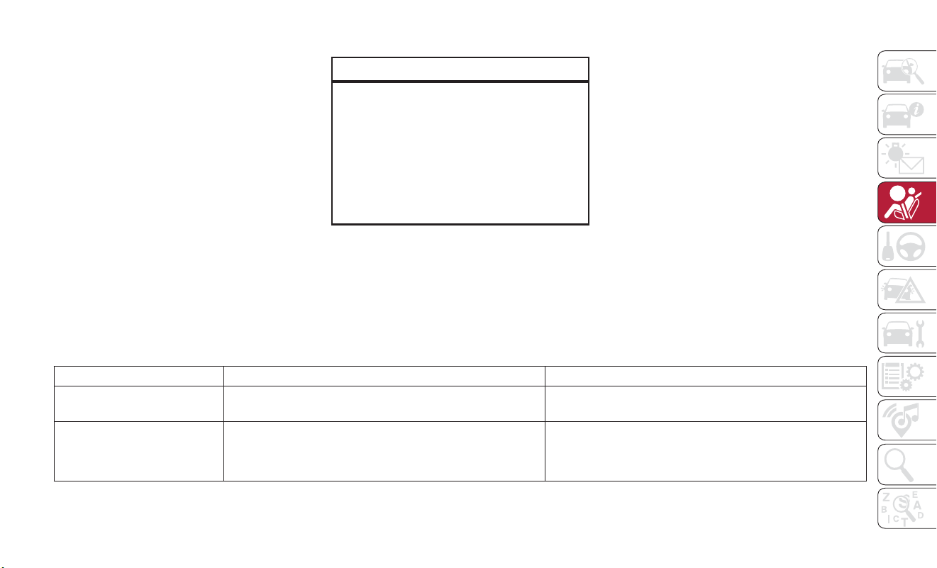
Child Restraints
Everyone in your vehicle needs to be buckled up
at all times, including babies and children. Every
state in the United Sta tes, and every Canadian
province, requires that small children ride in
proper restraint systems. This is the law, and you
can be prosecuted for ignoring it.
Children 12 years or younger should ride prop-
erly buckled up in a rear seat, if available.
According to crash statistics, children are safer
when properly restrained in the rear seats rather
than in the front.
WARNING!
In a collision, an unrestrained child can become
a projectile inside the vehicle. The force re-
quired to hold even an infant on your lap could
become so great that you could not hold the
child, no matter how strong you are. The child
and others could be badly injured or killed.Any
child riding in your vehicle should be in a
proper restraint for the child’s size.
T
here are different sizes and types of restraints for
children from newborn size to the child almost
large enough for an adult safety belt. Always check
the child seat Owner’s Manual to make sure you
have the correct seat for your child. Carefully read
and follow all the instructions and warnings in the
child restraint Owner’s Manual and on all the labels
attached to the child restraint.
Before buying any restraint system, make sure that
it has a label certifying that it meets all applicable
Safety Standards. You should also make sure that
you can install it in the vehicle where you will
use it.
NOTE:
• For additional information, refer to http://
www.nhtsa.gov/parents-and-caregivers or call
1-888-327-4236.
• Canadian residents should refer to Transport
Canada’s website for additional informa tion:
http://www.tc.gc.ca/eng/motorvehiclesafety/
safedrivers-childsafety-index-53.htm.
Summary Of Recommendations For Restraining Children In Vehicles
Child Size, Height, Weight Or Age Recommended Type Of Child Restraint
Infants and Toddlers
Children who are two years old or younger and who have
not reached the height or weight limits of their child restraint
Either an Infant Carrier or a Convertible Child Restraint,
facing rearward in a rear seat of the vehicle
Small Children
Children who are at least two years old or who have
outgrown the height or weight limit of their rear-facing
child restraint
Forward-Facing Child Restraint with a five-point Harness,
facing forward in a rear seat of the vehicle
85

Child Size, Height, Weight Or Age Recommended Type Of Child Restraint
Larger Children
Children who have outgrown their forward-facing child re-
straint, but are too small to properly fit the vehicle’s seat belt
Belt Positioning Booster Seat and the vehicle seat belt, seated
in a rear seat of the vehicle
Children Too Large for Child
Restraints
Children 12 years old or younger, who have outgrown the
height or weight limit of their booster seat
Vehicle Seat Belt, seated in a rear seat of the vehicle
Infant And Child Restraints
Safety experts recommend that children ride
rear-facing in t he vehicle until they are two years
old or until they reach either the height or weight
limit of their rear-facing child restraint. Two types
of child restraints can be used rear-facing: infant
carriers and convertible child sea ts.
The infant carrier is only used rear-facing in the
vehicle. It is recommended for children from
birth until they reach the weight or height limit of
the infant carrier. Convertible child seats can be
used either rear-facing or forward-facing in t he
vehicle. Convertible child sea ts often have a
higher weight limit in the rear-facing direction
than infant carriers do, so they can be used
rear-facing by children who have outgrown their
infant carrier but are still less than at least two
years old. Children should remain rear-facing until
they reach the highest weight or height allowed
by their convertible child seat.
WARNING!
• Never place a rear-facing child restraint in
front of an air bag. A deploying passenger
front air bag can cause death or serious
injur y to a child 12 years or younger, includ-
ing a child in a rear-facing child restraint.
• Never install a rear-facing child restraint in
the front seat of a vehicle. Only use a
rear-facing child restraint in the rear seat. If
the vehicle does not have a rear seat, do not
transport a rear-facing child restraint in that
vehicle.
Older Children And Child Restraints
Children who are two years old or who have
outgrown their rear-facing convertible child seat
can ride forward-facing in the vehicle. Forward-
facing child seats and convertible child seats used
in the forward-facing direction are for children
who are over two years old or who have
outgrown the rear-facing weight or height limit of
their rear-facing convertible child seat. Children
should remain in a forward-facing child seat with
a harness for as long as possible, up to the highest
weight or height allowed by the child seat.
All children whose weight or height is above the
forward-facing limit for the child seat should use a
belt-positioning booster seat until the vehicle’s
seat belts fit properly. If the child cannot sit with
knees bent over the vehicle’s seat cushion while
the child’s back is against the seatback, they should
use a belt-positioning booster seat. The child and
belt-positioning booster seat are held in the
vehicle by the seat belt.
SAFETY
86

WARNING!
• Improper installation can lead to failure of an
infant or child restraint. It could come loose
in a collision.The child could be badly injured
or killed. Follow the child restraint manufac-
turer’s directions exactly when installing an
infant or child restraint.
• After a child restraint is installed in the
vehicle, do not move the vehicle seat for-
ward or rearward because it can loosen the
child restraint attachments. Remove the
child restraint before adjusting the vehicle
seat position. When the vehicle seat has
been adjusted, reinstall the child restraint.
• When your child restraint is not in use ,
secure it in the vehicle with the seat belt or
LATCH anchorages, or remove it from the
vehicle. Do not leave it loose in the vehicle.
In a sudden stop or accident, it could strike
the occupants or seatbacks and cause seri-
ous personal injury.
Children Too Large For Booster Seats
Children who are large enough to wear the
shoulder belt comfortably, and whose legs are
long enough to bend over the front of the seat
when their back is against the seatback, should use
the seat belt in a rear seat. Use this simple 5-step
test to decide whet her the child can use the
vehicle’s seat belt alone:
1. Can the child sit all t he way back against the
back of the vehicle seat?
2. Do the child’s knees bend comfortably over
the front of the vehicle seat – while the child
is still sitting all the way back?
3. Does t he shoulder belt cross the child’s shoul-
der between the neck and arm?
4. Is the lap part of the belt as low as possible,
touching the child’s thighs and not the
stomach?
5. Can the child stay seated like this for the
whole trip?
If the answer to any of t hese questions was “no,”
then the child still needs to use a booster seat in
this vehicle. If the child is using the lap/shoulder
belt, check seat belt fit periodically and make sure
the seat belt buckle is latched. A child’s squirming
or slouching can move the belt out of position. If
the shoulder belt contacts the face or neck, move
the child closer to the center of the vehicle, or
use a booster seat to position the seat belt on the
child correctly.
WARNING!
Never allow a child to put the shoulder belt
under an arm or behind their back. In a crash,
the shoulder belt will not protect a child
properly, which may result in serious injury or
death. A child must always wear both the lap
and shoulder portions of the seat belt cor-
rectly.
87

Recommendations For Attaching Child Restraints
Restraint Type Combined Weight of
the Child + Child
Restraint
Use Any Attachment Method Shown With An “X” Below
LATCH – Lower
Anchors Only
Seat Belt Only LATCH – Lower
Anchors + Top Tether
Anchor
Seat Belt + Top Tether
Anchor
Rear-Facing Child
Restraint
Up to 65 lbs (29.5kg)
XX
Rear-Facing Child
Restraint
More than 65 lbs
(29.5kg)
X
Forward-Facing Child
Restraint
Up to 65 lbs (29.5kg) X X
Forward-Facing Child
Restraint
More than 65 lbs
(29.5kg)
X
SAFETY
88

Lower Anchors And Tethers For CHildren
(LATCH) Restraint System
Your vehicle is equipped with the child restraint
anchorage system called LATCH, which stands for
Lower Anchors and Tethers for CHildren. The
LATCH system has three vehicle anchor points
for installing LATCH-equipped child seats. There
are two lower anchorages located at the back of
the seat cushion where it meets the seatback and
one top tether anchorage located behind the
seating position. These anchorages are used to
install LATCH-equipped child seats without using
the vehicle’s seat belts. Some seating positions
may have a top tether anchorage but no lower
anchorages. In these seating positions, the seat
belt must be used with the top tether anchorage
to install the child restraint. Please see the
following table for more information.
LATCH Positions For Installing Child
Restraints In This Vehicle
Frequently Asked Questions About Installing Child Restraints With LATCH
What is the weight limit (child’s weight + weight of the child
restraint) for using the LATCH anchorage system to attach
the child restraint?
65 lbs (29.5kg)
Use the LATCH anchorage system until the combined weight
of the child and the child restraint is 65 lbs (29.5kg).
Use the seat belt and tether anchor instead of the LATCH
anchorage system once the combined weight is more than
65 lbs (29.5kg).
LATCH Label
LATCH Positions
Lower Anchorage Symbol
(2 Anchorages Per Seating Position)
Top Tether Anchorage Symbol
89

Frequently Asked Questions About Installing Child Restraints With LATCH
Can the LATCH anchorages and the seat belt be used to-
gether to attach a rear-facing or forward-facing child restraint?
No
Do not use the seat belt when you use the LATCH
anchorage system to attach a rear-facing or forward-facing
child restraint.
Booster seats may be attached to the LATCH anchorages if
allowed by the booster seat manufacturer. See your booster
seat owner’s manual for more information.
Can a child seat be installed in the center position using the
inner LATCH lower anchorage?
No
Use the seat belt and tether anchor to install a child seat in
the center seating position.
Can two child restraints be attached using a common lower
LATCH anchorage?
No
Never “share” a LATCH anchorage with two or more child
restraints. If the center position does not have dedicated
LATCH lower anchorages, use the seat belt to install a child
seat in the center position next to a child seat using the
LATCH anchorages in an outboard position.
Can the rear-facing child restraint touch the back of the front
passenger seat?
Ye s
The child seat may touch the back of the front passenger seat
if the child restraint manufacturer also allows contact. See
your child restraint owner’s manual for more information.
Can the rear head restraints be removed? Yes
The head restraints can be removed in each seating position
if they interfere with the installation of the child restraint.
Refer to “Head Restraints” in “Getting To Know Your Vehicle”
in the Owner’s Manual for further information.
SAFETY
90

Locating The LATCH Anchorages
The lower anchorages are round bars that are
found at the rear of the seat cushion where it
meets the seatback, below the anchorage symbols
on the seatback. They are just visible when you
lean into the rear seat to install the child restraint.
You will easily feel them if you run your finger
along the gap between the seatback and seat
cushion.
Locating The Upper Tether Anchorages
There are tether s trap anchorages behind each
rear seating position located on the back of the
seat.
LATCH-compatible child restraint systems will be
equipped with a rigid bar or a flexible strap on
each side. Each will have a hook or connector to
attach to the lower anchorage and a way to
tighten the connection to the anchorage.
Forward-facing child restraints and some rear-
facing child restraints will also be equipped with a
tether s trap. The tether strap will have a hook at
the end to attach to the top tether anchorage and
a way to tighten the strap after it is att ached to
the anchorage.
Center Seat LATCH :
WARNING!
• Do not install a child restraint in the center
position using the LATCH system. This po-
sition is not approved for inst alling child seats
using the LATCH attachments.You must use
the seat belt and tether anchor to install a
child seat in the center sea ting position.
• Never use the same lower anchorage to
attach more than one child restraint. Please
refer to “To Install A LATCH-Compatible
Child Restraint” for typical installation in-
structions.
Always follow the directions of the child re-
straint manufacturer when installing your child
restraint. Not all child restraint systems will be
installed as described here.
Lower Anchorage Location
Tether Anchorage Locations
91

To Install A LATCH-Compatible Child
Restraint
If the selected seating position has a Switchable
Automatic Locking Retractor (ALR) seat belt,
stow the seat belt, following the instructions
below. See the section “Installing Child Restraints
Using theVehicle Seat Belt” to check what type of
seat belt each seating position has.
1. Loosen the adjusters on the lower straps and
on the tether strap of the child seat so that
you can more easily attach the hooks or
connectors to the vehicle anchorages.
2. Place the child seat between the lower an-
chorages for that seating position. For some
second row seats, you may need to recline the
seat and / or raise the head restraint (if
adjustable) to get a better fit. If the rear seat
can be moved forward and rearward in the
vehicle, you may wish to move it to its
rear-most position to make room for the child
seat. You may also move the front seat for-
ward to allow more room for the child seat.
3. Attach the lower hooks or connectors of the
child restraint to t he lower anchorages in the
selected seating position.
4. If the child restraint has a tether s trap, connect
it to the top tether anchorage. See the section
“Installing Child Restraints Using the Top
Tether Anchorage” for directions to attach a
tether anchor.
5. Tighten all of the straps as you push the child
restraint rearward and downward into the
seat. Remove slack in the straps according to
the child restraint manufacturer’s instructions.
6. Test that the child restraint is installed tightly
by pulling back and forth on the child seat at
the belt path. It should not move more than
1 inch (25.4 mm) in any direction.
How To Stow An Unused Switchable-ALR
(ALR) Seat Belt:
When using the LATCH attaching system to
install a child restraint, stow all ALR seat belts that
are not being used by other occupants or being
used to secure child restraints. An unused belt
could injure a child if they play wit h it and
accidentally lock t he seat belt retractor. Before
installing a child restraint using the LATCH sys-
tem, buckle the seat bel t behind the child restraint
and out of the child’s reach. If the buckled seat
belt interferes with the child restraint installation,
instead of buckling it behind the child restraint,
route the seat belt through the child restraint belt
path and then buckle it. Do not lock the seat belt.
Remind all children in the vehicle that the seat
belts are not toys and that they should not play
with them.
WARNING!
• Improper installation of a child restraint to
the LATCH anchorages can lead to failure of
the restraint. The child could be badly in-
jured or killed. Follow the child restraint
manufacturer’s directions exactly when in-
stalling an infant or child restraint.
• Child restraint anchorages are designed to
withs tand only those loads imposed by
correctly-fitted child restraints. Under no
circumstances are they to be used for adult
seat belts, harnesses, or for attaching other
items or equipment to the vehicle.
SAFETY
92

Installing Child Restraints Using The Vehicle
Seat Belt
Child restraint systems are designed to be se-
cured in vehicle seats by lap belts or the lap belt
portion of a lap/shoulder belt.
WARNING!
• Improper installation or failure to properly
secure a child restraint can lead to failure of
the restraint. The child could be badly in-
jured or killed.
• Follow the child restraint manufacturer’s
directions exactly when installing an infant or
child restraint.
The seat belts in the passenger seating positions
are equipped wit h a Switchable Automatic Lock-
ing Retractor (ALR) tha t is designed to keep the
lap portion of the seat belt tight around the child
restraint so that it is not necessary to use a locking
clip. The ALR retractor can be “switched” into a
locked mode by pulling all of the webbing out of
the retractor and then letting the webbing retract
back into the retractor. If it is locked, the ALR will
make a clicking noise while the webbing is pulled
back into the retractor.
Refer to the “Automatic Locking Mode” descrip-
tion in “Switchable Automatic Locking Retractors
(ALR)” under “Occupant Restraint Systems” for
additional information on ALR.
Please see the table below and the following
sections for more information.
Lap/Shoulder Belt Systems For Installing
Child Restraints In This Vehicle
Frequently Asked Questions About Installing Child Restraints With Seat Belts
What is the weight limit (child’s weight + weight of the child
restraint) for using the Tether Anchor with the seat belt to
attach a forward facing child restraint?
Weight limit of the
Child Restraint
Always use the tether anchor when using the seat belt to
install a forward facing child restraint, up to the recommended
weight limit of the child restraint.
Automatic Locking Retractor (ALR)
Locations
ALR = Switchable Automatic Locking
Retractor
Top Tether Anchorage Symbol
93

Frequently Asked Questions About Installing Child Restraints With Seat Belts
Can the rear-facing child restraint touch the back of the front
passenger seat?
Ye s
Contact between the front passenger seat and the child
restraint is allowed, if the child restraint manufacturer also
allows contact.
Can the rear head restraints be removed? Yes
The head restraints can be removed in each seating position if
they interfere with the installation of the child restraint.
Refer to “Head Restraints” in “Getting To Know Your Vehicle”
in the Owner’s Manual for further information.
Can the buckle stalk be twisted to tighten the seat belt
against the belt path of the child restraint?
No
Do not twist the buckle stalk in a seating position with an
ALR retractor.
Installing A Child Restraint With A Switch-
able Automatic Locking Retractor (ALR):
Child restraint systems are designed to be se-
cured in vehicle seats by lap belts or the lap belt
portion of a lap/shoulder belt.
WARNING!
• Improper installation or failure to properly
secure a child restraint can lead to failure of
the restraint. The child could be badly in-
jured or killed.
• Follow the child restraint manufacturer’s
directions exactly when installing an infant
or child restraint.
1. Place the child seat in the center of the seating
position. For some second row seats, you may
need to recline the seat and/or raise the head
restraint (if adjustable) to get a better fit. If the
rear seat can be moved forward and rearward
in the vehicle, you may wish to move it to its
rear-most position to make room for the child
seat. You may also move the front seat for-
ward to allow more room for the child seat.
2. Pull enough of t he seat belt webbing from the
retractor to pass it through the belt path of
the child restraint. Do not twist the belt
webbing in the belt path.
3. Slide the latch plate into the buckle until you
hear a “click.”
4. Pull on the webbing to make the lap portion
tight against the child seat.
5. To lock the seat belt, pull down on the
shoulder part of the belt until you have pulled
all the seat belt webbing out of the retractor.
Then, allow the webbing to retract back into
the retractor.As the webbing retracts, you will
hear a clicking sound.This means the seat belt
is now in the Automatic Locking mode.
SAFETY
94

6. Try to pull the webbing out of t he retractor. If
it is locked, you should not be able to pull out
any webbing. If the retractor is not locked,
repeat step 5.
7. Finally, pull up on any excess webbing to
tighten the lap portion around the child re-
straint while you push the child restraint
rearward and downward into the vehicle seat.
8. If the child restraint has a top tether strap and
the seating position has a top tether anchor-
age, connect the tether strap to the anchorage
and tighten the tether strap. See the section
“Installing Child Restraints Using the Top
Tether Anchorage” for directions to attach a
tether anchor.
9. Test that the child restraint is installed tightly
by pulling back and forth on the child seat at
the belt path. It should not move more than
1 inch (25.4 mm) in any direction.
Any seat belt system will loosen with time, so
check the belt occasionally, and pull it tight if
necessar y.
Installing Child Restraints Using The Top
Tether Anchorage:
WARNING!
Do not attach a tether strap for a rear-facing
car seat to any location in front of the car seat,
including the seat frame or a tether anchor-
age. Only attach the tether strap of a rear-
facing car seat to t he tether anchorage that is
approved for that seating position, located
behind the top of the vehicle seat. See t he
section “Lower Anchors and Tethers for CHil-
dren (LATCH) Restraint System” for the loca-
tion of approved tether anchorages in your
vehicle.
1. Look behind the seating position where you
plan to install the child restraint to find t he
tether anchorage.You may need to move the
seat forward to provide better access to the
tether anchorage. If there is no top tether
anchorage for that seating position, move the
child restraint to another position in the
vehicle if one is available.
2.
Route the tether strap to provide the most
direct path for the strap between the anchor
and the child seat. If your vehicle is equipped
with adjustable rear head restraints, raise the
head restraint, and where possible, route the
tether strap under the head restraint and
between the two posts. If not possible, lower
the head restraint and pass the tether strap
around the outboard side of the head restraint.
95

3.
Attach the tether strap hook of the child
restraint to the top tether anchorage as shown
in the diagram.
4. Remove slack in the tether strap according to
the child restraint manufacturer’s instructions.
WARNING!
• An incorrectly anchored tether strap could
lead to increased head motion and possible
injur y to the child. Use only the anchorage
position directly behind the child seat to
secure a child restraint top tether strap.
WARNING!
• If your vehicle is equipped with a split rear
seat, make sure the tether strap does not
slip into the opening between the seatbacks
as you remove slack in the strap.
Transporting Pets
Air Bags deploying in the front seat could harm
your pet. An unrestrained pet will be thrown
about and possibly injured, or injure a passenger
during panic braking or in a collision.
Pets should be restrained in the rear seat in pet
harnesses or pet carriers that are secured by seat
belts.
SAFETY TIPS
Transporting Passengers
NEVER TRANSPORT PASSENGERS IN THE
CARGO AREA.
WARNING!
• Do not leave children or animals inside
parked vehicles in hot weather. Interior heat
build-up may cause serious injury or death.
• It is extremely dangerous to ride in a cargo
area, inside or outside of a vehicle. In a
collision, people riding in these areas are
more likely to be seriously injured or killed.
• Do not allow people to ride in any area of
your vehicle that is not equipped with seats
and seat belts.
• Be sure everyone in your vehicle is in a seat
and using a seat belt properly.
Exhaust Gas
WARNING!
Exhaust gases can injure or kill. They contain
carbon monoxide (CO), which is colorless and
odorless. Breathing it can make you uncon-
scious and can eventually poison you.To avoid
breathing (CO), follow these safety tips:
• Do not run the engine in a closed garage or
in confined areas any longer than needed to
move your vehicle in or out of the area.
Tether Anchorage Locations
SAFETY
96

WARNING!
• If you are required to drive with the trunk/
liftgate/rear doors open, make sure that all
windows are closed and the climate control
BLOWER switch is set at high speed. DO
NOT use the recirculation mode.
• If it is necessary to sit in a parked vehicle
with the engine running, adjust your heating
or cooling controls to force outside air into
the vehicle. Set the blower at high speed.
The best protection against carbon monoxide
entr y into the vehicle body is a properly main-
tained engine exhaust system.
Whenever a change is noticed in the sound of the
exhaust system, when exhaust fumes can be
detected inside the vehicle, or when the under-
side or rear of the vehicle is damaged, have a
competent mechanic inspect the complete ex-
haust system and adjacent body areas for broken,
damaged, deteriorated, or mispositioned parts.
Open seams or loose connections could permit
exhaust fumes to seep into the passenger com-
partment. In addition, inspect the exhaust system
each time the vehicle is raised for lubrica tion or
oil change. Replace as required.
Safety Checks You Should Make Inside The
Vehicle
Seat Belts
Inspect the seat belt system periodically, checking
for cuts, frays, and loose parts. Damaged parts
must be replaced immediately. Do not disas-
semble or modify the system.
Front seat belt assemblies must be replaced after
a collision. Rear seat belt assemblies must be
replaced after a collision if they have been
damaged (i.e., bent retractor, torn webbing, etc.).
If there is any question regarding seat belt or
retractor condition, replace the seat belt.
Air Bag Warning Light
The Air Bag warning light will turn on for
four to eight seconds as a bulb check when the
ignition switch is first turned to ON/RUN. If the
light is either not on during starting, stays on, or
turns on while driving, have the system inspected
at an authorized dealer as soon as possible. After
the bulb check, this light will illuminate with a
single chime when a fault with the Air Bag System
has been detected. It will stay on until the fault is
removed. If the light comes on intermittently or
remains on while driving, have an authorized
dealer service the vehicle immediately.
Refer to “Occupant Restraint Systems” in “Safety”
for further information.
Defroster
Check operation by selecting the defrost mode
and place the blower control on high speed. Yo u
should be able to feel the air directed agains t the
windshield. See an authorized dealer for service if
your defroster is inoperable.
Floor Mat Safety Information
Always use floor mats designed to fit your
vehicle. Only use a floor mat that does not
interfere with the operation of the accelerator,
brake or clutch pedals. Only use a floor mat that
is securely attached using the floor mat fasteners
so it cannot slip out of position and interfere with
the accelerator, brake or clutch pedals or impair
safe operation of your vehicle in other ways.
97

WARNING!
An improperly attached, damaged, folded, or
stacked floor mat, or damaged floor mat
fasteners may cause your floor mat to inter-
fere with the accelerator, brake, or clutch
pedals and cause a loss of vehicle control. To
prevent SERIOUS INJURY or DEATH:
• ALWAYS securely attach
your floor
mat using the floor mat fasteners. DO NOT
install your floor mat upside down or turn
your floor mat over. Lightly pull to confirm
mat is secured using the floor mat fasteners
on a regular basis.
• ALWAYS REMOVE THE EXISTING FLOOR
MAT FROM THE VEHICLE
before
installing any other floor mat. NEVER install
or stack an additional floor mat on top of an
existing floor mat.
• ONLY install floor mats designed to fit your
vehicle. NEVER install a floor mat that
cannot be properly attached and secured to
your vehicle. If a floor mat needs to be
WARNING!
replaced, only use a FCA approved floor mat
for the specific make, model, and year of
your vehicle.
• ONLY use the driver’s side floor mat on the
driver’s side floor area. To check for inter-
ference, with the vehicle properly parked
with t he engine of f, fully depress the accel-
erator, the brake, and the clutch pedal (if
present) to check for interference. If your
floor mat interferes with the operation of
any pedal, or is not secure to the floor,
remove the floor mat from the vehicle and
place the floor mat in your trunk.
• ONLY use the passenger’s side floor mat on
the passenger’s side floor area.
• ALWAYS make sure objects cannot fall or
slide into the driver’s side floor area when
the vehicle is moving. Objects can become
trapped under accelerator, brake, or clutch
pedals and could cause a loss of vehicle
control.
WARNING!
• NEVER place any objects under the floor
mat (e.g., towels, keys, etc.). These objects
could change the position of the floor mat
and may cause interference with the accel-
erator, brake, or clutch pedals.
• If the vehicle carpet has been removed and
re-installed, always properly attach carpet to
the floor and check the floor mat fasteners
are secure to the vehicle carpet. Fully de-
press each pedal to check for interference
with the accelerator, brake, or clutch pedals
then re-install the f loor mats.
• It is recommended to only use mild soap
and water to clean your floor mats. After
cleaning, always check your floor mat has
been properly installed and is secured to
your vehicle using t he floor mat fasteners by
lightly pulling mat.
SAFETY
98

Periodic Safety Checks You Should Make
Outside The Vehicle
Tires
Examine tires for excessive tread wear and uneven
wear patterns. Check for stones, nails, glass, or other
objects lodged in the tread or sidewall. Inspect the
tread for cuts and cracks. Inspect sidewalls for cuts,
cracks, and bulges. Check the wheel nuts for
tightness. Check the tires (including spare) for
proper cold inflation pressure.
Lights
Have someone observe the operation of brake
lights and exterior lights while you work the
controls. Check turn signal and high beam indica-
tor lights on the instrument panel.
Door Latches
Check for proper closing, latching, and locking.
Fluid Leaks
Check area under the vehicle after overnight
parking for fuel, coolant, oil, or other fluid leaks.
Also, if gasoline fumes are detected or if fuel, or
brake fluid leaks are suspected. The cause should
be located and corrected immediately.
99

STARTING THE ENGINE
Before starting your vehicle, adjust your seat,
adjust the inside and outside mirrors, fasten your
seat belt, and if present, instruct all other occu-
pants to buckle their seat belts.
WARNING!
• Never leave children alone in a vehicle, or
with access to an unlocked vehicle.
• Allowing children to be in a vehicle unat-
tended is dangerous for a number of rea-
sons.A child or others could be seriously or
fatally injured. Children should be warned
not to touch the parking brake, brake pedal
or the gear selector.
• Do not leave the key fob in or near the
vehicle (or in a location accessible to chil-
dren), and do not leave the ignition in the
ON or RUN mode. A child could operate
power windows,other controls,or move the
vehicle.
Start the engine with the gear selector in the
NEUTRAL or PARK position. Apply the brake
before shifting to any driving range.
Proceed as follows:
1. Set the Electric Park Brake (EPB) and put the
gear selector in the PARK or NEUTRAL
position.
2. Press on the brake pedal, without pressing the
accelerator.
3. Cycle the ignition to the START mode and
release it as soon as the engine is started.
4. If the engine does not start, place the ignition
in the OFF mode and wait 10-15 seconds
before a ttempting to restart the engine.
Stopping The Engine
To shut off the engine with vehicle speed greater
than 5 mph (8 km/h), you must push and hold the
ignition or push the START/STOP button three
times consecutively within a few seconds. The
engine will shut down, and the ignition will be
placed in the RUN position.
Turning OFF the car (cycle the ignition from the
RUN mode to the OFF mode), the power supply
to the accessories are maintained for a period of
three minutes.
NOTE:
If the vehicle fails to shut off using the ignition,
refer to “Instrument Cluster Display” in “Getting
To Know Your Instrument Panel” for further
information.
Opening the driver side door with the ignition in
RUN will sound a short chime that reminds the
driver to place the ignition to OFF.
When the ignition is in the OFF mode, the window
switches remains active for three minutes. Opening
a front door will cancel this function.
After severe driving, idle the engine to allow the
temperature inside the engine compartment to
cool before shutting off the engine.
ENGINE BREAK-IN
RECOMMENDATIONS
A long break-in period is not required for the
engine and drivetrain (transmission and axle) in
your vehicle.
Drive moderately during the first 300 miles
(500 km). After the initial 60 miles (100 km),
speeds up to 50 or 55 mph (80 or 90 km/h) are
desirable.
STARTING AND OPERATING
100

While cruising, brief full-throttle acceleration
within the limits of local traffic laws contributes to
a good break-in. Wide-open throttle acceleration
in low gear can be detrimental and should be
avoided.
The engine oil installed in t he engine at the
fac tory is a high-quality energy conserving type
lubricant. Oil changes should be consistent with
anticipated climate conditions under which ve-
hicle operations will occur. For the recommended
viscosity and quality grades, refer to “Dealer
Service” in “Servicing And Maintenance”.
CAUTION!
Never use Non-Detergent Oil or Straight
Mineral Oil in the engine or damage may
result.
NOTE:
A new engine may consume some oil during its
first few thousand miles (kilometers) of opera-
tion. This should be considered a normal part of
the break-in and not interpreted as a problem.
ELECTRIC PARK BRAKE (EPB)
Your vehicle is equipped with a new Electric Park
Brake System (EPB) that offers greater conve-
nience. The EPB switch is located in the center
console.
To apply the park brake manually, pull up on the
switch momentarily. Once the parking brake is
fully engaged, the BRAKE warning lamp in the
instrument cluster and an indicator on the switch
will illuminate.
To release the park brake manually, the ignition
must be in RUN.Then put your foot on the brake
pedal and push the park brake switch down
momentarily. Once the park brake is fully disen-
gaged, the BRAKE warning lamp and the switch
indicator will extinguish.
The park brake can also be automatically released
if the driver’s seat bel t is buckled (in case of
automatic transmission) and driver's intention to
start (in forward or reverse direction) is recog-
nized by the system.
NOTE:
On a manual transmission vehicle, if the clutch
pedal is released at the same time the gas pedal is
pressed, the EPB will be automatically released.
NOTE:
• You may hear a slight whirring sound from the
back of the vehicle while the parking brake
engages or disengages.
• If your foot is on the brake pedal while you are
engaging or disengaging the parking brake, you
may notice a small amount of brake pedal
movement.
Park Brake Switch
101

• The new Auto Park Brake feature can be used
to apply the park brake automatically whenever
the vehicle speed is below 1.9 mph (3 km/h)
and the automatic transmission is placed in
PARK, or with a manual transmission, whenever
the ignition is turned off. Auto Park Brake can
be enabled and disabled in the Settings menu in
Uconnect.
•
The parking brake can be engaged even when the
ignition is OFF, however, it can only be disengaged
when the ignition is in the RUN mode.
• SafeHold is a new feature that will automatically
apply the park brake under certain conditions.
The EPB monitors the st atus of the driver’s seat
belt, driver’s door and pedal positions to deter-
mine if the driver may have exited while the
vehicle is still capable of moving and will then
automatically apply the park brake to prevent
the vehicle from rolling.
• If vehicle speed is below 1.9 mph (3 km/h), the
EPB fault lamp will illuminate if the EPB switch is
held for longer than 10 seconds in either the
released or applied position. The light will
extinguish upon releasing the switch.
•R
efer to the “Starting and Operating” section of
your vehicle’s Owner’s Manual for further details.
WARNING!
• When exiting the vehicle, always remove the
key fob from the vehicle and lock your
vehicle.
• Never leave children alone in a vehicle, or
with access to an unlocked vehicle. Allowing
children to be in a vehicle unattended is
dangerous for a number of reasons. A child
or others could be seriously or fatally in-
jured. Children should be warned not to
touch the parking brake, brake pedal or the
transmission gear selector.
• Do not leave the key fob in or near the
vehicle (or in a location accessible to chil-
dren), and do not leave the ignition in the
ON or RUN mode. A child could operate
power windows,other controls,or move the
vehicle.
WARNING!
• Be sure the parking brake is fully diseng aged
before driving; failure to do so can lead to
brake failure and a collision.
• Always fully apply the parking brake when
leaving your vehicle, or it may roll and cause
damage or injury. Also be certain to leave
the transmission in PARK. Failure to do so
may allow the vehicle to roll and cause
damage or injury.
CAUTION!
If the Brake System Warning Light remains on
with the parking brake released, a brake sys-
tem malfunction is indicated. Have the brake
system serviced by an authorized dealer im-
mediately.
STARTING AND OPERATING
102

DYNAMIC SELECTOR —
IF EQUIPPED
The Dynamic Selector combines the capabilities
of the vehicle control systems, along with driver
input, to provide the best performance in all
driving conditions.
The Dynamic Selector consists of the following
positions:
Auto Mode – This mode is designed for comfort
and safety in normal driving conditions. In versions
equipped with all-wheel drive, this mode also
reduces fuel consumption by automatically alter-
ing the distribution of torque between the front
and rear axle.
All Weather Mode – This mode offers increased
traction control and stability control for low
traction conditions such as driving on a dirt road
or off road as well as wet and slippery roads.
Sport Mode – This mode is designed to increase
steering feedback to the driver with a slight
increase in effort and changes the transmission
shift schedules for more aggressive shifting. This
driving mode is useful while driving on twisty
roads where more steering precision is desired in
spirited cornering.
Warning Messages
In the event of a system fault, the system automati-
cally defaults to "Auto" mode and a message will
appear in the instrument cluster display.
Refer to “Instrument Cluster Display” in “Getting
To Know Your Instrument Panel” in your Owner’s
Manual for further information.
STOP/START SYSTEM
The Stop/Start function was developed to reduce
fuel consumption.The system will stop the engine
automatically during a vehicle stop if the required
conditions are met. Releasing the brake pedal or
pressing the accelerator pedal will automatically
restart the engine.
Automatic Mode
The Stop/Start feature is enabled after every
normal customer engine start. At that time, the
system will go into STOP/START READY and if
all other conditions are met, can go into a STOP/
START AUTOSTOP ACTIVE “Autostop” mode.
Dynamic Selector Switch
103

To Activate The Autostop Mode, The Following
Must Occur:
• The system must be in STOP/START READY
state. A STOP/START READY message will be
displayed in the instrument cluster display within
the Stop/Start section. Refer to “Warning Lights
And Messages” in “Getting To KnowYour Instru-
ment Panel” in your Owner’s Manual.
• The vehicle must be completely stopped.
• The gear selector must be in a forward gear
and the brake pedal depressed.
The engine will shut down, the tachometer will
move to the zero position and the Stop/Start
telltale will illuminate indicating you are in Au-
tostop. Customer settings will be maintained
upon return to an engine running condition.
Refer to the “Stop/Start System” in the “Starting
And Operating” in your Owner’s Manual.
Possible Reasons The Engine Does Not
Autostop
Prior to engine shut down, the system will check
many safety and comfort conditions to see if they
are fulfilled. Detailed information about the op-
eration of the Stop/Start system may be viewed
in the instrument cluster display Stop/Start
Screen. In the following situations the engine will
not stop:
• Driver’s sea t belt is not buckled.
• Driver’s door is not closed.
• Battery temperature is too warm or cold.
• Battery charge is low.
• The vehicle is on a steep grade.
• Cabin heating or cooling is in process and an
acceptable cabin temperature has not been
achieved.
• HVAC is set to full defrost mode at a high
blower speed.
• HVAC set to MAX A/C.
• Engine has not reached normal operating tem-
perature.
• The transmission is not in a forward gear.
• Hood is open.
• Vehicle is in 4LO transfer case mode
(if equipped with 4WD).
• Brake pedal is not pressed with sufficient pres-
sure with vehicle in DRIVE position.
Other Factors Which Can Inhibit Autostop
Include:
• Accelerator pedal input.
• Engine temp too high.
• 5 mph threshold not achieved from previous
AUTOSTOP.
• Steering angle beyond threshold.
It
may be possible for the vehicle to be driven
several times without the STOP/START system
going into a STOP/START READY sta te under
more extreme conditions of the items listed above.
STARTING AND OPERATING
104

To Start The Engine While In Autostop Mode
While in a for ward gear, the engine will start
when the brake pedal is released or the throttle
pedal is depressed. The transmission will auto-
matically re-engage upon engine restart.
Conditions That Will Cause The Engine To Start
Automatically While In Autostop Mode:
• The transmission gear selector is moved out of
DRIVE except in the PARK and NEUTRAL
position.
• To maintain cabin temperature comfort.
• HVAC is set to full defrost mode.
• HVAC system temperature or fan speed is
manually adjusted.
• Battery voltage drops too low.
• Low brake vacuum (e.g. after several brake
pedal applications).
• STOP/START OFF switch is pushed.
• A STOP/START system error occurs.
• 4WD system is put into 4LO mode (if equipped
with 4WD).
Conditions That Force An Application Of The
Electric Park Brake While In Autostop Mode:
• The driver’s door is open and brake pedal
released.
• The driver’s door is open and the driver’s seat
belt is unbuckled.
• The engine hood has been opened.
• A STOP/START system error occurs.
If the Electric Park Brake is applied with the
engine off, the engine may require a manual
restart and the electric park brake may require a
manual release (depress brake pedal and push
Electric Park Brake switch). Refer to “Instrument
Cluster Display” in “Getting To Know Your Instru-
ment Panel” in your Owner’s Manual.
To Manually Turn Off The Stop/Start System
1. Push the STOP/START Off switch (located on
the switch bank). The light on the switch will
illuminate.
2. The “STOP/START OFF” message will appear
in the ins trument cluster display. Ref er to
“Warning Lights And Messages” in “Getting To
KnowYour Instrument Panel” in your Owner’s
Manual.
STOP/START OFF Switch
105

3. At the next vehicle stop (after turning off the
STOP/START system), the engine will not be
stopped.
4. The STOP/START system will reset itself back
to the ON mode every time the ignition is
turned off and back on.
To Manually Turn On The Stop/Start System
Push the STOP/START Off switch (located on the
switch bank).The light on the switch will turn off.
For complete details on the Stop/Start System,
refer to the “Stop/Start System” in the “Starting
And Operating” section located in your Owner’s
Manual.
SPEED CONTROL
When engaged, the Speed Control takes over
accelerator operations at speeds greater than
20 mph (32 km/h) with a maximum speed of
100 mph (160 km/h).
The Speed Control buttons are located on the
right side of the steering wheel.
NOTE:
In order to ensure proper operation, the Speed
Control System has been designed to shut down
if multiple Speed Control functions are operated
at the same time. If this occurs, the Speed Control
System can be reactivated by pushing the Speed
Control on/off button and resetting the desired
vehicle set speed.
To Activate
Push the On/Off button to activate the Speed
Control. The cruise indicator light in the instru-
ment cluster display will illuminate . To turn the
system off, push the On/Off button a second
time. The cruise indicator light will turn off. The
system should be turned off when not in use.
WARNING!
Leaving t he Speed Control system on when
not in use is dangerous.You could accidentally
set the system or cause it to go faster than you
want. You could lose control and have an
accident. Always leave the system off when
you are not using it.
To Set A Desired Speed
Turn the Speed Control on.
NOTE:
The vehicle should be traveling at a steady speed
and on level ground before pushing the SET (+)
or SET (-) button.
Speed Control Buttons
1 — SET (+)/Accel 4 — SET (-)/Decel
2 — RES/Resume 5 — CANC/Cancel
3 — On/Off
STARTING AND OPERATING
106

When t he vehicle has reached the desired speed,
push the SET (+) or SET (-) button and release.
Release the accelerator and the vehicle will
operate at the selected speed.
To Resume Speed
To resume a previously set speed, push the RES
button and release. Resume can be used at any
speed above 20 mph (32 km/h) with a maximum
speed of 100 mph (160 km/h).
Deactivation
A soft tap on the brake pedal, pushing the CANC
button, ESC intervention, brake control mitiga tion,
electronic park brake intervention, or normal
brake pressure while slowing the vehicle will
deactivate the Speed Control without erasing the
set speed from memory.
Pushing the on/off button or turning the ignition
switch to STOP erases the set speed from
memor y.
ADAPTIVE CRUISE CONTROL
(ACC) — IF EQUIPPED
ACC utilizes a radar sensor and a forward facing
camera designed to detect a vehicle directly
ahead of you.
NOTE:
• If the sensor does not detect a vehicle ahead of
you, ACC will maintain a fixed set speed.
• If the ACC sensor detects a vehicle ahead,ACC
will apply limited braking or acceleration (not to
exceed the original set speed) automatically to
maintain a preset following dist ance, while
matching the speed of the vehicle ahead.
To Activate/Deactivate
Push and release the Adaptive Cruise Control
(ACC) on/off button. The ACC menu in the
instrument cluster display will read “ACC Ready.”
To turn the system of f, push and release the
Adaptive Cruise Control (ACC) on/off button
again.At this time, the system will turn off and the
instrument cluster display will read “Adaptive
Cruise Control (ACC) Off.”
Adaptive Cruise Switches
1 — Adaptive Cruise Control (ACC)
On/Off
2 — Distance Setting – Decrease
3 — Distance Setting – Increase
107

WARNING!
Leaving the Adaptive Cruise Control (ACC)
system on when not in use is dangerous. Yo u
could accidentally set the system or cause it to
go faster than you want.You could lose control
and have a collision. Always leave the system
off when you are not using it.
Activating Adaptive Cruise Control (ACC)
The minimum set speed for the ACC system is
20 mph (32 km/h) and the maximum speed is
100 mph (160 km/h).
When the system is turned on and in the ready
state, the instrument cluster display will read
“ACC Ready.”
When the system is off, the instrument cluster
display will read “Adaptive Cruise Control (ACC)
Off.”
NOTE:
You cannot engage ACC under the following
conditions:
• When in Four-Wheel Drive Low.
• When you apply the brakes.
• When t he parking brake is applied.
• When the automatic transmission is in PARK,
REVERSE or NEUTRAL.
• When the vehicle speed is outside of the speed
range.
• When t he brakes are overheated.
• When t he ESC, ABS, or other stability control
systems are operating or have just operated.
• During automatic braking by the Full Brake
Control system (if equipped).
• When Speed Control is activated.
To Set A Desired ACC Speed
When the vehicle reaches the speed desired,
push the SET (+) button or the SET (-) button
and release. The instrument cluster display will
show the set speed.
NOTE:
ACC cannot be set if there is a stationary vehicle
in front of your vehicle in close proximity.
Remove your foot from the accelerator pedal.
If you do not, the vehicle may continue to
accelerate beyond the set speed. If this occurs:
•
The message “Adaptive Cruise Control Override”
will display in the instrument cluster display.
• The system will not be controlling the distance
between your vehicle and the vehicle ahead.
The vehicle speed will only be determined by
the position of the accelerator pedal.
To Resume
If there is a set speed in the memory, push the
RES button and then remove your foot from the
accelerator pedal. The instrument cluster display
will show the last set speed.
WARNING!
The Resume function should only be used if
traffic and road conditions permit. Resuming a
set speed that is too high or too low for
prevailing traffic and road conditions could
cause the vehicle to accelerate or decelerate
too sharply for safe operation. Failure to follow
these warnings can result in a collision and
death or serious personal injury.
STARTING AND OPERATING
108

To Vary The Speed Setting
To Increase Speed
While ACC is set, you can increase the set speed
by pushing the SET (+) button.
The driver's preferred units can be selected
through the instrument panel settings if equipped.
Refer to “Getting To Know Your Instrument Panel”
in your Owner’s Manual for more information. The
speed increment shown is dependant on the cho-
sen speed unit of U.S. (mph) or Metric ( km/h):
U.S. Speed (mph)
•P
ushing the SET
(+) button once will result in a
1 mph increase in set speed. Each subsequent
tap of the button results in an increase of
1 mph.
• If the button is continually pushed, the set speed
will continue to increase in 5 mph increments
until the button is released. The increase in set
speed is reflected in the instrument cluster
display.
Metric Speed (km/h)
•P
ushing the SET
(+) button once will result in a
1
km/h increase in set speed. Each subsequent
tap of the button results in an increase of 1 km/h.
• If the button is continually pushed, the set speed
will continue to increase in 5 km/h increments
until the button is released. The increase in set
speed is reflected in the instrument cluster
display.
To Decrease Speed
While ACC is set, the set speed can be decreased
by pushing the SET (-) button.
The driver's preferred units can be selected
through the instrument panel settings if equipped.
Refer to “Getting To Know Your Instrument Panel”
in your Owner’s Manual for more information.
The speed decrement shown is dependant on the
chosen speed unit of U.S. (mph) or Metric (km/h):
U.S. Speed (mph)
• Pushing the SET (-) button once will result in a
1
mph decrease in set speed. Each subsequent
tap of the button results in a decrease of 1 mph.
• If the button is continually pushed, the set speed
will continue to decrease in 5 mph decrements
until the button is released.The decrease in set
speed is reflected in the instrument cluster
display.
Metric Speed (km/h)
•
P
ushing the SET
(-) button once will result in a
1 km/h
decrease in set speed. Each subsequent
tap of the button results in a decrease of 1 km/h.
• If the button is continually pushed, the set speed
will continue to decrease in 5 km/h decrements
until the button is released.The decrease in set
speed is reflected in the instrument cluster
display.
NOTE:
• When you override and push the SET (+)
button or SET (-) buttons, the new set speed
will be the current speed of the vehicle.
• When you use the SET (-) button to decelerate,
if the engine’s braking power does not slow the
vehicle sufficiently to reach the set speed, the
brake system will automatically slow the vehicle.
109

• The ACC system decelerates the vehicle to a
full stop when following a target vehicle. If an
ACC host vehicle follows a t arget vehicle to a
standstill, after two seconds the driver will
either have to push the RES (resume) button, or
apply the accelerator pedal to reengage the
ACC to the existing set speed.
• The ACC system maintains set speed when
driving up hill and down hill. However, a slight
speed change on moderate hills is normal. In
addition, downshifting may occur while climbing
uphill or descending downhill. This is normal
operation and necessary to maintain set speed.
When driving up hill and down hill, the ACC
system will cancel if the braking temperature
exceeds normal range (overheated).
• If “Sport” mode is chosen on the Dynamic
Selector, the ACC system will switch to sport
mode.The system will become more reactive in
case of acceleration.
Setting The Following Distance In ACC
T
he specified following distance for ACC can be set
by varying the distance setting between four bars
(longest), three bars (long), two bars (medium) and
one bar (short). Using this distance setting and the
vehicle speed, ACC calculates and sets the distance
to the vehicle ahead.This distance setting will show
in the instrument cluster display.
To increase the distance setting, push the Dis-
tance Setting — Increase button and release.
Each time the button is pushed, the distance
setting increases by one bar (longer). Once the
longest setting is reached, if the button is pushed
again it will be set to the shortest setting available.
To decrease the distance setting, push the Dis-
tance Setting — Decrease button and release.
Each time the button is pushed, the distance
setting decreases by one bar (shorter).
General Information
The following regulatory statement applies to all
Radio Frequency (RF) devices equipped in this
vehicle:
This device complies with Part 15 of the FCC
Rules and with Industry Canada license-exempt
RSS standard(s). Operation is subject to the
following two conditions:
1.
This device may not cause harmful interference.
2. This device must accept any interference
received, including interference that may cause
undesired operation.
NOTE:
Changes or modifications not expressly approved
by the party responsible for compliance could
void the user’s authority to operate the equip-
ment.
Changes or modifications to any of these systems
by other than an authorized ser vice facility could
void authorization to use this equipment.
STARTING AND OPERATING
110

REAR PARK ASSIST —
IF EQUIPPED
The Rear Park Assist system provides visual and
audible indications of the distance between the
rear fascia and a detected obstacle when backing
up, e.g. during a parking maneuver.
P
ark Assist will retain the last system state (enabled
or disabled) from the last ignition cycle when the
ignition is changed to RUN mode.
Park Assis t can be active only when the gear
selector is in REVERSE.
Park Assist Sensors
The four Park Assist sensors, located in the rear
fascia/bumper, monitor the area behind the ve-
hicle that is within the sensors’ field of view.
The sensors can detect obstacles from approxi-
mately 12 inches (30 cm) up to 59 inches
(150 cm) from the rear fascia/bumper in the
horizontal direction, depending on the loca tion,
type and orientation of the obstacle.
Chime
By shifting the vehicle in REVERSE, and in the case
of the presence of a rear obstacle, an acoustic
signal that varies with the distance of the obstacle
from the bumper is activated.
The frequency of the acoustic signal:
• Increases with the distance between car and
object decreases.
• Becomes continuous when the distance that
separates the car from the obstacle is less than
approximately 12 inches (30 cm), while termi-
nates immediately if the distance to the obstacle
increases.
• Remains constant if the distance between car
and obstacle remains unchanged. If this situation
occurs for t he side sensors, the signal is stopped
after approximately three seconds to avoid, for
example, it activates in case of maneuver along
a wall.
When the system emits a beeping sound, the
volume of the Uconnect system, if turned on, is
automatically lowered by Park Assist.
Detection Distances
If the sensors detect more obstacles, it is taken
into account only what is the shorter distance.
Instrument Cluster Display
Park Assist is displayed on the instrument cluster
only if you have selected the item "Sound And
Display" inside the "Settings" menu of the Uconnect
system.
If an obstacle is detected in the center rear
region, the display will show a single solid arc in
the center rear region and will produce a one-half
second tone. As the vehicle moves closer to the
obstacle, the display will show the single arc
moving closer to the vehicle and the sound tone
will change from slow, to fast, to continuous.
If an obstacle is detected in the left and/or right
rear region, the display will show a single flashing
arc in the left and/or right rear region and will
produce a fast sound tone. As the vehicle moves
closer to the obstacle, the display will show the
single arc moving closer to the vehicle and the
tone will change from fast to continuous.
111

In general, the car is closest to the obs tacle when
the display shows only a flashing arc and the
chime becomes continuous.
The color on the display depends on the distance
and location of the obstacle.
Enabling And Disabling Park Assist
Park Assist can be enabled and disabled with the
Park Assist switch.
When the Park Assist switch is pushed to disable
the system, the instrument cluster will display the
“PARK ASSIST OFF” message for approximately
five seconds. Refer to “Ins trument Cluster Dis-
play” in “Getting To KnowYour Instrument Panel”
in your Owner’s Manual for further information.
The Park Assist switch LED will be on when Park
Assist is disabled or requires service. The Park
Assist switch LED will be of f when the system is
enabled. If the Park Assist switch is pushed, and
requires service, the Park Assist switch LED will
blink momentarily, and then the LED will be on.
Park Assist will remember the previous state
when the vehicle is switched off.
CAUTION!
After turning the ignition to STOP, the Park
Assist remains in this setting until the next key
cycle. This is true even in the case of changing
the ignition from RUN to STOP, and then again
to RUN.
Service The Rear Park Assist System
During vehicle start up, when the Rear Park Assist
System has detected a faulted condition, the
instrument clus ter will actuate a single chime,
once per ignition cycle, and it will display a
dedicated message such as “PARK ASSIST UN-
AVAILABLE WIPE REAR SENSORS” or the
“PARK ASSIST UNAVAILABLE SERVICE RE-
QUIRED” message. Refer to “Instrument Cluster
Display” in “Getting To Know Your Instrument
Panel” in your Owner’s Manual for further infor-
mation. When the gear selector is moved to
REVERSE and the system has detected a faulted
condition, the instrument cluster display will dis-
play a dedicated message such as "PARK ASSIST
UNAVAILABLE WIPE REAR SENSORS" or
"PARK ASSIST UNAVAILABLE SERVICE RE-
QUIRED". Under this condition, Rear Park Assist
will not operate.
If a message such as “PARK ASSIST UNAVAIL-
ABLE WIPE REAR SENSORS” appears in the
instrument cluster display, make sure the outer
surface and the underside of the rear fascia/
bumper is clean and clear of snow, ice, mud, dirt
or other obstructions, and then cycle the ignition.
If the message continues to appear, see an
authorized dealer.
If a message such as “PARK ASSIST UNAVAIL-
ABLE SERVICE REQUIRED” appears in the in-
strument cluster display, see an authorized dealer.
Park Assist System Usage Precautions
NOTE:
• Ensure that the outer surface and the underside
of the rear bumper is clean and clear of snow,
ice, mud, dirt or other obstruction to keep the
Rear Park Assist system operating properly.
•J
ackhammers, large trucks, and other vibrations
could affect t he performance of Rear Park Assist.
STARTING AND OPERATING
112

• Clean the Rear Park Assist sensors regularly,
taking care not to scratch or damage them.The
sensors must not be covered with ice, snow,
slush, mud, dirt or debris. Failure to do so can
result in the system not working properly.
The Rear ParkAssist system might not detect an
obstacle behind the fascia/bumper, or it could
provide a false indication that an obstacle is
behind the fascia/bumper.
• Objects such as bicycle carriers, etc., must not
be placed within 12 inches (30 cm) from the
rear fascia/bumper while driving the vehicle.
Failure to do so can result in the system
misinterpreting a close object as a sensor prob-
lem, causing a failure indication to be displayed in
the instrument cluster.
WARNING!
• Drivers must be careful when backing up
even when using Park Assist. Always check
carefully behind your vehicle, look behind
you, and be sure to check for pedestrians,
animals, other vehicles, obstructions, and
blind spots before backing up. You are re-
WARNING!
sponsible for safety and must continue to
pay attention to your surroundings. Failure
to do so can result in serious injury or death.
• Before using Park Assist, it is strongly recom-
mended that the ball mount and hitch ball
assembly is disconnected from the vehicle
when the vehicle is not used for towing.
Failure to do so can result in injury or
damage to vehicles or obstacles because the
hitch ball will be much closer to the obstacle
than the rear fascia when the loudspeaker
sounds the continuous tone. Also, the sen-
sors could detect the ball mount and hitch
ball assembly, depending on its size and
shape, giving a false indication that an ob-
stacle is behind the vehicle.
CAUTION!
• Park Assist is only a parking aid and it is
unable to recognize every obstacle, including
small obstacles. Parking curbs might be tem-
porarily detected or not detected at all.
CAUTION!
Obstacles located above or below the sen-
sors will not be detected when they are in
close proximity.
• The vehicle must be driven slowly when
using Park Assist in order to be able to stop
in time when an obstacle is detected. It is
recommended that the driver looks over
his/her shoulder when using Park Assist.
If it’s necessary to keep the trailer hitch and hitch
ball assembly mounted for a long period, it is
possible to filter out the trailer hitch and hitch ball
assembly presence in sensor field of view. The
filtering operation must be performed only by an
authorized dealer.
113

FRONT AND REAR PARK
ASSIST — IF EQUIPPED
The Park Assist system provides visual and audible
indications of the distance between the rear
and/or front fascia and a detected obstacle when
backing up or moving forward, e.g. during a
parking maneuver.
Refer to “Park Assist System Usage Precautions” for
limitations of this system and recommendations.
Park Assist will retain the last system state (enabled
or disabled) from the last ignition cycle when the
ignition is changed to the ON/RUN position.
Park Assist is active when the gear selector is
shifted to REVERSE or to a for ward gear and an
obstacle is detected, as long as the system is ON.
When the gear selector shifted to NEUTRAL (or
PARK in case of automatic gearbox), t he system
becomes inactive. When the vehicle is moving
forward, the system will remain active until the
vehicle speed remains below approximately
11 mph (18 km/h). Reducing the speed approxi-
mately below 9 mph (15 km/h), the system will
come back active. When the vehicle is moving in
REVERSE, the system will remain active as long as
the speed remains below the maximum operating
speed of 7 mph (11 km/h). When the maximum
speed limit is exceeded, the sys tem is disabled and
the Park Assist switch LED with illuminate. The sys-
tem will become active again if the vehicle speed
reduces below approximately 6 mph (9 km/h).
Park Assist Sensors
The four Park Assist sensors, located in the rear
fascia/bumper, monitor the area behind the ve-
hicle that is within the sensors’ field of view. The
sensors can detect obstacles from approximately
12 inches (30 cm) up to 59 inches (150 cm) from
the rear fascia/bumper in the horizontal direction,
depending on the location, type and orientation
of the obstacle.
The four Park Assist sensors, located in the front
fascia/bumper, monitor the area in front of the
vehicle that is within the sensors’ field of view.
The sensors can detect obstacles from approxi-
mately 12 inches (30 cm) up to 39 inches
(100 cm) from the front fascia/bumper in the
horizontal direction, depending on the location,
type and orientation of the obstacle.
Enabling And Disabling Park Assist
Park Assist can be enabled and disabled with the
Park Assist switch, located on the switch panel
below the Uconnect display.
When the Park Assist switch is pushed to disable
the system, the instrument cluster display will
show the “Park Assist Disabled” message for
approximately five seconds. Refer to “Instrument
Cluster Display” in “Getting To Know Your Instru-
ment Panel” in your Owner’s Manual for further
details.
The Park Assist switch LED turns on when the
system is disabled by pushing the switch, as well as
in case of failure or temporary disabling condi-
tions.The Park Assist switch LED will be off when
the system is enabled. If the Park Assist switch is
pushed, and requires service, the Park Assist
switch LED will blink momentarily, and then the
LED will be on.
STARTING AND OPERATING
114

LANESENSE — IF EQUIPPED
LaneSense Operation
The LaneSense system is operational at speeds
above 37 mph (60 km/h) and below 112 mph
(180 km/h). The LaneSense system uses a for-
ward looking camera to detec t lane markings and
measure vehicle position within the lane bound-
aries.
When both lane markings are detected and the
driver unintentionally drifts out of t he lane (no
turn signal applied), the LaneSense sys tem pro-
vides a haptic warning in the form of torque
applied to the steering wheel to prompt the
driver to remain within the lane boundaries. If the
driver continues to unintentionally drift out of the
lane, the LaneSense system provides a visual
warning through the instrument cluster display
to prompt the driver to remain within the lane
boundaries.
The driver may manually override t he haptic
warning by applying torque into the steering
wheel at any time .
When only a single lane marking is detected and
the driver unintentionally drifts across the lane
marking (no turn signal applied), the LaneSense
system provides a visual warning through the
instrument cluster display to prompt the driver to
remain within the lane. When only a single lane
marking is detected, a haptic (torque) warning will
not be provided.
NOTE:
When operating conditions have been met, the
LaneSense system will monitor if the driver’s
hands are on the s teering wheel and provides an
audible warning to the driver when the driver’s
hands are not detected on the steering wheel.
The system will cancel if the driver does not
return their hands to the wheel.
Turning LaneSense On Or Off
The default status of LaneSense is “off”.
The LaneSense button is located on the end of
the turn signal stalk , located on the left side of the
steering column.
To turn the LaneSense
system on, push the
LaneSense button once.
A “Lane Sense On” mes-
sage is shown in the in-
strument cluster display.
To turn the LaneSense system off, push the
LaneSense button once.
NOTE:
The LaneSense system will retain the last system
state on or off from the last ignition cycle when
the ignition is changed to RUN mode.
115

LaneSense Warning Message
The LaneSense system will indicate the current
lane drift condition through the instrument clus-
ter display.
Base Instrument Cluster Display
When the LaneSense system is on, the lane lines
are gray when both of the lane boundaries have
not been detected and the LaneSense indicator is
solid white.
Left Lane Departure — Only Left Lane Detected
• When the LaneSense system is on, the Lane-
Sense indicator is solid white when only the left
lane marking has been detected and the system
is ready to provide visual warnings in the
instrument cluster display if an unintentional
lane departure occurs.
• When the LaneSense system senses the lane
has been approached and is in a lane departure
situation, the left thick lane line flashes yellow
(on/off), the left thin line remains solid yellow
and the LaneSense indicator changes from solid
white to flashing yellow.
NOTE:
The LaneSense system operates with the similar
behavior for a right lane departure when only the
right lane marking has been detected.
Left Lane Departure — Both Lanes Detected
• When the LaneSense system is on, the lane lines
turn from gray to white to indicate that both of
the lane markings have been detected. The
LaneSense indicator is solid green when both
lane markings have been detected and the
system is “armed” to provide visual warnings in
the instrument cluster display and a torque
warning in the steering wheel if an unintentional
lane departure occurs.
• When the LaneSense system senses a lane drift
situation, the left thick lane line and left thin line
turn solid yellow. The LaneSense indicator
changes from solid green to solid yellow. At this
time torque is applied to the steering wheel in
the opposite direction of the lane boundary.
For example: If approaching the left side of the
lane the steering wheel will turn to the right.
• When the LaneSense system senses the lane
has been approached and is in a lane departure
situation, the left thick lane line flashes yellow
(on/off) and the left thin line remains solid
yellow. The LaneSense indicator changes from
solid yellow to flashing yellow. At this time
torque is applied to the steering wheel in the
opposite direction of the lane boundary.
For example: If approaching the left side of the
lane the steering wheel will turn to the right.
NOTE:
The LaneSense system operates with the similar
behavior for a right lane departure.
Changing LaneSense Status
The LaneSense system has settings to adjust the
intensity of the torque warning and the warning
zone sensitivity (early/late) that you can configure
through the Uconnect system screen.
STARTING AND OPERATING
116

NOTE:
•
When enabled the system operates above 37 mph
(60 km/h) and below 112 mph (180 km/h).
• Use of t he turn signal suppresses the warnings.
• The system will not apply torque to the steering
wheel whenever a safety system engages. (anti-
lock brakes, traction control system, electronic
stability control, full brake control system, etc.).
PARKVIEW REAR BACK UP
CAMERA
The ParkView Rear Back Up Camera that allows
you to see an on-screen image of your vehicle's
rear surroundings when the gear selector is put
into REVERSE.The image will be displayed on the
touchscreen display along with a note to “check
entire surroundings” across the top of the screen.
After five seconds this note will disappear. The
ParkView camera is located above the rear license
plate.
When the vehicle is shifted out of REVERSE (with
camera delay turned off), the rear camera mode
is exited and the navigation or audio screen
appears again.
When the vehicle is shifted out of REVERSE (with
camera delay turned on), the camera image will
continue to be displayed for up to 10 seconds
after shifting out of REVERSE unless the vehicle
speed exceeds 8 mph (13 km/h), the vehicle is
shifted into PARK or the ignition is switched to
STOP mode.
A touchscreen button to disable the camera is
available when the vehicle is not in REVERSE.
Display of the camera image after shifting out of
REVERSE can be disabled via Uconnect Settings.
When enabled, active guide lines are overlaid on
the image to illustrate the width of the vehicle
and its projected backup path based on the
steering wheel position.
Different colored zones indicate the distance to
the rear of the vehicle.
The following table shows the approximate dis-
tances for each zone:
Zone
Distance To The Rear Of The
Vehicle
Red 0-1ft(0-30cm)
Yellow 1 ft - 3 ft (30 cm - 1 m)
Green
3ftorgreater(1morgreater)
NOTE:
If
snow, ice, mud, or any foreign substance builds up
on the camera lens, clean the lens, rinse with water,
and dry with a soft cloth. Do not cover the lens.
Back Up Camera Location
117

WARNING!
Drivers must be careful when backing up even
when using the ParkView Rear Back Up Cam-
era. Always check carefully behind your ve-
hicle, and be sure to check for pedestrians,
animals, other vehicles, obstructions, or blind
spots before backing up. You are responsible
for the safety of your surroundings and must
continue to pay attention while backing up.
Failure to do so can result in serious injury or
death.
CAUTION!
• To avoid vehicle damage, ParkView should
only be used as a parking aid. The ParkView
camera is unable to view every obstacle or
object in your drive pat h.
• To avoid vehicle damage , the vehicle must be
driven slowly when using ParkView to be
able to stop in time when an obstacle is
seen. It is recommended that the driver look
frequently over his/her shoulder when using
ParkView.
ADDING FUEL
The Capless Fuel System uses a flapper placed at
the filler pipe of the fuel tank; it opens and closes
automatically upon insertion/extraction of the
fuel nozzle.
The Capless Fuel System is designed so that it
prevents the filling of an incorrect type of fuel.
Opening The Door
For filling, proceed as follows:
1. Open the door by pulling the tab outwards.
2. Insert the fuel nozzle in the filler pipe and
proceed with filling the fuel tank.
3. Before removing the nozzle, wait at least
10 seconds to allow the fuel to flow inside of
the tank.
4. Pull the nozzle from the filler pipe and then
close the door.
Emergency Refueling Procedure
If the vehicle is out of fuel, proceed as follows:
1. Open the liftgate and remove the emergency
fuel fill funnel located in the cargo area.
2. Open the fuel door.
3. Insert the emergency fuel fill funnel in the
filler pipe and proceed to fill the fuel tank.
Fueling With Emergency Fuel Fill Funnel
STARTING AND OPERATING
118
4. Remove the emergency fuel fill funnel, and
close the door.
5. Store the emergency fuel fill funnel in the
cargo area.
WARNING!
• Do not affix objects/plugs to the end of the
filler neck other than is provided on the car.
• The use of objects/plugs do not comply with
the vehicle and may cause pressure increases
inside the tank , creating dangerous condi-
tions.
• Do not approach the neck of t he tank with
open flames or lit cigarettes its an extreme
fire hazard.Also, avoid close contact with the
filler pipe with your face, do not inhale
harmful vapors.
• Do not use your mobile phone in the vicinity
of the pump fuel nozzle, it can be a possible
risk of fire.
Materials Added To Fuel
Designated TOP TIER
Detergent Gasoline con-
tains a higher level of
detergents to further
aide in minimizing en-
gine and fuel system de-
posits. When available,
the usage of Top Tier
Detergent gasoline is recommended. Visit
www.toptiergas.com for a list of TOP TIER
Detergent Gasoline Retailers.
I
ndiscriminate use of fuel system cleaning agents
should be avoided. Many of these materials in-
tended for gum and varnish removal may contain
active solvents or similar ingredients. These can
harm fuel system gasket and diaphragm materials.
119

TRAILER TOWING
Trailer Towing Weights (Maximum Trailer
Weight Ratings)
The following chart provides the maximum trailer
weight ra tings towable for your given drivetrain.
Engine Max. GTW (Gross Trailer Wt.) Max. Tongue Wt. (See Note)
1.3L Turbo AWD 2,000 lbs (906 kg) with braked trailer 200 lbs (90 kg)
Refer to local laws for maximum trailer towing speeds.
NOTE: The trailer tongue weight must be considered as part of the combined weight of occupants and cargo and should never exceed the weight refer-
enced on the Tire and Loading Information placard. Refer to “Tire Safety Information” in “Servicing And Maintenance” for further information.
RECREATIONAL TOWING
(BEHIND MOTORHOME, ETC.)
Towing This Vehicle Behind Another Vehicle
TOWING CONDITION WHEELS OFF THE GROUND ALL-WHEEL DRIVE (AWD)
Flat Tow NONE NOT ALLOWED
Dolly Tow
REAR NOT ALLOWED
FRONT NOT ALLOWED
On Trailer ALL OK
NOTE:
When towing your vehicle, always follow applicable state and provincial laws. Contact state and provincial Highway Safety offices for additional details.
STARTING AND OPERATING
120

NOTE:
You must ensure that the Auto Park Brake feature
is disabled before towing this vehicle, to avoid
inadvertent Electric Park Brake engagement. The
Auto Park Brake feature is enabled or disabled
via the Customer Programmable Features in the
Uconnect Settings.
All-Wheel Drive (AWD) Models
Recreational towing (with all four wheels on the
ground, or using a towing dolly) is NOT AL-
LOWED. This vehicle may be towed on a flatbed
or vehicle trailer provided all four wheels are OFF
the ground.
CAUTION!
Towing this vehicle wit h ANY of its wheels on
the ground can cause severe transmission
and/or power transfer unit damage. Damage
from improper towing is not covered under
the New Vehicle Limited Warranty.
121
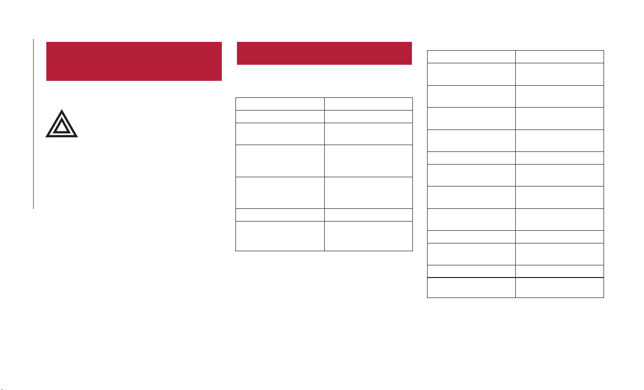
HAZARD WARNING
FLASHERS
The Hazard Warning flasher switch is located on
the switch bank below the radio.
Push the switch to turn on the Haz-
ardWarning Flasher. When the switch
is activated, all directional turn signals
will flash on and off to warn oncom-
ing traffic of an emergency. Push the switch a
second time to turn off the Hazard Warning
flashers.
This is an emergency warning system and it
should not be used when the vehicle is in motion.
Use it when your vehicle is disabled and it is
creating a safety hazard for other motorists.
When you must leave the vehicle to seek assis-
tance, the Hazard Warning flashers will continue
to operate even though t he ignition is placed in
OFF mode.
NOTE:
With extended use the Hazard Warning flashers
may wear down your battery.
BULB REPLACEMENT
Replacement Bulbs
Interior Bulbs
Lamps Bulb Number
Front Courtesy Light C5W
Front Courtesy Lights
(Sun Visors)
C5W
Rear Dome Light
(Models Without
Retractable Roof)
C5W
Rear Interior Lights
(Models With Retract-
able Roof)
C5W
Interior Lights W5W
Dome Light (Glove
Compartment)
W5W
Exterior Bulbs
Lamps Bulb Number
Low Beam/High Beam
Headlamps
HIR2
Optional Low Beam/
High Bean Headlamps
LED (Serviced At An
Authorized Dealer)
Front Position/Daytime
Running Lights (DRL)
LED (Serviced At An
Authorized Dealer)
Front Direction Indica-
tor Lamps
WY21W
Front Fog Lamps H11
Side Indicators
(Side View Mirror)
WY5W
Side Marker LED (Serviced At An
Authorized Dealer)
Tail/Brake lights LED (Serviced At An
Authorized Dealer)
Turn Indicators WY21W
Center High Mounted
Stop Lamp (CHMSL)
LED (Serviced At An
Authorized Dealer)
Reverse P21W
License Plate Lamp W5W
IN C ASE OF EMERGENCY
122

FUSES
WARNING!
•
When replacing a blown fuse, always use an
appropriate replacement fuse with the same
amp rating as the original fuse. Never replace
a fuse with another fuse of higher amp rating.
Never replace a blown fuse with metal wires
or any other material. Failure to use proper
fuses may result in serious personal injury, fire
and/or property damage.
• Before replacing a fuse, make sure that the
ignition is off and t hat all the other services
are switched off and/or disengaged.
WARNING!
• If the replaced fuse blows again, contact an
authorized dealer.
• If a general protection fuse for safety sys-
tems (air bag system, braking system), power
unit systems (engine system, gearbox sys-
tem) or steering system blows, contact an
authorized dealer.
Engine Compartment Fuses/Distribution Unit
The engine compartment fuse panel is located on
the left side of the engine compartment.
Refer to your Owner’s Manual for further fuse
information.
Cavity Maxi Fuse Cartage Fuse Mini Fuse Description
F01 70 Amp Tan – – Module Body Computer
F02 60 Amp Blue – – Module Body Computer, Rear Distribution Units
F03 – 20 Amp Blue – Controller Power Supply Body Computer
F04 – 30 Amp Pink – Brake Control Electronics Module
F05 70 Amp Tan – – Electric Power-Assisted Steering
F06 70 Amp Tan – – Engine Cooling fan
F08 – 30 Amp Pink – Automatic Transmission, GSM
F09 – – 5 Amp Tan Control Module Engine
Engine Compartment Fuse Location
123

Cavity Maxi Fuse Cartage Fuse Mini Fuse Description
F10 – – 10 Amp Red Horn
F11 – – 5 Amp Tan Supply Secondary Loads
F14 – – 15 Amp Blue Pump Power "After run" AGS Supply
F15 40 Amp Orange – – Brake Control Module Pump
F16 – – 5 Amp Tan Engine Control Module Power, Automatic Transmission
F17 – – 30 Amp Green Power Control Module Engine
F18 – – 30 Amp Green Power All-Wheel Drive
F19 – – 7.5 Amp Brown Air Conditioner Compressor
F20 – – 5 Amp Tan Electronic Power Four-Wheel Drive
F21 – – 15 Amp Blue Fuel Pump
F22 – – 10 Amp Red Supply Primary Loads
F23 – – 20 Amp Yellow
(Customer In-
stalled)
Power Outlet (Battery Powered)
F24 – – 15 Amp Blue Electronic Unit Supply Automatic Transmission
F30 – – 30 Amp Green Heated Windshield – If Equipped
F83 – 40 Amp Green – Air Conditioning Fan
F84 – – 20 Amp Yellow Power Outlet (Ignition Powered)
F87 – – 5 Amp Tan Gear Selector Automatic Transmission
F88 – – 7.5 Amp Brown Heated Outside Mirrors
F89 – 30 Amp Pink – Heated Rear Window
F90 – – 5 Amp Tan IBS Sensor (Battery Sta te of Charge)
IN C ASE OF EMERGENCY
124

Body Computer Fuse Center
The controller is located at the left side of the
steering column at the bottom of the instrument
panel.
For the fuse replacement see an authorized
dealer.
Cavity Mini Fuse Description
F31 7.5 Amp Brown Fan Air Conditioning, Power Socket
F33 20 Amp Yellow Power Window Front (Passenger Side)
F34 20 Amp Yellow Power Window Front (Driver’s Side)
F36 15 Amp Blue Supply Uconnect System, Air Conditioning, USB Port, Rear lateral ceiling light in case of open roof, EOBD port
F37 10 Amp Red System Power Forward Collision Warning Plus, All Wheel Drive (AWD), IPC, Central stack switches, Brake Pedal
Switch (NC)
F38 20 Amp Yellow Central Locking
F42 7.5 Amp Brown BSM - Brake Control Module, EPS - Electric Power-Assisted Steering
F43 20 Amp Yellow Bi-directional Pump Washer
F47 20 Amp Yellow Power Rear Window (Driver Side)
F48 20 Amp Yellow Power Rear Window (Passenger Side)
F49 7.5 Amp Brown Supply ParkSense, Spot Lights Front Dome, Internal Electocromic Mirror, Heated Front Seats, SGW, Sunroof Motor.
F50 7.5 Amp Brown Supply Air Bag
F51 7.5 Amp Brown Air Conditioning Compressor, Plaque Automatic Transmission, Rear Camera, Air Conditioning, LDW - Lane
Departure Warning,ASS - Auxiliary Stack Switch, DSU - Drive Syle Selector Unit, Reverse gear switch, side mirrors
and rear window defrost
F53 7.5 Amp Brown Supply IPC/Starter Device/System Keyless Enter-N-Go, Brake Pedal Switch (NA), EPB - Elec tric Parking Brake
125

Rear Cargo Fuse/Relay Distribution Unit
To access the fuses, remove the access door from
the left rear panel of the rear cargo area.
Push on the left side of the access door to
unhinge and remove.
Cavity Mini Fuse Description
F2 20 Amp Yellow Audio System
F3 20 Amp Yellow Electric Sunroof
F5 30 Amp Green Power Seat (driver side)
F6 7.5 Amp Brown Power Seat (driver side) Lumbar Adjustment
F8 20 Amp Yellow Heating Front Sea ts
JACKING AND TIRE
CHANGING
WARNING!
• Do not attempt to change a tire on t he side
of the vehicle close to moving traffic. Pull far
enough off the road to avoid the danger of
being hit when operating the jack or chang-
ing the wheel.
WARNING!
• Being under a jacked-up vehicle is danger-
ous. The vehicle could slip off the jack and
fall on you.You could be crushed. Never put
any part of your body under a vehicle that is
onajack. If you need to get under a raised
vehicle, take it to a service center where it
can be raised on a lift.
• Never start or run the engine while the
vehicle is on a jack.
WARNING!
• The jack is designed to be used as a tool for
changing tires only. The jack should not be
used to lift the vehicle for service purposes.
The vehicle should be jacked on a firm level
surface only. Avoid ice or slippery areas.
IN C ASE OF EMERGENCY
126

Jack Location/Spare Tire Stowage —
If Equipped
The jack and tools are located in t he rear storage
compartment if equipped, inside a special con-
tainer.
1. Open the liftgate.
2. Lift the access cover using the load floor
handle.
3. Remove the fastener securing the spare tire.
Jack And Tools Location
Load Floor Handle
Spare Tire Fastener
127

4. Remove the jack, wheel bolt wrench, and
wheel chocks (if equipped).
5. Remove the spare tire.
WARNING!
A loose tire or jack thrown forward in a
collision or hard stop could endanger the
occupants of the vehicle. Always stow the jack
parts and the spare tire in the places provided.
Have the deflated (flat) tire repaired or re-
placed immedia tely.
Preparations For Jacking
1. Park the vehicle on a firm level surface as far
from the edge of the roadway as possible.
Avoid icy or slippery areas.
WARNING!
Do not attempt to change a tire on the side of
the vehicle close to moving traffic. Pull far
enough off the road to avoid being hit when
operating the jack or changing the wheel.
2. Turn on the Hazard Warning flasher.
3. Apply the Electric Park Brake.
4. Place the gear selector into PARK.
5. Turn the ignition to STOP mode.
6. Chock both the front and rear of the wheel
diagonally opposite of the jacking position. For
example, if changing the right front tire, chock
the left rear wheel.
NOTE:
Passengers should not remain in the vehicle when
the vehicle is being jacked.
Jack And Tools
1 — Jack
2 — Wheel Bolt Wrench
3 — Wheel Chock (If Equipped)
4 — Emergency Funnel
5 — Screwdriver
Wheels Chocked
IN C ASE OF EMERGENCY
128

Jacking Instructions
WARNING!
Carefully follow these tire changing warnings
to help prevent personal injury or damage to
your vehicle:
• Always park on a firm, level surface as far
from the edge of the roadway as possible
before raising the vehicle.
• Turn on the Hazard Warning flasher.
• Chock the wheel diagonally opposite the
wheel to be raised.
• Apply the parking brake and place an auto-
matic transmission in PARK.
• Never start or run the engine with the
vehicle on a jack.
• Do not let anyone sit in the vehicle when it
is on a jack.
• Do not get under the vehicle when it is on
ajack. If you need to get under a raised
vehicle, take it to a service center where it
can be raised on a lift.
•
Only use the jack in the positions indicated
and for lifting this vehicle during a tire change.
WARNING!
• If working on or near a roadway, be ex-
tremely careful of motor traffic.
• To assure that spare tires, flat or inflated, are
securely stowed, spares must be stowed
with the valve stem facing the ground.
CAUTION!
Do not attempt to raise the vehicle by jacking
on locations other than those indicated in the
Jacking Instructions for this vehicle.
1. Remove the spare tire, jack, and wheel bolt
wrench.
2. If equipped with wheels where the center cap
covers the wheel bolts, use the wheel bol t
wrench to pry the center cap off carefully
before raising the vehicle.
3. Before raising the vehicle, use the wheel bolt
wrench to loosen, but not remove the wheel
bolts on t he wheel with the flat tire. Turn the
wheel bolts counterclockwise one turn while
the wheel is still on the ground.
Jack Warning Label
129

4. Place the jack underneath the lift area that is
closest to the flat tire. Turnthejackscrew
clockwise to firmly engage the jack saddle with
the lift area of the sill flange, centering the jack
saddle inside the cutout in the sill cladding.
Jacking Locations
1 — Front Jacking Location
2 — Rear Jacking Location
Front Jacking Location Rear Jacking Location
IN C ASE OF EMERGENCY
130

5. Raise the vehicle just enough to remove the
flat tire.
WARNING!
Raising the vehicle higher than necessary can
make the vehicle less stable. It could slip off
the jack and hurt someone near it. Raise the
vehicle only enough to remove the tire.
6. Remove the wheel bol ts and tire.
7. Mount the spare tire.
CAUTION!
Be sure to mount the spare tire with the valve
stem facing outward. The vehicle could be
damaged if the spare tire is mounted incor-
rectly.
Front Jacking Engagement Point Rear Jacking Engagement Point
Mounting Spare Tire
131

NOTE:
• Your vehicle may be equipped with a
compact spare tire or a limited-use spare
tire. For further information refer to “Tires
— General Information” in “Servicing And
Maintenance” in your Owner’s Manual for
further information.
• For vehicles so equipped, do not attempt to
install a center cap or wheel cover on the
compact spare.
8. Install the wheel bolts with the threaded end
of the wheel bolt toward the wheel. Lightly
tighten the wheel bolts.
WARNING!
To avoid the risk of forcing the vehicle off the
jack, do not fully tighten the wheel bol ts until
the vehicle has been lowered. Failure to follow
this warning may result in serious injury.
9. Lower the vehicle to the ground by turning
the wheel bolt wrench counterclockwise.
10. Finish tightening the wheel bolts. Push down
on the wrench while at the end of the handle
for increased leverage. Tighten the wheel
bolts in a star pa ttern until each wheel bol t
has been tightened twice. Refer to “Torque
Specifications” in “Technical Specifications”
for the proper lug bolt torque. If in doubt
about the correct tightness, have them
checked wit h a torque wrench by an autho-
rized dealer or at a service station.
11. Securely stow the jack, tools, chocks and flat
tire.
WARNING!
A loose tire or jack thrown forward in a
collision or hard stop could endanger the
occupants of the vehicle. Always stow the jack
parts and the spare tire in the places provided.
Have the deflated (flat) tire repaired or re-
placed immedia tely.
Road Tire Installation
1. Mount the road tire on the axle.
2. Install the remaining wheel bolts with the
threaded end of the wheel bolt toward the
wheel. Lightly tighten the wheel bolts.
WARNING!
To avoid the risk of forcing the vehicle off the
jack, do not tighten the wheel bolts fully until
the vehicle has been lowered. Failure to follow
this warning may result in serious injury.
3. Lower the vehicle to the ground by turning
the jack handle counterclockwise.
IN C ASE OF EMERGENCY
132

4. Finish tightening the wheel bolts. Push down
on the wrench while at the end of the handle
for increased leverage.Tighten the wheel bolts
in a star pattern until each wheel bolt has been
tightened twice. Refer to “Torque Specifica-
tions” in the “Technical Specifications” section
for the proper lug bolt torque. If in doubt
about the correct tightness, have them
checked with a torque wrench by an autho-
rized dealer or service station.
5. Lower the jack until it is free. Remove the
wheel chocks. Stow the jack and tools back in
the proper storage location. Release the Elec-
tric Park Brake before driving the vehicle.
6. After 25 miles (40 km) check the wheel bolt
torque with a torque wrench to ensure that all
wheel bol ts are properly seated against the
wheel.
TIRE SERVICE KIT — IF
EQUIPPED
Tire Service Kit Storage
The Tire Service Kit is located in the rear storage
compartment inside a storage container. Loca ted
inside the container are a screwdriver and the
emergency fuel funnel. To access the Tire Service
Kit open the liftgate and remove the load floor.
Tire Service Kit Components And Operation
If a tire is punctured, you can make a first emer-
gency repair using the Tire Service Kit located in the
rear storage compartment inside the storage con-
tainer.
Tire Service Kit Location
Tire Service Kit Components
1 — Power Plug (Located On Bottom Side
Of Tire Service Kit)
2 — Sealant Hose (Clear)
3 — Power Button
4 — Pressure Gauge
5 — Warning Label
133

Tire punctures of up to 1/4 inch (6 mm) can be
repaired; the kit can be used in all weather
conditions. Do not remove the foreign object
from the punctured tire, i.e., screw or nail.
1. Remove the Tire Service Kit from the vehicle,
take it out from the bag and place it near the
punctured tire. Screw the clear flexible filling
tube to the tire valve.
2. Insert the power plug into the vehicle power
outlet socket. Start the vehicle engine.
3. Push the Tire Service Kit power button to the
“I” position. The electric compressor will be
turned on, sealant and air will inflate the tire.
Minimum 26 psi (1.8 bar) of pressure should
be reached within 20 minutes. If the pressure
has not been reached turn off and remove
the Tire Service Kit, drive the vehicle 30 feet
(10 meters) back and forth, to better dis trib-
ute the sealant inside the tire.
4. Attach the clear flexible filling tube of the
compressor directly to the tire valve and
repeat the inflation process.
When the correct pressure has been
reached, start driving the vehicle to uniformly
distribute the sealant inside t he tire. After
10 minutes, stop and check the tire pressure.
If the pressure is below 19 psi (1.3 bar), do
not drive the vehicle , as the tire is too
damaged, and contact the nearest authorized
dealer.
WARNING!
Tire Service Kit is not a permanent flat tire
repair. Have the tire inspected and repaired or
replaced after using Tire Service Kit. Do not
exceed 50 mph (80 km/h) until the tire is
repaired or replaced. Failure to follow this
warning can result in injuries that are serious
or fatal to you, your passengers, and others
around you. Have the tire checked as soon as
possible at an authorized dealer.
If the pressure is at 19 psi (1.3 bar) or above
repeat the inflation process to reach the
correct tire pressure and continue driving.
5. Peel off t he warning label from the bottle and
place it on the dashboard as a reminder to the
driver that the tire has been treated with Tire
Service Kit.
WARNING!
The metal end fitting from Power Plug may get
hot after use, so it should be handled carefully.
Tire Service Kit Usage Precautions
WARNING!
• Do not attempt to seal a tire on the side of
the vehicle closest to traffic. Pull far enough
off t he road to avoid t he danger of being hit
when using the Tire Service Kit.
• Do not use Tire Service Kit or drive the
vehicle under the following circumstances:
–If
the puncture in the tire tread is
approximately 1/4 inch (6 mm) or larger.
– If the tire has any sidewall damage.
– If the tire has any damage from driving
with extremely low tire pressure.
– If the tire has any damage from driving
on a flat tire.
– If the wheel has any damage.
– If you are unsure of the condition of
the tire or the wheel.
IN C ASE OF EMERGENCY
134

WARNING!
• Keep Tire Service Kit away from open flames
or heat source.
• A loose Tire Service Kit thrown forward in a
collision or hard stop could endanger the
occupants of the vehicle. Always stow the
Tire Service Kit in the place provided. Failure
to follow these warnings can result in injuries
that are serious or fatal to you, your passen-
gers, and others around you.
• Take care not to allow the contents of Tire
Service Kit to come in contact with hair,
eyes, or clothing. Tire Service Kit sealant is
harmful if inhaled, swallowed, or absorbed
through the skin. It causes skin, eye, and
respiratory irritation. Flush immedia tely with
plenty of water if there is any contact with
eyes or skin. Change clothing as soon as
possible, if there is any contact with clothing.
• Tire Service Kit Sealant solution contains
latex. In case of an allergic reaction or rash,
consult a physician immediately. Keep Tire
Service Kit out of reach of children. If
swallowed, rinse mouth immediately with
plenty of water and drink plenty of water.
WARNING!
Do not induce vomiting! Consult a physician
immediately.
Replacing The Sealant
NOTE:
Replace the sealant canister prior to the expira-
tion date at an authorized dealer.
WARNING!
Store the sealant canister in its special com-
partment, away from sources of heat. Failure
to follow this WARNING may result in sealant
canister rupture and serious injury or death.
JUMP STARTING
If your vehicle has a discharged battery it can be
jump started using a set of jumper cables and a
battery in another vehicle or by using a portable
battery booster pack. Jump starting can be dan-
gerous if done improperly so please follow the
procedures in this section carefully.
NOTE:
When using a portable battery booster pack
follow the manufacturer’s operating instructions
and precautions.
WARNING!
Do not attempt jump starting if the battery is
frozen. It could rupture or explode and cause
personal injury.
Tire Service Kit Expiration Date Location
135

CAUTION!
Do not use a portable battery booster pack or
any ot her booster source with a system
voltage greater than 12Volts or damage to the
battery, starter motor, alternator or electrical
system may occur.
Preparations For Jump Start
The battery in your vehicle is located in the front
of the engine compartment, behind the left
headlight assembly.
NOTE:
The positive battery post is covered with a
protective cap. Lif t up on the cap to gain access to
the positive battery post.
WARNING!
• Take care to avoid the radiator cooling fan
whenever the hood is raised. It can start
anytime the ignition switch is ON. You can
be injured by moving fan blades.
• Remove any met al jewelry such as rings,
watch bands and bracelets that could make
an inadvertent electrical contact. You could
be seriously injured.
• Batteries contain sulfuric acid that can burn
your skin or eyes and generate hydrogen gas
which is flammable and explosive. Keep
open flames or sparks away from the bat-
tery.
Proceed as follows:
1. Apply the Electric Park Brake, shift the trans-
mission into PARK and place the ignition OFF.
2. Turn off the heater, radio, and all unnecessary
electrical accessories.
3. If using anot her vehicle to jump start the
battery, park the vehicle within the jumper
cables reach, set the parking brake and make
sure the ignition is OFF.
WARNING!
Do not allow vehicles to touch each other as
this could establish a ground connection and
personal injury could result.
Jump Starting Procedure
WARNING!
Failure to follow this jump starting procedure
could result in personal injury or property
damage due to battery explosion.
CAUTION!
Failure to follow these procedures could result
in damage to the charging system of the
booster vehicle or the discharged vehicle.
Positive Battery Post
IN C ASE OF EMERGENCY
136

Connecting The Jumper Cables
1. Connect the positive (+) end of the jumper
cable to the positive (+) post of the dis-
charged vehicle.
2. Connect the opposite end of the positive (+)
jumper cable to the positive (+) post of the
booster battery.
3. Connect the negative (-) end of the jumper
cable to the negative (-) post of the booster
battery.
4. Connect the opposite end of the negative (-)
jumper cable to a good engine ground (ex-
posed metal part of the discharged vehicle’s
engine) away from the battery and the fuel
injection system.
WARNING!
Do not connect the jumper cable to the
negative (-) post of the discharged battery.The
resulting electrical spark could cause the bat-
tery to explode and could result in personal
injur y. Only use the specific ground point, do
not use any other exposed metal parts.
5. Start the engine in the vehicle tha t has the
booster battery, let the engine idle a few
minutes, and then start the engine in the
vehicle with the discharged battery.
6. Once the engine is st arted, remove the
jumper cables in the reverse sequence:
Disconnecting The Jumper Cables
1. Disconnect the negative (-) end of the jumper
cable from the engine ground of the vehicle
with the discharged batter y.
2. Disconnect the opposite end of the neg ative
(-) jumper cable from the negative (-) post of
the booster battery.
3. Disconnect the positive (+) end of the jumper
cable from the positive (+) post of the
booster battery.
4. Disconnect the opposite end of the positive
(+) jumper cable from the positive (+) post of
the vehicle with the discharged battery.
If frequent jump starting is required to start your
vehicle you should have the battery and charging
system inspected at an authorized dealer.
CAUTION!
Accessories plugged into the vehicle power
outlets draw power from the vehicle’s battery,
even when not in use (i.e., cellular devices,
etc.). Eventually, if plugged in long enough
without engine operation, the vehicle’s battery
will discharge sufficiently to degrade battery
life and/or prevent the engine from starting.
IF YOUR ENGINE OVERHEATS
In any of the following situations, you can reduce
the potential for overheating your engine by
taking the appropriate action.
• On t he highways — slow down.
• In city traffic — while stopped, put transmission
in NEUTRAL, but do not increase engine idle
speed.
CAUTION!
Driving with a hot cooling system could
damage your vehicle. If the temperature gauge
reads “H,” pull over and stop the vehicle.
137

CAUTION!
Idle the vehicle with the air conditioner turned
off until the pointer drops back into the
normal range. If the pointer remains on the
“H” and you hear continuous chimes, turn the
engine off immediately and call for service.
NOTE:
There are steps that you can t ake to slow down
an impending overheat condition:
• If your air conditioner (A/C) is on, turn it off.
The A/C system adds heat to the engine cooling
system and turning the A/C off can help remove
this heat.
• You can also turn the temperature control to
maximum heat, the mode control to floor and
the blower control to high. This allows the
heater core to act as a supplement to the
radiator and aids in removing heat from the
engine cooling system.
WARNING!
You or others can be badly burned by hot
engine coolant (antifreeze) or steam from
your radiator. If you see or hear steam coming
from under the hood, do not open the hood
until the radiator has had time to cool. Never
tr y to open a cooling system pressure cap
when the radiator or coolant bottle is hot.
GEAR SELECTOR OVERRIDE
If a malfunction occurs and t he gear selector
cannot be moved out of the PARK position, you
can use the following procedure to temporarily
move the gear selector:
1. Turn the engine OFF.
2. Apply the Electric Park Brake.
3. Carefully separate the gear selector bezel and
boot assembly from the center console.
4. Press and maintain firm pressure on the brake
pedal.
5. Insert a small screwdriver or similar tool down
into the gear selector override access hole (at
the right front corner of the gear selector
assembly), and push and hold the override
release lever down.
Gear Selector Bezel Location
IN C ASE OF EMERGENCY
138

6. Move the gear selector to the NEUTRAL
position.
7.
The vehicle may then be started in NEUTRAL.
8. Reinstall the gear selector bezel.
FREEING A STUCK VEHICLE
If your vehicle becomes stuck in mud, sand or
snow, it can often be moved using a rocking
motion. Turn the steering wheel right and left to
clear the area around the front wheels. Push and
hold the lock button on the gear selector. Then
shift back and forth between DRIVE and RE-
VERSE, while gently pressing the accelerator.
Use the leas t amount of accelerator pedal pres-
sure that will maintain the rocking motion without
spinning the wheels or racing the engine.
Shifts between DRIVE and REVERSE can only be
achieved a t wheel speeds of 5 mph (8 km/h) or
less.Whenever the transmission remains in NEU-
TRAL for more t han two seconds, you must press
the brake pedal to engage DRIVE or REVERSE.
NOTE:
Push the "ESC Off" switch, to place the Electronic
Stability Control (ESC) system in "Partial Off"
mode, before rocking the vehicle. Refer to “Elec-
tronic Brake Control” in “Safety” in your Owner’s
Manual for further information. Once the vehicle
has been freed, push the "ESC Off" switch again
to restore "ESC On" mode.
WARNING!
Fast spinning tires can be dangerous. Forces
generated by excessive wheel speeds may cause
damage, or even failure, of t he axle and tires.
A tire could explode and injure someone. Do
not spin your vehicle's wheels faster than
30 mph (48 km/h) or for longer than 30 seconds
continuously without stopping when you are
stuck and do not let anyone near a spinning
wheel, no matter what the speed.
CAUTION!
•
Racing the engine or spinning the wheels may
lead to transmission overheating and failure.
Allow the engine to idle with the transmission
in NEUTRAL for at least one minute after
every five rocking-motion cycles. This will
minimize overheating and reduce the risk of
clutch or transmission failure during pro-
longed efforts to free a s tuck vehicle.
•
When “rocking” a stuck vehicle by shifting
between DRIVE/SECOND gear and RE-
VERSE, do not spin the wheels faster than
15 mph (24 km/h), or drivetrain damage may
result.
Gear Selector Override Location
139

CAUTION!
• Revving the engine or spinning the wheels
too fast may lead to transmission overheat-
ing and failure. It can also damage the tires.
Do not spin the wheels above 30 mph
(48 km/h) while in gear (no transmission
shifting occurring).
TOWING A DISABLED
VEHICLE
T
his section describes procedures for towing a dis-
abled vehicle using a commercial towing service.
Towing Condition Wheels OFF The Ground ALL WHEEL DRIVE
Flat Tow
NONE NOT ALLOWED
Wheel Lift Or Dolly Tow
Rear
NOT ALLOWED
Front
NOT ALLOWED
Flatbed
ALL OK
This vehicle must be towed with all four wheels
OFF the ground.
If you must use the accessories (wipers, defrost-
ers, etc.) while being towed, the ignition must be
in the RUN position.
If the key fob is unavailable, or the vehicle’s battery
is discharged, refer to“Gear Selector Override” in
this section for instructions on shifting the trans-
mission out of PARK so that the vehicle can be
moved.
CAUTION!
• Do not use sling type equipment when
towing. Vehicle damage may occur.
• When securing the vehicle to a flat bed
truck, do not attach to front or rear suspen-
sion components. Damage to your vehicle
may result from improper towing.
IN C ASE OF EMERGENCY
140

All Wheel Drive (AWD) Models
The manufacturer requires towing with all four
wheels OFF the ground. Acceptable methods are
to tow the vehicle on a flatbed, or with one end
of the vehicle raised and the opposite end on a
towing dolly.
CAUTION!
• DO NOT tow this vehicle with ANY of its
wheels on the ground. Damage to the
drivetrain will result.
• Front or rear wheel lifts must not be used
(if the remaining wheels are on the ground).
Internal damage to the transmission or
power transfer unit will occur if a front or
rear wheel lift is used when towing.
• Towing this vehicle in violation of the above
requirements can cause severe transmission
and/or power transfer unit damage. Damage
from improper towing is not covered under
the New Vehicle Limited Warranty.
Tow Eye Usage — If Equipped
Your vehicle is equipped with a tow eye that can
be used to move a disabled vehicle.
When using a tow eye be sure to follow the “Tow
Eye Usage Precautions” and the “Towing A Dis-
abled Vehicle” instructions in this section.
Tow Eye Usage Precautions
CAUTION!
• The tow eye must only be used for roadside
emergencies. Use with an appropriate de-
vice in accordance with highway code (a
rigid bar or rope) to maneuver the vehicle
in preparation for transport via a tow truck.
• The tow eye must not be used to move the
vehicle off the road or where there are
obstacles.
• Do not use the tow eyes for tow truck
hookup or highway towing.
• Do not use the tow eye to free a stuck
vehicle. Refer to the “Freeing A Stuck Ve-
hicle” section for further information.
• Please refer to the “Towing A Disabled
Vehicle” section for detailed instructions.
Damage to your vehicle may occur if these
guidelines are not followed.
Tow E ye
141

WARNING!
Stand clear of vehicles when pulling with tow
eyes.
• Do not use a chain with a tow eye. Chains
may break, causing serious injury or death.
WARNING!
• Do not use a tow strap with a tow eye.Tow
straps may break or become diseng aged,
causing serious injury or death.
• Failure to follow proper tow eye usage may
cause components to break resulting in
serious injury or death.
Front Tow Eye Installation
The front tow eye receptacle is located behind an
access door, located on the right front bumper
fascia.To install the tow eye, open the access door
using the vehicle key or a small screwdriver, and
thread the tow eye into the receptacle.
Insert t he wheel bolt wrench handle through the
eye and tighten, refer to “Jacking And Tire Chang-
ing” for further information.The tow eye must be
fully seated to the attaching bracket through the
lower front fascia as shown. Ifthetoweyeisnot
fully seated to the attaching bracket, the vehicle
should not be towed.
Rear Tow Eye Installation
The rear tow eye receptacle is located behind a
access door on the rear bumper fascia.
To install the tow eye, open the access door using
the vehicle key or a small screwdriver, and thread
the tow eye into the receptacle.
Insert t he wheel bolt wrench handle through the
eye and tighten, refer to “Jacking And Tire Chang-
ing” for further information.The tow eye must be
fully seated to the attaching bracket through the
lower rear fascia. If the tow eye is not fully seated
to the attaching bracket, the vehicle should not be
towed.
Tow Eye Warning Label
IN C ASE OF EMERGENCY
142

ENHANCED ACCIDENT
RESPONSE SYSTEM (EARS)
This vehicle is equipped with an Enhanced Acci-
dent Response System.
Please refer to “Occupant Restraint Systems” in
“Safety” for further information on the Enhanced
Accident Response System (EARS) function.
EVENT DATA RECORDER
(EDR)
This vehicle is equipped with an Event Data
Recorder (EDR). The main purpose of an EDR is
to record data that will assist in understanding
how a vehicle’s systems performed under certain
crash or near crash-like situations, such as an air
bag deployment or hitting a road obstacle.
Please refer to “Occupant Restraint Systems” in
“Safety” for further information on the Event
Data Recorder (EDR).
143

SCHEDULED MAINTENANCE
Your vehicle is equipped with an automatic oil
change indicator system. The oil change indicator
system will remind you that it is time to take your
vehicle in for scheduled maintenance.
Based on engine operation conditions, the oil
change indicator message will illumina te in the
instrument cluster. This means that service is
required for your vehicle. Opera ting conditions
such as frequent short-trips, trailer tow and
extremely hot or cold ambient temperatures will
influence when the “Change Oil” or “Oil Change
Required” message is displayed. Severe Operating
Conditions can cause the change oil message to
illuminate as early as 3,500 miles (5,600 km) since
last reset. Have your vehicle serviced as soon as
possible, within the next 500 miles (805 km).
Your authorized dealer will reset the oil change
indicator message after completing the scheduled
oil change. If a scheduled oil change is performed
by someone other than your authorized dealer,
the message can be reset by referring to the steps
described under “Instrument Cluster Display” in
“Getting To KnowYour Instrument Panel” in your
Owner’s Manual.
NOTE:
Under no circumstances should oil change intervals
exceed 10,000 miles (16,000 km), twelve months
or 350 hours of engine run time, whichever comes
first. The 350 hours of engine run or idle time is
generally only a concern for fleet customers.
Severe Duty All Models
Change Engine Oil at 4,000 miles (6,500 km) if
the vehicle is operated in a dusty and off road
environment or is operated predominately at idle
or only very low engine RPM’s. This type of
vehicle use is considered Severe Duty.
NOTE:
The Oil Change Indicator will not illuminate
under these conditions.
Once A Month Or Before A Long Trip:
• Check engine oil level.
• Check windshield washer fluid level.
• Check the tire inflation pressures and look for
unusual wear or damage.
• Check the fluid levels of the coolant reservoir,
and brake master cylinder reservoir, and fill as
needed.
• Check function of all interior and exterior
lights.
Maintenance Plan
Required Maintenance Intervals
At Every Oil Change Interval As Indicated By
Oil Change Indicator System:
Change oil and filter.
Inspect battery and clean and tighten terminals
as required.
Inspect brake pads, shoes, rotors, drums, and
hoses.
Inspect engine cooling system protection and
hoses.
Check and adjust hand brake.
Inspect exhaust system.
Inspect engine air filter if using in dusty or off-
road conditions.
Refer to the “Maintenance Chart” on the follow-
ing page for the required maintenance intervals.
SERVICING AND MAINTENANCE
144

Mileage or time passed (whichever comes first)
10,000
20,000
30,000
40,000
50,000
60,000
70,000
80,000
90,000
100,000
110,000
120,000
130,000
140,000
150,000
Or Years: 1 2 3 4 5 6 7 8 9 10 11 12 13 14 15
Or Kilometers:
16,000
32,000
48,000
64,000
80,000
96,000
112,000
128,000
144,000
160,000
176,000
192,000
208,000
224,000
240,000
Check tire condition/wear and adjust pressure, if necessary, check Tire
Service Kit expiration date (if provided).
••• •••••• • • • • • •
Check opera tion of lighting system (headlamps, direction indicators, haz-
ard warning lights, luggage compartment, passenger compartment, glove
compartment, instrument panel warning lights, etc.).
••• •••••• • • • • • •
Check and, if necessary, top up fluid levels (brakes/hydraulic clutch, wind-
shield washer, battery, engine coolant, etc.). (1)
••• •••••• • • • • • •
Check engine control system operation (via diagnostic tool). (2) • • • • • • • • • • • • • • •
Visually inspect condition of: exterior bodywork, underbody protection,
pipes and hoses (exhaust - fuel system - brakes), rubber elements
(boots, sleeves, bushings, etc.).
•• ••• • • •
Check windshield/rear window wiper blade position/wear. •• ••• • • •
Check operation of windshield washer system and adjust jets if necessary.
•• ••• • • •
Check cleanliness of hood and tailgate locks and cleanliness and lubrica-
tion of linkages.
•••• • • •
Visually check the condition and wear of the front and rear brakes. ••• •••••• • • • • • •
Check the front suspension, tie rods, CV joints and replace if necessary. •••• • • •
Visual inspect the condition of the accessory drive belt.(3) •
Check the tension of the accessory drive belt. ••
Inspect and replace, if required, front end accessory drive belt, tensioner,
and, idler pulley.(3)
••
145

Mileage or time passed (whichever comes first)
10,000
20,000
30,000
40,000
50,000
60,000
70,000
80,000
90,000
100,000
110,000
120,000
130,000
140,000
150,000
Or Years: 1 2 3 4 5 6 7 8 9 10 11 12 13 14 15
Or Kilometers:
16,000
32,000
48,000
64,000
80,000
96,000
112,000
128,000
144,000
160,000
176,000
192,000
208,000
224,000
240,000
Inspect and replace PCV valve if necessary. •
Change engine oil and replace oil filter. * In accordance with Oil Change Indicator System OR Severe Duty Mileage, whichever occurs first.
Inspect the PTU fluid level. •• •
Inspect the rear differential fluid level. •• •
Replace spark plugs (1.3L Turbo engine). ** • • •
Replace engine air filter. #•••••••
Replace brake fluid every two years. •••• • • •
Replace cabin filter. ○ • ○ • ○ • ○ • ○ • ○ • ○ • ○
Flush and replace the engine coolant at 10 years or 150,000 miles
(240,000 km) whichever comes first.
••
○ Recommend replacement
• Mandatory service
# The engine air cleaner should be inspected
at every oil change if used in dusty areas.
* The oil and oil filter replacement must be
carried out when indicated by a warning light
or message on the instrument panel, or in any
case should not exceed 1 year or 10,000 miles
(16,000 km).
** The spark plug change is distance based
only, yearly intervals do not apply. The following
are essential to ensure correct operation and
prevent serious damage to the engine:
•
Only use spark plugs of the same make and type
which are specially certified for such engines
(refer to “Fluids And Lubricants” in “Technical
Specifications” for further information).
SERVICING AND MAINTENANCE
146

• Strictly comply with the spark plug replacement
interval given in the “Maintenance Plan” for
spark plug replacement.
• Contact an authorized dealer if you have any
questions.
(1) Always only use the liquids shown in the
handbook for topping up after having checked
that the system is not damage.
(2) If the engine oil quality detected by the
vehicle diagnostics is lower than 20%, it is advis-
able to replace the engine oil and engine filter
in order to avoid another service operation
after a short time.
(3) The maximum mileage is 120,000 km. The
belt must be replaced every 6 years, regardless
of distance travelled. If the vehicle is used in
heavy conditions (dus ty areas, cold climates, ur-
ban driving, long periods of idling), the maxi-
mum mileage is 60,000 km. The belt must be
replaced every 4 years regardless of the
mileage.
WARNING!
• You can be badly injured working on or
around a motor vehicle. Do only service
work for which you have the knowledge and
the right equipment. If you have any doubt
about your ability to perform a service job,
take your vehicle to a competent mechanic.
• Failure to properly inspect and maintain
your vehicle could result in a component
malfunction and effect vehicle handling and
performance. This could cause an accident.
Heavy Duty Use Of The Vehicle
Change engine oil at 4,000 miles (6,500 km) or
350 hours of engine run time if the vehicle is
operated in a dusty and off road environment or
is operated predominately at idle or only very low
engine RPM’s. This type of vehicle use is consid-
ered Severe Duty.
147

ENGINE COMPARTMENT
1.3L Turbo Engine
1 — Brake Fluid Reservoir 5 — Engine Coolant Pressure Cap
2 — Battery 6 — Engine Coolant Reservoir
3 — Power Distribution Center (Fuses) 7 — Oil Fill Cap/Engine Oil Dipstick
4 — Washer Fluid Reservoir
SERVICING AND MAINTENANCE
148

RAISING THE VEHICLE
In the case where it is necessary to raise the
vehicle, go to an authorized dealer or service
station.
The vehicle lifting points on the vehicle are
marked on side skirts with
symbols.
TIRES
Tire Safety Information
Tire safety information will cover aspects of the
following information: Tire Markings, Tire Identifi-
cation Numbers,TireTerminology and Definitions,
Tire Pressures, and Tire Loading.
Tire Markings
NOTE:
• P (Passenger) — Metric tire sizing is based on
U.S. design standards. P-Metric tires have the
letter “P” molded into the sidewall preceding
the size designation. Example: P215/65R15 95H.
• European — Metric tire sizing is based on
European design standards. Tires designed to
this standard have the tire size molded into the
sidewall beginning with the section width. The
letter "P" is absent from this tire size designa-
tion. Example: 215/65R15 96H.
• LT (Light Truck) — Metric tire sizing is based on
U.S. design standards. The size designation for
LT-Metric tires is the same as for P-Metric tires
except for the letters “LT” that are molded into
the sidewall preceding the size designation.
Example: LT235/85R16.
• Temporary spare tires are designed for tempo-
rar y emergency use only. Temporary high pres-
sure compact spare tires have the letter “T” or
“S” molded into the sidewall preceding the size
designation. Example: T145/80D18 103M.
•
High flotation tire sizing is based on U.S. design
standards and it begins with the tire diameter
molded into the sidewall. Example:
31x10.5 R15 LT.
Tire Markings
1—U.S. DOT
Safety Standards
Code (TIN)
4 — Maximum
Load
2 — Size
Designation
5 — Maximum
Pressure
3 — Service
Description
6 — Treadwear,
Traction and
Temperature
Grades
149

Tire Sizing Chart
EXAMPLE:
Example Size Designation: P215/65R15XL 95H, 215/65R15 96H, LT235/85R16C, T145/80D18 103M, 31x10.5 R15 LT
P = Passenger car tire size based on U.S. design standards, or
"....blank...." = Passenger car tire based on European design standards, or
LT = Light truck tire based on U.S. design standards, or
TorS= Temporary spare tire or
31 = Overall diameter in inches (in)
215, 235, 145 = Section width in millimeters (mm)
65, 85, 80 = Aspect ratio in percent (%)
•
Ratio of section height to section width of tire, or
10.5 = Section width in inches (in)
R = Construction code
•
"R" means radial construction, or
• "D" means diagonal or bias construction
15, 16, 18 = Rim diameter in inches (in)
Service Description:
95 = Load Index
•
A numerical code associated with the maximum load a tire can carry
H = Speed Symbol
•
A symbol indicating the range of speeds at which a tire can carry a load corresponding to its load index under certain operating conditions
• The maximum speed corresponding to the speed symbol should only be achieved under specified operating conditions (i.e., tire pressure, vehicle loading, road
conditions, and posted speed limits)
SERVICING AND MAINTENANCE
150

EXAMPLE:
Load Identification:
Absence of the following load identification symbols on the sidewall of the tire indicates a Standard Load (SL) tire:
•
XL = Extra load (or reinforced) tire, or
• LL = Light load tire or
• C, D, E, F, G = Load range associated with the maximum load a tire can carry at a specified pressure
Maximum Load – Maximum load indicates the maximum load this tire is designed to carry
Maximum Pressure – Maximum pressure indicates the maximum permissible cold tire inflation pressure for this tire
Tire Identification Number (TIN)
The TIN may be found on one or both sides of
the tire; however, the date code may only be on
one side. Tires with white sidewalls will have the
full TIN, including the date code, located on the
white sidewall side of the tire. Look for the TIN
on the outboard side of black sidewall tires as
mounted on the vehicle. If the TIN is not found
on the outboard side, then you will find it on the
inboard side of the tire.
EXAMPLE:
DOT MA L9 ABCD 0301
DOT = Department of Transportation
•
This symbol certifies that the tire is in compliance with the U.S. Department of Transporta tion tire safety standards and is approved for highway use
MA = Code representing the tire manufacturing location (two digits)
L9 = Code representing the tire size (two digits)
ABCD = Code used by the tire manufacturer (one to four digits)
03 = Number representing the week in which the tire was manufactured (two digits)
•
03 means the 3rd week
151

EXAMPLE:
01 = Number representing the year in which the tire was manufactured (two digits)
•
01 means the year 2001
• Prior to July 2000, tire manufacturers were only required to have one number to represent the year in which the tire was manufactured. Example: 031 could
represent the 3rd week of 1981 or 1991
Tire Terminology And Definitions
Term Definition
B-Pillar
The vehicle B-Pillar is the structural member of the body located behind the front door.
Cold Tire Inflation Pressure
Cold tire inflation pressure is defined as the tire pressure after the vehicle has not been
driven for at least three hours, or driven less than 1 mile (1.6 km) after sitting for a minimum
of three hours. Inflation pressure is measured in units of PSI (pounds per square inch) or kPa
(kilopascals).
Maximum Inflation Pressure
The maximum inflation pressure is the maximum permissible cold tire inflation pressure for
this tire. The maximum inflation pressure is molded into the sidewall.
Recommended Cold Tire Inflation Pressure
Vehicle manufacturer's recommended cold tire inflation pressure as shown on the tire placard.
Tire Placard
A label permanently attached to the vehicle describing the vehicle’s loading capacity, the original
equipment tire sizes and the recommended cold tire inflation pressures.
SERVICING AND MAINTENANCE
152

Tire Loading And Tire Pressure
NOTE:
The proper cold tire inflation pressure is listed on
the driver’s side B-Pillar or the rear edge of the
driver's side door.
Check the inflation pressure of each tire, including
the spare tire (if equipped), at least monthly and
inflate to the recommended pressure for your
vehicle.
Tire And Loading Information Placard
This placard tells you important information
about the:
1. Number of people that can be carried in the
vehicle.
2. Total weight your vehicle can carry.
3. Tire size designed for your vehicle.
4. Cold tire inflation pressures for the front, rear,
and spare tires.
Loading
The vehicle maximum load on the tire must not
exceed the load carrying capacity of the tire on
your vehicle. You will not exceed the tire's load
carrying capacity if you adhere to the loading
conditions, tire size, and cold tire inflation pres-
sures specified on the Tire and Loading Informa-
tion placard in “Vehicle Loading” in the “Starting
And Operating” section of this manual.
NOTE:
Under a maximum loaded vehicle condition, gross
axle weight ratings (GAWRs) for the front and
rear axles must not be exceeded.
Example Tire Placard Location (Door)
Example Tire Placard Location (B-Pillar)
Tire And Loading Information Placard
153

To determine the maximum loading conditions of
your vehicle, locate the statement “The combined
weight of occupants and cargo should never
exceed XXX kg or XXX lbs” on the Tire and
Loading Information placard. The combined
weight of occupants, cargo/luggage and trailer
tongue weight (if applicable) should never exceed
the weight referenced here.
Steps For Determining Correct Load
Limit—
(1) Locate the s tatement “The combined
weight of occupants and cargo should
never exceed XXX kg or XXX lbs.”on
your vehicle's placard.
(2) Determine the combined weight of
the driver and passengers that will be
riding in your vehicle.
(3) Subtract the combined weight of the
driver and passengers from XXX kg or
XXX lbs.
(4) The resulting figure equals the available
amount of cargo and luggage load capac-
ity. For example, if “XXX” amount equals
1400 lbs. and there will be five 150 lb
passengers in your vehicle, the amount of
available cargo and luggage load capacity is
650 lbs. (1400-750 (5x150) = 650 lbs.)
(5) Determine the combined weight of
luggage and cargo being loaded on the
vehicle.That weight may not safely exceed
the available cargo and luggage load capac-
ity calculated in Step 4.
(6) If your vehicle will be towing a trailer,
load from your trailer will be transferred
to your vehicle. Consult this manual to
determine how this reduces the available
cargo and luggage load capacity of your
vehicle.
Metric Example For Load Limit
For example, if “XXX” amount equals 635 kg and
there will be five 68 kg passengers in your vehicle,
the amount of available cargo and luggage load
capacity is 295 kg (635-340 (5x68) = 295 kg) as
shown in step 4.
NOTE:
• If your vehicle will be towing a trailer, load from
your trailer will be transferred to your vehicle.
The following table shows examples on how to
calculate total load, cargo/luggage, and towing
capacities of your vehicle with varying seating
configurations and number and size of occu-
pants.This table is for illustration purposes only
and may not be accurate for the seating and
load carry capacity of your vehicle.
• For the following example, the combined weight
of occupants and cargo should never exceed
865 lbs (392 kg).
SERVICING AND MAINTENANCE
154

155

WARNING!
Overloading of your tires is dangerous. Over-
loading can cause tire failure, affect vehicle
handling, and increase your stopping distance.
Use tires of the recommended load capacity
for your vehicle. Never overload them.
Tires — General Information
Tire Pressure
Proper tire inflation pressure is essential to the
safe and satisfactory operation of your vehicle.
Four primary areas are affected by improper tire
pressure:
• Safety and Vehicle Stability
• Economy
• Tread Wear
• Ride Comfort
Safety
WARNING!
• Improperly inflated tires are dangerous and
can cause collisions.
• Underinflation increases tire flexing and can
result in overheating and tire failure.
• Overinflation reduces a tire's ability to cush-
ion shock. Objects on the road and chuck-
holes can cause damage that result in tire
failure.
• Overinflated or underinflated tires can af-
fect vehicle handling and can fail suddenly,
resulting in loss of vehicle control.
• Unequal tire pressures can cause steering
problems. You could lose control of your
vehicle.
• Unequal tire pressures from one side of the
vehicle to the other can cause the vehicle to
drift to the right or left.
• Always drive wit h each tire inflated to the
recommended cold tire inflation pressure.
Both under-inflation and over-inflation affect the
stability of the vehicle and can produce a feeling
of sluggish response or over responsiveness in the
steering.
NOTE:
•
Unequal tire pressures from side to side may cause
erratic and unpredictable steering response.
• Unequal tire pressure from side to side may
cause the vehicle to drift left or right.
Fuel Economy
Underinflated tires will increase tire rolling resis-
tance resulting in higher fuel consumption.
Tread Wear
Improper cold tire inflation pressures can cause
abnormal wear patterns and reduced tread life,
resulting in the need for earlier tire replacement.
Ride Comfort And Vehicle Stability
Proper tire inflation contributes to a comfortable
ride. Over-inflation produces a jarring and un-
comfortable ride.
SERVICING AND MAINTENANCE
156
Tire Inf lation Pressures
The proper cold tire inflation pressure is listed on
the driver's side B-Pillar or rear edge of the
driver's side door.
At least once a month:
• Check and adjust tire pressure with a good
quality pocket-type pressure gauge. Do not
make a visual judgement when determining
proper inflation. Tires may look properly in-
flated even when they are under-inflated.
• Inspect tires for signs of tire wear or visible
damage.
CAUTION!
After inspec ting or adjusting the tire pressure,
always reinst all the valve stem cap. This will
prevent moisture and dirt from entering the
valve stem, which could damage the valve stem.
Inflation pressures specified on the placard are
always “cold tire inflation pressure”. Cold tire
inflation pressure is defined as the tire pressure
after the vehicle has not been driven for at least
three hours, or driven less than 1 mile (1.6 km)
after sitting for a minimum of three hours. The
cold tire inflation pressure must not exceed the
maximum inflation pressure molded into the tire
sidewall.
Check tire pressures more often if subject to a
wide range of outdoor temperatures, as tire
pressures vary with temperature changes.
Tire pressures change by approximately 1 psi
(7 kPa) per 12°F (7°C) of air temperature change.
Keep this in mind when checking tire pressure
inside a garage, especially in the Winter.
Example: If garage temperature = 68°F (20°C)
and the outside temperature = 32°F (0°C)
then the cold tire inflation pressure should be
increased by 3 psi (21 kPa), which equals 1 psi
(7 kPa) for every 12°F (7°C) for this outside
temperature condition.
Tire pressure may increase from 2 to 6 psi (13 to
40 kPa) during operation. DO NOT reduce this
normal pressure build up or your tire pressure
will be too low.
Tire Pressures For High Speed Operation
The manufacturer advocates driving at safe
speeds and within posted speed limits. Where
speed limits or conditions are such that the
vehicle can be driven at high speeds, maintaining
correct tire inflation pressure is very important.
Increased tire pressure and reduced vehicle load-
ing may be required for high-speed vehicle op-
eration. Refer to an authorized tire dealer or
original equipment vehicle dealer for recom-
mended safe operating speeds, loading and cold
tire inflation pressures.
WARNING!
High speed driving with your vehicle under
maximum load is dangerous. The added strain
on your tires could cause them to fail. You
could have a serious collision. Do not drive a
vehicle loaded to the maximum capacity at
continuous speeds above 75 mph (120 km/h).
157

Radial Ply Tires
WARNING!
Combining radial ply tires with other types of
tires on your vehicle will cause your vehicle to
handle poorly. The instability could cause a
collision. Always use radial ply tires in sets of
four. Never combine them with other types
of tires.
Tire Repair
If your tire becomes damaged, it may be repaired
if it meets the following criteria:
• The tire has not been driven on when flat.
• The damage is only on the tread section of your
tire (sidewall damage is not repairable).
• The puncture is no greater thana¼ofaninch
(6 mm).
Consult an authorized tire dealer for tire repairs
and additional information.
Damaged Run Flat tires, or Run Flat tires that have
experienced a loss of pressure should be re-
placed immediately with another Run Flat tire of
identical size and service description (Load Index
and Speed Symbol). Replace the tire pressure
sensor as well as it is not designed to be reused.
Run Flat Tires — If Equipped
Run Flat tires allow you the capability to drive
50 miles (80 km) at 50 mph (80 km/h) after a rapid
loss of inflation pressure.This rapid loss of inflation
is referred to as the Run Flat mode. A Run Flat
mode occurs when the tire inflation pressure is
of/or below 14 psi (96 kPa). Once a Run Flat tire
reaches the run flat mode it has limited driving
capabilities and needs to be replaced immediately.
A Run Flat tire is not repairable. When a run flat
tire is changed after driving with underinfla ted tire
condition, please replace the TPM sensor as it is not
designed to be reused when driven under run flat
mode (14 psi (96 kPa)) condition.
NOTE:
TPM Sensor must be replaced after driving the
vehicle on a flat tire condition.
It is not recommended driving a vehicle loaded at
full capacity or to tow a trailer while a tire is in the
run flat mode.
See the tire pressure monitoring section for more
information.
Tire Spinning
When stuck in mud, sand, snow, or ice conditions,
do not spin your vehicle's wheels above 30 mph
(48 km/h) or for longer than 30 seconds continu-
ously without stopping.
Refer to “Freeing A Stuck Vehicle” in “In Case Of
Emergency” for further information.
WARNING!
Fast spinning tires can be dangerous. Forces
generated by excessive wheel speeds may
cause tire damage or failure. A tire could
explode and injure someone. Do not spin your
vehicle's wheels faster than 30 mph (48 km/h)
for more than 30 seconds continuously when
you are stuck, and do not let anyone near a
spinning wheel, no matter what the speed.
SERVICING AND MAINTENANCE
158

Tread Wear Indicators
Tread wear indicators are in the original equip-
ment tires to help you in determining when your
tires should be replaced.
These indicators are molded into the bottom of
the tread grooves. They will appear as bands
when the tread depth becomes a 1/16 of an inch
(1.6 mm). When the tread is worn to the tread
wear indica tors, the tire should be replaced.
Refer to “Replacement Tires” in this section for
further information.
Life Of Tire
The service life of a tire is dependent upon
var ying fac tors including, but not limited to:
• Driving style.
• Tire pressure - Improper cold tire inflation
pressures can cause uneven wear patterns to
develop across the tire tread. These abnormal
wear patterns will reduce tread life, resulting in
the need for earlier tire replacement.
• Distance driven.
• Performance tires, tires with a speed rating of V
or higher, and Summer tires typically have a
reduced tread life. Rotation of these tires per
the vehicle scheduled maintenance is highly
recommended.
WARNING!
Tires and the spare tire should be replaced
after six years, regardless of the remaining
tread. Failure to follow this warning can result
in sudden tire failure. You could lose control
and have a collision resulting in serious injury
or death.
NOTE:
WheelValve Stem must be replaced as well when
installing new tires due to wear and tear in
existing tires.
Keep dismounted tires in a cool, dry place with as
little exposure to light as possible. Protect tires
from contact with oil, grease, and gasoline.
Replacement Tires
The tires on your new vehicle provide a balance
of many characteristics.They should be inspected
regularly for wear and correct cold tire inflation
pressures. The manufacturer strongly recom-
mends that you use tires equivalent to the
originals in size, quality and performance when
replacement is needed. Refer to the paragraph on
“Tread Wear Indicators” in this section. Ref er to
the Tire and Loading Information placard or the
Vehicle Certification Label for the size designation
of your tire. The Load Index and Speed Symbol
for your tire will be found on the original
equipment tire sidewall.
See the Tire Sizing Chart example found in the
“Tire Safety Information” section of this manual
for more information relating to the Load Index
and Speed Symbol of a tire.
Tire Tread
1 — Worn Tire
2 — New Tire
159

It is recommended to replace the two front tires
or two rear tires as a pair. Replacing just one tire
can seriously affect your vehicle’s handling. If you
ever replace a wheel, make sure that the wheel’s
specifications match those of the original wheels.
It is recommended you contact an authorized tire
dealer or original equipment dealer with any
questions you may have on tire specifications or
capability. Failure to use equivalent replacement
tires may adversely affect the safety, handling, and
ride of your vehicle.
WARNING!
• Do not use a tire, wheel size, load rating, or
speed rating other than that specified for
your vehicle. Some combinations of unap-
proved tires and wheels may change suspen-
sion dimensions and performance character-
istics, resulting in changes to steering,
handling, and braking of your vehicle. This
can cause unpredictable handling and stress
to steering and suspension components.Yo u
could lose control and have a collision
WARNING!
resulting in serious injury or death. Use only
the tire and wheel sizes with load ratings
approved for your vehicle.
• Never use a tire with a smaller load index or
capacity, other than what was originally
equipped on your vehicle. Using a tire with
a smaller load index could result in tire
overloading and failure. You could lose con-
trol and have a collision.
• Failure to equip your vehicle with tires
having adequate speed capability can result
in sudden tire failure and loss of vehicle
control.
CAUTION!
Replacing original tires with tires of a different
size may result in false speedometer and
odometer readings.
Tire Types
All Season Tires — If Equipped
All Season tires provide traction for all seasons
(Spring, Summer, Fall, and Winter). Traction levels
may vary between different all season tires. All
season tires can be identified by the M+S, M&S,
M/S or MS designation on the tire sidewall. Use all
season tires only in sets of four; failure to do so
may adversely affect the safety and handling of
your vehicle.
Summer Or Three Season Tires —
If Equipped
Summer tires provide traction in both wet and
dr y conditions, and are not intended to be driven
in snow or on ice. If your vehicle is equipped with
Summer tires, be aware these tires are not
designed for Winter or cold driving conditions.
Install Winter tires on your vehicle when ambient
temperatures are less than 40°F (5°C) or if roads
are covered with ice or snow. For more informa-
tion, contact an authorized dealer.
SERVICING AND MAINTENANCE
160

Summer tires do not contain the all season
designation or mountain/snowflake symbol on t he
tire sidewall. Use Summer tires only in sets of
four; failure to do so may adversely affect the
safety and handling of your vehicle.
WARNING!
Do not use Summer tires in snow/ice condi-
tions.You could lose vehicle control, resulting in
severe injury or death. Driving too fast for
conditions also creates the possibility of loss of
vehicle control.
Snow Tires
Some areas of the country require the use of
snow tires during the Winter. Snow tires can be
identified by a “mountain/snowflake” symbol on
the tire sidewall.
If you need snow tires,
select tires equivalent in
size and type to the origi-
nal equipment tires. Use
snow tires only in sets of
four; failure to do so may adversely affect the
safety and handling of your vehicle.
Snow tires generally have lower speed ratings
than what was originally equipped with your
vehicle and should not be operated a t sus tained
speeds over 75 mph (120 km/h). For speeds
above 75 mph (120 km/h) refer to original
equipment or an authorized tire dealer for rec-
ommended safe opera ting speeds, loading and
cold tire inflation pressures.
While studded tires improve performance on ice,
skid and traction capability on wet or dry surfaces
may be poorer than that of non-studded tires.
Some states prohibit studded tires; therefore, local
laws should be checked before using these tire
types.
Spare Tires — If Equipped
NOTE:
For vehicles equipped with Tire Ser vice Kit in-
stead of a spare tire, please refer to “Tire Service
Kit” in “In Case Of Emergency” in the Owner’s
Manual for further information.
CAUTION!
Because of the reduced ground clearance, do
not take your vehicle through an automatic car
wash with a compact or limited use temporary
spare installed. Damage to the vehicle may
result.
Refer to the “Towing Requirements - Tires” in
“Starting And Operating” in the Owner’s Manual
for restrictions when towing with a spare tire
designated for temporary emergency use.
Spare Tire Matching Original Equipped Tire
And Wheel — If Equipped
Your vehicle may be equipped with a spare tire
and wheel equivalent in look and function to the
original equipment tire and wheel found on the
front or rear axle of your vehicle. This spare tire
may be used in the tire rotation for your vehicle.
If your vehicle has this option, refer to an
authorized tire dealer for the recommended tire
rotation pattern.
161

Compact Spare Tire — If Equipped
The compact spare is for temporary emergency
use only. You can identify if your vehicle is
equipped with a compact spare by looking at the
spare tire description on the Tire and Loading
Information Placard located on the driver’s side
door opening or on the sidewall of the tire.
Compact spare tire descriptions begin with the
letter “T” or “S” preceding the size designation.
Example: T145/80D18 103M.
T, S = Temporary Spare Tire
Since this tire has limited tread life, the original
equipment tire should be repaired (or replaced)
and reinstalled on your vehicle at the first oppor-
tunity.
Do not install a wheel cover or attempt to mount
a conventional tire on the compact spare wheel,
since the wheel is designed specifically for t he
compact spare tire. Do not install more than one
compact spare tire and wheel on the vehicle at
any given time.
WARNING!
Compact and collapsible spares are for tem-
porar y emergency use only.With these spares,
do not drive more than 50 mph (80 km/h).
Temporary use spares have limited tread life.
When the tread is worn to the tread wear
indicators, the temporary use spare tire needs
to be replaced. Be sure to follow the warnings,
which apply to your spare. Failure to do so
could result in spare tire failure and loss of
vehicle control.
Collapsible Spare Tire — If Equipped
The collapsible spare is for temporary emergency
use only. You can identify if your vehicle is
equipped with a collapsible spare by looking at
the spare tire description on the Tire and Loading
Information Placard located on the driver’s side
door opening or on the sidewall of the tire.
Collapsible spare tire description example:
165/80-17 101P.
Since this tire has limited tread life, the original
equipment tire should be repaired (or replaced)
and reinstalled on your vehicle at the first oppor-
tunity.
Inflate collapsible tire only after the wheel is
properly installed to the vehicle. Inflate the col-
lapsible tire using the elec tric air pump before
lowering the vehicle.
Do not install a wheel cover or attempt to mount
a conventional tire on the collapsible spare wheel,
since the wheel is designed specifically for t he
collapsible spare tire.
WARNING!
Compact and Collapsible spares are for tem-
porar y emergency use only.With these spares,
do not drive more than 50 mph (80 km/h).
Temporary use spares have limited tread life.
When the tread is worn to the tread wear
indicators, the temporary use spare tire needs
to be replaced. Be sure to follow the warnings,
which apply to your spare. Failure to do so
could result in spare tire failure and loss of
vehicle control.
SERVICING AND MAINTENANCE
162

Full Size Spare — If Equipped
The full size spare is for temporary emergency
use only. This tire may look like the originally
equipped tire on the front or rear axle of your
vehicle, but it is not. This spare tire may have
limited tread life. When the tread is worn to the
tread wear indicators, the temporary use full size
spare tire needs to be replaced. Since it is not the
same as your original equipment tire, replace
(or repair) the original equipment tire and rein-
stall on the vehicle at the first opportunity.
Limited Use Spare — If Equipped
The limited use spare tire is for temporary
emergency use only. This tire is identified by a
label located on the limited use spare wheel.This
label contains the driving limitations for this spare.
This tire may look like the original equipped tire
on the front or rear axle of your vehicle, but it is
not. Installation of this limited use spare tire
affects vehicle handling. Since it is not the same as
your original equipment tire, replace (or repair)
the original equipment tire and reinstall on the
vehicle at the first opportunity.
WARNING!
Limited use spares are for emergency use only.
Installation of this limited use spare tire affects
vehicle handling. With this tire, do not drive
more than the speed lis ted on the limited use
spare wheel. Keep inflated to the cold tire
inflation pressures listed on your Tire and
Loading Information Placard located on the
driver’s side B-Pillar or the rear edge of the
driver’s side door. Replace (or repair) the
original equipment tire at the first opportunity
and reinstall it on your vehicle. Failure to do so
could result in loss of vehicle control.
Wheel And Wheel Trim Care
All wheels and wheel trim, especially aluminum
and chrome plated wheels, should be cleaned
regularly using mild (neutral Ph) soap and wa ter
to maint ain their luster and to prevent corrosion.
Wash wheels with the same soap solution rec-
ommended for the body of the vehicle and
remember to always wash when the surfaces are
not hot to the touch.
Your wheels are susceptible to deterioration
caused by salt, sodium chloride, magnesium chlo-
ride, calcium chloride, etc., and other road chemi-
cals used to melt ice or control dust on dirt
roads. Use a soft cloth or sponge and mild soap to
wipe away promptly. Do not use harsh chemicals
or a stiff brush. They can damage the wheel’s
protective coating that helps keep them from
corroding and t arnishing.
CAUTION!
Avoid products or automatic car washes that
use acidic solutions or strong alkaline additives
or harsh brushes. Many aftermarket wheel
cleaners and automatic car washes may dam-
age the wheel's protective finish. Such damage
is not covered by the New Vehicle Limited
Warranty. Only car wash soap, Mopar Wheel
Cleaner or equivalent is recommended.
When cleaning extremely dirty wheels including
excessive brake dust, care must be taken in the
selection of tire and wheel cleaning chemicals and
equipment to prevent damage to the wheels.
163

Mopar Wheel Treatment or Mopar Chrome
Cleaner or their equivalent is recommended or
select a non-abrasive, non-acidic cleaner for alu-
minum or chrome wheels.
CAUTION!
Do not use scouring pads, steel wool, a bristle
brush, metal polishes or oven cleaner. These
products may damage the wheel's protective
finish. Such damage is not covered by the New
Vehicle Limited Warranty. Only car wash soap,
Mopar Wheel Cleaner or equivalent is recom-
mended.
NOTE:
If you intend parking or storing your vehicle for an
extended period after cleaning the wheels with
wheel cleaner, drive your vehicle and apply the
brakes to remove the water droplets from the
brake components. This activity will remove the
red rust on the brake rotors and prevent vehicle
vibration when braking.
Dark Vapor Chrome, Black Satin Chrome, or
Low Gloss Clear Coat Wheels
CAUTION!
If your vehicle is equipped with these specialty
wheels, DO NOT USE wheel cleaners, abra-
sives, or polishing compounds. They will per-
manently damage this finish and such damage
is not covered by the New Vehicle Limited
Warranty. HAND WASH ONLY USING
MILD SOAP AND WATER WITH A SOFT
CLOTH. Used on a regular basis; this is all that
is required to maintain this finish.
DEPARTMENT OF
TRANSPORTATION UNIFORM
TIRE QUALITY GRADES
The following tire grading categories were
established by the National Highway Traf-
fic Safety Administration. The specific
grade rating assigned by the tire's manu-
facturer in each category is shown on the
sidewall of the tires on your vehicle.
All passenger vehicle tires must conform
to Federal safety requirements in addition
to these grades.
Treadwear
The Treadwear grade is a comparative
rating, based on the wear rate of the tire
when tested under controlled conditions
on a specified government test course.
For example, a tire graded 150 would
wear one and one-half times as well on
the government course as a tire graded
100. The relative performance of tires
depends upon the actual conditions of
their use, however, and may depart signifi-
cantly from the norm due to variations in
driving habits, service practices, and differ-
ences in road characteristics and climate.
SERVICING AND MAINTENANCE
164

Traction Grades
T
he Traction grades, from highest to lowest,
are AA,A, B, and C.These grades represent
the tire's ability to stop on wet pavement, as
measured under controlled conditions on
specified government test surfaces of as-
phalt and concrete. A tire marked C may
have poor traction performance.
WARNING!
The traction grade assigned to this tire
is based on straight-ahead braking trac-
tion tests, and does not include accel-
eration, cornering, hydroplaning, or peak
traction characteristics.
Temperature Grades
T
he Temperature grades are A (the high-
est), B, and C, representing the tire's resis-
tance to the generation of heat and its
ability to dissipate heat, when tested under
controlled conditions on a specified indoor
laborator y test wheel.
S
ustained high temperature can cause the
material of the tire to degenerate and
reduce tire life, and excessive temperature
can lead to sudden tire failure.The grade C
corresponds to a level of performance,
which all passenger vehicle tires must meet
under the Federal Motor Vehicle Safety
Standard No. 109. Grades B and A repre-
sent higher levels of performance on the
laborator y test wheel, than the minimum
required by law.
WARNING!
The temperature grade for this tire is
established for a tire that is properly
infla ted and not overloaded. Excessive
speed, under-inflation, or excessive
loading, either separately or in combi-
nation, can cause heat buildup and pos-
sible tire failure.
165

WHEEL AND TIRE TORQUE
SPECIFICATIONS
Proper lug nut/bolt torque is very important to
ensure that the wheel is properly mounted to the
vehicle. Any time a wheel has been removed and
reinstalled on the vehicle, the lug nuts/bolts
should be torqued using a properly calibrated
torque wrench using a high quality six sided (hex)
deep wall socket.
Torque Specifications
Lug Nut/Bolt
Torqu e
**Lug Nut/
Bolt Size
Lug Nut/
Bolt
Socket
Size
89 Ft-Lbs
(120 N·m)
M12 x
1.25x25.5
17 mm
**Use only your authorized dealer recom-
mended lug nuts/bolts and clean or remove any
dirt or oil before tightening.
Inspect the wheel mounting surface prior to
mounting the tire and remove any corrosion or
loose particles.
Tighten the lug nuts/bolts in a star pattern until
each nut/bolt has been tightened twice.
After 25 miles (40 km) check the lug nut/bolt
torque to be sure that all the lug nuts/bolts are
properly seated against the wheel.
WARNING!
To avoid the risk of forcing the vehicle off the
jack, do not tighten the lug nuts/bolts fully until
the vehicle has been lowered. Failure to follow
this warning may result in personal injury.
Torque Pattern
TECHNICAL SPECIFICATIONS
166

FLUID CAPACITIES
U.S Metric
Fuel (Approximate)
1.3L Turbo Engine 12.7 Gallons 48 Liters
Engine Oil With Filter
1.3L Turbo Engine (SAE 0W-30 SN PLUS Synthetic, API Certified) 4.5 Quarts 4.3 Liters
Cooling System *
1.3L Turbo Engine (Mopar Antifreeze/Engine Coolant 10 Year/150,000 Mile Formula) 8.8 Quarts 8.3 Liters
* Includes heater and coolant recovery bottle filled to MAX level.
FLUIDS AND LUBRICANTS
Engine
Component Fluid, Lubricant, or Genuine Part
Engine Coolant
We recommend you use Mopar Antifreeze/Coolant 10 Year/150,000 Mile Formula OAT (Organic Additive
Technology) or equivalent meeting the requirements of FCA Material St andard MS.90032.
Engine Oil – 1.3L Turbo Engine We recommend you use SAE 0W-30 SN PLUS API Certified Synthetic Engine Oil, meeting the requirements of
FCA material standard MS.13340. Refer to your engine oil filler cap for correct SAE grade.
Engine Oil Filter We recommend you use a Mopar Engine Oil Filter.
Spark Plugs We recommend you use Mopar Spark Plugs.
Fuel Selection – 1.3L Turbo Engine
87 Octane (R+M)/2, 0-15% Ethanol.
167

Chassis
Component Fluid, Lubricant, or Genuine Part
Automatic Transmission Use only Mopar ZF 8&9 Speed ATF AutomaticTransmission Fluid, or equivalent. Failure to use the correct fluid
may affect the function or performance of your transmission.
Power Transfer Unit (PTU) We recommended you use Mopar Front Axle/PTU Synthetic Axle Lubricant SAE 75W-90 (API GL-5).
Rear Differential (RDM) We recommended you use Mopar Rear Axle/RDM Synthetic Axle Lubricant SAE 75W-90 (API GL-5).
Brake Master Cylinder We recommend you use Mopar DOT 4. If DOT 4 brake fluid is not available, then DOT 3 is acceptable.
DOT 4 brake fluid must be changed every 2 years regardless of mileage.
MOPAR ACCESSORIES
Authentic Accessories By Mopar
• The following highlights just some of the many
Authentic FIAT Accessories by Mopar featuring
a fit, finish, and functionality specifically for your
FIAT 500X.
• In choosing Authentic Accessories you gain far
more than expressive style, premium protec-
tion, or extreme entertainment, you also benefit
from enhancing your vehicle with accessories
that have been thoroughly tested and factory-
approved.
• For the full line of Authentic FIAT Accessories
by Mopar, visit your local dealership or online at
mopar.com for U.S. residents and mopar.ca for
Canadian residents.
NOTE:
All parts are subject to availability.
Accessories
TECHNICAL SPECIFICATIONS
168

EXTERIOR:
• Chrome Hood Spear •18” Wheels • Front End Cover
• Chrome Mirror Cover • Wheel Locks • Molded Splash Guards
• Painted Mirror Cover • License Plate Frames • Vehicle Cover
• Roof And Body Graphics • Fender Badges • Valve Stem Caps
• Body Side Moldings • Front Air Deflector • Spare Tire Kit
INTERIOR:
• Door Sill Guards • Pedal Kits • Premium Carpet Mats
• Cargo Tray • Key Covers • Slush Mats
• Premium Door Sill • Roadside Safety Kit • Cargo Organizer
• Katzkin Leather Interiors
ELECTRONICS:
• GPS Tracking System(s) • Wi-Fi • Alarm Kits
CARRIERS:
• Bike Carrier • Luggage Carrier • Snowboard/Ski Carrier
• Roof Rack
PERFORMANCE:
• Performance Exhaust
169

CYBERSECURITY
Your vehicle may be a connected vehicle and may
be equipped with both wired and wireless net-
works.These networks allow your vehicle to send
and receive information. This information allows
systems and features in your vehicle to function
properly.
Your vehicle may be equipped with certain secu-
rity features to reduce the risk of unauthorized
and unlawful access to vehicle systems and wire-
less communications.Vehicle software technology
continues to evolve over time and FCA US LLC ,
working wit h its suppliers, evaluates and takes
appropriate s teps as needed. Similar to a com-
puter or other devices, your vehicle may require
software updates to improve the usability and
performance of your systems or to reduce the
potential risk of unauthorized and unlawful access
to your vehicle systems.
The risk of unauthorized and unlawful access to
your vehicle systems may still exist, even if the
most recent version of vehicle software (such as
Uconnect software) is installed.
WARNING!
• It is not possible to know or to predict all of
the possible outcomes if your vehicle’s sys-
tems are breached. It may be possible that
vehicle systems, including safety related sys-
tems, could be impaired or a loss of vehicle
control could occur that may result in an
accident involving serious injury or death.
• ONLY insert media (e.g., USB, SD card, or
CD) into your vehicle if it came from a
trusted source. Media of unknown origin
could possibly contain malicious software,
and if installed in your vehicle, it may in-
crease the possibility for vehicle systems to
be breached.
• As always, if you experience unusual vehicle
behavior, take your vehicle to your nearest
authorized dealer immediately.
NOTE:
• FCA or your dealer may contact you directly
regarding software updates.
• To help fur ther improve vehicle security and
minimize the potential risk of a security breach,
vehicle owners should:
– Routinely check www.driveuconnect.com/
support/software-update.html to learn
about available Uconnect software updates.
– Only connect and use trusted media de-
vices (e.g. personal mobile phones, USBs,
CDs).
Privacy of any wireless and wired communications
cannot be assured. Third parties may unlawfully
intercept information and private communica-
tions without your consent. For further informa-
tion, refer to “Onboard Diagnostic System
(OBD II) Cybersecurity” in “Getting To KnowYour
Instrument Panel” in your Owner’s Manual for
further information.
MULTIMEDIA
170

UCONNECT 4/4 NAV WITH
7-INCH DISPLAY
Uconnect 4/4 NAV At A Glance
NOTE:
Uconnect screen images are for illustration pur-
poses only and may not reflect exact software for
your vehicle.
CAUTION!
Do NOT attach any object to the touchscreen,
doing so can result in damage to t he screen.
Setting The Time
• For Uconnect 4/4 NAV, turn the unit on, and
then press the time display at the top of the
screen. Press “Yes.”
• If the time is not displayed at the top of the
screen, press the “Settings” button on the
touchscreen. In the Settings screen, press the
“Time & Date” button on the touchscreen, then
check or uncheck this option.
• Press “+” or“–” next to Set Time Hours and Set
Time Minutes to adjust the time.
• If these features are not available, uncheck the
Sync Time box.
• Press “X” to save your settings and exit out of
the Clock Setting screen.
Audio Settings
• Press of the “Audio” button on the touchscreen
to ac tivate the Audio settings screen to adjust
Balance\Fade, Equalizer, Speed Adjusted Volume,
Surround Sound, Loudness,AUXVolume Offset.
• You can return to the Radio screen by pressing
the “X” located at t he top right.
Balance/Fade
• Press the “Balance/Fade” button on the touch-
screen to Balance audio between the front
speakers or fade the audio between the rear
and front speakers.
• Pressing the “Front,” “Rear,” “Left,” or “Right”
buttons on the touchscreen or press and drag
the Speaker Icon to adjust the Balance/Fade.
Equalizer – If Equipped
• Press the “Equalizer” button on the touchscreen
to activate the Equalizer screen.
• Press the “+” or “–” buttons on the touch-
screen, or press and drag over the level bar for
each of the equalizer bands. The level value,
which spans between plus or minus nine, is
displayed a t the bottom of each of the bands.
Speed Adjusted Volume
• Press t he “Speed Adjusted Volume” button on
the touchscreen to activate the Speed Adjusted
Volume screen. The Speed Adjusted Volume is
adjusted by pressing the volume level indicator.
This alters the automatic adjustment of the
audio volume with variation to vehicle speed.
Uconnect 4/4 NAV Radio Screen
171

Loudness
• Press the “On” button on the touchscreen to
activate Loudness. Press “Off” to deactivate this
feature. When Loudness is On, the sound
quality at lower volumes improves.
AUX Volume Offset
• Press the “AUX Volume Offset” button on the
touchscreen to activate the AUXVolume Offset
screen. The AUX Volume Offset is adjusted by
pressing of the “+” and “–” buttons. This alters
the AUX input audio volume. The level value ,
which spans between plus or minus three, is
displayed above the adjustment bar.
Auto On Radio
• Press the “Auto On Radio” button to select how
you want to have the radio function when the
vehicle is started.
Radio Off Delay
•
Press the ”Engine Off Options” button on the
touchscreen, and then the “Radio Off Delay”
button to activate the Radio Off Delay feature.
Select the amount of time you wish your radio to
remain on after the engine is shut off, if no door
is opened. Once any door is opened, it will
overwrite the time set and the radio will shut off.
Drag & Drop Menu Bar
The Uconnect features and services in the main
menu bar are easily changed for your conve-
nience. Simply follow these steps:
1. Press the “Uconnect
” button to open the
App screen.
2. Press and hold, then drag t he selected App to
replace an existing shortcut in the main menu
bar.
The new app shortcut, that was dragged
down onto the main menu bar, will now be an
active App/shortcut.
NOTE:
This feature is only available if the vehicle is in
PARK.
Radio
WARNING!
ALWAYS drive safely with your hands on the
wheel. You have full responsibility and assume
all risks related to the use of the Uconnect
features and applications in this vehicle. Only
use Uconnect when it is safe to do so. Failure
to do so may result in an accident involving
serious injury or death.
• To access the Radio mode, press the “Radio”
button on the touchscreen.
Uconnect 4/4 NAV Main Menu
Uconnect 4/4 NAV With 7–inch Display
Radio
MULTIMEDIA
172

Selecting Radio Stations
• Press the desired radio band (AM, FM or SXM)
button on the touchscreen.
Seek Up/Seek Down
• Press the Seek up or down arrow buttons on
the touchscreen for less than two seconds to
seek through radio stations.
• Press and hold either arrow button on the
touchscreen for more than two seconds to
bypass stations without stopping. The radio
stops at the next lis tenable station once the
arrow button on the touchscreen is released.
Direct Tune
• Tune direc tly to a radio station by pressing the
“Tune” button on the screen, and entering the
desired station number.
Store Radio Presets Manually
Y
our radio can store 36 total preset stations,
12 presets per band (AM, FM and SXM). They are
shown at the top of your radio screen. To see the
12 preset stations per band, press the arrow button
on the touchscreen at the top right of the screen to
toggle between the two sets of six presets.
To store a radio preset manually, follow the steps
below:
1. Tune to the desired station.
2. Press and hold the desired numbered button
on the touchscreen for more t han two sec-
onds or until you hear a confirmation beep.
Media Hub — USB/Audio Jack (AUX) —
If Equipped
There are many ways to play music from
MP3 players or USB devices t hrough your vehi-
cle's sound system. Press your Media button on
the touchscreen to begin.
Audio Jack (AUX)
• The AUX allows a device to be plugged into the
radio and utilize the vehicle’s sound system, using
a3.5 mm audio cable, to amplify the source and
play through the vehicle speakers.
• Pressing the “AUX” button on the touchscreen
will change the mode to auxiliary device if the
audio jack is connected, allowing the music from
your device to be heard through the vehicle's
speakers.To ac tivate the AUX, plug in the audio
jack.
• The functions of the device are controlled using
the device buttons. The volume may be con-
trolled using the radio or device.
• To route the audio cable out of the center
console, use the access cut out in the front of
the console.
Uconnect Media Hub
1 — USB Port One
2 — Audio/AUX Jack
3 — USB Port Two (Only Recharge)
173

USB Port
•C
onnect your compatible device using a USB
cable into the USB Port. USB Memory sticks with
audio files can also be used. Audio from the
device can be played on the vehicles sound
system while providing metadata (artist, track
title , album, etc.) information on the radio display.
• When connected, the compatible USB device
can be controlled using the radio or Steering
Wheel Audio Controls to play, skip to the next
or previous track, browse, and lis t the contents.
• The battery charges when plugged into the USB
port (if supported by the specific device).
NOTE:
When connecting your device for the first time,
the system may take several minutes to read your
music, depending on the number of files. For
example, the system will take approximately five
minutes for every 1,000 songs loaded on the
device. Also during the reading process, the
Shuffle and Browse functions will be disabled.This
process is needed to ensure the full use of your
features and only happens t he first time it is
connected. After the first time , the reading pro-
cess of your device will take considerably less
time unless changes are made or new songs are
added to the playlist.
If equipped, a USB port for transferring data to
the Uconnect System and for slow recharging of
external devices may be present on the back of
the center console.
NOTE:
After using a USB recharging socket, disconnect
the device (smartphone), always removing the
cable from the vehicle socket first, never from the
device. Cables left flying or connected incorrectly
could compromise corrected recharging and/or
the USB socket condition. The USB port handles
data transmission from the Pen Drive/ Smart-
phone, etc. and slow recharging of an external
device, which is not guaranteed as it depends on
the device type/brand.
Bluetooth Streaming Audio
• If equipped with Uconnect Voice Command,
your Bluetooth-equipped device may also be
able to stream music to your vehicle's sound
system. Your connected device must be
Bluetooth-compatible and paired with your
system (see Uconnect Phone for pairing in-
structions).You can access the music from your
connected Bluetooth device by pressing the
Bluetooth
button on the touchscreen while
in Media mode.
Rear Center Console USB Port
MULTIMEDIA
174

Media Controls
The controls are accessed by pressing the desired
button on the touchscreen and choosing between
AUX, USB, or Bluetooth.
NOTE:
Uconnect will automatically switch to the appro-
priate mode when something is first connected
or inserted into the system.
Uconnect 4 NAV Navigation
Press the NAV button to access the Navigation
feature.
Changing The Navigation Voice Prompt Volume
1. Press the right arrow button on the touch-
screen from the Nav Main Menu to browse
through the main menu options.
2. Press the gear icon, within t he Nav Main Menu
to enter Settings.
3. In the Settings menu, press the “Voices” button
on the touchscreen.
4. In the Voices menu, use the up and down
arrows to scroll through settings. Press the
toggle button to turn settings on and off.
Finding A Place By Spelling The Name
• From the Main Navigation Menu press the
“Search” button on the touchscreen.
• Press “Points of Interest” and enter the name of
the location.
• Select your destination and press the Drive
button on the touchscreen to begin navigation.
Entering A Destination Address
• From the Main Navigation Menu press the
“Search” button on the touchscreen.
• Enter the address of the location using the
keyboard on the touchscreen.
• Select your destination and press the Drive
button on the touchscreen to begin navigation.
Setting Your Home Location
• Press the NAV button to access the Navigation
system and the Main Navigation menu.
• Press t he “My Places” button on the touch-
screen, then press the “Home” button on the
touchscreen.
•
Use the search function to enter an address.
Select “Whole Map” to select option that narrow
down your search. Once a destination is selected,
press the house icon to save your destination.
Media Controls
Uconnect 4 NAV Navigation
175

Home
A Home location must be saved in the system.
• From the Main Navigation menu, press the “My
Places” button on the touchscreen, then press
the “Home” button on the touchscreen. From
there you can edit the location, add to your
current route, or use as a starting point. Select
the Drive button to begin navigation.
• Your route is marked with a blue line on the
map. If you depart from the original route, your
route is recalculated. A speed limit icon could
appear as you travel on major roadways.
NOTE:
For more information, see your Uconnect 4/4 NAV
Owner’s Manual Supplement.
Android Auto — If Equipped
NOTE:
Feature availability depends on your carrier and
mobile phone manufacturer. Some Android Auto
features may or may not be available in every
region and/or language.
Android Auto is a feature of your Uconnect
system, and your Android 5.0 Lollipop, or higher,
powered smartphone with a data plan, that allows
you to project your smartphone and a number of
its apps onto the touchscreen radio display.
Android Auto automatically brings you useful
information, and organizes it into simple cards that
appear just when they are needed. Android Auto
can be used with Google's best-in-class speech
technology, the steering wheel controls, the knobs
and buttons on your radio faceplate, and the radio
display’s touchscreen to control many of your
apps. To use Android Auto follow the following
steps:
1. Download the Android Auto app from the
Google Play store on your Android-powered
smartphone.
2. Connect your Android powered smartphone
to one of the media USB ports in your
vehicle. If you have not downloaded the
Android Auto app to your smartphone before
plugging in the device for the first time, the
app begins to download.
NOTE:
Be sure to use the factory-provided USB
cable that came with your phone, as af ter-
market cables may not work.
Your phone may ask you to approve the
use of the Android Auto app before use.
3. Once the device is connected and recognized,
Android Auto should automatically launch, but
you can also launch it by touching the Android
Auto icon on the touchscreen, located under
Apps.
Android Auto
MULTIMEDIA
176

Once Android Auto is up and running on your
Uconnect system, the following features can be
utilized using your smartphone’s data plan:
• Google Maps for navigation
• Google Play Music, Spotify, iHeart Radio, etc. for
music
•
Handsfree Calling, and Texting for communication
• Hundred of compatible apps, and many more!
NOTE:
T
o use Android Auto, make sure you are in an area
with cellular coverage. Android Auto may use
cellular data and your cellular coverage is shown in
the upper right corner of the radio screen. Once
Android Auto has made a connection through USB,
Android Auto will also connect via Bluetooth.
NOTE:
Requires compatible smartphone running
Android 5.0 Lollipop or higher and download app
on Google Play. Android, Android Auto, and
Google Play are trademarks of Google Inc.
Apple CarPlay Integration — If Equipped
NOTE:
Feature availability depends on your carrier and
mobile phone manufacturer. Some Apple CarPlay
features may or may not be available in every
region and/or language.
Uconnect works seamlessly with Apple CarPlay,
the smarter, more secure way to use your iPhone
in the car, and stay focused on the road. Use your
Uconnect Touchscreen display, the vehicle's knobs
and controls, and your voice with Siri to get access
to Apple Music, Maps, Messages, and more.
To use CarPlay, make sure you are using iPhone
5 or later, have Siri enabled in Settings, that your
iPhone is unlocked for the very first connection
only, and then use the following procedure:
1. Connect your iPhone to one of the media
USB ports in your vehicle.
NOTE:
Be sure to use the factory-provided Lightning
cable that came with your phone, as aftermar-
ket cables may not work.
2. Once the device is connected and recognized,
CarPlay should automatically launch, but you
can also launch it by touching the CarPlay icon
on the touchscreen, located under Apps.
Google Maps Data And Cellular Coverage
CarPlay
177

Once CarPlay is up and running on your Uconnect
system, the following features can be utilized using
your iPhone’s data plan:
• Phone
• Music
• Messages
•Maps
NOTE:
To use CarPlay make sure that cellular data is
turned on, and that you are in an area with
cellular coverage.Your data and cellular coverage
is shown on the left side of the radio screen.
NOTE:
Requires compatible iPhone. See dealer for
phone compatibility. Data plan rates apply.Vehicle
user interface is a product of Apple. Apple
CarPlay is a trademark of Apple Inc. iPhone is a
trademark of Apple Inc., registered in the US and
other countries. Apple terms of use and privacy
statements apply.
UCONNECT SETTINGS
The Uconnect system allows you to access Cus-
tomer Programmable feature settings through
buttons on the touchscreen.
To change a setting:
1. Push the SETTINGS
button located on
the right side of the display.
2. Select a programmable feature you would like
to adjust.
3. Make your selection highlighting the button.
Depending on the vehicles options, the following
feature settings are available:
• Display • Auto-On Comfort
• Units • Engine Off Options
• Voice • Audio
• Clock & Date • Phone/Bluetooth
• Safety Assistance • SiriusXM/Setup
• Brakes • Radio Setup
• Lights • Restore Settings
• Doors and Locks • Clear Personal Data
Refer to “Uconnect Settings” in “Multimedia” in
your Owner’s Manual for further information.
CarPlay Data And Cellular Coverage
MULTIMEDIA
178

STEERING WHEEL AUDIO
CONTROLS
The steering wheel audio controls are located on
the rear surface of the steering wheel.
Left Switch
• Push the switch up or down for less than two
seconds to search for the next listenable station
or song on USB.
• Push the switch up or down for more than two
seconds to scan stations or fast scan USB.
• Push the button in the center to tune to the
next preset station that you have programmed
in the radio preset button.
Right Switch
• Push the switch up or down to increase or
decrease the volume.
• Push the button in the center to make the radio
switch between the various modes available
(AM/FM/SAT/AUX,etc.).
Steering Wheel Audio Controls
179

UCONNECT PHONE
Uconnect Phone (Bluetooth Hands Free Calling)
Uconnect 4 Phone Menu
1 — Favorite Contacts
2 — Mobile Phone Battery Life
3 — Currently Paired Mobile Phone
4 — Siri
5 — Mute Microphone
6 — Transfer To/From Uconnect System
7 — Conference Call*
8 — Phone Settings
9 — Text Messaging**
10 — Direct Dial Pad
11 — Recent Call Log
12 — Browse Phone Book Entries
13 — End Call
14 — Call/Redial/Hold
15 — Do Not Disturb
16 — Reply with Text Message
* — Conference call feature only available on
GSM mobile devices
**
— Text messaging feature not available on all
mobile phones (requires Bluetooth MAP profile)
MULTIMEDIA
180

The Uconnect Phone feature enables you to
place and receive hands-free mobile phone calls.
Drivers can also place mobile phone calls using
their voice or by using the buttons on the
touchscreen (see Voice Command section).
The hands-free calling feature is made possible
through Bluetooth technology — the global stan-
dard that enables different electronic devices to
connect to each other wirelessly.
If the Uconnect Phone Button
exists on
your steering wheel, you then have the Uconnect
Phone features.
NOTE:
• The Uconnect Phone requires a mobile phone
equipped with the Bluetooth Hands-Free Pro-
file,Version 1.0 or higher.
• Most mobile phones/devices are compatible
with the Uconnect system, however some mo-
bile phones/devices may not be equipped with
all of the required features to utilize all of the
Uconnect system features.
For Uconnect Customer Care:
•U.S. residents visit UconnectPhone.com or call
1-877-855-8400.
•
Canadian residents visit UconnectPhone.com
or
call 1-800-465-2001 (English) or
1-800-387-9983
(French).
Pairing (Wirelessly Connecting) Your Mobile
Phone To The Uconnect System
Mobile phone pairing is the process of establish-
ing a wireless connection between a cellular
phone and the Uconnect system.
NOTE:
• To use the Uconnect Phone feature, you first
must determine if your mobile phone and
software are compatible with the Uconnect
system. Please visit UconnectPhone.com for
complete mobile phone compatibility informa-
tion.
• Mobile phone pairing is not available while the
vehicle is in motion.
• A maximum of ten mobile phones can be
paired to the Uconnect system.
Start Pairing Procedure On The Radio
Uconnect 4/4 NAV:
1. Place the ignition in the ACC or ON position.
2. Press the “Phone” button.
3. Select “Settings.”
4. Select “Paired Phones.”
5. Select “Add device.”
•
Uconnect Phone will display an “In progress”
screen while the system is connecting.
Uconnect 4/4 NAV
181

Pair Your iPhone:
To search for available devices on your Bluetooth
enabled iPhone:
1. Press the Settings button.
2. Select Bluetooth.
• Ensure the Bluetooth feature is enabled.
Once enabled, the mobile phone will begin
to search for Bluetooth connections.
3. When your mobile phone finds the Uconnect
system, select “Uconnect”.
Complete The iPhone Pairing Procedure:
1.
When prompted on the mobile phone, accept
the connection request from Uconnect Phone.
NOTE:
Some mobile phones will require you to enter
the PIN number.
Select The iPhone's Priority Level
When the pairing process has successfully com-
pleted, the system will prompt you to choose
whether or not this is your favorite mobile
phone. Selecting “Yes” will make this mobile
phone the highest priority.This mobile phone will
take precedence over other paired mobile
phones within range and will connect to t he
Uconnect system automatically when entering
the vehicle. Only one mobile phone and/or one
Bluetooth audio device can be connected to the
Uconnect system at a time. If “No” is selected,
simply select “Uconnect” from the mobile phone/
audio device Bluetooth screen, and the Uconnect
system will reconnect to the Bluetooth device.
Pair Your Android Device:
Bluetooth On/Uconnect Device
Pairing Request
Uconnect Device
MULTIMEDIA
182

To search for available devices on your Bluetooth
enabled Android Device:
1. Push the Menu button.
2. Select Settings.
3. Select Connections.
4. Turn Bluetooth setting to “On.”
• Ensure the Bluetooth feature is enabled.
Once enabled, the mobile phone will begin
to search for Bluetooth connections.
5. Once your mobile phone finds the Uconnect
system, select “Uconnect”.
• You may be prompted by your mobile
phone to download the phonebook, check
“Do Not Ask Again” to automatically
download the phonebook. This is so you
can make calls by saying the name of your
contact.
Complete The Android Pairing Procedure:
1. Confirm the passkey shown on the mobile
phone matches the passkey shown on the
Uconnect system then accept the Bluetooth
pairing request.
NOTE:
Some mobile phones require the PIN to be
entered manually, enter the PIN number
shown on the Uconnect screen.
Select The Android Mobile Phone's Priority Level
When the pairing process has successfully com-
pleted, the system will prompt you to choose
whether or not this is your favorite mobile
phone. Selecting “Yes” will make this mobile
phone the highest priority.This mobile phone will
take precedence over other paired mobile
phones within range and will connect to the
Uconnect system automatically when entering the
vehicle. Only one mobile phone and/or one
Bluetooth audio device can be connected to the
Uconnect system a t a time. If “No” is selected,
simply select “Uconnect” from the mobile phone/
audio device Bluetooth screen, and the Uconnec t
system will reconnect to the Bluetooth device.
NOTE:
Software updates on your phone or the Uconnect
system may interfere with the Bluetooth connec-
tion. If this happens, simply repeat the pairing
process. However, first, make sure to delete the
device from the list of phones on your Uconnect
system. Next, be sure to remove Uconnect from
the list of devices in your phone’s Bluetooth
settings.
Pairing Request
183

You are now ready to make hands-free calls. Press
the Uconnect “Phone” button
on your
steering wheel to begin.
NOTE:
Refer to UconnectPhone.com website for addi-
tional information on mobile phone pairing and
for a list of compatible phones.
Common Phone Commands (Examples)
• “Call John Smith”
• “Call John Smith mobile”
• “Dial 1 248 555 1212”
• “Redial”
Mute (Or Unmute) Microphone During Call
•
During a call, press the “Mute” button on the
Phone main screen to mute and unmute the call.
Transfer Ongoing Call Between Handset And
Vehicle
• During an on-going call, press the “Transfer”
button on the Phone main screen to transfer an
on-going call between handset and vehicle.
Phonebook
T
he Uconnect system will automatically sync your
phonebook from your paired phone, if this feature
is supported by your phone. Phonebook contacts
are updated each time that the phone is con-
nected. If your phone book entries do not appear,
check the settings on your phone. Some phones
require you to enable this feature manually.
• Your phonebook can be browsed on the
Uconnect system touchscreen, but editing can
only be done on your phone. To browse, press
the “Phone” button on the touchscreen, then
the “Phonebook” button on the touchscreen.
Favorite phonebook entries can be saved as
Favorites for quicker access. Favorites are shown
at the top of the main phone screen.
Call Browsing — If Equipped
• Pressing the steering wheel command button
displays the last 10 calls (missed/ received/
made). Press the button again to select a
desired number.
• To exit the menu or terminate the ongoing call,
press the "handset down" steering wheel com-
mand button.
Browsing Favorites — If Equipped
You can view and manage your favorite numbers
on the instrument panel using the steering wheel
commands.
• To use this function, the mobile phone must
support exchanging information via bluetooth
and the favorite numbers must be saved in the
Uconnect system.
• Select "Phone" from the instrument panel setup
menu using the steering wheel control.
• If the phone is connected, select the "Favorite
numbers" option and the submenu enables you
to view and select the favorite number.
• If the "Phone" option is selected with the phone
not connected, the list of favorite numbers
cannot be viewed.
Voice Command Tips
• Speaking complete names (i.e; Call John Doe vs.
Call John) will result in greater system accuracy.
•
You can “link” commands together for faster
results. Say “Call John Doe, mobile,” for example.
MULTIMEDIA
184

• If you are listening to available voice command
options, you do not have to listen to the entire
list. When you hear the command that you
need, push the
button on the steering
wheel, wait for the beep and say your command.
Changing The Volume
• Start a dialogue by pushing theVR button
,
then say a command. For example, "Help".
• Use the radio VOLUME/MUTE rotary knob to
adjust the volume to a comfort able level while
the Uconnect system is speaking.
NOTE:
The volume setting for Uconnect is different than
the audio system.
NOTE:
To access help, push the VR button
on the
steering wheel and say "help." Push the VR button
and say "cancel".
Using Do Not Disturb
With Do Not Disturb, you can disable notifica-
tions from incoming calls and texts, allowing you
to keep your eyes on the road and hands on the
wheel. For your convenience, there is a counter
display to keep track of your missed calls and text
messages while you were using Do Not Disturb.
Do Not Disturb can automatically reply with a
text message, a call or both, when declining an
incoming call and send it to voicemail.
Automatic reply messages can be:
• “I can't talk right now”
• “I'll call you later”
• “I'm on my way”
• “Yes”
• “No”
• “Okay”
Only use the numbers listed, otherwise the
system will not take the message.
NOTE:
• See the dedicated section for details on how to
send a text message using the voice commands.
• When receiving an SMS, the systems also allows
the same message to be forwarded.
• Some mobile phones may not recognize the
delivery confirmation settings. If a message is
sent using the Uconnect system, the user could
face an additional cost without warning. Contact
the telephone service provider for any prob-
lems.
• Only the beginning of your custom message will
be seen on the touchscreen.
• Reply with text message is not compatible with
iPhones.
• Auto reply with text message is only available on
phones that supporting Bluetooth MAP.
Incoming Text Messages
After pairing your Uconnect system with a
Bluetooth enabled mobile device with the Mes-
sage Access Profile (MAP), the Uconnect system
can announce a new incoming text message and
read it to you over the vehicle’s audio system.
NOTE:
Only incoming text messages received during the
current ignition cycle can be viewed/read.
185

To enable incoming text messaging:
iPhone
1.
Press t he settings button on the mobile phone.
2. Select Bluetooth.
•
Ensure Bluetooth is enabled, and the mobile
phone is paired to the Uconnect system.
3. Select located under DEVICES next to
Uconnect.
4. Turn “Show Notifications” to on.
Android Devices
1. Press the Menu button on the mobile phone.
2. Select “Settings.”
3. Select “Connections.”
4. Turn “Show Notifications” to on.
• A pop up will appear asking you to accept
a request for permission to connect to
your messages. Select “Don’t ask again”
and press OK.
NOTE:
All incoming text messages received during the
current ignition cycle will be deleted from the
Uconnect system when the ignition is turned to
the OFF position.
Browsing Text Messages
Using the steering wheel controls and manage the
last 10 SMS messages received on the instrument
panel.To use this function the mobile phone must
support the SMS exchange function through
bluetooth.
Select "Phone" on the instrument panel menu and
then select "SMS reader" using the buttons on the
steering wheel controls. The ‘SMS reader’ sub-
menu allows the last 10 SMS messages to display.
Enable iPhone Incoming Text Messages
Enable Android Device Incoming Text
Messages
MULTIMEDIA
186

UCONNECT VOICE
RECOGNITION QUICK TIPS
Introducing Uconnect
Start using Uconnect Voice Recognition with
these helpful quick tips. It provides the key Voice
Commands and tips you need to know to control
your Uconnect 4/4 NAV system.
If you see the NAV icon on the bottom bar, or in
the Apps menus, of your touchscreen, you have
the Uconnect 4 NAV system. If not, you have a
Uconnect 4 system.
Get Started
All you need to control your Uconnect system
with your voice are the buttons on your steering
wheel.
1. Visit UconnectPhone.com to check mobile
device and fea ture compatibility and to find
phone pairing instructions.
2. Reduce background noise. Wind and passen-
ger conversations are examples of noise that
may impact recognition.
3. Speak clearly at a normal pace and volume
while facing straight ahead.
4. Each time you give a Voice Command, you
must first push either theVR or Phone button,
wait until after the beep, then say your Voice
Command.
5. You can interrupt the help message or system
prompts by pushing the VR or Phone button
and saying a Voice Command from current
category.
Uconnect 4 NAV
Uconnect Voice Command
1
— Push To Initiate Or To Answer A Phone
Call, See Last Ten Calls And Favorites
2 — Push To Say Vocal Commands
3 — Push To End Call
187

Basic Voice Commands
The basicVoice Commands below can be given at
any point while using your Uconnect system.
Push the VR button
. Af ter the beep, say:
•“Cancel” to stop a current voice session
•“Help” to hear a list of suggested Voice Com-
mands
•“Repeat” to listen to the system prompts again
Notice the visual cues that inform you of your
voice recognition system’s status. Cues appear on
the touchscreen.
Radio
Use your voice to quickly get to the AM, FM or
SiriusXM Satellite Radio stations you would like to
hear. (Subscription or included SiriusXM Satellite
Radio trial required.)
Push the VR button
. Af ter the beep, say:
•“Tune to ninety-five-point-five FM”
•“Tune to Satellite Channel Hits 1”
TIP: At any time, if you are not sure of what to
say or want to learn a Voice Command, push the
VR button
and say “Help.” The system
provides you with a list of commands.
Media
Uconnect offers connections via USB, Bluetooth
and auxiliary ports (if equipped).Voice operation
is only available for connected USB and AUX
devices.
Push the VR button
. After the beep, say
one of the following commands and follow the
prompts to switch your media source or choose
an artist.
•“Change source to Bluetooth”
•“Change source to AUX”
•“Change source to USB”
•“Play artist Beethoven”; “Play album Greatest
Hits”;“Play song Moonlight Sonata”;“Play genre
Classical”
TIP: Press the Browse button on the touch-
screen to see all of the music on your USB
device.Your Voice Command must match exactly
how the artist, album, song and genre information
is displayed.
Uconnect 4/4 NAV Basic Voice
Commands
Uconnect 4/4 NAV Radio
MULTIMEDIA
188

Phone
Making and answering hands-free phone calls is
easy with Uconnect. When the Phone button is
illuminated on your touchscreen, your system is
ready. Check UconnectPhone.com for mobile
phone compatibility and pairing instructions.
Push theVR Button
.After the beep, say one
of the following commands:
•“Call John Smit h”
•“Dial 123-456-7890 and follow the system
prompts”
•“Redial (call previous outgoing phone number)”
•“Call back (call previous incoming phone
number)”
TIP: When providing a Voice Command, push the
VR button
and say “Call,” then pronounce
the name exactly as it appears in your phone
book. When a contact has multiple phone num-
bers, you can say “Call John Smith work.”
Navigation (4 NAV) — If Equipped
T
he Uconnect navigation feature helps you save
time and become more productive when you know
exactly how to get to where you want to go.
1. To enter a destination, push the VR button
. After the beep, say, “Navigate to 800
Chr ysler Drive Auburn Hills, Michigan.”
2. Then follow the system prompts.
TIP: To start a POI search, push the VR button
. After the beep, say: “Find nearest coffee
shop.”
Uconnect 4/4 NAV Media
Uconnect 4/4 NAV Phone
Uconnect 4 NAV Navigation
189

Siri Eyes Free — If Equipped
Siri lets you use your voice to send text messages,
select media, place phone calls and much more.
Siri uses your natural language and interacts with
requests. The system is designed to keep your
eyes on the road and your hands on the wheel by
letting Siri help you perform useful t asks.
Press and hold the
button on the steering
wheel to activate Siri. As soon as your hear a
double beep, you can start interacting with Siri to
listen to music, get directions, read text messages
and more.
Using Do Not Disturb
With Do Not Disturb, you can disable notifica-
tions from incoming calls and texts, allowing you
to keep your eyes on the road and hands on the
wheel. For your convenience, there is a counter
display to keep track of your missed calls and text
messages while you were using Do Not Disturb.
Do Not Disturb can automatically reply with a
text message, a call, or both, when declining an
incoming call and send it to voicemail.
Automatic reply messages can be:
• “I am driving right now, I will get back to you
shortly.”
• Create a custom auto reply message up to
160 characters.
While in Do Not Disturb, Conference Call can be
selected so you can still place a second call
without being interrupted by incoming calls.
NOTE:
•
Only the beginning of your custom message will
be seen on the touchscreen.
• Reply with text message is not compatible with
iPhones.
• Auto reply with text message is only available on
phones that support Bluetooth MAP.
Android Auto — If Equipped
NOTE:
Feature availability depends on your carrier and
mobile phone manufacturer. Some Android Auto
features may or may not be available in every
region and/or language.
Android Auto allows you to use your voice to
interact with Android’s best-in-class speech technol-
ogy through your vehicle’s voice recognition system,
and use your smartphone’s data plan to project
your Android powered smartphone and a number
of its apps onto your Uconnec t touchscreen.
Connect your Android 5.0 (Lollipop), or higher, to
one of the media USB ports, using the factory-
provided USB cable, and press the new Android
Auto icon that replaces your “Phone” icon on the
main menu bar to begin Android Auto. Push and
hold the VR button on the steering wheel, or press
and hold the “Microphone” icon within Android
Auto, to activate Android’s VR, which recognizes
natural voice commands, to use a list of your
smartphone’s features:
•Maps
• Music
• Phone
Siri Eyes Free Available
MULTIMEDIA
190

• Text Messages
• Additional Apps
Refer to your Uconnect Owner’s Manual Supple-
ment for further information.
NOTE:
Requires compatible smartphone running Android
5.0 Lollipop or higher and download app on
Google Play. Android, Android Auto, and Google
Play are trademarks of Google Inc.
Apple CarPlay — If Equipped
NOTE:
Feature availability depends on your carrier and
mobile phone manufacturer. Some Apple CarPlay
and Android Auto features may or may not be
available in every region and/or language.
Apple CarPlay allows you to use your voice to
interact with Siri through your vehicle’s voice
recognition system, and use your smartphone’s
data plan to project your iPhone and a number of
its apps onto your Uconnect touchscreen. Con-
nect your iPhone 5, or higher, to one of the media
USB ports, using t he factory-provided Lightning
cable, and press the new CarPlay icon that
replaces your “Phone” icon on the main menu bar
to begin Apple CarPlay. Press and hold the VR
button on the steering wheel, or press and hold
the “Home” button within Apple CarPlay, to
activate Siri, which recognizes natural voice com-
mands to use a list of your iPhone’s features:
• Phone
• Music
• Messages
•Maps
• Additional Apps
Refer to your Uconnect Owner’s Manual Supple-
ment for further information.
NOTE:
Requires compatible iPhone. See dealer for
phone compatibility. Data plan rates apply.Vehicle
user interface is a product of Apple. Apple
CarPlay is a trademark of Apple Inc. iPhone is a
trademark of Apple Inc., registered in the US and
other countries. Apple terms of use and privacy
statements apply.
Android Auto
Apple CarPlay
191

General Information
The following regulatory statement applies to all
Radio Frequency (RF) devices equipped in this
vehicle:
This device complies with Part 15 of the FCC
Rules and with Industry Canada license-exempt
RSS standard(s). Operation is subject to the
following two conditions:
1. This device may not cause harmful interfer-
ence, and
2. This device must accept any interference
received, including interference that may cause
undesired operation.
NOTE:
Changes or modifications not expressly approved
by the party responsible for compliance could
void the user’s authority to operate the equip-
ment.
Additional Information
© 2018 FCA US LLC. All rights reserved. Mopar
and Uconnect are registered trademarks and
Mopar Owner Connect is a trademark of FCA
US LLC. Android is a trademark of Google Inc.
SiriusXM and all related marks and logos are
trademarks of SiriusXM Radio Inc.
Uconnect System Support:
•U.S. residents visit DriveUconnect.com or call:
1-877-855-8400 (24 hours a day 7 days a week)
•
Canadian residents visit DriveUconnect.ca
or call:
1-800-465-2001 (English) or 1-800-387-9983
(French)
MULTIMEDIA
192

IF YOU NEED ASSISTANCE
The manufacturer and its authorized dealer are
vitally interested in your satisfaction.We want you
to be happy with our products and services.
Warranty service must be done by an authorized
dealer.We strongly recommend that you take the
vehicle to an authorized dealer. They know your
vehicle the best, and are most concerned that you
get prompt and high quality service. The manu-
fac turer's authorized dealer have the facilities,
fac tory-trained technicians, special tools, and the
latest informa tion to ensure the vehicle is fixed
correctly and in a timely manner.
This is why you should always talk to an autho-
rized dealer service manager first. Most matters
can be resolved with this process.
• If for some reason you are still not satisfied,
talk to the general manager or owner of the
authorized dealer. They want to know if you
need assistance.
• If an authorized dealer is unable to resolve the
concern, you may contact the manufacturer's
customer center.
Any communication to the manufacturer's cus-
tomer center should include the following infor-
mation:
• Owner's name and address
• Owner's telephone number (home and office)
• Authorized dealer name
• Vehicle Identification Number (VIN)
• Vehicle delivery date and mileage
FCA US LLC Customer Center
P.O. Box 21–8004
Auburn Hills, MI 48321–8004
Phone: (888) 242-6342
FCA Canada Inc. Customer Center
P.O. Box 1621
Windsor, Ontario N9A 4H6
Phone: (800) 465-2001 English / (800) 387-9983
French
In Mexico Contact
Av. Prolongacion Paseo de la Reforma, 1240
Sante Fe C.P. 05109
Mexico, D. F.
In Mexico City: 800-505-1300
Outside Mexico City: +(52)55 50817568
Puerto Rico And U.S. Virgin Islands
FCA Caribbean LLC
P.O. Box 191857
San Juan 00919-1857
Phone: (888) 242-6342
Fax: (787) 782-3345
193

Customer Assistance For The Hearing Or
Speech Impaired (TDD/TTY)
To assist customers who have hearing difficulties,
the manufacturer has installed special TDD (Tele-
communication Devices for the Deaf) equipment
at its cus tomer center. Any hearing or speech
impaired customer, who has access to a TDD or a
conventional teletypewriter (TTY) in the United
States, can communicate with the manufacturer
by dialing 1-800-380-CHRY.
Canadian residents with hearing difficulties that
require assistance can use the special needs relay
service offered by Bell Canada. For TTY teletype-
writer users, dial 711 and for Voice callers, dial
1-800-855-0511 to connect with a Bell Relay
Service operator.
Service Contract
You may have purchased a service contract for a
vehicle to help protect you from the high cost of
unexpected repairs after the manufacturer's
NewVehicle LimitedWarranty expires.The manu-
fac turer stands behind only the manufacturer's
service contracts. If you purchased a manufactur-
er's service contract, you will receive Plan Provi-
sions and an Owner Identification Card in the
mail within three weeks of the vehicle delivery
date. If you have any questions about the service
contract, call the manufacturer's Service Contract
National Customer Hotline at 1-800-521-9922
(Canadian residents, call (800) 465-2001 English /
(800) 387-9983 French).
The manufacturer will not stand behind any
service contract that is not the manufacturer's
service contract. It is not responsible for any
service contract other than the manufacturer's
service contract. If you purchased a service
contract that is not a manufacturer's service
contract, and you require service after t he manu-
fac turer's New Vehicle Limited Warranty expires,
please refer to the contract documents, and
contact the person listed in t hose documents.
We appreciate that you have made a major
investment when you purchased the vehicle.
An authorized dealer has also made a major
investment in facilities, tools, and training to assure
that you are absolutely delighted with the own-
ership experience. You will be pleased with t heir
sincere efforts to resolve any warranty issues or
related concerns.
WARNING!
Engine exhaust (internal combustion engines
only), some of its constituents, and certain
vehicle components contain, or emit, chemicals
known to the State of California to cause
cancer and birth defects, or other reproduc-
tive harm. In addition, cert ain fluids contained
in vehicles and certain products of component
wear contain, or emit, chemicals known to the
State of California to cause cancer and birth
defects, or other reproductive harm.
CUSTOMER ASSISTANCE
194

REPORTING SAFETY DEFECTS
In The 50 United States And Washington, D.C.
If you believe t hat your vehicle has a
defect that could cause a crash or cause
injury or death, you should immediately
inform the National Highway Traffic Safety
Administration (NHTSA) in addition to
notifying FCA US LLC.
If
NHTSA receives similar complaints, it
may open an investigation, and if it finds that
a safety defect exists in a group of vehicles,
it may order a recall and remedy campaign.
However, NHTSA cannot become involved
in individual problems between you, an
authorized dealer or FCA US LLC.
To contact NHTSA, you may call theVehicle
Safety Hotline toll free at 1-888-327-4236
(TTY: 1-800-424-9153); or go to
http://
www.safercar.gov; or write to:Administra-
tor, NHTSA, 1200 New JerseyAvenue, SE.,
West Building, Washington, D.C. 20590.
You can also obt ain other information
about motor vehicle safety from http://
www.safercar.gov.
In Canada
If you believe that your vehicle has a safety
defect, you should contact the Customer
Service Department immediately. Cana-
dian customers who wish to report a
safety defect to the Canadian government
should contact Transport Canada, Motor
Vehicle Defect Investigations and Recalls
at 1-800-333-0510 or go to http://
www.tc.gc.ca/roadsafety/.
PUBLICATION ORDER FORMS
• You can purchase a copy of the Owner's
Manual, United States customers may visit the
Fiat Contact Us page at www.fiat.com scroll to
the bottom of t he page and select the “Contact
Us” link, then select the “Owner’s Manual and
Glove Compartment Material” from the left
menu. You can also purchase a copy by calling
1-888-242-6342 (U.S.) or 1-800-387-1143
(Canada).
• Replacement English User Guide kits may be
purchased by visiting www.techauthority.com
(U.S.) or by calling 1-800-890-4038 (U.S.)or
1-800-387-1143 (Canada).
NOTE:
• The Owner's Manual and User Guide electronic
files are also available on the FIAT website.
•
Click on the “For Owners” tab, select “Owner/
Service Manuals”.Then select your desired model
year and vehicle from the drop down lists.
195

196

Accessories ...................168
Mopar ....................168
Adaptive Cruise Control (ACC)
(Cruise Control) ..............107
Adding Fuel ...................118
Additives, Fuel .................119
Air Bag ......................76
Air Bag Operation ..............77
Driver Knee Air Bag .............78
Enhanced Accident Response .....82, 143
Event Data Recorder (EDR) .......143
Front Air Bag .................76
If Deployment Occurs ............81
Knee Impact Bolsters ............78
Maintaining Your Air Bag System ......84
Maintenance .................84
Redundant Air Bag Warning Light .....76
Side Air Bags .................78
Transporting Pets ..............96
Air Bag Light .................48, 97
Air Conditioning Filter .............41
Air Conditioning, Operating Tips ........40
Air Pressure
Tires .....................157
Alarm
Arm The System ...............15
Disarm The System .............15
Security Alarm ..............15, 50
Android Auto ...............176, 190
Antifreeze (Engine Coolant)..........167
Anti-Lock Warning Light ..........50, 55
Apple CarPlay...............177, 191
Audio Jack ...................173
Automatic Headlights ..............28
Automatic Transmission
Adding Fluid ................168
Fluid Type ..................168
Axle
Fluid ....................168
Axle Lubrication ................168
Battery ......................49
Charging System Light ............49
Belts, Seat ....................97
Blind Spot Monitoring ..............58
B-Pillar Location ................153
Brake Fluid ...................168
Brake System
Fluid Check .................168
Warning Light ................48
Bulbs, Light ....................99
Camera, Rear ..................117
Capacities, Fluid.................167
Caps, Filler
Oil (Engine) .................148
Carbon Monoxide Warning...........96
Changing A Flat Tire ..............149
Chart,Tire Sizing ................150
Checking Your Vehicle For Safety ........96
Checks, Safety ..................96
Child Restraint ..................85
Child Restraints
Booster Seats ................87
Child Seat Installation ............94
How To Stow An unused ALR Seat Belt ..92
Infant And Child Restraints .........86
LATCH Positions ...............89
Locating The LATCH Anchorages .....91
Lower Anchors And Tethers For
Children ...................89
Older Children And Child Restraints ....86
Seating Positions ...............88
Cigar Lighter ...................45
INDEX
197

Cleaning
Wheels ...................163
Climate Control .................33
Automatic ..................40
Manual ....................33
Compact Spare Tire ..............162
Contract, Service ................194
Cooling System
Cooling Capacity ..............167
Selection Of Coolant (Antifreeze) ....167
Cruise Light .................55, 56
Customer Assistance..............193
Customer Programmable Features ......178
Cybersecurity..................170
Daytime Running Lights .............27
Defroster, Rear Window ............31
Defroster, Windshield ..............97
Diagnostic System, Onboard ..........56
Dimmer Switch
Headlight ...................27
Disabled Vehicle Towing ............140
Disturb .....................185
Do Not Disturb ................190
Door Ajar ....................49
Door Ajar Light .................49
Door Locks
Remote Keyless Entry ............16
Driver’s Seat Back Tilt ..............21
Electrical Outlet, Auxiliary (Power Outlet) ..44
Electrical Power Outlets ............44
Electric Park Brake ...............101
Electric Parking Brake .............101
Electronic Throttle Control Warning Light...49
Emergency, In Case Of
Hazard Warning Flasher ..........122
Jacking .................126, 149
Jump Starting ................135
Overheating .................137
T
owing ...................140
Engine ......................148
Break-In Recommendations ........100
Compartment ...............148
Coolant (Antifreeze) ............167
Exhaust Gas Caution ............96
Jump Starting ................135
Oil ......................167
Oil Filler Cap ................148
Oil Selection ................167
Overheating .................137
Starting ...................100
Enhanced Accident Response Feature
...82, 143
Exhaust Gas Cautions ..............96
Exhaust System .................96
Exterior Lighting .................26
Exterior Lights ................26, 99
Filters
Air Conditioning ...............41
Engine Oil ..................167
Flashers
Hazard Warning ..............122
Turn Signals .............29, 55, 99
Fluid, Brake ...................168
Fluid Capacities .................167
Fluid Leaks ....................99
Fluids And Lubricants .............167
Fog Lights ....................28
Folding Rear Seats ................21
Freeing A Stuck Vehicle ............139
Front And Rear Park Assist System ......114
Fuel
Adding ....................118
Additives ..................119
Gauge .....................52
Materials Added ..............119
Octane Rating ...............167
Specifications ................167
Tank Capacity ................167
INDEX
198

Full Brake Control System ...........61
Fuses ......................123
Gauges
Fuel ......................52
Gear Selector Override ............138
Hazard Warning Flashers ...........122
Headlights
Automatic ..................28
Delay .....................28
High Beam/Low Beam Select Switch ....27
Lights On Reminder .............28
Switch .....................26
Time Delay ..................28
Head Restraints .................23
High Beam/Low Beam Select (Dimmer)
Switch .....................27
Hood Prop....................43
Hood Release ..................43
Ignition ......................13
Switch .....................13
Instrument Cluster
Descriptions .................55
Display ....................46
Intermittent Wipers (Delay Wipers) ......29
Introduction ....................1
Jacking Instructions ...............129
Jack Loca tion ..................127
Jack Opera tion ..............129, 149
Jump Starting ..................135
Key Fob
Arm The Alarm ...............15
Disarm The Alarm ..............15
Keyless Entry .................16
Remote Keyless Entry ............11
Keyless Enter-N-Go
Enter The Trunk ...............16
Lock The Vehicle’s Doors ..........16
Passive Entry .................16
Passiv
e Entry Programming .........16
Remote Control ...............16
Unlock From The Driver’s Side .......16
Unlock From The Passenger’s Side .....16
Keyless Entry ...................11
Keys ........................11
Replacement .................12
Lane Change And Turn Signals .........29
LaneSense....................115
Lap/Shoulder Belts................69
Latches ......................99
Hood .....................43
Leaks, Fluid ....................99
Life Of Tires ..................159
Liftgate Window Wiper/Washer ........31
Light Bulbs ....................99
Lighter
Cigar .....................45
Lights .......................99
Air Bag ..................48, 97
Automatic Headlights ............28
Brake Warning ................48
Cruise ...................55, 56
Daytime Running ...............27
Dimmer Switch, Headlight ..........27
Exterior ..................26, 99
Fog ......................28
Hazard Warning Flasher ..........122
Headlights ..................26
Headlights On Reminder ..........28
Headlight Switch ...............26
High Beam ..................27
Instrument Cluster ..............26
Lights On Reminder .............28
Malfunction Indicator (Check Engine) ...52
Park ......................55
199

Seat Belt Reminder .............50
Security Alarm ................50
Tire Pressure Monitoring (TPMS) .....64
Turn Signals .............29, 55, 99
Warning Instrument Cluster Descriptions
..55
Loading Vehicle
Tires .....................153
Locks
Automatic Door ...............16
Low Tire Pressure System ...........64
Lug Nuts/Bolts .................166
Maintenance Schedule .............144
Making A Phone Call..............180
Malfunction Indicator Light (Check Engine) ..52
Manual
Service ...................195
Monitor, Tire Pressure System .........64
Mopar Accessories ...............168
Navigation ...................175
New Vehicle Break-In Period .........100
Occupant Restraints ...............67
Octane Rating, Gasoline (Fuel) ........167
Oil Change Indicator ..............47
Reset .....................47
Oil, Engine ...................167
Capacity ...................167
Filter .....................167
Pressure Warning Light ...........50
Recommendation ..............167
Viscosity ...................167
Oil Pressure Light ................50
Onboard Diagnostic System ..........56
Operating Precautions..............56
Operator Manual
Owner's Manual ..............195
Overheating, Engine ..............137
Park Assist ...................114
Park Assist System, Front And Rear......114
Park Assist System, Rear ............111
Parking Brake..................101
Pets ........................96
Phonebook ...................184
Phone
(Uconnect) ...............180
Pairing ....................181
Placard, Tire And Loading Information ....153
Pregnant Women And Seat Belts........73
Preparation For Jacking ............128
Radial Ply Tires .................158
Radio
Presets ...................172
Radio Frequency
General Information .........12, 15, 20
Radio Opera tion ................171
Radio Screens .................171
Rain Sensitive Wiper System ..........30
Rear Camera ..................117
Rear Cross Path .................59
Rear Park Assist System ............111
Rear Seats, Folding................21
Rear Window Defroster ............31
Rear Wiper/Washer ...............31
Recreational Towing ..............120
Release, Hood ..................43
Reminder, Lights On ...............28
Reminder, Seat Belt ...............68
Remote Control
Starting System ...............14
Remote Keyless Entry ..............11
Arm The Alarm ...............15
Disarm The Alarm ..............15
Keyless Enter-N-Go .............16
Remote Starting System ............14
Replacement Keys ................12
Replacement Tires ...............159
INDEX
200

Reporting Safety Defects ...........195
Restraints, Child .................85
Restraints, Head .................23
Roll Over Warning ................2
Safety Checks Inside Vehicle...........97
Safety Checks Outside Vehicle .........99
Safety Defects, Reporting ...........195
Safety, Exhaust Gas ...............96
Safety Information, Tire.............149
Safety Tips ....................96
Schedule, Maintenance .............144
Seat Belt Reminder ...............50
Seat Belts...................68, 97
Adjustable Shoulder Belt ..........72
Adjustable Upper Shoulder Anchorage ..72
Adjustable Upper Shoulder Belt
Anchorage ..................72
Automatic Locking Retractor (ALR) ....73
Child Restraints ...............85
Front Seat ..............68, 69, 71
Inspection ...................97
Lap/Shoulder Belt Operation ........71
Lap/Shoulder Belts ..............69
Lap/Shoulder Belt Untwisting ........72
Operating Instructions ............71
Pregnant Women ..............73
Rear Seat ...................69
Reminder ...................68
Untwisting Procedure ............72
Seats .......................21
Adjustment ..................21
Rear Folding .................21
Seatback Release ...............21
Tilting .....................21
Security Alarm ................15, 50
Arm
The System ...............15
Disarm The System .............15
Selection Of Coolant (Antifreeze) ......167
Sentr y Key Replacement ............12
Service Assistance ...............193
Service Contract ................194
Service Manuals ................195
Shift Lever Override ..............138
Shoulder Belts ..................69
Signals, Turn ...............29, 55, 99
Siri........................190
Snow Tires ...................161
Spare Tires ..............161, 162, 163
Spark Plugs ...................167
Specifications
Fuel (Gasoline) ...............167
Oil ......................167
Speed Control
Distance Setting (ACC Only) .......107
Mode Setting (ACC Only) .........107
Resume ...................107
Speed Control (Cruise Control) .......106
Starting .....................100
Button ....................13
Remote ....................14
Starting And Operating ............100
Starting Procedures ..............100
Steering
Tilt Column .................25
Wheel, Heated ..............25, 26
Wheel, Tilt ..................25
Steering Wheel Audio Controls ........179
Storage,Vehicle..................40
Stuck, Freeing ..................139
Supplemental Restraint System – Air Bag ...76
System, Remote Starting ............14
T
elescoping Steering Column ..........25
Temperature Control, Automatic (ATC) ....40
Text Messages .................185
Tilt Steering Column ..............25
Time Delay
Headlight ...................28
Tire And Loading Informa tion Placard ....153
201

Tire Markings ..................149
Tires ...............99, 156, 161, 164
Aging (Life Of Tires) ............159
Air Pressure ................156
Changing ................126, 149
Compact Spare ...............162
General Information .........156, 161
High Speed .................157
Inflation Pressure ..............157
Jacking ....................149
Life Of Tires ................159
Load Capacity ................153
Pressure Monitoring System (TPMS) ..53, 64
Quality Grading ...............164
Radial ....................158
Replacement ................159
Safety .................149, 156
Sizes .....................150
Snow Tires .................161
Spare Tires ..............161, 163
Spinning ...................158
Tread Wear Indicators ...........159
Wheel Nut Torque .............166
Tire Safety Information ............149
Tire Service Kit.................133
To Open Hood .................43
Towing .....................120
Disabled Vehicle ...............140
Guide ....................120
Recreational .................120
Weight ...................120
Towing Behind A Motorhome.........120
Towing Eyes ..................141
Trailer Towing..................120
T
railer Towing Guide ..............120
Trailer Weight .................120
Transfer Case
Fluid .....................168
Transmission
Fluid .....................168
Transporting Pets ................96
Tread Wear Indicators .............159
Turn Signals .................29, 55
Uconnect (Radio) ...............171
Uconnect Voice Command ..........187
Uniform Tire Quality Grades .........164
Untwisting Procedure, Seat Belt ........72
USB Port ....................173
Vehicle Loading .................153
Vehicle Storage .................40
Voice Command ................184
Commands .................184
Voice Recognition System (VR) ..184, 185, 187
Warning Flashers, Hazard ...........122
Warning Lights (Instrument Cluster
Descriptions) .................51
Warnings, Roll Over ...............2
Wheel And Wheel Tire Care .........163
Wheel And Wheel Tire Trim .........163
Wind Buffeting..................43
Window Fogging.................40
Windows.....................41
Windshield Defroster ..............97
Windshield Washers...............29
Windshield Wipers ...............29
Wipers, Intermittent...............29
Wipers, Rain Sensitive..............30
Wrecker Towing ................140
202

203

204

205

206

207

208

The driver’s primary responsibility is the safe operation of the vehicle. Driving while distracted can result in loss of vehicle
control, resulting in a collision and personal injury. FCA US LLC strongly recommends that the driver use extreme caution
when using any device or feature that may take their attention off the road. Use of any electrical devices, such as cellular
telephones, computers, portable radios, vehicle navigation or other devices, by the driver while the vehicle is moving is
dangerous and could lead to a serious collision. Texting while driving is also dangerous and should never be done while the
vehicle is moving. If you fi nd yourself unable to devote your full attention to vehicle operation, pull off the road to a safe location
and stop your vehicle. Some states or provinces prohibit the use of cellular telephones or texting while driving. It is always the
driver’s responsibility to comply with all local laws.
IMPORTANT:
Get warranty and other information online – you can review and print or download a copy of the Owner’s
Manual, Navigation/Uconnect manuals and the limited warranties provided by FCA US LLC for your vehicle by visiting
www.mopar.com
(U.S.) or
www.owners.mopar.ca
(Canada). Click on the applicable link in the “Popular Topics” area
of the
www.mopar.com
(U.S.) or
www.owners.mopar.ca
(Canada) home page and follow the instructions to select
the applicable year, make and model of your vehicle.
This guide has been prepared to help you get quickly acquainted with your new FIAT
®
brand vehicle and to provide
a convenient reference source for common questions. However, it is not a substitute for your Owner’s Manual.
For complete operational instructions, maintenance procedures and important safety messages, please consult your
Owner’s Manual, Navigation/Uconnect manuals found on the website on the back cover and other Warning Labels in
your vehicle.
Not all features shown in this guide may apply to your vehicle. For additional information on accessories to help
personalize your vehicle, visit www.mopar.com (U.S.), www.mopar.ca (Canada) or your local FIAT
®
brand dealer.
If you are the fi rst registered retail owner of your vehicle, you may obtain a complimentary printed copy of the
Warranty Booklet by calling 1-888-242-6342 (U.S.) or 1-800-387-1143 (Canada) or by contacting your dealer.
Driving after drinking can lead to a collision. Your perceptions are less sharp, your refl exes are slower and your
judgment is impaired when you have been drinking. Never drink and then drive.
WARNING
DRIVING AND ALCOHOL: Drunk driving is one of the most frequent causes of collisions. Your driving
ability can be seriously impaired with blood alcohol levels far below the legal minimum. If you are drinking,
don’t drive. Ride with a designated non-drinking driver, call a cab, a friend or use public transportation.
WARNING: Operating, servicing and maintaining a passenger vehicle or off-road
highway motor can expose you to chemicals including engine exhaust, carbon monoxide,
phthalates, and lead, which are known to the State of California to cause cancer and birth
defects or other reproductive harm. To minimize exposure, avoid breathing exhaust, do
not idle the engine except as necessary, service your vehicle in a well-ventilated area and
wear gloves or wash your hands frequently when servicing your vehicle. For more
information go to: www.p65Warnings.ca.gov/passenger-vehicle.

2019 FIAT
®
500X USER GUIDE
19FD-926-AA
First Edition V1
©2018 FCA US LLC. All Rights Reserved.
FIAT is a registered trademark of FCA Group Marketing S.p.A., used under license by FCA US LLC.
App Store is a registered trademark of Apple Inc. Google Play Store is a registered trademark of Google.
Whether it’s providing information about specifi c product features, taking a tour through your vehicle’s
heritage, knowing what steps to take following an accident or scheduling your next appointment, we know
you’ll fi nd the app an important extension of your FIAT
®
brand vehicle. Simply download the app, select
your make and model and enjoy the ride. To get this app, go directly to the App Store
®
or
Google Play
®
Store and enter the search keyword “FIAT” (U.S. residents only).
www.fi atusa.com/en/owners (U.S.) provides special offers tailored to your needs, customized vehicle
galleries, personalized service records and more. To get this information, just create an account and check
back often.
Get warranty and other information online – you can review and print or download a copy of the Owner’s
Manual, Navigation/Uconnect manuals and the limited warranties provided by FCA US LLC for your vehicle
by visiting www.mopar.com (U.S.) or www.owners.mopar.ca (Canada). Click on the applicable link
in the “Popular Topics” area of the www.mopar.com (U.S.) or www.owners.mopar.ca (Canada)
home page and follow the instructions to select the applicable year, make and model of your vehicle.
Download a FREE electronic copy
of the most up-to-date Owner’s Manual, media and warranty booklet by visiting:
www.mopar.com/en-us/care/owners-manual.html (U.S. residents) or
www.owners.mopar.ca (Canadian residents)
fi atusa.com (U.S.) or fi atcanada.com/en (Canada)