
THANK YOU for purchasing this high-quality product. Register your new range at www.whirlpool.com. In Canada, register your range
at www.whirlpool.ca.
For future reference, please make a note of your product model and serial numbers. These can be located on the oven frame behind the
top right side of the oven door.
Model Number__________________________________________ Serial Number__________________________________________
Table of Contents
W11085352E
USER GUIDE
ELECTRIC RANGE
RANGE SAFETY .............................................................................2
The Anti-Tip Bracket ....................................................................2
KEY USAGE TIPS ...........................................................................4
AquaLift
®
Self-Cleaning Technology ............................................4
Surface Temperatures ..................................................................4
Preheating ....................................................................................4
Ceramic Glass Cooktop Cleaning ...............................................4
FEATURE GUIDE ............................................................................5
Touch Panel ..................................................................................6
Display ..........................................................................................6
Display Navigation .......................................................................6
Setup and Demo Mode ................................................................ 6
Cooking Methods ......................................................................... 6
Favorites .......................................................................................8
Assisted Cooking .........................................................................8
Tools .............................................................................................9
More Modes ...............................................................................10
COOKTOP ....................................................................................11
Cookware ...................................................................................13
Home Canning ...........................................................................14
OVEN USE .....................................................................................14
Aluminum Foil .............................................................................14
Positioning Racks and Bakeware ..............................................14
Oven Vent ...................................................................................15
Baking and Roasting ..................................................................15
Broiling........................................................................................16
Convection Cooking ..................................................................16
Oven Light ..................................................................................17
RANGE CARE ...............................................................................17
Clean Cycle ................................................................................17
General Cleaning ........................................................................18
TROUBLESHOOTING ..................................................................20
ACCESSORIES .............................................................................21
WARRANTY ..................................................................................22
2
RANGE SAFETY
The Anti-Tip Bracket
The range will not tip during normal use. However, the range can tip if you apply too much force or weight to the open door without the
anti-tip bracket fastened down properly.
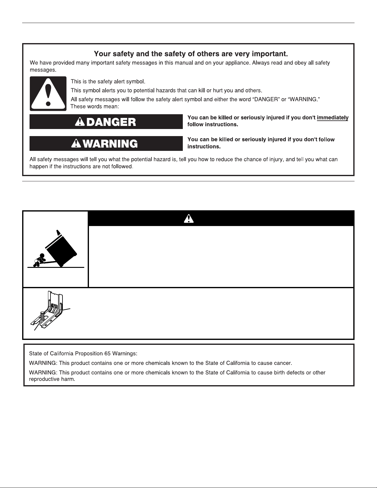
Tip Over Hazard
A child or adult can tip the range and be killed.
Verify the anti-tip bracket has been properly installed and engaged per installation instructions.
Re-engage anti-tip bracket if range is moved.
Do not operate range without anti-tip bracket installed and engaged.
Failure to follow these instructions can result in death or serious burns to children and adults.
To verify the anti-tip bracket is installed and engaged:
• Slide range forward.
• Look for the anti-tip bracket securely attached to floor or wall.
• Slide range back so rear range foot is under anti-tip bracket.
• See installation instructions for details.
WARNING
Anti-Tip
Bracket
Range Foot

3
IMPORTANT SAFETY INSTRUCTIONS
SAVE THESE INSTRUCTIONS
WARNING: To reduce the risk of fire, electrical shock,
injury to persons, or damage when using the range, follow
basic precautions, including the following:
■ WARNING:
TO REDUCE THE RISK OF TIPPING OF
THE RANGE, THE RANGE MUST BE SECURED BY
PROPERLY INSTALLED ANTI-TIP DEVICES. TO CHECK
IF THE DEVICES ARE INSTALLED PROPERLY, SLIDE
RANGE FORWARD, LOOK FOR ANTI-TIP BRACKET
SECURELY ATTACHED TO FLOOR OR WALL, AND
SLIDE RANGE BACK SO REAR RANGE FOOT IS
UNDER ANTI-TIP BRACKET.
■
CAUTION:
Do not store items of interest to children in
cabinets above a range or on the backguard of a range –
children climbing on the range to reach items could be
seriously injured.
■
Proper Installation – Be sure the range is properly installed
and grounded by a qualified technician.
■
Never Use the Range for Warming or Heating the Room.
■ Do Not Leave Children Alone – Children should not be left
alone or unattended in area where the range is in use.
They should never be allowed to sit or stand on any part of
the range.
■ Wear Proper Apparel – Loose-fitting or hanging garments
should never be worn while using the range.
■ User Servicing – Do not repair or replace any part of the
range unless specifically recommended in the manual. All
other servicing should be referred to a qualified technician.
■ Storage in or on the Range – Flammable materials should
not be stored in an oven or near surface units.
■ Do Not Use Water on Grease Fires – Smother fire or flame
or use dry chemical or foam-type extinguisher.
■ Use Only Dry Potholders – Moist or damp potholders on
hot surfaces may result in burns from steam. Do not let
potholder touch hot heating elements. Do not use a towel
or other bulky cloth.
■ DO NOT TOUCH SURFACE UNITS OR AREAS NEAR
UNITS – Surface units may be hot even though they are
dark in color. Areas near surface units may become hot
enough to cause burns. During and after use, do not touch,
or let clothing or other flammable materials contact surface
units or areas near units until they have had sufficient time
to cool. Among those areas are the cooktop and surfaces
facing the cooktop.
■
Use Proper Pan Size – The range is equipped with one or
more surface units of different size. Select utensils having
flat bottoms large enough to cover the surface unit heating
element. The use of undersized utensils will expose a
portion of the heating element to direct contact and may
result in ignition of clothing. Proper relationship of utensil to
burner will also improve efficiency.
■ Never Leave Surface Units Unattended at High Heat
Settings – Boilover causes smoking and greasy spillovers
that may ignite.
■ Make Sure Reflector Pans or Drip Bowls Are in Place –
Absence of these pans or bowls during cooking may
subject wiring or components underneath to damage.
■ Protective Liners – Do not use aluminum foil to line surface
unit drip bowls or oven bottoms, except as suggested in the
manual. Improper installation of these liners may result in a
risk of electric shock, or fire.
■
Glazed Cooking Utensils – Only certain types of glass,
glass/ceramic, ceramic, earthenware, or other glazed
utensils are suitable for range-top service without breaking
due to the sudden change in temperature.
■ Utensil Handles Should Be Turned Inward and Not Extend
Over Adjacent Surface Units – To reduce the risk of burns,
ignition of flammable materials, and spillage due to
unintentional contact with the utensil, the handle of a
utensil should be positioned so that it is turned inward, and
does not extend over adjacent surface units.
■ Do Not Soak Removable Heating Elements – Heating
elements should never be immersed in water.
■
Do Not Cook on Broken Cooktop – If cooktop should
break, cleaning solutions and spillovers may penetrate the
broken cooktop and create a risk of electric shock. Contact
a qualified technician immediately.
■
Clean Cooktop With Caution – If a wet sponge or cloth is
used to wipe spills on a hot cooking area, be careful to
avoid steam burn. Some cleaners can produce noxious
fumes if applied to a hot surface.
■ Use Care When Opening Door – Let hot air or steam
escape before removing or replacing food.
■
Do Not Heat Unopened Food Containers – Build-up of
pressure may cause container to burst and result in injury.
■ Keep Oven Vent Ducts Unobstructed.
■ Placement of Oven Racks – Always place oven racks in
desired location while oven is
cool. If rack must be moved
while oven is hot, do not let potholder contact hot heating
element in oven.
■ DO NOT TOUCH HEATING ELEMENTS OR INTERIOR
SURFACES OF OVEN – Heating elements may be hot even
though they are dark in color. Interior surfaces of an oven
become hot enough to cause burns. During and after use,
do not touch, or let clothing or other flammable materials
contact heating elements or interior surfaces of oven until
they have had sufficient time to cool. Other surfaces of the
appliance may become hot enough to cause burns – among
these surfaces are oven vent openings and surfaces near
these openings, oven doors, and windows of oven doors.
For self-cleaning ranges –
■ Do Not Clean Door Gasket – The door gasket is essential
for a good seal. Care should be taken not to rub, damage,
or move the gasket.
■ Do Not Use Oven Cleaners – No commercial oven cleaner
or oven liner protective coating of any kind should be used
in or around any part of the oven.
■ Clean Only Parts Listed in Manual.
■ Before Self-Cleaning the Oven – Remove broiler pan and
other utensils.
For units with ventilating hood –
■ Clean Ventilating Hoods Frequently – Grease should not
be allowed to accumulate on hood or filter.
■ When flambeing foods under the hood, turn the fan on.
For smart enabled ranges and ovens:
■ Remote operation – This appliance is configurable to allow
remote operation at any time. Do not store any flammable
materials or temperature sensitive items inside, on top or
near surface units of the appliance.
4
KEY USAGE TIPS
AquaLift
®
Self-Cleaning Technology
AquaLift
®
Self-Cleaning Technology is a first-of-its-kind
cleaning solution designed to minimize the time, temperature,
and odors that ordinarily come with traditional self-cleaning
methods. With AquaLift
®
Self-Cleaning Technology, an innovative
coating on the interior of the oven is activated with heat and
water to release baked-on soil. To use AquaLift
®
Self-Cleaning
Technology, simply wipe out loose debris, pour water into the
oven bottom, and run the AquaLift
®
Self-Cleaning cycle. When
the cycle finishes in under 1 hour at a lower temperature than
in traditional self-cleaning methods, just wipe out the remaining
water and loose debris. See the “Clean Cycle” section for more
detailed instructions. For additional information, frequently
asked questions and videos on using AquaLift
®
Self-Cleaning
Technology, visit our website at http://whirlpoolcorp.com/
aqualift.
Surface Temperatures
When the range is in use, all range surfaces may become hot,
such as the knobs and oven door.
Warming or Storage Drawer
When the oven is in use, the drawer may become hot. Do not
store plastics, cloth, or other items that could melt or burn in
the drawer.
Oven Vent
The oven vent releases hot air and moisture from the oven and
should not be blocked or covered. Do not set plastics, papers,
or other items that could melt or burn near the oven vent.
Preheating
When beginning a Bake, Convect Bake, or Convect Roast cycle,
the oven will begin preheating after Start is pressed. The oven
will take approximately 12 to 15 minutes to reach 350°F (177°C)
with all of the oven racks provided with your oven inside the
oven cavity. Higher temperatures will take longer to preheat.
The preheat cycle rapidly increases the oven temperature. The
actual oven temperature will go above your set temperature to
offset the heat lost when your oven door is opened to insert food.
This ensures that when you place your food in the oven, the
oven will begin at the proper temperature. Insert your food when
the preheat tone sounds. Do not open the door during preheat
before the tone sounds.
Ceramic Glass Cooktop Cleaning
To avoid damaging the cooktop, do not use steel wool, abrasive
powder cleansers, chlorine bleach, rust remover, or ammonia.
1. Remove food/residue with the Cooktop Scraper.
■ For best results, use the Cooktop Scraper while the
cooktop is still warm but not hot to the touch. It is
recommended to wear an oven mitt while scraping
the warm cooktop.
■ Hold the Cooktop Scraper at approximately a 45° angle
against the glass surface and scrape the residue. It
will be necessary to apply pressure in order to remove
the residue.
Allow the cooktop to cool down completely before
proceeding to Step 2.
2. Apply a few dime-sized drops of affresh
®
Cooktop Cleaner
to the affected areas.
■ Rub affresh
®
Cooktop Cleaner onto the cooktop surface
with the blue Cooktop Cleaning Pad. Some pressure is
needed to remove stubborn stains.
■ Allow the cleaner to dry to a white haze before
proceeding to Step 3.
3. Polish with a clean, dry cloth or a clean, dry paper towel.
■ Repeat steps 1 through 3 as necessary for stubborn
or burned-on stains.
The Complete Cooktop Cleaner Kit is available for order and
includes the following:
■ Cooktop Scraper
■ Affresh
®
Cooktop Cleaner
■ Blue Cooktop Cleaning Pads
See the “Accessories” section for part numbers and information
on ordering.

5
FEATURE GUIDE
These instructions cover several models. Your model may have some or all of the items listed. Refer to these instructions or the
Frequently Asked Questions (FAQs) section of our website at www.whirlpool.com for more detailed instructions. In Canada, visit our
website at www.whirlpool.ca.
Keypad Feature Instructions
Oven Power Oven function
power
The Oven Power keypad begins oven function and wakes it from sleep mode.
Home Home screen
If pressed once, the Home Screen enables the user to return to the “Cooking Methods” and
“Assisted Cooking” screen.
Oven Light Oven cavity light
The oven light is controlled by a keypad on the oven control panel. While the oven door
is closed, press the oven light keypad to turn the light on and off. When the oven door is
opened, the Oven Light will automatically turn on.
Oven Cancel Oven function
cancel
The Oven Cancel keypad stops any oven function except the Clock, Timer, and Control Lock.
Tools Oven use
functions
Enables you to personalize the audible tones and oven operation to suit your needs. See the
“Tools” and “More Modes” sections.
Favorites Favorites screen
The Favorites keypad allows the user to save and access the cycles that they use on a
frequent basis.
6
Touch Panel
The touch panel houses the control menu and function controls.
The touch keypads are very sensitive and require only a touch to
activate.
Scroll up, down, left, or right to explore the different options and
features.
For more information about the individual controls, see their
respective sections in this manual.
Display
The display is for both the menu and oven function controls. The
touch panel allows you to scroll through the oven menus. The
display is very sensitive and requires only a light touch to activate
and control.
When the oven is in use, the display will show the clock, mode,
oven temperature, kitchen timer, and oven timer, if set. If the oven
timer is not set, you can set it from this screen.
During use, the display will show menus and the appropriate
selections for the options being chosen.
Display Navigation
If the oven is off, touch the Home keypad to activate the menu.
From this screen, all automatic cooking programs can be
activated, all manual cooking programs can be set, options
can be adjusted, and instructions, preparation, and tips can be
accessed.
Setup and Demo Mode
1. Select STORE DEMO MODE to enter Demo Mode.
OR
1. Select NEXT to enter into product use.
2. Follow the prompts on the display screen to select a
language, set up Wi-Fi/connect to network, accept the terms
of service, and set the time.
NOTE: The display screen will show the time and date
(default screen/standby mode).
3. If you selected Store Demo Mode, select TRY THE PRODUCT
to explore various features and options of the product.
OPTIONAL: Select VIEW PRODUCT VIDEOS to view a video
about how to navigate and interact with the product, explore
Voice Control, and Scan-To-Cook.
4. Scroll and select EXPLORE.
5. Select the Tools keypad.
To exit Demo mode, see the “Tools” section.
Cooking Methods
The Cooking Methods keypad allows users to select one of the cooking methods below according to their cooking needs:
■ Bake
■ Broil
■ Convect Bake
■ Convect Broil
■ Convect Roast
■ Keep Warm
To Use:
1. Touch the Home keypad.
2. Select the Cooking Methods keypad.
3. Select desired cooking method.
WARNING
Food Poisoning Hazard
Do not let food sit in oven more than one hour before
or after cooking.
Doing so can result in food poisoning or sickness.
Cooking Method Feature Instructions
BAKE Baking and
roasting
1. Select BAKE.
2. Select the desired temperature by scrolling left to right or manually by selecting the grid in
the upper right corner and entering the BAKE temperature into the keypad.
3. Select START to begin preheating. A tone will sound when preheating is complete.
(Optional) To quickly preheat the oven, see the “Rapid” section for more information in this
section.
4. Press the Cancel keypad when finished.
BROIL Broiling
1. Select BROIL.
2. Select the desired temperature by scrolling left to right or manually by selecting the grid in
the upper right corner and entering the BROIL temperature into the keypad.
3. Select START to begin broiling.
4. Press the Cancel keypad when finished.

7
Cooking Method Feature Instructions
CONVECT BAKE Convection
baking
1. Select CONVECT BAKE.
2. Select the desired temperature by scrolling left to right or manually by selecting the grid in
the upper right corner and entering the CONVECT BAKE temperature into the keypad.
3. Select START to begin preheating. A tone will sound when preheating is complete.
(Optional) To quickly preheat the oven, see the “Rapid” section.
4. Press the Cancel keypad when finished.
For more information, see the “Convection Cooking” section.
CONVECT BROIL Convection
broiling
1. Select CONVECT BROIL.
2. Select the desired temperature by scrolling left to right or manually by selecting the grid in
the upper right corner and entering the CONVECT BROIL temperature into the keypad.
3. Select START.
4. Press the Cancel keypad when finished.
For more information, see the “Convection Cooking” section.
CONVECT
ROAST
Convection
roasting
1. Select CONVECT ROAST.
2. Select the desired temperature by scrolling left to right or manually by selecting the grid in
the upper right corner and entering the CONVECT ROAST temperature into the keypad.
3. Select START.
4. Press the Cancel keypad when finished.
For more information, see the “Convection Cooking” section
KEEP WARM Keep warm
Food must be at serving temperature before placing it in the warmed oven.
1. Select KEEP WARM.
2. Select the desired temperature by scrolling left to right or manually by selecting the grid in
the upper right corner and entering the desired temperature into the keypad.
3. Press START.
4. Press the Cancel keypad when finished.
RAPID Rapid oven
preheating
Provides the fastest preheat time for the Bake function. Rapid Preheat is preset to off.
1. Select RAPID to toggle between turning the rapid preheat off and on.
2. The current setting will be displayed.
IMPORTANT: This feature should only be used for one-rack baking. Unused racks should be
removed prior to Rapid Preheat. A standard rack should be used for Rapid Preheat.
If preheating for the BAKE cycle has already started, Rapid Preheat may be started by selecting
RAPID.
DELAY Delayed start
Delay is used to enter the ending cook time for an oven function with a delayed start. Once the
cooking method is selected, input the bake temperature. Select DELAY and follow the prompts
on the screen.
NOTE: Delay Start should not be used for foods such as breads and cakes because they may
not bake properly.
COOK TIME Timed cooking
Cook Time allows the oven to be set to turn on, cook for a set length of time, and/or shut off
automatically.

8
Favorites
The Favorites feature stores the oven mode and temperature for
your favorite recipe.
As you continue to utilize your Favorites tool, your product will
refine and tailor suggestions towards your cooking cravings/
needs.
NOTE: A select set of Favorites and suggestions may be
automatically shown on the Home screen based on your meal
times.
To save a recipe, select the Favorites keypad (heart icon) and
follow the prompts on the screen to customize your favorites.
Add an image or name to the favorite to customize it to your
preferences.
Assisted Cooking
Assisted cooking helps you select the right mode for your everyday cooking needs. Some modes allow you to skip preheat. Follow the
prompts on screen for guidance throughout the cooking process.
NOTE: Traditional bake temperatures will be converted to convection bake temperatures. Convect Bake requires time and temperature
input. It also requires preheat. Traditional roast times will be converted to convection roast times. Convect Roast requires time and
temperature input, but preheat is not required. Some modes will convert standard bake times for convection cooking. Input your time
and temperature and your screen will convert accordingly.
Assisted
Cooking Modes
Food Selections Tips for best results
FROZEN
■ Frozen Pizza
■ Frozen Pie
■ Frozen Fries
■ Frozen Lasagna
■ Frozen Nuggets
■ Frozen Meals
Frozen foods do not require preheat. Insert food right away. Input the
manufacturer’s maximum recommended time and temperature.
For more information, see the “Frozen Bake™” section.
POULTRY
■ Chicken Pieces
■ Whole Chicken
Poultry food items do not require preheat. Insert food right away.
SEAFOOD
■ Fish Fillet
■ Fish Sticks
Fish Fillet and Fish Sticks require preheat. Insert food when preheat is complete.
BAKED GOODS
■ Biscuits
■ Croissants
Baked Goods require preheat. Insert food when preheat is complete.
DESSERTS
■ Cake
■ Fresh Pie
■ Cookies
■ Frozen Pie
Cake, Cookies, and Fresh Pies requires preheat. Insert food when preheat is
complete.
Frozen Pie does not require preheat. Insert food right away. Input the
manufacturer’s maximum recommended time and temperature.
PIZZA
■ Fresh Pizza
■ Frozen Pizza
Fresh Pizza does require preheat.
Frozen Pizza does not require preheat. Insert food right away, and then input
the manufacturer’s maximum recommended time and temperature. For more
information, see the “Frozen Bake™” section.
MEATS
■ Meatloaf
■ Pork Roast
■ Beef Roast
■ Lamb Roast
Meatloaf requires preheat. Insert food when preheat is complete.
Lamb, Beef, and Pork Roasts do not require preheat. Insert food right away.
VEGGIES
■ Baked Potato
■ Roasted Fresh Veggies
Roasted Fresh Veggies and Baked Potato do not require preheat. Insert food right
way.
CASSEROLES
■ Casserole
■ Frozen Lasagna
Casserole does require preheat. Insert food when preheat is complete.
Frozen Lasagna does not require preheat. Insert food right away. Input the
manufacturer’s maximum recommended time and temperature. For more
information, see the “Frozen Bake™” section.
SNACKS
N/A Snacks require preheat. Insert food when preheat is complete.

9
Tools
The Tools keypad allows you access to functions and
customization options for your oven. These tools allow you to set
the clock, change the oven temperature between Fahrenheit and
Celsius, turn the audible signals and prompts on and off, adjust
the oven calibration, change the language, and more.
Select the Tools keypad to view the Tools features.
See the “More Modes” section for more information.
Tool Notes
Remote Enable
Select Remote Enable to enable the ability to
utilize the Whirlpool
®
app.
NOTE: Remote Enable does not turn off
when the door is opened. Do not store any
flammable materials or temperature sensitive
items inside the oven.
Kitchen Timer
Set a kitchen timer by manually entering the
desired time into the keypad.
1. Select KITCHEN TIMER.
2. Manually input the time to the desired
timer length.
3. Select START.
4. Select the Cancel keypad to end the
Kitchen Timer.
Light
Select the LIGHT keypad to turn the light on
and off. When the oven door is opened, the
oven light will automatically turn on.
Self-Clean
See the “Range Care” section.
Mute
Select MUTE to mute or unmute the
oven sounds.
Control Lock
The Control Lock locks the control panel
keypads to avoid unintended use of the
oven(s). If set before the power failure
occurs, the CONTROL LOCK keypad will
remain set after a power failure.
The Control Lock is preset unlocked, but can
be locked.
To Lock or Unlock Control:
1. Check that the oven is off.
2. Select the CONTROL LOCK keypad.
3. “CONTROL LOCK” will display.
4. Scroll up to unlock.
No keypads will function with the controls
locked. The cooktop functions are not
affected by the oven control lockout.
Preferences
Times and Dates
Set time and date preferences.
NOTE: If user is connected to Wi-Fi, time and date will be set
automatically.
■ Your Meal Times: Adjust when breakfast/lunch/dinner
is shown
■ Time
■ Date
■ Time Format (AM/PM vs 24 Hour [Military Time])
Sound Volume
Set sound volume preferences.
■ Timers and Alerts
■ Buttons and Effects
Display Settings
Set the screen brightness.
■ Display Brightness
Regional
Set regional preferences.
■ Language: English, Spanish, or French
■ Temperature Units: Fahrenheit and Celsius
Wi-Fi
■ Connect to Network: Download the Whirlpool
®
app from the
app store on your mobile phone. See the Connectivity Setup
sheet for more detailed instructions.
■ SAID Code: The SAID code is used to sync a smart
device with your appliance. Enter the SAID code in the
Whirlpool
®
app.
■ MAC Address: MAC Address is displayed for the Wi-Fi
module.
■ Wi-Fi Radio: Turn Wi-Fi on or off.
Info
■ Service and Support: Displays model number, Customer
Support contact info, and Diagnostics.
■ Store Demo Mode: Select STORE DEMO MODE to toggle
Demo Mode off and on.
To Start Demo Mode:
1. Select the Tools keypad.
2. Scroll and select INFO.
3. Select STORE DEMO MODE and select ON.
NOTE: The display screen will show the time (default screen/
standby mode).
4. Select the Tools keypad.
5. Select TRY THE PRODUCT or VIEW PRODUCT VIDEOS.
If the unit is in Demo Mode after power up, follow these steps to
exit the Demo Mode.
To Exit Demo Mode:
1. Select TRY THE PRODUCT.
2. Scroll and select EXPLORE.
3. Select the Tools keypad.
4. Scroll and select INFO.
5. Select STORE DEMO MODE and select OFF.
6. Select YES on the confirmation screen.
■ Restore Factory: This will restore your product to the original
factory default settings.
■ Wi-Fi Terms and Conditions: www.whirlpool.com/connect.
■ Software Terms and Conditions.

10
More Modes
Sabbath Mode
For guidance on usage and a complete list of models with
Sabbath Mode, visit www.star-k.org.
The Sabbath Mode sets the oven to remain on in a bake setting
until disabled.
When the Sabbath Mode is activated, only the Bake cycle will
operate. All other cooking and cleaning cycles are disabled. No
tones will sound, and the displays will not indicate temperature
changes. When the oven door is opened or closed, the oven light
will not turn on or off, and the heating elements will not turn on or
off immediately.
If a cook timer is set, the countdown will appear. Countdown will
begin once the timer is set.
NOTE: If a power failure happens while Sabbath Mode is running,
the oven will show Sabbath Mode is on, but the Bake cycle will
not be on. If the oven door is opened during this time, the oven
light will not turn on.
To Enable and Activate Sabbath Mode:
1. Press the Tools keypad.
2. Select MORE MODES.
3. Select SABBATH MODE.
4. Press SABBATH MODE again to enable Sabbath Mode
(Sabbath Mode is preset to Off).
5. Select YES if you would like to have your oven on and baking
during the Sabbath.
6. Enter the desired temperature.
(Optional) For timed cooking in Sabbath Mode, press ADD
A COOK TIME for the selected oven, Enter the desired cook
time and then press NEXT.
7. Select START.
To Disable and Exit Sabbath Mode:
1. Press the Oven Cancel keypad.
2. Press and hold the display screen for three seconds.
To Adjust Temperature:
1. Press the +/- 25 on the display screen to select the new
temperature.
NOTE: The temperature adjustment will not appear on the
display, and no tones will sound.
Temperature Calibration
IMPORTANT: Do not use a thermometer to measure the oven
temperature. Elements will cycle on and off as needed to
maintain a consistent temperature but may run slightly hot or cool
at any point in time due to this cycling. Opening the oven door
will affect cycling of the elements and impact the temperature.
The oven provides accurate temperatures and has been
thoroughly tested at the factory. However, it may cook faster
or slower than your previous oven, causing baking or browning
differences. If necessary, the temperature calibration can be
adjusted in either Fahrenheit or Celsius.
A minus sign means the oven will be cooler by the displayed
amount. The absence of a minus sign means the oven will be
warmer by the displayed amount.
Adjust the oven temp up to (+,-) 30° (-18°C). It is recommended
to make changes in 5°F (3°C) increments until desired results are
achieved.
NOTE: The oven display will continue to show the original
set temperature and will not reflect the calibration offset. For
example, if set to 350° (177°C) and calibrated to -20, the display
will continue to show 350° (177°C).
To Adjust Oven Temperature Calibration:
1. Press the Tools keypad.
2. Select MORE MODES.
3. Select TEMPERATURE CALIBRATION.
4. Scroll from left to right to increase or decrease the
temperature.
11
COOKTOP
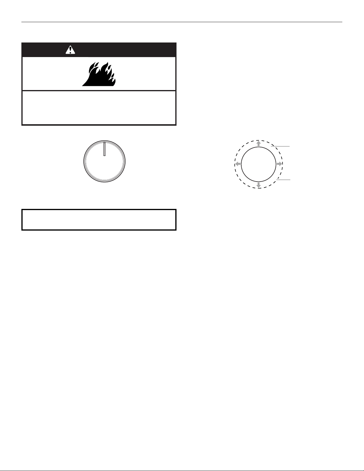
The control knobs can be set to anywhere between HI and LO.
Push in and turn to setting.
Ceramic Glass (on some models)
The surface cooking area may glow red when an element is on.
Some parts of the surface cooking area may not glow red when
an element is on. The glow will also randomly cycle off and back
on again, even while on Hi, to keep the cooktop from extreme
temperatures. This is normal operation.
It is normal for the surface of light-colored ceramic glass to
appear to change color when surface cooking areas are hot.
As the glass cools, it will return to its original color.
Cleaning off the cooktop before and after each use will help
keep it free from stains and provide the most even heating. On
cooktops with light-colored ceramic glass, soils and stains may
be more visible, and may require more cleaning and attention.
Cooktop cleaner and a cooktop scraper are recommended.
For more information, see the “General Cleaning” section.
IMPORTANT: To avoid permanent damage to the cooktop
surface and to make soils easier to remove, clean the cooktop
after each use to remove all soils.
■ Avoid storing jars or cans above the cooktop. Dropping
a heavy or hard object onto the cooktop could crack
the cooktop.
■ To avoid damage to the cooktop, do not leave a hot lid on
the cooktop. As the cooktop cools, air can become trapped
between the lid and the cooktop and the ceramic glass
could break when the lid is removed.
■ For foods containing sugar in any form, clean up all spills
and soils as soon as possible. Allow the cooktop to cool
down slightly. Then, while wearing oven mitts, remove the
spills using a scraper while the surface is still warm. If sugary
spills are allowed to cool down, they can adhere to the
cooktop and can cause pitting and permanent marks.
■ To avoid scratches, do not slide cookware or bakeware
across the cooktop. Aluminum or copper bottoms and rough
finishes on cookware or bakeware could leave scratches or
marks on the cooktop.
■ Do not cook popcorn in prepackaged aluminum containers
on the cooktop. They could leave aluminum marks that
cannot be removed completely.
■ To avoid damage to the cooktop, do not allow objects that
could melt, such as plastic or aluminum foil, to touch any
part of the entire cooktop.
■ To avoid damage to the cooktop, do not use the cooktop
as a cutting board.
■ Use cookware about the same size as the surface cooking
area. Cookware should not extend more than 1/2" (13 mm)
outside the area.
■ Use flat-bottomed cookware for best heat conduction and
energy efficiency. Cookware with rounded, warped, ribbed,
or dented bottoms could cause uneven heating and poor
cooking results.
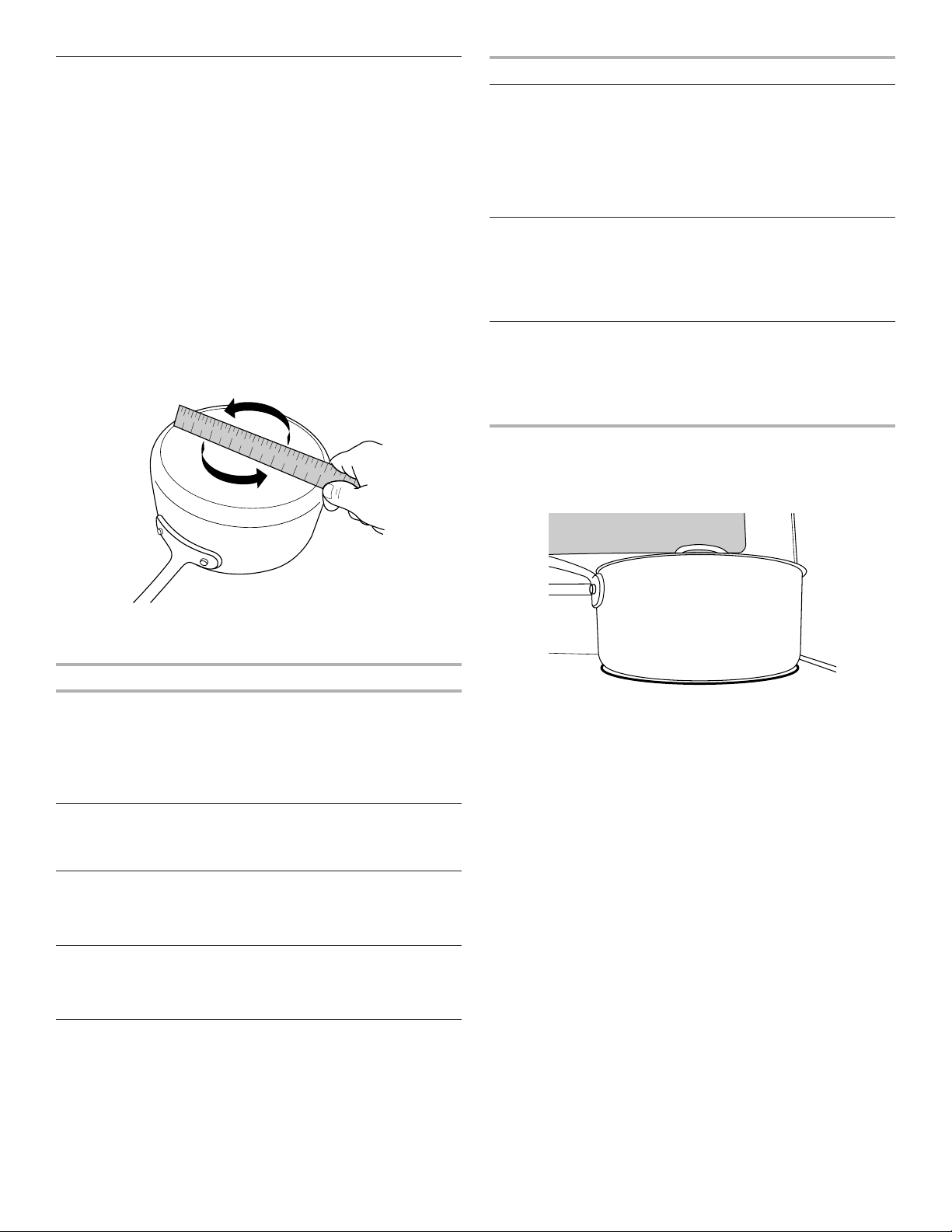
■ Determine flatness by placing the straight edge of a ruler
across the bottom of the cookware. While you rotate the
ruler, no space or light should be visible between it and
the cookware.
■ Cookware designed with slightly indented bottoms or small
expansion channels can be used.
■ Make sure the bottoms of pots and pans are clean and dry
before using them. Residue and water can leave deposits
when heated.
■ To avoid damage to the cooktop, do not cook foods directly
on the cooktop.
Coil Elements and Burner Bowls (on some models)
Coil elements should be level for optimal cooking results. Burner
bowls, when clean, reflect heat back to the cooktop. They also
help catch spills.
Cookware should not extend more than 1/2" (13 mm) over the
coil element. If cookware is uneven or too large, it can produce
excess heat, causing the burner bowl to change color.
Cooktop On Indicator Light
The Cooktop On indicator light is located on the console panel.
When any control knob on the console panel is turned on, the
Cooktop On indicator light will glow.
WARNING
Fire Hazard
Turn off all controls when done cooking.
Failure to do so can result in death or fire.
OFF
ON
REMEMBER: When range is in use, the entire cooktop area
may become hot.
A
B
C
A. Surface cooking area
B. Cookware/canner
C. 1/2" (13 mm) maximum overhang
12
Hot Surface Indicator Light
On ceramic glass models, the Hot Surface indicator light
is located on the console panel.
The Hot Surface indicator light will glow as long as any surface
cooking area is too hot to touch, even after the surface cooking
area is turned off.
Triple Zone Cooking Element
The Triple Zone cooking element offers flexibility depending on
the size of the cookware. Single size can be used in the same
way as a regular element. The dual and triple sizes combine the
single, dual, and outer elements and is recommended for larger
cookware, larger quantities of food, and home canning.
Dual Zone Cooking Element (on some models)
The Dual Zone cooking element offers flexibility depending on the
size of the cookware. Single size can be used in the same way as
a regular element. The dual size combines both the single and
outer element and is recommended for larger size cookware.
Rapid Boil Element (right front element)
The Rapid Boil cooking element offers additional cooking
flexibility. The Rapid Boil cooking element can be used to boil
liquids faster. The lowest melt setting can be used to prepare
sauces, to brown or saute foods, and to keep foods at a low
temperature. Use cookware appropriate in size for the Rapid
Boil cooking element.
Melt Element
The Melt cooking element offers flexibility due to a wide range
of settings between High and Melt. The High heat option can be
used to boil small amounts of liquid quickly. To reduce the power
setting, turn the knob clockwise. The Melt setting is designed
for delicate foods that require low heat, such as when melting
chocolate or holding sauces. Use cookware appropriate in
size for the Melt cooking element.
Warm Zone Element
Use the Cooktop Warm Zone element to keep cooked foods
warm. One hour is the recommended maximum time to maintain
food quality.
Do not use it to heat cold foods.
The Warm Zone element can be used alone or when any of the
other surface cooking areas are being used.
The Warm Zone element area will not glow red when cycling on.
However, the Cooktop On indicator light will be displayed when
the Warm Zone is in use.
■ Use only cookware recommended for oven and cooktop use.
■ Cover all foods with a lid or aluminum foil. When warming
baked goods, allow a small opening in the cover for moisture
to escape.
■ To avoid damage to the cooktop, do not use plastic wrap to
cover food because the plastic wrap may melt.
■ Use pot holders or oven mitts to remove food.
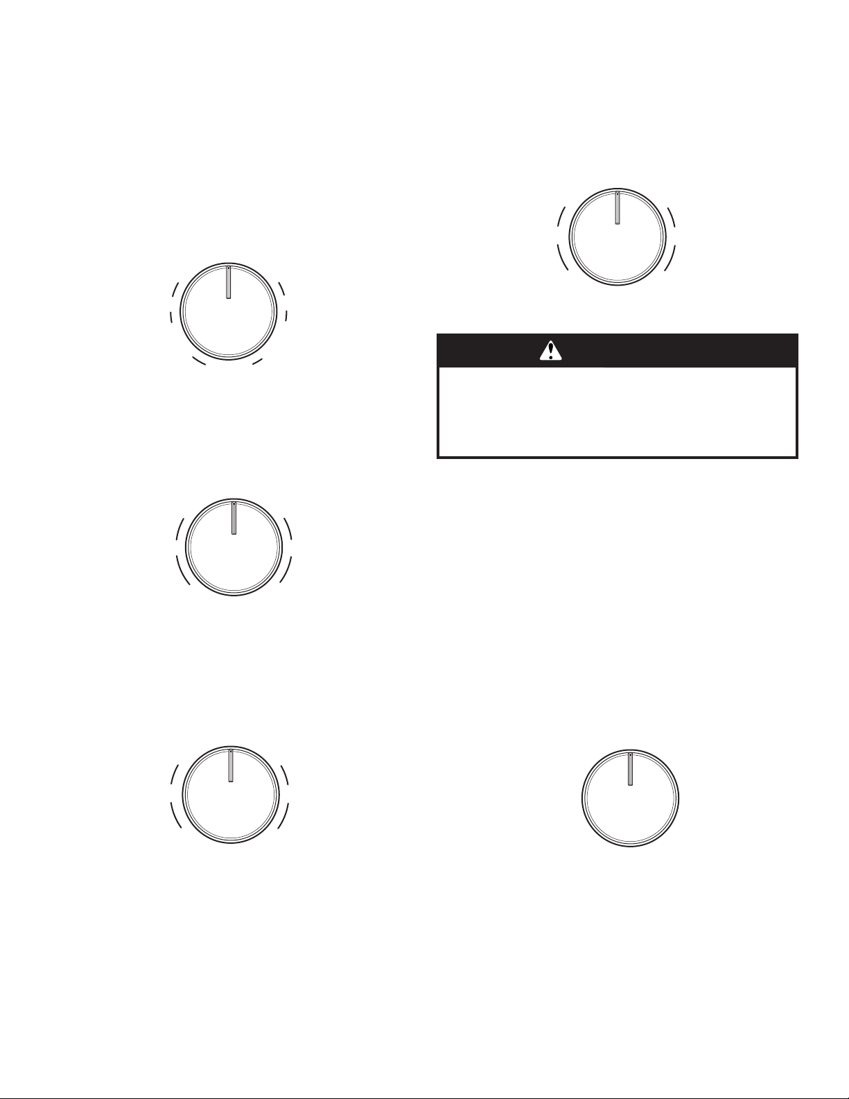
To use:
To turn on, turn knob to the On position.
To turn off, turn knob to the Off position.
Off
Hi Lo
SingleTriple
Hi
Lo
Hi Lo
Double
Off
Hi Lo
Single
Hi
Lo
Double
OFF
Lo
Melt
Hi
Max
Lo
Hi
OFF
Lo
Melt
Hi
Max
Lo
Hi
WARNING
Food Poisoning Hazard
Do not let food sit in oven more than one hour before
or after cooking.
Doing so can result in food poisoning or sickness.
OFF
ON
13
Cookware
IMPORTANT: Do not leave empty cookware on a hot surface
cooking area, element, or surface burner.
Ideal cookware should have a flat bottom, straight sides, and a
well-fitting lid, and the material should be of medium-to-heavy
thickness.
Rough finishes may scratch the cooktop or coils. Aluminum
and copper may be used as a core or base in cookware.
However, when used as a base, they can leave permanent
marks on the surfaces.
Cookware material is a factor in how quickly and evenly heat
is transferred which affects cooking results. A nonstick finish
has the same characteristics as its base material. For example,
aluminum cookware with a nonstick finish will take on the
properties of aluminum.
Cookware with nonstick surfaces should not be used under
the broiler.
Check for flatness by placing the straight edge of a ruler across
the bottom of the cookware. While you rotate the ruler, no space
or light should be visible between it and the cookware.
Use the following chart as a guide for cookware material
characteristics.
Cookware Characteristics
Copper
■ Heats very quickly and evenly.
■ May leave copper residues which may
be diminished if cleaned immediately
after cooking.
■ Can leave a permanent stain or bond
to the cooktop if overheated.
Earthenware
■ Follow manufacturer’s instructions.
■ Use on low heat settings.
■ May scratch the cooktop.
Porcelain
enamel-on-steel
or cast iron
■ See stainless steel or cast iron.
■ Porcelain enamel bakeware without the
metal base may bond to the cooktop if
overheated.
Stainless steel
■ Heats quickly, but unevenly.
■ A core or base of aluminum or copper
on stainless steel provides even
heating.
Cookware Characteristics
Aluminum
■ Heats quickly and evenly.
■ Suitable for all types of cooking
■ Medium or heavy thickness is best
for most cooking tasks.
■ May leave aluminum residues
which may be diminished if cleaned
immediately after cooking.
Cast iron
■ Heats slowly and evenly.
■ Good for browning and frying
■ Maintains heat for slow cooking.
■ Rough edges or burrs may scratch
the cooktop.
Ceramic or
ceramic glass
■ Follow manufacturer’s instructions.
■ Heats slowly, but unevenly.
■ Ideal results on low-to-medium heat
settings
■ May scratch the cooktop.
Use flat-bottomed cookware for best cooking results and energy
efficiency. The cookware should be about the same size as
the cooking area outlined on the cooktop or the coil element.
Cookware should not extend more than 1/2" (13 mm) beyond
the surface cooking area or element.
1
2
3
4
5
6
7
8
9
1 0
1 1
1 2
1 3
1 4
1 5
1 6
1 7
1 8
1 9
2 0
1
2
3
4
5
6
7
14
Home Canning
Canning can be performed on a glass smoothtop cooking
surface or traditional coil element cooktop. When canning for
long periods, alternate the use of surface cooking areas or
elements between batches. This allows time for the most recently
used areas to cool.
■ Center the canner on the largest surface cooking area or
element. On electric cooktops, canners should not extend
more than 1/2" (13 mm) beyond the surface cooking area or
element.
■ Do not place canner on two surface cooking areas or
elements at the same time.
■ On ceramic glass models, use only flat-bottomed canners
to avoid damage to the cooktop and elements.
■ For more information, contact your local agricultural
extension office or refer to published home canning guides.
Companies that manufacture home canning products can
also offer assistance.
OVEN USE
Odors and smoke are normal when the oven is used the first
few times or when it is heavily soiled.
IMPORTANT: The health of some birds is extremely sensitive
to the fumes given off by the oven. Exposure to the fumes may
result in death to certain birds. Always move birds to another
closed and well-ventilated room.
Aluminum Foil
IMPORTANT: To avoid permanent damage to the oven bottom
finish, do not line the oven bottom with any type of foil or liner.
For best cooking results, do not cover entire oven rack with foil
because air must be able to move freely.
Positioning Racks and Bakeware
IMPORTANT: To avoid permanent damage to the porcelain
finish, do not place food or bakeware directly on the oven door
or bottom.
Bakeware
To cook food evenly, hot air must be able to circulate. Allow
2" (5 cm) of space around bakeware and oven walls. Make sure
that no bakeware piece is directly over another.
Racks
■ Position racks before turning on the oven.
■ Do not position racks with bakeware on them.
■ Make sure racks are level.
To position a rack, pull it out to the stop position, raise the front
edge, and then lift out. Use the following illustration and charts
as a guide.
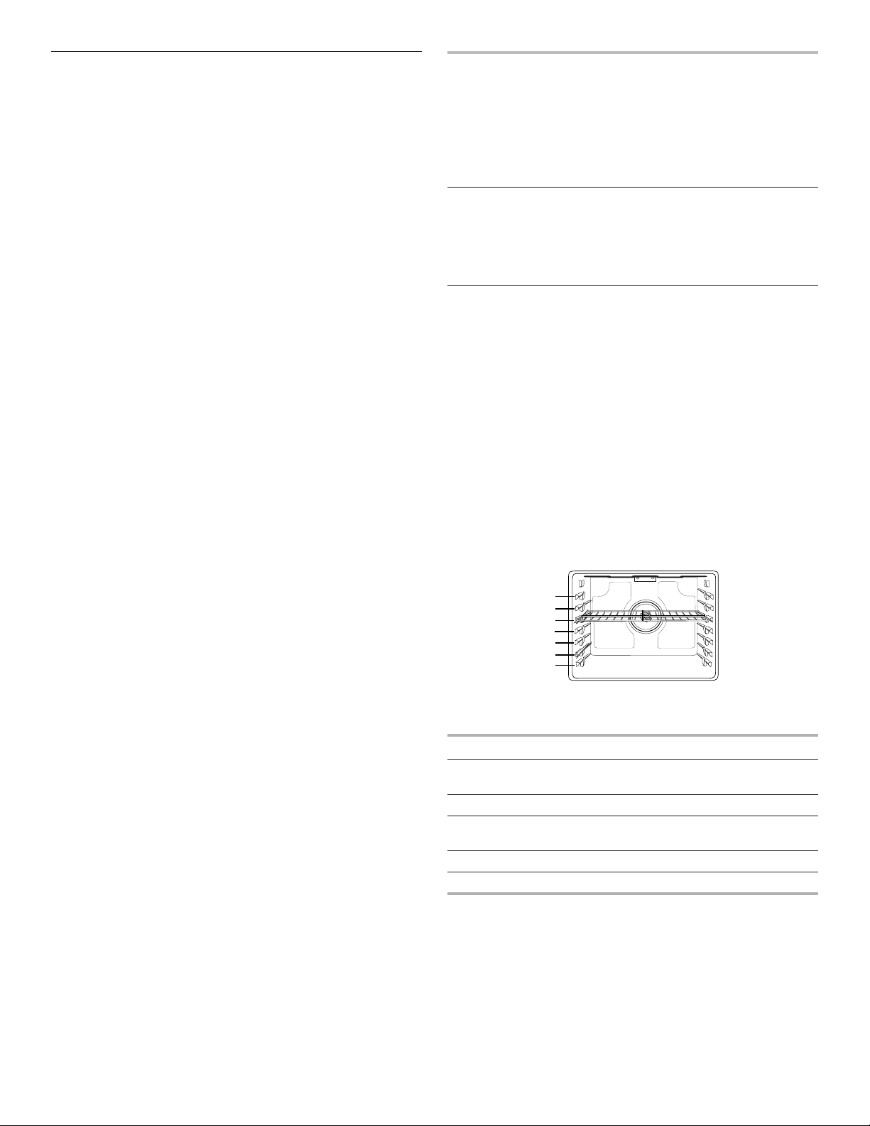
The oven has 7 positions for a flat rack, as shown in the previous
illustration and the following table.
Flat Rack Position* Type of Food
7 Broiling/searing meats,
hamburgers, steaks
6 Broiled meats, poultry, fish
3 or 4 Most baked goods, casseroles,
frozen foods
2 Roasted meats
1 Large roasts or poultry
For hamburger patties to have a well-seared exterior and a rare
interior, use a flat rack in rack position 7. Preheat the oven for
2 minutes. Side 1 should cook for approximately 2
1
/
2
to 3
1
/
2
minutes. Side 2 should cook for approximately 4 to 5 minutes.
Expect a moderate degree of smoke when broiling.
* If your model has a Max Capacity Oven Rack, the recessed
ends must be placed in the rack position above the desired
position of the food. See the following illustration.
7
6
5
4
3
2
1
15
IMPORTANT: These rack positions are for flat racks. If a Max
Capacity Oven Rack is used, the rack position must be adjusted
as shown in the previous figure.
Multiple Rack Cooking
Two-rack (non-convection): Use rack positions 2 and 5 or 3
and 6.
Two-rack (convection): Use rack positions 2 and 5 or 3 and 6.
Three-rack (convection): Use rack positions 2 and 7 and a Max
Capacity Oven Rack in rack position 5.
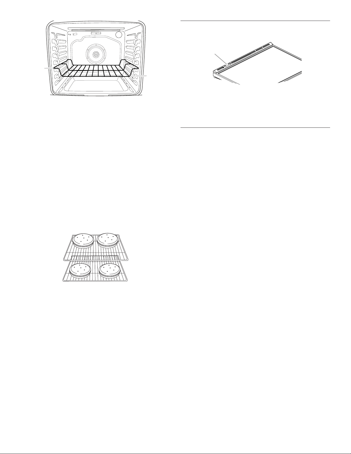
Baking Cookies and Layer Cakes on Two Racks
Baking Layer Cakes
For best results when baking cakes on two racks, use the Bake
function, a flat rack in rack position 5, and a flat rack in rack
position 2. If you do not have two flat racks, use a Max Capacity
Oven Rack in rack position 6. Place the cakes on the racks as
shown. Keep at least 3" (7.6 cm) of space between the front of
the racks and the front cakes.
Baking Cookies
For best results when baking cookies on two racks, use
the Convection Bake function, a flat rack in rack position 5,
and a flat rack in rack position 2.
If you do not have two flat racks, use a flat rack in rack position
2 and a Max Capacity Oven Rack in rack position 6.
If you do not have Convection Bake, use the standard
Bake function.
Oven Vent
The oven vent releases hot air and moisture from the oven
and should not be blocked or covered. Blocking or covering the
oven vent will cause poor air circulation, affecting cooking and
cleaning results. Do not set plastics, paper, or other items that
could melt or burn near the oven vent.
Baking and Roasting
Preheating
When beginning a Bake, or Convect Bake cycle, the oven
will begin preheating after Start is pressed. The oven will take
approximately 12 to 15 minutes to reach 350°F (177°C) with all
of the oven racks provided with your oven inside the oven cavity.
Higher temperatures will take longer to preheat. The preheat
cycle rapidly increases the oven temperature. The actual oven
temperature will go above your set temperature to offset the heat
lost when your oven door is opened to insert food. This ensures
that when you place your food in the oven, the oven will begin at
the proper temperature. Insert your food when the preheat tone
sounds. Do not open the door during preheat before the tone
sounds.
Rapid Preheat
Rapid Preheat can be used to shorten the preheating time. Only
one standard flat oven rack should be in the oven during Rapid
Preheat. Extra racks should be removed prior to starting. The
preheating cycle should be completed before placing food in the
oven. When the Rapid Preheat cycle is complete, the oven starts
a normal Bake cycle.
IMPORTANT: Rapid Preheat should be used only for one-rack
baking.
Oven Temperature
While in use, the oven elements will cycle on and off as needed
to maintain a consistent temperature, but they may run slightly
hot or cool at any point in time due to this cycling. Opening the
oven door while in use will release the hot air and cool the oven
which could impact the cooking time and performance. It is
recommended to use the oven light to monitor cooking progress.
NOTE: On models with convection, the convection fan may run
in the non-convection Bake mode to improve oven performance.
Temperature Management System
The temperature management system electronically regulates the
oven heat levels during preheat and Bake to maintain a precise
temperature range for optimal cooking results. The bake and broil
elements or burners cycle on and off in intervals. On convection
range models, the fan will run while preheating and may be
cycled on and off for short intervals during Bake to provide the
best results. This feature is automatically activated when the oven
is in use.
Before baking and roasting, position racks according to the
“Positioning Racks and Bakeware” section. When roasting, it is
not necessary to wait for the oven preheat cycle to end before
putting food in, unless it is recommended in the recipe.
A
B
A. Ends of rack in position 3
B. Food in position 2
A
A. Oven vent
16
Frozen Bake™
Frozen Bake™ Technology automatically adjusts the
manufacturer’s bake time by combining preheating and baking,
to deliver great packaged frozen food results without the wait.
There are six programmed food options to choose from: Pizza,
Lasagna, Nuggets, Fries, Pie and Meal. The Frozen Bake™
cycles have been customized to work only with these foods.
When using Frozen Bake™ Technology, it is important that
you follow all manufacturer’s instructions including venting,
covering, stirring or placing on a baking sheet to ensure a good
result. When cooking frozen meals, only cook items that provide
instructions for cooking in a conventional oven. Place your dish
in the center of the rack and select one of the rack positions
recommended for Frozen Bake™ in the “Positioning Racks and
Bakeware” section and bake only one package or pan at a time.
Use the temperature and maximum bake time from the package.
A tone will alert you to check the food for doneness before the
cook time is complete and again at the end of the cook time. The
display will prompt you to add additional cook time if desired.
Broiling
When broiling, preheat the oven for 2 minutes before putting
food in, unless recommended otherwise in the recipe. Position
food on grid in a broiler pan, and then place it in the center of
the oven rack.
IMPORTANT: Close the door to ensure proper broiling
temperature.
Changing the temperature when broiling allows more precise
control when cooking. The lower the broil setting is, the slower
the cooking. Thicker cuts and unevenly shaped pieces of meat,
fish and poultry may cook better at lower broil settings. Use rack
6 or 7 for broiling. Refer to the “Positioning Racks and Bakeware”
section for more information.
On lower settings, the broil element will cycle on and off to
maintain the proper temperature.
■ For best results, use a broiler pan and grid. It is designed
to drain juices and help avoid spatter and smoke.
If you would like to purchase a broiler pan, one may be
ordered. See the “Accessories” section.
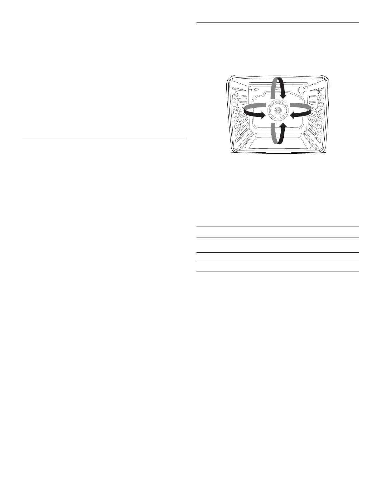
Convection Cooking
In a convection oven, the fan-circulated hot air continually
distributes heat more evenly than the natural movement of air
in a standard thermal oven. This movement of hot air helps
maintain a consistent temperature throughout the oven, cooking
foods more evenly, crisping surfaces while sealing in moisture,
and yielding crustier breads.
During convection baking or roasting, the bake, broil, and
convection elements cycle on and off in intervals while the fan
circulates the hot air. During convection broiling, the broil and
convection elements cycle on and off.
If the oven door is opened during convection cooking, the fan
will turn off immediately. It will come back on when the oven
door is closed.
With convection cooking, most foods can be cooked at a lower
temperature and/or a shorter cooking time than in a standard
thermal oven. Use the following chart as a guide.
Convection Mode Time/Temp. Guidelines
Convection Bake 25°F (15°C) lower temperature;
possible shortened cooking time
Convection Roast Cooking time shortened by up to 30%
Convection Broil Shortened cooking time
Convect Options
Convect Bake: multiple-rack baking or cookies, biscuits, breads,
casseroles, tarts, tortes, cakes
Convect Roast: whole chicken or turkey, vegetables, pork roasts,
beef roasts
Convect Broil: thicker cuts or unevenly shaped pieces of meat,
fish, or poultry

17
Oven Light
The oven light is a standard 40-watt appliance bulb. Before
replacing, make sure the oven and cooktop are cool and the
control knobs are in the Off position.
To Replace:
1. Unplug range or disconnect power.
2. Turn the glass bulb cover in the back of the oven
counterclockwise to remove.
3. Turn bulb counterclockwise to remove from socket.
4. Replace bulb by turning clockwise.
5. Replace bulb cover by turning clockwise.
6. Plug in range or reconnect power.
RANGE CARE
Clean Cycle
AquaLift
®
Technology is an innovative cleaning solution that
utilizes heat and water to release baked-on spills from the oven
in less than 1 hour. This new cleaning technology is a low-heat,
odor-free alternative to traditional self-cleaning options.
Allow the oven to cool to room temperature before using the
Clean cycle. If your oven cavity is above 200°F (93°C), “Oven
Cooling” will appear in the display, and the Clean cycle will
not be activated until the oven cavity cools down.
To Clean:
1. Remove all racks and accessories from the oven cavity,
and wipe excess soil. Use a plastic scraper to remove
easily removed soils.
2. Pour 2 cups (16 oz [500 mL]) of distilled or filtered water onto
the bottom of the empty oven, and close the oven door.
IMPORTANT: Do not use chemicals or other additives with
the water. Do not open the oven door during the Clean cycle.
The water on the oven bottom is hot.
3. Press AQUALIFT SELF CLEAN and then START on the oven
control panel.
NOTE: Do not start Self Clean before the oven has cooled
down.
4. Allow 40 minutes for cleaning and cooldown. A beep will
sound when the Clean cycle is complete.
5. Press CANCEL at the end of the cycle. Cancel may be
pressed at any time to stop the Clean cycle.
6. Remove the residual water and loosened soils with a sponge
or cloth immediately after the Clean cycle is complete. Much
of the initial 2 cups (16 oz [500 mL]) of water will remain in the
oven after the cycle is completed. If additional soils remain,
leave a small amount of water in the oven bottom to assist
with the cleaning.
7. If any soils remain, remove them with a nonscratch scrubbing
sponge or plastic scraper. Additional Clean cycles may be run
to help remove the stubborn soils.
IMPORTANT: Do not use oven cleaners. The use of chemicals,
including commercial oven cleaners or metal scouring pads,
may cause permanent damage to the porcelain surface of the
oven interior.
NOTES:
■ The range should be level to ensure that the entire surface
of the bottom of the oven cavity is covered by water at the
beginning of the Clean cycle.
■ For best results, use distilled or filtered water. Tap water
may leave mineral deposits on the oven bottom.
■ Before removing the residual water and loosened soils at the
end of the Clean cycle, insert a cloth or paper towel between
the lower edge of the oven door and the front frame to keep
water from spilling onto the front of the range and the floor.
■ Soil baked on through several cooking cycles will be more
difficult to remove with the Clean cycle.
18
■ Nonabrasive scrub sponges or eraser-style cleaning pads
(without cleaners) can be effective for cleaning the oven
cavity walls, oven door, and oven bottom for difficult soils.
For best results, moisten the pads and sponges before use.
■ Run an additional Clean cycle for stubborn soils.
■ Affresh
®
Kitchen Appliance Cleaner and affresh
®
Cooktop
Cleaner may be used to clean the oven bottom, walls, and
door when the oven has finished the cycle and returned to
room temperature. If affresh
®
Cooktop Cleaner is used, it
is recommended to wipe out the cavity with distilled water
as well. Refer to the “Accessories” section for information
on ordering.
■ Additional AquaLift
®
Technology Cleaning Kits may be
obtained by ordering Part Number W10423113RP. See
the “Accessories” section for more information.
■ For assistance with AquaLift
®
Technology, call 1-877-258-
0808 in the U.S.A. or 1-800-807-6777 in Canada, or visit our
website at http://whirlpoolcorp.com/aqualift.
General Cleaning
IMPORTANT: Before cleaning, make sure all controls are off and
the oven and cooktop are cool. Always follow label instructions
on cleaning products. For additional information, you can visit our
website at www.whirlpool.com. In Canada, visit our website at
www.whirlpool.ca.
Soap, water, and a soft cloth or sponge are suggested first unless
otherwise noted.
EXTERIOR PORCELAIN ENAMEL SURFACES
(on some models)
Food spills containing acids, such as vinegar and tomato, should
be cleaned as soon as the entire range is cool. These spills may
affect the finish.
Cleaning Method:
■ Glass cleaner, mild liquid cleaner or nonabrasive
scrubbing pad:
Gently clean around the model/serial/rating plate
because scrubbing may remove numbers.
■ Affresh
®
Kitchen and Appliance Cleaner Part Number
W10355010 (not included):
See the “Accessories” section for more information.
STAINLESS STEEL (on some models)
NOTE: To avoid damage to stainless steel surfaces, do not use
soap-filled scouring pads, abrasive cleaners, cooktop cleaner,
steel-wool pads, gritty washcloths, or abrasive paper towels.
Damage may occur to stainless steel surfaces, even with one-
time or limited use.
Cleaning Method:
Rub in direction of grain to avoid damaging.
■ Affresh
®
Stainless Steel Cleaner Part Number W10355016
(not included):
See the “Accessories” section for more information.
METALLIC PAINT (on some models)
Do not use abrasive cleaners, cleaners with bleach, rust
removers, ammonia, or sodium hydroxide (lye) because the
paint surface may stain.
CERAMIC GLASS
Cleaning Method:
To avoid damaging the cooktop, do not use steel wool, abrasive
powder cleansers, chlorine bleach, rust remover, or ammonia.
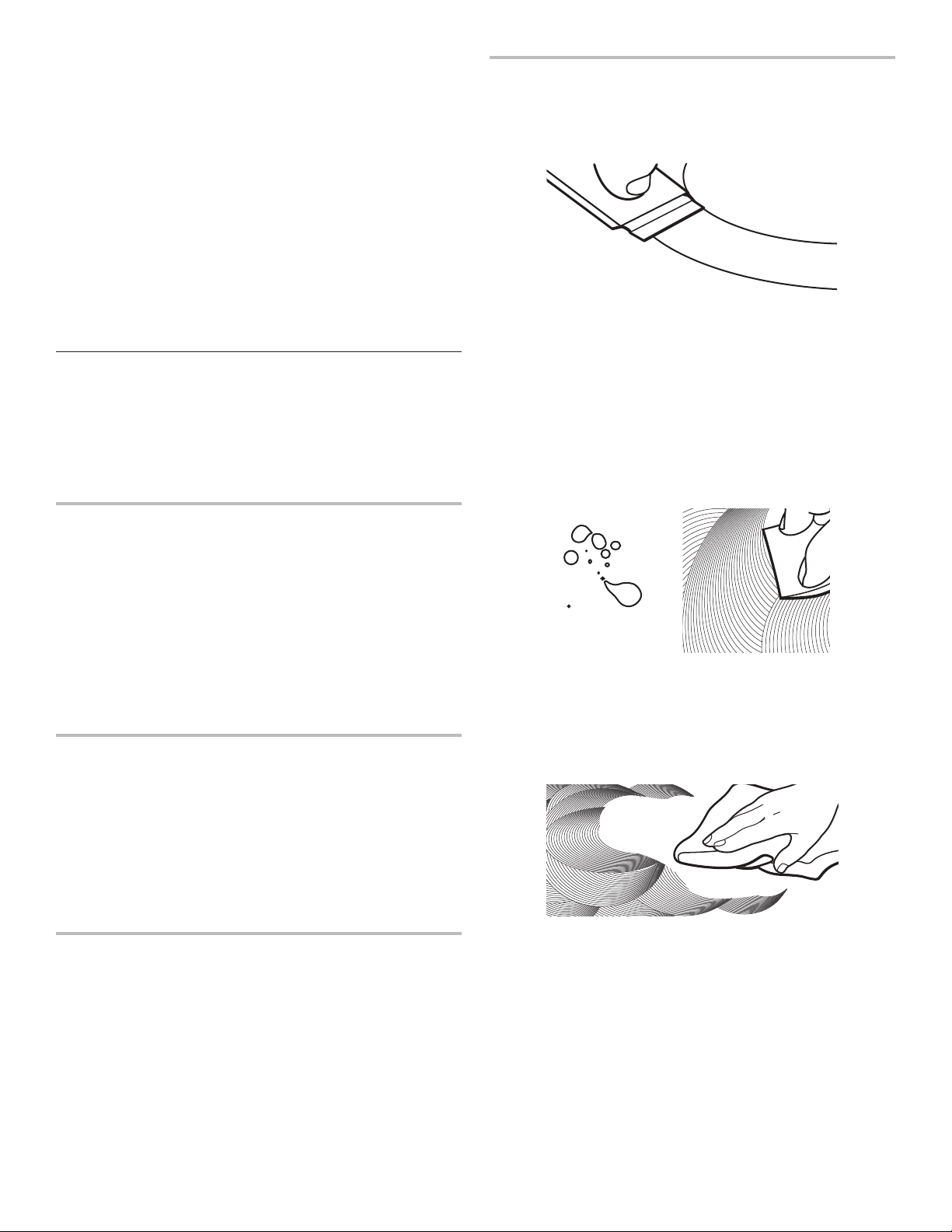
1. Remove food/residue with the Cooktop Scraper.
■ For best results, use the Cooktop Scraper while the
cooktop is still warm but not hot to the touch. It is
recommended to wear an oven mitt while scraping
the warm cooktop.
■ Hold the Cooktop Scraper at approximately a 45° angle
against the glass surface and scrape the residue. It will
be necessary to apply pressure in order to remove the
residue.
Allow the cooktop to cool down completely before
proceeding to Step 2.
2. Apply a few dime-sized drops of Cooktop Cleaner to the
affected areas.
■ Rub Cooktop Cleaner onto the cooktop surface with the
blue Cooktop Cleaning Pad. Some pressure is needed to
remove stubborn stains.
■ Allow the cleaner to dry to a white haze before
proceeding to Step 3.
3. Polish with a clean, dry cloth or a clean, dry paper towel.
■ Repeat steps 1 through 3 as necessary for stubborn
or burned-on stains.
The Complete Cooktop Cleaner Kit is available for order and
includes the following:
■ Cooktop Scraper
■ Cooktop Cleaner
■ Blue Cooktop Cleaning Pads
See the “Accessories” section for part numbers and information
on ordering.

COIL ELEMENTS (on some models)
Cleaning Method:
■ Damp cloth:
Make sure control knobs are off and elements are cool.
Do not clean or immerse in water. Soil will burn off when hot.
BURNER BOWLS (on some models)
Before removing or replacing coil elements and burner bowls,
make sure they are cool and the control knobs are in the Off
position.
Remove the coil element by pushing the edge of the coil element
toward the receptacle. Lift it enough to clear the burner bowl. Pull
the coil element straight away from the receptacle to remove. Lift
out the burner bowl.
Cleaning Method:
Chrome burner bowls
Wash frequently in warm, soapy water. It is not recommended to
wash chrome bowls in a dishwasher. A mild abrasive cleaner and
a plastic scrubber can be used to remove stubborn stains.
For heavily soiled bowls, place an ammonia soaked paper towel
on the stains and allow to soak for a short time, then gently scrub
with a plastic scrubber.
COOKTOP CONTROLS
To avoid damage to the cooktop controls, do not use steel wool,
abrasive cleansers, or oven cleaner.
To avoid damage, do not soak knobs. When replacing knobs,
make sure knobs are in the Off position.
On some models, do not remove seals under knobs.
Cleaning Method:
■ Soap and water:
Pull knobs straight away from control panel to remove.
CONTROL PANEL AND OVEN DOOR EXTERIOR
To avoid damage to the control panel, do not use abrasive
cleaners, steel-wool pads, gritty washcloths, or abrasive
paper towels.
Cleaning Method:
■ Glass cleaner and soft cloth or sponge:
Apply glass cleaner to soft cloth or sponge, not directly
on panel.
■ Affresh
®
Kitchen and Appliance Cleaner Part Number
W10355010 (not included):
See the “Accessories” section for more information.
OVEN RACKS
Cleaning Method:
■ Steel-wool pad
■ For racks that have discolored and are harder to slide,
a light coating of vegetable oil applied to the rack guides
will help them slide.
STORAGE DRAWER OR WARMING DRAWER
(on some models)
Check that storage drawer or warming drawer is cool and empty
before cleaning.
Cleaning Method:
■ Mild detergent
OVEN CAVITY
Use AquaLift
®
Technology regularly to clean oven spills.
Do not use oven cleaners.
Food spills should be cleaned when oven cools. At
high temperatures, foods react with porcelain. Staining,
etching, pitting, or faint white spots can result.
Cleaning Method:
Clean cycle:
See the “Clean Cycle” section.

20
TROUBLESHOOTING
First try the solutions suggested here. If you need further assistance or more recommendations that may help you avoid
a service call, refer to the warranty page in this manual or visit producthelp.www.whirlpool.com. In Canada, visit www.whirlpool.ca.
Contact us by mail with any questions or concerns at the address below:
In the U.S.A.:
Whirlpool Brand Home Appliances
Customer eXperience Center
553 Benson Road
Benton Harbor, MI 49022-2692
In Canada:
Whirlpool Brand Home Appliances
Customer eXperience Centre
200 - 6750 Century Ave.
Mississauga, Ontario L5N 0B7
Please include a daytime phone number in your correspondence.
Problem Possible Causes and/or Solutions
Nothing will operate
Power supply cord is unplugged: Plug into a grounded outlet.
Household fuse is blown or a circuit breaker is tripped: Replace the fuse or reset the circuit breaker.
If the problem continues, call an electrician.
The control displays an F9 or F9 E0 error code: The electrical outlet in the home may be miswired.
Contact a qualified electrician to verify the electrical supply.
Cooktop will not
operate
The control knob is not set correctly: Push in knob before turning to a setting.
On ceramic glass models, the oven control lockout is set: See “Control Lock” in the “Feature Guide”
section.
Excessive heat
around cookware
on cooktop
Cookware is not the proper size: Use cookware about the same size as the surface cooking area, element,
or surface burner. Cookware should not extend more than 1/2" (13 mm) outside the cooking area.
Cooktop cooking
results not
what expected
Control knob set to incorrect heat level: See the “Cooktop” section.
Range is not level: Level the range. See the Installation Instructions.
Cooktop element
cycles on and off
on High setting
Element cycling due to a temperature limiter: This is normal operation. The element may cycle on and off
to keep the cooktop from overheating.
Oven will not operate
Delay Start is set: See the “Cook Time” section.
Control is locked: See “Control Lock” in the “Tools” section.
The range is in Demo Mode: Demo Mode will deactivate all oven elements. See “Info” in the “Tools”
section.
Electronic oven control set incorrectly: See the “Tools” and “More Modes” sections.
Oven temperature
too high or too low
Oven temperature needs adjustment: See “Temperature Calibration” in the “More Modes” section.
Oven indicator
lights flash
Power to range is turned on or restored: See the “Tools” and “More Modes” sections. If the indicator
lights keep flashing, call for service.
Display shows
messages
Power failure: On some models, reset the clock, if needed. See “Preferences” in the “Tools” section.
Error code (Display shows letter followed by number.): Depending on your model, press the Cancel
keypad to clear the display. See the “Tools” and “More Modes” sections. If it reappears, call for service.
Range is in Sabbath mode (display shows “Sabbath Mode”): See the “Sabbath Mode” section to exit
Sabbath mode.
Demo Mode (product is in Demo Mode): See the “Tools” section to exit Demo Mode.
Clean cycle did not
work on all spills
Several cooking cycles between Clean cycles or spills on oven walls and doors: Run additional
Clean cycles. Use the AquaLift
®
Technology Cleaning Kit. See the “Clean Cycle” section for more
information.
Mineral deposits
are left on the oven
bottom after the
Clean cycle
Tap water was used in the Clean cycle: Use distilled or filtered water in the Clean cycle.
To remove deposits, use a cloth soaked with vinegar. Then use a cloth dampened with water to thoroughly
remove any vinegar residue.
Range is not level: Mineral deposits will collect on dry areas of the oven bottom during the Clean cycle.
Level the range. See the Installation Instructions.
To remove deposits, use a cloth soaked with vinegar. Then use a cloth dampened with water to thoroughly
remove any vinegar residue.

21
ACCESSORIES
For accessories in the U.S.A., you can visit our website at www.whirlpool.com. In Canada, visit our website at www.whirlpool.ca.
If you have any problems or questions, call Whirlpool Corporation Connected Appliances at 1-866-333-4591.
Complete Cooktop Cleaner Kit
(ceramic glass models)
(includes cleaner, protectant, protectant
applicator, scraper, and cleaner pads)
Order Part Number 31605
Affresh
®
Stainless Steel Cleaning
Wipes
(stainless steel models)
Order Part Number W10355049
Affresh
®
Cooktop Cleaner
(ceramic glass models)
Order Part Number W10355051
Cooktop Cleaning Pads
(ceramic glass models)
Order Part Number W10391473
Affresh
®
Stainless Steel Cleaner
(stainless steel models)
Order Part Number W10355016
Affresh
®
Kitchen and Appliance
Cleaner
Order Part Number W10355010
AquaLift
®
Oven Cleaning Kit
Order Part Number W10423113RP
Cooktop Scraper
(ceramic glass models)
Order Part Number WA906B
Granite Cleaner and Polish
Order Part Number W10275756
Canning Unit Kit
(coil models)
Order Part Number 242905
Gourmet Griddle
Order Part Number W10432544
Standard Flat Oven Rack
Order Part Number W10551060
Split Oven Rack
Order Part Number 4396927
Max Capacity Oven Rack
Order Part Number WPW10289145
Porcelain Broiler Pan and Grid
Order Part Number 4396923
Premium Broiler Pan and Roasting
Rack
Order Part Number W10123240
Problem Possible Causes and/or Solutions
Oven cooking results
not as expected
Range is not level: Level the range. See the Installation Instructions.
The set temperature was incorrect: Double-check the recipe in a reliable cookbook.
Oven temperature needs adjustment: See “Oven Temperature Control” in the “Electronic Oven Controls”
section.
Oven was not preheated: See the “Baking and Roasting” section.
Racks were positioned improperly: See the “Positioning Racks and Bakeware” section.
Not enough air circulation around bakeware: See the “Positioning Racks and Bakeware” section.
Darker browning of food caused by dull or dark bakeware: Lower oven temperature 25°F (15°C) or move
rack to a higher position in the oven.
Lighter browning of food caused by shiny or light-colored bakeware: Move rack to a lower position
in the oven.
Batter distributed unevenly in pan: Check that batter is level in the pan.
Incorrect length of cooking time was used: Adjust cooking time.
Oven door was not closed: Be sure that the bakeware does not keep the door from closing.
Oven door was opened during cooking: Oven peeking releases oven heat and can result in longer cooking
times.
Rack is too close to bake burner, making baked items too brown on bottom: Move rack to higher
position in the oven.
Pie crusts browning too quickly: Use aluminum foil to cover the edge of the crust and/or reduce baking
temperature.
22
11/14
IF YOU NEED SERVICE:
1. Before contacting us to arrange service, please determine whether your product requires repair. Some questions can be addressed without
service. Please take a few minutes to review the Troubleshooting or Problem Solver section of the Use and Care Guide, or visit
www.whirlpool.com/product_help.
2. All warranty service is provided exclusively by our authorized Whirlpool Service Providers. In the U.S. and Canada, direct all requests for
warranty service to:
Whirlpool Customer eXperience Center
In the U.S.A., call 1-800-253-1301. In Canada, call 1-800-807-6777.
If outside the 50 United States or Canada, contact your authorized Whirlpool dealer to determine whether another warranty applies.
WHIRLPOOL
®
MAJOR APPLIANCE
LIMITED WARRANTY
ATTACH YOUR RECEIPT HERE. PROOF OF PURCHASE IS REQUIRED
TO OBTAIN WARRANTY SERVICE.
Please have the following information available when you call the
Customer eXperience Center:
■ Name, address and telephone number
■ Model number and serial number
■ A clear, detailed description of the problem
■ Proof of purchase including dealer or retailer name and address
ONE YEAR LIMITED WARRANTY
WHAT IS COVERED WHAT IS NOT COVERED
For one year from the date of purchase,
when this major appliance is installed,
operated and maintained according to
instructions attached to or furnished
with the product, Whirlpool Corporation
or Whirlpool Canada LP (hereafter
“Whirlpool”) will pay for Factory
Specified Replacement Parts and repair
labor to correct defects in materials or
workmanship that existed when this
major appliance was purchased, or at
its sole discretion replace the product.
In the event of product replacement,
your appliance will be warranted for
the remaining term of the original unit’s
warranty period.
YOUR SOLE AND EXCLUSIVE
REMEDY UNDER THIS LIMITED
WARRANTY SHALL BE PRODUCT
REPAIR AS PROVIDED HEREIN.
Service must be provided by a
Whirlpool designated service company.
This limited warranty is valid only in
the United States or Canada and
applies only when the major appliance
is used in the country in which it was
purchased. This limited warranty is
effective from the date of original
consumer purchase. Proof of original
purchase date is required to obtain
service under this limited warranty.
1. Commercial, non-residential, multiple-family use, or use inconsistent with published user, operator or
installation instructions.
2. In-home instruction on how to use your product.
3. Service to correct improper product maintenance or installation, installation not in accordance with
electrical or plumbing codes or correction of household electrical or plumbing (i.e. house wiring, fuses
or water inlet hoses).
4. Consumable parts (i.e. light bulbs, batteries, air or water filters, preservation solutions, etc.).
5. Defects or damage caused by the use of non-genuine Whirlpool parts or accessories.
6. Conversion of products from natural gas or propane gas.
7. Damage from accident, misuse, abuse, fire, floods, acts of God or use with products not approved by
Whirlpool.
8. Repairs to parts or systems to correct product damage or defects caused by unauthorized service,
alteration or modification of the appliance.
9. Cosmetic damage including scratches, dents, chips, and other damage to the appliance finishes
unless such damage results from defects in materials and workmanship and is reported to Whirlpool
within 30 days.
10. Discoloration, rust or oxidation of surfaces resulting from caustic or corrosive environments including
but not limited to high salt concentrations, high moisture or humidity or exposure to chemicals.
11. Food or medicine loss due to product failure.
12. Pick-up or delivery. This product is intended for in-home repair.
13. Travel or transportation expenses for service in remote locations where an authorized Whirlpool
servicer is not available.
14. Removal or reinstallation of inaccessible appliances or built-in fixtures (i.e. trim, decorative panels,
flooring, cabinetry, islands, countertops, drywall, etc.) that interfere with servicing, removal or
replacement of the product.
15. Service or parts for appliances with original model/serial numbers removed, altered or not easily
determined.
The cost of repair or replacement under these excluded circumstances shall be borne by
the customer.
DISCLAIMER OF IMPLIED WARRANTIES
IMPLIED WARRANTIES, INCLUDING ANY IMPLIED WARRANTY OF MERCHANTABILITY OR IMPLIED WARRANTY OF FITNESS FOR A
PARTICULAR PURPOSE, ARE LIMITED TO ONE YEAR OR THE SHORTEST PERIOD ALLOWED BY LAW. Some states and provinces do not allow
limitations on the duration of implied warranties of merchantability or fitness, so this limitation may not apply to you. This warranty gives you specific
legal rights, and you also may have other rights that vary from state to state or province to province.
DISCLAIMER OF REPRESENTATIONS OUTSIDE OF WARRANTY
Whirlpool makes no representations about the quality, durability, or need for service or repair of this major appliance other than the representations
contained in this warranty. If you want a longer or more comprehensive warranty than the limited warranty that comes with this major appliance, you
should ask Whirlpool or your retailer about buying an extended warranty.
LIMITATION OF REMEDIES; EXCLUSION OF INCIDENTAL AND CONSEQUENTIAL DAMAGES
YOUR SOLE AND EXCLUSIVE REMEDY UNDER THIS LIMITED WARRANTY SHALL BE PRODUCT REPAIR AS PROVIDED HEREIN. WHIRLPOOL
SHALL NOT BE LIABLE FOR INCIDENTAL OR CONSEQUENTIAL DAMAGES. Some states and provinces do not allow the exclusion or limitation of
incidental or consequential damages, so these limitations and exclusions may not apply to you. This warranty gives you specific legal rights, and you
also may have other rights that vary from state to state or province to province.

23
MERCI d’avoir acheté ce produit de grande qualité. Enregistrez la cuisinière sur www.whirlpool.ca.
Pour référence ultérieure, consignez par écrit les numéros de modèle et de série de votre produit. Vous trouverez les numéros de
modèle et de série sur la plaque signalétique située sur le châssis du four, derrière la partie supérieure droite de la porte du four.
Numéro de modèle_______________________________________ Numéro de série du produit________________________________
Table des matières
SÉCURITÉ DE LA CUISINIÈRE ..................................................24
La bride antibasculement ...........................................................24
CONSEILS ÉLÉMENTAIRES D’UTILISATION ............................26
Technologie d’autonettoyage AquaLift
®
....................................27
Températures en surface ............................................................27
Préchauffage ..............................................................................27
Nettoyage de la table de cuisson en vitrocéramique ................27
GUIDE DES CARACTÉRISTIQUES .............................................28
Panneau tactile ...........................................................................29
Affichage ...................................................................................29
Affichage du menu .....................................................................29
Mode de paramétrage et de démonstration..............................29
Méthodes de cuisson .................................................................29
Favoris ........................................................................................31
Cuisson assistée ........................................................................31
Outils ..........................................................................................32
Plus de modes ...........................................................................33
TABLE DE CUISSON ....................................................................33
Ustensiles de cuisson ................................................................36
Mise en conserve à la maison....................................................36
UTILISATION DU FOUR ...............................................................37
Papier d’aluminium ....................................................................37
Positionnement des grilles et
des ustensiles de cuisson au four .............................................37
Évent du four ..............................................................................38
Cuisson au four et rôtissage ......................................................38
Cuisson au gril ............................................................................38
Cuisson par convection .............................................................39
Lampe du four ............................................................................39
ENTRETIEN DE LA CUISINIÈRE .................................................40
Programme de nettoyage ..........................................................40
Nettoyage général ......................................................................41
DÉPANNAGE .................................................................................43
ACCESSOIRES .............................................................................45
GARANTIE .....................................................................................46
GUIDE D’UTILISATION
CUISINIÈRE ÉLECTRIQUE
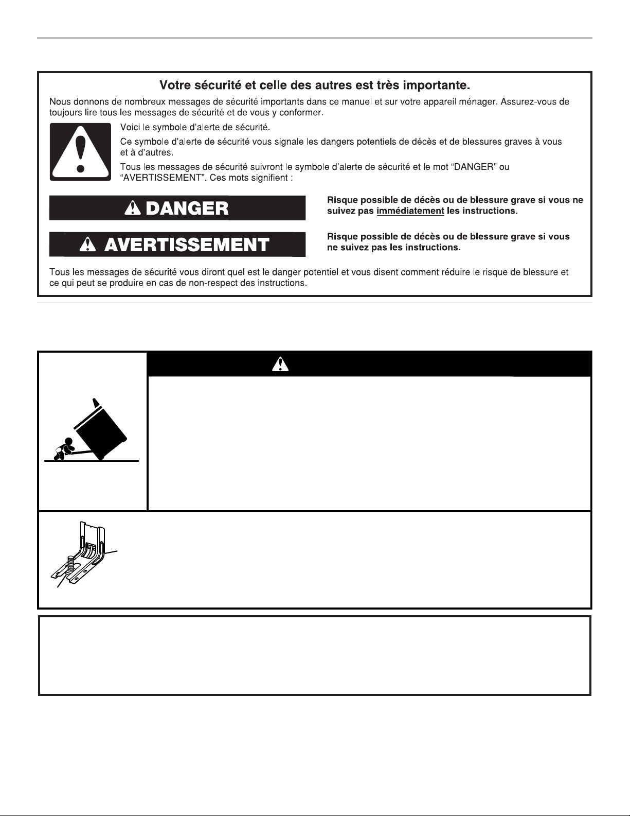
24
SÉCURITÉ DE LA CUISINIÈRE
La bride antibasculement
Dans des conditions de service normales, la cuisinière ne bascule pas. Elle peut cependant basculer si une force ou un poids excessif
est appliqué sur la porte ouverte alors que la bride antibasculement n’est pas convenablement fixée.
Risque de basculement
Un enfant ou une personne adulte peut faire basculer la cuisinière, ce qui peut causer un
décès.
Vérifier que la bride antibasculement est bien installée et engagée, conformément aux
instructions d'installation.
Réengager la bride antibasculement si la cuisinière a été déplacée.
Ne pas faire fonctionner la cuisinière si la bride antibasculement n'est pas installée et engagée.
Le non-respect de ces instructions peut causer un décès ou des brûlures graves aux enfants et
aux adultes.
Pour vérifier que la bride antibasculement est bien installée et engagée :
• Faire glisser la cuisinière vers l'avant.
• Vérifier que la bride antibasculement est bien fixée au plancher ou au mur.
• Faire de nouveau glisser la cuisinière vers l'arrière de sorte que le pied de la cuisinière
se trouve sous la bride antibasculement.
• Voir les instructions d'installation pour plus de détails.
AVERTISSEMENT
Bride
antibasculement
Pied de la cuisinière
Avertissements de la proposition 65 de l'État de Californie :
AVERTISSEMENT : Ce produit contient au moins un produit chimique connu par l’État de Californie pour être à l’origine de
cancers.
AVERTISSEMENT : Ce produit contient au moins un produit chimique connu par l’État de Californie pour être à l’origine de
malformations et autres déficiences de naissance.

25
IMPORTANTES INSTRUCTIONS DE SÉCURITÉ
CONSERVEZ CES INSTRUCTIONS
AVERTISSEMENT : Pour réduire le risque d’incendie, de
choc électrique, de blessures ou de dommages lors de
l’utilisation de la cuisinière, il convient d’observer certaines
précautions élémentaires dont les suivantes :
■ AVERTISSEMENT : POUR MINIMISER LE RISQUE
DE BASCULEMENT DE LA CUISINIÈRE, ELLE DOIT
ÊTRE BIEN IMMOBILISÉE PAR DES DISPOSITIFS
ANTIBASCULEMENT CORRECTEMENT INSTALLÉS.
POUR VÉRIFIER SI LES DISPOSITIFS SONT
CORRECTEMENT INSTALLÉS, GLISSER LA CUISINIÈRE
VERS L’AVANT ET VÉRIFIER SI LA BRIDE
ANTIBASCULEMENT EST BIEN FIXÉE AU PLANCHER
OU AU MUR, ET GLISSER LA CUISINIÈRE VERS
L’ARRIÈRE POUR QUE LE PIED ARRIÈRE DE LA
CUISINIÈRE SOIT SOUS LA BRIDE
ANTIBASCULEMENT.
■ MISE EN GARDE : Ne pas remiser dans des armoires
au-dessus de la cuisinière ou sur le dosseret d’une
cuisinière, des objets que des enfants pourraient vouloir
atteindre. Les enfants pourraient se brûler ou se blesser en
grimpant sur la cuisinière.
■ Installation appropriée – S’assurer que la cuisinière est
correctement installée et reliée à la terre par un technicien
qualifié.
■ Ne jamais utiliser la cuisinière pour réchauffer ou chauffer
la pièce.
■ Ne pas laisser les enfants seuls – Les enfants ne doivent
pas être laissés seuls ou sans surveillance dans la pièce
où la cuisinière est en service. Ne jamais laisser les
enfants s’asseoir ou se tenir sur une partie quelconque de
la cuisinière.
■ Porter des vêtements appropriés – Des vêtements amples
ou détachés ne doivent jamais être portés pendant
l’utilisation de la cuisinière.
■
Entretien par l’utilisateur – Ne pas réparer ni remplacer
toute pièce de la cuisinière si ce n’est pas spécifiquement
recommandé dans le manuel. Toute autre opération
d’entretien ou de réparation doit être confiée à un
technicien qualifié.
■ Remisage dans ou sur la cuisinière – Des matériaux
inflammables ne doivent pas être remisés dans un four ou
près des éléments de surface.
■ Ne pas utiliser d’eau pour éteindre un feu de graisse –
Étouffer le feu ou les flammes ou utiliser un extincteur à
produits chimiques secs, ou un extincteur à mousse.
■ N’utiliser que des mitaines sèches de four – Des mitaines
de four mouillées ou humides sur des surfaces chaudes
peuvent provoquer des brûlures provenant de la vapeur.
Ne pas laisser les mitaines de four toucher les éléments
chauffants. Ne pas utiliser une serviette ou un tissu épais.
■ NE PAS TOUCHER LES ÉLÉMENTS DE SURFACE OU
L’ESPACE PRÈS DES ÉLÉMENTS – Les éléments de
surface peuvent être chauds même lorsqu’ils ont une teinte
foncée. Les endroits près des éléments de surface peuvent
devenir assez chauds pour causer des brûlures. Pendant
et après l’utilisation, ne pas toucher les éléments
chauffants et ne pas laisser les vêtements ou autres
matériaux inflammables entrer en contact avec ces
éléments de surface ou les endroits près des éléments,
avant qu’ils soient suffisamment refroidis. Ces endroits
comprennent la table de cuisson et les surfaces près de la
table de la cuisson.
■ Utiliser des ustensiles de dimension appropriée – La
cuisinière est munie d’un ou de
plusieurs éléments
chauffants de différentes grandeurs. Choisir les ustensiles
qui ont un fond plat assez grand pour couvrir l’élément
chauffant de la surface de cuisson. L’utilisation d’ustensiles
trop petits exposera une partie de l’élément chauffant, ce
qui peut provoquer l’inflammation des vêtements.
L’utilisation d’un récipient de dimension correcte améliore
aussi l’efficacité de la cuisson.
■ Ne jamais laisser les éléments de la table de cuisson sans
surveillance alors qu’ils chauffent à la puissance maximale.
Il pourrait en résulter une ébullition qui cause de la fumée
et des renversements de corps gras qui peuvent
s’enflammer.
■ S’assurer que les cuvettes réfléchissantes ou les bols de
renversement sont en place – L’absence de ces cuvettes
ou bols au cours de la cuisson peut causer des dommages
aux fils ou aux composants en dessous des éléments.
■ Garnissages protecteurs – Ne pas recouvrir les cuvettes
ou le fond du four de papier d’aluminium sauf tel que
suggéré dans le manuel. L’installation incorrecte de papier
d’aluminium ou d’autre matériau peut causer un risque de
choc électrique ou d’incendie.
■ Ustensiles de cuisson vitrifiés – Seulement certains types
d’ustensiles de verre, vitrocéramique, céramique, faïence
ou autres surfaces vitrifiées conviennent pour le service
sur une table de cuisson, sans bris attribuables aux
changements soudains de température.
■ Les poignées des ustensiles doivent être tournées vers
l’intérieur et non vers le dessus des éléments adjacents –
Pour réduire le risque de brûlures, d’inflammation de
produits inflammables et de renversements dus à
l’entrechoquement non intentionnel des ustensiles, la
poignée d’un ustensile doit être positionnée de sorte
qu’elle est tournée vers l’intérieur et non au-dessus des
éléments de surface adjacents.
■ Ne pas tremper les éléments de chauffage amovibles –
Les éléments de chauffage ne doivent jamais être
immergés dans l’eau.
■ Ne pas faire cuire sur une table de cuisson endommagée –
Si la table de cuisson est brisée, les solutions de nettoyage
et les renversements peuvent pénétrer dans la table de
cuisson brisée et créer un risque d’un choc électrique.
Contacter immédiatement un technicien qualifié.

26
IMPORTANTES INSTRUCTIONS DE SÉCURITÉ
CONSERVEZ CES INSTRUCTIONS
■ Nettoyer la table de cuisson avec prudence – Si une
éponge ou un chiffon mouillé est utilisé pour essuyer les
renversements sur une surface de cuisson chaude, éviter
les brûlures causées par la vapeur chaude. Certains
nettoyants peuvent produire des émanations désagréables
lorsqu’ils sont utilisés sur une surface chaude.
■ Exercer une grande prudence lors de l’ouverture de la
porte – Laisser l’air chaud ou la vapeur s’échapper avant
d’enlever ou de replacer un plat.
■ Ne pas faire chauffer des contenants fermés –
L’accumulation de pression peut causer une explosion du
contenant et des blessures.
■ Ne jamais obstruer les ouvertures des évents.
■ Positionnement des grilles du four – Toujours placer les
grilles du four en position désirée pendant que le four est
froid. Si la grille doit être déplacée pendant que le four est
chaud, ne pas laisser les mitaines de four toucher l’élément
chaud du four.
■ NE PAS TOUCHER LES ÉLÉMENTS CHAUFFANTS OU
LES SURFACES INTÉRIEURES DU FOUR – Les
éléments chauffants peuvent être chauds même s’ils ont
une teinte foncée. Les surfaces intérieures d’un four
deviennent assez chaudes pour causer des brûlures.
Pendant et après l’utilisation, ne pas toucher ou laisser des
vêtements ou autres matériaux inflammables venir en
contact avec les éléments chauds ou les surfaces
intérieures chaudes du four avant qu’ils aient eu assez de
temps pour refroidir. D’autres surfaces de l’appareil
peuvent devenir assez chaudes pour causer des brûlures.
Ces surfaces comprennent les ouvertures de l’évent du
four et les surfaces près de ces ouvertures, les portes du
four, et les hublots des portes du four.
Pour les cuisinières avec programme d’autonettoyage –
■
Ne pas nettoyer le joint de la porte – Le joint de la porte
est essentiel pour l’étanchéité. Veiller à ne pas frotter,
endommager ou déplacer le joint.
■ Ne pas utiliser des produits commerciaux de nettoyage du
four – On ne doit pas utiliser un produit commercial de
nettoyage de four ou un enduit de protection des surfaces
internes du four quel qu’en soit le type, sur les surfaces du
four ou les surfaces voisines.
■ Nettoyer uniquement les pièces indiquées dans le manuel.
■ Avant d’exécuter le programme d’autonettoyage du four –
Ôter la lèchefrite et son plat et les autres ustensiles.
Pour les appareils avec hotte de ventilation –
■ Nettoyer les hottes de ventilation fréquemment – La
graisse ne doit pas s’accumuler sur la hotte ou le filtre.
■
Lorsque vous flambez des aliments sous la hotte, mettre le
ventilateur en marche.
Pour les cuisinières et fours intelligents –
■ Utilisation à distance – Cet appareil peut être configuré
pour permettre l’utilisation à distance en tout temps. Ne
pas ranger de matériaux inflammables ou sensibles à la
température sur le dessus ou près de la surface de
l’appareil.
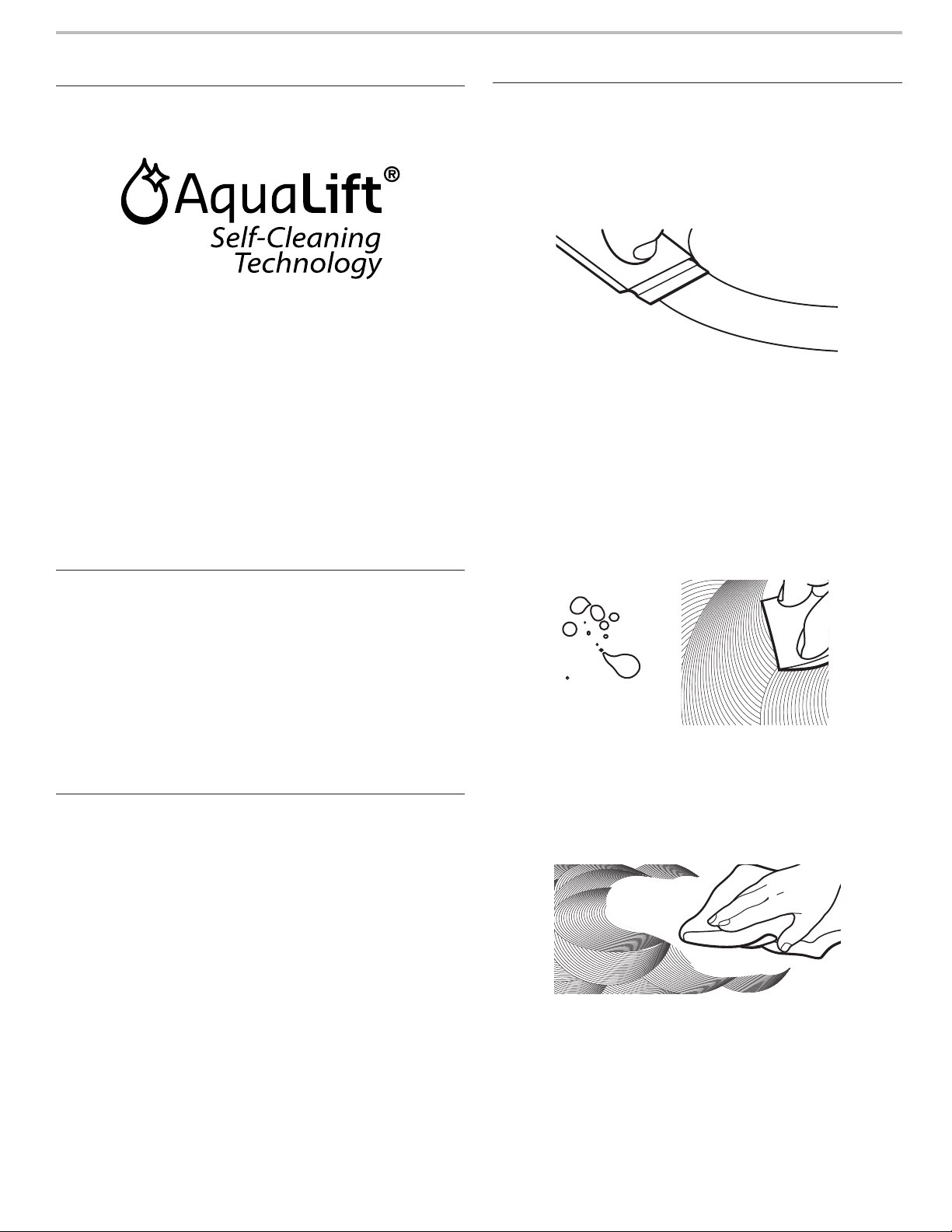
27
CONSEILS ÉLÉMENTAIRES D’UTILISATION
Technologie d’autonettoyage
AquaLift
®
La technologie d’autonettoyage AquaLift
®
est une solution
de nettoyage inédite permettant de réduire la durée, la
température et les odeurs habituellement dégagées par
rapport aux méthodes d’autonettoyage traditionnelles. Avec
la technologie d’autonettoyage AquaLift
®
, une pellicule protectrice
exclusive est activée par la chaleur et l’eau à l’intérieur du four
pour décoller les salissures incrustées. Pour utiliser la technologie
d’autonettoyage AquaLift
®
, il suffit d’essuyer les débris décollés,
de verser de l’eau au fond du four et de lancer le programme
d’autonettoyage AquaLift
®
. Une fois le programme terminé, en
moins de 1 heure à une température plus basse que les méthodes
d’autonettoyage traditionnelles, essuyer simplement l’eau
restante et les salissures décollées. Voir la section “Programme
de nettoyage” pour des instructions plus détaillées. Pour plus
d’informations, des réponses aux questions fréquentes et des
vidéos consacrées à la technologie d’autonettoyage AquaLift
®
,
visiter notre site Web à l’adresse http://whirlpoolcorp.com/
aqualift.
Températures en surface
Lorsque la cuisinière est en marche, toutes ses surfaces peuvent
chauffer, y compris les boutons de commande et la porte du four.
Tiroir-réchaud ou tiroir de remisage
Lorsque le four est en marche, le tiroir peut chauffer. Ne pas
placer d’objets en plastique, en tissu ou susceptibles de fondre
ou de brûler dans le tiroir.
Évent du four
L’évent du four permet l’évacuation de l’air chaud et de l’humidité
du four. Il ne doit pas être obstrué ou couvert. Ne pas placer
près de l’évent du four des objets en plastique, en papier ou
susceptibles de fondre ou de brûler.
Préchauffage
Au début d’un programme de cuisson au four, de cuisson au
four avec convection ou de rôtissage avec convection, le four
commence par un préchauffage une fois la touche Start (mise
en marche) enfoncée. Le four atteint 350°F (177°C) en 12 à
15 minutes environ lorsque toutes les grilles fournies avec le four
sont à l’intérieur. Pour atteindre une température plus élevée,
le préchauffage est plus long. Le programme de préchauffage
augmente rapidement la température du four. La température
réelle du four dépasse alors la température programmée,
pour compenser la chaleur perdue à l’ouverture du four pour
y introduire le plat à cuire. Ainsi, le four entame la cuisson
à la température correcte après y avoir placé le plat. Placer
les aliments au four lorsque le signal sonore de préchauffage
retentit. Ne pas ouvrir la porte du four pendant le préchauffage
tant que le signal sonore n’a pas retenti.
Nettoyage de la table de cuisson
envitrocéramique
Afin d’éviter d’endommager la table de cuisson, ne pas utiliser
de laine d’acier, de nettoyants en poudre abrasifs, d’eau de Javel,
de produit antirouille ou d’ammoniaque.
1. Éliminer les salissures alimentaires avec le grattoir
pour table de cuisson.
■ Pour de meilleurs résultats, utiliser le grattoir pendant que
la table de cuisson est encore tiède, mais non brûlante au
toucher. Il est recommandé de porter des mitaines de four
pour gratter la table de cuisson tiède.
■ Tenir le grattoir pour table de cuisson à un angle
d’environ 45° par rapport à la surface de verre et gratter
les salissures. Il convient d’appuyer fermement pour
éliminer les salissures.
Laisser la table de cuisson refroidir complètement avant
de passer à l’étape 2.
2. Appliquer quelques gouttes de nettoyant pour table
de cuisson affresh
®
sur les zones concernées.
■ Frotter le nettoyant affresh
®
sur la surface de la table
de cuisson avec le tampon bleu de nettoyage des
tables de cuisson. Il convient d’appuyer fermement
pour éliminer les taches rebelles.
■ Laisser le produit nettoyant sécher en une pellicule
blanchâtre avant de passer à l’étape 3.
3. Faire briller avec un chiffon ou essuie-tout propre et sec.
■ Répéter éventuellement les étapes 1 à 3 pour les taches
les plus tenaces ou incrustées.
Le nécessaire complet de nettoyage des tables de cuisson
est disponible à la commande. Il contient :
■ Grattoir pour table de cuisson
■ Nettoyant pour table de cuisson affresh
®
■ Tampons bleus de nettoyage des tables de cuisson
Consulter la section “Accessoires” pour les références
et les informations de commande.
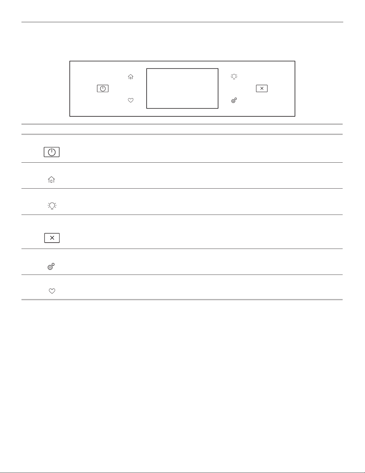
28
GUIDE DES CARACTÉRISTIQUES
Ces instructions concerne plusieurs modèles. Le modèle que vous avez peut comporter toutes les caractéristiques énumérées ou
seulement certaines d’entre elles. Se reporter à ces instructions ou à la section d’aide sur les produits à l’adresse www.whirlpool.ca
pour des instructions plus détaillées.
Clavier Caractéristique Instructions
Alimentation Fonction
d’alimentation
La touche d’alimentation met en marche les fonctions du four et le réveille lorsqu’il est en
mode de veille.
Accueil Écran d’accueil
En appuyant une fois, l’utilisateur peut accéder à l’écran des méthodes de cuisson et de la
cuisson assistée.
Lampe du four Lampe de la
cavité du four
La lampe du four désirée est commandée par une touche située sur le tableau de commande
du four. Alors que la porte du four est fermée, appuyer sur la touche lampe du four pour
allumer ou éteindre la lampe. La lampe du four s’allume à l’ouverture de la porte.
Annulation
du four
Annulation
de la fonction
d’alimentation
La touche annulation du four désactive toutes les fonctions à l’exception de l’horloge, de la
minuterie et du verrouillage des commandes du four.
Outils Fonctions
d’utilisation
du four
Permet de personnaliser les signaux sonores et le fonctionnement du four selon les
préférences de l’utilisateur. Voir la section “Tools” et “More Modes”.
Favoris Écran des favoris
Le clavier des favoris permet à l’utilisateur de sauvegarder les programmes qu’il utilise le plus
souvent et d’y accéder.
29
Panneau tactile
Le panneau tactile regroupe le menu de commande et les
commandes des différentes fonctions. Le panneau tactile est très
sensible, il suffit d’un léger toucher pour l’activer.
Naviguer vers le haut, le bas, la gauche ou la droite pour explorer
les différentes options et fonctions.
Pour plus d’information sur chaque commande, voir leurs
sections respectives dans ce manuel.
Afchage
L’affichage est pour le menu et les commandes de
fonctionnement du four. L’écran tactile permet de faire défiler les
menus du four. L’affichage est très sensible; il suffit d’un léger
toucher pour l’activer et sélectionner les commandes.
Lorsque le four est utilisé, l’affichage indique l’horloge, le mode,
la température du four, la minuterie de cuisine, et la minuterie du
four si réglée. Si la minuterie du four n’est pas réglée, on peut la
régler à partir de cet écran.
Au cours de l’utilisation, l’affichage indique les menus et les
sélections appropriées pour les options choisies.
Afchage du menu
Si le four est éteint, appuyer sur la touche de marche pour activer
le menu. À partir de l’écran d’accueil, tous les programmes de
cuisson automatique peuvent être activés; tous les programmes
de cuisson manuels peuvent être réglés; les options peuvent être
ajustées et les instructions, les directives de préparation et les
conseils sont accessibles.
Mode de paramétrage et de
démonstration
1. Sélectionner STORE DEMO MODE (mode de démonstration
en magasin) pour activer ce mode.
OU
1. Sélectionner NEXT (suivant) pour utiliser le produit.
2. Suivre les instructions à l’écran pour sélectionner une langue,
configurer Wi-Fi/connexion au réseau, accepter les modalités
et régler l’heure.
REMARQUE : L’écran affiche l’heure et la date (écran par
défaut/mode Veille).
3. Si Store Demo Mode (mode démonstration en magasin) est
sélectionné, sélectionner TRY THE PRODUCT (essayer le
produit) pour découvrir diverses caractéristiques et options
du produit.
OPTIONNELLE : Sélectionner VIEW PRODUCT VIDEOS
(afficher les vidéos du produit) pour afficher une vidéo sur la
façon de naviguer et d’interagir avec le produit, d’explorer
Voice Control (commande vocale) et de balayer une recette
Scan-To-Cook.
4. Faire défiler l’écran et sélectionner EXPLORE (explorer).
5. Appuyer sur la touche outils.
Pour quitter le mode Demo (démonstration), voir la section
“Tools” (outils).
Méthodes de cuisson
Le clavier des méthodes de cuisson permet aux utilisateurs de sélectionner l’une des méthodes de cuisson suivantes en fonction de
leur besoin :
■ Cuisson au four
■ Cuisson au gril
■ Cuisson par convection
■ Grillage par convection
■ Rôtissage par convection
■ Maintien au chaud
Utiliser:
1. Appuyer sur la touche de accueil.
2. Appuyer sur la touche de méthodes de cuisson.
3. Sélectionner le mode de cuisson désire.
AVERTISSEMENT
Risque d'empoisonnement alimentaire
Ne pas laisser des aliments dans un four plus d'une
heure avant ou après la cuisson.
Le non-respect de cette instruction peut causer un
empoisonnement alimentaire ou une maladie.
Méthodes de
cuisson
Caractéristique Instructions
BAKE
(cuisson au four)
Cuisson au four
et rôtissage
1. Appuyer sur BAKE (cuisson au four).
2. Sélectionner la température de cuisson souhaitée en naviguant vers la gauche et la droite
ou manuellement à l’aide de la grille située dans le coin supérieur droit pour saisir la
température de cuisson à l’aide du clavier.
3. Appuyer sur mise en marche pour commencer le préchauffage. Lorsque le préchauffage
est terminé, un signal sonore retentit.
(Optionnelle) Consulter la section “Rapide” pour obtenir plus d’information sur le
préchauffage rapide du four.
4. Appuyer sur la touche annulation une fois l’opération terminée.

30
Méthodes de
cuisson
Caractéristique Instructions
BROIL
(cuisson au gril)
Cuisson au gril
1. Sélectionner BROIL (cuisson au gril).
2. Sélectionner la température de gril souhaitée en naviguant vers la gauche et la droite
ou manuellement à l’aide de la grille située dans le coin supérieur droit pour saisir la
température de cuisson à l’aide du clavier.
3. Appuyer sur START (mise en marche) pour commencer le cussion au gril.
4. Appuyer sur la touche annulation une fois l’opération terminée.
CONVECT BAKE
(cuisson par
convection)
Cuisson par
convection
1. Sélectionner CONVECT BAKE (cussion par convection).
2. Sélectionner la température de cuisson par convection souhaitée en naviguant vers la
gauche et la droite ou manuellement à l’aide de la grille située dans le coin supérieur droit
pour saisir la température de cuisson à l’aide du clavier.
3. Appuyer sur START (mise en marche) pour commencer le préchauffage. Lorsque le
préchauffage est terminé, un signal sonore retentit.
(Optionnelle) Consulter la section « Rapide » pour préchauffer rapidement du four.
4. Appuyer sur la touche annulation une fois l’opération terminée.
Pour plus d’informations, consulter la section “Cuisson par convection”.
CONVECT BROIL
(grillage par
convection)
Grillage par
convection
1. Sélectionner CONVECT BROIL (grillage par convection).
2. Sélectionner la température de gril par convection souhaitée en naviguant vers la gauche et
la droite ou manuellement à l’aide de la grille située dans le coin supérieur droit pour saisir
la température de cuisson à l’aide du clavier.
3. Appuyer sur la touche mise en marche.
4. Appuyer sur la touche annulation une fois l’opération terminée.
Pour plus d’informations, consulter la section “Cuisson par convection”.
CONVECT
ROAST
(rôtissage par
convection)
Rôtissage par
convection
1. Sélectionner CONVECT ROAST (rôtissage par convection).
2. Sélectionner la température de rôtissage par convection souhaitée en naviguant vers la
gauche et la droite ou manuellement à l’aide de la grille située dans le coin supérieur droit
pour saisir la température de cuisson à l’aide du clavier.
3. Appuyer sur START (mise en marche) pour commencer le préchauffage. Une tonalité se fait
entendre une fois le préchauffage terminé.
4. Appuyer sur la touche annulation une fois l’opération terminée.
Pour plus d’informations, consulter la section “Cuisson par convection”.
KEEP WARM
(maintien au
chaud)
Maintien au
chaud
Les aliments doivent être à la température de service avant d’être placés dans le four chaud.
1. Sélectionner KEEP WARM (maintien au chaud).
2. Sélectionner la température souhaitée en naviguant vers la gauche et la droite ou
manuellement à l’aide de la grille située dans le coin supérieur droit pour saisir la
température de cuisson à l’aide du clavier.
3. Appuyer sur la touche mise en marche.
4. Appuyer sur la touche annulation une fois l’opération terminée.
RAPID (rapide) Préchauffage
rapide du four
Offre la durée de préchauffage le plus rapide pour la fonction Bake (cuisson au four).
Le préchauffage rapide est initialement réglé sur désactivé.
1. Sélectionner RAPID (rapide) pour mettre en marche et arrêter le préchauffage du four.
2. Le réglage en cours s’affiche.
IMPORTANT : Cette caractéristique doit être utilisée pour la cuisson au four sur une seule grille
uniquement. Les grilles inutilisées doivent être retirées avant le préchauffage rapide. On doit
utiliser une grille standard pour la fonction de préchauffage rapide.
Si le préchauffage pour le programme de cuisson au four a déjà commencé, le préchauffage
rapide peut être lancé directement en appuyant sur RAPID (rapide).
DELAY (mise en
marche différée)
Mise en marche
différée
La touche Delay (mise en marche différée) sert à entrer l’heure de terminent pour un four
équipé de la mise en marche différée. Une fois la méthode de cuisson sélectionnée, saisir
la température de cuisson. Sélectionner DELAY (mise en marche différée) et suivre les
commandes à l’écran.
REMARQUE : La mise en marche différée ne doit pas être utilisée pour les aliments tels que
pains et gâteaux, car ils risquent de ne pas bien cuire.
COOK TIME
(durée de
cuisson)
Cuisson
minutée
La cuisson minutée permet d’allumer le four, d’effectuer une cuisson pendant une durée
déterminée et/ou d’éteindre le four automatiquement.

31
Favoris
La fonction des favoris sauvegarde le mode et la température du
four pour vos recettes préférées.
Au fur et à mesure que l’outil Favoris est utilisé, cet appareil
affinera et adaptera les suggestions concernant les envies/
besoins alimentaires de l’utilisateur.
REMARQUE : Un ensemble de favoris et de suggestions peut
être automatiquement affiché à l’écran d’accueil selon l’heure du
repas.
Pour sauvegarder une recette, sélectionner l’icône des favoris et
suivre les étapes à l’écran pour personnaliser les favoris.
Ajouter une image ou un nom au favori pour le personnaliser.
Cuisson assistée
La cuisson assistée aide à choisir le bon mode pour les besoins quotidiens de cuisson. Certains modes permettent de sauter l’étape de
préchauffage. Suivre les instructions à l’écran pour obtenir des conseils tout au long de la procédure de cuisson.
REMARQUE : Les températures de cuisson traditionnelles seront converties en températures de cuisson par convection. La cuisson au
four par convection nécessite des entrées de durée et de température. Elle nécessite également un préchauffage.
Les durées traditionnelles de rôtissage seront converties en durées de rôtissage par convection. Le rôtissage par convection nécessite
des entrées de durée et de température, mais le préchauffage n’est pas nécessaire. Certains modes convertiront les durées de cuisson
standard pour la cuisson par convection. Entrer la durée et la température et l’écran convertira les données en conséquence.
Mode de cuisson
assistée
Sélection des aliments Astuces pour des résultats optimaux
FROZEN (congelés)
■ Pizza surgelée
■ Tarte surgelée
■ Frites congelées
■ Lasagnes surgelées
■ Croquettes
surgelées
■ Plat surgelé
Les aliments congelés ne nécessitent pas de préchauffage. Insérer immédiatement
les aliments, entrer la durée et la température maximum recommandées par le
fabricant.
Pour obtenir plus de renseignements, consulter la section “Frozen Bake™”.
POULTRY (volaille)
■ Morceaux de poulet
■ Poulet entier
Les volailles ne nécessitent pas de préchauffage. Insérer les aliments
immédiatement.
SEAFOOD (fruits
de mer)
■ Filet de poisson
■ Bâtonnets de
poisson
Le filet de poisson et les bâtonnets de poisson nécessitent un préchauffage. Insérer
les aliments lorsque le préchauffage est terminé.
BAKED GOODS
(produits de
boulangerie)
■ Biscuits
■ Croissants
Les produits de boulangerie nécessitent un préchauffage. Insérer les aliments
lorsque le préchauffage est terminé.
DESSERTS
(desserts)
■ Gâteau
■ Tarte fraîche
■ Biscuits
■ Tarte surgelée
Les gâteaux, les biscuits et les tartes fraîches nécessitent un préchauffage. Insérer
les aliments lorsque le préchauffage est terminé.
Les tartes surgelées ne nécessitent pas de préchauffage. Insérer immédiatement
les aliments, entrer la durée et la température maximum recommandées par le
fabricant.
PIZZA (pizza)
■ Pizza fraîche
■ Pizza surgelée
La pizza fraîche nécessite un préchauffage.
Les pizzas surgelées ne nécessitent pas de préchauffage. Insérer immédiatement
les aliments, entrer la durée et la température maximum recommandées par le
fabricant. Pour obtenir plus de renseignements, voir la section “Frozen Bake™”
(cuisson au four de plats congelés).
MEAT (repas)
■ Pain de viande
■ Rôti de porc
■ Rôti de bœuf
■ Gigot d’agneau
Le pain de viande nécessite un préchauffage. Insérer les aliments lorsque le
préchauffage est terminé.
Les rôtis d’agneau, de bœuf et de porc ne nécessitent pas de préchauffage. Insérer
les aliments immédiatement.
VEGGIES (légumes)
■ Pomme de terre au
four
■ Légumes frais
grillés
Les légumes frais grillés et la pomme de terre au four ne nécessitent pas de
préchauffage. Insérer les aliments immédiatement.
CASSEROLES (mets
en sauce)
■ Mets en sauce
■ Lasagne surgelée
Les mets en sauce nécessitent un préchauffage. Insérer les aliments lorsque le
préchauffage est terminé.
La lasagne surgelée ne nécessite pas de préchauffage. Insérer les aliments
immédiatement. Entrer la durée et la température maximum recommandées par
le fabricant. Pour obtenir plus de renseignements, voir la section “Frozen Bake™”
(cuisson au four de plats congelés).
SNACKS (collations)
N/A Les collations nécessitent un préchauffage. Insérer les aliments lorsque le
préchauffage est terminé.

32
Outils
La touche outils permet d’accéder aux fonctions et aux options
pour personnaliser. Ces outils permettent de régler l’horloge,
d’alterner entre unités Fahrenheit et Celsius pour la température
du four, d’activer ou de désactiver les signaux sonores et les
messages, de régler le calibrage du four, de choisir la langue et
plus.
Sélectionner le clavier des outils pour afficher les outils.
Voir la section “Plus de modes” pour plus de renseignements.
Outils Remarque
L’activation à
distance
Appuyer sur Remote Enable (connexion
à distance) pour pouvoir utiliser l’appli
Whirlpool
®
.
REMARQUE : L’activation à distance se ne
ferme pas lorsque la porte est ouverte. Ne
pas ranger de matériaux inflammables ou
sensibles à la température sur le dessus de
l’appareil.
Minuterie de
cuisine
Régler la minuterie de cuisine en saisissant
le temps désiré à l’aide du clavier.
1. Sélectionner KITCHEN TIMER (minuterie
de cuisine).
2. Entrer manuellement le temps désiré.
3. Sélectionner START (mise en marche).
4. Sélectionner la touche annulation pour
mettre fin à la minuterie de cuisine.
Éclairage
Appuyer sur la touche lampe pour allumer
ou éteindre la lampe. Les lampes du four
s’allument automatiquement à l’ouverture de
la porte.
Autonettoyage
Voir la section “Entretien de la cuisinière”.
Silence
Sélectionner MUTE (sourdine) pour enlever
ou remettre les sons du four.
Le verrouillage
des
commandes
Le verrouillage des commandes désactive
le tableau de commande pour éviter
une utilisation involontaire du four. Si le
verrouillage des commandes a été réglé
avant une panne de courant, la fonction
reste activée après cette panne de courant.
Le verrouillage des commandes est préréglé
désactivé, mais peut être activé.
Pour verrouiller/déverrouiller les
commandes :
1. Vérifier que le four est éteint.
2. Sélectionner le clavier CONTROL LOCK
(verrouillage des commandes).
3. “CONTROL LOCK” (verrouillage des
commandes) s’affiche.
4. Naviguer vers le haut pour déverrouiller.
Aucune touche ne fonctionne lorsque les
commandes sont verrouillées.Les fonctions
de la table de cuisson ne sont pas affectées
par le verrouillage des commandes du four.
Préférences
Heures et dates
Régler les préférences pour l’heure et la date.
■ Vos heures de repas : Régler quand petit déjeuner/déjeuner/
dîner s’affiche
■ Date
■ Format de l’heure (AM/PM ou 24 hour [heure militaire])
Volume sonore
Régler les préférences pour le volume sonore.
■ Minuteries et alertes
■ Boutons et effets
Réglages de l’écran
Régler la luminosité de l’écran.
■ Luminosité de l’affichage
Régional
Régler les préférences régionales.
■ Langue: Anglais, Français ou Espagnol
■ Unités de température : Fahrenheit et Celsius
Wi-Fi
■ Connexion au réseau : Télécharger l’app Whirlpool
®
de la
boutique d’apps sur votre téléphone mobile. Voir la section
“Configuration de la connectivité” pour des instructions plus
détaillées.
■ Code SAID : Le code SAID s’utilise pour synchroniser un
dispositif intelligent avec votre appareil. Saisir le code SAID
dans l’application Whirlpool.
■ Adresse MAC : L’adresse MAC est affichée pour le module
Wi-Fi.
■ Radio Wi-Fi : Met en marche et arrête le Wi-Fi.
Info
■ Service et assistance : Affiche le numéro de modèle, les
informations pour contacter le service à la clientèle et le
diagnostic.
■ Conserver le mode démo : Sélectionner le mode Store
Demo (démonstrateur en magasin) pour mettre en marche et
arrêter ce mode.
Pour démarrer le mode de démonstration :
1. Appuyer sur la touche outils.
2. Faire défiler l’écran et sélectionner INFO.
3. Sélectionner STORE DEMO MODE (mode de démonstration
en magasin) et sélectionner ON (marche).
REMARQUE : L’écran affiche l’heure (écran par défaut/mode
Veille).
4. Appuyer sur la touche outils.
5. Sélectionner TRY THE PRODUCT (essayer le produit) ou
VIEW PRODUCT VIDEOS (afficher les vidéos du produit).
Si l’appareil est en mode Demo (démonstration) après la
mise sous tension, suivre ces étapes pour quitter le mode de
démonstration.
Pour quitter le mode de démonstration :
1. Sélectionner TRY THE PRODUCT (essayer le produit).
2. Faire défiler l’écran et sélectionner EXPLORE (explorer).
3. Appuyer sur la touche outils.
4. Faire défiler l’écran et sélectionner INFO.
5. Sélectionner STORE DEMO MODE (mode de démonstration
en magasin) et sélectionner OFF (arrêt).
6. Sélectionner YES (oui) à l’écran de confirmation.
■ Restaurer réglages d’usine : Cela restaurera votre produit
aux réglages d’usine par défaut.
■ Modalités et conditions du Wi-Fi :
www.whirlpool.com/connect.
■ Modalités et conditions du logiciel.
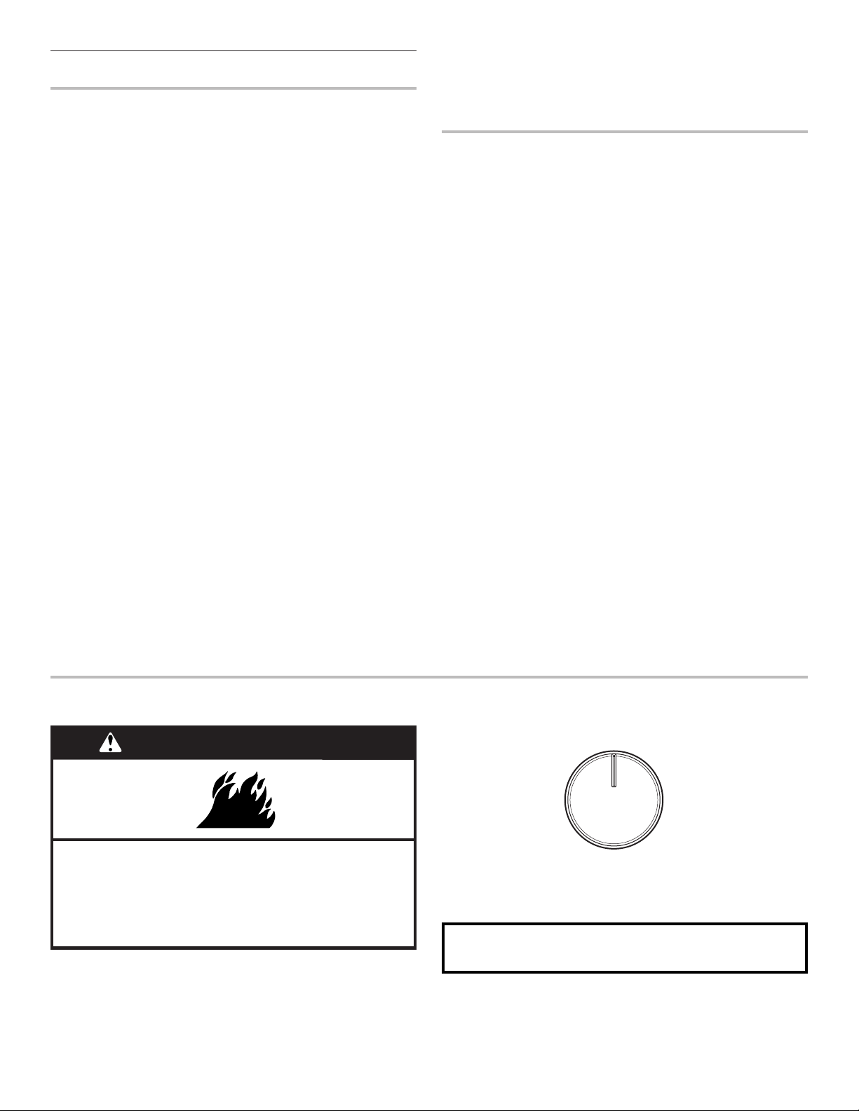
33
Plus de modes
Mode Sabbat
Pour obtenir de l’aide concernant l’utilisation de ce produit, ainsi
qu’une liste des modèles munis du mode Sabbat, consulter le
www.star-k.org.
Le mode Sabbat permet au four de continuer à fonctionner sur
un réglage de cuisson au four jusqu’à ce qu’on l’éteigne.
Lorsque le mode Sabbat est réglé, seul le programme de cuisson
au four fonctionne. Tous les autres programmes de cuisson et
de nettoyage sont désactivés. Aucun signal sonore ne retentit et
les affichages n’indiquent pas les changements de température.
Lorsque la porte du four est ouverte ou fermée, la lampe du four
ne s’allume ou ne s’éteint pas et les éléments de chauffage ne
s’allument ou ne s’éteignent pas immédiatement.
Si une minuterie de cuisson est réglée, le compte à rebours
n’apparaît pas. La minuterie apparaît fixe au temps réglé.
REMARQUE : Si une panne de courant se produit lorsque le
mode Sabbat est en fonction, le four indiquera que ce mode est
en fonction, mais le programme de cuisson ne fonctionnera pas.
La lumière du four ne s’allumera si la porte est ouverte pendant
cette période.
Activation du mode Sabbat :
1. Appuyer sur la touche outils.
2. Appuyer sur MORE MODES (plus de modes).
3. Sélectionner le mode Sabbat
4. Appuyer de nouveau sur le mode Sabbat pour activer le
mode Sabbat (ce mode est à la base désactivé)
5. Sélectionner YES (oui) pour faire fonctionner le four pendant
le Sabbat.
6. Saisir la température désirée.
(Optionnelle) Pour la cuisson minutée pendant le mode
Sabbat, appuyer sur ADD A COOK TIME (ajouter un temps de
cuisson) du four sélectionné, puis saisir le temps de cuisson
désiré et appuyer sur NEXT (suivant).
7. Sélectionner START (mise en marche).
Désactivation du mode Sabbat :
1. Appuyer sur la touche annulation du four.
2. Maintenir enfoncée la flèche “vers le haut” pendant 5
secondes.
Réglage de la température
1. Appuyer sur +/- 25 à l’écran pour sélectionner la nouvelle
température.
REMARQUE : Le changement de température n’apparaît pas sur
l’affichage et aucun son n’est émis.
Calibrage de température
IMPORTANT : Ne pas utiliser de thermomètre pour mesurer
la température du four. Les éléments chauffants s’allument
et s’éteignent en alternance pour maintenir une température
constante, mais leur température peut varier légèrement dans un
sens ou dans l’autre du fait de cette alternance.L’ouverture de la
porte du four affecte la mise en marche alternée des éléments et
influence la température.
Le four fournit des températures précises et a été testé avec
soin à l’usine. Toutefois, il peut cuire plus rapidement ou plus
lentement que votre four précédent, et ainsi entraîner des
différences de cuisson ou de brunissage.Si nécessaire, le
calibrage de la température peut se régler en degrés Fahrenheit
ou Celsius.
Un signe moins signifie que le four sera plus froid du nombre
de degrés affiché. L’absence de signe moins signifie que le four
sera plus chaud du nombre de degrés affiché. Utiliser le tableau
suivant comme guide.
La température du four peut être réglée jusqu’à (+,-) 30° (-18 °C).
Il est recommandé de modifier la température par tranche de 5 °F
(3 °C) jusqu’à l’obtention du résultat souhaité.
REMARQUE : Cet affichage se poursuit pour indiquer la
température du réglage d’origine, il n’indiquera pas le décalage
de calibration.Par exemple, si la température a été réglée à
350 °F (177 °C) et calibrée à -20 °, la température affichée sera
toujours 350 °F (177 °C).
Ajustement de la température du four :
1. Appuyer sur la touche outils.
2. Appuyer sur MORE MODES (plus de modes).
3. Sélectionner Calibrage de température
4. Naviguer de gauche à droite pour augmenter ou réduire la
température.
TABLE DE CUISSON
Les boutons de commande peuvent être réglés sur n’importe
quelle position entre Hi (élevé) et Lo (bas). Pousser et tourner le
bouton jusqu’au réglage choisi.
Risque d'incendie
Fermer tous les réglages lorsque la cuisson est
terminée.
Le non-respect de cette instruction peut causer un
décès ou un incendie.
AVERTISSEMENT
OFF
ON
N’OUBLIEZ PAS : Lors de l’utilisation de la cuisinière, toute
la surface de la table de cuisson peut devenir chaude.

34
Vitrocéramique (sur certains modèles)
La surface de cuisson peut rougeoyer lorsqu’un élément est
allumé. Il est possible que certaines zones de la surface de
cuisson ne rougeoient pas lorsqu’un élément est allumé. Le
rougeoiement apparaît également par intermittence et de façon
aléatoire (même en position élevée) afin de protéger la table de
cuisson contre les températures extrêmes. Ce phénomène est
normal.
Il est normal que la surface de vitrocéramique claire semble
changer de couleur lorsque les zones de cuisson à la surface
sont chaudes. Lorsque le verre refroidit, il revient à sa couleur
originale.
Nettoyer la table de cuisson après chaque utilisation afin d’éviter
les égratignures, les piqûres et l’abrasion et pour entretenir la
surface de verre. Nettoyant pour table de cuisson affresh
®
et
le grattoir de table de cuisson sont aussi recommandés pour
les saletés tenaces. Ne pas utiliser de produits de nettoyage
abrasifs, de tampons de nettoyage ou de produits chimiques
agressifs. La trousse d’entretien de la table de cuisson contient
tous les articles nécessaires pour nettoyer et entretenir votre
table de cuisson en vitrocéramique. Consulter la section
“Entretien de la cuisinière” pour plus de renseignements.
IMPORTANT : Pour éviter d’endommager irrémédiablement la
surface de la table de cuisson et pour faciliter l’élimination des
salissures, nettoyer la table de cuisson après chaque utilisation
pour éliminer toutes les salissures.
■ Ne pas ranger de bocaux ou de boîtes de conserve au-
dessus de la table de cuisson. La chute d’un objet lourd
ou dur sur la table de cuisson pourrait la fêler.
■ Afin d’éviter d’endommager la table de cuisson, ne pas
laisser un couvercle chaud sur la table de cuisson. Lorsque
la table de cuisson refroidit, de l’air peut se trouver piégé
entre le couvercle et la table de cuisson, et la vitrocéramique
pourrait se casser lorsqu’on enlève le couvercle.
■ Nettoyer dès que possible tous les renversements et
toutes les salissures des aliments contenant du sucre sous
n’importe quelle forme. Laisser la table de cuisson refroidir
légèrement. Ensuite, tout en portant des mitaines de four,
nettoyer les renversements avec un grattoir pendant que la
surface est encore tiède. Si on laisse le sucre refroidir sur la
table de cuisson, il se peut que celui-ci adhère à la surface
et laisse un creux et des marques permanentes.
■ Afin d’éviter toute égratignure, ne pas faire glisser
d’ustensiles de cuisson sur la table de cuisson. Les fonds
en aluminium ou en cuivre et les finis rugueux des ustensiles
de cuisson pourraient laisser des égratignures ou des
marques sur la table de cuisson.
■ Ne pas faire cuire de maïs soufflé dans son emballage
en aluminium d’origine sur la table de cuisson. Il pourrait
rester des traces d’aluminium qui ne peuvent être
complètement enlevées.
■ Afin d’éviter d’endommager la table de cuisson, ne pas
laisser d’objets qui pourraient fondre, comme du plastique
ou du papier d’aluminium, toucher une partie quelconque
de la table de cuisson.
■ Afin d’éviter d’endommager la table de cuisson, ne pas
l’utiliser en guise de planche à découper.
■ Utiliser des ustensiles de cuisson d’un diamètre comparable
à la surface de cuisson. L’ustensile de cuisson ne doit pas
dépasser la surface de cuisson de plus de 1/2" (13 mm).
■ Utiliser des ustensiles de cuisson à fond plat pour une
meilleure conduction de la chaleur et une meilleure utilisation
de l’énergie. Les ustensiles de cuisson à fond arrondi,
déformé, cannelé ou bosselé pourraient causer un chauffage
inégal et de mauvais résultats de cuisson.
■ Contrôler la planéité du récipient en plaçant une règle plate
en travers du fond du récipient. Lorsque l’on fait tourner la
règle, aucun espace ou jour ne doit être visible entre celle-ci
et le récipient.
■ Les ustensiles de cuisson à fond légèrement cannelé ou
à petites stries de dilatation peuvent être utilisés.
■ S’assurer que les fonds des casseroles et poêles sont
propres et secs avant de les utiliser. Les résidus et l’eau
peuvent laisser des dépôts quand ils sont chauffés.
■ Afin d’éviter d’endommager la table de cuisson, ne pas faire
cuire d’aliments directement sur la table de cuisson.
Éléments à spirale et cuvettes de brûleur
Pour une cuisson optimale, les éléments en spirale doivent être
horizontaux. Lorsqu’elles sont propres, les cuvettes de brûleur
réfléchissent la chaleur vers la table de cuisson. Elles permettent
de contenir les renversements.
L’ustensile de cuisson ne doit pas dépasser de plus de 1/2"
(13 mm) l’élément en spirale. Si le fond de l’ustensile de cuisson
est irrégulier ou trop grand, il peut produire une chaleur excessive
et entraîner la décoloration de la cuvette de brûleur.
Témoin lumineux d’allumage de la table de cuisson
Le témoin lumineux d’allumage de la table de cuisson se trouve
sur le panneau de la console. Lorsqu’un bouton de commande
sur le panneau de la console est activé, le témoin lumineux
d’allumage de la table de cuisson s’allume.
Témoin lumineux de surface chaude
Sur les modèles avec vitrocéramique, le témoin lumineux
de surface chaude est situé sur le panneau de commande.
Le témoin de surface chaude reste allumé tant qu’une surface
de cuisson est trop chaude au toucher, même si la surface
de cuisson est éteinte.
Élément de cuisson à triple zone
L’élément de cuisson à triple zone offre une grande souplesse
d’utilisation en fonction de la taille des ustensiles de cuisson. La
dimension simple peut être utilisée de la même manière qu’un
élément ordinaire. La dimension double et la dimension triple
combinent l’élément simple, l’élément double et les éléments
externes; leur utilisation est recommandée pour les ustensiles de
cuisson de plus grande dimension, les grandes quantités de
nourriture et la préparation de conserves à la maison.
A
B
C
A. Surface de cuisson
B. Ustensiles de cuisson/autoclave
C. Dépassement maximum de 1/2" (13 mm)
Off
Hi Lo
SingleTriple
Hi
Lo
Hi Lo
Double
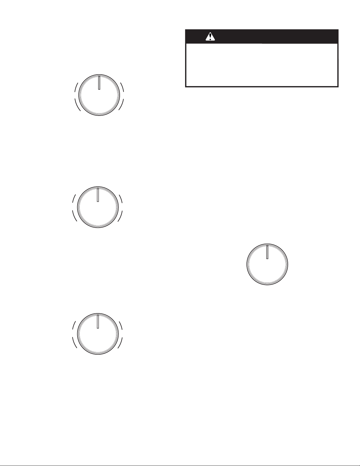
35
Élément de cuisson à double zone (sur certains modèles)
L’élément de cuisson à double zone offre une grande souplesse
d’utilisation en fonction de la taille des ustensiles de cuisson. La
dimension simple peut être utilisée de la même manière qu’un
élément ordinaire. La dimension double combine l’élément simple
et l’élément extérieur; elle est recommandée pour les ustensiles
de cuisson de plus grande dimension.
Élément d’ébullition rapide (élément avant droit)
L’élément d’ébullition rapide apporte une plus grande souplesse
de cuisson. L’élément d’ébullition rapide peut être utilisé pour
faire bouillir des liquides plus vite. Le réglage le plus bas pour
faire fondre peut servir à préparer des sauces, faire dorer ou
sauter des aliments et maintenir des préparations à basse
température. Utiliser des ustensiles de cuisson de diamètre
approprié pour l’élément d’ébullition rapide.
Élément Melt (faire fondre)
L’élément Melt (faire fondre) offre plus de souplesse de chauffe
grâce à une grande amplitude de réglages entre Hi (élevé) et Melt
(faire fondre). L’option de chauffage Hi (chauffage élevé) peut être
utilisée pour faire bouillir rapidement de petites quantités de
liquide. Pour réduire le réglage du niveau de puissance, tourner le
bouton dans le sens horaire. Le réglage Melt (faire fondre) est
destiné aux aliments délicats qui nécessitent une température
basse, comme pour faire fondre du chocolat ou maintenir des
sauces au chaud. Utiliser des ustensiles de cuisson de
dimensions appropriées pour l’élément Melt (faire fondre).
Élément de zone de maintien au chaud
Utiliser l’élément de maintien au chaud de la table de cuisson
pour garder au chaud les aliments cuits. La durée maximale
recommandée pour préserver la qualité des aliments est
d’une heure.
Ne pas l’utiliser pour chauffer des aliments froids.
L’élément de maintien au chaud peut être utilisé seul ou
en même temps qu’une autre surface de cuisson.
La surface de l’élément de maintien au chaud ne rougeoie pas
lorsque l’élément s’allume (par intermittence). En revanche,
le témoin de zone chaude de la table de cuisson reste allumé
lorsque la zone de maintien au chaud est en cours d’utilisation.
■ N’utiliser que les ustensiles de cuisson recommandés pour
une utilisation avec le four et la table de cuisson.
■ Couvrir tous les aliments avec un couvercle ou du papier
d’aluminium. Lors du réchauffage de produits de boulangerie,
prévoir une petite ouverture pour laisser l’humidité
s’échapper.
■ Pour éviter d’endommager la table de cuisson, ne pas utiliser
de film alimentaire en plastique pour couvrir les aliments,
car le plastique risque de fondre.
■ Utiliser des maniques ou des mitaines de four pour retirer
les aliments.
Utilisation :
Pour activer la fonction, tourner le bouton de commande à la
position On (ouverte).
Pour éteindre la fonction, tourner le bouton de commande à la
position Off (arrêt).
Off
Hi Lo
Single
Hi
Lo
Double
OFF
Lo
Melt
Hi
Max
Lo
Hi
OFF
Lo
Melt
Hi
Max
Lo
Hi
A. Option Hi (chauffage élevé)
B. Option Melt (faire fondre)
AVERTISSEMENT
Risque d'empoisonnement alimentaire
Ne pas laisser des aliments dans un four plus d'une
heure avant ou après la cuisson.
Le non-respect de cette instruction peut causer un
empoisonnement alimentaire ou une maladie.
OFF
ON
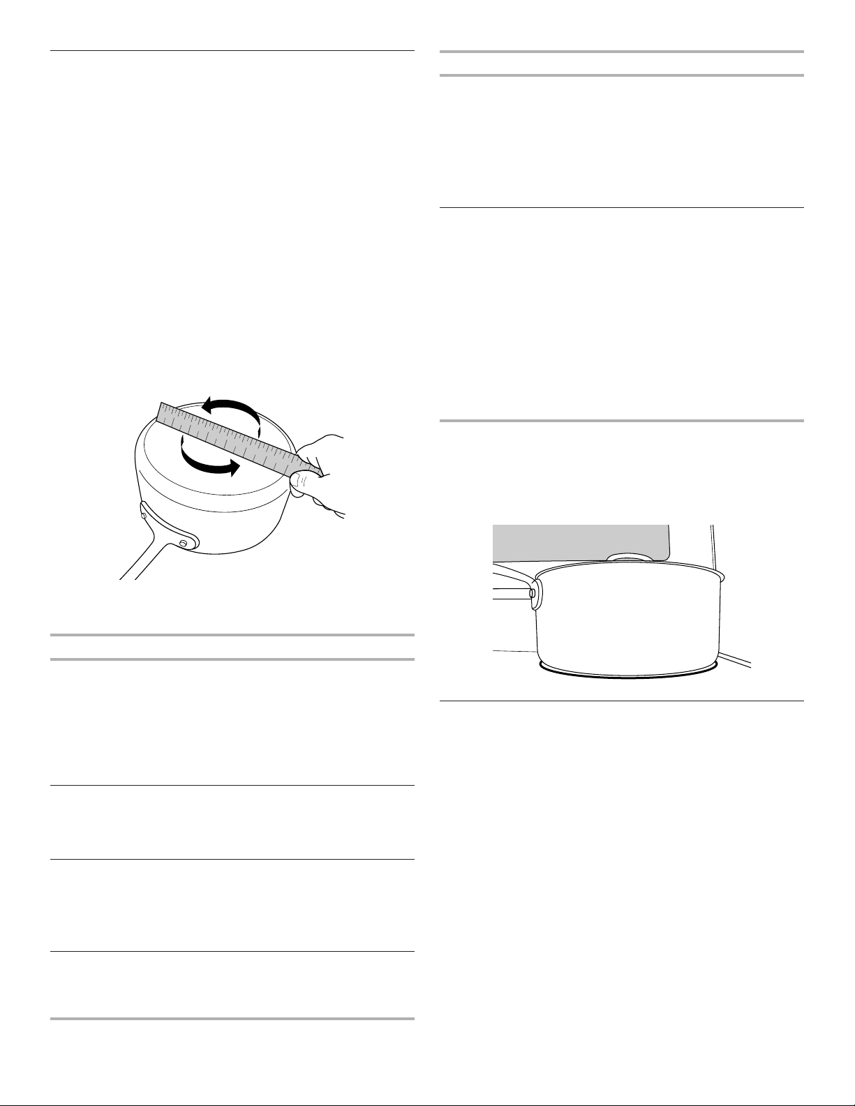
36
Ustensiles de cuisson
IMPORTANT : Ne pas laisser d’ustensile de cuisson vide sur une
surface de cuisson, un élément ou un brûleur de surface chauds.
Les ustensiles de cuisson idéals doivent avoir un fond plat, des
parois droites, un couvercle qui ferme hermétiquement et le
matériau doit être d’épaisseur moyenne à forte.
Les finis rugueux peuvent égratigner la table de cuisson.
L’aluminium et le cuivre peuvent être utilisés comme fond ou
base d’un ustensile de cuisson. Toutefois, lorsqu’ils sont utilisés
comme base, ils peuvent laisser des marques permanentes sur
les grilles.
Le matériau d’un ustensile a une influence sur la rapidité
et l’uniformité de la transmission de la chaleur, lesquelles
contribuent aux résultats de cuisson. Un fini antiadhésif a les
mêmes caractéristiques que son matériau de base. Par exemple,
un ustensile de cuisson en aluminium avec un fini antiadhésif
aura les propriétés de l’aluminium.
Les ustensiles de cuisson avec surface antiadhésive ne doivent
pas être utilisés sous le gril.
Vérifier que le récipient est plat en plaçant le bord plat d’une règle
en travers du fond du récipient. Lorsque l’on fait tourner la règle,
aucun espace ni aucune lumière ne devraient être visibles entre
celle-ci et le récipient.
Utiliser le tableau suivant comme guide pour les caractéristiques
du matériau d’ustensile de cuisson.
Ustensile Caractéristiques
Cuivre
■ Chauffe très rapidement
et uniformément.
■ Peut laisser des résidus de cuivre.
Pour en réduire la quantité, les nettoyer
immédiatement après la cuisson.
■ Peut laisser une tache indélébile ou
adhérer à la table de cuisson en cas
de surchauffe du matériau.
Terre cuite
■ Suivre les instructions du fabricant.
■ Utiliser des réglages de température
basse.
■ Peut érafler la table de cuisson.
Acier émaillé en
porcelaine ou
fonte émaillée
■ Voir acier inoxydable ou fonte.
■ Les ustensiles de cuisson au four
en émail vitrifié dépourvus d’une
base métallique peuvent adhérer à la
table de cuisson en cas de surchauffe
du matériau.
Acier inoxydable
■ Chauffe rapidement, mais inégalement.
■ Un fond ou une base d’aluminium ou
de cuivre sur l’acier inoxydable procure
un chauffage uniforme.
Ustensile Caractéristiques
Aluminium
■ Chauffe rapidement et uniformément.
■ Convient à tous les genres de cuisson
■ L’épaisseur moyenne ou forte convient
le mieux pour la plupart des tâches
de cuisson.
■ Peut laisser des résidus d’aluminium.
Pour en réduire la quantité, les nettoyer
immédiatement après la cuisson.
Fonte
■ Chauffe lentement et uniformément.
■ Convient pour le brunissage et la friture
■ Maintient la chaleur pour une cuisson
lente.
■ Des rebords anguleux ou mal poncés
peuvent érafler la table de cuisson.
Céramique ou
vitrocéramique
■ Suivre les instructions du fabricant.
■ Chauffe lentement, mais inégalement.
■ Les meilleurs résultats sont obtenus
sur les réglages de chaleur basse
à moyenne
■ Peut érafler la table de cuisson.
Utiliser des ustensiles de cuisson à fond plat pour obtenir
de meilleurs résultats de cuisson et une meilleure utilisation
de l’énergie. Les ustensiles de cuisson doivent avoir la même
taille que la zone de cuisson indiquée sur la table de cuisson
ou l’élément en spirale. L’ustensile de cuisson ne doit pas
dépasser de plus de 1/2" (13 mm) hors de la zone de cuisson
ou de l’élément.
Mise en conserve à la maison
La mise en conserve peut se faire sur une surface de cuisson
lisse en verre ou sur une table de cuisson à éléments tubulaires
traditionnels. Lors de la préparation de conserves pendant de
longues périodes, alterner l’utilisation des surfaces de cuisson
ou des éléments entre les quantités préparées. Ceci permet aux
dernières surfaces utilisées de refroidir.
■ Centrer l’autoclave sur la plus grande surface de cuisson
ou sur le plus grand élément. Sur les tables de cuisson
électriques, l’autoclave ne doit pas dépasser de plus de
1/2" (13 mm) hors de la surface de cuisson ou l’élément
de cuisson.
■ Ne pas placer l’autoclave sur deux surfaces de cuisson
ou deux éléments à la fois.
■ Sur les modèles en vitrocéramique, utiliser seulement des
autoclaves à fond plat pour éviter d’endommager la table
de cuisson et les éléments.
■ Pour plus de renseignements, contacter votre bureau de
développement agricole local, ou consulter les guides de
mise en conserve à la maison. Les compagnies qui fabriquent
des produits pour la préparation de conserves peuvent aussi
offrir de l’aide.
1
2
3
4
5
6
7
8
9
1 0
1 1
1 2
1 3
1 4
1 5
1 6
1 7
1 8
1 9
2 0
1
2
3
4
5
6
7
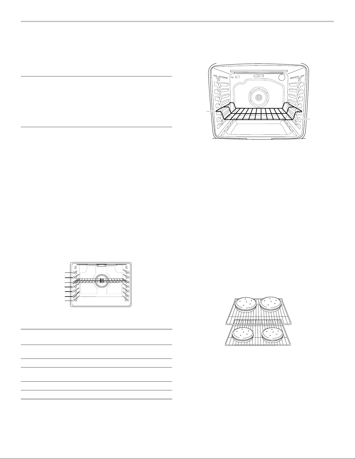
37
UTILISATION DU FOUR
Des odeurs et de la fumée sont normales lorsque le four est
utilisé les premières fois, ou lorsqu’il est très sale.
IMPORTANT : La santé de certains oiseaux est très sensible
aux émanations de fumée. L’exposition aux émanations peut
entraîner la mort de certains oiseaux. Toujours déplacer les
oiseaux dans une autre pièce fermée et bien aérée.
Papier d’aluminium
IMPORTANT : Pour éviter des dommages permanents au fini
du fond du four, ne pas recouvrir le fond du four avec du papier
d’aluminium ou un revêtement quelconque.
Pour assurer une bonne circulation de l’air et des résultats de
cuisson optimaux, ne pas recouvrir la grille entière de papier
d’aluminium.
Positionnement des grilles et des
ustensiles de cuisson au four
IMPORTANT : Afin d’éviter d’endommager irrémédiablement
la finition en émail, ne pas placer d’aliments ou d’ustensiles de
cuisson au four directement sur la porte ou sur le fond du four.
Ustensiles de cuisson
L’air chaud doit pouvoir circuler autour de l’aliment pour le cuire
uniformément. Laisser 2" (5 cm) entre les ustensiles de cuisson
et les parois du four. S’assurer qu’aucun ustensile de cuisson
ne se trouve directement au-dessus d’un autre.
Grilles
■ Placer les grilles avant d’allumer le four.
■ Ne pas déplacer les grilles lorsque des ustensiles de cuisson
se trouvent dessus.
■ S’assurer que les grilles sont horizontales.
Pour déplacer une grille, la tirer jusqu’à la butée, soulever l’avant
puis la retirer. Se servir de l’illustration et du tableau suivants
comme guide.
Le four possède 7 positions pour grille plate, comme indiqué
dans l’illustration précédente et le tableau suivant.
Position de
la grille plate*
Type d’aliment
7 Cuire au gril/griller les viandes,
les hamburgers, les steaks
6 Viandes grillées, volaille, poisson
3 ou 4 La plupart des produits de boulangerie,
plats en sauce, plats surgelés
2 Viandes rôties
1 Gros rôtis/volailles
Pour qu’une galette à hamburger soit bien saisie à l’extérieur
tout en restant saignante à l’intérieur, utiliser une grille plate en
position 7. Préchauffer le four pendant 2 minutes. Cuire le 1
er
côté pendant 2
1
/
2
à 3
1
/
2
minutes. Cuire le 2
e
côté pendant 4 à 5
minutes. Une légère fumée peut se dégager durant la cuisson
au gril.
* Si votre modèle possède une grille de four à capacité maxi-
male, les bords surélevés doivent être placés dans la position
immédiatement supérieure à la position souhaitée pour les
aliments. Voir l’illustration ci-dessous.
IMPORTANT : Ces positions de grille concernent les grilles
plates. En cas d’utilisation d’une grille de four à capacité
maximale, la position de la grille doit être ajustée en conséquence
comme dans l’illustration précédente.
Cuisson sur plusieurs grilles
Cuisson sur deux grilles (sans convection) : Utiliser les positions
de grille 2 et 5 ou 3 et 6.
Cuisson sur deux grilles (avec convection) : Utiliser les positions
de grille 2 et 5 ou 3 et 6.
Cuisson sur trois grilles (avec convection) : Utiliser les positions
2 et 7 et une grille de four à capacité maximale en position 5.
Cuisson au four de biscuits et de gâteaux à étages
sur deux grilles
Cuisson au four de gâteaux à étages
Pour une cuisson optimale de gâteaux sur deux grilles, utiliser la
fonction Bake (cuisson au four), une grille plate en position 5
et une grille plate en position 2. Si seule une grille plate est
disponible, utiliser une grille de four à capacité maximale en
position 6. Placer les gâteaux sur les grilles tel qu’indiqué.
Prévoir un espace d’au moins 3" (7,6 cm) entre le bord avant
des grilles et les gâteaux placés à l’avant.
Cuisson au four de biscuits
Pour une cuisson optimale de biscuits sur deux grilles, utiliser
la fonction Convection Bake (cuisson au four par convection),
une grille plate en position 5 et une grille plate en position 2.
Si seule une grille plate est disponible, utiliser une grille plate en
position 2 et une grille de four à capacité maximale en position 6.
Si le four est dépourvu de la fonction Convection Bake (cuisson
au four par convection), utiliser la fonction Bake (cuisson au
four) standard.
7
6
5
4
3
2
1
A
B
A. Bordures de grille en position 3
B. Aliments en position 2

38
Évent du four
L’évent du four permet l’évacuation de l’air chaud et de l’humidité
du four et ne doit pas être obstrué ou couvert. Le fait d’obstruer
ou de couvrir l’évent nuit à la circulation adéquate de l’air et
affecte les résultats de cuisson et de nettoyage. Ne pas placer
près de l’évent du four des produits en plastique, en papier ou
d’autres articles qui pourraient fondre ou brûler.
Cuisson au four et rôtissage
Préchauffage
Au début d’un programme de cuisson au four, de cuisson au
four avec convection ou de rôtissage avec convection, le four
commence par un préchauffage une fois la touche Start (mise
en marche) enfoncée. Le four atteint 350°F (177°C) en 12 à
15 minutes environ lorsque toutes les grilles fournies avec le
four sont à l’intérieur. Pour atteindre une température plus élevée,
le préchauffage est plus long. Le programme de préchauffage
augmente rapidement la température du four. La température
réelle du four dépasse alors la température programmée,
pour compenser la chaleur perdue à l’ouverture du four pour
y introduire le plat à cuire. Ainsi, le four entame la cuisson à
la température correcte après y avoir placé le plat. Placer les
aliments au four lorsque le signal sonore de préchauffage retentit.
Ne pas ouvrir la porte du four pendant le préchauffage tant que
le signal sonore n’a pas retenti.
Préchauffage rapide
La fonction Rapid Preheat (préchauffage rapide) peut servir à
réduire la durée de préchauffage. Durant le préchauffage rapide,
seule une grille doit se trouver dans le four. Les autres grilles
doivent être retirées avant de démarrer le préchauffage rapide. Le
programme de préchauffage doit être terminé avant de placer de
la nourriture dans le four. Une fois le programme de préchauffage
rapide terminé, le four commence un programme normal de
cuisson au four.
IMPORTANT: La fonction de préchauffage rapide doit être
utilisée uniquement pour la cuisson au four sur une seule grille.
Température du four
En cours d’utilisation, les éléments chauffants du four s’allument
et s’éteignent en alternance pour maintenir une température
constante, mais leur température peut varier légèrement dans
un sens ou dans l’autre du fait de cette alternance. L’ouverture
de la porte du four en cours d’utilisation laisse échapper l’air
chaud et refroidit le four, ce qui peut modifier la durée nécessaire
et le résultat de la cuisson. Pour suivre l’avancement de la
cuisson, il est conseillé d’utiliser l’éclairage du four.
REMARQUE : Sur les modèles équipés d’une fonction de
convection, le ventilateur de convection peut tourner dans
le mode de cuisson sans convection pour améliorer la
performance du four.
Système de gestion de la température
Le système de gestion de la température contrôle
électroniquement les niveaux de température du four durant le
préchauffage et la cuisson afin de maintenir une gamme précise
de températures pour des résultats de cuisson optimaux. Les
éléments de cuisson au four et au gril ou brûleurs s’allument et
s’éteignent par intermittence. Pour les cuisinières à convection, le
ventilateur fonctionne pendant le préchauffage et peut s’allumer
et s’éteindre par intermittence pendant de courts intervalles
dans le mode Bake (cuisson au four) afin de produire un meilleur
résultat. Ce comportement est automatique lorsque le four est
utilisé.
Avant la cuisson au four et le rôtissage, placer les grilles tel
qu’indiqué à la section “Positionnement des grilles et des
ustensiles de cuisson”. Lors du rôtissage, il n’est pas nécessaire
d’attendre la fin du préchauffage du four avant d’y placer la
nourriture, sauf si la recette le recommande.
Frozen Bake™
La technologie Frozen Bake™ règle automatiquement le temps
de cuisson du fabricant en combinant le préchauffage et la
cuisson pour offrir sans attente de bons résultats avec les
plats congelés. Il est possible de choisir parmi six options de
programmes pour aliments : Pizza, lasagne, croquettes, frites,
tartes et repas. Le programme Frozen Bake™ est conçu pour
ne fonctionner qu’avec ces aliments. Lors de l’utilisation de
la technologie Frozen Bake™, il est important de respecter
toutes les instructions du fabricant, incluant la ventilation et le
fait de recouvrir les aliments, de les mélanger ou de les poser
sur une plaque à pâtisserie pour obtenir de bons résultats. Lors
de la préparation de plats congelés, ne cuire que des aliments
munis d’instructions pour un four conventionnel. Placer le plat
au centre de la grille et sélectionner l’une des positions de
grille recommandées pour les plats congelés dans la section
“Positionnement des grilles et ustensiles de cuisson au four”.
Ne faire cuire qu’un plat ou une plaque à la fois. Utiliser la
température et le temps de cuisson maximum indiqué sur
l’emballage.
Une tonalité vous indiquera de vérifier le degré de cuisson avant
la fin du temps de cuisson et à la fin du temps de cuisson.
L’affichage vous demandera d’ajouter du temps de cuisson
(au besoin).
Cuisson au gril
Pour la cuisson au gril, préchauffer le four pendant 2 minutes
avant d’y placer des aliments, à moins que la recette ne
recommande autre chose. Placer l’aliment sur la grille de la
lèchefrite, puis placer celle-ci au centre de la grille du four.
IMPORTANT: Fermer la porte pour une température de cuisson
au gril adéquate.
Le changement de température lors de la cuisson au gril permet
un contrôle plus précis de la cuisson. Plus le réglage du gril est
bas, plus la cuisson est lente. Les morceaux épais et de forme
irrégulière de viande, de poisson et de volaille cuisent mieux
à des réglages de gril plus bas. Utiliser la grille 6 ou 7 pour la
cuisson au gril. Consulter la section “Positionnement des grilles
et ustensiles de cuisson” pour plus d’informations.
À des réglages inférieurs, l’élément de cuisson au gril s’allume
et s’éteint par intermittence afin de maintenir une température
adéquate.
■ Pour de meilleurs résultats, utiliser une lèchefrite et une
grille - elles sont conçues pour laisser s’écouler les jus
et aider à éviter les éclaboussures et la fumée.
Il est possible de commander une lèchefrite. Voir la section
“Accessoires”.
A
A. Oven vent
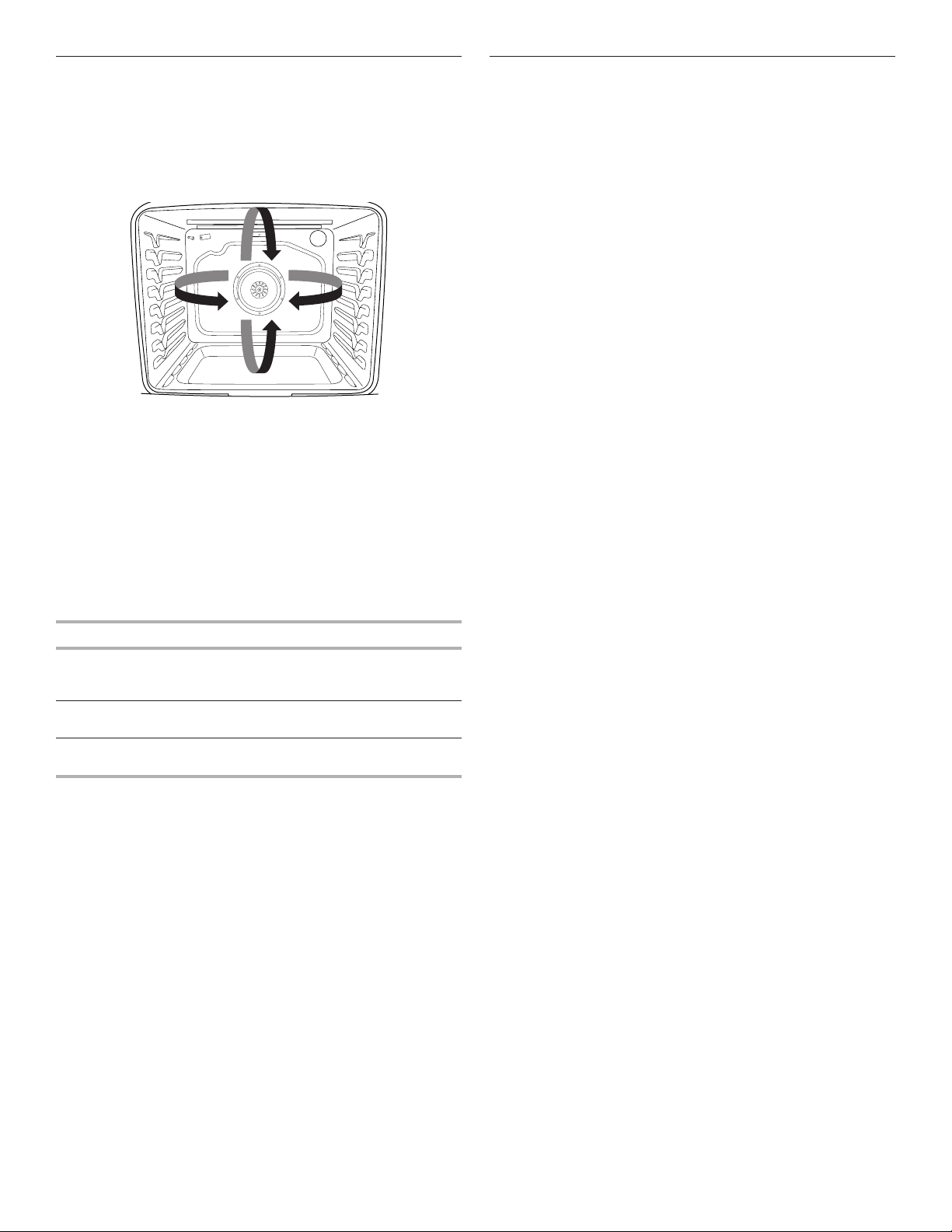
39
Cuisson par convection
Dans un four à convection, l’air chaud que fait circuler le
ventilateur répartit plus uniformément la chaleur que le
mouvement naturel de l’air dans un four thermique standard. Ce
déplacement d’air chaud contribue à maintenir une température
constante dans tout le four, qui permet de cuire les aliments plus
uniformément, de dorer leur surface tout en conservant leur
humidité naturelle et de donner des pains plus croustillants.
Durant la cuisson ou le rôtissage par convection, les éléments
de cuisson au four, cuisson au gril et de convection s’allument et
s’éteignent par intermittence tandis que le ventilateur fait circuler
l’air chaud. Durant la cuisson au gril par convection, les éléments
de cuisson au gril et de convection s’allument et s’éteignent par
intermittence.
Si la porte du four est ouverte durant la cuisson par convection,
le ventilateur s’éteint immédiatement. Il s’allume à nouveau
lorsque la porte du four est fermée.
La cuisson par convection permet de cuire la majorité des
aliments à une température plus basse et/ou moins longtemps
qu’avec un four thermique standard. Utiliser le tableau suivant
comme guide.
Mode de convection Recommandation de durée/temp.
Cuisson au four par
convection
Température plus basse de
25°F (15°C); réduction éventuelle
du temps de cuisson
Rôtissage par
convection
Temps de cuisson réduit jusqu’à 30 %
Cuisson au gril par
convection
Raccourcissement du temps
de cuisson
Options de cuisson par convection
Cuisson au four par convection : cuisson au four sur plusieurs
grilles de biscuits, pains, plats en sauce, tartes, tourtes
et gâteaux
Rôtissage par convection : poulets ou dindes entiers, légumes,
rôtis de porc, rôtis de boeuf
Cuisson au gril par convection : morceaux plus épais ou inégaux
de viande, de poisson ou de volaille
Lampe du four
La lampe du four est une ampoule standard de 40 watts pour
appareil électroménager. Avant le remplacement, s’assurer que
le four et la table de cuisson sont froids et que les boutons de
commande sont à la position d’arrêt.
Remplacement :
1. Débrancher la cuisinière ou déconnecter la source
de courant électrique.
2. Tourner le protège-ampoule en verre à l’arrière du four
dans le sens antihoraire et l’enlever.
3. Tourner l’ampoule dans le sens antihoraire pour l’enlever
de la douille.
4. Remplacer l’ampoule en la tournant dans le sens horaire.
5. Remplacer le protège-ampoule en le tournant dans
le sens horaire.
6. Brancher la cuisinière ou reconnecter la source de
courant électrique.
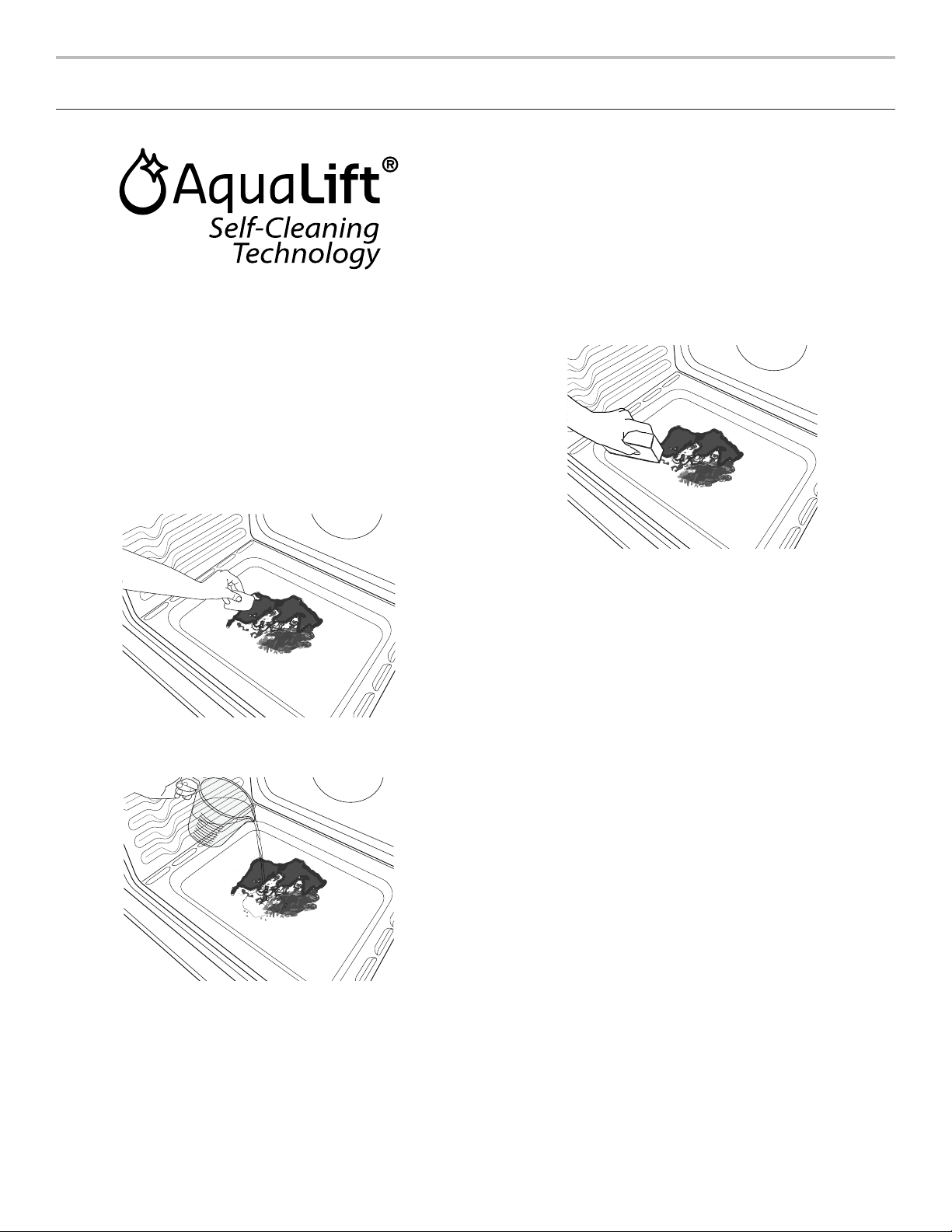
40
ENTRETIEN DE LA CUISINIÈRE
Programme de nettoyage
La technologie AquaLift
®
est une solution de nettoyage novatrice
qui utilise la chaleur et l’eau pour débarrasser le four des produits
renversés cuits en moins d’une heure. Cette nouvelle technologie
de nettoyage est une alternative à basse température et sans
odeurs aux options traditionnelles de nettoyage automatique.
Laisser le four refroidir et atteindre la température ambiante
avant d’utiliser le programme de nettoyage. Si la température de
la cavité du four est supérieure à 200°F (93°C), “Oven Cooling”
(refroidissement du four) apparaît sur l’afficheur et le programme
de nettoyage ne s’activera pas avant que la cavité ait refroidi.
Nettoyage :
1. Retirer toutes les grilles et tous les accessoires de la cavité
du four et essuyer l’excès de saleté. Utiliser une spatule en
plastique pour enlever les saletés faciles à enlever.
2. Verser 2 tasses (16 oz [500 mL]) d’eau distillée ou filtrée dans
le fond du four vide et fermer la porte du four.
IMPORTANT : Ne pas utiliser des produits chimiques ou
d’autres additifs avec l’eau. Ne pas ouvrir la porte du four
au cours du programme de lavage. L’eau au fond du four
est chaude.
3. Appuyer sur AQUALIFT SELF CLEAN (autonettoyage
AquaLift) et ensuite sur la touche Start (mise en marche) sur
le tableau de commande du four.
REMARQUE : Ne pas démarrer la fonction d’autonettoyage
avant que le four ne soit refroidi.
4. Accorder 40 minutes pour le nettoyage et le refroidissement.
Un signal sonore vous avertit lorsque le programme de
nettoyage est terminé.
5. Appuyer sur la touche annulation à la fin du programme.
On peut appuyer sur la touche annulation à tout moment
pour arrêter le programme de nettoyage.
6. Enlever l’eau résiduelle et les saletés délogées avec une
éponge ou un chiffon immédiatement après la fin du
programme de nettoyage. La plupart de l’eau initiale
contenue dans 2 tasses (16 oz [500 mL]) restera dans le four
après la fin du programme de nettoyage. S’il reste encore des
saletés, laisser une petite quantité d’eau au fond du four pour
aider le nettoyage.
7. S’il reste des saletés, les enlever avec une éponge à gratter
non abrasive ou une spatule en plastique. Des programmes
de nettoyage supplémentaires peuvent être lancés pour aider
à se débarrasser des saletés tenaces.
IMPORTANT : Ne pas utiliser de nettoyants à four. L’utilisation
de produits chimiques, y compris les nettoyants à four qu’on
retrouve sur le marché, ou des tampons à récurer métalliques,
pourrait causer des dommages permanents à la surface en
porcelaine qui se trouve à l’intérieur du four.
REMARQUES :
■ La cuisinière doit être d’aplomb de façon à s’assurer que la
surface du fond de la cavité du four est couverte par l’eau au
début du programme de nettoyage.
■ Pour des résultats optimaux, utiliser de l’eau distillée ou filtrée.
L’eau du robinet pourrait laisser des dépôts minéraux sur le
fond du four.
■ Avant d’enlever l’eau résiduelle et les saletés délogées à la fin
du programme de nettoyage, insérer un chiffon ou un essuie-
tout entre l’extrémité inférieure de la porte du four et l’avant du
châssis, afin d’empêcher l’eau de se déverser sur le devant de
la cuisinière et le plancher.
■ Les saletés cuites suite à plusieurs programmes de cuisson
seront plus difficiles à enlever avec le programme de
nettoyage.
■ Les éponges à gratter non abrasives ou les tampons
nettoyeurs en gomme (sans nettoyants) peuvent être efficaces
pour le nettoyage des parois de la cavité du four, de la porte
du four et du fond du four pour les saletés difficiles. Pour de
meilleurs résultats, mouiller les tampons et les éponges avant
de les utiliser.
■ Exécuter un programme de nettoyage supplémentaire pour
les saletés tenaces.
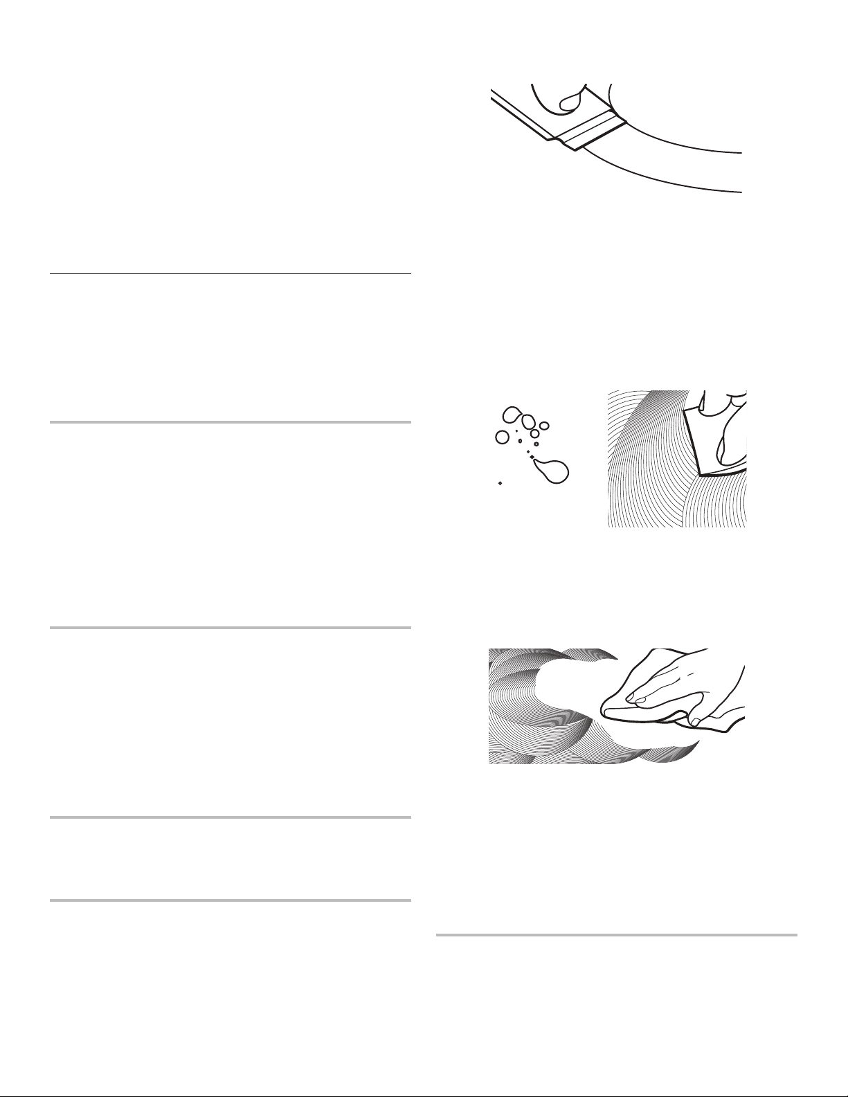
41
■ Le nettoyant pour appareils ménagers de cuisine affresh
®
et le nettoyant pour table de cuisson affresh
®
peuvent être
utilisés pour nettoyer le fond du four, ses parois et sa porte
lorsque le four a terminé le programme de nettoyage et que
sa température est redevenue ambiante. Si l’on utilise le
nettoyant pour table de cuisson affresh
®
, il est recommandé
d’essuyer aussi la cavité avec de l’eau distillée. Consulter la
section “Accessoires” pour obtenir des renseignements sur
la commande.
■ Des ensembles de nettoyage à technologie AquaLift
®
supplémentaires peuvent être obtenus en commandant la
pièce numéro W10423113RP. Voir la section “Accessoires”
pour plus d’informations.
■ Pour obtenir de l’aide concernant la technologie AquaLift
®
,
appeler le 1 800 807-6777 ou visiter notre site Web
http://whirlpoolcorp.com/aqualift.
Nettoyage général
IMPORTANT : Avant le nettoyage, s’assurer que toutes les
commandes sont éteintes et que le four et la table de cuisson
sont froids. Toujours suivre les instructions figurant sur les
étiquettes des produits de nettoyage. Pour plus d’informations,
consulter la section service à la clientèle à l’adresse
www.whirlpool.ca.
Du savon, de l’eau et un chiffon doux ou une éponge sont
recommandés, à moins d’indications contraires.
SURFACES EXTÉRIEURES ÉMAILLÉES
(sur certains modèles)
Les éclaboussures alimentaires acides, telles que vinaigre et
tomate, doivent être nettoyées dès que la cuisinière a refroidi.
Ces salissures peuvent endommager le fini.
Méthode de nettoyage :
■ Nettoyant à vitre, nettoyant doux liquide ou tampon à récurer
non abrasif :
Nettoyer doucement autour de la plaque signalétique car
le frottement pourrait en effacer les chiffres.
■ Nettoyant pour cuisine et appareils ménagers affresh
®
référence W10355010 (non fourni) :
Voir la section “Accessoires” pour plus de renseignements.
ACIER INOXYDABLE (sur certains modèles)
REMARQUE : Afin d’éviter d’endommager les surfaces en acier
inoxydable, ne pas utiliser de tampons à récurer savonneux,
de nettoyants abrasifs, de crème à polir pour table de cuisson,
de tampons en laine d’acier, de chiffons de lavage rêches ou
d’essuie-tout abrasifs. Ils peuvent endommager les surfaces en
acier inoxydable, même après usage unique ou limité.
Méthode de nettoyage :
Frotter dans la direction du grain pour éviter les dommages.
■ Nettoyant pour acier inoxydable affresh
®
référence
W10355016 (non fourni) :
Voir la section “Accessoires” pour plus de renseignements.
PEINTURE MÉTALLIQUE (sur certains modèles)
Ne pas utiliser de nettoyants abrasifs, de nettoyants avec agent
de blanchiment, de produits antirouille, d’ammoniaque ou
d’hydroxyde de sodium (soude), car la surface peinte pourrait
se tacher.
VITROCÉRAMIQUE
Afin d’éviter d’endommager la table de cuisson, ne pas utiliser
de laine d’acier, de nettoyants en poudre abrasifs, d’eau de Javel,
de produit antirouille ou d’ammoniaque.
1. Éliminer les salissures alimentaires avec le grattoir
pour table de cuisson.
■ Pour de meilleurs résultats, utiliser le grattoir pendant que
la table de cuisson est encore tiède, mais non brûlante au
toucher. Il est recommandé de porter des mitaines de four
pour gratter la table de cuisson tiède.
■ Tenir le grattoir pour table de cuisson à un angle
d’environ 45° par rapport à la surface de verre et gratter
les salissures. Il convient d’appuyer fermement pour
éliminer les salissures.
Laisser la table de cuisson refroidir complètement avant
de passer à l’étape 2.
2. Appliquer quelques gouttes de nettoyant pour table
de cuisson affresh
®
sur les zones concernées.
■ Frotter le nettoyant affresh
®
sur la surface de la table
de cuisson avec le tampon bleu de nettoyage des
tables de cuisson. Il convient d’appuyer fermement
pour éliminer les taches rebelles.
■ Laisser le produit nettoyant sécher en une pellicule
blanchâtre avant de passer à l’étape 3.
3. Faire briller avec un chiffon ou essuie-tout propre et sec.
■ Répéter éventuellement les étapes 1 à 3 pour les taches
les plus tenaces ou incrustées.
Le nécessaire complet de nettoyage des tables de cuisson
est disponible à la commande. Il contient :
■ Grattoir pour table de cuisson
■ Nettoyant pour table de cuisson affresh
®
■ Tampons bleus de nettoyage des tables de cuisson
Consulter la section “Accessoires” pour les références
et les informations de commande.
ÉLÉMENTS EN SPIRALE (sur certains modèles)
Méthode de nettoyage :
■ Chiffon humide :
Vérifier que les commandes sont éteintes et que les éléments
sont froids.
Ne pas nettoyer ni immerger dans l’eau. Les salissures brûlent
lorsqu’elles chauffent.

42
CUVETTES DES BRÛLEURS (sur certains modèles)
Avant de retirer ou de remplacer les éléments en spirale et
les cuvettes de brûleur, s’assurer qu’ils sont froids et que les
boutons de commande sont en position Off (arrêt).
Retirer l’élément en spirale en poussant son pourtour vers le
réceptacle. Le soulever suffisamment pour pouvoir dégager
la cuvette de brûleur. Tirer l’élément en spirale en ligne droite
pour le dégager du réceptacle. Soulever la cuvette du brûleur
pour la dégager.
Méthode de nettoyage :
Cuvettes de brûleur chromées
Laver fréquemment à l’eau savonneuse tiède. Il n’est pas
recommandé de laver les cuvettes chromées au lave-vaisselle.
Il est possible d’utiliser un produit de nettoyage modérément
abrasif et une spatule à récurer en plastique pour éliminer les
taches tenaces.
Pour les cuvettes de brûleur très sales, placer un morceau
d’essuie-tout imbibé d’ammoniaque sur les taches et laisser
tremper pendant une courte durée. Frotter ensuite doucement
avec une spatule à récurer en plastique.
COMMANDES DE LA TABLE DE CUISSON
Afin d’éviter d’endommager les commandes de la table de
cuisson, ne pas utiliser de laine d’acier, de nettoyants abrasifs
ou de nettoyant pour four.
Afin d’éviter toute détérioration, ne pas laisser tremper les
boutons de commande. Lors de la réinstallation des boutons,
s’assurer que chaque bouton est à la position Off (arrêt).
Sur certains modèles, ne pas enlever les joints sous les boutons.
Méthode de nettoyage :
■ Savon et eau :
Tirer les boutons en ligne droite hors du tableau
de commande pour les enlever.
TABLEAU DE COMMANDE ET EXTÉRIEUR
DE LA PORTE DU FOUR
Afin d’éviter d’endommager le tableau de commande, ne pas
utiliser de nettoyants abrasifs, de tampons en laine d’acier, de
chiffons de lavage rêches ou d’essuie-tout abrasifs.
Méthode de nettoyage :
■ Nettoyant à vitre et chiffon doux ou éponge :
Appliquer le nettoyant à vitre sur un chiffon doux ou une
éponge, et non directement sur le tableau.
■ Nettoyant pour cuisine et appareils ménagers affresh
®
référence W10355010 (non fourni) :
Voir la section “Accessoires” pour plus de renseignements.
GRILLES DU FOUR
Méthode de nettoyage :
■ Tampon en laine d’acier
■ Pour les grilles ternies qui glissent difficilement, enduire
légèrement les glissières d’huile végétale; cela facilitera leur
glissement.
TIROIR-RÉCHAUD OU TIROIR DE REMISAGE
(sur certains modèles)
S’assurer que le tiroir est froid et vide avant le nettoyage.
Méthode de nettoyage :
■ Détergent doux
CAVITÉ DU FOUR
Utiliser régulièrement la technologie AquaLift
®
nettoyage alternatif
pour nettoyer les éclaboussures dans le four.
Ne pas utiliser de nettoyants à four.
Les éclaboussures alimentaires doivent être nettoyées lorsque le
four a refroidi. À haute température, les aliments réagissent avec
l’émail et peuvent provoquer la formation de taches, une attaque
acide, des piqûres ou des décolorations blanchâtres.
Méthode de nettoyage :
■ Programme de nettoyage :
Voir la section “Programme de nettoyage”.

43
DÉPANNAGE
Essayer d’abord les solutions suggérées ici. Pour obtenir de l’aide ou des conseils qui permettront peut-être d’éviter une intervention de
dépannage, consulter la page de garantie de ce manuel, ou consultez le site internet www.whirlpool.ca.
Vous pouvez adresser tous commentaires ou questions par courrier à l’adresse ci-dessous :
Au Canada :
Whirlpool Brand Home Appliances
Customer eXperience Centre
200 - 6750 Century Ave.
Mississauga, Ontario L5N 0B7
Dans votre correspondance, veuillez indiquer un numéro de téléphone où l’on peut vous joindre dans la journée.
Problème Causes et/ou solutions possibles
Rien ne fonctionne
Cordon d’alimentation électrique débranché : Le brancher à une prise à 3 alvéoles reliée à la terre.
Un fusible du domicile est grillé ou un disjoncteur s’est ouvert : Remplacer le fusible ou réarmer le
disjoncteur. Si le problème persiste, appeler un électricien.
Le tableau de commande de la cuisinière affiche le code d’erreur F9 ou F9, E0 : Le câblage de la
prise électrique du domicile peut être défectueux. Demander à un électricien qualifié d’inspecter le circuit
d’alimentation électrique.
La table de cuisson
ne fonctionne pas
Le bouton de commande n’est pas correctement engagé : Appuyer sur le bouton avant de le tourner
à un réglage donné.
Sur les modèles à vitrocéramique, les commandes du four sont verrouillées : Voir “Control Lock”
(verrouillage des commandes) dans la section “Guide des caractéristiques”.
Chaleur excessive
autour des ustensiles
de cuisson sur la
table de cuisson
L’ustensile de cuisson n’a pas la dimension correcte : Utiliser un ustensile de cuisson d’un diamètre
comparable à la surface de cuisson, à l’élément ou au brûleur de surface. L’ustensile de cuisson ne doit
pas dépasser de plus de 1/2" (13 mm) à l’extérieur de la zone de cuisson.
La cuisson ne produit
pas les résultats
prévus
Le bouton de commande est réglé sur une puissance de chauffe incorrecte : Voir la section “Utilisation
de la table de cuisson”.
La cuisinière n’est pas d’aplomb : Régler l’aplomb de la cuisinière. Voir les Instructions d’installation.
L’élément de la
table de cuisson
s’allume et s’éteint
en alternance sur
le réglage élevé
Alternance marche/arrêt de l’élément en raison du limiteur de température : Ce phénomène est normal.
L’élément fonctionne par intermittence pour éviter toute surchauffe de la table de cuisson.
Le four ne
fonctionne pas
La mise en marche différée est activée : Voir la section “Durée de cuisson”.
Les commandes sont verrouillées : Voir “Control Lock” (verrouillage des commandes) dans la section
“Outils”.
La cuisinière est en mode démonstration : Le mode démonstration désactivera tous les éléments
chauffants. Voir “Info” dans la section “Outils”.
Réglage incorrect des commandes électroniques du four : Voir les sections “Outils” et “Plus de modes”.

44
Problème Causes et/ou solutions possibles
La température du
four est trop élevée
ou trop basse
La température du four doit être ajustée : Voir “Calibrage de température” dans la section “Plus de
modes”.
Les témoins
lumineux du four
clignotent
L’alimentation de la cuisinière vient d’être établie ou rétablie : Voir les sections “Outils” et
“Plus de modes”. Si les témoins lumineux clignotent toujours, appeler le service de maintenance.
Des messages
s’affichent
Panne de courant : Sur certains modèles, régler de nouveau l’horloge au besoin. Voir “Préférences” dans la
section “Outils”.
Code d’erreur (L’afficheur indique une lettre suivie d’un numéro.) : Selon le modèle, appuyer sur la
touche annulation pour effacer l’affichage. Voir les sections “Outils” et “Plus de modes”. S’il réapparaît,
appeler le service de dépannage. Voir la section “Garantie” pour des renseignements de contact.
La cuisinière est en mode Sabbat (“Sabbath Mode” affiché) : Voir la section “Mode Sabbat” pour quitter
le mode Sabbat.
Mode de démonstration (l’appareil est en mode de démonstration) : Pour quitter le mode Demo
(démonstration), voir la section “Tools” (outils).
Le programme de
nettoyage n’a pas
éliminé toutes les
salissures
Plusieurs programmes de cuisson entre les programmes de nettoyage, ou éclaboussures sur les
parois et la porte du four : Lancer des programmes de nettoyage supplémentaires. Utiliser le nécessaire
de nettoyage à technologie AquaLift
®
. Pour les salissures tenaces, utiliser le nettoyant pour cuisine et
appareils ménagers affresh
®
ou le nettoyant pour table de cuisson affresh
®
. Voir les sections “Outils” et
“Plus de modes”.
Des dépôts minéraux
se forment au fond
du four après le
programme de
nettoyage
Le programme de nettoyage a été effectué avec de l’eau du robinet : Utiliser de l’eau distillée ou filtrée
pour le programme de nettoyage.
Utiliser un chiffon imbibé de vinaigre pour enlever les dépôts. Utiliser ensuite un chiffon humide pour enlever
complètement tout résidu de vinaigre.
La cuisinière n’est pas d’aplomb : Les dépôts minéraux s’accumulent sur les surfaces sèches du fond du
four durant le programme de nettoyage. Régler l’aplomb de la cuisinière. Voir les Instructions d’installation.
Utiliser un chiffon imbibé de vinaigre pour enlever les dépôts. Utiliser ensuite un chiffon humide pour enlever
complètement tout résidu de vinaigre.
La cuisson au four
ne produit pas les
résultats prévus
La cuisinière n’est pas d’aplomb : Régler l’aplomb de la cuisinière. Voir les instructions d’installation.
Le réglage de la température était incorrect : Revérifier la recette dans un livre de cuisine fiable.
La température du four doit être ajustée : Voir “Commande de température du four” dans la section
“Commandes électroniques du four”.
Le four n’a pas été préchauffé : Voir la section “Cuisson au four et rôtissage”.
Les grilles n’étaient pas placées correctement : Voir la section “Positionnement des grilles et ustensiles
de cuisson au four”.
Circulation d’air déficiente autour des ustensiles de cuisson : Voir la section “Positionnement des grilles
et ustensiles de cuisson au four”.
Brunissement excessif des aliments causé par un plat à four terne ou foncé : Diminuer la température
du four de 25°F (15°C) ou placer la grille plus haut dans le four.
Brunissement insuffisant des aliments causé par un plat à four brillant ou clair : Placer la grille plus bas
dans le four.
Répartition irrégulière de la pâte dans le plat : Vérifier que la pâte est répartie uniformément dans le plat.
Durée de cuisson incorrecte : Revoir la durée de cuisson.
Porte du four non fermée : Vérifier que le plat à four n’empêche pas la fermeture de la porte.
La porte du four a été ouverte durant la cuisson : L’ouverture de la porte pour vérifier la cuisson laisse
échapper la chaleur du four et peut allonger la durée de cuisson.
La grille est trop proche du brûleur de cuisson au four, ce qui brunit trop le fond des aliments cuits
au four : Placer la grille plus haut dans le four.
Les croûtes des tartes brunissent trop vite : Recouvrir de papier d’aluminium le périmètre de la croûte
et/ou réduire la température de cuisson du four.

45
ACCESSOIRES
Pour les accessoires, consulter notre site Web www.whirlpool.ca. Si vous avez des problèmes ou des questions,
appelez Whirlpool Corporation Connected Appliances au 1-866-333-4591.
Ensemble d’entretien complet
de la table de cuisson
(modèles avec vitrocéramique)
(comprend le nettoyant, le protecteur, son
applicateur, le grattoir et les tampons à
nettoyer)
Commander la pièce numéro 31605
Protecteur de table de cuisson
(modèles avec vitrocéramique)
Commander la pièce numéro 31463A
Chiffons pour acier inoxydable
affresh
®
(modèles en acier inoxydable)
Commander la pièce numéro W10355049
Nettoyant pour table de cuisson
affresh
®
(modèles avec vitrocéramique)
Commander la pièce numéro W10355051
Tampons à nettoyer les tables
de cuisson
(modèles avec vitrocéramique)
Commander la pièce numéro W10391473
Nettoyant pour acier inoxydable
affresh
®
(modèles en acier inoxydable)
Commander la pièce numéro W10355016
Nettoyant pour cuisine et appareils
électroménagers affresh
®
Commander la pièce numéro W10355010
Ensemble de nettoyage pour four
à technologie AquaLift
®
Commander la pièce numéro
W10423113RP
Grattoir pour table de cuisson
(modèles avec vitrocéramique)
Commander la pièce numéro WA906B
Nettoyant et poli pour granite
Commander la pièce numéro W10275756
Nettoyant pour plateau d’égouttement
et grille de cuisinière à gaz
Commander la pièce numéro 31617A
Ensemble pour la mise en conserves
(modèles avec éléments en spirale)
Commander la pièce numéro 242905
Plaque à frire Gourmet
Commander la pièce numéro W10432539
Grille de four plate standard
Commander la pièce numéro W10551060
Grille de four en deux pièces
Commander la pièce numéro 4396927
Grille à capacité maximale
Commander la pièce numéro W10289145
Lèchefrite et grille en porcelaine
Commander la pièce numéro 4396923
Lèchefrite et grille de rôtissage
de qualité supérieure
Commander la pièce numéro W10123240

46
SI VOUS AVEZ BESOIN DE SERVICE :
1. Avant de nous contacter pour obtenir un dépannage, veuillez déterminer si des réparations sont nécessaires pour votre produit. Certains
problèmes peuvent être résolus sans intervention de dépannage. Prenez quelques minutes pour parcourir la section Dépannage ou
Résolution de problèmes du guide d’utilisation et d’entretien, ou rendez-vous sur le site http://www.whirlpool.ca.
2. Tout service sous garantie doit être effectué exclusivement par nos fournisseurs de dépannage autorisés Whirlpool. Aux É.-U. et au Canada,
dirigez toutes vos demandes de service sous garantie au
Centre d’eXpérience de la clientèle Whirlpool
Aux É.-U., composer le 1-800-253-1301. Au Canada, composer le 1-800-807-6777.
Si vous résidez à l’extérieur du Canada et des 50 États des États-Unis, contactez votre marchand Whirlpool autorisé pour déterminer si une autre
garantie s’applique.
GARANTIE LIMITÉE DES
GROS APPAREILS
MÉNAGERS WHIRLPOOL
®
ATTACHEZ ICI VOTRE REÇU DE VENTE. UNE PREUVE D’ACHAT EST
OBLIGATOIRE POUR OBTENIR L’APPLICATION DE LA GARANTIE.
Lorsque vous appelez le centre d’eXpérience de la clientèle, veuillez
garder à disposition les renseignements suivants :
■ Nom, adresse et numéro de téléphone
■ Numéros de modèle et de série
■ Une description claire et détaillée du problème rencontré
■ Une preuve d’achat incluant le nom et l’adresse du marchand ou du
détaillant
GARANTIE LIMITÉE DE UN AN
CE QUI EST COUVERT CE QUI N’EST PAS COUVERT
Pendant un an à compter de la date
d’achat, lorsque ce gros appareil
ménager est installé, utilisé et entretenu
conformément aux instructions jointes
à ou fournies avec le produit, Whirlpool
Corporation ou Whirlpool Canada, LP (ci-
après désignées “Whirlpool”) décidera
à sa seule discrétion de remplacer le
produit ou de couvrir le coût des pièces
spécifiées par l’usine et de la main-
d’œuvre nécessaires pour corriger les
vices de matériaux ou de fabrication qui
existaient déjà lorsque ce gros appareil
ménager a été acheté. S’il est remplacé,
l’appareil sera couvert pour la période
restant à courir de la garantie limitée d’un
an du produit d’origine.
LE SEUL ET EXCLUSIF RECOURS
DU CLIENT DANS LE CADRE DE
LA PRÉSENTE GARANTIE LIMITÉE
CONSISTE EN LA RÉPARATION
PRÉVUE PAR LA PRÉSENTE. Le service
doit être fourni par une compagnie de
service désignée par Whirlpool. Cette
garantie limitée est valide uniquement
aux États-Unis ou au Canada et
s’applique exclusivement lorsque le gros
appareil ménager est utilisé dans le pays
où il a été acheté. La présente garantie
limitée est valable à compter de la date
d’achat initial par le consommateur.
Une preuve de la date d’achat initial est
exigée pour obtenir un dépannage dans
le cadre de la présente garantie limitée.
1. Usage commercial, non résidentiel ou par plusieurs familles, ou non-respect des instructions de
l’utilisateur, de l’opérateur ou des instructions d’installation.
2. Visite d’instruction à domicile pour montrer à l’utilisateur comment utiliser l’appareil.
3. Visites de service pour rectifier une installation ou un entretien fautifs du produit, une installation
non conforme aux codes d’électricité ou de plomberie, ou la rectification de l’installation
électrique ou de la plomberie du domicile (ex : câblage électrique, fusibles ou tuyaux d’arrivée
d’eau du domicile).
4. Pièces consomptibles (ex : ampoules, batteries, filtres à air ou à eau, solutions de conservation,
etc.).
5. Défauts ou dommage résultant de l’utilisation de pièces ou accessoires Whirlpool non
authentiques.
6. Conversion des produits du gaz naturel ou du gaz propane.
7. Dommages causés par : accident, mésusage, abus, incendie, inondations, catastrophe naturelle
ou l’utilisation de produits non approuvés par Whirlpool.
8. Réparations aux pièces ou systèmes dans le but de rectifier un dommage ou des défauts
résultant d’une réparation, altération ou modification non autorisée faite à l’appareil.
9. Défauts d’apparence, notamment les éraflures, traces de choc, fissures ou tout autre dommage
subi par le fini de l’appareil ménager, à moins que ces dommages ne résultent de vices de
matériaux ou de fabrication et ne soient signalés à Whirlpool dans les 30 jours suivant la date
d’achat.
10. Décoloration, rouille ou oxydation des surfaces résultant d’environnements caustiques ou
corrosifs incluant des concentrations élevées de sel, un haut degré d’humidité ou une exposition
à des produits chimiques (exemples non exhaustifs).
11. Perte d’aliments ou de médicaments due à la défaillance du produit.
12. Enlèvement ou livraison. Ce produit est conçu pour être réparé à l’intérieur du domicile.
13. Frais de déplacement et de transport pour le dépannage/la réparation dans une région éloignée
où une compagnie de service Whirlpool autorisée n’est pas disponible.
14. Retrait ou réinstallation d’appareils inaccessibles ou de dispositifs préinstallés (ex : garnitures,
panneaux décoratifs, plancher, meubles, îlots de cuisine, plans de travail, panneaux de gypse,
etc.) qui entravent le dépannage, le retrait ou le remplacement du produit.
15. Service et pièces pour des appareils dont les numéros de série et de modèle originaux ont été
enlevés, modifiés ou ne peuvent pas être facilement identifiés.
Le coût d’une réparation ou d’un remplacement dans le cadre de ces circonstances exclues est
à la charge du client.

47
11/14
CLAUSE D’EXONÉRATION DE RESPONSABILITÉ AU TITRE DES GARANTIES IMPLICITES
LES GARANTIES IMPLICITES, Y COMPRIS LES GARANTIES APPLICABLES DE QUALITÉ MARCHANDE OU D’APTITUDE À UN USAGE
PARTICULIER, SONT LIMITÉES À UN AN OU À LA PLUS COURTE PÉRIODE AUTORISÉE PAR LA LOI. Certains États et provinces ne permettent
pas de limitation sur la durée des garanties implicites de qualité marchande ou d’aptitude à un usage particulier, de sorte que la limitation ci-
dessus peut ne pas être applicable dans votre cas. Cette garantie vous confère des droits juridiques spécifiques et vous pouvez également jouir
d’autres droits qui peuvent varier d’une juridiction à l’autre.
EXONÉRATION DE RESPONSABILITÉ DANS LES DOMAINES NON COUVERTS PAR LA GARANTIE
Whirlpool décline toute responsabilité au titre de la qualité, de la durabilité ou en cas de dépannage ou de réparation nécessaire sur ce gros
appareil ménager autre que les responsabilités énoncées dans la présente garantie. Si vous souhaitez une garantie plus étendue ou plus complète
que la garantie limitée fournie avec ce gros appareil ménager, adressez-vous à Whirlpool ou à votre détaillant pour obtenir les modalités d’achat
d’une garantie étendue.
LIMITATION DES RECOURS; EXCLUSION DES DOMMAGES FORTUITS OU INDIRECTS
LE SEUL ET EXCLUSIF RECOURS DU CLIENT DANS LE CADRE DE LA PRÉSENTE GARANTIE LIMITÉE CONSISTE EN LA RÉPARATION
PRÉVUE PAR LA PRÉSENTE. WHIRLPOOL N’ASSUME AUCUNE RESPONSABILITÉ POUR LES DOMMAGES FORTUITS OU INDIRECTS.
Certains États et certaines provinces ne permettent pas l’exclusion ou la limitation des dommages fortuits ou indirects de sorte que ces limitations
et exclusions peuvent ne pas être applicables dans votre cas. Cette garantie vous confère des droits juridiques spécifiques et vous pouvez
également jouir d’autres droits qui peuvent varier d’une juridiction à l’autre.

48
LE AGRADECEMOS la compra de este producto de alta calidad. Registre su nueva estufa en www.whirlpool.com. En Canadá, registre
su estufa en www.whirlpool.ca.
Para referencia futura, tome nota de los números de modelo y de serie de su producto. Puede encontrarlos en el marco del horno,
detrás del lado derecho superior de la puerta del horno.
Número de modelo_______________________________________ Número de serie__________________________________________
Indice
SEGURIDAD DE LA ESTUFA.......................................................49
Soporte antivuelco .....................................................................49
CONSEJOS DE USO ESENCIALES ............................................52
Tecnología autolimpiante AquaLift
®
...........................................52
Temperaturas de la superficie .................................................... 52
Precalentamiento .......................................................................52
Limpieza de la superficie de cocción de vitrocerámica ............52
GUÍA DE FUNCIONES ..................................................................53
Panel táctil ..................................................................................54
Pantalla .......................................................................................54
Desplazamiento por la pantalla..................................................54
Configuración y modo de demostración ...................................54
Métodos de cocción ..................................................................54
Favoritos .....................................................................................56
Cocción asistida .........................................................................56
Herramientas ..............................................................................57
Más modos ................................................................................58
SUPERFICIE DE COCCIÓN .........................................................59
Utensilios de cocina ...................................................................61
Envasado casero ........................................................................62
USO DEL HORNO ........................................................................62
Papel de aluminio .......................................................................62
Colocación de las parrillas y los utensilios para hornear ..........62
Ventilación del horno .................................................................. 63
Cómo hornear y asar .................................................................63
Asado a la parrilla .......................................................................64
Cocción por convección ............................................................64
Luz del horno .............................................................................64
CUIDADO DE LA ESTUFA ...........................................................65
Ciclo de limpieza ........................................................................65
Limpieza general ........................................................................66
SOLUCIÓN DE PROBLEMAS......................................................68
ACCESORIOS ...............................................................................70
GARANTÍA.....................................................................................71
INSTRUCCIONES PARA EL
USUARIODE LA ESTUFA ELÉCTRICA
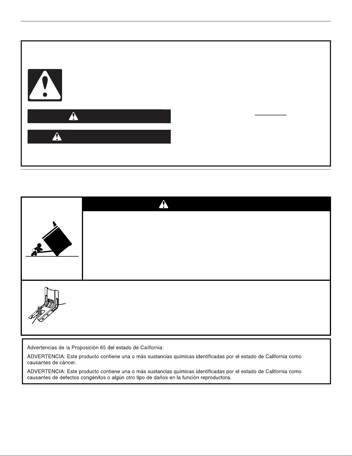
49
SEGURIDAD DE LA ESTUFA
Soporte antivuelco
La estufa no se volcará durante el uso normal. Sin embargo, se puede volcar si se aplica demasiada fuerza o peso sobre la puerta
abierta sin tener el soporte antivuelco adecuadamente sujeto al piso.
Si no sigue las instrucciones de inmediato, usted puede
morir o sufrir una lesión grave.
Si no sigue las instrucciones, usted puede morir o sufrir
una lesión grave.
Todos los mensajes de seguridad le dirán el peligro potencial, le dirán cómo reducir las posibilidades de sufrir una lesión y lo que
puede suceder si no se siguen las instrucciones.
Su seguridad y la seguridad de los demás es muy importante.
Hemos incluido muchos mensajes importantes de seguridad en este manual y en su electrodoméstico. Lea y obedezca siempre
todos los mensajes de seguridad.
ADVERTENCIA
PELIGRO
Este es el símbolo de alerta de seguridad.
Este símbolo le llama la atención sobre peligros potenciales que pueden ocasionar la muerte o una lesión a
usted y a los demás.
Todos los mensajes de seguridad irán a continuación del símbolo de advertencia de seguridad y de la palabra
“PELIGRO” o “ADVERTENCIA”. Estas palabras significan:
Peligro de Vuelco
Un niño o un adulto puede volcar accidentalmente la estufa y resultar muerto.
Verifique que se haya instalado y asegurado debidamente el soporte anti-vuelco según las
instrucciones de instalación.
Si traslada de lugar la estufa, vuelva a asegurar el soporte anti-vuelco.
No ponga a funcionar la estufa sin tener el soporte anti-vuelco instalado y asegurado.
No seguir estas instrucciones puede ocasionar la muerte o quemaduras graves en niños y
adultos.
Para verificar que el soporte anti-vuelco esté instalado y asegurado:
• Deslice la estufa hacia adelante.
• Verifique que el soporte anti-vuelco esté bien sujeto al piso o a la pared.
• Deslice la estufa hacia atrás de modo que la pata trasera quede debajo del soporte
anti-vuelco.
• Consulte las instrucciones de instalación para ver más detalles.
ADVERTENCIA
Soporte
anti-vuelco
Pata de la estufa

50
INSTRUCCIONES IMPORTANTES DE SEGURIDAD
GUARDE ESTAS INSTRUCCIONES
ADVERTENCIA: Para reducir el riesgo de incendio,
electrocución, lesiones a personas o daños al usar la estufa,
siga precauciones básicas, incluyendo las siguientes:
■ ADVERTENCIA: PARA REDUCIR EL RIESGO DE
VUELCO DE LA ESTUFA, ÉSTA DEBE ASEGURARSE EN
EL PISO MEDIANTE LA INSTALACIÓN DEBIDA DE
DISPOSITIVOS ANTIVUELCO. PARA VERIFICAR SI LOS
DISPOSITIVOS ESTÁN DEBIDAMENTE INSTALADOS,
DESLICE LA ESTUFA HACIA DELANTE, CERCIÓRESE
DE QUE EL SOPORTE ANTIVUELCO ESTÉ BIEN
SUJETO AL PISO O A LA PARED Y DESLICE LA ESTUFA
HACIA ATRÁS DE MANERA QUE LA PATA TRASERA DE
LA ESTUFA QUEDE FIJA DEBAJO DEL SOPORTE
ANTIVUELCO.
■ AVISO: No guarde artículos que interesen a los niños en
los armarios que están encima de la estufa o en el respaldo
de protección de la estufa - cuando los niños suban encima
de la estufa para poder coger objetos podrían lastimarse
seriamente.
■ Instalación apropiada - Cerciórese de que la instalación y
puesta a tierra de la estufa sean efectuadas
adecuadamente por un técnico competente.
■
Nunca use la estufa como calefacción del cuarto.
■ No deje a los niños solos - No se debe dejar a los niños sin
supervisión en el área donde la estufa está en uso. Jamás
se les debe permitir que se sienten o se paren en parte
alguna de la estufa.
■ Use ropa apropiada – Nunca debe ponerse ropa holgada
o que se esté colgando mientras esté usando la estufa.
■
Servicio del usuario - No repare ni reemplace pieza alguna
de la estufa a menos que se recomiende específicamente
en el manual. Cualquier otro servicio se debe dejar en las
manos de un técnico competente.
■ Almacenaje dentro o encima de la estufa - No se debe
guardar material inflamable en el horno ni cerca de las
unidades exteriores.
■ No use agua en incendios provocados por grasa - Extinga
el incendio o la llama o use un extinguidor de tipo espuma o
químico seco.
■ Use sólo agarradores de ollas secos - Los agarradores de
ollas húmedos o mojados en las superficies calientes
pueden ocasionar quemaduras por vapor. No deje que el
agarrador de ollas toque los elementos calefactores
calientes. No use toallas u otros paños voluminosos.
■ NO TOQUE LAS UNIDADES EXTERIORES O ÁREAS
CERCANAS A LAS UNIDADES. Las
unidades exteriores
podrían estar calientes no obstante su color sea oscuro. Las
áreas cercanas a las unidades exteriores se pueden calentar
lo suficiente para ocasionar quemaduras. Durante y después
del uso, no toque ni deje que la ropa u otros materiales
inflamables toquen las superficies exteriores o las áreas
cercanas a las unidades hasta que haya transcurrido tiempo
suficiente para que se enfríen. Entre esas áreas están la
superficie de cocción y las superficies que están frente a la
superficie de cocción.
■ Use cacerolas de tamaño apropiado - La estufa está
equipada con una o más unidades exteriores de tamaño
distinto. Seleccione utensilios que tengan el asiento liso lo
suficientemente grande para cubrir el elemento calefactor
de la unidad exterior. El uso de utensilios de menor tamaño
expondrá una porción del elemento calefactor a contacto
directo y puede ocasionar que la ropa se incendie. La
relación apropiada entre el utensilio y el quemador también
mejorará el rendimiento.
■ Nunca deje sin supervisión las unidades exteriores a fuego
alto. Los derrames por ebullición ocasionan salpicaduras
grasosas y humeantes que pueden incendiarse.
■ Cerciórese de que las charolas reflectoras o platillos para
goteo estén en su lugar - La ausencia de éstos durante la
cocción puede ocasionar daños al alambrado o
componentes que están debajo.
■ Forros protectores - No use papel de aluminio para forrar
los platillos para goteo de las unidades exteriores o el
fondo del horno, excepto como lo sugiera el manual. La
instalación inapropiada de estos forros puede dar lugar a
riesgos de electrocución o incendio.
■ Utensilios de cocción vidriados - Sólo algunos tipos de
utensilios de vidrio, cerámica vitrificada, cerámica, de barro
u otros utensilios vidriados son adecuados para uso en la
estufa sin que se rompan debido a cambios repentinos de
temperatura.
■ Los mangos de los utensilios deben colocarse hacia adentro
y no deben extenderse hasta las unidades exteriores
adyacentes - Para reducir riesgos de quemaduras, incendio
de materiales inflamables y salpicaduras debido a contacto
accidental con el utensilio, el mango del utensilio debe
colocarse hacia adentro y no debe extenderse hasta las
unidades exteriores adyacentes.
■
No remoje los elementos calefactores desmontables -
Nunca se deben sumergir los elementos calefactores en
el agua.
■
No cocine en una superficie de cocción quebrada - Si la
superficie de cocción se quiebra, las soluciones de limpieza
y derrames pueden penetrar en la superficie de cocción
quebrada y dar lugar a un riesgo de electrocución. Póngase
en contacto con un técnico competente de inmediato.
■ Limpie la superficie de cocción con cuidado - Si usa una
esponja o un paño mojado para limpiar los derrames en el
área de cocción caliente, tenga cuidado para evitar
quemaduras por vapor. Algunos productos de limpieza
pueden producir gases nocivos al ser aplicados en una
superficie caliente.
■ Tenga cuidado al abrir la puerta - Deje que el aire caliente
o el vapor se escape antes de retirar o volver a colocar los
alimentos.
■ No caliente recipientes sellados de alimentos - La
acumulación de presión podría hacer estallar el recipiente y
ocasionar una lesión.
■ Mantenga despejados los conductos de ventilación
del horno.

51
INSTRUCCIONES IMPORTANTES DE SEGURIDAD
GUARDE ESTAS INSTRUCCIONES
■
Ubicación de las parrillas del horno - coloque siempre las
parrillas del horno en la ubicación deseada mientras el
horno esté frío. Si tiene que mover la parrilla cuando el
horno está caliente, no deje que el agarrador de ollas toque
el elemento calefactor caliente en el horno.
■ NO TOQUE LOS ELEMENTOS CALEFACTORES O LAS
SUPERFICIES INTERIORES DEL HORNO - No obstante
su color oscuro, los elementos calefactores podrían estar
calientes. Las superficies interiores de un horno se
calientan lo suficiente como para ocasionar quemaduras.
Durante y después del uso, no toque ni deje que la ropa u
otros materiales inflamables toquen los elementos
calefactores o las superficies interiores del horno hasta que
haya transcurrido suficiente tiempo para que se enfríen.
Otras superficies del electrodoméstico pueden calentarse lo
suficiente para ocasionar quemaduras - entre estas
superficies se encuentran los orificios de los conductos de
ventilación del horno y las superficies cercanas a estos
orificios, puertas del horno y ventanas de las puertas
del horno.
Para estufas con función de autolimpieza -
■ No limpie la junta de la puerta. La junta de la puerta es
esencial para un buen cierre. Se debe tener cuidado de no
frotar, dañar o mover la junta.
■ No use productos de limpieza para hornos - No se debe
usar productos comerciales de limpieza para hornos o
revestimientos protectores para el forro del horno de ningún
tipo en o alrededor de cualquier parte del horno.
■ Limpie únicamente las piezas enumeradas en el manual.
■ Antes de realizar la autolimpieza del horno - quite la
charola para asar a la parrilla y otros utensilios.
Para unidades con campana de ventilación -
■ Limpie las campanas de ventilación con frecuencia - No se
debe dejar que la grasa se acumule en la campana o en
el filtro.
■ Al flamear los alimentos debajo de la campana, encienda el
ventilador.
Para cocinas y hornos inteligentes habilitados -
■ Operación remota: Este electrodoméstico es configurable
para autorizar la operación remota en cualquier momento.
No almacene materiales inflamables o artículos sensibles a
la temperatura en el interior, en o cerca de la superficie del
electrodoméstico.

52
CONSEJOS DE USO ESENCIALES
Tecnología autolimpiante AquaLift
®
La tecnología autolimpiante AquaLift
®
es una solución de
limpieza de primera clase diseñada para minimizar el tiempo,
la temperatura y los olores que comúnmente conllevan los
métodos autolimpiantes tradicionales. Con la tecnología
autolimpiante AquaLift
®
un revestimiento innovador del interior
del horno se activa con calor y agua para aflojar la suciedad
quemada adherida. Para usar la tecnología autolimpiante
AquaLift
®
, simplemente repase los restos sueltos, vuelque agua
en el piso del horno y haga funcionar el ciclo autolimpiante
AquaLift
®
. Cuando el ciclo finaliza en menos de 1 hora a una
temperatura inferior a la de métodos autolimpiantes tradicionales,
simplemente recoja el agua restante y los restos sueltos. Vea
la sección “Ciclo de limpieza” para obtener instrucciones más
detalladas. Para información adicional, preguntas frecuentes y
videos sobre el uso de la tecnología autolimpiante AquaLift
®
,
visite nuestro sitio web en http://whirlpoolcorp.com/aqualift.
Temperaturas de la supercie
Cuando la estufa está en uso, todas las superficies pueden
calentarse, incluidas las perillas y la puerta del horno.
Cajón de calentamiento o almacenamiento
Cuando el horno está funcionando, es posible que el cajón se
caliente. No guarde en el cajón objetos de plástico, paños ni
otros objetos que pudieran derretirse o quemarse.
Ventilación del horno
La ventilación del horno libera aire caliente y humedad del horno
y no debe bloquearse ni taparse. No coloque objetos de plástico,
papel ni otros objetos que puedan derretirse o quemarse cerca
de la ventilación del horno.
Precalentamiento
Cuando comience un ciclo de horneado, horneado por
convección o asado por convección, el horno empezará a
precalentarse después de que se presione la tecla Start (Inicio).
El horno tardará 12 a 15 minutos aproximadamente para alcanzar
177 °C (350 °F) con todas las parrillas de horno provistas con el
horno dentro de la cavidad. Cuanto mayor sea la temperatura,
más tiempo tardará el horno en precalentarse. El ciclo de
precalentamiento aumenta rápidamente la temperatura del
horno. La temperatura real del horno superará la temperatura
fijada para compensar la pérdida de calor cuando se abra la
puerta del horno para introducir los alimentos. Esto asegura que
el horno comience a la temperatura correcta cuando se coloquen
los alimentos en el horno. Introduzca los alimentos cuando
suene el tono de precalentamiento. No abra la puerta durante el
precalentamiento antes de que suene el tono.
Limpieza de la supercie de
cocciónde vitrocerámica
Método de limpieza:
Para evitar daños en la superficie de cocción, no use lana de
acero, productos de limpieza en polvo abrasivos, blanqueador
con cloro, removedor de óxido o amoníaco.
1. Quite los alimentos/residuos con el raspador para superficies
de cocción.
■ Para resultados óptimos, use el raspador para superficies
de cocción mientras la superficie de cocción todavía
esté tibia, pero no caliente al tacto. Se recomienda usar
guantes para horno cuando se raspa la superficie de
cocción tibia.
■ Sostenga el raspador para superficies de cocción en un
ángulo de aproximadamente 45° contra la superficie de
vidrio y raspe los residuos. Será necesario aplicar presión
para retirar los residuos.
Espere hasta que la superficie de cocción se enfríe por
completo antes de seguir con el paso 2.
2. Aplique pocas gotas del tamaño de una moneda pequeña de
limpiador para superficies de cocción affresh
®
en las zonas
afectadas.
■ Frote una almohadilla de limpieza para superficies de
cocción azul con limpiador para superficies de cocción
affresh
®
sobre la superficie de cocción. Se requiere algo
de presión para eliminar las manchas rebeldes.
■ Espere hasta que el limpiador se seque y deje una
opacidad blanca antes de seguir con el paso 3.
3. Pula con una toalla de papel o con un paño limpio y seco.
■ Repita los pasos 1 a 3 según sea necesario para las
manchas rebeldes o adheridas al quemarse.
Se puede pedir el kit completo de limpieza para superficies de
cocción, que incluye lo siguiente:
■ Raspador para superficies de cocción
■ Limpiador para superficies de cocción affresh
®
■ Almohadillas de limpieza para superficies de cocción azules
Vea la sección “Accesorios” para obtener los números de pieza e
información sobre pedidos.
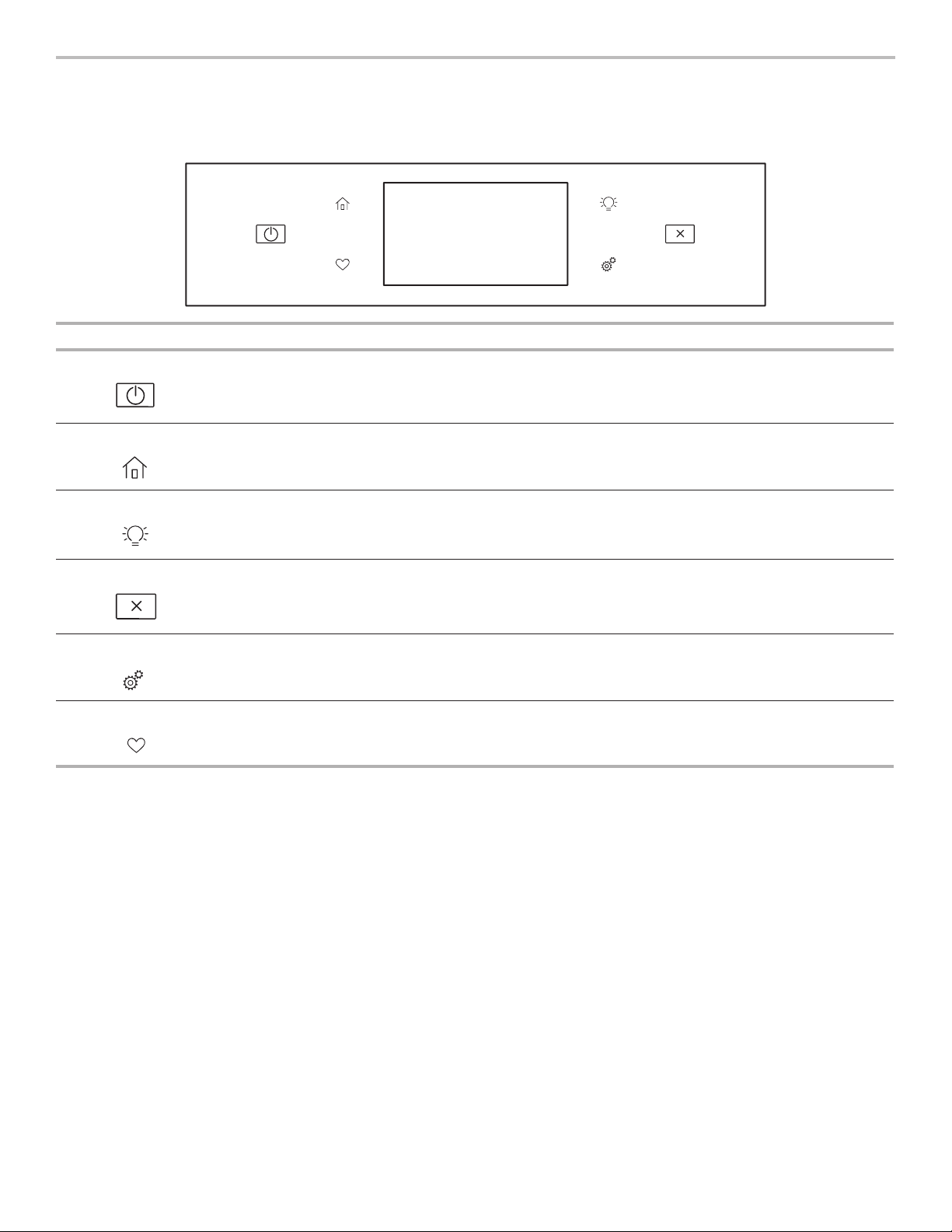
53
GUÍA DE FUNCIONES
Estas instrucciones describen varios modelos; Su modelo puede contar con algunos o todos los elementos enumerados. Consulte
estas instrucciones o la sección de preguntas frecuentes (FAQ) de nuestro sitio web en www.whirlpool.com para obtener
instrucciones más detalladas. En Canadá, visite nuestro sitio web en www.whirlpool.ca.
Tecla Función Instrucciones
Oven Power Función de
encendido del
horno
La tecla de encendido del horno inicia la función del horno y lo activa si está en modo de
suspensión.
Home Pantalla inicial
Si se presiona una vez, permite al usuario volver a las pantallas “Métodos de cocción” y
“Cocción asistida”.
Luz del horno Luz de la cavidad
del horno
La luz del horno se controla con una tecla situada en el panel de control del horno.
Mientras la puerta del horno está cerrada, presione el botón de la luz del horno para
encender y apagar la luz. Cuando se abre la puerta del horno, la luz interior se enciende
automáticamente.
Oven Cancel Cancelación de
la función del
horno
La tecla de cancelación del horno detiene todas las funciones del horno, con excepción de
Clock (Reloj), Timer (Temporizador) y Control Lock (Bloqueo de control).
Herramientas Funciones para
usar el horno
Permite adaptar los tonos audibles y el funcionamiento del horno a sus necesidades.
Consulte las secciones “Herramientas” y “Otros modos”.
Favorites Pantalla de
favoritos
La tecla de favoritos permite al usuario guardar y buscar los ciclos que utiliza con frecuencia.
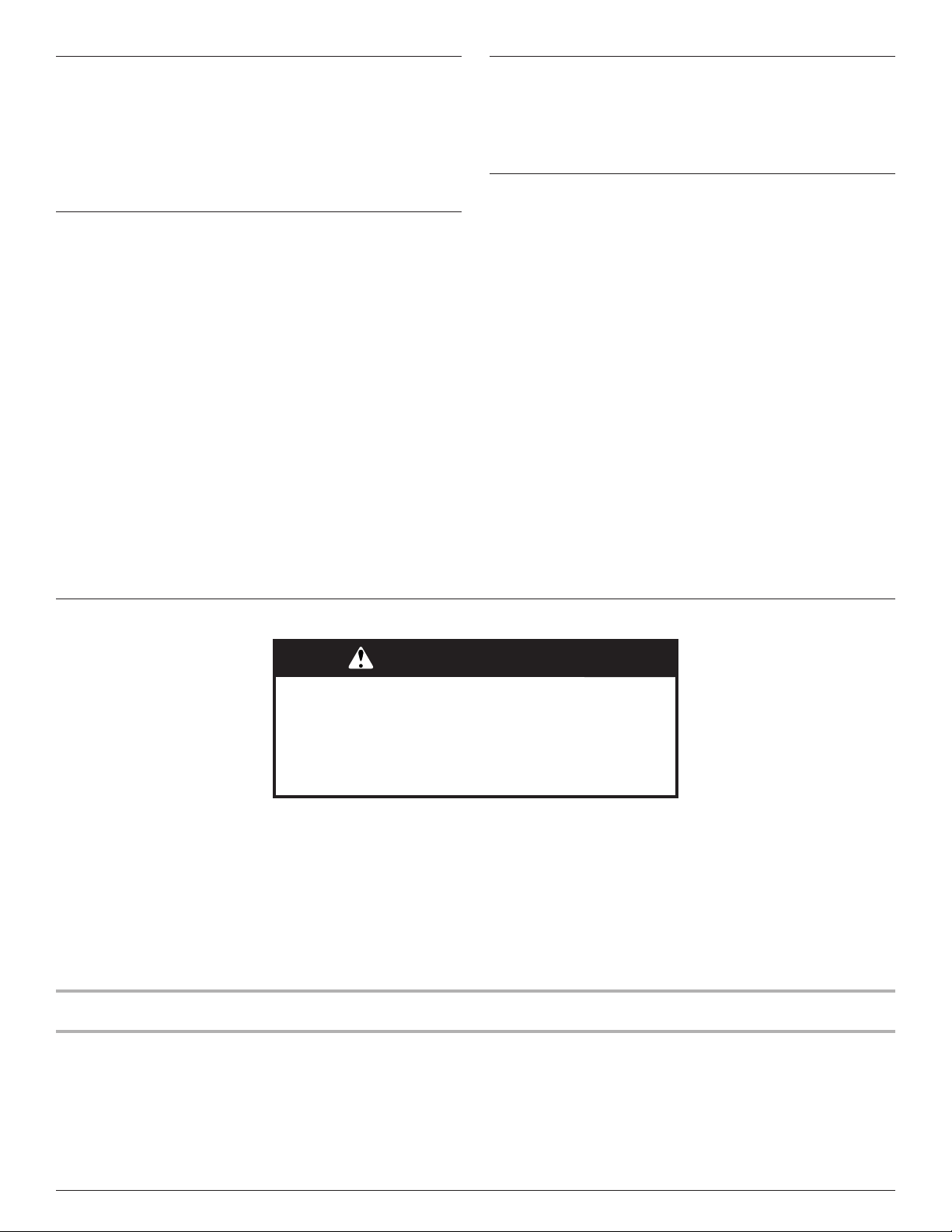
54
Panel táctil
El panel de control aloja el menú de control y los controles de las
funciones. Las teclas táctiles son muy sensibles y se activan con
un toque ligero.
Desplácese hacia arriba, abajo, derecha o izquierda para explorar
las distintas opciones y funciones.
Para obtener más información acerca de los controles
individuales, consulte las secciones respectivas en este manual.
Pantalla
La pantalla contiene los controles de las funciones de menú y del
horno. La pantalla táctil permite desplazarse por los menús del
horno. La pantalla es muy sensible y se activa y controla con un
toque ligero.
Cuando se utiliza el horno, la pantalla muestra el reloj, el modo, la
temperatura del horno, el temporizador de cocina y el del horno,
si se ha ajustado. Si no se ajustó el temporizador del horno,
puede hacerlo en esta pantalla.
Durante el uso, la pantalla muestra los menús y las selecciones
adecuadas para las opciones elegidas.
Desplazamiento por la pantalla
Si el horno está apagado, toque la tecla Home (Pantalla inicial)
para activar el menú. En esta pantalla pueden activarse todos los
programas de cocción automática; puede programarse toda la
cocción manual; pueden regularse as opciones y se tiene acceso
a las instrucciones, formas de preparación y consejos.
Conguración y modo de
demostración
1. Seleccione STORE DEMO MODE (Guardar modo de
demostración) para ingresar al modo de demostración.
O
1. Seleccione NEXT (Siguiente) para ingresar al uso del
producto.
Siga las indicaciones en pantalla para seleccionar un idioma,
configurar Wi-Fi/la conexión a la red, aceptar las condiciones
de servicio y ajustar la hora.
NOTA: La pantalla mostrará fecha y hora (pantalla
predeterminada/modo en espera).
2. Si seleccionó Store Demo Mode (Guardar modo de
demostración), seleccione TRY THE PRODUCT (Pruebe el
producto) para examinar diversas características y opciones
del producto.
OPCIONAL: Seleccione VIEW PRODUCT VIDEOS (Ver
videos del producto) para ver un video sobre cómo navegar
e interactuar con el producto, examinar el control de voz y la
función Scan-To-Cook.
3. Desplácese y seleccione EXPLORE (Explorar).
4. Seleccione la tecla herramientas.
Para salir del modo de demostración, vea la sección
“Herramientas”.
Métodos de cocción
La tecla Cooking Methods (Métodos de cocción) permite que el usuario seleccione uno de los métodos siguientes según las
necesidades de cocción:
■ Bake (Hornear)
■ Broil (Asar a la parrilla)
■ Convect Bake (Hornear por convección)
■ Convect Broil (Asar a la parrilla por convección)
■ Convect Roast (Asar por convección)
■ Keep Warm (Mantener caliente)
Forma de uso:
1. Toque la tecla Home (Pantalla inicial).
2. Seleccione la tecla Cooking Methods (Método de cocción).
3. Seleccione el método de cocción que desee.
ADVERTENCIA
Peligro de Intoxicación Alimentaria
No deje sus alimentos en el horno por más de una hora
antes o después de su cocción.
No seguir esta instrucción puede ocasionar
intoxicación alimentaria o enfermedad.
Método de
cocción
Función Instrucciones
BAKE (Hornear) Hornear y asar
1. Seleccione BAKE (Hornear).
2. Seleccione la temperatura que desee desplazándose a izquierda o derecha, o
manualmente, seleccionando la parrilla en la esquina superior derecha e introduciendo
la temperatura de horneado en el teclado.
3. Seleccione START (Inicio) para empezar a precalentar. Suena una señal al terminar el
precalentamiento.
(Opcional) Para precalentar el horno con rapidez, vea la sección “Rápido” para buscar
más información en esta sección.
4. Presione la tecla cancelar cuando haya finalizado.

55
Método de
cocción
Función Instrucciones
BROIL (asado a
la parrilla)
Asar a la parrilla
1. Seleccione BROIL (Asar a la parrilla).
2. Seleccione la temperatura que desee desplazándose a izquierda o derecha, o
manualmente, seleccionando la parrilla en la esquina superior derecha e introduciendo
la temperatura de asado a la parrilla en el teclado.
3. Seleccione START (Inicio) para empezar a asar a la parrilla.
4. Presione la tecla cancelar cuando haya finalizado.
CONVECT BAKE
(Hornear por
convección)
Horneado por
convección
1. Seleccione CONVECT BAKE (horneado por convección).
2. Seleccione la temperatura que desee desplazándose a izquierda o derecha, o
manualmente, seleccionando la cuadrícula en la esquina superior derecha e
introduciendo la temperatura de horneado por convección en el teclado.
3. Seleccione START (Inicio) para empezar a precalentar. Suena una señal al terminar el
precalentamiento.
(Opcional) Para precalentar el horno con rapidez, vea la sección “Rápido”.
4. Presione la tecla cancelar cuando haya finalizado.
Para obtener más información, consulte la sección “Cocción por convección”.
CONVECT BROIL
(Asar a la parrilla
por convección)
Asado a la parrilla
por convección
1. Seleccione CONVECT BROIL (asado a la parrilla por convección).
2. Seleccione la temperatura que desee desplazándose a izquierda o derecha, o
manualmente, seleccionando la parrilla en la esquina superior derecha e introduciendo
la temperatura de asado a la parrilla por convección en el teclado.
3. Seleccione START (Inicio).
4. Presione la tecla cancelar cuando haya finalizado.
Para obtener más información, consulte la sección “Cocción por convección”.
CONVECT
ROAST (asado
por convección)
Asado por
convección
1. Seleccione CONVECT ROAST (asado por convección).
2. Seleccione la temperatura que desee desplazándose a izquierda o derecha, o
manualmente, seleccionando la parrilla en la esquina superior derecha e introduciendo
la temperatura de asado por convección en el teclado.
3. Seleccione START (Inicio) para empezar a precalentar.
4. Presione la tecla cancelar cuando haya finalizado.
Para obtener más información, vea la sección “Cocción por convección”.
KEEP WARM
(Mantener
caliente)
Mantener caliente
Los alimentos deberán estar a la temperatura para ser servidos antes de colocarlos en el
horno calentado.
1. Seleccione KEEP WARM (Mantener caliente).
2. Seleccione la temperatura que desee desplazándose a izquierda o derecha, o
manualmente, seleccionando la parrilla en la esquina superior derecha e introduciendo
la temperatura que desee en el teclado.
3. Presione START (Inicio).
4. Presione la tecla cancelar cuando haya finalizado.
RAPID (rápido) Precalentamiento
rápido del horno
Proporciona el tiempo de precalentamiento más rápido para la función de horneado. El
Precalentamiento rápido está prefijado como apagado.
1. Seleccione RAPID (rápido) para alternar entre el encendido y el apagado del
precalentamiento rápido.
2. Aparecerá el ajuste actual.
IMPORTANTE: Esta función debe usarse solamente para hornear con una parrilla. Las
parrillas que no se usen deberán retirarse antes de utilizar el precalentamiento rápido.
Deberá usarse una parrilla estándar para Precalentamiento rápido.
Si ya ha comenzado a precalentarse el horno para el ciclo de horneado, puede ponerse en
marcha el precalentamiento rápido si se selecciona RAPID (Rápido).
DELAY (inicio
diferido)
Inicio diferido
El Delay (inicio diferido) se utiliza para ingresar la hora en la que terminará una función del
horno con inicio diferido. Cuando haya seleccionado el método de cocción, introduzca la
temperatura del horno. Seleccione DELAY (diferido) y siga las instrucciones en pantalla.
NOTA: El inicio diferido no debe usarse para alimentos como panes y pasteles, ya que tal
vez no se horneen como es debido.
COOK TIME
(Hora de
cocción)
Cocción
programada
La función Cook Time (Hora de cocción) permite que el horno se programe para
encenderse a una determinada hora del día, durante un tiempo establecido y/o se apague
automáticamente.

56
Favoritos
La función Favoritos almacena el modo y la temperatura del
horno de sus recetas favoritas.
Cuando sigue utilizando su herramienta de favoritos, su producto
pule y personaliza las sugerencia de sus necesidades de
cocción.
NOTA: Es posible que la pantalla inicial muestre
automáticamente un conjunto seleccionado de favoritos y
recomendaciones basado en sus tiempos de cocción.
Para guardar una receta, seleccione la tecla favoritos y siga las
instrucciones en pantalla para personalizar sus favoritos.
Añada una imagen o asigne nombre al favorito para
personalizarlo de acuerdo con sus preferencias.
Cocción asistida
La cocción asistida le ayuda a seleccionar el modo adecuado para sus necesidades de cocción cotidianas. Algunos modelos permiten
que se salte el precalentamiento. Siga las instrucciones en la pantalla para obtener orientación en el proceso de cocción.
NOTA: Las temperaturas de horneado tradicionales se convertirán en temperaturas de horneado de convección. Convect Bake
(Horneado de convección) requiere que ingrese el tiempo y la temperatura. Los tiempos tradicionales para asar se convertirán en
tiempos para asar por convección. Convect Roast (Asado por convección) requiere que ingrese el tiempo y la temperatura, pero no es
necesario que precaliente el horno. Algunos modelos convierten los tiempos de horneado estándar para la cocción por convección.
Ingrese su tiempo y temperatura y su pantalla los convertirá según corresponda.
Modos de
cocción asistida
Opción de alimento Consejos para obtener resultados óptimos
FROZEN
(congelado)
■ Pizza congelada
■ Empanada congelada
■ Papas fritas congeladas
■ Lasaña congelada
■ Nuggets congelados
■ Comidas congeladas
Los alimentos congelados no requieren que precaliente el horno. Inserte
los alimentos inmediatamente, ingrese el tiempo y la temperatura máximos
recomendados por el fabricante.
Para obtener más información, vea la sección “Frozen Bake™”.
POULTRY (pollo)
■ Presas de pollo
■ Pollo entero
Los alimentos de pollo no requieren que precaliente el horno. Inserte los alimentos
inmediatamente.
SEAFOOD
(marisco)
■ Filetes de pescado
■ Palitos de pescado
Los filetes de pescado y palitos de pescado requieren que precaliente el horno.
Introduzca el alimento cuando termine de precalentar.
BAKED GOODS
(productos
horneados)
■ Galletas
■ Medialunas
Los alimentos horneados requieren que precaliente el horno. Introduzca el alimento
cuando termine de precalentar.
DESSERTS
(postres)
■ Tarta
■ Pay frescos
■ Galletas
■ Empanada congelada
Los pasteles, galletas y pasteles frescos requieren precalentar el horno. Introduzca
el alimento cuando termine de precalentar.
Las empanadas congeladas no requieren que precaliente el horno. Introduzca
los alimentos inmediatamente, ingrese el tiempo y la temperatura máximos
recomendados por el fabricante.
PIZZA (pizza)
■ Pizza fresca
■ Pizza congelada
La pizza fresca requiere que precaliente el horno.
La pizza congelada no requiere que precaliente el horno. Inserte los alimentos
inmediatamente, ingrese el tiempo y la temperatura máximos recomendados
por el fabricante. Para obtener más información, vea la sección “Frozen Bake™”
(Hornear congelados).
MEATS (carnes)
■ Pastel de carne
■ Asado de cerdo
■ Asado de carne de res
■ Asado de cordero
El pastel de carne requiere que precaliente el horno. Introduzca el alimento cuando
termine de precalentar.
Los asados de cordero, vacuno y cerno no requieren que precaliente el horno.
Inserte los alimentos inmediatamente.
VEGGIES
(verduras)
■ Patata horneada
■ Verduras frescas
asadas
Las verduras frescas asadas y patatas horneadas no requieren que precaliente el
horno. Inserte los alimentos inmediatamente.
CASSEROLES
(estofados)
■ Cacerola
■ Lasaña congelada
Los guisados no requieren que precaliente el horno. Introduzca el alimento cuando
termine de precalentar.
La lasaña congelada no requiere que precaliente el horno. Inserte los alimentos
inmediatamente. Ingrese el tiempo y la temperatura máximos recomendados
por el fabricante. Para obtener más información, vea la sección “Frozen Bake™”
(Hornear congelados).
SNACKS (snack)
N/A Los bocadillos requieren que precaliente el horno. Introduzca el alimento cuando
termine de precalentar.

57
Herramientas
La tecla Herramientas permite acceder a funciones y opciones
de personalización del horno. Con dichas herramientas puede
ajustar el reloj, cambiar la temperatura del horno entre Fahrenheit
y Celsius, activar o desactivar las señales y mensajes sonoros,
ajustar la calibración del horno o cambiar el idioma, entre otras
cosas.
Seleccione la tecla Herramientas para ver sus funciones.
Para obtener más información, consulte la sección “Otros
modos”.
Herramienta Notas
Habilitación
remota
Seleccione Habilitación remota para utilizar
la aplicación Whirlpool
®
.
NOTA: La habilitación remota no se
desactiva cuando se abre la puerta del
horno. No almacene materiales inflamables
o artículos sensibles a la temperatura en el
interior del electrodoméstico.
Kitchen Timer
(temporizador
de cocina)
Ajuste el temporizador de cocina
manualmente con la introducción del tiempo
que desee en el teclado.
1. Seleccione KITCHEN TIMER
(temporizador de cocina).
2. Introduzca manualmente la duración que
desee.
3. Seleccione START (Inicio).
4. Seleccione Cancel (Cancelar) para
detener el temporizador de cocina.
Luz
Seleccione luz para encender o apagar la
luz. Cuando se abre la puerta del horno, la
luz interior se enciende automáticamente.
Autolimpieza
Vea la sección “Cuidado de la estufa”.
Silencio
Seleccione Silencio para silenciar o activar
los sonidos del horno.
Bloqueo de
controles
Con Control Lock (Bloqueo de control)
se desactivan las teclas del panel de
control para evitar el uso accidental de
los hornos. Si se ajusta antes de un corte
de electricidad, la tecla CONTROL LOCK
(Bloqueo de control) seguirá activada
después del corte.
El valor predeterminado de Control Lock
(bloqueo de controles) es desactivado, pero
puede activarse.
Para bloquear/desbloquear los controles:
1. Verifique que el horno esté apagado.
2. Seleccione la tecla CONTROL LOCK
(bloqueo de controles).
3. Se muestra “CONTROL LOCK” (bloqueo
de controles).
4. Desplace hacia arriba para desbloquear.
Cuando los controles estén bloqueados, no
funcionará ninguna tecla. Las funciones de
la superficie de cocción no se ven afectadas
por el bloqueo del control del horno.
Preferencias
Horas y fechas
Ajuste las preferencias de hora y fecha.
■ Sus horarios de comidas: Ajuste cuando aparezca
desayuno/almuerzo/cena
■ Hora
■ Fecha
■ Formato horario (AM/PM o 24 horas [horario militar])
NOTA: Si el usuario está conectado a una red Wi-Fi, la hora y
la fecha se ajustan automáticamente.
Volumen de sonido
Ajuste las preferencias de volumen de sonido.
■ Temporizadores y alertas
■ Teclas y efectos
Ajustes de pantalla
Ajuste el brillo de la pantalla.
■ Brillo de la pantalla
Regional
Ajuste las preferencias regionales.
■ Idioma: inglés, español o francés
■ Unidades de temperatura: Fahrenheit y Celsius.
Wi-Fi
■ Conéctese a la red: Descargue la aplicación Whirlpool
®
de la tienda de aplicaciones de su celular. Consulte la hoja
Configuración de la conectividad para obtener instrucciones
más detalladas.
■ Código SAID: El código SAID se utiliza para sincronizar un
dispositivo inteligente con el aparato. Introduzca el código
SAID en la aplicación Whirlpool
®
.
■ Dirección MAC: Se muestra la dirección MAC del módulo
Wi-Fi.
■ Radio Wi-Fi: Active o desactive la red Wi-Fi.
Información
■ Servicio y asistencia: Muestra el número de modelo, los
datos de contacto de asistencia al cliente y diagnósticos.
■ Guardar modo demo: Seleccione Store Demo Mode para
activar o desactivar la demostración.
Para inicie el modo de demostración:
1. Presione la tecla herramientas.
2. Desplácese y seleccione INFO (Información).
3. Seleccione STORE DEMO MODE (Guardar modo de
demostración) y seleccione On (Encendido).
NOTA: La pantalla mostrará fecha (pantalla predeterminada/
modo en espera).
4. Presione la tecla Herramientas.
5. Seleccione TRY THE PRODUCT (Pruebe el producto) o VIEW
PRODUCT VIDEOS (Ver videos del producto).
Si la unidad está en modo de demostración después
de encenderla, siga estos pasos para salir del modo de
demostración.
Para salir del modo de demostración:
1. Seleccione TRY THE PRODUCT (Pruebe el producto).
2. Desplácese y seleccione EXPLORE (Explorar).
3. Presione la tecla herramientas.
4. Desplácese y seleccione INFO (Información).
5. Seleccione STORE DEMO MODE (Guardar modo de
demostración) y seleccione OFF (Apagar).
6. Seleccione YES (Sí) en la pantalla de confirmación.
■ Restablecer fábrica: Devuelve el producto a los ajustes
originales de fábrica.
■ Condiciones del uso de Wi-Fi: www.whirlpool.com/
connect.
■ Condiciones de uso del software.

58
Más modos
Modo Sabbath
Para buscar orientación sobre el uso y una lista completa de
modelos con modo Sabbath, visite www.star-k.org.
El modo Sabbat programa el horno para que permanezca
encendido en un ajuste de hornear hasta que se desconecte.
Cuando se activa el modo Sabbat, solo funciona el ciclo Bake
(hornear). Todos los demás ciclos de cocción y limpieza estarán
deshabilitados. No sonará ningún tono y la pantalla no indicará
los cambios de temperatura. Cuando se abra o se cierre la puerta
del horno, la luz no se encenderá ni apagará, y los elementos de
calentamiento no se encenderán ni apagarán inmediatamente.
Si se ajusta el temporizador de cocción, aparece la cuenta
regresiva. La cuenta regresiva comenzará una vez que se ajuste
el temporizador.
NOTA: Si ocurre una falla de energía mientras el modo de
descanso está en funcionamiento, el horno mostrará el modo
de descanso encendido, pero el ciclo de horneado no estará
encendido. Si se abre la puerta del horno durante este periodo, la
luz del horno se encenderá.
Para activar y desactivar el modo Sabbath:
1. Presione la tecla Herramientas.
2. Seleccione More Modes (otros modos).
3. Seleccione Sabbath Mode (modo Sabbat).
4. Vuelva a presionar Sabbath Mode (modo Sabbat) para
activarlo (este modo está prefijado como desconectado).
5. Seleccione Yes (Sí) si desea que el horno esté encendido y
hornee durante el día de descanso.
6. Introduzca la temperatura deseada.
(Opcional) Para la cocción temporizada en modo de
descanso, presione ADD A COOK TIME (Agregar un tiempo
de cocción) para el horno seleccionado. Introduzca el tiempo
de cocción deseado y, después, presione NEXT (Siguiente).
7. Seleccione START (Inicio).
Para desactivar y salir del modo Sabbath (de día de
descanso):
1. Presione la tecla cancelar el horno.
2. Mantenga presionada la pantalla durante tres segundos.
Para regular la temperatura:
1. Presione +/- 25 en la pantalla para seleccionar la nueva
temperatura.
NOTA: El ajuste de temperatura no aparecerá en la pantalla y no
sonará ningún tono.
Calibración de la temperatura
IMPORTANTE: No use un termómetro para medir la temperatura
del horno. Los elementos se encenderán y se apagarán según
sea necesario para mantener una temperatura uniforme, pero
es posible que funcione en algún momento ligeramente caliente
o frío a causa de este ciclo. La apertura del horno afecta a los
ciclos de los elementos y a la temperatura.
El horno proporciona temperaturas precisas y se ha sometido a
pruebas exhaustivas en la fábrica. Sin embargo, puede cocinar
más rápido o más lento que su horno anterior, con diferencias de
horneado o de dorado final. Si es necesario, la calibración de la
temperatura se puede ajustar en grados Fahrenheit o Celsius.
Un signo menos significa que el horno estará más frío con el
valor que se muestra en la pantalla. La ausencia de signo menos
significa que el horno estará a temperatura más caliente con el
valor que aparece en la pantalla.
Regule la temperatura del horno hasta (+, -) 30°F ([+, -]18°C).
Se recomienda realizar cambios en tramos de 3°C (5°F) hasta
conseguir el resultado que se busca.
NOTA: La pantalla del horno sigue mostrando el ajuste de
temperatura original y no refleja el cambio de calibración. Por
ejemplo, si está ajustado en 350°F (177 °C) y se calibra a -20, la
pantalla seguirá mostrando 350°F (177°C).
Para ajustar la calibración de la temperatura del horno:
1. Presione la tecla herramientas.
2. Seleccione MORE MODES (otros modos).
3. Seleccione TEMPERATURE CALIBRATION (calibración de
temperatura).
4. Desplace de izquierda a derecha para aumentar o reducir la
temperatura.
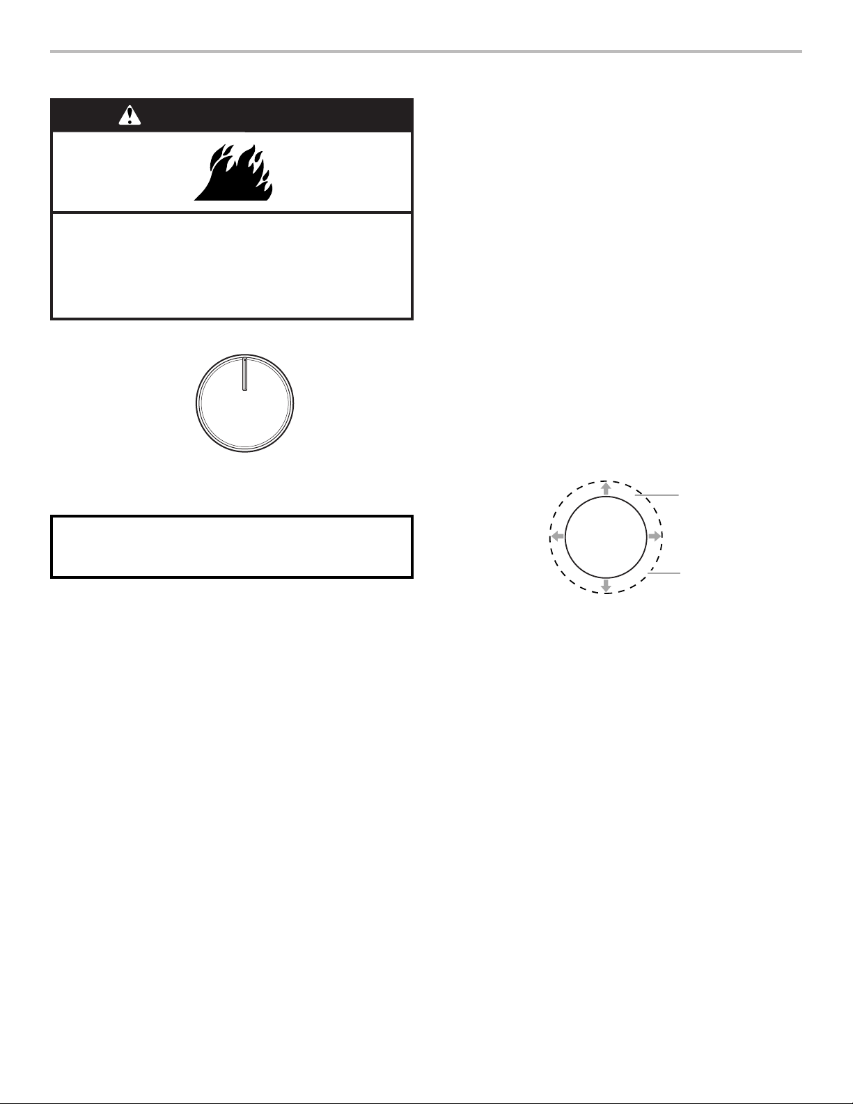
59
SUPERFICIE DE COCCIÓN
Las perillas de control pueden fijarse en cualquier posición entre
HIGH (Alto) y LOW (Bajo). Presione y gire hacia un ajuste.
Vidrio de cerámica (en algunos modelos)
Es posible que el área de la superficie de cocción se ilumine
de color rojo cuando esté encendido un elemento. Es posible
que algunas partes del área de la superficie de cocción no se
pongan rojas cuando está encendido un elemento. El brillo rojo
también se encenderá y apagará al azar incluso mientras esté
ajustado alto para evitar que la superficie de cocción alcance
temperaturas extremas. Ese es el funcionamiento normal.
Es normal que parezca que la superficie de vidrio de cerámica de
color claro cambia de color cuando hay áreas de la superficie de
cocción que están calientes. El vidrio volverá a su color original a
medida que se enfríe.
Para mantener la superficie de cocción sin manchas y
proporcionar un calor uniforme, límpiela antes y después de
cada uso. En las superficies de cocción con vidrio de cerámica
claro, la suciedad y las manchas pueden ser más visibles y
pueden requerir más cuidado y limpieza. Se recomienda usar un
limpiador y una espátula para superficies de cocción.
Para obtener más información, vea la sección “Limpieza
general”.
IMPORTANTE: Para evitar daños permanentes en la superficie
de cocción y para poder quitar la suciedad con más facilidad,
límpiela después de cada uso.
■ Evite colocar tarros o latas sobre la superficie de cocción.
La caída de un objeto pesado o duro sobre la superficie de
cocción podría quebrarla.
■ Para evitar que se dañe la superficie de cocción, no deje
una tapa caliente sobre la superficie de cocción. A medida
que se enfríe la superficie de cocción, el aire puede quedar
atrapado entre la tapa y la superficie de cocción, y el vidrio
de cerámica podría romperse cuando se quite la tapa.
■ En caso de alimentos que contengan cualquier clase de
azúcar, limpie todos los derrames y las manchas lo antes
posible. Permita que la superficie de cocción se enfríe
ligeramente. Luego, con guantes para horno, limpie las
salpicaduras con un raspador mientras la superficie aún está
tibia. Si se deja que las salpicaduras azucaradas se enfríen,
pueden adherirse a la superficie de cocción, lo que causará
picaduras y marcas permanentes.
■ Para evitar rayaduras, no deslice utensilios de cocina o
para hornear sobre la superficie de cocción. Los fondos de
aluminio o de cobre, así como los acabados ásperos de los
utensilios de cocina o para hornear podrían dejar rayas o
marcas en la superficie de cocción.
■ No cocine en la superficie de cocción las palomitas de maíz
que vienen en recipientes previamente empaquetados de
papel de aluminio. Estos podrían dejar marcas de aluminio
que no podrán quitarse por completo.
■ Para evitar que se dañe la superficie de cocción, no deje
que los objetos de materiales que puedan derretirse, como
plástico o papel de aluminio, toquen ninguna parte de toda la
superficie de cocción.
■ Para evitar que se dañe la superficie de cocción, no la use
como tabla para cortar.
■ Utilice utensilios de cocina que tengan más o menos el
mismo tamaño que el área de cocción de la superficie. Los
utensilios de cocina no deben extenderse más de 1/2"
(13 mm) fuera del área.
■ Use utensilios de cocina de fondo plano para una óptima
conducción del calor y un consumo eficiente de la energía.
Los utensilios de cocina con fondos redondeados,
combados, con relieve o abollados pueden causar un calor
desparejo y resultados de cocción poco satisfactorios.
■ Para determinar si un fondo está plano, coloque el borde
recto de una regla cruzando el fondo del utensilio de cocina.
Mientras rota la regla, no debe verse espacio ni luz entre la
regla y el utensilio de cocina.
■ Pueden usarse utensilios de cocina con fondos ligeramente
estriados o con pequeños canales.
■ Asegúrese de que los fondos de las ollas y las cacerolas
estén limpios y secos antes de usarlos. El agua y los residuos
pueden dejar marcas cuando se calientan.
■ Para evitar que se dañe la superficie de cocción, no cocine
alimentos directamente sobre la superficie de cocción.
Peligro de Incendio
Apague todos los controles cuando haya terminado de
cocinar.
No seguir esta instrucción puede ocasionar la muerte
o incendio.
ADVERTENCIA
OFF
ON
RECUERDE: Cuando se esté usando la estufa o (en
algunos modelos) durante el ciclo de autolimpieza, toda la
superficie de cocción se puede calentar.
A
B
C
A. Zona de cocción de la superficie
B. Utensilios de cocina/instrumentos
para enlatado
C. 1/2" (13 mm) de saliente máxima
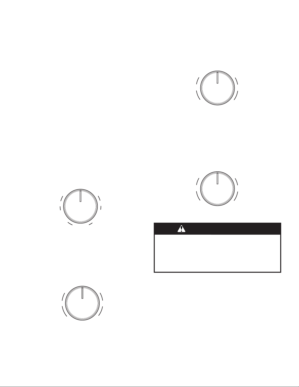
60
Elementos con bobina y tazones de quemadores
(en algunos modelos)
Los elementos con bobina deberán estar nivelados para obtener
resultados de cocción óptimos. Cuando están limpios, los
tazones para quemadores reflejan de nuevo el calor hacia la
superficie de cocción. También ayudan a atrapar los derrames.
Los utensilios de cocina no deben extenderse más de 1/2"
(13 mm) por encima del elemento de bobina. Si el utensilio de
cocina está desparejo o es muy grande, puede producir calor en
exceso, lo que causará que el tazón del quemador cambie de
color.
Luz indicadora de encendido de superficie de cocción
La luz indicadora de encendido de superficie de cocción está
ubicada en el panel de la consola. Cuando esté encendida
cualquier perilla de control en el panel de la consola, se iluminará
la luz indicadora de encendido de superficie de cocción.
Luz indicadora de superficie caliente
En los modelos con vidrio de cerámica, la luz indicadora de
superficie caliente está ubicada en el panel de la consola.
La luz indicadora de superficie caliente se iluminará mientras
cualquier área de la superficie de cocción esté muy caliente
para tocarla, aun después de que se haya apagado el área de la
superficie de cocción.
Elemento de cocción de zona triple
El elemento de zona triple ofrece flexibilidad según el tamaño del
utensilio de cocción. El tamaño simple puede usarse de la misma
manera que un elemento común. Los tamaños doble y triple
combinan los elementos simple, doble y exterior y se
recomiendan para utensilios de cocina más grandes, mayores
cantidades de alimentos y para procesos de envasado caseros.
Elemento de la zona de cocción dual
(en algunos modelos)
El elemento de cocción de la zona dual ofrece flexibilidad
respecto al tamaño del utensilio de cocina. El tamaño simple
puede usarse de la misma manera que un elemento común. El
tamaño dual combina el elemento simple y el exterior, y también
se recomienda para los utensilios de cocina de tamaño más
grande.
Elemento Rapid Boil (elemento delantero derecho)
El elemento de cocción Rapid Boil (Hervor rápido) ofrece
flexibilidad adicional para la cocción. El elemento Rapid Boil
(Hervor rápido) se puede utilizar para hervir líquidos en menos
tiempo. El ajuste mínimo para derretir se puede utilizar para
preparar salsas, dorar o sofreír alimentos y para mantener la
comida a una temperatura baja. Use utensilios de cocina de
tamaño apropiado para el elemento de cocción Rapid Boil
(Hervor rápido).
Elemento Melt
El elemento de cocción Melt (Derretir) ofrece flexibilidad debido a
una amplia variedad de ajustes entre High (Alto) y Melt (Derretir).
La opción de calor High (Alto) puede usarse para hervir
rápidamente pequeñas cantidades de líquido. Para reducir el
ajuste de intensidad, gire la perilla hacia la derecha. El ajuste Melt
(Derretir) se ha diseñado para alimentos delicados que requieran
un calor bajo, por ejemplo para derretir chocolate o mantener
salsas calientes. Use utensilios de cocina de tamaño apropiado
para el elemento de cocción para derretir.
Elemento Warm Zone
Use el elemento Cooktop Warm Zone (Zona de calentamiento de
la superficie de cocción) para mantener calientes los alimentos
cocinados. Se recomienda una hora como tiempo máximo para
mantener la calidad de la comida.
No lo use para calentar alimentos fríos.
El elemento Warm Zone (Zona de calentamiento) puede usarse
solo o cuando se usen cualquiera de las otras áreas de la
superficie de cocción.
El área del elemento Warm Zone (Zona de calentamiento) no
se pondrá roja cuando esté encendida. Sin embargo, la luz
indicadora de elemento encendido se encenderá mientras se
esté usando el elemento Warm Zone (Zona de calentamiento).
■ Use sólo utensilios de cocina recomendados para ser usados
en hornos y en superficies de cocción.
■ Cubra todos los alimentos con una tapa o con papel de
aluminio. Cuando caliente alimentos horneados, deje una
abertura pequeña en la tapa para que salga la humedad.
Off
Hi Lo
SingleTriple
Hi
Lo
Hi Lo
Double
Off
Hi Lo
Single
Hi
Lo
Double
OFF
Lo
Melt
Hi
Max
Lo
Hi
OFF
Lo
Melt
Hi
Max
Lo
Hi
ADVERTENCIA
Peligro de Intoxicación Alimentaria
No deje sus alimentos en el horno por más de una hora
antes o después de su cocción.
No seguir esta instrucción puede ocasionar
intoxicación alimentaria o enfermedad.
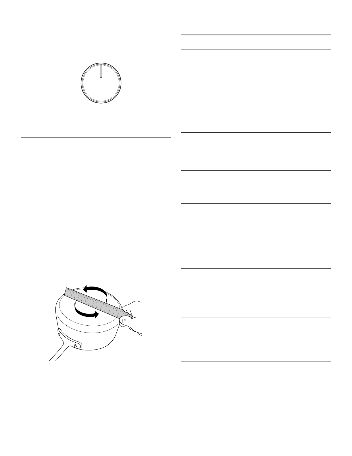
61
■ Para evitar daños en la superficie de cocción, no use
envoltorios de plástico para cubrir los alimentos, ya que los
mismos se pueden derretir.
■ Use agarraderas para ollas o guantes de horno para remover
la comida.
Forma de uso:
Para encender, gire la perilla hasta la posición On (Encendido).
Para apagar, gire la perilla hasta la posición Off (Apagado).
Utensilios de cocina
IMPORTANTE: No deje utensilios de cocina vacíos sobre una
zona de cocción, un elemento o un quemador de superficie que
estén calientes.
El utensilio de cocina ideal debe tener fondo plano, lados rectos,
una tapa que encaje bien y el material debe ser de grosor
mediano a pesado.
Los acabados ásperos pueden rayar la superficie de cocción
o las bobinas de encendido. El aluminio y el cobre pueden
usarse como centro o base del utensilio de cocina. Sin embargo,
cuando se usen como base pueden dejar marcas permanentes
en las superficies.
El material de los utensilios de cocina es un factor que influye en
la rapidez y la uniformidad con que se trasmite el calor, lo cual
afecta los resultados de la cocción. Un acabado antiadherente
tiene las mismas características que su material de base. Por
ejemplo, un utensilio de cocina de aluminio con un acabado
antiadherente tendrá las mismas propiedades que el aluminio.
No deben usarse utensilios de cocina con superficies
antiadherentes bajo el asador.
Verifique si está plano colocando el borde derecho de una regla a
lo largo del fondo del utensilio de cocina. Mientras rota la regla,
no debe verse espacio ni luz entre la regla y el utensilio de
cocina.
Utilice la siguiente tabla como guía para ver las características de
los materiales de los utensilios de cocina.
Utensilios de
cocina
Características
Cobre
■ Se calienta de manera rápida y
uniforme.
■ Puede dejar residuos de cobre,
que disminuirán si se limpia
inmediatamente después de la
cocción.
■ Puede dejar manchas o adherencias
permanentes en la superficie de
cocción si se calienta en exceso.
Barro cocido
■ Siga las instrucciones del fabricante.
■ Use con ajustes de calor bajos.
■ Podría rayar la superficie de cocción.
Hierro fundido o
acero esmaltado
■ Vea acero inoxidable o hierro fundido.
■ Los utensilios para hornear con
esmalte de porcelana que no tengan
la base de metal podrían pegarse a la
superficie de cocción si se calientan
en exceso.
Acero inoxidable
■ Se calienta de manera rápida pero no
uniforme.
■ Un centro o una base de aluminio
o cobre sobre acero inoxidable
proporciona un calor uniforme.
Aluminio
■ Se calienta de manera rápida y
uniforme.
■ Apto para todos los tipos de cocción
■ Los espesores medianos o pesados
son óptimos para la mayoría de los
trabajos de cocción.
■ Pueden dejar residuos de aluminio,
que se reducirán si se limpian
inmediatamente después de la
cocción.
Hierro fundido
■ Se calienta de manera lenta y
uniforme.
■ Es adecuado para dorar y freír
■ Mantiene el calor para una cocción
lenta.
■ Los bordes ásperos o las rebabas
podrían rayar la superficie de cocción.
Cerámica
o vidrio de
cerámica
■ Siga las instrucciones del fabricante.
■ Calienta de manera lenta pero
desigual.
■ Ofrece buenos resultados con los
ajustes de calor bajo a medio.
■ Podría rayar la superficie de cocción.
OFF
ON
1
2
3
4
5
6
7
8
9
1 0
1 1
1 2
1 3
1 4
1 5
1 6
1 7
1 8
1 9
2 0
1
2
3
4
5
6
7
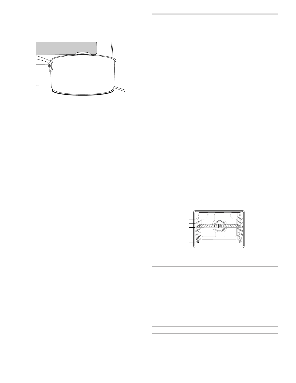
62
Use utensilios de cocina con fondo plano para lograr los mejores
resultados de cocción y un uso eficiente de energía. El recipiente
de cocción deberá ser aproximadamente del mismo tamaño que
el área de cocción delineada en la superficie de cocción o el
elemento de bobina. Los utensilios de cocina no deben superar
la zona o elemento de cocción más de 1/2" (13 cm).
Envasado casero
El envasado puede realizarse sobre una superficie de cocción de
vidrio con la parte superior lisa o en una superficie de cocción
tradicional con un elemento de bobina. Cuando esté haciendo
envasados por largos períodos, alterne y use las áreas o los
elementos de cocción de la superficie entre una tanda y otra.
Esto da tiempo para que se enfríen las áreas que se han usado
recientemente.
■ Centre el envasador sobre el área o elemento de cocción
más grande de la superficie. En las superficies de cocción
eléctricas, los envasadores no deben superar la zona o el
elemento de cocción más de 1/2" (13 cm).
■ No coloque el envasador sobre dos zonas o elementos de
cocción al mismo tiempo.
■ En los modelos con vidrio de cerámica, use solamente
envasadores con la base plana para evitar que se dañen la
superficie de cocción y los elementos.
■ Para obtener más información, póngase en contacto con la
oficina de extensión del departamento de agricultura local o
consulte guías para envasado casero publicadas. También
pueden ofrecer ayuda las compañías que fabrican productos
para envasado casero.
USO DEL HORNO
Los olores y el humo son normales cuando el horno se usa las
primeras veces o cuando tiene suciedad profunda.
IMPORTANTE: La salud de algunos pájaros es sumamente
sensible a los gases emanados por el horno. La exposición a los
gases puede ocasionar la muerte de ciertos pájaros. Traslade
siempre los pájaros a otro cuarto cerrado y bien ventilado.
Papel de aluminio
IMPORTANTE: Para evitar daños permanentes en el acabado
de la base del horno, no lo cubra con ningún tipo de papel de
aluminio o revestimiento.
Para obtener resultados de cocción óptimos, no cubra toda
la parrilla del horno con papel de aluminio, ya que el aire debe
poder circular libremente.
Colocación de las parrillas y los
utensilios para hornear
IMPORTANTE: Para evitar daños permanentes en el acabado
de porcelana, no coloque alimentos ni utensilios para hornear
directamente sobre la puerta o el piso del horno.
Utensilios para hornear
Para una cocción uniforme del alimento, el aire caliente debe
poder circular. Deje 2" (5 cm) de espacio alrededor del utensilio
para hornear y las paredes del horno. Asegúrese de que ningún
utensilio para hornear esté directamente encima de otro.
Parrillas
■ Coloque las parrillas antes de encender el horno.
■ No coloque parrillas con utensilios para hornear encima.
■ Asegúrese de que las parrillas estén niveladas.
Para ubicar una parrilla, retírela hasta la posición de tope, levante
el borde delantero y luego sáquela. Use como guía la ilustración
y las tablas siguientes.
El horno tiene 7 posiciones para una parrilla plana, como se
muestra en la ilustración anterior y en la tabla a continuación.
Posición de parrilla
plana*
Tipo de alimento
7 Asar a la parrilla/dorar rápidamente
carnes, hamburguesas y filetes
6 Carnes, pollo y pescado asados a la
parrilla
3 o 4 La mayoría de los alimentos
horneados, guisados, alimentos
congelados
2 Carnes asadas
1 Asados o aves grandes
7
6
5
4
3
2
1

63
Para que las hamburguesas tengan un exterior bien dorado y un
interior a punto, use una parrilla plana en la posición de parrilla 7.
Caliente previamente el horno durante 2 minutos. El lado 1 debe
cocinarse durante aproximadamente 2
1
/
2
a 3
1
/
2
minutos. El lado
2 debe cocinarse durante aproximadamente 4 a 5 minutos. Es
normal que haya un grado moderado de humo cuando se asa a
la parrilla.
* Si su modelo tiene una parrilla de horno de máxima capacidad,
los extremos en relieve deberán colocarse en la posición de
parrilla por encima de la posición deseada para el alimento.
Vea la siguiente ilustración.
IMPORTANTE: Estas posiciones de parrilla son para las parrillas
planas. Si se usa una parrilla de horno de máxima capacidad,
la posición de la parrilla debe ajustarse como se muestra en la
figura anterior.
Cocción en varias parrillas
Dos parrillas (sin convección): Use las posiciones de parrilla 2 y 5
o 3 y 6.
Dos parrillas (con convección): Use las posiciones de parrilla 2 y
5 o 3 y 6.
Tres parrillas (con convección): Use las posiciones de parrilla 2 y
7 y una parrilla de horno de máxima capacidad en la posición de
parrilla 5.
Horneado de galletas y pasteles de capas en dos parrillas
Horneado de pasteles de capas
Para obtener resultados óptimos cuando se hornean pasteles en
dos parrillas, use la función Bake (Horneado), una parrilla plana
en la posición de parrilla 5 y una parrilla plana en la posición de
parrilla 2. Si no dispone de 2 parrillas planas, utilice una parrilla
de horno de máxima capacidad en la posición de parrilla 6.
Coloque los pasteles en las parrillas como se muestra. Deje un
espacio de al menos 3" (7,6 cm) entre la parte delantera de las
parrillas y los pasteles delanteros.
Horneado de galletas
Para obtener resultados óptimos cuando se hornean galletas
en 2 parrillas, use la función Convection Bake (Horneado por
convección), una parrilla plana en la posición de parrilla 5 y una
parrilla plana en la posición de parrilla 2.
Si no dispone de 2 parrillas planas, utilice una parrilla plana en
la posición 2 y una parrilla de horno de máxima capacidad en la
posición 6.
Si no dispone de la función Convection Bake, utilice la función
Bake estándar.
Ventilación del horno
La ventilación del horno libera aire caliente y humedad del horno
y no debe bloquearse ni taparse; de lo contrario, se producirá
una circulación de aire deficiente que afectará los resultados de
la cocción y de la limpieza. No coloque objetos de plástico, papel
ni otros objetos que puedan derretirse o quemarse cerca de la
ventilación del horno.
Cómo hornear y asar
Precalentamiento
Cuando comience un ciclo de horneado u horneado por
convección, el horno empezará a precalentarse después de
que se presione la tecla Start (Inicio). El horno tardará 12 a 15
minutos aproximadamente para alcanzar 177°C (350°F) con
todas las parrillas de horno provistas con el horno dentro de
la cavidad. Cuanto mayor sea la temperatura, más tiempo
tardará el horno en precalentarse. El ciclo de precalentamiento
aumenta rápidamente la temperatura del horno. La temperatura
real del horno superará la temperatura fijada para compensar
la pérdida de calor cuando se abra la puerta del horno para
introducir los alimentos. Esto asegura que el horno comience
a la temperatura correcta cuando se coloquen los alimentos
en el horno. Introduzca el alimento cuando suene el tono de
precalentamiento. No abra la puerta durante el precalentamiento
antes de que suene el tono.
Precalentamiento rápido
Puede usarse Rapid Preheat (precalentamiento rápido)
para acortar el tiempo de precalentamiento. Deberá usarse
solamente una parrilla estándar plana para horno durante el
precalentamiento rápido. Las parrillas adicionales deben quitarse
antes de utilizar Rapid Preheat (precalentamiento rápido). El
ciclo de precalentamiento debe completarse antes de colocar
los alimentos en el horno. Cuando se haya terminado el ciclo de
precalentamiento rápido, el horno pondrá en marcha un ciclo
normal de horneado.
IMPORTANTE: El precalentamiento rápido se debe utilizar
únicamente para hornear con una sola parrilla.
Temperatura del horno
Mientras esté en uso, los elementos del horno se encenderán
y se apagarán según sea necesario para mantener una
temperatura constante, pero es posible que funcione en algún
momento ligeramente caliente o frío a causa de este ciclo. Si se
abre la puerta del horno mientras se encuentra en uso, saldrá el
aire caliente y el horno se enfriará, lo que podría afectar el tiempo
y el rendimiento de la cocción. Se recomienda usar la luz del
horno para controlar el progreso de cocción.
NOTA: En los modelos con convección, el ventilador de
convección puede funcionar en el modo de horneado sin
convección para mejorar el rendimiento del horno.
A
B
A. Extremos de la parrilla en
la posición 3
B. Alimento en la posición 2
A
A. Ventilación del horno
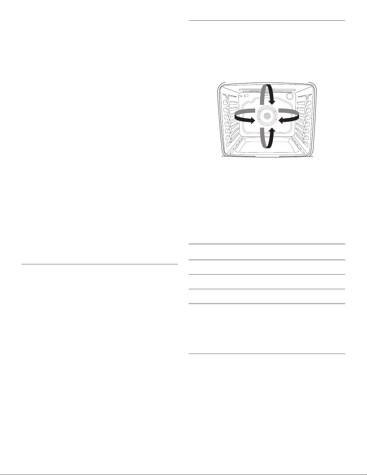
64
Sistema de control de temperatura
El sistema de control de temperatura regula electrónicamente
los niveles de calor del horno durante el precalentamiento y el
horneado para mantener una temperatura precisa y obtener
resultados de cocción óptimos. Los elementos o quemadores
de hornear y asar a la parrilla tendrán ciclos con encendido
y apagado a intervalos. En los modelos de estufas con
convección, el ventilador se encenderá mientras la estufa se está
precalentando, y se enciende y apaga a intervalos cortos durante
el horneado para dar los mejores resultados. Esta característica
se activa automáticamente cuando el horno está en uso.
Antes de hornear o asar, coloque las parrillas según la sección
“Posición de las parrillas y los utensilios para hornear”.
Al asar, no es necesario esperar a que termine el ciclo de
precalentamiento del horno antes de colocar los alimentos, a
menos que la receta de cocina lo recomiende.
Tecnología Frozen Bake™
La tecnología Frozen Bake™ regula automáticamente el tiempo
de horneado fijado por el fabricante mediante la combinación
de precalentamiento y horneado con el fin de ofrecer
excelentes resultados con alimentos congelados envasados
sin necesidad de espera. Se pueden elegir seis opciones
preprogramadas para alimentos: Pizza, Lasaña, Croquetas,
Patatas fritas, Pay, y Comida. Los ciclos Frozen Bake™ se
han adaptado para funcionar únicamente con estos alimentos.
Cuando se utilice la tecnología Frozen Bake™, es importante
seguir todas las instrucciones del fabricante respecto a la
ventilación, la cobertura, la agitación o la colocación en una
hoja de hornear para asegurar un resultado óptimo. Al cocinar
alimentos congelados, solo se deben cocinar los que contengan
instrucciones para cocinarlos en un horno convencional.
Coloque el plato en el centro de la parrilla y seleccione una
de las posiciones de parrilla recomendadas para horneado de
congelados en la sección “Colocación de rejillas y utensilios para
hornear” y hornee los paquetes o bandejas de uno en uno. Utilice
la temperatura y el tiempo de horneado máximo recomendados
en el paquete.
Un sonido le indicará que debe comprobar si los alimentos
están hechos antes de que se complete el tiempo de cocción
y nuevamente al finalizar el tiempo de cocción. La pantalla le
indicará que agregue tiempo de cocción o que finalice el ciclo.
Asado a la parrilla
Cuando ase a la parrilla, precaliente el horno durante 2 minutos
antes de colocar los alimentos, a menos que se recomiende otra
cosa en la receta. Coloque los alimentos sobre una rejilla en una
bandeja para asar y después ubíquelos en el centro de la parrilla
del horno.
IMPORTANTE: Cierre la puerta para garantizar una temperatura
adecuada para asar.
Para obtener un control más preciso al cocinar, cambie la
temperatura mientras esté asando. Cuanto más bajo sea el
ajuste de temperatura, más lenta será la cocción. Los cortes
más gruesos y las piezas de carne, pescado y aves con forma
irregular se pueden cocinar mejor con ajustes para asar a la
parrilla más bajos. Use las parrillas 6 o 7 para asar a la parrilla.
Consulte la sección “Posición de las parrillas y los utensilios para
hornear” para obtener más información.
Con los ajustes más bajos, el elemento para asar a la parrilla se
encenderá y se apagará para mantener la temperatura adecuada.
■ Para obtener resultados óptimos, utilice un recipiente para
asar y una rejilla. Se han diseñado para drenar los jugos y
evitar salpicaduras y humo.
Si desea comprar una charola para asar, puede hacer un
pedido. Consulte la sección “Accesorios”.
Cocción por convección
En un horno por convección, el aire caliente que hace circular el
ventilador distribuye el calor continuamente y con más
uniformidad que el movimiento natural del aire en un horno
térmico estándar. Este movimiento de aire caliente ayuda a
mantener una temperatura uniforme en todo el horno, cocina los
alimentos más uniformemente y deja las superficies crujientes a
la vez que atrapa la humedad y hace que los panes salgan con
cortezas más crujientes.
Durante el horneado o asado por convección, el ciclo de
horneado, asado a la parrilla y de los elementos de convección
se enciende y apaga a intervalos, mientras el ventilador
hace circular aire caliente. Durante el asado a la parrilla por
convección, el ciclo de los elementos de asado a la parrilla y
convección se enciende y apaga.
Si se abre la puerta del horno durante la cocción por convección,
el ventilador se apagará de inmediato. Se encenderá nuevamente
cuando se cierre la puerta del horno.
Por medio de la cocción por convección, la mayoría de los
alimentos puede cocinarse a una temperatura más baja y/o un
tiempo de cocción menor que en un horno térmico estándar.
Utilice la siguiente tabla como guía.
Modo de cocción
por convección
Indicaciones de Directrices
Horneado por
convección
Temperatura menor, 25 °F (15 °C),
posible reducción del tiempo de cocción
Asado por
convección
Reducción del tiempo de cocción en
hasta un 30%
Asado a la parrilla
por convección
Reducción del tiempo de cocción
Opciones de convección
Horneado por convección: horneado en varias parrillas para
galletas, bizcochos, panes, guisados, tartas, tortas y pasteles
Asar por convección: pollo o pavo entero, verduras, asados de
cerdo y de carne de res
Asar a la parrilla por convección: cortes más gruesos o piezas de
carne, pescado o ave de forma irregular
Luz del horno
La luz del horno es un foco estándar de 40 vatios para
electrodomésticos. Antes de cambiarlas, asegúrese de que el
horno y la superficie de cocción estén fríos y que las perillas de
control estén la posición Off (Apagado).
Para hacer un reemplazo:
1. Desenchufe la estufa o desconecte el suministro de energía.
2. Gire en sentido antihorario la cubierta de vidrio del foco en la
parte posterior del horno para retirarla.
3. Gire el foco a la izquierda para sacarlo del casquillo.
4. Vuelva a colocar el foco girando en sentido horario.
5. Vuelva a colocar la cubierta del foco girando en sentido
horario.
6. Enchufe la estufa o reconecte el suministro de energía.
65
CUIDADO DE LA ESTUFA
Ciclo de limpieza
La tecnología AquaLift
®
es una solución de limpieza innovadora
que utiliza calor y agua para aflojar los derrames quemados
adheridos en el horno en menos de 1 hora. Esta nueva tecnología
de limpieza presenta una alternativa de calor bajo y sin olor frente
a las opciones tradicionales de autolimpieza.
Deje que el horno se enfríe a temperatura ambiente antes de
usar el ciclo Clean (Limpieza). Si la temperatura de la cavidad
del horno es mayor que 200°F (93°C), aparecerá "Oven Cooling"
(Enfriamiento del horno) en la pantalla y el ciclo de limpieza no se
activará hasta que la cavidad del horno se haya enfriado.
Para limpiar:
1. Quite todas las parrillas y los accesorios de la cavidad del
horno y limpie el exceso de suciedad. Use un raspador de
plástico para quitar la suciedad fácil de retirar.
2. Vierta 2 tazas (16 oz [500 mL]) de agua destilada o filtrada
sobre el piso del horno vacío y cierre la puerta.
IMPORTANTE: No use productos químicos ni otros aditivos
con el agua. No abra el horno durante el ciclo de limpieza. El
agua que está en el piso del horno está caliente.
3. Presione AQUALIFT SELF CLEAN (Autolimpieza Aqualift) y,
después, START (Inicio) en el panel de control del horno.
NOTA: No comience la Autolimpieza hasta que se haya
enfriado el horno.
4. Espere 40 minutos para la limpieza y el enfriamiento. Se
escuchará un pitido cuando se haya terminado el ciclo Clean
(Limpieza).
5. Presione CANCEL (Cancelar) al final del ciclo. Se puede
presionar CANCEL (Cancelar) en cualquier momento para
detener el ciclo de limpieza.
6. Retire el agua residual y la suciedad que se aflojó con una
esponja o un paño de inmediato una vez que el ciclo de
limpieza esté completo. La mayor parte de las 2 tazas (16 oz
[500 mL]) iniciales de agua permanecerá en el horno después
de que se termine el ciclo. Si todavía queda suciedad, deje
una pequeña cantidad de agua en el piso del horno para
facilitar la limpieza.
7. Si queda suciedad, quítela con una esponja para restregar
que no raye o un raspador de plástico. Se pueden hacer
funcionar ciclos de limpieza adicionales para ayudar a quitar
la suciedad rebelde.
IMPORTANTE: No use productos de limpieza para hornos.
El uso de sustancias químicas, incluso productos de limpieza
comerciales para hornos o estropajos de metal, puede causar
daños permanentes a la superficie de porcelana del interior del
horno.
NOTAS:
■ La estufa deberá estar nivelada para asegurarse de que toda
la superficie del piso de la cavidad del horno esté cubierta
con agua al comienzo del ciclo de Clean (Limpieza).
■ Para obtener resultados óptimos, use agua destilada o
filtrada. Es posible que el agua del grifo deje depósitos
minerales en el piso del horno.
■ Antes de quitar el agua restante y la suciedad floja al final
del ciclo Clean (Limpieza), inserte un paño o una toalla de
papel entre el borde inferior de la puerta del horno y el marco
delantero para evitar que el agua se derrame sobre el frente
de la estufa y el piso.
■ Será más difícil quitar suciedad acumulada después de
varios ciclos de cocción con el ciclo Clean (Limpieza).
■ Las esponjas para restregar no abrasivas o las almohadillas
de limpieza tipo borrador (sin productos de limpieza) pueden
ser eficaces para limpiar suciedad rebelde en las paredes
de la cavidad, la puerta y el piso del horno. Para obtener
resultados óptimos, humedezca las almohadillas y las
esponjas antes de usarlas.
■ Ponga a funcionar un ciclo Clean (Limpieza) adicional para la
suciedad rebelde.
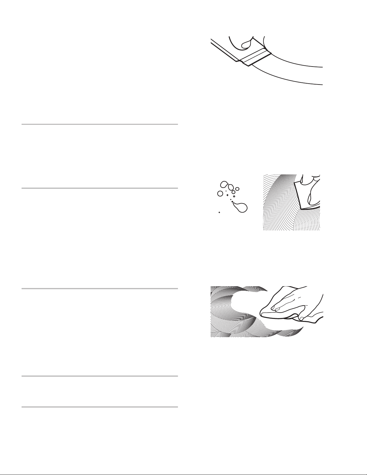
66
■ El limpiador para electrodomésticos de cocina affresh
®
y
el limpiador para superficies de cocción affresh
®
pueden
usarse para limpiar el piso, las paredes y la puerta del
horno cuando se haya terminado el ciclo y el horno haya
vuelto a la temperatura ambiente. Si se usa el limpiador
para superficies de cocción affresh
®
, se recomienda limpiar
también la cavidad con agua destilada. Consulte la sección
“Accesorios” para obtener información sobre cómo hacer un
pedido.
■ Para obtener kits de limpieza con tecnología AquaLift
®
adicionales, haga un pedido de la pieza número
W10423113RP. Para obtener más información, vea la sección
“Accesorios”.
■ Para pedir asistencia con la tecnología AquaLift
®
, llame al
1-877-258-0808 en EE. UU. o al 1-800-807-6777 en Canadá;
o bien, visite nuestro sitio web en http://whirlpoolcorp.com/
aqualift
Limpieza general
IMPORTANTE: Antes de la limpieza, asegúrese de que todos
los controles estén apagados y que el horno y la superficie
de cocción estén fríos. Siempre siga las instrucciones de las
etiquetas de los productos de limpieza. Para obtener información
adicional, visite nuestro sitio web en www.whirlpool.com. En
Canadá, visite nuestro sitio web en www.whirlpool.ca.
Se sugiere usar primero agua, jabón y un paño o una esponja
suave, a menos que se indique otra cosa.
SUPERFICIES EXTERIORES DE ESMALTE DE
PORCELANA (en algunos modelos)
Los derrames de alimentos que contienen ácidos, como vinagre
y tomate, deben limpiarse apenas se enfríe por completo la
estufa: esos derrames pueden afectar el acabado.
Método de limpieza:
■ Limpiavidrios, limpiador líquido suave o estropajo no
abrasivo:
Limpie con cuidado alrededor de la placa con el número
de modelo/serie/valores nominales porque al fregarlos se
pueden borrar los números.
■ Limpiador affresh
®
para cocina y electrodomésticos,
referencia W10355010 (no se incluye):
Para obtener más información, consulte la sección
“Accesorios”.
ACERO INOXIDABLE (en algunos modelos)
NOTA: Para evitar daños a las superficies de acero inoxidable,
no use estropajos precargados con jabón, productos de limpieza
abrasivos, limpiador para superficies de cocción, estropajos
de lana de acero, paños de lavar ásperos o toallas de papel
abrasivas. podrían producir daños en las superficies de acero
inoxidable, aún si solo se usan una vez o en forma limitada.
Método de limpieza:
Frote en la dirección de la veta para evitar daños.
■ Limpiador para acero inoxidable affresh
®
, pieza número
W10355016 (no se incluye):
Para obtener más información, consulte la sección
“Accesorios”.
PINTURA METÁLICA (en algunos modelos)
No use productos de limpieza abrasivos, limpiadores con
blanqueador, removedores de óxido, amoníaco ni hidróxido de
sodio (lejía), ya que se pueden manchar las superficies pintadas.
VIDRIO DE CERÁMICA
Método de limpieza:
Para evitar daños en la superficie de cocción, no use lana de
acero, productos de limpieza en polvo abrasivos, blanqueador
con cloro, removedor de óxido o amoníaco.
1. Quite los alimentos/residuos con el raspador para superficies
de cocción.
■ Para resultados óptimos, use el raspador para superficies
de cocción mientras la superficie de cocción todavía
esté tibia, pero no caliente al tacto. Se recomienda usar
guantes para horno cuando se raspa la superficie de
cocción tibia.
■ Sostenga el raspador para superficies de cocción en un
ángulo de aproximadamente 45° contra la superficie de
vidrio y raspe los residuos. Será necesario aplicar presión
para retirar los residuos.
Espere hasta que la superficie de cocción se enfríe por
completo antes de seguir con el paso 2.
2. Aplique pocas gotas del tamaño de una moneda pequeña de
limpiador para superficies de cocción en las zonas afectadas.
■ Frote limpiador para superficies de cocción sobre la
superficie de cocción con la almohadilla de limpieza para
superficies de cocción azul. Se requiere algo de presión
para eliminar las manchas rebeldes.
■ Espere hasta que el limpiador se seque y deje una
opacidad blanca antes de seguir con el paso 3.
3. Pula con una toalla de papel o con un paño limpio y seco.
■ Repita los pasos 1 a 3 según sea necesario para las
manchas rebeldes o adheridas al quemarse.
Se puede pedir el kit completo de limpieza para superficies de
cocción, que incluye lo siguiente:
■ Raspador para superficies de cocción
■ Limpiador de superficie de cocción
■ Almohadillas de limpieza para superficies de cocción azules
Vea la sección “Accesorios” para obtener los números de pieza e
información sobre pedidos.

67
ELEMENTOS CON BOBINA (en algunos modelos)
Método de limpieza:
■ Paño húmedo:
Asegúrese de que las perillas de control estén apagadas y
que los elementos estén fríos.
No los limpie ni los sumerja en agua. Si hay suciedad, ésta se
quemará cuando se caliente.
TAZONES PARA QUEMADORES (en algunos modelos)
Antes de sacar o de volver a colocar los elementos de bobina y
los tazones de los quemadores, asegúrese de que estén fríos y
de que las perillas de control estén en la posición Off (Apagado).
Para quitar el elemento con bobina, empuje el borde del
elemento hacia el receptáculo. Levántelo lo suficiente como para
despejar el tazón del quemador. Jale el elemento con bobina
directamente hacia fuera del receptáculo para sacarlo. Levante y
saque el tazón del quemador.
Método de limpieza:
Tazones cromados de los quemadores
Lave en agua jabonosa tibia con frecuencia. No se recomienda
lavar los tazones de cromo en la lavavajillas. Puede usarse un
limpiador abrasivo suave y un estropajo de plástico para quitar
las manchas rebeldes.
Para los tazones que tengan suciedad profunda, coloque una
toalla de papel humedecida con amoníaco en las manchas
y déjelos en remojo por un período corto; luego refriegue
suavemente con un estropajo de plástico.
CONTROLES DE LA SUPERFICIE DE COCCIÓN
Para evitar daños en los controles de la superficie de cocción,
no use lana de acero, productos de limpieza abrasivos ni
limpiahornos.
Para evitar daños, no remoje las perillas. Cuando vuelva a
colocar las perillas, asegúrese de que estén en la posición Off
(Apagado).
En algunos modelos, no retire los obturadores que hay debajo de
las perillas.
Método de limpieza:
■ Agua y jabón:
Tire de las perillas en sentido recto para retirarlas del panel
de control.
PANEL DE CONTROL Y EXTERIOR DE LA PUERTA DEL
HORNO
Para evitar daños en el panel de control, no use productos de
limpieza abrasivos, estropajos de lana de acero, paños de lavar
ásperos ni toallas de papel abrasivas.
Método de limpieza:
■ Limpiavidrios y un paño o una esponja suave:
Aplique limpiavidrios en una esponja o un paño suave, no
directamente sobre el panel.
■ Limpiador affresh
®
para cocina y electrodomésticos,
referencia W10355010 (no se incluye):
Para obtener más información, consulte la sección
“Accesorios”.
PARRILLAS DEL HORNO
Método de limpieza:
■ Estropajo de lana de acero
■ Para las parrillas que han cambiado de color y que no se
deslizan con facilidad, la aplicación de una capa ligera de
aceite vegetal en las guías de la parrilla ayudará a que se
deslicen con mayor facilidad.
CAJÓN DE ALMACENAMIENTO O CAJÓN DE
CALENTAMIENTO (en algunos modelos)
Antes de limpiar el cajón de almacenamiento o cajón de
calentamiento, revise que esté frío y vacío.
Método de limpieza:
■ Detergente suave
CAVIDAD DEL HORNO
Use la tecnología AquaLift
®
con regularidad para limpiar
derrames en el horno.
No use productos de limpieza para hornos.
Los derrames de alimentos deben limpiarse cuando el horno
se enfría. A altas temperaturas, los alimentos reaccionan con la
porcelana y Esto puede dar lugar a manchas, marcas, picaduras
o manchas blancas tenues.
Método de limpieza:
Ciclo de limpieza:
Vea la sección “Ciclo de limpieza”.

68
Problema Posibles causas y/o soluciones
Nada funciona
El cable de suministro eléctrico está desenchufado. Conéctelo a un enchufe con conexión a tierra.
Se ha fundido un fusible de la casa o se ha disparado un cortacircuitos. Sustituya el fusible o rearme el
cortacircuitos. Si el problema continúa, llame a un electricista.
Aparece un código de error F9 o F9 E0 en la pantalla: Es posible que se haya hecho mal el cableado del
contacto eléctrico de la casa. Póngase en contacto con un electricista calificado para verificar el suministro
eléctrico.
La superficie de
cocción no funciona
La perilla del control no está fijada correctamente. Empuje hacia adentro la perilla antes de girar hasta
un ajuste.
En los modelos con vidrio de cerámica, se ha fijado el bloqueo de control del horno. Vea la "Bloqueo
de control" en la sección “Guía de características”.
Hay demasiado calor
alrededor de los
utensilios de cocina
sobre la superficie de
cocción
El utensilio de cocina no es del tamaño adecuado: Use utensilios de cocina que tengan
aproximadamente el mismo tamaño que la zona, el elemento o el quemador de la superficie de cocción. Los
recipientes no deben superar la zona de cocción más de 1/2" (1.3 cm).
Los resultados
de cocción de la
superficie de cocción
no son los esperados
Se ha fijado la perilla de control en el nivel de calor incorrecto. Consulte la sección “Superficie de
cocción”.
La estufa no está nivelada: Nivele la estufa. Vea las Instrucciones de instalación.
El elemento de
cocción se enciende
y se apaga en el
ajuste High (Alto)
El elemento se enciende y se apaga debido a un limitador de temperatura: Ese es el funcionamiento
normal. Es posible que el elemento se encienda y se apague para evitar que la superficie de cocción se
caliente en exceso.
El horno no funciona
Se ha ajustado el inicio diferido: Vea la sección “Tiempo de cocción”.
El control está bloqueado: Vea la “Bloqueo de control” en la sección “Herrmientas”.
La estufa está en modo Demo (modo de demostración): El modo de demostración desactiva todos los
elementos del horno. Vea “Información” en la sección “Herrmientas”.
Se ha fijado incorrectamente el control electrónico del horno: Consulte las secciones “Herramientas” y
“Otros modos”.
La temperatura
del horno está
demasiado alta o
demasiado baja
La temperatura del horno debe regularse: Consulte las secciones “Herramientas” y “Otros modos”.
Las luces indicadoras
del horno destellan
Se ha encendido o restablecido la energía a la estufa: Consulte las secciones “Herramientas” y “Otros
modos”. Si las luces indicadoras continúan destellando, solicite servicio técnico.
La pantalla muestra
mensajes
Corte de corriente: En algunos modelos, vuelva a fijar el reloj, si es necesario. Vea la característica del
botón “Preferencias” en la sección “Herramientas”.
Código de error (la pantalla muestra una letra seguida de un número): Según el modelo, presione
cancelar para borrar la pantalla. Consulte las secciones “Herramientas” y “Otros modos”. Si vuelve a
aparecer, solicite servicio técnico.
La estufa está en modo Sabbath (de descanso) (pantalla muestra “Sabbath Mode”): Consulte la
sección “Sabbath Mode” (Modo Sabbath) para salir de este modo.
Modo de demostración (la estufa está en modo Demo): Para salir del modo de demostración, vea la
sección “Herramientas”.
El ciclo de limpieza
no actuó con todos
los derrames
Pasan demasiados ciclos de cocción entre los ciclos de limpieza o hay demasiadas salpicaduras
en las paredes y las puertas del horno: Ponga a funcionar ciclos de limpieza adicionales. Use el kit de
limpieza con tecnología AquaLift
®
. Vea la sección “Ciclo de limpieza” para obtener más información.
SOLUCIÓN DE PROBLEMAS
Pruebe primero las soluciones que aquí se recomiendan. Si necesita asistencia adicional o más recomendaciones que puedan ayudarle
a evitar una llamada de servicio técnico, consulte la página de la garantía de este manual o visite producthelp.www.whirlpool.com. En
Canadá, visite www.whirlpool.ca.
Contáctenos por correo con sus preguntas o dudas a la dirección que aparece a continuación:
En Estados Unidos:
Whirlpool Brand Home Appliances
Customer eXperience Center
553 Benson Road
Benton Harbor, MI 49022-2692
En Canadá:
Whirlpool Brand Home Appliances
Customer eXperience Centre
200 - 6750 Century Ave.
Mississauga, Ontario L5N 0B7
Incluya en su correspondencia un número de teléfono en el que se le pueda localizar durante el día.

69
Problema Posibles causas y/o soluciones
Quedan depósitos de
minerales en el piso
del horno después
del ciclo de limpieza
Se ha usado agua del grifo en el ciclo de limpieza: Use agua destilada o filtrada en el ciclo de limpieza.
Para quitar los depósitos, use un paño empapado con vinagre. Luego use un paño humedecido con agua
para quitar a fondo el resto de vinagre.
La estufa no está nivelada: Los depósitos de minerales se acumularán en las áreas secas del piso del
horno durante el ciclo de limpieza. Nivele la estufa. Vea las Instrucciones de instalación.
Para quitar los depósitos, use un paño empapado con vinagre. Luego use un paño humedecido con agua
para quitar a fondo el resto de vinagre.
Los resultados de
cocción del horno
no son los que se
esperaban
La estufa no está nivelada: Nivele la estufa. Vea las Instrucciones de instalación.
La temperatura fijada era incorrecta: Vuelva a verificar la receta en un libro de cocina confiable.
La temperatura del horno debe regularse: Vea “Control de la temperatura del horno” en la sección
“Controles electrónicos del horno”.
No se ha precalentado el horno: Consulte la sección “Cómo hornear y asar”.
Se han colocado las parrillas de modo inadecuado: Consulte la sección “Colocación de las parrillas y los
utensilios para hornear”.
No hay suficiente circulación de aire alrededor de los utensilios para hornear: Consulte la sección
“Colocación de las parrillas y los utensilios para hornear”.
Los alimentos tienen un dorado más oscuro causado por un utensilio de horneado de color mate u
oscuro: Baje la temperatura del horno 25°F (15°C) o mueva la parrilla a una posición más alta en el horno.
Los alimentos tienen un dorado más claro causado por un utensilio de cocción lustroso o de color
claro: Mueva la parrilla a una posición más baja en el horno.
Se ha distribuido el batido de manera despareja en el recipiente: Verifique que el batido esté nivelado en
la bandeja.
Se ha usado un tiempo de cocción incorrecto: Ajuste el tiempo de cocción.
No se ha cerrado la puerta del horno: Asegúrese de que el utensilio para hornear no impida que se cierre
la puerta.
Se ha abierto la puerta del horno durante la cocción: Al entreabrir el horno, se libera el calor y esto
puede dar como resultado tiempos de cocción más largos.
La parrilla está demasiado cerca del quemador para hornear, con lo que los artículos horneados
quedan demasiado dorados en la parte inferior: Sitúe la parrilla en una posición del horno más elevada.
Las cortezas de las tartas se doran con demasiada rapidez: Use papel de aluminio para cubrir el borde
de la tarta y/o reduzca la temperatura de horneado.

70
ACCESORIOS
Para obtener accesorios en EE. UU., puede visitar nuestro sitio web en www.whirlpool.com. En Canadá, visite nuestro sitio web en
www.whirlpool.ca. Si tiene consultas o problemas, llame a Whirlpool Corporation Connected Appliances al número 1-866-333-4591.
Kit completo de limpieza para la
superficie de cocción
(modelos con vidrio de cerámica) (incluye
limpiador, protector, aplicador de protector,
raspador y estropajos)
Pida la pieza número 31605
Toallitas affresh
®
para limpiar acero
inoxidable
(modelos de acero inoxidable) Referencia
para pedido W10355049
Limpiador para superficies de
cocción affresh
®
(modelos con vidrio de cerámica)
Pida la pieza número W10355051
Almohadillas de limpieza para
superficies de cocción
(modelos con vidrio de cerámica)
Pida la pieza número W10391473
Limpiador affresh
®
para acero
inoxidable
(modelos de acero inoxidable)
Referencia para pedido W10355016
Limpiador affresh
®
para cocina y
electrodomésticos
Referencia para pedido W10355010
Kit de limpieza de hornos AquaLift
®
Pida la pieza número W10423113RP
Raspador para superficies de cocción
(modelos con vidrio de cerámica)
Pida la pieza número WA906B
Limpiador y pulidor de granito
Pida la pieza número W10275756
Juego para enlatado
(modelos con bobina)
Pida la pieza número 242905
Comal tipo gourmet
Pida la pieza número W10432544
Parrilla plana estándar para horno
Pida el número de pieza W10551060
Rejilla dividida para horno
Pida la pieza número 4396927
Parrilla de horno de máxima
capacidad
Pida la pieza número WPW10289145
Charola para asar y rejilla de
porcelana
Pida la pieza número 4396923
Parrilla para asar y bandeja para asar
a la parrilla de alta calidad
Referencia para pedido W10123240
71
SI NECESITA SERVICIO TÉCNICO:
1. Antes de contactarnos para obtener servicio, determine si el producto requiere reparación. Algunas consultas pueden atenderse sin servicio
técnico. Tómese unos minutos para revisar la sección de Solución de problemas o Problemas y soluciones del Manual de uso y cuidado, o
visite www.whirlpool.com/product_help.
2. Todos los servicios bajo la garantía los brindan exclusivamente Prestadores autorizados de servicio de Whirlpool. Para EE.UU. y Canadá,
dirija todas las solicitudes de servicio bajo la garantía a:
Centro para la eXperiencia del cliente de Whirlpool
En EE.UU., llame al 1-800-253-1301. En Canadá, llame al 1-800-807-6777.
Si usted se encuentra fuera de los cincuenta Estados Unidos o Canadá, póngase en contacto con su distribuidor autorizado de Whirlpool para
determinar si corresponde otra garantía.
GARANTÍA LIMITADA DE
LOS ELECTRODOMÉSTICOS
PRINCIPALES DE
WHIRLPOOL
®
ADJUNTE SU RECIBO AQUÍ. SE REQUIERE LA PRUEBA DE COMPRA
PARA OBTENER SERVICIO BAJO LA GARANTÍA.
Tenga a mano la siguiente información cuando llame al Centro para la
eXperiencia del cliente:
■ Nombre, dirección y número de teléfono
■ Número de modelo y de serie
■ Una descripción clara y detallada del problema
■ Prueba de compra incluido el nombre y la dirección del distribuidor
o vendedor
GARANTÍA LIMITADA DE UN AÑO
LO QUE ESTÁ CUBIERTO LO QUE NO ESTÁ CUBIERTO
Durante un año a partir de la fecha
de compra, siempre y cuando este
electrodoméstico principal haya sido
instalado, mantenido y operado según las
instrucciones adjuntas o provistas con el
producto, Whirlpool Corporation o Whirlpool
Canada LP (en lo sucesivo denominado
“Whirlpool”) se hará cargo del costo de
las piezas especificadas de fábrica y del
trabajo de reparación para corregir defectos
en los materiales o en la mano de obra
existentes en el momento de la compra
de este electrodoméstico principal o, a su
sola discreción, reemplazará el producto.
En el caso de reemplazar el producto, su
electrodoméstico estará cubierto por la
garantía por el tiempo restante del período
de garantía de la unidad original.
SU ÚNICO Y EXCLUSIVO RECURSO
SEGÚN LOS TÉRMINOS DE ESTA
GARANTÍA LIMITADA SERÁ EL DE
REPARAR EL PRODUCTO SEGÚN SE
ESTIPULA EN LA PRESENTE. El servicio
deberá ser suministrado por una compañía
de servicio designada por Whirlpool. Esta
garantía limitada es válida solamente en
Estados Unidos o en Canadá y se aplica
solamente cuando el electrodoméstico
principal se use en el país en el que se ha
comprado. Esta garantía limitada entrará
en vigor a partir de la fecha de la compra
del consumidor original. Se requiere una
prueba de la fecha de compra original para
obtener servicio bajo esta garantía limitada.
1. Uso comercial, no residencial o familiar múltiple o uso diferente del indicado en las instrucciones
del usuario, del operador o de instalación publicadas.
2. Instrucción a domicilio sobre cómo usar el producto.
3. Servicio para corregir el mantenimiento o la instalación incorrecta del producto, la instalación
que no esté de acuerdo con los códigos eléctricos o de plomería o corrección de plomería o
instalación eléctrica doméstica (por ejemplo, instalación eléctrica, fusibles o mangueras de
entrada de agua del hogar).
4. Piezas de consumo (por ejemplo, focos de luz, baterías, filtros de agua o de aire, soluciones
de conservación, etc.).
5. Defectos o daños causados por el uso de piezas o accesorios no legítimos de Whirlpool.
6. Conversión de productos de gas natural o gas propano.
7. Daño causado por accidente, uso indebido, abuso, incendio, inundación, actos fortuitos o el
empleo de productos no aprobados por Whirlpool.
8. Reparaciones a piezas o sistemas para corregir el daño o los defectos del producto a causa de
reparaciones por servicio no autorizado, alteraciones o modificaciones en el electrodoméstico.
9. Daños estéticos, incluyendo rayaduras, abolladuras, desportilladuras u otro daño al acabado del
electrodoméstico a menos que el mismo sea debido a defectos en los materiales o la mano de
obra y se le informe a Whirlpool en un lapso de 30 días.
10. Decoloración, herrumbre u oxidación de las superficies producto de entornos corrosivos o
cáusticos que incluyen, entre otras cosas, altas concentraciones de sal, humedad elevada o
exposición a productos químicos.
11. Pérdida de comida o medicamentos debido a la falla del producto.
12. Recogida o entrega. Este producto está destinado para ser reparado en su hogar.
13. Gastos de viaje o de transporte para prestar servicio en lugares remotos en los cuales no haya
disponible un técnico de servicio autorizado por Whirlpool.
14. Remoción o reinstalación de electrodomésticos en lugares inaccesibles o dispositivos
empotrados (por ejemplo, adornos, paneles decorativos, pisos, armarios, islas, mostradores,
paredes, etc.) que interfieran con el servicio, la remoción o el reemplazo del producto.
15. Servicio técnico o piezas para electrodomésticos con números de serie/modelo originales
removidos, alterados o no identificados con facilidad.
El costo de la reparación o del reemplazo bajo estas circunstancias excluidas correrá por
cuenta del cliente.

72
11/14
EXCLUSIÓN DE GARANTÍAS IMPLÍCITAS
LAS GARANTÍAS IMPLÍCITAS, INCLUYENDO CUALQUIER GARANTÍA IMPLÍCITA DE COMERCIABILIDAD O GARANTÍA IMPLÍCITA DE
CAPACIDAD PARA UN PROPÓSITO PARTICULAR, SERÁN LIMITADAS A UN AÑO O AL PERÍODO MÁS CORTO PERMITIDO POR LEY. Algunos
estados y provincias no permiten la limitación de la duración de las garantías implícitas de comerciabilidad o capacidad, de modo que la limitación
arriba indicada quizá no le corresponda. Esta garantía le otorga derechos legales específicos y es posible que usted tenga también otros derechos
que varían de un estado a otro o de una provincia a otra.
EXCLUSIÓN DE DECLARACIONES FUERA DE LA GARANTÍA
Whirlpool no hace declaraciones acerca de la calidad, durabilidad o necesidad de servicio técnico o reparación de este electrodoméstico principal
aparte de las declaraciones incluidas en esta garantía. Si usted desea una garantía con una duración más prolongada o más completa que la
garantía limitada que se incluye con este electrodoméstico principal, deberá dirigirse a Whirlpool o a su distribuidor acerca de la compra de una
garantía extendida.
LIMITACIÓN DE RECURSOS; EXCLUSIÓN DE DAÑOS INCIDENTALES Y CONSECUENTES
SU ÚNICO Y EXCLUSIVO RECURSO SEGÚN LOS TÉRMINOS DE ESTA GARANTÍA LIMITADA SERÁ EL DE REPARAR EL PRODUCTO SEGÚN SE
ESTIPULA EN LA PRESENTE. WHIRLPOOL NO SE RESPONSABILIZARÁ POR DAÑOS INCIDENTALES O CONSECUENTES. Algunos estados y
provincias no permiten la exclusión o limitación de daños incidentales o consecuentes, de modo que estas limitaciones y exclusiones quizás no le
correspondan. Esta garantía le otorga derechos legales específicos y es posible que usted tenga también otros derechos que varían de un estado a
otro o de una provincia a otra.

73
NotesNotes

74
Notes

75
Notes

®
/™ ©2018 Whirlpool. Used under license in Canada. All rights reserved.
Utilisé sous licence au Canada. Tous droits réservés.
Usado en Canadá bajo licencia. Todos los derechos reservados
W11085352E
02/18