Product dimension, cutout and installation specifications are provided for planning purposes only. Before installing
any product, be sure to verify cutout dimensions and electrical/gas connections as actual product dimensions may vary.
JENN-AIR
®
DETAILED PLANNING DIMENSIONS
1 of 4
JRC120004A 07/2012
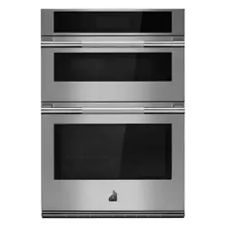
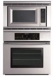
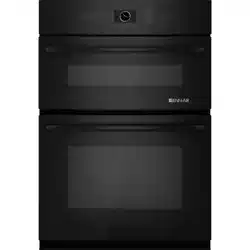
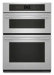
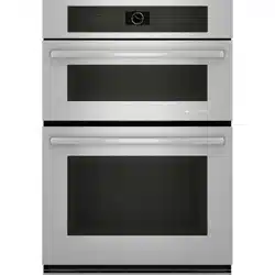
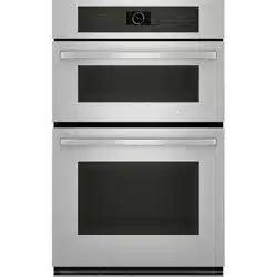
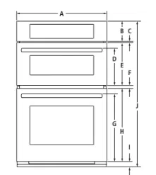
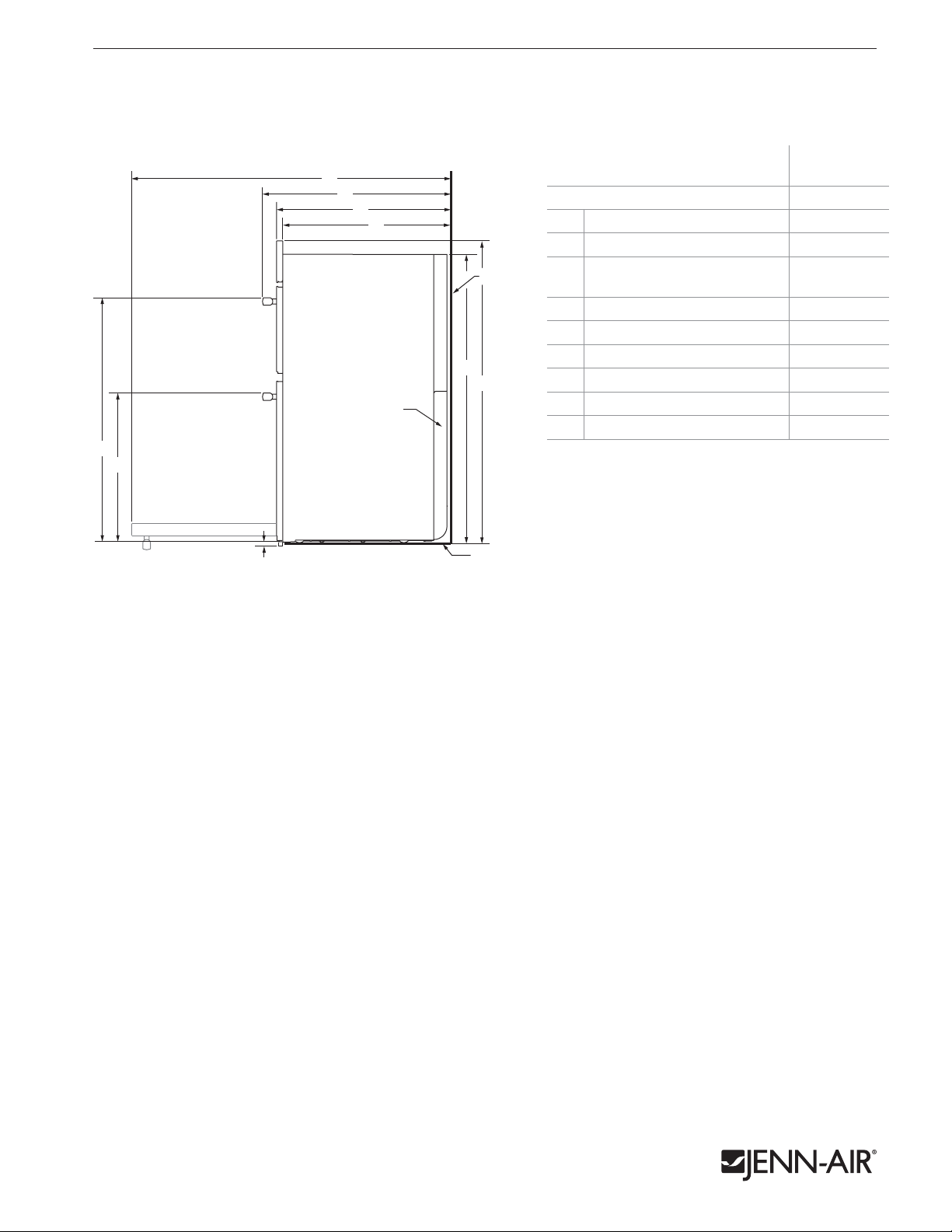
27" cOMbINATION MIcROwAvE/wALL OvENS
JMW2427W, JMW2327W – 26
3
⁄4" x 43
1
⁄8" x 26
3
⁄4"
MODEL #
JMW2427W
JMW2327W
in cm
A
Overall width
Euro-Style Stainless 26
3
⁄4 67.9
Floating Glass 26
5
⁄8 67.6
B
Height of control panel
6 15.2
C
Space between control panel and door
3
⁄8 0.9
D
Height to top of microwave oven handle
11 28.0
E
Height of microwave oven door
12
5
⁄8 31.9
F
Space between doors
1 2.4
G
Height to top of oven handle
20 50.7
H
Height of oven door
21
5
⁄8 54.9
I
Height of trim
1
1
⁄2 4.0
J
Overall height
43
1
⁄8 109.4
K
Width of recessed oven
25
1
⁄4 64.1
L
Width of conduit channel
2 4.9
M
Depth of recessed oven
23
7
⁄8 60.5
N
Depth with doors
24
3
⁄4 62.8
O
Depth with handles
26
3
⁄4 68.0
P
Depth with door fully open
45
3
⁄8 115.2
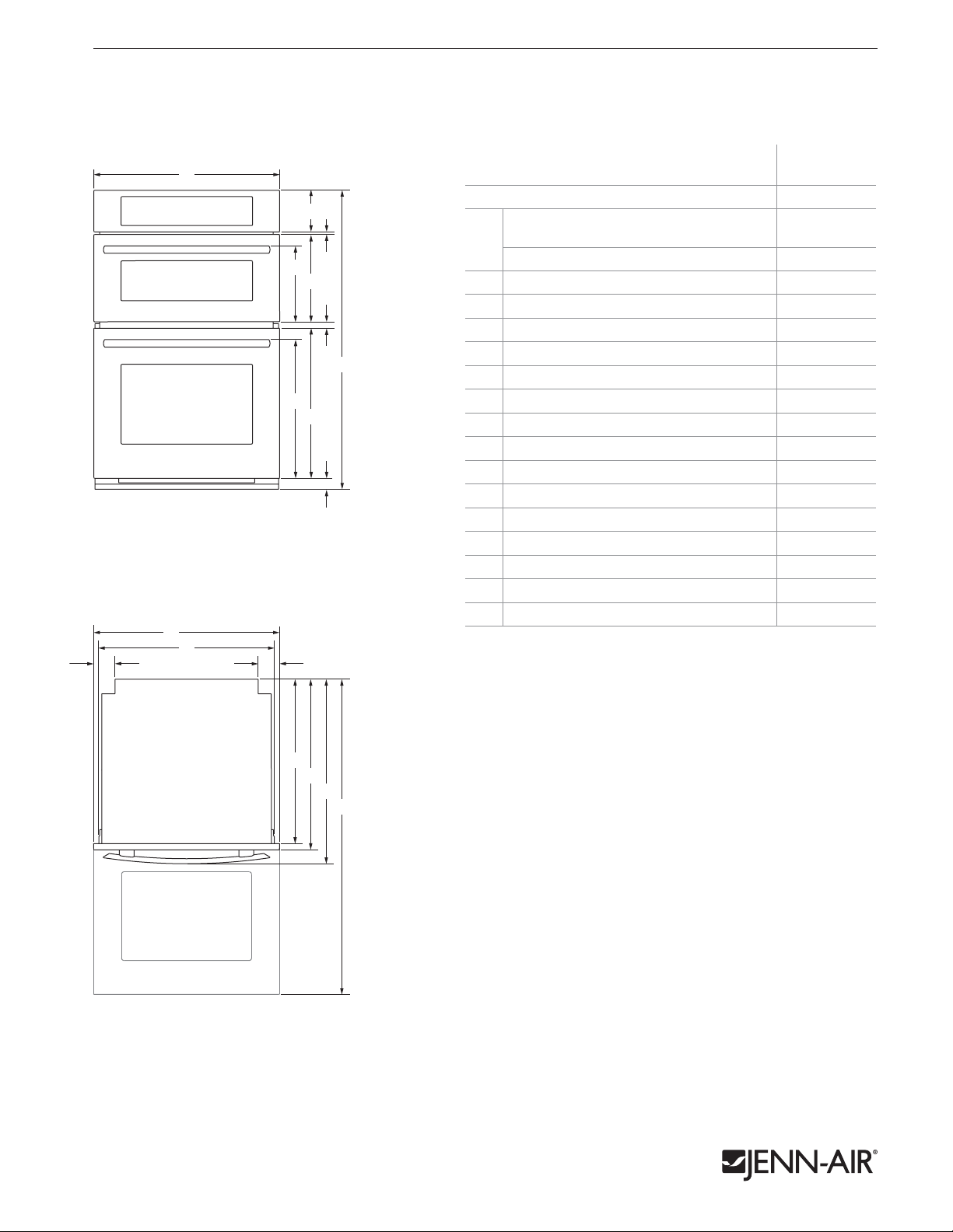
FRONT VIEW
A
D
G
E
H
B C
F
I
J
K
A
M
N
O
P
L L
C
Bottom of Cabinet
Back of Cabinet
F
A
B
H
I
D
E
G
Conduit Channel
Power Supply Location
A
D
G
E
H
B C
F
I
J
K
A
M
N
O
P
L L
C
Bottom of Cabinet
Back of Cabinet
F
A
B
H
I
D
E
G
Conduit Channel
Power Supply Location
TOP VIEW
PRODUcT DIMENSIONS
Product dimension, cutout and installation specifications are provided for planning purposes only. Before installing
any product, be sure to verify cutout dimensions and electrical/gas connections as actual product dimensions may vary.
JENN-AIR
®
DETAILED PLANNING DIMENSIONS
2 of 4
JRC120004A 07/2012
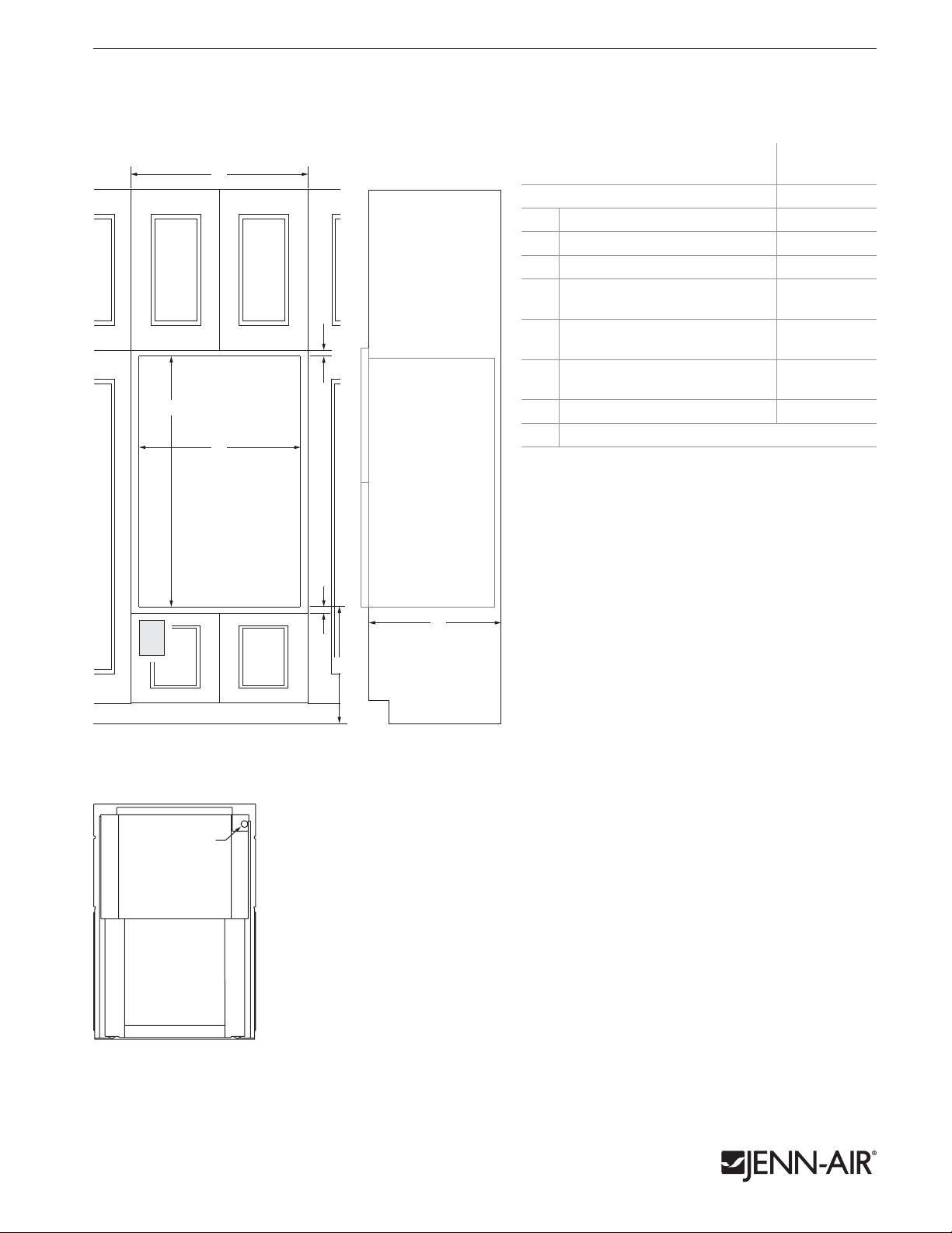
MODEL #
JMW2427W
JMW2327W
in cm
A
Height to top of upper handle 34
7
⁄8 88.7
B
Height to top of lower handle 21
3
⁄8 54.4
C
Height of trim extending
below cutout
1
⁄4 0.6
D
Height of recessed oven 41 104.2
E
Height to top of control panel 43 109.1
F
Depth with door fully open 45
3
⁄8 115.2
G
Depth with handles 26
3
⁄4 68.0
H
Depth with doors
24
3
⁄4 62.8
I
Depth of recessed oven
23
7
⁄8 60.5
27" cOMbINATION MIcROwAvE/wALL OvENS
JMW2427W, JMW2327W – 26
3
⁄4" x 43
1
⁄8" x 26
3
⁄4"
DIMENSIONS AS INSTALLED
A
D
G
E
H
B C
F
I
J
K
A
M
N
O
P
L L
C
Bottom of Cabinet
Back of Cabinet
F
A
B
H
I
D
E
G
Conduit Channel
Power Supply Location
SIDE VIEW
Product dimension, cutout and installation specifications are provided for planning purposes only. Before installing
any product, be sure to verify cutout dimensions and electrical/gas connections as actual product dimensions may vary.
JENN-AIR
®
DETAILED PLANNING DIMENSIONS
3 of 4
JRC120004A 07/2012
27" cOMbINATION MIcROwAvE/wALL OvENS
JMW2427W, JMW2327W – 26
3
⁄4" x 43
1
⁄8" x 26
3
⁄4"
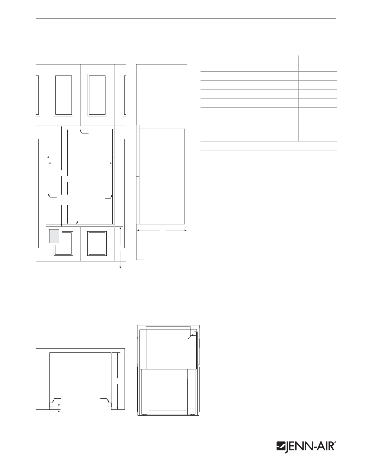
MODEL #
JMW2427W
JMW2327W
in cm
A
Width of cabinet (min.)
27 68.6
B
Width of cutout
25
1
⁄2 64.8
C
Height of cutout
41
1
⁄4 104.8
D
Top of cutout to bottom
of upper cabinet door (min.)
2
5.1
E
Bottom of cutout to top
of lower cabinet door (min.)
1
1
⁄2 3.8
F
Bottom of cutout to floor
4
5
⁄8-
19
1
⁄4
11.7-
48.9
G
Depth of cutout (min.) 24 61.0
e
Recommended junction box location
Bottom of Cabinet
Back of Cabinet
F
A
B
G
H
I
D
E
C
A
B
C
D
E
F
G
H
I
J
Conduit Channel
K
A
M
N
O
P
L L
Power Supply Location
A
B
C*
A
B
C*
G
G
e
e
A
B
C
e
E
D
D
D
F
E
F
E
F
B
C*
e
e
F
A
H
A
B
C*
A
B
C*
G
G
e
e
A
B
C
e
E
D
D
D
F
E
F
E
F
B
C*
e
e
F
A
H
FRONT VIEW SIDE VIEW
BACK VIEW
OPENING/cLEARANcE DIMENSIONS
ELECTRICAL REQUIREMENTS
240 volt, 40-amp fused, grounded circuit is required. A dedicated
circuit is recommended.
The length of conduit provided is for serviceability. Do not cut the
conduit. The junction box should be located 3" (7.6 cm) maximum
below the support surface. Drill a 1
1
⁄4" (3.4 cm) minimum diameter
hole in the left rear corner of the support surface for access to the
junction box.
Product dimension, cutout and installation specifications are provided for planning purposes only. Before installing
any product, be sure to verify cutout dimensions and electrical/gas connections as actual product dimensions may vary.
JENN-AIR
®
DETAILED PLANNING DIMENSIONS
4 of 4
JRC120004A 07/2012
OPENING/cLEARANcE DIMENSIONS
B
D
e
e
A
3
⁄4" (1.9 cm)
Side Cleat*
3
⁄4" (1.9 cm)
Side Cleat*
2" (5.1 cm)
Top Cleat*
E
C
A
E
B
A
B
C
D
F
F
e
e
A
E
B
C
D
e
2" (5.1 cm)
Top Cleat*
3
⁄4" (1.9 cm)
Side Cleat*
F
Side Cleat*
1" (2.5 cm)
Side Cleat*
2
1
⁄16" (5.2 cm)
Top Cleat*
3
⁄4" (1.9 cm)
Side Cleat*
3
⁄4" (1.9 cm)
Side Cleat*
3
⁄4" (1.9 cm)
Side Cleat*
3
⁄4" (1.9 cm)
Side Cleat*
E
Power Supply Location
1
1
⁄2" (3.8 cm)
Platform*
2
3
⁄4" (7.0 cm)
Top Cleat*
1
1
⁄2" (3.8 cm)
Platform*
1
1
⁄2" (3.8 cm)
Platform*
1
1
⁄2" (3.8 cm)
Platform*
D
C
3
⁄4" (1.9 cm)
Side Cleat*
B
D
e
e
A
3
⁄4" (1.9 cm)
Side Cleat*
3
⁄4" (1.9 cm)
Side Cleat*
2" (5.1 cm)
Top Cleat*
E
C
A
E
B
A
B
C
D
F
F
e
e
A
E
B
C
D
e
2" (5.1 cm)
Top Cleat*
3
⁄4" (1.9 cm)
Side Cleat*
F
Side Cleat*
1" (2.5 cm)
Side Cleat*
2
1
⁄16" (5.2 cm)
Top Cleat*
3
⁄4" (1.9 cm)
Side Cleat*
3
⁄4" (1.9 cm)
Side Cleat*
3
⁄4" (1.9 cm)
Side Cleat*
3
⁄4" (1.9 cm)
Side Cleat*
E
Power Supply Location
1
1
⁄2" (3.8 cm)
Platform*
2
3
⁄4" (7.0 cm)
Top Cleat*
1
1
⁄2" (3.8 cm)
Platform*
1
1
⁄2" (3.8 cm)
Platform*
1
1
⁄2" (3.8 cm)
Platform*
D
C
3
⁄4" (1.9 cm)
Side Cleat*
FRONT VIEW SIDE VIEW
27" cOMbINATION MIcROwAvE/wALL OvENS – FLUSh INSTALLATION
JMW2427W, JMW2327W – 26
3
⁄4" x 43
1
⁄8" x 24
3
⁄4" (depth without handles)
MODEL #
JMW2427W
JMW2327W
in cm
A
Width of flush inset cutout (min.)
27 68.6
B
Width of opening (min.)
25
1
⁄2 64.8
C
Height of flush inset cutout (min.) 44
13
⁄16 113.8
D
Height of opening (min.) 41
1
⁄4 104.8
E
Bottom of cutout to floor
4
5
⁄8-
19
1
⁄4
11.7-
48.9
F
Depth of cutout (min.) 25 63.5
e
Recommended junction box location
ELECTRICAL REQUIREMENTS
240 volt, 40-amp fused, grounded circuit is required. A dedicated
circuit is recommended.
The length of conduit provided is for serviceability. Do not cut the
conduit. The junction box should be located 3" (7.6 cm) maximum
below the support surface. Drill a 1
1
⁄4" (3.4 cm) minimum diameter
hole in the left rear corner of the support surface for access to the
junction box.
FLUSH INSTALLATION REQUIREMENTS
A 25" (63.5 cm) minimum cutout depth is required.
These dimensions will result in a
3
⁄8" (1.0 cm) reveal on the top,
a
1
⁄8" (0.3 cm) reveal on the sides and a 1
3
⁄8" (3.5 cm) reveal on the
bottom of the wall oven.
The front face of the cleats and platform will be visible and should
be treated as a finished surface.
BACK VIEW
Bottom of Cabinet
Back of Cabinet
F
A
B
G
H
I
D
E
C
A
B
C
D
E
F
G
H
I
J
Conduit Channel
K
A
M
N
O
P
L L
Power Supply Location
B
D
e
e
A
3
⁄4" (1.9 cm)
Side Cleat*
3
⁄4" (1.9 cm)
Side Cleat*
2" (5.1 cm)
Top Cleat*
E
C
A
E
B
A
B
C
D
F
F
e
e
A
E
B
C
D
e
2" (5.1 cm)
Top Cleat*
3
⁄4" (1.9 cm)
Side Cleat*
F
Side Cleat*
1" (2.5 cm)
Side Cleat*
2
1
⁄16" (5.2 cm)
Top Cleat*
3
⁄4" (1.9 cm)
Side Cleat*
3
⁄4" (1.9 cm)
Side Cleat*
3
⁄4" (1.9 cm)
Side Cleat*
3
⁄4" (1.9 cm)
Side Cleat*
E
Power Supply Location
1
1
⁄2" (3.8 cm)
Platform*
2
3
⁄4" (7.0 cm)
Top Cleat*
1
1
⁄2" (3.8 cm)
Platform*
1
1
⁄2" (3.8 cm)
Platform*
1
1
⁄2" (3.8 cm)
Platform*
D
C
3
⁄4" (1.9 cm)
Side Cleat*
TOP VIEW
* Cleats and platform must be recessed 1" (2.5 cm) from the front of the cabinet.