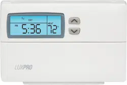
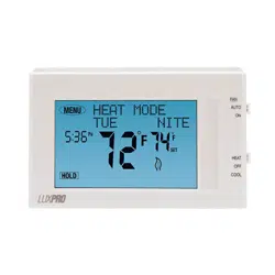
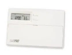
Owner’s Manual Thermostat Separate Program
FEATURES

- Small elegant design
- Exclusive LUX Speed Dial®
- “EL” Illuminated Display
- Air Filter Monitor
- 5-2 Day Programming
- Energy Star Compliant
- 4 Periods Per Day
- Battery Free Memory Storage
- Temporary Temperature Override
- Temperature Hold
- Keyboard Lockout
- F/C Temperature Display
- 12/24 Hr Clock Display
- Adjustable Temperature Differential / Cycle Rate
- User Temperature Offset / Calibration
- System or Battery Powered
- 5 Minute Minimum Run/Off Time For Short Cycle and Compressor Protection
INSTALLATION
LOCATION
On replacement installations, mount the new thermostat in place of the old one unless the conditions listed below suggest otherwise. On new installations, follow the guidelines listed below.
- Locate the thermostat on an inside wall, about 5 ft. (1.5m) above the floor, and in a room that is used often.
- Do not locate where air circulation is poor, such as in a corner or an alcove, or behind an open door.
- Do not install it where there are unusual heating conditions, such as: in direct sunlight; near a lamp, television, radiator, register, or fireplace; near hot water pipes in a wall; near a stove on the other side of a wall.
- Do not locate in unusual cooling conditions, such as: on a wall separating an unheated room; or in a draft from a stairwell, door, or window.
- Do not locate in a damp area. This can lead to corrosion that may shorten thermostat life.
- If painting or construction work has yet to be completed, cover the unit completely or do not install it.
WARNING:
- Read instructions carefully before removing any wires from your existing thermostat.
- This thermostat should be limited to 1.5 amps per terminal, and a maximum of 2 amps total; higher current than this may cause damage to the thermostat.
- All wiring must conform to the local codes and ordinances that are in your particular location.
REMOVAL OF OLD UNIT
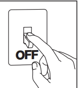
- Turn OFF the electricity to all heating and cooling components. Do not turn the electricity back on until all work is completed.
- Remove the cover and front portion of your old thermostat to expose the wiring connections.
- Write down the letters printed near each wire terminal that is used, and the color of the wire that is connected to it. Using the enclosed labels, attach a label to each of your wires so that the letter matches the marking on your existing thermostat.
- When they are all labeled, carefully remove the wires one at a time, making sure that they do not fall back inside the wall. Do not allow any of the bare wire ends to touch each other, or any parts on the thermostat.
- Loosen all of the screws on the old thermostat and remove it from the wall.
MOUNTING
- Strip insulation leaving 3/8 in. (9.5mm) bare wire ends and clean off any corrosion.
- Fill wall opening with non-combustible insulation to prevent drafts from affecting the thermostat.
- Remove the body from the thermostat’s base by pressing the thumb latch at the bottom center of the unit and swinging the body away.
- NOTE: If you are mounting the base to soft material like plasterboard or if you are using the old mounting holes, the screws may not hold. Drill a 3/16 in. (4.8mm) hole at each screw, and insert the plastic anchors provided.
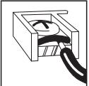
- Hold the base against the wall. Route the wires through the hole below the terminal block. Position the base for best appearance (to hide any marks from an old thermostat). Attach the base to the wall with the two screws provided.
CONNECTING THE WIRES
5. Wires must be trapped between the black clamps and the brass terminals as shown here.
6. Being careful not to overighten them, securely tighten all of the electrical terminal screws, including any unused ones.
NOTE: When you are finished performing your installation and setup options, please remove the thin plastic film that is protecting the LCD display screen on the front of the thermostat. This plastic may or may not be present, and is evident by the appearance of fake digits appearing on the display screen.
SETUP OPTIONS
SYSTEM TYPE SETTING:
This setting tells the thermostat about the type of heating and cooling equipment that it is controlling, so that the system is operated properly. There are two operating modes based on your system type, “Furnace (Fn)” or “Heat Pump (HP)”. If you have a Furnace, ensure this is set to "Fn". If you have a Heat Pump, ensure this is set to "HP".
Install two new Energizer® or DURACELL® "AA" size alkaline batteries before continuing further. Ensure that the batteries are installed in the proper direction as per the markings shown in the battery tray. With the thermostat powered by batteries, press and hold the HOLD button, and then press the Hardware Reset button once on the back of the unit’s circuit board. Continue to hold the HOLD button until “SYS” is shown on the LCD screen. Use the UP or DOWN buttons to toggle between “Fn” and “HP” modes. When you are finished, press NEXT. This setting is now complete, and will not change unless you adjust it again. This is true even in the event of a power failure, or if a reset button is pressed.
NOTE: All of the settings, options, and components listed in this section are located on the rear of the thermostat, on the circuit board.
HARDWARE RESET
The hardware reset is a push button that is located on the right edge of the circuit board, just above the battery location. This reset button is used by the thermostat to reset the unit’s clock, and read the position of all of the option switches. When any of the following items are changed, the hardware reset button must be pushed for the change to be recognized. User temperature programs are not erased when a hardware reset is performed.
HEAT FAN CONTROL
This setting defines the fan operation while in Heat mode, and when the fan is in Auto. This setting has no effect while the thermostat is in Cool mode, or if there is no blower fan connected to the “G” wire terminal.
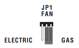
GAS: Use this setting if you have a gas or Oil heating system. In the GAS setting, the heating system itself controls the operation of the blower fan (if equipped).
ELECTRIC: Use this setting if you have a Heat Pump or Electric heating system. In the ELEC setting, the heating system requires the thermostat to control the operation of the blower fan.
The following option settings are all located within a group of small switches labeled 1 through 4 as shown below, and are located in the center of the circuit board.
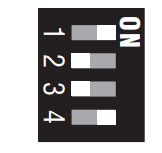
TIME FORMAT
This determines how the thermostat displays the clock and all other times on the screen. Switch position OFF is 12 HR, and ON is 24 HR.
TEMPERATURE SCALE
This determines how the thermostat displays all temperatures on the screen. Switch position OFF is F°, and ON is C°.
FILTER DISPLAY
This determines how the remaining filter life will be displayed when the rotary dial is turned to the AIR FILTER position. In the Percent (%) mode, the display will count down the percentage of air filter life remaining before a filter change is recommended. In the Days mode, the display will count down the number of calendar days remaining before a filter change is recommended. Switch position OFF is Percent mode, and ON is Days mode.
BATTERY MONITOR
This determines whether the internal battery voltage monitor watches the condition of the batteries that are installed in the thermostat. This setting should always remain enabled unless the thermostat is being powered by System Power alone, without any batteries present. Switch position OFF is Battery Monitor On (Enabled), and Switch position ON is Battery Monitor Off (Disabled).
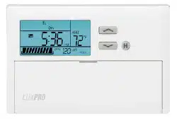
FRONT PANEL ITEMS
SOFTWARE RESET
The software reset is a small recessed push button that is located right above the
NEXT button. This button can be pushed with a pencil or the end of a paper clip. This
reset clears all of the heating and cooling programs, filter settings, and other user changeable preferences to their default values. You should write down your heating and cooling program times and temperatures prior to using the software reset.
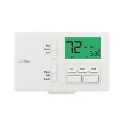
MODE SWITCHES
There are two mode switches on the front, a Temperature mode switch and a Fan
mode switch. The Temperature mode switch has three positions: HEAT, OFF, and COOL.
In the winter, set the system switch to HEAT to control your heating system. In the summer, set the switch to COOL to control your air conditioner. In the spring and fall or when the windows are open, you can set the switch OFF. The Fan mode switch has two positions, AUTO and ON. Setting the Fan mode switch to AUTO, automatically runs your system's blower fan as required only during heating and cooling activation. Setting the Fan mode switch to ON, runs your system’s fan continuously, even if heating or cooling is not needed, including when the Temperature mode switch is in the OFF position to provide air circulation only.
NOTE: The Fan mode switch only works if your system provides a wire for the thermostat’s
“G” wire terminal.
PUSH BUTTONS
There are four primary push buttons on the front of the thermostat: The UP and DOWN
arrow keys, the NEXT button, and the HOLD button.
ROTARY DIAL
The LUX Speed Dial® provides an easy way to quickly navigate between the different
programming areas. This rotary dial has five individual positions.
OPERATING INSTRUCTIONS
SET DAY/TIME
Rotate the dial to the SET DAY/TIME position. You should see the word SET appear on the display, along with the clock and a day of the week that is flashing. With the day flashing, press the UP button to advance the day to the desired day. Press the NEXT button, this should cause the time to start flashing and the day to remain on steady. Using either the UP or DOWN buttons, adjust the clock to the desired time. The clock digits will increment rapidly if either the UP or DOWN buttons are held in the pressed position.
HEATING AND COOLING
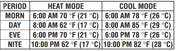
Basic operation of your heating or cooling system can be obtained by ensuring that the rotary dial is in the RUN position, and simply moving the Temperature mode switch to either the HEAT or COOL position. Prior to being set initially with your custom temperature program, and also after a Software Reset, the thermostat will follow the default temperature program routines that are preset within the thermostat’s memory, as shown below.
MINIMUM RUN TIME DELAY
This is determined by the thermostat, and controls the minimum length of time that the thermostat must remain with Heat or Cool either On or Off, before it will automatically switch to the alternate On or Off state. This feature prevents rapid or short cycling, and provides compressor protection for cooling equipment. The time amount for this delay is fixed at 5 minutes between on or off load changes.
TEMPERATURE OVERRIDE
A Temperature Override occurs in Run mode, in either Heat or Cool, anytime the user adjusts the set temperature to a value that differs from the stored program temperature for that day and time. When the thermostat is in an Override, the word Override will appear in the temperature area of the display. The thermostat will maintain thermal control using this new set temperature, until the start of the next program period time is reached. At the start of the next program period, the set temperature will return to its programmed value. To enter an Override in either Heat or Cool mode, push either the UP or DOWN button once and the set temperature will begin to flash. Push either the UP or DOWN button to the new desired set temperature value. An Override may be cancelled by rotating the dial, changing the Temperature mode switch, or by initiating a Temperature Hold.
TEMPERATURE HOLD
A Temperature Hold is similar to an override, but is used for maintaining a constant set temperature for a longer time duration. Once a Hold is initiated, the thermostat will maintain the Hold set temperature indefinitely. A temperature hold may be used for days, weeks, or even months at a time. To enter a Hold, push the HOLD button once, and the word Hold will appear in the temperature portion of the screen, along with the set temperature flashing. While the set temperature is flashing, push either the UP or DOWN button to the new desired set temperature value. To cancel a Hold, press and release the HOLD button once again, rotate the dial, or change the Temperature mode switch.
AIR FILTER MONITOR
The Air Filter Monitor counts the number of days, and the amount of usage since your furnace filter has been replaced. In Run mode, the CHANGE FILTER indicator will appear when the remaining filter days have reached zero and the filter should be changed. To set and use the Air Filter Monitor, turn the rotary dial to AIR FILTER. Press NEXT and the Filter Days Left value will start flashing. Use the UP or DOWN buttons to select the number of days of filter life that your filter is rated for. Setting this value to OFF will disable the filter monitor. Return the dial to the RUN position once you are finished setting the filter life. To monitor the Filter Days Left or Filter Percent Left, turn the dial to the AIR FILTER position. The amount of filter life remaining will be shown in the clock portion of the display screen. Return the dial to the RUN position once you are finished viewing the filter life remaining.
RESET FILTER COUNTER
Once you have replaced your filter, the filter life counter is reset back to its full amount remaining value by turning the dial to AIR FILTER and pressing the UP and DOWN buttons together at the same time.
NOTE: The counter is also reset by changing the filter setting value, as described above, to a different number of days.
ADVANCED FEATURES
SWING SETTING
A thermostat works by turning your heating or cooling system on and off whenever the room temperature varies from the set-point temperature. The amount of this variation is called the “swing.” Your system should cycle on about 3 to 6 times per hour. A smaller swing number increases the number of cycles per hour, so the room temperature is more precise and constant. A larger swing number decreases the number of cycles per hour, but saves energy in most cases. To change the Swing setting, turn the dial to RUN mode. Hold down the NEXT button and push the HOLD button once, then let go of both. The words SWING and SET will appear on the screen with a number. Use the UP/DOWN buttons to change the number value between 1 and 9. Number 1 is the default
setting. Press the NEXT button to accept the setting and return to normal Run mode.
TEMPERATURE CALIBRATION
The internal temperature sensor in this thermostat is accurately calibrated at the factory. The Temperature Calibration feature allows you to manually offset the measured temperature by as much as plus or minus 5°F (3°C) degrees from its original value. This feature can be useful to match this thermostat to another one or more, if multiple thermostats are used in the same home. To change the Temperature Calibration, turn the dial to RUN mode, and place the Temperature mode switch in the OFF position. Hold down the UP button and push the DOWN button once, then let go of both. The words CAL and SET will appear on the screen with a number. Use the UP/DOWN buttons to change the number value between -5°F (-3°C) and +5°F (+3°C) degrees. 0 degrees of correction is the default setting. Press the NEXT button to accept the setting and return to Run mode.
PROGRAMMING
For all of the programming areas that are described below, this thermostat provides four independent periods per day for Heat mode and Cool mode, they are: MORN, DAY, EVE, and NITE. Each period ends at the start time of the following period. The programs for each Temperature mode are programmed separately. When you perform a Software Reset, a default temperature program routine is inserted into all of the program periods. You can use these default programs or alter any portion of them to suit your own preferences. When setting the program items, the value that is flashing is the item that you can change at that time.
SET WEEKDAY PROGRAM
Select either HEAT or COOL with the Temperature mode switch. Rotate the dial to WEEKDAY PROGRAM. You will be programming all five weekdays at the same time. The first period is MORN. Using the UP and DOWN buttons, set the start time for this period, and then push the NEXT button to proceed. Now set the desired set temperature for the MORN period using the UP and DOWN buttons, and push NEXT to proceed. Now set the start time and set temperature for the DAY period, pushing NEXT after each to advance. Continue with these same steps to set the start time and set temperature for the EVE, and NITE program periods. When you are finished setting all four periods, you may continue pushing the NEXT button through all four periods to review your entries, or turn the dial to RUN if you are finished. These same programming steps for all four periods must be performed in both Heat and Cool Temperature modes independently.
SET WEEKEND PROGRAM
Turn the dial to WEEKEND PROGRAM. You will be programming both Saturday and Sunday at the same time. You will begin with the start time of the MORN period, and use the same procedures that were performed while setting the Weekday Program periods, using the NEXT button to advance through the values. Return the dial to the RUN position when you are finished.
BATTERIES AND MAINTENANCE
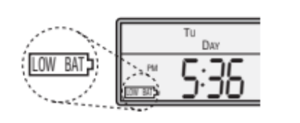
This thermostat can be powered either by “AA” alkaline batteries, by 24VAC system common power, or a combination of both. If you are using batteries alone, the batteries should be replaced AT LEAST once per year, or sooner if the LOW BAT battery symbol appears in the lower left portion of the display screen as shown below.
To replace the batteries in the thermostat, remove the thermostat’s body from the base plate attached to the wall by pressing the thumb latch at the bottom center of the unit and swinging the body towards you, up and away from the base. Remove the used batteries from the battery tray and discard appropriately.
Install two new Energizer® or DURACELL®, “AA” size alkaline batteries into the battery tray. Observe the polarity markings shown in the battery compartment to ensure proper installation. When finished, hang the top of the unit by the tabs at the top corners of the base, then snap the bottom of the unit into place. Do not use unnecessary force. If the body does not snap into place easily, remove the body, re-hang it from the tabs and try again.
WIRE IDENTIFICATION AND WIRING SCHEMATICS

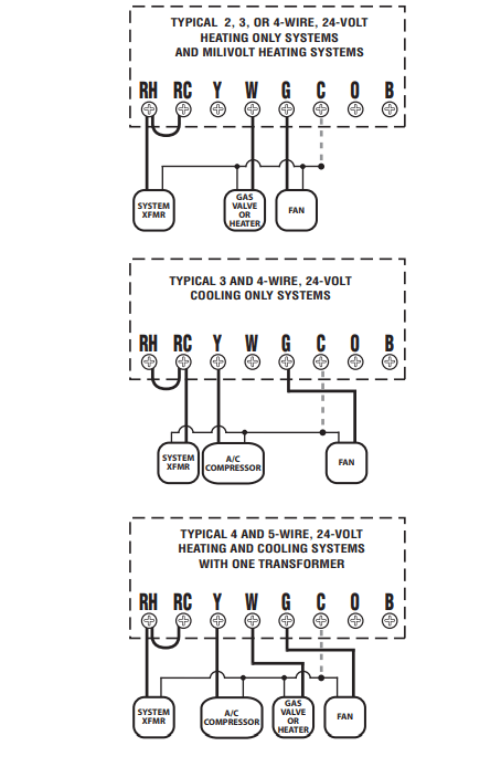
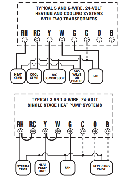
WIRING DIAGRAM NOTES:
- All of the dashed wires are optional, and usage depends upon your specific system type. Use either the “B” or the “O” wire, but not both. Generally, the B and O terminals are only used for Heat Pump systems.
- If replacing a Honeywell TM-11, tape off the “R” wire. Connect the “B” wire to the “RH” terminal.
- If replacing a thermostat that has a clock wire labeled as “C,” tape off this wire and do not connect it to this thermostat.
- If “Y” and “C” wires are both present, then “C” is a common wire.
- If a “B” wire in your system is a common wire, connecting it to the “B” terminal of this thermostat may damage your system and the thermostat, tape it off and do not connect it.