
DXAEPS14
Power Station
Fuente de energía
INSTRUCTION MANUAL
MANUAL DE INSTRUCCIONES
If you have questions or comments, contact us.
Si tiene dudas o comentarios, contáctenos.
1-888-394-3392
BC
RD020221
DXAEPS14_ManualENSP_020221.indd 56-1DXAEPS14_ManualENSP_020221.indd 56-1 2/2/2021 10:56:29 AM2/2/2021 10:56:29 AM

English
3
Definitions: Safety Guidelines
The definitions below describe the level of severity for each signal
word. Please read the manual and pay attention to these symbols.
DANGER: Indicates an imminently hazardous situation which,
if not avoided, will result in death or serious injury.
WARNING: Indicates a potentially hazardous situation which,
if not avoided, could result in death or serious injury.
CAUTION: Indicates a potentially hazardous situation which,
if not avoided, may result in minor or moderate injury.
NOTICE: Indicates a practice not related to personal injury
which, if not avoided, may result in property damage.
IF YOU HAVE ANY QUESTIONS OR COMMENTS ABOUT THIS
DeWALT
TOOL, CALL US TOLL FREE AT: 1-888-394-3392.
Power Station
The DXAEPS14 Power Station is a D
e
WALT power station that features
a jump starter, digital compressor, dual 120V AC power outlets, four
USB ports and LED area lights.
Important Safety
Instructions
WARNING: WHEN USING ELECTRICAL APPLIANCES, BASIC
PRECAUTIONS SHOULD ALWAYS BE FOLLOWED, INCLUDING THE
FOLLOWING:
1. Keep these instructions.
2. Heed all warnings.
3. Follow all instructions.
4. Avoid dangerous environments. Don’t use this unit in damp or wet
locations; or in the rain or snow.
5. Clean only with a dry cloth.
6. The jump starter and supplied charging adapter are not toys
and cannot be played with as toys. To reduce the risk of injury,
close supervision is necessary when these units are used near
children.
7. Store indoors. When not in use, this unit should be stored indoors
in a dry and high or locked-up place – out of the reach of children.
8. Stay alert. Use common sense. Do not operate this equipment
when you are tired or impaired.
9. Only use attachments/accessories specified by the manufacturer.
The use of any accessory or attachment not recommended for
use with this appliance may result in a risk of fire, electric shock,
or injury to persons.
10. Use only on a flat, level surface. If a cart is
used, use caution when moving the cart/
apparatus combination to avoid injury from
tip-over.
ADVERTENCIA: Lea todas las instrucciones antes de utilizar
el producto. No seguir todas las instrucciones que aparecen a
continuación pueden provocar descargas eléctricas, incendios
y/o lesiones graves.
ADVERTENCIA: Este producto o su cable de alimentación contiene
plomo, una sustancia química reconocida por el Estado de California
como causante de cáncer, defectos de nacimiento u otros problemas
reproductivos. Lávese las manos después de utilizarlo. Para más
información, visite www.P65Warnings.ca.gov
WARNING: Read all instructions before operating product.
Failure to follow all instructions listed below may result in electric
shock, fire and/or serious injury.
WARNING: This product or its power cord contains lead, a chemical
known to the State of California to cause cancer and birth defect or
other reproductive harm. Wash hands after handling. For more
information go to www.P65Warnings.ca.gov
DXAEPS14_ManualENSP_020221.indd 2-3DXAEPS14_ManualENSP_020221.indd 2-3 2/2/2021 10:56:29 AM2/2/2021 10:56:29 AM

English
English
4 5
11. To reduce risk of electric shock, disconnect the unit from any
power source before attempting maintenance or cleaning. Turning
off controls without disconnecting will not reduce this risk.
12. Check for damaged parts. Any part that is damaged should be
properly repaired or replaced by manufacturer unless otherwise
indicated elsewhere in this instruction manual before further
use. Servicing is required when the unit has been damaged in
any way, such as power-supply cord or plug is damaged, liquid
has been spilled or objects have fallen into the unit, the unit has
been exposed to rain or moisture, does not operate normally, or
has been dropped. Do not operate the charger if it has received
a sharp blow, been dropped or otherwise damaged in any
way. Contact the manufacturer at 1-888-394-3392 for more
information.
13. Do not use appliance that is damaged or modified. Damaged or
modified batteries may exhibit unpredictable behavior resulting
in fire, explosion or risk of injury.
14. Do not disassemble the appliance, there are no user serviceable
parts inside. Incorrect reassembly may result in a risk of fire or
electric shock.
15. This unit is intended to be used in an upright position. The unit
MUST be kept upright during use.
16. Unit shall not be exposed to dripping or splashing and no objects
filled with liquids, shall be placed on the unit.
17. Do not operate this unit near flammable liquids or in gaseous or
explosive atmospheres. Motors in these tools normally spark,
and the sparks might ignite fumes.
18. This unit employs parts (switches, relays, etc.) that produce arcs
or sparks. Therefore, if used in a garage or enclosed area, the
unit MUST be placed not less than 18 inches above the floor.
19. Do not overcharge the battery – refer to the appropriate section
of this manual.
NOTE: This equipment has been tested and found to comply with
the limits for a Class B digital device, pursuant to Part 15 of the FCC
Rules. These limits are designed to provide reasonable protection
against harmful interference in a residential installation. This equipment
generates, uses and can radiate radio frequency energy and, if not
installed and used in accordance with the instructions, may cause
harmful interference to radio communications. However, there is no
guarantee that interference will not occur in a particular installation. If
this equipment does cause harmful interference to radio or television
reception, which can be determined by turning the equipment off and
on, the user is encouraged to try to correct the interference by one or
more of the following measures:
• Reorient or relocate the receiving antenna.
• Increase the separation between the equipment and the
receiver.
• Connect the equipment into an outlet on a circuit different
from that to which the receiver is connected
• Consult the dealer or an experienced radio/TV technician
for help.
NOTICE: Per FCC Part 15, changes or modifications to this equipment
not expressly approved by
DeWALT
could void your authority to operate
this equipment.
READ ALL INSTRUCTIONS
Specific Safety Instructions for Charging
this Unit
• Don’t abuse the cord. Protect the extension cord from being walked
on or pinched particularly at plugs, convenience receptacles, and the
point where it connects to the unit. Never carry the unit by the cord
or yank it to disconnect from receptacle. Pull by the plug rather than
the cord when disconnecting from the unit.
• Ground fault circuit interrupter (GFCI) protection should be
provided on the circuits or outlets to be used. Receptacles are
available having built in GFCI protection and may be used for this
measure of safety.
• IMPORTANT: This unit is delivered in a partially charged state. Fully
charge unit with a household extension cord for a full 40 hours or until
the battery status icon shows 4 solid bars before using for the first
time. You cannot overcharge the unit using the AC charging method.
• To recharge this unit, use only the supplied AC charging adapter.
Plug in the charging adapter at the unit first, then plug into the
charging source.
• All functions should be turned off when the unit is charging or not
in use. Make sure all functions are turned off before connection to a
power source or load.
• Position the charging adapter cord so it does not become entangled
or become a safety hazard. Keep the charging adapter cord away
from sharp edges.
• Do not crush, cut, pull or expose charging adapter cords to extreme
heat.
• Use in a dry location only.
• Do not attempt to charge the unit if the charging adapter is damaged –
return the charging adapter to manufacturer for repair or replacement.
• After charging/recharging, disconnect charging adapter and wait 5
minutes before use.
• Only charge the unit in a well ventilated area.
CAUTION – To reduce the risk of injury or property damage: Pull
by plug rather than cord when unplugging the charging adapter.
Extension Cords
WARNING: Use of an improper extension cord could result in a
risk of fire and electric shock, and will void warranty. Make sure your
extension cord is in good condition. When using an extension cord,
be sure to use one heavy enough to carry the current your product
will draw. An undersized cord will cause a drop in line voltage resulting
in loss of power and overheating. The following table shows the correct
size to use depending on cord length and nameplate ampere rating.
If in doubt, use the next heavier gauge. The smaller the gauge number,
the heavier the cord.
MINIMUM GAGE FOR CORD SETS
Volts Total Length of Cord in Feet
120V 0-25 26-50 51-100 101-150
(0-7.6m) (7.6-15.2m) (15.2-30.4m) (30.4-45.7m)
240V 0-50 51-100 101-200 201-300
(0-15.2m) (15.2-30.4m) (30.4-60.9m) (60.9-91.4m)
Ampere Rating Extension Cord Length
More Not more
0’-25’ 26’-50’ 51 ’-100 ’ 101’ -150 ’
Than Than American Wire Gage (AWG)
0 - 6 18 16 16 14
6 - 10 18 16 14 12
10 - 12 16 16 14 12
12 - 16 14 12 Not Recommended
When an extension cord is used, make sure that:
• the pins of extension cord are the same number, size and shape as
those in the charger,
• the extension cord is properly wired and in good electrical condition,
and
• the wire size is large enough for the AC rating of the charger.
Outdoor use extension cords: When the unit is charged outdoors,
use only extension cords intended for use outdoors and so marked.
Specific Safety Instructions for
Jump Starters
WARNING – Burst hazard: Do not use the unit for charging dry-cell
batteries that are commonly used with home appliances. These
batteries may burst and cause injury to persons and damage property.
Use the unit for charging/boosting a lead-acid battery only. It is not
DXAEPS14_ManualENSP_020221.indd 4-5DXAEPS14_ManualENSP_020221.indd 4-5 2/2/2021 10:56:30 AM2/2/2021 10:56:30 AM

English
English
6 7
intended to supply power to a low-voltage electrical system other than
in a starter-motor application.
WARNING: To reduce the risk of electric shock, never immerse this
unit in water or any other liquid, or use when wet.
WARNING – Risk of explosive gases:
• Working in the vicinity of a lead acid battery is dangerous. Batteries
generate explosive gases during normal battery operation. For this
reason, it is of the utmost importance that each time before using
the jump-starter you read this manual and follow instructions exactly.
• To reduce the risk of battery explosion, follow these instructions and
those published by the battery manufacturer and manufacturer of
any equipment you intend to use in the vicinity of the battery. Review
cautionary markings on these products and on the engine.
WARNING – Risk of serious injury or property damage:
• Never allow red and black clamps to touch each other or another
common metal conductor — this could cause damage to the unit
and/or create a sparking/explosion hazard.
WARNING – To reduce the risk of fire:
• Do not operate near flammable materials, fumes, dust or gases.
• Do not expose to extreme heat or flames.
CAUTION – To reduce the risk of injury or property damage:
• NEVER ATTEMPT TO JUMP-START OR CHARGE A FROZEN
BATTERY.
• Vehicles that have on-board computerized systems may be damaged
if vehicle battery is jump-started. Before jump-starting, read the
vehicle’s owner’s manual to confirm that external-starting assistance
is suitable.
• Jump-start procedures should only be performed in a safe, dry,
well-ventilated area.
• Always store battery clamps properly when not in use.
• When using this unit close to the vehicle’s battery and engine, stand
the unit on a flat, stable surface, and be sure to keep all clamps, cords,
clothing and body parts away from moving vehicle parts.
• Make sure to connect the clamps with correct polarity. Damage
caused by improper connection is not covered by the Warranty.
• Do not expose battery to fire or intense heat since it may explode.
Before disposing of the battery, protect exposed terminals with
heavy-duty electrical tape to prevent shorting (shorting can result
in injury or fire).
• Place this unit as far away from the battery as cables permit.
• Never allow battery acid to come in contact with this unit.
• Do not operate this unit in a closed area or restrict ventilation in any
way.
• This system is designed to be used only on vehicles with a 12 volt DC
battery system. Do not connect to a 6 volt or 24 volt battery system.
• This system is not designed to be used as a replacement for a
vehicular battery. Do not attempt to operate a vehicle that does not
have a battery installed.
• Excessive engine cranking can damage a vehicle’s starter motor. If
the engine fails to start after the recommended number of attempts,
discontinue jump-start procedures and look for other problems that
may need to be corrected.
• Do not use this jump starter on a watercraft. It is not qualified for
marine applications.
• Although this unit contains a non-spillable battery, it is recommended
that unit be kept upright during storage and recharging. To avoid
possible damage that may shorten the unit’s working life, protect it
from direct sunlight, direct heat and/or moisture.
Specific Safety Instructions for
Compressors
WARNING – Burst hazard: Bursting articles can cause serious
injury.
• Carefully follow instructions on articles to be inflated.
• Never exceed the recommended pressure listed in instructions
on articles to be inflated. If no pressure is given, contact article
manufacturer before inflating.
• Always monitor the pressure on the LCD screen.
CAUTION: To reduce the risk of property damage:
• Never leave the compressor unattended while in use.
• Do not operate compressor continuously for longer than 10 minutes.
This could damage the compressor. Follow the instructions in the
“Portable Compressor” section.
Specific Safety Instructions for
Inverters
WARNING – To reduce the risk of electric shock:
• Do not connect to AC distribution wiring.
• Do not make any electrical connections or disconnections in areas
designated as IGNITION PROTECTED. This inverter is NOT approved
for ignition protected areas.
• Never immerse the unit in water or any other liquid, or use when wet.
WARNING – To reduce the risk of fire:
• Do not operate near flammable materials, fumes, dust or gases.
• Do not expose to extreme heat or flames.
CAUTION – To reduce the risk of injury or property damage:
• Do not insert foreign objects into the inverter outlets.
• Do not attach AC outlet taps or multi-outlet extension cords, or attach
more than one electrical appliance to each inverter outlet.
• Disconnect any appliance plugs from the inverter outlets before
attempting any repairs to the appliance.
• Observe all Safety Instructions in the “Specific Safety Instructions
for Power Cords” section of this Instruction Manual when using the
inverter outlets. When an appliance plugged into this unit is used
outdoors, use only extension cords intended for use outdoors and
so marked.
• Do not attempt to connect the inverter while operating your vehicle.
Not paying attention to the road may result in a serious accident.
• Always use the inverter where there is adequate ventilation.
• Always turn the inverter off when not in use.
• Keep in mind that this inverter will not operate high wattage appliances
or equipment that produce heat, such as hair dryers, microwave
ovens and toasters.
• Do not use this inverter with medical devices. It is not tested for
medical applications.
• Operate this inverter only as described in this Instruction Manual.
CAUTION – Rechargeable devices
• Certain rechargeable devices are designed to be charged by plugging
them directly into an AC receptacle. These devices may damage the
inverter or the charging circuit.
• When using a rechargeable device, monitor its temperature for the
initial ten minutes of use to determine if it produces excessive heat.
• If excessive heat is produced, this indicates the device should not
be used with this inverter.
• This problem does not occur with most of the battery-operated
equipment. Most of these devices use a separate charger or
transformer that is plugged into an AC receptacle.
• The inverter is capable of running most chargers and transformers.
IMPORTANT: Some laptop computers may not operate with this
inverter.
DXAEPS14_ManualENSP_020221.indd 6-7DXAEPS14_ManualENSP_020221.indd 6-7 2/2/2021 10:56:30 AM2/2/2021 10:56:30 AM

English
English
8 9
Specific Safety Instructions for USB Ports
• Do not insert foreign objects into the USB Ports.
• Do not attach USB hubs or more than one personal electronic device
to each USB Port.
• Do not use this unit to operate appliances that require more than 6.2
amps in total to operate from the USB Ports.
First Aid
PERSONAL SAFETY:
• When working with lead acid batteries, always make sure immediate
assistance is available in case of accident or emergency.
• Have plenty of fresh water and soap nearby in case battery acid
contacts skin.
• Never smoke or allow a spark or flame in vicinity of vehicle battery,
engine or power station.
• Stay clear of fan blades, belts, pulleys, and other parts that can
cause injury to persons.
• Remove personal metal items such as rings, bracelets,
necklaces and watches when working with a lead acid battery. A
lead acid battery can produce a short circuit current high enough to
weld a ring, or similar metal object, to skin, causing a severe burn.
• Do not wear vinyl clothing when jump-starting a vehicle. Friction can
cause dangerous static-electrical sparks.
• Do not wear loose clothing or jewelry. They can be caught in
moving parts. Rubber gloves and substantial, non-skid footwear are
recommended when working outdoors. Wear protective hair covering
to contain long hair.
• Be extra careful to avoid dropping a metal tool onto the battery. It
might spark or short-circuit the battery or another electrical part and
could cause an explosion.
• WARNING – Battery fluid is a diluted sulphuric acid and may
cause personal injury or damage to property. In case of skin or eye
contact, follow the instructions below.
• Skin: If battery acid comes in contact with skin, rinse immediately
with water, then wash thoroughly with soap and water. If redness,
pain, or irritation occurs, seek immediate medical attention.
• Eyes: If battery acid comes in contact with eyes, flush eyes
immediately, for a minimum of 15 minutes and seek immediate
medical attention. Avoid touching the eyes while working with a
battery. Acid, acid particles or corrosion may get into the eyes.
• Always have protective eyewear when using this product: contact with
battery acid may cause blindness and/or severe burns. Be aware of
first aid procedures in case of accidental contact with battery acid.
• LCD Liquid Crystal Display: If liquid crystal comes in contact with
your skin: Wash area off completely with plenty of water. Remove
contaminated clothing. If liquid crystal gets into your eye: Flush the
affected eye with clean water and then seek medical attention. If liquid
crystal is swallowed: Flush your mouth thoroughly with water. Drink
large quantities of water and induce vomiting. Then seek medical
attention.
SAVE THESE
INSTRUCTIONS
FOR FUTURE USE
Control Panel (Fig. 1)
A. Backlit LCD Screen
B. Compressor Power Button
C. Decrease Compressor
Pressure Control Button ( )
D. Increase Compressor
Pressure Control Button ( )
E. Area Light Power Button
F. USB Power Button
G. Alternator Check Button
H. AC Power Button
H
A
B
C
D
F
E
G
Components (Fig. 2)
A. Air Hose and Sure Fit
®
Nozzle on Hose Wrap
B. Boost Cables Wrap
C. Handle
D. Control Panel (see Fig. 1)
E. Battery Clamp Tabs and
Battery Clamps
F. USB Ports (with USB
Power/Fault Indicators)
G. Dual 120 Volt AC Outlets
C
D
A
B
E
G
F
DXAEPS14_ManualENSP_020221.indd 8-9DXAEPS14_ManualENSP_020221.indd 8-9 2/2/2021 10:56:30 AM2/2/2021 10:56:30 AM

English
English
10 11
H. 120V AC Charging Port
(under protective cover)
I. LED Area Light (two banks
of two LEDs)
J. 12 Volt AC Charging
Adapter
I
I
J
H
Battery Clamps Stored On /
Removed From Battery Clamp Tabs
(Fig. 3)
NOTE: Clamp tabs rotate down for easy storage.
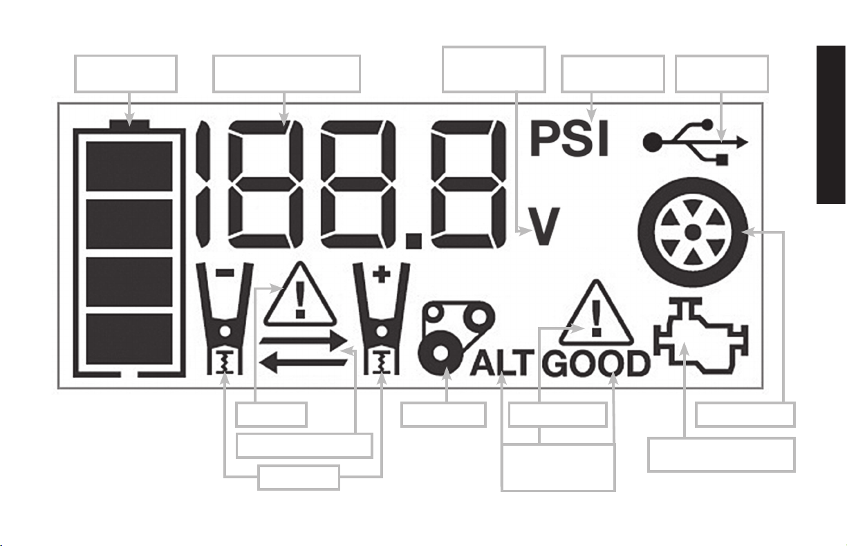
LCD Display Detail (Fig. 4)
Battery Status
Icon
Digital Display (varies by
function)
Alarm Icon
Reverse Polarity Icons
Clamp Icons
Voltage Indicator
Compressor
Pressure Indicator
USB Icon
Compressor Icon
Jump Starter Icon
Alternator Icon
Alternator Good/
Fault Indicators
Fault Icon
DXAEPS14_ManualENSP_020221.indd 10-11DXAEPS14_ManualENSP_020221.indd 10-11 2/2/2021 10:56:31 AM2/2/2021 10:56:31 AM
English
English
10 11
H. 120V AC Charging Port
(under protective cover)
I. LED Area Light (two banks
of two LEDs)
J. 12 Volt AC Charging
Adapter
I
I
J
H
Battery Clamps Stored On /
Removed From Battery Clamp Tabs
(Fig. 3)
NOTE: Clamp tabs rotate down for easy storage.
LCD Display Detail (Fig. 4)
Battery Status
Icon
Digital Display (varies by
function)
Alarm Icon
Reverse Polarity Icons
Clamp Icons
Voltage Indicator
Compressor
Pressure Indicator
USB Icon
Compressor Icon
Jump Starter Icon
Alternator Icon
Alternator Good/
Fault Indicators
Fault Icon
DXAEPS14_ManualENSP_020221.indd 10-11DXAEPS14_ManualENSP_020221.indd 10-11 2/2/2021 10:56:31 AM2/2/2021 10:56:31 AM

English
English
12 13
Overview
COMMON ACTIONS AND UNIT RESPONSES
The following actions turn the unit on and activate the LCD screen:
Press the LED Area Light
Power Button. (Refer to the
"LED Area Light" section.)
A beep will sound and the Area
Light will turn on. The backlight
will turn on for 10 seconds (only).
The LCD screen will continue
to display the Battery Status
Icon and Battery Voltage Indicator.
The unit remains on until the LED
Area Light Power Button is pressed
again to turn it off.
Press the Alternator
Check Button. (Refer to the
"Alternator Check" section.)
A beep will sound and the backlit
LCD screen will display the Battery
Status Icon, and the Alternator
Icon will flash. The unit remains on
until the Alternator Check Button is
pressed again to turn it off.
Press the AC Power Button.
(Refer to the “120V AC Power
Outlets” section.)
A beep will sound and the backlit
LCD screen will display the Battery
Status Icon; and the Digital Display
shows “AC”, indicating the dual
AC outlets are ready to use. The
unit remains on until the AC Power
Button is pressed again to turn
it off.
Press the USB Power
Button. (Refer to the "USB
Ports" section.)
A beep will sound and the
backlight will turn on for 10
seconds (only). The LCD screen
will display the Battery Status Icon,
Battery Voltage Indicator, and the
USB Icon; and the USB Power/
Fault Indicators will light solid blue
indicating the four USB Ports are
active. The unit remains on until
the USB Power Button is pressed
again to turn it off.
Press the Compressor
Power Button. (Refer to
the "Portable Compressor"
section.)
A beep will sound and the backlit
LCD screen will display the Battery
Status Icon, "XXX" PSI and the
Compressor Icon. If no further
actions are taken after 1 minute,
the unit will display the Battery
Status Icon and Battery Voltage
Indicator for 10 seconds before
automatically turning off.
Whenever the clamps are
properly connected to a
battery (refer to the "Jump
Starter" section) …
… a beep will sound and the
backlit LCD screen will display
the Battery Status Icon, Battery
Voltage Indicator, the Clamp Icons,
and the “+” and ”–” signs, as
well as the flashing Jump Starter
Icon. The unit remains on until the
clamps are disconnected from the
battery.
If the red and black clamps
touch each other (refer to
the "Jump Starter" section) …
… the backlit LCD screen will
display the Battery Status Icon
and Battery Voltage Indicator. The
Clamp Icons, “+” and ”–” signs and
the Alarm Icon will flash. The unit
will sound a two-second warning
every ten seconds continuously
until the clamps are separated.
If the clamp connections
to the battery’s positive
and negative terminals are
reversed (refer to the "Jump
Starter" section) …
… the backlit LCD screen will
display the Battery Status Icon,
Battery Voltage Indicator, and the
Clamp Icons. The Alarm Icon, the
“+” and ”–” signs and the Reverse
Polarity Icons will flash and the unit
will sound a warning continuously
until the clamps are disconnected
from the battery.
When the unit is charging
or recharging using the
supplied Charging Adapter
(refer to the "Charging/
Recharging" section) …
… the backlight will turn on for 10
seconds (only). The LCD screen
will continue to display the Battery
Status Icon and Battery Voltage
Indicator. The bars on the Battery
Status Icon will change from empty
to solid (bottom to top) repeatedly.
NOTE: The unit will automatically power off once ALL the functions
and the charging process are turned off.
Viewing Battery Status
The Battery Status Icon and Battery Voltage Indicator indicate the
battery charge level as follows.
• If the battery charge level is at full capacity, four solid bars will display.
• If the battery is partially charged, two or three solid bars will display.
• If the battery is nearly empty, one solid bar will display. The unit should
be charged at this time.
• If the battery is completely empty, four blank bars will display. The
unit MUST be charged at this time or the unit’s built-in low voltage
protection will activate. The empty Battery Status Icon will flash for
a short period of time before automatic shut down. The unit will not
operate until the battery is recharged.
Charging/Recharging
Lead-acid batteries require routine maintenance to ensure a full charge
and long battery life. All batteries lose energy from self-discharge over
time and more rapidly at higher temperatures. Therefore, batteries need
periodic charging to replace energy lost through self-discharge. When
the unit is not in frequent use, manufacturer recommends the battery
should be recharged at least every 30 days and after each use.
Important Charging Notes
1. This unit is delivered in a partially charged state – you must fully
charge it before using it for the first time. Initial AC charge should
be for 40 hours or until the Battery Status Icon shows 4 solid bars.
DXAEPS14_ManualENSP_020221.indd 12-13DXAEPS14_ManualENSP_020221.indd 12-13 2/2/2021 10:56:31 AM2/2/2021 10:56:31 AM

English
English
14 15
2. Recharging the battery after each use will prolong battery life;
frequent heavy discharges between recharges and/or overcharging
will reduce battery life.
3. Make sure all other unit functions are turned off during recharging,
as this can slow the recharging process.
CAUTION – Risk of property damage: Failure to keep the battery
charged will cause permanent damage and result in poor jump starting
performance.
IMPORTANT: If you know the unit is discharged, but the battery icon
displays four solid bars as if the unit is fully charged when connected to
a charging power source, this may be due to the internal battery having
high impedance. The manufacturer suggests leaving the unit charging
for a period of 40 hours using the supplied AC charger before use.
Charging/Recharging Using the
Supplied Charging Adapter
1. Lift the protective cover of 12V DC Charging Port located on the
back of the unit (refer to Fig. 2 to locate). Insert the barrel connector
of the AC charging adapter into the DC charging port. Insert the
plug end into a (powered) standard North American 120 volt 60Hz
outlet. When the unit is properly connected to an AC power source,
the LCD screen will display the following:
The bars on the Battery Status Icon represent the charge level of
the unit’s internal battery. The bars on the Battery Status Icon will
change from empty to solid (bottom to top) repeatedly to indicate
the unit is charging. The backlight will turn on for 10 seconds (only).
2. Charge for approximately 40 hours or until the Battery Status Icon
shows 4 solid bars.
3. When charging is complete, disconnect the AC charging adapter –
first unplug the adapter from the AC power source, then disconnect
the barrel connector from the unit.
Jump-Starter
A. For negative-grounded systems (most common), connect the
positive (red) clamp to the positive ungrounded battery post
and the negative (black) clamp to the vehicle chassis or engine
block away from the battery. Do not connect the clamp to the
carburetor, fuel lines or sheet-metal body parts. Connect to a
heavy gage metal part of the frame or engine block.
B. For positive-grounded systems, connect the negative (black)
clamp to the negative ungrounded battery post and the positive
(red) clamp to the vehicle chassis or engine block away from the
battery. Do not connect the clamp to the carburetor, fuel lines or
sheet-metal body parts. Connect to a heavy gage metal part of
the frame or engine block.
IMPORTANT: . All features
must be turned off with the
exception of the area light
when jump-starting. The unit
is intended to be used only in
the upright position. The unit
must be kept upright during
use. See the illustration
to the right for correct
orientation.
WARNING – To reduce the risk of serious injury or property
damage:
• Follow all safety instructions found in the “Specific Safety Instructions
for Jump Starters” section of this instruction manual.
• If the clamps are connected incorrectly with regard to polarity, the unit
will sound a continuous alarm until the clamps are disconnected. The
backlit LCD Screen will display the Battery Status Icon, the Battery
Voltage Indicator and the Clamp Icons. The “+” and”–” signs above
the Clamp Icons, the Arrow Icons and the Alarm Icon will flash. The
backlit LCD screen will display the following:
Disconnect the clamps and reconnect to battery with correct polarity.
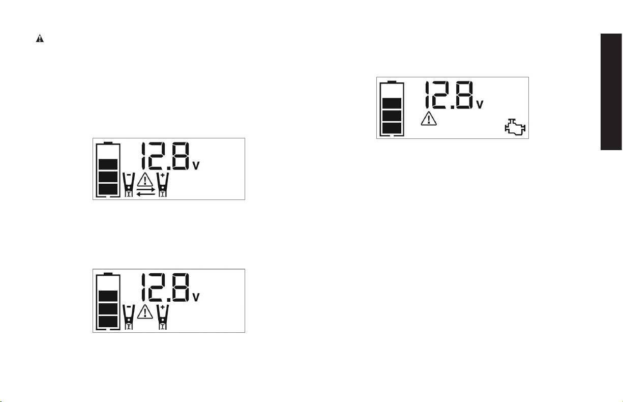
• Never touch red and black clamps together. This can cause
dangerous sparks, power arcing, and/or explosion.
If the red and black clamps touch each other, the unit will sound a
continuous two-second alarm every ten seconds until the clamps are
separated. The backlit LCD screen will display the following:
The Battery Status Icon and Battery Voltage Indicator light solid.
The Alarm Icon, Clamp Icons and the “+” and”–” signs will flash.
Immediately separate the clamps and do not allow them to touch
again.
• If the unit is overheated during the jump starting process, the thermal
protection will activate and the backlit LCD screen will display the
following:
The Battery Status Icon and Battery Voltage Indicator light solid. The
alarm icon and Jump Starter Icon will flash. Allow the unit to cool for
10-30 minutes before use.
• Always disconnect the negative (black) jumper cable first, followed by
the positive (red) jumper cable, except for positive grounded systems.
PROCEDURE
Take the following steps, observing all cautions and warnings in the
“Important Safety Instructions” section at the front of this manual.
1. Turn off vehicle ignition and all accessories (radio, A/C, lights,
connected cell phone chargers, etc.). Place vehicle in “park” and
set the emergency brake.
2. Remove jumper clamps from clamp tabs. Connect the red clamp
first, then the black clamp.
3. Procedure for jump-starting a NEGATIVE GROUNDED
SYSTEM (negative battery terminal is connected to chassis)
(MOST COMMON)
3a. Connect positive (+) red clamp to vehicle battery’s positive
terminal.
3b. Connect negative (–) black clamp to chassis or a solid, non-
moving, metal vehicle component or body part. Never clamp
DXAEPS14_ManualENSP_020221.indd 14-15DXAEPS14_ManualENSP_020221.indd 14-15 2/2/2021 10:56:31 AM2/2/2021 10:56:31 AM
English
English
14 15
2. Recharging the battery after each use will prolong battery life;
frequent heavy discharges between recharges and/or overcharging
will reduce battery life.
3. Make sure all other unit functions are turned off during recharging,
as this can slow the recharging process.
CAUTION – Risk of property damage: Failure to keep the battery
charged will cause permanent damage and result in poor jump starting
performance.
IMPORTANT: If you know the unit is discharged, but the battery icon
displays four solid bars as if the unit is fully charged when connected to
a charging power source, this may be due to the internal battery having
high impedance. The manufacturer suggests leaving the unit charging
for a period of 40 hours using the supplied AC charger before use.
Charging/Recharging Using the
Supplied Charging Adapter
1. Lift the protective cover of 12V DC Charging Port located on the
back of the unit (refer to Fig. 2 to locate). Insert the barrel connector
of the AC charging adapter into the DC charging port. Insert the
plug end into a (powered) standard North American 120 volt 60Hz
outlet. When the unit is properly connected to an AC power source,
the LCD screen will display the following:
The bars on the Battery Status Icon represent the charge level of
the unit’s internal battery. The bars on the Battery Status Icon will
change from empty to solid (bottom to top) repeatedly to indicate
the unit is charging. The backlight will turn on for 10 seconds (only).
2. Charge for approximately 40 hours or until the Battery Status Icon
shows 4 solid bars.
3. When charging is complete, disconnect the AC charging adapter –
first unplug the adapter from the AC power source, then disconnect
the barrel connector from the unit.
Jump-Starter
A. For negative-grounded systems (most common), connect the
positive (red) clamp to the positive ungrounded battery post
and the negative (black) clamp to the vehicle chassis or engine
block away from the battery. Do not connect the clamp to the
carburetor, fuel lines or sheet-metal body parts. Connect to a
heavy gage metal part of the frame or engine block.
B. For positive-grounded systems, connect the negative (black)
clamp to the negative ungrounded battery post and the positive
(red) clamp to the vehicle chassis or engine block away from the
battery. Do not connect the clamp to the carburetor, fuel lines or
sheet-metal body parts. Connect to a heavy gage metal part of
the frame or engine block.
IMPORTANT: . All features
must be turned off with the
exception of the area light
when jump-starting. The unit
is intended to be used only in
the upright position. The unit
must be kept upright during
use. See the illustration
to the right for correct
orientation.
WARNING – To reduce the risk of serious injury or property
damage:
• Follow all safety instructions found in the “Specific Safety Instructions
for Jump Starters” section of this instruction manual.
• If the clamps are connected incorrectly with regard to polarity, the unit
will sound a continuous alarm until the clamps are disconnected. The
backlit LCD Screen will display the Battery Status Icon, the Battery
Voltage Indicator and the Clamp Icons. The “+” and”–” signs above
the Clamp Icons, the Arrow Icons and the Alarm Icon will flash. The
backlit LCD screen will display the following:
Disconnect the clamps and reconnect to battery with correct polarity.
• Never touch red and black clamps together. This can cause
dangerous sparks, power arcing, and/or explosion.
If the red and black clamps touch each other, the unit will sound a
continuous two-second alarm every ten seconds until the clamps are
separated. The backlit LCD screen will display the following:
The Battery Status Icon and Battery Voltage Indicator light solid.
The Alarm Icon, Clamp Icons and the “+” and”–” signs will flash.
Immediately separate the clamps and do not allow them to touch
again.
• If the unit is overheated during the jump starting process, the thermal
protection will activate and the backlit LCD screen will display the
following:
The Battery Status Icon and Battery Voltage Indicator light solid. The
alarm icon and Jump Starter Icon will flash. Allow the unit to cool for
10-30 minutes before use.
• Always disconnect the negative (black) jumper cable first, followed by
the positive (red) jumper cable, except for positive grounded systems.
PROCEDURE
Take the following steps, observing all cautions and warnings in the
“Important Safety Instructions” section at the front of this manual.
1. Turn off vehicle ignition and all accessories (radio, A/C, lights,
connected cell phone chargers, etc.). Place vehicle in “park” and
set the emergency brake.
2. Remove jumper clamps from clamp tabs. Connect the red clamp
first, then the black clamp.
3. Procedure for jump-starting a NEGATIVE GROUNDED
SYSTEM (negative battery terminal is connected to chassis)
(MOST COMMON)
3a. Connect positive (+) red clamp to vehicle battery’s positive
terminal.
3b. Connect negative (–) black clamp to chassis or a solid, non-
moving, metal vehicle component or body part. Never clamp
DXAEPS14_ManualENSP_020221.indd 14-15DXAEPS14_ManualENSP_020221.indd 14-15 2/2/2021 10:56:31 AM2/2/2021 10:56:31 AM

English
English
16 17
directly to negative battery terminal or moving part. Refer to
the automobile owner’s manual.
4. Procedure for jump-starting POSITIVE GROUND SYSTEMS
NOTE: In the rare event that the vehicle to be started has a
Positive Grounded System (positive battery terminal is connected
to chassis), replace steps 3a and 3b above with steps 4a and 4b,
then proceed to step 5.
4a. Connect negative (–) black clamp to vehicle battery’s negative
terminal.
4b. Connect positive (+) red clamp to vehicle chassis or a solid,
non-moving, metal vehicle component or body part. Never
clamp directly to positive battery terminal or moving part. Refer
to the automobile owner’s manual.
5. When the clamps are connected properly, the backlit LCD screen
will display the following to indicate the unit is ready to jump-start:
The Battery Status icon, Battery Voltage Indicator, Clamp Icons
and the “+” and”–” signs light solid. The jump starter icon will flash
to indicate the clamps are properly connected.
6. Turn on the ignition and crank the engine in 5-6 second bursts until
engine starts. The backlit LCD screen will display the following:
The Battery Status Icon, the Battery Voltage Indicator, Clamp
Icons and the “+” and”–” signs light solid to indicate the unit is
jump-starting. The Jump Starter Icon flashes. The Jump Starter
Icon lights solid if vehicle is started.
7. Disconnect the negative (–) engine or chassis clamp first, then
disconnect the positive (+) battery clamp.
NOTE: If the unit is malfunctioning after jump start procedure, please
recharge the unit with the supplied AC charger to reset the unit.
IMPORTANT: Always turn the unit off when not in use. Recharge this
unit fully after each use.
CAUTION – To reduce the risk of property damage:
• Vehicles that have on-board computerized systems may be damaged
if vehicle battery is jump-started. Before jump-starting this type of
vehicle, read the vehicle manual to confirm that external-starting
assistance is advised.
• Excessive engine cranking can damage the vehicle‘s starter motor. If
the engine fails to start after the recommended number of attempts,
discontinue jump-start procedure and look for other problems that
need to be corrected.
• If vehicle fails to start, turn off the ignition, disconnect the jump-start
system’s leads and contact a qualified technician to investigate why
the engine did not start.
Alternator Check
Set up the unit, connect the battery clamps and connect to the battery
following steps 1 through 5 under “Procedure” in the “Jump-Starter”
section.
Important Notes About the Alternator Check Function
1. The unit may detect that the alternator is out of typical voltage
range because someone has added a number of accessory loads
on the charging system, thereby increasing current demand from
the alternator. MAKE SURE THAT THE ALTERNATOR IS RATED
TO SUPPORT THE APPLICATION.
2. This check may not be accurate for every make, manufacturer and
model of vehicle. Check only 12 volt systems.
PART 1
No Load (turn OFF all vehicle’s accessories): The vehicle battery
must be fully charged before testing the alternator. Run the engine
long enough to achieve normal idle speed and verify there is a no-load
voltage.
1. Press the Alternator Check Button to start the check. The backlit
LCD screen will display the following to indicate the unit is analyzing
the alternator:
The Battery Status Icon will light solid and the Alternator Icon will
flash.
2. If the unit detects that the alternator is good, the backlit LCD screen
will display the following:
The Battery Status Icon, Alternator Icon, and “ALT GOOD” will light
solid.
3. If the unit detects that the alternator is out of typical voltage range,
the backlit LCD screen will display the following:
The Battery Status Icon, Alternator Icon and “ALT” will light solid.
The Fault Icon will flash.
4. Press the Alternator Check Button again to stop the test and turn
off the unit.
PART 2
Under Load (accessories ON): Next, load the alternator by turning
on as many accessories as possible (except for A/C and Defrost).
DXAEPS14_ManualENSP_020221.indd 16-17DXAEPS14_ManualENSP_020221.indd 16-17 2/2/2021 10:56:31 AM2/2/2021 10:56:31 AM

English
English
18 19
1. Press the Alternator Check Button to start the check. The backlit
LCD screen will display the following to indicate the unit is analyzing
the alternator:
The Battery Status Icon will light solid and the Alternator Icon will
flash.
2. If the unit detects that the alternator is good, the backlit LCD screen
will display the following:
The Battery Status Icon, Alternator Icon, and “ALT GOOD” will light
solid.
3. If the unit detects that the alternator is out of typical voltage range,
the backlit LCD screen will display the following:
The Battery Status Icon, Alternator Icon and “ALT” will light solid.
The Fault Icon will flash.
4. Press the Alternator Check Button again to stop the test and turn
off the unit.
IMPORTANT: Always turn the unit off when not in use. Recharge this
unit fully after each use.
Portable Compressor
The built-in 12 volt DC compressor is the ultimate compressor for all
vehicle tires, trailer tires and recreational inflatables. A nozzle adaptor
is supplied that screws onto the end of the Sure Fit
®
nozzle at the free
end of the compressor hose. The compressor hose with tire fitting is
stored on the compressor hose bracket on the right side of the unit.
Refer to the “Features” illustration for locations of compressor hose.
The Compressor Power Button and Increase ( ) and Decrease ( )
Compressor Pressure Control Buttons are located on the control panel
on the front of the unit.
Before proceeding, check the unit’s battery status on the LCD screen.
Four solid bars in the battery icon indicates a full battery. When the
battery level is nearly empty with only one solid bar, the unit MUST be
recharged before use or the unit’s built-in low voltage protection will
activate. The empty Battery Status Icon will flash for a short period of
time before automatic shut down.
The compressor is capable of inflating up to 120 pounds per square
inch (psi) pressure. Return hose to the storage bracket after use.
WARNING – To reduce the risk of serious injury or property damage:
Follow all safety instructions found in the “Specific Safety Instructions
for Compressors” section of this instruction manual.
CAUTION – To reduce the risk of serious injury or property damage:
When the compressor is operated at a low PSI, the unit may start in
low and gradually rev up. When the compressor is operated at higher
PSIs, the unit may operate normally for several minutes, then rev down
for a few minutes before returning to normal operation. This feature
protects the unit from overheating during normal use. In any event, do
not operate compressor continuously for longer than 10 minutes, as
it may overheat. This could damage the compressor. If the compressor
must be operated for longer periods: every 10 minutes press the
Compressor Power Button to turn the compressor off, then restart
after a cooling down period of approximately 30 minutes. In any event,
the compressor will automatically shut down after operating
continuously for 10 minutes.
INFLATING TIRES OR PRODUCTS WITH VALVE STEMS
1. Screw the Sure Fit
®
nozzle onto the valve stem. Do not overtighten.
2. Press the Compressor Power Button. A beep will sound and the
backlit LCD screen will display the following:
The Compressor Icon will light and the digital display will alternately
show the flashing pre-set psi value (that was last set by the
compressor pressure control buttons) and the current pressure of
the item being inflated (which will light solid).
3. Press the “ ” and “ ” Pressure Control Buttons to set the desired
pressure from a range pre-set values (between 3 and 120), which
will display on the backlit LCD screen. The unit will sound a beep
with each press of the buttons (holding the button speeds up the
upward or downward value selection). Once the desired pressure
has been entered, release the button and the flashing digital display
will show the new selected pressure, as follows:
The new selected value is now stored in the unit’s memory until it
is manually reset.
4. Press the Compressor Power Button once more to begin inflating.
The Compressor Icon will flash and the digital display will only show
the current pressure value (which will light solid) to indicate the
compressor is activated. Monitor the pressure on the LCD screen.
IMPORTANT NOTE: To interrupt during inflation, press the
Compressor Power Button again.
5. When desired pre-set pressure is reached, the compressor will
automatically stop.
6. Press the Compressor Power Button again to turn off the unit.
7. Unscrew and remove the Sure Fit
®
nozzle from the valve stem.
8. Allow the unit to cool, then recharge before storing away.
9. Store the compressor hose and Sure Fit
®
nozzle in storage bracket.
INFLATING OTHER INFLATABLES WITHOUT VALVE STEMS
Inflation of other items requires use of the nozzle adapter.
1. Screw the nozzle adapter into the Sure Fit
®
nozzle. Do not
overtighten.
2. Insert the nozzle adapter into item to be inflated.
3. Follow steps 2 through 4 of the “Inflating Tires or Products With
Valve Stems” section.
DXAEPS14_ManualENSP_020221.indd 18-19DXAEPS14_ManualENSP_020221.indd 18-19 2/2/2021 10:56:31 AM2/2/2021 10:56:31 AM
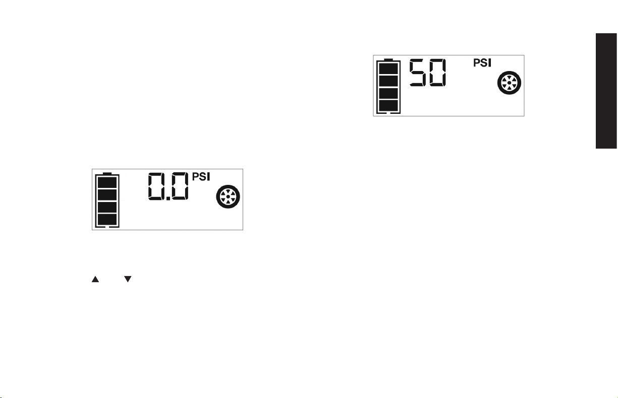
English
English
20 21
IMPORTANT: Small items such as volleyballs, footballs, etc. inflate
very rapidly. Keep this in mind when setting pressure. Take extra
care not to over-inflate.
4. When the desired pressure is reached, the compressor will
automatically stop. Press the Compressor Power Button again to
turn off the unit.
5. Disconnect the adapter from the inflated item.
6. Unscrew and remove the nozzle adapter from the Sure Fit
®
nozzle.
7. Allow the unit to cool, then recharge before storing away.
8. Store the compressor hose, Sure Fit
®
nozzle and nozzle adapter
in the storage bracket.
120 Volt AC Power Outlets
RATED VERSUS ACTUAL CURRENT DRAW OF EQUIPMENT
Most electrical tools, appliances, electronic devices and audio/visual
equipment have labels that indicate the power consumption in amps or
watts. Be sure that the power consumption of the item to be operated
is below 500 watts. If the power consumption is rated in amps AC,
simply multiply by the AC volts (120) to determine the wattage.
Resistive loads are the easiest for this unit to run; however, it will not
run larger resistive loads (such as electric stoves and heaters), which
require far more wattage than the unit can deliver on a continuous
basis. Inductive loads (such as TVs and stereos) require more current
to operate than do resistive loads of the same wattage rating.
POWER INVERTER OUTPUT WAVEFORM
The AC output waveform of this unit is known as a modified sine wave.
It is a stepped waveform that has characteristics similar to the sine wave
shape of utility power. This type of waveform is suitable for most AC
loads, including linear and switching power supplies used in electronic
equipment, transformers, and small motors.
PROTECTIVE FEATURES
The unit monitors the following conditions:
Low internal battery voltage: The unit will automatically shut down
when the battery voltage drops too low, as this can harm the battery.
High internal battery voltage: The unit will automatically shut down
when the battery voltage is too high, as this can harm the unit.
Thermal shutdown protection: The unit will automatically shut down
when the unit becomes overheated.
Overload/short circuit protection: The unit will automatically shut
down when an overload or short circuit occurs.
Important Notes Concerning the AC Power Outlets
The two AC Power Outlets provide a combined total power draw of
500W.
When the AC Power Outlets are in use, the unit will monitor for the
following fault conditions: thermal fault, low and high battery voltage
fault, overload and short circuit (refer to the “Protective Features”
section).
1. If a low internal battery voltage fault condition exists, the AC Power
Outlets will shut down automatically and the backlit LCD screen
will display the following until the fault is corrected:
The Digital Display will show “AC”; the EMPTY Battery Status Icon
and Fault Icon on the LCD Screen will flash.
2. If a high internal battery voltage fault condition exists, the AC Power
Outlets will shut down automatically and the backlit LCD screen
will display the following until the fault is corrected:
The Digital Display will show “AC”; the FULL Battery Status Icon
and Fault Icon on the LCD Screen will flash.
3. If a thermal, overload or short circuit fault condition exists, the AC
Power Outlets will shut down automatically and the backlit LCD
screen will display the following until the fault is corrected:
The Battery Status Icon will light solid; the “AC” on the Digital
Display and the Fault Icon on the LCD Screen will flash.
Should any of the above fault conditions occur:
1. Disconnect the appliance from the unit.
2. Press the AC Power Button to turn the AC Power Outlet off.
3. Make sure the unit does not need to be recharged.
4. Allow the unit to cool down for several minutes.
5. Make sure the rating of the appliance plugged into the unit is
500 watts or lower and that the appliance cord and plug are not
damaged.
6. Assure there is adequate ventilation around the unit before
proceeding.
USING THE DUAL 120 VOLT AC OUTLETS
The two 120 Volt AC Outlets are located on the front of the unit (refer
to Fig. 2 to locate). The two outlets support a combined maximum
power draw of 500 watts.
1. Press the AC Power Button to turn on both 120V AC Power
Outlets. A beep will sound and the LCD Screen will display the
following:
The Battery Status Icon lights solid and the Digital Display shows
“AC,” indicating the dual AC outlets are ready to use.
2. Pull and hold the protective cover of the left AC outlet
counterclockwise or the protective cover of the right AC outlet
clockwise to expose the outlets. Insert the 120 volt AC plug from
the appliance into one of the 120 volt AC outlets.
3. Switch on the appliance and operate as usual.
NOTE: Ensure that the wattage of all equipment simultaneously
plugged into both 120V AC Power Outlets does not exceed 500
watts continuous.
4. Press the AC Power Button again to turn off the 120V AC Power
Outlets.
Monitor the unit’s internal battery status on the LCD Screen. Four solid
bars in the battery icon indicates a full battery. When the battery level
is nearly empty with only one solid bar, the unit MUST be recharged
at this time.
Make sure the AC Power Outlets are turned off when the unit is being
recharged or stored.
DXAEPS14_ManualENSP_020221.indd 20-21DXAEPS14_ManualENSP_020221.indd 20-21 2/2/2021 10:56:31 AM2/2/2021 10:56:31 AM

English
English
20 21
IMPORTANT: Small items such as volleyballs, footballs, etc. inflate
very rapidly. Keep this in mind when setting pressure. Take extra
care not to over-inflate.
4. When the desired pressure is reached, the compressor will
automatically stop. Press the Compressor Power Button again to
turn off the unit.
5. Disconnect the adapter from the inflated item.
6. Unscrew and remove the nozzle adapter from the Sure Fit
®
nozzle.
7. Allow the unit to cool, then recharge before storing away.
8. Store the compressor hose, Sure Fit
®
nozzle and nozzle adapter
in the storage bracket.
120 Volt AC Power Outlets
RATED VERSUS ACTUAL CURRENT DRAW OF EQUIPMENT
Most electrical tools, appliances, electronic devices and audio/visual
equipment have labels that indicate the power consumption in amps or
watts. Be sure that the power consumption of the item to be operated
is below 500 watts. If the power consumption is rated in amps AC,
simply multiply by the AC volts (120) to determine the wattage.
Resistive loads are the easiest for this unit to run; however, it will not
run larger resistive loads (such as electric stoves and heaters), which
require far more wattage than the unit can deliver on a continuous
basis. Inductive loads (such as TVs and stereos) require more current
to operate than do resistive loads of the same wattage rating.
POWER INVERTER OUTPUT WAVEFORM
The AC output waveform of this unit is known as a modified sine wave.
It is a stepped waveform that has characteristics similar to the sine wave
shape of utility power. This type of waveform is suitable for most AC
loads, including linear and switching power supplies used in electronic
equipment, transformers, and small motors.
PROTECTIVE FEATURES
The unit monitors the following conditions:
Low internal battery voltage: The unit will automatically shut down
when the battery voltage drops too low, as this can harm the battery.
High internal battery voltage: The unit will automatically shut down
when the battery voltage is too high, as this can harm the unit.
Thermal shutdown protection: The unit will automatically shut down
when the unit becomes overheated.
Overload/short circuit protection: The unit will automatically shut
down when an overload or short circuit occurs.
Important Notes Concerning the AC Power Outlets
The two AC Power Outlets provide a combined total power draw of
500W.
When the AC Power Outlets are in use, the unit will monitor for the
following fault conditions: thermal fault, low and high battery voltage
fault, overload and short circuit (refer to the “Protective Features”
section).
1. If a low internal battery voltage fault condition exists, the AC Power
Outlets will shut down automatically and the backlit LCD screen
will display the following until the fault is corrected:
The Digital Display will show “AC”; the EMPTY Battery Status Icon
and Fault Icon on the LCD Screen will flash.
2. If a high internal battery voltage fault condition exists, the AC Power
Outlets will shut down automatically and the backlit LCD screen
will display the following until the fault is corrected:
The Digital Display will show “AC”; the FULL Battery Status Icon
and Fault Icon on the LCD Screen will flash.
3. If a thermal, overload or short circuit fault condition exists, the AC
Power Outlets will shut down automatically and the backlit LCD
screen will display the following until the fault is corrected:
The Battery Status Icon will light solid; the “AC” on the Digital
Display and the Fault Icon on the LCD Screen will flash.
Should any of the above fault conditions occur:
1. Disconnect the appliance from the unit.
2. Press the AC Power Button to turn the AC Power Outlet off.
3. Make sure the unit does not need to be recharged.
4. Allow the unit to cool down for several minutes.
5. Make sure the rating of the appliance plugged into the unit is
500 watts or lower and that the appliance cord and plug are not
damaged.
6. Assure there is adequate ventilation around the unit before
proceeding.
USING THE DUAL 120 VOLT AC OUTLETS
The two 120 Volt AC Outlets are located on the front of the unit (refer
to Fig. 2 to locate). The two outlets support a combined maximum
power draw of 500 watts.
1. Press the AC Power Button to turn on both 120V AC Power
Outlets. A beep will sound and the LCD Screen will display the
following:
The Battery Status Icon lights solid and the Digital Display shows
“AC,” indicating the dual AC outlets are ready to use.
2. Pull and hold the protective cover of the left AC outlet
counterclockwise or the protective cover of the right AC outlet
clockwise to expose the outlets. Insert the 120 volt AC plug from
the appliance into one of the 120 volt AC outlets.
3. Switch on the appliance and operate as usual.
NOTE: Ensure that the wattage of all equipment simultaneously
plugged into both 120V AC Power Outlets does not exceed 500
watts continuous.
4. Press the AC Power Button again to turn off the 120V AC Power
Outlets.
Monitor the unit’s internal battery status on the LCD Screen. Four solid
bars in the battery icon indicates a full battery. When the battery level
is nearly empty with only one solid bar, the unit MUST be recharged
at this time.
Make sure the AC Power Outlets are turned off when the unit is being
recharged or stored.
DXAEPS14_ManualENSP_020221.indd 20-21DXAEPS14_ManualENSP_020221.indd 20-21 2/2/2021 10:56:31 AM2/2/2021 10:56:31 AM
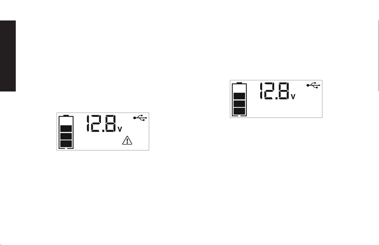
English
English
22 23
USB Ports
The USB Power Button and the four USB Ports are located on the front
of the unit; the USB Power/Fault Indicator is a translucent ring around
each of the USB Ports. Refer to Fig. 2 to locate.
Important Notes Concerning the USB Ports
1. The four USB Ports provide a combined total of 6.2A. The two left
USB Ports provide a total of 3.1A (5V each). The two right USB
Ports provide a total of 3.1A (5V each).
2. When the USB Ports are in use, the unit will monitor for the following
USB fault conditions on all the USB Ports: low battery voltage fault,
overload and short circuit. If a fault condition exists in either of the
USB Ports, the USB Power/Fault Indicators will flash blue. In any
of these cases, the backlit LCD screen will continuously display
the following:
The Fault Icon will flash. The USB Ports will automatically shut
down. Should this occur:
a. Disconnect the USB-powered device and press the USB Power
Button again to turn off the USB Ports immediately.
b. Make sure the unit does not need to be recharged.
c. Allow the unit to cool down for several minutes before attempting
to use the USB Ports again.
d. If an individual USB device is within specifications and the fault
occurs, have the USB device checked for malfunction and do
not continue to use it with these USB Ports.
3. This unit’s USB Ports do not support data communication. They
only provide power to external USB-powered devices.
4. Some household USB-powered electronics will not operate with
this unit.
USING THE USB PORTS
1. Press the USB Power Button to turn on all of the USB Ports. A
beep will sound, the USB Power/Fault Indicators around each of the
four USB Ports will light blue and the LCD screen will continuously
display the following:
The Battery Status Icon and Battery Voltage Indicator will light
solid, as well as the USB Icon, indicating the USB ports are ready
to use.
2. Plug the USB-powered device into the USB power port(s) and
operate normally.
3. Press the USB Power Button again to turn off the USB Ports.
Periodically check the unit’s battery status on the backlit LCD screen.
Four solid bars in the battery icon indicates a full battery. When the
battery level is nearly empty with only one solid bar or completely empty
with 4 empty bars, the unit must be recharged at this time or the unit’s
built-in low voltage protection will activate. The empty Battery Status
Icon will flash for a short period of time before automatic shut down.
IMPORTANT: Make sure the USB Ports are turned off when the unit
is being recharged or stored.
LED Area Light
The built-in LED Area Light consists of two banks of two LEDs (one on
the right hand side, one on the left hand side of the back of the unit).
It is controlled by the Area Light Power Button on the control panel
(refer to Fig. 2 to locate).
1. Press the Area Light Power Button once to turn the light on.
2. Press the Area Light Power Button again to turn the area light off.
When the Area Light Power Button is pressed to turn it on, a beep will
sound. The backlit LCD screen will turn on for 10 seconds (only) and
will then continuously display the Battery Status Icon and the Battery
Voltage Indicator.
Periodically check the unit’s battery status on the backlit LCD screen.
Four solid bars in the battery icon indicates a full battery. When the
battery level is nearly empty with only one solid bar or completely empty
with 4 empty bars, the unit must be recharged at this time or the unit’s
built-in low voltage protection will activate. The empty Battery Status
Icon will flash for a short period of time before automatic shut down.
IMPORTANT: Make sure the Area Light is turned off when the unit is
being recharged or stored.
Care and Maintenance
WARNING: To reduce the risk of injury, turn the unit off and
disconnect it from any power source before installing and removing
accessories, before adjusting or when performing maintenance. An
accidental start-up can cause injury.
Never submerge this unit in water. Dirt and grease may be removed
from the exterior of the unit using a cloth or soft non-metallic brush.
Never let any liquid get inside the unit; never immerse any part of the
unit into a liquid.
WARNING: Shock hazard. Disconnect the 12 Volt AC Charging
Adapter before cleaning the unit.
There are no user-replaceable parts. Periodically inspect the condition
of adapters, connectors and wires. Contact manufacturer to replace
any components that have become worn or broken.
THE INTERNAL BATTERY
All batteries lose energy from self-discharge over time and more rapidly
at higher temperatures. When the unit is not in use, we recommend
that the battery is charged at least every 30 days.
BATTERY REPLACEMENT
The battery should last the service life of the unit. Service life is
dependent on a number of factors including but not limited to the
number of recharge cycles, and proper care and maintenance of the
battery by the end user. Contact manufacturer for any information you
may need.
SAFE BATTERY DISPOSAL
Contains a maintenance-free, sealed, non-spillable, lead
acid battery, which must be disposed of properly. Recycling
is required. Failure to comply with local, state and federal
regulations can result in fines, or imprisonment.
Please recycle.
WARNING: To reduce the risk of serious injury or property
damage:
• Do not dispose of the battery in fire as this may result in an explosion.
• Before disposing of the battery, protect exposed terminals with
heavy-duty electrical tape to prevent shorting (shorting can result
in injury or fire).
• Do not expose battery to fire or intense heat as it may explode.
DXAEPS14_ManualENSP_020221.indd 22-23DXAEPS14_ManualENSP_020221.indd 22-23 2/2/2021 10:56:31 AM2/2/2021 10:56:31 AM

English
English
24 25
Troubleshooting
Problem Possible Solution
Unit will not charge If the unit’s battery is deeply depleted, it
may require up to 96 hours of charging
using the AC method.
Make sure all of the unit’s functions are
turned off.
Check the connection to the AC power
source.
Confirm there is a functioning
AC current.
Unit fails to jump-start Make sure a proper polarity cable
connection has been established.
The unit may be overheated due to
the excessive engine cranking. Make
sure all the unit functions are turned off
and allow the unit to cool down before
resuming operation.
Make sure the unit is not being operated
in the Compressor mode.
Check that the unit has a full charge.
Recharge the unit if necessary.
Problem Possible Solution
Portable Compressor
will not inflate
Make sure the Compressor Power
Button has been pressed to turn the
compressor on.
Make sure the unit is not being
operated in the Jump Starter mode.
Make sure the Sure Fit
®
nozzle is
securely screwed on to the valve stem
when attempting to inflate tires; or that
the nozzle adapter is securely screwed
into the Sure Fit
®
nozzle and is inserted
properly into the item to be inflated on
all other inflatables.
Check that the unit has a full charge.
Recharge the unit if necessary.
120 Volt AC Outlet will
not power appliance
Make sure the AC Power Button has
been turned on.
Make sure you have followed all the
steps in the “120 AC Power Outlets”
section carefully. Refer to the important
notes included in that section that
explain common problems and
solutions.
Make sure the combined draw of all
appliances being powered is not more
than 500 watts.
Check that unit has a full charge.
Recharge unit if necessary.
Problem Possible Solution
USB Port will not
power device
Make sure the USB Power Button is in
the on position.
Make sure all the USB Power/Fault
Indicators light solid blue. If a fault
condition exists in either of the USB
Ports, the USB Power/Fault Indicators
will flash blue. Refer to the Important
Notes in the “USB Ports” section to
remedy any faults.
Make sure that the total draw of all USB
devices plugged into the two left USB
Ports does not exceed 3.1A and/or the
total draw of all USB devices plugged
into the two right USB Ports does not
exceed 3.1A.
Some USB-powered household
electronics will not operate with this
USB charging/power port. Check the
manual of the corresponding electronic
device to confirm that it can be used
with this type of USB charging/power
port.
Check that the unit has a full charge.
Recharge the unit if necessary.
LED Area Light does
not come on
Make sure the Area Light Power Button
is in the on position
Check that the unit has a full charge.
Recharge the unit if necessary.
Accessories
WARNING: Since accessories, other than those offered by
D
e
WALT, have not been tested with this product, use of such
accessories with this unit could be hazardous. To reduce the risk of
injury, only D
e
WALT recommended accessories should be used with
this product.
If you need assistance regarding accessories, please contact the
manufacturer at 1-888-394-3392 or CustomerService@dewalt12volt.
com.
Service Information
Whether you need technical advice, repair, or genuine factory
replacement parts, contact the manufacturer at 1-888-394-3392 or
One Year Limited Warranty
The warranty of this product is covered by Baccus Global LLC
(1-888-394-3392 or CustomerService@dewalt12volt.com). The
manufacturer warrants this product against defects in material and
workmanship for a period of one (1) year from the date of retail purchase
by the original end-user purchaser (“Warranty Period”).
If there is a defect and a valid claim is received within the Warranty
Period, the defective product can be repaired, replaced or refunded,
without charge, in the following ways: (1) Return the product to the
manufacturer for repair, replacement or refund at manufacturer’s option.
Proof of purchase may be required by manufacturer. (2) Return the
product to the retailer where product was purchased for an exchange
(provided that the store is a participating retailer). Returns to retailer
should be made within the time period of the retailer’s return policy for
exchanges only (usually 30 to 90 days after the sale). Proof of purchase
may be required. Please check with the retailer for their specific return
policy regarding returns that are beyond the time set for exchanges.
DXAEPS14_ManualENSP_020221.indd 24-25DXAEPS14_ManualENSP_020221.indd 24-25 2/2/2021 10:56:31 AM2/2/2021 10:56:31 AM

English
English
24 25
Troubleshooting
Problem Possible Solution
Unit will not charge If the unit’s battery is deeply depleted, it
may require up to 96 hours of charging
using the AC method.
Make sure all of the unit’s functions are
turned off.
Check the connection to the AC power
source.
Confirm there is a functioning
AC current.
Unit fails to jump-start Make sure a proper polarity cable
connection has been established.
The unit may be overheated due to
the excessive engine cranking. Make
sure all the unit functions are turned off
and allow the unit to cool down before
resuming operation.
Make sure the unit is not being operated
in the Compressor mode.
Check that the unit has a full charge.
Recharge the unit if necessary.
Problem Possible Solution
Portable Compressor
will not inflate
Make sure the Compressor Power
Button has been pressed to turn the
compressor on.
Make sure the unit is not being
operated in the Jump Starter mode.
Make sure the Sure Fit
®
nozzle is
securely screwed on to the valve stem
when attempting to inflate tires; or that
the nozzle adapter is securely screwed
into the Sure Fit
®
nozzle and is inserted
properly into the item to be inflated on
all other inflatables.
Check that the unit has a full charge.
Recharge the unit if necessary.
120 Volt AC Outlet will
not power appliance
Make sure the AC Power Button has
been turned on.
Make sure you have followed all the
steps in the “120 AC Power Outlets”
section carefully. Refer to the important
notes included in that section that
explain common problems and
solutions.
Make sure the combined draw of all
appliances being powered is not more
than 500 watts.
Check that unit has a full charge.
Recharge unit if necessary.
Problem Possible Solution
USB Port will not
power device
Make sure the USB Power Button is in
the on position.
Make sure all the USB Power/Fault
Indicators light solid blue. If a fault
condition exists in either of the USB
Ports, the USB Power/Fault Indicators
will flash blue. Refer to the Important
Notes in the “USB Ports” section to
remedy any faults.
Make sure that the total draw of all USB
devices plugged into the two left USB
Ports does not exceed 3.1A and/or the
total draw of all USB devices plugged
into the two right USB Ports does not
exceed 3.1A.
Some USB-powered household
electronics will not operate with this
USB charging/power port. Check the
manual of the corresponding electronic
device to confirm that it can be used
with this type of USB charging/power
port.
Check that the unit has a full charge.
Recharge the unit if necessary.
LED Area Light does
not come on
Make sure the Area Light Power Button
is in the on position
Check that the unit has a full charge.
Recharge the unit if necessary.
Accessories
WARNING: Since accessories, other than those offered by
D
e
WALT, have not been tested with this product, use of such
accessories with this unit could be hazardous. To reduce the risk of
injury, only D
e
WALT recommended accessories should be used with
this product.
If you need assistance regarding accessories, please contact the
manufacturer at 1-888-394-3392 or CustomerService@dewalt12volt.
com.
Service Information
Whether you need technical advice, repair, or genuine factory
replacement parts, contact the manufacturer at 1-888-394-3392 or
One Year Limited Warranty
The warranty of this product is covered by Baccus Global LLC
(1-888-394-3392 or [email protected]). The
manufacturer warrants this product against defects in material and
workmanship for a period of one (1) year from the date of retail purchase
by the original end-user purchaser (“Warranty Period”).
If there is a defect and a valid claim is received within the Warranty
Period, the defective product can be repaired, replaced or refunded,
without charge, in the following ways: (1) Return the product to the
manufacturer for repair, replacement or refund at manufacturer’s option.
Proof of purchase may be required by manufacturer. (2) Return the
product to the retailer where product was purchased for an exchange
(provided that the store is a participating retailer). Returns to retailer
should be made within the time period of the retailer’s return policy for
exchanges only (usually 30 to 90 days after the sale). Proof of purchase
may be required. Please check with the retailer for their specific return
policy regarding returns that are beyond the time set for exchanges.
DXAEPS14_ManualENSP_020221.indd 24-25DXAEPS14_ManualENSP_020221.indd 24-25 2/2/2021 10:56:31 AM2/2/2021 10:56:31 AM

Español
27
English
26
This warranty does not apply to: accessories, bulbs, fuses and batteries;
defects resulting from normal wear and tear, accidents; damages
sustained during shipping; alterations; unauthorized use or repair;
neglect, misuse, abuse; and failure to follow instructions for care and
maintenance for the product.
This warranty gives you, the original retail purchaser, specific legal rights
and you may have other rights which vary in certain states or provinces.
This product is not intended for commercial use.
90 DAY REFUND POLICY
If you are not completely satisfied with the performance of this product
for any reason, you can return it within ninety (90) days from the date
of purchase with a receipt for a full refund.
Please visit our website www.baccusglobal.com/register to register
your new Baccus Global LLC product and to be kept up to date on
new products and special offers.
Specifications
Boost Ampere 1,600A peak, 750A instant
Battery Type SLA, 12V DC
Input 120V AC, 60Hz, 14W
Compressor 120 PSI
USB Output 5V DC each, 6.2A total (3.1A
total in the two left USB Ports;
3.1A total in the two right USB
Ports)
120V AC Power Outlets 120V AC, 60Hz, 500W
Sure Fit
®
is a registered trademark owned by Baccus Global, LLC.
Manufactured and Imported by Baccus Global LLC,
621 NW 53rd St., Suite 450, Boca Raton, FL 33487
www.dewalt12volt.com 1-888-394-3392
Made in Vietnam
Copyright © 2021 Baccus Global, LLC. D
e
WALT
®
and the D
e
WALT
Logo are trademarks of the D
e
WALT Industrial Tool Co., or an affiliate
thereof and are used under license. The yellow/black color scheme is
a trademark for D
e
WALT power tools & accessories.
www.dewalt12volt.com
Definiciones: Normas de seguridad
Las siguientes definiciones describen el nivel de gravedad de
cada palabra de señal. Lea el manual y preste atención a estos
símbolos.
PELIGRO: Indica una situación de peligro inminente que, si
no se evita, provocará la muerte o lesiones graves.
ADVERTENCIA: Indica una situación de peligro potencial
que, si no se evita, podría provocar la muerte o lesiones
graves.
ATENCIÓN: Indica una situación de peligro potencial que, si
no se evita, posiblemente provocaría lesiones leves o
moderadas.
AVISO: Se refiere a una práctica no relacionada a lesiones
corporales que de no evitarse puede resultar en daños a la
propiedad.
SI TIENE ALGUNA DUDA O ALGÚN COMENTARIO SOBRE ÉSTA
HERRAMIENTA D
e
WALT, LLÁMENOS AL NÚMERO GRATUITO:
1-888-394-3392.
Fuente de energía
La DXAEPS14 fuente de energía es un
DeWALT
fuente de energía que
incluye un puente auxiliar de arranque, compresor digital, dos tomas de
corriente 120V CA, cuatro puertos USB y luces de área LED.
Instrucciones
importantes sobre
seguridad
ADVERTENCIA: Cuando se utilizan aparatos eléctricos, siempre
se deben seguir las precauciones básicas, entre las que se incluyen
las siguientes;
1. Conserve estas instrucciones.
2. Preste atención a todas las advertencias.
3. Obedezca todas las advertencias.
4. Evite las condiciones ambientales peligrosas. No utilice artefactos
en zonas húmedas o mojadas. No utilice artefactos bajo la lluvia.
5. Limpie únicamente con un trapo seco.
6. El arrancador y el adaptador de carga suministrado no son
juguetes y no se puede jugar con ellos como si fueran juguetes.
Para reducir el riesgo de lesiones, es necesario supervisar de
cerca cuando estas unidades se utilizan cerca de niños.
7. Guarde en el interior . Cuando no los utilice, los artefactos deben
guardarse bajo techo, en un lugar seco, alto o bajo llave, lejos
del alcance de los niños.
8. Manténgase alerta. Use el sentido común. No opere este equipo
si está cansado o con impedimentos.
9. Utilice únicamente los aditamentos y accesorios especificados
por el fabricante. El uso de cualquier accesorio o dispositivo no
recomendado para su uso con este dispositivo puede provocar
un riesgo de incendio, descarga eléctrica o lesiones a las
personas.
DXAEPS14_ManualENSP_020221.indd 26-27DXAEPS14_ManualENSP_020221.indd 26-27 2/2/2021 10:56:32 AM2/2/2021 10:56:32 AM

Español
Español
2928
LEA TODAS LAS INSTRUCCIONES
Instrucciones de seguridad específicas
para cargar esta unidad
• No abuse del cable. Proteja el cable de extensión para que sea
pisado o aplastado, especialmente en los enchufes, los receptáculos
y el punto donde se conecta a la unidad. Nunca lleve la unidad por el
cable ni tire de éste para desconectarlo de la toma. Tire del enchufe
y no del cable al desconectar de la unidad.
• La protección del interruptor de corte por falla a tierra (GFCI)
debe aplicarse a los circuitos o los tomacorrientes que se utilizarán.
Hay tomacorrientes con protección GFCI incorporada que pueden
utilizarse para tomar esta medida de seguridad.
• IMPORTANTE: Esta unidad se entrega en un estado parcialmente
cargada. Cargar completamente la unidad con un cable de extensión
del hogar para un total de 40 horas o hasta que el icono de estado
de la batería muestra 4 barras sólidas antes de utilizar por primera
vez. No puede sobrecargar la unidad mediante el método de carga
de corriente alterna.
• Para recargar esta unidad, utilice únicamente el adaptador de carga
de CA suministrado. Enchufe primero el adaptador de carga en la
unidad y luego en la fuente de carga.
• Todas las funciones deben estar apagados cuando la unidad se
está cargando o no en uso. Asegúrese de que todas las funciones
se desactivan antes de la conexión a una fuente de alimentación o
de carga.
• Coloque el cable del adaptador de carga de forma que no se enrede
ni se convierta en un peligro para la seguridad. Mantenga el cable
del adaptador de carga alejado de los bordes afilados.
• No aplaste, corte, tire o exponga los cables del adaptador de carga
a un calor extremo.
• Utilícelo sólo en un lugar seco.
• No intente cargar la unidad si el adaptador de carga está dañado
– devuelva el adaptador de carga al fabricante para su reparación
o reemplazo.
• Después de cargar o recargar, desconecte el adaptador de carga y
espere 5 minutos antes de usarlo.
• Cargue la unidad sólo en un área bien ventilada.
ATENCIÓN: Para reducir el riesgo de lesiones o daños a la
propiedad: Tire del enchufe en lugar del cable cuando desenchufe el
adaptador de carga.
Cables de extensión
ADVERTENCIA: El uso de un cable de extensión incorrecta podría
dar lugar a un riesgo de fuego y descarga eléctrica. Al usar un cable
de extensión, cerciórese de que los pernos del cable de extensión son
el mismo número, tamaño y forma que ésos en el cargador; y esté
seguro de utilizar uno bastante pesado para llevar la corriente que su
producto dibujará. Un cable de menor capacidad provocará una
disminución en el voltaje de la línea, lo cual producirá una pérdida de
potencia y sobrecalentamiento. La siguiente tabla muestra la medida
correcta que debe utilizar según la longitud del cable y la capacidad
nominal en amperios indicada en la placa. En caso de duda, utilice el
calibre inmediatamente superior. Cuanto menor es el número de calibre,
más grueso es el cable.
10. Utilice únicamente sobre una superficie plana
y nivelada. Cuando use un carrito, tenga
cuidado al mover la combinación de carro/
aparato para evitar daños por vuelco.
11. Para reducir el riesgo de descarga eléctrica,
desconecte la unidad de la toma de corriente
antes de mantenimiento o limpieza. Apagar los controles sin
desconectar no reducirá este riesgo.
12. Compruebe si hay piezas dañadas. Cualquier pieza que esté
dañada debe ser reparada o reemplazada por el fabricante
a menos que se indique lo contrario en este manual de
instrucciones antes de su uso posterior. Se requiere servicio
cuando el aparato ha sido dañado de alguna manera, como
cuando el cable de alimentación o el enchufe están dañados, se
ha derramado líquido o han caído objetos dentro del aparato, el
aparato ha sido expuesto a la lluvia o humedad, si no funciona
con normalidad , o se ha caído. No utilice el cargador si ha
recibido un golpe fuerte, se ha caído o se ha dañado de alguna
manera. Póngase en contacto con el fabricante en 1-888-394-
3392 para más información.
13. No utilice aparatos que estén dañados o modificados. Las baterías
dañadas o modificadas pueden exhibir un comportamiento
impredecible que resulta en fuego, explosión o riesgo de lesiones.
14. No desmonte el aparato, no hay piezas reparables por el usuario
en el lateral. Llévelo a una persona de servicio calificada cuando
se requiera un servicio o una reparación. El reensamblaje
incorrecto puede provocar un riesgo de incendio o de descarga.
15. Esta unidad está diseñada para usarse en posición vertical. La
unidad DEBE mantenerse en posición vertical durante el uso
16. La unidad no debe exponerse a goteos o salpicaduras y no
deben colocarse objetos llenos de líquidos sobre la unidad.
17. No funcione el aparato cerca de líquidos inflamables o en
atmósferas gaseosas o explosivas. Los motores de estas
herramientas normalmente chispean, y las chispas pueden
encender los vapores.
18. Considere la posibilidad de tener a alguien lo suficientemente
cerca para que le ayude cuando trabaje cerca de una batería
de plomo.
19. No sobrecargue la batería – consulte la sección correspondiente
de este manual.
NOTA: Este equipo ha sido probado y se ha encontrado que cumple
con los límites establecidos para dispositivos digitales Clase B, en
conformidad con la Parte 15 del Reglamento de la FCC. Estos límites
están diseñados para ofrecer un nivel razonable de protección contra la
interferencia dañina en instalaciones residenciales. Este equipo genera,
utiliza y puede emitir energía de radiofrecuencia y, si no se instala y
utiliza de acuerdo a las instrucciones proporcionadas, puede producir
una interferencia dañina para la comunicación radial. Sin embargo,
no existen garantías de que no ocurra interferencia alguna en una
instalación en particular. Si este equipo produce interferencia dañina
para su recepción de radio o televisión, lo que puede ser determinado
al apagar y volver a encender el equipo, se pide al usuario que corrija
la interferencia implementando una o más de las siguientes medidas:
• Cambie la orientación o el lugar donde está ubicada la antena
receptora.
• Aumente el espacio que separa al equipo del receptor.
• Conecte el equipo a una toma de corriente que esté en un
circuito diferente al circuito al que está conectado el receptor.
• Consulte con el concesionario o con un técnico de radio y
televisión experimentado que pueda ayudarle.
AVISO: De acuerdo con la FCC Parte 15, los cambios o modificaciones
a este equipo que no sean expresamente aprobados por
DeWALT
podrían invalidar su autoridad para operar este equipo.
DXAEPS14_ManualENSP_020221.indd 28-29DXAEPS14_ManualENSP_020221.indd 28-29 2/2/2021 10:56:32 AM2/2/2021 10:56:32 AM

Español
Español
2928
LEA TODAS LAS INSTRUCCIONES
Instrucciones de seguridad específicas
para cargar esta unidad
• No abuse del cable. Proteja el cable de extensión para que sea
pisado o aplastado, especialmente en los enchufes, los receptáculos
y el punto donde se conecta a la unidad. Nunca lleve la unidad por el
cable ni tire de éste para desconectarlo de la toma. Tire del enchufe
y no del cable al desconectar de la unidad.
• La protección del interruptor de corte por falla a tierra (GFCI)
debe aplicarse a los circuitos o los tomacorrientes que se utilizarán.
Hay tomacorrientes con protección GFCI incorporada que pueden
utilizarse para tomar esta medida de seguridad.
• IMPORTANTE: Esta unidad se entrega en un estado parcialmente
cargada. Cargar completamente la unidad con un cable de extensión
del hogar para un total de 40 horas o hasta que el icono de estado
de la batería muestra 4 barras sólidas antes de utilizar por primera
vez. No puede sobrecargar la unidad mediante el método de carga
de corriente alterna.
• Para recargar esta unidad, utilice únicamente el adaptador de carga
de CA suministrado. Enchufe primero el adaptador de carga en la
unidad y luego en la fuente de carga.
• Todas las funciones deben estar apagados cuando la unidad se
está cargando o no en uso. Asegúrese de que todas las funciones
se desactivan antes de la conexión a una fuente de alimentación o
de carga.
• Coloque el cable del adaptador de carga de forma que no se enrede
ni se convierta en un peligro para la seguridad. Mantenga el cable
del adaptador de carga alejado de los bordes afilados.
• No aplaste, corte, tire o exponga los cables del adaptador de carga
a un calor extremo.
• Utilícelo sólo en un lugar seco.
• No intente cargar la unidad si el adaptador de carga está dañado
– devuelva el adaptador de carga al fabricante para su reparación
o reemplazo.
• Después de cargar o recargar, desconecte el adaptador de carga y
espere 5 minutos antes de usarlo.
• Cargue la unidad sólo en un área bien ventilada.
ATENCIÓN: Para reducir el riesgo de lesiones o daños a la
propiedad: Tire del enchufe en lugar del cable cuando desenchufe el
adaptador de carga.
Cables de extensión
ADVERTENCIA: El uso de un cable de extensión incorrecta podría
dar lugar a un riesgo de fuego y descarga eléctrica. Al usar un cable
de extensión, cerciórese de que los pernos del cable de extensión son
el mismo número, tamaño y forma que ésos en el cargador; y esté
seguro de utilizar uno bastante pesado para llevar la corriente que su
producto dibujará. Un cable de menor capacidad provocará una
disminución en el voltaje de la línea, lo cual producirá una pérdida de
potencia y sobrecalentamiento. La siguiente tabla muestra la medida
correcta que debe utilizar según la longitud del cable y la capacidad
nominal en amperios indicada en la placa. En caso de duda, utilice el
calibre inmediatamente superior. Cuanto menor es el número de calibre,
más grueso es el cable.
10. Utilice únicamente sobre una superficie plana
y nivelada. Cuando use un carrito, tenga
cuidado al mover la combinación de carro/
aparato para evitar daños por vuelco.
11. Para reducir el riesgo de descarga eléctrica,
desconecte la unidad de la toma de corriente
antes de mantenimiento o limpieza. Apagar los controles sin
desconectar no reducirá este riesgo.
12. Compruebe si hay piezas dañadas. Cualquier pieza que esté
dañada debe ser reparada o reemplazada por el fabricante
a menos que se indique lo contrario en este manual de
instrucciones antes de su uso posterior. Se requiere servicio
cuando el aparato ha sido dañado de alguna manera, como
cuando el cable de alimentación o el enchufe están dañados, se
ha derramado líquido o han caído objetos dentro del aparato, el
aparato ha sido expuesto a la lluvia o humedad, si no funciona
con normalidad , o se ha caído. No utilice el cargador si ha
recibido un golpe fuerte, se ha caído o se ha dañado de alguna
manera. Póngase en contacto con el fabricante en 1-888-394-
3392 para más información.
13. No utilice aparatos que estén dañados o modificados. Las baterías
dañadas o modificadas pueden exhibir un comportamiento
impredecible que resulta en fuego, explosión o riesgo de lesiones.
14. No desmonte el aparato, no hay piezas reparables por el usuario
en el lateral. Llévelo a una persona de servicio calificada cuando
se requiera un servicio o una reparación. El reensamblaje
incorrecto puede provocar un riesgo de incendio o de descarga.
15. Esta unidad está diseñada para usarse en posición vertical. La
unidad DEBE mantenerse en posición vertical durante el uso
16. La unidad no debe exponerse a goteos o salpicaduras y no
deben colocarse objetos llenos de líquidos sobre la unidad.
17. No funcione el aparato cerca de líquidos inflamables o en
atmósferas gaseosas o explosivas. Los motores de estas
herramientas normalmente chispean, y las chispas pueden
encender los vapores.
18. Considere la posibilidad de tener a alguien lo suficientemente
cerca para que le ayude cuando trabaje cerca de una batería
de plomo.
19. No sobrecargue la batería – consulte la sección correspondiente
de este manual.
NOTA: Este equipo ha sido probado y se ha encontrado que cumple
con los límites establecidos para dispositivos digitales Clase B, en
conformidad con la Parte 15 del Reglamento de la FCC. Estos límites
están diseñados para ofrecer un nivel razonable de protección contra la
interferencia dañina en instalaciones residenciales. Este equipo genera,
utiliza y puede emitir energía de radiofrecuencia y, si no se instala y
utiliza de acuerdo a las instrucciones proporcionadas, puede producir
una interferencia dañina para la comunicación radial. Sin embargo,
no existen garantías de que no ocurra interferencia alguna en una
instalación en particular. Si este equipo produce interferencia dañina
para su recepción de radio o televisión, lo que puede ser determinado
al apagar y volver a encender el equipo, se pide al usuario que corrija
la interferencia implementando una o más de las siguientes medidas:
• Cambie la orientación o el lugar donde está ubicada la antena
receptora.
• Aumente el espacio que separa al equipo del receptor.
• Conecte el equipo a una toma de corriente que esté en un
circuito diferente al circuito al que está conectado el receptor.
• Consulte con el concesionario o con un técnico de radio y
televisión experimentado que pueda ayudarle.
AVISO: De acuerdo con la FCC Parte 15, los cambios o modificaciones
a este equipo que no sean expresamente aprobados por
DeWALT
podrían invalidar su autoridad para operar este equipo.
DXAEPS14_ManualENSP_020221.indd 28-29DXAEPS14_ManualENSP_020221.indd 28-29 2/2/2021 10:56:32 AM2/2/2021 10:56:32 AM
Español
Español
3130
del vehículo para confirmar que la ayuda externa para arrancar es
adecuada.
• Los procedimientos de arranque mediante puente sólo se deben
realizar en un área segura, seca y bien ventilada.
• Siempre guarde las abrazaderas de la batería correctamente cuando
no esté en uso.
• Cuando use esta unidad cerca de la batería y el motor del vehículo,
coloque la unidad sobre una superficie plana y estable, y asegúrese
de mantener todas las pinzas, los cables, la ropa y las partes del
cuerpo alejados de los elementos móviles del vehículo.
• Asegúrese de conectar las pinzas con la polaridad correcta. Los
daños causados por una conexión incorrecta no está cubierta por
la garantía.
• No exponga la batería al fuego o a un calor intenso, porque puede
explotar. Antes de eliminar la batería, proteja los terminales expuestos
con cinta aislante para trabajo pesado para evitar cortocircuitos (un
cortocircuito puede producir lesiones o incendio).
• Coloque esta unidad lo más lejos posible de la batería que los cables
permitan.
• Nunca permita que el ácido de la batería entre en contacto con
esta unidad.
• No opere esta unidad en un área cerrada ni restrinja la ventilación
de alguna forma.
• Este sistema está diseñado para ser utilizado únicamente en vehículos
con sistema de batería de CC de 12 voltios. No lo conecte a un
sistema de batería de 6 o 24 voltios.
• Este sistema no está diseñado para ser utilizado en reemplazo de
una batería de vehículo. No intente hacer funcionar un vehículo que
no tenga la batería instalada.
• El exceso de revoluciones del motor puede dañar el mecanismo
de arranque de un vehículo. Si el motor no arranca después de la
cantidad recomendada de intentos, abandone los procedimientos
de arranque mediante puente y busque otros problemas que deban
solucionarse.
• No utilice este puente auxiliar de arranque en una moto de agua. No
fue diseñado para prácticas marinas.
• Si bien esta unidad contiene una batería que no derrama,
se recomienda que la unidad se conserve parada durante el
almacenamiento, el uso y la recarga. Para evitar daños posibles
que puedan acortar la duración de la unidad, protéjala de la luz solar
directa, el calor directo o la humedad.
Instrucciones de seguridad específicas
para compresores
ADVERTENCIA – Peligro de estallido: los artículos que estallan
pueden provocar lesiones graves.
• Siga cuidadosamente las instrucciones en los artículos de ser inflado.
• Nunca exceda la presión recomendada enumerada en instrucciones
en los artículos de ser inflado. Si no se da ninguna presión, contacto
con el fabricante del artículo antes de inflar.
• Siempre monitorear la presión en la pantalla LCD.
PRECAUCIÓN: Para reducir el riesgo de daño a la propiedad:
• Nunca deje el compresor sin supervisión mientras se está usando.
• No funcione el aparato para inflar con aire continuamente por más
de largo que 10 minutos. Esto podría dañar el compresor. Siga las
instrucciones de la sección “Compresor portátil.”
Instrucciones de seguridad específicas
para invertidores
ADVERTENCIA – Para reducir el riesgo de descarga eléctrica:
• No conecte al cableado de distribución de CA.
• No realice conexiones o desconexiones eléctricas en áreas
designadas como PROTEGIDAS CONTRA IGNICIÓN. Esta unidad
NO está aprobada para áreas protegidas contra ignición.
CALIBRE MÍNIMO PARA LOS JUEGOS DE CABLES
Voltios Largo total del cable en pies
120V 0-25 26-50 51-100 101-150
(0-7.6m) (7.6-15.2m) (15.2-30.4m) (30.4-45.7m)
240V 0-50 51-100 101-200 201-300
(0-15.2m) (15.2-30.4m) (30.4-60.9m) (60.9-91.4m)
Grado del amperio Longitud de la cable de extensión
Más No más
0’-25’ 26’-50’ 51 ’-100 ’ 101’ -150 ’
que que Calibrador de alambre Americano (AWG)
0 - 6 18 16 16 14
6 - 10 18 16 14 12
10 - 12 16 16 14 12
12 - 16 14 12 No recomendado
Cuando se utiliza un cable prolongador, asegúrese de que:
• las patas del cable prolongador sean del mismo número, el mismo
tamaño y la misma forma que las del cargador,
• el cable prolongador posea los conductores correctos y esté en
buenas condiciones eléctricas,
• la medida del conductor sea suficientemente grande para la
capacidad nominal en amperios.
• Cables de extensión para uso en exteriores: Cuando la unidad
se carga en el exterior, utilice únicamente cables de extensión
destinados a ser utilizados en el exterior y marcados de esta manera.
Instrucciones de seguridad específicas
para auxiliares de arranque
ADVERTENCIA – Peligro de estallido: No utilice la unidad para
cargar las baterías secas que se usan normalmente con los aparatos
domésticos. Estas baterías pueden estallar y provocar lesiones a las
personas y daños a la propiedad. Use la unidad para carga/ refuerzo
solamente de una batería de plomo-ácido. No está diseñada para
proveer energía a un sistema eléctrico de bajo voltaje que no sea para
arrancar un motor.
El uso de un accesorio no suministrado, recomendado o vendido
por el fabricante específicamente para el uso con esta unidad puede
resultar en un riesgo de descarga eléctrica y lesiones a las personas.
ADVERTENCIA: Para reducir el riesgo de descargas eléctricas,
no sumerja esta unidad en agua o cualquier otro líquido, o usar cuando
está mojado.
ADVERTENCIA – Riesgo de gases explosivos:
• Trabajar cerca de una batería de plomo ácido es peligroso. Las
baterías generan gases explosivos durante su funcionamiento normal.
Por esta razón, es muy importante que siempre lea este manual antes
de utilizar el puente auxiliar de arranque y que siga las instrucciones
con exactitud.
• Para reducir el riesgo de explosión de la batería, siga estas
instrucciones y las publicadas por el fabricante de la batería y el
fabricante de cualquier equipo que tenga la intención de utilizar cerca
de la batería. Revise las indicaciones sobre precauciones en estos
productos y en el motor.
ADVERTENCIA – ra reducir el riesgo de lesiones graves o daño a
la propiedad:
• Almacene siempre las pinzas de la batería cuando no se usa. Nunca
toque las pinzas de la batería entre sí. Esto puede generar chispas
peligrosas, arcos eléctricos o explosión.
ADVERTENCIA – Para reducir el riesgo de incendio:
• No opere cerca de materiales, vapores, polvos o gases inflamables.
• No exponga al calor extremo o las llamas.
PRECAUCIÓN – Para reducir el riesgo de lesiones o daño a la
propiedad:
• NUNCA INTENTE ARRANCAR MEDIANTE PUENTE NI CARGAR
UNA BATERÍA CONGELADA.
• Los vehículos que tienen sistemas computarizados incorporados
pueden resultar dañados si la batería del vehículo se arranca mediante
puente. Antes de arrancar mediante puente, lea el manual del cliente
DXAEPS14_ManualENSP_020221.indd 30-31DXAEPS14_ManualENSP_020221.indd 30-31 2/2/2021 10:56:32 AM2/2/2021 10:56:32 AM

Español
Español
3332
• Manténgase alejado de las paletas del ventilador, las correas, poleas
y otras piezas que puedan causar lesiones a las personas.
• Quítese los elementos personales metálicos, como anillos, pulseras,
collares y relojes cuando trabaja con una batería de plomo-ácido. Una
batería de plomo-ácido puede producir un cortocircuito con bastante
corriente como para soldar un anillo u objeto metálico similar a la piel
y provocar una quemadura grave.
• No use ropa de vinilo cuando arranque un vehículo mediante
puente; la fricción puede provocar chispas peligrosas a causa de la
electricidad estática.
• No use ropas holgadas o joyas. Pueden atascarse en las piezas
en movimiento. Se recomienda utilizar guantes de goma y calzado
antideslizante considerable al trabajar al aire libre. Recójase y cubra
el cabello largo.
• Tenga mucho cuidado de no dejar caer una herramienta de metal
sobre la batería. Puede ser que producir chispas o un cortocircuito
en la batería o en otra parte eléctrica y podría causar una explosión.
• ADVERTENCIA – El líquido de la batería es un ácido sulfúrico
diluido y puede causar lesiones personales o daños a la propiedad.
En caso de contacto con la piel o los ojos, siga las instrucciones a
continuación.
• Piel: Si el ácido de la batería entra en contacto con la piel, enjuáguese
inmediatamente con agua, luego lávese con agua y jabón. Si se
presenta enrojecimiento, dolor o irritación, busque asistencia médica
de inmediato.
• Ojos: Si el ácido de la batería entra en contacto con los ojos, lávese
los ojos inmediatamente durante 15 minutos como mínimo y busque
asistencia médica de inmediato.
• Utilice siempre protección para los ojos al emplear este producto;
el contacto con el ácido de la batería puede producir ceguera o
quemaduras graves. Conozca los procedimientos de primeros
auxilios para el caso de contacto accidental con el ácido de la batería.
• Indicador de cristal líquido del LCD: Si es líquido el cristal viene
en contacto con su piel: Lave el área apagado totalmente con el un
montón de agua. Quite la ropa contaminada. Si es líquido el cristal
consigue en su ojo: Limpie el ojo con un chorro de agua afectado
con agua limpia y después busque la atención médica. Si es líquido
se traga el cristal: Limpie su boca con un chorro de agua a fondo
con agua. Beba las cantidades grandes de agua e induzca vomitar.
Entonces busque la atención médica.
GUARDA ESTAS
INSTRUCCIONES
PARA USO FUTURO
• Nunca sumerja la unidad en el agua ni en ningún otro líquido, ni la
utilice cuando esté húmeda.
ADVERTENCIA – Para reducir el riesgo de incendio:
• No opere cerca de materiales, vapores, polvos o gases inflamables.
• No lo exponga al calor extremo o a las llamas.
PRECAUCIÓN – Para reducir el riesgo de lesiones o daño a la
propiedad:
• Desconecte el enchufe de la aplicación del enchufe del convertidor
antes de intentar cualesquiera reparaciones a la aplicación.
• Cuando un artefacto conectado a esta unidad se usa al aire libre,
utilice sólo cables de extensión diseñados para uso en exteriores y
marcado.
• No intente conectar el inversor mientras que funciona su vehículo.
El hecho de no prestar atención a la carretera puede tener como
consecuencia un accidente grave.
• Siempre utilice el convertidor en lugares adecuadamente ventilados.
• Apague siempre el convertidor cuando es parado.
• Tenga en cuenta que este convertidor no funcionará con aparatos
o equipos de alta potencia en vatios que produzcan calor, como
secadores de cabello, hornos de microondas y tostadores.
• No utilice este convertidor con dispositivos médicos. No se ha
comprobado su funcionamiento en aplicaciones médicas.
• Opere la unidad solamente como se describe en este manual de
instrucciones.
PRECAUCIÓN – Dispositivos recargables
• Algunos dispositivos recargables están diseñados para cargarse
al ser enchufados directamente en un tomacorriente de CA. Estos
dispositivos pueden dañar el inversor o el circuito que se está
cargando.
• Al utilizar un dispositivo recargable, supervise la temperatura durante
los primeros 10 minutos de uso para determinar si genera calor en
exceso.
• Si produce calor en exceso, esto indica que el dispositivo no debe
utilizarse con este inversor.
• Este problema no se presenta con la mayoría de los equipos
operados con batería. La mayoría de estos dispositivos utiliza un
cargador o transformador por separado que está enchufado en un
tomacorriente de CA.
• El inversor puede funcionar con la mayoría de los cargadores y
transformadores.
IMPORTANTE: Algunos equipos portátiles pueden no funcionar con
este inversor.
Instrucciones de seguridad específicas
para el puertos USB
• No introduzca objetos extraños dentro ya sea el puertos USB.
• No conecte un concentrador USB y no conecte más de un dispositivo
electrónico personal a cada puerto USB.
• No utilice esta unidad para operar los aparatos que requieren más
de 6.2 amperios en total para operar desde los puertos USB.
Primeros auxilios
SEGURIDAD PERSONAL:
• Cuando trabaje con baterías de plomo-ácido, asegúrese de que
siempre haya ayuda inmediata disponible en caso de accidente o
emergencia.
• Tenga al alcance mucha agua potable y jabón en el caso de que el
ácido de la batería entre en contacto con la piel.
• Nunca fume o permita que haya una chispa o llama cerca de la
batería, el motor o la central de energía.
DXAEPS14_ManualENSP_020221.indd 32-33DXAEPS14_ManualENSP_020221.indd 32-33 2/2/2021 10:56:32 AM2/2/2021 10:56:32 AM

Español
Español
3332
• Manténgase alejado de las paletas del ventilador, las correas, poleas
y otras piezas que puedan causar lesiones a las personas.
• Quítese los elementos personales metálicos, como anillos, pulseras,
collares y relojes cuando trabaja con una batería de plomo-ácido. Una
batería de plomo-ácido puede producir un cortocircuito con bastante
corriente como para soldar un anillo u objeto metálico similar a la piel
y provocar una quemadura grave.
• No use ropa de vinilo cuando arranque un vehículo mediante
puente; la fricción puede provocar chispas peligrosas a causa de la
electricidad estática.
• No use ropas holgadas o joyas. Pueden atascarse en las piezas
en movimiento. Se recomienda utilizar guantes de goma y calzado
antideslizante considerable al trabajar al aire libre. Recójase y cubra
el cabello largo.
• Tenga mucho cuidado de no dejar caer una herramienta de metal
sobre la batería. Puede ser que producir chispas o un cortocircuito
en la batería o en otra parte eléctrica y podría causar una explosión.
• ADVERTENCIA – El líquido de la batería es un ácido sulfúrico
diluido y puede causar lesiones personales o daños a la propiedad.
En caso de contacto con la piel o los ojos, siga las instrucciones a
continuación.
• Piel: Si el ácido de la batería entra en contacto con la piel, enjuáguese
inmediatamente con agua, luego lávese con agua y jabón. Si se
presenta enrojecimiento, dolor o irritación, busque asistencia médica
de inmediato.
• Ojos: Si el ácido de la batería entra en contacto con los ojos, lávese
los ojos inmediatamente durante 15 minutos como mínimo y busque
asistencia médica de inmediato.
• Utilice siempre protección para los ojos al emplear este producto;
el contacto con el ácido de la batería puede producir ceguera o
quemaduras graves. Conozca los procedimientos de primeros
auxilios para el caso de contacto accidental con el ácido de la batería.
• Indicador de cristal líquido del LCD: Si es líquido el cristal viene
en contacto con su piel: Lave el área apagado totalmente con el un
montón de agua. Quite la ropa contaminada. Si es líquido el cristal
consigue en su ojo: Limpie el ojo con un chorro de agua afectado
con agua limpia y después busque la atención médica. Si es líquido
se traga el cristal: Limpie su boca con un chorro de agua a fondo
con agua. Beba las cantidades grandes de agua e induzca vomitar.
Entonces busque la atención médica.
GUARDA ESTAS
INSTRUCCIONES
PARA USO FUTURO
• Nunca sumerja la unidad en el agua ni en ningún otro líquido, ni la
utilice cuando esté húmeda.
ADVERTENCIA – Para reducir el riesgo de incendio:
• No opere cerca de materiales, vapores, polvos o gases inflamables.
• No lo exponga al calor extremo o a las llamas.
PRECAUCIÓN – Para reducir el riesgo de lesiones o daño a la
propiedad:
• Desconecte el enchufe de la aplicación del enchufe del convertidor
antes de intentar cualesquiera reparaciones a la aplicación.
• Cuando un artefacto conectado a esta unidad se usa al aire libre,
utilice sólo cables de extensión diseñados para uso en exteriores y
marcado.
• No intente conectar el inversor mientras que funciona su vehículo.
El hecho de no prestar atención a la carretera puede tener como
consecuencia un accidente grave.
• Siempre utilice el convertidor en lugares adecuadamente ventilados.
• Apague siempre el convertidor cuando es parado.
• Tenga en cuenta que este convertidor no funcionará con aparatos
o equipos de alta potencia en vatios que produzcan calor, como
secadores de cabello, hornos de microondas y tostadores.
• No utilice este convertidor con dispositivos médicos. No se ha
comprobado su funcionamiento en aplicaciones médicas.
• Opere la unidad solamente como se describe en este manual de
instrucciones.
PRECAUCIÓN – Dispositivos recargables
• Algunos dispositivos recargables están diseñados para cargarse
al ser enchufados directamente en un tomacorriente de CA. Estos
dispositivos pueden dañar el inversor o el circuito que se está
cargando.
• Al utilizar un dispositivo recargable, supervise la temperatura durante
los primeros 10 minutos de uso para determinar si genera calor en
exceso.
• Si produce calor en exceso, esto indica que el dispositivo no debe
utilizarse con este inversor.
• Este problema no se presenta con la mayoría de los equipos
operados con batería. La mayoría de estos dispositivos utiliza un
cargador o transformador por separado que está enchufado en un
tomacorriente de CA.
• El inversor puede funcionar con la mayoría de los cargadores y
transformadores.
IMPORTANTE: Algunos equipos portátiles pueden no funcionar con
este inversor.
Instrucciones de seguridad específicas
para el puertos USB
• No introduzca objetos extraños dentro ya sea el puertos USB.
• No conecte un concentrador USB y no conecte más de un dispositivo
electrónico personal a cada puerto USB.
• No utilice esta unidad para operar los aparatos que requieren más
de 6.2 amperios en total para operar desde los puertos USB.
Primeros auxilios
SEGURIDAD PERSONAL:
• Cuando trabaje con baterías de plomo-ácido, asegúrese de que
siempre haya ayuda inmediata disponible en caso de accidente o
emergencia.
• Tenga al alcance mucha agua potable y jabón en el caso de que el
ácido de la batería entre en contacto con la piel.
• Nunca fume o permita que haya una chispa o llama cerca de la
batería, el motor o la central de energía.
DXAEPS14_ManualENSP_020221.indd 32-33DXAEPS14_ManualENSP_020221.indd 32-33 2/2/2021 10:56:32 AM2/2/2021 10:56:32 AM
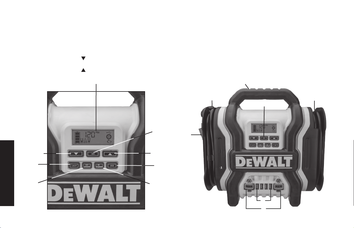
Español
Español
3534
H. 120V Puerto de carga
de CA (bajo la cubierta
protectora)
M. Luz de área LED (dos
bancos de dos LED)
N. Adaptador de carga de 12
voltios AC
I
I
J
H
Pinzas de la batería almacenada en
/ fuera de la batería pestañas
(Fig. 3)
NOTA: Las pestañas de la pinza giran hacia abajo para facilitar el
almacenamiento.
Panel de control (Fig. 1)
A. Pantalla del LCD
retroiluminada
B. Botón de alimentación del
compresor
C. Botón para disminuir la
presión del compresor ( )
D. Botón para aumentar la
presión del compresor ( )
E. Botón de encendido de la
luz de área
F. Botón de alimentación USB
G. Botón de comprobación del
alternador
H.
Botón de alimentación de
CA
H
A
B
C
D
F
E
G
Componentes (Fig. 2)
A. Manguera e boquilla de
Sure Fit
®
B. Cables de arranque
envueltos
C. Manija
D. Panel de control (véase la
Fig. 1)
E. Pestañas de la pinza de la
batería
F. Puertos USB ( con
indicadores de USB
potencia / fallo)
G. Tomas de corriente 120V
CA dobles
C
D
A
B
E
G
F
DXAEPS14_ManualENSP_020221.indd 34-35DXAEPS14_ManualENSP_020221.indd 34-35 2/2/2021 10:56:33 AM2/2/2021 10:56:33 AM
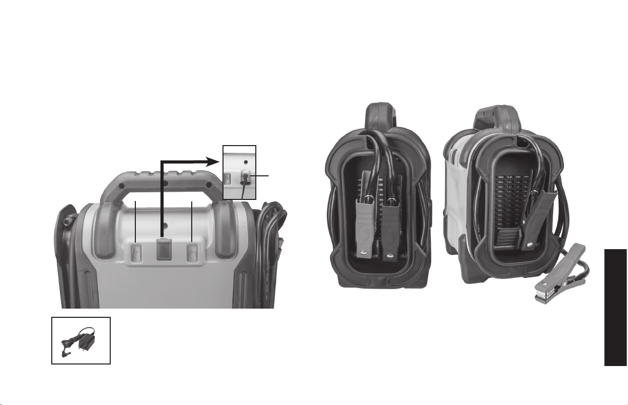
Español
Español
3534
H. 120V Puerto de carga
de CA (bajo la cubierta
protectora)
M. Luz de área LED (dos
bancos de dos LED)
N. Adaptador de carga de 12
voltios AC
I
I
J
H
Pinzas de la batería almacenada en
/ fuera de la batería pestañas
(Fig. 3)
NOTA: Las pestañas de la pinza giran hacia abajo para facilitar el
almacenamiento.
Panel de control (Fig. 1)
A. Pantalla del LCD
retroiluminada
B. Botón de alimentación del
compresor
C. Botón para disminuir la
presión del compresor ( )
D. Botón para aumentar la
presión del compresor ( )
E. Botón de encendido de la
luz de área
F. Botón de alimentación USB
G. Botón de comprobación del
alternador
H.
Botón de alimentación de
CA
H
A
B
C
D
F
E
G
Componentes (Fig. 2)
A. Manguera e boquilla de
Sure Fit
®
B. Cables de arranque
envueltos
C. Manija
D. Panel de control (véase la
Fig. 1)
E. Pestañas de la pinza de la
batería
F. Puertos USB ( con
indicadores de USB
potencia / fallo)
G. Tomas de corriente 120V
CA dobles
C
D
A
B
E
G
F
DXAEPS14_ManualENSP_020221.indd 34-35DXAEPS14_ManualENSP_020221.indd 34-35 2/2/2021 10:56:33 AM2/2/2021 10:56:33 AM
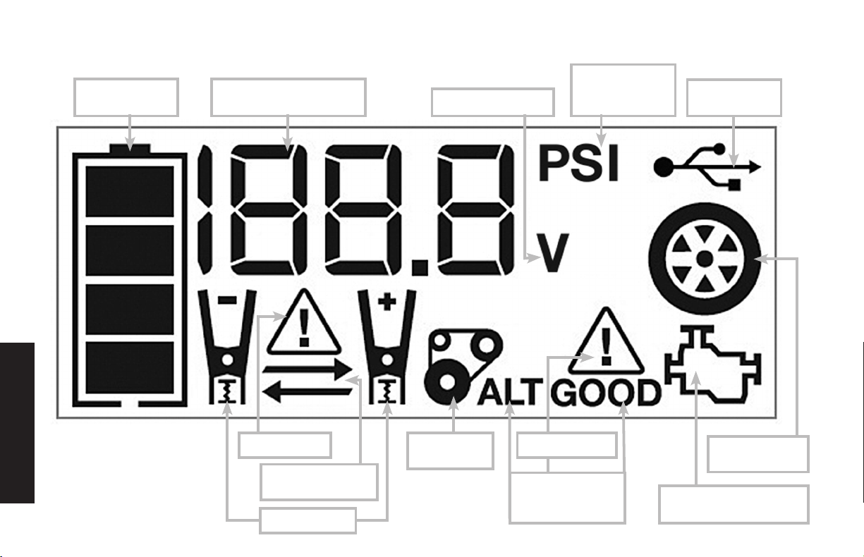
Español
Español
3736
Descripción general
ACCIONES COMUNES Y RESPUESTAS DE LA UNIDAD
The following actions turn the unit on and activate the LCD screen:
Presione el botón de
encendido de la luz de área
LED. (Consulte la sección
“Luz de área LED”.)
Sonará un bip y la luz de área LED
se encenderá. La retroiluminación
se encenderá durante 10 segundos
(sólo). La pantalla LCD continuará
mostrando el icono de estado de
la batería y el indicador del voltaje
de la batería. La unidad permanece
encendida hasta que se pulsa el
botón de encendido de la luz de
área LED de nuevo para apagarlo.
Pulse el botón de
verificación del alternador.
(Consulte la sección
“Verificación del alternador”.)
Sonará un bip y la pantalla
retroiluminada LCD mostrará el
icono de estado de la batería, y el
icono del alternador parpadeará.
La unidad permanece encendida
hasta que se pulsa el botón de
verificación del alternador de nuevo
para apagarlo.
Pulse el botón de de
alimentación de CA. (Consulte
la sección “Tomas de corriente
120V CA” .)
Sonará un bip y la pantalla
retroiluminada LCD mostrará el
icono de estado de la batería; y
la pantalle digital mostrará “AC,”
indicando que las dos tomas de
corriente 120V CA se activan. La
unidad permanece encendida hasta
se presiona el botón de alimentación
de CA de nuevo para desactivarla.
Presione el botón de
alimentación USB. (Consulte
la sección "Puertos USB".)
Sonará un bip y la pantalla
retroiluminada LCD mostrará el
icono de estado de la batería y el
indicador del voltaje de la batería,
y los Indicadores de USB potencia
/ fallo se iluminará sólidamente
azul indicando que los cuatro
puertos USB se activan. La unidad
permanece encendida hasta se
presiona el botón de alimentación
USB de nuevo para desactivarla.
Presione el botón
de alimentación del
compresor. (Consulte la
sección “Compresor portátil”.)
Sonará un pitido y la pantalla LCD
retroiluminada mostrará el icono
de estado de la batería, “XXX”
PSI y el icono de compresor. Si no
se toman medidas adicionales,
después de 1 minuto, la unidad
mostrará el estado de la batería
y el indicador de tensión durante
10 segundos antes de apagarse
automáticamente.
Cada vez que las pinzas
estén correctamente
conectados a una batería
(consulte la sección “Puente
auxiliar de arranque”) …
... sonará un bip y la pantalla
retroiluminada LCD mostrará el
icono de estado de la batería, el
indicador del voltaje de la batería,
el icono de pinzas, el signos
“+” y “–”, así como el icono del
puente auxiliar de arranque de
parpadear. La unidad permanece
encendida hasta que las pinzas se
desconecta de la batería.
Pantalla LCD detalles (Fig. 3)
Icono de estado
de la batería
Indicador digital (varía
dependiendo de la función)
Icono de alarma
Iconos de polaridad
inversa
Iconos de pinzas
Indicador del voltaje
Indicador de
presión del
compresor
Icono de USB
Icono del
compresor
Icono del puente auxiliar
de arranque
Icono del
alternador
Indicadores
alternador de
bueno / fallo
Icono del falla
DXAEPS14_ManualENSP_020221.indd 36-37DXAEPS14_ManualENSP_020221.indd 36-37 2/2/2021 10:56:33 AM2/2/2021 10:56:33 AM

Español
Español
3736
Descripción general
ACCIONES COMUNES Y RESPUESTAS DE LA UNIDAD
The following actions turn the unit on and activate the LCD screen:
Presione el botón de
encendido de la luz de área
LED. (Consulte la sección
“Luz de área LED”.)
Sonará un bip y la luz de área LED
se encenderá. La retroiluminación
se encenderá durante 10 segundos
(sólo). La pantalla LCD continuará
mostrando el icono de estado de
la batería y el indicador del voltaje
de la batería. La unidad permanece
encendida hasta que se pulsa el
botón de encendido de la luz de
área LED de nuevo para apagarlo.
Pulse el botón de
verificación del alternador.
(Consulte la sección
“Verificación del alternador”.)
Sonará un bip y la pantalla
retroiluminada LCD mostrará el
icono de estado de la batería, y el
icono del alternador parpadeará.
La unidad permanece encendida
hasta que se pulsa el botón de
verificación del alternador de nuevo
para apagarlo.
Pulse el botón de de
alimentación de CA. (Consulte
la sección “Tomas de corriente
120V CA” .)
Sonará un bip y la pantalla
retroiluminada LCD mostrará el
icono de estado de la batería; y
la pantalle digital mostrará “AC,”
indicando que las dos tomas de
corriente 120V CA se activan. La
unidad permanece encendida hasta
se presiona el botón de alimentación
de CA de nuevo para desactivarla.
Presione el botón de
alimentación USB. (Consulte
la sección "Puertos USB".)
Sonará un bip y la pantalla
retroiluminada LCD mostrará el
icono de estado de la batería y el
indicador del voltaje de la batería,
y los Indicadores de USB potencia
/ fallo se iluminará sólidamente
azul indicando que los cuatro
puertos USB se activan. La unidad
permanece encendida hasta se
presiona el botón de alimentación
USB de nuevo para desactivarla.
Presione el botón
de alimentación del
compresor. (Consulte la
sección “Compresor portátil”.)
Sonará un pitido y la pantalla LCD
retroiluminada mostrará el icono
de estado de la batería, “XXX”
PSI y el icono de compresor. Si no
se toman medidas adicionales,
después de 1 minuto, la unidad
mostrará el estado de la batería
y el indicador de tensión durante
10 segundos antes de apagarse
automáticamente.
Cada vez que las pinzas
estén correctamente
conectados a una batería
(consulte la sección “Puente
auxiliar de arranque”) …
... sonará un bip y la pantalla
retroiluminada LCD mostrará el
icono de estado de la batería, el
indicador del voltaje de la batería,
el icono de pinzas, el signos
“+” y “–”, así como el icono del
puente auxiliar de arranque de
parpadear. La unidad permanece
encendida hasta que las pinzas se
desconecta de la batería.
Pantalla LCD detalles (Fig. 3)
Icono de estado
de la batería
Indicador digital (varía
dependiendo de la función)
Icono de alarma
Iconos de polaridad
inversa
Iconos de pinzas
Indicador del voltaje
Indicador de
presión del
compresor
Icono de USB
Icono del
compresor
Icono del puente auxiliar
de arranque
Icono del
alternador
Indicadores
alternador de
bueno / fallo
Icono del falla
DXAEPS14_ManualENSP_020221.indd 36-37DXAEPS14_ManualENSP_020221.indd 36-37 2/2/2021 10:56:33 AM2/2/2021 10:56:33 AM
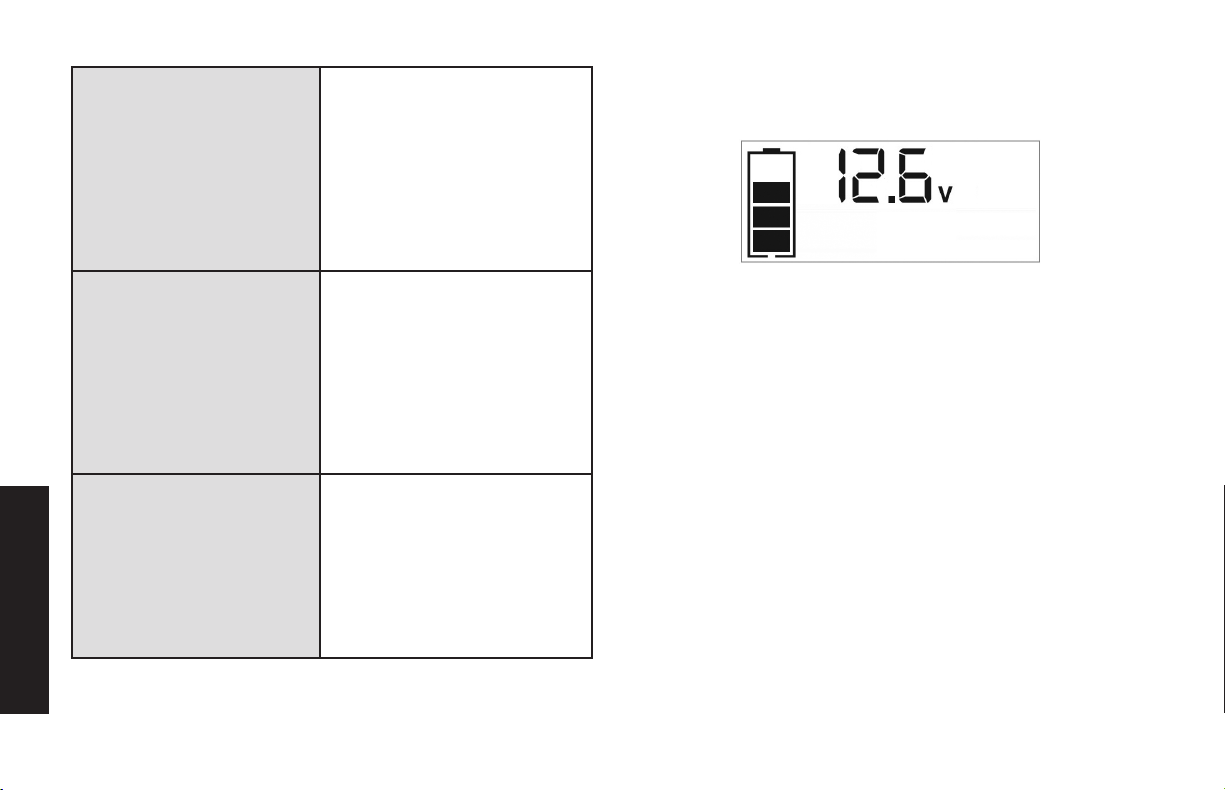
Español
Español
3938
recomienda que se debe ser recargada la batería al menos cada 30
días y después de cada uso.
Notas importantes de carga
1. Esta unidad se entrega en un estado parcialmente cargado - usted
debe cargarlo completamente antes de usarlo para la primera vez.
La carga inicial de la CA debe ser por 40 horas o hasta que el
icono de estado de la batería muestra 4 barras sólidas.
2. Recargar la batería luego de cada uso prolongará la vida de la
batería; las descargas importantes frecuentes entre recargas o el
cargarla en exceso reducirán la duración de la batería.
3. Cerciórese de que el resto de las funciones de unidad estén
apagadas durante la recarga, pues ésta puede retardar el proceso
de recarga.
PRECAUCIÓN – Para reducir el riesgo de daño a la propiedad: Si
no se mantiene la batería cargada puede causar daños permanentes
y resultar en un pobre rendimiento de arranque.
IMPORTANTE: Si usted sabe que la unidad se descarga, pero el icono
de la batería muestra cuatro barras sólidas, como si la unidad está
totalmente cargada cuando se conecta a una fuente de alimentación
de carga, esto puede ser debido a la batería interna que tiene una
alta impedancia. El fabricante sugiere salir de la unidad de carga por
un período de 40 horas usando el cargador de CA antes de su uso.
Cargar/recargar con el cargador
cargador de 120 voltios CA suministrado
1. Levante la cubierta protectora del puerto de carga de 12V DC
ubicado en la parte posterior de la unidad (refiérase a la Fig. 2 para
ubicarlo). Inserte el conector de barril del adaptador de carga de
CA en el puerto de carga de CC. Inserte el extremo del enchufe
en un tomacorriente (alimentado) estándar norteamericano de 120
voltios 60Hz:
Las barras en el icono de estado de la batería representan el nivel
de carga de la batería interna de la unidad. Las barras en el icono
de estado de la batería cambiará de vacía a sólido (de abajo a
arriba) varias veces para indicar que la unidad se está cargando.
La luz de fondo se encenderá durante 10 segundos (solamente).
2. Carga por aproximadamente 40 horas o hasta que el icono de la
batería demuestra 4 barras sólidas.
3. Cuando la carga esté completa, desconecte el adaptador de
carga de CA – primero desenchufe el adaptador de la fuente de
alimentación de CA, luego desconecte el conector del barril de la
unidad.
Puente auxiliar de arranque
A. Para los sistemas con negativo a tierra (más común), conecte
la pinza del positivo (roja) al borne sin conexión a tierra de la
batería y la pinza del negativo (NEGRA) al bastidor del vehículo
o al bloque del motor, lejos de la batería. No conecte la pinza al
carburador, las cañerías de combustible o a las piezas de chapa
de la carrocería. Conecte a una pieza de metal sólida del bastidor
o del bloque del motor.
B. Para los sistemas con positivo a tierra, conecte la pinza del
negativo (negra) al borne sin conexión a tierra negativo de la
batería y la pinza del positivo (roja) al bastidor del vehículo o
al bloque del motor, lejos de la batería. No conecte la pinza al
Si las pinzas rojas y negras
se tocan entre sí (consulte
la sección de “Arranque en
salto”) ...
... la pantalla LCD retroiluminada
mostrará el icono de estado de la
batería y el indicador de voltaje de
la batería. Los iconos de la pinza,
los signos “+” y “-” y el icono de
la alarma parpadearán. La unidad
emitirá una advertencia de dos
segundos cada diez segundos
de forma continua hasta que las
abrazaderas están separadas.
Si se invierten las
conexiones de pinza de
bornes positivo y negativo
de la batería (consulte la
sección “Puente auxiliar de
arranque”) …
… la pantalla LCD retroiluminada
mostrará el icono de estado de la
batería, el indicador del voltaje de
la batería, y el icono de pinzas. El
icono de alarma, el signos “+” y “–”
y los iconos de polaridad inversa
parpadearán y la unidad la unidad
sonará una advertencia continua
hasta que las pinzas estén
desconectados de la batería.
Cuando la unidad se está
cargando o recargando
con el adaptador de carga
suministrado (consulte la
sección “Cargar/Recargar”) …
… la retroiluminación se encenderá
durante 10 segundos (sólo).
La pantalla LCD continuará
mostrando el icono de estado de
la batería y el indicador del voltaje
de la batería. Las barras del icono
de la batería cambiará de vacía
a sólido (de abajo hacia arriba)
repetidamente.
NOTA: La unidad se apagará automáticamente una vez que TODAS
las funciones y el proceso de carga están desactivadas.
Viendo el estado de la batería
El icono de estado de la batería y el indicador del voltaje de la batería
indican el nivel de carga como sigue:
• Si el nivel de carga de la batería está a plena capacidad, cuatro barras
sólidas se muestran.
• Si la batería está parcialmente cargada, dos o tres barras sólidas se
mostrarán.
• Si la batería está casi vacía, una barra sólida se vea. La unidad debe
ser cargada en este momento.
• Si la batería está completamente vacía, el icono de la batería
muestra cuatro barras vacías. La unidad TIENE QUE SER cargado
en este momento o protección integrada de baja tensión de
la unidad se activará. El icono de estado de la batería vacía
parpadeará para un corto período de tiempo antes de apagado
automático. La unidad no funcionará hasta que la batería
es recargada.
Cargar/recargar
Las baterías de plomo-ácido requieren mantenimiento de rutina para
asegurar una carga completa y una mayor duración de la batería.
Todas las baterías pierden energía por descarga espontánea, se
descargan con el paso del tiempo, y con mayor rapidez cuando
están a temperaturas más altas. Por lo tanto, las baterías necesitan
ser cargadas periódicamente para reemplazar la energía perdida
por descarga espontánea. Cuando la unidad no se usa, fabricante
DXAEPS14_ManualENSP_020221.indd 38-39DXAEPS14_ManualENSP_020221.indd 38-39 2/2/2021 10:56:33 AM2/2/2021 10:56:33 AM
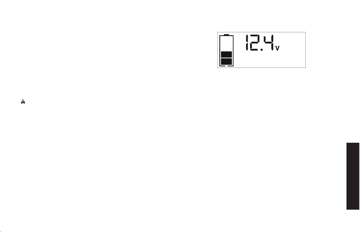
Español
Español
3938
recomienda que se debe ser recargada la batería al menos cada 30
días y después de cada uso.
Notas importantes de carga
1. Esta unidad se entrega en un estado parcialmente cargado - usted
debe cargarlo completamente antes de usarlo para la primera vez.
La carga inicial de la CA debe ser por 40 horas o hasta que el
icono de estado de la batería muestra 4 barras sólidas.
2. Recargar la batería luego de cada uso prolongará la vida de la
batería; las descargas importantes frecuentes entre recargas o el
cargarla en exceso reducirán la duración de la batería.
3. Cerciórese de que el resto de las funciones de unidad estén
apagadas durante la recarga, pues ésta puede retardar el proceso
de recarga.
PRECAUCIÓN – Para reducir el riesgo de daño a la propiedad: Si
no se mantiene la batería cargada puede causar daños permanentes
y resultar en un pobre rendimiento de arranque.
IMPORTANTE: Si usted sabe que la unidad se descarga, pero el icono
de la batería muestra cuatro barras sólidas, como si la unidad está
totalmente cargada cuando se conecta a una fuente de alimentación
de carga, esto puede ser debido a la batería interna que tiene una
alta impedancia. El fabricante sugiere salir de la unidad de carga por
un período de 40 horas usando el cargador de CA antes de su uso.
Cargar/recargar con el cargador
cargador de 120 voltios CA suministrado
1. Levante la cubierta protectora del puerto de carga de 12V DC
ubicado en la parte posterior de la unidad (refiérase a la Fig. 2 para
ubicarlo). Inserte el conector de barril del adaptador de carga de
CA en el puerto de carga de CC. Inserte el extremo del enchufe
en un tomacorriente (alimentado) estándar norteamericano de 120
voltios 60Hz:
Las barras en el icono de estado de la batería representan el nivel
de carga de la batería interna de la unidad. Las barras en el icono
de estado de la batería cambiará de vacía a sólido (de abajo a
arriba) varias veces para indicar que la unidad se está cargando.
La luz de fondo se encenderá durante 10 segundos (solamente).
2. Carga por aproximadamente 40 horas o hasta que el icono de la
batería demuestra 4 barras sólidas.
3. Cuando la carga esté completa, desconecte el adaptador de
carga de CA – primero desenchufe el adaptador de la fuente de
alimentación de CA, luego desconecte el conector del barril de la
unidad.
Puente auxiliar de arranque
A. Para los sistemas con negativo a tierra (más común), conecte
la pinza del positivo (roja) al borne sin conexión a tierra de la
batería y la pinza del negativo (NEGRA) al bastidor del vehículo
o al bloque del motor, lejos de la batería. No conecte la pinza al
carburador, las cañerías de combustible o a las piezas de chapa
de la carrocería. Conecte a una pieza de metal sólida del bastidor
o del bloque del motor.
B. Para los sistemas con positivo a tierra, conecte la pinza del
negativo (negra) al borne sin conexión a tierra negativo de la
batería y la pinza del positivo (roja) al bastidor del vehículo o
al bloque del motor, lejos de la batería. No conecte la pinza al
Si las pinzas rojas y negras
se tocan entre sí (consulte
la sección de “Arranque en
salto”) ...
... la pantalla LCD retroiluminada
mostrará el icono de estado de la
batería y el indicador de voltaje de
la batería. Los iconos de la pinza,
los signos “+” y “-” y el icono de
la alarma parpadearán. La unidad
emitirá una advertencia de dos
segundos cada diez segundos
de forma continua hasta que las
abrazaderas están separadas.
Si se invierten las
conexiones de pinza de
bornes positivo y negativo
de la batería (consulte la
sección “Puente auxiliar de
arranque”) …
… la pantalla LCD retroiluminada
mostrará el icono de estado de la
batería, el indicador del voltaje de
la batería, y el icono de pinzas. El
icono de alarma, el signos “+” y “–”
y los iconos de polaridad inversa
parpadearán y la unidad la unidad
sonará una advertencia continua
hasta que las pinzas estén
desconectados de la batería.
Cuando la unidad se está
cargando o recargando
con el adaptador de carga
suministrado (consulte la
sección “Cargar/Recargar”) …
… la retroiluminación se encenderá
durante 10 segundos (sólo).
La pantalla LCD continuará
mostrando el icono de estado de
la batería y el indicador del voltaje
de la batería. Las barras del icono
de la batería cambiará de vacía
a sólido (de abajo hacia arriba)
repetidamente.
NOTA: La unidad se apagará automáticamente una vez que TODAS
las funciones y el proceso de carga están desactivadas.
Viendo el estado de la batería
El icono de estado de la batería y el indicador del voltaje de la batería
indican el nivel de carga como sigue:
• Si el nivel de carga de la batería está a plena capacidad, cuatro barras
sólidas se muestran.
• Si la batería está parcialmente cargada, dos o tres barras sólidas se
mostrarán.
• Si la batería está casi vacía, una barra sólida se vea. La unidad debe
ser cargada en este momento.
• Si la batería está completamente vacía, el icono de la batería
muestra cuatro barras vacías. La unidad TIENE QUE SER cargado
en este momento o protección integrada de baja tensión de
la unidad se activará. El icono de estado de la batería vacía
parpadeará para un corto período de tiempo antes de apagado
automático. La unidad no funcionará hasta que la batería
es recargada.
Cargar/recargar
Las baterías de plomo-ácido requieren mantenimiento de rutina para
asegurar una carga completa y una mayor duración de la batería.
Todas las baterías pierden energía por descarga espontánea, se
descargan con el paso del tiempo, y con mayor rapidez cuando
están a temperaturas más altas. Por lo tanto, las baterías necesitan
ser cargadas periódicamente para reemplazar la energía perdida
por descarga espontánea. Cuando la unidad no se usa, fabricante
DXAEPS14_ManualENSP_020221.indd 38-39DXAEPS14_ManualENSP_020221.indd 38-39 2/2/2021 10:56:33 AM2/2/2021 10:56:33 AM
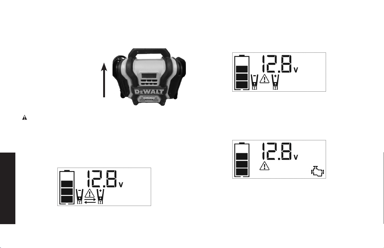
Español
Español
4140
PROCEDIMIENTO
Tome las medidas siguientes, observando todas las precauciones
y advertencias en la sección de las “instrucciones de seguridad
importantes” en el frente de este manual.
1. Apague la ignición del vehículo y todos los accesorios (radio, aire
acondicionado, luces, cargadores de teléfono celular conectados,
etc.). Ubique el vehículo en “estacionar” y coloque el freno de
emergencia.
2. Retire las pinzas del puente de sus respectivas lengüetas. Conecte
primero la pinza roja, luego la pinza negra.
3. Procedimiento para arrancar mediante puente un SISTEMA
CON NEGATIVO A TIERRA (el terminal de la batería está
conectado al bastidor) (LO MÁS COMÚN)
3a. Conecte la pinza roja del positivo (+) al terminal del positivo de
la batería del vehículo.
3b. Conecte la pinza negra del negativo (–) al bastidor o a un
componente metálico no móvil y sólido, o una parte de la
carrocería. Nunca fije la pinza directamente al terminal del
negativo de la batería o a una pieza móvil. Refiera al manual
del dueño del automóvil.
4. Procedimiento para arrancar SISTEMAS CON POSITIVO A
TIERRA
NOTA: En el caso poco habitual de que el vehículo que se debe
arrancar tenga un sistema de positivo a tierra (el terminal positivo
de la batería está conectado al bastidor), reemplace los pasos
3a y 3b anteriores con los pasos 4a y 4b, luego continúe con el
paso 5.
4a. Conecte la pinza negra del negativo (-) al terminal del negativo
de la batería del vehículo.
4b. Conecte la pinza roja del positivo (+) al bastidor del vehículo o
a un componente metálico no móvil y sólido, o una parte de
la carrocería. Nunca fije la pinza directamente al terminal del
positivo de la batería o a una pieza móvil. Refiera al manual
del dueño del automóvil.
5. Cuando las pinzas están conectadas correctamente, la pantalla
LCD retroiluminada demostrará que lo que sigue para indicar que
la unidad está lista para arrancar el motor:
El icono de estado de la batería, el indicador del voltaje de la
batería, los iconos de pinzas y los signos “+” y “–” se iluminan
sólidamente. El icono del puente auxiliar de arranque se parpadeará
para indicar que las pinzas están conectadas correctamente.
6. Encienda la ignición y acelere el motor en etapas de 5 a 6 segundos
hasta que arranque. La pantalla LCD retroiluminada mostrará
siguiento:
El icono del estado de la batería, el indicador de voltaje de la batería,
los iconos de las abrazaderas y los signos “+” y “-” se iluminan
de forma sólida para indicar que la unidad se está poniendo en
marcha. El icono de arranque parpadea. El icono de arranque se
ilumina de forma permanente si el vehículo está en marcha.
7. Desconecte la pinza del negativo (–) del motor o bastidor primero
y luego desconecte la pinza del positivo (+) de la batería.
carburador, las cañerías de combustible o a las piezas de chapa
de la carrocería. Conecte a una pieza de metal sólida del bastidor
o del bloque del motor.
IMPORTANTE: Todas
las funciones deben estar
apagadas, con la excepción
de la luz del área al arrancar.
La unidad está destinada
a ser usado sólo en el
montante posición. La
unidad debe mantenerse
en posición vertical durante
uso. Ver la ilustración a la
derecha para la correcta
orientación.
ADVERTENCIA – Para reducir el riesgo de lesiones o daño a la
propiedad:
• Siga todas las instrucciones de seguridad encontradas en la sección
de las “Instrucciones de seguridad específicas para auxiliares de
arranque” de este manual de la instrucción.
• Si las pinzas están conectados incorrectamente con respecto a la
polaridad, la unidad sonará una alarma continua hasta que las pinzas
estén desconectados. La pantalla LCD retroiluminada mostrará
siguiento:
Desconecte y vuelva a conectar las pinzas a la batería con la polaridad
correcta.
• Nunca toque entre sí las pinzas roja y negra de la batería: esto puede
provocar chispas peligrosas, arco eléctrico o explosión.
Si las pinzas rojas y negras se tocan entre sí, la unidad emitirá una
alarma continua de dos segundos cada diez segundos hasta que
las abrazaderas se separen. La pantalla LCD retroiluminada mostrará
lo siguiente:
El ícono de estado de la batería y el indicador de voltaje de la batería
se iluminan. El ícono de alarma, los íconos de pinza y los signos “+”
y “–” parpadearán. Separe inmediatamente las pinzas y no permita
que se toquen nuevamente.
• Si la unidad se sobrecalienta durante el proceso de arranque, la
protección térmica se activará y la pantalla LCD retroiluminada
mostrará lo siguiente:
El ícono de estado de la batería y el indicador de voltaje de la batería
se iluminan. El ícono de alarma y el Icono del puente auxiliar de
arranque parpadearán Deje que la unidad se enfríe durante 10 a
30 minutos.
• Siempre desconecte primero el cable del puente del negativo (negro) y
luego el cable del puente del positivo (rojo), excepto para los sistemas
con positivo a tierra.
DXAEPS14_ManualENSP_020221.indd 40-41DXAEPS14_ManualENSP_020221.indd 40-41 2/2/2021 10:56:33 AM2/2/2021 10:56:33 AM
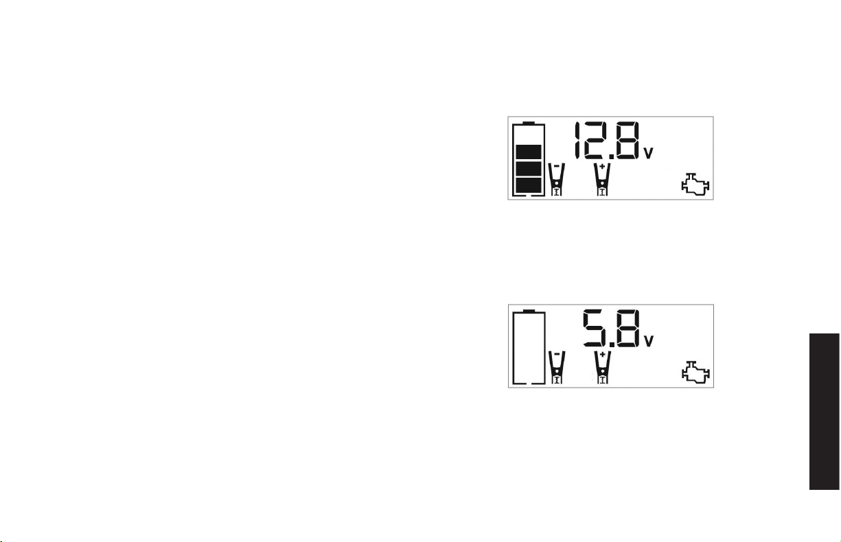
Español
Español
4140
PROCEDIMIENTO
Tome las medidas siguientes, observando todas las precauciones
y advertencias en la sección de las “instrucciones de seguridad
importantes” en el frente de este manual.
1. Apague la ignición del vehículo y todos los accesorios (radio, aire
acondicionado, luces, cargadores de teléfono celular conectados,
etc.). Ubique el vehículo en “estacionar” y coloque el freno de
emergencia.
2. Retire las pinzas del puente de sus respectivas lengüetas. Conecte
primero la pinza roja, luego la pinza negra.
3. Procedimiento para arrancar mediante puente un SISTEMA
CON NEGATIVO A TIERRA (el terminal de la batería está
conectado al bastidor) (LO MÁS COMÚN)
3a. Conecte la pinza roja del positivo (+) al terminal del positivo de
la batería del vehículo.
3b. Conecte la pinza negra del negativo (–) al bastidor o a un
componente metálico no móvil y sólido, o una parte de la
carrocería. Nunca fije la pinza directamente al terminal del
negativo de la batería o a una pieza móvil. Refiera al manual
del dueño del automóvil.
4. Procedimiento para arrancar SISTEMAS CON POSITIVO A
TIERRA
NOTA: En el caso poco habitual de que el vehículo que se debe
arrancar tenga un sistema de positivo a tierra (el terminal positivo
de la batería está conectado al bastidor), reemplace los pasos
3a y 3b anteriores con los pasos 4a y 4b, luego continúe con el
paso 5.
4a. Conecte la pinza negra del negativo (-) al terminal del negativo
de la batería del vehículo.
4b. Conecte la pinza roja del positivo (+) al bastidor del vehículo o
a un componente metálico no móvil y sólido, o una parte de
la carrocería. Nunca fije la pinza directamente al terminal del
positivo de la batería o a una pieza móvil. Refiera al manual
del dueño del automóvil.
5. Cuando las pinzas están conectadas correctamente, la pantalla
LCD retroiluminada demostrará que lo que sigue para indicar que
la unidad está lista para arrancar el motor:
El icono de estado de la batería, el indicador del voltaje de la
batería, los iconos de pinzas y los signos “+” y “–” se iluminan
sólidamente. El icono del puente auxiliar de arranque se parpadeará
para indicar que las pinzas están conectadas correctamente.
6. Encienda la ignición y acelere el motor en etapas de 5 a 6 segundos
hasta que arranque. La pantalla LCD retroiluminada mostrará
siguiento:
El icono del estado de la batería, el indicador de voltaje de la batería,
los iconos de las abrazaderas y los signos “+” y “-” se iluminan
de forma sólida para indicar que la unidad se está poniendo en
marcha. El icono de arranque parpadea. El icono de arranque se
ilumina de forma permanente si el vehículo está en marcha.
7. Desconecte la pinza del negativo (–) del motor o bastidor primero
y luego desconecte la pinza del positivo (+) de la batería.
carburador, las cañerías de combustible o a las piezas de chapa
de la carrocería. Conecte a una pieza de metal sólida del bastidor
o del bloque del motor.
IMPORTANTE: Todas
las funciones deben estar
apagadas, con la excepción
de la luz del área al arrancar.
La unidad está destinada
a ser usado sólo en el
montante posición. La
unidad debe mantenerse
en posición vertical durante
uso. Ver la ilustración a la
derecha para la correcta
orientación.
ADVERTENCIA – Para reducir el riesgo de lesiones o daño a la
propiedad:
• Siga todas las instrucciones de seguridad encontradas en la sección
de las “Instrucciones de seguridad específicas para auxiliares de
arranque” de este manual de la instrucción.
• Si las pinzas están conectados incorrectamente con respecto a la
polaridad, la unidad sonará una alarma continua hasta que las pinzas
estén desconectados. La pantalla LCD retroiluminada mostrará
siguiento:
Desconecte y vuelva a conectar las pinzas a la batería con la polaridad
correcta.
• Nunca toque entre sí las pinzas roja y negra de la batería: esto puede
provocar chispas peligrosas, arco eléctrico o explosión.
Si las pinzas rojas y negras se tocan entre sí, la unidad emitirá una
alarma continua de dos segundos cada diez segundos hasta que
las abrazaderas se separen. La pantalla LCD retroiluminada mostrará
lo siguiente:
El ícono de estado de la batería y el indicador de voltaje de la batería
se iluminan. El ícono de alarma, los íconos de pinza y los signos “+”
y “–” parpadearán. Separe inmediatamente las pinzas y no permita
que se toquen nuevamente.
• Si la unidad se sobrecalienta durante el proceso de arranque, la
protección térmica se activará y la pantalla LCD retroiluminada
mostrará lo siguiente:
El ícono de estado de la batería y el indicador de voltaje de la batería
se iluminan. El ícono de alarma y el Icono del puente auxiliar de
arranque parpadearán Deje que la unidad se enfríe durante 10 a
30 minutos.
• Siempre desconecte primero el cable del puente del negativo (negro) y
luego el cable del puente del positivo (rojo), excepto para los sistemas
con positivo a tierra.
DXAEPS14_ManualENSP_020221.indd 40-41DXAEPS14_ManualENSP_020221.indd 40-41 2/2/2021 10:56:33 AM2/2/2021 10:56:33 AM
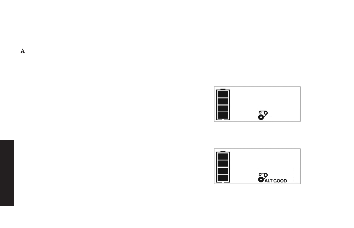
Español
Español
4342
3. Si la unidad detecta que el alternador está fuera de gama típica
del voltaje, la pantalla del LCD retroiluminada exhibirá el siguiente:
El icono de estado de la batería, el icono del alternador y “ALT”
se iluminarán sólido. El icono del falla parpadeará.
4. Presione el botón del cheque del alternador otra vez para parar la
prueba y apague la unidad.
PART 2
Bajo carga (accesorios encendido): Después, cargue el alternador
girando tantos accesorios como sea posible (a excepción del aire/
acondicionado y descongele).
1. Presione el botón del cheque del alternador para comenzar el
cheque. La pantalla del LCD retroiluminada exhibirá el siguiente
para indicar que la unidad está analizando el alternador:
El icono de estado de la batería se iluminará sólido y el icono del
alternador parpadeará.
2. Si la unidad detecta que el alternador es bueno, la pantalla del
LCD retroiluminada exhibirá el siguiente:
El icono de estado de la batería, el icono del alternador, y “ALT
GOOD” se iluminarán sólido.
3. Si la unidad detecta que el alternador está fuera de gama típica
del voltaje, la pantalla del LCD retroiluminada exhibirá el siguiente:
El icono de estado de la batería, el icono del alternador y “ALT”
se iluminarán sólido. El icono del falla parpadeará.
4. Presione el botón del cheque del alternador otra vez para parar la
prueba y apague la unidad.
IMPORTANTE: Siempre apague la unidad cuando no está en uso.
Vuelva a cargar la unidad completamente después de cada uso.
Compresor portátil
El compresor incorporado de 12 voltios CC es el compresor de última
generación para los neumáticos de todos los vehículos, remolques
y artículos inflables para recreación. Un adaptador de la boquilla se
suministra que los tornillos en el extremo de la boquilla Sure Fit®
en el extremo libre de la manguera del compresor. La manguera del
NOTA: Si la unidad no funciona correctamente después del
procedimiento de arranque rápido, recargue la unidad con el cargador
de CA suministrado para reiniciarla
IMPORTANTE: Siempre apague la unidad cuando no está en uso.
Vuelva a cargar la unidad completamente después de cada uso.
PRECAUCIÓN – Para reducir el riesgo de daño a la propiedad:
• Los vehículos que tienen sistemas computarizados incorporados
pueden resultar dañados si la batería del vehículo se arranca mediante
puente. Antes de arrancar mediante puente este tipo de vehículo,
lea el manual del vehículo para confirmar que se aconseja ayuda
externa para arrancar.
• El exceso de revoluciones del motor puede dañar el mecanismo
de arranque del vehículo. Si el motor no arranca después de la
cantidad recomendada de intentos, abandone el procedimiento de
arranque mediante puente y busque otros problemas que puedan
ser solucionados.
• Si el vehículo no arranca, apague la ignición, desconecte los
conductores del puente auxiliar de arranque y comuníquese con
un técnico calificado para investigar por qué no arrancó el motor.
Cheque del alternador
Configurar la unidad, conectar las pinzas de la batería y conecte a la
batería siguiendo los pasos 1 a 5 bajo “procedimientos” en la sección
“Puente auxiliar de arranque.”
Notas importantes relativos al función cheque del alternador
1. La unidad puede detectar que el alternador está fuera del rango de
voltaje típico porque alguien ha agregado una cantidad de cargas
accesorias en el sistema de carga, lo que aumenta la demanda de
corriente del alternador. ASEGÚRESE DE QUE EL ALTERNADOR
ESTÉ CLASIFICADO PARA APOYAR LA APLICACIÓN.
2. Este cheque puede no ser exacto para cada hace, fabricante y
modelo del vehículo. Compruebe los sistemas de solamente 12
voltios.
PARTE 1
Ninguna carga (apague todos los accesorios del vehículo): La
batería del vehículo debe ser cargada completamente antes de probar
el alternador. Funcione con el motor bastante tiempo para alcanzar
velocidad ociosa normal y verificar allí es un voltaje sin carga.
1. Presione el botón del cheque del alternador para comenzar el
cheque. La pantalla del LCD retroiluminada exhibirá el siguiente
para indicar que la unidad está analizando el alternador:
El icono de estado de la batería se iluminará sólido y el icono del
alternador parpadeará.
2. Si la unidad detecta que el alternador es bueno, la pantalla del
LCD retroiluminada exhibirá el siguiente:
El icono de estado de la batería, el icono del alternador, y “ALT
GOOD” se iluminarán sólido.
DXAEPS14_ManualENSP_020221.indd 42-43DXAEPS14_ManualENSP_020221.indd 42-43 2/2/2021 10:56:33 AM2/2/2021 10:56:33 AM
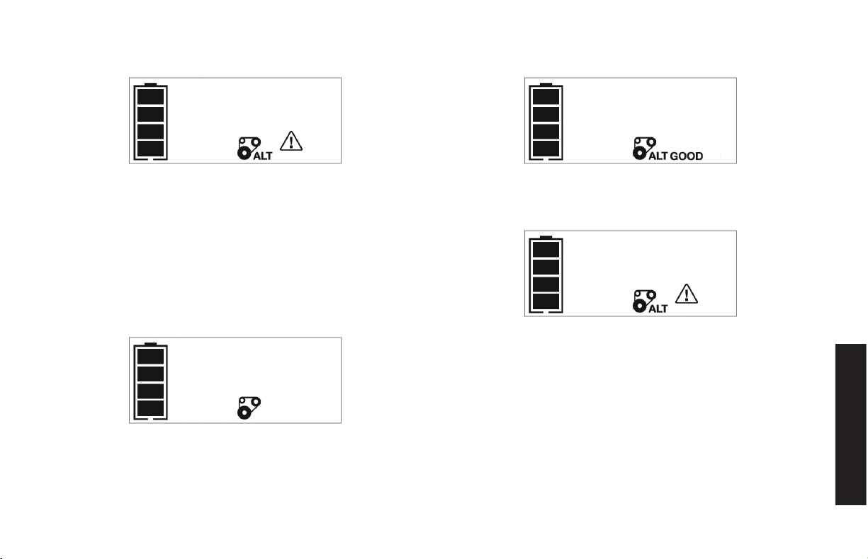
Español
Español
4342
3. Si la unidad detecta que el alternador está fuera de gama típica
del voltaje, la pantalla del LCD retroiluminada exhibirá el siguiente:
El icono de estado de la batería, el icono del alternador y “ALT”
se iluminarán sólido. El icono del falla parpadeará.
4. Presione el botón del cheque del alternador otra vez para parar la
prueba y apague la unidad.
PART 2
Bajo carga (accesorios encendido): Después, cargue el alternador
girando tantos accesorios como sea posible (a excepción del aire/
acondicionado y descongele).
1. Presione el botón del cheque del alternador para comenzar el
cheque. La pantalla del LCD retroiluminada exhibirá el siguiente
para indicar que la unidad está analizando el alternador:
El icono de estado de la batería se iluminará sólido y el icono del
alternador parpadeará.
2. Si la unidad detecta que el alternador es bueno, la pantalla del
LCD retroiluminada exhibirá el siguiente:
El icono de estado de la batería, el icono del alternador, y “ALT
GOOD” se iluminarán sólido.
3. Si la unidad detecta que el alternador está fuera de gama típica
del voltaje, la pantalla del LCD retroiluminada exhibirá el siguiente:
El icono de estado de la batería, el icono del alternador y “ALT”
se iluminarán sólido. El icono del falla parpadeará.
4. Presione el botón del cheque del alternador otra vez para parar la
prueba y apague la unidad.
IMPORTANTE: Siempre apague la unidad cuando no está en uso.
Vuelva a cargar la unidad completamente después de cada uso.
Compresor portátil
El compresor incorporado de 12 voltios CC es el compresor de última
generación para los neumáticos de todos los vehículos, remolques
y artículos inflables para recreación. Un adaptador de la boquilla se
suministra que los tornillos en el extremo de la boquilla Sure Fit®
en el extremo libre de la manguera del compresor. La manguera del
NOTA: Si la unidad no funciona correctamente después del
procedimiento de arranque rápido, recargue la unidad con el cargador
de CA suministrado para reiniciarla
IMPORTANTE: Siempre apague la unidad cuando no está en uso.
Vuelva a cargar la unidad completamente después de cada uso.
PRECAUCIÓN – Para reducir el riesgo de daño a la propiedad:
• Los vehículos que tienen sistemas computarizados incorporados
pueden resultar dañados si la batería del vehículo se arranca mediante
puente. Antes de arrancar mediante puente este tipo de vehículo,
lea el manual del vehículo para confirmar que se aconseja ayuda
externa para arrancar.
• El exceso de revoluciones del motor puede dañar el mecanismo
de arranque del vehículo. Si el motor no arranca después de la
cantidad recomendada de intentos, abandone el procedimiento de
arranque mediante puente y busque otros problemas que puedan
ser solucionados.
• Si el vehículo no arranca, apague la ignición, desconecte los
conductores del puente auxiliar de arranque y comuníquese con
un técnico calificado para investigar por qué no arrancó el motor.
Cheque del alternador
Configurar la unidad, conectar las pinzas de la batería y conecte a la
batería siguiendo los pasos 1 a 5 bajo “procedimientos” en la sección
“Puente auxiliar de arranque.”
Notas importantes relativos al función cheque del alternador
1. La unidad puede detectar que el alternador está fuera del rango de
voltaje típico porque alguien ha agregado una cantidad de cargas
accesorias en el sistema de carga, lo que aumenta la demanda de
corriente del alternador. ASEGÚRESE DE QUE EL ALTERNADOR
ESTÉ CLASIFICADO PARA APOYAR LA APLICACIÓN.
2. Este cheque puede no ser exacto para cada hace, fabricante y
modelo del vehículo. Compruebe los sistemas de solamente 12
voltios.
PARTE 1
Ninguna carga (apague todos los accesorios del vehículo): La
batería del vehículo debe ser cargada completamente antes de probar
el alternador. Funcione con el motor bastante tiempo para alcanzar
velocidad ociosa normal y verificar allí es un voltaje sin carga.
1. Presione el botón del cheque del alternador para comenzar el
cheque. La pantalla del LCD retroiluminada exhibirá el siguiente
para indicar que la unidad está analizando el alternador:
El icono de estado de la batería se iluminará sólido y el icono del
alternador parpadeará.
2. Si la unidad detecta que el alternador es bueno, la pantalla del
LCD retroiluminada exhibirá el siguiente:
El icono de estado de la batería, el icono del alternador, y “ALT
GOOD” se iluminarán sólido.
DXAEPS14_ManualENSP_020221.indd 42-43DXAEPS14_ManualENSP_020221.indd 42-43 2/2/2021 10:56:33 AM2/2/2021 10:56:33 AM
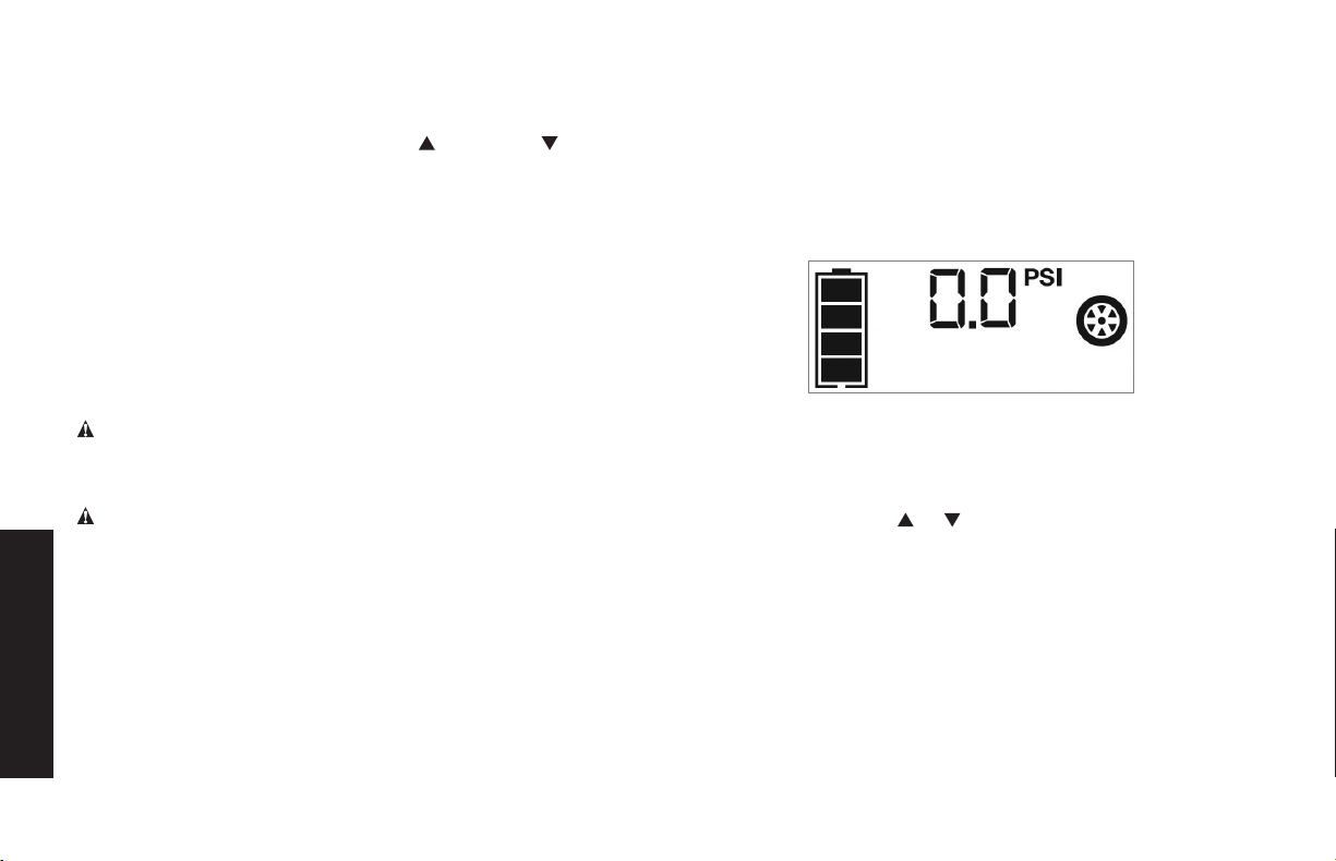
Español
Español
4544
pantalla LCD retroiluminada intermitente mostrará la nueva presión
seleccionado, de la siguiente manera:
El valor seleccionado nuevo se guarda en la memoria de la unidad
hasta que se resetea manualmente.
4. Presione el botón de alimentación del compresor una vez más para
comenzar a inflar. El icono del compresor parpadea y la pantalla
digital sólo se mostrará el valor de la presión actual (que se ilumina
sólido) para indicar que el compresor se activa. Supervise la presión
sobre la pantalla del LCD.
NOTA IMPORTANTE: Para interrumpir durante el inflado, pulse
el botón de alimentación del compresor una vez más.
5. Cuando se alcance la presión predefinido deseada, el compresor
parará automáticamente.
6. Pulse el botón de alimentación del compresor para apagar la
unidad.
7. Desatornille y retire el conector de la boquilla Sure Fit
®
desde el
vástago de la válvula.
9. Permita que la unidad se refresque, después recargue antes de
almacenarla.
10. Almacene la manguera del compresor y la boquilla Sure Fit
®
en el
compartimiento de almacenamiento.
CÓMO INFLAR OTROS ARTÍCULOS INFLABLES SIN
VÁSTAGO DE VÁLVULA
El inflado de otros artículos requiere el uso del adaptador de la boquilla.
1. Atornille el adaptador dentro la boquilla Sure Fit
®
. No apriete
demasiado.
2. Inserte el adaptador en el artículo a ser inflado.
3. Siga los pasos 2 a 4 de la sección “Cómo inflar neumáticos o
productos con vástagos de válvulas.”
NOTA IMPORTANTE: Los artículos pequeños como las pelotas
de voleibol, fútbol, etc. se inflan muy rápidamente. No infle
demasiado.
4. Cuando se alcanza la presión deseada, el compresor se parará
automáticamente. Pulse el botón de alimentación del compresor
para apagar la unidad.
5. Desconecte el adaptador del artículo inflado.
6. Desatornille y retire el adaptador dla boquilla Sure Fit®.
7. Permita que la unidad se enfríe antes de almacenarla.
8. Almacene la manguera del compresor, la boquilla Sure Fit® y el
adaptador de la boquilla en el compartimiento de almacenamiento.
Tomas de corriente de 120V CA
CONSUMO DE CORRIENTE REAL VERSUS CALIFICADO DEL
EQUIPO
La mayoría de las herramientas eléctricas, los aparatos, los dispositivos
electrónicos y los equipos visuales/de audio poseen etiquetas que
indican el consumo de energía en amperios o vatios. Asegúrese de
que el consumo de energía del artículo que desee operar sea menor a
500 vatios. Si el consumo de energía se clasifica en CA de amperios,
simplemente multiplique por los voltios de CA (120) para determinar
la vatiaje.
compresor con accesorio de neumático se almacena en el soporte
de almacenamiento en el lado derecho de la unidad. Consulte la Fig.
1 para localizar la manguera del compresor. El botón de alimentación
del compresor y botones para aumentar ( ) y disminuir ( ) la presión
del compresor están localizados en el panel de control en la parte
frontal de la unidad.
Antes de continuar, compruebe el estado de la batería de la unidad en
la pantalla LCD. Cuatro barras sólidas en el icono de la batería indica
una batería llena. Cuando el nivel de la batería está casi vacío con sólo
una barra sólida, la unidad se debe recargar antes de usar o protección
integrada de baja tensión de la unidad se activará. El icono de estado
de la batería vacía parpadeará para un corto período de tiempo antes
de apagado automático.
El compresor es capaz de inflar hasta 120 libras por la presión de la
pulgada cuadrada (PSI). Vuelva a colocar la manguera en el soporte
de almacenamiento después de su uso.
ADVERTENCIA – Para reducir el riesgo de lesiones graves o daños
materiales. Siga todas las instrucciones de seguridad encontradas en
la sección de las “instrucciones de seguridad específicas para
compresores” de este manual de la instrucción.
PRECAUCIÓN – Para reducir el riesgo de daños materiales:
Cuando el compresor es operado a un ISP baja, la unidad puede
comenzar en baja y acelerar gradualmente. Cuando el compresor es
operado a más alto PSIs, la unidad puede funcionar normalmente
durante varios minutos, luego decelerar durante unos minutos antes
de volver a la operación normal. Esta característica protege la unidad
del sobrecalentamiento durante uso normal. En cualquier caso, no
haga funcionar el compresor de forma continua durante más de 10
minutos, ya que se puede sobrecalentar. Esto podría dañar el
compresor. Si el compresor debe funcionar durante más tiempo: cada
10 minutos, pulse el botón de encendido para encender compresor
del compresor, a continuación, reiniciar después de un periodo de
enfriamiento de aproximadamente 30 minutos. En cualquier caso, el
compresor se apagará automáticamente después de funcionar
continuamente durante 10 minutos.
CÓMO INFLAR NEUMÁTICOS O PRODUCTOS CON
VÁSTAGOS DE VÁLVULAS
1. Atornille la boquilla Sure Fit
®
en el vástago de la válvula. No apriete
demasiado.
2. Presione el botón de alimentación del compresor. Sonará un pitido
y la pantalla LCD retroiluminada demostrará siguiento:
El icono del compresor se encenderá y la pantalla LCD
retroiluminada mostrará alternativamente el preajustado valor psi
que parpadea (el último valor introducido por los botones de control
de presión del compresor) y la actual psi presión del artículo al ser
inflado (que se ilumina sólido).
3. Presione los botones “ ” y “ ” de control de presión para ajustar la
presión deseada entre una gama de valores predefinidos (entre 3 y
120), que se mostrará en la pantalla LCD retroiluminada. La unidad
emitirá un pitido cada vez que pulsa los botones (sosteniendo el
botón acelera la selección de valor hacia arriba o hacia abajo). Una
vez que se ha entrado en la presión deseada, suelte el botón y la
DXAEPS14_ManualENSP_020221.indd 44-45DXAEPS14_ManualENSP_020221.indd 44-45 2/2/2021 10:56:33 AM2/2/2021 10:56:33 AM

Español
Español
4544
pantalla LCD retroiluminada intermitente mostrará la nueva presión
seleccionado, de la siguiente manera:
El valor seleccionado nuevo se guarda en la memoria de la unidad
hasta que se resetea manualmente.
4. Presione el botón de alimentación del compresor una vez más para
comenzar a inflar. El icono del compresor parpadea y la pantalla
digital sólo se mostrará el valor de la presión actual (que se ilumina
sólido) para indicar que el compresor se activa. Supervise la presión
sobre la pantalla del LCD.
NOTA IMPORTANTE: Para interrumpir durante el inflado, pulse
el botón de alimentación del compresor una vez más.
5. Cuando se alcance la presión predefinido deseada, el compresor
parará automáticamente.
6. Pulse el botón de alimentación del compresor para apagar la
unidad.
7. Desatornille y retire el conector de la boquilla Sure Fit
®
desde el
vástago de la válvula.
9. Permita que la unidad se refresque, después recargue antes de
almacenarla.
10. Almacene la manguera del compresor y la boquilla Sure Fit
®
en el
compartimiento de almacenamiento.
CÓMO INFLAR OTROS ARTÍCULOS INFLABLES SIN
VÁSTAGO DE VÁLVULA
El inflado de otros artículos requiere el uso del adaptador de la boquilla.
1. Atornille el adaptador dentro la boquilla Sure Fit
®
. No apriete
demasiado.
2. Inserte el adaptador en el artículo a ser inflado.
3. Siga los pasos 2 a 4 de la sección “Cómo inflar neumáticos o
productos con vástagos de válvulas.”
NOTA IMPORTANTE: Los artículos pequeños como las pelotas
de voleibol, fútbol, etc. se inflan muy rápidamente. No infle
demasiado.
4. Cuando se alcanza la presión deseada, el compresor se parará
automáticamente. Pulse el botón de alimentación del compresor
para apagar la unidad.
5. Desconecte el adaptador del artículo inflado.
6. Desatornille y retire el adaptador dla boquilla Sure Fit®.
7. Permita que la unidad se enfríe antes de almacenarla.
8. Almacene la manguera del compresor, la boquilla Sure Fit® y el
adaptador de la boquilla en el compartimiento de almacenamiento.
Tomas de corriente de 120V CA
CONSUMO DE CORRIENTE REAL VERSUS CALIFICADO DEL
EQUIPO
La mayoría de las herramientas eléctricas, los aparatos, los dispositivos
electrónicos y los equipos visuales/de audio poseen etiquetas que
indican el consumo de energía en amperios o vatios. Asegúrese de
que el consumo de energía del artículo que desee operar sea menor a
500 vatios. Si el consumo de energía se clasifica en CA de amperios,
simplemente multiplique por los voltios de CA (120) para determinar
la vatiaje.
compresor con accesorio de neumático se almacena en el soporte
de almacenamiento en el lado derecho de la unidad. Consulte la Fig.
1 para localizar la manguera del compresor. El botón de alimentación
del compresor y botones para aumentar ( ) y disminuir ( ) la presión
del compresor están localizados en el panel de control en la parte
frontal de la unidad.
Antes de continuar, compruebe el estado de la batería de la unidad en
la pantalla LCD. Cuatro barras sólidas en el icono de la batería indica
una batería llena. Cuando el nivel de la batería está casi vacío con sólo
una barra sólida, la unidad se debe recargar antes de usar o protección
integrada de baja tensión de la unidad se activará. El icono de estado
de la batería vacía parpadeará para un corto período de tiempo antes
de apagado automático.
El compresor es capaz de inflar hasta 120 libras por la presión de la
pulgada cuadrada (PSI). Vuelva a colocar la manguera en el soporte
de almacenamiento después de su uso.
ADVERTENCIA – Para reducir el riesgo de lesiones graves o daños
materiales. Siga todas las instrucciones de seguridad encontradas en
la sección de las “instrucciones de seguridad específicas para
compresores” de este manual de la instrucción.
PRECAUCIÓN – Para reducir el riesgo de daños materiales:
Cuando el compresor es operado a un ISP baja, la unidad puede
comenzar en baja y acelerar gradualmente. Cuando el compresor es
operado a más alto PSIs, la unidad puede funcionar normalmente
durante varios minutos, luego decelerar durante unos minutos antes
de volver a la operación normal. Esta característica protege la unidad
del sobrecalentamiento durante uso normal. En cualquier caso, no
haga funcionar el compresor de forma continua durante más de 10
minutos, ya que se puede sobrecalentar. Esto podría dañar el
compresor. Si el compresor debe funcionar durante más tiempo: cada
10 minutos, pulse el botón de encendido para encender compresor
del compresor, a continuación, reiniciar después de un periodo de
enfriamiento de aproximadamente 30 minutos. En cualquier caso, el
compresor se apagará automáticamente después de funcionar
continuamente durante 10 minutos.
CÓMO INFLAR NEUMÁTICOS O PRODUCTOS CON
VÁSTAGOS DE VÁLVULAS
1. Atornille la boquilla Sure Fit
®
en el vástago de la válvula. No apriete
demasiado.
2. Presione el botón de alimentación del compresor. Sonará un pitido
y la pantalla LCD retroiluminada demostrará siguiento:
El icono del compresor se encenderá y la pantalla LCD
retroiluminada mostrará alternativamente el preajustado valor psi
que parpadea (el último valor introducido por los botones de control
de presión del compresor) y la actual psi presión del artículo al ser
inflado (que se ilumina sólido).
3. Presione los botones “ ” y “ ” de control de presión para ajustar la
presión deseada entre una gama de valores predefinidos (entre 3 y
120), que se mostrará en la pantalla LCD retroiluminada. La unidad
emitirá un pitido cada vez que pulsa los botones (sosteniendo el
botón acelera la selección de valor hacia arriba o hacia abajo). Una
vez que se ha entrado en la presión deseada, suelte el botón y la
DXAEPS14_ManualENSP_020221.indd 44-45DXAEPS14_ManualENSP_020221.indd 44-45 2/2/2021 10:56:33 AM2/2/2021 10:56:33 AM
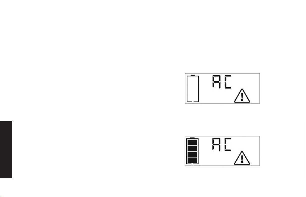
Español
Español
4746
3. Si existe un fallo térmico, cortocircuitos o sobrecargas en el
tomacorriente de CA, los tomacorrientes deCA se apagará
automáticamente y la pantalla LCD retroiluminada se mostrará lo
siguiento hasta que se corrija la falla:
El icono de estado de la batería se encenderá de forma sólida;
y “AC” en la pantalla digital y el icono de fallo en la pantalla LCD
parpadearán.
En caso de que se produzca alguna de las condiciones de
falla anteriores:
1. Desconecta el dispositivo de la unidad.
2. Pulse el botón de alimentación de CA para desactivar el
tomacorriente CA.
3. Asegúrese de que la unidad no necesita ser recargada.
4. Deje que la unidad se enfríe durante varios minutos.
5. Asegúrese de que la calificación del aparato conectado a la unidad
es de 500 vatios o más bajas y que el cable del aparato y el enchufe
no estén dañados.
6. Asegurar que haya suficiente ventilación alrededor de la unidad
antes de continuar.
EL USO DE LAS TOMAS DE CORRIENTE DE CA DOBLES
Las dos tomas de corriente de 120 voltios están situados en el lado
derecho de la unidad (refer to Fig. 2 to locate). Las dos tomas de
corriente apoyan un consumo de energía máximo combinado de 500
vatios.
1. Pulse el botón de alimentación de CA para encender dos tomas de
corriente de 120V AC. Sonará un pitido y la pantalla LCD mostrará
el siguiente:
El icono de estado de la batería se ilumina sólido y la pantalla
digital muestra “AC”, indicando que las dos tomas de CA están
listas para usar.
2. Tire y sostenga la cubierta protectora de la salida de CA izquierda
en sentido antihorario o la cubierta protectora de la salida de CA
derecha en sentido horario para exponer las salidas. Inserte el
enchufe de la CA de 120 voltios de la aplicación en una de las
tomas de corriente de CA.
3. Encender el aparato y operar como de costumbre.
NOTA: Asegúrese de que la clasificación combinada de todos
los dispositivos conectados simultaneamente a ambos tomas de
corriente de 120V CA no exceda de 500 vatios continuos.
4. Pulse el botón de alimentación de CA de nuevo para apagar ambos
tomas de corriente de 120V CA.
Compruebe periódicamente el estado de la batería de la unidad en la
pantalla del LCD. Cuatro barras sólidas en el icono de la batería indican
una batería llena. Cuando el nivel de la batería está casi vacía con
sólo una única de barras sólidas o 4 bares vacíos, la unidad debe ser
recargada en este momento o protección integrada de baja tensión de
la unidad se activará. El icono de estado de la batería vacía parpadeará
para un corto período de tiempo antes de apagado automático.
Asegúrese de que los tomas de corriente de CA se desactivan cuando
la unidad se está recargando o almacenado.
La unidad puede transportar las cargas resistivas con más facilidad.
No obstante, las cargas resistivas más grandes, como estufas o
calentadores eléctricos, generalmente requieren más potencia en
vatios de la que puede suministrar la unidad en forma continua. Las
cargas inductivas, como televisores y estéreos, requieren más corriente
para funcionar que las cargas resistivas de la misma clasificación de
potencia en vatios.
LA FORMA DE ONDA DE SALIDA DEL INVERSOR
La forma de onda de la salida CA de este inversor se conoce como
una onda senoidal modificada. Es una forma de onda escalonada
que posee características similares a la forma de onda senoidal de la
electricidad. Este tipo de forma de onda es adecuado para la mayoría
de las cargas CA, incluidas las fuentes de energía por conmutación y
lineales utilizadas en equipos electrónicos, transformadores y motores
pequeños.
CARACTERÍSTICAS DE PROTECCIÓN
La unidad supervisa para las siguientas condiciones:
Baja voltaje de la batería interna: La unidad cerrará automáticamente
cuando las caídas de voltaje de la batería demasiado bajas, como esto
pueden dañar la batería.
Alta voltaje de la batería interna: La unidad cerrará automáticamente
cuando el voltaje de la batería es demasiado alto, pues éste puede
dañar la unidad.
Protección de apagado térmico: El inversor se apagará
automáticamente cuando la unidad se sobrecaliente.
Protección contra cortocircuitos o sobrecargas: El inversor
se apagará automáticamente en presencia de un cortocircuito o
sobrecargas.
Notas importante para las tomas de corriente de 120V CA
Las dos salidas de alimentación de CA proporcionan una potencia
total combinada de 500W.
Cuando las tomas de alimentación de CA están en uso, la unidad
controlará las siguientes condiciones de falla: falla térmica, falla de
voltaje alto y bajo de la batería, sobrecarga y cortocircuito (consulte la
sección “Características de protección”).
1. Si existe una condición de falla de bajo voltaje de la batería interna,
los tomacorrientes de CA se apagarán automáticamente y la
pantalla LCD retroiluminada mostrará lo siguiente hasta que se
corrija la falla:
La pantalla digital mostrará “AC”; el icono de estado de la batería
VACÍO y el icono de fallo en la pantalla LCD parpadearán.
2. Si existe un fallo de alta voltaje de la batería interna en el
tomacorriente CA, los tomacorrientes de CA se apagarán
automáticamente y la pantalla LCD retroiluminada se mostrará lo
siguiento hasta que se corrija la falla:
La pantalla digital mostrará “AC”; el icono de estado de la batería
LLENA y el icono de fallo en la pantalla LCD parpadearán.
DXAEPS14_ManualENSP_020221.indd 46-47DXAEPS14_ManualENSP_020221.indd 46-47 2/2/2021 10:56:33 AM2/2/2021 10:56:33 AM
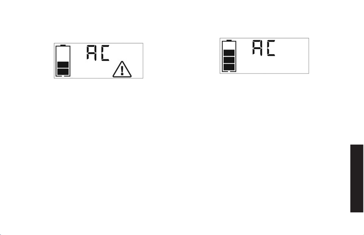
Español
Español
4746
3. Si existe un fallo térmico, cortocircuitos o sobrecargas en el
tomacorriente de CA, los tomacorrientes deCA se apagará
automáticamente y la pantalla LCD retroiluminada se mostrará lo
siguiento hasta que se corrija la falla:
El icono de estado de la batería se encenderá de forma sólida;
y “AC” en la pantalla digital y el icono de fallo en la pantalla LCD
parpadearán.
En caso de que se produzca alguna de las condiciones de
falla anteriores:
1. Desconecta el dispositivo de la unidad.
2. Pulse el botón de alimentación de CA para desactivar el
tomacorriente CA.
3. Asegúrese de que la unidad no necesita ser recargada.
4. Deje que la unidad se enfríe durante varios minutos.
5. Asegúrese de que la calificación del aparato conectado a la unidad
es de 500 vatios o más bajas y que el cable del aparato y el enchufe
no estén dañados.
6. Asegurar que haya suficiente ventilación alrededor de la unidad
antes de continuar.
EL USO DE LAS TOMAS DE CORRIENTE DE CA DOBLES
Las dos tomas de corriente de 120 voltios están situados en el lado
derecho de la unidad (refer to Fig. 2 to locate). Las dos tomas de
corriente apoyan un consumo de energía máximo combinado de 500
vatios.
1. Pulse el botón de alimentación de CA para encender dos tomas de
corriente de 120V AC. Sonará un pitido y la pantalla LCD mostrará
el siguiente:
El icono de estado de la batería se ilumina sólido y la pantalla
digital muestra “AC”, indicando que las dos tomas de CA están
listas para usar.
2. Tire y sostenga la cubierta protectora de la salida de CA izquierda
en sentido antihorario o la cubierta protectora de la salida de CA
derecha en sentido horario para exponer las salidas. Inserte el
enchufe de la CA de 120 voltios de la aplicación en una de las
tomas de corriente de CA.
3. Encender el aparato y operar como de costumbre.
NOTA: Asegúrese de que la clasificación combinada de todos
los dispositivos conectados simultaneamente a ambos tomas de
corriente de 120V CA no exceda de 500 vatios continuos.
4. Pulse el botón de alimentación de CA de nuevo para apagar ambos
tomas de corriente de 120V CA.
Compruebe periódicamente el estado de la batería de la unidad en la
pantalla del LCD. Cuatro barras sólidas en el icono de la batería indican
una batería llena. Cuando el nivel de la batería está casi vacía con
sólo una única de barras sólidas o 4 bares vacíos, la unidad debe ser
recargada en este momento o protección integrada de baja tensión de
la unidad se activará. El icono de estado de la batería vacía parpadeará
para un corto período de tiempo antes de apagado automático.
Asegúrese de que los tomas de corriente de CA se desactivan cuando
la unidad se está recargando o almacenado.
La unidad puede transportar las cargas resistivas con más facilidad.
No obstante, las cargas resistivas más grandes, como estufas o
calentadores eléctricos, generalmente requieren más potencia en
vatios de la que puede suministrar la unidad en forma continua. Las
cargas inductivas, como televisores y estéreos, requieren más corriente
para funcionar que las cargas resistivas de la misma clasificación de
potencia en vatios.
LA FORMA DE ONDA DE SALIDA DEL INVERSOR
La forma de onda de la salida CA de este inversor se conoce como
una onda senoidal modificada. Es una forma de onda escalonada
que posee características similares a la forma de onda senoidal de la
electricidad. Este tipo de forma de onda es adecuado para la mayoría
de las cargas CA, incluidas las fuentes de energía por conmutación y
lineales utilizadas en equipos electrónicos, transformadores y motores
pequeños.
CARACTERÍSTICAS DE PROTECCIÓN
La unidad supervisa para las siguientas condiciones:
Baja voltaje de la batería interna: La unidad cerrará automáticamente
cuando las caídas de voltaje de la batería demasiado bajas, como esto
pueden dañar la batería.
Alta voltaje de la batería interna: La unidad cerrará automáticamente
cuando el voltaje de la batería es demasiado alto, pues éste puede
dañar la unidad.
Protección de apagado térmico: El inversor se apagará
automáticamente cuando la unidad se sobrecaliente.
Protección contra cortocircuitos o sobrecargas: El inversor
se apagará automáticamente en presencia de un cortocircuito o
sobrecargas.
Notas importante para las tomas de corriente de 120V CA
Las dos salidas de alimentación de CA proporcionan una potencia
total combinada de 500W.
Cuando las tomas de alimentación de CA están en uso, la unidad
controlará las siguientes condiciones de falla: falla térmica, falla de
voltaje alto y bajo de la batería, sobrecarga y cortocircuito (consulte la
sección “Características de protección”).
1. Si existe una condición de falla de bajo voltaje de la batería interna,
los tomacorrientes de CA se apagarán automáticamente y la
pantalla LCD retroiluminada mostrará lo siguiente hasta que se
corrija la falla:
La pantalla digital mostrará “AC”; el icono de estado de la batería
VACÍO y el icono de fallo en la pantalla LCD parpadearán.
2. Si existe un fallo de alta voltaje de la batería interna en el
tomacorriente CA, los tomacorrientes de CA se apagarán
automáticamente y la pantalla LCD retroiluminada se mostrará lo
siguiento hasta que se corrija la falla:
La pantalla digital mostrará “AC”; el icono de estado de la batería
LLENA y el icono de fallo en la pantalla LCD parpadearán.
DXAEPS14_ManualENSP_020221.indd 46-47DXAEPS14_ManualENSP_020221.indd 46-47 2/2/2021 10:56:33 AM2/2/2021 10:56:33 AM
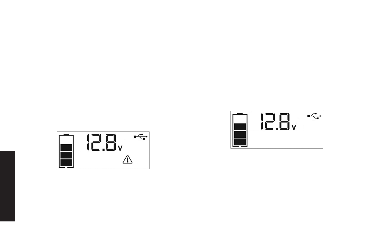
Español
Español
4948
recargada en este momento o protección integrada de baja tensión de
la unidad se activará. El icono de estado de la batería vacía parpadeará
para un corto período de tiempo antes de apagado automático.
IMPORTANTE: Asegúrese de que los puertos USB estén apagados
cuando la unidad se recarga o almacenado.
Luz de área LED
Integrada en el área de LED la luz consiste de dos bancos de dos LEDs
(uno en el lado derecho, uno en el lado izquierdo de la parte posterior
de la unidad). Es controlada por la luz del área de botón de encendido
del panel de control (consulte la Fig. 1 para localizar).
1. Presione el botón de encendido de la luz de área una vez encender
la luz.
2. Presione el botón de encendido de la luz de área nuevamente
para apagar la luz zonal.
Cuando se pulsa el botón de encendido luz de área para encenderlo,
sonará un pitido. La pantalla retroiluminada LCD se encenderá durante
10 segundos (solamente) y luego mostrará continuamente el icono del
estado de la batería y el indicador del voltaje de la batería.
Compruebe periódicamente el estado de la batería de la unidad en la
pantalla del LCD. Cuatro barras sólidas en el icono de la batería indican
una batería llena. Cuando el nivel de la batería está casi vacía con
sólo una única de barras sólidas o 4 bares vacíos, la unidad debe ser
recargada en este momento o protección integrada de baja tensión de
la unidad se activará. El icono de estado de la batería vacía parpadeará
para un corto período de tiempo antes de apagado automático.
IMPORTANTE: Cerciórese de que la luz de área y la unidad estén
dadas vuelta de cuando se está recargando o se está almacenando
la unidad.
Cuidado y mantenimiento
ADVERTENCIA: Para reducir el riesgo de lesiones, apague la
unidad y desconecte de cualquier fuente de alimentación antes de
instalar o retirar accesorios, antes de ajustar o al realizar el
mantenimiento. Un arranque accidental puede causar lesiones.
Nunca sumerja esta unidad en agua. La suciedad y la grasa pueden
ser removidos de la parte exterior de la unidad con un paño o un
cepillo no metálico suave. Nunca permita que penetre líquido dentro
de la unidad; nunca sumerja ninguna parte de la unidad en un líquido.
ADVERTENCIA: Riesgo de descarga eléctrica. Desenchufe el
adaptador de carga de CA de 12V antes de limpiar el dispositivo.
No hay piezas sustituibles por el usuario. Inspeccione periódicamente el
estado de los adaptadores, cables y conectores. Póngase en contacto
con el fabricante para sustituir a cualquiera de los componentes que
se han volverse desgastado o roto.
LA BATERÍA INTERNA
Con el tiempo, todas las baterías pierden energía debido a la descarga
automática y con mayor rapidez en ambientes con temperaturas
elevadas. Cuando la unidad no esté en uso, recomendamos cargar la
batería al menos cada 30 días.
Reemplazo de la batería
La batería debe durar la vida útil de la unidad. La vida de servicio
depende en un número de factores, incluyendo pero no limitado al
número de ciclos de recarga, y el cuidado y mantenimiento adecuado
de la batería por el usuario. Comuníquese con el fabricante para
cualquier información que pueda necesitar.
Puertos USB
El botón de alimentación USB y los cuatro puertos USB están situados
en el lado derecho de la unidad. Los indicadores de USB potencia /
fallo consiste en un translúcido anillo alrededor de cada uno de los
cuatro puertos USB. Consulte la Fig. 2 para localizar.
Notas importantes sobre los puertos USB
1. Los cuatro puertos USB proporcionan un total combinado de 6.2A.
Los dos puertos USB izquierdos proporcionan un total de 3.1A
(5V cada uno). Los dos puertos USB derechos proporcionan un
total de 3.1A (5V cada uno).
2. Cuando los puertos USB están en uso, la unidad vigilará todos
los puertos USB para las siguientes condiciones de fallo: fallo
en la tensión de la batería baja, sobrecarga y cortocircuito. Si
existe una condición de fallo en cualquiera de los puertos USB,
los indicadores de USB potencia / fallo parpadearán en azul. En
cualquiera de estos casos, la pantalla LCD retroiluminado mostrará
continuamente la siguiente:
El icono del falla parpadeará. Los puertos USB con alimentación
se apagará automáticamente. Si esto ocurre:
a. Desconecte el dispositivo USB y pulse el botón de alimentación
USB de nuevo para desactivar los puertos USB inmediatamente.
b. Asegúrese de que la unidad no necesita ser recargada.
c. Deje que la unidad se enfríe durante varios minutos antes de
intentar usar los puertos USB de nuevo.
d. Si un dispositivo USB individuo está dentro de las especificaciones
y se produce el fallo, tener el dispositivo USB comprobado para
funcionamiento defectuoso y no seguir utilizándolo con estos
puertos USB.
3. Los puertos USB de esta unidad no soportan la comunicación
de datos. Sólo proporcionan alimentación a dispositivos USB
externos.
4. Algunos dispositivos electrónicos con conexión USB no funcionará
con esta unidad.
USANDO LOS PUERTOS USB
1. Pulse el botón de alimentación USB para activar todos los puertos
USB. Sonará un pitido, los indicadores de USB potencia / fallo en
torno a cada uno de los cuatro puertos USB se ilumina en azul
y la pantalla LCD retroiluminada se mostrará continuamente lo
siguiento:
El icono de estado de la batería y el indicador del voltaje de la
batería se iluminará de sólidos, así como el icono USB, indicando
los puertos USB están listos para usar.
2. Conecte el dispositivo USB en el puerto (los puertos) USB y
funciona normalmente.
3. Pulse el botón de alimentación USB de nuevo para desactivar los
puertos USB.
Compruebe periódicamente el estado de la batería de la unidad en la
pantalla del LCD. Cuatro barras sólidas en el icono de la batería indican
una batería llena. Cuando el nivel de la batería está casi vacía con
sólo una única de barras sólidas o 4 bares vacíos, la unidad debe ser
DXAEPS14_ManualENSP_020221.indd 48-49DXAEPS14_ManualENSP_020221.indd 48-49 2/2/2021 10:56:33 AM2/2/2021 10:56:33 AM

Español
Español
4948
recargada en este momento o protección integrada de baja tensión de
la unidad se activará. El icono de estado de la batería vacía parpadeará
para un corto período de tiempo antes de apagado automático.
IMPORTANTE: Asegúrese de que los puertos USB estén apagados
cuando la unidad se recarga o almacenado.
Luz de área LED
Integrada en el área de LED la luz consiste de dos bancos de dos LEDs
(uno en el lado derecho, uno en el lado izquierdo de la parte posterior
de la unidad). Es controlada por la luz del área de botón de encendido
del panel de control (consulte la Fig. 1 para localizar).
1. Presione el botón de encendido de la luz de área una vez encender
la luz.
2. Presione el botón de encendido de la luz de área nuevamente
para apagar la luz zonal.
Cuando se pulsa el botón de encendido luz de área para encenderlo,
sonará un pitido. La pantalla retroiluminada LCD se encenderá durante
10 segundos (solamente) y luego mostrará continuamente el icono del
estado de la batería y el indicador del voltaje de la batería.
Compruebe periódicamente el estado de la batería de la unidad en la
pantalla del LCD. Cuatro barras sólidas en el icono de la batería indican
una batería llena. Cuando el nivel de la batería está casi vacía con
sólo una única de barras sólidas o 4 bares vacíos, la unidad debe ser
recargada en este momento o protección integrada de baja tensión de
la unidad se activará. El icono de estado de la batería vacía parpadeará
para un corto período de tiempo antes de apagado automático.
IMPORTANTE: Cerciórese de que la luz de área y la unidad estén
dadas vuelta de cuando se está recargando o se está almacenando
la unidad.
Cuidado y mantenimiento
ADVERTENCIA: Para reducir el riesgo de lesiones, apague la
unidad y desconecte de cualquier fuente de alimentación antes de
instalar o retirar accesorios, antes de ajustar o al realizar el
mantenimiento. Un arranque accidental puede causar lesiones.
Nunca sumerja esta unidad en agua. La suciedad y la grasa pueden
ser removidos de la parte exterior de la unidad con un paño o un
cepillo no metálico suave. Nunca permita que penetre líquido dentro
de la unidad; nunca sumerja ninguna parte de la unidad en un líquido.
ADVERTENCIA: Riesgo de descarga eléctrica. Desenchufe el
adaptador de carga de CA de 12V antes de limpiar el dispositivo.
No hay piezas sustituibles por el usuario. Inspeccione periódicamente el
estado de los adaptadores, cables y conectores. Póngase en contacto
con el fabricante para sustituir a cualquiera de los componentes que
se han volverse desgastado o roto.
LA BATERÍA INTERNA
Con el tiempo, todas las baterías pierden energía debido a la descarga
automática y con mayor rapidez en ambientes con temperaturas
elevadas. Cuando la unidad no esté en uso, recomendamos cargar la
batería al menos cada 30 días.
Reemplazo de la batería
La batería debe durar la vida útil de la unidad. La vida de servicio
depende en un número de factores, incluyendo pero no limitado al
número de ciclos de recarga, y el cuidado y mantenimiento adecuado
de la batería por el usuario. Comuníquese con el fabricante para
cualquier información que pueda necesitar.
Puertos USB
El botón de alimentación USB y los cuatro puertos USB están situados
en el lado derecho de la unidad. Los indicadores de USB potencia /
fallo consiste en un translúcido anillo alrededor de cada uno de los
cuatro puertos USB. Consulte la Fig. 2 para localizar.
Notas importantes sobre los puertos USB
1. Los cuatro puertos USB proporcionan un total combinado de 6.2A.
Los dos puertos USB izquierdos proporcionan un total de 3.1A
(5V cada uno). Los dos puertos USB derechos proporcionan un
total de 3.1A (5V cada uno).
2. Cuando los puertos USB están en uso, la unidad vigilará todos
los puertos USB para las siguientes condiciones de fallo: fallo
en la tensión de la batería baja, sobrecarga y cortocircuito. Si
existe una condición de fallo en cualquiera de los puertos USB,
los indicadores de USB potencia / fallo parpadearán en azul. En
cualquiera de estos casos, la pantalla LCD retroiluminado mostrará
continuamente la siguiente:
El icono del falla parpadeará. Los puertos USB con alimentación
se apagará automáticamente. Si esto ocurre:
a. Desconecte el dispositivo USB y pulse el botón de alimentación
USB de nuevo para desactivar los puertos USB inmediatamente.
b. Asegúrese de que la unidad no necesita ser recargada.
c. Deje que la unidad se enfríe durante varios minutos antes de
intentar usar los puertos USB de nuevo.
d. Si un dispositivo USB individuo está dentro de las especificaciones
y se produce el fallo, tener el dispositivo USB comprobado para
funcionamiento defectuoso y no seguir utilizándolo con estos
puertos USB.
3. Los puertos USB de esta unidad no soportan la comunicación
de datos. Sólo proporcionan alimentación a dispositivos USB
externos.
4. Algunos dispositivos electrónicos con conexión USB no funcionará
con esta unidad.
USANDO LOS PUERTOS USB
1. Pulse el botón de alimentación USB para activar todos los puertos
USB. Sonará un pitido, los indicadores de USB potencia / fallo en
torno a cada uno de los cuatro puertos USB se ilumina en azul
y la pantalla LCD retroiluminada se mostrará continuamente lo
siguiento:
El icono de estado de la batería y el indicador del voltaje de la
batería se iluminará de sólidos, así como el icono USB, indicando
los puertos USB están listos para usar.
2. Conecte el dispositivo USB en el puerto (los puertos) USB y
funciona normalmente.
3. Pulse el botón de alimentación USB de nuevo para desactivar los
puertos USB.
Compruebe periódicamente el estado de la batería de la unidad en la
pantalla del LCD. Cuatro barras sólidas en el icono de la batería indican
una batería llena. Cuando el nivel de la batería está casi vacía con
sólo una única de barras sólidas o 4 bares vacíos, la unidad debe ser
DXAEPS14_ManualENSP_020221.indd 48-49DXAEPS14_ManualENSP_020221.indd 48-49 2/2/2021 10:56:33 AM2/2/2021 10:56:33 AM
Español
Español
5150
ELIMINACIÓN DE LA BATERÍA
Contiene una batería de plomo-ácido sellada, no
derramable, libre de mantenimiento, que debe desecharse
adecuadamente. Se requiere reciclaje. El incumplimiento
de las regulaciones locales, estatales y federales puede
resultar en multas o encarcelamiento.
Por favor recicla.
ADVERTENCIA – Para reducir el riesgo de lesiones grave o
daño a la propiedad:
• No deseche la batería en el fuego ya que puede ocasionar una
explosión.
• Antes de desechar la batería, proteja las terminales descubiertas con
cinta eléctrica para trabajos pesados. De esta manera previene cortos
circuitos (los cortos circuitos pueden ocasionar lesiones e incendios).
• No exponga la batería al fuego o al calor extremo ya que puede
explotar.
Detección de problemas
Problema Solución posible
La unidad no cargará Si la batería de la unidad está muy
agotada, puede requerir hasta 96 horas
de carga con el método de CA.
Cerciórese de que todas las funciones
de unidad estén apagadas.
Compruebe la conexión a la fuente de
alimentación CA.
Confirmar hay corriente CA.
La unidad no arranca
el motor
Asegúrese de que se han realizado
las conexiones de los cables con la
polaridad correcta.
Asegúrese de que la unidad no
está siendo operado en el modo de
compresor.
Controle que el puente auxiliar de
arranque tenga la carga completa.
Recargue la unidad en caso de
necesidad.
La luz de área LED no
enciende
Cerciórese de que el botón de
encendido de la luz de área LED esté
en la posición de trabajo.
Compruebe que la unidad tiene una
carga completa. Recargue la unidad
en caso de necesidad.
Problema Solución posible
El compresor portátil
no inflará
Asegúrese de que el botón de
encendido del compresor se ha
presionado para activar el compresor.
Asegúrese de que el interruptor del
puente auxiliar de arranque se ha
apagado antes de intentar utilizar la
unidad como un compresor
Asegúrese de que la boquilla Sure Fit
®
está firmemente atornillada al vástago
de válvula cuando se intenta inflar los
neumáticos; o que el adaptador de
la boquilla se atornilla firmemente en
la boquilla Sure Fit
®
y está insertado
correctamente en el elemento a ser
inflado en todos los otros objetos
inflables.
Compruebe que la unidad tiene una
carga completa. Recargue la unidad
en caso de necesidad.
Toma de corriente de
120V CA no accionará
el aparato
Asegúrese de que el botón de
alimentación de CA esté en la posición
de encendido.
Asegúrese de que la combinación
de dibujar de todos los aparatos
alimentados no es más de 500 vatios.
Compruebe que la unidad tiene una
carga completa. Recargue la unidad
en caso de necesidad.
Problema Solución posible
Toma de corriente de
120V CA no accionará
el aparato (continuado)
Asegúrese de que ha seguido todos
los pasos de la sección “Tomas de
corriente de 120V CA” con cuidado.
Consulte las notas importantes
incluidas en esa sección que explican
los problemas comunes y soluciones.
El puerto de la energía
del USB no accionará
el aparato
Asegúrese de que el botón de encendido/
apagado del puerto de carga USB esté
en la posición de encendido.
Asegúrese de que poder total de todos
los dispositivos USB en dos puertos
izquierdos/derechos no excedan 3.1A.
Compruebe que la unidad tiene una
carga completa. Recargue la unidad
en caso de necesidad.
Asegúrese de que toda los indicadores
de USB potencia / fallo se iluminan de
color azul constante. Si existe un fallo
en cualquiera de los dos puertos USB,
los indicadores de USB potencia / fallo
parpadeará en azul. Consulte las notas
importantes en la sección “Puertos
USB” para obtener instrucciones para
remediar cualquier fallas.
DXAEPS14_ManualENSP_020221.indd 50-51DXAEPS14_ManualENSP_020221.indd 50-51 2/2/2021 10:56:33 AM2/2/2021 10:56:33 AM

Español
Español
5150
ELIMINACIÓN DE LA BATERÍA
Contiene una batería de plomo-ácido sellada, no
derramable, libre de mantenimiento, que debe desecharse
adecuadamente. Se requiere reciclaje. El incumplimiento
de las regulaciones locales, estatales y federales puede
resultar en multas o encarcelamiento.
Por favor recicla.
ADVERTENCIA – Para reducir el riesgo de lesiones grave o
daño a la propiedad:
• No deseche la batería en el fuego ya que puede ocasionar una
explosión.
• Antes de desechar la batería, proteja las terminales descubiertas con
cinta eléctrica para trabajos pesados. De esta manera previene cortos
circuitos (los cortos circuitos pueden ocasionar lesiones e incendios).
• No exponga la batería al fuego o al calor extremo ya que puede
explotar.
Detección de problemas
Problema Solución posible
La unidad no cargará Si la batería de la unidad está muy
agotada, puede requerir hasta 96 horas
de carga con el método de CA.
Cerciórese de que todas las funciones
de unidad estén apagadas.
Compruebe la conexión a la fuente de
alimentación CA.
Confirmar hay corriente CA.
La unidad no arranca
el motor
Asegúrese de que se han realizado
las conexiones de los cables con la
polaridad correcta.
Asegúrese de que la unidad no
está siendo operado en el modo de
compresor.
Controle que el puente auxiliar de
arranque tenga la carga completa.
Recargue la unidad en caso de
necesidad.
La luz de área LED no
enciende
Cerciórese de que el botón de
encendido de la luz de área LED esté
en la posición de trabajo.
Compruebe que la unidad tiene una
carga completa. Recargue la unidad
en caso de necesidad.
Problema Solución posible
El compresor portátil
no inflará
Asegúrese de que el botón de
encendido del compresor se ha
presionado para activar el compresor.
Asegúrese de que el interruptor del
puente auxiliar de arranque se ha
apagado antes de intentar utilizar la
unidad como un compresor
Asegúrese de que la boquilla Sure Fit
®
está firmemente atornillada al vástago
de válvula cuando se intenta inflar los
neumáticos; o que el adaptador de
la boquilla se atornilla firmemente en
la boquilla Sure Fit
®
y está insertado
correctamente en el elemento a ser
inflado en todos los otros objetos
inflables.
Compruebe que la unidad tiene una
carga completa. Recargue la unidad
en caso de necesidad.
Toma de corriente de
120V CA no accionará
el aparato
Asegúrese de que el botón de
alimentación de CA esté en la posición
de encendido.
Asegúrese de que la combinación
de dibujar de todos los aparatos
alimentados no es más de 500 vatios.
Compruebe que la unidad tiene una
carga completa. Recargue la unidad
en caso de necesidad.
Problema Solución posible
Toma de corriente de
120V CA no accionará
el aparato (continuado)
Asegúrese de que ha seguido todos
los pasos de la sección “Tomas de
corriente de 120V CA” con cuidado.
Consulte las notas importantes
incluidas en esa sección que explican
los problemas comunes y soluciones.
El puerto de la energía
del USB no accionará
el aparato
Asegúrese de que el botón de encendido/
apagado del puerto de carga USB esté
en la posición de encendido.
Asegúrese de que poder total de todos
los dispositivos USB en dos puertos
izquierdos/derechos no excedan 3.1A.
Compruebe que la unidad tiene una
carga completa. Recargue la unidad
en caso de necesidad.
Asegúrese de que toda los indicadores
de USB potencia / fallo se iluminan de
color azul constante. Si existe un fallo
en cualquiera de los dos puertos USB,
los indicadores de USB potencia / fallo
parpadeará en azul. Consulte las notas
importantes en la sección “Puertos
USB” para obtener instrucciones para
remediar cualquier fallas.
DXAEPS14_ManualENSP_020221.indd 50-51DXAEPS14_ManualENSP_020221.indd 50-51 2/2/2021 10:56:33 AM2/2/2021 10:56:33 AM
Español
Español
5352
Problema Solución posible
El puerto de la energía
del USB no accionará
el aparato (continuado)
Algunos productos electrónicos de uso
doméstico alimentados por USB no
funcionan con esta puerto de carga
/ potencia del USB. Compruebe el
manual del dispositivo electrónico
correspondiente para confirmar que se
puede utilizar con este tipo de puerto
de carga / potencia del USB.
Accessories
ADVERTENCIA: Debido a que no se han probado con este producto
otros accesorios que no sean los que ofrece DeWALT, el uso de dichos
accesorios con esta herramienta podría ser peligroso. Para reducir el
riesgo de lesiones, con este producto deben usarse sólo los accesorios
recomendados por DeWALT.
Si necesita ayuda con respecto a los accesorios, póngase en contacto
con el fabricante al 1-888-394-3392 o CustomerService@dewalt12volt.
com.
Información de servicio
Si usted necesita asesoramiento técnico, reparación, o partes genuinas
del fabricante, póngase en contacto con el fabricante al 1-888-394-
3392 o [email protected].
Garantía Limitada de Un Año
La garantía de este producto está cubierta por Baccus Global LLC
(1-888-394-3392 o [email protected]). El fabricante
garantiza este producto contra defectos de materiales y mano de obra
durante un período de UN (1) AÑO a partir de la fecha de compra del
producto por el comprador usuario final (“Período de Garantía”). Si hay
un defecto y una reclamación válida se recibe dentro del período de
garantía, el producto defectuoso puede ser reemplazado, reparado,
o reembolsado, sin cargo, en el las siguientes maneras: (1) Devuelva
el producto al fabricante para reparación, reemplazo o reembolso, a
opción del fabricante. La prueba de compra puede ser requerida por
el fabricante. (2) Devuelva el producto a la tienda donde el producto
fue comprado para un intercambio (siempre y cuando se trate de un
minorista participante). Devoluciones al minorista deben hacerse dentro
del plazo de póliza de devoluciones del minorista para intercambios
solamente (por lo general 30 a 90 días después de la fecha de compra).
La prueba de compra puede ser requerida por el minorista. Por favor
consulte la póliza de devoluciones del minorista sobre devoluciones
que están fuera del plazo establecido para intercambios.
Esta garantía no se aplica a los accesorios, bombillos, fusibles y
baterías; defectos a consecuencias de desgaste normal; accidentes;
daños y perjuicios sufridos durante el envío y manejo, alteraciones,
reparaciones o uso no autorizado, negligencia, abuso, y si no se siguen
instrucciones para el cuidado y mantenimiento del producto.
Esta garantía le otorga al comprador usuario final, derechos legales
específicos y usted puede tener otros derechos que varían de estado
a estado o de provincia a provincia. Este producto no está diseñado
para uso comercial.
POLÍTICA DE DEVOLUCIÓN DE 90 DÍAS
Si usted no está completamente satisfecho con el rendimiento de
este producto por cualquier razón, puede devolverlo en un plazo de
noventa (90) días desde la fecha de compra con un recibo para un
reembolso complete.
Por favor, visite nuestro sitio web www.baccusglobal. com/register para
registrar el nuevo Baccus Global LLC producto y mantenerse al tanto
de los nuevos productos y ofertas especiales.
Especificaciones
Amperios de impulso 1,600A pico batería,
750A instantánea
Tipo de batería De plomo, sellada, 12 volt CC
Entrada 120V CA, 60Hz
Compresor 120 PSI
Salida USB 5 V CC cada uno, 6.2 A en
total (3.1 A en total en los dos
puertos USB izquierdos; 3.1 A
en total en los dos puertos USB
derechos)
Tomas de corriente de 120V CA 120V CC, 60Hz, 500W
Sure Fit
®
es una marca registrada propiedad de Baccus Global, LLC.
Fabricado e importado por Baccus Global LLC,
621 NW 53rd St., Suite 450, Boca Raton, FL 33487
www.dewalt12volt.com 1-888-394-3392
Hecho en Vietnam
Derechos Reservados © 2021 Baccus Global, LLC. D
e
WALT
®
y el
logotipo son marcas comerciales de D
e
WALT el D
e
WALT Industrial
Tool Co., o una filial de la misma y se utilizan bajo licencia. El
esquema de color amarillo y negro es una marca comerciale de
herramientas y accesorios de D
e
WALT.
www.dewalt12volt.com
DXAEPS14_ManualENSP_020221.indd 52-53DXAEPS14_ManualENSP_020221.indd 52-53 2/2/2021 10:56:34 AM2/2/2021 10:56:34 AM

Español
Español
5352
Problema Solución posible
El puerto de la energía
del USB no accionará
el aparato (continuado)
Algunos productos electrónicos de uso
doméstico alimentados por USB no
funcionan con esta puerto de carga
/ potencia del USB. Compruebe el
manual del dispositivo electrónico
correspondiente para confirmar que se
puede utilizar con este tipo de puerto
de carga / potencia del USB.
Accessories
ADVERTENCIA: Debido a que no se han probado con este producto
otros accesorios que no sean los que ofrece DeWALT, el uso de dichos
accesorios con esta herramienta podría ser peligroso. Para reducir el
riesgo de lesiones, con este producto deben usarse sólo los accesorios
recomendados por DeWALT.
Si necesita ayuda con respecto a los accesorios, póngase en contacto
con el fabricante al 1-888-394-3392 o CustomerService@dewalt12volt.
com.
Información de servicio
Si usted necesita asesoramiento técnico, reparación, o partes genuinas
del fabricante, póngase en contacto con el fabricante al 1-888-394-
3392 o [email protected].
Garantía Limitada de Un Año
La garantía de este producto está cubierta por Baccus Global LLC
(1-888-394-3392 o [email protected]). El fabricante
garantiza este producto contra defectos de materiales y mano de obra
durante un período de UN (1) AÑO a partir de la fecha de compra del
producto por el comprador usuario final (“Período de Garantía”). Si hay
un defecto y una reclamación válida se recibe dentro del período de
garantía, el producto defectuoso puede ser reemplazado, reparado,
o reembolsado, sin cargo, en el las siguientes maneras: (1) Devuelva
el producto al fabricante para reparación, reemplazo o reembolso, a
opción del fabricante. La prueba de compra puede ser requerida por
el fabricante. (2) Devuelva el producto a la tienda donde el producto
fue comprado para un intercambio (siempre y cuando se trate de un
minorista participante). Devoluciones al minorista deben hacerse dentro
del plazo de póliza de devoluciones del minorista para intercambios
solamente (por lo general 30 a 90 días después de la fecha de compra).
La prueba de compra puede ser requerida por el minorista. Por favor
consulte la póliza de devoluciones del minorista sobre devoluciones
que están fuera del plazo establecido para intercambios.
Esta garantía no se aplica a los accesorios, bombillos, fusibles y
baterías; defectos a consecuencias de desgaste normal; accidentes;
daños y perjuicios sufridos durante el envío y manejo, alteraciones,
reparaciones o uso no autorizado, negligencia, abuso, y si no se siguen
instrucciones para el cuidado y mantenimiento del producto.
Esta garantía le otorga al comprador usuario final, derechos legales
específicos y usted puede tener otros derechos que varían de estado
a estado o de provincia a provincia. Este producto no está diseñado
para uso comercial.
POLÍTICA DE DEVOLUCIÓN DE 90 DÍAS
Si usted no está completamente satisfecho con el rendimiento de
este producto por cualquier razón, puede devolverlo en un plazo de
noventa (90) días desde la fecha de compra con un recibo para un
reembolso complete.
Por favor, visite nuestro sitio web www.baccusglobal. com/register para
registrar el nuevo Baccus Global LLC producto y mantenerse al tanto
de los nuevos productos y ofertas especiales.
Especificaciones
Amperios de impulso 1,600A pico batería,
750A instantánea
Tipo de batería De plomo, sellada, 12 volt CC
Entrada 120V CA, 60Hz
Compresor 120 PSI
Salida USB 5 V CC cada uno, 6.2 A en
total (3.1 A en total en los dos
puertos USB izquierdos; 3.1 A
en total en los dos puertos USB
derechos)
Tomas de corriente de 120V CA 120V CC, 60Hz, 500W
Sure Fit
®
es una marca registrada propiedad de Baccus Global, LLC.
Fabricado e importado por Baccus Global LLC,
621 NW 53rd St., Suite 450, Boca Raton, FL 33487
www.dewalt12volt.com 1-888-394-3392
Hecho en Vietnam
Derechos Reservados © 2021 Baccus Global, LLC. D
e
WALT
®
y el
logotipo son marcas comerciales de D
e
WALT el D
e
WALT Industrial
Tool Co., o una filial de la misma y se utilizan bajo licencia. El
esquema de color amarillo y negro es una marca comerciale de
herramientas y accesorios de D
e
WALT.
www.dewalt12volt.com
DXAEPS14_ManualENSP_020221.indd 52-53DXAEPS14_ManualENSP_020221.indd 52-53 2/2/2021 10:56:34 AM2/2/2021 10:56:34 AM