GRT SERIES INSTALL & USER GUIDE
GRT SERIES
INSTALL & USER GUIDE
I N S P I R I N G T H E W O R L D ’ S K I T C H E N
IMPORTANT SAFETY INSTRUCTIONS
Carefully read the following Important information redarding installation
safety and maintenance. Keep these instruction for future reference.
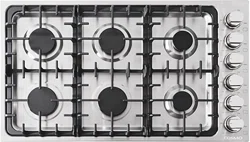
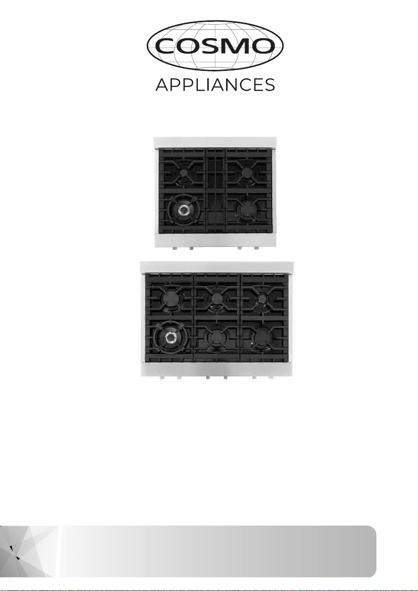
SLIDE-IN GAS COOKTOP
2 3
THANK YOU FOR YOUR PURCHASE
Thank you for your purchase. We know that you have many brands and
products to choose from and we are honored to know that you have decided
to take one of our products into your home and hope that you enjoy it.
COSMO appliances are designed according to the strictest safety and performance
standard for the North American market. We follow the most advanced
manufacturing philosophy. Each appliance leaves the factory after thorough
quality inspection and testing. Our distributors and our service partners are
ready to answer any questions you may have regarding how to install, use and
care for your products. We hope that this manual will help you learn to use the
product in the safest and most effective manner .
If you have any questions or concerns, please contact the dealer from whom you
purchased it, or contact our Customer Support at:
1-888-784-3108.
TABLE OF CONTENTS
SAFETY INSTRUCTIONS 4
INSTALLATION INSTRUCTIONS 5-12
OPERATING INSTRUCTIONS 13-15
CARE INSTRUCTIONS 16-17
REFERENCE FIGURES 18-20
WARRANTY & SERVICE 22-23
4 5
IMPORTANT SAFETY INSTRUCTIONS
INSTALLATION INSTRUCTIONS
If the information in this manual is not followed exactly, a fire
or explosion may result causing property damage, personal
injury or death.
Do not store or use gasoline or other flammable vapors and
liquid in the vicinity of this or any other appliance.
WHAT TO DO IF YOU SMELL GAS
- Do not try to light any appliance.
- Do not touch any electrical switch.
- Do not use any phone in your building.
- Immediately call your gas supplier from a neighbor’s phone.
Follow the gas supplier’s instructions.
- If you cannot reach your gas suppliers, call the fire depart-
ment.
Installation and service must be performed by a qualified
installer, service agency or the gas supplier.
!
WARNING
IMPORTANT
SAVE FOR LOCAL ELECTRICAL INSPECTOR’S USE. READ AND SAVE
THESE INSTRUCTIONS FOR FUTURE REFERENCE. OBSERVE ALL
GOVERNING CODES AND ORDINANCES.
The manufacturer will not be responsible for any damage to
property or to persons caused by incorrect installation or improper
use of the appliance.
The manufacturer reserves the right to make changes to its
products when considered necessary and useful, without affecting
the essential safety and operating characteristics.
This appliance has been designed for non-professional, domestic
use only.
This appliance shall only be installed by an authorized person and shall
be installed in accordance with the manufacturers installation instruc-
tions.
IMPORTANT
This appliance must be installed in accordance with the norms in force
of the country concerned. The installation of this appliance must con-
form to local codes and ordinances. In the absence of local codes, In-
stallations must conforms to American National Standards, National
Fuel Gas Code ANSI Z223.1 – latest edition** or B149.1. If local codes
permit, a flexible metal appliance connection with the new AGA or
CGA certified design, max. 5 feet (1,5 m) long, 1⁄2” I.D. recommended for
connecting this cooktop to the gas supply line.
Do not bend or damage the flexible connector when moving the
cooktop. The pressure regulator has 1⁄2” female pipe thread. You will
need to determine the fitting required, depending on the size of your
gas supply line, the flexible metal connector and the shutoff valve.
The appliance, when installed, must be electrically grounded in accor-
dance with local codes or, in the absence of local codes, with the Na-
tional Electrical Code, ANSI/NFPA 70.
The appliance and its individual shutoff valve must be disconnected
from the gas supply piping system any pressure testing of that system
at test pressure in excess of 1⁄2 psi (3,5 kPa).
The appliance must be isolated from the gas supply piping system by
closing its individual manual shutoff valve during any pressure testing
of the gas supply piping system at test pressures equal to or less than
1⁄2 psi (3.5 kPa).
For use with a pressure regulator. The regulator supplied must be used
with this appliance. The gas appliance pressure regulator must be set
for the gas with which the appliance is used.
which the appliance is used.

6 7
This appliance can be used with Natural Gas and LP Gas. It is
shipped from the factory adjusted for use with Natural Gas. Propane
conversion kits can be purchased separately.
The maximum inlet gas supply pressure incoming to the gas appli-
ance pressure regulator is 20’’ water column (5 kPa). The minimum
gas supply pressure for checking the regulator setting shall be at
least 1“ w.c. (249 Pa) above the inlet specified manifold pressure to
the appliance (this operating pressure is
4” w.c. (1.00 kPa) for Natural Gas and 10” w.c. (2.75 kPa) for LP Gas).
ATTENTION
A manual valve shall be installed in an accessible location in the gas
line external to the appliance for the purpose of turning on or shut-
ting off gas to the appliance.
WARNING
Do not use aerosol sprays in the vicinity of this appliance while it is in
operation
INSERTING THE COOKTOP
After having removed the various loose parts from the internal and
external packing, make sure that the cooktop is not damaged and is
suitable for the specific gas usage. The gas type label is on the un-
derside of the cooktop base.
In case of doubt, do not use the appliance and contact skilled
personnel.
Keep all the packaging parts (polystyrene foam, cardboard, staples,
etc.) away from children. Consider the critical dimensions of the ap-
pliance, before making an opening in the top surface of the
countertop. (relative measurements as per Page 18-19, Fig. 1, 2).
ATTACHING THE COOKTOP
To prevent liquids from leaking accidentally into the underlying
storage space, the appliance is equipped with a special gasket.
To apply this gasket, carefully follow the instructions in Fig. 3. Lay out
the protective sealing strips along the edges of the opening in the
countertop and carefully overlap the strip end. (See Fig. 3). Insert the
cooktop into the countertop opening. With a screwdriver assemble
the brackets A to the cooktop bottom by means of the screws B.
(See Fig. 4). Slide the hooks into position and secure them with the
screws.Trim the part of the sealing strips which extend beyond the
hotplate base.
GAS CONNECTION
Before connecting the appliance to the gas supply, first remove the
plastic plug on which is press- fitted into the gas inlet union; to
remove, just pull it off.
1. Check the ‘gas type’ sticker attached to the cooktop. Details of the
injector sizes used are recorded on the data plate located on the
base of the appliance.
2. This appliance shall be installed in accordance with installation re-
quirements of the local gas authority of the appropriate
installation code.
3. Before installing the cooktop consider the location of the gas supply
and routing the gas line.(Refer fig.6)
4. For LPG models: the gas supply is connected to the regulator which
is supplied loose. The inlet connection has a 1/2” B.S.P. male thread. IT
IS ESSENTIAL THAT THE ELBOW ON THE APPLIANCE BE HELD FIRMLY
WITH A SPANNER WHEN CONNECTING THE SUPPLY. DO NOT OVER
TIGHTEN. The regulated pressure For LPG is 10” w.c. (See Fig. 5).
INSTALLATION INSTRUCTIONS INSTALLATION INSTRUCTIONS
8 9
5. For NG models the gas supply is connected to the regulator loose.
The inlet connection has a 1/2” B.S.P. male thread. IT IS ESSENTIAL
THAT THE ELBOW ON THE APPLIANCE BE HELD FIRMLY WITH A SPAN-
NER WHEN CONNECTING THE SUPPLY. DO NOT OVER TIGHTEN. The
regulated pressure for NG is 4” W.C. (See Fig. 5).
6. For gas inlet position of appliance refer Fig 5, 6 and 7. After in-
stalling the gas supply and making all connections, check thoroughly
for possible leaks. Turn all control knobs on the unit to ‘OFF’ position.
Open the valve on the gas supply. Using a soap and water solution
check each gas connection one at a time, by brushing the solution over
the connection. Presence of bubbles will indicate a leak. Tighten the fit-
ting and re- check for leaks. If it is not possible to correct the leak, re-
place fitting. Under no circumstances should matches or flames be
used for checking leaks. It is essential that the gasket and the pressure
test point stopper are properly installed to avoid gas leakage.
7. To checking inlet pressure at the appliance, perform the following:
a) Disconnect electric power before checking pressure.
b) Take off one of the gas burner cap and the relative flame spreader
in order to gain access to the burner injector.
c) Put the pressure detector directly on the burner injector. Afterwards,
open the relative burner knob at maximum position keeping it pressed,
then measure the outlet pressure from the burner injector.
d) Once the pressure checking has been carried out, replace the burner
cap and flame spreader in the correct and original
8. Turn on appliance control and light each burner. Check for a
clear blue flame without yellow tipping. If burners show any
abnormalities, check that they are situated properly and in line with
the injector nipple.
position and re-connect electric power to the appliance.
8. Turn on appliance control and light each burner. Check for a
clear blue flame without yellow tipping. If burners show any
abnormalities, check that they are situated properly and in line with
the injector nipple.
9. Sometimes the burners will not ignite immediately and seem
to "blow" slightly when they do ignite. This is usually due to air in
the gas lines, which will clear itself within minutes of use.
10. If after following the instructions given, satisfactory
performance cannot be obtained, contact your local gas authority for
advice and assistance.
ELECTRICAL CONNECTION
The connection of the hobs to mains is effected via the flex and the
three pin plug located underneath the hotplate. The appliance
operates at a main voltage of 120V a.c., frequency: 60Hz. Electric
power absorption is about 1W for 5 gas burners version or 2W for 6
gas burners version.
WARNING
Electrical Grounding Instructions: This appliance is equipped with a
(three-prong) grounding plug for your protection against shock
hazard and should be plugged directly into a properly grounded out-
let. Do not cut or remove the grounding prong from this plug.
WIRING DIAGRAMS (see Fig. 12.)
Wiring diagram description:
1. Cable terminal
2. Ignition switch
3. Spark generator
4. Ignition spark L. Black N. White T. Green (earth)
4. Ignition spark L. Black N. White T. Green (earth)
INSTALLATION INSTRUCTIONS INSTALLATION INSTRUCTIONS
10 11
INSTALLATION INSTRUCTIONS INSTALLATION INSTRUCTIONS
GAS CONVERSION
Before carrying out any maintenance work, disconnect the appli-
ance from the gas and electric supply.
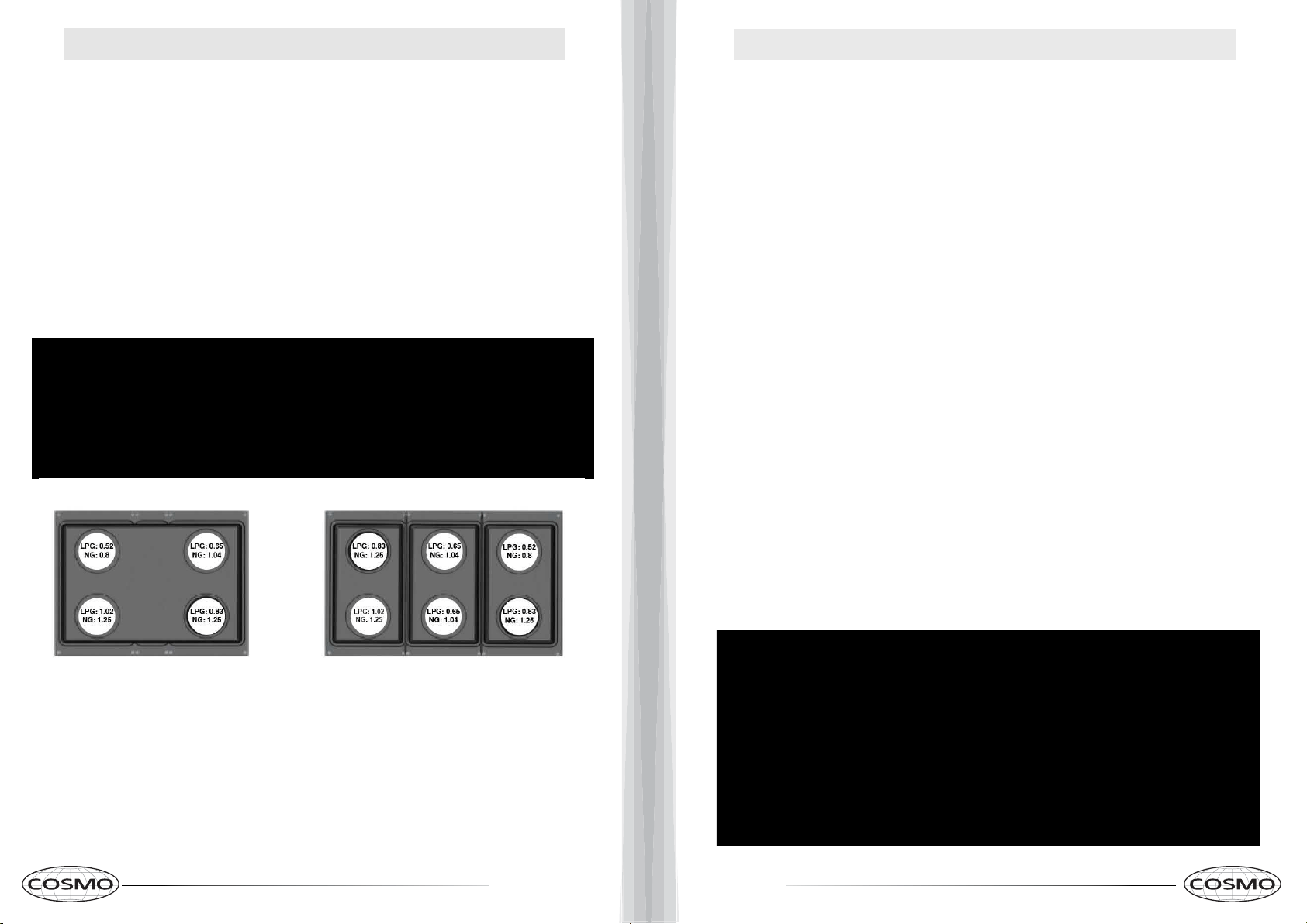
CHANGING THE BURNER NOZZLES
Lift up the burners and unscrew the nozzles ( Fig. 8) using an ad-
justable wrench of 7 mm and change the nozzles with those de-
signed for the new gas supply according to the information given in
TABLE A shown below.
TABLE A
CAUTION: Save the orifices removed from the appliance for
future use
PRESSURE REGULATOR ADJUSTMENT FOR GAS CONVERSION
The pressure regulator supplied with the appliance is a convertible type
pressure regulator for use with Natural Gas at a nominal outlet pres-
sure of 4” W.C. or LP gas at a nominal outlet pressure of 10” W.C. and it
is pre-arranged from the factory to operate with one of these gas/pres-
sure as indicated in the pre-arranging labels affixed on the appliance,
package and Instruction booklet.
Your cooktop is shipped from the factory set for use with natural gas.
It can be converted for use with propane gas by following steps
below. Note: The agency performing this work assumes responsibility
for the conversion.
1) Unscrew by hand the upper metal stopper of the regulator (Fig. 5)
2) Unscrew by hand the white plastic piece screwed under the above
mentioned metal stopper. Afterward, screw in this part again in
opposite way under the metal stopper (for gas reference see the
written “LP” and “NAT” with relative indicating arrows on the white
piece).
3) Screw again by hand the metal stopper in the original position on
the regulator.
TABLE A
12 13
INSTALLATION INSTRUCTIONS
OPERATING INSTRUCTIONS
REGULATION OF BURNER FLAME INTENSITY
To regulate the minimum flame on the burners, carry out the
following procedure indicated below:
1) Turn on the burner and put the knob onto position MINIMUM (small
flame).
2) Remove the knob ( Fig. 9) of the tap which is set for standard pres-
sure. The knob is found on the shaft of the valve itself.
3) Beside the valve shaft, use a small screwdriver that fits the gold col-
ored screw found on the lower part of the tap (auxiliary, semi-rapid,
rapid Fig. 9) (dual fig.10) and turn the adjustment clock-wise or counter
clock-wise until the minimum flame reaches a desired intensity level.
4) Make sure that that the flame does not go out when changing the
position quickly from MAXIMUM to the MINIMUM position. If it does,
the minimum flame intensity needs to be increased.
WARNING
Keep appliance area clear and free from combustible materials,
gasoline and other flammable vapors and liquid.
• Do not store dangerous or flammable material in the cabinet areas
above appliance; store them in a safe place in order to avoid poten-
tial hazards.
• For safe use of appliance, do not use it for space heating.
• Do not use aerosol sprays in the vicinity of this appliance while it is in
operation For description of hotplates refer to installation instructions.
• This product is intended for the cooking of food and must not be
used for other purposes.
• Unstable or deformed pans should not be placed on the burners or
hot plates in order to avoid accidents caused by spill over.
• Added care should be taken when cooking with oil or fat.
• Always ensure that the knobs are in the "O" Off or Stop position when
the appliance is not in use.
• Before maintenance and cleaning, disconnect the appliance and al-
low cooling down.
• For reasons of hygiene and safety, this appliance must be regularly
cleaned and maintained.
• Ensure that air can circulate around the gas appliance. Poor ventila-
tion can result in lack of oxygen and extinguish the flame.
• The use of a gas cooking appliance produces heat and humidity in
the room where it is installed.
• The use of a gas cooking appliance produces heat and humidity in
the room where it is installed.
• The use of a gas cooking appliance produces heat and humidity in the
room where it is installed.
14 15
OPERATING INSTRUCTIONS
OPERATING INSTRUCTIONS
.
BURNER CONTROLS
To light each burner, push the knob and turn it counter-clockwise to
maximum setting, and hold it for 3 to 5 seconds. The igniter will spark
and ignite the flame. At this position the gas supply is at the maxi-
mum and the flame also at its maximum.
You can reduce the flame size by turning the knob in counter-
clockwise to your desired flame height. Should the burner fail to
light up, turn the knob to its original position and try again.
NOTE: When first used, the gas burner will not ignite immediately.
Hold the knob pressed down for an extended time for the gases to
fully fill the operating system.
• Ensure good ventilation of the room. Keep adequate natural
ventilation or install an extractor hood with a discharge tube. In
case of doubt, ask a professional installer for advice.
• Supply the appliance with the type of gas stamped on the
relevant label situated in the immediate vicinity of the gas
connection tube.
• To facilitate ignition, light the burners before placing pans on the
grid. Check that the flame is regular. Always lower the flame or turn
it off before removing the pan.
• Ensure burner caps are installed correctly (See instruction as
below.)
TIPS FOR USING PANS CORRECTLY
Always ensure that bottom and handles of pans do not protrude from
the worktop. When cooking with flammable fat such as oil, do not
leave the range unattended.Use pots of the appropriate size on each
burner following the indication of the diagram below.
BURNER RECOMMENDED PAN SIZE INCHES (mm)
Auxiliary 3%"-5 1/2" (90 -140)
Semi Rapid 51/2"-10 1/4" (140 - 260)
Rapid 71/8"-10 1/4" (180-260)
Dual burner 82/3"-10 1/4" (220 - 260)
When boiling liquids, turn the knob to the MINIMUM position once boil-
ing is reached to avoid overflow. Always use pots with matching lid. Dry
the bottom of pans before operation. Use pots with a flat, thick bottom
(except for wok cooking).
WOK COOKING
Always use the wok adapter supplied with the range. Wok pan exter-
nal diameter shall not be smaller than 10" (25cm) and larger than 16"
(40cm).
DO NOT USE AN OPEN FLAME WHEN CHECKING FOR LEAKS!
!
WARNING

16 17
CARE INSTRUCTIONS CARE INSTRUCTIONS
CLEANING THE COOKTOP
Periodically clean the burner heads, the cast iron pan supports and
the burner caps using warm water. Remove burned food and fat
residues with a rubber spatula . If food residue prevent the smooth
operation of the control knobs, call the customer service hotline to
schedule service by a factory-trained professional.
CLEANING THE STAINLESS STEEL
For best results use a stainless steel cleaner product with a soft
sponge or wipe. Alternatively use a soft sponge or cloth with a warm
soap and water solution. Never use abrasive
powders or liquids!
CLEANING THE BURNER CAPS
Lift the burner caps from the burner heads and wash them in a warm
soap and water solution. Dry thoroughly before using them again. Be-
fore reinstalling them on the burner head, check that the gas flow
holes are not clogged with food residues or cleaning product residues.
ATTENTION: For further details about cleaning of the appliance,
please contact your appliance retailer.
SERVICE & MAINTENANCE INSTRUCTIONS
Service and maintenance only to be carried out by authorized
professional.
To replace parts such as burners, valves and electric components, the
cooktop must be removed from the countertop by releasing the at-
tachment hooks, loosening the attachment screws of each burner, un-
screwing the cooktop attachment nuts which are visible at the bottom
of the surface, removing the cooktop stainless steel top, and finally re-
placing the defective parts.
NOTE: If the valves must be replaced, first disassemble the ignition
switches wires. It is recommended to replace the valve gaskets each
time the valve is replaced, thus ensuring a perfect seal between the
body and the gas manifold.
WARNING: Disconnect power before servicing unit. For the location of
the wall receptacle for the three-prong grounded plug of the appliance,
see Fig. 1- 2.
WARNING: After first installation of the appliance or after any service
intervention concerning main gas parts of the appliance, perform
leak test using water with soap on the gas connections in order to verify
proper installation. Do not use fire for gas leak testing.
GREASING THE VALVES
If it becomes difficult to operate the valve, it should be greased immedi-
ately by following the steps below:
1. Disassemble the valve body by loosening the two screws located on
the body of the valve. (See Fig. 13).
2. Extract and clean the seal cone and its housing with a rag
soaked with thinners.
3. Lightly grease the cone with a special grease.
4. Insert the cone, moving it several times, remove it again, remove
the excess grease and make sure that the gas passage ways are
unobstructed.
5. Replace all the pieces in reverse order and check that the valve oper-
ates correctly.
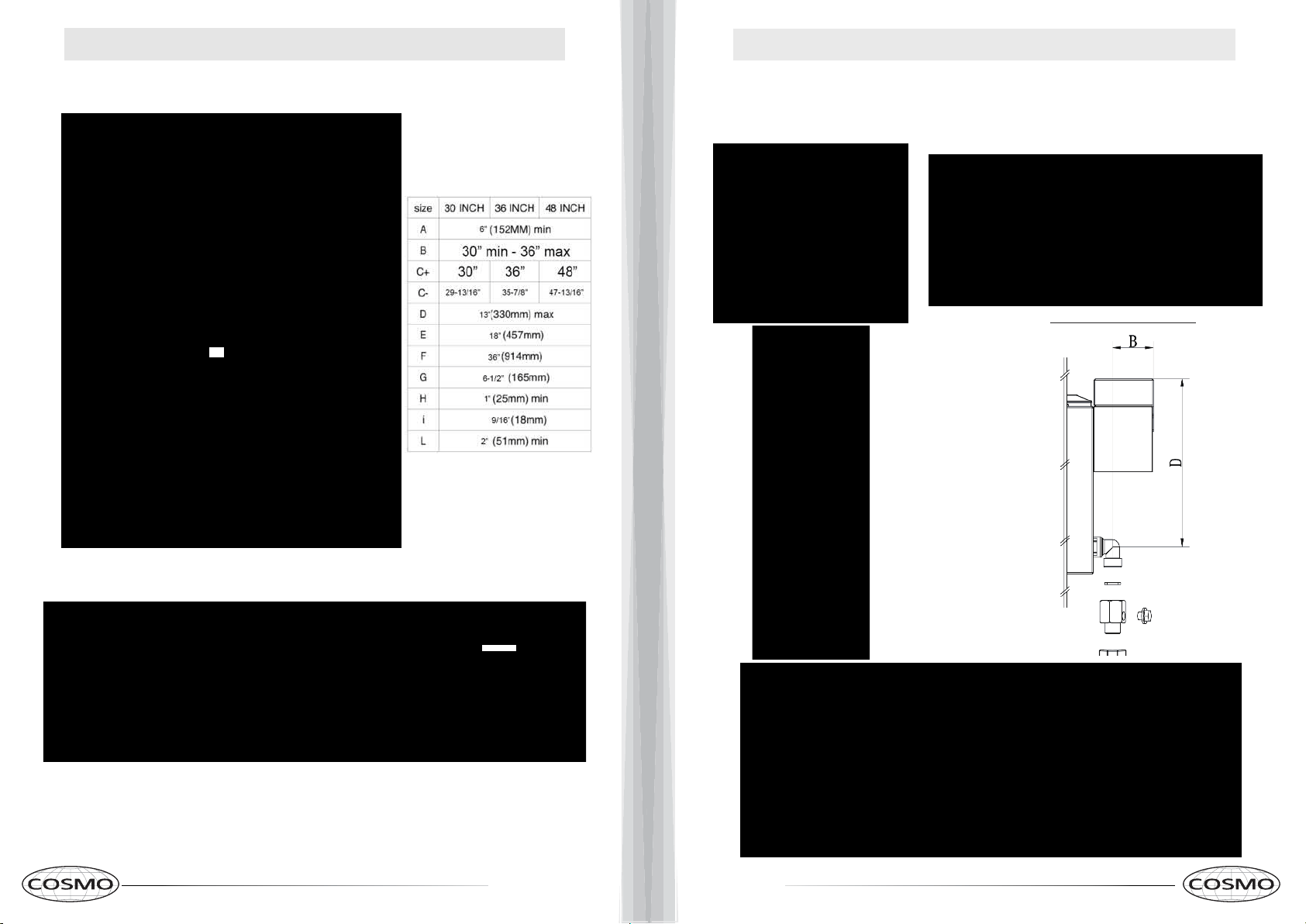
18 19
REFERENCE FIGURES REFERENCE FIGURES
C-
c+
Table n. 1
Fig. 1
Fig. 2
Fig. 3- Fig.4
Fig. 5 Fig. 6
Fig. 7
B = 1.89"
D = 7.91"
A= 3.01"
B = 2.56"
E = 5.37"
F = 4.05"
30" MODEL : W = 29.8" , D= 27.36"
36" MODEL : W= 35.8", D = 27.36"
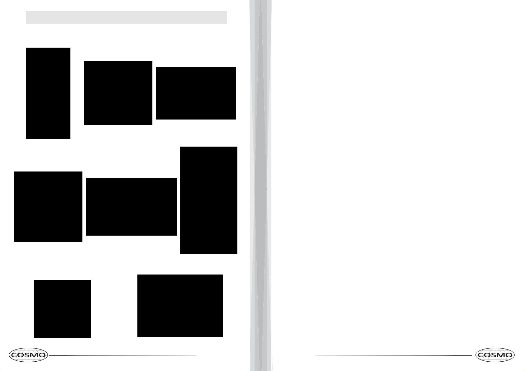
20 21
REFERENCE FIGURES
Fig. 8 Fig. 9 Fig. 10
Fig. 13
Fig. 1
1
Fig. 12
Fig. 15Fig. 14
22 23
Correct Disposal of this product:
This marking indicates that this appliance should not
be disposed with other household wastes. To prevent
possible harm to the environment or human health
from uncontrolled waste disposal, recycle it responsibly to
promote the sustainable reuse of material resources.
IMPORTANT
Do Not Return This Product To The Store If
you have a problem with this product, please contact
Cosmo Customer Support at
+1(888)784-3108
DATED PROOF OF PURCHASE, MODEL #, AND SERIAL #
REQUIRED FOR WARRANTY SERVICE
IMPORTANT
Ne pas Réexpédier ce Produit au Magasin
Pour tout problème concernant ce produit, veuillez contacter
le service des consommateurs Cosmo Customer Support au
+1(888) 784-3108
UNE PREUVE D’ACHAT DATEE EST REQUISE POUR BENEFICIER DE
LA GARANTIE.
IMPORTANTE
No regrese este producto a la tienda
Si tiene algún problema con este producto, por favor contacte el
AYUDA AL CLIENTE COSMO al
+1(888)784-3108
(Válido solo en E.U.A).
NECESITA UNA PRUEBA DE DE COMPRA FECHADA, NÚMERO DE
MODELO Y DE SERIE PARA EL SERVICIO DE LA GARANTÍA
WARRANTY AND SERVICE
For full warranty details on this product please visit:
http://www.cosmoappliances.com/warranty
TO RECEIVE WARRANTY SERVICE, YOUR
PRODUCT MUST BE REGISTERED. TO REGISTER, VISIT:
WWW.COSMOAPPLIANCES.COM/WARRANTY
SCAN TO REGISTER

Electronic version of this manual is available at:
www.cosmoappliances.com
Cosmo is constantly making efforts to improve the quality and
performance of our products, so we may make changes to our
appliances without updating this manual.