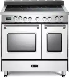

ELECTRIC RANGE
for residential use only
Models: VEFSEE 365 ..
USERS OPERATING INSTRUCTIONS
IMPORTANT - PLEASE READ AND FOLLOW
• Beforebeginning,pleasereadtheseinstructionscompletelyandcarefully.
• Donotremovepermanentlyafxedlabels,warnings,orplatesfromtheproduct.Thismay
voidthewarranty.
• Pleaseobservealllocalandnationalcodesandordinances.
• Pleaseensurethatthisproductisproperlygrounded.
• The installer should leave these instructions with the consumer who should retain
for local inspector’s use and for future reference.
ElectricalinstallationmustbeinaccordancewiththeNationalElectricalCode,ANSI/NFPA70
-latesteditionand/orlocalcodes.
IN CANADA: Electrical installation must be in accordance with the current CSA C22.1
CanadianElectricalCodesPart1and/orlocalcodes.
R
FOR INSTALLER ONLY
THIS RANGE IS FOR RESIDENTIAL USE ONLY
Some models are supplied with a protective lm on steel and aluminium
parts.Thislmmustberemovedbeforeinstalling/usingtheappliance.
INSTALLATION

2
3
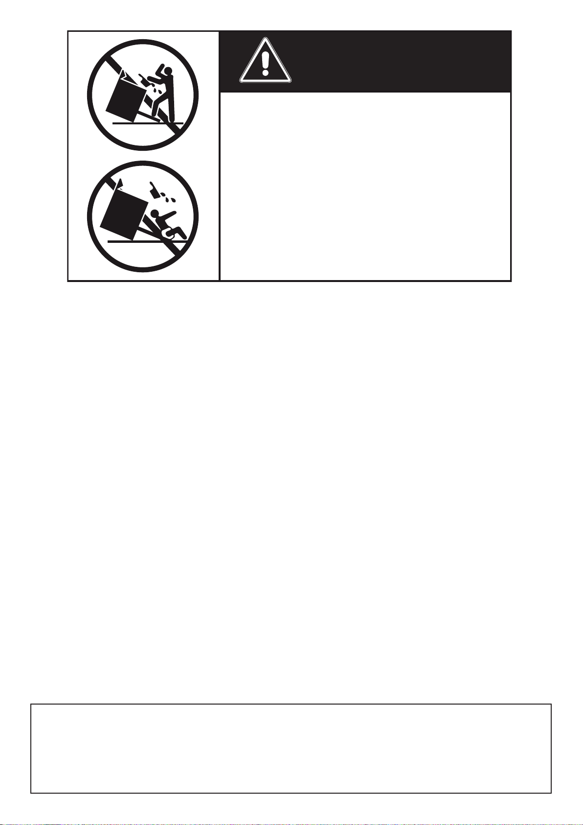
WARNING !
Toreducetheriskoftippingtheappliance,
theappliancemustbesecuredbyproperly
installed anti-tip device packed with the
appliance.
• ALL RANGES CAN TIP
• INJURY TO PERSONS COULD RESULT
• INSTALL ANTI-TIP DEVICE PACKED
WITH RANGE
• SEE INSTALLATION INSTRUCTIONS
This appliance is designed and manufactured solely for the cooking of domestic (household)
foodandinnotsuitableforanynonedomesticapplicationandthereforeshouldnotbeusedina
commercialenvironmement.
Theappliancewarrantywillbevoidiftheapplianceisusedwithinanonedomesticenvironmement
i.e.asemicommercial,commercialorcommunalenvironment.
4
Screwdriver
Tape
measurePencil
Adjustable
pliers
Adjustable
wrench
Suitable protective
gloves Drill
Hammer
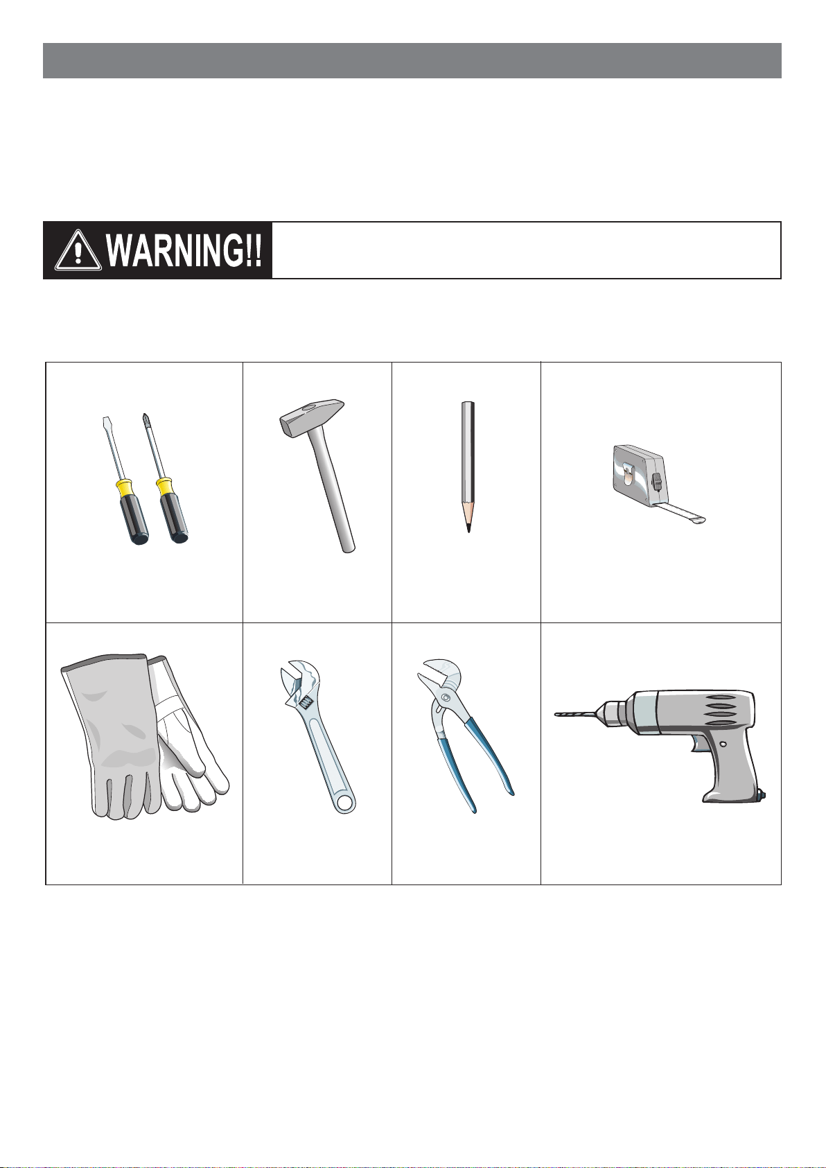
INSTALLATION INSTRUCTIONS
WARNING!
THIS APPLIANCE MUST BE INSTALLED BY A QUALIFIED INSTALLER.
Installation must conform with local codes.
Improperinstallation,adjustment,alteration,services,ormaintenancecancauseinjuryorpropertydamage.Consulta
qualiedinstalleroraserviceagent.
TOOLS NEEDED FOR INSTALLATION (NOT SUPPLIED WITH THE APPLIANCE)
IMPORTANT:Theuseofsuitableprotectiveclothing/glovesis
recommendedwhenhandling,installingofthisappliance.

5
GENERAL INFORMATION
1. WARNING!!
Thisapplianceshallnotbeusedforspaceheating.This
informationisbasedonsafetyconsiderations.
2. AlIopeningsinthewallbehindtheapplianceandintheoor
undertheapplianceshallbesealed.
3. Keep appliance area clear and free from combustible
materials,gasoline,andotherammablevapors.
4. Donotobstructtheowofventilationair.
5. Disconnect the electrical supply to the appliance before
servicing.
6. Whenremovingapplianceforcleaningand/orservice;
A. DisconnectACpowersupply.
B. Carefullyremovetherangebypullingoutward.
CAUTION:Rangeisheavy;usecareinhandling.
7. Electrical Requirement
Electrical installation should comply with national and local
codes.
8. Themisuseofovendoor(e.g.stepping,sitting,orleaningon
them)canresultinpotentialhazardsand/orinjuries.
9. Wheninstallingorremovingtherangeforservice,arollinglift
jackshouldbeused.Donotpushagainstanyoftheedgesof
therangeinanattempttoslideitintooroutoftheinstallation.
Pushingorpullingarange(ratherthanusingaliftjack)also
increases the possibility of bending the leg spindles or the
internalcouplingconnectors.
WARNING!!
ELECTRICAL GROUNDING INSTRUCTIONS
Therangemustbeelectricallygroundedinaccordancewith
localcodesor,intheabsenceoflocalcodes,withtheNational
Electrical Code,ANSI/NFPANo. 70-latest edition, inCanada
Canadian ElectricalCode.Installationshould be made bya
Iicensed electrician.
FOR PERSONAL SAFETY, THIS APPLIANCE MUST BE
PROPERLY GROUNDED.
If an external electrical source is utilized, the installation must
be electrically grounded in accordance with local codes or, in
the absence of local codes, with the national Electrical Code,
ANSI/NFPA70.
REPLACEMENT PARTS
Only authorized replacement parts may be used in performing
serviceontherange.Replacementpartsareavailablefromfactory
authorizedpartsdistributors.Contactthenearestpartsdistributor
inyourarea.
6
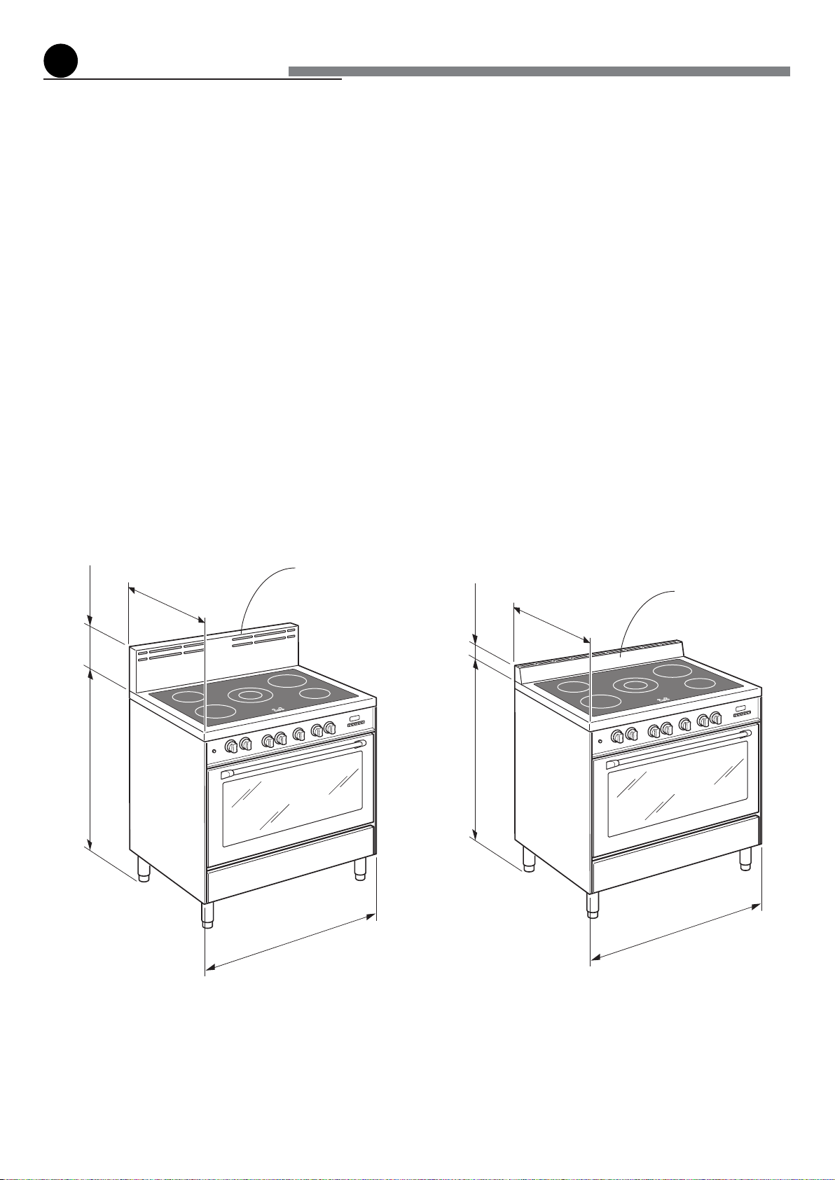
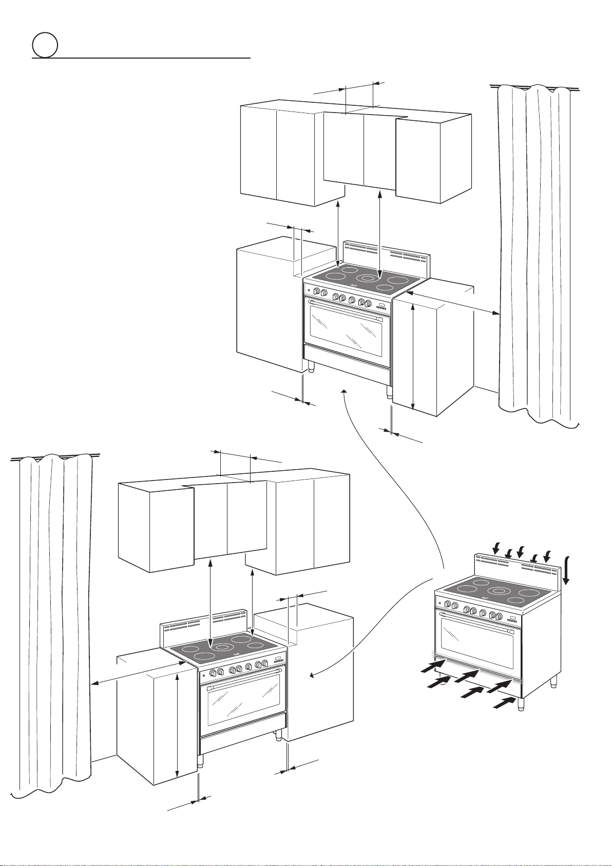
PROXIMITY TO SIDE CABINETS
1. This rangemay beinstalleddirectlyadjacentto existing36”
(914mm)highbasecabinets.
Rangedimensions:
• width:35”7/8(911mm)
• depth:23”31/32(609mm)
• height (without backguard / island trim): MIN 35” 7/16
(900mm)MAX37”13/32(950mm)
• backguard(height):8”(203mm)
• islandtrim(height):3”(76mm)
Groundedoutlet:shouldbelocated fromthe lefttotheright
sideofthe range;from6” 11/16(170mm) to8”21/32 (220
mm)[dependingonfeetregulation]fromthefloor.
Fig.1.1a
Fig.1.1b
2.TherangeCANNOTbeinstalleddirectlyadjacenttosidewalls,
tall cabinets, tall appliances, or other side vertical surfaces
above36”(914mm)high.
Theremustbeaminimumof2”(50mm)sideclearancefrom
therangetosuchcombustiblesurfacesTOTHELEFTorTO
THERIGHTabovethe36”(914mm)highcountertop.
IMPORTANT:Oneside(leftorright)abovethe36”(914mm)
highcountertopmustalwaysbekeptclear.
Installationwithislandtrim:Theremustbeaminimumof12”
(305mm)clearancefromthebackoftheislandtrimtosuch
combustiblesurfaceonthebackoftherangeabovethe36”
(914mm)highcountertop.
3.Themaximumuppercabinetdepthrecommendedis13”(330
mm).Wallcabinetabovetherangemustbeaminimumof30”
(762mm)abovethe countertop forawidth of minimum35”
7/8(911mm):ithastobecentredwiththerange.Sidewall
cabinetsabovetherangemustbeaminimumof18”(457mm)
abovethecountertop.
Backguard
Islandtrim
8"
(203 mm)
23"
31/32
(609 mm)
(911 mm)
35"
7/8
MIN 35" 7/16 (900 mm)
MAX 37"
13/32 (950 mm)
3"
(76 mm)
23"
31/32
(609 mm)
(911 mm)
35"
7/8
MIN 35" 7/16 (900 mm)
MAX 37"
13/32 (950 mm)
installation
1
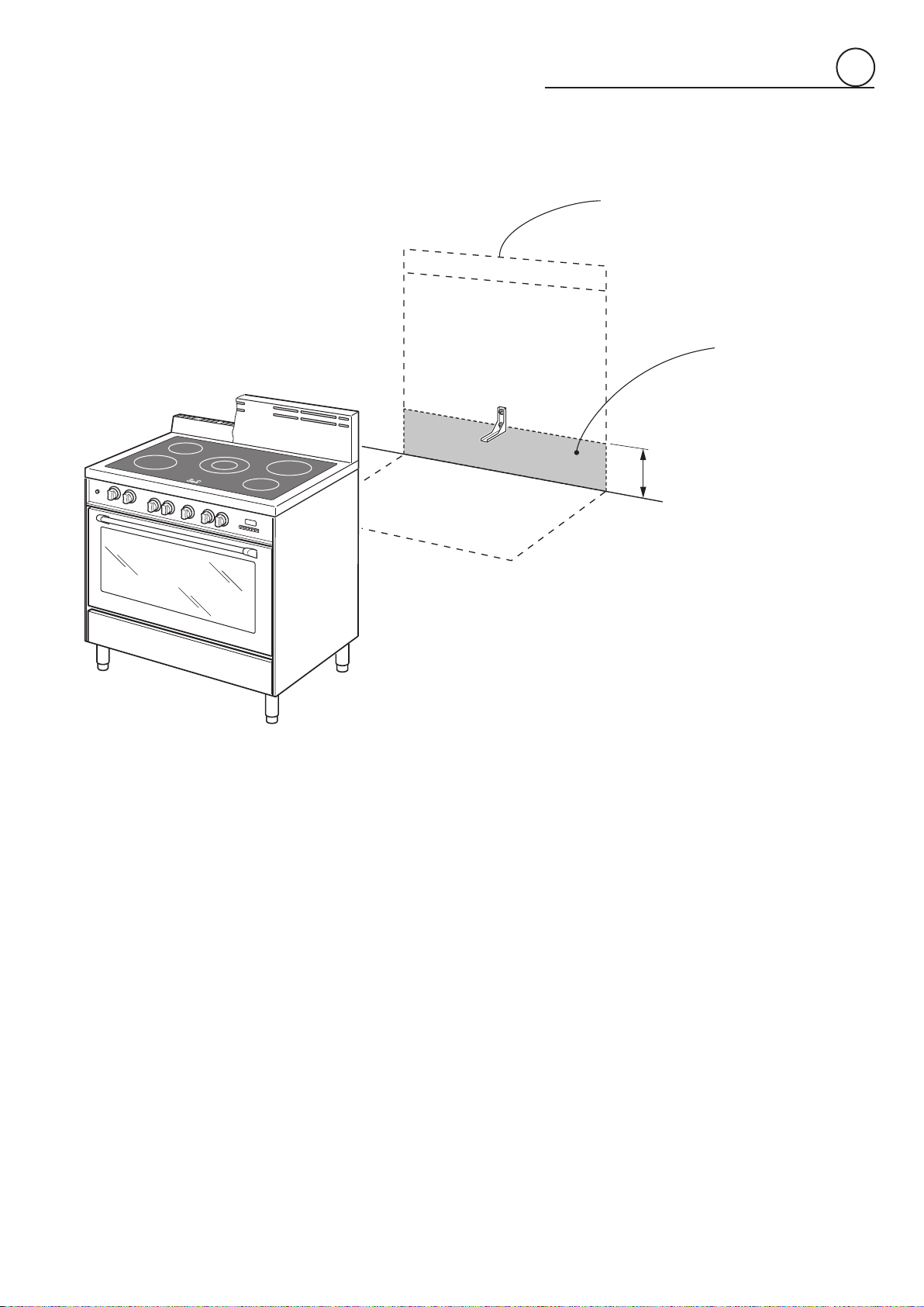
7
Dottedlineshowingtheposition
oftherangewheninstalled
Areafor
ELECTRICAL
connection
6”11/16÷8”21/32(170÷220mm)
[dependingonfeetregulation]
Fig.1.2
ELECTRIC CONNECTION
1
8
Fig.1.3b
Fig.1.3a
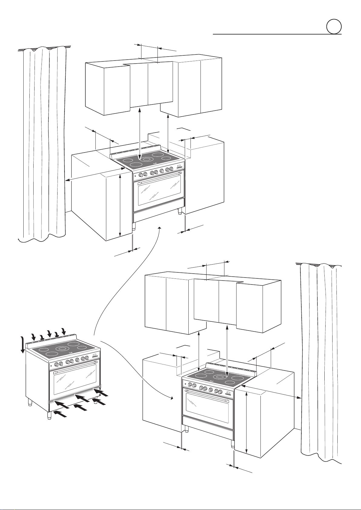
PROXIMITY TO SIDE CABINETS
RANGE WITH BACKGUARD
(457 mm)
18" min.
30" min.
(762 mm)
(914 mm)
36"
0"
(0 mm)
0"
(0 mm)
20" min. (500 mm)
2" (50 mm)
13" max. (330 mm)
(457 mm)
18" min.
30" min.
(762 mm)
(914 mm)
36"
0"
0"
(0 mm)
(0 mm)
20" min. (500 mm)
2" (50 mm)
13" max. (330 mm)
OVEN VENT
OVEN VENT
1
9
Fig.1.3c
Fig.1.3d
PROXIMITY TO SIDE
CABINETS
RANGE WITH ISLAND TRIM
(457 mm)
18" min.
30" min.
(762 mm)
(914 mm)
36"
0"
0"
(0 mm)
(0 mm)
20" min. (500 mm)
13" max. (330 mm)
2" (50 mm)
12"
min. (305 mm)
(457 mm)
18" min.
30" min.
(762 mm)
(914 mm)
36"
0"
(0 mm)
0"
(0 mm)
20" min. (500 mm)
2" (50 mm)
13" max. (330 mm)
12"
min. (305 mm)
OVEN VENT
OVEN VENT
1
10
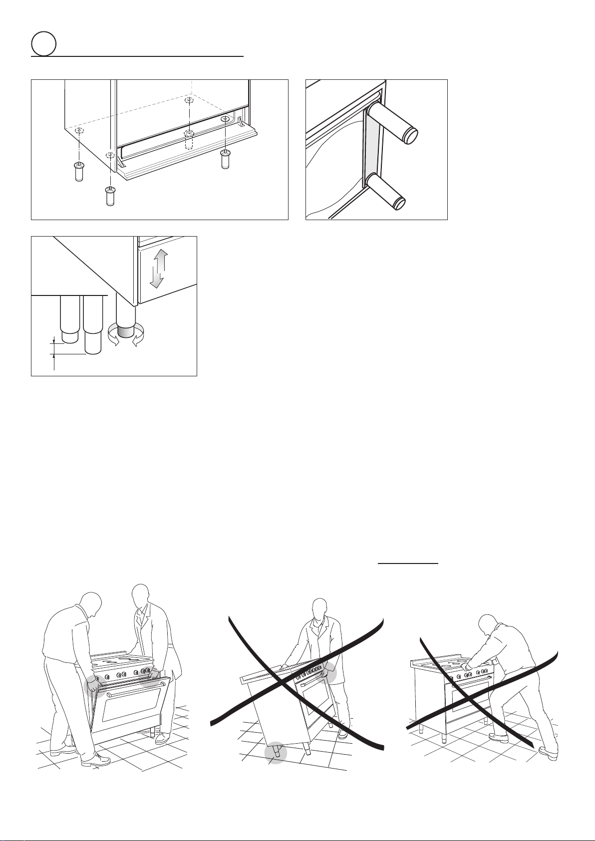
Fig.1.4
FITTING THE ADJUSTABLE FEET
Theadjustablefeetmustbefittedtothebaseofthecookerbeforeuse.
Resttherearofthecookeronapieceofthepolystyrenepackagingexposingthebase
forthefittingofthefeet.
ATTENTION:Mostimportant! Pay specialattentionnot to damagetherange during
this operation.
Fitthe4legsbyscrewingthemtightintothesupportbaseasshowninpicture1.5.
Fig.1.5
LEVELLING THE COOKER
ThecookermaybelevelledbyscrewingthelowerendsofthefeetINorOUT(fig.1.6).
Itisimportanttoobservethedirectionsoffigure1.6.
+ 1" 31/32
+ 50 mm
0 mm
0"
Fig.1.6
Fig.1.7a
Fig.1.7b
Fig.1.7c
MOVING THE COOKER
WARNING
When raising cooker to upright position always ensure two people carry out this
manoeuvretopreventdamagetotheadjustablefeet(fig.1.7a).
WARNING
Becareful:donotliftthecookerbythedoorhandlewhenraisingtotheuprightposition
(fig.1.7b).
WARNING
Whenmovingcookertoitsfinalposition
DO NOT DRAG
(fig.1.7c).
Liftfeetclearoffloor(fig.1.7a).
1
11
Fig.1.8
Fig.1.9
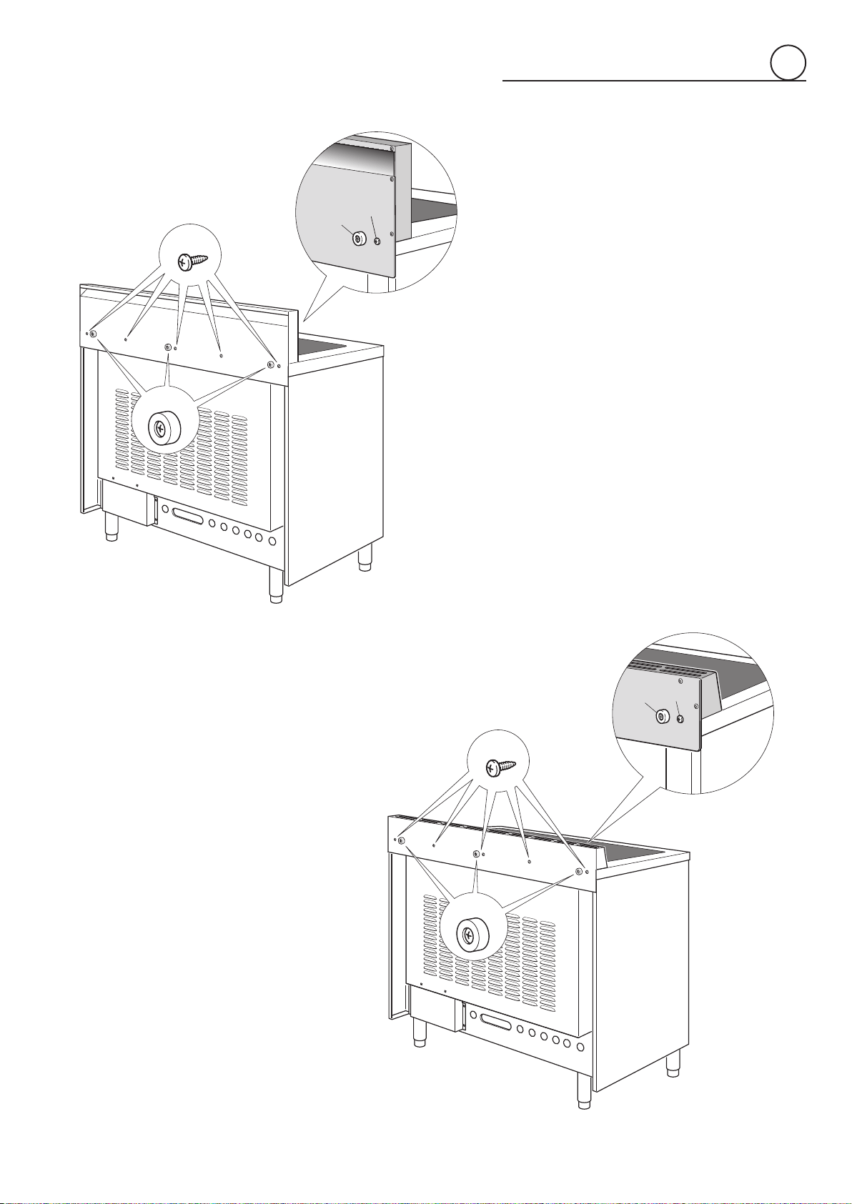
ASSEMBLING THE BACKGUARD
OR THE ISLAND TRIM
It is mandatory to install the backguard or
the island trim
• Assemble thebackguardorthe island trim
as shown in figure 1.8 or 1.9 and fix it
by screwing the 5 screws “
A
” (which are
alreadyfixedonthebackofthecooktop).
• Do not remove the 3 spacers “
B
” already
fittedonthebackofthebackguardorisland
trim.
A
A
B
B
A
A
B
B
1
12
26" 11/16 (678 mm)
from top of cooktop
with range installed
in final position
(455.5 mm)
17"
15/16
(455.5 mm)
17"
15/16
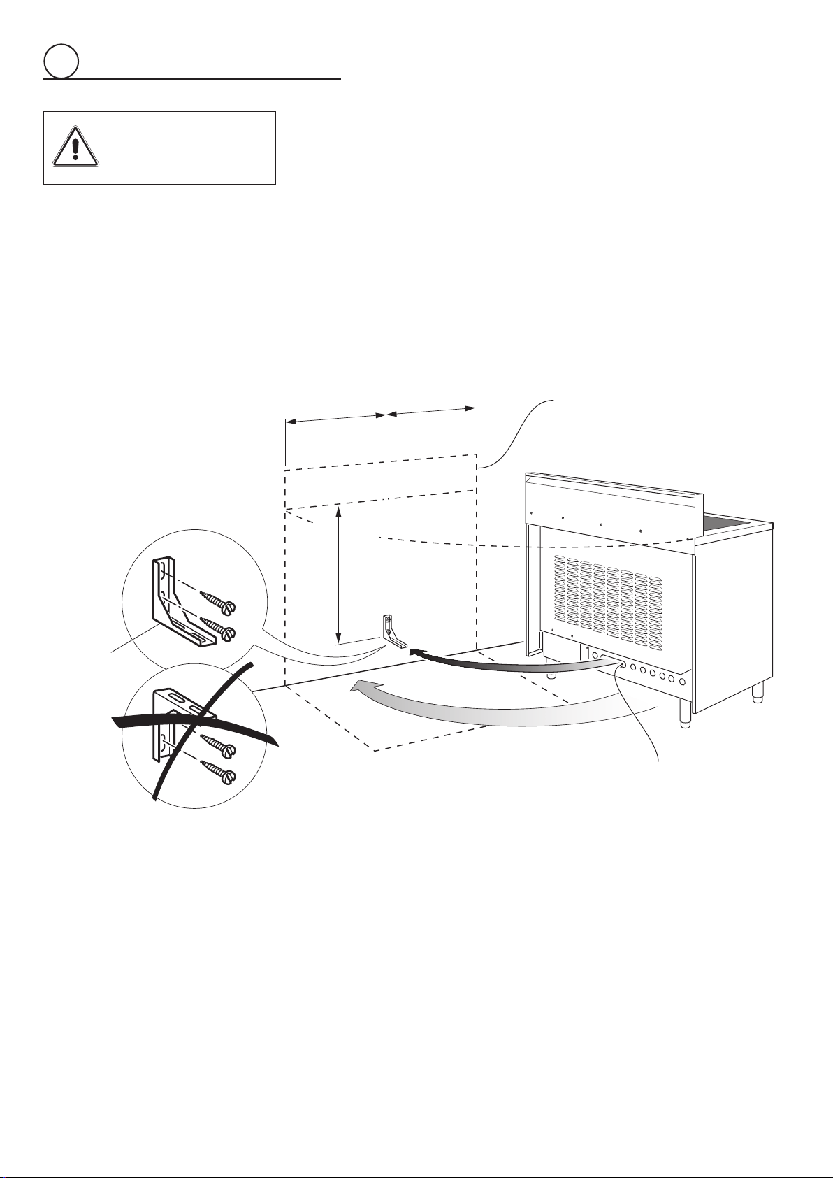
ANTI-TIP STABILITY DEVICE INSTALLATION INSTRUCTIONS
1. Theanti-tipbrackethastobeattachedasshownonfigurebelow,ithastobefixed
ontherearwallbyno.2(two)suitablescrews(suppliedwiththeanti-tipkit).
2. Afterfixingtheanti-tipbracket,sliderangeintoplace.Besuretheanti-tipbracketis
fullyinsertedintheslotoftherangeback.
Dottedlineshowingtheposition
oftherangewheninstalled
Slotforinserting
theanti-tipbracket
ANTI-TIPSTABILITY
DEVICEFIXING
Fig.1.10
Anti-tip
stabilitydevice
YOU MUST USE
STABILITY ANTI TIP
BRACKET TO PREVENT
UNIT FROM TIPPING.
1
13
ELECTRICAL REQUIREMENTS
• This appliancemustbe properlyinstalledand groundedbya qualifiedtechnicianin
accordancewiththeNational Electrical Code ANSI/NFPA No.70 (latestedition)and
local electrical code requirements. IN CANADA: Electrical installation must be in
accordancewiththecurrentCSAC22.1CanadianElectricalCodesPart1and/orlocal
codes.
• This appliance may beconnected bymeans ofpermanent “HardWiring” or“Power
SupplyCordKit”.Powersupplycord isnotsupplied,but itisavailablethroughyour
localelectricsupplyhouse.
• Useonly3-conductoror4-conductorCSA/ULlistedrangecordratedat50ampswith
250Vminimumandprovidedwithringterminals.Thesecordsshouldbeprovidedwith
strainrelieforconduitconnector.
Warning:Framegroundedthroughneutrallead.Ifusedin,
-Newbranch-circuitinstallations(1996NEC),
-Mobilehomes,
-Recreationalvehicles,or
-Inanareawherelocalcodesprohibitgroundingthroughneutral,usea4conductor
cordorconduit.
• Therangemustbeconnectedtotheproperelectricalvoltageandfrequencyasspeci-
fiedontheratingplate.
• Therangecanbeconnecteddirectlytothefuseddisconnect(orcircuitbreakerbox)
through flexible, armoured or non-metallic sheathed, copper cable (with grounding
wire).Allowtwotothreefeetofslackinthelinesothatitcanbemovedifservicingis
evernecessary.
VoltageandPowerConsumption
240-208/120V60Hz
11416W(240V)8575W(208V)
47.6A(240V)41.22A(208V)
ELECTRICAL CONNECTION WITH POWER CORD
Usea3-wirepowersupplycordkitratedfor50amps-125/250voltswithclosedloop
terminalsandmarkedforusewithranges.Wherelocalcodesdonotpermitgrounding
throughneutral,usea4-wirepowersupplycordkit.
Thecordmustbesecuredtotherangewithasuitablestrainrelief.Theelectricalcon-
nectionismadeattheterminalblock,whichislocatedbehindtheterminalblockaccess
plateonthebackoftherange.
ELECTRICAL CONNECTION WITH CONDUIT
Use3/4”tradesizeCSA/UL-listedconduitwithaconduitclamp,10AWG/600voltcopper
conductorcoloredredforline1andblackforline2and12AWG/600voltcopperconduc-
tor(or10AWG/600Voltcopperconductorifgroundingthroughneutral)coloredwhitefor
neutralwithclosedloopterminalsmarkedforusewithranges.
Wherelocalcodesdonotpermitgroundingthroughneutral,useagreen10AWGcopper
conductorasdirectedinthe4-wireconnectordirections.Theconduitmustbesecuredto
therangewiththestrainreliefbracket.Theelectricalconnectionismadeattheterminal
blockwhichislocatedbehindtheterminalblockaccessplateonthebackoftherange.
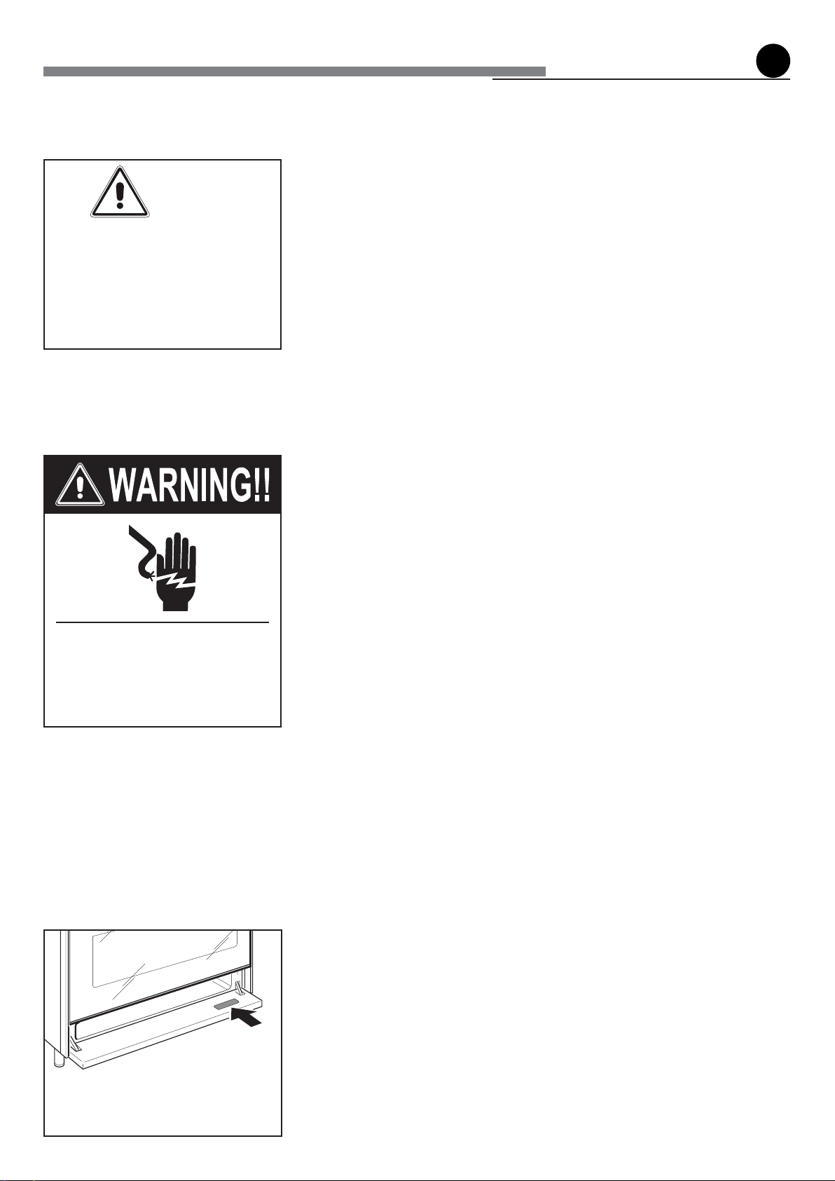
Location of
Nameplate
2
electrical connection
WARNING
TO AVOID ELECTRICAL SHOCK
HAZARD, BEFORE INSTALLING
THEAPPLIANCE, SWITCH POWER
OFF AT THE SERVICE PANEL AND
LOCK THE PANEL TO PREVENT
THE POWER FROM BEING
SWITCHED ON ACCIDENTALLY.
Electrical Shock Hazard
Electrically ground range.Failure to
follow these instruc-tions can result
indeath,re,orelectricalshock.
14
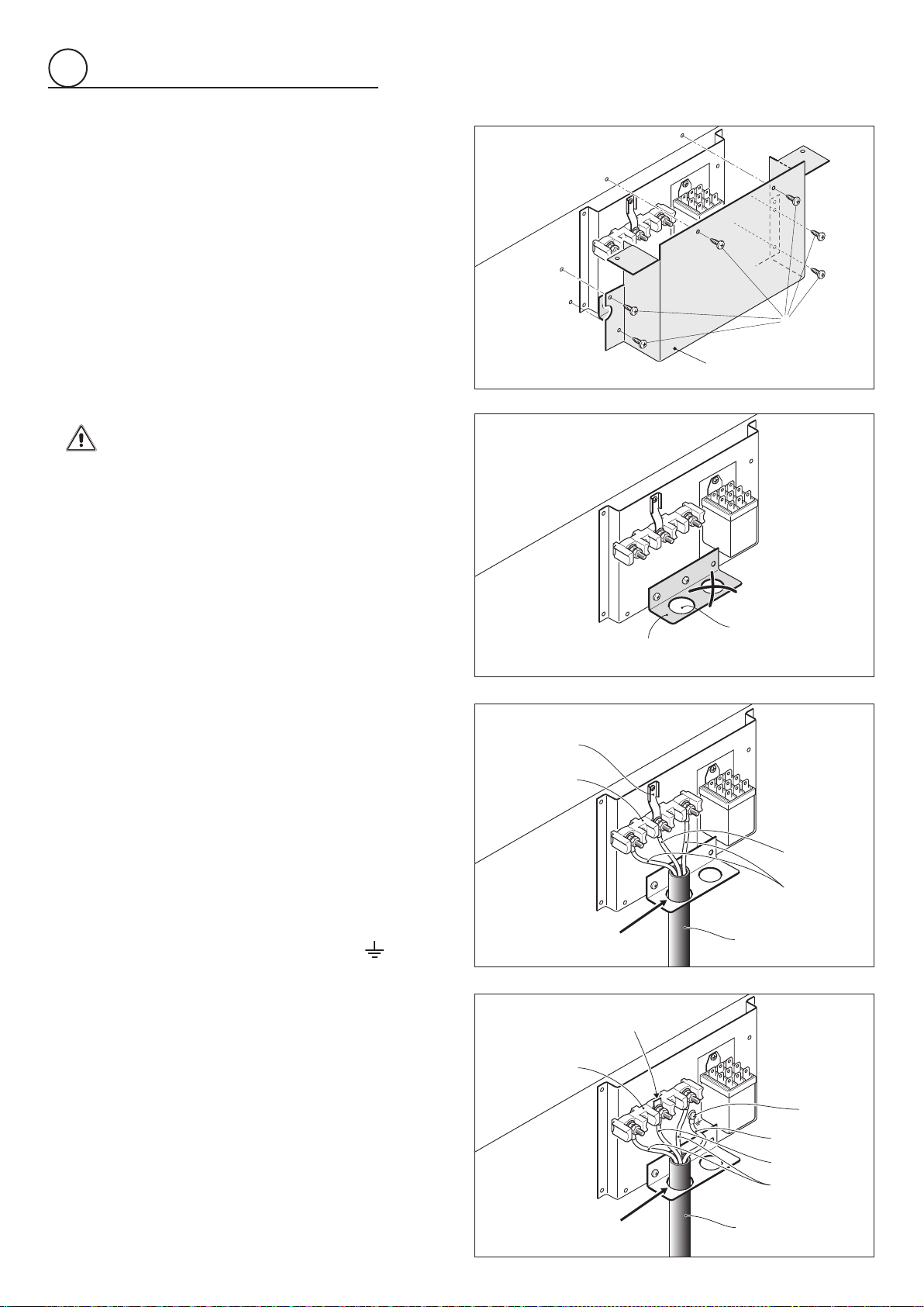
3-Wire Power Cord Installation
(SeeFigures3.1,3.2and3.3)
1. Removethe
Terminal Block Access Plate
onthebackofthe
rangebyunscrewingthe6fixing
Screws
(fig.3.1).
2. Insert the
Power Cord
through the hole in the
Power Cord
Bracket
; then tighten the
Power Cord
by using a suitable
Strain Relief
. Allow enough slack to easily attach the cord
terminalstothe
Terminal Block
.
3. Remove the 3 wire terminal nuts and washers from the
Terminal Block
.
4. Plugtheterminalholesof
Power Cord
.The
Neutral or Ground
Wire
of the
Power Cord
must be connected to the neutral
terminallocatedin the center of
Terminal Block
.The
Power
Wires
mustbeconnectedtotheoutsideterminals.
5. Plugwashersandtightennutssecurely.
Donotremove
Ground strap
.
6. Assemblethe
Terminal Block Access Plate
.
4-WirePowerCordInstallation
(SeeFigures3.1,3.2and3.4)
1. Removethe
Terminal Block Access Plate
onthebackofthe
rangebyunscrewingthe6fixing
Screws
(fig.3.1).
2. Insert the
Power Cord
through the hole in the
Power Cord
Bracket
; then tighten the
Power Cord
by using a suitable
Strain Relief
. Allow enough slack to easily attach the cord
terminalstothe
Terminal Block
.
3. Remove the 3 wire terminal nuts and washers from the
Terminal Block
.
4. Remove the
Ground Strap
from the frame of range and
terminal by removing its screw and cutting it as shown in
figure3.4.
5. Plugtheterminalholesof
Power Cord
.The
Neutral Wire
ofthe
Power Cord
mustbeconnectedtotheneutralterminallocated
in the center of
Terminal Block
; the
Power Wires
must be
connectedtotheoutsideterminals;the
Ground Wire
mustbe
attached to the frame of range by using the
(Ground)
identified
GroundingScrew
.
6. Plugwashersandtightennutssecurely.
7. Assemblethe
Terminal Block Access Plate
.
Terminal Block
Access Plate
Screws
Fig.3.1
Power Cord
Bracket
Hole D 1"
3/8
(34.93 mm)
Power Wires
Power Cord
Tighten the Power Cord
by using a suitable Strain Relief
Terminal Block
Ground strap
Neutral Wire
Power Wires
Power Cord
Tighten the Power Cord
by using a suitable Strain Relief
Terminal Block
Neutral Wire
Grounding Wire
Cut Ground Strap
Grounding
Screw
Fig.3.2
Fig.3.3
Fig.3.4
2
15
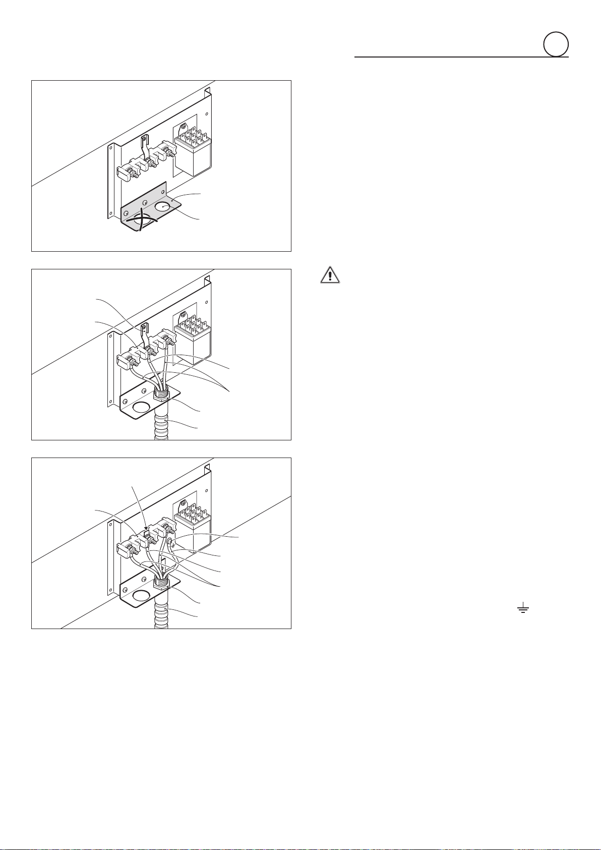
3-Wire Conduit Installation
(SeeFigures3.1,3.5and3.6)
1. Removethe
Terminal Block Access Plate
onthebackofthe
rangebyunscrewingthe6fixing
Screws
(fig.3.1).
2. Feed3/4”tradesize
Conduit
throughtheholeinthe
Conduit
Bracket
and secure to the
Conduit Bracket
with a
Conduit
Clamp
.
3. Remove the 3 wire terminal nuts and washers from the
Terminal Block
.
4. Plugtheterminalholesofconductors.The
Neutral or Ground
Wire
of the
Power Cord
must be connected to the neutral
terminallocatedin the center of
Terminal Block
.The
Power
Wires
mustbeconnectedtotheoutsideterminals.
5. Plugwashersandtightennutssecurely.
Donotremove
Ground strap
.
6. Assemblethe
Terminal Block Access Plate
.
4-WireConduitInstallation
(Seefigures3.1,3.5and3.7)
1. Removethe
Terminal Block Access Plate
onthebackofthe
rangebyunscrewingthe6fixing
Screws
(fig.3.1).
2. Feed3/4”tradesize
Conduit
throughtheholeinthe
Conduit
Bracket
and secure to the
Conduit Bracket
with a
Conduit
Clamp
.
3. Remove the 3 wire terminal nuts and washers from the
Terminal Block
.
4. Remove the
Ground Strap
from the frame of range and
terminal by removing its screw and cutting it as shown in
figure3.7.
5. Plug the terminal holes of conductors. The
Neutral Wire
of
the
Power Cord
must be connected to the neutral terminal
locatedinthecenterof
Terminal Block
;the
Power Wires
must
beconnectedtotheoutsideterminals;the
Ground Wire
must
beattached totheframeofrange byusingthe
(Ground)
identified
GroundingScrew
.
6. Plugwashersandtightennutssecurely.
7. Assemblethe
Terminal Block Access Plate
.
Hole D 1" 1/8
(28.58 mm)
Counduit
Bracket
Power Wires
Terminal Block
Ground strap
Neutral Wire
Conduit
Conduit Clamp
Power Wires
Terminal Block
Neutral Wire
Grounding Wire
Cut Ground Strap
Grounding
Screw
Conduit
Conduit Clamp
Fig.3.5
Fig.3.6
Fig.3.7
2
16
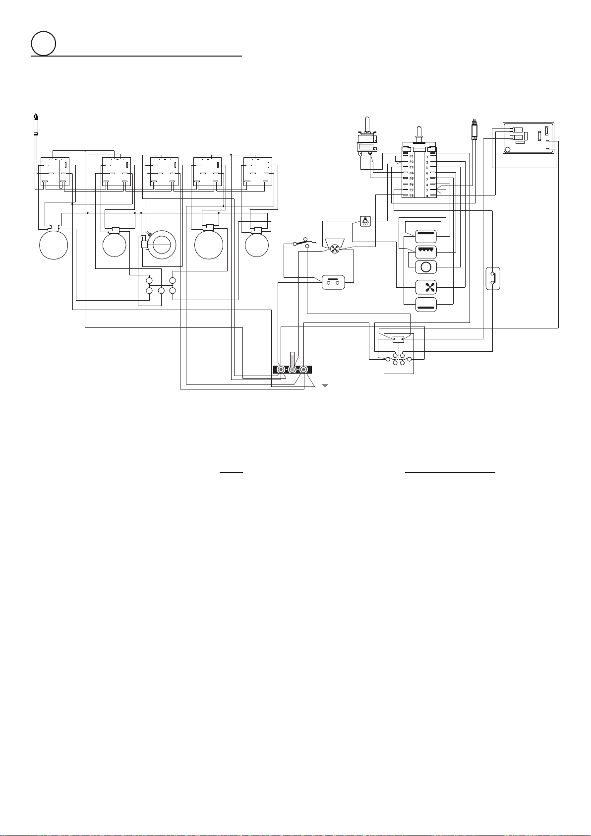
WIRING DIAGRAM
ELECTRIC DIAGRAM KEY
CF Cooling fan motor
TL1 Cooling fan thermal overload
AS Air switch
R Relay
M Terminal block
T Grounding point
OVEN
F1 Oven switch
TM Oven thermostat
PR Electronic programmer
TL Thermal overload
LF Oven lamp
S1 Oven temperature indicator light
C Top element
G Broil element
CIR Circular element
S Bottom element
V Fan motor
GLASS CERAMIC HOB
F2/3/5/6 Single zones energy regulators
F4 Double zone energy regulator
P1/2/4/5 Single zone radiant elements
P3 Double zone radiant element
CR Residual heat indicator lights
S3 Line pilot lamp
TL1
N/7
1
2
1a
2a
L/8
1
6
P1
P6
4
P4
3
8
P3
P8
2
7
P2
P7
5
P5
F1
C
CIR
S
G
V
LF
M
T
R
TL
CF
AS
TM
S1
PR
S3
F2
F3
F4
F5
P2P1
H
S
2
4
H
S
2
4
P4
H
S
2
4
P5
H
S
2
4
S1S2
4
Pilot
P1
P2
2
S1S2
4
Pilot
P1
P2
2
S1S2
4
Pilot
P1
P2
2
S1S2
4
Pilot
P1
P2
2
S1S2
4
4a
P1
P2
2
P3
4A
4
HS
2
F6
CR
ELECTRIC DIAGRAM KEY
CF Cooling fan motor
TL1 Cooling fan thermal overload
AS Air switch
R Relay
M Terminal block
T Grounding point
OVEN
F1 Oven switch
TM Oven thermostat
PR Electronic programmer
TL Thermal overload
LF Oven lamp
S1 Oven temperature indicator light
C Top element
G Broil element
CIR Circular element
S Bottom element
V Fan motor
GLASS CERAMIC HOB
F2/3/5/6 Single zones energy regulators
F4 Double zone energy regulator
P1/2/4/5 Single zone radiant elements
P3 Double zone radiant element
CR Residual heat indicator lights
S3 Line pilot lamp
2

17

18

19

Themanufacturercannotbeheldresponsibleforpossibleinaccuraciesduetoprintingortranscriptionerrors
inthepresentbooklet.
The manufacturer reserves the right to make all modications to its products deemed necessary for
manufacture or commercial reasons at any moment and without prior notice, without jeopardising the
essentialfunctionalandsafetycharacteristicsoftheappliances.
Cod.1104877-ß1