Installation Instructions
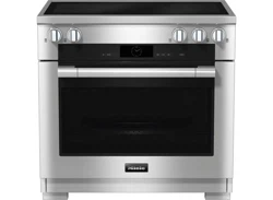
30" Electric, 30" Induction Range
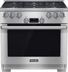
30", 36" All Gas Range
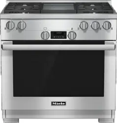
30", 36", 48" Dual Fuel Range
To prevent accidents and damage to the range, you must read all
instructions supplied before installing or using the appliance.
en-US, CA M.-Nr. 10 876 460
IMPORTANT SAFETY INSTRUCTIONS
2
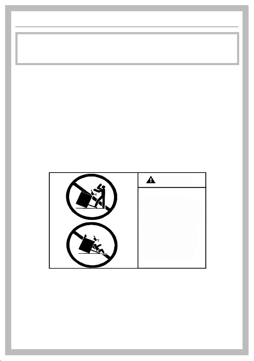
WARNING
Children and adults can tip over the range if has not been secured.
This may lead to fatal injuries.
This range must be secured and connected using the anti-tip
device according to the installation instructions.
If you have moved the range, slide the locking latch onto the anti-
tip device until you feel it lock into place.
Do not use the range if the anti-tip device has not been properly
installed and engaged.
Failure to observe the information contained in the installation
instructions can lead to serious or fatal injuries for children and
adults.
All ranges can tip
Injury to persons
could result
Install anti-tip devices
packed with range
See installation
instructions
WARNING

IMPORTANT SAFETY INSTRUCTIONS
3
WARNING: If the information in this manual is not followed exactly, a fire or
explosion may result causing property damage, personal injury, or death.
– Do not use or store gasoline or other combustible liquids or vapors in the vicinity
of this or any other appliance.
– WHAT TO DO IF YOU SMELL GAS
– Do not try to light any appliance.
– Do not touch any electric switches.
– Do not use any phones inside your building.
– Immediately call your gas supplier from a neighbor's phone. Follow the gas
supplier's instructions.
– If you are unable to reach your gas provider, call the fire department.
– Installation and service must be performed by a qualified installer, qualified
service agency or your gas provider.
(In Massachusetts, installation must be performed by a licensed installer / gas
fitter.)
– Note to the installer:
Please give these installation instructions to the consumer for the local
electrical/gas inspector.
®
®

Contents
4
IMPORTANT SAFETY INSTRUCTIONS ................................................................ 2
IMPORTANT SAFETY INSTRUCTIONS ................................................................ 7
Notes on installation ........................................................................................... 15
Model numbers .................................................................................................... 15
Data plate ............................................................................................................. 15
Distance to the range hood................................................................................... 15
Items included with this range............................................................................... 15
Toe-kick and drip tray....................................................................................... 16
Installation of the toe-kick ................................................................................16
Installation of the drip tray................................................................................ 16
Assembling the grill .......................................................................................... 17
Optional accessories............................................................................................. 18
RBGAG All Gas Backguard/RBGDF Dual Fuel Backguard .............................. 18
RBS Backsplash............................................................................................... 21
XKM3000W Remote Vision (USA Only).......................................................... 21
Required connections ........................................................................................... 23
All Electric Range dimensions ........................................................................... 24
HR 1421; HR 1622 ................................................................................................ 24
Detailed views of HR 1421 .................................................................................... 26
Detailed views of HR 1622 .................................................................................... 30
All Gas Range dimensions.................................................................................. 34
All Gas Range HR 1124 with Standard Burner Configuration M Pro Power Plus . 34
All Gas Range HR 113x with Standard Burner Configuration M Pro Power Plus . 36
All Gas Range HR 113x with BTU reducing nozzle configuration (M Pro Power Zero
Gap Kit, M Pro - décor hood)................................................................................ 39
Detailed views of HR 1124 .................................................................................... 42
Detailed views of HR 1134 .................................................................................... 46
Detailed views of HR 1135 .................................................................................... 50
Detailed views of HR 1136 .................................................................................... 54
Dual Fuel Range dimensions.............................................................................. 58
Dual Fuel Range HR 1724 with Standard Burner Configuration M Pro Power Plus...
58
Dual Fuel Range HR 1924 with Standard Burner Configuration M Pro Power Plus...
60
Dual Fuel Range HR 193x/195x with Standard Burner Configuration M Pro Power
Plus........................................................................................................................ 62
Dual Fuel Range HR 193x with BTU reducing nozzle configuration (M Pro Power
Zero Gap Kit, M Pro - Décor Hood)....................................................................... 66

Contents
5
Dual Fuel Range HR 195x with BTU reducing nozzle configuration
M Pro Power Zero Gap Kit .................................................................................... 69
Detailed views of HR 1724 .................................................................................... 71
Detailed views of HR 1924 .................................................................................... 75
Detailed views of HR 1934 .................................................................................... 79
Detailed views of HR 1935 .................................................................................... 83
Detailed views of HR 1936 .................................................................................... 87
Detailed views of HR 1954 .................................................................................... 91
Detailed views of HR 1955 .................................................................................... 95
Detailed views of HR 1956 .................................................................................... 99
Anti-tip device.................................................................................................... 103
Before installation................................................................................................ 103
Checking the installation space .......................................................................... 104
Included accessories........................................................................................... 106
Installation dimensions of locking bolt ................................................................ 106
Installing the range with the anti-tip device......................................................... 106
Disconnecting the range from the anti-tip device ............................................... 110
Electrical connection ........................................................................................ 111
Data plate ....................................................................................................... 112
Plumbing ............................................................................................................ 113
Notes on connecting to the water supply ........................................................... 113
Attach the stainless steel hose to the range. ...................................................... 114
Connecting to the water supply .......................................................................... 114
Gas connection.................................................................................................. 115
Burner ratings of Standard Burner Configuration.......................................... 117
Burner ratings for HR 1124 ................................................................................. 117
Burner ratings for HR 1134 ................................................................................. 118
Burner ratings for HR 1135 ................................................................................. 119
Burner ratings for HR 1136 ................................................................................. 120
Burner ratings for HR 1724 ................................................................................. 121
Burner ratings for HR 1924 ................................................................................. 121
Burner ratings for HR 1934 ................................................................................. 121
Burner ratings for HR 1935 ................................................................................. 122
Burner ratings for HR 1936 ................................................................................. 122
Burner ratings for HR 1954 ................................................................................. 123
Burner ratings for HR 1955 ................................................................................. 123
Burner ratings for HR 1956 ................................................................................. 124
Burner ratings of M Pro Power (Zero Gap) .................................................... 125

Contents
6
Burner ratings of M Pro (Décor Hood) ............................................................ 126
Possible combinations - Range with BTU Reducing jet kit........................... 127
Caring for the environment .............................................................................. 128
IMPORTANT SAFETY INSTRUCTIONS
7
When using the appliance, follow basic safety precautions, including the
following:
Read all instructions before installation and use of the range to prevent
accidents and machine damage.
This range complies with current safety requirements. However,
improper use of the appliance can result in personal injury or
damage to property.
Please read the installation instructions carefully before installing
and connecting the appliance.
Read the operating instructions before using the range for the first
time. To prevent accidents and damage to the appliance, always
observe both the installation instructions and operating
instructions. Both documents contain important information about
installation, safety, use and maintenance.
Miele cannot be held liable for damage occurring as a result of
non-compliance with the instructions.
Keep these installation instructions and operating instructions in a
safe place and pass them on to any future owner.
IMPORTANT SAFETY INSTRUCTIONS
8
Use
This range is intended for domestic use and use in other similar
environments.
This appliance is not intended for outdoor use.
Use the range exclusively under normal domestic conditions:
– Use the oven for baking, roasting, broiling, defrosting, canning
and drying food.
– Use the stovetop to prepare food and keep it warm.
Any other use is not permitted.
Risk of Fire! Do not use this oven to store or dry combustible
materials.
Persons who lack physical, sensory or mental abilities, or
experience with the appliance should not use it without supervision
or instruction by a responsible person.

IMPORTANT SAFETY INSTRUCTIONS
9
Children
Children must be kept away from the range unless constantly
supervised.
Please supervise any children in the vicinity of the range and do
not let them play with the appliance.
Burn hazard from improper use! Do not allow children to operate
the oven.
Danger of suffocation! Ensure that any plastic wrappings, bags,
etc. are disposed of safely and kept out of the reach of children.
Burn hazard!
Keep the spaces above and behind the range clear of any items that
could draw the attention of children. Otherwise, they can be tempted
into climbing onto the appliance.
Danger of injury. Never allow children to hang or lean on any part
of the appliance.

IMPORTANT SAFETY INSTRUCTIONS
10
Technical safety
Installation, repair and maintenance work should be performed by
a Miele authorized service technician in accordance with national
and local safety regulations and the provided installation
instructions. Contact Miele’s Technical Service Department for
examination, repair or adjustment. Repairs and other work by
unauthorized persons could be dangerous and may void the
warranty.
Do not carry or lift the range by the oven door handle or the
control panel!
Check whether the anti-tip device is properly installed and locked
into place (see"Anti-tip device"):
– The anti-tip device must be fastened to the floor or wall with
suitable screws.
– You must be able to feel that the locking latch is engaged in the
bolt of the anti-tip device.
Slide the range's locking latch into place on the anti-tip device.
The locking latch must be noticeably engaged with the bolt of the
anti-tip bracket.
A damaged range can be dangerous. Always check for visible
signs of damage. Never use a damaged appliance.
Reliable and safe operation of the range can only be guaranteed if
it is connected to the public power supply.
The electrical safety of the range can only be guaranteed when it
is properly grounded. Compliance with this essential safety
requirement is absolutely mandatory. If in any doubt, please have the
building's wiring system inspected by a qualified electrician.
To avoid damaging the range, make sure that the connection data
(voltage and frequency) on the data plate correspond to the
building's power supply before connecting the appliance.
When in doubt, consult a qualified electrician.

IMPORTANT SAFETY INSTRUCTIONS
11
During installation, maintenance and repair work, e.g. if the oven
lighting is broken, the range must be completely disconnected from
the household electricity supply (see"Frequently asked questions").
The gas inlet valve must be closed. It is only completely isolated
from the supply when:
– The circuit breakers have been switched off, or
– the fuses of the electrical installation have been completely
removed, or
– the plug (if present) is removed from the socket. To do this, pull
the plug not the cord.
– Shut off the gas supply and disconnect the range from the gas
supply. Installation and maintenance of the gas connection must
be performed by qualified installers, service agencies or gas
providers.
Do not use a power strip or extension cord to connect the range
to electricity. These are a fire hazard and do not guarantee the
required level of appliance safety.
Any contact with live connections or tampering with the electrical
or mechanical components of the range will endanger your safety
and may lead to appliance malfunctions.
Do not open the appliance housing under any circumstances.

IMPORTANT SAFETY INSTRUCTIONS
12
This appliance must not be installed and operated in mobile
installations (e.g. on a ship).
Any repairs not performed by a Miele authorized service
technician will void the warranty.
Defective components should be replaced by Miele original parts
only. Only with these parts can the manufacturer guarantee the
safety of the appliance.
Risk of electric shock! If the ceramic surface of the stovetop is
defective or chipped, cracked or broken in any way, immediately
switch the stovetop off and do not continue to use it. Disconnect the
range from the power supply and contact Miele Technical Service.
In order for the range to function properly, it requires an adequate
supply of cool air. Ensure that the air flow is not impaired. Also be
sure that the cool air supply is not excessively heated by other heat
sources (e.g. solid fuel stoves).
If the range is installed behind a cabinet door, do not close the
door while the appliance is in operation. Heat and moisture can build
up behind the closed door and cause damage to the range and to
the surrounding cabinets and flooring. Do not close the door until the
appliance has completely cooled down.
Reaching over a hot cooktop to access the cabinets can result in
burns. You can reduce the risk of burns by installing a range hood
that extends at least 4 3/4" (12 cm) past the bottom of the cabinets.

IMPORTANT SAFETY INSTRUCTIONS
13
The water shutoff valve must be accessible after the range has
been installed.
The integrated Waterproof System offers protection against water
damage if the following conditions are met:
– The range is properly installed (connected to electric and water
supply).
– The range is repaired immediately whenever damage is detected.
– The water supply is shut off during extended periods of non-use
(e.g. vacation).
Hard water, water containing minerals and water from reverse
osmosis filtering systems can damage the range. Only use filtered,
softened and demineralized water from the building's plumbing to
supply the range.
Preparing your appliance for an extended vacation
If you elect to turn off the water to your home for an extended
period of time, please note that this may not be enough to reduce
the risk of a leak. To be completely safe, you must turn off the water
supply to each individual appliance.
IMPORTANT SAFETY INSTRUCTIONS
14
Cleaning and care
The steam from a steam cleaning appliance could reach live
electrical components and cause a short circuit.
Do not use a steam cleaner to clean the range.
Only clean parts listed in these Operating and Installation
Instructions.
Scratches on the door glass can cause the glass to break.
Do not use abrasive cleaners, hard sponges, brushes or sharp metal
tools to clean the door glass.
The shelf runners can be removed for cleaning purposes (see
"Cleaning and care"). Ensure they are correctly fitted after cleaning
and never operate the oven without the shelf runners inserted.
There is a seal around the oven interior which seals the inside of
the door. Take care not to rub, damage or move the gasket.
Do not use oven cleaners. Commercial oven cleaners or oven
liners of any kind should not be used in or around any part of the
oven.
Debris should be removed before running the Self Clean program.
If not removed this debris can smoke causing the self-cleaning
program to turn itself off.
SAVE THESE INSTRUCTIONS AND REVIEW THEM PERIODICALLY

Notes on installation
15
Model numbers
A list of the ovens described in these
operating instructions can be found on
the back page.
Data plate
The data plate is behind the toe-kick.
The toe-kick cover is attached to the
base of the range by magnets so it can
be removed and put back again easily.
There you can find the model number,
the serial number and the connection
data (voltage/frequency/maximum rated
load) for your range.
Have this information available when
contacting Miele Technical Service.
Distance to the range hood
The minimum clearance between the
appliance and a range hood above will
be listed by the hood manufacturer.
If there is more than one appliance
installed below the range hood, each
with a different safety clearance, the
largest clearance must be used.
Items included with this range
The range is supplied with:
– Installation Instructions,
– Multiple operating instructions
(depending on model) for:
– Electric Range
– Induction Range
– Convection Oven
– Gas Cooktop
– Gas Convection Oven
– Speed Oven
– Warming Drawer
– an anti-tip device including screws
for fastening the range,
– various accessories.
Notes on installation
16
Toe-kick and drip tray
30" and 36" range
The components are located in the
packaging of the range.
48" range
The components are already installed.
Installation of the toe-kick
The toe-kick has sheet metal lugs and
magnets by means of which it can be
positioned and attached to the base of
the range.
Position the toe-kick in such a way
that the sheet metal lugs are facing
the provided holes in the base.
Push the toe-kick onto the base of
the range until it audibly locks into
place.
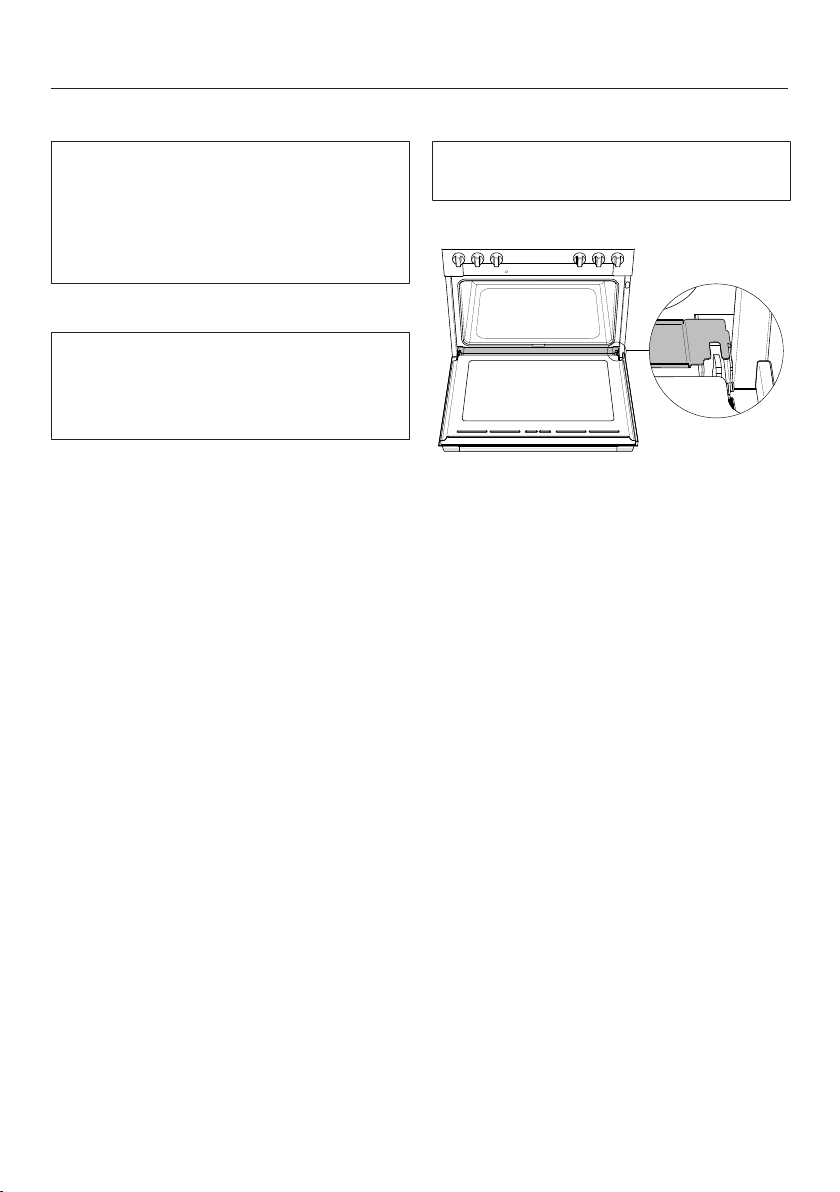
Installation of the drip tray
The drip tray covers the gap between
the oven cavity and the door.
Open the oven door.
Lay the drip tray over the gap
between the oven cavity and the
door.
Close the oven door.
Notes on installation
17
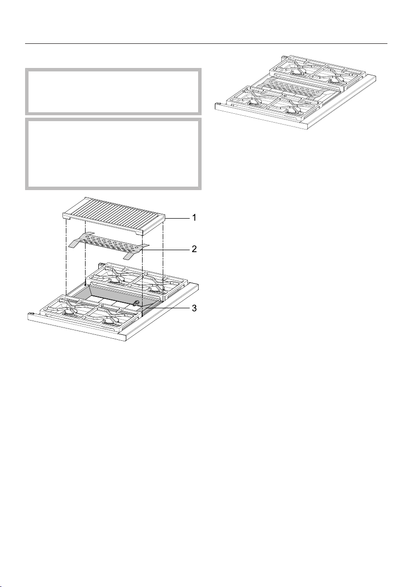
Assembling the grill
Burn hazard!
The burners must be turned off and
allowed to cool completely.
Risk of injury!
The cast-iron grill is heavy.
Carry the grill carefully and place it
securely on a soft base so that it lies
flat.
a
Grill
b
Radiant plate
c
Frame
Using a soft sponge, clean radiant
plate with a solution of warm water
and a small amount of liquid dish
soap. Dry the parts thoroughly after
cleaning.
Remove the grill from the gas
cooktop.
Place the radiant plate on top of
the frame .
Place the grill into position.
Cleaning and care
Tip: All parts can be disassembled in
the reverse order. You can also remove
the frame for cleaning.

Notes on installation
18
Optional accessories
All accessories and cleaning products
listed in these instructions are designed
to be used with the Miele range.
These can be ordered from the Miele
website (see end of this booklet for
contact details).
When ordering, please have your model
number available.
RBGAG All Gas Backguard/RBGDF
Dual Fuel Backguard
Depending on the model, you can
exchange the existing island trim of
your appliance for a larger range
backguard. The backguard is available
in the following heights: 12" (305 mm)
and 20" (508 mm).
Installing the RBGDF Dual Fuel
Backguard
The rear of the range must be
accessible.
Install the backguard before installing
the anti-tip device and connecting of
the range.
Loosen the screws of the island trim.
Pull back the island trim slightly until
it can be removed.
The backguard can be installed in
reverse order.
Notes on installation
19
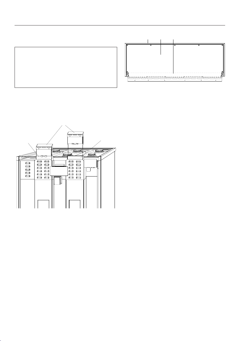
Mounting the RBGAG All Gas
Backguard
The rear of the range must be
accessible.
Mount the backguard before installing
the anti-tip device and connecting of
the range.
Loosen the screws of the island trim.
Pull back the island trim slightly until
it can be removed.
1
22
a
Extender
b
Air ducts
Insert one extender onto each of
the left and right air ducts .
Screw the extenders into place with
2 screws each.
1 2 3
a
Backguard
b
Rear panel backguard
c
Interior panel
To avoid scratching the backguard
, place it front side downwards on a
soft surface (e.g., a blanket). The
lower edge should line up with the
edge of the table so that the
backguard is lying flat.
Remove the screws from the rear of
the backguard.
Remove the rear and interior
panels.
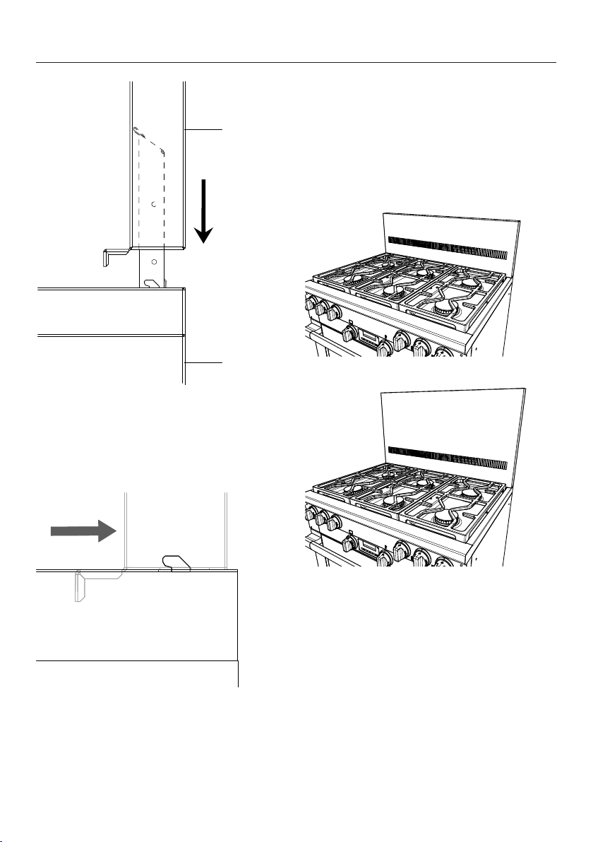
Notes on installation
20
1
2
a
Backguard
b
Range
Push the backguard over the air
duct extensions from above.
As soon as the backguard is sitting
on the range, push the backguard
backwards.
Secure the interior panel and the rear
panel to the backguard with the
screws supplied.
Secure the backguard to the range
with the screws supplied.
Backguard 12"
Backguard 20"

Notes on installation
21
RBS Backsplash
The backsplash is intended for
installation to a Miele Range Hood (DAR
model). Observe the installation
instructions of the Miele Range Hood.
XKM3000W Remote Vision (USA
Only)
Depending on the model, the range
maybe compatible with
RemoteVision
TM
.
In order to use the RemoteVision
TM
monitoring service, you will require a
XKM3000W Communication Module.
Refer to the Operating and Installation
Instructions of the Miele XKM3000W
Communication Module.
Notes on installation
22
Do not carry or lift the range by the oven door handle or the control panel!
The range is heavy.
Due to the size and weight of the appliance, installation should be performed by
two people.
The net weight of the range with accessories is as follows:
Model Width Net weight incl.
accessories
HR 1421
HR 1622
HR 112x
HR 1724
HR 192x
2915/16"
(762mm)
approx. 307 lbs (140 kg)
HR 113x
HR 193x
3515/16"
(915mm)
approx. 405 lbs (180 kg)
HR 195x 4715/16"
(1220mm)
approx. 573 lbs (260 kg)
Installation location
This appliance is not intended for outdoor use.
Ranges with a connection to the water supply should not be installed in rooms
where there is a risk of freezing temperatures.
The floor of the space where the appliance is to be installed must be flat, level and
made of a strong, rigid material.
The niche floor must be made of strong, rigid material.
Because the Range is heavy and has to be secured with the anti-tip device
supplied, the surface must be able to fully bear the load of the appliance. If
necessary, seek the advice of an architect or construction expert.
Ventilation
The air intake and outlet openings must not be covered or blocked in any way.
Notes on installation
23
Required connections
Model Electrical
connection
Gas connection Plumbed-water
connection
HR 1421 X – –
HR 1622 X – X
HR 112x
HR 113x
X X –
HR 1724 X X –
HR 192x
HR 193x
HR 195x
X X X
X Connection required
– Connection not provided
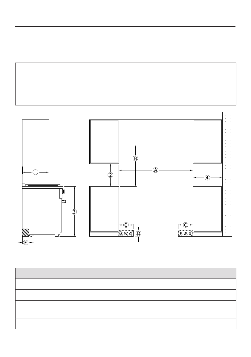
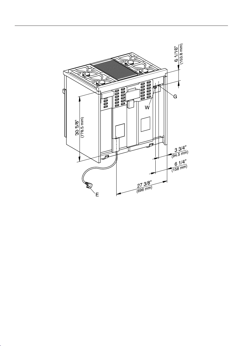
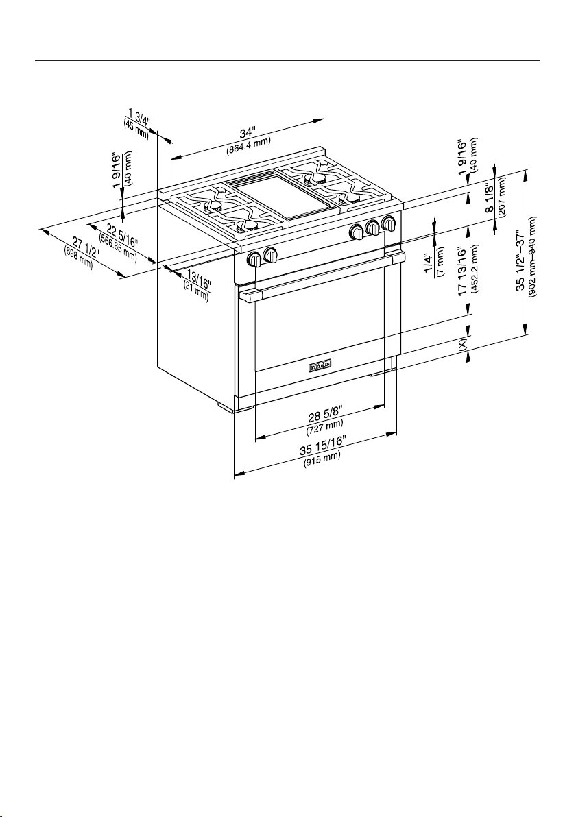
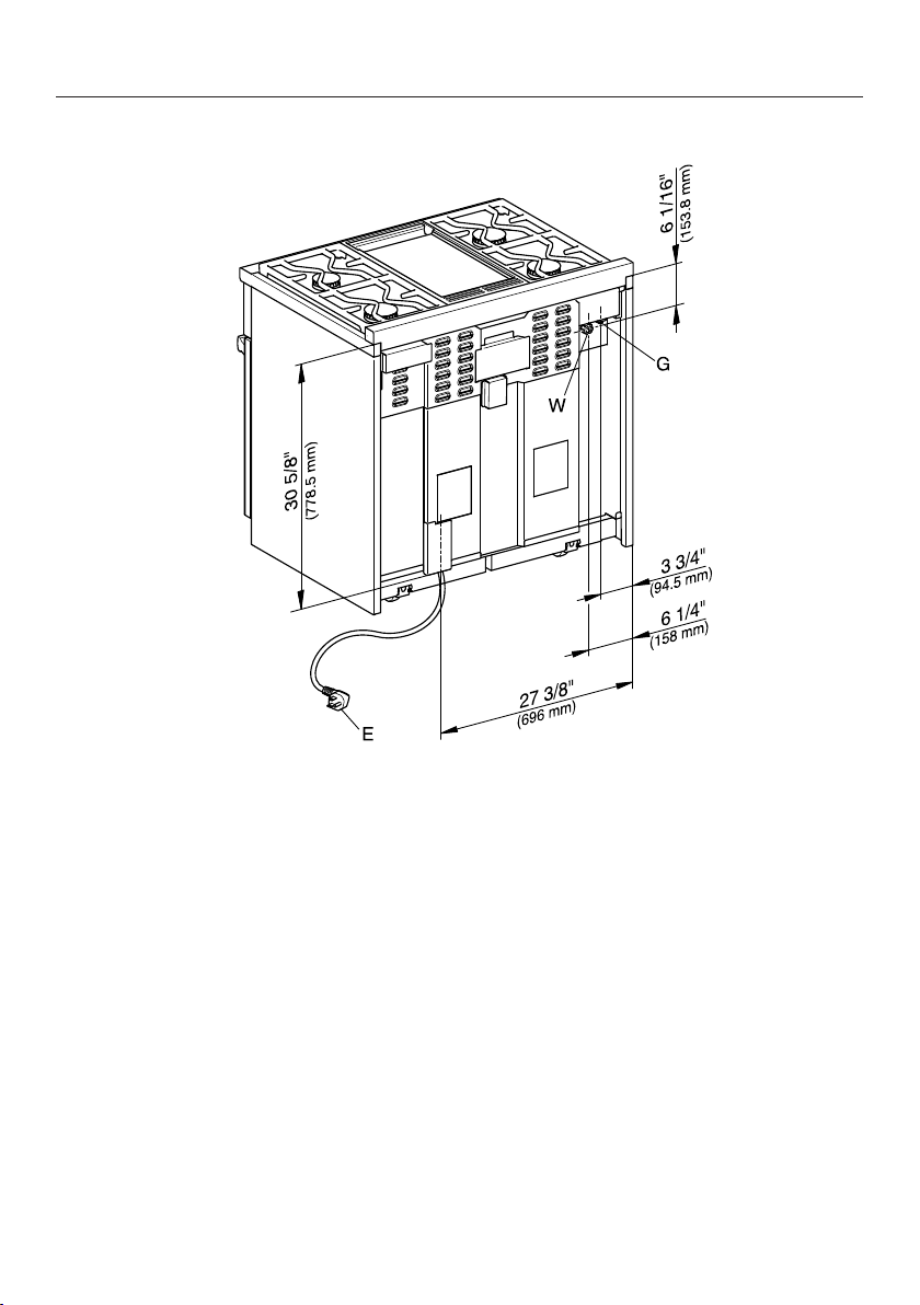
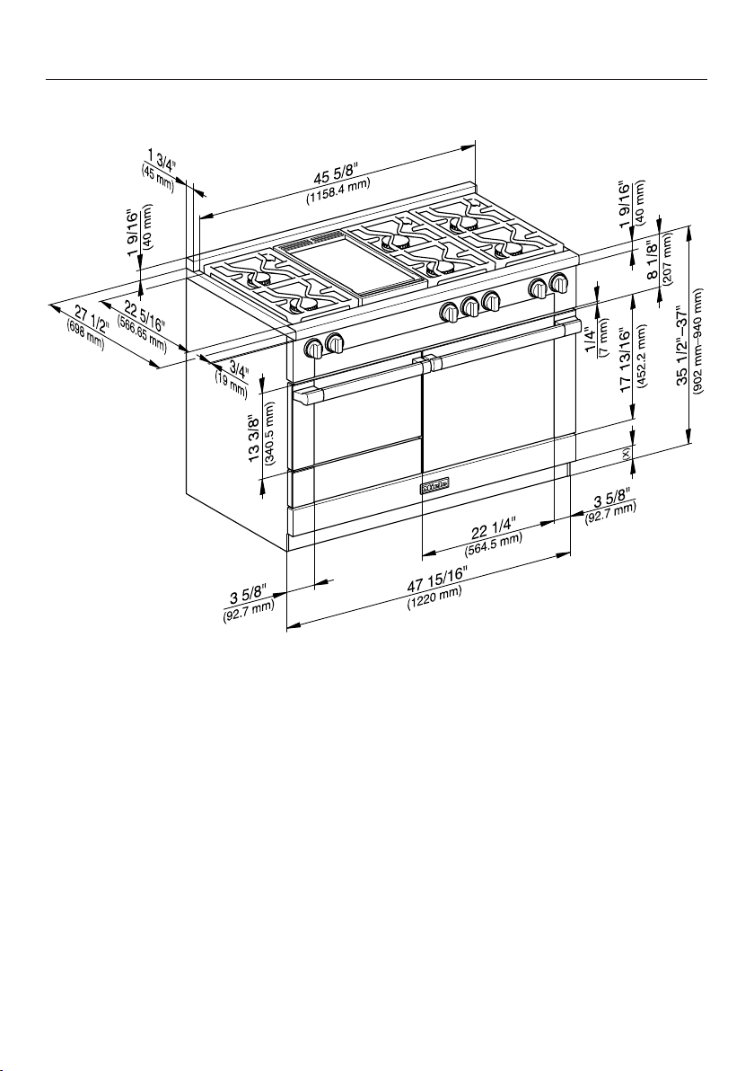
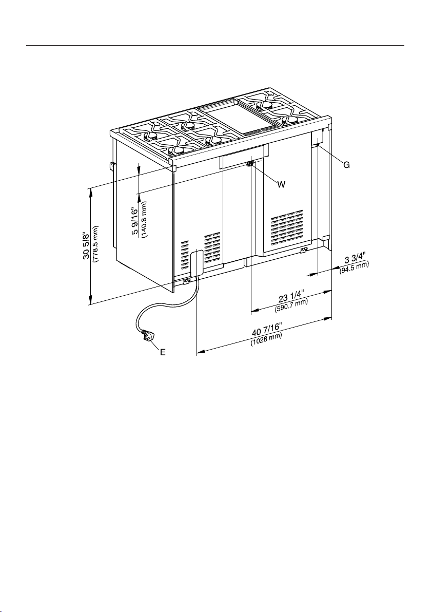
All Electric Range dimensions
24
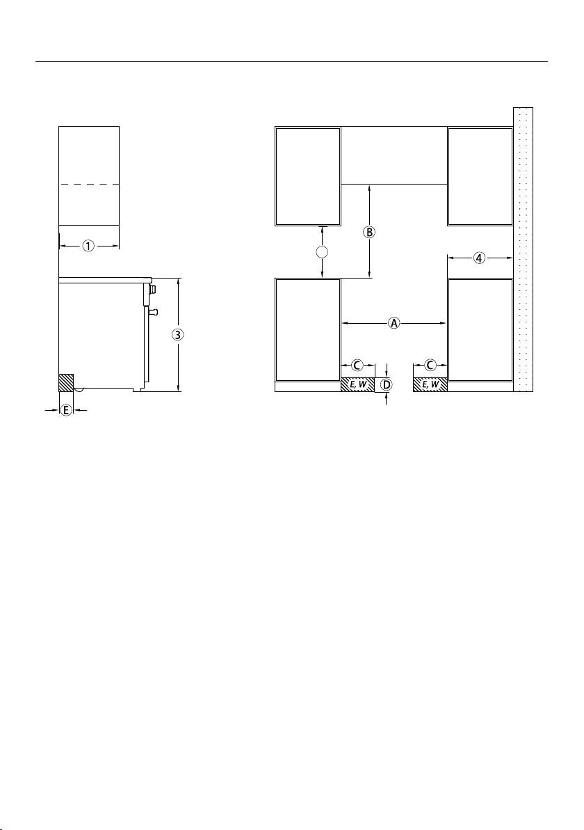
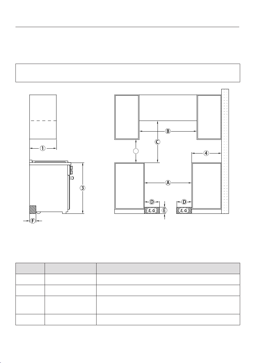
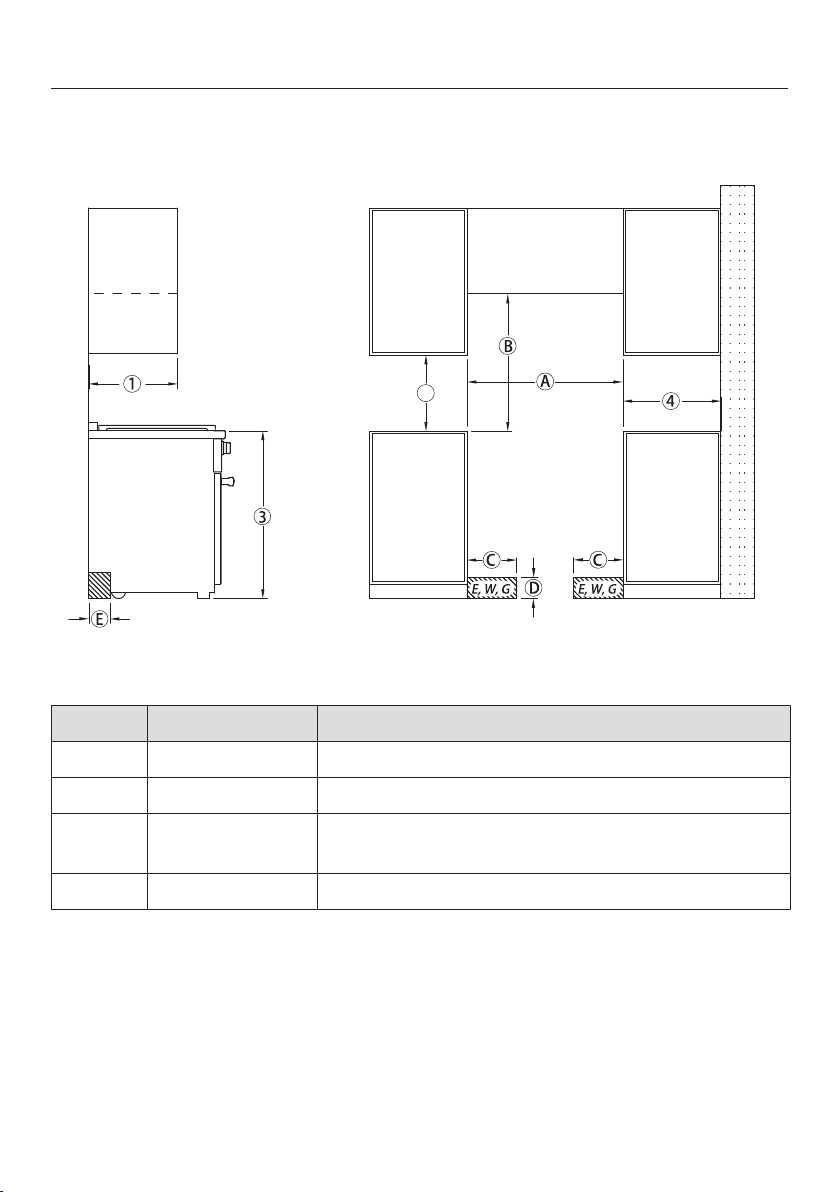
HR 1421; HR 1622
2
, , The shaded area represents the installation area for the connections:
E = Electrical connection,
W = Water connection (only HR 1622)
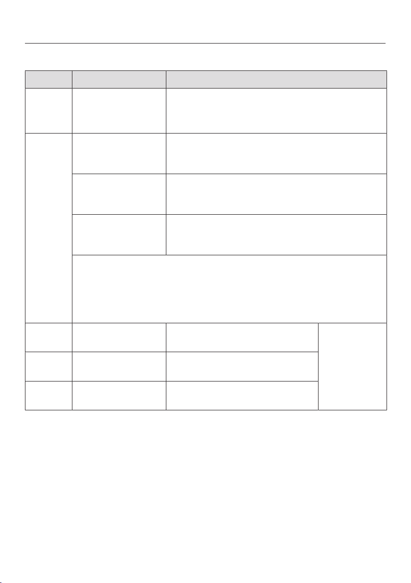
All Electric Range dimensions
25
HR 1421; HR 1622
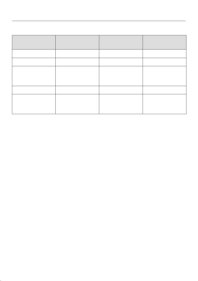
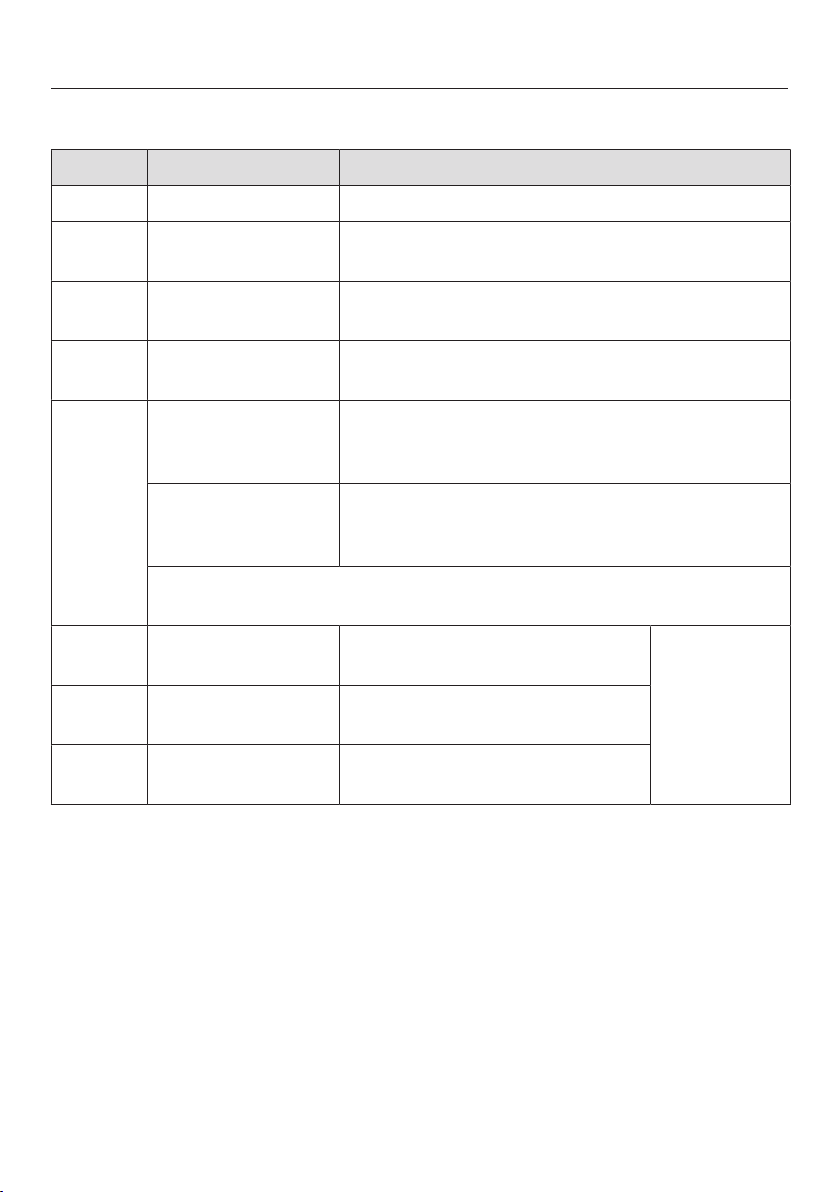
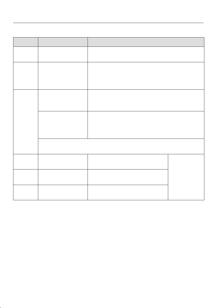
Position Dimensions Description
13" (330mm) Maximum depth of top cabinet
18" (547mm) Minimum distance to bottom edge of top
cabinet
35 1/2"–37"
(901–940 mm)
Distance from the floor to cooktop surface
min. 30"
(762mm)
Niche width
30" (762mm) Minimum distance between the top of the
cooking area and the bottom of an unprotected
combustible surface.
or 24" (609mm) Minimum distance to a protected combustible
surface or when a Miele Ventilation Hood is
installed.
For all other hoods please consult the manufacturer's specifications
for required distances.
approx.
101/16" (256 mm)
Maximum connection width right
and left
Position of
the wall
socket
approx.
4
1/2" (115mm)
Maximum connection height
approx.
2
13/16" (72mm)
Maximum connection depth
Please observe safe distances to rear combustible surfaces of 12" (305mm) clearance. For
zero clearance installation the Miele Backguards will satisfy the required distance to
combustible surfaces. The Miele Backguard is available in 12" (305mm) or 20" (508mm)
heights.
All Electric Range dimensions
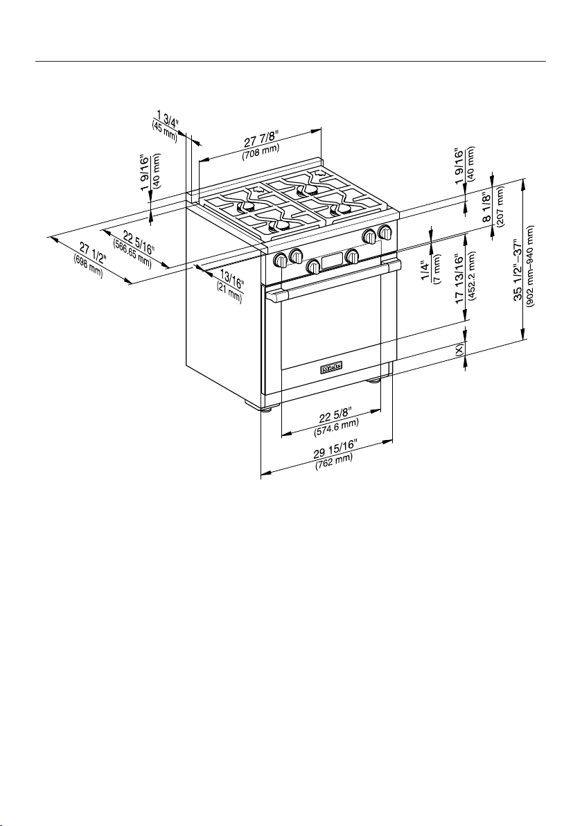
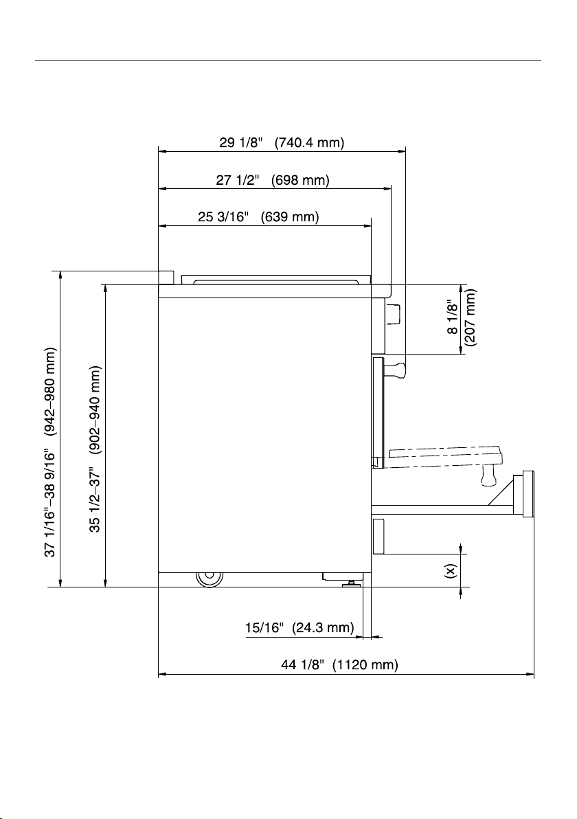
26
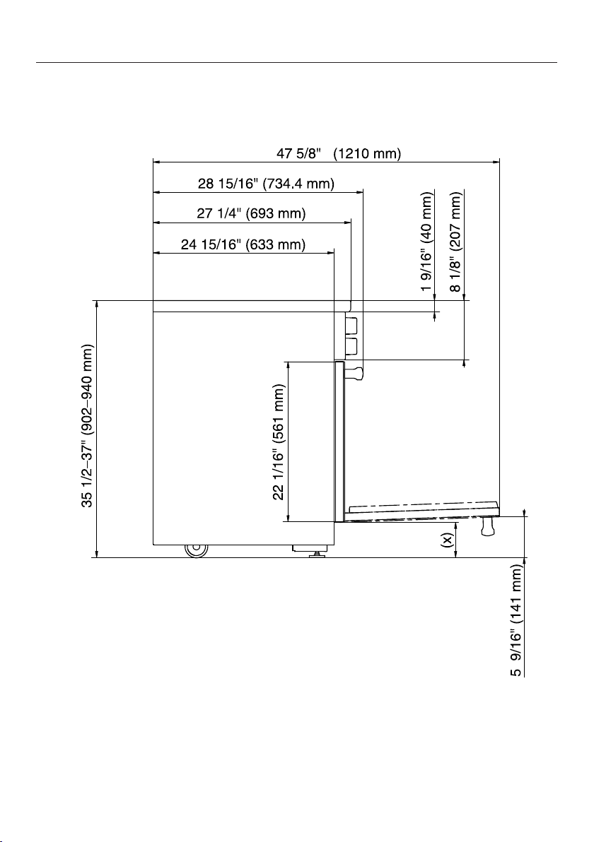
Detailed views of HR 1421
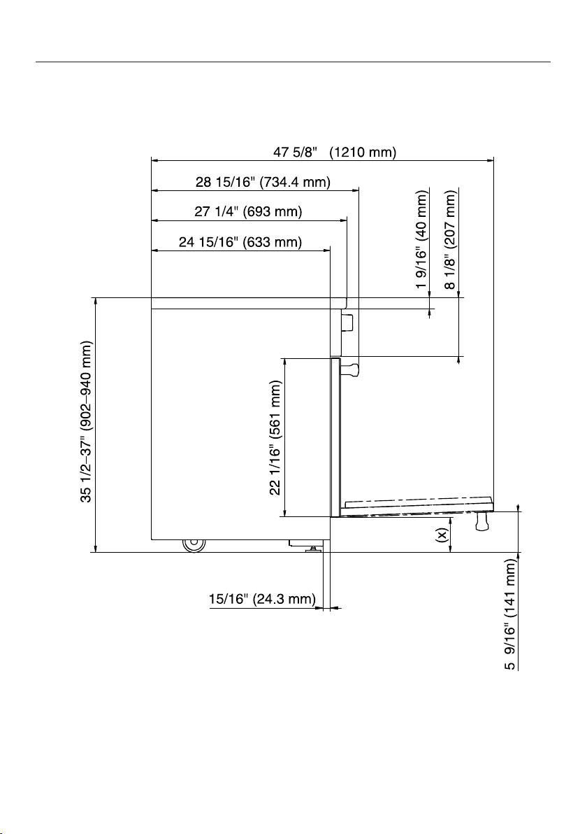
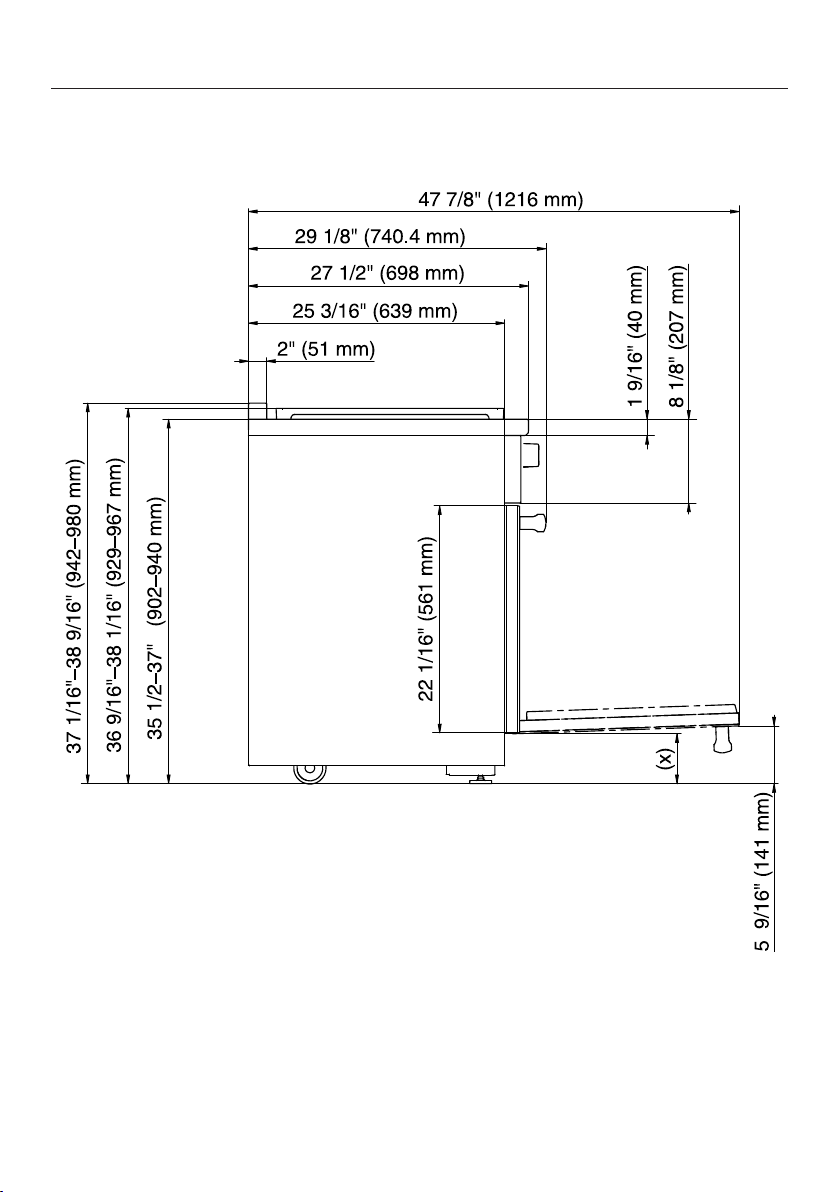
Side view of HR 1421
(x) = Depending on the appliance height adjustment
5" - 61/2" (127 mm - 165.1 mm)
All Electric Range dimensions
27
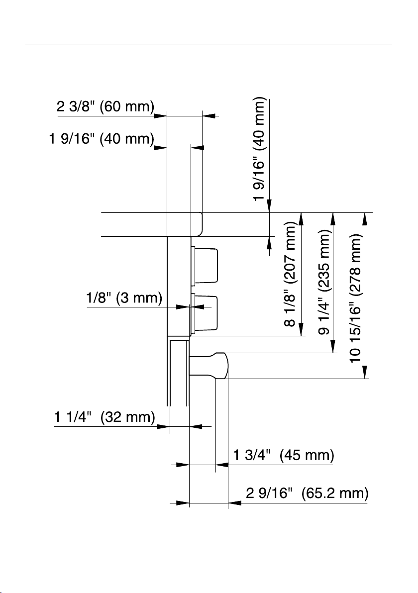
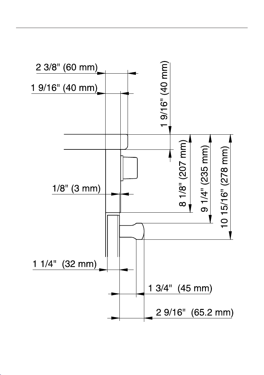
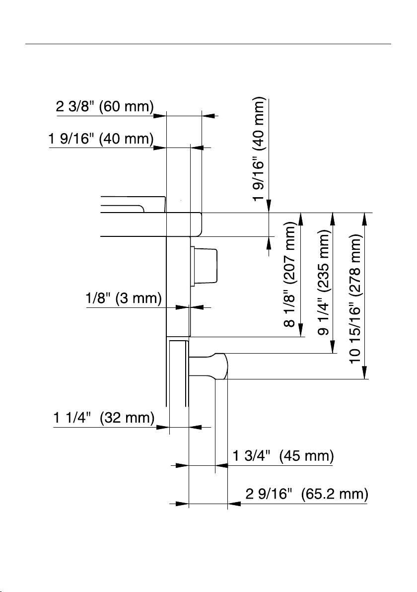
Detailed front side view of HR 1421
All Electric Range dimensions
28
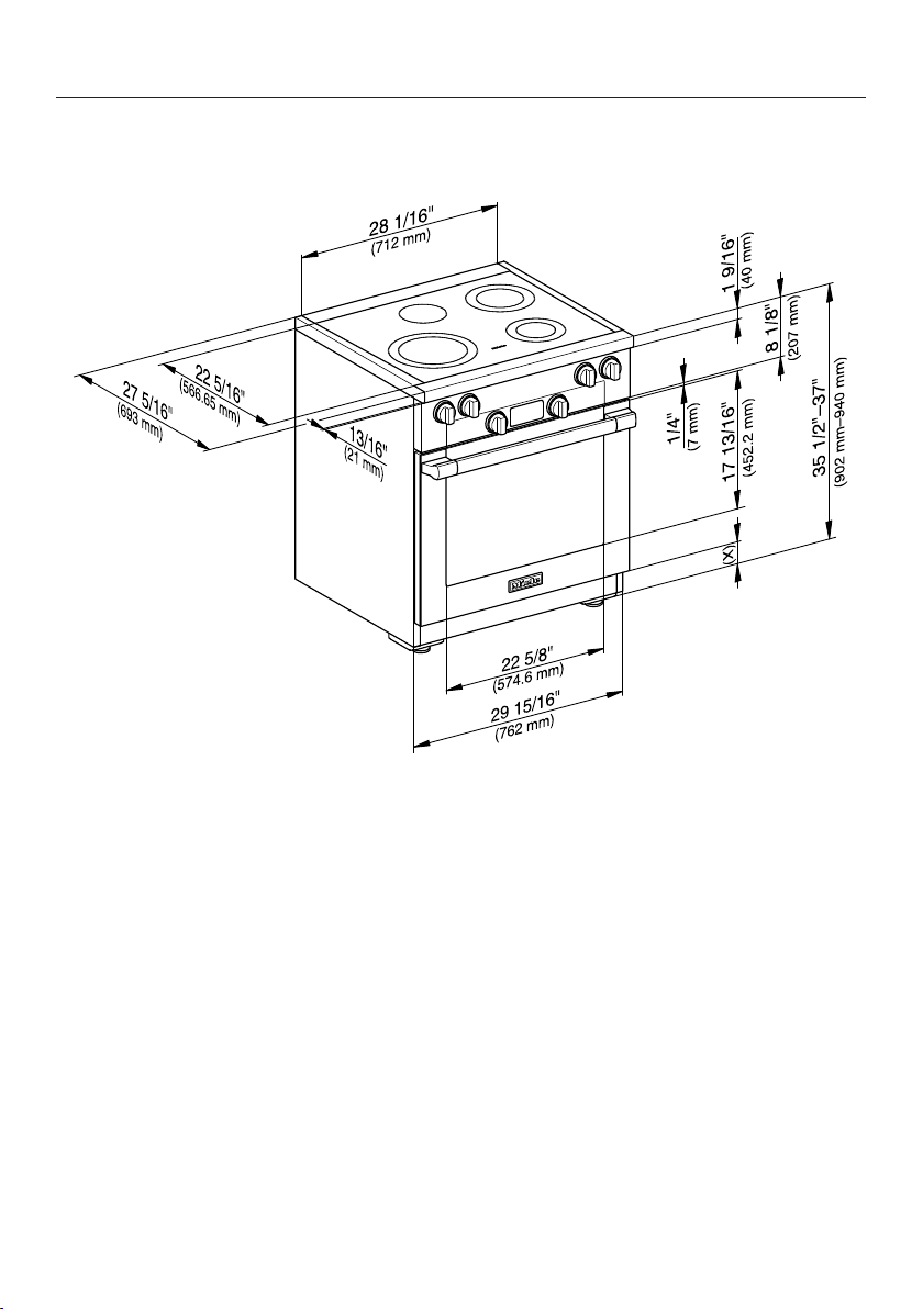
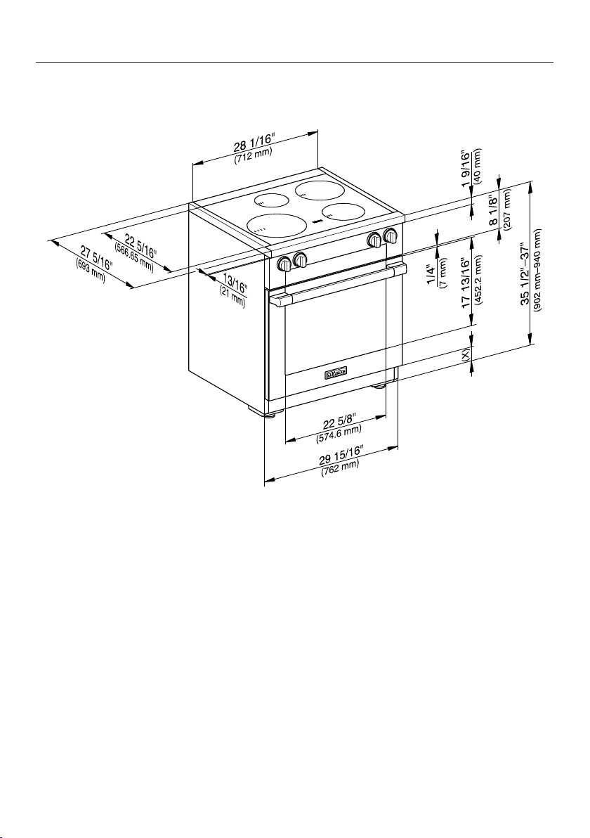
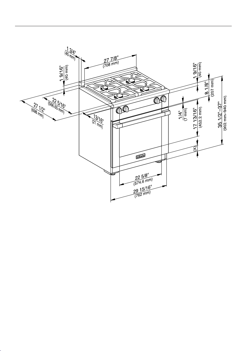
Front side view of HR 1421
(x) = Depending on the appliance height adjustment
5" - 61/2" (127 mm - 165.1 mm)
All Electric Range dimensions
29
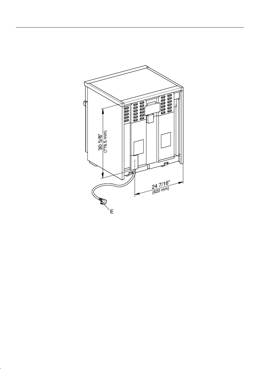
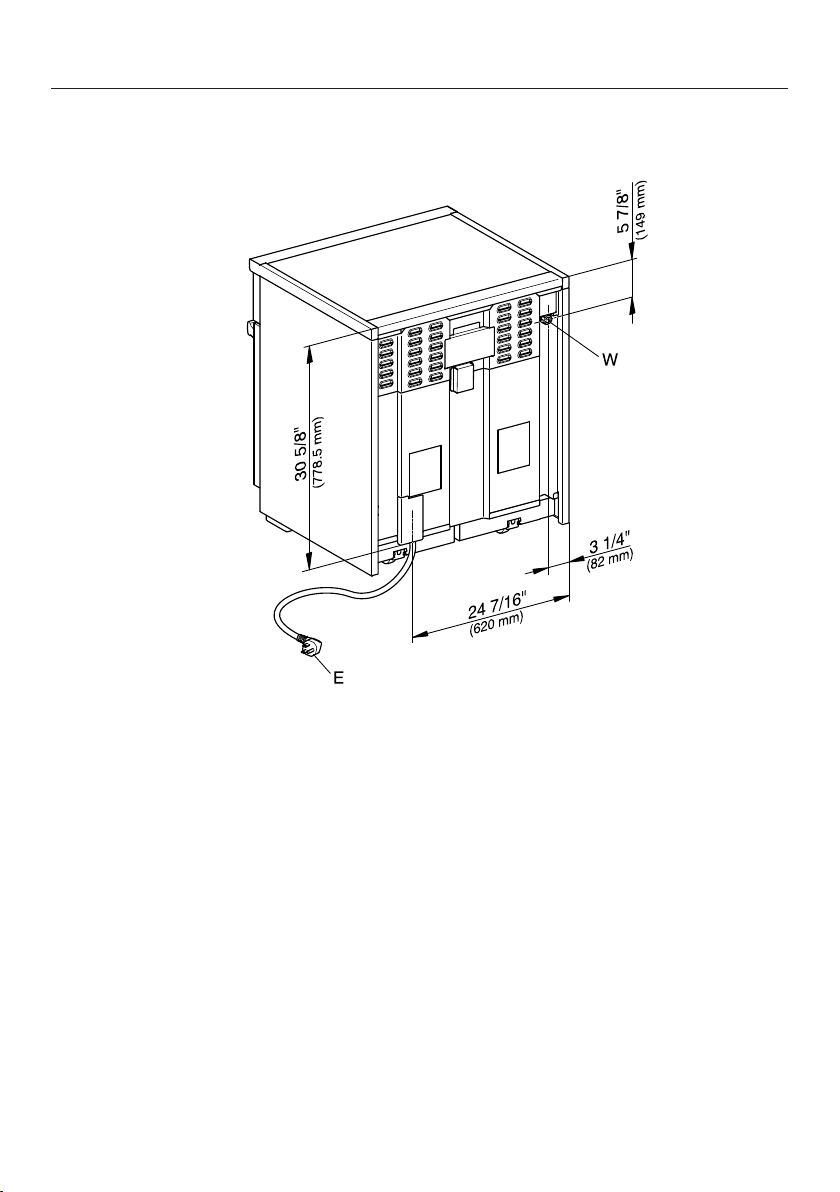
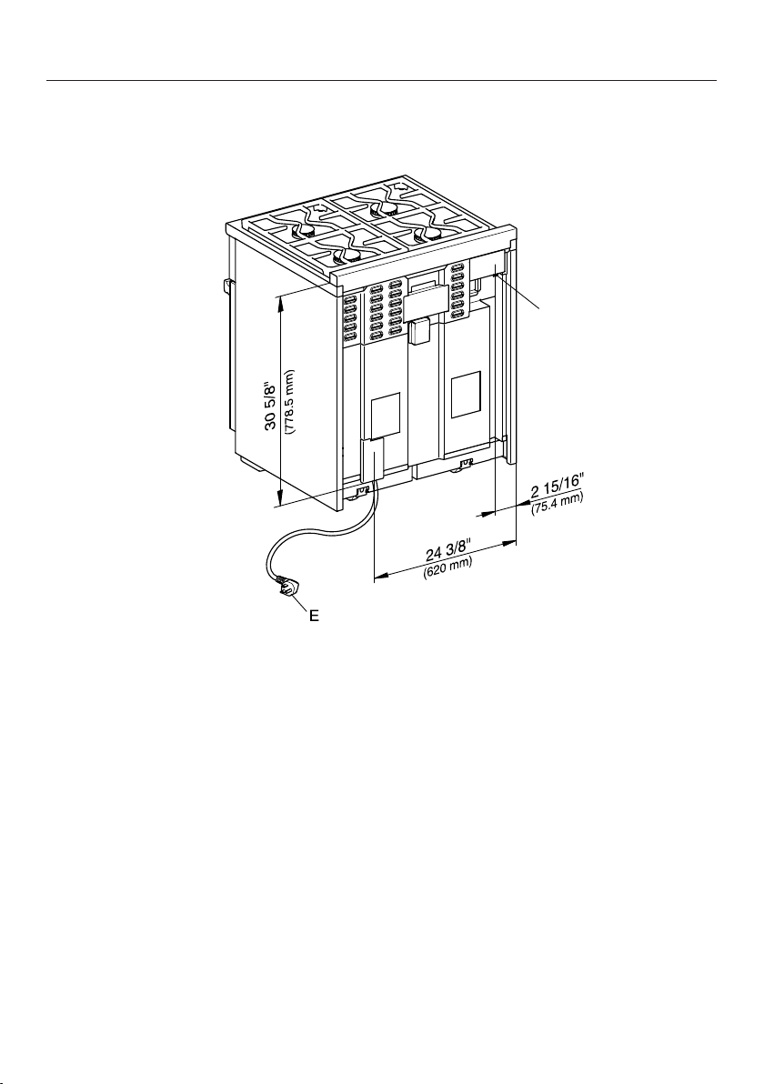
Rear view of HR 1421
E = Electrical connection
All Electric Range dimensions
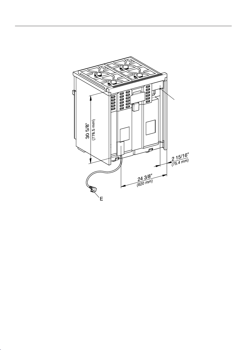
30
Detailed views of HR 1622
Side view of HR 1622
(x) = Depending on the appliance height adjustment
5" - 6 1/2" (127 mm - 165.1 mm)
All Electric Range dimensions
31
Detailed front side view of HR 1622
All Electric Range dimensions
32
Front side view of HR 1622
(x) = Depending on the appliance height adjustment
5" - 6 1/2" (127 mm - 165.1 mm)
All Electric Range dimensions
33
Rear view of HR 1622
E = Electrical connection
W = Water connection

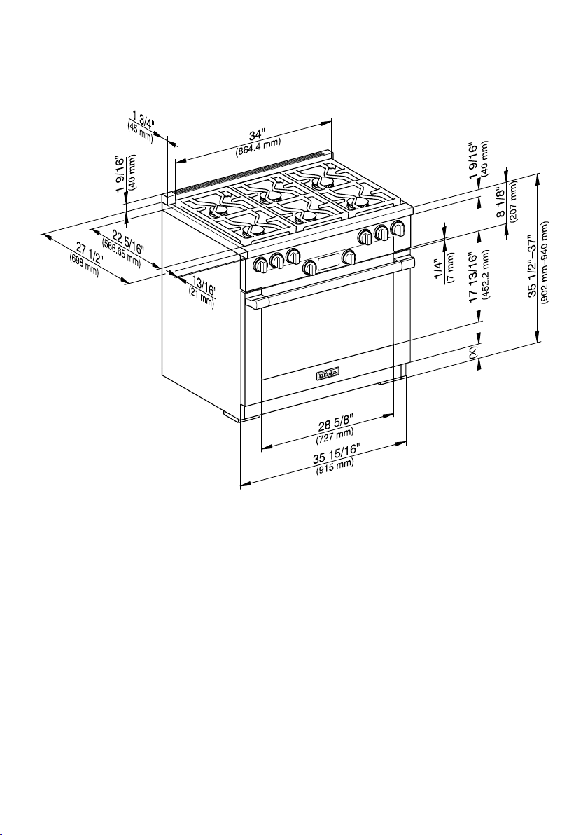
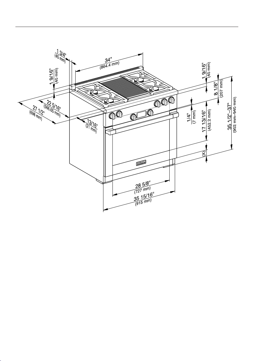
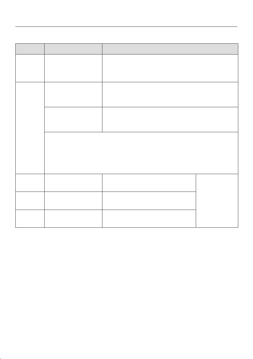
All Gas Range dimensions
34
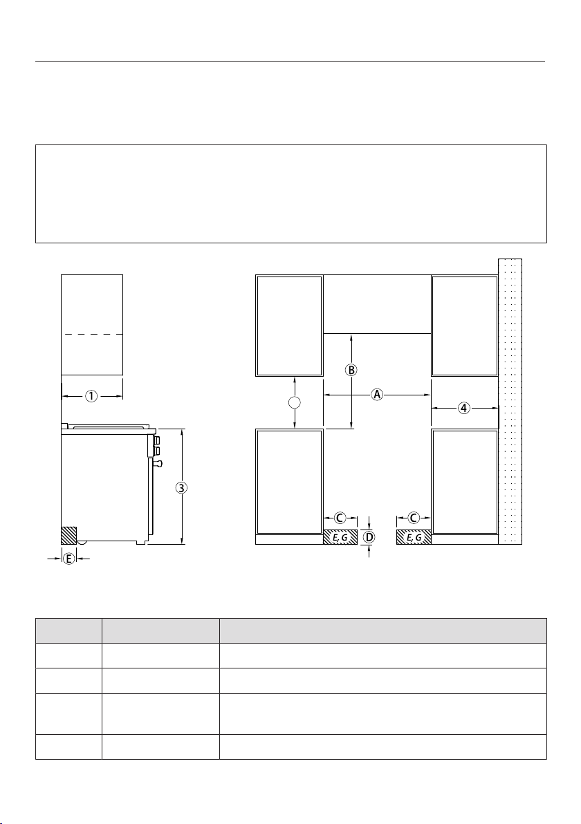
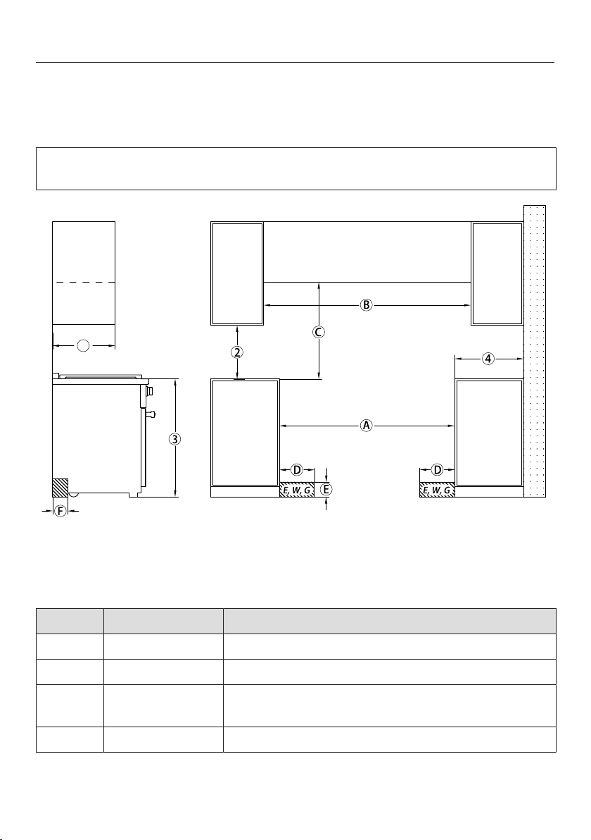
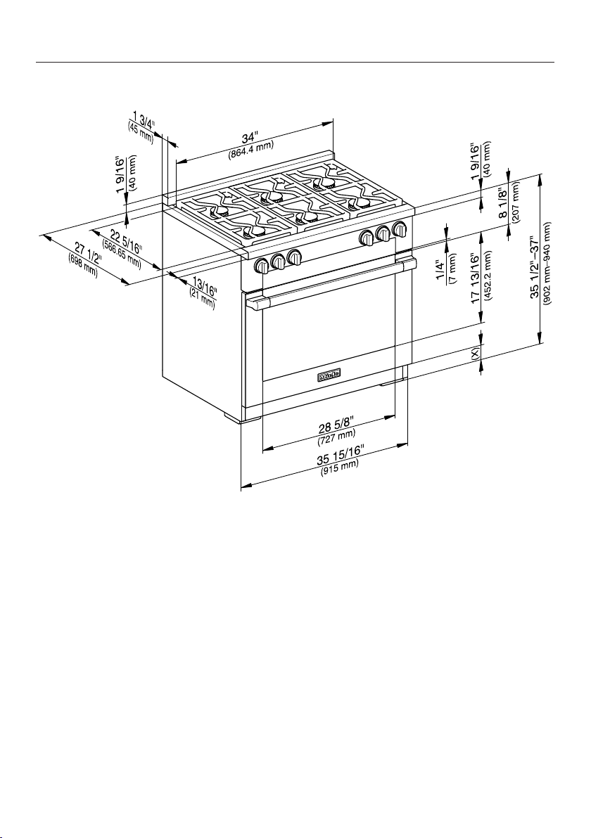
All Gas Range HR 1124 with Standard Burner Configuration
M Pro Power Plus
2
, , The shaded area represents the installation area for the connections:
E = Electrical connection, G = Gas connection
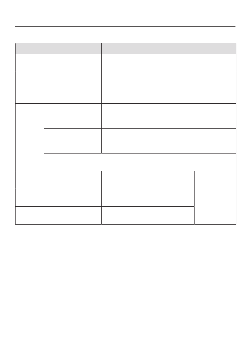
Position Dimensions Description
13" (330mm) Maximum depth of top cabinet
18" (457mm) Minimum distance to bottom edge of top cabinet
35 1/2"–37"
(901–940mm)
Distance from the floor to cooktop surface
10" (254mm) Minimum distance to combustible surfaces.
All Gas Range dimensions
35
Position Dimensions Description
min. 30"
(762mm)
Niche width
37" (940mm) Minimum distance between the top of the
cooking area and the bottom of an unprotected
combustible surface.
30" (762mm) Minimum distance between the top of the
cooking area and the bottom of the Miele Range
Hood (DAR model with DRxB XL blower).
Refer to the Installation instructions for the Miele ventilation hood,
Appliance dimensions (Distance between cooktop and ventilation
hood (S)).
For all other hoods please consult the manufacturer's specifications
for required distances.
approx.
101/16" (2
56mm)
Maximum connection width right
and left
Position of
the wall
socket
approx.
4 1/2" (115mm)
Maximum connection height
approx.
213/16" (72mm)
Maximum connection depth
Please observe safe distances to rear combustible surfaces of 12" (305mm) clearance. For
zero clearance installation the Miele Backguards will satisfy the required distance to
combustible surfaces. The Miele Backguard is available in 12" (305mm) or 20" (508mm)
heights.
All Gas Range dimensions
36
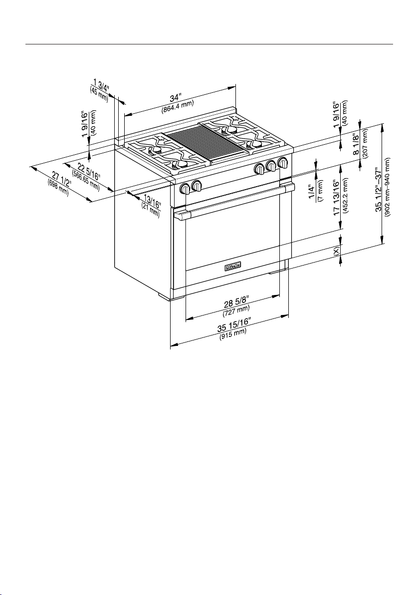
All Gas Range HR 113x with Standard Burner Configuration
M Pro Power Plus
HR 1134, HR 1135, HR 1136
If a BTU reducing jet kit is necessary an authorized installer is required to adapt
the product in accordance with local codes and standards.
2
In case of combustible materials, a minimum distance of 6" must be observed on each
side in addition to dimension .
, , The shaded area represents the installation ar
ea for the connections:
E = Electrical connection, G = Gas connection
Position Dimensions Description
13" (330mm) Maximum depth of top cabinet
18" (457mm) Minimum distance to bottom edge of top cabinet
35 1/2"–37"
(901–940mm)
Distance from the floor to cooktop surface
10" (254mm) Minimum distance to combustible surfaces.
All Gas Range dimensions
37
HR 1134
Position Dimensions Description
min. 36"
(915mm)
Niche width
6" + + 6"
(150mm + +
150mm)
If combustible materials are present, an
additional minimum distance of 6" (150mm)
(each side) is required. Ensure that the local
regulations are observed.
37" (940mm) Minimum distance between the top of the
cooking area and the bottom of an unprotected
combustible surface.
36" (915mm) Minimum distance between the top of the
cooking area and the bottom of the Miele Range
Hood (DAR model with DRxB XL blower).
30" (762mm) Minimum distance between the top of the
cooking area and the bottom of the Miele Range
Hood (DAR model with DRxB XXL blower).
For all other hoods please consult the manufacturer's specifications
for required distances.
approx.
13
1/16" (332.5mm)
Maximum connection width right
and left
Position of
the wall
socket
approx.
4 1/2" (115mm)
Maximum connection height
approx.
213/16" (72mm)
Maximum connection depth
Please observe safe distances to rear combustible surfaces of 12" (305mm) clearance. For
zero clearance installation the Miele Backguards will satisfy the required distance to
combustible surfaces. The Miele Backguard is available in 12" (305mm) or 20" (508mm)
heights.

All Gas Range dimensions
38
HR 1135, HR 1136
Position Dimensions Description
min. 36"
(915mm)
Niche width
6" + + 6"
(150mm + +
150mm)
If combustible materials are present, an
additional minimum distance of 6" (150mm)
(each side) is required. Ensure that the local
regulations are observed.
37" (940mm) Minimum distance between the top of the
cooking area and the bottom of an unprotected
combustible surface.
30" (762mm) Minimum distance between the top of the
cooking area and the bottom of the Miele Range
Hood (DAR model with DRxB XL or DRxB XXL
blower).
For all other hoods please consult the manufacturer's specifications
for required distances.
approx.
13 1/16" (332.5mm)
Maximum connection width right
and left
Position of
the wall
socket
approx.
4
1/2" (115mm)
Maximum connection height
approx.
213/16" (72mm)
Maximum connection depth
Please observe safe distances to rear combustible surfaces of 12" (305mm) clearance. For
zero clearance installation the Miele Backguards will satisfy the required distance to
combustible surfaces. The Miele Backguard is available in 12" (305mm) or 20" (508mm)
heights.
All Gas Range dimensions
39
All Gas Range HR 113x with BTU reducing nozzle configuration
(M Pro Power Zero Gap Kit, M Pro - décor hood)
HR 1134, HR 1135, HR 1136
For Miele Range Hoods and Miele Range-Décor Hoods:
If a BTU reducing jet kit is necessary an authorized installer is required to adapt
the product in accordance with local codes and standards. The nozzles are a
standard accessory and are changed during installation, see also "Possible
combinations - Range with BTU reducing jet kit".
2
, , The shaded area represents the installation area for the connections:
E = Electrical connection, G = Gas connection
Position Dimensions Description
13" (330mm) Maximum depth of top cabinet
18" (457mm) Minimum distance to bottom edge of top cabinet
35 1/2"–37"
(901–940mm)
Distance from the floor to cooktop surface
10" (254mm) Minimum distance to combustible surfaces.

All Gas Range dimensions
40
HR 1134
Position Dimensions Description
min. 36"
(915mm)
Niche width
Please contact Miele Service for more
information.
37" (940mm) Minimum distance between the top of the
cooking area and the bottom of an unprotected
combustible surface.
36" (915mm) Minimum distance between the top of the
cooking area and the bottom of the Miele Range
Hood (DAR model with DRxB XL blower).
30" (762mm) Minimum distance between the top of the
cooking area and the bottom of the Miele Range
Hood (DAR model with DRxB XXL blower).
Refer to the Installation instructions for the Miele ventilation hood,
Appliance dimensions (Distance between cooktop and ventilation
hood (S)).
For all other hoods please consult the manufacturer's specifications
for required distances.
approx.
13 1/16" (332.5mm)
Maximum connection width right
and left
Position of
the wall
socket
approx.
4 1/2" (115mm)
Maximum connection height
approx.
213/16" (72mm)
Maximum connection depth
Please observe safe distances to rear combustible surfaces of 12" (305mm) clearance. For
zero clearance installation the Miele Backguards will satisfy the required distance to
combustible surfaces. The Miele Backguard is available in 12" (305mm) or 20" (508mm)
heights.

All Gas Range dimensions
41
HR 1135, HR 1136
Position Dimensions Description
min. 36"
(915mm)
Niche width
Please contact Miele Service for more
information.
37" (940mm) Minimum distance between the top of the
cooking area and the bottom of an unprotected
combustible surface.
30" (762mm) Minimum distance between the top of the
cooking area and the bottom of the Miele Range
Hood (DAR model with DRxB XL or DRxB XXL
blower).
Refer to the Installation instructions for the Miele ventilation hood,
Appliance dimensions (Distance between cooktop and ventilation
hood (S)).
For all other hoods please consult the manufacturer's specifications
for required distances.
approx.
13 1/16" (332.5mm)
Maximum connection width right
and left
Position of
the wall
socket
approx.
4
1/2" (115mm)
Maximum connection height
approx.
213/16" (72mm)
Maximum connection depth
Please observe safe distances to rear combustible surfaces of 12" (305mm) clearance. For
zero clearance installation the Miele Backguards will satisfy the required distance to
combustible surfaces. The Miele Backguard is available in 12" (305mm) or 20" (508mm)
heights.

All Gas Range dimensions
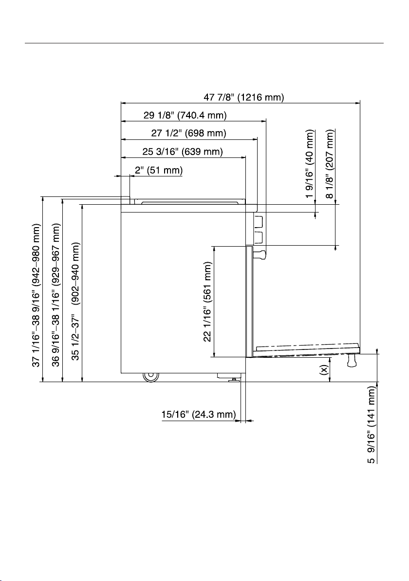
42
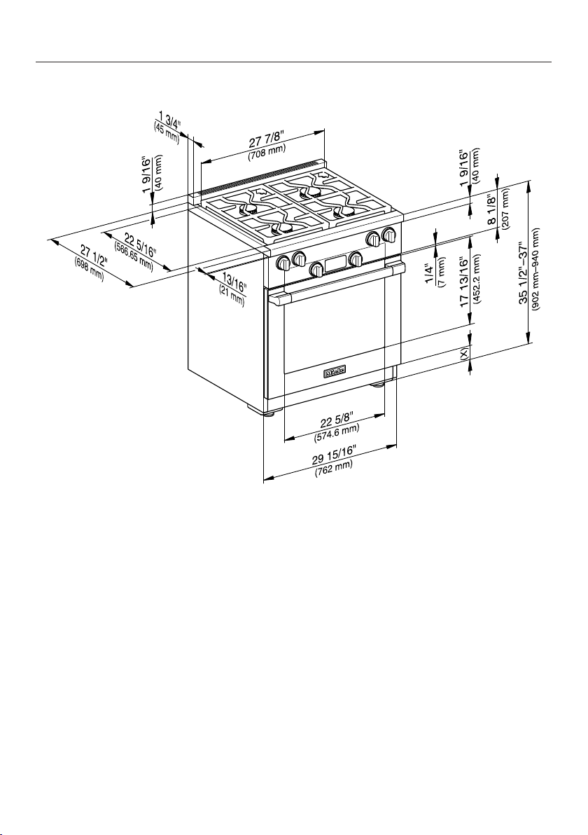
Detailed views of HR 1124
Side view of HR 1124
(x) = Depending on the appliance height adjustment: 5" - 6 1/2" (127 mm - 165.1
mm)

All Gas Range dimensions
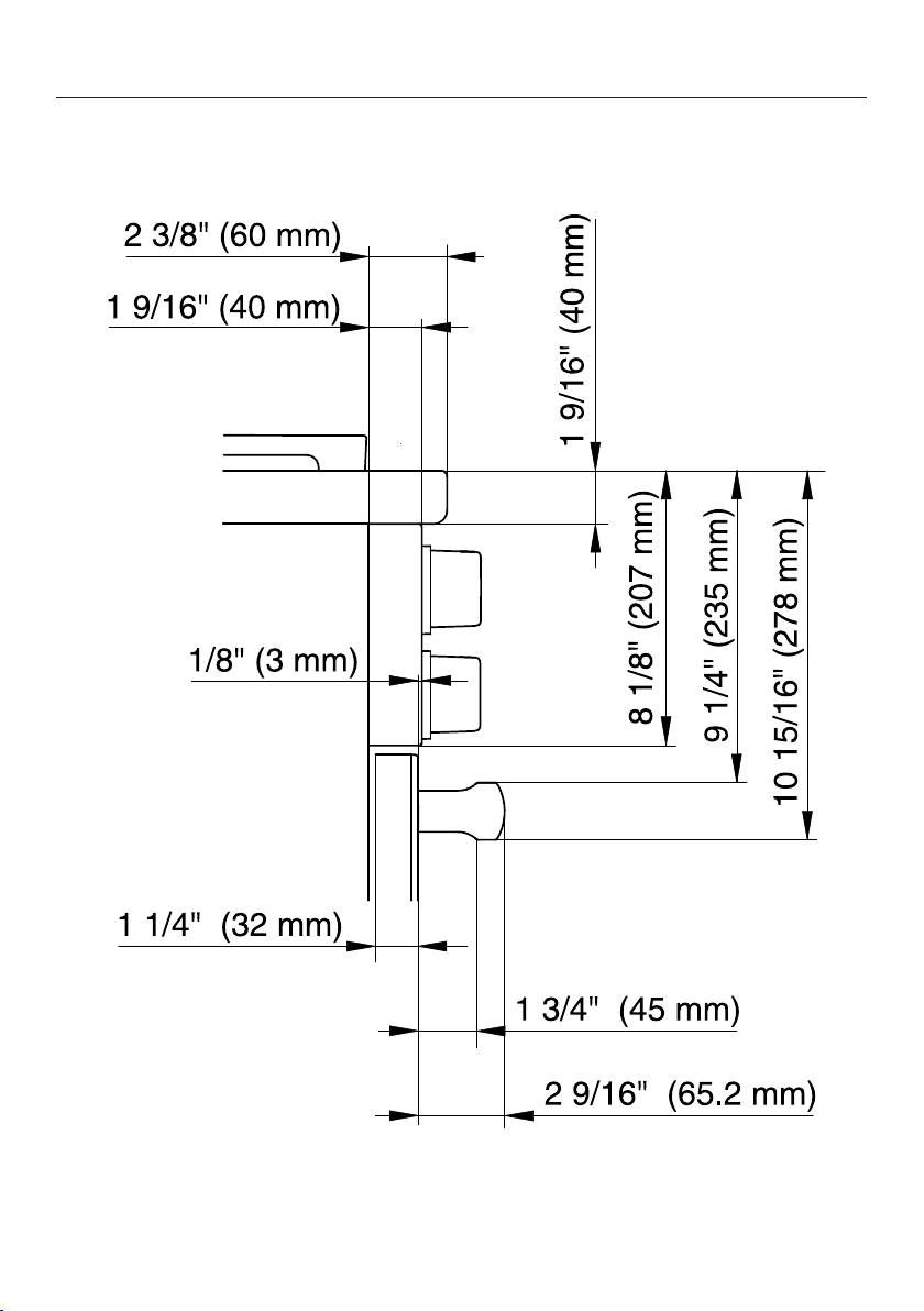
43
Detailed front side view of HR 1124
All Gas Range dimensions
44
Front side view of HR 1124
(x) = Depending on the appliance height adjustment: 5" - 6 1/2" (127 mm - 165.1
mm)
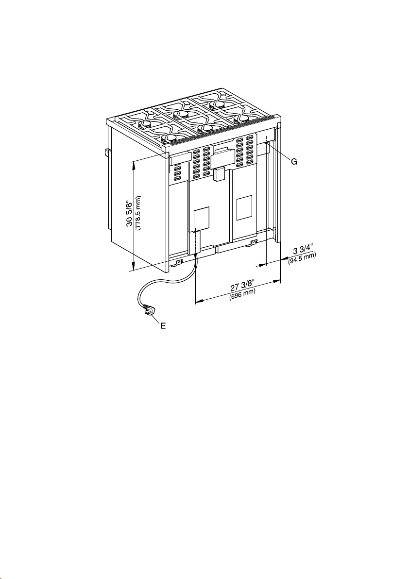
All Gas Range dimensions
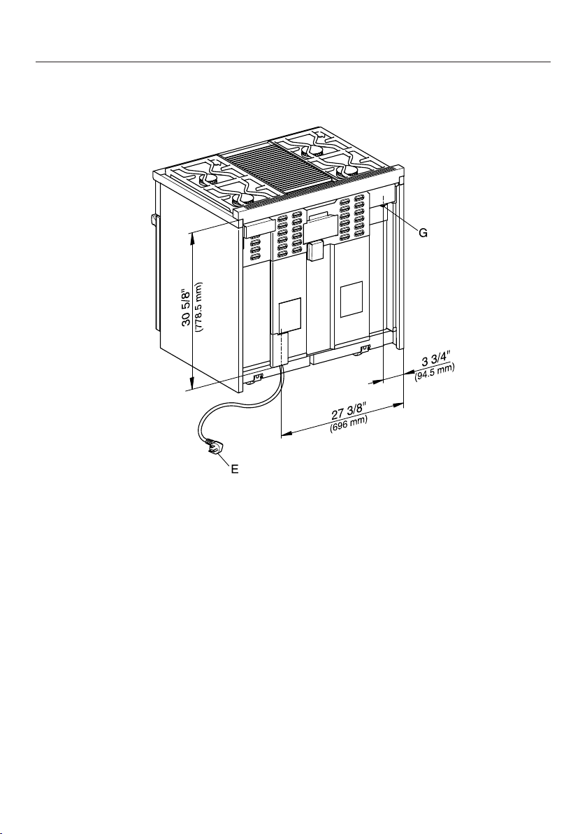
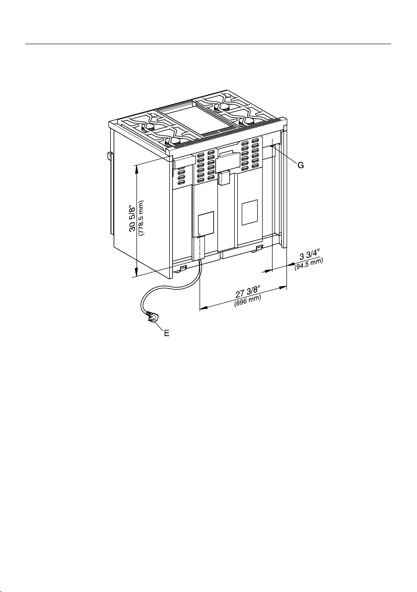
45
Rear view of HR 1124
G
E = Electrical connection
G = Gas connection

All Gas Range dimensions
46
Detailed views of HR 1134
Side view of HR 1134
(x) = Depending on the appliance height adjustment: 5" - 6 1/2" (127 mm - 165.1
mm)

All Gas Range dimensions
47
Detailed front side view of HR 1134
All Gas Range dimensions
48
Front side view of HR 1134
(x) = Depending on the appliance height adjustment: 5" - 6 1/2" (127 mm - 165.1
mm)
All Gas Range dimensions
49
Rear view of HR 1134
E = Electrical connection
G = Gas connection

All Gas Range dimensions
50
Detailed views of HR 1135
Side view of HR 1135
(x) = Depending on the appliance height adjustment: 5" - 6 1/2" (127 mm - 165.1
mm)
All Gas Range dimensions
51
Detailed front side view of HR 1135
All Gas Range dimensions
52
Front side view of HR 1135
(x) = Depending on the appliance height adjustment: 5" - 6 1/2" (127 mm - 165.1
mm)
All Gas Range dimensions
53
Rear view of HR 1135
E = Electrical connection
G = Gas connection
All Gas Range dimensions
54
Detailed views of HR 1136
Side view of HR 1136
(x) = Depending on the appliance height adjustment: 5" - 6 1/2" (127 mm - 165.1
mm)

All Gas Range dimensions
55
Detailed front side view of HR 1136

All Gas Range dimensions
56
Front side view of HR 1136
(x) = Depending on the appliance height adjustment: 5" - 6 1/2" (127 mm - 165.1
mm)
All Gas Range dimensions
57
Rear view of HR 1136
E = Electrical connection
G = Gas connection

Dual Fuel Range dimensions
58
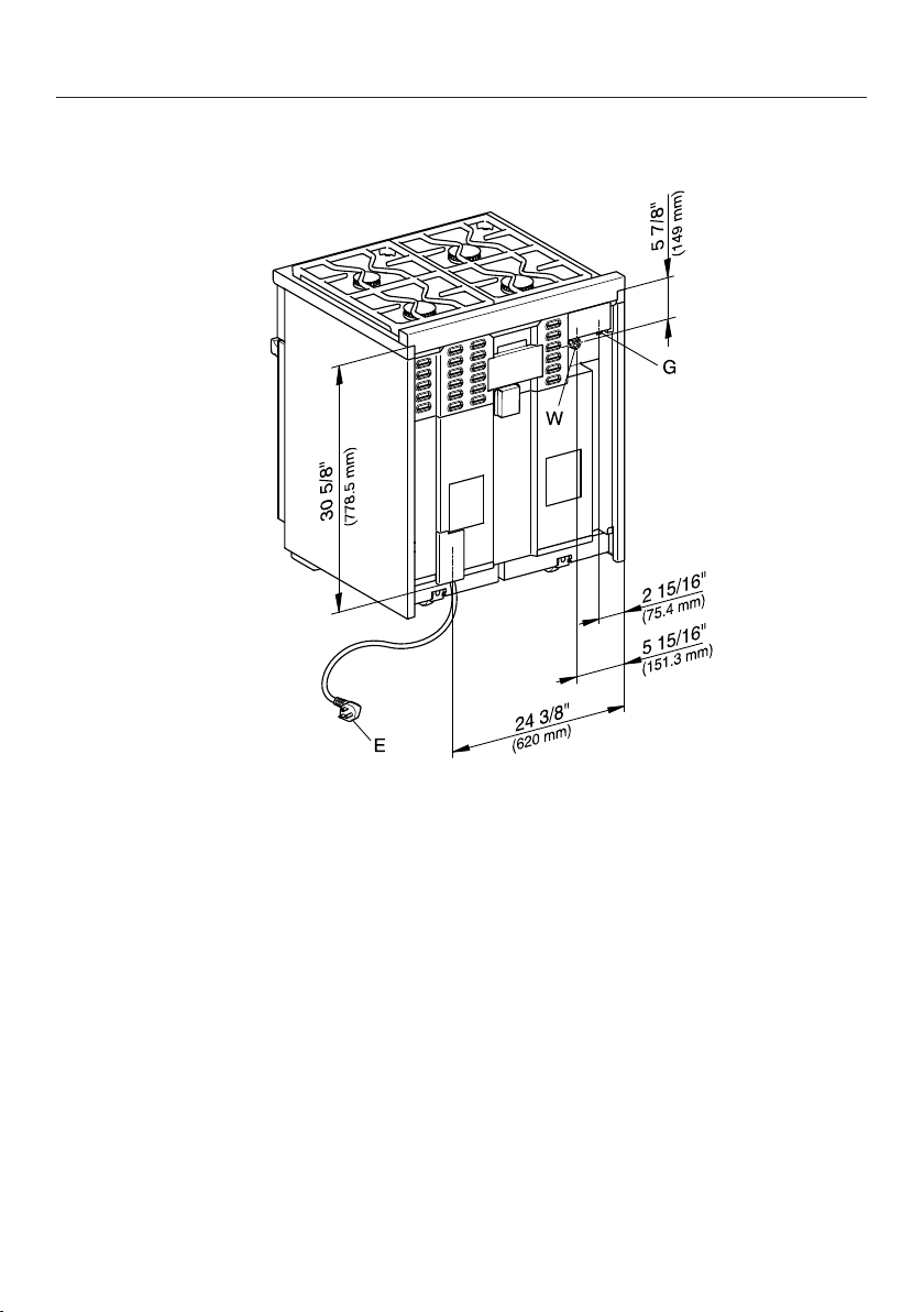
Dual Fuel Range HR 1724 with Standard Burner Configuration
M Pro Power Plus
2
, , The shaded area represents the installation area for the connections:
E = Electrical connection, G = Gas connection
Position Dimensions Description
13" (330mm) Maximum depth of top cabinet
18" (457mm) Minimum distance to bottom edge of top cabinet
35 1/2"–37"
(901–940mm)
Distance from the floor to cooktop surface
10" (254mm) Minimum distance to combustible surfaces.

Dual Fuel Range dimensions
59
Position Dimensions Description
min. 30"
(762mm)
Niche width
37" (940 mm) Minimum distance between the top of the
cooking area and the bottom of an unprotected
combustible surface.
30" (762 mm) Minimum distance between the top of the
cooking area and the bottom of the Miele Range
Hood (DAR model with DRxB XL blower).
Refer to the Installation instructions for the Miele ventilation hood,
Appliance dimensions (Distance between cooktop and ventilation
hood (S)).
For all other hoods please consult the manufacturer's specifications
for required distances.
approx.
101/16" (2
56mm)
Maximum connection width right
and left
Position of
the wall
socket
approx.
4
1/2" (115mm)
Maximum connection height
approx.
213/16" (72mm)
Maximum connection depth
Please observe safe distances to rear combustible surfaces of 12" (305mm) clearance. For
zero clearance installation the Miele Backguards will satisfy the required distance to
combustible surfaces. The Miele Backguard is available in 12" (305mm) or 20" (508mm)
heights.
Dual Fuel Range dimensions
60
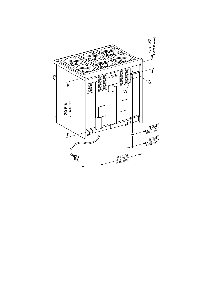
Dual Fuel Range HR 1924 with Standard Burner Configuration
M Pro Power Plus
2
, , The shaded area represents the installation area for the connections:
E = Electrical connection, W = W
ater connection, G = Gas connection
Position Dimensions Description
13" (330mm) Maximum depth of top cabinet
18" (457mm) Minimum distance to bottom edge of top cabinet
35 1/2"–37"
(901–940mm)
Distance from the floor to cooktop surface
10" (254mm) Minimum distance to combustible surfaces.

Dual Fuel Range dimensions
61
Position Dimensions Description
min. 30"
(762mm)
Niche width
37" (940 mm) Minimum distance between the top of the
cooking area and the bottom of an unprotected
combustible surface.
30" (762 mm) Minimum distance between the top of the
cooking area and the bottom of the Miele Range
Hood (DAR model with DRxB XL blower).
Refer to the Installation instructions for the Miele ventilation hood,
Appliance dimensions (Distance between cooktop and ventilation
hood (S)).
For all other hoods please consult the manufacturer's specifications
for required distances.
approx.
101/16" (2
56mm)
Maximum connection width right
and left
Position of
the wall
socket
approx.
4 1/2" (115mm)
Maximum connection height
approx.
213/16" (72mm)
Maximum connection depth
Please observe safe distances to rear combustible surfaces of 12" (305mm) clearance. For
zero clearance installation the Miele Backguards will satisfy the required distance to
combustible surfaces. The Miele Backguard is available in 12" (305mm) or 20" (508mm)
heights.
Dual Fuel Range dimensions
62
Dual Fuel Range HR 193x/195x with Standard Burner
Configuration M Pro Power Plus
HR 1934, HR 1935, HR 1936, HR 1954, HR 1955, HR1956
If a BTU reducing jet kit is necessary an authorized installer is required to adapt
the product in accordance with local codes and standards.
1
In case of combustible materials, a minimum distance of 6" must be observed on each
side in addition to dimension .
, , The shaded area represents the installation ar
ea for the connections:
E = Electrical connection, W = W
ater connection, G = Gas connection
Position Dimensions Description
13" (330mm) Maximum depth of top cabinet
18" (457mm) Minimum distance to bottom edge of top cabinet
35 1/2"–37"
(901–940mm)
Distance from the floor to cooktop surface
10" (254mm) Minimum distance to combustible surfaces.

Dual Fuel Range dimensions
63
HR 1934
Position Dimensions Description
min. 36"
(915mm)
Niche width
6" + + 6"
(150mm + +
150mm)
If combustible materials are present, an
additional minimum distance of 6" (150mm)
(each side) is required. Ensure that the local
regulations are observed.
37" (940 mm) Minimum distance between the top of the
cooking area and the bottom of an unprotected
combustible surface.
36" (915 mm) Minimum distance between the top of the
cooking area and the bottom of the Miele Range
Hood (DAR model with DRxB XL blower).
30" (762 mm) Minimum distance between the top of the
cooking area and the bottom of the Miele Range
Hood (DAR model with DRxB XXL blower).
For all other hoods please consult the manufacturer's specifications
for required distances.
approx.
13 1/16" (332.5mm)
Maximum connection width right
and left
Position of
the wall
socket
approx.
4 1/2" (115mm)
Maximum connection height
approx.
213/16" (72mm)
Maximum connection depth
Please observe safe distances to rear combustible surfaces of 12" (305mm) clearance. For
zero clearance installation the Miele Backguards will satisfy the required distance to
combustible surfaces. The Miele Backguard is available in 12" (305mm) or 20" (508mm)
heights.
Dual Fuel Range dimensions
64
HR 1935, HR 1936
Position Dimensions Description
min. 36"
(915mm)
Niche width
6" + + 6"
(150mm + +
150mm)
If combustible materials are present, an
additional minimum distance of 6" (150mm)
(each side) is required. Ensure that the local
regulations are observed.
37" (940 mm) Minimum distance between the top of the
cooking area and the bottom of an unprotected
combustible surface.
30" (762 mm) Minimum distance between the top of the
cooking area and the bottom of the Miele Range
Hood (DAR model with DRxB XL or DRxB XXL
blower).
For all other hoods please consult the manufacturer's specifications
for required distances.
approx.
13 1/16" (332.5mm)
Maximum connection width right
and left
Position of
the wall
socket
approx.
4 1/2" (115mm)
Maximum connection height
approx.
213/16" (72mm)
Maximum connection depth
Please observe safe distances to rear combustible surfaces of 12" (305mm) clearance. For
zero clearance installation the Miele Backguards will satisfy the required distance to
combustible surfaces. The Miele Backguard is available in 12" (305mm) or 20" (508mm)
heights.
Dual Fuel Range dimensions
65
HR 1954, HR 1955, HR 1956
Position Dimensions Description
min. 48"
(1220mm)
Niche width
6" + + 6"
(150mm + +
150mm)
If combustible materials are present, an
additional minimum distance of 6" (150mm)
(each side) is required. Ensure that the local
regulations are observed.
37" (940 mm) Minimum distance between the top of the
cooking area and the bottom of an unprotected
combustible surface.
36" (915 mm) Minimum distance between the top of the
cooking area and the bottom of the Miele Range
Hood (DAR model with DRxB XXL blower).
For all other hoods please consult the manufacturer's specifications
for required distances.
approx.
19 1/8" (485 mm)
Maximum connection width right
and left
Position of
the wall
socket
approx.
3
1/2" (90mm)
Maximum connection height
approx.
213/16" (72mm)
Maximum connection depth
Please observe safe distances to rear combustible surfaces of 12" (305mm) clearance. For
zero clearance installation the Miele Backguards will satisfy the required distance to
combustible surfaces. The Miele Backguard is available in 12" (305mm) or 20" (508mm)
heights.
Dual Fuel Range dimensions
66
Dual Fuel Range HR 193x with BTU reducing nozzle
configuration (M Pro Power Zero Gap Kit, M Pro - Décor Hood)
HR 1934, HR 1935, HR 1936
For Miele Range Hoods and Miele Range-Décor Hoods:
If a BTU reducing jet kit is necessary an authorized installer is required to adapt
the product in accordance with local codes and standards. The nozzles are a
standard accessory and are changed during installation, see also "Possible
combinations - Range with BTU reducing jet kit".
1
, , The shaded area represents the installation area for the connections:
E = Electrical connection, W = W
ater connection, G = Gas connection
Position Dimensions Description
13" (330mm) Maximum depth of top cabinet
18" (457mm) Minimum distance to bottom edge of top cabinet
35 1/2"–37"
(901–940mm)
Distance from the floor to cooktop surface
10" (254mm) Minimum distance to combustible surfaces.
Dual Fuel Range dimensions
67
HR 1934
Position Dimensions Description
min. 36"
(915mm)
Niche width
Please contact Miele Service for more
information.
37" (940 mm) Minimum distance between the top of the
cooking area and the bottom of an unprotected
combustible surface.
36" (915 mm) Minimum distance between the top of the
cooking area and the bottom of the Miele Range
Hood (DAR model with DRxB XL blower).
30" (762 mm) Minimum distance between the top of the
cooking area and the bottom of the Miele Range
Hood (DAR model with DRxB XXL blower).
Refer to the Installation instructions for the Miele ventilation hood,
Appliance dimensions (Distance between cooktop and ventilation
hood (S)).
For all other hoods please consult the manufacturer's specifications
for required distances.
approx.
13 1/16" (332.5 mm)
Maximum connection width right
and left
Position of
the wall
socket
approx.
4 1/2" (115mm)
Maximum connection height
approx.
213/16" (72mm)
Maximum connection depth
Please observe safe distances to rear combustible surfaces of 12" (305mm) clearance. For
zero clearance installation the Miele Backguards will satisfy the required distance to
combustible surfaces. The Miele Backguard is available in 12" (305mm) or 20" (508mm)
heights.

Dual Fuel Range dimensions
68
HR 1935, HR 1936
Position Dimensions Description
min. 36"
(915mm)
Niche width
Please contact Miele Service for more
information.
37" (940 mm) Minimum distance between the top of the
cooking area and the bottom of an unprotected
combustible surface.
30" (762 mm) Minimum distance between the top of the
cooking area and the bottom of the Miele Range
Hood (DAR model with DRxB XL or DRxB XXL
blower).
Refer to the Installation instructions for the Miele ventilation hood,
Appliance dimensions (Distance between cooktop and ventilation
hood (S)).
For all other hoods please consult the manufacturer's specifications
for required distances.
approx.
13 1/16" (332.5 mm)
Maximum connection width right
and left
Position of
the wall
socket
approx.
4
1/2" (115mm)
Maximum connection height
approx.
213/16" (72mm)
Maximum connection depth
Please observe safe distances to rear combustible surfaces of 12" (305mm) clearance. For
zero clearance installation the Miele Backguards will satisfy the required distance to
combustible surfaces. The Miele Backguard is available in 12" (305mm) or 20" (508mm)
heights.

Dual Fuel Range dimensions
69
Dual Fuel Range HR 195x with BTU reducing nozzle
configuration M Pro Power Zero Gap Kit
HR 1954, HR 1955, HR1956
For Miele Range Hoods:
If a BTU reducing jet kit is necessary an authorized installer is required to adapt
the product in accordance with local codes and standards. The nozzles are a
standard accessory and are changed during installation, see also "Possible
combinations - Range with BTU reducing jet kit".
1
, , The shaded area represents the installation area for the connections:
E = Electrical connection, W = W
ater connection, G = Gas connection
Position Dimensions Description
13" (330mm) Maximum depth of top cabinet
18" (457mm) Minimum distance to bottom edge of top cabinet
35 1/2"–37"
(901–940mm)
Distance from the floor to cooktop surface
10" (254mm) Minimum distance to combustible surfaces.
Dual Fuel Range dimensions
70
HR 1954, HR 1955, HR 1956
Position Dimensions Description
min. 48"
(1220mm)
Niche width
Please contact Miele Service for more
information.
37" (940 mm) Minimum distance between the top of the
cooking area and the bottom of an unprotected
combustible surface.
30" (762 mm) Minimum distance between the top of the
cooking area and the bottom of the Miele Range
Hood (DAR model with DRxB XXL blower).
Refer to the Installation instructions for the Miele ventilation hood,
Appliance dimensions (Distance between cooktop and ventilation
hood (S)).
For all other hoods please consult the manufacturer's specifications
for required distances.
approx.
19 1/8" (485 mm)
Maximum connection width right
and left
Position of
the wall
socket
approx.
3
1/2" (90mm)
Maximum connection height
approx.
213/16" (72mm)
Maximum connection depth
Please observe safe distances to rear combustible surfaces of 12" (305mm) clearance. For
zero clearance installation the Miele Backguards will satisfy the required distance to
combustible surfaces. The Miele Backguard is available in 12" (305mm) or 20" (508mm)
heights.

Dual Fuel Range dimensions
71
Detailed views of HR 1724
Side view of HR 1724
(x) = Depending on the appliance height adjustment: 5" - 6 1/2" (127 mm - 165.1
mm)

Dual Fuel Range dimensions
72
Detailed front side view of HR 1724
Dual Fuel Range dimensions
73
Front side view of HR 1724
(x) = Depending on the appliance height adjustment: 5" - 6 1/2" (127 mm - 165.1
mm)
Dual Fuel Range dimensions
74
Rear view of HR 1724
G
E = Electrical connection
G = Gas connection
Dual Fuel Range dimensions
75
Detailed views of HR 1924
Side view of HR 1924
(x) = Depending on the appliance height adjustment: 5" - 6 1/2" (127 mm - 165.1
mm)
Dual Fuel Range dimensions
76
Detailed front side view of HR 1924
Dual Fuel Range dimensions
77
Front side view of HR 1924
(x) = Depending on the appliance height adjustment: 5" - 6 1/2" (127 mm - 165.1
mm)
Dual Fuel Range dimensions
78
Rear view of HR 1924
E = Electrical connection
W = Water connection
G = Gas connection

Dual Fuel Range dimensions
79
Detailed views of HR 1934
Side view of HR 1934
(x) = Depending on the appliance height adjustment: 5" - 6 1/2" (127 mm - 165.1
mm)

Dual Fuel Range dimensions
80
Detailed front side view of HR 1934
Dual Fuel Range dimensions
81
Front side view of HR 1934
(x) = Depending on the appliance height adjustment: 5" - 6 1/2" (127 mm - 165.1
mm)
Dual Fuel Range dimensions
82
Rear view of HR 1934
E = Electrical connection
W = Water connection
G = Gas connection

Dual Fuel Range dimensions
83
Detailed views of HR 1935
Side view of HR 1935
(x) = Depending on the appliance height adjustment: 5" - 6 1/2" (127 mm - 165.1
mm)

Dual Fuel Range dimensions
84
Detailed front side view of HR 1935
Dual Fuel Range dimensions
85
Front side view of HR 1935
(x) = Depending on the appliance height adjustment: 5" - 6 1/2" (127 mm - 165.1
mm)
Dual Fuel Range dimensions
86
Rear view of HR 1935
E = Electrical connection
W = Water connection
G = Gas connection

Dual Fuel Range dimensions
87
Detailed views of HR 1936
Side view of HR 1936
(x) = Depending on the appliance height adjustment: 5" - 6 1/2" (127 mm - 165.1
mm)

Dual Fuel Range dimensions
88
Detailed front side view of HR 1936
Dual Fuel Range dimensions
89
Front side view of HR 1936
(x) = Depending on the appliance height adjustment: 5" - 6 1/2" (127 mm - 165.1
mm)
Dual Fuel Range dimensions
90
Rear view of HR 1936
E = Electrical connection
W = Water connection
G = Gas connection
Dual Fuel Range dimensions
91
Detailed views of HR 1954
Side view of HR 1954
(x) = Depending on the appliance height adjustment: 4" - 5 1/2" (101.6 mm - 139.7
mm)

Dual Fuel Range dimensions
92
Detailed front side view of HR 1954
Dual Fuel Range dimensions
93
Front side view of HR 1954
(x) = Depending on the appliance height adjustment: 4" - 5 1/2" (101.6 mm - 139.7
mm)
Dual Fuel Range dimensions
94
Rear view of HR 1954
E = Electrical connection
W = Water connection
G = Gas connection

Dual Fuel Range dimensions
95
Detailed views of HR 1955
Side view of HR 1955
(x) = Depending on the appliance height adjustment: 4" - 5 1/2" (101.6 mm - 139.7
mm)

Dual Fuel Range dimensions
96
Detailed front side view of HR 1955
Dual Fuel Range dimensions
97
Front side view of HR 1955
(x) = Depending on the appliance height adjustment: 4" - 5 1/2" (101.6 mm - 139.7
mm)
Dual Fuel Range dimensions
98
Rear view of HR 1955
E = Electrical connection
W = Water connection
G = Gas connection

Dual Fuel Range dimensions
99
Detailed views of HR 1956
Side view of HR 1956
(x) = Depending on the appliance height adjustment: 4" - 5 1/2" (101.6 mm - 139.7
mm)

Dual Fuel Range dimensions
100
Detailed front side view of HR 1956
Dual Fuel Range dimensions
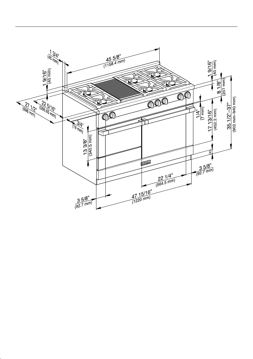
101
Front side view of HR 1956
(x) = Depending on the appliance height adjustment: 4" - 5 1/2" (101.6 mm - 139.7
mm)
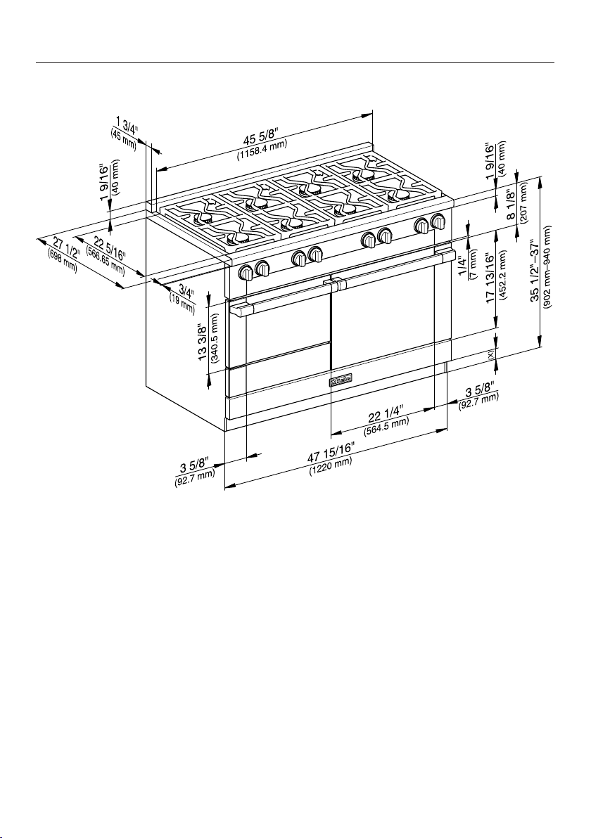
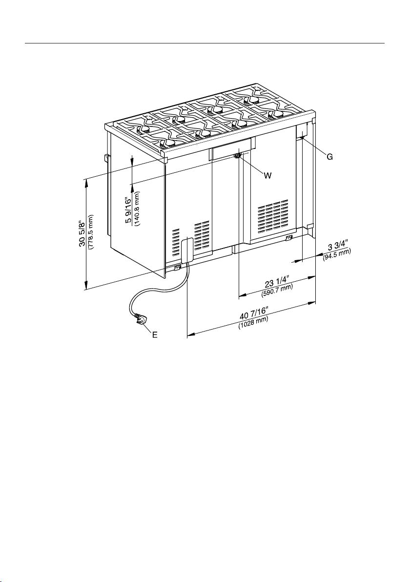
Dual Fuel Range dimensions
102
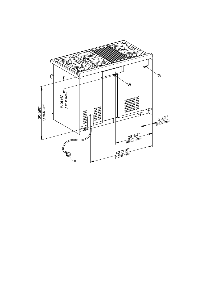
Rear view of HR 1956
E = Electrical connection
W = Water connection
G = Gas connection
Anti-tip device
103
Before installation
WARNING
Children and adults can tip over the
range if has not been secured. This
may lead to fatal injuries.
Make sure that the anti-tip device is
properly installed and locked into
place. It should be screwed to the
floor or wall and engage with the
center of the bottom of the range.
You must take care to protect the
installed flooring when moving the
range.
After moving the range, make sure
that the anti-tip device locks back
into place. It should be screwed to
the floor or wall and engage with the
center of the bottom of the range.
Do not use the range if the anti-tip
device has not been properly
installed and engaged.
Due to the size and weight of the
appliance, installation should be
carried out by two people.
Any opening in the wall behind the
appliance and in the floor under the
appliance shall be sealed.
We recommend removing the oven
door before installing the range (see
"Removing the door" in the Operating
Instructions) and all accessories from
the oven interior. This will make it
easier to install the appliance in its
designated space.
Once the range has been installed and
secured against tipping, you can
reattach the oven door (see
"Reinstalling the door" in the
Operating Instructions).
Do not carry or lift the range by the
oven door handle or the control
panel!
Anti-tip device
104
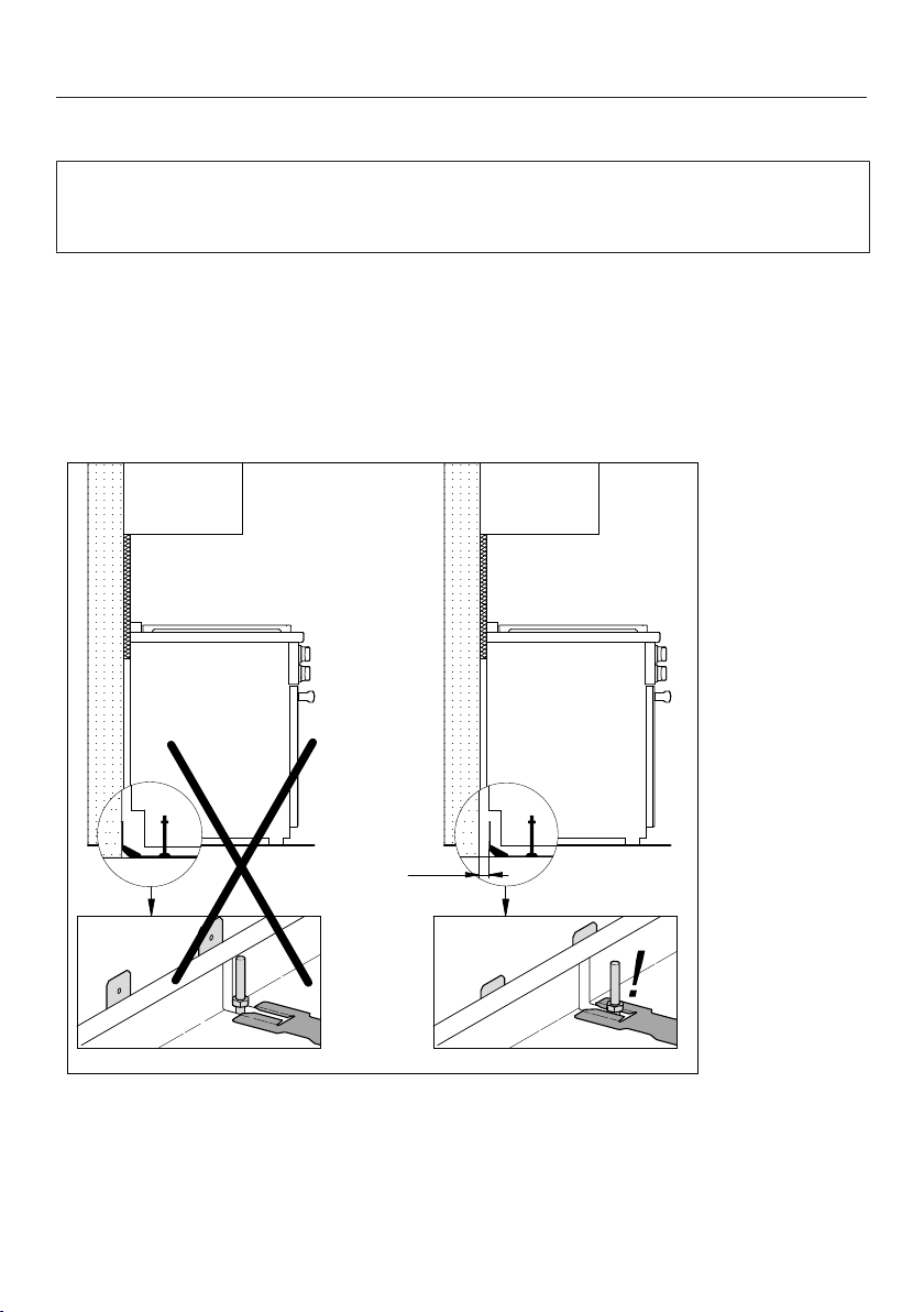
Checking the installation space
Install the anti-tip device on a floor capable of bearing significant weight, such as
a concrete floor, concrete wall or timber framing. The surface must be flat and
level.
If the rear of the range has distance A to the supporting wall due to unevenness
or wall covering (e.g., tile level), you must install the anti-tip device to the
supporting floor. Alternatively, you can also install the anti-tip device with an
adapter between the supporting wall and the anti-tip device. The adapter must
compensate dimension A and be made of suitable material so that a supporting
composite arises between the wall and anti-tip device. Use the corresponding
screws (length and diameter).
A
A = Distance between the rear of the range to the supporting wall
Check the floor surface.
Check the installation dimensions.

Anti-tip device
105
Check the diagrams for the building's supply lines. Make sure that you do not
damage any lines when drilling the holes to attach the anti-tip device.
Check the position of the electric, gas and water connections (see "Electrical
connection," "Gas connection" and "Plumbing"). An overview on the electrical
connections for your range can be found in "Notes on installation".
Anti-tip device
106
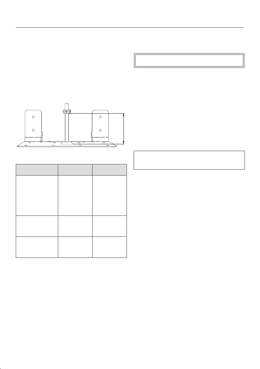
Included accessories
– 1 anti-tip device
– 4 screws
– 4 plugs
Installation dimensions of
locking bolt
X
Anti-tip device, front view
Model Width X
HR 1421
HR 1622
HR 112x
HR 1724
HR 192x
2915/16"
(762mm)
313/16"
(97mm)
HR 113x
HR 193x
3515/16"
(915mm)
313/16"
97mm
HR 195x 4715/16"
(1220mm)
31/4"
82mm
Installing the range with the
anti-tip device
Wear safety shoes and gloves.
The anti-tip device should be installed
at the bottom rear of the range at the
midpoint of the width.
Measure the installation space for the
range close to floor level.
Mark the wall at the middle of the
space width.
Position the notch of the anti-tip
device on the wall marking.
The anti-tip device must fit tightly on
the floor or the wall.
Anti-tip device
107
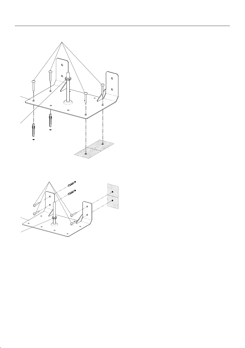
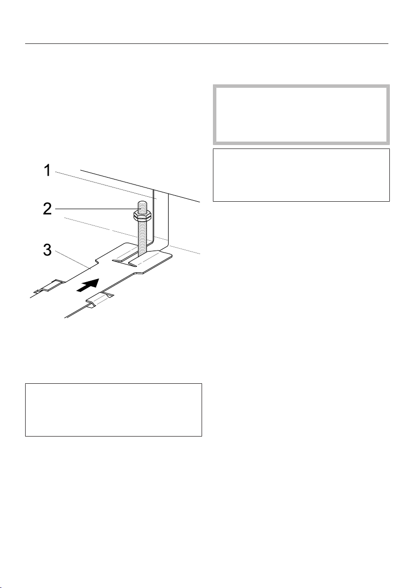
1
3
2
Attaching to the floor
1
2
3
Attaching to the wall
a
Anti-tip device
b
Screws
c
Locking nut
Secure the anti-tip device to the
floor surface with suitable bearing
capacity, either to the floor or wall.
using four screws .
Screw the locking nut to the bolt,
see the"Installation dimensions of
locking bolt" table.
Anti-tip device
108
Do not push the range into
position before all supply
connections have been
established.
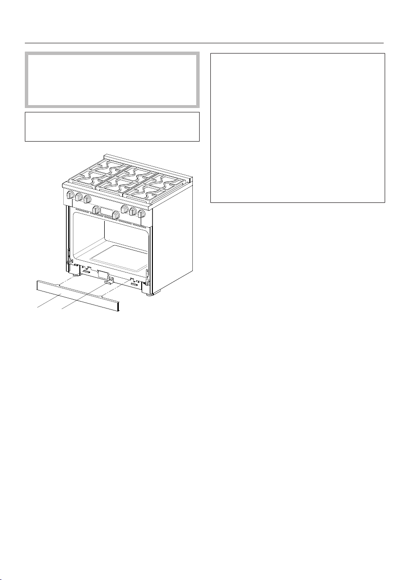
The toe kick cover is attached to the
base of the range by magnets.
21
a
Toe kick cover
b
Locking clamp
Remove the toe kick cover from
the appliance.
Pull out the locking clamp .
The locking clamp extends through
the toe kick cover of the range
housing. Its length is approximately
equal to the depth of the range. It can
be pulled out and pushed back in
again. Its length is approximately
equal to the depth of the range.
A slot is located in the non-visible rear
section of the locking latch. This slot
engages with the bolt of the anti-tip
device when you slide the locking
latch into the range.
Anti-tip device
109
Complete all necessary connections
for the range. Read the information in
the"Electrical connection","Gas
connection" and"Plumbing" sections.
The range can be damaged if it is
lifted using the cover, the trim or the
door handle.
Open the oven door and hold the
appliance by the front of the oven
interior.
Lift the range and move it with the
help of the rear wheels.
Slide the range into position, guiding
the middle of the appliance onto the
anti-tip device. Slide the appliance all
the way back to the wall.
The range can be aligned if necessary.
Check it with a spirit level.
– Rear adjustment right and left:
You will need an open-end wrench
(3/8" (10 mm)).
– Front adjustment right and left:
You will need an open-end wrench
(5/8" (16 mm)) for the locknut and
an open-end wrench (1/2" (13
mm)) for the adjustable nut.
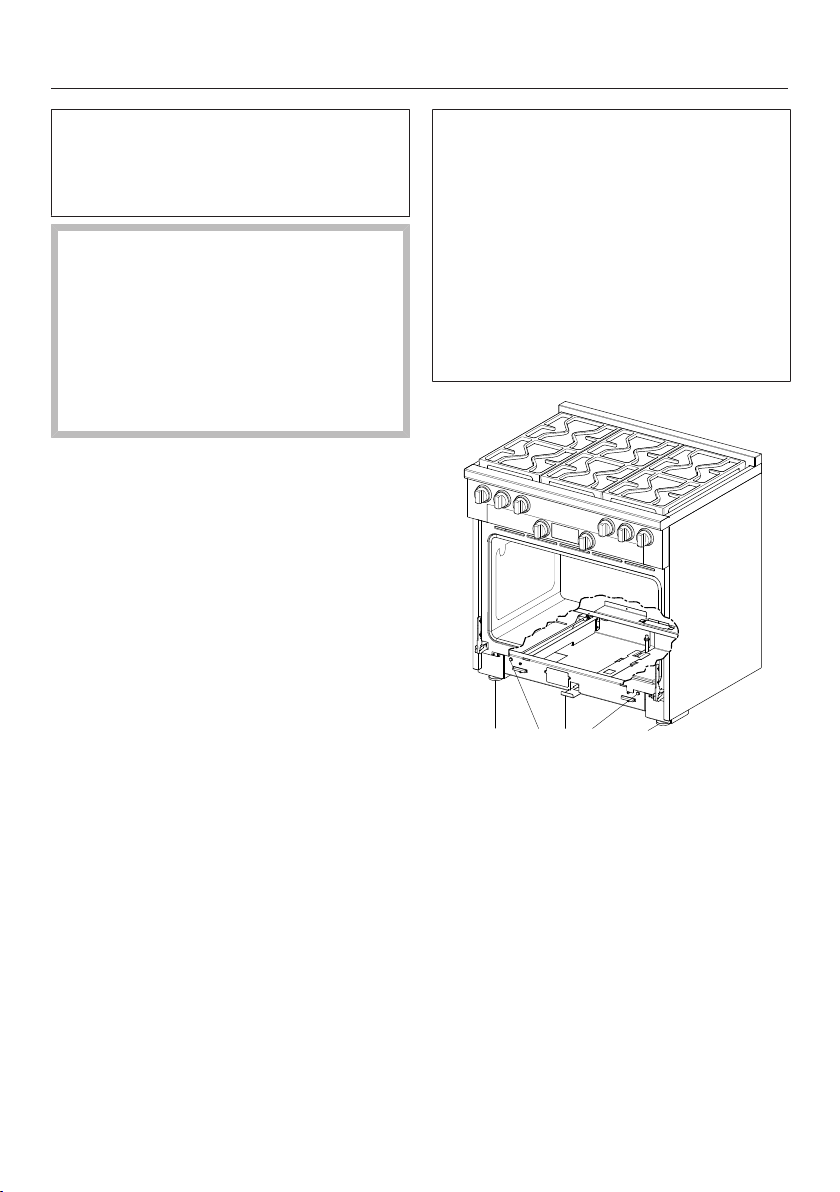
1 22 33
a
Locking clamp
b
Rear adjustment
c
Front adjustment
Align the range.
Slide the locking clamp firmly
back.
Anti-tip device
110
In the range housing, there is an
opening for the bolt of the anti-tip
device. The opening allows the range to
be slid onto the anti-tip device and
back to the wall.
The locking clamp must noticeably
engage with the bolt so that anti-tip
protection is ensured for the range.
a
Opening in the range housing
b
Anti-tip device bolt
c
Locking clamp with slot
The toe kick cover can only be
attached if the locking clamp has
been slid all the way into the
appliance.
Fit the toe kick cover on the range.
Disconnecting the range from
the anti-tip device
WARNING
Children and adults can tip over the
range if has not been secured. This
may lead to fatal injuries.
If you need to remove the range from
its installation space, e.g. for service,
you first need to disconnect the
appliance from the anti-tip device.
Follow the instructions for installation
in reverse order.
Electrical connection
111
ATTENTION:
During installation, maintenance and
repair work, the range must be
disconnected from the electrical
supply. It is only completely isolated
from the electrical supply if the plug
fuses have been fully unscrewed
(where applicable), the circuit breaker
has been tripped or the power cord
has been unplugged from the wall
outlet.
Installation work and repairs should
only be performed by a qualified
technician in accordance with all
applicable codes and standards.
Repairs and service by unqualified
persons could be dangerous and the
manufacturer will not be held
responsible.Installation, repair, and
maintenance work should only be
performed by a Miele-authorized
service technician. Work by
unqualified persons can cause
considerable danger to users. Miele
cannot be held liable for any damage
arising as a result of such work.
To avoid damaging the range, make
sure that the connection data
(voltage and frequency) on the data
plate correspond to the building's
power supply before connecting the
appliance.
When in doubt, consult a qualified
electrician.
The internal electrical wiring of the
appliance has been performed and
tested according to the valid
regulations. To guarantee
malfunction-free operation, ensure
the proper phase assignment of the
socket. In case of doubt, ask an
electrician.
The plug must be inserted into a
suitable outlet that has been installed
and grounded in compliance with all
applicable local regulations.
WARNING: THIS APPLIANCE MUST
BE GROUNDED
Installer: Please pass these
instructions on to the customer.
Electrical connection
112
Electrical connection
Model Power cord NEMA For electrical supply with
USA Canad
a
HR 1421 Approx. 5' 11"
(1.80 m)
14-50 P
plug
120/208 V
or
120/240 V
50 A 40 A 60 Hz
HR 1622 Approx. 5' 11"
(1.80 m)
14-50 P
plug
120/208 V
or
120/240 V
50 A 40 A 60 Hz
HR 195x Approx. 5' 11"
(1.80 m)
14-50 P
plug
120/208 V
or
120/240 V
50 A 40 A 60 Hz
HR 1724
HR 192x
HR 193x
Approx. 5' 11"
(1.80 m)
14-30 P
plug
120/208 V
or
120/240 V
30 A 30 A 60 Hz
HR 112x
HR 113x
Approx. 5' 11"
(1.80 m)
5-15 P
plug
120V 15 A 15 A 60 Hz
Data plate
The data plate with the connection information for the range is located in the
middle of the base front behind the removable toe kick cover (see "Guide to the
range").
SAVE THESE INSTRUCTIONS FOR THE ELECTRICAL INSPECTOR'S USE.
This appliance must be grounded in compliance with all applicable local and
national regulations.
Installation, repair and maintenance work should only be performed by a Miele
authorized service technician in compliance with local regulations and the ANSI
National Electrical Code / NFPA 70 in the United States or the Canadian
Electrical Code, Part I in Canada (CSA standard C22.1).
Plumbing
113
Notes on connecting to the
water supply
The appliance must be connected to
the water supply by a qualified
professional.
Disconnect the appliance from the
power supply before connecting it to
the water line.
Turn off the water supply before
connecting the water lines for the
range.
– All devices used for connecting the
appliance to the water supply must
comply with the current national and
local safety regulations in the country
in which the range is being installed.
– We do not recommend the use of
water produced by Reverse Osmosis
filtration systems. Along with the
possibility of detrimental health
effects, highly purified water can
cause the premature corrosion and
failure of components in your
appliance. Furthermore, many RO
systems, especially under counter
systems, do not deliver sufficient
water pressure to allow the appliance
to operate properly. Connection to
such a water supply could cause
poor performance, premature
appliance failure, leaks and/or
flooding. Miele will not be responsible
for any damages caused by
appliances connected to these
systems. Only use filtered, softened
and demineralized water from the
building's plumbing to supply the
oven.
– Connect the range to a cold water
supply only.
– The range may be connected to a
water supply without a non-return
valve.
– A water shut-off valve must be
provided between the stainless steel
hose and the household water supply
to ensure that the water supply can
be cut off if necessary.
– The water shut-off valve must be
accessible after installation.
– The water pressure must be between
1 and 10 bar (10
5
and 10
6
Pa or 14.5
and 145 psi). If the pressure is higher
than this, install a pressure reducer.
– 30" and 36" range: The provided
stainless steel hose has a length of 4'
11" (1.5m).
48" Range: The provided stainless
steel hose has a length of 9'
10" (3m).
Longer intake hoses are available if
necessary. Do not shorten the hoses.
– The total hose length must not
exceed 24.5 ft. (7.5 m).
Ensure that the shut-off valve is
accessible after installation.
Replace the stainless steel hose if it
is damaged, using only an original
Miele hose to do so (available from
Miele). The hose must be suitable for
supplying drinking water.
Plumbing
114
Attach the stainless steel hose
to the range.
Make sure that the stainless steel
hose is not kinked or damaged. The
stainless steel hose must not be
shortened.
Remove the cover from the water
supply connection at the back of the
range.
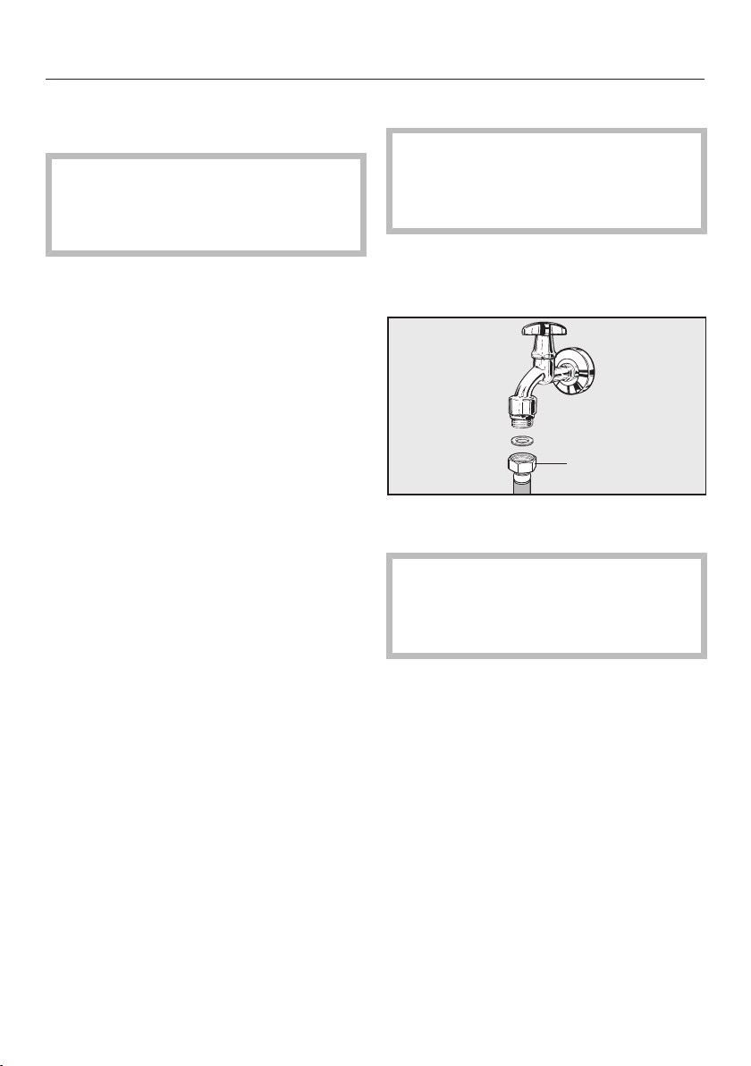
Take the angled side of the stainless
steel hose and check whether a
gasket is present. If not, insert one.
Screw the stainless steel hose
coupling nut onto the threaded union.
Ensure that the hose is correctly
seated.
Connecting to the water supply
Danger of electric shock!
Disconnect the range from the
electrical supply before connecting it
to the water supply.
Check that the gasket is present.
Replace, if not, insert before
connecting to the water supply.
3/8"
Connect the stainless steel hose to
the water supply.
Old or previously used tubing should
never be connected to the range.
Only use the stainless steel hose
supplied.
Ensure that the hose is correctly
seated.
Slowly open the shut-off valve to the
water supply and check for leaks.
Gas connection
115
Connection to the gas supply
may only be performed by a duly
authorized technician. This
technician is responsible for proper
function at the installation site.
In Massachusetts, the gas
connection may be performed only
by a certified gas installer.
The range must be connected with
its own shut-off valve.
The shut-off valve must be
accessible and visible, after the
opening of a cabinet door, if
necessary.
The connection of the range can be
for natural gas or propane gas
according to the model.
Ask your gas company what kind of
gas is used and compare it with the
specifications on the data plate.
The range is not connected to an
exhaust vent.
During the setup and connection of
the range, observe the applicable
installation conditions, especially
suitable ventilation measures.
The gas connections must be
arranged in such a way that they are
not heated and damaged by the
operation of the range.
In particular, make sure that the gas
hose lines and connection fittings on
the range do not come into contact
with hot exhaust gases.
Flexible connection lines can be
damaged by incorrect routing.
Attach flexible connecting lines in
such a way so that they do not come
into contact with any moving kitchen
parts (e.g., a drawer) and are not
exposed to mechanical stress.
The range and the shut-off valve
must be disconnected from the gas
supply during gas pressure tests.
Disconnect the range and the shut-
off valve from the gas supply before
performing a gas pressure test at a
pressure of more than 1/2psi
(3.5kPA). Close the shut-off valve of
the gas supply before performing a
gas pressure test at a pressure of
less than or equal to 1/2psi
(3.5kPA).
Incorrectly sealed gas lines can lead
to a gas leak and thus to an
explosion.
Seal all gas lines with a suitable
thread sealant.
Seal tightness tests on the range
must be performed according to
manufacturer specifications.
The gas connection must be
established only Miele-authorized
specialists according to the local and
following regulations:
National Fuel Gas Code
ANSIZ21.1 / NFPA No. 54 for the
United States or the current Can /
CGAB149.1 and 2 Installation
Codes of Gas Appliances for
Canada.
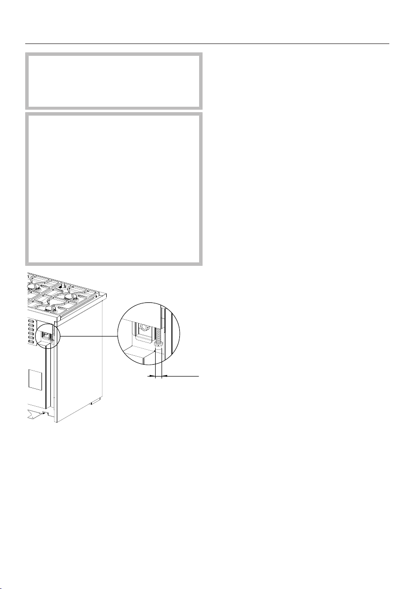
Gas connection
116
The installation must conform with
local codes or, in the absence of
local codes, with the National Fuel
Gas Code, ANSI Z223.1/NFPA 54.
The gas pressure may not
undershoot or exceed certain values.
Make sure that the maximum gas
pressure upstream of the gas
pressure controller does not amount
to more than 1/2psi (3.5kPA) for
natural and propane gas.
Make sure that the minimum gas
pressure amounts to a 6" (150 mm)
water head in the case of natural gas
and a 11" (279,4mm) water head in
the case of propane gas.
G NPT
1/2"
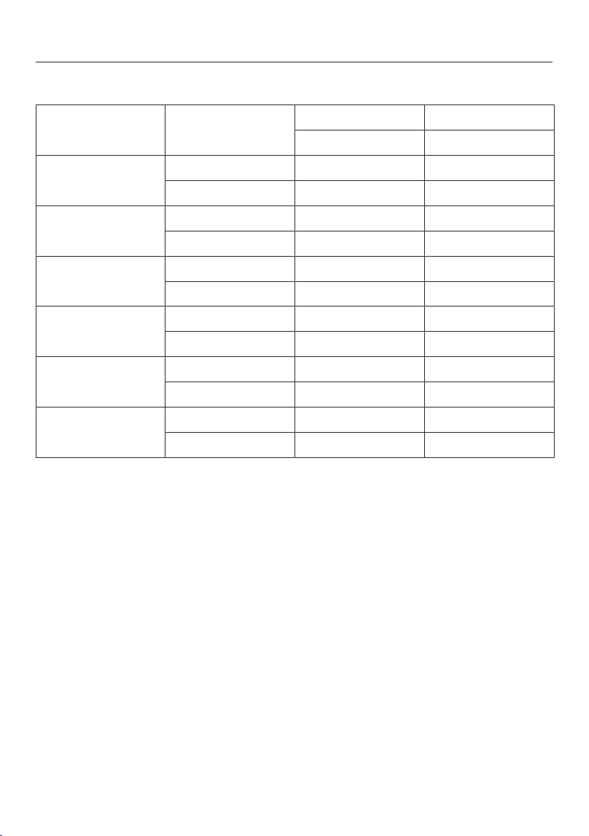
Burner ratings of Standard Burner Configuration
117
Burner ratings for HR 1124
Gas type Btu/hr kW
max max
Simmer burner Natural gas 12.500 3.70
Propane gas 12.500 3.70
Power burner Natural gas 19.500 5.70
Propane gas 19.500 5.70
Oven top burner Natural gas 22.000 6.45
Propane gas 20.150 5.90
Oven bottom
burner
Natural gas 23.200 6.79
Propane gas 23.200 6.79
Total output of
Cooktop
Natural gas 71.000 20.80
Propane gas 71.000 20.80
Maximum total
output of Range
Natural gas 94.200 27.59
Propane gas 94.200 27.59

Burner ratings of Standard Burner Configuration
118
Burner ratings for HR 1134
Gas type Btu/hr kW
max max
Simmer burner Natural gas 12.500 3.70
Propane gas 12.500 3.70
Power burner Natural gas 19.500 5.70
Propane gas 19.500 5.70
Oven top burner Natural gas 22.000 6.45
Propane gas 20.150 5.90
Oven bottom
burner
Natural gas 25.500 7.47
Propane gas 27.000 7.90
Total output of
Cooktop
Natural gas 110.000 32.20
Propane gas 110.000 32.20
Maximum total
output of Range
Natural gas 135.500 39.67
Propane gas 137.000 40.10
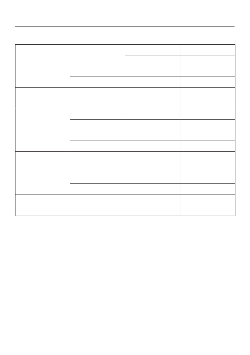
Burner ratings of Standard Burner Configuration
119
Burner ratings for HR 1135
Gas type Btu/hr kW
max max
Simmer burner Natural gas 12.500 3.70
Propane gas 12.500 3.70
Power burner Natural gas 19.500 5.70
Propane gas 19.500 5.70
Grill Natural gas 19.000 5.50
Propane gas 15.500 4.50
Oven top burner Natural gas 22.000 6.45
Propane gas 20.150 5.90
Oven bottom
burner
Natural gas 25.500 7.47
Propane gas 27.000 7.90
Total output of
Cooktop
Natural gas 90.000 26.30
Propane gas 86.500 25.30
Maximum total
output of Range
Natural gas 115.500 33.77
Propane gas 113.500 33.20

Burner ratings of Standard Burner Configuration
120
Burner ratings for HR 1136
Gas type Btu/hr kW
max max
Simmer burner Natural gas 12.500 3.70
Propane gas 12.500 3.70
Power burner Natural gas 19.500 5.70
Propane gas 19.500 5.70
Griddle Natural gas 13.000 3.80
Propane gas 14.300 4.20
Oven top burner Natural gas 22.000 6.45
Propane gas 20.150 5.90
Oven bottom
burner
Natural gas 25.500 7.47
Propane gas 27.000 7.90
Total output of
Cooktop
Natural gas 84.000 24.60
Propane gas 85.300 25.00
Maximum total
output of Range
Natural gas 109.500 32.07
Propane gas 112.300 32.90
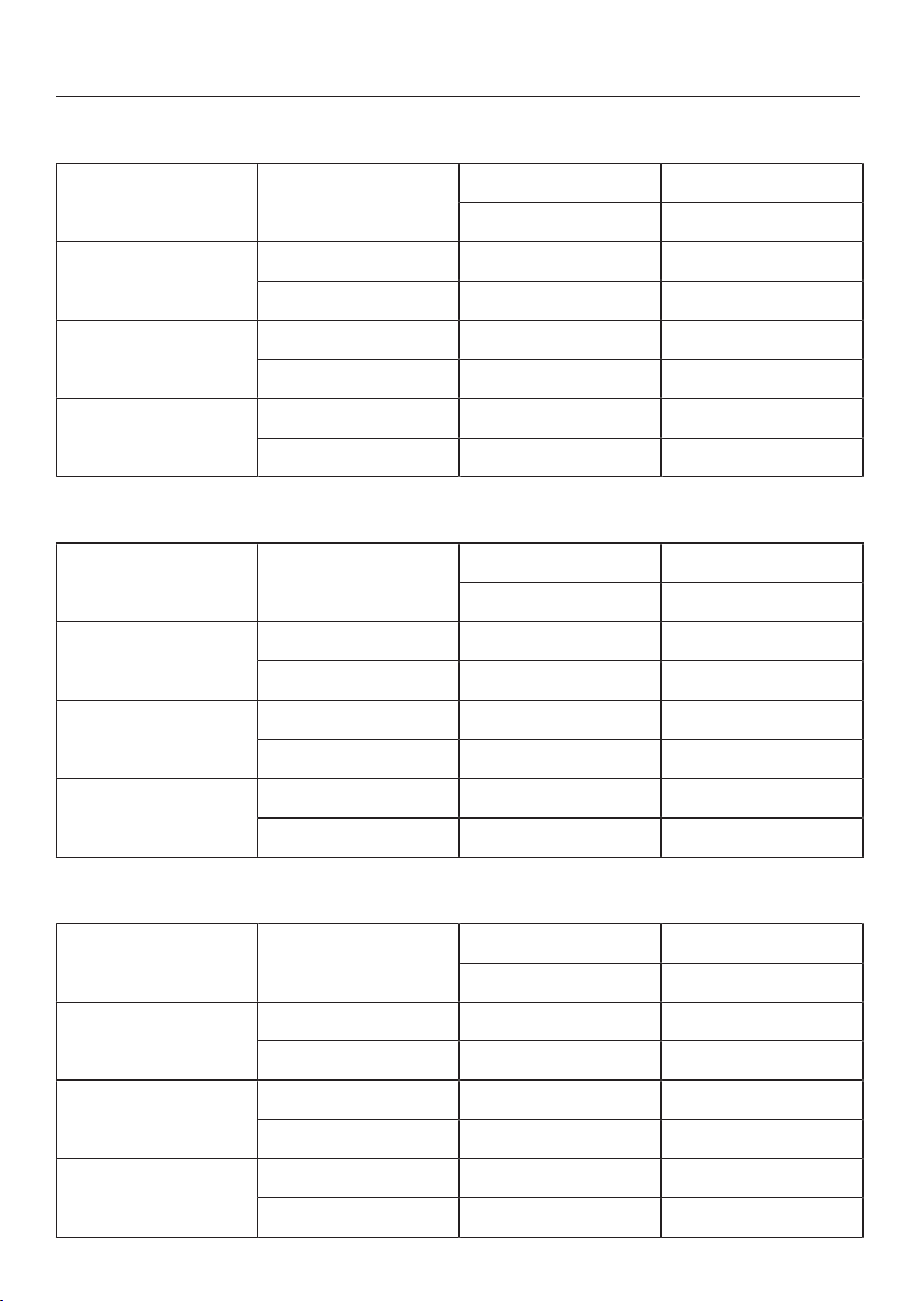
Burner ratings of Standard Burner Configuration
121
Burner ratings for HR 1724
Gas type Btu/hr kW
max max
Simmer burner Natural gas 12.500 3.70
Propane gas 12.500 3.70
Power burner Natural gas 19.500 5.70
Propane gas 19.500 5.70
Total output of
Cooktop
Natural gas 71.000 20.80
Propane gas 71.000 20.80
Burner ratings for HR 1924
Gas type Btu/hr kW
max max
Simmer burner Natural gas 12.500 3.70
Propane gas 12.500 3.70
Power burner Natural gas 19.500 5.70
Propane gas 19.500 5.70
Total output of
Cooktop
Natural gas 71.000 20.80
Propane gas 71.000 20.80
Burner ratings for HR 1934
Gas type Btu/hr kW
max max
Simmer burner Natural gas 12.500 3.70
Propane gas 12.500 3.70
Power burner Natural gas 19.500 5.70
Propane gas 19.500 5.70
Total output of
Cooktop
Natural gas 110.000 32.20
Propane gas 110.000 32.20
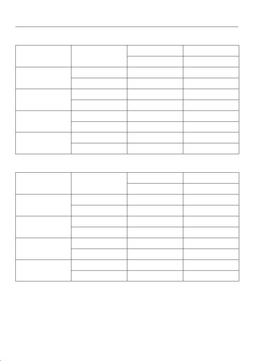
Burner ratings of Standard Burner Configuration
122
Burner ratings for HR 1935
Gas type Btu/hr kW
max max
Simmer burner Natural gas 12.500 3.70
Propane gas 12.500 3.70
Power burner Natural gas 19.500 5.70
Propane gas 19.500 5.70
Grill Natural gas 19.000 5.50
Propane gas 15.500 4.50
Total output of
Cooktop
Natural gas 90.000 26.30
Propane gas 86.500 25.30
Burner ratings for HR 1936
Gas type Btu/hr kW
max max
Simmer burner Natural gas 12.500 3.70
Propane gas 12.500 3.70
Power burner Natural gas 19.500 5.70
Propane gas 19.500 5.70
Griddle Natural gas 13.000 3.80
Propane gas 14.300 4.20
Total output of
Cooktop
Natural gas 84.000 24.60
Propane gas 85.300 25.00
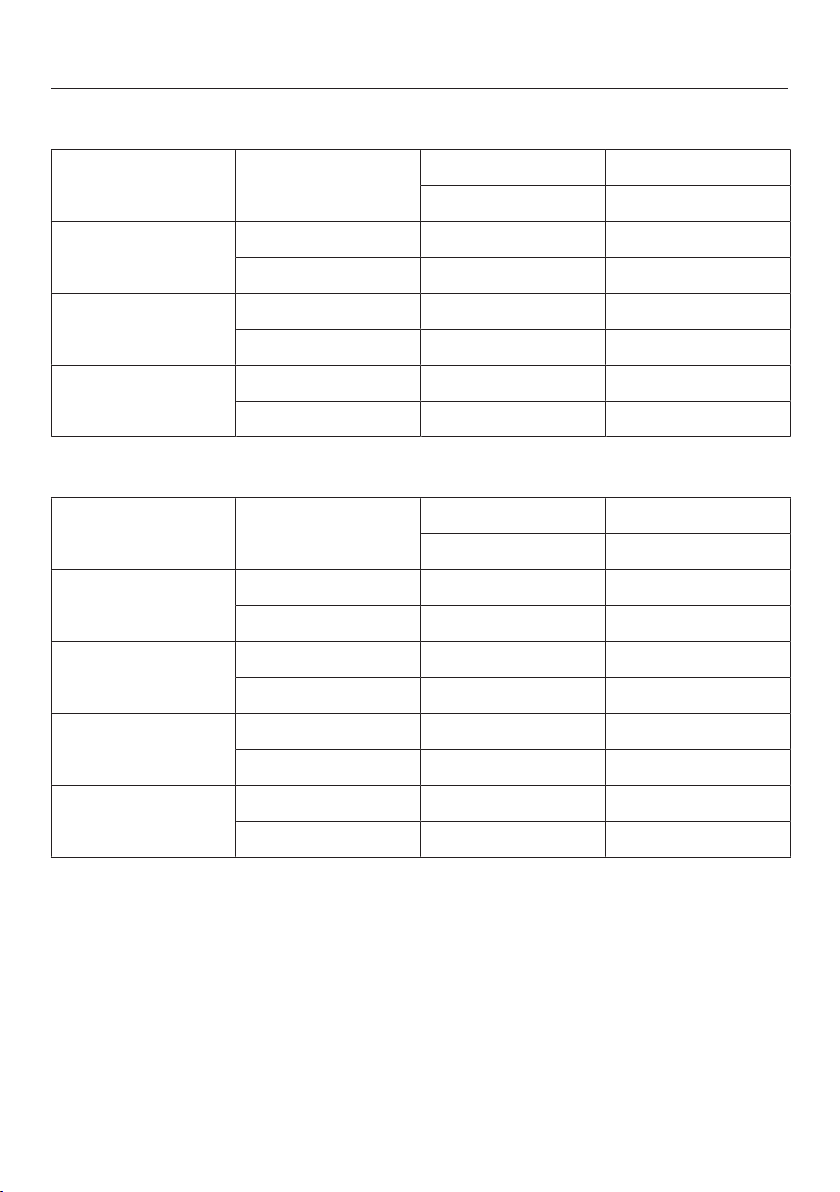
Burner ratings of Standard Burner Configuration
123
Burner ratings for HR 1954
Gas type Btu/hr kW
max max
Simmer burner Natural gas 12.500 3.70
Propane gas 12.500 3.70
Power burner Natural gas 19.500 5.70
Propane gas 19.500 5.70
Total output of
Cooktop
Natural gas 142.000 41.60
Propane gas 142.000 41.60
Burner ratings for HR 1955
Gas type Btu/hr kW
max max
Simmer burner Natural gas 12.500 3.70
Propane gas 12.500 3.70
Power burner Natural gas 19.500 5.70
Propane gas 19.500 5.70
Grill Natural gas 19.000 5.50
Propane gas 15.500 4.50
Total output of
Cooktop
Natural gas 122.000 35.70
Propane gas 118.500 34.70
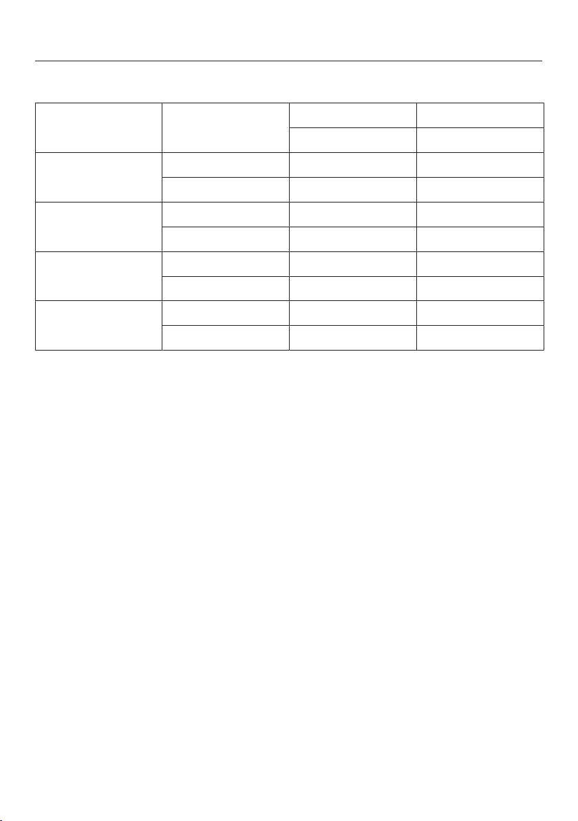
Burner ratings of Standard Burner Configuration
124
Burner ratings for HR 1956
Gas type Btu/hr kW
max max
Simmer burner Natural gas 12.500 3.70
Propane gas 12.500 3.70
Power burner Natural gas 19.500 5.70
Propane gas 19.500 5.70
Griddle Natural gas 13.000 3.80
Propane gas 14.300 4.20
Total output of
Cooktop
Natural gas 116.000 34.00
Propane gas 117.300 34.40
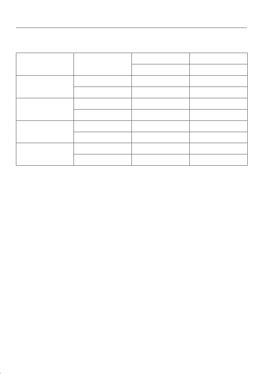
Burner ratings of M Pro Power (Zero Gap)
125
When the BTU-reducing kit (Zero Gap) is used, the burner ratings of the burners
change as follows:
Gas type BTU/hr kW
max max
Simmer burner Natural gas 10.000 2.93
Propane gas 10.000 2.93
Power burner Natural gas 14.700 4.31
Propane gas 14.700 4.31
Grill Natural gas 19.000 5.50
Propane gas 15.500 4.50
Griddle Natural gas 13.000 3.80
Propane gas 14.300 4.20

Burner ratings of M Pro (Décor Hood)
126
When the BTU-reducing kit (Décor Hood) is used, the burner ratings of the burners
change as follows:
Gas type BTU/hr kW
max max
Simmer burner Natural gas 10.000 2.93
Propane gas 10.000 2.93
Power burner Natural gas 12.200 3.58
Propane gas 12.200 3.58
Grill Natural gas 19.000 5.50
Propane gas 15.500 4.50
Griddle Natural gas 13.000 3.80
Propane gas 14.300 4.20
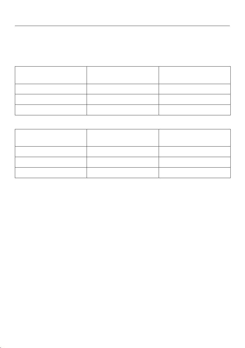
Possible combinations - Range with BTU Reducing jet
kit
127
If a BTU reducing jet kit is necessary an authorized installer is required to adapt the
product in accordance with local codes and standards. The nozzles are a standard
accessory and are changed during installation.
Natural gas
BTU Reducing jet kit HR 113x
HR 193x
HR 195x NG
36" NG Zero Gap Yes –
36" NG Decor Yes –
48" NG Zero Gap – Yes
Propane gas
BTU Reducing jet kit HR 113x LP
HR 193x LP
HR 195x LP
36" LP Zero Gap Yes –
36" LP Decor Yes –
48" LP Zero Gap – Yes
Caring for the environment
128
Disposal of the packing
material
The cardboard box and packing
materials protect the appliance during
shipping. They have been designed to
be biodegradable and recyclable.
Ensure that any plastic wrappings,
bags, etc. are disposed of safely and
kept out of the reach of children.
Danger of suffocation!
Disposal of your old appliance
Electrical and electronic appliances
contain valuable materials. They also
contain certain substances, compounds
and components which were essential
for the proper functioning and safe use
of the equipment. Handling these
materials improperly by disposing of
them in your household waste can be
harmful to your health and the
environment. Therefore, please do not
dispose of your old appliance with
regular household waste and follow
local regulations on proper disposal.
Consult with local authorities, dealers or
Miele in order to dispose of and recycle
electrical and electronic appliances.
Miele assumes no responsibility for
deleting any personal data left on the
appliance being disposed. Please
ensure that your old appliance is kept
away from children until removal.
Observe safety requirements for
appliances that may tip over or pose an
entrapment hazard.


9 Independence Way
Princeton, NJ 08540
Phone:
Fax:
www.mieleusa.com
U.S.A.
Miele, Inc.
National Headquarters
Please have the model and serial number
of your appliance available when
contacting Customer Service.
Canada
Importer
Miele Limited
Headquarters and Miele Centre
800-843-7231
609-419-4298
Customer Service & Support
Phone:
Fax:
161 Four Valley Drive
Vaughan, ON L4K 4V8
www.miele.ca
888-99-MIELE(64353)
888-586-8056
Customer Care Centre
Phone:
800-565-6435
905-532-2272
International Headquarters
Miele & Cie. KG
Carl-Miele-Straße 29
33332 Gütersloh
Germany

M.-Nr. 10 876 460 / 03
en-US, CA
All Electric: HR1421; HR1622; All Gas: HR1124; HR1134;
HR1135; HR1136; Dual Fuel: HR1724; HR1924; HR1934;
HR1935; HR1936; HR1954; HR1955; HR1956