1. Overview
This manual provides instructions for the LJPXHHU Digital Multimeter, a True RMS 4000-count auto-ranging meter designed for electrical testing. The device measures AC/DC voltage, resistance, continuity, and includes a non-contact voltage (NCV) detection function. It is powered by 2 x AAA batteries (included).

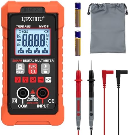
1.1 Package Contents
- Digital Multimeter (Model MY8331)
- Test Leads with CAT III/CAT IV safety caps
- Instruction Manual
- 2 x AAA Batteries
- Removable Orange Protective Silicone Cover
2. Safety Information
WARNING: To prevent electric shock, injury, or damage to the meter, read and follow all safety instructions. This meter is certified to CE and RoHS standards and features overload protection. The test leads are rated CAT III/CAT IV.
- Do not use the meter if it or the test leads are damaged.
- Do not measure voltages exceeding 600V AC/DC.
- Do not use the meter in wet or damp environments.
- Use the non-contact voltage (NCV) function to check for live AC voltage before making contact with conductors.
- Replace batteries when the low battery indicator appears.
- This meter cannot measure AC current.
3. Product Features and Components
3.1 Front Panel Description
- Large Backlit LCD Display: Shows measurement readings, units, and mode indicators.
- Rotary Function Switch: Selects the measurement mode (OFF, NCV, V, Ω, Continuity, Battery Test).
- Data Hold (HOLD) Button: Freezes the current reading on the display.
- Backlight/Flashlight Button: Turns on the display backlight and the integrated white LED flashlight.
- NCV Sensor Area: Located at the top of the meter for non-contact voltage detection.
- Input Jacks:
- COM (Black): Common ground jack for the black test lead.
- VΩ (Red): Jack for voltage, resistance, continuity, and diode tests. Accepts the red test lead.
3.2 Key Features
- Auto-Ranging: Automatically selects the correct measurement range.
- True RMS: Provides accurate measurements of AC voltage and current.
- Non-Contact Voltage (NCV) Detection: Detects AC voltage with audible and visual alarms.
- Continuity Test: Audible buzzer sounds for resistances below approximately 50Ω.
- Battery Test: Supports testing of 1.5V, 9V, and 12V batteries.
- Data Hold & Auto Power-Off: Conserves battery life.
- Protective Silicone Case: Provides drop protection and insulation.
4. Basic Operation
4.1 Initial Setup
- Install 2 x AAA batteries into the compartment on the back of the meter.
- Insert the black test lead into the COM jack and the red test lead into the VΩ jack.
- Turn the rotary switch to the desired function. The meter will power on.
4.2 Taking Measurements
Measuring AC/DC Voltage
- Set the rotary switch to the "V" position. The meter will auto-range.
- For DC voltage, ensure the red lead is connected to the positive point and the black lead to the negative point.
- Touch the probe tips to the circuit under test. Read the voltage value on the display.
Range: 0.8V to 600V AC/DC.
Measuring Resistance
- Set the rotary switch to the "Ω" position.
- Ensure the circuit under test is not powered.
- Connect the probes across the resistor or component. Read the resistance value.
Range: 4 kΩ to 40 MΩ.
Continuity Test
- Set the rotary switch to the continuity symbol (⋅⋅⋅)).
- Touch the probe tips together. The meter should emit a continuous beep, confirming the function is working.
- Touch the probes to the two points of the circuit. A continuous beep indicates continuity (resistance < ~50Ω).
Non-Contact Voltage (NCV) Detection
- Set the rotary switch to the "NCV" position.
- Slowly bring the top of the meter (NCV sensor area) close to an AC wire or outlet.
- The meter will provide both visual and audible indications:
- Weak Signal ("---L"): Green indicator lights up.
- Strong Signal ("---H"): Yellow indicator lights up and buzzer sounds.
Testing Batteries
- Set the rotary switch to the battery test position (appropriate for 1.5V, 9V, or 12V).
- Connect the red probe to the battery's positive terminal and the black probe to the negative terminal.
- Read the voltage on the display to assess battery health.
5. Display Symbols and Indicators
| Symbol | Meaning |
|---|---|
| AC | Alternating Current measurement |
| DC | Direct Current measurement |
| V, mV | Volts, Millivolts |
| Ω, kΩ, MΩ | Ohms, Kilohms, Megohms |
| ⋅⋅⋅) | Continuity test mode |
| ---L / ---H | NCV weak/strong signal |
| HOLD | Data Hold function is active |
| Battery Icon | Low battery warning |
| OL | Overload or out-of-range |
6. Care and Maintenance
- Keep the meter clean and dry. Use a soft, damp cloth for cleaning.
- Remove the batteries if the meter will not be used for an extended period.
- Use the protective silicone cover during operation to prevent damage.
- Do not expose the meter to extreme temperatures, direct sunlight, or high humidity.
- Store the meter and test leads in a safe, dry place.
7. Specifications
| Feature | Specification |
|---|---|
| Display | 4000 Counts, LCD with Backlight |
| AC Voltage Range | 0.8V - 600V |
| DC Voltage Range | 0.8V - 600V |
| Resistance Range | 4 kΩ - 40 MΩ |
| Continuity Test | Audible Buzzer (< ~50Ω) |
| Battery Test | 1.5V, 9V, 12V |
| NCV Detection | AC Voltage, with Visual/Audible Alarm |
| Power Supply | 2 x AAA Batteries (Included) |
| Safety Rating | CAT III / CAT IV, CE, RoHS |
| Auto Power-Off | Yes |
| Dimensions | Compact Design with Silicone Case |
8. Troubleshooting
| Problem | Possible Cause | Solution |
|---|---|---|
| Display is blank. | Batteries are dead or installed incorrectly. | Replace or reinstall batteries. |
| Readings are inaccurate or unstable. | Weak batteries; poor probe contact; testing a live circuit for resistance. | Replace batteries. Ensure good contact. Turn off power before resistance tests. |
| NCV function not detecting voltage. | Sensor not close enough; voltage below detection threshold; battery low. | Move sensor closer to the wire. Check battery level. |
| Continuity buzzer does not sound. | Circuit resistance is too high; buzzer function is faulty. | Check for open circuit. Test by touching probes together. |
| "OL" displayed. | Measurement is out of range (e.g., resistance too high). | Select a higher range manually (if applicable) or check the circuit. |
9. Warranty and Support
The LJPXHHU Digital Multimeter is covered by a 3-Year Quality Guarantee. This warranty covers defects in materials and craftsmanship. If a problem occurs within 36 months of purchase, contact the seller, LJPXHHU US, through your Amazon purchase history for support and potential replacement.
Note: The warranty does not cover damage caused by misuse, accidents, or unauthorized modifications.